US12239282B2 - Vacuum cleaner with liquid retention - Google Patents
Vacuum cleaner with liquid retentionDownload PDFInfo
- Publication number
- US12239282B2 US12239282B2US17/356,934US202117356934AUS12239282B2US 12239282 B2US12239282 B2US 12239282B2US 202117356934 AUS202117356934 AUS 202117356934AUS 12239282 B2US12239282 B2US 12239282B2
- Authority
- US
- United States
- Prior art keywords
- cyclone chamber
- vacuum cleaner
- arcuate passage
- motor
- dirt cup
- Prior art date
- Legal status (The legal status is an assumption and is not a legal conclusion. Google has not performed a legal analysis and makes no representation as to the accuracy of the status listed.)
- Active
Links
Images


Classifications
- A—HUMAN NECESSITIES
- A47—FURNITURE; DOMESTIC ARTICLES OR APPLIANCES; COFFEE MILLS; SPICE MILLS; SUCTION CLEANERS IN GENERAL
- A47L—DOMESTIC WASHING OR CLEANING; SUCTION CLEANERS IN GENERAL
- A47L9/00—Details or accessories of suction cleaners, e.g. mechanical means for controlling the suction or for effecting pulsating action; Storing devices specially adapted to suction cleaners or parts thereof; Carrying-vehicles specially adapted for suction cleaners
- A47L9/10—Filters; Dust separators; Dust removal; Automatic exchange of filters
- A47L9/16—Arrangement or disposition of cyclones or other devices with centrifugal action
- A47L9/165—Construction of inlets
- A—HUMAN NECESSITIES
- A47—FURNITURE; DOMESTIC ARTICLES OR APPLIANCES; COFFEE MILLS; SPICE MILLS; SUCTION CLEANERS IN GENERAL
- A47L—DOMESTIC WASHING OR CLEANING; SUCTION CLEANERS IN GENERAL
- A47L5/00—Structural features of suction cleaners
- A47L5/12—Structural features of suction cleaners with power-driven air-pumps or air-compressors, e.g. driven by motor vehicle engine vacuum
- A47L5/22—Structural features of suction cleaners with power-driven air-pumps or air-compressors, e.g. driven by motor vehicle engine vacuum with rotary fans
- A47L5/24—Hand-supported suction cleaners
- A—HUMAN NECESSITIES
- A47—FURNITURE; DOMESTIC ARTICLES OR APPLIANCES; COFFEE MILLS; SPICE MILLS; SUCTION CLEANERS IN GENERAL
- A47L—DOMESTIC WASHING OR CLEANING; SUCTION CLEANERS IN GENERAL
- A47L7/00—Suction cleaners adapted for additional purposes; Tables with suction openings for cleaning purposes; Containers for cleaning articles by suction; Suction cleaners adapted to cleaning of brushes; Suction cleaners adapted to taking-up liquids
- A47L7/0004—Suction cleaners adapted to take up liquids, e.g. wet or dry vacuum cleaners
- A47L7/0019—Details of the casing
- A—HUMAN NECESSITIES
- A47—FURNITURE; DOMESTIC ARTICLES OR APPLIANCES; COFFEE MILLS; SPICE MILLS; SUCTION CLEANERS IN GENERAL
- A47L—DOMESTIC WASHING OR CLEANING; SUCTION CLEANERS IN GENERAL
- A47L7/00—Suction cleaners adapted for additional purposes; Tables with suction openings for cleaning purposes; Containers for cleaning articles by suction; Suction cleaners adapted to cleaning of brushes; Suction cleaners adapted to taking-up liquids
- A47L7/0004—Suction cleaners adapted to take up liquids, e.g. wet or dry vacuum cleaners
- A47L7/0042—Gaskets; Sealing means
- A—HUMAN NECESSITIES
- A47—FURNITURE; DOMESTIC ARTICLES OR APPLIANCES; COFFEE MILLS; SPICE MILLS; SUCTION CLEANERS IN GENERAL
- A47L—DOMESTIC WASHING OR CLEANING; SUCTION CLEANERS IN GENERAL
- A47L9/00—Details or accessories of suction cleaners, e.g. mechanical means for controlling the suction or for effecting pulsating action; Storing devices specially adapted to suction cleaners or parts thereof; Carrying-vehicles specially adapted for suction cleaners
- A47L9/10—Filters; Dust separators; Dust removal; Automatic exchange of filters
- A47L9/16—Arrangement or disposition of cyclones or other devices with centrifugal action
- A47L9/1608—Cyclonic chamber constructions
- A—HUMAN NECESSITIES
- A47—FURNITURE; DOMESTIC ARTICLES OR APPLIANCES; COFFEE MILLS; SPICE MILLS; SUCTION CLEANERS IN GENERAL
- A47L—DOMESTIC WASHING OR CLEANING; SUCTION CLEANERS IN GENERAL
- A47L9/00—Details or accessories of suction cleaners, e.g. mechanical means for controlling the suction or for effecting pulsating action; Storing devices specially adapted to suction cleaners or parts thereof; Carrying-vehicles specially adapted for suction cleaners
- A47L9/22—Mountings for motor fan assemblies
- A—HUMAN NECESSITIES
- A47—FURNITURE; DOMESTIC ARTICLES OR APPLIANCES; COFFEE MILLS; SPICE MILLS; SUCTION CLEANERS IN GENERAL
- A47L—DOMESTIC WASHING OR CLEANING; SUCTION CLEANERS IN GENERAL
- A47L9/00—Details or accessories of suction cleaners, e.g. mechanical means for controlling the suction or for effecting pulsating action; Storing devices specially adapted to suction cleaners or parts thereof; Carrying-vehicles specially adapted for suction cleaners
- A47L9/28—Installation of the electric equipment, e.g. adaptation or attachment to the suction cleaner; Controlling suction cleaners by electric means
- A47L9/2868—Arrangements for power supply of vacuum cleaners or the accessories thereof
- A47L9/2884—Details of arrangements of batteries or their installation
- A—HUMAN NECESSITIES
- A47—FURNITURE; DOMESTIC ARTICLES OR APPLIANCES; COFFEE MILLS; SPICE MILLS; SUCTION CLEANERS IN GENERAL
- A47L—DOMESTIC WASHING OR CLEANING; SUCTION CLEANERS IN GENERAL
- A47L9/00—Details or accessories of suction cleaners, e.g. mechanical means for controlling the suction or for effecting pulsating action; Storing devices specially adapted to suction cleaners or parts thereof; Carrying-vehicles specially adapted for suction cleaners
- A47L9/32—Handles
- A47L9/322—Handles for hand-supported suction cleaners
- B—PERFORMING OPERATIONS; TRANSPORTING
- B04—CENTRIFUGAL APPARATUS OR MACHINES FOR CARRYING-OUT PHYSICAL OR CHEMICAL PROCESSES
- B04C—APPARATUS USING FREE VORTEX FLOW, e.g. CYCLONES
- B04C3/00—Apparatus in which the axial direction of the vortex flow following a screw-thread type line remains unchanged ; Devices in which one of the two discharge ducts returns centrally through the vortex chamber, a reverse-flow vortex being prevented by bulkheads in the central discharge duct
- B04C3/06—Construction of inlets or outlets to the vortex chamber
Definitions
- the present disclosurerelates to vacuum cleaners. More particularly, the present disclosure relates to handheld vacuum cleaners.
- a housing for a handheld vacuum cleanerincludes a suction opening, a cyclone chamber, and a helical passage.
- the suction openingis defined in the housing.
- the cyclone chamberis in fluid communication with the suction opening.
- the helical passageincludes a first end, a second end, and at least one sidewall. The first end is in fluid communication with the suction opening. The second end is in fluid communication with the cyclone chamber.
- the at least one sidewallextends between the first end and the second end. The at least one sidewall separates the helical passage from the cyclone chamber.
- a housing for a handheld vacuum cleanerincludes a suction opening, a dirt cup, and a rigid arcuate passage.
- the suction openingis defined in the housing.
- the dirt cupincludes a cyclone chamber defined therein.
- the rigid arcuate passagefluidly communicates the suction opening with the cyclone chamber.
- the rigid arcuate passageis discrete from the cyclone chamber along a majority of a length of the rigid arcuate passage.
- the rigid arcuate passageis open to the cyclone chamber at an end of the rigid arcuate passage.
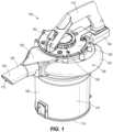
- FIG. 1is a perspective view of a handheld vacuum cleaner, according to embodiments disclosed herein.
- FIG. 2is a top plan view of the handheld vacuum cleaner of FIG. 1 .
- FIG. 4is a right side elevation view of the handheld vacuum cleaner of FIG. 1 .
- FIG. 6is a front elevation view of the handheld vacuum cleaner of FIG. 1 .
- FIG. 7is a rear elevation view of the handheld vacuum cleaner of FIG. 1 .
- FIG. 8is an exploded perspective view of the handheld vacuum cleaner of FIG. 1 .
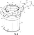
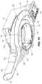
- FIG. 9is a rear perspective view of the handheld vacuum cleaner with the handle and suction source housing removed.
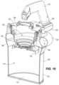
- FIG. 10is a cross-sectional front perspective view of the handheld vacuum cleaner of FIG. 1 .
- FIG. 11is a cross-sectional side elevation view of the handheld vacuum cleaner of FIG. 1 .
- FIG. 12is a cross-sectional top plan view of the handheld vacuum cleaner of FIG. 1 .
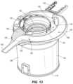
- FIG. 13is a cross-sectional front perspective view of the handheld vacuum cleaner of FIG. 1 , the cross section being taken along the same plane as in FIG. 12 .
- FIG. 14is a cross-sectional bottom plan view of the handheld vacuum cleaner of FIG. 1 .
- FIG. 15is a cross-sectional bottom perspective view of the handheld vacuum cleaner of FIG. 1 .
- FIG. 16is a cross-sectional perspective view of a motor and impeller in a cavity of a suction source housing of the handheld vacuum cleaner of FIG. 1 .
- FIG. 17is a cross-sectional side elevation view of the handheld vacuum cleaner of FIG. 1 .
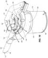
- FIG. 18is a top rear perspective view of the handheld vacuum cleaner of FIG. 1 .
- the vacuum cleaner 100includes a housing 102 , an inlet portion 104 , a dirt cup 106 , a passage 108 extending between the inlet portion 104 and the dirt cup 106 , and a handle 110 .
- the housing 102itself includes the inlet portion 104 , the dirt cup 106 , and the passage 108 .
- the vacuum cleaner 100also includes a suction source ( FIGS. 16 and 17 ), for example, a suction motor 150 that rotates a fan or impeller 152 to generate a suction airflow.
- the inlet portion 104may be integrally formed with the housing 102 as a single component or may be separately formed from the housing 102 .
- the inlet portion 104is a protrusion of the housing 102 .
- the inlet portion 104includes a suction opening 112 defined therein for receiving liquid, dirt, and other debris drawn up from a surface being cleaned via the inlet portion 104 alone or via a wand or hose (not shown) attached to the inlet portion 104 .
- the inlet portion 104may be a male component configured to be inserted in a female portion of a corresponding wand or hose (not shown), or the inlet portion 104 may be a female component configured to receive a male portion of a corresponding wand or hose (not shown).
- the illustrated embodimentfurther includes a dirt cup 106 as a part of the housing 102 .
- the dirt cup 106is shown as being generally cylindrical in shape, but other shapes are also contemplated herein. Some embodiments may include the dirt cup 106 having a bottom door 114 pivotably coupled to the dirt cup wall 116 to allow a user to quickly and easily empty the contents of the dirt cup 106 into, for instance, a garbage can.
- the pivotable bottom door 114may be secured with a latch that is diametrically opposite the one or more hinge components.
- the bottom of the dirt cup 106may be integrally formed with the remainder of the dirt cup 106 , such that the lid section 136 must be removed to access the cyclone chamber 118 for emptying the dirt cup 106 .
- the dirt cup 106includes a cyclone chamber 118 defined therein.
- the cyclone chamber 118is in fluid communication with the suction opening 112 via the passage 108 , as described in more detail below.
- the cyclone chamber 118is also in fluid communication with the suction source ( FIGS. 16 and 17 ) of the vacuum cleaner 100 and receives debris that has been picked up by the vacuum cleaner 100 , as described below.
- the passage 108fluidly communicates the suction opening 112 of the inlet portion 104 with the cyclone chamber 118 of the dirt cup 106 .
- the suction sourceFIGS. 16 and 17
- the passage 108may be operable to draw dirt, liquid and other debris through the inlet portion 104 and into the dirt cup 106 via the passage 108 .
- the passage 108may be integrally formed with the housing 102 as a single component or may be separately formed from the housing 102 .
- the passage 108is a rigid conduit integrally formed with and protruding or bulging from the housing 102 .
- the passage 108is arcuate, following along a portion of the outer circumference of the cylindrical dirt cup 106 .
- the passage 108may include the passage 108 having a different route that may or may not be arcuate or positioned within the perimeter of the housing 102 .
- the passage 108has a first end 120 and a second end 122 .
- the first end 120is in fluid communication with the suction opening 112 of the inlet portion 104 .
- the second end 122is downstream from the first end 120 , and the second end 122 is in fluid communication with the cyclone chamber 118 of the dirt cup 106 .
- the passage 108is a helical passage, in that the first end 120 is at a different elevation from the second end 122 .
- the passage 108is separated from the cyclone chamber 118 of the dirt cup 106 by a sidewall 124 of the passage 108 .
- the sidewall 124extends along at least a portion the length of the passage 108 between the first end 120 and the second end 122 . More specifically, the sidewall 124 prevents direct communication between the suction opening 112 and the cyclone chamber 118 , instead forcing the incoming debris and air to travel a relatively circuitous route through the passage 108 prior to being discharged into the cyclone chamber 118 .
- this configurationhelps to prevent liquid drawn up by the vacuum cleaner 100 in the dirt cup 106 from accidentally escaping out of the dirt cup 106 via the suction opening 112 when a user tilts the vacuum cleaner 100 forward, for example, during a subsequent vacuuming operation.
- the sidewall 124 of the passage 108is a portion of the housing 102 and may be integrally formed as a unitary piece with the dirt cup wall 116 .
- the passage 108is shown as being circular in cross-section, but other cross-sectional shapes are also contemplated herein, such as, for example, triangular, rectangular, elliptical, or the like.
- the circular cross-section passage 108is considered to have only one sidewall 124 , but other cross-sectional shaped passages may have more than one sidewall.
- a passage 108 with a triangular cross-sectionfor example, one of the three sidewalls may face the cyclone chamber 118 and the other two of the three sidewalls may project radially outwardly and may be exposed on the outside of the housing 102 .
- any incoming air, debris, and/or liquid drawn up by the vacuum cleanerenters the suction opening 112 of the inlet portion 104 , travels through a straight section 126 of the inlet portion 104 , travels through a bend 128 , enters the first end 120 of the passage 108 , travels through the passage 108 , and exits the passage 108 via the second end 122 into the cyclone chamber 118 of the dirt cup 106 .
- the cross-sectional area of the passage 108 at the second end 122is smaller than the cross-sectional area of other portions of the passage 108 , such as the first end 120 . This arrangement may increase the speed of the operational airflow 200 as it enters the cyclone chamber 118 .
- heavier liquid and heavier debris (compared to, for example, air) exiting the second end 122 of the passage 108may at least partially move along a cyclonic route in the cyclone chamber 118 and be forced outwardly by a centrifugal force against the wall 116 of the dirt cup 106 , where the liquid and debris may then fall to the bottom of the dirt cup 106 , while air and lighter debris (such as fine dust) continue to move along a cyclonic route in the cyclone chamber 118 and then get pulled through a filter 154 ( FIG. 17 ) of conventional design.
- a suction source housing 130is coupled to an upper portion of the housing 102 and extends centrally and downwardly into the cyclone chamber 118 .
- the suction source housing 130includes a cavity 132 for housing a motor 150 and impeller 152 ( FIGS. 16 and 17 ) that moves the working air through the vacuum.
- the suction source housing 130further includes a downwardly facing filter connection portion 134 for receiving the filter.
- the filter 154depends from the filter connection portion 134 and further extends downwardly and centrally into the cyclone chamber 118 .
- the filter 154removably couples to the filter connection portion 134 with a twist-and-lock connection.
- the vacuum cleaner 100further includes a lid section 136 .
- the lid section 136is removably coupled to the housing 102 with a plurality of fasteners.
- the lid section 136may be removed to replace the filter, access the motor 150 for cleaning or repair, or the like.
- the lid section 136is shown as a two-part assembly of a clamshell design, but other configurations are also contemplated herein including, but not limited to, a single unitary component.
- the lid section 136includes one or more exhaust vents 138 defined therein.
- the exhaust vents 138allow the working air to leave the vacuum cleaner 100 after having traveled through the suction opening 112 , the passage 108 , the cyclone chamber 118 , and the impeller 152 .
- the lid section 136further includes a handle 110 that is indirectly coupled to the housing 102 . In some embodiments, however, the handle 110 is coupled directly to, for instance, the dirt cup wall 116 . In the illustrated embodiment, the handle 110 includes one or more controls 140 disposed thereon.
- the lid section 136also includes a battery connection rail 142 coupled to an end of the handle 110 , although some embodiments may include the battery connection rail 142 coupled to, for instance, the dirt cup wall 116 . In the illustrated embodiment, the battery connection rail 142 removably receives a rechargeable battery pack (not shown).
- the rechargeable battery packin some embodiments, may also be configured to couple to and power other power tools, such as a drill.
- the passage 108As shown in FIG. 2 , the passage 108 , surrounded by the sidewall 124 , is almost completely disposed on a single side of a plane passing through and bisecting both the handle 110 and the cyclone chamber 118 .
- a benefit of this configurationis that the second end 122 of the passage 108 is disposed nearly centrally at the rear of the vacuum cleaner 100 . As such, a user would have to excessively tilt the vacuum cleaner 100 rearwardly relative a normal operating position in order to allow liquid that is in the bottom of the cyclone chamber 118 to enter the second end 122 of the passage 108 .
- the illustrated embodiment of a vacuum cleaner 100is able to better contain liquid that has been picked up when compared to a non-circuitous pathway from the suction opening 112 to the cyclone chamber 118 .
- Other embodimentsmay include the passage 108 extending about a majority of the perimeter of the dirt cup wall 116 and/or extending about the cyclone chamber 118 more than once.
- the passage 108can also be said to extend circumferentially about a central cyclone axis of the cyclone chamber 118 through an angle A 1 .
- this angle A 1is at least 90 degrees.
- the angle A 1is between 90 degrees and 180 degrees.
- the angle A 1is greater than 180 degrees, such as 270 degrees, 360 degrees, or even greater (to form a helix with multiple loops, for instance)
- the passage 108is disposed such that the sidewall 124 is visible from the outside of the vacuum cleaner 100 as an outward bulge relative to the dirt cup wall 116 and the lid section 136 .
- Other embodimentsmay include a passage 108 that is disposed in a different position such that the sidewall 124 is flush with the surrounding housing 102 and/or lid section 136 .
- Still other embodimentsmay include a passage 108 having a different cross-sectional shape to minimize or eliminate the outward bulge of the sidewall 124 .
- the motor 150 and impeller 152are disposed in the cavity 132 of the suction source housing 130 .
- the illustrated embodimentfurther includes a motor housing 156 disposed within the suction source housing 130 .
- the motor 150is disposed entirely in the motor housing 156 while the impeller 152 is disposed outside of the motor housing 156 but within the suction source housing 130 .
- An end wall member 157is coupled to the motor housing 156 between the motor 150 and the impeller 152 to separate the interior of the motor housing 156 from the rest of the cavity 132 .
- the motor housing 156 and end wall member 157cooperate to act as a barrier between the motor 150 and any liquid that may travel through the vacuum cleaner 100 . As best shown in FIG.
- the motor housing 156includes, for instance, a lap or tongue and groove joint where the inner wall of the motor housing 156 meets the lid section 136 and where the inner wall of the motor housing 156 meets the end wall member 157 . Some embodiments may further include a sealing material located at one or both of these joints.
- the arrangement shown in FIGS. 16 - 18allows for a fluid flow 200 to travel into the suction opening 112 , through the passage 108 , into the cyclone chamber 118 , through the filter 154 , through the suction source housing 130 past the impeller 152 , between inner and outer walls of the motor housing 156 , and out the exhaust vents 138 in the lid section 136 .
- This fluid flow 200represents the operational airflow path through the vacuum cleaner 100 but also represents the flow path of any liquid that might enter and then subsequently escape the vacuum cleaner 100 .
Landscapes
- Engineering & Computer Science (AREA)
- Mechanical Engineering (AREA)
- Filters For Electric Vacuum Cleaners (AREA)
Abstract
Description
Claims (10)
Priority Applications (2)
| Application Number | Priority Date | Filing Date | Title |
|---|---|---|---|
| US17/356,934US12239282B2 (en) | 2020-06-24 | 2021-06-24 | Vacuum cleaner with liquid retention |
| US19/036,254US20250160590A1 (en) | 2020-06-24 | 2025-01-24 | Vacuum cleaner with liquid retention |
Applications Claiming Priority (3)
| Application Number | Priority Date | Filing Date | Title |
|---|---|---|---|
| US202063043395P | 2020-06-24 | 2020-06-24 | |
| US202063093371P | 2020-10-19 | 2020-10-19 | |
| US17/356,934US12239282B2 (en) | 2020-06-24 | 2021-06-24 | Vacuum cleaner with liquid retention |
Related Child Applications (1)
| Application Number | Title | Priority Date | Filing Date |
|---|---|---|---|
| US19/036,254ContinuationUS20250160590A1 (en) | 2020-06-24 | 2025-01-24 | Vacuum cleaner with liquid retention |
Publications (2)
| Publication Number | Publication Date |
|---|---|
| US20210401249A1 US20210401249A1 (en) | 2021-12-30 |
| US12239282B2true US12239282B2 (en) | 2025-03-04 |
Family
ID=79032853
Family Applications (2)
| Application Number | Title | Priority Date | Filing Date |
|---|---|---|---|
| US17/356,934ActiveUS12239282B2 (en) | 2020-06-24 | 2021-06-24 | Vacuum cleaner with liquid retention |
| US19/036,254PendingUS20250160590A1 (en) | 2020-06-24 | 2025-01-24 | Vacuum cleaner with liquid retention |
Family Applications After (1)
| Application Number | Title | Priority Date | Filing Date |
|---|---|---|---|
| US19/036,254PendingUS20250160590A1 (en) | 2020-06-24 | 2025-01-24 | Vacuum cleaner with liquid retention |
Country Status (3)
| Country | Link |
|---|---|
| US (2) | US12239282B2 (en) |
| EP (2) | EP4591774A2 (en) |
| WO (1) | WO2021262952A1 (en) |
Families Citing this family (2)
| Publication number | Priority date | Publication date | Assignee | Title |
|---|---|---|---|---|
| USD952969S1 (en)* | 2021-05-26 | 2022-05-24 | Liang Jun Chen | Vacuum cleaner |
| USD1093781S1 (en)* | 2023-09-27 | 2025-09-16 | Zhejiang Prulde Electric Appliance Co., Ltd. | Vacuum cleaner |
Citations (41)
| Publication number | Priority date | Publication date | Assignee | Title |
|---|---|---|---|---|
| US2276844A (en) | 1937-11-10 | 1942-03-17 | Gen Electric | Vacuum cleaner |
| US2684125A (en)* | 1952-05-31 | 1954-07-20 | Hoover Co | Suction cleaner having multiple concentric filters |
| US6428589B1 (en) | 2000-09-29 | 2002-08-06 | Royal Appliance Mfg. Co. | Two-stage particle separator for vacuum cleaners |
| US20020189048A1 (en)* | 2001-06-18 | 2002-12-19 | Twinbird Corporation | Vacuum cleaner |
| US6829804B2 (en) | 2002-03-26 | 2004-12-14 | White Consolidated, Ltd. | Filtration arrangement of a vacuum cleaner |
| JP2004351234A (en) | 2003-03-31 | 2004-12-16 | Takayuki Sekijima | Steam jet type cleaning apparatus |
| US20070266678A1 (en)* | 2006-05-18 | 2007-11-22 | Royal Appliance Mfg. Co. | Single stage cyclone vacuum cleaner |
| US20080172992A1 (en) | 2006-12-15 | 2008-07-24 | G.B.D. Corp. | Vacuum cleaner with openable lid |
| US20080196196A1 (en)* | 2006-12-15 | 2008-08-21 | G.B.D. Corp. | Vacuum cleaner with wheeled base |
| USD582114S1 (en) | 2006-07-19 | 2008-12-02 | Dyson Limited | Nozzle for a surface-treating appliance |
| US7544224B2 (en) | 2003-08-05 | 2009-06-09 | Electrolux Home Care Products, Inc. | Cyclonic vacuum cleaner |
| US20090265883A1 (en)* | 2005-07-12 | 2009-10-29 | Bissell Homecare, Inc. | Vacuum Cleaner with Cyclonic Dirt Separation |
| US7686858B2 (en) | 2005-10-10 | 2010-03-30 | Samsung Gwangju Electronics Co., Ltd. | Cyclone dust collection apparatus |
| FR2940902A1 (en)* | 2009-01-15 | 2010-07-16 | Seb Sa | CYCLONIC SEPARATION DEVICE WITH ACCELERATION RAMP |
| EP2255710A1 (en) | 2009-05-28 | 2010-12-01 | De' Longhi Appliances Srl Con Unico Socio | Bagless vacuum cleaner with filtration unit with automatic cleaning capacity |
| US20110185535A1 (en)* | 2005-06-24 | 2011-08-04 | Bengt Ivar Anders Ivarsson | Twin cyclone vacuum cleaner |
| KR20120052692A (en) | 2010-11-16 | 2012-05-24 | 삼성전자주식회사 | Cyclone dust collecting apparatus and vacuum cleaner having the same |
| US8578555B2 (en) | 2010-03-12 | 2013-11-12 | G.B.D. Corp. | Surface cleaning apparatus |
| US8813305B2 (en)* | 2010-03-12 | 2014-08-26 | G.B.D. Corp. | Compact surface cleaning apparatus |
| US8844093B2 (en)* | 2007-08-29 | 2014-09-30 | G.B.D. Corp. | Cyclonic surface cleaning apparatus |
| US9005325B2 (en)* | 2011-10-12 | 2015-04-14 | Black & Decker Inc. | Cyclonic separation apparatus |
| US9027198B2 (en) | 2013-02-27 | 2015-05-12 | G.B.D. Corp. | Surface cleaning apparatus |
| US9066643B2 (en) | 2006-12-12 | 2015-06-30 | G.B.D. Corp. | Surface cleaning apparatus |
| US9265395B2 (en) | 2010-03-12 | 2016-02-23 | Omachron Intellectual Property Inc. | Surface cleaning apparatus |
| US9320401B2 (en) | 2013-02-27 | 2016-04-26 | Omachron Intellectual Property Inc. | Surface cleaning apparatus |
| CN102878115B (en) | 2011-07-14 | 2016-05-18 | 百得有限公司 | Chip purges and/or aspirator |
| US9433332B2 (en) | 2013-02-27 | 2016-09-06 | Omachron Intellectual Property Inc. | Surface cleaning apparatus |
| US9591958B2 (en) | 2013-02-27 | 2017-03-14 | Omachron Intellectual Property Inc. | Surface cleaning apparatus |
| USD813475S1 (en) | 2016-06-01 | 2018-03-20 | Milwaukee Electric Tool Corporation | Handheld vacuum cleaner |
| CN107898383A (en) | 2017-11-10 | 2018-04-13 | 江苏美的清洁电器股份有限公司 | Dirt cup and there is its dust catcher |
| US9980616B2 (en) | 2016-01-08 | 2018-05-29 | Omachron Intellectual Property Inc. | Hand carryable surface cleaning apparatus |
| EP3338611A1 (en) | 2016-12-05 | 2018-06-27 | Robert Bosch GmbH | Suction device |
| US20190133389A1 (en) | 2016-03-31 | 2019-05-09 | Lg Electronics Inc. | Cleaner |
| US20190254492A1 (en) | 2006-12-12 | 2019-08-22 | Omachron Intellectual Property Inc. | Surface cleaning apparatus with a variable inlet flow area |
| US20190254491A1 (en) | 2006-12-12 | 2019-08-22 | Omachron Intellectual Property Inc. | Surface cleaning apparatus with a variable inlet flow area |
| US10405710B2 (en) | 2014-07-18 | 2019-09-10 | Omachron Intellectual Property Inc. | Portable surface cleaning apparatus |
| US20190307301A1 (en) | 2010-03-12 | 2019-10-10 | Omachron Intellectual Property Inc. | Surface cleaning apparatus |
| WO2019231131A1 (en) | 2018-05-31 | 2019-12-05 | Lg Electronics Inc. | Cleaner |
| WO2020014782A1 (en)* | 2018-07-19 | 2020-01-23 | Omachron Intellectual Property Inc. | Surface cleaning apparatus |
| US20200037838A1 (en)* | 2018-08-06 | 2020-02-06 | Tti (Macao Commercial Offshore) Limited | Vacuum cleaner |
| US20200163512A1 (en) | 2016-03-31 | 2020-05-28 | Lg Electronics Inc. | Cleaner |
- 2021
- 2021-06-24USUS17/356,934patent/US12239282B2/enactiveActive
- 2021-06-24EPEP25183095.6Apatent/EP4591774A2/enactivePending
- 2021-06-24EPEP21828394.3Apatent/EP4171340B1/enactiveActive
- 2021-06-24WOPCT/US2021/038853patent/WO2021262952A1/ennot_activeCeased
- 2025
- 2025-01-24USUS19/036,254patent/US20250160590A1/enactivePending
Patent Citations (53)
| Publication number | Priority date | Publication date | Assignee | Title |
|---|---|---|---|---|
| US2276844A (en) | 1937-11-10 | 1942-03-17 | Gen Electric | Vacuum cleaner |
| US2684125A (en)* | 1952-05-31 | 1954-07-20 | Hoover Co | Suction cleaner having multiple concentric filters |
| US6428589B1 (en) | 2000-09-29 | 2002-08-06 | Royal Appliance Mfg. Co. | Two-stage particle separator for vacuum cleaners |
| US20020189048A1 (en)* | 2001-06-18 | 2002-12-19 | Twinbird Corporation | Vacuum cleaner |
| US6829804B2 (en) | 2002-03-26 | 2004-12-14 | White Consolidated, Ltd. | Filtration arrangement of a vacuum cleaner |
| JP2004351234A (en) | 2003-03-31 | 2004-12-16 | Takayuki Sekijima | Steam jet type cleaning apparatus |
| US7931722B2 (en) | 2003-08-05 | 2011-04-26 | Electrolux Home Care Products, Inc. | Cyclonic vacuum cleaner |
| US7544224B2 (en) | 2003-08-05 | 2009-06-09 | Electrolux Home Care Products, Inc. | Cyclonic vacuum cleaner |
| US20090235482A1 (en) | 2003-08-05 | 2009-09-24 | Electrolux Home Care Products, Ltd. | Cyclonic Vacuum Cleaner |
| US20110185535A1 (en)* | 2005-06-24 | 2011-08-04 | Bengt Ivar Anders Ivarsson | Twin cyclone vacuum cleaner |
| US20090265883A1 (en)* | 2005-07-12 | 2009-10-29 | Bissell Homecare, Inc. | Vacuum Cleaner with Cyclonic Dirt Separation |
| US7686858B2 (en) | 2005-10-10 | 2010-03-30 | Samsung Gwangju Electronics Co., Ltd. | Cyclone dust collection apparatus |
| US20070266678A1 (en)* | 2006-05-18 | 2007-11-22 | Royal Appliance Mfg. Co. | Single stage cyclone vacuum cleaner |
| USD582114S1 (en) | 2006-07-19 | 2008-12-02 | Dyson Limited | Nozzle for a surface-treating appliance |
| US9084524B2 (en) | 2006-12-12 | 2015-07-21 | G.B.D. Corp. | Surface cleaning apparatus |
| US9066643B2 (en) | 2006-12-12 | 2015-06-30 | G.B.D. Corp. | Surface cleaning apparatus |
| US20190254492A1 (en) | 2006-12-12 | 2019-08-22 | Omachron Intellectual Property Inc. | Surface cleaning apparatus with a variable inlet flow area |
| US20190254491A1 (en) | 2006-12-12 | 2019-08-22 | Omachron Intellectual Property Inc. | Surface cleaning apparatus with a variable inlet flow area |
| US9119514B2 (en) | 2006-12-12 | 2015-09-01 | G.B.D. Corp. | Surface cleaning apparatus |
| US9095245B2 (en) | 2006-12-12 | 2015-08-04 | G.B.D. Corp. | Surface cleaning apparatus |
| US9084522B2 (en) | 2006-12-12 | 2015-07-21 | G.B.D. Corp. | Surface cleaning apparatus |
| US20080196196A1 (en)* | 2006-12-15 | 2008-08-21 | G.B.D. Corp. | Vacuum cleaner with wheeled base |
| US20080172992A1 (en) | 2006-12-15 | 2008-07-24 | G.B.D. Corp. | Vacuum cleaner with openable lid |
| US8844093B2 (en)* | 2007-08-29 | 2014-09-30 | G.B.D. Corp. | Cyclonic surface cleaning apparatus |
| US8806707B2 (en)* | 2009-01-15 | 2014-08-19 | Seb S.A. | Cyclonic separation device with acceleration ramp |
| FR2940902A1 (en)* | 2009-01-15 | 2010-07-16 | Seb Sa | CYCLONIC SEPARATION DEVICE WITH ACCELERATION RAMP |
| EP2255710A1 (en) | 2009-05-28 | 2010-12-01 | De' Longhi Appliances Srl Con Unico Socio | Bagless vacuum cleaner with filtration unit with automatic cleaning capacity |
| US8813305B2 (en)* | 2010-03-12 | 2014-08-26 | G.B.D. Corp. | Compact surface cleaning apparatus |
| US10080472B2 (en) | 2010-03-12 | 2018-09-25 | Omachron Intellectual Property Inc. | Hand carriable surface cleaning apparatus |
| US8578555B2 (en) | 2010-03-12 | 2013-11-12 | G.B.D. Corp. | Surface cleaning apparatus |
| US9265395B2 (en) | 2010-03-12 | 2016-02-23 | Omachron Intellectual Property Inc. | Surface cleaning apparatus |
| US20190307301A1 (en) | 2010-03-12 | 2019-10-10 | Omachron Intellectual Property Inc. | Surface cleaning apparatus |
| US20160120382A1 (en) | 2010-03-12 | 2016-05-05 | Omachron Intellectual Property Inc. | Surface cleaning apparatus |
| US10376112B2 (en) | 2010-03-12 | 2019-08-13 | Omachron Intellectual Property Inc. | Surface cleaning apparatus |
| KR20120052692A (en) | 2010-11-16 | 2012-05-24 | 삼성전자주식회사 | Cyclone dust collecting apparatus and vacuum cleaner having the same |
| CN102878115B (en) | 2011-07-14 | 2016-05-18 | 百得有限公司 | Chip purges and/or aspirator |
| US9005325B2 (en)* | 2011-10-12 | 2015-04-14 | Black & Decker Inc. | Cyclonic separation apparatus |
| US9027198B2 (en) | 2013-02-27 | 2015-05-12 | G.B.D. Corp. | Surface cleaning apparatus |
| US9591958B2 (en) | 2013-02-27 | 2017-03-14 | Omachron Intellectual Property Inc. | Surface cleaning apparatus |
| US9320401B2 (en) | 2013-02-27 | 2016-04-26 | Omachron Intellectual Property Inc. | Surface cleaning apparatus |
| US9433332B2 (en) | 2013-02-27 | 2016-09-06 | Omachron Intellectual Property Inc. | Surface cleaning apparatus |
| US10264934B2 (en) | 2013-02-27 | 2019-04-23 | Omachron Intellectual Property Inc. | Surface cleaning apparatus |
| US10405710B2 (en) | 2014-07-18 | 2019-09-10 | Omachron Intellectual Property Inc. | Portable surface cleaning apparatus |
| US9980616B2 (en) | 2016-01-08 | 2018-05-29 | Omachron Intellectual Property Inc. | Hand carryable surface cleaning apparatus |
| US20190133390A1 (en) | 2016-03-31 | 2019-05-09 | Lg Electronics Inc. | Cleaner |
| US20190133389A1 (en) | 2016-03-31 | 2019-05-09 | Lg Electronics Inc. | Cleaner |
| US20200163512A1 (en) | 2016-03-31 | 2020-05-28 | Lg Electronics Inc. | Cleaner |
| USD813475S1 (en) | 2016-06-01 | 2018-03-20 | Milwaukee Electric Tool Corporation | Handheld vacuum cleaner |
| EP3338611A1 (en) | 2016-12-05 | 2018-06-27 | Robert Bosch GmbH | Suction device |
| CN107898383A (en) | 2017-11-10 | 2018-04-13 | 江苏美的清洁电器股份有限公司 | Dirt cup and there is its dust catcher |
| WO2019231131A1 (en) | 2018-05-31 | 2019-12-05 | Lg Electronics Inc. | Cleaner |
| WO2020014782A1 (en)* | 2018-07-19 | 2020-01-23 | Omachron Intellectual Property Inc. | Surface cleaning apparatus |
| US20200037838A1 (en)* | 2018-08-06 | 2020-02-06 | Tti (Macao Commercial Offshore) Limited | Vacuum cleaner |
Non-Patent Citations (5)
| Title |
|---|
| Extended European Search Report for Application No. 21828394.3 dated Jun. 25, 2024 (5 pages). |
| FR-2940902 PE2E Translation; Soen, Alain; Cyclonic Separation Device with Acceleration Ramp; Jul. 16, 2010 (Year: 2010).* |
| International Search Report and Written Opinion for Application No. PCT/US2021/038853 dated Oct. 19, 2021 (15 pages). |
| PE2E Translation KR2012-0052692; Kim, Min Ha; Cyclone Dust Collecting Apparatus and Vacuum Cleaning Having the Same; May 24, 2012 (Year: 2012).* |
| PE2E Translation WO-2020014782; Surface Cleaning Apparatus; Conrad, Wayne; Jan. 23, 2020 (Year: 2020).* |
Also Published As
| Publication number | Publication date |
|---|---|
| WO2021262952A1 (en) | 2021-12-30 |
| US20250160590A1 (en) | 2025-05-22 |
| EP4171340A1 (en) | 2023-05-03 |
| EP4171340B1 (en) | 2025-08-06 |
| EP4591774A2 (en) | 2025-07-30 |
| US20210401249A1 (en) | 2021-12-30 |
| EP4171340A4 (en) | 2024-07-24 |
Similar Documents
| Publication | Publication Date | Title |
|---|---|---|
| US20250160590A1 (en) | Vacuum cleaner with liquid retention | |
| TWI637718B (en) | Vacuum cleaner | |
| TWI643597B (en) | Vacuum cleaner | |
| TWI641351B (en) | Vacuum cleaner | |
| US7749294B2 (en) | Compact robot vacuum cleaner | |
| CN101583302B (en) | Improvements on Airflow Losses in Vacuum Collectors | |
| TW201731444A (en) | Vacuum cleaner | |
| TW201731437A (en) | Vacuum cleaner | |
| EP1825798B1 (en) | Vacuum cleaner and dust separator of the same | |
| TW201731433A (en) | Vacuum cleaner | |
| TW201731436A (en) | Vacuum cleaner | |
| JP2016511671A (en) | Surface cleaning device | |
| CN207220759U (en) | vacuum cleaner | |
| TW201731438A (en) | Vacuum cleaner | |
| US20220287528A1 (en) | Vacuum cleaner docking station | |
| US20040134026A1 (en) | Air-flow routing in the bottom part of a vacuum cleaner | |
| US7337493B2 (en) | Upright-type electric vacuum cleaner with detachable dust collector | |
| CN220236790U (en) | Housing for a hand-held vacuum cleaner | |
| KR20220146292A (en) | Robot cleaner | |
| EP1692993B1 (en) | Dust collector for vacuum cleaner | |
| TWI637716B (en) | Vacuum cleaner | |
| US20230248195A1 (en) | Cleaner | |
| KR101851586B1 (en) | Dust collector for vacuum cleaner | |
| KR101872100B1 (en) | Vacuum cleaner | |
| JP7174654B2 (en) | vacuum cleaner |
Legal Events
| Date | Code | Title | Description |
|---|---|---|---|
| FEPP | Fee payment procedure | Free format text:ENTITY STATUS SET TO UNDISCOUNTED (ORIGINAL EVENT CODE: BIG.); ENTITY STATUS OF PATENT OWNER: LARGE ENTITY | |
| STPP | Information on status: patent application and granting procedure in general | Free format text:DOCKETED NEW CASE - READY FOR EXAMINATION | |
| AS | Assignment | Owner name:MILWAUKEE ELECTRIC TOOL CORPORATION, WISCONSIN Free format text:ASSIGNMENT OF ASSIGNORS INTEREST;ASSIGNORS:SCOTT, JOHN S.;MOELLER, SCOTT T.;CORNELL, BRIAN;SIGNING DATES FROM 20210628 TO 20210820;REEL/FRAME:059479/0635 | |
| STPP | Information on status: patent application and granting procedure in general | Free format text:NON FINAL ACTION MAILED | |
| STPP | Information on status: patent application and granting procedure in general | Free format text:RESPONSE TO NON-FINAL OFFICE ACTION ENTERED AND FORWARDED TO EXAMINER | |
| STPP | Information on status: patent application and granting procedure in general | Free format text:FINAL REJECTION MAILED | |
| STPP | Information on status: patent application and granting procedure in general | Free format text:RESPONSE AFTER FINAL ACTION FORWARDED TO EXAMINER | |
| STPP | Information on status: patent application and granting procedure in general | Free format text:ADVISORY ACTION MAILED | |
| STPP | Information on status: patent application and granting procedure in general | Free format text:DOCKETED NEW CASE - READY FOR EXAMINATION | |
| STPP | Information on status: patent application and granting procedure in general | Free format text:NON FINAL ACTION MAILED | |
| STPP | Information on status: patent application and granting procedure in general | Free format text:RESPONSE TO NON-FINAL OFFICE ACTION ENTERED AND FORWARDED TO EXAMINER | |
| STPP | Information on status: patent application and granting procedure in general | Free format text:FINAL REJECTION MAILED | |
| STPP | Information on status: patent application and granting procedure in general | Free format text:RESPONSE AFTER FINAL ACTION FORWARDED TO EXAMINER | |
| STPP | Information on status: patent application and granting procedure in general | Free format text:NOTICE OF ALLOWANCE MAILED -- APPLICATION RECEIVED IN OFFICE OF PUBLICATIONS | |
| STPP | Information on status: patent application and granting procedure in general | Free format text:PUBLICATIONS -- ISSUE FEE PAYMENT RECEIVED | |
| STPP | Information on status: patent application and granting procedure in general | Free format text:PUBLICATIONS -- ISSUE FEE PAYMENT VERIFIED | |
| STCF | Information on status: patent grant | Free format text:PATENTED CASE |