US12236582B2 - Breast mapping and abnormality localization - Google Patents
Breast mapping and abnormality localizationDownload PDFInfo
- Publication number
- US12236582B2 US12236582B2US17/279,002US201917279002AUS12236582B2US 12236582 B2US12236582 B2US 12236582B2US 201917279002 AUS201917279002 AUS 201917279002AUS 12236582 B2US12236582 B2US 12236582B2
- Authority
- US
- United States
- Prior art keywords
- breast
- imaging
- structures
- ultrasound
- mapping
- Prior art date
- Legal status (The legal status is an assumption and is not a legal conclusion. Google has not performed a legal analysis and makes no representation as to the accuracy of the status listed.)
- Active, expires
Links
Images


Classifications
- A—HUMAN NECESSITIES
- A61—MEDICAL OR VETERINARY SCIENCE; HYGIENE
- A61B—DIAGNOSIS; SURGERY; IDENTIFICATION
- A61B5/00—Measuring for diagnostic purposes; Identification of persons
- A61B5/0033—Features or image-related aspects of imaging apparatus, e.g. for MRI, optical tomography or impedance tomography apparatus; Arrangements of imaging apparatus in a room
- A61B5/0035—Features or image-related aspects of imaging apparatus, e.g. for MRI, optical tomography or impedance tomography apparatus; Arrangements of imaging apparatus in a room adapted for acquisition of images from more than one imaging mode, e.g. combining MRI and optical tomography
- A—HUMAN NECESSITIES
- A61—MEDICAL OR VETERINARY SCIENCE; HYGIENE
- A61B—DIAGNOSIS; SURGERY; IDENTIFICATION
- A61B5/00—Measuring for diagnostic purposes; Identification of persons
- A61B5/05—Detecting, measuring or recording for diagnosis by means of electric currents or magnetic fields; Measuring using microwaves or radio waves
- A61B5/055—Detecting, measuring or recording for diagnosis by means of electric currents or magnetic fields; Measuring using microwaves or radio waves involving electronic [EMR] or nuclear [NMR] magnetic resonance, e.g. magnetic resonance imaging
- A—HUMAN NECESSITIES
- A61—MEDICAL OR VETERINARY SCIENCE; HYGIENE
- A61B—DIAGNOSIS; SURGERY; IDENTIFICATION
- A61B6/00—Apparatus or devices for radiation diagnosis; Apparatus or devices for radiation diagnosis combined with radiation therapy equipment
- A61B6/44—Constructional features of apparatus for radiation diagnosis
- A61B6/4417—Constructional features of apparatus for radiation diagnosis related to combined acquisition of different diagnostic modalities
- A—HUMAN NECESSITIES
- A61—MEDICAL OR VETERINARY SCIENCE; HYGIENE
- A61B—DIAGNOSIS; SURGERY; IDENTIFICATION
- A61B6/00—Apparatus or devices for radiation diagnosis; Apparatus or devices for radiation diagnosis combined with radiation therapy equipment
- A61B6/50—Apparatus or devices for radiation diagnosis; Apparatus or devices for radiation diagnosis combined with radiation therapy equipment specially adapted for specific body parts; specially adapted for specific clinical applications
- A61B6/502—Apparatus or devices for radiation diagnosis; Apparatus or devices for radiation diagnosis combined with radiation therapy equipment specially adapted for specific body parts; specially adapted for specific clinical applications for diagnosis of breast, i.e. mammography
- A—HUMAN NECESSITIES
- A61—MEDICAL OR VETERINARY SCIENCE; HYGIENE
- A61B—DIAGNOSIS; SURGERY; IDENTIFICATION
- A61B6/00—Apparatus or devices for radiation diagnosis; Apparatus or devices for radiation diagnosis combined with radiation therapy equipment
- A61B6/52—Devices using data or image processing specially adapted for radiation diagnosis
- A61B6/5211—Devices using data or image processing specially adapted for radiation diagnosis involving processing of medical diagnostic data
- A61B6/5217—Devices using data or image processing specially adapted for radiation diagnosis involving processing of medical diagnostic data extracting a diagnostic or physiological parameter from medical diagnostic data
- A—HUMAN NECESSITIES
- A61—MEDICAL OR VETERINARY SCIENCE; HYGIENE
- A61B—DIAGNOSIS; SURGERY; IDENTIFICATION
- A61B6/00—Apparatus or devices for radiation diagnosis; Apparatus or devices for radiation diagnosis combined with radiation therapy equipment
- A61B6/52—Devices using data or image processing specially adapted for radiation diagnosis
- A61B6/5211—Devices using data or image processing specially adapted for radiation diagnosis involving processing of medical diagnostic data
- A61B6/5229—Devices using data or image processing specially adapted for radiation diagnosis involving processing of medical diagnostic data combining image data of a patient, e.g. combining a functional image with an anatomical image
- A61B6/5247—Devices using data or image processing specially adapted for radiation diagnosis involving processing of medical diagnostic data combining image data of a patient, e.g. combining a functional image with an anatomical image combining images from an ionising-radiation diagnostic technique and a non-ionising radiation diagnostic technique, e.g. X-ray and ultrasound
- A—HUMAN NECESSITIES
- A61—MEDICAL OR VETERINARY SCIENCE; HYGIENE
- A61B—DIAGNOSIS; SURGERY; IDENTIFICATION
- A61B8/00—Diagnosis using ultrasonic, sonic or infrasonic waves
- A61B8/08—Clinical applications
- A61B8/0825—Clinical applications for diagnosis of the breast, e.g. mammography
- A—HUMAN NECESSITIES
- A61—MEDICAL OR VETERINARY SCIENCE; HYGIENE
- A61B—DIAGNOSIS; SURGERY; IDENTIFICATION
- A61B8/00—Diagnosis using ultrasonic, sonic or infrasonic waves
- A61B8/44—Constructional features of the ultrasonic, sonic or infrasonic diagnostic device
- A61B8/4416—Constructional features of the ultrasonic, sonic or infrasonic diagnostic device related to combined acquisition of different diagnostic modalities, e.g. combination of ultrasound and X-ray acquisitions
- A—HUMAN NECESSITIES
- A61—MEDICAL OR VETERINARY SCIENCE; HYGIENE
- A61B—DIAGNOSIS; SURGERY; IDENTIFICATION
- A61B8/00—Diagnosis using ultrasonic, sonic or infrasonic waves
- A61B8/46—Ultrasonic, sonic or infrasonic diagnostic devices with special arrangements for interfacing with the operator or the patient
- A61B8/467—Ultrasonic, sonic or infrasonic diagnostic devices with special arrangements for interfacing with the operator or the patient characterised by special input means
- A—HUMAN NECESSITIES
- A61—MEDICAL OR VETERINARY SCIENCE; HYGIENE
- A61B—DIAGNOSIS; SURGERY; IDENTIFICATION
- A61B8/00—Diagnosis using ultrasonic, sonic or infrasonic waves
- A61B8/52—Devices using data or image processing specially adapted for diagnosis using ultrasonic, sonic or infrasonic waves
- A61B8/5215—Devices using data or image processing specially adapted for diagnosis using ultrasonic, sonic or infrasonic waves involving processing of medical diagnostic data
- A61B8/5223—Devices using data or image processing specially adapted for diagnosis using ultrasonic, sonic or infrasonic waves involving processing of medical diagnostic data for extracting a diagnostic or physiological parameter from medical diagnostic data
- A—HUMAN NECESSITIES
- A61—MEDICAL OR VETERINARY SCIENCE; HYGIENE
- A61B—DIAGNOSIS; SURGERY; IDENTIFICATION
- A61B8/00—Diagnosis using ultrasonic, sonic or infrasonic waves
- A61B8/52—Devices using data or image processing specially adapted for diagnosis using ultrasonic, sonic or infrasonic waves
- A61B8/5215—Devices using data or image processing specially adapted for diagnosis using ultrasonic, sonic or infrasonic waves involving processing of medical diagnostic data
- A61B8/5238—Devices using data or image processing specially adapted for diagnosis using ultrasonic, sonic or infrasonic waves involving processing of medical diagnostic data for combining image data of patient, e.g. merging several images from different acquisition modes into one image
- A61B8/5261—Devices using data or image processing specially adapted for diagnosis using ultrasonic, sonic or infrasonic waves involving processing of medical diagnostic data for combining image data of patient, e.g. merging several images from different acquisition modes into one image combining images from different diagnostic modalities, e.g. ultrasound and X-ray
- G—PHYSICS
- G06—COMPUTING OR CALCULATING; COUNTING
- G06T—IMAGE DATA PROCESSING OR GENERATION, IN GENERAL
- G06T7/00—Image analysis
- G06T7/0002—Inspection of images, e.g. flaw detection
- G06T7/0012—Biomedical image inspection
- A—HUMAN NECESSITIES
- A61—MEDICAL OR VETERINARY SCIENCE; HYGIENE
- A61B—DIAGNOSIS; SURGERY; IDENTIFICATION
- A61B6/00—Apparatus or devices for radiation diagnosis; Apparatus or devices for radiation diagnosis combined with radiation therapy equipment
- A61B6/04—Positioning of patients; Tiltable beds or the like
- A61B6/0407—Supports, e.g. tables or beds, for the body or parts of the body
- A61B6/0414—Supports, e.g. tables or beds, for the body or parts of the body with compression means
- A—HUMAN NECESSITIES
- A61—MEDICAL OR VETERINARY SCIENCE; HYGIENE
- A61B—DIAGNOSIS; SURGERY; IDENTIFICATION
- A61B6/00—Apparatus or devices for radiation diagnosis; Apparatus or devices for radiation diagnosis combined with radiation therapy equipment
- A61B6/44—Constructional features of apparatus for radiation diagnosis
- A61B6/4429—Constructional features of apparatus for radiation diagnosis related to the mounting of source units and detector units
- A61B6/4435—Constructional features of apparatus for radiation diagnosis related to the mounting of source units and detector units the source unit and the detector unit being coupled by a rigid structure
- A61B6/4441—Constructional features of apparatus for radiation diagnosis related to the mounting of source units and detector units the source unit and the detector unit being coupled by a rigid structure the rigid structure being a C-arm or U-arm
- G—PHYSICS
- G06—COMPUTING OR CALCULATING; COUNTING
- G06T—IMAGE DATA PROCESSING OR GENERATION, IN GENERAL
- G06T2207/00—Indexing scheme for image analysis or image enhancement
- G06T2207/10—Image acquisition modality
- G06T2207/10048—Infrared image
- G—PHYSICS
- G06—COMPUTING OR CALCULATING; COUNTING
- G06T—IMAGE DATA PROCESSING OR GENERATION, IN GENERAL
- G06T2207/00—Indexing scheme for image analysis or image enhancement
- G06T2207/10—Image acquisition modality
- G06T2207/10072—Tomographic images
- G06T2207/10081—Computed x-ray tomography [CT]
- G—PHYSICS
- G06—COMPUTING OR CALCULATING; COUNTING
- G06T—IMAGE DATA PROCESSING OR GENERATION, IN GENERAL
- G06T2207/00—Indexing scheme for image analysis or image enhancement
- G06T2207/10—Image acquisition modality
- G06T2207/10072—Tomographic images
- G06T2207/10088—Magnetic resonance imaging [MRI]
- G—PHYSICS
- G06—COMPUTING OR CALCULATING; COUNTING
- G06T—IMAGE DATA PROCESSING OR GENERATION, IN GENERAL
- G06T2207/00—Indexing scheme for image analysis or image enhancement
- G06T2207/10—Image acquisition modality
- G06T2207/10116—X-ray image
- G—PHYSICS
- G06—COMPUTING OR CALCULATING; COUNTING
- G06T—IMAGE DATA PROCESSING OR GENERATION, IN GENERAL
- G06T2207/00—Indexing scheme for image analysis or image enhancement
- G06T2207/10—Image acquisition modality
- G06T2207/10132—Ultrasound image
- G—PHYSICS
- G06—COMPUTING OR CALCULATING; COUNTING
- G06T—IMAGE DATA PROCESSING OR GENERATION, IN GENERAL
- G06T2207/00—Indexing scheme for image analysis or image enhancement
- G06T2207/20—Special algorithmic details
- G06T2207/20084—Artificial neural networks [ANN]
- G—PHYSICS
- G06—COMPUTING OR CALCULATING; COUNTING
- G06T—IMAGE DATA PROCESSING OR GENERATION, IN GENERAL
- G06T2207/00—Indexing scheme for image analysis or image enhancement
- G06T2207/30—Subject of image; Context of image processing
- G06T2207/30004—Biomedical image processing
- G06T2207/30068—Mammography; Breast
Definitions
- Medical imagingmay be used to imaging devices provide non-invasive methods to visualize the internal structure of a patient. Such non-invasive visualization methods can be helpful in treating patients for various ailments. For example, the visualization methods aid in early detection of cancer or tumors in a patient, which may increase survival probability of patients. In some instances, understanding the particular location of structures within the patient may also be useful in determining next steps in a treatment regime.
- ultrasound imagingis a non-invasive medical imaging technique that uses sound waves, typically produced by piezoelectric transducers, to image a tissue in a patient.
- the ultrasound probefocuses the sound waves, typically producing an arc-shaped sound wave which travels into the body and is partially reflected from the layers between different tissues in the patient.
- the reflected sound waveis detected by the transducers and converted into electrical signals that can be processed by the ultrasound scanner to form an ultrasound image of the tissue.
- x-ray radiationa plurality of x-ray images, each of discrete layers or slices of the breast, through the entire thickness thereof.
- a tomosynthesis systemacquires a series of x-ray projection images, each projection image obtained at a different angular displacement as the x-ray source moves along a path, such as a circular arc, over the breast.
- Examples of the present disclosuredescribe systems and methods for mapping the ducts of a breast and localization of abnormalities through one or more medical imaging techniques.
- the technologyrelates to a method for locating an abnormality within a breast.
- the methodincludes acquiring first imaging data for a breast from a first imaging modality, wherein the first imaging modality is at least one of an x-ray-based imaging modality or a magnetic resonance imaging (MRI) modality, and acquiring second imaging data for the breast from a second imaging modality, wherein the second imaging modality is at least one of an ultrasound imaging modality or a thermal imaging modality.
- MRImagnetic resonance imaging
- the methodfurther includes co-registering the first imaging data from the first imaging modality with the second imaging data from the second imaging modality, such that the first imaging data from the first imaging modality and the second imaging data from the second imaging modality share a common coordinate space; mapping, based on the second imaging data from the second imaging modality, a plurality of ducts within the breast to generate a mapping of the plurality of ducts; locating, from at least one of the first imaging data or the second imaging data, the abnormality in the breast; and concurrently displaying the mapping of the plurality of ducts and the located abnormality in the breast.
- the methodfurther includes determining that the located abnormality is within one of the plurality of ducts based on the mapping of the plurality of ducts.
- the abnormalityis a calcification.
- displaying the mapping of the plurality of ducts and the located abnormality in the breastincludes displaying the abnormality as an overlay of a portion of the mapping of the plurality of ducts.
- the mappingis a three-dimensional mapping.
- the first imaging datais three-dimensional imaging data acquired from one of tomosynthesis, computed tomography, or MRI.
- the first imaging datais mammogram data and the second imaging data is ultrasound imaging data.
- the technologyin another aspect, relates to a method for imaging a breast.
- the methodincludes receiving ultrasound data for a breast scanned with an ultrasound probe; executing an image analysis technique to remove at least a portion of non-ductal tissue from the ultrasound data to generate ductal image data; generating, from the ductal image data, a mapping of the ducts of the breast in a three-dimensional volume; analyzing the mapping of the ducts to determine a statistical correlation between the mapping of the ducts and data for an aggregation of ductal structures for other breasts; and based on the determined statistical correlation, generating a risk assessment for the breast.
- the methodfurther includes scanning the breast with the ultrasound probe to generate the ultrasound data; tracking the location of the ultrasound probe during scanning of the breast; and providing visual feedback regarding progress of the scanning.
- the risk assessmentindicates whether additional diagnostic procedures should be performed for the breast.
- the image analysis techniquecomprises an artificial-intelligence technique.
- the methodfurther includes receiving x-ray imaging data for the breast; locating an abnormality in the x-ray imaging data for the breast; and displaying the abnormality in the x-ray imaging data concurrently with at least a portion of the mapping of the ducts.
- the methodfurther includes displaying the x-ray imaging data; receiving a selection of a region of interest in the x-ray imaging data; and based on receiving the selection of the region of interest, displaying a portion of the mapping of the ducts corresponding to the selected region of interest.
- the methodfurther includes determining that the located abnormality is within one of the plurality of ducts based on the mapping of the ducts.
- the technologyin another aspect, relates to a system for imaging ducts of a breast.
- the systemincludes a display; at least one processor operatively connected to the display; and memory, operatively connected to the at least one processor, storing instructions that when executed by the at least one processor cause the system to perform a set of operations.
- the set of operationsincludes receiving ultrasound data during a scan of the breast with an ultrasound probe; based on the ultrasound data, generating a three-dimensional mapping of the ducts of the breast; receiving x-ray imaging data for the breast; locating an abnormality in the x-ray imaging data for the breast; and displaying the abnormality in the x-ray imaging data concurrently with at least a portion of the three-dimensional mapping of the ducts.
- the operationsfurther include determining that the located abnormality is within one of the ducts of the breast based on the three-dimensional mapping of the ducts.
- the operationsfurther include tracking the location of the ultrasound probe during the scan of the breast; and providing visual feedback regarding progress of the scanning during the scan of the breast.
- the operationsfurther include displaying the x-ray imaging data; receiving a selection of a region of interest in the x-ray imaging data; and based on receiving the selection of the region of interest, displaying a portion of the three-dimensional mapping of the ducts corresponding to the selected region of interest.
- the operationsfurther include analyzing the three-dimensional mapping of the ducts to determine a statistical correlation between the mapping of the ducts and data for an aggregation of ductal structures for other breasts; and based on the determined statistical correlation, generating a risk assessment for the breast.
- the risk assessmentindicates whether additional diagnostic tests should be performed for the breast.
- the technologyin another aspect, relates to a method for locating an abnormality within a breast.
- the methodincludes acquiring first imaging data for a breast from a first imaging modality, wherein the first imaging modality is at least one of an x-ray-based imaging modality or a magnetic resonance imaging (MRI) modality, and acquiring second imaging data for the breast from a second imaging modality, wherein the second imaging modality is at least one of an ultrasound imaging modality or a thermal imaging modality.
- MRImagnetic resonance imaging
- the methodalso includes, based on the second imaging data from the second imaging modality, generating a model of the one or more structures within the breast to generate a mapping of the one or more structures; locating, from at least one of the first imaging data or the second imaging data, the abnormality in the breast; and based at least on the generated model of the one or more structures, determining a location of the abnormality relative to modeled one or more structures within the breast.
- the methodfurther includes displaying at least a portion of a visual representation of the model concurrently with the abnormality.
- the one or more structuresare breast ducts.
- the one or more structuresare at least one of breast ducts, lobules, lymph nodes, vascular structures, or Cooper's ligaments.
- determining the location of abnormality relative to modeled one or more structures within the breastincludes determining whether the abnormality is within one of the one or more structures.
- the first imaging datais three-dimensional imaging data acquired from one of tomosynthesis, computed tomography, or MRI.
- the first imaging datais mammogram data and the second imaging data is ultrasound imaging data.
- the methodfurther comprises: co-registering the first imaging data from the first imaging modality with the second imaging data from the second imaging modality, such that the first imaging data from the first imaging modality and the second imaging data from the second imaging modality share a common coordinate space.
- the technologyin another aspect, relates to a method for imaging a breast.
- the methodincludes receiving ultrasound data for a breast scanned with an ultrasound probe; executing an image analysis technique to identify one or more anatomical structures of the breast; generating, from the identified one or more anatomical structures, a mapping of the one or more structures of the breast; analyzing the mapping of the one or more anatomical structures to determine a statistical correlation between the mapping of the one or more anatomical structures and data for an aggregation of mappings of the one or more anatomical structures for other breasts; and based on the determined statistical correlation, generating a risk assessment for the breast.
- the methodfurther includes scanning the breast with the ultrasound probe to generate the ultrasound data; tracking the location of the ultrasound probe during scanning of the breast; and providing visual feedback regarding progress of the scanning.
- the risk assessmentindicates whether additional diagnostic procedures should be performed for the breast.
- the image analysis techniquecomprises an artificial-intelligence technique.
- the one or more anatomical structuresare breast ducts.
- the methodfurther includes extracting from the generated mapping, quantitative values at least one of the number of ducts, a regularity pattern for the ducts, or a termination regularity for the ducts; and wherein the statistical correlation is based on the extracted quantitative values.
- the one or more anatomical structuresare at least one of breast ducts, lobules, lymph nodes, vascular structures, or Cooper's ligaments.
- the ultrasound datais 3D ultrasound data for the whole breast.
- the technologyin another aspect, relates to a system for imaging ducts of a breast.
- the systemincludes at least one processor; and memory, operatively connected to the at least one processor, storing instructions that when executed by the at least one processor cause the system to perform a set of operations.
- the set of operationsinclude receiving ultrasound data for a breast scanned with an ultrasound probe; executing an image analysis technique to identify one or more anatomical structures of the breast; generating, from the identified one or more anatomical structures, a mapping of the one or more anatomical structures of the breast; extracting at least one feature from the mapping of the one or more anatomical structures; comparing the extracted at least one feature to a threshold value; and based on the comparison of the extracted at least one feature to the threshold value, generating a risk assessment for the breast.
- the thresholdis based on an aggregate of mapping for the one or more anatomical structures.
- the one or more anatomical structuresare at least one of breast ducts, lobules, lymph nodes, vascular structures, or Cooper's ligaments.
- the extracted at least one featureis represented by a quantitative value.
- FIG. 1 Adepicts an example medical imaging system for breast mapping and abnormality localization.
- FIG. 1 Bdepicts a perspective view of a portion of an upright breast x-ray imaging system.
- FIG. 1 Cis a side elevation of the system of FIG. 1 B .
- FIG. 1 Dis a front elevation illustrating a patient shield for a system similar to that seen in FIGS. 1 B and 1 C .
- FIG. 1 Eis a side elevation that is the same as FIG. 1 C but illustrates a patient shield.
- FIGS. 1 F and 1 Gare similar to FIGS. 1 B and 1 D , respectively, but illustrate the system as used in a tomosynthesis mode or a mammography mode and shows a gantry that is spaced further from a support column than in FIGS. 1 C and 1 E .
- FIG. 1 Hdepicts an example of an ultrasound imaging system.
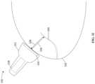
- FIG. 1 Idepicts an example of the ultrasound imaging system in use with breast of a patient.
- FIG. 2 Adepicts a method for localization of an abnormality within a breast.
- FIG. 2 Bdepicts a method for localization of an abnormality within a breast.
- FIG. 3 Adepicts an example method for imaging a breast and generating a risk assessment.
- FIG. 3 Bdepicts another example method for imaging a breast and generating a risk assessment.
- FIG. 4illustrates one example of a suitable operating environment in which one or more of the present examples can be implemented.
- Detection and localization of abnormalities within a breastmay be an important part in diagnosing a type of abnormality, or in some examples, a type of cancer.
- the location of a lesion or a calcification in relation other structures of the breastmay provide additional information that may be useful for diagnostics.
- the relative location of abnormalities, such as lesions or calcifications, to structures such as breast ducts lobules, Cooper's ligaments, dense tissue, fat, skin, vascular structures, and/or lymph nodesmay all provide additional diagnostic information.
- whether an abnormality is located in a duct of a breastmay be informative as to what type of cancer the abnormality may correspond.
- DCISductal carcinoma in situ
- DCISis a non-invasive cancer where abnormal cells are found in a duct of the breast. If the abnormal cells are confined within the duct, the cancer is generally very treatable by a variety of treatment options. In contrast, if abnormal cells are located outside of the breast ducts, the cancer is likely to be more invasive and spread more quickly.
- DCISis often diagnosed based on a pattern of abnormalities displaying as bright dots within a mammogram. Depending on the shape or pattern of the dots, a prediction is made as to whether the patient has DCIS. There is no determination, however, as to whether the abnormalities are actually confined to a breast duct. As such, it would be beneficial to be able to identify through non-invasive medical imaging whether an abnormality is located inside or outside of a breast duct.
- x-ray imaging systemsare generally effective for identifying some abnormalities (such as calcifications), the identification of other structures (such as breast ducts) through x-ray imaging is difficult.
- ultrasound imaging systemsare generally effective at identifying tissue such as ducts, but may not be as effective at identifying abnormalities.
- X-ray based imagingmay also be somewhat limited in dense tissue, whereas ultrasound imaging often performs well in dense tissue.
- the present technologyprovides for combining x-ray imaging data with ultrasound imaging data to provide an indication or determinations regarding the location of abnormalities in relation to other structures or features of the breast.
- the present technologymay be used to provide an indication or determination as to whether abnormalities are located inside or outside the ducts of the breast.
- a tomosynthesis systemmay be used to image a breast of a patient and an ultrasound system may also be used to image the breast.
- the imaging data from the tomosynthesis systemmay be co-registered with the imaging data from the ultrasound imaging system, such that a location in the tomosynthesis imaging data may be correlated with imaging data from the ultrasound imaging system.
- the structures of the breastmay be also be mapped to form a 3D mapping of the structures of the breast.
- the ducts of the breastmay be mapped so as to form a 3D mapping of the ducts in the breast.
- An abnormalitymay be located or identified in the x-ray imaging data. The abnormality may then be overlaid, visually or mathematically, on the mapping of the ducts to determine whether the abnormality lies inside or outside one the structures, such as a duct.
- the mapping of the breast structuresmay also be used to determine a risk factor for different types of cancers or other conditions. Particular patterns and configurations of structures within a breast may be indicative of a higher risk for invasive cancers, whereas other patterns and configurations of structures may indicate a lower risk for such invasive cancers. Accordingly, the present technology may analyze the 3D mapping of the ducts to determine a statistical correlation between the mapping of structures and data for an aggregation of the same type of structures from other breasts. Based on the determined statistical correlation, a risk assessment for the analyzed breast may be determined. If the risk is considered high, additional procedures may be recommended for the patient to determine if any cancerous cells are present in the breast.
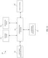
- FIG. 1 Adepicts an example medical imaging system 100 for breast mapping and abnormality localization.
- System 100includes an x-ray image acquisition system 101 , a tracking system 107 , an ultrasound imaging system 150 , a navigation system 105 and a display system 160 , all representatively connected via communication network 103 .
- the ‘systems’are shown in FIG. 1 as functional blocks, different systems may be integrated into a common device, and the communication link may be coupled between fewer than all of the systems; for example, the tracking system 107 , navigation system 105 and display system 160 may be included in an acquisition work station or a technologist work station which may control the acquisition of the x-ray images in a radiology suite.
- navigation system 107 and tracking system 105may be integrated into the ultrasound system 150 , or provided as standalone modules with separate communication links to the display 160 , x-ray acquisition system 101 and ultrasound system 150 .
- communication network 103can be a local area network, wide area network, wireless network, internet, intranet, or other similar communication network.
- x-ray image acquisition system 101is a tomosynthesis acquisition system which captures a set of projection images of a patient's breast as an x-ray tube scans across a path over the breast. The set of projection images is subsequently reconstructed to a three-dimensional volume which may be viewed as slices or slabs along any plane. The three-dimensional volume may be stored locally on x-ray imaging system 101 or in some embodiments in a database or other storage means. Additional details regarding an example x-ray image acquisition system are depicts in FIGS. 1 B- 1 G .
- X-ray imaging system 101may transmit the three-dimensional x-ray image volume to navigation system 105 via communication network 103 , where such x-ray image can be stored and viewed.
- the x-ray image of a patientcan, in alternative embodiments, be stored locally on x-ray imaging system 101 and accessed remotely by navigation system 105 via communications network 130 , and in other embodiments can be stored on a server in communication with navigation system 105 via communications network 103 .
- Navigation system 105displays the x-ray image obtained by x-ray imaging system and once reconstructed for display on navigation system 105 the x-ray image can be reformatted and repositioned to view the image at any plane and any slice position or orientation.
- navigation system 105displays multiple frames or windows on the same screen showing alternative positions or orientations of the x-ray-image slice.
- the x-ray image volume obtained by x-ray imaging system 101can be transmitted to navigation system 105 at any point in time and is not necessarily transmitted immediately after obtaining the x-ray image volume, but instead can be transmitted on the request of navigation system 105 .
- the x-ray image volumeis transmitted to navigation system 105 by a transportable media device, such as a flash drive, CD-ROM, diskette, or other such transportable media device.
- Ultrasound imaging system 150obtains an ultrasound image of a tissue of a patient, typically using an ultrasound probe, which is used to image a portion of a tissue of a patient within the field of view of the ultrasound probe.
- the ultrasound imaging system 150may be used to image a breast, and more specifically, structures such as the ducts of a breast.
- Ultrasound imaging system 150obtains and displays an ultrasound image of a patient's anatomy within the field of view of the ultrasound probe and typically displays the image in real-time as the patient is being imaged.
- the ultrasound imagecan additionally be stored on a storage medium, such as a hard drive, CD-ROM, flash drive or diskette, for reconstruction or playback at a later time. Additional details regarding the ultrasound imaging system are depicted in FIGS. 1 G- 1 I .
- navigation system 150can access the ultrasound image, and in such embodiments ultrasound imaging system 150 is further connected to communication network 103 and a copy of the ultrasound image obtained by ultrasound imaging system 150 can be transmitted to navigation system 105 via communication network 103 .
- navigation system 105can remotely access and copy the ultrasound image via communication network 103 , and in alternative embodiments, a copy of the ultrasound image can be stored on a server in communication with navigation system 105 via communications network 103 and accessed remotely by navigation system 105 .
- Tracking system 107is in communication with navigation system 105 via communications network 130 and may track the physical position in which ultrasound imaging system 150 is imaging the tissue of the patient.
- tracking system 107can be connected directly to navigation system 105 via a direct communication link or wireless communication link.
- Tracking system 107tracks the position of transmitters connected to ultrasound imaging system 150 and provides navigation system 105 with data representing their coordinates in a tracker coordinate space.
- tracking systemmay be an optical tracking system comprising an optical camera and optical transmitters, however skilled persons will understand that any device or system capable of tracking the position of an object in space can be used.
- an RF tracking systemcan be used, comprising an RF receiver and RF transmitters.
- Ultrasound imaging system 150may be configured for use with navigation system 105 by a calibration process using tracking system 107 .
- Transmitters that are connected to the ultrasound probe of ultrasound imaging system 105may transmit their position to tracking system 107 in the tracker coordinate space, which in turn provides this information to navigation system 105 .
- transmittersmay be positioned on the probe of ultrasound imaging system 150 so that tracking system 107 can monitor the position and orientation of the ultrasound probe and provide this information to navigation system 105 in the tracker coordinate space.
- Navigation system 105may use this tracked position to determine the position and orientation of the ultrasound probe, relative to the tracked position of the transmitters.
- configurationoccurs using a configuration tool.
- the position and orientation of the configuration toolmay be additionally tracked by tracking system 107 .
- the configuration toolcontacts the transducer face of the ultrasound probe of ultrasound imaging system 150 and tracking system 107 transmits information representing the position and orientation of the configuration tool in the tracker coordinate space to navigation system 105 .
- Navigation system 105may determine a configuration matrix that can be used to determine the position and orientation of the field of view of the ultrasound probe in the tracker coordinate space, based on the tracked position of the transmitters connected to the ultrasound probe.
- a database having configuration data of a plurality of brands or models of various ultrasound probescan be used to pre-load a field of view configuration into navigation system 105 during configuration.
- ultrasound imaging system 150is configured with navigation system 105 , the tissue of a patient can be imaged with ultrasound imaging system 150 .
- tracking system 107monitors the position and orientation of the ultrasound probe of ultrasound imaging system 150 and provides this information in the tracker coordinate space to navigation system 105 . Since ultrasound imaging system 150 has been configured for use with navigation system 105 , navigation system 105 is able to determine position and orientation of the field of view of the ultrasound probe of ultrasound imaging system 150 .
- Navigation system 105can be configured to co-register an ultrasound image with an x-ray image.
- navigation system 130can be configured to transform the position and orientation of the field of view of the ultrasound probe from the tracker coordinate space to a position and orientation in the x-ray image, for example, to x-ray system coordinates. This can be accomplished by tracking the position and orientation of the ultrasound probe and transmitting this positional information in the tracker coordinate space to navigation system 105 and relating this positional information to the x-ray coordinate system.
- a usercan select an anatomical plane within the x-ray image, and the user can then manipulate the position and orientation of a tracked ultrasound probe to align the field of view of the ultrasound probe with the selected anatomical plane.
- the associated tracker space coordinates of the ultrasound imagecan be captured. Registration of the anatomic axes (superior-inferior (SI), left-right (LR) and anterior-posterior (AP)) between the x-ray image and the tracker coordinate space can be determined from the relative rotational differences between the tracked ultrasound field of view orientation and the selected anatomical plane using techniques known to those of skill in the art.
- SIsuperior-inferior
- LRleft-right
- APanterior-posterior
- This configurationmay further include the selection of landmark within the x-ray image, for example, using an interface permitting a user to select an anatomical target.
- the landmarkcan be an internal tissue landmark, such as veins or arteries, and in other embodiments, the landmark can be an external landmark, such as a fiducial skin marker or external landmark, such as a nipple.
- the same landmark selected in the x-ray imagecan be located with the ultrasound probe, and upon location, a mechanism can be provided for capturing coordinates of the representation of the target in the tracker coordinate space. The relative differences between the coordinates of the target in the x-ray image and the coordinates of the target in the tracker coordinate space are used to determine the translational parameters required to align the two co-ordinate spaces.
- the plane orientation information acquired previouslycan be combined with the translation parameters to provide a complete 4 ⁇ 4 transformation matrix capable of co-registering the two coordinate spaces.
- Navigation system 105can then use the transformation matrix to reformat the x-ray image being displayed so that the slice of tissue being displayed is in the same plane and in the same orientation as the field of view of the ultrasound probe of ultrasound imaging system 150 .
- Matched ultrasound and x-ray imagesmay then be displayed side by side, or directly overlaid in a single image viewing frame.
- navigation system 105can display additional x-ray images in separate frames or positions on a display screen.
- the x-ray imagecan be displayed with a graphical representation of the field of view of ultrasound imaging system 150 wherein the graphical representation of the field of view is shown slicing through a 3D representation of the x-ray image.
- annotationscan be additionally displayed, these annotations representing, for example, the position of instruments imaged by ultrasound imaging system 150 , such as biopsy needles, guidance wires, imaging probes or other similar devices.
- the ultrasound image being displayed by ultrasound imaging system 150can be superimposed on the slice of the x-ray image being displayed by navigation system 150 so that a user can view both the x-ray and ultrasound images simultaneously, overlaid on the same display.
- navigation system 105can enhance certain aspects of the super imposed ultrasound or x-ray images to increase the quality of the resulting combined image.
- system 100is generally described as having an x-ray image acquisition system 101
- system 100may have a magnetic resonance imaging (MRI) system in place of, or in addition to, the x-ray image acquisition system 101
- MRImagnetic resonance imaging
- system 100is generally described as having an ultrasound imaging system 150
- system 100may have an optical and/or thermal imaging system in place of, or in addition to, the ultrasound imaging system 150 .
- the optical and/or thermal imaging systemis incorporated in to the x-ray image acquisition system 101 .
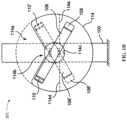
- FIGS. 1 B and 1 Cillustrate portions of a non-limiting example of a multi-mode breast x-ray imaging system operable in a CT mode but also configured to selectively operate in a tomosynthesis mode including a wide angle tomosynthesis mode and a narrow angle tomosynthesis mode, and in a mammography mode.
- a patient shield for use in the CT modeis omitted from FIGS. 1 B and 1 C but examples are illustrated in FIGS. 1 D and E.
- a support column 100is secured to a floor and houses a motorized mechanism for raising and lowering a horizontally extending axle 102 , which protrudes through an opening 100 a in column 100 , and for rotating axle 102 about its central axis.
- Axle 102in turn supports a coaxial axle 102 a that can rotate with or independently of axle 102 .
- Axle 102supports a breast immobilization unit comprising an upper plate 104 a and a lower plate 104 b such that each plate can move up and down along the long dimension of support 100 together with axles 102 and 102 a , at least one of the plates can move toward the other, and unit 104 can rotate about the common central axis of axles 102 and 102 a .
- axle 102supports a gantry 106 for two types of motorized movement: rotation about the central axis of axle 102 , and motion relative to axle 102 along the length of gantry 106 .
- Gantry 106carries at one end an x-ray source such as a shrouded x-ray tube generally indicated at 108 , and at the other end a receptor housing 110 enclosing an imaging x-ray detector or receptor 112 .
- FIGS. 1 B and 1 CWhen operating in a CT mode, the system of FIGS. 1 B and 1 C immobilizes a patient's breast between plates 104 a and 104 b .
- unit 104is raised or lowered together with axle 102 to the height of the breast while the patient is upright, e.g., standing or sitting.
- the patientleans toward unit 104 from the left side of the system as seen in FIG. 1 C , and a health professional, typically an x-ray technician, adjusts the breast between plates 104 a and 104 b while pulling tissue to the right in FIG.
- gantry 106rotates about the central axis of axle 102 while the breast remains immobilized in unit 104 .
- Imaging receptor 112 inside housing 110remains fixed relative to x-ray tube 108 during the rotation of gantry 106 .
- a pyramid shaped beam of x-rays from tube 108traverses the breast immobilized in unit 104 and impinges on imaging receptor 112 , which in response generates a respective two-dimensional array of pixel values related to the amount of x-ray energy received for each increment of rotation at respective pixel positions in an imaging plane of the receptor.
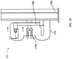
- These arrays of pixel values for real projection imagesare delivered to and processed by a computer system to reconstruct slice images of the breast.
- Gantry 106may be configured for motorized movement toward column 100 , to facilitate the x-ray technician's access to the patient's breast for positioning the breast in unit 104 , and away from column 100 to ensure that x-ray tube 108 and imaging receptor 112 inside housing 110 can image the appropriate breast tissue.
- gantry 106can maintain a fixed distance from column 100 , to the left of the position seen in FIG. 1 C , so that the imaging x-ray beam can pass through as much as practical of the breast immobilized in unit 104 , in which case there would be no need for a mechanism to vary that distance.
- CT scanningtypically involves a rotation of the source and receptor through an angle of 180° plus the angle subtended by the imaging x-ray beam, and preferably a rotation through a greater angle, e.g., 360°.
- the rotationincludes the 0° position of x-ray source 108 as seen in FIGS. 1 B and 1 C , the patient's head may be too close to x-ray source 108 .
- the rotation for CT imagingexcludes positions of x-ray source 108 in the 90° sector or segment between 45° and 315°, or in the 120° sector or segment between 60° and 300°, or in some other sector or segment that is sufficient to clear the patient's head position while taking x-ray CT data over a sufficient angle of rotation for the reconstruction of high quality slice images. While the rotation of x-ray tube 108 and receptor housing 110 still has to clear the lower part of the patient's body, it is generally easier for a patient to keep the lower part of her body away from the rotating components, to the left as seen in FIG. 2 (and preferably behind a shield), than to arch back her head and shoulders.
- FIGS. 1 D and 1 EAn example of such a shield is illustrated in FIGS. 1 D and 1 E .
- FIG. 4is a side elevation that is otherwise the same as FIG. 1 C but additionally illustrates a patient shield 114 having a central opening 114 c .
- Shield 114may be completely circular in front elevation, as illustrated by the circle that includes an arc in broken line in FIG. 1 D , in front elevation. In that case, gantry 106 can rotate through a complete circle in the CT mode.
- shield 114can leave open a sector or segment 114 a illustrated in FIG. 1 D as the area below the broken line arc and between the solids line of shield 114 .
- gantry 106can rotate in the CT mode only through an angle that is less than 360°, but the patient can have space for her head and perhaps a shoulder and an arm in the V-shaped cutout 114 b of shield 114 , for a more comfortable body posture.
- gantry 106can rotate only within the portion of shield 114 that is outside V-shaped cutout 114 b .
- One of the possible positions of gantry 106 and tube 108 and receptor housing 110is shown in solid lines.
- Another possible positionis shown in broken lines, and designated as gantry 106 ′, carrying x-ray source 108 ′ and receptor housing 110 ′.
- FIG. 1 Eillustrates a possible shape of shield 114 in side elevation.
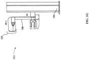
- FIGS. 1 F and 1 GUse of the system in a tomosynthesis mode is illustrated in FIGS. 1 F and 1 G , which are otherwise the same as FIGS. 1 A and B respectively, except that gantry 106 is in a different position relative to breast immobilization unit 104 and axle 102 and column 100 , and no shield 114 is shown.
- x-ray source 108is further from unit 104 and column 100
- receptor housing 110is closer to unit 104 .
- the patient's breastalso is immobilized between plates 104 a and 104 b , which remain in place during imaging.
- x-ray tube 108 and receptor housing 110may undergo a rotation about the immobilized breast that is similar to that in the CT mode operation but is through a smaller angle.
- x-ray tube 108 and receptor 112can be as in said system offered under the trade name Selenia® Dimensions' of the common assignee, certain aspect of which are described in commonly owned U.S. Pat. No. 7,616,801, the disclosure of which is hereby incorporated by reference herein in its entirety.
- x-ray tuberotates about the central axis of axle 102
- receptor housing 110remains in place while imaging receptor 112 rotates or pivots inside housing 110 about an axis that typically passes through the image plane of the receptor, is parallel to the central axis of axle 102 , and bisects imaging receptor 112 .
- the rotation or pivoting of receptor 112typically is through a smaller angle than the rotation angle of x-ray tube 108 , calculated so that a normal to the imaging plane of receptor 112 can continue pointing at or close to the focal spot in x-ray tube 108 from which the imaging x-ray beam is emitted, and so that the beam continues to illuminate all or most of the imaging surface of receptor 112 .
- x-ray tube 108rotates through an arc of about ⁇ 15° while imaging receptor rotates or pivots through about ⁇ 5° about the horizontal axis that bisects its imaging surface.
- plural projection images RPare taken, such as 20 or 21 images, at regular increments of rotation angle.
- the central angle of the ⁇ 15° arc of x-ray source 108 rotationcan be the 0° angle, i.e., the position of the x-ray source 108 seen in FIGS. 5 and 6 , or some other angle, e.g., the angle for the x-ray source position typical for MLO imaging in conventional mammography.
- the breastmay be immobilized in unit 104 but, alternatively, lower plate 104 b may be removed so that the breast is supported between the upper surface of receptor housing 110 and upper plate 104 a , in a manner analogous to the way the breast is immobilized in said system offered under the trade name Selenia®.
- greater degree of breast compressioncan be used under operator control than in the CT mode.
- the same concave plates 104 a and 104 bcan be used, or generally flat plates can be substituted, or a single compression paddle can be used while the breast is supported by the upper surface of receptor housing 110 , as used in said system offered under the Selenia® trade name.
- the system of FIGS. 1 F and 1 GWhen operating in a tomosynthesis mode, the system of FIGS. 1 F and 1 G provides multiple choices of that mode, selectable by an operator, for example a narrow angle mode and a wide angle mode.
- x-ray source 108rotates around unit 104 and the patient's breast immobilized therein through an angle such as ⁇ 15°
- x-ray tube 108rotates through an angle such as in the range of about ⁇ 15° to ⁇ 60°.
- the wide angle modemay involve taking the same number of projection images RP as the narrow angle mode, or a greater number.
- the wide angle modemay involve taking the same number of images RP or a greater number, such as 40 or 60 or some other number, typically at regular angular increments.
- the examples of angles of rotation of x-ray source 108are not limiting. The important point is to provide multiple modes of tomosynthesis operations, where one mode involves x-ray source rotation through a greater angle around the breast than another tomosynthesis mode. Additional details regarding the structure and operation of image system of FIGS. 1 B- 1 G are provided in U.S. Pat. No.
- MMI proceduresgenerally refers to the use of a combination of different imaging modes or techniques, such as DBT acquisitions with varying dosage levels and/or angular coverage, computerized tomography (CT) of a compressed breast, and/or a combination of the two.
- DBTdigital breast tomosynthesis
- MMI proceduresgenerally refers to the use of a combination of different imaging modes or techniques, such as DBT acquisitions with varying dosage levels and/or angular coverage, computerized tomography (CT) of a compressed breast, and/or a combination of the two.
- CTcomputerized tomography
- the system 101may also include one or more optical and/or thermal imaging devices, such as digital cameras.
- the optical and/or thermal imaging devicesmay be mounted or incorporated in the gantry 106 .
- the optical and/or thermal imaging devicesmay be mounted or incorporated near, or proximate to, the x-ray tube 108 .
- optical and thermal imaging data of the breastmay be captured.
- the optical and thermal imaging data of the breastmay be captured concurrently with the capture of the tomosynthesis and/or mammogram images.
- a map of the structures, such as ducts, of the breast and, in some examples, a vascular map of the breastmay be generated from the optical and/or thermal imaging data.
- the optical and/or thermal imaging datamay also be used to map the structures of the breast in combination with, or as a substitute for, ultrasound imaging data.
- the optical and/or thermal imaging datamay also be co-registered with the x-ray data captured by the system 101 .
- the co-registration of the optical and/or thermal imaging data with the x-ray datais simplified due to the optical and/or thermal imaging devices being attached to the gantry 106 near the x-ray tube 108 . In such examples, the optical and/or thermal imaging devices move with the x-ray tube 108 .
- FIG. 1 Hdepicts an example of an ultrasound imaging system 150 .
- the ultrasound localization system 150includes an ultrasound probe 152 that includes an ultrasonic transducer 154 .
- the ultrasonic transducer 154is configured to emit an array of ultrasonic sound waves 156 .
- the ultrasonic transducer 154converts an electrical signal into ultrasonic sound waves 156 .
- the ultrasonic transducer 154may also be configured to detect ultrasonic sound waves, such as ultrasonic sound waves that have been reflected from internal portions of a patient, such as ducts within a breast.
- the ultrasonic transducer 154may incorporate a capacitive transducer and/or a piezoelectric transducer, as well as other suitable transducing technology.
- the ultrasonic transducer 154is also operatively connected (e.g., wired or wirelessly) to a display 160 .
- the display 160may be a part of a computing system, including processors and memory configured to produce and analyze ultrasound images. Further discussion of a suitable computing system is provided below with reference to FIG. 5 .
- the display 160is configured to display ultrasound images based on an ultrasound imaging of a patient.
- the ultrasound imaging performed in the ultrasound localization system 150is primarily B-mode imaging, which results in a two-dimensional ultrasound image of a cross-section of a portion of the interior of a patient.
- the brightness of the pixels in the resultant imagegenerally corresponds to amplitude or strength of the reflected ultrasound waves.
- Other ultrasound imaging modesmay also be utilized.
- the ultrasound probemay operate in a 3D ultrasound mode that acquires ultrasound image data from a plurality of angles relative to the breast to build a 3D model of the breast.
- ultrasound imagesmay not be displayed during the acquisition process. Rather, the ultrasound data is acquired and a 3D model of the breast is generated without B-mode images being displayed.
- the ultrasound probe 152may also include a probe localization transceiver 158 .
- the probe localization transceiver 158is a transceiver that emits a signal providing localization information for the ultrasound probe 152 .
- the probe localization transceiver 158may include a radio frequency identification (RFID) chip or device for sending and receiving information as well as accelerometers, gyroscopic devices, or other sensors that are able to provide orientation information.
- RFIDradio frequency identification
- the signal emitted by the probe localization transceiver 158may be processed to determine the orientation or location of the ultrasound probe 152 .
- the orientation and location of the ultrasound probe 152may be determined or provided in three-dimensional components, such as Cartesian coordinates or spherical coordinates.
- the orientation and location of the ultrasound probe 152may also be determined or provided relative to other items, such as an incision instrument, a marker, a magnetic direction, a normal to gravity, etc. With the orientation and location of the ultrasound probe 152 , additional information can be generated and provided to the surgeon to assist in guiding the surgeon to a lesion within the patient, as described further below. While the term transceiver is used herein, the term is intended to cover both transmitters, receivers, and transceivers, along with any combination thereof. Additional details of examples of systems and components for localization and co-registration of an ultrasound probe are provided in U.S. Patent Publication No. 2012/0150034, titled “System and Method for Fusing Three Dimensional Image Data from a Plurality of Different Imaging Systems for Use in Diagnostic Imaging,” which is hereby incorporated by reference in its entirety.
- FIG. 1 Idepicts an example of the ultrasound imaging system 100 in use with breast 162 of a patient.
- the ultrasound probe 152is in contact with a portion of the breast 162 .
- the ultrasound probe 152is being used to image a structure of the breast.
- the ultrasound probe 152is being used to image a duct 164 of the breast 162 .
- the ultrasonic transducer 154emits an array of ultrasonic sound waves 156 into the interior of the breast 162 .
- a portion of the ultrasonic sound waves 156are reflected off internal components of the breast, such as the duct 164 when the duct is in the field of view, and return to the ultrasound probe 152 as reflected ultrasonic sound waves 166 .
- the reflected ultrasonic sound waves 166may be detected by the ultrasonic transducer 154 .
- the ultrasonic transducer 154receives the reflected ultrasonic sound waves 166 and converts the reflected ultrasonic sound waves 166 into an electric signal that can be processed and analyzed to generate ultrasound image data on display 160 .
- the depth of the duct 164 or other objects in an imaging planemay be determined from the time between a pulse of ultrasonic waves 156 being emitted from the ultrasound prove 152 and the reflected ultrasonic waves 166 being detected by the ultrasonic probe 152 .
- the speed of soundis well-known and the effects of the speed of sound based on soft tissue are also determinable. Accordingly, based on the time of flight of the ultrasonic waves 156 (more specifically, half the time of flight), the depth of the object within an ultrasound image may be determined. Other corrections or methods for determining object depth, such as compensating for refraction and variant speed of waves through tissue, may also be implemented. Those having skill in the art will understand further details of depth measurements in medical ultrasound imaging technology.
- Such depth measurements and determinationsmay be used to build a 3D model of the breast 162 , and more specifically, a 3D model of the ducts 164 of the breast 162 .
- a whole breast 162may be imaged with the ultrasound probe 152 .
- 3D models of different structures, such as ducts 164may be generated.
- multiple frequencies or modes of ultrasound techniquesmay be utilized. For instance, real time and concurrent transmit and receive multiplexing of localization frequencies as well as imaging frequencies and capture frequencies may be implemented. Utilization of these capabilities provide information to co-register or fuse multiple data sets from the ultrasound techniques to allow for visualization of ducts 164 and other medical images on the display 160 .
- the imaging frequencies and capture sequencesmay include B-mode imaging (with or without compounding), Doppler modes (e.g., color, duplex), harmonic mode, shearwave and other elastography modes, and contrast-enhanced ultrasound, among other imaging modes and techniques.
- FIG. 2 Adepicts an example method 200 for locating an abnormality within a breast.
- first imaging data for a breast from a first imaging modalityis acquired or received, which may be an x-ray-based imaging modality and/or a magnetic resonance imaging (MRI) modality.
- the first imaging datamay be two-dimensional imaging data or three-dimensional imaging data.
- the first imaging datamay be acquired from a tomosynthesis imaging system and/or a computed tomography system.
- the first imaging datamay be 3D imaging data.
- the first imaging datamay be 2D imaging data, such as mammography imaging data.
- second imaging datais acquired for the breast from a second imaging modality.
- the second imaging modalitymay be an ultrasound imaging modality.
- the second imaging modalitymay be an optical and/or thermal imaging modality.
- the second imaging modalitymay include both the ultrasound imaging modality and the optical and/or thermal imaging modality.
- the first imaging data and the second imaging datamay then be co-registered at operation 206 , such that the first imaging data from the first imaging modality and the second image data from the second imaging modality share a common coordinate space. Co-registering the imaging data from the different modalities at operation 206 may be accomplished through any of the means discussed above.
- a plurality of ducts for the breastare mapped to generate a mapping of the plurality of ducts.
- the mapping of the breast ductsmay be generated from the second imaging data, such as ultrasound imaging data, acquired at operation 204 .
- the mapping of the breast ductsmay be 3D mapping or a plurality of 2D mappings of the breast ducts and may include a mapping of all the ducts in the breast.
- the mapping of the breast ductsmay achieved through artificial-intelligence image analysis techniques. Such image analysis techniques may analyze the second image data to identify ductal structures within the image data for the imaged breast.
- the non-ductal tissuei.e., the tissue of the breast other than the ducts
- the image analysis techniquesmay be trained using a dataset of image data where ductal structures have been previously identified, such as by manual identification. Once the image analysis techniques have been trained, the image analysis techniques are able to identify ducts within image data. Once the ducts are identified, the mapping of the breast ducts is generated.
- an abnormalityis located or identified in the first imaging data from the first modality that was received or acquired in operation 202 and/or the second imaging data from the second imaging modality that was received or acquired in operation 204 .
- the abnormalitymay appear brighter in the image data, such as when the abnormality is a calcification.
- pixels in the image data having a higher valuei.e., brighter
- the abnormalitymay be identified through the use of image analysis techniques that analyze the image data based on pixel values or the patterns of pixels. The image analysis techniques may be performed in the spatial, transform, or frequency domains.
- image analysis techniques in the spatial domaingenerally operate based on the pixel values in the imaging data.
- Image analysis techniques within the transform or frequency domainsgenerally operate based on mathematical transforms, such as a Fourier or Laplace transform, of the pixel data from imaging data.
- the image analysis techniquesmay be based on a rate of change of pixel values within the spatial domain.
- an abnormalitymay be identified through the assistance of a medical professional. For instance, locating the abnormality may include the medical professional selecting the abnormality on a screen displaying the imaging data.
- At operation 212at least a portion of the mapping of the breast ducts generated in operation 208 is displayed concurrently with in the abnormality that was located in operation 210 .
- the concurrent display of the mapping of the breast ducts and the abnormalityallows for a determination as to whether the abnormality is located inside or outside of one of the breast ducts.
- the abnormalitymay be displayed as an overlay of a portion of the mapping of the plurality of ducts. Due to the first imaging data being co-registered with the second imaging data, an abnormality that is located in the first imaging data may be displayed in a mapping of the breast ducts in the proper location even though the mapping of the breast ducts was generated from the second imaging data.
- imaging data displaying the abnormalitymaybe displayed, and a selection of a region of interest, such as a region containing the abnormality, may be selected from the displayed imaging data. Based on receiving the selection of the region of interest, a portion of the mapping of the ducts corresponding to the selected region of interest may be displayed.
- a determinationmay be made as to whether the abnormality is inside or outside of a breast duct based on the mapping of the breast ducts.
- the determinationmay be made based on the concurrent display of the abnormality and the duct mapping.
- the determinationmay be made through image analysis techniques that analyze the concurrent display of the abnormality and the duct mapping to identify whether the abnormality is inside or outside of a breast duct.
- the determinationmay also be made based on the location of the abnormality and the locations of the breast ducts. For example, a location of the abnormality may be determined and represented in coordinates of the shared coordinate space between the first imaging data and the second imaging data.
- the structures of the ductsmay also be represented in coordinates of the shared coordinate space. Accordingly, a determination may be made as to whether the location of the abnormality falls inside or outside the ducts.
- FIG. 2 Bdepicts another example method 220 for locating an abnormality within a breast.
- first imaging data for a breast from a first imaging modalityis acquired or received, which may be an x-ray-based imaging modality and/or a magnetic resonance imaging (MRI) modality.
- the first imaging datamay be two-dimensional imaging data or three-dimensional imaging data.
- the first imaging datamay be acquired from a tomosynthesis imaging system and/or a computed tomography system.
- the first imaging datamay be 3D imaging data.
- the first imaging datamay be 2D imaging data, such as mammography imaging data.
- second imaging datais acquired for the breast from a second imaging modality.
- the second imaging modalitymay be an ultrasound imaging modality.
- the second imaging datamay include 3D ultrasound data of a whole breast. For instance, during an ultrasound imaging procedure, the ultrasound imaging system may acquire a series of 2D slice and stitches and/or stacks the 2D slices together to form a set of 3D data or a 3D ultrasound volume of the breast.
- the second imaging modalitymay be an optical and/or thermal imaging modality.
- the second imaging modalitymay include both the ultrasound imaging modality and the optical and/or thermal imaging modality.
- the first imaging data and the second imaging datamay then be co-registered at operation 226 , such that the first imaging data from the first imaging modality and the second image data from the second imaging modality share a common coordinate space. Co-registering the imaging data from the different modalities at operation 226 may be accomplished through any of the means discussed above.
- one or more structures of the breastare mapped or modeled based on the first imaging data and/or the second imaging data.
- the mapping or modeling of the structuresmay be generated from the second imaging data, such as ultrasound imaging data, acquired at operation 224 .
- the mapping or modeling of the breast structuresmay be a 3D model or mapping or a 2D model of mapping.
- the mapping or modelmay also be for the whole breast.
- the mapping or modeling of the breast structuresmay be achieved through artificial-intelligence image analysis techniques.
- image analysis techniquesmay analyze the first imaging data and/or the second imaging data to identify particular structures within the breast.
- the structuresmay be ducts, lobules, Cooper's ligaments, dense tissue, fat, skin, vascular structures and/or lymph nodes.
- the particular structure(s) that are modeledmay be selected by a clinician or automatically set by the imaging system.
- multiple models or mappingsmay be generated. For instance, a first model or mapping of ducts may be generated and a second model or mapping for lobules may be generated.
- the tissue of the breast that is not the structure being modeled(such as non-ductal tissue) may be removed from the imaging data when generating the mapping or modeling of the breast structure(s).
- the image analysis techniquesmay be trained using a dataset of image data where the desired structures have been previously identified, such as by manual identification. Once the image analysis techniques have been trained, the image analysis techniques are able to identify ducts within image data. For example, the echogenicity of different structures as well as patterns and textures of those structures allows for the structures to be identified within the image data. Once the structures are identified, the mapping or model of the structures is generated.
- an abnormalityis located or identified in the first imaging data from the first modality that was received or acquired in operation 222 and/or the second imaging data from the second imaging modality that was received or acquired in operation 224 .
- the abnormalitymay appear brighter in the image data, such as when the abnormality is a calcification.
- pixels in the image data having a higher valuei.e., brighter
- the abnormalitymay be identified through the use of image analysis techniques that analyze the image data based on pixel values or the patterns of pixels. The image analysis techniques may be performed in the spatial, transform, or frequency domains.
- image analysis techniques in the spatial domaingenerally operate based on the pixel values in the imaging data.
- Image analysis techniques within the transform or frequency domainsgenerally operate based on mathematical transforms, such as a Fourier or Laplace transform, of the pixel data from imaging data.
- the image analysis techniquesmay be based on a rate of change of pixel values within the spatial domain.
- an abnormalitymay be identified through the assistance of a medical professional. Locating the abnormality may include the medical professional selecting the abnormality on a screen displaying the imaging data.
- the abnormality that was located in operation 230is compared to the mapping or model of the breast structures generated in operation 228 .
- the comparison of the abnormality to the mapping or modelmay include displaying at least a portion of a visual representation of the mapping concurrently with the abnormality.
- the concurrent displaymay include an overlapped display such that the abnormality is displayed within the mapping or model of the breast structure.
- the comparisonmay include a mathematical or numerical comparison. For instance, the locations of the structures may be defined mathematically in the mapping or model. Similarly, the location of the abnormality may be also be defined mathematically.
- the location of abnormality relative to the mapped or modeled structure(s)is determined.
- a determinationmay be made as to whether the abnormality is within the duct of a breast or within or attached to a lobule. Such information can provide additional information for identifying the type or risk of the abnormality.
- the determined relative locationmay be displayed or presented in a variety of manners. For instance, the relative location may be displayed as a distance from the center or perimeter of the abnormality to the center or perimeter of one or more of the modeled structures.
- FIG. 3 Adepicts an example method 300 for imaging a breast and generating a risk assessment.
- the breastis scanned with an ultrasound probe.
- an ultrasound technicianmay contact the probe to the surface of the breast and begin scanning the breast.
- the location of the ultrasound probeis tracked during the scan of the breast. Tracking the location of the ultrasound probe may also include tracking the orientation of the probe as well.
- a 3D mapping of the breast ductsmay later be generated and the image data acquired from the ultrasound imaging may be co-registered with imaging data from another imaging modality, such as x-ray imaging data. Feedback regarding progress of the scan may also be provided during the scan at operation 306 .
- the feedbackmay be visual feedback that indicates to the ultrasound technician whether the breast has been fully imaged. For example, to map all the ducts in the breast, the entire breast may need to imaged, or at least the portion of the breast that includes ducts.
- the visual feedbackmay be in the form of a graphical user interface element that updates during the scan.
- the graphical user interface elementmay be a circle or ellipse that is generally representative of the breast. As portions of the breast are scanned, the equivalent portions of the circle will change color or appear shaded to indicate that the corresponding portion of the breast has been scanned. As such, the ultrasound technician is able to see what portions of the breast still need to be scanned. Other visual indicators that indicate similar information may also be used.
- an image analysis techniqueis executed to identify the ducts within the breast.
- the identification and mapping of the breast ductsmay achieved through artificial-intelligence image analysis techniques.
- image analysis techniquesmay analyze image data from the ultrasound scan to identify ductal structures within the image data for the imaged breast.
- the non-ductal tissuei.e., the tissue of the breast other than the ducts
- the image analysis techniquesmay be trained using from a dataset of image data where ductal structures have been previously identified, such as by manual identification. Once the image analysis techniques have been trained, the image analysis techniques are able to identify ducts within image data.
- a mapping of the ducts of the breastmay be generated.
- the mapping of the ductsmay be a 3D mapping of the ducts or a plurality of 2D mapping of the ducts.
- the mapping of the ducts of the breastis generated from the ductal image data generated in operation 310 .
- the mapping of the ducts generated in operation 312is analyzed to determine a statistical correlation between the mapping of the ducts and data for an aggregation of ductal structures for other breasts.
- the pattern or structure of the ducts of a breastmay be indicative of potential invasive cancers.
- operations 310 - 316may also be performed with optical and/or thermal imaging data.
- optical and/or thermal imaging datamay be acquired instead of, or in addition to, the ultrasound imaging data.
- the identification of ducts in operation 310 and the generation of the mapping of the ducts in operation 312may then be performed based on the optical and/or thermal imaging data.
- FIG. 3 Bdepicts another example method 320 for imaging a breast and generating a risk assessment.
- the method 320begins with scanning of the breast with the ultrasound probe in operation 322 .
- the location of the ultrasound probeis tracked at operation 324 .
- Feedback regarding progress of the scanmay also be provided during the scan at operation 326 .
- a determinationis made as to whether the scan has been completed.
- Operations 322 - 328may be substantially the same as operations 302 - 308 in method 300 depicted in FIG. 3 A .
- one or more anatomical structures of the breastare identified within the image data generated by the scan.
- the mapping of the breast ductsmay achieved through artificial-intelligence image analysis techniques.
- image analysis techniquesmay analyze image data from the ultrasound scan to identify the desired or selected structures within the image data for the imaged breast.
- the image analysis techniquesmay be trained from a dataset of image data where the selected or desired structures have been previously identified, such as by manual identification. Once the image analysis techniques have been trained, the image analysis techniques are able to identify the selected structures within image data.
- a mapping or model of the selected or desired structures of the breastmay be generated.
- the mapping or model of the structuresmay be a 3D mapping of the structures or a plurality of 2D mapping of the structures and may be for substantially the whole breast. In some examples, the mapping or model may be for a portion of the breast.
- the mapping or model of the structures of the breastmay be generated from the structures identified in operation 330 .
- the mapping or model of the structures generated in operation 332is analyzed to determine and generate a risk assessment in operation 336 .
- the analysis of the structuresmay include analyzing patterns within the mapping or model to extract features or values associated with the structures. For example, from the mapping or model of the structures, quantitative values for features may be extracted.
- the number of ducts, a regularity pattern for the ducts, and/or a termination regularity for the ductsmay be extracted from the mapping or model. Those extracted features or structures may then be compared to one or more thresholds, known values, or benchmarks.
- the analysismay also include a statistical correlation between the mapping or model of the structure(s) and data for an aggregation of the same type of structure(s) for other breasts. For instance, comparing the mapping of the structure for a patient to prior mappings of the same type of structures for patients having different types of cancers may reveal potential risk factors. As an example, data may be aggregated for a number of patients that have been diagnosed with different types of cancers.
- the datamay include the type of cancer and a mapping of the structure for the patient.
- a statistical correlationmay then be determined for a current mapping of a breast to the aggregated data for prior duct mappings of other patients. Based on that analysis, a risk assessment for the breast may be generated at operation 336 .
- features of breast ducts that may increase a risk assessment for a patientmay include features indicative of ductal ectasia (dilation), solid material or masses within a duct, an abrupt change in the caliber of the duct, and/or an abrupt termination of a duct.
- Such featuresmay be extracted from a mapping or model of the ducts and/or from the imaging data itself generated during the scan.
- features that may increase a risk assessment for a patientmay include features indicative of dilation of a lobule, solid material or masses within the lobule, and/or a distortion of a lobular cluster.
- Such featuresmay be extracted from a mapping or model of the lobules and/or from the imaging data itself generated during the scan.
- the selected or desired structureis a Cooper's ligament
- features that may increase a risk assessment for a patientmay include distortion of a normal undulating flow, an abrupt interruption of a Cooper's ligament, and/or a thickening of the ligament.
- features that may increase a risk assessment for a patientmay include areas of prominent shadowing and/or asymmetry of the dense tissue in the breast.
- features that may increase a risk assessment for a patientmay include a lack of homogeneity, such as stranding in normally hypoechoic fat (indicating edema), retroglandular fat (near the pectoralis muscle) stranding (suggesting tumor invasion), and/or edema or inflammation.
- features that may increase a risk assessment for a patientmay include a thickening of the skin (such as greater than about 2 mm) and/or an interruption of a deep dermis.
- features that may increase a risk assessment for a patientmay include a region of increased vascularity.
- features that may increase a risk assessment for a patientmay include a thickened cortex of the lymph node (such as greater than 3 mm) and/or a lack of a fatty central hilum.
- Values for the above discussed features of the respective structuresmay be determined based on aggregated patient data. For instance, for the feature of a thickened cortex of a lymph node, the value of the thickness of a lymph node that may be indicative of a high likelihood for an abnormality may be determined based on an aggregate of lymph node mappings from patients having cancer or other abnormalities.
- the risk assessmentmay indicate whether the breast is at a high or low risk for certain types of cancers.
- the risk assessmentmay also indicate whether additional diagnostic procedures, such as mammography or tomography procedures, biopsy procedures, or other diagnostic procedures should be performed.
- a systemmay include one or more imaging systems, such as a tomosynthesis, mammography, MRI, ultrasound, thermal, and/or optical imaging systems.
- imaging systemssuch as a tomosynthesis, mammography, MRI, ultrasound, thermal, and/or optical imaging systems.
- One or more of those imaging systemsmay be operatively connected to a computing device, such as a computing device incorporating the operating environment discussed below with reference to FIG. 4 .
- the imaging datamay be received by the computing device and the computing device may then perform the operations of the methods described herein.
- the computing devicemay include at least one processor and memory that is operatively connected to the at least one processor.
- the memorymay store instructions that when executed by the at least one processor cause the system to perform the operations described herein.
- FIG. 4illustrates one example of a suitable operating environment 400 in which one or more of the present embodiments can be implemented.
- This operating environmentmay be incorporated directly into the imaging systems disclosed herein, or may be incorporated into a computer system discrete from, but used to control, the imaging systems described herein.
- Thisis only one example of a suitable operating environment and is not intended to suggest any limitation as to the scope of use or functionality.
- Other computing systems, environments, and/or configurations that can be suitable for useinclude, but are not limited to, imaging systems, personal computers, server computers, hand-held or laptop devices, multiprocessor systems, microprocessor-based systems, programmable consumer electronics such as smart phones, network PCs, minicomputers, mainframe computers, tablets, distributed computing environments that include any of the above systems or devices, and the like.
- operating environment 400typically includes at least one processing unit 402 and memory 404 .
- memory 404storing, among other things, instructions to perform the image acquisition and processing methods disclosed herein
- memory 404can be volatile (such as RAM), non-volatile (such as ROM, flash memory, etc.), or some combination of the two.
- This most basic configurationis illustrated in FIG. 4 by dashed line 406 .
- environment 400can also include storage devices (removable, 408 , and/or non-removable, 410 ) including, but not limited to, magnetic or optical disks or tape.
- environment 400can also have input device(s) 414 such as touch screens, keyboard, mouse, pen, voice input, etc., and/or output device(s) 416 such as a display, speakers, printer, etc.
- input device(s) 414such as touch screens, keyboard, mouse, pen, voice input, etc.
- output device(s) 416such as a display, speakers, printer, etc.
- Also included in the environmentcan be one or more communication connections 412 , such as LAN, WAN, point to point, Bluetooth, RF, etc.
- Operating environment 400typically includes at least some form of computer readable media.
- Computer readable mediacan be any available media that can be accessed by processing unit 402 or other devices comprising the operating environment.
- Computer readable mediacan comprise computer storage media and communication media.
- Computer storage mediaincludes volatile and nonvolatile, removable and non-removable media implemented in any method or technology for storage of information such as computer readable instructions, data structures, program modules or other data.
- Computer storage mediaincludes, RAM, ROM, EEPROM, flash memory or other memory technology, CD-ROM, digital versatile disks (DVD) or other optical storage, magnetic cassettes, magnetic tape, magnetic disk storage or other magnetic storage devices, solid state storage, or any other tangible medium which can be used to store the desired information.
- Communication mediaembodies computer readable instructions, data structures, program modules, or other data in a modulated data signal such as a carrier wave or other transport mechanism and includes any information delivery media.
- modulated data signalmeans a signal that has one or more of its characteristics set or changed in such a manner as to encode information in the signal.
- communication mediaincludes wired media such as a wired network or direct-wired connection, and wireless media such as acoustic, RF, infrared and other wireless media. Combinations of the any of the above should also be included within the scope of computer readable media.
- a computer-readable deviceis a hardware device incorporating computer storage media.
- the operating environment 400can be a single computer operating in a networked environment using logical connections to one or more remote computers.
- the remote computercan be a personal computer, a server, a router, a network PC, a peer device or other common network node, and typically includes many or all of the elements described above as well as others not so mentioned.
- the logical connectionscan include any method supported by available communications media.
- Such networking environmentsare commonplace in offices, enterprise-wide computer networks, intranets and the Internet.
- the components described hereincomprise such modules or instructions executable by computer system 400 that can be stored on computer storage medium and other tangible mediums and transmitted in communication media.
- Computer storage mediaincludes volatile and non-volatile, removable and non-removable media implemented in any method or technology for storage of information such as computer readable instructions, data structures, program modules, or other data. Combinations of any of the above should also be included within the scope of readable media.
- computer system 400is part of a network that stores data in remote storage media for use by the computer system 400 .
Landscapes
- Health & Medical Sciences (AREA)
- Life Sciences & Earth Sciences (AREA)
- Engineering & Computer Science (AREA)
- Medical Informatics (AREA)
- Nuclear Medicine, Radiotherapy & Molecular Imaging (AREA)
- Physics & Mathematics (AREA)
- General Health & Medical Sciences (AREA)
- Radiology & Medical Imaging (AREA)
- Animal Behavior & Ethology (AREA)
- Heart & Thoracic Surgery (AREA)
- Pathology (AREA)
- Molecular Biology (AREA)
- Surgery (AREA)
- Biophysics (AREA)
- Public Health (AREA)
- Veterinary Medicine (AREA)
- Biomedical Technology (AREA)
- Computer Vision & Pattern Recognition (AREA)
- High Energy & Nuclear Physics (AREA)
- Optics & Photonics (AREA)
- Physiology (AREA)
- Dentistry (AREA)
- Oral & Maxillofacial Surgery (AREA)
- Quality & Reliability (AREA)
- General Physics & Mathematics (AREA)
- Theoretical Computer Science (AREA)
- Apparatus For Radiation Diagnosis (AREA)
- Ultra Sonic Daignosis Equipment (AREA)
- Magnetic Resonance Imaging Apparatus (AREA)
Abstract
Description
Claims (12)
Priority Applications (1)
| Application Number | Priority Date | Filing Date | Title |
|---|---|---|---|
| US17/279,002US12236582B2 (en) | 2018-09-24 | 2019-09-24 | Breast mapping and abnormality localization |
Applications Claiming Priority (3)
| Application Number | Priority Date | Filing Date | Title |
|---|---|---|---|
| US201862735556P | 2018-09-24 | 2018-09-24 | |
| US17/279,002US12236582B2 (en) | 2018-09-24 | 2019-09-24 | Breast mapping and abnormality localization |
| PCT/US2019/052727WO2020068851A1 (en) | 2018-09-24 | 2019-09-24 | Breast mapping and abnormality localization |
Publications (2)
| Publication Number | Publication Date |
|---|---|
| US20220036545A1 US20220036545A1 (en) | 2022-02-03 |
| US12236582B2true US12236582B2 (en) | 2025-02-25 |
Family
ID=69952771
Family Applications (1)
| Application Number | Title | Priority Date | Filing Date |
|---|---|---|---|
| US17/279,002Active2041-07-25US12236582B2 (en) | 2018-09-24 | 2019-09-24 | Breast mapping and abnormality localization |
Country Status (7)
| Country | Link |
|---|---|
| US (1) | US12236582B2 (en) |
| EP (1) | EP3856031B1 (en) |
| JP (2) | JP7441828B2 (en) |
| KR (1) | KR102761182B1 (en) |
| CN (1) | CN112804944B (en) |
| AU (1) | AU2019349684B2 (en) |
| WO (1) | WO2020068851A1 (en) |
Families Citing this family (15)
| Publication number | Priority date | Publication date | Assignee | Title |
|---|---|---|---|---|
| WO2007095330A2 (en) | 2006-02-15 | 2007-08-23 | Hologic Inc | Breast biopsy and needle localization using tomosynthesis systems |
| ES2862525T3 (en) | 2009-10-08 | 2021-10-07 | Hologic Inc | Needle Breast Biopsy System and Method of Use |
| JP6057922B2 (en) | 2011-03-08 | 2017-01-11 | ホロジック, インコーポレイテッドHologic, Inc. | System and method for dual energy and / or contrast enhanced breast imaging for screening, diagnosis and biopsy |
| EP2782505B1 (en) | 2011-11-27 | 2020-04-22 | Hologic, Inc. | System and method for generating a 2d image using mammography and/or tomosynthesis image data |
| JP6240097B2 (en) | 2012-02-13 | 2017-11-29 | ホロジック インコーポレイティッド | How to navigate a tomosynthesis stack using composite image data |
| US10092358B2 (en) | 2013-03-15 | 2018-10-09 | Hologic, Inc. | Tomosynthesis-guided biopsy apparatus and method |
| CN105451657A (en) | 2013-03-15 | 2016-03-30 | 霍罗吉克公司 | System and method for navigating tomosynthesis stack including automatic focusing |
| US11944486B2 (en)* | 2016-06-27 | 2024-04-02 | Taihao Medical Inc. | Analysis method for breast image and electronic apparatus using the same |
| CN110621233B (en) | 2017-03-30 | 2023-12-12 | 豪洛捷公司 | Method for processing breast tissue image data |
| US11896428B2 (en)* | 2019-10-24 | 2024-02-13 | Duke University | Adaptive selection of ultrasound frequency |
| US11620746B2 (en)* | 2020-11-10 | 2023-04-04 | International Business Machines Corporation | MRI annotation |
| CN116685262A (en)* | 2020-12-03 | 2023-09-01 | 医达科技公司 | Spectromechanical imaging for characterizing embedded lesions |
| US12254586B2 (en) | 2021-10-25 | 2025-03-18 | Hologic, Inc. | Auto-focus tool for multimodality image review |
| WO2023097279A1 (en) | 2021-11-29 | 2023-06-01 | Hologic, Inc. | Systems and methods for correlating objects of interest |
| CN117115515B (en)* | 2023-08-07 | 2024-12-20 | 南方医科大学南方医院 | A method for processing images of structurally distorted lesions in digital breast three-dimensional tomography |
Citations (496)
| Publication number | Priority date | Publication date | Assignee | Title |
|---|---|---|---|---|
| US3502878A (en) | 1967-09-22 | 1970-03-24 | Us Health Education & Welfare | Automatic x-ray apparatus for limiting the field size of a projected x-ray beam in response to film size and to source-to-film distance |
| US3863073A (en) | 1973-04-26 | 1975-01-28 | Machlett Lab Inc | Automatic system for precise collimation of radiation |
| US3971950A (en) | 1975-04-14 | 1976-07-27 | Xerox Corporation | Independent compression and positioning device for use in mammography |
| US4160906A (en) | 1977-06-23 | 1979-07-10 | General Electric Company | Anatomically coordinated user dominated programmer for diagnostic x-ray apparatus |
| US4310766A (en) | 1978-09-06 | 1982-01-12 | Siemens Aktiengesellschaft | Motor driven x-ray grid and film-holder assembly |
| US4496557A (en) | 1981-08-27 | 1985-01-29 | Adir | Tricyclic ethers, their preparation and the pharmaceutical compositions containing them |
| US4559557A (en) | 1984-06-01 | 1985-12-17 | General Electric Company | Region-of-interest digital subtraction angiography |
| US4559641A (en) | 1983-06-24 | 1985-12-17 | Thomson-Cgr | Retractable cassette holder for a radiological and radiographic examination apparatus |
| US4706269A (en) | 1985-03-11 | 1987-11-10 | Reina Leo J | Anti-scatter grid structure |
| US4727565A (en) | 1983-11-14 | 1988-02-23 | Ericson Bjoern E | Method of localization |
| US4744099A (en) | 1983-11-03 | 1988-05-10 | Siemens Aktiengesellschaft | X-ray diagnostic apparatus comprising radiation filters |
| US4773086A (en) | 1983-12-16 | 1988-09-20 | Yokogawa Medical Systems, Limited | Operator console for X-ray tomographs |
| US4773087A (en) | 1986-04-14 | 1988-09-20 | University Of Rochester | Quality of shadowgraphic x-ray images |
| US4819258A (en) | 1986-11-28 | 1989-04-04 | Bennett X-Ray Corp. | Auto-setting of KV in an x-ray machine after selection of technic factors |
| US4821727A (en) | 1986-10-30 | 1989-04-18 | Elscint Ltd. | Mammographic biopsy needle holder system |
| US4907156A (en) | 1987-06-30 | 1990-03-06 | University Of Chicago | Method and system for enhancement and detection of abnormal anatomic regions in a digital image |
| WO1990005485A1 (en) | 1988-11-23 | 1990-05-31 | Nrt-Nordisk Roentgen Teknik A/S | X-ray apparatus |
| US4969174A (en) | 1989-09-06 | 1990-11-06 | General Electric Company | Scanning mammography system with reduced scatter radiation |
| US4989227A (en) | 1989-04-28 | 1991-01-29 | General Electric Cgr S.A. | Cassette carrier adaptable in size and position for mammography |
| US5018176A (en) | 1989-03-29 | 1991-05-21 | General Electric Cgr S.A. | Mammograph equipped with an integrated device for taking stereotaxic photographs and a method of utilization of said mammograph |
| US5029193A (en) | 1989-07-03 | 1991-07-02 | Siemens Aktiengesellschaft | X-ray diagnostic installation for mammography exposures |
| USRE33634E (en) | 1986-09-23 | 1991-07-09 | Method and structure for optimizing radiographic quality by controlling X-ray tube voltage, current focal spot size and exposure time | |
| US5051904A (en) | 1988-03-24 | 1991-09-24 | Olganix Corporation | Computerized dynamic tomography system |
| US5078142A (en) | 1989-11-21 | 1992-01-07 | Fischer Imaging Corporation | Precision mammographic needle biopsy system |
| US5099846A (en) | 1988-12-23 | 1992-03-31 | Hardy Tyrone L | Method and apparatus for video presentation from a variety of scanner imaging sources |
| US5129911A (en) | 1991-03-11 | 1992-07-14 | Siczek Bernard W | Orbital aiming device |
| US5133020A (en) | 1989-07-21 | 1992-07-21 | Arch Development Corporation | Automated method and system for the detection and classification of abnormal lesions and parenchymal distortions in digital medical images |
| US5163075A (en) | 1991-08-08 | 1992-11-10 | Eastman Kodak Company | Contrast enhancement of electrographic imaging |
| US5164976A (en) | 1989-09-06 | 1992-11-17 | General Electric Company | Scanning mammography system with improved skin line viewing |
| US5199056A (en) | 1989-11-28 | 1993-03-30 | Darrah Carol J | Mammography compression paddle |
| US5219351A (en) | 1990-10-24 | 1993-06-15 | General Electric Cgr S.A. | Mammograph provided with an improved needle carrier |
| US5240011A (en) | 1991-11-27 | 1993-08-31 | Fischer Imaging Corporation | Motorized biopsy needle positioner |
| WO1993017620A1 (en) | 1992-03-12 | 1993-09-16 | Fischer Imaging Corporation | Isocentric puncture instrument aiming device |
| US5280427A (en) | 1989-11-27 | 1994-01-18 | Bard International, Inc. | Puncture guide for computer tomography |
| US5279309A (en) | 1991-06-13 | 1994-01-18 | International Business Machines Corporation | Signaling device and method for monitoring positions in a surgical operation |
| US5289520A (en) | 1991-11-27 | 1994-02-22 | Lorad Corporation | Stereotactic mammography imaging system with prone position examination table and CCD camera |
| WO1994006352A1 (en) | 1992-09-23 | 1994-03-31 | Fischer Imaging Corporation | Mammographic screening and biopsy apparatus |
| US5343390A (en) | 1992-02-28 | 1994-08-30 | Arch Development Corporation | Method and system for automated selection of regions of interest and detection of septal lines in digital chest radiographs |
| US5359637A (en) | 1992-04-28 | 1994-10-25 | Wake Forest University | Self-calibrated tomosynthetic, radiographic-imaging system, method, and device |
| US5365562A (en) | 1993-09-20 | 1994-11-15 | Fischer Imaging Corporation | Digital imaging apparatus |
| US5415169A (en) | 1989-11-21 | 1995-05-16 | Fischer Imaging Corporation | Motorized mammographic biopsy apparatus |
| US5452367A (en) | 1993-11-29 | 1995-09-19 | Arch Development Corporation | Automated method and system for the segmentation of medical images |
| US5491627A (en) | 1993-05-13 | 1996-02-13 | Arch Development Corporation | Method and system for the detection of microcalcifications in digital mammograms |
| US5499097A (en) | 1994-09-19 | 1996-03-12 | Neopath, Inc. | Method and apparatus for checking automated optical system performance repeatability |
| US5506877A (en) | 1994-11-23 | 1996-04-09 | The General Hospital Corporation | Mammography breast compression device and method |
| US5526394A (en) | 1993-11-26 | 1996-06-11 | Fischer Imaging Corporation | Digital scan mammography apparatus |
| US5539797A (en) | 1993-03-29 | 1996-07-23 | Ge Medical Systems Sa | Method and apparatus for digital stereotaxic mammography |
| US5553111A (en) | 1994-10-26 | 1996-09-03 | The General Hospital Corporation | Apparatus and method for improved tissue imaging |
| US5592562A (en) | 1994-01-19 | 1997-01-07 | International Business Machines Corporation | Inspection system for cross-sectional imaging |
| WO1997000649A1 (en) | 1995-06-20 | 1997-01-09 | Wan Sing Ng | Articulated arm for medical procedures |
| US5594769A (en) | 1991-11-27 | 1997-01-14 | Thermotrex Corporation | Method and apparatus for obtaining stereotactic mammographic guided needle breast biopsies |
| US5596200A (en) | 1992-10-14 | 1997-01-21 | Primex | Low dose mammography system |
| US5598454A (en) | 1994-04-26 | 1997-01-28 | Siemens Aktiengesellschaft | X-ray diagnostics installation |
| JPH0935043A (en) | 1995-07-17 | 1997-02-07 | Toshiba Medical Eng Co Ltd | Diagnosis support device |
| US5627869A (en) | 1995-11-22 | 1997-05-06 | Thermotrex Corporation | Mammography apparatus with proportional collimation |
| EP0775467A1 (en) | 1995-11-23 | 1997-05-28 | Planmed Oy | Method and system for controlling the functions of a mammography apparatus |
| US5642433A (en) | 1995-07-31 | 1997-06-24 | Neopath, Inc. | Method and apparatus for image contrast quality evaluation |
| US5642441A (en) | 1995-10-24 | 1997-06-24 | Neopath, Inc. | Separation apparatus and method for measuring focal plane |
| US5647025A (en) | 1994-09-20 | 1997-07-08 | Neopath, Inc. | Automatic focusing of biomedical specimens apparatus |
| JPH09198490A (en) | 1996-01-22 | 1997-07-31 | Hitachi Medical Corp | Three-dimensional discrete data projector |
| US5657362A (en) | 1995-02-24 | 1997-08-12 | Arch Development Corporation | Automated method and system for computerized detection of masses and parenchymal distortions in medical images |
| US5660185A (en) | 1995-04-13 | 1997-08-26 | Neovision Corporation | Image-guided biopsy apparatus with enhanced imaging and methods |
| US5668889A (en) | 1990-04-19 | 1997-09-16 | Fuji Photo Film Co., Ltd. | Apparatus for determining an image position, and method for adjusting read-out conditions and/or image processing conditions for a radiation image |
| JPH09238934A (en) | 1996-03-11 | 1997-09-16 | Toshiba Medical Eng Co Ltd | Image display system |
| US5671288A (en) | 1995-05-31 | 1997-09-23 | Neopath, Inc. | Method and apparatus for assessing slide and specimen preparation quality |
| US5709206A (en) | 1995-11-27 | 1998-01-20 | Teboul; Michel | Imaging system for breast sonography |
| US5712890A (en) | 1994-11-23 | 1998-01-27 | Thermotrex Corp. | Full breast digital mammography device |
| JPH1033523A (en) | 1996-07-24 | 1998-02-10 | Hitachi Medical Corp | X-ray ct device |
| WO1998016903A1 (en) | 1996-10-16 | 1998-04-23 | Vital Images, Inc. | Advanced diagnostic viewer |
| US5757880A (en) | 1997-01-08 | 1998-05-26 | Colomb; Denis | Apparatus, article of manufacture, and method for creation of an uncompressed image of compressed matter |
| US5763871A (en) | 1994-09-20 | 1998-06-09 | Neopath, Inc. | Cytological system autofocus integrity checking apparatus |
| US5769086A (en) | 1995-12-06 | 1998-06-23 | Biopsys Medical, Inc. | Control system and method for automated biopsy device |
| US5773832A (en) | 1995-11-21 | 1998-06-30 | Loral Fairchild Corporation | Advanced CCD-based x-ray image sensor system |
| US5818898A (en) | 1995-11-07 | 1998-10-06 | Kabushiki Kaisha Toshiba | X-ray imaging apparatus using X-ray planar detector |
| US5828722A (en) | 1996-05-17 | 1998-10-27 | Sirona Dental Systems Gmbh & Co., Kg | X-ray diagnostic apparatus for tomosynthesis having a detector that detects positional relationships |
| US5835079A (en) | 1996-06-13 | 1998-11-10 | International Business Machines Corporation | Virtual pointing device for touchscreens |
| US5841124A (en) | 1996-06-19 | 1998-11-24 | Neopath, Inc. | Cytological system autofocus integrity checking apparatus |
| US5872828A (en) | 1996-07-23 | 1999-02-16 | The General Hospital Corporation | Tomosynthesis system for breast imaging |
| US5875258A (en) | 1994-09-20 | 1999-02-23 | Neopath, Inc. | Biological specimen analysis system processing integrity checking apparatus |
| US5878104A (en) | 1996-05-17 | 1999-03-02 | Sirona Dental Systems Gmbh & Co. Kg | Method for producing tomosynthesis exposures employing a reference object formed by a region of the examination subject |
| US5878746A (en) | 1993-08-25 | 1999-03-09 | Lemelson; Jerome H. | Computerized medical diagnostic system |
| US5896437A (en) | 1996-05-17 | 1999-04-20 | Sirona Dental Systems Gmbh & Co. Kg | X-ray diagnostics apparatus for tomosynthesis having a reference object in fixed relationship to a radiation emitter |
| US5941832A (en) | 1991-09-27 | 1999-08-24 | Tumey; David M. | Method and apparatus for detection of cancerous and precancerous conditions in a breast |
| US5954650A (en) | 1996-11-13 | 1999-09-21 | Kabushiki Kaisha Toshiba | Medical image processing apparatus |
| US6005907A (en) | 1996-05-17 | 1999-12-21 | Sirona Dental Systems Gmbh & Co. Kg | Method and apparatus for producing tomosynthesis exposures employing a reference object composed of a number of sub-objects |
| EP0982001A1 (en) | 1998-08-25 | 2000-03-01 | General Electric Company | Protocol driven image reconstruction, display, and processing in a multislice imaging system |
| US6067079A (en) | 1996-06-13 | 2000-05-23 | International Business Machines Corporation | Virtual pointing device for touchscreens |
| US6075879A (en) | 1993-09-29 | 2000-06-13 | R2 Technology, Inc. | Method and system for computer-aided lesion detection using information from multiple images |
| JP2000200340A (en) | 1999-01-06 | 2000-07-18 | Ge Yokogawa Medical Systems Ltd | Method and device for displaying image and ct system |
| US6091841A (en) | 1997-09-04 | 2000-07-18 | Qualia Computing, Inc. | Method and system for segmenting desired regions in digital mammograms |
| US6091981A (en)* | 1997-09-16 | 2000-07-18 | Assurance Medical Inc. | Clinical tissue examination |
| US6101236A (en) | 1998-10-02 | 2000-08-08 | University Of Iowa Research Foundation | Iterative method and apparatus for x-ray computed tomographic fluoroscopy |
| US6102866A (en) | 1996-10-15 | 2000-08-15 | Fischer Imaging Corporation | Enhanced breast imaging/biopsy system employing targeted ultrasound |
| WO2000051484A2 (en) | 1998-11-25 | 2000-09-08 | Fischer Imaging Corporation | User interface system for mammographic imager |
| US6137527A (en) | 1996-12-23 | 2000-10-24 | General Electric Company | System and method for prompt-radiology image screening service via satellite |
| US6149301A (en) | 1998-12-30 | 2000-11-21 | General Electric Company | X-ray target centering apparatus for radiographic imaging system |
| US6175117B1 (en) | 1998-01-23 | 2001-01-16 | Quanta Vision, Inc. | Tissue analysis apparatus |
| US6196715B1 (en) | 1959-04-28 | 2001-03-06 | Kabushiki Kaisha Toshiba | X-ray diagnostic system preferable to two dimensional x-ray detection |
| US6215892B1 (en) | 1995-11-30 | 2001-04-10 | Chromavision Medical Systems, Inc. | Method and apparatus for automated image analysis of biological specimens |
| US6216540B1 (en) | 1995-06-06 | 2001-04-17 | Robert S. Nelson | High resolution device and method for imaging concealed objects within an obscuring medium |
| US6233473B1 (en) | 1999-02-16 | 2001-05-15 | Hologic, Inc. | Determining body composition using fan beam dual-energy x-ray absorptiometry |
| US6243441B1 (en) | 1999-07-13 | 2001-06-05 | Edge Medical Devices | Active matrix detector for X-ray imaging |
| US6245028B1 (en) | 1999-11-24 | 2001-06-12 | Marconi Medical Systems, Inc. | Needle biopsy system |
| US6256370B1 (en) | 2000-01-24 | 2001-07-03 | General Electric Company | Method and apparatus for performing tomosynthesis |
| US6272207B1 (en) | 1999-02-18 | 2001-08-07 | Creatv Microtech, Inc. | Method and apparatus for obtaining high-resolution digital X-ray and gamma ray images |
| US6289235B1 (en) | 1998-03-05 | 2001-09-11 | Wake Forest University | Method and system for creating three-dimensional images using tomosynthetic computed tomography |
| US6292530B1 (en) | 1999-04-29 | 2001-09-18 | General Electric Company | Method and apparatus for reconstructing image data acquired by a tomosynthesis x-ray imaging system |
| US6293282B1 (en) | 1996-11-05 | 2001-09-25 | Jerome Lemelson | System and method for treating select tissue in living being |
| US20010038681A1 (en) | 2000-02-11 | 2001-11-08 | Brandeis University | Method and system for low-dose three-dimensional imaging of a scene |
| US20010038861A1 (en) | 1999-12-16 | 2001-11-08 | Tsung-Min Hsu | Transdermal administration of nonsteroidal anti-inflammatory drugs using hydroxide-releasing agents as permeation enhancers |
| US6327336B1 (en) | 2000-06-05 | 2001-12-04 | Direct Radiography Corp. | Radiogram showing location of automatic exposure control sensor |
| US6327377B1 (en) | 1988-04-08 | 2001-12-04 | Autocyte North Carolina, L.L.C. | Automated cytological specimen classification system and method |
| US6341156B1 (en) | 1999-05-14 | 2002-01-22 | Siemens Aktiengesellschaft | X-ray diagnostic apparatus with relatively moved x-ray source and detector |
| US20020012450A1 (en) | 1998-01-09 | 2002-01-31 | Osamu Tsujii | Image processing apparatus and method |
| JP2002109510A (en) | 2000-09-27 | 2002-04-12 | Fuji Photo Film Co Ltd | Possible abnormal shadow detecting and processing system |
| US6375352B1 (en) | 1999-10-01 | 2002-04-23 | General Electric Company | Apparatus and method for obtaining x-ray tomosynthesis data for mammography |
| US20020050986A1 (en) | 2000-08-11 | 2002-05-02 | Hitoshi Inoue | Image display apparatus and method, and storage medium |
| US6389104B1 (en) | 2000-06-30 | 2002-05-14 | Siemens Corporate Research, Inc. | Fluoroscopy based 3-D neural navigation based on 3-D angiography reconstruction data |
| US20020075997A1 (en) | 2000-12-18 | 2002-06-20 | Unger Christopher David | Medical diagnostic method and apparatus to control dual energy exposure techniques based on image information |
| US6411836B1 (en) | 1999-12-30 | 2002-06-25 | General Electric Company | Method and apparatus for user preferences configuring in an image handling system |
| US6415015B2 (en) | 1999-12-28 | 2002-07-02 | Ge Medical Systems Sa | Method and system of compensation of thickness of an organ |
| US6424332B1 (en) | 1999-01-29 | 2002-07-23 | Hunter Innovations, Inc. | Image comparison apparatus and method |
| US20020113681A1 (en) | 2001-02-16 | 2002-08-22 | Byram Robert James | Rotary position sensor |
| US6442288B1 (en) | 1997-12-17 | 2002-08-27 | Siemens Aktiengesellschaft | Method for reconstructing a three-dimensional image of an object scanned in the context of a tomosynthesis, and apparatus for tomosynthesis |
| US20020122533A1 (en) | 2000-12-19 | 2002-09-05 | Alain Marie | Mammography apparatus and method |
| JP2002282248A (en) | 2000-11-27 | 2002-10-02 | Ge Medical Systems Global Technology Co Llc | Color parametric synthesizing map for ct perfusion method |
| US6463181B2 (en) | 2000-12-22 | 2002-10-08 | The United States Of America As Represented By The Secretary Of The Navy | Method for optimizing visual display of enhanced digital images |
| US6468226B1 (en) | 2000-11-22 | 2002-10-22 | Mcintyre, Iv John J. | Remote tissue biopsy apparatus and associated methods |
| US6480565B1 (en) | 1999-11-18 | 2002-11-12 | University Of Rochester | Apparatus and method for cone beam volume computed tomography breast imaging |
| US20020188466A1 (en) | 2001-04-18 | 2002-12-12 | Barrette Pierre Philip | Secure digital medical intellectual property (IP) distribution, market applications, and mobile devices |
| US20020193676A1 (en) | 2001-05-29 | 2002-12-19 | Anke Bodicker | Method and computer system for screening of medical cases |
| US20030007598A1 (en) | 2000-11-24 | 2003-01-09 | U-Systems, Inc. | Breast cancer screening with adjunctive ultrasound mammography |
| US20030018272A1 (en) | 2001-06-28 | 2003-01-23 | Treado Patrick J. | Method for Raman chemical imaging and characterization of calcification in tissue |
| US20030026386A1 (en) | 2001-02-01 | 2003-02-06 | Cha-Mei Tang | Anti-scatter grids and collimator designs, and their motion, fabrication and assembly |
| WO2003020114A2 (en) | 2001-08-31 | 2003-03-13 | Analogic Corporation | Image positioning method and system for tomosynthesis in a digital x-ray radiography system |
| US20030048260A1 (en) | 2001-08-17 | 2003-03-13 | Alec Matusis | System and method for selecting actions based on the identification of user's fingers |
| US6556655B1 (en) | 1998-11-27 | 2003-04-29 | Ge Medical Systems Sa | Method for automatic detection of glandular tissue |
| JP2003126073A (en) | 2001-09-25 | 2003-05-07 | Ge Medical Systems Global Technology Co Llc | Mammography apparatus and method |
| US20030097055A1 (en) | 2001-11-21 | 2003-05-22 | Philips Medical Systems(Cleveland), Inc. | Method of reviewing tomographic scans with a large number of images |
| US20030095624A1 (en) | 2001-11-21 | 2003-05-22 | Eberhard Jeffrey Wayne | Dose management system for mammographic tomosynthesis |
| US6574304B1 (en) | 2002-09-13 | 2003-06-03 | Ge Medical Systems Global Technology Company, Llc | Computer aided acquisition of medical images |
| JP2003189179A (en) | 2001-12-14 | 2003-07-04 | Konica Corp | Abnormal shade detector and image output device |
| US20030128893A1 (en) | 2001-11-19 | 2003-07-10 | Alfio Castorina | Method for merging digital images to obtain a high dynamic range digital image |
| JP2003199737A (en) | 2001-10-12 | 2003-07-15 | General Electric Co <Ge> | Reconstruction method for tomosynthesis |
| US20030135115A1 (en) | 1997-11-24 | 2003-07-17 | Burdette Everette C. | Method and apparatus for spatial registration and mapping of a biopsy needle during a tissue biopsy |
| US6597762B1 (en) | 2002-11-27 | 2003-07-22 | Ge Medical Systems Global Technology Co., Llc | Method and apparatus of lesion detection and validation based on multiple reviews of a CT image |
| US6611575B1 (en) | 2001-07-27 | 2003-08-26 | General Electric Company | Method and system for high resolution 3D visualization of mammography images |
| US20030169847A1 (en) | 2001-11-21 | 2003-09-11 | University Of Massachusetts Medical Center | System and method for x-ray fluoroscopic imaging |
| US6620111B2 (en) | 2001-04-20 | 2003-09-16 | Ethicon Endo-Surgery, Inc. | Surgical biopsy device having automatic rotation of the probe for taking multiple samples |
| WO2003077202A1 (en) | 2002-03-06 | 2003-09-18 | Siemens Corporate Research, Inc. | Visualization of volume-volume fusion |
| US6626849B2 (en) | 2001-11-01 | 2003-09-30 | Ethicon Endo-Surgery, Inc. | MRI compatible surgical biopsy device |
| US6633674B1 (en) | 1999-11-24 | 2003-10-14 | General Electric Company | Picture archiving and communication system employing improved data compression |
| US20030195433A1 (en) | 2002-04-16 | 2003-10-16 | Roman Turovskiy | Localization element with energized tip |
| US20030194124A1 (en)* | 2002-04-12 | 2003-10-16 | The University Of Chicago | Massive training artificial neural network (MTANN) for detecting abnormalities in medical images |
| US20030194050A1 (en) | 2002-04-15 | 2003-10-16 | General Electric Company | Multi modality X-ray and nuclear medicine mammography imaging system and method |
| US20030194121A1 (en) | 2002-04-15 | 2003-10-16 | General Electric Company | Computer aided detection (CAD) for 3D digital mammography |
| JP2003531516A (en) | 2000-04-18 | 2003-10-21 | リットン システムズ、 インコーポレーテッド | Enhanced visualization of live breast biopsy locations for medical documentation |
| US6638235B2 (en) | 2000-11-06 | 2003-10-28 | Suros Surgical Systems, Inc. | Biopsy apparatus |
| US6647092B2 (en) | 2002-01-18 | 2003-11-11 | General Electric Company | Radiation imaging system and method of collimation |
| US20030210254A1 (en) | 2002-05-13 | 2003-11-13 | Doan William D. | Method, system and computer product for displaying axial images |
| US20030212327A1 (en) | 2000-11-24 | 2003-11-13 | U-Systems Inc. | Adjunctive ultrasound processing and display for breast cancer screening |
| US20030215120A1 (en) | 2002-05-15 | 2003-11-20 | Renuka Uppaluri | Computer aided diagnosis of an image set |
| US20040008900A1 (en) | 2002-07-12 | 2004-01-15 | Jabri Kadri N. | System and method for efficiently customizing an imaging system |
| US20040008809A1 (en) | 1998-07-24 | 2004-01-15 | Webber Richard L. | Method and system for creating task-dependent three-dimensional images |
| US20040008901A1 (en) | 2002-07-11 | 2004-01-15 | Avinash Gopal B. | Interpolated image filtering method and apparatus |
| US6683934B1 (en) | 2000-06-05 | 2004-01-27 | General Electric Company | Dual energy x-ray imaging system and method for radiography and mammography |
| US20040036680A1 (en) | 2002-08-26 | 2004-02-26 | Mark Davis | User-interface features for computers with contact-sensitive displays |
| US20040047518A1 (en) | 2002-08-28 | 2004-03-11 | Carlo Tiana | Image fusion system and method |
| US20040052328A1 (en) | 2002-09-13 | 2004-03-18 | Sabol John M. | Computer assisted analysis of tomographic mammography data |
| US20040064037A1 (en) | 2002-09-27 | 2004-04-01 | Confirma, Inc. | Rules-based approach for processing medical images |
| US20040066884A1 (en) | 2002-10-07 | 2004-04-08 | Hermann Claus Bernhard Erich | Continuous scan tomosynthesis system and method |
| US20040070582A1 (en) | 2002-10-11 | 2004-04-15 | Matthew Warren Smith To Sonocine, Inc. | 3D modeling system |
| US20040077938A1 (en) | 2002-10-07 | 2004-04-22 | Mark Joseph L. | Introduction system for minimally invasive surgical instruments |
| US20040081273A1 (en) | 1999-11-18 | 2004-04-29 | Ruola Ning | Apparatus and method for cone beam volume computed tomography breast imaging |
| US20040094167A1 (en) | 2000-03-17 | 2004-05-20 | Brady John Michael | Three-dimensional reconstructions of a breast from two x-ray mammographics |
| US20040101095A1 (en) | 2002-11-27 | 2004-05-27 | Hologic Inc. | Full field mammography with tissue exposure control, tomosynthesis, and dynamic field of view processing |
| US20040109529A1 (en) | 2002-12-10 | 2004-06-10 | General Electric Company | Full field digital tomosynthesis method and apparatus |
| US20040109028A1 (en) | 2002-12-10 | 2004-06-10 | Siemens Medical Solutions Usa, Inc. | Medical imaging programmable custom user interface system and method |
| US20040127789A1 (en) | 2002-12-17 | 2004-07-01 | Kabushiki Kaisha Toshiba | Method and system for X-ray diagnosis of object in which X-ray contrast agent is injected |
| US20040138569A1 (en) | 1999-08-20 | 2004-07-15 | Sorin Grunwald | User interface for handheld imaging devices |
| US20040171986A1 (en) | 1999-04-26 | 2004-09-02 | Scimed Life System, Inc. | Apparatus and methods for guiding a needle |
| US20040171933A1 (en) | 2002-11-25 | 2004-09-02 | Milton Stoller | Mammography needle biopsy system and method |
| JP2004254742A (en) | 2003-02-24 | 2004-09-16 | Konica Minolta Holdings Inc | Medical image processor and method of judging malignancy |
| US6813334B2 (en) | 2000-10-20 | 2004-11-02 | Koninklijke Philips Electronics N.V. | Tomosynthesis in a limited angular range |
| US20050047636A1 (en) | 2003-08-29 | 2005-03-03 | David Gines | System and method for performing auto-focused tomosynthesis |
| US20050063509A1 (en) | 2001-10-19 | 2005-03-24 | Defreitas Kenneth F | Mammography system and method employing offset compression paddles automatic collimation and retractable anti-scatter grid |
| US20050078797A1 (en) | 2002-03-01 | 2005-04-14 | Mats Danielsson | X-ray protection device |
| US6882700B2 (en) | 2002-04-15 | 2005-04-19 | General Electric Company | Tomosynthesis X-ray mammogram system and method with automatic drive system |
| US20050084060A1 (en) | 2003-10-15 | 2005-04-21 | Seppi Edward J. | Systems and methods for functional imaging using contrast-enhanced multiple-energy computed tomography |
| US6885724B2 (en) | 2003-08-22 | 2005-04-26 | Ge Medical Systems Global Technology Company, Llc | Radiographic tomosynthesis image acquisition utilizing asymmetric geometry |
| JP2005110843A (en) | 2003-10-06 | 2005-04-28 | Canon Inc | Radiation image processing apparatus and processing method |
| US20050089205A1 (en) | 2003-10-23 | 2005-04-28 | Ajay Kapur | Systems and methods for viewing an abnormality in different kinds of images |
| US20050105679A1 (en) | 2003-02-12 | 2005-05-19 | Tao Wu | Tomosynthesis imaging system and method |
| US20050107689A1 (en) | 2003-11-14 | 2005-05-19 | Konica Minolta Meical & Graphic, Inc. | Medical image management system |
| US20050113715A1 (en) | 2000-11-06 | 2005-05-26 | Jeffrey Schwindt | Biopsy apparatus |
| US20050111718A1 (en) | 2003-11-26 | 2005-05-26 | University Of Chicago | Automated method and system for the evaluation of disease and registration accuracy in the subtraction of temporally sequential medical images |
| US20050113681A1 (en) | 2002-11-27 | 2005-05-26 | Defreitas Kenneth F. | X-ray mammography with tomosynthesis |
| US20050113680A1 (en) | 2003-10-29 | 2005-05-26 | Yoshihiro Ikeda | Cerebral ischemia diagnosis assisting apparatus, X-ray computer tomography apparatus, and apparatus for aiding diagnosis and treatment of acute cerebral infarct |
| US6901156B2 (en) | 2000-02-04 | 2005-05-31 | Arch Development Corporation | Method, system and computer readable medium for an intelligent search workstation for computer assisted interpretation of medical images |
| US20050124845A1 (en) | 2003-09-18 | 2005-06-09 | Thomadsen Bruce R. | Device for placement of needles and radioactive seeds in radiotherapy |
| US20050135664A1 (en) | 2003-12-23 | 2005-06-23 | Kaufhold John P. | Methods and apparatus for reconstruction of volume data from projection data |
| US20050135555A1 (en) | 2003-12-23 | 2005-06-23 | Claus Bernhard Erich H. | Method and system for simultaneously viewing rendered volumes |
| JP2005522305A (en) | 2002-04-15 | 2005-07-28 | ゼネラル・エレクトリック・カンパニイ | General-purpose filter-corrected backprojection reconstruction in digital tomosynthesis |
| JP2005227350A (en) | 2004-02-10 | 2005-08-25 | Olympus Corp | Electric revolver controller and program for controlling electric revolver |
| US20050226375A1 (en) | 2004-03-31 | 2005-10-13 | Eberhard Jeffrey W | Enhanced X-ray imaging system and method |
| JP2005322257A (en) | 2005-05-25 | 2005-11-17 | Hitachi Medical Corp | Three dimensional image processing method |
| WO2005110230A1 (en) | 2004-05-14 | 2005-11-24 | Philips Intellectual Property & Standards Gmbh | System and method for diagnosing breast cancer |
| WO2005112767A1 (en) | 2004-05-21 | 2005-12-01 | Tissuomics Limited | Apparatus and method for penetrating radiation measurements |
| US6978040B2 (en) | 2001-12-19 | 2005-12-20 | Canon Kabushiki Kaisha | Optical recovery of radiographic geometry |
| US20060004278A1 (en) | 2004-02-13 | 2006-01-05 | University Of Chicago | Method, system, and computer software product for feature-based correlation of lesions from multiple images |
| US20060009693A1 (en) | 2004-04-08 | 2006-01-12 | Techniscan, Inc. | Apparatus for imaging and treating a breast |
| US6987331B2 (en) | 1999-01-29 | 2006-01-17 | American Superconductor Corporation | Voltage recovery device for use with a utility power network |
| US20060018526A1 (en) | 2004-07-23 | 2006-01-26 | Avinash Gopal B | Methods and apparatus for noise reduction filtering of images |
| US20060025680A1 (en) | 2004-07-29 | 2006-02-02 | Fanny Jeune-Iomme | Method and apparatus for contrast enhanced medical imaging |
| US6999553B2 (en) | 2003-03-04 | 2006-02-14 | Livingston Products, Inc. | Method and apparatus for x-ray mammography imaging |
| US6999554B2 (en) | 2003-11-17 | 2006-02-14 | Siemens Aktiengesellschaft | X-ray diagnostic apparatus for mammography examinations |
| US20060074288A1 (en) | 2004-10-04 | 2006-04-06 | Thomas Kelly | Estimating visceral fat by dual-energy x-ray absorptiometry |
| US7025725B2 (en) | 2002-03-28 | 2006-04-11 | Ultrasound Detection Systems, Llc | Three-dimensional ultrasound computed tomography imaging system |
| US7030861B1 (en) | 2001-02-10 | 2006-04-18 | Wayne Carl Westerman | System and method for packing multi-touch gestures onto a hand |
| US20060098855A1 (en) | 2002-11-27 | 2006-05-11 | Gkanatsios Nikolaos A | Image handling and display in X-ray mammography and tomosynthesis |
| WO2006055830A2 (en) | 2004-11-15 | 2006-05-26 | Hologic, Inc. | Matching geometry generation and display of mammograms and tomosynthesis images |
| WO2006058160A2 (en) | 2004-11-26 | 2006-06-01 | Hologic, Inc. | Integrated multi-mode mammography/tomosynthesis x-ray system and method |
| US20060132508A1 (en) | 2004-12-16 | 2006-06-22 | Navid Sadikali | Multi-planar image viewing system and method |
| US20060147099A1 (en) | 2004-12-30 | 2006-07-06 | R2 Technology, Inc. | Medical image review workstation with integrated content-based resource retrieval |
| CN1802121A (en) | 2003-05-06 | 2006-07-12 | 威克特·约翰·小雅那柯尼 | Systems and methods for identifying and classifying dynamic thermodynamic processes in mammals and differentiating such processes |
| US20060154267A1 (en)* | 2003-09-19 | 2006-07-13 | Arcturus Bioscience, Inc. | Diagnosis and treatment of breast cancer |
| JP2006519634A (en) | 2003-03-11 | 2006-08-31 | シーメンス メディカル ソリューションズ ユーエスエー インコーポレイテッド | System and method for performing automatic three-dimensional lesion segmentation and measurement |
| US20060197753A1 (en) | 2005-03-04 | 2006-09-07 | Hotelling Steven P | Multi-functional hand-held device |
| US7110502B2 (en) | 2003-05-12 | 2006-09-19 | Canon Kabushiki Kaisha | Radiographic apparatus and method for switching a grid |
| US20060210131A1 (en) | 2005-03-15 | 2006-09-21 | Wheeler Frederick W Jr | Tomographic computer aided diagnosis (CAD) with multiple reconstructions |
| US7117098B1 (en) | 1997-02-27 | 2006-10-03 | Cellomics, Inc. | Machine-readable storage medium for analyzing distribution of macromolecules between the cell membrane and the cell cytoplasm |
| US20060228012A1 (en) | 2005-04-06 | 2006-10-12 | Kabushiki Kaisha Toshiba | Image display apparatus and image display method |
| US7127091B2 (en) | 2000-12-22 | 2006-10-24 | Koninklijke Philips Electronics, N.V. | Method and apparatus for visualizing a limited part of a 3D medical image-point-related data set, through basing a rendered image on an intermediate region between first and second clipping planes, and including spectroscopic viewing of such region |
| US20060238546A1 (en) | 2005-03-08 | 2006-10-26 | Carrie Handley | Comparative image review system and method |
| US20060257009A1 (en) | 2000-11-24 | 2006-11-16 | Shih-Ping Wang | Controlling thick-slice viewing of breast ultrasound data |
| JP2006312026A (en) | 2005-04-06 | 2006-11-16 | Toshiba Corp | Image display device |
| US20060269040A1 (en) | 2005-05-17 | 2006-11-30 | Thomas Mertelmeier | Mammography method and apparatus for forming a tomosynthetic 3-D X-ray image |
| US20060274928A1 (en) | 2005-06-02 | 2006-12-07 | Jeffrey Collins | System and method of computer-aided detection |
| US20070014468A1 (en) | 2005-07-12 | 2007-01-18 | Gines David L | System and method for confidence measures for mult-resolution auto-focused tomosynthesis |
| US20070019846A1 (en) | 2003-08-25 | 2007-01-25 | Elizabeth Bullitt | Systems, methods, and computer program products for analysis of vessel attributes for diagnosis, disease staging, and surfical planning |
| US20070036265A1 (en) | 2005-08-15 | 2007-02-15 | Zhenxue Jing | X-ray mammography/tomosynthesis of patient's breast |
| US20070047793A1 (en) | 2005-08-24 | 2007-03-01 | Tao Wu | Multi-threshold peripheral equalization method and apparatus for digital mammography and breast tomosynthesis |
| US20070046649A1 (en) | 2005-08-30 | 2007-03-01 | Bruce Reiner | Multi-functional navigational device and method |
| US20070052700A1 (en) | 2005-09-07 | 2007-03-08 | Wheeler Frederick W | System and method for 3D CAD using projection images |
| US20070114424A1 (en) | 2005-11-18 | 2007-05-24 | Sectra Mamea Ab | Method and arrangement relating to x-ray imaging |
| US20070118400A1 (en) | 2005-11-22 | 2007-05-24 | General Electric Company | Method and system for gesture recognition to drive healthcare applications |
| US20070156451A1 (en) | 2006-01-05 | 2007-07-05 | Gering David T | System and method for portable display of relevant healthcare information |
| WO2007095330A2 (en) | 2006-02-15 | 2007-08-23 | Hologic Inc | Breast biopsy and needle localization using tomosynthesis systems |
| JP2007216022A (en) | 2006-02-16 | 2007-08-30 | General Electric Co <Ge> | X-ray device and image-processing method |
| US20070223651A1 (en) | 2006-03-21 | 2007-09-27 | Wagenaar Douglas J | Dual modality mammography device |
| US20070236490A1 (en) | 2005-11-25 | 2007-10-11 | Agfa-Gevaert | Medical image display and review system |
| US7286634B2 (en) | 2002-12-23 | 2007-10-23 | Select Technologies, Llc | Method and apparatus for improving baggage screening examination |
| US7289825B2 (en) | 2004-03-15 | 2007-10-30 | General Electric Company | Method and system for utilizing wireless voice technology within a radiology workflow |
| CN101066212A (en) | 2006-05-05 | 2007-11-07 | 通用电气公司 | User interface and method for identifying relevant information displayed in an ultrasound system |
| US20070263765A1 (en) | 2003-12-03 | 2007-11-15 | The General Hospital Corporation D/B/A Massachusetts General Hospital | Multi-Segment Cone-Beam Reconstruction System and Method for Tomosynthesis Imaging |
| US20070274585A1 (en) | 2006-05-25 | 2007-11-29 | Zhang Daoxian H | Digital mammography system with improved workflow |
| JP2007325928A (en) | 2006-06-07 | 2007-12-20 | General Electric Co <Ge> | Method of processing radiation image in tomosynthesis for detecting radiological sign |
| JP2007330334A (en) | 2006-06-12 | 2007-12-27 | Toshiba Corp | X-ray imaging apparatus and method thereof |
| US7315607B2 (en) | 2005-09-02 | 2008-01-01 | Siemens Aktiengesellschaft | Mammograph system with a face shield |
| US20080019581A1 (en) | 2002-11-27 | 2008-01-24 | Gkanatsios Nikolaos A | Image Handling and display in X-ray mammography and tomosynthesis |
| US7323692B2 (en) | 2004-08-10 | 2008-01-29 | Research Foundation Of State University Of New York | Flat-panel detector with avalanche gain |
| WO2008014670A1 (en) | 2006-07-25 | 2008-02-07 | Xiangshen Ni | Micro-invasive surgery x-ray puncturing and locating device and method |
| US20080043905A1 (en) | 2006-08-21 | 2008-02-21 | Bamdad Hassanpourgol | Portable Prone Stereotactic Mammography System for Biopsies, Image Guided Lumpectomies, and Radiation Treatment |
| US7346381B2 (en) | 2002-11-01 | 2008-03-18 | Ge Medical Systems Global Technology Company Llc | Method and apparatus for medical intervention procedure planning |
| JP2008068032A (en) | 2006-09-15 | 2008-03-27 | Toshiba Corp | Image display device |
| WO2008047270A1 (en) | 2006-10-17 | 2008-04-24 | Koninklijke Philips Electronics N.V. | Visualization of 3d images in combination with 2d projection images |
| US20080101537A1 (en) | 2006-10-26 | 2008-05-01 | Fujifilm Corporation | Tomographic image obtainment apparatus and method |
| WO2008050823A1 (en) | 2006-10-26 | 2008-05-02 | Hitachi Medical Corporation | Medical image display device |
| WO2008054436A2 (en) | 2006-01-05 | 2008-05-08 | United Technologies Corporation | Damped coil pin for attachment hanger hinge |
| US20080114614A1 (en) | 2006-11-15 | 2008-05-15 | General Electric Company | Methods and systems for healthcare application interaction using gesture-based interaction enhanced with pressure sensitivity |
| US20080125643A1 (en) | 2006-11-24 | 2008-05-29 | Qview, Inc. | Processing and displaying dynamic contrast-enhanced magnetic resonance imaging information |
| JP2008518684A (en) | 2004-11-02 | 2008-06-05 | メトロヘルス システム | Method and apparatus for determining correlation between spatial coordinates in the chest |
| US20080139896A1 (en) | 2006-10-13 | 2008-06-12 | Siemens Medical Solutions Usa, Inc. | System and Method for Graphical Annotation of Anatomical Images Using a Touch Screen Display |
| US20080152086A1 (en) | 2006-12-21 | 2008-06-26 | Sectra Ab | Synchronized viewing of tomosynthesis and/or mammograms |
| US20080165136A1 (en) | 2007-01-07 | 2008-07-10 | Greg Christie | System and Method for Managing Lists |
| US7406150B2 (en) | 2002-11-29 | 2008-07-29 | Hologic, Inc. | Distributed architecture for mammographic image acquisition and processing |
| US20080187095A1 (en) | 2005-05-03 | 2008-08-07 | The Regents Of The University Of California | Biopsy Systems For Breast Computed Tomography |
| US20080198966A1 (en) | 2007-01-31 | 2008-08-21 | Sectra Mamea Ab | Method and Arrangement Relating to X-Ray Imaging |
| US20080221479A1 (en) | 2007-03-07 | 2008-09-11 | Ritchie Paul G | Integrated Imaging and Biopsy System with Integrated Utilities |
| US20080229256A1 (en) | 2007-03-12 | 2008-09-18 | Fuji Xerox Co., Ltd. | Image processing apparatus, image processing method and computer readable medium |
| US20080240533A1 (en) | 2007-03-27 | 2008-10-02 | Cameron Anthony Piron | Post-acquisition adaptive reconstruction of mri data |
| JP2008253401A (en) | 2007-04-02 | 2008-10-23 | Toshiba Corp | Data management system |
| US20080297482A1 (en) | 2007-05-30 | 2008-12-04 | Microsoft Corporation | Recognizing selection regions from multiple simultaneous inputs |
| US20090005693A1 (en) | 2004-12-22 | 2009-01-01 | Biotree Systems, Inc. | Medical Imaging Methods and Apparatus for Diagnosis and Monitoring of Diseases and Uses Therefor |
| US20090005668A1 (en) | 2007-06-30 | 2009-01-01 | West Jay B | Non-invasive method for using 2D angiographic images for radiosurgical target definition |
| US20090037821A1 (en) | 2004-07-23 | 2009-02-05 | O'neal David Sheldon | System And Method For Electronic Presentations |
| US20090034684A1 (en) | 2007-08-02 | 2009-02-05 | Sylvain Bernard | Method and system for displaying tomosynthesis images |
| WO2009026587A1 (en) | 2007-08-23 | 2009-02-26 | Fischer Medical Technologies, Inc. | Improved computed tomography breast imaging and biopsy system |
| US20090063118A1 (en) | 2004-10-09 | 2009-03-05 | Frank Dachille | Systems and methods for interactive navigation and visualization of medical images |
| US20090080765A1 (en) | 2007-09-20 | 2009-03-26 | General Electric Company | System and method to generate a selected visualization of a radiological image of an imaged subject |
| US20090080602A1 (en) | 2006-08-03 | 2009-03-26 | Kenneth Brooks | Dedicated breast radiation imaging/therapy system |
| US20090079705A1 (en) | 2007-09-14 | 2009-03-26 | Steven Sizelove | Portable User Control Device and Method for Vehicle Information Systems |
| US20090080752A1 (en) | 2007-09-20 | 2009-03-26 | Chris Ruth | Breast tomosynthesis with display of highlighted suspected calcifications |
| US20090087067A1 (en) | 2007-10-02 | 2009-04-02 | George Allen Khorasani | Displaying breast tomosynthesis computer-aided detection results |
| US20090123052A1 (en) | 2002-11-27 | 2009-05-14 | Chris Ruth | System and Method for Generating a 2D Image from a Tomosynthesis Data Set |
| US20090129644A1 (en) | 2007-11-21 | 2009-05-21 | Confirma Inc | System and method for efficient workflow in reading medical image data |
| US20090135997A1 (en) | 2006-03-27 | 2009-05-28 | Hologic, Inc. | Breast Compression For Digital Mammography, Tomosynthesis And Other Modalities |
| US20090138280A1 (en) | 2007-11-26 | 2009-05-28 | The General Electric Company | Multi-stepped default display protocols |
| JP2009522005A (en) | 2005-12-29 | 2009-06-11 | ケアストリーム ヘルス インク | Cross-time and cross-modality medical diagnosis |
| US20090167702A1 (en) | 2008-01-02 | 2009-07-02 | Nokia Corporation | Pointing device detection |
| US20090171244A1 (en) | 2007-12-21 | 2009-07-02 | Koning Corporation | Methods and apparatus of cone beam ct imaging and image-guided procedures |
| JP2009207545A (en) | 2008-02-29 | 2009-09-17 | Fujifilm Corp | Image display method and apparatus |
| US20090238424A1 (en) | 2008-03-19 | 2009-09-24 | Kazumasa Arakita | Image processing apparatus and image processing method |
| US20090259958A1 (en) | 2008-04-10 | 2009-10-15 | Pantech Co., Ltd. | Mobile terminal and method for controlling widget arrangement on standby screen |
| US7606801B2 (en) | 2005-06-07 | 2009-10-20 | Varonis Inc. | Automatic management of storage access control |
| US20090268865A1 (en) | 2003-11-26 | 2009-10-29 | Baorui Ren | X-ray imaging with X-ray markers that provide adjunct information but preserve image quality |
| US20090278812A1 (en) | 2008-05-09 | 2009-11-12 | Synaptics Incorporated | Method and apparatus for control of multiple degrees of freedom of a display |
| US7634050B2 (en) | 2007-11-23 | 2009-12-15 | General Electric Company | Mammography devices |
| US7640051B2 (en) | 2003-06-25 | 2009-12-29 | Siemens Medical Solutions Usa, Inc. | Systems and methods for automated diagnosis and decision support for breast imaging |
| US20100034348A1 (en) | 2008-08-07 | 2010-02-11 | Xcision Medical Systems Llc | Method and system for translational digital tomosynthesis mammography |
| US20100049046A1 (en) | 2008-08-21 | 2010-02-25 | General Electric Company | System and method for touch screen control of an ultrasound system |
| US20100054400A1 (en) | 2008-08-29 | 2010-03-04 | Hologic, Inc. | Multi-mode tomosynthesis/mammography gain calibration and image correction using gain map information from selected projection angles |
| WO2010028208A1 (en) | 2008-09-04 | 2010-03-11 | Hologic, Inc. | Integrated multi-mode mammography/tomosynthesis x-ray system and method |
| US20100067648A1 (en) | 2008-09-17 | 2010-03-18 | Fujifilm Corporation | Radiation imaging apparatus and method for breast |
| US20100079405A1 (en) | 2008-09-30 | 2010-04-01 | Jeffrey Traer Bernstein | Touch Screen Device, Method, and Graphical User Interface for Moving On-Screen Objects Without Using a Cursor |
| US20100088346A1 (en) | 2008-10-08 | 2010-04-08 | General Electric Company | Method and system for attaching objects to a data repository |
| US20100098214A1 (en) | 2008-10-22 | 2010-04-22 | Varian Medical Systems, Inc. | Methods and Systems for Treating Breast Cancer Using External Beam Radiation |
| US20100105879A1 (en) | 2007-03-28 | 2010-04-29 | Jsr Corporation | Support having protein immobilized thereon and method of producing the same |
| US20100131482A1 (en) | 2008-11-26 | 2010-05-27 | General Electric Company | Adaptive user interface systems and methods for healthcare applications |
| US20100131294A1 (en) | 2008-11-26 | 2010-05-27 | Medhi Venon | Mobile medical device image and series navigation |
| US20100135558A1 (en) | 2002-11-27 | 2010-06-03 | Chris Ruth | System and Method for Generating a 2D Image from a Tomosynthesis Data Set |
| US20100152570A1 (en) | 2006-04-12 | 2010-06-17 | Nassir Navab | Virtual Penetrating Mirror Device for Visualizing Virtual Objects in Angiographic Applications |
| JP2010137004A (en) | 2008-12-15 | 2010-06-24 | Fujifilm Corp | Radiation image processing system and processing method |
| US20100166267A1 (en) | 2008-12-26 | 2010-07-01 | Three Palm Software | Computer-aided diagnosis and visualization of tomosynthesis mammography data |
| US20100166147A1 (en) | 2008-12-29 | 2010-07-01 | Analogic Corporation | Multi-modality image acquisition |
| US20100171764A1 (en) | 2009-01-04 | 2010-07-08 | Feng Pei-Hua | Image zooming device and image zooming method |
| US20100189322A1 (en) | 2009-01-27 | 2010-07-29 | Canon Kabushiki Kaisha | Diagnostic supporting apparatus and method for controlling the same |
| US7769219B2 (en) | 2006-12-11 | 2010-08-03 | Cytyc Corporation | Method for assessing image focus quality |
| US20100208037A1 (en) | 2009-02-19 | 2010-08-19 | Fujifilm Corporation | Image displaying system and image capturing and displaying system |
| US7787936B2 (en) | 2004-01-23 | 2010-08-31 | Traxyz Medical, Inc. | Methods and apparatus for performing procedures on target locations in the body |
| US20100231522A1 (en) | 2005-02-23 | 2010-09-16 | Zienon, Llc | Method and apparatus for data entry input |
| US20100246909A1 (en) | 2009-03-26 | 2010-09-30 | Thomas Blum | Medical imaging device and method to evaluate a test bolus image series |
| US20100246884A1 (en)* | 2009-03-27 | 2010-09-30 | Shoupu Chen | Method and system for diagnostics support |
| US7809175B2 (en) | 2005-07-01 | 2010-10-05 | Hologic, Inc. | Displaying and navigating computer-aided detection results on a review workstation |
| EP2236085A1 (en) | 2009-03-31 | 2010-10-06 | Fujifilm Corporation | Biopsy apparatus and biopsy method |
| US20100259561A1 (en) | 2009-04-10 | 2010-10-14 | Qualcomm Incorporated | Virtual keypad generator with learning capabilities |
| US20100259645A1 (en) | 2009-04-13 | 2010-10-14 | Pure Digital Technologies | Method and system for still image capture from video footage |
| US20100260316A1 (en) | 2009-04-13 | 2010-10-14 | Jay Stein | Integrated Breast X-Ray and Molecular Imaging System |
| US20100280375A1 (en) | 2003-11-28 | 2010-11-04 | U-Systems, Inc. | Breast Ultrasound Examination Including Scanning Through Chestwardly Compressing Membrane And Processing And Displaying Acquired Ultrasound Image Information |
| US7828733B2 (en) | 2000-11-24 | 2010-11-09 | U-Systems Inc. | Coronal and axial thick-slice ultrasound images derived from ultrasonic scans of a chestwardly-compressed breast |
| US20100293500A1 (en) | 2009-05-13 | 2010-11-18 | International Business Machines Corporation | Multi-finger touch adaptations for medical imaging systems |
| WO2011008239A1 (en) | 2009-06-29 | 2011-01-20 | Thomson Licensing | Contrast enhancement |
| US20110018817A1 (en) | 2007-06-28 | 2011-01-27 | Panasonic Corporation | Touchpad-enabled remote controller and user interaction methods |
| US20110019891A1 (en) | 2009-07-27 | 2011-01-27 | Sylvie Puong | Medical imaging process for triple-energy modeling, and device for implementing such a process |
| US20110054944A1 (en) | 1999-12-30 | 2011-03-03 | Sandberg Dale E | Systems and methods for providing and maintaining electronic medical records |
| US20110069906A1 (en) | 2009-09-23 | 2011-03-24 | Samsung Electronics Co., Ltd. | Method and apparatus for blending images |
| EP2301432A1 (en) | 2008-06-03 | 2011-03-30 | FUJIFILM Corporation | Projection image creation device, method, and program |
| WO2011043838A1 (en) | 2009-10-08 | 2011-04-14 | Hologic, Inc . | Needle breast biopsy system and method of use |
| US20110105879A1 (en) | 2009-09-15 | 2011-05-05 | Fujifilm Corporation | Diagnosis assisting system, computer readable recording medium having diagnosis assisting program recorded thereon, and diagnosis assisting method |
| US20110110576A1 (en) | 2009-10-07 | 2011-05-12 | Hologic, Inc. | Selective Display Of Computer-Aided Detection Findings With Associated Breast X-Ray Mammogram and/or Tomosynthesis Image Information |
| US20110110570A1 (en) | 2009-11-10 | 2011-05-12 | Avi Bar-Shalev | Apparatus and methods for generating a planar image |
| US20110125526A1 (en) | 2009-11-24 | 2011-05-26 | Greg Gustafson | Multiple modality mammography image gallery and clipping system |
| WO2011065950A1 (en) | 2009-11-27 | 2011-06-03 | Qview Medical, Inc. | Interactive display of computer aided detection radiological screening results combined with quantitative prompts |
| US20110134113A1 (en) | 2009-11-27 | 2011-06-09 | Kayan Ma | Systems and methods for tracking positions between imaging modalities and transforming a displayed three-dimensional image corresponding to a position and orientation of a probe |
| JP2011110175A (en) | 2009-11-26 | 2011-06-09 | Konica Minolta Medical & Graphic Inc | Medical image display system and program |
| US20110150447A1 (en) | 2009-12-21 | 2011-06-23 | Sony Corporation | Autofocus with confidence measure |
| WO2011073864A2 (en) | 2009-12-17 | 2011-06-23 | Koninklijke Philips Electronics N.V. | Reconstructing an object of interest |
| US20110157154A1 (en) | 2009-12-30 | 2011-06-30 | General Electric Company | Single screen multi-modality imaging displays |
| US7974924B2 (en) | 2006-07-19 | 2011-07-05 | Mvisum, Inc. | Medical data encryption for communication over a vulnerable system |
| US20110163939A1 (en) | 2010-01-05 | 2011-07-07 | Rovi Technologies Corporation | Systems and methods for transferring content between user equipment and a wireless communications device |
| US20110178389A1 (en) | 2008-05-02 | 2011-07-21 | Eigen, Inc. | Fused image moldalities guidance |
| WO2011091300A2 (en) | 2010-01-24 | 2011-07-28 | Mistretta Medical, Llc | System and method for implementation of 4d time-energy subtraction computed tomography |
| US20110182402A1 (en) | 2010-01-28 | 2011-07-28 | Varian Medical Systems, Inc. | Imaging breast cancerous lesions with microcalcifications |
| DE102010009295A1 (en) | 2010-02-25 | 2011-08-25 | Siemens Aktiengesellschaft, 80333 | Method for displaying a region to be examined and / or treated |
| CN102169530A (en) | 2010-02-25 | 2011-08-31 | 卡尔斯特里姆保健公司 | Method for image processing of mammographic images |
| US20110234630A1 (en) | 2008-11-28 | 2011-09-29 | Fujifilm Medical Systems USA, Inc | Active Overlay System and Method for Accessing and Manipulating Imaging Displays |
| US20110242092A1 (en) | 2010-03-30 | 2011-10-06 | Fujifilm Corporation | Image display system |
| US8051386B2 (en) | 2006-12-21 | 2011-11-01 | Sectra Ab | CAD-based navigation of views of medical image data stacks or volumes |
| US20110310126A1 (en) | 2010-06-22 | 2011-12-22 | Emil Markov Georgiev | Method and system for interacting with datasets for display |
| WO2012001572A1 (en) | 2010-06-28 | 2012-01-05 | Koninklijke Philips Electronics N.V. | Medical tomosynthesis system |
| US20120014501A1 (en) | 2010-07-16 | 2012-01-19 | Norbert Joseph Pelc | Real-time tomosynthesis guidance for radiation therapy |
| US20120014578A1 (en) | 2010-07-19 | 2012-01-19 | Qview Medical, Inc. | Computer Aided Detection Of Abnormalities In Volumetric Breast Ultrasound Scans And User Interface |
| JP2012011255A (en) | 2011-10-20 | 2012-01-19 | Toshiba Corp | Image display device |
| US20120014504A1 (en) | 2010-07-19 | 2012-01-19 | Samsung Electronics Co., Ltd. | Apparatus and method for imaging breast |
| CN202161328U (en) | 2011-03-16 | 2012-03-14 | 西门子公司 | Compression plate for tomosynthesis shooting |
| US20120069951A1 (en) | 2010-09-17 | 2012-03-22 | Fujifilm Corporation | Tomographic image displaying method and apparatus |
| CN102429678A (en) | 2010-08-27 | 2012-05-02 | 富士胶片株式会社 | Radiographic image capturing system and bioptic method using radiographic image capturing system |
| US20120106698A1 (en) | 2009-07-16 | 2012-05-03 | Karim Karim S | Multi-layer flat panel x-ray detector |
| WO2012063653A1 (en) | 2010-11-12 | 2012-05-18 | 株式会社 日立メディコ | Medical image display device and medical image display method |
| CN102473300A (en) | 2009-07-17 | 2012-05-23 | 皇家飞利浦电子股份有限公司 | Multi-modality breast imaging |
| US20120127297A1 (en) | 2010-11-24 | 2012-05-24 | Baxi Vipul A | Digital microscopy with focus grading in zones distinguished for comparable image structures |
| US20120131488A1 (en) | 2010-11-23 | 2012-05-24 | David Karlsson | Gui controls with movable touch-control objects for alternate interactions |
| WO2012068373A1 (en) | 2010-11-18 | 2012-05-24 | Hologic Inc. | Table for performing medical procedures |
| US20120134464A1 (en) | 2010-10-04 | 2012-05-31 | Mathias Hoernig | Method to show a concentration of a contrast agent in a predetermined volume segment by means of tomosynthesis, and corresponding tomosynthesis apparatus |
| US20120133600A1 (en) | 2010-11-26 | 2012-05-31 | Hologic, Inc. | User interface for medical image review workstation |
| US20120148151A1 (en) | 2010-12-10 | 2012-06-14 | Casio Computer Co., Ltd. | Image processing apparatus, image processing method, and storage medium |
| US20120150034A1 (en) | 2010-12-14 | 2012-06-14 | Defreitas Kenneth F | System and Method for Fusing Three Dimensional Image Data from a Plurality of Different Imaging Systems for Use in Diagnostic Imaging |
| US20120189092A1 (en) | 2011-01-25 | 2012-07-26 | Siemens Aktiengesellschaft | Imaging Method with Improved Display of a Tissue Region, Imaging Device, and Computer Program Product |
| US20120194425A1 (en) | 2009-10-05 | 2012-08-02 | Koninklijke Philips Electronics N.V. | Interactive selection of a region of interest in an image |
| WO2012112627A2 (en) | 2011-02-14 | 2012-08-23 | University Of Rochester | Method and apparatus of cone beam breast ct image-based computer-aided detection and diagnosis |
| EP2491863A1 (en) | 2011-02-25 | 2012-08-29 | I.M.S. Internazionale Medico Scientifica S.r.l. | Apparatus for tomosynthesis and mammography |
| WO2012122399A1 (en) | 2011-03-08 | 2012-09-13 | Hologic, Inc. | System and method for dual energy and/or contrast enhanced breast imaging for screening, diagnosis and biopsy |
| US20120277625A1 (en) | 2011-04-27 | 2012-11-01 | Fujifilm Corporation | Radiographic image capturing apparatus |
| WO2013001439A2 (en) | 2011-06-27 | 2013-01-03 | Koninklijke Philips Electronics N.V. | Method of anatomical tagging of findings in image data |
| US20130016255A1 (en) | 2011-07-13 | 2013-01-17 | Apple Inc. | Zooming to Faces Depicted in Images |
| US20130022165A1 (en) | 2011-07-22 | 2013-01-24 | Samsung Electronics Co., Ltd. | X-ray imaging apparatus and method |
| US20130044861A1 (en) | 2011-02-15 | 2013-02-21 | Serge Muller | Method for acquiring morphology of a breast |
| US20130059758A1 (en) | 2010-05-23 | 2013-03-07 | Technion Research And Development Foundation Ltd. | Detection, Staging and Grading of Benign and Malignant Tumors |
| WO2013035026A1 (en) | 2011-09-07 | 2013-03-14 | Koninklijke Philips Electronics N.V. | Interactive live segmentation with automatic selection of optimal tomography slice |
| US20130108138A1 (en) | 2010-06-30 | 2013-05-02 | Fujifilm Corporation | Radiological image radiographing display method and system thereof |
| US20130121569A1 (en) | 2009-09-14 | 2013-05-16 | Vikas Yadav | Methods and Apparatus for Blending Images |
| US20130121618A1 (en) | 2011-05-27 | 2013-05-16 | Vikas Yadav | Seamless Image Composition |
| DE102011087127A1 (en) | 2011-11-25 | 2013-05-29 | Siemens Aktiengesellschaft | Determination of acquisition parameters in a dual-energy tomosynthesis |
| WO2013078476A1 (en) | 2011-11-27 | 2013-05-30 | Hologic, Inc. | System and method for generating a 2d image using mammography and/or tomosynthesis image data |
| JP2013530768A (en) | 2010-07-09 | 2013-08-01 | コーニンクレッカ フィリップス エレクトロニクス エヌ ヴィ | Automatic point-by-point verification of respiratory motion estimation |
| US20130202168A1 (en) | 2012-02-03 | 2013-08-08 | Siemens Aktiengesellschaft | Plane-by-plane iterative reconstruction for digital breast tomosynthesis |
| WO2013123091A1 (en) | 2012-02-13 | 2013-08-22 | Hologic, Inc. | System and method for navigating a tomosynthesis stack using synthesized image data |
| WO2013136222A2 (en) | 2012-03-12 | 2013-09-19 | Koninklijke Philips N.V. | Providing image information of an object |
| US20130259193A1 (en) | 2012-04-03 | 2013-10-03 | Nathan J. Packard | Apparatus and method for breast imaging |
| US20130272494A1 (en) | 2002-11-27 | 2013-10-17 | Hologic, Inc. | X-ray mammography with tomosynthesis |
| EP2656789A1 (en) | 2012-04-24 | 2013-10-30 | I.M.S. Internazionale Medico Scientifica S.r.l. | Apparatus for carrying out an examination on the breast of a patient |
| JP2013244211A (en) | 2012-05-25 | 2013-12-09 | Toshiba Corp | Medical image processor, medical image processing method and control program |
| US20140033126A1 (en) | 2008-12-08 | 2014-01-30 | Hologic, Inc. | Displaying Computer-Aided Detection Information With Associated Breast Tomosynthesis Image Information |
| US20140035811A1 (en) | 2012-08-06 | 2014-02-06 | Jens Guehring | Control module and control method to determine perspective in the rendering of medical image data sets |
| US20140064444A1 (en) | 2012-09-05 | 2014-03-06 | Samsung Life Public Welfare Foundation | X-ray imaging device and x-ray image forming method |
| US20140082542A1 (en) | 2010-07-19 | 2014-03-20 | Qview, Inc. | Viewing and correlating between breast ultrasound and mammogram or breast tomosynthesis images |
| WO2014080215A1 (en) | 2012-11-23 | 2014-05-30 | University Of Reading | Control method |
| US20140200433A1 (en) | 2013-01-16 | 2014-07-17 | Korea Advanced Institute Of Science And Technology | Apparatus and method for estimating malignant tumor |
| US8787522B2 (en) | 2010-10-05 | 2014-07-22 | Hologic, Inc | Upright x-ray breast imaging with a CT mode, multiple tomosynthesis modes, and a mammography mode |
| US20140219548A1 (en) | 2013-02-07 | 2014-08-07 | Siemens Aktiengesellschaft | Method and System for On-Site Learning of Landmark Detection Models for End User-Specific Diagnostic Medical Image Reading |
| US20140276061A1 (en) | 2013-03-15 | 2014-09-18 | Cubuus, Inc. | System and Method for Identification of Breast Ductal Network |
| WO2014149554A1 (en) | 2013-03-15 | 2014-09-25 | Hologic, Inc. | System and method for navigating a tomosynthesis stack including automatic focusing |
| US20140327702A1 (en) | 2005-11-10 | 2014-11-06 | Hologic, Inc | System and method for generating a 2d image using mammography and/or tomosynthesis image data |
| US20140328517A1 (en) | 2011-11-30 | 2014-11-06 | Rush University Medical Center | System and methods for identification of implanted medical devices and/or detection of retained surgical foreign objects from medical images |
| WO2014207080A1 (en) | 2013-06-28 | 2014-12-31 | Koninklijke Philips N.V. | Methods for generation of edge-preserving synthetic mammograms from tomosynthesis data |
| US20150004558A1 (en) | 2011-12-21 | 2015-01-01 | Carestream Health, Inc. | Dental imaging with photon-counting detector |
| EP2823765A1 (en) | 2012-03-05 | 2015-01-14 | FUJIFILM Corporation | Medical image display device and medical image display method as well as medical image display program |
| EP2823464A2 (en) | 2012-03-08 | 2015-01-14 | Koninklijke Philips N.V. | Intelligent landmark selection to improve registration accuracy in multimodal image fusion |
| KR20150010515A (en) | 2013-07-19 | 2015-01-28 | 삼성전자주식회사 | Apparatus and method for photographing a medical image |
| US20150061582A1 (en) | 2012-03-28 | 2015-03-05 | Panasonic Corporation | Power supply apparatus |
| US8983156B2 (en) | 2012-11-23 | 2015-03-17 | Icad, Inc. | System and method for improving workflow efficiences in reading tomosynthesis medical image data |
| WO2015061582A2 (en) | 2013-10-24 | 2015-04-30 | Smith Andrew P | System and method for navigating x-ray guided breast biopsy |
| WO2015066650A1 (en) | 2013-11-04 | 2015-05-07 | Terarecon, Inc. | Evolving contextual clinical data engine for medical information |
| EP2889743A1 (en) | 2013-12-23 | 2015-07-01 | Samsung Electronics Co., Ltd | Method of and apparatus for providing medical image |
| JP2015144632A (en) | 2014-01-31 | 2015-08-13 | 国立大学法人 熊本大学 | Image processing method, image processing apparatus, and program |
| US20150238148A1 (en) | 2013-10-17 | 2015-08-27 | Siemens Aktiengesellschaft | Method and system for anatomical object detection using marginal space deep neural networks |
| WO2015130916A1 (en) | 2014-02-28 | 2015-09-03 | Hologic, Inc. | System and method for generating and displaying tomosynthesis image slabs |
| US9129362B2 (en) | 2013-05-22 | 2015-09-08 | Siemens Aktiengesellschaft | Semantic navigation and lesion mapping from digital breast tomosynthesis |
| US20150258271A1 (en) | 2005-12-01 | 2015-09-17 | Dr. Susan Love Research Foundation | Methods of assessing intraductal disease |
| US20150331995A1 (en) | 2014-05-14 | 2015-11-19 | Tiecheng Zhao | Evolving contextual clinical data engine for medical data processing |
| CN105193447A (en) | 2015-10-09 | 2015-12-30 | 汕头市超声仪器研究所有限公司 | X-ray and ultrasound combined breast examination device and fusion imaging method thereof |
| US20160000399A1 (en) | 2014-07-02 | 2016-01-07 | General Electric Company | Method and apparatus for ultrasound needle guidance |
| US20160022364A1 (en) | 2013-03-15 | 2016-01-28 | Kenneth F. Defreitas | Tomosynthesis-guided biopsy in prone |
| US20160078645A1 (en) | 2014-09-12 | 2016-03-17 | Siemens Aktiengesellschaft | Method and apparatus for projection image generation from tomographic images |
| JP2016059743A (en) | 2014-09-22 | 2016-04-25 | コニカミノルタ株式会社 | Medical image system and program |
| WO2016103094A1 (en) | 2014-12-24 | 2016-06-30 | Koninklijke Philips N.V. | Needle trajectory prediction for target biopsy |
| US20160210774A1 (en)* | 2015-01-15 | 2016-07-21 | QT Ultrasound LLC | Breast density estimation |
| WO2016184746A1 (en) | 2015-05-18 | 2016-11-24 | Koninklijke Philips N.V. | Intra-procedural accuracy feedback for image-guided biopsy |
| US20160350933A1 (en)* | 2015-05-29 | 2016-12-01 | Moira F. Schieke | Method of forming a probability map |
| JP2016198197A (en) | 2015-04-08 | 2016-12-01 | 株式会社エクスメディオ | Diagnosis support system and application program |
| US20160364526A1 (en)* | 2015-06-12 | 2016-12-15 | Merge Healthcare Incorporated | Methods and Systems for Automatically Analyzing Clinical Images Using Models Developed Using Machine Learning Based on Graphical Reporting |
| WO2016206942A1 (en) | 2015-06-25 | 2016-12-29 | Koninklijke Philips N.V. | Image registration |
| JP2017000364A (en) | 2015-06-09 | 2017-01-05 | コニカミノルタ株式会社 | Ultrasonograph and ultrasonic image processing method |
| US9589374B1 (en) | 2016-08-01 | 2017-03-07 | 12 Sigma Technologies | Computer-aided diagnosis system for medical images using deep convolutional neural networks |
| US9592019B2 (en) | 2014-02-04 | 2017-03-14 | Toshiba Medical Systems Corporation | Medical image processing apparatus and medical image diagnostic apparatus for associating a positional relation of a breast between pieces of image data |
| US20170071562A1 (en) | 2014-01-15 | 2017-03-16 | Alara Systems, Inc | Converting low-dose to higher dose 3d tomosynthesis images through machine-learning processes |
| CN106659468A (en) | 2014-05-30 | 2017-05-10 | 深圳迈瑞生物医疗电子股份有限公司 | Systems and methods for selectively enhancing regions of interest in images |
| US20170132792A1 (en) | 2015-11-09 | 2017-05-11 | Siemens Healthcare Gmbh | Method and apparatuses for assisting a diagnosing practitioner with describing the location of a target structure in a breast |
| KR20170062839A (en) | 2015-11-30 | 2017-06-08 | 임욱빈 | diagnostics system for cell using Deep Neural Network learning, diagnostics management method of the same, and computer-readable recording medium for the same |
| US20170202453A1 (en) | 2016-01-18 | 2017-07-20 | Canon Kabushiki Kaisha | Image processing apparatus, estimation method, system, and medium |
| US20170262737A1 (en) | 2016-03-11 | 2017-09-14 | Magic Leap, Inc. | Structure learning in convolutional neural networks |
| CN107440730A (en) | 2016-05-12 | 2017-12-08 | 太豪生医股份有限公司 | Breast image alignment method and image processing device |
| US20180008236A1 (en) | 2015-10-08 | 2018-01-11 | Zmk Medical Technologies Inc. | 3d multi-parametric ultrasound imaging |
| US20180109698A1 (en)* | 2016-02-08 | 2018-04-19 | Imago Systems, Inc. | System and Method for the Visualization and Characterization of Objects in Images |
| US20180132722A1 (en)* | 2011-10-10 | 2018-05-17 | Philip E. Eggers | Method, apparatus and system for complete examination of tissue with hand-held imaging devices |
| US20180144244A1 (en) | 2016-11-23 | 2018-05-24 | Vital Images, Inc. | Distributed clinical workflow training of deep learning neural networks |
| US10074199B2 (en)* | 2013-06-27 | 2018-09-11 | Tractus Corporation | Systems and methods for tissue mapping |
| WO2018183549A1 (en) | 2017-03-30 | 2018-10-04 | Hologic, Inc. | System and method for synthesizing low-dimensional image data from high-dimensional image data using an object grid enhancement |
| WO2018183548A1 (en) | 2017-03-30 | 2018-10-04 | Hologic, Inc. | System and method for hierarchical multi-level feature image synthesis and representation |
| WO2018183550A1 (en) | 2017-03-30 | 2018-10-04 | Hologic, Inc. | System and method for targeted object enhancement to generate synthetic breast tissue images |
| WO2018236565A1 (en) | 2017-06-20 | 2018-12-27 | Hologic, Inc. | METHOD AND SYSTEM FOR MEDICAL IMAGING WITH DYNAMIC SELF-LEARNING |
| US20190000318A1 (en)* | 2015-12-28 | 2019-01-03 | Metritrack, Inc. | System and method for the coregistration of medical image data |
| US20190037173A1 (en) | 2016-02-02 | 2019-01-31 | Samsung Electronics Co., Ltd. | Method and apparatus for providing image service |
| WO2019032558A1 (en) | 2017-08-07 | 2019-02-14 | Imago Systems, Inc. | System and method for the visualization and characterization of objects in images |
| US20190057778A1 (en) | 2017-08-16 | 2019-02-21 | The Johns Hopkins University | Abnormal Tissue Detection Via Modal Upstream Data Fusion |
| US10242490B2 (en) | 2016-11-25 | 2019-03-26 | Screenpoint Medical | Displaying system for displaying digital breast tomosynthesis data |
| US10276265B2 (en)* | 2016-08-31 | 2019-04-30 | International Business Machines Corporation | Automated anatomically-based reporting of medical images via image annotation |
| US10282840B2 (en)* | 2010-07-21 | 2019-05-07 | Armin Moehrle | Image reporting method |
| WO2019091807A1 (en) | 2017-11-08 | 2019-05-16 | Koninklijke Philips N.V. | Ultrasound system and method for correlation between ultrasound breast images and breast images of other imaging modalities |
| US20190287241A1 (en)* | 2016-07-19 | 2019-09-19 | Volpara Health Technologies Limited | System and apparatus for clinical decision optimisation |
| US20190325573A1 (en) | 2018-04-24 | 2019-10-24 | General Electric Company | Multimodality 2D To 3D Imaging Navigation |
| US20210000553A1 (en) | 2018-05-04 | 2021-01-07 | Hologic, Inc. | Introducer and localization wire visualization |
| WO2021021329A1 (en) | 2019-07-31 | 2021-02-04 | Google Llc | System and method for interpretation of multiple medical images using deep learning |
| CN112561908A (en) | 2020-12-24 | 2021-03-26 | 北京医准智能科技有限公司 | Mammary gland image focus matching method, device and storage medium |
| US20210100626A1 (en) | 2018-05-04 | 2021-04-08 | Hologic, Inc. | Biopsy needle visualization |
| US20210174504A1 (en) | 2019-12-09 | 2021-06-10 | Case Western Reserve University | Specialized computer-aided diagnosis and disease characterization with a multi-focal ensemble of convolutional neural networks |
| US20210212665A1 (en) | 2020-01-13 | 2021-07-15 | GE Precision Healthcare LLC | System and methods for automatic lesion characterization |
| WO2021168281A1 (en) | 2020-02-21 | 2021-08-26 | Hologic, Inc. | Real-time ai for physical biopsy marker detection |
| WO2021195084A1 (en) | 2020-03-27 | 2021-09-30 | Hologic, Inc. | Systems and methods for identifying regions of interest in multiple imaging modalities |
| US20230000467A1 (en) | 2019-11-01 | 2023-01-05 | Koninklijke Philips N.V. | Systems and methods for vascular imaging |
| US20230038498A1 (en) | 2020-01-07 | 2023-02-09 | The Regents Of The University Of Michigan | Systems and methods for robotically-assisted histotripsy targeting based on mri/ct scans taken prior to treatment |
| US20230098305A1 (en) | 2020-03-27 | 2023-03-30 | Hologic, Inc. | Systems and methods to produce tissue imaging biomarkers |
| US20230103969A1 (en) | 2020-03-27 | 2023-04-06 | Hologic, Inc. | Systems and methods for correlating regions of interest in multiple imaging modalities |
| US20230125385A1 (en) | 2021-10-25 | 2023-04-27 | Hologic, Inc. | Auto-focus tool for multimodality image review |
| US20230344453A1 (en)* | 2022-04-25 | 2023-10-26 | Airoha Technology Corp. | Bluetooth transmitter, bluetooth device, and transmitter capable of improving success rate of broadcast operation |
| US20240320827A1 (en) | 2021-11-29 | 2024-09-26 | Hologic, Inc. | Systems and methods for correlating objects of interest |
Family Cites Families (2)
| Publication number | Priority date | Publication date | Assignee | Title |
|---|---|---|---|---|
| JP4348310B2 (en)* | 2004-09-30 | 2009-10-21 | ジーイー・メディカル・システムズ・グローバル・テクノロジー・カンパニー・エルエルシー | Ultrasonic imaging apparatus, image processing apparatus, and program |
| US20060241445A1 (en)* | 2005-04-26 | 2006-10-26 | Altmann Andres C | Three-dimensional cardial imaging using ultrasound contour reconstruction |
- 2019
- 2019-09-24WOPCT/US2019/052727patent/WO2020068851A1/ennot_activeCeased
- 2019-09-24CNCN201980062533.3Apatent/CN112804944B/enactiveActive
- 2019-09-24KRKR1020217008244Apatent/KR102761182B1/enactiveActive
- 2019-09-24JPJP2021516359Apatent/JP7441828B2/enactiveActive
- 2019-09-24EPEP19867977.1Apatent/EP3856031B1/enactiveActive
- 2019-09-24AUAU2019349684Apatent/AU2019349684B2/enactiveActive
- 2019-09-24USUS17/279,002patent/US12236582B2/enactiveActive
- 2023
- 2023-04-24JPJP2023070736Apatent/JP7451802B2/enactiveActive
Patent Citations (676)
| Publication number | Priority date | Publication date | Assignee | Title |
|---|---|---|---|---|
| US6196715B1 (en) | 1959-04-28 | 2001-03-06 | Kabushiki Kaisha Toshiba | X-ray diagnostic system preferable to two dimensional x-ray detection |
| US3502878A (en) | 1967-09-22 | 1970-03-24 | Us Health Education & Welfare | Automatic x-ray apparatus for limiting the field size of a projected x-ray beam in response to film size and to source-to-film distance |
| US3863073A (en) | 1973-04-26 | 1975-01-28 | Machlett Lab Inc | Automatic system for precise collimation of radiation |
| US3971950A (en) | 1975-04-14 | 1976-07-27 | Xerox Corporation | Independent compression and positioning device for use in mammography |
| US4160906A (en) | 1977-06-23 | 1979-07-10 | General Electric Company | Anatomically coordinated user dominated programmer for diagnostic x-ray apparatus |
| US4310766A (en) | 1978-09-06 | 1982-01-12 | Siemens Aktiengesellschaft | Motor driven x-ray grid and film-holder assembly |
| US4496557A (en) | 1981-08-27 | 1985-01-29 | Adir | Tricyclic ethers, their preparation and the pharmaceutical compositions containing them |
| US4559641A (en) | 1983-06-24 | 1985-12-17 | Thomson-Cgr | Retractable cassette holder for a radiological and radiographic examination apparatus |
| US4744099A (en) | 1983-11-03 | 1988-05-10 | Siemens Aktiengesellschaft | X-ray diagnostic apparatus comprising radiation filters |
| US4727565A (en) | 1983-11-14 | 1988-02-23 | Ericson Bjoern E | Method of localization |
| US4773086A (en) | 1983-12-16 | 1988-09-20 | Yokogawa Medical Systems, Limited | Operator console for X-ray tomographs |
| US4559557A (en) | 1984-06-01 | 1985-12-17 | General Electric Company | Region-of-interest digital subtraction angiography |
| US4706269A (en) | 1985-03-11 | 1987-11-10 | Reina Leo J | Anti-scatter grid structure |
| US4773087A (en) | 1986-04-14 | 1988-09-20 | University Of Rochester | Quality of shadowgraphic x-ray images |
| USRE33634E (en) | 1986-09-23 | 1991-07-09 | Method and structure for optimizing radiographic quality by controlling X-ray tube voltage, current focal spot size and exposure time | |
| US4821727A (en) | 1986-10-30 | 1989-04-18 | Elscint Ltd. | Mammographic biopsy needle holder system |
| US4819258A (en) | 1986-11-28 | 1989-04-04 | Bennett X-Ray Corp. | Auto-setting of KV in an x-ray machine after selection of technic factors |
| US4907156A (en) | 1987-06-30 | 1990-03-06 | University Of Chicago | Method and system for enhancement and detection of abnormal anatomic regions in a digital image |
| US5051904A (en) | 1988-03-24 | 1991-09-24 | Olganix Corporation | Computerized dynamic tomography system |
| US6327377B1 (en) | 1988-04-08 | 2001-12-04 | Autocyte North Carolina, L.L.C. | Automated cytological specimen classification system and method |
| WO1990005485A1 (en) | 1988-11-23 | 1990-05-31 | Nrt-Nordisk Roentgen Teknik A/S | X-ray apparatus |
| US5099846A (en) | 1988-12-23 | 1992-03-31 | Hardy Tyrone L | Method and apparatus for video presentation from a variety of scanner imaging sources |
| US5018176A (en) | 1989-03-29 | 1991-05-21 | General Electric Cgr S.A. | Mammograph equipped with an integrated device for taking stereotaxic photographs and a method of utilization of said mammograph |
| US4989227A (en) | 1989-04-28 | 1991-01-29 | General Electric Cgr S.A. | Cassette carrier adaptable in size and position for mammography |
| US5029193A (en) | 1989-07-03 | 1991-07-02 | Siemens Aktiengesellschaft | X-ray diagnostic installation for mammography exposures |
| US5133020A (en) | 1989-07-21 | 1992-07-21 | Arch Development Corporation | Automated method and system for the detection and classification of abnormal lesions and parenchymal distortions in digital medical images |
| US4969174A (en) | 1989-09-06 | 1990-11-06 | General Electric Company | Scanning mammography system with reduced scatter radiation |
| US5164976A (en) | 1989-09-06 | 1992-11-17 | General Electric Company | Scanning mammography system with improved skin line viewing |
| US5078142A (en) | 1989-11-21 | 1992-01-07 | Fischer Imaging Corporation | Precision mammographic needle biopsy system |
| US5735264A (en) | 1989-11-21 | 1998-04-07 | Fischer Imaging Corporation | Motorized mammographic biopsy apparatus |
| US5415169A (en) | 1989-11-21 | 1995-05-16 | Fischer Imaging Corporation | Motorized mammographic biopsy apparatus |
| US6022325A (en) | 1989-11-21 | 2000-02-08 | Fischer Imaging Corporation | Mammographic biopsy apparatus |
| US5803912A (en) | 1989-11-21 | 1998-09-08 | Fischer Imaging Corporation | Positioning function mammographic biopsy function system with offset |
| US5280427A (en) | 1989-11-27 | 1994-01-18 | Bard International, Inc. | Puncture guide for computer tomography |
| US5199056A (en) | 1989-11-28 | 1993-03-30 | Darrah Carol J | Mammography compression paddle |
| US5668889A (en) | 1990-04-19 | 1997-09-16 | Fuji Photo Film Co., Ltd. | Apparatus for determining an image position, and method for adjusting read-out conditions and/or image processing conditions for a radiation image |
| US5219351A (en) | 1990-10-24 | 1993-06-15 | General Electric Cgr S.A. | Mammograph provided with an improved needle carrier |
| US5129911A (en) | 1991-03-11 | 1992-07-14 | Siczek Bernard W | Orbital aiming device |
| US5279309A (en) | 1991-06-13 | 1994-01-18 | International Business Machines Corporation | Signaling device and method for monitoring positions in a surgical operation |
| US5163075A (en) | 1991-08-08 | 1992-11-10 | Eastman Kodak Company | Contrast enhancement of electrographic imaging |
| US5941832A (en) | 1991-09-27 | 1999-08-24 | Tumey; David M. | Method and apparatus for detection of cancerous and precancerous conditions in a breast |
| US5426685A (en) | 1991-11-27 | 1995-06-20 | Thermotrex Corporation | Stereotactic mammography system imaging |
| US5240011A (en) | 1991-11-27 | 1993-08-31 | Fischer Imaging Corporation | Motorized biopsy needle positioner |
| US5289520A (en) | 1991-11-27 | 1994-02-22 | Lorad Corporation | Stereotactic mammography imaging system with prone position examination table and CCD camera |
| US5609152A (en) | 1991-11-27 | 1997-03-11 | Thermotrex Corporation | Prone position stereotactic mammography needle biopsy apparatus and method for using the same |
| US5594769A (en) | 1991-11-27 | 1997-01-14 | Thermotrex Corporation | Method and apparatus for obtaining stereotactic mammographic guided needle breast biopsies |
| US5343390A (en) | 1992-02-28 | 1994-08-30 | Arch Development Corporation | Method and system for automated selection of regions of interest and detection of septal lines in digital chest radiographs |
| WO1993017620A1 (en) | 1992-03-12 | 1993-09-16 | Fischer Imaging Corporation | Isocentric puncture instrument aiming device |
| US5359637A (en) | 1992-04-28 | 1994-10-25 | Wake Forest University | Self-calibrated tomosynthetic, radiographic-imaging system, method, and device |
| US5386447A (en) | 1992-09-23 | 1995-01-31 | Fischer Imaging Corporation | Mammographic screening and biopsy apparatus |
| WO1994006352A1 (en) | 1992-09-23 | 1994-03-31 | Fischer Imaging Corporation | Mammographic screening and biopsy apparatus |
| US5596200A (en) | 1992-10-14 | 1997-01-21 | Primex | Low dose mammography system |
| US5539797A (en) | 1993-03-29 | 1996-07-23 | Ge Medical Systems Sa | Method and apparatus for digital stereotaxic mammography |
| US5491627A (en) | 1993-05-13 | 1996-02-13 | Arch Development Corporation | Method and system for the detection of microcalcifications in digital mammograms |
| US5878746A (en) | 1993-08-25 | 1999-03-09 | Lemelson; Jerome H. | Computerized medical diagnostic system |
| US5365562A (en) | 1993-09-20 | 1994-11-15 | Fischer Imaging Corporation | Digital imaging apparatus |
| US6075879A (en) | 1993-09-29 | 2000-06-13 | R2 Technology, Inc. | Method and system for computer-aided lesion detection using information from multiple images |
| US5526394A (en) | 1993-11-26 | 1996-06-11 | Fischer Imaging Corporation | Digital scan mammography apparatus |
| US5452367A (en) | 1993-11-29 | 1995-09-19 | Arch Development Corporation | Automated method and system for the segmentation of medical images |
| US5719952A (en) | 1994-01-19 | 1998-02-17 | International Business Machines Corporation | Inspection system for cross-sectional imaging |
| US5592562A (en) | 1994-01-19 | 1997-01-07 | International Business Machines Corporation | Inspection system for cross-sectional imaging |
| US5598454A (en) | 1994-04-26 | 1997-01-28 | Siemens Aktiengesellschaft | X-ray diagnostics installation |
| US5499097A (en) | 1994-09-19 | 1996-03-12 | Neopath, Inc. | Method and apparatus for checking automated optical system performance repeatability |
| US5875258A (en) | 1994-09-20 | 1999-02-23 | Neopath, Inc. | Biological specimen analysis system processing integrity checking apparatus |
| US5647025A (en) | 1994-09-20 | 1997-07-08 | Neopath, Inc. | Automatic focusing of biomedical specimens apparatus |
| US5763871A (en) | 1994-09-20 | 1998-06-09 | Neopath, Inc. | Cytological system autofocus integrity checking apparatus |
| US5553111A (en) | 1994-10-26 | 1996-09-03 | The General Hospital Corporation | Apparatus and method for improved tissue imaging |
| US5506877A (en) | 1994-11-23 | 1996-04-09 | The General Hospital Corporation | Mammography breast compression device and method |
| US5712890A (en) | 1994-11-23 | 1998-01-27 | Thermotrex Corp. | Full breast digital mammography device |
| US5657362A (en) | 1995-02-24 | 1997-08-12 | Arch Development Corporation | Automated method and system for computerized detection of masses and parenchymal distortions in medical images |
| US5660185A (en) | 1995-04-13 | 1997-08-26 | Neovision Corporation | Image-guided biopsy apparatus with enhanced imaging and methods |
| US5671288A (en) | 1995-05-31 | 1997-09-23 | Neopath, Inc. | Method and apparatus for assessing slide and specimen preparation quality |
| US6216540B1 (en) | 1995-06-06 | 2001-04-17 | Robert S. Nelson | High resolution device and method for imaging concealed objects within an obscuring medium |
| WO1997000649A1 (en) | 1995-06-20 | 1997-01-09 | Wan Sing Ng | Articulated arm for medical procedures |
| JPH0935043A (en) | 1995-07-17 | 1997-02-07 | Toshiba Medical Eng Co Ltd | Diagnosis support device |
| US5642433A (en) | 1995-07-31 | 1997-06-24 | Neopath, Inc. | Method and apparatus for image contrast quality evaluation |
| US5642441A (en) | 1995-10-24 | 1997-06-24 | Neopath, Inc. | Separation apparatus and method for measuring focal plane |
| US5818898A (en) | 1995-11-07 | 1998-10-06 | Kabushiki Kaisha Toshiba | X-ray imaging apparatus using X-ray planar detector |
| US5773832A (en) | 1995-11-21 | 1998-06-30 | Loral Fairchild Corporation | Advanced CCD-based x-ray image sensor system |
| US5627869A (en) | 1995-11-22 | 1997-05-06 | Thermotrex Corporation | Mammography apparatus with proportional collimation |
| EP0775467A1 (en) | 1995-11-23 | 1997-05-28 | Planmed Oy | Method and system for controlling the functions of a mammography apparatus |
| US5709206A (en) | 1995-11-27 | 1998-01-20 | Teboul; Michel | Imaging system for breast sonography |
| US6215892B1 (en) | 1995-11-30 | 2001-04-10 | Chromavision Medical Systems, Inc. | Method and apparatus for automated image analysis of biological specimens |
| US5769086A (en) | 1995-12-06 | 1998-06-23 | Biopsys Medical, Inc. | Control system and method for automated biopsy device |
| JPH09198490A (en) | 1996-01-22 | 1997-07-31 | Hitachi Medical Corp | Three-dimensional discrete data projector |
| JPH09238934A (en) | 1996-03-11 | 1997-09-16 | Toshiba Medical Eng Co Ltd | Image display system |
| US5828722A (en) | 1996-05-17 | 1998-10-27 | Sirona Dental Systems Gmbh & Co., Kg | X-ray diagnostic apparatus for tomosynthesis having a detector that detects positional relationships |
| US5896437A (en) | 1996-05-17 | 1999-04-20 | Sirona Dental Systems Gmbh & Co. Kg | X-ray diagnostics apparatus for tomosynthesis having a reference object in fixed relationship to a radiation emitter |
| US5878104A (en) | 1996-05-17 | 1999-03-02 | Sirona Dental Systems Gmbh & Co. Kg | Method for producing tomosynthesis exposures employing a reference object formed by a region of the examination subject |
| US6005907A (en) | 1996-05-17 | 1999-12-21 | Sirona Dental Systems Gmbh & Co. Kg | Method and apparatus for producing tomosynthesis exposures employing a reference object composed of a number of sub-objects |
| US5835079A (en) | 1996-06-13 | 1998-11-10 | International Business Machines Corporation | Virtual pointing device for touchscreens |
| US6067079A (en) | 1996-06-13 | 2000-05-23 | International Business Machines Corporation | Virtual pointing device for touchscreens |
| US5841124A (en) | 1996-06-19 | 1998-11-24 | Neopath, Inc. | Cytological system autofocus integrity checking apparatus |
| US5872828A (en) | 1996-07-23 | 1999-02-16 | The General Hospital Corporation | Tomosynthesis system for breast imaging |
| JPH1033523A (en) | 1996-07-24 | 1998-02-10 | Hitachi Medical Corp | X-ray ct device |
| US6102866A (en) | 1996-10-15 | 2000-08-15 | Fischer Imaging Corporation | Enhanced breast imaging/biopsy system employing targeted ultrasound |
| US20030073895A1 (en) | 1996-10-15 | 2003-04-17 | Nields Morgan W. | User interface system for mammographic imager |
| US20090143674A1 (en) | 1996-10-15 | 2009-06-04 | Nields Morgan W | User interface system for mammographic imager |
| US5986662A (en) | 1996-10-16 | 1999-11-16 | Vital Images, Inc. | Advanced diagnostic viewer employing automated protocol selection for volume-rendered imaging |
| WO1998016903A1 (en) | 1996-10-16 | 1998-04-23 | Vital Images, Inc. | Advanced diagnostic viewer |
| US6219059B1 (en) | 1996-10-16 | 2001-04-17 | Vital Images, Inc. | Interactive control of voxel attributes using selectable characteristics |
| US6293282B1 (en) | 1996-11-05 | 2001-09-25 | Jerome Lemelson | System and method for treating select tissue in living being |
| US5954650A (en) | 1996-11-13 | 1999-09-21 | Kabushiki Kaisha Toshiba | Medical image processing apparatus |
| US6137527A (en) | 1996-12-23 | 2000-10-24 | General Electric Company | System and method for prompt-radiology image screening service via satellite |
| US5757880A (en) | 1997-01-08 | 1998-05-26 | Colomb; Denis | Apparatus, article of manufacture, and method for creation of an uncompressed image of compressed matter |
| US7117098B1 (en) | 1997-02-27 | 2006-10-03 | Cellomics, Inc. | Machine-readable storage medium for analyzing distribution of macromolecules between the cell membrane and the cell cytoplasm |
| US6091841A (en) | 1997-09-04 | 2000-07-18 | Qualia Computing, Inc. | Method and system for segmenting desired regions in digital mammograms |
| US6091981A (en)* | 1997-09-16 | 2000-07-18 | Assurance Medical Inc. | Clinical tissue examination |
| US20030135115A1 (en) | 1997-11-24 | 2003-07-17 | Burdette Everette C. | Method and apparatus for spatial registration and mapping of a biopsy needle during a tissue biopsy |
| US6442288B1 (en) | 1997-12-17 | 2002-08-27 | Siemens Aktiengesellschaft | Method for reconstructing a three-dimensional image of an object scanned in the context of a tomosynthesis, and apparatus for tomosynthesis |
| US20020012450A1 (en) | 1998-01-09 | 2002-01-31 | Osamu Tsujii | Image processing apparatus and method |
| US6175117B1 (en) | 1998-01-23 | 2001-01-16 | Quanta Vision, Inc. | Tissue analysis apparatus |
| US6289235B1 (en) | 1998-03-05 | 2001-09-11 | Wake Forest University | Method and system for creating three-dimensional images using tomosynthetic computed tomography |
| US20040008809A1 (en) | 1998-07-24 | 2004-01-15 | Webber Richard L. | Method and system for creating task-dependent three-dimensional images |
| US6141398A (en) | 1998-08-25 | 2000-10-31 | General Electric Company | Protocol driven image reconstruction, display, and processing in a multislice imaging system |
| EP0982001A1 (en) | 1998-08-25 | 2000-03-01 | General Electric Company | Protocol driven image reconstruction, display, and processing in a multislice imaging system |
| US6101236A (en) | 1998-10-02 | 2000-08-08 | University Of Iowa Research Foundation | Iterative method and apparatus for x-ray computed tomographic fluoroscopy |
| US6459925B1 (en) | 1998-11-25 | 2002-10-01 | Fischer Imaging Corporation | User interface system for mammographic imager |
| WO2000051484A2 (en) | 1998-11-25 | 2000-09-08 | Fischer Imaging Corporation | User interface system for mammographic imager |
| US6556655B1 (en) | 1998-11-27 | 2003-04-29 | Ge Medical Systems Sa | Method for automatic detection of glandular tissue |
| US6149301A (en) | 1998-12-30 | 2000-11-21 | General Electric Company | X-ray target centering apparatus for radiographic imaging system |
| JP2000200340A (en) | 1999-01-06 | 2000-07-18 | Ge Yokogawa Medical Systems Ltd | Method and device for displaying image and ct system |
| US6424332B1 (en) | 1999-01-29 | 2002-07-23 | Hunter Innovations, Inc. | Image comparison apparatus and method |
| US6987331B2 (en) | 1999-01-29 | 2006-01-17 | American Superconductor Corporation | Voltage recovery device for use with a utility power network |
| US6233473B1 (en) | 1999-02-16 | 2001-05-15 | Hologic, Inc. | Determining body composition using fan beam dual-energy x-ray absorptiometry |
| US6272207B1 (en) | 1999-02-18 | 2001-08-07 | Creatv Microtech, Inc. | Method and apparatus for obtaining high-resolution digital X-ray and gamma ray images |
| US20040171986A1 (en) | 1999-04-26 | 2004-09-02 | Scimed Life System, Inc. | Apparatus and methods for guiding a needle |
| US6292530B1 (en) | 1999-04-29 | 2001-09-18 | General Electric Company | Method and apparatus for reconstructing image data acquired by a tomosynthesis x-ray imaging system |
| US6341156B1 (en) | 1999-05-14 | 2002-01-22 | Siemens Aktiengesellschaft | X-ray diagnostic apparatus with relatively moved x-ray source and detector |
| US6243441B1 (en) | 1999-07-13 | 2001-06-05 | Edge Medical Devices | Active matrix detector for X-ray imaging |
| US20040138569A1 (en) | 1999-08-20 | 2004-07-15 | Sorin Grunwald | User interface for handheld imaging devices |
| US7022075B2 (en) | 1999-08-20 | 2006-04-04 | Zonare Medical Systems, Inc. | User interface for handheld imaging devices |
| US6375352B1 (en) | 1999-10-01 | 2002-04-23 | General Electric Company | Apparatus and method for obtaining x-ray tomosynthesis data for mammography |
| US20040081273A1 (en) | 1999-11-18 | 2004-04-29 | Ruola Ning | Apparatus and method for cone beam volume computed tomography breast imaging |
| US7697660B2 (en) | 1999-11-18 | 2010-04-13 | University Of Rochester | Apparatus and method for cone beam computed tomography breast imaging |
| US6480565B1 (en) | 1999-11-18 | 2002-11-12 | University Of Rochester | Apparatus and method for cone beam volume computed tomography breast imaging |
| US6912319B1 (en) | 1999-11-24 | 2005-06-28 | Ge Medical Systems Information Technologies, Inc. | Method and system for lossless wavelet decomposition, compression and decompression of data |
| US6633674B1 (en) | 1999-11-24 | 2003-10-14 | General Electric Company | Picture archiving and communication system employing improved data compression |
| US6245028B1 (en) | 1999-11-24 | 2001-06-12 | Marconi Medical Systems, Inc. | Needle biopsy system |
| US20010038861A1 (en) | 1999-12-16 | 2001-11-08 | Tsung-Min Hsu | Transdermal administration of nonsteroidal anti-inflammatory drugs using hydroxide-releasing agents as permeation enhancers |
| US6415015B2 (en) | 1999-12-28 | 2002-07-02 | Ge Medical Systems Sa | Method and system of compensation of thickness of an organ |
| US20110054944A1 (en) | 1999-12-30 | 2011-03-03 | Sandberg Dale E | Systems and methods for providing and maintaining electronic medical records |
| US6411836B1 (en) | 1999-12-30 | 2002-06-25 | General Electric Company | Method and apparatus for user preferences configuring in an image handling system |
| US6256370B1 (en) | 2000-01-24 | 2001-07-03 | General Electric Company | Method and apparatus for performing tomosynthesis |
| US6901156B2 (en) | 2000-02-04 | 2005-05-31 | Arch Development Corporation | Method, system and computer readable medium for an intelligent search workstation for computer assisted interpretation of medical images |
| US6744848B2 (en) | 2000-02-11 | 2004-06-01 | Brandeis University | Method and system for low-dose three-dimensional imaging of a scene |
| US20010038681A1 (en) | 2000-02-11 | 2001-11-08 | Brandeis University | Method and system for low-dose three-dimensional imaging of a scene |
| US20040094167A1 (en) | 2000-03-17 | 2004-05-20 | Brady John Michael | Three-dimensional reconstructions of a breast from two x-ray mammographics |
| JP2003531516A (en) | 2000-04-18 | 2003-10-21 | リットン システムズ、 インコーポレーテッド | Enhanced visualization of live breast biopsy locations for medical documentation |
| US6683934B1 (en) | 2000-06-05 | 2004-01-27 | General Electric Company | Dual energy x-ray imaging system and method for radiography and mammography |
| US6327336B1 (en) | 2000-06-05 | 2001-12-04 | Direct Radiography Corp. | Radiogram showing location of automatic exposure control sensor |
| US6389104B1 (en) | 2000-06-30 | 2002-05-14 | Siemens Corporate Research, Inc. | Fluoroscopy based 3-D neural navigation based on 3-D angiography reconstruction data |
| US20020050986A1 (en) | 2000-08-11 | 2002-05-02 | Hitoshi Inoue | Image display apparatus and method, and storage medium |
| JP2002109510A (en) | 2000-09-27 | 2002-04-12 | Fuji Photo Film Co Ltd | Possible abnormal shadow detecting and processing system |
| US6813334B2 (en) | 2000-10-20 | 2004-11-02 | Koninklijke Philips Electronics N.V. | Tomosynthesis in a limited angular range |
| US20060129062A1 (en) | 2000-11-06 | 2006-06-15 | Nicoson Zachary R | Fluid control element for biopsy apparatus |
| US6638235B2 (en) | 2000-11-06 | 2003-10-28 | Suros Surgical Systems, Inc. | Biopsy apparatus |
| US6758824B1 (en) | 2000-11-06 | 2004-07-06 | Suros Surgical Systems, Inc. | Biopsy apparatus |
| US20060155209A1 (en) | 2000-11-06 | 2006-07-13 | Miller Michael E | Selectively detachable outer cannula hub |
| US20040267157A1 (en) | 2000-11-06 | 2004-12-30 | Miller Michael E | Biopsy apparatus |
| US20050113715A1 (en) | 2000-11-06 | 2005-05-26 | Jeffrey Schwindt | Biopsy apparatus |
| US20050049521A1 (en) | 2000-11-06 | 2005-03-03 | Suros Surgical Systems, Inc. | Collection filter for biopsy apparatus |
| US20060030784A1 (en) | 2000-11-06 | 2006-02-09 | Miller Michael E | Collection filter |
| US6468226B1 (en) | 2000-11-22 | 2002-10-22 | Mcintyre, Iv John J. | Remote tissue biopsy apparatus and associated methods |
| US20030212327A1 (en) | 2000-11-24 | 2003-11-13 | U-Systems Inc. | Adjunctive ultrasound processing and display for breast cancer screening |
| US20060257009A1 (en) | 2000-11-24 | 2006-11-16 | Shih-Ping Wang | Controlling thick-slice viewing of breast ultrasound data |
| US7828733B2 (en) | 2000-11-24 | 2010-11-09 | U-Systems Inc. | Coronal and axial thick-slice ultrasound images derived from ultrasonic scans of a chestwardly-compressed breast |
| US20030007598A1 (en) | 2000-11-24 | 2003-01-09 | U-Systems, Inc. | Breast cancer screening with adjunctive ultrasound mammography |
| US7556602B2 (en)* | 2000-11-24 | 2009-07-07 | U-Systems, Inc. | Breast cancer screening with adjunctive ultrasound mammography |
| JP2002282248A (en) | 2000-11-27 | 2002-10-02 | Ge Medical Systems Global Technology Co Llc | Color parametric synthesizing map for ct perfusion method |
| US6650928B1 (en) | 2000-11-27 | 2003-11-18 | Ge Medical Systems Global Technology Company, Llc | Color parametric and composite maps for CT perfusion |
| US20020075997A1 (en) | 2000-12-18 | 2002-06-20 | Unger Christopher David | Medical diagnostic method and apparatus to control dual energy exposure techniques based on image information |
| US6501819B2 (en) | 2000-12-18 | 2002-12-31 | Ge Medical Systems Global Technology Company, Llc | Medical diagnostic method and apparatus to control dual energy exposure techniques based on image information |
| US20020122533A1 (en) | 2000-12-19 | 2002-09-05 | Alain Marie | Mammography apparatus and method |
| US7127091B2 (en) | 2000-12-22 | 2006-10-24 | Koninklijke Philips Electronics, N.V. | Method and apparatus for visualizing a limited part of a 3D medical image-point-related data set, through basing a rendered image on an intermediate region between first and second clipping planes, and including spectroscopic viewing of such region |
| US6463181B2 (en) | 2000-12-22 | 2002-10-08 | The United States Of America As Represented By The Secretary Of The Navy | Method for optimizing visual display of enhanced digital images |
| US20030026386A1 (en) | 2001-02-01 | 2003-02-06 | Cha-Mei Tang | Anti-scatter grids and collimator designs, and their motion, fabrication and assembly |
| US7705830B2 (en) | 2001-02-10 | 2010-04-27 | Apple Inc. | System and method for packing multitouch gestures onto a hand |
| US7030861B1 (en) | 2001-02-10 | 2006-04-18 | Wayne Carl Westerman | System and method for packing multi-touch gestures onto a hand |
| US20020113681A1 (en) | 2001-02-16 | 2002-08-22 | Byram Robert James | Rotary position sensor |
| US20020188466A1 (en) | 2001-04-18 | 2002-12-12 | Barrette Pierre Philip | Secure digital medical intellectual property (IP) distribution, market applications, and mobile devices |
| US6620111B2 (en) | 2001-04-20 | 2003-09-16 | Ethicon Endo-Surgery, Inc. | Surgical biopsy device having automatic rotation of the probe for taking multiple samples |
| US20020193676A1 (en) | 2001-05-29 | 2002-12-19 | Anke Bodicker | Method and computer system for screening of medical cases |
| US20030018272A1 (en) | 2001-06-28 | 2003-01-23 | Treado Patrick J. | Method for Raman chemical imaging and characterization of calcification in tissue |
| US6611575B1 (en) | 2001-07-27 | 2003-08-26 | General Electric Company | Method and system for high resolution 3D visualization of mammography images |
| US20030048260A1 (en) | 2001-08-17 | 2003-03-13 | Alec Matusis | System and method for selecting actions based on the identification of user's fingers |
| WO2003020114A2 (en) | 2001-08-31 | 2003-03-13 | Analogic Corporation | Image positioning method and system for tomosynthesis in a digital x-ray radiography system |
| JP2003126073A (en) | 2001-09-25 | 2003-05-07 | Ge Medical Systems Global Technology Co Llc | Mammography apparatus and method |
| JP2003199737A (en) | 2001-10-12 | 2003-07-15 | General Electric Co <Ge> | Reconstruction method for tomosynthesis |
| US7443949B2 (en) | 2001-10-19 | 2008-10-28 | Hologic, Inc. | Mammography system and method employing offset compression paddles, automatic collimation, and retractable anti-scatter grid |
| US20050063509A1 (en) | 2001-10-19 | 2005-03-24 | Defreitas Kenneth F | Mammography system and method employing offset compression paddles automatic collimation and retractable anti-scatter grid |
| US20070076844A1 (en) | 2001-10-19 | 2007-04-05 | Defreitas Kenneth F | Mammography system and method employing offset compression paddles, automatic collimation, and retractable anti-scatter grid |
| US7319735B2 (en) | 2001-10-19 | 2008-01-15 | Hologic, Inc. | Mammography system and method employing offset compression paddles, automatic collimation, and retractable anti-scatter grid |
| US6626849B2 (en) | 2001-11-01 | 2003-09-30 | Ethicon Endo-Surgery, Inc. | MRI compatible surgical biopsy device |
| US20030128893A1 (en) | 2001-11-19 | 2003-07-10 | Alfio Castorina | Method for merging digital images to obtain a high dynamic range digital image |
| US20030095624A1 (en) | 2001-11-21 | 2003-05-22 | Eberhard Jeffrey Wayne | Dose management system for mammographic tomosynthesis |
| US20030097055A1 (en) | 2001-11-21 | 2003-05-22 | Philips Medical Systems(Cleveland), Inc. | Method of reviewing tomographic scans with a large number of images |
| US20030169847A1 (en) | 2001-11-21 | 2003-09-11 | University Of Massachusetts Medical Center | System and method for x-ray fluoroscopic imaging |
| US6751285B2 (en) | 2001-11-21 | 2004-06-15 | General Electric Company | Dose management system for mammographic tomosynthesis |
| JP2003189179A (en) | 2001-12-14 | 2003-07-04 | Konica Corp | Abnormal shade detector and image output device |
| US6978040B2 (en) | 2001-12-19 | 2005-12-20 | Canon Kabushiki Kaisha | Optical recovery of radiographic geometry |
| US20040066904A1 (en) | 2002-01-18 | 2004-04-08 | Eberhard Jeffrey Wayne | Radiation imaging system and method of collimation |
| US6647092B2 (en) | 2002-01-18 | 2003-11-11 | General Electric Company | Radiation imaging system and method of collimation |
| US20050078797A1 (en) | 2002-03-01 | 2005-04-14 | Mats Danielsson | X-ray protection device |
| WO2003077202A1 (en) | 2002-03-06 | 2003-09-18 | Siemens Corporate Research, Inc. | Visualization of volume-volume fusion |
| US7025725B2 (en) | 2002-03-28 | 2006-04-11 | Ultrasound Detection Systems, Llc | Three-dimensional ultrasound computed tomography imaging system |
| US20030194124A1 (en)* | 2002-04-12 | 2003-10-16 | The University Of Chicago | Massive training artificial neural network (MTANN) for detecting abnormalities in medical images |
| US20030194121A1 (en) | 2002-04-15 | 2003-10-16 | General Electric Company | Computer aided detection (CAD) for 3D digital mammography |
| US20030194050A1 (en) | 2002-04-15 | 2003-10-16 | General Electric Company | Multi modality X-ray and nuclear medicine mammography imaging system and method |
| US6882700B2 (en) | 2002-04-15 | 2005-04-19 | General Electric Company | Tomosynthesis X-ray mammogram system and method with automatic drive system |
| US7218766B2 (en) | 2002-04-15 | 2007-05-15 | General Electric Company | Computer aided detection (CAD) for 3D digital mammography |
| JP2005522305A (en) | 2002-04-15 | 2005-07-28 | ゼネラル・エレクトリック・カンパニイ | General-purpose filter-corrected backprojection reconstruction in digital tomosynthesis |
| US20030195433A1 (en) | 2002-04-16 | 2003-10-16 | Roman Turovskiy | Localization element with energized tip |
| US20030210254A1 (en) | 2002-05-13 | 2003-11-13 | Doan William D. | Method, system and computer product for displaying axial images |
| US20030215120A1 (en) | 2002-05-15 | 2003-11-20 | Renuka Uppaluri | Computer aided diagnosis of an image set |
| US20040008901A1 (en) | 2002-07-11 | 2004-01-15 | Avinash Gopal B. | Interpolated image filtering method and apparatus |
| US20040008900A1 (en) | 2002-07-12 | 2004-01-15 | Jabri Kadri N. | System and method for efficiently customizing an imaging system |
| US20040036680A1 (en) | 2002-08-26 | 2004-02-26 | Mark Davis | User-interface features for computers with contact-sensitive displays |
| US20040047518A1 (en) | 2002-08-28 | 2004-03-11 | Carlo Tiana | Image fusion system and method |
| US6748044B2 (en) | 2002-09-13 | 2004-06-08 | Ge Medical Systems Global Technology Company, Llc | Computer assisted analysis of tomographic mammography data |
| US6574304B1 (en) | 2002-09-13 | 2003-06-03 | Ge Medical Systems Global Technology Company, Llc | Computer aided acquisition of medical images |
| US20040052328A1 (en) | 2002-09-13 | 2004-03-18 | Sabol John M. | Computer assisted analysis of tomographic mammography data |
| US20040064037A1 (en) | 2002-09-27 | 2004-04-01 | Confirma, Inc. | Rules-based approach for processing medical images |
| US20040066884A1 (en) | 2002-10-07 | 2004-04-08 | Hermann Claus Bernhard Erich | Continuous scan tomosynthesis system and method |
| US20040077938A1 (en) | 2002-10-07 | 2004-04-22 | Mark Joseph L. | Introduction system for minimally invasive surgical instruments |
| US6940943B2 (en) | 2002-10-07 | 2005-09-06 | General Electric Company | Continuous scan tomosynthesis system and method |
| US20040070582A1 (en) | 2002-10-11 | 2004-04-15 | Matthew Warren Smith To Sonocine, Inc. | 3D modeling system |
| US7346381B2 (en) | 2002-11-01 | 2008-03-18 | Ge Medical Systems Global Technology Company Llc | Method and apparatus for medical intervention procedure planning |
| US20040171933A1 (en) | 2002-11-25 | 2004-09-02 | Milton Stoller | Mammography needle biopsy system and method |
| US20040101095A1 (en) | 2002-11-27 | 2004-05-27 | Hologic Inc. | Full field mammography with tissue exposure control, tomosynthesis, and dynamic field of view processing |
| US9456797B2 (en) | 2002-11-27 | 2016-10-04 | Hologic, Inc. | System and method for generating a 2D image from a tomosynthesis data set |
| US8571289B2 (en) | 2002-11-27 | 2013-10-29 | Hologic, Inc. | System and method for generating a 2D image from a tomosynthesis data set |
| US10413263B2 (en) | 2002-11-27 | 2019-09-17 | Hologic, Inc. | System and method for generating a 2D image from a tomosynthesis data set |
| US20130272494A1 (en) | 2002-11-27 | 2013-10-17 | Hologic, Inc. | X-ray mammography with tomosynthesis |
| US20070030949A1 (en) | 2002-11-27 | 2007-02-08 | Zhenxue Jing | Full field mammography with tissue exposure control, tomosynthesis, and dynamic field of view processing |
| US8897535B2 (en) | 2002-11-27 | 2014-11-25 | Hologic, Inc. | System and method for generating a 2D image from a tomosynthesis data set |
| US7577282B2 (en) | 2002-11-27 | 2009-08-18 | Hologic, Inc. | Image handling and display in X-ray mammography and tomosynthesis |
| US20090010384A1 (en) | 2002-11-27 | 2009-01-08 | Hologic, Inc. | Full field mammography with tissue exposure control, tomosynthesis, and dynamic field of view processing |
| US7430272B2 (en) | 2002-11-27 | 2008-09-30 | Hologic, Inc. | Full field mammography with tissue exposure control, tomosynthesis, and dynamic field of view processing |
| US20100135558A1 (en) | 2002-11-27 | 2010-06-03 | Chris Ruth | System and Method for Generating a 2D Image from a Tomosynthesis Data Set |
| US7831296B2 (en) | 2002-11-27 | 2010-11-09 | Hologic, Inc. | X-ray mammography with tomosynthesis |
| US20080019581A1 (en) | 2002-11-27 | 2008-01-24 | Gkanatsios Nikolaos A | Image Handling and display in X-ray mammography and tomosynthesis |
| US20090296882A1 (en) | 2002-11-27 | 2009-12-03 | Hologic, Inc. | Image Handling And Display In X-Ray Mammography And Tomosynthess |
| US10010302B2 (en) | 2002-11-27 | 2018-07-03 | Hologic, Inc. | System and method for generating a 2D image from a tomosynthesis data set |
| US20090123052A1 (en) | 2002-11-27 | 2009-05-14 | Chris Ruth | System and Method for Generating a 2D Image from a Tomosynthesis Data Set |
| US20060098855A1 (en) | 2002-11-27 | 2006-05-11 | Gkanatsios Nikolaos A | Image handling and display in X-ray mammography and tomosynthesis |
| US7123684B2 (en) | 2002-11-27 | 2006-10-17 | Hologic, Inc. | Full field mammography with tissue exposure control, tomosynthesis, and dynamic field of view processing |
| US20050113681A1 (en) | 2002-11-27 | 2005-05-26 | Defreitas Kenneth F. | X-ray mammography with tomosynthesis |
| US7616801B2 (en) | 2002-11-27 | 2009-11-10 | Hologic, Inc. | Image handling and display in x-ray mammography and tomosynthesis |
| US7760924B2 (en) | 2002-11-27 | 2010-07-20 | Hologic, Inc. | System and method for generating a 2D image from a tomosynthesis data set |
| US20110069808A1 (en) | 2002-11-27 | 2011-03-24 | Hologic, Inc. | X-ray mammography with tomosynthesis |
| US6597762B1 (en) | 2002-11-27 | 2003-07-22 | Ge Medical Systems Global Technology Co., Llc | Method and apparatus of lesion detection and validation based on multiple reviews of a CT image |
| US9808215B2 (en) | 2002-11-27 | 2017-11-07 | Hologic, Inc. | System and method for generating a 2D image from a tomosynthesis data set |
| US7406150B2 (en) | 2002-11-29 | 2008-07-29 | Hologic, Inc. | Distributed architecture for mammographic image acquisition and processing |
| US20060291618A1 (en) | 2002-12-10 | 2006-12-28 | General Electric Company | Tomographic mammography method |
| US20040109028A1 (en) | 2002-12-10 | 2004-06-10 | Siemens Medical Solutions Usa, Inc. | Medical imaging programmable custom user interface system and method |
| US7110490B2 (en) | 2002-12-10 | 2006-09-19 | General Electric Company | Full field digital tomosynthesis method and apparatus |
| US7466795B2 (en) | 2002-12-10 | 2008-12-16 | General Electric Company | Tomographic mammography method |
| EP1428473A2 (en) | 2002-12-10 | 2004-06-16 | General Electric Company | Full field digital tomosynthesis method and apparatus |
| US20040109529A1 (en) | 2002-12-10 | 2004-06-10 | General Electric Company | Full field digital tomosynthesis method and apparatus |
| US20040127789A1 (en) | 2002-12-17 | 2004-07-01 | Kabushiki Kaisha Toshiba | Method and system for X-ray diagnosis of object in which X-ray contrast agent is injected |
| US7286634B2 (en) | 2002-12-23 | 2007-10-23 | Select Technologies, Llc | Method and apparatus for improving baggage screening examination |
| US20050105679A1 (en) | 2003-02-12 | 2005-05-19 | Tao Wu | Tomosynthesis imaging system and method |
| JP2004254742A (en) | 2003-02-24 | 2004-09-16 | Konica Minolta Holdings Inc | Medical image processor and method of judging malignancy |
| US6999553B2 (en) | 2003-03-04 | 2006-02-14 | Livingston Products, Inc. | Method and apparatus for x-ray mammography imaging |
| JP2006519634A (en) | 2003-03-11 | 2006-08-31 | シーメンス メディカル ソリューションズ ユーエスエー インコーポレイテッド | System and method for performing automatic three-dimensional lesion segmentation and measurement |
| CN1802121A (en) | 2003-05-06 | 2006-07-12 | 威克特·约翰·小雅那柯尼 | Systems and methods for identifying and classifying dynamic thermodynamic processes in mammals and differentiating such processes |
| US7110502B2 (en) | 2003-05-12 | 2006-09-19 | Canon Kabushiki Kaisha | Radiographic apparatus and method for switching a grid |
| US20100121178A1 (en) | 2003-06-25 | 2010-05-13 | Sriram Krishnan | Systems and Methods for Automated Diagnosis and Decision Support for Breast Imaging |
| US7640051B2 (en) | 2003-06-25 | 2009-12-29 | Siemens Medical Solutions Usa, Inc. | Systems and methods for automated diagnosis and decision support for breast imaging |
| US6885724B2 (en) | 2003-08-22 | 2005-04-26 | Ge Medical Systems Global Technology Company, Llc | Radiographic tomosynthesis image acquisition utilizing asymmetric geometry |
| US20070019846A1 (en) | 2003-08-25 | 2007-01-25 | Elizabeth Bullitt | Systems, methods, and computer program products for analysis of vessel attributes for diagnosis, disease staging, and surfical planning |
| US20050047636A1 (en) | 2003-08-29 | 2005-03-03 | David Gines | System and method for performing auto-focused tomosynthesis |
| US20050124845A1 (en) | 2003-09-18 | 2005-06-09 | Thomadsen Bruce R. | Device for placement of needles and radioactive seeds in radiotherapy |
| US20060154267A1 (en)* | 2003-09-19 | 2006-07-13 | Arcturus Bioscience, Inc. | Diagnosis and treatment of breast cancer |
| JP2005110843A (en) | 2003-10-06 | 2005-04-28 | Canon Inc | Radiation image processing apparatus and processing method |
| US20050084060A1 (en) | 2003-10-15 | 2005-04-21 | Seppi Edward J. | Systems and methods for functional imaging using contrast-enhanced multiple-energy computed tomography |
| US20050089205A1 (en) | 2003-10-23 | 2005-04-28 | Ajay Kapur | Systems and methods for viewing an abnormality in different kinds of images |
| US20050113680A1 (en) | 2003-10-29 | 2005-05-26 | Yoshihiro Ikeda | Cerebral ischemia diagnosis assisting apparatus, X-ray computer tomography apparatus, and apparatus for aiding diagnosis and treatment of acute cerebral infarct |
| US20050107689A1 (en) | 2003-11-14 | 2005-05-19 | Konica Minolta Meical & Graphic, Inc. | Medical image management system |
| US6999554B2 (en) | 2003-11-17 | 2006-02-14 | Siemens Aktiengesellschaft | X-ray diagnostic apparatus for mammography examinations |
| US20050111718A1 (en) | 2003-11-26 | 2005-05-26 | University Of Chicago | Automated method and system for the evaluation of disease and registration accuracy in the subtraction of temporally sequential medical images |
| US20090268865A1 (en) | 2003-11-26 | 2009-10-29 | Baorui Ren | X-ray imaging with X-ray markers that provide adjunct information but preserve image quality |
| US20100280375A1 (en) | 2003-11-28 | 2010-11-04 | U-Systems, Inc. | Breast Ultrasound Examination Including Scanning Through Chestwardly Compressing Membrane And Processing And Displaying Acquired Ultrasound Image Information |
| US20070263765A1 (en) | 2003-12-03 | 2007-11-15 | The General Hospital Corporation D/B/A Massachusetts General Hospital | Multi-Segment Cone-Beam Reconstruction System and Method for Tomosynthesis Imaging |
| US20050135664A1 (en) | 2003-12-23 | 2005-06-23 | Kaufhold John P. | Methods and apparatus for reconstruction of volume data from projection data |
| US20050135555A1 (en) | 2003-12-23 | 2005-06-23 | Claus Bernhard Erich H. | Method and system for simultaneously viewing rendered volumes |
| US7787936B2 (en) | 2004-01-23 | 2010-08-31 | Traxyz Medical, Inc. | Methods and apparatus for performing procedures on target locations in the body |
| JP2005227350A (en) | 2004-02-10 | 2005-08-25 | Olympus Corp | Electric revolver controller and program for controlling electric revolver |
| US7298881B2 (en) | 2004-02-13 | 2007-11-20 | University Of Chicago | Method, system, and computer software product for feature-based correlation of lesions from multiple images |
| US20060004278A1 (en) | 2004-02-13 | 2006-01-05 | University Of Chicago | Method, system, and computer software product for feature-based correlation of lesions from multiple images |
| US7289825B2 (en) | 2004-03-15 | 2007-10-30 | General Electric Company | Method and system for utilizing wireless voice technology within a radiology workflow |
| US7142633B2 (en) | 2004-03-31 | 2006-11-28 | General Electric Company | Enhanced X-ray imaging system and method |
| US20050226375A1 (en) | 2004-03-31 | 2005-10-13 | Eberhard Jeffrey W | Enhanced X-ray imaging system and method |
| US20060009693A1 (en) | 2004-04-08 | 2006-01-12 | Techniscan, Inc. | Apparatus for imaging and treating a breast |
| US20070225600A1 (en) | 2004-05-14 | 2007-09-27 | Koninklijke Philips Electronics, N.V. | System And Method For Diagnosing Breast Cancer |
| WO2005110230A1 (en) | 2004-05-14 | 2005-11-24 | Philips Intellectual Property & Standards Gmbh | System and method for diagnosing breast cancer |
| JP2007536968A (en) | 2004-05-14 | 2007-12-20 | コーニンクレッカ フィリップス エレクトロニクス エヌ ヴィ | Breast cancer diagnosis system and method |
| WO2005112767A1 (en) | 2004-05-21 | 2005-12-01 | Tissuomics Limited | Apparatus and method for penetrating radiation measurements |
| US20060018526A1 (en) | 2004-07-23 | 2006-01-26 | Avinash Gopal B | Methods and apparatus for noise reduction filtering of images |
| US20090037821A1 (en) | 2004-07-23 | 2009-02-05 | O'neal David Sheldon | System And Method For Electronic Presentations |
| US20060025680A1 (en) | 2004-07-29 | 2006-02-02 | Fanny Jeune-Iomme | Method and apparatus for contrast enhanced medical imaging |
| US7323692B2 (en) | 2004-08-10 | 2008-01-29 | Research Foundation Of State University Of New York | Flat-panel detector with avalanche gain |
| US20060074288A1 (en) | 2004-10-04 | 2006-04-06 | Thomas Kelly | Estimating visceral fat by dual-energy x-ray absorptiometry |
| US20090063118A1 (en) | 2004-10-09 | 2009-03-05 | Frank Dachille | Systems and methods for interactive navigation and visualization of medical images |
| JP2008518684A (en) | 2004-11-02 | 2008-06-05 | メトロヘルス システム | Method and apparatus for determining correlation between spatial coordinates in the chest |
| US9084579B2 (en) | 2004-11-15 | 2015-07-21 | Hologic, Inc. | Matching geometry generation and display of mammograms and tomosynthesis |
| US20100195882A1 (en) | 2004-11-15 | 2010-08-05 | Hologic, Inc. | Matching Geometry Generation And Display Of Mammograms And Tomosynthesis Images |
| US9811758B2 (en) | 2004-11-15 | 2017-11-07 | Hologic, Inc. | Matching geometry generation and display of mammograms and tomosynthesis |
| US20150317538A1 (en) | 2004-11-15 | 2015-11-05 | Hologic, Inc. | Matching geometry generation and display of mammograpms and tomosynthesis |
| US7702142B2 (en) | 2004-11-15 | 2010-04-20 | Hologic, Inc. | Matching geometry generation and display of mammograms and tomosynthesis images |
| US20180137385A1 (en) | 2004-11-15 | 2018-05-17 | Hologic, Inc. | Matching geometry generation and display of mammograms and tomosynthesis images |
| US8712127B2 (en) | 2004-11-15 | 2014-04-29 | Hologic, Inc. | Matching geometry generation and display of mammograms and tomosynthesis images |
| US8155421B2 (en) | 2004-11-15 | 2012-04-10 | Hologic, Inc. | Matching geometry generation and display of mammograms and tomosynthesis images |
| WO2006055830A2 (en) | 2004-11-15 | 2006-05-26 | Hologic, Inc. | Matching geometry generation and display of mammograms and tomosynthesis images |
| US20080130979A1 (en) | 2004-11-15 | 2008-06-05 | Baorui Ren | Matching Geometry Generation and Display of Mammograms and Tomosynthesis Images |
| US20090003519A1 (en) | 2004-11-26 | 2009-01-01 | Kenneth Defreitas | Integrated Multi-Mode Mammography/Tomosynthesis X-Ray System And Method |
| US7869563B2 (en) | 2004-11-26 | 2011-01-11 | Hologic, Inc. | Integrated multi-mode mammography/tomosynthesis x-ray system and method |
| WO2006058160A2 (en) | 2004-11-26 | 2006-06-01 | Hologic, Inc. | Integrated multi-mode mammography/tomosynthesis x-ray system and method |
| US20060132508A1 (en) | 2004-12-16 | 2006-06-22 | Navid Sadikali | Multi-planar image viewing system and method |
| US20090005693A1 (en) | 2004-12-22 | 2009-01-01 | Biotree Systems, Inc. | Medical Imaging Methods and Apparatus for Diagnosis and Monitoring of Diseases and Uses Therefor |
| US20060147099A1 (en) | 2004-12-30 | 2006-07-06 | R2 Technology, Inc. | Medical image review workstation with integrated content-based resource retrieval |
| US20100231522A1 (en) | 2005-02-23 | 2010-09-16 | Zienon, Llc | Method and apparatus for data entry input |
| US20060197753A1 (en) | 2005-03-04 | 2006-09-07 | Hotelling Steven P | Multi-functional hand-held device |
| US20060238546A1 (en) | 2005-03-08 | 2006-10-26 | Carrie Handley | Comparative image review system and method |
| US20060210131A1 (en) | 2005-03-15 | 2006-09-21 | Wheeler Frederick W Jr | Tomographic computer aided diagnosis (CAD) with multiple reconstructions |
| US20060228012A1 (en) | 2005-04-06 | 2006-10-12 | Kabushiki Kaisha Toshiba | Image display apparatus and image display method |
| JP2006312026A (en) | 2005-04-06 | 2006-11-16 | Toshiba Corp | Image display device |
| CN1846622A (en) | 2005-04-06 | 2006-10-18 | 株式会社东芝 | Image display device and image display method |
| US20080187095A1 (en) | 2005-05-03 | 2008-08-07 | The Regents Of The University Of California | Biopsy Systems For Breast Computed Tomography |
| US20180008220A1 (en) | 2005-05-03 | 2018-01-11 | Regents Of The University Of California | Measuring breast density using breast computed technology |
| US20060269040A1 (en) | 2005-05-17 | 2006-11-30 | Thomas Mertelmeier | Mammography method and apparatus for forming a tomosynthetic 3-D X-ray image |
| JP2005322257A (en) | 2005-05-25 | 2005-11-17 | Hitachi Medical Corp | Three dimensional image processing method |
| US20060274928A1 (en) | 2005-06-02 | 2006-12-07 | Jeffrey Collins | System and method of computer-aided detection |
| US7606801B2 (en) | 2005-06-07 | 2009-10-20 | Varonis Inc. | Automatic management of storage access control |
| US7809175B2 (en) | 2005-07-01 | 2010-10-05 | Hologic, Inc. | Displaying and navigating computer-aided detection results on a review workstation |
| US20070014468A1 (en) | 2005-07-12 | 2007-01-18 | Gines David L | System and method for confidence measures for mult-resolution auto-focused tomosynthesis |
| US20090304147A1 (en) | 2005-08-15 | 2009-12-10 | Hologic, Inc. | X-ray mammography/tomosynthesis of patient's breast |
| US7245694B2 (en) | 2005-08-15 | 2007-07-17 | Hologic, Inc. | X-ray mammography/tomosynthesis of patient's breast |
| US20070036265A1 (en) | 2005-08-15 | 2007-02-15 | Zhenxue Jing | X-ray mammography/tomosynthesis of patient's breast |
| US20070242800A1 (en) | 2005-08-15 | 2007-10-18 | Zhenxue Jing | X-ray mammography/tomosynthesis of patient's breast |
| US20070047793A1 (en) | 2005-08-24 | 2007-03-01 | Tao Wu | Multi-threshold peripheral equalization method and apparatus for digital mammography and breast tomosynthesis |
| US20070046649A1 (en) | 2005-08-30 | 2007-03-01 | Bruce Reiner | Multi-functional navigational device and method |
| US7315607B2 (en) | 2005-09-02 | 2008-01-01 | Siemens Aktiengesellschaft | Mammograph system with a face shield |
| US20070052700A1 (en) | 2005-09-07 | 2007-03-08 | Wheeler Frederick W | System and method for 3D CAD using projection images |
| US20140327702A1 (en) | 2005-11-10 | 2014-11-06 | Hologic, Inc | System and method for generating a 2d image using mammography and/or tomosynthesis image data |
| JP2007130487A (en) | 2005-11-10 | 2007-05-31 | Hologic Inc | Image processing and display in X-ray mammography and tomosynthesis |
| US10008184B2 (en) | 2005-11-10 | 2018-06-26 | Hologic, Inc. | System and method for generating a 2D image using mammography and/or tomosynthesis image data |
| US20070114424A1 (en) | 2005-11-18 | 2007-05-24 | Sectra Mamea Ab | Method and arrangement relating to x-ray imaging |
| US20070118400A1 (en) | 2005-11-22 | 2007-05-24 | General Electric Company | Method and system for gesture recognition to drive healthcare applications |
| US20070236490A1 (en) | 2005-11-25 | 2007-10-11 | Agfa-Gevaert | Medical image display and review system |
| US20150258271A1 (en) | 2005-12-01 | 2015-09-17 | Dr. Susan Love Research Foundation | Methods of assessing intraductal disease |
| JP2009522005A (en) | 2005-12-29 | 2009-06-11 | ケアストリーム ヘルス インク | Cross-time and cross-modality medical diagnosis |
| US20070156451A1 (en) | 2006-01-05 | 2007-07-05 | Gering David T | System and method for portable display of relevant healthcare information |
| WO2008054436A2 (en) | 2006-01-05 | 2008-05-08 | United Technologies Corporation | Damped coil pin for attachment hanger hinge |
| US8532745B2 (en) | 2006-02-15 | 2013-09-10 | Hologic, Inc. | Breast biopsy and needle localization using tomosynthesis systems |
| US20140073913A1 (en) | 2006-02-15 | 2014-03-13 | Hologic, Inc. | Breast biopsy and needle localization using tomosynthesis systems |
| JP2009526618A (en) | 2006-02-15 | 2009-07-23 | ホロジック, インコーポレイテッド | Breast biopsy and needle localization using tomosynthesis system |
| EP1986548A2 (en) | 2006-02-15 | 2008-11-05 | Hologic, Inc. | Breast biopsy and needle localization using tomosynthesis systems |
| US20080045833A1 (en) | 2006-02-15 | 2008-02-21 | Defreitas Kenneth F | Breast biopsy and needle localization using tomosynthesis systems |
| US20180256118A1 (en) | 2006-02-15 | 2018-09-13 | Hologic, Inc. | Breast biopsy and needle localization using tomosynthesis systems |
| WO2007095330A2 (en) | 2006-02-15 | 2007-08-23 | Hologic Inc | Breast biopsy and needle localization using tomosynthesis systems |
| US9901309B2 (en) | 2006-02-15 | 2018-02-27 | Hologic Inc. | Breast biopsy and needle localization using tomosynthesis systems |
| US20200046303A1 (en) | 2006-02-15 | 2020-02-13 | Hologic, Inc. | Breast biopsy and needle localization using tomosynthesis systems |
| US20200390404A1 (en) | 2006-02-15 | 2020-12-17 | Hologic, Inc. | Breast biopsy and needle localization using tomosynthesis systems |
| US10335094B2 (en) | 2006-02-15 | 2019-07-02 | Hologic, Inc. | Breast biopsy and needle localization using tomosynthesis systems |
| JP2007216022A (en) | 2006-02-16 | 2007-08-30 | General Electric Co <Ge> | X-ray device and image-processing method |
| US20070223651A1 (en) | 2006-03-21 | 2007-09-27 | Wagenaar Douglas J | Dual modality mammography device |
| US20090135997A1 (en) | 2006-03-27 | 2009-05-28 | Hologic, Inc. | Breast Compression For Digital Mammography, Tomosynthesis And Other Modalities |
| US20100152570A1 (en) | 2006-04-12 | 2010-06-17 | Nassir Navab | Virtual Penetrating Mirror Device for Visualizing Virtual Objects in Angiographic Applications |
| CN101066212A (en) | 2006-05-05 | 2007-11-07 | 通用电气公司 | User interface and method for identifying relevant information displayed in an ultrasound system |
| US20070274585A1 (en) | 2006-05-25 | 2007-11-29 | Zhang Daoxian H | Digital mammography system with improved workflow |
| JP2007325928A (en) | 2006-06-07 | 2007-12-20 | General Electric Co <Ge> | Method of processing radiation image in tomosynthesis for detecting radiological sign |
| JP2007330334A (en) | 2006-06-12 | 2007-12-27 | Toshiba Corp | X-ray imaging apparatus and method thereof |
| US7974924B2 (en) | 2006-07-19 | 2011-07-05 | Mvisum, Inc. | Medical data encryption for communication over a vulnerable system |
| WO2008014670A1 (en) | 2006-07-25 | 2008-02-07 | Xiangshen Ni | Micro-invasive surgery x-ray puncturing and locating device and method |
| US20090080602A1 (en) | 2006-08-03 | 2009-03-26 | Kenneth Brooks | Dedicated breast radiation imaging/therapy system |
| US20090080594A1 (en) | 2006-08-03 | 2009-03-26 | Kenneth Brooks | Dedicated breast radiation imaging/therapy system |
| US20080043905A1 (en) | 2006-08-21 | 2008-02-21 | Bamdad Hassanpourgol | Portable Prone Stereotactic Mammography System for Biopsies, Image Guided Lumpectomies, and Radiation Treatment |
| JP2008068032A (en) | 2006-09-15 | 2008-03-27 | Toshiba Corp | Image display device |
| US20080139896A1 (en) | 2006-10-13 | 2008-06-12 | Siemens Medical Solutions Usa, Inc. | System and Method for Graphical Annotation of Anatomical Images Using a Touch Screen Display |
| WO2008047270A1 (en) | 2006-10-17 | 2008-04-24 | Koninklijke Philips Electronics N.V. | Visualization of 3d images in combination with 2d projection images |
| WO2008050823A1 (en) | 2006-10-26 | 2008-05-02 | Hitachi Medical Corporation | Medical image display device |
| US20080101537A1 (en) | 2006-10-26 | 2008-05-01 | Fujifilm Corporation | Tomographic image obtainment apparatus and method |
| US20080114614A1 (en) | 2006-11-15 | 2008-05-15 | General Electric Company | Methods and systems for healthcare application interaction using gesture-based interaction enhanced with pressure sensitivity |
| US20080125643A1 (en) | 2006-11-24 | 2008-05-29 | Qview, Inc. | Processing and displaying dynamic contrast-enhanced magnetic resonance imaging information |
| US7769219B2 (en) | 2006-12-11 | 2010-08-03 | Cytyc Corporation | Method for assessing image focus quality |
| US8044972B2 (en) | 2006-12-21 | 2011-10-25 | Sectra Mamea Ab | Synchronized viewing of tomosynthesis and/or mammograms |
| US20080152086A1 (en) | 2006-12-21 | 2008-06-26 | Sectra Ab | Synchronized viewing of tomosynthesis and/or mammograms |
| US8051386B2 (en) | 2006-12-21 | 2011-11-01 | Sectra Ab | CAD-based navigation of views of medical image data stacks or volumes |
| US20080165136A1 (en) | 2007-01-07 | 2008-07-10 | Greg Christie | System and Method for Managing Lists |
| US20080198966A1 (en) | 2007-01-31 | 2008-08-21 | Sectra Mamea Ab | Method and Arrangement Relating to X-Ray Imaging |
| US20080221479A1 (en) | 2007-03-07 | 2008-09-11 | Ritchie Paul G | Integrated Imaging and Biopsy System with Integrated Utilities |
| US20080229256A1 (en) | 2007-03-12 | 2008-09-18 | Fuji Xerox Co., Ltd. | Image processing apparatus, image processing method and computer readable medium |
| US20080240533A1 (en) | 2007-03-27 | 2008-10-02 | Cameron Anthony Piron | Post-acquisition adaptive reconstruction of mri data |
| US20100105879A1 (en) | 2007-03-28 | 2010-04-29 | Jsr Corporation | Support having protein immobilized thereon and method of producing the same |
| JP2008253401A (en) | 2007-04-02 | 2008-10-23 | Toshiba Corp | Data management system |
| US20080297482A1 (en) | 2007-05-30 | 2008-12-04 | Microsoft Corporation | Recognizing selection regions from multiple simultaneous inputs |
| US20110018817A1 (en) | 2007-06-28 | 2011-01-27 | Panasonic Corporation | Touchpad-enabled remote controller and user interaction methods |
| US20090005668A1 (en) | 2007-06-30 | 2009-01-01 | West Jay B | Non-invasive method for using 2D angiographic images for radiosurgical target definition |
| JP2009034503A (en) | 2007-08-02 | 2009-02-19 | General Electric Co <Ge> | Method and system for displaying tomosynthesis images |
| US8165365B2 (en) | 2007-08-02 | 2012-04-24 | General Electric Company | Method and system for displaying tomosynthesis images |
| US20090034684A1 (en) | 2007-08-02 | 2009-02-05 | Sylvain Bernard | Method and system for displaying tomosynthesis images |
| US20110237927A1 (en) | 2007-08-03 | 2011-09-29 | Hologic, Inc. | Dedicated breast radiation imaging/therapy system |
| US20090080604A1 (en) | 2007-08-23 | 2009-03-26 | Fischer Medical Technologies, Inc. | Computed tomography breast imaging and biopsy system |
| WO2009026587A1 (en) | 2007-08-23 | 2009-02-26 | Fischer Medical Technologies, Inc. | Improved computed tomography breast imaging and biopsy system |
| US20090079705A1 (en) | 2007-09-14 | 2009-03-26 | Steven Sizelove | Portable User Control Device and Method for Vehicle Information Systems |
| US8126226B2 (en) | 2007-09-20 | 2012-02-28 | General Electric Company | System and method to generate a selected visualization of a radiological image of an imaged subject |
| US20090080752A1 (en) | 2007-09-20 | 2009-03-26 | Chris Ruth | Breast tomosynthesis with display of highlighted suspected calcifications |
| US20100086188A1 (en) | 2007-09-20 | 2010-04-08 | Hologic, Inc. | Breast Tomosynthesis With Display Of Highlighted Suspected Calcifications |
| US20090080765A1 (en) | 2007-09-20 | 2009-03-26 | General Electric Company | System and method to generate a selected visualization of a radiological image of an imaged subject |
| US7630533B2 (en) | 2007-09-20 | 2009-12-08 | Hologic, Inc. | Breast tomosynthesis with display of highlighted suspected calcifications |
| US20090087067A1 (en) | 2007-10-02 | 2009-04-02 | George Allen Khorasani | Displaying breast tomosynthesis computer-aided detection results |
| US20090129644A1 (en) | 2007-11-21 | 2009-05-21 | Confirma Inc | System and method for efficient workflow in reading medical image data |
| US7634050B2 (en) | 2007-11-23 | 2009-12-15 | General Electric Company | Mammography devices |
| US20090138280A1 (en) | 2007-11-26 | 2009-05-28 | The General Electric Company | Multi-stepped default display protocols |
| US20090171244A1 (en) | 2007-12-21 | 2009-07-02 | Koning Corporation | Methods and apparatus of cone beam ct imaging and image-guided procedures |
| US20090167702A1 (en) | 2008-01-02 | 2009-07-02 | Nokia Corporation | Pointing device detection |
| JP2009207545A (en) | 2008-02-29 | 2009-09-17 | Fujifilm Corp | Image display method and apparatus |
| US20090238424A1 (en) | 2008-03-19 | 2009-09-24 | Kazumasa Arakita | Image processing apparatus and image processing method |
| US20090259958A1 (en) | 2008-04-10 | 2009-10-15 | Pantech Co., Ltd. | Mobile terminal and method for controlling widget arrangement on standby screen |
| US20110178389A1 (en) | 2008-05-02 | 2011-07-21 | Eigen, Inc. | Fused image moldalities guidance |
| US20090278812A1 (en) | 2008-05-09 | 2009-11-12 | Synaptics Incorporated | Method and apparatus for control of multiple degrees of freedom of a display |
| EP2301432A1 (en) | 2008-06-03 | 2011-03-30 | FUJIFILM Corporation | Projection image creation device, method, and program |
| US20100034348A1 (en) | 2008-08-07 | 2010-02-11 | Xcision Medical Systems Llc | Method and system for translational digital tomosynthesis mammography |
| US20100049046A1 (en) | 2008-08-21 | 2010-02-25 | General Electric Company | System and method for touch screen control of an ultrasound system |
| US20100054400A1 (en) | 2008-08-29 | 2010-03-04 | Hologic, Inc. | Multi-mode tomosynthesis/mammography gain calibration and image correction using gain map information from selected projection angles |
| US7991106B2 (en) | 2008-08-29 | 2011-08-02 | Hologic, Inc. | Multi-mode tomosynthesis/mammography gain calibration and image correction using gain map information from selected projection angles |
| JP2012501750A (en) | 2008-09-04 | 2012-01-26 | ホロジック,インコーポレイテッド | Integrated multi-mode mammography / tomosynthesis x-ray system and method |
| WO2010028208A1 (en) | 2008-09-04 | 2010-03-11 | Hologic, Inc. | Integrated multi-mode mammography/tomosynthesis x-ray system and method |
| US20100067648A1 (en) | 2008-09-17 | 2010-03-18 | Fujifilm Corporation | Radiation imaging apparatus and method for breast |
| US20100079405A1 (en) | 2008-09-30 | 2010-04-01 | Jeffrey Traer Bernstein | Touch Screen Device, Method, and Graphical User Interface for Moving On-Screen Objects Without Using a Cursor |
| US20100088346A1 (en) | 2008-10-08 | 2010-04-08 | General Electric Company | Method and system for attaching objects to a data repository |
| US20100098214A1 (en) | 2008-10-22 | 2010-04-22 | Varian Medical Systems, Inc. | Methods and Systems for Treating Breast Cancer Using External Beam Radiation |
| WO2010059920A2 (en) | 2008-11-21 | 2010-05-27 | Hologic, Inc. | System and method for generating a 2d image from a tomosynthesis data set |
| EP2215600A2 (en) | 2008-11-21 | 2010-08-11 | Hologic Inc. | System and method for generating a 2d image from a tomosynthesis data set |
| US20100131294A1 (en) | 2008-11-26 | 2010-05-27 | Medhi Venon | Mobile medical device image and series navigation |
| US20100131482A1 (en) | 2008-11-26 | 2010-05-27 | General Electric Company | Adaptive user interface systems and methods for healthcare applications |
| US20110234630A1 (en) | 2008-11-28 | 2011-09-29 | Fujifilm Medical Systems USA, Inc | Active Overlay System and Method for Accessing and Manipulating Imaging Displays |
| US20140033126A1 (en) | 2008-12-08 | 2014-01-30 | Hologic, Inc. | Displaying Computer-Aided Detection Information With Associated Breast Tomosynthesis Image Information |
| US20200054300A1 (en) | 2008-12-08 | 2020-02-20 | Hologic, Inc. | Displaying computer-aided detection information with associated breast tomosynthesis image information |
| JP2010137004A (en) | 2008-12-15 | 2010-06-24 | Fujifilm Corp | Radiation image processing system and processing method |
| US20100166267A1 (en) | 2008-12-26 | 2010-07-01 | Three Palm Software | Computer-aided diagnosis and visualization of tomosynthesis mammography data |
| US20100166147A1 (en) | 2008-12-29 | 2010-07-01 | Analogic Corporation | Multi-modality image acquisition |
| US20100171764A1 (en) | 2009-01-04 | 2010-07-08 | Feng Pei-Hua | Image zooming device and image zooming method |
| US20100189322A1 (en) | 2009-01-27 | 2010-07-29 | Canon Kabushiki Kaisha | Diagnostic supporting apparatus and method for controlling the same |
| US20100208037A1 (en) | 2009-02-19 | 2010-08-19 | Fujifilm Corporation | Image displaying system and image capturing and displaying system |
| US20100246909A1 (en) | 2009-03-26 | 2010-09-30 | Thomas Blum | Medical imaging device and method to evaluate a test bolus image series |
| US20100246884A1 (en)* | 2009-03-27 | 2010-09-30 | Shoupu Chen | Method and system for diagnostics support |
| EP2236085A1 (en) | 2009-03-31 | 2010-10-06 | Fujifilm Corporation | Biopsy apparatus and biopsy method |
| US20100259561A1 (en) | 2009-04-10 | 2010-10-14 | Qualcomm Incorporated | Virtual keypad generator with learning capabilities |
| US20100260316A1 (en) | 2009-04-13 | 2010-10-14 | Jay Stein | Integrated Breast X-Ray and Molecular Imaging System |
| US20100259645A1 (en) | 2009-04-13 | 2010-10-14 | Pure Digital Technologies | Method and system for still image capture from video footage |
| US20100293500A1 (en) | 2009-05-13 | 2010-11-18 | International Business Machines Corporation | Multi-finger touch adaptations for medical imaging systems |
| US8677282B2 (en) | 2009-05-13 | 2014-03-18 | International Business Machines Corporation | Multi-finger touch adaptations for medical imaging systems |
| WO2011008239A1 (en) | 2009-06-29 | 2011-01-20 | Thomson Licensing | Contrast enhancement |
| US20120106698A1 (en) | 2009-07-16 | 2012-05-03 | Karim Karim S | Multi-layer flat panel x-ray detector |
| CN102473300A (en) | 2009-07-17 | 2012-05-23 | 皇家飞利浦电子股份有限公司 | Multi-modality breast imaging |
| US20110019891A1 (en) | 2009-07-27 | 2011-01-27 | Sylvie Puong | Medical imaging process for triple-energy modeling, and device for implementing such a process |
| US20130121569A1 (en) | 2009-09-14 | 2013-05-16 | Vikas Yadav | Methods and Apparatus for Blending Images |
| US20110105879A1 (en) | 2009-09-15 | 2011-05-05 | Fujifilm Corporation | Diagnosis assisting system, computer readable recording medium having diagnosis assisting program recorded thereon, and diagnosis assisting method |
| US20110069906A1 (en) | 2009-09-23 | 2011-03-24 | Samsung Electronics Co., Ltd. | Method and apparatus for blending images |
| US20120194425A1 (en) | 2009-10-05 | 2012-08-02 | Koninklijke Philips Electronics N.V. | Interactive selection of a region of interest in an image |
| US20110110576A1 (en) | 2009-10-07 | 2011-05-12 | Hologic, Inc. | Selective Display Of Computer-Aided Detection Findings With Associated Breast X-Ray Mammogram and/or Tomosynthesis Image Information |
| US20110109650A1 (en) | 2009-10-07 | 2011-05-12 | Hologic, Inc. | Displaying Computer-Aided Detection Information With Associated Breast Tomosynthesis Image Information |
| US20230225821A1 (en) | 2009-10-08 | 2023-07-20 | Hologic, Inc. | Needle breast biopsy system and method of use |
| WO2011043838A1 (en) | 2009-10-08 | 2011-04-14 | Hologic, Inc . | Needle breast biopsy system and method of use |
| US20110087132A1 (en) | 2009-10-08 | 2011-04-14 | Hologic, Inc. | Needle Breast Biopsy System and Method for Use |
| US10595954B2 (en) | 2009-10-08 | 2020-03-24 | Hologic, Inc. | Needle breast biopsy system and method for use |
| US20200205928A1 (en) | 2009-10-08 | 2020-07-02 | Hologic, Inc. | Needle breast biopsy system and method of use |
| US11701199B2 (en) | 2009-10-08 | 2023-07-18 | Hologic, Inc. | Needle breast biopsy system and method of use |
| US20110110570A1 (en) | 2009-11-10 | 2011-05-12 | Avi Bar-Shalev | Apparatus and methods for generating a planar image |
| US20110125526A1 (en) | 2009-11-24 | 2011-05-26 | Greg Gustafson | Multiple modality mammography image gallery and clipping system |
| US20110123073A1 (en)* | 2009-11-24 | 2011-05-26 | Greg Gustafson | Mammography statistical diagnostic profiler and prediction system |
| JP2011110175A (en) | 2009-11-26 | 2011-06-09 | Konica Minolta Medical & Graphic Inc | Medical image display system and program |
| US9289183B2 (en) | 2009-11-27 | 2016-03-22 | Qview Medical, Inc. | Interactive display of computer aided detection results in combination with quantitative prompts |
| US20110134113A1 (en) | 2009-11-27 | 2011-06-09 | Kayan Ma | Systems and methods for tracking positions between imaging modalities and transforming a displayed three-dimensional image corresponding to a position and orientation of a probe |
| WO2011065950A1 (en) | 2009-11-27 | 2011-06-03 | Qview Medical, Inc. | Interactive display of computer aided detection radiological screening results combined with quantitative prompts |
| WO2011073864A2 (en) | 2009-12-17 | 2011-06-23 | Koninklijke Philips Electronics N.V. | Reconstructing an object of interest |
| US20110150447A1 (en) | 2009-12-21 | 2011-06-23 | Sony Corporation | Autofocus with confidence measure |
| US20110157154A1 (en) | 2009-12-30 | 2011-06-30 | General Electric Company | Single screen multi-modality imaging displays |
| US9451924B2 (en) | 2009-12-30 | 2016-09-27 | General Electric Company | Single screen multi-modality imaging displays |
| US20110163939A1 (en) | 2010-01-05 | 2011-07-07 | Rovi Technologies Corporation | Systems and methods for transferring content between user equipment and a wireless communications device |
| WO2011091300A2 (en) | 2010-01-24 | 2011-07-28 | Mistretta Medical, Llc | System and method for implementation of 4d time-energy subtraction computed tomography |
| US20110182402A1 (en) | 2010-01-28 | 2011-07-28 | Varian Medical Systems, Inc. | Imaging breast cancerous lesions with microcalcifications |
| US20120293511A1 (en) | 2010-02-25 | 2012-11-22 | Siemens Aktiengesellschaft | Method for displaying an area to be medically examined and/or treated |
| DE102010009295A1 (en) | 2010-02-25 | 2011-08-25 | Siemens Aktiengesellschaft, 80333 | Method for displaying a region to be examined and / or treated |
| CN102169530A (en) | 2010-02-25 | 2011-08-31 | 卡尔斯特里姆保健公司 | Method for image processing of mammographic images |
| US20110242092A1 (en) | 2010-03-30 | 2011-10-06 | Fujifilm Corporation | Image display system |
| US20130059758A1 (en) | 2010-05-23 | 2013-03-07 | Technion Research And Development Foundation Ltd. | Detection, Staging and Grading of Benign and Malignant Tumors |
| US20110310126A1 (en) | 2010-06-22 | 2011-12-22 | Emil Markov Georgiev | Method and system for interacting with datasets for display |
| WO2012001572A1 (en) | 2010-06-28 | 2012-01-05 | Koninklijke Philips Electronics N.V. | Medical tomosynthesis system |
| US20130108138A1 (en) | 2010-06-30 | 2013-05-02 | Fujifilm Corporation | Radiological image radiographing display method and system thereof |
| JP2013530768A (en) | 2010-07-09 | 2013-08-01 | コーニンクレッカ フィリップス エレクトロニクス エヌ ヴィ | Automatic point-by-point verification of respiratory motion estimation |
| US20120014501A1 (en) | 2010-07-16 | 2012-01-19 | Norbert Joseph Pelc | Real-time tomosynthesis guidance for radiation therapy |
| US20140082542A1 (en) | 2010-07-19 | 2014-03-20 | Qview, Inc. | Viewing and correlating between breast ultrasound and mammogram or breast tomosynthesis images |
| US20120014578A1 (en) | 2010-07-19 | 2012-01-19 | Qview Medical, Inc. | Computer Aided Detection Of Abnormalities In Volumetric Breast Ultrasound Scans And User Interface |
| US20120014504A1 (en) | 2010-07-19 | 2012-01-19 | Samsung Electronics Co., Ltd. | Apparatus and method for imaging breast |
| US10282840B2 (en)* | 2010-07-21 | 2019-05-07 | Armin Moehrle | Image reporting method |
| CN102429678A (en) | 2010-08-27 | 2012-05-02 | 富士胶片株式会社 | Radiographic image capturing system and bioptic method using radiographic image capturing system |
| JP2012061196A (en) | 2010-09-17 | 2012-03-29 | Fujifilm Corp | Tomographic image displaying method and apparatus |
| US20120069951A1 (en) | 2010-09-17 | 2012-03-22 | Fujifilm Corporation | Tomographic image displaying method and apparatus |
| US8594274B2 (en) | 2010-10-04 | 2013-11-26 | Siemens Aktiengesellschaft | Method to show a concentration of a contrast agent in a predetermined volume segment by means of tomosynthesis, and corresponding tomosynthesis apparatus |
| US20120134464A1 (en) | 2010-10-04 | 2012-05-31 | Mathias Hoernig | Method to show a concentration of a contrast agent in a predetermined volume segment by means of tomosynthesis, and corresponding tomosynthesis apparatus |
| US8787522B2 (en) | 2010-10-05 | 2014-07-22 | Hologic, Inc | Upright x-ray breast imaging with a CT mode, multiple tomosynthesis modes, and a mammography mode |
| WO2012063653A1 (en) | 2010-11-12 | 2012-05-18 | 株式会社 日立メディコ | Medical image display device and medical image display method |
| WO2012068373A1 (en) | 2010-11-18 | 2012-05-24 | Hologic Inc. | Table for performing medical procedures |
| US20120131488A1 (en) | 2010-11-23 | 2012-05-24 | David Karlsson | Gui controls with movable touch-control objects for alternate interactions |
| US20120127297A1 (en) | 2010-11-24 | 2012-05-24 | Baxi Vipul A | Digital microscopy with focus grading in zones distinguished for comparable image structures |
| US20150309712A1 (en) | 2010-11-26 | 2015-10-29 | Hologic, Inc. | User interface for medical image review workstation |
| US10444960B2 (en) | 2010-11-26 | 2019-10-15 | Hologic, Inc. | User interface for medical image review workstation |
| US9075903B2 (en) | 2010-11-26 | 2015-07-07 | Hologic, Inc. | User interface for medical image review workstation |
| US20150302146A1 (en) | 2010-11-26 | 2015-10-22 | Hologic, Inc. | User interface for medical image review workstation |
| US20120133601A1 (en) | 2010-11-26 | 2012-05-31 | Hologic, Inc. | User interface for medical image review workstation |
| US20120133600A1 (en) | 2010-11-26 | 2012-05-31 | Hologic, Inc. | User interface for medical image review workstation |
| US20120148151A1 (en) | 2010-12-10 | 2012-06-14 | Casio Computer Co., Ltd. | Image processing apparatus, image processing method, and storage medium |
| US20120150034A1 (en) | 2010-12-14 | 2012-06-14 | Defreitas Kenneth F | System and Method for Fusing Three Dimensional Image Data from a Plurality of Different Imaging Systems for Use in Diagnostic Imaging |
| US20120189092A1 (en) | 2011-01-25 | 2012-07-26 | Siemens Aktiengesellschaft | Imaging Method with Improved Display of a Tissue Region, Imaging Device, and Computer Program Product |
| WO2012112627A2 (en) | 2011-02-14 | 2012-08-23 | University Of Rochester | Method and apparatus of cone beam breast ct image-based computer-aided detection and diagnosis |
| US20130044861A1 (en) | 2011-02-15 | 2013-02-21 | Serge Muller | Method for acquiring morphology of a breast |
| EP2491863A1 (en) | 2011-02-25 | 2012-08-29 | I.M.S. Internazionale Medico Scientifica S.r.l. | Apparatus for tomosynthesis and mammography |
| US9020579B2 (en) | 2011-03-08 | 2015-04-28 | Hologic, Inc. | System and method for dual energy and/or contrast enhanced breast imaging for screening, diagnosis and biopsy |
| US20120238870A1 (en) | 2011-03-08 | 2012-09-20 | Hologic, Inc. | System and method for dual energy and/or contrast enhanced breast imaging for screening, diagnosis and biopsy |
| US10357211B2 (en) | 2011-03-08 | 2019-07-23 | Hologic, Inc. | Method for dual energy and/or contrast enhanced breast imaging for screening, diagnosis and biopsy |
| US20190290221A1 (en) | 2011-03-08 | 2019-09-26 | Hologic, Inc. | System and Method for Dual Energy and/or Contrast Enhanced Breast Imaging for Screening, Diagnosis and Biopsy |
| US20220386969A1 (en) | 2011-03-08 | 2022-12-08 | Hologic, Inc. | System and method for dual energy and/or contrast enhanced breast imaging for screening, diagnosis and biopsy |
| JP2014507250A (en) | 2011-03-08 | 2014-03-27 | ホロジック,インコーポレイテッド | System and method for dual energy and / or contrast enhanced breast imaging for screening, diagnosis and biopsy |
| WO2012122399A1 (en) | 2011-03-08 | 2012-09-13 | Hologic, Inc. | System and method for dual energy and/or contrast enhanced breast imaging for screening, diagnosis and biopsy |
| CN202161328U (en) | 2011-03-16 | 2012-03-14 | 西门子公司 | Compression plate for tomosynthesis shooting |
| US20120277625A1 (en) | 2011-04-27 | 2012-11-01 | Fujifilm Corporation | Radiographic image capturing apparatus |
| US20130121618A1 (en) | 2011-05-27 | 2013-05-16 | Vikas Yadav | Seamless Image Composition |
| WO2013001439A2 (en) | 2011-06-27 | 2013-01-03 | Koninklijke Philips Electronics N.V. | Method of anatomical tagging of findings in image data |
| US20130016255A1 (en) | 2011-07-13 | 2013-01-17 | Apple Inc. | Zooming to Faces Depicted in Images |
| US20130022165A1 (en) | 2011-07-22 | 2013-01-24 | Samsung Electronics Co., Ltd. | X-ray imaging apparatus and method |
| US20140219534A1 (en) | 2011-09-07 | 2014-08-07 | Koninklijke Philips N.V. | Interactive live segmentation with automatic selection of optimal tomography slice |
| WO2013035026A1 (en) | 2011-09-07 | 2013-03-14 | Koninklijke Philips Electronics N.V. | Interactive live segmentation with automatic selection of optimal tomography slice |
| US20180132722A1 (en)* | 2011-10-10 | 2018-05-17 | Philip E. Eggers | Method, apparatus and system for complete examination of tissue with hand-held imaging devices |
| JP2012011255A (en) | 2011-10-20 | 2012-01-19 | Toshiba Corp | Image display device |
| DE102011087127A1 (en) | 2011-11-25 | 2013-05-29 | Siemens Aktiengesellschaft | Determination of acquisition parameters in a dual-energy tomosynthesis |
| US20240169958A1 (en) | 2011-11-27 | 2024-05-23 | Hologic, Inc. | System and method for generating a 2d image using mammography and/or tomosynthesis image data |
| US20190043456A1 (en) | 2011-11-27 | 2019-02-07 | Hologic, Inc. | System and method for generating a 2d image using mammography and/or tomosynthesis image data |
| JP2014534042A (en) | 2011-11-27 | 2014-12-18 | ホロジック, インコーポレイテッドHologic, Inc. | System and method for generating 2D images using mammography and / or tomosynthesis image data |
| JP2017056358A (en) | 2011-11-27 | 2017-03-23 | ホロジック, インコーポレイテッドHologic, Inc. | System and method for generating 2d image using mammography and/or tomosynthesis image data |
| US10573276B2 (en) | 2011-11-27 | 2020-02-25 | Hologic, Inc. | System and method for generating a 2D image using mammography and/or tomosynthesis image data |
| US10978026B2 (en) | 2011-11-27 | 2021-04-13 | Hologic, Inc. | System and method for generating a 2D image using mammography and/or tomosynthesis image data |
| US20220013089A1 (en) | 2011-11-27 | 2022-01-13 | Hologic, Inc. | System and method for generating a 2d image using mammography and/or tomosynthesis image data |
| US11508340B2 (en) | 2011-11-27 | 2022-11-22 | Hologic, Inc. | System and method for generating a 2D image using mammography and/or tomosynthesis image data |
| US20230053489A1 (en) | 2011-11-27 | 2023-02-23 | Hologic, Inc. | System and method for generating a 2d image using mammography and/or tomosynthesis image data |
| WO2013078476A1 (en) | 2011-11-27 | 2013-05-30 | Hologic, Inc. | System and method for generating a 2d image using mammography and/or tomosynthesis image data |
| US20160228034A1 (en) | 2011-11-30 | 2016-08-11 | Rush University Medical Center | System and methods for identification of implanted medical devices and/or detection of retained surgical foreign objects from medical images |
| US20140328517A1 (en) | 2011-11-30 | 2014-11-06 | Rush University Medical Center | System and methods for identification of implanted medical devices and/or detection of retained surgical foreign objects from medical images |
| US20150004558A1 (en) | 2011-12-21 | 2015-01-01 | Carestream Health, Inc. | Dental imaging with photon-counting detector |
| US20130202168A1 (en) | 2012-02-03 | 2013-08-08 | Siemens Aktiengesellschaft | Plane-by-plane iterative reconstruction for digital breast tomosynthesis |
| US20150052471A1 (en) | 2012-02-13 | 2015-02-19 | Hologic, Inc. | System and method for navigating a tomosynthesis stack using synthesized image data |
| JP2015506794A (en) | 2012-02-13 | 2015-03-05 | ホロジック インコーポレイティッド | System and method for navigating a tomosynthesis stack using composite image data |
| US20180047211A1 (en) | 2012-02-13 | 2018-02-15 | Hologic, Inc. | System and method for navigating a tomosynthesis stack using synthesized image data |
| US11663780B2 (en) | 2012-02-13 | 2023-05-30 | Hologic Inc. | System and method for navigating a tomosynthesis stack using synthesized image data |
| US20220005277A1 (en) | 2012-02-13 | 2022-01-06 | Hologic, Inc. | System and method for navigating a tomosynthesis stack using synthesized image data |
| US10410417B2 (en) | 2012-02-13 | 2019-09-10 | Hologic, Inc. | System and method for navigating a tomosynthesis stack using synthesized image data |
| US10977863B2 (en) | 2012-02-13 | 2021-04-13 | Hologic, Inc. | System and method for navigating a tomosynthesis stack using synthesized image data |
| US20230394769A1 (en) | 2012-02-13 | 2023-12-07 | Hologic, Inc. | System and method for navigating a tomosynthesis stack using synthesized image data |
| WO2013123091A1 (en) | 2012-02-13 | 2013-08-22 | Hologic, Inc. | System and method for navigating a tomosynthesis stack using synthesized image data |
| US9805507B2 (en) | 2012-02-13 | 2017-10-31 | Hologic, Inc | System and method for navigating a tomosynthesis stack using synthesized image data |
| EP2823765A1 (en) | 2012-03-05 | 2015-01-14 | FUJIFILM Corporation | Medical image display device and medical image display method as well as medical image display program |
| US9119599B2 (en) | 2012-03-05 | 2015-09-01 | Fujifilm Corporation | Medical image display apparatus, medical image display method and non-transitory computer-readable recording medium having stored therein medical image display program |
| EP2823464A2 (en) | 2012-03-08 | 2015-01-14 | Koninklijke Philips N.V. | Intelligent landmark selection to improve registration accuracy in multimodal image fusion |
| US9478028B2 (en) | 2012-03-08 | 2016-10-25 | Koninklijke Philips N.V. | Intelligent landmark selection to improve registration accuracy in multimodal image fusion |
| WO2013136222A2 (en) | 2012-03-12 | 2013-09-19 | Koninklijke Philips N.V. | Providing image information of an object |
| US20150061582A1 (en) | 2012-03-28 | 2015-03-05 | Panasonic Corporation | Power supply apparatus |
| US20130259193A1 (en) | 2012-04-03 | 2013-10-03 | Nathan J. Packard | Apparatus and method for breast imaging |
| EP2656789A1 (en) | 2012-04-24 | 2013-10-30 | I.M.S. Internazionale Medico Scientifica S.r.l. | Apparatus for carrying out an examination on the breast of a patient |
| JP2013244211A (en) | 2012-05-25 | 2013-12-09 | Toshiba Corp | Medical image processor, medical image processing method and control program |
| US20140035811A1 (en) | 2012-08-06 | 2014-02-06 | Jens Guehring | Control module and control method to determine perspective in the rendering of medical image data sets |
| US20140064444A1 (en) | 2012-09-05 | 2014-03-06 | Samsung Life Public Welfare Foundation | X-ray imaging device and x-ray image forming method |
| WO2014080215A1 (en) | 2012-11-23 | 2014-05-30 | University Of Reading | Control method |
| US8983156B2 (en) | 2012-11-23 | 2015-03-17 | Icad, Inc. | System and method for improving workflow efficiences in reading tomosynthesis medical image data |
| US20140200433A1 (en) | 2013-01-16 | 2014-07-17 | Korea Advanced Institute Of Science And Technology | Apparatus and method for estimating malignant tumor |
| US20140219548A1 (en) | 2013-02-07 | 2014-08-07 | Siemens Aktiengesellschaft | Method and System for On-Site Learning of Landmark Detection Models for End User-Specific Diagnostic Medical Image Reading |
| US10624598B2 (en) | 2013-03-15 | 2020-04-21 | Hologic, Inc. | System and method for navigating a tomosynthesis stack including automatic focusing |
| US20160051215A1 (en) | 2013-03-15 | 2016-02-25 | Hologic, Inc. | System and method for navigating a tomosynthesis stack including automatic focusing |
| US10456213B2 (en) | 2013-03-15 | 2019-10-29 | Hologic, Inc. | Tomosynthesis-guided biopsy apparatus and method |
| WO2014149554A1 (en) | 2013-03-15 | 2014-09-25 | Hologic, Inc. | System and method for navigating a tomosynthesis stack including automatic focusing |
| US20140276061A1 (en) | 2013-03-15 | 2014-09-18 | Cubuus, Inc. | System and Method for Identification of Breast Ductal Network |
| US20200093562A1 (en) | 2013-03-15 | 2020-03-26 | Hologic, Inc. | Tomosynthesis-guided biopsy apparatus and method |
| US20200345320A1 (en) | 2013-03-15 | 2020-11-05 | Hologic, Inc. | System and method for navigating a tomosynthesis stack including automatic focusing |
| US10092358B2 (en) | 2013-03-15 | 2018-10-09 | Hologic, Inc. | Tomosynthesis-guided biopsy apparatus and method |
| US20230230679A1 (en) | 2013-03-15 | 2023-07-20 | Hologic, Inc. | System and method for navigating a tomosynthesis stack including automatic focusing |
| US20190015173A1 (en) | 2013-03-15 | 2019-01-17 | Hologic, Inc. | Tomosynthesis-guided biopsy apparatus and method |
| US20160022364A1 (en) | 2013-03-15 | 2016-01-28 | Kenneth F. Defreitas | Tomosynthesis-guided biopsy in prone |
| US11589944B2 (en) | 2013-03-15 | 2023-02-28 | Hologic, Inc. | Tomosynthesis-guided biopsy apparatus and method |
| US20230240785A1 (en) | 2013-03-15 | 2023-08-03 | Hologic, Inc. | Tomosynthesis-guided biopsy in prone |
| US9129362B2 (en) | 2013-05-22 | 2015-09-08 | Siemens Aktiengesellschaft | Semantic navigation and lesion mapping from digital breast tomosynthesis |
| US10074199B2 (en)* | 2013-06-27 | 2018-09-11 | Tractus Corporation | Systems and methods for tissue mapping |
| WO2014207080A1 (en) | 2013-06-28 | 2014-12-31 | Koninklijke Philips N.V. | Methods for generation of edge-preserving synthetic mammograms from tomosynthesis data |
| US20160140749A1 (en) | 2013-06-28 | 2016-05-19 | Koninklijke Philips N.V. | Methods for generation of edge=preserving synthetic mammograms from tomosynthesis data |
| KR20150010515A (en) | 2013-07-19 | 2015-01-28 | 삼성전자주식회사 | Apparatus and method for photographing a medical image |
| US20150238148A1 (en) | 2013-10-17 | 2015-08-27 | Siemens Aktiengesellschaft | Method and system for anatomical object detection using marginal space deep neural networks |
| EP3060132A2 (en) | 2013-10-24 | 2016-08-31 | Inc. Hologic | System and method for navigating x-ray guided breast biopsy |
| US20230008465A1 (en) | 2013-10-24 | 2023-01-12 | Hologic, Inc. | System and method for navigating x-ray guided breast biopsy |
| US20160235380A1 (en) | 2013-10-24 | 2016-08-18 | Andrew P. Smith | System and method for navigating x-ray guided breast biopsy |
| WO2015061582A2 (en) | 2013-10-24 | 2015-04-30 | Smith Andrew P | System and method for navigating x-ray guided breast biopsy |
| AU2014339982A1 (en) | 2013-10-24 | 2016-05-12 | Hologic, Inc. | System and method for navigating x-ray guided breast biopsy |
| WO2015066650A1 (en) | 2013-11-04 | 2015-05-07 | Terarecon, Inc. | Evolving contextual clinical data engine for medical information |
| EP2889743A1 (en) | 2013-12-23 | 2015-07-01 | Samsung Electronics Co., Ltd | Method of and apparatus for providing medical image |
| US20170071562A1 (en) | 2014-01-15 | 2017-03-16 | Alara Systems, Inc | Converting low-dose to higher dose 3d tomosynthesis images through machine-learning processes |
| JP2015144632A (en) | 2014-01-31 | 2015-08-13 | 国立大学法人 熊本大学 | Image processing method, image processing apparatus, and program |
| US9592019B2 (en) | 2014-02-04 | 2017-03-14 | Toshiba Medical Systems Corporation | Medical image processing apparatus and medical image diagnostic apparatus for associating a positional relation of a breast between pieces of image data |
| WO2015130916A1 (en) | 2014-02-28 | 2015-09-03 | Hologic, Inc. | System and method for generating and displaying tomosynthesis image slabs |
| US10575807B2 (en) | 2014-02-28 | 2020-03-03 | Hologic, Inc. | System and method for generating and displaying tomosynthesis image slabs |
| US20200253573A1 (en) | 2014-02-28 | 2020-08-13 | Hologic, Inc. | System and method for generating and displaying tomosynthesis image slabs |
| US20230056692A1 (en) | 2014-02-28 | 2023-02-23 | Hologic, Inc. | System and method for generating and displaying tomosynthesis image slabs |
| US20160367210A1 (en) | 2014-02-28 | 2016-12-22 | Hologic, Inc. | System and method for generating and displaying tomosynthesis image slabs |
| US10111631B2 (en) | 2014-02-28 | 2018-10-30 | Hologic, Inc. | System and method for generating and displaying tomosynthesis image slabs |
| US11419565B2 (en) | 2014-02-28 | 2022-08-23 | IIologic, Inc. | System and method for generating and displaying tomosynthesis image slabs |
| US20150331995A1 (en) | 2014-05-14 | 2015-11-19 | Tiecheng Zhao | Evolving contextual clinical data engine for medical data processing |
| CN106659468A (en) | 2014-05-30 | 2017-05-10 | 深圳迈瑞生物医疗电子股份有限公司 | Systems and methods for selectively enhancing regions of interest in images |
| US20160000399A1 (en) | 2014-07-02 | 2016-01-07 | General Electric Company | Method and apparatus for ultrasound needle guidance |
| US20160078645A1 (en) | 2014-09-12 | 2016-03-17 | Siemens Aktiengesellschaft | Method and apparatus for projection image generation from tomographic images |
| JP2016059743A (en) | 2014-09-22 | 2016-04-25 | コニカミノルタ株式会社 | Medical image system and program |
| WO2016103094A1 (en) | 2014-12-24 | 2016-06-30 | Koninklijke Philips N.V. | Needle trajectory prediction for target biopsy |
| US20160210774A1 (en)* | 2015-01-15 | 2016-07-21 | QT Ultrasound LLC | Breast density estimation |
| JP2016198197A (en) | 2015-04-08 | 2016-12-01 | 株式会社エクスメディオ | Diagnosis support system and application program |
| WO2016184746A1 (en) | 2015-05-18 | 2016-11-24 | Koninklijke Philips N.V. | Intra-procedural accuracy feedback for image-guided biopsy |
| US20160350933A1 (en)* | 2015-05-29 | 2016-12-01 | Moira F. Schieke | Method of forming a probability map |
| JP2017000364A (en) | 2015-06-09 | 2017-01-05 | コニカミノルタ株式会社 | Ultrasonograph and ultrasonic image processing method |
| US20160364526A1 (en)* | 2015-06-12 | 2016-12-15 | Merge Healthcare Incorporated | Methods and Systems for Automatically Analyzing Clinical Images Using Models Developed Using Machine Learning Based on Graphical Reporting |
| WO2016206942A1 (en) | 2015-06-25 | 2016-12-29 | Koninklijke Philips N.V. | Image registration |
| US20180008236A1 (en) | 2015-10-08 | 2018-01-11 | Zmk Medical Technologies Inc. | 3d multi-parametric ultrasound imaging |
| CN105193447A (en) | 2015-10-09 | 2015-12-30 | 汕头市超声仪器研究所有限公司 | X-ray and ultrasound combined breast examination device and fusion imaging method thereof |
| US20170132792A1 (en) | 2015-11-09 | 2017-05-11 | Siemens Healthcare Gmbh | Method and apparatuses for assisting a diagnosing practitioner with describing the location of a target structure in a breast |
| KR20170062839A (en) | 2015-11-30 | 2017-06-08 | 임욱빈 | diagnostics system for cell using Deep Neural Network learning, diagnostics management method of the same, and computer-readable recording medium for the same |
| US20190000318A1 (en)* | 2015-12-28 | 2019-01-03 | Metritrack, Inc. | System and method for the coregistration of medical image data |
| US20170202453A1 (en) | 2016-01-18 | 2017-07-20 | Canon Kabushiki Kaisha | Image processing apparatus, estimation method, system, and medium |
| US20190037173A1 (en) | 2016-02-02 | 2019-01-31 | Samsung Electronics Co., Ltd. | Method and apparatus for providing image service |
| US20180109698A1 (en)* | 2016-02-08 | 2018-04-19 | Imago Systems, Inc. | System and Method for the Visualization and Characterization of Objects in Images |
| US20170262737A1 (en) | 2016-03-11 | 2017-09-14 | Magic Leap, Inc. | Structure learning in convolutional neural networks |
| CN107440730A (en) | 2016-05-12 | 2017-12-08 | 太豪生医股份有限公司 | Breast image alignment method and image processing device |
| US20190287241A1 (en)* | 2016-07-19 | 2019-09-19 | Volpara Health Technologies Limited | System and apparatus for clinical decision optimisation |
| US9589374B1 (en) | 2016-08-01 | 2017-03-07 | 12 Sigma Technologies | Computer-aided diagnosis system for medical images using deep convolutional neural networks |
| US10276265B2 (en)* | 2016-08-31 | 2019-04-30 | International Business Machines Corporation | Automated anatomically-based reporting of medical images via image annotation |
| US20180144244A1 (en) | 2016-11-23 | 2018-05-24 | Vital Images, Inc. | Distributed clinical workflow training of deep learning neural networks |
| US10242490B2 (en) | 2016-11-25 | 2019-03-26 | Screenpoint Medical | Displaying system for displaying digital breast tomosynthesis data |
| US20210113167A1 (en) | 2017-03-30 | 2021-04-22 | Hologic, Inc. | System and method for hierarchical multi-level feature image synthesis and representation |
| US20230054121A1 (en) | 2017-03-30 | 2023-02-23 | Hologic, Inc. | System and method for synthesizing low-dimensional image data from high-dimensional image data using an object grid enhancement |
| US20210118199A1 (en) | 2017-03-30 | 2021-04-22 | Hologic, Inc. | System and method for synthesizing low-dimensional image data from high-dimensional image data using an object grid enhancement |
| WO2018183548A1 (en) | 2017-03-30 | 2018-10-04 | Hologic, Inc. | System and method for hierarchical multi-level feature image synthesis and representation |
| US20210100518A1 (en) | 2017-03-30 | 2021-04-08 | Hologic, Inc. | System and method for targeted object enhancement to generate synthetic breast tissue images |
| US20230082494A1 (en) | 2017-03-30 | 2023-03-16 | Hologic, Inc. | System and method for targeted object enhancement to generate synthetic breast tissue images |
| US20220192615A1 (en) | 2017-03-30 | 2022-06-23 | Hologic, Inc. | System and method for hierarchical multi-level feature image synthesis and representation |
| US20240315654A1 (en) | 2017-03-30 | 2024-09-26 | Hologic, Inc. | System and method for hierarchical multi-level feature image synthesis and representation |
| WO2018183549A1 (en) | 2017-03-30 | 2018-10-04 | Hologic, Inc. | System and method for synthesizing low-dimensional image data from high-dimensional image data using an object grid enhancement |
| WO2018183550A1 (en) | 2017-03-30 | 2018-10-04 | Hologic, Inc. | System and method for targeted object enhancement to generate synthetic breast tissue images |
| US20230033601A1 (en) | 2017-06-20 | 2023-02-02 | Hologic, Inc. | Dynamic self-learning medical image method and system |
| US20200184262A1 (en) | 2017-06-20 | 2020-06-11 | Hologic, Inc. | Dynamic self-learning medical image method and system |
| WO2018236565A1 (en) | 2017-06-20 | 2018-12-27 | Hologic, Inc. | METHOD AND SYSTEM FOR MEDICAL IMAGING WITH DYNAMIC SELF-LEARNING |
| WO2019032558A1 (en) | 2017-08-07 | 2019-02-14 | Imago Systems, Inc. | System and method for the visualization and characterization of objects in images |
| US20190057778A1 (en) | 2017-08-16 | 2019-02-21 | The Johns Hopkins University | Abnormal Tissue Detection Via Modal Upstream Data Fusion |
| WO2019091807A1 (en) | 2017-11-08 | 2019-05-16 | Koninklijke Philips N.V. | Ultrasound system and method for correlation between ultrasound breast images and breast images of other imaging modalities |
| US20190325573A1 (en) | 2018-04-24 | 2019-10-24 | General Electric Company | Multimodality 2D To 3D Imaging Navigation |
| US20210000553A1 (en) | 2018-05-04 | 2021-01-07 | Hologic, Inc. | Introducer and localization wire visualization |
| US20210100626A1 (en) | 2018-05-04 | 2021-04-08 | Hologic, Inc. | Biopsy needle visualization |
| US20220254023A1 (en) | 2019-07-31 | 2022-08-11 | Google Llc | System and Method for Interpretation of Multiple Medical Images Using Deep Learning |
| WO2021021329A1 (en) | 2019-07-31 | 2021-02-04 | Google Llc | System and method for interpretation of multiple medical images using deep learning |
| US20230000467A1 (en) | 2019-11-01 | 2023-01-05 | Koninklijke Philips N.V. | Systems and methods for vascular imaging |
| US20210174504A1 (en) | 2019-12-09 | 2021-06-10 | Case Western Reserve University | Specialized computer-aided diagnosis and disease characterization with a multi-focal ensemble of convolutional neural networks |
| US20230038498A1 (en) | 2020-01-07 | 2023-02-09 | The Regents Of The University Of Michigan | Systems and methods for robotically-assisted histotripsy targeting based on mri/ct scans taken prior to treatment |
| US20210212665A1 (en) | 2020-01-13 | 2021-07-15 | GE Precision Healthcare LLC | System and methods for automatic lesion characterization |
| WO2021168281A1 (en) | 2020-02-21 | 2021-08-26 | Hologic, Inc. | Real-time ai for physical biopsy marker detection |
| US20230124481A1 (en) | 2020-03-27 | 2023-04-20 | Hologic, Inc. | Systems and methods for identifying regions of interest in multiple imaging modalities |
| US20230103969A1 (en) | 2020-03-27 | 2023-04-06 | Hologic, Inc. | Systems and methods for correlating regions of interest in multiple imaging modalities |
| US20230098305A1 (en) | 2020-03-27 | 2023-03-30 | Hologic, Inc. | Systems and methods to produce tissue imaging biomarkers |
| WO2021195084A1 (en) | 2020-03-27 | 2021-09-30 | Hologic, Inc. | Systems and methods for identifying regions of interest in multiple imaging modalities |
| CN112561908A (en) | 2020-12-24 | 2021-03-26 | 北京医准智能科技有限公司 | Mammary gland image focus matching method, device and storage medium |
| US20230125385A1 (en) | 2021-10-25 | 2023-04-27 | Hologic, Inc. | Auto-focus tool for multimodality image review |
| US20240320827A1 (en) | 2021-11-29 | 2024-09-26 | Hologic, Inc. | Systems and methods for correlating objects of interest |
| US20230344453A1 (en)* | 2022-04-25 | 2023-10-26 | Airoha Technology Corp. | Bluetooth transmitter, bluetooth device, and transmitter capable of improving success rate of broadcast operation |
Non-Patent Citations (86)
| Title |
|---|
| "Filtered Back Projection", (NYGREN), published May 8, 2007, URL: http://web.archive.org/web/19991010131715/http://www.owlnet.rice.edu/˜elec539/Projects97/cult/node2.html, 2 pgs. |
| "Supersonic to feature Aixplorer Ultimate at ECR", AuntiMinnie.com, 3 pages (Feb. 2018). |
| Al Sallab et al., "Self Learning Machines Using Deep Networks", Soft Computing and Pattern Recognition (SoCPaR), 2011 Int'l. Conference of IEEE, Oct. 14, 2011, pp. 21-26. |
| Berg, WA et al., "Combined screening with ultrasound and mammography vs mammography alone in women at elevated risk of breast cancer", JAMA 299:2151-2163, 2008. |
| Burbank, Fred, "Stereotactic Breast Biopsy: Its History, Its Present, and Its Future", published in 1996 at the Southeastern Surgical Congress, 24 pages. |
| Bushberg, Jerrold et al., "The Essential Physics of Medical Imaging", 3rd ed., In: "The Essential Physics of Medical Imaging, Third Edition", Dec. 28, 2011, Lippincott & Wilkins, Philadelphia, PA, USA, XP05579051, pp. 270-272. |
| Caroline, B.E. et al., "Computer aided detection of masses in digital breast tomosynthesis: A review", 2012 International Conference on Emerging Trends in Science, Engineering and Technology (INCOSET), Tiruchirappalli, 2012, pp. 186-191. |
| Carton, AK, et al., "Dual-energy contrast-enhanced digital breast tomosynthesis—a feasibility study", Br J Radiol. Apr. 2010;83 (988):344-50. |
| Chan, Heang-Ping et al., "Computer-aided detection system for breast masses on digital tomosynthesis mammograms: Preliminary Experience", Radiology, Dec. 2005, 1075-1080. |
| Chan, Heang-Ping et al., "ROC Study of the effect of stereoscopic imaging on assessment of breast lesions," Medical Physics, vol. 32, No. 4, Apr. 2005, 1001-1009. |
| Chen, SC, et al., "Initial clinical experience with contrast-enhanced digital breast tomosynthesis", Acad Radio. Feb. 2007 14(2):229-38. |
| Cho, N. et al., "Distinguishing Benign from Malignant Masses at Breast US: Combined US Elastography and Color Doppler US-Influence on Radiologist Accuracy", Radiology, 262(1): 80-90 (Jan. 2012). |
| Conner, Peter, "Breast Response to Menopausal Hormone Therapy—Aspects on Proliferation, apoptosis and Mammographic Density", 2007 Annals of Medicine, 39;1, 28-41. |
| Diekmann, Felix et al., "Thick Slices from Tomosynthesis Data Sets: Phantom Study for the Evaluation of Different Algorithms", Journal of Digital Imaging, Springer, vol. 22, No. 5, Oct. 23, 2007, pp. 519-526. |
| Diekmann, Felix., et al., "Digital mammography using iodine-based contrast media: initial clinical experience with dynamic contrast medium enhancement", Invest Radiol 2005; 40:397-404. |
| Dromain C., et al., "Contrast enhanced spectral mammography: a multi-reader study", RSNA 2010, 96th Scientific Assembly and Scientific Meeting. |
| Dromain, C., et al., "Contrast-enhanced digital mammography", Eur J Radiol. 2009; 69:34-42. |
| Dromain, Clarisse et al., "Dual-energy contrast-enhanced digital mammography: initial clinical results", European Radiology, Sep. 14, 2010, vol. 21, pp. 565-574. |
| Dromain, Clarisse, et al., "Evaluation of tumor angiogenesis of breast carcinoma using contrast-enhanced digital mammography", AJR: 187, Nov. 2006, 16 pages. |
| Duan, Xiaoman et al., "Matching corresponding regions of interest on cranio-caudal and medio-lateral oblique view mammograms", IEEE Access, vol. 7, Mar. 25, 2019, pp. 31586-31597, XP011715754, DOI: 10.1109/Access.2019.2902854, retrieved on Mar. 20, 2019, abstract. |
| E. Shaw de Paredes et al., "Interventional Breast Procedure", published Sep./Oct. 1998 in Curr Probl Diagn Radiol, pp. 138-184. |
| EFilm Mobile HD by Merge Healthcare, web site: http://itunes.apple.com/bw/app/efilm-mobile-hd/id405261243?mt=8, accessed on Nov. 3, 2011 (2 pages). |
| EFilm Solutions, eFilm Workstation (tm) 3.4, website: http://estore.merge.com/na/estore/content.aspx?productID=405, accessed on Nov. 3, 2011 (2 pages). |
| Elbakri, Idris A. et al., "Automatic exposure control for a slot scanning full field digital mammography system", Med. Phys. 2005; Sep; 32(9):2763-2770, Abstract only. |
| Ertas, M. et al., "2D versus 3D total variation minimization in digital breast tomosynthesis", 2015 IEEE International Conference on Imaging Systems and Techniques (IST), Macau, 2015, pp. 1-4. |
| European Extended Search Report in Application 19867977.1, mailed Sep. 29, 2022, 18 pages. |
| European partial Search Report in Application 19867977.1, mailed May 13, 2022, 14 pages. |
| Feng, Steve Si Jia, et al., "Clinical digital breast tomosynthesis system: Dosimetric Characterization", Radiology, Apr. 2012, 263(1); pp. 35-42. |
| Fischer Imaging Corp, Mammotest Plus manual on minimally invasive breast biopsy system, 2002, 8 pages. |
| Fischer Imaging Corporation, Installation Manual, MammoTest Family of Breast Biopsy Systems, 86683G, 86684G, P-55957-IM, Issue 1, Revision 3, Jul. 2005, 98 pages. |
| Fischer Imaging Corporation, Operator Manual, MammoTest Family of Breast Biopsy Systems, 86683G, 86684G, P-55956-OM, Issue 1, Revision 6, Sep. 2005, 258 pages. |
| Freiherr, G., "Breast tomosynthesis trials show promise", Diagnostic Imaging—San Francisco 2005, V27; N4:42-48. |
| Georgian-Smith, Dianne, et al., "Stereotactic Biopsy of the Breast Using an Upright Unit, a Vacuum-Suction Needle, and a Lateral Arm-Support System", 2001, at the American Roentgen Ray Society meeting, 8 pages. |
| Ghiassi, M. et al., "A Dynamic Architecture for Artificial Networks", Neurocomputing, vol. 63, Aug. 20, 2004, pp. 397-413. |
| Giger et al. "Development of a smart workstation for use in mammography", in Proceedings of SPIE, vol. 1445 (1991), pp. 101103; 4 pages. |
| Giger et al., "An Intelligent Workstation for Computer-aided Diagnosis", in RadioGraphics, May 1993, 13:3 pp. 647-656; 10 pages. |
| Glick, Stephen J., "Breast CT", Annual Rev. Biomed. Eng., 2007, 9;501-26. |
| Green, C. et al., "Deformable mapping using biochemical models to relate corresponding lesions in digital breast tomosynthesis and automated breast ultrasound images", Medical Image Analysis, 60: 1-18 (Nov. 2019). |
| Hologic, "Lorad StereoLoc II" Operator's Manual 9-500-0261, Rev. 005, 2004, 78 pgs. |
| Hologic, Inc., 510(k) Summary, prepared Aug. 14, 2012, for Affirm Breast Biopsy Guidance System Special 510(k) Premarket Notification, 5 pages. |
| Hologic, Inc., 510(k) Summary, prepared Nov. 28, 2010, for Affirm Breast Biopsy Guidance System Special 510(k) Premarket Notification, 5 pages. |
| ICRP Publication 60: 1990 Recommendations of the International Commission on Radiological Protection, 12 pages. |
| Ijaz, Umer Zeeshan, et al., "Mammography phantom studies using 3D electrical impedance tomography with numerical forward solver", Frontiers in the Convergence of Bioscience and Information Technologies 2007, 379-383. |
| International Search Report and Written Opinion of the International Searching Authority for International Patent Application No. PCT/US2019/052727 mailed Dec. 12, 2019, 15 pages. |
| Jochelson, M., et al, "Bilateral Dual Energy contrast-enhanced digital mammography: Initial Experience", RSNA 2010, 96th Scientific Assembly and Scientific Meeting, 1 page. |
| Jong, RA, et al., Contrast-enhanced digital mammography: initial clinical experience. Radiology 2003; 228:842-850. |
| Kao, Tzu-Jen et al., "Regional admittivity spectra with tomosynthesis images for breast cancer detection", Proc. Of the 29th Annual Int'l. Conf. of the IEEE EMBS, Aug. 23-26, 2007, 4142-4145. |
| Kim, Eun Sil, et al., "Significance of microvascular evaluation of ductal lesions on breast ultrasonography: Influence on diagnostic performance", Clinical Imaging, Elsevier, NY, vol. 51, Jun. 6, 2018, pp. 252-259. |
| Koechli, Ossi R., "Available Sterotactic Systems for Breast Biopsy", Renzo Brun del Re (Ed.), Minimally Invasive Breast Biopsies, Recent Results in Cancer Research 173:105-113; Springer-Verlag, 2009. |
| Kopans, Daniel B., "Breast Imaging", 3rd Edition, Lippincott Williams and Wilkins, published Nov. 2, 2006, pp. 960-967. |
| Kopans, et. al. Will tomosynthesis replace conventional mammography? Plenary Session SFN08: RSNA 2005. |
| Lee, E. et al., "Combination of Quantitative Parameters of Shear Wave Elastography and Superb Microvascular Imaging to Evaluate Breast Masses", Korean Journal of Radiology: Official Journal of the Korean Radiological Society, 21(9): 1045-1054 (Jan. 2020). |
| Lehman, CD, et al. MRI evaluation of the contralateral breast in women with recently diagnosed breast cancer. N Engl J Med 2007; 356:1295-1303. |
| Lewin,JM, et al., Dual-energy contrast-enhanced digital subtraction mammography: feasibility. Radiology 2003; 229:261-268. |
| Lilja, Mikko, "Fast and accurate voxel projection technique in free-form cone-beam geometry with application to algebraic reconstruction," Applies Sciences on Biomedical and Communication Technologies, 2008, Isabel '08, first international symposium on, IEEE, Piscataway, NJ, Oct. 25, 2008. |
| Lindfors, KK, et al., Dedicated breast CT: initial clinical experience. Radiology 2008; 246(3): 725-733. |
| Love, Susan M., et al. "Anatomy of the nipple and breast ducts revisited", Cancer, American Cancer Society, Philadelphia, PA, vol. 101, No. 9, Sep. 20, 2004, pp. 1947-1957. |
| Mahesh, Mahadevappa, "AAPM/RSNA Physics Tutorial for Residents—Digital Mammography: An Overview", Nov.-Dec. 2004, vol. 24, No. 6, 1747-1760. |
| Metheany, Kathrine G. et al., "Characterizing anatomical variability in breast CT images", Oct. 2008, Med. Phys. 35 (10); 4685-4694. |
| Niklason, L., et al., Digital tomosynthesis in breast imaging. Radiology. Nov. 1997; 205(2):399-406. |
| Nikunjc, Oza et al., Dietterich, T.G., Ed., "Ensemble methods in machine learning", Jan. 1, 2005, Multiple Classifier Systems, Lecture Notes in Computer Science; LNCS, Springer-Verlag Berlin/Heidelberg, pp. 1-15, abstract. |
| Pathmanathan et al., "Predicting tumour location by simulating large deformations of the breast using a 3D finite element model and nonlinear elasticity", Medical Image Computing and Computer-Assisted Intervention, pp. 217-224, vol. 3217 (2004). |
| PCT International Preliminary Report on Patentability in Application PCT/US2019/052727, mailed Apr. 1, 2021, 10 pages. |
| Pediconi, "Color-coded automated signal intensity-curve for detection and characterization of breast lesions: Preliminary evaluation of new software for MR-based breast imaging," International Congress Series 1281 (2005) 1081-1086. |
| Poplack, SP, et al., Digital breast tomosynthesis: initial experience in 98 women with abnormal digital screening mammography. AJR Am J Roentgenology Sep. 2007 189(3):616-23. |
| Prionas, ND, et al., Contrast-enhanced dedicated breast CT: initial clinical experience. Radiology. Sep. 2010 256(3):714-723. |
| Rafferty, E. et al., "Assessing Radiologist Performance Using Combined Full-Field Digital Mammography and Breast Tomosynthesis Versus Full-Field Digital Mammography Alone: Results" . . . presented at 2007 Radiological Society of North America meeting, Chicago IL. |
| Reynolds, April, "Stereotactic Breast Biopsy: A Review", Radiologic Technology, vol. 80, No. 5, Jun. 1, 2009, pp. 447M-464M, XP055790574. |
| Sakic et al., "Mammogram synthesis using a 3D simulation. I. breast tissue model and image acquisition simulation" Medical Physics. 29, pp. 2131-2139 (2002). |
| Samani, A. et al., "Biomechanical 3-D Finite Element Modeling of the Human Breast Using MRI Data", 2001, IEEE Transactions on Medical Imaging, vol. 20, No. 4, pp. 271-279. |
| Samulski, Maurice et al., "Optimizing case-based detection performance in a multiview CAD system for mammography", IEEE Transactions on Medical Imaging, vol. 30, No. 4, Apr. 1, 2011, pp. 1001-1009, XP011352387, ISSN: 0278-0062, DOI: 10.1109/TMI.2011.2105886, abstract. |
| Sechopoulos, et al., "Glandular radiation dose in tomosynthesis of the breast using tungsten targets", Journal of Applied Clinical Medical Physics, vol. 8, No. 4, Fall 2008, 161-171. |
| Shrading, Simone et al., "Digital Breast Tomosynthesis-guided Vacuum-assisted Breast Biopsy: Initial Experiences and Comparison with Prone Stereotactic Vacuum-assisted Biopsy", the Department of Diagnostic and Interventional Radiology, Univ. of Aachen, Germany, published Nov. 12, 2014, 10 pgs. |
| Smith, A., "Full field breast tomosynthesis", Radiol Manage. Sep.-Oct. 2005; 27(5):25-31. |
| Taghibakhsh, f. et al., "High dynamic range 2-TFT amplified pixel sensor architecture for digital mammography tomosynthesis", IET Circuits Devices Syst., 2007, 1(10, pp. 87-92. |
| Van Schie, Guido, et al., "Generating Synthetic Mammograms from Reconstructed Tomosynthesis Volumes", IEEE Transactions on Medical Imaging, vol. 32, No. 12, Dec. 2013, 2322-2331. |
| Van Schie, Guido, et al., "Mass detection in reconstructed digital breast tomosynthesis volumes with a computer-aided detection system trained on 2D mammograms", Med. Phys. 40(4), Apr. 2013, 41902-1-41902-11. |
| Varjonen, Mari, "Three-Dimensional Digital Breast Tomosynthesis in the Early Diagnosis and Detection of Breast Cancer", IWDM 2006, LNCS 4046, 152-159. |
| Weidner N, et al., "Tumor angiogenesis and metastasis: correlation in invasive breast carcinoma", New England Journal of Medicine 1991; 324:1-8. |
| Weidner, N, "The importance of tumor angiogenesis: the evidence continues to grow", Am J Clin Pathol. Nov. 2004 122(5):696-703. |
| Wen, Junhai et al., "A study on truncated cone-beam sampling strategies for 3D mammography", 2004, IEEE, 3200-3204. |
| Williams, Mark B. et al., "Optimization of exposure parameters in full field digital mammography", Medical Physics 35, 2414 (May 20, 2008); doi: 10.1118/1.2912177, pp. 2414-2423. |
| Wodajo, Felasfa, MD, "Now Playing: Radiology Images from Your Hospital PACS on your iPad," Mar. 17, 2010; web site: http://www.imedicalapps.com/2010/03/now-playing-radiology-images-from-your-hospital-pacs-on-your-ipad/, accessed on Nov. 3, 2011 (3 pages). |
| Yin, H.M., et al., "Image Parser: a tool for finite element generation from three-dimensional medical images", BioMedical Engineering Online. 3:31, pp. 1-9, Oct. 1, 2004. |
| Zhang, Yiheng et al., "A comparative study of limited-angle cone-beam reconstruction methods for breast tomosythesis", Med Phys., Oct. 2006, 33(10): 3781-3795. |
| Zhao, Bo, et al., "Imaging performance of an amorphous selenium digital mammography detector in a breast tomosynthesis system", May 2008, Med. Phys 35(5); 1978-1987. |
Also Published As
| Publication number | Publication date |
|---|---|
| EP3856031B1 (en) | 2025-06-11 |
| JP2023083527A (en) | 2023-06-15 |
| US20220036545A1 (en) | 2022-02-03 |
| CN112804944A (en) | 2021-05-14 |
| JP2022502126A (en) | 2022-01-11 |
| KR20210064210A (en) | 2021-06-02 |
| CN112804944B (en) | 2024-07-23 |
| WO2020068851A1 (en) | 2020-04-02 |
| EP3856031A1 (en) | 2021-08-04 |
| KR102761182B1 (en) | 2025-02-03 |
| AU2019349684B2 (en) | 2025-04-10 |
| JP7441828B2 (en) | 2024-03-01 |
| AU2019349684A1 (en) | 2021-03-11 |
| JP7451802B2 (en) | 2024-03-18 |
| EP3856031A4 (en) | 2022-11-02 |
Similar Documents
| Publication | Publication Date | Title |
|---|---|---|
| US12236582B2 (en) | Breast mapping and abnormality localization | |
| EP4125601B1 (en) | Systems and methods for correlating regions of interest in multiple imaging modalities | |
| US12419605B2 (en) | System for imaging a patient breast | |
| US20230098305A1 (en) | Systems and methods to produce tissue imaging biomarkers | |
| KR102848014B1 (en) | Systems and methods for identifying regions of interest in multiple imaging modalities | |
| US9717474B2 (en) | Image processing apparatus, ultrasound diagnosis apparatus, and image processing method | |
| US20180132722A1 (en) | Method, apparatus and system for complete examination of tissue with hand-held imaging devices | |
| JP2025157426A (en) | Systems and methods for correlating regions of interest in multiple imaging modalities |
Legal Events
| Date | Code | Title | Description |
|---|---|---|---|
| FEPP | Fee payment procedure | Free format text:ENTITY STATUS SET TO UNDISCOUNTED (ORIGINAL EVENT CODE: BIG.); ENTITY STATUS OF PATENT OWNER: LARGE ENTITY | |
| STPP | Information on status: patent application and granting procedure in general | Free format text:DOCKETED NEW CASE - READY FOR EXAMINATION | |
| AS | Assignment | Owner name:HOLOGIC, INC., MASSACHUSETTS Free format text:ASSIGNMENT OF ASSIGNORS INTEREST;ASSIGNORS:HARVEY, SUSAN;ST. PIERRE, SHAWN;SIGNING DATES FROM 20151208 TO 20211221;REEL/FRAME:058454/0532 | |
| AS | Assignment | Owner name:HOLOGIC, INC., MASSACHUSETTS Free format text:ASSIGNMENT OF ASSIGNORS INTEREST;ASSIGNOR:ST. PIERRE, SHAWN;REEL/FRAME:061924/0525 Effective date:20221108 | |
| STPP | Information on status: patent application and granting procedure in general | Free format text:NON FINAL ACTION MAILED | |
| STPP | Information on status: patent application and granting procedure in general | Free format text:RESPONSE TO NON-FINAL OFFICE ACTION ENTERED AND FORWARDED TO EXAMINER | |
| STPP | Information on status: patent application and granting procedure in general | Free format text:FINAL REJECTION MAILED | |
| STPP | Information on status: patent application and granting procedure in general | Free format text:DOCKETED NEW CASE - READY FOR EXAMINATION | |
| STPP | Information on status: patent application and granting procedure in general | Free format text:NOTICE OF ALLOWANCE MAILED -- APPLICATION RECEIVED IN OFFICE OF PUBLICATIONS | |
| STPP | Information on status: patent application and granting procedure in general | Free format text:PUBLICATIONS -- ISSUE FEE PAYMENT RECEIVED | |
| STPP | Information on status: patent application and granting procedure in general | Free format text:PUBLICATIONS -- ISSUE FEE PAYMENT VERIFIED | |
| STCF | Information on status: patent grant | Free format text:PATENTED CASE |