US12235697B2 - Backplane connector attachment mechanism for modular energy system - Google Patents
Backplane connector attachment mechanism for modular energy systemDownload PDFInfo
- Publication number
- US12235697B2 US12235697B2US17/217,402US202117217402AUS12235697B2US 12235697 B2US12235697 B2US 12235697B2US 202117217402 AUS202117217402 AUS 202117217402AUS 12235697 B2US12235697 B2US 12235697B2
- Authority
- US
- United States
- Prior art keywords
- connector
- module
- panel
- surgical
- support member
- Prior art date
- Legal status (The legal status is an assumption and is not a legal conclusion. Google has not performed a legal analysis and makes no representation as to the accuracy of the status listed.)
- Active, expires
Links
Images


Classifications
- G—PHYSICS
- G06—COMPUTING OR CALCULATING; COUNTING
- G06F—ELECTRIC DIGITAL DATA PROCESSING
- G06F1/00—Details not covered by groups G06F3/00 - G06F13/00 and G06F21/00
- G06F1/26—Power supply means, e.g. regulation thereof
- G06F1/266—Arrangements to supply power to external peripherals either directly from the computer or under computer control, e.g. supply of power through the communication port, computer controlled power-strips
- A—HUMAN NECESSITIES
- A61—MEDICAL OR VETERINARY SCIENCE; HYGIENE
- A61B—DIAGNOSIS; SURGERY; IDENTIFICATION
- A61B18/00—Surgical instruments, devices or methods for transferring non-mechanical forms of energy to or from the body
- A61B18/04—Surgical instruments, devices or methods for transferring non-mechanical forms of energy to or from the body by heating
- A61B18/12—Surgical instruments, devices or methods for transferring non-mechanical forms of energy to or from the body by heating by passing a current through the tissue to be heated, e.g. high-frequency current
- A61B18/1206—Generators therefor
- H—ELECTRICITY
- H02—GENERATION; CONVERSION OR DISTRIBUTION OF ELECTRIC POWER
- H02J—CIRCUIT ARRANGEMENTS OR SYSTEMS FOR SUPPLYING OR DISTRIBUTING ELECTRIC POWER; SYSTEMS FOR STORING ELECTRIC ENERGY
- H02J1/00—Circuit arrangements for DC mains or DC distribution networks
- H02J1/10—Parallel operation of DC sources
- H—ELECTRICITY
- H02—GENERATION; CONVERSION OR DISTRIBUTION OF ELECTRIC POWER
- H02J—CIRCUIT ARRANGEMENTS OR SYSTEMS FOR SUPPLYING OR DISTRIBUTING ELECTRIC POWER; SYSTEMS FOR STORING ELECTRIC ENERGY
- H02J3/00—Circuit arrangements for AC mains or AC distribution networks
- H02J3/007—Arrangements for selectively connecting the load or loads to one or several among a plurality of power lines or power sources
- A—HUMAN NECESSITIES
- A61—MEDICAL OR VETERINARY SCIENCE; HYGIENE
- A61B—DIAGNOSIS; SURGERY; IDENTIFICATION
- A61B17/00—Surgical instruments, devices or methods
- A61B2017/00017—Electrical control of surgical instruments
- A61B2017/00225—Systems for controlling multiple different instruments, e.g. microsurgical systems
- A—HUMAN NECESSITIES
- A61—MEDICAL OR VETERINARY SCIENCE; HYGIENE
- A61B—DIAGNOSIS; SURGERY; IDENTIFICATION
- A61B17/00—Surgical instruments, devices or methods
- A61B2017/00477—Coupling
- A—HUMAN NECESSITIES
- A61—MEDICAL OR VETERINARY SCIENCE; HYGIENE
- A61B—DIAGNOSIS; SURGERY; IDENTIFICATION
- A61B18/00—Surgical instruments, devices or methods for transferring non-mechanical forms of energy to or from the body
- A61B2018/00053—Mechanical features of the instrument of device
- A61B2018/00172—Connectors and adapters therefor
- A61B2018/00178—Electrical connectors
- A—HUMAN NECESSITIES
- A61—MEDICAL OR VETERINARY SCIENCE; HYGIENE
- A61B—DIAGNOSIS; SURGERY; IDENTIFICATION
- A61B90/00—Instruments, implements or accessories specially adapted for surgery or diagnosis and not covered by any of the groups A61B1/00 - A61B50/00, e.g. for luxation treatment or for protecting wound edges
- A61B90/36—Image-producing devices or illumination devices not otherwise provided for
- A61B90/37—Surgical systems with images on a monitor during operation
- A61B2090/372—Details of monitor hardware
- A—HUMAN NECESSITIES
- A61—MEDICAL OR VETERINARY SCIENCE; HYGIENE
- A61B—DIAGNOSIS; SURGERY; IDENTIFICATION
- A61B2560/00—Constructional details of operational features of apparatus; Accessories for medical measuring apparatus
- A61B2560/04—Constructional details of apparatus
- A61B2560/0443—Modular apparatus
- A—HUMAN NECESSITIES
- A61—MEDICAL OR VETERINARY SCIENCE; HYGIENE
- A61B—DIAGNOSIS; SURGERY; IDENTIFICATION
- A61B34/00—Computer-aided surgery; Manipulators or robots specially adapted for use in surgery
- A61B34/25—User interfaces for surgical systems
- A—HUMAN NECESSITIES
- A61—MEDICAL OR VETERINARY SCIENCE; HYGIENE
- A61B—DIAGNOSIS; SURGERY; IDENTIFICATION
- A61B90/00—Instruments, implements or accessories specially adapted for surgery or diagnosis and not covered by any of the groups A61B1/00 - A61B50/00, e.g. for luxation treatment or for protecting wound edges
- A61B90/36—Image-producing devices or illumination devices not otherwise provided for
- A61B90/37—Surgical systems with images on a monitor during operation
- H—ELECTRICITY
- H02—GENERATION; CONVERSION OR DISTRIBUTION OF ELECTRIC POWER
- H02J—CIRCUIT ARRANGEMENTS OR SYSTEMS FOR SUPPLYING OR DISTRIBUTING ELECTRIC POWER; SYSTEMS FOR STORING ELECTRIC ENERGY
- H02J2310/00—The network for supplying or distributing electric power characterised by its spatial reach or by the load
- H02J2310/10—The network having a local or delimited stationary reach
- H02J2310/20—The network being internal to a load
- H02J2310/23—The load being a medical device, a medical implant, or a life supporting device
- H—ELECTRICITY
- H05—ELECTRIC TECHNIQUES NOT OTHERWISE PROVIDED FOR
- H05K—PRINTED CIRCUITS; CASINGS OR CONSTRUCTIONAL DETAILS OF ELECTRIC APPARATUS; MANUFACTURE OF ASSEMBLAGES OF ELECTRICAL COMPONENTS
- H05K7/00—Constructional details common to different types of electric apparatus
- H05K7/02—Arrangements of circuit components or wiring on supporting structure
- H05K7/023—Stackable modules
- H—ELECTRICITY
- H05—ELECTRIC TECHNIQUES NOT OTHERWISE PROVIDED FOR
- H05K—PRINTED CIRCUITS; CASINGS OR CONSTRUCTIONAL DETAILS OF ELECTRIC APPARATUS; MANUFACTURE OF ASSEMBLAGES OF ELECTRICAL COMPONENTS
- H05K7/00—Constructional details common to different types of electric apparatus
- H05K7/14—Mounting supporting structure in casing or on frame or rack
- H05K7/1422—Printed circuit boards receptacles, e.g. stacked structures, electronic circuit modules or box like frames
Definitions
- ORsOperating rooms
- Capital equipmentis a major offender in creating clutter within ORs because most capital equipment performs one task or job, and each type of capital equipment requires unique techniques or methods to use and has a unique user interface.
- the present disclosureprovides a modular energy system, comprising a first module.
- the first modulecomprises a first panel.
- the first panelcomprises a first support member attached to the panel, and a second support member attached to the panel, wherein the second support member is offset from the first support member.
- the first panelfurther comprises a support ledge attached to the first panel, wherein the support ledge is located between the first support member and the second support member.
- the first modulefurther comprises a first connector, defining a first hole in the first connector.
- the first connectorcomprises a support rib that extends away from the first connector.
- the first connectoris slidably attachable to the first panel, wherein the first support member is slidably insertable into the first hole.
- the support ribis configured to rest against the support ledge.
- a portion of the first connectorextends past a first edge of the first panel.
- the first modulefurther comprises a second connector defining a cavity and a second hole.
- the second connectoris slidably attachable to the first panel, wherein the second support member is slidably receivable into the second hole.
- the second connectoris aligned with a second edge of the first panel, wherein the second edge of the first panel is opposite the first edge of the first panel.
- the present disclosureprovides a module for a modular energy system
- the modulecomprises a panel.
- the panelcomprises a first support member attached to and extending away from the panel, a second support member attached to and extending away from the panel, wherein the second support member is offset from the first support member.
- the modulefurther comprises a first connector defining a first hole in the first connector.
- the first connectoris slidably attachable to the panel, wherein the first support member is slidably receivable into the first hole. In the attached configuration a portion of the first connector extends past a first edge of the panel.
- the modulefurther comprises a second connector defining a cavity and a second hole.
- the second connectoris slidably attachable to the first panel, wherein the second support member is slidably receivable into the second hole. In the attached configuration the second connector is aligned with a second edge of the panel, and wherein the second edge of the first panel is opposite the first edge of the panel.
- the present disclosureprovides a modular energy system that comprises a header module, wherein the header module is configured to supply power to one or more connected dependent modules.
- the a modular energy systemfurther comprises at least one dependent module connected to the header module and powered by the header module, and a power module connected to the dependent module, wherein the power module is configured to supply power to one or more other connected dependent modules.
- FIG. 1is a block diagram of a computer-implemented interactive surgical system, in accordance with at least one aspect of the present disclosure.
- FIG. 2is a surgical system being used to perform a surgical procedure in an operating room, in accordance with at least one aspect of the present disclosure.
- FIG. 3is a surgical hub paired with a visualization system, a robotic system, and an intelligent instrument, in accordance with at least one aspect of the present disclosure.
- FIG. 4is a surgical system comprising a generator and various surgical instruments usable therewith, in accordance with at least one aspect of the present disclosure.
- FIG. 5is a diagram of a situationally aware surgical system, in accordance with at least one aspect of the present disclosure.
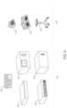
- FIG. 6is a diagram of various modules and other components that are combinable to customize modular energy systems, in accordance with at least one aspect of the present disclosure.
- FIG. 7 Ais a first illustrative modular energy system configuration including a header module and a display screen that renders a graphical user interface (GUI) for relaying information regarding modules connected to the header module, in accordance with at least one aspect of the present disclosure.
- GUIgraphical user interface
- FIG. 7 Bis the modular energy system shown in FIG. 7 A mounted to a cart, in accordance with at least one aspect of the present disclosure.
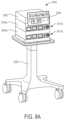
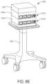
- FIG. 8 Ais a second illustrative modular energy system configuration including a header module, a display screen, an energy module, and an expanded energy module connected together and mounted to a cart, in accordance with at least one aspect of the present disclosure.
- FIG. 8 Bis a third illustrative modular energy system configuration that is similar to the second configuration shown in FIG. 7 A , except that the header module lacks a display screen, in accordance with at least one aspect of the present disclosure.
- FIG. 9is a fourth illustrative modular energy system configuration including a header module, a display screen, an energy module, ae expanded energy module, and a technology module connected together and mounted to a cart, in accordance with at least one aspect of the present disclosure.
- FIG. 10is a fifth illustrative modular energy system configuration including a header module, a display screen, an energy module, an expanded energy module, a technology module, and a visualization module connected together and mounted to a cart, in accordance with at least one aspect of the present disclosure.
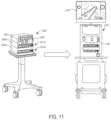
- FIG. 11is a diagram of a modular energy system including communicably connectable surgical platforms, in accordance with at least one aspect of the present disclosure.
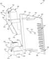
- FIG. 12is a perspective view of a header module of a modular energy system including a user interface, in accordance with at least one aspect of the present disclosure.
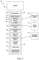
- FIG. 13is a block diagram of a stand-alone hub configuration of a modular energy system, in accordance with at least one aspect of the present disclosure.
- FIG. 14is a block diagram of a hub configuration of a modular energy system integrated with a surgical control system, in accordance with at least one aspect of the present disclosure.
- FIG. 15is a schematic diagram of a modular energy system stack illustrating a power backplane, in accordance with at least one aspect of the present disclosure.
- FIG. 16is a schematic diagram of a modular energy system, in accordance with at least one aspect of the present disclosure.
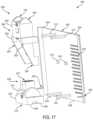
- FIG. 17is an exploded view of a backplane connector subassembly for a module of a modular energy system, in accordance with at least one aspect of the present disclosure.
- FIG. 18is an elevated view of a backplane connector subassembly for a module of a modular energy system, in accordance with at least one aspect of the present disclosure.
- FIG. 19is an elevated view of a panel of the backplane connector subassembly, in accordance with at least one aspect of the present disclosure.
- FIG. 20is an elevated view of an upstream connector for a backplane connector subassembly, in accordance with at least one aspect of the present disclosure.
- FIG. 21is an elevated view of a downstream connector for a backplane connector subassembly, in accordance with at least one aspect of the present disclosure.
- FIG. 22is a front view of a panel for a backplane connector subassembly, in accordance with at least one aspect of the present disclosure.
- FIG. 23is a front view of the panel for a backplane connector subassembly shown in FIG. 22 with the upstream and downstream connectors attached, in accordance with at least one aspect of the present disclosure.
- FIG. 24is a back view of the panel shown in FIG. 23 with the upstream and downstream connectors attached, in accordance with at least one aspect of the present disclosure.
- FIG. 25is an elevated view of the backplane connector subassembly shown in FIG. 7 with connection wires added, in accordance with at least one aspect of the present disclosure.
- FIG. 26is a front view of the backplane connector subassembly shown in FIG. 7 with connection wires added, in accordance with at least one aspect of the present disclosure.
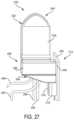
- FIG. 27is a side view of the upstream connector attached to the panel of the backplane subassembly, in accordance with at least one aspect of the present disclosure.
- FIG. 28is an elevated view of the backplane connector subassembly of FIG. 9 with the circuit board added, in accordance with at least one aspect of the present disclosure.
- FIG. 29is a front view of the backplane connector subassembly of FIG. 9 with the circuit board added, in accordance with at least one aspect of the present disclosure.
- FIG. 30illustrates a modular energy system, in accordance with at least one aspect of the present disclosure.
- FIG. 31illustrates various electrical connections in the modular energy system of FIG. 30 , in accordance with at least one aspect of the present disclosure.
- FIG. 32illustrates a module of the modular energy system of FIG. 30 , in accordance with at least one aspect of the present disclosure.
- FIG. 33illustrates a module of a modular energy system, which includes a rigid wire harness, in accordance with at least one aspect of the present disclosure, in accordance with at least one aspect of the present disclosure.
- FIG. 34is an elevated view of the backplane connector subassembly showing the connection wires as wire ribbons, in accordance with at least one aspect of the present disclosure.
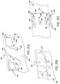
- FIG. 35is a side view of a method to connect the upstream connector to the panel of the backplane subassembly, in accordance with at least one aspect of the present disclosure.
- FIG. 36is a side view of a method to connect the downstream connector to the panel of the backplane subassembly, in accordance with at least one aspect of the present disclosure.
- FIG. 37 Ais an elevated view of a method to connect the upstream and downstream connectors to a panel for the backplane connector subassembly, in accordance with at least one aspect of the present disclosure.
- FIG. 37 Bis an elevated view of a method to connect the upstream and downstream connectors to a panel for the backplane connector subassembly, in accordance with at least one aspect of the present disclosure.
- FIG. 37 Cis an elevated view of a method to connect the upstream and downstream connectors to a panel for the backplane connector subassembly, in accordance with at least one aspect of the present disclosure.
- FIG. 38is an elevated view of a cartridge system to allow a backplane connector to be connected to a module, in accordance with at least one aspect of the present disclosure.
- FIG. 39is an elevated view of a backplane connector that snaps into the bottom of the module enclosure, in accordance with at least one aspect of the present disclosure.
- FIG. 40is a front view of a backplane connector subassembly that is built into a module enclosure, in accordance with at least one aspect of the present disclosure.
- FIG. 41is a bottom view of the upstream connector shown in FIG. 18 , in accordance with at least one aspect of the present disclosure.
- FIG. 42is a front view of a backplane connector subassembly that is built into a module enclosure, in accordance with at least one aspect of the present disclosure.
- FIG. 43illustrates a modular energy system that contains a power module, in accordance with at least one aspect of the present disclosure.
- aspects of the ultrasonic surgical devicescan be configured for transecting and/or coagulating tissue during surgical procedures, for example.
- aspects of the electrosurgical devicescan be configured for transecting, coagulating, scaling, welding and/or desiccating tissue during surgical procedures, for example.
- a computer-implemented interactive surgical system 100includes one or more surgical systems 102 and a cloud-based system (e.g., the cloud 104 that may include a remote server 113 coupled to a storage device 105 ).
- Each surgical system 102includes at least one surgical hub 106 in communication with the cloud 104 that may include a remote server 113 .
- the surgical system 102includes a visualization system 108 , a robotic system 110 , and a handheld intelligent surgical instrument 112 , which are configured to communicate with one another and/or the hub 106 .
- a surgical system 102may include an M number of hubs 106 , an N number of visualization systems 108 , an O number of robotic systems 110 , and a P number of handheld intelligent surgical instruments 112 , where M, N, O, and P are integers greater than or equal to one.
- An image of the surgical sitecan be obtained by a medical imaging device 124 , which can be manipulated by the patient side cart 120 to orient the imaging device 124 .
- the robotic hub 122can be used to process the images of the surgical site for subsequent display to the surgeon through the surgeon's console 118 .
- the imaging device 124includes at least one image sensor and one or more optical components.
- Suitable image sensorsinclude, but are not limited to, Charge-Coupled Device (CCD) sensors and Complementary Metal-Oxide Semiconductor (CMOS) sensors.
- CCDCharge-Coupled Device
- CMOSComplementary Metal-Oxide Semiconductor
- the optical components of the imaging device 124may include one or more illumination sources and/or one or more lenses.
- the one or more illumination sourcesmay be directed to illuminate portions of the surgical field.
- the one or more image sensorsmay receive light reflected or refracted from the surgical field, including light reflected or refracted from tissue and/or surgical instruments.
- the invisible spectrumis that portion of the electromagnetic spectrum that lies below and above the visible spectrum (i.e., wavelengths below about 380 nm and above about 750 nm).
- the invisible spectrumis not detectable by the human eye.
- Wavelengths greater than about 750 nmare longer than the red visible spectrum, and they become invisible infrared (IR), microwave, and radio electromagnetic radiation.
- Wavelengths less than about 380 nmare shorter than the violet spectrum, and they become invisible ultraviolet, x-ray, and gamma ray electromagnetic radiation.
- the imaging device 124is configured for use in a minimally invasive procedure.
- imaging devices suitable for use with the present disclosureinclude, but not limited to, an arthroscope, angioscope, bronchoscope, choledochoscope, colonoscope, cytoscope, duodenoscope, enteroscope, esophagogastro-duodenoscope (gastroscope), endoscope, laryngoscope, nasopharyngo-neproscope, sigmoidoscope, thoracoscope, and ureteroscope.
- the imaging deviceemploys multi-spectrum monitoring to discriminate topography and underlying structures.
- a multi-spectral imageis one that captures image data within specific wavelength ranges across the electromagnetic spectrum. The wavelengths may be separated by filters or by the use of instruments that are sensitive to particular wavelengths, including light from frequencies beyond the visible light range, e.g., IR and ultraviolet. Spectral imaging can allow extraction of additional information the human eye fails to capture with its receptors for red, green, and blue.
- Multi-spectrum monitoringcan be a useful tool in relocating a surgical field after a surgical task is completed to perform one or more of the previously described tests on the treated tissue.
- the sterile fieldmay be considered a specified area, such as within a tray or on a sterile towel, that is considered free of microorganisms, or the sterile field may be considered an area, immediately around a patient, who has been prepared for a surgical procedure.
- the sterile fieldmay include the scrubbed team members, who are properly attired, and all furniture and fixtures in the area.
- the visualization system 108includes one or more imaging sensors, one or more image-processing units, one or more storage arrays, and one or more displays that are strategically arranged with respect to the sterile field, as illustrated in FIG. 2 .
- the visualization system 108includes an interface for HL7, PACS, and EMR.
- Various components of the visualization system 108are described under the heading “Advanced Imaging Acquisition Module” in U.S. Provisional Patent Application Ser. No. 62/611,341, titled INTERACTIVE SURGICAL PLATFORM, filed Dec. 28, 2017, the disclosure of which is herein incorporated by reference in its entirety.
- a primary display 119is positioned in the sterile field to be visible to an operator at the operating table 114 .
- a visualization tower 111is positioned outside the sterile field.
- the visualization tower 111includes a first non-sterile display 107 and a second non-sterile display 109 , which face away from each other.
- the visualization system 108guided by the hub 106 , is configured to utilize the displays 107 , 109 , and 119 to coordinate information flow to operators inside and outside the sterile field.
- the hub 106may cause the visualization system 108 to display a snapshot of a surgical site, as recorded by an imaging device 124 , on a non-sterile display 107 or 109 , while maintaining a live feed of the surgical site on the primary display 119 .
- the snapshot on the non-sterile display 107 or 109can permit a non-sterile operator to perform a diagnostic step relevant to the surgical procedure, for example.
- the hub 106is also configured to route a diagnostic input or feedback entered by a non-sterile operator at the visualization tower 111 to the primary display 119 within the sterile field, where it can be viewed by a sterile operator at the operating table.
- the inputcan be in the form of a modification to the snapshot displayed on the non-sterile display 107 or 109 , which can be routed to the primary display 119 by the hub 106 .
- a surgical instrument 112is being used in the surgical procedure as part of the surgical system 102 .
- the hub 106is also configured to coordinate information flow to a display of the surgical instrument 112 .
- a diagnostic input or feedback entered by a non-sterile operator at the visualization tower 111can be routed by the hub 106 to the surgical instrument display 115 within the sterile field, where it can be viewed by the operator of the surgical instrument 112 .
- Example surgical instrumentsthat are suitable for use with the surgical system 102 are described under the heading SURGICAL INSTRUMENT HARDWARE and in U.S. Provisional Patent Application Ser. No. 62/611,341, titled INTERACTIVE SURGICAL PLATFORM, filed Dec. 28, 2017, the disclosure of which is herein incorporated by reference in its entirety, for example.
- a hub 106is depicted in communication with a visualization system 108 , a robotic system 110 , and a handheld intelligent surgical instrument 112 .
- the visualization system 108may be a separable piece of equipment.
- the visualization system 108could be contained within the hub 106 as a functional module.
- the hub 106includes a hub display 135 , an imaging module 138 , a generator module 140 , a communication module 130 , a processor module 132 , a storage array 134 , and an operating room mapping module 133 . In certain aspects, as illustrated in FIG.
- the hub 106further includes a smoke evacuation module 126 , a suction/irrigation module 128 , and/or an insufflation module 129 .
- any of the modules in the hub 106may be combined with each other into a single module.
- the hub modular enclosure 136offers a unified environment for managing the power, data, and fluid lines, which reduces the frequency of entanglement between such lines.
- the surgical hubfor use in a surgical procedure that involves energy application to tissue at a surgical site.
- the surgical hubincludes a hub enclosure and a combo generator module slidably receivable in a docking station of the hub enclosure.
- the docking stationincludes data and power contacts.
- the combo generator moduleincludes one or more of an ultrasonic energy generator component, a bipolar RF energy generator component, and a monopolar RF energy generator component that are housed in a single unit.
- the combo generator modulealso includes a smoke evacuation component, at least one energy delivery cable for connecting the combo generator module to a surgical instrument, at least one smoke evacuation component configured to evacuate smoke, fluid, and/or particulates generated by the application of therapeutic energy to the tissue, and a fluid line extending from the remote surgical site to the smoke evacuation component.
- the fluid lineis a first fluid line and a second fluid line extends from the remote surgical site to a suction and irrigation module slidably received in the hub enclosure.
- the hub enclosurecomprises a fluid interface.
- Certain surgical proceduresmay require the application of more than one energy type to the tissue.
- One energy typemay be more beneficial for cutting the tissue, while another different energy type may be more beneficial for sealing the tissue.
- a bipolar generatorcan be used to seal the tissue while an ultrasonic generator can be used to cut the sealed tissue.
- the modular surgical enclosureincludes a first energy-generator module, configured to generate a first energy for application to the tissue, and a first docking station comprising a first docking port that includes first data and power contacts.
- the first energy-generator moduleis slidably movable into an electrical engagement with the power and data contacts and wherein the first energy-generator module is slidably movable out of the electrical engagement with the first power and data contacts.
- the first energy-generator moduleis stackably movable into an electrical engagement with the power and data contacts and wherein the first energy-generator module is stackably movable out of the electrical engagement with the first power and data contacts.
- the modular surgical enclosurealso includes a second energy-generator module configured to generate a second energy, either the same or different than the first energy, for application to the tissue, and a second docking station comprising a second docking port that includes second data and power contacts.
- the second energy-generator moduleis slidably movable into an electrical engagement with the power and data contacts, and wherein the second energy-generator module is slidably movable out of the electrical engagement with the second power and data contacts.
- the second energy-generator moduleis stackably movable into an electrical engagement with the power and data contacts, and wherein the second energy-generator module is stackably movable out of the electrical engagement with the second power and data contacts.
- the modular surgical enclosurealso includes a communication bus between the first docking port and the second docking port, configured to facilitate communication between the first energy-generator module and the second energy-generator module.
- a hub modular enclosure 136that allows the modular integration of a generator module 140 , a smoke evacuation module 126 , a suction/irrigation module 128 , and an insufflation module 129 .
- the hub modular enclosure 136further facilitates interactive communication between the modules 140 , 126 , 128 , 129 .
- the generator module 140can be a generator module with integrated monopolar, bipolar, and ultrasonic components supported in a single housing unit slidably insertable into the hub modular enclosure 136 .
- the generator module 140can be configured to connect to a monopolar device 142 , a bipolar device 144 , and an ultrasonic device 148 .
- the generator module 140may comprise a series of monopolar, bipolar, and/or ultrasonic generator modules that interact through the hub modular enclosure 136 .
- the hub modular enclosure 136can be configured to facilitate the insertion of multiple generators and interactive communication between the generators docked into the hub modular enclosure 136 so that the generators would act as a single generator.
- the hub modular enclosure 136comprises a modular power and communication backplane 149 with external and wireless communication headers to enable the removable attachment of the modules 140 , 126 , 128 , 129 and interactive communication therebetween.
- wirelessand its derivatives may be used to describe circuits, devices, systems, methods, techniques, communications channels, etc., that may communicate data through the use of modulated electromagnetic radiation through a non-solid medium. The term does not imply that the associated devices do not contain any wires, although in some aspects they might not.
- the communication modulemay implement any of a number of wireless or wired communication standards or protocols, including but not limited to Wi-Fi (IEEE 802.11 family), WiMAX (IEEE 802.16 family), IEEE 802.20, long term evolution (LTE), Ev-DO, HSPA+, HSDPA+, HSUPA+, EDGE, GSM, GPRS, CDMA, TDMA, DECT, Bluetooth, Ethernet derivatives thereof, as well as any other wireless and wired protocols that are designated as 3G, 4G, 5G, and beyond.
- the computing modulemay include a plurality of communication modules.
- a first communication modulemay be dedicated to shorter range wireless communications such as Wi-Fi and Bluetooth and a second communication module may be dedicated to longer range wireless communications such as GPS, EDGE, GPRS, CDMA, WiMAX, LTE, Ev-DO, and others.
- processor or processing unitis an electronic circuit which performs operations on some external data source, usually memory or some other data stream.
- the termis used herein to refer to the central processor (central processing unit) in a system or computer systems (especially systems on a chip (SoCs)) that combine a number of specialized “processors.”
- SoCsystem on a chip or system on chip
- SOCsystem on chip
- ICintegrated circuit
- a SoCintegrates a microcontroller (or microprocessor) with advanced peripherals like graphics processing unit (GPU), Wi-Fi module, or coprocessor.
- a SoCmay or may not contain built-in memory.
- a microcontroller or controlleris a system that integrates a microprocessor with peripheral circuits and memory.
- a microcontroller(or MCU for microcontroller unit) may be implemented as a small computer on a single integrated circuit. It may be similar to a SoC; a SoC may include a microcontroller as one of its components.
- a microcontrollermay contain one or more core processing units (CPUs) along with memory and programmable input/output peripherals. Program memory in the form of Ferroelectric RAM, NOR flash or OTP ROM is also often included on chip, as well as a small amount of RAM.
- Microcontrollersmay be employed for embedded applications, in contrast to the microprocessors used in personal computers or other general purpose applications consisting of various discrete chips.
- controller or microcontrollermay be a stand-alone IC or chip device that interfaces with a peripheral device. This may be a link between two parts of a computer or a controller on an external device that manages the operation of (and connection with) that device.
- processors or microcontrollers described hereinmay be implemented by any single core or multicore processor such as those known under the trade name ARM Cortex by Texas Instruments.
- the processormay be an LM4F230H5QR ARM Cortex-M4F Processor Core, available from Texas Instruments, for example, comprising on-chip memory of 256 KB single-cycle flash memory, or other non-volatile memory, up to 40 MHz, a prefetch buffer to improve performance above 40 MHz, a 32 KB single-cycle serial random access memory (SRAM), internal read-only memory (ROM) loaded with StellarisWare® software, 2 KB electrically erasable programmable read-only memory (EEPROM), one or more pulse width modulation (PWM) modules, one or more quadrature encoder inputs (QEI) analog, one or more 12-bit Analog-to-Digital Converters (ADC) with 12 analog input channels, details of which are available for the product datasheet.
- the processormay comprise a safety controller comprising two controller-based families such as TMS570 and RM4 ⁇ known under the trade name Hercules ARM Cortex R4, also by Texas Instruments.
- the safety controllermay be configured specifically for IEC 61508 and ISO 26262 safety critical applications, among others, to provide advanced integrated safety features while delivering scalable performance, connectivity, and memory options.
- Modular devicesinclude the modules (as described in connection with FIG. 3 , for example) that are receivable within a surgical hub and the surgical devices or instruments that can be connected to the various modules in order to connect or pair with the corresponding surgical hub.
- the modular devicesinclude, for example, intelligent surgical instruments, medical imaging devices, suction/irrigation devices, smoke evacuators, energy generators, ventilators, insufflators, and displays.
- the modular devices described hereincan be controlled by control algorithms.
- the control algorithmscan be executed on the modular device itself, on the surgical hub to which the particular modular device is paired, or on both the modular device and the surgical hub (e.g., via a distributed computing architecture).
- the modular devices' control algorithmscontrol the devices based on data sensed by the modular device itself (i.e., by sensors in, on, or connected to the modular device). This data can be related to the patient being operated on (e.g., tissue properties or insufflation pressure) or the modular device itself (e.g., the rate at which a knife is being advanced, motor current, or energy levels).
- a control algorithm for a surgical stapling and cutting instrumentcan control the rate at which the instrument's motor drives its knife through tissue according to resistance encountered by the knife as it advances.
- FIG. 4illustrates one form of a surgical system 2200 comprising a modular energy system 2000 and various surgical instruments 2204 , 2206 , 2208 usable therewith, where the surgical instrument 2204 is an ultrasonic surgical instrument, the surgical instrument 2206 is an RF electrosurgical instrument, and the multifunction surgical instrument 2208 is a combination ultrasonic/RF electrosurgical instrument.
- the modular energy system 2000is configurable for use with a variety of surgical instruments. According to various forms, the modular energy system 2000 may be configurable for use with different surgical instruments of different types including, for example, ultrasonic surgical instruments 2204 , RF electrosurgical instruments 2206 , and multifunction surgical instruments 2208 that integrate RF and ultrasonic energies delivered individually or simultaneously from the modular energy system 2000 .
- FIG. 4illustrates one form of a surgical system 2200 comprising a modular energy system 2000 and various surgical instruments 2204 , 2206 , 2208 usable therewith, where the surgical instrument 2204 is an ultrasonic surgical instrument, the surgical instrument 2206 is an RF electrosurgical instrument,
- the modular energy system 2000is shown separate from the surgical instruments 2204 , 2206 , 2208 in one form, the modular energy system 2000 may be formed integrally with any of the surgical instruments 2204 , 2206 , 2208 to form a unitary surgical system.
- the modular energy system 2000may be configured for wired or wireless communication.
- the modular energy system 2000is configured to drive multiple surgical instruments 2204 , 2206 , 2208 .
- the first surgical instrumentis an ultrasonic surgical instrument 2204 and comprises a handpiece 2205 (HP), an ultrasonic transducer 2220 , a shaft 2226 , and an end effector 2222 .
- the end effector 2222comprises an ultrasonic blade 2228 acoustically coupled to the ultrasonic transducer 2220 and a clamp arm 2240 .
- the handpiece 2205comprises a trigger 2243 to operate the clamp arm 2240 and a combination of the toggle buttons 2234 a , 2234 b , 2234 c to energize and drive the ultrasonic blade 2228 or other function.
- the toggle buttons 2234 a , 2234 b , 2234 ccan be configured to energize the ultrasonic transducer 2220 with the modular energy system 2000 .
- the modular energy system 2000also is configured to drive a second surgical instrument 2206 .
- the second surgical instrument 2206is an RF electrosurgical instrument and comprises a handpiece 2207 (HP), a shaft 2227 , and an end effector 2224 .
- the end effector 2224comprises electrodes in clamp arms 2242 a , 2242 b and return through an electrical conductor portion of the shaft 2227 .
- the electrodesare coupled to and energized by a bipolar energy source within the modular energy system 2000 .
- the handpiece 2207comprises a trigger 2245 to operate the clamp arms 2242 a , 2242 b and an energy button 2235 to actuate an energy switch to energize the electrodes in the end effector 2224 .
- the modular energy system 2000also is configured to drive a multifunction surgical instrument 2208 .
- the multifunction surgical instrument 2208comprises a handpiece 2209 (HP), a shaft 2229 , and an end effector 2225 .
- the end effector 2225comprises an ultrasonic blade 2249 and a clamp arm 2246 .
- the ultrasonic blade 2249is acoustically coupled to the ultrasonic transducer 2220 .
- the ultrasonic transducer 2220may be separable from or integral to the handpiece 2209 .
- the handpiece 2209comprises a trigger 2247 to operate the clamp arm 2246 and a combination of the toggle buttons 2237 a , 2237 b , 2237 c to energize and drive the ultrasonic blade 2249 or other function.
- the toggle buttons 2237 a , 2237 b , 2237 ccan be configured to energize the ultrasonic transducer 2220 with the modular energy system 2000 and energize the ultrasonic blade 2249 with a bipolar energy source also contained within the modular energy system 2000 .
- the modular energy system 2000is configurable for use with a variety of surgical instruments. According to various forms, the modular energy system 2000 may be configurable for use with different surgical instruments of different types including, for example, the ultrasonic surgical instrument 2204 , the RF electrosurgical instrument 2206 , and the multifunction surgical instrument 2208 that integrates RF and ultrasonic energies delivered individually or simultaneously from the modular energy system 2000 . Although in the form of FIG. 4 the modular energy system 2000 is shown separate from the surgical instruments 2204 , 2206 , 2208 , in another form the modular energy system 2000 may be formed integrally with any one of the surgical instruments 2204 , 2206 , 2208 to form a unitary surgical system. Further aspects of generators for digitally generating electrical signal waveforms and surgical instruments are described in U.S. Patent Application Publication No. 2017/0086914, which is herein incorporated by reference in its entirety.
- an “intelligent” device including control algorithms that respond to sensed datacan be an improvement over a “dumb” device that operates without accounting for sensed data
- some sensed datacan be incomplete or inconclusive when considered in isolation, i.e., without the context of the type of surgical procedure being performed or the type of tissue that is being operated on.
- the control algorithmmay control the modular device incorrectly or sub optimally given the particular context-free sensed data.
- the optimal manner for a control algorithm to control a surgical instrument in response to a particular sensed parametercan vary according to the particular tissue type being operated on.
- tissue typeshave different properties (e.g., resistance to tearing) and thus respond differently to actions taken by surgical instruments. Therefore, it may be desirable for a surgical instrument to take different actions even when the same measurement for a particular parameter is sensed.
- the optimal manner in which to control a surgical stapling and cutting instrument in response to the instrument sensing an unexpectedly high force to close its end effectorwill vary depending upon whether the tissue type is susceptible or resistant to tearing. For tissues that are susceptible to tearing, such as lung tissue, the instrument's control algorithm would optimally ramp down the motor in response to an unexpectedly high force to close to avoid tearing the tissue.
- the instrument's control algorithmwould optimally ramp up the motor in response to an unexpectedly high force to close to ensure that the end effector is clamped properly on the tissue. Without knowing whether lung or stomach tissue has been clamped, the control algorithm may make a suboptimal decision.
- FIG. 5illustrates a diagram of a situationally aware surgical system 2300 , in accordance with at least one aspect of the present disclosure.
- the data sources 2326include, for example, the modular devices 2302 (which can include sensors configured to detect parameters associated with the patient and/or the modular device itself), databases 2322 (e.g., an EMR database containing patient records), and patient monitoring devices 2324 (e.g., a blood pressure (BP) monitor and an electrocardiography (EKG) monitor).
- the surgical hub 2304can be configured to derive the contextual information pertaining to the surgical procedure from the data based upon, for example, the particular combination(s) of received data or the particular order in which the data is received from the data sources 2326 .
- the contextual information inferred from the received datacan include, for example, the type of surgical procedure being performed, the particular step of the surgical procedure that the surgeon is performing, the type of tissue being operated on, or the body cavity that is the subject of the procedure.
- This ability by some aspects of the surgical hub 2304 to derive or infer information related to the surgical procedure from received datacan be referred to as “situational awareness.”
- the surgical hub 2304can incorporate a situational awareness system, which is the hardware and/or programming associated with the surgical hub 2304 that derives contextual information pertaining to the surgical procedure from the received data.
- the situational awareness systemcan include a lookup table storing pre-characterized contextual information regarding a surgical procedure in association with one or more inputs (or ranges of inputs) corresponding to the contextual information. In response to a query with one or more inputs, the lookup table can return the corresponding contextual information for the situational awareness system for controlling the modular devices 2302 .
- the contextual information received by the situational awareness system of the surgical hub 2304is associated with a particular control adjustment or set of control adjustments for one or more modular devices 2302 .
- the situational awareness systemincludes a further machine learning system, lookup table, or other such system, which generates or retrieves one or more control adjustments for one or more modular devices 2302 when provided the contextual information as input.
- a surgical hub 2304 incorporating a situational awareness systemprovides a number of benefits for the surgical system 2300 .
- One benefitincludes improving the interpretation of sensed and collected data, which would in turn improve the processing accuracy and/or the usage of the data during the course of a surgical procedure.
- a situationally aware surgical hub 2304could determine what type of tissue was being operated on; therefore, when an unexpectedly high force to close the surgical instrument's end effector is detected, the situationally aware surgical hub 2304 could correctly ramp up or ramp down the motor of the surgical instrument for the type of tissue.
- the type of tissue being operatedcan affect the adjustments that are made to the compression rate and load thresholds of a surgical stapling and cutting instrument for a particular tissue gap measurement.
- a situationally aware surgical hub 2304could infer whether a surgical procedure being performed is a thoracic or an abdominal procedure, allowing the surgical hub 2304 to determine whether the tissue clamped by an end effector of the surgical stapling and cutting instrument is lung (for a thoracic procedure) or stomach (for an abdominal procedure) tissue. The surgical hub 2304 could then adjust the compression rate and load thresholds of the surgical stapling and cutting instrument appropriately for the type of tissue.
- the type of body cavity being operated in during an insufflation procedurecan affect the function of a smoke evacuator.
- a situationally aware surgical hub 2304could determine whether the surgical site is under pressure (by determining that the surgical procedure is utilizing insufflation) and determine the procedure type. As a procedure type is generally performed in a specific body cavity, the surgical hub 2304 could then control the motor rate of the smoke evacuator appropriately for the body cavity being operated in. Thus, a situationally aware surgical hub 2304 could provide a consistent amount of smoke evacuation for both thoracic and abdominal procedures.
- the type of procedure being performedcan affect the optimal energy level at which an ultrasonic surgical instrument or radio frequency (RF) electrosurgical instrument operates.
- Arthroscopic proceduresfor example, require higher energy levels because the end effector of the ultrasonic surgical instrument or RF electrosurgical instrument is immersed in fluid.
- a situationally aware surgical hub 2304could determine whether the surgical procedure is an arthroscopic procedure. The surgical hub 2304 could then adjust the RF power level or the ultrasonic amplitude of the generator (i.e., “energy level”) to compensate for the fluid filled environment.
- the type of tissue being operated oncan affect the optimal energy level for an ultrasonic surgical instrument or RF electrosurgical instrument to operate at.
- a situationally aware surgical hub 2304could determine what type of surgical procedure is being performed and then customize the energy level for the ultrasonic surgical instrument or RF electrosurgical instrument, respectively, according to the expected tissue profile for the surgical procedure. Furthermore, a situationally aware surgical hub 2304 can be configured to adjust the energy level for the ultrasonic surgical instrument or RF electrosurgical instrument throughout the course of a surgical procedure, rather than just on a procedure-by-procedure basis. A situationally aware surgical hub 2304 could determine what step of the surgical procedure is being performed or will subsequently be performed and then update the control algorithms for the generator and/or ultrasonic surgical instrument or RF electrosurgical instrument to set the energy level at a value appropriate for the expected tissue type according to the surgical procedure step.
- datacan be drawn from additional data sources 2326 to improve the conclusions that the surgical hub 2304 draws from one data source 2326 .
- a situationally aware surgical hub 2304could augment data that it receives from the modular devices 2302 with contextual information that it has built up regarding the surgical procedure from other data sources 2326 .
- a situationally aware surgical hub 2304can be configured to determine whether hemostasis has occurred (i.e., whether bleeding at a surgical site has stopped) according to video or image data received from a medical imaging device. However, in some cases the video or image data can be inconclusive.
- the surgical hub 2304can be further configured to compare a physiologic measurement (e.g., blood pressure sensed by a BP monitor communicably connected to the surgical hub 2304 ) with the visual or image data of hemostasis (e.g., from a medical imaging device 124 ( FIG. 2 ) communicably coupled to the surgical hub 2304 ) to make a determination on the integrity of the staple line or tissue weld.
- a physiologic measuremente.g., blood pressure sensed by a BP monitor communicably connected to the surgical hub 2304
- the visual or image data of hemostasise.g., from a medical imaging device 124 ( FIG. 2 ) communicably coupled to the surgical hub 2304
- the situational awareness system of the surgical hub 2304can consider the physiological measurement data to provide additional context in analyzing the visualization data.
- the additional contextcan be useful when the visualization data may be inconclusive or incomplete on its own.
- Another benefitincludes proactively and automatically controlling the paired modular devices 2302 according to the particular step of the surgical procedure that is being performed to reduce the number of times that medical personnel are required to interact with or control the surgical system 2300 during the course of a surgical procedure.
- a situationally aware surgical hub 2304could proactively activate the generator to which an RF electrosurgical instrument is connected if it determines that a subsequent step of the procedure requires the use of the instrument. Proactively activating the energy source allows the instrument to be ready for use a soon as the preceding step of the procedure is completed.
- a situationally aware surgical hub 2304could determine whether the current or subsequent step of the surgical procedure requires a different view or degree of magnification on the display according to the feature(s) at the surgical site that the surgeon is expected to need to view. The surgical hub 2304 could then proactively change the displayed view (supplied by, e.g., a medical imaging device for the visualization system 108 ) accordingly so that the display automatically adjusts throughout the surgical procedure.
- a situationally aware surgical hub 2304could determine which step of the surgical procedure is being performed or will subsequently be performed and whether particular data or comparisons between data will be required for that step of the surgical procedure.
- the surgical hub 2304can be configured to automatically call up data screens based upon the step of the surgical procedure being performed, without waiting for the surgeon to ask for the particular information.
- a situationally aware surgical hub 2304could determine whether the operating theater is setup properly or optimally for the surgical procedure to be performed.
- the surgical hub 2304can be configured to determine the type of surgical procedure being performed, retrieve the corresponding checklists, product location, or setup needs (e.g., from a memory), and then compare the current operating theater layout to the standard layout for the type of surgical procedure that the surgical hub 2304 determines is being performed.
- the surgical hub 2304can be configured to compare the list of items for the procedure (scanned by a scanner, for example) and/or a list of devices paired with the surgical hub 2304 to a recommended or anticipated manifest of items and/or devices for the given surgical procedure. If there are any discontinuities between the lists, the surgical hub 2304 can be configured to provide an alert indicating that a particular modular device 2302 , patient monitoring device 2324 , and/or other surgical item is missing. In one exemplification, the surgical hub 2304 can be configured to determine the relative distance or position of the modular devices 2302 and patient monitoring devices 2324 via proximity sensors, for example. The surgical hub 2304 can compare the relative positions of the devices to a recommended or anticipated layout for the particular surgical procedure. If there are any discontinuities between the layouts, the surgical hub 2304 can be configured to provide an alert indicating that the current layout for the surgical procedure deviates from the recommended layout.
- a situationally aware surgical hub 2304could determine whether the surgeon (or other medical personnel) was making an error or otherwise deviating from the expected course of action during the course of a surgical procedure.
- the surgical hub 2304can be configured to determine the type of surgical procedure being performed, retrieve the corresponding list of steps or order of equipment usage (e.g., from a memory), and then compare the steps being performed or the equipment being used during the course of the surgical procedure to the expected steps or equipment for the type of surgical procedure that the surgical hub 2304 determined is being performed.
- the surgical hub 2304can be configured to provide an alert indicating that an unexpected action is being performed or an unexpected device is being utilized at the particular step in the surgical procedure.
- the situational awareness system for the surgical hub 2304improves surgical procedure outcomes by adjusting the surgical instruments (and other modular devices 2302 ) for the particular context of each surgical procedure (such as adjusting to different tissue types) and validating actions during a surgical procedure.
- the situational awareness systemalso improves surgeons' efficiency in performing surgical procedures by automatically suggesting next steps, providing data, and adjusting displays and other modular devices 2302 in the surgical theater according to the specific context of the procedure.
- Surgical capital equipmenttends to be a major contributor to this issue because most surgical capital equipment performs a single, specialized task. Due to their specialized nature and the surgeons' needs to utilize multiple different types of devices during the course of a single surgical procedure, an OR may be forced to be stocked with two or even more pieces of surgical capital equipment, such as energy generators. Each of these pieces of surgical capital equipment may need to be individually plugged into a power source and may be connected to one or more other devices that are being passed between OR personnel, creating a tangle of cords that have to be navigated.
- a surgical hub 106can be configured to interchangeably receive a variety of modules, which can in turn interface with surgical devices (e.g., a surgical instrument or a smoke evacuator) or provide various other functions (e.g., communications).
- a surgical hub 106can be embodied as a modular energy system 2000 , which is illustrated in connection with FIGS. 6 - 12 .
- the modular energy system 2000can include a variety of different modules 2001 that are connectable together in a stacked configuration.
- the modules 2001can be both physically and communicably coupled together when stacked or otherwise connected together into a singular assembly. Further, the modules 2001 can be interchangeably connectable together in different combinations or arrangements.
- each of the modules 2001can include a consistent or universal array of connectors disposed along their upper and lower surfaces, thereby allowing any module 2001 to be connected to another module 2001 in any arrangement (except that, in some aspects, a particular module type, such as the header module 2002 , can be configured to serve as the uppermost module within the stack, for example).
- the modular energy system 2000can include a housing that is configured to receive and retain the modules 2001 , as is shown in FIG. 3 .
- the modular energy system 2000can also include a variety of different components or accessories that are also connectable to or otherwise associatable with the modules 2001 .
- the modular energy system 2000can be embodied as a generator module 140 ( FIG. 3 ) of a surgical hub 106 .
- the modular energy system 2000can be a distinct system from a surgical hub 106 . In such aspects, the modular energy system 2000 can be communicably couplable to a surgical hub 206 for transmitting and/or receiving data therebetween.
- the modular energy system 2000can be assembled from a variety of different modules 2001 , some examples of which are illustrated in FIG. 6 .
- Each of the different types of modules 2001can provide different functionality, thereby allowing the modular energy system 2000 to be assembled into different configurations to customize the functions and capabilities of the modular energy system 2000 by customizing the modules 2001 that are included in each modular energy system 2000 .
- the modules 2001 of the modular energy system 2000can include, for example, a header module 2002 (which can include a display screen 2006 ), an energy module 2004 , a technology module 2040 , and a visualization module 2042 .
- the header module 2002is configured to serve as the top or uppermost module within the modular energy system stack and can thus lack connectors along its top surface.
- the header module 2002can be configured to be positioned at the bottom or the lowermost module within the modular energy system stack and can thus lack connectors along its bottom surface. In yet another aspect, the header module 2002 can be configured to be positioned at an intermediate position within the modular energy system stack and can thus include connectors along both its bottom and top surfaces.
- the header module 2002can be configured to control the system-wide settings of each module 2001 and component connected thereto through physical controls 2011 thereon and/or a graphical user interface (GUI) 2008 rendered on the display screen 2006 .
- GUIgraphical user interface
- the header module 2002can also be configured to provide communications, processing, and/or power for the modules 2001 that are connected to the header module 2002 .
- the energy module 2004which can also be referred to as a generator module 140 ( FIG. 3 ), can be configured to generate one or multiple energy modalities for driving electrosurgical and/or ultrasonic surgical instruments connected thereto.
- the technology module 2040can be configured to provide additional or expanded control algorithms (e.g., electrosurgical or ultrasonic control algorithms for controlling the energy output of the energy module 2004 ).
- the visualization module 2042can be configured to interface with visualization devices (i.e., scopes) and accordingly provide increased visualization capabilities.
- the modular energy system 2000can further include a variety of accessories 2029 that are connectable to the modules 2001 for controlling the functions thereof or that are otherwise configured to work on conjunction with the modular energy system 2000 .
- the accessories 2029can include, for example, a single-pedal footswitch 2032 , a dual-pedal footswitch 2034 , and a cart 2030 for supporting the modular energy system 2000 thereon.
- the footswitches 2032 , 2034can be configured to control the activation or function of particular energy modalities output by the energy module 2004 , for example.
- the depicted modular energy system 2000provides a surgical platform that grows with the availability of technology and is customizable to the needs of the facility and/or surgeons. Further, the modular energy system 2000 supports combo devices (e.g., dual electrosurgical and ultrasonic energy generators) and supports software-driven algorithms for customized tissue effects. Still further, the surgical system architecture reduces the capital footprint by combining multiple technologies critical for surgery into a single system.
- the various modular components utilizable in connection with the modular energy system 2000can include monopolar energy generators, bipolar energy generators, dual electrosurgical/ultrasonic energy generators, display screens, and various other modules and/or other components, some of which are also described above in connection with FIGS. 1 - 3 .
- the header module 2002can, in some aspects, include a display screen 2006 that renders a GUI 2008 for relaying information regarding the modules 2001 connected to the header module 2002 .
- the GUI 2008 of the display screen 2006can provide a consolidated point of control of all of the modules 2001 making up the particular configuration of the modular energy system 2000 .
- the header module 2002can lack the display screen 2006 or the display screen 2006 can be detachably connected to the housing 2010 of the header module 2002 .
- the header module 2002can be communicably couplable to an external system that is configured to display the information generated by the modules 2001 of the modular energy system 2000 .
- the modular energy system 2000can be communicably couplable to a robotic cart or robotic control console, which is configured to display the information generated by the modular energy system 2000 to the operator of the robotic surgical system.
- the modular energy system 2000can be communicably couplable to a mobile display that can be carried or secured to a surgical staff member for viewing thereby.
- the modular energy system 2000can be communicably couplable to a surgical hub 2100 or another computer system that can include a display 2104 , as is illustrated in FIG. 11 .
- the user interfacecan be wirelessly connectable with the modular energy system 2000 as a whole or one or more modules 2001 thereof such that the user interface can display information from the connected modules 2001 thereon.
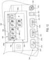
- the energy module 2004can include a port assembly 2012 including a number of different ports configured to deliver different energy modalities to corresponding surgical instruments that are connectable thereto.
- the port assembly 2012includes a bipolar port 2014 , a first monopolar port 2016 a , a second monopolar port 2016 b , a neutral electrode port 2018 (to which a monopolar return pad is connectable), and a combination energy port 2020 .
- this particular combination of portsis simply provided for illustrative purposes and alternative combinations of ports and/or energy modalities may be possible for the port assembly 2012 .
- FIGS. 7 A and 7 Billustrate a first illustrative configuration of the modular energy system 2000 including a header module 2002 (including a display screen 2006 ) and an energy module 2004 connected together.
- a header module 2002including a display screen 2006
- an energy module 2004connected together.
- Such a configurationcan be suitable for laparoscopic and open surgical procedures, for example.
- FIG. 8 Aillustrates a second illustrative configuration of the modular energy system 2000 including a header module 2002 (including a display screen 2006 ), a first energy module 2004 a , and a second energy module 2004 b connected together.
- the modular energy system 2000can provide a pair of port assemblies 2012 a , 2012 b for expanding the array of energy modalities deliverable by the modular energy system 2000 from the first configuration.
- the second configuration of the modular energy system 2000can accordingly accommodate more than one bipolar/monopolar electrosurgical instrument, more than two bipolar/monopolar electrosurgical instruments, and so on. Such a configuration can be suitable for particularly complex laparoscopic and open surgical procedures.
- FIG. 8 Billustrates a third illustrative configuration that is similar to the second configuration, except that the header module 2002 lacks a display screen 2006 . This configuration can be suitable for robotic surgical applications or mobile display applications, as noted above.
- FIG. 9illustrates a fourth illustrative configuration of the modular energy system 2000 including a header module 2002 (including a display screen 2006 ), a first energy module 2004 a , a second energy module 2004 b , and a technology module 2040 connected together.
- a header module 2002including a display screen 2006
- a first energy module 2004 acan be suitable for surgical applications where particularly complex or computation-intensive control algorithms are required.
- the technology module 2040can be a newly released module that supplements or expands the capabilities of previously released modules (such as the energy module 2004 ).
- FIG. 10illustrates a fifth illustrative configuration of the modular energy system 2000 including a header module 2002 (including a display screen 2006 ), a first energy module 2004 a , a second energy module 2004 b , a technology module 2040 , and a visualization module 2042 connected together.
- a header module 2002including a display screen 2006
- a first energy module 2004 aa first energy module 2004 a
- a second energy module 2004 ba technology module 2040
- a visualization module 2042connected together.
- Such a configurationcan be suitable for endoscopic procedures by providing a dedicated surgical display 2044 for relaying the video feed from the scope coupled to the visualization module 2042 .
- FIGS. 7 A- 11 and described aboveare provided simply to illustrate the various concepts of the modular energy system 2000 and should not be interpreted to limit the modular energy system 2000 to the particular aforementioned configurations.
- the modular energy system 2000can be communicably couplable to an external system, such as a surgical hub 2100 as illustrated in FIG. 11 .
- an external systemsuch as a surgical hub 2100 as illustrated in FIG. 11 .
- Such external systemscan include a display screen 2104 for displaying a visual feed from an endoscope (or a camera or another such visualization device) and/or data from the modular energy system 2000 .
- Such external systemscan also include a computer system 2102 for performing calculations or otherwise analyzing data generated or provided by the modular energy system 2000 , controlling the functions or modes of the modular energy system 2000 , and/or relaying data to a cloud computing system or another computer system.
- Such external systemscould also coordinate actions between multiple modular energy systems 2000 and/or other surgical systems (e.g., a visualization system 108 and/or a robotic system 110 as described in connection with FIGS. 1 and 2 ).
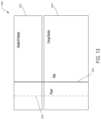
- the header module 2002can include or support a display 2006 configured for displaying a GUI 2008 , as noted above.
- the display screen 2006can include a touchscreen for receiving input from users in addition to displaying information.
- the controls displayed on the GUI 2008can correspond to the module(s) 2001 that are connected to the header module 2002 .
- different portions or areas of the GUI 2008can correspond to particular modules 2001 .
- a first portion or area of the GUI 2008can correspond to a first module and a second portion or area of the GUI 2008 can correspond to a second module.
- the GUI 2008can adjust to accommodate the different and/or additional controls for each newly added module 2001 or remove controls for each module 2001 that is removed.
- Each portion of the display corresponding to a particular module connected to the header module 2002can display controls, data, user prompts, and/or other information corresponding to that module.
- a first or upper portion 2052 of the depicted GUI 2008displays controls and data associated with an energy module 2004 that is connected to the header module 2002 .
- the first portion 2052 of the GUI 2008 for the energy module 2004provides first widget 2056 a corresponding to the bipolar port 2014 , a second widget 2056 b corresponding to the first monopolar port 2016 a , a third widget 2056 c corresponding to the second monopolar port 2016 b , and a fourth widget 2056 d corresponding to the combination energy port 2020 .
- Each of these widgets 2056 a - dprovides data related to its corresponding port of the port assembly 2012 and controls for controlling the modes and other features of the energy modality delivered by the energy module 2004 through the respective port of the port assembly 2012 .
- the widgets 2056 a - dcan be configured to display the power level of the surgical instrument connected to the respective port, change the operational mode of the surgical instrument connected to the respective port (e.g., change a surgical instrument from a first power level to a second power level and/or change a monopolar surgical instrument from a “spray” mode to a “blend” mode), and so on.
- the header module 2002can include various physical controls 2011 in addition to or in lieu of the GUI 2008 .
- Such physical controls 2011can include, for example, a power button that controls the application of power to each module 2001 that is connected to the header module 2002 in the modular energy system 2000 .
- the power buttoncan be displayed as part of the GUI 2008 . Therefore, the header module 2002 can serve as a single point of contact and obviate the need to individually activate and deactivate each individual module 2001 from which the modular energy system 2000 is constructed.
- the header module 2002can display still images, videos, animations, and/or information associated with the surgical modules 2001 of which the modular energy system 2000 is constructed or the surgical devices that are communicably coupled to the modular energy system 2000 .
- the still images and/or videos displayed by the header module 2002can be received from an endoscope or another visualization device that is communicably coupled to the modular energy system 2000 .
- the animations and/or information of the GUI 2008can be overlaid on or displayed adjacent to the images or video feed.
- the modules 2001 other than the header module 2002can be configured to likewise relay information to users.
- the energy module 2004can include light assemblies 2015 disposed about each of the ports of the port assembly 2012 .
- the light assemblies 2015can be configured to relay information to the user regarding the port according to their color or state (e.g., flashing).
- the light assemblies 2015can change from a first color to a second color when a plug is fully seated within the respective port.
- the color or state of the light assemblies 2015can be controlled by the header module 2002 .
- the header module 2002can cause the light assembly 2015 of each port to display a color corresponding to the color display for the port on the GUI 2008 .
- FIG. 13is a block diagram of a stand-alone hub configuration of a modular energy system 3000 , in accordance with at least one aspect of the present disclosure
- FIG. 14is a block diagram of a hub configuration of a modular energy system 3000 integrated with a surgical control system 3010 , in accordance with at least one aspect of the present disclosure.
- the modular energy system 3000can be either utilized as stand-alone units or integrated with a surgical control system 3010 that controls and/or receives data from one or more surgical hub units.
- the integrated header/UI module 3002 of the modular energy system 3000includes a header module and a UI module integrated together as a singular module.
- the header module and the UI modulecan be provided as separate components that are communicatively coupled though a data bus 3008 .
- an example of a stand-alone modular energy system 3000includes an integrated header module/user interface (UI) module 3002 coupled to an energy module 3004 .
- Power and dataare transmitted between the integrated header/UI module 3002 and the energy module 3004 through a power interface 3006 and a data interface 3008 .
- the integrated header/UI module 3002can transmit various commands to the energy module 3004 through the data interface 3008 . Such commands can be based on user inputs from the UI.
- powermay be transmitted to the energy module 3004 through the power interface 3006 .
- a surgical hub configurationincludes a modular energy system 3000 integrated with a control system 3010 and an interface system 3022 for managing, among other things, data and power transmission to and/or from the modular energy system 3000 .
- the modular energy system depicted in FIG. 14includes an integrated header module/UI module 3002 , a first energy module 3004 , and a second energy module 3012 .
- a data transmission pathwayis established between the system control unit 3024 of the control system 3010 and the second energy module 3012 through the first energy module 3004 and the header/UI module 3002 through a data interface 3008 .
- a power pathwayextends between the integrated header/UI module 3002 and the second energy module 3012 through the first energy module 3004 through a power interface 3006 .
- the first energy module 3004is configured to function as a power and data interface between the second energy module 3012 and the integrated header/UI module 3002 through the power interface 3006 and the data interface 3008 . This arrangement allows the modular energy system 3000 to expand by seamlessly connecting additional energy modules to energy modules 3004 , 3012 that are already connected to the integrated header/UI module 3002 without the need for dedicated power and energy interfaces within the integrated header/UI module 3002 .
- the system control unit 3024which may be referred to herein as a control circuit, control logic, microprocessor, microcontroller, logic, or FPGA, or various combinations thereof, is coupled to the system interface 3022 via energy interface 3026 and instrument communication interface 3028 .
- the system interface 3022is coupled to the first energy module 3004 via a first energy interface 3014 and a first instrument communication interface 3016 .
- the system interface 3022is coupled to the second energy module 3012 via a second energy interface 3018 and a second instrument communication interface 3020 .
- additional modulessuch as additional energy modules, are stacked in the modular energy system 3000 , additional energy and communications interfaces are provided between the system interface 3022 and the additional modules.
- the energy modules 3004 , 3012are connectable to a hub and can be configured to generate electrosurgical energy (e.g., bipolar or monopolar), ultrasonic energy, or a combination thereof (referred to herein as an “advanced energy” module) for a variety of energy surgical instruments.
- electrosurgical energye.g., bipolar or monopolar
- ultrasonic energye.g., bipolar or monopolar
- ultrasonic energye.g., bipolar or monopolar
- ultrasonic controllere.g., an ultrasonic controller
- an advanced energy RF controllere.g., bipolar RF controller
- control algorithms executed by the controllerthat receives outputs from the controller and controls the operation of the various energy modules 3004 , 3012 accordingly.
- the controllers described hereinmay be implemented as a control circuit, control logic, microprocessor, microcontroller, logic, or FPGA, or various combinations thereof.
- the modules of the modular energy system 3000can include an optical link allowing high speed communication (10-50 Mb/s) across the patient isolation boundary. This link would carry device communications, mitigation signals (watchdog, etc.), and low bandwidth run-time data. In some aspects, the optical link(s) will not contain real-time sampled data, which can be done on the non-isolated side.
- the modules of the modular energy system 3000can include a multi-function circuit block which can: (i) read presence resistor values via A/D and current source, (ii) communicate with legacy instruments via hand switch Q protocols, (iii) communicate with instruments via local bus 1-Wire protocols, and (iv) communicate with CAN FD-enabled surgical instruments.
- a surgical instrumentis properly identified by an energy generator module, the relevant pin functions and communications circuits are enabled, while the other unused functions are disabled or disconnected, and set to a high impedance state.
- the modules of the modular energy system 3000can include a pulse/stimulation/auxiliary amplifier.
- a pulse/stimulation/auxiliary amplifierThis is a flexible-use amplifier based on a full-bridge output and incorporates functional isolation. This allows its differential output to be referenced to any output connection on the applied part (except, in some aspects, a monopolar active electrode).
- the amplifier outputcan be either small signal linear (pulse/stim) with waveform drive provided by a DAC or a square wave drive at moderate output power for DC applications such as DC motors, illumination, FET drive, etc.
- the output voltage and currentare sensed with functionally isolated voltage and current feedback to provide accurate impedance and power measurements to the FPGA. Paired with a CAN FD-enabled instrument, this output can offer motor/motion control drive, while position or velocity feedback is provided by the CAN FD interface for closed loop control.
- a modular energy systemcomprises a header module and one or more functional or surgical modules.
- the modular energy systemis a modular energy system.
- the surgical modulesinclude energy modules, communication modules, user interface modules; however, the surgical modules are envisioned to be any suitable type of functional or surgical module for use with the modular energy system.
- Modular energy systemoffers many advantages in a surgical procedure, as described above in connection with the modular energy systems 2000 ( FIGS. 6 - 12 ), 3000 ( FIGS. 13 - 15 ).
- cable management and setup/teardown timecan be a significant deterrent.
- Various aspects of the present disclosureprovide a modular energy system with a single power cable and a single power switch to control startup and shutdown of the entire modular energy system, which obviated the need to individually activate and deactivate each individual module from which the modular energy system is constructed.
- various aspects of the present disclosureprovide a modular energy system with power management schemes that facilitate a safe and, in some instances, concurrent delivery of power to the modules of a modular energy system.
- a modular energy system 6000that is similar in many respects to the modular energy systems 2000 ( FIGS. 6 - 12 ), 3000 ( FIGS. 13 - 15 ).
- various details of the modular energy system 6000which are similar to the modular energy system 2000 and/or the modular energy system 3000 , are not repeated herein.
- the modular energy system 6000comprises a header module 6002 and an “N” number of surgical modules 6004 , where “N” is an integer greater than or equal to one.
- the modular energy system 6000includes a UI module such as, for example, the UI module 3030 and/or a communication module such as, for example, the communication module 3032 .
- pass-through hub connectorscouple individual modules to one another in a stack configuration.
- the header module 6002is coupled to a surgical module 6004 via pass-through hub connectors 6005 , 6006 .
- the modular energy system 6000comprises an example power architecture that consists of a single AC/DC power supply 6003 that provides power to all the surgical modules in the stack.
- the AC/DC power supply 6003is housed in the header module 6002 , and utilizes a power backplane 6008 to distribute power to each module in the stack.
- the example of FIG. 15demonstrates three separate power domains on the power backplane 6008 : a primary power domain 6009 , a standby power domain 6010 , and an Ethernet switch power domain 6013 .
- the power backplane 6008extends from the header module 6002 through a number of intermediate modules 6004 to a most bottom, or farthest, module in the stack.
- the power backplane 6008is configured to deliver power to a surgical module 6004 through one or more other surgical modules 6004 that are ahead of it in the stack.
- the surgical module 6004 receiving power from the header module 6002can be coupled to a surgical instrument or tool configured to deliver therapeutic energy to a patient.
- the primary power domain 6009is the primary power source for the functional module-specific circuits 6013 , 6014 , 6015 of the modules 6002 , 6004 . It consists of a single voltage rail that is provided to every module. In at least one example, a nominal voltage of 60V can be selected to be higher than the local rails needed by any module, so that the modules can exclusively implement buck regulation, which is generally more efficient than boost regulation.
- the primary power domain 6009is controlled by the header module 6002 .
- a local power switch 6018is positioned on the header module 6002 .
- a remote on/off interface 6016can be configured to control a system power control 6017 on the header module 6002 , for example.
- the remote on/off interface 6016is configured to transmit pulsed discrete commands (separate commands for On and Off) and a power status telemetry signal.
- the primary power domain 6009is configured to distribute power to all the modules in the stack configuration following a user-initiated power-up.
- the modules of the modular energy system 6000can be communicably coupled to the header module 6002 and/or to each other via a communication (Serial bus/Ethernet) interface 6040 such that data or other information is shared by and between the modules of which the modular energy system is constructed.
- An Ethernet switch domain 6013can be derived from the primary power domain 6009 , for example.
- the Ethernet switch power domain 6013is segregated into a separate power domain, which is configured to power Ethernet switches within each of the modules in the stack configuration, so that the primary communications interface 6040 will remain alive when local power to a module is removed.
- the primary communication interface 6040comprises a 1000BASE-T Ethernet network, where each module represents a node on the network, and each module downstream from the header module 6002 contains a 3-port Ethernet switch for routing traffic to the local module or passing the data up or downstream as appropriate.
- the modular energy system 6000includes secondary, low speed, communication interface between modules for critical, power related functions including module power sequencing and module power status.
- the secondary communications interfacecan, for example, be a multi-drop Local Interconnect Network (LIN), where the header module is the master and all downstream modules are slaves.
- LINLocal Interconnect Network
- a standby power domain 6010is a separate output from the AC/DC power supply 6003 that is always live when the supply is connected to mains power 6020 .
- the standby power domain 6010is used by all the modules in the system to power circuitry for a mitigated communications interface, and to control the local power to each module. Further, the standby power domain 6010 is configured to provide power to circuitry that is critical in a standby mode such as, for example, on/off command detection, status LEDs, secondary communication bus, etc.
- the individual surgical modules 6004lack independent power supplies and, as such, rely on the header module 6002 to supply power in the stack configuration. Only the header module 6002 is directly connected to the mains power 6020 . The surgical modules 6004 lack direct connections to the mains power 6020 , and can receive power only in the stack configuration. This arrangement improves the safety of the individual surgical modules 6004 , and reduces the overall footprint of the modular energy system 6000 . This arrangement further reduces the number of cords required for proper operation of the modular energy system 6000 , which can reduce clutter and footprint in the operating room.
- a surgical instrument connected to surgical modules 6004 of a modular energy system 6000receives therapeutic energy for tissue treatment that is generated by the surgical module 6004 from power delivered to the surgical module 6004 from the AC/DC power supply 6003 of the header module 6002 .
- a header module 6002while a header module 6002 is assembled in a stack configuration with a first surgical module 6004 ′, energy can flow from the AC/DC power supply 6003 to the first surgical module 6004 ′. Further, while a header module 6002 is assembled in a stack configuration with a first surgical module 6004 ′ (connected to the header module 6002 ) and a second surgical module 6004 ′′ (connected to the first surgical module 6004 ′), energy can flow from the AC/DC power supply 6003 to the second surgical module 6004 ′′ through the first surgical module 6004 ′.
- the energy generated by the AC/DC power supply 6003 of the header module 6002is transmitted through a segmented power backplane 6008 defined through the modular energy system 6000 .
- the header module 6002houses a power backplane segment 6008 ′
- the first surgical module 6004 ′houses a power backplane segment 6008 ′′
- the second surgical module 6004 ′′houses a power backplane segment 6008 ′′.
- the power backplane segment 6008 ′is detachably coupled to the power backplane segment 6008 ′′ in the stack configuration.
- the power backplane 6008 ′′is detachably coupled to the power backplane segment 6008 ′′′ in the stack configuration. Accordingly, energy flows from the AC/DC power supply 6003 to the power backplane segment 6008 ′, then to the power backplane segment 6008 ′′, and then to the power backplane segment 6008 ′′′.
- the power backplane segment 6008 ′is detachably connected to the power backplane segment 6008 ′′ via pass-through hub connectors 6005 , 6006 in the stack configuration. Further, the power backplane segment 6008 ′′ is detachably connected to the power backplane segment 6008 ′′′ via pass-through hub connectors 6025 , 6056 in the stack configuration. In certain instances, removing a surgical module from the stack configuration severs its connection to the power supply 6003 . For example, separating the second surgical module 6004 ′′ from the first surgical module 6004 ′ disconnects the power backplane segment 6008 ′′′ from the power backplane segment 6008 ′′.
- each of the modules 6002 , 6004includes a mitigated module control 6023 .
- the mitigated module controls 6023are coupled to corresponding local power regulation modules 6024 that are configured to regulate power based on input from the mitigated module controls 6023 .
- the mitigated module controls 6023allow the header module 6002 to independently control the local power regulation modules 6024 .
- the modular energy system 6000further includes a mitigated communications interface 6021 that includes a segmented communication backplane 6027 extending between the mitigated module controls 6023 .
- the segmented communication backplane 6027is similar in many respects to the segmented power backplane 6008 .
- Mitigated Communication between the mitigated module controls 6023 of the header module 6002 and the surgical modules 6004can be achieved through the segmented communication backplane 6027 defined through the modular energy system 6000 .
- the header module 6002houses a communication backplane segment 6027 ′
- the first surgical module 6004 ′houses a communication backplane segment 6027 ′′
- the second surgical module 6004 ′′houses a communication backplane segment 6027 ′′′.
- the communication backplane segment 6027 ′is detachably coupled to the communication backplane segment 6027 ′′ in the stack configuration via the pass-through hub connectors 6005 , 6006 . Further, the communication backplane 6027 ′′ is detachably coupled to the communication backplane segment 6027 ′′ in the stack configuration via the pass-through hub connectors 6025 , 6026 .
- FIG. 15depicts a modular energy system 6000 includes a header module 6002 and two surgical modules 6004 ′ 6004 ′′, this is not limiting. Modular energy systems with more or less surgical modules are contemplated by the present disclosure.
- the modular energy system 6000includes other modules such as, for example, a communications module.
- the header module 6502supports a display screen such as, for example, the display 2006 ( FIG. 7 A ) that renders a GUI such as, for example, the GUI 2008 for relaying information regarding the modules connected to the header module 6002 .
- the GUI 2008 of the display screen 2006can provide a consolidated point of control all of the modules making up the particular configuration of a modular energy system.
- FIG. 16depicts a simplified schematic diagram of the modular energy system 6000 , which illustrates a primary communications interface 6040 between the header module 6002 and the surgical modules 6004 .
- the primary communications interface 6040communicably connects module processors 6041 , 6041 ′, 6041 ′′ of the header module 6002 and the surgical modules 6004 . Commands generated by the module processor 6041 of the header module are transmitted downstream to a desired functional surgical module via the primary communications interface 6040 .
- the primary communications interface 6040is configured to establish a two-way communication pathway between neighboring modules. In other instances, the primary communications interface 6040 is configured to establish a one-way communication pathway between neighboring modules.
- the primary communications interface 6040includes a segmented communication backplane 6031 , which is similar in many respects to the segmented power backplane 6008 .
- Communication between the header module 6002 and the surgical modules 6004can be achieved through the segmented communication backplane 6031 defined through the modular energy system 6000 .
- the header module 6002houses a communication backplane segment 6031 ′
- the first surgical module 6004 ′houses a communication backplane segment 6031 ′′
- the second surgical module 6004 ′′houses a communication backplane segment 6031 ′′′.
- the communication backplane segment 6031 ′is detachably coupled to the communication backplane segment 6031 ′′ in the stack configuration via the pass-through hub connectors 6005 , 6006 . Further, the communication backplane 6031 ′′ is detachably coupled to the communication backplane segment 6031 ′′ in the stack configuration via the pass-through hub connectors 6025 , 6026 .
- the primary communications interface 6040is implemented using the DDS framework running on a Gigabit Ethernet interface.
- the module processors 6041 , 6041 ′, 6041 ′′are connected to Gigabit Ethernet Phy 6044 , and Gigabit Ethernet Switches 6042 ′, 6042 ′′.
- the segmented communication backplane 6031connects the Gigabit Ethernet Phy 6044 and the Gigabit Ethernet Switches 6042 of the neighboring modules.
- the header module 6002includes a separate Gigabit Ethernet Phy 6045 for an external communications interface 6043 with the processor module 6041 of the header module 6002 .
- the processor module 6041 of the header module 6002handles firewalls and information routing.
- the AC/DC power supply 6003may provide an AC Status signal 6011 that indicates a loss of AC power supplied by the AC/DC power supply 6003 .
- the AC status signal 6011can be provided to all the modules of the modular energy system 6000 via the segmented power backplane 6008 to allow each module as much time as possible for a graceful shutdown, before primary output power is lost.
- the AC status signal 6011is received by the module specific circuits 6013 , 6014 , 6015 , for example.
- the system power control 6017can be configured to detect AC power loss. In at least one example, the AC power loss is detected via one or more suitable sensors.
- the primary power input to all modulescan be fused or a similar method of current limiting can be used (e-fuse, circuit breaker, etc.).
- Ethernet switch poweris segregated into a separate power domain 6013 so that the primary communications interface 6040 remains alive when local power to a module is removed. In other words, primary power can be removed and/or diverted from a surgical module without losing its ability to communicate with other surgical modules 6004 and/or the header module 6002 .
- the disclosurenow turns to describe various aspects of other modular energy systems.
- the other modular energy systemsare substantially similar to the modular energy system 2000 , the modular energy system 3000 , and/or the modular energy system 6000 .
- various details of the other modular energy systemsbeing described in the following sections, which are similar to the modular energy system 2000 , the modular energy system 3000 , and/or the modular energy system 6000 , are not repeated herein. Any aspect of the other modular energy systems described below can be brought into the modular energy system 2000 , the modular energy system 3000 , or the modular energy system 6000 .
- the disclosurenow turns to various aspects of the backplane connector of the modular energy systems 2000 , 3000 , 6000 .
- the below described backplane connectorcan be added to any module of any of the modular energy systems 2000 , 3000 , 6000 accommodating modules of varying heights.
- the back plane connectorcan be built into a module enclosure.
- the back plane connectorcan electrically and physically connect stacked modules of any of the modular energy systems 2000 , 3000 , 6000 with low profile cabling.
- the back plane connectorcan be attached to a module of any of the modular energy systems 2000 , 3000 , 6000 with snapping features.
- the modular energy systemcan have multiple modules stacked on top of one another.
- the modules of the module energy systemmay contain a backplane connector subassembly that physically and electrically connect the stacked modules.
- each backplane connector subassemblymay be required to withstand the weight of two modules, which could occur due to misalignment by the user when stacking a module. Accordingly, to withstand the weight of two modules the backplane connectors may require a robust attachment that can withstand the weight.
- the backplane connector subassemblymay be required to be adapted to different heights of future modules without modifying the connector design. Additionally, the attachment features may be required to not be visible from the outside of the unit to maintain an ideal aesthetic.
- the back panel of the backplane connector subassemblycould have, in one aspect, support members attached to it.
- the support memberscould be used to attach the upstream and downstream connectors via mating holes in the sides of each connector.
- the back panel attachment features or support membersin one aspect, could be fastener inserts that are attached to a sheet metal back panel.
- Such fastener insertsinclude inserts manufactured by PennEngineering known under the tradename PEM.
- Such fastenersinclude any one or more fasteners that utilize self-clinching, broaching, flaring, surface mount, or weld technology to provide strong, reusable, and permanent threads and mounting points in thin sheet metal, PCB materials, and other ductile or non-ductile thin material, for example.
- the upstream connectoronce attached may have ribs that extend down and may touch off on square fastener inserts, for example support ledges, attached to the back panel for added mechanical support.
- fastener insertsare designed to be used for attaching components via threads, zip ties, etc. so this is a non-traditional way to use these inserts. From a Preliminary Finite Element Analysis the design may withstand loads of at least 60 lbs without yielding. In one aspect, by using fastener inserts to attach the support members to the panel, the attachment to the panel is nearly invisible from the rear of the panel which satisfies aesthetic requirements. The design may be adaptable for future modules as the support members can be attached to a sheet metal back panel of another module without the need to modify the backplane connectors themselves.
- FIGS. 17 - 19show a backplane connector subassembly 343 .
- the back panel 202has 2 sets of support members attached to the inner surface 208 of the back panel 202 .
- the support members 212 , 214 , 220 , 222are attached to and extending away from the back panel 202 .
- the support members 212 , 214 , 220 , 222could be fastener inserts that are attached to a surface 208 of the back panel 202 .
- the support memberscould extend perpendicularly away from the back panel 202 .
- the support members 212 , 214 , 220 , 222could extend away at any angle from the back panel 202 .
- Support ledges 216 , 218may be attached to the back panel 202 between the first set of support members 212 , 214 and the second set of support members 220 222 .
- the support ledges 216 , 218may be offset from the first set of support member 212 , 214 .
- the back panel 202may have vent holes 224 to allow air flow into the module. Additionally the back panel 202 may have side edges 226 to allow the back panel to be attached to the enclosure of the module.
- the upstream connector 200can attach to the back panel 202 by sliding mating holes onto support members 212 , 214 .
- the downstream connector 254attaches to the back panel 202 by a similar means as the upstream connector 200 .
- the downstream connector 254can attach to the back panel 202 by sliding mating holes onto the support members 220 , 222 .
- FIG. 17shows the upstream connector 200 and the downstream connector 254 detached from the back panel 202 .
- FIG. 18shows the upstream connector 200 and the downstream connector 254 attached to the back panel 202 .
- the upstream connector 200may attach to the back panel 202 by sliding mating holes onto support members 212 , 214 of the back panel 202 .
- the mating holesmay be located on the lower portion 260 of the upstream connector 200 , for example there may be a mating hole located in each protrusions 262 , 264 .
- the housing 234may extend away from the lower portion 260 ending in the upper portion 232 . Referring primarily to FIG. 18 , when the upstream connector 200 is attached to the back panel 202 a portion of the housing 234 and upper portion 232 extends past the top edge 204 of the back panel 202 .
- a hole 240is where the electrical components may pass from the module above in the stack to the physically connected module below in the stack. Power and electrical communications may pass between the two modules.
- Support ribs 236 , 238can extend away from the lower portion 260 in the opposite direction of the housing 234 .
- the support rib 236may attach to the upstream connector 200 at the protrusion 264 and the support rib 238 may attach to the upstream connector 200 at the protrusions 262 .
- the support ribs 236 , 238may rest on the support ledges 216 , 218 .
- the support rib 236may rest on the support ledge 216 and the support rib 238 may rest on the support ledge 218 . It is noted that a design without the support ribs may also be possible.
- the downstream connector 254may attach to the back panel 202 by sliding mating holes onto support members 220 , 222 of the back panel 202 .
- the mating holesmay be located in the protrusions 278 , 280 .
- the housing 274may extend away from the protrusions 278 , 280 .
- the bottom 290 of the downstream connector 254may align with the bottom edge 206 of the back panel 202 .
- the hole 276is where the electrical components may pass through the module to the next module down in the stack.
- the downstream connector 254may have a cavity 272 at the bottom surface 290 of the downstream connector 254 .
- the cavity 272may be made to mate with the upper portion 232 of an upstream connector during stacking of modules.
- the upper portion 232 of the upstream connector 200 of the lower modulemay enter the cavity 272 of the downstream connector 254 located in the upper module to electrically and physically connect the two modules.
- the plugmay be integrated into the connector assembly such that it is one molded component and not two separate components.
- the plugcould be a separate component inserted into the connector.
- electrical pins/contactsmay be integrated into the connector, for example pressed into.
- electrical wiresmay start at the plug inside of the upstream connector 230 and terminate at a printed circuit board in the module. In one aspect, similarly, electrical wires may start at the plug inside of the downstream connector 270 and terminate at a printed circuit board in the module.
- Multiple modulescan be stacked on top of one another no matter the height of the module. Each module may have the same upstream connector 200 and downstream connector 254 , which may allow the modules to be physically and electrically connected when the modules are stacked. When the modules are stacked and connected, power may transfer through the upstream connector 200 into the module and then through the downstream connector 254 to the next module lower in the stack. Electrical communications can pass through the upstream connector 200 and downstream connector 254 both ways.
- a first modulecan be on the bottom of the stack, a second module can be in the middle of the stack, and a third module can be on the top of the stack.
- the second modulemay be stacked on top of the first module.
- the upper portion 232 of the upstream connector 200 of the first modulemay enter the cavity 272 of the downstream connector 254 of the second module.
- the first and second modulesmay then be physically and electrically connected.
- the third modulemay be stacked on top of the second module.
- the upper portion 232 of the upstream connector 200 of the second modulemay enter the cavity 272 of the downstream connector 254 of the third module.
- the first, second, and third modulesmay then be physically and electrically connected.
- the upstream connector 200 and downstream connector 254can be the same in each module.
- the height of the modulesmay vary since the upstream connector 200 and the downstream connector 254 are connected to the back panel 202 of the modules themselves.
- FIGS. 20 - 29show different views of an alternate backplane connector subassembly 345 that is substantially similar to the back plane connector subassembly 343 of FIGS. 17 - 19 .
- FIG. 20shows an alternative upstream connector 230 that may be substantially similar to upstream connector 200 .
- the upstream connector 230may comprise an upper portion 232 , a hole 240 , a housing 234 , a lower portion 260 , two protrusions 262 , 264 , and holes that mate with support members 212 , 214 , where each of these features are the substantially similar to the upstream connector 200 .
- the upstream connector 230may have a hole 244 located on the surface 258 of protrusion 262 and a hole 242 located on the surface 256 of the protrusion 264 .
- the surface 256may be offset from the housing 234 by a distance d 1
- the surface 258may be offset the same distance d 1 from the housing 234 .
- the upstream connector 230may comprise 4 support ribs that extend away from the lower portion 260 . There may be two support ribs 246 , 248 that extend away from the protrusion 262 and two support ribs 250 , 252 that extend away from the protrusion 264 .
- a hole 240is where the electrical components may pass from the module above in the stack to the physically connected module below in the stack.
- FIG. 21shows an alternate downstream connector 270 that may be substantially similar to downstream connector 254 .
- the downstream connector 270may comprise a housing 274 , two protrusions 278 , 280 , a cavity 272 , and holes that mate with support members 220 , 222 , where each of these features are substantially similar to the downstream connector 254 .
- the downstream connector 270may have a hole 286 located on a surface 284 of protrusion 280 and a hole 288 located on a surface 282 of the protrusion 278 .
- the surface 282may be offset from the housing 274 by a distance d 2 , and the surface 258 may be offset the same distance d 2 from the housing 274 .
- Hole 276is where the electrical components may pass from the current module the stack to the physically connected module below in the stack.
- the downstream connector 270may have a bottom surface 290 and on that surface there may be a cavity 272 .
- the cavity 272may be made to mate with the upper portion 232 of the upstream connector 230 during module stacking.
- the downstream connector 270 of the upper modulemates with the upstream connector 230 of the lower module to physically and electrically connect the two modules.
- the hole 240 and hole 276allow electrical components to connect between the upper module and the lower module.
- FIG. 22shows an alternate back panel 210 that may be substantially similar to downstream connector 254 .
- the back panel 210may have a top edge 204 , a bottom edge 206 , a first set of support members 212 , 214 , a second set of support members 220 , 222 , a surface 208 , side edges 226 , vent holes 224 , and support ledges 216 , 218 , where each of these features are substantially similar to the back panel 202 .
- the support ledges 216 , 218may be attached to the surface 208 between the first set of support members 212 , 214 and the second set of support members 220 , 222 . In one aspect, the support ledges 216 , 218 may be attached closer to the first set of support members 212 , 214 than the second set of support members 220 , 222 . In one aspect, the support members 212 , 214 , 220 , 222 could extend perpendicularly away from the back panel 202 . In other aspects, the support members 212 , 214 , 220 , 222 could extend away at any angle from the back panel 202 .
- the upstream connector 230 and the downstream connector 270are connected to the back panel 210 .
- the upstream connector 230may be attach to the back panel 210 by sliding the holes 242 , 244 onto the support members 212 , 214 .
- the hole 242slides onto the support member 212 and the hole 244 slides onto the support member 214 .
- the upstream connector 230may slide the holes 242 , 244 onto the support members 212 , 214 such that the surfaces 256 , 258 touch surface 208 .
- the upstream connector 230may be attached to the back panel 210 .
- the support ribs 246 , 248 , 250 , 252may rest on the support ledges 216 , 218 once the upstream connector 230 is attached to the back panel 210 .
- the support ribs 250 , 252may rest on support ledge 216 and the support ribs 246 , 248 may rest on the support ledge 218 .
- the support ribs 246 , 248 , 250 , 252provide additional physical support when modules are stacked.
- the upstream connector 230may have upper portion 232 that extends past the top edge 204 of the back panel 210 .
- a hole 240is where the electrical components may pass from the module above in the stack to the physically connected module below in the stack.
- the downstream connector 270may be attach to the back panel 210 by sliding the holes 288 , 286 onto the support members 220 , 222 .
- the hole 288slides onto the support member 220 and the hole 286 slides onto the support member 222 .
- the downstream connector 270may slide the holes 288 , 286 onto the support members 220 , 222 such that the surfaces 282 , 284 touch surface 208 .
- the downstream connector 270may be attached to the back panel 210 .
- the downstream connector 270may have a surface 290 that aligns with the bottom edge 206 such that nothing extends past the bottom edge 206 of the back panel 210 .
- the hole 276is where the electrical components from the current module may pass to the next module below in the stack.
- FIG. 24shows a back view of the back panel 210 shown in FIG. 23 .
- FIG. 24shows the view of the back of the module from the outside, where FIG. 23 shows the view of the back panel 210 from the inside of the module.
- the upper portion 232may extend past the top edge 204 of the back panel 210 .
- the indents 212 a , 214 amay be all that is seen from the outside of the module from the attachment of the support members 212 , 214 .
- the indents 216 a , 218 amay be all that is seen from the outside of the module from the attachment of the support ridges 216 , 218 .
- the indents 220 a , 222 amay be all that is seen from the outside of the module of the attachment of the support members 220 , 222 . From the outside of the module, the downstream connector 270 may not be seen.
- FIGS. 25 - 27show some of the wires of the back plane connector subassembly.
- the electrical wires 294may come down from a plug inside of the upstream connector 230 and terminate at plug 296 .
- the electrical wires 294can be used to send data between the stacked modules, for example sending data back and forth from the module higher in the stack to the current module.
- the electrical wires 304may come down from a plug inside of the upstream connector 230 and terminate at plug 296 .
- the electrical wires 304can be used to send data between the stacked modules, for example sending data back and forth from the module higher in the stack to the current module.
- the electrical wires 292may come from a plug inside of the downstream connector 270 and terminate at the plug 296 .
- the electrical wires 292can be used to send data between the stacked modules, for example sending data back and forth from the module lower in the stack to the current module.
- a printed circuit board 306 for the modulemay connect with plug 296 .
- the printed circuit board 306controls the module and receives the transmits signals through the sets of wires 294 , 304 , 292 .
- the printed circuit boardmay be able to send data to and from the modules that are stacked above and below the current module.
- the electrical wire 298 and the electrical wire 300may come from a plug in the upstream connector 230 and terminate at plug 302 .
- the electrical wires 298 and 300can be used to transport power to the current module.
- the upper portion 232 of the upstream connector 230 of the lower modulemay enter a cavity 272 of the downstream connector 270 located in the upper module electrically and physically connecting the two modules.
- a plug inside of the upstream connector 230may connect with a plug inside of the downstream connector 270 to electrically connect the modules that are stacked.
- the plugmay be integrated into the connector assembly such that it is one molded component and not two separate components.
- the plugcould be a separate component inserted into the connector.
- electrical pins/contactsmay be integrated into the connector, for example pressed into.
- electrical wiresmay start at the plug inside of the upstream connector 230 and terminate at a printed circuit board in the module.
- electrical wiresmay start at the plug inside of the downstream connector 270 and terminate at a printed circuit board in the module.
- Multiple modulescan be stacked on top of one another no matter the height the modules. Each module may have the same upstream connector 230 and downstream connector 270 , which allow the modules to be physically and electrically connected when the modules are stacked. When the modules are stacked and connected, power transfers through the upstream connector 230 into the module and then through the downstream connector 270 to the next module lower in the stack. Electrical communications can pass through the upstream connector 230 and downstream connector 270 both ways.
- a first modulecan be on the bottom of the stack, a second module can be in the middle of the stack, and a third module can be on the top of the stack.
- the second modulemay be stacked on top of the first module.
- the upper portion 232 of the upstream connector 230 of the first modulemay enter the cavity 272 of the downstream connector 270 of the second module.
- the first and second modulesmay then be physically and electrically connected.
- the third modulemay be stacked on top of the second module.
- the upper portion 232 of the upstream connector 230 of the second modulemay enter the cavity 272 of the downstream connector 270 of the third module.
- the first, second, and third modulesmay then be physically and electrically connected.
- the upstream connector 230 and downstream connector 270can be the same in each module.
- the height of the modulesmay vary since the upstream connector 230 and the downstream connector 270 are connected to the back panel 210 of the modules themselves.
- an end useris permitted to assemble any suitable number of modules into a variety of different stacked configurations that support electrical energy flow therebetween.
- Each of the different types of modulesprovides different functionality, thereby allowing individuals to customize the functions provided by each surgical platform by customizing the modules that are included in each surgical platform.
- the modular energy systemis assembled or is modified by an end user either prior to or during a surgical procedure. Since the manufacturer is not involved with the final assembly of a modular energy system, suitable precautions are taken to ensure proper stacking of an assembled modular energy system and/or alignment of modules within the modular energy system.
- the one or more modulescan be connected together in a variety of different stacked configurations to form various modular energy systems.
- the surgical modulesare configured to communicate and transmit power therebetween.
- external wiring connectionscan be utilized in order to electrically couple the modules when stacked together to facilitate the transmission of communication signals and power.
- the modulescan include bridge connectors that are configured to transmit power and/or communication signals between the modules in the modular energy system when the modules are assembled or engaged together.
- the present disclosureprovides a connector positioned on the top and a socket on the bottom of a stackable energy module, which can carry communication and power through multiple units (i.e., modules).
- the connector shapefacilitates mechanical alignment, then grounding, then electrical contact of a series of power and communication lines when multiple energy modules are assembled together into a modular energy system.
- the present disclosureprovides a bridge circuit that is segmented into identical boards residing within each module and is connected by connectors shaped to align and connect a variable number of stacked modules together (including a header module).
- the present disclosureprovides a module connector configured to have a first or stowed configuration and second or extended configuration.
- the modular connectors for energy modulescan carry both communication and power between modules, where the connector is configured to be transitioned between the stowed configuration, which has a first low profile, and the extended configuration, which provides for both an electrical and mechanical connection between modules.
- the present disclosureprovides a surgical platform comprising a first surgical module and a second surgical module.
- the first surgical moduleis configured to be assembled in a stack configuration with the second surgical module.
- the first surgical moduleincludes a first bridge connector portion, which comprises a first outer housing and first electrical connection elements.
- the second surgical modulecomprises a second bridge connector portion, which comprises a second outer housing and second electrical connection elements.
- the second outer housingis shaped and configured to engage the first outer housing during the assembly before second electrical connection elements engage the first electrical connection elements.
- the present disclosureprovides a surgical platform comprising a first surgical module and a second surgical module.
- the first surgical modulecomprises a first enclosure comprising a bottom surface, a first bridge connector, wherein the first bridge connector comprises a recess, a first printed circuit board (PCB), and a first wire assembly connected to the first PCB.
- the first wire assemblyextends from the first PCB to the first bridge connector and the first wire assembly is operably coupled to the first bridge connector.
- the second surgical modulecomprises a second enclosure comprising a top surface, a second bridge connector, a second PCB, and a second wire assembly connected to the second PCB.
- FIGS. 30 and 31a configuration is shown in which three surgical modules, a first module 10002 , a second module 10004 , and a third module 10006 , are assembled together in a stacked configuration by an end user utilizing an internal wiring arrangement to facilitate the transmission of communication signals and power between modules in a modular energy system 10000 .
- Each module 10002 , 10004 , and 10006can be the same type of surgical module or different types of surgical modules.
- each module 10002 , 10004 , and 10006can be a header module, an energy module, a generator module, an imaging module, a smoke evacuation module, a suction/irrigation module, a communication module, a processor module, a storage array, a surgical device coupled to a display, a non-contact sensor module, or other modular device.
- a header modulean energy module, a generator module, an imaging module, a smoke evacuation module, a suction/irrigation module, a communication module, a processor module, a storage array, a surgical device coupled to a display, a non-contact sensor module, or other modular device.
- Each module 10002 , 10004 , and 10006can include a bridge connector.
- the first module 10002can comprise a lower bridge connector 10008
- the second module 10004can comprise an upper bridge connector 10010 ( FIG. 32 ) and a lower bridge connector 10012
- the third module 10006can comprise an upper bridge connector (not shown) and a lower bridge connector 10016 .
- Each bridge connector, 10008 , 10010 , 10012 , and 10016can include an outer housing extending at least partially around electrical connection elements of the respective bridge connector.
- the first module 10002 and the third module 10006can be configured as the second module 10004 illustrated in FIG. 32 .
- the upper bridge connector 10010 of the second module 10004is mounted to a top surface 10018 a of the enclosure 10018 and extends away from the second module 10004 .
- the lower bridge connector 10012 of the second module 10004is mounted to the bottom surface 10018 b of the enclosure 10018 of the second module 10004 .
- the lower bridge connector 10012includes a recess 10020 that is shaped and configured to receive an upper bridge connector from a separate module.
- the upper bridge connector of the third module 10006is inserted into the recess 10020 of the lower bridge connector 10016 of the second module 10004 , thus, aligning the second module 10004 with the third module 10006 .
- each module, 10002 , 10004 , and 10006further includes a PCB.
- the first module 10002includes a first PCB 10022
- the second module 10004includes a second PCB 10024
- the third module 10006includes a third PCB 10026 .
- each module, 10002 , 10004 , and 10006includes a flexible wire harness (e.g., flexible cable) electrically connected to the respective PCB, 10022 , 10024 , and 10026 , by any suitable number of connections.
- the first module 10002includes a first flexible wire harness 10028 extending from the first PCB 10022 and operably coupled to the lower bridge connector 10008 of the first module 10002 to connect the first PCB 10022 with electrical connection elements of the lower bridge connector 10008 .
- the first flexible wire harness 10028is positioned within the first module 10002 and, thus, may facilitate quicker assembly of a modular energy system.
- the second module 10004includes a second flexible wire harness 10030 and a third flexible wire harness 10032 extending from the second PCB 10024 .
- the second flexible wire harness 10030is operably coupled to the upper bridge connector 10010 of the second module 10004 to connect the second PCB 10024 with electrical connection elements of the upper bridge connector 10010 .
- the third flexible wire harness 10032is operably coupled to the lower bridge connector 10012 of the second module 10004 to connect the second PCB 10024 with electrical connection elements of the lower bridge connector 10012 .
- the second and third flexible wire harnesses 10030 and 10032are positioned within the second module 10002 and, thus, may facilitate quick assembly of a modular energy system.
- the third module 10006includes a fourth flexible wire harness 10034 and a fifth flexible wire harness 10036 extending from the third PCB 10026 .
- the fourth flexible wire harness 10034is operably coupled to the upper bridge connector of the third module 10006 to connect the third PCB 10026 with electrical connection elements of the upper bridge connector of the third module 10006 .
- the fifth flexible wire harness 10036is operably coupled to the lower bridge connector 10016 of the third module 10006 to connect the third PCB 10026 with the electrical connection elements of the lower bridge connector 10016 .
- the fourth and fifth flexible wire harnesses 10034 and 10036are positioned within the third module 10002 and thus, may facilitate quick assembly of a modular energy system.
- the upper flexible wire harness connected to the upper bridge connector of the lower moduleis electrically coupled with the lower flexible wire harness connected to the lower bridge connector of the upper module.
- power and communication signalsare able to flow from the lower module to the upper module (and/or from the upper module to the lower module) by way of the internal flexible wire harnesses and the PCBs.
- the fourth flexible wire harness 10034is electrically coupled with the third flexible wire harness 10032 .
- power and communications signalsare able to flow from the third module 10006 to the second module 10004 by way of the third and fourth flexible wire harnesses, 10032 and 10034 , and the respective PCBs, 10023 and 10026 .
- a board connector 10038is mounted on the second PCB 10024 and a board connector 10066 is mounted on the third PCB 10026 .
- the second flexible wire harness 10030is configured to extend from the upper bridge connector 10010 and connect to the board connector 10038
- the third flexible wire harness 10032is configured to extend from the lower bridge connector 10012 and connect to the board connector 10038 .
- the fourth flexible wire harness 10034is configured to extend from the upper bridge connector of the third module 10006 and connect to the board connector 10066
- the fifth flexible wire harness 10036is configured to extend from the lower bridge connector 10016 and connect to the board connector 10066 .
- the upper and lower modulesare able to communicate and transmit power therebetween by way of the PCBs, the board connectors, and the flexible wire harnesses.
- power and communications signalsare able to flow from the third module 10006 to the second module 10004 by way of the third and fourth flexible wire harnesses, 10032 and 10034 , the board connectors, 10038 and 10066 , and the respective PCBs, 10024 and 10026 .
- FIG. 33a separate aspect of a module 10040 is shown.
- the module 10040 illustrated in FIG. 33is similar in many respects to the second module 10004 shown and described in FIGS. 30 - 32 .
- a rigid wire harness 10042is utilized instead of a flexible wire harness.
- the rigid wire harness 10042can be sized and configured to stand between a top surface 10044 a of an enclosure 10044 of the module 10040 and a bottom surface 10044 b of the enclosure 10044 of the module 10040 .
- the rigid wire harness 10042can extend the full, or at least substantially the full, height, h 1 , of the module 10040 .
- the upper and lower bridge connectors, 10046 and 10048are operably coupled (e.g., directly mated) to the rigid wire harness 10042 rather than to the enclosure 10044 of the module 10040 .
- the upper and lower bridge connectors, 10046 and 10048are integrated with the rigid wire harness 10042 .
- upper wires 10050extend from a board connector 10054 on the PCB 10056 , along the rigid wire harness 10042 , and connect to the upper bridge connector 10046 .
- lower wires 10052extend from the board connector 10054 and connect to the lower bridge connector 10048 .
- the lower bridge connector 10048includes a recess 10062 that is shaped and configured to receive an upper bridge connector from a separate module.
- the ability to mate the rigid wire harness 10042 with the upper bridge connector 10046 and lower bridge connector 10048provides a distinct advantage when assembling the module 10040 .
- the rigid wire harness 10042is one piece and extends the full, or at least substantially the full, height, h 1 , of the module 10040 , the rigid wire harness 10042 can be inserted into the module 10040 during assembly of the module 10040 and stand free.
- the upper and lower bridge connecters, 10046 , 10048can be mated directly with the rigid wire harness 10042 , thereby eliminating the need to mount the upper and lower bridge connectors, 10046 , 10048 , to the top and bottom surfaces, 10044 a , 10044 b , of the enclosure 10044 , respectively, thus, reducing assembly time.
- the rigid wire harness 10042can limit force applied to an enclosure 10044 of the module 10040 during assembly of a modular energy system and can reliably establish and/or maintain connections between bridge connectors.
- the modular energy backplane upstream connector and downstream connectormay need to electrically connect to the module in an area where space is limited.
- the electrical connectionmay be required to be flexible to accommodate future modules that may be different heights.
- the backplane upstream and downstream connectorscan electrically connects to the module via a flex ribbon cable which is low profile and space efficient.
- the backplane connector subassembly 345may require the upstream connector 230 and downstream connector 270 to electrically connect into the main printed circuit board of the module in a way that is space efficient and flexible in height to accommodate future modules of different heights.
- the signals from the upstream connector 230may be taken to the module printed circuit board through a flexible ribbon cable 310 .
- the signals from the downstream connector 270may be taken to the module printed circuit board through a flexible ribbon cable 308 .
- the flexible ribbon cables 310 , 308may be flexible and low profile accommodating a limited space environment. The flexibility of the flexible ribbon cables 310 , 308 may allow for any additional cable length to be pushed aside in smaller sized modules. In one aspect, having additional cable length provides the needed cable length for modules of varying height.
- the module printed circuit boardcould be a flexible circuit with flexible cable coming off of it to attach to the upstream connector 230 and the downstream connector 270 .
- the upstream connector 230would have flexible ribbon cable that connected to a flexible circuit board and the downstream connector 270 would have flexible ribbon cable that connected to the flexible circuit board.
- this aspectcould reduce the number of electrical connections needed between the backplane and the printed circuit board, which may have the potential to reduce any possible voltage drop in the system that could occur.
- the modular energy backplane connectormay be rigidly mounted so it can withstand abuse loads from misaligning modules while stacking.
- the upstream and downstream connectorscan be attached to part of the back panel, which offers assembly benefits and eliminates the need to add additional components for mechanical mounting of the upstream connector.
- FIGS. 35 and 36show different views of an alternate backplane connector subassembly 347 that is substantially similar to the back plane connector subassemblies 343 , 345 .
- FIG. 35shows an alternative upstream connector 211 that may be substantially similar to upstream connectors 200 , 230 .
- upstream connector 211may differ from the previous upstream connectors 200 , 230 in how it attaches to the back panel 217 .
- the back panel 217may have two bent flanges 219 located toward the middle of edge 209 of the back panel 217 . Referring to FIG.
- a cross-section of the back panel 217is shown with the cross section location being at the bent flange 219 .
- the two bent flanges 219are located such that each one may slide along an opposing side of the upstream connector 213 to place the upstream connector 213 in the middle of the back panel 217 .
- the back panel 217may define a first vertical plane along the back panel.
- the bent flanges 219may move away from the first plane by a distance d 3 and then turn vertical along a second vertical plane.
- the first vertical plane and the second vertical planemay be parallel to each other. Then the bent flange may turn at an angle perpendicular to the first plane and second plane prior to reaching the edge 209 , as shown in FIG. 35 .
- the upstream connector 211may slide onto the two bend flanges 219 .
- the upstream connector 211may have 2 slots 231 on each side of the upstream connector 211 , the two slots 231 may slide over the bend flanges 219 .
- Each bent flange 219may have a hole 233 .
- the protrusions 229snap into the holes 233 , which may attach the upstream connector 211 to the back panel 217 .
- the hole 233also aligns with a hole in the upstream connector 211 .
- the protrusion 229can be pressed down and out of the hole 231 so it can be slid off of the flange 219 .
- Circle 227may highlight the area of FIG. 35 where the protrusion 229 snaps into the hole 233 .
- the upstream connector 211may contain a housing and upper portion that extends vertically past the edge 209 similarly to the upstream connectors 200 , 230 .
- the upstream connector 211also may contain a support rib or support ribs 225 that extend down to rest against the back panel 217 .
- the back panel 217may contain holes 221 that are located below the bent flanges 219 . Upon attaching the upstream connector 211 to the back panel 217 the support ribs 225 may come down in line with the holes 221 such that a protrusion 223 on the support rib 225 may enter the hole 221 .
- the support ribs 225 resting against the back panel 217 and the protrusions 223 entering the holes 221may provide additional mechanical support.
- FIG. 36shows an alternative downstream connector 243 that may be substantially similar to downstream connectors 254 , 270 .
- downstream connector 243may differ from the previous downstream connectors 254 , 270 in how it attaches to the back panel 217 .
- the back panel 217may have two bent flanges 237 and 235 located toward the middle of edge of the back panel 217 . Referring to FIG. 36 , a cross-section of the back panel 217 is shown with the cross section location being at the bent flange 237 .
- the two bent flanges 237 , 235are located such that each one may slide into a slot in the downstream connector 243 to place the downstream connector 243 in the middle of the back panel 217 .
- the flange 237may slide into slot 249 of the downstream connector and on the opposite side of the downstream connector the flange 235 may slide into a similar slot that is not shown.
- the back panel 217may then be attached to the bottom of the module enclosure 239 and a standoff 241 on the enclosure may slide into a slot 251 that is located in both the flange 237 and downstream connector 243 .
- the slot 251may only be located in the downstream connector 243 .
- the downstream connector 243On the opposing side of the downstream connector 243 , there may be a similar standoff 241 that may slide into a second slot located on the flange 235 and downstream connector 243 .
- the second slotmay only be located in the downstream connector 243 .
- the standoffs 241may allow the downstream connector to be located in the appropriate place in the bottom enclosure.
- Circle 247may highlight the area of FIG. 36 where the flange 241 slides into the slot 251 .
- Stacking modules using the back plane connector subassembly 347is substantially similar to the stacking of modules using the back plane connector subassembly 343 , 345 .
- the upper portion 213 of the upstream connector 211 of the lower modulemay enter a cavity of the downstream connector 243 located in the upper module electrically and physically connecting the two modules.
- a plug inside of the upstream connector 211may connect with a plug inside of the downstream connector 243 to electrically connect the modules that are stacked.
- the upper portion 213may enter the cavity and a plug inside of the downstream connector 243 may enter a hole in the upstream connector 211 and connect with a plug inside of the upstream connector 211 to electrically connect the modules.
- the plugmay be integrated into the connector assembly such that it is one molded component and not two separate components.
- the plugcould be a separate component inserted into the connector.
- electrical pins/contactsmay be integrated into the connector, for example pressed into.
- electrical wiresmay come down from a hole in the upstream connector 213 , where the electrical wires may start at the plug inside of the upstream connector 211 and may terminate at a printed circuit board.
- electrical wiresmay come up from a hole 245 in the downstream connector 243 , where the electrical wires may start at the plug inside of the downstream connector 243 and may terminate at a printed circuit board.
- Multiple modulescan be stacked on top of one another no matter the height the modules.
- Each modulemay have the same upstream connector 211 and downstream connector 243 , which allow the modules to be physically and electrically connected when the modules are stacked.
- powermay transfer through the upstream connector 211 into the module and then through the downstream connector 243 to the next module lower in the stack. Electrical communications can pass through the upstream connector 211 and downstream connector 243 both ways.
- flanges 261could be attached to the back panel 255 such that they may be aligned or offset from edge 253 of the back panel 255 .
- the flanges 261may bend 257 away from the back panel 255 to provide an area between them to slide an upstream connector or downstream connector.
- the flanges 261may comprise holes 259 where the upstream or downstream connector may have features that could snap into the holes 259 . Similar to the protrusion 229 of upstream connector 211 .
- the upstream or downstream connectorcould be slid in direction 265 until the bottom of the connector sat on the support ledges 267 and then slid in direction 263 until the connector snapped into holes 259 .
- the flanges 261could be attached to the back panel 255 by welding.
- the flanges 261could be attached to the back panel 255 by any means that would allow the mechanical support needed.
- the back panel 255may require two sets of flanges 262 to be attached to allow one set to attach an upstream connector and one set to attach a downstream connector.
- flanges 273could be attached to the back panel 269 such that they may be aligned or offset from an edge of the back panel 269 .
- the flanges 273may be substantially similar to the flanges 261 .
- the flanges 273may bend away from the back panel 269 to provide an area between them to slide an upstream connector or downstream connector.
- the flanges 273comprise holes 271 where the upstream or downstream connector may have features that could snap into the holes 271 . Similar to the protrusion 229 of upstream connector 211 .
- the upstream or downstream connectorcould be slid in direction 275 until the bottom of the connector sat on the flanges 273 and then slid in direction 277 until a feature on the connector snapped into holes 271 .
- the flanges 273could be attached to the back panel 269 by welding.
- the flanges 273could be attached to the back panel 269 by any means that would provide the mechanical support needed.
- the back panel 269may require two sets of flanges 271 to be attached to allow one set to attach an upstream connector and one set to attach a downstream connector.
- the 2 types of flanges 273 , 271could be used together to attach an upstream connector and a downstream connector to a back panel of a module.
- a panel 281could be attached to the back panel 279 such that the panel 281 is in the middle of the back panel 279 .
- the panel 281may have flanges 285 located at the top of the panel 281 .
- the flanges 285may comprise holes 287 .
- An upstream connectormay attach to the flanges 287 in a manner similar to flanges 261 or flanges 271 .
- an upstream connectormay slide onto the flanges 287 until a feature on the upstream connector snaps into the holes 287 .
- the featurecould be similar to the protrusion 229 of upstream connector 211 .
- the panel 281may have flanges 289 located at the top of the panel 281 .
- the flanges 289may comprise holes 291 .
- a downstream connectormay attach to the flanges 289 in a manner similar to flanges 261 or flanges 271 .
- a downstream connectormay slide onto the flanges 289 until a feature on the downstream connector snaps into the holes 291 .
- the featurecould be similar to the protrusion 229 of upstream connector 211 .
- the panel 281could be attached to the back panel 279 by welding.
- the panel 281could be attached to the back panel 279 by fastener inserts 283 .
- the panel 281could be attached to the back panel 279 by any means that would provide the mechanical support needed.
- the backplane connector subassemblymay be integrated to the system in a robust mechanical manner with the ability to withstand substantial mechanical forces pressing downward on the connector.
- another considerationis to create a design that does not add complexity of assembly or additional parts such as screws etc.
- another considerationis to provide a solution that enables flexibility of attachment that accounts for varying heights of modules.
- the modular energy systemfeatures a backplane connector subassembly that supplies communication and power to the modules in the system.
- a backplane connector subassemblythat supplies communication and power to the modules in the system.
- one aspect for integrating the backplane into mechanical architectureis to create a backplane subassembly similar to a cartridge style design such it attaches to the lower enclosure. In one aspect, this could be implemented by attaching the backplane subassembly on a framework shown in FIG. 38 , or by snapping features in the subassembly into tabs on the lower enclosure shown in FIG. 39 .
- both aspectswould enable ease and simplicity of assembly by eliminating any additional assembly parts such as screws etc.
- the backplane connector subassembly cartridge designwould enable use of this design in a modular system provided modules were similar in height or that the cartridge height could be extended or reduced.
- FIG. 38a cartridge style back plane connector subassembly 349 is shown.
- FIG. 38illustrates 2 cartridge style back plane connectors 354 , 356 .
- both cartridge style back plane connectors 354 , 356may connect to the bottom 352 of the module enclosure.
- a framework 360may be attached to the bottom 352 of the module enclosure.
- the cartridge style connector 358 of the back plane connector 354is in one piece and slides on to the framework 360 to attach the cartridge style connector 358 to the bottom 352 of the enclosure.
- the top of the cartridge style connector 358may extend outside of the top of the module enclosure, not shown.
- the height of the components in the cartridge style backplane connector 354may vary based on the height of the module.
- an alternate cartridge style backplane connector 356is shown, where the backplane connector 356 is in multiple pieces.
- the lower portion 364may connect to a framework on the bottom 352 of the enclosure.
- the middle portion 362may attach to the lower portion as indicated by arrow 368 .
- the upper portionmay attach to the lower portion as indicated by arrow 366 .
- the cartridge style back plane connectors 356is assembled and attached to the bottom 352 of the lower enclosure, then the upper portion 360 may extend outside of the top of the module enclosure, not shown.
- the height of the components in the cartridge style backplane connector 356may vary based on the height of the module.
- Modules using the cartridge style back plane connector subassembly 349can stack in a substantially similar manner to the back plane connector subassemblies 343 , 345 , 347 .
- the stacking of the moduleshas the top portion of the connector in the lower module enter the lower portion of the connector in the upper module.
- Stacking of modulesmay electrically and physically connect the modules and the module height may vary between the modules being stacked.
- a cartridge style back plane connector subassembly 351is shown.
- the cartridge 372 of the cartridge style back plane connector subassembly 351may attach to the bottom 394 of the enclosure.
- the attachmentmay be made by snapping features 290 on the cartridge 372 that snap into tabs 392 on the bottom 394 of the enclosure.
- the snapping features 290are located at the bottom of frame 378 .
- the frame 378may run the length of the cartridge 378 on either side of the cartridge 372 .
- the bottom of the cartridge 378may have a first connector enclosure 386 that may extend into an enclosure 209 that can receive a connection from a cartridge of a lower module.
- the frame 378may contain protrusions 203 that can hold a printed circuit board 201 .
- a plug 388may be connected to the first connector enclosure 386 and electrical wires can extend from the plug 388 to the circuit board 201 .
- the electrical wires 380extend away from the circuit board 201 and into a plug located in the second connector enclosure 384 .
- the hole 374 in the second connector enclosure 380allows a plug from a module higher in the stack to connect with the plug located in the second connector enclosure 384 of the current module.
- the back panel 396 of the current modulemay comprise vent holes 205 to allow air flow into the module.
- the cartridge 372When the cartridge 372 is connected to the bottom 394 of the enclosure, the cartridge 372 extends vertically past the edge 398 of the back panel such that the upper portion 376 of the cartridge 372 extends outside of the module.
- specific cartridges 273 of varying heightscan be created to account for the varying heights of the module.
- Modules using the cartridge style back plane connector subassembly 351can stack in a substantially similar manner to the back plane connector subassemblies 343 , 345 , 347 , 349 .
- the staking of the modulesmay have an upper portion 376 of the back plane connector in the lower module enter the lower portion of a back plane connector in the upper module.
- Stacking of modulesmay electrically and physically connect the modules and the module height may vary between the modules being stacked.
- the modular energy systemfeatures a backplane that supplies communication and power to the modules in the system.
- the backplanemay be integrated to the system in a robust mechanical manner with the ability to withstand substantial mechanical forces pressing downward on the connector.
- another considerationis to create a design that does not add complexity of assembly or additional parts such as screws etc.
- another considerationis to provide a solution that enables flexibility of attachment that accounts for varying heights of modules.
- crush ribsare protruding features that are added to an injection molding design to aid in the stability of a press-fit connection. These structures are used in holes or other components into which another part may be press-fit.
- crush ribsmay define either a pointed or rounded form.
- crush ribsmay be formed of a foam like material with high tolerances, and the thixoformed enclosure to sandwich the upstream and downstream connectors between the crush ribs and enclosure. This process could be implemented by adding crush ribs and guide bosses in the crush ribs to secure and fix the backplane connector. This aspect would eliminate any complex assemble features or additional components for assembly purposes (such as screws, etc.), and allow for a similar implementation among all modules in the system.
- a back plane connector subassembly 353is shown.
- the crush rib 312which is a foam like material with high tolerances, sits inside of the back of the enclosure 318 .
- the crush ribmay be viewed as broke up into 3 sections a top crush rib 324 , a middle crush rib 326 , and a lower crush rib 328 .
- the upstream connector 314may be slid between the crush rib 312 and the top of the enclosure 318 .
- the upstream connector 314may be similar in many aspects to upstream connectors 211 , 230 , 200 . For the sake of brevity, not all of the details that are the same will be reiterated.
- the upstream connector 314rests on top of the crushed ribs 330 of the crush rib 312 .
- the upstream connector 314may be placed on the crushed ribs 330 so that the alignment bosses 332 of the crush rib 312 enter into the guide holes 334 on the upstream connector 314 .
- FIG. 41illustrates the bottom of the upstream connector 314 .
- the guide holesmay be located on either side of the housing 348 of the upstream connector 314 and the indents 346 may be touch points for the crushed ribs 330 .
- a hole 320may be the location where electrical component can pass information and power between the modules. For example, a plug that may be located inside of the hole 320 , where the plug can connect the upstream connector with a downstream connector of another module that may be stacked on top of the current module.
- the downstream connector 316may be slid between the crush rib 312 and the bottom of the enclosure 318 .
- the downstream connector 316may be similar in many aspects to downstream connectors 254 , 270 , 234 .
- the downstream connector 316may rest on the bottom of the enclosure 318 with crushed ribs 342 of the crush rib 312 holding the downstream connector 316 against the enclosure 318 .
- the downstream connector 316may be placed in the correct location by sliding the guide holes 344 on to the alignment bosses 340 .
- the downstream connectormay comprise a housing 350 that contains a cavity 322 that is made to receive an upper portion 338 of an upstream connector during stacking of modules.
- Modules using the back plane connector subassembly 353can stack in a substantially similar manner to the back plane connector subassemblies 343 , 345 , 347 , 349 , 351 .
- the upper portion 338 of the upstream connector 314 of the lower modulemay enter a cavity 322 of the downstream connector 316 located in the upper module electrically and physically connecting the two modules.
- a plug inside of the upstream connector 314may connect with a plug inside of the downstream connector 316 to electrically connect the modules that are stacked.
- the upper portion 338may enter the cavity 322 and a plug inside of the downstream connector 316 may enter the hole 320 and connect with a plug inside of the upstream connector 338 to electrically connect the modules.
- the plugmay be integrated into the connector assembly such that it is one molded component and not two separate components.
- the plugcould be a separate component inserted into the connector.
- electrical pins/contactsmay be integrated into the connector, for example pressed into.
- electrical wiresmay start at the plug inside of the upstream connector 338 and terminate at a printed circuit board in the module.
- electrical wiresmay start at the plug inside of the downstream connector 316 and terminate at a printed circuit board in the module.
- Each modulemay have the same upstream connector 314 and downstream connector 316 , which allow the modules to be physically and electrically connected when the modules are stacked.
- powermay transfer through the upstream connector 338 into the module and then through the downstream connector 316 to the next module lower in the stack.
- Electrical communicationscan pass through the upstream connector 314 and downstream connector 316 both ways.
- the modular energy system backplane assemblyrequires a connector out both the top and bottom with a wire harness in the middle.
- the design and assemblycan be complicated based on the requirements.
- ribsmay be added to the back panel that stick out to support both the downstream and upstream connectors back plane subassembly.
- the bottom enclosuremay be used to locate the downstream connector and then the back panel may be placed over the top to secure the downstream connector in place.
- the upstream connectormay be placed on the back panel ribs and then the whole assembly could be sandwiched together by the top enclosure. In one aspect, this process eliminates the need for screws into the two enclosures and ensures a robust backplane connector with a simplistic design.
- the upstream connector 293 , support ribs 307 a , 307 b , and downstream connector 309may be sandwiched together inside of the enclosure bottom 305 and enclosure top 303 .
- the upstream connector 293 and the downstream connector 309may be-similar to upstream connectors 211 , 230 , 200 , 314 and downstream connectors 254 , 270 , 234 , 316 .
- upstream connectors 211 , 230 , 200 , 314 and downstream connectors 254 , 270 , 234 , 316For the sake of brevity, not all of the details that are the same will be reiterated.
- the back panel 301may be placed against the enclosure bottom 305 so that the support ribs 307 a , 307 b may rest on top of indents 317 a , 317 b of the downstream connector 309 .
- the upstream connector 293may rest on the support ribs 307 a , 307 b so that the support ribs 307 a , 307 b rest inside of holes 319 a , 319 b of the upstream connector 293 .
- the enclosure top 303may rest against the upstream connector 293 to keep the back plane connector subassembly 355 together. Varying heights in modules may be accommodated by attaching support ribs 307 a , 307 b that are an appropriate length to account for the height of the module.
- Modules using the back plane connector subassembly 355stack in a substantially similar manner to the back plane connector subassemblies 343 , 345 , 347 , 349 , 351 , 353 .
- the upper portion 297 of the upstream connector 293 of the lower modulemay enter a cavity 311 of the downstream connector 309 located in the upper module electrically and physically connecting the two modules.
- a plug inside of the upstream connector 293may connect with a plug inside of the downstream connector 309 to electrically connect the modules that are stacked.
- the upper portion 297may enter the cavity 311 and a plug inside of the downstream connector 309 may enter the hole 295 and connect with a plug inside of the upstream connector 293 to electrically connect the modules.
- the plugmay be integrated into the connector assembly such that it is one molded component and not two separate components.
- the plugcould be a separate component inserted into the connector.
- electrical pins/contactsmay be integrated into the connector, for example pressed into.
- electrical wiresmay start at the plug inside of the upstream connector 293 and terminate at a printed circuit board in the module.
- electrical wiresmay start at the plug inside of the downstream connector 309 and terminate at a printed circuit board in the module.
- powermay be distributed through a common backplane interface.
- the main power supplymay be in the Header Module which can distribute 60V DC to downstream modules.
- This architecturemay be designed to reduce the number of AC power cords in the OR.
- the systemmay be only as extensible as the AC power coming from the walls. External standards and known variation by country limit this to approximately 12A and approximately 1200 watts per power cord. A solution may be needed to add additional power supplies while meeting external standards once 1200 watts is exceeded.
- a modulemay be added to the stack of modules that can supply additional power.
- a “power module”can be added to the stack which has an additional 1200 W AC to DC power supply that can provide back plane power.
- its power domainmay be required to be isolated from the Header module's power domain as well as the domain of any upstream modules.
- the power modulemay power itself, as well as other downstream modules.
- the power modulecould be a stand-alone module that provides power, or it could be a module that provides some other clinical function as well, such as Visualization, Smoke Evac/Insufflation, Fluid Management, etc.
- FIG. 43illustrates a cross-section of a corner of a modular energy system 357 .
- the modular energy system 357may comprise a header module 323 that can provide power to any module below it in the module stack.
- the header module 323may provide power to a first generator module 325 and a second generator module 327 .
- the header module 323may comprise a power cable 341 that may bring power to the header module 323 .
- the modular energy system 357may also comprise a power module 329 that can provide power to any module below it in the module stack.
- the power module 329may provide power to a future module.
- the future module 331could be another generator module.
- the future modulecould be any type of module.
- the power module 329may comprise a power cable 339 that may bring power to the power module 329 .
- the power cable 339 and the power cable 341may be required to be connected to separate branch circuits.
- All the modules in the modular energy system 357comprise rubber isolating feet at the bottom corners of the modules.
- modules 323 , 325 , 327 , 329 , 331 in the modular energy system 357may have rubber isolating feet 333 a - e at the bottom corners of the modules.
- Modules that require power from an upstream modulemay have metal grounding pads attached to the top corners.
- the modules 325 , 327 , 331may have metal grounding pads 335 a - c attached to the top corners.
- the metal grounding padsmake contact with the module stacked above them so that the isolating feet do not make contact.
- metallic grounding feetmay not be present on the top surface of the power module such that the rubber isolating feet 333 c of the module upstream of the power module make contact, which provides an isolation distance between the power domain of the header module 323 and the power domain of the power module 329 .
- the header modulehas a first power domain 337 and the power module has a second power domain 359 .
- the two power domains 337 , 359may be isolated by the rubber isolating feet 333 c making contact the with the last module in the first power domain 337 and the first module in the second power domain 359 .
- the last module in the first power domain 337may be the second generator module 327 and the first module in the second power domain 359 may be the power module 329 .
- Modules that require power from an upstream modulemay have a metal grounding pad attached to the top corners. The metal grounding pads may rest against the modules above and below the grounding pad providing a common ground between the modules in the power domain.
- the metal grounding pad of the module belowmay keep the rubber isolating feet of the module above from resting on the module below.
- the metal grounding pads 335 bmay lift the first generator module 325 so that the rubber isolating feet 333 b do not rest against the second generator module 327 and the first generator module 325 may rests solely on the metal grounding pads 335 b.
- powermay flow through the power cords 341 , 339 to their respective power domains 337 , 359 .
- Powermay flow into the header module 323 and then may be provided down the stack to the first generator module 325 and the second generator module 327 .
- Power and communication electrical wiresmay begin at the header module 323 and go into a downstream connector of the header module 325 that is connected to an upstream connector of the first generator module 325 .
- the power and communication electrical wiresmay then continue into the first generator module 325 from the upstream connector of the first generator module 325 .
- the power and communication electrical wiresmay then continue from the first generator module 325 into a downstream connector of the first generator module 325 that is connected to an upstream connector of the second generator module 327 .
- the power and communication electrical wiresmay then continue into the second generator module 327 from the upstream connector of the second generator module 327 .
- the power and communication electrical wiresmay then continue from the second generator module 327 into a downstream connector of the second generator module 327 that is connected to an upstream connector of the power module 329 .
- the communication electrical wiresmay then continue from the upstream connector of the power module 329 and into the power module 329 .
- the upstream connector of the power module 329may only contain communication electrical wires and no power electrical wires.
- Power electrical wiresmay enter the power module 329 through the power cord 339 . Power electrical wires may start at the power module 329 and go to the downstream connector of the power module 329 .
- the communication electrical wiresmay continue from the power module 329 and go to the downstream connector of the power module 329 .
- the downstream connector of the power module 329may be connected to the upstream connector of the future module 331 .
- the power and communication electrical wiresmay continue from the upstream connector of the future module 331 into the future module 331 . If more modules were connected below the future module 331 , then the power and communication electrical wires may continue in a similar manner to that described above.
- the communication electrical wiresconnect all the modules in the modular energy system 357 and the communication electrical wires are isolated between the modules.
- the first and second generator modules 325 , 327may be power by the header module 323 and have metal grounding pads 335 a , 335 b to maintain a common ground with the header module 323 .
- the future module 331may be power by the power module 329 and may have metal grounding pads 335 c to maintain a common ground with the power module 329 .
- the power module 329may not have a metal grounding pad and the rubber isolating feet 333 c make contact between the power module 329 and second generator module 327 .
- the contact of the rubber isolating feet 333 cmay provide an isolation distance between the first power domain 337 and the second power domain 359 .
- modulesare either independent or dependent. Independent modules may have their own power supply and pass power through their downstream backplane connector.
- the header module 323 and the power module 329may be independent modules. Independent modules may not have power lines in their upstream connector.
- the power passed through their downstream backplane connectormay be 60V DC. In another aspect, the power passed through their downstream backplane connector may be any voltage of power not exceeding electrical limitations.
- Dependent modulesmay receive their power through the modules above it through the upstream backplane connector and may have the ability to pass that power to the module below via the downstream backplane connector.
- the first generator module 325 , the second generator module 327 , and the future module 331are dependent modules.
- Example 1A modular energy system that comprises a first module, comprising a first panel, and a first connector attached to the first panel. A portion of the first connector extends past a first edge of the first panel.
- the modular energy systemfurther comprises a second module, comprising a second panel, and a second connector attached to the second panel. The second connector is aligned with a second edge of the second panel, and the second connector defines a cavity.
- the second moduleis coupled to the first module, wherein the portion of the first connector that extends past the first edge of the first panel is positioned within the cavity defined by the second connector.
- Example 2The modular energy system of Example 1, further comprising a third module, comprising a third panel and a third connector attached to the third panel.
- the third connectoris aligned with a third edge of the third panel and the third connector defines a second cavity.
- the second modulefurther comprises a fourth connector attached to the second panel, wherein a portion of the fourth connector extends past a fourth edge of the second panel.
- the fourth edge of the second panelis opposite the second edge of the second panel.
- the third moduleis coupled to the second module, wherein the portion of the fourth connector that extends past the fourth edge of the second panel is positioned within the second cavity of the third connector.
- Example 4The modular energy system of any one or more of Examples 1 through 3, wherein the first panel comprises a first support member attached to and extending away from the first panel.
- the first connectorfurther defines a first hole in the first connector.
- the first connectoris slidably attachable to the panel, wherein the first support member is slidably receivable into the first hole defined by the first connector.
- Example 5The modular energy system of Example 4, wherein the first panel further comprises a support ledge attached to the panel, wherein the support ledge is offset from the first support member.
- the first connectorfurther comprises a support rib that extends away from the first connector, and wherein the support rib is configured to rest against the support ledge in a configuration defined by the first connector attached to the first panel.
- Example 7The modular energy system of any one or more of Examples 1 through 6, wherein in the coupled configuration, the first module and the second module are physically and electrically connected.
- Example 8The modular energy system of any one of Examples 4 through 7, wherein the first support member comprises a fastener insert.
- Example 10A modular energy system, comprising a first module.
- the first modulecomprises a first panel.
- the first panelcomprises a first support member attached to the panel, and a second support member attached to the panel, wherein the second support member is offset from the first support member.
- the first panelfurther comprises a support ledge attached to the first panel, wherein the support ledge is located between the first support member and the second support member.
- the first modulefurther comprises a first connector, defining a first hole in the first connector.
- the first connectorcomprises a support rib that extends away from the first connector.
- the first connectoris slidably attachable to the first panel, wherein the first support member is slidably insertable into the first hole. In the attached configuration, the support rib is configured to rest against the support ledge.
- the second support ribis configured to rest against the second support ledge.
- a second portion of the third connectorextends past a third edge of the second panel.
- the modular energy systemfurther comprises a fourth connector defining a second cavity and a fourth hole in the fourth connector.
- the fourth connectoris slidably attachable to the second panel, wherein the fourth support member is slidably receivable into the fourth hole defined by the fourth connector.
- the second connectoris aligned with a fourth edge of the second panel, and wherein the third edge is opposite the fourth edge.
- Example 12The modular energy system of Example 11, wherein the first module is coupled to the second module, and in the coupled configuration the second portion of the third connector that extends past the second panel is positioned within the cavity defined by the second connector.
- Example 13The modular energy system of Example 11, wherein the second module is coupled to the first module, and in the coupled configuration the portion of the first connector that extends past the first panel is positioned within the cavity defined by the fourth connector.
- Example 15A module for a modular energy system, the module comprises a panel.
- the panelcomprises a first support member attached to and extending away from the panel, a second support member attached to and extending away from the panel, wherein the second support member is offset from the first support member.
- the modulefurther comprises a first connector defining a first hole in the first connector.
- the first connectoris slidably attachable to the panel, wherein the first support member is slidably receivable into the first hole. In the attached configuration a portion of the first connector extends past a first edge of the panel.
- the modulefurther comprises a second connector defining a cavity and a second hole.
- the second connectoris slidably attachable to the first panel, wherein the second support member is slidably receivable into the second hole. In the attached configuration the second connector is aligned with a second edge of the panel, and wherein the second edge of the first panel is opposite the first edge of the panel.
- Example 16The module of Example 15, wherein the panel further comprises a support ledge attached to the panel.
- the support ledgeis located between the first support member and the second support member.
- the first connectorfurther comprises a support rib that extends away from the first connector. In the attached configuration the support rib rests against the support ledge.
- Example 17The module of any one of Examples 15 through 16, wherein the module is one of a plurality of modules and the plurality of modules are stackable by inserting the portion of a first connector that extends past one module inside the cavity defined by a second connector of another module, wherein in the stacked configuration, the plurality of modules are physically and electrically connected.
- Example 18A modular energy system that comprises a header module, wherein the header module is configured to supply power to one or more connected dependent modules.
- the modular energy systemfurther comprises at least one dependent module connected to the header module and powered by the header module, and a power module connected to the dependent module, wherein the power module is configured to supply power to one or more other connected dependent modules.
- Example 20The modular energy system of any one of Examples 18 through 19, wherein the dependent module comprises isolating feet at the bottom corners of the dependent module, wherein the isolating feet rest between the dependent module and the power module, and wherein the isolating feet separate the dependent module from the power module.
- Example 21The modular energy system of any one or more of Examples 18 through 20, wherein the header module and the dependent module are part of a first power domain and the power module is part of a second power domain, and wherein the first power domain is separate from the second power domain.
- control circuitmay refer to, for example, hardwired circuitry, programmable circuitry (e.g., a computer processor including one or more individual instruction processing cores, processing unit, processor, microcontroller, microcontroller unit, controller, digital signal processor (DSP), programmable logic device (PLD), programmable logic array (PLA), or field programmable gate array (FPGA)), state machine circuitry, firmware that stores instructions executed by programmable circuitry, and any combination thereof.
- programmable circuitrye.g., a computer processor including one or more individual instruction processing cores, processing unit, processor, microcontroller, microcontroller unit, controller, digital signal processor (DSP), programmable logic device (PLD), programmable logic array (PLA), or field programmable gate array (FPGA)
- state machine circuitryfirmware that stores instructions executed by programmable circuitry, and any combination thereof.
- the control circuitmay, collectively or individually, be embodied as circuitry that forms part of a larger system, for example, an integrated circuit (IC), an application-specific integrated circuit (ASIC), a system on-chip (SoC), desktop computers, laptop computers, tablet computers, servers, smart phones, etc.
- ICintegrated circuit
- ASICapplication-specific integrated circuit
- SoCsystem on-chip
- control circuitincludes, but is not limited to, electrical circuitry having at least one discrete electrical circuit, electrical circuitry having at least one integrated circuit, electrical circuitry having at least one application specific integrated circuit, electrical circuitry forming a general purpose computing device configured by a computer program (e.g., a general purpose computer configured by a computer program which at least partially carries out processes and/or devices described herein, or a microprocessor configured by a computer program which at least partially carries out processes and/or devices described herein), electrical circuitry forming a memory device (e.g., forms of random access memory), and/or electrical circuitry forming a communications device (e.g., a modem, communications switch, or optical-electrical equipment).
- a computer programe.g., a general purpose computer configured by a computer program which at least partially carries out processes and/or devices described herein, or a microprocessor configured by a computer program which at least partially carries out processes and/or devices described herein
- electrical circuitry forming a memory device
- the terms “component,” “system,” “module” and the likecan refer to a computer-related entity, either hardware, a combination of hardware and software, software, or software in execution.
- the communication devicesmay be capable of communicating with each other using a frame relay communications protocol.
- the frame relay communications protocolmay comply or be compatible with a standard promulgated by Consultative Committee for International Circuit and Telephone (CCITT) and/or the American National Standards Institute (ANSI).
- the transceiversmay be capable of communicating with each other using an Asynchronous Transfer Mode (ATM) communications protocol.
- ATMAsynchronous Transfer Mode
- the ATM communications protocolmay comply or be compatible with an ATM standard published by the ATM Forum titled “ATM-MPLS Network Interworking 2.0” published August 2001, and/or later versions of this standard.
- ATM-MPLS Network Interworking 2.0published August 2001
- proximal and distalare used herein with reference to a clinician manipulating the handle portion of the surgical instrument.
- proximalrefers to the portion closest to the clinician and the term “distal” refers to the portion located away from the clinician.
- distalrefers to the portion located away from the clinician.
- spatial termssuch as “vertical”, “horizontal”, “up”, and “down” may be used herein with respect to the drawings.
- surgical instrumentsare used in many orientations and positions, and these terms are not intended to be limiting and/or absolute.
- any reference to “one aspect,” “an aspect,” “an exemplification,” “one exemplification,” and the likemeans that a particular feature, structure, or characteristic described in connection with the aspect is included in at least one aspect.
- appearances of the phrases “in one aspect,” “in an aspect,” “in an exemplification,” and “in one exemplification” in various places throughout the specificationare not necessarily all referring to the same aspect.
- the particular features, structures or characteristicsmay be combined in any suitable manner in one or more aspects.
Landscapes
- Engineering & Computer Science (AREA)
- Health & Medical Sciences (AREA)
- Power Engineering (AREA)
- General Engineering & Computer Science (AREA)
- Theoretical Computer Science (AREA)
- Physics & Mathematics (AREA)
- Life Sciences & Earth Sciences (AREA)
- Surgery (AREA)
- Computer Hardware Design (AREA)
- General Physics & Mathematics (AREA)
- Otolaryngology (AREA)
- Nuclear Medicine, Radiotherapy & Molecular Imaging (AREA)
- Plasma & Fusion (AREA)
- Biomedical Technology (AREA)
- Heart & Thoracic Surgery (AREA)
- Medical Informatics (AREA)
- Molecular Biology (AREA)
- Animal Behavior & Ethology (AREA)
- General Health & Medical Sciences (AREA)
- Public Health (AREA)
- Veterinary Medicine (AREA)
- Surgical Instruments (AREA)
- Connector Housings Or Holding Contact Members (AREA)
Abstract
Description
- U.S. patent application Ser. No. 17/217,394, titled METHOD FOR MECHANICAL PACKAGING FOR MODULAR ENERGY SYSTEM, now U.S. Patent Application Publication No. 2022/0322523;
- U.S. patent application Ser. No. 17/217,436, titled BEZEL WITH LIGHT BLOCKING FEATURES FOR MODULAR ENERGY SYSTEM, now U.S. Pat. No. 11,857,252;
- U.S. patent application Ser. No. 17/217,446, titled HEADER FOR MODULAR ENERGY SYSTEM, now U.S. Patent Application Publication No. 2022/0313342;
- U.S. patent application Ser. No. 17/217,403, titled SURGICAL PROCEDURALIZATION VIA MODULAR ENERGY SYSTEM, now U.S. Patent Application Publication No. 2022/0313341;
- U.S. patent application Ser. No. 17/217,424, titled METHOD FOR ENERGY DELIVERY FOR MODULAR ENERGY SYSTEM, now U.S. Patent Application Publication No. 2022/0317751;
- U.S. patent application Ser. No. 17/217,439, titled MODULAR ENERGY SYSTEM WITH DUAL AMPLIFIERS AND TECHNIQUES FOR UPDATING PARAMETERS THEREOF, now U.S. Patent Application Publication No. 2022/0321059;
- U.S. patent application Ser. No. 17/217,471, titled MODULAR ENERGY SYSTEM WITH MULTI-ENERGY PORT SPLITTER FOR MULTIPLE ENERGY DEVICES, now U.S. Patent Application Publication No. 2022/0313373;
- U.S. patent application Ser. No. 17/217,385, titled METHOD FOR INTELLIGENT INSTRUMENTS FOR MODULAR ENERGY SYSTEM, now U.S. Patent Application Publication No. 2022/0313369;
- U.S. patent application Ser. No. 17/217,392, titled RADIO FREQUENCY IDENTIFICATION TOKEN FOR WIRELESS SURGICAL INSTRUMENTS, now U.S. Patent Application Publication No. 2022/0319693;
- U.S. patent application Ser. No. 17/217,397, titled INTELLIGENT DATA PORTS FOR MODULAR ENERGY SYSTEMS, now U.S. Patent Application Publication No. 2022/0318179;
- U.S. patent application Ser. No. 17/217,405, titled METHOD FOR SYSTEM ARCHITECTURE FOR MODULAR ENERGY SYSTEM, now U.S. Patent Application Publication No. 2022/0313370;
- U.S. patent application Ser. No. 17/217,423, titled USER INTERFACE MITIGATION TECHNIQUES FOR MODULAR ENERGY SYSTEMS, now U.S. Patent Application Publication No. 2022/0313371;
- U.S. patent application Ser. No. 17/217,429, titled ENERGY DELIVERY MITIGATIONS FOR MODULAR ENERGY SYSTEMS, now U.S. Patent Application Publication No. 2022/0313338;
- U.S. patent application Ser. No. 17/217,449, titled ARCHITECTURE FOR MODULAR ENERGY SYSTEM, now U.S. Patent Application Publication No. 2022/0313372; and
- U.S. patent application Ser. No. 17/217,461, titled MODULAR ENERGY SYSTEM WITH HARDWARE MITIGATED COMMUNICATION, now U.S. Patent Application Publication No. 2022/0319685.
- U.S. patent application Ser. No. 16/562,144, titled METHOD FOR CONTROLLING A MODULAR ENERGY SYSTEM USER INTERFACE, now U.S. Patent Application Publication No. 2020/0078106;
- U.S. patent application Ser. No. 16/562,151, titled PASSIVE HEADER MODULE FOR A MODULAR ENERGY SYSTEM, now U.S. Patent Application Publication No. 2020/0078110;
- U.S. patent application Ser. No. 16/562,157, titled CONSOLIDATED USER INTERFACE FOR MODULAR ENERGY SYSTEM, now U.S. Patent Application Publication No. 2020/0081585;
- U.S. patent application Ser. No. 16/562,159, titled AUDIO TONE CONSTRUCTION FOR AN ENERGY MODULE OF A MODULAR ENERGY SYSTEM, now U.S. Patent Application Publication No. 2020/0314569;
- U.S. patent application Ser. No. 16/562,163, titled ADAPTABLY CONNECTABLE AND REASSIGNABLE SYSTEM ACCESSORIES FOR MODULAR ENERGY SYSTEM, now U.S. Patent Application Publication No. 2020/0078111;
- U.S. patent application Ser. No. 16/562,123, titled METHOD FOR CONSTRUCTING AND USING A MODULAR SURGICAL ENERGY SYSTEM WITH MULTIPLE DEVICES, now U.S. Patent Application Publication No. 2020/0100830;
- U.S. patent application Ser. No. 16/562,135, titled METHOD FOR CONTROLLING AN ENERGY MODULE OUTPUT, now U.S. Patent Application Publication No. 2020/0078076;
- U.S. patent application Ser. No. 16/562,180, titled ENERGY MODULE FOR DRIVING MULTIPLE ENERGY MODALITIES, now U.S. Patent Application Publication No. 2020/0078080;
- U.S. patent application Ser. No. 16/562,184, titled GROUNDING ARRANGEMENT OF ENERGY MODULES, now U.S. Patent Application Publication No. 2020/0078081;
- U.S. patent application Ser. No. 16/562,188, titled BACKPLANE CONNECTOR DESIGN TO CONNECT STACKED ENERGY MODULES, now U.S. Patent Application Publication No. 2020/0078116;
- U.S. patent application Ser. No. 16/562,195, titled ENERGY MODULE FOR DRIVING MULTIPLE ENERGY MODALITIES THROUGH A PORT, now U.S. Patent Application Publication No. 20200078117;
- U.S. patent application Ser. No. 16/562,202 titled SURGICAL INSTRUMENT UTILIZING DRIVE SIGNAL TO POWER SECONDARY FUNCTION, now U.S. Patent Application Publication No. 2020/0078082;
- U.S. patent application Ser. No. 16/562,142, titled METHOD FOR ENERGY DISTRIBUTION IN A SURGICAL MODULAR ENERGY SYSTEM, now U.S. Patent Application Publication No. 2020/0078070;
- U.S. patent application Ser. No. 16/562,169, titled SURGICAL MODULAR ENERGY SYSTEM WITH A SEGMENTED BACKPLANE, now U.S. Patent Application Publication No. 2020/0078112;
- U.S. patent application Ser. No. 16/562,185, titled SURGICAL MODULAR ENERGY SYSTEM WITH FOOTER MODULE, now U.S. Patent Application Publication No. 2020/0078115;
- U.S. patent application Ser. No. 16/562,203, titled POWER AND COMMUNICATION MITIGATION ARRANGEMENT FOR MODULAR SURGICAL ENERGY SYSTEM, now U.S. Patent Application Publication No. 2020/0078118;
- U.S. patent application Ser. No. 16/562,212, titled MODULAR SURGICAL ENERGY SYSTEM WITH MODULE POSITIONAL AWARENESS SENSING WITH VOLTAGE DETECTION, now U.S. Patent Application Publication No. 2020/0078119;
- U.S. patent application Ser. No. 16/562,234, titled MODULAR SURGICAL ENERGY SYSTEM WITH MODULE POSITIONAL AWARENESS SENSING WITH TIME COUNTER, now U.S. Patent Application Publication No. 2020/0305945;
- U.S. patent application Ser. No. 16/562,243, titled MODULAR SURGICAL ENERGY SYSTEM WITH MODULE POSITIONAL AWARENESS WITH DIGITAL LOGIC, now U.S. Patent Application Publication No. 2020/0078120;
- U.S. patent application Ser. No. 16/562,125, titled METHOD FOR COMMUNICATING BETWEEN MODULES AND DEVICES IN A MODULAR SURGICAL SYSTEM, now U.S. Patent Application Publication No. 2020/0100825;
- U.S. patent application Ser. No. 16/562,137, titled FLEXIBLE HAND-SWITCH CIRCUIT, now U.S. Patent Application Publication No. 2020/0106220;
- U.S. patent application Ser. No. 16/562,143, titled FIRST AND SECOND COMMUNICATION PROTOCOL ARRANGEMENT FOR DRIVING PRIMARY AND SECONDARY DEVICES THROUGH A SINGLE PORT, now U.S. Patent Application Publication No. 2020/0090808;
- U.S. patent application Ser. No. 16/562,148, titled FLEXIBLE NEUTRAL ELECTRODE, now U.S. Patent Application Publication No. 2020/0078077;
- U.S. patent application Ser. No. 16/562,154, titled SMART RETURN PAD SENSING THROUGH MODULATION OF NEAR FIELD COMMUNICATION AND CONTACT QUALITY MONITORING SIGNALS, now U.S. Patent Application Publication No. 2020/0078089;
- U.S. patent application Ser. No. 16/562,162, titled AUTOMATIC ULTRASONIC ENERGY ACTIVATION CIRCUIT DESIGN FOR MODULAR SURGICAL SYSTEMS, now U.S. Patent Application Publication No. 2020/0305924;
- U.S. patent application Ser. No. 16/562,167, titled COORDINATED ENERGY OUTPUTS OF SEPARATE BUT CONNECTED MODULES, now U.S. Patent Application Publication No. 2020/0078078;
- U.S. patent application Ser. No. 16/562,170, titled MANAGING SIMULTANEOUS MONOPOLAR OUTPUTS USING DUTY CYCLE AND SYNCHRONIZATION, now U.S. Patent Application Publication No. 2020/0078079;
- U.S. patent application Ser. No. 16/562,172, titled PORT PRESENCE DETECTION SYSTEM FOR MODULAR ENERGY SYSTEM, now U.S. Patent Application Publication No. 2020/0078113;
- U.S. patent application Ser. No. 16/562,175, titled INSTRUMENT TRACKING ARRANGEMENT BASED ON REAL TIME CLOCK INFORMATION, now U.S. Patent Application Publication No. 2020/0078071;
- U.S. patent application Ser. No. 16/562,177, titled REGIONAL LOCATION TRACKING OF COMPONENTS OF A MODULAR ENERGY SYSTEM, now U.S. Patent Application Publication No. 2020/0078114;
- U.S. Design patent application Ser. No. 29/704,610, titled ENERGY MODULE;
- U.S. Design patent application Ser. No. 29/704,614, titled ENERGY MODULE MONOPOLAR PORT WITH FOURTH SOCKET AMONG THREE OTHER SOCKETS;
- U.S. Design patent application Ser. No. 29/704,616, titled BACKPLANE CONNECTOR FOR ENERGY MODULE; and
- U.S. Design Patent application serial Ser. No. 29/704,617, titled ALERT SCREEN FOR ENERGY MODULE.
- U.S. Provisional Patent Application Ser. No. 62/826,584, titled MODULAR SURGICAL PLATFORM ELECTRICAL ARCHITECTURE;
- U.S. Provisional Patent Application Ser. No. 62/826,587, titled MODULAR ENERGY SYSTEM CONNECTIVITY;
- U.S. Provisional Patent Application Ser. No. 62/826,588, titled MODULAR ENERGY SYSTEM INSTRUMENT COMMUNICATION TECHNIQUES; and
- U.S. Provisional Patent Application Ser. No. 62/826,592, titled MODULAR ENERGY DELIVERY SYSTEM.
- U.S. Provisional Patent Application Ser. No. 62/728,480, titled MODULAR ENERGY SYSTEM AND USER INTERFACE.
Claims (15)
Priority Applications (7)
| Application Number | Priority Date | Filing Date | Title |
|---|---|---|---|
| US17/217,402US12235697B2 (en) | 2021-03-30 | 2021-03-30 | Backplane connector attachment mechanism for modular energy system |
| BR112023020021ABR112023020021A2 (en) | 2021-03-30 | 2022-03-28 | BACK PANEL CONNECTOR ATTACHMENT MECHANISM FOR MODULAR POWER SYSTEM |
| JP2023560538AJP2024512717A (en) | 2021-03-30 | 2022-03-28 | Backplane connector mounting mechanism for modular energy systems |
| EP22714574.5AEP4185223A1 (en) | 2021-03-30 | 2022-03-28 | Backplane connector attachment mechanism for modular energy system |
| CN202280026598.4ACN117098508A (en) | 2021-03-30 | 2022-03-28 | Floor connector attachment mechanism for modular energy systems |
| PCT/IB2022/052814WO2022208295A1 (en) | 2021-03-30 | 2022-03-28 | Backplane connector attachment mechanism for modular energy system |
| US19/014,571US20250224791A1 (en) | 2021-03-30 | 2025-01-09 | Backplane connector attachment mechanism for modular energy system |
Applications Claiming Priority (1)
| Application Number | Priority Date | Filing Date | Title |
|---|---|---|---|
| US17/217,402US12235697B2 (en) | 2021-03-30 | 2021-03-30 | Backplane connector attachment mechanism for modular energy system |
Related Child Applications (1)
| Application Number | Title | Priority Date | Filing Date |
|---|---|---|---|
| US19/014,571ContinuationUS20250224791A1 (en) | 2021-03-30 | 2025-01-09 | Backplane connector attachment mechanism for modular energy system |
Publications (2)
| Publication Number | Publication Date |
|---|---|
| US20220317750A1 US20220317750A1 (en) | 2022-10-06 |
| US12235697B2true US12235697B2 (en) | 2025-02-25 |
Family
ID=81325410
Family Applications (2)
| Application Number | Title | Priority Date | Filing Date |
|---|---|---|---|
| US17/217,402Active2041-12-12US12235697B2 (en) | 2021-03-30 | 2021-03-30 | Backplane connector attachment mechanism for modular energy system |
| US19/014,571PendingUS20250224791A1 (en) | 2021-03-30 | 2025-01-09 | Backplane connector attachment mechanism for modular energy system |
Family Applications After (1)
| Application Number | Title | Priority Date | Filing Date |
|---|---|---|---|
| US19/014,571PendingUS20250224791A1 (en) | 2021-03-30 | 2025-01-09 | Backplane connector attachment mechanism for modular energy system |
Country Status (6)
| Country | Link |
|---|---|
| US (2) | US12235697B2 (en) |
| EP (1) | EP4185223A1 (en) |
| JP (1) | JP2024512717A (en) |
| CN (1) | CN117098508A (en) |
| BR (1) | BR112023020021A2 (en) |
| WO (1) | WO2022208295A1 (en) |
Families Citing this family (24)
| Publication number | Priority date | Publication date | Assignee | Title |
|---|---|---|---|---|
| US12144136B2 (en) | 2018-09-07 | 2024-11-12 | Cilag Gmbh International | Modular surgical energy system with module positional awareness with digital logic |
| US20200078113A1 (en) | 2018-09-07 | 2020-03-12 | Ethicon Llc | Port presence detection system for modular energy system |
| US11923084B2 (en) | 2018-09-07 | 2024-03-05 | Cilag Gmbh International | First and second communication protocol arrangement for driving primary and secondary devices through a single port |
| US11510720B2 (en) | 2018-09-07 | 2022-11-29 | Cilag Gmbh International | Managing simultaneous monopolar outputs using duty cycle and synchronization |
| US11804679B2 (en) | 2018-09-07 | 2023-10-31 | Cilag Gmbh International | Flexible hand-switch circuit |
| US11218822B2 (en) | 2019-03-29 | 2022-01-04 | Cilag Gmbh International | Audio tone construction for an energy module of a modular energy system |
| USD939545S1 (en) | 2019-09-05 | 2021-12-28 | Cilag Gmbh International | Display panel or portion thereof with graphical user interface for energy module |
| USD928726S1 (en)* | 2019-09-05 | 2021-08-24 | Cilag Gmbh International | Energy module monopolar port |
| US12228987B2 (en) | 2021-03-30 | 2025-02-18 | Cilag Gmbh International | Method for energy delivery for modular energy system |
| US12369994B2 (en) | 2021-03-30 | 2025-07-29 | Cilag Gmbh International | Modular energy system with multi-energy port splitter for multiple energy devices |
| US11963727B2 (en) | 2021-03-30 | 2024-04-23 | Cilag Gmbh International | Method for system architecture for modular energy system |
| US11968776B2 (en) | 2021-03-30 | 2024-04-23 | Cilag Gmbh International | Method for mechanical packaging for modular energy system |
| US12329437B2 (en) | 2021-03-30 | 2025-06-17 | Cilag Gmbh International | Surgical proceduralization via modular energy system |
| US12142373B2 (en) | 2021-03-30 | 2024-11-12 | Cilag Gmbh International | Modular energy system with hardware mitigated communication |
| US11857252B2 (en) | 2021-03-30 | 2024-01-02 | Cilag Gmbh International | Bezel with light blocking features for modular energy system |
| US12004824B2 (en) | 2021-03-30 | 2024-06-11 | Cilag Gmbh International | Architecture for modular energy system |
| US12040749B2 (en) | 2021-03-30 | 2024-07-16 | Cilag Gmbh International | Modular energy system with dual amplifiers and techniques for updating parameters thereof |
| US11950860B2 (en) | 2021-03-30 | 2024-04-09 | Cilag Gmbh International | User interface mitigation techniques for modular energy systems |
| US12127777B2 (en) | 2021-03-30 | 2024-10-29 | Cilag Gmbh International | Energy delivery mitigations for modular energy systems |
| US11978554B2 (en) | 2021-03-30 | 2024-05-07 | Cilag Gmbh International | Radio frequency identification token for wireless surgical instruments |
| US11980411B2 (en) | 2021-03-30 | 2024-05-14 | Cilag Gmbh International | Header for modular energy system |
| US20220331051A1 (en) | 2021-04-14 | 2022-10-20 | Cilag Gmbh International | Utilizing contextual parameters of one or more surgical devices to predict a frequency interval for displaying surgical information |
| US12079460B2 (en) | 2022-06-28 | 2024-09-03 | Cilag Gmbh International | Profiles for modular energy system |
| US20240001416A1 (en)* | 2022-06-30 | 2024-01-04 | Cilag Gmbh International | System for determining disposal of surgical instrument and related methods |
Citations (500)
| Publication number | Priority date | Publication date | Assignee | Title |
|---|---|---|---|---|
| US4171700A (en) | 1976-10-13 | 1979-10-23 | Erbe Elektromedizin Gmbh & Co. Kg | High-frequency surgical apparatus |
| US4378801A (en) | 1979-12-17 | 1983-04-05 | Medical Research Associates Ltd. #2 | Electrosurgical generator |
| US4640279A (en) | 1985-08-08 | 1987-02-03 | Oximetrix, Inc. | Combination surgical scalpel and electrosurgical instrument |
| JPS635457A (en) | 1986-06-25 | 1988-01-11 | Omron Tateisi Electronics Co | I/o unit for programmable controller |
| US4849752A (en) | 1985-09-27 | 1989-07-18 | U. S. Philips Corporation | Method and apparatus for circuit units |
| USD303787S (en) | 1986-10-31 | 1989-10-03 | Messenger Ronald L | Connector strain relieving back shell |
| EP0408160A1 (en) | 1989-07-10 | 1991-01-16 | Kabushiki Kaisha TOPCON | Laser surgical apparatus |
| US5041110A (en) | 1989-07-10 | 1991-08-20 | Beacon Laboratories, Inc. | Cart for mobilizing and interfacing use of an electrosurgical generator and inert gas supply |
| EP0473987A1 (en) | 1990-08-21 | 1992-03-11 | Schott Glaswerke | Method and apparatus for optoelectrical recognition of disposable medical applicators connected to a laser |
| USD327061S (en) | 1991-07-29 | 1992-06-16 | Motorola, Inc. | Radio telephone controller or similar article |
| US5189277A (en) | 1991-04-08 | 1993-02-23 | Thermal Dynamics Corporation | Modular, stackable plasma cutting apparatus |
| US5204669A (en) | 1990-08-30 | 1993-04-20 | Datacard Corporation | Automatic station identification where function modules automatically initialize |
| US5318563A (en) | 1992-06-04 | 1994-06-07 | Valley Forge Scientific Corporation | Bipolar RF generator |
| US5325270A (en) | 1992-05-29 | 1994-06-28 | Telco Systems, Inc. | Modular backplane |
| US5383880A (en) | 1992-01-17 | 1995-01-24 | Ethicon, Inc. | Endoscopic surgical system with sensing means |
| US5395033A (en) | 1993-05-24 | 1995-03-07 | Ethicon, Inc. | Endoscopic surgical instrument with electromagnetic sensor |
| US5425375A (en) | 1993-09-09 | 1995-06-20 | Cardiac Pathways Corporation | Reusable medical device with usage memory, system using same |
| JPH08280706A (en) | 1995-04-18 | 1996-10-29 | Olympus Optical Co Ltd | High frequency cautery device |
| US5613158A (en) | 1994-05-25 | 1997-03-18 | Tandem Computers, Inc. | System for specifying addresses by creating a multi-bit ranked ordered anchor pattern and creating next address by shifting in the direction of the superior position |
| USD379346S (en) | 1995-09-05 | 1997-05-20 | International Business Machines Corporation | Battery charger |
| US5690504A (en) | 1996-05-13 | 1997-11-25 | Teradyne, Inc. | Plastic guide pin with steel core |
| US5693042A (en) | 1994-04-28 | 1997-12-02 | Ethicon Endo-Surgery, Inc. | Identification device for surgical instrument |
| US5724468A (en) | 1996-09-09 | 1998-03-03 | Lucent Technologies Inc. | Electronic backplane device for a fiber distribution shelf in an optical fiber administration system |
| JPH1069453A (en) | 1996-08-27 | 1998-03-10 | Matsushita Electric Works Ltd | Programmable controller provided with extension unit |
| US5788688A (en) | 1992-11-05 | 1998-08-04 | Bauer Laboratories, Inc. | Surgeon's command and control |
| US5817119A (en) | 1993-07-21 | 1998-10-06 | Charles H. Klieman | Surgical instrument for endoscopic and general surgery |
| US5849020A (en) | 1997-06-30 | 1998-12-15 | Ethicon Endo-Surgery, Inc. | Inductively coupled electrosurgical instrument |
| US5865361A (en) | 1997-09-23 | 1999-02-02 | United States Surgical Corporation | Surgical stapling apparatus |
| US5872481A (en) | 1995-12-27 | 1999-02-16 | Qualcomm Incorporated | Efficient parallel-stage power amplifier |
| US5901150A (en) | 1995-12-19 | 1999-05-04 | Fresenius Ag | Modular system, particularly for biomedical applications, addressable unit and a communication system for use therein |
| US5910139A (en) | 1996-08-29 | 1999-06-08 | Storz Instrument Co. | Numeric keypad simulated on touchscreen |
| US5941846A (en) | 1995-03-13 | 1999-08-24 | Alaris Medical Systems, Inc. | Method and apparatus for power connection in a modular patient care system |
| JPH11318921A (en) | 1998-03-30 | 1999-11-24 | Ethicon Endo Surgery Inc | Surgical instrument identifying method and instrument |
| US6019745A (en) | 1993-05-04 | 2000-02-01 | Zeneca Limited | Syringes and syringe pumps |
| JP2000089850A (en) | 1998-09-09 | 2000-03-31 | Matsushita Electric Ind Co Ltd | Electronic device having guide mechanism and extension unit |
| US6049467A (en) | 1998-08-31 | 2000-04-11 | Unisys Corporation | Stackable high density RAM modules |
| US6055062A (en) | 1997-12-19 | 2000-04-25 | Hewlett-Packard Company | Electronic printer having wireless power and communications connections to accessory units |
| US6055458A (en) | 1997-08-28 | 2000-04-25 | Bausch & Lomb Surgical, Inc. | Modes/surgical functions |
| US6068627A (en) | 1997-12-10 | 2000-05-30 | Valleylab, Inc. | Smart recognition apparatus and method |
| JP2000217836A (en) | 1999-01-28 | 2000-08-08 | Olympus Optical Co Ltd | Condition setting apparatus for surgical equipment |
| USD431811S (en) | 1999-07-07 | 2000-10-10 | Mitsumi Electric Co., Ltd. | Distributor for electronic calculator |
| JP2000515050A (en) | 1996-08-29 | 2000-11-14 | バウシュ アンド ロンブ サージカル,インク. | Surgical module with neuron chip communication device |
| US6172875B1 (en)* | 1998-11-17 | 2001-01-09 | Rockwell Technologies, Llc | Programmable logic controller module assembly and locking system |
| US6179136B1 (en) | 1996-07-01 | 2001-01-30 | John Sterling Corporation | Shelf mounting system |
| JP2001029353A (en) | 1999-07-21 | 2001-02-06 | Olympus Optical Co Ltd | Ultrasonic treating device |
| WO2001012089A1 (en) | 1999-08-12 | 2001-02-22 | Somnus Medical Technologies, Inc. | Nerve stimulation and tissue ablation apparatus and method |
| JP2001128993A (en) | 1999-11-02 | 2001-05-15 | Olympus Optical Co Ltd | Medical system |
| US6269411B1 (en) | 1999-08-12 | 2001-07-31 | Hewlett-Packard Company | System for enabling stacking of autochanger modules |
| US6273750B1 (en)* | 1999-09-28 | 2001-08-14 | Rockwell Technologies, Llc | Connector and cable system for panel-mounted circuitry |
| US6288606B1 (en) | 1998-11-10 | 2001-09-11 | Nokia Mobile Phones Ltd. | Linear power amplifier arrangement and method for its operation |
| US20010029315A1 (en) | 2000-02-29 | 2001-10-11 | Tomohisa Sakurai | Surgical operation system |
| US20010031975A1 (en) | 1999-06-02 | 2001-10-18 | Whitman Michael P. | Electro-mechanical surgical device |
| US20020022836A1 (en) | 1999-03-05 | 2002-02-21 | Gyrus Medical Limited | Electrosurgery system |
| US20020052563A1 (en) | 1997-09-03 | 2002-05-02 | Penn Richard D. | Device and method to measure and communicate body parameters |
| USH2037H1 (en) | 1997-05-14 | 2002-07-02 | David C. Yates | Electrosurgical hemostatic device including an anvil |
| US6416471B1 (en) | 1999-04-15 | 2002-07-09 | Nexan Limited | Portable remote patient telemonitoring system |
| US20020148942A1 (en) | 2001-04-11 | 2002-10-17 | The Regents Of The University Of California | Synthetic guide star generation |
| US20020151770A1 (en) | 2001-01-04 | 2002-10-17 | Noll Austin F. | Implantable medical device with sensor |
| JP2002336194A (en) | 2001-05-21 | 2002-11-26 | Olympus Optical Co Ltd | Medical system |
| US20020183734A1 (en) | 2001-02-26 | 2002-12-05 | Bommannan D. Bommi | System and method for reducing post-surgical complications |
| US20030007321A1 (en)* | 2001-07-03 | 2003-01-09 | Dayley J. Don | Modular processor based apparatus |
| US20030040670A1 (en) | 2001-06-15 | 2003-02-27 | Assaf Govari | Method for measuring temperature and of adjusting for temperature sensitivity with a medical device having a position sensor |
| US20030050654A1 (en) | 1999-06-02 | 2003-03-13 | Entire Interest | Electro-mechanical surgical device |
| US6546270B1 (en) | 2000-07-07 | 2003-04-08 | Biosense, Inc. | Multi-electrode catheter, system and method |
| US20030078631A1 (en) | 2001-10-23 | 2003-04-24 | Medtronic, Inc. | Network communications arrangement for IMD programming units |
| US20030093103A1 (en) | 2001-08-08 | 2003-05-15 | Don Malackowski | Surgical tool system with components that perform inductive data transfer |
| US20030114851A1 (en) | 2001-12-13 | 2003-06-19 | Csaba Truckai | Electrosurgical jaws for controlled application of clamping pressure |
| US6584358B2 (en) | 2000-01-07 | 2003-06-24 | Biowave Corporation | Electro therapy method and apparatus |
| US20030130677A1 (en) | 2002-01-08 | 2003-07-10 | Whitman Michael P. | Surgical device |
| US6592387B2 (en)* | 2000-12-22 | 2003-07-15 | Honeywell International Inc. | Spring-loaded connector setup for blind mating and method for using the same |
| US6611793B1 (en) | 1999-09-07 | 2003-08-26 | Scimed Life Systems, Inc. | Systems and methods to identify and disable re-use single use devices based on detecting environmental changes |
| US20030199794A1 (en) | 2002-04-17 | 2003-10-23 | Olympus Optical Co., Ltd. | Ultrasonic operating apparatus |
| US20030199864A1 (en) | 2002-04-22 | 2003-10-23 | Olaf Eick | Detecting coagulum formation |
| JP2004008581A (en) | 2002-06-07 | 2004-01-15 | Aloka Co Ltd | Electrosurgical instrument |
| US20040030328A1 (en) | 2001-07-12 | 2004-02-12 | Eggers Philip E. | Electrosurgical generator |
| US20040059323A1 (en) | 2002-09-25 | 2004-03-25 | Sturm Thomas A. | Multiple RF return pad contact detection system |
| JP2004097474A (en) | 2002-09-09 | 2004-04-02 | Toshiba Corp | Ultrasound therapy equipment |
| US6731514B2 (en) | 2001-02-27 | 2004-05-04 | Stmicroelectronics Limited | Stackable module |
| US20040094597A1 (en) | 2002-06-14 | 2004-05-20 | Whitman Michael P. | Surgical device |
| US20040111045A1 (en) | 2002-11-20 | 2004-06-10 | Hoana Technologies, Inc. | Devices and methods for passive patient monitoring |
| US20040111081A1 (en) | 1999-06-02 | 2004-06-10 | Whitman Michael P. | Electro-mechanical surgical device |
| US6760218B2 (en) | 2002-10-10 | 2004-07-06 | D-Link Corporation | Housing of network device |
| US20040153724A1 (en) | 2003-01-30 | 2004-08-05 | Microsoft Corporation | Operating system update and boot failure recovery |
| US20040164983A1 (en) | 2003-02-25 | 2004-08-26 | Bahram Khozai | System and method to present and display multiple data using enhanced box charts |
| JP2004290516A (en) | 2003-03-27 | 2004-10-21 | Olympus Corp | Surgery apparatus |
| US6839238B2 (en) | 2000-12-12 | 2005-01-04 | Testo Ag | Module for measuring purposes |
| US20050010209A1 (en) | 2000-06-07 | 2005-01-13 | Lee Fred T. | Radiofrequency ablation system using multiple prong probes |
| US6843657B2 (en) | 2001-01-12 | 2005-01-18 | Litton Systems Inc. | High speed, high density interconnect system for differential and single-ended transmission applications |
| US20050013459A1 (en) | 2003-07-18 | 2005-01-20 | Pioneer Corporation | Door speaker apparatus and door panel |
| US20050021026A1 (en) | 2003-05-01 | 2005-01-27 | Ali Baily | Method of fusing biomaterials with radiofrequency energy |
| US20050070800A1 (en) | 2003-09-29 | 2005-03-31 | Olympus Corporation | Ultrasonic surgical system, and abnormality detection method and abnormality detection program for ultrasonic surgical system |
| US20050090730A1 (en) | 2001-11-27 | 2005-04-28 | Gianpaolo Cortinovis | Stereoscopic video magnification and navigation system |
| US6888848B2 (en) | 2000-12-14 | 2005-05-03 | Nortel Networks Limited | Compact segmentation of variable-size packet streams |
| US20050113815A1 (en) | 2003-11-26 | 2005-05-26 | Ritchie Paul G. | Medical treatment system with energy delivery device for limiting reuse |
| US20050113823A1 (en) | 2003-11-20 | 2005-05-26 | Reschke Arlan J. | Electrosurgical pencil with improved controls |
| US20050127868A1 (en) | 2003-12-12 | 2005-06-16 | Microsoft Corporation | Inductive battery charger |
| US20050131390A1 (en) | 2002-04-25 | 2005-06-16 | Russell Heinrich | Surgical instruments including mems devices |
| US20050127869A1 (en) | 2003-12-12 | 2005-06-16 | Microsoft Corporation | Inductive power adapter |
| US6913471B2 (en) | 2002-11-12 | 2005-07-05 | Gateway Inc. | Offset stackable pass-through signal connector |
| US20050159778A1 (en) | 2002-05-10 | 2005-07-21 | Russell Heinrich | Electrosurgical stapling apparatus |
| US20050165390A1 (en) | 2002-02-11 | 2005-07-28 | Aldo Mauti | Apparatus for electrosurgery |
| US20050173490A1 (en) | 2003-05-20 | 2005-08-11 | Ethicon Endo-Surgery, Inc. | Surgical stapling instrument having an electroactive polymer actuated single lockout mechanism for prevention of firing |
| US20050229110A1 (en) | 2002-06-06 | 2005-10-13 | Gunter Gegner | Method of optimizing the presentation on a display screen of objects of a user interface which can be freely positioned and scaled by means of control elements |
| US20050251233A1 (en) | 2004-05-07 | 2005-11-10 | John Kanzius | System and method for RF-induced hyperthermia |
| US20060020213A1 (en) | 2004-07-09 | 2006-01-26 | Whitman Michael P | Surgical imaging device |
| US7009511B2 (en) | 2002-12-17 | 2006-03-07 | Cardiac Pacemakers, Inc. | Repeater device for communications with an implantable medical device |
| US20060085049A1 (en) | 2004-10-20 | 2006-04-20 | Nervonix, Inc. | Active electrode, bio-impedance based, tissue discrimination system and methods of use |
| US20060136622A1 (en) | 2004-12-21 | 2006-06-22 | Spx Corporation | Modular controller apparatus and method |
| US20060149418A1 (en) | 2004-07-23 | 2006-07-06 | Mehran Anvari | Multi-purpose robotic operating system and method |
| US7074205B1 (en) | 1995-03-13 | 2006-07-11 | Cardinal Health 303, Inc. | Method and apparatus for power connection in a modular patient care system |
| US20060212069A1 (en) | 2005-03-17 | 2006-09-21 | Ethicon Endo-Surgery, Inc. | Surgical stapling instrument having load sensing control circuitry |
| JP2006303167A (en) | 2005-04-20 | 2006-11-02 | Kawasaki Microelectronics Kk | Electronic circuit device |
| US7134994B2 (en) | 2002-05-20 | 2006-11-14 | Volcano Corporation | Multipurpose host system for invasive cardiovascular diagnostic measurement acquisition and display |
| US20060256516A1 (en) | 2005-05-10 | 2006-11-16 | Cho Hyun-Je | Portable computer with detachable display |
| US20060278680A1 (en) | 2005-06-03 | 2006-12-14 | Viola Frank J | Surgical stapler with timer and feedback display |
| US20060278681A1 (en) | 2005-06-03 | 2006-12-14 | Viola Frank J | Battery powered surgical instrument |
| US20060289600A1 (en) | 2005-02-18 | 2006-12-28 | Ethicon Endo-Surgery, Inc. | Surgical instrument having fluid actuated opposing jaws |
| US7171784B2 (en) | 2002-04-12 | 2007-02-06 | Newell Operating Company | Tilt-latch for a sash window |
| US20070061393A1 (en) | 2005-02-01 | 2007-03-15 | Moore James F | Management of health care data |
| US20070076363A1 (en) | 2005-07-15 | 2007-04-05 | Wei-Kuang Liang | Notebook computer with detachable display and support stand for detachable display |
| US20070085602A1 (en) | 2005-10-17 | 2007-04-19 | Electronics And Telecommunications Research Institute | High-efficiency mixed-mode power amplifier |
| US7217269B2 (en) | 2003-10-28 | 2007-05-15 | Uab Research Foundation | Electrosurgical control system |
| US20070136218A1 (en) | 2005-10-20 | 2007-06-14 | Bauer James D | Intelligent human-machine interface |
| JP2007174666A (en) | 2005-12-22 | 2007-07-05 | Intuitive Surgical Inc | Multi-priority messaging |
| US7252664B2 (en) | 2000-05-12 | 2007-08-07 | Cardima, Inc. | System and method for multi-channel RF energy delivery with coagulum reduction |
| US7268684B2 (en) | 2004-12-08 | 2007-09-11 | Sdgi Holdings, Inc. | Workstation RFID reader for surgical instruments and surgical instrument trays and methods of using same |
| US20070282321A1 (en) | 2002-04-16 | 2007-12-06 | Baylis Medical Company Inc. | Computerized electrical signal generator |
| US7331699B2 (en) | 2002-10-18 | 2008-02-19 | Exfo Photonics Solutions Inc. | Light source unit |
| US7344532B2 (en) | 2001-08-27 | 2008-03-18 | Gyrus Medical Limited | Electrosurgical generator and system |
| US20080072896A1 (en) | 2006-09-27 | 2008-03-27 | Nellcor Puritan Bennett Incorporated | Multi-Level User Interface for a Breathing Assistance System |
| US7353068B2 (en) | 2003-08-19 | 2008-04-01 | Olympus Corporation | Control device for a medical system and control method for medical system |
| US20080090652A1 (en) | 2006-10-16 | 2008-04-17 | Kuehling Brian L | Progressive controller |
| WO2008053485A1 (en) | 2006-11-05 | 2008-05-08 | Gyrus Group Plc | Modular surgical workstation |
| US20080129465A1 (en) | 1996-12-16 | 2008-06-05 | Rao Raman K | System for seamless and secure networking of implantable medical devices, electronic patch devices and wearable devices |
| US7408439B2 (en) | 1996-06-24 | 2008-08-05 | Intuitive Surgical, Inc. | Method and apparatus for accessing medical data over a network |
| USD575792S1 (en) | 2006-09-22 | 2008-08-26 | Amico Source, Corp. | Control interface for air compressor or vacuum system |
| US20080249377A1 (en) | 2005-08-25 | 2008-10-09 | Gambro Lundia Ab | Medical Apparatus |
| US7443296B2 (en) | 2006-07-21 | 2008-10-28 | Alcon, Inc. | Smart connector system for surgical machine |
| USD579876S1 (en) | 2005-01-07 | 2008-11-04 | Apple Inc. | Connector system |
| USD583328S1 (en) | 2008-04-01 | 2008-12-23 | Cheng Uei Precision Industry Co., Ltd. | Receptacle connector |
| US20080316304A1 (en) | 2006-09-07 | 2008-12-25 | Advanced Medical Optics, Inc. | Digital video capture system and method with customizable graphical overlay |
| US20090036884A1 (en) | 2007-08-01 | 2009-02-05 | Gregg William N | System and method for return electrode monitoring |
| US7496418B2 (en) | 2003-08-25 | 2009-02-24 | Lg Electronics Inc. | Audio level information recording/management method and audio output level adjustment method |
| US20090054908A1 (en) | 2005-04-15 | 2009-02-26 | Jason Matthew Zand | Surgical instruments with sensors for detecting tissue properties, and system using such instruments |
| US7500747B2 (en) | 2003-10-09 | 2009-03-10 | Ipventure, Inc. | Eyeglasses with electrical components |
| USD589447S1 (en) | 2006-09-26 | 2009-03-31 | Hosiden Corporation | Photoelectric-transfer connector for optical fiber |
| US7518502B2 (en) | 2007-05-24 | 2009-04-14 | Smith & Nephew, Inc. | System and method for tracking surgical assets |
| US20090101692A1 (en) | 2007-09-21 | 2009-04-23 | Power Medical Interventions, Inc. | Surgical Device |
| US20090131929A1 (en) | 2006-08-09 | 2009-05-21 | Olympus Medical Systems Corp. | Relay device and ultrasonic-surgical and electrosurgical system |
| US7563259B2 (en) | 2002-10-02 | 2009-07-21 | Olympus Corporation | Operation system |
| US20090216091A1 (en) | 2008-02-25 | 2009-08-27 | Ideal Innovations Incorporated | System and Method for Knowledge Verification Utilizing Biopotentials and Physiologic Metrics |
| US20090228024A1 (en) | 2004-10-08 | 2009-09-10 | Whitfield Kenneth H | Endoscopic surgical clip applier |
| US20090234352A1 (en) | 2008-03-17 | 2009-09-17 | Tyco Healthcare Group Lp | Variable Capacitive Electrode Pad |
| US7601149B2 (en) | 2005-03-07 | 2009-10-13 | Boston Scientific Scimed, Inc. | Apparatus for switching nominal and attenuated power between ablation probes |
| US20090273353A1 (en) | 2003-09-16 | 2009-11-05 | Cardiomems | Strain monitoring system and apparatus |
| JP2009291308A (en) | 2008-06-03 | 2009-12-17 | Fujifilm Corp | Medical device management system |
| US7637907B2 (en) | 2006-09-19 | 2009-12-29 | Covidien Ag | System and method for return electrode monitoring |
| US7656671B2 (en) | 2007-11-29 | 2010-02-02 | Axiomtek Co., Ltd. | Expansion module and system thereof |
| US20100036405A1 (en) | 2008-08-06 | 2010-02-11 | Ethicon Endo-Surgery, Inc. | Ultrasonic device for cutting and coagulating with stepped output |
| US20100069939A1 (en) | 2008-09-15 | 2010-03-18 | Olympus Medical Systems Corp. | Operation system |
| US20100076453A1 (en) | 2008-09-22 | 2010-03-25 | Advanced Medical Optics, Inc. | Systems and methods for providing remote diagnostics and support for surgical systems |
| US7695485B2 (en) | 2001-11-30 | 2010-04-13 | Power Medical Interventions, Llc | Surgical device |
| US20100092006A1 (en) | 2008-10-10 | 2010-04-15 | Rosen Michael D | Ducting Sound |
| US20100120266A1 (en) | 2007-04-03 | 2010-05-13 | Mats Rimborg | Backplane To Mate Boards With Different Widths |
| US7722603B2 (en) | 2006-09-28 | 2010-05-25 | Covidien Ag | Smart return electrode pad |
| US7757028B2 (en) | 2005-12-22 | 2010-07-13 | Intuitive Surgical Operations, Inc. | Multi-priority messaging |
| US20100198200A1 (en) | 2009-01-30 | 2010-08-05 | Christopher Horvath | Smart Illumination for Surgical Devices |
| US7794457B2 (en) | 2006-09-28 | 2010-09-14 | Covidien Ag | Transformer for RF voltage sensing |
| US20100312239A1 (en) | 2007-05-14 | 2010-12-09 | Peter Sclig | Hf surgical testing device |
| US20110015660A1 (en) | 2009-07-15 | 2011-01-20 | Ethicon Endo-Surgery, Inc. | Rotating transducer mount for ultrasonic surgical instruments |
| USD631252S1 (en) | 2010-05-26 | 2011-01-25 | Leslie Henry E | Glove holder for engaging a garment |
| US20110092972A1 (en) | 2009-10-21 | 2011-04-21 | Tyco Healthcare Group Lp | Methods for Ultrasonic Tissue Sensing and Feedback |
| US20110093796A1 (en) | 2009-10-20 | 2011-04-21 | Otho Raymond Plummer | Generation and data management of a medical study using instruments in an integrated media and medical system |
| US7932826B2 (en) | 2008-06-12 | 2011-04-26 | Abbott Laboratories Inc. | System for tracking the location of components, assemblies, and subassemblies in an automated diagnostic analyzer |
| US20110106567A1 (en) | 2009-10-30 | 2011-05-05 | Hartford Fire Insurance Company | System and method for intelligently tracking and managing claim based calculations |
| US7945065B2 (en) | 2004-05-07 | 2011-05-17 | Phonak Ag | Method for deploying hearing instrument fitting software, and hearing instrument adapted therefor |
| US7945342B2 (en) | 2006-04-21 | 2011-05-17 | Hong Fu Jin Precision Industry (Shen Zhen) Co., Ltd. | Audio processing apparatus for automatic gain control |
| US20110125149A1 (en) | 2007-02-06 | 2011-05-26 | Rizk El-Galley | Universal surgical function control system |
| US20110130689A1 (en) | 2009-06-27 | 2011-06-02 | Nathan Cohen | Oncological Ameliorization by Irradiation and/or Ensonification of Tumor Vascularization |
| KR20110081018A (en) | 2010-01-07 | 2011-07-13 | 오준수 | Pair-matching portable device with slide moving or rotating display unit and detachable coupling unit |
| US7982776B2 (en) | 2007-07-13 | 2011-07-19 | Ethicon Endo-Surgery, Inc. | SBI motion artifact removal apparatus and method |
| US7995045B2 (en) | 2007-04-13 | 2011-08-09 | Ethicon Endo-Surgery, Inc. | Combined SBI and conventional image processor |
| US8019094B2 (en) | 2005-11-11 | 2011-09-13 | Hong Fu Jin Precision Industry (Shen Zhen) Co., Ltd. | Audio processing system with function of automatic gain control and method thereof |
| US20110238063A1 (en) | 2010-03-29 | 2011-09-29 | Tyco Healthcare Group Lp | Method of Tracking Reposable Instrument Usage |
| US20110245630A1 (en) | 2010-03-31 | 2011-10-06 | St Pierre Shawn C | Integrated Patient Data Management for Physiological Monitor Devices |
| US20110273465A1 (en) | 2009-10-28 | 2011-11-10 | Olympus Medical Systems Corp. | Output control apparatus of medical device |
| US8057492B2 (en) | 2008-02-12 | 2011-11-15 | Ethicon Endo-Surgery, Inc. | Automatically adjusting band system with MEMS pump |
| US20110288451A1 (en) | 2010-03-31 | 2011-11-24 | Olympus Medical Systems Corp. | Medical apparatus and surgical treatment instrument |
| US20110306840A1 (en) | 2009-01-30 | 2011-12-15 | The Trustees Of Columbia University In The City Of New York | Controllable magnetic source to fixture intracorporeal apparatus. |
| US20120029304A1 (en) | 2010-07-29 | 2012-02-02 | Nellcor Puritan Bennett Llc | Configurable patient monitoring system |
| USD655678S1 (en) | 2010-11-11 | 2012-03-13 | Hosiden Corporation | Electrical connector |
| USD657368S1 (en) | 2009-12-31 | 2012-04-10 | Welch Allyn, Inc. | Patient monitoring device with graphical user interface |
| US20120116380A1 (en) | 2010-11-05 | 2012-05-10 | Madan Ashvani K | Sterile Medical Instrument Charging Device |
| US8187263B2 (en) | 2008-02-04 | 2012-05-29 | Tyco Healthcare Group Lp | System and method for return electrode monitoring |
| US20120132661A1 (en) | 2010-11-26 | 2012-05-31 | Hon Hai Precision Industry Co., Ltd. | Display device with detachable display module |
| US8218279B2 (en) | 2009-07-24 | 2012-07-10 | Hon Hai Precision Industry Co., Ltd. | Electronic device and method for dynamic USB power assignment |
| US8231614B2 (en) | 2007-05-11 | 2012-07-31 | Tyco Healthcare Group Lp | Temperature monitoring return electrode |
| US8239066B2 (en) | 2008-10-27 | 2012-08-07 | Lennox Industries Inc. | System and method of use for a user interface dashboard of a heating, ventilation and air conditioning network |
| US20120319890A1 (en) | 2011-06-15 | 2012-12-20 | Waveconnex, Inc. | Distance measurement using ehf signals |
| US20130031201A1 (en) | 2008-04-03 | 2013-01-31 | Electro Industries/Gauge Tech | Intelligent electronic device communication solutions for network topologies |
| USD676392S1 (en) | 2010-03-09 | 2013-02-19 | Wago Verwaltungsgesellschaft Mbh | Electrical connector |
| USD678304S1 (en) | 2010-03-31 | 2013-03-19 | Spintso International Ab | Display screen or portion thereof with graphical user interface |
| USD678196S1 (en) | 2011-01-07 | 2013-03-19 | Seiko Epson Corporation | Input signal selector for projector |
| US8423182B2 (en) | 2009-03-09 | 2013-04-16 | Intuitive Surgical Operations, Inc. | Adaptable integrated energy control system for electrosurgical tools in robotic surgical systems |
| US20130176220A1 (en) | 2012-01-11 | 2013-07-11 | Biosense Webster (Israel), Ltd. | Touch free operation of ablator workstation by use of depth sensors |
| USD687146S1 (en) | 2011-03-02 | 2013-07-30 | Baylis Medical Company Inc. | Electrosurgical generator |
| US20130197503A1 (en) | 2012-01-30 | 2013-08-01 | Tyco Healthcare Group Lp | Electrosurgical Apparatus with Integrated Energy Sensing at Tissue Site |
| US8504136B1 (en) | 2009-10-06 | 2013-08-06 | University Of South Florida | See-through abdomen display for minimally invasive surgery |
| US8540709B2 (en) | 2009-12-07 | 2013-09-24 | Covidien Lp | Removable ink for surgical instrument |
| US8551088B2 (en) | 2008-03-31 | 2013-10-08 | Applied Medical Resources Corporation | Electrosurgical system |
| US20130268283A1 (en) | 2012-04-05 | 2013-10-10 | Welch Allyn, Inc. | Process to Streamline Workflow for Continuous Monitoring of a Patient |
| US20130267975A1 (en) | 2012-04-09 | 2013-10-10 | Ethicon Endo-Surgery, Inc. | Switch arrangements for ultrasonic surgical instruments |
| US8567393B2 (en) | 2001-11-01 | 2013-10-29 | Scott Laboratories, Inc | User interface for sedation and analgesia delivery systems and methods |
| US20140009894A1 (en)* | 2012-07-03 | 2014-01-09 | Sercomm Corporation | Communication device having multi-module assembly |
| WO2014031800A1 (en) | 2012-08-22 | 2014-02-27 | Energize Medical Llc | Therapeutic energy systems |
| US20140058714A1 (en) | 2012-08-27 | 2014-02-27 | Nellcor Puritan Bennett Llc | Dynamic configurable clinical analysis |
| US20140087573A1 (en) | 2011-04-06 | 2014-03-27 | Markus Kroeckel | Leading ground contact with the aid of a spring element |
| US20140097903A1 (en) | 2012-10-04 | 2014-04-10 | Fujitsu Limited | Doherty amplifier |
| US20140108048A1 (en) | 2009-07-08 | 2014-04-17 | Steven Charles Cohn | Medical History System |
| WO2014071184A1 (en) | 2012-11-02 | 2014-05-08 | Intuitive Surgical Operations, Inc. | Flux transmission connectors and systems, flux disambiguation, and systems and methods for mapping flux supply paths |
| US20140155721A1 (en) | 2012-11-30 | 2014-06-05 | John A. Hauck | Correction of shift and drift in impedance-based medical device navigation using measured impedances at external patch electrodes |
| US20140180274A1 (en) | 2012-04-26 | 2014-06-26 | Olympus Medical Systems Corp. | Surgical operation system |
| US20140194683A1 (en) | 2013-01-10 | 2014-07-10 | National University Corporation Chiba University | Trocar, and surgery assistance system |
| US8795001B1 (en) | 2012-08-10 | 2014-08-05 | Cisco Technology, Inc. | Connector for providing pass-through power |
| US20140226572A1 (en) | 2013-02-13 | 2014-08-14 | Qualcomm Incorporated | Smart WiFi Access Point That Selects The Best Channel For WiFi Clients Having Multi-Radio Co-Existence Problems |
| US8819581B2 (en) | 2008-09-12 | 2014-08-26 | Fujitsu Ten Limited | Information processing device and image processing device |
| US20140263552A1 (en) | 2013-03-13 | 2014-09-18 | Ethicon Endo-Surgery, Inc. | Staple cartridge tissue thickness sensor system |
| US20140262598A1 (en) | 2013-03-15 | 2014-09-18 | Yamaha Corporation | Bass reflex port and tubular body |
| US8840609B2 (en) | 2010-07-23 | 2014-09-23 | Conmed Corporation | Tissue fusion system and method of performing a functional verification test |
| USD716333S1 (en) | 2013-01-24 | 2014-10-28 | Broadbandtv, Corp. | Display screen or portion thereof with a graphical user interface |
| JP2014210052A (en) | 2013-04-18 | 2014-11-13 | 株式会社東芝 | Medical image diagnostic apparatus and magnetic resonance imaging apparatus |
| US8911437B2 (en) | 2008-09-15 | 2014-12-16 | Olympus Winter & Ibe Gmbh | Medical technology device and medical technology device arrangement |
| US8917513B1 (en) | 2012-07-30 | 2014-12-23 | Methode Electronics, Inc. | Data center equipment cabinet information center and updateable asset tracking system |
| US20140378958A1 (en) | 2011-12-29 | 2014-12-25 | Koninklijke Philips N.V. | Electrosurgical ablation apparatus |
| US8920186B2 (en) | 2011-12-28 | 2014-12-30 | Tyco Electronics Japan G.K. | Electrical connector having a deformable lock arm |
| US8923012B2 (en) | 2011-06-15 | 2014-12-30 | Rockwell Automation Technologies, Inc. | Electrostatic discharge protection for modular equipment |
| US8961441B2 (en) | 2008-05-07 | 2015-02-24 | Sanuwave, Inc. | Medical treatment system including an ancillary medical treatment apparatus with an associated data storage medium |
| US8968296B2 (en) | 2012-06-26 | 2015-03-03 | Covidien Lp | Energy-harvesting system, apparatus and methods |
| US8986288B2 (en) | 2012-01-19 | 2015-03-24 | Olympus Medical Systems Corp. | Medical system |
| WO2015047693A1 (en) | 2013-09-30 | 2015-04-02 | Animas Corporation | Methods for secure communication and pairing of a medical infusion device and a remote controller for such medical device |
| US9017326B2 (en) | 2009-07-15 | 2015-04-28 | Ethicon Endo-Surgery, Inc. | Impedance monitoring apparatus, system, and method for ultrasonic surgical instruments |
| USD729267S1 (en) | 2012-08-28 | 2015-05-12 | Samsung Electronics Co., Ltd. | Oven display screen with a graphical user interface |
| US9055870B2 (en) | 2012-04-05 | 2015-06-16 | Welch Allyn, Inc. | Physiological parameter measuring platform device supporting multiple workflows |
| US9065394B2 (en) | 2011-10-14 | 2015-06-23 | Samsung Electronics Co., Ltd. | Apparatus and method for expanding operation region of power amplifier |
| US20150190189A1 (en) | 2014-01-07 | 2015-07-09 | Ethicon Endo-Surgery, Inc. | Harvesting energy from a surgical generator |
| US9129054B2 (en) | 2012-09-17 | 2015-09-08 | DePuy Synthes Products, Inc. | Systems and methods for surgical and interventional planning, support, post-operative follow-up, and, functional recovery tracking |
| US20150272575A1 (en) | 2014-03-26 | 2015-10-01 | Ethicon Endo-Surgery, Inc. | Surgical instrument comprising a sensor system |
| US9160853B1 (en) | 2014-12-17 | 2015-10-13 | Noble Systems Corporation | Dynamic display of real time speech analytics agent alert indications in a contact center |
| US20150289929A1 (en) | 2012-11-05 | 2015-10-15 | Autonomix Medical, Inc. | Systems, methods, and devices for monitoring and treatment of tissues within and/or through a lumen well |
| US20150300923A1 (en) | 2014-04-18 | 2015-10-22 | Carefusion 303, Inc. | Remote Maintenance Of Medical Devices |
| US9168091B2 (en) | 2004-06-17 | 2015-10-27 | Serene Medical, Inc. | Ablation apparatus and system to limit nerve conduction |
| US9168054B2 (en) | 2009-10-09 | 2015-10-27 | Ethicon Endo-Surgery, Inc. | Surgical generator for ultrasonic and electrosurgical devices |
| EP2942023A2 (en) | 2014-05-06 | 2015-11-11 | Jr. Eric R. Cosman | Electrosurgical generator |
| US20150334879A1 (en) | 2015-03-13 | 2015-11-19 | Advanced Micro Devices, Inc. | Bimodal cooling in modular server system |
| US9198711B2 (en) | 2012-03-22 | 2015-12-01 | Covidien Lp | Electrosurgical system for communicating information embedded in an audio tone |
| US20150373115A1 (en) | 2014-06-23 | 2015-12-24 | Liqid Inc. | Modular switched fabric for data storage systems |
| US9226791B2 (en) | 2012-03-12 | 2016-01-05 | Advanced Cardiac Therapeutics, Inc. | Systems for temperature-controlled ablation using radiometric feedback |
| US9226766B2 (en) | 2012-04-09 | 2016-01-05 | Ethicon Endo-Surgery, Inc. | Serial communication protocol for medical device |
| US20160000495A1 (en) | 2014-05-16 | 2016-01-07 | Applied Medical Resources Corporation | Electrosurgical system |
| US9237921B2 (en) | 2012-04-09 | 2016-01-19 | Ethicon Endo-Surgery, Inc. | Devices and techniques for cutting and coagulating tissue |
| US20160045247A1 (en) | 2014-08-12 | 2016-02-18 | Invuity, Inc. | Illuminated electrosurgical system and method of use |
| US20160045365A1 (en) | 2014-08-14 | 2016-02-18 | Novartis Ag | Multi lumen co-radial pneumatic connector |
| US9265429B2 (en) | 2009-09-18 | 2016-02-23 | Welch Allyn, Inc. | Physiological parameter measuring platform device supporting multiple workflows |
| US20160062954A1 (en) | 2012-09-15 | 2016-03-03 | Numbergun Llc | Flexible high-speed generation and formatting of application-specified strings |
| US20160058286A1 (en) | 2014-09-02 | 2016-03-03 | Covidien Lp | Distributed health care monitoring |
| US9281615B1 (en) | 2015-04-17 | 2016-03-08 | OSRAM SLYVANIA Inc. | Retainer clip for a wire harness |
| US9277961B2 (en) | 2009-06-12 | 2016-03-08 | Advanced Cardiac Therapeutics, Inc. | Systems and methods of radiometrically determining a hot-spot temperature of tissue being treated |
| US9277969B2 (en) | 2009-04-01 | 2016-03-08 | Covidien Lp | Microwave ablation system with user-controlled ablation size and method of use |
| US20160074096A1 (en) | 2014-09-15 | 2016-03-17 | Covidien Lp | Aseptic transfer devices, systems, and methods for maintaining the sterility of surgical instruments |
| US9320646B2 (en) | 2006-02-27 | 2016-04-26 | Novartis Ag | System and method for a procedure based graphical interface |
| US20160120591A1 (en) | 2014-10-31 | 2016-05-05 | Medtronic Advanced Energy Llc | Power monitoring circuitry and method for reducing leakage current in rf generators |
| US9345900B2 (en) | 2006-06-28 | 2016-05-24 | Medtronic Ardian Luxembourg S.A.R.L. | Methods and systems for thermally-induced renal neuromodulation |
| US9351653B1 (en) | 2012-11-29 | 2016-05-31 | Intan Technologies, LLC | Multi-channel reconfigurable systems and methods for sensing biopotential signals |
| US20160164466A1 (en) | 2012-10-30 | 2016-06-09 | Eta Devices, Inc. | Asymmetric Multilevel Backoff Amplifier with Radio-Frequency Splitter |
| US9391670B2 (en) | 2007-06-15 | 2016-07-12 | Animas Corporation | Methods for secure communication and pairing of a medical infusion device and a remote controller for such medical device |
| US20160199240A1 (en) | 2007-03-30 | 2016-07-14 | Hill-Rom Services, Inc. | User interface for hospital bed |
| US20160225192A1 (en) | 2015-02-03 | 2016-08-04 | Thales USA, Inc. | Surgeon head-mounted display apparatuses |
| US9430438B2 (en) | 2014-03-08 | 2016-08-30 | Atieva, Inc. | Communication bus with zero power wake function |
| US9427255B2 (en) | 2012-05-14 | 2016-08-30 | Ethicon Endo-Surgery, Inc. | Apparatus for introducing a steerable camera assembly into a patient |
| US20160249945A1 (en) | 2015-02-27 | 2016-09-01 | Ethicon Endo-Surgery, Llc | Adaptable surgical instrument handle |
| US20160287312A1 (en) | 2015-03-31 | 2016-10-06 | St. Jude Medical, Cardiology Division, Inc. | Methods and devices for delivering pulsed RF energy during catheter ablation |
| US20160287337A1 (en) | 2015-03-31 | 2016-10-06 | Luke J. Aram | Orthopaedic surgical system and method for patient-specific surgical procedure |
| US9463646B2 (en) | 2011-10-07 | 2016-10-11 | Transact Technologies Incorporated | Tilting touch screen for printer and printer with tilting touch screen |
| US9474565B2 (en) | 2009-09-22 | 2016-10-25 | Mederi Therapeutics, Inc. | Systems and methods for treating tissue with radiofrequency energy |
| US9486271B2 (en) | 2012-03-05 | 2016-11-08 | Covidien Lp | Method and apparatus for identification using capacitive elements |
| US9491895B2 (en) | 2013-03-03 | 2016-11-08 | General Electric Company | Power distribution rack bus bar assembly and method of assembling the same |
| USD772252S1 (en) | 2012-04-05 | 2016-11-22 | Welch Allyn, Inc. | Patient monitoring device with a graphical user interface |
| US9532827B2 (en) | 2009-06-17 | 2017-01-03 | Nuortho Surgical Inc. | Connection of a bipolar electrosurgical hand piece to a monopolar output of an electrosurgical generator |
| US20170000553A1 (en) | 2015-06-30 | 2017-01-05 | Ethicon Endo-Surgery, Llc | Surgical system with user adaptable techniques employing multiple energy modalities based on tissue parameters |
| US20170007146A1 (en) | 2014-08-08 | 2017-01-12 | Warsaw Orthopedic, Inc. | Wireless sensors and corresponding systems and methods for intra-operative nerve root decompression monitoring |
| US20170024978A1 (en) | 2014-12-01 | 2017-01-26 | Qatar University | Cutaneous haptic feedback system and methods of use |
| US9589720B2 (en) | 2012-10-11 | 2017-03-07 | Fuji Electric Co., Ltd. | Signal transmission device and switching power supply |
| US20170078455A1 (en) | 2015-09-16 | 2017-03-16 | Profire Energy, Inc | Safety networking protocol and method |
| US9603277B2 (en) | 2014-03-06 | 2017-03-21 | Adtran, Inc. | Field-reconfigurable backplane system |
| US9600031B2 (en) | 2015-02-10 | 2017-03-21 | Toshiba Tec Kabushiki Kaisha | Commodity sales data processing apparatus |
| US20170080346A1 (en) | 2014-05-01 | 2017-03-23 | Mohamad Abbas | Methods and systems relating to personalized evolving avatars |
| US20170086911A1 (en) | 2015-09-30 | 2017-03-30 | Ethicon Endo-Surgery, Llc | Circuits for supplying isolated direct current (dc) voltage to surgical instruments |
| WO2017058617A2 (en) | 2015-09-30 | 2017-04-06 | Ethicon Endo-Surgery, Llc | Circuit topologies for combined generator |
| USD783675S1 (en) | 2013-11-18 | 2017-04-11 | Mitsubishi Electric Corporation | Information display for an automotive vehicle with a computer generated icon |
| USD784270S1 (en) | 2016-02-08 | 2017-04-18 | Vivint, Inc. | Control panel |
| US9666974B2 (en) | 2014-02-10 | 2017-05-30 | Erbe Elektromedizin Gmbh | Socket insert for an electrosurgical device, electrosurgical device with a socket insert and set with a removal tool |
| US20170189096A1 (en) | 2015-12-31 | 2017-07-06 | Ethicon Endo-Surgery, Llc | Adapter for electrical surgical instruments |
| US20170202595A1 (en) | 2016-01-15 | 2017-07-20 | Ethicon Endo-Surgery, Llc | Modular battery powered handheld surgical instrument with a plurality of control programs |
| US9713503B2 (en) | 2013-12-04 | 2017-07-25 | Novartis Ag | Surgical utility connector |
| US9715271B2 (en) | 2014-05-06 | 2017-07-25 | Microchip Technology Incorporated | USB power port control |
| US20170209718A1 (en) | 2010-10-12 | 2017-07-27 | Smith & Nephew, Inc. | Medical device |
| US20170251305A1 (en) | 2016-02-26 | 2017-08-31 | Braven LC | Portable speaker with features for vehicle integration and system |
| US9750563B2 (en) | 2009-09-22 | 2017-09-05 | Mederi Therapeutics, Inc. | Systems and methods for treating tissue with radiofrequency energy |
| US20170252091A1 (en) | 2015-06-17 | 2017-09-07 | Olympus Corporation | Energy treatment device |
| US9770103B2 (en) | 2014-06-30 | 2017-09-26 | Hewlett Packard Enterprise Development Lp | Shelf movable between an extended shelf position and a shelf storage position |
| US9773093B2 (en) | 2009-03-23 | 2017-09-26 | Roche Diabetes Care, Inc. | Medical system having plug and play function |
| US9782214B2 (en) | 2010-11-05 | 2017-10-10 | Ethicon Llc | Surgical instrument with sensor and powered control |
| US9788907B1 (en) | 2017-02-28 | 2017-10-17 | Kinosis Ltd. | Automated provision of real-time custom procedural surgical guidance |
| US20170296213A1 (en) | 2016-04-15 | 2017-10-19 | Ethicon Endo-Surgery, Llc | Systems and methods for controlling a surgical stapling and cutting instrument |
| US9804977B2 (en) | 2015-04-28 | 2017-10-31 | Microchip Technology Incorporated | Universal serial bus smart hub |
| US20170319259A1 (en) | 2016-05-05 | 2017-11-09 | Covidien Lp | Advanced simultaneous activation algorithm |
| US20170360466A1 (en) | 2014-12-16 | 2017-12-21 | Covidien Lp | Surgical device with incorporated tissue extraction |
| USD806721S1 (en) | 2016-11-30 | 2018-01-02 | Drägerwerk AG & Co. KGaA | Display screen or portion thereof with graphical user interface |
| US20180014872A1 (en) | 2016-07-15 | 2018-01-18 | Ethicon Endo-Surgery, Llc | Paired device and generator codes |
| US9892483B2 (en) | 2013-11-13 | 2018-02-13 | Samsung Electronics Co., Ltd. | Timing controller, display system including the same, and method of use thereof |
| US9892564B1 (en) | 2017-03-30 | 2018-02-13 | Novarad Corporation | Augmenting real-time views of a patient with three-dimensional data |
| US20180042659A1 (en) | 2016-08-09 | 2018-02-15 | Covidien Lp | Ultrasonic and radiofrequency energy production and control from a single power converter |
| US20180049795A1 (en) | 2016-08-16 | 2018-02-22 | Ethicon Endo-Surgery, Llc | Modular surgical robotic tool |
| US9907196B2 (en) | 2013-12-05 | 2018-02-27 | Sagemcom Broadband Sas | Electrical module |
| US20180065248A1 (en) | 2016-09-06 | 2018-03-08 | Verily Life Sciences Llc | Systems and methods for prevention of surgical mistakes |
| US20180082480A1 (en) | 2016-09-16 | 2018-03-22 | John R. White | Augmented reality surgical technique guidance |
| US20180078216A1 (en) | 2016-09-16 | 2018-03-22 | Welch Allyn, Inc. | Non-Invasive Determination of Disease States |
| US20180099161A1 (en) | 2015-06-17 | 2018-04-12 | Olympus Corporation | Energy treatment device |
| US9971395B2 (en) | 2014-08-20 | 2018-05-15 | Microchip Technology Incorporated | Low power connection detect method and system for USB charging |
| US9974595B2 (en) | 2014-04-04 | 2018-05-22 | Covidien Lp | Systems and methods for optimizing emissions from simultaneous activation of electrosurgery generators |
| US9987072B2 (en) | 2008-03-17 | 2018-06-05 | Covidien Lp | System and method for detecting a fault in a capacitive return electrode for use in electrosurgery |
| US9987068B2 (en) | 2014-04-04 | 2018-06-05 | Covidien Lp | Systems and methods for optimizing emissions from simultaneous activation of electrosurgery generators |
| US20180166809A1 (en) | 2015-06-10 | 2018-06-14 | Fairphone B.V. | Connector for an electronic device |
| WO2018116247A1 (en) | 2016-12-22 | 2018-06-28 | Baylis Medical Company Inc. | Multiplexing algorithm with power allocation |
| US10028402B1 (en) | 2017-03-22 | 2018-07-17 | Seagate Technology Llc | Planar expansion card assembly |
| US20180206909A1 (en) | 2010-10-01 | 2018-07-26 | Applied Medical Resources Corporation | Electrosurgical instruments and connections thereto |
| US10039589B2 (en) | 2014-04-09 | 2018-08-07 | Gyrus Acmi, Inc. | Enforcement device for limited usage product |
| US20180221005A1 (en) | 2003-06-27 | 2018-08-09 | Stryker Corporation | Foot-operated control console for wirelessly controlling medical devices |
| US20180228528A1 (en) | 2017-02-14 | 2018-08-16 | Medtronic, Inc. | Method of confirming safe delivery pathway to patient prior to energy delivery |
| US20180239856A1 (en) | 2017-02-23 | 2018-08-23 | Nxp Usa, Inc. | Field-programmable gate array based emulation system and method therefor |
| US20180262916A1 (en) | 2017-03-07 | 2018-09-13 | Lonza Ltd. | Wireless Sensor Information Monitoring |
| US20180263557A1 (en) | 2015-09-03 | 2018-09-20 | Koninklijke Philips N.V. | Battery module for wireless exchange of data and power |
| US10098527B2 (en) | 2013-02-27 | 2018-10-16 | Ethidcon Endo-Surgery, Inc. | System for performing a minimally invasive surgical procedure |
| US20180296283A1 (en) | 2012-06-21 | 2018-10-18 | Globus Medical, Inc. | Robotic systems providing co-registration using natural fiducials and related methods |
| US10105470B2 (en) | 2012-10-24 | 2018-10-23 | Stryker Corporation | Mobile instrument assembly for use as part of a medical/surgical waste collection system, the assembly including a vacuum source to which a mobile waste collection cart can be releasably attached |
| US10109835B2 (en) | 2016-08-25 | 2018-10-23 | Formosa Electronic Industries Inc. | Connector assembly for stacked electric power modules |
| USD832211S1 (en) | 2016-05-23 | 2018-10-30 | Ultralife Corporation | Modular component housing |
| US10117702B2 (en) | 2015-04-10 | 2018-11-06 | Ethicon Llc | Surgical generator systems and related methods |
| US10128612B1 (en) | 2017-05-09 | 2018-11-13 | Cubic Corporation | Dual purpose latch |
| US20180333207A1 (en) | 2017-04-14 | 2018-11-22 | Stryker Corporation | Surgical systems and methods for facilitating ad-hoc intraoperative planning of surgical procedures |
| USD834541S1 (en) | 2017-05-19 | 2018-11-27 | Universal Remote Control, Inc. | Remote control |
| US10136954B2 (en) | 2012-06-21 | 2018-11-27 | Globus Medical, Inc. | Surgical tool systems and method |
| US10137245B2 (en) | 2010-08-17 | 2018-11-27 | University Of Florida Research Foundation, Inc. | Central site photoplethysmography, medication administration, and safety |
| US10147148B2 (en) | 2014-08-26 | 2018-12-04 | Gree Electric Appliances Inc. Of Zhuhai | Distributed energy power source control method, apparatus and system for providing loads with dynamic power distribution modes |
| US20180367870A1 (en) | 2017-06-14 | 2018-12-20 | Quanta Computer Inc. | System for determining slot location in an equipment rack |
| US10170205B2 (en) | 2013-07-24 | 2019-01-01 | Karl Storz Endoscopy-America, Inc. | Multi-dimensional surgical safety countermeasure system |
| US10166061B2 (en) | 2014-03-17 | 2019-01-01 | Intuitive Surgical Operations, Inc. | Teleoperated surgical system equipment with user interface |
| US20190000478A1 (en) | 2017-06-28 | 2019-01-03 | Ethicon Llc | Surgical system couplable with staple cartridge and radio frequency cartridge, and method of using same |
| US10201365B2 (en) | 2012-10-22 | 2019-02-12 | Ethicon Llc | Surgeon feedback sensing and display methods |
| US10219858B2 (en) | 2005-04-21 | 2019-03-05 | Boston Scientific Scimed, Inc. | Control methods and devices for energy delivery |
| US20190069957A1 (en) | 2017-09-06 | 2019-03-07 | Verily Life Sciences Llc | Surgical recognition system |
| US20190110855A1 (en) | 2017-10-17 | 2019-04-18 | Verily Life Sciences Llc | Display of preoperative and intraoperative images |
| US20190117322A1 (en) | 2017-04-28 | 2019-04-25 | Stryker Corporation | System And Method For Indicating Mapping Of Console-Based Surgical Systems |
| US20190125455A1 (en) | 2017-10-30 | 2019-05-02 | Ethicon Llc | Method of hub communication with surgical instrument systems |
| US20190197712A1 (en) | 2017-12-27 | 2019-06-27 | Ethicon Llc | Hyperspectral imaging with tool tracking in a light deficient environment |
| US10339496B2 (en) | 2015-06-15 | 2019-07-02 | Milwaukee Electric Tool Corporation | Power tool communication system |
| US20190206563A1 (en) | 2017-12-28 | 2019-07-04 | Ethicon Llc | Method for adaptive control schemes for surgical network control and interaction |
| US20190201158A1 (en) | 2017-12-28 | 2019-07-04 | Ethicon Llc | Control of a surgical system through a surgical barrier |
| US20190200981A1 (en) | 2017-12-28 | 2019-07-04 | Ethicon Llc | Method of compressing tissue within a stapling device and simultaneously displaying the location of the tissue within the jaws |
| US20190201140A1 (en) | 2017-12-28 | 2019-07-04 | Ethicon Llc | Surgical hub situational awareness |
| US20190200906A1 (en) | 2017-12-28 | 2019-07-04 | Ethicon Llc | Dual cmos array imaging |
| US20190200844A1 (en) | 2017-12-28 | 2019-07-04 | Ethicon Llc | Method of hub communication, processing, storage and display |
| US20190201102A1 (en) | 2017-12-28 | 2019-07-04 | Ethicon Llc | Surgical network recommendations from real time analysis of procedure variables against a baseline highlighting differences from the optimal solution |
| US10357184B2 (en) | 2012-06-21 | 2019-07-23 | Globus Medical, Inc. | Surgical tool systems and method |
| US20190224434A1 (en) | 2018-01-17 | 2019-07-25 | Zoll Medical Corporation | Systems and methods for assisting patient airway management |
| US20190236840A1 (en) | 2018-01-26 | 2019-08-01 | Surgical Theater LLC | System and method for patient engagement |
| US20190247141A1 (en) | 2018-02-12 | 2019-08-15 | GYRUS ACMI, INC., d/b/a Olympus Surgical Technologies America | Electrosurgical instrument with a functional element |
| US20190247664A1 (en) | 2016-06-10 | 2019-08-15 | Jack Williams | System for wireless recording and stimulating bioelectric events |
| US10386990B2 (en) | 2009-09-22 | 2019-08-20 | Mederi Rf, Llc | Systems and methods for treating tissue with radiofrequency energy |
| US20190269457A1 (en) | 2018-03-01 | 2019-09-05 | Cmr Surgical Limited | Electrosurgical connection unit |
| US20190278262A1 (en) | 2016-12-01 | 2019-09-12 | Kinze Manufacturing, Inc. | Systems, methods, and/or apparatus for providing a user display and interface for use with an agricultural implement |
| US20190279524A1 (en) | 2018-03-06 | 2019-09-12 | Digital Surgery Limited | Techniques for virtualized tool interaction |
| US10441345B2 (en) | 2009-10-09 | 2019-10-15 | Ethicon Llc | Surgical generator for ultrasonic and electrosurgical devices |
| US10449004B2 (en) | 2015-09-11 | 2019-10-22 | AOD Holdings, LLC | Intraoperative systems and methods for determining and providing for display a virtual image overlaid onto a visual image of a bone |
| WO2019215354A1 (en) | 2018-05-09 | 2019-11-14 | Andres Del Amor Arroyo Tristan | Endoscope video camera head which can be attached to a surgical wound protector, without a rigid tube or manual support |
| US20190348169A1 (en) | 2018-05-14 | 2019-11-14 | Novarad Corporation | Aligning image data of a patient with actual views of the patient using an optical code affixed to the patient |
| US10493287B2 (en) | 2017-02-27 | 2019-12-03 | Medtronic, Inc. | Facilitating trusted pairing of an implantable device and an external device |
| US20190371012A1 (en) | 2017-01-17 | 2019-12-05 | Koninklijke Philips N.V. | Augmented reality interventional system providing contextual overylays |
| US10499847B2 (en) | 2012-10-31 | 2019-12-10 | Covidien Lp | Surgical devices and methods utilizing optical coherence tomography (OCT) to monitor and control tissue sealing |
| US10499996B2 (en) | 2015-03-26 | 2019-12-10 | Universidade De Coimbra | Methods and systems for computer-aided surgery using intra-operative video acquired by a free moving camera |
| US10499794B2 (en) | 2013-05-09 | 2019-12-10 | Endochoice, Inc. | Operational interface in a multi-viewing element endoscope |
| US10523122B2 (en) | 2017-12-29 | 2019-12-31 | Lg Display Co., Ltd. | Power supply apparatus and display apparatus including the same |
| US20200004487A1 (en) | 2017-02-21 | 2020-01-02 | Roland Dg Corporation | Object moving program |
| US10531579B2 (en) | 2016-05-04 | 2020-01-07 | Shenzhen China Star Optoelectronics Technology Co., Ltd | Display apparatus, backplane and mold for making backplane bracket |
| US20200015907A1 (en) | 2018-07-16 | 2020-01-16 | Ethicon Llc | Integration of imaging data |
| US20200030044A1 (en) | 2017-04-18 | 2020-01-30 | Intuitive Surgical Operations, Inc. | Graphical user interface for planning a procedure |
| US20200038120A1 (en) | 2017-02-17 | 2020-02-06 | Nz Technologies Inc. | Methods and systems for touchless control of surgical environment |
| US10561753B2 (en) | 2016-03-02 | 2020-02-18 | Asp Global Manufacturing Gmbh | Method of sterilizing medical devices, analyzing biological indicators, and linking medical device sterilization equipment |
| USD876466S1 (en) | 2018-03-29 | 2020-02-25 | Mitsubishi Electric Corporation | Display screen with graphical user interface |
| US20200078106A1 (en) | 2018-09-07 | 2020-03-12 | Ethicon Llc | Method for controlling a modular energy system user interface |
| US20200078113A1 (en) | 2018-09-07 | 2020-03-12 | Ethicon Llc | Port presence detection system for modular energy system |
| US20200078120A1 (en) | 2018-09-07 | 2020-03-12 | Ethicon Llc | Modular surgical energy system with module positional awareness with digital logic |
| US20200078083A1 (en) | 2017-04-28 | 2020-03-12 | Stryker Corporation | Control Console And Accessories For RF Nerve Ablation And Methods Of Operating The Same |
| US20200090808A1 (en) | 2018-09-07 | 2020-03-19 | Ethicon Llc | First and second communication protocol arrangement for driving primary and secondary devices through a single port |
| US10602007B2 (en) | 2017-07-21 | 2020-03-24 | Toshibe Tec Kabushiki Kaisha | Information processing apparatus configured to block inputs from an operation panel when the operation panel is swiveled |
| US20200106220A1 (en) | 2018-09-07 | 2020-04-02 | Ethicon Llc | Flexible hand-switch circuit |
| US10624667B2 (en) | 2016-05-20 | 2020-04-21 | Ethicon Llc | System and method to track usage of surgical instrument |
| US20200129223A1 (en) | 2018-10-31 | 2020-04-30 | Aerin Medical, Inc. | Electrosurgical device console |
| US20200159313A1 (en) | 2018-11-17 | 2020-05-21 | Novarad Corporation | Using Optical Codes with Augmented Reality Displays |
| US10675027B2 (en) | 2013-01-23 | 2020-06-09 | Ethicon Llc | Surgical instrument with selectable integral or external power source |
| US10675100B2 (en) | 2017-03-06 | 2020-06-09 | Covidien Lp | Systems and methods for improving medical instruments and devices |
| US20200237422A1 (en) | 2019-01-28 | 2020-07-30 | Jerome Canady Research Institute for Advanced Biological and Technological Sciences | System and Method for Pre-programmed Cold Atmospheric Plasma |
| US10729502B1 (en) | 2019-02-21 | 2020-08-04 | Theator inc. | Intraoperative surgical event summary |
| US10743872B2 (en) | 2017-09-29 | 2020-08-18 | Ethicon Llc | System and methods for controlling a display of a surgical instrument |
| US20200265398A1 (en) | 2019-02-15 | 2020-08-20 | CyberData Corporation | Point of sale modular processor system |
| US20200268472A1 (en) | 2019-02-21 | 2020-08-27 | Theator inc. | Estimating a source and extent of fluid leakage during surgery |
| US10758309B1 (en) | 2019-07-15 | 2020-09-01 | Digital Surgery Limited | Methods and systems for using computer-vision to enhance surgical tool control during surgeries |
| US10758310B2 (en) | 2017-12-28 | 2020-09-01 | Ethicon Llc | Wireless pairing of a surgical device with another device within a sterile surgical field based on the usage and situational awareness of devices |
| US10772673B2 (en) | 2016-05-02 | 2020-09-15 | Covidien Lp | Surgical energy system with universal connection features |
| US20200305924A1 (en) | 2019-03-29 | 2020-10-01 | Ethicon Llc | Automatic ultrasonic energy activation circuit design for modular surgical systems |
| US20200305945A1 (en) | 2019-03-29 | 2020-10-01 | Ethicon Llc | Modular surgical energy system with module positional awareness sensing with time counter |
| US20200342228A1 (en) | 2017-10-23 | 2020-10-29 | Koninklijke Philips N.V. | Self-expanding augmented reality-based service instructions library |
| US10838386B1 (en)* | 2019-09-26 | 2020-11-17 | Rockwell Automation Technologies, Inc. | Distributed modular I/O device with configurable single-channel I/O submodules |
| US10878966B2 (en) | 2017-08-13 | 2020-12-29 | Theator inc. | System and method for analysis and presentation of surgical procedure videos |
| US20200405375A1 (en) | 2019-06-27 | 2020-12-31 | Ethicon Llc | Robotic surgical system with safety and cooperative sensing control |
| US10881399B2 (en) | 2017-06-20 | 2021-01-05 | Ethicon Llc | Techniques for adaptive control of motor velocity of a surgical stapling and cutting instrument |
| US10898279B2 (en) | 2017-10-13 | 2021-01-26 | Boston Scientific Scimed, Inc. | Medical systems, devices, and related methods |
| US10898256B2 (en) | 2015-06-30 | 2021-01-26 | Ethicon Llc | Surgical system with user adaptable techniques based on tissue impedance |
| US10932705B2 (en) | 2017-05-08 | 2021-03-02 | Masimo Corporation | System for displaying and controlling medical monitoring data |
| US10932772B2 (en) | 2017-06-29 | 2021-03-02 | Ethicon Llc | Methods for closed loop velocity control for robotic surgical instrument |
| WO2021044136A1 (en) | 2019-09-03 | 2021-03-11 | Cmr Surgical Limited | Electrosurgical network |
| US10950982B2 (en) | 2011-08-08 | 2021-03-16 | Molex, Llc | Connector with tuned channel |
| US10989724B1 (en) | 2016-07-29 | 2021-04-27 | Labrador Diagnostics Llc | Systems and methods for multi-analysis |
| US10987176B2 (en) | 2018-06-19 | 2021-04-27 | Tornier, Inc. | Virtual guidance for orthopedic surgical procedures |
| US20210121246A1 (en) | 2019-10-29 | 2021-04-29 | Alcon Inc. | System and method of utilizing three-dimensional overlays with medical procedures |
| US20210169578A1 (en) | 2019-12-10 | 2021-06-10 | Globus Medical, Inc. | Augmented reality headset with varied opacity for navigated robotic surgery |
| US20210203889A1 (en) | 2018-09-18 | 2021-07-01 | Johnson & Johnson Surgical Vision, Inc. | Live cataract surgery video in phacoemulsification surgical system |
| US20210196383A1 (en) | 2019-12-30 | 2021-07-01 | Ethicon Llc | Surgical systems correlating visualization data and powered surgical instrument data |
| USD924139S1 (en) | 2019-09-05 | 2021-07-06 | Ethicon Llc | Energy module with a backplane connector |
| US11056244B2 (en) | 2017-12-28 | 2021-07-06 | Cilag Gmbh International | Automated data scaling, alignment, and organizing based on predefined parameters within surgical networks |
| US20210212717A1 (en) | 2017-12-28 | 2021-07-15 | Ethicon Llc | Surgical system distributed processing |
| US11071595B2 (en) | 2017-12-14 | 2021-07-27 | Verb Surgical Inc. | Multi-panel graphical user interface for a robotic surgical system |
| US11077312B2 (en) | 2019-01-03 | 2021-08-03 | Avive Solutions, Inc. | Defibrillator communications architecture |
| US20210236755A1 (en) | 2020-02-04 | 2021-08-05 | Midmark Corporation | Veterinary vital signs monitor with pre-procedure checklist |
| US11083489B2 (en) | 2015-12-07 | 2021-08-10 | Kyocera Corporation | Trocar with deployable camera |
| USD928725S1 (en) | 2019-09-05 | 2021-08-24 | Cilag Gmbh International | Energy module |
| USD928726S1 (en) | 2019-09-05 | 2021-08-24 | Cilag Gmbh International | Energy module monopolar port |
| US11116587B2 (en) | 2018-08-13 | 2021-09-14 | Theator inc. | Timeline overlay on surgical video |
| US11129669B2 (en) | 2015-06-30 | 2021-09-28 | Cilag Gmbh International | Surgical system with user adaptable techniques based on tissue type |
| US20210313938A1 (en) | 2020-04-07 | 2021-10-07 | Murata Manufacturing Co., Ltd. | Power amplifier module |
| US20210338343A1 (en) | 2020-04-30 | 2021-11-04 | Gyrus Medical Limited | Electrosurgical system with customised control |
| US11185379B2 (en) | 2019-01-10 | 2021-11-30 | Verily Life Sciences Llc | Comprehensive messaging system for robotic surgical systems |
| US20210385889A1 (en) | 2018-03-09 | 2021-12-09 | Stryker Corporation | Systems and Methods for Remotely Controlling a Surgical Instrument of Console-Based Surgical Systems |
| USD939545S1 (en) | 2019-09-05 | 2021-12-28 | Cilag Gmbh International | Display panel or portion thereof with graphical user interface for energy module |
| US20220032442A1 (en) | 2018-09-18 | 2022-02-03 | Brigham Young University | Developable and collapsable shaft deployment mechanism |
| US11259875B2 (en) | 2010-08-31 | 2022-03-01 | Orthosoft Ulc | Proximity-triggered computer-assisted surgery system and method |
| US11272975B2 (en) | 2017-09-22 | 2022-03-15 | Covidien Lp | Systems and methods for controlled electrosurgical dissection |
| US11272839B2 (en) | 2018-10-12 | 2022-03-15 | Ma Simo Corporation | System for transmission of sensor data using dual communication protocol |
| US11284963B2 (en) | 2019-12-30 | 2022-03-29 | Cilag Gmbh International | Method of using imaging devices in surgery |
| US11296540B2 (en) | 2019-02-22 | 2022-04-05 | Aurora Flight Sciences Corporation | Programmable battery pack |
| US20220104867A1 (en) | 2020-10-02 | 2022-04-07 | Ethicon Llc | Smart energy combo control options |
| US20220104897A1 (en) | 2020-10-02 | 2022-04-07 | Ethicon Llc | Tiered system display control based on capacity and user operation |
| US20220104896A1 (en) | 2020-10-02 | 2022-04-07 | Ethicon Llc | Interactive information overlay on multiple surgical displays |
| US20220104911A1 (en) | 2020-10-02 | 2022-04-07 | Ethicon Llc | Cooperative surgical displays |
| US11304763B2 (en) | 2017-12-28 | 2022-04-19 | Cilag Gmbh International | Image capturing of the areas outside the abdomen to improve placement and control of a surgical device in use |
| US11314846B1 (en) | 2016-09-29 | 2022-04-26 | OR Link, Inc. | Surgical communication and computerization infrastructure |
| US20220155910A1 (en) | 2020-11-16 | 2022-05-19 | Samsung Electronics Co., Ltd. | Method for displaying user interface and electronic device therefor |
| US20220151704A1 (en) | 2019-03-04 | 2022-05-19 | Smith & Nephew, Inc. | Co-registration for augmented reality and surgical navigation |
| US11382700B2 (en) | 2020-05-08 | 2022-07-12 | Globus Medical Inc. | Extended reality headset tool tracking and control |
| US11382699B2 (en) | 2020-02-10 | 2022-07-12 | Globus Medical Inc. | Extended reality visualization of optical tool tracking volume for computer assisted navigation in surgery |
| US20220261056A1 (en) | 2019-07-12 | 2022-08-18 | Sharp Nec Display Solutions, Ltd. | Electronic device and power supply method for electronic device |
| US11424027B2 (en) | 2017-12-28 | 2022-08-23 | Cilag Gmbh International | Method for operating surgical instrument systems |
| US11432877B2 (en) | 2017-08-02 | 2022-09-06 | Medtech S.A. | Surgical field camera system that only uses images from cameras with an unobstructed sight line for tracking |
| US20220321059A1 (en) | 2021-03-30 | 2022-10-06 | Cilag Gmbh International | Modular energy system with dual amplifiers and techniques for updating parameters thereof |
| US20220313341A1 (en) | 2021-03-30 | 2022-10-06 | Ethicon Llc | Surgical proceduralization via modular energy system |
| US20220313338A1 (en) | 2021-03-30 | 2022-10-06 | Ethicon Llc | Energy delivery mitigations for modular energy systems |
| US20220313369A1 (en) | 2021-03-30 | 2022-10-06 | Cilag Gmbh International | Method for intelligent instruments for modular energy system |
| US20220313373A1 (en) | 2021-03-30 | 2022-10-06 | Cilag Gmbh International | Modular energy system with multi-energy port splitter for multiple energy devices |
| US20220313371A1 (en) | 2021-03-30 | 2022-10-06 | Ethicon Llc | User interface mitigation techniques for modular energy systems |
| US20220317751A1 (en) | 2021-03-30 | 2022-10-06 | Clilag GmbH International | Method for energy delivery for modular energy system |
| US20220319693A1 (en) | 2021-03-30 | 2022-10-06 | Cilag Gmbh International | Radio frequency identification token for wireless surgical instruments |
| US20220313372A1 (en) | 2021-03-30 | 2022-10-06 | Cilag Gmbh International | Architecture for modular energy system |
| US20220313342A1 (en) | 2021-03-30 | 2022-10-06 | Ethicon Llc | Header for modular energy system |
| US20220319685A1 (en) | 2021-03-30 | 2022-10-06 | Ethicon Llc | Modular energy system with hardware mitigated communication |
| US20220313370A1 (en) | 2021-03-30 | 2022-10-06 | Ethicon Llc | Method for system architecture for modular energy system |
| US20220313357A1 (en) | 2021-03-30 | 2022-10-06 | Ethicon Llc | Bezel with light blocking features for modular energy system |
| US20220318179A1 (en) | 2021-03-30 | 2022-10-06 | Cilag Gmbh International | Intelligent data ports for modular energy systems |
| US20220322523A1 (en) | 2021-03-30 | 2022-10-06 | Ethicon Llc | Method for mechanical packaging for modular energy system |
| US11464581B2 (en) | 2020-01-28 | 2022-10-11 | Globus Medical, Inc. | Pose measurement chaining for extended reality surgical navigation in visible and near infrared spectrums |
| US20220338049A1 (en) | 2021-04-14 | 2022-10-20 | Cilag Gmbh International | Indication of the couple pair of remote controls with remote devices functions |
| US20220337891A1 (en) | 2021-04-15 | 2022-10-20 | Synamedia Limited | Switching Between Transmitting a Preauthored Video Frame and a Composited Video Frame |
| US11478820B2 (en) | 2007-12-03 | 2022-10-25 | Covidien Ag | Battery-powered hand-held ultrasonic surgical cautery cutting device |
| US11504192B2 (en) | 2014-10-30 | 2022-11-22 | Cilag Gmbh International | Method of hub communication with surgical instrument systems |
| US11510750B2 (en) | 2020-05-08 | 2022-11-29 | Globus Medical, Inc. | Leveraging two-dimensional digital imaging and communication in medicine imagery in three-dimensional extended reality applications |
| US11559307B2 (en) | 2017-12-28 | 2023-01-24 | Cilag Gmbh International | Method of robotic hub communication, detection, and control |
| US11576677B2 (en) | 2017-12-28 | 2023-02-14 | Cilag Gmbh International | Method of hub communication, processing, display, and cloud analytics |
| US11589888B2 (en) | 2017-12-28 | 2023-02-28 | Cilag Gmbh International | Method for controlling smart energy devices |
| US20230072423A1 (en) | 2018-01-25 | 2023-03-09 | Meta Platforms Technologies, Llc | Wearable electronic devices and extended reality systems including neuromuscular sensors |
| US11659023B2 (en) | 2017-12-28 | 2023-05-23 | Cilag Gmbh International | Method of hub communication |
| US11712309B2 (en) | 2019-09-09 | 2023-08-01 | Magnisity Ltd. | Magnetic flexible catheter tracking system and method using digital magnetometers |
- 2021
- 2021-03-30USUS17/217,402patent/US12235697B2/enactiveActive
- 2022
- 2022-03-28BRBR112023020021Apatent/BR112023020021A2/enunknown
- 2022-03-28WOPCT/IB2022/052814patent/WO2022208295A1/ennot_activeCeased
- 2022-03-28JPJP2023560538Apatent/JP2024512717A/enactivePending
- 2022-03-28EPEP22714574.5Apatent/EP4185223A1/enactivePending
- 2022-03-28CNCN202280026598.4Apatent/CN117098508A/enactivePending
- 2025
- 2025-01-09USUS19/014,571patent/US20250224791A1/enactivePending
Patent Citations (575)
| Publication number | Priority date | Publication date | Assignee | Title |
|---|---|---|---|---|
| US4171700A (en) | 1976-10-13 | 1979-10-23 | Erbe Elektromedizin Gmbh & Co. Kg | High-frequency surgical apparatus |
| US4378801A (en) | 1979-12-17 | 1983-04-05 | Medical Research Associates Ltd. #2 | Electrosurgical generator |
| US4640279A (en) | 1985-08-08 | 1987-02-03 | Oximetrix, Inc. | Combination surgical scalpel and electrosurgical instrument |
| US4849752A (en) | 1985-09-27 | 1989-07-18 | U. S. Philips Corporation | Method and apparatus for circuit units |
| JPS635457A (en) | 1986-06-25 | 1988-01-11 | Omron Tateisi Electronics Co | I/o unit for programmable controller |
| USD303787S (en) | 1986-10-31 | 1989-10-03 | Messenger Ronald L | Connector strain relieving back shell |
| EP0408160A1 (en) | 1989-07-10 | 1991-01-16 | Kabushiki Kaisha TOPCON | Laser surgical apparatus |
| JPH0341943A (en) | 1989-07-10 | 1991-02-22 | Topcon Corp | Laser surgical operation device |
| US5041110A (en) | 1989-07-10 | 1991-08-20 | Beacon Laboratories, Inc. | Cart for mobilizing and interfacing use of an electrosurgical generator and inert gas supply |
| EP0473987A1 (en) | 1990-08-21 | 1992-03-11 | Schott Glaswerke | Method and apparatus for optoelectrical recognition of disposable medical applicators connected to a laser |
| US5204669A (en) | 1990-08-30 | 1993-04-20 | Datacard Corporation | Automatic station identification where function modules automatically initialize |
| US5189277A (en) | 1991-04-08 | 1993-02-23 | Thermal Dynamics Corporation | Modular, stackable plasma cutting apparatus |
| USD327061S (en) | 1991-07-29 | 1992-06-16 | Motorola, Inc. | Radio telephone controller or similar article |
| US5383880A (en) | 1992-01-17 | 1995-01-24 | Ethicon, Inc. | Endoscopic surgical system with sensing means |
| US5667517A (en) | 1992-01-17 | 1997-09-16 | Ethicon, Inc. | Endoscopic surgical system with sensing means |
| US5325270A (en) | 1992-05-29 | 1994-06-28 | Telco Systems, Inc. | Modular backplane |
| US5318563A (en) | 1992-06-04 | 1994-06-07 | Valley Forge Scientific Corporation | Bipolar RF generator |
| US5788688A (en) | 1992-11-05 | 1998-08-04 | Bauer Laboratories, Inc. | Surgeon's command and control |
| US6019745A (en) | 1993-05-04 | 2000-02-01 | Zeneca Limited | Syringes and syringe pumps |
| US5395033A (en) | 1993-05-24 | 1995-03-07 | Ethicon, Inc. | Endoscopic surgical instrument with electromagnetic sensor |
| US5817119A (en) | 1993-07-21 | 1998-10-06 | Charles H. Klieman | Surgical instrument for endoscopic and general surgery |
| US5425375A (en) | 1993-09-09 | 1995-06-20 | Cardiac Pathways Corporation | Reusable medical device with usage memory, system using same |
| US5693042A (en) | 1994-04-28 | 1997-12-02 | Ethicon Endo-Surgery, Inc. | Identification device for surgical instrument |
| US5613158A (en) | 1994-05-25 | 1997-03-18 | Tandem Computers, Inc. | System for specifying addresses by creating a multi-bit ranked ordered anchor pattern and creating next address by shifting in the direction of the superior position |
| US7074205B1 (en) | 1995-03-13 | 2006-07-11 | Cardinal Health 303, Inc. | Method and apparatus for power connection in a modular patient care system |
| US5941846A (en) | 1995-03-13 | 1999-08-24 | Alaris Medical Systems, Inc. | Method and apparatus for power connection in a modular patient care system |
| JPH08280706A (en) | 1995-04-18 | 1996-10-29 | Olympus Optical Co Ltd | High frequency cautery device |
| USD379346S (en) | 1995-09-05 | 1997-05-20 | International Business Machines Corporation | Battery charger |
| US5901150A (en) | 1995-12-19 | 1999-05-04 | Fresenius Ag | Modular system, particularly for biomedical applications, addressable unit and a communication system for use therein |
| US5872481A (en) | 1995-12-27 | 1999-02-16 | Qualcomm Incorporated | Efficient parallel-stage power amplifier |
| US5690504A (en) | 1996-05-13 | 1997-11-25 | Teradyne, Inc. | Plastic guide pin with steel core |
| US7408439B2 (en) | 1996-06-24 | 2008-08-05 | Intuitive Surgical, Inc. | Method and apparatus for accessing medical data over a network |
| US6179136B1 (en) | 1996-07-01 | 2001-01-30 | John Sterling Corporation | Shelf mounting system |
| JPH1069453A (en) | 1996-08-27 | 1998-03-10 | Matsushita Electric Works Ltd | Programmable controller provided with extension unit |
| EP1006892B1 (en) | 1996-08-29 | 2009-06-03 | Bausch & Lomb Surgical, Inc. | Surgical system providing automatic reconfiguration |
| EP0929263B1 (en) | 1996-08-29 | 2005-11-09 | Bausch & Lomb Incorporated | Microsurgical system with plurality of modes/surgical functions |
| US5910139A (en) | 1996-08-29 | 1999-06-08 | Storz Instrument Co. | Numeric keypad simulated on touchscreen |
| JP2000515050A (en) | 1996-08-29 | 2000-11-14 | バウシュ アンド ロンブ サージカル,インク. | Surgical module with neuron chip communication device |
| US5724468A (en) | 1996-09-09 | 1998-03-03 | Lucent Technologies Inc. | Electronic backplane device for a fiber distribution shelf in an optical fiber administration system |
| US20080129465A1 (en) | 1996-12-16 | 2008-06-05 | Rao Raman K | System for seamless and secure networking of implantable medical devices, electronic patch devices and wearable devices |
| USH2037H1 (en) | 1997-05-14 | 2002-07-02 | David C. Yates | Electrosurgical hemostatic device including an anvil |
| US5849020A (en) | 1997-06-30 | 1998-12-15 | Ethicon Endo-Surgery, Inc. | Inductively coupled electrosurgical instrument |
| US6055458A (en) | 1997-08-28 | 2000-04-25 | Bausch & Lomb Surgical, Inc. | Modes/surgical functions |
| US20020052563A1 (en) | 1997-09-03 | 2002-05-02 | Penn Richard D. | Device and method to measure and communicate body parameters |
| US5865361A (en) | 1997-09-23 | 1999-02-02 | United States Surgical Corporation | Surgical stapling apparatus |
| US6068627A (en) | 1997-12-10 | 2000-05-30 | Valleylab, Inc. | Smart recognition apparatus and method |
| US7044949B2 (en) | 1997-12-10 | 2006-05-16 | Sherwood Services Ag | Smart recognition apparatus and method |
| US6055062A (en) | 1997-12-19 | 2000-04-25 | Hewlett-Packard Company | Electronic printer having wireless power and communications connections to accessory units |
| JPH11318921A (en) | 1998-03-30 | 1999-11-24 | Ethicon Endo Surgery Inc | Surgical instrument identifying method and instrument |
| US6049467A (en) | 1998-08-31 | 2000-04-11 | Unisys Corporation | Stackable high density RAM modules |
| JP2000089850A (en) | 1998-09-09 | 2000-03-31 | Matsushita Electric Ind Co Ltd | Electronic device having guide mechanism and extension unit |
| US6288606B1 (en) | 1998-11-10 | 2001-09-11 | Nokia Mobile Phones Ltd. | Linear power amplifier arrangement and method for its operation |
| US6172875B1 (en)* | 1998-11-17 | 2001-01-09 | Rockwell Technologies, Llc | Programmable logic controller module assembly and locking system |
| JP2000217836A (en) | 1999-01-28 | 2000-08-08 | Olympus Optical Co Ltd | Condition setting apparatus for surgical equipment |
| US20020022836A1 (en) | 1999-03-05 | 2002-02-21 | Gyrus Medical Limited | Electrosurgery system |
| US6416471B1 (en) | 1999-04-15 | 2002-07-09 | Nexan Limited | Portable remote patient telemonitoring system |
| US20030050654A1 (en) | 1999-06-02 | 2003-03-13 | Entire Interest | Electro-mechanical surgical device |
| US20010031975A1 (en) | 1999-06-02 | 2001-10-18 | Whitman Michael P. | Electro-mechanical surgical device |
| US20040111081A1 (en) | 1999-06-02 | 2004-06-10 | Whitman Michael P. | Electro-mechanical surgical device |
| USD431811S (en) | 1999-07-07 | 2000-10-10 | Mitsumi Electric Co., Ltd. | Distributor for electronic calculator |
| JP2001029353A (en) | 1999-07-21 | 2001-02-06 | Olympus Optical Co Ltd | Ultrasonic treating device |
| US6269411B1 (en) | 1999-08-12 | 2001-07-31 | Hewlett-Packard Company | System for enabling stacking of autochanger modules |
| WO2001012089A1 (en) | 1999-08-12 | 2001-02-22 | Somnus Medical Technologies, Inc. | Nerve stimulation and tissue ablation apparatus and method |
| US6611793B1 (en) | 1999-09-07 | 2003-08-26 | Scimed Life Systems, Inc. | Systems and methods to identify and disable re-use single use devices based on detecting environmental changes |
| US6273750B1 (en)* | 1999-09-28 | 2001-08-14 | Rockwell Technologies, Llc | Connector and cable system for panel-mounted circuitry |
| JP2001128993A (en) | 1999-11-02 | 2001-05-15 | Olympus Optical Co Ltd | Medical system |
| US6584358B2 (en) | 2000-01-07 | 2003-06-24 | Biowave Corporation | Electro therapy method and apparatus |
| US20010029315A1 (en) | 2000-02-29 | 2001-10-11 | Tomohisa Sakurai | Surgical operation system |
| US7252664B2 (en) | 2000-05-12 | 2007-08-07 | Cardima, Inc. | System and method for multi-channel RF energy delivery with coagulum reduction |
| US20050010209A1 (en) | 2000-06-07 | 2005-01-13 | Lee Fred T. | Radiofrequency ablation system using multiple prong probes |
| US6546270B1 (en) | 2000-07-07 | 2003-04-08 | Biosense, Inc. | Multi-electrode catheter, system and method |
| US6839238B2 (en) | 2000-12-12 | 2005-01-04 | Testo Ag | Module for measuring purposes |
| US6888848B2 (en) | 2000-12-14 | 2005-05-03 | Nortel Networks Limited | Compact segmentation of variable-size packet streams |
| US6592387B2 (en)* | 2000-12-22 | 2003-07-15 | Honeywell International Inc. | Spring-loaded connector setup for blind mating and method for using the same |
| US20020151770A1 (en) | 2001-01-04 | 2002-10-17 | Noll Austin F. | Implantable medical device with sensor |
| US6843657B2 (en) | 2001-01-12 | 2005-01-18 | Litton Systems Inc. | High speed, high density interconnect system for differential and single-ended transmission applications |
| US20020183734A1 (en) | 2001-02-26 | 2002-12-05 | Bommannan D. Bommi | System and method for reducing post-surgical complications |
| US6731514B2 (en) | 2001-02-27 | 2004-05-04 | Stmicroelectronics Limited | Stackable module |
| US20020148942A1 (en) | 2001-04-11 | 2002-10-17 | The Regents Of The University Of California | Synthetic guide star generation |
| JP2002336194A (en) | 2001-05-21 | 2002-11-26 | Olympus Optical Co Ltd | Medical system |
| US20030040670A1 (en) | 2001-06-15 | 2003-02-27 | Assaf Govari | Method for measuring temperature and of adjusting for temperature sensitivity with a medical device having a position sensor |
| US20030007321A1 (en)* | 2001-07-03 | 2003-01-09 | Dayley J. Don | Modular processor based apparatus |
| US20040030328A1 (en) | 2001-07-12 | 2004-02-12 | Eggers Philip E. | Electrosurgical generator |
| US20030093103A1 (en) | 2001-08-08 | 2003-05-15 | Don Malackowski | Surgical tool system with components that perform inductive data transfer |
| US7344532B2 (en) | 2001-08-27 | 2008-03-18 | Gyrus Medical Limited | Electrosurgical generator and system |
| US20030078631A1 (en) | 2001-10-23 | 2003-04-24 | Medtronic, Inc. | Network communications arrangement for IMD programming units |
| US8567393B2 (en) | 2001-11-01 | 2013-10-29 | Scott Laboratories, Inc | User interface for sedation and analgesia delivery systems and methods |
| US20050090730A1 (en) | 2001-11-27 | 2005-04-28 | Gianpaolo Cortinovis | Stereoscopic video magnification and navigation system |
| US7695485B2 (en) | 2001-11-30 | 2010-04-13 | Power Medical Interventions, Llc | Surgical device |
| US20030114851A1 (en) | 2001-12-13 | 2003-06-19 | Csaba Truckai | Electrosurgical jaws for controlled application of clamping pressure |
| US20030130677A1 (en) | 2002-01-08 | 2003-07-10 | Whitman Michael P. | Surgical device |
| US20050165390A1 (en) | 2002-02-11 | 2005-07-28 | Aldo Mauti | Apparatus for electrosurgery |
| US7171784B2 (en) | 2002-04-12 | 2007-02-06 | Newell Operating Company | Tilt-latch for a sash window |
| US20070282321A1 (en) | 2002-04-16 | 2007-12-06 | Baylis Medical Company Inc. | Computerized electrical signal generator |
| US20030199794A1 (en) | 2002-04-17 | 2003-10-23 | Olympus Optical Co., Ltd. | Ultrasonic operating apparatus |
| US20030199864A1 (en) | 2002-04-22 | 2003-10-23 | Olaf Eick | Detecting coagulum formation |
| US20050131390A1 (en) | 2002-04-25 | 2005-06-16 | Russell Heinrich | Surgical instruments including mems devices |
| US20050159778A1 (en) | 2002-05-10 | 2005-07-21 | Russell Heinrich | Electrosurgical stapling apparatus |
| US7134994B2 (en) | 2002-05-20 | 2006-11-14 | Volcano Corporation | Multipurpose host system for invasive cardiovascular diagnostic measurement acquisition and display |
| US20050229110A1 (en) | 2002-06-06 | 2005-10-13 | Gunter Gegner | Method of optimizing the presentation on a display screen of objects of a user interface which can be freely positioned and scaled by means of control elements |
| JP2004008581A (en) | 2002-06-07 | 2004-01-15 | Aloka Co Ltd | Electrosurgical instrument |
| US20040094597A1 (en) | 2002-06-14 | 2004-05-20 | Whitman Michael P. | Surgical device |
| JP2004097474A (en) | 2002-09-09 | 2004-04-02 | Toshiba Corp | Ultrasound therapy equipment |
| US20040059323A1 (en) | 2002-09-25 | 2004-03-25 | Sturm Thomas A. | Multiple RF return pad contact detection system |
| US7563259B2 (en) | 2002-10-02 | 2009-07-21 | Olympus Corporation | Operation system |
| US6760218B2 (en) | 2002-10-10 | 2004-07-06 | D-Link Corporation | Housing of network device |
| US7331699B2 (en) | 2002-10-18 | 2008-02-19 | Exfo Photonics Solutions Inc. | Light source unit |
| US6913471B2 (en) | 2002-11-12 | 2005-07-05 | Gateway Inc. | Offset stackable pass-through signal connector |
| US20040111045A1 (en) | 2002-11-20 | 2004-06-10 | Hoana Technologies, Inc. | Devices and methods for passive patient monitoring |
| US7009511B2 (en) | 2002-12-17 | 2006-03-07 | Cardiac Pacemakers, Inc. | Repeater device for communications with an implantable medical device |
| US20040153724A1 (en) | 2003-01-30 | 2004-08-05 | Microsoft Corporation | Operating system update and boot failure recovery |
| US20040164983A1 (en) | 2003-02-25 | 2004-08-26 | Bahram Khozai | System and method to present and display multiple data using enhanced box charts |
| JP2004290516A (en) | 2003-03-27 | 2004-10-21 | Olympus Corp | Surgery apparatus |
| US20050021026A1 (en) | 2003-05-01 | 2005-01-27 | Ali Baily | Method of fusing biomaterials with radiofrequency energy |
| US20050173490A1 (en) | 2003-05-20 | 2005-08-11 | Ethicon Endo-Surgery, Inc. | Surgical stapling instrument having an electroactive polymer actuated single lockout mechanism for prevention of firing |
| US20180221005A1 (en) | 2003-06-27 | 2018-08-09 | Stryker Corporation | Foot-operated control console for wirelessly controlling medical devices |
| US20050013459A1 (en) | 2003-07-18 | 2005-01-20 | Pioneer Corporation | Door speaker apparatus and door panel |
| US7353068B2 (en) | 2003-08-19 | 2008-04-01 | Olympus Corporation | Control device for a medical system and control method for medical system |
| US7496418B2 (en) | 2003-08-25 | 2009-02-24 | Lg Electronics Inc. | Audio level information recording/management method and audio output level adjustment method |
| US20090273353A1 (en) | 2003-09-16 | 2009-11-05 | Cardiomems | Strain monitoring system and apparatus |
| US20050070800A1 (en) | 2003-09-29 | 2005-03-31 | Olympus Corporation | Ultrasonic surgical system, and abnormality detection method and abnormality detection program for ultrasonic surgical system |
| US7500747B2 (en) | 2003-10-09 | 2009-03-10 | Ipventure, Inc. | Eyeglasses with electrical components |
| US7217269B2 (en) | 2003-10-28 | 2007-05-15 | Uab Research Foundation | Electrosurgical control system |
| US20050113823A1 (en) | 2003-11-20 | 2005-05-26 | Reschke Arlan J. | Electrosurgical pencil with improved controls |
| US20050113815A1 (en) | 2003-11-26 | 2005-05-26 | Ritchie Paul G. | Medical treatment system with energy delivery device for limiting reuse |
| US20050127868A1 (en) | 2003-12-12 | 2005-06-16 | Microsoft Corporation | Inductive battery charger |
| US20050127869A1 (en) | 2003-12-12 | 2005-06-16 | Microsoft Corporation | Inductive power adapter |
| US20050251233A1 (en) | 2004-05-07 | 2005-11-10 | John Kanzius | System and method for RF-induced hyperthermia |
| US7945065B2 (en) | 2004-05-07 | 2011-05-17 | Phonak Ag | Method for deploying hearing instrument fitting software, and hearing instrument adapted therefor |
| US9168091B2 (en) | 2004-06-17 | 2015-10-27 | Serene Medical, Inc. | Ablation apparatus and system to limit nerve conduction |
| US20060020213A1 (en) | 2004-07-09 | 2006-01-26 | Whitman Michael P | Surgical imaging device |
| US20060149418A1 (en) | 2004-07-23 | 2006-07-06 | Mehran Anvari | Multi-purpose robotic operating system and method |
| US20090228024A1 (en) | 2004-10-08 | 2009-09-10 | Whitfield Kenneth H | Endoscopic surgical clip applier |
| US20060085049A1 (en) | 2004-10-20 | 2006-04-20 | Nervonix, Inc. | Active electrode, bio-impedance based, tissue discrimination system and methods of use |
| US7268684B2 (en) | 2004-12-08 | 2007-09-11 | Sdgi Holdings, Inc. | Workstation RFID reader for surgical instruments and surgical instrument trays and methods of using same |
| US20060136622A1 (en) | 2004-12-21 | 2006-06-22 | Spx Corporation | Modular controller apparatus and method |
| USD579876S1 (en) | 2005-01-07 | 2008-11-04 | Apple Inc. | Connector system |
| US20070061393A1 (en) | 2005-02-01 | 2007-03-15 | Moore James F | Management of health care data |
| US20060289600A1 (en) | 2005-02-18 | 2006-12-28 | Ethicon Endo-Surgery, Inc. | Surgical instrument having fluid actuated opposing jaws |
| US7601149B2 (en) | 2005-03-07 | 2009-10-13 | Boston Scientific Scimed, Inc. | Apparatus for switching nominal and attenuated power between ablation probes |
| US20060212069A1 (en) | 2005-03-17 | 2006-09-21 | Ethicon Endo-Surgery, Inc. | Surgical stapling instrument having load sensing control circuitry |
| US20090054908A1 (en) | 2005-04-15 | 2009-02-26 | Jason Matthew Zand | Surgical instruments with sensors for detecting tissue properties, and system using such instruments |
| JP2006303167A (en) | 2005-04-20 | 2006-11-02 | Kawasaki Microelectronics Kk | Electronic circuit device |
| US10219858B2 (en) | 2005-04-21 | 2019-03-05 | Boston Scientific Scimed, Inc. | Control methods and devices for energy delivery |
| US20060256516A1 (en) | 2005-05-10 | 2006-11-16 | Cho Hyun-Je | Portable computer with detachable display |
| US20060278680A1 (en) | 2005-06-03 | 2006-12-14 | Viola Frank J | Surgical stapler with timer and feedback display |
| US9370361B2 (en) | 2005-06-03 | 2016-06-21 | Covidien Lp | Surgical stapler with timer and feedback display |
| US20060278681A1 (en) | 2005-06-03 | 2006-12-14 | Viola Frank J | Battery powered surgical instrument |
| US20070076363A1 (en) | 2005-07-15 | 2007-04-05 | Wei-Kuang Liang | Notebook computer with detachable display and support stand for detachable display |
| US20080249377A1 (en) | 2005-08-25 | 2008-10-09 | Gambro Lundia Ab | Medical Apparatus |
| US20070085602A1 (en) | 2005-10-17 | 2007-04-19 | Electronics And Telecommunications Research Institute | High-efficiency mixed-mode power amplifier |
| US20070136218A1 (en) | 2005-10-20 | 2007-06-14 | Bauer James D | Intelligent human-machine interface |
| US8019094B2 (en) | 2005-11-11 | 2011-09-13 | Hong Fu Jin Precision Industry (Shen Zhen) Co., Ltd. | Audio processing system with function of automatic gain control and method thereof |
| US7757028B2 (en) | 2005-12-22 | 2010-07-13 | Intuitive Surgical Operations, Inc. | Multi-priority messaging |
| JP2007174666A (en) | 2005-12-22 | 2007-07-05 | Intuitive Surgical Inc | Multi-priority messaging |
| US9320646B2 (en) | 2006-02-27 | 2016-04-26 | Novartis Ag | System and method for a procedure based graphical interface |
| US7945342B2 (en) | 2006-04-21 | 2011-05-17 | Hong Fu Jin Precision Industry (Shen Zhen) Co., Ltd. | Audio processing apparatus for automatic gain control |
| US9345900B2 (en) | 2006-06-28 | 2016-05-24 | Medtronic Ardian Luxembourg S.A.R.L. | Methods and systems for thermally-induced renal neuromodulation |
| US7443296B2 (en) | 2006-07-21 | 2008-10-28 | Alcon, Inc. | Smart connector system for surgical machine |
| US20090131929A1 (en) | 2006-08-09 | 2009-05-21 | Olympus Medical Systems Corp. | Relay device and ultrasonic-surgical and electrosurgical system |
| US20080316304A1 (en) | 2006-09-07 | 2008-12-25 | Advanced Medical Optics, Inc. | Digital video capture system and method with customizable graphical overlay |
| US7637907B2 (en) | 2006-09-19 | 2009-12-29 | Covidien Ag | System and method for return electrode monitoring |
| USD575792S1 (en) | 2006-09-22 | 2008-08-26 | Amico Source, Corp. | Control interface for air compressor or vacuum system |
| USD589447S1 (en) | 2006-09-26 | 2009-03-31 | Hosiden Corporation | Photoelectric-transfer connector for optical fiber |
| US20080072896A1 (en) | 2006-09-27 | 2008-03-27 | Nellcor Puritan Bennett Incorporated | Multi-Level User Interface for a Breathing Assistance System |
| US7722603B2 (en) | 2006-09-28 | 2010-05-25 | Covidien Ag | Smart return electrode pad |
| US7794457B2 (en) | 2006-09-28 | 2010-09-14 | Covidien Ag | Transformer for RF voltage sensing |
| US20080090652A1 (en) | 2006-10-16 | 2008-04-17 | Kuehling Brian L | Progressive controller |
| WO2008053485A1 (en) | 2006-11-05 | 2008-05-08 | Gyrus Group Plc | Modular surgical workstation |
| US20110125149A1 (en) | 2007-02-06 | 2011-05-26 | Rizk El-Galley | Universal surgical function control system |
| US20160199240A1 (en) | 2007-03-30 | 2016-07-14 | Hill-Rom Services, Inc. | User interface for hospital bed |
| US20100120266A1 (en) | 2007-04-03 | 2010-05-13 | Mats Rimborg | Backplane To Mate Boards With Different Widths |
| US7995045B2 (en) | 2007-04-13 | 2011-08-09 | Ethicon Endo-Surgery, Inc. | Combined SBI and conventional image processor |
| US8231614B2 (en) | 2007-05-11 | 2012-07-31 | Tyco Healthcare Group Lp | Temperature monitoring return electrode |
| US20100312239A1 (en) | 2007-05-14 | 2010-12-09 | Peter Sclig | Hf surgical testing device |
| US7518502B2 (en) | 2007-05-24 | 2009-04-14 | Smith & Nephew, Inc. | System and method for tracking surgical assets |
| US9391670B2 (en) | 2007-06-15 | 2016-07-12 | Animas Corporation | Methods for secure communication and pairing of a medical infusion device and a remote controller for such medical device |
| US7982776B2 (en) | 2007-07-13 | 2011-07-19 | Ethicon Endo-Surgery, Inc. | SBI motion artifact removal apparatus and method |
| US20090036884A1 (en) | 2007-08-01 | 2009-02-05 | Gregg William N | System and method for return electrode monitoring |
| US20090101692A1 (en) | 2007-09-21 | 2009-04-23 | Power Medical Interventions, Inc. | Surgical Device |
| US7656671B2 (en) | 2007-11-29 | 2010-02-02 | Axiomtek Co., Ltd. | Expansion module and system thereof |
| US11478820B2 (en) | 2007-12-03 | 2022-10-25 | Covidien Ag | Battery-powered hand-held ultrasonic surgical cautery cutting device |
| US8187263B2 (en) | 2008-02-04 | 2012-05-29 | Tyco Healthcare Group Lp | System and method for return electrode monitoring |
| US8057492B2 (en) | 2008-02-12 | 2011-11-15 | Ethicon Endo-Surgery, Inc. | Automatically adjusting band system with MEMS pump |
| US20090216091A1 (en) | 2008-02-25 | 2009-08-27 | Ideal Innovations Incorporated | System and Method for Knowledge Verification Utilizing Biopotentials and Physiologic Metrics |
| US20090234352A1 (en) | 2008-03-17 | 2009-09-17 | Tyco Healthcare Group Lp | Variable Capacitive Electrode Pad |
| US9987072B2 (en) | 2008-03-17 | 2018-06-05 | Covidien Lp | System and method for detecting a fault in a capacitive return electrode for use in electrosurgery |
| US8551088B2 (en) | 2008-03-31 | 2013-10-08 | Applied Medical Resources Corporation | Electrosurgical system |
| US20170151011A1 (en) | 2008-03-31 | 2017-06-01 | Applied Medical Resources Corporation | Electrosurgical system |
| USD583328S1 (en) | 2008-04-01 | 2008-12-23 | Cheng Uei Precision Industry Co., Ltd. | Receptacle connector |
| US20130031201A1 (en) | 2008-04-03 | 2013-01-31 | Electro Industries/Gauge Tech | Intelligent electronic device communication solutions for network topologies |
| US8961441B2 (en) | 2008-05-07 | 2015-02-24 | Sanuwave, Inc. | Medical treatment system including an ancillary medical treatment apparatus with an associated data storage medium |
| JP2009291308A (en) | 2008-06-03 | 2009-12-17 | Fujifilm Corp | Medical device management system |
| US7932826B2 (en) | 2008-06-12 | 2011-04-26 | Abbott Laboratories Inc. | System for tracking the location of components, assemblies, and subassemblies in an automated diagnostic analyzer |
| US20100036405A1 (en) | 2008-08-06 | 2010-02-11 | Ethicon Endo-Surgery, Inc. | Ultrasonic device for cutting and coagulating with stepped output |
| US8819581B2 (en) | 2008-09-12 | 2014-08-26 | Fujitsu Ten Limited | Information processing device and image processing device |
| JP2010063883A (en) | 2008-09-15 | 2010-03-25 | Olympus Medical Systems Corp | Operation system |
| US20100069939A1 (en) | 2008-09-15 | 2010-03-18 | Olympus Medical Systems Corp. | Operation system |
| US8911437B2 (en) | 2008-09-15 | 2014-12-16 | Olympus Winter & Ibe Gmbh | Medical technology device and medical technology device arrangement |
| US20100076453A1 (en) | 2008-09-22 | 2010-03-25 | Advanced Medical Optics, Inc. | Systems and methods for providing remote diagnostics and support for surgical systems |
| US20100092006A1 (en) | 2008-10-10 | 2010-04-15 | Rosen Michael D | Ducting Sound |
| US8239066B2 (en) | 2008-10-27 | 2012-08-07 | Lennox Industries Inc. | System and method of use for a user interface dashboard of a heating, ventilation and air conditioning network |
| US20110306840A1 (en) | 2009-01-30 | 2011-12-15 | The Trustees Of Columbia University In The City Of New York | Controllable magnetic source to fixture intracorporeal apparatus. |
| US20100198200A1 (en) | 2009-01-30 | 2010-08-05 | Christopher Horvath | Smart Illumination for Surgical Devices |
| US8423182B2 (en) | 2009-03-09 | 2013-04-16 | Intuitive Surgical Operations, Inc. | Adaptable integrated energy control system for electrosurgical tools in robotic surgical systems |
| US9773093B2 (en) | 2009-03-23 | 2017-09-26 | Roche Diabetes Care, Inc. | Medical system having plug and play function |
| US9867670B2 (en) | 2009-04-01 | 2018-01-16 | Covidien Lp | Microwave ablation system and user-controlled ablation size and method of use |
| US9277969B2 (en) | 2009-04-01 | 2016-03-08 | Covidien Lp | Microwave ablation system with user-controlled ablation size and method of use |
| US9277961B2 (en) | 2009-06-12 | 2016-03-08 | Advanced Cardiac Therapeutics, Inc. | Systems and methods of radiometrically determining a hot-spot temperature of tissue being treated |
| US9532827B2 (en) | 2009-06-17 | 2017-01-03 | Nuortho Surgical Inc. | Connection of a bipolar electrosurgical hand piece to a monopolar output of an electrosurgical generator |
| US20110130689A1 (en) | 2009-06-27 | 2011-06-02 | Nathan Cohen | Oncological Ameliorization by Irradiation and/or Ensonification of Tumor Vascularization |
| US20140108048A1 (en) | 2009-07-08 | 2014-04-17 | Steven Charles Cohn | Medical History System |
| US9017326B2 (en) | 2009-07-15 | 2015-04-28 | Ethicon Endo-Surgery, Inc. | Impedance monitoring apparatus, system, and method for ultrasonic surgical instruments |
| US20110015660A1 (en) | 2009-07-15 | 2011-01-20 | Ethicon Endo-Surgery, Inc. | Rotating transducer mount for ultrasonic surgical instruments |
| US8218279B2 (en) | 2009-07-24 | 2012-07-10 | Hon Hai Precision Industry Co., Ltd. | Electronic device and method for dynamic USB power assignment |
| US9265429B2 (en) | 2009-09-18 | 2016-02-23 | Welch Allyn, Inc. | Physiological parameter measuring platform device supporting multiple workflows |
| US9474565B2 (en) | 2009-09-22 | 2016-10-25 | Mederi Therapeutics, Inc. | Systems and methods for treating tissue with radiofrequency energy |
| US9750563B2 (en) | 2009-09-22 | 2017-09-05 | Mederi Therapeutics, Inc. | Systems and methods for treating tissue with radiofrequency energy |
| US10386990B2 (en) | 2009-09-22 | 2019-08-20 | Mederi Rf, Llc | Systems and methods for treating tissue with radiofrequency energy |
| US8504136B1 (en) | 2009-10-06 | 2013-08-06 | University Of South Florida | See-through abdomen display for minimally invasive surgery |
| US9168054B2 (en) | 2009-10-09 | 2015-10-27 | Ethicon Endo-Surgery, Inc. | Surgical generator for ultrasonic and electrosurgical devices |
| US10441345B2 (en) | 2009-10-09 | 2019-10-15 | Ethicon Llc | Surgical generator for ultrasonic and electrosurgical devices |
| US20110093796A1 (en) | 2009-10-20 | 2011-04-21 | Otho Raymond Plummer | Generation and data management of a medical study using instruments in an integrated media and medical system |
| US20110092972A1 (en) | 2009-10-21 | 2011-04-21 | Tyco Healthcare Group Lp | Methods for Ultrasonic Tissue Sensing and Feedback |
| US20110273465A1 (en) | 2009-10-28 | 2011-11-10 | Olympus Medical Systems Corp. | Output control apparatus of medical device |
| US20110106567A1 (en) | 2009-10-30 | 2011-05-05 | Hartford Fire Insurance Company | System and method for intelligently tracking and managing claim based calculations |
| US8540709B2 (en) | 2009-12-07 | 2013-09-24 | Covidien Lp | Removable ink for surgical instrument |
| USD667838S1 (en) | 2009-12-31 | 2012-09-25 | Welch Allyn, Inc. | Patient monitoring device with graphical user interface |
| USD657368S1 (en) | 2009-12-31 | 2012-04-10 | Welch Allyn, Inc. | Patient monitoring device with graphical user interface |
| KR20110081018A (en) | 2010-01-07 | 2011-07-13 | 오준수 | Pair-matching portable device with slide moving or rotating display unit and detachable coupling unit |
| USD676392S1 (en) | 2010-03-09 | 2013-02-19 | Wago Verwaltungsgesellschaft Mbh | Electrical connector |
| US20110238063A1 (en) | 2010-03-29 | 2011-09-29 | Tyco Healthcare Group Lp | Method of Tracking Reposable Instrument Usage |
| US20110288451A1 (en) | 2010-03-31 | 2011-11-24 | Olympus Medical Systems Corp. | Medical apparatus and surgical treatment instrument |
| US20110245630A1 (en) | 2010-03-31 | 2011-10-06 | St Pierre Shawn C | Integrated Patient Data Management for Physiological Monitor Devices |
| USD678304S1 (en) | 2010-03-31 | 2013-03-19 | Spintso International Ab | Display screen or portion thereof with graphical user interface |
| USD631252S1 (en) | 2010-05-26 | 2011-01-25 | Leslie Henry E | Glove holder for engaging a garment |
| US8840609B2 (en) | 2010-07-23 | 2014-09-23 | Conmed Corporation | Tissue fusion system and method of performing a functional verification test |
| US20120029304A1 (en) | 2010-07-29 | 2012-02-02 | Nellcor Puritan Bennett Llc | Configurable patient monitoring system |
| US10137245B2 (en) | 2010-08-17 | 2018-11-27 | University Of Florida Research Foundation, Inc. | Central site photoplethysmography, medication administration, and safety |
| US11259875B2 (en) | 2010-08-31 | 2022-03-01 | Orthosoft Ulc | Proximity-triggered computer-assisted surgery system and method |
| US20180206909A1 (en) | 2010-10-01 | 2018-07-26 | Applied Medical Resources Corporation | Electrosurgical instruments and connections thereto |
| US20170209718A1 (en) | 2010-10-12 | 2017-07-27 | Smith & Nephew, Inc. | Medical device |
| US20120116380A1 (en) | 2010-11-05 | 2012-05-10 | Madan Ashvani K | Sterile Medical Instrument Charging Device |
| US9782214B2 (en) | 2010-11-05 | 2017-10-10 | Ethicon Llc | Surgical instrument with sensor and powered control |
| USD655678S1 (en) | 2010-11-11 | 2012-03-13 | Hosiden Corporation | Electrical connector |
| USD675164S1 (en) | 2010-11-11 | 2013-01-29 | Hosiden Corporation | Electrical connector |
| US20120132661A1 (en) | 2010-11-26 | 2012-05-31 | Hon Hai Precision Industry Co., Ltd. | Display device with detachable display module |
| USD678196S1 (en) | 2011-01-07 | 2013-03-19 | Seiko Epson Corporation | Input signal selector for projector |
| USD687146S1 (en) | 2011-03-02 | 2013-07-30 | Baylis Medical Company Inc. | Electrosurgical generator |
| USD704839S1 (en) | 2011-03-02 | 2014-05-13 | Baylis Medical Company Inc. | Electrosurgical generator |
| US20140087573A1 (en) | 2011-04-06 | 2014-03-27 | Markus Kroeckel | Leading ground contact with the aid of a spring element |
| US20120319890A1 (en) | 2011-06-15 | 2012-12-20 | Waveconnex, Inc. | Distance measurement using ehf signals |
| US8923012B2 (en) | 2011-06-15 | 2014-12-30 | Rockwell Automation Technologies, Inc. | Electrostatic discharge protection for modular equipment |
| US10950982B2 (en) | 2011-08-08 | 2021-03-16 | Molex, Llc | Connector with tuned channel |
| US9463646B2 (en) | 2011-10-07 | 2016-10-11 | Transact Technologies Incorporated | Tilting touch screen for printer and printer with tilting touch screen |
| US9065394B2 (en) | 2011-10-14 | 2015-06-23 | Samsung Electronics Co., Ltd. | Apparatus and method for expanding operation region of power amplifier |
| US8920186B2 (en) | 2011-12-28 | 2014-12-30 | Tyco Electronics Japan G.K. | Electrical connector having a deformable lock arm |
| US20140378958A1 (en) | 2011-12-29 | 2014-12-25 | Koninklijke Philips N.V. | Electrosurgical ablation apparatus |
| US20130176220A1 (en) | 2012-01-11 | 2013-07-11 | Biosense Webster (Israel), Ltd. | Touch free operation of ablator workstation by use of depth sensors |
| US8986288B2 (en) | 2012-01-19 | 2015-03-24 | Olympus Medical Systems Corp. | Medical system |
| US20130197503A1 (en) | 2012-01-30 | 2013-08-01 | Tyco Healthcare Group Lp | Electrosurgical Apparatus with Integrated Energy Sensing at Tissue Site |
| US9486271B2 (en) | 2012-03-05 | 2016-11-08 | Covidien Lp | Method and apparatus for identification using capacitive elements |
| US9226791B2 (en) | 2012-03-12 | 2016-01-05 | Advanced Cardiac Therapeutics, Inc. | Systems for temperature-controlled ablation using radiometric feedback |
| US9198711B2 (en) | 2012-03-22 | 2015-12-01 | Covidien Lp | Electrosurgical system for communicating information embedded in an audio tone |
| US20130268283A1 (en) | 2012-04-05 | 2013-10-10 | Welch Allyn, Inc. | Process to Streamline Workflow for Continuous Monitoring of a Patient |
| USD772252S1 (en) | 2012-04-05 | 2016-11-22 | Welch Allyn, Inc. | Patient monitoring device with a graphical user interface |
| US9055870B2 (en) | 2012-04-05 | 2015-06-16 | Welch Allyn, Inc. | Physiological parameter measuring platform device supporting multiple workflows |
| US9226766B2 (en) | 2012-04-09 | 2016-01-05 | Ethicon Endo-Surgery, Inc. | Serial communication protocol for medical device |
| US9237921B2 (en) | 2012-04-09 | 2016-01-19 | Ethicon Endo-Surgery, Inc. | Devices and techniques for cutting and coagulating tissue |
| US20130267975A1 (en) | 2012-04-09 | 2013-10-10 | Ethicon Endo-Surgery, Inc. | Switch arrangements for ultrasonic surgical instruments |
| US20140180274A1 (en) | 2012-04-26 | 2014-06-26 | Olympus Medical Systems Corp. | Surgical operation system |
| US9427255B2 (en) | 2012-05-14 | 2016-08-30 | Ethicon Endo-Surgery, Inc. | Apparatus for introducing a steerable camera assembly into a patient |
| US10136954B2 (en) | 2012-06-21 | 2018-11-27 | Globus Medical, Inc. | Surgical tool systems and method |
| US10357184B2 (en) | 2012-06-21 | 2019-07-23 | Globus Medical, Inc. | Surgical tool systems and method |
| US20180296283A1 (en) | 2012-06-21 | 2018-10-18 | Globus Medical, Inc. | Robotic systems providing co-registration using natural fiducials and related methods |
| US8968296B2 (en) | 2012-06-26 | 2015-03-03 | Covidien Lp | Energy-harvesting system, apparatus and methods |
| US20140009894A1 (en)* | 2012-07-03 | 2014-01-09 | Sercomm Corporation | Communication device having multi-module assembly |
| US8917513B1 (en) | 2012-07-30 | 2014-12-23 | Methode Electronics, Inc. | Data center equipment cabinet information center and updateable asset tracking system |
| US8795001B1 (en) | 2012-08-10 | 2014-08-05 | Cisco Technology, Inc. | Connector for providing pass-through power |
| WO2014031800A1 (en) | 2012-08-22 | 2014-02-27 | Energize Medical Llc | Therapeutic energy systems |
| US20140058714A1 (en) | 2012-08-27 | 2014-02-27 | Nellcor Puritan Bennett Llc | Dynamic configurable clinical analysis |
| USD729267S1 (en) | 2012-08-28 | 2015-05-12 | Samsung Electronics Co., Ltd. | Oven display screen with a graphical user interface |
| US20160062954A1 (en) | 2012-09-15 | 2016-03-03 | Numbergun Llc | Flexible high-speed generation and formatting of application-specified strings |
| US9129054B2 (en) | 2012-09-17 | 2015-09-08 | DePuy Synthes Products, Inc. | Systems and methods for surgical and interventional planning, support, post-operative follow-up, and, functional recovery tracking |
| US20140097903A1 (en) | 2012-10-04 | 2014-04-10 | Fujitsu Limited | Doherty amplifier |
| US9589720B2 (en) | 2012-10-11 | 2017-03-07 | Fuji Electric Co., Ltd. | Signal transmission device and switching power supply |
| US10201365B2 (en) | 2012-10-22 | 2019-02-12 | Ethicon Llc | Surgeon feedback sensing and display methods |
| US10105470B2 (en) | 2012-10-24 | 2018-10-23 | Stryker Corporation | Mobile instrument assembly for use as part of a medical/surgical waste collection system, the assembly including a vacuum source to which a mobile waste collection cart can be releasably attached |
| US20160164466A1 (en) | 2012-10-30 | 2016-06-09 | Eta Devices, Inc. | Asymmetric Multilevel Backoff Amplifier with Radio-Frequency Splitter |
| US10499847B2 (en) | 2012-10-31 | 2019-12-10 | Covidien Lp | Surgical devices and methods utilizing optical coherence tomography (OCT) to monitor and control tissue sealing |
| WO2014071184A1 (en) | 2012-11-02 | 2014-05-08 | Intuitive Surgical Operations, Inc. | Flux transmission connectors and systems, flux disambiguation, and systems and methods for mapping flux supply paths |
| JP2015535193A (en) | 2012-11-02 | 2015-12-10 | インテュイティブ サージカル オペレーションズ, インコーポレイテッド | Flux transmission connector and system, flux removal, and system and method for mapping a flux supply path |
| US20150289929A1 (en) | 2012-11-05 | 2015-10-15 | Autonomix Medical, Inc. | Systems, methods, and devices for monitoring and treatment of tissues within and/or through a lumen well |
| US9351653B1 (en) | 2012-11-29 | 2016-05-31 | Intan Technologies, LLC | Multi-channel reconfigurable systems and methods for sensing biopotential signals |
| US20140155721A1 (en) | 2012-11-30 | 2014-06-05 | John A. Hauck | Correction of shift and drift in impedance-based medical device navigation using measured impedances at external patch electrodes |
| US20140194683A1 (en) | 2013-01-10 | 2014-07-10 | National University Corporation Chiba University | Trocar, and surgery assistance system |
| US10675027B2 (en) | 2013-01-23 | 2020-06-09 | Ethicon Llc | Surgical instrument with selectable integral or external power source |
| USD716333S1 (en) | 2013-01-24 | 2014-10-28 | Broadbandtv, Corp. | Display screen or portion thereof with a graphical user interface |
| US20140226572A1 (en) | 2013-02-13 | 2014-08-14 | Qualcomm Incorporated | Smart WiFi Access Point That Selects The Best Channel For WiFi Clients Having Multi-Radio Co-Existence Problems |
| US10098527B2 (en) | 2013-02-27 | 2018-10-16 | Ethidcon Endo-Surgery, Inc. | System for performing a minimally invasive surgical procedure |
| US9491895B2 (en) | 2013-03-03 | 2016-11-08 | General Electric Company | Power distribution rack bus bar assembly and method of assembling the same |
| US20140263552A1 (en) | 2013-03-13 | 2014-09-18 | Ethicon Endo-Surgery, Inc. | Staple cartridge tissue thickness sensor system |
| US9345481B2 (en) | 2013-03-13 | 2016-05-24 | Ethicon Endo-Surgery, Llc | Staple cartridge tissue thickness sensor system |
| US20140262598A1 (en) | 2013-03-15 | 2014-09-18 | Yamaha Corporation | Bass reflex port and tubular body |
| JP2014210052A (en) | 2013-04-18 | 2014-11-13 | 株式会社東芝 | Medical image diagnostic apparatus and magnetic resonance imaging apparatus |
| US10499794B2 (en) | 2013-05-09 | 2019-12-10 | Endochoice, Inc. | Operational interface in a multi-viewing element endoscope |
| US10170205B2 (en) | 2013-07-24 | 2019-01-01 | Karl Storz Endoscopy-America, Inc. | Multi-dimensional surgical safety countermeasure system |
| WO2015047693A1 (en) | 2013-09-30 | 2015-04-02 | Animas Corporation | Methods for secure communication and pairing of a medical infusion device and a remote controller for such medical device |
| US9892483B2 (en) | 2013-11-13 | 2018-02-13 | Samsung Electronics Co., Ltd. | Timing controller, display system including the same, and method of use thereof |
| USD783675S1 (en) | 2013-11-18 | 2017-04-11 | Mitsubishi Electric Corporation | Information display for an automotive vehicle with a computer generated icon |
| US9713503B2 (en) | 2013-12-04 | 2017-07-25 | Novartis Ag | Surgical utility connector |
| US9907196B2 (en) | 2013-12-05 | 2018-02-27 | Sagemcom Broadband Sas | Electrical module |
| US20150190189A1 (en) | 2014-01-07 | 2015-07-09 | Ethicon Endo-Surgery, Inc. | Harvesting energy from a surgical generator |
| US9666974B2 (en) | 2014-02-10 | 2017-05-30 | Erbe Elektromedizin Gmbh | Socket insert for an electrosurgical device, electrosurgical device with a socket insert and set with a removal tool |
| US9603277B2 (en) | 2014-03-06 | 2017-03-21 | Adtran, Inc. | Field-reconfigurable backplane system |
| US9430438B2 (en) | 2014-03-08 | 2016-08-30 | Atieva, Inc. | Communication bus with zero power wake function |
| US10166061B2 (en) | 2014-03-17 | 2019-01-01 | Intuitive Surgical Operations, Inc. | Teleoperated surgical system equipment with user interface |
| US20150272575A1 (en) | 2014-03-26 | 2015-10-01 | Ethicon Endo-Surgery, Inc. | Surgical instrument comprising a sensor system |
| US9974595B2 (en) | 2014-04-04 | 2018-05-22 | Covidien Lp | Systems and methods for optimizing emissions from simultaneous activation of electrosurgery generators |
| US9987068B2 (en) | 2014-04-04 | 2018-06-05 | Covidien Lp | Systems and methods for optimizing emissions from simultaneous activation of electrosurgery generators |
| US10039589B2 (en) | 2014-04-09 | 2018-08-07 | Gyrus Acmi, Inc. | Enforcement device for limited usage product |
| US20150300923A1 (en) | 2014-04-18 | 2015-10-22 | Carefusion 303, Inc. | Remote Maintenance Of Medical Devices |
| US20170080346A1 (en) | 2014-05-01 | 2017-03-23 | Mohamad Abbas | Methods and systems relating to personalized evolving avatars |
| EP2942023A2 (en) | 2014-05-06 | 2015-11-11 | Jr. Eric R. Cosman | Electrosurgical generator |
| US9715271B2 (en) | 2014-05-06 | 2017-07-25 | Microchip Technology Incorporated | USB power port control |
| US20160000495A1 (en) | 2014-05-16 | 2016-01-07 | Applied Medical Resources Corporation | Electrosurgical system |
| US20150373115A1 (en) | 2014-06-23 | 2015-12-24 | Liqid Inc. | Modular switched fabric for data storage systems |
| US9770103B2 (en) | 2014-06-30 | 2017-09-26 | Hewlett Packard Enterprise Development Lp | Shelf movable between an extended shelf position and a shelf storage position |
| US20170007146A1 (en) | 2014-08-08 | 2017-01-12 | Warsaw Orthopedic, Inc. | Wireless sensors and corresponding systems and methods for intra-operative nerve root decompression monitoring |
| US20160045247A1 (en) | 2014-08-12 | 2016-02-18 | Invuity, Inc. | Illuminated electrosurgical system and method of use |
| US20160045365A1 (en) | 2014-08-14 | 2016-02-18 | Novartis Ag | Multi lumen co-radial pneumatic connector |
| US9971395B2 (en) | 2014-08-20 | 2018-05-15 | Microchip Technology Incorporated | Low power connection detect method and system for USB charging |
| US10147148B2 (en) | 2014-08-26 | 2018-12-04 | Gree Electric Appliances Inc. Of Zhuhai | Distributed energy power source control method, apparatus and system for providing loads with dynamic power distribution modes |
| US20160058286A1 (en) | 2014-09-02 | 2016-03-03 | Covidien Lp | Distributed health care monitoring |
| US20160074096A1 (en) | 2014-09-15 | 2016-03-17 | Covidien Lp | Aseptic transfer devices, systems, and methods for maintaining the sterility of surgical instruments |
| US11504192B2 (en) | 2014-10-30 | 2022-11-22 | Cilag Gmbh International | Method of hub communication with surgical instrument systems |
| US20160120591A1 (en) | 2014-10-31 | 2016-05-05 | Medtronic Advanced Energy Llc | Power monitoring circuitry and method for reducing leakage current in rf generators |
| US20170024978A1 (en) | 2014-12-01 | 2017-01-26 | Qatar University | Cutaneous haptic feedback system and methods of use |
| US20170360466A1 (en) | 2014-12-16 | 2017-12-21 | Covidien Lp | Surgical device with incorporated tissue extraction |
| US9160853B1 (en) | 2014-12-17 | 2015-10-13 | Noble Systems Corporation | Dynamic display of real time speech analytics agent alert indications in a contact center |
| US20160225192A1 (en) | 2015-02-03 | 2016-08-04 | Thales USA, Inc. | Surgeon head-mounted display apparatuses |
| US9600031B2 (en) | 2015-02-10 | 2017-03-21 | Toshiba Tec Kabushiki Kaisha | Commodity sales data processing apparatus |
| US20160249945A1 (en) | 2015-02-27 | 2016-09-01 | Ethicon Endo-Surgery, Llc | Adaptable surgical instrument handle |
| US20150334879A1 (en) | 2015-03-13 | 2015-11-19 | Advanced Micro Devices, Inc. | Bimodal cooling in modular server system |
| US10499996B2 (en) | 2015-03-26 | 2019-12-10 | Universidade De Coimbra | Methods and systems for computer-aided surgery using intra-operative video acquired by a free moving camera |
| US20160287312A1 (en) | 2015-03-31 | 2016-10-06 | St. Jude Medical, Cardiology Division, Inc. | Methods and devices for delivering pulsed RF energy during catheter ablation |
| US20160287337A1 (en) | 2015-03-31 | 2016-10-06 | Luke J. Aram | Orthopaedic surgical system and method for patient-specific surgical procedure |
| US10117702B2 (en) | 2015-04-10 | 2018-11-06 | Ethicon Llc | Surgical generator systems and related methods |
| US9281615B1 (en) | 2015-04-17 | 2016-03-08 | OSRAM SLYVANIA Inc. | Retainer clip for a wire harness |
| US9804977B2 (en) | 2015-04-28 | 2017-10-31 | Microchip Technology Incorporated | Universal serial bus smart hub |
| US20180166809A1 (en) | 2015-06-10 | 2018-06-14 | Fairphone B.V. | Connector for an electronic device |
| US10339496B2 (en) | 2015-06-15 | 2019-07-02 | Milwaukee Electric Tool Corporation | Power tool communication system |
| US20180099161A1 (en) | 2015-06-17 | 2018-04-12 | Olympus Corporation | Energy treatment device |
| US20170252091A1 (en) | 2015-06-17 | 2017-09-07 | Olympus Corporation | Energy treatment device |
| US11129669B2 (en) | 2015-06-30 | 2021-09-28 | Cilag Gmbh International | Surgical system with user adaptable techniques based on tissue type |
| US10898256B2 (en) | 2015-06-30 | 2021-01-26 | Ethicon Llc | Surgical system with user adaptable techniques based on tissue impedance |
| US20170000553A1 (en) | 2015-06-30 | 2017-01-05 | Ethicon Endo-Surgery, Llc | Surgical system with user adaptable techniques employing multiple energy modalities based on tissue parameters |
| US20180263557A1 (en) | 2015-09-03 | 2018-09-20 | Koninklijke Philips N.V. | Battery module for wireless exchange of data and power |
| US10449004B2 (en) | 2015-09-11 | 2019-10-22 | AOD Holdings, LLC | Intraoperative systems and methods for determining and providing for display a virtual image overlaid onto a visual image of a bone |
| US20170078455A1 (en) | 2015-09-16 | 2017-03-16 | Profire Energy, Inc | Safety networking protocol and method |
| US10624691B2 (en) | 2015-09-30 | 2020-04-21 | Ethicon Llc | Techniques for operating generator for digitally generating electrical signal waveforms and surgical instruments |
| US10687884B2 (en) | 2015-09-30 | 2020-06-23 | Ethicon Llc | Circuits for supplying isolated direct current (DC) voltage to surgical instruments |
| US20170086911A1 (en) | 2015-09-30 | 2017-03-30 | Ethicon Endo-Surgery, Llc | Circuits for supplying isolated direct current (dc) voltage to surgical instruments |
| US20170090507A1 (en) | 2015-09-30 | 2017-03-30 | Ethicon Endo-Surgery, Llc | Generator for digitally generating electrical signal waveforms for electrosurgical and ultrasonic surgical instruments |
| WO2017058617A2 (en) | 2015-09-30 | 2017-04-06 | Ethicon Endo-Surgery, Llc | Circuit topologies for combined generator |
| US11083489B2 (en) | 2015-12-07 | 2021-08-10 | Kyocera Corporation | Trocar with deployable camera |
| US20170189096A1 (en) | 2015-12-31 | 2017-07-06 | Ethicon Endo-Surgery, Llc | Adapter for electrical surgical instruments |
| US20170202595A1 (en) | 2016-01-15 | 2017-07-20 | Ethicon Endo-Surgery, Llc | Modular battery powered handheld surgical instrument with a plurality of control programs |
| USD784270S1 (en) | 2016-02-08 | 2017-04-18 | Vivint, Inc. | Control panel |
| US20170251305A1 (en) | 2016-02-26 | 2017-08-31 | Braven LC | Portable speaker with features for vehicle integration and system |
| US10561753B2 (en) | 2016-03-02 | 2020-02-18 | Asp Global Manufacturing Gmbh | Method of sterilizing medical devices, analyzing biological indicators, and linking medical device sterilization equipment |
| US20170296213A1 (en) | 2016-04-15 | 2017-10-19 | Ethicon Endo-Surgery, Llc | Systems and methods for controlling a surgical stapling and cutting instrument |
| US10772673B2 (en) | 2016-05-02 | 2020-09-15 | Covidien Lp | Surgical energy system with universal connection features |
| US10531579B2 (en) | 2016-05-04 | 2020-01-07 | Shenzhen China Star Optoelectronics Technology Co., Ltd | Display apparatus, backplane and mold for making backplane bracket |
| US20170319259A1 (en) | 2016-05-05 | 2017-11-09 | Covidien Lp | Advanced simultaneous activation algorithm |
| US10624667B2 (en) | 2016-05-20 | 2020-04-21 | Ethicon Llc | System and method to track usage of surgical instrument |
| USD832211S1 (en) | 2016-05-23 | 2018-10-30 | Ultralife Corporation | Modular component housing |
| US20190247664A1 (en) | 2016-06-10 | 2019-08-15 | Jack Williams | System for wireless recording and stimulating bioelectric events |
| US20180014872A1 (en) | 2016-07-15 | 2018-01-18 | Ethicon Endo-Surgery, Llc | Paired device and generator codes |
| US10989724B1 (en) | 2016-07-29 | 2021-04-27 | Labrador Diagnostics Llc | Systems and methods for multi-analysis |
| US20180042659A1 (en) | 2016-08-09 | 2018-02-15 | Covidien Lp | Ultrasonic and radiofrequency energy production and control from a single power converter |
| US20180049795A1 (en) | 2016-08-16 | 2018-02-22 | Ethicon Endo-Surgery, Llc | Modular surgical robotic tool |
| US10109835B2 (en) | 2016-08-25 | 2018-10-23 | Formosa Electronic Industries Inc. | Connector assembly for stacked electric power modules |
| US20180065248A1 (en) | 2016-09-06 | 2018-03-08 | Verily Life Sciences Llc | Systems and methods for prevention of surgical mistakes |
| US20180082480A1 (en) | 2016-09-16 | 2018-03-22 | John R. White | Augmented reality surgical technique guidance |
| US20180078216A1 (en) | 2016-09-16 | 2018-03-22 | Welch Allyn, Inc. | Non-Invasive Determination of Disease States |
| US11314846B1 (en) | 2016-09-29 | 2022-04-26 | OR Link, Inc. | Surgical communication and computerization infrastructure |
| USD806721S1 (en) | 2016-11-30 | 2018-01-02 | Drägerwerk AG & Co. KGaA | Display screen or portion thereof with graphical user interface |
| US20190278262A1 (en) | 2016-12-01 | 2019-09-12 | Kinze Manufacturing, Inc. | Systems, methods, and/or apparatus for providing a user display and interface for use with an agricultural implement |
| WO2018116247A1 (en) | 2016-12-22 | 2018-06-28 | Baylis Medical Company Inc. | Multiplexing algorithm with power allocation |
| US20190371012A1 (en) | 2017-01-17 | 2019-12-05 | Koninklijke Philips N.V. | Augmented reality interventional system providing contextual overylays |
| US20180228528A1 (en) | 2017-02-14 | 2018-08-16 | Medtronic, Inc. | Method of confirming safe delivery pathway to patient prior to energy delivery |
| US20200038120A1 (en) | 2017-02-17 | 2020-02-06 | Nz Technologies Inc. | Methods and systems for touchless control of surgical environment |
| US20200004487A1 (en) | 2017-02-21 | 2020-01-02 | Roland Dg Corporation | Object moving program |
| US20180239856A1 (en) | 2017-02-23 | 2018-08-23 | Nxp Usa, Inc. | Field-programmable gate array based emulation system and method therefor |
| US10493287B2 (en) | 2017-02-27 | 2019-12-03 | Medtronic, Inc. | Facilitating trusted pairing of an implantable device and an external device |
| US9788907B1 (en) | 2017-02-28 | 2017-10-17 | Kinosis Ltd. | Automated provision of real-time custom procedural surgical guidance |
| US10675100B2 (en) | 2017-03-06 | 2020-06-09 | Covidien Lp | Systems and methods for improving medical instruments and devices |
| US20180262916A1 (en) | 2017-03-07 | 2018-09-13 | Lonza Ltd. | Wireless Sensor Information Monitoring |
| US10028402B1 (en) | 2017-03-22 | 2018-07-17 | Seagate Technology Llc | Planar expansion card assembly |
| US20230038130A1 (en) | 2017-03-30 | 2023-02-09 | Novarad Corporation | Augmenting Real-Time Views of a Patient with Three-Dimensional Data |
| US9892564B1 (en) | 2017-03-30 | 2018-02-13 | Novarad Corporation | Augmenting real-time views of a patient with three-dimensional data |
| US10475244B2 (en) | 2017-03-30 | 2019-11-12 | Novarad Corporation | Augmenting real-time views of a patient with three-dimensional data |
| US20210264680A1 (en) | 2017-03-30 | 2021-08-26 | Novarad Corporation | Augmenting real-time views of a patient with three-dimensional data |
| US20180333207A1 (en) | 2017-04-14 | 2018-11-22 | Stryker Corporation | Surgical systems and methods for facilitating ad-hoc intraoperative planning of surgical procedures |
| US20200030044A1 (en) | 2017-04-18 | 2020-01-30 | Intuitive Surgical Operations, Inc. | Graphical user interface for planning a procedure |
| US20200078083A1 (en) | 2017-04-28 | 2020-03-12 | Stryker Corporation | Control Console And Accessories For RF Nerve Ablation And Methods Of Operating The Same |
| US20190117322A1 (en) | 2017-04-28 | 2019-04-25 | Stryker Corporation | System And Method For Indicating Mapping Of Console-Based Surgical Systems |
| US10932705B2 (en) | 2017-05-08 | 2021-03-02 | Masimo Corporation | System for displaying and controlling medical monitoring data |
| US10128612B1 (en) | 2017-05-09 | 2018-11-13 | Cubic Corporation | Dual purpose latch |
| USD834541S1 (en) | 2017-05-19 | 2018-11-27 | Universal Remote Control, Inc. | Remote control |
| US20180367870A1 (en) | 2017-06-14 | 2018-12-20 | Quanta Computer Inc. | System for determining slot location in an equipment rack |
| US10881399B2 (en) | 2017-06-20 | 2021-01-05 | Ethicon Llc | Techniques for adaptive control of motor velocity of a surgical stapling and cutting instrument |
| US20190000478A1 (en) | 2017-06-28 | 2019-01-03 | Ethicon Llc | Surgical system couplable with staple cartridge and radio frequency cartridge, and method of using same |
| US10932772B2 (en) | 2017-06-29 | 2021-03-02 | Ethicon Llc | Methods for closed loop velocity control for robotic surgical instrument |
| US10602007B2 (en) | 2017-07-21 | 2020-03-24 | Toshibe Tec Kabushiki Kaisha | Information processing apparatus configured to block inputs from an operation panel when the operation panel is swiveled |
| US11432877B2 (en) | 2017-08-02 | 2022-09-06 | Medtech S.A. | Surgical field camera system that only uses images from cameras with an unobstructed sight line for tracking |
| US10878966B2 (en) | 2017-08-13 | 2020-12-29 | Theator inc. | System and method for analysis and presentation of surgical procedure videos |
| US20190069957A1 (en) | 2017-09-06 | 2019-03-07 | Verily Life Sciences Llc | Surgical recognition system |
| US11272975B2 (en) | 2017-09-22 | 2022-03-15 | Covidien Lp | Systems and methods for controlled electrosurgical dissection |
| US10743872B2 (en) | 2017-09-29 | 2020-08-18 | Ethicon Llc | System and methods for controlling a display of a surgical instrument |
| US10898279B2 (en) | 2017-10-13 | 2021-01-26 | Boston Scientific Scimed, Inc. | Medical systems, devices, and related methods |
| US20190110855A1 (en) | 2017-10-17 | 2019-04-18 | Verily Life Sciences Llc | Display of preoperative and intraoperative images |
| US20200342228A1 (en) | 2017-10-23 | 2020-10-29 | Koninklijke Philips N.V. | Self-expanding augmented reality-based service instructions library |
| US20190125455A1 (en) | 2017-10-30 | 2019-05-02 | Ethicon Llc | Method of hub communication with surgical instrument systems |
| US11071595B2 (en) | 2017-12-14 | 2021-07-27 | Verb Surgical Inc. | Multi-panel graphical user interface for a robotic surgical system |
| US20190197712A1 (en) | 2017-12-27 | 2019-06-27 | Ethicon Llc | Hyperspectral imaging with tool tracking in a light deficient environment |
| US11304763B2 (en) | 2017-12-28 | 2022-04-19 | Cilag Gmbh International | Image capturing of the areas outside the abdomen to improve placement and control of a surgical device in use |
| US20190200906A1 (en) | 2017-12-28 | 2019-07-04 | Ethicon Llc | Dual cmos array imaging |
| US11559307B2 (en) | 2017-12-28 | 2023-01-24 | Cilag Gmbh International | Method of robotic hub communication, detection, and control |
| US11424027B2 (en) | 2017-12-28 | 2022-08-23 | Cilag Gmbh International | Method for operating surgical instrument systems |
| US11659023B2 (en) | 2017-12-28 | 2023-05-23 | Cilag Gmbh International | Method of hub communication |
| US11576677B2 (en) | 2017-12-28 | 2023-02-14 | Cilag Gmbh International | Method of hub communication, processing, display, and cloud analytics |
| US20190206563A1 (en) | 2017-12-28 | 2019-07-04 | Ethicon Llc | Method for adaptive control schemes for surgical network control and interaction |
| US20190201158A1 (en) | 2017-12-28 | 2019-07-04 | Ethicon Llc | Control of a surgical system through a surgical barrier |
| US10758310B2 (en) | 2017-12-28 | 2020-09-01 | Ethicon Llc | Wireless pairing of a surgical device with another device within a sterile surgical field based on the usage and situational awareness of devices |
| US20190200981A1 (en) | 2017-12-28 | 2019-07-04 | Ethicon Llc | Method of compressing tissue within a stapling device and simultaneously displaying the location of the tissue within the jaws |
| US20190201140A1 (en) | 2017-12-28 | 2019-07-04 | Ethicon Llc | Surgical hub situational awareness |
| US11056244B2 (en) | 2017-12-28 | 2021-07-06 | Cilag Gmbh International | Automated data scaling, alignment, and organizing based on predefined parameters within surgical networks |
| US20190200844A1 (en) | 2017-12-28 | 2019-07-04 | Ethicon Llc | Method of hub communication, processing, storage and display |
| US20190201102A1 (en) | 2017-12-28 | 2019-07-04 | Ethicon Llc | Surgical network recommendations from real time analysis of procedure variables against a baseline highlighting differences from the optimal solution |
| US20210212717A1 (en) | 2017-12-28 | 2021-07-15 | Ethicon Llc | Surgical system distributed processing |
| US11589888B2 (en) | 2017-12-28 | 2023-02-28 | Cilag Gmbh International | Method for controlling smart energy devices |
| US10523122B2 (en) | 2017-12-29 | 2019-12-31 | Lg Display Co., Ltd. | Power supply apparatus and display apparatus including the same |
| US20190224434A1 (en) | 2018-01-17 | 2019-07-25 | Zoll Medical Corporation | Systems and methods for assisting patient airway management |
| US20230072423A1 (en) | 2018-01-25 | 2023-03-09 | Meta Platforms Technologies, Llc | Wearable electronic devices and extended reality systems including neuromuscular sensors |
| US20190236840A1 (en) | 2018-01-26 | 2019-08-01 | Surgical Theater LLC | System and method for patient engagement |
| US20190247141A1 (en) | 2018-02-12 | 2019-08-15 | GYRUS ACMI, INC., d/b/a Olympus Surgical Technologies America | Electrosurgical instrument with a functional element |
| US20190269457A1 (en) | 2018-03-01 | 2019-09-05 | Cmr Surgical Limited | Electrosurgical connection unit |
| US20210045804A1 (en) | 2018-03-01 | 2021-02-18 | Cmr Surgical Limited | Token-based electrosurgical instrument activation |
| US20190279524A1 (en) | 2018-03-06 | 2019-09-12 | Digital Surgery Limited | Techniques for virtualized tool interaction |
| US20210385889A1 (en) | 2018-03-09 | 2021-12-09 | Stryker Corporation | Systems and Methods for Remotely Controlling a Surgical Instrument of Console-Based Surgical Systems |
| USD876466S1 (en) | 2018-03-29 | 2020-02-25 | Mitsubishi Electric Corporation | Display screen with graphical user interface |
| WO2019215354A1 (en) | 2018-05-09 | 2019-11-14 | Andres Del Amor Arroyo Tristan | Endoscope video camera head which can be attached to a surgical wound protector, without a rigid tube or manual support |
| US20190348169A1 (en) | 2018-05-14 | 2019-11-14 | Novarad Corporation | Aligning image data of a patient with actual views of the patient using an optical code affixed to the patient |
| US10987176B2 (en) | 2018-06-19 | 2021-04-27 | Tornier, Inc. | Virtual guidance for orthopedic surgical procedures |
| US11571205B2 (en) | 2018-07-16 | 2023-02-07 | Cilag Gmbh International | Surgical visualization feedback system |
| US20200015900A1 (en) | 2018-07-16 | 2020-01-16 | Ethicon Llc | Controlling an emitter assembly pulse sequence |
| US11259793B2 (en) | 2018-07-16 | 2022-03-01 | Cilag Gmbh International | Operative communication of light |
| US20200015924A1 (en) | 2018-07-16 | 2020-01-16 | Ethicon Llc | Robotic light projection tools |
| US20200015899A1 (en) | 2018-07-16 | 2020-01-16 | Ethicon Llc | Surgical visualization with proximity tracking features |
| US20200015907A1 (en) | 2018-07-16 | 2020-01-16 | Ethicon Llc | Integration of imaging data |
| US10925598B2 (en) | 2018-07-16 | 2021-02-23 | Ethicon Llc | Robotically-assisted surgical suturing systems |
| US11000270B2 (en) | 2018-07-16 | 2021-05-11 | Ethicon Llc | Surgical visualization platform |
| US11369366B2 (en) | 2018-07-16 | 2022-06-28 | Cilag Gmbh International | Surgical visualization and monitoring |
| US11419604B2 (en) | 2018-07-16 | 2022-08-23 | Cilag Gmbh International | Robotic systems with separate photoacoustic receivers |
| US11564678B2 (en) | 2018-07-16 | 2023-01-31 | Cilag Gmbh International | Force sensor through structured light deflection |
| US11116587B2 (en) | 2018-08-13 | 2021-09-14 | Theator inc. | Timeline overlay on surgical video |
| US20200078089A1 (en) | 2018-09-07 | 2020-03-12 | Ethicon Llc | Smart return pad sensing through modulation of near field communication and contact quality monitoring signals |
| US20200078076A1 (en) | 2018-09-07 | 2020-03-12 | Ethicon Llc | Method for controlling an energy module output |
| US20230397941A1 (en) | 2018-09-07 | 2023-12-14 | Cilag Gmbh International | Method for controlling an energy module output |
| US20200078111A1 (en) | 2018-09-07 | 2020-03-12 | Ethicon Llc | Adaptably connectable and reassignable system accessories for modular energy system |
| US20200078077A1 (en) | 2018-09-07 | 2020-03-12 | Ethicon Llc | Flexible neutral electrode |
| US20200078118A1 (en) | 2018-09-07 | 2020-03-12 | Ethicon Llc | Power and communication mitigation arrangement for modular surgical energy system |
| US20230346446A1 (en) | 2018-09-07 | 2023-11-02 | Cilag Gmbh International | Method for constructing and using a modular surgical energy system with multiple devices |
| US20200078117A1 (en) | 2018-09-07 | 2020-03-12 | Ethicon Llc | Energy module for drivig multiple energy modalities through a port |
| US20200078106A1 (en) | 2018-09-07 | 2020-03-12 | Ethicon Llc | Method for controlling a modular energy system user interface |
| US20200078081A1 (en) | 2018-09-07 | 2020-03-12 | Ethicon Llc | Grounding arrangement of energy modules |
| US20200078110A1 (en) | 2018-09-07 | 2020-03-12 | Ethicon Llc | Passive header module for a modular energy system |
| US20200078119A1 (en) | 2018-09-07 | 2020-03-12 | Ethicon Llc | Modular surgical energy system with module positional awareness sensing with voltage detection |
| US20200078079A1 (en) | 2018-09-07 | 2020-03-12 | Ethicon Llc | Managing simultaneous monopolar outputs using duty cycle and synchronization |
| US20200078080A1 (en) | 2018-09-07 | 2020-03-12 | Ethicon Llc | Energy module for driving multiple energy modalities |
| US20230069787A1 (en) | 2018-09-07 | 2023-03-02 | Cilag Gmbh International | Method for controlling a modular energy system user interface |
| US20200078070A1 (en) | 2018-09-07 | 2020-03-12 | Ethicon Llc | Method for energy distribution in a surgical modular energy system |
| US20200078113A1 (en) | 2018-09-07 | 2020-03-12 | Ethicon Llc | Port presence detection system for modular energy system |
| US20200078112A1 (en) | 2018-09-07 | 2020-03-12 | Ethicon Llc | Surgical modular energy system with a segmented backplane |
| US20200078071A1 (en) | 2018-09-07 | 2020-03-12 | Ethicon Llc | Instrument tracking arrangement based on real time clock information |
| US20200106220A1 (en) | 2018-09-07 | 2020-04-02 | Ethicon Llc | Flexible hand-switch circuit |
| US20200078116A1 (en) | 2018-09-07 | 2020-03-12 | Ethicon Llc | Backplane connector design to connect stacked energy modules |
| US20200100825A1 (en) | 2018-09-07 | 2020-04-02 | Ethicon Llc | Method for communicating between modules and devices in a modular surgical system |
| US20200078115A1 (en) | 2018-09-07 | 2020-03-12 | Ethicon Llc | Surgical modular energy system with footer module |
| US20200081585A1 (en) | 2018-09-07 | 2020-03-12 | Ethicon Llc | Consolidated user interface for modular energy system |
| US20200100830A1 (en) | 2018-09-07 | 2020-04-02 | Ethicon Llc | Method for constructing and using a modular surgical energy system with multiple devices |
| US20230039037A1 (en) | 2018-09-07 | 2023-02-09 | Cilag Gmbh International | Method for energy distribution in a surgical modular energy system |
| US20200078120A1 (en) | 2018-09-07 | 2020-03-12 | Ethicon Llc | Modular surgical energy system with module positional awareness with digital logic |
| US20200090808A1 (en) | 2018-09-07 | 2020-03-19 | Ethicon Llc | First and second communication protocol arrangement for driving primary and secondary devices through a single port |
| US20200078078A1 (en) | 2018-09-07 | 2020-03-12 | Ethicon Llc | Coordinated energy outputs of separate but connected modules |
| US20200078082A1 (en) | 2018-09-07 | 2020-03-12 | Ethicon Llc | Surgical instrument utilizing drive signal to power secondary function |
| US20200078114A1 (en) | 2018-09-07 | 2020-03-12 | Ethicon Llc | Regional location tracking of components of a modular energy system |
| US20220032442A1 (en) | 2018-09-18 | 2022-02-03 | Brigham Young University | Developable and collapsable shaft deployment mechanism |
| US20210203889A1 (en) | 2018-09-18 | 2021-07-01 | Johnson & Johnson Surgical Vision, Inc. | Live cataract surgery video in phacoemulsification surgical system |
| US11272839B2 (en) | 2018-10-12 | 2022-03-15 | Ma Simo Corporation | System for transmission of sensor data using dual communication protocol |
| US20200129223A1 (en) | 2018-10-31 | 2020-04-30 | Aerin Medical, Inc. | Electrosurgical device console |
| US20200159313A1 (en) | 2018-11-17 | 2020-05-21 | Novarad Corporation | Using Optical Codes with Augmented Reality Displays |
| US11077312B2 (en) | 2019-01-03 | 2021-08-03 | Avive Solutions, Inc. | Defibrillator communications architecture |
| US11185379B2 (en) | 2019-01-10 | 2021-11-30 | Verily Life Sciences Llc | Comprehensive messaging system for robotic surgical systems |
| US20200237422A1 (en) | 2019-01-28 | 2020-07-30 | Jerome Canady Research Institute for Advanced Biological and Technological Sciences | System and Method for Pre-programmed Cold Atmospheric Plasma |
| US20200265398A1 (en) | 2019-02-15 | 2020-08-20 | CyberData Corporation | Point of sale modular processor system |
| US10729502B1 (en) | 2019-02-21 | 2020-08-04 | Theator inc. | Intraoperative surgical event summary |
| US11065079B2 (en) | 2019-02-21 | 2021-07-20 | Theator inc. | Image-based system for estimating surgical contact force |
| US20200268472A1 (en) | 2019-02-21 | 2020-08-27 | Theator inc. | Estimating a source and extent of fluid leakage during surgery |
| US11296540B2 (en) | 2019-02-22 | 2022-04-05 | Aurora Flight Sciences Corporation | Programmable battery pack |
| US20220151704A1 (en) | 2019-03-04 | 2022-05-19 | Smith & Nephew, Inc. | Co-registration for augmented reality and surgical navigation |
| US20200305924A1 (en) | 2019-03-29 | 2020-10-01 | Ethicon Llc | Automatic ultrasonic energy activation circuit design for modular surgical systems |
| US20200305945A1 (en) | 2019-03-29 | 2020-10-01 | Ethicon Llc | Modular surgical energy system with module positional awareness sensing with time counter |
| US20200314569A1 (en) | 2019-03-29 | 2020-10-01 | Ethicon Llc | Audio tone construction for an energy module of a modular energy system |
| US20200405375A1 (en) | 2019-06-27 | 2020-12-31 | Ethicon Llc | Robotic surgical system with safety and cooperative sensing control |
| US20220261056A1 (en) | 2019-07-12 | 2022-08-18 | Sharp Nec Display Solutions, Ltd. | Electronic device and power supply method for electronic device |
| US10758309B1 (en) | 2019-07-15 | 2020-09-01 | Digital Surgery Limited | Methods and systems for using computer-vision to enhance surgical tool control during surgeries |
| WO2021044136A1 (en) | 2019-09-03 | 2021-03-11 | Cmr Surgical Limited | Electrosurgical network |
| USD939545S1 (en) | 2019-09-05 | 2021-12-28 | Cilag Gmbh International | Display panel or portion thereof with graphical user interface for energy module |
| USD928726S1 (en) | 2019-09-05 | 2021-08-24 | Cilag Gmbh International | Energy module monopolar port |
| USD928725S1 (en) | 2019-09-05 | 2021-08-24 | Cilag Gmbh International | Energy module |
| USD924139S1 (en) | 2019-09-05 | 2021-07-06 | Ethicon Llc | Energy module with a backplane connector |
| US11712309B2 (en) | 2019-09-09 | 2023-08-01 | Magnisity Ltd. | Magnetic flexible catheter tracking system and method using digital magnetometers |
| US10838386B1 (en)* | 2019-09-26 | 2020-11-17 | Rockwell Automation Technologies, Inc. | Distributed modular I/O device with configurable single-channel I/O submodules |
| US20210121246A1 (en) | 2019-10-29 | 2021-04-29 | Alcon Inc. | System and method of utilizing three-dimensional overlays with medical procedures |
| US20210169578A1 (en) | 2019-12-10 | 2021-06-10 | Globus Medical, Inc. | Augmented reality headset with varied opacity for navigated robotic surgery |
| US20210196383A1 (en) | 2019-12-30 | 2021-07-01 | Ethicon Llc | Surgical systems correlating visualization data and powered surgical instrument data |
| US11284963B2 (en) | 2019-12-30 | 2022-03-29 | Cilag Gmbh International | Method of using imaging devices in surgery |
| US11464581B2 (en) | 2020-01-28 | 2022-10-11 | Globus Medical, Inc. | Pose measurement chaining for extended reality surgical navigation in visible and near infrared spectrums |
| US20210236755A1 (en) | 2020-02-04 | 2021-08-05 | Midmark Corporation | Veterinary vital signs monitor with pre-procedure checklist |
| US11382699B2 (en) | 2020-02-10 | 2022-07-12 | Globus Medical Inc. | Extended reality visualization of optical tool tracking volume for computer assisted navigation in surgery |
| US20210313938A1 (en) | 2020-04-07 | 2021-10-07 | Murata Manufacturing Co., Ltd. | Power amplifier module |
| US20210338343A1 (en) | 2020-04-30 | 2021-11-04 | Gyrus Medical Limited | Electrosurgical system with customised control |
| US11510750B2 (en) | 2020-05-08 | 2022-11-29 | Globus Medical, Inc. | Leveraging two-dimensional digital imaging and communication in medicine imagery in three-dimensional extended reality applications |
| US11382700B2 (en) | 2020-05-08 | 2022-07-12 | Globus Medical Inc. | Extended reality headset tool tracking and control |
| US20220104896A1 (en) | 2020-10-02 | 2022-04-07 | Ethicon Llc | Interactive information overlay on multiple surgical displays |
| US20220104867A1 (en) | 2020-10-02 | 2022-04-07 | Ethicon Llc | Smart energy combo control options |
| US20220104911A1 (en) | 2020-10-02 | 2022-04-07 | Ethicon Llc | Cooperative surgical displays |
| US20220104897A1 (en) | 2020-10-02 | 2022-04-07 | Ethicon Llc | Tiered system display control based on capacity and user operation |
| US20220155910A1 (en) | 2020-11-16 | 2022-05-19 | Samsung Electronics Co., Ltd. | Method for displaying user interface and electronic device therefor |
| US20220319693A1 (en) | 2021-03-30 | 2022-10-06 | Cilag Gmbh International | Radio frequency identification token for wireless surgical instruments |
| US20220322523A1 (en) | 2021-03-30 | 2022-10-06 | Ethicon Llc | Method for mechanical packaging for modular energy system |
| US20220321059A1 (en) | 2021-03-30 | 2022-10-06 | Cilag Gmbh International | Modular energy system with dual amplifiers and techniques for updating parameters thereof |
| US20220313341A1 (en) | 2021-03-30 | 2022-10-06 | Ethicon Llc | Surgical proceduralization via modular energy system |
| US20220313338A1 (en) | 2021-03-30 | 2022-10-06 | Ethicon Llc | Energy delivery mitigations for modular energy systems |
| US20220313369A1 (en) | 2021-03-30 | 2022-10-06 | Cilag Gmbh International | Method for intelligent instruments for modular energy system |
| US20220313373A1 (en) | 2021-03-30 | 2022-10-06 | Cilag Gmbh International | Modular energy system with multi-energy port splitter for multiple energy devices |
| US20220313371A1 (en) | 2021-03-30 | 2022-10-06 | Ethicon Llc | User interface mitigation techniques for modular energy systems |
| US20220317751A1 (en) | 2021-03-30 | 2022-10-06 | Clilag GmbH International | Method for energy delivery for modular energy system |
| US20220313372A1 (en) | 2021-03-30 | 2022-10-06 | Cilag Gmbh International | Architecture for modular energy system |
| US20220313342A1 (en) | 2021-03-30 | 2022-10-06 | Ethicon Llc | Header for modular energy system |
| US20220319685A1 (en) | 2021-03-30 | 2022-10-06 | Ethicon Llc | Modular energy system with hardware mitigated communication |
| US20220313370A1 (en) | 2021-03-30 | 2022-10-06 | Ethicon Llc | Method for system architecture for modular energy system |
| US20220313357A1 (en) | 2021-03-30 | 2022-10-06 | Ethicon Llc | Bezel with light blocking features for modular energy system |
| US20220318179A1 (en) | 2021-03-30 | 2022-10-06 | Cilag Gmbh International | Intelligent data ports for modular energy systems |
| US20220336078A1 (en) | 2021-04-14 | 2022-10-20 | Cilag Gmbh International | System and method for tracking a portion of the user as a proxy for non-monitored instrument |
| US20220331013A1 (en) | 2021-04-14 | 2022-10-20 | Cilag Gmbh International | Mixing directly visualized with rendered elements to display blended elements and actions happening on-screen and off-screen |
| US20220335696A1 (en) | 2021-04-14 | 2022-10-20 | Cilag Gmbh International | Mixed reality feedback systems that cooperate to increase efficient perception of complex data feeds |
| US20220338049A1 (en) | 2021-04-14 | 2022-10-20 | Cilag Gmbh International | Indication of the couple pair of remote controls with remote devices functions |
| US20220334787A1 (en) | 2021-04-14 | 2022-10-20 | Cilag Gmbh International | Customization of overlaid data and configuration |
| US20220336097A1 (en) | 2021-04-14 | 2022-10-20 | Cilag Gmbh International | Risk based prioritization of display aspects in surgical field view |
| US20220331051A1 (en) | 2021-04-14 | 2022-10-20 | Cilag Gmbh International | Utilizing contextual parameters of one or more surgical devices to predict a frequency interval for displaying surgical information |
| US20220331047A1 (en) | 2021-04-14 | 2022-10-20 | Cilag Gmbh International | Method for intraoperative display for surgical systems |
| US20220331054A1 (en) | 2021-04-14 | 2022-10-20 | Cilag Gmbh International | Adaptation and adjustability or overlaid instrument information for surgical systems |
| US20220331048A1 (en) | 2021-04-14 | 2022-10-20 | Cilag Gmbh International | Utilization of surgical data values and situational awareness to control the overlay in surgical field view |
| US20220335604A1 (en) | 2021-04-14 | 2022-10-20 | Cilag Gmbh International | Anticipation of interactive utilization of common data overlays by different users |
| US20220331053A1 (en) | 2021-04-14 | 2022-10-20 | Cilag Gmbh International | Intraoperative display for surgical systems |
| US20220331052A1 (en) | 2021-04-14 | 2022-10-20 | Cilag Gmbh International | Cooperation among multiple display systems to provide a healthcare user customized information |
| US20220331050A1 (en) | 2021-04-14 | 2022-10-20 | Cilag Gmbh International | Systems and methods for changing display overlay of surgical field view based on triggering events |
| US20220335660A1 (en) | 2021-04-14 | 2022-10-20 | Cilag Gmbh International | Selective and adjustable mixed reality overlay in surgical field view |
| US20220331056A1 (en) | 2021-04-14 | 2022-10-20 | Cilag Gmbh International | Cooperative overlays of interacting instruments which result in both overlays being effected |
| US20220331049A1 (en) | 2021-04-14 | 2022-10-20 | Cilag Gmbh International | Systems and methods for controlling surgical data overlay |
| US20220337891A1 (en) | 2021-04-15 | 2022-10-20 | Synamedia Limited | Switching Between Transmitting a Preauthored Video Frame and a Composited Video Frame |
Non-Patent Citations (9)
| Title |
|---|
| "ATM-MPLS Network Interworking Version 2.0, af-aic-0178.001" ATM Standard, The ATM Forum Technical Committe, published Aug. 2003. |
| "BOWA ARC 400" Oct. 30, 2018, posted at bowa-medical.com, [site visited Aug. 6, 2021], https://www.bowa-medical.com/tradepro/shopru/artikel/allgemein/BOWA_BRO_11181_ARC400_V2.1_2018_10_30_EN.pdf (Year: 2018). |
| "Electrosurgical Generator ECONT-0201.3" Mar. 18, 2018, posted at contact-endoscopy.com, [site visited Aug. 6, 2021], https://contact-endoscopy.com/electrosurgical-system (Year: 2018). |
| IEEE Std 802.Mar. 2012 (Revision of IEEE Std 802.3-2008, published Dec. 28, 2012. |
| Li et al., "Wearable Energy Harvesters Generating Electricity From Low-Frequency Human Limb Movement," Microsystems & Nanoengineering (2018), vol. 4(24), 13 pages. |
| Qian, et al., "A Review of Augmented Reality in Robotic-Assisted Surgery", IEEE Transactions On Medical Robotics and Bionics, IEEE, vol. 2, No. 1, pp. 1-16, Feb. 2020. |
| Sorrells, P., "Application Note AN680. Passive RFID Basics," retrieved from http://ww1.microchip.com/downloads/en/AppNotes/00680b.pdf on Feb. 26/2020, Dec. 31, 1998, pp. 1-7. |
| Yu et al., "Skin-Integrated Wireless Haptic Interfaces for Virtual and Augmented Reality," Nature, vol. 575, pp. 473-479, Nov. 21, 2019. |
| Zhu et al. "Haptic-feedback smart glove as a creative human-machine interface (HMI) for virtual/augmented reality applications," Sci. Adv, vol. 6, No. 19, May 8, 2020. |
Also Published As
| Publication number | Publication date |
|---|---|
| BR112023020021A2 (en) | 2023-11-14 |
| CN117098508A (en) | 2023-11-21 |
| JP2024512717A (en) | 2024-03-19 |
| EP4185223A1 (en) | 2023-05-31 |
| US20220317750A1 (en) | 2022-10-06 |
| WO2022208295A1 (en) | 2022-10-06 |
| US20250224791A1 (en) | 2025-07-10 |
Similar Documents
| Publication | Publication Date | Title |
|---|---|---|
| US12235697B2 (en) | Backplane connector attachment mechanism for modular energy system | |
| US11980411B2 (en) | Header for modular energy system | |
| US12289824B2 (en) | Modular energy system | |
| US11857252B2 (en) | Bezel with light blocking features for modular energy system | |
| US12040749B2 (en) | Modular energy system with dual amplifiers and techniques for updating parameters thereof | |
| US12228987B2 (en) | Method for energy delivery for modular energy system | |
| US12127777B2 (en) | Energy delivery mitigations for modular energy systems | |
| US12369994B2 (en) | Modular energy system with multi-energy port splitter for multiple energy devices | |
| US20220318179A1 (en) | Intelligent data ports for modular energy systems | |
| US12142373B2 (en) | Modular energy system with hardware mitigated communication | |
| US20220313369A1 (en) | Method for intelligent instruments for modular energy system | |
| EP4601191A2 (en) | Energy module with dual power amplifiers |
Legal Events
| Date | Code | Title | Description |
|---|---|---|---|
| FEPP | Fee payment procedure | Free format text:ENTITY STATUS SET TO UNDISCOUNTED (ORIGINAL EVENT CODE: BIG.); ENTITY STATUS OF PATENT OWNER: LARGE ENTITY | |
| AS | Assignment | Owner name:ETHICON LLC, PUERTO RICO Free format text:ASSIGNMENT OF ASSIGNORS INTEREST;ASSIGNORS:JAYME, MADELEINE C.;ASHER, RYAN M.;WEISENBURGH, WILLIAM B., II;AND OTHERS;SIGNING DATES FROM 20210401 TO 20210406;REEL/FRAME:055904/0210 | |
| AS | Assignment | Owner name:CILAG GMBH INTERNATIONAL, SWITZERLAND Free format text:ASSIGNMENT OF ASSIGNORS INTEREST;ASSIGNOR:ETHICON LLC;REEL/FRAME:056601/0339 Effective date:20210405 | |
| AS | Assignment | Owner name:CILAG GMBH INTERNATIONAL, SWITZERLAND Free format text:ASSIGNMENT OF ASSIGNORS INTEREST;ASSIGNORS:JAYME, MADELEINE C.;ASHER, RYAN M.;WEISENBURGH, WILLIAM B, II;AND OTHERS;SIGNING DATES FROM 20210716 TO 20210720;REEL/FRAME:056982/0627 | |
| STPP | Information on status: patent application and granting procedure in general | Free format text:DOCKETED NEW CASE - READY FOR EXAMINATION | |
| STPP | Information on status: patent application and granting procedure in general | Free format text:NON FINAL ACTION MAILED | |
| STPP | Information on status: patent application and granting procedure in general | Free format text:RESPONSE TO NON-FINAL OFFICE ACTION ENTERED AND FORWARDED TO EXAMINER | |
| STPP | Information on status: patent application and granting procedure in general | Free format text:FINAL REJECTION MAILED | |
| STPP | Information on status: patent application and granting procedure in general | Free format text:RESPONSE AFTER FINAL ACTION FORWARDED TO EXAMINER | |
| STPP | Information on status: patent application and granting procedure in general | Free format text:ADVISORY ACTION MAILED | |
| STPP | Information on status: patent application and granting procedure in general | Free format text:NON FINAL ACTION MAILED | |
| STPP | Information on status: patent application and granting procedure in general | Free format text:RESPONSE TO NON-FINAL OFFICE ACTION ENTERED AND FORWARDED TO EXAMINER | |
| STPP | Information on status: patent application and granting procedure in general | Free format text:FINAL REJECTION MAILED | |
| STPP | Information on status: patent application and granting procedure in general | Free format text:RESPONSE AFTER FINAL ACTION FORWARDED TO EXAMINER | |
| STPP | Information on status: patent application and granting procedure in general | Free format text:NOTICE OF ALLOWANCE MAILED -- APPLICATION RECEIVED IN OFFICE OF PUBLICATIONS | |
| STPP | Information on status: patent application and granting procedure in general | Free format text:PUBLICATIONS -- ISSUE FEE PAYMENT VERIFIED | |
| STCF | Information on status: patent grant | Free format text:PATENTED CASE |