US12235617B2 - Site command and control tool with dynamic model viewer - Google Patents
Site command and control tool with dynamic model viewerDownload PDFInfo
- Publication number
- US12235617B2 US12235617B2US17/666,344US202217666344AUS12235617B2US 12235617 B2US12235617 B2US 12235617B2US 202217666344 AUS202217666344 AUS 202217666344AUS 12235617 B2US12235617 B2US 12235617B2
- Authority
- US
- United States
- Prior art keywords
- model
- building
- user
- user input
- equipment
- Prior art date
- Legal status (The legal status is an assumption and is not a legal conclusion. Google has not performed a legal analysis and makes no representation as to the accuracy of the status listed.)
- Active, expires
Links
Images


Classifications
- G—PHYSICS
- G05—CONTROLLING; REGULATING
- G05B—CONTROL OR REGULATING SYSTEMS IN GENERAL; FUNCTIONAL ELEMENTS OF SUCH SYSTEMS; MONITORING OR TESTING ARRANGEMENTS FOR SUCH SYSTEMS OR ELEMENTS
- G05B15/00—Systems controlled by a computer
- G05B15/02—Systems controlled by a computer electric
- G—PHYSICS
- G05—CONTROLLING; REGULATING
- G05B—CONTROL OR REGULATING SYSTEMS IN GENERAL; FUNCTIONAL ELEMENTS OF SUCH SYSTEMS; MONITORING OR TESTING ARRANGEMENTS FOR SUCH SYSTEMS OR ELEMENTS
- G05B17/00—Systems involving the use of models or simulators of said systems
- G05B17/02—Systems involving the use of models or simulators of said systems electric
- G—PHYSICS
- G06—COMPUTING OR CALCULATING; COUNTING
- G06F—ELECTRIC DIGITAL DATA PROCESSING
- G06F3/00—Input arrangements for transferring data to be processed into a form capable of being handled by the computer; Output arrangements for transferring data from processing unit to output unit, e.g. interface arrangements
- G06F3/01—Input arrangements or combined input and output arrangements for interaction between user and computer
- G06F3/048—Interaction techniques based on graphical user interfaces [GUI]
- G06F3/0481—Interaction techniques based on graphical user interfaces [GUI] based on specific properties of the displayed interaction object or a metaphor-based environment, e.g. interaction with desktop elements like windows or icons, or assisted by a cursor's changing behaviour or appearance
- G06F3/04815—Interaction with a metaphor-based environment or interaction object displayed as three-dimensional, e.g. changing the user viewpoint with respect to the environment or object
- G—PHYSICS
- G06—COMPUTING OR CALCULATING; COUNTING
- G06F—ELECTRIC DIGITAL DATA PROCESSING
- G06F3/00—Input arrangements for transferring data to be processed into a form capable of being handled by the computer; Output arrangements for transferring data from processing unit to output unit, e.g. interface arrangements
- G06F3/01—Input arrangements or combined input and output arrangements for interaction between user and computer
- G06F3/048—Interaction techniques based on graphical user interfaces [GUI]
- G06F3/0484—Interaction techniques based on graphical user interfaces [GUI] for the control of specific functions or operations, e.g. selecting or manipulating an object, an image or a displayed text element, setting a parameter value or selecting a range
- G—PHYSICS
- G05—CONTROLLING; REGULATING
- G05B—CONTROL OR REGULATING SYSTEMS IN GENERAL; FUNCTIONAL ELEMENTS OF SUCH SYSTEMS; MONITORING OR TESTING ARRANGEMENTS FOR SUCH SYSTEMS OR ELEMENTS
- G05B2219/00—Program-control systems
- G05B2219/20—Pc systems
- G05B2219/26—Pc applications
- G05B2219/2642—Domotique, domestic, home control, automation, smart house
Definitions
- the present disclosurerelates generally to a command and control tool for a site or a building. More specifically, according to some illustrative embodiments, the present disclosure relates to a command and control tool that can dynamically generate and present user interfaces to provide a wide variety of information.
- a sitemay include a large number of subsystems, spaces, and/or equipment that can be centrally managed by a command and control system.
- the command and control systemcan aggregate data from any number of points (e.g., devices, spaces, etc.) and can present the data in one or more user interfaces.
- Some site management systemse.g., a building management system (BMS)
- BMSbuilding management system
- 3D3-dimensional
- One implementation of the present disclosureis a building system including one or more memory devices having instructions stored thereon that, when executed by one or more processors, cause the one or more processors to generate a user interface comprising a 2-dimensional (2D) model of a building and a 3-dimensional (3D) model of the building.
- the instructionsfurther cause the one or more processors to receive a first user input indicating a selection of a first object in the 2D model or the 3D model.
- the instructionsfurther cause the one or more processors to determine a physical space or equipment represented by the first object.
- the instructionsfurther cause the one or more processors to determine one or more events associated with the physical space or equipment.
- the instructionsfurther cause the one or more processors to receive a second user input indicating creation of an incident based on the one or more events.
- the instructionsfurther cause the one or more processors to initiate an automated response process in response to the creation of the incident.
- Another implementation of the present disclosureis a method including generating a user interface comprising a 2-dimensional (2D) model of a building and a 3-dimensional (3D) model of the building.
- the methodfurther includes receiving a first user input indicating a selection of a first object in the 2D model or the 3D model.
- the methodfurther includes determining a physical space or equipment represented by the first object.
- the methodfurther includes determining one or more events associated with the physical space or equipment.
- the methodfurther includes receiving a second user input indicating creation of an incident based on the one or more events.
- the methodfurther includes initiating an automated response process in response to the creation of the incident.
- FIG. 1Another implementation of the present disclosure is a building system including one or more memory devices having instructions stored thereon that, when executed by one or more processors, cause the one or more processors to generate a user interface comprising a 2-dimensional (2D) model of a building and a 3-dimensional (3D) model of the building.
- the instructionsfurther cause the one or more processors to receive a first user input indicating a selection of a first object in the 2D model or the 3D model.
- the instructionsfurther cause the one or more processors to determine a physical space or equipment represented by the first object.
- the instructionsfurther cause the one or more processors to determine one or more events associated with the physical space or equipment.
- the instructionsfurther cause the one or more processors to receive a second user input associated with adjusting a view of one of the 2D model or the 3D model.
- the instructionsfurther cause the one or more processors to automatically update a view of the other of the 2D model or the 3D model based on the second user input.
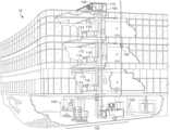
- FIG. 1is a drawing of a building equipped with a HVAC system, according to some embodiments.
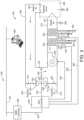
- FIG. 2is a block diagram of a waterside system that may be used in conjunction with the building of FIG. 1 , according to some embodiments.
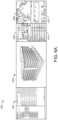
- FIG. 3is a block diagram of an airside system that may be used in conjunction with the building of FIG. 1 , according to some embodiments.
- FIG. 4is a block diagram of a building management system (BMS) that may be used to monitor and/or control the building of FIG. 1 , according to some embodiments.
- BMSbuilding management system
- FIG. 5 Ais a block diagram of a system for command and control of a site or building, according to some embodiments.
- FIG. 5 Bis a block diagram of a command and control tool implemented in the system of FIG. 5 A , according to some embodiments.
- FIGS. 6 A- 6 Care example interfaces generated and presented by the command and control tool, according to some embodiments.
- FIG. 7is a process for implementing a building or site model in a command and control interface, according to some embodiments.
- FIG. 8is a process for generating an incident from a site model, according to some embodiments.
- FIGS. 9 A- 9 Dare example command and control interfaces for viewing site models and creating incidents, according to some embodiments.
- the site command and control toolmay be configured to generate a command and control dashboard (i.e., user interface) that presents a wide variety of operating data and event data relating to equipment and spaces of a site, within a single interface.
- a command and control dashboardcould present aggregate energy usage data, operating statuses, occupancy levels, alarm or event information, security data, etc., for an entire site in a single, intuitive interface.
- a command and control dashboardcan provide a “one-stop shop” for users to monitor, command, and/or control the various systems, equipment, and spaces of a site.
- the site command and control toolcan generate a dynamic user interface that includes one or more model viewers for presenting 2-dimensional (2D) and/or 3-dimensional (3D) models of a site or building.
- a user interfaceincludes both a 2D and a 3D model viewer for presenting two models simultaneously.
- the usercan determine where an object shown in the 3D model is located in a floorplan (e.g., a 2D model) of a building.
- a usermay also be able to generate incidents within the 2D or 3D model viewers, such as by selecting an object within a model. This may reduce the amount of user interaction required to identify or select a particular space or equipment when creating an incident, and may provide a more intuitive incident response. Additional features and advantages of the present disclosure are described in greater detail below.
- HVAC system 100can include a plurality of HVAC devices (e.g., heaters, chillers, air handling units, pumps, fans, thermal energy storage, etc.) configured to provide heating, cooling, ventilation, or other services for building 10 .
- HVAC system 100is shown to include a waterside system 120 and an airside system 130 .
- Waterside system 120can provide a heated or chilled fluid to an air handling unit of airside system 130 .
- Airside system 130can use the heated or chilled fluid to heat or cool an airflow provided to building 10 .
- An exemplary waterside system and airside system which can be used in HVAC system 100are described in greater detail with reference to FIGS. 2 - 3 .
- HVAC system 100is shown to include a chiller 102 , a boiler 104 , and a rooftop air handling unit (AHU) 106 .
- Waterside system 120can use boiler 104 and chiller 102 to heat or cool a working fluid (e.g., water, glycol, etc.) and can circulate the working fluid to AHU 106 .
- the HVAC devices of waterside system 120can be located in or around building 10 (as shown in FIG. 1 ) or at an offsite location such as a central plant (e.g., a chiller plant, a steam plant, a heat plant, etc.).
- the working fluidcan be heated in boiler 104 or cooled in chiller 102 , depending on whether heating or cooling is required in building 10 .
- Boiler 104can add heat to the circulated fluid, for example, by burning a combustible material (e.g., natural gas) or using an electric heating element.
- Chiller 102can place the circulated fluid in a heat exchange relationship with another fluid (e.g., a refrigerant) in a heat exchanger (e.g., an evaporator) to absorb heat from the circulated fluid.
- the working fluid from chiller 102 and/or boiler 104can be transported to AHU 106 via piping 108 .
- Airside system 130can deliver the airflow supplied by AHU 106 (i.e., the supply airflow) to building 10 via air supply ducts 112 and can provide return air from building 10 to AHU 106 via air return ducts 114 .
- airside system 130includes multiple variable air volume (VAV) units 116 .
- VAVvariable air volume
- airside system 130is shown to include a separate VAV unit 116 on each floor or zone of building 10 .
- VAV units 116can include dampers or other flow control elements that can be operated to control an amount of the supply airflow provided to individual zones of building 10 .
- airside system 130delivers the supply airflow into one or more zones of building 10 (e.g., via supply ducts 112 ) without using intermediate VAV units 116 or other flow control elements.
- AHU 106can include various sensors (e.g., temperature sensors, pressure sensors, etc.) configured to measure attributes of the supply airflow.
- AHU 106can receive input from sensors located within AHU 106 and/or within the building zone and can adjust the flow rate, temperature, or other attributes of the supply airflow through AHU 106 to achieve setpoint conditions for the building zone.
- waterside system 200is shown as a central plant having a plurality of subplants 202 - 212 .
- Subplants 202 - 212are shown to include a heater subplant 202 , a heat recovery chiller subplant 204 , a chiller subplant 206 , a cooling tower subplant 208 , a hot thermal energy storage (TES) subplant 210 , and a cold thermal energy storage (TES) subplant 212 .
- Subplants 202 - 212consume resources (e.g., water, natural gas, electricity, etc.) from utilities to serve the thermal energy loads (e.g., hot water, cold water, heating, cooling, etc.) of a building or campus.
- resourcese.g., water, natural gas, electricity, etc.
- heater subplant 202may be configured to heat water in a hot water loop 214 that circulates the hot water between heater subplant 202 and building 10 .
- Chiller subplant 206may be configured to chill water in a cold water loop 216 that circulates the cold water between chiller subplant 206 building 10 .
- Heat recovery chiller subplant 204may be configured to transfer heat from cold water loop 216 to hot water loop 214 to provide additional heating for the hot water and additional cooling for the cold water.
- Condenser water loop 218may absorb heat from the cold water in chiller subplant 206 and reject the absorbed heat in cooling tower subplant 208 or transfer the absorbed heat to hot water loop 214 .
- Hot TES subplant 210 and cold TES subplant 212may store hot and cold thermal energy, respectively, for subsequent use.
- Hot water loop 214 and cold water loop 216may deliver the heated and/or chilled water to air handlers located on the rooftop of building 10 (e.g., AHU 106 ) or to individual floors or zones of building 10 (e.g., VAV units 116 ).
- the air handlerspush air past heat exchangers (e.g., heating coils or cooling coils) through which the water flows to provide heating or cooling for the air.
- the heated or cooled airmay be delivered to individual zones of building 10 to serve the thermal energy loads of building 10 .
- the waterthen returns to subplants 202 - 212 to receive further heating or cooling.
- subplants 202 - 212are shown and described as heating and cooling water for circulation to a building, it is understood that any other type of working fluid (e.g., glycol, CO2, etc.) may be used in place of or in addition to water to serve the thermal energy loads. In other embodiments, subplants 202 - 212 may provide heating and/or cooling directly to the building or campus without requiring an intermediate heat transfer fluid. These and other variations to waterside system 200 are within the teachings of the present invention.
- working fluide.g., glycol, CO2, etc.
- Each of subplants 202 - 212may include a variety of equipment configured to facilitate the functions of the subplant.
- heater subplant 202is shown to include a plurality of heating elements 220 (e.g., boilers, electric heaters, etc.) configured to add heat to the hot water in hot water loop 214 .
- Heater subplant 202is also shown to include several pumps 222 and 224 configured to circulate the hot water in hot water loop 214 and to control the flow rate of the hot water through individual heating elements 220 .
- Chiller subplant 206is shown to include a plurality of chillers 232 configured to remove heat from the cold water in cold water loop 216 .
- Chiller subplant 206is also shown to include several pumps 234 and 236 configured to circulate the cold water in cold water loop 216 and to control the flow rate of the cold water through individual chillers 232 .
- Heat recovery chiller subplant 204is shown to include a plurality of heat recovery heat exchangers 226 (e.g., refrigeration circuits) configured to transfer heat from cold water loop 216 to hot water loop 214 .
- Heat recovery chiller subplant 204is also shown to include several pumps 228 and 230 configured to circulate the hot water and/or cold water through heat recovery heat exchangers 226 and to control the flow rate of the water through individual heat recovery heat exchangers 226 .
- Cooling tower subplant 208is shown to include a plurality of cooling towers 238 configured to remove heat from the condenser water in condenser water loop 218 .
- Cooling tower subplant 208is also shown to include several pumps 240 configured to circulate the condenser water in condenser water loop 218 and to control the flow rate of the condenser water through individual cooling towers 238 .
- Hot TES subplant 210is shown to include a hot TES tank 242 configured to store the hot water for later use. Hot TES subplant 210 may also include one or more pumps or valves configured to control the flow rate of the hot water into or out of hot TES tank 242 .
- Cold TES subplant 212is shown to include cold TES tanks 244 configured to store the cold water for later use. Cold TES subplant 212 may also include one or more pumps or valves configured to control the flow rate of the cold water into or out of cold TES tanks 244 .
- one or more of the pumps in waterside system 200(e.g., pumps 222 , 224 , 228 , 230 , 234 , 236 , and/or 240 ) or pipelines in waterside system 200 include an isolation valve associated therewith. Isolation valves may be integrated with the pumps or positioned upstream or downstream of the pumps to control the fluid flows in waterside system 200 .
- waterside system 200may include more, fewer, or different types of devices and/or subplants based on the particular configuration of waterside system 200 and the types of loads served by waterside system 200 .
- airside system 300may supplement or replace airside system 130 in HVAC system 100 or may be implemented separate from HVAC system 100 .
- airside system 300may include a subset of the HVAC devices in HVAC system 100 (e.g., AHU 106 , VAV units 116 , ducts 112 - 114 , fans, dampers, etc.) and may be located in or around building 10 .
- Airside system 300may operate to heat or cool an airflow provided to building 10 using a heated or chilled fluid provided by waterside system 200 .
- Each of dampers 316 - 320may be operated by an actuator.
- exhaust air damper 316may be operated by actuator 324
- mixing damper 318may be operated by actuator 326
- outside air damper 320may be operated by actuator 328 .
- Actuators 324 - 328may communicate with an AHU controller 330 via a communications link 332 .
- Actuators 324 - 328may receive control signals from AHU controller 330 and may provide feedback signals to AHU controller 330 .
- Feedback signalsmay include, for example, an indication of a current actuator or damper position, an amount of torque or force exerted by the actuator, diagnostic information (e.g., results of diagnostic tests performed by actuators 324 - 328 ), status information, commissioning information, configuration settings, calibration data, and/or other types of information or data that may be collected, stored, or used by actuators 324 - 328 .
- diagnostic informatione.g., results of diagnostic tests performed by actuators 324 - 328
- status informatione.g., commissioning information, configuration settings, calibration data, and/or other types of information or data that may be collected, stored, or used by actuators 324 - 328 .
- AHU controller 330may be an economizer controller configured to use one or more control algorithms (e.g., state-based algorithms, extremum seeking control (ESC) algorithms, proportional-integral (PI) control algorithms, proportional-integral-derivative (PID) control algorithms, model predictive control (MPC) algorithms, feedback control algorithms, etc.) to control actuators 324 - 328 .
- control algorithmse.g., state-based algorithms, extremum seeking control (ESC) algorithms, proportional-integral (PI) control algorithms, proportional-integral-derivative (PID) control algorithms, model predictive control (MPC) algorithms, feedback control algorithms, etc.
- AHU 302is shown to include a cooling coil 334 , a heating coil 336 , and a fan 338 positioned within supply air duct 312 .
- Fan 338may be configured to force supply air 310 through cooling coil 334 and/or heating coil 336 and provide supply air 310 to building zone 306 .
- AHU controller 330may communicate with fan 338 via communications link 340 to control a flow rate of supply air 310 .
- AHU controller 330controls an amount of heating or cooling applied to supply air 310 by modulating a speed of fan 338 .
- Cooling coil 334may receive a chilled fluid from waterside system 200 (e.g., from cold water loop 216 ) via piping 342 and may return the chilled fluid to waterside system 200 via piping 344 .
- Valve 346may be positioned along piping 342 or piping 344 to control a flow rate of the chilled fluid through cooling coil 334 .
- cooling coil 334includes multiple stages of cooling coils that can be independently activated and deactivated (e.g., by AHU controller 330 , by BMS controller 366 , etc.) to modulate an amount of cooling applied to supply air 310 .
- Heating coil 336may receive a heated fluid from waterside system 200 (e.g., from hot water loop 214 ) via piping 348 and may return the heated fluid to waterside system 200 via piping 350 .
- Valve 352may be positioned along piping 348 or piping 350 to control a flow rate of the heated fluid through heating coil 336 .
- heating coil 336includes multiple stages of heating coils that can be independently activated and deactivated (e.g., by AHU controller 330 , by BMS controller 366 , etc.) to modulate an amount of heating applied to supply air 310 .
- valves 346 and 352may be controlled by an actuator.
- valve 346may be controlled by actuator 354 and valve 352 may be controlled by actuator 356 .
- Actuators 354 - 356may communicate with AHU controller 330 via communications links 358 - 360 .
- Actuators 354 - 356may receive control signals from AHU controller 330 and may provide feedback signals to AHU controller 330 .
- AHU controller 330receives a measurement of the supply air temperature from a temperature sensor 362 positioned in supply air duct 312 (e.g., downstream of cooling coil 334 and/or heating coil 336 ).
- AHU controller 330may also receive a measurement of the temperature of building zone 306 from a temperature sensor 364 located in building zone 306 .
- AHU controller 330operates valves 346 and 352 via actuators 354 - 356 to modulate an amount of heating or cooling provided to supply air 310 (e.g., to achieve a setpoint temperature for supply air 310 or to maintain the temperature of supply air 310 within a setpoint temperature range).
- the positions of valves 346 and 352affect the amount of heating or cooling provided to supply air 310 by cooling coil 334 or heating coil 336 and may correlate with the amount of energy consumed to achieve a desired supply air temperature.
- AHU controller 330may control the temperature of supply air 310 and/or building zone 306 by activating or deactivating coils 334 - 336 , adjusting a speed of fan 338 , or a combination of both.
- airside system 300is shown to include a building automation system (BMS) controller 366 and a client device 368 .
- BMS controller 366may include one or more computer systems (e.g., servers, supervisory controllers, subsystem controllers, etc.) that serve as system level controllers, application or data servers, head nodes, or master controllers for airside system 300 , waterside system 200 , HVAC system 100 , and/or other controllable systems that serve building 10 .
- computer systemse.g., servers, supervisory controllers, subsystem controllers, etc.
- application or data serverse.g., application or data servers, head nodes, or master controllers for airside system 300 , waterside system 200 , HVAC system 100 , and/or other controllable systems that serve building 10 .
- BMS controller 366may communicate with multiple downstream building systems or subsystems (e.g., HVAC system 100 , a security system, a lighting system, waterside system 200 , etc.) via a communications link 370 according to like or disparate protocols (e.g., LON, BACnet, etc.).
- AHU controller 330 and BMS controller 366may be separate (as shown in FIG. 3 ) or integrated.
- AHU controller 330may be a software module configured for execution by a processor of BMS controller 366 .
- AHU controller 330receives information from BMS controller 366 (e.g., commands, setpoints, operating boundaries, etc.) and provides information to BMS controller 366 (e.g., temperature measurements, valve or actuator positions, operating statuses, diagnostics, etc.). For example, AHU controller 330 may provide BMS controller 366 with temperature measurements from temperature sensors 362 - 364 , equipment on/off states, equipment operating capacities, and/or any other information that can be used by BMS controller 366 to monitor or control a variable state or condition within building zone 306 .
- BMS controller 366e.g., commands, setpoints, operating boundaries, etc.
- BMS controller 366e.g., temperature measurements, valve or actuator positions, operating statuses, diagnostics, etc.
- AHU controller 330may provide BMS controller 366 with temperature measurements from temperature sensors 362 - 364 , equipment on/off states, equipment operating capacities, and/or any other information that can be used by BMS controller 366 to monitor or control a variable
- Client device 368may include one or more human-machine interfaces or client interfaces (e.g., graphical user interfaces, reporting interfaces, text-based computer interfaces, client-facing web services, web servers that provide pages to web clients, etc.) for controlling, viewing, or otherwise interacting with HVAC system 100 , its subsystems, and/or devices.
- Client device 368may be a computer workstation, a client terminal, a remote or local interface, or any other type of user interface device.
- Client device 368may be a stationary terminal or a mobile device.
- client device 368may be a desktop computer, a computer server with a user interface, a laptop computer, a tablet, a smartphone, a PDA, or any other type of mobile or non-mobile device.
- Client device 368may communicate with BMS controller 366 and/or AHU controller 330 via communications link 372 .
- BMS 400may be implemented in building 10 to automatically monitor and control various building functions.
- BMS 400is shown to include BMS controller 366 and a plurality of building subsystems 428 .
- Building subsystems 428are shown to include a building electrical subsystem 434 , an information communication technology (ICT) subsystem 436 , a security subsystem 438 , a HVAC subsystem 440 , a lighting subsystem 442 , a lift/escalators subsystem 432 , and a fire safety subsystem 430 .
- building subsystems 428can include fewer, additional, or alternative subsystems.
- building subsystems 428may also or alternatively include a refrigeration subsystem, an advertising or signage subsystem, a cooking subsystem, a vending subsystem, a printer or copy service subsystem, or any other type of building subsystem that uses controllable equipment and/or sensors to monitor or control building 10 .
- building subsystems 428include waterside system 200 and/or airside system 300 , as described with reference to FIGS. 2 - 3 .
- HVAC subsystem 440may include many of the same components as HVAC system 100 , as described with reference to FIGS. 1 - 3 .
- HVAC subsystem 440may include a chiller, a boiler, any number of air handling units, economizers, field controllers, supervisory controllers, actuators, temperature sensors, and other devices for controlling the temperature, humidity, airflow, or other variable conditions within building 10 .
- Lighting subsystem 442may include any number of light fixtures, ballasts, lighting sensors, dimmers, or other devices configured to controllably adjust the amount of light provided to a building space.
- Security subsystem 438may include occupancy sensors, video surveillance cameras, digital video recorders, video processing servers, intrusion detection devices, access control devices and servers, or other security-related devices.
- BMS controller 366is shown to include a communications interface 407 and a BMS interface 409 .
- Interface 407may facilitate communications between BMS controller 366 and external applications (e.g., monitoring and reporting applications 422 , enterprise control applications 426 , remote systems and applications 444 , applications residing on client devices 448 , etc.) for allowing user control, monitoring, and adjustment to BMS controller 366 and/or subsystems 428 .
- Interface 407may also facilitate communications between BMS controller 366 and client devices 448 .
- BMS interface 409may facilitate communications between BMS controller 366 and building subsystems 428 (e.g., HVAC, lighting security, lifts, power distribution, business, etc.).
- Interfaces 407 , 409can be or include wired or wireless communications interfaces (e.g., jacks, antennas, transmitters, receivers, transceivers, wire terminals, etc.) for conducting data communications with building subsystems 428 or other external systems or devices.
- communications via interfaces 407 , 409may be direct (e.g., local wired or wireless communications) or via a communications network 446 (e.g., a WAN, the Internet, a cellular network, etc.).
- interfaces 407 , 409can include an Ethernet card and port for sending and receiving data via an Ethernet-based communications link or network.
- interfaces 407 , 409can include a WiFi transceiver for communicating via a wireless communications network.
- one or both of interfaces 407 , 409may include cellular or mobile phone communications transceivers.
- communications interface 407is a power line communications interface and BMS interface 409 is an Ethernet interface.
- both communications interface 407 and BMS interface 409are Ethernet interfaces or are the same Ethernet interface.
- BMS controller 366is shown to include a processing circuit 404 including a processor 406 and memory 408 .
- Processing circuit 404may be communicably connected to BMS interface 409 and/or communications interface 407 such that processing circuit 404 and the various components thereof can send and receive data via interfaces 407 , 409 .
- Processor 406can be implemented as a general purpose processor, an application specific integrated circuit (ASIC), one or more field programmable gate arrays (FPGAs), a group of processing components, or other suitable electronic processing components.
- ASICapplication specific integrated circuit
- FPGAsfield programmable gate arrays
- Memory 408may include one or more devices (e.g., RAM, ROM, Flash memory, hard disk storage, etc.) for storing data and/or computer code for completing or facilitating the various processes, layers and modules described in the present application.
- Memory 408may be or include volatile memory or non-volatile memory.
- Memory 408may include database components, object code components, script components, or any other type of information structure for supporting the various activities and information structures described in the present application.
- memory 408is communicably connected to processor 406 via processing circuit 404 and includes computer code for executing (e.g., by processing circuit 404 and/or processor 406 ) one or more processes described herein.
- BMS controller 366is implemented within a single computer (e.g., one server, one housing, etc.). In various other embodiments BMS controller 366 may be distributed across multiple servers or computers (e.g., that can exist in distributed locations). Further, while FIG. 4 shows applications 422 and 426 as existing outside of BMS controller 366 , in some embodiments, applications 422 and 426 may be hosted within BMS controller 366 (e.g., within memory 408 ).
- memory 408is shown to include an enterprise integration layer 410 , an automated measurement and validation (AM&V) layer 412 , a demand response (DR) layer 414 , a fault detection and diagnostics (FDD) layer 416 , an integrated control layer 418 , and a building subsystem integration later 420 .
- Layers 410 - 420may be configured to receive inputs from building subsystems 428 and other data sources, determine optimal control actions for building subsystems 428 based on the inputs, generate control signals based on the optimal control actions, and provide the generated control signals to building subsystems 428 .
- the following paragraphsdescribe some of the general functions performed by each of layers 410 - 420 in BMS 400 .
- Enterprise integration layer 410may be configured to serve clients or local applications with information and services to support a variety of enterprise-level applications.
- enterprise control applications 426may be configured to provide subsystem-spanning control to a graphical user interface (GUI) or to any number of enterprise-level business applications (e.g., accounting systems, user identification systems, etc.).
- GUIgraphical user interface
- Enterprise control applications 426may also or alternatively be configured to provide configuration GUIs for configuring BMS controller 366 .
- enterprise control applications 426can work with layers 410 - 420 to optimize building performance (e.g., efficiency, energy use, comfort, or safety) based on inputs received at interface 407 and/or BMS interface 409 .
- Building subsystem integration layer 420may be configured to manage communications between BMS controller 366 and building subsystems 428 .
- building subsystem integration layer 420may receive sensor data and input signals from building subsystems 428 and provide output data and control signals to building subsystems 428 .
- Building subsystem integration layer 420may also be configured to manage communications between building subsystems 428 .
- Building subsystem integration layer 420translate communications (e.g., sensor data, input signals, output signals, etc.) across a plurality of multi-vendor/multi-protocol systems.
- Demand response layer 414may be configured to optimize resource usage (e.g., electricity use, natural gas use, water use, etc.) and/or the monetary cost of such resource usage in response to satisfy the demand of building 10 .
- the optimizationmay be based on time-of-use prices, curtailment signals, energy availability, or other data received from utility providers, distributed energy generation systems 424 , from energy storage 427 (e.g., hot TES 242 , cold TES 244 , etc.), or from other sources.
- Demand response layer 414may receive inputs from other layers of BMS controller 366 (e.g., building subsystem integration layer 420 , integrated control layer 418 , etc.).
- the inputs received from other layersmay include environmental or sensor inputs such as temperature, carbon dioxide levels, relative humidity levels, air quality sensor outputs, occupancy sensor outputs, room schedules, and the like.
- the inputsmay also include inputs such as electrical use (e.g., expressed in kWh), thermal load measurements, pricing information, projected pricing, smoothed pricing, curtailment signals from utilities, and the like.
- demand response layer 414includes control logic for responding to the data and signals it receives. These responses can include communicating with the control algorithms in integrated control layer 418 , changing control strategies, changing setpoints, or activating/deactivating building equipment or subsystems in a controlled manner. Demand response layer 414 may also include control logic configured to determine when to utilize stored energy. For example, demand response layer 414 may determine to begin using energy from energy storage 427 just prior to the beginning of a peak use hour.
- demand response layer 414includes a control module configured to actively initiate control actions (e.g., automatically changing setpoints) which minimize energy costs based on one or more inputs representative of or based on demand (e.g., price, a curtailment signal, a demand level, etc.).
- demand response layer 414uses equipment models to determine an optimal set of control actions.
- the equipment modelsmay include, for example, thermodynamic models describing the inputs, outputs, and/or functions performed by various sets of building equipment.
- Equipment modelsmay represent collections of building equipment (e.g., subplants, chiller arrays, etc.) or individual devices (e.g., individual chillers, heaters, pumps, etc.).
- Demand response layer 414may further include or draw upon one or more demand response policy definitions (e.g., databases, XML files, etc.).
- the policy definitionsmay be edited or adjusted by a user (e.g., via a graphical user interface) so that the control actions initiated in response to demand inputs may be tailored for the user's application, desired comfort level, particular building equipment, or based on other concerns.
- the demand response policy definitionscan specify which equipment may be turned on or off in response to particular demand inputs, how long a system or piece of equipment should be turned off, what setpoints can be changed, what the allowable set point adjustment range is, how long to hold a high demand setpoint before returning to a normally scheduled setpoint, how close to approach capacity limits, which equipment modes to utilize, the energy transfer rates (e.g., the maximum rate, an alarm rate, other rate boundary information, etc.) into and out of energy storage devices (e.g., thermal storage tanks, battery banks, etc.), and when to dispatch on-site generation of energy (e.g., via fuel cells, a motor generator set, etc.).
- the energy transfer ratese.g., the maximum rate, an alarm rate, other rate boundary information, etc.
- energy storage devicese.g., thermal storage tanks, battery banks, etc.
- dispatch on-site generation of energye.g., via fuel cells, a motor generator set, etc.
- Integrated control layer 418may be configured to use the data input or output of building subsystem integration layer 420 and/or demand response later 414 to make control decisions. Due to the subsystem integration provided by building subsystem integration layer 420 , integrated control layer 418 can integrate control activities of the subsystems 428 such that the subsystems 428 behave as a single integrated super-system. In an exemplary embodiment, integrated control layer 418 includes control logic that uses inputs and outputs from a plurality of building subsystems to provide greater comfort and energy savings relative to the comfort and energy savings that separate subsystems could provide alone. For example, integrated control layer 418 may be configured to use an input from a first subsystem to make an energy-saving control decision for a second subsystem. Results of these decisions can be communicated back to building subsystem integration layer 420 .
- Integrated control layer 418is shown to be logically below demand response layer 414 .
- Integrated control layer 418may be configured to enhance the effectiveness of demand response layer 414 by enabling building subsystems 428 and their respective control loops to be controlled in coordination with demand response layer 414 .
- This configurationmay advantageously reduce disruptive demand response behavior relative to conventional systems.
- integrated control layer 418may be configured to assure that a demand response-driven upward adjustment to the setpoint for chilled water temperature (or another component that directly or indirectly affects temperature) does not result in an increase in fan energy (or other energy used to cool a space) that would result in greater total building energy use than was saved at the chiller.
- Integrated control layer 418may be configured to provide feedback to demand response layer 414 so that demand response layer 414 checks that constraints (e.g., temperature, lighting levels, etc.) are properly maintained even while demanded load shedding is in progress.
- the constraintsmay also include setpoint or sensed boundaries relating to safety, equipment operating limits and performance, comfort, fire codes, electrical codes, energy codes, and the like.
- Integrated control layer 418is also logically below fault detection and diagnostics layer 416 and automated measurement and validation layer 412 .
- Integrated control layer 418may be configured to provide calculated inputs (e.g., aggregations) to these higher levels based on outputs from more than one building subsystem.
- Automated measurement and validation (AM&V) layer 412may be configured to verify that control strategies commanded by integrated control layer 418 or demand response layer 414 are working properly (e.g., using data aggregated by AM&V layer 412 , integrated control layer 418 , building subsystem integration layer 420 , FDD layer 416 , or otherwise).
- the calculations made by AM&V layer 412may be based on building system energy models and/or equipment models for individual BMS devices or subsystems. For example, AM&V layer 412 may compare a model-predicted output with an actual output from building subsystems 428 to determine an accuracy of the model.
- FDD layer 416may be configured to provide on-going fault detection for building subsystems 428 , building subsystem devices (i.e., building equipment), and control algorithms used by demand response layer 414 and integrated control layer 418 .
- FDD layer 416may receive data inputs from integrated control layer 418 , directly from one or more building subsystems or devices, or from another data source.
- FDD layer 416may automatically diagnose and respond to detected faults. The responses to detected or diagnosed faults may include providing an alert message to a user, a maintenance scheduling system, or a control algorithm configured to attempt to repair the fault or to work-around the fault.
- FDD layer 416may be configured to output a specific identification of the faulty component or cause of the fault (e.g., loose damper linkage) using detailed subsystem inputs available at building subsystem integration layer 420 .
- FDD layer 416is configured to provide “fault” events to integrated control layer 418 which executes control strategies and policies in response to the received fault events.
- FDD layer 416(or a policy executed by an integrated control engine or business rules engine) may shut-down systems or direct control activities around faulty devices or systems to reduce energy waste, extend equipment life, or assure proper control response.
- FDD layer 416may be configured to store or access a variety of different system data stores (or data points for live data). FDD layer 416 may use some content of the data stores to identify faults at the equipment level (e.g., specific chiller, specific AHU, specific terminal unit, etc.) and other content to identify faults at component or subsystem levels.
- building subsystems 428may generate temporal (i.e., time-series) data indicating the performance of BMS 400 and the various components thereof.
- the data generated by building subsystems 428may include measured or calculated values that exhibit statistical characteristics and provide information about how the corresponding system or process (e.g., a temperature control process, a flow control process, etc.) is performing in terms of error from its setpoint. These processes can be examined by FDD layer 416 to expose when the system begins to degrade in performance and alert a user to repair the fault before it becomes more severe.
- System 500may provide a high-level overview of the operations of various building or site equipment, and may allow a user to manage a variety of subsystems and equipment from a single device or interface. In some embodiments, described in detail below, system 500 provides intuitive and user-friendly interfaces that allow a user to monitor, command, and/or control these subsystems and equipment. It will be appreciated that, as discussed herein, system 500 may be implemented in in sort of location or structure that includes one or more devices or subsystems. For example, system 500 can be implemented for a sports arena, a hospital, a campus, etc. Accordingly, while “site” and “building” are used herein, these terms are not intended to be limiting.
- system 500also allows a user to quickly and efficiently respond to events or incidents that may affect site equipment and spaces.
- a usere.g., a building manager
- the usercould determine what device (e.g., an alarm panel, a sensor, etc.) is experiencing the fire alarm event (e.g., has detected a fire), and may initiate a response procedure to deal with the fire alarm.
- System 500is shown to include a server 502 communicably coupled to network 446 . While shown as a single component (e.g., a remote server or computing device), server 502 may also be implemented across multiple servers (e.g., via a distributed computing architecture).
- Server 502generally includes a processor and memory for storing and executing instructions. Similar to BMS controller 366 , the memory of server 502 may include one or more devices (e.g., RAM, ROM, Flash memory, hard disk storage, etc.) for storing data and/or computer code for completing or facilitating the various processes, layers and modules described in the present application.
- the memorymay be or include volatile memory or non-volatile memory and may include database components, object code components, script components, or any other type of information structure for supporting the various activities and information structures described in the present application.
- System 500is also shown to include one or more user devices 501 that are communicably coupled to network 446 .
- user devices 501may be connected to network 446 via an intranet or via the Internet, either via a wired connection or a wireless connection.
- Examples of user devices 501include, but are not limited to, mobile phones, electronic tablets, laptops, desktop computers, workstations, and other types of electronic devices. More generally, user devices 501 may include any electronic device that allows a user to interact with system 500 (e.g., through a user interface). Accordingly, each of user devices 501 can include an input device (e.g., a keyboard) and an output device (e.g., a screen).
- an input devicee.g., a keyboard
- an output devicee.g., a screen
- System 500is further shown to include a command and control tool 504 .
- Command and control tool 504may aggregate data from multiple subsystems, devices, and/or spaces of a site, may generate dynamic and intuitive user interfaces for monitor and/or controlling said subsystems, devices, and/or spaces, and may initiate automated response processes based on detected incidents.
- command and control tool 504may include and/or integrate with one or more additional platforms or services such as a workflow automation platform, a collaboration platform, and an active directory.
- command and control tool 504allows for easy integration of third party services and components to increase functionality.
- command and control tool 504is implemented via a dedicated computer or computing device that includes a processor and memory.
- command and control tool 504may be implemented via a user device such as user device 448 .
- command and control tool 504is implemented at least partially via BMS controller 366 (e.g., within memory 408 ) or server 502 .
- command and control tool 504may be implemented by a separate or dedicated computer, or may be implemented at least partially by server 502 .
- the functionality of command and control tool 504is implemented jointly by BMS controller 366 and server 502 , via network 446 .
- command and control tool 504may be implemented on one or more workstations, such as workstation 503 or 505 .
- Workstations 503 and 505can include one or more computing devices (e.g., including processors and memory), and in some cases can include multiple user interface (e.g., monitors).
- workstation 503may be a central command workstation that includes at least three monitors for viewing large amounts of information.
- workstation 503 and 505represent groups of workstations (e.g., groups of individual computing devices) organized together based on one or more parameters. For example, a group of computing devices or user interfaces may be organized into a group based on a role or a location of the user's operating said devices.
- command and control tool 504is implemented in a server, multiple servers (e.g. via a distributed computing architecture), a cloud computing platform, a controller, via microservices located across multiple computing devices, and/or on (or distributed across) any other computing device or system.
- command and control tool 504is implemented via a processing circuit (e.g., a memory and/or a processor) and/or implemented across multiple processing circuits (e.g., multiple memories and/or processors).
- command and control tool 504may be communicably coupled to any number of building systems 506 - 510 .
- Systems 506 - 510may include any of the building systems and subsystems previously described with respect to FIG. 4 , for example, including building electrical subsystem 434 , ICT subsystem 436 , security subsystem 438 , HVAC subsystem 440 , lighting subsystem 442 , lift/escalators subsystem 432 , fire safety subsystem 430 , or any other system/subsystem associated with a building or site monitored by command and control tool 504 .
- command and control tool 504is communicably coupled to systems 506 - 510 through BMS controller 366 .
- systems 506 - 510may be coupled to one or more subsystems, such as subsystems 512 and 514 (e.g., “Subsystem A” and “Subsystem B,” respectively).
- Subsystems 512 and 514may be any system controlled and/or monitored by one of the higher-level systems 506 - 510 .
- subsystems 512 and 514may also include any of building electrical subsystem 434 , ICT subsystem 436 , security subsystem 438 , HVAC subsystem 440 , lighting subsystem 442 , lift/escalators subsystem 432 , fire safety subsystem 430 , or may include smaller subsets of building equipment.
- Each of systems 506 - 510 and/or subsystems 512 and 514is connected to a plurality of equipment, shown as equipment 516 - 530 .
- equipment 516 - 530For example, if subsystem 512 is an HVAC subsystem including an HVAC controller or other central controller, then each of equipment 516 and equipment 518 may include any type of HVAC device (e.g., a VAV, an AHU, etc.).
- each of systems 506 - 510 and/or subsystems 512 and 514may include a controller or other computing device that aggregates data received from corresponding equipment 516 - 530 .
- each of systems 506 - 510 and/or subsystems 512 and 514may receive and aggregate data from any corresponding equipment regarding the operation of the equipment.
- higher-level systemse.g., system 506
- system 506may be configured to receive and aggregate data from subsystems 512 and 514 .
- equipment 524 and 526may be fire alarm, sensors, or alarm panels that transmit data such as current values, alarms, live video/audio, etc., to a central controller.
- each of systems 506 - 510may receive and aggregate alarm or event data and/or operational data (e.g., sensor readings) from equipment 516 - 530 .
- an eventmay be any noteworthy indication received from any of equipment 516 - 530 .
- an eventmay be an indication that a condition (i.e., a sensor value, energy usage, etc.) is outside of a normal range.
- An eventcould range from an indication of an equipment failure, for example, to a security breach within a stadium or building.
- an eventmay indicate that a security camera is disconnected or that an area of a building is overcrowded.
- an eventmay simply indicate that one of equipment 516 - 530 changed any operating mode or a state.
- an eventmay include any number of conditions, and that the examples described herein are for exemplary purposes and are not intended to be limiting.
- Command and control tool 504may receive the aggregate alarm/event data and/or other operational data from each of systems 506 - 510 , and may further aggregate the received data for the entire system.
- command and control tool 504can utilize the aggregate data to generate an overview (e.g., a user interface) of all alarms and events for the entire system (e.g., for all of equipment 516 - 530 ), and, more generally, an overview of system operations.
- a usere.g., of user device 448 or user device(s) 501
- command and control tool 504may enrich the received data by retrieving additional information, such as from server 502 and/or another database.
- the additional informationmay include, for example, an indication of where equipment is located within a building or site, equipment/subsystem relationships, etc.
- command and control tool 504may even retrieve building information model (BIM) files or other 2D or 3D model data corresponding to the equipment.
- BIMbuilding information model
- a user of user device 448 or user device(s) 501may view the additional data for an alarm or an event to determine where the event is occurring and what equipment it is affecting, and may even view 3D models of the affected equipment, as described in detail below.
- command and control tool 504may generally obtain and aggregate operational data from a plurality of site systems, subsystems, and/or equipment (e.g., systems 506 - 510 , subsystems 512 and 514 , and/or equipment 516 - 530 ).
- Command and control tool 504may allow a user to quickly and easily respond to events by creating incidents and initiating automated response procedures.
- Command and control tool 504may also generate dynamic user interfaces to aid in site management.
- command and control tool 504generates user interfaces that include 2D and/or 3D model viewers to provide additional context/information to a user, as described in greater detail below.
- Command and control tool 504is shown to include a processing circuit 531 that includes a processor 532 and a memory 534 . It will be appreciated that these components can be implemented using a variety of different types and quantities of processors and memory.
- processor 532can be a general purpose processor, an application specific integrated circuit (ASIC), one or more field programmable gate arrays (FPGAs), a group of processing components, or other suitable electronic processing components.
- ASICapplication specific integrated circuit
- FPGAsfield programmable gate arrays
- Processor 532can be communicatively coupled to memory 534 . While processing circuit 531 is shown as including one processor 532 and one memory 534 , it should be understood that, as discussed herein, a processing circuit and/or memory may be implemented using multiple processors and/or memories in various embodiments. All such implementations are contemplated within the scope of the present disclosure.
- Memory 534can include one or more devices (e.g., memory units, memory devices, storage devices, etc.) for storing data and/or computer code for completing and/or facilitating the various processes described in the present disclosure.
- Memory 534can include random access memory (RAM), read-only memory (ROM), hard drive storage, temporary storage, non-volatile memory, flash memory, optical memory, or any other suitable memory for storing software objects and/or computer instructions.
- Memory 534can include database components, object code components, script components, or any other type of information structure for supporting the various activities and information structures described in the present disclosure.
- Memory 534can be communicably connected to processor 532 via processing circuit 531 and can include computer code for executing (e.g., by processor 532 ) one or more processes described herein.
- Incident response tool 540may receive the aggregate alarm and event data from each of systems 506 - 510 and further aggregate the alarm and event data for the entire system. In this regard, incident response tool 540 may generate an overview of all alarms and events for the entire system (e.g., for all of equipment 516 - 530 ). A user may access then view the aggregate alarm and event data, and may choose to create an incident based on a detected event. In some embodiments, incident response tool 540 may automatically generate an incident based on an event.
- incident response tool 540may automatically or semi-automatically initiate response procedures.
- a user that is monitoring system 500e.g., via user device 448
- the usermay view a model of the equipment that reported the fire alarm event (e.g., an alarm control panel) and may determine additional information such as where the equipment is located within a building.
- the usermay validate the fire alarm, such as by viewing security camera data from a space (e.g., a hallway) near the location of the equipment or by corresponding with another user (e.g., a technician that travels to the location of the event).
- the usermay create an incident to initiate a response to the event.
- the usermay select an icon or button within a user interface to create the incident.
- an API callmay be generated to create the incident.
- selecting a “Create Incident” icon or buttonmay cause an API call to a workflow and decision automation platform.
- the workflow and decision automation platformmay handle at least a portion of the automated response process.
- the workflow and decision automation platformmay be included in incident response tool 540 or may called by incident response tool 540 to handle at least a portion of the creation of an incident.
- incident response tool 540may generate an incident and initiate automated or semi-automated response procedures.
- the response proceduresmay follow a standard operating procedure designed by a building or site manager, or by another user or group.
- the response proceduresmay follow a predetermined process based on the event type and severity.
- command and control tool 504may first retrieve a process corresponding to the event from server 502 and/or another database.
- the retrieved datamay include a list of task to be performed, a list of users designated to complete the tasks, contact information for the users, and other applicable information.
- incident response tool 540may additionally generate a meeting invitation through a communication and collaboration platform, such as a platform via which multiple users are able to meet via audio and/or video devices, share documents or other media, communicate with one another via text and/or voice, etc.
- a communication and collaboration platformsuch as a platform via which multiple users are able to meet via audio and/or video devices, share documents or other media, communicate with one another via text and/or voice, etc.
- a communication and collaboration platformsuch as a platform via which multiple users are able to meet via audio and/or video devices, share documents or other media, communicate with one another via text and/or voice, etc.
- incident response tool 540may automatically create a meeting or a calendar invite, and populate the meeting or invite with information corresponding to the event.
- the meetingmay include an indication of the type of event, a location associated with the event (e.g., a location of the equipment), an indication of the particular asset or equipment that reported the event, and any other applicable information.
- incident response tool 540may transmit or send the meeting/calendar invite to a set of users associated with the particular event type.
- incident response tool 540may call an API associated with the communication and collaboration platform to generate the meeting.
- the set of usersmay be predetermined, such as by a building manager, and may include contact information for one or more users (e.g., technicians, security guards, etc.) that have been designated as a member of a team or group for responding to a particular event.
- the set of usersmay be grouped as a team based on an active directory maintained by the building management or company. For example, a team for responding to fire alarms may be created based on a customer active directory.
- the generated teamsmay include user segmented by type (e.g., security, facility, etc.) or by space (e.g., stadium, building, etc.).
- a new team or channelmay be created corresponding to each event.
- the incident informationmay be added to the previous team/channel, such that the team members can view the new incident information in relation to information about prior incidents, which may be helpful in addressing the present incident.
- incident response tool 540may generate a meeting request that indicates at least the type of event (e.g., “Chiller Malfunction”), a location of the effected chiller, and other information about the chiller or the event, and may transmit the meeting request to a set of users associated with the HVAC subsystem.
- the meeting invitemay be sent to one or more maintenance technicians and a building manager, so that the building manager may coordinate with the technicians to fix the chiller.
- the set of users that receive the meeting invitemay be automatically determined based on the event type or affected equipment.
- the meeting requestmay include a link to a video, audio, and/or chat interface.
- a linkmay be included within the meeting invite or post that a user may select to join a virtual meeting.
- the set of users that receive the meeting invitemay join the virtual meeting and share video, audio, or text data to resolve the event.
- the usersmay share video of the equipment or space associated with the event in order to troubleshoot or resolve the event.
- the meetingmay be automatically or manually recorded.
- the meetingmay be generated in real-time or near real-time, such that the relevant users are invited to join the meeting upon receiving the invitation.
- the meetingmay be generated for a future timeframe.
- the future timeframemay be determined based on factors such as, but not limited to, the availability of the users (e.g., according to shared schedules/calendars of the users), the type of the incident, the urgency of the incident, etc.
- memory 534is also shown to include an external services interface 542 .
- Command and control tool 504may obtain data from a variety of external (i.e., remote) and/or third-party services via external services interface 542 .
- External services interface 542may obtain data from remote systems and applications 444 , for example. These external and/or third-party services can provide any sort of information that may be useful in the command and control of a site or building.
- external services interface 542receives weather data from an external weather service.
- external services interface 542receives data from an external event and risk detection service, such as Dataminr®.
- external services interface 542may receive social media data, such as live feeds or posts.
- external services interface 542may receive a feed of social media posts that relate to a football game, mention a location at or near the stadium, use a particular hashtag or keyword, etc. Though not discussed here in the interest of brevity, will be appreciated that external services interface 542 can receive any other sort of external or third-party data in addition to weather and social media data.
- Memory 534also includes a user interface generator 544 , configured to dynamically generate, modify, and/or update graphical user interfaces that present a variety of site data, such as alarm/event data, equipment operating data, space data, etc.
- user interface generator 544generates a customizable and dynamically modifiable command and control “dashboard” (i.e., user interface), that provides an overview of the various subsystems, equipment, and spaces within a site or building.
- a command and control dashboardmay be dynamically modifiable based on a number of parameters (e.g., a user's role or preferences, a site status, event detection, etc.).
- user interface generator 544can provide user-friendly and easy-to-navigate interfaces that provide the most relevant information to a user at any given time.
- An interface or dashboard generated by user interface generator 544may advantageously provide a large amount of data relating to site operations and/or events without necessarily requiring system 500 to handle all the data.
- a plurality of external or internal computing systemse.g., servers
- system 500may generate a tile-based interface through which the information from other separate applications may be displayed.
- utilizing tiles that display separate application data as described hereinleads to a more lightweight, less processing-intensive software, as it does not require the software to ingest and normalize all of the information from disparate sources, and allows for the easy integration of third-party components (e.g., applications). That said, in various implementations, system 500 could also integrate the information from other sources, and one or more of the displayed tiles may display information ingested into and/or otherwise processed by the software generating the tile-based graphical interface.
- User interface generator 544includes a tile manager 546 and a layout manager 548 .
- Tile manager 546may be configured to generate, identify, and/or obtain (e.g., from a database or a library) a plurality of “tiles” to be presented in a user interface.
- the “tiles”may be graphical elements (e.g., local or external (e.g., web-based) applications, widgets, etc.), that present information to a user.
- the tilesmay be even be separate user interfaces embedded within a command and control dashboard.
- a tilemay be an embedded application that presents weather information or social media information to a user (e.g., obtained by external services interface 542 ).
- a tilemay present operating data for one or more building devices or spaces, such as current equipment operating parameters, energy usage, etc. It will be appreciated that any number and type of tiles may be generated or otherwise obtained by tile manager 546 for display any sort of information. Accordingly, the example tiles described herein are not intended to be limiting. Example tiles generated by tile manager 546 are described in detail with respect to FIGS. 6 A- 6 C .
- Layout manager 548may be configured to generate or determine a layout for the various tiles based on any number of parameters. For example, layout manager 548 may generate or identify a layout based on a user's role or a user's preferences, the status of a site, a detected event or alarm, etc. Accordingly, layout manager 548 may dynamically generate or modify a layout as parameters of a site or building change. For example, layout manager 548 may generate a first layout when a first user logs in (e.g., to system 500 ), and may generate a second, different layout when a second user log in. As another example, layout manager 548 may adjust the layout of tiles within the interface when a site's status changes.
- Each tilemay represent a portion of a graphical user interface and may be dynamically adjusted to fit within a layout. For example, the size, shape, and/or information presented within a tile may be adjusted to correspond to a layout.
- Various example tiles and layoutsare described in greater detail below.
- Model generator 550configured to generate 2D and/or 3D models of a site and to present the 2D or 3D models via a user interface.
- model generator 550is configured to generate 2D and/or 3D site models from one or more building information models (BIMs), although it will be appreciated that site models can be generated from any sort of data file.
- BIMcan represent physical and/or functional characteristics of a building.
- a BIMmay represent structural characteristics of the building such as walls, floors, ceilings, doors, windows, etc., and/or subsystems of the building such as electrical, mechanical, HVAC, or other subsystems.
- a BIMmay represent a plurality of physical building assets including spaces and/or equipment of a building represented by the BIM.
- a BIMrepresents building components as objects (e.g., software objects).
- a BIMmay include a plurality of objects that represent physical components within the building as well as building spaces.
- Each objectmay include a collection of attributes that define the physical geometry of the object, the type of object, and/or other properties of the object.
- objects representing building spacesmay define the size and location of the building space.
- Objects representing physical componentsmay define the geometry of the physical component, the type of component (e.g., lighting fixture, air handling unit, wall, etc.), the location of the physical component, a material from which the physical component is constructed, and/or other attributes of the physical component.
- a BIMcan be viewed and manipulated using a 2D/3D modeling program (e.g., CAD software), a model viewer, a web browser, and/or any other software capable of interpreting and rendering the information contained within the BIM.
- CAD softwaree.g., CAD software
- Appropriate viewing softwaremay allow a user to view the representation of the building from any of a variety of perspectives and/or locations. For example, a user can view the BIM from a perspective within the building to see how the building would look from that location. In other words, a user can simulate the perspective of a person within the building.
- model generator 550may include a 2D or 3D modeling program, such as CAD, for generating and displaying models from BIM data.
- model generator 550obtains model files (e.g., BIM files) from a model database 552 .
- Model database 552can store model files, as well as objects and object attribute information.
- model database 552can store objects and object parameters for any of the building equipment described above with respect to FIGS. 1 - 4 .
- an objectmay be a digital representation of a physical point within a site.
- an objectmay represent a physical device, a point, or a space within a building.
- model database 552can also store object relationships, which describe how objects are related to one another.
- an equipment object representing a piece of HVAC equipmentmay be related to a space object represent a space in a building. In this example, the equipment object could “serve” the space object (i.e., the HVAC equipment could “serve” the space).
- model database 552may be or may include a graph database for storing and identifying relationships between objects.
- the graph databasemay include a plurality of space references or objects, and may also indicate one or more other objects (e.g., representing building equipment) associated with each of the spaces.
- a space object for a classroommay include a variety of HVAC, lighting, and/or IT equipment represented by objects in the graph database.
- the graph databasemay allow for quick identification of related objects in a building model.
- model database 552is a local database, hosted by command and control tool 504 .
- model database 552is an external database, hosted by a remote device (e.g., a remote server). It will be appreciated, however, that model database 552 can be implemented in any manner, and may even be implemented via both a local and a remote device.
- Interface 600may be generated by user interface generator 544 , for example, and presented via user device 448 or user device(s) 501 . Accordingly, a user may interact with interface 600 to view site data and/or to control site equipment.
- interface 600is an example of a first interface/dashboard that presents a first set of tiles in a first layout. Interface 600 may be a “default” view for a first user, for example, prior to being dynamically modified.
- Interface 600is generally shown to include a plurality of “tiles” (i.e., interfaces, widgets) that present various information regarding a site.
- the tiles shown in FIGS. 6 A- 6 Care selected and populated according to the first layout based on a user's role.
- FIG. 6 Aan overview of interface 600 is shown, according to some embodiments.
- FIG. 6 Aillustrates an example of a full command and control dashboard that may be presented across multiple user devices (e.g., multiple screens).
- interface 600provides a high-level overview of a particular site, in this example a building (“Building B”).
- FIG. 6 Ashows that interface 600 includes an events tile 602 , a model tile 604 (e.g., showing 3D model of the building), and a plurality of application interface tiles.
- FIGS. 6 A- 6 Cis for exemplary purposes only and is not intended to be limiting.
- any other suitable layout and selection of interfaces or “tiles”may be implemented.
- command and control tool 504may dynamically generate interface 600 to present one or more applications or tiles that are applicable to an identified event, based on the role or preferences of a user, based on a “status” of the site or system 500 , or based on another parameter.
- at least a portion of the tiles presented in interface 600are selected by the user.
- interface 600may be customizable based on a user's preferences, and may be dynamically updated, either by the user or by command and control tool 504 (e.g., based on an event).
- interface 600may be updated to present a particular set of tiles based on a role of the user interacting with interface 600 or logged-in to command and control tool 504 .
- changing or updating one or more tiles within interface 600may decrease a user's response time to site events (e.g., alarms, warnings, etc.) and may increase intuitiveness by presenting the most applicable or important tiles in a single interface.
- site eventse.g., alarms, warnings, etc.
- any of the tiles or interfaces described below with respect to interface 600may be changed, replaced, or moved to fit a user's preferences or a particular scenario.
- events tile 602presenting events (e.g., alarms) for a building.
- events tile 602allows a user to search events (e.g., filter by type, location, etc.) as well as select a particular event to view additional information or to create an incident, thereby initiating response procedures.
- Each event displayed within events tile 602may include a type of event (e.g., fire alarm, camera disconnected), time and date associated with the event, an equipment identifier of a piece of equipment associated with the event, and a location associated with the event.
- model tile 604Next to the events tiles is model tile 604 that allows a user to select either a 2D or 3D model (i.e., digital representation) of a building, floor, space, equipment, etc., associated with a selected site.
- a 3D model of “Building B”is presented.
- allowing a user to select between 2D and 3D viewingallows for quick identification of equipment and spaces that are near an event, while providing the user a complete view of the situation.
- a usermay select a particular event from events tile 602 , and the model presented in model tile 604 may be automatically adjusted (e.g., zoomed-in, panned, rotated, etc.) to show a part of the model corresponding to the event (e.g., a space or device).
- Model tile 604is described in greater detail below, with respect to FIGS. 7 - 9 A .
- Interface 600also includes an exemplary variety of application interface tiles (e.g., widgets) that present a wide variety of information. As described above, any of the application interface tiles may be customized, either by a user or automatically in response to the selection of an event or based on the user's role. As shown, interface 600 includes examples of a collaboration platform tile 606 , a map tile 608 , a secondary event tile 610 , and an asset health tile 612 .
- application interface tilese.g., widgets
- Collaboration platform tile 606is may provide a live view of a meeting between various users (e.g., members of an incident response team).
- collaboration platform tile 606shows a video stream from a webcam of a user (i.e., a team member), allowing multiple team members to chat (e.g., while responding to an event).
- the collaboration platform tile 606may further include the user's name and position within the company.
- Collaboration platform tile 606may also include a chat window, audio feed, or live video feed from other cameras such as security cameras.
- an on-ground usermay be able to stream video from the scene of an event via collaboration platform tile 606 .
- collaboration platform tile 606may be automatically rendered via interface 600 when a meeting is started in response to an event.
- Map tile 608provides a visual indication of the location of various events, sites, or equipment.
- map tile 608may indicate the location of various buildings (e.g., as shown by the building indicator in FIG. 6 B ) that are managed or monitored by a single user (e.g., a facilities manager, a security manager, etc.).
- map tile 608may provide an indication of where various events are occurring. For example, a first building located in a first county may be experiencing an equipment malfunction, while a second building in a second county may be experiencing a security breach. Accordingly, map tile 608 allows the user to quickly locate and respond to events across multiple sites.
- map tile 608provides an indication of where multiple buildings or sites, managed by a single user or via a single dashboard, are located.
- Secondary event tile 610may present a variety of information on various historical or current events.
- secondary event tile 610may display multiple events (e.g., fire, shooter on campus, flood, riot, demonstration, and emergency) that a user is handling simultaneously. The user may select an event from secondary event tile 610 to dynamically adjust interface 600 and switch between events. Additionally, secondary event tile 610 may indicate a time associated with each event, a location associated with each event, and a list of other users (e.g., members of a team) handling the various events.
- Asset health tile 612may provide a variety of information regarding the health or status of various assets or equipment. For example, as shown, asset health tile 612 may present current electricity consumption for a building or site (e.g., the illustrated graph shows the kilowatt-hours consumed each day over the course of a month), along with a variety of other information such as CO 2 emissions, hot water and natural gas usage, steam production, a comparison of month-to-month electricity consumption between a present month and a preceding month, etc. Additionally, asset health tile 612 may present real-time statuses of various connected devices (e.g., equipment 516 - 530 ). For example, asset health tile 612 may presented a variety of devices, organized by type, and indicate how many of each device is experiencing an event (e.g., a warning or alarm), offline, or online.
- an evente.g., a warning or alarm
- a security tile 614is shown that includes a plurality of feeds from security cameras associated with a site or building.
- a usermay customize which security camera feeds are shown in security tile 614 , or the feeds may change at a predetermined interval (e.g., every 30 seconds).
- a usermay monitor live video from anywhere around a site, such as to use the video feeds provided in security tile 614 to locate and view a space associated with an event.
- Response process tile 616illustrates a time and tasks associated with the response to an event.
- response process tile 616may include the tasks that are automatically initiated at the generation of an incident, as described above.
- response process tile 616includes a time of when various task of a response process where completed.
- a time stampfor when the task was completed and an indication of the user that marked the task complete. In this manner, a first user that is overseeing a response to an event may monitor the response status and how quickly the various tasks are completed. Additionally, collecting timestamps for each task may benefit in auditing and reporting of event responses.
- a secondary response process tile 620may be presented in addition to response process tile 616 .
- the secondary response process tile 620includes a “tasks” tab and a standard operating procedure (SOP) timeline.
- the “tasks” tabmay show various subtasks associated with an initiated SOP.
- the SOP timelineincludes a timeline of the various subtasks associated with the SOP including the time that the tasks were completed and an indication of the person who completed the task.
- 2D model tile 618is shown.
- 2D model tile 618may be presented in addition to, or in place of, model tile 604 .
- 2D model tile 618provides an aerial or overhead view (i.e., a layout) of a building or site.
- the 2D modelis a floorplan of a site.
- a usermay use 2D model tile 618 to locate an event, develop ingress or egress routes, etc.
- the usermay be presented with a complete view of a particular area of a site or building (e.g., an entire floor).
- the 2D model shown in 2D model tile 618may be presented in model tile 604 , and 2D model tile 618 may be replaced with a 3D model of the building or site.
- a dynamic risk tilemay leverage data from a dynamic risk engine (e.g., Dataminr®), which receives, correlates, and filters threat data in real time.
- the threat datais continuously scored using a model to generate a map or list of potential risks, such as active shooters, bomb threats, explosion, hate crimes, virus spread, etc.
- the overall risk for a space or equipmentis calculated based on a calculated threat rating, vulnerability rating, and cost. Accordingly a user may quickly identify potential threats or issues before they occur, and may attempt to mitigate the threat.
- interface 600may include any of a news tile, a weather tile, a social media tile, a traffic tile, etc. Accordingly, interface 600 may provide a feed of social media data received from a social media site, or may present current and forecasted weather data.
- a social media tilemay be configured to track keywords associated with a site, building, stadium, etc., to identify and respond to events (e.g., a rowdy fan, a fight, overcrowding, etc.).
- a weather tilecould be configured to track storms so that a building could be evacuated. It should be understood that, for various applications and use cases, a wide variety of different applications and corresponding tiles could be utilized, and all such implementations are contemplated within the scope of the present disclosure.
- Process 700may be implemented by system 500 , for example, and at least in part by command and control tool 504 .
- Process 700may advantageously produce intuitive and easy-to-navigate user interfaces that include 2D and/or 3D site models, in addition to aggregate site data.
- a usermay view a wide variety of information from a single interface, and may interact with various site models to navigate through a digital version of a site.
- process 700may require significantly less user interaction than other event response methods. It will be appreciated that certain steps of process 700 may be optional and, in some embodiments, process 700 may be implemented using less than all of the steps.
- a 2D and/or a 3D model of a siteis presented via a user interface.
- the model(s)are presented in a command and control dashboard (e.g., similar to interface 600 ), implemented by a user device (e.g., user devices 501 ).
- each site modelmay be presented in a separate tile in the command and control dashboard.
- a first tilemay present a 3D site model while a second tile may present a 2D site model, similar to interface 600 described above with respect to FIGS. 6 A- 6 C .
- the command and control dashboardcan present a both a 2D model and a 3D model concurrently, to provide more robust navigation.
- a 3D model tilemay be more prominent than a 2D model tile.
- the 3D model tilemay larger in size, or may be positioned near the center or another focal point of a user interface.
- the 2D model tilemay be more prominent than the 3D model tile. It will be appreciate that all such configurations of 2D and 3D model viewing tiles are contemplated herein.
- each of the modelsmay be presented with a number of navigation tools.
- a usermay interact with the navigation tools (e.g., pan, zoom, rotate, etc.) to adjust the model shown in either tile.
- the usermay simply interact directly with a model to pan, zoom, rotate, etc.
- the usermay view the model(s) on a touch screen device and may use on or more fingers to interact with the model (e.g., pinch-to-zoom, swipe left/right to rotate, etc.).
- a usermay navigate or “explore” the 2D and/or 3D models to view different objects (e.g., spaces, equipment, etc.).
- the model(s)can be generated from a BIM file, in some embodiments. Although, in other embodiments, the model(s) may be generated from any other suitable model file.
- An example of an interface including both a 2D site model and a 3D site modelis shown in FIGS. 9 A- 9 D , described in detail below.
- a first user input selecting a portion of the 2D or 3D modelis received.
- the usermay select a portion of the model(s) using the navigation tools to navigate to a particular portion or object of the model(s).
- the “portion of the model”may be a particular space, device, or point, represented by an object in the model.
- the usermay select a particular area represented in the model (e.g., a room, a floor, a space, etc.) using a navigation bar or another type of menu (e.g., the navigation menu shown in FIG. 6 A ).
- the usermay simply hover over a portion of the model (e.g., holding a pointer over the portion of the model). In any case, the portion of the model(s) or the objects being selected by the user are identified.
- a tag or other information relating to the identified portion of the modelis presented. For example, if the user hovers over a particular portion of the model, a name or an identifier of the space represented by that portion of the model (i.e., a name or identifier of a space object) may be displayed. Other information may also be presented when the user selects a portion of the model. For example, any number of parameters (e.g., stored in an object) associated with the identified portion of the model may be presented (e.g., current values for a device object, setpoints for a space object, etc.).
- parameterse.g., stored in an object
- the tag or other informationmay be presented as a pop-up or an overlay to the user interface (e.g., when the user hovers over a space in the model, the space name may pop-up in a text box near the user's cursor).
- a usermay quickly identify a name and/or other information for a portion (e.g., a space or device object) of the model, without having to navigate to a second interface.
- a second user input indicating a filter parameter for the model(s)is received.
- the filter parametermay be any sort of parameter or identifier that applies to a subset of objects within a model.
- the filter parameteris a tag defining a type of object (e.g., an HVAC object, an electrical object, “conference room” spaces, etc.) or a particular space (e.g., a particular floor or room, a particular building, etc.).
- the usermay choose to filter the model(s) to only display objects on the second floor of a building, or to only display objects associated with a security subsystem.
- the filter parametermay be entered via a selection from a menu (e.g., a drop down menu, by selecting one or more check boxes, etc.), via a text box, etc.
- the model(s)are filtered based on the second user input.
- only objects relating to the filter parameter(s)are shown within the model(s).
- any objects shown in the model relating to other floorse.g., space or equipment objects
- the usermay choose to display only HVAC equipment, in which case the model(s) may be filtered to only display a model of an HVAC subsystem of the building.
- a filter parameteris applied to only one of the 2D or 3D model.
- the usermay filter only the 3D model according to the filter parameter, while the 2D model remains unchanged. This may provide the user with additional information that may be hidden or lost if only a filtered version of the model(s), or if only one model, were presented.
- a third user inputis received.
- the third user inputmay include multiple individual user inputs to one or more navigation tools of the 2D/3D model viewers, or may otherwise include a user input that adjusts the model shown in one of the 2D or 3D model viewers.
- the usermay pan, zoom, rotate, etc., a 3D model to hone in on a particular object (e.g., a space or a device) in the model.
- the usermay navigate through the 3D model to view and/or identify a particular device object, representing a device within a building.
- Additional informationmay include object parameters that are associated with/stored in the object (e.g., in model database 552 ), and/or that are associated with a physical space or equipment associated with the object.
- object parametersmay be associated with a space object representing a room, or a capacity may be associated with a device object representing a particular device (e.g., a chiller in an HVAC system).
- the additional informationmay include stored information or information received (e.g., in real-time) from a physical space or device associated with the identified object.
- the additional informationincludes event data corresponding to the identified object.
- an eventmay be any noteworthy indication relating to any space or device of a site.
- an eventcould be an alarm condition for a building device or an indication that a setpoint for a space has been exceeded.
- Event datais described in greater detail above.
- selecting a particular object in the modelmay present event data for physical spaces or equipment associated with that object.
- event data for any objects shown in a current view of the 2D or 3D model viewersis presented.
- event data for additional objects associated with a selected objecte.g., close in proximity, part of the same subsystem, etc.
- An example of event data corresponding to a modelis described in detail below, with respect to FIG. 9 A .
- one of the modelsis updated based on a current view of the other model.
- the second modelmay be navigated/adjusted in kind.
- the 2D modelmay be updated to indicate where, in the 2D model, the particular device is located.
- the usermay navigate to a particular room in the 2D model, and the 3D model may be updated to display corresponding 3D model objects. Updating the 2D/3D model based on the other model is shown in FIGS. 9 A and 9 B , described in greater detail below.
- step 716occurs simultaneously with step 714 .
- one of step 714 or step 716may occur before the other.
- step 714may be skipped completely, and process 700 may proceed directly to step 716 from step 712 .
- adjusting the view of one model when navigating through the other modelmay provide an even more immersive and robust experience for a user. Not only does this feature provide more context to a user, but presenting and updating both models simultaneously can help a user identify and locate site objects (e.g., spaces, devices) quickly, which may be advantageous when responding to events. For example, if a fire alarm event occurs, the user may be able to quickly determine where affect equipment is located, what other equipment or spaces are nearby and may be affected, etc. This information may also enhance the planning of ingress and egress routes in an emergency, for example.
- site objectse.g., spaces, devices
- Process 800may also be implemented by system 500 , for example, and at least in part by command and control tool 504 .
- Process 800may allow a user to identify, and respond to, events within a system or site represented by a site model.
- identifying and responding to events using the site modelmay shorten response times, by allowing the user to identify necessary information more quickly.
- the usermay also be provided with more complete and/or robust event information, to aid in the response.
- process 800may require significantly less user interaction than other event response methods. It will be appreciated that certain steps of process 800 may be optional and, in some embodiments, process 800 may be implemented using less than all of the steps.
- a 2D and/or a 3D site modelis presented (e.g., via user device 501 ).
- the model(s)are presented in a command and control dashboard (e.g., similar to interface 600 ), implemented by a user device (e.g., user devices 501 ).
- each site modelmay be presented in a separate tile in the command and control dashboard.
- a first tilemay present a 3D site model while a second tile may present a 2D site model, similar to interface 600 described above with respect to FIGS. 6 A- 6 C .
- the 2D and 3D site modelmay, advantageously, be presented in a single interface.
- step 802may be similar to step 702 of process 700 .
- a first user input identifying an object within the modelis received.
- the objectmay represent a space, equipment, or point of the site.
- the usermay identify the object by selecting the object from a list or a menu (e.g., selecting a particular floor of a building from a navigation menu), by navigating to the object in one of the 2D or 3D model viewers, by selecting (e.g., clicking on) the object in one of the 2D or 3D models, or by any other means.
- the first user inputmay include multiple individual user inputs to one or more navigation tools of the 2D/3D model viewers, or may otherwise include a user input that adjusts the model shown in one of the 2D or 3D model viewers.
- step 804may also be similar to step 712 of process 700 .
- a physical space or equipment of the site, represented by the objectis identified.
- the physical space or equipmentis identified by referencing data associated with the object.
- model database 552may be queried to identify physical points associated with the object (e.g., bound to the object).
- One or more physical points, corresponding to sensors, equipment, etc.may be associated with each object of the model(s).
- data relating to the identified space or equipmentis also obtained. For example, sensor values may be obtained for physical equipment represented by the object.
- the dataincludes at least event data corresponding to the physical spaces or equipment represented by a selected object.
- the event datamay be displayed as a pop-up or overlay once the object is selected, or may be displayed in a third tile (e.g., as shown in FIG. 9 A ).
- an object in either of the modelsmay also indicate the presence of event data. For example, an object representing a building device (e.g., a piece of fire alarm equipment) may flash or may be highlighted within the model, indicating that an event has occurred that relates to that object. In this manner, a user may quickly identify events and objects affected by said events.
- a second user input indicating the creation of an incidentis received.
- the usercreates an incident from an event associated with the identified object.
- event data associated with the objectmay be presented at step 806 , and the user may select a particular event to create an incident.
- the usermay create the incident directly within one of the 2D or 3D model viewers/tiles, or may at least identify the object via the 2D/3D models prior to creating the incident. Having the option to create an incident from a 2D or 3D model may decrease user response times to events, and may reduce a burden on the user to identify necessary information prior to creating an event.
- the process of creating an incident via a 2D or 3D modelis described in greater detail below with respect to FIGS. 9 B- 9 D .
- the incidentin response to a user indication to create an incident, the incident is generated.
- the incidentis generated by the incident response tool 540 , as described above.
- the userindicates that a selected event warrants additional attention. For example, a fire alarm event may be verified by the user at step 808 (e.g., by checking security camera feeds for evidence of smoke or flames) and, if the user determines that the fire alarm is not a false positive, an incident may be generated. Generating the incident may also initiated one or more automated processes, as described at step 812 and 814 .
- the user interface(e.g., the command and control dashboard) is dynamically modified based on the incident. For example, one or more tiles presented in the original user interface may be adjusted, removed, or replaced, and/or one or more additional tiles may be added. The layout of the tile may also be adjusted. In this manner, the user interface may be dynamically modified to enhance the response to the incident. For example, if a security breach incident is generated (at step 810 ), tiles providing security camera audio and video feeds or access control device statuses may be prioritized over other tiles (e.g., energy usage tiles, weather tiles, etc.).
- tiles providing security camera audio and video feeds or access control device statusesmay be prioritized over other tiles (e.g., energy usage tiles, weather tiles, etc.).
- a graph database(e.g., model database 552 ) is also queried at step 812 to identify object relationships for dynamically modifying the user interface.
- related objectse.g., spaces and equipment
- the graph databasemay be queried to quickly identify equipment within the affected space.
- the graph databasemay indicate that the space contains multiple security cameras and may provide the ID of these cameras to one or more video viewing tiles of the interface. In this manner, video feeds from near the incident can be automatically displayed when creating or selecting an event.
- an automated response processis initiated.
- the automated response processescan include any number of automated steps or sub-processes that may be implemented to correct an incident.
- the dynamic modification of the user interface at step 812is at least a portion of the automated response process.
- the automated response processmay also determine and initiate a digital standard operating procedure (SOP).
- SOPmay be presented in a tile (e.g., secondary response process tile 620 ) on the user interface, to provide a reference for a user when responding to the incident.
- the SOPmay outline steps that the user or users should take to correct the incident.
- the automated response processalso includes creating a meeting invite, adding relevant users to the meeting invite, and opening a meeting or a chat via a collaboration platform. For example, users associated with a fire response team may be added to a meeting based on the creation of a fire alarm incident. The team members may also be automatically added to a chat (e.g., text, video, call) to discuss and coordinate a response.
- a notificatione.g., a text, a phone call, an email
- the automated response processincludes automatically scheduling maintenance or service for a device. For example, if a chiller is malfunctioning, a service ticket may be automatically generated and sent to a service technician.
- example command and control interfacesfor viewing site models and generating incidents are shown, according to some embodiments. These example interfaces may be generated by command and control tool 504 , as described above, for example.
- Each interfacecan include a plurality of tiles having various functionalities, depending a particular implementation. For example, the particular tiles and/or the layout of the tiles in each interface may vary based on the role or preferences of a user, a site status, a detected incident, etc.
- the interfaces shown in FIGS. 9 A- 9 Dare intuitive and user-friendly, allowing a user to quickly navigate each interface and, thereby, easily locate desired information.
- an example interface 900which includes a 2D model viewer 902 and a 3D model viewer 904 .
- 2D model viewer 902 and 3D model viewer 904can present graphical representations of a site or building, a particular space in the site or building (e.g., a room, a floor, etc.), or a particular device.
- 2D model viewer 902presents a 2D model of a site.
- the 2D modelis a floor plan of the site.
- 2D model viewer 902is displaying a floor plan of a stadium, also represented by the 3D model of 3D model viewer 904 .
- presenting both a 2D and a 3D site model in a single interfacemay provide a great deal more information to a user, when compared to other interfaces that present only one of a 2D or 3D model.
- 3D model viewer 904is a BIM viewer that renders 3D models based on BIM files, as discussed above.
- 3D model viewer 904is shown as presenting a 3D model of a stadium.
- 2D model viewer 902 and/or 3D model viewer 904can also include a number of controls to navigate through the 2D/3D model (e.g., by panning, rotating, zooming in/out, etc.).
- a usermay interact with 2D model viewer 902 and/or 3D model viewer 904 to view different areas or equipment represented in a model.
- 2D model viewer 902 and/or 3D model viewermay also allow the user to select to view various triggered alarms and incidents, as well as various sub-model portions.
- the 2D model shown in 2D model viewer 902may be updated as a user navigates or moves the 3D model in 3D model viewer 904 , or vice versa (e.g., the 3D model may be updated as the user navigates or adjusts the 2D model).
- 2D model viewer 902 and 3D model viewer 904may be switched in position within interface 900 , where 3D model viewer 904 is larger and placed more centrally than 2D model viewer 902 . It will be appreciated that any such arrangement of interface 900 is contemplated herein.
- 2D model viewer 902 and/or 3D model viewer 904may also include a number of identifiers 910 .
- Identifiers 910may highlight or otherwise indicate predefined portions or areas within a model. For example, the user may select a particular one of identifiers 910 to quickly navigate a corresponding preset view. Additionally, the user may select or hover over one of identifiers 910 to view additional information, such as a tag (i.e., name) or identifier associated with that portion of the model.
- a usermay hover over one of identifiers 910 to be presented with a name for an area corresponding the identifier (e.g., “concessions”, “locker room”, “west end”, “entrance A”, etc.).
- the usermay selected (e.g., click on) the identifier to automatically zoom in to, or otherwise navigate to, a portion of the model associated with that identifier.
- the 2D model view 902 and/or the 3D model viewer 904may allow for the user to search for different events, equipment, and spaces or locations within the 2D and/or 3D model.
- Interface 900also includes an event details tile 906 .
- a usercan view event information relating to an identified or selected object. As shown, for example, the user is currently viewing a complete model of a stadium. Accordingly, event details tile 906 may present all events for the entirety of the stadium.
- a usermay navigate (e.g., using the control tools of 3D model viewer 904 ) to a particular device (e.g., a fire alarm panel), which may be experiencing an event.
- the 3D modelmay indicate the presence of an event for a particular object by altering the color (e.g., flashing) of the affected device or space.
- the usermay select an object (e.g., by navigating to the object) to populate event details tile 906 with corresponding event details, or the user may simply select an event from event details tile 906 , and 3D model viewer 904 and/or 2D model viewer 902 may automatically navigate to the affected object.
- objecte.g., by navigating to the object
- 3D model viewer 904 and/or 2D model viewer 902may automatically navigate to the affected object.
- a usercan also view event information, such as a time and date the event was recorded, affected equipment information, a type of event, an importance of the event, a severity of the event, a location of the event, equipment involved in the event, an indication of whether the event has been acknowledged, etc.
- the usercan then acknowledge or close the event (e.g., by selecting a button or icon), and/or can create an incident based on the event.
- creating an incidentmay initiate automated response procedures, and may cause interface 900 to dynamically update based on the incident. In other embodiments, an incident will be automatically generated.
- model viewer 902model viewer 904 , and event details tile 906 , as described above, and may be interchangeable (e.g., based on a particular layout of interface 900 ).
- interface 900also includes a site status selector 908 , which allows a user to select a predefined site status or interface. As shown, for example, a user may select “pregame,” “game on,” or “stadium idle” to dynamically modify interface 900 based on these predetermined layouts, having a number of predetermined tiles.
- FIG. 9 Ban example of interface 900 is shown after a user has navigated to a particular object within the model.
- the userhas navigated to an object representing a fire alarm panel.
- the useralso may have navigated to the fire alarm panel object by selecting one of identifiers 910 .
- the usermay also have utilized navigation tools or another method to navigate to the fire alarm panel object.
- the usermay be presented with one or more events associated with the selected object, and/or one or more event associated with other objects still shown in the model (e.g., other, nearby objects).
- the usermay select an event from event details tile 906 to create an incident. As shown, the user has selected a fire alarm event. Here, the user can view additional information about the fire alarm event (e.g., time and date, status, etc.), and can choose to either acknowledge the event, close the event, or create and incident.
- additional information about the fire alarm evente.g., time and date, status, etc.
- incident creation interface 912may be presented, as shown in FIG. 9 C .
- incident creation interface 912may be a pop-up or overlay, presented over interface 900 .
- Incident creation interface 912includes a number of fields (e.g., text boxes, menus, etc.) that a user can utilize to input information regarding the incident. For example, the user may define a type or a priority of the incident using a number of drop-down menus, and/or the user may enter a description of the incident in a text box. Certain fields within incident creation interface 912 may be automatically populated based on the event details. However, incident creation interface 912 provides a level of user control over the creation of an incident.
- fieldse.g., text boxes, menus, etc.
- an incident response interface 920(i.e., dashboard) may be generated.
- incident response interface 920is a modified version of interface 900 , where one or more tiles are replaced, adjusted, moved, or removed.
- a usermay be presented with interface 920 that includes a number of tiles applicable to the identified incident.
- interface 920includes a response process tile 922 , a collaboration tool tile 924 , camera feed tiles 926 , a 2D model viewer tile 928 , and a social media feed tile 930 .
- the response process tile 922may be similar to and include similar information as the response process tile 616 and/or the secondary response process tile 620 discussed above.
- the collaboration tool tile 924may be similar to the collaboration platform tile 606 discussed above and may allow for the user to navigate to a discussion regarding a given event.
- the collaboration tool tile 924may include a listing of events within differing zones of a building. The user may then select a particular event and have a corresponding chat window displayed showing a chat between users associated with the event.
- the social media feed tile 930may include a variety of recent and/or trending posts pertaining to events associated with or taking place near the building or stadium.
- certain tiles of interface 920may be larger and/or may be presented in a layout to catch the user's attention. For example, in the event of a fire alarm, response process tile 922 and collaboration tool tile 924 may be much larger than the other tiles. This allows a user to quickly determine the steps of a response process to a fire alarm, and to collaborate with other users (e.g., security personnel, technicians) to resolve the incident. In some embodiments, as steps of an incident response are completed, interface 920 may be dynamically modified to replace certain tiles or to alter the position and size of certain tiles.
- the present disclosurecontemplates methods, systems and program products on any machine-readable media for accomplishing various operations.
- the embodiments of the present disclosuremay be implemented using existing computer processors, or by a special purpose computer processor for an appropriate system, incorporated for this or another purpose, or by a hardwired system.
- Embodiments within the scope of the present disclosureinclude program products including machine-readable media for carrying or having machine-executable instructions or data structures stored thereon.
- Such machine-readable mediacan be any available media that can be accessed by a general purpose or special purpose computer or other machine with a processor.
- machine-readable mediacan comprise RAM, ROM, EPROM, EEPROM, CD-ROM or other optical disk storage, magnetic disk storage or other magnetic storage devices, or any other medium which can be used to carry or store desired program code in the form of machine-executable instructions or data structures and which can be accessed by a general purpose or special purpose computer or other machine with a processor.
- a network or another communications connectioneither hardwired, wireless, or a combination of hardwired or wireless
- any such connectionis properly termed a machine-readable medium.
- Machine-executable instructionsinclude, for example, instructions and data which cause a general purpose computer, special purpose computer, or special purpose processing machines to perform a certain function or group of functions.
Landscapes
- Engineering & Computer Science (AREA)
- General Engineering & Computer Science (AREA)
- Theoretical Computer Science (AREA)
- Physics & Mathematics (AREA)
- General Physics & Mathematics (AREA)
- Human Computer Interaction (AREA)
- Automation & Control Theory (AREA)
- Management, Administration, Business Operations System, And Electronic Commerce (AREA)
Abstract
Description
Claims (20)
Priority Applications (1)
| Application Number | Priority Date | Filing Date | Title |
|---|---|---|---|
| US17/666,344US12235617B2 (en) | 2021-02-08 | 2022-02-07 | Site command and control tool with dynamic model viewer |
Applications Claiming Priority (2)
| Application Number | Priority Date | Filing Date | Title |
|---|---|---|---|
| US202163146851P | 2021-02-08 | 2021-02-08 | |
| US17/666,344US12235617B2 (en) | 2021-02-08 | 2022-02-07 | Site command and control tool with dynamic model viewer |
Publications (2)
| Publication Number | Publication Date |
|---|---|
| US20220253027A1 US20220253027A1 (en) | 2022-08-11 |
| US12235617B2true US12235617B2 (en) | 2025-02-25 |
Family
ID=82703785
Family Applications (1)
| Application Number | Title | Priority Date | Filing Date |
|---|---|---|---|
| US17/666,344Active2042-10-03US12235617B2 (en) | 2021-02-08 | 2022-02-07 | Site command and control tool with dynamic model viewer |
Country Status (1)
| Country | Link |
|---|---|
| US (1) | US12235617B2 (en) |
Citations (394)
| Publication number | Priority date | Publication date | Assignee | Title |
|---|---|---|---|---|
| US5301109A (en) | 1990-06-11 | 1994-04-05 | Bell Communications Research, Inc. | Computerized cross-language document retrieval using latent semantic indexing |
| US5446677A (en) | 1994-04-28 | 1995-08-29 | Johnson Service Company | Diagnostic system for use in an environment control network |
| US5581478A (en) | 1995-04-13 | 1996-12-03 | Cruse; Michael | Facility environmental control system |
| JPH1049552A (en) | 1996-08-05 | 1998-02-20 | Shimizu Corp | Centralized energy management and analysis system |
| US5812962A (en) | 1996-12-09 | 1998-09-22 | White Oak Borough Authority | Method and apparatus for organizing storing and retrieving information to administer a sewer system |
| US5960381A (en) | 1998-07-07 | 1999-09-28 | Johnson Controls Technology Company | Starfield display of control system diagnostic information |
| US5973662A (en) | 1997-04-07 | 1999-10-26 | Johnson Controls Technology Company | Analog spectrum display for environmental control |
| US6014612A (en) | 1997-10-02 | 2000-01-11 | Fisher Controls International, Inc. | Remote diagnostics in a process control network having distributed control functions |
| US6031547A (en) | 1997-11-10 | 2000-02-29 | Lam Research Corporation | Computer graphical status display |
| US6134511A (en) | 1998-04-15 | 2000-10-17 | Subbarao; Krishnappa | Method and apparatus for improving building energy simulations |
| US6157943A (en) | 1998-11-12 | 2000-12-05 | Johnson Controls Technology Company | Internet access to a facility management system |
| US6285966B1 (en) | 1998-06-25 | 2001-09-04 | Fisher Controls International, Inc. | Function block apparatus for viewing data in a process control system |
| US20020010562A1 (en) | 1999-02-22 | 2002-01-24 | Fisher Rosemount Systems, Inc. | Diagnostics in a process control system |
| US20020016639A1 (en) | 1996-10-01 | 2002-02-07 | Intelihome, Inc., Texas Corporation | Method and apparatus for improved building automation |
| US6363422B1 (en) | 1998-06-24 | 2002-03-26 | Robert R. Hunter | Multi-capability facilities monitoring and control intranet for facilities management system |
| US6385510B1 (en) | 1997-12-03 | 2002-05-07 | Klaus D. Hoog | HVAC remote monitoring system |
| US6389331B1 (en) | 1999-03-11 | 2002-05-14 | Johnson Controls Technology Company | Technique for monitoring performance of a facility management system |
| US20020059229A1 (en) | 2000-10-04 | 2002-05-16 | Nsk Ltd. | Method and system for providing performance index information of a machine element, and method and system for supporting selection of a machine element |
| US6401027B1 (en) | 1999-03-19 | 2002-06-04 | Wenking Corp. | Remote road traffic data collection and intelligent vehicle highway system |
| US6437691B1 (en) | 1999-01-09 | 2002-08-20 | Heat-Timer Corporation | Electronic message delivery system utilizable in the monitoring of remote equipment and method of same |
| US20020123864A1 (en) | 2001-03-01 | 2002-09-05 | Evren Eryurek | Remote analysis of process control plant data |
| US20020147506A1 (en) | 2001-03-01 | 2002-10-10 | Evren Eryurek | Fiducial technique for estimating and using degradation levels in a process plant |
| US6477518B1 (en) | 2000-01-31 | 2002-11-05 | Visteon Global Technologies, Inc. | Method of knowledge-based engineering cost and weight estimation of an HVAC air-handling assembly for a climate control system |
| US6487457B1 (en) | 1999-02-12 | 2002-11-26 | Honeywell International, Inc. | Database for a remotely accessible building information system |
| US20020177909A1 (en) | 2001-03-23 | 2002-11-28 | Ye Fu | Multi-variable control loop assessment |
| US6493755B1 (en) | 1999-01-15 | 2002-12-10 | Compaq Information Technologies Group, L.P. | Automatic notification rule definition for a network management system |
| US20030005486A1 (en) | 2001-05-29 | 2003-01-02 | Ridolfo Charles F. | Health monitoring display system for a complex plant |
| US20030014130A1 (en) | 2001-05-04 | 2003-01-16 | Alain Grumelart | Process control loop analysis system |
| US20030073432A1 (en) | 2001-10-16 | 2003-04-17 | Meade, William K. | Mobile computing device with method and system for interrupting content performance among appliances |
| JP2003162573A (en) | 2001-11-28 | 2003-06-06 | E & E Planning:Kk | Building energy management method and management system |
| US6577323B1 (en) | 1999-07-01 | 2003-06-10 | Honeywell Inc. | Multivariable process trend display and methods regarding same |
| US20030158704A1 (en) | 2000-11-27 | 2003-08-21 | Phil Triginai | Apparatus and method for diagnosing performance of air-conditioning systems |
| US20030171851A1 (en) | 2002-03-08 | 2003-09-11 | Peter J. Brickfield | Automatic energy management and energy consumption reduction, especially in commercial and multi-building systems |
| US6626366B2 (en) | 2000-09-13 | 2003-09-30 | Miura Co., Ltd. | System for servicing and maintaining heat supply equipment |
| US20030200059A1 (en) | 2002-04-18 | 2003-10-23 | International Business Machines Corporation | Method and system of an integrated simulation tool using business patterns and scripts |
| US6646660B1 (en) | 2000-09-29 | 2003-11-11 | Advanced Micro Devices Inc. | Method and apparatus for presenting process control performance data |
| US20040012491A1 (en) | 2002-07-19 | 2004-01-22 | Kulesz James J. | System for detection of hazardous events |
| US6704016B1 (en) | 2000-05-08 | 2004-03-09 | 3Com Corporation | Method and apparatus for the graphical presentation of selected data |
| US20040068390A1 (en) | 2002-10-04 | 2004-04-08 | Saunders Michael A. | Compressor performance calculator |
| US6732540B2 (en) | 2002-07-19 | 2004-05-11 | Hitachi Plant Engineering & Construction Co., Ltd. | Air conditioning plant and control method thereof |
| US20040128314A1 (en) | 2002-12-30 | 2004-07-01 | International Business Machines Corporation | Method, system, and program for optimization of temporal and spatial data processing |
| US20040133314A1 (en) | 2002-03-28 | 2004-07-08 | Ehlers Gregory A. | System and method of controlling an HVAC system |
| US6764019B1 (en) | 2000-06-30 | 2004-07-20 | Miura Co., Ltd. | Method for servicing and maintaining heat supply equipment |
| US20040199360A1 (en) | 2001-08-31 | 2004-10-07 | Mats Friman | Method and system for analysing control circuit performance in industrial process |
| US6816811B2 (en) | 2001-06-21 | 2004-11-09 | Johnson Controls Technology Company | Method of intelligent data analysis to detect abnormal use of utilities in buildings |
| US6826454B2 (en) | 2001-09-19 | 2004-11-30 | Louis E. Sulfstede | Air conditioning diagnostic analyzer |
| US6823680B2 (en) | 2000-11-22 | 2004-11-30 | Copeland Corporation | Remote data acquisition system and method |
| US6865511B2 (en) | 2002-12-10 | 2005-03-08 | Abb Inc. | Process and device for evaluating the performance of a process control system |
| US20050055308A1 (en) | 2000-07-19 | 2005-03-10 | Meyer Mark Gregory | Global asset risk management system and methods |
| US20050108262A1 (en) | 2003-11-13 | 2005-05-19 | Fawcett John Jr. | Systems and methods for retrieving data |
| US20050154494A1 (en) | 2003-09-26 | 2005-07-14 | Osman Ahmed | Integrated building environment data system |
| US20050278703A1 (en) | 2004-06-15 | 2005-12-15 | K5 Systems Inc. | Method for using statistical analysis to monitor and analyze performance of new network infrastructure or software applications for deployment thereof |
| US20050283337A1 (en) | 2004-06-22 | 2005-12-22 | Mehmet Sayal | System and method for correlation of time-series data |
| US6986138B1 (en) | 1999-04-08 | 2006-01-10 | Hitachi, Ltd. | Virtual work flow management method |
| US7031880B1 (en) | 2004-05-07 | 2006-04-18 | Johnson Controls Technology Company | Method and apparatus for assessing performance of an environmental control system |
| US20060095521A1 (en) | 2004-11-04 | 2006-05-04 | Seth Patinkin | Method, apparatus, and system for clustering and classification |
| US20060140207A1 (en) | 2004-12-29 | 2006-06-29 | Eschbach Jeffrey T | Selectively receiving data in a multicast environment |
| US20060184479A1 (en) | 2005-02-14 | 2006-08-17 | Levine Joel H | System and method for automatically categorizing objects using an empirically based goodness of fit technique |
| US20060200476A1 (en) | 2005-03-03 | 2006-09-07 | Microsoft Corporation | Creating, storing and viewing process models |
| US20060265751A1 (en) | 2005-05-18 | 2006-11-23 | Alcatel | Communication network security risk exposure management systems and methods |
| US20060271589A1 (en) | 2005-02-21 | 2006-11-30 | Horowitz Stephen A | Enterprise controller display method |
| JP2007018322A (en) | 2005-07-08 | 2007-01-25 | Yamatake Corp | Energy saving amount estimation apparatus, method, and program |
| US20070028179A1 (en) | 2002-12-31 | 2007-02-01 | Levin Issac S | Method and apparatus to present an integrated process modeler |
| US20070203693A1 (en) | 2002-05-22 | 2007-08-30 | Estes Timothy W | Knowledge Discovery Agent System and Method |
| US20070261062A1 (en) | 2006-04-25 | 2007-11-08 | Emerson Retail Services, Inc. | Building system event manager |
| US20070273497A1 (en) | 2006-05-24 | 2007-11-29 | Tekuya Kuroda | Security monitoring device, security monitoring system and security monitoring method |
| US20070273610A1 (en) | 2006-05-26 | 2007-11-29 | Itt Manufacturing Enterprises, Inc. | System and method to display maintenance and operational instructions of an apparatus using augmented reality |
| US20080034425A1 (en) | 2006-07-20 | 2008-02-07 | Kevin Overcash | System and method of securing web applications across an enterprise |
| JP4073946B1 (en) | 2007-03-30 | 2008-04-09 | 三菱電機株式会社 | Information processing device |
| US20080094230A1 (en) | 2006-10-23 | 2008-04-24 | Motorola, Inc. | Using location capabilities of a mobile device to permit users to avoid potentially harmful interactions |
| US20080097816A1 (en) | 2006-04-07 | 2008-04-24 | Juliana Freire | Analogy based updates for rapid development of data processing results |
| JP2008107930A (en) | 2006-10-23 | 2008-05-08 | Omron Corp | Risk monitoring device, risk monitoring system, and risk monitoring method |
| US7401057B2 (en) | 2002-12-10 | 2008-07-15 | Asset Trust, Inc. | Entity centric computer system |
| US20080186160A1 (en) | 2007-02-06 | 2008-08-07 | Jun-Tae Kim | Integrated management system for multi-air conditioner and integrated management method thereof |
| US20080249756A1 (en) | 2007-04-06 | 2008-10-09 | Pongsak Chaisuparasmikul | Method and system for integrating computer aided design and energy simulation |
| US20080252723A1 (en) | 2007-02-23 | 2008-10-16 | Johnson Controls Technology Company | Video processing systems and methods |
| US20080281472A1 (en) | 2007-03-01 | 2008-11-13 | Syracuse University | Open Web Services-Based Indoor Climate Control System |
| WO2009020158A1 (en) | 2007-08-06 | 2009-02-12 | Panasonic Electric Works Co., Ltd. | Device management system |
| CN101415011A (en) | 2008-10-31 | 2009-04-22 | 北京工业大学 | Safety effective data polymerization method for wireless sensor network |
| US7552467B2 (en) | 2006-04-24 | 2009-06-23 | Jeffrey Dean Lindsay | Security systems for protecting an asset |
| US20090195349A1 (en) | 2008-02-01 | 2009-08-06 | Energyhub | System and method for home energy monitor and control |
| US7627544B2 (en) | 2005-05-20 | 2009-12-01 | Microsoft Corporation | Recognizing event patterns from event streams |
| US20100045439A1 (en) | 2008-08-22 | 2010-02-25 | Pusan National University Industry-University Cooperation Foundation | Method for optimization in RFID location recognition system using blueprint |
| US20100058248A1 (en) | 2008-08-29 | 2010-03-04 | Johnson Controls Technology Company | Graphical user interfaces for building management systems |
| US20100131533A1 (en) | 2008-11-25 | 2010-05-27 | Ortiz Joseph L | System for automatic organization and communication of visual data based on domain knowledge |
| US7818249B2 (en) | 2001-01-02 | 2010-10-19 | Verizon Patent And Licensing Inc. | Object-oriented method, system and medium for risk management by creating inter-dependency between objects, criteria and metrics |
| US20100274366A1 (en) | 2009-04-15 | 2010-10-28 | DiMi, Inc. | Monitoring and control systems and methods |
| US20100281387A1 (en) | 2009-05-01 | 2010-11-04 | Johnson Controls Technology Company | Systems and methods for managing building automation systems and it systems |
| US20100286937A1 (en) | 2009-05-08 | 2010-11-11 | Jay Hedley | Building energy consumption analysis system |
| US20100324962A1 (en) | 2009-06-22 | 2010-12-23 | Johnson Controls Technology Company | Smart building manager |
| US20110015802A1 (en) | 2009-07-20 | 2011-01-20 | Imes Kevin R | Energy management system and method |
| US7889051B1 (en) | 2003-09-05 | 2011-02-15 | The Watt Stopper Inc | Location-based addressing lighting and environmental control system, device and method |
| US20110047418A1 (en) | 2009-06-22 | 2011-02-24 | Johnson Controls Technology Company | Systems and methods for using rule-based fault detection in a building management system |
| US20110061015A1 (en) | 2009-06-22 | 2011-03-10 | Johnson Controls Technology Company | Systems and methods for statistical control and fault detection in a building management system |
| US20110071685A1 (en) | 2009-09-03 | 2011-03-24 | Johnson Controls Technology Company | Creation and use of software defined building objects in building management systems and applications |
| US20110077950A1 (en) | 2009-09-28 | 2011-03-31 | Disney Enterprises, Inc. | Risk profiling system and method |
| US20110087988A1 (en) | 2009-10-12 | 2011-04-14 | Johnson Controls Technology Company | Graphical control elements for building management systems |
| US20110087650A1 (en) | 2009-10-06 | 2011-04-14 | Johnson Controls Technology Company | Creation and use of causal relationship models in building management systems and applications |
| US20110088000A1 (en) | 2009-10-06 | 2011-04-14 | Johnson Controls Technology Company | Systems and methods for displaying a hierarchical set of building management system information |
| US20110125737A1 (en) | 2009-11-21 | 2011-05-26 | Microsoft Corporation | Type Projection Query Of An Instance Space |
| US20110137853A1 (en) | 2009-10-06 | 2011-06-09 | Johnson Controls Technology Company | Systems and methods for reporting a cause of an event or equipment state using causal relationship models in a building management system |
| US20110153603A1 (en) | 2009-12-17 | 2011-06-23 | Yahoo! Inc. | Time series storage for large-scale monitoring system |
| US20110154363A1 (en) | 2009-12-21 | 2011-06-23 | Amit Karmarkar | Smart device configured to determine higher-order context data |
| US20110157357A1 (en) | 2009-12-31 | 2011-06-30 | Honeywell International Inc. | Combined real-time data and live video system |
| US20110178977A1 (en) | 2009-06-22 | 2011-07-21 | Johnson Controls Technology Company | Building management system with fault analysis |
| CN102136099A (en) | 2010-01-25 | 2011-07-27 | 索尼公司 | Analysis server and data analyzing method |
| CN102136100A (en) | 2010-01-25 | 2011-07-27 | 索尼公司 | Power Management Apparatus, Electronic Appliance, and Method of Managing Power |
| US20110191343A1 (en) | 2008-05-19 | 2011-08-04 | Roche Diagnostics International Ltd. | Computer Research Tool For The Organization, Visualization And Analysis Of Metabolic-Related Clinical Data And Method Thereof |
| US7996488B1 (en) | 2006-11-27 | 2011-08-09 | Disney Enterprises, Inc. | Systems and methods for interconnecting media applications and services with automated workflow orchestration |
| WO2011100255A2 (en) | 2010-02-09 | 2011-08-18 | Johnson Controls Technology Company | Systems and methods for measuring and verifying energy savings in buildings |
| US20110205022A1 (en) | 2010-02-24 | 2011-08-25 | Cavallaro Richard H | Tracking system |
| US20110218777A1 (en) | 2010-03-03 | 2011-09-08 | Honeywell International Inc. | System and method for generating a building information model |
| US20120011126A1 (en) | 2010-07-07 | 2012-01-12 | Johnson Controls Technology Company | Systems and methods for facilitating communication between a plurality of building automation subsystems |
| US20120011141A1 (en) | 2010-07-07 | 2012-01-12 | Johnson Controls Technology Company | Query engine for building management systems |
| US8104044B1 (en) | 2007-07-31 | 2012-01-24 | Amazon Technologies, Inc. | System and method for client-side widget communication |
| US20120062577A1 (en) | 2010-09-13 | 2012-03-15 | Mark Nixon | Methods and apparatus to display process control information |
| US20120064923A1 (en) | 2009-08-21 | 2012-03-15 | Allure Energy, Inc. | Method for zone based energy management system with scalable map interface |
| US20120083930A1 (en) | 2010-09-30 | 2012-04-05 | Robert Bosch Gmbh | Adaptive load management: a system for incorporating customer electrical demand information for demand and supply side energy management |
| US20120101637A1 (en) | 2009-08-21 | 2012-04-26 | Imes Kevin R | Zone based system for altering an operating condition |
| US20120100825A1 (en) | 2010-10-21 | 2012-04-26 | Sherman Michael Jay | Method and apparatus for prioritizing and routing emergent activity reporting |
| US20120136485A1 (en) | 2010-11-19 | 2012-05-31 | Weber Theodore E | Control System and Method for Managing Wireless and Wired Components |
| US20120158633A1 (en) | 2002-12-10 | 2012-06-21 | Jeffrey Scott Eder | Knowledge graph based search system |
| US8229470B1 (en) | 2010-10-22 | 2012-07-24 | Narus, Inc. | Correlating user interests and location in a mobile network |
| CN102650876A (en) | 2012-02-17 | 2012-08-29 | 深圳市新基点智能技术有限公司 | Real-time energy saving linkage control device and method for intelligent building |
| US20120259583A1 (en) | 2009-06-22 | 2012-10-11 | Johnson Controls Technology Company | Automated fault detection and diagnostics in a building management system |
| US20120272228A1 (en) | 2011-04-20 | 2012-10-25 | Raj Narayan Marndi | Method and apparatus for determining compatible versions of dependent entities in a computer system |
| US20120278051A1 (en) | 2011-04-29 | 2012-11-01 | International Business Machines Corporation | Anomaly detection, forecasting and root cause analysis of energy consumption for a portfolio of buildings using multi-step statistical modeling |
| EP2528033A1 (en) | 2011-05-24 | 2012-11-28 | Honeywell International Inc. | Virtual sub-metering using combined classifiers |
| US20130007063A1 (en) | 2011-06-30 | 2013-01-03 | Nokia Corporation | Method and apparatus for real-time processing of data items |
| US20130038430A1 (en) | 2010-03-03 | 2013-02-14 | Wireless Energy Management Systems Internatioal Limited | Building management system |
| US20130038707A1 (en) | 2011-08-09 | 2013-02-14 | Tyco Healthcare Group Lp | Apparatus and Method for Using Augmented Reality Vision System in Surgical Procedures |
| US20130060820A1 (en) | 2011-09-01 | 2013-03-07 | Tata Consultancy Services Limited | Data Masking Setup |
| US8401991B2 (en) | 2008-08-08 | 2013-03-19 | Oracle International Corporation | Database-based inference engine for RDFS/OWL constructs |
| US20130086497A1 (en) | 2011-09-30 | 2013-04-04 | Siemens Aktiengesellschaft | Management system using function abstraction for output generation |
| WO2013050333A1 (en) | 2011-10-03 | 2013-04-11 | Siemens Aktiengesellschaft | Application-generated function block for data exchange between control programs and building automation objects |
| US20130097706A1 (en) | 2011-09-16 | 2013-04-18 | Veracode, Inc. | Automated behavioral and static analysis using an instrumented sandbox and machine learning classification for mobile security |
| US20130103221A1 (en) | 2010-07-16 | 2013-04-25 | Verizon Patent And Licensing, Inc. | Remote energy management using persistent smart grid network context |
| US20130170710A1 (en) | 2010-08-09 | 2013-07-04 | Valeo Schalter Und Sensoren Gmbh | Method for supporting a user of a motor vehicle in operating the vehicle and portable communication device |
| US8495745B1 (en) | 2009-11-30 | 2013-07-23 | Mcafee, Inc. | Asset risk analysis |
| JP2013152618A (en) | 2012-01-25 | 2013-08-08 | Hitachi Building Systems Co Ltd | Energy consumption management system |
| US20130204836A1 (en) | 2012-02-08 | 2013-08-08 | Electronics And Telecommunications Research Institute | Method and apparatus for constructing data warehouse to manage mass building energy information |
| US20130247205A1 (en) | 2010-07-14 | 2013-09-19 | Mcafee, Inc. | Calculating quantitative asset risk |
| US20130246916A1 (en) | 2012-03-19 | 2013-09-19 | Robert Reimann | Context-Based User Music Menu Systems and Methods |
| US20130262035A1 (en) | 2012-03-28 | 2013-10-03 | Michael Charles Mills | Updating rollup streams in response to time series of measurement data |
| US20130275908A1 (en) | 2012-04-16 | 2013-10-17 | Rockwell Automation Technologies, Inc. | Mapping between hierarchies in an industrial automation system |
| US20130275174A1 (en) | 2012-03-13 | 2013-10-17 | Lutron Electronics Co., Inc. | Mobile and/or cloud based tool for enabling accurate information of new and retrofit projects |
| US20130298244A1 (en) | 2012-05-01 | 2013-11-07 | Taasera, Inc. | Systems and methods for threat identification and remediation |
| US20130331995A1 (en) | 2012-06-08 | 2013-12-12 | Howard Rosen | Thermostat with Selectable Embedded Preprogrammed Energy Savings Profiles |
| US20130338970A1 (en) | 2012-06-14 | 2013-12-19 | Joseph P. Reghetti | Cradle to grave design and management of systems |
| US20140032506A1 (en) | 2012-06-12 | 2014-01-30 | Quality Attributes Software, Inc. | System and methods for real-time detection, correction, and transformation of time series data |
| US20140059483A1 (en) | 2012-08-21 | 2014-02-27 | Trane International Inc. | Mobile device with graphical user interface for interacting with a building automation system |
| JP2014044457A (en) | 2012-08-24 | 2014-03-13 | Hitachi Consumer Electronics Co Ltd | System for supporting continuation of energy-saving action |
| US20140081652A1 (en) | 2012-09-14 | 2014-03-20 | Risk Management Solutions Llc | Automated Healthcare Risk Management System Utilizing Real-time Predictive Models, Risk Adjusted Provider Cost Index, Edit Analytics, Strategy Management, Managed Learning Environment, Contact Management, Forensic GUI, Case Management And Reporting System For Preventing And Detecting Healthcare Fraud, Abuse, Waste And Errors |
| US20140135952A1 (en) | 2012-11-15 | 2014-05-15 | Samsung Electronics Co., Ltd. | Home network system |
| US8731724B2 (en) | 2009-06-22 | 2014-05-20 | Johnson Controls Technology Company | Automated fault detection and diagnostics in a building management system |
| US8737334B2 (en) | 2009-12-07 | 2014-05-27 | Lg Electronics Inc. | Method for transmitting a sounding reference signal in an uplink comp communication system, and apparatus for same |
| US20140152651A1 (en) | 2012-11-30 | 2014-06-05 | Honeywell International Inc. | Three dimensional panorama image generation systems and methods |
| US8751487B2 (en) | 2011-02-28 | 2014-06-10 | International Business Machines Corporation | Generating a semantic graph relating information assets using feedback re-enforced search and navigation |
| US20140172184A1 (en) | 2012-12-18 | 2014-06-19 | ThinkEco, Inc. | Systems and Methods for Plug Load Control and Management |
| US20140189861A1 (en) | 2012-10-16 | 2014-07-03 | Bikram Kumar Gupta | System and method for correlating network information with subscriber information in a mobile network environment |
| US20140207282A1 (en) | 2013-01-18 | 2014-07-24 | Irobot Corporation | Mobile Robot Providing Environmental Mapping for Household Environmental Control |
| US8805995B1 (en) | 2008-05-23 | 2014-08-12 | Symantec Corporation | Capturing data relating to a threat |
| CN104040583A (en) | 2011-09-02 | 2014-09-10 | 汉特能源智商公司 | Dynamic tagging to create logical models and optimize caching in energy management systems |
| US20140258052A1 (en) | 2011-10-03 | 2014-09-11 | Avocent Huntsville Corp. | Data center infrastructure management system having real time enhanced reality tablet |
| US20140269614A1 (en) | 2013-03-15 | 2014-09-18 | Facebook, Inc. | Portable Platform for Networked Computing |
| US20140278461A1 (en) | 2013-03-15 | 2014-09-18 | Memorial Sloan-Kettering Cancer Center | System and method for integrating a medical sequencing apparatus and laboratory system into a medical facility |
| US20140277765A1 (en) | 2013-03-15 | 2014-09-18 | University Of Southern California | Human-building interaction framework for personalized comfort driven system operations in buildings |
| US8843238B2 (en) | 2011-09-30 | 2014-09-23 | Johnson Controls Technology Company | Systems and methods for controlling energy use in a building management system using energy budgets |
| US20140327555A1 (en) | 2013-04-23 | 2014-11-06 | Canary Connect, Inc. | Monitoring & security systems and methods with learning capabilities |
| US20150019174A1 (en) | 2013-07-09 | 2015-01-15 | Honeywell International Inc. | Ontology driven building audit system |
| US8941465B2 (en) | 2010-12-02 | 2015-01-27 | Viscount Security Systems Inc. | System and method for secure entry using door tokens |
| US20150042240A1 (en) | 2013-08-12 | 2015-02-12 | Abl Ip Holding Llc | Lighting element-centric network of networks |
| US8990127B2 (en) | 2009-06-22 | 2015-03-24 | Commonwealth Scientific And Industrial Research Organisation | Method and system for ontology-driven querying and programming of sensors |
| US20150105917A1 (en) | 2013-10-15 | 2015-04-16 | Panasonic Intellectual Property Corporation Of America | Control method for air-conditioning equipment, program, and mobile information terminal |
| CN104603832A (en) | 2012-05-04 | 2015-05-06 | 西门子工业公司 | Method and system for improving time cost and accuracy of energy usage benchmarking |
| US20150145468A1 (en) | 2013-11-27 | 2015-05-28 | Spreadtrum Communications (Shanghai) Co., Ltd. | Device and chip for controlling charging, and user terminal |
| US20150156031A1 (en) | 2012-09-21 | 2015-06-04 | Google Inc. | Environmental sensing with a doorbell at a smart-home |
| US20150168931A1 (en) | 2013-01-10 | 2015-06-18 | Kwang-Hone Jin | System for controlling lighting and security by using switch device having built-in bluetooth module |
| US20150172300A1 (en) | 2013-12-17 | 2015-06-18 | Hoplite Industries, Inc. | Behavioral model based malware protection system and method |
| US20150178421A1 (en) | 2013-12-20 | 2015-06-25 | BrightBox Technologies, Inc. | Systems for and methods of modeling, step-testing, and adaptively controlling in-situ building components |
| US9070113B2 (en) | 2010-12-17 | 2015-06-30 | Verizon Patent And Licensing Inc. | Stock keeping units for content processing |
| US20150186777A1 (en) | 2013-12-30 | 2015-07-02 | International Business Machines Corporation | Automated creation of semantically-enriched diagnosis models |
| WO2015106702A1 (en) | 2014-01-17 | 2015-07-23 | 杭州赫智电子科技有限公司 | Cloud platform control method, based on sdmp protocol, for smart device |
| US20150202962A1 (en) | 2014-01-21 | 2015-07-23 | Honda Motor Co., Ltd. | System and method for providing an augmented reality vehicle interface |
| US20150235267A1 (en) | 2014-02-19 | 2015-08-20 | Cox Target Media, Inc. | Systems and methods for delivering content |
| US20150244732A1 (en) | 2011-11-03 | 2015-08-27 | Cyphort Inc. | Systems And Methods For Malware Detection And Mitigation |
| US20150244730A1 (en) | 2014-02-24 | 2015-08-27 | Cyphort Inc. | System And Method For Verifying And Detecting Malware |
| US20150241895A1 (en) | 2012-09-05 | 2015-08-27 | Siemens Corporation | Tablet based distributed intelligent load management |
| CN104919484A (en) | 2013-01-22 | 2015-09-16 | 株式会社日立制作所 | Energy management device and energy management system |
| US20150263900A1 (en) | 2014-03-11 | 2015-09-17 | Schlumberger Technology Corporation | High performance distributed computing environment particularly suited for reservoir modeling and simulation |
| US20150261863A1 (en) | 2014-03-11 | 2015-09-17 | Tata Consultancy Services Limited | Method and system for identifying a sensor to be deployed in a physical environment |
| WO2015145648A1 (en) | 2014-03-27 | 2015-10-01 | 株式会社 日立製作所 | Disaster handling support system and disaster handling support method |
| US20150286969A1 (en) | 2014-04-08 | 2015-10-08 | Northrop Grumman Systems Corporation | System and method for providing a scalable semantic mechanism for policy-driven assessment and effective action taking on dynamically changing data |
| US20150295796A1 (en) | 2014-04-15 | 2015-10-15 | Splunk Inc. | Adjusting network data storage based on event stream statistics |
| US20150304193A1 (en) | 2012-04-18 | 2015-10-22 | Yokogawa Electric Corporation | Controller, control system, and control method |
| US20150316918A1 (en) | 2002-10-22 | 2015-11-05 | Fisher-Rosemount Systems, Inc. | Smart Process Modules and Objects in Process Plants |
| US9185095B1 (en) | 2012-03-20 | 2015-11-10 | United Services Automobile Association (Usaa) | Behavioral profiling method and system to authenticate a user |
| US20150324422A1 (en) | 2014-05-08 | 2015-11-12 | Marvin Elder | Natural Language Query |
| US9196009B2 (en) | 2009-06-22 | 2015-11-24 | Johnson Controls Technology Company | Systems and methods for detecting changes in energy usage in a building |
| US20150341212A1 (en) | 2014-04-15 | 2015-11-26 | Splunk Inc. | Visualizations of statistics associated with captured network data |
| US20150348417A1 (en) | 2014-05-30 | 2015-12-03 | Ford Global Technologies, Llc | Boundary detection system |
| US20150379080A1 (en) | 2014-06-30 | 2015-12-31 | Tektronix, Inc. | Dynamic selection of source table for db rollup aggregation and query rewrite based on model driven definitions and cardinality estimates |
| US9229966B2 (en) | 2008-09-15 | 2016-01-05 | Palantir Technologies, Inc. | Object modeling for exploring large data sets |
| US20160011753A1 (en) | 2014-07-09 | 2016-01-14 | Siemens Industry, Inc. | Integration of building automation systems in a logical graphics display without scale and a geographic display with scale |
| US20160033946A1 (en) | 2014-07-31 | 2016-02-04 | Honeywell International Inc. | Building management system analysis |
| US20160035246A1 (en) | 2014-07-31 | 2016-02-04 | Peter M. Curtis | Facility operations management using augmented reality |
| US20160065601A1 (en) | 2014-02-24 | 2016-03-03 | Cyphort Inc. | System And Method For Detecting Lateral Movement And Data Exfiltration |
| CA2957726A1 (en) | 2014-08-26 | 2016-03-03 | Johnson Solid State, Llc | Hvac control system and methods for operating same |
| US20160070736A1 (en) | 2006-10-05 | 2016-03-10 | Splunk Inc. | Determining Timestamps To Be Associated With Events In Machine Data |
| US9286582B2 (en) | 2009-06-22 | 2016-03-15 | Johnson Controls Technology Company | Systems and methods for detecting changes in energy usage in a building |
| US20160078229A1 (en) | 2014-02-24 | 2016-03-17 | Cyphort Inc. | System And Method For Threat Risk Scoring Of Security Threats |
| US20160090839A1 (en) | 2014-11-26 | 2016-03-31 | Larry G. Stolarczyk | Method of protecting the health and well-being of coal mine machine operators |
| US9311807B2 (en) | 2014-09-03 | 2016-04-12 | Oberon, Inc. | Environmental monitor device |
| US20160109473A1 (en) | 2014-10-16 | 2016-04-21 | Practichem Llc | Web-based interactive process facilities and systems management |
| US20160119434A1 (en) | 2013-05-06 | 2016-04-28 | Convida Wireless LLC | Intelligent negotiation service for internet of things |
| US20160127712A1 (en) | 2013-06-27 | 2016-05-05 | Abb Technology Ltd | Method and video communication device for transmitting video to a remote user |
| US20160132816A1 (en) | 2014-11-11 | 2016-05-12 | QMerit, Inc. | Unified Workforce Platform |
| US9344751B1 (en) | 2015-05-08 | 2016-05-17 | Istreamplanet Co. | Coordination of fault-tolerant video stream processing in cloud-based video streaming system |
| US20160139752A1 (en) | 2013-06-18 | 2016-05-19 | Samsung Electronics Co., Ltd. | User terminal apparatus and management method of home network thereof |
| US9354968B2 (en) | 2011-09-30 | 2016-05-31 | Johnson Controls Technology Company | Systems and methods for data quality control and cleansing |
| US20160163186A1 (en) | 2014-12-09 | 2016-06-09 | Edison Global Circuits, Llc | Integrated hazard risk management and mitigation system |
| US20160170390A1 (en) | 2014-12-16 | 2016-06-16 | Samsung Electronics Co., Ltd. | Method and apparatus for controlling device using a service rule |
| US20160173816A1 (en) | 2013-08-16 | 2016-06-16 | Siemens Healthcare Diagnostics Inc. | User Interface Tool Kit for Mobile Devices |
| US20160171862A1 (en) | 2014-12-15 | 2016-06-16 | Saptarshi DAS | Dynamic virtual fencing for a hazardous environment |
| US20160179315A1 (en) | 2014-12-18 | 2016-06-23 | Aditazz, Inc. | Room plan generation user interface for component placement configuration |
| US20160179990A1 (en) | 2014-12-18 | 2016-06-23 | Aditazz, Inc. | Room plan generation user interface for rule configuration |
| US20160179342A1 (en) | 2014-12-18 | 2016-06-23 | Aditazz, Inc. | Room plan generation user interface for room plan selection |
| US20160195856A1 (en) | 2014-01-08 | 2016-07-07 | Yechezkal Evan Spero | Integrated Docking System for Intelligent Devices |
| US20160212165A1 (en) | 2013-09-30 | 2016-07-21 | Hewlett Packard Enterprise Development Lp | Hierarchical threat intelligence |
| US20160239660A1 (en) | 2013-09-26 | 2016-08-18 | British Telecommunications Public Limited Company | Sequence identification |
| US20160239756A1 (en) | 2013-10-10 | 2016-08-18 | Ge Intelligent Platforms, Inc. | Correlation and annotation of time series data sequences to extracted or existing discrete data |
| US20160247129A1 (en) | 2015-02-25 | 2016-08-25 | Siemens Corporation | Digital twins for energy efficient asset maintenance |
| KR20160102923A (en) | 2015-02-23 | 2016-08-31 | 한남대학교 산학협력단 | Apparatus for detecting intrusion |
| US20160260063A1 (en) | 2015-03-03 | 2016-09-08 | Adp, Llc | Dynamic nodes for managing organization structure |
| US20160313752A1 (en) | 2015-04-23 | 2016-10-27 | Johnson Controls Technology Company | Building management system with linked thermodynamic models for hvac equipment |
| US20160313751A1 (en) | 2015-04-23 | 2016-10-27 | Johnson Controls Technology Company | Hvac controller with predictive cost optimization |
| US20160313902A1 (en) | 2015-04-27 | 2016-10-27 | David M. Hill | Mixed environment display of attached control elements |
| US9507686B2 (en) | 2013-12-20 | 2016-11-29 | Netapp, Inc. | System, method, and computer program product for monitoring health of computer system assets |
| US20160350364A1 (en) | 2015-06-01 | 2016-12-01 | Siemens Aktiengesellschaft | Method And Computer Program Product For Semantically Representing A System Of Devices |
| CN106204392A (en) | 2016-07-05 | 2016-12-07 | 杨林 | Environment risk source early warning system |
| US20160358432A1 (en) | 2014-07-29 | 2016-12-08 | GeoFrenzy, Inc. | Systems and methods for geofence security |
| US20160357828A1 (en) | 2015-06-05 | 2016-12-08 | Palantir Technologies Inc. | Time-series data storage and processing database system |
| US20160357521A1 (en) | 2015-06-08 | 2016-12-08 | Cisco Technology, Inc. | Integrated developer environment for internet of things applications |
| US20160363336A1 (en) | 2013-08-18 | 2016-12-15 | Sensibo Ltd. | Method and apparatus for controlling an hvac system |
| US9524594B2 (en) | 2014-01-10 | 2016-12-20 | Honeywell International Inc. | Mobile access control system and method |
| US20160370258A1 (en) | 2015-06-19 | 2016-12-22 | Johnson Controls Technology Company | Building management system with voting-based fault detection and diagnostics |
| US20160379326A1 (en) | 2015-06-25 | 2016-12-29 | Marie N. Chan-Gove | Risk modeling system |
| US20160378306A1 (en) | 2015-06-26 | 2016-12-29 | Iconics, Inc. | Asset-driven dynamically composed visualization system |
| US20170006135A1 (en) | 2015-01-23 | 2017-01-05 | C3, Inc. | Systems, methods, and devices for an enterprise internet-of-things application development platform |
| US20170011318A1 (en) | 2015-07-09 | 2017-01-12 | Johnson Controls Technology Company | Automated monitoring and service provider recommendation platform for hvac equipment |
| US20170017221A1 (en) | 2015-07-16 | 2017-01-19 | Siemens Aktiengesellschaft | Knowledge-based programmable logic controller with flexible in-field knowledge management and analytics |
| US9558196B2 (en) | 2012-12-18 | 2017-01-31 | Cisco Technology, Inc. | Automatic correlation of dynamic system events within computing devices |
| US20170039255A1 (en) | 2015-08-03 | 2017-02-09 | Tata Consultancy Services Ltd. | Computer Implemented System and Method for Integrating and Presenting Heterogeneous Information |
| CN106406806A (en) | 2016-09-19 | 2017-02-15 | 北京智能管家科技有限公司 | A control method and device for intelligent apparatuses |
| US20170052536A1 (en) | 2014-05-28 | 2017-02-23 | Siemens Schweiz Ag | System and method for fault analysis and prioritization |
| US20170053441A1 (en) | 2015-08-19 | 2017-02-23 | Honeywell International Inc. | Augmented reality-based wiring, commissioning and monitoring of controllers |
| US20170063894A1 (en) | 2015-08-31 | 2017-03-02 | Splunk Inc. | Network Security Threat Detection by User/User-Entity Behavioral Analysis |
| WO2017035536A1 (en) | 2015-08-27 | 2017-03-02 | FogHorn Systems, Inc. | Edge intelligence platform, and internet of things sensor streams system |
| US20170068409A1 (en) | 2015-09-04 | 2017-03-09 | Nuwafin Holdings Ltd | Computer implemented system and method for dynamically modeling relationships between entities |
| US20170070775A1 (en) | 2015-09-03 | 2017-03-09 | EchoStar Technologies, L.L.C. | Methods and systems for coordinating home automation activity |
| US20170075984A1 (en) | 2015-09-14 | 2017-03-16 | International Business Machines Corporation | Identifying entity mappings across data assets |
| US20170084168A1 (en) | 2013-02-21 | 2017-03-23 | Thai Oil Public Company Limited | Methods, systems, and devices for managing a plurality of alarms |
| US20170090437A1 (en) | 2015-09-25 | 2017-03-30 | Intel Corporation | Environment customization |
| US20170093700A1 (en) | 2015-09-30 | 2017-03-30 | WoT. io, Inc. | Device platform integrating disparate data sources |
| US20170098086A1 (en) | 2015-10-06 | 2017-04-06 | Netflix, Inc. | Systems and Methods for Security And Risk Assessment And Testing Of Applications |
| US20170103327A1 (en) | 2011-04-22 | 2017-04-13 | Angel A. Penilla | Methods and Cloud Processing Systems for Processing Data Streams From Data Producing Objects of Vehicle and Home Entities |
| US20170103403A1 (en) | 2015-10-12 | 2017-04-13 | International Business Machines Corporation | Transaction data analysis |
| US20170123397A1 (en) | 2015-10-30 | 2017-05-04 | Rockwell Automation Technologies, Inc. | Automated creation of industrial dashboards and widgets |
| US20170123389A1 (en) | 2015-10-30 | 2017-05-04 | International Business Machines Corporation | Managing internet of things collection having different capabilities |
| US9652813B2 (en) | 2012-08-08 | 2017-05-16 | The Johns Hopkins University | Risk analysis engine |
| US20170177715A1 (en) | 2015-12-21 | 2017-06-22 | Adobe Systems Incorporated | Natural Language System Question Classifier, Semantic Representations, and Logical Form Templates |
| US20170180147A1 (en) | 2015-12-21 | 2017-06-22 | Hartford Fire Insurance Company | Sensors and system for accessing and validating sensor data |
| US20170188216A1 (en) | 2015-12-27 | 2017-06-29 | AMOTZ Koskas | Personal emergency saver system and method |
| CN106960269A (en) | 2017-02-24 | 2017-07-18 | 浙江鹏信信息科技股份有限公司 | Safe emergence treating method and system based on analytic hierarchy process (AHP) |
| US20170212482A1 (en) | 2016-01-22 | 2017-07-27 | Johnson Controls Technology Company | Building energy management system with energy analytics |
| US20170212668A1 (en) | 2016-01-22 | 2017-07-27 | Johnson Controls Technology Company | Building energy management system with ad hoc dashboard |
| US20170220641A1 (en) | 2016-02-01 | 2017-08-03 | Clement Chi | Context-based view service |
| US20170230930A1 (en) | 2016-02-09 | 2017-08-10 | Siemens Schweiz Ag | Method And Arrangement For Commissioning A Building Automation System |
| US20170235817A1 (en) | 2016-02-12 | 2017-08-17 | Nutanix, Inc. | Entity database feedback aggregation |
| US20170251182A1 (en) | 2016-02-26 | 2017-08-31 | BOT Home Automation, Inc. | Triggering Actions Based on Shared Video Footage from Audio/Video Recording and Communication Devices |
| CN107147639A (en) | 2017-05-08 | 2017-09-08 | 国家电网公司 | A real-time security early warning method based on complex event processing |
| US20170270124A1 (en) | 2016-03-17 | 2017-09-21 | Kabushiki Kaisha Toshiba | Data Management Device, Data Management System, and Data Management Method |
| US20170278003A1 (en) | 2014-12-15 | 2017-09-28 | Huawei Technologies Co., Ltd. | Complex Event Processing Method, Apparatus, and System |
| US20170277769A1 (en) | 2016-03-28 | 2017-09-28 | Netapp, Inc. | Techniques to manage time-varying cluster configuration information |
| US20170294132A1 (en) | 2016-04-06 | 2017-10-12 | Gulfstream Aerospace Corporation | Wearable aircraft towing collision warning devices and methods |
| US20170315522A1 (en) | 2016-04-27 | 2017-11-02 | Samsung Sds Co., Ltd. | Virtual simulator and building management system including the same |
| US20170315697A1 (en) | 2016-04-27 | 2017-11-02 | Crestron Electronics, Inc. | Three-dimensional building management system visualization |
| US9811249B2 (en) | 2012-02-24 | 2017-11-07 | Honeywell International Inc. | Generating an operational user interface for a building management system |
| US20170323389A1 (en) | 2016-05-05 | 2017-11-09 | Sensormatic Electronics, LLC | Method and Apparatus for Evaluating Risk Based on Sensor Monitoring |
| US20170322534A1 (en) | 2016-05-04 | 2017-11-09 | Johnson Controls Technology Company | Systems and methods for agent interaction with building management system |
| WO2017194244A1 (en) | 2016-05-12 | 2017-11-16 | Continental Automotive Gmbh | Turbine for an exhaust turbocharger having a two-channel turbine housing and a valve for channel connection |
| US20170329289A1 (en) | 2016-05-13 | 2017-11-16 | Atigeo Corp. | Using sensor data to assist in controlling a target system by modeling the functionality of the target system |
| US20170336770A1 (en) | 2014-12-27 | 2017-11-23 | Switchee Limited | System and method for conrolling energy consuming devices within a building |
| US20170345287A1 (en) | 2016-05-31 | 2017-11-30 | Honeywell International Inc. | Reducing nuisance notifications from a building automation system |
| WO2017205330A1 (en) | 2016-05-25 | 2017-11-30 | Tyco Fire & Security Gmbh | Dynamic threat analysis engine for mobile users |
| US9838844B2 (en) | 2015-09-25 | 2017-12-05 | Ca, Inc. | Using augmented reality to assist data center operators |
| US20170357490A1 (en) | 2016-06-14 | 2017-12-14 | Johnson Controls Technology Company | Building management system with framework agnostic user interface description |
| US20170357908A1 (en) | 2016-06-13 | 2017-12-14 | General Electric Company | Method and system of alarm rationalization in an industrial control system |
| US20170357225A1 (en) | 2016-06-14 | 2017-12-14 | Johnson Controls Technology Company | Building management system with virtual points and optimized data integration |
| WO2017213918A1 (en) | 2016-06-06 | 2017-12-14 | Sensormatic Electronics, LLC | Method and apparatus for increasing the density of data surrounding an event |
| US20180013579A1 (en) | 2015-01-02 | 2018-01-11 | Systech Corporation | Control infrastructure |
| US20180012159A1 (en) | 2016-07-06 | 2018-01-11 | International Business Machines Corporation | System, method, and recording medium for risk optimization through equipment, user, and site modeling |
| CN107598928A (en) | 2017-10-25 | 2018-01-19 | 中国科学院沈阳自动化研究所 | Camera and robot control system and its automatic adaptation method based on semantic model |
| US20180024520A1 (en) | 2016-07-11 | 2018-01-25 | Johnson Controls Technology Company | Systems and methods for agent interaction with building management system |
| US9886478B2 (en) | 2005-10-07 | 2018-02-06 | Honeywell International Inc. | Aviation field service report natural language processing |
| US20180039238A1 (en) | 2016-08-03 | 2018-02-08 | Siemens Schweiz Ag | System and method for detecting faults and/or for providing optimization measures to enhance the performance of one or more buildings |
| US20180048485A1 (en) | 2016-02-09 | 2018-02-15 | Bruce A. Pelton | Integrated building management sensor system |
| CA3043996A1 (en) | 2016-08-09 | 2018-02-15 | Johnson Solid State, Llc | Temperature control system and methods for operating same |
| US20180069932A1 (en) | 2015-03-24 | 2018-03-08 | Carrier Corporation | Floor-plan based learning and registration of distributed devices |
| US9948359B2 (en) | 2013-09-20 | 2018-04-17 | At&T Intellectual Property I, L.P. | Secondary short-range wireless assist for wireless-based access control |
| US20180114140A1 (en) | 2016-10-26 | 2018-04-26 | International Business Machines Corporation | Automatic identification and deployment of virtual sensor models |
| US20180137288A1 (en) | 2016-11-15 | 2018-05-17 | ERPScan B.V. | System and method for modeling security threats to prioritize threat remediation scheduling |
| EP3324306A1 (en) | 2016-11-21 | 2018-05-23 | Sap Se | Cognitive enterprise system |
| US20180157930A1 (en) | 2014-11-18 | 2018-06-07 | Elwha Llc | Satellite constellation with image edge processing |
| US20180162400A1 (en) | 2016-12-08 | 2018-06-14 | Hassa M. Abdar | Controlling a motor vehicle based upon wind |
| US20180176241A1 (en) | 2016-12-21 | 2018-06-21 | Hewlett Packard Enterprise Development Lp | Abnormal behavior detection of enterprise entities using time-series data |
| US20180198627A1 (en) | 2017-01-06 | 2018-07-12 | Microsoft Technology Licensing, Llc | Cryptographic operations in an isolated collection |
| WO2018132112A1 (en) | 2017-01-16 | 2018-07-19 | Siemens Aktiengesellschaft | Digital twin graph |
| US20180203961A1 (en) | 2016-03-16 | 2018-07-19 | Kabushiki Kaisha Toshiba | Operation draft plan creation apparatus, operation draft plan creation method, non-transitory computer readable medium, and operation draft plan creation system |
| US10031494B2 (en) | 2014-08-15 | 2018-07-24 | Honeywell International Inc. | Dashboard and button/tile system for an interface |
| US20180239982A1 (en) | 2014-11-18 | 2018-08-23 | Elwha Llc | Satellite with machine vision |
| US20180275625A1 (en) | 2017-03-24 | 2018-09-27 | Johnson Controls Technology Company | Building management system with dynamic channel communication |
| US20180276962A1 (en) | 2015-05-01 | 2018-09-27 | Intamac Systems Limited | Monitoring and automation systems, and related methods |
| US20180292797A1 (en) | 2014-11-18 | 2018-10-11 | Siemens Aktiengesellschaft | Semantic contextualization in a programmable logic controller |
| US20180336785A1 (en) | 2017-05-18 | 2018-11-22 | Ford Global Technologies, Llc | Vehicle ice strike prediction |
| US20180359111A1 (en) | 2017-06-13 | 2018-12-13 | PassiveLogic, Inc. | Automatic control method of generating sub-systems and sub-system arbitration from the deconstruction of a complex equipment graph |
| US20180356775A1 (en) | 2017-06-12 | 2018-12-13 | PassiveLogic, Inc. | Heuristic method of automated and learning control, and building automation systems thereof |
| US20180364654A1 (en) | 2017-06-15 | 2018-12-20 | Johnson Controls Technology Company | Building management system with artificial intelligence for unified agent based control of building subsystems |
| US10171297B2 (en) | 2016-07-07 | 2019-01-01 | Honeywell International Inc. | Multivariable controller for coordinated control of computing devices and building infrastructure in data centers or other locations |
| US10169454B2 (en) | 2016-05-17 | 2019-01-01 | Xerox Corporation | Unsupervised ontology-based graph extraction from texts |
| US10171586B2 (en) | 2013-07-11 | 2019-01-01 | Neura, Inc. | Physical environment profiling through Internet of Things integration platform |
| US20190005025A1 (en) | 2017-06-29 | 2019-01-03 | International Business Machines Corporation | Performing semantic graph search |
| US20190013023A1 (en) | 2017-07-05 | 2019-01-10 | Johnson Controls Technology Company | Systems and methods for conversational interaction with a building automation system |
| US10187258B2 (en) | 2016-04-26 | 2019-01-22 | Cognito Networks, Inc. | Creating and managing dynamic internet of things entities |
| US20190025771A1 (en) | 2017-02-10 | 2019-01-24 | Johnson Controls Technology Company | Web services platform with cloud-based feedback control |
| US20190027255A1 (en) | 2016-09-26 | 2019-01-24 | Philip Thomas D'Amelia | Systems and methods for predicting and detecting hazardous conditions and facilitating regulatory compliance through automated communication platforms |
| US20190037135A1 (en) | 2017-07-26 | 2019-01-31 | Sony Corporation | Image Processing Method and Device for Composite Selfie Image Composition for Remote Users |
| US20190042988A1 (en) | 2017-08-03 | 2019-02-07 | Telepathy Labs, Inc. | Omnichannel, intelligent, proactive virtual agent |
| US20190088106A1 (en) | 2017-09-19 | 2019-03-21 | Hedge Tactical Solutions | Active Alert System |
| US20190097909A1 (en) | 2017-09-25 | 2019-03-28 | Splunk Inc. | Collaborative incident management for networked computing systems |
| US20190096217A1 (en) | 2017-09-27 | 2019-03-28 | Johnson Controls Technology Company | Building risk analysis system with global risk dashboard |
| US20190102840A1 (en) | 2017-09-06 | 2019-04-04 | Swiss Reinsurance Company Ltd. | Electronic System for Dynamic, Quasi-Realtime Measuring and Identifying Driver Maneuvers Solely Based on Mobile Phone Telemetry, and a Corresponding Method Thereof |
| US20190121801A1 (en) | 2017-10-24 | 2019-04-25 | Ge Inspection Technologies, Lp | Generating Recommendations Based on Semantic Knowledge Capture |
| US20190130718A1 (en) | 2017-10-23 | 2019-05-02 | Martin Alpert | Facility monitoring apparatus and method |
| US20190138512A1 (en) | 2017-09-27 | 2019-05-09 | Johnson Controls Technology Company | Building risk analysis system with dynamic and base line risk |
| US20190147883A1 (en) | 2017-07-05 | 2019-05-16 | Johnson Controls Technology Company | Building automation system with nlp service abstraction |
| US20190158309A1 (en) | 2017-02-10 | 2019-05-23 | Johnson Controls Technology Company | Building management system with space graphs |
| US20190163152A1 (en) | 2016-08-11 | 2019-05-30 | Iteros, Inc. | Power sharing in a mesh energy system |
| US20190310979A1 (en) | 2016-07-06 | 2019-10-10 | Mitsubishi Electric Corporation | Anomaly data priority assessment device and anomaly data priority assessment method |
| US20190325368A1 (en) | 2017-05-25 | 2019-10-24 | Johnson Controls Technology Company | Model predictive maintenance system with budgetary constraints |
| US20190324986A1 (en) | 2018-04-18 | 2019-10-24 | Microsoft Technology Licensing, Llc | In-context event orchestration of physical and cyber resources |
| US20190355177A1 (en)* | 2018-05-15 | 2019-11-21 | Honeywell International Inc. | Building system maintenance using mixed reality |
| US20190377306A1 (en) | 2018-06-12 | 2019-12-12 | PassiveLogic, Inc. | Predictive control loops using time-based simulation and building-automation systems thereof |
| US10515098B2 (en) | 2017-02-10 | 2019-12-24 | Johnson Controls Technology Company | Building management smart entity creation and maintenance using time series data |
| US10514963B2 (en) | 2014-12-08 | 2019-12-24 | View, Inc. | Multiple interacting systems at a site |
| US10534326B2 (en) | 2015-10-21 | 2020-01-14 | Johnson Controls Technology Company | Building automation system with integrated building information model |
| US10564993B2 (en) | 2017-11-07 | 2020-02-18 | General Electric Company | Contextual digital twin runtime environment |
| US20200065151A1 (en)* | 2018-08-21 | 2020-02-27 | Accenture Global Solutions Limited | Automation plan generation and ticket classification for automated ticket resolution |
| WO2020061621A1 (en) | 2018-09-24 | 2020-04-02 | Willow Technology Corporation Pty Ltd | Technology configured to facilitate monitoring of operational parameters and maintenance conditions of physical infrastructure |
| EP3268821B1 (en) | 2015-03-11 | 2020-07-15 | Siemens Industry, Inc. | Cascaded identification in building automation |
| US20200226156A1 (en) | 2019-01-14 | 2020-07-16 | Salesforce.Com, Inc. | Systems, methods, and apparatuses for executing a graph query against a graph representing a plurality of data stores |
| US20200265375A1 (en) | 2016-08-12 | 2020-08-20 | Paul AZAD | Method and system for resolving service requests |
| US10760815B2 (en) | 2017-12-19 | 2020-09-01 | Honeywell International Inc. | Building system commissioning using mixed reality |
| US20200285203A1 (en) | 2019-03-07 | 2020-09-10 | Honeywell International Inc. | Systems and approaches for establishing relationships between building automation system components |
| AU2019226217A1 (en) | 2019-05-03 | 2020-11-19 | Willow IP Pty Ltd | Configuration of a digital twin for a building or other facility via bim data extraction and asset register mapping |
| US10845771B2 (en) | 2017-05-22 | 2020-11-24 | PassiveLogic, Inc. | Automated method of generalized building automation from atomic physical models and control loops thereof |
| AU2019226264A1 (en) | 2019-05-06 | 2020-11-26 | Willow IP Pty Ltd | Systems configured to enable isolated client device interaction with building automation and control (bac) networks, including third-party application access framework |
| US10854194B2 (en) | 2017-02-10 | 2020-12-01 | Johnson Controls Technology Company | Building system with digital twin based data ingestion and processing |
| US10862928B1 (en) | 2020-06-12 | 2020-12-08 | Sailpoint Technologies, Inc. | System and method for role validation in identity management artificial intelligence systems using analysis of network identity graphs |
| US10871756B2 (en) | 2014-08-26 | 2020-12-22 | Johnson Solid State, Llc | Temperature control system and methods for operating same |
| US20210043221A1 (en) | 2018-07-12 | 2021-02-11 | Honeywell International Inc. | Monitoring industrial equipment using audio |
| US20210042299A1 (en) | 2013-02-08 | 2021-02-11 | Douglas T. Migliori | Metadata-driven computing system |
| US10969133B2 (en) | 2017-05-31 | 2021-04-06 | PassiveLogic, Inc. | Methodology of occupant comfort management in buildings using occupant comfort models and user interfaces thereof |
| US10976068B2 (en) | 2019-09-03 | 2021-04-13 | Resolute Building Intelligence, LLC | System and method for configuring analytic rules to equipment based upon building data |
| US10986121B2 (en) | 2019-01-24 | 2021-04-20 | Darktrace Limited | Multivariate network structure anomaly detector |
| US11041650B2 (en) | 2019-05-20 | 2021-06-22 | Honeywell International Inc. | Cloud and edge integrated energy optimizer |
| US11113295B2 (en) | 2017-02-10 | 2021-09-07 | Johnson Controls Technology Company | Building management system with declarative views of timeseries data |
| US20210325070A1 (en) | 2020-04-15 | 2021-10-21 | Honeywell International Inc. | Building supervisory control system having safety features |
| US20210342961A1 (en) | 2020-04-30 | 2021-11-04 | Honeywell International Inc. | Smart building score interface |
| US20210381711A1 (en) | 2020-06-05 | 2021-12-09 | PassiveLogic, Inc. | Traveling Comfort Information |
| US20210383611A1 (en)* | 2020-06-03 | 2021-12-09 | UrsaLeo Inc. | System for three dimensional visualization of a monitored item, sensors, and reciprocal rendering for a monitored item incorporating extended reality |
| US11229138B1 (en) | 2020-08-26 | 2022-01-18 | PassiveLogic, Inc. | Controller modules |
| WO2022042925A1 (en) | 2020-08-25 | 2022-03-03 | Siemens Aktiengesellschaft | Method and assembly for presenting a three-dimensional building model on a display device on the basis of a knowledge graph |
| US20220121965A1 (en) | 2020-10-16 | 2022-04-21 | Honeywell International Inc. | Extensible object model and graphical user interface enabling modeling |
| US11314788B2 (en) | 2017-09-27 | 2022-04-26 | Johnson Controls Tyco IP Holdings LLP | Smart entity management for building management systems |
| US11314726B2 (en) | 2017-09-27 | 2022-04-26 | Johnson Controls Tyco IP Holdings LLP | Web services for smart entity management for sensor systems |
| US20220138684A1 (en) | 2020-10-29 | 2022-05-05 | PassiveLogic, Inc. | Automated Bill of Materials |
| US20220147000A1 (en) | 2020-11-11 | 2022-05-12 | Mapped Inc. | Automated data integration pipeline with storage and enrichment |
| US20220215264A1 (en) | 2021-01-07 | 2022-07-07 | PassiveLogic, Inc. | Heterogenous Neural Network |
| US20230010757A1 (en) | 2021-07-12 | 2023-01-12 | PassiveLogic, Inc. | Device energy use determination |
| US20230071312A1 (en) | 2021-09-08 | 2023-03-09 | PassiveLogic, Inc. | External Activation of Quiescent Device |
| US20230076011A1 (en) | 2021-09-08 | 2023-03-09 | PassiveLogic, Inc. | External Activating of Quiescent Device |
| US20230083703A1 (en) | 2021-09-15 | 2023-03-16 | PassiveLogic, Inc. | Capturing Environmental Features Using 2D and 3D Scans |
| US11783658B2 (en) | 2020-06-15 | 2023-10-10 | Honeywell International Inc. | Methods and systems for maintaining a healthy building |
- 2022
- 2022-02-07USUS17/666,344patent/US12235617B2/enactiveActive
Patent Citations (487)
| Publication number | Priority date | Publication date | Assignee | Title |
|---|---|---|---|---|
| US5301109A (en) | 1990-06-11 | 1994-04-05 | Bell Communications Research, Inc. | Computerized cross-language document retrieval using latent semantic indexing |
| US5446677A (en) | 1994-04-28 | 1995-08-29 | Johnson Service Company | Diagnostic system for use in an environment control network |
| US5581478A (en) | 1995-04-13 | 1996-12-03 | Cruse; Michael | Facility environmental control system |
| JPH1049552A (en) | 1996-08-05 | 1998-02-20 | Shimizu Corp | Centralized energy management and analysis system |
| US20020016639A1 (en) | 1996-10-01 | 2002-02-07 | Intelihome, Inc., Texas Corporation | Method and apparatus for improved building automation |
| US5812962A (en) | 1996-12-09 | 1998-09-22 | White Oak Borough Authority | Method and apparatus for organizing storing and retrieving information to administer a sewer system |
| US5973662A (en) | 1997-04-07 | 1999-10-26 | Johnson Controls Technology Company | Analog spectrum display for environmental control |
| US6014612A (en) | 1997-10-02 | 2000-01-11 | Fisher Controls International, Inc. | Remote diagnostics in a process control network having distributed control functions |
| US6031547A (en) | 1997-11-10 | 2000-02-29 | Lam Research Corporation | Computer graphical status display |
| US6385510B1 (en) | 1997-12-03 | 2002-05-07 | Klaus D. Hoog | HVAC remote monitoring system |
| US6134511A (en) | 1998-04-15 | 2000-10-17 | Subbarao; Krishnappa | Method and apparatus for improving building energy simulations |
| US6363422B1 (en) | 1998-06-24 | 2002-03-26 | Robert R. Hunter | Multi-capability facilities monitoring and control intranet for facilities management system |
| US6285966B1 (en) | 1998-06-25 | 2001-09-04 | Fisher Controls International, Inc. | Function block apparatus for viewing data in a process control system |
| US5960381A (en) | 1998-07-07 | 1999-09-28 | Johnson Controls Technology Company | Starfield display of control system diagnostic information |
| US6157943A (en) | 1998-11-12 | 2000-12-05 | Johnson Controls Technology Company | Internet access to a facility management system |
| US6437691B1 (en) | 1999-01-09 | 2002-08-20 | Heat-Timer Corporation | Electronic message delivery system utilizable in the monitoring of remote equipment and method of same |
| US6493755B1 (en) | 1999-01-15 | 2002-12-10 | Compaq Information Technologies Group, L.P. | Automatic notification rule definition for a network management system |
| US6487457B1 (en) | 1999-02-12 | 2002-11-26 | Honeywell International, Inc. | Database for a remotely accessible building information system |
| US20020010562A1 (en) | 1999-02-22 | 2002-01-24 | Fisher Rosemount Systems, Inc. | Diagnostics in a process control system |
| US6389331B1 (en) | 1999-03-11 | 2002-05-14 | Johnson Controls Technology Company | Technique for monitoring performance of a facility management system |
| US6401027B1 (en) | 1999-03-19 | 2002-06-04 | Wenking Corp. | Remote road traffic data collection and intelligent vehicle highway system |
| US6986138B1 (en) | 1999-04-08 | 2006-01-10 | Hitachi, Ltd. | Virtual work flow management method |
| US6577323B1 (en) | 1999-07-01 | 2003-06-10 | Honeywell Inc. | Multivariable process trend display and methods regarding same |
| US6477518B1 (en) | 2000-01-31 | 2002-11-05 | Visteon Global Technologies, Inc. | Method of knowledge-based engineering cost and weight estimation of an HVAC air-handling assembly for a climate control system |
| US6704016B1 (en) | 2000-05-08 | 2004-03-09 | 3Com Corporation | Method and apparatus for the graphical presentation of selected data |
| US6764019B1 (en) | 2000-06-30 | 2004-07-20 | Miura Co., Ltd. | Method for servicing and maintaining heat supply equipment |
| US20050055308A1 (en) | 2000-07-19 | 2005-03-10 | Meyer Mark Gregory | Global asset risk management system and methods |
| US6626366B2 (en) | 2000-09-13 | 2003-09-30 | Miura Co., Ltd. | System for servicing and maintaining heat supply equipment |
| US6646660B1 (en) | 2000-09-29 | 2003-11-11 | Advanced Micro Devices Inc. | Method and apparatus for presenting process control performance data |
| US20020059229A1 (en) | 2000-10-04 | 2002-05-16 | Nsk Ltd. | Method and system for providing performance index information of a machine element, and method and system for supporting selection of a machine element |
| US6782385B2 (en) | 2000-10-04 | 2004-08-24 | Nsk Ltd. | Method and system for providing performance index information of a machine element, and method and system for supporting selection of a machine element |
| US6823680B2 (en) | 2000-11-22 | 2004-11-30 | Copeland Corporation | Remote data acquisition system and method |
| US20030158704A1 (en) | 2000-11-27 | 2003-08-21 | Phil Triginai | Apparatus and method for diagnosing performance of air-conditioning systems |
| US7818249B2 (en) | 2001-01-02 | 2010-10-19 | Verizon Patent And Licensing Inc. | Object-oriented method, system and medium for risk management by creating inter-dependency between objects, criteria and metrics |
| US20020123864A1 (en) | 2001-03-01 | 2002-09-05 | Evren Eryurek | Remote analysis of process control plant data |
| US6925338B2 (en) | 2001-03-01 | 2005-08-02 | Fisher-Rosemount Systems, Inc. | Fiducial technique for estimating and using degradation levels in a process plant |
| US20020147506A1 (en) | 2001-03-01 | 2002-10-10 | Evren Eryurek | Fiducial technique for estimating and using degradation levels in a process plant |
| US6813532B2 (en) | 2001-03-01 | 2004-11-02 | Fisher-Rosemount Systems, Inc. | Creation and display of indices within a process plant |
| US20020177909A1 (en) | 2001-03-23 | 2002-11-28 | Ye Fu | Multi-variable control loop assessment |
| US20030014130A1 (en) | 2001-05-04 | 2003-01-16 | Alain Grumelart | Process control loop analysis system |
| US20030005486A1 (en) | 2001-05-29 | 2003-01-02 | Ridolfo Charles F. | Health monitoring display system for a complex plant |
| US6816811B2 (en) | 2001-06-21 | 2004-11-09 | Johnson Controls Technology Company | Method of intelligent data analysis to detect abnormal use of utilities in buildings |
| US20040199360A1 (en) | 2001-08-31 | 2004-10-07 | Mats Friman | Method and system for analysing control circuit performance in industrial process |
| US6826454B2 (en) | 2001-09-19 | 2004-11-30 | Louis E. Sulfstede | Air conditioning diagnostic analyzer |
| US20030073432A1 (en) | 2001-10-16 | 2003-04-17 | Meade, William K. | Mobile computing device with method and system for interrupting content performance among appliances |
| JP2003162573A (en) | 2001-11-28 | 2003-06-06 | E & E Planning:Kk | Building energy management method and management system |
| US20030171851A1 (en) | 2002-03-08 | 2003-09-11 | Peter J. Brickfield | Automatic energy management and energy consumption reduction, especially in commercial and multi-building systems |
| US8078330B2 (en) | 2002-03-08 | 2011-12-13 | Intercap Capital Partners, Llc | Automatic energy management and energy consumption reduction, especially in commercial and multi-building systems |
| US20040133314A1 (en) | 2002-03-28 | 2004-07-08 | Ehlers Gregory A. | System and method of controlling an HVAC system |
| US20030200059A1 (en) | 2002-04-18 | 2003-10-23 | International Business Machines Corporation | Method and system of an integrated simulation tool using business patterns and scripts |
| US20070203693A1 (en) | 2002-05-22 | 2007-08-30 | Estes Timothy W | Knowledge Discovery Agent System and Method |
| US20040012491A1 (en) | 2002-07-19 | 2004-01-22 | Kulesz James J. | System for detection of hazardous events |
| US6732540B2 (en) | 2002-07-19 | 2004-05-11 | Hitachi Plant Engineering & Construction Co., Ltd. | Air conditioning plant and control method thereof |
| US20040068390A1 (en) | 2002-10-04 | 2004-04-08 | Saunders Michael A. | Compressor performance calculator |
| US20150316918A1 (en) | 2002-10-22 | 2015-11-05 | Fisher-Rosemount Systems, Inc. | Smart Process Modules and Objects in Process Plants |
| US6865511B2 (en) | 2002-12-10 | 2005-03-08 | Abb Inc. | Process and device for evaluating the performance of a process control system |
| US7401057B2 (en) | 2002-12-10 | 2008-07-15 | Asset Trust, Inc. | Entity centric computer system |
| US20120158633A1 (en) | 2002-12-10 | 2012-06-21 | Jeffrey Scott Eder | Knowledge graph based search system |
| US20040128314A1 (en) | 2002-12-30 | 2004-07-01 | International Business Machines Corporation | Method, system, and program for optimization of temporal and spatial data processing |
| US20070028179A1 (en) | 2002-12-31 | 2007-02-01 | Levin Issac S | Method and apparatus to present an integrated process modeler |
| US7889051B1 (en) | 2003-09-05 | 2011-02-15 | The Watt Stopper Inc | Location-based addressing lighting and environmental control system, device and method |
| US20050154494A1 (en) | 2003-09-26 | 2005-07-14 | Osman Ahmed | Integrated building environment data system |
| US20050108262A1 (en) | 2003-11-13 | 2005-05-19 | Fawcett John Jr. | Systems and methods for retrieving data |
| US7031880B1 (en) | 2004-05-07 | 2006-04-18 | Johnson Controls Technology Company | Method and apparatus for assessing performance of an environmental control system |
| US20050278703A1 (en) | 2004-06-15 | 2005-12-15 | K5 Systems Inc. | Method for using statistical analysis to monitor and analyze performance of new network infrastructure or software applications for deployment thereof |
| US20050283337A1 (en) | 2004-06-22 | 2005-12-22 | Mehmet Sayal | System and method for correlation of time-series data |
| US20060095521A1 (en) | 2004-11-04 | 2006-05-04 | Seth Patinkin | Method, apparatus, and system for clustering and classification |
| US20060140207A1 (en) | 2004-12-29 | 2006-06-29 | Eschbach Jeffrey T | Selectively receiving data in a multicast environment |
| US20060184479A1 (en) | 2005-02-14 | 2006-08-17 | Levine Joel H | System and method for automatically categorizing objects using an empirically based goodness of fit technique |
| US20060271589A1 (en) | 2005-02-21 | 2006-11-30 | Horowitz Stephen A | Enterprise controller display method |
| US20060200476A1 (en) | 2005-03-03 | 2006-09-07 | Microsoft Corporation | Creating, storing and viewing process models |
| US20060265751A1 (en) | 2005-05-18 | 2006-11-23 | Alcatel | Communication network security risk exposure management systems and methods |
| US7627544B2 (en) | 2005-05-20 | 2009-12-01 | Microsoft Corporation | Recognizing event patterns from event streams |
| JP2007018322A (en) | 2005-07-08 | 2007-01-25 | Yamatake Corp | Energy saving amount estimation apparatus, method, and program |
| US9886478B2 (en) | 2005-10-07 | 2018-02-06 | Honeywell International Inc. | Aviation field service report natural language processing |
| US20080097816A1 (en) | 2006-04-07 | 2008-04-24 | Juliana Freire | Analogy based updates for rapid development of data processing results |
| US7552467B2 (en) | 2006-04-24 | 2009-06-23 | Jeffrey Dean Lindsay | Security systems for protecting an asset |
| US20070261062A1 (en) | 2006-04-25 | 2007-11-08 | Emerson Retail Services, Inc. | Building system event manager |
| US20070273497A1 (en) | 2006-05-24 | 2007-11-29 | Tekuya Kuroda | Security monitoring device, security monitoring system and security monitoring method |
| US20070273610A1 (en) | 2006-05-26 | 2007-11-29 | Itt Manufacturing Enterprises, Inc. | System and method to display maintenance and operational instructions of an apparatus using augmented reality |
| US20080034425A1 (en) | 2006-07-20 | 2008-02-07 | Kevin Overcash | System and method of securing web applications across an enterprise |
| US20160070736A1 (en) | 2006-10-05 | 2016-03-10 | Splunk Inc. | Determining Timestamps To Be Associated With Events In Machine Data |
| US20080094230A1 (en) | 2006-10-23 | 2008-04-24 | Motorola, Inc. | Using location capabilities of a mobile device to permit users to avoid potentially harmful interactions |
| JP2008107930A (en) | 2006-10-23 | 2008-05-08 | Omron Corp | Risk monitoring device, risk monitoring system, and risk monitoring method |
| US7996488B1 (en) | 2006-11-27 | 2011-08-09 | Disney Enterprises, Inc. | Systems and methods for interconnecting media applications and services with automated workflow orchestration |
| US20080186160A1 (en) | 2007-02-06 | 2008-08-07 | Jun-Tae Kim | Integrated management system for multi-air conditioner and integrated management method thereof |
| US20080252723A1 (en) | 2007-02-23 | 2008-10-16 | Johnson Controls Technology Company | Video processing systems and methods |
| US20080281472A1 (en) | 2007-03-01 | 2008-11-13 | Syracuse University | Open Web Services-Based Indoor Climate Control System |
| JP4073946B1 (en) | 2007-03-30 | 2008-04-09 | 三菱電機株式会社 | Information processing device |
| US20080249756A1 (en) | 2007-04-06 | 2008-10-09 | Pongsak Chaisuparasmikul | Method and system for integrating computer aided design and energy simulation |
| US8104044B1 (en) | 2007-07-31 | 2012-01-24 | Amazon Technologies, Inc. | System and method for client-side widget communication |
| WO2009020158A1 (en) | 2007-08-06 | 2009-02-12 | Panasonic Electric Works Co., Ltd. | Device management system |
| US20090195349A1 (en) | 2008-02-01 | 2009-08-06 | Energyhub | System and method for home energy monitor and control |
| US20150185261A1 (en) | 2008-02-01 | 2015-07-02 | Energyhub | System and method for home energy monitor and control |
| US20110191343A1 (en) | 2008-05-19 | 2011-08-04 | Roche Diagnostics International Ltd. | Computer Research Tool For The Organization, Visualization And Analysis Of Metabolic-Related Clinical Data And Method Thereof |
| US8805995B1 (en) | 2008-05-23 | 2014-08-12 | Symantec Corporation | Capturing data relating to a threat |
| US8401991B2 (en) | 2008-08-08 | 2013-03-19 | Oracle International Corporation | Database-based inference engine for RDFS/OWL constructs |
| US20100045439A1 (en) | 2008-08-22 | 2010-02-25 | Pusan National University Industry-University Cooperation Foundation | Method for optimization in RFID location recognition system using blueprint |
| US20100058248A1 (en) | 2008-08-29 | 2010-03-04 | Johnson Controls Technology Company | Graphical user interfaces for building management systems |
| US9229966B2 (en) | 2008-09-15 | 2016-01-05 | Palantir Technologies, Inc. | Object modeling for exploring large data sets |
| CN101415011A (en) | 2008-10-31 | 2009-04-22 | 北京工业大学 | Safety effective data polymerization method for wireless sensor network |
| US20100131533A1 (en) | 2008-11-25 | 2010-05-27 | Ortiz Joseph L | System for automatic organization and communication of visual data based on domain knowledge |
| US20100274366A1 (en) | 2009-04-15 | 2010-10-28 | DiMi, Inc. | Monitoring and control systems and methods |
| US20100281387A1 (en) | 2009-05-01 | 2010-11-04 | Johnson Controls Technology Company | Systems and methods for managing building automation systems and it systems |
| US20100286937A1 (en) | 2009-05-08 | 2010-11-11 | Jay Hedley | Building energy consumption analysis system |
| US9196009B2 (en) | 2009-06-22 | 2015-11-24 | Johnson Controls Technology Company | Systems and methods for detecting changes in energy usage in a building |
| US8600556B2 (en) | 2009-06-22 | 2013-12-03 | Johnson Controls Technology Company | Smart building manager |
| US20110178977A1 (en) | 2009-06-22 | 2011-07-21 | Johnson Controls Technology Company | Building management system with fault analysis |
| US20120259583A1 (en) | 2009-06-22 | 2012-10-11 | Johnson Controls Technology Company | Automated fault detection and diagnostics in a building management system |
| US8532808B2 (en) | 2009-06-22 | 2013-09-10 | Johnson Controls Technology Company | Systems and methods for measuring and verifying energy savings in buildings |
| US20100324962A1 (en) | 2009-06-22 | 2010-12-23 | Johnson Controls Technology Company | Smart building manager |
| US9753455B2 (en) | 2009-06-22 | 2017-09-05 | Johnson Controls Technology Company | Building management system with fault analysis |
| US20110047418A1 (en) | 2009-06-22 | 2011-02-24 | Johnson Controls Technology Company | Systems and methods for using rule-based fault detection in a building management system |
| US8731724B2 (en) | 2009-06-22 | 2014-05-20 | Johnson Controls Technology Company | Automated fault detection and diagnostics in a building management system |
| US8788097B2 (en) | 2009-06-22 | 2014-07-22 | Johnson Controls Technology Company | Systems and methods for using rule-based fault detection in a building management system |
| US8990127B2 (en) | 2009-06-22 | 2015-03-24 | Commonwealth Scientific And Industrial Research Organisation | Method and system for ontology-driven querying and programming of sensors |
| US8532839B2 (en) | 2009-06-22 | 2013-09-10 | Johnson Controls Technology Company | Systems and methods for statistical control and fault detection in a building management system |
| US9286582B2 (en) | 2009-06-22 | 2016-03-15 | Johnson Controls Technology Company | Systems and methods for detecting changes in energy usage in a building |
| US20110061015A1 (en) | 2009-06-22 | 2011-03-10 | Johnson Controls Technology Company | Systems and methods for statistical control and fault detection in a building management system |
| US20110015802A1 (en) | 2009-07-20 | 2011-01-20 | Imes Kevin R | Energy management system and method |
| US20120064923A1 (en) | 2009-08-21 | 2012-03-15 | Allure Energy, Inc. | Method for zone based energy management system with scalable map interface |
| US20120101637A1 (en) | 2009-08-21 | 2012-04-26 | Imes Kevin R | Zone based system for altering an operating condition |
| US20130167035A1 (en) | 2009-08-21 | 2013-06-27 | Kevin R. Imes | Method for zone based energy management with web browser interface |
| US20150204563A1 (en) | 2009-08-21 | 2015-07-23 | Allure Energy, Inc. | Auto-adaptable energy management apparatus |
| US20120135759A1 (en) | 2009-08-21 | 2012-05-31 | Imes Kevin R | Method for zone based energy management system with scalable map interface |
| US20110071685A1 (en) | 2009-09-03 | 2011-03-24 | Johnson Controls Technology Company | Creation and use of software defined building objects in building management systems and applications |
| US20110077950A1 (en) | 2009-09-28 | 2011-03-31 | Disney Enterprises, Inc. | Risk profiling system and method |
| US8635182B2 (en) | 2009-10-06 | 2014-01-21 | Johnson Controls Technology Company | Systems and methods for reporting a cause of an event or equipment state using causal relationship models in a building management system |
| US20110087650A1 (en) | 2009-10-06 | 2011-04-14 | Johnson Controls Technology Company | Creation and use of causal relationship models in building management systems and applications |
| US20110088000A1 (en) | 2009-10-06 | 2011-04-14 | Johnson Controls Technology Company | Systems and methods for displaying a hierarchical set of building management system information |
| US20110137853A1 (en) | 2009-10-06 | 2011-06-09 | Johnson Controls Technology Company | Systems and methods for reporting a cause of an event or equipment state using causal relationship models in a building management system |
| US20120022698A1 (en) | 2009-10-06 | 2012-01-26 | Johnson Controls Technology Company | Systems and methods for reporting a cause of an event or equipment state using causal relationship models in a building management system |
| US20110087988A1 (en) | 2009-10-12 | 2011-04-14 | Johnson Controls Technology Company | Graphical control elements for building management systems |
| US20110125737A1 (en) | 2009-11-21 | 2011-05-26 | Microsoft Corporation | Type Projection Query Of An Instance Space |
| US8495745B1 (en) | 2009-11-30 | 2013-07-23 | Mcafee, Inc. | Asset risk analysis |
| US8737334B2 (en) | 2009-12-07 | 2014-05-27 | Lg Electronics Inc. | Method for transmitting a sounding reference signal in an uplink comp communication system, and apparatus for same |
| US20110153603A1 (en) | 2009-12-17 | 2011-06-23 | Yahoo! Inc. | Time series storage for large-scale monitoring system |
| US20110154363A1 (en) | 2009-12-21 | 2011-06-23 | Amit Karmarkar | Smart device configured to determine higher-order context data |
| US20110157357A1 (en) | 2009-12-31 | 2011-06-30 | Honeywell International Inc. | Combined real-time data and live video system |
| CN102136099A (en) | 2010-01-25 | 2011-07-27 | 索尼公司 | Analysis server and data analyzing method |
| CN102136100A (en) | 2010-01-25 | 2011-07-27 | 索尼公司 | Power Management Apparatus, Electronic Appliance, and Method of Managing Power |
| WO2011100255A2 (en) | 2010-02-09 | 2011-08-18 | Johnson Controls Technology Company | Systems and methods for measuring and verifying energy savings in buildings |
| US20110205022A1 (en) | 2010-02-24 | 2011-08-25 | Cavallaro Richard H | Tracking system |
| US20130038430A1 (en) | 2010-03-03 | 2013-02-14 | Wireless Energy Management Systems Internatioal Limited | Building management system |
| US20110218777A1 (en) | 2010-03-03 | 2011-09-08 | Honeywell International Inc. | System and method for generating a building information model |
| US8516016B2 (en) | 2010-07-07 | 2013-08-20 | Johnson Controls Technology Company | Systems and methods for facilitating communication between a plurality of building automation subsystems |
| US8682921B2 (en) | 2010-07-07 | 2014-03-25 | Johnson Controls Technology Company | Query engine for building management systems |
| US20120011126A1 (en) | 2010-07-07 | 2012-01-12 | Johnson Controls Technology Company | Systems and methods for facilitating communication between a plurality of building automation subsystems |
| US20120011141A1 (en) | 2010-07-07 | 2012-01-12 | Johnson Controls Technology Company | Query engine for building management systems |
| US9189527B2 (en) | 2010-07-07 | 2015-11-17 | Johnson Controls Technology Company | Systems and methods for facilitating communication between a plurality of building automation subsystems |
| US9116978B2 (en) | 2010-07-07 | 2015-08-25 | Johnson Controls Technology Company | Query engine for building management systems |
| US20130247205A1 (en) | 2010-07-14 | 2013-09-19 | Mcafee, Inc. | Calculating quantitative asset risk |
| US20130103221A1 (en) | 2010-07-16 | 2013-04-25 | Verizon Patent And Licensing, Inc. | Remote energy management using persistent smart grid network context |
| US20130170710A1 (en) | 2010-08-09 | 2013-07-04 | Valeo Schalter Und Sensoren Gmbh | Method for supporting a user of a motor vehicle in operating the vehicle and portable communication device |
| US20120062577A1 (en) | 2010-09-13 | 2012-03-15 | Mark Nixon | Methods and apparatus to display process control information |
| US20120083930A1 (en) | 2010-09-30 | 2012-04-05 | Robert Bosch Gmbh | Adaptive load management: a system for incorporating customer electrical demand information for demand and supply side energy management |
| US8874071B2 (en) | 2010-10-21 | 2014-10-28 | Digital Sandbox | Method and apparatus for prioritizing and routing emergent activity reporting |
| US20120100825A1 (en) | 2010-10-21 | 2012-04-26 | Sherman Michael Jay | Method and apparatus for prioritizing and routing emergent activity reporting |
| US8229470B1 (en) | 2010-10-22 | 2012-07-24 | Narus, Inc. | Correlating user interests and location in a mobile network |
| US20120136485A1 (en) | 2010-11-19 | 2012-05-31 | Weber Theodore E | Control System and Method for Managing Wireless and Wired Components |
| US8941465B2 (en) | 2010-12-02 | 2015-01-27 | Viscount Security Systems Inc. | System and method for secure entry using door tokens |
| US9070113B2 (en) | 2010-12-17 | 2015-06-30 | Verizon Patent And Licensing Inc. | Stock keeping units for content processing |
| US8751487B2 (en) | 2011-02-28 | 2014-06-10 | International Business Machines Corporation | Generating a semantic graph relating information assets using feedback re-enforced search and navigation |
| US20120272228A1 (en) | 2011-04-20 | 2012-10-25 | Raj Narayan Marndi | Method and apparatus for determining compatible versions of dependent entities in a computer system |
| US20170103327A1 (en) | 2011-04-22 | 2017-04-13 | Angel A. Penilla | Methods and Cloud Processing Systems for Processing Data Streams From Data Producing Objects of Vehicle and Home Entities |
| US20120278051A1 (en) | 2011-04-29 | 2012-11-01 | International Business Machines Corporation | Anomaly detection, forecasting and root cause analysis of energy consumption for a portfolio of buildings using multi-step statistical modeling |
| US8738334B2 (en) | 2011-04-29 | 2014-05-27 | International Business Machines Corporation | Anomaly detection, forecasting and root cause analysis of energy consumption for a portfolio of buildings using multi-step statistical modeling |
| EP2528033A1 (en) | 2011-05-24 | 2012-11-28 | Honeywell International Inc. | Virtual sub-metering using combined classifiers |
| US20130007063A1 (en) | 2011-06-30 | 2013-01-03 | Nokia Corporation | Method and apparatus for real-time processing of data items |
| US20130038707A1 (en) | 2011-08-09 | 2013-02-14 | Tyco Healthcare Group Lp | Apparatus and Method for Using Augmented Reality Vision System in Surgical Procedures |
| US20130060820A1 (en) | 2011-09-01 | 2013-03-07 | Tata Consultancy Services Limited | Data Masking Setup |
| CN104040583A (en) | 2011-09-02 | 2014-09-10 | 汉特能源智商公司 | Dynamic tagging to create logical models and optimize caching in energy management systems |
| US20130097706A1 (en) | 2011-09-16 | 2013-04-18 | Veracode, Inc. | Automated behavioral and static analysis using an instrumented sandbox and machine learning classification for mobile security |
| US20130086497A1 (en) | 2011-09-30 | 2013-04-04 | Siemens Aktiengesellschaft | Management system using function abstraction for output generation |
| US9354968B2 (en) | 2011-09-30 | 2016-05-31 | Johnson Controls Technology Company | Systems and methods for data quality control and cleansing |
| US8843238B2 (en) | 2011-09-30 | 2014-09-23 | Johnson Controls Technology Company | Systems and methods for controlling energy use in a building management system using energy budgets |
| WO2013050333A1 (en) | 2011-10-03 | 2013-04-11 | Siemens Aktiengesellschaft | Application-generated function block for data exchange between control programs and building automation objects |
| US20140258052A1 (en) | 2011-10-03 | 2014-09-11 | Avocent Huntsville Corp. | Data center infrastructure management system having real time enhanced reality tablet |
| US20150244732A1 (en) | 2011-11-03 | 2015-08-27 | Cyphort Inc. | Systems And Methods For Malware Detection And Mitigation |
| JP2013152618A (en) | 2012-01-25 | 2013-08-08 | Hitachi Building Systems Co Ltd | Energy consumption management system |
| US20130204836A1 (en) | 2012-02-08 | 2013-08-08 | Electronics And Telecommunications Research Institute | Method and apparatus for constructing data warehouse to manage mass building energy information |
| CN102650876A (en) | 2012-02-17 | 2012-08-29 | 深圳市新基点智能技术有限公司 | Real-time energy saving linkage control device and method for intelligent building |
| US9811249B2 (en) | 2012-02-24 | 2017-11-07 | Honeywell International Inc. | Generating an operational user interface for a building management system |
| US20130275174A1 (en) | 2012-03-13 | 2013-10-17 | Lutron Electronics Co., Inc. | Mobile and/or cloud based tool for enabling accurate information of new and retrofit projects |
| US20130246916A1 (en) | 2012-03-19 | 2013-09-19 | Robert Reimann | Context-Based User Music Menu Systems and Methods |
| US9185095B1 (en) | 2012-03-20 | 2015-11-10 | United Services Automobile Association (Usaa) | Behavioral profiling method and system to authenticate a user |
| US20130262035A1 (en) | 2012-03-28 | 2013-10-03 | Michael Charles Mills | Updating rollup streams in response to time series of measurement data |
| US20130275908A1 (en) | 2012-04-16 | 2013-10-17 | Rockwell Automation Technologies, Inc. | Mapping between hierarchies in an industrial automation system |
| US20130297050A1 (en) | 2012-04-16 | 2013-11-07 | Rockwell Automation Technologies, Inc. | Multiple applications utilized in an industrial automation system displayed as a single application |
| US20150304193A1 (en) | 2012-04-18 | 2015-10-22 | Yokogawa Electric Corporation | Controller, control system, and control method |
| US20130298244A1 (en) | 2012-05-01 | 2013-11-07 | Taasera, Inc. | Systems and methods for threat identification and remediation |
| CN104603832A (en) | 2012-05-04 | 2015-05-06 | 西门子工业公司 | Method and system for improving time cost and accuracy of energy usage benchmarking |
| US20130331995A1 (en) | 2012-06-08 | 2013-12-12 | Howard Rosen | Thermostat with Selectable Embedded Preprogrammed Energy Savings Profiles |
| US20140032506A1 (en) | 2012-06-12 | 2014-01-30 | Quality Attributes Software, Inc. | System and methods for real-time detection, correction, and transformation of time series data |
| US20130338970A1 (en) | 2012-06-14 | 2013-12-19 | Joseph P. Reghetti | Cradle to grave design and management of systems |
| US9652813B2 (en) | 2012-08-08 | 2017-05-16 | The Johns Hopkins University | Risk analysis engine |
| US20140059483A1 (en) | 2012-08-21 | 2014-02-27 | Trane International Inc. | Mobile device with graphical user interface for interacting with a building automation system |
| JP2014044457A (en) | 2012-08-24 | 2014-03-13 | Hitachi Consumer Electronics Co Ltd | System for supporting continuation of energy-saving action |
| US20150241895A1 (en) | 2012-09-05 | 2015-08-27 | Siemens Corporation | Tablet based distributed intelligent load management |
| US20140081652A1 (en) | 2012-09-14 | 2014-03-20 | Risk Management Solutions Llc | Automated Healthcare Risk Management System Utilizing Real-time Predictive Models, Risk Adjusted Provider Cost Index, Edit Analytics, Strategy Management, Managed Learning Environment, Contact Management, Forensic GUI, Case Management And Reporting System For Preventing And Detecting Healthcare Fraud, Abuse, Waste And Errors |
| US20150156031A1 (en) | 2012-09-21 | 2015-06-04 | Google Inc. | Environmental sensing with a doorbell at a smart-home |
| US20140189861A1 (en) | 2012-10-16 | 2014-07-03 | Bikram Kumar Gupta | System and method for correlating network information with subscriber information in a mobile network environment |
| US20140135952A1 (en) | 2012-11-15 | 2014-05-15 | Samsung Electronics Co., Ltd. | Home network system |
| US20140152651A1 (en) | 2012-11-30 | 2014-06-05 | Honeywell International Inc. | Three dimensional panorama image generation systems and methods |
| US9558196B2 (en) | 2012-12-18 | 2017-01-31 | Cisco Technology, Inc. | Automatic correlation of dynamic system events within computing devices |
| US20140172184A1 (en) | 2012-12-18 | 2014-06-19 | ThinkEco, Inc. | Systems and Methods for Plug Load Control and Management |
| US20150168931A1 (en) | 2013-01-10 | 2015-06-18 | Kwang-Hone Jin | System for controlling lighting and security by using switch device having built-in bluetooth module |
| US20140207282A1 (en) | 2013-01-18 | 2014-07-24 | Irobot Corporation | Mobile Robot Providing Environmental Mapping for Household Environmental Control |
| CN104919484A (en) | 2013-01-22 | 2015-09-16 | 株式会社日立制作所 | Energy management device and energy management system |
| US20210042299A1 (en) | 2013-02-08 | 2021-02-11 | Douglas T. Migliori | Metadata-driven computing system |
| US20170084168A1 (en) | 2013-02-21 | 2017-03-23 | Thai Oil Public Company Limited | Methods, systems, and devices for managing a plurality of alarms |
| US20140277765A1 (en) | 2013-03-15 | 2014-09-18 | University Of Southern California | Human-building interaction framework for personalized comfort driven system operations in buildings |
| US20140278461A1 (en) | 2013-03-15 | 2014-09-18 | Memorial Sloan-Kettering Cancer Center | System and method for integrating a medical sequencing apparatus and laboratory system into a medical facility |
| US20140269614A1 (en) | 2013-03-15 | 2014-09-18 | Facebook, Inc. | Portable Platform for Networked Computing |
| US20140327555A1 (en) | 2013-04-23 | 2014-11-06 | Canary Connect, Inc. | Monitoring & security systems and methods with learning capabilities |
| US20160119434A1 (en) | 2013-05-06 | 2016-04-28 | Convida Wireless LLC | Intelligent negotiation service for internet of things |
| US20160139752A1 (en) | 2013-06-18 | 2016-05-19 | Samsung Electronics Co., Ltd. | User terminal apparatus and management method of home network thereof |
| US20160127712A1 (en) | 2013-06-27 | 2016-05-05 | Abb Technology Ltd | Method and video communication device for transmitting video to a remote user |
| US20150019174A1 (en) | 2013-07-09 | 2015-01-15 | Honeywell International Inc. | Ontology driven building audit system |
| US10171586B2 (en) | 2013-07-11 | 2019-01-01 | Neura, Inc. | Physical environment profiling through Internet of Things integration platform |
| US20150042240A1 (en) | 2013-08-12 | 2015-02-12 | Abl Ip Holding Llc | Lighting element-centric network of networks |
| US20160173816A1 (en) | 2013-08-16 | 2016-06-16 | Siemens Healthcare Diagnostics Inc. | User Interface Tool Kit for Mobile Devices |
| US20160363336A1 (en) | 2013-08-18 | 2016-12-15 | Sensibo Ltd. | Method and apparatus for controlling an hvac system |
| US9948359B2 (en) | 2013-09-20 | 2018-04-17 | At&T Intellectual Property I, L.P. | Secondary short-range wireless assist for wireless-based access control |
| US20160239660A1 (en) | 2013-09-26 | 2016-08-18 | British Telecommunications Public Limited Company | Sequence identification |
| US20160212165A1 (en) | 2013-09-30 | 2016-07-21 | Hewlett Packard Enterprise Development Lp | Hierarchical threat intelligence |
| US20160239756A1 (en) | 2013-10-10 | 2016-08-18 | Ge Intelligent Platforms, Inc. | Correlation and annotation of time series data sequences to extracted or existing discrete data |
| US20150105917A1 (en) | 2013-10-15 | 2015-04-16 | Panasonic Intellectual Property Corporation Of America | Control method for air-conditioning equipment, program, and mobile information terminal |
| US20150145468A1 (en) | 2013-11-27 | 2015-05-28 | Spreadtrum Communications (Shanghai) Co., Ltd. | Device and chip for controlling charging, and user terminal |
| US20150172300A1 (en) | 2013-12-17 | 2015-06-18 | Hoplite Industries, Inc. | Behavioral model based malware protection system and method |
| US20150178421A1 (en) | 2013-12-20 | 2015-06-25 | BrightBox Technologies, Inc. | Systems for and methods of modeling, step-testing, and adaptively controlling in-situ building components |
| US9507686B2 (en) | 2013-12-20 | 2016-11-29 | Netapp, Inc. | System, method, and computer program product for monitoring health of computer system assets |
| US20150186777A1 (en) | 2013-12-30 | 2015-07-02 | International Business Machines Corporation | Automated creation of semantically-enriched diagnosis models |
| US20170351957A1 (en) | 2013-12-30 | 2017-12-07 | International Business Machines Corporation | Automated creation of semantically-enriched diagnosis models |
| US20160195856A1 (en) | 2014-01-08 | 2016-07-07 | Yechezkal Evan Spero | Integrated Docking System for Intelligent Devices |
| US9524594B2 (en) | 2014-01-10 | 2016-12-20 | Honeywell International Inc. | Mobile access control system and method |
| WO2015106702A1 (en) | 2014-01-17 | 2015-07-23 | 杭州赫智电子科技有限公司 | Cloud platform control method, based on sdmp protocol, for smart device |
| US20150202962A1 (en) | 2014-01-21 | 2015-07-23 | Honda Motor Co., Ltd. | System and method for providing an augmented reality vehicle interface |
| US20150235267A1 (en) | 2014-02-19 | 2015-08-20 | Cox Target Media, Inc. | Systems and methods for delivering content |
| US20160078229A1 (en) | 2014-02-24 | 2016-03-17 | Cyphort Inc. | System And Method For Threat Risk Scoring Of Security Threats |
| US20150244730A1 (en) | 2014-02-24 | 2015-08-27 | Cyphort Inc. | System And Method For Verifying And Detecting Malware |
| US20160065601A1 (en) | 2014-02-24 | 2016-03-03 | Cyphort Inc. | System And Method For Detecting Lateral Movement And Data Exfiltration |
| US20150261863A1 (en) | 2014-03-11 | 2015-09-17 | Tata Consultancy Services Limited | Method and system for identifying a sensor to be deployed in a physical environment |
| US20150263900A1 (en) | 2014-03-11 | 2015-09-17 | Schlumberger Technology Corporation | High performance distributed computing environment particularly suited for reservoir modeling and simulation |
| WO2015145648A1 (en) | 2014-03-27 | 2015-10-01 | 株式会社 日立製作所 | Disaster handling support system and disaster handling support method |
| US20150286969A1 (en) | 2014-04-08 | 2015-10-08 | Northrop Grumman Systems Corporation | System and method for providing a scalable semantic mechanism for policy-driven assessment and effective action taking on dynamically changing data |
| US20150341212A1 (en) | 2014-04-15 | 2015-11-26 | Splunk Inc. | Visualizations of statistics associated with captured network data |
| US20150295796A1 (en) | 2014-04-15 | 2015-10-15 | Splunk Inc. | Adjusting network data storage based on event stream statistics |
| US20150324422A1 (en) | 2014-05-08 | 2015-11-12 | Marvin Elder | Natural Language Query |
| US20170052536A1 (en) | 2014-05-28 | 2017-02-23 | Siemens Schweiz Ag | System and method for fault analysis and prioritization |
| US20150348417A1 (en) | 2014-05-30 | 2015-12-03 | Ford Global Technologies, Llc | Boundary detection system |
| US20150379080A1 (en) | 2014-06-30 | 2015-12-31 | Tektronix, Inc. | Dynamic selection of source table for db rollup aggregation and query rewrite based on model driven definitions and cardinality estimates |
| US20160011753A1 (en) | 2014-07-09 | 2016-01-14 | Siemens Industry, Inc. | Integration of building automation systems in a logical graphics display without scale and a geographic display with scale |
| US20160358432A1 (en) | 2014-07-29 | 2016-12-08 | GeoFrenzy, Inc. | Systems and methods for geofence security |
| US20160033946A1 (en) | 2014-07-31 | 2016-02-04 | Honeywell International Inc. | Building management system analysis |
| US20160035246A1 (en) | 2014-07-31 | 2016-02-04 | Peter M. Curtis | Facility operations management using augmented reality |
| US11467550B2 (en) | 2014-08-15 | 2022-10-11 | Honeywell International Inc. | Dashboard and button/tile system for an interface |
| US10031494B2 (en) | 2014-08-15 | 2018-07-24 | Honeywell International Inc. | Dashboard and button/tile system for an interface |
| US10409243B2 (en) | 2014-08-15 | 2019-09-10 | Honeywell International Inc. | Dashboard and button/tile system for an interface |
| US11868104B2 (en) | 2014-08-15 | 2024-01-09 | Honeywell International Inc. | Dashboard and button/tile system for an interface |
| US11054796B2 (en) | 2014-08-15 | 2021-07-06 | Honeywell International Inc. | Dashboard and button/tile system for an interface |
| EP3186687A1 (en) | 2014-08-26 | 2017-07-05 | Johnson Solid State, LLC | Hvac control system and methods for operating same |
| US11156978B2 (en) | 2014-08-26 | 2021-10-26 | Johnson Solid State, Llc | Intelligent ventilation control for optimizing HVAC operations |
| CA2957726A1 (en) | 2014-08-26 | 2016-03-03 | Johnson Solid State, Llc | Hvac control system and methods for operating same |
| US10871756B2 (en) | 2014-08-26 | 2020-12-22 | Johnson Solid State, Llc | Temperature control system and methods for operating same |
| US10908578B2 (en) | 2014-08-26 | 2021-02-02 | Johnson Solid State, Llc | Temperature control system and methods for operating same |
| US10921768B2 (en) | 2014-08-26 | 2021-02-16 | Johnson Solid State, Llc | Temperature control system and methods for operating same |
| EP3186687A4 (en) | 2014-08-26 | 2017-11-01 | Johnson Solid State, LLC | Hvac control system and methods for operating same |
| US9447985B2 (en) | 2014-08-26 | 2016-09-20 | Johnson Solid State, Llc | HVAC control system and methods for operating same |
| US9311807B2 (en) | 2014-09-03 | 2016-04-12 | Oberon, Inc. | Environmental monitor device |
| US20160109473A1 (en) | 2014-10-16 | 2016-04-21 | Practichem Llc | Web-based interactive process facilities and systems management |
| US20160132816A1 (en) | 2014-11-11 | 2016-05-12 | QMerit, Inc. | Unified Workforce Platform |
| US20180239982A1 (en) | 2014-11-18 | 2018-08-23 | Elwha Llc | Satellite with machine vision |
| US20180292797A1 (en) | 2014-11-18 | 2018-10-11 | Siemens Aktiengesellschaft | Semantic contextualization in a programmable logic controller |
| US20180157930A1 (en) | 2014-11-18 | 2018-06-07 | Elwha Llc | Satellite constellation with image edge processing |
| US20160090839A1 (en) | 2014-11-26 | 2016-03-31 | Larry G. Stolarczyk | Method of protecting the health and well-being of coal mine machine operators |
| US10514963B2 (en) | 2014-12-08 | 2019-12-24 | View, Inc. | Multiple interacting systems at a site |
| US20160163186A1 (en) | 2014-12-09 | 2016-06-09 | Edison Global Circuits, Llc | Integrated hazard risk management and mitigation system |
| US20170278003A1 (en) | 2014-12-15 | 2017-09-28 | Huawei Technologies Co., Ltd. | Complex Event Processing Method, Apparatus, and System |
| US20160171862A1 (en) | 2014-12-15 | 2016-06-16 | Saptarshi DAS | Dynamic virtual fencing for a hazardous environment |
| US20190094824A1 (en) | 2014-12-16 | 2019-03-28 | Samsung Electronics Co., Ltd. | Method and apparatus for controlling device using a service rule |
| US20160170390A1 (en) | 2014-12-16 | 2016-06-16 | Samsung Electronics Co., Ltd. | Method and apparatus for controlling device using a service rule |
| US20160179342A1 (en) | 2014-12-18 | 2016-06-23 | Aditazz, Inc. | Room plan generation user interface for room plan selection |
| US20160179315A1 (en) | 2014-12-18 | 2016-06-23 | Aditazz, Inc. | Room plan generation user interface for component placement configuration |
| US20160179990A1 (en) | 2014-12-18 | 2016-06-23 | Aditazz, Inc. | Room plan generation user interface for rule configuration |
| US20170336770A1 (en) | 2014-12-27 | 2017-11-23 | Switchee Limited | System and method for conrolling energy consuming devices within a building |
| US10116461B2 (en) | 2015-01-02 | 2018-10-30 | Systech Corporation | Control infrastructure |
| US10536295B2 (en) | 2015-01-02 | 2020-01-14 | Systech Corporation | Control infrastructure |
| US20190268178A1 (en) | 2015-01-02 | 2019-08-29 | Systech Corporation | Control infrastructure |
| US20180013579A1 (en) | 2015-01-02 | 2018-01-11 | Systech Corporation | Control infrastructure |
| US20170006135A1 (en) | 2015-01-23 | 2017-01-05 | C3, Inc. | Systems, methods, and devices for an enterprise internet-of-things application development platform |
| KR20160102923A (en) | 2015-02-23 | 2016-08-31 | 한남대학교 산학협력단 | Apparatus for detecting intrusion |
| US20160247129A1 (en) | 2015-02-25 | 2016-08-25 | Siemens Corporation | Digital twins for energy efficient asset maintenance |
| US10762475B2 (en) | 2015-02-25 | 2020-09-01 | Siemens Schweiz Ag | Digital twins for energy efficient asset maintenance |
| US20160260063A1 (en) | 2015-03-03 | 2016-09-08 | Adp, Llc | Dynamic nodes for managing organization structure |
| US10824120B2 (en) | 2015-03-11 | 2020-11-03 | Siemens Industry, Inc. | Diagnostics in building automation |
| EP3268821B1 (en) | 2015-03-11 | 2020-07-15 | Siemens Industry, Inc. | Cascaded identification in building automation |
| US20180069932A1 (en) | 2015-03-24 | 2018-03-08 | Carrier Corporation | Floor-plan based learning and registration of distributed devices |
| US20160313751A1 (en) | 2015-04-23 | 2016-10-27 | Johnson Controls Technology Company | Hvac controller with predictive cost optimization |
| US20160313752A1 (en) | 2015-04-23 | 2016-10-27 | Johnson Controls Technology Company | Building management system with linked thermodynamic models for hvac equipment |
| US20160313902A1 (en) | 2015-04-27 | 2016-10-27 | David M. Hill | Mixed environment display of attached control elements |
| US20180276962A1 (en) | 2015-05-01 | 2018-09-27 | Intamac Systems Limited | Monitoring and automation systems, and related methods |
| US9344751B1 (en) | 2015-05-08 | 2016-05-17 | Istreamplanet Co. | Coordination of fault-tolerant video stream processing in cloud-based video streaming system |
| US20160350364A1 (en) | 2015-06-01 | 2016-12-01 | Siemens Aktiengesellschaft | Method And Computer Program Product For Semantically Representing A System Of Devices |
| US20160357828A1 (en) | 2015-06-05 | 2016-12-08 | Palantir Technologies Inc. | Time-series data storage and processing database system |
| US20160357521A1 (en) | 2015-06-08 | 2016-12-08 | Cisco Technology, Inc. | Integrated developer environment for internet of things applications |
| US20160370258A1 (en) | 2015-06-19 | 2016-12-22 | Johnson Controls Technology Company | Building management system with voting-based fault detection and diagnostics |
| US20160379326A1 (en) | 2015-06-25 | 2016-12-29 | Marie N. Chan-Gove | Risk modeling system |
| US20160378306A1 (en) | 2015-06-26 | 2016-12-29 | Iconics, Inc. | Asset-driven dynamically composed visualization system |
| US20170011318A1 (en) | 2015-07-09 | 2017-01-12 | Johnson Controls Technology Company | Automated monitoring and service provider recommendation platform for hvac equipment |
| US20170017221A1 (en) | 2015-07-16 | 2017-01-19 | Siemens Aktiengesellschaft | Knowledge-based programmable logic controller with flexible in-field knowledge management and analytics |
| US20170039255A1 (en) | 2015-08-03 | 2017-02-09 | Tata Consultancy Services Ltd. | Computer Implemented System and Method for Integrating and Presenting Heterogeneous Information |
| US20170053441A1 (en) | 2015-08-19 | 2017-02-23 | Honeywell International Inc. | Augmented reality-based wiring, commissioning and monitoring of controllers |
| WO2017035536A1 (en) | 2015-08-27 | 2017-03-02 | FogHorn Systems, Inc. | Edge intelligence platform, and internet of things sensor streams system |
| US20170134415A1 (en) | 2015-08-31 | 2017-05-11 | Splunk Inc. | Network Security Threat Detection by User/User-Entity Behavioral Analysis |
| US20170063894A1 (en) | 2015-08-31 | 2017-03-02 | Splunk Inc. | Network Security Threat Detection by User/User-Entity Behavioral Analysis |
| US20170070775A1 (en) | 2015-09-03 | 2017-03-09 | EchoStar Technologies, L.L.C. | Methods and systems for coordinating home automation activity |
| US20170068409A1 (en) | 2015-09-04 | 2017-03-09 | Nuwafin Holdings Ltd | Computer implemented system and method for dynamically modeling relationships between entities |
| US20170075984A1 (en) | 2015-09-14 | 2017-03-16 | International Business Machines Corporation | Identifying entity mappings across data assets |
| US20170090437A1 (en) | 2015-09-25 | 2017-03-30 | Intel Corporation | Environment customization |
| US9838844B2 (en) | 2015-09-25 | 2017-12-05 | Ca, Inc. | Using augmented reality to assist data center operators |
| US20170093700A1 (en) | 2015-09-30 | 2017-03-30 | WoT. io, Inc. | Device platform integrating disparate data sources |
| US20170098086A1 (en) | 2015-10-06 | 2017-04-06 | Netflix, Inc. | Systems and Methods for Security And Risk Assessment And Testing Of Applications |
| US20170103403A1 (en) | 2015-10-12 | 2017-04-13 | International Business Machines Corporation | Transaction data analysis |
| US10534326B2 (en) | 2015-10-21 | 2020-01-14 | Johnson Controls Technology Company | Building automation system with integrated building information model |
| US20170123397A1 (en) | 2015-10-30 | 2017-05-04 | Rockwell Automation Technologies, Inc. | Automated creation of industrial dashboards and widgets |
| US20170123389A1 (en) | 2015-10-30 | 2017-05-04 | International Business Machines Corporation | Managing internet of things collection having different capabilities |
| US20170177715A1 (en) | 2015-12-21 | 2017-06-22 | Adobe Systems Incorporated | Natural Language System Question Classifier, Semantic Representations, and Logical Form Templates |
| US20170180147A1 (en) | 2015-12-21 | 2017-06-22 | Hartford Fire Insurance Company | Sensors and system for accessing and validating sensor data |
| US20170188216A1 (en) | 2015-12-27 | 2017-06-29 | AMOTZ Koskas | Personal emergency saver system and method |
| US20170212668A1 (en) | 2016-01-22 | 2017-07-27 | Johnson Controls Technology Company | Building energy management system with ad hoc dashboard |
| US20170212482A1 (en) | 2016-01-22 | 2017-07-27 | Johnson Controls Technology Company | Building energy management system with energy analytics |
| US10055114B2 (en) | 2016-01-22 | 2018-08-21 | Johnson Controls Technology Company | Building energy management system with ad hoc dashboard |
| US10921972B2 (en) | 2016-01-22 | 2021-02-16 | Johnson Controls Technology Company | Building system with data model including bidirectional relationships |
| US11073976B2 (en) | 2016-01-22 | 2021-07-27 | Johnson Controls Technology Company | Building system with a building graph |
| US20170220641A1 (en) | 2016-02-01 | 2017-08-03 | Clement Chi | Context-based view service |
| US20180048485A1 (en) | 2016-02-09 | 2018-02-15 | Bruce A. Pelton | Integrated building management sensor system |
| US20170230930A1 (en) | 2016-02-09 | 2017-08-10 | Siemens Schweiz Ag | Method And Arrangement For Commissioning A Building Automation System |
| US20170235817A1 (en) | 2016-02-12 | 2017-08-17 | Nutanix, Inc. | Entity database feedback aggregation |
| US20170251182A1 (en) | 2016-02-26 | 2017-08-31 | BOT Home Automation, Inc. | Triggering Actions Based on Shared Video Footage from Audio/Video Recording and Communication Devices |
| US20180203961A1 (en) | 2016-03-16 | 2018-07-19 | Kabushiki Kaisha Toshiba | Operation draft plan creation apparatus, operation draft plan creation method, non-transitory computer readable medium, and operation draft plan creation system |
| US20170270124A1 (en) | 2016-03-17 | 2017-09-21 | Kabushiki Kaisha Toshiba | Data Management Device, Data Management System, and Data Management Method |
| US20170277769A1 (en) | 2016-03-28 | 2017-09-28 | Netapp, Inc. | Techniques to manage time-varying cluster configuration information |
| US20170294132A1 (en) | 2016-04-06 | 2017-10-12 | Gulfstream Aerospace Corporation | Wearable aircraft towing collision warning devices and methods |
| US10187258B2 (en) | 2016-04-26 | 2019-01-22 | Cognito Networks, Inc. | Creating and managing dynamic internet of things entities |
| US20170315697A1 (en) | 2016-04-27 | 2017-11-02 | Crestron Electronics, Inc. | Three-dimensional building management system visualization |
| US20170315522A1 (en) | 2016-04-27 | 2017-11-02 | Samsung Sds Co., Ltd. | Virtual simulator and building management system including the same |
| US20170322534A1 (en) | 2016-05-04 | 2017-11-09 | Johnson Controls Technology Company | Systems and methods for agent interaction with building management system |
| WO2017192422A1 (en) | 2016-05-05 | 2017-11-09 | Sensormatic Electronics, Inc. | Method and apparatus for evaluating risk based on sensor monitoring |
| US20170323389A1 (en) | 2016-05-05 | 2017-11-09 | Sensormatic Electronics, LLC | Method and Apparatus for Evaluating Risk Based on Sensor Monitoring |
| WO2017194244A1 (en) | 2016-05-12 | 2017-11-16 | Continental Automotive Gmbh | Turbine for an exhaust turbocharger having a two-channel turbine housing and a valve for channel connection |
| US20170329289A1 (en) | 2016-05-13 | 2017-11-16 | Atigeo Corp. | Using sensor data to assist in controlling a target system by modeling the functionality of the target system |
| US10169454B2 (en) | 2016-05-17 | 2019-01-01 | Xerox Corporation | Unsupervised ontology-based graph extraction from texts |
| WO2017205330A1 (en) | 2016-05-25 | 2017-11-30 | Tyco Fire & Security Gmbh | Dynamic threat analysis engine for mobile users |
| US20170345287A1 (en) | 2016-05-31 | 2017-11-30 | Honeywell International Inc. | Reducing nuisance notifications from a building automation system |
| WO2017213918A1 (en) | 2016-06-06 | 2017-12-14 | Sensormatic Electronics, LLC | Method and apparatus for increasing the density of data surrounding an event |
| US20170357908A1 (en) | 2016-06-13 | 2017-12-14 | General Electric Company | Method and system of alarm rationalization in an industrial control system |
| US10055206B2 (en) | 2016-06-14 | 2018-08-21 | Johnson Controls Technology Company | Building management system with framework agnostic user interface description |
| US20170357490A1 (en) | 2016-06-14 | 2017-12-14 | Johnson Controls Technology Company | Building management system with framework agnostic user interface description |
| US20170357225A1 (en) | 2016-06-14 | 2017-12-14 | Johnson Controls Technology Company | Building management system with virtual points and optimized data integration |
| CN106204392A (en) | 2016-07-05 | 2016-12-07 | 杨林 | Environment risk source early warning system |
| US20190310979A1 (en) | 2016-07-06 | 2019-10-10 | Mitsubishi Electric Corporation | Anomaly data priority assessment device and anomaly data priority assessment method |
| US20180012159A1 (en) | 2016-07-06 | 2018-01-11 | International Business Machines Corporation | System, method, and recording medium for risk optimization through equipment, user, and site modeling |
| US10171297B2 (en) | 2016-07-07 | 2019-01-01 | Honeywell International Inc. | Multivariable controller for coordinated control of computing devices and building infrastructure in data centers or other locations |
| US20180024520A1 (en) | 2016-07-11 | 2018-01-25 | Johnson Controls Technology Company | Systems and methods for agent interaction with building management system |
| US20180039238A1 (en) | 2016-08-03 | 2018-02-08 | Siemens Schweiz Ag | System and method for detecting faults and/or for providing optimization measures to enhance the performance of one or more buildings |
| CA3043996A1 (en) | 2016-08-09 | 2018-02-15 | Johnson Solid State, Llc | Temperature control system and methods for operating same |
| EP3497377A1 (en) | 2016-08-09 | 2019-06-19 | Johnson Solid State, LLC | Temperature control system and methods for operating same |
| US20190163152A1 (en) | 2016-08-11 | 2019-05-30 | Iteros, Inc. | Power sharing in a mesh energy system |
| US20200265375A1 (en) | 2016-08-12 | 2020-08-20 | Paul AZAD | Method and system for resolving service requests |
| CN106406806A (en) | 2016-09-19 | 2017-02-15 | 北京智能管家科技有限公司 | A control method and device for intelligent apparatuses |
| US20190027255A1 (en) | 2016-09-26 | 2019-01-24 | Philip Thomas D'Amelia | Systems and methods for predicting and detecting hazardous conditions and facilitating regulatory compliance through automated communication platforms |
| US20180114140A1 (en) | 2016-10-26 | 2018-04-26 | International Business Machines Corporation | Automatic identification and deployment of virtual sensor models |
| US20180137288A1 (en) | 2016-11-15 | 2018-05-17 | ERPScan B.V. | System and method for modeling security threats to prioritize threat remediation scheduling |
| EP3324306A1 (en) | 2016-11-21 | 2018-05-23 | Sap Se | Cognitive enterprise system |
| US20180162400A1 (en) | 2016-12-08 | 2018-06-14 | Hassa M. Abdar | Controlling a motor vehicle based upon wind |
| US20180176241A1 (en) | 2016-12-21 | 2018-06-21 | Hewlett Packard Enterprise Development Lp | Abnormal behavior detection of enterprise entities using time-series data |
| US20180198627A1 (en) | 2017-01-06 | 2018-07-12 | Microsoft Technology Licensing, Llc | Cryptographic operations in an isolated collection |
| WO2018132112A1 (en) | 2017-01-16 | 2018-07-19 | Siemens Aktiengesellschaft | Digital twin graph |
| US20190158309A1 (en) | 2017-02-10 | 2019-05-23 | Johnson Controls Technology Company | Building management system with space graphs |
| US11016998B2 (en) | 2017-02-10 | 2021-05-25 | Johnson Controls Technology Company | Building management smart entity creation and maintenance using time series data |
| US11024292B2 (en) | 2017-02-10 | 2021-06-01 | Johnson Controls Technology Company | Building system with entity graph storing events |
| US11038709B2 (en) | 2017-02-10 | 2021-06-15 | Johnson Controls Technology Company | Building system with a space graph with entity relationships and ingested data |
| US20190025771A1 (en) | 2017-02-10 | 2019-01-24 | Johnson Controls Technology Company | Web services platform with cloud-based feedback control |
| US11070390B2 (en) | 2017-02-10 | 2021-07-20 | Johnson Controls Technology Company | Building system with a space graph with new entity relationship updates |
| US11108587B2 (en) | 2017-02-10 | 2021-08-31 | Johnson Controls Tyco IP Holdings LLP | Building management system with space graphs |
| US11113295B2 (en) | 2017-02-10 | 2021-09-07 | Johnson Controls Technology Company | Building management system with declarative views of timeseries data |
| US10515098B2 (en) | 2017-02-10 | 2019-12-24 | Johnson Controls Technology Company | Building management smart entity creation and maintenance using time series data |
| US10854194B2 (en) | 2017-02-10 | 2020-12-01 | Johnson Controls Technology Company | Building system with digital twin based data ingestion and processing |
| CN106960269A (en) | 2017-02-24 | 2017-07-18 | 浙江鹏信信息科技股份有限公司 | Safe emergence treating method and system based on analytic hierarchy process (AHP) |
| US20180275625A1 (en) | 2017-03-24 | 2018-09-27 | Johnson Controls Technology Company | Building management system with dynamic channel communication |
| CN107147639A (en) | 2017-05-08 | 2017-09-08 | 国家电网公司 | A real-time security early warning method based on complex event processing |
| US20180336785A1 (en) | 2017-05-18 | 2018-11-22 | Ford Global Technologies, Llc | Vehicle ice strike prediction |
| US10845771B2 (en) | 2017-05-22 | 2020-11-24 | PassiveLogic, Inc. | Automated method of generalized building automation from atomic physical models and control loops thereof |
| US20190325368A1 (en) | 2017-05-25 | 2019-10-24 | Johnson Controls Technology Company | Model predictive maintenance system with budgetary constraints |
| US10969133B2 (en) | 2017-05-31 | 2021-04-06 | PassiveLogic, Inc. | Methodology of occupant comfort management in buildings using occupant comfort models and user interfaces thereof |
| US20200348632A1 (en) | 2017-06-12 | 2020-11-05 | PassiveLogic, Inc. | Heuristic method of automated and learning control, and building automation systems thereof |
| US20180356775A1 (en) | 2017-06-12 | 2018-12-13 | PassiveLogic, Inc. | Heuristic method of automated and learning control, and building automation systems thereof |
| US10705492B2 (en) | 2017-06-12 | 2020-07-07 | PassiveLogic, Inc. | Heuristic method of automated and learning control, and building automation systems thereof |
| US10708078B2 (en) | 2017-06-13 | 2020-07-07 | PassiveLogic, Inc. | Automatic control method of generating sub-systems and sub-system arbitration from the deconstruction of a complex equipment graph |
| US20200336328A1 (en) | 2017-06-13 | 2020-10-22 | PassiveLogic, Inc. | Automatic control method of generating sub-systems and sub-system arbitration from the deconstruction of a complex equipment graph |
| US20180359111A1 (en) | 2017-06-13 | 2018-12-13 | PassiveLogic, Inc. | Automatic control method of generating sub-systems and sub-system arbitration from the deconstruction of a complex equipment graph |
| US20180364654A1 (en) | 2017-06-15 | 2018-12-20 | Johnson Controls Technology Company | Building management system with artificial intelligence for unified agent based control of building subsystems |
| US20190005025A1 (en) | 2017-06-29 | 2019-01-03 | International Business Machines Corporation | Performing semantic graph search |
| US20190013023A1 (en) | 2017-07-05 | 2019-01-10 | Johnson Controls Technology Company | Systems and methods for conversational interaction with a building automation system |
| US20190147883A1 (en) | 2017-07-05 | 2019-05-16 | Johnson Controls Technology Company | Building automation system with nlp service abstraction |
| US20190037135A1 (en) | 2017-07-26 | 2019-01-31 | Sony Corporation | Image Processing Method and Device for Composite Selfie Image Composition for Remote Users |
| US20190042988A1 (en) | 2017-08-03 | 2019-02-07 | Telepathy Labs, Inc. | Omnichannel, intelligent, proactive virtual agent |
| US20190102840A1 (en) | 2017-09-06 | 2019-04-04 | Swiss Reinsurance Company Ltd. | Electronic System for Dynamic, Quasi-Realtime Measuring and Identifying Driver Maneuvers Solely Based on Mobile Phone Telemetry, and a Corresponding Method Thereof |
| US20190088106A1 (en) | 2017-09-19 | 2019-03-21 | Hedge Tactical Solutions | Active Alert System |
| US20190097909A1 (en) | 2017-09-25 | 2019-03-28 | Splunk Inc. | Collaborative incident management for networked computing systems |
| US20190096217A1 (en) | 2017-09-27 | 2019-03-28 | Johnson Controls Technology Company | Building risk analysis system with global risk dashboard |
| US20190138512A1 (en) | 2017-09-27 | 2019-05-09 | Johnson Controls Technology Company | Building risk analysis system with dynamic and base line risk |
| US11314726B2 (en) | 2017-09-27 | 2022-04-26 | Johnson Controls Tyco IP Holdings LLP | Web services for smart entity management for sensor systems |
| US11314788B2 (en) | 2017-09-27 | 2022-04-26 | Johnson Controls Tyco IP Holdings LLP | Smart entity management for building management systems |
| US20190130718A1 (en) | 2017-10-23 | 2019-05-02 | Martin Alpert | Facility monitoring apparatus and method |
| US20190121801A1 (en) | 2017-10-24 | 2019-04-25 | Ge Inspection Technologies, Lp | Generating Recommendations Based on Semantic Knowledge Capture |
| CN107598928A (en) | 2017-10-25 | 2018-01-19 | 中国科学院沈阳自动化研究所 | Camera and robot control system and its automatic adaptation method based on semantic model |
| US10564993B2 (en) | 2017-11-07 | 2020-02-18 | General Electric Company | Contextual digital twin runtime environment |
| US10760815B2 (en) | 2017-12-19 | 2020-09-01 | Honeywell International Inc. | Building system commissioning using mixed reality |
| US20190324986A1 (en) | 2018-04-18 | 2019-10-24 | Microsoft Technology Licensing, Llc | In-context event orchestration of physical and cyber resources |
| US20190355177A1 (en)* | 2018-05-15 | 2019-11-21 | Honeywell International Inc. | Building system maintenance using mixed reality |
| US10921760B2 (en) | 2018-06-12 | 2021-02-16 | PassiveLogic, Inc. | Predictive control loops using time-based simulation and building-automation systems thereof |
| US20190377306A1 (en) | 2018-06-12 | 2019-12-12 | PassiveLogic, Inc. | Predictive control loops using time-based simulation and building-automation systems thereof |
| US20210043221A1 (en) | 2018-07-12 | 2021-02-11 | Honeywell International Inc. | Monitoring industrial equipment using audio |
| US20200065151A1 (en)* | 2018-08-21 | 2020-02-27 | Accenture Global Solutions Limited | Automation plan generation and ticket classification for automated ticket resolution |
| WO2020061621A1 (en) | 2018-09-24 | 2020-04-02 | Willow Technology Corporation Pty Ltd | Technology configured to facilitate monitoring of operational parameters and maintenance conditions of physical infrastructure |
| US20200226156A1 (en) | 2019-01-14 | 2020-07-16 | Salesforce.Com, Inc. | Systems, methods, and apparatuses for executing a graph query against a graph representing a plurality of data stores |
| US10986121B2 (en) | 2019-01-24 | 2021-04-20 | Darktrace Limited | Multivariate network structure anomaly detector |
| US20200285203A1 (en) | 2019-03-07 | 2020-09-10 | Honeywell International Inc. | Systems and approaches for establishing relationships between building automation system components |
| US20200387576A1 (en) | 2019-05-03 | 2020-12-10 | Willow Technology Corporation Pty Ltd | Configuration of a digital twin for a building or other facility via bim data extraction and asset register mapping |
| AU2019226217A1 (en) | 2019-05-03 | 2020-11-19 | Willow IP Pty Ltd | Configuration of a digital twin for a building or other facility via bim data extraction and asset register mapping |
| US20200396208A1 (en) | 2019-05-06 | 2020-12-17 | Willow Technology Corporation Pty Ltd | Systems configured to enable isolated client device interaction with building automation and control (bac) networks, including third-party application access framework |
| AU2019226264A1 (en) | 2019-05-06 | 2020-11-26 | Willow IP Pty Ltd | Systems configured to enable isolated client device interaction with building automation and control (bac) networks, including third-party application access framework |
| US11041650B2 (en) | 2019-05-20 | 2021-06-22 | Honeywell International Inc. | Cloud and edge integrated energy optimizer |
| US10976068B2 (en) | 2019-09-03 | 2021-04-13 | Resolute Building Intelligence, LLC | System and method for configuring analytic rules to equipment based upon building data |
| US20210325070A1 (en) | 2020-04-15 | 2021-10-21 | Honeywell International Inc. | Building supervisory control system having safety features |
| US20210342961A1 (en) | 2020-04-30 | 2021-11-04 | Honeywell International Inc. | Smart building score interface |
| US20210383611A1 (en)* | 2020-06-03 | 2021-12-09 | UrsaLeo Inc. | System for three dimensional visualization of a monitored item, sensors, and reciprocal rendering for a monitored item incorporating extended reality |
| US20210383042A1 (en) | 2020-06-05 | 2021-12-09 | PassiveLogic, Inc. | Creating equipment control sequences from constraint data |
| US20210381712A1 (en) | 2020-06-05 | 2021-12-09 | PassiveLogic, Inc. | Determining demand curves from comfort curves |
| US20210383200A1 (en) | 2020-06-05 | 2021-12-09 | PassiveLogic, Inc. | Neural Network Methods for Defining System Topology |
| US20210383235A1 (en) | 2020-06-05 | 2021-12-09 | PassiveLogic, Inc. | Neural networks with subdomain training |
| US20210383219A1 (en) | 2020-06-05 | 2021-12-09 | PassiveLogic, Inc. | Neural Network Initialization |
| US20210383041A1 (en) | 2020-06-05 | 2021-12-09 | PassiveLogic, Inc. | In-situ thermodynamic model training |
| US20210381711A1 (en) | 2020-06-05 | 2021-12-09 | PassiveLogic, Inc. | Traveling Comfort Information |
| US20210382445A1 (en) | 2020-06-05 | 2021-12-09 | PasssiveLogic, Inc. | Control sequence generation system and methods |
| US20210383236A1 (en) | 2020-06-05 | 2021-12-09 | PassiveLogic, Inc. | Sensor Fusion Quality Of Data Determination |
| US10862928B1 (en) | 2020-06-12 | 2020-12-08 | Sailpoint Technologies, Inc. | System and method for role validation in identity management artificial intelligence systems using analysis of network identity graphs |
| US11783658B2 (en) | 2020-06-15 | 2023-10-10 | Honeywell International Inc. | Methods and systems for maintaining a healthy building |
| WO2022042925A1 (en) | 2020-08-25 | 2022-03-03 | Siemens Aktiengesellschaft | Method and assembly for presenting a three-dimensional building model on a display device on the basis of a knowledge graph |
| US20220069863A1 (en) | 2020-08-26 | 2022-03-03 | PassiveLogic Inc. | Perceptible Indicators Of Wires Being Attached Correctly To Controller |
| US20220067227A1 (en) | 2020-08-26 | 2022-03-03 | PassiveLogic, Inc. | Automated Point Mapping Generation |
| US20220066761A1 (en) | 2020-08-26 | 2022-03-03 | PassiveLogic, Inc. | Semantic Lowering |
| US20220066434A1 (en) | 2020-08-26 | 2022-03-03 | PassiveLogic, Inc. | Automated Commissioning |
| US20220070293A1 (en) | 2020-08-26 | 2022-03-03 | PassiveLogic, Inc. | Automated Line Testing |
| US20220066402A1 (en) | 2020-08-26 | 2022-03-03 | PassiveLogic, Inc. | Distributed building automation controllers |
| US20220066722A1 (en) | 2020-08-26 | 2022-03-03 | PassiveLogic, Inc. | Controller With Moveable Interactive Screen |
| US20220066432A1 (en) | 2020-08-26 | 2022-03-03 | PassiveLogic, Inc. | Control System Having an Adjacent Electronic Display for Auto Labeling and Guided Wiring |
| US20220066528A1 (en) | 2020-08-26 | 2022-03-03 | PassiveLogic, Inc. | Energy Efficient Sensor |
| US20220066754A1 (en) | 2020-08-26 | 2022-03-03 | PassiveLogic, Inc. | Semantic Labeling Analysis |
| US20220067230A1 (en) | 2020-08-26 | 2022-03-03 | PassiveLogic, Inc. | Building Automation Programming Using UI Representations of Physical Models |
| US20220066405A1 (en) | 2020-08-26 | 2022-03-03 | Troy Aaron Harvey | Methods and systems of building automation STATE load and user preference via network systems activity |
| US20220067226A1 (en) | 2020-08-26 | 2022-03-03 | PassiveLogic, Inc. | Automated Point Mapping Interface |
| US11229138B1 (en) | 2020-08-26 | 2022-01-18 | PassiveLogic, Inc. | Controller modules |
| US20220121965A1 (en) | 2020-10-16 | 2022-04-21 | Honeywell International Inc. | Extensible object model and graphical user interface enabling modeling |
| US20220138684A1 (en) | 2020-10-29 | 2022-05-05 | PassiveLogic, Inc. | Automated Bill of Materials |
| WO2022103831A1 (en) | 2020-11-11 | 2022-05-19 | Mapped Inc. | Subtended device mapping through controller introspection |
| US11556105B2 (en) | 2020-11-11 | 2023-01-17 | Mapped Inc. | Graph data enrichment |
| WO2022103824A1 (en) | 2020-11-11 | 2022-05-19 | Mapped Inc. | Data mapping based on device profiles |
| WO2022103812A1 (en) | 2020-11-11 | 2022-05-19 | Mapped Inc. | Automatic discovery of relationships among equipment through automated cycling and observation |
| WO2022103822A1 (en) | 2020-11-11 | 2022-05-19 | Mapped Inc. | Graph data enrichment |
| WO2022103820A1 (en) | 2020-11-11 | 2022-05-19 | Mapped Inc. | Automated data integration pipeline with storage and enrichment |
| US20220147000A1 (en) | 2020-11-11 | 2022-05-12 | Mapped Inc. | Automated data integration pipeline with storage and enrichment |
| WO2022103813A1 (en) | 2020-11-11 | 2022-05-19 | Mapped Inc. | Automatic discovery of relationships among equipment through observation over time |
| US20220150124A1 (en) | 2020-11-11 | 2022-05-12 | Mapped Inc. | Automatic discovery of automated digital systems through link salience |
| WO2022103829A1 (en) | 2020-11-11 | 2022-05-19 | Mapped Inc. | Automatic discovery of automated digital systems through link salience |
| US11561523B2 (en) | 2020-11-11 | 2023-01-24 | Mapped Inc. | Subtended device mapping through controller introspection |
| US11561522B2 (en) | 2020-11-11 | 2023-01-24 | Mapped Inc. | Data mapping based on device profiles |
| US11573551B2 (en) | 2020-11-11 | 2023-02-07 | Mapped Inc. | Automatic discovery of relationships among equipment through automated cycling and observation |
| US11586167B2 (en) | 2020-11-11 | 2023-02-21 | Mapped Inc. | Automatic discovery of relationships among equipment through observation over time |
| EP4226263A1 (en) | 2020-11-11 | 2023-08-16 | Mapped Inc. | Graph data enrichment |
| US20220215264A1 (en) | 2021-01-07 | 2022-07-07 | PassiveLogic, Inc. | Heterogenous Neural Network |
| US20230010757A1 (en) | 2021-07-12 | 2023-01-12 | PassiveLogic, Inc. | Device energy use determination |
| US20230076011A1 (en) | 2021-09-08 | 2023-03-09 | PassiveLogic, Inc. | External Activating of Quiescent Device |
| US20230071312A1 (en) | 2021-09-08 | 2023-03-09 | PassiveLogic, Inc. | External Activation of Quiescent Device |
| US20230083703A1 (en) | 2021-09-15 | 2023-03-16 | PassiveLogic, Inc. | Capturing Environmental Features Using 2D and 3D Scans |
Non-Patent Citations (101)
| Title |
|---|
| Balaji et al, "Brick: Metadata schema for portable smart building applications," Applied Energy, 2018 (20 pages). |
| Balaji et al, "Brick: Metadata schema for portable smart building applications," Applied Energy, Sep. 15, 2018, 3 pages, (Abstract). |
| Balaji et al, "Demo Abstract: Portable Queries Using the Brick Schema for Building Applications," BuildSys '16, Palo Alto, CA, USA, Nov. 16-17, 2016 (2 pages). |
| Balaji, B. et al., "Brick: Towards a Unified Metadata Schema for Buildings." BuildSys '16, Palo Alto, CA, USA, Nov. 16-17, 2016 (10 pages). |
| Bhattacharya et al., "Short Paper: Analyzing Metadata Schemas for Buildings—The Good, the Bad and the Ugly," BuildSys '15, Seoul, South Korea, Nov. 4-5, 2015 (4 pages). |
| Bhattacharya, A., "Enabling Scalable Smart-Building Analytics," Electrical Engineering and Computer Sciences, University of California at Berkeley, Technical Report No. UCB/EECS-2016-201, Dec. 15, 2016 (121 pages). |
| Brick, "Brick Schema: Building Blocks for Smart Buildings," URL: chrome-extension://efaidnbmnnnibpcajpcglclefindmkaj/https://www.memoori.com/wp-content/uploads/2016/06/Brick_Schema_Whitepaper.pdf, Mar. 2019 (17 pages). |
| Brick, "Brick: Towards a Unified Metadata Schema for Buildings," URL: chrome-extension://efaidnbmnnnibpcajpcglclefindmkaj/https://brickschema.org/papers/Brick_BuildSys_Presentation.pdf, Presented at BuildSys '16, Nov. 2016 (46 pages). |
| Brick, "Metadata Schema for Buildings," URL: https://brickschema.org/docs/Brick-Leaflet.pdf, retrieved from internet Dec. 24, 2019 (3 pages). |
| Chinese Office Action on CN Appl. No. 201780003995.9 dated Apr. 8, 2021 (21 pages with English language translation). |
| Chinese Office action on CN Appl. No. 201780043400.2 dated Apr. 25, 2021 (15 pages with English language translation). |
| Coolinglogic, "CoolingLogic: Up early, saving billions." URL: http://coolinglogic.com/documents/MarketingFlyer_FINAL_HiRes8.5x11.pdf, retrieved from internet Oct. 27, 2022 (1 page). |
| Curry, E. et al., "Linking building data in the cloud: Integrating cross-domain building data using linked data." Advanced Engineering Informatics, 2013, 27 (pp. 206-219). |
| Digital Platform Litigation Documents Part 1, includes cover letter, dismissal of case DDE-1-21-cv-01796, IPR2023-00022 (documents filed Jan. 26, 2023-Oct. 7, 2022), and IPR2023-00085 (documents filed Jan. 26, 2023-Oct. 20, 2022) (748 pages total). |
| Digital Platform Litigation Documents Part 10, includes DDE-1-21-cv-01796 (documents filed Nov. 1, 2022-Dec. 22, 2021 (1795 pages total). |
| Digital Platform Litigation Documents Part 2, includes IPR2023-00085 (documents filed Oct. 20, 2022) (172 pages total). |
| Digital Platform Litigation Documents Part 3, includes IPR2023-00085 (documents filed Oct. 20, 2022) and IPR2023-00170 (documents filed Nov. 28, 2022-Nov. 7, 2022) (397 pages total). |
| Digital Platform Litigation Documents Part 4, includes IPR2023-00170 (documents filed Nov. 7, 2022) and IPR2023-00217 (documents filed Jan. 18, 2023-Nov. 15, 2022) (434 pages total). |
| Digital Platform Litigation Documents Part 5, includes IPR2023-00217 (documents filed Nov. 15, 2022) and IPR2023-00257 (documents filed Jan. 25, 2023-Nov. 23, 2022) (316 pages total). |
| Digital Platform Litigation Documents Part 6, includes IPR2023-00257 (documents filed Nov. 23, 2022) and IPR 2023-00346 (documents filed Jan. 3, 2023-Dec. 13, 2022) (295 pages total). |
| Digital Platform Litigation Documents Part 7, includes IPR 2023-00346 (documents filed Dec. 13, 2022) and IPR2023-00347 (documents filed Jan. 3, 2023-Dec. 13, 2022) (217 pages total). |
| Digital Platform Litigation Documents Part 8, includes IPR2023-00347 (documents filed Dec. 13, 2022), EDTX-2-22-cv-00243 (documents filed Sep. 20, 2022-Jun. 29, 2022), and DDE-1-21-cv-01796 (documents filed Feb. 3, 2023-Jan. 1, 2023 (480 pages total). |
| Digital Platform Litigation Documents Part 9, includes DDE-1-21-cv-01796 (documents filed Jan. 10, 2023-Nov. 1, 2022 (203 pages total). |
| El Kaed, C. et al., "Building management insights driven by a multi-system semantic representation approach," 2016 IEEE 3rd World Forum on Internet of Things (WF-loT), Dec. 12-14, 2016, (pp. 520-525). |
| Ellis, C. et al., "Creating a room connectivity graph of a building from per-room sensor units." BuildSys '12, Toronto, ON, Canada, Nov. 6, 2012 (7 pages). |
| Extended European Search Report on EP Application No. 18196948.6 dated Apr. 10, 2019 (9 pages). |
| Fierro et al., "Beyond a House of Sticks: Formalizing Metadata Tags with Brick," BuildSys '19, New York, NY, USA, Nov. 13-14, 2019 (10 pages). |
| Fierro et al., "Dataset: An Open Dataset and Collection Tool for BMS Point Labels," DATA'19, New York, NY, USA, Nov. 10, 2019 (3 pages). |
| Fierro et al., "Design and Analysis of a Query Processor for Brick," ACM Transactions on Sensor Networks, Jan. 2018, vol. 1, No. 1, art. 1 (25 pages). |
| Fierro et al., "Design and Analysis of a Query Processor for Brick," BuildSys '17, Delft, Netherlands, Nov. 8-9, 2017 (10 pages). |
| Fierro et al., "Mortar: An Open Testbed for Portable Building Analytics," BuildSys '18, Shenzhen, China, Nov. 7-8, 2018 (10 pages). |
| Fierro et al., "Why Brick is a Game Changer for Smart Buildings," URL: https://brickschema.org/papers/Brick_Memoori_Webinar_Presentation.pdf, Memoori Webinar, 2019 (67 pages). |
| Fierro, "Writing Portable Building Analytics with the Brick Metadata Schema," UC Berkeley, ACM E-Energy, 2019 (39 pages). |
| Fierro, G., "Design of an Effective Ontology and Query Processor Enabling Portable Building Applications," Electrical Engineering and Computer Sciences, University of California at Berkeley, Technical Report No. UCB/EECS-2019-106, Jue 27, 2019 (118 pages). |
| File History for U.S. Appl. No. 12/776,159, filed May 7, 2010 (722 pages). |
| Final Conference Program, ACM BuildSys 2016, Stanford, CA, USA, Nov. 15-17, 2016 (7 pages). |
| Gao et al., "A large-scale evaluation of automated metadata inference approaches on sensors from air handling units," Advanced Engineering Informatics, 2018, 37 (pp. 14-30). |
| Harvey, T., "Quantum Part 3: The Tools of Autonomy, How PassiveLogic's Quantum Creator and Autonomy Studio software works," URL: https://www.automatedbuildings.com/news/jan22/articles/passive/211224010000passive.html, Jan. 2022 (7 pages). |
| Harvey, T., "Quantum: The Digital Twin Standard for Buildings," URL: https://www.automatedbuildings.com/news/feb21/articles/passivelogic/210127124501passivelogic.html, Feb. 2021 (6 pages). |
| Hu, S. et al., "Building performance optimisation: A hybrid architecture for the integration of contextual information and time-series data," Automation in Construction, 2016, 70 (pp. 51-61). |
| Incomplete File of Communication with Various Companies, etc. in 2016-2021, URL: http://coolinglogic.com/documents/22072101_Letters_and_Signature_Receipts.pdf, published, as one document, on: Jul. 21, 2022 (211 pages). |
| International Search Report and Written Opinion for PCT Appl. Ser. No. PCT/US2017/013831 dated Mar. 31, 2017 (14 pages). |
| International Search Report and Written Opinion for PCT Appl. Ser. No. PCT/US2017/035524 dated Jul. 24, 2017 (14 pages). |
| International Search Report and Written Opinion on PCT/US2017/052060, mailed Oct. 5, 2017, 11 pages. |
| International Search Report and Written Opinion on PCT/US2017/052633, mailed Oct. 23, 2017, 9 pages. |
| International Search Report and Written Opinion on PCT/US2017/052829, mailed Nov. 27, 2017, 24 pages. |
| International Search Report and Written Opinion on PCT/US2018/024068, mailed Jun. 15, 2018, 22 pages. |
| International Search Report and Written Opinion on PCT/US2018/052971, dated Mar. 1, 2019, 19 pages. |
| International Search Report and Written Opinion on PCT/US2018/052974, mailed Dec. 19, 2018, 13 pages. |
| International Search Report and Written Opinion on PCT/US2018/052975, mailed Jan. 2, 2019, 13 pages. |
| International Search Report and Written Opinion on PCT/US2018/052994, mailed Jan. 7, 2019, 15 pages. |
| International Search Report and Written Opinion on PCT/US2019/015481, dated May 17, 2019, 78 pages. |
| International Search Report and Written Opinion on PCT/US2020/058381, dated Jan. 27, 2021, 30 pages. |
| Japanese Office Action on JP Appl. No. 2018-534963 dated May 11, 2021 (16 pages with English language translation). |
| Johnson Heating and Cooling L.L.C., "Divine Grace Building Automation (Images)," URL: http://cooljohnson.com/Building-Automation-Systems-Michigan/Oakland-County-Michigan/Building-Automation-Images.html, retrieved from internet Oct. 27, 2022 (8 pages). |
| Johnson Heating and Cooling L.L.C., "Divine Grace Building Automation," URL: http://cooljohnson.com/Building-Automation-Systems-Michigan/Oakland-County-Michigan/Building-Automation-Divine-Grace.html, retrieved from internet Oct. 27, 2022 (3 pages). |
| Johnson Heating and Cooling L.L.C., "Excel Rehabilitation Building Automation," URL: http://cooljohnson.com/Building-Automation-Systems-Michigan/Waterford-Michigan/Building-Automation-System--Excel.html, retrieved from internet Oct. 27, 2022 (2 pages). |
| Johnson Heating and Cooling L.L.C., "Intertek Testing Services Building Automation," URL: http://cooljohnson.com/Building-Automation-Systems-Michigan/Plymouth-Michigan/Building-Automation-System-Plymouth-Michigan.html, retrieved from internet Oct. 27, 2022 (8 pages). |
| Johnson Heating and Cooling L.L.C., "JLA Medical Building Building Automation," URL: http://cooljohnson.com/Building-Automation-Systems-Michigan/Waterford-Michigan/Building-Automation-System--JLA.html, retrieved from internet Oct. 27, 2022 (3 pages). |
| Johnson Heating and Cooling L.L.C., "Mosaic Christian Building Automation (Images)," URL: http://cooljohnson.com/Building-Automation-Systems-Michigan/Detroit/Building-Automation-Images.html, retrieved from internet Oct. 27, 2022 (12 pages). |
| Johnson Heating and Cooling L.L.C., "Mosaic Christian Building Automation," URL: http://cooljohnson.com/Building-Automation-Systems-Michigan/Detroit/Mosaic-Christian.html, retrieved from internet Oct. 27, 2022 (5 pages). |
| Johnson Heating and Cooling L.L.C., "Shepherd's Gate Lutheran Church Building Automation," URL: http://cooljohnson.com/Building-Automation-Systems-Michigan/Shelby-Township-Michigan/Building-Automation-Systems-SG.html, retrieved from internet Oct. 27, 2022 (3 pages). |
| Johnson Heating and Cooling L.L.C., "St. Clair County Residence Building Automation," URL: http://cooljohnson.com/Building-Automation-Systems-Michigan/St-Clair-Michigan/Building-Automation-System-St-Clair-Michigan.html, retrieved from internet Oct. 27, 2022 (4 pages). |
| Johnson Heating and Cooling L.L.C., "St. Joseph Mercy Oakland U. C. Building Automation," URL: http://cooljohnson.com/Building-Automation-Systems-Michigan/Waterford-Michigan/Building-Automation-Systems-SJMO.html, retrieved from internet Oct. 27, 2022 (2 pages). |
| Johnson Heating and Cooling L.L.C., "Waterford Internal Medicine Building Automation," URL: http://cooljohnson.com/Building-Automation-Systems-Michigan/Waterford-Michigan/Building-Automation-Systems-WIM.html, retrieved from internet Oct. 27, 2022 (3 pages). |
| Johnson Heating and Cooling, LLC, "Building Automation Clawson Michigan 2.0," URL: http://cooljohnson.com/Building-Automation-Systems-Michigan/Clawson-Michigan/Building-Automation-Clawson-Manor-2.html, retrieved from the internet Oct. 27, 2022 (6 pages). |
| Johnson Heating and Cooling, LLC, "Building Automation Images Clawson Michigan 2.0," URL: http://cooljohnson.com/Building-Automation-Systems-Michigan/Clawson-Michigan/Building-Automation-Clawson-Manor-2-Images.html, retrieved from the internet Oct. 27, 2022 (14 pages). |
| Johnson Heating and Cooling, LLC, "Building Automation System Clawson Michigan Clawson Manor," URL: http://cooljohnson.com/Building-Automation-Systems-Michigan/Clawson-Michigan/Building-Automation-System-Clawson-Manor.html; retrieved from the internet Oct. 27, 2022 (3 pages). |
| Johnson Heating and Cooling, LLC, "Building Automation System in Michigan Images," URL: http://cooljohnson.com/Building-Automation-Systems-Michigan/Macomb-County-Michigan/Building-Automation-Images.html; retrieved from the internet Oct. 27, 2022 (13 pages). |
| Johnson Heating and Cooling, LLC, "Building Automation System in Michigan," URL: http://cooljohnson.com/Building-Automation-Systems-Michigan/Macomb-County-Michigan/Building-Automation-Confidential-Customer.html; retrieved from the internet, Oct. 27, 2022 (4 pages). |
| Johnson Solid State LLC, "Building Automation Equipment," URL: http://cooljohnson.com/Video/Building_Automation/Confidential_Customer_BLD_2/Building_Automation_Equipment.mp4, retrieved from internet Oct. 27, 2022 (35 pages). |
| Johnson Solid State LLC, "Building Automation Gui," URL: http://cooljohnson.com/Video/Building_Automation/Confidential_Customer_BLD_2/Building_Automation_GUI.mp4, retrieved from internet Oct. 27, 2022 (24 pages). |
| Johnson Solid State LLC, "Cooling Logic Overview," URL: http://coolinglogic.com/documents/CoolingLogic_Overview_High_Quality.mp4, retrieved from internet Oct. 27, 2022 (16 pages). |
| Johnson Solid State LLC, "So what is CoolingLogic™?" URL: http://coolinglogic.com/Coolinglogic-How-it-Works.html, retrieved from the internet Oct. 27, 2022 (3 pages). |
| Johnson, David, "A Method to Increase HVAC System Efficiency and Decrease Energy Consumption," White Paper: Johnson Solid State, LLC, URL: http://coolinglogic.com/documents/16102106_White_Paper_High_Resolution_Protected.pdf, Sep. 24, 2016 (51 pages). |
| Johnson, David, "CoolingLogic™: Changing the Way You Cool," Report: Johnson Solid State, LLC, URL: http://coolinglogic.com/documents/18111303_Changing_the_way_you_Cool.pdf, Nov. 7, 2018 (12 pages). |
| Johnson, David, "CoolingLogic™: Mosaic Christian Church a Case Study," Report: Johnson Solid State, LLC, URL: http://coolinglogic.com/documents/19020301_Mosaic_Christian_Coolinglogic_Case_Study.pdf, Feb. 2, 2019 (140 pages). |
| Johnson, David, "Excel Rehabilitation Building Automation: Building Automation System User Manual ," URL: http://cooljohnson.com/Building-Automation-Systems-Michigan/Waterford-Michigan/Building-Automation-System-Excel-Manual.html, 2012 (10 pages). |
| Johnson, David, "Temperature Control System and Methods for Operating Same," Pre-Publication printout of U.S. Appl. No. 15/231,943, filed Aug. 9, 2016, URL: http://coolinglogic.com/documents/16080901_CIP_As_Filed.pdf (99 pages). |
| Koh et al., "Plaster: An Integration, Benchmark, and Development Framework for Metadata Normalization Methods," BuildSys '18, Shenzhen, China, Nov. 7-8, 2018 (10 pages). |
| Koh et al., "Scrabble: Transferrable Semi-Automated Semantic Metadata Normalization using Intermediate Representation," BuildSys '18, Shenzhen, China, Nov. 7-8, 2018 (10 pages). |
| Koh et al., "Who can Access What, and When?" BuildSys '19, New York, NY, USA, Nov. 13-14, 2019 (4 pages). |
| Li et al., "Event Stream Processing with Out-of-Order Data Arrival," International Conferences on Distributed Computing Systems, 2007, (8 pages). |
| Nissin Electric Co., Ltd., "Smart power supply system (SPSS)," Outline of the scale verification plan, Nissin Electric Technical Report, Japan, Apr. 23, 2014, vol. 59, No. 1 (23 pages). |
| Passivelogic, "Explorer: Digital Twin Standard for Autonomous Systems. Made interactive." URL: https://passivelogic.com/software/quantum-explorer/, retrieved from internet Jan. 4, 2023 (13 pages). |
| Passivelogic, "Quantum: The Digital Twin Standard for Autonomous Systems, a physics-based ontology for next-generation control and AI." URL: https://passivelogic.com/software/quantum-standard/, retrieved from internet Jan. 4, 2023 (20 pages). |
| Quantum Alliance, "Quantum Explorer Walkthrough," 2022, (7 pages) (screenshots from video). |
| Results of the Partial International Search for PCT/US2018/052971, dated Jan. 3, 2019, 3 pages. |
| Sinha, Sudhi and Al Huraimel, Khaled, "Reimagining Businesses with Al" John Wiley & Sons, Inc., Hoboken, NJ, USA, 2021 (156 pages). |
| Sinha, Sudhi R. and Park, Youngchoon, "Building an Effective IoT Ecosystem for Your Business," Johnson Controls International, Springer International Publishing, 2017 (286 pages). |
| Sinha, Sudhi, "Making Big Data Work for Your Business: A guide to effective Big Data analytics," Impackt Publishing LTD., Birmingham, UK, Oct. 2014 (170 pages). |
| The Virtual Nuclear Tourist, "Calvert Cliffs Nuclear Power Plant," URL: http://www.nucleartourist.com/us/calvert.htm, Jan. 11, 2006 (2 pages). |
| U.S. Appl. No. 17/566,029, Passivelogic, Inc. |
| U.S. Appl. No. 17/567,275, Passivelogic, Inc. |
| U.S. Appl. No. 17/722,115, Passivelogic, Inc. |
| University of California at Berkeley, EECS Department, "Enabling Scalable Smart-Building Analytics," URL: https://www2.eecs.berkeley.edu/Pubs/TechRpts/2016/EECS-2016-201.html, retrieved from internet Feb. 15, 2022 (7 pages). |
| Van Hoof, Bert, "Announcing Azure Digital Twins: Create digital replicas of spaces and infrastructure using cloud, AI and IoT," URL: https://azure.microsoft.com/en-us/blog/announcing-azure-digital-twins-create-digital-replicas-of-spaces-and-infrastructure-using-cloud-ai-and-iot/, Sep. 24, 2018 (11 pages). |
| W3C, "Sparql: Query Language for RDF," located on the Wayback Machine, URL: https://web.archive.org/web/20161230061728/http://www.w3.org/TR/rdf-sparql-query/), retrieved from internet Nov. 15, 2022 (89 pages). |
| Wei et al., "Development and Implementation of Software Gateways of Fire Fighting Subsystem Running on EBI," Control, Automation and Systems Engineering, IITA International Conference on, IEEE, Jul. 2009 (pp. 9-12). |
| White et al., "Reduce building maintenance costs with AWS IoT TwinMaker Knowledge Graph," the Internet of Things on AWS—Official Blog, URL: https://aws.amazon.com/blogs/iot/reduce-building-maintenance-costs-with-aws-iot-twinmaker-knowledge-graph/, Nov. 18, 2022 (10 pages). |
| Zhou, Q. et al., "Knowledge-infused and Consistent Complex Event Processing over Real-time and Persistent Streams," Further Generation Computer Systems, 2017, 76 (pp. 391-406). |
Also Published As
| Publication number | Publication date |
|---|---|
| US20220253027A1 (en) | 2022-08-11 |
Similar Documents
| Publication | Publication Date | Title |
|---|---|---|
| US12405581B2 (en) | Building automation system with integrated building information model | |
| US12099334B2 (en) | Systems and methods for presenting multiple BIM files in a single interface | |
| US10139792B2 (en) | Building management system with heuristics for configuring building spaces | |
| US11698610B2 (en) | Systems and methods for interfacing with a building management system | |
| US10481574B2 (en) | Building alarm management system with mobile device notifications | |
| US11182047B2 (en) | Building management system with fault detection and diagnostics visualization | |
| US11216168B2 (en) | Systems and methods for building enterprise management | |
| US20200034622A1 (en) | Systems and methods for visual interaction with building management systems | |
| US20170300193A1 (en) | Building management system user interfaces | |
| US11139998B2 (en) | Building management system with dynamic control sequence and plug and play functionality | |
| US20180113682A1 (en) | Building control manager with integrated engineering tool and controller application file application program interface (api) | |
| US20220027856A1 (en) | Incident response tool | |
| US20180316517A1 (en) | Building management system with user interactivity analytics | |
| US11206153B2 (en) | Building management system with advanced search actions and bulk commands | |
| US20210149352A1 (en) | Building management system with involvement user interface | |
| US12235617B2 (en) | Site command and control tool with dynamic model viewer | |
| US20220253025A1 (en) | Site command and control tool with dynamic user interfaces | |
| US20250110495A1 (en) | Building automation system with integrated video feed | |
| US12406414B2 (en) | Building management system with audiovisual dynamic and interactive fault presentation interfaces | |
| US20190205018A1 (en) | Building management system with graffiti annotations |
Legal Events
| Date | Code | Title | Description |
|---|---|---|---|
| FEPP | Fee payment procedure | Free format text:ENTITY STATUS SET TO UNDISCOUNTED (ORIGINAL EVENT CODE: BIG.); ENTITY STATUS OF PATENT OWNER: LARGE ENTITY | |
| AS | Assignment | Owner name:JOHNSON CONTROLS TYCO IP HOLDINGS LLP, WISCONSIN Free format text:ASSIGNMENT OF ASSIGNORS INTEREST;ASSIGNORS:PIASKOWSKI, RYAN A.;PARK, YOUNGCHOON;HEIDGER, CHRISTOPHER;SIGNING DATES FROM 20220207 TO 20220214;REEL/FRAME:059015/0441 | |
| STPP | Information on status: patent application and granting procedure in general | Free format text:DOCKETED NEW CASE - READY FOR EXAMINATION | |
| AS | Assignment | Owner name:TYCO FIRE & SECURITY GMBH, SWITZERLAND Free format text:ASSIGNMENT OF ASSIGNORS INTEREST;ASSIGNOR:JOHNSON CONTROLS TYCO IP HOLDINGS LLP;REEL/FRAME:067056/0552 Effective date:20240201 | |
| STPP | Information on status: patent application and granting procedure in general | Free format text:NON FINAL ACTION MAILED | |
| STPP | Information on status: patent application and granting procedure in general | Free format text:RESPONSE TO NON-FINAL OFFICE ACTION ENTERED AND FORWARDED TO EXAMINER | |
| STPP | Information on status: patent application and granting procedure in general | Free format text:NOTICE OF ALLOWANCE MAILED -- APPLICATION RECEIVED IN OFFICE OF PUBLICATIONS | |
| STPP | Information on status: patent application and granting procedure in general | Free format text:AWAITING TC RESP., ISSUE FEE NOT PAID | |
| STPP | Information on status: patent application and granting procedure in general | Free format text:NOTICE OF ALLOWANCE MAILED -- APPLICATION RECEIVED IN OFFICE OF PUBLICATIONS | |
| STPP | Information on status: patent application and granting procedure in general | Free format text:PUBLICATIONS -- ISSUE FEE PAYMENT VERIFIED | |
| STPP | Information on status: patent application and granting procedure in general | Free format text:AWAITING TC RESP, ISSUE FEE PAYMENT VERIFIED | |
| STPP | Information on status: patent application and granting procedure in general | Free format text:PUBLICATIONS -- ISSUE FEE PAYMENT VERIFIED | |
| STCF | Information on status: patent grant | Free format text:PATENTED CASE |