US12234638B2 - Formwork system - Google Patents
Formwork systemDownload PDFInfo
- Publication number
- US12234638B2 US12234638B2US16/680,344US201916680344AUS12234638B2US 12234638 B2US12234638 B2US 12234638B2US 201916680344 AUS201916680344 AUS 201916680344AUS 12234638 B2US12234638 B2US 12234638B2
- Authority
- US
- United States
- Prior art keywords
- tie
- formwork
- filler
- panel
- standard
- Prior art date
- Legal status (The legal status is an assumption and is not a legal conclusion. Google has not performed a legal analysis and makes no representation as to the accuracy of the status listed.)
- Active, expires
Links
Images


Classifications
- E—FIXED CONSTRUCTIONS
- E04—BUILDING
- E04B—GENERAL BUILDING CONSTRUCTIONS; WALLS, e.g. PARTITIONS; ROOFS; FLOORS; CEILINGS; INSULATION OR OTHER PROTECTION OF BUILDINGS
- E04B2/00—Walls, e.g. partitions, for buildings; Wall construction with regard to insulation; Connections specially adapted to walls
- E04B2/84—Walls made by casting, pouring, or tamping in situ
- E04B2/86—Walls made by casting, pouring, or tamping in situ made in permanent forms
- E04B2/8623—Walls made by casting, pouring, or tamping in situ made in permanent forms with spacers and at least one form leaf being monolithic
- E04B2/8629—Walls made by casting, pouring, or tamping in situ made in permanent forms with spacers and at least one form leaf being monolithic with both form leaves and spacers being monolithic
- E—FIXED CONSTRUCTIONS
- E04—BUILDING
- E04G—SCAFFOLDING; FORMS; SHUTTERING; BUILDING IMPLEMENTS OR AIDS, OR THEIR USE; HANDLING BUILDING MATERIALS ON THE SITE; REPAIRING, BREAKING-UP OR OTHER WORK ON EXISTING BUILDINGS
- E04G11/00—Forms, shutterings, or falsework for making walls, floors, ceilings, or roofs
- E04G11/06—Forms, shutterings, or falsework for making walls, floors, ceilings, or roofs for walls, e.g. curved end panels for wall shutterings; filler elements for wall shutterings; shutterings for vertical ducts
- E04G11/062—Forms for curved walls
- E—FIXED CONSTRUCTIONS
- E04—BUILDING
- E04G—SCAFFOLDING; FORMS; SHUTTERING; BUILDING IMPLEMENTS OR AIDS, OR THEIR USE; HANDLING BUILDING MATERIALS ON THE SITE; REPAIRING, BREAKING-UP OR OTHER WORK ON EXISTING BUILDINGS
- E04G11/00—Forms, shutterings, or falsework for making walls, floors, ceilings, or roofs
- E04G11/06—Forms, shutterings, or falsework for making walls, floors, ceilings, or roofs for walls, e.g. curved end panels for wall shutterings; filler elements for wall shutterings; shutterings for vertical ducts
- E04G11/08—Forms, which are completely dismantled after setting of the concrete and re-built for next pouring
- E04G11/085—End form panels for walls
- E—FIXED CONSTRUCTIONS
- E04—BUILDING
- E04G—SCAFFOLDING; FORMS; SHUTTERING; BUILDING IMPLEMENTS OR AIDS, OR THEIR USE; HANDLING BUILDING MATERIALS ON THE SITE; REPAIRING, BREAKING-UP OR OTHER WORK ON EXISTING BUILDINGS
- E04G11/00—Forms, shutterings, or falsework for making walls, floors, ceilings, or roofs
- E04G11/06—Forms, shutterings, or falsework for making walls, floors, ceilings, or roofs for walls, e.g. curved end panels for wall shutterings; filler elements for wall shutterings; shutterings for vertical ducts
- E04G11/08—Forms, which are completely dismantled after setting of the concrete and re-built for next pouring
- E04G11/087—Fill-in form panels in the plane of two adjacent forms
- E—FIXED CONSTRUCTIONS
- E04—BUILDING
- E04G—SCAFFOLDING; FORMS; SHUTTERING; BUILDING IMPLEMENTS OR AIDS, OR THEIR USE; HANDLING BUILDING MATERIALS ON THE SITE; REPAIRING, BREAKING-UP OR OTHER WORK ON EXISTING BUILDINGS
- E04G11/00—Forms, shutterings, or falsework for making walls, floors, ceilings, or roofs
- E04G11/36—Forms, shutterings, or falsework for making walls, floors, ceilings, or roofs for floors, ceilings, or roofs of plane or curved surfaces end formpanels for floor shutterings
- E04G11/48—Supporting structures for shutterings or frames for floors or roofs
- E04G11/50—Girders, beams, or the like as supporting members for forms
- E04G11/54—Girders, beams, or the like as supporting members for forms of extensible type, with or without adjustable supporting shoes, fishplates, or the like
- E04G11/56—Girders, beams, or the like as supporting members for forms of extensible type, with or without adjustable supporting shoes, fishplates, or the like of telescopic type
- E—FIXED CONSTRUCTIONS
- E04—BUILDING
- E04G—SCAFFOLDING; FORMS; SHUTTERING; BUILDING IMPLEMENTS OR AIDS, OR THEIR USE; HANDLING BUILDING MATERIALS ON THE SITE; REPAIRING, BREAKING-UP OR OTHER WORK ON EXISTING BUILDINGS
- E04G13/00—Falsework, forms, or shutterings for particular parts of buildings, e.g. stairs, steps, cornices, balconies foundations, sills
- E04G13/02—Falsework, forms, or shutterings for particular parts of buildings, e.g. stairs, steps, cornices, balconies foundations, sills for columns or like pillars; Special tying or clamping means therefor
- E—FIXED CONSTRUCTIONS
- E04—BUILDING
- E04G—SCAFFOLDING; FORMS; SHUTTERING; BUILDING IMPLEMENTS OR AIDS, OR THEIR USE; HANDLING BUILDING MATERIALS ON THE SITE; REPAIRING, BREAKING-UP OR OTHER WORK ON EXISTING BUILDINGS
- E04G17/00—Connecting or other auxiliary members for forms, falsework structures, or shutterings
- E04G17/001—Corner fastening or connecting means for forming or stiffening elements
- E—FIXED CONSTRUCTIONS
- E04—BUILDING
- E04G—SCAFFOLDING; FORMS; SHUTTERING; BUILDING IMPLEMENTS OR AIDS, OR THEIR USE; HANDLING BUILDING MATERIALS ON THE SITE; REPAIRING, BREAKING-UP OR OTHER WORK ON EXISTING BUILDINGS
- E04G17/00—Connecting or other auxiliary members for forms, falsework structures, or shutterings
- E04G17/002—Workplatforms, railings; Arrangements for pouring concrete, attached to the form
- E—FIXED CONSTRUCTIONS
- E04—BUILDING
- E04G—SCAFFOLDING; FORMS; SHUTTERING; BUILDING IMPLEMENTS OR AIDS, OR THEIR USE; HANDLING BUILDING MATERIALS ON THE SITE; REPAIRING, BREAKING-UP OR OTHER WORK ON EXISTING BUILDINGS
- E04G17/00—Connecting or other auxiliary members for forms, falsework structures, or shutterings
- E04G17/04—Connecting or fastening means for metallic forming or stiffening elements, e.g. for connecting metallic elements to non-metallic elements
- E04G17/042—Connecting or fastening means for metallic forming or stiffening elements, e.g. for connecting metallic elements to non-metallic elements being tensioned by threaded elements
- E—FIXED CONSTRUCTIONS
- E04—BUILDING
- E04G—SCAFFOLDING; FORMS; SHUTTERING; BUILDING IMPLEMENTS OR AIDS, OR THEIR USE; HANDLING BUILDING MATERIALS ON THE SITE; REPAIRING, BREAKING-UP OR OTHER WORK ON EXISTING BUILDINGS
- E04G17/00—Connecting or other auxiliary members for forms, falsework structures, or shutterings
- E04G17/06—Tying means; Spacers ; Devices for extracting or inserting wall ties
- E04G17/0644—Plug means for tie-holes
- E—FIXED CONSTRUCTIONS
- E04—BUILDING
- E04G—SCAFFOLDING; FORMS; SHUTTERING; BUILDING IMPLEMENTS OR AIDS, OR THEIR USE; HANDLING BUILDING MATERIALS ON THE SITE; REPAIRING, BREAKING-UP OR OTHER WORK ON EXISTING BUILDINGS
- E04G17/00—Connecting or other auxiliary members for forms, falsework structures, or shutterings
- E04G17/06—Tying means; Spacers ; Devices for extracting or inserting wall ties
- E04G17/065—Tying means, the tensional elements of which are threaded to enable their fastening or tensioning
- E04G17/0651—One-piece elements
- E04G17/0652—One-piece elements fully recoverable
- E—FIXED CONSTRUCTIONS
- E04—BUILDING
- E04G—SCAFFOLDING; FORMS; SHUTTERING; BUILDING IMPLEMENTS OR AIDS, OR THEIR USE; HANDLING BUILDING MATERIALS ON THE SITE; REPAIRING, BREAKING-UP OR OTHER WORK ON EXISTING BUILDINGS
- E04G17/00—Connecting or other auxiliary members for forms, falsework structures, or shutterings
- E04G17/14—Bracing or strutting arrangements for formwalls; Devices for aligning forms
- E—FIXED CONSTRUCTIONS
- E04—BUILDING
- E04G—SCAFFOLDING; FORMS; SHUTTERING; BUILDING IMPLEMENTS OR AIDS, OR THEIR USE; HANDLING BUILDING MATERIALS ON THE SITE; REPAIRING, BREAKING-UP OR OTHER WORK ON EXISTING BUILDINGS
- E04G17/00—Connecting or other auxiliary members for forms, falsework structures, or shutterings
- E04G17/16—Members, e.g. consoles, for attachment to the wall to support girders, beams, or the like carrying forms or moulds for floors, lintels, or transoms
- E—FIXED CONSTRUCTIONS
- E04—BUILDING
- E04B—GENERAL BUILDING CONSTRUCTIONS; WALLS, e.g. PARTITIONS; ROOFS; FLOORS; CEILINGS; INSULATION OR OTHER PROTECTION OF BUILDINGS
- E04B2/00—Walls, e.g. partitions, for buildings; Wall construction with regard to insulation; Connections specially adapted to walls
- E04B2/02—Walls, e.g. partitions, for buildings; Wall construction with regard to insulation; Connections specially adapted to walls built-up from layers of building elements
- E04B2/14—Walls having cavities in, but not between, the elements, i.e. each cavity being enclosed by at least four sides forming part of one single element
- E—FIXED CONSTRUCTIONS
- E04—BUILDING
- E04G—SCAFFOLDING; FORMS; SHUTTERING; BUILDING IMPLEMENTS OR AIDS, OR THEIR USE; HANDLING BUILDING MATERIALS ON THE SITE; REPAIRING, BREAKING-UP OR OTHER WORK ON EXISTING BUILDINGS
- E04G9/00—Forming or shuttering elements for general use
- E04G9/02—Forming boards or similar elements
- E04G2009/023—Forming boards or similar elements with edge protection
- E04G2009/025—Forming boards or similar elements with edge protection by a flange of the board's frame
- E—FIXED CONSTRUCTIONS
- E04—BUILDING
- E04G—SCAFFOLDING; FORMS; SHUTTERING; BUILDING IMPLEMENTS OR AIDS, OR THEIR USE; HANDLING BUILDING MATERIALS ON THE SITE; REPAIRING, BREAKING-UP OR OTHER WORK ON EXISTING BUILDINGS
- E04G9/00—Forming or shuttering elements for general use
- E04G9/02—Forming boards or similar elements
- E04G2009/028—Forming boards or similar elements with reinforcing ribs on the underside
- E—FIXED CONSTRUCTIONS
- E04—BUILDING
- E04G—SCAFFOLDING; FORMS; SHUTTERING; BUILDING IMPLEMENTS OR AIDS, OR THEIR USE; HANDLING BUILDING MATERIALS ON THE SITE; REPAIRING, BREAKING-UP OR OTHER WORK ON EXISTING BUILDINGS
- E04G17/00—Connecting or other auxiliary members for forms, falsework structures, or shutterings
- E04G2017/008—Pin and hole connection type
- E—FIXED CONSTRUCTIONS
- E04—BUILDING
- E04G—SCAFFOLDING; FORMS; SHUTTERING; BUILDING IMPLEMENTS OR AIDS, OR THEIR USE; HANDLING BUILDING MATERIALS ON THE SITE; REPAIRING, BREAKING-UP OR OTHER WORK ON EXISTING BUILDINGS
- E04G21/00—Preparing, conveying, or working-up building materials or building elements in situ; Other devices or measures for constructional work
- E04G21/32—Safety or protective measures for persons during the construction of buildings
- E04G21/3261—Safety-nets; Safety mattresses; Arrangements on buildings for connecting safety-lines
- E04G21/3276—Arrangements on buildings for connecting safety-lines
Definitions
- Formwork systemshave been used as a tool to help builders construct concrete structures. Many different pre-engineered modern formwork systems have been developed to mold liquid concrete into building systems. These systems have continued to develop in the last several decades to become more efficient, allowing contractors to help reduce overall construction costs, and to reduce schedule completion times.
- the formwork systemincludes aluminum extrusions and aluminum castings.
- the aluminum castings and the aluminum extrusionscan be assembled by being pressed and riveted together.
- the aluminum extrusionscan be side rail extrusions. In one implementation, the aluminum extrusions can be interior rail extrusions.
- the aluminum extrusions and the aluminum castingscan be made of structural grade aluminum.
- the aluminum extrusions and aluminum castingsmay be integrated into a shoring deck application.
- the formwork systemincludes a first formwork panel having a first standard panel width.
- the formwork systemalso includes a second formwork panel having a second standard panel width different from the first panel width.
- the formwork systemfurther includes an adjustable filler assembly.
- the adjustable filler assemblyincludes two filler side rails and at least one adjustable inner rail. In another implementation, the adjustable filler assembly includes two filler side rails and radius cut lumber. In another implementation, the adjustable filler assembly includes two filler side rails and straight lumber.
- the aluminum formwork systemincludes a clamp having: a first member having a first opening configured to accommodate a first flange; a second member having a second opening configured to accommodate a second flange; and a connector clip attached to the clamp and configured to be coupled to one or more attachments for the aluminum formwork system.
- an accessory clipis attached to the connector clip.
- the accessory clipcan be coupled to the one or more attachments.
- the one or more attachmentsmay include, but are not limited to, a pipe brace clip, an alignment bar, a lifting bar, and/or a tie-off point.
- first flange and the second flangeare part of an inner rail.
- first flangeis part of a first side rail and the second flange is part of a second side rail.
- the first side rail and the second side railmay be connected by tightening the clamp.
- the clampcan be a standard clamp that couples formwork panels and couples attachments to the formwork panels.
- the formwork systemincludes a plurality of standard formwork panels.
- Each of the plurality of standard formwork panelshas a respective height.
- the plurality of standard formwork panelshave tie holes. The tie holes are configured to be symmetrical for all of the respective heights of the plurality of formwork panels.
- the standard formwork panelsare constructed of lightweight aluminum extrusions and fittings that are assembled with mechanical fasteners and have no welding.
- various adjustable filler componentsare used to create on-demand filler panels sizes in a wide range of odd dimensional configurations, to meet dimensional requirements. This eliminates the need to carry an inventory of various pre-set sizes of filler panels and small shims.
- a windmill overlap outside corner bracketis used to form outside corners of walls or columns.
- standard form panelshave the optional ability to increase the base design capacity by inserting a high pressure strut in critical locations where design pressures are higher than standard limits.
- the formwork systemincludes aluminum extruded hinged corner extrusions having a first side and a second side.
- a first formwork panelis coupled to the first side of the hinged corner extrusion.
- a second formwork panelis coupled to the second side of the hinged corner extrusion.
- the hinged corner extrusionis configurable to position the first formwork panel and the second formwork panel at a plurality of angles.
- the aluminum extruded hinged corner extrusioncomprises a hinged inside corner extrusion.
- the hinged corner extrusioncomprises a hinged outside corner extrusion.
- tie insertsare used with a formwork panel.
- Tie insertsmay include self-sealing ties, tie plugs and tie inserts that install from the outside (or backside) of ganged form panel assemblies. This increases labor efficiency and reduces risk of concrete leakage through the tie port assembly.
- Ringlok scaffoldingis standardized as the access component of the formwork system. In one implementation, the same components also function as a moveable personal tie-off point accessory.
- a dual purpose bracketcan be used to both operate as a dry tie bracket and a hold down bracket.
- a hold down bracketthe bracket is used to tie forms down to a base slab from vertical uplift loads.
- a dry tie bracketthe bracket is used to place a dry tie over the top of the form.
- standard clampsare used to connect one form panel to all adjacent panels, fillers or corners.
- the standard clampalso serves as the attachment point for all other accessories to the form panel, with the addition of the standard accessory clip vs. attaching accessories directly to the panels with various adaptor fixtures.
- Aluminum extrusionsare provided.
- Aluminum castingsare provided.
- the aluminum castings and aluminum extrusionsare pressed and riveted.
- the aluminum extrusionscan be side rail extrusions and/or interior rail extrusions.
- the aluminum extrusions and the aluminum castingscan be made of structural grade aluminum.
- the formwork systemcan be configured such that the aluminum extrusions and aluminum castings are integrated into a shoring deck application.
- the aluminum extrusionsare adjustable and a width of the aluminum extrusions can be incrementally adjusted using different configurations.
- the aluminum extrusionscan be assembled to be part of a series or system of formwork panels that are coupled together using a standard clamp.
- the formwork panelsare constructed of lightweight aluminum extrusions and fittings and are assembled with mechanical fasteners and have no welding.
- the standard clampmay also be used to couple attachments to the formwork panels.
- a connector clipcan be attached to the standard clamp and configured to be coupled to one or more attachments for the formwork system.
- an accessory clipcan be attached to the connector clip.
- the accessory clipcan be coupled to the one or more attachments.
- the attachmentsmay include, but are not limited to, a pipe brace clip, an alignment bar, a lifting bar, a tie-off point.
- formwork panelscan be coupled via an aluminum extruded hinged corner extrusion and configured to be positioned relative to each other at a plurality of angles.
- the aluminum extruded hinged corner extrusioncan be a hinged inside corner extrusion. In one implementation, the hinged corner extrusion can be a hinged outside corner extrusion.
- tie insertsare used with a formwork panel.
- Tie insertsmay include self-sealing ties, tie plugs and tie inserts that install from the outside (or backside) of ganged form panel assemblies. This increases labor efficiency and reduces risk of concrete leakage through the tie port assembly.
- a tie nut and rod assemblycan be used to couple a formwork panel to an opposing formwork panel.
- FIGS. 1 A- 1 Tillustrate various formwork system component drawings in accordance with implementations of various techniques described herein.
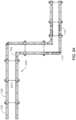
- FIGS. 2 A- 2 Dillustrate a top view of wall and corner plan details of the present formwork system in accordance with implementations of various techniques described herein.
- FIGS. 3 A- 3 Cillustrate various wall plans in accordance with implementations of various techniques described herein.
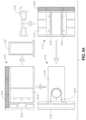
- FIGS. 4 A- 4 Gillustrate side views of various wall configurations in accordance with implementations of various techniques described herein.
- FIGS. 5 A- 5 Dillustrate how a side rail, an interior rail and a tie extrusion fit together in the formwork system in accordance with implementations of various techniques described herein.
- FIGS. 6 A- 6 Gillustrate views of a side rail extrusion in accordance with implementations of various techniques described herein.
- FIG. 7illustrates how a side rail, an interior rail and a tie extrusion fit together in the formwork system in accordance with implementations of various techniques described herein.
- FIGS. 8 A- 8 Dillustrate standard panel assembly plan views in accordance with implementations of various techniques described herein.
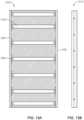
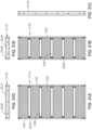
- FIGS. 9 A- 9 Billustrate elevational views of a standard panel assembly in accordance with implementations of various techniques described herein.
- FIGS. 10 A- 10 Gillustrate filler extensions and fittings in accordance with implementations of various techniques described herein.
- FIGS. 11 A- 11 Lillustrate filler assembly plan views in accordance with implementations of various techniques described herein.
- FIGS. 12 A- 12 Oillustrate the range of lengths achievable using adjustable fillers in the present formwork system in accordance with implementations of various techniques described herein.
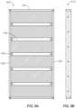
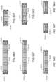
- FIGS. 13 A- 13 Billustrate elevational views of the filler frame in accordance with implementations of various techniques described herein.
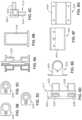
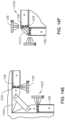
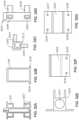
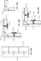
- FIGS. 14 A- 14 Fillustrate corner assembly details in accordance with implementations of various techniques described herein.
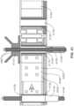
- FIG. 15illustrates a top cutaway view of the formwork system using a tie assembly in accordance with implementations of various techniques described herein.
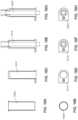
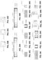
- FIGS. 16 A- 16 Hillustrate tie port inserts in accordance with implementations of various techniques described herein.
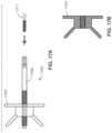
- FIGS. 17 A- 17 Billustrate a she bolt assembly in accordance with implementations of various techniques described herein.
- FIGS. 18 A- 18 Eillustrate different views of a standard clamp in accordance with implementations of various techniques described herein.
- FIGS. 19 A- 19 Eillustrate an accessory clip in accordance with implementations of various techniques described herein.
- FIGS. 20 A- 20 Dillustrate various views of a scaffold bracket adaptor in accordance with implementations of various techniques described herein.
- FIGS. 21 A- 21 Dillustrate various views of an alignment/lifting bar clamp attachment in accordance with implementations of various techniques described herein.
- FIGS. 22 A- 22 Eillustrate additional alignment/lifting bar attachments in accordance with implementations of various techniques described herein.
- FIGS. 23 A- 23 Cillustrate various views of a dry tie/hold down bracket in accordance with implementations of various techniques described herein.
- FIGS. 24 A- 24 Billustrate implementations of a dry tie/hold down bracket in accordance with implementations of various techniques described herein.
- FIGS. 25 A- 25 Willustrate various formwork system component drawings in accordance with implementations of various techniques described herein.
- FIGS. 26 A- 26 Eshow a top view of wall and corner plan details of the present formwork system in accordance with implementations of various techniques described herein.
- FIG. 27shows a top view of a rectangular core wall configuration in accordance with implementations of various techniques described herein.
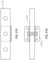
- FIGS. 28 A- 28 Cshow various wall plans that provide arc and circular configurations in accordance with implementations of various techniques described herein.
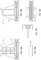
- FIGS. 29 A- 29 Gshow side views of various wall configurations in accordance with implementations of various techniques described herein.
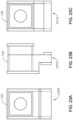
- FIGS. 30 A- 30 Dillustrate standard panel assembly plan views in accordance with implementations of various techniques described herein.
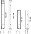
- FIGS. 31 A- 31 Eillustrate elevational views of the standard panel assembly in accordance with implementations of various techniques described herein.
- FIGS. 32 A- 32 Gillustrate views of a side rail extrusion, an interior rail extrusion, a corner casting and a tie extrusion in accordance with implementations of various techniques described herein.
- FIGS. 33 A- 33 Dillustrate how a side rail, an interior rail and a tie extrusion fit together in the formwork system in accordance with implementations of various techniques described herein.
- FIGS. 34 A- 34 Uillustrate filler assembly plan views in accordance with implementations of various techniques described herein.
- FIGS. 35 A- 35 Iillustrate lumber and adjustable fillers in accordance with implementations of various techniques described herein.
- FIGS. 36 A- 36 Dillustrate adjustable filler splice extrusions in accordance with implementations of various techniques described herein.
- FIGS. 37 A- 37 Fillustrate lumber filler fittings and details in accordance with implementations of various techniques described herein.
- FIGS. 38 A- 38 Cillustrate tie port inserts in accordance with implementations of various techniques described herein.
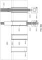
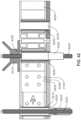
- FIG. 39illustrates a top cross-sectional view of a tie rod assembly in accordance with implementations of various techniques described herein.
- FIG. 40illustrates a top cross-sectional view of a she bolt and a tie rod assembly in accordance with implementations of various techniques described herein.
- FIG. 41illustrates a top cutaway view of a tie rod and PVC sleeve in accordance with implementations of various techniques described herein.
- FIG. 42illustrates a top cutaway view of a she bolt and tie rod assembly in accordance with implementations of various techniques described herein.
- FIGS. 43 A- 43 Dillustrate various views of hinged inside corner and hinged outside corner extrusions in accordance with implementations of various techniques described herein.
- FIGS. 44 A- 44 Fillustrate various connection configurations for inside corner extrusions and outside corner extrusions in accordance with implementations of various techniques described herein.
- FIGS. 45 A- 45 Dillustrate a stripping inside corner in accordance with implementations of various techniques described herein.
- FIGS. 46 A- 46 Dillustrate a stripping inside corner in accordance with implementations of various techniques described herein.
- FIGS. 47 A- 47 Cillustrate an overlapping outside corner configuration in accordance with implementations of various techniques described herein.
- FIGS. 48 A- 48 Eillustrate different views of a standard clamp in accordance with implementations of various techniques described herein.
- FIGS. 49 A- 49 Eillustrate various views of an accessory clip in accordance with implementations of various techniques described herein.
- FIGS. 50 A- 50 Dillustrate various views of a scaffold bracket adaptor in accordance with implementations of various techniques described herein.
- FIGS. 51 A- 51 Billustrate a Ringlok side bracket adaptor in accordance with implementations of various techniques described herein.
- FIGS. 52 A- 52 Dillustrate various views of an alignment/lifting bar clamp attachment in accordance with implementations of various techniques described herein.
- FIGS. 53 A- 53 Eillustrate additional alignment/lifting bar attachments in accordance with implementations of various techniques described herein
- FIGS. 54 A- 54 Cillustrate various views of a dry tie/hold down bracket in accordance with implementations of various techniques described herein.
- FIGS. 55 A- 55 Billustrate implementations of a dry tie application and a hold down bracket application in accordance with implementations of various techniques described herein.
- FIG. 56illustrate a block diagram of a method of assembling a formwork system in accordance with implementations of various techniques described herein.
- the formwork system of the present disclosurehas been designed to rectify many of the short comings of imported European formwork systems, provides a further reduction in the amount of components needed, and provides a high degree of versatility.
- the formwork systemmay be built from non-welded lightweight aluminum components.
- the present formwork systemmay also have implementations that include a synthetic form face. Most prior art systems are made from welded rolled steel, and use a wood form face that has to be replaced periodically.
- the unique design and manufacture of the new formwork system of the present disclosurevastly elevates the inventory service life, improves aspects of inventory maintenance, and offers a significant reduction in the amount of different components needed to achieve an enormous variety of usable configurations.
- Various unique features of the present formwork systemare described in more detail below.
- the present formwork system designincludes several key unique features that are not found in similar systems currently available in the market.
- the improvement provided by this new formwork systemwhich may be composed of non-welded aluminum components, is that this formwork system has significantly less components in its usable inventory, as compared to prior art formwork systems.
- the present formwork systemalso has a unique approach to the type of materials used in its construction, as well as the method of assembly and manufacture.
- the present formwork systemmay also be configured to be used in shoring deck applications. The combination of minimizing required components and the unique method of manufacture is what separates the present formwork system from prior art formwork systems currently being offered to the construction industry.
- the present formwork systemreduces the amount of inventoried components by over 75%, as compared to existing systems.
- the main driver to eliminate many infrequently used itemsis the use of the fabricated Filler Side Rail in various applications.
- the cost to own the present formwork systemcan vastly be reduced for both a dead asset basis, as well as the physical maintenance cost required to maintain a formwork inventory.
- the present formwork systemelevates the flexibility to handle field applications, as well as increase the efficiency for the contractors that will use the present formwork system to build concrete structures.
- FIGS. 1 A- 1 Tinclude various formwork system component drawings.
- FIGS. 1 A- 1 Tinclude plan views of the formwork at various widths (adjustable 110 , lumber 112 , standard 2′ panel 108 , standard 3′ panel 106 ).
- FIGS. 1 A- 1 Talso include views of clamps, brackets, clips, adapters, supports, assemblies and braces used with the formwork system. Additionally, FIGS. 1 A- 1 T show an implementation that couples the present formwork system with a standard scaffold.
- FIG. 1 A- 1 Binclude corner brackets 102 , 104 , 114 .
- Element 102is an inside hinged corner.
- Element 104is a hinged stripping corner and element 114 is a hinged outside corner bracket.
- the hinged and stripping corner bracketsmay be aluminum components.
- Standard clamp 128 amay also be used to tie formwork panels having different heights and as a lifting device for a series of ganged formwork panels.
- element 126is a standard pipe brace with a clip assembly.
- Pipe brace 126can be used to provide support for scaffolding.
- standard pin lock scaffolding adaptoris shown at element 124 .
- Scaffold bracket adaptor 118is used in this configuration.
- accessory clip 116attaches to the standard clamp and serves as a standard connection for the alignment bar configuration (using alignment bar 122 ), pipe brace attachment (using pipe brace 126 ), and lifting bar configuration (using gang lifting configuration 123 and lifting bracket 120 ).
- FIG. 1 RA dry tie or hold down bracket 130 and an alignment center support 132 a are included in FIG. 1 R which also illustrates a side 132 b of alignment center support 132 a . Also included in FIG. 1 S is the tie nut and rod assembly 136 .
- FIG. 1 KAn outside corner bracket configuration 134 is also shown in FIG. 1 K .
- This outside corner bracket 133is used to attach to formwork panels, e.g., formwork panels 106 , 108 in a corner configuration.
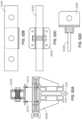
- FIGS. 2 A- 2 Dshow a top view of wall and corner plan details of the present formwork system. Also shown is an alignment bar 122 configuration that can be used to provide additional support for the panels.
- Item 205shows a wall detail at an inside corner using standard panels 106 , 108 and adjustable filler 110 .
- tie rod assemblies 207are included.
- Item 210shows wall details for an implementation of a variable angle inside corner using corner bracket 102 .
- the implementation of item 210uses lumber filler 112 and formwork panel 106 ; however, other implementations may include adjustable filler, lumber filler and/or other standard panels.
- Item 215shows details for a windmill column using standard panels, e.g., formwork panel 108 , and a hinged outside corner bracket 133 .
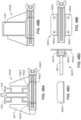
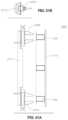
- FIGS. 3 A- 3 Cshow various wall plans that provide arc and circular configurations.
- Item 305is illustrated in FIG. 3 A as an implementation that provides a large diameter tank or serpentine walls 307 provided using lumber inner rails (not shown), lumber clips 309 , filler side rails 112 , tie rod assemblies 207 and standard clamps (not shown).
- Item 310is shown in FIG. 3 B as standard panels with an arc shaped or rounded nose that is provided using standard panels 108 , filler side rails (not shown), lumber inner rails 312 , lumber clips 314 and tie rod assemblies 207 , and standard clamps (not shown).
- Item 315is shown in FIG. 3 B as a circular column provided using filler side rails (not shown), lumber inner rails 312 , lumber clips 314 and standard clamps (not shown).
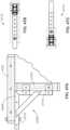
- FIGS. 4 A- 4 Gshow side views of various wall configurations.
- standard panelscan be 2′ or 3′ in width.
- Each standard panel 106 , 108 of width 2′ or 3′can have a panel length of 3′, 6′, or 9′ as shown in panels 426 , 424 , and 422 , respectively.
- Item 405is shown in FIG. 4 A and illustrates 3′ panels 426 supported by a tie assembly 207 or dry tie (as described below) on a top portion and a hold down assembly 407 or tie assembly on a bottom portion. Hold down assemblies and dry tie assemblies are described in further detail in FIGS. 24 A- 24 B and FIG. 55 A- 55 B .
- Item 410is shown in FIG.
- Item 4 Billustrates 9′ panels 422 supported by three tie assemblies 207 or dry ties.
- Item 410also shows a standard scaffold 124 attached to a 9′ panel 422 using a scaffold bracket adaptor 412 and secured with a pipe brace assembly 126 .
- Item 415is shown in FIG. 4 C and illustrates a vertical panel shear condition where panels 422 , 424 , 426 having different lengths, e.g., 3′, 6′ and 9′, are used. This type of configuration, i.e., using unequal heights for the formwork, is made possible because the formwork uses standardized tie hole locations for tie assemblies 207 .
- Item 415also includes the scaffolding 124 described in item 410 .
- Item 420is illustrated in FIG.
- FIG. 4 Dshows typical panel heights (9′ (panel 422 ), 6′ (panel 424 ) and 4′ (panel 426 )) for the formwork system.
- a gang lifting configurationis shown.
- the gang lifting configuration 123is used to move one or more panels, for example, with a crane or some other lifting/moving apparatus.
- FIG. 5 Aillustrates how a side rail 532 , an interior rail 536 and a tie extrusion 604 fit together in the formwork system.
- the views of FIG. 5 Ashow back side views of the formwork system.
- Item 505shows a top cutaway view of the formwork system.
- View 505shows side rail 532 , form face 534 and tie extrusion 604 .
- Item 510shows a side view of the formwork system.
- side rail 532 , interior rail 536 and the tie extrusion 604are clearly shown.
- Different types of tie port inserts 520 , 525 , 530which are illustrated in FIGS. 5 B, 5 C and 5 D , respectively, may be used within tie extrusion 604 .
- Item 515shows a vertical cutaway view of a portion of the formwork system. This view shows the interior rail 536 in further detail along with tie extrusion 604 and side rail 532 .
- FIGS. 6 A- 6 Gillustrate views of a side rail extrusion 532 , an interior rail extrusion 536 , a corner casting 602 and a tie extrusion 604 .
- Items 620 , 625 , 630show various views of tie extrusion 604 .
- Item 615is illustrated in FIG. 6 C and shows a top view of corner casting 602 .
- Item 617is illustrated in FIG. 6 D and shows an elevational side view of corner casting 602 .
- Corner casting 602includes arms 632 , 634 , 636 , 638 .
- the inside rail extrusions 536can be press fit with the side rail extrusions 532 and/or with arms 632 , 634 , 636 , 638 of the corner casting 602 to together make up part of the assembly for the formwork panels. It should be noted that when two side rails 532 are placed back to back, they form the same basic shape as the inner rail 536 . Having the same basic shape makes the connection of a standard clamp identical in both the vertical and horizontal positions. The standard clamp is described further in FIG. 18 . The flange design on the inner & side rails help to increase the pull away capacity of the standard clamp, which is useful since the standard clamp is used to attach all of the accessories. The use of the standard clamp to attach all of the accessories is unique to this formwork system.
- FIG. 7illustrates how a side rail 532 , an interior rail 536 and a tie extrusion 604 fit together in the formwork system.
- the views of FIG. 7show the items of FIG. 5 from a face side of the formwork system.
- FIGS. 8 A- 8 Dillustrate standard panel assembly plan views. Top/bottom 805 , 810 and cutaway elements 815 , 820 are shown for both 3 ft (panel 106 ) and 2 ft (panel 108 ) panel widths. In addition, elements 815 , 820 show side rail 532 and form face 534 .
- FIGS. 9 A- 9 Billustrate elevational views of a standard panel assembly, e.g., panel 424 .
- Item 905shows an elevational view.
- Item 905is shown in FIG. 9 A and includes side rail 532 , inner rail 536 , and tie extrusion 604 .
- Item 910is shown in FIG. 9 B and shows a side elevational view.
- FIGS. 10 A- 10 Gillustrate filler extensions and fittings.
- FIG. 10 Ashows a left hand view 1005
- FIG. 10 Bshows an edge view 1010
- FIG. 10 Cshows a right hand view 1015 of a filler edge clip 1002 are shown.
- FIGS. 10 D and 10 Eis also shown in FIGS. 10 D and 10 E is a lumber inner rail clip 1020 , 1025 an adjustable filler splice extrusion 1030 in FIG. 10 F and an optional steel splice 1035 in FIG. 10 G .
- FIGS. 11 A- 11 Lillustrate filler assembly plan views.
- FIGS. 11 A- 11 Lshow plan views of different configurations for adjustable fillers 1105 and lumber filler 1110 including any necessary extrusions and clips.
- Configurations for adjustable fillersmay include combinations of adjustable filler assembly components 1114 , 1116 , 1118 , 1120 , 1122 . Using these adjustable fillers provides greater flexibility and reduces the need for lumber filler in the formwork system.
- Using the adjustable filler assembly componentsprovides the ability to incrementally adjust the filler from 18 inches to 31 inches.
- the adjustable fillercan be incrementally adjusted in half-inch increments.
- the adjustable filler assemblyincludes spring loaded pins to attach the assembly components.
- the adjustable fillercan be made from aluminum or galvanized steel.
- Configurations 1110 for lumber fillermay include clips 1130 , 1132 , 1134 and adjustable filler components 1114 , 1118 for curved 1124 and straight 1126 , 1128 lumber inner rails.
- FIGS. 12 A- 12 Oillustrate various configurations 1205 for the range of lengths 1207 , 1209 , 1211 , 1213 , 1215 , 1217 , 1219 , 1221 , 1223 , 1225 , 1227 , 1229 , 1231 , 1233 , 1235 achievable using adjustable fillers in the present formwork system.
- the lengthcan be adjusted from 18 inches to 25 inches.
- FIGS. 13 A- 13 Billustrate elevational views of the filler frame.
- Item 1305shows a back view of a variable filler elevation.
- Item 1305is illustrated in FIG. 13 A and shows a panel that includes inner rails 1307 , side rails 532 and tie extrusion 604 .
- Item 1310is illustrated in FIG. 13 B and shows a side view of a variable filler elevation.
- FIGS. 14 A- 14 Fillustrate corner assembly details. Plan views for a hinged inside corner 102 , 1405 and a hinged outside corner 114 , 1410 are shown. Hinged inside corner includes arms 1407 , 1408 and cross bar 1409 . Also shown are partial elevation views of the hinged outside corner 1415 and the hinged inside corner 1420 . Further, connection details 1425 , 1430 illustrating how the hinged corners are connected to the panels 106 , 108 using the standard clamp 128 a are shown for the inside corner hinge and the outside corner hinge.
- FIG. 15illustrates a top cutaway view of the formwork system using a tie assembly, e.g., tie assembly 207 .
- the tie assemblyincludes a tie rod 1510 and a wing nut 1505 .
- the tie rodpasses through a tie port insert 1515 and a polyvinyl chloride (PVC) sleeve 1520 and is used to tie one panel to another using a second wing nut (not shown).
- PVCpolyvinyl chloride
- FIGS. 16 A- 16 Hillustrate tie port inserts for insertion into tie extrusion 604 .
- Tie port insertscan be permanent inserts 1605 , plugs 1610 , flush tie inserts 1615 and cone tie inserts 1620 .
- the flush tie inserts and cone tie insertsmay include a PVC sleeve, e.g., sleeve 1510 .
- FIGS. 17 A- 17 Billustrate a she bolt assembly 1705 .
- She bolt assemblyincludes wing nut 1707 , rod 1709 and rod 1711 .
- the she bolt assemblyis used to secure one formwork assembly to another. This she bolt assembly may secure the form panels to each other using tie port inserts in the form panels.
- FIGS. 18 A- 18 Eillustrate different views of a standard clamp 128 a .
- the clamp 128 ais shown clamping two side rails 532 .
- the clamp 128 ais shown clamping an inner rail 536 .
- the standard clampis designed to tighten with a screw mechanism and generally can be tightened without using a tool. Using this type of standard clamp makes all accessory connections more efficient and easier for the end user. The screw mechanism is safer than other coupling mechanisms because the clamp will not loosen as easily if someone accidentally hits the clamp.
- the accessory clip 1820 that attaches to the standard clampserves as a standard connection for the alignment bar configuration, personal tie-off point, pipe brace attachment, and lifting bar configuration.
- FIGS. 18 A- 18 Ecorrespond to FIGS. 48 A- 48 E which are described in more detail below.
- FIGS. 19 A- 19 Eillustrate an accessory clip 1905 .
- the accessory clip 1905can be used with the standard clamp and for various other applications, e.g., pipe brace clip, alignment bar, lifting bar and tie-off point.
- FIGS. 19 A- 19 Eshow a top view 1907 and side views 1909 , 1913 of accessory clip 1905 .
- Sleeve 1911 of accessory clip 1905is also shown.
- Accessory clip 1905may be attached to standard clamp 128 a using screw assembly 1915 .
- FIGS. 19 A- 19 Ecorrespond to FIG. 49 A- 49 E , which are described in more detail below.
- FIGS. 20 A- 20 Dillustrate various views 2005 of a scaffold bracket adaptor 118 .
- the scaffold bracket adaptor 118may be attached to the standard clamp 128 a using nut 2009 .
- FIGS. 20 A- 20 Dcorrespond to FIGS. 50 A- 50 D , which are described in more detail below.
- FIGS. 21 A- 21 Dillustrate various views of an alignment/lifting bar clamp attachment 2105 .
- the alignment/lifting bar clamp 2105can be coupled to standard accessory clip 2107 .
- the alignment/lifting bar clamp 2107 and standard accessory clip 2107can be coupled to standard clamp 128 a using screw assembly 2111 .
- FIGS. 21 A- 21 Dcorrespond to FIGS. 52 A- 52 D , which are described in more detail below.
- FIGS. 22 A- 22 Eillustrate additional alignment/lifting bar attachments.
- FIGS. 22 A- 22 Crespectively, include various views 2205 , 2207 , 2209 of an optional center support attachment 132 a
- FIGS. 22 D and 22 Erespectively, include various views 2210 , 2212 of a lifting bracket attachment 120 a and a side 120 b of lifting bracket attachment 120 a.
- FIGS. 23 A- 23 Crespectively, illustrate illustrates various views 2305 , 2310 , 2315 of a dry tie/hold down bracket 130 .
- FIGS. 24 A- 24 Billustrate implementations of a dry tie/hold down bracket 130 .
- Item 2405illustrated in FIG. 24 A
- item 2410illustrated in FIG. 24 B
- tie assembly 207Also shown in FIG. 23 A is tie assembly 207 and form face 534 .
- FIGS. 23 A- 23 C and 24 A- 24 Bcorrespond to FIGS. 54 A- 54 C and 55 A- 55 B , which are described in more detail below.
- FIGS. 25 A- 25 Winclude plan views of the formwork at various widths (adjustable 2540 , lumber (straight 2542 and radius 2544 ), standard 2′ panel 2538 , standard 3′ panel 2536 ).
- FIGS. 25 A- 25 Walso include views of clamps, brackets, clips, adaptors, supports, assemblies, insert systems and braces used with the formwork system. Additionally, FIGS. 25 A- 25 W show an implementation that couples the present formwork system with a standard scaffold.
- FIGS. 25 A- 25 Winclude corner brackets 2502 , 2504 , 2506 .
- Element 2502is an inside stripping corner bracket.
- Element 2504is a hinged inside corner bracket and element 2506 is a hinged outside corner bracket.
- the hinged inside and outside corner brackets 2504 , 2506may be aluminum components.
- Brackets 2504 , 2506can be configured to be set at a 90 degree angle. In some implementations, brackets 2504 , 2506 can be configured to be set at angles other than 90 degrees.
- Standard clamp 2508 ais the primary method of attaching all accessories to the standard form panels.
- Standard clamp 2508 amay also be used to tie formwork panels having different heights and as a lifting device for a series of ganged formwork panels.
- Also illustrated (in FIG. 25 D )is a side view 2508 b of the standard clamps 2508 a.
- Element 2510is a standard LD and HD pipe brace with a clip assembly.
- Element 2512is a turnbuckle brace with a clip assembly.
- Pipe brace 2510can be used to provide support for scaffolding.
- Turnbuckle brace 2512can be used to provide support for a formwork panel.
- the accessory clip 2514 aattaches to the standard clamp and serves as a standard connection for the alignment bar configuration (using alignment bar 2520 ), personal tie-off point (using Ringlok adaptor 2516 a ), pipe brace attachment (using pipe brace 2510 ), and lifting bar configuration (using gang lifting configuration 2522 ). Also illustrated (in FIG. 25 E ) is a side view 2514 b of the accessory clip 2514 a.
- Ringlok adaptor 2516 aWhen used as a personal tie-off point, Ringlok adaptor 2516 a can be attached to inner rails of the formwork panels.
- Scaffold assembly 2524includes a pin-lock scaffold bracket and post 2523 and includes a Ringlok adaptor 2516 a , Ringlok leg material 2517 and two standard clamps 2508 a coupled to the pin-lock scaffold bracket and post 2523 . Also illustrated (in FIG. 25 E ) is a side view 2516 b of the Ringlok adaptor 2516 b.
- Standard adjustable shear wall bracket 2526is used to support the weight of the form panels and fillers in a shear wall or exterior wall condition.
- a dry tie or hold down bracket 2528is included in FIG. 25 K . This element is further described below with respect to FIGS. 54 A- 54 C and FIGS. 55 A- 55 B .
- a self-sealing tie and color-coded insert system 2530is included in FIGS. 25 A- 25 W .
- the various elements of the self-sealing tie and color-coded insert system 2530are further described below with respect to FIGS. 33 A- 34 U and 36 A- 42 .
- FIG. 25 A- 25 WAn outside corner bracket configuration 2534 is also shown in FIG. 25 A- 25 W .
- This outside corner bracket 2546is used to attach to formwork panels 2536 , 2538 in a corner configuration.
- the outside corner bracketcan be adjusted in 1′′ increments along one of the formwork panels in the corner configuration.
- the outside corner bracketcan be adjusted up to 1′, e.g., 3′′ to 15′′, when a 2′ panel is used and up to 2′, e.g., 15′′ to 27′′, when a 3′ panel is used.
- FIGS. 26 A- 26 Eshow a top view of wall and corner plan details of the present formwork system. Also shown is an alignment bar configuration 2520 that can be used to provide additional support for the panels.
- Element 2605illustrated in FIG. 26 A , shows a wall detail at an inside corner using standard panels 2536 , 2538 and adjustable filler 2540 .
- tie rod assemblies 2607standard clamps (not shown), inside corner brackets 2504 and aluminum outside corner brackets 2506 are shown.
- Element 2610illustrated in FIG. 26 B , shows wall details for an implementation of a variable angle inside corner. The implementation of element 2610 uses lumber filler 2542 in addition to standard panel 2538 ; however, other implementations may include adjustable filler, lumber filler and/or standard panels.
- Element 2615illustrated in FIG. 26 C , shows details for a column 2617 using standard panels 2536 and outside windmill corner brackets 2546 .
- FIG. 27shows a top view of a rectangular core wall configuration 2705 .
- This particular configuration 2705is achieved using standard panels 2536 , adjustable fillers 2540 , tie rod assemblies 2607 , inside stripping corners 2502 and outside hinged corners 2506 .
- FIGS. 28 A- 28 Cshow various wall plans that provide arc and circular configurations.
- Element 2805shown in FIG. 28 A , illustrates an implementation that provides a large diameter tank or serpentine walls 2807 provided using lumber filler forms 2544 , tie rod assemblies 2607 and standard clamps (not shown).
- Element 2810illustrated in FIG. 28 B , shows standard panels 2536 with an arc shaped or rounded nose 2814 that is provided using standard panels 2536 and tie rod assemblies 2607 , a lumber filler form 2814 , lumber clips 2812 and standard clamps (not shown).
- Element 2815illustrated in FIG. 28 C , shows a circular column 2817 provided using lumber filler forms 2814 , lumber clips 2812 and standard clamps (not shown).
- FIGS. 29 A- 29 Fshow side views of various wall configurations.
- standard panelscan be 2′ or 3′ in width.
- Each standard panel 2536 , 2538 of width 2′ or 3′can have a panel length of 3′, 6′, or 9′ as shown in panels 2926 , 2924 , 2922 , respectively.
- Element 2905shown in FIG. 29 A , illustrates short panel walls 2926 , e.g., 3′ or 4′, supported by a dry tie 2907 on a top portion and a hold down or tie assembly 2909 on a bottom portion. Additionally, in element 2905 , bracing 2512 is shown.
- Element 2910shown in FIG.
- Element 29 Billustrates tall panel walls 2922 supported by three tie assemblies 2607 or dry ties.
- Element 2910also shows a standard scaffold 2524 attached to the tall panel walls 2922 using a scaffold bracket adaptor 2517 and secured with a pipe brace assembly 2510 .
- Element 2915shown in FIG. 29 C , illustrates a vertical panel shear condition where panels 2922 , 2924 , 2926 having different lengths, e.g., 3′, 6′ and 9′, are used. This type of configuration, i.e., using unequal heights for the formwork, is made possible because the formwork uses standardized tie hole locations.
- Element 2915also includes the scaffolding described in element 2910 .
- Element 2920illustrated in FIG.
- 29 Dshows typical panel heights (9′ (panel 2922 ), 6′ (panel 2924 ) and 4′ (panel 2926 )) for the formwork system.
- a gang lifting configuration 2522is shown.
- the gang lifting configuration 2522is used to move one or more panels, for example, with a crane or some other lifting/moving apparatus.
- FIG. 30 A- 30 Dillustrate standard panel assembly plan views. Top/bottom 3010 , 3020 and cutaway views 3005 , 3015 are shown for both 3 ft (panel 2536 ) and 2 ft (panel 2538 ) panel widths.
- FIG. 31 A- 31 Eillustrate elevational views 3110 , 3120 of the standard panel assembly for 2′ (panel 2538 ) and 3′ (panel 2536 ) widths.
- FIGS. 31 D, 31 E and 31 Crespectively, illustrate top/bottom 3105 , 3115 and side elevational 3125 views of panels 2536 , 2538 are also shown.
- Standard panels 2536 , 2538include side rails 532 , inner rails 536 and tie extrusion 3225 .
- FIGS. 32 A- 32 Gillustrate views of a side rail extrusion 532 , an interior rail extrusion 536 , a p 3242 and a tie extrusion 3225 .
- Item 3215illustrated in FIG. 32 C , shows a top view of corner casting 3242 .
- Item 3220illustrated in FIG. 32 D , shows an elevational side view of corner casting 3242 .
- Corner castingincludes arms 3244 , 3246 , 3248 , 3250 .
- inside rail extrusionscan be coupled to side rail extrusions 532 and/or press fit with arms 3244 , 3246 , 3248 , 3250 of corner castings 3225 to together make up part of the assembly for the formwork panels. It should be noted that when two side rails 532 are placed (as shown) back to back, they form the same basic shape as the inner rail 536 . Having the same basic shape makes the connection of a standard clamp identical in both the vertical and horizontal positions. The standard clamp is described further in Figured 48 A- 48 E.
- the flange design 3207 , 3209 on the inner & side rails 532 , 536help to increase the pull away capacity of the standard clamp 2508 a , which is useful since the standard clamp 2508 a is used to attach all of the accessories.
- the use of the standard clamp 2508 a to attach all of the accessoriesis unique to this formwork system.
- Tie extrusion 3225has an opening 3227 for a tie rod. Openings 3232 , 3234 of tie extrusion 3225 are used to attach the tie extrusion 3225 to the interior rail extrusion 536 . Openings 3236 , 3237 , 3238 , 3239 are used to attach the tie extrusion to the side rail extrusion.
- FIG. 33 A- 33 Dillustrates how a side rail 532 , an interior rail 536 and a tie extrusion 3225 fit together in the formwork system.
- the views of FIG. 33 A- 33 Dshow back side views of the formwork system.
- Element 3305illustrated in FIG. 33 A , shows a top cutaway view of the formwork system.
- Element 3310shows a side view of the formwork system. In this view, side rail 532 , interior rail 536 and the tie extrusion 3225 are clearly shown.
- Different types of tie port inserts 3311 , 3312 , 3313may be used within tie extrusion 3225 . These tie port inserts are discussed further in FIG. 38 .
- Element 3315shows a vertical cutaway view of a portion of the formwork system. This view shows the interior rail 536 in further detail along with tie extrusion 3225 and side rail 532 .
- FIGS. 34 A- 34 Uillustrates filler assembly plan views.
- FIGS. 34 A- 34 Ushow plan views of different configurations for adjustable fillers and lumber filler including any necessary extrusions, clips, inside splices and outside splices.
- Configurations for adjustable fillersmay include combinations of adjustable filler assembly components 3406 , 3410 , 3414 , 3418 , 3422 a . Using these adjustable fillers provides greater flexibility and reduces the need for field fitted lumber shimming in the formwork system. Using the adjustable filler assembly components provides the ability to incrementally adjust the filler. Tie locations can be placed in panels having adjustable or lumber fillers.
- Configurations for lumber fillermay include filler side rails 3422 and clips 3424 a , 3424 b , 3426 a for curved 3402 and straight 3404 lumber inner rails.
- Filler side rails 3422 acan be used in both lumber and adjustable filler configurations. An opposing end 3422 b of filler side rail 3422 a is illustrated in FIG. 34 K .
- Filler side railscan be 4′, 6′, or 9′ in height.
- Filler side railscan be attached to inside splices 3406 , 3414 . Inside splices 3406 , 3414 can be 51 ⁇ 2 inches or 81 ⁇ 2 inches long.
- FIGS. 34 D and 34 Eillustrate elements 3408 and 3416 , which are side views of inside splices 3406 and 3414 , respectively.
- Filler side railscan also be attached to lumber inner rail clip 3426 a .
- 34 Millustrates element 3426 b , which is a side view of lumber inner rail clip 3426 a .
- Left and right edge clips 3424 a , 3424 bare used to attach to adjacent filler side rails at top and bottom. Further details regarding the edge clips 3424 a , 3424 b are described below in FIG. 37 A- 37 F .
- Outside splices 3410 , 3418can be attached to inside splices 3406 , 3414 . Outside splices can be 61 ⁇ 2 or 101 ⁇ 2 inches long.
- FIGS. 34 F and 34 Jillustrates elements 3412 and 3420 , which are side views of outside splices 3410 and 3418 , respectively.
- the “U” connector 3430is used to connect various components. In one implementation, the “U” connector is used to attach the splices together and to attach the adjustable or lumber rail to the filler side rail. Further details regarding “U” connector connections are described below in FIGS. 36 A- 36 D and 37
- FIG. 34 Aillustrates element 3402 , which is a configuration having filler side rails 3422 a with lumber clips 3426 a and radius cut lumber 3448 .
- FIG. 34 Billustrates element 3404 , which is a configuration having filler side rails 3422 a with lumber clips 3426 a and sized or straight lumber 3450 .
- FIG. 34 Oillustrates element 3432 , which is a configuration having two 101 ⁇ 2 inch outside splices and three 81 ⁇ 2 inch inside splices. This configuration is adjustable from 29 to 43 inches in one inch increments.
- FIG. 34 Pillustrates element 3434 , which is a configuration having one 81 ⁇ 2 inch inside splice, two 51 ⁇ 2 inch inside splices and one 101 ⁇ 2 inch outside splice. This configuration is adjustable from 29 to 37 inches in one inch increments.
- FIG. 34 Qillustrates element 3436 , which is a configuration having two 81 ⁇ 2 inch inside splices and one 101 ⁇ 2 inch outside splice. This configuration is adjustable from 20 to 28 inches in one inch increments.
- FIG. 34 Rillustrates element 3438 , which is a configuration having two 51 ⁇ 2 inch inside splices and one 61 ⁇ 2 inch outside splice. This configuration is adjustable from 14 to 18 inches in one inch increments.
- FIG. 34 Sillustrates element 3440 , which is a configuration having two 51 ⁇ 2 inch inside splices and one 101 ⁇ 2 inch outside splice. This configuration is adjustable from 18 to 22 inches in one inch increments.
- FIG. 34 Tillustrates element 3442 , which is a configuration that includes a single 51 ⁇ 2 inch inside splice. This configuration is adjustable from 8 to 10 inches in 1 inch increments.
- FIG. 34 Uillustrates element 3444 , which is a configuration that includes a single 81 ⁇ 2 inch inside splice. This configuration is adjustable from 11 to 13 inches in one inch increments.
- FIG. 35 A- 35 Iillustrate lumber and adjustable fillers.
- Top/bottom views of adjustable filler 3432 and adjustable filler 3436are shown. Adjustable fillers 3432 and 3436 have different adjustable filler widths.
- a top/bottom view of lumber filler 3404is shown. Also shown are top/bottom 3535 and elevational side 3545 and end 3540 views of an edge clip 3424 . Elevational views of interior rail configurations of variable/adjustable fillers 3510 , 3520 and lumber filler 3530 are also shown.
- FIGS. 36 A- 36 Dillustrate adjustable filler splice extrusions.
- FIGS. 36 A- 36 Dalso show how the adjustable filler splice extrusions 3602 , 3607 are connected, e.g., using “U” connector 3620 .
- Front 3605 , side 3610 and top 3615 elevational viewsshow how the adjustable fillers 3602 , 3607 are connected to the side rail extrusion 532 and the tie extrusion 3225 using the “U” connectors 3620 .
- the synthetic nailer 3609is used to fasten the form face 534 material (plywood or synthetic) to the body of the assembled adjustable or lumber filler frame
- the side rail 532 , interior rails 536 , corner castings 3242 , and tie extrusion 3225are made of structural grade aluminum.
- the structural grade aluminumcan be 6060-T6 or equivalent.
- FIGS. 37 A- 37 Fillustrate filler side rail edge fittings and lumber inner rail fittings and details.
- a left hand view 3705illustrated in FIG. 37 A
- an edge view 3710illustrated in FIG. 37 B
- a right hand 3715 viewillustrated in FIG. 37 C
- different views 3720illustrated in FIG. 37 E , for coupling a lumber clip 3426 to a side rail 532 and a tie extrusion 3225 and further attaching the lumber clip to a lumber inner rail 3625 , for example, using a “U” connector 3620 .
- FIGS. 38 A- 38 Cillustrate tie port inserts.
- Tie port insertscan be permanent inserts 3820 , plugs 3825 , she-bolt tie washers 3830 and cone tie inserts 3835 .
- FIG. 38 B- 38 Cshow different top cross-sectional configurations for tie port inserts. These views show the tie port inserts projecting through the form frame 3815 and the form facing panel 3810 . These views also show poured concrete 3805 adjacent to the form facing panel.
- a permanent insert 3820is press-fit into the form frame 3815 and an end of the permanent insert occupies an opening of the form facing panel 3810 .
- Plug insert 3825fits within permanent insert 3820 and is used to prevent concrete from leaking through the tie ports.
- She-bolt tie washer 3830can be used to secure a tie rod passing through a sleeve 3840 passing through permanent insert 3820 and protruding out from form facing panel 3810 into the area for the concrete 3805 .
- Cone tie insert 3835can be used to pass a tie rod through concrete while keeping the concrete from hardening on a surface of the tie rod.
- the cone tie insert 3835is passed through permanent insert 3820 and protrudes out from the form facing panel.
- a sleeve 3845e.g., a PVC sleeve, can be attached to the cone tie insert to prevent concrete from coming into contact with the tie rod.
- FIG. 39illustrates a top cross-sectional view of a tie rod assembly 2607 at panel 3902 .
- a form face 534 of panel 3902 and a side rail 532are also shown.
- the tie assemblyincludes a tie rod 3905 and a wing nut 3910 .
- the tie rodpasses through a permanent insert 3915 and a cone tie insert 3920 inserted into the permanent insert 3915 .
- the tie rodfurther passes through a PVC sleeve 3925 attached to the tie rod insert.
- the tie rodis used to tie one panel to an opposing panel.
- panel 3904which is serially attached to panel 3902 , is a plug insert 3935 inserted into permanent insert 3930 .
- FIG. 40illustrates a top cross-sectional view of a she bolt and a tie rod assembly 2607 at panel 4002 .
- a form face 534 of panel 4002 and a side rail 532are also shown.
- the tie rod assemblyincludes a tie rod 4005 , she-bolt 4020 and a wing nut 4010 .
- the tie rod and she-boltpass through a permanent insert 4015 .
- the tie rodis secured to the panel using she bolt 4020 and wing nut 4010 .
- the tie rodis used to tie one panel to an opposing panel.
- panel 4004which is serially attached to panel 4002 , is a plug insert 4035 inserted into permanent insert 4030 .
- FIG. 41illustrates a top cutaway view of a tie rod and PVC sleeve at adjustable filler panel 4102 (e.g., components 3432 , 3436 ).
- the tie assembly 2607includes a tie rod 4105 and a wing nut 4110 .
- the tie rod 4105passes through a permanent insert 4115 and a cone tie insert 4120 inserted into the permanent insert 4115 .
- the tie rodfurther passes through a PVC sleeve 4125 attached to the cone tie insert 4120 .
- the tie rodis used to tie one panel to an opposing panel.
- adjustable filler panel 4102illustrates an optional tie assembly showing the tie rod 4140 passes through a permanent insert 4150 and a she-bolt 4145 inserted into the permanent insert 4150 .
- the tie rod 4140is secured to the panel using she bolt 4145 and a wing nut, not shown.
- the tie rodis used to tie one panel to an opposing panel.
- panel 4104which is serially attached to panel 4102 , is a plug insert 4135 inserted into permanent insert 4130 .
- FIG. 42illustrates a top cutaway view of a she bolt and tie rod assembly at adjustable filler panel 4102 (e.g., components 3432 , 3436 ).
- adjustable filler panel 4102e.g., components 3432 , 3436 .
- the tie rod 4140 and she-bolt 4245passes through a permanent insert 4250 .
- the tie rod 4240is secured to the panel using she bolt 4245 and wing nut 4210 .
- the tie rod 4240is used to tie one panel to an opposing panel.
- the optional tie assemblyincludes a tie rod 4205 and a wing nut (not shown).
- the tie rod 4205passes through a permanent insert 4215 and a cone tie insert 4220 inserted into the permanent insert 4215 .
- the tie rod 4205further passes through a PVC sleeve 4225 attached to the cone tie insert 4220 .
- the optional tie rodis used to tie one panel to an opposing panel.
- panel 4204which is serially attached to panel 4202 , is a plug insert 4235 inserted into permanent insert 4230 .
- tie inserts and the tie rodare assembled and slide into position from a back side of the panel.
- the tie insertsare also assembled from the back side of this panel.
- FIGS. 43 A- 43 Dillustrate various views of hinged inside corner 2504 and hinged outside corner 2506 extrusions.
- Hinged outside corner 2506includes a first member 4310 and a second member 4315 .
- a 90 degree strap 4320is used in a 90 degree configuration.
- the 90 degree strap 4320may be attached to the first member 4310 and the second member 4315 using screw and nut 4322 or some other attachment means.
- Hinged inside corner 2504includes a first member 4330 and a second member 4335 .
- a 90 degree strap 4340is used.
- the 90 degree strap 4340may be attached to the first member 4330 and the second member 4335 using screw and nut 4342 or some other attachment means.
- an adaptor plate(not shown) can be permanently mounted to each extrusion using bolts, and the 90 degree strap can be attached to the adaptor plate using pull pins.
- the 90 degree strapis easier to remove when an angle that is greater or less than 90 degrees is needed.
- FIG. 43 BA top view of first member 4310 is shown in FIG. 43 B as element 4345 .
- a side view of first member 4310is shown in FIG. 43 D as element 4350 .
- Side view 4350illustrated in FIG. 43 D shows two removal areas. The removal areas are the spaces between the hinge members. The two removal areas accommodate the hinge members of the second member (not shown in this view), which has one removal area.
- a hinge(not shown) is used to couple the first member to the second member.
- FIGS. 44 A- 44 Fillustrate various connection configurations for inside corner extrusions 2504 and outside corner extrusions 2506 that are connected to formwork panels 4401 , 4403 using the standard clamp 2508 a or a bolt connection.
- the configuration in FIG. 44 A as element 4405shows a 90 degree inside corner connection.
- the configuration in FIG. 44 B as element 4410shows a less than 90 degree angle.
- the configuration in FIG. 44 C as element 4415shows a greater than 90 degree angle.
- a hinged corner connectionis capable of achieving a maximum angle of 190 degrees.
- FIG. 44 D as element 4420shows a 90 degree outside corner connection.
- the configuration in FIG. 44 E as element 4425shows a hinged corner connection capable of achieving a maximum angle of 135 degrees.
- the configuration in FIG. 44 F as element 4430shows a hinged inside corner capable of achieving a minimum angle of 55 degrees if bolts (not shown) are used instead of the standard clamp.
- FIGS. 45 A- 45 Dillustrate a stripping inside corner 2502 according to an 8′′ implementation.
- a plan view and a partial elevational view of stripping inside corner 2502are shown in as element 4510 in FIG. 44 A .
- Also shownare a pour position 4515 and a stripping position 4520 for stripping inside corner 2502 .
- Pour/stripping position, shown in FIGS. 45 C and 45 D as views 4515 , 4520 , respectively,include panels 4501 , 4503 (including side rails 532 ) and clamps 2508 a.
- FIGS. 46 A- 46 Dillustrate a stripping inside corner 4605 according to a 12′′ implementation.
- a plan view and a partial elevational view of stripping inside corner 4605are shown in FIG. 46 A as element 4610 .
- Also shownare a pour position 4615 and a stripping position 4620 for stripping inside corner 4605 .
- Pour/stripping position views 4615 , 4620include panels 4501 , 4503 (including side rails 532 ) and clamps 2508 a.
- the stripping inside corneris adjusted from a pour position to a stripping position using either a screw mechanism (not shown) or a slotted slide plate (not shown) that draws the two sides of the inside stripping corner inward to strip and outward to re-set to the next pour position.
- the stripping inside cornercan be made from aluminum and includes a slide plate configuration.
- FIGS. 47 A- 47 Cillustrate an overlapping outside corner configuration using outside corner bracket 2546 .
- the overlapping outside corner assembly 4705includes outside corner bracket 2546 and standard panels 4701 , 4703 .
- the overlapping outside corner assembly 4705can be implemented using an even increment configuration, e.g., corresponding to side 4710 or an odd increment configuration, e.g., corresponding to side 4715 .
- Each side 4710 , 4715 of the outside corner assemblyis adjustable in 2′′ increments, however one side is offset from the other by one inch. Adjusting in 1′′ increments can be achieved by flipping the outside corner assembly over. Alternatively, this bracket can be fitted with holes every one inch to avoid having to flip the bracket over.
- FIGS. 48 A- 48 Eillustrates different views of a standard clamp 2508 a .
- the clamp 2508 ais shown clamping two side rails 532 .
- the clamp 2508 ais also shown clamping an inner rail 536 .
- Clamp 4805includes a first member 4817 having a first opening 4820 configured to accommodate a first flange.
- Clamp 2508 aalso includes a second member 4823 having a second opening 4822 configured to accommodate a second flange.
- a screw mechanism 4824is used to loosen and tighten the first 4817 and second 4823 members of the clamp. In particular, the screw mechanism engages with a bottom threaded portion of the first member 4817 in order to tighten the clamp.
- the standard clamp 2508 ais designed to tighten with a screw mechanism and generally can be tightened without using a tool. Using this type of standard clamp 2508 a makes all accessory connections more efficient and easier for the end user. The screw mechanism is safer than other coupling mechanisms because the clamp will not loosen as easily if someone accidentally hits the clamp.
- a connector clip 4830is permanently attached to the clamp and is configured to be coupled to other attachments used with the aluminum formwork system.
- the accessory clip that attaches to the connector clip of the standard clampcan serve as a standard connection for the alignment bar configuration, personal tie-off point, pipe brace attachment, and lifting bar configuration.
- FIG. 48 Dillustrates element 4835 , which is a side view of clamp 2508 a with connector clip 4830 permanently attached.
- FIG. 48 Eillustrates element 4840 , which is a front view of clamp 2508 a with the connector clip 4830 permanently attached.
- the connector clip 4830has openings 4845 that are used to couple the clamp 2508 a to an accessory clip.
- FIGS. 49 A- 49 Eillustrate various views 4907 , 4917 , 4920 of an accessory clip 4905 .
- the accessory clip 4905can be used with the standard clamp 2508 a for various other applications, e.g., pipe brace clip, alignment bar, lifting bar and tie-off point.
- Accessory clip 4905includes a screw assembly 4921 and sleeve 4919 .
- accessory clip 4905can be attached to clamp 2508 a using screws and nuts 4915 as shown in view 4910 .
- FIGS. 50 A- 50 Dillustrate various views 5005 of a scaffold bracket or horizontal adaptor 2516 a .
- the scaffold bracket or horizontal adaptor 2516 amay be attached to the standard clamp 2508 a using screws and nuts 5015 .
- the scaffold bracket or horizontal adaptor 2516 amay be used as a personal tie off point with a proper harness and lanyard.
- scaffold adaptor 2516 amay be used to attach either a Ringlok scaffold bracket or a Ringlok horizontal member.
- FIGS. 51 A and 51 Billustrate a Ringlok side bracket adaptor 2517 .
- This configurationshows how a Ringlok leg material 2517 can be attached to inner rails 536 of a panel 5131 using the standard clamp 2508 a according to one implementation.
- FIGS. 52 A- 52 Dillustrate various views of an alignment/lifting bar attachment.
- the alignment/lifting bar 5220can be coupled to the standard accessory clip 5205 using a bolt assembly (not numbered).
- the alignment/lifting bar 5220 and standard accessory clip 5205may be attached a standard clamp 2508 a using a screw assembly 5215 .
- FIGS. 53 A- 53 Eillustrate additional alignment/lifting bar attachments.
- FIGS. 53 B , FIG. 53 A , and FIG. 53 Cincludes respective views 5306 , 5307 , 5309 of an optional center support attachment 5305 and FIG. 53 D and
- FIG. 53 Eincludes respective views 5310 , 5312 of a lifting bracket attachment 2518 a .
- Also illustrated in FIGS. 53 D- 53 E )is a side view 2518 b of the lifting bracket 2518 a.
- FIG. 54 A- 54 Cillustrate respective views 5405 , 5410 , 5415 of a dry tie/hold down bracket 2528 . Opening 5420 is shaped to accommodate a tie rod or screw for dry tie and hold down applications.
- FIG. 55 A- 55 Billustrates implementations of a dry tie application 5505 and a hold down bracket application 5530 using the bracket of FIG. 54 A- 54 C .
- Dry tie application 5505includes a tie rod assembly (tie rod 5520 and wing nut 5510 ), bracket 2528 and formwork panel 5525 .
- the bracket 2528is attached to a top portion of formwork panel 5525 and the tie rod assembly 5510 , 5520 is used to couple bracket 2528 to an opposing bracket attached to a top portion of an opposing panel.
- Hold down bracket application 5530includes tie rod 5540 , anchor bolt 5545 , bracket 2528 and panel 5525 .
- Bracket 2528is attached to a bottom portion of formwork panel 5525 and is tied to surface 5535 using tie rod 5540 and anchor bolt 5545 .
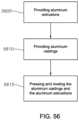
- FIG. 56illustrates a block diagram of a method of assembling a formwork system.
- aluminum extrusionsare provided.
- aluminum castingsare provided.
- the aluminum castings and aluminum extrusionsare pressed and riveted.
- the aluminum extrusionscan be side rail extrusions and/or interior rail extrusions.
- the aluminum extrusions and the aluminum castingscan be made of structural grade aluminum.
- the formwork systemcan be configured such that the aluminum extrusions and aluminum castings are integrated into a shoring deck application.
- the aluminum extrusionsare adjustable and a width of the aluminum extrusions can be incrementally adjusted using different configurations.
- the aluminum extrusionscan be assembled to be part of a series or system of formwork panels that are coupled together using a standard clamp.
- the formwork panelsare constructed of lightweight aluminum extrusions and fittings and are assembled with mechanical fasteners and have no welding.
- the standard clampmay also be used to couple attachments to the formwork panels.
- a connector clipcan be attached to the standard clamp and configured to be coupled to one or more attachments for the formwork system.
- an accessory clipcan be attached to the connector clip.
- the accessory clipcan be coupled to the one or more attachments.
- the attachmentsmay include, but are not limited to, a pipe brace clip, an alignment bar, a lifting bar, a tie-off point.
- formwork panelscan be coupled via an aluminum extruded hinged corner extrusion and configured to be positioned relative to each other at a plurality of angles.
- the aluminum extruded hinged corner extrusioncan be a hinged inside corner extrusion. In one implementation, the hinged corner extrusion can be a hinged outside corner extrusion.
- tie insertsare used with a formwork panel.
- Tie insertsmay include self-sealing ties, tie plugs and tie inserts that install from the outside (or backside) of ganged form panel assemblies. This increases labor efficiency and reduces risk of concrete leakage through the tie port assembly.
- a tie nut and rod assemblycan be used to couple a formwork panel to an opposing formwork panel.
- the formwork system of the present disclosureis constructed solely of aluminum extrusions and castings in a fashion that eliminates structural welding. This simplifies both the manufacturing, as well as the inventory maintenance aspects of a purchased inventory.
- the structural capacityis generated from having the castings pressed into the extrusions.
- the corner castingsare press fitted into the side rail extrusions and either riveted, or screwed together.
- the tie hole fittinge.g., the tie extrusion, is bolted to the side rail and press fitted and bolted into the interior rail.
- the result of this type of assemblyprovides a more rigid and consistently truer frame with a higher level of durability. Since the extrusions, i.e., side rails and inner rails, tie hole fittings and castings of the formwork system are aluminum, these elements will not rust and will maintain their structural rigidity for longer periods of time, as compared to traditional welded steel types.
- the corner castingprovides added durability to help prevent damage during normal construction activities.
- the side rail extrusionsare shaped to help prevent typical handling damage patterns by having specific areas thicker than those in protected areas (e.g., outer edges or walls are thicker). The thicker areas may provide protection against weather and/or damage due to construction workers or other mishaps that may occur on a construction site. There is no prior art system that is constructed in this manner.
- prior art systemshave a pre-defined pattern that provides limited amounts of flexibility. Additionally, prior art systems do not allow a form of two different heights to be connected on opposite sides of the wall in a fashion that allows staggering. For example, in prior art systems, the spacing of the tie holes on a shorter form are different from those on a taller height forms. This forces builders to use the same height forms on both sides of the wall, which limits the amount of configurations that a system can achieve.
- the tie pattern of the present systemallows ties to be placed in predefined increments, e.g., 12′′ increments.
- This symmetrical tie spacing featureallows panels to be stacked and staggered in a variety of patterns from one side of the wall to the other. This exponentially increases the versatility of the product and reduces the amount of components needed.
- This new systemtakes a very different approach, and has only two distinct panel widths.
- this systemhas a pre-fabricated filler side rail accessory that allows users to custom build fillers to meet the size requirements for each specific application.
- One additional component that allows the user to have fillers of variable widthssignificantly reduces the amount of items to inventory.
- Variable fillerscan be pre-assembled prior to shipment to meet the design specifications, or easily custom made in the field to handle dimensional changes from one pour to the next.
- the design of the present side railallows making custom filler sizes feasible.
- This componentallows the user, or form provider, to easily insert standard sized wood members to create custom sized filler panel that perform in the same manner as standard panels.
- the filler panelsattach to the primary components in the same way as the rest of the standard system, and also have the same tie hole configurations. This gives builders the same dimensional flexibility as other systems, while significantly reducing inventory components.
- One set of filler side railseliminate the need for the form owner to carry large amounts of pre-fabricated and seldom used small filler panels.
- the filler side railsmay be made or fabricated on a per order basis.
- the filler side rail assemblywill also be used for circular construction, and for walls that intersect at other than right angles. These conditions are two more examples of infrequent applications that create inventory inefficiencies as well.
- This systemalso includes an adjustable filler assembly.
- This adjustable filler assemblyis capable of handling a majority of straight wall filler applications. Using the adjustable filler assembly (and the lumber assembly) eliminates the necessity in the prior art of having fabricated fillers of various sizes. The adjustable filler reduces the amount of custom wood expense and time needed to fill a customer order. Using the adjustable filler assembly reduces the need for all wood inner members with a new aluminum adjustable inner member, so that the most common filler sizes can be achieved with the same frame assembly. This adjustable filler assembly is unique to the present system.
- filler side railsare designed to accept lumber inner rails, however, a much smaller quantity will be needed in practice.
- the lumber configurationswill be used primarily for odd fillers that aren't achievable using the other standard adjustable components and to make curved formwork.
- the lumber filler side railuses the same side rail design as the adjustable filler, with the addition of a lumber clip, and removal of the adjustable inner rail.
- CNCcomputer numerical control
- the design of the clamp for the present systemeliminates the need for multiple clamps because the clamp of the present system has attachment ports.
- the portsallow various items to be connected to the clamp, such as a simple piece of angle or wood, which can be used as an alignment bar, in straight wall applications. This aspect significantly reduces the inventory costs for clamps.
- the present systemuses side rails, e.g., aluminum filler side rails, to make variable sized filler, the need for the small wood shims of the prior art system is eliminated. Therefore, the adjustable style of clamp of the prior art is also eliminated.
- the present systemuses one style of clamp for connecting forms in a straight line.
- prior art systems on the market todayrequire three or more clamp varieties.
- the present formwork systemeliminates the special overlap form panels with the addition of the windmill outside corner connector, see FIGS. 25 , 26 (item 2615 ), and 47 .
- Thisallows two standard panels to be connected at a right angle and allows one panel to by-pass the other in a windmill fashion with the connection being at the standard tie ports.
- the windmill bracketallows for odd dimensional take-up based on the dimensions required for the application.
- the windmill outside corner bracketcan be used on an outside face of two walls that intersect at a right angle, or for forming individual column structures.
- windmill outside corner bracketeliminates the need for an inventory of specialty panels with additional tie holes that are used to make windmill outside corner assemblies.
- the present formwork systemutilizes an aluminum extruded hinged corner, with a standard 90 degree strap to make up variable angled corners, as well as right angles for both the inside and outside corner designs of various heights. Both the hinged and 90 degree corners configurations can be manufactured separately out of aluminum extrusions for this system. However, it is not necessary, given the design of much lighter hinged aluminum extruded corners and the addition of a 90-degree strap, shown in FIGS. 43 - 44 mentioned above. Combining the use of a hinged design and right angle design into one assembly eliminates redundant inventory.
- the present formwork systemdoes not have those specially designed components. Instead, the present formwork system has simple attachment accessories that allow existing types of standard scaffolding components to be utilized. Standard scaffolding systems are readily available in the market place, and are generally made in a standard configuration that integrates with the present formwork system.
- the formwork system described in this documentmay utilize a synthetic face product solely for the standard panels.
- This aspectadds to the overall robust nature of the present formwork system design and helps to reduce the overall cost to own and maintain this formwork system versus prior art systems.
- This enhancementallows all of the ties and inserts to be assembled from the outside of the form panel. Once in place, the tie cavity is sealed so concrete will not leak into the opening. This is a significant labor savings and product maintenance improvement.
- tie options1) She-Bolt with Inner Rod; and 2) Yellow Insert w/PVC Sleeve & re-usable through rod. Both options use the same size threaded rod & Wing Nut washer.
- Aluminum Design on CornersAll of the inside and outside standard right angle & hinged corners can be made of an aluminum extrusion with a bolt-on 90 degree strap, instead of fabricated steel. Using aluminum eliminates the need for welding and makes these parts much lighter and capable of handling various corner angles. Note: the stripping corner can still be steel, however, this stripping corner can be reduced in size from 12′′ ⁇ 12′′ to 8′′ ⁇ 8′′. In one implementation, an aluminum stripping corner with a center slide plate mechanism that can pull the sides of the stripping corner inward so that the complete form system can be stripped and moved as an entire unit.
- adjustable filler elementshave interlocking grooves 3423 a and 2423 b on the inner 3408 & outer 3412 overlapping splice members to limit deflection and increase capacity.
- the scaffold attachments for the standard Ringlok systemwere enhanced.
- the attachmentscan also be configured as a personnel tie-off point.
- Removable high pressure struta removable high pressure strut (not shown) for the standard panels can be included.
- This removable high pressure strutcan be made using the adjustable rail extrusions and allows for an increase in the allowable design pressure by reducing deflection on the form face.
- Most prior art systemsupgrade their core design to handle extreme pressures, but the downside is an overdesign for day to day common uses.
- the approach of the present disclosureminimizes component weights and allows for adding the strut in locations where pressures become high, as opposed to the entire system. This is similar in concept to having a moveable personal tie-off point for optimal placement based on the need.
- This componentcan be used with the standard panels when the construction application dictates.
- first, second, etc.may be used herein to describe various elements, these elements should not be limited by these terms. These terms are only used to distinguish one element from another.
- a first object or stepcould be termed a second object or step, and, similarly, a second object or step could be termed a first object or step, without departing from the scope of the invention.
- the first object or step, and the second object or stepare both objects or steps, respectively, but they are not to be considered the same object or step.
- the term “if”may be construed to mean “when” or “upon” or “in response to determining” or “in response to detecting,” depending on the context.
- the phrase “if it is determined” or “if [a stated condition or event] is detected”may be construed to mean “upon determining” or “in response to determining” or “upon detecting [the stated condition or event]” or “in response to detecting [the stated condition or event],” depending on the context.
Landscapes
- Engineering & Computer Science (AREA)
- Architecture (AREA)
- Civil Engineering (AREA)
- Structural Engineering (AREA)
- Mechanical Engineering (AREA)
- Physics & Mathematics (AREA)
- Electromagnetism (AREA)
- Forms Removed On Construction Sites Or Auxiliary Members Thereof (AREA)
Abstract
Description
Claims (9)
Priority Applications (8)
| Application Number | Priority Date | Filing Date | Title |
|---|---|---|---|
| US16/680,344US12234638B2 (en) | 2016-06-24 | 2019-11-11 | Formwork system |
| US16/805,723US12195961B2 (en) | 2016-06-24 | 2020-02-29 | Formwork system |
| US17/667,020US12146320B2 (en) | 2016-06-24 | 2022-02-08 | Formwork system |
| US17/988,640US20230075821A1 (en) | 2016-06-24 | 2022-11-16 | Formwork Panel of a Formwork System |
| US18/663,432US20240301688A1 (en) | 2016-06-24 | 2024-05-14 | Formwork System |
| US18/663,452US20240295120A1 (en) | 2016-06-24 | 2024-05-14 | Formwork System and Panel Therefor |
| US18/663,446US20240301689A1 (en) | 2016-06-24 | 2024-05-14 | Formwork System |
| US18/962,520US20250092673A1 (en) | 2016-06-24 | 2024-11-27 | Formwork System |
Applications Claiming Priority (4)
| Application Number | Priority Date | Filing Date | Title |
|---|---|---|---|
| US201662354325P | 2016-06-24 | 2016-06-24 | |
| US201762471173P | 2017-03-14 | 2017-03-14 | |
| US15/630,923US10472823B2 (en) | 2016-06-24 | 2017-06-22 | Formwork system |
| US16/680,344US12234638B2 (en) | 2016-06-24 | 2019-11-11 | Formwork system |
Related Parent Applications (1)
| Application Number | Title | Priority Date | Filing Date |
|---|---|---|---|
| US15/630,923ContinuationUS10472823B2 (en) | 2016-06-24 | 2017-06-22 | Formwork system |
Related Child Applications (5)
| Application Number | Title | Priority Date | Filing Date |
|---|---|---|---|
| US16/680,368Continuation-In-PartUS12116779B2 (en) | 2016-06-24 | 2019-11-11 | Formwork system |
| US16/805,723Continuation-In-PartUS12195961B2 (en) | 2016-06-24 | 2020-02-29 | Formwork system |
| US17/667,020DivisionUS12146320B2 (en) | 2016-06-24 | 2022-02-08 | Formwork system |
| US17/988,640DivisionUS20230075821A1 (en) | 2016-06-24 | 2022-11-16 | Formwork Panel of a Formwork System |
| US18/962,520ContinuationUS20250092673A1 (en) | 2016-06-24 | 2024-11-27 | Formwork System |
Publications (2)
| Publication Number | Publication Date |
|---|---|
| US20200080302A1 US20200080302A1 (en) | 2020-03-12 |
| US12234638B2true US12234638B2 (en) | 2025-02-25 |
Family
ID=60675323
Family Applications (13)
| Application Number | Title | Priority Date | Filing Date |
|---|---|---|---|
| US15/630,923ActiveUS10472823B2 (en) | 2016-06-24 | 2017-06-22 | Formwork system |
| US16/680,344Active2037-10-07US12234638B2 (en) | 2016-06-24 | 2019-11-11 | Formwork system |
| US16/680,368Active2037-10-18US12116779B2 (en) | 2016-06-24 | 2019-11-11 | Formwork system |
| US17/667,020Active2037-11-15US12146320B2 (en) | 2016-06-24 | 2022-02-08 | Formwork system |
| US17/988,640PendingUS20230075821A1 (en) | 2016-06-24 | 2022-11-16 | Formwork Panel of a Formwork System |
| US17/988,693ActiveUS12291864B2 (en) | 2016-06-24 | 2022-11-16 | Clamp assembly for a formwork system |
| US18/663,432PendingUS20240301688A1 (en) | 2016-06-24 | 2024-05-14 | Formwork System |
| US18/663,452PendingUS20240295120A1 (en) | 2016-06-24 | 2024-05-14 | Formwork System and Panel Therefor |
| US18/663,446PendingUS20240301689A1 (en) | 2016-06-24 | 2024-05-14 | Formwork System |
| US18/914,239PendingUS20250034863A1 (en) | 2016-06-24 | 2024-10-13 | Formwork System |
| US18/962,520PendingUS20250092673A1 (en) | 2016-06-24 | 2024-11-27 | Formwork System |
| US19/073,775PendingUS20250207389A1 (en) | 2016-06-24 | 2025-03-07 | Clamp Assembly for a Formwork System |
| US19/217,276PendingUS20250283329A1 (en) | 2016-06-24 | 2025-05-23 | Clamp Assembly for a Formwork System |
Family Applications Before (1)
| Application Number | Title | Priority Date | Filing Date |
|---|---|---|---|
| US15/630,923ActiveUS10472823B2 (en) | 2016-06-24 | 2017-06-22 | Formwork system |
Family Applications After (11)
| Application Number | Title | Priority Date | Filing Date |
|---|---|---|---|
| US16/680,368Active2037-10-18US12116779B2 (en) | 2016-06-24 | 2019-11-11 | Formwork system |
| US17/667,020Active2037-11-15US12146320B2 (en) | 2016-06-24 | 2022-02-08 | Formwork system |
| US17/988,640PendingUS20230075821A1 (en) | 2016-06-24 | 2022-11-16 | Formwork Panel of a Formwork System |
| US17/988,693ActiveUS12291864B2 (en) | 2016-06-24 | 2022-11-16 | Clamp assembly for a formwork system |
| US18/663,432PendingUS20240301688A1 (en) | 2016-06-24 | 2024-05-14 | Formwork System |
| US18/663,452PendingUS20240295120A1 (en) | 2016-06-24 | 2024-05-14 | Formwork System and Panel Therefor |
| US18/663,446PendingUS20240301689A1 (en) | 2016-06-24 | 2024-05-14 | Formwork System |
| US18/914,239PendingUS20250034863A1 (en) | 2016-06-24 | 2024-10-13 | Formwork System |
| US18/962,520PendingUS20250092673A1 (en) | 2016-06-24 | 2024-11-27 | Formwork System |
| US19/073,775PendingUS20250207389A1 (en) | 2016-06-24 | 2025-03-07 | Clamp Assembly for a Formwork System |
| US19/217,276PendingUS20250283329A1 (en) | 2016-06-24 | 2025-05-23 | Clamp Assembly for a Formwork System |
Country Status (3)
| Country | Link |
|---|---|
| US (13) | US10472823B2 (en) |
| CA (1) | CA3027229A1 (en) |
| WO (1) | WO2017223504A1 (en) |
Families Citing this family (25)
| Publication number | Priority date | Publication date | Assignee | Title |
|---|---|---|---|---|
| GB2508263B (en) | 2013-09-03 | 2014-10-08 | Fast Form Systems Ltd | An adjustable support |
| US12195961B2 (en) | 2016-06-24 | 2025-01-14 | Apache Industrial Services, Inc. | Formwork system |
| US10472823B2 (en) | 2016-06-24 | 2019-11-12 | Apache Industrial Services, Inc. | Formwork system |
| US11976483B2 (en) | 2016-06-24 | 2024-05-07 | Apache Industrial Services, Inc | Modular posts of an integrated construction system |
| US11306492B2 (en) | 2016-06-24 | 2022-04-19 | Apache Industrial Services, Inc | Load bearing components and safety deck of an integrated construction system |
| US11293194B2 (en) | 2016-06-24 | 2022-04-05 | Apache Industrial Services, Inc | Modular ledgers of an integrated construction system |
| US10415262B2 (en) | 2016-06-24 | 2019-09-17 | Apache Industrial Services, Inc. | Modular ledgers of an integrated construction system |
| US11624196B2 (en) | 2016-06-24 | 2023-04-11 | Apache Industrial Services, Inc | Connector end fitting for an integrated construction system |
| US10465399B2 (en)* | 2016-06-24 | 2019-11-05 | Apache Industrial Services, Inc. | Integrated construction system |
| GB2556866B (en)* | 2016-09-20 | 2021-06-16 | Fast Form Systems Ltd | Road form work |
| AT521553B1 (en)* | 2018-08-03 | 2023-02-15 | Sdo Zt Gmbh | Method and formwork for manufacturing a slab, and slab |
| CN110886487A (en)* | 2018-09-11 | 2020-03-17 | 中建铝新材料广东有限公司 | A kind of aluminum alloy formwork basement single-side formwork construction technology |
| CN109518948B (en)* | 2018-12-28 | 2023-09-01 | 云南建投第二建设有限公司 | Supporting and positioning template device for construction of assembled building beam column joints and application thereof |
| CN110145118A (en)* | 2019-05-27 | 2019-08-20 | 中冶建工集团有限公司 | Wall corner mold method |
| CN110821194A (en)* | 2019-11-06 | 2020-02-21 | 上海建工七建集团有限公司 | Telescopic protective railing and construction method |
| WO2021174138A1 (en)* | 2020-02-29 | 2021-09-02 | Apache Industrial Services, Inc. | Formwork system |
| CN111441602A (en)* | 2020-03-26 | 2020-07-24 | 金陵科技学院 | Building right-angle beam reinforcing apparatus |
| WO2021221542A1 (en)* | 2020-04-28 | 2021-11-04 | Zhuk Eduard Mikhailovich | Form system |
| CN111927088A (en)* | 2020-08-20 | 2020-11-13 | 山东溥鑫建筑科技有限公司 | Construction process of aluminum alloy template for building construction |
| CN112538967B (en)* | 2020-12-17 | 2022-05-17 | 中国建筑第七工程局有限公司 | Shear wall template is to drawing connecting piece and template reinforced structure thereof |
| CN112900890B (en)* | 2021-01-29 | 2023-05-02 | 中国建筑第八工程局有限公司 | Adjusting device and adjusting method for truss structure assembly |
| CN113279553A (en)* | 2021-05-26 | 2021-08-20 | 云南建丰实业(集团)有限公司 | Protection type scaffold of personnel's fixed displacement |
| US12421711B2 (en)* | 2021-06-21 | 2025-09-23 | The PAAC-Tech Response, LLC | Method for using aerated autoclaved concrete in residential and commercial construction |
| CN114278084A (en)* | 2022-02-21 | 2022-04-05 | 中铁十六局集团城市建设发展有限公司 | Shear force wall negative and positive corner template fixing device |
| USD1059632S1 (en)* | 2024-05-30 | 2025-01-28 | Xiangying Mai | Pet door |
Citations (432)
| Publication number | Priority date | Publication date | Assignee | Title |
|---|---|---|---|---|
| US559931A (en)* | 1896-05-12 | Mold for cisterns | ||
| US1163188A (en)* | 1914-07-17 | 1915-12-07 | Guy B Waite | Adjustable centering for reinforced-concrete floor construction. |
| US1176005A (en)* | 1914-07-17 | 1916-03-21 | Guy B Waite | Adjustable centering for concrete floor constructions. |
| US1473504A (en) | 1922-12-23 | 1923-11-06 | Neely Richard Earl | Rail clamp |
| US1575268A (en) | 1925-11-04 | 1926-03-02 | Frank H Howard | I-beam clamp |
| US1653126A (en) | 1923-07-30 | 1927-12-20 | Duff Mfg Co | Mine post or jack |
| USRE17629E (en) | 1930-03-25 | I-beam clamp | ||
| US1768543A (en) | 1926-05-15 | 1930-07-01 | Clausing George Walter | Hanger |
| US1890336A (en) | 1931-06-02 | 1932-12-06 | Frank E Nodine | Locking means |
| US1890386A (en) | 1928-12-13 | 1932-12-06 | Builders Patent Scaffolding Co | Ledger clamp |
| US1919405A (en) | 1928-04-16 | 1933-07-25 | William H Wilson | Truss |
| US1970547A (en) | 1933-02-11 | 1934-08-21 | Macgregor S Anderson | Wall form |
| US1974628A (en) | 1932-04-16 | 1934-09-25 | Cleveland Crane Eng | Clamp |
| US1974752A (en)* | 1933-08-17 | 1934-09-25 | Roberg Otto | Concrete mold construction |
| US2261907A (en) | 1939-06-23 | 1941-11-04 | Safway Steel Scaffolds Co Of W | Scaffold bracket |
| US2357819A (en) | 1940-06-07 | 1944-09-12 | Greer Robert Royden | Supporting frame for screens |
| US2382201A (en) | 1943-05-01 | 1945-08-14 | Joseph R Burke | Timber load carrying member |
| FR926917A (en) | 1946-05-14 | 1947-10-15 | Scaffolding console | |
| US2479962A (en) | 1946-10-17 | 1949-08-23 | Alf M Paulson | Scaffold construction |
| US2573806A (en) | 1948-12-23 | 1951-11-06 | Adeline E E Paterson | Unidirectional restraining device for a fastening cord |
| US2631346A (en) | 1949-12-29 | 1953-03-17 | Fargo Mfg Co Inc | Messenger wire clamp |
| US2760249A (en) | 1953-06-08 | 1956-08-28 | Wilson Thomas Woodrow | Concrete wall form |
| US2804673A (en)* | 1954-06-08 | 1957-09-03 | Fortunat B Fex | Concrete beam form supports |
| FR1165329A (en) | 1957-01-26 | 1958-10-21 | Railing fixing device, in particular for buildings under construction and scaffolding erected using this device | |
| US2877974A (en) | 1954-01-06 | 1959-03-17 | Thomas C Estes | Adjustable beam clamp |
| GB838828A (en) | 1956-12-28 | 1960-06-22 | Donald Mayer King | Improvements in or relating to devices for facilitating the attachment of items of equipment or other structural members to joists, beams or the like |
| US2944120A (en) | 1958-06-12 | 1960-07-05 | Zorro D Ruben | Safety foot switch |
| US2970677A (en) | 1955-12-09 | 1961-02-07 | Gen Fireproofing Co | Metallic partitioning devices |
| US2974762A (en)* | 1952-09-23 | 1961-03-14 | Hunnebeck Emil Mauritz | Girder units |
| US2976597A (en) | 1958-11-03 | 1961-03-28 | Symons Clamp & Mfg Co | Concrete wall form extension |
| GB877463A (en) | 1958-08-08 | 1961-09-13 | John Burton | A new or improved construction of scaffold frame |
| US3005282A (en) | 1958-01-28 | 1961-10-24 | Interlego Ag | Toy building brick |
| US3018898A (en) | 1960-03-14 | 1962-01-30 | John G Molek | Portable bracket pole |
| US3054486A (en)* | 1961-06-29 | 1962-09-18 | Hico Corp Of America | Form supporting girder for use in concrete construction |
| US3077653A (en) | 1960-09-07 | 1963-02-19 | Edward B Ward | Concrete wall form |
| US3124330A (en) | 1964-03-10 | I-beam clamp | ||
| US3168772A (en)* | 1963-10-10 | 1965-02-09 | Utah Construction & Mining Co | Form system for concrete construction |
| US3204918A (en) | 1962-04-23 | 1965-09-07 | Symons Mfg Co | Concrete wall form panel units and connecting means therefor |
| US3217833A (en) | 1964-06-29 | 1965-11-16 | Delmer W Smith | Safety device |
| US3222829A (en) | 1962-06-18 | 1965-12-14 | Lucy M Bening | Knockdown shelter |
| US3247639A (en)* | 1963-11-13 | 1966-04-26 | Rambelle Robert Dela | Form supporting girder for use in concrete construction |
| US3288427A (en) | 1963-07-10 | 1966-11-29 | Pluckebaum Paul | Assemblable formwork for reinforced concrete structures |
| US3318057A (en) | 1964-03-24 | 1967-05-09 | Robertson Co H H | Pedestal floor construction |
| US3325957A (en) | 1963-06-10 | 1967-06-20 | Standard Iron & Wire Works Inc | Adjustable length joist |
| US3392801A (en) | 1964-03-19 | 1968-07-16 | Kenneth W. Gethmann | Scaffold device |
| US3420012A (en) | 1966-09-01 | 1969-01-07 | Ernest C Liskey Jr | Elevated floor system |
| US3462110A (en) | 1967-06-26 | 1969-08-19 | Bliss Co | Support assembly |
| US3465995A (en) | 1968-02-23 | 1969-09-09 | Viber Co | I-beam clamp |
| US3486287A (en) | 1967-09-23 | 1969-12-30 | Massey Ferguson Ind Ltd | Wall assembling device |
| US3491852A (en) | 1968-06-20 | 1970-01-27 | Paul W Leist | Ladder scaffold |
| US3493208A (en) | 1967-05-06 | 1970-02-03 | Masataro Sato | Bracket for scaffolding |
| US3533587A (en) | 1968-10-04 | 1970-10-13 | Alcan Aluminum Corp | Beam clamp |
| US3533857A (en) | 1967-11-29 | 1970-10-13 | Hughes Aircraft Co | Method of restoring crystals damaged by irradiation |
| US3550723A (en) | 1968-11-29 | 1970-12-29 | Tom D Gentry | Bridge scaffold |
| US3559357A (en) | 1969-07-09 | 1971-02-02 | David A Lowe | Modular building system |
| CH506685A (en) | 1970-04-29 | 1971-04-30 | Baechli Jules | Scaffold girders |
| US3578060A (en) | 1969-04-18 | 1971-05-11 | Lloyd Spencer | Vertically movable self-locking shutter |
| US3601356A (en) | 1969-09-09 | 1971-08-24 | Kwik Lock Form Co | Vertical stiffening arrangement for wall forms |
| US3684058A (en) | 1971-05-13 | 1972-08-15 | Ultra Products Inc | Scaffold |
| US3696578A (en) | 1970-03-06 | 1972-10-10 | Liskey Aluminum | Floor panel for an elevated floor assembly |
| US3735953A (en)* | 1970-04-22 | 1973-05-29 | Mesa Ind Los Angeles | Concrete beam forms |
| US3751790A (en) | 1970-10-05 | 1973-08-14 | S Frazier | Construction of a form for concrete molding |
| US3776498A (en) | 1970-08-28 | 1973-12-04 | A Peters | Stabilizable scaffolding support bracket |
| US3790117A (en) | 1972-05-08 | 1974-02-05 | C Winkler | Auxiliary rear view mirror |
| US3815858A (en) | 1973-01-12 | 1974-06-11 | Waco Scaffold & Shoring Co | Roll out formwork support |
| US3822850A (en) | 1973-01-29 | 1974-07-09 | Dell Holdings Ltd | Support for construction fence |
| US3862737A (en) | 1973-10-01 | 1975-01-28 | Hoover Ball & Bearing Co | Concrete form panels and locking means therefor |
| US3876046A (en) | 1973-07-09 | 1975-04-08 | Licentia Gmbh | Mounting of an exchangeable adaptor rail on a contact rail |
| US3885648A (en) | 1973-01-31 | 1975-05-27 | Mills Echafaudages | Bayonet - type connection |
| US3890750A (en)* | 1972-12-08 | 1975-06-24 | Composite Const Systems | Construction system |
| US3900182A (en)* | 1972-12-08 | 1975-08-19 | Composite Const Systems | Construction form support member |
| US3900179A (en) | 1973-01-12 | 1975-08-19 | Waco Scaffold & Shoring Co | Column roll out support |
| US3993282A (en)* | 1972-12-08 | 1976-11-23 | Composite Construction Systems, Inc. | Construction form support member |
| US4003543A (en) | 1975-07-14 | 1977-01-18 | Harsco Corporation | Column lift bracket |
| GB1465950A (en) | 1973-05-10 | 1977-03-02 | Dreiskaemper Gmbh | Quick-assembly formwork |
| US4030266A (en) | 1976-02-17 | 1977-06-21 | Symons Corporation | Invertable, multi-purpose structural clamp |
| US4030694A (en)* | 1976-07-14 | 1977-06-21 | Symons Corporation | Composite concrete wall form unit with a special transition bolt |
| US4032100A (en) | 1976-03-11 | 1977-06-28 | Kahn William J | Instant scaffold and paint can holder |
| US4033081A (en) | 1975-05-16 | 1977-07-05 | Perkins Jr Fred M | Modular building system |
| US4036466A (en) | 1973-12-20 | 1977-07-19 | Symons Corporation | Flying deck-type concrete form installation |
| US4102096A (en) | 1977-03-02 | 1978-07-25 | Symons Corporation | Leg brace assembly for adjustable shoring apparatus |
| US4106256A (en) | 1976-12-01 | 1978-08-15 | Symons Corporation | Adjustable shoring apparatus |
| US4121804A (en)* | 1977-07-15 | 1978-10-24 | Leary Thomas J O | Adjustable concrete form |
| US4123031A (en)* | 1976-09-14 | 1978-10-31 | Hyre Robert W | Improvements in concrete roadway-slab forming and form-elevation adjusting means |
| US4133433A (en) | 1977-03-28 | 1979-01-09 | Wolf Morris A | Merchandising display system |
| US4158452A (en) | 1977-07-13 | 1979-06-19 | Gates & Sons, Inc. | Clamping lock for looped ties |
| US4162682A (en) | 1978-01-25 | 1979-07-31 | Miller Sharon | Pivotal sectionalized wall for hog raising enclosure |
| US4163537A (en) | 1976-07-12 | 1979-08-07 | Societe Anonyme Des Ateliers Marcadet Mobilier | Bearer structure for assembling modular elements |
| US4188017A (en) | 1978-10-10 | 1980-02-12 | Gerhard Dingler | Tensioning device for frame pieces |
| US4194338A (en) | 1977-09-20 | 1980-03-25 | Trafton Ronald H | Construction components, assemblies thereof, and methods of making and using same |
| US4202145A (en)* | 1978-11-20 | 1980-05-13 | Leav-Er-Rite Mfg. Co. Incorporated | Cast-in-place concrete slab pouring form |
| US4248024A (en) | 1978-03-02 | 1981-02-03 | Dahlstroem C I S | Centering for casting concrete roofs |
| US4261144A (en) | 1979-07-05 | 1981-04-14 | Rhw, Inc. | Vertical corner post for screened-in room structure |
| US4342440A (en)* | 1980-03-25 | 1982-08-03 | Eyden Everett A | Concrete deck forming apparatus |
| US4348002A (en)* | 1980-03-25 | 1982-09-07 | Eyden Everett A | Hanger for concrete deck forming apparatus |
| US4349491A (en)* | 1980-03-25 | 1982-09-14 | Eyden Everett A | Method for forming a concrete deck |
| EP0062420A1 (en)* | 1981-03-27 | 1982-10-13 | Aluma Systems Incorporated | Concrete forming structures |
| US4371203A (en) | 1981-07-13 | 1983-02-01 | Munro Donald C | Universal beam clamp |
| US4372425A (en) | 1981-01-12 | 1983-02-08 | Michael Murphy | Auxiliary scaffolding attachment |
| FR2527254A1 (en)* | 1982-05-19 | 1983-11-25 | Ricard Jacques | Device for assembling shuttering panels - comprises pivoting linkages on adjacent panels which are interconnected by traction device |
| US4458461A (en) | 1981-07-27 | 1984-07-10 | Planscape Systems (N.Z.) Limited | Support posts and/or a partitioning system |
| GB2133826A (en)* | 1983-01-11 | 1984-08-01 | Acrow | Adjusting curvature of formwork |
| US4470574A (en) | 1978-12-11 | 1984-09-11 | Jackson George W | Support structure for building forms |
| US4473209A (en) | 1982-01-15 | 1984-09-25 | Harsco Corporation | Prefabricated wall form modular unit |
| US4481748A (en) | 1980-09-10 | 1984-11-13 | Harsco Corporation | Shoring system and parts thereof |
| US4493172A (en) | 1982-08-06 | 1985-01-15 | Jones Brian D | Connector system |
| US4499967A (en) | 1983-11-09 | 1985-02-19 | Anderson Carl E | Scaffolding staging |
| GB2145761A (en) | 1983-08-04 | 1985-04-03 | Midlands Environmental Service | Roof structure and bracket for use in supporting said structure |
| US4516372A (en) | 1981-08-14 | 1985-05-14 | Grutsch George A | Concrete formwork |
| US4529163A (en) | 1984-04-20 | 1985-07-16 | Gerhard Dingler | Combination of form panels and form lock devices |
| US4558544A (en) | 1983-03-30 | 1985-12-17 | H. H. Robertson Company | Adjustable pedestal for elevated floors |
| US4582001A (en) | 1984-02-27 | 1986-04-15 | Nashville Wire Products | Shelf connector assembly |
| US4587786A (en) | 1983-10-26 | 1986-05-13 | Anthes Equipment Limited | Scaffolding and locking discs therefor |
| US4619433A (en)* | 1983-09-17 | 1986-10-28 | Josef Maier | Apparatus for erecting arcuate walls of concrete or the like |
| FR2593843A1 (en) | 1986-01-24 | 1987-08-07 | Ricard Bruno | CONNECTING FLANGE FOR ASSEMBLING BEAMS, AND WOOD FRAMEWORK PRODUCED USING THE CONNECTING FLANGE |
| US4685264A (en) | 1986-04-09 | 1987-08-11 | Epic Metals Corporation | Concrete slab-beam form system for composite metal deck concrete construction |
| US4743202A (en) | 1984-08-03 | 1988-05-10 | Interlego A.G. | Current-carrying building element |
| US4742985A (en)* | 1984-11-16 | 1988-05-10 | Rund-Stahl-Bau Gesellschaft M.B.H. | Formwork assembly for a poured concrete structure |
| US4761847A (en) | 1987-06-26 | 1988-08-09 | Savage Carl P | Folding ramp |
| US4776557A (en) | 1985-05-22 | 1988-10-11 | Rapid Metal Developments Ltd. | Formwork panel |
| US4787183A (en) | 1984-12-27 | 1988-11-29 | Aluma Systems Ltd. | Truss arrangement |
| US4805735A (en) | 1988-02-28 | 1989-02-21 | Carl Anderson | Scaffolding net system |
| US4805365A (en) | 1987-12-10 | 1989-02-21 | Hamilton Industries, Inc. | Corner post assembly |
| US4813196A (en) | 1986-05-22 | 1989-03-21 | Greyhound Exhibitgroup Inc. | Structural system |
| US4821844A (en) | 1988-04-11 | 1989-04-18 | Huffman Cary A | Outrigger for scaffolding |
| US4826113A (en) | 1984-11-23 | 1989-05-02 | The Dow Chemical Company | Pipe support assembly |
| US4831791A (en) | 1984-11-20 | 1989-05-23 | Hauserman, Inc. | Space divider system |
| GB2215374A (en) | 1988-02-24 | 1989-09-20 | Kwikform Ltd Gkn | Scaffolding |
| US4880195A (en) | 1988-12-09 | 1989-11-14 | Kalamazoo Banner Works, Inc. | Banner support |
| US4881716A (en) | 1987-10-10 | 1989-11-21 | Gerhard Dingler | Assembly for prefabricated formwork |
| US4919268A (en) | 1985-06-08 | 1990-04-24 | Creative Design And Packaging Cardiff Limited | Containers |
| EP0369108A2 (en)* | 1988-11-12 | 1990-05-23 | Josef Maier | Filling-in piece for shutterings |
| EP0375969A1 (en)* | 1988-12-28 | 1990-07-04 | THYSSEN HÜNNEBECK GmbH | Aligning clamp for shuttering systems |
| EP0408209A2 (en) | 1989-07-08 | 1991-01-16 | Gkn Kwikform Limited | Formwork system |
| US5009050A (en) | 1990-05-15 | 1991-04-23 | Ed. Shook, Jr. | Roofing clamp |
| WO1991009191A1 (en) | 1989-12-14 | 1991-06-27 | Industrial Innovations Limited | Structure support means |
| US5029803A (en) | 1990-01-05 | 1991-07-09 | Peri Gmbh | Device for adapting a formwork element to given radii of a circular formwork |
| US5029670A (en) | 1990-06-22 | 1991-07-09 | Whitmer Gerald T | Frame erection safety system and components thereof |
| US5044601A (en) | 1989-05-30 | 1991-09-03 | Symons Corporation | Outside bay adapter for a concrete forming system |
| US5048781A (en)* | 1990-04-26 | 1991-09-17 | Edward Breen | Concrete mold assembly device |
| US5078360A (en) | 1989-12-22 | 1992-01-07 | Speral Aluminium Inc. | Prefabricated assembly for poured concrete forming structures |
| US5104079A (en) | 1989-10-24 | 1992-04-14 | Lisega Gmbh | Supporting clamp for mounting constructional components, for example tubes or the like |
| US5125617A (en)* | 1990-03-29 | 1992-06-30 | Miller Alan P | Adjustable radius walers for forming |
| US5127342A (en) | 1990-11-14 | 1992-07-07 | International Storage Systems | Adjustable shelving |
| US5146816A (en) | 1988-11-12 | 1992-09-15 | Josef Maier | Connecting formwork panels |
| US5150557A (en) | 1990-12-17 | 1992-09-29 | Gregory Robert K | Adjustable shoring system |
| US5154837A (en)* | 1990-12-03 | 1992-10-13 | Jones A Alan | Flexible form |
| KR920008222Y1 (en) | 1990-06-14 | 1992-11-14 | 주식회사 대종건영 | Scaffolding fixture |
| US5174909A (en) | 1990-01-18 | 1992-12-29 | Western Forms, Inc. | Latching bolt mechanism and mount for concrete forming system |
| US5192145A (en) | 1990-05-21 | 1993-03-09 | Wolfgang Rixen | Cross coupling for bars |
| US5219473A (en)* | 1990-03-27 | 1993-06-15 | Sandwith Stanley R | Adjustable concrete formwork system |
| US5228258A (en) | 1989-11-27 | 1993-07-20 | Fuji Jukogyo Kabushiki Kaisha | Collapsible truss structure |
| DE9305194U1 (en) | 1993-04-06 | 1993-08-26 | Plettac AG, 58840 Plettenberg | System framework |
| US5240089A (en) | 1991-07-17 | 1993-08-31 | Speral Aluminum Inc. | Modular scaffolding assembly |
| DE9309950U1 (en)* | 1993-07-05 | 1993-09-16 | Paschal-Werk G. Maier GmbH, 77790 Steinach | Formwork panel with edge profiles |
| US5263296A (en) | 1991-07-17 | 1993-11-23 | Speral Aluminium Inc. | Modular scaffolding assembly |
| US5265836A (en) | 1992-07-01 | 1993-11-30 | Dale, Cox & Simon | Concrete form |
| US5292098A (en) | 1988-06-07 | 1994-03-08 | Thos. Storey (Engineers) Limited | Support work props |
| US5307601A (en) | 1992-02-06 | 1994-05-03 | Mccracken Robert G | Beam member for use in concrete forming apparatus |
| BE1006369A6 (en) | 1991-12-11 | 1994-08-02 | Callens Henri Evarist | Vibrating panel cover and covering grip for this |
| DE4328105C1 (en) | 1993-08-20 | 1994-09-29 | Paul Stange | Retaining jaw for a pipe-securing means |
| US5367852A (en) | 1991-12-27 | 1994-11-29 | Ono Tatsuo | Support system |
| US5379566A (en) | 1992-01-25 | 1995-01-10 | Peri Gmbh | Adjustable-height post |
| US5385323A (en) | 1993-10-14 | 1995-01-31 | Garelick; Richard J. | Telescoped tubular support members |
| US5447249A (en) | 1992-09-04 | 1995-09-05 | Vickers; Robert V. | Interengaging containers |
| JPH07279411A (en) | 1994-04-06 | 1995-10-27 | Kobe Steel Ltd | Form for concrete |
| US5509635A (en) | 1993-07-05 | 1996-04-23 | Paschal-Werk G. Maier Gmbh | Formwork with form panels and connecting means |
| US5529144A (en) | 1994-08-11 | 1996-06-25 | Henderson; Matt G. | Steel worker's safety clamp |
| US5549176A (en) | 1994-09-09 | 1996-08-27 | Modern Bridge Forming Co., Inc. | Bridge construction machinery and method for constructing bridges |
| EP0729536A1 (en) | 1993-11-20 | 1996-09-04 | Maier G Paschal Werk | CONTROL PANEL WITH EDGE BRIDGES FROM A FLAT-EXTRUSION PROFILE |
| US5560730A (en) | 1993-12-17 | 1996-10-01 | Scaffold Connection Corporation | Scaffold system |
| US5570500A (en) | 1994-01-22 | 1996-11-05 | Paschal-Werk G. Maier Gmbh | Clamp for connecting form panels with clamping jaws urging sections of panels together at their edges |
| US5575938A (en) | 1992-10-28 | 1996-11-19 | Tatsuo Ono | Form panel |
| US5641036A (en) | 1994-10-24 | 1997-06-24 | Maxwell; James Clifford | Climbing tree stand with backpack, climbing aid and seat |
| US5655336A (en)* | 1994-09-16 | 1997-08-12 | Azar; Tony | Telescopic light metal form board |
| US5680732A (en) | 1993-12-31 | 1997-10-28 | Skouras; Joseph Alexander | Lifting and shoring jack assembly |
| US5685121A (en) | 1996-02-16 | 1997-11-11 | Defrancesco; Frank | Metal stud |
| US5711397A (en) | 1995-02-03 | 1998-01-27 | Flora; Charles D. | Safety device for steelworkers |
| JPH1046806A (en) | 1996-08-07 | 1998-02-17 | Nikken Metal:Kk | Formwork panel for concrete |
| WO1998007935A1 (en)* | 1996-08-22 | 1998-02-26 | Arnfinn Saervoll | Formwork system |
| US5729948A (en) | 1996-08-29 | 1998-03-24 | Levy; Tzadok | Apparatus and method for rigidly joining construction elements to one another |
| US5729950A (en) | 1996-04-03 | 1998-03-24 | Hardy Industries, Inc. | All-metal reinforcing building frame |
| US5735100A (en) | 1996-10-07 | 1998-04-07 | 527233 B.C. Ltd. | Folding telescopic prefabricated framing units for non-load-bearing walls |
| US5746535A (en) | 1995-06-08 | 1998-05-05 | Heron Sondermaschinen Und Steuerungen Ges.M.B.H | Plate fastener |
| CN1188175A (en) | 1997-01-15 | 1998-07-22 | 安托尼奥·那瓦罗·皮利兹 | curved wall forming device |
| EP0678637B1 (en) | 1994-04-21 | 1998-07-29 | DOKA Industrie GmbH | Method and arrangement for shuttering floors |
| US5791096A (en) | 1997-03-07 | 1998-08-11 | Chen; Kingbow | Raised floor supporting structure |
| US5863020A (en) | 1995-11-01 | 1999-01-26 | Rose Manufacturing Company | Lifeline mounting apparatus |
| KR0134600Y1 (en) | 1995-09-20 | 1999-02-18 | 한준수 | Multipurpose Bracket for Construction |
| US5941486A (en) | 1997-03-24 | 1999-08-24 | Redev Management Corporation | Bracket assembly |
| DE19807860A1 (en) | 1998-02-25 | 1999-09-09 | Hofmann | Method for joining metal profile strip |
| US5961240A (en) | 1997-04-02 | 1999-10-05 | Aluma Enterprises Inc. | Scaffolding connector |
| DE29912555U1 (en) | 1999-07-17 | 1999-10-07 | Wilhelm Layher Vermögensverwaltungs-GmbH, 74363 Güglingen | Console device for a scaffolding device |
| US5979138A (en) | 1997-12-12 | 1999-11-09 | Allen; Timothy R. | Adjustable concrete forms |
| US5979119A (en) | 1996-03-27 | 1999-11-09 | Trafton; Ronald H. | Components and assemblies for building construction and methods of making and using same |
| US6003631A (en) | 1998-09-29 | 1999-12-21 | Knauth; Peter R. | Wall supported scaffolding device |
| US6059258A (en) | 1997-10-10 | 2000-05-09 | Jackson; George W. | Modular shoring frame and system |
| DE20006912U1 (en) | 1999-10-12 | 2000-06-29 | Baumann Verwertungsgesellschaft Gmbh, 88471 Laupheim | Scaffold holder for an eaves scaffold |
| US6092623A (en) | 1999-06-25 | 2000-07-25 | Collavino; Loris | Safety anchor system |
| US6106186A (en) | 1992-07-31 | 2000-08-22 | Wenger Corporation | Modular portable stage system |
| US6161359A (en) | 1997-12-26 | 2000-12-19 | Tatsuo Ono | Shoring |
| US6173809B1 (en) | 1998-03-25 | 2001-01-16 | Mc Enterprises International, Inc. | Safety stanchions |
| US6186856B1 (en) | 1997-10-21 | 2001-02-13 | Ching Yean Chen | Toy of equilateral triangular building blocks |
| US6298629B1 (en) | 1999-08-04 | 2001-10-09 | Protecta International S.A. | Safety line anchorage assemblies |
| US6318572B1 (en) | 2000-07-20 | 2001-11-20 | Yung Lin Lai | Multifunctional knockdown rack structure |
| US6321501B1 (en) | 1999-04-19 | 2001-11-27 | James P. Ignash | Collapsible three sided truss |
| US20020003061A1 (en) | 2000-07-06 | 2002-01-10 | Philippe Michel J. | Scaffolding |
| US20020036118A1 (en) | 1997-12-26 | 2002-03-28 | Nisso Sangyo, Co. Ltd. | Frames and structures assembled by same |
| US6363685B1 (en) | 2000-05-19 | 2002-04-02 | William E. Kugler | Method and apparatus for selectively adjusting the elevation of an undulating or plannar surface |
| US6370741B1 (en) | 2000-12-15 | 2002-04-16 | Haur-Wen Lu | Stationery clamp |
| US20020084141A1 (en) | 1999-04-22 | 2002-07-04 | Thomas Donald Harrison | Scaffolding units and platforms for use with scaffolding units |
| US20020092961A1 (en) | 2001-01-12 | 2002-07-18 | Gallis Anthony J. | Modular form tube and clamp system |
| US6422345B1 (en) | 1996-08-16 | 2002-07-23 | Peri Gmbh | Dismountable facade scaffold |
| WO2002063116A1 (en)* | 2001-02-08 | 2002-08-15 | Symons Corporation | Transition strip for disparate concrete forms |
| US6439344B1 (en) | 2001-01-26 | 2002-08-27 | Mc Enterprises International, Inc. | Concrete mounted safety stanchion and apparatus and methods for mounting to concrete |
| JP2002256700A (en) | 2000-12-27 | 2002-09-11 | Hideki Nakane | Concrete form, crosspiece for concrete form, and concrete placing method |
| DE10121957A1 (en) | 2001-05-05 | 2002-11-07 | Agemo Geruestbau Gmbh | Safety net temporary support frame for use during erection and dismantling of building scaffolding |
| US20020185335A1 (en) | 2001-06-11 | 2002-12-12 | Mark Verdyk | Safety device |
| US6520705B2 (en) | 2001-05-10 | 2003-02-18 | Wilson Frank Stasney, Jr. | Clamping assembly |
| US6520471B2 (en) | 2001-03-01 | 2003-02-18 | Appian Construction, Inc. | Pedestal support for an elevated paver deck assembly |
| US6554235B1 (en) | 1999-10-29 | 2003-04-29 | Force Et Forme | Support post with adjustable accessory supports |
| US6575652B2 (en) | 2001-01-16 | 2003-06-10 | Kurt F. Krauss | Structural couplings and system |
| US6591574B2 (en)* | 2001-08-09 | 2003-07-15 | Troy L. Humphrey | Bracket assembly for installation of concrete forms for building foundations |
| US20030213152A1 (en) | 2002-05-20 | 2003-11-20 | Kim Yong Soo | Traffic sign device |
| KR20030095163A (en) | 2002-06-29 | 2003-12-18 | 박경수 | Bracket for scaffole of construction works |
| US6688430B1 (en) | 1999-11-01 | 2004-02-10 | Pluseight Technology Ab | Device for coupling scaffolding elements |
| US20040035064A1 (en) | 2000-05-19 | 2004-02-26 | Kugler William E. | Non-threaded apparatus for selectively adjusting the elevation of a building surface |
| US20040055249A1 (en) | 2000-10-03 | 2004-03-25 | Kennedy Stephen John | Bridge deck panels, fabrication methods and use |
| US6712543B1 (en) | 1999-07-21 | 2004-03-30 | Fms Forder-Und Montage-Systeme Schmalzhofer Gmbh | Connecting device for profiled bars with grooves |
| US6722468B2 (en) | 2002-02-01 | 2004-04-20 | James R. Albano | Suspended scaffolding system |
| JP2004156416A (en) | 2002-11-05 | 2004-06-03 | Yoshitaka Kawasaki | House foundation structure and construction method |
| US6751914B2 (en) | 2002-03-01 | 2004-06-22 | Steelcase Development Corporation | Post and beam furniture system |
| US6752570B2 (en) | 2002-04-08 | 2004-06-22 | Richard Lanka | Shoring system apparatus and method for shoring |
| US20040118065A1 (en) | 2002-09-13 | 2004-06-24 | Jackson Barry W. | Column hung shoring bracket and slab support truss system |
| GB2398848A (en) | 2003-02-26 | 2004-09-01 | Sgb Services Ltd | A wedge arrangement |
| US20040200172A1 (en) | 2003-04-14 | 2004-10-14 | Beck John R. | Building construction systems and methods |
| US20040231922A1 (en) | 2001-06-15 | 2004-11-25 | Arthur Schwoerer | Dismountable scaffolding |
| US20040237437A1 (en) | 2003-05-27 | 2004-12-02 | Hur Teow Beng | Panel formwork system |
| KR200372312Y1 (en) | 2004-10-06 | 2005-01-10 | 이윤도 | A scaffold assembly |
| EP1498571A1 (en) | 2003-07-14 | 2005-01-19 | Ronaldus Johannes Stienstra | Ladder safety device |
| US20050045785A1 (en) | 2003-08-25 | 2005-03-03 | Warren Cohen | Mounting system for mounting a support to a rail of a deck |
| US6872117B1 (en) | 2004-07-26 | 2005-03-29 | Co-Union Industry Co., Ltd. | Bottom base for a soft water-spouting toy |
| US6874741B2 (en) | 2002-08-08 | 2005-04-05 | Hilti Aktiengesellschaft | Holding device for securing a shoe element of a pipeline section |
| KR200381397Y1 (en) | 2005-01-27 | 2005-04-11 | 용덕재 | Foot plate safety guardrail device of mold |
| US6886662B2 (en) | 2003-09-18 | 2005-05-03 | D. Paul Riley | Hanging scaffold support |
| EP1544379A2 (en) | 2003-12-19 | 2005-06-22 | Friedr. Ischebeck GmbH | Clamping device |
| US6913422B2 (en) | 2003-07-30 | 2005-07-05 | Aluma Enterprises Inc. | Shoring leg with node connectors |
| EP1559851A2 (en) | 2004-01-29 | 2005-08-03 | ALTEC Aluminium-Technik Hans-J. Gebauer GmbH | Safety guardrail |
| US20050166483A1 (en) | 2003-12-23 | 2005-08-04 | Bruce Mead | Cap |
| US20050217040A1 (en) | 2003-10-07 | 2005-10-06 | Jackson George W | Bridge overhang bracket |
| US6953106B2 (en) | 2001-06-07 | 2005-10-11 | James Thomas Weston | Collapsible scaffolding tower |
| US6962234B1 (en) | 2002-07-13 | 2005-11-08 | Reeves Eric W | Sliding anchorage device |
| ES2245264A1 (en) | 2005-04-11 | 2005-12-16 | Ingenieria De Encofrados Y Servicios, S.L. | Adjustable clamp for connecting panel boards has L-shaped sections articulated over intermediate support, in which their central axis crosses intermediate support while their individual transverse axes cross orifices of intermediate support |
| US20060011802A1 (en) | 2002-04-24 | 2006-01-19 | Profast | Vertical casting apparatus and method |
| US20060027729A1 (en)* | 2004-08-06 | 2006-02-09 | Mccracken Robert | Concrete form having adjustable curvature |
| US20060042179A1 (en)* | 2004-08-05 | 2006-03-02 | Peter Vanagan | Slab formwork systems |
| KR200410996Y1 (en) | 2005-12-23 | 2006-03-09 | 주식회사 신영 | Railing Structure of Construction Scaffolding Frame |
| KR20060078341A (en) | 2004-12-31 | 2006-07-05 | 박영식 | Scaffold Support for Form Railing |
| US20060175130A1 (en) | 2003-09-18 | 2006-08-10 | Riley D P | Hanging scaffold support bracket |
| US7096641B2 (en) | 2003-05-19 | 2006-08-29 | Hilti Aktiengesellschaft | Hollow profile |
| US20060191236A1 (en) | 2005-02-28 | 2006-08-31 | Surowiecki Matt F | Internally braced framing |
| US20060207215A1 (en) | 2005-03-15 | 2006-09-21 | Bruno Stephen M | Retractable brace |
| US20060239769A1 (en) | 2003-07-05 | 2006-10-26 | Schwoerer Artur | Hookable turnbuckle device |
| US20060272889A1 (en) | 2003-05-16 | 2006-12-07 | Denis Paquette | Safety restraint system |
| WO2006135223A1 (en)* | 2005-06-17 | 2006-12-21 | Elda Margarita Capetillo Ponce | Additional panel with adjustable frame |
| US7165361B2 (en) | 2003-04-24 | 2007-01-23 | Peter Vanagan | Building construction shores |
| US20070021048A1 (en) | 2005-07-05 | 2007-01-25 | Aero Industries, Inc. | Bulkhead construction |
| KR100682310B1 (en) | 2004-06-30 | 2007-02-15 | 주식회사 알루폼스코리아 | Concrete formwork |
| US7178765B2 (en) | 2004-09-16 | 2007-02-20 | Min-Hua Huang | Computer supporter |
| US20070045048A1 (en) | 2005-09-01 | 2007-03-01 | Wyse Steven J | Scaffold frame section with integral guard rail post |
| US20070056799A1 (en) | 2005-09-12 | 2007-03-15 | Charles Leidner | Scaffold device |
| US20070074480A1 (en) | 2005-08-18 | 2007-04-05 | Jude Kleila | Beam and joints for use in screened enclosure and method for designing screened enclosure |
| WO2007043897A2 (en) | 2005-10-12 | 2007-04-19 | Itw New Zealand Limited | Improvements in and relating to the construction of walls or panels |
| US7275731B1 (en)* | 2004-01-08 | 2007-10-02 | Shinault Edwin K | Telescopically adjustable support brace |
| US20080017783A1 (en) | 2006-07-20 | 2008-01-24 | Hy-Rise Scoffolding Ltd. | Formwork panel assemblies and clamp |
| US20080105172A1 (en) | 2006-11-02 | 2008-05-08 | John Repasky | Pedestal for Ballast Block Decking |
| US20080141601A1 (en) | 2005-02-08 | 2008-06-19 | Bruce Mead | Pedestal Head |
| US7404532B1 (en) | 2003-10-16 | 2008-07-29 | Jeffrey Baril | Safety gate mounting kit |
| US20080178641A1 (en) | 2006-12-22 | 2008-07-31 | Himmen Hans-Rudolf | Device and method for locking apparatuses |
| US20080210725A1 (en) | 2004-04-16 | 2008-09-04 | Thule Automotive Limited | Roof Rail |
| US20080244006A1 (en) | 2007-03-27 | 2008-10-02 | Sholem Weisner | Method and apparatus for a digital leg history |
| US20080244996A1 (en) | 2004-08-27 | 2008-10-09 | Paul Gillespie | Telescoping Shoring Post |
| US20090056258A1 (en) | 2007-08-28 | 2009-03-05 | Currier Donald W | Forming Apparatus and System |
| US7530540B2 (en) | 2005-12-15 | 2009-05-12 | Haworth, Ltd. | Upright post with mounting collar |
| JP2009127315A (en) | 2007-11-26 | 2009-06-11 | Kyowa Concrete Industry Co Ltd | Formwork panel wall |
| US20090188189A1 (en) | 2006-11-02 | 2009-07-30 | John Repasky | Stabilizing Systems For Deck Pedestals |
| US20090212195A1 (en) | 2005-02-23 | 2009-08-27 | Alberto Arocena Bergareche | Peripheral Slab Formwork System |
| US20090211195A1 (en) | 2005-07-04 | 2009-08-27 | Peri Gmbh | Ceiling Formwork System |
| DE102008026989B3 (en) | 2008-06-05 | 2009-09-03 | Dräger Medical AG & Co. KG | Fastening device, medical device and device system with such a fastening device |
| US20090230283A1 (en) | 2008-03-10 | 2009-09-17 | Western Forms, Inc. | Form clamp |
| DE202009010716U1 (en) | 2009-08-07 | 2009-11-19 | Hofin Gmbh | Betonierungs formwork panel |
| US20090301815A1 (en) | 2008-06-10 | 2009-12-10 | Rogers Peter J | Modular scaffold system |
| EP2141307A2 (en) | 2008-07-04 | 2010-01-06 | DOKA Industrie GmbH | Anti-tipping device, ceiling formwork system with same, method for constructing a ceiling formwork and use of a tool for applying ceiling formwork supports |
| US20100000822A1 (en) | 2008-07-03 | 2010-01-07 | Spanz Pty Ltd | Scaffolding system |
| US20100005735A1 (en) | 2004-08-27 | 2010-01-14 | Gillespie Enterprises Inc. | Telescoping shoring post with gross adjustment capacity |
| US20100025563A1 (en) | 2007-02-16 | 2010-02-04 | Tang Hang Seng | Formwork system |
| US20100024176A1 (en) | 2005-04-11 | 2010-02-04 | Sistemas Tecnicos De Encofrados, S.A | Clamp for securing shuttering panels |
| US20100071141A1 (en)* | 2008-09-19 | 2010-03-25 | Randall Julian Reiner | Variable length beam |
| WO2010054836A2 (en) | 2008-11-14 | 2010-05-20 | Hans Haindl | Clamp mounting |
| DE202010002426U1 (en) | 2010-02-11 | 2010-05-20 | Altrad Baumann Gmbh | Fastening device of a scaffolding holder for a roof scaffold on a building roof construction |
| US20100122872A1 (en) | 2008-11-17 | 2010-05-20 | Peter Korevaar | Scaffold elevator |
| US20100218452A1 (en)* | 2009-03-02 | 2010-09-02 | El Sacrificio Ventures, LLC | Adjustable Telescoping Support Mechanism for Use with Concrete Forming Systems |
| US20100224447A1 (en) | 2009-03-06 | 2010-09-09 | Athos Construction Products, Inc. | Integrated plank and toeboard system |
| US7823347B1 (en) | 2001-02-27 | 2010-11-02 | Lawrence Blinn | Structural member and structural systems using structural member |
| US20110011018A1 (en) | 2009-07-15 | 2011-01-20 | Frank Johnson | Modular construction mold apparatus and method for constructing concrete buildings and structures |
| US7913463B2 (en) | 2007-08-27 | 2011-03-29 | David Russell | Adjustable vertical brace |
| US20110101587A1 (en) | 2009-10-30 | 2011-05-05 | Pryor Products a California Corporation | Compact support clamp with rotating equipment attachment and jaw operator |
| CN201835529U (en) | 2010-11-04 | 2011-05-18 | 石家庄市太行钢模板有限公司 | Connecting fixture for side ribs of steel formworks of buildings |
| US7950199B2 (en) | 2007-05-18 | 2011-05-31 | Viking Range Corporation | Adjustable cabinet fillers |
| KR20110077096A (en) | 2009-12-30 | 2011-07-07 | 김광부 | Temporary stairs for underground power district construction |
| CA2712330A1 (en) | 2010-06-28 | 2011-07-22 | Evans Consoles Corporation | Universal cam lock mount |
| US8061672B1 (en) | 2006-03-20 | 2011-11-22 | Daniel Kaufman | Clamping device for securing metal struts to I-beams for interior wall construction |
| US8083192B2 (en) | 2005-10-27 | 2011-12-27 | Hub Street Equipment Pty Ltd | Pole mounting system and method |
| US20120025058A1 (en) | 2009-02-10 | 2012-02-02 | Precast Modular Solutions Pty. Ltd. | Modular building construction arrangement |
| US20120076605A1 (en) | 2010-09-29 | 2012-03-29 | Raildecks (2009) Inc. | Collapsible intermodal transport platform |
| US20120112376A1 (en) | 2009-06-29 | 2012-05-10 | Tian Khoo | Slab formwork sytem |
| US20120117913A1 (en) | 2010-11-16 | 2012-05-17 | Melic Jonathan J | Anchor assembly |
| US8181742B1 (en) | 2007-07-06 | 2012-05-22 | Ranese Thomas F | Safety jack plate |
| US8191840B2 (en) | 2008-10-24 | 2012-06-05 | Francis Clifton Jenestreet | T-channel fixture-mounting pole clamp |
| EP2462296A1 (en) | 2009-08-07 | 2012-06-13 | Hofin GmbH | Formwork panel for concrete work |
| WO2012096639A1 (en) | 2011-01-10 | 2012-07-19 | Johnson Frank K | Modular construction mold apparatus and method for constructing concrete buildings and structures |
| KR101194682B1 (en) | 2010-08-22 | 2012-10-29 | (주)블루폼 | Clamp for coupling of panels and concrete form using the same |
| US8302356B2 (en) | 2009-07-21 | 2012-11-06 | United Construction Products, Inc. | Support pedestal having an anchoring washer for securing elevated surface tiles |
| KR200463949Y1 (en) | 2012-05-04 | 2012-12-04 | 신영산업개발 주식회사 | Flat tie stopper for concrete wall mold |
| US20130015185A1 (en) | 2011-07-13 | 2013-01-17 | Gilberto Eugenio Galvan Leal | Interlocking Cap or Screw Cap |
| US20130036688A1 (en) | 2010-04-30 | 2013-02-14 | Ambe Engineering Pty Ltd | System For Forming An Insulated Concrete Thermal Mass Wall |
| US20130043095A1 (en) | 2011-08-16 | 2013-02-21 | Stephen H. Thacker | Masonry scaffold system with truss level rosettes |
| US8403280B2 (en) | 2010-08-25 | 2013-03-26 | Shure Acquisition Holdings, Inc. | Microphone mounting apparatus |
| US8418425B1 (en) | 2010-12-29 | 2013-04-16 | Patrick J. Santini | Tubular beam for the construction of temporary structures |
| US20130161462A1 (en) | 2011-12-23 | 2013-06-27 | Dustin M.M. Haddock | Mounting device using a lifting clamping action for installation on panel assembly |
| US8505864B1 (en) | 2012-02-29 | 2013-08-13 | Imp Inc. | PV kit for roof assembly |
| US20130221175A1 (en) | 2012-02-26 | 2013-08-29 | Troy A. McGee | Boat Transducer Mounting Apparatus |
| US20130228394A1 (en) | 2012-03-01 | 2013-09-05 | Sousa Truck Trailer Repair Ltd. | Worker Safety Device and Method |
| KR200469990Y1 (en) | 2011-07-12 | 2013-11-18 | 유림가설(주) | Bracket for scaffold and scaffold thereof |
| US20130312357A1 (en) | 2011-01-31 | 2013-11-28 | Value Chain Network (Hong Kong) Limited | Building blocks and building block fasteners |
| KR101335478B1 (en) | 2013-06-18 | 2013-12-02 | 오충식 | Beam clamp |
| US20130333191A1 (en) | 2011-03-04 | 2013-12-19 | Pluseight Technology Ab | Coupling arrangement |
| US8616519B2 (en) | 2010-08-23 | 2013-12-31 | Titan Formwork Systems, Llc | Shoring post with supplemental beam support |
| US20140020982A1 (en) | 2011-11-02 | 2014-01-23 | Saferile Platforms, Inc | Pivoting Horizontal and Vertical Scaffold Members and a Method of Erecting an Offset Scaffold Platform |
| US20140021424A1 (en) | 2011-04-08 | 2014-01-23 | Lasse Ramskov Holding Aps | Guardrail |
| US8635820B2 (en) | 2006-08-07 | 2014-01-28 | George A. Lafferty, III | Structural reinforcing system components |
| US8671635B2 (en) | 2011-01-04 | 2014-03-18 | Nigel Jones | Perimeter pedestals |
| US20140086669A1 (en) | 2011-05-17 | 2014-03-27 | Peter Rogers | Glued ledger head |
| US8684412B2 (en) | 2005-12-13 | 2014-04-01 | Karl M. Steins | Collapsible trailer |
| CN103899083A (en) | 2012-12-28 | 2014-07-02 | 深圳市特辰科技股份有限公司 | Building frame formwork |
| US20140228060A1 (en) | 2006-11-22 | 2014-08-14 | Raj Abhyanker | Marker placement in a mapping environment |
| US8827587B2 (en) | 2010-12-17 | 2014-09-09 | Zenith Products Corporation | Tension rod mechanism with opposing threads |
| US20140250821A1 (en) | 2006-05-18 | 2014-09-11 | Paradigm Focus Product Development Inc. | Light steel trusses and truss systems |
| US8850753B2 (en) | 2010-03-26 | 2014-10-07 | Ramin Tabibnia | Apparatus for establishing a paver surface over a subsurface |
| CN203878831U (en) | 2014-03-20 | 2014-10-15 | 武汉联创迈特建筑集成有限公司 | Special-shaped floor beam of truss type dry and wet regions for building |
| US8869477B2 (en) | 2008-09-30 | 2014-10-28 | Calera Corporation | Formed building materials |
| US20140339019A1 (en) | 2013-05-20 | 2014-11-20 | Apache Industrial Services | Scaffold bracket |
| US8898999B1 (en) | 2013-11-27 | 2014-12-02 | United Construction Products, Inc. | Restraint system for elevated surface tiles |
| US20140361144A1 (en) | 2013-04-08 | 2014-12-11 | Acrow Formwork (N.I.) Ltd. | Formwork panel |
| US20150033661A1 (en) | 2013-07-31 | 2015-02-05 | Staging Concepts Acquisitions, Llc | Staging system and method |
| US8978176B1 (en) | 2013-05-25 | 2015-03-17 | Zinus, Inc. | Adjustable, collapsible, compact mattress support |
| US8978822B2 (en) | 2006-10-11 | 2015-03-17 | Wilhelm Layher Verwaltungs-Gmbh | Vertical frame of metal |
| US9015950B2 (en) | 2010-11-08 | 2015-04-28 | Alustar As | Method and device for locking a support ring to a scaffolding column |
| CN204386134U (en) | 2014-12-31 | 2015-06-10 | 广西路建工程集团有限公司 | The attached mould scaffold of a kind of concrete cylindrical hoop |
| US20150157885A1 (en) | 2013-12-11 | 2015-06-11 | Yi-Pin Liu | Anti-Falling Device |
| US9056639B2 (en) | 2013-04-06 | 2015-06-16 | Roger Charles Bank | Folding vehicular utility trailer |
| US9074379B2 (en) | 2013-03-15 | 2015-07-07 | Romeo Ilarian Ciuperca | Hybrid insulated concrete form and method of making and using same |
| US20150211242A1 (en) | 2012-09-07 | 2015-07-30 | Form 700 Pty Ltd | Panel support bracket |
| US9153860B2 (en) | 2012-03-15 | 2015-10-06 | European Space Agency | Mechanical support ring structure |
| KR20150116373A (en) | 2014-04-07 | 2015-10-15 | 피앤케이에코 주식회사 | A form frame with a lighting hybrid-structure for decreasing noise and impact |
| EP2937056A1 (en) | 2014-04-22 | 2015-10-28 | Fresenius Vial SAS | Fastening device |
| US9179774B2 (en) | 2005-07-01 | 2015-11-10 | Spg International Llc | Adjustable shelving system |
| US9206632B1 (en) | 2013-03-15 | 2015-12-08 | Jerry Nicholas Fields | Safety gate hinge assembly used with a safety gate |
| US20160002936A1 (en) | 2013-02-11 | 2016-01-07 | 4 Ken Pty Ltd | Cantilevered supplementary support platform for modular scaffold |
| US9232783B2 (en) | 2013-08-02 | 2016-01-12 | James Blackwell | Adjustable platform assembly for attaching to tree |
| US9249565B2 (en) | 2011-12-07 | 2016-02-02 | Cpi Technologies, Llc | Deployable truss with orthogonally-hinged primary chords |
| EP2982813A1 (en) | 2014-08-05 | 2016-02-10 | Alphi | Primary support beam with adjustable length |
| US20160102462A1 (en) | 2013-07-09 | 2016-04-14 | Firestone Building Products Company, Llc. | Non-sequentially installed dry joint wall panel system |
| US20160199750A1 (en) | 2013-07-05 | 2016-07-14 | New Tech Shinsei Co., Ltd. | Method for manufacturing wooden building blocks |
| US9422711B1 (en) | 2015-03-17 | 2016-08-23 | Thomas G. Hendry | Screen support assembly with wide lateral support efficiency |
| US20160244984A1 (en) | 2013-07-10 | 2016-08-25 | Polytech Gmbh | Formwork panel for concreting formworks |
| EP3073028A1 (en) | 2015-03-23 | 2016-09-28 | Alphi | Beam with hinged connection ends |
| US20160281376A1 (en) | 2015-01-09 | 2016-09-29 | Philip T. Ward | Spring loaded waler bracket assembly |
| US20160305459A1 (en) | 2010-12-10 | 2016-10-20 | Solar Clam-P | Panel Mounting System and Method |
| US9546489B2 (en) | 2012-08-02 | 2017-01-17 | Form 700 Pty Ltd | Formwork support scaffold structure |
| US9556624B1 (en) | 2014-06-27 | 2017-01-31 | Utility Service Co., Inc. | Scaffold system |
| US20170037631A1 (en) | 2013-10-25 | 2017-02-09 | Mbrico, Llc | Tile and Support Structure |
| US9587298B2 (en) | 2013-02-19 | 2017-03-07 | Arconic Inc. | Heat treatable aluminum alloys having magnesium and zinc and methods for producing the same |
| US9719267B2 (en) | 2008-06-10 | 2017-08-01 | Athos Construction Products Inc. | High capacity vertical member for use with modular scaffolding |
| CN107100358A (en) | 2017-05-23 | 2017-08-29 | 北京六建集团有限责任公司 | Cantilever bracket, frame body and construction method for non-unloading industrialized safety protection |
| US20170254099A1 (en) | 2016-03-07 | 2017-09-07 | Safway Services, Llc | Adjustable Platform Extension Bracket For Work Platform Systems and Related Methods |
| US20170260758A1 (en) | 2014-11-21 | 2017-09-14 | Fast Beam Oy | Scaffolding arrangement |
| US20170292280A1 (en) | 2015-01-07 | 2017-10-12 | Fast-Form Systems Ltd | Method for erecting a shuttering framework |
| US20170321413A1 (en) | 2014-11-26 | 2017-11-09 | Andrew PRIDHAM | A Modular Platform Assembly and a Method of Assembling a Modular Platform |
| KR20170128688A (en) | 2016-05-12 | 2017-11-23 | 주식회사 블루폼 | Form with advanced structure |
| US20170350141A1 (en) | 2015-05-29 | 2017-12-07 | United Construction Products, Inc. | Deck pedestal |
| US20170370099A1 (en) | 2016-06-24 | 2017-12-28 | Apache Industrial Services, Inc. | Formwork System |
| US20180099233A1 (en) | 2015-04-21 | 2018-04-12 | Joachim Peiler | Planarly connectable toy bricks comprising an unilaterally open, box-like hollow body and plug-in studs at the bottom outer side as well as a bottom dome on the bottom inner side |
| US20180112423A1 (en)* | 2016-10-26 | 2018-04-26 | Terry S. Hartman | Adjustable concrete form brace and reinforcement bar hanger |
| US20180119435A1 (en) | 2016-11-03 | 2018-05-03 | Alum-A-Pole Corporation | Support member for joinable scaffolding planks |
| US20180187428A1 (en) | 2015-07-01 | 2018-07-05 | Justin MAHER | Device for locking down scaffold boards |
| US10018208B2 (en) | 2015-05-19 | 2018-07-10 | CKH, Inc. | Apparatus and method for securing planks |
| CN207686282U (en) | 2017-12-20 | 2018-08-03 | 恒强(天津)模架有限公司 | A kind of aluminum alloy pattern plate ruggedized construction of adjustable-angle |
| WO2018143534A1 (en) | 2017-01-31 | 2018-08-09 | 유대식 | Mold assembly |
| US10106991B2 (en) | 2015-06-01 | 2018-10-23 | Wausau Tile, Inc. | Paver pedestal and method of installing same |
| US10125505B2 (en) | 2012-06-01 | 2018-11-13 | Wls Intellectual Property Limited | Scaffolding |
| US20190010717A1 (en) | 2017-07-10 | 2019-01-10 | Doka Gmbh | Formwork support system and method of installing a formwork support system |
| US10266993B2 (en) | 2016-08-03 | 2019-04-23 | Astra Capital Incorporated | Bearing pad |
| US20190127996A1 (en) | 2016-06-24 | 2019-05-02 | Apache Industrial Services, Inc. | Load Bearing Components and Safety Deck of an Integrated Construction System |
| KR20190088168A (en)* | 2018-01-18 | 2019-07-26 | 에스오씨기술지주 주식회사 | Curvature-controllable concrete structure formwork |
| US10415262B2 (en) | 2016-06-24 | 2019-09-17 | Apache Industrial Services, Inc. | Modular ledgers of an integrated construction system |
| US10415311B2 (en) | 2017-11-13 | 2019-09-17 | Werner Co. | Pole grab and ladder including the same |
| US10422140B2 (en) | 2016-10-05 | 2019-09-24 | Danny P. Mitchell | Screen enclosure support assembly |
| KR20190115612A (en) | 2018-04-03 | 2019-10-14 | (주)의조산업 | Bracket for foot board |
| US20190321664A1 (en) | 2018-04-18 | 2019-10-24 | Shu-Chen Hsu | Mounting Type High-Altitude Movement Fall Arrester |
| US10465399B2 (en) | 2016-06-24 | 2019-11-05 | Apache Industrial Services, Inc. | Integrated construction system |
| US10465339B2 (en) | 2016-09-07 | 2019-11-05 | Valmet Technologies Oy | System and a method for producing aqueous sulphuric acid |
| US20200011074A1 (en) | 2016-06-24 | 2020-01-09 | Apache Industrial Services, Inc. | Modular Ledgers of an Integrated Construction System |
| CN110700585A (en) | 2019-11-11 | 2020-01-17 | 河北易鼎行环保科技有限公司 | A formwork reinforcement system structure and its construction technology |
| CN210086830U (en) | 2019-05-23 | 2020-02-18 | 四川万润铝模有限公司 | Hang mould corner and install connecting piece additional |
| US10570632B1 (en)* | 2019-01-15 | 2020-02-25 | Terry S. Hartman | Adjustable concrete form brace and reinforcement bar hanger |
| US10640968B2 (en) | 2018-06-21 | 2020-05-05 | Thomas Joseph Teffenhart, JR. | System and method having an improved beam and beam coupling system |
| US10641302B1 (en) | 2019-04-09 | 2020-05-05 | Kearney-National Inc. | Pole assembly with dovetail cam structure for accessory mounting |
| US10797372B2 (en) | 2016-09-22 | 2020-10-06 | Cue Dee Ab | Chain clamp |
| KR102180857B1 (en) | 2020-08-07 | 2020-11-19 | 이규운 | A TEMPORARY GUARDRAIL ASSEMBLY FOR THE POSt |
| US10844613B2 (en) | 2019-03-19 | 2020-11-24 | Hanover Prest-Paving Company | Paver supporting apparatus |
| US20210108427A1 (en) | 2019-10-10 | 2021-04-15 | Titan Formwork Systems, Llc | Adjustable beam |
| KR20210043807A (en)* | 2019-10-14 | 2021-04-22 | 김걸 | Finishing formwork for gap |
| US10995504B1 (en) | 2018-07-19 | 2021-05-04 | David S. Cook | Scaffold stabilizer |
| US20210156157A1 (en)* | 2017-05-15 | 2021-05-27 | Sistemas Tecnicos De Encofrados, S.A. | Runner holder |
| US20210180344A1 (en) | 2019-12-16 | 2021-06-17 | Wilian Holding Co. | Clamp for interconnecting components of a shoring apparatus |
| US20210246673A1 (en)* | 2020-02-10 | 2021-08-12 | Peri Gmbh | Equalizing beam |
| GB2592433A (en) | 2020-02-28 | 2021-09-01 | J Mac Safety Systems Ltd | Hop-up scaffold bracket |
| US11199011B2 (en) | 2016-04-07 | 2021-12-14 | Wilhelm Layher Verwaltungs—Gmbh | Metal fitting for a toeboard of a scaffold |
| US11203470B2 (en) | 2008-08-25 | 2021-12-21 | Ben Ezra | Modular bottle closure for coupling and assembly |
| US20220010568A1 (en) | 2018-11-26 | 2022-01-13 | Peri Gmbh | Scaffold node |
| US11530541B1 (en)* | 2017-09-22 | 2022-12-20 | Reinhardt Switzer | Adjustable form for concrete construction |
Family Cites Families (110)
| Publication number | Priority date | Publication date | Assignee | Title |
|---|---|---|---|---|
| US2281220A (en)* | 1941-03-24 | 1942-04-28 | American Steel & Wire Co | Gate construction |
| US2796158A (en)* | 1947-10-22 | 1957-06-18 | Johns Manville | Wall assembly |
| US2573086A (en)* | 1949-07-26 | 1951-10-30 | Sr Watson T Yoshimoto | Scaffold bracket |
| US2703159A (en)* | 1953-02-05 | 1955-03-01 | Vincent Van Fleet | Window sash |
| US3246871A (en)* | 1964-04-06 | 1966-04-19 | Symons Mfg Co | Rivetless concrete wall form panel with plywood facing and metal studding |
| US3399859A (en)* | 1966-12-23 | 1968-09-03 | Symons Mfg Co | Rivetless concrete wall form panel with plywood facing and metal studding |
| US3477684A (en)* | 1967-11-24 | 1969-11-11 | Symons Mfg Co | Concrete form panel with snap-in facing |
| US3472539A (en)* | 1969-01-02 | 1969-10-14 | Streater Ind Inc | Tubular frame joint member |
| US3614319A (en) | 1969-02-24 | 1971-10-19 | Graphic Sciences Inc | Telephonic transmission of data in graphic form |
| US3653629A (en)* | 1969-03-14 | 1972-04-04 | Anza Pacific Corp | Building corner form structure |
| CA918373A (en)* | 1971-01-20 | 1973-01-09 | W. Reilly Frederick | Connector for joining tubular members |
| US3698114A (en)* | 1971-03-15 | 1972-10-17 | Structural Ind Inc | Frame construction |
| AT332084B (en)* | 1971-04-13 | 1976-09-10 | Kreusel Ulrich | CORNER OR STUB JOINT OF HOLLOW PROFILES FOR WINDOWS, DOORS, RAILINGS OR DGL. |
| US3877138A (en)* | 1971-08-25 | 1975-04-15 | Hartz Mountain Corp | Method of making miter frame corner construction |
| US3767237A (en)* | 1971-08-25 | 1973-10-23 | Sternco Ind Inc | Miter frame corner construction |
| US3782054A (en)* | 1971-09-15 | 1974-01-01 | Capitol Prod Corp | Corner angle for windows |
| US3771757A (en)* | 1972-09-25 | 1973-11-13 | Superior Concrete Accessories | Self-contained, articulated, outside corner-forming device for a concrete wall form |
| US3859767A (en)* | 1973-10-31 | 1975-01-14 | Jahabow Of Utah Inc | Corner structure improvement and method |
| US4023913A (en)* | 1975-11-04 | 1977-05-17 | Kason Hardware Corporation | Convertible tube connecting system |
| US4111577A (en)* | 1977-04-18 | 1978-09-05 | Nihon Space Union Co., Ltd. | Tube joint |
| US4149352A (en)* | 1977-06-20 | 1979-04-17 | Allen David L | Modular panel apparatus |
| US4205470A (en)* | 1978-03-16 | 1980-06-03 | Kapnek Bertram H | Frame |
| US4240765A (en)* | 1979-04-27 | 1980-12-23 | Offterdinger Hermann F | Corner construction |
| US4273462A (en)* | 1979-07-02 | 1981-06-16 | Metako Kigyo Co., Ltd. | Joint unit |
| US4357744A (en)* | 1980-06-05 | 1982-11-09 | Mckenzie Everett R | Method of connecting insulated glass frame |
| US4397127A (en)* | 1980-09-22 | 1983-08-09 | Donn, Incorporated | Extendable stud for partition walls or the like |
| US4630550A (en)* | 1985-04-02 | 1986-12-23 | Jack J. Weitzman | Prefabricated knock-down metal-frame work table |
| US4683634A (en)* | 1985-10-18 | 1987-08-04 | Cole Richard D | Method of making an insulated window space assembly |
| SE448399B (en)* | 1986-04-07 | 1987-02-16 | Bahco Ventilation Ab | FRAMEWORK FOR THE BUILDING OF CHARACTERISTIC WRAPS |
| US4770560A (en)* | 1987-05-29 | 1988-09-13 | Ott Donald E | Self-tapping connector |
| US4835935A (en)* | 1987-12-10 | 1989-06-06 | Murphy Wesley T | Support structure including right angle stud bracket |
| US5071281A (en)* | 1989-06-15 | 1991-12-10 | Murphy Peter J | Joining device |
| US4974352A (en)* | 1989-08-23 | 1990-12-04 | Shwu Jen Chen | Picture frame |
| US4916879A (en)* | 1989-09-18 | 1990-04-17 | Boeshart Patrick E | Corner tie |
| US5079884A (en)* | 1990-06-04 | 1992-01-14 | National Gypsum Company | Extendible interconnected Z-studs |
| US5040456A (en)* | 1990-11-09 | 1991-08-20 | U.S. Graphics Ltd. | Screen printing frame |
| US5154531A (en)* | 1991-04-09 | 1992-10-13 | Alumet Mfg., Inc. | Flexible corner connector for insulated glass panel spacer frame |
| US5464302A (en)* | 1993-08-23 | 1995-11-07 | National Gypsum Company | Extendible interconnected C-studs |
| US5494369A (en)* | 1994-12-02 | 1996-02-27 | Stock Mfg. & Design Co., Inc. | Connector and method for interconnecting hollow frame members |
| US5556218A (en)* | 1995-04-14 | 1996-09-17 | Homer; John L. | Tubing connector |
| IT242513Y1 (en)* | 1996-02-02 | 2001-06-14 | Gianfranco Zuffetti | TELESCOPIC UPRIGHT FOR REMOVABLE WALLS |
| US5732760A (en)* | 1996-10-04 | 1998-03-31 | James J. Devine | Weather- or insect-proofing cover |
| US5817247A (en)* | 1996-12-27 | 1998-10-06 | Colatruglio; Timothy | Wall supporting |
| JP2997920B2 (en)* | 1997-02-24 | 2000-01-11 | 新一 野上 | Connecting tools such as formwork panels |
| US5782050A (en)* | 1997-03-07 | 1998-07-21 | Boeshart; Patrick E. | Two-piece corner tie |
| US5897816A (en)* | 1997-06-05 | 1999-04-27 | Johnson; James | Concrete corner form |
| US6205739B1 (en)* | 1998-10-09 | 2001-03-27 | Tomcat Global Corporation | Connector node |
| US6419205B1 (en)* | 1998-12-22 | 2002-07-16 | Allen Meendering | Corner bracket for concrete pouring forms |
| CA2270083A1 (en)* | 1999-01-15 | 2000-07-15 | Plasti-Fab, A Division Of Pfb Corporation | Concrete wall forming system |
| US6983569B1 (en)* | 1999-08-09 | 2006-01-10 | Zev Rosenberg | Modular metal wall framing system |
| US7344611B2 (en)* | 1999-10-04 | 2008-03-18 | Vinyllink Llc | Method and structure for joining and sealing two components |
| WO2002003116A1 (en) | 2000-06-30 | 2002-01-10 | Motorola, Inc. | Fiber-optic network having hybrid integrated circuit nodes |
| US6502802B2 (en)* | 2001-02-23 | 2003-01-07 | Wilian Holding Company | Double bias corner form |
| US6698709B2 (en)* | 2001-02-23 | 2004-03-02 | Western Forms, Inc. | Concrete forming panel with lightweight frame |
| JP4224226B2 (en) | 2001-06-26 | 2009-02-12 | 富士通株式会社 | Display control method, display control system, display control program, and computer-readable medium |
| US6881005B2 (en)* | 2001-11-09 | 2005-04-19 | Saul Siney Sosa | Frame connection mechanism |
| US20030096072A1 (en)* | 2001-11-21 | 2003-05-22 | Johnson Gregory D. | Concrete formworks and method of making same |
| DE10212747B4 (en)* | 2002-03-22 | 2013-05-29 | Peri Gmbh | Entrance and Ausschalvorrichtung |
| US20030213207A1 (en)* | 2002-05-16 | 2003-11-20 | Ghislain Belanger | Length adjustable composite stud |
| US20040094689A1 (en)* | 2002-11-18 | 2004-05-20 | Robert Rose | Adjustable form holder system and method |
| AU2003903086A0 (en)* | 2003-06-18 | 2003-07-03 | Salvatore Vasta | Extensible beam |
| US20060283130A1 (en)* | 2005-06-07 | 2006-12-21 | William Andrews | Structural members with gripping features and joining arrangements therefor |
| US20070084984A1 (en)* | 2005-09-30 | 2007-04-19 | Randy Pauley | Collapsible inside corner form |
| CN101646875B (en)* | 2006-12-19 | 2012-01-11 | 安德鲁斯·克劳斯·格斯温 | Component group capable of being coupled together |
| WO2008089442A2 (en)* | 2007-01-18 | 2008-07-24 | Western Forms, Inc. | Lightweight crane-set forming panel |
| US20080256895A1 (en)* | 2007-04-17 | 2008-10-23 | John Niswonger | Corner joint for silk screen frames |
| US20080302045A1 (en)* | 2007-06-08 | 2008-12-11 | Gleamond Shane Roach | Hinged insulated concrete form |
| US7883288B2 (en)* | 2007-09-28 | 2011-02-08 | Minnis & Samson Pty, Ltd. | Connector |
| JP5167779B2 (en)* | 2007-11-16 | 2013-03-21 | ルネサスエレクトロニクス株式会社 | Manufacturing method of semiconductor device |
| KR101505455B1 (en)* | 2008-07-21 | 2015-03-25 | 주식회사 에코닉스 | Exhaust Gas Treatment Apparatus For Vehicle |
| US20100218438A1 (en)* | 2009-01-30 | 2010-09-02 | Donald Sollars | Adjustable and/or reusable brace and kicker method and apparatus |
| US8261509B2 (en)* | 2009-03-13 | 2012-09-11 | Paul Harkin | Adjustable structural header beam |
| DE102009055690A1 (en)* | 2009-11-25 | 2011-05-26 | Peri Gmbh | Ausschalvorrichtung |
| US8028489B1 (en)* | 2010-01-07 | 2011-10-04 | Lawrence Barry G | Framed window screen and connector |
| TWM395145U (en)* | 2010-02-10 | 2010-12-21 | De Poan Pneumatic Corp | Corner connection device of frame used for embedding solar panel |
| US9091062B2 (en)* | 2010-10-07 | 2015-07-28 | Airlite Plastics Co. | Hinged corner form for an insulating concrete form system |
| US8733727B2 (en)* | 2011-02-15 | 2014-05-27 | Hy-Rise Scaffolding Ltd. | Connector for connecting perpendicular formwork panels in a formwork assembly |
| US20140318049A1 (en)* | 2011-04-14 | 2014-10-30 | A. Raymond Et Cie | Connector for hollow portions of profile member(s), particularly for double-pane window frames |
| FR2974140B1 (en)* | 2011-04-14 | 2013-04-26 | Raymond A & Cie | CONNECTOR FOR HOLLOW PORTIONS OF PROFILE (S) ESPECIALLY FOR DOUBLE GLAZING FRAME |
| GB2492815A (en)* | 2011-07-13 | 2013-01-16 | Dempsey Dyer Ltd | A corner joint arrangement for a frame |
| TWI514977B (en)* | 2011-07-21 | 2016-01-01 | 友達光電股份有限公司 | Corner key and frame assembly |
| WO2013016760A1 (en)* | 2011-08-03 | 2013-02-07 | Bracesava Pty Ltd | Improvements in formwork construction |
| TWI507612B (en)* | 2011-09-08 | 2015-11-11 | Au Optronics Corp | Corner key and frame assembly thereof |
| US8857129B2 (en)* | 2011-11-03 | 2014-10-14 | Proformance Maufacturing, Inc. | Frame assembly having a corner key |
| US8511011B2 (en)* | 2011-11-03 | 2013-08-20 | James Hardie Technology Limited | Structural frame member having a capped corner key passage |
| DE102011120374A1 (en)* | 2011-12-07 | 2013-06-13 | Heroal - Johann Henkenjohann Gmbh & Co. Kg | Corner joint of frame of e.g. window, has groove for formation of lateral gap which is formed in the corner connector profile |
| WO2014050087A1 (en)* | 2012-09-28 | 2014-04-03 | 三洋電機株式会社 | Solar cell module, and production method for solar cell module |
| US20140165499A1 (en)* | 2012-12-19 | 2014-06-19 | John Louis Vanker | Stud assembly |
| MX367747B (en)* | 2013-04-13 | 2019-09-04 | Milgard Mfg Inc | Fenestration trim assembly. |
| GB2508263B (en)* | 2013-09-03 | 2014-10-08 | Fast Form Systems Ltd | An adjustable support |
| US9103108B2 (en)* | 2013-11-22 | 2015-08-11 | Simpson Strong-Tie Company, Inc. | Drywall backing connector for steel studs |
| US10550589B2 (en)* | 2016-07-05 | 2020-02-04 | Meva Schalungs-Systeme Gmbh | Hinged concrete form |
| US9932734B1 (en)* | 2016-10-03 | 2018-04-03 | Roger Winter | Deck component with post sleeve and flanges |
| US10174498B2 (en)* | 2016-10-03 | 2019-01-08 | Roger Winter | Deck component with post sleeve and flanges |
| WO2018069275A1 (en)* | 2016-10-11 | 2018-04-19 | Saint-Gobain Glass France | Plug connector |
| MY170079A (en)* | 2017-03-06 | 2019-07-03 | Csr Building Products Ltd | Formwork system |
| US10422125B2 (en)* | 2017-05-05 | 2019-09-24 | Knaphus Exterior Panel Company | Panelized warp-corner for buildings |
| US10174544B2 (en)* | 2017-06-05 | 2019-01-08 | Amesbury Group, Inc. | Corner key for extruded windows and doors |
| EP3662118B1 (en)* | 2017-08-01 | 2022-07-06 | Wangwealth Pty Ltd | Formwork panel frame |
| US10280618B2 (en)* | 2017-08-08 | 2019-05-07 | Quick Headers, LLC | Extendable beam |
| WO2019151576A1 (en)* | 2018-02-02 | 2019-08-08 | 강경인 | Noise-reducing ultra-lightweight high-strength concrete mold frame |
| US10640969B2 (en)* | 2018-02-17 | 2020-05-05 | BuildXGroup, Inc. | Cube coupling joint |
| US11649649B2 (en)* | 2019-01-11 | 2023-05-16 | American Forming Products Llc | Concrete form apparatus and method of using |
| DE102019107461A1 (en)* | 2019-03-22 | 2020-09-24 | Peri Gmbh | Bracket for holding a railing component on a ceiling formwork panel |
| US11078667B2 (en)* | 2019-06-06 | 2021-08-03 | Quick Headers, LLC | Extendable beam with slots |
| US11619046B2 (en)* | 2020-07-17 | 2023-04-04 | Jon Sessler | Adjustable header |
| US11761203B2 (en)* | 2021-01-12 | 2023-09-19 | Vision Profile Extrusions Limited | Mold-in-place concrete formwork |
| US12305407B2 (en)* | 2022-01-26 | 2025-05-20 | Mcs Industries, Inc. | Decorative moulding assembly and method of manufacturing and assembling the same |
| CA3203799A1 (en)* | 2022-06-17 | 2023-12-17 | Ancra International Llc | Folding and extendable beam assembly for use in a cargo compartment |
| US20240263464A1 (en)* | 2023-02-06 | 2024-08-08 | Wilian Holding Co. | Corner casting and related systems and methods for use in formwork |
- 2017
- 2017-06-22USUS15/630,923patent/US10472823B2/enactiveActive
- 2017-06-23WOPCT/US2017/039097patent/WO2017223504A1/ennot_activeCeased
- 2017-06-23CACA3027229Apatent/CA3027229A1/enactivePending
- 2019
- 2019-11-11USUS16/680,344patent/US12234638B2/enactiveActive
- 2019-11-11USUS16/680,368patent/US12116779B2/enactiveActive
- 2022
- 2022-02-08USUS17/667,020patent/US12146320B2/enactiveActive
- 2022-11-16USUS17/988,640patent/US20230075821A1/enactivePending
- 2022-11-16USUS17/988,693patent/US12291864B2/enactiveActive
- 2024
- 2024-05-14USUS18/663,432patent/US20240301688A1/enactivePending
- 2024-05-14USUS18/663,452patent/US20240295120A1/enactivePending
- 2024-05-14USUS18/663,446patent/US20240301689A1/enactivePending
- 2024-10-13USUS18/914,239patent/US20250034863A1/enactivePending
- 2024-11-27USUS18/962,520patent/US20250092673A1/enactivePending
- 2025
- 2025-03-07USUS19/073,775patent/US20250207389A1/enactivePending
- 2025-05-23USUS19/217,276patent/US20250283329A1/enactivePending
Patent Citations (449)
| Publication number | Priority date | Publication date | Assignee | Title |
|---|---|---|---|---|
| US559931A (en)* | 1896-05-12 | Mold for cisterns | ||
| USRE17629E (en) | 1930-03-25 | I-beam clamp | ||
| US3124330A (en) | 1964-03-10 | I-beam clamp | ||
| US1163188A (en)* | 1914-07-17 | 1915-12-07 | Guy B Waite | Adjustable centering for reinforced-concrete floor construction. |
| US1176005A (en)* | 1914-07-17 | 1916-03-21 | Guy B Waite | Adjustable centering for concrete floor constructions. |
| US1473504A (en) | 1922-12-23 | 1923-11-06 | Neely Richard Earl | Rail clamp |
| US1653126A (en) | 1923-07-30 | 1927-12-20 | Duff Mfg Co | Mine post or jack |
| US1575268A (en) | 1925-11-04 | 1926-03-02 | Frank H Howard | I-beam clamp |
| US1768543A (en) | 1926-05-15 | 1930-07-01 | Clausing George Walter | Hanger |
| US1919405A (en) | 1928-04-16 | 1933-07-25 | William H Wilson | Truss |
| US1890386A (en) | 1928-12-13 | 1932-12-06 | Builders Patent Scaffolding Co | Ledger clamp |
| US1890336A (en) | 1931-06-02 | 1932-12-06 | Frank E Nodine | Locking means |
| US1974628A (en) | 1932-04-16 | 1934-09-25 | Cleveland Crane Eng | Clamp |
| US1970547A (en) | 1933-02-11 | 1934-08-21 | Macgregor S Anderson | Wall form |
| US1974752A (en)* | 1933-08-17 | 1934-09-25 | Roberg Otto | Concrete mold construction |
| US2261907A (en) | 1939-06-23 | 1941-11-04 | Safway Steel Scaffolds Co Of W | Scaffold bracket |
| US2357819A (en) | 1940-06-07 | 1944-09-12 | Greer Robert Royden | Supporting frame for screens |
| US2382201A (en) | 1943-05-01 | 1945-08-14 | Joseph R Burke | Timber load carrying member |
| FR926917A (en) | 1946-05-14 | 1947-10-15 | Scaffolding console | |
| US2479962A (en) | 1946-10-17 | 1949-08-23 | Alf M Paulson | Scaffold construction |
| US2573806A (en) | 1948-12-23 | 1951-11-06 | Adeline E E Paterson | Unidirectional restraining device for a fastening cord |
| US2631346A (en) | 1949-12-29 | 1953-03-17 | Fargo Mfg Co Inc | Messenger wire clamp |
| US2974762A (en)* | 1952-09-23 | 1961-03-14 | Hunnebeck Emil Mauritz | Girder units |
| US2760249A (en) | 1953-06-08 | 1956-08-28 | Wilson Thomas Woodrow | Concrete wall form |
| US2877974A (en) | 1954-01-06 | 1959-03-17 | Thomas C Estes | Adjustable beam clamp |
| US2804673A (en)* | 1954-06-08 | 1957-09-03 | Fortunat B Fex | Concrete beam form supports |
| US2970677A (en) | 1955-12-09 | 1961-02-07 | Gen Fireproofing Co | Metallic partitioning devices |
| GB838828A (en) | 1956-12-28 | 1960-06-22 | Donald Mayer King | Improvements in or relating to devices for facilitating the attachment of items of equipment or other structural members to joists, beams or the like |
| FR1165329A (en) | 1957-01-26 | 1958-10-21 | Railing fixing device, in particular for buildings under construction and scaffolding erected using this device | |
| US3005282A (en) | 1958-01-28 | 1961-10-24 | Interlego Ag | Toy building brick |
| US2944120A (en) | 1958-06-12 | 1960-07-05 | Zorro D Ruben | Safety foot switch |
| GB877463A (en) | 1958-08-08 | 1961-09-13 | John Burton | A new or improved construction of scaffold frame |
| US2976597A (en) | 1958-11-03 | 1961-03-28 | Symons Clamp & Mfg Co | Concrete wall form extension |
| US3018898A (en) | 1960-03-14 | 1962-01-30 | John G Molek | Portable bracket pole |
| US3077653A (en) | 1960-09-07 | 1963-02-19 | Edward B Ward | Concrete wall form |
| US3054486A (en)* | 1961-06-29 | 1962-09-18 | Hico Corp Of America | Form supporting girder for use in concrete construction |
| US3204918A (en) | 1962-04-23 | 1965-09-07 | Symons Mfg Co | Concrete wall form panel units and connecting means therefor |
| US3222829A (en) | 1962-06-18 | 1965-12-14 | Lucy M Bening | Knockdown shelter |
| US3325957A (en) | 1963-06-10 | 1967-06-20 | Standard Iron & Wire Works Inc | Adjustable length joist |
| US3288427A (en) | 1963-07-10 | 1966-11-29 | Pluckebaum Paul | Assemblable formwork for reinforced concrete structures |
| US3168772A (en)* | 1963-10-10 | 1965-02-09 | Utah Construction & Mining Co | Form system for concrete construction |
| US3247639A (en)* | 1963-11-13 | 1966-04-26 | Rambelle Robert Dela | Form supporting girder for use in concrete construction |
| US3392801A (en) | 1964-03-19 | 1968-07-16 | Kenneth W. Gethmann | Scaffold device |
| US3318057A (en) | 1964-03-24 | 1967-05-09 | Robertson Co H H | Pedestal floor construction |
| US3217833A (en) | 1964-06-29 | 1965-11-16 | Delmer W Smith | Safety device |
| US3420012A (en) | 1966-09-01 | 1969-01-07 | Ernest C Liskey Jr | Elevated floor system |
| US3493208A (en) | 1967-05-06 | 1970-02-03 | Masataro Sato | Bracket for scaffolding |
| US3462110A (en) | 1967-06-26 | 1969-08-19 | Bliss Co | Support assembly |
| US3486287A (en) | 1967-09-23 | 1969-12-30 | Massey Ferguson Ind Ltd | Wall assembling device |
| US3533857A (en) | 1967-11-29 | 1970-10-13 | Hughes Aircraft Co | Method of restoring crystals damaged by irradiation |
| US3465995A (en) | 1968-02-23 | 1969-09-09 | Viber Co | I-beam clamp |
| US3491852A (en) | 1968-06-20 | 1970-01-27 | Paul W Leist | Ladder scaffold |
| US3533587A (en) | 1968-10-04 | 1970-10-13 | Alcan Aluminum Corp | Beam clamp |
| US3550723A (en) | 1968-11-29 | 1970-12-29 | Tom D Gentry | Bridge scaffold |
| US3578060A (en) | 1969-04-18 | 1971-05-11 | Lloyd Spencer | Vertically movable self-locking shutter |
| US3559357A (en) | 1969-07-09 | 1971-02-02 | David A Lowe | Modular building system |
| US3601356A (en) | 1969-09-09 | 1971-08-24 | Kwik Lock Form Co | Vertical stiffening arrangement for wall forms |
| US3696578A (en) | 1970-03-06 | 1972-10-10 | Liskey Aluminum | Floor panel for an elevated floor assembly |
| US3735953A (en)* | 1970-04-22 | 1973-05-29 | Mesa Ind Los Angeles | Concrete beam forms |
| CH506685A (en) | 1970-04-29 | 1971-04-30 | Baechli Jules | Scaffold girders |
| US3776498A (en) | 1970-08-28 | 1973-12-04 | A Peters | Stabilizable scaffolding support bracket |
| US3751790A (en) | 1970-10-05 | 1973-08-14 | S Frazier | Construction of a form for concrete molding |
| US3684058A (en) | 1971-05-13 | 1972-08-15 | Ultra Products Inc | Scaffold |
| US3790117A (en) | 1972-05-08 | 1974-02-05 | C Winkler | Auxiliary rear view mirror |
| US3890750A (en)* | 1972-12-08 | 1975-06-24 | Composite Const Systems | Construction system |
| US3993282A (en)* | 1972-12-08 | 1976-11-23 | Composite Construction Systems, Inc. | Construction form support member |
| US3900182A (en)* | 1972-12-08 | 1975-08-19 | Composite Const Systems | Construction form support member |
| US3900179A (en) | 1973-01-12 | 1975-08-19 | Waco Scaffold & Shoring Co | Column roll out support |
| US3815858A (en) | 1973-01-12 | 1974-06-11 | Waco Scaffold & Shoring Co | Roll out formwork support |
| US3822850A (en) | 1973-01-29 | 1974-07-09 | Dell Holdings Ltd | Support for construction fence |
| US3885648A (en) | 1973-01-31 | 1975-05-27 | Mills Echafaudages | Bayonet - type connection |
| GB1465950A (en) | 1973-05-10 | 1977-03-02 | Dreiskaemper Gmbh | Quick-assembly formwork |
| US3876046A (en) | 1973-07-09 | 1975-04-08 | Licentia Gmbh | Mounting of an exchangeable adaptor rail on a contact rail |
| US3862737A (en) | 1973-10-01 | 1975-01-28 | Hoover Ball & Bearing Co | Concrete form panels and locking means therefor |
| US4036466A (en) | 1973-12-20 | 1977-07-19 | Symons Corporation | Flying deck-type concrete form installation |
| US4033081A (en) | 1975-05-16 | 1977-07-05 | Perkins Jr Fred M | Modular building system |
| US4003543A (en) | 1975-07-14 | 1977-01-18 | Harsco Corporation | Column lift bracket |
| US4030266A (en) | 1976-02-17 | 1977-06-21 | Symons Corporation | Invertable, multi-purpose structural clamp |
| US4032100A (en) | 1976-03-11 | 1977-06-28 | Kahn William J | Instant scaffold and paint can holder |
| US4163537A (en) | 1976-07-12 | 1979-08-07 | Societe Anonyme Des Ateliers Marcadet Mobilier | Bearer structure for assembling modular elements |
| US4030694A (en)* | 1976-07-14 | 1977-06-21 | Symons Corporation | Composite concrete wall form unit with a special transition bolt |
| US4123031A (en)* | 1976-09-14 | 1978-10-31 | Hyre Robert W | Improvements in concrete roadway-slab forming and form-elevation adjusting means |
| US4106256A (en) | 1976-12-01 | 1978-08-15 | Symons Corporation | Adjustable shoring apparatus |
| US4102096A (en) | 1977-03-02 | 1978-07-25 | Symons Corporation | Leg brace assembly for adjustable shoring apparatus |
| US4133433A (en) | 1977-03-28 | 1979-01-09 | Wolf Morris A | Merchandising display system |
| US4158452A (en) | 1977-07-13 | 1979-06-19 | Gates & Sons, Inc. | Clamping lock for looped ties |
| US4121804A (en)* | 1977-07-15 | 1978-10-24 | Leary Thomas J O | Adjustable concrete form |
| US4194338A (en) | 1977-09-20 | 1980-03-25 | Trafton Ronald H | Construction components, assemblies thereof, and methods of making and using same |
| US4162682A (en) | 1978-01-25 | 1979-07-31 | Miller Sharon | Pivotal sectionalized wall for hog raising enclosure |
| US4248024A (en) | 1978-03-02 | 1981-02-03 | Dahlstroem C I S | Centering for casting concrete roofs |
| US4188017A (en) | 1978-10-10 | 1980-02-12 | Gerhard Dingler | Tensioning device for frame pieces |
| US4202145A (en)* | 1978-11-20 | 1980-05-13 | Leav-Er-Rite Mfg. Co. Incorporated | Cast-in-place concrete slab pouring form |
| US4470574A (en) | 1978-12-11 | 1984-09-11 | Jackson George W | Support structure for building forms |
| US4261144A (en) | 1979-07-05 | 1981-04-14 | Rhw, Inc. | Vertical corner post for screened-in room structure |
| US4342440A (en)* | 1980-03-25 | 1982-08-03 | Eyden Everett A | Concrete deck forming apparatus |
| US4348002A (en)* | 1980-03-25 | 1982-09-07 | Eyden Everett A | Hanger for concrete deck forming apparatus |
| US4349491A (en)* | 1980-03-25 | 1982-09-14 | Eyden Everett A | Method for forming a concrete deck |
| US4481748A (en) | 1980-09-10 | 1984-11-13 | Harsco Corporation | Shoring system and parts thereof |
| US4372425A (en) | 1981-01-12 | 1983-02-08 | Michael Murphy | Auxiliary scaffolding attachment |
| EP0062420A1 (en)* | 1981-03-27 | 1982-10-13 | Aluma Systems Incorporated | Concrete forming structures |
| US4371203A (en) | 1981-07-13 | 1983-02-01 | Munro Donald C | Universal beam clamp |
| US4458461A (en) | 1981-07-27 | 1984-07-10 | Planscape Systems (N.Z.) Limited | Support posts and/or a partitioning system |
| US4516372A (en) | 1981-08-14 | 1985-05-14 | Grutsch George A | Concrete formwork |
| US4516372B1 (en) | 1981-08-14 | 2000-04-25 | Ciu Corp | Concrete formwork |
| US4473209A (en) | 1982-01-15 | 1984-09-25 | Harsco Corporation | Prefabricated wall form modular unit |
| FR2527254A1 (en)* | 1982-05-19 | 1983-11-25 | Ricard Jacques | Device for assembling shuttering panels - comprises pivoting linkages on adjacent panels which are interconnected by traction device |
| US4493172A (en) | 1982-08-06 | 1985-01-15 | Jones Brian D | Connector system |
| GB2133826A (en)* | 1983-01-11 | 1984-08-01 | Acrow | Adjusting curvature of formwork |
| US4558544A (en) | 1983-03-30 | 1985-12-17 | H. H. Robertson Company | Adjustable pedestal for elevated floors |
| GB2145761A (en) | 1983-08-04 | 1985-04-03 | Midlands Environmental Service | Roof structure and bracket for use in supporting said structure |
| US4619433A (en)* | 1983-09-17 | 1986-10-28 | Josef Maier | Apparatus for erecting arcuate walls of concrete or the like |
| US4587786A (en) | 1983-10-26 | 1986-05-13 | Anthes Equipment Limited | Scaffolding and locking discs therefor |
| US4499967A (en) | 1983-11-09 | 1985-02-19 | Anderson Carl E | Scaffolding staging |
| US4582001A (en) | 1984-02-27 | 1986-04-15 | Nashville Wire Products | Shelf connector assembly |
| US4529163A (en) | 1984-04-20 | 1985-07-16 | Gerhard Dingler | Combination of form panels and form lock devices |
| US4743202A (en) | 1984-08-03 | 1988-05-10 | Interlego A.G. | Current-carrying building element |
| US4742985A (en)* | 1984-11-16 | 1988-05-10 | Rund-Stahl-Bau Gesellschaft M.B.H. | Formwork assembly for a poured concrete structure |
| US4831791A (en) | 1984-11-20 | 1989-05-23 | Hauserman, Inc. | Space divider system |
| US4826113A (en) | 1984-11-23 | 1989-05-02 | The Dow Chemical Company | Pipe support assembly |
| US4787183A (en) | 1984-12-27 | 1988-11-29 | Aluma Systems Ltd. | Truss arrangement |
| US4776557A (en) | 1985-05-22 | 1988-10-11 | Rapid Metal Developments Ltd. | Formwork panel |
| US4919268A (en) | 1985-06-08 | 1990-04-24 | Creative Design And Packaging Cardiff Limited | Containers |
| FR2593843A1 (en) | 1986-01-24 | 1987-08-07 | Ricard Bruno | CONNECTING FLANGE FOR ASSEMBLING BEAMS, AND WOOD FRAMEWORK PRODUCED USING THE CONNECTING FLANGE |
| US4685264A (en) | 1986-04-09 | 1987-08-11 | Epic Metals Corporation | Concrete slab-beam form system for composite metal deck concrete construction |
| US4813196A (en) | 1986-05-22 | 1989-03-21 | Greyhound Exhibitgroup Inc. | Structural system |
| US4761847A (en) | 1987-06-26 | 1988-08-09 | Savage Carl P | Folding ramp |
| US4881716A (en) | 1987-10-10 | 1989-11-21 | Gerhard Dingler | Assembly for prefabricated formwork |
| US4805365A (en) | 1987-12-10 | 1989-02-21 | Hamilton Industries, Inc. | Corner post assembly |
| GB2215374A (en) | 1988-02-24 | 1989-09-20 | Kwikform Ltd Gkn | Scaffolding |
| US4805735A (en) | 1988-02-28 | 1989-02-21 | Carl Anderson | Scaffolding net system |
| US4821844A (en) | 1988-04-11 | 1989-04-18 | Huffman Cary A | Outrigger for scaffolding |
| US5292098A (en) | 1988-06-07 | 1994-03-08 | Thos. Storey (Engineers) Limited | Support work props |
| US5146816A (en) | 1988-11-12 | 1992-09-15 | Josef Maier | Connecting formwork panels |
| EP0369108A2 (en)* | 1988-11-12 | 1990-05-23 | Josef Maier | Filling-in piece for shutterings |
| US4880195A (en) | 1988-12-09 | 1989-11-14 | Kalamazoo Banner Works, Inc. | Banner support |
| EP0375969A1 (en)* | 1988-12-28 | 1990-07-04 | THYSSEN HÜNNEBECK GmbH | Aligning clamp for shuttering systems |
| US5044601A (en) | 1989-05-30 | 1991-09-03 | Symons Corporation | Outside bay adapter for a concrete forming system |
| EP0408209A2 (en) | 1989-07-08 | 1991-01-16 | Gkn Kwikform Limited | Formwork system |
| US5104079A (en) | 1989-10-24 | 1992-04-14 | Lisega Gmbh | Supporting clamp for mounting constructional components, for example tubes or the like |
| US5228258A (en) | 1989-11-27 | 1993-07-20 | Fuji Jukogyo Kabushiki Kaisha | Collapsible truss structure |
| WO1991009191A1 (en) | 1989-12-14 | 1991-06-27 | Industrial Innovations Limited | Structure support means |
| US5078360A (en) | 1989-12-22 | 1992-01-07 | Speral Aluminium Inc. | Prefabricated assembly for poured concrete forming structures |
| US5029803A (en) | 1990-01-05 | 1991-07-09 | Peri Gmbh | Device for adapting a formwork element to given radii of a circular formwork |
| US5174909A (en) | 1990-01-18 | 1992-12-29 | Western Forms, Inc. | Latching bolt mechanism and mount for concrete forming system |
| US5219473A (en)* | 1990-03-27 | 1993-06-15 | Sandwith Stanley R | Adjustable concrete formwork system |
| US5125617A (en)* | 1990-03-29 | 1992-06-30 | Miller Alan P | Adjustable radius walers for forming |
| US5048781A (en)* | 1990-04-26 | 1991-09-17 | Edward Breen | Concrete mold assembly device |
| US5009050A (en) | 1990-05-15 | 1991-04-23 | Ed. Shook, Jr. | Roofing clamp |
| US5192145A (en) | 1990-05-21 | 1993-03-09 | Wolfgang Rixen | Cross coupling for bars |
| KR920008222Y1 (en) | 1990-06-14 | 1992-11-14 | 주식회사 대종건영 | Scaffolding fixture |
| US5029670A (en) | 1990-06-22 | 1991-07-09 | Whitmer Gerald T | Frame erection safety system and components thereof |
| US5127342A (en) | 1990-11-14 | 1992-07-07 | International Storage Systems | Adjustable shelving |
| US5154837A (en)* | 1990-12-03 | 1992-10-13 | Jones A Alan | Flexible form |
| US5150557A (en) | 1990-12-17 | 1992-09-29 | Gregory Robert K | Adjustable shoring system |
| US5240089A (en) | 1991-07-17 | 1993-08-31 | Speral Aluminum Inc. | Modular scaffolding assembly |
| US5263296A (en) | 1991-07-17 | 1993-11-23 | Speral Aluminium Inc. | Modular scaffolding assembly |
| BE1006369A6 (en) | 1991-12-11 | 1994-08-02 | Callens Henri Evarist | Vibrating panel cover and covering grip for this |
| US5367852A (en) | 1991-12-27 | 1994-11-29 | Ono Tatsuo | Support system |
| US5379566A (en) | 1992-01-25 | 1995-01-10 | Peri Gmbh | Adjustable-height post |
| US5307601A (en) | 1992-02-06 | 1994-05-03 | Mccracken Robert G | Beam member for use in concrete forming apparatus |
| US5265836A (en) | 1992-07-01 | 1993-11-30 | Dale, Cox & Simon | Concrete form |
| US6106186A (en) | 1992-07-31 | 2000-08-22 | Wenger Corporation | Modular portable stage system |
| US5447249A (en) | 1992-09-04 | 1995-09-05 | Vickers; Robert V. | Interengaging containers |
| US5575938A (en) | 1992-10-28 | 1996-11-19 | Tatsuo Ono | Form panel |
| DE9305194U1 (en) | 1993-04-06 | 1993-08-26 | Plettac AG, 58840 Plettenberg | System framework |
| DE9309950U1 (en)* | 1993-07-05 | 1993-09-16 | Paschal-Werk G. Maier GmbH, 77790 Steinach | Formwork panel with edge profiles |
| US5509635A (en) | 1993-07-05 | 1996-04-23 | Paschal-Werk G. Maier Gmbh | Formwork with form panels and connecting means |
| DE4328105C1 (en) | 1993-08-20 | 1994-09-29 | Paul Stange | Retaining jaw for a pipe-securing means |
| US5385323A (en) | 1993-10-14 | 1995-01-31 | Garelick; Richard J. | Telescoped tubular support members |
| EP0729536A1 (en) | 1993-11-20 | 1996-09-04 | Maier G Paschal Werk | CONTROL PANEL WITH EDGE BRIDGES FROM A FLAT-EXTRUSION PROFILE |
| US5560730A (en) | 1993-12-17 | 1996-10-01 | Scaffold Connection Corporation | Scaffold system |
| US5680732A (en) | 1993-12-31 | 1997-10-28 | Skouras; Joseph Alexander | Lifting and shoring jack assembly |
| US5570500A (en) | 1994-01-22 | 1996-11-05 | Paschal-Werk G. Maier Gmbh | Clamp for connecting form panels with clamping jaws urging sections of panels together at their edges |
| JPH07279411A (en) | 1994-04-06 | 1995-10-27 | Kobe Steel Ltd | Form for concrete |
| EP0678637B1 (en) | 1994-04-21 | 1998-07-29 | DOKA Industrie GmbH | Method and arrangement for shuttering floors |
| US5529144A (en) | 1994-08-11 | 1996-06-25 | Henderson; Matt G. | Steel worker's safety clamp |
| US5549176A (en) | 1994-09-09 | 1996-08-27 | Modern Bridge Forming Co., Inc. | Bridge construction machinery and method for constructing bridges |
| US5655336A (en)* | 1994-09-16 | 1997-08-12 | Azar; Tony | Telescopic light metal form board |
| US5641036A (en) | 1994-10-24 | 1997-06-24 | Maxwell; James Clifford | Climbing tree stand with backpack, climbing aid and seat |
| US5711397A (en) | 1995-02-03 | 1998-01-27 | Flora; Charles D. | Safety device for steelworkers |
| US5746535A (en) | 1995-06-08 | 1998-05-05 | Heron Sondermaschinen Und Steuerungen Ges.M.B.H | Plate fastener |
| KR0134600Y1 (en) | 1995-09-20 | 1999-02-18 | 한준수 | Multipurpose Bracket for Construction |
| US5863020A (en) | 1995-11-01 | 1999-01-26 | Rose Manufacturing Company | Lifeline mounting apparatus |
| US5685121A (en) | 1996-02-16 | 1997-11-11 | Defrancesco; Frank | Metal stud |
| US5979119A (en) | 1996-03-27 | 1999-11-09 | Trafton; Ronald H. | Components and assemblies for building construction and methods of making and using same |
| US5729950A (en) | 1996-04-03 | 1998-03-24 | Hardy Industries, Inc. | All-metal reinforcing building frame |
| JPH1046806A (en) | 1996-08-07 | 1998-02-17 | Nikken Metal:Kk | Formwork panel for concrete |
| US6422345B1 (en) | 1996-08-16 | 2002-07-23 | Peri Gmbh | Dismountable facade scaffold |
| WO1998007935A1 (en)* | 1996-08-22 | 1998-02-26 | Arnfinn Saervoll | Formwork system |
| US5729948A (en) | 1996-08-29 | 1998-03-24 | Levy; Tzadok | Apparatus and method for rigidly joining construction elements to one another |
| US5735100A (en) | 1996-10-07 | 1998-04-07 | 527233 B.C. Ltd. | Folding telescopic prefabricated framing units for non-load-bearing walls |
| CN1188175A (en) | 1997-01-15 | 1998-07-22 | 安托尼奥·那瓦罗·皮利兹 | curved wall forming device |
| US5791096A (en) | 1997-03-07 | 1998-08-11 | Chen; Kingbow | Raised floor supporting structure |
| US5941486A (en) | 1997-03-24 | 1999-08-24 | Redev Management Corporation | Bracket assembly |
| US5961240A (en) | 1997-04-02 | 1999-10-05 | Aluma Enterprises Inc. | Scaffolding connector |
| US6059258A (en) | 1997-10-10 | 2000-05-09 | Jackson; George W. | Modular shoring frame and system |
| US6186856B1 (en) | 1997-10-21 | 2001-02-13 | Ching Yean Chen | Toy of equilateral triangular building blocks |
| US5979138A (en) | 1997-12-12 | 1999-11-09 | Allen; Timothy R. | Adjustable concrete forms |
| US6161359A (en) | 1997-12-26 | 2000-12-19 | Tatsuo Ono | Shoring |
| US6450291B1 (en) | 1997-12-26 | 2002-09-17 | Nisso Sangyo, Co., Ltd. | Frames and structures assembled by same |
| US20020036118A1 (en) | 1997-12-26 | 2002-03-28 | Nisso Sangyo, Co. Ltd. | Frames and structures assembled by same |
| DE19807860A1 (en) | 1998-02-25 | 1999-09-09 | Hofmann | Method for joining metal profile strip |
| US6173809B1 (en) | 1998-03-25 | 2001-01-16 | Mc Enterprises International, Inc. | Safety stanchions |
| US6003631A (en) | 1998-09-29 | 1999-12-21 | Knauth; Peter R. | Wall supported scaffolding device |
| US6321501B1 (en) | 1999-04-19 | 2001-11-27 | James P. Ignash | Collapsible three sided truss |
| US20020084141A1 (en) | 1999-04-22 | 2002-07-04 | Thomas Donald Harrison | Scaffolding units and platforms for use with scaffolding units |
| US6092623A (en) | 1999-06-25 | 2000-07-25 | Collavino; Loris | Safety anchor system |
| DE29912555U1 (en) | 1999-07-17 | 1999-10-07 | Wilhelm Layher Vermögensverwaltungs-GmbH, 74363 Güglingen | Console device for a scaffolding device |
| US6712543B1 (en) | 1999-07-21 | 2004-03-30 | Fms Forder-Und Montage-Systeme Schmalzhofer Gmbh | Connecting device for profiled bars with grooves |
| US6298629B1 (en) | 1999-08-04 | 2001-10-09 | Protecta International S.A. | Safety line anchorage assemblies |
| DE20006912U1 (en) | 1999-10-12 | 2000-06-29 | Baumann Verwertungsgesellschaft Gmbh, 88471 Laupheim | Scaffold holder for an eaves scaffold |
| US6554235B1 (en) | 1999-10-29 | 2003-04-29 | Force Et Forme | Support post with adjustable accessory supports |
| US6688430B1 (en) | 1999-11-01 | 2004-02-10 | Pluseight Technology Ab | Device for coupling scaffolding elements |
| US6363685B1 (en) | 2000-05-19 | 2002-04-02 | William E. Kugler | Method and apparatus for selectively adjusting the elevation of an undulating or plannar surface |
| US20040035064A1 (en) | 2000-05-19 | 2004-02-26 | Kugler William E. | Non-threaded apparatus for selectively adjusting the elevation of a building surface |
| US20020003061A1 (en) | 2000-07-06 | 2002-01-10 | Philippe Michel J. | Scaffolding |
| US6318572B1 (en) | 2000-07-20 | 2001-11-20 | Yung Lin Lai | Multifunctional knockdown rack structure |
| US20040055249A1 (en) | 2000-10-03 | 2004-03-25 | Kennedy Stephen John | Bridge deck panels, fabrication methods and use |
| US6370741B1 (en) | 2000-12-15 | 2002-04-16 | Haur-Wen Lu | Stationery clamp |
| JP2002256700A (en) | 2000-12-27 | 2002-09-11 | Hideki Nakane | Concrete form, crosspiece for concrete form, and concrete placing method |
| US20020092961A1 (en) | 2001-01-12 | 2002-07-18 | Gallis Anthony J. | Modular form tube and clamp system |
| US20030194265A1 (en) | 2001-01-16 | 2003-10-16 | Krauss Kurt F. | Structural couplings and system |
| US6575652B2 (en) | 2001-01-16 | 2003-06-10 | Kurt F. Krauss | Structural couplings and system |
| US6439344B1 (en) | 2001-01-26 | 2002-08-27 | Mc Enterprises International, Inc. | Concrete mounted safety stanchion and apparatus and methods for mounting to concrete |
| WO2002063116A1 (en)* | 2001-02-08 | 2002-08-15 | Symons Corporation | Transition strip for disparate concrete forms |
| US7823347B1 (en) | 2001-02-27 | 2010-11-02 | Lawrence Blinn | Structural member and structural systems using structural member |
| US6520471B2 (en) | 2001-03-01 | 2003-02-18 | Appian Construction, Inc. | Pedestal support for an elevated paver deck assembly |
| DE10121957A1 (en) | 2001-05-05 | 2002-11-07 | Agemo Geruestbau Gmbh | Safety net temporary support frame for use during erection and dismantling of building scaffolding |
| US6520705B2 (en) | 2001-05-10 | 2003-02-18 | Wilson Frank Stasney, Jr. | Clamping assembly |
| US6953106B2 (en) | 2001-06-07 | 2005-10-11 | James Thomas Weston | Collapsible scaffolding tower |
| US20020185335A1 (en) | 2001-06-11 | 2002-12-12 | Mark Verdyk | Safety device |
| US20040231922A1 (en) | 2001-06-15 | 2004-11-25 | Arthur Schwoerer | Dismountable scaffolding |
| US6591574B2 (en)* | 2001-08-09 | 2003-07-15 | Troy L. Humphrey | Bracket assembly for installation of concrete forms for building foundations |
| US6722468B2 (en) | 2002-02-01 | 2004-04-20 | James R. Albano | Suspended scaffolding system |
| US6751914B2 (en) | 2002-03-01 | 2004-06-22 | Steelcase Development Corporation | Post and beam furniture system |
| US7249624B2 (en) | 2002-03-01 | 2007-07-31 | Steelcase Development Corporation | Post and beam furniture system |
| US6752570B2 (en) | 2002-04-08 | 2004-06-22 | Richard Lanka | Shoring system apparatus and method for shoring |
| US20060011802A1 (en) | 2002-04-24 | 2006-01-19 | Profast | Vertical casting apparatus and method |
| US20030213152A1 (en) | 2002-05-20 | 2003-11-20 | Kim Yong Soo | Traffic sign device |
| KR20030095163A (en) | 2002-06-29 | 2003-12-18 | 박경수 | Bracket for scaffole of construction works |
| US6962234B1 (en) | 2002-07-13 | 2005-11-08 | Reeves Eric W | Sliding anchorage device |
| US6874741B2 (en) | 2002-08-08 | 2005-04-05 | Hilti Aktiengesellschaft | Holding device for securing a shoe element of a pipeline section |
| US20040118065A1 (en) | 2002-09-13 | 2004-06-24 | Jackson Barry W. | Column hung shoring bracket and slab support truss system |
| JP2004156416A (en) | 2002-11-05 | 2004-06-03 | Yoshitaka Kawasaki | House foundation structure and construction method |
| GB2398848A (en) | 2003-02-26 | 2004-09-01 | Sgb Services Ltd | A wedge arrangement |
| US20040200172A1 (en) | 2003-04-14 | 2004-10-14 | Beck John R. | Building construction systems and methods |
| US7165361B2 (en) | 2003-04-24 | 2007-01-23 | Peter Vanagan | Building construction shores |
| US20060272889A1 (en) | 2003-05-16 | 2006-12-07 | Denis Paquette | Safety restraint system |
| US7096641B2 (en) | 2003-05-19 | 2006-08-29 | Hilti Aktiengesellschaft | Hollow profile |
| US20040237437A1 (en) | 2003-05-27 | 2004-12-02 | Hur Teow Beng | Panel formwork system |
| US20060239769A1 (en) | 2003-07-05 | 2006-10-26 | Schwoerer Artur | Hookable turnbuckle device |
| EP1498571A1 (en) | 2003-07-14 | 2005-01-19 | Ronaldus Johannes Stienstra | Ladder safety device |
| US6913422B2 (en) | 2003-07-30 | 2005-07-05 | Aluma Enterprises Inc. | Shoring leg with node connectors |
| US20050045785A1 (en) | 2003-08-25 | 2005-03-03 | Warren Cohen | Mounting system for mounting a support to a rail of a deck |
| US20060175130A1 (en) | 2003-09-18 | 2006-08-10 | Riley D P | Hanging scaffold support bracket |
| US6886662B2 (en) | 2003-09-18 | 2005-05-03 | D. Paul Riley | Hanging scaffold support |
| US20050217040A1 (en) | 2003-10-07 | 2005-10-06 | Jackson George W | Bridge overhang bracket |
| US7032268B2 (en) | 2003-10-07 | 2006-04-25 | Jackson George W | Bridge overhang bracket |
| US7404532B1 (en) | 2003-10-16 | 2008-07-29 | Jeffrey Baril | Safety gate mounting kit |
| EP1544379A2 (en) | 2003-12-19 | 2005-06-22 | Friedr. Ischebeck GmbH | Clamping device |
| US20050166483A1 (en) | 2003-12-23 | 2005-08-04 | Bruce Mead | Cap |
| US7275731B1 (en)* | 2004-01-08 | 2007-10-02 | Shinault Edwin K | Telescopically adjustable support brace |
| EP1559851A2 (en) | 2004-01-29 | 2005-08-03 | ALTEC Aluminium-Technik Hans-J. Gebauer GmbH | Safety guardrail |
| US20080210725A1 (en) | 2004-04-16 | 2008-09-04 | Thule Automotive Limited | Roof Rail |
| KR100682310B1 (en) | 2004-06-30 | 2007-02-15 | 주식회사 알루폼스코리아 | Concrete formwork |
| US6872117B1 (en) | 2004-07-26 | 2005-03-29 | Co-Union Industry Co., Ltd. | Bottom base for a soft water-spouting toy |
| US20060042179A1 (en)* | 2004-08-05 | 2006-03-02 | Peter Vanagan | Slab formwork systems |
| US20060027729A1 (en)* | 2004-08-06 | 2006-02-09 | Mccracken Robert | Concrete form having adjustable curvature |
| US7210664B2 (en)* | 2004-08-06 | 2007-05-01 | Wilian Holding Company | Concrete form having adjustable curvature |
| US20100005735A1 (en) | 2004-08-27 | 2010-01-14 | Gillespie Enterprises Inc. | Telescoping shoring post with gross adjustment capacity |
| US20080244996A1 (en) | 2004-08-27 | 2008-10-09 | Paul Gillespie | Telescoping Shoring Post |
| US7178765B2 (en) | 2004-09-16 | 2007-02-20 | Min-Hua Huang | Computer supporter |
| KR200372312Y1 (en) | 2004-10-06 | 2005-01-10 | 이윤도 | A scaffold assembly |
| KR20060078341A (en) | 2004-12-31 | 2006-07-05 | 박영식 | Scaffold Support for Form Railing |
| KR200381397Y1 (en) | 2005-01-27 | 2005-04-11 | 용덕재 | Foot plate safety guardrail device of mold |
| US20080141601A1 (en) | 2005-02-08 | 2008-06-19 | Bruce Mead | Pedestal Head |
| US20090212195A1 (en) | 2005-02-23 | 2009-08-27 | Alberto Arocena Bergareche | Peripheral Slab Formwork System |
| US20060191236A1 (en) | 2005-02-28 | 2006-08-31 | Surowiecki Matt F | Internally braced framing |
| US20060207215A1 (en) | 2005-03-15 | 2006-09-21 | Bruno Stephen M | Retractable brace |
| ES2245264A1 (en) | 2005-04-11 | 2005-12-16 | Ingenieria De Encofrados Y Servicios, S.L. | Adjustable clamp for connecting panel boards has L-shaped sections articulated over intermediate support, in which their central axis crosses intermediate support while their individual transverse axes cross orifices of intermediate support |
| US20100024176A1 (en) | 2005-04-11 | 2010-02-04 | Sistemas Tecnicos De Encofrados, S.A | Clamp for securing shuttering panels |
| WO2006135223A1 (en)* | 2005-06-17 | 2006-12-21 | Elda Margarita Capetillo Ponce | Additional panel with adjustable frame |
| US9179774B2 (en) | 2005-07-01 | 2015-11-10 | Spg International Llc | Adjustable shelving system |
| US20090211195A1 (en) | 2005-07-04 | 2009-08-27 | Peri Gmbh | Ceiling Formwork System |
| US20070021048A1 (en) | 2005-07-05 | 2007-01-25 | Aero Industries, Inc. | Bulkhead construction |
| US20070074480A1 (en) | 2005-08-18 | 2007-04-05 | Jude Kleila | Beam and joints for use in screened enclosure and method for designing screened enclosure |
| US20070045048A1 (en) | 2005-09-01 | 2007-03-01 | Wyse Steven J | Scaffold frame section with integral guard rail post |
| US20070056799A1 (en) | 2005-09-12 | 2007-03-15 | Charles Leidner | Scaffold device |
| WO2007043897A2 (en) | 2005-10-12 | 2007-04-19 | Itw New Zealand Limited | Improvements in and relating to the construction of walls or panels |
| US8083192B2 (en) | 2005-10-27 | 2011-12-27 | Hub Street Equipment Pty Ltd | Pole mounting system and method |
| US8684412B2 (en) | 2005-12-13 | 2014-04-01 | Karl M. Steins | Collapsible trailer |
| US7530540B2 (en) | 2005-12-15 | 2009-05-12 | Haworth, Ltd. | Upright post with mounting collar |
| KR200410996Y1 (en) | 2005-12-23 | 2006-03-09 | 주식회사 신영 | Railing Structure of Construction Scaffolding Frame |
| US8061672B1 (en) | 2006-03-20 | 2011-11-22 | Daniel Kaufman | Clamping device for securing metal struts to I-beams for interior wall construction |
| US20140250821A1 (en) | 2006-05-18 | 2014-09-11 | Paradigm Focus Product Development Inc. | Light steel trusses and truss systems |
| US20080017783A1 (en) | 2006-07-20 | 2008-01-24 | Hy-Rise Scoffolding Ltd. | Formwork panel assemblies and clamp |
| US8635820B2 (en) | 2006-08-07 | 2014-01-28 | George A. Lafferty, III | Structural reinforcing system components |
| US8978822B2 (en) | 2006-10-11 | 2015-03-17 | Wilhelm Layher Verwaltungs-Gmbh | Vertical frame of metal |
| US20080105172A1 (en) | 2006-11-02 | 2008-05-08 | John Repasky | Pedestal for Ballast Block Decking |
| US20090188189A1 (en) | 2006-11-02 | 2009-07-30 | John Repasky | Stabilizing Systems For Deck Pedestals |
| US7918059B2 (en) | 2006-11-02 | 2011-04-05 | John Repasky | Pedestal for ballast block decking |
| US20140228060A1 (en) | 2006-11-22 | 2014-08-14 | Raj Abhyanker | Marker placement in a mapping environment |
| US20080178641A1 (en) | 2006-12-22 | 2008-07-31 | Himmen Hans-Rudolf | Device and method for locking apparatuses |
| US20100025563A1 (en) | 2007-02-16 | 2010-02-04 | Tang Hang Seng | Formwork system |
| US20080244006A1 (en) | 2007-03-27 | 2008-10-02 | Sholem Weisner | Method and apparatus for a digital leg history |
| US7950199B2 (en) | 2007-05-18 | 2011-05-31 | Viking Range Corporation | Adjustable cabinet fillers |
| US8181742B1 (en) | 2007-07-06 | 2012-05-22 | Ranese Thomas F | Safety jack plate |
| US7913463B2 (en) | 2007-08-27 | 2011-03-29 | David Russell | Adjustable vertical brace |
| US20090056258A1 (en) | 2007-08-28 | 2009-03-05 | Currier Donald W | Forming Apparatus and System |
| JP2009127315A (en) | 2007-11-26 | 2009-06-11 | Kyowa Concrete Industry Co Ltd | Formwork panel wall |
| US20090230283A1 (en) | 2008-03-10 | 2009-09-17 | Western Forms, Inc. | Form clamp |
| DE102008026989B3 (en) | 2008-06-05 | 2009-09-03 | Dräger Medical AG & Co. KG | Fastening device, medical device and device system with such a fastening device |
| US20090301815A1 (en) | 2008-06-10 | 2009-12-10 | Rogers Peter J | Modular scaffold system |
| US9719267B2 (en) | 2008-06-10 | 2017-08-01 | Athos Construction Products Inc. | High capacity vertical member for use with modular scaffolding |
| US8136633B2 (en) | 2008-06-10 | 2012-03-20 | Rogers Peter J | Modular scaffold system |
| US20100000822A1 (en) | 2008-07-03 | 2010-01-07 | Spanz Pty Ltd | Scaffolding system |
| EP2141307A2 (en) | 2008-07-04 | 2010-01-06 | DOKA Industrie GmbH | Anti-tipping device, ceiling formwork system with same, method for constructing a ceiling formwork and use of a tool for applying ceiling formwork supports |
| US11203470B2 (en) | 2008-08-25 | 2021-12-21 | Ben Ezra | Modular bottle closure for coupling and assembly |
| US20100071141A1 (en)* | 2008-09-19 | 2010-03-25 | Randall Julian Reiner | Variable length beam |
| US8869477B2 (en) | 2008-09-30 | 2014-10-28 | Calera Corporation | Formed building materials |
| US8191840B2 (en) | 2008-10-24 | 2012-06-05 | Francis Clifton Jenestreet | T-channel fixture-mounting pole clamp |
| WO2010054836A2 (en) | 2008-11-14 | 2010-05-20 | Hans Haindl | Clamp mounting |
| US20100122872A1 (en) | 2008-11-17 | 2010-05-20 | Peter Korevaar | Scaffold elevator |
| US20120025058A1 (en) | 2009-02-10 | 2012-02-02 | Precast Modular Solutions Pty. Ltd. | Modular building construction arrangement |
| US20100218452A1 (en)* | 2009-03-02 | 2010-09-02 | El Sacrificio Ventures, LLC | Adjustable Telescoping Support Mechanism for Use with Concrete Forming Systems |
| US20100224447A1 (en) | 2009-03-06 | 2010-09-09 | Athos Construction Products, Inc. | Integrated plank and toeboard system |
| US20110138723A1 (en) | 2009-04-03 | 2011-06-16 | John Repasky | Stabilizing System For Deck Pedestals |
| US20120112376A1 (en) | 2009-06-29 | 2012-05-10 | Tian Khoo | Slab formwork sytem |
| US9388561B2 (en) | 2009-07-15 | 2016-07-12 | Frank Johnson | Modular construction mold apparatus and method for constructing concrete buildings and structures |
| US20110011018A1 (en) | 2009-07-15 | 2011-01-20 | Frank Johnson | Modular construction mold apparatus and method for constructing concrete buildings and structures |
| US8302356B2 (en) | 2009-07-21 | 2012-11-06 | United Construction Products, Inc. | Support pedestal having an anchoring washer for securing elevated surface tiles |
| DE202009010716U1 (en) | 2009-08-07 | 2009-11-19 | Hofin Gmbh | Betonierungs formwork panel |
| EP2462296A1 (en) | 2009-08-07 | 2012-06-13 | Hofin GmbH | Formwork panel for concrete work |
| US20110101587A1 (en) | 2009-10-30 | 2011-05-05 | Pryor Products a California Corporation | Compact support clamp with rotating equipment attachment and jaw operator |
| KR20110077096A (en) | 2009-12-30 | 2011-07-07 | 김광부 | Temporary stairs for underground power district construction |
| DE202010002426U1 (en) | 2010-02-11 | 2010-05-20 | Altrad Baumann Gmbh | Fastening device of a scaffolding holder for a roof scaffold on a building roof construction |
| US8850753B2 (en) | 2010-03-26 | 2014-10-07 | Ramin Tabibnia | Apparatus for establishing a paver surface over a subsurface |
| US20130036688A1 (en) | 2010-04-30 | 2013-02-14 | Ambe Engineering Pty Ltd | System For Forming An Insulated Concrete Thermal Mass Wall |
| CA2712330A1 (en) | 2010-06-28 | 2011-07-22 | Evans Consoles Corporation | Universal cam lock mount |
| KR101194682B1 (en) | 2010-08-22 | 2012-10-29 | (주)블루폼 | Clamp for coupling of panels and concrete form using the same |
| US8616519B2 (en) | 2010-08-23 | 2013-12-31 | Titan Formwork Systems, Llc | Shoring post with supplemental beam support |
| US8403280B2 (en) | 2010-08-25 | 2013-03-26 | Shure Acquisition Holdings, Inc. | Microphone mounting apparatus |
| US20120076605A1 (en) | 2010-09-29 | 2012-03-29 | Raildecks (2009) Inc. | Collapsible intermodal transport platform |
| CN201835529U (en) | 2010-11-04 | 2011-05-18 | 石家庄市太行钢模板有限公司 | Connecting fixture for side ribs of steel formworks of buildings |
| US9015950B2 (en) | 2010-11-08 | 2015-04-28 | Alustar As | Method and device for locking a support ring to a scaffolding column |
| US20120117913A1 (en) | 2010-11-16 | 2012-05-17 | Melic Jonathan J | Anchor assembly |
| US20160305459A1 (en) | 2010-12-10 | 2016-10-20 | Solar Clam-P | Panel Mounting System and Method |
| US8827587B2 (en) | 2010-12-17 | 2014-09-09 | Zenith Products Corporation | Tension rod mechanism with opposing threads |
| US8418425B1 (en) | 2010-12-29 | 2013-04-16 | Patrick J. Santini | Tubular beam for the construction of temporary structures |
| US8671635B2 (en) | 2011-01-04 | 2014-03-18 | Nigel Jones | Perimeter pedestals |
| WO2012096639A1 (en) | 2011-01-10 | 2012-07-19 | Johnson Frank K | Modular construction mold apparatus and method for constructing concrete buildings and structures |
| US20130312357A1 (en) | 2011-01-31 | 2013-11-28 | Value Chain Network (Hong Kong) Limited | Building blocks and building block fasteners |
| US20130333191A1 (en) | 2011-03-04 | 2013-12-19 | Pluseight Technology Ab | Coupling arrangement |
| US9637937B2 (en) | 2011-03-04 | 2017-05-02 | Pluseight Technology Ab | Coupling arrangement |
| US20140021424A1 (en) | 2011-04-08 | 2014-01-23 | Lasse Ramskov Holding Aps | Guardrail |
| US20140086669A1 (en) | 2011-05-17 | 2014-03-27 | Peter Rogers | Glued ledger head |
| KR200469990Y1 (en) | 2011-07-12 | 2013-11-18 | 유림가설(주) | Bracket for scaffold and scaffold thereof |
| US20130015185A1 (en) | 2011-07-13 | 2013-01-17 | Gilberto Eugenio Galvan Leal | Interlocking Cap or Screw Cap |
| US20130043095A1 (en) | 2011-08-16 | 2013-02-21 | Stephen H. Thacker | Masonry scaffold system with truss level rosettes |
| US20140020982A1 (en) | 2011-11-02 | 2014-01-23 | Saferile Platforms, Inc | Pivoting Horizontal and Vertical Scaffold Members and a Method of Erecting an Offset Scaffold Platform |
| US9249565B2 (en) | 2011-12-07 | 2016-02-02 | Cpi Technologies, Llc | Deployable truss with orthogonally-hinged primary chords |
| US20130161462A1 (en) | 2011-12-23 | 2013-06-27 | Dustin M.M. Haddock | Mounting device using a lifting clamping action for installation on panel assembly |
| US20130221175A1 (en) | 2012-02-26 | 2013-08-29 | Troy A. McGee | Boat Transducer Mounting Apparatus |
| US8505864B1 (en) | 2012-02-29 | 2013-08-13 | Imp Inc. | PV kit for roof assembly |
| US20130228394A1 (en) | 2012-03-01 | 2013-09-05 | Sousa Truck Trailer Repair Ltd. | Worker Safety Device and Method |
| US9153860B2 (en) | 2012-03-15 | 2015-10-06 | European Space Agency | Mechanical support ring structure |
| KR200463949Y1 (en) | 2012-05-04 | 2012-12-04 | 신영산업개발 주식회사 | Flat tie stopper for concrete wall mold |
| US10125505B2 (en) | 2012-06-01 | 2018-11-13 | Wls Intellectual Property Limited | Scaffolding |
| US9546489B2 (en) | 2012-08-02 | 2017-01-17 | Form 700 Pty Ltd | Formwork support scaffold structure |
| US20150211242A1 (en) | 2012-09-07 | 2015-07-30 | Form 700 Pty Ltd | Panel support bracket |
| CN103899083A (en) | 2012-12-28 | 2014-07-02 | 深圳市特辰科技股份有限公司 | Building frame formwork |
| US20160002936A1 (en) | 2013-02-11 | 2016-01-07 | 4 Ken Pty Ltd | Cantilevered supplementary support platform for modular scaffold |
| US9587298B2 (en) | 2013-02-19 | 2017-03-07 | Arconic Inc. | Heat treatable aluminum alloys having magnesium and zinc and methods for producing the same |
| US20150337548A1 (en) | 2013-03-15 | 2015-11-26 | Romeo Ilarian Ciuperca | Hybrid insulated concrete form and method of making and using same |
| US9074379B2 (en) | 2013-03-15 | 2015-07-07 | Romeo Ilarian Ciuperca | Hybrid insulated concrete form and method of making and using same |
| US9206632B1 (en) | 2013-03-15 | 2015-12-08 | Jerry Nicholas Fields | Safety gate hinge assembly used with a safety gate |
| US9056639B2 (en) | 2013-04-06 | 2015-06-16 | Roger Charles Bank | Folding vehicular utility trailer |
| US20140361144A1 (en) | 2013-04-08 | 2014-12-11 | Acrow Formwork (N.I.) Ltd. | Formwork panel |
| US20140339019A1 (en) | 2013-05-20 | 2014-11-20 | Apache Industrial Services | Scaffold bracket |
| US8978176B1 (en) | 2013-05-25 | 2015-03-17 | Zinus, Inc. | Adjustable, collapsible, compact mattress support |
| KR101335478B1 (en) | 2013-06-18 | 2013-12-02 | 오충식 | Beam clamp |
| US20160199750A1 (en) | 2013-07-05 | 2016-07-14 | New Tech Shinsei Co., Ltd. | Method for manufacturing wooden building blocks |
| US20160102462A1 (en) | 2013-07-09 | 2016-04-14 | Firestone Building Products Company, Llc. | Non-sequentially installed dry joint wall panel system |
| JP2016532026A (en) | 2013-07-10 | 2016-10-13 | ポリテック ゲーエムベーハーPolytech Gmbh | Formwork panels for concrete work barriers |
| US20160244984A1 (en) | 2013-07-10 | 2016-08-25 | Polytech Gmbh | Formwork panel for concreting formworks |
| US20150033661A1 (en) | 2013-07-31 | 2015-02-05 | Staging Concepts Acquisitions, Llc | Staging system and method |
| US9232783B2 (en) | 2013-08-02 | 2016-01-12 | James Blackwell | Adjustable platform assembly for attaching to tree |
| US20170037631A1 (en) | 2013-10-25 | 2017-02-09 | Mbrico, Llc | Tile and Support Structure |
| US8898999B1 (en) | 2013-11-27 | 2014-12-02 | United Construction Products, Inc. | Restraint system for elevated surface tiles |
| US20150157885A1 (en) | 2013-12-11 | 2015-06-11 | Yi-Pin Liu | Anti-Falling Device |
| CN203878831U (en) | 2014-03-20 | 2014-10-15 | 武汉联创迈特建筑集成有限公司 | Special-shaped floor beam of truss type dry and wet regions for building |
| KR20150116373A (en) | 2014-04-07 | 2015-10-15 | 피앤케이에코 주식회사 | A form frame with a lighting hybrid-structure for decreasing noise and impact |
| EP2937056A1 (en) | 2014-04-22 | 2015-10-28 | Fresenius Vial SAS | Fastening device |
| US9556624B1 (en) | 2014-06-27 | 2017-01-31 | Utility Service Co., Inc. | Scaffold system |
| EP2982813A1 (en) | 2014-08-05 | 2016-02-10 | Alphi | Primary support beam with adjustable length |
| US20170260758A1 (en) | 2014-11-21 | 2017-09-14 | Fast Beam Oy | Scaffolding arrangement |
| US20170321413A1 (en) | 2014-11-26 | 2017-11-09 | Andrew PRIDHAM | A Modular Platform Assembly and a Method of Assembling a Modular Platform |
| CN204386134U (en) | 2014-12-31 | 2015-06-10 | 广西路建工程集团有限公司 | The attached mould scaffold of a kind of concrete cylindrical hoop |
| US20170292280A1 (en) | 2015-01-07 | 2017-10-12 | Fast-Form Systems Ltd | Method for erecting a shuttering framework |
| US20160281376A1 (en) | 2015-01-09 | 2016-09-29 | Philip T. Ward | Spring loaded waler bracket assembly |
| US9422711B1 (en) | 2015-03-17 | 2016-08-23 | Thomas G. Hendry | Screen support assembly with wide lateral support efficiency |
| EP3073028A1 (en) | 2015-03-23 | 2016-09-28 | Alphi | Beam with hinged connection ends |
| US20180099233A1 (en) | 2015-04-21 | 2018-04-12 | Joachim Peiler | Planarly connectable toy bricks comprising an unilaterally open, box-like hollow body and plug-in studs at the bottom outer side as well as a bottom dome on the bottom inner side |
| US10018208B2 (en) | 2015-05-19 | 2018-07-10 | CKH, Inc. | Apparatus and method for securing planks |
| US20170350141A1 (en) | 2015-05-29 | 2017-12-07 | United Construction Products, Inc. | Deck pedestal |
| US9951528B2 (en) | 2015-05-29 | 2018-04-24 | United Construction Products, Inc. | Deck pedestal |
| US10106991B2 (en) | 2015-06-01 | 2018-10-23 | Wausau Tile, Inc. | Paver pedestal and method of installing same |
| US20180187428A1 (en) | 2015-07-01 | 2018-07-05 | Justin MAHER | Device for locking down scaffold boards |
| US20170254099A1 (en) | 2016-03-07 | 2017-09-07 | Safway Services, Llc | Adjustable Platform Extension Bracket For Work Platform Systems and Related Methods |
| US11199011B2 (en) | 2016-04-07 | 2021-12-14 | Wilhelm Layher Verwaltungs—Gmbh | Metal fitting for a toeboard of a scaffold |
| KR20170128688A (en) | 2016-05-12 | 2017-11-23 | 주식회사 블루폼 | Form with advanced structure |
| US20190127996A1 (en) | 2016-06-24 | 2019-05-02 | Apache Industrial Services, Inc. | Load Bearing Components and Safety Deck of an Integrated Construction System |
| US20170370099A1 (en) | 2016-06-24 | 2017-12-28 | Apache Industrial Services, Inc. | Formwork System |
| US10472823B2 (en) | 2016-06-24 | 2019-11-12 | Apache Industrial Services, Inc. | Formwork system |
| WO2017223504A1 (en) | 2016-06-24 | 2017-12-28 | Apache Industrial Services, Inc. | Formwork system |
| US20200011074A1 (en) | 2016-06-24 | 2020-01-09 | Apache Industrial Services, Inc. | Modular Ledgers of an Integrated Construction System |
| US10415262B2 (en) | 2016-06-24 | 2019-09-17 | Apache Industrial Services, Inc. | Modular ledgers of an integrated construction system |
| US10465399B2 (en) | 2016-06-24 | 2019-11-05 | Apache Industrial Services, Inc. | Integrated construction system |
| US10266993B2 (en) | 2016-08-03 | 2019-04-23 | Astra Capital Incorporated | Bearing pad |
| US10465339B2 (en) | 2016-09-07 | 2019-11-05 | Valmet Technologies Oy | System and a method for producing aqueous sulphuric acid |
| US10797372B2 (en) | 2016-09-22 | 2020-10-06 | Cue Dee Ab | Chain clamp |
| US10422140B2 (en) | 2016-10-05 | 2019-09-24 | Danny P. Mitchell | Screen enclosure support assembly |
| US20180112423A1 (en)* | 2016-10-26 | 2018-04-26 | Terry S. Hartman | Adjustable concrete form brace and reinforcement bar hanger |
| US20180119435A1 (en) | 2016-11-03 | 2018-05-03 | Alum-A-Pole Corporation | Support member for joinable scaffolding planks |
| WO2018143534A1 (en) | 2017-01-31 | 2018-08-09 | 유대식 | Mold assembly |
| US20210156157A1 (en)* | 2017-05-15 | 2021-05-27 | Sistemas Tecnicos De Encofrados, S.A. | Runner holder |
| CN107100358A (en) | 2017-05-23 | 2017-08-29 | 北京六建集团有限责任公司 | Cantilever bracket, frame body and construction method for non-unloading industrialized safety protection |
| US20190010717A1 (en) | 2017-07-10 | 2019-01-10 | Doka Gmbh | Formwork support system and method of installing a formwork support system |
| US11530541B1 (en)* | 2017-09-22 | 2022-12-20 | Reinhardt Switzer | Adjustable form for concrete construction |
| US10415311B2 (en) | 2017-11-13 | 2019-09-17 | Werner Co. | Pole grab and ladder including the same |
| CN207686282U (en) | 2017-12-20 | 2018-08-03 | 恒强(天津)模架有限公司 | A kind of aluminum alloy pattern plate ruggedized construction of adjustable-angle |
| KR20190088168A (en)* | 2018-01-18 | 2019-07-26 | 에스오씨기술지주 주식회사 | Curvature-controllable concrete structure formwork |
| KR20190115612A (en) | 2018-04-03 | 2019-10-14 | (주)의조산업 | Bracket for foot board |
| KR102166828B1 (en) | 2018-04-03 | 2020-10-16 | (주)의조산업 | Bracket for foot board |
| US20190321664A1 (en) | 2018-04-18 | 2019-10-24 | Shu-Chen Hsu | Mounting Type High-Altitude Movement Fall Arrester |
| US10640968B2 (en) | 2018-06-21 | 2020-05-05 | Thomas Joseph Teffenhart, JR. | System and method having an improved beam and beam coupling system |
| US10995504B1 (en) | 2018-07-19 | 2021-05-04 | David S. Cook | Scaffold stabilizer |
| US20220010568A1 (en) | 2018-11-26 | 2022-01-13 | Peri Gmbh | Scaffold node |
| US10570632B1 (en)* | 2019-01-15 | 2020-02-25 | Terry S. Hartman | Adjustable concrete form brace and reinforcement bar hanger |
| US10844613B2 (en) | 2019-03-19 | 2020-11-24 | Hanover Prest-Paving Company | Paver supporting apparatus |
| US10641302B1 (en) | 2019-04-09 | 2020-05-05 | Kearney-National Inc. | Pole assembly with dovetail cam structure for accessory mounting |
| CN210086830U (en) | 2019-05-23 | 2020-02-18 | 四川万润铝模有限公司 | Hang mould corner and install connecting piece additional |
| US20210108427A1 (en) | 2019-10-10 | 2021-04-15 | Titan Formwork Systems, Llc | Adjustable beam |
| KR20210043807A (en)* | 2019-10-14 | 2021-04-22 | 김걸 | Finishing formwork for gap |
| CN110700585A (en) | 2019-11-11 | 2020-01-17 | 河北易鼎行环保科技有限公司 | A formwork reinforcement system structure and its construction technology |
| US20210180344A1 (en) | 2019-12-16 | 2021-06-17 | Wilian Holding Co. | Clamp for interconnecting components of a shoring apparatus |
| US20210246673A1 (en)* | 2020-02-10 | 2021-08-12 | Peri Gmbh | Equalizing beam |
| GB2592433A (en) | 2020-02-28 | 2021-09-01 | J Mac Safety Systems Ltd | Hop-up scaffold bracket |
| KR102180857B1 (en) | 2020-08-07 | 2020-11-19 | 이규운 | A TEMPORARY GUARDRAIL ASSEMBLY FOR THE POSt |
Non-Patent Citations (5)
| Title |
|---|
| PCT International Search Report and Written Opinion; PCT/US2017/039097; Jun. 23, 2017. |
| PCT International Search Report and Written Opinion; PCT/US2018/066256; Apr. 11, 2019. |
| PCT International Search Report and Written Opinion; PCT/US2021/020113; Aug. 2021. |
| Translation of DE 9309950 U1 (Year: 1993).* |
| Translation of FR 2527254 A1. (Year: 1983).* |
Also Published As
| Publication number | Publication date |
|---|---|
| US10472823B2 (en) | 2019-11-12 |
| WO2017223504A1 (en) | 2017-12-28 |
| US20250034863A1 (en) | 2025-01-30 |
| US12116779B2 (en) | 2024-10-15 |
| WO2017223504A9 (en) | 2018-10-18 |
| US20220228365A1 (en) | 2022-07-21 |
| US20200080302A1 (en) | 2020-03-12 |
| US12146320B2 (en) | 2024-11-19 |
| US20240301689A1 (en) | 2024-09-12 |
| CA3027229A1 (en) | 2017-12-28 |
| US20250207389A1 (en) | 2025-06-26 |
| US20230078508A1 (en) | 2023-03-16 |
| US20170370099A1 (en) | 2017-12-28 |
| US20250283329A1 (en) | 2025-09-11 |
| US20250092673A1 (en) | 2025-03-20 |
| US20240295120A1 (en) | 2024-09-05 |
| US20240301688A1 (en) | 2024-09-12 |
| US12291864B2 (en) | 2025-05-06 |
| US20230075821A1 (en) | 2023-03-09 |
| US20200080303A1 (en) | 2020-03-12 |
Similar Documents
| Publication | Publication Date | Title |
|---|---|---|
| US12291864B2 (en) | Clamp assembly for a formwork system | |
| US12195961B2 (en) | Formwork system | |
| US11970873B2 (en) | Bearing plate of an integrated construction system | |
| US6935607B2 (en) | Forming panel with extruded elongated threaded slot for receiving threaded attachment members | |
| US10415262B2 (en) | Modular ledgers of an integrated construction system | |
| US10465399B2 (en) | Integrated construction system | |
| US20100242403A1 (en) | Multiple dimension beam, deck and column system | |
| US20240287823A1 (en) | Modular Posts of an Integrated Construction System | |
| WO2021174138A1 (en) | Formwork system | |
| WO2019126187A1 (en) | Integrated construction system | |
| KR20240177671A (en) | Apparatus for supporting concrete form for joining concrete column and steel beam connecting part and construction method thereof |
Legal Events
| Date | Code | Title | Description |
|---|---|---|---|
| FEPP | Fee payment procedure | Free format text:ENTITY STATUS SET TO UNDISCOUNTED (ORIGINAL EVENT CODE: BIG.); ENTITY STATUS OF PATENT OWNER: LARGE ENTITY | |
| AS | Assignment | Owner name:APACHE INDUSTRIAL SERVICES, INC., TEXAS Free format text:ASSIGNMENT OF ASSIGNORS INTEREST;ASSIGNOR:CHEVIS, KENNETH M.;REEL/FRAME:050985/0513 Effective date:20170629 | |
| STPP | Information on status: patent application and granting procedure in general | Free format text:NON FINAL ACTION MAILED | |
| STPP | Information on status: patent application and granting procedure in general | Free format text:RESPONSE TO NON-FINAL OFFICE ACTION ENTERED AND FORWARDED TO EXAMINER | |
| STPP | Information on status: patent application and granting procedure in general | Free format text:NON FINAL ACTION MAILED | |
| STPP | Information on status: patent application and granting procedure in general | Free format text:NON FINAL ACTION MAILED | |
| STPP | Information on status: patent application and granting procedure in general | Free format text:RESPONSE TO NON-FINAL OFFICE ACTION ENTERED AND FORWARDED TO EXAMINER | |
| STPP | Information on status: patent application and granting procedure in general | Free format text:FINAL REJECTION MAILED | |
| STPP | Information on status: patent application and granting procedure in general | Free format text:ADVISORY ACTION MAILED | |
| STPP | Information on status: patent application and granting procedure in general | Free format text:DOCKETED NEW CASE - READY FOR EXAMINATION | |
| STPP | Information on status: patent application and granting procedure in general | Free format text:NON FINAL ACTION MAILED | |
| STPP | Information on status: patent application and granting procedure in general | Free format text:RESPONSE TO NON-FINAL OFFICE ACTION ENTERED AND FORWARDED TO EXAMINER | |
| STPP | Information on status: patent application and granting procedure in general | Free format text:FINAL REJECTION MAILED | |
| STPP | Information on status: patent application and granting procedure in general | Free format text:RESPONSE AFTER FINAL ACTION FORWARDED TO EXAMINER | |
| STPP | Information on status: patent application and granting procedure in general | Free format text:ADVISORY ACTION MAILED | |
| STPP | Information on status: patent application and granting procedure in general | Free format text:DOCKETED NEW CASE - READY FOR EXAMINATION | |
| STPP | Information on status: patent application and granting procedure in general | Free format text:NOTICE OF ALLOWANCE MAILED -- APPLICATION RECEIVED IN OFFICE OF PUBLICATIONS | |
| STPP | Information on status: patent application and granting procedure in general | Free format text:PUBLICATIONS -- ISSUE FEE PAYMENT RECEIVED | |
| STPP | Information on status: patent application and granting procedure in general | Free format text:PUBLICATIONS -- ISSUE FEE PAYMENT VERIFIED | |
| STCF | Information on status: patent grant | Free format text:PATENTED CASE | |
| AS | Assignment | Owner name:PNC BANK, NATIONAL ASSOCIATION, PENNSYLVANIA Free format text:SECURITY INTEREST;ASSIGNOR:APACHE INDUSTRIAL SERVICES, INC.;REEL/FRAME:071924/0523 Effective date:20250804 |