US12233858B2 - Trailer monitoring system - Google Patents
Trailer monitoring systemDownload PDFInfo
- Publication number
- US12233858B2 US12233858B2US17/963,546US202217963546AUS12233858B2US 12233858 B2US12233858 B2US 12233858B2US 202217963546 AUS202217963546 AUS 202217963546AUS 12233858 B2US12233858 B2US 12233858B2
- Authority
- US
- United States
- Prior art keywords
- trailer
- depth
- vehicle
- irregularity
- processor
- Prior art date
- Legal status (The legal status is an assumption and is not a legal conclusion. Google has not performed a legal analysis and makes no representation as to the accuracy of the status listed.)
- Active, expires
Links
Images


Classifications
- B—PERFORMING OPERATIONS; TRANSPORTING
- B60—VEHICLES IN GENERAL
- B60Q—ARRANGEMENT OF SIGNALLING OR LIGHTING DEVICES, THE MOUNTING OR SUPPORTING THEREOF OR CIRCUITS THEREFOR, FOR VEHICLES IN GENERAL
- B60Q1/00—Arrangement of optical signalling or lighting devices, the mounting or supporting thereof or circuits therefor
- B60Q1/26—Arrangement of optical signalling or lighting devices, the mounting or supporting thereof or circuits therefor the devices being primarily intended to indicate the vehicle, or parts thereof, or to give signals, to other traffic
- B60Q1/50—Arrangement of optical signalling or lighting devices, the mounting or supporting thereof or circuits therefor the devices being primarily intended to indicate the vehicle, or parts thereof, or to give signals, to other traffic for indicating other intentions or conditions, e.g. request for waiting or overtaking
- B60Q1/525—Arrangement of optical signalling or lighting devices, the mounting or supporting thereof or circuits therefor the devices being primarily intended to indicate the vehicle, or parts thereof, or to give signals, to other traffic for indicating other intentions or conditions, e.g. request for waiting or overtaking automatically indicating risk of collision between vehicles in traffic or with pedestrians, e.g. after risk assessment using the vehicle sensor data
- B—PERFORMING OPERATIONS; TRANSPORTING
- B60—VEHICLES IN GENERAL
- B60Q—ARRANGEMENT OF SIGNALLING OR LIGHTING DEVICES, THE MOUNTING OR SUPPORTING THEREOF OR CIRCUITS THEREFOR, FOR VEHICLES IN GENERAL
- B60Q5/00—Arrangement or adaptation of acoustic signal devices
- B60Q5/005—Arrangement or adaptation of acoustic signal devices automatically actuated
- B60Q5/006—Arrangement or adaptation of acoustic signal devices automatically actuated indicating risk of collision between vehicles or with pedestrians
- B—PERFORMING OPERATIONS; TRANSPORTING
- B60—VEHICLES IN GENERAL
- B60Q—ARRANGEMENT OF SIGNALLING OR LIGHTING DEVICES, THE MOUNTING OR SUPPORTING THEREOF OR CIRCUITS THEREFOR, FOR VEHICLES IN GENERAL
- B60Q9/00—Arrangement or adaptation of signal devices not provided for in one of main groups B60Q1/00 - B60Q7/00, e.g. haptic signalling
- B60Q9/008—Arrangement or adaptation of signal devices not provided for in one of main groups B60Q1/00 - B60Q7/00, e.g. haptic signalling for anti-collision purposes
- B—PERFORMING OPERATIONS; TRANSPORTING
- B60—VEHICLES IN GENERAL
- B60W—CONJOINT CONTROL OF VEHICLE SUB-UNITS OF DIFFERENT TYPE OR DIFFERENT FUNCTION; CONTROL SYSTEMS SPECIALLY ADAPTED FOR HYBRID VEHICLES; ROAD VEHICLE DRIVE CONTROL SYSTEMS FOR PURPOSES NOT RELATED TO THE CONTROL OF A PARTICULAR SUB-UNIT
- B60W30/00—Purposes of road vehicle drive control systems not related to the control of a particular sub-unit, e.g. of systems using conjoint control of vehicle sub-units
- B60W30/08—Active safety systems predicting or avoiding probable or impending collision or attempting to minimise its consequences
- B60W30/09—Taking automatic action to avoid collision, e.g. braking and steering
- B—PERFORMING OPERATIONS; TRANSPORTING
- B60—VEHICLES IN GENERAL
- B60W—CONJOINT CONTROL OF VEHICLE SUB-UNITS OF DIFFERENT TYPE OR DIFFERENT FUNCTION; CONTROL SYSTEMS SPECIALLY ADAPTED FOR HYBRID VEHICLES; ROAD VEHICLE DRIVE CONTROL SYSTEMS FOR PURPOSES NOT RELATED TO THE CONTROL OF A PARTICULAR SUB-UNIT
- B60W30/00—Purposes of road vehicle drive control systems not related to the control of a particular sub-unit, e.g. of systems using conjoint control of vehicle sub-units
- B60W30/08—Active safety systems predicting or avoiding probable or impending collision or attempting to minimise its consequences
- B60W30/095—Predicting travel path or likelihood of collision
- B60W30/0953—Predicting travel path or likelihood of collision the prediction being responsive to vehicle dynamic parameters
- B—PERFORMING OPERATIONS; TRANSPORTING
- B60—VEHICLES IN GENERAL
- B60W—CONJOINT CONTROL OF VEHICLE SUB-UNITS OF DIFFERENT TYPE OR DIFFERENT FUNCTION; CONTROL SYSTEMS SPECIALLY ADAPTED FOR HYBRID VEHICLES; ROAD VEHICLE DRIVE CONTROL SYSTEMS FOR PURPOSES NOT RELATED TO THE CONTROL OF A PARTICULAR SUB-UNIT
- B60W30/00—Purposes of road vehicle drive control systems not related to the control of a particular sub-unit, e.g. of systems using conjoint control of vehicle sub-units
- B60W30/08—Active safety systems predicting or avoiding probable or impending collision or attempting to minimise its consequences
- B60W30/095—Predicting travel path or likelihood of collision
- B60W30/0956—Predicting travel path or likelihood of collision the prediction being responsive to traffic or environmental parameters
- B—PERFORMING OPERATIONS; TRANSPORTING
- B60—VEHICLES IN GENERAL
- B60W—CONJOINT CONTROL OF VEHICLE SUB-UNITS OF DIFFERENT TYPE OR DIFFERENT FUNCTION; CONTROL SYSTEMS SPECIALLY ADAPTED FOR HYBRID VEHICLES; ROAD VEHICLE DRIVE CONTROL SYSTEMS FOR PURPOSES NOT RELATED TO THE CONTROL OF A PARTICULAR SUB-UNIT
- B60W50/00—Details of control systems for road vehicle drive control not related to the control of a particular sub-unit, e.g. process diagnostic or vehicle driver interfaces
- B60W50/08—Interaction between the driver and the control system
- B60W50/14—Means for informing the driver, warning the driver or prompting a driver intervention
- G—PHYSICS
- G06—COMPUTING OR CALCULATING; COUNTING
- G06T—IMAGE DATA PROCESSING OR GENERATION, IN GENERAL
- G06T7/00—Image analysis
- G06T7/0002—Inspection of images, e.g. flaw detection
- G—PHYSICS
- G06—COMPUTING OR CALCULATING; COUNTING
- G06T—IMAGE DATA PROCESSING OR GENERATION, IN GENERAL
- G06T7/00—Image analysis
- G06T7/10—Segmentation; Edge detection
- G06T7/13—Edge detection
- G—PHYSICS
- G06—COMPUTING OR CALCULATING; COUNTING
- G06T—IMAGE DATA PROCESSING OR GENERATION, IN GENERAL
- G06T7/00—Image analysis
- G06T7/50—Depth or shape recovery
- G—PHYSICS
- G06—COMPUTING OR CALCULATING; COUNTING
- G06V—IMAGE OR VIDEO RECOGNITION OR UNDERSTANDING
- G06V20/00—Scenes; Scene-specific elements
- G06V20/50—Context or environment of the image
- G06V20/56—Context or environment of the image exterior to a vehicle by using sensors mounted on the vehicle
- G06V20/58—Recognition of moving objects or obstacles, e.g. vehicles or pedestrians; Recognition of traffic objects, e.g. traffic signs, traffic lights or roads
- H—ELECTRICITY
- H04—ELECTRIC COMMUNICATION TECHNIQUE
- H04N—PICTORIAL COMMUNICATION, e.g. TELEVISION
- H04N23/00—Cameras or camera modules comprising electronic image sensors; Control thereof
- H04N23/50—Constructional details
- H04N23/54—Mounting of pick-up tubes, electronic image sensors, deviation or focusing coils
- H—ELECTRICITY
- H04—ELECTRIC COMMUNICATION TECHNIQUE
- H04N—PICTORIAL COMMUNICATION, e.g. TELEVISION
- H04N7/00—Television systems
- H04N7/18—Closed-circuit television [CCTV] systems, i.e. systems in which the video signal is not broadcast
- H04N7/183—Closed-circuit television [CCTV] systems, i.e. systems in which the video signal is not broadcast for receiving images from a single remote source
- B—PERFORMING OPERATIONS; TRANSPORTING
- B60—VEHICLES IN GENERAL
- B60Q—ARRANGEMENT OF SIGNALLING OR LIGHTING DEVICES, THE MOUNTING OR SUPPORTING THEREOF OR CIRCUITS THEREFOR, FOR VEHICLES IN GENERAL
- B60Q1/00—Arrangement of optical signalling or lighting devices, the mounting or supporting thereof or circuits therefor
- B60Q1/26—Arrangement of optical signalling or lighting devices, the mounting or supporting thereof or circuits therefor the devices being primarily intended to indicate the vehicle, or parts thereof, or to give signals, to other traffic
- B60Q1/30—Arrangement of optical signalling or lighting devices, the mounting or supporting thereof or circuits therefor the devices being primarily intended to indicate the vehicle, or parts thereof, or to give signals, to other traffic for indicating rear of vehicle, e.g. by means of reflecting surfaces
- B60Q1/305—Indicating devices for towed vehicles
- B—PERFORMING OPERATIONS; TRANSPORTING
- B60—VEHICLES IN GENERAL
- B60Q—ARRANGEMENT OF SIGNALLING OR LIGHTING DEVICES, THE MOUNTING OR SUPPORTING THEREOF OR CIRCUITS THEREFOR, FOR VEHICLES IN GENERAL
- B60Q1/00—Arrangement of optical signalling or lighting devices, the mounting or supporting thereof or circuits therefor
- B60Q1/26—Arrangement of optical signalling or lighting devices, the mounting or supporting thereof or circuits therefor the devices being primarily intended to indicate the vehicle, or parts thereof, or to give signals, to other traffic
- B60Q1/50—Arrangement of optical signalling or lighting devices, the mounting or supporting thereof or circuits therefor the devices being primarily intended to indicate the vehicle, or parts thereof, or to give signals, to other traffic for indicating other intentions or conditions, e.g. request for waiting or overtaking
- B60Q1/543—Arrangement of optical signalling or lighting devices, the mounting or supporting thereof or circuits therefor the devices being primarily intended to indicate the vehicle, or parts thereof, or to give signals, to other traffic for indicating other intentions or conditions, e.g. request for waiting or overtaking for indicating other states or conditions of the vehicle
- B—PERFORMING OPERATIONS; TRANSPORTING
- B60—VEHICLES IN GENERAL
- B60W—CONJOINT CONTROL OF VEHICLE SUB-UNITS OF DIFFERENT TYPE OR DIFFERENT FUNCTION; CONTROL SYSTEMS SPECIALLY ADAPTED FOR HYBRID VEHICLES; ROAD VEHICLE DRIVE CONTROL SYSTEMS FOR PURPOSES NOT RELATED TO THE CONTROL OF A PARTICULAR SUB-UNIT
- B60W2420/00—Indexing codes relating to the type of sensors based on the principle of their operation
- B60W2420/40—Photo, light or radio wave sensitive means, e.g. infrared sensors
- B60W2420/403—Image sensing, e.g. optical camera
- G—PHYSICS
- G06—COMPUTING OR CALCULATING; COUNTING
- G06T—IMAGE DATA PROCESSING OR GENERATION, IN GENERAL
- G06T2207/00—Indexing scheme for image analysis or image enhancement
- G06T2207/30—Subject of image; Context of image processing
- G06T2207/30248—Vehicle exterior or interior
- G06T2207/30252—Vehicle exterior; Vicinity of vehicle
- G—PHYSICS
- G06—COMPUTING OR CALCULATING; COUNTING
- G06V—IMAGE OR VIDEO RECOGNITION OR UNDERSTANDING
- G06V2201/00—Indexing scheme relating to image or video recognition or understanding
- G06V2201/08—Detecting or categorising vehicles
Definitions
- the embodiments disclosed hereinrelate to a trailer monitoring system and, more particularly, to a trailer monitoring system based on depth maps generated based on monocular camera images.
- Some vehiclesare equipped with trailer monitoring systems, which monitor a trailer towed by the vehicle to determine whether the trailer is being towed properly.
- trailer monitoring systemsmay be camera-based and may also require prior knowledge of the trailer's dimensions, weight, aerodynamics, etc. and/or the kinematics between the vehicle and the trailer. Accordingly, these systems may require complicated calculations based on those factors to determine whether the trailer is being towed properly.
- a trailer monitoring systemincludes a processor and a memory communicably coupled to the processor.
- the memorystores instructions that when executed by the processor cause the processor to receive, from at least one monocular camera mounted to a vehicle towing a trailer, at least one monocular camera image of at least a portion of the trailer.
- the instructionsalso cause the processor to generate at least one depth map based on the at least one monocular camera image.
- the instructionsfurther cause the processor to identify a trailer irregularity based on the at least one depth map.
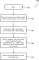
- a method of operating a trailer monitoring systemincludes receiving, from at least one monocular camera mounted to a vehicle towing a trailer, at least one monocular camera image of at least a portion of the trailer.
- the methodalso includes generating at least one depth map based on the at least one monocular camera image.
- the methodfurther includes identifying a trailer irregularity based on the at least one depth map.
- FIG. 1is an example of a trailer monitoring system for a vehicle configured to tow a trailer.
- FIG. 2 Ais an example of a monocular camera image of the trailer taken by a monocular camera mounted to the vehicle.
- FIG. 2 Bis an example of a depth map generated based on the monocular camera image.
- FIG. 3is an example of a depth map that the trailer monitoring system may use to detect an irregularity of the trailer, where the irregularity is an imminent collision with a nearby vehicle.
- FIG. 4 Ais an example of a first depth map that the trailer monitoring system may use to detect to detect an irregularity of the trailer, where the irregularity is lane departure.
- FIG. 4 Bis an example of a second depth map that the trailer monitoring system may use to detect lane departure.
- FIG. 4 Cis an example of a third depth map that the trailer monitoring system may use to detect lane departure.
- FIG. 5 Ais an example of a first depth map that the trailer monitoring system may use to detect to detect an irregularity of the trailer, where the irregularity is trailer sway.
- FIG. 5 Bis an example of a second depth map that the trailer monitoring system may use to detect trailer sway.
- FIG. 5 Cis an example of a third depth map that the trailer monitoring system may use to detect trailer sway.
- FIG. 6is an example of a monocular depth estimation (MDE) system.
- FIG. 7is an example of a method of generating a depth map based on a monocular camera image.
- FIG. 8is an example of a method of operating the trailer monitoring system.
- the trailer monitoring systemis configured to detect one or more irregularities of the trailer during towing, for example, an imminent collision of the trailer with a nearby object such as a nearby vehicle, departure of the trailer from the lane in which the vehicle is traveling, and/or swaying of the trailer within the lane in which the vehicle is traveling or across multiple lanes.
- the trailer monitoring systemmay detect an irregularity by receiving, from one or more monocular cameras mounted to the vehicle, one or more monocular camera images of at least a portion of the trailer. Based on the monocular camera image(s), the trailer monitoring system can generate one or more depth maps and identify the irregularity based on the depth map(s).
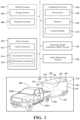
- a representative passenger vehicle 100is shown in FIG. 1 towing a representative trailer 102 .
- uses of “front,” “forward” and the like, and uses of “rear,” “rearward” and the like,refer to the longitudinal directions of the vehicle 100 .
- “Front,” “forward” and the likerefer to the front (fore) of the vehicle 100
- “rear,” “rearward” and the likerefer to the back (aft) of the vehicle 100 .
- Uses of “side,” “sideways,” “transverse” and the likerefer to the lateral directions of the vehicle 100 , with “driver's side” and the like referring to the left side of the vehicle 100 , and “passenger side” and the like referring to the right side of the vehicle 100 .
- the vehicle 100may be any suitable type of vehicle 100 .
- the vehicle 100is a pickup truck, but the vehicle 100 can be any other type of vehicle, such as a sedan, an SUV, a motorhome, etc.
- the vehicle 100is configured to tow the trailer 102 .
- the trailer 102is a storage trailer, but the trailer 102 can be any other type of trailer, such as a camper, a boat trailer, a flatbed trailer, etc.
- the vehicle 100includes an exterior and a number of interior compartments.
- the compartmentsinclude a passenger compartment, an engine compartment (and, in the illustrated pickup truck configuration of the vehicle 100 , an open-topped bed for carrying cargo).
- the vehicle 100may include seats, a dash assembly, an instrument panel, controls and the like housed in the passenger compartment.
- the vehicle 100may include an engine, a motor, a transmission, and the like, as well as other powertrain components, such as wheels, housed in the engine compartment and elsewhere in the vehicle 100 .
- the wheelssupport the remainder of the vehicle 100 on the ground. One, some or all of the wheels are powered by the remainder of the powertrain components to drive the vehicle 100 along the ground.
- the vehicle 100includes one or more vehicle systems 104 operable to perform vehicle functions.
- the vehicle 100includes a sensor system 110 as well as one or more processors 120 , a memory 122 , and a control module 124 to which the vehicle systems 104 and the sensor system 110 are communicatively connected.
- the sensor system 110is operable to detect information about the vehicle 100 .
- the processors 120 , the memory 122 , and the control module 124together serve as one or more computing devices 118 whose control module 124 is employable to orchestrate the operation of the vehicle 100 , in whole or in part.
- the control module 124operates the vehicle systems 104 based on information about the vehicle 100 .
- the control module 124gathers information about the vehicle 100 , including the information about the vehicle 100 detected by the sensor system 110 .
- the control module 124then evaluates the information about the vehicle 100 and operates the vehicle systems 104 based on its evaluation.
- the vehicle systems 104are part of, mounted to, or otherwise supported by the body.
- the vehicle systems 104may be housed, in whole or in part, in any combination of the passenger compartment, the engine compartment, or elsewhere in the vehicle 100 .
- Each vehicle system 104includes one or more vehicle elements.
- each vehicle elementOn behalf of the vehicle system 104 to which it belongs, each vehicle element is operable to perform, in whole or in part, any combination of vehicle functions with which the vehicle system 104 is associated. It will be understood that the vehicle elements, as well as the vehicle system 104 to which they belong, may but need not be mutually distinct.
- the vehicle systems 104include an energy system 106 and a propulsion system 108 .
- the energy system 106 and the propulsion system 108are connected to one another.
- the drivetrainis mechanically connected to the propulsion system 108 .
- the propulsion system 108 and the drivetraintogether serve as a powertrain for the vehicle 100 .
- the energy system 106is operable to perform one or more energy functions, including but not limited to storing and otherwise handling energy.
- the propulsion system 108is operable to perform one or more propulsion functions using energy from the energy system 106 , including but not limited to powering the wheels.
- the vehicle 100includes one or more vehicle sensors 112 and one or more environment sensors 114 .
- the vehicle sensor(s) 112monitor the vehicle 100 in real-time.
- the vehicle sensor(s) 112on behalf of the sensor system 110 , are operable to detect information about the vehicle 100 , including information about user requests and information about the operation of the vehicle 100 .
- the vehicle sensor(s) 112can be configured to detect and/or acquire data about various operating parameters of the vehicle 100 .
- the vehicle sensor(s) 112can include one or more speedometers, one or more gyroscopes, one or more accelerometers, one or more inertial measurement units (IMUs), one or more wheel sensors, one or more steering angle sensors, one or more controller area network (CAN) sensors, and the like.
- the sensor system 110is operable to detect the location and motion of the vehicle 100 , including its speed, acceleration, orientation, rotation, direction, and the like, the movement of the wheels, the steering angle, and the operational statuses of one, some, or all of the vehicle systems 104 .
- the environment sensor(s) 114can be configured to detect, determine, assess, monitor, measure, quantify, acquire, and/or sense data or information about the external environment in which the vehicle 100 is located or one or more portions thereof.
- the environment sensor(s) 114can include one or more exterior cameras and one or more exterior sensors, such as temperature sensors, weather sensors, LIDAR, RADAR, etc.
- the exterior camerascan include one or more monocular cameras 116 .
- the environment sensor(s) 114can be located on an exterior of the vehicle 100 or can be located in any other suitable location on the vehicle 100 .
- the vehicle systems 104can determine information about the external environment of the vehicle 100 .
- the vehicle systems 104can detect one or more objects in the external environment of the vehicle 100 .
- the vehicle systems 104 , the sensor system 110 , the processors 120 , the memory 122 , and the control module 124may be leveraged to implement a monocular depth estimation (MDE) system 126 .
- MDEmonocular depth estimation
- the vehicle systems 104 , the sensor system 110 , the processors 120 , the memory 122 , and the control module 124 leveraged to implement the MDE system 126may be part of one or more other control systems typical of vehicles or may be dedicated to the MDE system 126 .
- the MDE system 126will be described with reference to a representative monocular camera image 200 as shown in FIG. 2 A , a depth map 202 of FIG. 2 B , a depth map 300 of FIG.
- the MDE system 126may be configured to generate depth map(s) of at least a portion of the external environment of the vehicle 100 based on information received from the sensor system 110 . More specifically, the MDE system 126 may be configured to generate depth map(s) based, at least in part, on information received by the monocular camera(s) 116 . The depth map(s) may then be used as an input to other vehicle systems 104 , for example, a trailer monitoring system 128 , as described in further detail below.
- the vehicle 100may include one or more monocular cameras 116 .
- the monocular camera(s) 116may be mounted to the exterior of the vehicle 100 at the front of the vehicle 100 , at the rear of the vehicle 100 , and/or at any other location on the vehicle 100 .
- the monocular camera(s) 116can be mounted to the rear of the vehicle 100 and/or one or more side view mirrors 130 ( FIG. 1 ) of the vehicle 100 (for example, a left side view mirror 130 A and a right side view mirror 130 B) and can have a field of view of at least a portion of the trailer 102 .
- the monocular camera(s) 116are configured to capture one or more monocular camera images of the trailer 102 . Referring now to FIG.
- FIG. 2 Aan example of a monocular camera image 200 is shown.
- the monocular camera image 200shows a view of a front of the trailer 102 .
- the monocular camera image 200may be a color image typical of other types of vehicle-mounted cameras.
- FIG. 2 Ban example of a depth map 202 is shown.
- the depth map 202is generated based on the monocular camera image 200 and is a monochrome image in which the pixel values of the depth map 202 are proportional to the distance between the monocular camera 116 and the object in the monocular camera image 200 (e.g., the trailer 102 ).
- the vehicle systems 104 , the sensor system 110 , the processor(s) 120 , the memory 122 , and the control module 124may be leveraged to implement a trailer monitoring system 128 based on the MDE system 126 .
- the vehicle systems 104 , the sensor system 110 , the processor(s) 120 , the memory 122 , and the control module 124 leveraged to implement the trailer monitoring system 128may be part of one or more other control systems typical of vehicles or may be dedicated to the trailer monitoring system 128 .
- the trailer monitoring system 128may be configured to identify one or more trailer irregularities based only on the depth map(s).
- the trailer monitoring system 128may be configured to identify one or more contours of the trailer 102 . More specifically, based on each depth map 202 , a point cloud may be generated including an array of points that each correspond to the distance from the trailer 102 to the monocular camera 116 . Using a direct transformation, the point cloud can be used to detect the contours. Referring back to FIG. 1 , the contours can include one or more faces, for example, a front face 132 corresponding to the front of the trailer 102 , a left face 134 corresponding to the left side of the trailer 102 , and a right face 136 corresponding to the right side of the trailer 102 .
- the contourscan also include one or more edges, for example, two front side edges and two rear side edges.
- the two front side edgescan include a front left side edge 138 and a front right side edge 140 .
- the two rear side edgescan include a rear left side edge 142 and a rear right side edge 144 .
- the edgescan also include one or more top edges.
- the top edgescan include a top left side edge 146 and a top right side edge 148 .
- the edgescan also include one or more bottom edges.
- the bottom edgescan include a front bottom edge 150 , a left side bottom edge 152 , and a right side bottom edge 154 .
- the trailer irregularitycan be identified using a single depth map.
- the trailer irregularitycan be an imminent collision between the trailer 102 and an object 312 near the trailer 102 .
- the object 312may be a nearby vehicle located in a lane adjacent the vehicle 100 and the trailer 102 , as shown, or any other object.
- the objectcan be a fixed feature of the environment, such as one or more curbs, light poles, traffic lights, road signs, etc.
- the trailer monitoring system 128can identify an imminent collision between the trailer 102 and the object 312 by comparing the depth of one or more of the contours to the depth of the object 312 .
- an imminent collisionmay be identified.
- the trailer monitoring system 128can compare the depth of the front right side edge 140 and/or the depth of the rear right side edge 144 to the depth of the object 312 , and, if the depths are the same or similar, the trailer monitoring system 128 can identify an imminent collision with the object 312 .
- the trailer monitoring system 128can compare the depth of the front left side edge 138 and/or the depth of the rear left side edge 142 to the depth of the other vehicle, and, if the depths are the same, the trailer monitoring system 128 can identify an imminent collision between the trailer 102 and the other vehicle.
- the object 312may be the vehicle 100 itself, and the imminent collision may be an imminent collision between the trailer 102 and the vehicle 100 itself. This may occur when the vehicle 100 is making a sharp turn.
- the trailer irregularitymay be identified by comparing the depth of one or more of the contours over a plurality of consecutive or otherwise successive depth maps.
- the monocular camera(s) 116may be configured to capture a monocular camera image every second, for example, and thus, generate a depth map every second.
- the trailer irregularitycan be identified by detecting a change in the depth of one or more of the contours over time as the trailer 102 is moving. Referring to FIGS. 4 A- 4 C , the trailer irregularity can be departure of the trailer 102 from the lane in which the vehicle 100 is traveling (lane departure), assuming the vehicle 100 itself is not switching lanes.
- the trailer monitoring system 128can identify lane departure when the depth of one or more of the contours decreases over successive depth maps 400 , 402 , and 404 .
- the depth of each of the front face 132 , the right face 136 , the front right side edge 140 , the right side bottom edge 154 , and the rear right side edge 144all decrease over the successive depth maps 400 , 402 , and 404 , and the trailer monitoring system 128 can identify that the trailer 102 has departed the lane and at least a portion of the trailer 102 is in the adjacent right lane. More specifically, referring to FIG.
- FIG. 4 Awhich shows a first successive depth map 400
- the trailer 102is shown traveling in the same lane as the vehicle 100 , and is not departing the lane.
- FIG. 4 Bwhich shows a second successive depth map 402 , shows the trailer 102 moving into the adjacent lane.
- the depth of the front face 132 , the right face 136 , the front right side edge 140 , the right side bottom edge 154 , and/or the rear right side edge 144are less than they are in FIG. 4 A , and thus, the trailer monitoring system 128 can identify lane departure.
- FIG. 4 Cwhich shows a third successive depth map 404 , shows the trailer 102 moving further into the adjacent lane.
- the depth of the front face 132 , the right face 136 , the front right side edge 140 , the right side bottom edge 154 , and/or the rear right side edge 144are less than they are in FIG. 4 B , and thus, the trailer monitoring system 128 can identify lane departure.
- the trailer irregularitycan be swaying of the trailer 102 (trailer sway).
- the trailer monitoring system 128can identify trailer sway when the depth of one or more of the contours fluctuates (e.g., increases and decreases repeatedly) over successive depth maps 500 , 502 , and 504 .
- the trailer monitoring system 128can identify trailer sway when the depth of the front face 132 fluctuates, when the depth of the front right side edge 140 fluctuates, and/or when the depth of the front left side edge 138 fluctuates.
- the depth of the left face 134 , the left front side edge 138 , the rear left side edge 142 , and/or the left side bottom edge 152may fluctuate when the trailer is swaying toward the left.
- the depth of the right face 136 , the front right side edge 140 , the rear right side edge 144 , and/or the right side bottom edge 154may fluctuate when the trailer is swaying to the right.
- the trailer monitoring system 128can identify trailer sway when the depth of the right side of the trailer 102 fluctuates, for example, when the depth of the right face 136 fluctuates, when the depth of the top right side edge 148 fluctuates, and/or when the depth of the rear right side edge 144 fluctuates.
- the trailer monitoring system 128can identify trailer sway when the depth of the left side of the trailer 102 fluctuates, for example, when the depth of the left face 134 fluctuates, when the depth of the top left side edge 146 fluctuates, and/or when the depth of the rear left side edge 142 fluctuates.
- the trailer monitoring system 128may be configured to issue a warning or make a corrective action by taking control of the vehicle 100 .
- the trailer monitoring system 128can issue a warning to the driver and/or take control of the steering and/or speed of the vehicle 100 to reduce the trailer sway.
- the trailer monitoring system 128can issue a warning to the driver, take control of the steering and/or speed of the vehicle 100 to bring the trailer 102 back in the lane, and/or issue a warning to nearby vehicles, such as by honking or flashing the lights of the vehicle 100 and/or the trailer 102 .
- the trailer monitoring system 128can issue a warning to the driver, take control of the steering and/or speed of the vehicle 100 to prevent the collision, and/or issue a warning to nearby vehicles, such as by honking or flashing the lights of the vehicle 100 and/or the trailer 102 .
- the MDE system 126may be configured to receive an input 600 and generate an output 650 .
- the input 600may be the monocular camera image 200 .
- the monocular camera image 200can be a color image taken by a monocular camera 116 .
- the output 650can be the identification of one or more contours of the trailer 102 .
- the MDE system 126includes a monocular depth estimation (MDE) module 610 , a road segmentation and extraction (RSE) module 620 , a feature extraction module 630 , and one or more processor(s) 640 .
- the processor(s) 640may be the processor(s) 120 of FIG. 1 or any other suitable processor(s).
- the MDE module 610 , the RSE module 620 , and/or the feature extraction module 630can be components of the processor(s) 640 or may be components of one or more other processors.
- the MDE module 610is configured to receive the input 600 (i.e., the monocular camera image 200 ) and generate a depth map 202 using machine learning or any other suitable method.
- the depth map 202is a grayscale image in which each pixel value is proportional to the distance to the monocular camera 116 .
- the RSE module 620is configured to receive the monocular camera image 200 and/or the depth map 202 and detect, segment out, and extract the part of the monocular camera image 200 and/or the depth map 202 corresponding to the road.
- the feature extraction module 630may receive the input 600 and may be configured to detect features (e.g., one or more contours of the trailer 102 ) in the monocular camera image 200 .
- the processor(s) 640may function as a decision system based on the input 600 (i.e., the monocular camera image 200 ), the depth map 202 , the road, and/or the features to generate the output 650 .
- the output 650may be the detection of one or more contours of the trailer 102 .
- the processor(s) 120 , the memory 122 , and the control module 124together serve as the computing device(s) 118 whose control module 124 orchestrates the operation of the vehicle 100 , including but not limited to the operation of the vehicle systems 104 .
- the control module 124may be a dedicated control module for the trailer monitoring system 128 and/or the MDE system 126 .
- the vehicle 100may include a global control unit (GCU) to which the control module 124 is communicatively connected.
- the control module 124may be a global control module.
- the vehicle 100may include a global control unit (GCU) to which the control module 124 belongs.
- GCUglobal control unit
- the vehicle 100 as shownincludes one control module 124 , it will be understood that this disclosure is applicable in principle to otherwise similar vehicles including multiple control modules.
- the control module 124is shown as part of the vehicle 100 , it will be understood that the control module 124 may be located offboard the vehicle 100 .
- the processor(s) 120may be any components configured to execute any of the processes described herein or any form of instructions to carry out such processes or cause such processes to be performed.
- the processor(s) 120may be implemented with one or more general-purpose or special-purpose processors. Examples of suitable processors include microprocessors, microcontrollers, digital signal processors, or other forms of circuitry that execute software. Other examples of suitable processors include, without limitation, central processing units (CPUs), array processors, vector processors, digital signal processors (DSPs), field programmable gate arrays (FPGAs), programmable logic arrays (PLAs), application specific integrated circuits (ASICs), programmable logic circuitry, or controllers.
- CPUscentral processing units
- DSPsdigital signal processors
- FPGAsfield programmable gate arrays
- PLAsprogrammable logic arrays
- ASICsapplication specific integrated circuits
- the processor(s) 120may include at least one hardware circuit (e.g., an integrated circuit) configured to carry out instructions contained in program code. In arrangements where there are multiple processors, the processors may work independently from each other or in combination with one another. Moreover, although the processor(s) 120 are shown as part of the vehicle 100 , it will be understood that the processor(s) 120 may be located offboard the vehicle 100 .
- hardware circuite.g., an integrated circuit
- the memory 122is a non-transitory computer readable medium.
- the memory 122may include volatile or nonvolatile memory, or both. Examples of suitable memory include random access memory (RAM), flash memory, read-only memory (ROM), programmable read-only memory (PROM), erasable programmable read-only memory (EPROM), electrically erasable programmable read-only memory (EEPROM), registers, magnetic disks, optical disks, hard drives, or any other suitable storage medium, or any combination of these.
- RAMrandom access memory
- ROMread-only memory
- PROMprogrammable read-only memory
- EPROMerasable programmable read-only memory
- EEPROMelectrically erasable programmable read-only memory
- registersmagnetic disks, optical disks, hard drives, or any other suitable storage medium, or any combination of these.
- the memory 122includes stored instructions in program code. Such instructions are executable by the processor(s) 120 or the control module 124 .
- the memory 122may be part of the processor(s) 120 or the control module 124 or may be communicatively connected to the processor(s) 120 or the control module 124 .
- the control module 124includes instructions that may be executed by the processor(s) 120 .
- the control module 124may be implemented as computer readable program code that, when executed by the processor(s) 120 , executes one or more of the processes described herein. Such computer readable program code may be stored in the memory 122 .
- the control module 124may be part of the processor(s) 120 or may be communicatively connected to the processor(s) 120 .
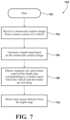
- the method 700may begin in operation 702 .
- the method 700may include receiving a monocular camera image 200 from a sensor system 110 of a vehicle 100 .
- the method 700may include generating a depth map 202 based on the monocular camera image 200 .
- the methodmay include detecting, segmenting out, and extracting a part of the depth map 202 corresponding to a surface upon which the vehicle 100 and the trailer 102 are traveling.
- the method 700may include detecting and extracting features from the depth map 202 .
- the method 700may be used to detect one or more contours of the trailer 102 .
- the method 800may begin in operation 802 .
- the method 800may include receiving, from at least one monocular camera 116 mounted to the vehicle 100 , at least one monocular camera image 200 of at least a portion of the trailer 102 .
- the method 800may include generating at least one depth map 202 based on the at least one monocular camera image 200 .
- the method 800may include identifying one or more contours of the trailer 102 based on the depth map 202 .
- the method 800may include identifying at least one trailer irregularity based on the depth of the one or more contours.
- the method 800can proceed to operation 812 and/or operation 814 .
- the method 800includes issuing a warning to a driver of the vehicle 100 and/or a nearby vehicle when the trailer irregularity is identified.
- the method 800includes taking control of the steering of the vehicle 100 and/or the speed of the vehicle 100 when the trailer irregularity is identified.
Landscapes
- Engineering & Computer Science (AREA)
- Mechanical Engineering (AREA)
- Automation & Control Theory (AREA)
- Physics & Mathematics (AREA)
- Transportation (AREA)
- General Physics & Mathematics (AREA)
- Theoretical Computer Science (AREA)
- Multimedia (AREA)
- Computer Vision & Pattern Recognition (AREA)
- Signal Processing (AREA)
- Human Computer Interaction (AREA)
- Acoustics & Sound (AREA)
- Quality & Reliability (AREA)
- Traffic Control Systems (AREA)
Abstract
Description
Claims (17)
Priority Applications (1)
| Application Number | Priority Date | Filing Date | Title |
|---|---|---|---|
| US17/963,546US12233858B2 (en) | 2022-10-11 | 2022-10-11 | Trailer monitoring system |
Applications Claiming Priority (1)
| Application Number | Priority Date | Filing Date | Title |
|---|---|---|---|
| US17/963,546US12233858B2 (en) | 2022-10-11 | 2022-10-11 | Trailer monitoring system |
Publications (2)
| Publication Number | Publication Date |
|---|---|
| US20240116497A1 US20240116497A1 (en) | 2024-04-11 |
| US12233858B2true US12233858B2 (en) | 2025-02-25 |
Family
ID=90574660
Family Applications (1)
| Application Number | Title | Priority Date | Filing Date |
|---|---|---|---|
| US17/963,546Active2043-05-29US12233858B2 (en) | 2022-10-11 | 2022-10-11 | Trailer monitoring system |
Country Status (1)
| Country | Link |
|---|---|
| US (1) | US12233858B2 (en) |
Families Citing this family (1)
| Publication number | Priority date | Publication date | Assignee | Title |
|---|---|---|---|---|
| US12233858B2 (en)* | 2022-10-11 | 2025-02-25 | Toyota Motor Engineering & Manufacturing North America, Inc. | Trailer monitoring system |
Citations (34)
| Publication number | Priority date | Publication date | Assignee | Title |
|---|---|---|---|---|
| US20090271078A1 (en)* | 2008-04-29 | 2009-10-29 | Mike Dickinson | System and method for identifying a trailer being towed by a vehicle |
| US20130226390A1 (en)* | 2012-02-29 | 2013-08-29 | Robert Bosch Gmbh | Hitch alignment assistance |
| US20140160276A1 (en)* | 2012-09-26 | 2014-06-12 | Magna Electronics Inc. | Vehicle vision system with trailer angle detection |
| US20140200759A1 (en)* | 2011-01-26 | 2014-07-17 | Magna Electronics Inc. | Rear vision system with trailer angle detection |
| US20170217372A1 (en)* | 2016-02-02 | 2017-08-03 | Magna Electronics Inc. | Wireless camera system for vehicle and trailer |
| US20180121742A1 (en)* | 2016-11-02 | 2018-05-03 | Lg Electronics Inc. | Apparatus for providing around view image, and vehicle |
| US9963004B2 (en)* | 2014-07-28 | 2018-05-08 | Ford Global Technologies, Llc | Trailer sway warning system and method |
| US20180350108A1 (en)* | 2017-05-30 | 2018-12-06 | Denso International America, Inc. | Smart Hitch Assistant System |
| US20190016382A1 (en)* | 2017-07-13 | 2019-01-17 | Continental Automotive Systems, Inc. | Trailer Reverse Assist With Follow-Me System |
| US20190064831A1 (en)* | 2017-08-25 | 2019-02-28 | Magna Electronics Inc. | Vehicle and trailer maneuver assist system |
| US20190283803A1 (en)* | 2018-03-13 | 2019-09-19 | Toyota Motor Engineering & Manufacturing North America, Inc. | Backup system for a vehicle with a trailer hitch |
| US20190322317A1 (en)* | 2018-04-18 | 2019-10-24 | GM Global Technology Operations LLC | System and method for automatically determining dimensions of a trailer |
| EP3560796A1 (en)* | 2018-04-26 | 2019-10-30 | Volkswagen Aktiengesellschaft | Trailer driving assistance system for a motor vehicle and method for operating a trailer driving assistance system of a motor vehicle |
| US20190340787A1 (en)* | 2018-05-01 | 2019-11-07 | Continental Automotive Systems, Inc. | Real-Time Trailer Coupler Localization and Tracking |
| US20200104612A1 (en)* | 2018-09-27 | 2020-04-02 | Baidu Online Network Technology (Beijing) Co., Ltd. | Method and apparatus for detecting obstacle, electronic device, vehicle and storage medium |
| US20200269852A1 (en)* | 2019-02-26 | 2020-08-27 | Robert Bosch Gmbh | Trailer characteristic estimation with vehicle sensors |
| US20210094473A1 (en)* | 2019-09-27 | 2021-04-01 | Magna Electronics Inc. | Vehicular trailering assist system |
| US11030476B2 (en)* | 2018-11-29 | 2021-06-08 | Element Ai Inc. | System and method for detecting and tracking objects |
| DE102019133948A1 (en)* | 2019-12-11 | 2021-06-17 | Connaught Electronics Ltd. | Method for driver assistance for a combination of a motor vehicle and a trailer |
| US20220001921A1 (en)* | 2018-11-07 | 2022-01-06 | Hitachi Astemo, Ltd. | Steering Control Device, Steering Control Method, and Steering Control System |
| US11231716B2 (en)* | 2020-01-28 | 2022-01-25 | GM Global Technology Operations LLC | Method and apparatus for determining trailer dimensions in a motor vehicle |
| US20220147742A1 (en)* | 2020-11-10 | 2022-05-12 | Ford Global Technologies, Llc | System and method for training trailer detection systems |
| US20220237952A1 (en)* | 2021-01-27 | 2022-07-28 | Ford Global Technologies, Llc | Systems and methods for modeling electric vehicle towing |
| US20220343535A1 (en)* | 2021-04-27 | 2022-10-27 | Continental Automotive Systems, Inc. | System and method for estimating relative trailer angle |
| US20220358677A1 (en)* | 2019-09-19 | 2022-11-10 | Continental Advanced Lidar Solutions Us, Llc | Automatic trailer camera calibration |
| US20220410804A1 (en)* | 2021-06-29 | 2022-12-29 | Ford Global Technologies, Llc | Trailer hitching assistance system including trailer type identification and adaptive interface |
| US20230128009A1 (en)* | 2021-10-26 | 2023-04-27 | Zebra Technologies Corporation | Systems and methods for assessing trailer utilization |
| US20230162509A1 (en)* | 2021-11-24 | 2023-05-25 | Paccar Inc. | Tractor-based trailer clearance and positioning system and method |
| US20230192122A1 (en)* | 2021-12-22 | 2023-06-22 | Eduardo Jose Ramirez Llanos | Autonomous vehicle trailer hitch coupling system |
| US20230249680A1 (en)* | 2022-02-10 | 2023-08-10 | Toyota Motor Eng & Mfg N.A., Inc. | Systems and methods for navigating a trailer with a vehicle when a physical connection disconnects |
| DE102022126702A1 (en)* | 2022-04-19 | 2023-10-19 | GM Global Technology Operations LLC | VEHICLE AND TRAILER PATH COLLISION DETECTION AND ALERT |
| US20240110805A1 (en)* | 2022-09-30 | 2024-04-04 | Toyota Motor Engineering & Manufacturing North America, Inc. | Parking assist system |
| US20240116530A1 (en)* | 2022-10-11 | 2024-04-11 | Toyota Motor Engineering & Manufacturing North America, Inc. | Object detection system |
| US20240116497A1 (en)* | 2022-10-11 | 2024-04-11 | Toyota Motor Engineering & Manufacturing North America, Inc. | Trailer monitoring system |
- 2022
- 2022-10-11USUS17/963,546patent/US12233858B2/enactiveActive
Patent Citations (54)
| Publication number | Priority date | Publication date | Assignee | Title |
|---|---|---|---|---|
| US20090271078A1 (en)* | 2008-04-29 | 2009-10-29 | Mike Dickinson | System and method for identifying a trailer being towed by a vehicle |
| US20140200759A1 (en)* | 2011-01-26 | 2014-07-17 | Magna Electronics Inc. | Rear vision system with trailer angle detection |
| US20130226390A1 (en)* | 2012-02-29 | 2013-08-29 | Robert Bosch Gmbh | Hitch alignment assistance |
| US20140160276A1 (en)* | 2012-09-26 | 2014-06-12 | Magna Electronics Inc. | Vehicle vision system with trailer angle detection |
| US9963004B2 (en)* | 2014-07-28 | 2018-05-08 | Ford Global Technologies, Llc | Trailer sway warning system and method |
| US20170217372A1 (en)* | 2016-02-02 | 2017-08-03 | Magna Electronics Inc. | Wireless camera system for vehicle and trailer |
| US20180121742A1 (en)* | 2016-11-02 | 2018-05-03 | Lg Electronics Inc. | Apparatus for providing around view image, and vehicle |
| EP3318469A1 (en)* | 2016-11-02 | 2018-05-09 | LG Electronics Inc. | Apparatus for providing around view image, and vehicle |
| US10496892B2 (en)* | 2016-11-02 | 2019-12-03 | Lg Electronics Inc. | Apparatus for providing around view image, and vehicle |
| US20180350108A1 (en)* | 2017-05-30 | 2018-12-06 | Denso International America, Inc. | Smart Hitch Assistant System |
| US20190016382A1 (en)* | 2017-07-13 | 2019-01-17 | Continental Automotive Systems, Inc. | Trailer Reverse Assist With Follow-Me System |
| US10899384B2 (en)* | 2017-07-13 | 2021-01-26 | Continental Automotive Systems, Inc. | Trailer reverse assist with follow-me system |
| US20190064831A1 (en)* | 2017-08-25 | 2019-02-28 | Magna Electronics Inc. | Vehicle and trailer maneuver assist system |
| US12001213B2 (en)* | 2017-08-25 | 2024-06-04 | Magna Electronics Inc. | Vehicle and trailer maneuver assist system |
| US20210341929A1 (en)* | 2017-08-25 | 2021-11-04 | Magna Electronics Inc. | Vehicle and trailer maneuver assist system |
| US11067993B2 (en)* | 2017-08-25 | 2021-07-20 | Magna Electronics Inc. | Vehicle and trailer maneuver assist system |
| US20190283803A1 (en)* | 2018-03-13 | 2019-09-19 | Toyota Motor Engineering & Manufacturing North America, Inc. | Backup system for a vehicle with a trailer hitch |
| US10479404B2 (en)* | 2018-03-13 | 2019-11-19 | Toyota Motor Engineering & Manufacturing North America, Inc. | Backup system for a vehicle with a trailer hitch |
| US20190322317A1 (en)* | 2018-04-18 | 2019-10-24 | GM Global Technology Operations LLC | System and method for automatically determining dimensions of a trailer |
| EP3560796A1 (en)* | 2018-04-26 | 2019-10-30 | Volkswagen Aktiengesellschaft | Trailer driving assistance system for a motor vehicle and method for operating a trailer driving assistance system of a motor vehicle |
| US10875574B2 (en)* | 2018-04-26 | 2020-12-29 | Volkswagen Aktiengesellschaft | Method for operating a trailer maneuvering assistance system of a transportation vehicle and trailer maneuvering assistance system for a transportation vehicle |
| US20190329821A1 (en)* | 2018-04-26 | 2019-10-31 | Volkswagen Aktiengesellschaft | Method for operating a trailer maneuvering assistance system of a transportation vehicle and trailer maneuvering assistance system for a transportation vehicle |
| US10984553B2 (en)* | 2018-05-01 | 2021-04-20 | Continental Automotive Systems, Inc. | Real-time trailer coupler localization and tracking |
| US20190340787A1 (en)* | 2018-05-01 | 2019-11-07 | Continental Automotive Systems, Inc. | Real-Time Trailer Coupler Localization and Tracking |
| US20200104612A1 (en)* | 2018-09-27 | 2020-04-02 | Baidu Online Network Technology (Beijing) Co., Ltd. | Method and apparatus for detecting obstacle, electronic device, vehicle and storage medium |
| US20220001921A1 (en)* | 2018-11-07 | 2022-01-06 | Hitachi Astemo, Ltd. | Steering Control Device, Steering Control Method, and Steering Control System |
| US11030476B2 (en)* | 2018-11-29 | 2021-06-08 | Element Ai Inc. | System and method for detecting and tracking objects |
| US20200269852A1 (en)* | 2019-02-26 | 2020-08-27 | Robert Bosch Gmbh | Trailer characteristic estimation with vehicle sensors |
| US20220358677A1 (en)* | 2019-09-19 | 2022-11-10 | Continental Advanced Lidar Solutions Us, Llc | Automatic trailer camera calibration |
| US20210094473A1 (en)* | 2019-09-27 | 2021-04-01 | Magna Electronics Inc. | Vehicular trailering assist system |
| US11661006B2 (en)* | 2019-09-27 | 2023-05-30 | Magna Electronics Inc. | Vehicular trailering assist system |
| DE102019133948A1 (en)* | 2019-12-11 | 2021-06-17 | Connaught Electronics Ltd. | Method for driver assistance for a combination of a motor vehicle and a trailer |
| US11231716B2 (en)* | 2020-01-28 | 2022-01-25 | GM Global Technology Operations LLC | Method and apparatus for determining trailer dimensions in a motor vehicle |
| US20220147742A1 (en)* | 2020-11-10 | 2022-05-12 | Ford Global Technologies, Llc | System and method for training trailer detection systems |
| US11721108B2 (en)* | 2020-11-10 | 2023-08-08 | Ford Global Technologies, Llc | System and method for training trailer detection systems |
| US20220237952A1 (en)* | 2021-01-27 | 2022-07-28 | Ford Global Technologies, Llc | Systems and methods for modeling electric vehicle towing |
| US11983969B2 (en)* | 2021-01-27 | 2024-05-14 | Ford Global Technologies, Llc | Systems and methods for modeling electric vehicle towing |
| US20220343535A1 (en)* | 2021-04-27 | 2022-10-27 | Continental Automotive Systems, Inc. | System and method for estimating relative trailer angle |
| US20220410804A1 (en)* | 2021-06-29 | 2022-12-29 | Ford Global Technologies, Llc | Trailer hitching assistance system including trailer type identification and adaptive interface |
| US11787336B2 (en)* | 2021-06-29 | 2023-10-17 | Ford Global Technologies , Llc | Trailer hitching assistance system including trailer type identification and adaptive interface |
| US20230415648A1 (en)* | 2021-06-29 | 2023-12-28 | Ford Global Technologies, Llc | Trailer hitching assistance system including trailer type identification and adaptive interface |
| WO2023075892A1 (en)* | 2021-10-26 | 2023-05-04 | Zebra Technologies Corporation | Systems and methods for assessing trailer utilization |
| US11763439B2 (en)* | 2021-10-26 | 2023-09-19 | Zebra Technologies Corporation | Systems and methods for assessing trailer utilization |
| US20230128009A1 (en)* | 2021-10-26 | 2023-04-27 | Zebra Technologies Corporation | Systems and methods for assessing trailer utilization |
| US20230162509A1 (en)* | 2021-11-24 | 2023-05-25 | Paccar Inc. | Tractor-based trailer clearance and positioning system and method |
| US20230192122A1 (en)* | 2021-12-22 | 2023-06-22 | Eduardo Jose Ramirez Llanos | Autonomous vehicle trailer hitch coupling system |
| US20230249680A1 (en)* | 2022-02-10 | 2023-08-10 | Toyota Motor Eng & Mfg N.A., Inc. | Systems and methods for navigating a trailer with a vehicle when a physical connection disconnects |
| DE102022126702A1 (en)* | 2022-04-19 | 2023-10-19 | GM Global Technology Operations LLC | VEHICLE AND TRAILER PATH COLLISION DETECTION AND ALERT |
| US20230331298A1 (en)* | 2022-04-19 | 2023-10-19 | GM Global Technology Operations LLC | Vehicle and trailer wheel path collision detection and alert |
| US11794809B1 (en)* | 2022-04-19 | 2023-10-24 | GM Global Technology Opertions LLC | Vehicle and trailer wheel path collision detection and alert |
| CN116946121A (en)* | 2022-04-19 | 2023-10-27 | 通用汽车环球科技运作有限责任公司 | Vehicle and trailer wheel path collision detection and warning |
| US20240110805A1 (en)* | 2022-09-30 | 2024-04-04 | Toyota Motor Engineering & Manufacturing North America, Inc. | Parking assist system |
| US20240116530A1 (en)* | 2022-10-11 | 2024-04-11 | Toyota Motor Engineering & Manufacturing North America, Inc. | Object detection system |
| US20240116497A1 (en)* | 2022-10-11 | 2024-04-11 | Toyota Motor Engineering & Manufacturing North America, Inc. | Trailer monitoring system |
Also Published As
| Publication number | Publication date |
|---|---|
| US20240116497A1 (en) | 2024-04-11 |
Similar Documents
| Publication | Publication Date | Title |
|---|---|---|
| US12352862B2 (en) | Lidar-based trailer tracking | |
| US11377029B2 (en) | Vehicular trailering assist system with trailer state estimation | |
| US11887378B2 (en) | Close-in sensing camera system | |
| US12366857B2 (en) | Perimeter sensor housings | |
| US10078892B1 (en) | Methods and systems for vehicle tire analysis using vehicle mounted cameras | |
| US20190073540A1 (en) | Vehicle control device, vehicle control method, and storage medium | |
| US10372131B2 (en) | Vehicles changing lanes based on trailing vehicles | |
| US11663860B2 (en) | Dynamic and variable learning by determining and using most-trustworthy inputs | |
| US20180074200A1 (en) | Systems and methods for determining the velocity of lidar points | |
| CN109278642B (en) | Vehicle Reversing Safety Mapping | |
| CN112977465A (en) | Method and apparatus for determining trailer hitch articulation angle in motor vehicle | |
| US12233858B2 (en) | Trailer monitoring system | |
| CN110134122A (en) | A Deep Learning Method Based on Hyperspectral Imaging Technology | |
| US12103553B2 (en) | Object detection system | |
| US12240480B2 (en) | Methods and systems for providing trailer guidance | |
| US12325414B2 (en) | Methods and systems for tracking of attached objects | |
| US20210114532A1 (en) | Image processing apparatus, imaging apparatus, and moveable body | |
| US20240110805A1 (en) | Parking assist system | |
| US11770495B2 (en) | Generating virtual images based on captured image data | |
| KR102826869B1 (en) | Auxiliary method for surrounding recognition based on camera of vehicle using road moisture information of first ultrasonic sensor | |
| US12412295B2 (en) | Methods and systems for estimating hitch articulation angle | |
| US20240227681A9 (en) | Methods and systems for augmented trailer view for vehicles | |
| US11410427B2 (en) | Vision system and method for a motor vehicle | |
| US20250322669A1 (en) | Close-in Sensing Camera System |
Legal Events
| Date | Code | Title | Description |
|---|---|---|---|
| FEPP | Fee payment procedure | Free format text:ENTITY STATUS SET TO UNDISCOUNTED (ORIGINAL EVENT CODE: BIG.); ENTITY STATUS OF PATENT OWNER: LARGE ENTITY | |
| AS | Assignment | Owner name:TOYOTA JIDOSHA KABUSHIKI KAISHA, JAPAN Free format text:ASSIGNMENT OF ASSIGNORS INTEREST;ASSIGNORS:SISBOT, EMRAH AKIN;UCAR, SEYHAN;HIGUCHI, TAKAMASA;AND OTHERS;REEL/FRAME:061467/0748 Effective date:20221010 Owner name:TOYOTA MOTOR ENGINEERING & MANUFACTURING NORTH AMERICA, INC., TEXAS Free format text:ASSIGNMENT OF ASSIGNORS INTEREST;ASSIGNORS:SISBOT, EMRAH AKIN;UCAR, SEYHAN;HIGUCHI, TAKAMASA;AND OTHERS;REEL/FRAME:061467/0748 Effective date:20221010 | |
| STPP | Information on status: patent application and granting procedure in general | Free format text:DOCKETED NEW CASE - READY FOR EXAMINATION | |
| STPP | Information on status: patent application and granting procedure in general | Free format text:NON FINAL ACTION MAILED | |
| STPP | Information on status: patent application and granting procedure in general | Free format text:RESPONSE TO NON-FINAL OFFICE ACTION ENTERED AND FORWARDED TO EXAMINER | |
| STPP | Information on status: patent application and granting procedure in general | Free format text:NOTICE OF ALLOWANCE MAILED -- APPLICATION RECEIVED IN OFFICE OF PUBLICATIONS | |
| STPP | Information on status: patent application and granting procedure in general | Free format text:AWAITING TC RESP., ISSUE FEE NOT PAID | |
| STPP | Information on status: patent application and granting procedure in general | Free format text:NOTICE OF ALLOWANCE MAILED -- APPLICATION RECEIVED IN OFFICE OF PUBLICATIONS | |
| STPP | Information on status: patent application and granting procedure in general | Free format text:PUBLICATIONS -- ISSUE FEE PAYMENT VERIFIED | |
| STCF | Information on status: patent grant | Free format text:PATENTED CASE | |
| AS | Assignment | Owner name:TOYOTA MOTOR ENGINEERING & MANUFACTURING NORTH AMERICA, INC., TEXAS Free format text:ASSIGNMENT OF ASSIGNORS INTEREST;ASSIGNOR:TOYOTA JIDOSHA KABUSHIKI KAISHA;REEL/FRAME:070967/0441 Effective date:20250409 |