US12233232B2 - Genderless aseptic connector - Google Patents
Genderless aseptic connectorDownload PDFInfo
- Publication number
- US12233232B2 US12233232B2US18/645,975US202418645975AUS12233232B2US 12233232 B2US12233232 B2US 12233232B2US 202418645975 AUS202418645975 AUS 202418645975AUS 12233232 B2US12233232 B2US 12233232B2
- Authority
- US
- United States
- Prior art keywords
- coupler
- valve
- conduit
- passageway
- elastically deformable
- Prior art date
- Legal status (The legal status is an assumption and is not a legal conclusion. Google has not performed a legal analysis and makes no representation as to the accuracy of the status listed.)
- Active
Links
Images


Classifications
- A—HUMAN NECESSITIES
- A61—MEDICAL OR VETERINARY SCIENCE; HYGIENE
- A61M—DEVICES FOR INTRODUCING MEDIA INTO, OR ONTO, THE BODY; DEVICES FOR TRANSDUCING BODY MEDIA OR FOR TAKING MEDIA FROM THE BODY; DEVICES FOR PRODUCING OR ENDING SLEEP OR STUPOR
- A61M39/00—Tubes, tube connectors, tube couplings, valves, access sites or the like, specially adapted for medical use
- A61M39/22—Valves or arrangement of valves
- A61M39/24—Check- or non-return valves
- A—HUMAN NECESSITIES
- A61—MEDICAL OR VETERINARY SCIENCE; HYGIENE
- A61M—DEVICES FOR INTRODUCING MEDIA INTO, OR ONTO, THE BODY; DEVICES FOR TRANSDUCING BODY MEDIA OR FOR TAKING MEDIA FROM THE BODY; DEVICES FOR PRODUCING OR ENDING SLEEP OR STUPOR
- A61M39/00—Tubes, tube connectors, tube couplings, valves, access sites or the like, specially adapted for medical use
- A61M39/10—Tube connectors; Tube couplings
- A61M39/1011—Locking means for securing connection; Additional tamper safeties
- A—HUMAN NECESSITIES
- A61—MEDICAL OR VETERINARY SCIENCE; HYGIENE
- A61M—DEVICES FOR INTRODUCING MEDIA INTO, OR ONTO, THE BODY; DEVICES FOR TRANSDUCING BODY MEDIA OR FOR TAKING MEDIA FROM THE BODY; DEVICES FOR PRODUCING OR ENDING SLEEP OR STUPOR
- A61M39/00—Tubes, tube connectors, tube couplings, valves, access sites or the like, specially adapted for medical use
- A61M39/22—Valves or arrangement of valves
- A61M39/26—Valves closing automatically on disconnecting the line and opening on reconnection thereof
- A—HUMAN NECESSITIES
- A61—MEDICAL OR VETERINARY SCIENCE; HYGIENE
- A61M—DEVICES FOR INTRODUCING MEDIA INTO, OR ONTO, THE BODY; DEVICES FOR TRANSDUCING BODY MEDIA OR FOR TAKING MEDIA FROM THE BODY; DEVICES FOR PRODUCING OR ENDING SLEEP OR STUPOR
- A61M39/00—Tubes, tube connectors, tube couplings, valves, access sites or the like, specially adapted for medical use
- A61M39/10—Tube connectors; Tube couplings
- A61M2039/1027—Quick-acting type connectors
- A—HUMAN NECESSITIES
- A61—MEDICAL OR VETERINARY SCIENCE; HYGIENE
- A61M—DEVICES FOR INTRODUCING MEDIA INTO, OR ONTO, THE BODY; DEVICES FOR TRANSDUCING BODY MEDIA OR FOR TAKING MEDIA FROM THE BODY; DEVICES FOR PRODUCING OR ENDING SLEEP OR STUPOR
- A61M39/00—Tubes, tube connectors, tube couplings, valves, access sites or the like, specially adapted for medical use
- A61M39/10—Tube connectors; Tube couplings
- A61M2039/1033—Swivel nut connectors, e.g. threaded connectors, bayonet-connectors
- A—HUMAN NECESSITIES
- A61—MEDICAL OR VETERINARY SCIENCE; HYGIENE
- A61M—DEVICES FOR INTRODUCING MEDIA INTO, OR ONTO, THE BODY; DEVICES FOR TRANSDUCING BODY MEDIA OR FOR TAKING MEDIA FROM THE BODY; DEVICES FOR PRODUCING OR ENDING SLEEP OR STUPOR
- A61M39/00—Tubes, tube connectors, tube couplings, valves, access sites or the like, specially adapted for medical use
- A61M39/10—Tube connectors; Tube couplings
- A61M2039/1083—Tube connectors; Tube couplings having a plurality of female connectors, e.g. Luer connectors
- A—HUMAN NECESSITIES
- A61—MEDICAL OR VETERINARY SCIENCE; HYGIENE
- A61M—DEVICES FOR INTRODUCING MEDIA INTO, OR ONTO, THE BODY; DEVICES FOR TRANSDUCING BODY MEDIA OR FOR TAKING MEDIA FROM THE BODY; DEVICES FOR PRODUCING OR ENDING SLEEP OR STUPOR
- A61M39/00—Tubes, tube connectors, tube couplings, valves, access sites or the like, specially adapted for medical use
- A61M39/10—Tube connectors; Tube couplings
- A61M2039/1088—Tube connectors; Tube couplings having a plurality of male connectors, e.g. Luer connectors
- A—HUMAN NECESSITIES
- A61—MEDICAL OR VETERINARY SCIENCE; HYGIENE
- A61M—DEVICES FOR INTRODUCING MEDIA INTO, OR ONTO, THE BODY; DEVICES FOR TRANSDUCING BODY MEDIA OR FOR TAKING MEDIA FROM THE BODY; DEVICES FOR PRODUCING OR ENDING SLEEP OR STUPOR
- A61M39/00—Tubes, tube connectors, tube couplings, valves, access sites or the like, specially adapted for medical use
- A61M39/22—Valves or arrangement of valves
- A61M2039/226—Spindles or actuating means
- A—HUMAN NECESSITIES
- A61—MEDICAL OR VETERINARY SCIENCE; HYGIENE
- A61M—DEVICES FOR INTRODUCING MEDIA INTO, OR ONTO, THE BODY; DEVICES FOR TRANSDUCING BODY MEDIA OR FOR TAKING MEDIA FROM THE BODY; DEVICES FOR PRODUCING OR ENDING SLEEP OR STUPOR
- A61M39/00—Tubes, tube connectors, tube couplings, valves, access sites or the like, specially adapted for medical use
- A61M39/22—Valves or arrangement of valves
- A61M39/24—Check- or non-return valves
- A61M2039/2426—Slit valve
- A—HUMAN NECESSITIES
- A61—MEDICAL OR VETERINARY SCIENCE; HYGIENE
- A61M—DEVICES FOR INTRODUCING MEDIA INTO, OR ONTO, THE BODY; DEVICES FOR TRANSDUCING BODY MEDIA OR FOR TAKING MEDIA FROM THE BODY; DEVICES FOR PRODUCING OR ENDING SLEEP OR STUPOR
- A61M39/00—Tubes, tube connectors, tube couplings, valves, access sites or the like, specially adapted for medical use
- A61M39/22—Valves or arrangement of valves
- A61M39/24—Check- or non-return valves
- A61M2039/2433—Valve comprising a resilient or deformable element, e.g. flap valve, deformable disc
- A61M2039/2446—Flexible disc
- A61M2039/246—Flexible disc being fixed along all or a part of its periphery
- A—HUMAN NECESSITIES
- A61—MEDICAL OR VETERINARY SCIENCE; HYGIENE
- A61M—DEVICES FOR INTRODUCING MEDIA INTO, OR ONTO, THE BODY; DEVICES FOR TRANSDUCING BODY MEDIA OR FOR TAKING MEDIA FROM THE BODY; DEVICES FOR PRODUCING OR ENDING SLEEP OR STUPOR
- A61M2205/00—General characteristics of the apparatus
- A61M2205/58—Means for facilitating use, e.g. by people with impaired vision
- A61M2205/581—Means for facilitating use, e.g. by people with impaired vision by audible feedback
- A—HUMAN NECESSITIES
- A61—MEDICAL OR VETERINARY SCIENCE; HYGIENE
- A61M—DEVICES FOR INTRODUCING MEDIA INTO, OR ONTO, THE BODY; DEVICES FOR TRANSDUCING BODY MEDIA OR FOR TAKING MEDIA FROM THE BODY; DEVICES FOR PRODUCING OR ENDING SLEEP OR STUPOR
- A61M2207/00—Methods of manufacture, assembly or production
Definitions
- a broad object of a particular embodiment of the inventioncan be to provide a connector system for releasably connecting together tubes, for example medical tubing, and methods of making and using such a connector system, whereby the connector system includes a first coupler including a first coupler passageway disposed therein, and a first coupler elastically deformable valve operable to seal the first coupler passageway from the external environment.
- the connector systemfurther includes a second coupler including a second coupler passageway disposed therein, and a second coupler elastically deformable valve operable to seal the second coupler passageway from the external environment.
- the first and second couplerscan be substantially identical; thus, the couplers can be genderless, as opposed to a connector system comprising male and female couplers.
- the connector systemcan further include a first coupler valve operable to interrupt fluid flow through the first coupler passageway, and a second coupler valve operable to interrupt fluid flow through the second coupler passageway.
- a closed fluid flow path conditioncan be provided, thus precluding fluid flow through the connector system.
- the connector systemcan further include a first coupler driver operable to forcibly urge the first coupler valve toward a first coupler valve open position which provides a first coupler passageway open condition that permits fluid to flow through the first coupler passageway, and a second coupler driver operable to forcibly urge the second coupler valve toward a second coupler valve open position which provides a second coupler passageway open condition that permits fluid to flow through the second coupler passageway.
- a first coupler driveroperable to forcibly urge the first coupler valve toward a first coupler valve open position which provides a first coupler passageway open condition that permits fluid to flow through the first coupler passageway
- a second coupler driveroperable to forcibly urge the second coupler valve toward a second coupler valve open position which provides a second coupler passageway open condition that permits fluid to flow through the second coupler passageway.
- an open fluid flow path conditioncan be provided which permits fluid to flow through the connector system.
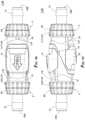
- FIG. 1 Ais a side view of a particular embodiment of the connector system.
- FIG. 1 Bis an end view of the particular embodiment of the connector system shown in FIG. 1 A .
- FIG. 1 Cis a cross-sectional view of the connector system shown in FIG. 1 B .
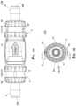
- FIG. 2 Ais a side view of a particular embodiment of the connector system.
- FIG. 2 Bis an end view of the particular embodiment of the connector system shown in FIG. 2 A .
- FIG. 2 Cis a cross-sectional view of the connector system shown in FIG. 2 B .
- FIG. 3 Ais a side view of a particular embodiment of the connector system.
- FIG. 3 Bis an end view of the particular embodiment of the connector system shown in FIG. 3 A .
- FIG. 3 Cis a cross-sectional view of the connector system shown in FIG. 3 B .
- FIG. 4 Ais a side view of a particular embodiment of the connector system.
- FIG. 4 Bis an end view of the particular embodiment of the connector system shown in FIG. 4 A .
- FIG. 4 Cis a cross-sectional view of the connector system shown in FIG. 4 B .
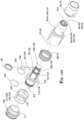
- FIG. 5 Ais an exploded perspective view of a particular embodiment of one of the two substantially identical couplers of the connector system shown in FIGS. 1 A through 4 C .
- FIG. 5 Bis an exploded side view of the particular embodiment of the coupler shown in FIG. 5 A .
- FIG. 6 Ais an exploded perspective view of a particular embodiment of a conduit, a valve, and a sleeve of one of the two substantially identical couplers of the connector system shown in FIGS. 1 A through 4 C .
- FIG. 6 Bis an exploded side view of the particular embodiment of the conduit, the valve, and the sleeve shown in FIG. 6 A .
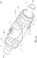
- FIG. 7 Ais a perspective view of a particular embodiment of the connector system, whereby first and second couplers dispose in adjacent axial relation but are not releasably connected, thus the first and second couplers are in a coupler disconnected condition.
- FIG. 7 Bis a top view of the particular embodiment of the connector system shown in FIG. 7 A .
- FIG. 7 Cis a side view of the particular embodiment of the connector system shown in FIG. 7 A .
- FIG. 7 Dis a bottom view of the particular embodiment of the connector system shown in FIG. 7 A .
- FIG. 7 Eis an end view of the particular embodiment of the connector system shown in FIG. 7 A .
- FIG. 8 Ais a perspective view of the particular embodiment of the connector system shown in FIGS. 7 A through 7 E , but whereby the first and second couplers are releasably connected to achieve a coupler connected condition.
- FIG. 8 Bis a top view of the particular embodiment of the connector system shown in FIG. 8 A .
- FIG. 8 Cis a side view of the particular embodiment of the connector system shown in FIG. 8 A .
- FIG. 8 Dis a bottom view of the particular embodiment of the connector system shown in FIG. 8 A .
- FIG. 8 Eis an end view of the particular embodiment of the connector system shown in FIG. 8 A .
- FIG. 9 Ais a perspective view of the particular embodiment of the connector system shown in FIGS. 8 A through 8 E , but whereby a first passageway of the first coupler is sealably engaged with a second passageway of the second coupler to provide a passageway connected condition; the first and second passageways are interrupted by respective valves, consequently resulting in a closed fluid flow path condition.
- FIG. 9 Bis a top view of the particular embodiment of the connector system shown in FIG. 9 A .
- FIG. 9 Cis a side view of the particular embodiment of the connector system shown in FIG. 9 A .
- FIG. 9 Dis a bottom view of the particular embodiment of the connector system shown in FIG. 9 A .
- FIG. 9 Eis an end view of the particular embodiment of the connector system shown in FIG. 9 A .
- FIG. 10 Ais a perspective view of the particular embodiment of the connector system shown in FIGS. 9 A through 9 E , but whereby the first and second passageways are uninterrupted to provide an open fluid flow path condition in which fluid can flow through the connector system.
- FIG. 10 Bis a top view of the particular embodiment of the connector system shown in FIG. 10 A .
- FIG. 10 Cis a side view of the particular embodiment of the connector system shown in FIG. 10 A .
- FIG. 10 Dis a bottom view of the particular embodiment of the connector system shown in FIG. 10 A .
- FIG. 10 Eis an end view of the particular embodiment of the connector system shown in FIG. 10 A .
- FIG. 11 Ais a cross-sectional view of the connector system shown in FIG. 7 E .
- FIG. 11 Bis a cross-sectional view of the connector system shown in FIG. 8 E .
- FIG. 11 Cis a cross-sectional view of the connector system shown in FIG. 9 E .
- FIG. 11 Dis a cross-sectional view of the connector system shown in FIG. 10 E .
- FIG. 12 Ais an exploded perspective view of a particular embodiment of one of the two substantially identical couplers of the connector system shown in FIGS. 7 A through 11 D .
- FIG. 12 Bis an exploded side view of the particular embodiment of the coupler shown in FIG. 12 A .
- FIG. 13 Ais an exploded perspective view of a particular embodiment of a conduit, a valve, and a sleeve of one of the two substantially identical couplers of the connector system shown in FIGS. 7 A through 11 D .
- FIG. 13 Bis an exploded side view of the particular embodiment of the conduit, the valve, and the sleeve shown in FIG. 13 A .
- FIG. 14is an exploded perspective view of a particular embodiment of the connector system showing release elements and their corresponding catches and catch-receiving elements.
- a connector system ( 1 ) for releasably connecting together tubes, such as medical tubing employed in a biomedical environment,is disclosed herein.
- the connector system ( 1 )can be relatively easily and securely connected, and yet relatively easily intentionally disconnected.
- the connector system ( 1 )can be connected and disconnected repeatedly.
- the connector system ( 1 )can be reusable as opposed to single-use.
- the connector system ( 1 )can be configured such that the aseptic or sterile environment therein can be preserved, which understandably benefits a repeatably connectable/disconnectable device and/or a reusable device.
- the connector system ( 1 )can comprise two discrete couplers ( 2 )( 3 ) which connect together to provide the connector system ( 1 ), whereby significantly, the couplers ( 2 )( 3 ) can have substantially identical or identical structures; thus, the couplers ( 2 )( 3 ) can be genderless, as opposed to a connector system ( 1 ) comprising male and female couplers.
- the connector system ( 1 )can accommodate bi-directional flow.
- the connector system ( 1 ) of the present inventionincludes a first coupler ( 2 ) having a first coupler passageway ( 4 ) disposed therein and a second coupler ( 3 ) having a second coupler passageway ( 5 ) disposed therein, whereby, as stated above, the first and second couplers ( 2 )( 3 ) can have substantially identical structures and/or components.
- the first and second coupler passageways ( 4 )( 5 )can dispose in fluidic communication to provide a fluid flow path ( 6 ) between the first and second couplers ( 2 )( 3 ) and through the connector system ( 1 ).
- an axial or longitudinal directioncan be considered parallel to a connector system longitudinal axis ( 7 ) and/or a first coupler longitudinal axis ( 8 ) and/or a second coupler longitudinal axis ( 9 ).
- two directional referencesmay be used which relate to the junction ( 10 ) between the first and second couplers ( 2 )( 3 ) when connected together to provide the connector system ( 1 ): an inward direction ( 11 ) means toward the junction ( 10 ), and an outward direction ( 12 ) means away from the junction ( 10 ).
- the first coupler ( 2 )can include a first coupler housing ( 15 ) which houses the first coupler passageway ( 4 ).
- the first coupler housing first end ( 18 )can include a fluid inlet/outlet ( 20 A) in fluidic communication with the first coupler passageway ( 4 ), whereby the fluid inlet/outlet ( 20 A) can couple to tubing, such as via a barb ( 21 ) coupled to or integrated with the first coupler housing first end ( 18 ).
- the tubingcan engage with the barb ( 21 ), for example via frictional engagement about the barb ( 21 ), to securely couple the tubing to the first coupler housing ( 15 ) (and correspondingly to the first coupler ( 2 )) and the first coupler passageway ( 4 ) disposed therein.
- the second coupler ( 3 )can include a second coupler housing ( 22 ) which houses the second coupler passageway ( 5 ).
- the second coupler housing ( 22 )which can be an annular second coupler housing ( 22 ), can have a second coupler housing interior space ( 23 ) defined by a second coupler housing internal surface ( 24 ) which extends between second coupler housing first and second ends ( 25 )( 26 ), whereby the second coupler passageway ( 5 ) can be disposed within the second coupler housing interior space ( 23 ).
- the second coupler housing first end ( 25 )can include a fluid outlet/inlet ( 20 B) in fluidic communication with the second coupler passageway ( 5 ), whereby the fluid outlet/inlet ( 20 B) can couple to tubing, such as via a barb ( 21 ) coupled to or integrated with the second coupler housing first end ( 25 ). Accordingly, the tubing can engage with the barb ( 21 ), for example via frictional engagement about the barb ( 21 ), to securely couple the tubing to the second coupler housing ( 22 ) (and correspondingly to the second coupler ( 3 )) and the second coupler passageway ( 5 ) disposed therein.
- the first coupler housing ( 15 )can be releasably connected to the second coupler housing ( 22 ) via axial movement in the inward direction ( 11 ) to achieve the coupler connected condition ( 14 ) in which the first and second couplers ( 2 )( 3 ) can be connected to one another to provide the connector system ( 1 ).
- the first and second coupler housing second ends ( 19 )( 26 )can be configured to connect to one another to connect the first coupler housing ( 15 ) (and correspondingly the first coupler ( 2 )) to the second coupler housing ( 22 ) (and correspondingly the second coupler ( 3 )).
- the present first and second coupler housing second ends ( 19 )( 26 )may include at least a portion that terminates in a plane which can be in angled relation to the respective first or second coupler longitudinal axis ( 8 )( 9 ).
- the angle ( ⁇ ) between the plane of the first and second coupler housing second ends ( 19 )( 26 ) and their respective first or second coupler longitudinal axis ( 8 )( 9 )can be about 25°.
- the angle ( ⁇ ) between the plane of the first and second coupler housing second ends ( 19 )( 26 ) and their respective first or second coupler longitudinal axis ( 8 )( 9 )can be less than about 90°.
- the angle ( ⁇ ) between the plane of the first and second coupler housing second ends ( 19 )( 26 ) and their respective first or second coupler longitudinal axis ( 8 )( 9 )can be less than about 80°.
- the angle ( ⁇ ) between the plane of the first and second coupler housing second ends ( 19 )( 26 ) and their respective first or second coupler longitudinal axis ( 8 )( 9 )can be less than about 70°.
- the angle ( ⁇ ) between the plane of the first and second coupler housing second ends ( 19 )( 26 ) and their respective first or second coupler longitudinal axis ( 8 )( 9 )can be less than about 60°. As to particular embodiments, the angle ( ⁇ ) between the plane of the first and second coupler housing second ends ( 19 )( 26 ) and their respective first or second coupler longitudinal axis ( 8 )( 9 ) can be less than about 50°. As to particular embodiments, the angle ( ⁇ ) between the plane of the first and second coupler housing second ends ( 19 )( 26 ) and their respective first or second coupler longitudinal axis ( 8 )( 9 ) can be less than about 40°. As to particular embodiments, the angle ( ⁇ ) between the plane of the first and second coupler housing second ends ( 19 )( 26 ) and their respective first or second coupler longitudinal axis ( 8 )( 9 ) can be less than about 30°.
- the angle ( ⁇ ) between the plane of the first and second coupler housing second ends ( 19 )( 26 ) and their respective first or second coupler longitudinal axis ( 8 )( 9 )can be between about 20° and about 80°. As to particular embodiments, the angle ( ⁇ ) between the plane of the first and second coupler housing second ends ( 19 )( 26 ) and their respective first or second coupler longitudinal axis ( 8 )( 9 ) can be between about 20° and about 70°. As to particular embodiments, the angle ( ⁇ ) between the plane of the first and second coupler housing second ends ( 19 )( 26 ) and their respective first or second coupler longitudinal axis ( 8 )( 9 ) can be between about 20° and about 60°.
- the angle ( ⁇ ) between the plane of the first and second coupler housing second ends ( 19 )( 26 ) and their respective first or second coupler longitudinal axis ( 8 )( 9 )can be between about 20° and about 50°.
- the angle ( ⁇ ) between the plane of the first and second coupler housing second ends ( 19 )( 26 ) and their respective first or second coupler longitudinal axis ( 8 )( 9 )can be between about 20° and about 40°.
- the angle ( ⁇ ) between the plane of the first and second coupler housing second ends ( 19 )( 26 ) and their respective first or second coupler longitudinal axis ( 8 )( 9 )can be between about 20° and about 30°.
- the junction ( 10 ) between the first and second coupler housing second ends ( 19 )( 26 )can be in angled relation to the connector system longitudinal axis ( 7 ), which may be a space-saving configuration that may also allow the first and second couplers ( 2 )( 3 ) to nest with one another.
- the first coupler ( 2 )can include a first coupler catch ( 27 ) movably coupled to the first coupler housing ( 15 ); correspondingly, a second coupler catch-receiving element ( 28 ) can be coupled to the second coupler housing ( 22 ) (such as via coupling to the second coupler elastically deformable valve seat ( 69 )).
- the first coupler catch ( 27 )can releasably engage with the second coupler catch-receiving element ( 28 ) to fix an axial position of the first coupler housing ( 15 ) in relation to the second coupler housing ( 22 ), thereby achieving the coupler connected condition ( 14 ).
- the term “catch”means a restraint which, upon engagement with a catch-receiving element ( 28 )( 30 ), can function to partially or completely restrain travel of an associated component, such as the first or second coupler housing ( 15 )( 22 ).
- the term “catch-receiving element”means a restraint which, upon engagement with a catch ( 27 )( 29 ), can function to partially or completely restrain travel of an associated component, such as the first or second coupler housing ( 15 )( 22 ).
- the first coupler catch ( 27 )can be configured a protrusion
- the second coupler catch-receiving element ( 28 )can be configured as a recess which can receive the protrusion for locking engagement therewith to fix an axial position of the first coupler housing ( 15 ) in relation to the second coupler housing ( 22 ), thereby achieving the coupler connected condition ( 14 ).
- the second coupler ( 3 )can include a second coupler catch ( 29 ) movably coupled to the second coupler housing ( 22 ); correspondingly, a first coupler catch-receiving element ( 30 ) can be coupled to the first coupler housing ( 15 ) (such as via coupling to the first coupler elastically deformable valve seat ( 50 )).
- the second coupler catch ( 29 )can releasably engage with the first coupler catch-receiving element ( 30 ) to fix an axial position of the second coupler housing ( 22 ) in relation to the first coupler housing ( 15 ), thereby achieving the coupler connected condition ( 14 ).
- the second coupler catch ( 29 )can be configured a protrusion
- the first coupler catch-receiving element ( 30 )can be configured as a recess which can receive the protrusion for locking engagement therewith to fix an axial position of the second coupler housing ( 22 ) in relation to the first coupler housing ( 15 ), thereby achieving the coupler connected condition ( 14 ).
- the connector system ( 1 )can be configured to provide a connection indicium upon successful releasable axial coupling of the first and second coupler housings ( 15 )( 22 ) to achieve the coupler connected condition ( 14 ), whereby the connection indicium can be a visible indicium, an audible indicium, a tactile indicium, or the like, or combinations thereof.
- the connection indiciumcan be an audible click which indicates successful releasable axial coupling of the first and second coupler housings ( 15 )( 22 ) to achieve the coupler connected condition ( 14 ).
- the audible clickcan be generated by the catch ( 27 )( 29 ) engaging with the catch-receiving element ( 28 )( 30 ).
- the connector system ( 1 )comprises two couplers ( 2 )( 3 ) having substantially identical structures
- the connector system ( 1 )can include two catches ( 27 )( 29 ) which engage with two respective catch-receiving elements ( 28 )( 30 ), correspondingly generating two audible clicks.
- the first coupler ( 2 )can include a first coupler release element ( 31 ) movably coupled to the first coupler housing ( 15 ), whereby travel of the first coupler release element ( 31 ), such as axial travel along or over a first coupler housing outer surface ( 32 ), can disengage the first coupler catch ( 27 ) from the second coupler catch-receiving element ( 28 ) to disconnect the first and second coupler housings ( 15 )( 22 ).
- the first coupler release element ( 31 )can be configured as a cam and the first coupler catch ( 27 ) can function as a follower, whereby the first coupler release element ( 31 ) can transform input motion into reciprocating motion of the first coupler catch ( 27 ).
- the term “cam”means a movable element in a mechanical linkage, whereby the cam can have an irregular periphery and may be useful in transforming motion, for example transforming motion in a first direction into motion in a second direction.
- followermeans a movable element in a mechanical linkage, whereby movement of the follower results from movement of the cam.
- the first coupler release element ( 31 )can be biased by a first coupler release element-biasing member ( 33 ) which biases the first coupler release element ( 31 ) to correspondingly bias the first coupler catch ( 27 ) toward releasable engagement with the second coupler catch-receiving element ( 28 ) to fix an axial position of the first coupler housing ( 15 ) in relation to the second coupler housing ( 22 ), thereby achieving the coupler connected condition ( 14 ).
- the first coupler release element-biasing member ( 33 )can be configured as a resilient member ( 34 ), such as a leaf spring, whereby when the resilient member ( 34 ) disposes in a non-flexed condition, which can be the default biased condition, the first coupler release element ( 31 ) biases the first coupler catch ( 27 ) toward releasable engagement with the second coupler catch-receiving element ( 28 ) to fix an axial position of the first coupler housing ( 15 ) in relation to the second coupler housing ( 22 ), thereby achieving the coupler connected condition ( 14 ).
- a resilient member34
- the resilient member ( 34 )biases the first coupler catch ( 27 ) toward releasable engagement with the second coupler catch-receiving element ( 28 ) to fix an axial position of the first coupler housing ( 15 ) in relation to the second coupler housing ( 22 ), thereby achieving the coupler connected condition ( 14 ).
- the resilient member ( 34 )can be flexed, allowing the first coupler catch ( 27 ) to disengage from the second coupler catch-receiving element ( 28 ) to disconnect the first and second coupler housings ( 15 )( 22 ).
- the first coupler release element ( 31 )can be the same as or similar to the release element disclosed in U.S. Pat. No. 10,173,046 which is hereby incorporated by reference in its entirety herein.
- the first coupler release element ( 31 )can be the same as or similar to the catch release disclosed in United States Patent Application Publication No. 2023/0003324 which is hereby incorporated by reference in its entirety herein.
- the second coupler ( 3 )can include a second coupler release element ( 35 ) movably coupled to the second coupler housing ( 22 ), whereby travel of the second coupler release element ( 35 ), such as axial travel along or over a second coupler housing outer surface ( 36 ), can disengage the second coupler catch ( 29 ) from the first coupler catch-receiving element ( 30 ) to disconnect the first and second coupler housings ( 15 )( 22 ).
- the second coupler release element ( 35 )can be configured as a cam and the second coupler catch ( 29 ) can function as a follower, whereby the second coupler release element ( 35 ) can transform input motion into reciprocating motion of the second coupler catch ( 29 ).
- the second coupler release element ( 35 )can be biased by a second coupler release element-biasing member ( 37 ) which biases the second coupler release element ( 35 ) to correspondingly bias the second coupler catch ( 29 ) toward releasable engagement with the first coupler catch-receiving element ( 30 ) to fix an axial position of the second coupler housing ( 22 ) in relation to the first coupler housing ( 15 ), thereby achieving the coupler connected condition ( 14 ).
- the second coupler release element-biasing member ( 37 )can be configured as a resilient member ( 34 ), such as a leaf spring, whereby when the resilient member ( 34 ) disposes in a non-flexed condition, which can be the default biased condition, the second coupler release element ( 35 ) biases the second coupler catch ( 29 ) toward releasable engagement with the first coupler catch-receiving element ( 30 ) to fix an axial position of the second coupler housing ( 22 ) in relation to the first coupler housing ( 15 ), thereby achieving the coupler connected condition ( 14 ).
- a resilient member34
- the resilient member ( 34 ) disposes in a non-flexed conditionwhich can be the default biased condition
- the second coupler release element ( 35 )biases the second coupler catch ( 29 ) toward releasable engagement with the first coupler catch-receiving element ( 30 ) to fix an axial position of the second coupler housing ( 22 ) in relation to the first
- the resilient member ( 34 )can be flexed, allowing the second coupler catch ( 29 ) to disengage from the first coupler catch-receiving element ( 30 ) to disconnect the first and second coupler housings ( 15 )( 22 ).
- the second coupler release element ( 35 )can be the same as or similar to the release element disclosed in U.S. Pat. No. 10,173,046 which is hereby incorporated by reference in its entirety herein.
- the second coupler release element ( 35 )can be the same as or similar to the catch release disclosed in United States Patent Application Publication No. 2023/0003324 which is hereby incorporated by reference in its entirety herein.
- the first coupler ( 2 )can include a first coupler conduit ( 39 ) disposed within the first coupler housing interior space ( 16 ), whereby the first coupler conduit ( 39 ) can include an annular first coupler conduit inner surface ( 40 ) which defines at least a portion of the first coupler passageway ( 4 ) through which fluid can flow.
- the first coupler passageway ( 4 )can be an aseptic or sterile environment, or an environment which is devoid of contaminants, such as microorganisms, bodily fluids, bodily excrements, bodily tissues, etc.
- the first coupler conduit ( 39 )can extend between first coupler conduit first and second ends ( 41 )( 42 ), whereby the first coupler conduit second end ( 42 ) can provide a first coupler conduit engagement end ( 43 ) which can sealably engage with an axially adjacent second coupler conduit engagement end ( 44 ) to fluidicly connect the first and second coupler passageways ( 4 )( 5 ), thus providing a passageway connected condition ( 38 ) and a fluid flow path ( 6 ) through the connector system ( 1 ).
- the first coupler ( 2 )can further include a first coupler elastically deformable valve ( 45 ) configured to (i) dispose in a default first coupler elastically deformable valve closed configuration ( 46 ) and (ii) be deformable to achieve a first coupler elastically deformable valve open configuration ( 47 ). Due to its elasticity, the first coupler elastically deformable valve ( 45 ) can return to its default shape after deformation, which can contribute to the repeated usability of the present connector system ( 1 ).
- a first coupler elastically deformable valve ( 45 )configured to (i) dispose in a default first coupler elastically deformable valve closed configuration ( 46 ) and (ii) be deformable to achieve a first coupler elastically deformable valve open configuration ( 47 ). Due to its elasticity, the first coupler elastically deformable valve ( 45 ) can return to its default shape after deformation, which can contribute to the repeated usability of the present connector system ( 1 ).
- the first coupler elastically deformable valve ( 45 )can be disposed within the first coupler housing interior space ( 16 ) in axial alignment with the first coupler conduit ( 39 ) and in particular, in axial alignment with the first coupler conduit engagement end ( 43 ), in spaced apart relation. Specifically, the first coupler elastically deformable valve ( 45 ) can be coupled to the first coupler housing ( 15 ), such as proximate the first coupler housing second end ( 19 ) or to the first coupler housing second end ( 19 ), such as via a first coupler elastically deformable valve perimeter ( 48 ).
- the first coupler elastically deformable valve ( 45 )can include a flange ( 49 ) proximate its perimeter or the first coupler elastically deformable valve ( 45 ) can be bounded by a flanged perimeter, whereby the flange ( 49 ) can facilitate the coupling of the first coupler elastically deformable valve ( 45 ) to the first coupler housing ( 15 ).
- the first coupler elastically deformable valve ( 45 )can be seated against the first coupler housing ( 15 ), such as against the first coupler housing second end ( 19 ), by a first coupler elastically deformable valve seat ( 50 ).
- the first coupler elastically deformable valve ( 45 )can be sandwiched between the first coupler housing ( 15 ), such as the first coupler housing second end ( 19 ), and the first coupler elastically deformable valve seat ( 50 ) to fixedly couple the first coupler elastically deformable valve ( 45 ) to the first coupler housing ( 15 ).
- the first coupler elastically deformable valve ( 45 )can include a first coupler elastically deformable valve inner face ( 51 ) oriented toward the first coupler housing interior space ( 16 ) and the first coupler housing first end ( 18 ), and an opposing first coupler elastically deformable valve outer face ( 52 ) oriented toward the external environment ( 53 ), whereby when in the first coupler elastically deformable valve closed configuration ( 46 ), the first coupler elastically deformable valve ( 45 ) can function to seal the portion of the first coupler housing interior space ( 16 ) in which the first coupler conduit ( 39 ) resides from the external environment ( 53 ) to preserve the aseptic environment therein, and especially the aseptic environment within the first coupler passageway ( 4 ).
- the first coupler conduit ( 39 )can be axially movable (i) within the first coupler housing interior space ( 16 ) and (ii) relative to the first coupler housing ( 15 ).
- the first coupler conduit ( 39 )can be axially movable between a first coupler conduit retracted position ( 54 ) and a first coupler conduit extended position ( 55 ).
- the first coupler conduit ( 39 )can dispose within the aseptic environment within the first coupler housing interior space ( 16 ) bounded by the first coupler elastically deformable valve ( 45 ) in the first coupler elastically deformable valve closed configuration ( 46 ), and correspondingly isolated from contaminants within the external environment ( 53 ).
- the first coupler conduit engagement end ( 43 )can engage with and deform (or change the shape of) the first coupler elastically deformable valve ( 45 ) and pass therethrough, thus disposing (i) the first coupler elastically deformable valve ( 45 ) in the first coupler elastically deformable valve open configuration ( 47 ) and (ii) the first coupler conduit ( 39 ) in the first coupler conduit extended position ( 55 ) in which the first coupler conduit engagement end ( 43 ) extends through the first coupler elastically deformable valve ( 45 ) and can sealably engage with an axially adjacent second coupler conduit engagement end ( 44 ) to fluidicly connect the first and second coupler passageways ( 4 )( 5 ), thus providing the passageway connected condition ( 38 ) and a fluid flow path ( 6
- a movable first coupler sleeve ( 56 )can (i) radially surround the first coupler conduit ( 39 ), and (ii) axially extend beyond the first coupler conduit engagement end ( 43 ) when the first coupler sleeve ( 56 ) is biased to dispose in its default first coupler sleeve extended position ( 57 ) by a first coupler sleeve biasing member ( 58 ), such as a spring, in a non-compressed condition ( 59 ), to further preserve the aseptic environment surrounding the first coupler conduit ( 39 ), and especially to preserve the aseptic environment within the first coupler passageway ( 4 ).
- a first coupler sleeve biasing member ( 58 )such as a spring
- the first coupler housing ( 15 )can engage with and forcibly urge the first coupler sleeve ( 56 ) in the outward direction ( 12 ) toward a first coupler sleeve retracted position ( 60 ), correspondingly compressing the first coupler sleeve biasing member ( 58 ).
- the first coupler sleeve ( 56 )When in the first coupler sleeve retracted position ( 60 ), the first coupler sleeve ( 56 ) can no longer extend beyond the first coupler conduit engagement end ( 43 ), thus allowing the first coupler conduit engagement end ( 43 ) to extend beyond the first coupler sleeve ( 56 ) and sealably engage with an axially adjacent second coupler conduit engagement end ( 44 ) to fluidicly connect the first and second coupler passageways ( 4 )( 5 ), thus providing the passageway connected condition ( 38 ) and a fluid flow path ( 6 ) through the connector system ( 1 ).
- the second coupler ( 3 )can include a second coupler conduit ( 61 ) disposed within the second coupler housing interior space ( 23 ), whereby the second coupler conduit ( 61 ) can include an annular second coupler conduit inner surface ( 62 ) which defines at least a portion of the second coupler passageway ( 5 ) through which fluid can flow.
- the second coupler passageway ( 5 )can be an aseptic or sterile environment, or an environment which is devoid of contaminants, such as microorganisms, bodily fluids, bodily excrements, bodily tissues, etc.
- the second coupler conduit ( 61 )can extend between second coupler conduit first and second ends ( 63 )( 64 ), whereby the second coupler conduit second end ( 64 ) can provide a second coupler conduit engagement end ( 44 ) which can sealably engage with an axially adjacent first coupler conduit engagement end ( 43 ) to fluidicly connect the first and second coupler passageways ( 4 )( 5 ), thus providing a passageway connected condition ( 38 ) and a fluid flow path ( 6 ) through the connector system ( 1 ).
- the second coupler ( 3 )can further include a second coupler elastically deformable valve ( 65 ) configured to (i) dispose in a default second coupler elastically deformable valve closed configuration ( 66 ) and (ii) be deformable to achieve a second coupler elastically deformable valve open configuration ( 67 ). Due to its elasticity, the second coupler elastically deformable valve ( 65 ) can return to its default shape after deformation, which can contribute to the repeated usability of the present connector system ( 1 ).
- a second coupler elastically deformable valve ( 65 )configured to (i) dispose in a default second coupler elastically deformable valve closed configuration ( 66 ) and (ii) be deformable to achieve a second coupler elastically deformable valve open configuration ( 67 ). Due to its elasticity, the second coupler elastically deformable valve ( 65 ) can return to its default shape after deformation, which can contribute to the repeated usability of the present connector system ( 1 ).
- the second coupler elastically deformable valve ( 65 )can be disposed within the second coupler housing interior space ( 23 ) in axial alignment with the second coupler conduit ( 61 ) and in particular, in axial alignment with the second coupler conduit engagement end ( 44 ), in spaced apart relation.
- the second coupler elastically deformable valve ( 65 )can be coupled to the second coupler housing ( 22 ), such as proximate the second coupler housing second end ( 26 ) or to the second coupler housing second end ( 26 ), such as via a second coupler elastically deformable valve perimeter ( 68 ).
- the second coupler elastically deformable valve ( 65 )can include a flange ( 49 ) proximate its perimeter or the second coupler elastically deformable valve ( 65 ) can be bounded by a flanged perimeter, whereby the flange ( 49 ) can facilitate the coupling of the second coupler elastically deformable valve ( 65 ) to the second coupler housing ( 22 ).
- the second coupler elastically deformable valve ( 65 )can be seated against the second coupler housing ( 22 ), such as against the second coupler housing second end ( 26 ), by a second coupler elastically deformable valve seat ( 69 ).
- the second coupler elastically deformable valve ( 65 )can be sandwiched between the second coupler housing ( 22 ), such as the second coupler housing second end ( 26 ), and the second coupler elastically deformable valve seat ( 69 ) to fixedly couple the second coupler elastically deformable valve ( 65 ) to the second coupler housing ( 22 ).
- the second coupler elastically deformable valve ( 65 )can include a second coupler elastically deformable valve inner face ( 70 ) oriented toward the second coupler housing interior space ( 23 ) and the second coupler housing first end ( 25 ), and an opposing second coupler elastically deformable valve outer face ( 71 ) oriented toward the external environment ( 53 ), whereby when in the second coupler elastically deformable valve closed configuration ( 66 ), the second coupler elastically deformable valve ( 65 ) can function to seal the portion of the second coupler housing interior space ( 23 ) in which the second coupler conduit ( 61 ) resides from the external environment ( 53 ) to preserve the aseptic environment therein, and especially the aseptic environment within the second coupler passageway ( 5 ).
- the second coupler conduit ( 61 )can be axially movable (i) within the second coupler housing interior space ( 23 ) and (ii) relative to the second coupler housing ( 22 ).
- the second coupler conduit ( 61 )can be axially movable between a second coupler conduit retracted position ( 72 ) and a second coupler conduit extended position ( 73 ).
- the second coupler conduit ( 61 )can dispose within the aseptic environment within the second coupler housing interior space ( 23 ) bounded by the second coupler elastically deformable valve ( 65 ) in the second coupler elastically deformable valve closed configuration ( 66 ), and correspondingly isolated from contaminants within the external environment ( 53 ).
- the second coupler conduit engagement end ( 44 )can engage with and deform (or change the shape of) the second coupler elastically deformable valve ( 65 ) and pass therethrough, thus disposing (i) the second coupler elastically deformable valve ( 65 ) in the second coupler elastically deformable valve open configuration ( 67 ) and (ii) the second coupler conduit ( 61 ) in the second coupler conduit extended position ( 73 ) in which the second coupler conduit engagement end ( 44 ) extends through the second coupler elastically deformable valve ( 65 ) and can sealably engage with an axially adjacent first coupler conduit engagement end ( 43 ) to fluidicly connect the first and second coupler passageways ( 4 )( 5 ), thus providing the passageway connected condition ( 38 ) and a fluid
- a movable second coupler sleeve ( 74 )can (i) radially surround the second coupler conduit ( 61 ), and (ii) axially extend beyond the second coupler conduit engagement end ( 44 ) when the second coupler sleeve ( 74 ) is biased to dispose in its default second coupler sleeve extended position ( 75 ) by a second coupler sleeve biasing member ( 76 ), such as a spring, in a non-compressed condition ( 59 ), to further preserve the aseptic environment surrounding the second coupler conduit ( 61 ), and especially to preserve the aseptic environment within the second coupler passageway ( 5 ).
- a second coupler sleeve biasing member ( 76 )such as a spring
- the second coupler housing ( 22 )can engage with and forcibly urge the second coupler sleeve ( 74 ) in the outward direction ( 12 ) toward a second coupler sleeve retracted position ( 77 ), correspondingly compressing the second coupler sleeve biasing member ( 76 ).
- the second coupler sleeve ( 74 )When in the second coupler sleeve retracted position ( 77 ), the second coupler sleeve ( 74 ) can no longer extend beyond the second coupler conduit engagement end ( 44 ), thus allowing the second coupler conduit engagement end ( 44 ) to extend beyond the second coupler sleeve ( 74 ) and sealably engage with an axially adjacent first coupler conduit engagement end ( 43 ) to fluidicly connect the first and second coupler passageways ( 4 )( 5 ), thus providing the passageway connected condition ( 38 ) and a fluid flow path ( 6 ) through the connector system ( 1 ).
- each of the first and second coupler conduit engagement ends ( 43 )( 44 )can include a fluid-tight seal ( 78 ), such as an annular seal, which can facilitate the sealable engagement therebetween.
- a fluid-tight sealsuch as an annular seal
- first and second coupler elastically deformable valves ( 45 )( 65 )can be configured (i) to seal an environment, such as from contaminants, and (ii) for axial opening via the application of an axial force; therefore, any valve suitable for such a purpose may be useful with the present connector system ( 1 ).
- the first and second coupler elastically deformable valves ( 45 )( 65 )can be formed from an elastomeric material, such as silicone, rubber, or the like.
- the first and second coupler elastically deformable valves ( 45 )( 65 )can be formed from medical-grade silicone.
- first and second coupler elastically deformable valves ( 45 )( 65 )can each be a one-piece component which can be self-contained, meaning the sealing function can be an integral part of the one-piece elastomeric component as opposed to a valve which has to engage with a valve seat to form a seal.
- first and second coupler elastically deformable valves ( 45 )( 65 )can each be configured as a duckbill valve.
- the first and second coupler elastically deformable valves ( 45 )( 65 )can each be configured as a cross-slit valve ( 79 ), which may have a larger flow capacity relative to a duckbill valve.
- a cross-slit valve ( 79 )may have a cylindrical shape with a valve functional region which includes a first slit ( 80 ) and a second slit ( 81 ) arranged in the form of a cross.
- the cross-slit valve ( 79 )may have four flaps (such as a four-flapped valve) or four cuspids (such as a quad-cusped valve) which extend from a center point.
- a cross-slit valve ( 79 ) useful with the present inventionneed not be limited to two slits and/or four flaps, and can have any number of slits and/or flaps, depending upon the embodiment.
- the flaps or cuspidscan be adjacent one another to form a fluid-tight seal therebetween.
- the cross-slit valve ( 79 )can deform such that the flaps or cuspids are urged apart, for example by a conduit engagement end ( 43 )( 44 ) which subsequently passes therethrough to dispose the conduit ( 39 )( 61 ) in the conduit extended position ( 55 )( 73 ).
- the cross-slit valve ( 79 )can be domed-shaped, whereby the cross-slit valve inner face ( 82 ) can be concave and the cross-slit valve outer face ( 83 ) can be convex.
- the first coupler elastically deformable valve ( 45 )is disposed in the first coupler elastically deformable valve open configuration ( 47 ) as a result of axial movement of the first coupler conduit ( 39 ) in the inward direction ( 11 ) to dispose the first coupler conduit ( 39 ) in the first coupler conduit extended position ( 55 )
- the second coupler elastically deformable valve ( 65 )is disposed in the second coupler elastically deformable valve open configuration ( 67 ) as a result of axial movement of the second coupler conduit ( 61 ) in the inward direction ( 11 ) to dispose the second coupler conduit ( 61 ) in the second coupler conduit extended position ( 73 )
- the first coupler conduit engagement end ( 43 )can sealably engage with the axially adjacent second coupler conduit engagement end ( 44 ) to fluidicly connect the first and second coupler passageways ( 4 )( 5 ), thus providing the passageway connected condition ( 38 ) and a fluid flow path ( 6 ) through
- the first coupler ( 2 )can include a first coupler first lock assembly ( 84 ) which can lock the first coupler conduit ( 39 ) in the first coupler conduit extended position ( 55 ) and accordingly, can lock the first coupler conduit engagement end ( 43 ) in axially adjacent relation to the second coupler conduit engagement end ( 44 ).
- the first coupler first lock assembly ( 84 )can include a rotatable first coupler first locking ring ( 85 ) having a catch-receiving element, such as a slot, that can receive a corresponding catch, such as a tooth, coupled to the first coupler housing ( 15 ).
- the toothcan be received within the slot.
- the first coupler first locking ring ( 85 )can be rotated in a first direction to rotate the slot relative to the tooth, whereby upon rotation, the tooth can engage with a stop proximate the slot.
- This engagementcan preclude the first coupler conduit ( 39 ) and the first coupler first locking ring ( 85 ) from axial movement relative to the first coupler housing ( 15 ) in the outward direction ( 12 ), thus precluding the first coupler conduit ( 39 ) from returning to the first coupler conduit retracted position ( 54 ).
- the first coupler first locking ring ( 85 )can be rotated in a second direction which can be opposite the first direction to rotate the slot relative to the tooth to disengage the tooth from the stop proximate the slot.
- the second coupler ( 3 )can include a second coupler first lock assembly ( 89 ) which can lock the second coupler conduit ( 61 ) in the second coupler conduit extended position ( 73 ) and accordingly, can lock the second coupler conduit engagement end ( 44 ) in axially adjacent relation to the first coupler conduit engagement end ( 43 ).
- the second coupler first lock assembly ( 89 )can include a rotatable second coupler first locking ring ( 90 ) having a catch-receiving element, such as a slot, that can receive a corresponding catch, such as a tooth, coupled to the second coupler housing ( 22 ).
- the toothcan be received within the slot.
- the second coupler first locking ring ( 90 )can be rotated in a first direction to rotate the slot relative to the tooth, whereby upon rotation, the tooth can engage with a stop proximate the slot.
- This engagementcan preclude the second coupler conduit ( 61 ) and the second coupler first locking ring ( 90 ) from axial movement relative to the second coupler housing ( 22 ) in the outward direction ( 12 ), thus precluding the second coupler conduit ( 61 ) from returning to the second coupler conduit retracted position ( 72 ).
- the second coupler first locking ring ( 90 )can be rotated in a second direction which can be opposite the first direction to rotate the slot relative to the tooth to disengage the tooth from the stop proximate the slot.
- fluidWhen in the passageway connected condition ( 38 ) in which the first coupler conduit engagement end ( 43 ) sealably engages with an axially adjacent second coupler conduit engagement end ( 44 ) to fluidicly connect the first and second coupler passageways ( 4 )( 5 ), fluid may be intentionally precluded from flowing through the first and second coupler passageways ( 4 )( 5 ), and thus through the connector system ( 1 ) via the fluid flow path ( 6 ), consequently resulting in a closed fluid flow path condition ( 91 ) (as shown in FIGS. 1 A through 3 C, 7 A through 9 E, 11 A, 11 B, and 11 C ).
- the first coupler ( 2 )can include a movable (such as axially movable) first coupler valve ( 93 ) operable to interrupt fluid flow through the first coupler conduit ( 39 ) and correspondingly, through the first coupler passageway ( 4 ).
- the first coupler valve ( 93 )can be movable within a first coupler valve seat ( 94 ) to sealably occlude a first coupler port ( 95 ) in fluidic communication with the first coupler passageway ( 4 ), thereby providing a first coupler passageway closed condition ( 96 ) in which fluid flow through the first coupler port ( 95 ) and accordingly, through the first coupler passageway ( 4 ), can be interrupted.
- the first coupler valve ( 93 )can be biased by a first coupler valve-biasing member ( 97 ) which biases the first coupler valve ( 93 ) toward a default first coupler valve closed position ( 98 ) in which the first coupler port ( 95 ) can be sealably occluded by engagement with a sealing surface ( 99 ) to provide the first coupler passageway closed condition ( 96 ).
- the first coupler valve ( 93 )can include an annular first coupler valve inner surface ( 100 ) which defines at least a portion of the first coupler passageway ( 4 ) through which fluid can flow; with this configuration, the first coupler conduit ( 39 ) and the first coupler valve ( 93 ) can together provide the first coupler passageway ( 4 ).
- the first coupler valve ( 93 )can include the first coupler port ( 95 ) in fluidic communication with the first coupler passageway ( 4 ).
- the first coupler port ( 95 )can be radially disposed within the first coupler valve ( 93 ) to communicate between first coupler valve inner and outer surfaces ( 100 )( 101 ).
- the first coupler port ( 95 )can be configured as a plurality of first coupler ports ( 95 ) radially disposed within the first coupler valve ( 93 ) in circumferentially spaced-apart relation.
- the first coupler port(s) ( 95 )can be disposed proximate a first coupler valve second end ( 102 ).
- the first coupler valve seat ( 94 )can telescopingly dispose about the first coupler valve ( 93 ) which can longitudinally travel within the first coupler valve seat ( 94 ), such as via sliding.
- the first coupler valve ( 93 ) and the first coupler valve seat ( 94 )can be coaxial or disposed in concentric relation.
- a first coupler valve seat inner surface ( 103 )can provide the sealing surface ( 99 ) which can dispose adjacent the first coupler valve outer surface ( 101 ) and sealably engage with the first coupler port ( 95 ), such as by overlaying the first coupler port ( 95 ), to provide the first coupler valve closed position ( 98 ) and the first coupler passageway closed condition ( 96 ) in which fluid flow through the first coupler port ( 95 ) and accordingly, through the first coupler passageway ( 4 ), is interrupted.
- a fluid-tight sealcan exist between the first coupler valve seat inner surface ( 103 ) and the first coupler valve outer surface ( 101 ) proximate the first coupler port ( 95 ).
- one or more o-rings ( 104 )can be coupled to the first coupler valve outer surface ( 101 ), whereby when overlaid by the first coupler valve seat inner surface ( 103 ), the o-ring(s) ( 104 ) can function to provide the fluid-tight seal between the first coupler valve seat inner surface ( 103 ) and the first coupler valve outer surface ( 101 ) proximate the first coupler port ( 95 ).
- the first coupler valve ( 93 )can be biased by a first coupler valve-biasing member ( 97 ) which biases the first coupler valve ( 93 ) toward the default first coupler valve closed position ( 98 ) to provide the first coupler passageway closed condition ( 96 ).
- the first coupler valve-biasing member ( 97 )can be configured as a resiliently compressible member ( 105 ), such as a spring ( 106 ) (for example, a coil spring or a helical spring); however, the first coupler valve-biasing member ( 97 ) need not be limited to this particular configuration.
- the spring ( 106 )can be disposed about a portion of the first coupler valve ( 93 ) (or about a portion of the first coupler valve outer surface ( 101 )) to entirely surround that portion of the first coupler valve ( 93 ) such that the spring ( 106 ) and the first coupler valve ( 93 ) can be coaxial or disposed in concentric relation.
- the present first coupler valve-biasing member ( 97 )is disposed about the first coupler valve ( 93 ), the present first coupler valve-biasing member ( 97 ) is correspondingly disposed external to or outside of the first coupler passageway ( 4 ) and accordingly, external to or outside of the fluid flow path ( 6 ) when the passageway connected condition ( 38 ) is achieved.
- fluid flowing through the connector system ( 1 ) via the fluid flow path ( 6 )does not contact the valve-biasing member ( 97 ), which may be advantageous for a plurality of reasons, including elimination of potential substrate for biofilm growth within the fluid flow path ( 6 ) and/or elimination of a physical impediment to fluid flow within the fluid flow path ( 6 ).
- the spring ( 106 )can bare against opposing spring bearing surfaces ( 107 )( 108 ); for example, a spring first end ( 109 ) can bear against a spring first bearing surface ( 107 ) outwardly extending from the first coupler valve outer surface ( 101 ), and an opposing spring second end ( 110 ) can bear against a spring second bearing surface ( 108 ) provided by, for example, a support member ( 111 ) axially aligned with the first coupler valve ( 93 ) proximate the first coupler valve first end ( 112 ).
- the spring ( 106 )can bias the first coupler valve ( 93 ) toward the first coupler valve closed position ( 98 ) in which the first coupler port ( 95 ) can be sealably occluded by the sealing surface ( 99 ) of the first coupler valve seat ( 94 ) to provide the first coupler passageway closed condition ( 96 ).
- the first coupler valve ( 93 )can be urged by a first coupler first driver ( 113 ) which can be movably coupled to the first coupler housing ( 15 ), whereby the first coupler first driver ( 113 ) can engage with and apply an axial force to the first coupler valve ( 93 ) in the outward direction ( 12 ) to correspondingly drive the first coupler valve ( 93 ) to travel in the outward direction ( 12 ) and compress the first coupler valve-biasing member ( 97 ).
- first coupler valve ( 93 )can axially travel within the first coupler valve seat ( 94 ) away from the first coupler port ( 95 ) toward a first coupler valve open position ( 114 ) in which the first coupler port ( 95 ) can be disengaged from the sealing surface ( 99 ) of the first coupler valve seat ( 94 ), thus providing a first coupler passageway open condition ( 115 ) which permits fluid to flow through the first coupler port ( 95 ) and accordingly, through the first coupler passageway ( 4 ).
- first coupler valve ( 93 )can include the spring first bearing surface ( 107 ), movement of the first coupler valve ( 93 ) in the outward direction ( 12 ) correspondingly compresses the first coupler valve-biasing member ( 97 ) toward its compressed condition.
- the first coupler first driver ( 113 )can be a component of the first coupler ( 2 ).
- movement of the first coupler first driver ( 113 )can be actuated by a second coupler second driver ( 116 ) which can be a component of the second coupler ( 3 ) and movably coupled to the second coupler housing ( 22 ).
- the first coupler first driver ( 113 )can only be actuated when the first and second couplers ( 2 )( 3 ) are connected.
- the second coupler second driver ( 116 )can be actuated by a second coupler second driver actuator ( 117 ) which can be a component of the second coupler ( 3 ).
- the second coupler second driver actuator ( 117 )can forcibly urge the second coupler second driver ( 116 ) to travel in the inward direction ( 11 ).
- the second coupler second driver ( 116 )can engage with and apply an axial force to the first coupler first driver ( 113 ) in the outward direction ( 12 ); correspondingly, the first coupler first driver ( 113 ) can forcibly urge the first coupler valve ( 93 ) to axially travel within the first coupler valve seat ( 94 ) away from the first coupler port ( 95 ) toward the first coupler valve open position ( 114 ) which disposes the first coupler passageway ( 4 ) in the first coupler passageway open condition ( 115 ), allowing the fluid flow path ( 6 ) to have an open fluid flow path condition ( 92 ) which permits fluid to flow through the connector system ( 1 ).
- the first coupler first driver ( 113 )can include at least one arm ( 118 ) which can be driven in the outward direction ( 12 ) by actuation of the second coupler second driver ( 116 ) to engage with and drive the first coupler valve ( 93 ) to travel in the outward direction ( 12 ) to dispose the first coupler passageway ( 4 ) in the first coupler passageway open condition ( 115 ).
- the first coupler first driver ( 113 )can include a plurality of arms ( 118 ) disposed in circumferentially spaced-apart relation, whereby the arms ( 118 ) can be connected together by an annular element ( 119 ).
- the second coupler second driver ( 116 )can include at least one arm ( 118 ) which can be driven in the inward direction ( 11 ) by actuation of the second coupler second driver actuator ( 117 ) to engage with and drive the first coupler first driver ( 113 ) to travel in the outward direction ( 12 ) to dispose the first coupler passageway ( 4 ) in the first coupler passageway open condition ( 115 ).
- the second coupler second driver ( 116 )can include a plurality of arms ( 118 ) disposed in circumferentially spaced-apart relation, whereby the arms ( 118 ) can be connected together by an annular element ( 119 ).
- the second coupler ( 3 )can include a movable (such as axially movable) second coupler valve ( 120 ) operable to interrupt fluid flow through the second coupler conduit ( 61 ) and correspondingly, through the second coupler passageway ( 5 ).
- a movable (such as axially movable) second coupler valve ( 120 )operable to interrupt fluid flow through the second coupler conduit ( 61 ) and correspondingly, through the second coupler passageway ( 5 ).
- the second coupler valve ( 120 )can be movable within a second coupler valve seat ( 121 ) to sealably occlude a second coupler port ( 122 ) in fluidic communication with the second coupler passageway ( 5 ), thereby providing a second coupler passageway closed condition ( 123 ) in which fluid flow through the second coupler port ( 122 ) and accordingly, through the second coupler passageway ( 5 ), can be interrupted.
- the second coupler valve ( 120 )can be biased by a second coupler valve-biasing member ( 124 ) which biases the second coupler valve ( 120 ) toward a default second coupler valve closed position ( 125 ) in which the second coupler port ( 122 ) can be sealably occluded by engagement with a sealing surface ( 99 ) to provide the second coupler passageway closed condition ( 123 ).
- the second coupler valve ( 120 )can include an annular second coupler valve inner surface ( 126 ) which defines at least a portion of the second coupler passageway ( 5 ) through which fluid can flow; with this configuration, the second coupler conduit ( 61 ) and the second coupler valve ( 120 ) can together provide the second coupler passageway ( 5 ).
- the second coupler valve ( 120 )can include the second coupler port ( 122 ) in fluidic communication with the second coupler passageway ( 5 ).
- the second coupler port ( 122 )can be radially disposed within the second coupler valve ( 120 ) to communicate between second coupler valve inner and outer surfaces ( 127 )( 127 ).
- the second coupler port ( 122 )can be configured as a plurality of second coupler ports ( 122 ) radially disposed within the second coupler valve ( 120 ) in circumferentially spaced-apart relation.
- the second coupler port(s) ( 122 )can be disposed proximate a second coupler valve second end ( 128 ).
- the second coupler valve seat ( 121 )can telescopingly dispose about the second coupler valve ( 120 ) which can longitudinally travel within the second coupler valve seat ( 121 ), such as via sliding.
- the second coupler valve ( 120 ) and the second coupler valve seat ( 121 )can be coaxial or disposed in concentric relation.
- a second coupler valve seat inner surface ( 129 )can provide the sealing surface ( 99 ) which can dispose adjacent the second coupler valve outer surface ( 127 ) and sealably engage with the second coupler port ( 122 ), such as by overlaying the second coupler port ( 122 ), to provide the second coupler valve closed position ( 125 ) and the second coupler passageway closed condition ( 123 ) in which fluid flow through the second coupler port ( 122 ) and accordingly, through the second coupler passageway ( 5 ), is interrupted.
- a fluid-tight sealcan exist between the second coupler valve seat inner surface ( 129 ) and the second coupler valve outer surface ( 127 ) proximate the second coupler port ( 122 ).
- one or more o-rings ( 104 )can be coupled to the second coupler valve outer surface ( 127 ), whereby when overlaid by the second coupler valve seat inner surface ( 129 ), the o-ring(s) ( 104 ) can function to provide the fluid-tight seal between the second coupler valve seat inner surface ( 129 ) and the second coupler valve outer surface ( 127 ) proximate the second coupler port ( 122 ).
- the second coupler valve ( 120 )can be biased by a second coupler valve-biasing member ( 124 ) which biases the second coupler valve ( 120 ) toward the default second coupler valve closed position ( 125 ) to provide the second coupler passageway closed condition ( 123 ).
- the second coupler valve-biasing member ( 124 )can be configured as a resiliently compressible member ( 105 ), such as a spring (for example, a coil spring or a helical spring); however, the second coupler valve-biasing member ( 124 ) need not be limited to this particular configuration.
- the spring ( 106 )can be disposed about a portion of the second coupler valve ( 120 ) (or about a portion of the second coupler valve outer surface ( 127 )) to entirely surround that portion of the second coupler valve ( 120 ) such that the spring ( 106 ) and the second coupler valve ( 120 ) can be coaxial or disposed in concentric relation.
- the present second coupler valve-biasing member ( 124 )is disposed about the second coupler valve ( 120 ), the present second coupler valve-biasing member ( 124 ) is correspondingly disposed external to or outside of the second coupler passageway ( 5 ) and accordingly, external to or outside of the fluid flow path ( 6 ) when the passageway connected condition ( 38 ) is achieved.
- fluid flowing through the connector system ( 1 ) via the fluid flow path ( 6 )does not contact the valve-biasing member ( 124 ), which may be advantageous for a plurality of reasons, including elimination of potential substrate for biofilm growth within the fluid flow path ( 6 ) and/or elimination of a physical impediment to fluid flow within the fluid flow path ( 6 ).
- the spring ( 106 )can bare against opposing spring bearing surfaces ( 107 )( 108 ); for example, a spring first end ( 109 ) can bear against a spring first bearing surface ( 107 ) outwardly extending from the second coupler valve outer surface ( 127 ), and an opposing spring second end ( 110 ) can bear against a spring second bearing surface ( 108 ) provided by, for example, a support member ( 111 ) axially aligned with the second coupler valve ( 120 ) proximate the second coupler valve first end ( 130 ).
- the spring ( 106 )can bias the second coupler valve ( 120 ) toward the second coupler valve closed position ( 125 ) in which the second coupler port ( 122 ) can be sealably occluded by the sealing surface ( 99 ) of the second coupler valve seat ( 121 ) to provide the second coupler passageway closed condition ( 123 ).
- the second coupler valve ( 120 )can be urged by a second coupler first driver ( 131 ) which can be movably coupled to the second coupler housing ( 22 ), whereby the second coupler first driver ( 131 ) can engage with and apply an axial force to the second coupler valve ( 120 ) in the outward direction ( 12 ) to correspondingly drive the second coupler valve ( 120 ) to travel in the outward direction ( 12 ) and compress the second coupler valve-biasing member ( 124 ).
- the second coupler valve ( 120 )can axially travel within the second coupler valve seat ( 121 ) away from the second coupler port ( 122 ) toward a second coupler valve open position ( 132 ) in which the second coupler port ( 122 ) can be disengaged from the sealing surface ( 99 ) of the second coupler valve seat ( 121 ), thus providing a second coupler passageway open condition ( 133 ) which permits fluid to flow through the second coupler port ( 122 ) and accordingly, through the second coupler passageway ( 5 ).
- the second coupler valve ( 120 )can include the spring first bearing surface ( 107 ), movement of the second coupler valve ( 120 ) in the outward direction ( 12 ) correspondingly compresses the second coupler valve-biasing member ( 124 ) toward its compressed condition.
- the second coupler first driver ( 131 )can be a component of the second coupler ( 3 ).
- movement of the second coupler first driver ( 131 )can be actuated by a first coupler second driver ( 134 ) which can be a component of the first coupler ( 2 ) and movably coupled to the first coupler housing ( 15 ).
- the second coupler first driver ( 131 )can only be actuated when the first and second couplers ( 2 )( 3 ) are connected.
- the first coupler second driver ( 134 )can be actuated by a first coupler second driver actuator ( 135 ) which can be a component of the first coupler ( 2 ).
- the first coupler second driver actuator ( 135 )can forcibly urge the first coupler second driver ( 134 ) to travel in the inward direction ( 11 ).
- the first coupler second driver ( 134 )can engage with and apply an axial force to the second coupler first driver ( 131 ) in the outward direction ( 12 ); correspondingly, the second coupler first driver ( 131 ) can forcibly urge the second coupler valve ( 120 ) to axially travel within the second coupler valve seat ( 121 ) away from the second coupler port ( 122 ) toward the second coupler valve open position ( 132 ) which disposes the second coupler passageway ( 5 ) in the second coupler passageway open condition ( 133 ), allowing the fluid flow path ( 6 ) to have an open fluid flow path condition ( 92 ) which permits fluid to flow through the connector system ( 1 ).
- the second coupler first driver ( 131 )can include at least one arm ( 118 ) which can be driven in the outward direction ( 12 ) by actuation of the first coupler second driver ( 134 ) to engage with and drive the second coupler valve ( 120 ) to travel in the outward direction ( 12 ) to dispose the second coupler passageway ( 5 ) in the second coupler passageway open condition ( 133 ).
- the second coupler first driver ( 131 )can include a plurality of arms ( 118 ) disposed in circumferentially spaced-apart relation, whereby the arms ( 118 ) can be connected together by an annular element ( 119 ).
- the first coupler second driver ( 134 )can include at least one arm ( 118 ) which can be driven in the inward direction ( 11 ) by actuation of the first coupler second driver actuator ( 135 ) to engage with and drive the second coupler first driver ( 131 ) to travel in the outward direction ( 12 ) to dispose the second coupler passageway ( 5 ) in the second coupler passageway open condition ( 133 ).
- the second coupler second driver ( 116 )can include a plurality of arms ( 118 ) disposed in circumferentially spaced-apart relation, whereby the arms ( 118 ) can be connected together by an annular element ( 119 ).
- the first coupler valve open position ( 114 )(and correspondingly the first coupler passageway open condition ( 115 )) and the second coupler valve open position ( 132 ) (and correspondingly the second coupler passageway open condition ( 133 )) can be fixed, thereby locking the open fluid flow path condition ( 92 ).
- the first coupler ( 2 )can include a first coupler second lock assembly ( 136 ) which can lock the first coupler valve ( 93 ) in the first coupler valve open position ( 114 ), whereby the first coupler second lock assembly ( 136 ) can be structurally the same as or similar to the first coupler first lock assembly ( 84 ) detailed above, thus including a rotatable first coupler second locking ring ( 137 ).
- the second coupler ( 3 )can include a second coupler second lock assembly ( 138 ) which can lock the second coupler valve ( 120 ) in the second coupler valve open position ( 132 ), whereby the second coupler second lock assembly ( 138 ) can be structurally the same as or similar to the second coupler first lock assembly ( 89 ) detailed above, thus including a rotatable second coupler second locking ring ( 139 ).
- first and second coupler second locking rings ( 137 )( 139 )can provide the respective first and second coupler second driver actuators ( 135 )( 117 ) or, said another way, the first and second coupler second driver actuators ( 135 )( 117 ) can provide the respective first and second coupler second locking rings ( 137 )( 139 ), meaning that one component can provide both functions.
- the first coupler ( 2 )may include an additional locking mechanism to maintain the coupler connected condition ( 14 ) during the open fluid flow path condition ( 92 ); for example, an arm ( 118 ) of the first coupler first driver ( 113 ) can lockingly engage with the first coupler catch ( 27 ) when received within the first coupler catch-receiving element ( 30 ) to fix the axial position of the first coupler housing ( 15 ) in relation to the second coupler housing ( 22 ).
- the first coupler catch ( 27 )can be configured as an annular protrusion ( 140 ) having an axial opening ( 141 ) therethrough, whereby the arm ( 118 ) can axially pass through the opening ( 141 ) to lock the annular protrusion ( 140 ) within the first coupler catch-receiving element ( 30 ).
- the second coupler ( 3 )may include an additional locking mechanism to maintain the coupler connected condition ( 14 ) during the open fluid flow path condition ( 92 ); for example, an arm ( 118 ) of the second coupler first driver ( 131 ) can lockingly engage with the second coupler catch ( 29 ) when received within the second coupler catch-receiving element ( 28 ) to fix the axial position of the second coupler housing ( 22 ) in relation to the first coupler housing ( 15 ).
- the second coupler catch ( 29 )can be configured as an annular protrusion ( 140 ) having an axial opening ( 141 ) therethrough, whereby the arm ( 118 ) can axially pass through the opening ( 141 ) to lock the annular protrusion ( 140 ) within the second coupler catch-receiving element ( 28 ).
- a method of making a particular embodiment of a connector system ( 1 ) for releasably connecting tubescan include providing and assembling the component parts detailed above and in the claims.
- Components of the connector system ( 1 )can be formed from one or more of any of a numerous and wide variety of materials capable of providing a functional connector system ( 1 ).
- the materialcan include or consist of: rubber, rubber-like material, plastic, plastic-like material, acrylic, polyamide, polyester, polypropylene, polyethylene, polyvinyl chloride-based materials, silicone-based materials, or the like, or combinations thereof.
- thermoplasticssuch as acrylic, nylon, polybenzimidazole, polyethylene, polypropylene, polystyrene, polyvinyl chloride, polytetrafluoroethylene, polysulfone, or the like, or combinations thereof
- thermosetssuch as polyester fiberglass, polyurethanes, rubber, polyoxybenzylmethylenglycolanhydride, urea-formaldehyde foam, melamine resin, epoxy resin, polyimides, cynate esters, polycyanurates, polyester resin, or the like, or combinations thereof
- elastomerssuch as natural polyisoprene, synthetic polyisoprene, polybutadiene, chloropene rubber, butyl rubber, styrene-butadiene rubber, nitrile rubber, ethylene propylene rubber, epichlorohydrin rubber, polyacrylic rubber, silicone rubber, fluorosilicone rubber, fluoroelastomers, per
- one or more components of the connector system ( 1 )can be formed from an antibacterial material.
- one or more components of the connector system ( 1 )can be formed entirely from a non-metallic material.
- components of the connector system ( 1 )can be produced from any of a wide variety of processes depending upon the application, such as press molding, injection molding, fabrication, machining, printing, additive printing, or the like, or combinations thereof, as one piece or assembled from a plurality of pieces into a component of the connector system ( 1 ).
- one or more components of the connector system ( 1 )can be disposable or repeatedly usable or reusable, depending upon the application.
- a method of using a particular embodiment of the present connector system ( 1 ) for releasably connecting tubescan include obtaining the first and second couplers ( 2 )( 3 ), as detailed above, and releasably connecting the first and second couplers ( 2 )( 3 ), such as by forcible urging in the axially inward direction ( 11 ), to achieve the coupler connected condition ( 14 ).
- the methodcan further include forcibly urging the first coupler conduit ( 39 ) in the axially inward direction ( 11 ) through the first coupler elastically deformable valve ( 45 ), and forcibly urging the second coupler conduit ( 61 ) in the axially inward direction ( 11 ) through the second coupler elastically deformable valve ( 45 ) to allow the first and second coupler conduit engagement ends ( 43 )( 44 ) to sealably engage.
- the methodcan further include forcibly urging the first coupler valve ( 93 ) in the axially outward direction ( 12 ) toward the first coupler valve open position ( 114 ) which provides the first coupler passageway open condition ( 115 ) that permits fluid to flow through the first coupler passageway ( 4 ), and forcibly urging the second coupler valve ( 120 ) in the axially outward direction ( 12 ) toward the second coupler valve open position ( 132 ) which provides the second coupler passageway open condition ( 133 ) that permits fluid to flow through the second coupler passageway ( 5 ); the first and second coupler passageway open conditions ( 115 )( 133 ) provide the open fluid flow path condition ( 92 ) which permits fluid to flow through the connector system ( 1 ).
- the methodcan further include disconnecting the first and second couplers ( 2 )( 3 ).
- the methodcan further include repeatedly connecting and disconnecting the first and second couplers ( 2 )( 3 ).
- the methodcan further include repeatedly using or reusing the first and second couplers ( 2 )( 3 ).
- a method of using a particular embodiment of the present connector system ( 1 ) for releasably connecting tubescan include a minimal number of steps, which may be in contrast to other connectable/disconnectable devices. As a first example, there can be less than five steps for connection of the connector system ( 1 ). As a second example, there can be no more than four steps for connection of the connector system ( 1 ).
- the present connector system ( 1 )can be disconnected (i) in less than five steps, (ii) in no more than four steps, (iii) in four steps, or (iv) in only four steps, such as by reversing the above connection steps.
- the basic concepts of the present inventionmay be embodied in a variety of ways.
- the inventioninvolves numerous and varied embodiments of a connector system and methods for making and using such a connector system, including the best mode.
- connectionshould be understood to encompass disclosure of the act of “connecting”—whether explicitly discussed or not—and, conversely, were there effectively disclosure of the act of “connecting”, such a disclosure should be understood to encompass disclosure of a “connector” and even a “means for connecting”.
- Such alternative terms for each element or stepare to be understood to be explicitly included in the description.
- the term “a” or “an” entityrefers to one or more of that entity unless otherwise limited. As such, the terms “a” or “an”, “one or more” and “at least one” can be used interchangeably herein.
- Coupledor derivatives thereof can mean indirectly coupled, coupled, directly coupled, connected, directly connected, or integrated with, depending upon the embodiment.
- each of the connector systems herein disclosed and describedii) the related methods disclosed and described, iii) similar, equivalent, and even implicit variations of each of these devices and methods, iv) those alternative embodiments which accomplish each of the functions shown, disclosed, or described, v) those alternative designs and methods which accomplish each of the functions shown as are implicit to accomplish that which is disclosed and described, vi) each feature, component, and step shown as separate and independent inventions, vii) the applications enhanced by the various systems or components disclosed, viii) the resulting products produced by such systems or components, ix) methods and apparatuses substantially as described hereinbefore and with reference to any of the accompanying examples, x) the various combinations and permutations of each of the previous elements disclosed.
Landscapes
- Health & Medical Sciences (AREA)
- Heart & Thoracic Surgery (AREA)
- Pulmonology (AREA)
- Engineering & Computer Science (AREA)
- Anesthesiology (AREA)
- Biomedical Technology (AREA)
- Hematology (AREA)
- Life Sciences & Earth Sciences (AREA)
- Animal Behavior & Ethology (AREA)
- General Health & Medical Sciences (AREA)
- Public Health (AREA)
- Veterinary Medicine (AREA)
- Quick-Acting Or Multi-Walled Pipe Joints (AREA)
Abstract
Description
Claims (20)
Priority Applications (2)
| Application Number | Priority Date | Filing Date | Title |
|---|---|---|---|
| PCT/US2024/026237WO2024226772A1 (en) | 2023-04-25 | 2024-04-25 | Genderless aseptic connector |
| US18/645,975US12233232B2 (en) | 2023-04-25 | 2024-04-25 | Genderless aseptic connector |
Applications Claiming Priority (2)
| Application Number | Priority Date | Filing Date | Title |
|---|---|---|---|
| US202363461638P | 2023-04-25 | 2023-04-25 | |
| US18/645,975US12233232B2 (en) | 2023-04-25 | 2024-04-25 | Genderless aseptic connector |
Publications (2)
| Publication Number | Publication Date |
|---|---|
| US20240358992A1 US20240358992A1 (en) | 2024-10-31 |
| US12233232B2true US12233232B2 (en) | 2025-02-25 |
Family
ID=93216937
Family Applications (1)
| Application Number | Title | Priority Date | Filing Date |
|---|---|---|---|
| US18/645,975ActiveUS12233232B2 (en) | 2023-04-25 | 2024-04-25 | Genderless aseptic connector |
Country Status (2)
| Country | Link |
|---|---|
| US (1) | US12233232B2 (en) |
| WO (1) | WO2024226772A1 (en) |
Citations (237)
| Publication number | Priority date | Publication date | Assignee | Title |
|---|---|---|---|---|
| CA21656A (en) | 1885-05-12 | Oliver Long | Material for packing bottles | |
| US964310A (en) | 1910-01-20 | 1910-07-12 | Valentine S Perazio | Pipe-coupling. |
| US2208286A (en) | 1937-01-26 | 1940-07-16 | Berger Julius | Pipe coupling |
| US2218318A (en) | 1939-05-01 | 1940-10-15 | Blackhawk Mfg Co | Detachable conduit coupling |
| US2263293A (en) | 1940-07-03 | 1941-11-18 | Romort Mfg Company | Quick action coupling |
| US2304390A (en) | 1940-11-14 | 1942-12-08 | Arthur L Parker | Coupling |
| US2451218A (en) | 1946-07-13 | 1948-10-12 | Bendix Aviat Corp | Quick disconnect coupling |
| US2456045A (en) | 1945-01-02 | 1948-12-14 | Brock William Hudson James | Pipe coupling |
| FR960425A (en) | 1950-04-18 | |||
| US2545796A (en) | 1947-10-08 | 1951-03-20 | Albert T Scheiwer | Quick-release coupling for highpressure fluid lines |
| US2648548A (en) | 1948-09-02 | 1953-08-11 | Albert T Scheiwer | Valved pipe coupling |
| US2777716A (en) | 1949-10-11 | 1957-01-15 | Grav Company Inc | Socket type hose coupler with reciprocating detent |
| US2805089A (en) | 1954-12-30 | 1957-09-03 | Hansen Mfg Co | Pipe coupling with wedged spring ring detent means |
| US2854259A (en) | 1955-05-16 | 1958-09-30 | Snap Tite Inc | Self-sealing detachable coupling |
| US2951713A (en) | 1956-03-12 | 1960-09-06 | Hoffstrom Bo Nilsson | Couplings |
| US3291152A (en) | 1964-01-07 | 1966-12-13 | Thiokol Chemical Corp | Self sealing quick disconnect coupling |
| US3460801A (en) | 1966-07-25 | 1969-08-12 | Hansen Mfg | Valved fluid coupling or conduit |
| CA844802A (en) | 1970-06-23 | Colgate-Palmolive Company | Diapers | |
| US3592231A (en) | 1969-10-17 | 1971-07-13 | Parker Hannifin Corp | Quick connect couplings with selective connection means |
| US3719194A (en) | 1971-09-23 | 1973-03-06 | Wiggens E Inc | Breakaway coupling |
| US3847413A (en) | 1973-10-23 | 1974-11-12 | Dow Chemical Co | Quick release coupling |
| US3916929A (en) | 1974-08-16 | 1975-11-04 | Scovill Manufacturing Co | Self-sealing break-away fitting |
| US4019512A (en) | 1975-12-04 | 1977-04-26 | Tenczar Francis J | Adhesively activated sterile connector |
| US4187846A (en) | 1978-06-22 | 1980-02-12 | Union Carbide Corporation | Sterile connectors |
| CA1084551A (en) | 1977-05-31 | 1980-08-26 | Houston W. Knight | Modified dry-break coupler |
| US4220174A (en) | 1978-03-29 | 1980-09-02 | Spitz Russell W | Fluid control valves |
| US4415085A (en) | 1981-12-21 | 1983-11-15 | Eli Lilly And Company | Dry pharmaceutical system |
| US4436125A (en) | 1982-03-17 | 1984-03-13 | Colder Products Company | Quick connect coupling |
| US4500118A (en) | 1982-12-30 | 1985-02-19 | Colder Products Company | Fitting apparatus for soft tubing |
| US4541457A (en) | 1982-03-17 | 1985-09-17 | Colder Products Company | Two-way uncoupling valve assembly |
| US4543993A (en) | 1983-04-04 | 1985-10-01 | Calvin John H | Positive locking connector |
| US4576359A (en) | 1984-03-15 | 1986-03-18 | Hans Oetiker | Coupling for pressure gas lines |
| US4625761A (en) | 1983-11-02 | 1986-12-02 | Daikin Industries | Corrosion-resistant, quick disconnecting coupling assembly for piping use |
| US4630847A (en) | 1984-10-05 | 1986-12-23 | Colder Products Company | Multiple tube connector |
| JPS6214465U (en) | 1985-07-11 | 1987-01-28 | ||
| US4676778A (en) | 1986-10-27 | 1987-06-30 | Nelson Jr Richard L | Long intestinal catheter with sump |
| US4703957A (en) | 1984-10-05 | 1987-11-03 | Colder Products Company | Miniature tube fitting having a barbed stem portion surrounded by a protective shroud and method for making same |
| US4703958A (en) | 1985-02-08 | 1987-11-03 | Raoul Fremy | Fast connection with radially acting bolt |
| US4733692A (en) | 1985-05-30 | 1988-03-29 | Nitto Kohki Co., Ltd | Tube coupling |
| US4819692A (en) | 1987-04-29 | 1989-04-11 | Bell Helicopter Textron Inc. | Straight connecting hydraulic quick coupler |
| US4877145A (en) | 1988-02-29 | 1989-10-31 | Warren R. Manner | Ribbon wrapped intrinsic opening plastic package |
| US4903995A (en) | 1988-09-30 | 1990-02-27 | Colder Products Company | Self-tightening soft tubing fitting and method of use |
| US4934655A (en) | 1989-03-13 | 1990-06-19 | Colder Products Company | Shutoff valve assembly |
| US4946200A (en) | 1988-09-30 | 1990-08-07 | Colder Products Company | Self-tightening soft tubing fitting and method |
| US4953592A (en) | 1989-03-25 | 1990-09-04 | Sanyo Kiki Kabushiki Kaisha | Self-sealing coupling with bypass for hydraulic circuit |
| US5009252A (en) | 1990-05-03 | 1991-04-23 | The United States Of America As Represented By The Secretary Of The Army | Air distribution connector valve |
| US5033777A (en) | 1987-09-15 | 1991-07-23 | Colder Products Company | Male insert member having integrally molded part line free seal |
| US5052725A (en) | 1989-03-13 | 1991-10-01 | Colder Products Company | Two piece molded female coupling |
| US5076615A (en) | 1988-02-19 | 1991-12-31 | Sampson Richard K | Apparatus for connecting an elastic hose to a system with an anti-hose rotation shaped hollow body |
| US5104158A (en) | 1989-03-13 | 1992-04-14 | Colder Products Company | Two piece molded female coupling |
| US5137527A (en) | 1990-09-20 | 1992-08-11 | Clintec Nutrition Co. | Enteral-specific spike/bag port system |
| US5165733A (en) | 1988-02-19 | 1992-11-24 | Sampson Richard K | Apparatus for connecting an elastic hose to a system |
| US5178303A (en) | 1991-05-17 | 1993-01-12 | Colder Products Company, Inc. | Dispensing valve apparatus |
| USD339417S (en) | 1991-02-14 | 1993-09-14 | Sampson Richard K | Tubing connector |
| US5259894A (en) | 1990-01-26 | 1993-11-09 | Sampson Richard K | Method for solvent bonding non-porous materials to automatically create variable bond characteristics |
| US5295339A (en) | 1992-08-10 | 1994-03-22 | Manner Value Plastic, Inc. | Simulated individual self-venting overlapping plastic shake |
| US5316041A (en) | 1992-10-27 | 1994-05-31 | Colder Product Company | Quick connection coupling valve assembly |
| US5353836A (en) | 1992-08-19 | 1994-10-11 | Colder Products Company | Dispensing valve |
| US5390702A (en) | 1994-02-15 | 1995-02-21 | National Coupling Company, Inc. | Undersea hydraulic coupling with pre-sealing guidance |
| USD357307S (en) | 1992-10-27 | 1995-04-11 | Colder Products Company | Quick connection coupling valve assembly |
| US5529085A (en) | 1994-09-13 | 1996-06-25 | Richards Industries | Breakaway hose coupling |
| USD372093S (en) | 1993-09-10 | 1996-07-23 | Sampson Richard K | Circular tubing connector handle |
| US5546985A (en) | 1992-09-21 | 1996-08-20 | Proprietary Technology, Inc. | Quick connect fluid coupling |
| USD375160S (en) | 1993-09-10 | 1996-10-29 | Sampson Richard K | Tubing connector handle |
| USD384731S (en) | 1994-10-04 | 1997-10-07 | Colder Products Company | Quick connection coupling valve assembly |
| US5695221A (en) | 1995-10-02 | 1997-12-09 | Dover Corporation | Fuel hose breakaway units |
| USD388876S (en) | 1995-12-04 | 1998-01-06 | Sampson Richard K | Barb connector |
| US5704106A (en) | 1991-12-30 | 1998-01-06 | Value Plastics, Inc. | Modular tubing assembly device |
| US5799987A (en) | 1995-06-05 | 1998-09-01 | Sampson; Richard K. | Fluid fitting coupling system |
| US5820614A (en) | 1996-03-15 | 1998-10-13 | Becton Dickinson And Company | Disconnect for medical access devices |
| US5826610A (en) | 1996-05-06 | 1998-10-27 | Vita International, Inc. | Breakaway coupling device |
| US5837180A (en) | 1997-02-05 | 1998-11-17 | Fluoroware, Inc. | Composite plastic sanitary fitting |
| US5845943A (en) | 1996-12-02 | 1998-12-08 | Colder Products Company | Hybrid insert for fluid couplings |
| US5869803A (en) | 1993-11-02 | 1999-02-09 | Sony Corporation | Method of forming polycrystalline silicon layer on substrate and surface treatment apparatus thereof |
| US5911403A (en) | 1996-04-12 | 1999-06-15 | Colder Products Company | Valve and method for assembling the same |
| US5938244A (en) | 1997-06-20 | 1999-08-17 | Colder Products Company | Apparatus for forming fluid tight seal between coupling body and insert |
| US5975489A (en) | 1996-04-12 | 1999-11-02 | Colder Products Company | Valve and method for assembling the same |
| US6024124A (en) | 1995-01-06 | 2000-02-15 | Colder Products Company | Low spill high flow quick coupling valve assembly |
| US6050297A (en) | 1998-11-17 | 2000-04-18 | Dresser Industries, Inc. | Breakaway hose coupling for fuel dispensers |
| US6082401A (en) | 1995-01-06 | 2000-07-04 | Colder Products Company | Low spill high flow quick coupling valve assembly |
| US6095191A (en) | 1998-12-03 | 2000-08-01 | National Coupling Company Inc. | Undersea hydraulic coupling with tapered probe |
| US6161578A (en) | 1996-10-09 | 2000-12-19 | Colder Products Company | Low spill high flow quick coupling valve assembly |
| WO2001010362A1 (en) | 1999-08-06 | 2001-02-15 | Maersk Medical A/S | Tubular conduit for urine collecting receptacle |
| US6206040B1 (en) | 2000-03-28 | 2001-03-27 | National Coupling Company Inc. | Undersea hydraulic coupling |
| US6231089B1 (en) | 1999-03-10 | 2001-05-15 | Colder Products Company | Two piece molded female coupling |
| US20010035220A1 (en) | 2000-04-03 | 2001-11-01 | Russell Larry R. | Dual snap action for valves |
| US20020011730A1 (en) | 2000-05-26 | 2002-01-31 | Stickan Kelley Allen | Apparatus and method for connecting flow conveyances |
| US20020014608A1 (en) | 2000-07-13 | 2002-02-07 | Decler Peter | Fluid coupling valve assembly |
| US20020024216A1 (en) | 1999-04-08 | 2002-02-28 | Rose Joseph Lorney | Coupler |
| US6382593B1 (en) | 2000-03-06 | 2002-05-07 | Colder Products Company | Fluid coupling |
| US20020063427A1 (en) | 2000-11-28 | 2002-05-30 | Froh House Tech Gmbh & Co. Kg | Latch for telescoping vacuum-cleaner tube |
| US20020074533A1 (en) | 2000-12-18 | 2002-06-20 | Colder Products Company | Coupling and closure apparatus for dispensing valve assembly |
| US6412829B1 (en) | 1997-10-23 | 2002-07-02 | Bo Erik Nyberg | Quick-action coupling |
| US20020101076A1 (en) | 2001-01-26 | 2002-08-01 | Barrier M.M. ?Quot;Buddy?Quot; | Latch screw coupling and method of using same |
| US20020129858A1 (en) | 2001-03-16 | 2002-09-19 | Colder Products Company | Connector apparatus and method of coupling bioprocessing equipment to a media source |
| US20020170731A1 (en) | 2001-05-21 | 2002-11-21 | Colder Products Company | Connector apparatus and method for connecting the same for controlling fluid dispensing |
| US20020190453A1 (en) | 2001-06-15 | 2002-12-19 | Colder Products Company | Coated spring and method of making the same |
| US6511100B1 (en) | 1998-12-02 | 2003-01-28 | Legris Sa | Ball-bearing coupler |
| US20030042734A1 (en) | 2001-02-28 | 2003-03-06 | Nitto Kohki Co., Ltd. | Pipe coupling |
| US20030062501A1 (en) | 2001-10-02 | 2003-04-03 | Colder Products Company | Poppet valve and method of making same |
| US20030062498A1 (en) | 2001-09-28 | 2003-04-03 | Colder Products Company | Closure valve apparatus for fluid dispensing |
| US6557824B1 (en) | 2000-10-20 | 2003-05-06 | Eaton Aeroquip | Releasable coupling assembly |
| US6581907B1 (en) | 1999-03-01 | 2003-06-24 | Nitto Kohki Co., Ltd. | Pipe coupling |
| US6607097B2 (en) | 1999-11-10 | 2003-08-19 | Scholle Corporation | Collapsible bag for dispensing liquids and method |
| US20030196703A1 (en) | 2002-04-18 | 2003-10-23 | Colder Products Company | Closure device with self-aligning poppet |
| US20040016900A1 (en) | 1999-10-18 | 2004-01-29 | Toru Kouda | Pipe coupling socket |
| US20040079423A1 (en) | 2002-10-25 | 2004-04-29 | Toshio Mikiya | Fluid coupler |
| US20040130438A1 (en) | 2002-10-08 | 2004-07-08 | Colder Products Company | Data collision detection device and method |
| US20040222180A1 (en) | 2003-04-18 | 2004-11-11 | Wicks Jeffrey Clark | Apparatus for dispensing fluid into or drawing fluid from a container using a syringe |
| US20040232175A1 (en) | 2003-05-19 | 2004-11-25 | Colder Products Company | Fluid coupling with disposable connector body |
| US20050001425A1 (en) | 2003-07-02 | 2005-01-06 | Colder Products Company | Coupler and method of making molded coupler |
| US20050012330A1 (en) | 2003-07-17 | 2005-01-20 | Colder Products Company | Coupling with latch mechanism |
| US20050057042A1 (en) | 2003-09-12 | 2005-03-17 | Wicks Jeffrey Clark | Push button bayonet tube connector |
| USD503778S1 (en) | 2003-09-12 | 2005-04-05 | Value Plastics, Inc. | Tube connector |
| US20050076964A1 (en) | 2003-09-09 | 2005-04-14 | Colder Products Company | Connector apparatus and method of coupling bioprocessor equipment to a media source |
| US20050082828A1 (en) | 2003-09-12 | 2005-04-21 | Wicks Jeffrey C. | Releasable connection assembly for joining tubing sections |
| US6886803B2 (en) | 2003-05-30 | 2005-05-03 | Nitto Kohki Co., Ltd. | Female and male couplers of pipe coupling |
| US6902144B2 (en) | 2003-01-10 | 2005-06-07 | Colder Products Company | Connector apparatus with seal protector and method of the same |
| US20050237241A1 (en) | 2004-04-27 | 2005-10-27 | Garber Richard S | Antenna for radio frequency identification reader |
| US20050247371A1 (en) | 2004-05-06 | 2005-11-10 | Colder Products Company | Connect/disconnect coupling for a container |
| US20060048849A1 (en) | 2004-09-09 | 2006-03-09 | Colder Products Company | Penetrable membrane structure and coupler incorporating the same in a fluid path |
| US20060076419A1 (en) | 2004-09-24 | 2006-04-13 | Colder Products Company | Coupler with radio frequency identification tag |
| US20060186233A1 (en) | 2003-07-07 | 2006-08-24 | Cvp Clean Value Plastics Gmbh | Method for producing a fibrous material |
| US20060196556A1 (en) | 2005-03-07 | 2006-09-07 | Colder Products Company | Poppet Valve Member |
| US20060207345A1 (en) | 2005-03-17 | 2006-09-21 | Colder Products Company | Coupling Device |
| US7147627B2 (en) | 2002-08-21 | 2006-12-12 | Hollister Incorporated | Bowel management system |
| US20070001452A1 (en) | 2005-04-25 | 2007-01-04 | Ian Friel | Fastening system |
| US20070025811A1 (en) | 2005-07-26 | 2007-02-01 | Colder Products Company | Coupling Assembly with Overmold Sealing Structures and Method of Forming the Same |
| US20070102051A1 (en) | 2005-11-05 | 2007-05-10 | Dennis Zeiber | Threaded coupling with flow shutoff |
| US20070169825A1 (en) | 2006-01-20 | 2007-07-26 | Value Plastics, Inc. | Fluid conduit coupling assembly having male and female couplers with integral valves |
| US20070209716A1 (en) | 2006-03-13 | 2007-09-13 | Colder Products Company | Connection State Sensing for Coupling Device |
| US20070259246A1 (en) | 2006-05-04 | 2007-11-08 | Won-Hyouk Jang | Fuel cartridge coupler for fuel cell |
| US20080001395A1 (en) | 2006-06-02 | 2008-01-03 | Nitto Kohki Co., Ltd. | Coupling and socket thereof |
| US7316424B2 (en) | 2002-12-20 | 2008-01-08 | W&H Dentalwerk Burmoos Gmbh | Fast-fit coupling for connecting appliances forming part of a medical or surgical handpiece system to a supply hose |
| US20080011785A1 (en) | 2006-07-11 | 2008-01-17 | Thomas Anthony Braun | Connect/Disconnect Coupling for a Container |
| US20080067807A1 (en) | 2006-05-15 | 2008-03-20 | Decler Charles P | Aseptic Coupling Devices |
| US7384783B2 (en) | 2004-04-27 | 2008-06-10 | Baxter International Inc. | Stirred-tank reactor system |
| US20080191069A1 (en) | 2005-03-21 | 2008-08-14 | Cvp Clean Value Plastics Gmbh | Method and Apparatus for Comminuting and Cleaning of Waste Plastic |
| US7448653B2 (en) | 2005-06-10 | 2008-11-11 | Value Plastics, Inc. | Female connector for releasable coupling with a male connector defining a fluid conduit |
| US20090021007A1 (en) | 2007-07-18 | 2009-01-22 | Legris Sa | Ball coupler |
| US20090051161A1 (en) | 2006-02-01 | 2009-02-26 | Bo Erik Nyberg | Multiconnector For a Conduit |
| US7544191B2 (en) | 2002-10-22 | 2009-06-09 | Baxter International Inc. | Formed, filled, sealed solution container, port and method for establishing flow between the container and an administration set |
| US20090167018A1 (en) | 2007-12-26 | 2009-07-02 | Taiwan Vertex Production Corp. | Coupling assembly with a core unit therein |
| US20090188575A1 (en) | 2008-01-28 | 2009-07-30 | Colder Products Company | Quick Connect/Disconnect Coupling Assemblies |
| USD602128S1 (en) | 2009-01-28 | 2009-10-13 | Colder Products Company | Coupling insert |
| US20090261582A1 (en) | 2006-11-15 | 2009-10-22 | Stephane Gaudin | quick connector |
| US20100001516A1 (en) | 2008-07-03 | 2010-01-07 | Value Plastics, Inc. | Latch assembly for joining two conduits |
| US20100006157A1 (en) | 2008-08-15 | 2010-01-14 | Colder Products Company | Combination Cap and Plug Assembly |
| US20100019487A1 (en) | 2008-07-25 | 2010-01-28 | Decler Charles Peter | Coupling with Low Friction Material |
| US20100043988A1 (en) | 2006-11-17 | 2010-02-25 | Cvp Clean Value Plastics Gmbh | Method for isolating cellulose and other adhesive materials during the recycling of waste plastics, in particular mixed plastics |
| USD612021S1 (en) | 2004-07-15 | 2010-03-16 | Colder Products Company | Fluid coupling face |
| USD612019S1 (en) | 2009-01-28 | 2010-03-16 | Colder Products Company | Coupling body |
| US20100127492A1 (en) | 2007-07-25 | 2010-05-27 | Philippe Poder | Coupling with an indicator |
| US20100230950A1 (en) | 2009-03-16 | 2010-09-16 | Colder Products Company | Aseptic Coupling Devices |
| US7828336B2 (en) | 2004-12-09 | 2010-11-09 | Adroit Development, Inc. | Quick disconnect safety connector |
| USD629894S1 (en) | 2008-07-03 | 2010-12-28 | Value Plastics, Inc. | Male body of connector for fluid tubing |
| USD630320S1 (en) | 2008-07-03 | 2011-01-04 | Value Plastics, Inc. | Connector for fluid tubing |
| US7875346B2 (en) | 2003-06-06 | 2011-01-25 | Cvp Clean Value Plastics Gmbh | Board consisting of a derived timber product and method for the production thereof |
| US20110062701A1 (en) | 2009-09-15 | 2011-03-17 | Colder Products Company | Hinge Coupling Assembly |
| USD634840S1 (en) | 2008-07-03 | 2011-03-22 | Value Plastics, Inc. | Female body of connector for fluid tubing |
| US7921875B2 (en) | 2007-09-28 | 2011-04-12 | Kabushiki Kaisha Nagahori Shokai | Fluid coupling |
| JP2011075055A (en) | 2009-09-30 | 2011-04-14 | Nitto Kohki Co Ltd | Female joint member for pipe joint |
| US20110121035A1 (en) | 2008-08-22 | 2011-05-26 | Medmix Systems Ag | Connector for a discharge device |
| US7950700B2 (en) | 2008-03-13 | 2011-05-31 | Paw Bioscience Products, Inc. | Connector assembly for sterile connectors |
| USD639398S1 (en) | 2006-07-26 | 2011-06-07 | Colder Products Company | Fluid coupling |
| US7976072B2 (en) | 2007-03-06 | 2011-07-12 | Cooper Technologies Company | Receptacle with rotating release lock |
| US20110204622A1 (en) | 2009-12-09 | 2011-08-25 | Value Plastics, Inc. | Male bayonet connector |
| US20110204621A1 (en) | 2009-12-09 | 2011-08-25 | Value Plastics, Inc. | Fluid connector latches with profile lead-ins |
| US20110210541A1 (en) | 2009-12-09 | 2011-09-01 | Value Plastics, Inc. | Button latch with integrally molded cantilever springs |
| US8016816B2 (en) | 2003-09-09 | 2011-09-13 | Convatec Technologies Inc. | Fecal management appliance and method and apparatus for introducing same |
| USD645547S1 (en) | 2007-11-19 | 2011-09-20 | Value Plastics, Inc. | Male quick connect fitting |
| US20110240158A1 (en) | 2010-04-05 | 2011-10-06 | Daniel Py | Aseptic connector with deflectable ring of concern and method |
| USD649240S1 (en) | 2009-12-09 | 2011-11-22 | Value Plastics, Inc. | Male dual lumen bayonet connector |
| US20110295236A1 (en) | 2008-05-01 | 2011-12-01 | Convatec Technologies, Inc. | Rectal drain appliance |
| USD649939S1 (en) | 2010-05-25 | 2011-12-06 | Colder Products Company | Fluid and electrical coupling |
| USD649938S1 (en) | 2010-05-25 | 2011-12-06 | Colder Products Company | Fluid and electrical coupling |
| US8075540B2 (en) | 2004-11-09 | 2011-12-13 | Hollister Incorporated | Bowel management system with physiologic sensors |
| USD650478S1 (en) | 2009-12-23 | 2011-12-13 | Value Plastics, Inc. | Female dual lumen connector |
| USD652510S1 (en) | 2011-02-11 | 2012-01-17 | Value Plastics, Inc. | Connector for fluid tubing |
| USD652511S1 (en) | 2011-02-11 | 2012-01-17 | Value Plastics, Inc. | Female body of connector for fluid tubing |
| US20120031515A1 (en) | 2010-08-06 | 2012-02-09 | Value Plastics, Inc. | Shutoff Valves for Fluid Conduit Connectors |
| USD655393S1 (en) | 2009-06-23 | 2012-03-06 | Value Plastics, Inc. | Multi-port valve |
| US20120161051A1 (en) | 2010-12-22 | 2012-06-28 | Randall Scott Williams | Breakaway Coupling Assembly |
| USD663022S1 (en) | 2011-02-11 | 2012-07-03 | Nordson Corporation | Male body of connector for fluid tubing |
| US20120179052A1 (en) | 2011-01-10 | 2012-07-12 | Colder Products Company | Biodegradable Fluid Delivery Device |
| US8256803B2 (en) | 2008-02-28 | 2012-09-04 | Nitto Kohki Co., Ltd. | Socket for pipe joint and pipe joint |
| US20120259237A1 (en) | 2011-04-05 | 2012-10-11 | Carticept Medical, Inc. | Fluid injection system comprising a motion transfer cable |
| US20130030387A1 (en) | 2011-07-28 | 2013-01-31 | Applied Medical Technology, Inc. | Coupling for medical fluids |
| US20130092271A1 (en) | 2011-10-14 | 2013-04-18 | Colder Products Company | Coupling |
| US20130207380A1 (en) | 2012-02-15 | 2013-08-15 | Colder Products Company | Aseptic Coupling Devices |
| US20130245531A1 (en) | 2012-03-16 | 2013-09-19 | Fresenius Medical Care Deutschland Gmbh | Medical apparatus with a socket unit for the connection of a device for supplying medical fluids |
| US20130289517A1 (en) | 2012-04-27 | 2013-10-31 | Colder Products Company | Aseptic Coupling Devices |
| US20130320668A1 (en) | 2007-06-30 | 2013-12-05 | Koolance. Inc. | Coupling with automatic seal |
| US20130333767A1 (en) | 2012-06-15 | 2013-12-19 | Colder Products Company | Quick Disconnect Coupling |
| USD698440S1 (en) | 2011-07-29 | 2014-01-28 | Nordson Corporation | Connector for fluid tubing |
| USD699841S1 (en) | 2011-07-29 | 2014-02-18 | Nordson Corporation | Female body of connector for fluid tubing |
| US20140060675A1 (en) | 2012-02-24 | 2014-03-06 | Colder Products Company | Coupling for Fluid Bladder |
| US8684035B2 (en) | 2006-12-13 | 2014-04-01 | Oscar Meier Ag | Quick connect coupling for connecting hydraulic lines, especially in earth moving machines, and the interchangeable add-on devices and tools thereof |
| US20140117664A1 (en) | 2011-06-30 | 2014-05-01 | Cejn Ab | Quick coupling for pipes/hoses with locking feature |
| US8795256B1 (en)* | 2010-04-12 | 2014-08-05 | Jonathan R. Smith | Breakaway valve for an IV |
| US20140261819A1 (en) | 2013-03-15 | 2014-09-18 | Colder Products Company | Low-Spill Coupling Assembly |
| US20140260554A1 (en) | 2013-03-15 | 2014-09-18 | Colder Products Company | Leak Detector |
| WO2014178861A1 (en) | 2013-05-01 | 2014-11-06 | Parker-Hannifin Corporation | Twist-to-connect dry break coupling |
| US8897756B2 (en) | 2009-12-30 | 2014-11-25 | Telefonaktiebolaget L M Ericsson (Publ) | Call-tracking |
| US8926577B2 (en) | 2006-10-17 | 2015-01-06 | C. R. Bard, Inc. | Waste management system |
| US20150028586A1 (en) | 2013-07-23 | 2015-01-29 | Colder Products Company | Aseptic Coupling Devices |
| USD724703S1 (en) | 2012-08-01 | 2015-03-17 | Colder Products Company | Coupler with a side port |
| US20150076815A1 (en) | 2013-09-13 | 2015-03-19 | Nordson Corporation | Quick connect fluid conduit connector having latch with integral spring arms for button release |
| US20150090915A1 (en) | 2013-03-15 | 2015-04-02 | Colder Products Company | Low-Spill Coupling Assembly |
| US20150135502A1 (en) | 2013-10-14 | 2015-05-21 | Colder Products Company | Reagent Magazine with Motor Latch Coupler |
| US20150231369A1 (en) | 2014-02-20 | 2015-08-20 | Boston Scientific Scimed, Inc. | Peelable sheath |
| US20150260325A1 (en) | 2014-03-14 | 2015-09-17 | Colder Products Company | Genderless Coupling Devices |
| US20150276111A1 (en) | 2014-03-28 | 2015-10-01 | Eldon James Corp. | Releasable Valved Coupler |
| US9157560B2 (en) | 2010-12-10 | 2015-10-13 | LinkTech Quick Couplings Incorporated | Coupling assembly |
| US20160018037A1 (en) | 2014-07-15 | 2016-01-21 | Colder Products Company | Fluid Manifold Assembly |
| US20160033068A1 (en) | 2014-07-29 | 2016-02-04 | Colder Products Company | Bayonet Coupling Assembly |
| US20160046130A1 (en) | 2014-08-14 | 2016-02-18 | Colder Products Company | Mechanical Lock-Out Mechanism for Motor Latch Coupler |
| US20160047503A1 (en) | 2014-08-14 | 2016-02-18 | Flomax International, Inc. | Nozzle and keyed flush face receiver |
| US9266257B2 (en) | 2011-07-21 | 2016-02-23 | Cvp Clean Value Plastics Gmbh | Method for removing impurities from shredded plastic |
| US20160102791A1 (en) | 2014-10-09 | 2016-04-14 | Colder Products Company | Coupling Assembly with Retaining Clip Member |
| US9327893B2 (en) | 2011-03-07 | 2016-05-03 | Nordson Corporation | Sanitary fitting with parabolic entrance and vortex-forming, suction-relief ribs |
| US9371921B2 (en) | 2009-06-23 | 2016-06-21 | Nordson Corporation | Multi-port valve |
| USD761395S1 (en) | 2015-03-09 | 2016-07-12 | Colder Products Company | Fluid coupling |
| USD762826S1 (en) | 2015-03-09 | 2016-08-02 | Colder Products Company | Fluid coupling |
| US20160305574A1 (en) | 2015-04-20 | 2016-10-20 | Colder Products Company | Single-use aseptic fluid couplings |
| US9498800B2 (en) | 2011-07-21 | 2016-11-22 | Cvp Clean Value Plastics Gmbh | Device and method for removing impurities from shredded plastic |
| US20170203089A1 (en) | 2016-01-19 | 2017-07-20 | Wilmarc Holdings, Llc | Connector System For Releasably Connecting Fluid Conduits |
| JP6214465B2 (en) | 2014-05-19 | 2017-10-18 | 大阪ガスケミカル株式会社 | Resin fluidity improvement method |
| US9901729B2 (en) | 2013-03-29 | 2018-02-27 | Emd Millipore Corporation | Sterile connection/disconnection coupling and method |
| US20180243546A1 (en)* | 2015-02-25 | 2018-08-30 | Washington University | Breakaway connector |
| US20190078714A1 (en) | 2011-06-08 | 2019-03-14 | Nxstage Medical, Inc. | Methods, Devices, and Systems for Coupling Fluid Lines |
| US20190138032A1 (en) | 2017-11-08 | 2019-05-09 | Carefusion Corporation | Diaphragm check valve |
| US10350401B2 (en) | 2017-03-08 | 2019-07-16 | Wilmarc Holdings, Llc | Catch assembly for releasably connecting fluid conduits |
| US10486880B2 (en) | 2015-09-30 | 2019-11-26 | Dow Global Technologies, Llc | Fitment with ethylene/α-olefin multi-block copolymer |
| WO2022129413A1 (en) | 2020-12-16 | 2022-06-23 | Parker Hannifin Emea Sarl | Aseptic coupling device for a tube |
| US20220252194A1 (en) | 2021-02-08 | 2022-08-11 | Colder Products Company | Fluid couplings |
| US20230003324A1 (en) | 2021-07-01 | 2023-01-05 | Wilmarc Holdings, Llc | Genderless Aseptic Connector |
- 2024
- 2024-04-25USUS18/645,975patent/US12233232B2/enactiveActive
- 2024-04-25WOPCT/US2024/026237patent/WO2024226772A1/enactivePending
Patent Citations (346)
| Publication number | Priority date | Publication date | Assignee | Title |
|---|---|---|---|---|
| CA21656A (en) | 1885-05-12 | Oliver Long | Material for packing bottles | |
| CA844802A (en) | 1970-06-23 | Colgate-Palmolive Company | Diapers | |
| FR960425A (en) | 1950-04-18 | |||
| US964310A (en) | 1910-01-20 | 1910-07-12 | Valentine S Perazio | Pipe-coupling. |
| US2208286A (en) | 1937-01-26 | 1940-07-16 | Berger Julius | Pipe coupling |
| US2218318A (en) | 1939-05-01 | 1940-10-15 | Blackhawk Mfg Co | Detachable conduit coupling |
| US2263293A (en) | 1940-07-03 | 1941-11-18 | Romort Mfg Company | Quick action coupling |
| US2304390A (en) | 1940-11-14 | 1942-12-08 | Arthur L Parker | Coupling |
| US2456045A (en) | 1945-01-02 | 1948-12-14 | Brock William Hudson James | Pipe coupling |
| US2451218A (en) | 1946-07-13 | 1948-10-12 | Bendix Aviat Corp | Quick disconnect coupling |
| US2545796A (en) | 1947-10-08 | 1951-03-20 | Albert T Scheiwer | Quick-release coupling for highpressure fluid lines |
| US2648548A (en) | 1948-09-02 | 1953-08-11 | Albert T Scheiwer | Valved pipe coupling |
| US2777716A (en) | 1949-10-11 | 1957-01-15 | Grav Company Inc | Socket type hose coupler with reciprocating detent |
| US2805089A (en) | 1954-12-30 | 1957-09-03 | Hansen Mfg Co | Pipe coupling with wedged spring ring detent means |
| US2854259A (en) | 1955-05-16 | 1958-09-30 | Snap Tite Inc | Self-sealing detachable coupling |
| US2951713A (en) | 1956-03-12 | 1960-09-06 | Hoffstrom Bo Nilsson | Couplings |
| US3291152A (en) | 1964-01-07 | 1966-12-13 | Thiokol Chemical Corp | Self sealing quick disconnect coupling |
| US3460801A (en) | 1966-07-25 | 1969-08-12 | Hansen Mfg | Valved fluid coupling or conduit |
| US3592231A (en) | 1969-10-17 | 1971-07-13 | Parker Hannifin Corp | Quick connect couplings with selective connection means |
| US3719194A (en) | 1971-09-23 | 1973-03-06 | Wiggens E Inc | Breakaway coupling |
| US3847413A (en) | 1973-10-23 | 1974-11-12 | Dow Chemical Co | Quick release coupling |
| US3916929A (en) | 1974-08-16 | 1975-11-04 | Scovill Manufacturing Co | Self-sealing break-away fitting |
| US4019512A (en) | 1975-12-04 | 1977-04-26 | Tenczar Francis J | Adhesively activated sterile connector |
| CA1084551A (en) | 1977-05-31 | 1980-08-26 | Houston W. Knight | Modified dry-break coupler |
| US4220174A (en) | 1978-03-29 | 1980-09-02 | Spitz Russell W | Fluid control valves |
| US4187846A (en) | 1978-06-22 | 1980-02-12 | Union Carbide Corporation | Sterile connectors |
| US4415085A (en) | 1981-12-21 | 1983-11-15 | Eli Lilly And Company | Dry pharmaceutical system |
| US4436125A (en) | 1982-03-17 | 1984-03-13 | Colder Products Company | Quick connect coupling |
| US4541457A (en) | 1982-03-17 | 1985-09-17 | Colder Products Company | Two-way uncoupling valve assembly |
| US4500118A (en) | 1982-12-30 | 1985-02-19 | Colder Products Company | Fitting apparatus for soft tubing |
| US4543993A (en) | 1983-04-04 | 1985-10-01 | Calvin John H | Positive locking connector |
| US4625761A (en) | 1983-11-02 | 1986-12-02 | Daikin Industries | Corrosion-resistant, quick disconnecting coupling assembly for piping use |
| US4576359A (en) | 1984-03-15 | 1986-03-18 | Hans Oetiker | Coupling for pressure gas lines |
| US4630847A (en) | 1984-10-05 | 1986-12-23 | Colder Products Company | Multiple tube connector |
| US4703957A (en) | 1984-10-05 | 1987-11-03 | Colder Products Company | Miniature tube fitting having a barbed stem portion surrounded by a protective shroud and method for making same |
| US4703958A (en) | 1985-02-08 | 1987-11-03 | Raoul Fremy | Fast connection with radially acting bolt |
| US4733692A (en) | 1985-05-30 | 1988-03-29 | Nitto Kohki Co., Ltd | Tube coupling |
| JPS6214465U (en) | 1985-07-11 | 1987-01-28 | ||
| US4676778A (en) | 1986-10-27 | 1987-06-30 | Nelson Jr Richard L | Long intestinal catheter with sump |
| US4819692A (en) | 1987-04-29 | 1989-04-11 | Bell Helicopter Textron Inc. | Straight connecting hydraulic quick coupler |
| US5033777A (en) | 1987-09-15 | 1991-07-23 | Colder Products Company | Male insert member having integrally molded part line free seal |
| US5165733A (en) | 1988-02-19 | 1992-11-24 | Sampson Richard K | Apparatus for connecting an elastic hose to a system |
| US5076615A (en) | 1988-02-19 | 1991-12-31 | Sampson Richard K | Apparatus for connecting an elastic hose to a system with an anti-hose rotation shaped hollow body |
| US4877145A (en) | 1988-02-29 | 1989-10-31 | Warren R. Manner | Ribbon wrapped intrinsic opening plastic package |
| US4946200A (en) | 1988-09-30 | 1990-08-07 | Colder Products Company | Self-tightening soft tubing fitting and method |
| US4903995A (en) | 1988-09-30 | 1990-02-27 | Colder Products Company | Self-tightening soft tubing fitting and method of use |
| US5104158A (en) | 1989-03-13 | 1992-04-14 | Colder Products Company | Two piece molded female coupling |
| US4934655A (en) | 1989-03-13 | 1990-06-19 | Colder Products Company | Shutoff valve assembly |
| US5052725A (en) | 1989-03-13 | 1991-10-01 | Colder Products Company | Two piece molded female coupling |
| US4953592A (en) | 1989-03-25 | 1990-09-04 | Sanyo Kiki Kabushiki Kaisha | Self-sealing coupling with bypass for hydraulic circuit |
| US5460413A (en) | 1990-01-26 | 1995-10-24 | Sampson; Richard K. | Method and apparatus for solvent bonding non-porous materials to automatically create variable bond characteristics |
| US5259894A (en) | 1990-01-26 | 1993-11-09 | Sampson Richard K | Method for solvent bonding non-porous materials to automatically create variable bond characteristics |
| US5848811A (en) | 1990-01-26 | 1998-12-15 | Value Plastics, Inc. | Apparatus for solvent bonding non-porous materials to automatically create variable bond charteristics |
| US5564752A (en) | 1990-01-26 | 1996-10-15 | Sampson; Richard K. | Apparatus for solvent bonding non-porous materials to automatically create variable bond characteristics |
| US5009252A (en) | 1990-05-03 | 1991-04-23 | The United States Of America As Represented By The Secretary Of The Army | Air distribution connector valve |
| US5137527A (en) | 1990-09-20 | 1992-08-11 | Clintec Nutrition Co. | Enteral-specific spike/bag port system |
| USD339417S (en) | 1991-02-14 | 1993-09-14 | Sampson Richard K | Tubing connector |
| US5178303A (en) | 1991-05-17 | 1993-01-12 | Colder Products Company, Inc. | Dispensing valve apparatus |
| US5704106A (en) | 1991-12-30 | 1998-01-06 | Value Plastics, Inc. | Modular tubing assembly device |
| US5295339A (en) | 1992-08-10 | 1994-03-22 | Manner Value Plastic, Inc. | Simulated individual self-venting overlapping plastic shake |
| US5353836A (en) | 1992-08-19 | 1994-10-11 | Colder Products Company | Dispensing valve |
| US5639064A (en) | 1992-08-19 | 1997-06-17 | Colder Products Company | Dispensing valve |
| US5546985A (en) | 1992-09-21 | 1996-08-20 | Proprietary Technology, Inc. | Quick connect fluid coupling |
| USD357307S (en) | 1992-10-27 | 1995-04-11 | Colder Products Company | Quick connection coupling valve assembly |
| US5316041A (en) | 1992-10-27 | 1994-05-31 | Colder Product Company | Quick connection coupling valve assembly |
| US5494074A (en) | 1992-10-27 | 1996-02-27 | Colder Products Company | Quick connection coupling valve assembly |
| USD372093S (en) | 1993-09-10 | 1996-07-23 | Sampson Richard K | Circular tubing connector handle |
| USD375160S (en) | 1993-09-10 | 1996-10-29 | Sampson Richard K | Tubing connector handle |
| US5869803A (en) | 1993-11-02 | 1999-02-09 | Sony Corporation | Method of forming polycrystalline silicon layer on substrate and surface treatment apparatus thereof |
| US5390702A (en) | 1994-02-15 | 1995-02-21 | National Coupling Company, Inc. | Undersea hydraulic coupling with pre-sealing guidance |
| US5529085A (en) | 1994-09-13 | 1996-06-25 | Richards Industries | Breakaway hose coupling |
| USD384731S (en) | 1994-10-04 | 1997-10-07 | Colder Products Company | Quick connection coupling valve assembly |
| US6082401A (en) | 1995-01-06 | 2000-07-04 | Colder Products Company | Low spill high flow quick coupling valve assembly |
| US6024124A (en) | 1995-01-06 | 2000-02-15 | Colder Products Company | Low spill high flow quick coupling valve assembly |
| US5799987A (en) | 1995-06-05 | 1998-09-01 | Sampson; Richard K. | Fluid fitting coupling system |
| US5937885A (en) | 1995-06-05 | 1999-08-17 | Value Plastics, Inc. | Fluid fitting coupling system |
| US5695221A (en) | 1995-10-02 | 1997-12-09 | Dover Corporation | Fuel hose breakaway units |
| USD388876S (en) | 1995-12-04 | 1998-01-06 | Sampson Richard K | Barb connector |
| US5820614A (en) | 1996-03-15 | 1998-10-13 | Becton Dickinson And Company | Disconnect for medical access devices |
| US5848997A (en) | 1996-03-15 | 1998-12-15 | Becton Dickinson And Company | Disconnect for medical access devices |
| US6146374A (en) | 1996-03-15 | 2000-11-14 | Becton, Dickinson And Company | Disconnect for medical access devices |
| US5911403A (en) | 1996-04-12 | 1999-06-15 | Colder Products Company | Valve and method for assembling the same |
| US5975489A (en) | 1996-04-12 | 1999-11-02 | Colder Products Company | Valve and method for assembling the same |
| US5826610A (en) | 1996-05-06 | 1998-10-27 | Vita International, Inc. | Breakaway coupling device |
| US6161578A (en) | 1996-10-09 | 2000-12-19 | Colder Products Company | Low spill high flow quick coupling valve assembly |
| US5845943A (en) | 1996-12-02 | 1998-12-08 | Colder Products Company | Hybrid insert for fluid couplings |
| US5837180A (en) | 1997-02-05 | 1998-11-17 | Fluoroware, Inc. | Composite plastic sanitary fitting |
| US5938244A (en) | 1997-06-20 | 1999-08-17 | Colder Products Company | Apparatus for forming fluid tight seal between coupling body and insert |
| US6412829B1 (en) | 1997-10-23 | 2002-07-02 | Bo Erik Nyberg | Quick-action coupling |
| US6050297A (en) | 1998-11-17 | 2000-04-18 | Dresser Industries, Inc. | Breakaway hose coupling for fuel dispensers |
| US6511100B1 (en) | 1998-12-02 | 2003-01-28 | Legris Sa | Ball-bearing coupler |
| US6095191A (en) | 1998-12-03 | 2000-08-01 | National Coupling Company Inc. | Undersea hydraulic coupling with tapered probe |
| US6581907B1 (en) | 1999-03-01 | 2003-06-24 | Nitto Kohki Co., Ltd. | Pipe coupling |
| US6231089B1 (en) | 1999-03-10 | 2001-05-15 | Colder Products Company | Two piece molded female coupling |
| US20020024216A1 (en) | 1999-04-08 | 2002-02-28 | Rose Joseph Lorney | Coupler |
| WO2001010362A1 (en) | 1999-08-06 | 2001-02-15 | Maersk Medical A/S | Tubular conduit for urine collecting receptacle |
| US20040016900A1 (en) | 1999-10-18 | 2004-01-29 | Toru Kouda | Pipe coupling socket |
| US6607097B2 (en) | 1999-11-10 | 2003-08-19 | Scholle Corporation | Collapsible bag for dispensing liquids and method |
| US6382593B1 (en) | 2000-03-06 | 2002-05-07 | Colder Products Company | Fluid coupling |
| US6206040B1 (en) | 2000-03-28 | 2001-03-27 | National Coupling Company Inc. | Undersea hydraulic coupling |
| US20010035220A1 (en) | 2000-04-03 | 2001-11-01 | Russell Larry R. | Dual snap action for valves |
| US20020011730A1 (en) | 2000-05-26 | 2002-01-31 | Stickan Kelley Allen | Apparatus and method for connecting flow conveyances |
| US6626419B2 (en) | 2000-07-13 | 2003-09-30 | Colder Products Company | Fluid coupling valve assembly |
| US20020014608A1 (en) | 2000-07-13 | 2002-02-07 | Decler Peter | Fluid coupling valve assembly |
| US6557824B1 (en) | 2000-10-20 | 2003-05-06 | Eaton Aeroquip | Releasable coupling assembly |
| US20020063427A1 (en) | 2000-11-28 | 2002-05-30 | Froh House Tech Gmbh & Co. Kg | Latch for telescoping vacuum-cleaner tube |
| US20020074533A1 (en) | 2000-12-18 | 2002-06-20 | Colder Products Company | Coupling and closure apparatus for dispensing valve assembly |
| US6848602B2 (en) | 2000-12-18 | 2005-02-01 | Colder Products Company | Coupling and closure apparatus for dispensing valve assembly |
| US20050127117A1 (en) | 2000-12-18 | 2005-06-16 | Colder Products Company | Coupling enclosure apparatus for dispensing valve assembly |
| US20020101076A1 (en) | 2001-01-26 | 2002-08-01 | Barrier M.M. ?Quot;Buddy?Quot; | Latch screw coupling and method of using same |
| US20030042734A1 (en) | 2001-02-28 | 2003-03-06 | Nitto Kohki Co., Ltd. | Pipe coupling |
| US20020129858A1 (en) | 2001-03-16 | 2002-09-19 | Colder Products Company | Connector apparatus and method of coupling bioprocessing equipment to a media source |
| US6871669B2 (en) | 2001-03-16 | 2005-03-29 | Colder Products Company | Connector apparatus and method of coupling bioprocessing equipment to a media source |
| US20050084410A1 (en) | 2001-03-16 | 2005-04-21 | Colder Products Company | Sterilized connector apparatus and method of coupling a bioprocessor to a media source |
| US7488446B2 (en) | 2001-03-16 | 2009-02-10 | Colder Products Company | Sterilized connector apparatus and method of coupling a bioprocessor to a media source |
| US6897374B2 (en) | 2001-05-21 | 2005-05-24 | Colder Products Company | Connector apparatus and method for connecting the same |
| US6649829B2 (en) | 2001-05-21 | 2003-11-18 | Colder Products Company | Connector apparatus and method for connecting the same for controlling fluid dispensing |
| US20020170731A1 (en) | 2001-05-21 | 2002-11-21 | Colder Products Company | Connector apparatus and method for connecting the same for controlling fluid dispensing |
| US7647954B2 (en) | 2001-05-21 | 2010-01-19 | Colder Products Company | Connector apparatus and method for connecting the same for controlling fluid dispensing |
| US20040169368A1 (en) | 2001-05-21 | 2004-09-02 | Garber Richard Stewart | Connector apparatus and method for connecting the same for controlling fluid dispensing |
| US20050211934A1 (en) | 2001-05-21 | 2005-09-29 | Colder Products Company | Connector apparatus and method for connecting the same for controlling fluid dispensing |
| US20020190453A1 (en) | 2001-06-15 | 2002-12-19 | Colder Products Company | Coated spring and method of making the same |
| US6916007B2 (en) | 2001-09-28 | 2005-07-12 | Colder Products Company | Closure valve apparatus for fluid dispensing |
| US20030062498A1 (en) | 2001-09-28 | 2003-04-03 | Colder Products Company | Closure valve apparatus for fluid dispensing |
| US20040173769A1 (en) | 2001-10-02 | 2004-09-09 | Colder Products Company | Poppet valve and method of making same |
| US6705591B2 (en) | 2001-10-02 | 2004-03-16 | Colder Products Company | Poppet valve and method of making same |
| US20030062501A1 (en) | 2001-10-02 | 2003-04-03 | Colder Products Company | Poppet valve and method of making same |
| US6978800B2 (en) | 2002-04-18 | 2005-12-27 | Colder Products Company | Closure device with self-aligning poppet |
| US20030196703A1 (en) | 2002-04-18 | 2003-10-23 | Colder Products Company | Closure device with self-aligning poppet |
| US20090030387A1 (en) | 2002-08-21 | 2009-01-29 | Hollister Incorporated | Bowel management system and waste collection bag therefor |
| US8323255B2 (en) | 2002-08-21 | 2012-12-04 | Hollister Incorporated | Bowel management system |
| US7722583B2 (en) | 2002-08-21 | 2010-05-25 | Hollister Incorporated | Bowel management system and waste collection bag therefor |
| US7147627B2 (en) | 2002-08-21 | 2006-12-12 | Hollister Incorporated | Bowel management system |
| US20040130438A1 (en) | 2002-10-08 | 2004-07-08 | Colder Products Company | Data collision detection device and method |
| US7544191B2 (en) | 2002-10-22 | 2009-06-09 | Baxter International Inc. | Formed, filled, sealed solution container, port and method for establishing flow between the container and an administration set |
| US20040079423A1 (en) | 2002-10-25 | 2004-04-29 | Toshio Mikiya | Fluid coupler |
| US7316424B2 (en) | 2002-12-20 | 2008-01-08 | W&H Dentalwerk Burmoos Gmbh | Fast-fit coupling for connecting appliances forming part of a medical or surgical handpiece system to a supply hose |
| US6902144B2 (en) | 2003-01-10 | 2005-06-07 | Colder Products Company | Connector apparatus with seal protector and method of the same |
| US20040222180A1 (en) | 2003-04-18 | 2004-11-11 | Wicks Jeffrey Clark | Apparatus for dispensing fluid into or drawing fluid from a container using a syringe |
| US6962275B2 (en) | 2003-05-19 | 2005-11-08 | Colder Products Company | Fluid coupling with disposable connector body |
| US20040232175A1 (en) | 2003-05-19 | 2004-11-25 | Colder Products Company | Fluid coupling with disposable connector body |
| US6886803B2 (en) | 2003-05-30 | 2005-05-03 | Nitto Kohki Co., Ltd. | Female and male couplers of pipe coupling |
| US7875346B2 (en) | 2003-06-06 | 2011-01-25 | Cvp Clean Value Plastics Gmbh | Board consisting of a derived timber product and method for the production thereof |
| US20050001425A1 (en) | 2003-07-02 | 2005-01-06 | Colder Products Company | Coupler and method of making molded coupler |
| US7547047B2 (en) | 2003-07-02 | 2009-06-16 | Colder Products Company | Coupler and method of making molded coupler |
| US7469472B2 (en) | 2003-07-02 | 2008-12-30 | Colder Products Company | Method of making molded coupler |
| US20060138704A1 (en) | 2003-07-02 | 2006-06-29 | Colder Products Company | Coupler and method of making molded coupler |
| US20060186233A1 (en) | 2003-07-07 | 2006-08-24 | Cvp Clean Value Plastics Gmbh | Method for producing a fibrous material |
| US7514025B2 (en) | 2003-07-07 | 2009-04-07 | Cvp Clean Value Plastics Gmbh | Method for producing a fibrous material |
| US20100295295A1 (en) | 2003-07-17 | 2010-11-25 | Colder Products Company | Coupling with Latch Mechanism |
| US7695020B2 (en) | 2003-07-17 | 2010-04-13 | Colder Products Company | Coupling with latch mechanism |
| US20090284007A1 (en) | 2003-07-17 | 2009-11-19 | Colder Products Company | Coupling with Latch Mechanism |
| US20080061553A1 (en) | 2003-07-17 | 2008-03-13 | Colder Products Company | Coupling with Latch Mechanism |
| US7562906B2 (en) | 2003-07-17 | 2009-07-21 | Colder Products Company | Coupling with latch mechanism |
| US20050012330A1 (en) | 2003-07-17 | 2005-01-20 | Colder Products Company | Coupling with latch mechanism |
| US7434842B2 (en) | 2003-07-17 | 2008-10-14 | Colder Products Company | Coupling with latch mechanism |
| US20050076964A1 (en) | 2003-09-09 | 2005-04-14 | Colder Products Company | Connector apparatus and method of coupling bioprocessor equipment to a media source |
| US7163022B2 (en) | 2003-09-09 | 2007-01-16 | Colder Products Company | Connector apparatus and method of coupling bioprocessing equipment to a media source |
| US20060231137A1 (en) | 2003-09-09 | 2006-10-19 | Colder Products Company | Connector Apparatus and Method of Coupling Bioprocessing Equipment to a Media Source |
| US8016816B2 (en) | 2003-09-09 | 2011-09-13 | Convatec Technologies Inc. | Fecal management appliance and method and apparatus for introducing same |
| US7080665B2 (en) | 2003-09-09 | 2006-07-25 | Colder Products Company | Connector apparatus and method of coupling bioprocessor equipment to a media source |
| US20050057042A1 (en) | 2003-09-12 | 2005-03-17 | Wicks Jeffrey Clark | Push button bayonet tube connector |
| US20110127767A1 (en) | 2003-09-12 | 2011-06-02 | Value Plastics, Inc. | Releasable Connection Assembly for Joining Tubing Sections |
| USD503778S1 (en) | 2003-09-12 | 2005-04-05 | Value Plastics, Inc. | Tube connector |
| US20050082828A1 (en) | 2003-09-12 | 2005-04-21 | Wicks Jeffrey C. | Releasable connection assembly for joining tubing sections |
| US20090256355A1 (en) | 2003-09-12 | 2009-10-15 | Value Plastics, Inc. | Releasable connection assembly for joining tubing sections |
| US7878553B2 (en) | 2003-09-12 | 2011-02-01 | Value Plastics, Inc. | Releasable connection assembly for joining tubing sections |
| US9540606B2 (en) | 2004-04-27 | 2017-01-10 | Life Technologies Corporation | Stirred tank reactor systems and methods of use |
| US7901934B2 (en) | 2004-04-27 | 2011-03-08 | Hyclone Laboratories, Inc. | Probe connector assembly and method of use |
| US7384783B2 (en) | 2004-04-27 | 2008-06-10 | Baxter International Inc. | Stirred-tank reactor system |
| US8623640B2 (en) | 2004-04-27 | 2014-01-07 | Hyclone Laboratories, Inc. | Stirred tank reactor systems and methods of use |
| US11591556B2 (en) | 2004-04-27 | 2023-02-28 | Life Technologies Corporation | Stirred tank reactor systems and methods of use |
| US8187867B2 (en) | 2004-04-27 | 2012-05-29 | Hyclone Laboratories, Inc. | Probe connector assembly and method of use |
| US20050237241A1 (en) | 2004-04-27 | 2005-10-27 | Garber Richard S | Antenna for radio frequency identification reader |
| US10640741B2 (en) | 2004-04-27 | 2020-05-05 | Life Technologies Corporation | Stirred tank reactor systems and methods of use |
| US20050247371A1 (en) | 2004-05-06 | 2005-11-10 | Colder Products Company | Connect/disconnect coupling for a container |
| USRE44310E1 (en) | 2004-05-06 | 2013-06-25 | Colder Products Company | Connect/disconnect coupling for a container |
| US7546857B2 (en) | 2004-05-06 | 2009-06-16 | Colder Products Company | Connect/disconnect coupling for a container |
| USD612021S1 (en) | 2004-07-15 | 2010-03-16 | Colder Products Company | Fluid coupling face |
| US20060048849A1 (en) | 2004-09-09 | 2006-03-09 | Colder Products Company | Penetrable membrane structure and coupler incorporating the same in a fluid path |
| US7394375B2 (en) | 2004-09-24 | 2008-07-01 | Colder Products Company | Coupler with radio frequency identification tag |
| US20060076419A1 (en) | 2004-09-24 | 2006-04-13 | Colder Products Company | Coupler with radio frequency identification tag |
| US8075540B2 (en) | 2004-11-09 | 2011-12-13 | Hollister Incorporated | Bowel management system with physiologic sensors |
| US7828336B2 (en) | 2004-12-09 | 2010-11-09 | Adroit Development, Inc. | Quick disconnect safety connector |
| US7708025B2 (en) | 2005-03-07 | 2010-05-04 | Colder Products Company | Poppet valve member |
| US20060196556A1 (en) | 2005-03-07 | 2006-09-07 | Colder Products Company | Poppet Valve Member |
| US7954374B2 (en) | 2005-03-17 | 2011-06-07 | Colder Products Company | Estimating the consumption of a fluid by sensing displacement of a coupling device |
| US20100006162A1 (en) | 2005-03-17 | 2010-01-14 | Colder Products Company | Coupling Device |
| US20060207345A1 (en) | 2005-03-17 | 2006-09-21 | Colder Products Company | Coupling Device |
| US20080191069A1 (en) | 2005-03-21 | 2008-08-14 | Cvp Clean Value Plastics Gmbh | Method and Apparatus for Comminuting and Cleaning of Waste Plastic |
| US7757974B2 (en) | 2005-03-21 | 2010-07-20 | Cvp Clean Value Plastics Gmbh | Method and apparatus for comminuting and cleaning of waste plastic |
| US20070001452A1 (en) | 2005-04-25 | 2007-01-04 | Ian Friel | Fastening system |
| US7448653B2 (en) | 2005-06-10 | 2008-11-11 | Value Plastics, Inc. | Female connector for releasable coupling with a male connector defining a fluid conduit |
| US7770939B2 (en) | 2005-06-10 | 2010-08-10 | Value Plastics, Inc. | Female connector for releasable coupling with a male connector defining a fluid conduit |
| US20080277924A1 (en) | 2005-06-10 | 2008-11-13 | Value Plastics, Inc. | Female connector for releasable coupling with a male connector defining a fluid conduit |
| US8113546B2 (en) | 2005-06-10 | 2012-02-14 | Value Plastics, Inc. | Latching female fluid tubing coupler |
| US20100301599A1 (en) | 2005-06-10 | 2010-12-02 | Value Plastics, Inc. | Latching Female Fluid Tubing Coupler |
| US20070025811A1 (en) | 2005-07-26 | 2007-02-01 | Colder Products Company | Coupling Assembly with Overmold Sealing Structures and Method of Forming the Same |
| US20070102051A1 (en) | 2005-11-05 | 2007-05-10 | Dennis Zeiber | Threaded coupling with flow shutoff |
| US8397756B2 (en) | 2006-01-20 | 2013-03-19 | Nordson Corporation | Fluid conduit couplers with depressible latch mechanism |
| US7806139B2 (en) | 2006-01-20 | 2010-10-05 | Value Plastics, Inc. | Fluid conduit coupling assembly having male and female couplers with integral valves |
| US20070169825A1 (en) | 2006-01-20 | 2007-07-26 | Value Plastics, Inc. | Fluid conduit coupling assembly having male and female couplers with integral valves |
| US20110012340A1 (en) | 2006-01-20 | 2011-01-20 | Value Plastics, Inc. | Fluid Conduit Couplers with Depressible Latch Mechanism |
| US20090051161A1 (en) | 2006-02-01 | 2009-02-26 | Bo Erik Nyberg | Multiconnector For a Conduit |
| US7841357B2 (en) | 2006-03-13 | 2010-11-30 | Colder Products Company | Connection state sensing for coupling device |
| US20070209716A1 (en) | 2006-03-13 | 2007-09-13 | Colder Products Company | Connection State Sensing for Coupling Device |
| US20070259246A1 (en) | 2006-05-04 | 2007-11-08 | Won-Hyouk Jang | Fuel cartridge coupler for fuel cell |
| US20080067807A1 (en) | 2006-05-15 | 2008-03-20 | Decler Charles P | Aseptic Coupling Devices |
| US7631660B2 (en) | 2006-05-15 | 2009-12-15 | Colder Products Company | Aseptic coupling devices |
| US20080001395A1 (en) | 2006-06-02 | 2008-01-03 | Nitto Kohki Co., Ltd. | Coupling and socket thereof |
| US20080011785A1 (en) | 2006-07-11 | 2008-01-17 | Thomas Anthony Braun | Connect/Disconnect Coupling for a Container |
| USD639398S1 (en) | 2006-07-26 | 2011-06-07 | Colder Products Company | Fluid coupling |
| USD642244S1 (en) | 2006-07-26 | 2011-07-26 | Colder Products Company | Fluid coupling |
| US20170020711A1 (en) | 2006-10-17 | 2017-01-26 | C. R. Bard, Inc. | Waste management system |
| US8926577B2 (en) | 2006-10-17 | 2015-01-06 | C. R. Bard, Inc. | Waste management system |
| US9463110B2 (en) | 2006-10-17 | 2016-10-11 | C. R. Bard, Inc. | Waste management system |
| US20090261582A1 (en) | 2006-11-15 | 2009-10-22 | Stephane Gaudin | quick connector |
| US8388873B2 (en) | 2006-11-17 | 2013-03-05 | Cvp Clean Value Plastics Gmbh | Method for recycling all waste plastics in particular mixed plastics |
| US20100043988A1 (en) | 2006-11-17 | 2010-02-25 | Cvp Clean Value Plastics Gmbh | Method for isolating cellulose and other adhesive materials during the recycling of waste plastics, in particular mixed plastics |
| US8162242B2 (en) | 2006-11-17 | 2012-04-24 | Cvp Clean Value Plastics Gmbh | Method for isolating cellulose and other adhesive materials during the recycling of waste plastics, in particular mixed plastics |
| US20100155979A1 (en) | 2006-11-17 | 2010-06-24 | Cvp Clean Value Plastics Gmbh | Method for recycling all waste plastics in particular mixed plastics |
| US8684035B2 (en) | 2006-12-13 | 2014-04-01 | Oscar Meier Ag | Quick connect coupling for connecting hydraulic lines, especially in earth moving machines, and the interchangeable add-on devices and tools thereof |
| US7976072B2 (en) | 2007-03-06 | 2011-07-12 | Cooper Technologies Company | Receptacle with rotating release lock |
| US20130320668A1 (en) | 2007-06-30 | 2013-12-05 | Koolance. Inc. | Coupling with automatic seal |
| US20090021007A1 (en) | 2007-07-18 | 2009-01-22 | Legris Sa | Ball coupler |
| US20100127492A1 (en) | 2007-07-25 | 2010-05-27 | Philippe Poder | Coupling with an indicator |
| US7921875B2 (en) | 2007-09-28 | 2011-04-12 | Kabushiki Kaisha Nagahori Shokai | Fluid coupling |
| USD654573S1 (en) | 2007-11-19 | 2012-02-21 | Value Plastics, Inc. | Female quick connect fitting |
| USD645547S1 (en) | 2007-11-19 | 2011-09-20 | Value Plastics, Inc. | Male quick connect fitting |
| US20090167018A1 (en) | 2007-12-26 | 2009-07-02 | Taiwan Vertex Production Corp. | Coupling assembly with a core unit therein |
| US20090188575A1 (en) | 2008-01-28 | 2009-07-30 | Colder Products Company | Quick Connect/Disconnect Coupling Assemblies |
| US8256803B2 (en) | 2008-02-28 | 2012-09-04 | Nitto Kohki Co., Ltd. | Socket for pipe joint and pipe joint |
| US7950700B2 (en) | 2008-03-13 | 2011-05-31 | Paw Bioscience Products, Inc. | Connector assembly for sterile connectors |
| US20110295236A1 (en) | 2008-05-01 | 2011-12-01 | Convatec Technologies, Inc. | Rectal drain appliance |
| USD629894S1 (en) | 2008-07-03 | 2010-12-28 | Value Plastics, Inc. | Male body of connector for fluid tubing |
| US8235426B2 (en) | 2008-07-03 | 2012-08-07 | Nordson Corporation | Latch assembly for joining two conduits |
| US8448994B2 (en) | 2008-07-03 | 2013-05-28 | Nordson Corporation | Latch assembly for joining two conduits |
| US20100001516A1 (en) | 2008-07-03 | 2010-01-07 | Value Plastics, Inc. | Latch assembly for joining two conduits |
| USD630320S1 (en) | 2008-07-03 | 2011-01-04 | Value Plastics, Inc. | Connector for fluid tubing |
| US8596688B2 (en) | 2008-07-03 | 2013-12-03 | Nordson Corporation | Latch assembly for joining two conduits |
| USD634840S1 (en) | 2008-07-03 | 2011-03-22 | Value Plastics, Inc. | Female body of connector for fluid tubing |
| US20120068457A1 (en) | 2008-07-03 | 2012-03-22 | Value Plastics, Inc. | Latch Assembly for Joining Two Conduits |
| US20100019487A1 (en) | 2008-07-25 | 2010-01-28 | Decler Charles Peter | Coupling with Low Friction Material |
| US20100006157A1 (en) | 2008-08-15 | 2010-01-14 | Colder Products Company | Combination Cap and Plug Assembly |
| US7954515B2 (en) | 2008-08-15 | 2011-06-07 | Colder Products Company | Combination cap and plug assembly |
| US20110121035A1 (en) | 2008-08-22 | 2011-05-26 | Medmix Systems Ag | Connector for a discharge device |
| USD612019S1 (en) | 2009-01-28 | 2010-03-16 | Colder Products Company | Coupling body |
| USD602128S1 (en) | 2009-01-28 | 2009-10-13 | Colder Products Company | Coupling insert |
| US9879808B2 (en) | 2009-03-16 | 2018-01-30 | Colder Products Company | Aseptic coupling devices |
| US20210095802A1 (en) | 2009-03-16 | 2021-04-01 | Colder Products Company | Aseptic Coupling Devices |
| US10871250B2 (en) | 2009-03-16 | 2020-12-22 | Colder Products Company | Aseptic coupling devices |
| US20100230950A1 (en) | 2009-03-16 | 2010-09-16 | Colder Products Company | Aseptic Coupling Devices |
| US9027968B2 (en) | 2009-03-16 | 2015-05-12 | Colder Products Company | Aseptic coupling devices |
| US20130099489A1 (en) | 2009-03-16 | 2013-04-25 | Colder Products Company | Aseptic Coupling Devices |
| US8491016B2 (en) | 2009-03-16 | 2013-07-23 | Colder Products Company | Aseptic coupling devices |
| US9371921B2 (en) | 2009-06-23 | 2016-06-21 | Nordson Corporation | Multi-port valve |
| USD655393S1 (en) | 2009-06-23 | 2012-03-06 | Value Plastics, Inc. | Multi-port valve |
| US20110062701A1 (en) | 2009-09-15 | 2011-03-17 | Colder Products Company | Hinge Coupling Assembly |
| JP2011075055A (en) | 2009-09-30 | 2011-04-14 | Nitto Kohki Co Ltd | Female joint member for pipe joint |
| US20110210541A1 (en) | 2009-12-09 | 2011-09-01 | Value Plastics, Inc. | Button latch with integrally molded cantilever springs |
| US9046205B2 (en) | 2009-12-09 | 2015-06-02 | Nordson Corporation | Fluid connector latches with profile lead-ins |
| USD649240S1 (en) | 2009-12-09 | 2011-11-22 | Value Plastics, Inc. | Male dual lumen bayonet connector |
| US20170009919A1 (en) | 2009-12-09 | 2017-01-12 | Nordson Corporation | Button latch with integrally molded cantilever springs |
| US9388929B2 (en) | 2009-12-09 | 2016-07-12 | Nordson Corporation | Male bayonet connector |
| US20110204621A1 (en) | 2009-12-09 | 2011-08-25 | Value Plastics, Inc. | Fluid connector latches with profile lead-ins |
| US9464741B2 (en) | 2009-12-09 | 2016-10-11 | Nordson Corporation | Button latch with integrally molded cantilever springs |
| US20110204622A1 (en) | 2009-12-09 | 2011-08-25 | Value Plastics, Inc. | Male bayonet connector |
| US20160208971A1 (en) | 2009-12-09 | 2016-07-21 | Nordson Corporation | Male Bayonet Connector |
| US20160208972A1 (en) | 2009-12-09 | 2016-07-21 | Nordson Corporation | Male Bayonet Connector |
| USD650478S1 (en) | 2009-12-23 | 2011-12-13 | Value Plastics, Inc. | Female dual lumen connector |
| US8897756B2 (en) | 2009-12-30 | 2014-11-25 | Telefonaktiebolaget L M Ericsson (Publ) | Call-tracking |
| US20110240158A1 (en) | 2010-04-05 | 2011-10-06 | Daniel Py | Aseptic connector with deflectable ring of concern and method |
| US8795256B1 (en)* | 2010-04-12 | 2014-08-05 | Jonathan R. Smith | Breakaway valve for an IV |
| USD649939S1 (en) | 2010-05-25 | 2011-12-06 | Colder Products Company | Fluid and electrical coupling |
| USD649938S1 (en) | 2010-05-25 | 2011-12-06 | Colder Products Company | Fluid and electrical coupling |
| US20120031515A1 (en) | 2010-08-06 | 2012-02-09 | Value Plastics, Inc. | Shutoff Valves for Fluid Conduit Connectors |
| US9157560B2 (en) | 2010-12-10 | 2015-10-13 | LinkTech Quick Couplings Incorporated | Coupling assembly |
| US8945091B2 (en) | 2010-12-22 | 2015-02-03 | Colder Products Company | Breakaway coupling assembly |
| US20120161051A1 (en) | 2010-12-22 | 2012-06-28 | Randall Scott Williams | Breakaway Coupling Assembly |
| US20120179052A1 (en) | 2011-01-10 | 2012-07-12 | Colder Products Company | Biodegradable Fluid Delivery Device |
| USD652510S1 (en) | 2011-02-11 | 2012-01-17 | Value Plastics, Inc. | Connector for fluid tubing |
| USD652511S1 (en) | 2011-02-11 | 2012-01-17 | Value Plastics, Inc. | Female body of connector for fluid tubing |
| USD663022S1 (en) | 2011-02-11 | 2012-07-03 | Nordson Corporation | Male body of connector for fluid tubing |
| US9327893B2 (en) | 2011-03-07 | 2016-05-03 | Nordson Corporation | Sanitary fitting with parabolic entrance and vortex-forming, suction-relief ribs |
| US20120259237A1 (en) | 2011-04-05 | 2012-10-11 | Carticept Medical, Inc. | Fluid injection system comprising a motion transfer cable |
| US20190078714A1 (en) | 2011-06-08 | 2019-03-14 | Nxstage Medical, Inc. | Methods, Devices, and Systems for Coupling Fluid Lines |
| US20140117664A1 (en) | 2011-06-30 | 2014-05-01 | Cejn Ab | Quick coupling for pipes/hoses with locking feature |
| US9266257B2 (en) | 2011-07-21 | 2016-02-23 | Cvp Clean Value Plastics Gmbh | Method for removing impurities from shredded plastic |
| US9498800B2 (en) | 2011-07-21 | 2016-11-22 | Cvp Clean Value Plastics Gmbh | Device and method for removing impurities from shredded plastic |
| US20130030387A1 (en) | 2011-07-28 | 2013-01-31 | Applied Medical Technology, Inc. | Coupling for medical fluids |
| USD698440S1 (en) | 2011-07-29 | 2014-01-28 | Nordson Corporation | Connector for fluid tubing |
| USD699841S1 (en) | 2011-07-29 | 2014-02-18 | Nordson Corporation | Female body of connector for fluid tubing |
| USD712537S1 (en) | 2011-07-29 | 2014-09-02 | Nordson Corporation | Connector for fluid tubing |
| US20130092271A1 (en) | 2011-10-14 | 2013-04-18 | Colder Products Company | Coupling |
| US20130207380A1 (en) | 2012-02-15 | 2013-08-15 | Colder Products Company | Aseptic Coupling Devices |
| US9506590B2 (en) | 2012-02-24 | 2016-11-29 | Colder Products Company | Coupling for fluid bladder |
| US20140060675A1 (en) | 2012-02-24 | 2014-03-06 | Colder Products Company | Coupling for Fluid Bladder |
| US20130245531A1 (en) | 2012-03-16 | 2013-09-19 | Fresenius Medical Care Deutschland Gmbh | Medical apparatus with a socket unit for the connection of a device for supplying medical fluids |
| US20160243348A1 (en) | 2012-04-27 | 2016-08-25 | Colder Products Company | Aseptic coupling devices |
| US11357963B2 (en) | 2012-04-27 | 2022-06-14 | Colder Products Company | Aseptic coupling devices |
| US9364653B2 (en) | 2012-04-27 | 2016-06-14 | Colder Products Company | Aseptic coupling devices |
| US20130289517A1 (en) | 2012-04-27 | 2013-10-31 | Colder Products Company | Aseptic Coupling Devices |
| US10307583B2 (en) | 2012-04-27 | 2019-06-04 | Colder Products Company | Aseptic coupling devices |
| US20220305249A1 (en) | 2012-04-27 | 2022-09-29 | Colder Products Company | Aseptic Coupling Devices |
| US9279530B2 (en) | 2012-06-15 | 2016-03-08 | Colder Products Company | Quick disconnect coupling |
| US20130333767A1 (en) | 2012-06-15 | 2013-12-19 | Colder Products Company | Quick Disconnect Coupling |
| USD724703S1 (en) | 2012-08-01 | 2015-03-17 | Colder Products Company | Coupler with a side port |
| US20140261819A1 (en) | 2013-03-15 | 2014-09-18 | Colder Products Company | Low-Spill Coupling Assembly |
| US20150090915A1 (en) | 2013-03-15 | 2015-04-02 | Colder Products Company | Low-Spill Coupling Assembly |
| US20140260554A1 (en) | 2013-03-15 | 2014-09-18 | Colder Products Company | Leak Detector |
| US10675454B2 (en) | 2013-03-29 | 2020-06-09 | Emd Millipore Corporation | Sterile connection/disconnection coupling and method |
| US9901729B2 (en) | 2013-03-29 | 2018-02-27 | Emd Millipore Corporation | Sterile connection/disconnection coupling and method |
| WO2014178861A1 (en) | 2013-05-01 | 2014-11-06 | Parker-Hannifin Corporation | Twist-to-connect dry break coupling |
| US20150028586A1 (en) | 2013-07-23 | 2015-01-29 | Colder Products Company | Aseptic Coupling Devices |
| US10213592B2 (en) | 2013-07-23 | 2019-02-26 | Colder Products Company | Aseptic coupling devices |
| US10632297B2 (en) | 2013-07-23 | 2020-04-28 | Colder Products Company | Aseptic Coupling Devices |
| US9770581B2 (en) | 2013-07-23 | 2017-09-26 | Colder Products Company | Aseptic coupling devices |
| US20150076815A1 (en) | 2013-09-13 | 2015-03-19 | Nordson Corporation | Quick connect fluid conduit connector having latch with integral spring arms for button release |
| US20150135502A1 (en) | 2013-10-14 | 2015-05-21 | Colder Products Company | Reagent Magazine with Motor Latch Coupler |
| US20150231369A1 (en) | 2014-02-20 | 2015-08-20 | Boston Scientific Scimed, Inc. | Peelable sheath |
| US20150260325A1 (en) | 2014-03-14 | 2015-09-17 | Colder Products Company | Genderless Coupling Devices |
| US20150276111A1 (en) | 2014-03-28 | 2015-10-01 | Eldon James Corp. | Releasable Valved Coupler |
| JP6214465B2 (en) | 2014-05-19 | 2017-10-18 | 大阪ガスケミカル株式会社 | Resin fluidity improvement method |
| US20160018037A1 (en) | 2014-07-15 | 2016-01-21 | Colder Products Company | Fluid Manifold Assembly |
| US20160033068A1 (en) | 2014-07-29 | 2016-02-04 | Colder Products Company | Bayonet Coupling Assembly |
| US20160047503A1 (en) | 2014-08-14 | 2016-02-18 | Flomax International, Inc. | Nozzle and keyed flush face receiver |
| US20160046130A1 (en) | 2014-08-14 | 2016-02-18 | Colder Products Company | Mechanical Lock-Out Mechanism for Motor Latch Coupler |
| US20160102791A1 (en) | 2014-10-09 | 2016-04-14 | Colder Products Company | Coupling Assembly with Retaining Clip Member |
| US20180243546A1 (en)* | 2015-02-25 | 2018-08-30 | Washington University | Breakaway connector |
| USD761395S1 (en) | 2015-03-09 | 2016-07-12 | Colder Products Company | Fluid coupling |
| USD762826S1 (en) | 2015-03-09 | 2016-08-02 | Colder Products Company | Fluid coupling |
| US20160305574A1 (en) | 2015-04-20 | 2016-10-20 | Colder Products Company | Single-use aseptic fluid couplings |
| US10486880B2 (en) | 2015-09-30 | 2019-11-26 | Dow Global Technologies, Llc | Fitment with ethylene/α-olefin multi-block copolymer |
| US10293150B2 (en) | 2016-01-19 | 2019-05-21 | Wilmarc Holdings, Llc | Connector system for releasably connecting fluid conduits |
| US20190269901A1 (en) | 2016-01-19 | 2019-09-05 | Wilmarc Holdings, Llc | Connector System For Releasably Connecting Fluid Conduits |
| US20200188651A1 (en) | 2016-01-19 | 2020-06-18 | Wilmarc Holdings, Llc | Connector System For Releasably Connecting Fluid Conduits |
| US10173046B2 (en) | 2016-01-19 | 2019-01-08 | Wilmarc Holdings, Llc | Connector system for releasably connecting fluid conduits |
| US20180304066A1 (en) | 2016-01-19 | 2018-10-25 | Wilmarc Holdings, Llc | Connector System For Releasably Connecting Fluid Conduits |
| US20170203089A1 (en) | 2016-01-19 | 2017-07-20 | Wilmarc Holdings, Llc | Connector System For Releasably Connecting Fluid Conduits |
| US10350401B2 (en) | 2017-03-08 | 2019-07-16 | Wilmarc Holdings, Llc | Catch assembly for releasably connecting fluid conduits |
| US10583281B2 (en) | 2017-03-08 | 2020-03-10 | Wilmarc Holdings, Llc | Catch assembly for releasably connecting fluid conduits |
| US20190138032A1 (en) | 2017-11-08 | 2019-05-09 | Carefusion Corporation | Diaphragm check valve |
| WO2022129413A1 (en) | 2020-12-16 | 2022-06-23 | Parker Hannifin Emea Sarl | Aseptic coupling device for a tube |
| US20240044428A1 (en)* | 2020-12-16 | 2024-02-08 | Parker Hannifin Emea Sarl | Aseptic coupling device for a tube |
| US20220252194A1 (en) | 2021-02-08 | 2022-08-11 | Colder Products Company | Fluid couplings |
| US20230003324A1 (en) | 2021-07-01 | 2023-01-05 | Wilmarc Holdings, Llc | Genderless Aseptic Connector |
Non-Patent Citations (40)
| Title |
|---|
| Canadian Patent Application No. 3,156,502, Office Action mailed Sep. 11, 2024, 4 pages. |
| CPC. Aseptiquik® G Series Connectors. Specification List. Website, https://www.cpcworldwide.com, originally downloaded Mar. 28, 2023, 2 pages. |
| CPC. AseptiQuik® Sterile Connectors. Website, https://www.cpcworldwide.com/Biopharma/AseptiQuik?gad_source=1&gclid=Cj0KCQjw_gexBhCoARIsAFgBleuFzYyKVkpbsUva0O2xF4kC0jrOGt-QnRzmwhN41UGB1C4Nn5eBbToaAszaEALw_wcB, originally downloaded Jul. 1, 2024, 4 pages. |
| Eldon James. Introducing SeriesLock™ the Spring-Free Flow Path Quick Disconnect Coupler (with video). Website, https://www.eldonjames.com/serieslock-quick-disconnect-coupler/, originally downloaded Jun. 6, 2018, 5 pages. |
| European Patent Application No. 16000568.2, Office Action dated Apr. 1, 2019, 7 pages. |
| European Patent Application No. 17741950.4, Extended European Search Report dated Sep. 9, 2019, 8 pages. |
| European Patent Application No. 17741950.4, Office Action dated Jul. 30, 2020, 5 pages. |
| European Patent Application No. 18763491.0, Extended European Search Report dated Dec. 16, 2020, 13 pages. |
| Japanese Patent Application No. 2018/537509, Official Action mailed Apr. 2, 2020, 7 pages (with English translation). |
| Milliporesigma. Connectors, Tubing and Crimping. Website, https://www.emdmillipore.com/US/en/products/biopharmaceutical-manufacturing/downstream-processing/single-use-manufacturing/connectors-crimping-tubing/adOb.qB.O.IAAAFDezF4saSR,nav, originally downloaded Nov. 20, 2024, 1 page. |
| Nordson Medical. Shop Fluid Management Products. Website, https://www.nordsonmedical.com, originally downloaded Jun. 29, 2020, 3 pages. |
| PCT International Patent Application No. PCT/US18/21467, International Search Report and Written Opinion of the International Searching Authority dated Jun. 1, 2018, 9 pages. |
| PCT International Patent Application No. PCT/US2017/014189, filed Jan. 19, 2017. |
| PCT International Patent Application No. PCT/US2017/014189, International Search Report and Written Opinion of the International Searching Authority, mailed May 23, 2017, 13 pages total. |
| PCT International Patent Application No. PCT/US22/35669, International Search Report and Written Opinion of the International Searching Authority dated Oct. 20, 2022, 11 pages. |
| PCT International Patent Application No. PCT/US24/26237, International Search Report and Written Opinion of the International Searching Authority dated Aug. 14, 2024, 10 pages. |
| Saint-Gobain. Pure-Fit® SC Sterile Connectors. Website, https://www.biopharm.saint-gobain.com/components/connection-flow-control/pure-fit-sc-sterile-connectors, originally downloaded Jul. 1, 2024, 5 pages. |
| U.S. Appl. No. 15/410,636, filed Jan. 19, 2017. |
| U.S. Appl. No. 15/410,636, Office Action mailed Aug. 18, 2017. |
| U.S. Appl. No. 15/410,636, Office Action mailed Jan. 25, 2018. |
| U.S. Appl. No. 15/410,636, Office Action mailed Sep. 22, 2017. |
| U.S. Appl. No. 15/447,033, filed Mar. 1, 2017. |
| U.S. Appl. No. 15/912,280, filed Mar. 5, 2018. |
| U.S. Appl. No. 15/912,280, Office Action mailed Apr. 23, 2019. |
| U.S. Appl. No. 15/912,280, Office Action mailed Dec. 17, 2018. |
| U.S. Appl. No. 16/024,414, Office Action mailed Aug. 31, 2021. |
| U.S. Appl. No. 16/024,414, Office Action mailed Dec. 18, 2019. |
| U.S. Appl. No. 16/024,414, Office Action mailed Feb. 2, 2021. |
| U.S. Appl. No. 16/024,414, Office Action mailed Jul. 24, 2020. |
| U.S. Appl. No. 16/415,640, Office Action mailed Apr. 27, 2020. |
| U.S. Appl. No. 16/415,640, Office Action mailed Jan. 12, 2021. |
| U.S. Appl. No. 16/415,640, Office Action mailed Jul. 20, 2021. |
| U.S. Appl. No. 16/503,757, Office Action mailed Aug. 15, 2019. |
| U.S. Appl. No. 16/802,412, Office Action mailed Oct. 27, 2020. |
| U.S. Appl. No. 16/811,223, Office Action mailed Jul. 22, 2021. |
| U.S. Appl. No. 62/280,354, filed Jan. 19, 2016. |
| U.S. Appl. No. 62/299,499, filed Feb. 24, 2016. |
| U.S. Appl. No. 62/468,800, filed Mar. 8, 2017. |
| Youtube. CPC Aseptiquik G Assembly. Video, https://www.youtube.com/watch?v=XEFy0cQ6cJg, published in Year: 2017, originally downloaded Apr. 24, 2023. |
| Youtube. Kleenpak® Presto Sterile Connector (Pall Biotech). Video, https://www.youtube.com/watch?v=8LktNhZQras, published in Year: 2018, originally downloaded Apr. 24, 2023. |
Also Published As
| Publication number | Publication date |
|---|---|
| US20240358992A1 (en) | 2024-10-31 |
| WO2024226772A1 (en) | 2024-10-31 |
Similar Documents
| Publication | Publication Date | Title |
|---|---|---|
| US11534594B2 (en) | Connector system for releasably connecting fluid conduits | |
| US11992646B2 (en) | Catch assembly for releasably connecting fluid conduits | |
| US20230003324A1 (en) | Genderless Aseptic Connector | |
| US12233232B2 (en) | Genderless aseptic connector | |
| US12188586B2 (en) | Sanitary fitting |
Legal Events
| Date | Code | Title | Description |
|---|---|---|---|
| FEPP | Fee payment procedure | Free format text:ENTITY STATUS SET TO UNDISCOUNTED (ORIGINAL EVENT CODE: BIG.); ENTITY STATUS OF PATENT OWNER: SMALL ENTITY | |
| AS | Assignment | Owner name:WILMARC HOLDINGS, LLC, COLORADO Free format text:ASSIGNMENT OF ASSIGNORS INTEREST;ASSIGNORS:CICCONE, PAUL C.;COULSON, WILLIAM A.;COULSON, MARCIA;REEL/FRAME:067233/0648 Effective date:20240412 | |
| FEPP | Fee payment procedure | Free format text:ENTITY STATUS SET TO MICRO (ORIGINAL EVENT CODE: MICR); ENTITY STATUS OF PATENT OWNER: SMALL ENTITY | |
| FEPP | Fee payment procedure | Free format text:ENTITY STATUS SET TO SMALL (ORIGINAL EVENT CODE: SMAL); ENTITY STATUS OF PATENT OWNER: SMALL ENTITY | |
| STPP | Information on status: patent application and granting procedure in general | Free format text:NON FINAL ACTION MAILED | |
| STPP | Information on status: patent application and granting procedure in general | Free format text:RESPONSE TO NON-FINAL OFFICE ACTION ENTERED AND FORWARDED TO EXAMINER | |
| STPP | Information on status: patent application and granting procedure in general | Free format text:NOTICE OF ALLOWANCE MAILED -- APPLICATION RECEIVED IN OFFICE OF PUBLICATIONS | |
| STPP | Information on status: patent application and granting procedure in general | Free format text:PUBLICATIONS -- ISSUE FEE PAYMENT VERIFIED | |
| STCF | Information on status: patent grant | Free format text:PATENTED CASE |