US12232874B2 - Electrode apparatus for diagnosis of arrhythmias - Google Patents
Electrode apparatus for diagnosis of arrhythmiasDownload PDFInfo
- Publication number
- US12232874B2 US12232874B2US17/029,752US202017029752AUS12232874B2US 12232874 B2US12232874 B2US 12232874B2US 202017029752 AUS202017029752 AUS 202017029752AUS 12232874 B2US12232874 B2US 12232874B2
- Authority
- US
- United States
- Prior art keywords
- loop
- loop members
- end effector
- support frame
- members
- Prior art date
- Legal status (The legal status is an assumption and is not a legal conclusion. Google has not performed a legal analysis and makes no representation as to the accuracy of the status listed.)
- Active, expires
Links
Images


Classifications
- A—HUMAN NECESSITIES
- A61—MEDICAL OR VETERINARY SCIENCE; HYGIENE
- A61B—DIAGNOSIS; SURGERY; IDENTIFICATION
- A61B5/00—Measuring for diagnostic purposes; Identification of persons
- A61B5/24—Detecting, measuring or recording bioelectric or biomagnetic signals of the body or parts thereof
- A61B5/25—Bioelectric electrodes therefor
- A61B5/279—Bioelectric electrodes therefor specially adapted for particular uses
- A61B5/28—Bioelectric electrodes therefor specially adapted for particular uses for electrocardiography [ECG]
- A61B5/283—Invasive
- A—HUMAN NECESSITIES
- A61—MEDICAL OR VETERINARY SCIENCE; HYGIENE
- A61B—DIAGNOSIS; SURGERY; IDENTIFICATION
- A61B18/00—Surgical instruments, devices or methods for transferring non-mechanical forms of energy to or from the body
- A61B18/04—Surgical instruments, devices or methods for transferring non-mechanical forms of energy to or from the body by heating
- A61B18/12—Surgical instruments, devices or methods for transferring non-mechanical forms of energy to or from the body by heating by passing a current through the tissue to be heated, e.g. high-frequency current
- A61B18/14—Probes or electrodes therefor
- A61B18/1492—Probes or electrodes therefor having a flexible, catheter-like structure, e.g. for heart ablation
- A—HUMAN NECESSITIES
- A61—MEDICAL OR VETERINARY SCIENCE; HYGIENE
- A61B—DIAGNOSIS; SURGERY; IDENTIFICATION
- A61B5/00—Measuring for diagnostic purposes; Identification of persons
- A61B5/24—Detecting, measuring or recording bioelectric or biomagnetic signals of the body or parts thereof
- A61B5/25—Bioelectric electrodes therefor
- A61B5/279—Bioelectric electrodes therefor specially adapted for particular uses
- A61B5/28—Bioelectric electrodes therefor specially adapted for particular uses for electrocardiography [ECG]
- A61B5/283—Invasive
- A61B5/287—Holders for multiple electrodes, e.g. electrode catheters for electrophysiological study [EPS]
- A—HUMAN NECESSITIES
- A61—MEDICAL OR VETERINARY SCIENCE; HYGIENE
- A61B—DIAGNOSIS; SURGERY; IDENTIFICATION
- A61B5/00—Measuring for diagnostic purposes; Identification of persons
- A61B5/68—Arrangements of detecting, measuring or recording means, e.g. sensors, in relation to patient
- A61B5/6846—Arrangements of detecting, measuring or recording means, e.g. sensors, in relation to patient specially adapted to be brought in contact with an internal body part, i.e. invasive
- A61B5/6847—Arrangements of detecting, measuring or recording means, e.g. sensors, in relation to patient specially adapted to be brought in contact with an internal body part, i.e. invasive mounted on an invasive device
- A61B5/6852—Catheters
- A61B5/6859—Catheters with multiple distal splines
- A—HUMAN NECESSITIES
- A61—MEDICAL OR VETERINARY SCIENCE; HYGIENE
- A61B—DIAGNOSIS; SURGERY; IDENTIFICATION
- A61B17/00—Surgical instruments, devices or methods
- A61B2017/00526—Methods of manufacturing
- A—HUMAN NECESSITIES
- A61—MEDICAL OR VETERINARY SCIENCE; HYGIENE
- A61B—DIAGNOSIS; SURGERY; IDENTIFICATION
- A61B18/00—Surgical instruments, devices or methods for transferring non-mechanical forms of energy to or from the body
- A61B2018/00053—Mechanical features of the instrument of device
- A61B2018/00059—Material properties
- A61B2018/00071—Electrical conductivity
- A61B2018/00077—Electrical conductivity high, i.e. electrically conducting
- A—HUMAN NECESSITIES
- A61—MEDICAL OR VETERINARY SCIENCE; HYGIENE
- A61B—DIAGNOSIS; SURGERY; IDENTIFICATION
- A61B18/00—Surgical instruments, devices or methods for transferring non-mechanical forms of energy to or from the body
- A61B2018/00053—Mechanical features of the instrument of device
- A61B2018/00059—Material properties
- A61B2018/00071—Electrical conductivity
- A61B2018/00083—Electrical conductivity low, i.e. electrically insulating
- A—HUMAN NECESSITIES
- A61—MEDICAL OR VETERINARY SCIENCE; HYGIENE
- A61B—DIAGNOSIS; SURGERY; IDENTIFICATION
- A61B18/00—Surgical instruments, devices or methods for transferring non-mechanical forms of energy to or from the body
- A61B2018/00053—Mechanical features of the instrument of device
- A61B2018/0016—Energy applicators arranged in a two- or three dimensional array
- A—HUMAN NECESSITIES
- A61—MEDICAL OR VETERINARY SCIENCE; HYGIENE
- A61B—DIAGNOSIS; SURGERY; IDENTIFICATION
- A61B18/00—Surgical instruments, devices or methods for transferring non-mechanical forms of energy to or from the body
- A61B2018/00053—Mechanical features of the instrument of device
- A61B2018/00172—Connectors and adapters therefor
- A61B2018/00178—Electrical connectors
- A—HUMAN NECESSITIES
- A61—MEDICAL OR VETERINARY SCIENCE; HYGIENE
- A61B—DIAGNOSIS; SURGERY; IDENTIFICATION
- A61B18/00—Surgical instruments, devices or methods for transferring non-mechanical forms of energy to or from the body
- A61B2018/00053—Mechanical features of the instrument of device
- A61B2018/00214—Expandable means emitting energy, e.g. by elements carried thereon
- A61B2018/00267—Expandable means emitting energy, e.g. by elements carried thereon having a basket shaped structure
- A—HUMAN NECESSITIES
- A61—MEDICAL OR VETERINARY SCIENCE; HYGIENE
- A61B—DIAGNOSIS; SURGERY; IDENTIFICATION
- A61B18/00—Surgical instruments, devices or methods for transferring non-mechanical forms of energy to or from the body
- A61B2018/00315—Surgical instruments, devices or methods for transferring non-mechanical forms of energy to or from the body for treatment of particular body parts
- A61B2018/00345—Vascular system
- A61B2018/00351—Heart
- A—HUMAN NECESSITIES
- A61—MEDICAL OR VETERINARY SCIENCE; HYGIENE
- A61B—DIAGNOSIS; SURGERY; IDENTIFICATION
- A61B18/00—Surgical instruments, devices or methods for transferring non-mechanical forms of energy to or from the body
- A61B2018/00571—Surgical instruments, devices or methods for transferring non-mechanical forms of energy to or from the body for achieving a particular surgical effect
- A61B2018/00577—Ablation
- A—HUMAN NECESSITIES
- A61—MEDICAL OR VETERINARY SCIENCE; HYGIENE
- A61B—DIAGNOSIS; SURGERY; IDENTIFICATION
- A61B18/00—Surgical instruments, devices or methods for transferring non-mechanical forms of energy to or from the body
- A61B2018/00636—Sensing and controlling the application of energy
- A61B2018/00773—Sensed parameters
- A61B2018/00839—Bioelectrical parameters, e.g. ECG, EEG
- A—HUMAN NECESSITIES
- A61—MEDICAL OR VETERINARY SCIENCE; HYGIENE
- A61B—DIAGNOSIS; SURGERY; IDENTIFICATION
- A61B18/00—Surgical instruments, devices or methods for transferring non-mechanical forms of energy to or from the body
- A61B2018/00636—Sensing and controlling the application of energy
- A61B2018/00773—Sensed parameters
- A61B2018/00875—Resistance or impedance
- A—HUMAN NECESSITIES
- A61—MEDICAL OR VETERINARY SCIENCE; HYGIENE
- A61B—DIAGNOSIS; SURGERY; IDENTIFICATION
- A61B18/00—Surgical instruments, devices or methods for transferring non-mechanical forms of energy to or from the body
- A61B18/04—Surgical instruments, devices or methods for transferring non-mechanical forms of energy to or from the body by heating
- A61B18/12—Surgical instruments, devices or methods for transferring non-mechanical forms of energy to or from the body by heating by passing a current through the tissue to be heated, e.g. high-frequency current
- A61B18/14—Probes or electrodes therefor
- A61B2018/1405—Electrodes having a specific shape
- A61B2018/1407—Loop
- A—HUMAN NECESSITIES
- A61—MEDICAL OR VETERINARY SCIENCE; HYGIENE
- A61B—DIAGNOSIS; SURGERY; IDENTIFICATION
- A61B18/00—Surgical instruments, devices or methods for transferring non-mechanical forms of energy to or from the body
- A61B18/04—Surgical instruments, devices or methods for transferring non-mechanical forms of energy to or from the body by heating
- A61B18/12—Surgical instruments, devices or methods for transferring non-mechanical forms of energy to or from the body by heating by passing a current through the tissue to be heated, e.g. high-frequency current
- A61B18/14—Probes or electrodes therefor
- A61B2018/1467—Probes or electrodes therefor using more than two electrodes on a single probe
- A—HUMAN NECESSITIES
- A61—MEDICAL OR VETERINARY SCIENCE; HYGIENE
- A61B—DIAGNOSIS; SURGERY; IDENTIFICATION
- A61B18/00—Surgical instruments, devices or methods for transferring non-mechanical forms of energy to or from the body
- A61B18/04—Surgical instruments, devices or methods for transferring non-mechanical forms of energy to or from the body by heating
- A61B18/12—Surgical instruments, devices or methods for transferring non-mechanical forms of energy to or from the body by heating by passing a current through the tissue to be heated, e.g. high-frequency current
- A61B18/14—Probes or electrodes therefor
- A61B18/16—Indifferent or passive electrodes for grounding
- A61B2018/162—Indifferent or passive electrodes for grounding located on the probe body
- A—HUMAN NECESSITIES
- A61—MEDICAL OR VETERINARY SCIENCE; HYGIENE
- A61B—DIAGNOSIS; SURGERY; IDENTIFICATION
- A61B34/00—Computer-aided surgery; Manipulators or robots specially adapted for use in surgery
- A61B34/20—Surgical navigation systems; Devices for tracking or guiding surgical instruments, e.g. for frameless stereotaxis
- A61B2034/2046—Tracking techniques
- A61B2034/2051—Electromagnetic tracking systems
- A—HUMAN NECESSITIES
- A61—MEDICAL OR VETERINARY SCIENCE; HYGIENE
- A61B—DIAGNOSIS; SURGERY; IDENTIFICATION
- A61B2218/00—Details of surgical instruments, devices or methods for transferring non-mechanical forms of energy to or from the body
- A61B2218/001—Details of surgical instruments, devices or methods for transferring non-mechanical forms of energy to or from the body having means for irrigation and/or aspiration of substances to and/or from the surgical site
- A61B2218/002—Irrigation
- A—HUMAN NECESSITIES
- A61—MEDICAL OR VETERINARY SCIENCE; HYGIENE
- A61B—DIAGNOSIS; SURGERY; IDENTIFICATION
- A61B2562/00—Details of sensors; Constructional details of sensor housings or probes; Accessories for sensors
- A61B2562/02—Details of sensors specially adapted for in-vivo measurements
- A61B2562/0209—Special features of electrodes classified in A61B5/24, A61B5/25, A61B5/283, A61B5/291, A61B5/296, A61B5/053
Definitions
- Cardiac arrhythmiasuch as atrial fibrillation, occurs when regions of cardiac tissue abnormally conduct electric signals to adjacent tissue, thereby disrupting the normal cardiac cycle and causing asynchronous rhythm.
- Sources of undesired signalscan be located in tissue of an atria or a ventricle. Unwanted signals are conducted elsewhere through heart tissue where they can initiate or continue arrhythmia.
- Procedures for treating arrhythmiainclude surgically disrupting the origin of the signals causing the arrhythmia, as well as disrupting the conducting pathway for such signals. More recently, it has been found that by mapping the electrical properties of the endocardium and the heart volume, and selectively ablating cardiac tissue by application of energy, it is possible to cease or modify the propagation of unwanted electrical signals from one portion of the heart to another. The ablation process destroys the unwanted electrical pathways by formation of non-conducting lesions.
- a mapping catheterFor greater mapping resolution, it is desirable for a mapping catheter to provide high-density signal maps through the use of several electrodes sensing electrical activity of tissue in an area on the order of a square centimeter. For mapping within an atria or a ventricle (for example, an apex of a ventricle), it is desirable for a catheter to collect larger amounts of data signals within shorter time spans. It is also desirable for such a catheter to be adaptable to different tissue surfaces, for example, flat, curved, irregular or nonplanar surface tissue and be collapsible for atraumatic advancement and withdrawal through a patient's vasculature.
- Example apparatuses disclosed hereinare generally usable with catheter-based systems to measure or provide electrical signals within the heart and surrounding vasculature.
- Example apparatusesgenerally include an end effector having loop members with electrodes thereon.
- the end effectorcan include features which provide improved and/or alternative diagnostic or treatment options compared to existing end effectors.
- Such featurescan include three loop members that are non-coplanar when expanded unconstrained that become contiguous to a planar surface when the spines are deflected against the surface, a mechanical linkage that joins three loop members of the end effector, electrodes having surface treatment to enhance surface roughness of the electrodes, twisted pair electrode wires, a bonded spine cover, and/or any combination thereof.
- An example apparatusincludes an elongated shaft and an end effector.
- the elongated shafthas a proximal portion and a distal portion and is configured to be manipulated at the proximal portion to position the distal portion into the heart of a patient.
- the elongated shaftdefines a longitudinal axis of the apparatus.
- the end effectoris disposed near the distal portion of the elongated shaft.
- the end effectorincludes three loop members overlapping at a common distal vertex along the longitudinal axis. Each of the three loop members includes a respective pair of ends affixed to the distal portion of the elongated shaft.
- the end effectorcan be configured to expand to an unconstrained configuration when unconstrained to define three different planes for the respective three loop members.
- a majority of a length of each of the loop membersbecomes contiguous to a planar surface, thereby moving the end effector into in a flattened configuration.
- the three loop membersare thereby movable to a flattened configuration when the loop members are positioned against a planar surface.
- the majority of the length each of the loop memberscan be non-coplanar with the majority of the length of at least one of the other loop members when the end effector is in the unconstrained configuration.
- Each of the loop membersrespectively can include a support frame extending through a respective loop member.
- Each support framecan be affixed to the distal portion of the elongated shaft where each end of the respective pair of ends of the respective loop member is affixed to the distal portion of the elongates shaft.
- Each of the respective support framescan define a respective looped path of its respective loop member when the end effector is in the unconstrained configuration.
- Each of the respective support framescan include a respective cross sectional shape orthogonal to the respective looped path, each of the respective cross sectional shapes varying along the respective looped path.
- Each of the respective support framescan include a serrated edge engaged to the distal portion of the elongated shaft.
- Each of the respective support framescan include a respective pair of parallel segments.
- a majority of the length of each segment of the pairs of parallel segmentscan be coplanar with each other.
- the majority of the length of at least one segment of the pairs of parallel segmentscan be non-coplanar with the majority of the respective length of at least one of the other segments of the pairs of parallel segments.
- Each of the support framescan include a respective connecting segment extending between the respective pair of parallel segments and overlapping at the distal vertex with the respective connecting segment of each of the other respective support frames.
- the apparatuscan further include a mechanical linkage binding the three loop members at the common distal vertex.
- the mechanical linkagecan include a rectangular or ovular shape having an opening through which the three loop members extend and a side comprising a seam.
- the mechanical linkagecan include four contiguous sides, i.e. lacking a seam.
- the mechanical linkagecan include three openings through which a respective loop member extends. At least one of the three openings can have a substantially circular shape while at least one other of the three openings has an oblong shape.
- the mechanical linkagecan have a cylindrical shape with three passageways therethrough.
- the three passagewayscan each have a respective loop member of the three loop members extending therethrough.
- Some or all of the three loop memberscan include a respective tubular housing surrounding the respective support frame that also extends through the respective passageway.
- Some or all of the looped memberscan lack an outer housing where they extend through the respective passageway (e.g. support members can be bare at the distal vertex.
- Some or all of the support members which are bare where they pass through the respective passagewaycan have a respective tubular housing surrounding the respective support frame elsewhere along the looped path.
- the mechanical linkagecan be shaped in the form of a tapered ring having an annular opening through which the three loop members extend and a tapered height extending across a diameter of annular opening.
- the apparatuscan further include multiple electrodes affixed to the three loop members.
- Each electrodecan have a surface characterized by roughness parameter Ra representing an arithmetical mean deviation of a profile of the surface, where Ra measures from about 0.3 micrometers to about 0.4 micrometers.
- the apparatuscan further include wires connected to electrodes carried by the loop members.
- the wirescan be bundled together within the loop members.
- the apparatuscan further include wire pairs twisted about each other within the end effector. Each wire pair can be electrically connected to a respective pair of electrodes.
- the three loop memberscan each respectively include an inner tube housing, an outer tubular housing, and electrical conductors.
- the inner tubular housingcan surround at least a portion of the respective support frame.
- the outer tubular housingcan surround at least a portion of the inner tubular housing and can be bonded to the inner tubular housing.
- the electrical conductorscan be disposed at least partially within the outer tubular housing and outside of the inner tubular housing.
- Each of the three loop memberscan further respectively include an irrigation tube positioned within the outer tubular housing and outside of the inner tubular housing.
- the three loop memberscan each respectively include a tubular housing, electrical conductors, and an irrigation tube.
- Each respective tubular housingcan surround the respective support frame and include at least two lumens therethrough such that the respective support frame extends through a first lumen of the two lumens.
- the electrical conductorscan be disposed in a second lumen of the at least two lumens separate from the first lumen.
- the irrigation tubecan also be disposed in the second lumen.
- the three loop memberscan each respectively include a tubular housing, electrical conductors, and an irrigation lumen.
- Each tubular housingcan surround the respective support frame and include at least three lumens therethrough.
- the respective support framecan extend through a first lumen of the at least three lumens.
- the electrical conductorscan be disposed in a second lumen of the at least three lumens separate from the first lumen.
- the third lumen of the at least three lumens separate from the first and second lumenscan be configured for irrigation.
- the third lumencan be configured to irrigate direction and/or can include an irrigation tube.
- the first, second, and third loop member configurationsare combinable such that one loop member in the apparatus can have one of the first, second, and third possible loop member housing configurations and another loop member of the apparatus can have a different configuration.
- the apparatuscan further include at least one pull wire extending through the elongated shaft and attached to the distal portion of the elongated shaft so that when the pull wire is retracted toward the proximal portion relative to the elongated shaft, the distal portion and the end effector are bent at an angle with respect to the longitudinal axis.
- An example methodcan include one or more of the following steps presented in no particular order.
- a first loop member, a second loop member, and a third loop membercan each respectively be shaped to each form a respective loop.
- a respective pair of ends of each of the first loop member, the second loop member, and the third loop membercan be coupled to a distal portion of an elongated shaft.
- the first loop member, the second loop member, and the third loop membercan be overlapped at a common distal vertex distal to the distal portion of the elongated shaft such that when the first, second, and third loop members are unconstrained, a majority of the first loop member is non-coplanar with a majority of at least one of the second loop member and the third loop member.
- the majority of the first loop member, the majority of the second loop member, and the majority of the third loop membercan be pressed in contact with a planar surface via manipulation of the elongated shaft.
- the first, second and third loop memberscan be placed into contact with a planar surface to align the majority of the first loop member, the majority of the second loop member, and the majority of the third loop member with the planar surface.
- the methodcan further include positioning the first loop member, second loop member, third loop member, and distal portion of the elongated shaft within an intravascular catheter (or guiding sheath) while a proximal portion of the elongated shaft extends proximally from the intravascular catheter.
- the methodcan further include moving the first loop member, second loop member, and third loop member out of a distal end of the catheter via manipulation of the proximal portion of the elongated shaft.
- the methodcan further include pressing the majority of the first loop member, the majority of the second loop member, and the majority of the third loop member in contact with the planar surface via manipulation of the proximal portion of the elongated shaft.
- the methodcan further include shaping a first support frame to define a first looped path such that the first support frame comprises a cross sectional shape orthogonal to the first looped path that varies along the first looped path.
- the methodcan further include positioning the first support frame in the first loop member.
- the methodcan further include shaping a second support frame to define a second looped path such that the second support frame comprises a cross sectional shape orthogonal to the second looped path that varies along the second looped path.
- the methodcan further include positioning the second support frame in the second loop member.
- the methodcan further include shaping a third support frame to define a third looped path such that the third support frame comprises a cross sectional shape orthogonal to the third looped path that varies along the third looped path.
- the methodcan further include positioning the third support frame in the third loop member.
- the methodcan further include affixing the first, second, and third support frames to the distal portion of the elongated shaft at each end of the respective pair of ends of the first loop member, the second loop member, and the third loop member.
- the methodcan further include engaging a serrated edge of each of the first, second, and third support frames to the distal portion of the elongated shaft.
- the methodcan further include positioning the first support frame, the second support frame, and the third support frame such that the first looped path defines a first plane intersecting at least one of a second plane defined by the second looped path and a third plane defined by the third looped path.
- the methodcan further include shaping a first pair of parallel segments in the first support frame, a second pair of parallel segments in the second support frame, and a third pair of parallel segments in the third support frame.
- the methodcan further include moving a majority of a length of each segment of the first pair of parallel segments, the second pair of parallel segments, and the third pair of parallel segments into alignment parallel to the planar surface via manipulation of the elongated shaft.
- the methodcan further include shaping a first connecting segment extending between the first pair of parallel segments, a second connecting segment extending between the second pair of parallel segments, and a third connecting segment extending between the third pair of parallel segments.
- the methodcan further include mechanically binding the three loop members at the distal vertex.
- the methodcan further include forming a clip having two ends and a partially wrapped shape having an opening sized to receive the first, second, and third loop members.
- the methodcan further include moving the first, second, and third loop members through the opening into the partially wrapped shape.
- the methodcan further include moving the two ends of the clip to collapse the opening.
- the methodcan further include confining the first, second, the third loop members at the distal vertex with the clip.
- the methodcan include confining the first, second, the third loop members at the distal vertex within an opening of an alternative mechanical linkage having a contiguous perimeter.
- the methodcan include forming another alternative mechanical linkage having a rectangular or ovular shape having a first opening, a second opening, and a third opening.
- the methodcan further include positioning the first loop member in the first opening, the second loop member in the second opening, and the third loop member in the third opening.
- the methodcan further include linking the first, second, and third loop members at the distal vertex with the mechanical linkage.
- the methodcan further include forming the first opening to have a substantially circular shape.
- the methodcan further include forming at least one of the second opening and the third opening to have an oblong shape.
- the methodcan include forming another alternative mechanical linkage having a cylindrical shape with a first passageway therethrough, a second passageway therethrough, and a third passageway therethrough.
- the methodcan further include positioning the first loop member in the first passageway, the second loop member in the second passageway, and the third loop member in the third passageway.
- the methodcan further include linking the first, second, and third loop members at the distal vertex with the mechanical linkage.
- the methodcan further include surrounding each of the first loop member, the second loop member, and the third loop member with a respective tubular housing.
- the methodcan further include positioning each of the respective tubular housings respectively through the first passageway, the second passageway, and the third passageway.
- the methodcan include surrounding each of the first loop member, the second loop member, and the third loop member with a respective tubular housing excepting at least a respective portion of the first loop member, the second loop member, and the third loop member where the respective loop member extends through the respective passageway.
- the methodcan include confining the first, second, the third loop members at the distal vertex within an opening of a mechanical linkage including a tapered ring having an annular opening through which the first, second, the third loop members extend and a height tapering across a diameter of annular opening.
- the methodcan further include affixing a plurality of electrodes to the three loop members.
- the methodcan further include abrading at least a portion of a surface of each electrode of the plurality of electrodes.
- the methodcan further include swaging each electrode of the plurality of electrodes.
- the methodcan further include electrically connecting wires to electrodes carried by the first, second, and third loop members.
- the methodcan further include bundling the wires within the first, second, and third loop members.
- the methodcan further include at least partially surrounding the first support frame in an inner tubular housing.
- the methodcan further include positioning a plurality of electrical conductors adjacent to the first support frame and outside of the inner tubular housing.
- the methodcan further include at least partially surrounding the inner tubular housing and the plurality of electrical conductors with an outer tubular housing.
- the methodcan further include bonding the outer tubular housing to the inner tubular housing.
- the methodcan further include positioning the first support frame within a first lumen of a tubular housing having at least three lumens therethrough.
- the methodcan further include positioning a plurality of electrical conductors within a second lumen of the tubular housing, the second lumen being separate from the first lumen.
- the methodcan further include positioning an irrigation tube within a third lumen of the tubular housing, the third lumen being separate from the first lumen and the second lumen.
- a distal portion of an elongated shaft and an end effector extending distally from the distal portioncan be moved through a catheter (or guiding sheath) to the heart.
- the end effectorcan be moved from a distal end of the catheter via manipulation of a proximal portion of the elongated shaft.
- the end effectorcan be expanded to an unconstrained configuration distal to the distal end of the catheter such that the end effector has three loop members overlapping in three layers at a common distal vertex in the unconstrained configuration.
- the end effectorcan be pressed into cardiac tissue via manipulation of the proximal portion of the elongated shaft. A majority of each of the loop members can be conformed to the cardiac tissue as a result of pressing the end effector into cardiac tissue.
- the methodcan further include expanding the end effector in the unconstrained configuration such that the majority of each of the three loop members are non-coplanar with at least one of the other three loop members.
- the methodcan further include bending three support frames, each extending through a respective loop member of the three loop members and affixed to the distal portion of the elongated shaft, as a result of pressing the end effector into cardiac tissue.
- the methodcan further include positioning the three support frames such that each respective support frame has a respective pair of parallel segments.
- the methodcan further include aligning a majority of each length of each segment of each of the respective pair of parallel segments parallel to the cardiac tissue as a result of pressing the end effector into cardiac tissue.
- the methodcan further include bending the three support frames on either side of the majority of each length of each segment of each of the respective pair of parallel segments as a result of pressing the end effector into cardiac tissue.
- the methodcan further include bending the three support frames along thinner segments of the support frame, the thinner segments having a cross sectional area measuring less than a cross sectional area of the majority of each length of each segment of each of the respective pair of parallel segments.
- the methodcan further include positioning the three support frames such that each respective support frame includes a respective connecting segment extending between the respective pair of parallel segments and overlapping, at the distal vertex, the respective connecting segment of each of the other respective support frames.
- the methodcan further include maintaining the overlapping of the three loop members at the distal vertex with a mechanical linkage positioned at the distal vertex.
- the methodcan further include receiving electrical signals having signals representing noise of less than 0.03 mV from electrodes positioned on the end effector and in contact with the cardiac tissue.
- FIG. 1 Ais an illustration of a catheter having an end effector at a distal portion of the catheter and a proximal handle at a proximal portion of the catheter according to aspects of the present invention.
- FIGS. 1 B and 1 Cillustrations of orthogonal side plan views of a variation of the apparatus illustrated in FIG. 1 A according to aspects of the present invention.
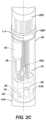
- FIGS. 2 A through 2 Care illustrations of an intermediate section and distal portion of a shaft of the catheter in greater detail according to aspects of the present invention.
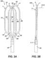
- FIGS. 3 A and 3 Bare illustrations of a front and side view of the end effector according to aspects of the present invention.
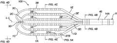
- FIGS. 4 A through 4 Dare illustrations depicting orientation of loop members of the end effector according to aspects of the present invention.
- FIG. 5 Ais an illustration depicting electrode spacing and dimensions on the end effector according to aspects of the present invention.
- FIG. 5 Bis another illustration of the end effector including a mechanical linkage according to aspects of the present invention.
- FIGS. 6 A and 6 Bare illustrations of views of the end effector pressed to a planar surface according to aspects of the present invention.
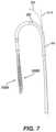
- FIG. 7is an illustration of an intermediate section of the shaft of the catheter deflected with a puller wire.
- FIGS. 8 A and 8 Bare illustrations of views of support frames of the end effector in an unconstrained configuration according to aspects of the present invention.
- FIGS. 8 C and 8 Dare illustrations of the support frames of FIGS. 8 A and 8 B being pressed to a surface according to aspects of the present invention.
- FIGS. 9 A and 9 Bare illustrations of example support frames that vary in cross section along a respective looped path of each support frame according to aspects of the present invention.
- FIG. 10 Ais an illustration of example support frames of the end effector according to aspects of the present invention.
- FIGS. 10 B through 10 Eare illustrations of cross sectional areas of the example support frame as indicated in FIG. 10 A .
- FIGS. 10 F and 10 Gare illustrations of possible transition schemes between regions of a support frame of the end effector according to aspects of the present invention.
- FIG. 11 Ais an illustration of an asymmetrical support frame of the end effector according to aspects of the present invention.
- FIGS. 11 B and 11 Care illustrations of cross sections of the asymmetrical support frame as indicated in FIG. 11 A .
- FIG. 12 Ais an illustration of a symmetrical support frame of the end effector according to aspects of the present invention.
- FIGS. 12 B and 12 Care illustrations of cross sections of the symmetrical support frame as indicated in FIG. 12 A .
- FIG. 12 Dis an illustration of a detailed section of the symmetrical support frame as indicated in FIG. 12 A .
- FIG. 13 Ais an illustration of another asymmetrical support frame of the end effector according to aspects of the present invention.
- FIGS. 13 B and 13 Care illustrations of cross sections of the asymmetrical support frame as indicated in FIG. 13 A .
- FIGS. 13 D and 13 Eare illustrations of a detailed sections of the asymmetrical support frame as indicated in FIG. 13 A .
- FIG. 14 Ais an illustration of a symmetrical support frame of the end effector according to aspects of the present invention.
- FIGS. 14 B and 14 Care illustrations of cross sections of the symmetrical support frame as indicated in FIG. 14 A .
- FIGS. 14 D and 14 Eare illustrations of a detailed sections of the symmetrical support frame as indicated in FIG. 14 A .
- FIG. 15is an illustration of crimped or serrated features at end of the support frames according to aspects of the present invention.
- FIGS. 16 A through 16 Dare illustrations of deformation of the support frames as a result of application of various forces according to aspects of the present invention.
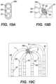
- FIGS. 17 A through 17 Dare illustrations of an example rectangular or ovular mechanical linkage having a closable single opening and used for joining the loop members according to aspects of the present invention.
- FIGS. 20 A through 20 Care illustrations of an example cylindrical mechanical linkage having three passageways and used for joining support members of the loop members according to aspects of the present invention.
- FIGS. 24 A through 24 Care illustrations of an alternative example loop member having a tubular housing having two or three lumens therethrough in which the support frame, conductive wires, and an irrigation tube are positioned according to aspects of the present invention.
- the terms “about” or “approximately” for any numerical values or rangesindicate a suitable dimensional tolerance that allows the part or collection of components to function for its intended purpose as described herein. More specifically, “about” or “approximately” may refer to the range of values ⁇ 10% of the recited value, e.g. “about 90%” may refer to the range of values from 81% to 99%.
- the terms “patient,” “host,” “user,” and “subject”refer to any human or animal subject and are not intended to limit the systems or methods to human use, although use of the subject invention in a human patient represents a preferred embodiment.
- FIG. 1 Aillustrates an example apparatus 10 having an elongated shaft 9 , a distal electrode assembly or end effector 100 , and a deflection control handle 16 .
- the shaft 9is preferably a tubular member.
- the apparatus 10can have several design variations to while including novel aspects illustrated herein.
- the apparatus 10is presented for illustration purposes only and is not intended to be limiting.
- the elongated shaft 9has a proximal portion 12 in the shape of an elongated catheter body, an intermediate deflection section 14 , and distal portion 14 A.
- the deflection control handle 16is attached to the proximal end of the catheter body 12 .
- the distal portion 14 A of the shaftis coupled to the end effector 100 via a connector tubing 46 .
- the elongated shaft 9forms a tubular catheter body sized and otherwise configured to traverse vasculature.
- the end effector 100has a plurality of loop members 1 , 2 , 3 that overlap at a common distal vertex and are joined at the distal vertex with a mechanical linkage 50 .
- the proximal portion 12 , intermediate section 14 , distal portion 14 A, and end effector 100are generally aligned along a longitudinal axis L-L.
- the intermediate section 14can be configured to bend to deflect the distal portion 14 A and end effector 100 from the longitudinal axis L-L.
- the end effector 100can be collapsed (compressed toward the longitudinal axis L-L) to fit within a guiding sheath or catheter (not illustrated).
- the shaft 9can be pushed distally to move the end effector 100 distally through the guiding sheath.
- the end effector 100can be moved to exit a distal end of the guiding sheath via manipulation of the shaft 9 and/or control handle 16 .
- An example of a suitable guiding sheath for this purposeis the Preface Braided Guiding Sheath, commercially available from Biosense Webster, Inc. (Irvine, California, USA).
- the end effector 100has first, second and third loop members 1 , 2 , and 3 .
- Each loop member 1 , 2 , 3has two spines 1 A, 1 B, 2 A, 2 B, 3 A, 3 B and a connector 1 C, 2 C, 3 C that connects the two spines of the respective loop member 1 , 2 , 3 .
- Spines 1 A, 1 B of a first loop member 1are connected by a first connector 1 C; spines 2 A, 2 B of a second loop member 2 are connected by a second connector 2 C; and spines 3 A, 3 B of a third loop member 3 are connected by a third connector 3 C.
- the connectors 1 C, 2 C, 3 Care preferably arcuate members as illustrated.
- the spines 1 A, 1 B, 2 A, 2 B, 3 A, 3 B in the respective pair of spinescan be substantially parallel to each other along a majority of their respective lengths when the end effector 100 is expanded in an unconstrained configuration as illustrated in FIG. 1 A .
- all spines in the end effectorare parallel to each other along the majority of their respective lengths when the end effector 100 is in the unconstrained configuration.
- the spinesare not necessarily all coplanar as described in greater detail elsewhere herein, for instance in relation to FIGS. 4 A through 4 C .
- Each spine 1 A, 1 B, 2 A, 2 B, 3 A or 3 Bcan have a length ranging between about 5 and 50 mm, preferably about 10 and 35 mm, and more preferably about 28 mm.
- the parallel portions of each spine 1 A, 1 B, 2 A, 2 B, 3 A, 3 Bcan be spaced apart from each other by a distance ranging between about 1 mm and 20 mm, preferably about 2 and 10 mm, and more preferably about 4 mm.
- Each spine 1 A, 1 A, 1 B, 2 A, 2 B, 3 A, 3 Bpreferably carries at least eight electrodes per spine member.
- the end effectorpreferably includes six spines as illustrated. With eight electrodes on six spines, the end effector 100 includes forty-eight electrodes.
- a distal electrode 38 D and a proximal electrode 38 Pare positioned near the distal portion 14 A of the shaft 9 .
- the electrodes 38 D and 38 Pcan be configured to cooperate (e.g. by masking of a portion of one electrode and masking a different portion on the other electrode) to define a referential electrode (an electrode that is not in contact with tissues).
- One or more impedance sensing electrodes 38 Rcan be configured to allow for location sensing via impedance location sensing technique, as described in U.S. Pat. Nos. 5,944,022; 5,983,126; and 6,445,864, of which a copy is provided in the priority U.S. Provisional Patent Application 63/031,955 and incorporated herein by reference.
- FIGS. 2 A through 2 Cillustrates the intermediate section 14 and distal portion 14 A of the shaft 9 of the apparatus in greater detail.
- FIG. 2 Ais a cross sectional view, along the longitudinal axis L-L, of the elongated shaft 9 at the interface between the proximal portion 12 and intermediate section 14 .
- FIG. 2 Bis a cross sectional view of the intermediate section 14 orthogonal to the longitudinal axis L-L.
- FIG. 2 Cis an isometric view of the distal portion 14 A and connector tubing 46 with certain components illustrated as transparent.
- the outer diameter of the catheter body 12is preferably no more than about 8 French, more preferably about 7 French.
- the thickness of the outer wall 20is thin enough so that the central lumen 18 can accommodate at least one puller wire, one or more lead wires, and any other desired wires, cables or tubes.
- the inner surface of the outer wall 20is lined with a stiffening tube 22 to provide improved torsional stability.
- the outer wall 20has an outer diameter of from about 0.090 inch to about 0.094 inch (from about 2.3 mm to about 2.4 mm) and an inner diameter of from about 0.061 inch to about 0.065 inch (from about 1.5 mm to about 1.7 mm).
- the intermediate section 14can include a shorter section of tubing 19 having multiple lumens, for example, four off-axis lumens 31 , 32 , 33 and 34 .
- the first lumen 31carries a plurality of lead wires 40 S for ring electrodes 37 carried on the spines 1 A, 1 B, 2 A, 2 B, 3 A, 3 B.
- the second lumen 32carries a first puller wire 24 .
- the third lumen 33carries a cable 36 for an electromagnetic position sensor 42 and lead wires 40 D and 40 P for distal and proximal ring electrodes 38 D and 38 P carried on the catheter proximally of the end effector 100 . Electromagnetic location sensing technique is described in U.S. Pat.
- the magnetic location sensor 42can be utilized with impedance sensing electrode 38 R in a hybrid magnetic and impedance position sensing technique known as ACL described in U.S. Pat. Nos. 7,536,218; 7,756,567; 7,848,787; 7,869,865; and 8,456,182, of which a copy is provided in the priority U.S. Provisional Patent Application 63/031,955 and incorporated herein by reference.
- the fourth lumen 34(for example, diametrically opposite of the second lumen 32 as illustrated) carries a second puller wire 26 .
- the tubing 19is made of a suitable non-toxic material that is preferably more flexible than the catheter body 12 .
- One suitable material for the tubing 19is braided polyurethane, i.e., polyurethane with an embedded mesh of braided stainless steel or the like. The size of each lumen is sufficient to house the lead wires, puller wires, the cable and any other components.
- the useful length of the catheter shaft 9i.e., that portion of the apparatus 10 that can be inserted into the body excluding the end effector, can vary as desired. Preferably the useful length ranges from about 110 cm to about 120 cm.
- the length of the intermediate section 14is a relatively smaller portion of the useful length, and preferably ranges from about 3.5 cm to about 10 cm, more preferably from about 5 cm to about 6.5 cm.
- Catheter body proximal portion 12can be attached to the intermediate section 14 as shown and described in FIGS. 2A and 2B of U.S. Pat. No. 9,820,664, of which a copy is provided in the priority U.S. Provisional Patent Application 63/031,955 and incorporated herein by reference.
- a spacer(not shown) can be located within the catheter body 12 between the distal end of the stiffening tube (if provided) and the proximal end of the intermediate section 14 .
- the spacercan provide a transition in flexibility at the junction of the catheter body 12 and intermediate section 14 , which can allow this junction to bend smoothly without folding or kinking.
- a catheter having such a spaceris described in U.S. Pat. No. 5,964,757 of which a copy is provided in the priority U.S. Provisional Patent Application 63/031,955 and incorporated herein by reference.
- the distal portion 14 A of the shaft 9can be substantially contiguous with the intermediate section 14 such that the intermediate section comprises the distal portion 14 A; the distal portion being distinguished from the intermediate section 14 by the positioning of one or more (optional) ring electrodes 38 R. As referred to herein, the distal portion 14 A of the shaft 9 can therefore correspond to a distal portion of the intermediate section 14 .
- the distal portion 14 A of the shaft 9is coupled to the end effector 100 with a connector tubing 46 .
- the connector tubing 46includes an insert for connection of loop members 1 , 2 , 3 to provide electrical connection through the intermediate portion 14 of the catheter body.
- the connector tubing 46can be affixed to the distal portion 14 A of the catheter by glue or the like.
- the connector tubing 46can be shaped to house various components such as an electromagnetic position sensor, a puller wire anchor, ring electrodes 38 D, 38 P, etc.
- the connector tubing 46can include a central lumen 48 to house various components.
- An outer circumferential notch 27 ( FIG. 2 A ) in the distal end of the tubing 19 that receives the inner surface of the proximal end of the connector tubing 46can be used to attach the connector tubing 46 and the intermediate section 14 (distal portion 14 A of shaft 9 ).
- the intermediate section 14 and connector tubing 46are attached by glue or the like.
- the connector tubing 46can house various components, including an electromagnetic position sensor 42 , and a distal anchor bar for a first puller wire 24 and another anchor bar 51 B for a second puller wire 26 . Only the anchor 51 B for second puller wire 26 is visible in FIG. 2 C .
- the anchor bar for the first puller wirecan be configured as a mirror image to the illustrated puller wire anchor bar 51 B.
- FIGS. 3 A and 3 Bare illustrations of a front and side view of the end effector 100 .
- the three loop members 1 , 2 , 3overlap at a common distal vertex 50 along the longitudinal axis L-L.
- Each of the loop members 1 , 2 , 3respectively include proximal end segments 1 D, 2 D, 3 D, 1 E, 2 E, 3 E affixed to the distal portion 14 A of the elongated shaft 9 of the apparatus 10 .
- the end effector 100is in an unconstrained configuration as illustrated in FIGS. 3 A and 3 B .
- the loop members 1 , 2 , 3are not coplanar with each other.
- FIG. 3 Balso illustrates an orthogonal axis O-O orthogonal to the longitudinal axis L-L and approximately orthogonal to the front view of the end effector 100 .
- FIGS. 4 A through 4 Dare illustrations depicting orientation of loop members of the end effector.
- FIGS. 4 B and 4 Care cross sectional views of the end effector 100 and as indicated in FIG. 4 A .
- FIG. 4 Dis a view of the end effector 100 looking proximally from a distal end of the end effector 100 as indicated in FIG. 4 A .
- FIG. 4 Billustrates a cross sectional view through the connector 46 .
- the connector 46includes a tubular insert 200 that has its center coinciding with the longitudinal axis L-L.
- Orthogonal planes P 4 and P 5are in alignment with the longitudinal axis to define four quadrants in the insert 200 .
- a parallel reference plane P 5is approximately parallel to the front view of the end effector 100 illustrated in FIG. 3 A .
- An orthogonal reference plane P 4is approximately orthogonal to the parallel reference plane P 5 and approximately parallel to the orthogonal axis O-O.
- Apertures 202 , 204 , 206 , 208 , 210 , 212 of the insert 200are sized, positioned, and otherwise configured for insertion of respective end segments 1 D, 2 D, 3 D, 1 E, 2 E, 3 E. Openings 214 , 216 are disposed on orthogonal plane P 4 for insertion of puller wires or electrical wires as well as any other components to and from the end effector 100 . Components which traverse the apertures 202 , 204 , 206 , 208 , 210 , 212 and openings 214 , 216 are not illustrated in FIG. 4 B for the purposes of illustration.
- loop members 1 , 2 and 3are arrayed in a non-coplanar unconstrained arrangement, shown in the sectional view of FIG. 4 C (as viewed from the proximal end), whereby loop 3 defines a plane P 3 (demarcated by spines 3 A and 3 B with connector 3 C) that intersects orthogonal plane P 4 with loop 1 having a plane P 1 (demarcated by spines 1 A and 1 B with connector 1 C) that intersects both orthogonal planes P 4 and P 5 and loop 2 having a plane P 2 (demarcated by spines 2 A and 2 B and connector 2 C) that intersects orthogonal plane P 4 and is substantially parallel to orthogonal plane P 5 .
- FIG. 4 Dis a view of the distal end of the end effector looking proximally.
- loop 1(defined by spines 1 A, 1 B and connector 1 C) is arrayed to define plane P 1 that is contiguous to or extend through spines 1 A, 1 B and loop 1 C whereas spines 2 A, 2 B and connector 2 C of loop 2 are arrayed to define a plane P 2 that intersects with plane P 1 .
- Spines 3 A, 3 B and connector 3 C of loop 3are arrayed to define a plane P 3 that intersects with both planes P 1 and P 2 .
- the planes P 1 , P 2 , and P 3 defined by the respective loops 1 , 2 and 3are configured so that the loops P 1 , P 2 and P 3 are not contiguous to or arrayed such that a common plane passes through the loops. Thus, planes P 1 , P 2 and P 3 are non-parallel and intersects each other. It is noted that the longitudinal axis L-L may be contiguous to the second plane P 2 . In alternative embodiment, longitudinal axis L-L may be disposed in between a region bounded by planes P 1 , P 2 and P 3 .
- FIGS. 4 A through 4 Dare one example of non-coplanar arrangement of loop members 1 , 2 , 3 in an end effector. There are numerous possible arrangements non-coplanar arrangements of loop members which can result in an end effector having the general appearance of the illustrated end effector 100 .
- FIG. 5 Ais an illustration depicting electrode spacing and dimensions on the end effector.
- the electrodes 37can include one or more pairs of closely-spaced bipolar microelectrodes 37 A, 37 B which are configured to pick up electrocardiogram signals from tissue.
- the microelectrodes 37 A, 37 B of a pairhas a separation space gap distance (Lg) therebetween of approximately 1 mm to 200 microns and preferably no greater than about 200 microns.
- Each electrode 37 A, 37 Bhas an electrode area (Ae) and electrode length (L).
- the electrode lengthcan be from about 2 mm to about 0.5 mm.
- Each spine electrode 37preferably has a length of 1 mm to 0.5 mm.
- the electrodes 37 as illustratedare cylindrical such that the electrode area is calculated as a produce of the circumference (C) and length (L) of the electrode.
- the spinehas a diameter (D).
- the microelectrodes 37 A, 37 Bneed not completely circumscribe the respective loop 1 , 2 , 3 ; in which case the microelectrodes 37 A, 37 B can have a rectangular shape that is rectilinear or arced having a width (W) such that the electrode area (Ae) is a produce of the electrode length (L) and width (W), the width being the arc length when the rectangular shape is arced.
- a conversion factor CFmay be used to determine the appropriate gap distance between the electrodes based on the known area of either one of the pair of electrodes.
- the conversion factor CFmay range from about 2 to 0.1 in the inverse of the same root dimensional unit as the planar area of an electrode.
- the smallest gap distance (Lg) along the longitudinal axis extending through both electrodescan be determined by applying the conversion factor CF (in the inverse of the same root dimensional unit of the area or mm) to arrive at a gap distance Lg of about 100 microns.
- the conversion factor CFin the inverse of the same root dimensional unit or mm ⁇ 1 ) can be 1.25 mm ⁇ 1 or less, giving the range of the smallest gap distance Lg from about 300 microns to about 24 microns. Regardless of the shape of the electrodes, a preferred conversion factor CF is about 0.8 (in the inverse of the same root dimensional unit for the electrode area).
- FIG. 5 Bis another illustration of the end effector 100 including a mechanical linkage 50 .
- At least one pair of closely-spaced bipolar microelectrodes 37 A, 37 Bis provided on each spine 1 A, 2 A, 3 A, 1 B, 2 B, 3 B in the present example. More particularly, each spine 1 A, 2 A, 3 A, 1 B, 2 B, 3 B carries four pairs of bipolar microelectrodes 37 corresponding to eight microelectrodes 37 per spine. This number may be varied as desired.
- FIG. 5 Balso illustrates a clip 50 coupling connectors 1 C, 2 C, 3 C together in a single connection point. The clip 50 functions to maintain a spatially fixed arrangement between the loops 1 , 2 , 3 at the common distal vertex.
- FIGS. 6 A and 6 Bare illustrations of views of the end effector pressed to a planar surface S.
- the loop members 1 , 2 , 3can be pressed to the planar surface S via manipulation of the shaft 9 of the device. More specifically, when the end effector 100 is positioned within a patient, manipulation of the catheter body 12 and the control handle 16 can be used to position the end effector 100 against a surface within a wall of an internal cavity of the patient such internal walls of the heart and/or blood vessels. When the end effector 100 is positioned against the planar surface S, a majority of each length of each spine 1 A, 2 A, 3 A, 1 B, 2 B, 3 B can become contiguous and aligned to the planar surface.
- each spine 1 A, 2 A, 3 A, 1 B, 2 B, 3 Bcan become aligned with a majority of each length of the other spines.
- the surface Sneed not necessarily be planar in order for the spines 1 A, 2 A, 3 A, 1 B, 2 B, 3 B to become contiguous and aligned to the surface.
- the end effector 100may be able to conform to a curved surface, for instance.
- the connecting segments 1 C, 2 C, 3 Ccan be stacked on top of the surface S at the distal vertex at the linkage 50 .
- a first connecting segment 1 C nearest to the surface Scan be separated from the surface S by the linkage 50 .
- a second connecting segment 3 C stacked onto the first connecting segment 1 Ccan be separated from the surface S by the linkage 50 and the first connecting segment 1 C.
- a third connecting segment 2 Ccan be separated from the surface S by the linkage 50 and the first and second connecting segments 1 C, 3 C.
- each connecting segment 1 C, 2 C, 3 Ccan be separated from the planar surface S when the majority of each spine 1 A, 2 A, 3 A, 1 B, 2 B, 3 B is pressed to the planar surface.
- the linkage 50can be inset into the first connecting segment 1 C such that the first connecting segment is substantially contiguous to the planar surface S. In that case, only the second and third connecting segments 3 C, 2 C are separated from the planar surface S at the distal vertex.
- Proximal segments 1 D, 2 D, 3 D, 1 E, 2 E, 3 E of the loop members 1 , 2 , 3can be bent such that at least a portion of each of the proximal segments curves away from the surface S.
- each spine 1 A, 2 A, 3 A, 1 B, 2 B, 3 BWhen the majority of each spine 1 A, 2 A, 3 A, 1 B, 2 B, 3 B is pressed to the surface S, at least some of the electrodes 37 on each spine can be in contact with the surface S. In some examples, every electrode 37 on each spine can be in contact with the surface 37 .
- each spine 1 A, 2 A, 3 A, 1 B, 2 B, 3 BWhen the majority of each spine 1 A, 2 A, 3 A, 1 B, 2 B, 3 B is pressed to the surface S, the majority of each respective length of each loop member can become contiguous to the surface S, where the respective length of each loop member includes the length of the respective loop member's spines 1 A, 2 A, 3 A, 1 B, 2 B, 3 B, connectors 1 C, 2 C, 3 C, and proximal segments 1 D, 2 D, 3 D, 1 E, 2 E, 3 E (distal to the connector tubing 46 ).
- FIG. 7is an illustration of the intermediate section 14 of the shaft of the catheter deflected at approximately 360°.
- the end effector 100has a first side 100 A and a second side 100 B. This allows the user to place first side 100 A (or 100 B) against the tissue surface, with at least the intermediate section 14 (if not also a distal portion of the catheter body 12 ) generally perpendicular to the tissue surface, and actuates the control handle to deflect the intermediate deflection section 14 to arrive at various deflections or radii of curvature (e.g., arrows D 1 and D 2 ) such that the second side 100 B deflects back toward the catheter body 12 .
- various deflections or radii of curvaturee.g., arrows D 1 and D 2
- the intermediate sectioncan be deflected via manipulation of the puller wires 24 , 26 illustrated in FIGS. 2 A through 2 C .
- the puller wires 24 , 26can be two separate tensile members or parts of a single tensile member.
- the puller wires 24 , 26can be actuated for bi-directional deflection of the intermediate section 14 .
- the puller wires 24 , 26can be actuated by mechanisms in the control handle 16 that are responsive to a thumb control knob or a deflection control knob 11 .
- Suitable control handlesare disclosed in U.S. Pat. Nos. 6,123,699; 6,171,277; 6,183,435; 6,183,463; 6,198,974; 6,210,407 and 6,267,746, of which a copy is provided in the priority U.S. Provisional Patent Application 63/031,955 and incorporated herein by reference.
- puller wires 24 and 26can be made of any suitable metal, such as stainless steel or Nitinol.
- the puller wires 24 , 26are preferably coated with TEFLON or the like. The coating imparts lubricity to the puller wires.
- the puller wirespreferably have a diameter ranging from about 0.006 to about 0.010 inch.
- FIGS. 8 A through 8 Dare illustrations of a support frame assembly 80 of the end effector 100 .
- FIGS. 8 A and 8 Billustrate the support frame assembly 80 in an unconstrained configuration.
- FIGS. 8 C and 8 Dillustrate the support frame assembly 80 being pressed to a surface S.
- the loop members 1 , 2 , 3each includes a respective support frame 81 , 82 , 83 .
- the support frame assembly 80extends into the connector tubing 46 to mechanically affix the loop members 1 , 2 , 3 to the shaft 9 .
- the support frames 81 , 82 , 83provide structural integrity for the loop members 1 , 2 , 3 .
- the support frames 81 , 82 , 83can include plastic or metal cut-off sheets, plastic or metal round wire, plastic or metal square wire, or other suitable biocompatible material.
- the support framesare made from shape memory material such as, for example, nitinol.
- the support frame assembly 80is joined at a distal vertex with mechanical linkage 50 .
- the support frames 81 , 82 , 83can be assembled by virtue of a mechanical linkage affixed to an outer housing of the loop members 1 , 2 , 3 or a direct linkage between the support frames 81 , 82 , 83 .
- each of the respective support frames 81 , 82 , 83defines a respective looped path of its respective loop member 1 , 2 , 3 as illustrated in FIG. 8 A .
- Each support frame 81 , 82 , 83includes respective parallel segments 81 A, 82 A, 83 A, 81 B, 82 B, 83 B that extend through corresponding spines 1 A, 2 A, 3 A, 1 B, 2 B, 3 B of the end effector 100 .
- Each support frame 81 , 82 , 83includes respective proximal segments 81 D, 82 D, 83 D, 81 E, 82 E, 83 E that extend through corresponding proximal segments 1 D, 2 D, 3 D, 1 E, 2 E, 3 E of respective loop members 1 , 2 , 3 .
- the proximal segments 81 D, 82 D, 83 D, 81 E, 82 E, 83 Eextend into the connector tubing 46 to join the end effector 100 to the shaft 9 .
- Each support frame 81 , 82 , 83includes a respective connecting segments 81 C, 82 C, 83 C that extends between the respective pair of parallel segments 81 A, 82 A, 83 A, 81 B, 82 B, 83 B and through the respective connecting segment 1 C, 2 C, 3 C of the respective loop member 1 , 2 , 3 .
- the parallel segments 81 A, 82 A, 83 A, 81 B, 82 B, 83 Bis not aligned in a common plane with other parallel segments. Said another way, at least one of the looped paths is non-coplanar with one or both of the other looped paths.
- the pair of parallel segments 81 A, 82 A, 83 A, 81 B, 82 B, 83 B for each support frame 81 , 82 , 83can define a plane for the pair's respective support frame 81 , 82 , 83 .
- the support members 81 , 82 , 83can generally align to define three planes P 3 , P 4 , P 5 as illustrated in FIG. 4 C when the end effector 100 is in the unconstrained configuration.
- a majority of the respective length of each segment in each of the respective pairs of parallel segmentscan become approximately coplanar with a majority of the respective length of each of the other segments in each of the respective pairs of parallel segments.
- the support members 80can become aligned with the surface S as the loop members 1 , 2 , 3 are pressed into the surface S as illustrated in FIG. 6 B .
- the parallel segments 81 A, 82 A, 83 A, 81 B, 82 B, 83 Bbecome coplanar with each other along a majority of their respective lengths.
- Each support frame 81 , 82 , 83can include knuckles to promote conformance of the loop members 1 , 2 , 3 to the surface S.
- the knucklescan be spaced uniformly or non-uniformly along the looped path of a respective support member 81 , 82 , 83 .
- Knuckle featurescan include thinned out sections of the material of the support members 81 , 82 , 83 . Additionally, or alternatively, the knuckle features can include hinge mechanisms.
- the regions I-I configured to resist deflectioncan have a larger cross sectional area compared to the regions II-II configured to facilitate deflection.
- the regions I-I configured to resist deflectioncan be flattened to resist deflection in the direction of long sides of the cross section while having a similar cross section to non-flattened, or less flattened regions II-II. That is, in FIG. 9 A , the thin sections are intended to promote sheath retraction (lower force for the frame to collapse) while in FIG. 9 B , the distal II-II section is intended still for frame collapsing, but the proximal II-II section (knuckles) are intended to promote deflection with respect to the longitudinal axis L-L.
- FIG. 10 Ais another illustration of an example support frame assembly 80 c of the end effector 100 .
- FIGS. 10 B through 10 Eare illustrations of cross sectional areas of the example support frame as indicated in FIG. 10 A .
- FIGS. 10 F and 10 Gare illustrations of example transitions schemes between wide and narrow regions.
- FIG. 10 Bshows a cross section having a substantially rectangular shape and corresponding to sections of each support frame 81 , 82 , 83 annotated with Roman Numerals I-I.
- the parallel segments 81 A, 82 A, 83 A, 81 B, 82 B, 83 Bdefine a respective plane for each support frame 81 , 82 , 83 .
- the rectangleis long in the plane of the respective support frame.
- the rectangleis short in the direction orthogonal to the plane of the respective support frame 81 , 82 , 83 .
- this shapepermits greater flexibility along an axis aligned with the short edges of the shape compared to the flexibility along an axis aligned with the long edges of the shape.
- the width of the long side of the rectangleis about 0.012 inches (0.3 millimeters) and the short side of the rectangle is about 0.008 inches (0.2 millimeters).
- FIG. 10 Cshows an alternative cross section having an ovoid or oval-shaped shape and corresponding to sections of each support frame 81 , 82 , 83 annotated with Roman Numerals I-I.
- the oval illustrated in FIG. 10 Cis long in the plane of the respective support frame 81 , 82 , 83 and short orthogonal to the respective plane, affecting the relatively flexibility in each direction as understood by a person skilled in the pertinent art.
- the width of the long side of the ovalis about 0.012 inches (0.3 millimeters) and the short side of the oval is about 0.005 inches (0.13 millimeters).
- FIG. 10 Dshows a cross section corresponding to sections of each support frame 81 , 82 , 83 , annotated with Roman Numerals II-II.
- the cross section illustrated in FIG. 10 Dhas a substantially rectangular shape having a width that is shorter in the plane of the respective support frame 81 , 82 , 83 compared to the width of the rectangular cross section illustrated in FIG. 10 B .
- the height of the cross section illustrated in FIG. 10 D orthogonal to the plane of the support frame 81 , 82 , 83can be about equal to the height of the cross section of the rectangle illustrated in FIG. 10 B .
- the height of the narrower section II-IIcan be greater than the height of the wider section I-I.
- Areas of the respective support frame 81 , 82 , 83 having a cross section as illustrated in FIG. 10 Dhave a higher flexibility in the plane of the respective support frame compared to areas of the respective support frame having a cross section as illustrated in FIG. 10 B .
- the cross sectionis approximately square shaped having an edge length of about 0.008 inches (0.2 millimeters).
- a support frame 81 , 82 , 83 including rectangular cross sections illustrated in FIGS. 10 B and 10 Dcan be formed by selecting a sheet having a thickness about equal to the height of the cross sectional shapes illustrated in FIGS. 10 B and 10 D and cutting the sheet to the shape of each respective support frame 81 , 82 , 83 as illustrating in FIG. 10 A , varying the width of each segment of each support frame 81 , 82 , 83 to be wider in regions indicated by the Roman Numerals I-I and narrower in regions indicated by Roman Numerals II-II.
- the support frame 81 , 82 , 83can be formed by selecting square or rectangular wire, shaping the wire to form a looped path, and flattening the wire to have regions with wider cross sections I-I and narrower cross sections II-II.
- FIG. 10 Eshows an alternative cross section corresponding to sections of each support frame 81 , 82 , 83 annotated with Roman Numerals II-II.
- the cross sectionhas an ovoid or oval-shaped shape that is shorter in the plane of the respective support frame 81 , 82 , 83 compared to the width of the oval cross section illustrated in FIG. 10 C .
- the height of the cross section illustrated in FIG. 10 E orthogonal to the plane of the support frame 81 , 82 , 83can be greater than the height of the cross section of the oval illustrated in FIG. 10 C .
- the 10 Ehave a higher flexibility in the plane of the respective support frame compared to areas of the respective support frame having a cross section as illustrated in FIG. 10 C .
- the cross sectionis approximately circular having a diameter of about 0.008 inches (0.2 millimeters).
- a support frame 81 , 82 , 83 including ovoid or oval-shaped cross sections illustrated in FIGS. 10 C and 10 Ecan be formed by selecting a round or oval wire, shaping the wire to form a looped path, and flattening the wire to have regions with wider cross sections I-I and narrower cross sections II-II.
- the end effector 100can include a support frame assembly 80 c having some or all of the cross sections illustrated in FIGS. 10 B through 10 E in any combination. Further, each support frame 81 , 82 , 83 can individually include some or all of the cross sections illustrated in FIG. 10 B through 10 E in any combination.
- the effector 100can additionally, or alternatively include cross sections not illustrated herein to achieve a difference in flexibility between regions indicated by Roman Numerals I-I and regions indicated by Roman Numerals II-II as understood by a person skilled in the pertinent art according to the teachings herein.
- individual support frames 81 , 82 , 83can include primarily rectangular cross sectional shapes (e.g. FIGS. 10 B and 10 D ) or primarily ovoid shapes (e.g. FIGS. 10 C and 10 E ) as combining rectangular shapes with ovoid shapes in the same support frame 81 , 82 , 83 can increase cost and/or difficulty in manufacturing.
- FIGS. 10 F and 10 Gare illustrations of possible transition schemes (knuckles) between regions of a support frame of the end effector.
- the support framecan transition asymmetrically in width from a wider cross section I-I to a narrower cross section II-II and vice versa.
- the support framecan transition symmetrically in width from a wider cross section I-I to a narrower cross section II-II and vice versa.
- the support framecan include only asymmetrical transitions in width, only symmetrical transitions in width, or a mix of asymmetrical and symmetrical transitions in width. Such transitions can be applied to any of the example support members illustrated and otherwise described herein.
- FIG. 11 Ais an illustration of an asymmetrical support frame 181 of the end effector 100 .
- FIGS. 11 B and 11 Care illustrations of cross sections of the asymmetrical support frame 181 as indicated in FIG. 11 A .
- the asymmetrical support frame 181is another example support frame that can be used in place of the outer support frames 81 , 83 illustrated and described elsewhere herein (e.g. in relation to FIGS. 8 A through 8 D ).
- FIG. 12 Ais an illustration of a symmetrical support frame 182 of the end effector 100 .
- the symmetrical support frame 182is another example support frame that can be used in place of the central support frame 82 illustrated and described elsewhere herein (e.g. in relation to FIGS. 8 A through 8 D ).
- FIG. 12 B and 12 Care illustrations of cross sections of the symmetrical support frame as indicated in FIG. 12 A .
- FIG. 12 Dis an illustration of a detailed section of the symmetrical support frame as indicated in FIG. 12 A .
- the support frame assembly 80can include two asymmetrical support frames 181 and a single symmetrical support frame 182 .
- FIG. 11 Aillustrates that the parallel segments 81 A, 81 B of the asymmetric support frame 181 can have a wider cross section I-I as illustrated in FIG. 11 C compared to the narrower cross section II-II of the connecting segment 81 C as illustrated in FIG. 11 B .
- the cross sectional shape of the parallel segments 81 A, 81 Bcan be substantially rectangular with a width in the plane of the support frame 181 of about 0.013 inches (0.33 millimeters) and a height orthogonal to the plane of the support frame 181 of about 0.005 inches (0.13 millimeters).
- the cross sectional shape of the connecting segment 81 Ccan be substantially rectangular or square with a width in the plane of the support frame 181 of about 0.008 inches (0.2 millimeters) and a height orthogonal to the plane of the support frame 181 of about 0.008 inches (0.2 millimeters).
- the proximal segments 81 E, 81 Dcan have a cross section I-I of approximately the same dimensions as the parallel segments 81 A, 81 B.
- FIG. 12 Aillustrates that a majority of the length of the parallel segments 82 A, 82 B of the symmetric support frame 182 can have a wider cross section I-I as illustrated in FIG. 12 C compared to the narrower cross section II-II of the connecting segment 82 C.
- the parallel segments 82 A, 82 Bcan include a tapering transition as illustrated in FIG. 12 D and indicated in FIG. 12 A that tapers from the wider width of the wider cross section I-I to the narrower width II-II of the narrower cross section II-II.
- a distal portion of each parallel segment 82 A, 82 B distal to the tapering transitioncan have the narrower cross section I-I.
- the proximal segments 82 E, 83 Dcan have a cross section I-I of approximately the same dimensions as the majority of the length of the parallel segments 82 A, 82 B.
- the symmetric support frame 182can further include a narrower width sections 82 F, 82 G that respectively include a proximal portion of a respective parallel segment 82 A, 82 B and a distal portion of a respective proximal segment 82 D, 82 E. These narrower width sections 82 F, 82 G can have a cross section II-II as illustrated in FIG. 12 B . These narrower width sections 82 F, 82 G can have a length of approximately 0.102 inches (2.6 millimeters).
- the symmetric support frame 82can have a width of approximately 0.294 inches (7.5 millimeters) as measured between outer edges of the parallel segments 82 A, 82 B in the plane of the support frame 82 as illustrated.
- the narrower cross sectional regions II-IIcan have a cross sectional shape that is substantially rectangular or square with a width in the plane of the support frame 182 of about 0.005 inches (0.13 millimeters) and a height orthogonal to the plane of the support frame 182 of about 0.005 inches (0.13 millimeters).
- the wider cross sectional regions I-Ican have a substantially rectangular cross sectional shape with a width in the plane of the support frame 182 of about 0.01 inches (0.25 millimeters) and a height orthogonal to the plane of the support frame 182 of about 0.005 inches (0.13 millimeters).
- FIG. 13 Ais an illustration of an asymmetrical support frame 281 of the end effector 100 .
- FIGS. 13 B and 13 Care illustrations of cross sections of the asymmetrical support frame 281 as indicated in FIG. 13 A .
- the asymmetrical support frame 281is another example support frame that can be used in place of the outer support frames 81 , 83 illustrated and described elsewhere herein (e.g. in relation to FIGS. 8 A through 8 D ).
- FIGS. 13 D and 13 Eare illustrations of detailed sections of the asymmetrical support frame 281 as indicated in FIG. 13 A .
- FIG. 14 Ais an illustration of a symmetrical support frame 282 of the end effector 100 .
- the symmetrical support frame 282is another example support frame that can be used in place of the central support frame 82 illustrated and described elsewhere herein (e.g. in relation to FIGS. 8 A through 8 D ).
- FIGS. 14 B and 14 Care illustrations of cross sections of the symmetrical support frame as indicated in FIG. 14 A .
- FIGS. 14 D and 14 Eare illustrations of a detailed section of the symmetrical support frame as indicated in FIG. 14 A .
- the support frame assembly 80can include two asymmetrical support frames 281 and a single symmetrical support frame 282 .
- FIG. 13 Aillustrates that the parallel segments 81 A, 81 B of the asymmetric support frame 281 can have a wider cross section I-I as illustrated in FIG. 13 B compared to the narrower cross section II-II of the connecting segment 81 C.
- the cross sectional shape of the parallel segments 81 A, 81 Bcan be substantially rectangular with a width in the plane of the support frame 281 of about 0.01 inches (0.25 millimeters) and a height orthogonal to the plane of the support frame 281 of about 0.007 inches (0.18 millimeters).
- the cross sectional shape of the connecting segment 81 Cat least in the area indicated by section A-A in FIG.
- the proximal segments 81 E, 81 Dcan have a cross section I-I of approximately the same dimensions as the parallel segments 81 A, 81 B.
- a length L 1 of the frame 81 B as measured from a distal end to the proximal end (indicated as “y” in FIG. 13 A )can be approximately 1.4 inches (or 36 mm) and a width W 1 as measured from frame 81 A to frame 81 B is approximately 0.29 inches (or 7.4 mm).
- FIG. 13 Dillustrates transition, on the connector segment 81 C between the wider cross section I-I illustrated in FIG. 13 D and the narrower cross section II-II illustrated in FIG. 13 C .
- FIG. 13 Eillustrates a serrated segment of the support frame 281 shaped to secure the two ends of the loop member to the distal portion of the shaft 9 or connector tubing 46 .
- FIG. 14 Aillustrates that a majority of the length of the parallel segments 82 A, 82 B of the symmetric support frame 282 can have a wider cross section I-I as illustrated in FIG. 14 C compared to the narrower cross section II-II of the connecting segment 82 C as illustrated in FIG. 14 B .
- the parallel segments 82 A, 82 Bcan include a tapering transition as illustrated in FIG. 14 D and indicated in FIG. 14 A that tapers from the wider width of the wider cross section I-I to the narrower width II-II of the narrower cross section II-II.
- FIG. 14 Eillustrates a serrated segments of the support frame 282 shaped to secure the two ends of the loop member to the distal portion of the shaft.
- an aspect ratio of the length L 1 to width W 1i.e., L 1 /W 1
- the aspect ratio (L 1 /W 1 ) of the frame support of FIGS. 13 A and 14 Ais one of 4.5 or 4.75.
- the narrower cross sectional regions II-IIcan have a cross sectional shape that is substantially rectangular with a width in the plane of the support frame 282 of about 0.005 inches (0.13 millimeters) and a height orthogonal to the plane of the support frame 282 of about 0.007 inches (0.18 millimeters).
- the wider cross sectional regions I-Ican have a substantially rectangular cross sectional shape with a width in the plane of the support frame 282 of about 0.01 inches (0.25 millimeters) and a height orthogonal to the plane of the support frame 282 of about 0.005 inches (0.13 millimeters).
- FIG. 15is an illustration of crimped or serrated features 86 at ends of the support frames.
- the crimped or serrated features 86can facilitate engagement of the support frames 81 , 82 , 83 to the distal end 14 A of the shaft 9 (e.g. within the connector tubing 46 ).
- the serrations 86 of each support framecan be molded together with the connector tubing 46 or affixed (e.g., adhesive or epoxy) with the connector tubing 46 .
- each serration 86 of each support frameare affixed directly to the tubing 46 and one serration 86 does not engage or mate with another serration 86 from another support member.
- FIGS. 16 A through 16 Dare illustrations of deformation of support frame assemblies as a result of application of various forces.
- Each support frame assembly 80includes a first support frame 81 , a second support frame 82 , and a third support frame 83 .
- the first and third support frames 81 , 83are outer support frames surrounding the second central support frame 82 .
- the support frame assembly 80includes a mechanical linkage 50 joining the first, second, and third support frames 81 , 82 , 83 at the distal vertex.
- FIG. 16 Aillustrates the first support frame 81 pressed into a planar surface S as an apex of a wedge W is pressed with a force F 1 into the third support frame 83 .
- the support frame assembly 80is aligned approximately orthogonal to the planar surface S.
- the force F 1is applied approximately orthogonal to, and in a direction toward the planar surface S.
- the force F 1is applied centrally along the length of the outer parallel segment 83 B of the third support frame 83 .
- the outer parallel segment 83 B of the third support framebows toward the surface S as a result of the force F 1 .
- the support frame assembly 80can be configured to resist spine-to-spine contact when the force F 1 is applied. In FIG.
- the outer parallel segment 83 B of the third support frameis bowed to contact the second support frame 82 .
- the force F 1 sufficient to move the outer parallel segment 83 B of the third support frame 83 into contact with the second support frame 82can be a metric used to compare variations in support frame assembly design (e.g. with differing support frame cross section design) where a higher force F 1 indicates a more favorable result for this test.
- FIG. 16 Billustrates the support frame assembly 80 compressed between two planar surfaces S 1 , S 2 with a force F 2 .
- the planar surfaces S 1 , S 2are aligned approximately parallel to each other.
- the support frame assembly 80is aligned approximately orthogonal to the planar surfaces S 1 , S 2 .
- An outer parallel segment 81 A of the first support frame 81is pressed by the first planar surface 51 .
- the outer parallel segment 83 B of the third support frame 83is pressed by the second planar surface S 2 .
- the outer parallel segments 81 A, 83 Bbow toward the opposite planar surface S 1 , S 2 .
- the support frame assembly 80can be configured to resist spine-to-spine contact when the force F 2 is applied.
- the force F 2 sufficient to move the outer parallel segment 83 B of the third support frame 83 or the outer parallel segment 81 A of the first support frame 81 into contact with the second support frame 82can be a metric used to compare variations in support frame assembly design (e.g. with differing support frame cross section design) where a higher force F 2 indicates a more favorable result for this test.
- F 1 or F 2is approximately 10 gram-force or greater.
- the range of suitable forceis about 10 gram-force to 50 gram-force for F 1 and 10 gram-force to 70 gram-force.
- FIG. 16 Cillustrates the support frame assembly 80 compressed by a planar surface S applying a force F 3 to a distal end of the support frame assembly 80 .
- the distal portion 14 A of the shaft 9is held at a position in the proximal direction of the connector tubing 46 such that the longitudinal axis L-L defined by the shaft 9 is approximately orthogonal to the surface S.
- the force F 3is applied to the connector segments 81 C, 83 C of the first and third support frames 81 , 83 .
- the support frame assembly 80 and connector tubing 46deflect out of alignment with the longitudinal axis L-L.
- FIG. 16 Dillustrates the support frame assembly 80 deflected by a force F 4 applied approximately orthogonal to the support frame assembly near the mechanical linkage 50 at the distal vertex.
- the distal portion 14 A of the shaft 9is held near the connector tubing 46 .
- the support frame 80is deflected out of alignment with the longitudinal axis L-L.
- FIGS. 17 A through 17 Dare illustrations of an example rectangular or ovular mechanical linkage 50 a having a closable single opening and used for joining the loop members according to aspects of the present invention.
- Alternative mechanical linkages 50 b - hare illustrated in FIGS. 18 A through 22 C .
- the linkages 50 a - hcan be used to join loop members (or other electrode carrying structures) of catheter-based devices similar to how the loop members 1 , 2 , 3 are joined at the distal vertex as described and illustrated herein.
- the mechanical linkagecan serve to inhibit electrodes 37 on the spines 1 A, 2 A, 3 A, 1 B, 2 B, 3 B of the end effector 100 from coming into contact with each other.
- Loop members 1 , 2 , 3are spatially affixed relative to each other by the connector tubing 46 near the proximal end of the end effector 100 . Without the mechanical linkage, the distal ends of the respective loop members 1 , 2 , 3 are free to move in relation to each other when acted on by a force such as the forces F 1 , F 2 , F 3 , F 4 illustrated in FIGS. 16 A through 16 D .
- the mechanical linkageis sized, shaped, and otherwise configured to allow the end effector 100 to be collapsed for delivery through a catheter or guiding sheath to a treatment site. Ease of assembly of the end effector 100 is also a design consideration for the mechanical linkage.
- FIG. 17 Aillustrates the mechanical linkage 50 a joining three loop members 1 , 2 , 3 .
- the mechanical linkage 50 aincludes a seam or gap 52 .
- FIGS. 17 B and 17 Cillustrate the mechanical linkage 50 a as manufactured.
- the linkage 50 ais initially formed as an open clip.
- a stiff material, preferably metal,is formed or cut into a shape resembling an open paper clip.
- the individual loop members 1 , 2 , 3can be constructed prior to being joined by the mechanical linkage 50 a .
- the end effector 100can be entirely contracted and affixed to the shaft 9 before the linkage 50 a is affixed to the loop members 1 , 2 , 3 .
- the linkage 50 acan include an opening 52 sized to allow loop members 1 , 2 , 3 , one at a time, to be inserted into the linkage 50 a .
- the opening 52 as manufacturedcan be larger than respective diameters of the loop members 1 , 2 , 3 near the distal vertex.
- a short side of the linkage 50 acan be moved through an angle of about 20° and the free open end on a long side of the linkage 50 a can be moved through an angle of about 59° as illustrated in FIG. 17 B .
- the mechanical linkage 50 a illustrated in FIGS. 17 A through 17 Dis symmetrical.
- the mechanical linkage 50 acan be asymmetrical to promote consistent collapsing geometry of the end effector for delivery through a catheter.
- FIGS. 18 A through 18 Care illustrations of an example rectangular or ovular mechanical linkage 50 b having a single opening and used for joining the loop members 1 , 2 , 3 .
- the example mechanical linkage 50 bhas four contiguous sides.
- the example mechanical linkage 50 b in FIGS. 18 A through 18 Clacks a gap or seam 52 .
- loop members 1 , 2 , 3can be fed through the opening 54 of the linkage 50 b before the ends of the loop members 1 , 2 , 3 are affixed to the shaft 9 .
- the mechanical linkage 50 b illustrated in FIGS. 18 A through 18 Cis symmetrical.
- one side of the ringcan be wider than the other to promote the loop members 1 , 2 , 3 to fold to a particular side when the end effector 100 is collapsed for delivery through a catheter or guiding sheath.
- FIGS. 19 A through 19 Care illustrations of an example rectangular or ovular mechanical linkage 50 c having three openings 56 , 57 , 58 and used for joining the loop members 1 , 2 , 3 .
- Each opening 56 , 57 , 58can be shaped and otherwise configured to receive a loop member 1 , 2 , 3 .
- the linkage 50 ccan include a circular opening 57 to receive the central, symmetric loop member 2 .
- the central loop member 2can be approximately orthogonal to the linkage 50 c at the distal vertex, allowing for the respective opening 57 of the linkage 50 c to be circular.
- the linkage 50 ccan include two oblong openings 58 , 56 each respectively shaped to receive a respective outer, asymmetrical loop member 1 , 3 .
- the outer loop members 1 , 3can pass through the linkage 50 c at a non-orthogonal angle.
- the oblong shape of the corresponding linkage openings 56 , 58can be elongated to account for non-orthogonal trajectory of the outer loop members 1 , 3 through the linkage 50 c.
- Each of the loop members 1 , 2 , 3can include a respective tubular housing 91 , 92 , 93 covering a majority of the support frame 81 , 82 , 83 for that loop member 1 , 2 , 3 .
- the loop members 1 , 2 , 3need not include tubular housing 91 , 92 , 93 near the distal vertex.
- the openings 56 , 57 , 58 of the linkage 50 ccan be sized to allow the support frame 81 , 82 , 83 of the loop members to pass through, but need not be sized to allow the tubular housings 91 , 92 , 93 to pass through.
- the support frames 81 , 82 , 83can be positioned through the openings 56 , 57 , 58 of the linkage 50 c before the tubular housings 91 , 92 , 93 are added to the loop members 1 , 2 , 3 .
- the openings 56 , 57 , 58can be sized to allow the tubular housings 91 , 92 , 93 of the loop members 1 , 2 , 3 to pass therethrough to allow for a design where some or all of the tubular housings 91 , 92 , 93 cross the distal vertex and/or to allow for an assembly process where the tubular housings 91 , 92 , 93 are affixed to the loop members 1 , 2 , 3 before the mechanical linkage 50 c.
- FIGS. 20 A through 20 Care illustrations of an example cylindrical mechanical linkage 50 d having three passageways 60 , 62 , 64 and used for joining support members 81 , 82 , 83 of the loop members 1 , 2 , 3 .
- the openings 60 , 62 , 64 of the linkage 50 dcan be sized to allow the support frame 81 , 82 , 83 of the loop members to pass through, but need not be sized to allow the tubular housings 91 , 92 , 93 to pass through.
- the support frames 81 , 82 , 83can be positioned through the openings 60 , 62 , 64 of the linkage 50 d before the tubular housings 91 , 92 , 93 are added to the loop members 1 , 2 , 3 .
- FIGS. 21 A through 21 Care illustrations of an example cylindrical mechanical linkage 50 e having three passageways 66 , 68 , 70 and used for joining the loop members 1 , 2 , 3 with tubular housings 91 , 92 , 93 over the support members 81 , 82 , 83 .
- the passageways 66 , 68 , 70can be sized to allow for an assembly process where the tubular housings 91 , 92 , 93 are affixed to the loop members 1 , 2 , 3 before the mechanical linkage 50 e.
- FIGS. 22 A through 22 Care illustrations of additional example mechanical linkages.
- FIG. 22 Aillustrates a mechanical linkage 50 f including polymer shaped to closely conform to the dimensions of the loop members 1 , 2 , 3 .
- the linkage 50 fcan include an adhesive.
- the linkage 50 fcan be applied by hand, over molded, or by other means as understood by a person skilled in the pertinent art.
- FIG. 22 Billustrates a mechanical linkage 50 g including an adhesive.
- FIG. 22 Cillustrates a tapered ring linkage 50 h having an annular opening 72 through which the three loop members 1 , 2 , 3 can extend and a height that tapers from a larger dimension H 2 to a smaller dimension H 1 across the diameter of the opening 72 .
- the link 50 hhas a portion on one side that is narrower on one side (H 1 ) as compared to the portion H 2 on the other side.
- the narrowed portion H 1encourages the loops 1 , 2 and 3 to bend toward the narrowed side when retracting into the sheath. This can be used to reduce forces required for sheath retraction.
- FIGS. 23 A and 23 Bare illustrations of an example loop member 1 having an inner housing 94 and outer housing 90 surrounding the support frame 81 .
- the illustrated loop member 1can be used in place of loop members 1 , 2 , 3 illustrated and otherwise disclosed herein according to the teachings herein. In particular, it can be advantageous to use the illustrated loop member in place of loop members 1 , 2 , 3 illustrated in FIGS. 19 C and 20 C .
- the inner housing 94 and outer housing 90can collectively function as the tubular housing 91 , 92 , 93 illustrated elsewhere herein.
- the outer housing 90can include polymeric tube (e.g. thermoplastic polyurethane) having a single lumen sized to house the support frame 80 and wires 40 that provide electrical connections to the end effector electrodes 37 .
- the lumen of the outer housing 90can also be sized to house an irrigation tube 96 having an irrigation lumen therethrough.
- the support frameis surrounded by a sleeve to isolate its edges from damaging the conductors.
- the support frame, sleeve and conductorsare in one lumen, shown in FIG. 23 B (whereby irrigation is optional).
- a small diameter tube 95 in FIG. 23 Ais a separate piece that is bonded to the larger tube, with the purpose of reducing the outer diameter when passing through the mechanical linkage.
- the inner housing 94( FIG. 23 B ) can be shaped, sized, and otherwise configured to closely surround the support frame 81 .
- the inner housing 94can include a polymeric material, for example a shrink sleeve applied during a reflow process. Because neither the wires 40 nor the irrigation tube 96 need extend beyond the spines of the loop member, the outer housing 90 need not cover the connector segment of the loop member.
- the inner housing 94can be dimensioned to allow less separation between the loop members 1 , 2 , 3 near the distal vertex compared to a loop member having a tubular housing dimensioned similar to the outer housing 90 crossing, or extending near, the distal vertex. Further, the distal end of the end effector 100 can collapse to a smaller dimension compared to an end effector having a tubular housing dimensioned similar to the outer housing 90 crossing, or extending near, the distal vertex.
- the inner housing 94can be bonded to the outer housing 90 .
- the bond between the inner housing 94 and outer housing 90can inhibit fluid leakage.
- the bond between the inner housing 94 and outer housing 90can promote conformity of the shape of the outer housing 90 to that of the support frame 81 inhibiting shifting of the support frame 81 within the outer housing 90 when the end effector 100 is deformed from its unconstrained configuration.
- the loop member 1can include a joint 41 configured to inhibit fluid ingress into the outer housing 90 .
- the joint 41can be bonded to the outer housing 90 and inner housing 94 .
- FIGS. 24 A through 24 Care illustrations of an alternative example loop member having a tubular housing 90 a , 90 b having two lumens 90 a or three lumens 90 b therethrough in which the support frame 81 , conductive wires 40 , and an irrigation tube 96 are positioned. Regardless of whether the tubular housing 90 a , 90 b has two or three lumens, the loop member can have an outer appearance similar to as illustrated in FIG. 24 A .
- FIG. 24 Billustrates a cross section of the loop member having a tubular housing 90 a with two lumens. The design purpose of the embodiment in FIG. 24 B is to isolate the support member from damaging the conductors or irrigation lines.
- FIG. 24 Cillustrates a cross section of the loop member having a tubular housing 90 b with three lumens. The cross sections illustrated in FIGS. 24 B and 24 C are viewed along a spine of the loop member as indicated in FIG. 24 A .
- FIG. 24 Billustrates the support frame 81 positioned in one lumen of the dual lumen tubular housing 90 a and the wires 40 and irrigation tube 96 positioned in the other lumen of the dual lumen tubular housing 90 b . Separation of the support frame 81 from the wires 40 and irrigation tube 96 can inhibit edges of the support frame 81 from abating insulation the wires 40 or walls of the irrigation tube 96 .
- the dual lumen tubular housing 90 bcan be used in place of tubular housings 91 , 92 , 93 illustrated elsewhere herein.
- FIG. 24 Cillustrates the support frame 81 positioned in a first lumen of the tri lumen tubular housing 90 b , wires 40 in a second lumen of the tri lumen tubular housing 90 b , and an irrigation tube 96 in a third lumen of the tri lumen tubular housing 90 b .
- the tri lumen tubular housing 90 ccan be used in place of tubular housings 91 , 92 , 93 illustrated elsewhere herein.
- the purpose of this design in FIG. 24 Cis to isolate the irrigation line 96 from contact with the other materials.
- the loop member 1need not include an irrigation tube 96 , and the lumen of the tubular housing 90 b in which the irrigation tube 96 is illustrated can be used direction for irrigation.
- Spine covers 90 , 90 a , 90 bcan be preferably 3 French to 2 French.
- the spine cover 90 illustrated in FIGS. 23 A and 23 Bcompared to the spine covers 90 a , 90 b illustrated in FIGS. 24 A through 24 B , can have more usable interior space for the same French sizing, allowing for a larger support frame, larger irrigation tube 96 , and/or increased volume of wires 40 .
- FIGS. 25 A through 25 Fare illustration of example end effector electrodes 37 with varying degrees of surface roughness.
- Contact resistance between an electrode and tissueis inversely proportionate to the surface area of the electrode in contact with the tissue.
- electrical energyis transferred more efficiently from the electrode to the tissue and vice versa when contact area between the electrode and tissue is increased.
- more efficient electrical energy transfer from tissue to electroderesults in clearer, less noisy, more accurate electrical signals (sensor measurements).
- Dimensions of the footprint, or perimeter, of the electrodeis limited by the geometry of the vasculature through which the end effector 100 travels to reach a treatment site, the geometry of the treatment site, and the geometry of other components of the end effector 100 .
- Micro-roughness on the electrode surfaceincreases effective surface area of the electrode, thereby reducing contact resistance when the electrode surface is pressed to tissue, without increasing the footprint of the electrode.
- increasing surface roughnesscan also promote thrombus formation on the electrode which can lead to complications during treatment.
- FIG. 25 Aillustrates a control electrode 37 with an untreated surface.
- FIG. 25 Billustrates an electrode 37 compacted from a swaging process. The compacted electrode is compressed to have an outer circumference that approximates the outer circumference of the tubular housing 91 , 92 , 93 .
- FIG. 25 Cillustrates a micro-blasted electrode 37 that is not swaged. Micro-blasting introduces surface roughness on a micrometer scale. The surface can alternatively be roughed by other suitable process such as chemical etching, sputtering, and/or other deposition method.
- FIG. 25 Dillustrates a micro-blasted and swaged electrode 37 .
- the combination of roughening (e.g. micro-blasting) and swaging the electrode surfacecreates a controlled, shallow surface roughness. Swaging reduces the ring diameter of the electrode 37 and can also flatten some vertical features created from roughening, resulting in an electrode with a higher surface area and relatively flattened outer surface. The higher surface area can be effective to reduce contact resistance between an electrode and tissue.
- Surface roughnesscan be characterized by roughness parameter Ra representing an arithmetical mean deviation of a profile of the surface.
- some or all of the electrodes 37 of the end effector 100can have a surface roughness parameter Ra measuring from about 0.3 micrometers to about 0.4 micrometers. This surface roughness can be effective to increase surface area of the electrodes 37 to decrease contact resistance to tissue while not significantly promoting thrombus formation.
- the untreated surfacecan have a surface roughness parameter Ra measuring from about 0.1 micrometers to about 0.2 micrometers.
- wires 40 carrying electrical signals of the end effector electrodes 37can shift and vibrate. This vibration can cause noise in the electrical signals carried by the wires 40 .
- wires 40can be twisted, as a bundle, within the end effector 100 and/or within the shaft 9 to inhibit movement and vibration of the wires 40 .
- other strategies for bundling wires 40 to inhibit wire movementcan include shrink sleeving the wires 40 , using adhesive to join the wires 40 , and/or braiding the wires 40 .
- pairs of the wires 40 connected to a bipolar pair of electrodes 37can be twisted within a respective spine 1 A, 2 A, 3 A, 1 B, 2 B, 3 B to promote electromagnetic compatibility between each twisted pair, thereby reducing electrical noise in electrical signals carried by the respective twisted pairs.
Landscapes
- Health & Medical Sciences (AREA)
- Life Sciences & Earth Sciences (AREA)
- Surgery (AREA)
- Engineering & Computer Science (AREA)
- Public Health (AREA)
- Animal Behavior & Ethology (AREA)
- Veterinary Medicine (AREA)
- Physics & Mathematics (AREA)
- Biomedical Technology (AREA)
- Heart & Thoracic Surgery (AREA)
- Medical Informatics (AREA)
- Molecular Biology (AREA)
- General Health & Medical Sciences (AREA)
- Cardiology (AREA)
- Biophysics (AREA)
- Pathology (AREA)
- Plasma & Fusion (AREA)
- Nuclear Medicine, Radiotherapy & Molecular Imaging (AREA)
- Otolaryngology (AREA)
- Physiology (AREA)
- Surgical Instruments (AREA)
Abstract
Description
Claims (18)
Priority Applications (14)
| Application Number | Priority Date | Filing Date | Title |
|---|---|---|---|
| US17/029,752US12232874B2 (en) | 2020-05-29 | 2020-09-23 | Electrode apparatus for diagnosis of arrhythmias |
| JP2020164914AJP7512156B2 (en) | 2020-05-29 | 2020-09-30 | Intracluminal reference electrodes for cardiovascular devices |
| IL277699AIL277699B2 (en) | 2020-05-29 | 2020-09-30 | Intraluminal reference electrode for a cardiovascular treatment device |
| CN202011055244.1ACN113796868A (en) | 2020-05-29 | 2020-09-30 | Intraluminal reference electrode for cardiovascular therapy device |
| CN202011069986.XACN113796869A (en) | 2020-05-29 | 2020-09-30 | Electrode device for diagnosing cardiac arrhythmias |
| JP2020164921AJP2021186647A (en) | 2020-05-29 | 2020-09-30 | Electrode device for diagnosing arrhythmia |
| EP23163381.9AEP4218579B1 (en) | 2020-05-29 | 2020-09-30 | Intraluminal reference electrode for cardiovascular treatment apparatus |
| EP20199230.2AEP3915501B1 (en) | 2020-05-29 | 2020-09-30 | Intraluminal reference electrode for cardiovascular treatment apparatus |
| EP22194803.7AEP4159124B1 (en) | 2020-05-29 | 2020-09-30 | Intraluminal reference electrode for cardiovascular treatment apparatus |
| EP24202982.5AEP4477171A3 (en) | 2020-05-29 | 2020-09-30 | Intraluminal reference electrode for cardiovascular treatment apparatus |
| EP20199175.9AEP3915477B1 (en) | 2020-05-29 | 2020-09-30 | Electrode apparatus for diagnosis of arrhythmias |
| EP24213973.1AEP4483828A3 (en) | 2020-05-29 | 2020-09-30 | Electrode apparatus for diagnosis of arrhythmias |
| IL277697AIL277697B2 (en) | 2020-05-29 | 2020-09-30 | Install electrodes to diagnose cardiac arrhythmias |
| US19/060,555US20250185968A1 (en) | 2020-05-29 | 2025-02-21 | Electrode apparatus for diagnosis of arrhythmias |
Applications Claiming Priority (3)
| Application Number | Priority Date | Filing Date | Title |
|---|---|---|---|
| US202063031955P | 2020-05-29 | 2020-05-29 | |
| US202063052553P | 2020-07-16 | 2020-07-16 | |
| US17/029,752US12232874B2 (en) | 2020-05-29 | 2020-09-23 | Electrode apparatus for diagnosis of arrhythmias |
Related Child Applications (1)
| Application Number | Title | Priority Date | Filing Date |
|---|---|---|---|
| US19/060,555DivisionUS20250185968A1 (en) | 2020-05-29 | 2025-02-21 | Electrode apparatus for diagnosis of arrhythmias |
Publications (2)
| Publication Number | Publication Date |
|---|---|
| US20210369339A1 US20210369339A1 (en) | 2021-12-02 |
| US12232874B2true US12232874B2 (en) | 2025-02-25 |
Family
ID=78707119
Family Applications (2)
| Application Number | Title | Priority Date | Filing Date |
|---|---|---|---|
| US17/029,752Active2041-10-06US12232874B2 (en) | 2020-05-29 | 2020-09-23 | Electrode apparatus for diagnosis of arrhythmias |
| US17/029,890PendingUS20210369132A1 (en) | 2020-05-29 | 2020-09-23 | Intraluminal reference electrode for cardiovascular treatment apparatus |
Family Applications After (1)
| Application Number | Title | Priority Date | Filing Date |
|---|---|---|---|
| US17/029,890PendingUS20210369132A1 (en) | 2020-05-29 | 2020-09-23 | Intraluminal reference electrode for cardiovascular treatment apparatus |
Country Status (1)
| Country | Link |
|---|---|
| US (2) | US12232874B2 (en) |
Families Citing this family (22)
| Publication number | Priority date | Publication date | Assignee | Title |
|---|---|---|---|---|
| US12350050B2 (en)* | 2014-04-14 | 2025-07-08 | Recor Medical, Inc. | Intraluminal microneurography probes and related systems and methods |
| US11850051B2 (en) | 2019-04-30 | 2023-12-26 | Biosense Webster (Israel) Ltd. | Mapping grid with high density electrode array |
| US12232874B2 (en) | 2020-05-29 | 2025-02-25 | Biosense Webster (Israel) Ltd. | Electrode apparatus for diagnosis of arrhythmias |
| WO2022038546A1 (en) | 2020-08-18 | 2022-02-24 | St. Jude Medical, Cardiology Division, Inc. | High-density electrode catheters with magnetic position tracking |
| US20230009573A1 (en) | 2021-07-09 | 2023-01-12 | Biosense Webster (Israel) Ltd. | Ablation and mapping with a singular multi-electrode catheter |
| EP4376745A1 (en) | 2021-07-30 | 2024-06-05 | Biosense Webster (Israel) Ltd. | Planar end effector with irrigation |
| US20230225788A1 (en)* | 2022-01-20 | 2023-07-20 | Biosense Webster (Israel) Ltd. | Systems and methods for c-shaped spines forming a spherical basket for improved tissue contact and current delivery |
| US20230337956A1 (en)* | 2022-04-21 | 2023-10-26 | Biosense Webster (Israel) Ltd. | Collapsible electrode apparatus for diagnosis of arrhythmias |
| US20230380746A1 (en)* | 2022-05-31 | 2023-11-30 | Biosense Webster (Israel) Ltd. | Catheter end effector providing mapping grid with high density electrode array and strain reduction |
| US20240156524A1 (en) | 2022-11-11 | 2024-05-16 | Biosense Webster (Israel) Ltd. | Electrode catheter with corrugated support structure |
| US20240197389A1 (en) | 2022-12-16 | 2024-06-20 | Biosense Webster (Israel) Ltd. | Catheter with pull ring coupler |
| US20240215921A1 (en)* | 2022-12-28 | 2024-07-04 | Biosense Webster (Israel) Ltd. | Electrode arrangement for planar catheter end effector |
| US20240216050A1 (en) | 2022-12-29 | 2024-07-04 | Biosense Webster (Israel) Ltd. | Multi-electrode catheter with interlaced substrate |
| US20240215920A1 (en)* | 2022-12-30 | 2024-07-04 | Biosense Webster (Israel) Ltd. | Arrhythmia diagnosis electrode apparatus having reduced directional stiffness |
| US20240215894A1 (en) | 2022-12-30 | 2024-07-04 | Biosense Webster (Israel) Ltd. | Catheter with flexible polymer as outer support structure |
| IL312953A (en) | 2023-06-02 | 2025-01-01 | Biosense Webster Israel Ltd | Double-Sided Encapsulated Planar Catheter |
| US20240398468A1 (en)* | 2023-06-02 | 2024-12-05 | Biosense Webster (Israel) Ltd. | Basket catheter distal end feature |
| US20240407696A1 (en) | 2023-06-09 | 2024-12-12 | Biosense Webster (Israel) Ltd. | Medical probe with concentric reference and sense electrodes |
| US20250032103A1 (en) | 2023-07-24 | 2025-01-30 | Biosense Webster (Israel) Ltd. | Catheter end effector with nonplanar substrate |
| US20250032177A1 (en) | 2023-07-28 | 2025-01-30 | Biosense Webster (Israel) Ltd. | Double-sided encapsulated planar catheter with encapsulating polymer |
| US20250186109A1 (en)* | 2023-12-06 | 2025-06-12 | Biosense Webster (Israel) Ltd. | Reference electrode dedicated to catheter tissue proximity estimation |
| US20250213163A1 (en) | 2023-12-28 | 2025-07-03 | Biosense Webster (Israel) Ltd. | Encapsulated catheters, systems, and methods associated therewith |
Citations (403)
| Publication number | Priority date | Publication date | Assignee | Title |
|---|---|---|---|---|
| US4699147A (en) | 1985-09-25 | 1987-10-13 | Cordis Corporation | Intraventricular multielectrode cardial mapping probe and method for using same |
| US4940064A (en) | 1986-11-14 | 1990-07-10 | Desai Jawahar M | Catheter for mapping and ablation and method therefor |
| US5215103A (en) | 1986-11-14 | 1993-06-01 | Desai Jawahar M | Catheter for mapping and ablation and method therefor |
| US5255679A (en) | 1992-06-02 | 1993-10-26 | Cardiac Pathways Corporation | Endocardial catheter for mapping and/or ablation with an expandable basket structure having means for providing selective reinforcement and pressure sensing mechanism for use therewith, and method |
| US5293869A (en) | 1992-09-25 | 1994-03-15 | Ep Technologies, Inc. | Cardiac probe with dynamic support for maintaining constant surface contact during heart systole and diastole |
| US5309910A (en) | 1992-09-25 | 1994-05-10 | Ep Technologies, Inc. | Cardiac mapping and ablation systems |
| US5324284A (en) | 1992-06-05 | 1994-06-28 | Cardiac Pathways, Inc. | Endocardial mapping and ablation system utilizing a separately controlled ablation catheter and method |
| US5345936A (en) | 1991-02-15 | 1994-09-13 | Cardiac Pathways Corporation | Apparatus with basket assembly for endocardial mapping |
| WO1994021169A1 (en) | 1993-03-16 | 1994-09-29 | Ep Technologies, Inc. | Flexible interlaced multiple electrode assemblies |
| WO1994021167A1 (en) | 1993-03-16 | 1994-09-29 | Ep Technologies, Inc. | Multiple layer guide body for cardiac mapping and ablation catheters |
| US5365926A (en) | 1986-11-14 | 1994-11-22 | Desai Jawahar M | Catheter for mapping and ablation and method therefor |
| US5391199A (en) | 1993-07-20 | 1995-02-21 | Biosense, Inc. | Apparatus and method for treating cardiac arrhythmias |
| US5396887A (en) | 1993-09-23 | 1995-03-14 | Cardiac Pathways Corporation | Apparatus and method for detecting contact pressure |
| US5400783A (en) | 1993-10-12 | 1995-03-28 | Cardiac Pathways Corporation | Endocardial mapping apparatus with rotatable arm and method |
| US5411025A (en) | 1992-06-30 | 1995-05-02 | Cordis Webster, Inc. | Cardiovascular catheter with laterally stable basket-shaped electrode array |
| US5415166A (en) | 1991-02-15 | 1995-05-16 | Cardiac Pathways Corporation | Endocardial mapping apparatus and cylindrical semiconductor device mounting structure for use therewith and method |
| EP0668740A1 (en) | 1992-09-25 | 1995-08-30 | Ep Technologies, Inc. | Electrode support splines for cardiac systems |
| US5456254A (en) | 1991-02-15 | 1995-10-10 | Cardiac Pathways Corp | Flexible strip assembly having insulating layer with conductive pads exposed through insulating layer and device utilizing the same |
| US5465717A (en) | 1991-02-15 | 1995-11-14 | Cardiac Pathways Corporation | Apparatus and Method for ventricular mapping and ablation |
| US5526810A (en) | 1993-10-07 | 1996-06-18 | Wang; Dai-Yuen | Intraventricular mapping catheter |
| US5546940A (en) | 1994-01-28 | 1996-08-20 | Ep Technologies, Inc. | System and method for matching electrical characteristics and propagation velocities in cardiac tissue to locate potential ablation sites |
| WO1996025095A1 (en) | 1995-02-17 | 1996-08-22 | Ep Technologies, Inc. | Systems and methods for making time-sequential measurements of biological events |
| US5549108A (en) | 1992-09-25 | 1996-08-27 | Ep Technologies, Inc. | Cardiac mapping and ablation systems |
| US5558091A (en) | 1993-10-06 | 1996-09-24 | Biosense, Inc. | Magnetic determination of position and orientation |
| WO1996034560A1 (en) | 1995-05-02 | 1996-11-07 | Heart Rhythm Technologies, Inc. | Catheter with expandable probe |
| US5577509A (en) | 1994-01-28 | 1996-11-26 | Ep Technologies, Inc. | Systems and methods for examining the electrical characteristics and timing of electrical events in cardiac tissue |
| US5595183A (en) | 1995-02-17 | 1997-01-21 | Ep Technologies, Inc. | Systems and methods for examining heart tissue employing multiple electrode structures and roving electrodes |
| US5598848A (en) | 1994-03-31 | 1997-02-04 | Ep Technologies, Inc. | Systems and methods for positioning multiple electrode structures in electrical contact with the myocardium |
| US5609157A (en) | 1995-02-17 | 1997-03-11 | Ep Technologies, Inc. | Systems and methods for analyzing biopotential morphologies in body tissue using iterative techniques |
| US5630918A (en)* | 1994-06-13 | 1997-05-20 | Tosoh Corporation | ITO sputtering target |
| US5681280A (en) | 1995-05-02 | 1997-10-28 | Heart Rhythm Technologies, Inc. | Catheter control system |
| US5702438A (en) | 1995-06-08 | 1997-12-30 | Avitall; Boaz | Expandable recording and ablation catheter system |
| US5722401A (en) | 1994-10-19 | 1998-03-03 | Cardiac Pathways Corporation | Endocardial mapping and/or ablation catheter probe |
| US5722403A (en) | 1996-10-28 | 1998-03-03 | Ep Technologies, Inc. | Systems and methods using a porous electrode for ablating and visualizing interior tissue regions |
| US5725525A (en) | 1993-03-16 | 1998-03-10 | Ep Technologies, Inc. | Multiple electrode support structures with integral hub and spline elements |
| US5738096A (en) | 1993-07-20 | 1998-04-14 | Biosense, Inc. | Cardiac electromechanics |
| US5881727A (en) | 1993-10-14 | 1999-03-16 | Ep Technologies, Inc. | Integrated cardiac mapping and ablation probe |
| US5893847A (en) | 1993-03-16 | 1999-04-13 | Ep Technologies, Inc. | Multiple electrode support structures with slotted hub and hoop spline elements |
| US5904680A (en) | 1992-09-25 | 1999-05-18 | Ep Technologies, Inc. | Multiple electrode support structures having optimal bio-mechanical characteristics |
| US5911739A (en) | 1994-03-04 | 1999-06-15 | Ep Technologies, Inc. | Structures for supporting diagnostic or therapeutic elements in internal body regions |
| US5928228A (en) | 1993-03-16 | 1999-07-27 | Ep Technologies, Inc. | Flexible high density multiple electrode circuit assemblies employing ribbon cable |
| US5944022A (en) | 1997-04-28 | 1999-08-31 | American Cardiac Ablation Co. Inc. | Catheter positioning system |
| US5964757A (en) | 1997-09-05 | 1999-10-12 | Cordis Webster, Inc. | Steerable direct myocardial revascularization catheter |
| US5968040A (en) | 1994-03-04 | 1999-10-19 | Ep Technologies, Inc. | Systems and methods using asymmetric multiple electrode arrays |
| US5983126A (en) | 1995-11-22 | 1999-11-09 | Medtronic, Inc. | Catheter location system and method |
| US6014590A (en) | 1974-03-04 | 2000-01-11 | Ep Technologies, Inc. | Systems and methods employing structures having asymmetric mechanical properties to support diagnostic or therapeutic elements in contact with tissue in interior body regions |
| US6014579A (en) | 1997-07-21 | 2000-01-11 | Cardiac Pathways Corp. | Endocardial mapping catheter with movable electrode |
| EP0644738B1 (en) | 1993-04-07 | 2000-03-08 | Cardiac Pathways Corporation | Apparatus for ventricular mapping and ablation |
| US6071280A (en) | 1993-11-08 | 2000-06-06 | Rita Medical Systems, Inc. | Multiple electrode ablation apparatus |
| US6071282A (en) | 1994-10-07 | 2000-06-06 | Ep Technologies, Inc. | Structures for deploying electrode elements |
| US6119030A (en) | 1998-06-22 | 2000-09-12 | Ep Technologies, Inc. | Silicone tip for multiple electrode basket assemblies |
| US6123699A (en) | 1997-09-05 | 2000-09-26 | Cordis Webster, Inc. | Omni-directional steerable catheter |
| US6142993A (en) | 1998-02-27 | 2000-11-07 | Ep Technologies, Inc. | Collapsible spline structure using a balloon as an expanding actuator |
| US6171277B1 (en) | 1997-12-01 | 2001-01-09 | Cordis Webster, Inc. | Bi-directional control handle for steerable catheter |
| US6172499B1 (en) | 1999-10-29 | 2001-01-09 | Ascension Technology Corporation | Eddy current error-reduced AC magnetic position measurement system |
| US6183463B1 (en) | 1997-12-01 | 2001-02-06 | Cordis Webster, Inc. | Bidirectional steerable cathether with bidirectional control handle |
| US6183435B1 (en) | 1999-03-22 | 2001-02-06 | Cordis Webster, Inc. | Multi-directional steerable catheters and control handles |
| US6198974B1 (en) | 1998-08-14 | 2001-03-06 | Cordis Webster, Inc. | Bi-directional steerable catheter |
| US6210407B1 (en) | 1998-12-03 | 2001-04-03 | Cordis Webster, Inc. | Bi-directional electrode catheter |
| US6216043B1 (en) | 1994-03-04 | 2001-04-10 | Ep Technologies, Inc. | Asymmetric multiple electrode support structures |
| US20010001314A1 (en) | 1997-06-13 | 2001-05-17 | Arthrocare Corporation | Electrosurgical systems and methods for recanalization of occluded body lumens |
| US6239724B1 (en) | 1997-12-30 | 2001-05-29 | Remon Medical Technologies, Ltd. | System and method for telemetrically providing intrabody spatial position |
| US6245068B1 (en) | 1994-08-08 | 2001-06-12 | Scimed Life Systems, Inc. | Resilient radiopaque electrophysiology electrodes and probes including the same |
| US6267746B1 (en) | 1999-03-22 | 2001-07-31 | Biosense Webster, Inc. | Multi-directional steerable catheters and control handles |
| WO2001082814A2 (en) | 2000-05-03 | 2001-11-08 | C.R. Bard, Inc. | Apparatus and methods for mapping and ablation in electrophysiology procedures |
| US6332089B1 (en) | 1996-02-15 | 2001-12-18 | Biosense, Inc. | Medical procedures and apparatus using intrabody probes |
| US6415187B1 (en) | 1998-02-10 | 2002-07-02 | Advanced Bionics Corporation | Implantable, expandable, multicontact electrodes and insertion needle for use therewith |
| US6428537B1 (en) | 1998-05-22 | 2002-08-06 | Scimed Life Systems, Inc. | Electrophysiological treatment methods and apparatus employing high voltage pulse to render tissue temporarily unresponsive |
| US6445864B2 (en) | 2000-03-24 | 2002-09-03 | Corning Incorporated | Dispersion compensating optical fiber |
| US6484118B1 (en) | 2000-07-20 | 2002-11-19 | Biosense, Inc. | Electromagnetic position single axis system |
| EP0727183B1 (en) | 1995-02-14 | 2002-11-27 | SORIN BIOMEDICA CARDIO S.p.A. | A catheter, particularly for the treatment of cardiac arrhythmia |
| EP0727184B1 (en) | 1995-02-15 | 2002-12-11 | SORIN BIOMEDICA CARDIO S.p.A. | A catheter, particularly for the treatment of cardiac arrhythmia |
| US6522932B1 (en) | 1998-02-10 | 2003-02-18 | Advanced Bionics Corporation | Implantable, expandable, multicontact electrodes and tools for use therewith |
| US6574492B1 (en) | 1996-01-08 | 2003-06-03 | Biosense, Inc. | Catheter having multiple arms with electrode and position sensor |
| US6584345B2 (en) | 2001-03-13 | 2003-06-24 | Biosense, Inc. | Apparatus and method for measuring a plurality of electrical signals from the body of a patient |
| US6590963B2 (en) | 1997-10-22 | 2003-07-08 | Acterna | Modular test instrument |
| US6618612B1 (en) | 1996-02-15 | 2003-09-09 | Biosense, Inc. | Independently positionable transducers for location system |
| US20030236455A1 (en) | 2000-10-05 | 2003-12-25 | Scimed Life Systems, Inc. | Probe assembly for mapping and ablating pulmonary vein tissue and method of using same |
| US6690963B2 (en) | 1995-01-24 | 2004-02-10 | Biosense, Inc. | System for determining the location and orientation of an invasive medical instrument |
| US6738655B1 (en) | 1999-04-05 | 2004-05-18 | The Regents Of The University Of California | Endomyocardial monophasic action potential for early detection of myocardium pathology |
| US6741878B2 (en) | 2001-12-14 | 2004-05-25 | Biosense Webster, Inc. | Basket catheter with improved expansion mechanism |
| US6748255B2 (en) | 2001-12-14 | 2004-06-08 | Biosense Webster, Inc. | Basket catheter with multiple location sensors |
| US6780183B2 (en) | 2002-09-16 | 2004-08-24 | Biosense Webster, Inc. | Ablation catheter having shape-changing balloon |
| US20040199200A1 (en)* | 2003-04-07 | 2004-10-07 | Scimed Life Systems, Inc. | Beaded basket retrieval device |
| WO2004087249A2 (en) | 2003-03-28 | 2004-10-14 | C.R. Bard, Inc. | Braided mesh catheter |
| US20040254572A1 (en) | 2003-04-25 | 2004-12-16 | Mcintyre Jon T. | Self anchoring radio frequency ablation array |
| US6866662B2 (en) | 2002-07-23 | 2005-03-15 | Biosense Webster, Inc. | Ablation catheter having stabilizing array |
| US6892091B1 (en) | 2000-02-18 | 2005-05-10 | Biosense, Inc. | Catheter, method and apparatus for generating an electrical map of a chamber of the heart |
| US20050159741A1 (en) | 2004-01-16 | 2005-07-21 | Saurav Paul | Conforming-electrode catheter and method for ablation |
| US6961602B2 (en) | 2001-12-31 | 2005-11-01 | Biosense Webster, Inc. | Catheter having multiple spines each having electrical mapping and location sensing capabilities |
| US6980858B2 (en) | 2001-12-31 | 2005-12-27 | Biosense Webster, Inc. | Method and system for atrial defibrillation |
| US7048734B1 (en) | 1993-10-15 | 2006-05-23 | Ep Technologies, Inc. | Systems and methods for electronically altering the energy emitting characteristics of an electrode array to create different lesion patterns in body tissue |
| US20060253117A1 (en) | 1992-01-07 | 2006-11-09 | Arthrocare Corporation | Systems and methods for electrosurgical treatment of obstructive sleep disorders |
| US7155270B2 (en) | 2003-10-24 | 2006-12-26 | Biosense Webster, Inc. | Catheter with multi-spine mapping assembly |
| US20070093806A1 (en) | 1991-07-05 | 2007-04-26 | Desai Jawahar M | Device and Method for Multi-Phase Radio-Frequency Ablation |
| US7257435B2 (en) | 2003-06-02 | 2007-08-14 | Biosense Webster, Inc. | Catheter and method for mapping a pulmonary vein |
| US7255695B2 (en) | 2001-04-27 | 2007-08-14 | C.R. Bard, Inc. | Systems and methods for three-dimensional mapping of electrical activity |
| US20070255273A1 (en)* | 2006-04-29 | 2007-11-01 | Board Of Regents, The University Of Texas System | Devices for use in Transluminal and Endoluminal Surgery |
| US7366557B2 (en) | 2003-11-07 | 2008-04-29 | Biosense Webster, Inc. | Flower catheter |
| US7399299B2 (en) | 2003-07-11 | 2008-07-15 | S.D.M.H. Pty. Ltd. | Thermal ablation of biological tissue |
| US7412274B2 (en) | 2002-10-30 | 2008-08-12 | Biosense Webster, Inc. | Multi-tip steerable catheter |
| US7429261B2 (en) | 2004-11-24 | 2008-09-30 | Ablation Frontiers, Inc. | Atrial ablation catheter and method of use |
| US20080249522A1 (en) | 2007-04-04 | 2008-10-09 | Carlo Pappone | Irrigated Catheter with Improved fluid flow |
| US20080249463A1 (en) | 2007-04-04 | 2008-10-09 | Carlo Pappone | Multi-Electrode Irrigated Balloon Catheter |
| US20080294158A1 (en) | 2007-05-23 | 2008-11-27 | Carlo Pappone | Ablation catheter with flexible tip and methods of making the same |
| WO2009006616A1 (en) | 2007-07-03 | 2009-01-08 | Irvine Biomedical, Inc. | Magnetically guided catheter |
| US7536218B2 (en) | 2005-07-15 | 2009-05-19 | Biosense Webster, Inc. | Hybrid magnetic-based and impedance-based position sensing |
| US20090198300A1 (en) | 2008-02-01 | 2009-08-06 | Siemens Medical Solutions Usa, Inc. | System for Characterizing Patient Tissue Impedance for Monitoring and Treatment |
| US20100076426A1 (en) | 2007-05-09 | 2010-03-25 | De La Rama Alan | Basket catheter having multiple electrodes |
| USRE41334E1 (en) | 1992-09-23 | 2010-05-11 | St. Jude Medical, Atrial Fibrillation Division, Inc. | Endocardial mapping system |
| US20100152731A1 (en) | 2007-04-04 | 2010-06-17 | Irvine Biomedical, Inc. | Flexible tip catheter with extended fluid lumen |
| US20100174177A1 (en) | 2007-07-03 | 2010-07-08 | Kirk Wu | Magnetically guided catheter |
| US7756567B2 (en) | 2003-08-29 | 2010-07-13 | Accuray Incorporated | Image guided radiosurgery method and apparatus using registration of 2D radiographic images with digitally reconstructed radiographs of 3D scan data |
| US7756576B2 (en) | 2005-08-26 | 2010-07-13 | Biosense Webster, Inc. | Position sensing and detection of skin impedance |
| WO2010129661A1 (en) | 2009-05-07 | 2010-11-11 | St. Jude Medical, Inc. | Irrigated ablation catheter with multiple segmented ablation electrodes |
| US7848787B2 (en) | 2005-07-08 | 2010-12-07 | Biosense Webster, Inc. | Relative impedance measurement |
| US7846157B2 (en) | 2002-03-15 | 2010-12-07 | C.R. Bard, Inc. | Method and apparatus for control of ablation energy and electrogram acquisition through multiple common electrodes in an electrophysiology catheter |
| US7848757B2 (en) | 2004-10-29 | 2010-12-07 | Samsung Electronics Co., Ltd. | Apparatus and method for extending mobility in a mobile ad hoc network |
| US7869865B2 (en) | 2005-01-07 | 2011-01-11 | Biosense Webster, Inc. | Current-based position sensing |
| US7930018B2 (en) | 2006-06-13 | 2011-04-19 | Rhythmia Medical, Inc. | Cardiac mapping, including moving catheter and multi-beat integration |
| US20110118726A1 (en) | 2009-11-13 | 2011-05-19 | St. Jude Medical, Inc. | Assembly of staggered ablation elements |
| US20110160574A1 (en) | 2006-06-13 | 2011-06-30 | Rhythmia Medical, Inc. | Cardiac mapping with catheter shape information |
| US8007495B2 (en) | 2004-03-31 | 2011-08-30 | Biosense Webster, Inc. | Catheter for circumferential ablation at or near a pulmonary vein |
| US20110245756A1 (en) | 2009-12-03 | 2011-10-06 | Rishi Arora | Devices for material delivery, electroporation, sonoporation, and/or monitoring electrophysiological activity |
| US8048063B2 (en) | 2006-06-09 | 2011-11-01 | Endosense Sa | Catheter having tri-axial force sensor |
| US20110288392A1 (en) | 2009-12-31 | 2011-11-24 | De La Rama Alan | Kit for Non-Invasive Electrophysiology Procedures and Method of its Use |
| WO2011159861A2 (en) | 2010-06-16 | 2011-12-22 | St. Jude Medical, Inc. | Ablation catheter having flexible tip with multiple flexible electrode segments |
| US20120010490A1 (en) | 2010-06-16 | 2012-01-12 | Kauphusman James V | Medical devices having flexible electrodes mounted thereon |
| US8103327B2 (en) | 2007-12-28 | 2012-01-24 | Rhythmia Medical, Inc. | Cardiac mapping catheter |
| US8167845B2 (en) | 2009-06-02 | 2012-05-01 | St. Jude Medical, Atrial Fibrillation Division, Inc. | Catheter having distal sealing member |
| WO2012068505A1 (en) | 2010-11-19 | 2012-05-24 | St. Jude Medical, Atrial Fibrillation Division, Inc. | Electrode catheter device with indifferent electrode for direct current tissue therapies |
| US20120130217A1 (en) | 2010-11-23 | 2012-05-24 | Kauphusman James V | Medical devices having electrodes mounted thereon and methods of manufacturing therefor |
| US20120130218A1 (en) | 2010-11-23 | 2012-05-24 | Kauphusman James V | Medical devices having an electroanatomical system imaging element mounted thereon |
| US20120172859A1 (en) | 2011-01-05 | 2012-07-05 | Medtronic Ablation Frontiers Llc | Multipolarity epicardial radiofrequency ablation |
| WO2012100185A2 (en) | 2011-01-21 | 2012-07-26 | Kardium Inc. | Enhanced medical device for use in bodily cavities, for example an atrium |
| US8235988B2 (en) | 2008-01-24 | 2012-08-07 | Coherex Medical, Inc. | Systems and methods for reduction of atrial fibrillation |
| US8271099B1 (en) | 2009-03-23 | 2012-09-18 | Advanced Neuromodulation Systems, Inc. | Implantable paddle lead comprising compressive longitudinal members for supporting electrodes and method of fabrication |
| US20120271138A1 (en) | 2011-04-22 | 2012-10-25 | Topera, Inc. | Basket style cardiac mapping catheter having a flexible electrode assembly for detection of cardiac rhythm disorders |
| US20120296232A1 (en) | 2011-05-18 | 2012-11-22 | St. Jude Medical, Inc. | Method and apparatus of assessing transvascular denervation |
| US20130030426A1 (en) | 2011-07-28 | 2013-01-31 | Diana Gallardo | Integrated ablation system using catheter with multiple irrigation lumens |
| US8391947B2 (en) | 2010-12-30 | 2013-03-05 | Biosense Webster (Israel), Ltd. | Catheter with sheet array of electrodes |
| WO2013052852A1 (en) | 2011-10-07 | 2013-04-11 | Boston Scientific Scimed, Inc. | Methods and systems for detection and thermal treatment of lower urinary tract conditions |
| US20130090651A1 (en) | 2011-10-11 | 2013-04-11 | Boston Scientific Scimed, Inc. | Off-wall electrode device and methods for nerve modulation |
| US8456182B2 (en) | 2008-09-30 | 2013-06-04 | Biosense Webster, Inc. | Current localization tracker |
| US20130172872A1 (en) | 2011-12-28 | 2013-07-04 | Boston Scientific Scimed, Inc. | Device and methods for nerve modulation using a novel ablation catheter with polymeric ablative elements |
| US20130190587A1 (en) | 2011-01-21 | 2013-07-25 | Kardium Inc. | High-density electrode-based medical device system |
| US8498686B2 (en) | 2011-10-04 | 2013-07-30 | Biosense Webster (Israel), Ltd. | Mapping catheter with spiral electrode assembly |
| US20130226167A1 (en) | 2004-11-05 | 2013-08-29 | Asthmatx, Inc. | Energy delivery devices and methods |
| CN103315806A (en) | 2012-03-21 | 2013-09-25 | 韦伯斯特生物官能(以色列)有限公司 | Flower catheter for mapping and ablating veinous and other tubular locations |
| US8545490B2 (en) | 2007-12-06 | 2013-10-01 | Koninklijke Philips N.V. | Apparatus, a method and a computer program for applying energy to an object |
| US8560086B2 (en) | 2010-12-02 | 2013-10-15 | St. Jude Medical, Atrial Fibrillation Division, Inc. | Catheter electrode assemblies and methods of construction therefor |
| US20130274582A1 (en) | 2010-12-30 | 2013-10-17 | Valtino X. Afonso | System and Method for Diagnosing Arrhythmias and Directing Catheter Therapies |
| US8565851B2 (en) | 2009-07-29 | 2013-10-22 | Medtronic Ablation Frontiers Llc | Mono-phasic action potential electrogram recording catheter, and method |
| US8567265B2 (en) | 2006-06-09 | 2013-10-29 | Endosense, SA | Triaxial fiber optic force sensing catheter |
| WO2013162884A1 (en) | 2012-04-26 | 2013-10-31 | Medtronic Ablation Frontiers Llc | System for detecting tissue contact during ablation |
| US20130296852A1 (en) | 2012-05-02 | 2013-11-07 | The Charlotte-Mecklenburg Hospital Authority D/B/A Carolinas Healthcare System | Devices, systems, and methods for treating cardiac arrhythmias |
| WO2013176881A1 (en) | 2012-05-21 | 2013-11-28 | Kardium Inc. | Systems and methods for selecting, activating, or selecting and activating transducers |
| US8603069B2 (en) | 2004-06-14 | 2013-12-10 | Biosense Webster, Inc. | Steering mechanism for bi-directional catheter |
| US20140018788A1 (en) | 2012-07-04 | 2014-01-16 | Zoar Jacob ENGELMAN | Devices and Systems for Carotid Body Ablation |
| US20140025069A1 (en) | 2012-07-17 | 2014-01-23 | Boston Scientific Scimed, Inc. | Renal nerve modulation catheter design |
| US20140052118A1 (en) | 2012-08-17 | 2014-02-20 | Medtronic Ablation Frontiers Llc | Catheters and methods for intracardiac electrical mapping |
| US8712550B2 (en) | 2008-12-30 | 2014-04-29 | Biosense Webster, Inc. | Catheter with multiple electrode assemblies for use at or near tubular regions of the heart |
| US8744599B2 (en) | 2007-03-09 | 2014-06-03 | St. Jude Medical, Atrial Fibrillation Division, Inc. | High density mapping catheter |
| US20140180147A1 (en) | 2012-12-20 | 2014-06-26 | Boston Scientific Scimed, Inc. | Estimating interspline distances on mapping catheters |
| US20140180152A1 (en) | 2012-12-20 | 2014-06-26 | Boston Scientific Scimed, Inc. | Real-time feedback for electrode contact during mapping |
| US20140180151A1 (en) | 2012-12-20 | 2014-06-26 | Boston Scientific Scimed, Inc. | Suppression of global activation signals during anatomical mapping |
| US20140194716A1 (en) | 2013-01-08 | 2014-07-10 | Biosense Webster (Israel), Ltd. | Catheter with multiple spines of different lengths arranged in one or more distal assemblies |
| US20140200639A1 (en) | 2013-01-16 | 2014-07-17 | Advanced Neuromodulation Systems, Inc. | Self-expanding neurostimulation leads having broad multi-electrode arrays |
| US20140207136A1 (en) | 2012-05-04 | 2014-07-24 | St. Jude Medical, Inc. | Multiple staggered electrodes connected via flexible joints |
| US8825130B2 (en) | 2011-12-30 | 2014-09-02 | St. Jude Medical, Atrial Fibrillation Division, Inc. | Electrode support structure assemblies |
| US20140257069A1 (en) | 2013-03-08 | 2014-09-11 | St. Jude Medical, Atrial Fibrillation Division, Inc. | Basket for a multi-electrode array catheter |
| US20140276712A1 (en) | 2013-03-15 | 2014-09-18 | Medtronic Ablation Frontiers Llc | Contact specific rf therapy balloon |
| EP2783651A1 (en) | 2011-11-21 | 2014-10-01 | Denerve Inc. | Renal artery ablation catheter and system |
| US20140296902A1 (en) | 2011-08-25 | 2014-10-02 | Covidien Lp | Expandable support structure for delivery through a working channel |
| US20140309512A1 (en) | 2013-04-11 | 2014-10-16 | Biosense Webster (Israel), Ltd. | High density electrode structure |
| US20140316496A1 (en) | 2012-11-21 | 2014-10-23 | NeuroTronik IP Holding (Jersey) Limited | Intravascular Electrode Arrays for Neuromodulation |
| US20140316294A1 (en) | 2013-04-22 | 2014-10-23 | Boston Scientific Scimed, Inc. | Method and apparatus for suppressing far-field sensing during atrial mapping |
| WO2014176205A1 (en) | 2013-04-25 | 2014-10-30 | St. Jude Medical, Cardiology Division, Inc. | Electrode assembly for catheter system |
| US8906011B2 (en) | 2007-11-16 | 2014-12-09 | Kardium Inc. | Medical device for use in bodily lumens, for example an atrium |
| US20150011991A1 (en) | 2013-07-03 | 2015-01-08 | St. Jude Medical, Cardiology Division, Inc. | Electrode Assembly For Catheter System |
| US20150045863A1 (en) | 2013-08-07 | 2015-02-12 | Boston Scientific Scimed, Inc. | Expandable electrodes and methods for treating tissues |
| US8956353B2 (en) | 2011-12-29 | 2015-02-17 | Biosense Webster (Israel) Ltd. | Electrode irrigation using micro-jets |
| US20150105645A1 (en) | 2013-10-14 | 2015-04-16 | Boston Scientific Scimed, Inc. | High resolution cardiac mapping electrode array catheter |
| US20150105770A1 (en) | 2013-10-11 | 2015-04-16 | Biosense Webster (Israel) Ltd. | Patient-specific pre-shaped cardiac catheter |
| US20150119878A1 (en) | 2013-10-24 | 2015-04-30 | St. Jude Medical, Cardiology Division, Inc. | Electrode assembly having asymmetric electrode placement |
| WO2015095577A1 (en) | 2013-12-20 | 2015-06-25 | St. Jude Medical, Cardiology Division, Inc. | Coaxial electrode catheters for extracting electrophysiologic parameters |
| US20150208942A1 (en) | 2014-01-29 | 2015-07-30 | Biosense Webster (Israel) Ltd. | Double bipolar configuration for atrial fibrillation annotation |
| EP2907462A1 (en) | 2014-02-12 | 2015-08-19 | Biosense Webster (Israel), Ltd. | Catheter with transverse branches |
| WO2015130824A1 (en) | 2014-02-25 | 2015-09-03 | St. Jude Medical, Cardiology Division, Inc. | System and method for local electrophysiological characterization of cardiac substrate using multi-electrode catheters |
| US20150250424A1 (en) | 2014-03-05 | 2015-09-10 | Biosense Webster (Israel) Ltd. | Multi-arm catheter with signal transmission over braid wires |
| US9131980B2 (en) | 2011-12-19 | 2015-09-15 | Medtronic Advanced Energy Llc | Electrosurgical devices |
| US20150270634A1 (en) | 2014-03-21 | 2015-09-24 | St. Jude Medical, Cardiology Division, Inc. | Electrode assembly for catheter system including struts having a non-uniform thickness |
| US20150342532A1 (en) | 2013-04-11 | 2015-12-03 | Biosense Webster (Israel) Ltd. | High electrode density basket catheter |
| US9204929B2 (en) | 2013-09-16 | 2015-12-08 | Biosense Webster (Israel) Ltd. | Basket catheter with deflectable spine |
| EP1585446B1 (en) | 2003-01-15 | 2015-12-09 | Medtronic, Inc. | Methods and apparatus for accessing and stabilizing an area of the heart |
| US20150351652A1 (en) | 2014-06-04 | 2015-12-10 | Boston Scientific Scimed, Inc. | Electrode assembly |
| US20150374252A1 (en) | 2007-05-23 | 2015-12-31 | St. Jude Medical, Cardiology Division, Inc. | Flexible high-density mapping catheter tips and flexible ablation catheter tips with onboard high-density mapping electrodes |
| WO2016001015A1 (en) | 2014-07-03 | 2016-01-07 | Heraeus Deutschland GmbH & Co. KG | Multi-layered structure and method |
| WO2016019760A1 (en) | 2014-08-05 | 2016-02-11 | 上海魅丽纬叶医疗科技有限公司 | Radiofrequency ablation catheter having petal-shaped stent structure and apparatus thereof |
| US9277960B2 (en) | 2011-09-08 | 2016-03-08 | Kardium Inc. | Intra-cardiac mapping and ablating |
| US20160073913A1 (en) | 2013-04-22 | 2016-03-17 | Imperial Innovations Limited | Image display interfaces |
| WO2016044687A1 (en) | 2014-09-18 | 2016-03-24 | University Of Utah Research Foundation | Cardiac mapping catheter |
| US9314208B1 (en) | 2014-10-28 | 2016-04-19 | Biosense Webster (Israel) Ltd. | Basket catheter with microelectrode array distal tip |
| US20160113709A1 (en) | 2013-06-05 | 2016-04-28 | Tel Hashomer Medical Research Infrastructure And Services Ltd | Myocardial ablation by irreversible electroporation |
| EP3023052A1 (en) | 2014-11-20 | 2016-05-25 | Biosense Webster (Israel) Ltd. | Catheter with high density electrode spine array |
| US20160183877A1 (en) | 2014-12-31 | 2016-06-30 | Biosense Webster (Israel) Ltd. | Basket catheter with improved spine flexibility |
| US20160228023A1 (en) | 2015-02-09 | 2016-08-11 | Biosense Webster (Israel) Ltd. | Basket catheter with far-field electrode |
| US20160242667A1 (en) | 2015-02-20 | 2016-08-25 | Boston Scientific Scimed Inc. | Tissue contact sensing using a medical device |
| US20160278853A1 (en) | 2013-11-29 | 2016-09-29 | Cathrx Ltd | A basket catheter and method of manufacturing |
| US20160302858A1 (en) | 2015-04-17 | 2016-10-20 | Boston Scientific Scimed Inc. | Tissue diagnosis and treatment using electrodes and mini-electrodes |
| US9480491B1 (en)* | 2003-04-25 | 2016-11-01 | Annex Medical, Inc. | Medical retrieval device |
| US9480416B2 (en) | 2014-01-17 | 2016-11-01 | Biosense Webster (Israel) Ltd. | Signal transmission using catheter braid wires |
| US20160317093A1 (en) | 2015-04-30 | 2016-11-03 | The Regents Of The University Of Michigan | Method and system for mapping and analyzing cardiac electrical activity |
| US20160338770A1 (en) | 2015-05-19 | 2016-11-24 | Biosense Webster (Israel) Ltd. | Woven foldable catheter |
| US20160346038A1 (en) | 2014-02-06 | 2016-12-01 | St. Jude Medical, Cardiology Division, Inc. | Elongate medical device including chamfered ring electrode and variable shaft |
| US20160374753A1 (en)* | 2015-06-29 | 2016-12-29 | Biosense Webster (Israel) Ltd. | Catheter having closed loop array with in-plane linear electrode portion |
| US20170000365A1 (en) | 2015-06-30 | 2017-01-05 | Biosense Webster (Israel) Ltd. | Catheter having closed electrode assembly with spines of uniform length |
| US20170007158A1 (en) | 2015-07-08 | 2017-01-12 | Rainbow Medical Ltd. | Hemodynamic-signal-based electrode-tissue contact detection |
| US20170027638A1 (en) | 2015-07-29 | 2017-02-02 | Biosense Webster (Israel) Ltd. | Dual basket catheter |
| US20170035497A1 (en) | 2015-08-03 | 2017-02-09 | Boston Scientific Scimed, Inc. | Steerable tissue mapping and ablation device |
| US20170049349A1 (en) | 2015-08-20 | 2017-02-23 | Boston Scientific Scimed Inc. | Flexible electrode for cardiac sensing and method for making |
| US20170056105A1 (en) | 2003-09-12 | 2017-03-02 | Vessix Vascular, Inc. | Selectable eccentric remodeling and/or ablation |
| US9585588B2 (en) | 2014-06-03 | 2017-03-07 | Boston Scientific Scimed, Inc. | Electrode assembly having an atraumatic distal tip |
| US20170065227A1 (en) | 2014-05-06 | 2017-03-09 | St. Jude Medical, Cardiology Division, Inc. | Electrode support structure assembly |
| US20170071544A1 (en) | 2015-09-14 | 2017-03-16 | Biosense Webster (Israel) Ltd. | Basket catheter with individual spine control |
| US20170071543A1 (en) | 2015-09-14 | 2017-03-16 | Biosense Webster (Israel) Ltd. | Convertible basket catheter |
| US20170071494A1 (en) | 2015-09-14 | 2017-03-16 | Biosense Webster (Israel) Ltd. | Dual multiray electrode catheter |
| USD782686S1 (en) | 2012-08-31 | 2017-03-28 | Acutus Medical, Inc. | Transducer-electrode pair for a catheter |
| US9616199B2 (en) | 2009-12-31 | 2017-04-11 | St. Jude Medical, Atrial Fibrillation Division, Inc. | Irrigated catheter employing multi-lumenal irrigation tubing |
| US20170100187A1 (en) | 2015-10-08 | 2017-04-13 | Biosense Webster (Israel) Ltd. | Catheter with membraned spines for pulmonary vein isolation |
| US20170112405A1 (en) | 2015-10-21 | 2017-04-27 | St. Jude Medical, Cardiology Division, Inc. | High density electrode mapping catheter |
| US20170112404A1 (en) | 2015-10-21 | 2017-04-27 | St. Jude Medical, Cardiology Division, Inc. | High density electrode mapping catheter |
| US9642675B2 (en) | 2004-10-14 | 2017-05-09 | Medtronic Ablation Frontiers Llc | Ablation catheter |
| US20170156790A1 (en) | 2015-12-07 | 2017-06-08 | Biosense Webster (Israel) Ltd. | Basket catheter with an improved seal |
| EP2578173B1 (en) | 2008-12-29 | 2017-06-14 | St. Jude Medical, Atrial Fibrillation Division, Inc. | Non-contact electrode basket catheters with irrigation |
| US20170165000A1 (en) | 2015-12-10 | 2017-06-15 | Biosense Webster (Israel) Ltd. | Stabilized spine electrophysiologic catheter |
| EP3184037A1 (en) | 2015-12-23 | 2017-06-28 | Biosense Webster (Israel), Ltd. | Catheter frame pieces used as large single axis sensors |
| US20170185702A1 (en) | 2015-12-24 | 2017-06-29 | Biosense Webster (Israel) Ltd. | Global mapping catheter contact optimization |
| US20170202515A1 (en) | 2016-01-14 | 2017-07-20 | Biosense Webster (Israel) Ltd. | Region of interest rotational activity pattern detection |
| US20170221262A1 (en) | 2014-03-06 | 2017-08-03 | Boston Scientific Scimed Inc. | Medical devices for mapping cardiac tissue and methods for displaying mapping data |
| US20170224958A1 (en) | 2014-10-30 | 2017-08-10 | Kardium Inc. | Catheter system |
| US20170251978A1 (en) | 2014-09-12 | 2017-09-07 | Universidad Politecnica De Valencia | Catheter and method for detecting electrical activity in an organ |
| US20170265812A1 (en) | 2016-03-15 | 2017-09-21 | Biosense Webster (Israel) Ltd. | Asymmetric basket catheter |
| US20170273738A1 (en) | 2016-03-23 | 2017-09-28 | Biosense Webster (Israel) Ltd. | Dispersed irrigation configuration for catheter tip design |
| US20170281268A1 (en) | 2016-04-04 | 2017-10-05 | Biosense Webster (Israel) Ltd. | Basket catheter structural elements |
| US20170281031A1 (en) | 2016-03-31 | 2017-10-05 | Biosense Webster (Israel) Ltd. | Mapping of atrial fibrillation |
| US20170296251A1 (en) | 2016-04-13 | 2017-10-19 | Biosense Webster (Israel) Ltd. | Basket catheter with prestrained framework |
| US9801585B2 (en) | 2014-12-31 | 2017-10-31 | Biosense Webster (Israel) Ltd. | Electrocardiogram noise reduction |
| EP3238645A1 (en) | 2016-04-15 | 2017-11-01 | Cook Medical Technologies LLC | Ablation medical device with basket |
| US20170319269A1 (en) | 2016-05-03 | 2017-11-09 | St. Jude Medical, Cardiology Division, Inc. | Irrigated high density electrode catheter |
| US9814618B2 (en) | 2013-06-06 | 2017-11-14 | Boston Scientific Scimed, Inc. | Devices for delivering energy and related methods of use |
| US20170332970A1 (en) | 2016-05-17 | 2017-11-23 | Biosense Webster (Israel) Ltd. | Multi-electrode catheter spine and method of making the same |
| US9833608B2 (en) | 2012-11-20 | 2017-12-05 | NeuroTronik IP Holding (Jersey) Limited | Positioning methods for intravascular electrode arrays for neuromodulation |
| US20170347959A1 (en) | 2016-06-03 | 2017-12-07 | Biosense Webster (Israel) Ltd. | Spine construction for basket catheter |
| US20170354339A1 (en) | 2016-06-10 | 2017-12-14 | Biosense Webster (Israel) Ltd. | Identification and visualization of cardiac activation sequence in multi-channel recordings |
| US20170354364A1 (en) | 2016-06-09 | 2017-12-14 | Biosense Webster (Israel) Ltd. | Multi-function conducting elements for a catheter |
| US20170354338A1 (en) | 2016-06-09 | 2017-12-14 | Biosense Webster (Israel) Ltd. | Dual-function sensors for a basket catheter |
| US20170367756A1 (en) | 2016-06-23 | 2017-12-28 | St. Jude Medical, Cardiology Division, Inc. | Catheter system and electrode assembly for intraprocedural evaluation of renal denervation |
| US20180008203A1 (en) | 2016-07-06 | 2018-01-11 | Biosense Webster (Israel) Ltd. | Automatic creation of multiple electroanatomic maps |
| JP2018503435A (en) | 2015-01-28 | 2018-02-08 | セント・ジュード・メディカル,カーディオロジー・ディヴィジョン,インコーポレイテッド | Thermal mapping catheter |
| US9894756B2 (en) | 2015-12-08 | 2018-02-13 | Kardium Inc. | Circuits for flexible structures |
| US20180055563A1 (en) | 2016-08-24 | 2018-03-01 | Boston Scientific Scimed, Inc. | Solutions For Early Diagnoses, Prevention And Treatment Of Endometriosis |
| US20180056038A1 (en) | 2016-08-24 | 2018-03-01 | Biosense Webster (Israel ) LTD. | Catheter with bipole electrode spacer and related methods |
| US9907480B2 (en) | 2016-02-08 | 2018-03-06 | Biosense Webster (Israel) Ltd. | Catheter spine assembly with closely-spaced bipole microelectrodes |
| US9907609B2 (en) | 2014-02-04 | 2018-03-06 | Boston Scientific Scimed, Inc. | Alternative placement of thermal sensors on bipolar electrode |
| US20180071017A1 (en) | 2016-09-12 | 2018-03-15 | Biosense Webster (Israel) Ltd. | Ablation catheter with a flexible printed circuit board |
| US20180085064A1 (en) | 2016-09-29 | 2018-03-29 | Biosense Webster (Israel) Ltd. | Basket catheter conforming to organ using strain-relief elements |
| US9949656B2 (en) | 2015-06-29 | 2018-04-24 | Biosense Webster (Israel) Ltd. | Catheter with stacked spine electrode assembly |
| US20180116539A1 (en)* | 2016-10-28 | 2018-05-03 | St. Jude Medical, Cardiology Division, Inc. | Flexible high-density mapping catheter |
| US20180137687A1 (en) | 2016-11-15 | 2018-05-17 | Biosense Webster (Israel) Ltd. | Marking sparse areas on maps |
| US20180132749A1 (en) | 2016-11-14 | 2018-05-17 | Biosense Webster (Israel) Ltd. | Asic with switching noise reduction |
| US9974460B2 (en) | 2016-05-06 | 2018-05-22 | Biosense Webster (Israel) Ltd. | Basket-shaped catheter with improved distal hub |
| US9993160B2 (en) | 2014-01-07 | 2018-06-12 | Kardium Inc. | Medical device including manipulable portion with connected elongate members |
| US20180161577A1 (en) | 2016-03-09 | 2018-06-14 | CARDIONOMIC, Inc. | Methods of reducing duty cycle during neurostimulation treatment |
| US20180160978A1 (en) | 2016-12-12 | 2018-06-14 | Biosense Webster (Israel) Ltd. | Real time electroanatomical coloring of the heart |
| WO2018111600A1 (en) | 2016-12-15 | 2018-06-21 | St. Jude Medical, Cardiology Division, Inc. | Pulmonary vein isolation balloon catheter |
| US20180168511A1 (en) | 2016-12-19 | 2018-06-21 | Boston Scientific Scimed Inc. | Distally-facing electrode array with longitudinally mounted splines |
| US10014607B1 (en) | 2017-03-13 | 2018-07-03 | Bionsense Webster (Israel) Ltd. | PCB sub-connectors |
| US20180185651A1 (en) | 2017-01-05 | 2018-07-05 | Medtronic Bakken Research Center B.V. | Impedance-based allocation of electrical stimulation to electrode clusters |
| US20180192958A1 (en) | 2017-01-06 | 2018-07-12 | Biosense Webster (Israel) Ltd. | Multi-electrode assembly with controlled folding mechanism |
| US20180206792A1 (en) | 2017-01-23 | 2018-07-26 | Biosense Webster (Israel) Ltd. | Basket catheter made from flexible circuit board with mechanical strengthening |
| US20180235692A1 (en) | 2017-02-01 | 2018-08-23 | The George Washington University | High resolution multi-function and conformal electronics device for diagnosis and treatment of cardiac arrhythmias |
| US20180249959A1 (en) | 2017-03-01 | 2018-09-06 | Peter Osypka Stiftung | Mapping catheter |
| US20180256109A1 (en) | 2017-03-09 | 2018-09-13 | Biosense Webster (Israel) Ltd. | Electrode assembly having spines with controlled flexibility |
| US20180279954A1 (en) | 2017-03-31 | 2018-10-04 | Biosense Webster (Israel) Ltd. | Method to project a two dimensional image/photo onto a 3d reconstruction, such as an epicardial view of heart |
| WO2018191149A1 (en) | 2017-04-10 | 2018-10-18 | St. Jude Medical, Cardiology Division, Inc. | Electroporation system and method of energizing a catheter |
| US20180303414A1 (en) | 2015-10-21 | 2018-10-25 | Landy Toth | Controlled and precise treatment of cardiac tissues |
| US10111623B2 (en) | 2014-09-12 | 2018-10-30 | X-Rhythm, Llc | Multi-electrode mapping catheter |
| US20180310987A1 (en) | 2017-04-27 | 2018-11-01 | Biosense Webster (Israel) Ltd. | Systems and processes for map-guided automatic cardiac ablation |
| US20180311497A1 (en) | 2017-04-28 | 2018-11-01 | Iowa Approach, Inc. | Systems, devices, and methods for delivery of pulsed electric field ablative energy to esophageal tissue |
| US10130422B2 (en) | 2014-11-20 | 2018-11-20 | Biosense Webster (Israel) Ltd. | Catheter with soft distal tip for mapping and ablating tubular region |
| US20180344202A1 (en) | 2017-05-30 | 2018-12-06 | Biosense Webster (Israel) Ltd. | Catheter Splines as Location Sensors |
| US20180344393A1 (en) | 2017-06-06 | 2018-12-06 | Cardiac Pacemakers, Inc. | Ablation delivery using a catheter having a semi-permeable inflatable balloon structure |
| US20180360534A1 (en) | 2017-06-19 | 2018-12-20 | St. Jude Medical, Cardiology Division, Inc. | Apparatuses and methods for high-density sensing and ablation during a medical procedure |
| US20190000540A1 (en) | 2017-06-30 | 2019-01-03 | Biosense Webster (Israel) Ltd. | System and method for glass state view in real-time three-dimensional (3d) cardiac imaging |
| US20190008582A1 (en) | 2017-07-06 | 2019-01-10 | Biosense Webster (Israel) Ltd. | Temperature controlled short duration ablation with multiple electrodes |
| US20190015007A1 (en) | 2017-07-17 | 2019-01-17 | Biosense Webster (Israel) Ltd. | Catheter with fibonacci distributed electrodes |
| US20190030328A1 (en) | 2017-07-28 | 2019-01-31 | Medtronic, Inc. | Expandable elements for delivery of electric fields |
| US10201311B2 (en) | 2013-02-08 | 2019-02-12 | Acutus Medical, Inc. | Expandable catheter assembly with flexible printed circuit board (PCB) electrical pathways |
| US20190053708A1 (en) | 2017-08-21 | 2019-02-21 | Biosense Webster (Israel) Ltd. | Advanced current location (acl) automatic map rotation to de-tect holes in current position map (cpm) mapping |
| US10219860B2 (en) | 2016-05-02 | 2019-03-05 | Affera, Inc. | Catheter sensing and irrigating |
| US20190069950A1 (en) | 2017-07-06 | 2019-03-07 | Farapulse, Inc. | Systems, devices, and methods for focal ablation |
| US20190069954A1 (en) | 2017-09-06 | 2019-03-07 | Biosense Webster (Israel) Ltd. | Mesh fitting algorithm |
| US20190117303A1 (en) | 2015-08-06 | 2019-04-25 | Apama Medical, Inc. | Multipurpose electrode |
| US20190117111A1 (en) | 2017-10-19 | 2019-04-25 | Biosense Webster (Israel) Ltd. | Baseline impedance maps for tissue proximity indications |
| US20190117315A1 (en) | 2017-10-24 | 2019-04-25 | Biosense Webster (Israel) Ltd. | Determining balloon catheter contact with anatomy using ultrasound |
| WO2019084442A1 (en) | 2017-10-27 | 2019-05-02 | St. Jude Medical, Cardiology Division, Inc. | Pulmonary vein isolation balloon catheter |
| US20190125439A1 (en) | 2017-10-26 | 2019-05-02 | Boston Scientific Scimed Inc. | Use of electromagnetic fields in ire device delivery and therapy monitoring |
| US20190133552A1 (en) | 2017-11-08 | 2019-05-09 | Biosense Webster (Israel) Ltd. | System and method for providing auditory guidance in medical systems |
| US20190164633A1 (en) | 2017-11-27 | 2019-05-30 | Biosense Webster (Israel) Ltd. | System and method for interactive event timeline |
| US10314648B2 (en) | 2013-12-13 | 2019-06-11 | The Trustees of the Universoty of Pennsylvania | Coaxial ablation probe and method and system for real-time monitoring of ablation therapy |
| US10314649B2 (en) | 2012-08-02 | 2019-06-11 | Ethicon Endo-Surgery, Inc. | Flexible expandable electrode and method of intraluminal delivery of pulsed power |
| US20190188909A1 (en) | 2017-12-20 | 2019-06-20 | Biosense Webster (Israel) Ltd. | Marking a computerized model of a cardiac surface |
| US20190201664A1 (en) | 2018-01-02 | 2019-07-04 | Biosense Webster (Israel) Ltd. | Deflectable medical probe |
| US20190209089A1 (en) | 2018-01-10 | 2019-07-11 | Biosense Webster (Israel) Ltd. | Mapping of Intra-Body Cavity Using a Distributed Ultrasound Array on Basket Catheter |
| US20190216346A1 (en) | 2018-01-16 | 2019-07-18 | Boston Scientific Scimed Inc. | Systems and methods for mapping electrical activity in the heart |
| US20190216347A1 (en) | 2018-01-16 | 2019-07-18 | Boston Scientific Scimed Inc. | Systems and methods for activation mapping of the heart without the use of a reference catheter |
| WO2019143960A1 (en) | 2018-01-18 | 2019-07-25 | Farapulse, Inc. | Systems, devices, and methods for focal ablation |
| US20190231421A1 (en) | 2016-01-05 | 2019-08-01 | Farapulse, Inc. | Systems, devices, and methods for focal ablation |
| US10376170B2 (en) | 2015-08-10 | 2019-08-13 | Boston Scientific Scimed, Inc. | Catheter with annular lumen to provide distal flushing |
| EP2349440B1 (en) | 2008-10-07 | 2019-08-21 | Mc10, Inc. | Catheter balloon having stretchable integrated circuitry and sensor array |
| US20190282116A1 (en) | 2018-03-13 | 2019-09-19 | St. Jude Medical, Cardiology Division, Inc. | Variable density mapping catheter |
| US20190298442A1 (en) | 2016-07-11 | 2019-10-03 | Retrovascular, Inc. | Bi-polar tissue ablation device and methods of use thereof |
| US10441188B2 (en) | 2017-09-12 | 2019-10-15 | Biosense Webster (Israel) Ltd. | Automatic display of earliest LAT point |
| US20190314083A1 (en) | 2018-04-11 | 2019-10-17 | Biosense Webster (Israel) Ltd. | Flexible Multi-Arm Catheter with Diametrically Opposed Sensing Electrodes |
| US20190343580A1 (en) | 2017-01-06 | 2019-11-14 | St. Jude Medical, Cardiology Division, Inc. | Pulmonary vein isolation balloon catheter |
| US20190350649A1 (en) | 2018-05-21 | 2019-11-21 | St. Jude Medical, Cardiology Division, Inc. | Radio-frequency ablation and direct current electroporation catheters |
| US10492857B2 (en) | 2015-08-06 | 2019-12-03 | Boston Scientific Scimed Inc | Deployment control apparatus for a catheter with a deployable array |
| US20200000518A1 (en) | 2018-06-29 | 2020-01-02 | Biosense Webster (Israel) Ltd. | Catheter with mechanically expandable element having flex circuit |
| US20200008705A1 (en) | 2018-07-09 | 2020-01-09 | Biosense Webster (Israel) Ltd. | Multiplexing of high count electrode catheter(s) |
| US20200015890A1 (en) | 2017-04-12 | 2020-01-16 | Kardium Inc. | Medical device systems and methods including helically configured or twisted, non-helically configured elongate members |
| US20200022653A1 (en) | 2018-07-20 | 2020-01-23 | Kardium Inc. | Systems and methods for facilitating improved transducer-to-tissue contact |
| US20200029845A1 (en) | 2018-07-30 | 2020-01-30 | Biosense Webster (Israel) Ltd. | Left atrium shape reconstruction from sparse location measurements using neural networks |
| WO2020026217A1 (en) | 2018-08-01 | 2020-02-06 | テルモ株式会社 | Medical device |
| US20200038101A1 (en) | 2018-08-03 | 2020-02-06 | Biosense Webster (Israel) Ltd. | Unipolar reference electrode for electrophysiology mapping catheter |
| US20200046421A1 (en) | 2018-08-13 | 2020-02-13 | Biosense Webster (Israel) Ltd. | Estimation of electrode-tissue contact using oscillator at common ground of electrocardiogram (ecg) system |
| US20200046423A1 (en) | 2016-01-05 | 2020-02-13 | Farapulse, Inc. | Systems, devices, and methods for delivery of pulsed electric field ablative energy to endocardial tissue |
| EP2736434B1 (en) | 2011-07-29 | 2020-02-19 | Medtronic Ablation Frontiers LLC | Intracardiac tool for delivery of electroporation therapies |
| US20200060569A1 (en) | 2018-08-23 | 2020-02-27 | St. Jude Medical, Cardiology Division, Inc. | Curved high density electrode mapping catheter |
| US20200093539A1 (en) | 2018-09-20 | 2020-03-26 | Farapulse, Inc. | Systems, apparatuses, and methods for delivery of pulsed electric field ablative energy to endocardial tissue |
| US20200129128A1 (en) | 2018-10-25 | 2020-04-30 | Biosense Webster (Israel) Ltd. | Electrodes on double-sided printed circuit board (pcb) to cancel far-field signal |
| JP2020065933A (en) | 2018-10-25 | 2020-04-30 | バイオセンス・ウエブスター・(イスラエル)・リミテッドBiosense Webster (Israel), Ltd. | Balloon catheter with diagnostic electrode, far-field detection electrode and guide wire |
| US20200129089A1 (en) | 2018-10-25 | 2020-04-30 | Biosense Webster (Israel) Ltd. | Combined active current location (acl) and tissue proximity indication (tpi) system |
| US10660700B2 (en) | 2016-04-28 | 2020-05-26 | Biosense Webster (Israel) Ltd. | Irrigated balloon catheter with flexible circuit electrode assembly |
| US20200163707A1 (en) | 2017-06-05 | 2020-05-28 | St. Jude Medical, Cardiology Division, Inc. | Balloon-in-basket ablation catheter |
| CN111248993A (en) | 2019-12-09 | 2020-06-09 | 韦伯斯特生物官能(以色列)有限公司 | Irreversible Electroporation (IRE) Balloon Catheter with Membrane Insulated High Voltage Balloon Lead |
| CN111248996A (en) | 2019-12-09 | 2020-06-09 | 韦伯斯特生物官能(以色列)有限公司 | Directed irreversible electroporation (IRE) pulses to compensate for cell size and orientation |
| US20200179650A1 (en) | 2018-12-11 | 2020-06-11 | Biosense Webster (Israel) Ltd. | Balloon Catheter with High Articulation |
| US20200205876A1 (en) | 2018-12-28 | 2020-07-02 | Biosense Webster (Israel) Ltd. | Adjusting Phases of Multiphase Ablation Generator to Detect Contact |
| US20200205689A1 (en) | 2018-12-28 | 2020-07-02 | Biosense Webster (Israel) Ltd. | Mapping ECG Signals Using a Multipole Electrode Assembly |
| US20200205892A1 (en) | 2017-09-12 | 2020-07-02 | Farapulse, Inc. | Systems, apparatuses, and methods for ventricular focal ablation |
| US20200205737A1 (en) | 2018-12-28 | 2020-07-02 | Biosense Webster (Israel) Ltd. | Flexible Nested Sensing Electrodes |
| US10702178B2 (en) | 2017-10-13 | 2020-07-07 | St. Jude Medical, Cardiology Division, Inc. | Catheter with high-density mapping electrodes |
| US20200297281A1 (en) | 2019-03-18 | 2020-09-24 | Biosense Webster (Israel) Ltd. | Electrode configurations for diagnosis of arrhythmias |
| US20200305946A1 (en) | 2017-10-13 | 2020-10-01 | Mayo Foundation For Medical Education And Research | Methods and devices for electroporation for treatment of ventricular fibrillation |
| WO2020206328A1 (en) | 2019-04-04 | 2020-10-08 | Farapulse, Inc. | Systems, devices, and methods for focal ablation |
| US10799281B2 (en) | 2013-03-13 | 2020-10-13 | Kardium, Inc. | Detecting improper energy transmission configuration in medical device system |
| EP3733103A1 (en) | 2019-04-30 | 2020-11-04 | Biosense Webster (Israel) Ltd. | Mapping grid with high density electrode array |
| US20200398048A1 (en) | 2017-12-26 | 2020-12-24 | Galary, Inc. | Optimization of energy delivery for various applications |
| US20200397328A1 (en) | 2019-06-19 | 2020-12-24 | Biosense Webster (Israel) Ltd. | Extension of Electrocardiography (ECG) Acquisition Capabilities of Catheter-Based Cardiac System |
| US20210015549A1 (en) | 2019-05-29 | 2021-01-21 | Sirona Medical Technologies, Inc. | Ablation lesion quality |
| US20210015551A1 (en) | 2019-07-17 | 2021-01-21 | Biosense Webster (Israel) Ltd. | Blooming leaflet catheter with high density electrode array |
| US20210022684A1 (en) | 2019-07-22 | 2021-01-28 | Biosense Webster (Israel) Ltd. | Recording Apparatus Noise Reduction |
| US10918306B2 (en) | 2016-12-13 | 2021-02-16 | Biosense Webster (Israel) Ltd. | Catheter splines with embedded circuit elements |
| US20210045805A1 (en) | 2019-08-15 | 2021-02-18 | Biosense Webster (Israel) Ltd. | Dynamic ablation and sensing according to contact of segmented electrodes |
| US20210059743A1 (en) | 2019-08-27 | 2021-03-04 | Biosense Webster (Israel) Ltd. | Estimation of Electrode-Tissue Contact Using Stem and Edge Electrodes |
| US20210059747A1 (en) | 2019-08-29 | 2021-03-04 | St. Jude Medical, Cardiology Division, Inc. | Force sensing catheter including sealed electrode tip assembly and methods of assembling same |
| US20210059745A1 (en) | 2019-09-03 | 2021-03-04 | Biosense Webster (Israel) Ltd. | Mapping catheter with flex panel electrode assembly |
| US20210059550A1 (en) | 2019-08-26 | 2021-03-04 | Biosense Webster (Israel) Ltd. | Automatic identification of a location of focal source in atrial fibrillation (af) |
| US20210059608A1 (en) | 2019-08-27 | 2021-03-04 | Biosense Webster (Israel) Ltd. | Accurate Basket Catheter Tracking |
| US20210059549A1 (en) | 2019-08-26 | 2021-03-04 | Biosense Webster (Israel) Ltd. | Error estimation of local activation times (lat) measured by multiple electrode catheter |
| US20210082157A1 (en) | 2019-09-12 | 2021-03-18 | Biosense Webster (Israel) Ltd. | Graphical user interface for an ablation system |
| US20210077184A1 (en) | 2019-09-16 | 2021-03-18 | Biosense Webster (Israel) Ltd. | Catheter with thin-film electrodes on expandable membrane |
| US20210085215A1 (en) | 2019-09-22 | 2021-03-25 | Biosense Webster (Israel) Ltd. | Ecg-based cardiac wall thickness estimation |
| US20210085387A1 (en) | 2019-09-22 | 2021-03-25 | Biosense Webster (Israel) Ltd. | Guiding cardiac ablation using machine learning (ml) |
| US20210085200A1 (en) | 2019-09-24 | 2021-03-25 | Biosense Webster (Israel) Ltd. | Intracardiac electrocardiogram presentation |
| US20210085204A1 (en) | 2019-09-24 | 2021-03-25 | Biosense Webster (Israel) Ltd. | 3d intracardiac activity presentation |
| US20210093374A1 (en) | 2019-09-26 | 2021-04-01 | Biosense Webster (Israel) Ltd. | Wiring for Multi-Electrode Catheter |
| US20210093292A1 (en) | 2019-09-30 | 2021-04-01 | Biosense Webster (Israel) Ltd. | Multi-frequency mapping catheter and method of mapping |
| US20210100612A1 (en) | 2019-10-07 | 2021-04-08 | Biosense Webster (Israel) Ltd. | 3d electrical activity representation |
| US20210127999A1 (en) | 2019-11-05 | 2021-05-06 | Biosense Webster (Israel) Ltd. | Using Statistical Characteristics of Multiple Grouped ECG Signals to Detect Inconsistent Signals |
| US20210133516A1 (en) | 2019-11-05 | 2021-05-06 | Biosense Webster (Israel) Ltd. | Optimizing Mapping of ECG Signals Retrospectively by Detecting Inconsistency |
| US11006902B1 (en) | 2019-12-23 | 2021-05-18 | Biosense Webster (Israel) Ltd. | GUI for selective operation of multi-electrode catheters |
| US20210169421A1 (en) | 2019-12-09 | 2021-06-10 | Biosense Webster (Israel) Ltd. | Catheter with Plurality of Sensing Electrodes Used as Ablation Electrode |
| US20210177294A1 (en) | 2019-12-13 | 2021-06-17 | Biosense Webster (Israel) Ltd. | Automated Graphical Presentation of Electrophysiological Parameters |
| US20210177356A1 (en) | 2019-12-12 | 2021-06-17 | Biosense Webster (Israel) Ltd. | Multi-Dimensional Acquisition of Bipolar Signals from a Catheter |
| US20210178166A1 (en) | 2019-12-17 | 2021-06-17 | Biosense Webster (Israel) Ltd. | Distributed cardiac pacing system |
| US20210187241A1 (en) | 2019-12-20 | 2021-06-24 | Biosense Webster (Israel) Ltd. | Expandable Assembly Catheter |
| US20210186363A1 (en) | 2019-12-20 | 2021-06-24 | Biosense Webster (Israel) Ltd. | Selective Graphical Presentation of Electrophysiological Parameters |
| US20210196394A1 (en) | 2019-12-27 | 2021-07-01 | Biosense Webster (Israel) Ltd. | Device and method of determining location of sheath using electromagnetic sensors on sheath |
| US20210196372A1 (en) | 2019-12-31 | 2021-07-01 | Biosense Webster (Israel) Ltd. | Using irrigation on irreversible-electroporation (ire) electrodes to prevent arcing |
| US11051877B2 (en) | 2013-11-07 | 2021-07-06 | St. Jude Medical, Cardiology Division, Inc. | Medical device with contact force sensing tip |
| US20210212591A1 (en) | 2019-07-18 | 2021-07-15 | Biosense Webster (Israel) Ltd. | Visual Guidance for Positioning a Distal End of a Medical Probe |
| US20210219904A1 (en) | 2020-01-21 | 2021-07-22 | Biosense Webster (Israel) Ltd. | Automatic pattern acquisition |
| US20210278936A1 (en) | 2020-03-09 | 2021-09-09 | Biosense Webster (Israel) Ltd. | Electrophysiological user interface |
| US20210282659A1 (en) | 2020-03-12 | 2021-09-16 | Biosense Webster (Israel) Ltd. | Adjusting Annotation Points in Real Time |
| US20210307815A1 (en) | 2020-04-07 | 2021-10-07 | Biosense Webster (Israel) Ltd. | Basket Catheter with Solid Conducting Spines as Electrodes for IRE |
| US20210338319A1 (en) | 2020-04-30 | 2021-11-04 | Biosense Webster (Israel) Ltd. | Catheter with Stretchable Irrigiation Tube |
| EP3915477A1 (en) | 2020-05-29 | 2021-12-01 | Biosense Webster (Israel) Ltd | Electrode apparatus for diagnosis of arrhythmias |
| US20210369339A1 (en) | 2020-05-29 | 2021-12-02 | Biosense Webster (Israel) Ltd. | Electrode apparatus for diagnosis of arrhythmias |
| US20220054198A1 (en) | 2020-08-18 | 2022-02-24 | St. Jude Medical, Cardiology Division, Inc. | High-density electrode catheters with magnetic position tracking |
| US20220054192A1 (en) | 2019-12-20 | 2022-02-24 | Biosense Webster (Israel) Ltd. | Devices and methods for an expandable assembly catheter |
| US20230190166A1 (en) | 2021-12-21 | 2023-06-22 | CoreMap, Inc. | Devices and methods for tissue mapping |
Family Cites Families (1)
| Publication number | Priority date | Publication date | Assignee | Title |
|---|---|---|---|---|
| CN118557279A (en)* | 2018-02-05 | 2024-08-30 | 梅奥医学教育与研究基金会 | System and method for mapping and modulating repolarization |
- 2020
- 2020-09-23USUS17/029,752patent/US12232874B2/enactiveActive
- 2020-09-23USUS17/029,890patent/US20210369132A1/enactivePending
Patent Citations (704)
| Publication number | Priority date | Publication date | Assignee | Title |
|---|---|---|---|---|
| US6014590A (en) | 1974-03-04 | 2000-01-11 | Ep Technologies, Inc. | Systems and methods employing structures having asymmetric mechanical properties to support diagnostic or therapeutic elements in contact with tissue in interior body regions |
| US4699147A (en) | 1985-09-25 | 1987-10-13 | Cordis Corporation | Intraventricular multielectrode cardial mapping probe and method for using same |
| US5365926A (en) | 1986-11-14 | 1994-11-22 | Desai Jawahar M | Catheter for mapping and ablation and method therefor |
| US4940064A (en) | 1986-11-14 | 1990-07-10 | Desai Jawahar M | Catheter for mapping and ablation and method therefor |
| US5215103A (en) | 1986-11-14 | 1993-06-01 | Desai Jawahar M | Catheter for mapping and ablation and method therefor |
| US5415166A (en) | 1991-02-15 | 1995-05-16 | Cardiac Pathways Corporation | Endocardial mapping apparatus and cylindrical semiconductor device mounting structure for use therewith and method |
| US5345936A (en) | 1991-02-15 | 1994-09-13 | Cardiac Pathways Corporation | Apparatus with basket assembly for endocardial mapping |
| US5465717A (en) | 1991-02-15 | 1995-11-14 | Cardiac Pathways Corporation | Apparatus and Method for ventricular mapping and ablation |
| US5456254A (en) | 1991-02-15 | 1995-10-10 | Cardiac Pathways Corp | Flexible strip assembly having insulating layer with conductive pads exposed through insulating layer and device utilizing the same |
| US20070093806A1 (en) | 1991-07-05 | 2007-04-26 | Desai Jawahar M | Device and Method for Multi-Phase Radio-Frequency Ablation |
| US20060253117A1 (en) | 1992-01-07 | 2006-11-09 | Arthrocare Corporation | Systems and methods for electrosurgical treatment of obstructive sleep disorders |
| US5255679A (en) | 1992-06-02 | 1993-10-26 | Cardiac Pathways Corporation | Endocardial catheter for mapping and/or ablation with an expandable basket structure having means for providing selective reinforcement and pressure sensing mechanism for use therewith, and method |
| US5324284A (en) | 1992-06-05 | 1994-06-28 | Cardiac Pathways, Inc. | Endocardial mapping and ablation system utilizing a separately controlled ablation catheter and method |
| US5782899A (en) | 1992-06-05 | 1998-07-21 | Cardiac Pathways Corporation | Endocardial mapping and ablation system utilizing a separately controlled ablation catheter and method |
| US5411025A (en) | 1992-06-30 | 1995-05-02 | Cordis Webster, Inc. | Cardiovascular catheter with laterally stable basket-shaped electrode array |
| US5628313A (en) | 1992-06-30 | 1997-05-13 | Cordis Webster, Inc. | Cardiovascular catheter with laterally stable basket-shaped electrode array |
| USRE41334E1 (en) | 1992-09-23 | 2010-05-11 | St. Jude Medical, Atrial Fibrillation Division, Inc. | Endocardial mapping system |
| US5293869A (en) | 1992-09-25 | 1994-03-15 | Ep Technologies, Inc. | Cardiac probe with dynamic support for maintaining constant surface contact during heart systole and diastole |
| US5549108A (en) | 1992-09-25 | 1996-08-27 | Ep Technologies, Inc. | Cardiac mapping and ablation systems |
| EP0668740A1 (en) | 1992-09-25 | 1995-08-30 | Ep Technologies, Inc. | Electrode support splines for cardiac systems |
| US5904680A (en) | 1992-09-25 | 1999-05-18 | Ep Technologies, Inc. | Multiple electrode support structures having optimal bio-mechanical characteristics |
| US5309910A (en) | 1992-09-25 | 1994-05-10 | Ep Technologies, Inc. | Cardiac mapping and ablation systems |
| WO1994021167A1 (en) | 1993-03-16 | 1994-09-29 | Ep Technologies, Inc. | Multiple layer guide body for cardiac mapping and ablation catheters |
| WO1994021169A1 (en) | 1993-03-16 | 1994-09-29 | Ep Technologies, Inc. | Flexible interlaced multiple electrode assemblies |
| US5476495A (en) | 1993-03-16 | 1995-12-19 | Ep Technologies, Inc. | Cardiac mapping and ablation systems |
| US6216044B1 (en) | 1993-03-16 | 2001-04-10 | Ep Technologies, Inc. | Medical device with three dimensional collapsible basket structure |
| US5499981A (en) | 1993-03-16 | 1996-03-19 | Ep Technologies, Inc. | Flexible interlaced multiple electrode assemblies |
| US5928228A (en) | 1993-03-16 | 1999-07-27 | Ep Technologies, Inc. | Flexible high density multiple electrode circuit assemblies employing ribbon cable |
| US5893847A (en) | 1993-03-16 | 1999-04-13 | Ep Technologies, Inc. | Multiple electrode support structures with slotted hub and hoop spline elements |
| US5725525A (en) | 1993-03-16 | 1998-03-10 | Ep Technologies, Inc. | Multiple electrode support structures with integral hub and spline elements |
| EP0644738B1 (en) | 1993-04-07 | 2000-03-08 | Cardiac Pathways Corporation | Apparatus for ventricular mapping and ablation |
| US5443489A (en) | 1993-07-20 | 1995-08-22 | Biosense, Inc. | Apparatus and method for ablation |
| US5738096A (en) | 1993-07-20 | 1998-04-14 | Biosense, Inc. | Cardiac electromechanics |
| US5391199A (en) | 1993-07-20 | 1995-02-21 | Biosense, Inc. | Apparatus and method for treating cardiac arrhythmias |
| US5396887A (en) | 1993-09-23 | 1995-03-14 | Cardiac Pathways Corporation | Apparatus and method for detecting contact pressure |
| US5558091A (en) | 1993-10-06 | 1996-09-24 | Biosense, Inc. | Magnetic determination of position and orientation |
| US5526810A (en) | 1993-10-07 | 1996-06-18 | Wang; Dai-Yuen | Intraventricular mapping catheter |
| US5558073A (en) | 1993-10-12 | 1996-09-24 | Cardiac Pathways Corporation | Endocardial mapping apparatus with rotatable arm and method |
| US5730128A (en) | 1993-10-12 | 1998-03-24 | Cardiac Pathways Corporation | Endocardial mapping apparatus |
| US5400783A (en) | 1993-10-12 | 1995-03-28 | Cardiac Pathways Corporation | Endocardial mapping apparatus with rotatable arm and method |
| US5881727A (en) | 1993-10-14 | 1999-03-16 | Ep Technologies, Inc. | Integrated cardiac mapping and ablation probe |
| US7048734B1 (en) | 1993-10-15 | 2006-05-23 | Ep Technologies, Inc. | Systems and methods for electronically altering the energy emitting characteristics of an electrode array to create different lesion patterns in body tissue |
| US6071280A (en) | 1993-11-08 | 2000-06-06 | Rita Medical Systems, Inc. | Multiple electrode ablation apparatus |
| US5546940A (en) | 1994-01-28 | 1996-08-20 | Ep Technologies, Inc. | System and method for matching electrical characteristics and propagation velocities in cardiac tissue to locate potential ablation sites |
| US5577509A (en) | 1994-01-28 | 1996-11-26 | Ep Technologies, Inc. | Systems and methods for examining the electrical characteristics and timing of electrical events in cardiac tissue |
| US5968040A (en) | 1994-03-04 | 1999-10-19 | Ep Technologies, Inc. | Systems and methods using asymmetric multiple electrode arrays |
| US6216043B1 (en) | 1994-03-04 | 2001-04-10 | Ep Technologies, Inc. | Asymmetric multiple electrode support structures |
| US5911739A (en) | 1994-03-04 | 1999-06-15 | Ep Technologies, Inc. | Structures for supporting diagnostic or therapeutic elements in internal body regions |
| US5598848A (en) | 1994-03-31 | 1997-02-04 | Ep Technologies, Inc. | Systems and methods for positioning multiple electrode structures in electrical contact with the myocardium |
| US5630918A (en)* | 1994-06-13 | 1997-05-20 | Tosoh Corporation | ITO sputtering target |
| US6245068B1 (en) | 1994-08-08 | 2001-06-12 | Scimed Life Systems, Inc. | Resilient radiopaque electrophysiology electrodes and probes including the same |
| US6071282A (en) | 1994-10-07 | 2000-06-06 | Ep Technologies, Inc. | Structures for deploying electrode elements |
| US5722401A (en) | 1994-10-19 | 1998-03-03 | Cardiac Pathways Corporation | Endocardial mapping and/or ablation catheter probe |
| US6690963B2 (en) | 1995-01-24 | 2004-02-10 | Biosense, Inc. | System for determining the location and orientation of an invasive medical instrument |
| EP0727183B1 (en) | 1995-02-14 | 2002-11-27 | SORIN BIOMEDICA CARDIO S.p.A. | A catheter, particularly for the treatment of cardiac arrhythmia |
| EP0727184B1 (en) | 1995-02-15 | 2002-12-11 | SORIN BIOMEDICA CARDIO S.p.A. | A catheter, particularly for the treatment of cardiac arrhythmia |
| WO1996025095A1 (en) | 1995-02-17 | 1996-08-22 | Ep Technologies, Inc. | Systems and methods for making time-sequential measurements of biological events |
| US5595183A (en) | 1995-02-17 | 1997-01-21 | Ep Technologies, Inc. | Systems and methods for examining heart tissue employing multiple electrode structures and roving electrodes |
| US5609157A (en) | 1995-02-17 | 1997-03-11 | Ep Technologies, Inc. | Systems and methods for analyzing biopotential morphologies in body tissue using iterative techniques |
| WO1996034560A1 (en) | 1995-05-02 | 1996-11-07 | Heart Rhythm Technologies, Inc. | Catheter with expandable probe |
| US5681280A (en) | 1995-05-02 | 1997-10-28 | Heart Rhythm Technologies, Inc. | Catheter control system |
| US5702438A (en) | 1995-06-08 | 1997-12-30 | Avitall; Boaz | Expandable recording and ablation catheter system |
| US5983126A (en) | 1995-11-22 | 1999-11-09 | Medtronic, Inc. | Catheter location system and method |
| US6574492B1 (en) | 1996-01-08 | 2003-06-03 | Biosense, Inc. | Catheter having multiple arms with electrode and position sensor |
| US6600948B2 (en) | 1996-01-08 | 2003-07-29 | Biosense, Inc. | Method for velocity component vector mapping |
| US6618612B1 (en) | 1996-02-15 | 2003-09-09 | Biosense, Inc. | Independently positionable transducers for location system |
| US6332089B1 (en) | 1996-02-15 | 2001-12-18 | Biosense, Inc. | Medical procedures and apparatus using intrabody probes |
| US5722403A (en) | 1996-10-28 | 1998-03-03 | Ep Technologies, Inc. | Systems and methods using a porous electrode for ablating and visualizing interior tissue regions |
| US5944022A (en) | 1997-04-28 | 1999-08-31 | American Cardiac Ablation Co. Inc. | Catheter positioning system |
| US6788967B2 (en) | 1997-05-14 | 2004-09-07 | Biosense, Inc. | Medical diagnosis, treatment and imaging systems |
| US20010001314A1 (en) | 1997-06-13 | 2001-05-17 | Arthrocare Corporation | Electrosurgical systems and methods for recanalization of occluded body lumens |
| US6014579A (en) | 1997-07-21 | 2000-01-11 | Cardiac Pathways Corp. | Endocardial mapping catheter with movable electrode |
| US5964757A (en) | 1997-09-05 | 1999-10-12 | Cordis Webster, Inc. | Steerable direct myocardial revascularization catheter |
| US6123699A (en) | 1997-09-05 | 2000-09-26 | Cordis Webster, Inc. | Omni-directional steerable catheter |
| US6590963B2 (en) | 1997-10-22 | 2003-07-08 | Acterna | Modular test instrument |
| US6183463B1 (en) | 1997-12-01 | 2001-02-06 | Cordis Webster, Inc. | Bidirectional steerable cathether with bidirectional control handle |
| US6171277B1 (en) | 1997-12-01 | 2001-01-09 | Cordis Webster, Inc. | Bi-directional control handle for steerable catheter |
| US6239724B1 (en) | 1997-12-30 | 2001-05-29 | Remon Medical Technologies, Ltd. | System and method for telemetrically providing intrabody spatial position |
| US6415187B1 (en) | 1998-02-10 | 2002-07-02 | Advanced Bionics Corporation | Implantable, expandable, multicontact electrodes and insertion needle for use therewith |
| US6658302B1 (en) | 1998-02-10 | 2003-12-02 | Advanced Bionics Corporation | Insertion needle for use with implantable, expandable, multicontact electrodes |
| US6522932B1 (en) | 1998-02-10 | 2003-02-18 | Advanced Bionics Corporation | Implantable, expandable, multicontact electrodes and tools for use therewith |
| US6142993A (en) | 1998-02-27 | 2000-11-07 | Ep Technologies, Inc. | Collapsible spline structure using a balloon as an expanding actuator |
| US6428537B1 (en) | 1998-05-22 | 2002-08-06 | Scimed Life Systems, Inc. | Electrophysiological treatment methods and apparatus employing high voltage pulse to render tissue temporarily unresponsive |
| US6119030A (en) | 1998-06-22 | 2000-09-12 | Ep Technologies, Inc. | Silicone tip for multiple electrode basket assemblies |
| US6198974B1 (en) | 1998-08-14 | 2001-03-06 | Cordis Webster, Inc. | Bi-directional steerable catheter |
| US6210407B1 (en) | 1998-12-03 | 2001-04-03 | Cordis Webster, Inc. | Bi-directional electrode catheter |
| US6183435B1 (en) | 1999-03-22 | 2001-02-06 | Cordis Webster, Inc. | Multi-directional steerable catheters and control handles |
| US6267746B1 (en) | 1999-03-22 | 2001-07-31 | Biosense Webster, Inc. | Multi-directional steerable catheters and control handles |
| US6738655B1 (en) | 1999-04-05 | 2004-05-18 | The Regents Of The University Of California | Endomyocardial monophasic action potential for early detection of myocardium pathology |
| US6172499B1 (en) | 1999-10-29 | 2001-01-09 | Ascension Technology Corporation | Eddy current error-reduced AC magnetic position measurement system |
| US6892091B1 (en) | 2000-02-18 | 2005-05-10 | Biosense, Inc. | Catheter, method and apparatus for generating an electrical map of a chamber of the heart |
| US6445864B2 (en) | 2000-03-24 | 2002-09-03 | Corning Incorporated | Dispersion compensating optical fiber |
| WO2001082814A2 (en) | 2000-05-03 | 2001-11-08 | C.R. Bard, Inc. | Apparatus and methods for mapping and ablation in electrophysiology procedures |
| US6837886B2 (en) | 2000-05-03 | 2005-01-04 | C.R. Bard, Inc. | Apparatus and methods for mapping and ablation in electrophysiology procedures |
| US6484118B1 (en) | 2000-07-20 | 2002-11-19 | Biosense, Inc. | Electromagnetic position single axis system |
| US20030236455A1 (en) | 2000-10-05 | 2003-12-25 | Scimed Life Systems, Inc. | Probe assembly for mapping and ablating pulmonary vein tissue and method of using same |
| US6584345B2 (en) | 2001-03-13 | 2003-06-24 | Biosense, Inc. | Apparatus and method for measuring a plurality of electrical signals from the body of a patient |
| US7255695B2 (en) | 2001-04-27 | 2007-08-14 | C.R. Bard, Inc. | Systems and methods for three-dimensional mapping of electrical activity |
| US20070276212A1 (en) | 2001-12-14 | 2007-11-29 | Biosense Webster, Inc. | Basket catheter with improved expansion mechanism |
| US20040210121A1 (en) | 2001-12-14 | 2004-10-21 | Biosense Webster, Inc. | Basket catheter with multiple location sensors |
| US7257434B2 (en) | 2001-12-14 | 2007-08-14 | Biosense Webster, Inc. | Basket catheter with improved expansion mechanism |
| US6748255B2 (en) | 2001-12-14 | 2004-06-08 | Biosense Webster, Inc. | Basket catheter with multiple location sensors |
| US6741878B2 (en) | 2001-12-14 | 2004-05-25 | Biosense Webster, Inc. | Basket catheter with improved expansion mechanism |
| US7149563B2 (en) | 2001-12-14 | 2006-12-12 | Biosense Webster, Inc. | Basket catheter with multiple location sensors |
| US6970730B2 (en) | 2001-12-14 | 2005-11-29 | Biosense Webster, Inc. | Basket catheter with multiple location sensors |
| US6973340B2 (en) | 2001-12-14 | 2005-12-06 | Biosense Webster, Inc. | Basket catheter with improved expansion mechanism |
| US7522950B2 (en) | 2001-12-14 | 2009-04-21 | Biosence Webster, Inc. | Basket catheter with improved expansion mechanism |
| US7099712B2 (en) | 2001-12-31 | 2006-08-29 | Biosense Webster, Inc. | Catheter having multiple spines each having electrical mapping and location sensing capabilities |
| US6980858B2 (en) | 2001-12-31 | 2005-12-27 | Biosense Webster, Inc. | Method and system for atrial defibrillation |
| US6961602B2 (en) | 2001-12-31 | 2005-11-01 | Biosense Webster, Inc. | Catheter having multiple spines each having electrical mapping and location sensing capabilities |
| US20060100669A1 (en) | 2001-12-31 | 2006-05-11 | Biosense Webster, Inc. | Method and system for atrial defibrillation |
| US7846157B2 (en) | 2002-03-15 | 2010-12-07 | C.R. Bard, Inc. | Method and apparatus for control of ablation energy and electrogram acquisition through multiple common electrodes in an electrophysiology catheter |
| US6866662B2 (en) | 2002-07-23 | 2005-03-15 | Biosense Webster, Inc. | Ablation catheter having stabilizing array |
| US6780183B2 (en) | 2002-09-16 | 2004-08-24 | Biosense Webster, Inc. | Ablation catheter having shape-changing balloon |
| US7412274B2 (en) | 2002-10-30 | 2008-08-12 | Biosense Webster, Inc. | Multi-tip steerable catheter |
| EP1585446B1 (en) | 2003-01-15 | 2015-12-09 | Medtronic, Inc. | Methods and apparatus for accessing and stabilizing an area of the heart |
| WO2004087249A2 (en) | 2003-03-28 | 2004-10-14 | C.R. Bard, Inc. | Braided mesh catheter |
| US20040199200A1 (en)* | 2003-04-07 | 2004-10-07 | Scimed Life Systems, Inc. | Beaded basket retrieval device |
| US20040254572A1 (en) | 2003-04-25 | 2004-12-16 | Mcintyre Jon T. | Self anchoring radio frequency ablation array |
| US9480491B1 (en)* | 2003-04-25 | 2016-11-01 | Annex Medical, Inc. | Medical retrieval device |
| US7257435B2 (en) | 2003-06-02 | 2007-08-14 | Biosense Webster, Inc. | Catheter and method for mapping a pulmonary vein |
| US7399299B2 (en) | 2003-07-11 | 2008-07-15 | S.D.M.H. Pty. Ltd. | Thermal ablation of biological tissue |
| US7756567B2 (en) | 2003-08-29 | 2010-07-13 | Accuray Incorporated | Image guided radiosurgery method and apparatus using registration of 2D radiographic images with digitally reconstructed radiographs of 3D scan data |
| US20170056105A1 (en) | 2003-09-12 | 2017-03-02 | Vessix Vascular, Inc. | Selectable eccentric remodeling and/or ablation |
| US7155270B2 (en) | 2003-10-24 | 2006-12-26 | Biosense Webster, Inc. | Catheter with multi-spine mapping assembly |
| US7366557B2 (en) | 2003-11-07 | 2008-04-29 | Biosense Webster, Inc. | Flower catheter |
| US20050159741A1 (en) | 2004-01-16 | 2005-07-21 | Saurav Paul | Conforming-electrode catheter and method for ablation |
| US8945120B2 (en) | 2004-03-31 | 2015-02-03 | Biosense Webster, Inc. | Catheter for circumferential ablation at or near a pulmonary vein |
| US20150133919A1 (en) | 2004-03-31 | 2015-05-14 | Biosense Webster, Inc. | Catheter for circumferential ablation at or near a pulmonary vein |
| US8007495B2 (en) | 2004-03-31 | 2011-08-30 | Biosense Webster, Inc. | Catheter for circumferential ablation at or near a pulmonary vein |
| US20110301597A1 (en) | 2004-03-31 | 2011-12-08 | Biosense Webster, Inc. | Catheter for Circumferential Ablation at or Near a Pulmonary Vein |
| US8603069B2 (en) | 2004-06-14 | 2013-12-10 | Biosense Webster, Inc. | Steering mechanism for bi-directional catheter |
| US9642675B2 (en) | 2004-10-14 | 2017-05-09 | Medtronic Ablation Frontiers Llc | Ablation catheter |
| US7848757B2 (en) | 2004-10-29 | 2010-12-07 | Samsung Electronics Co., Ltd. | Apparatus and method for extending mobility in a mobile ad hoc network |
| US20130226167A1 (en) | 2004-11-05 | 2013-08-29 | Asthmatx, Inc. | Energy delivery devices and methods |
| US20140025063A1 (en) | 2004-11-05 | 2014-01-23 | Asthmatx, Inc. | Energy delivery devices and methods |
| US8273084B2 (en) | 2004-11-24 | 2012-09-25 | Medtronic Ablation Frontiers Llc | Atrial ablation catheter and method of use |
| US7429261B2 (en) | 2004-11-24 | 2008-09-30 | Ablation Frontiers, Inc. | Atrial ablation catheter and method of use |
| US7869865B2 (en) | 2005-01-07 | 2011-01-11 | Biosense Webster, Inc. | Current-based position sensing |
| US7848787B2 (en) | 2005-07-08 | 2010-12-07 | Biosense Webster, Inc. | Relative impedance measurement |
| US7536218B2 (en) | 2005-07-15 | 2009-05-19 | Biosense Webster, Inc. | Hybrid magnetic-based and impedance-based position sensing |
| US7756576B2 (en) | 2005-08-26 | 2010-07-13 | Biosense Webster, Inc. | Position sensing and detection of skin impedance |
| US20070255273A1 (en)* | 2006-04-29 | 2007-11-01 | Board Of Regents, The University Of Texas System | Devices for use in Transluminal and Endoluminal Surgery |
| US8435232B2 (en) | 2006-06-09 | 2013-05-07 | Nicolas Aeby | Catheter having tri-axial force sensor |
| US8048063B2 (en) | 2006-06-09 | 2011-11-01 | Endosense Sa | Catheter having tri-axial force sensor |
| US9597036B2 (en) | 2006-06-09 | 2017-03-21 | St. Jude Medical International Holding S.À R.L. | Triaxial fiber optic force sensing catheter and method of use |
| US8567265B2 (en) | 2006-06-09 | 2013-10-29 | Endosense, SA | Triaxial fiber optic force sensing catheter |
| US10596346B2 (en) | 2006-06-09 | 2020-03-24 | St. Jude Medical International Holding S.À R.L. | Triaxial fiber optic force sensing catheter |
| US7930018B2 (en) | 2006-06-13 | 2011-04-19 | Rhythmia Medical, Inc. | Cardiac mapping, including moving catheter and multi-beat integration |
| US20110190625A1 (en) | 2006-06-13 | 2011-08-04 | Rhythmia Medical, Inc. | Cardiac mapping |
| US20110160574A1 (en) | 2006-06-13 | 2011-06-30 | Rhythmia Medical, Inc. | Cardiac mapping with catheter shape information |
| US8744599B2 (en) | 2007-03-09 | 2014-06-03 | St. Jude Medical, Atrial Fibrillation Division, Inc. | High density mapping catheter |
| US20100152731A1 (en) | 2007-04-04 | 2010-06-17 | Irvine Biomedical, Inc. | Flexible tip catheter with extended fluid lumen |
| US20140303619A1 (en) | 2007-04-04 | 2014-10-09 | St. Jude Medical, Atrial Fibrillation Division, Inc. | Irrigated catheter |
| US20080249522A1 (en) | 2007-04-04 | 2008-10-09 | Carlo Pappone | Irrigated Catheter with Improved fluid flow |
| US8979837B2 (en) | 2007-04-04 | 2015-03-17 | St. Jude Medical, Atrial Fibrillation Division, Inc. | Flexible tip catheter with extended fluid lumen |
| US20150209547A1 (en) | 2007-04-04 | 2015-07-30 | St. Jude Medical, Atrial Fibrillation Division, Inc. | Flexible tip catheter with extended fluid lumen |
| US20080249463A1 (en) | 2007-04-04 | 2008-10-09 | Carlo Pappone | Multi-Electrode Irrigated Balloon Catheter |
| US9724492B2 (en) | 2007-04-04 | 2017-08-08 | St. Jude Medical, Atrial Fibrillation Division, Inc. | Flexible tip catheter with extended fluid lumen |
| US20170105796A1 (en) | 2007-04-04 | 2017-04-20 | St. Jude Medical, Atrial Fibrillation Division, Inc. | Irrigated catheter with improved fluid flow |
| US8517999B2 (en) | 2007-04-04 | 2013-08-27 | St. Jude Medical, Atrial Fibrillation Division, Inc. | Irrigated catheter with improved fluid flow |
| WO2008124602A1 (en) | 2007-04-04 | 2008-10-16 | Irvine Biomedical, Inc. | Irrigated catheter with improved fluid flow |
| US10433903B2 (en) | 2007-04-04 | 2019-10-08 | St. Jude Medical, Atrial Fibrillation Division, Inc. | Irrigated catheter |
| US9962224B2 (en) | 2007-04-04 | 2018-05-08 | St. Jude Medical, Atrial Fibrillation Division, Inc. | Irrigated catheter with improved fluid flow |
| US20130310825A1 (en) | 2007-04-04 | 2013-11-21 | St. Jude Medical, Atrial Fibrillation Division, Inc. | Irrigated catheter with improved fluid flow |
| US8764742B2 (en) | 2007-04-04 | 2014-07-01 | St. Jude Medical, Atrial Fibrillation Division, Inc. | Irrigated catheter |
| US20200038103A1 (en) | 2007-04-04 | 2020-02-06 | St. Jude Medical, Atrial Fibrillation Division, Inc. | Multi-electrode irrigated balloon catheter |
| US20200206456A1 (en) | 2007-04-04 | 2020-07-02 | St. Jude Medical, Atrial Fibrillation Division, Inc. | Flexible tip catheter with extended fluid lumen |
| US9561075B2 (en) | 2007-04-04 | 2017-02-07 | St. Jude Medical, Atrial Fibrillation Division, Inc. | Irrigated catheter with improved fluid flow |
| WO2008124619A1 (en) | 2007-04-04 | 2008-10-16 | Irvine Biomedical, Inc. | Irrigated catheter with varying fluid flow lumen |
| US20170354797A1 (en) | 2007-04-04 | 2017-12-14 | St. Jude Medical, Atrial Fibrillation Division, Inc. | Flexible tip catheter with extended fluid lumen |
| US10576244B2 (en) | 2007-04-04 | 2020-03-03 | St. Jude Medical, Atrial Fibrillation Division, Inc. | Flexible tip catheter with extended fluid lumen |
| US20100076426A1 (en) | 2007-05-09 | 2010-03-25 | De La Rama Alan | Basket catheter having multiple electrodes |
| US8224416B2 (en) | 2007-05-09 | 2012-07-17 | St. Jude Medical, Atrial Fibrillation Division, Inc. | Basket catheter having multiple electrodes |
| US8827910B2 (en) | 2007-05-23 | 2014-09-09 | St. Jude Medical, Atrial Fibrillation Divsion, Inc. | Magnetically guided catheter with flexible tip |
| US10492729B2 (en) | 2007-05-23 | 2019-12-03 | St. Jude Medical, Cardiology Division, Inc. | Flexible high-density mapping catheter tips and flexible ablation catheter tips with onboard high-density mapping electrodes |
| US20080294158A1 (en) | 2007-05-23 | 2008-11-27 | Carlo Pappone | Ablation catheter with flexible tip and methods of making the same |
| US20190192221A1 (en) | 2007-05-23 | 2019-06-27 | St. Jude Medical, Atrial Fibrillation Division, Inc. | Ablation catheter with flexible electrode |
| EP3300681A1 (en) | 2007-05-23 | 2018-04-04 | Irvine Biomedical, Inc. | Ablation catheter with flexible tip |
| US8790341B2 (en) | 2007-05-23 | 2014-07-29 | St. Jude Medical, Atrial Fibrillation Division, Inc. | Ablation catheter with flexible tip |
| US20120239031A1 (en) | 2007-05-23 | 2012-09-20 | Carlo Pappone | Ablation catheter with flexible tip |
| US20140330269A1 (en) | 2007-05-23 | 2014-11-06 | St. Jude Medical, Atrial Fibrillation Division, Inc. | Irrigated flexible ablation catheter |
| EP2977020B1 (en) | 2007-05-23 | 2017-11-29 | Irvine Biomedical, Inc. | Ablation catheter with flexible tip |
| US20150374252A1 (en) | 2007-05-23 | 2015-12-31 | St. Jude Medical, Cardiology Division, Inc. | Flexible high-density mapping catheter tips and flexible ablation catheter tips with onboard high-density mapping electrodes |
| US20170065341A1 (en) | 2007-05-23 | 2017-03-09 | St. Jude Medical, Atrial Fibrillation Division, Inc. | Ablation catheter with flexible electrode |
| EP2977020A1 (en) | 2007-05-23 | 2016-01-27 | Irvine Biomedical, Inc. | Ablation catheter with flexible tip |
| EP3300681B1 (en) | 2007-05-23 | 2019-11-06 | Irvine Biomedical, Inc. | Ablation catheter with flexible tip |
| US8480669B2 (en) | 2007-05-23 | 2013-07-09 | St. Jude Medical, Atrial Fibrillation Division, Inc. | Ablation catheter with flexible tip |
| WO2009006616A1 (en) | 2007-07-03 | 2009-01-08 | Irvine Biomedical, Inc. | Magnetically guided catheter |
| US20120265130A1 (en) | 2007-07-03 | 2012-10-18 | De La Rama Alan | Magnetically guided catheter |
| WO2009023385A1 (en) | 2007-07-03 | 2009-02-19 | Irvine Biomedical, Inc. | Magnetically guided catheter with flexible tip |
| EP2173426B1 (en) | 2007-07-03 | 2016-04-20 | Irvine Biomedical, Inc. | Magnetically guided catheter |
| US10039598B2 (en) | 2007-07-03 | 2018-08-07 | St. Jude Medical, Atrial Fibrillation Division, Inc. | Magnetically guided catheter |
| US8715279B2 (en) | 2007-07-03 | 2014-05-06 | St. Jude Medical, Atrial Fibrillation Division, Inc. | Magnetically guided catheter |
| US8734440B2 (en) | 2007-07-03 | 2014-05-27 | St. Jude Medical, Atrial Fibrillation Division, Inc. | Magnetically guided catheter |
| US20090012517A1 (en) | 2007-07-03 | 2009-01-08 | Irvine Biomedical, Inc. | Magnetically guided catheter |
| EP2166936A4 (en) | 2007-07-03 | 2010-07-28 | Irvine Biomedical Inc | Magnetically guided catheter with flexible tip |
| EP2166936A1 (en) | 2007-07-03 | 2010-03-31 | Irvine Biomedical, Inc. | Magnetically guided catheter with flexible tip |
| EP2173426A1 (en) | 2007-07-03 | 2010-04-14 | Irvine Biomedical, Inc. | Magnetically guided catheter |
| EP2173426A4 (en) | 2007-07-03 | 2010-07-28 | Irvine Biomedical Inc | Magnetically guided catheter |
| US20140343546A1 (en) | 2007-07-03 | 2014-11-20 | St. Jude Medical, Atrial Fibrillation Division, Inc. | Magnetically guided catheter |
| US8206404B2 (en) | 2007-07-03 | 2012-06-26 | St. Jude Medical, Atrial Fibrillation Division, Inc. | Magnetically guided catheter |
| US20100174177A1 (en) | 2007-07-03 | 2010-07-08 | Kirk Wu | Magnetically guided catheter |
| US8906011B2 (en) | 2007-11-16 | 2014-12-09 | Kardium Inc. | Medical device for use in bodily lumens, for example an atrium |
| US8545490B2 (en) | 2007-12-06 | 2013-10-01 | Koninklijke Philips N.V. | Apparatus, a method and a computer program for applying energy to an object |
| US8103327B2 (en) | 2007-12-28 | 2012-01-24 | Rhythmia Medical, Inc. | Cardiac mapping catheter |
| US10034637B2 (en) | 2007-12-28 | 2018-07-31 | Boston Scientific Scimed, Inc. | Cardiac mapping catheter |
| US8755861B2 (en) | 2007-12-28 | 2014-06-17 | Rhythmia Medical, Inc. | Cardiac mapping catheter |
| US8447377B2 (en) | 2007-12-28 | 2013-05-21 | Rhythmia Medical, Inc. | Cardiac mapping catheter |
| US20180344251A1 (en) | 2007-12-28 | 2018-12-06 | Boston Scientific Scimed Inc. | Cardiac mapping catheter |
| US8235988B2 (en) | 2008-01-24 | 2012-08-07 | Coherex Medical, Inc. | Systems and methods for reduction of atrial fibrillation |
| US20090198300A1 (en) | 2008-02-01 | 2009-08-06 | Siemens Medical Solutions Usa, Inc. | System for Characterizing Patient Tissue Impedance for Monitoring and Treatment |
| US8456182B2 (en) | 2008-09-30 | 2013-06-04 | Biosense Webster, Inc. | Current localization tracker |
| EP2349440B1 (en) | 2008-10-07 | 2019-08-21 | Mc10, Inc. | Catheter balloon having stretchable integrated circuitry and sensor array |
| EP3318211B1 (en) | 2008-12-29 | 2019-12-11 | St. Jude Medical, Atrial Fibrillation Division, Inc. | Non-contact electrode basket catheters with irrigation |
| EP2578173B1 (en) | 2008-12-29 | 2017-06-14 | St. Jude Medical, Atrial Fibrillation Division, Inc. | Non-contact electrode basket catheters with irrigation |
| US8712550B2 (en) | 2008-12-30 | 2014-04-29 | Biosense Webster, Inc. | Catheter with multiple electrode assemblies for use at or near tubular regions of the heart |
| US8271099B1 (en) | 2009-03-23 | 2012-09-18 | Advanced Neuromodulation Systems, Inc. | Implantable paddle lead comprising compressive longitudinal members for supporting electrodes and method of fabrication |
| JP5539498B2 (en) | 2009-05-07 | 2014-07-02 | セント・ジュード・メディカル・インコーポレーテッド | Irrigated ablation catheter with multi-segment ablation electrode |
| JP2017176879A (en) | 2009-05-07 | 2017-10-05 | セント・ジュード・メディカル・インコーポレーテッドSt Jude Medical Incorporated | Irrigated ablation catheter with multiple segmented ablation electrodes |
| US20100286684A1 (en) | 2009-05-07 | 2010-11-11 | Cary Hata | Irrigated ablation catheter with multiple segmented ablation electrodes |
| WO2010129661A1 (en) | 2009-05-07 | 2010-11-11 | St. Jude Medical, Inc. | Irrigated ablation catheter with multiple segmented ablation electrodes |
| EP2429436A1 (en) | 2009-05-07 | 2012-03-21 | St. Jude Medical, Inc. | Irrigated ablation catheter with multiple segmented ablation electrodes |
| JP2014158957A (en) | 2009-05-07 | 2014-09-04 | St Jude Medical Inc | Irrigated ablation catheter with multiple segmented ablation electrodes |
| JP5778823B2 (en) | 2009-05-07 | 2015-09-16 | セント・ジュード・メディカル・インコーポレーテッドSt Jude Medical Incorporated | Irrigated ablation catheter with multi-segment ablation electrode |
| JP2015211874A (en) | 2009-05-07 | 2015-11-26 | セント・ジュード・メディカル・インコーポレーテッドSt Jude Medical Incorporated | Irrigated ablation catheter with multi-segment ablation electrode |
| EP2429436B1 (en) | 2009-05-07 | 2016-11-09 | St. Jude Medical, Inc. | Irrigated ablation catheter with multiple segmented ablation electrodes |
| JP2012525933A (en) | 2009-05-07 | 2012-10-25 | セント・ジュード・メディカル・インコーポレーテッド | Irrigated ablation catheter with multi-segment ablation electrode |
| EP3146926A1 (en) | 2009-05-07 | 2017-03-29 | St. Jude Medical, Inc. | Irrigated ablation catheter with multiple segmented ablation electrodes |
| US8167845B2 (en) | 2009-06-02 | 2012-05-01 | St. Jude Medical, Atrial Fibrillation Division, Inc. | Catheter having distal sealing member |
| US8571626B2 (en) | 2009-07-29 | 2013-10-29 | Medtronic Ablation Frontiers Llc | Mono-phasic action potential electrogram recording catheter, and method |
| US8565851B2 (en) | 2009-07-29 | 2013-10-22 | Medtronic Ablation Frontiers Llc | Mono-phasic action potential electrogram recording catheter, and method |
| EP2498706B1 (en) | 2009-11-13 | 2016-04-20 | St. Jude Medical, Inc. | Assembly of staggered ablation elements |
| US8979839B2 (en) | 2009-11-13 | 2015-03-17 | St. Jude Medical, Inc. | Assembly of staggered ablation elements |
| US20110118726A1 (en) | 2009-11-13 | 2011-05-19 | St. Jude Medical, Inc. | Assembly of staggered ablation elements |
| US20200206498A1 (en) | 2009-12-03 | 2020-07-02 | Northwestern University | Devices for material delivery, electroporation, sonoporation, and/or monitoring electrophysiological activity |
| US20110245756A1 (en) | 2009-12-03 | 2011-10-06 | Rishi Arora | Devices for material delivery, electroporation, sonoporation, and/or monitoring electrophysiological activity |
| CN102665586B (en) | 2009-12-31 | 2016-03-16 | 圣犹达医疗用品电生理部门有限公司 | Flexible tip catheter with extended fluid lumen |
| US20110288392A1 (en) | 2009-12-31 | 2011-11-24 | De La Rama Alan | Kit for Non-Invasive Electrophysiology Procedures and Method of its Use |
| US8974454B2 (en) | 2009-12-31 | 2015-03-10 | St. Jude Medical, Atrial Fibrillation Division, Inc. | Kit for non-invasive electrophysiology procedures and method of its use |
| EP2470101A4 (en) | 2009-12-31 | 2013-06-26 | St Jude Medical Atrial Fibrill | Flexible tip catheter with extended fluid lumen |
| US9616199B2 (en) | 2009-12-31 | 2017-04-11 | St. Jude Medical, Atrial Fibrillation Division, Inc. | Irrigated catheter employing multi-lumenal irrigation tubing |
| WO2011081686A1 (en) | 2009-12-31 | 2011-07-07 | St. Jude Medical, Atrial Fibrillation Division, Inc. | Flexible tip catheter with extended fluid lumen |
| JP2013516218A (en) | 2009-12-31 | 2013-05-13 | セント・ジュード・メディカル・エイトリアル・フィブリレーション・ディヴィジョン・インコーポレーテッド | Flexible tip catheter with an extended fluid lumen |
| JP6059535B2 (en) | 2009-12-31 | 2017-01-11 | セント・ジュード・メディカル・エイトリアル・フィブリレーション・ディヴィジョン・インコーポレーテッド | Flexible tip catheter with an extended fluid lumen |
| CN102665586A (en) | 2009-12-31 | 2012-09-12 | 圣犹达医疗用品电生理部门有限公司 | Flexible tip catheter with extended fluid lumen |
| EP2470101B1 (en) | 2009-12-31 | 2020-05-06 | St. Jude Medical, Atrial Fibrillation Division, Inc. | Flexible tip catheter with extended fluid lumen |
| EP2470101A1 (en) | 2009-12-31 | 2012-07-04 | St. Jude Medical, Atrial Fibrillation Division, Inc. | Flexible tip catheter with extended fluid lumen |
| EP2544749A1 (en) | 2010-03-12 | 2013-01-16 | St. Jude Medical Atrial Fibrillation Division Inc. | Magnetically guided catheter |
| WO2011112814A1 (en) | 2010-03-12 | 2011-09-15 | St. Jude Medical, Atrial Fibrillation Division, Inc. | Magnetically guided catheter |
| JP5753862B2 (en) | 2010-03-12 | 2015-07-22 | セント・ジュード・メディカル・エイトリアル・フィブリレーション・ディヴィジョン・インコーポレーテッド | Magnetic guide catheter |
| CN102892453A (en) | 2010-03-12 | 2013-01-23 | 圣犹达医疗用品电生理部门有限公司 | Magnetically guided catheter |
| EP2544749B1 (en) | 2010-03-12 | 2015-08-12 | St. Jude Medical Atrial Fibrillation Division Inc. | Magnetically guided catheter |
| JP2013521892A (en) | 2010-03-12 | 2013-06-13 | セント・ジュード・メディカル・エイトリアル・フィブリレーション・ディヴィジョン・インコーポレーテッド | Magnetic guide catheter |
| CN102892453B (en) | 2010-03-12 | 2015-04-22 | 圣犹达医疗用品电生理部门有限公司 | Magnetic Guidance Catheter |
| EP2544749A4 (en) | 2010-03-12 | 2013-10-02 | St Jude Medical Atrial Fibrill | MAGNETICALLY GUIDED CATHETER |
| EP2568906B1 (en) | 2010-06-16 | 2017-08-16 | St. Jude Medical, Inc. | Catheter having flexible tip with multiple flexible segments |
| EP2568906A4 (en) | 2010-06-16 | 2014-05-21 | St Jude Medical | CATHETER WITH A FLEXIBLE END AND SEVERAL FLEXIBLE SEGMENTS |
| WO2011159861A3 (en) | 2010-06-16 | 2012-02-23 | St. Jude Medical, Inc. | Ablation catheter having flexible tip with multiple flexible electrode segments |
| US20190099585A1 (en) | 2010-06-16 | 2019-04-04 | St. Jude Medical, Atrial Fibrillation Division, In | Catheter having flexible tip with multiple flexible segments |
| EP2568906A1 (en) | 2010-06-16 | 2013-03-20 | St. Jude Medical, Inc. | Catheter having flexible tip with multiple flexible segments |
| US20120010490A1 (en) | 2010-06-16 | 2012-01-12 | Kauphusman James V | Medical devices having flexible electrodes mounted thereon |
| US20110313417A1 (en) | 2010-06-16 | 2011-12-22 | St. Jude Medical, Inc. | Ablation catheter having flexible tip with multiple flexible electrode segments |
| WO2011159955A1 (en) | 2010-06-16 | 2011-12-22 | St. Jude Medical, Inc. | Catheter having flexible tip with multiple flexible segments |
| US20130085479A1 (en) | 2010-06-16 | 2013-04-04 | Alan de la Rama | Catheter having Flexible Tip with Multiple Flexible Segments |
| US10220187B2 (en) | 2010-06-16 | 2019-03-05 | St. Jude Medical, Llc | Ablation catheter having flexible tip with multiple flexible electrode segments |
| WO2011159861A2 (en) | 2010-06-16 | 2011-12-22 | St. Jude Medical, Inc. | Ablation catheter having flexible tip with multiple flexible electrode segments |
| US20190275291A2 (en) | 2010-06-16 | 2019-09-12 | St. Jude Medical, Atrial Fibrillation Division, Inc. | Catheter having flexible tip with multiple flexible segments |
| WO2012068505A1 (en) | 2010-11-19 | 2012-05-24 | St. Jude Medical, Atrial Fibrillation Division, Inc. | Electrode catheter device with indifferent electrode for direct current tissue therapies |
| WO2012068505A9 (en) | 2010-11-19 | 2012-10-04 | St. Jude Medical, Atrial Fibrillation Division, Inc. | Electrode catheter device with indifferent electrode for direct current tissue therapies |
| EP2613723B1 (en) | 2010-11-19 | 2017-10-25 | St. Jude Medical Atrial Fibrillation Division Inc. | Electrode catheter device with indifferent electrode for direct current tissue therapies |
| CN103220994A (en) | 2010-11-19 | 2013-07-24 | 圣犹达医疗用品电生理部门有限公司 | Lead Sets with Extraneous Electrodes for Direct Current Tissue Therapy |
| US9877781B2 (en) | 2010-11-19 | 2018-01-30 | St. Jude Medical, Atrial Fibrillation Division, Inc. | Electrode catheter device with indifferent electrode for direct current tissue therapies |
| JP6078471B2 (en) | 2010-11-19 | 2017-02-08 | セント・ジュード・メディカル・エイトリアル・フィブリレーション・ディヴィジョン・インコーポレーテッド | Electrode catheter device with indifferent electrode for direct current tissue treatment |
| JP2014502195A (en) | 2010-11-19 | 2014-01-30 | セント・ジュード・メディカル・エイトリアル・フィブリレーション・ディヴィジョン・インコーポレーテッド | Electrode catheter device with indifferent electrode for direct current tissue treatment |
| US20130338467A1 (en) | 2010-11-19 | 2013-12-19 | St. Jude Medical, Atrial Fibrillation Division, Inc. | Electrode catheter device with indifferent electrode for direct current tissue therapies |
| EP2613723A4 (en) | 2010-11-19 | 2015-04-15 | St Jude Medical Atrial Fibrill | Electrode catheter device with indifferent electrode for direct current tissue therapies |
| EP2613723A1 (en) | 2010-11-19 | 2013-07-17 | St. Jude Medical Atrial Fibrillation Division Inc. | Electrode catheter device with indifferent electrode for direct current tissue therapies |
| EP2613686A1 (en) | 2010-11-23 | 2013-07-17 | St. Jude Medical Atrial Fibrillation Division Inc. | Medical devices having an electroanatomical system imaging element mounted thereon |
| EP2613686A4 (en) | 2010-11-23 | 2014-07-02 | St Jude Medical Atrial Fibrill | Medical devices having an electroanatomical system imaging element mounted thereon |
| US20120130217A1 (en) | 2010-11-23 | 2012-05-24 | Kauphusman James V | Medical devices having electrodes mounted thereon and methods of manufacturing therefor |
| US20120130218A1 (en) | 2010-11-23 | 2012-05-24 | Kauphusman James V | Medical devices having an electroanatomical system imaging element mounted thereon |
| CN103298392B (en) | 2010-11-23 | 2016-08-24 | 圣犹达医疗用品电生理部门有限公司 | There is the medical treatment device of electro-anatomical system imaging element mounted thereto |
| JP2014501557A (en) | 2010-11-23 | 2014-01-23 | セント・ジュード・メディカル・エイトリアル・フィブリレーション・ディヴィジョン・インコーポレーテッド | Medical device with electroanatomical system imaging element |
| CN103298392A (en) | 2010-11-23 | 2013-09-11 | 圣犹达医疗用品电生理部门有限公司 | Medical devices having an electroanatomical system imaging element mounted thereon |
| EP2613686B1 (en) | 2010-11-23 | 2018-09-19 | St. Jude Medical Atrial Fibrillation Division Inc. | Medical devices having an electroanatomical system imaging element mounted thereon |
| WO2012071087A1 (en) | 2010-11-23 | 2012-05-31 | St. Jude Medical, Atrial Fibrillation Division, Inc. | Medical devices having an electroanatomical system imaging element mounted thereon |
| US8560086B2 (en) | 2010-12-02 | 2013-10-15 | St. Jude Medical, Atrial Fibrillation Division, Inc. | Catheter electrode assemblies and methods of construction therefor |
| US10219861B2 (en) | 2010-12-02 | 2019-03-05 | St. Jude Medical, Atrial Fibrillation Division, Inc. | Catheter electrode assemblies and methods of construction thereof |
| US9687297B2 (en) | 2010-12-02 | 2017-06-27 | St. Jude Medical, Atrial Fibrillation Division, Inc. | Catheter electrode assemblies and methods of construction thereof |
| US9037264B2 (en) | 2010-12-02 | 2015-05-19 | St. Jude Medical, Atrial Fibrillation Division, Inc. | Catheter electrode assemblies and methods for construction therefor |
| US8391947B2 (en) | 2010-12-30 | 2013-03-05 | Biosense Webster (Israel), Ltd. | Catheter with sheet array of electrodes |
| US20130274582A1 (en) | 2010-12-30 | 2013-10-17 | Valtino X. Afonso | System and Method for Diagnosing Arrhythmias and Directing Catheter Therapies |
| US9044245B2 (en) | 2011-01-05 | 2015-06-02 | Medtronic Ablation Frontiers Llc | Multipolarity epicardial radiofrequency ablation |
| US20120172859A1 (en) | 2011-01-05 | 2012-07-05 | Medtronic Ablation Frontiers Llc | Multipolarity epicardial radiofrequency ablation |
| WO2012100185A2 (en) | 2011-01-21 | 2012-07-26 | Kardium Inc. | Enhanced medical device for use in bodily cavities, for example an atrium |
| US20130178850A1 (en) | 2011-01-21 | 2013-07-11 | Kardium Inc. | Enhanced medical device for use in bodily cavities, for example an atrium |
| US20130190587A1 (en) | 2011-01-21 | 2013-07-25 | Kardium Inc. | High-density electrode-based medical device system |
| US20130172883A1 (en) | 2011-01-21 | 2013-07-04 | Kardium Inc. | Enhanced medical device for use in bodily cavities, for example an atrium |
| JP2014512227A (en) | 2011-04-22 | 2014-05-22 | トペラ インコーポレイテッド | Basket style cardiac mapping catheter with non-invasive basket tip for detecting cardiac rhythm disorders |
| EP2699151B1 (en) | 2011-04-22 | 2015-11-25 | Topera, Inc. | Basket style cardiac mapping catheter having spline bends for detection of cardiac rhythm disorders |
| US8346339B2 (en) | 2011-04-22 | 2013-01-01 | Topera, Inc. | Basket style cardiac mapping catheter having a flexible electrode assembly for detection of cardiac rhythm disorders |
| EP2699152B1 (en) | 2011-04-22 | 2015-11-04 | Topera, Inc. | Basket style cardiac mapping catheter having an atraumatic basket tip for detection of cardiac rhythm disorders |
| EP2699153B1 (en) | 2011-04-22 | 2015-12-16 | Topera, Inc. | Flexible electrode assembly for insertion into body lumen or organ |
| US20120271138A1 (en) | 2011-04-22 | 2012-10-25 | Topera, Inc. | Basket style cardiac mapping catheter having a flexible electrode assembly for detection of cardiac rhythm disorders |
| US20120296232A1 (en) | 2011-05-18 | 2012-11-22 | St. Jude Medical, Inc. | Method and apparatus of assessing transvascular denervation |
| US20130030426A1 (en) | 2011-07-28 | 2013-01-31 | Diana Gallardo | Integrated ablation system using catheter with multiple irrigation lumens |
| EP2736434B1 (en) | 2011-07-29 | 2020-02-19 | Medtronic Ablation Frontiers LLC | Intracardiac tool for delivery of electroporation therapies |
| US20140296902A1 (en) | 2011-08-25 | 2014-10-02 | Covidien Lp | Expandable support structure for delivery through a working channel |
| US9713418B2 (en) | 2011-08-25 | 2017-07-25 | Covidien Lp | Expandable support structure for delivery through a working channel |
| US9277960B2 (en) | 2011-09-08 | 2016-03-08 | Kardium Inc. | Intra-cardiac mapping and ablating |
| US20190231423A1 (en) | 2011-09-08 | 2019-08-01 | Kardium Inc. | Intra-cardiac mapping and ablating |
| US10350003B2 (en) | 2011-09-08 | 2019-07-16 | Kardium Inc. | Intra-cardiac mapping and ablating |
| US8498686B2 (en) | 2011-10-04 | 2013-07-30 | Biosense Webster (Israel), Ltd. | Mapping catheter with spiral electrode assembly |
| WO2013052852A1 (en) | 2011-10-07 | 2013-04-11 | Boston Scientific Scimed, Inc. | Methods and systems for detection and thermal treatment of lower urinary tract conditions |
| US20130090651A1 (en) | 2011-10-11 | 2013-04-11 | Boston Scientific Scimed, Inc. | Off-wall electrode device and methods for nerve modulation |
| EP2783651A1 (en) | 2011-11-21 | 2014-10-01 | Denerve Inc. | Renal artery ablation catheter and system |
| US9131980B2 (en) | 2011-12-19 | 2015-09-15 | Medtronic Advanced Energy Llc | Electrosurgical devices |
| US20130172872A1 (en) | 2011-12-28 | 2013-07-04 | Boston Scientific Scimed, Inc. | Device and methods for nerve modulation using a novel ablation catheter with polymeric ablative elements |
| US8956353B2 (en) | 2011-12-29 | 2015-02-17 | Biosense Webster (Israel) Ltd. | Electrode irrigation using micro-jets |
| US20190239811A1 (en) | 2011-12-30 | 2019-08-08 | St Jude Medical, Atrial Fibrillation Division, Inc | Electrode support structure assemblies |
| US8825130B2 (en) | 2011-12-30 | 2014-09-02 | St. Jude Medical, Atrial Fibrillation Division, Inc. | Electrode support structure assemblies |
| US10182762B2 (en) | 2011-12-30 | 2019-01-22 | St. Jude Medical, Atrial Fibrillation Division Inc. | Electrode support structure assemblies |
| CN103315806A (en) | 2012-03-21 | 2013-09-25 | 韦伯斯特生物官能(以色列)有限公司 | Flower catheter for mapping and ablating veinous and other tubular locations |
| US20130253504A1 (en) | 2012-03-21 | 2013-09-26 | Itzhak Fang | Flower catheter for mapping and ablating veinous and other tubular locations |
| WO2013162884A1 (en) | 2012-04-26 | 2013-10-31 | Medtronic Ablation Frontiers Llc | System for detecting tissue contact during ablation |
| US20130296852A1 (en) | 2012-05-02 | 2013-11-07 | The Charlotte-Mecklenburg Hospital Authority D/B/A Carolinas Healthcare System | Devices, systems, and methods for treating cardiac arrhythmias |
| US20140207136A1 (en) | 2012-05-04 | 2014-07-24 | St. Jude Medical, Inc. | Multiple staggered electrodes connected via flexible joints |
| WO2013176881A1 (en) | 2012-05-21 | 2013-11-28 | Kardium Inc. | Systems and methods for selecting, activating, or selecting and activating transducers |
| WO2013173917A1 (en) | 2012-05-21 | 2013-11-28 | Kardium Inc. | High-density electrode-based medical device system |
| US20140018788A1 (en) | 2012-07-04 | 2014-01-16 | Zoar Jacob ENGELMAN | Devices and Systems for Carotid Body Ablation |
| US20140025069A1 (en) | 2012-07-17 | 2014-01-23 | Boston Scientific Scimed, Inc. | Renal nerve modulation catheter design |
| US10314649B2 (en) | 2012-08-02 | 2019-06-11 | Ethicon Endo-Surgery, Inc. | Flexible expandable electrode and method of intraluminal delivery of pulsed power |
| US20140052118A1 (en) | 2012-08-17 | 2014-02-20 | Medtronic Ablation Frontiers Llc | Catheters and methods for intracardiac electrical mapping |
| US9801681B2 (en) | 2012-08-17 | 2017-10-31 | Medtronic Ablation Frontiers Llc | Catheters and methods for intracardiac electrical mapping |
| EP2884931B1 (en) | 2012-08-17 | 2018-01-17 | Medtronic Ablation Frontiers LLC | Catheters for intracardiac electrical mapping |
| US10667753B2 (en) | 2012-08-31 | 2020-06-02 | Acutus Medical, Inc. | Catheter system and methods of medical uses of same, including diagnostic and treatment uses for the heart |
| USD851774S1 (en) | 2012-08-31 | 2019-06-18 | Acutus Medical, Inc. | Set of transducer-electrode pairs for a catheter |
| USD782686S1 (en) | 2012-08-31 | 2017-03-28 | Acutus Medical, Inc. | Transducer-electrode pair for a catheter |
| US20180050190A1 (en) | 2012-11-20 | 2018-02-22 | NeuroTronik IP Holding (Jersey) Limited | Positioning Methods for Intravascular Electrode Arrays for Neuromodulation |
| US9833608B2 (en) | 2012-11-20 | 2017-12-05 | NeuroTronik IP Holding (Jersey) Limited | Positioning methods for intravascular electrode arrays for neuromodulation |
| US20140316496A1 (en) | 2012-11-21 | 2014-10-23 | NeuroTronik IP Holding (Jersey) Limited | Intravascular Electrode Arrays for Neuromodulation |
| US20140180147A1 (en) | 2012-12-20 | 2014-06-26 | Boston Scientific Scimed, Inc. | Estimating interspline distances on mapping catheters |
| US20140180151A1 (en) | 2012-12-20 | 2014-06-26 | Boston Scientific Scimed, Inc. | Suppression of global activation signals during anatomical mapping |
| US20140180152A1 (en) | 2012-12-20 | 2014-06-26 | Boston Scientific Scimed, Inc. | Real-time feedback for electrode contact during mapping |
| US10172536B2 (en) | 2012-12-20 | 2019-01-08 | Boston Scientific Scimed, Inc. | Real-time feedback for electrode contact during mapping |
| US20140194716A1 (en) | 2013-01-08 | 2014-07-10 | Biosense Webster (Israel), Ltd. | Catheter with multiple spines of different lengths arranged in one or more distal assemblies |
| CN104968261B (en) | 2013-01-16 | 2019-05-31 | 圣犹达医疗用品心脏病学部门有限公司 | Flexible High Density Mapping Catheter Tip and Flexible Ablation Catheter Tip with Onboard High Density Mapping Electrodes |
| JP6445509B2 (en) | 2013-01-16 | 2018-12-26 | セント・ジュード・メディカル,カーディオロジー・ディヴィジョン,インコーポレイテッド | Flexible ablation catheter tip with flexible high density mapping catheter tip and on-board high density mapping electrode |
| US10857349B2 (en) | 2013-01-16 | 2020-12-08 | St. Jude Medical, Cardiology Division, Inc. | Flexible high-density mapping catheter tips and flexible ablation catheter tips with onboard high-density mapping electrodes |
| US20160213916A1 (en) | 2013-01-16 | 2016-07-28 | Advanced Neuromodulation Systems, Inc. | Self-expanding neurostimulation leads having broad multi-electrode arrays |
| EP3679861A1 (en) | 2013-01-16 | 2020-07-15 | St. Jude Medical, Cardiology Division, Inc. | Flexible high-density mapping catheter tips and flexible ablation catheter tips with onboard hihg-density mapping electrodes |
| US20200297996A1 (en) | 2013-01-16 | 2020-09-24 | St. Jude Medical, Cardiology Division, Inc. | Flexible high-density mapping catheter tips and flexible ablation catheter tips with onboard high-density mapping electrodes |
| JP2019030685A (en) | 2013-01-16 | 2019-02-28 | セント・ジュード・メディカル,カーディオロジー・ディヴィジョン,インコーポレイテッド | Flexible high-density mapping catheter tips, and flexible ablation catheter tips with onboard high-density mapping electrodes |
| US20200138378A1 (en) | 2013-01-16 | 2020-05-07 | St. Jude Medical, Cardiology Division, Inc. | Flexible high-density mapping catheter tips and flexible ablation catheter tips with onboard high-density mapping electrodes |
| JP6050522B2 (en) | 2013-01-16 | 2016-12-21 | セント・ジュード・メディカル,カーディオロジー・ディヴィジョン,インコーポレイテッド | Flexible ablation catheter tip with flexible high density mapping catheter tip and on-board high density mapping electrode |
| US20140200639A1 (en) | 2013-01-16 | 2014-07-17 | Advanced Neuromodulation Systems, Inc. | Self-expanding neurostimulation leads having broad multi-electrode arrays |
| US20200330752A1 (en) | 2013-01-16 | 2020-10-22 | St. Jude Medical, Cardiology Division, Inc. | Flexible high-density mapping catheter tips and flexible ablation catheter tips with onboard high-density mapping electrodes |
| CN104968261A (en) | 2013-01-16 | 2015-10-07 | 圣犹达医疗用品心脏病学部门有限公司 | Flexible High Density Mapping Catheter Tip and Flexible Ablation Catheter Tip with Onboard High Density Mapping Electrodes |
| EP3738509A1 (en) | 2013-01-16 | 2020-11-18 | St. Jude Medical, Cardiology Division, Inc. | Flexible high-density mapping catheter tips and flexible ablation catheter tips with onboard high-density mapping electrodes |
| JP2016502912A (en) | 2013-01-16 | 2016-02-01 | セント・ジュード・メディカル,カーディオロジー・ディヴィジョン,インコーポレイテッド | Flexible ablation catheter tip with flexible high density mapping catheter tip and on-board high density mapping electrode |
| EP3738508A1 (en) | 2013-01-16 | 2020-11-18 | St. Jude Medical, Cardiology Division, Inc. | Flexible high-density mapping catheter tips and flexible ablation catheter tips with onboard high-density mapping electrodes |
| WO2014113612A1 (en) | 2013-01-16 | 2014-07-24 | St. Jude Medical, Cardiology Division, Inc. | Flexible high-density mapping catheter tips and flexible ablation catheter tips with onboard high-density mapping electrodes |
| EP2908723A1 (en) | 2013-01-16 | 2015-08-26 | St. Jude Medical, Cardiology Division, Inc. | Flexible high-density mapping catheter tips and flexible ablation catheter tips with onboard high-density mapping electrodes |
| EP2908723B1 (en) | 2013-01-16 | 2020-03-25 | St. Jude Medical, Cardiology Division, Inc. | Flexible high-density mapping catheter tips and flexible ablation catheter tips with onboard high-density mapping electrodes |
| US10842990B2 (en) | 2013-01-16 | 2020-11-24 | St. Jude Medical, Cardiology Division, Inc. | Flexible high-density mapping catheter tips and flexible ablation catheter tips with onboard high-density mapping electrodes |
| JP2017077479A (en) | 2013-01-16 | 2017-04-27 | セント・ジュード・メディカル,カーディオロジー・ディヴィジョン,インコーポレイテッド | Flexible high-density mapping catheter tips and flexible ablation catheter tips with onboard high-density mapping electrodes |
| US10201311B2 (en) | 2013-02-08 | 2019-02-12 | Acutus Medical, Inc. | Expandable catheter assembly with flexible printed circuit board (PCB) electrical pathways |
| US20140257069A1 (en) | 2013-03-08 | 2014-09-11 | St. Jude Medical, Atrial Fibrillation Division, Inc. | Basket for a multi-electrode array catheter |
| US10799281B2 (en) | 2013-03-13 | 2020-10-13 | Kardium, Inc. | Detecting improper energy transmission configuration in medical device system |
| US20140276712A1 (en) | 2013-03-15 | 2014-09-18 | Medtronic Ablation Frontiers Llc | Contact specific rf therapy balloon |
| US20150342532A1 (en) | 2013-04-11 | 2015-12-03 | Biosense Webster (Israel) Ltd. | High electrode density basket catheter |
| US10575743B2 (en) | 2013-04-11 | 2020-03-03 | Biosense Webster (Israel) Ltd. | High electrode density basket catheter |
| US20140309512A1 (en) | 2013-04-11 | 2014-10-16 | Biosense Webster (Israel), Ltd. | High density electrode structure |
| US10602947B2 (en) | 2013-04-11 | 2020-03-31 | Biosense Webster (Israel), Ltd. | High density electrode structure |
| US20160073913A1 (en) | 2013-04-22 | 2016-03-17 | Imperial Innovations Limited | Image display interfaces |
| US20140316294A1 (en) | 2013-04-22 | 2014-10-23 | Boston Scientific Scimed, Inc. | Method and apparatus for suppressing far-field sensing during atrial mapping |
| WO2014176205A1 (en) | 2013-04-25 | 2014-10-30 | St. Jude Medical, Cardiology Division, Inc. | Electrode assembly for catheter system |
| US20160113709A1 (en) | 2013-06-05 | 2016-04-28 | Tel Hashomer Medical Research Infrastructure And Services Ltd | Myocardial ablation by irreversible electroporation |
| US9814618B2 (en) | 2013-06-06 | 2017-11-14 | Boston Scientific Scimed, Inc. | Devices for delivering energy and related methods of use |
| US20150011991A1 (en) | 2013-07-03 | 2015-01-08 | St. Jude Medical, Cardiology Division, Inc. | Electrode Assembly For Catheter System |
| US20150045863A1 (en) | 2013-08-07 | 2015-02-12 | Boston Scientific Scimed, Inc. | Expandable electrodes and methods for treating tissues |
| US9486282B2 (en) | 2013-09-16 | 2016-11-08 | Biosense Webster (Israel) Ltd. | Basket catheter with deflectable spine |
| US20200196896A1 (en) | 2013-09-16 | 2020-06-25 | Biosense Webster (Israel) Ltd. | Basket catheter with deflectable spine |
| US20170071665A1 (en) | 2013-09-16 | 2017-03-16 | Biosense Webster (Israel) Ltd. | Basket catheter with deflectable spine |
| US9204929B2 (en) | 2013-09-16 | 2015-12-08 | Biosense Webster (Israel) Ltd. | Basket catheter with deflectable spine |
| US20190142293A1 (en) | 2013-09-16 | 2019-05-16 | Biosense Webster (Israel) Ltd. | Basket catheter with deflectable spine |
| US10143394B2 (en) | 2013-09-16 | 2018-12-04 | Biosense Webster (Israel) Ltd. | Basket catheter with deflectable spine |
| US20160081746A1 (en) | 2013-09-16 | 2016-03-24 | Biosense Webster (Israel) Ltd. | Basket catheter with deflectable spine |
| US10575745B2 (en) | 2013-09-16 | 2020-03-03 | Biosense Webster (Israel) Ltd. | Basket catheter with deflectable spine |
| US20180049803A1 (en) | 2013-09-16 | 2018-02-22 | Biosense Webster (Israel) Ltd. | Basket catheter with deflectable spine |
| US11160482B2 (en) | 2013-09-16 | 2021-11-02 | Biosense Webster (Israel) Ltd. | Basket catheter with deflectable spine |
| US9788895B2 (en) | 2013-09-16 | 2017-10-17 | Biosense Webster (Israel) Ltd. | Basket catheter with deflectable spine |
| US20150105770A1 (en) | 2013-10-11 | 2015-04-16 | Biosense Webster (Israel) Ltd. | Patient-specific pre-shaped cardiac catheter |
| US20150105645A1 (en) | 2013-10-14 | 2015-04-16 | Boston Scientific Scimed, Inc. | High resolution cardiac mapping electrode array catheter |
| US20150119878A1 (en) | 2013-10-24 | 2015-04-30 | St. Jude Medical, Cardiology Division, Inc. | Electrode assembly having asymmetric electrode placement |
| US11051877B2 (en) | 2013-11-07 | 2021-07-06 | St. Jude Medical, Cardiology Division, Inc. | Medical device with contact force sensing tip |
| US20160278853A1 (en) | 2013-11-29 | 2016-09-29 | Cathrx Ltd | A basket catheter and method of manufacturing |
| US10314648B2 (en) | 2013-12-13 | 2019-06-11 | The Trustees of the Universoty of Pennsylvania | Coaxial ablation probe and method and system for real-time monitoring of ablation therapy |
| WO2015095577A1 (en) | 2013-12-20 | 2015-06-25 | St. Jude Medical, Cardiology Division, Inc. | Coaxial electrode catheters for extracting electrophysiologic parameters |
| US9993160B2 (en) | 2014-01-07 | 2018-06-12 | Kardium Inc. | Medical device including manipulable portion with connected elongate members |
| US20200305726A1 (en) | 2014-01-07 | 2020-10-01 | Kardium Inc. | Medical device including manipulable portion with connected elongate members |
| US10716477B2 (en) | 2014-01-07 | 2020-07-21 | Kardium Inc. | Medical device including manipulable portion with connected elongate members |
| US10278590B2 (en) | 2014-01-07 | 2019-05-07 | Kardium Inc. | Medical device including manipulable portion with connected elongate members |
| US9480416B2 (en) | 2014-01-17 | 2016-11-01 | Biosense Webster (Israel) Ltd. | Signal transmission using catheter braid wires |
| US20150208942A1 (en) | 2014-01-29 | 2015-07-30 | Biosense Webster (Israel) Ltd. | Double bipolar configuration for atrial fibrillation annotation |
| US10238309B2 (en) | 2014-01-29 | 2019-03-26 | Biosense Webster (Israel) Ltd. | Double bipolar configuration for atrial fibrillation annotation |
| US9554718B2 (en) | 2014-01-29 | 2017-01-31 | Biosense Webster (Israel) Ltd. | Double bipolar configuration for atrial fibrillation annotation |
| US20170095173A1 (en) | 2014-01-29 | 2017-04-06 | Biosense Webster (Israel) Ltd. | Double bipolar configuration for atrial fibrillation annotation |
| US20190167137A1 (en) | 2014-01-29 | 2019-06-06 | Biosense Webster (Israel) Ltd. | Double bipolar configuration for atrail fibrillation annotation |
| US9907609B2 (en) | 2014-02-04 | 2018-03-06 | Boston Scientific Scimed, Inc. | Alternative placement of thermal sensors on bipolar electrode |
| US20160346038A1 (en) | 2014-02-06 | 2016-12-01 | St. Jude Medical, Cardiology Division, Inc. | Elongate medical device including chamfered ring electrode and variable shaft |
| EP2907462A1 (en) | 2014-02-12 | 2015-08-19 | Biosense Webster (Israel), Ltd. | Catheter with transverse branches |
| US20170049348A1 (en) | 2014-02-25 | 2017-02-23 | St. Jude Medical, Cardiology Division, Inc. | Systems and methods for using electrophysiology properties for classifying arrhythmia sources |
| WO2015130824A1 (en) | 2014-02-25 | 2015-09-03 | St. Jude Medical, Cardiology Division, Inc. | System and method for local electrophysiological characterization of cardiac substrate using multi-electrode catheters |
| US10470682B2 (en) | 2014-02-25 | 2019-11-12 | St. Jude Medical, Cardiology Division, Inc. | System and method for local electrophysiological characterization of cardiac substrate using multi-electrode catheters |
| US20170042449A1 (en)* | 2014-02-25 | 2017-02-16 | St. Jude Medical, Cardiology Division, Inc. | System and method for local electrophysiological characterization of cardiac substrate using multi-electrode catheters |
| US20150250424A1 (en) | 2014-03-05 | 2015-09-10 | Biosense Webster (Israel) Ltd. | Multi-arm catheter with signal transmission over braid wires |
| US9986949B2 (en) | 2014-03-05 | 2018-06-05 | Biosense Webster (Israel) Ltd. | Multi-arm catheter with signal transmission over braid wires |
| US20170221262A1 (en) | 2014-03-06 | 2017-08-03 | Boston Scientific Scimed Inc. | Medical devices for mapping cardiac tissue and methods for displaying mapping data |
| US20150270634A1 (en) | 2014-03-21 | 2015-09-24 | St. Jude Medical, Cardiology Division, Inc. | Electrode assembly for catheter system including struts having a non-uniform thickness |
| US20170065227A1 (en) | 2014-05-06 | 2017-03-09 | St. Jude Medical, Cardiology Division, Inc. | Electrode support structure assembly |
| US9585588B2 (en) | 2014-06-03 | 2017-03-07 | Boston Scientific Scimed, Inc. | Electrode assembly having an atraumatic distal tip |
| US20170143227A1 (en) | 2014-06-03 | 2017-05-25 | Boston Scientific Scimed Inc. | Electrode assembly having an atraumatic distal tip |
| US20150351652A1 (en) | 2014-06-04 | 2015-12-10 | Boston Scientific Scimed, Inc. | Electrode assembly |
| US9848795B2 (en) | 2014-06-04 | 2017-12-26 | Boston Scientific Scimed Inc. | Electrode assembly |
| WO2016001015A1 (en) | 2014-07-03 | 2016-01-07 | Heraeus Deutschland GmbH & Co. KG | Multi-layered structure and method |
| WO2016019760A1 (en) | 2014-08-05 | 2016-02-11 | 上海魅丽纬叶医疗科技有限公司 | Radiofrequency ablation catheter having petal-shaped stent structure and apparatus thereof |
| US10111623B2 (en) | 2014-09-12 | 2018-10-30 | X-Rhythm, Llc | Multi-electrode mapping catheter |
| US20170251978A1 (en) | 2014-09-12 | 2017-09-07 | Universidad Politecnica De Valencia | Catheter and method for detecting electrical activity in an organ |
| WO2016044687A1 (en) | 2014-09-18 | 2016-03-24 | University Of Utah Research Foundation | Cardiac mapping catheter |
| US9314208B1 (en) | 2014-10-28 | 2016-04-19 | Biosense Webster (Israel) Ltd. | Basket catheter with microelectrode array distal tip |
| US10470714B2 (en) | 2014-10-28 | 2019-11-12 | Biosense Webster (Israel) Ltd. | Basket catheter with microelectrode array distal tip |
| US20170296125A1 (en) | 2014-10-28 | 2017-10-19 | Biosense Webster (Israel) Ltd. | Basket catheter with microelectrode array distal tip |
| US10939871B2 (en) | 2014-10-28 | 2021-03-09 | Biosense Webster (Israel) Ltd. | Basket catheter with microelectrode array distal tip |
| US20160228062A1 (en) | 2014-10-28 | 2016-08-11 | Biosense Webster (Israel) Ltd. | Basket catheter with microelectrode array distal tip |
| CN105534518A (en) | 2014-10-28 | 2016-05-04 | 韦伯斯特生物官能(以色列)有限公司 | Basket catheter with microelectrode array distal tip |
| US20180338722A1 (en) | 2014-10-28 | 2018-11-29 | Biosense Webster (Israel) Ltd. | Basket catheter with microelectrode array distal tip |
| US20200077959A1 (en) | 2014-10-28 | 2020-03-12 | Biosense Webster (Israel) Ltd. | Basket catheter with microelectrode array distal tip |
| US9693733B2 (en) | 2014-10-28 | 2017-07-04 | Biosense Webster (Israel) Ltd. | Basket catheter with microelectrode array distal tip |
| US10039494B2 (en) | 2014-10-28 | 2018-08-07 | Biosense Webster (Israel) Ltd. | Basket catheter with microelectrode array distal tip |
| US20170224958A1 (en) | 2014-10-30 | 2017-08-10 | Kardium Inc. | Catheter system |
| EP3023052A1 (en) | 2014-11-20 | 2016-05-25 | Biosense Webster (Israel) Ltd. | Catheter with high density electrode spine array |
| US9820664B2 (en) | 2014-11-20 | 2017-11-21 | Biosense Webster (Israel) Ltd. | Catheter with high density electrode spine array |
| JP2016104129A (en) | 2014-11-20 | 2016-06-09 | バイオセンス・ウエブスター・(イスラエル)・リミテッドBiosense Webster (Israel), Ltd. | Catheter with high density electrode spine array |
| US10130422B2 (en) | 2014-11-20 | 2018-11-20 | Biosense Webster (Israel) Ltd. | Catheter with soft distal tip for mapping and ablating tubular region |
| CN105615994A (en) | 2014-11-20 | 2016-06-01 | 韦伯斯特生物官能(以色列)有限公司 | Catheter with high density electrode spine array |
| US20160143588A1 (en) | 2014-11-20 | 2016-05-26 | Biosense Webster (Israel) Ltd. | Catheter with high density electrode spine array |
| EP3527125A1 (en) | 2014-11-20 | 2019-08-21 | Biosense Webster (Israel) Ltd. | Catheter with high density electrode spine array |
| US20180070845A1 (en) | 2014-11-20 | 2018-03-15 | Biosense Webster (Israel) Ltd. | Catheter with high density electrode spine array |
| US20180028084A1 (en) | 2014-12-31 | 2018-02-01 | Biosense Webster (Israel) Ltd. | Basket catheter with improved spine flexibility |
| US10582871B2 (en) | 2014-12-31 | 2020-03-10 | Biosense Webster (Israel) Ltd. | Basket catheter with improved spine flexibility |
| US20160183877A1 (en) | 2014-12-31 | 2016-06-30 | Biosense Webster (Israel) Ltd. | Basket catheter with improved spine flexibility |
| US20190167140A1 (en) | 2014-12-31 | 2019-06-06 | Biosense Webster (Israle) Ltd. | Basket catheter with improved spine flexibility |
| US20200205690A1 (en) | 2014-12-31 | 2020-07-02 | Biosense Webster (Israel) Ltd. | Basket catheter with improved spine flexibility |
| US9801585B2 (en) | 2014-12-31 | 2017-10-31 | Biosense Webster (Israel) Ltd. | Electrocardiogram noise reduction |
| US9782099B2 (en) | 2014-12-31 | 2017-10-10 | Biosense Webster (Israel) Ltd. | Basket catheter with improved spine flexibility |
| US10194818B2 (en) | 2014-12-31 | 2019-02-05 | Biosense Webster (Israel) Ltd. | Basket catheter with improved spine flexibility |
| US10973426B2 (en) | 2014-12-31 | 2021-04-13 | Biosense Webster (Israel) Ltd. | Basket catheter with improved spine flexibility |
| US20180042667A1 (en) | 2015-01-28 | 2018-02-15 | St. Jude Medical, Cardiology Division, Inc. | Thermal mapping catheter |
| JP2018503435A (en) | 2015-01-28 | 2018-02-08 | セント・ジュード・メディカル,カーディオロジー・ディヴィジョン,インコーポレイテッド | Thermal mapping catheter |
| US10045707B2 (en) | 2015-02-09 | 2018-08-14 | Biosense Webster (Israel) Ltd. | Basket catheter with far-field electrode |
| US20160228023A1 (en) | 2015-02-09 | 2016-08-11 | Biosense Webster (Israel) Ltd. | Basket catheter with far-field electrode |
| US9833161B2 (en) | 2015-02-09 | 2017-12-05 | Biosense Webster (Israel) Ltd. | Basket catheter with far-field electrode |
| US20160242667A1 (en) | 2015-02-20 | 2016-08-25 | Boston Scientific Scimed Inc. | Tissue contact sensing using a medical device |
| US20160302858A1 (en) | 2015-04-17 | 2016-10-20 | Boston Scientific Scimed Inc. | Tissue diagnosis and treatment using electrodes and mini-electrodes |
| US20160317093A1 (en) | 2015-04-30 | 2016-11-03 | The Regents Of The University Of Michigan | Method and system for mapping and analyzing cardiac electrical activity |
| US20160338770A1 (en) | 2015-05-19 | 2016-11-24 | Biosense Webster (Israel) Ltd. | Woven foldable catheter |
| US20160374753A1 (en)* | 2015-06-29 | 2016-12-29 | Biosense Webster (Israel) Ltd. | Catheter having closed loop array with in-plane linear electrode portion |
| US20180303361A1 (en) | 2015-06-29 | 2018-10-25 | Biosense Webster (Israel) Ltd. | Catheter having closed loop array with in-plane linear electrode portion |
| EP3111872A1 (en) | 2015-06-29 | 2017-01-04 | Biosense Webster (Israel) Ltd. | Catheter having closed loop array with in-plane linear electrode portion |
| EP3111872B1 (en) | 2015-06-29 | 2018-04-11 | Biosense Webster (Israel) Ltd. | Catheter having closed loop array with in-plane linear electrode portion |
| US10537259B2 (en) | 2015-06-29 | 2020-01-21 | Biosense Webster (Israel) Ltd. | Catheter having closed loop array with in-plane linear electrode portion |
| US9949656B2 (en) | 2015-06-29 | 2018-04-24 | Biosense Webster (Israel) Ltd. | Catheter with stacked spine electrode assembly |
| US20170000365A1 (en) | 2015-06-30 | 2017-01-05 | Biosense Webster (Israel) Ltd. | Catheter having closed electrode assembly with spines of uniform length |
| US20170007158A1 (en) | 2015-07-08 | 2017-01-12 | Rainbow Medical Ltd. | Hemodynamic-signal-based electrode-tissue contact detection |
| US20170027638A1 (en) | 2015-07-29 | 2017-02-02 | Biosense Webster (Israel) Ltd. | Dual basket catheter |
| US9895073B2 (en) | 2015-07-29 | 2018-02-20 | Biosense Webster (Israel) Ltd. | Dual basket catheter |
| US20170035497A1 (en) | 2015-08-03 | 2017-02-09 | Boston Scientific Scimed, Inc. | Steerable tissue mapping and ablation device |
| US20190117303A1 (en) | 2015-08-06 | 2019-04-25 | Apama Medical, Inc. | Multipurpose electrode |
| US10492857B2 (en) | 2015-08-06 | 2019-12-03 | Boston Scientific Scimed Inc | Deployment control apparatus for a catheter with a deployable array |
| US10376170B2 (en) | 2015-08-10 | 2019-08-13 | Boston Scientific Scimed, Inc. | Catheter with annular lumen to provide distal flushing |
| US20170049349A1 (en) | 2015-08-20 | 2017-02-23 | Boston Scientific Scimed Inc. | Flexible electrode for cardiac sensing and method for making |
| US20170071494A1 (en) | 2015-09-14 | 2017-03-16 | Biosense Webster (Israel) Ltd. | Dual multiray electrode catheter |
| US10987045B2 (en) | 2015-09-14 | 2021-04-27 | Biosense Webster (Israel) Ltd. | Basket catheter with individual spine control |
| US20170071544A1 (en) | 2015-09-14 | 2017-03-16 | Biosense Webster (Israel) Ltd. | Basket catheter with individual spine control |
| US20170071543A1 (en) | 2015-09-14 | 2017-03-16 | Biosense Webster (Israel) Ltd. | Convertible basket catheter |
| US10130420B2 (en) | 2015-10-08 | 2018-11-20 | Biosense Webster (Israel) Ltd. | Catheter with membraned spines for pulmonary vein isolation |
| US20170100187A1 (en) | 2015-10-08 | 2017-04-13 | Biosense Webster (Israel) Ltd. | Catheter with membraned spines for pulmonary vein isolation |
| US20170112404A1 (en) | 2015-10-21 | 2017-04-27 | St. Jude Medical, Cardiology Division, Inc. | High density electrode mapping catheter |
| US20200253497A1 (en) | 2015-10-21 | 2020-08-13 | St. Jude Medical, Cardiology Division, Inc. | High density electrode mapping catheter |
| US20180303414A1 (en) | 2015-10-21 | 2018-10-25 | Landy Toth | Controlled and precise treatment of cardiac tissues |
| US20170112405A1 (en) | 2015-10-21 | 2017-04-27 | St. Jude Medical, Cardiology Division, Inc. | High density electrode mapping catheter |
| US20170156790A1 (en) | 2015-12-07 | 2017-06-08 | Biosense Webster (Israel) Ltd. | Basket catheter with an improved seal |
| US10758304B2 (en) | 2015-12-07 | 2020-09-01 | Biosense Webster (Israel) Ltd. | Basket catheter with an improved seal |
| US10231328B2 (en) | 2015-12-08 | 2019-03-12 | Kardium Inc. | Flexible circuit structures including connection arrangement connected to load measurement lead |
| US9894756B2 (en) | 2015-12-08 | 2018-02-13 | Kardium Inc. | Circuits for flexible structures |
| US10375827B2 (en) | 2015-12-08 | 2019-08-06 | Kardium Inc. | Circuits for flexible structures |
| US10028376B2 (en) | 2015-12-08 | 2018-07-17 | Kardium Inc. | Circuits for flexible structures |
| US10542620B2 (en) | 2015-12-08 | 2020-01-21 | Kardium, Inc. | Flexible circuit structures including connection arrangement connected to load measurement lead |
| US10681805B2 (en) | 2015-12-08 | 2020-06-09 | Kardium Inc. | Flexible circuit structures including connection arrangement connected to load measurement lead |
| US20170165000A1 (en) | 2015-12-10 | 2017-06-15 | Biosense Webster (Israel) Ltd. | Stabilized spine electrophysiologic catheter |
| EP3184037A1 (en) | 2015-12-23 | 2017-06-28 | Biosense Webster (Israel), Ltd. | Catheter frame pieces used as large single axis sensors |
| US10078713B2 (en) | 2015-12-24 | 2018-09-18 | Biosense Webster (Israel) Ltd. | Global mapping catheter contact optimization |
| US20180365355A1 (en) | 2015-12-24 | 2018-12-20 | Biosense Webster (Israel) Ltd. | Global mapping catheter contact optimization |
| US10482198B2 (en) | 2015-12-24 | 2019-11-19 | Biosense Webster (Israel) Ltd. | Global mapping catheter contact optimization |
| US20170185702A1 (en) | 2015-12-24 | 2017-06-29 | Biosense Webster (Israel) Ltd. | Global mapping catheter contact optimization |
| US10842561B2 (en) | 2016-01-05 | 2020-11-24 | Farapulse, Inc. | Systems, devices, and methods for delivery of pulsed electric field ablative energy to endocardial tissue |
| US20190231421A1 (en) | 2016-01-05 | 2019-08-01 | Farapulse, Inc. | Systems, devices, and methods for focal ablation |
| US20200046423A1 (en) | 2016-01-05 | 2020-02-13 | Farapulse, Inc. | Systems, devices, and methods for delivery of pulsed electric field ablative energy to endocardial tissue |
| US20200289197A1 (en) | 2016-01-05 | 2020-09-17 | Farapulse, Inc. | Systems, devices, and methods for focal ablation |
| US10660702B2 (en) | 2016-01-05 | 2020-05-26 | Farapulse, Inc. | Systems, devices, and methods for focal ablation |
| US20170202515A1 (en) | 2016-01-14 | 2017-07-20 | Biosense Webster (Israel) Ltd. | Region of interest rotational activity pattern detection |
| US10582894B2 (en) | 2016-01-14 | 2020-03-10 | Biosense Webster (Israel) Ltd. | Region of interest rotational activity pattern detection |
| US9907480B2 (en) | 2016-02-08 | 2018-03-06 | Biosense Webster (Israel) Ltd. | Catheter spine assembly with closely-spaced bipole microelectrodes |
| US11051708B2 (en) | 2016-02-08 | 2021-07-06 | Biosense Webster (Israel) Ltd. | Catheter spine assembly with closely-spaced bipole microelectrodes |
| US20180161577A1 (en) | 2016-03-09 | 2018-06-14 | CARDIONOMIC, Inc. | Methods of reducing duty cycle during neurostimulation treatment |
| US10314505B2 (en) | 2016-03-15 | 2019-06-11 | Biosense Webster (Israel) Ltd. | Asymmetric basket catheter |
| US20170265812A1 (en) | 2016-03-15 | 2017-09-21 | Biosense Webster (Israel) Ltd. | Asymmetric basket catheter |
| US20170273738A1 (en) | 2016-03-23 | 2017-09-28 | Biosense Webster (Israel) Ltd. | Dispersed irrigation configuration for catheter tip design |
| US20200297234A1 (en) | 2016-03-31 | 2020-09-24 | Biosense Webster (Israel) Ltd. | Mapping of atrial fibrillation |
| US20190059766A1 (en) | 2016-03-31 | 2019-02-28 | Biosense Webster (Israel) Ltd. | Mapping of atrial fibrillation |
| US10136828B2 (en) | 2016-03-31 | 2018-11-27 | Biosense Webster (Israel) Ltd. | Mapping of atrial fibrillation |
| US10674929B2 (en) | 2016-03-31 | 2020-06-09 | Biosense Webster (Israel) Ltd. | Mapping of atrial fibrillation |
| US20170281031A1 (en) | 2016-03-31 | 2017-10-05 | Biosense Webster (Israel) Ltd. | Mapping of atrial fibrillation |
| US10362991B2 (en) | 2016-04-04 | 2019-07-30 | Biosense Webster (Israel) Ltd. | Convertible basket catheter |
| US20170281268A1 (en) | 2016-04-04 | 2017-10-05 | Biosense Webster (Israel) Ltd. | Basket catheter structural elements |
| US20170296251A1 (en) | 2016-04-13 | 2017-10-19 | Biosense Webster (Israel) Ltd. | Basket catheter with prestrained framework |
| EP3238645A1 (en) | 2016-04-15 | 2017-11-01 | Cook Medical Technologies LLC | Ablation medical device with basket |
| US10660700B2 (en) | 2016-04-28 | 2020-05-26 | Biosense Webster (Israel) Ltd. | Irrigated balloon catheter with flexible circuit electrode assembly |
| EP3451962B1 (en) | 2016-05-02 | 2020-03-18 | Affera, Inc. | Catheter with ablation electrode |
| US10219860B2 (en) | 2016-05-02 | 2019-03-05 | Affera, Inc. | Catheter sensing and irrigating |
| US10842558B2 (en) | 2016-05-02 | 2020-11-24 | Affera, Inc. | Catheter sensing and irrigating |
| WO2017192712A1 (en) | 2016-05-03 | 2017-11-09 | St. Jude Medical, Cardiology Division, Inc. | Irrigated high density electrode catheter |
| US20170319269A1 (en) | 2016-05-03 | 2017-11-09 | St. Jude Medical, Cardiology Division, Inc. | Irrigated high density electrode catheter |
| US9974460B2 (en) | 2016-05-06 | 2018-05-22 | Biosense Webster (Israel) Ltd. | Basket-shaped catheter with improved distal hub |
| US20170332970A1 (en) | 2016-05-17 | 2017-11-23 | Biosense Webster (Israel) Ltd. | Multi-electrode catheter spine and method of making the same |
| US10772566B2 (en) | 2016-05-17 | 2020-09-15 | Biosense Weber (Israel) Ltd. | Multi-electrode catheter spine and method of making the same |
| EP3581135A1 (en) | 2016-05-17 | 2019-12-18 | Biosense Webster (Israel) Ltd. | Multi-electrode catheter spine and method of making the same |
| US10898139B2 (en) | 2016-06-03 | 2021-01-26 | Biosense Webster (Israel) Ltd. | Spine construction for basket catheter |
| US20170347959A1 (en) | 2016-06-03 | 2017-12-07 | Biosense Webster (Israel) Ltd. | Spine construction for basket catheter |
| US20210145282A1 (en) | 2016-06-09 | 2021-05-20 | Biosense Webster (Israel) Ltd. | Multi-Function Conducting Elements for a Catheter |
| US20170354338A1 (en) | 2016-06-09 | 2017-12-14 | Biosense Webster (Israel) Ltd. | Dual-function sensors for a basket catheter |
| US20170354364A1 (en) | 2016-06-09 | 2017-12-14 | Biosense Webster (Israel) Ltd. | Multi-function conducting elements for a catheter |
| US10905329B2 (en) | 2016-06-09 | 2021-02-02 | Biosense Webster (Israel) Ltd. | Multi-function conducting elements for a catheter |
| US20170354339A1 (en) | 2016-06-10 | 2017-12-14 | Biosense Webster (Israel) Ltd. | Identification and visualization of cardiac activation sequence in multi-channel recordings |
| US20190328260A1 (en) | 2016-06-10 | 2019-10-31 | Biosense Webster (Israel) Ltd. | Identification and visualization of cardiac activiation sequence in multi-channel recordings |
| US10349855B2 (en) | 2016-06-10 | 2019-07-16 | Biosense Webster (Israel) Ltd. | Identification and visualization of cardiac activation sequence in multi-channel recordings |
| US20170367756A1 (en) | 2016-06-23 | 2017-12-28 | St. Jude Medical, Cardiology Division, Inc. | Catheter system and electrode assembly for intraprocedural evaluation of renal denervation |
| US10376221B2 (en) | 2016-07-06 | 2019-08-13 | Biosense Webster (Israel) Ltd. | Automatic creation of multiple electroanatomic maps |
| US20180008203A1 (en) | 2016-07-06 | 2018-01-11 | Biosense Webster (Israel) Ltd. | Automatic creation of multiple electroanatomic maps |
| US20190298442A1 (en) | 2016-07-11 | 2019-10-03 | Retrovascular, Inc. | Bi-polar tissue ablation device and methods of use thereof |
| US20180056038A1 (en) | 2016-08-24 | 2018-03-01 | Biosense Webster (Israel ) LTD. | Catheter with bipole electrode spacer and related methods |
| US20180055563A1 (en) | 2016-08-24 | 2018-03-01 | Boston Scientific Scimed, Inc. | Solutions For Early Diagnoses, Prevention And Treatment Of Endometriosis |
| US10702177B2 (en) | 2016-08-24 | 2020-07-07 | Biosense Webster (Israel) Ltd. | Catheter with bipole electrode spacer and related methods |
| US20180071017A1 (en) | 2016-09-12 | 2018-03-15 | Biosense Webster (Israel) Ltd. | Ablation catheter with a flexible printed circuit board |
| US20180085064A1 (en) | 2016-09-29 | 2018-03-29 | Biosense Webster (Israel) Ltd. | Basket catheter conforming to organ using strain-relief elements |
| US20180116539A1 (en)* | 2016-10-28 | 2018-05-03 | St. Jude Medical, Cardiology Division, Inc. | Flexible high-density mapping catheter |
| US20180132749A1 (en) | 2016-11-14 | 2018-05-17 | Biosense Webster (Israel) Ltd. | Asic with switching noise reduction |
| US10863914B2 (en) | 2016-11-14 | 2020-12-15 | Biosense Webster (Israel) Ltd. | ASIC with switching noise reduction |
| US20190246935A1 (en) | 2016-11-14 | 2019-08-15 | Biosense Webster (Israel) Ltd. | Asic with switching noise reduction |
| US10314507B2 (en) | 2016-11-14 | 2019-06-11 | Biosense Webster (Israel) Ltd. | ASIC with switching noise reduction |
| US20180137687A1 (en) | 2016-11-15 | 2018-05-17 | Biosense Webster (Israel) Ltd. | Marking sparse areas on maps |
| US10403053B2 (en) | 2016-11-15 | 2019-09-03 | Biosense Webster (Israel) Ltd. | Marking sparse areas on maps |
| US20180160978A1 (en) | 2016-12-12 | 2018-06-14 | Biosense Webster (Israel) Ltd. | Real time electroanatomical coloring of the heart |
| US11129574B2 (en) | 2016-12-12 | 2021-09-28 | Biosense Webster (Israel) Ltd. | Real time electroanatomical coloring of the heart |
| US20210128010A1 (en) | 2016-12-13 | 2021-05-06 | Biosense Webster (Israel) Ltd. | Catheter splines with embedded circuit elements |
| US10918306B2 (en) | 2016-12-13 | 2021-02-16 | Biosense Webster (Israel) Ltd. | Catheter splines with embedded circuit elements |
| WO2018111600A1 (en) | 2016-12-15 | 2018-06-21 | St. Jude Medical, Cardiology Division, Inc. | Pulmonary vein isolation balloon catheter |
| US20180168511A1 (en) | 2016-12-19 | 2018-06-21 | Boston Scientific Scimed Inc. | Distally-facing electrode array with longitudinally mounted splines |
| US20180185651A1 (en) | 2017-01-05 | 2018-07-05 | Medtronic Bakken Research Center B.V. | Impedance-based allocation of electrical stimulation to electrode clusters |
| US20180192958A1 (en) | 2017-01-06 | 2018-07-12 | Biosense Webster (Israel) Ltd. | Multi-electrode assembly with controlled folding mechanism |
| US20190343580A1 (en) | 2017-01-06 | 2019-11-14 | St. Jude Medical, Cardiology Division, Inc. | Pulmonary vein isolation balloon catheter |
| US20180206792A1 (en) | 2017-01-23 | 2018-07-26 | Biosense Webster (Israel) Ltd. | Basket catheter made from flexible circuit board with mechanical strengthening |
| US20180235692A1 (en) | 2017-02-01 | 2018-08-23 | The George Washington University | High resolution multi-function and conformal electronics device for diagnosis and treatment of cardiac arrhythmias |
| US20180249959A1 (en) | 2017-03-01 | 2018-09-06 | Peter Osypka Stiftung | Mapping catheter |
| US20180256109A1 (en) | 2017-03-09 | 2018-09-13 | Biosense Webster (Israel) Ltd. | Electrode assembly having spines with controlled flexibility |
| US10014607B1 (en) | 2017-03-13 | 2018-07-03 | Bionsense Webster (Israel) Ltd. | PCB sub-connectors |
| US20180279954A1 (en) | 2017-03-31 | 2018-10-04 | Biosense Webster (Israel) Ltd. | Method to project a two dimensional image/photo onto a 3d reconstruction, such as an epicardial view of heart |
| US10765371B2 (en) | 2017-03-31 | 2020-09-08 | Biosense Webster (Israel) Ltd. | Method to project a two dimensional image/photo onto a 3D reconstruction, such as an epicardial view of heart |
| WO2018191149A1 (en) | 2017-04-10 | 2018-10-18 | St. Jude Medical, Cardiology Division, Inc. | Electroporation system and method of energizing a catheter |
| US20200015890A1 (en) | 2017-04-12 | 2020-01-16 | Kardium Inc. | Medical device systems and methods including helically configured or twisted, non-helically configured elongate members |
| US20180310987A1 (en) | 2017-04-27 | 2018-11-01 | Biosense Webster (Israel) Ltd. | Systems and processes for map-guided automatic cardiac ablation |
| US10617867B2 (en) | 2017-04-28 | 2020-04-14 | Farapulse, Inc. | Systems, devices, and methods for delivery of pulsed electric field ablative energy to esophageal tissue |
| US20180311497A1 (en) | 2017-04-28 | 2018-11-01 | Iowa Approach, Inc. | Systems, devices, and methods for delivery of pulsed electric field ablative energy to esophageal tissue |
| US20180344202A1 (en) | 2017-05-30 | 2018-12-06 | Biosense Webster (Israel) Ltd. | Catheter Splines as Location Sensors |
| US20200163707A1 (en) | 2017-06-05 | 2020-05-28 | St. Jude Medical, Cardiology Division, Inc. | Balloon-in-basket ablation catheter |
| US20180344393A1 (en) | 2017-06-06 | 2018-12-06 | Cardiac Pacemakers, Inc. | Ablation delivery using a catheter having a semi-permeable inflatable balloon structure |
| US20180360534A1 (en) | 2017-06-19 | 2018-12-20 | St. Jude Medical, Cardiology Division, Inc. | Apparatuses and methods for high-density sensing and ablation during a medical procedure |
| US10952795B2 (en) | 2017-06-30 | 2021-03-23 | Biosense Webster (Israel) Ltd. | System and method for glass state view in real-time three-dimensional (3D) cardiac imaging |
| US20190000540A1 (en) | 2017-06-30 | 2019-01-03 | Biosense Webster (Israel) Ltd. | System and method for glass state view in real-time three-dimensional (3d) cardiac imaging |
| US20190069950A1 (en) | 2017-07-06 | 2019-03-07 | Farapulse, Inc. | Systems, devices, and methods for focal ablation |
| US20190008582A1 (en) | 2017-07-06 | 2019-01-10 | Biosense Webster (Israel) Ltd. | Temperature controlled short duration ablation with multiple electrodes |
| US20190015007A1 (en) | 2017-07-17 | 2019-01-17 | Biosense Webster (Israel) Ltd. | Catheter with fibonacci distributed electrodes |
| US11109788B2 (en) | 2017-07-17 | 2021-09-07 | Biosense Webster (Israel) Ltd. | Catheter with Fibonacci distributed electrodes |
| US20190030328A1 (en) | 2017-07-28 | 2019-01-31 | Medtronic, Inc. | Expandable elements for delivery of electric fields |
| US20200009378A1 (en) | 2017-07-28 | 2020-01-09 | Medtronic, Inc. | Expandable elements for delivery of electric fields |
| US20190053708A1 (en) | 2017-08-21 | 2019-02-21 | Biosense Webster (Israel) Ltd. | Advanced current location (acl) automatic map rotation to de-tect holes in current position map (cpm) mapping |
| US10682181B2 (en) | 2017-09-06 | 2020-06-16 | Biosense Webster (Israel) Ltd. | Methods and systems for modeling and registration of 3-dimensional images of the heart |
| US20190069954A1 (en) | 2017-09-06 | 2019-03-07 | Biosense Webster (Israel) Ltd. | Mesh fitting algorithm |
| US10441188B2 (en) | 2017-09-12 | 2019-10-15 | Biosense Webster (Israel) Ltd. | Automatic display of earliest LAT point |
| US20200205892A1 (en) | 2017-09-12 | 2020-07-02 | Farapulse, Inc. | Systems, apparatuses, and methods for ventricular focal ablation |
| US20200305946A1 (en) | 2017-10-13 | 2020-10-01 | Mayo Foundation For Medical Education And Research | Methods and devices for electroporation for treatment of ventricular fibrillation |
| US10702178B2 (en) | 2017-10-13 | 2020-07-07 | St. Jude Medical, Cardiology Division, Inc. | Catheter with high-density mapping electrodes |
| US20190117111A1 (en) | 2017-10-19 | 2019-04-25 | Biosense Webster (Israel) Ltd. | Baseline impedance maps for tissue proximity indications |
| US10398348B2 (en) | 2017-10-19 | 2019-09-03 | Biosense Webster (Israel) Ltd. | Baseline impedance maps for tissue proximity indications |
| US20190117315A1 (en) | 2017-10-24 | 2019-04-25 | Biosense Webster (Israel) Ltd. | Determining balloon catheter contact with anatomy using ultrasound |
| US20190125439A1 (en) | 2017-10-26 | 2019-05-02 | Boston Scientific Scimed Inc. | Use of electromagnetic fields in ire device delivery and therapy monitoring |
| WO2019084442A1 (en) | 2017-10-27 | 2019-05-02 | St. Jude Medical, Cardiology Division, Inc. | Pulmonary vein isolation balloon catheter |
| US20190133552A1 (en) | 2017-11-08 | 2019-05-09 | Biosense Webster (Israel) Ltd. | System and method for providing auditory guidance in medical systems |
| US10881376B2 (en) | 2017-11-08 | 2021-01-05 | Biosense Webster (Israel) Ltd. | System and method for providing auditory guidance in medical systems |
| US20210093294A1 (en) | 2017-11-08 | 2021-04-01 | Biosense Webster (Israel) Ltd. | System and method for providing auditory guidance in medical systems |
| US20190164633A1 (en) | 2017-11-27 | 2019-05-30 | Biosense Webster (Israel) Ltd. | System and method for interactive event timeline |
| US20190188909A1 (en) | 2017-12-20 | 2019-06-20 | Biosense Webster (Israel) Ltd. | Marking a computerized model of a cardiac surface |
| US11164371B2 (en) | 2017-12-20 | 2021-11-02 | Biosense Webster (Israel) Ltd. | Marking a computerized model of a cardiac surface |
| US20200398048A1 (en) | 2017-12-26 | 2020-12-24 | Galary, Inc. | Optimization of energy delivery for various applications |
| US20190201664A1 (en) | 2018-01-02 | 2019-07-04 | Biosense Webster (Israel) Ltd. | Deflectable medical probe |
| US20190209089A1 (en) | 2018-01-10 | 2019-07-11 | Biosense Webster (Israel) Ltd. | Mapping of Intra-Body Cavity Using a Distributed Ultrasound Array on Basket Catheter |
| US10973461B2 (en) | 2018-01-10 | 2021-04-13 | Biosense Webster (Israel) Ltd. | Mapping of intra-body cavity using a distributed ultrasound array on basket catheter |
| US20190216347A1 (en) | 2018-01-16 | 2019-07-18 | Boston Scientific Scimed Inc. | Systems and methods for activation mapping of the heart without the use of a reference catheter |
| US20190216346A1 (en) | 2018-01-16 | 2019-07-18 | Boston Scientific Scimed Inc. | Systems and methods for mapping electrical activity in the heart |
| WO2019143960A1 (en) | 2018-01-18 | 2019-07-25 | Farapulse, Inc. | Systems, devices, and methods for focal ablation |
| US20190282116A1 (en) | 2018-03-13 | 2019-09-19 | St. Jude Medical, Cardiology Division, Inc. | Variable density mapping catheter |
| WO2019177809A1 (en) | 2018-03-13 | 2019-09-19 | St. Jude Medical, Cardiology Division, Inc. | Variable density mapping catheter |
| US20190314083A1 (en) | 2018-04-11 | 2019-10-17 | Biosense Webster (Israel) Ltd. | Flexible Multi-Arm Catheter with Diametrically Opposed Sensing Electrodes |
| US20210093377A1 (en) | 2018-04-11 | 2021-04-01 | Biosense Webster (Isreal) Ltd. | Flexible multi-arm catheter with diametrically opposed sensing electrodes |
| JP2021526401A (en) | 2018-05-21 | 2021-10-07 | セント・ジュード・メディカル,カーディオロジー・ディヴィジョン,インコーポレイテッド | High frequency ablation and DC electroporation catheter |
| US20190350649A1 (en) | 2018-05-21 | 2019-11-21 | St. Jude Medical, Cardiology Division, Inc. | Radio-frequency ablation and direct current electroporation catheters |
| US20200000518A1 (en) | 2018-06-29 | 2020-01-02 | Biosense Webster (Israel) Ltd. | Catheter with mechanically expandable element having flex circuit |
| US10912484B2 (en) | 2018-07-09 | 2021-02-09 | Biosense Webster (Israel) Ltd. | Multiplexing of high count electrode catheter(s) |
| US20200008705A1 (en) | 2018-07-09 | 2020-01-09 | Biosense Webster (Israel) Ltd. | Multiplexing of high count electrode catheter(s) |
| US20200022653A1 (en) | 2018-07-20 | 2020-01-23 | Kardium Inc. | Systems and methods for facilitating improved transducer-to-tissue contact |
| US20200029845A1 (en) | 2018-07-30 | 2020-01-30 | Biosense Webster (Israel) Ltd. | Left atrium shape reconstruction from sparse location measurements using neural networks |
| WO2020026217A1 (en) | 2018-08-01 | 2020-02-06 | テルモ株式会社 | Medical device |
| CN110786926A (en) | 2018-08-03 | 2020-02-14 | 韦伯斯特生物官能(以色列)有限公司 | Monopolar Reference Electrode for Electrophysiology Mapping Catheters |
| US20200038101A1 (en) | 2018-08-03 | 2020-02-06 | Biosense Webster (Israel) Ltd. | Unipolar reference electrode for electrophysiology mapping catheter |
| JP2020018857A (en) | 2018-08-03 | 2020-02-06 | バイオセンス・ウエブスター・(イスラエル)・リミテッドBiosense Webster (Israel), Ltd. | Unipolar reference electrode for electrophysiology mapping catheter |
| US20200046421A1 (en) | 2018-08-13 | 2020-02-13 | Biosense Webster (Israel) Ltd. | Estimation of electrode-tissue contact using oscillator at common ground of electrocardiogram (ecg) system |
| US20200060569A1 (en) | 2018-08-23 | 2020-02-27 | St. Jude Medical, Cardiology Division, Inc. | Curved high density electrode mapping catheter |
| US20200093539A1 (en) | 2018-09-20 | 2020-03-26 | Farapulse, Inc. | Systems, apparatuses, and methods for delivery of pulsed electric field ablative energy to endocardial tissue |
| US10687892B2 (en) | 2018-09-20 | 2020-06-23 | Farapulse, Inc. | Systems, apparatuses, and methods for delivery of pulsed electric field ablative energy to endocardial tissue |
| US20200129128A1 (en) | 2018-10-25 | 2020-04-30 | Biosense Webster (Israel) Ltd. | Electrodes on double-sided printed circuit board (pcb) to cancel far-field signal |
| US20200129125A1 (en) | 2018-10-25 | 2020-04-30 | Biosense Webster (Israel) Ltd. | Balloon Catheter with Diagnostic Electrodes, Far Field Electrodes, and Guidewire |
| JP2020065933A (en) | 2018-10-25 | 2020-04-30 | バイオセンス・ウエブスター・(イスラエル)・リミテッドBiosense Webster (Israel), Ltd. | Balloon catheter with diagnostic electrode, far-field detection electrode and guide wire |
| US20200129089A1 (en) | 2018-10-25 | 2020-04-30 | Biosense Webster (Israel) Ltd. | Combined active current location (acl) and tissue proximity indication (tpi) system |
| CN111096788A (en) | 2018-10-25 | 2020-05-05 | 韦伯斯特生物官能(以色列)有限公司 | Balloon catheter with diagnostic electrode, far field detection electrode and guidewire |
| US11045628B2 (en) | 2018-12-11 | 2021-06-29 | Biosense Webster (Israel) Ltd. | Balloon catheter with high articulation |
| US20210308424A1 (en) | 2018-12-11 | 2021-10-07 | Biosense Webster (Israel) Ltd. | Balloon catheter with high articulation |
| US20200179650A1 (en) | 2018-12-11 | 2020-06-11 | Biosense Webster (Israel) Ltd. | Balloon Catheter with High Articulation |
| US20200205876A1 (en) | 2018-12-28 | 2020-07-02 | Biosense Webster (Israel) Ltd. | Adjusting Phases of Multiphase Ablation Generator to Detect Contact |
| US20200205689A1 (en) | 2018-12-28 | 2020-07-02 | Biosense Webster (Israel) Ltd. | Mapping ECG Signals Using a Multipole Electrode Assembly |
| US20200205737A1 (en) | 2018-12-28 | 2020-07-02 | Biosense Webster (Israel) Ltd. | Flexible Nested Sensing Electrodes |
| US20200297281A1 (en) | 2019-03-18 | 2020-09-24 | Biosense Webster (Israel) Ltd. | Electrode configurations for diagnosis of arrhythmias |
| WO2020206328A1 (en) | 2019-04-04 | 2020-10-08 | Farapulse, Inc. | Systems, devices, and methods for focal ablation |
| US20200345262A1 (en) | 2019-04-30 | 2020-11-05 | Biosense Webster (Israel) Ltd. | Mapping Grid with High Density Electrode Array |
| EP3733103A1 (en) | 2019-04-30 | 2020-11-04 | Biosense Webster (Israel) Ltd. | Mapping grid with high density electrode array |
| US20210015549A1 (en) | 2019-05-29 | 2021-01-21 | Sirona Medical Technologies, Inc. | Ablation lesion quality |
| US20200397328A1 (en) | 2019-06-19 | 2020-12-24 | Biosense Webster (Israel) Ltd. | Extension of Electrocardiography (ECG) Acquisition Capabilities of Catheter-Based Cardiac System |
| US20210015551A1 (en) | 2019-07-17 | 2021-01-21 | Biosense Webster (Israel) Ltd. | Blooming leaflet catheter with high density electrode array |
| US20210212591A1 (en) | 2019-07-18 | 2021-07-15 | Biosense Webster (Israel) Ltd. | Visual Guidance for Positioning a Distal End of a Medical Probe |
| US20210022684A1 (en) | 2019-07-22 | 2021-01-28 | Biosense Webster (Israel) Ltd. | Recording Apparatus Noise Reduction |
| US20210045805A1 (en) | 2019-08-15 | 2021-02-18 | Biosense Webster (Israel) Ltd. | Dynamic ablation and sensing according to contact of segmented electrodes |
| US20210059549A1 (en) | 2019-08-26 | 2021-03-04 | Biosense Webster (Israel) Ltd. | Error estimation of local activation times (lat) measured by multiple electrode catheter |
| US20210059550A1 (en) | 2019-08-26 | 2021-03-04 | Biosense Webster (Israel) Ltd. | Automatic identification of a location of focal source in atrial fibrillation (af) |
| US11116435B2 (en) | 2019-08-26 | 2021-09-14 | Biosense Webster (Israel) Ltd. | Automatic identification of a location of focal source in atrial fibrillation (AF) |
| US20210059743A1 (en) | 2019-08-27 | 2021-03-04 | Biosense Webster (Israel) Ltd. | Estimation of Electrode-Tissue Contact Using Stem and Edge Electrodes |
| US20210059608A1 (en) | 2019-08-27 | 2021-03-04 | Biosense Webster (Israel) Ltd. | Accurate Basket Catheter Tracking |
| US20210059747A1 (en) | 2019-08-29 | 2021-03-04 | St. Jude Medical, Cardiology Division, Inc. | Force sensing catheter including sealed electrode tip assembly and methods of assembling same |
| EP3972510A1 (en) | 2019-08-29 | 2022-03-30 | St. Jude Medical, Cardiology Division, Inc. | Force sensing catheter including sealed electrode tip assembly and methods of assembling same |
| US20210059745A1 (en) | 2019-09-03 | 2021-03-04 | Biosense Webster (Israel) Ltd. | Mapping catheter with flex panel electrode assembly |
| US20210082157A1 (en) | 2019-09-12 | 2021-03-18 | Biosense Webster (Israel) Ltd. | Graphical user interface for an ablation system |
| US20210077184A1 (en) | 2019-09-16 | 2021-03-18 | Biosense Webster (Israel) Ltd. | Catheter with thin-film electrodes on expandable membrane |
| US20210085215A1 (en) | 2019-09-22 | 2021-03-25 | Biosense Webster (Israel) Ltd. | Ecg-based cardiac wall thickness estimation |
| US20210085387A1 (en) | 2019-09-22 | 2021-03-25 | Biosense Webster (Israel) Ltd. | Guiding cardiac ablation using machine learning (ml) |
| US20210085200A1 (en) | 2019-09-24 | 2021-03-25 | Biosense Webster (Israel) Ltd. | Intracardiac electrocardiogram presentation |
| US20210085204A1 (en) | 2019-09-24 | 2021-03-25 | Biosense Webster (Israel) Ltd. | 3d intracardiac activity presentation |
| US20210093374A1 (en) | 2019-09-26 | 2021-04-01 | Biosense Webster (Israel) Ltd. | Wiring for Multi-Electrode Catheter |
| US20210093292A1 (en) | 2019-09-30 | 2021-04-01 | Biosense Webster (Israel) Ltd. | Multi-frequency mapping catheter and method of mapping |
| US20210100612A1 (en) | 2019-10-07 | 2021-04-08 | Biosense Webster (Israel) Ltd. | 3d electrical activity representation |
| US20210127999A1 (en) | 2019-11-05 | 2021-05-06 | Biosense Webster (Israel) Ltd. | Using Statistical Characteristics of Multiple Grouped ECG Signals to Detect Inconsistent Signals |
| US20210133516A1 (en) | 2019-11-05 | 2021-05-06 | Biosense Webster (Israel) Ltd. | Optimizing Mapping of ECG Signals Retrospectively by Detecting Inconsistency |
| US20210169568A1 (en) | 2019-12-09 | 2021-06-10 | Biosense Webster (Israel) Ltd. | Oriented irreversible-electroporation (ire) pulses to compensate for cell size and orientation |
| CN111248993A (en) | 2019-12-09 | 2020-06-09 | 韦伯斯特生物官能(以色列)有限公司 | Irreversible Electroporation (IRE) Balloon Catheter with Membrane Insulated High Voltage Balloon Lead |
| CN111248996A (en) | 2019-12-09 | 2020-06-09 | 韦伯斯特生物官能(以色列)有限公司 | Directed irreversible electroporation (IRE) pulses to compensate for cell size and orientation |
| US20210169421A1 (en) | 2019-12-09 | 2021-06-10 | Biosense Webster (Israel) Ltd. | Catheter with Plurality of Sensing Electrodes Used as Ablation Electrode |
| US20210177356A1 (en) | 2019-12-12 | 2021-06-17 | Biosense Webster (Israel) Ltd. | Multi-Dimensional Acquisition of Bipolar Signals from a Catheter |
| US20210177294A1 (en) | 2019-12-13 | 2021-06-17 | Biosense Webster (Israel) Ltd. | Automated Graphical Presentation of Electrophysiological Parameters |
| US11040208B1 (en) | 2019-12-17 | 2021-06-22 | Biosense Webster (Israel) Ltd. | Distributed cardiac pacing system |
| US20210178166A1 (en) | 2019-12-17 | 2021-06-17 | Biosense Webster (Israel) Ltd. | Distributed cardiac pacing system |
| US20210186363A1 (en) | 2019-12-20 | 2021-06-24 | Biosense Webster (Israel) Ltd. | Selective Graphical Presentation of Electrophysiological Parameters |
| US20220054192A1 (en) | 2019-12-20 | 2022-02-24 | Biosense Webster (Israel) Ltd. | Devices and methods for an expandable assembly catheter |
| US20210187241A1 (en) | 2019-12-20 | 2021-06-24 | Biosense Webster (Israel) Ltd. | Expandable Assembly Catheter |
| US11006902B1 (en) | 2019-12-23 | 2021-05-18 | Biosense Webster (Israel) Ltd. | GUI for selective operation of multi-electrode catheters |
| US20210196394A1 (en) | 2019-12-27 | 2021-07-01 | Biosense Webster (Israel) Ltd. | Device and method of determining location of sheath using electromagnetic sensors on sheath |
| US20210196372A1 (en) | 2019-12-31 | 2021-07-01 | Biosense Webster (Israel) Ltd. | Using irrigation on irreversible-electroporation (ire) electrodes to prevent arcing |
| US20210219904A1 (en) | 2020-01-21 | 2021-07-22 | Biosense Webster (Israel) Ltd. | Automatic pattern acquisition |
| US20210278936A1 (en) | 2020-03-09 | 2021-09-09 | Biosense Webster (Israel) Ltd. | Electrophysiological user interface |
| US20210282659A1 (en) | 2020-03-12 | 2021-09-16 | Biosense Webster (Israel) Ltd. | Adjusting Annotation Points in Real Time |
| US20210307815A1 (en) | 2020-04-07 | 2021-10-07 | Biosense Webster (Israel) Ltd. | Basket Catheter with Solid Conducting Spines as Electrodes for IRE |
| US20210338319A1 (en) | 2020-04-30 | 2021-11-04 | Biosense Webster (Israel) Ltd. | Catheter with Stretchable Irrigiation Tube |
| EP3915477A1 (en) | 2020-05-29 | 2021-12-01 | Biosense Webster (Israel) Ltd | Electrode apparatus for diagnosis of arrhythmias |
| US20210369339A1 (en) | 2020-05-29 | 2021-12-02 | Biosense Webster (Israel) Ltd. | Electrode apparatus for diagnosis of arrhythmias |
| US20220054198A1 (en) | 2020-08-18 | 2022-02-24 | St. Jude Medical, Cardiology Division, Inc. | High-density electrode catheters with magnetic position tracking |
| US20230190166A1 (en) | 2021-12-21 | 2023-06-22 | CoreMap, Inc. | Devices and methods for tissue mapping |
Non-Patent Citations (25)
| Title |
|---|
| Decision to Grant a Patent dated Aug. 6, 2024, from corresponding Japanese Application No. 2020-078996. |
| Decision to Grant a Patent dated May 28, 2024, from corresponding Japanese Application No. 2020-164914. |
| Examination Report dated Sep. 6, 2023, from corresponding EP Application No. 20172013.3. |
| Extended European Search Report dated Aug. 14, 2023, from corresponding European Application No. 23168941.5. |
| Extended European Search Report dated Feb. 27, 2023, from corresponding European Application No. 22194803.7. |
| Extended European Search Report dated Jul. 18, 2023, from corresponding European Application No. 22207377.7. |
| Extended European Search Report dated Jul. 4, 2024, from corresponding European Application No. 23220720.9. |
| Extended European Search Report dated Jun. 5, 2024, from corresponding European Application No. 23220734.0. |
| Extended European Search Report dated Mar. 18, 2021, from corresponding EP Application No. 20199175.9. |
| Extended European Search Report dated Mar. 18, 2021, from corresponding EP Application No. 20199230.2. |
| Extended European Search Report dated May 11, 2023, from corresponding EP Application No. 23163381.9. |
| Extended European Search Report dated Oct. 23, 2023, from corresponding European Application No. 23175980.4. |
| Extended European Search Report for European Application No. 20172013.3, mailed Sep. 21, 2020, 8 Pages. |
| Extended European Search Report for European Application No. 22194801.1, mailed Dec. 23, 2022, 9 pages. |
| Extended European Search Reported dated Feb. 27, 2023, from corresponding European Patent Application No. 22194803.7. |
| First Office Action and Search Report with English translation dated Sep. 30, 2024, from corresponding Chinese Application No. 202011055244.1. |
| International Search Report & Written Opinion dated Oct. 21, 2022, from corresponding International PCT Application No. PCT/IB2022/056738. |
| Notice of Reasons for Refusal dated Dec. 5, 2023, from corresponding Japanese Application No. 2020-078996. |
| Notice of Reasons for Refusal dated Feb. 27, 2024, from corresponding Japanese Application No. 2020-164914. |
| Notice of Reasons for Refusal dated May 14, 2024, from corresponding Japanese Application No. 2020-078996. |
| Search Report dated Feb. 22, 2024, from corresponding Japanese Application No. 2020-164914. |
| Search Report dated Nov. 29, 2023, from corresponding Japanese Application No. 2020-078996. |
| Written Opinion dated Jul. 23, 2024, from corresponding Japanese Application No. 2020-078996. |
| Written Opinion dated Mar. 5, 2024, from corresponding Japanese Application No. 2020-078996. |
| Written Opinion dated May 15, 2024, from corresponding Japanese Application No. 2020-164914. |
Also Published As
| Publication number | Publication date |
|---|---|
| US20210369132A1 (en) | 2021-12-02 |
| US20210369339A1 (en) | 2021-12-02 |
Similar Documents
| Publication | Publication Date | Title |
|---|---|---|
| US12232874B2 (en) | Electrode apparatus for diagnosis of arrhythmias | |
| EP3915477B1 (en) | Electrode apparatus for diagnosis of arrhythmias | |
| US12336825B2 (en) | Basket style cardiac mapping catheter having a flexible electrode assembly for detection of cardiac rhythm disorders | |
| JP7646980B2 (en) | CATHETER HAVING TAPERED SUPPORT MEMBER FOR A VARIABLE ARC DISTAL ASSEMBLY - Patent application | |
| CN115634041A (en) | Catheter with improved loop constriction and greater constriction displacement | |
| EP4368133A1 (en) | Electrode catheter with corrugated support structure | |
| EP4205684A1 (en) | Reconfigurable electrode apparatus for diagnosis of arrhythmias | |
| US20250185968A1 (en) | Electrode apparatus for diagnosis of arrhythmias | |
| EP4144397A1 (en) | Steerable sheath and catheter with circular deflection | |
| EP4190257B1 (en) | Planar catheter with overlapping electrode pairs | |
| US20240215920A1 (en) | Arrhythmia diagnosis electrode apparatus having reduced directional stiffness | |
| US20230337956A1 (en) | Collapsible electrode apparatus for diagnosis of arrhythmias |
Legal Events
| Date | Code | Title | Description |
|---|---|---|---|
| AS | Assignment | Owner name:BIOSENSE WEBSTER (ISRAEL) LTD., ISRAEL Free format text:ASSIGNMENT OF ASSIGNORS INTEREST;ASSIGNORS:SALAZAR, HENRY F.;TOBEY, DUSTIN R.;BASU, SHUBHAYU;AND OTHERS;SIGNING DATES FROM 20200529 TO 20200921;REEL/FRAME:053861/0984 | |
| FEPP | Fee payment procedure | Free format text:ENTITY STATUS SET TO UNDISCOUNTED (ORIGINAL EVENT CODE: BIG.); ENTITY STATUS OF PATENT OWNER: LARGE ENTITY | |
| STPP | Information on status: patent application and granting procedure in general | Free format text:DOCKETED NEW CASE - READY FOR EXAMINATION | |
| STPP | Information on status: patent application and granting procedure in general | Free format text:FINAL REJECTION MAILED | |
| STPP | Information on status: patent application and granting procedure in general | Free format text:ADVISORY ACTION MAILED | |
| STPP | Information on status: patent application and granting procedure in general | Free format text:DOCKETED NEW CASE - READY FOR EXAMINATION | |
| STPP | Information on status: patent application and granting procedure in general | Free format text:NON FINAL ACTION MAILED | |
| STPP | Information on status: patent application and granting procedure in general | Free format text:RESPONSE TO NON-FINAL OFFICE ACTION ENTERED AND FORWARDED TO EXAMINER | |
| STPP | Information on status: patent application and granting procedure in general | Free format text:NOTICE OF ALLOWANCE MAILED -- APPLICATION RECEIVED IN OFFICE OF PUBLICATIONS | |
| STPP | Information on status: patent application and granting procedure in general | Free format text:DOCKETED NEW CASE - READY FOR EXAMINATION | |
| STPP | Information on status: patent application and granting procedure in general | Free format text:NOTICE OF ALLOWANCE MAILED -- APPLICATION RECEIVED IN OFFICE OF PUBLICATIONS | |
| STPP | Information on status: patent application and granting procedure in general | Free format text:PUBLICATIONS -- ISSUE FEE PAYMENT RECEIVED | |
| STPP | Information on status: patent application and granting procedure in general | Free format text:PUBLICATIONS -- ISSUE FEE PAYMENT VERIFIED | |
| STCF | Information on status: patent grant | Free format text:PATENTED CASE |