US12232790B2 - Adjustable angle orthopedic distractor, compressor, and distractor-compressor - Google Patents
Adjustable angle orthopedic distractor, compressor, and distractor-compressorDownload PDFInfo
- Publication number
- US12232790B2 US12232790B2US18/401,121US202318401121AUS12232790B2US 12232790 B2US12232790 B2US 12232790B2US 202318401121 AUS202318401121 AUS 202318401121AUS 12232790 B2US12232790 B2US 12232790B2
- Authority
- US
- United States
- Prior art keywords
- pair
- pivot
- pivotally
- feet
- fitting
- Prior art date
- Legal status (The legal status is an assumption and is not a legal conclusion. Google has not performed a legal analysis and makes no representation as to the accuracy of the status listed.)
- Active
Links
Images


Classifications
- A—HUMAN NECESSITIES
- A61—MEDICAL OR VETERINARY SCIENCE; HYGIENE
- A61B—DIAGNOSIS; SURGERY; IDENTIFICATION
- A61B17/00—Surgical instruments, devices or methods
- A61B17/56—Surgical instruments or methods for treatment of bones or joints; Devices specially adapted therefor
- A61B17/58—Surgical instruments or methods for treatment of bones or joints; Devices specially adapted therefor for osteosynthesis, e.g. bone plates, screws or setting implements
- A61B17/88—Osteosynthesis instruments; Methods or means for implanting or extracting internal or external fixation devices
- A61B17/8866—Osteosynthesis instruments; Methods or means for implanting or extracting internal or external fixation devices for gripping or pushing bones, e.g. approximators
- A—HUMAN NECESSITIES
- A61—MEDICAL OR VETERINARY SCIENCE; HYGIENE
- A61B—DIAGNOSIS; SURGERY; IDENTIFICATION
- A61B17/00—Surgical instruments, devices or methods
- A61B17/56—Surgical instruments or methods for treatment of bones or joints; Devices specially adapted therefor
- A61B17/58—Surgical instruments or methods for treatment of bones or joints; Devices specially adapted therefor for osteosynthesis, e.g. bone plates, screws or setting implements
- A61B17/68—Internal fixation devices, including fasteners and spinal fixators, even if a part thereof projects from the skin
- A61B17/70—Spinal positioners or stabilisers, e.g. stabilisers comprising fluid filler in an implant
- A61B17/7074—Tools specially adapted for spinal fixation operations other than for bone removal or filler handling
- A61B17/7076—Tools specially adapted for spinal fixation operations other than for bone removal or filler handling for driving, positioning or assembling spinal clamps or bone anchors specially adapted for spinal fixation
- A61B17/7077—Tools specially adapted for spinal fixation operations other than for bone removal or filler handling for driving, positioning or assembling spinal clamps or bone anchors specially adapted for spinal fixation for moving bone anchors attached to vertebrae, thereby displacing the vertebrae
- A—HUMAN NECESSITIES
- A61—MEDICAL OR VETERINARY SCIENCE; HYGIENE
- A61B—DIAGNOSIS; SURGERY; IDENTIFICATION
- A61B17/00—Surgical instruments, devices or methods
- A61B17/56—Surgical instruments or methods for treatment of bones or joints; Devices specially adapted therefor
- A61B17/58—Surgical instruments or methods for treatment of bones or joints; Devices specially adapted therefor for osteosynthesis, e.g. bone plates, screws or setting implements
- A61B17/68—Internal fixation devices, including fasteners and spinal fixators, even if a part thereof projects from the skin
- A61B17/80—Cortical plates, i.e. bone plates; Instruments for holding or positioning cortical plates, or for compressing bones attached to cortical plates
- A61B17/8004—Cortical plates, i.e. bone plates; Instruments for holding or positioning cortical plates, or for compressing bones attached to cortical plates with means for distracting or compressing the bone or bones
- A61B17/8019—Cortical plates, i.e. bone plates; Instruments for holding or positioning cortical plates, or for compressing bones attached to cortical plates with means for distracting or compressing the bone or bones where the means are a separate tool rather than being part of the plate
- A—HUMAN NECESSITIES
- A61—MEDICAL OR VETERINARY SCIENCE; HYGIENE
- A61B—DIAGNOSIS; SURGERY; IDENTIFICATION
- A61B17/00—Surgical instruments, devices or methods
- A61B17/56—Surgical instruments or methods for treatment of bones or joints; Devices specially adapted therefor
- A61B2017/564—Methods for bone or joint treatment
- A61B2017/565—Methods for bone or joint treatment for surgical correction of axial deviation, e.g. hallux valgus or genu valgus
Definitions
- the present inventionrelates to the field of orthopedic distractors and compressors, and more particularly to orthopedic distractors and compressors with control of proximity and angle of proximation.
- a number of devicesare known for separating proximate bones during a procedure. These are known as bone distractors. Because the human hand is well adapted to generate a squeezing force, these devices generally have handles which are pivoting about an axis, but the working end does not cross the pivot plane. A more complex mechanism may be implemented to convert the squeezing force into a distraction force, which may pass the force across a main pivot plane or axis of symmetry.
- a bone compressoris a device that is used to compress proximate bones across a gap, such as due to injury or during an orthopedic procedure. When the bones are compressed into proximity, alignment is important. Typically, after alignment, the bones are fixed with a plate or other fixation device, though in some cases the compressor fixture is maintained until the bone fuses.
- a bone plateis a metal implantable device used to mechanically hold and stabilize two bone fragments together after alignment of the bones. This implant aids in the fusion of the bones through healing and is fastened to the bone with screws. Proper placement of this device requires it to rest flat on the two adjoining pieces of bone.
- U.S. Pat. No. 4,944,739discloses a bone fixation clamp with distal feet that compress two bone fragments together.
- the feetcannot be mounted into the bone and therefore may be prone to lateral repositioning on the bone surface during compression, which leads to failure of collinear alignment of bone fragments when proximated.
- this devicecould not be used for distraction of bone fragments and cleaning of the cartilage surface.
- This bone clampis intended for use in fusing bones with a diagonal cut after an osteotomy rather than for transverse fractures.
- U.S. Pat. No. 4,475,544discloses a scissors-like bone clamp similar to the above device except for having sharp distal feet that are turned inwards towards each other.
- U.S. Pat. No. 9,339,319discloses a surgical instrument that is capable of both distraction and compression of bone fragments through engagement of tips with one or more implants in the bone.
- This patentdescribes an instrument that has one tip that engages with a bone plate and another that can engage with a bone fastener, such as a guide wire and/or a screw, and uses a ratchet mechanism to move the distal ends with respect to one another and hold them in a locked position.
- a bone fastenersuch as a guide wire and/or a screw
- U.S. Pat. No. 6,315,780discloses a bone clamp that has a pair of jaws with spikes that effect stabilization of two adjacent bone fragments in parallel, and uses a ratcheting mechanism to apply and maintain pressure.
- the Jansen retractorhas a central screw and passes through a follower that displaces extensions of a pair of pivoting arms. Thus, the axial displacement is converted to an arcuate movement of the pivoting arms. See, www.eickemeyer.co.uk/Orthopaedic-Implants/Knee/Stifle-Distractor-Wallace.html.
- U.S. Pat. No. 7,097,647discloses an orthopedic device similar to the Jansen retractor, having a central screw actuator that adjusts the angle of a pair of pivoting arms.
- the mechanismhas a screw, and a follower, and controls the distance of a plate from the follower.
- the plateis connected to a pair of pivoting intermediate arms, which in turn are connected to two pincer arms.
- the pincer armshave a root pivot axis on lateral aspects of the follower. See, www.dginstruments.com/Tarsal.html.
- the intermediate armsreduce, but do not eliminate the arcuate movement.
- the present inventionprovides a mechanism which enables a surgeon to easily achieve compression, distraction, and correction of angular deformity of bone fractures, osteotomies, deformities, and musculoskeletal joints of the spine, upper and lower extremities, skull, jaw, ribs, and pelvis.
- This mechanismenables a surgeon to independently control both the relative distances and relative angles of two bones or bone fragments.
- the quadrilateral linkagesensure that the bone fixation elements maintain their relative angle as they are proximated or displaced from each other.
- the common pointis at the base of the screw actuator and corresponds to the scissor pivot axis.
- the armsmay be separated by a spring mechanism, e.g., a flexural leaf spring, to release the compression of the feet when the ratchet is not engaged.
- a spring mechanisme.g., a flexural leaf spring
- the quadrilateralsare defined by the common point pivot at the base of the screw, two pivots on lateral aspects of an element displaced by the follower, two pivots on the ends of the scissor mechanism, and two pivots which float between pairs of arms from the ends of the scissors mechanism and the lateral aspects of the displaced element.
- the deviceis useful in a range of common orthopedic operations including, but not limited to, correction of bony malunions, fractures, or deformities in long bones, the reduction of fractures in the hands and feet, bunion surgery, discectomy and corpectomy, and the treatment of kyphosis or lordosis in the spine.
- the adjustable angle orthopedic distractor and/or compressor according to the present technologyallows the surgeon to perform multiple steps of the surgery, namely distraction, cleaning, compression, and fixation, with one handheld tool instead of multiple tools.
- the technologyallows the user to change the angle of two mounting feet during a procedure. By giving the surgeon control over the relative angle of the bone fragments, the tool provides better access to the joint surfaces while cleaning and ensures better alignment and compression of bones during fixation. Furthermore, the mechanism allows the user to adjust the relative angles of two mounting feet independently of their relative distance. This mechanism can be combined with a variety of tool bodies to address specific orthopedic applications.
- the first series of embodiments, the Adjustable Angle Orthopedic Distractor and the Adjustable Angle Orthopedic Compressor,are intended to be used in the reduction of fractures in long bones such as the pediatric (or adult) femur and humerus.
- This procedurean example of open reduction and internal fixation (ORIF) surgery, involves two steps: realignment of the bone fragments followed by fixation with wires, bone screws, and/or plates.
- the relative distance of the mounting feetcan be adjusted via manual compression of a pair of handles with a scissor mechanism.
- the compression force on the manual manipulator endpasses through a pivot and is transferred as a contraction or distraction force between the mounting feet, depending on the configuration of the device.
- a second, independent controlprovides an axial displacement along a central plane of symmetry of the device and controls a relative angle of the mounting feet.
- the first optionhas the handles cross in an X pattern such that each mounting foot is leveraged by a handle on the opposite side of the device, resulting in compression of the two bone fragments upon compression of the handles.
- the second optionhas the handles meet at the central pivot point, but they do not cross, instead connecting to mounting feet on the same side of the tool, which permits distraction of the feet upon compression of the handles.
- Manipulation of the knob on the angular adjustment shaftmoves the U-bar forward or backward and alters the quadrilateral geometry formed by the handles, outer bars, mounting feet, and U-bar. This shift in geometry produces a change in the relative angle of the mounting feet.
- a ratchetmay be provided at the rear of the compression handle embodiment to maintain the force after initial application, until the ratchet is released.
- This technologymay also be tailored for surgeries on small bones in the hands and feet.
- One such common procedureis the reduction of a Lisfranc fracture, in which misalignment of the midfoot joints (including the Lisfranc joint between the medial cuneiform and the second metatarsal) resulting from physical injury is corrected in a multi-step process.
- This procedureinvolves distraction of the dislocated bones in the midfoot and cleaning of the joint and fracture surfaces (i.e., removal of cartilage or damaged tissue), realignment of the bones, compression of the bones across the joint, and fixation with a combination of wires, screws, and/or plates.
- the devicemay provide two screw mechanisms to control the relative angle and distance between the feet, respectively.
- This embodiment of the devicetakes advantage of a dual-knob system with a mechanism to both compress and distract bone fragments, as well as independently adjust their relative angle.
- This designprovides precise positioning and alignment of the bones, and does not require a ratchet, but takes more time to position than a ratchet due to the need for multiple turns of the screws.
- the two handlesconnect with each other and with each mounting foot and are responsible for transmitting force to each mounting foot.
- Outer parallel barsconnect with a central U-bar and to each mounting foot and permit the application of torsional force to each mounting point.
- the dual-knob systemconsists of a separation adjustment shaft and an angular adjustment shaft, with a separation adjustment shaft knob and an angular adjustment shaft knob to adjust the relative distance or angle, respectively, of the mounting feet. These rods are connected orthogonally with a central slider that permits translation of the separation adjustment shaft only along the angular adjustment shaft.
- the separation adjustment shafthas a pair of mirrored threads (clockwise and counterclockwise) and one fixed knob; rotation of this rod moves the threaded catches closer together or farther apart, transmitting a force through the inner bars and resulting in a corresponding contraction or distraction at the mounting feet.
- the feetmay be offset from a plane defined by the arms, or inclined.
- a bone platemay be provided at the working end closest to the mounting feet and would be placed onto the bone fragments prior to alignment of the bones.
- This bone platewould consist of a metal implant with two long slots in the center and screw holes on both sides.
- the mounting feet on each devicewould have removable bone screws that fit through the central slots.
- the central slotsallow the user to first place bone screws partially into the two bone fragments and then adjust the relative angle of the bone fragments by manipulation of the angular adjustment shaft mechanism. After alignment of the bone fragments is achieved, additional bone screws would be placed into the bone fragments through the screw holes on either side of the bone plate, effectively fixing the bone plate to the aligned bone fragments and joining the fragments together. The device would then be removed from the surgical space by detaching it from the central slot screws.
- a further iteration of the toolcomprises a main handle with a fixed mounting foot positioned on the working end at a preset (or manually adjustable) angle and four different configurations for adjustment of the relative distance of the mounting feet: a ratchet mechanism (for distraction or compression) and a screw mechanism (for distraction or both distraction and compression).
- the devicefeatures a rack-and-pinion mechanism with a linkage, e.g., quadrilateral linkage, that connects to an adjustable mounting foot.
- An L-shaped bracketattaches a worm gear to the rack-and-pinion mechanism and connects it to the quadrilateral linkage.
- the rack-and-pinion mechanismis driven by rotation of a worm gear via a key, wrench, screwdriver, or other twisting driver. This mechanism permits adjustment of the relative angle of the mounting feet through rotation of the adjustable mounting foot.
- the adjustable handleis connected to the main handle via a joint that pivots. Compression of the adjustable handle allows transmission of a force that results in a corresponding separation (or proximation) of the adjustable mounting foot relative to the fixed mounting foot.
- a non-crossed set of handles and ratchet mechanismmay be provided to control distraction of the bone, or a crossed set of handles and ratchet mechanism may be provided to control compression of the bone.
- the threaded rodis attached to the main handle via an anchor that pivots to accommodate the angle changes of the adjustable handle relative to the main handle during compression or distraction.
- a threaded knobis manually rotated and translated along the axis of the screw until it reaches a follower, at which it begins to exert a force on the adjustable handle resulting in a corresponding separation of the mounting feet.
- the second screw configurationfeatures the same knob that can be manually rotated to translate it along the axis of the screw, except that it is flanked on both sides by followers.
- this second configuration of the screw mechanismenables both compression and distraction of the bones.
- the screwcan be released from the follower(s) and rotated out of the place of the scissors mechanism to enable cleaning of the threading.
- a further iteration of the toolcomprises a main handle with a fixed mounting foot positioned on the working end at a preset (or manually adjustable) angle and two different configurations for adjustment of the relative distance of the mounting feet: a ratchet mechanism and a screw mechanism.
- the devicefeatures a rack-and-pinion mechanism with a linkage, e.g., quadrilateral linkage, that connects to an adjustable mounting foot.
- An L-shaped bracketattaches a worm gear to the rack-and-pinion mechanism and connects it to the quadrilateral linkage.
- the rack-and-pinion mechanismis driven by rotation of a worm gear via a key, wrench, screwdriver, or other twisting driver. This mechanism permits adjustment of the relative angle of the mounting feet through rotation of the adjustable mounting foot.
- the adjustable handleis connected to the main handle via a joint that pivots. Compression of the adjustable handle allows transmission of a force that results in a corresponding separation of the adjustable mounting foot relative to the fixed mounting foot.
- a non-crossed set of handles and ratchet mechanismmay be provided to control distraction of the bone, or a crossed set of handles and ratchet mechanism may be provided to control compression of the bone.
- the threaded rodis attached to the main handle via a joint that allows it to pivot to accommodate the angle changes of the adjustable handle relative to the main handle during compression or distraction.
- a counter-threaded knobpermits translation of a screw follower along the axis of the screw, resulting in a corresponding separation or proximation of the mounting feet.
- a modification of this devicein which the angle of the fixed mounting foot can be adjusted, such as with a screw or gear, would provide dual maneuverability for the mounting feet, as opposed to adjustability of a single mounting foot.
- An additional modification of this devicecould be included in which a mechanism allows the fixed mounting foot to be translated along the axis of the main handle, such as with a sliding bar. The addition of this mechanism would provide means by which the user could account for any offset in the relative position of the feet in the orthogonal axis, thereby increasing the precision of alignment of two bone fragments.
- corpectomyusing, e.g., a device with knob controls for adjustment of both foot separation and foot angle
- ACDFanterior cervical discectomy and fusion
- Corpectomyis a surgical excision of part or all of a vertebral body, which is performed in cases of serious compression of the spinal cord and nerve, where a large degree of decompression is necessary.
- ACDFis one of the most common surgeries in spinal procedures to relieve minor compression on the spinal cord and nerve and involves the removal of one or more intervertebral disc(s) in the spine.
- a common risk of corpectomyis placing excessive stress on the spinal cord and nerves during distraction of the vertebrae.
- the use of the dual-knob embodiment or the screw configuration of the asymmetric embodimentwould allow a surgeon to precisely control the distance and angle of the vertebrae, resulting in less stress placed on the nerves and spinal cord, thereby reducing the risk of injury to the patient. Precise control over the angle comes with the added benefit of allowing surgeons to control for kyphosis and lordosis and correct improper angulation of the fused vertebrae.
- the deviceswould likewise prove useful in ACDF procedures. As in a corpectomy, the use of these devices would allow the surgeon to distract the vertebral bodies and adjust their relative angle such that the intervertebral disc can be removed, and an artificial disc or bone graft can be inserted.
- each of the devicescan be scaled to meet the needs of the specific use case, with smaller sizes for more delicate small bone procedures and larger sizes for procedures involving larger bones.
- a range of sizesmay be provided to ensure that the forces applied by the tool are sufficient to adequately distract and/or compress the bones in each use case.
- the mounting feet at the front end of the toolmay be modular and interchangeable such that different mounting foot sizes, hole sizes, and hole types can be used for specific applications.
- the mounting feetmay have recesses which engage with the heads of bone screws and, after alignment of the bones and affixation of the screws, may be disengaged from the screws.
- Modular mounting feetwould also allow for a left-handed surgeon to have the feet oriented in the opposite direction as those for a right-handed surgeon to make the device compatible with either handedness.
- a U-shaped configuration of the mounting feetwould allow for a large offset of the body of the tool from the incision site to prevent intrusion in the wound or obstruction of the surgical space by the tool body.
- the bone plate at the front end of the toolmay be modular and interchangeable such that different bone plate sizes, hole sizes, and hole types can be used for specific applications.
- the bone screwsmay be interchangeable such that different bone screw sizes and types can be used for specific applications and to accommodate different types of bone plates.
- These devicesshould be made from austenitic 316 stainless or martensitic 420 or 440 surgical stainless steel due to their strength, corrosion resistance, and ease of sterilization.
- This materialis commonly used for medical devices and may be machined in order to produce the various components of the tool. No plating is required on the metal and the surface may be smooth.
- these toolsare constructed using surgical-grade stainless steel, they can be subjected to a wide variety of sterilization methods to ensure adequate cleaning of the tool after each use.
- These devicesmay be sterilized using high heat and pressure (such as those used in gravity-displacement autoclaves), sodium hydroxide, enzymatic or detergent cleaners, and ultrasonic sterilization, without danger of corrosion, wear, or damage to the components.
- high heat and pressuresuch as those used in gravity-displacement autoclaves
- sodium hydroxidesodium hydroxide
- enzymatic or detergent cleanersenzymatic or detergent cleaners
- ultrasonic sterilizationwithout danger of corrosion, wear, or damage to the components.
- these toolsshould be partially disassembled and certain parts manually cleaned.
- the knobis removed and the handles separated until the ends of the handles release from the separation adjustment shaft.
- the separation adjustment shaftcan then be unclipped from the central slider.
- the separation adjustment shaftcan be cleaned by hand and replaced onto the tool by putting it back into the central slider and allowing the threaded catches to be rethreaded onto either end of the rod.
- the pin 307may be removable, to permit the mechanism to be disassembled for cleaning.
- the angular adjustment shaftcan also be cleaned and sterilized.
- the angular adjustment shafthas a ball joint at its base and is removed by aligning cutouts on the U-bar and central follower (slider) with paired grooves on the angular adjustment shaft. When the cutout is properly aligned with the slot, the angular adjustment shaft can pivot away from the plane of the tool about a ball joint. Because this procedure requires the angle and distance of the mounting feet to be much greater than the working range of the tool during surgery, there is no danger of the rod being released outside of a cleaning procedure. Once cleaned, the angular adjustment shaft can be slotted back in. To place the rod back onto the device, it is rotated back onto the central slider and the knob is turned clockwise until the angular adjustment shaft catches the threading on the U-bar, restoring the function of the knob mechanism to adjust the relative angle of the mounting feet.
- an orthopedic instrument for angular and displacement control of bonecomprising: a pair of pivotally-connected arms, extending beyond a pivot axis of a first pivot; a pair of feet having a displacement controlled by the pair of pivotally-connected arms, at least one foot being pivotally mounted, the pair of feet being configured for affixation to respective portions of bone; an adjustment configured to control a relative orientation of the pair of feet; and a mechanism configured to maintain the relative orientation of the pair of feet over a range of displacement controlled by the pair of pivotally-connected arms.
- the adjustmentmay comprise a screw, and the mechanism comprise a screw follower displaced by the screw, linked to a displaceable side of a quadrilateral linkage.
- the mechanismmay comprise a first fitting, proximate to the first pivot, for retaining an axial element; a second fitting, displaced from the first fitting, wherein a manipulation of the axial element by the adjustment alters a distance between the first fitting and the second fitting; a second pivot on an end of a pivotally-connected arm extending beyond the first pivot; one of the feet being pivotally mounted by the second pivot to the end of one of the pair of pivotally-connected arms extending beyond the first pivot; a third pivot each linked to the second fitting, and being laterally displaced from a plane (a bisecting symmetric plane, in a symmetric embodiment, or in an asymmetric embodiment, from an axis which intersects the pivot connecting the arms and provides one foot on each side of the axis) of the pair of pivotally-connected arms; a fourth pivot on the pivotally mounted foot, laterally displaced from the second pivot from the central plane of symmetry; and a lateral arm linking the third pivot and the fourth pivot, wherein the first pivot, second pivot, third
- the mechanismmay comprise a first fitting, proximate to the first pivot, for retaining an axial element; a second fitting, displaced from the first fitting, wherein a manipulation of the axial element by the adjustment alters a distance between the first fitting and the second fitting; a pair of second pivots on ends of the pair of pivotally-connected arms extending beyond the first pivot; the pair of feet being pivotally mounted by the pair of second pivots to the ends of the pair of pivotally-connected arms extending beyond the first pivot; a pair of third pivots each linked to the second fitting, and being laterally displaced from a bisecting plane of the pair of pivotally-connected arms; a pair of fourth pivots on the pair of feet, laterally displaced from the pair of second pivots from the central plane of symmetry; and a pair of lateral arms linking the third pivots and the fourth pivots, on the same side of the central plane of symmetry, wherein the first pivot, second pivots, third pivots and fourth pivots define vertices of a pair of linked quad
- an orthopedic instrumentfor aligning and proximating or displacing bone, comprising: a pair of pivotally-connected arms, extending beyond a pivot axis of a first pivot and defining a central plane of symmetry; a first fitting, proximate to the first pivot, for retaining an axial element; a second fitting, displaced from the first fitting, wherein a manipulation of the axial element alters a distance between the first fitting and the second fitting; a pair of second pivots on ends of the pair of pivotally-connected arms extending beyond the first pivot; a pair of feet pivotally mounted by the pair of second pivots to the ends of the pair of pivotally-connected arms extending beyond the first pivot; a pair of third pivots each linked to the second fitting, and being laterally displaced from the central plane of symmetry; a pair of fourth pivots on the pair of feet, laterally displaced from the pair of second pivots from the central plane of symmetry; and a pair of lateral arms linking the third pivot
- an orthopedic instrumentcomprising: a pair of pivotally-connected arms, extending beyond a pivot axis of a first pivot and defining a central plane of symmetry; a pair of feet mounted to ends of the pair of pivotally-connected arms; and a quadrilateral linkage configured to maintain parallelism between the pair of feet over a range of angles and to selectively alter a distance between the pair of feet.
- the orthopedic instrumentmay comprise a first fitting, proximate to the first pivot, for retaining an axial element; a second fitting, displaced from the first fitting, wherein a manipulation of the axial element alters a distance between the first fitting and the second fitting; a pair of second pivots on ends of the pair of pivotally-connected arms extending beyond the first pivot; the pair of feet being pivotally mounted by the pair of second pivots to the ends of the pair of pivotally-connected arms extending beyond the first pivot; a pair of third pivots each linked to the second fitting, and being laterally displaced from the central plane of symmetry; a pair of fourth pivots on the pair of feet, laterally displaced from the pair of second pivots from the central plane of symmetry; and a pair of lateral arms linking the third pivots and the fourth pivots, on the same side of the central plane of symmetry, wherein the quadrilateral linkage comprises the first pivot, second pivots, third pivots and fourth pivots define vertices of a pair of linked quadrilaterals
- the distance between the pair of feetis controlled by rotation of a threaded rod or compression of two handles.
- the relative angle between the pair of feetis controlled by rotation of a threaded rod or rotation of a worm gear on a rack-and-pinion mechanism.
- the quadrilateral linkagemay comprise a pair of quadrilateral linkages, each having rigid arms connected by pivots, which share a common pivot.
- a compression of the arms on one side of the pivotmay separate or alternately compress the pair of feet.
- the pair of pivotally-connected armsmay act across the central plane of symmetry, such that compression on one side of the first pivot causes compression on the other side of the first pivot.
- the pair of pivotally-connected armsmay act on respective sides of the central plane of symmetry, such that compression on one side of the first pivot causes expansion on the other side of the first pivot.
- the pair of pivotally-connected armsmay also be hinged asymmetrically, such that one is static (i.e., one foot and corresponding handle remain in fixed relative position) whereas the other moves (i.e., the angle and displacement of the foot to the supporting handle changes along with a change in the relative angle and displacement of the handles), such that compression on the moving arm causes a distraction force relative to the static arm.
- the orthopedic instrumentmay further comprise a ratchet configured to retain unidirectional displacement of the pair of pivotally-connected arms until released.
- the orthopedic instrumentmay further comprise a screw configured to control a displacement of the pair of pivotally-connected arms.
- the feetmay each comprise at least one hole or slot for retaining a bone pin or screw.
- the followermay comprise a U-shaped member, which maintains the pair of third pivots laterally displaced from the central plane of symmetry and proximal to the first fitting with respect to a contact region of the second fitting with the axial element.
- the axial elementmay comprise a screw, and the second fitting comprises a screw follower.
- first pivot and each third pivotmay define a line parallel to a line defined by the second pivot and fourth pivot.
- first pivot and each second pivotmay define a line parallel to a line defined by the third pivot and fourth pivot.
- the first fittingmay comprise a ball joint that retains the axial element while permitting rotation when the axial element is aligned with the central plane of symmetry, and permitting release of the axial element when inclined away from the central plane of symmetry.
- the second fittingmay comprise a slot, configured to follow a screw thread on the axial element when the axial element is aligned with the central plane of symmetry, and to permit the axial element to incline away from the central plane of symmetry.
- the axial elementmay be centered between the pair of pivotally-connected arms in the central plane of symmetry by a pair of arms and a sleeve.
- the orthopedic instrumentmay further comprise a transverse screw configured to control a displacement of the pair of pivotally-connected arms, wherein the axial element is centered between the pair of pivotally-connected arms in the central plane of symmetry by a sleeve riding on the transverse screw.
- the transverse screwmay be mounted on ends of the pair of pivotally-connected arms through a pair of fifth pivots to a pair of third fittings.
- an orthopedic instrumentcomprising a pair of pivotally-connected arms, extending beyond a pivot axis of a first pivot and defining a central plane of symmetry; a pair of feet mounted to ends of the pair of pivotally-connected arms; and a quadrilateral linkage configured to maintain parallelism between the pair of feet over a range of angles and to selectively alter a distance between the pair of feet.
- the distance between the pair of feetmay be controlled by rotation of a first threaded rod and the relative angle between the pair of feet is controlled by rotation of a second threaded rod.
- the quadrilateral linkagemay comprise a pair of quadrilateral linkages, each having rigid arms connected by pivots, which share a common pivot.
- the orthopedic instrumentmay further comprise: a first fitting, proximate to the first pivot, for retaining an axial element; a second fitting, displaced from the first fitting, wherein a manipulation of the axial element alters a distance between the first fitting and the second fitting; a pair of second pivots on ends of the pair of pivotally-connected arms extending beyond the first pivot; the pair of feet being pivotally mounted by the pair of second pivots to the ends of the pair of pivotally-connected arms extending beyond the first pivot; a pair of third pivots each linked to the second fitting, and being laterally displaced from the central plane of symmetry; a pair of fourth pivots on the pair of feet, laterally displaced from the pair of second pivots from the central plane of symmetry; and a pair of lateral arms linking the third pivots and the fourth pivots, on the same side of the central plane of symmetry, wherein the quadrilateral linkage comprises the first pivot, second pivots, third pivots and fourth pivots define vertices of a pair of linked quadri
- It is a further object to provide a method of aligning bonecomprising: providing an instrument comprising: a pair of pivotally-connected arms, extending beyond a pivot axis of a first pivot and defining a central plane of symmetry; a pair of feet mounted to ends of the pair of pivotally-connected arms; and a quadrilateral linkage configured to maintain a relative orientation between the pair of feet over a range of angles and to selectively alter a distance between the pair of feet; affixing the pair of feet to sections of bone; adjusting the quadrilateral linkage to define a relative orientation between the pair of feet; and adjusting a displacement of the pair of feet, to thereby relocate the portions of bone.
- FIG. 1shows a front view of a large orthopedic compressor with a scissor hinge and a screw adjustment
- FIG. 2shows a perspective view of the large orthopedic compressor with the scissor hinge
- FIG. 3shows a first perspective view of the large orthopedic compressor with the scissor hinge and an adjustment screw displaced from an operational position
- FIG. 4shows a second perspective view of the large orthopedic compressor with the scissor hinge and an adjustment screw displaced from the operational position;
- FIG. 5shows a perspective view of the large orthopedic compressor according to FIGS. 1 - 4 , in use to proximate portions of a femur;
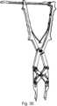
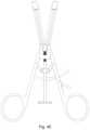
- FIG. 6shows a front view of a large orthopedic distractor, with an uncrossed hinge
- FIG. 7shows a perspective view of the large distractor, with the uncrossed hinge
- FIG. 8shows a front view of a small orthopedic compressor with a scissor hinge and two screw adjustments
- FIGS. 9 and 10show perspective views of the small orthopedic compressor with the scissor hinge and two screw adjustments
- FIG. 11shows a perspective view of the small orthopedic compressor with the scissor hinge and two screw adjustments, in use to align bones for placement of a bone plate;
- FIGS. 12 and 13shows a front view of the small orthopedic compressor with the scissor hinge and two screw adjustments as shown in FIG. 11 , before and after alignment of bones using a bone plate;
- FIG. 14shows a top view of the small orthopedic compressor with the scissor hinge and two screw adjustments, after alignment of bone and placement of the bone plate;
- FIG. 13shows a front view of the small orthopedic compressor with the scissor hinge and two screw adjustments as shown in FIG. 10 , after alignment of bone and placement of the bone plate;
- FIG. 14shows a top view of the small orthopedic compressor with the scissor hinge and two screw adjustments as shown in FIG. 13 , after alignment of bone and placement of the bone plate;
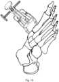
- FIG. 15shows a perspective view of the small orthopedic compressor with the scissor hinge and two screw adjustments, in use to proximate a metatarsal and cuneiform
- FIG. 16shows an orthopedic compressor-distractor with offset feet, and having a handle for the angular adjustment shaft removed;
- FIGS. 17 - 18shows an orthopedic compressor-distractor with offset feet according to FIG. 16 , and having the angular adjustment shaft and handle removed;
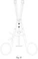
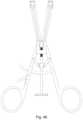
- FIG. 19shows a front view of an orthopedic distractor with an asymmetric adjustment mechanism and ratchet
- FIG. 20shows a perspective view of the orthopedic compressor with an asymmetric adjustment mechanism and ratchet according to FIG. 19 ;
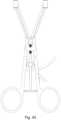
- FIG. 21shows a front view of an orthopedic compressor with an asymmetric adjustment mechanism and rachet
- FIG. 22shows a perspective view of the orthopedic compressor with an asymmetric adjustment mechanism and ratchet according to FIG. 21 ;
- FIGS. 24 and 25show perspective views of the first embodiment of the orthopedic distractor with an asymmetric adjustment mechanism and screw adjustment of displacement according to FIG. 23 ;
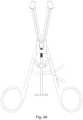
- FIG. 26shows a front view of a second embodiment of an orthopedic distractor with an asymmetric adjustment mechanism and screw adjustment of displacement
- FIGS. 27 and 28show perspective views of the second embodiment of the orthopedic distractor with an asymmetric adjustment mechanism and screw adjustment of displacement according to FIG. 26 ;
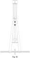
- FIG. 29shows a prior art Intech Medical parallel compressor
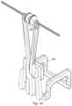
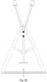
- FIG. 30shows a prior art Omnia Health self-retaining parallel compressor.
- FIG. 31shows a prior art Innomed compressor-distractor with switchable functioning.
- FIGS. 32 - 40 Bshow a compressor embodiment with feet angled with respect to the pivot axis, arms which are uncrossed, and a ratcheting mechanism to maintain separation of the feet.
- a longitudinal screw mechanismcontrols the relative angle of the feet.
- FIGS. 41 - 49 Bshow a distractor embodiment with feet angled with respect to the pivot axis, arms which are crossed, and a ratcheting mechanism to maintain separation of the feet.
- a longitudinal screw mechanismcontrols the relative angle of the feet.
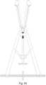
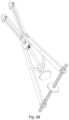
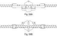
- FIGS. 50 - 60 Bshow a compressor-distractor embodiment with feet angled with respect to the pivot axis, arms which are crossed, and a helical screw mechanism to control separation of the feet.
- a longitudinal screw mechanismcontrols the relative angle of the feet.
- the handlesare crossed in a scissor linkage, so that a compression of the handle leads to a corresponding compression of the operative legs of the device.
- the handlesare uncrossed and have a linking pivot, so that a compression of the handle leads to a corresponding separation (distraction) of the operative legs of the device.
- distraction and compressionmay be achieved by the same device.
- other convenient simple mechanismsmay be used to define the separation of the feet.
- the present technologyprovides an embodiment which is a distractor-compressor, having a distance between the feet bidirectionally controlled by action of a threaded rod on a follower; an embodiment which is a distractor, and acts to separate the bone; and an embodiment which is a compressor, that serves to proximate bone.
- Each of the embodimentshas separate and independent control over the angle of the feet, which are affixed to the separate bones (or portions of a fractured or cut bone) when in use, and the distance between the feet.
- Each of the embodimentsprovides a pair of pivotally-connected arms, extending beyond a pivot axis of a first pivot.
- the devicesmay be generally symmetric, or asymmetric.
- a first fittingis provided proximate to the first pivot, for retaining an axially displaceable element, which is, for example, a threaded rod which sits in a threaded orifice.
- a second fittingis provided, displaced from the first fitting, wherein a manipulation of the axially displaceable element alters a distance between the first fitting and the second fitting.
- the end of the threaded rodis retained, such that a rotation of the threaded rod causes the first fitting to ride up or down the threaded rod.
- a second pivot(or pair of pivots) is provided on end or ends of one or both pivotally-connected arms extending beyond the first pivot.
- One or both of the pair of feetare pivotally mounted by the second pivot(s) to the ends of the pivotally-connected arm(s) extending beyond the first pivot.
- a third pivot or pair of third pivotsare also provided, each linked to the second fitting, and being laterally displaced from the central plane of symmetry.
- the third pivot(s)are longitudinally spaced from the first pivot by an element.
- the elementmay be a U-shaped member.
- a fourth pivot or pair of fourth pivotsis provided on the foot or pair of feet, laterally displaced from the second pivot(s) from a longitudinal axis extending through the central pivot, or alternately, having been inclined with respect to a plane defined by the lateral arms.
- a lateral arm or pair of lateral arms linking the third pivot(s) and the fourth pivot(s)are provided, on the same side of the longitudinal axis.
- the first pivot, second pivots, third pivots and fourth pivotsthus define vertices of a quadrilateral linkage or a pair of linked quadrilaterals sharing the first pivot, and the pivotally-connected arms extending beyond the first pivot, the feet, the pair of lateral arms, and the second fitting representing the sides of the pair of linked quadrilaterals.
- the instrumentmay be disassembled in two steps. First, the arms are separated to their maximum, and in the case of the first embodiment, the separation adjustment shaft is freed. Then, the axially mounted angular adjustment rod is inclined out of the plane of the device, and may then be disengaged.
- FIGS. 1 - 4show a large orthopedic compressor with a scissor hinge and a screw adjustment.
- a pair of handles 115linked with a hinge 110 , control a displacement of a pair of feet 114 .
- the handles 115are retained in a desired degree of displacement by a ratchet mechanism having a ratchet bar 118 , which is hinged to one of the handles 115 with a pivot 117 , and which is maintained by a spur 119 .
- the angle of the feetis adjusted by a screw 105 , controlled by a knob 101 , acting on a shaft 102 having a first notch 103 and a second notch 121 .
- the screw 105acts on a screw follower 122 to control an axial depth of a U-shaped link 106 , which is part of a quadrilateral linkage which includes outer sides 108 , inner sides 109 , and distal sides 112 .
- the quadrilateral linkagehas pivots 107 between the U-shaped link 106 and the outer sides 108 , pivots 111 between the outer sides 108 and the distal sides 112 , pivots 113 between the distal sides 112 and the inner sides 109 .
- the hinge 110acts as a common pivot for both halves.
- the shaft 102is centered and retained by a pair of arms 124 attached to the handles 115 by pivots 116 , meeting at a central retaining element 104 .
- the notch 103aligns with the central retaining element
- the notch 121aligns with the screw follower 122 , allowing the shaft 102 to be angled out of the plane of the instrument on a ball joint having ball 135 and socket 136 to allow for, e.g., cleaning of the shaft 102 .
- FIG. 1shows a front view of a large orthopedic compressor in an operational state
- FIG. 2shows a perspective view
- FIGS. 3 and 4show perspective views of the large orthopedic compressor with the adjustment screw displaced from an operational position, as described above.
- FIG. 5shows a perspective view of the large orthopedic compressor according to FIGS. 1 - 4 , in use to proximate portions of a femur.
- the feet 114are pinned to the bone, with the ends aligned and separated, and then the displacement of the portions of bone controlled by a displacement of the handles, with the angle of the portions maintained by the quadrilateral linkage.
- FIGS. 6 and 7show a large orthopedic distractor with a ratcheting mechanism and an uncrossed hinge, such that a compression of the handles separates the feet, in contrast to the embodiment shown in FIGS. 1 - 4 , in which a compression of the handles causes the feet to compress.
- a pair of handles 123linked with a hinge 124 , control a displacement of a pair of feet 114 .
- the handles 123are retained in a desired degree of displacement by a ratchet mechanism having a ratchet bar 118 , which is hinged to one of the handles 115 with a pivot 117 , and which is maintained by a spur 119 .
- the angle of the feetis adjusted by a screw 105 , controlled by a knob 101 , acting on a shaft 102 having a first notch 103 and a second notch 121 .
- the screw 105acts on a screw follower 122 to control an axial depth of a U-shaped link 106 , which is part of a quadrilateral linkage which includes outer sides 108 , inner sides 109 , and distal sides 112 .
- the quadrilateral linkagehas pivots 107 between the U-shaped link 106 and the outer sides 108 , pivots 111 between the outer sides 108 and the distal sides 112 , pivots 113 between the distal sides 112 and the inner sides 109 .
- the hinge 110acts as a common pivot for both halves.
- the shaft 202is centered and retained by a sleeve that rides on a second screw 230 , having knob 231 , and a pair of screw followers 233 linked to arms 224 .
- a pair of handles arms 224linked with a hinge 210 , control a displacement of a pair of feet 214 by rotation of the screw 230 , which is right hand threaded on one side, and left hand threaded on the other. Because the screw 230 is double threaded, rotation of the screw 230 causes a compression or distraction of the screw followers 233 , which in turn apply a corresponding force on the arms 224 through the pivots 232 .
- the screw followers 233are attached to the arms 224 with pivots 232 .
- the angle of the feet 214is adjusted by a screw 205 , controlled by a knob 201 , acting on a shaft 202 having a notch 203 .
- the screw 205acts on a screw follower 204 to control an axial depth of a U-shaped link 206 , which is part of a quadrilateral linkage which includes outer sides 208 , inner sides 209 , and distal sides 212 .
- the quadrilateral linkagehas pivots 207 between the U-shaped link 206 and the outer sides 208 , pivots 211 between the outer sides 208 and the distal sides 212 , pivots 213 between the distal sides 212 and the inner sides 209 .
- the hinge 210acts as a common pivot for both halves.
- the pivots 207 , and outer side (lateral arms) 208are also raised or lowered. Since the distal sides 212 are fixed by the pivots 213 holding the respective distal sides 212 to the respective arms 224 , the angle of the distal sides 212 symmetrically changes with the adjustment.
- FIGS. 11 , 12 , 13 , and 14show the small orthopedic compressor according to the embodiments of FIGS. 8 to 10 , in use to align bones for placement of a bone plate.
- the bone plate 250has slots to accommodate the feet 214 over a range of lateral displacement.
- the feet 214have recesses to accept and release from screws 252 .
- the bone plateis screwed to the bone portions 253 , 254 with the screws 252 , and the adjustments used to align the bone 253 , 254 portions and to proximate the respective ends.
- the screws 252are held in place to the feet 214 of the instrument, such that the feet 214 , screws 252 , and the bone plate 250 form one unit prior to contact with the bones.
- the screws 252are loosely screwed through the plate 250 into the bone through slots in the plate 250 . This allows adjustment of the lateral position of the feet 214 and of the relative angle of the feet 214 by rotation of the knobs 231 and 201 , respectively.
- the screws 251 , 252are tightened into the bone 253 , 254 , and the instrument may be removed from the field. Therefore, the plate 250 can provide two-point fixation on each side of the fracture or spacing.
- the screws 252have heads which engage with the recess of the feet 214 , but which after alignment of the bones and affixation of the screws 251 , the feet 214 are disengaged from the screws 252 , and the screws 252 then tightened to hold the bone plate securely.
- the head of screw 252may be, e.g., hexagonal or square, permitting adjustment and/or removal of the screw 252 after the instrument is detached.
- FIG. 16shows a perspective view of the small orthopedic compressor with the scissor hinge and two screw adjustments, in use to proximate a metatarsal and cuneiform.
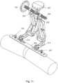
- FIGS. 16 - 18shows a perspective view of an orthopedic compressor-distractor having offset feet 281 , removing the mechanism from the surgical field for increased visibility and reduced interference with other instruments.
- a knob corresponding to knob 201is removed for visibility from FIG. 16 , and the knob and angular adjustment shaft are removed in FIGS. 17 and 18 .
- the feet 281 in this embodimentare displaced from the plane formed by the handles and scissor hinge, and are maintained in a defined relative angle by a rotation of shaft 283 , which acts to rotate the quadrilateral linkage 282 , which is continuous with the feet 281 .
- the separation of the feet 281is controlled by a clockwise and counterclockwise threated rod 284 , in followers 286 , controlled by a rotation of thumbwheel 285 .
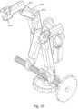
- FIGS. 19 - 20show an orthopedic distractor with uncrossed handles linked by a pivoting hinge 324 and helical threaded adjustment acting on a rack.
- a pair of handles 323 , 325linked with the hinge 324 , control a distraction of a pair of feet 314 , 315 .
- the handles 323 , 325are retained in a desired degree of displacement by a ratchet mechanism having a ratchet bar 118 , which is hinged to handle 325 with a pivot 117 , and which is maintained by a spur 119 .
- the angle of the feet 314 , 315is adjusted by a helical screw 351 , which is knurled, acting on a rack 352 , and guided by a slot 353 , to control an axial depth of a link 306 , which is part of a quadrilateral linkage which includes outer side 308 , inner side 309 , and distal side 312 .
- the helical screw 351has a hexagonal recess 354 which accepts a hex key (Allen key) to provide an alternate to finger rotation of the helical screw.
- a motor drivemay be provided with a foot-operated switch to permit the surgeon or operator to adjust the distance between the feet 344 , 345 in a hands-free manner.
- FIGS. 21 - 22show an orthopedic compressor, similar to that of FIGS. 19 - 20 , but with crossed handles instead of uncrossed handles, which upon application of force result in a corresponding contraction of the mounting feet rather than separation.
- a pair of handles 343 , 345linked with a scissor hinge 344 , control a compression of a pair of feet 344 , 345 .
- the handles 343 , 345are retained in a desired degree of displacement by a ratchet mechanism having a ratchet bar 118 , which is hinged to handle 345 with a pivot 117 , and which is maintained by a spur 119 .
- the angle of the feet 344 , 345is adjusted by a helical screw 351 , which is knurled, acting on a rack 352 , and guided by a slot 353 , to control an axial depth of a link 346 , which is part of a quadrilateral linkage which includes outer side 348 , inner side 349 , and distal side 342 .
- the helical screw 351has a hexagonal recess 354 which accepts a hex key (Allen key) to provide an alternate to finger rotation of the helical screw.
- a motor drivemay be provided with a foot-operated switch to permit the surgeon or operator to adjust the distance between the feet 344 , 345 in a hands-free manner.
- the quadrilateral linkagehas pivots 347 between the link 346 and the outer side 348 , pivot 341 between the outer side 348 and the distal side 342 , pivot 343 between the distal side 342 and the inner side 349 .
- the hinge 344acts as a common pivot for both halves. This mechanism provides independence of separation of the feet 344 , 345 and the relative angle of the feet 344 , 345 .
- FIGS. 23 - 25show a first embodiment of an orthopedic distractor with an asymmetric adjustment mechanism and screw adjustment of displacement.
- a screw 362is rotated by manual rotation of a handle 361 , to change a relative displacement of the scissors mechanism by applying a force between anchor 364 and follower 363 .
- the anchor 364is rotatable about an axis parallel to hinge 324 , and also out of the plane of the uncrossed hinge mechanism.
- Follower 363permits the screw 362 to be released and rotate out of the place of the scissors mechanism.
- FIGS. 26 - 28show a second embodiment of an orthopedic distractor with an asymmetric adjustment mechanism and screw adjustment of displacement.
- the adjustment mechanismis located at the end of the handles, with threaded rod 372 mounted on anchor 374 , which is hinged to rotate parallel to the hinge 324 .
- Knurled adjustment 371acts on the threaded rod 372 to control the displacement of the anchor 374 and the follower 373 . For cleaning, the knurled adjustment 371 may be removed from the follower 373 and the threaded rod 372 rotated downward.
- FIG. 29shows a prior art Intech Medical parallel compressor (www.intech-medical.com/products/instruments/compressors/parallel-compressor/).
- FIG. 30shows a prior art Omnia Health self-retaining parallel compressor (www.omnia-health.com/product/retractors-self-retaining-gcompressor-parallel). Note that these prior designs provide only a parallel orientation of the feet, and do not permit independent adjustment of the relative angles of the feet.
- FIG. 31shows a prior art Innomed small bone compressor/distractor 4865-LS, with a switchable mechanism to provide ratcheted compression and distraction, in different modes of operation. Such a switchable mechanism may be employed in conjunction with the present designs.
- FIGS. 32 - 60 Bshow embodiments in which the feet are angled with respect to the pivot axis, and therefore in use the scissor mechanism is displaced from the line of sight of the surgeon.
- the design as shownhas comparatively fewer rigid members, which may flex during use under high load. However, the loss of perfect maintained angles is counterbalanced by lighter weight, and smaller size.
- FIGS. 32 - 40 Bshow a compressor embodiment with feet angled with respect to the pivot axis, arms which are uncrossed, and a ratcheting mechanism to maintain separation of the feet without altering the angle of the feet.
- a longitudinal screw mechanismcontrols the relative angle of the feet.
- FIGS. 41 - 49 Bshow a distractor embodiment with feet angled with respect to the pivot axis, arms which are crossed, and a ratcheting mechanism to maintain separation of the feet separation without altering the angle of the feet.
- a longitudinal screw mechanismcontrols the relative angle of the feet.
- FIGS. 50 - 60 Bshow a compressor-distractor embodiment with feet angled with respect to the pivot axis, arms which are crossed, and a lateral helical screw mechanism to control separation of the feet without altering the angle of the feet.
- a longitudinal screw mechanismcontrols the relative angle of the feet.
Landscapes
- Health & Medical Sciences (AREA)
- Orthopedic Medicine & Surgery (AREA)
- Surgery (AREA)
- Life Sciences & Earth Sciences (AREA)
- Heart & Thoracic Surgery (AREA)
- Nuclear Medicine, Radiotherapy & Molecular Imaging (AREA)
- Engineering & Computer Science (AREA)
- Biomedical Technology (AREA)
- Neurology (AREA)
- Medical Informatics (AREA)
- Molecular Biology (AREA)
- Animal Behavior & Ethology (AREA)
- General Health & Medical Sciences (AREA)
- Public Health (AREA)
- Veterinary Medicine (AREA)
- Surgical Instruments (AREA)
Abstract
Description
Claims (20)
Priority Applications (1)
| Application Number | Priority Date | Filing Date | Title |
|---|---|---|---|
| US18/401,121US12232790B2 (en) | 2022-12-30 | 2023-12-29 | Adjustable angle orthopedic distractor, compressor, and distractor-compressor |
Applications Claiming Priority (2)
| Application Number | Priority Date | Filing Date | Title |
|---|---|---|---|
| US202263436387P | 2022-12-30 | 2022-12-30 | |
| US18/401,121US12232790B2 (en) | 2022-12-30 | 2023-12-29 | Adjustable angle orthopedic distractor, compressor, and distractor-compressor |
Publications (2)
| Publication Number | Publication Date |
|---|---|
| US20240216031A1 US20240216031A1 (en) | 2024-07-04 |
| US12232790B2true US12232790B2 (en) | 2025-02-25 |
Family
ID=91667469
Family Applications (1)
| Application Number | Title | Priority Date | Filing Date |
|---|---|---|---|
| US18/401,121ActiveUS12232790B2 (en) | 2022-12-30 | 2023-12-29 | Adjustable angle orthopedic distractor, compressor, and distractor-compressor |
Country Status (1)
| Country | Link |
|---|---|
| US (1) | US12232790B2 (en) |
Citations (262)
| Publication number | Priority date | Publication date | Assignee | Title |
|---|---|---|---|---|
| US4475544A (en) | 1982-02-23 | 1984-10-09 | Reis Norman I | Bone gripping forceps |
| US4944739A (en) | 1989-03-24 | 1990-07-31 | Torre Randall J | Bone gripping fixation clamp |
| US20010010008A1 (en) | 1996-11-08 | 2001-07-26 | Gellman Barry N. | Protective sheath for transvaginal anchor implantation device |
| US6315780B1 (en) | 1999-04-12 | 2001-11-13 | Accurate Surgical & Scientific Instruments Corporation | Bone clamp for dynamic and non-dynamic compression of transverse fractures and method of use thereof |
| US20020022764A1 (en) | 1996-03-22 | 2002-02-21 | Smith Maurice M. | Devices and methods for percutaneous surgery |
| US20020161375A1 (en) | 2001-04-27 | 2002-10-31 | Ralph James D. | Femoral ring loader |
| US6716218B2 (en) | 2001-02-28 | 2004-04-06 | Hol-Med Corporation | Instrument for bone distraction and compression having ratcheting tips |
| US20040147935A1 (en) | 2003-01-25 | 2004-07-29 | Christopher Segler | Tarsal Joint Space Distractor |
| US20040162568A1 (en) | 1999-06-25 | 2004-08-19 | Usgi Medical | Apparatus and methods for forming and securing gastrointestinal tissue folds |
| US20040176763A1 (en) | 1996-03-22 | 2004-09-09 | Foley Kevin T. | Methods for percutaneous surgery |
| US20040186346A1 (en) | 1996-03-22 | 2004-09-23 | Smith Maurice M. | Devices and methods for percutaneous surgery |
| US20040199169A1 (en) | 2002-11-20 | 2004-10-07 | Koons Kirk C. | Cable clamp tool for surgical applications |
| US20040225295A1 (en) | 2001-07-16 | 2004-11-11 | Rafail Zubok | Wedge ramp distractor and related methods for use in implanting artificial intervertebral discs |
| US20050038498A1 (en) | 2003-04-17 | 2005-02-17 | Nanosys, Inc. | Medical device applications of nanostructured surfaces |
| US20050085720A1 (en) | 2003-10-17 | 2005-04-21 | Jascob Bradley A. | Method and apparatus for surgical navigation |
| US20050221072A1 (en) | 2003-04-17 | 2005-10-06 | Nanosys, Inc. | Medical device applications of nanostructured surfaces |
| US20050222576A1 (en) | 2004-03-18 | 2005-10-06 | Kick George F | Expandable medical access device |
| US20060025677A1 (en) | 2003-10-17 | 2006-02-02 | Verard Laurent G | Method and apparatus for surgical navigation |
| US20060036255A1 (en) | 2004-08-13 | 2006-02-16 | Pond John D Jr | System and method for positioning a connecting member adjacent the spinal column in minimally invasive procedures |
| US20060041270A1 (en) | 2004-05-07 | 2006-02-23 | Jay Lenker | Medical access sheath |
| US20060064164A1 (en) | 2000-03-07 | 2006-03-23 | Thelen Sarah L | Method and apparatus for reducing femoral fractures |
| US20060084867A1 (en) | 2003-10-17 | 2006-04-20 | Tremblay Brian M | Method and apparatus for surgical navigation |
| US20060204738A1 (en) | 2003-04-17 | 2006-09-14 | Nanosys, Inc. | Medical device applications of nanostructured surfaces |
| US20060235279A1 (en) | 2005-03-18 | 2006-10-19 | Hawkes David T | Less invasive access port system and method for using the same |
| US7141015B2 (en) | 2003-05-09 | 2006-11-28 | Bernard Joseph Ruane | Expandable and pivotally adjustable surgical retractor |
| US20060271061A1 (en) | 2001-07-25 | 2006-11-30 | Disc-O-Tech, Ltd. | Deformable tools and implants |
| US20070100212A1 (en) | 2004-10-08 | 2007-05-03 | Nuvasive, Inc. | Surgical access system and related methods |
| US20070106123A1 (en) | 2005-09-26 | 2007-05-10 | Josef Gorek | Minimally invasive retractor and methods of use |
| US20070198022A1 (en) | 2001-05-25 | 2007-08-23 | Conformis, Inc. | Patient Selectable Joint Arthroplasty Devices and Surgical Tools |
| US20070282448A1 (en) | 2006-05-26 | 2007-12-06 | Abdou M S | Inter-Vertebral Disc Motion Devices and Methods of Use |
| US20070282247A1 (en) | 2003-05-05 | 2007-12-06 | Nanosys, Inc. | Medical Device Applications of Nanostructured Surfaces |
| US20080015417A1 (en) | 2006-07-11 | 2008-01-17 | Hawkes David T | Selectively locking minimally traumatic access port |
| US20080243127A1 (en) | 2001-05-25 | 2008-10-02 | Conformis, Inc. | Surgical Tools for Arthroplasty |
| US20080255498A1 (en) | 2005-08-25 | 2008-10-16 | Houle Philip R | Sensitizer Solutions, Systems, and Methods of Use |
| US20080262318A1 (en) | 2007-04-17 | 2008-10-23 | K2M, Inc. | Minimally open interbody access retraction device and surgical method |
| US20090012612A1 (en) | 2007-04-10 | 2009-01-08 | David White | Devices and methods for push-delivery of implants |
| US20090018665A1 (en) | 2007-07-09 | 2009-01-15 | Exploramed Nc4, Inc. | Surgical implantation method and devices for an extra-articular mechanical energy absorbing apparatus |
| US20090018656A1 (en) | 2007-07-09 | 2009-01-15 | Exploramed Nc4, Inc. | Surgical implantation method and devices for an extra-articular mechanical energy absorbing apparatus |
| US20090014016A1 (en) | 2007-07-09 | 2009-01-15 | Exploramed Nc4, Inc. | Surgical implantation method and devices for an extra-articular mechanical energy absorbing apparatus |
| US20090149857A1 (en) | 2004-08-03 | 2009-06-11 | Triage Medical | Telescopic Percutaneous Tissue Dilation Systems and Related Methods |
| US20090157087A1 (en) | 2007-07-10 | 2009-06-18 | Guobao Wei | Delivery system attachment |
| US20090216234A1 (en) | 2006-11-03 | 2009-08-27 | Innovative Spine | Spinal Access Systems and Methods |
| US20090259107A1 (en) | 2008-04-11 | 2009-10-15 | Physcient, Inc. | Methods and devices to decrease tissue trauma during surgery |
| US20090264930A1 (en) | 2008-04-16 | 2009-10-22 | Warsaw Orthopedic, Inc. | Minimally invasive Systems and Methods for Insertion of a Connecting Member Adjacent the Spinal Column |
| US20090276054A1 (en) | 2007-07-09 | 2009-11-05 | Exploramed Nc4, Inc. | Surgical implantation method and devices for an extra-articular mechanical energy absorbing apparatus |
| US20100160982A1 (en) | 2005-08-26 | 2010-06-24 | Warsaw Orthopedic, Inc. | Instruments for Minimally Invasive Stabilization of Bony Structures |
| US20100168864A1 (en) | 2008-09-12 | 2010-07-01 | Articulinx, Inc. | Tensioned delivery of orthopedic joint device |
| US20100178100A1 (en) | 2006-10-06 | 2010-07-15 | Helmut Fricke | Lockable joint |
| US20100204699A1 (en) | 2009-02-12 | 2010-08-12 | Guobao Wei | Delivery system cartridge |
| US20100210939A1 (en) | 1999-10-28 | 2010-08-19 | Medtronic Navigation, Inc. | Method and Apparatus for Surgical Navigation |
| US20100249659A1 (en) | 2009-03-31 | 2010-09-30 | Sherman Jason T | Device and method for displaying joint force data |
| US20100249789A1 (en) | 2009-03-31 | 2010-09-30 | Mick Rock | Method for performing an orthopaedic surgical procedure |
| US20100249660A1 (en) | 2009-03-31 | 2010-09-30 | Sherman Jason T | System and method for displaying joint force data |
| US20100249658A1 (en) | 2009-03-31 | 2010-09-30 | Sherman Jason T | Device and method for determining force of a knee joint |
| US20100249777A1 (en) | 2009-03-31 | 2010-09-30 | Sherman Jason T | Device and method for determining forces of a patient's joint |
| US20100286791A1 (en) | 2006-11-21 | 2010-11-11 | Goldsmith David S | Integrated system for the ballistic and nonballistic infixion and retrieval of implants |
| US20110054408A1 (en) | 2007-07-10 | 2011-03-03 | Guobao Wei | Delivery systems, devices, tools, and methods of use |
| US20110184325A1 (en) | 2010-01-25 | 2011-07-28 | Kamran Behzadian | Orthopedic apparatuses for mobilizing, stretching and protecting the spinal column |
| US20110240064A1 (en) | 2002-09-09 | 2011-10-06 | Reactive Surfaces, Ltd. | Polymeric Coatings Incorporating Bioactive Enzymes for Cleaning a Surface |
| US20110250626A1 (en) | 2002-09-09 | 2011-10-13 | Reactive Surfaces, Ltd. | Visual Assays for Coatings Incorporating Bioactive Enzymes for Catalytic Functions |
| US20110257664A1 (en) | 1999-10-20 | 2011-10-20 | Anulex Technologies, Inc. | Tissue anchoring system and method |
| US20120097194A1 (en) | 2002-09-09 | 2012-04-26 | Reactive Surfaces, Ltd. | Polymeric Coatings Incorporating Bioactive Enzymes for Catalytic Function |
| US20120130180A1 (en) | 2009-04-13 | 2012-05-24 | Physcient, Inc. | Methods and devices to decrease tissue trauma during surgery |
| US20120215315A1 (en) | 2010-01-22 | 2012-08-23 | Stephen Hochschuler | Apparatus and method for stabilizing adjacent bone portions |
| US20130019883A1 (en) | 2011-07-22 | 2013-01-24 | Stryker Corporation | Multi-position limb holder |
| US20130131683A1 (en) | 2011-05-02 | 2013-05-23 | Insight Surgical Instruments, Llc | Minimally invasive surgical applicator |
| US20130144297A1 (en) | 2011-10-27 | 2013-06-06 | Smith & Nephew, Inc. | Devices and methods for performing knee arthroplasty |
| US20130173004A1 (en) | 2010-08-24 | 2013-07-04 | Flexmedex, LLC | Support device and method for use |
| US20130204372A1 (en) | 2011-12-23 | 2013-08-08 | Pioneer Surgical Technology, Inc. | Systems and Methods for Inserting a Spinal Device |
| US20130237766A1 (en) | 2009-04-13 | 2013-09-12 | Physcient, Inc. | Rib-protecting devices for thoracoscopic surgery, and related methods |
| US20140038777A1 (en) | 2012-07-31 | 2014-02-06 | John M. Bird | Resistance Apparatus, System, and Method |
| US20140107659A1 (en) | 2012-10-12 | 2014-04-17 | Alphatec Spine, Inc. | In situ rod measuring instrument and method of use |
| US20140148828A1 (en) | 2012-11-28 | 2014-05-29 | Usgi Medical, Inc. | Apparatus and methods for forming and securing gastrointestinal tissue folds |
| US20140163683A1 (en) | 2012-12-11 | 2014-06-12 | Jody L. Seifert | Expandable Vertebral Implant |
| US20140163664A1 (en) | 2006-11-21 | 2014-06-12 | David S. Goldsmith | Integrated system for the ballistic and nonballistic infixion and retrieval of implants with or without drug targeting |
| US20140364917A1 (en) | 2010-01-22 | 2014-12-11 | Frontier Medical Devices, Inc. | Apparatus and method for stabilizing adjacent bone portions |
| US20140378980A1 (en) | 2013-06-24 | 2014-12-25 | Roman Lomeli | Cortical Rim-Supporting Interbody Device |
| US20150010341A1 (en) | 2006-10-06 | 2015-01-08 | Helmut Fricke | Lockable joint |
| US20150032163A1 (en) | 2009-11-06 | 2015-01-29 | Samy Abdou | Spinal fixation devices and methods of use |
| US8951258B2 (en)* | 2013-03-01 | 2015-02-10 | Warsaw Orthopedic, Inc. | Spinal correction system and method |
| US8979850B2 (en) | 2010-06-03 | 2015-03-17 | Clear Surgical Limited | Surgical guide device |
| US20150148886A1 (en) | 2012-05-21 | 2015-05-28 | Medplate Lifesciences Corporation | Collapsible, shape memory alloy structures and folding fixtures for collapsing same |
| US20150250672A1 (en) | 2014-03-10 | 2015-09-10 | Stryker Corporation | Limb positioning system |
| US20150289910A1 (en) | 2014-04-12 | 2015-10-15 | Seyed Alireza Mirghasemi | Modular bone plate |
| US20160089188A1 (en) | 2014-09-25 | 2016-03-31 | Warsaw Orthopedic, Inc. | Spinal implant system and method |
| US9339319B2 (en) | 2012-07-25 | 2016-05-17 | Stryker European Holdings I, Llc | Surgical reduction clamp |
| US20160242927A1 (en) | 2012-12-11 | 2016-08-25 | Globus Medical, Inc. | Expandable vertebral implant |
| US20160242923A1 (en) | 2013-03-15 | 2016-08-25 | Globus Medical, Inc. | Expandable intervertebral implant |
| US20160278821A1 (en) | 2015-03-23 | 2016-09-29 | Globus Medical, Inc. | Orthopedic derotation devices and methods of installlation thereof |
| US20170135706A1 (en) | 2010-06-29 | 2017-05-18 | Mighty Oak Medical, Inc. | Patient-matched apparatus and methods for performing surgical procedures |
| US20170151022A1 (en) | 1999-10-28 | 2017-06-01 | Medtronic Navigation, Inc. | Method And Apparatus For Surgical Navigation |
| US9795410B2 (en) | 2009-08-27 | 2017-10-24 | Cotera, Inc. | Method and apparatus for force redistribution in articular joints |
| USRE46582E1 (en) | 2004-06-07 | 2017-10-24 | DePuy Synthes Products, Inc. | Orthopaedic implant with sensors |
| US9795399B2 (en) | 2006-06-09 | 2017-10-24 | Biomet Manufacturing, Llc | Patient-specific knee alignment guide and associated method |
| US9801729B2 (en) | 2003-02-14 | 2017-10-31 | DePuy Synthes Products, Inc. | In-situ formed intervertebral fusion device and method |
| US9801639B2 (en) | 2010-06-24 | 2017-10-31 | DePuy Synthes Products, Inc. | Lateral spondylolisthesis reduction cage |
| US9801546B2 (en) | 2014-05-27 | 2017-10-31 | Jcbd, Llc | Systems for and methods of diagnosing and treating a sacroiliac joint disorder |
| US9808346B2 (en) | 2003-03-10 | 2017-11-07 | Ilion Medical, Inc. | Sacroiliac joint immobilization |
| US9814499B2 (en) | 2014-09-30 | 2017-11-14 | Arthrex, Inc. | Intramedullary fracture fixation devices and methods |
| US9827108B2 (en) | 2007-08-09 | 2017-11-28 | Simplify Medical Pty Ltd | Customized intervertebral prosthetic disc with shock absorption |
| US20170340454A1 (en) | 2013-06-24 | 2017-11-30 | DePuy Synthes Products, Inc. | Cortical Rim-Supporting Interbody Device |
| US9833335B2 (en) | 2005-01-28 | 2017-12-05 | Warsaw Orthopedic, Inc. | Implant for transforaminal intracorporeal fusion |
| US9839374B2 (en) | 2011-09-23 | 2017-12-12 | Orthosensor Inc. | System and method for vertebral load and location sensing |
| US9844335B2 (en) | 2012-02-27 | 2017-12-19 | Orthosensor Inc | Measurement device for the muscular-skeletal system having load distribution plates |
| US9848914B2 (en) | 2009-02-23 | 2017-12-26 | Nuvasive Specialized Orthopedics, Inc. | Non-invasive adjustable distraction system |
| US9848995B2 (en) | 2012-03-20 | 2017-12-26 | Titan Spine Llc | Process for fabricating bioactive vertebral endplate bone-contacting surfaces on a spinal implant |
| US9855075B2 (en) | 2008-07-24 | 2018-01-02 | OrthAlign, Inc. | Systems and methods for joint replacement |
| US9861446B2 (en) | 2016-03-12 | 2018-01-09 | Philipp K. Lang | Devices and methods for surgery |
| US9872709B2 (en) | 2014-05-23 | 2018-01-23 | Warsaw Orthopedic, Inc. | Spinal correction construct and method |
| US9877846B2 (en) | 2015-01-20 | 2018-01-30 | Warsaw Orthopedic, Inc. | Spinal implant system and method |
| US9888928B2 (en) | 2007-04-19 | 2018-02-13 | Howmedica Osteonics Corp. | Cutting guide with internal distraction |
| US9889020B2 (en) | 2013-03-15 | 2018-02-13 | Atlas Spine, Inc. | PLIF hinged spacer |
| US20180064497A1 (en) | 2012-06-21 | 2018-03-08 | Globus Medical, Inc. | Surgical robotic automation with tracking markers |
| US9913734B2 (en) | 2006-02-27 | 2018-03-13 | Biomet Manufacturing, Llc | Patient-specific acetabular alignment guides |
| US9918849B2 (en) | 2015-04-29 | 2018-03-20 | Institute for Musculoskeletal Science and Education, Ltd. | Coiled implants and systems and methods of use thereof |
| US9937062B2 (en) | 2011-09-23 | 2018-04-10 | Orthosensor Inc | Device and method for enabling an orthopedic tool for parameter measurement |
| US9936994B2 (en) | 2015-07-14 | 2018-04-10 | Treace Medical Concepts, Inc. | Bone positioning guide |
| US20180098798A1 (en) | 2016-10-11 | 2018-04-12 | Warsaw Orthopedic, Inc | Spinal implant system and method |
| US20180098788A1 (en) | 2015-09-04 | 2018-04-12 | Medos International Sarl | Surgical access port stabilization |
| US9949731B2 (en) | 2015-10-07 | 2018-04-24 | Medos International Sàrl | Systems and methods for manipulating bone |
| US9956010B2 (en) | 2013-10-07 | 2018-05-01 | Intelligent Implant Systems, Llc | Polyaxial plate rod system and surgical procedure |
| US9956003B2 (en) | 2015-09-18 | 2018-05-01 | Warsaw Orthopedic, Inc | Spinal implant system and methods of use |
| US9968376B2 (en) | 2010-11-29 | 2018-05-15 | Biomet Manufacturing, Llc | Patient-specific orthopedic instruments |
| US9968573B2 (en) | 2011-03-11 | 2018-05-15 | Hemoteq Ag | Endoprosthesis having and active substance coating |
| US9981071B2 (en) | 2008-07-17 | 2018-05-29 | Micell Technologies, Inc. | Drug delivery medical device |
| US9999416B2 (en) | 2015-08-28 | 2018-06-19 | Arthrex, Inc. | Methods and apparatus for internal hip distraction |
| US9999519B2 (en) | 2016-10-04 | 2018-06-19 | Javier Garcia-Bengochea | Instruments and methods for orthopedic implant assembly |
| US10004449B2 (en) | 2012-02-27 | 2018-06-26 | Orthosensor Inc. | Measurement device for the muscular-skeletal system having alignment features |
| US10004538B2 (en) | 2016-04-27 | 2018-06-26 | Warsaw Orthopedic, Inc. | Surgical instrument and method |
| US10016226B2 (en) | 2011-12-12 | 2018-07-10 | Children's Hospital Medical Center Of Akron | Noninvasive device for adjusting fastener |
| US10016221B2 (en) | 2004-07-02 | 2018-07-10 | Nuvasive Specialized Orthopedics, Inc. | Expandable rod system to treat scoliosis and method of using the same |
| US10034767B2 (en) | 2014-06-03 | 2018-07-31 | Atlas Spine, Inc. | Spinal implant device |
| US10034769B2 (en) | 2014-08-26 | 2018-07-31 | Atlas Spine, Inc. | Spinal implant device |
| US10039570B2 (en) | 2015-12-10 | 2018-08-07 | Hamid Farzadfard | Orthopedic device for closed fracture reduction |
| US10039661B2 (en) | 2006-10-20 | 2018-08-07 | Nuvasive Specialized Orthopedics, Inc. | Adjustable implant and method of use |
| US10064739B2 (en) | 2004-06-30 | 2018-09-04 | Synergy Disc Replacement, Inc. | Systems and methods for vertebral disc replacement |
| US10070973B2 (en) | 2012-03-31 | 2018-09-11 | Depuy Ireland Unlimited Company | Orthopaedic sensor module and system for determining joint forces of a patient's knee joint |
| US10080590B2 (en) | 2007-02-26 | 2018-09-25 | Nuvasive, Inc. | Spinal stabilization system and methods of use |
| US10080559B2 (en) | 2014-07-07 | 2018-09-25 | Warsaw Orthopedic, Inc. | Multiple spinal surgical pathways systems and methods |
| US10085855B2 (en) | 2010-05-14 | 2018-10-02 | Beacon Biomedical, Llc | Surgical instrument for implant insertion |
| US10092283B2 (en) | 2015-08-18 | 2018-10-09 | Globus Medical Inc | Devices and systems for surgical retraction |
| US10105167B2 (en) | 2011-02-14 | 2018-10-23 | Nuvasive Specialized Orthopedics, Inc. | System and method for altering rotational alignment of bone sections |
| US10111757B2 (en) | 2012-10-22 | 2018-10-30 | Cogent Spine, LLC | Devices and methods for spinal stabilization and instrumentation |
| US10117682B2 (en) | 2008-04-10 | 2018-11-06 | Life Spine, Inc. | Adjustable spine distraction implant |
| US10117972B2 (en) | 2011-07-15 | 2018-11-06 | Micell Technologies, Inc. | Drug delivery medical device |
| US10149674B2 (en) | 2015-08-12 | 2018-12-11 | K2M, Inc. | Orthopedic surgical system including surgical access systems, distraction systems, and methods of using same |
| US10149673B2 (en) | 2008-06-06 | 2018-12-11 | Providence Medical Technology, Inc. | Facet joint implants and delivery tools |
| US10159578B2 (en) | 2003-03-06 | 2018-12-25 | Spinecore, Inc. | Instrumentation and methods for use in implanting a cervical disc replacement device |
| US10159498B2 (en) | 2008-04-16 | 2018-12-25 | Biomet Manufacturing, Llc | Method and apparatus for manufacturing an implant |
| US10179054B2 (en) | 2008-02-06 | 2019-01-15 | Jeffrey B. Kleiner | Spinal fusion cage system with inserter |
| US10188772B2 (en) | 2011-10-18 | 2019-01-29 | Micell Technologies, Inc. | Drug delivery medical device |
| US10188529B2 (en) | 2004-11-24 | 2019-01-29 | Samy Abdou | Devices and methods for inter-vertebral orthopedic device placement |
| US10194959B2 (en) | 2005-02-23 | 2019-02-05 | Pioneer Surgical Technology, Inc. | Minimally invasive surgical system |
| US10195053B2 (en) | 2009-09-18 | 2019-02-05 | Spinal Surgical Strategies, Llc | Bone graft delivery system and method for using same |
| US10194958B2 (en) | 2016-04-27 | 2019-02-05 | Warsaw Othopedic, Inc. | Spinal correction system and method |
| US10201891B2 (en) | 2014-10-17 | 2019-02-12 | Matthew E. Williams | Alignment and adjustment clamp |
| US10206695B2 (en) | 2006-02-27 | 2019-02-19 | Biomet Manufacturing, Llc | Femoral acetabular impingement guide |
| US10206792B2 (en) | 2012-03-31 | 2019-02-19 | Depuy Ireland Unlimited Company | Orthopaedic surgical system for determining joint forces of a patients knee joint |
| US10213322B2 (en) | 2005-05-27 | 2019-02-26 | Spinecore, Inc. | Intervertebral disc and insertion methods therefor |
| US10226285B2 (en) | 2008-06-06 | 2019-03-12 | Providence Medical Technology, Inc. | Vertebral joint implants and delivery tools |
| US10231739B1 (en) | 2001-08-28 | 2019-03-19 | Bonutti Skeletal Innovations Llc | System and method for robotic surgery |
| US10231849B2 (en) | 2016-10-13 | 2019-03-19 | Warsaw Orthopedic, Inc. | Surgical instrument system and method |
| US10238508B2 (en) | 2013-12-23 | 2019-03-26 | Jmea Corporation | Devices and methods for preparation of vertebral members |
| US10238378B2 (en) | 2004-10-26 | 2019-03-26 | P Tech, Llc | Tissue fixation system and method |
| US10238499B2 (en) | 2014-03-14 | 2019-03-26 | Atlas Spine, Inc. | Bilateral clamping spacer |
| US20190090979A1 (en) | 2017-09-22 | 2019-03-28 | Medos International Sarl | Patient-mounted surgical support |
| US10245154B2 (en) | 2005-05-27 | 2019-04-02 | Spinecore, Inc. | Instruments and methods for inserting artificial intervertebral implants |
| US10245087B2 (en) | 2013-03-15 | 2019-04-02 | Jcbd, Llc | Systems and methods for fusing a sacroiliac joint and anchoring an orthopedic appliance |
| US10251676B2 (en) | 2014-03-06 | 2019-04-09 | Mps Micro Precision Systems Ag | Implantable device |
| US10278711B2 (en) | 2006-02-27 | 2019-05-07 | Biomet Manufacturing, Llc | Patient-specific femoral guide |
| US10278687B2 (en) | 2015-08-18 | 2019-05-07 | Globus Medical, Inc. | Devices and systems for surgical retraction |
| US10285683B2 (en) | 2015-03-24 | 2019-05-14 | Omnilife Science, Inc | Orthopedic joint distraction device |
| US10307263B2 (en) | 2017-04-04 | 2019-06-04 | Robert B. Dzioba | Mobile cage system for restoring motion kinematics of the spine |
| US10322011B2 (en) | 2014-06-03 | 2019-06-18 | Atlas Spine, Inc. | Spinal implant device with bone screws |
| US10335209B2 (en) | 2007-10-23 | 2019-07-02 | Alphatec Spine, Inc. | Systems and methods for spinal fixation |
| US10349995B2 (en) | 2007-10-30 | 2019-07-16 | Nuvasive Specialized Orthopedics, Inc. | Skeletal manipulation method |
| US10349982B2 (en) | 2011-11-01 | 2019-07-16 | Nuvasive Specialized Orthopedics, Inc. | Adjustable magnetic devices and methods of using same |
| US10350391B2 (en) | 2008-07-17 | 2019-07-16 | Micell Technologies, Inc. | Drug delivery medical device |
| US20190216454A1 (en) | 2015-09-04 | 2019-07-18 | Medos International Sarl | Surgical instrument connectors and related methods |
| US10363073B2 (en) | 2016-07-13 | 2019-07-30 | Medos International Sàrl | Bone anchor assemblies and related instrumentation |
| US10376287B2 (en) | 2005-11-30 | 2019-08-13 | Smith & Nephew, Inc. | Hip distraction |
| US20190247050A1 (en) | 2006-11-21 | 2019-08-15 | David S. Goldsmith | Integrated system for the infixion and retrieval of implants |
| US10383665B2 (en) | 2005-05-12 | 2019-08-20 | Globus Medical, Inc. | Revisable anterior cervical plating system |
| US10390862B2 (en) | 2016-04-27 | 2019-08-27 | Warsaw Orthopedic, Inc. | Spinal correction system and method |
| US10390845B2 (en) | 2006-02-27 | 2019-08-27 | Biomet Manufacturing, Llc | Patient-specific shoulder guide |
| US10398572B2 (en) | 2005-05-27 | 2019-09-03 | Spinecore, Inc. | Intervertebral disc implants and tooling |
| US20190269469A1 (en) | 2018-03-02 | 2019-09-05 | Mako Surgical Corp. | Tool Assembly, Systems, and Methods For Manipulating Tissue |
| US10413287B2 (en) | 2009-02-26 | 2019-09-17 | Bhdl Holdings, Llc | Surgical dilator, retractor and mounting pad |
| US10413426B2 (en) | 2013-03-15 | 2019-09-17 | Centinel Spine, Llc | Spinal implant configured for midline insertion and related instruments |
| US10420655B2 (en) | 2002-10-21 | 2019-09-24 | Warsaw Orthopedic, Inc. | Systems and techniques for restoring and maintaining intervertebral anatomy |
| US10420593B2 (en) | 2016-07-21 | 2019-09-24 | Warsaw Orthopedic, Inc. | Spinal correction system and method |
| US10426453B2 (en) | 2009-03-17 | 2019-10-01 | Pivot Medical, Inc. | Method and apparatus for distracting a joint |
| US10426454B2 (en) | 2014-10-21 | 2019-10-01 | Globus Medical, Inc. | Orthopedic tools for implantation |
| US10426492B2 (en) | 2006-02-27 | 2019-10-01 | Biomet Manufacturing, Llc | Patient specific alignment guide with cutting surface and laser indicator |
| US10433880B2 (en) | 2013-03-15 | 2019-10-08 | Jcbd, Llc | Systems and methods for fusing a sacroiliac joint and anchoring an orthopedic appliance |
| US10433872B2 (en) | 2006-09-15 | 2019-10-08 | Board Of Regents, The University Of Texas System | System, kit and apparatus for attachment of external fixators for bone realignment |
| US10433887B2 (en) | 2011-04-26 | 2019-10-08 | DePuy Synthes Products, Inc. | Hinged fixation devices for combined upper jaw correction |
| US10441318B2 (en) | 2010-01-13 | 2019-10-15 | Jcbd, Llc | Additively manufactured systems for low profile spinopelvic fixation and sacroiliac joint fusion for complex spinal deformities |
| US10463406B2 (en) | 2013-03-08 | 2019-11-05 | Nuvasive Specialized Orthopedics, Inc. | Systems and methods for ultrasonic detection of device distraction |
| US10463402B2 (en) | 2016-07-13 | 2019-11-05 | Medos International Sàrl | Bone anchor assemblies and related instrumentation |
| US10478232B2 (en) | 2009-04-29 | 2019-11-19 | Nuvasive Specialized Orthopedics, Inc. | Interspinous process device and method |
| US10485530B2 (en) | 2012-03-29 | 2019-11-26 | Depuy Ireland Unlimited Company | Orthopedic surgical instrument for knee surgery |
| US10485678B2 (en) | 2016-10-04 | 2019-11-26 | Javier Garcia-Bengochea | Instruments and methods for orthopedic implant assembly |
| US10499894B2 (en) | 2015-08-12 | 2019-12-10 | K2M, Inc. | Orthopedic surgical system including surgical access systems, distraction systems, and methods of using same |
| US10507120B2 (en) | 2001-09-25 | 2019-12-17 | Nuvasive, Inc. | Systems and methods for performing surgical procedures and assessments |
| US10512470B1 (en) | 2016-08-26 | 2019-12-24 | Treace Medical Concepts, Inc. | Osteotomy procedure for correcting bone misalignment |
| US10524808B1 (en) | 2016-11-11 | 2020-01-07 | Treace Medical Concepts, Inc. | Devices and techniques for performing an osteotomy procedure on a first metatarsal to correct a bone misalignment |
| US10543024B2 (en) | 2007-04-10 | 2020-01-28 | Life Spine, Inc. | Adjustable spine distraction implant |
| US10543107B2 (en) | 2009-12-07 | 2020-01-28 | Samy Abdou | Devices and methods for minimally invasive spinal stabilization and instrumentation |
| US10549014B2 (en) | 2008-02-01 | 2020-02-04 | DePuy Synthes Products, Inc. | Porous biocompatible polymer material and methods |
| US10555757B2 (en) | 2014-07-15 | 2020-02-11 | Treace Medical Concepts, Inc. | Bone positioning and cutting system and method |
| US10561426B1 (en) | 2015-01-07 | 2020-02-18 | Treace Medical Concepts, Inc. | Bone cutting guide systems and methods |
| US10568667B2 (en) | 2016-07-13 | 2020-02-25 | Medos International Sàrl | Bone anchor assemblies and related instrumentation |
| US10575862B2 (en) | 2015-09-18 | 2020-03-03 | Treace Medical Concepts, Inc. | Joint spacer systems and methods |
| US10582955B2 (en) | 2017-03-22 | 2020-03-10 | Zavation, Llc | Methods of implanting bone plate assemblies |
| US20200093529A1 (en) | 2018-09-21 | 2020-03-26 | Biedermann Technologies Gmbh & Co. Kg | Instrument for attaching to a bone anchor and instrument for use in distraction and/or retraction, in particular for orthopedic surgery or neurosurgery, more specifically for spinal surgery |
| US10603179B2 (en) | 2006-02-27 | 2020-03-31 | Biomet Manufacturing, Llc | Patient-specific augments |
| US10603055B2 (en) | 2017-09-15 | 2020-03-31 | Jcbd, Llc | Systems for and methods of preparing and fusing a sacroiliac joint |
| US10603076B2 (en) | 2016-02-03 | 2020-03-31 | Texas Scottish Rite Hospital For Children | Dynamization device for orthopedic fixation device |
| US10610377B2 (en) | 2014-06-03 | 2020-04-07 | Atlas Spine, Inc. | Spinal implant device |
| US10617453B2 (en) | 2015-10-16 | 2020-04-14 | Nuvasive Specialized Orthopedics, Inc. | Adjustable devices for treating arthritis of the knee |
| US10631900B2 (en) | 2012-12-12 | 2020-04-28 | Wright Medical Technology, Inc. | Orthopedic compression/distraction device |
| US20200138518A1 (en) | 2017-01-16 | 2020-05-07 | Philipp K. Lang | Optical guidance for surgical, medical, and dental procedures |
| US10646213B2 (en) | 2016-12-19 | 2020-05-12 | Warsaw Orthopedic, Inc. | Remote spinal manipulating assembly and method for remote spinal manipulation |
| US10653467B2 (en) | 2015-05-06 | 2020-05-19 | Treace Medical Concepts, Inc. | Intra-osseous plate system and method |
| US10660631B1 (en) | 2018-12-13 | 2020-05-26 | Invictus Development & Engineering, Inc. | Pedicle screw mounted retractor system |
| US10660675B2 (en) | 2010-06-30 | 2020-05-26 | Nuvasive Specialized Orthopedics, Inc. | External adjustment device for distraction device |
| US20200170723A1 (en) | 2018-12-04 | 2020-06-04 | Globus Medical, Inc. | Drill guide fixtures, cranial insertion fixtures, and related methods and robotic systems |
| US20200170730A1 (en) | 2018-12-04 | 2020-06-04 | Globus Medical, Inc. | Drill guide fixtures, cranial insertion fixtures, and related methods and robotic systems |
| US10682160B2 (en) | 2015-12-03 | 2020-06-16 | Globus Medical, Inc. | External fixator assembly |
| US10687830B2 (en) | 2015-07-06 | 2020-06-23 | Javier Garcia-Bengochea | Methods and devices for surgical access |
| US10695112B2 (en) | 2014-03-28 | 2020-06-30 | DePuy Synthes Products, Inc. | Bone distraction system |
| US10695105B2 (en) | 2012-08-28 | 2020-06-30 | Samy Abdou | Spinal fixation devices and methods of use |
| US10722310B2 (en) | 2017-03-13 | 2020-07-28 | Zimmer Biomet CMF and Thoracic, LLC | Virtual surgery planning system and method |
| US10729470B2 (en) | 2008-11-10 | 2020-08-04 | Nuvasive Specialized Orthopedics, Inc. | External adjustment device for distraction device |
| US10736667B2 (en) | 2017-10-06 | 2020-08-11 | Warsaw Orthopedic, Inc. | Spinal implant system and methods of use |
| US10736666B2 (en) | 2017-10-06 | 2020-08-11 | Warsaw Orthopedic, Inc | Spinal implant system and methods of use |
| US20200253657A1 (en) | 2019-02-13 | 2020-08-13 | Loubert S. Suddaby | Anterior and lateral spinal retractor system with pivotable k-wire |
| US10743794B2 (en) | 2011-10-04 | 2020-08-18 | Nuvasive Specialized Orthopedics, Inc. | Devices and methods for non-invasive implant length sensing |
| US10743937B2 (en) | 2006-02-27 | 2020-08-18 | Biomet Manufacturing, Llc | Backup surgical instrument system and method |
| US10751094B2 (en) | 2013-10-10 | 2020-08-25 | Nuvasive Specialized Orthopedics, Inc. | Adjustable spinal implant |
| US10751197B2 (en) | 2017-04-04 | 2020-08-25 | Robert B. Dzioba | Mobile cage system for restoring motion kinematics of the spine |
| US10751127B2 (en) | 2018-02-14 | 2020-08-25 | Warsaw Orthopedic, Inc. | Spinal implant system and methods of use |
| US10772641B2 (en) | 2016-12-22 | 2020-09-15 | Orthosensor Inc. | Surgical apparatus having a frame and moving support structure and method therefore |
| US10772557B2 (en) | 2015-04-27 | 2020-09-15 | Ao Technology Ag | Kit for assembling a medical device provided with data acquisition means |
| US10806493B2 (en) | 2017-11-27 | 2020-10-20 | Safiullah Sadat | Sadat fixation device and method |
| US10828070B2 (en) | 2016-07-29 | 2020-11-10 | Zimmer Biomet Spine, Inc. | Bone anchor housing limiter |
| US10835290B2 (en) | 2015-12-10 | 2020-11-17 | Nuvasive Specialized Orthopedics, Inc. | External adjustment device for distraction device |
| US10849663B2 (en) | 2015-07-14 | 2020-12-01 | Treace Medical Concepts, Inc. | Bone cutting guide systems and methods |
| US10849631B2 (en) | 2015-02-18 | 2020-12-01 | Treace Medical Concepts, Inc. | Pivotable bone cutting guide useful for bone realignment and compression techniques |
| US10874414B2 (en) | 2017-07-21 | 2020-12-29 | Nextremity Solutions, Inc. | Tissue release instrument and methods of use |
| US10874438B2 (en) | 2016-07-13 | 2020-12-29 | Medos International Sarl | Bone anchor assemblies and related instrumentation |
| US10874446B2 (en) | 2015-07-14 | 2020-12-29 | Treace Medical Concepts, Inc. | Bone positioning guide |
| US10893874B2 (en) | 2017-08-15 | 2021-01-19 | Howmedica Osteonics Corp. | Instruments and methods for preparing a bone to receive a prosthesis |
| US20210023250A1 (en) | 2017-10-25 | 2021-01-28 | Sterifre Medical, Inc. | Devices, systems, and methods for sterilization, disinfection, sanitization and decontamination |
| US10918425B2 (en) | 2016-01-28 | 2021-02-16 | Nuvasive Specialized Orthopedics, Inc. | System and methods for bone transport |
| US10932826B2 (en) | 2007-10-23 | 2021-03-02 | Alphatec Spine, Inc. | Rod inserter and methods of use |
| US10939939B1 (en) | 2017-02-26 | 2021-03-09 | Treace Medical Concepts, Inc. | Fulcrum for tarsal-metatarsal joint procedure |
| US10966736B2 (en) | 2018-05-21 | 2021-04-06 | Warsaw Orthopedic, Inc. | Spinal implant system and methods of use |
| US10966839B2 (en) | 2017-06-30 | 2021-04-06 | Warsaw Orthopedic, Inc. | Spinal implant system and method |
| US10973529B2 (en) | 2015-04-16 | 2021-04-13 | Minmaxmedical | Patient-specific surgical guide |
| US10993783B2 (en) | 2016-12-02 | 2021-05-04 | Align Technology, Inc. | Methods and apparatuses for customizing a rapid palatal expander |
- 2023
- 2023-12-29USUS18/401,121patent/US12232790B2/enactiveActive
Patent Citations (455)
| Publication number | Priority date | Publication date | Assignee | Title |
|---|---|---|---|---|
| US4475544A (en) | 1982-02-23 | 1984-10-09 | Reis Norman I | Bone gripping forceps |
| US4944739A (en) | 1989-03-24 | 1990-07-31 | Torre Randall J | Bone gripping fixation clamp |
| US20040176763A1 (en) | 1996-03-22 | 2004-09-09 | Foley Kevin T. | Methods for percutaneous surgery |
| US20020022764A1 (en) | 1996-03-22 | 2002-02-21 | Smith Maurice M. | Devices and methods for percutaneous surgery |
| US20040186346A1 (en) | 1996-03-22 | 2004-09-23 | Smith Maurice M. | Devices and methods for percutaneous surgery |
| US20010010008A1 (en) | 1996-11-08 | 2001-07-26 | Gellman Barry N. | Protective sheath for transvaginal anchor implantation device |
| US6315780B1 (en) | 1999-04-12 | 2001-11-13 | Accurate Surgical & Scientific Instruments Corporation | Bone clamp for dynamic and non-dynamic compression of transverse fractures and method of use thereof |
| US20100211086A1 (en) | 1999-06-25 | 2010-08-19 | Usgi Medical, Inc. | Apparatus and methods for forming and securing gastrointestinal tissue folds |
| US20040162568A1 (en) | 1999-06-25 | 2004-08-19 | Usgi Medical | Apparatus and methods for forming and securing gastrointestinal tissue folds |
| US20040225305A1 (en) | 1999-06-25 | 2004-11-11 | Usgi Medical | Apparatus and methods for forming and securing gastrointestinal tissue folds |
| US20040225183A1 (en) | 1999-06-25 | 2004-11-11 | Usgi Medical | Apparatus and methods for forming and securing gastrointestinal tissue folds |
| US20050075653A1 (en) | 1999-06-25 | 2005-04-07 | Usgi Medical Inc. | Apparatus and methods for forming and securing gastrointestinal tissue folds |
| US20050245945A1 (en) | 1999-06-25 | 2005-11-03 | Usgi Medical Inc. | Apparatus and methods for forming and securing gastrointestinal tissue folds |
| US20170340321A1 (en) | 1999-10-20 | 2017-11-30 | Krt Investors, Inc. | Apparatus for the treatment of tissue |
| US20140316439A1 (en) | 1999-10-20 | 2014-10-23 | Anulex Technologies, Inc. | Apparatus for the treatment of tissue |
| US20110257664A1 (en) | 1999-10-20 | 2011-10-20 | Anulex Technologies, Inc. | Tissue anchoring system and method |
| US20100210939A1 (en) | 1999-10-28 | 2010-08-19 | Medtronic Navigation, Inc. | Method and Apparatus for Surgical Navigation |
| US20140148692A1 (en) | 1999-10-28 | 2014-05-29 | Medtronic Navigation, Inc. | Method and Apparatus for Surgical Navigation |
| US20170151022A1 (en) | 1999-10-28 | 2017-06-01 | Medtronic Navigation, Inc. | Method And Apparatus For Surgical Navigation |
| US20060064164A1 (en) | 2000-03-07 | 2006-03-23 | Thelen Sarah L | Method and apparatus for reducing femoral fractures |
| US6716218B2 (en) | 2001-02-28 | 2004-04-06 | Hol-Med Corporation | Instrument for bone distraction and compression having ratcheting tips |
| US20140172110A1 (en) | 2001-04-27 | 2014-06-19 | Spinecore, Inc. | Femoral ring loader |
| US20110184476A1 (en) | 2001-04-27 | 2011-07-28 | Spinecore, Inc. | Femoral ring loader |
| US20080262504A1 (en) | 2001-04-27 | 2008-10-23 | Spinecore, Inc. | Femoral ring loader |
| US20040102790A1 (en) | 2001-04-27 | 2004-05-27 | Ralph James D. | Femoral ring loader |
| US20020161375A1 (en) | 2001-04-27 | 2002-10-31 | Ralph James D. | Femoral ring loader |
| US20160206331A1 (en) | 2001-05-25 | 2016-07-21 | Conformis, Inc. | Patient Selectable Joint Arthroplasty Devices and Surgical Tools |
| US20080281328A1 (en) | 2001-05-25 | 2008-11-13 | Conformis, Inc. | Surgical Tools for Arthroplasty |
| US20100305574A1 (en) | 2001-05-25 | 2010-12-02 | Conformis, Inc. | Patient Selectable Joint Arthroplasty Devices and Surgical Tools |
| US20130123792A1 (en) | 2001-05-25 | 2013-05-16 | Conformis, Inc. | Patient Selectable Joint Arthroplasty Devices and Surgical Tools |
| US20140074441A1 (en) | 2001-05-25 | 2014-03-13 | Conformis, Inc. | Patient selectable joint arthroplasty devices and surgical tools |
| US20120143197A1 (en) | 2001-05-25 | 2012-06-07 | Conformis, Inc. | Surgical Tools for Arthroplasty |
| US20100305573A1 (en) | 2001-05-25 | 2010-12-02 | Conformis, Inc. | Patient Selectable Joint Arthroplasty Devices and Surgical Tools |
| US20120101503A1 (en) | 2001-05-25 | 2012-04-26 | Conformis, Inc. | Surgical Tools for Arthroplasty |
| US20110066193A1 (en) | 2001-05-25 | 2011-03-17 | Conformis, Inc. | Surgical Tools for Arthroplasty |
| US20070198022A1 (en) | 2001-05-25 | 2007-08-23 | Conformis, Inc. | Patient Selectable Joint Arthroplasty Devices and Surgical Tools |
| US20120071882A1 (en) | 2001-05-25 | 2012-03-22 | Conformis, Inc. | Patient selectable joint arthroplasty devices and surgical tools |
| US20120072185A1 (en) | 2001-05-25 | 2012-03-22 | Conformis, Inc. | Patient selectable joint arthroplasty devices and surgical tools |
| US20120071883A1 (en) | 2001-05-25 | 2012-03-22 | Conformis, Inc. | Patient selectable joint arthroplasty devices and surgical tools |
| US20080243127A1 (en) | 2001-05-25 | 2008-10-02 | Conformis, Inc. | Surgical Tools for Arthroplasty |
| US20120071881A1 (en) | 2001-05-25 | 2012-03-22 | Conformis, Inc. | Patient selectable joint arthroplasty devices and surgical tools |
| US20110071581A1 (en) | 2001-05-25 | 2011-03-24 | Conformis, Inc. | Surgical Tools for Arthroplasty |
| US20110295329A1 (en) | 2001-05-25 | 2011-12-01 | Conformis, Inc. | Patient Selectable Joint Arthroplasty Devices and Surgical Tools |
| US20140066936A1 (en) | 2001-05-25 | 2014-03-06 | Conformis, Inc. | Patient selectable joint arthroplasty devices and surgical tools |
| US20080281426A1 (en) | 2001-05-25 | 2008-11-13 | Conformis, Inc. | Patient Selectable Joint Arthroplasty Devices and Surgical Tools |
| US20080281329A1 (en) | 2001-05-25 | 2008-11-13 | Conformis, Inc. | Patient Selectable Joint Arthroplasty Devices and Surgical Tools |
| US20120066892A1 (en) | 2001-05-25 | 2012-03-22 | Conformis, Inc. | Patient selectable joint arthroplasty devices and surgical tools |
| US20050143747A1 (en) | 2001-07-16 | 2005-06-30 | Rafail Zubok | Parallel distractor and related methods for use in implanting an artificial intervertebral disc |
| US20040225295A1 (en) | 2001-07-16 | 2004-11-11 | Rafail Zubok | Wedge ramp distractor and related methods for use in implanting artificial intervertebral discs |
| US20060271061A1 (en) | 2001-07-25 | 2006-11-30 | Disc-O-Tech, Ltd. | Deformable tools and implants |
| US10321918B2 (en) | 2001-08-28 | 2019-06-18 | Bonutti Skeletal Innovations Llc | Methods for robotic surgery using a cannula |
| US10231739B1 (en) | 2001-08-28 | 2019-03-19 | Bonutti Skeletal Innovations Llc | System and method for robotic surgery |
| US10470780B2 (en) | 2001-08-28 | 2019-11-12 | Bonutti Skeletal Innovations Llc | Systems and methods for ligament balancing in robotic surgery |
| US10507120B2 (en) | 2001-09-25 | 2019-12-17 | Nuvasive, Inc. | Systems and methods for performing surgical procedures and assessments |
| US20140196631A1 (en) | 2002-09-09 | 2014-07-17 | Reactive Surface, Ltd. | Visual assays for coatings incorporating bioactive enzymes for catalytic functions |
| US20120097194A1 (en) | 2002-09-09 | 2012-04-26 | Reactive Surfaces, Ltd. | Polymeric Coatings Incorporating Bioactive Enzymes for Catalytic Function |
| US20110240064A1 (en) | 2002-09-09 | 2011-10-06 | Reactive Surfaces, Ltd. | Polymeric Coatings Incorporating Bioactive Enzymes for Cleaning a Surface |
| US20110250626A1 (en) | 2002-09-09 | 2011-10-13 | Reactive Surfaces, Ltd. | Visual Assays for Coatings Incorporating Bioactive Enzymes for Catalytic Functions |
| US10420655B2 (en) | 2002-10-21 | 2019-09-24 | Warsaw Orthopedic, Inc. | Systems and techniques for restoring and maintaining intervertebral anatomy |
| US20040199169A1 (en) | 2002-11-20 | 2004-10-07 | Koons Kirk C. | Cable clamp tool for surgical applications |
| US7097647B2 (en) | 2003-01-25 | 2006-08-29 | Christopher Paige Segler | Tarsal joint space distractor |
| US20040147935A1 (en) | 2003-01-25 | 2004-07-29 | Christopher Segler | Tarsal Joint Space Distractor |
| US9925060B2 (en) | 2003-02-14 | 2018-03-27 | DePuy Synthes Products, Inc. | In-situ formed intervertebral fusion device and method |
| US9814590B2 (en) | 2003-02-14 | 2017-11-14 | DePuy Synthes Products, Inc. | In-situ formed intervertebral fusion device and method |
| US10555817B2 (en) | 2003-02-14 | 2020-02-11 | DePuy Synthes Products, Inc. | In-situ formed intervertebral fusion device and method |
| US10492918B2 (en) | 2003-02-14 | 2019-12-03 | DePuy Synthes Products, Inc. | In-situ formed intervertebral fusion device and method |
| US10420651B2 (en) | 2003-02-14 | 2019-09-24 | DePuy Synthes Products, Inc. | In-situ formed intervertebral fusion device and method |
| US9801729B2 (en) | 2003-02-14 | 2017-10-31 | DePuy Synthes Products, Inc. | In-situ formed intervertebral fusion device and method |
| US10405986B2 (en) | 2003-02-14 | 2019-09-10 | DePuy Synthes Products, Inc. | In-situ formed intervertebral fusion device and method |
| US10433971B2 (en) | 2003-02-14 | 2019-10-08 | DePuy Synthes Products, Inc. | In-situ formed intervertebral fusion device and method |
| US9808351B2 (en) | 2003-02-14 | 2017-11-07 | DePuy Synthes Products, Inc. | In-situ formed intervertebral fusion device and method |
| US10575959B2 (en) | 2003-02-14 | 2020-03-03 | DePuy Synthes Products, Inc. | In-situ formed intervertebral fusion device and method |
| US10639164B2 (en) | 2003-02-14 | 2020-05-05 | DePuy Synthes Products, Inc. | In-situ formed intervertebral fusion device and method |
| US10786361B2 (en) | 2003-02-14 | 2020-09-29 | DePuy Synthes Products, Inc. | In-situ formed intervertebral fusion device and method |
| US10376372B2 (en) | 2003-02-14 | 2019-08-13 | DePuy Synthes Products, Inc. | In-situ formed intervertebral fusion device and method |
| US10583013B2 (en) | 2003-02-14 | 2020-03-10 | DePuy Synthes Products, Inc. | In-situ formed intervertebral fusion device and method |
| US10085843B2 (en) | 2003-02-14 | 2018-10-02 | DePuy Synthes Products, Inc. | In-situ formed intervertebral fusion device and method |
| US10159578B2 (en) | 2003-03-06 | 2018-12-25 | Spinecore, Inc. | Instrumentation and methods for use in implanting a cervical disc replacement device |
| US10835385B2 (en) | 2003-03-06 | 2020-11-17 | Howmedica Osteonics Corp. | Instrumentation and methods for use in implanting a cervical disc replacement device |
| US9808346B2 (en) | 2003-03-10 | 2017-11-07 | Ilion Medical, Inc. | Sacroiliac joint immobilization |
| US20050221072A1 (en) | 2003-04-17 | 2005-10-06 | Nanosys, Inc. | Medical device applications of nanostructured surfaces |
| US20110201984A1 (en) | 2003-04-17 | 2011-08-18 | Nanosys, Inc. | Medical Device Applications of Nanostructured Surfaces |
| US20090162643A1 (en) | 2003-04-17 | 2009-06-25 | Nanosys, Inc. | Medical Device Applications of Nanostructured Surfaces |
| US20050038498A1 (en) | 2003-04-17 | 2005-02-17 | Nanosys, Inc. | Medical device applications of nanostructured surfaces |
| US20060204738A1 (en) | 2003-04-17 | 2006-09-14 | Nanosys, Inc. | Medical device applications of nanostructured surfaces |
| US20070282247A1 (en) | 2003-05-05 | 2007-12-06 | Nanosys, Inc. | Medical Device Applications of Nanostructured Surfaces |
| US7141015B2 (en) | 2003-05-09 | 2006-11-28 | Bernard Joseph Ruane | Expandable and pivotally adjustable surgical retractor |
| US20060025677A1 (en) | 2003-10-17 | 2006-02-02 | Verard Laurent G | Method and apparatus for surgical navigation |
| US20050085720A1 (en) | 2003-10-17 | 2005-04-21 | Jascob Bradley A. | Method and apparatus for surgical navigation |
| US20060084867A1 (en) | 2003-10-17 | 2006-04-20 | Tremblay Brian M | Method and apparatus for surgical navigation |
| US20100274124A1 (en) | 2003-10-17 | 2010-10-28 | Medtronic Navigation, Inc. | Method and Apparatus for Surgical Navigation |
| US20110218584A1 (en) | 2003-11-25 | 2011-09-08 | Conformis, Inc. | Patient Selectable Joint Arthroplasty Devices and Surgical Tools |
| US20110213429A1 (en) | 2003-11-25 | 2011-09-01 | Conformis, Inc. | Patient Selectable Joint Arthroplasty Devices and Surgical Tools |
| US20110230888A1 (en) | 2003-11-25 | 2011-09-22 | Conformis, Inc. | Patient Selectable Joint Arthroplasty Devices and Surgical Tools |
| US20110238073A1 (en) | 2003-11-25 | 2011-09-29 | Conformis, Inc. | Patient Selectable Joint Arthroplasty Devices and Surgical Tools |
| US20160074124A1 (en) | 2003-11-25 | 2016-03-17 | Conformis, Inc. | Patient Selectable Joint Arthroplasty Devices and Surgical Tools |
| US20110213430A1 (en) | 2003-11-25 | 2011-09-01 | Conformis, Inc. | Patient Selectable Joint Arthroplasty Devices and Surgical Tools |
| US20110213428A1 (en) | 2003-11-25 | 2011-09-01 | Conformis, Inc. | Patient Selectable Joint Arthroplasty Devices and Surgical Tools |
| US20110213431A1 (en) | 2003-11-25 | 2011-09-01 | Conformis, Inc. | Patient Selectable Joint Arthroplasty Devices and Surgical Tools |
| US20110213427A1 (en) | 2003-11-25 | 2011-09-01 | Conformis, Inc. | Patient Selectable Joint Arthroplasty Devices and Surgical Tools |
| US20110213377A1 (en) | 2003-11-25 | 2011-09-01 | Conformis, Inc. | Patient Selectable Joint Arthroplasty Devices and Surgical Tools |
| US20110213373A1 (en) | 2003-11-25 | 2011-09-01 | Conformis, Inc. | Patient Selectable Joint Arthroplasty Devices and Surgical Tools |
| US20120029520A1 (en) | 2003-11-25 | 2012-02-02 | Conformis, Inc. | Patient Selectable Joint Arthroplasty Devices and Surgical Tools |
| US20110213368A1 (en) | 2003-11-25 | 2011-09-01 | Conformis, Inc. | Patient Selectable Joint Arthroplasty Devices and Surgical Tools |
| US20190008532A1 (en) | 2003-11-25 | 2019-01-10 | Conformis, Inc. | Patient Selectable Joint Arthroplasty Devices and Surgical Tools |
| US20110213374A1 (en) | 2003-11-25 | 2011-09-01 | Conformis, Inc. | Patient Selectable Joint Arthroplasty Devices and Surgical Tools |
| US20110218539A1 (en) | 2003-11-25 | 2011-09-08 | Conformis, Inc. | Patient Selectable Joint Arthroplasty Devices and Surgical Tools |
| US20050222576A1 (en) | 2004-03-18 | 2005-10-06 | Kick George F | Expandable medical access device |
| US20060041270A1 (en) | 2004-05-07 | 2006-02-23 | Jay Lenker | Medical access sheath |
| USRE46582E1 (en) | 2004-06-07 | 2017-10-24 | DePuy Synthes Products, Inc. | Orthopaedic implant with sensors |
| US10786362B2 (en) | 2004-06-30 | 2020-09-29 | Synergy Disc Replacement, Inc. | Systems and methods for vertebral disc replacement |
| US10064739B2 (en) | 2004-06-30 | 2018-09-04 | Synergy Disc Replacement, Inc. | Systems and methods for vertebral disc replacement |
| US10016221B2 (en) | 2004-07-02 | 2018-07-10 | Nuvasive Specialized Orthopedics, Inc. | Expandable rod system to treat scoliosis and method of using the same |
| US10293147B2 (en) | 2004-08-03 | 2019-05-21 | DePuy Synthes Products, Inc. | Telescopic percutaneous tissue dilation systems and related methods |
| US20170143945A1 (en) | 2004-08-03 | 2017-05-25 | Interventional Spine, Inc. | Telescopic percutaneous tissue dilation systems and related methods |
| US20090149857A1 (en) | 2004-08-03 | 2009-06-11 | Triage Medical | Telescopic Percutaneous Tissue Dilation Systems and Related Methods |
| US20060036255A1 (en) | 2004-08-13 | 2006-02-16 | Pond John D Jr | System and method for positioning a connecting member adjacent the spinal column in minimally invasive procedures |
| US20150119989A1 (en) | 2004-10-08 | 2015-04-30 | Nuvasive, Inc. | Surgical Access System and Related Methods |
| US20070100212A1 (en) | 2004-10-08 | 2007-05-03 | Nuvasive, Inc. | Surgical access system and related methods |
| US10238378B2 (en) | 2004-10-26 | 2019-03-26 | P Tech, Llc | Tissue fixation system and method |
| US10188529B2 (en) | 2004-11-24 | 2019-01-29 | Samy Abdou | Devices and methods for inter-vertebral orthopedic device placement |
| US10918498B2 (en) | 2004-11-24 | 2021-02-16 | Samy Abdou | Devices and methods for inter-vertebral orthopedic device placement |
| US9833335B2 (en) | 2005-01-28 | 2017-12-05 | Warsaw Orthopedic, Inc. | Implant for transforaminal intracorporeal fusion |
| US10194959B2 (en) | 2005-02-23 | 2019-02-05 | Pioneer Surgical Technology, Inc. | Minimally invasive surgical system |
| US20060235279A1 (en) | 2005-03-18 | 2006-10-19 | Hawkes David T | Less invasive access port system and method for using the same |
| US10383665B2 (en) | 2005-05-12 | 2019-08-20 | Globus Medical, Inc. | Revisable anterior cervical plating system |
| US10398572B2 (en) | 2005-05-27 | 2019-09-03 | Spinecore, Inc. | Intervertebral disc implants and tooling |
| US10835389B2 (en) | 2005-05-27 | 2020-11-17 | Howmedica Osteonics Corp. | Intervertebral disc and insertion methods therefor |
| US10213322B2 (en) | 2005-05-27 | 2019-02-26 | Spinecore, Inc. | Intervertebral disc and insertion methods therefor |
| US10245154B2 (en) | 2005-05-27 | 2019-04-02 | Spinecore, Inc. | Instruments and methods for inserting artificial intervertebral implants |
| US20080255498A1 (en) | 2005-08-25 | 2008-10-16 | Houle Philip R | Sensitizer Solutions, Systems, and Methods of Use |
| US20100160982A1 (en) | 2005-08-26 | 2010-06-24 | Warsaw Orthopedic, Inc. | Instruments for Minimally Invasive Stabilization of Bony Structures |
| US20070106123A1 (en) | 2005-09-26 | 2007-05-10 | Josef Gorek | Minimally invasive retractor and methods of use |
| US20130041228A1 (en) | 2005-09-26 | 2013-02-14 | K2M, Inc. | Minimally invasive retractor and methods of use |
| US20140243605A1 (en) | 2005-09-26 | 2014-08-28 | K2M, Inc. | Minimally invasive retractor and methods of use |
| US20160038182A1 (en) | 2005-09-26 | 2016-02-11 | K2M, Inc. | Minimally invasive retractor and methods of use |
| US20110054259A1 (en) | 2005-09-26 | 2011-03-03 | K2M, Inc. | Minimally invasive retractor and methods of use |
| US10376287B2 (en) | 2005-11-30 | 2019-08-13 | Smith & Nephew, Inc. | Hip distraction |
| US20110319897A1 (en) | 2006-02-06 | 2011-12-29 | Conformis, Inc. | Patient Selectable Joint Arthroplasty Devices and Surgical Tools |
| US20110319900A1 (en) | 2006-02-06 | 2011-12-29 | Conformis, Inc. | Patient Selectable Joint Arthroplasty Devices and Surgical Tools |
| US20110313423A1 (en) | 2006-02-06 | 2011-12-22 | Conformis, Inc. | Patient Selectable Joint Arthroplasty Devices and Surgical Tools |
| US10278711B2 (en) | 2006-02-27 | 2019-05-07 | Biomet Manufacturing, Llc | Patient-specific femoral guide |
| US10206695B2 (en) | 2006-02-27 | 2019-02-19 | Biomet Manufacturing, Llc | Femoral acetabular impingement guide |
| US10603179B2 (en) | 2006-02-27 | 2020-03-31 | Biomet Manufacturing, Llc | Patient-specific augments |
| US10743937B2 (en) | 2006-02-27 | 2020-08-18 | Biomet Manufacturing, Llc | Backup surgical instrument system and method |
| US9913734B2 (en) | 2006-02-27 | 2018-03-13 | Biomet Manufacturing, Llc | Patient-specific acetabular alignment guides |
| US10426492B2 (en) | 2006-02-27 | 2019-10-01 | Biomet Manufacturing, Llc | Patient specific alignment guide with cutting surface and laser indicator |
| US10390845B2 (en) | 2006-02-27 | 2019-08-27 | Biomet Manufacturing, Llc | Patient-specific shoulder guide |
| US20070282448A1 (en) | 2006-05-26 | 2007-12-06 | Abdou M S | Inter-Vertebral Disc Motion Devices and Methods of Use |
| US9795399B2 (en) | 2006-06-09 | 2017-10-24 | Biomet Manufacturing, Llc | Patient-specific knee alignment guide and associated method |
| US10206697B2 (en) | 2006-06-09 | 2019-02-19 | Biomet Manufacturing, Llc | Patient-specific knee alignment guide and associated method |
| US10893879B2 (en) | 2006-06-09 | 2021-01-19 | Biomet Manufacturing, Llc | Patient-specific knee alignment guide and associated method |
| US20080015417A1 (en) | 2006-07-11 | 2008-01-17 | Hawkes David T | Selectively locking minimally traumatic access port |
| US10433872B2 (en) | 2006-09-15 | 2019-10-08 | Board Of Regents, The University Of Texas System | System, kit and apparatus for attachment of external fixators for bone realignment |
| US20100178100A1 (en) | 2006-10-06 | 2010-07-15 | Helmut Fricke | Lockable joint |
| US20150010341A1 (en) | 2006-10-06 | 2015-01-08 | Helmut Fricke | Lockable joint |
| US10039661B2 (en) | 2006-10-20 | 2018-08-07 | Nuvasive Specialized Orthopedics, Inc. | Adjustable implant and method of use |
| US20090216234A1 (en) | 2006-11-03 | 2009-08-27 | Innovative Spine | Spinal Access Systems and Methods |
| US20190247050A1 (en) | 2006-11-21 | 2019-08-15 | David S. Goldsmith | Integrated system for the infixion and retrieval of implants |
| US20100286791A1 (en) | 2006-11-21 | 2010-11-11 | Goldsmith David S | Integrated system for the ballistic and nonballistic infixion and retrieval of implants |
| US20140163664A1 (en) | 2006-11-21 | 2014-06-12 | David S. Goldsmith | Integrated system for the ballistic and nonballistic infixion and retrieval of implants with or without drug targeting |
| US10080590B2 (en) | 2007-02-26 | 2018-09-25 | Nuvasive, Inc. | Spinal stabilization system and methods of use |
| US20090012612A1 (en) | 2007-04-10 | 2009-01-08 | David White | Devices and methods for push-delivery of implants |
| US10543024B2 (en) | 2007-04-10 | 2020-01-28 | Life Spine, Inc. | Adjustable spine distraction implant |
| US10405841B2 (en) | 2007-04-17 | 2019-09-10 | K2M, Inc. | Minimally open interbody access retraction device and surgical method |
| US20170273677A1 (en) | 2007-04-17 | 2017-09-28 | K2M, Inc. | Minimally open interbody access retraction device and surgical method |
| US20200077996A1 (en) | 2007-04-17 | 2020-03-12 | K2M, Inc. | Minimally Open Interbody Access Retraction Device And Surgical Method |
| US20150157305A1 (en) | 2007-04-17 | 2015-06-11 | K2M, Inc. | Minimally open interbody access retraction device and surgical method |
| US20080262318A1 (en) | 2007-04-17 | 2008-10-23 | K2M, Inc. | Minimally open interbody access retraction device and surgical method |
| US9888928B2 (en) | 2007-04-19 | 2018-02-13 | Howmedica Osteonics Corp. | Cutting guide with internal distraction |
| US20090018665A1 (en) | 2007-07-09 | 2009-01-15 | Exploramed Nc4, Inc. | Surgical implantation method and devices for an extra-articular mechanical energy absorbing apparatus |
| US20090276054A1 (en) | 2007-07-09 | 2009-11-05 | Exploramed Nc4, Inc. | Surgical implantation method and devices for an extra-articular mechanical energy absorbing apparatus |
| US20110071643A1 (en) | 2007-07-09 | 2011-03-24 | Moximed, Inc. | Surgical implantation method and devices for an extra-articular mechanical energy absorbing apparatus |
| US20090018656A1 (en) | 2007-07-09 | 2009-01-15 | Exploramed Nc4, Inc. | Surgical implantation method and devices for an extra-articular mechanical energy absorbing apparatus |
| US20090014016A1 (en) | 2007-07-09 | 2009-01-15 | Exploramed Nc4, Inc. | Surgical implantation method and devices for an extra-articular mechanical energy absorbing apparatus |
| US20130218272A1 (en) | 2007-07-09 | 2013-08-22 | Moximed, Inc. | Surgical Implantation Method and Devices for an Extra-Articular Mechanical Energy |
| US20090157087A1 (en) | 2007-07-10 | 2009-06-18 | Guobao Wei | Delivery system attachment |
| US10028837B2 (en) | 2007-07-10 | 2018-07-24 | Warsaw Orthopedic, Inc. | Delivery system attachment |
| US20160250038A1 (en) | 2007-07-10 | 2016-09-01 | Warsaw Orthopedic, Inc. | Delivery system attachment |
| US20110054408A1 (en) | 2007-07-10 | 2011-03-03 | Guobao Wei | Delivery systems, devices, tools, and methods of use |
| US10548739B2 (en) | 2007-08-09 | 2020-02-04 | Simplify Medical Pty Ltd | Customized intervertebral prosthetic disc with shock absorption |
| US9827108B2 (en) | 2007-08-09 | 2017-11-28 | Simplify Medical Pty Ltd | Customized intervertebral prosthetic disc with shock absorption |
| US10932826B2 (en) | 2007-10-23 | 2021-03-02 | Alphatec Spine, Inc. | Rod inserter and methods of use |
| US10335209B2 (en) | 2007-10-23 | 2019-07-02 | Alphatec Spine, Inc. | Systems and methods for spinal fixation |
| US10349995B2 (en) | 2007-10-30 | 2019-07-16 | Nuvasive Specialized Orthopedics, Inc. | Skeletal manipulation method |
| US10549014B2 (en) | 2008-02-01 | 2020-02-04 | DePuy Synthes Products, Inc. | Porous biocompatible polymer material and methods |
| US10179054B2 (en) | 2008-02-06 | 2019-01-15 | Jeffrey B. Kleiner | Spinal fusion cage system with inserter |
| US10117682B2 (en) | 2008-04-10 | 2018-11-06 | Life Spine, Inc. | Adjustable spine distraction implant |
| US20120203070A1 (en) | 2008-04-11 | 2012-08-09 | Physcient, Inc. | Methods and devices to decrease tissue trauma during surgery |
| US20090259107A1 (en) | 2008-04-11 | 2009-10-15 | Physcient, Inc. | Methods and devices to decrease tissue trauma during surgery |
| US10159498B2 (en) | 2008-04-16 | 2018-12-25 | Biomet Manufacturing, Llc | Method and apparatus for manufacturing an implant |
| US20090264930A1 (en) | 2008-04-16 | 2009-10-22 | Warsaw Orthopedic, Inc. | Minimally invasive Systems and Methods for Insertion of a Connecting Member Adjacent the Spinal Column |
| US10588672B2 (en) | 2008-06-06 | 2020-03-17 | Providence Medical Technology, Inc. | Vertebral joint implants and delivery tools |
| US10226285B2 (en) | 2008-06-06 | 2019-03-12 | Providence Medical Technology, Inc. | Vertebral joint implants and delivery tools |
| US10568666B2 (en) | 2008-06-06 | 2020-02-25 | Providence Medical Technology, Inc. | Vertebral joint implants and delivery tools |
| US10456175B2 (en) | 2008-06-06 | 2019-10-29 | Providence Medical Technology, Inc. | Vertebral joint implants and delivery tools |
| US10149673B2 (en) | 2008-06-06 | 2018-12-11 | Providence Medical Technology, Inc. | Facet joint implants and delivery tools |
| US10350391B2 (en) | 2008-07-17 | 2019-07-16 | Micell Technologies, Inc. | Drug delivery medical device |
| US9981071B2 (en) | 2008-07-17 | 2018-05-29 | Micell Technologies, Inc. | Drug delivery medical device |
| US10206714B2 (en) | 2008-07-24 | 2019-02-19 | OrthAlign, Inc. | Systems and methods for joint replacement |
| US9855075B2 (en) | 2008-07-24 | 2018-01-02 | OrthAlign, Inc. | Systems and methods for joint replacement |
| US10864019B2 (en) | 2008-07-24 | 2020-12-15 | OrthAlign, Inc. | Systems and methods for joint replacement |
| US20100168864A1 (en) | 2008-09-12 | 2010-07-01 | Articulinx, Inc. | Tensioned delivery of orthopedic joint device |
| US10729470B2 (en) | 2008-11-10 | 2020-08-04 | Nuvasive Specialized Orthopedics, Inc. | External adjustment device for distraction device |
| US20160038207A1 (en) | 2009-02-12 | 2016-02-11 | Warsaw Orthopedic, Inc. | Segmented delivery system |
| US20100204699A1 (en) | 2009-02-12 | 2010-08-12 | Guobao Wei | Delivery system cartridge |
| US20100203155A1 (en) | 2009-02-12 | 2010-08-12 | Guobao Wei | Segmented delivery system |
| US10098681B2 (en) | 2009-02-12 | 2018-10-16 | Warsaw Orthopedic, Inc. | Segmented delivery system |
| US20100268232A1 (en) | 2009-02-12 | 2010-10-21 | Osteotech, Inc. | Delivery systems, tools, and methods of use |
| US9848914B2 (en) | 2009-02-23 | 2017-12-26 | Nuvasive Specialized Orthopedics, Inc. | Non-invasive adjustable distraction system |
| US10413287B2 (en) | 2009-02-26 | 2019-09-17 | Bhdl Holdings, Llc | Surgical dilator, retractor and mounting pad |
| US10426453B2 (en) | 2009-03-17 | 2019-10-01 | Pivot Medical, Inc. | Method and apparatus for distracting a joint |
| US20100249777A1 (en) | 2009-03-31 | 2010-09-30 | Sherman Jason T | Device and method for determining forces of a patient's joint |
| US20140018707A1 (en) | 2009-03-31 | 2014-01-16 | Jason T. Sherman | Device and method for determining force of a knee joint |
| US20100249659A1 (en) | 2009-03-31 | 2010-09-30 | Sherman Jason T | Device and method for displaying joint force data |
| US20170245872A1 (en) | 2009-03-31 | 2017-08-31 | Depuy Ireland Unlimited Company | Method for performing an orthopaedic surgical procedure |
| US20140222007A1 (en) | 2009-03-31 | 2014-08-07 | Depuy (Ireland) | Method for performing an orthopaedic surgical procedure |
| US20100249789A1 (en) | 2009-03-31 | 2010-09-30 | Mick Rock | Method for performing an orthopaedic surgical procedure |
| US20100249660A1 (en) | 2009-03-31 | 2010-09-30 | Sherman Jason T | System and method for displaying joint force data |
| US20100249658A1 (en) | 2009-03-31 | 2010-09-30 | Sherman Jason T | Device and method for determining force of a knee joint |
| US20130237766A1 (en) | 2009-04-13 | 2013-09-12 | Physcient, Inc. | Rib-protecting devices for thoracoscopic surgery, and related methods |
| US10368854B2 (en) | 2009-04-13 | 2019-08-06 | Physcient, Inc. | Methods and devices to decrease tissue trauma during surgery |
| US20180035992A1 (en) | 2009-04-13 | 2018-02-08 | Physcient, Inc. | Methods and devices to decrease tissue trauma during surgery |
| US20200054315A1 (en) | 2009-04-13 | 2020-02-20 | Physcient, Inc. | Methods and devices to decrease tissue trauma during surgery |
| US20120130180A1 (en) | 2009-04-13 | 2012-05-24 | Physcient, Inc. | Methods and devices to decrease tissue trauma during surgery |
| US20150351734A1 (en) | 2009-04-13 | 2015-12-10 | Physcient, Inc. | Methods and devices to decrease tissue trauma during surgery |
| US10478232B2 (en) | 2009-04-29 | 2019-11-19 | Nuvasive Specialized Orthopedics, Inc. | Interspinous process device and method |
| US9795410B2 (en) | 2009-08-27 | 2017-10-24 | Cotera, Inc. | Method and apparatus for force redistribution in articular joints |
| US10195053B2 (en) | 2009-09-18 | 2019-02-05 | Spinal Surgical Strategies, Llc | Bone graft delivery system and method for using same |
| US20150032163A1 (en) | 2009-11-06 | 2015-01-29 | Samy Abdou | Spinal fixation devices and methods of use |
| US10543107B2 (en) | 2009-12-07 | 2020-01-28 | Samy Abdou | Devices and methods for minimally invasive spinal stabilization and instrumentation |
| US10857004B2 (en) | 2009-12-07 | 2020-12-08 | Samy Abdou | Devices and methods for minimally invasive spinal stabilization and instrumentation |
| US10610380B2 (en) | 2009-12-07 | 2020-04-07 | Samy Abdou | Devices and methods for minimally invasive spinal stabilization and instrumentation |
| US10945861B2 (en) | 2009-12-07 | 2021-03-16 | Samy Abdou | Devices and methods for minimally invasive spinal stabilization and instrumentation |
| US10441318B2 (en) | 2010-01-13 | 2019-10-15 | Jcbd, Llc | Additively manufactured systems for low profile spinopelvic fixation and sacroiliac joint fusion for complex spinal deformities |
| US10646258B2 (en) | 2010-01-13 | 2020-05-12 | Jcbd, Llc | Implant assembly for low profile spinopelvic fixation and sacroiliac joint fusion |
| US20120215315A1 (en) | 2010-01-22 | 2012-08-23 | Stephen Hochschuler | Apparatus and method for stabilizing adjacent bone portions |
| US10080670B2 (en) | 2010-01-22 | 2018-09-25 | J.M. Longyear Manufacturing Llc | Apparatus and method for stabilizing adjacent bone portions |
| US20140364917A1 (en) | 2010-01-22 | 2014-12-11 | Frontier Medical Devices, Inc. | Apparatus and method for stabilizing adjacent bone portions |
| US20170143513A1 (en) | 2010-01-22 | 2017-05-25 | Jason Sandstrom | Apparatus and method for stabilizing adjacent bone portions |
| US20110184325A1 (en) | 2010-01-25 | 2011-07-28 | Kamran Behzadian | Orthopedic apparatuses for mobilizing, stretching and protecting the spinal column |
| US10893876B2 (en) | 2010-03-05 | 2021-01-19 | Biomet Manufacturing, Llc | Method and apparatus for manufacturing an implant |
| US10085855B2 (en) | 2010-05-14 | 2018-10-02 | Beacon Biomedical, Llc | Surgical instrument for implant insertion |
| US10779959B2 (en) | 2010-05-14 | 2020-09-22 | Beacon Biomedical, Llc | Surgical instrument for implant insertion |
| US8979850B2 (en) | 2010-06-03 | 2015-03-17 | Clear Surgical Limited | Surgical guide device |
| US10449057B2 (en) | 2010-06-24 | 2019-10-22 | DePuy Synthes Products, Inc. | Lateral spondylolisthesis reduction cage |
| US9801639B2 (en) | 2010-06-24 | 2017-10-31 | DePuy Synthes Products, Inc. | Lateral spondylolisthesis reduction cage |
| US9801640B2 (en) | 2010-06-24 | 2017-10-31 | DePuy Synthes Products, Inc. | Lateral spondylolisthesis reduction cage |
| US10588754B2 (en) | 2010-06-24 | 2020-03-17 | DePuy Snythes Products, Inc. | Lateral spondylolisthesis reduction cage and instruments and methods for non-parallel disc space preparation |
| US10405989B2 (en) | 2010-06-24 | 2019-09-10 | DePuy Synthes Products, Inc. | Lateral spondylolisthesis reduction cage |
| US9987024B2 (en) | 2010-06-29 | 2018-06-05 | Mighty Oak Medical, Inc. | Patient-matched apparatus and methods for performing surgical procedures |
| US20170135706A1 (en) | 2010-06-29 | 2017-05-18 | Mighty Oak Medical, Inc. | Patient-matched apparatus and methods for performing surgical procedures |
| US10660675B2 (en) | 2010-06-30 | 2020-05-26 | Nuvasive Specialized Orthopedics, Inc. | External adjustment device for distraction device |
| US20130173004A1 (en) | 2010-08-24 | 2013-07-04 | Flexmedex, LLC | Support device and method for use |
| US20180368986A1 (en) | 2010-08-24 | 2018-12-27 | Flexmedex, LLC | Support device and method for use |
| US10070968B2 (en) | 2010-08-24 | 2018-09-11 | Flexmedex, LLC | Support device and method for use |
| US20160022429A1 (en) | 2010-08-24 | 2016-01-28 | Flexmedex, LLC | Support device and method for use |
| US9968376B2 (en) | 2010-11-29 | 2018-05-15 | Biomet Manufacturing, Llc | Patient-specific orthopedic instruments |
| US10105167B2 (en) | 2011-02-14 | 2018-10-23 | Nuvasive Specialized Orthopedics, Inc. | System and method for altering rotational alignment of bone sections |
| US10646262B2 (en) | 2011-02-14 | 2020-05-12 | Nuvasive Specialized Orthopedics, Inc. | System and method for altering rotational alignment of bone sections |
| US9968573B2 (en) | 2011-03-11 | 2018-05-15 | Hemoteq Ag | Endoprosthesis having and active substance coating |
| US10433887B2 (en) | 2011-04-26 | 2019-10-08 | DePuy Synthes Products, Inc. | Hinged fixation devices for combined upper jaw correction |
| US20140058399A1 (en) | 2011-05-02 | 2014-02-27 | Insight Surgical Instruments, Llc | Minimally invasive surgical applicator |
| US20130131683A1 (en) | 2011-05-02 | 2013-05-23 | Insight Surgical Instruments, Llc | Minimally invasive surgical applicator |
| US10117972B2 (en) | 2011-07-15 | 2018-11-06 | Micell Technologies, Inc. | Drug delivery medical device |
| US10729819B2 (en) | 2011-07-15 | 2020-08-04 | Micell Technologies, Inc. | Drug delivery medical device |
| US20130019883A1 (en) | 2011-07-22 | 2013-01-24 | Stryker Corporation | Multi-position limb holder |
| US9937062B2 (en) | 2011-09-23 | 2018-04-10 | Orthosensor Inc | Device and method for enabling an orthopedic tool for parameter measurement |
| US9839374B2 (en) | 2011-09-23 | 2017-12-12 | Orthosensor Inc. | System and method for vertebral load and location sensing |
| US10856914B2 (en) | 2011-09-28 | 2020-12-08 | Life Spine, Inc. | Adjustable spine distraction implant |
| US10743794B2 (en) | 2011-10-04 | 2020-08-18 | Nuvasive Specialized Orthopedics, Inc. | Devices and methods for non-invasive implant length sensing |
| US10188772B2 (en) | 2011-10-18 | 2019-01-29 | Micell Technologies, Inc. | Drug delivery medical device |
| US20130144297A1 (en) | 2011-10-27 | 2013-06-06 | Smith & Nephew, Inc. | Devices and methods for performing knee arthroplasty |
| US10349982B2 (en) | 2011-11-01 | 2019-07-16 | Nuvasive Specialized Orthopedics, Inc. | Adjustable magnetic devices and methods of using same |
| US10016226B2 (en) | 2011-12-12 | 2018-07-10 | Children's Hospital Medical Center Of Akron | Noninvasive device for adjusting fastener |
| US20190110821A1 (en) | 2011-12-23 | 2019-04-18 | Pioneer Surgical Technology, Inc. | Instrument for inserting a spinal device |
| US20130204372A1 (en) | 2011-12-23 | 2013-08-08 | Pioneer Surgical Technology, Inc. | Systems and Methods for Inserting a Spinal Device |
| US10980575B2 (en) | 2011-12-23 | 2021-04-20 | Pioneer Surgical Technology, Inc. | Instrument for inserting a spinal device |
| US9844335B2 (en) | 2012-02-27 | 2017-12-19 | Orthosensor Inc | Measurement device for the muscular-skeletal system having load distribution plates |
| US10004449B2 (en) | 2012-02-27 | 2018-06-26 | Orthosensor Inc. | Measurement device for the muscular-skeletal system having alignment features |
| US9848995B2 (en) | 2012-03-20 | 2017-12-26 | Titan Spine Llc | Process for fabricating bioactive vertebral endplate bone-contacting surfaces on a spinal implant |
| US10485530B2 (en) | 2012-03-29 | 2019-11-26 | Depuy Ireland Unlimited Company | Orthopedic surgical instrument for knee surgery |
| US10206792B2 (en) | 2012-03-31 | 2019-02-19 | Depuy Ireland Unlimited Company | Orthopaedic surgical system for determining joint forces of a patients knee joint |
| US10070973B2 (en) | 2012-03-31 | 2018-09-11 | Depuy Ireland Unlimited Company | Orthopaedic sensor module and system for determining joint forces of a patient's knee joint |
| US20150148886A1 (en) | 2012-05-21 | 2015-05-28 | Medplate Lifesciences Corporation | Collapsible, shape memory alloy structures and folding fixtures for collapsing same |
| US20170182225A1 (en) | 2012-05-21 | 2017-06-29 | Medplate Lifesciences Corporation | Collapsible, shape memory alloy structures and folding fixtures with associated method for collapsing same |
| US20190336652A1 (en) | 2012-05-21 | 2019-11-07 | Medplate Lifesciences Corporation | Collapsible, shape memory alloy structures and folding fixtures with associated method for collapsing same |
| US20180064497A1 (en) | 2012-06-21 | 2018-03-08 | Globus Medical, Inc. | Surgical robotic automation with tracking markers |
| US9339319B2 (en) | 2012-07-25 | 2016-05-17 | Stryker European Holdings I, Llc | Surgical reduction clamp |
| US20140038777A1 (en) | 2012-07-31 | 2014-02-06 | John M. Bird | Resistance Apparatus, System, and Method |
| US20170333756A1 (en) | 2012-07-31 | 2017-11-23 | John M. Bird | Resistance Apparatus, System, and Method |
| US10159869B2 (en) | 2012-07-31 | 2018-12-25 | John M. Bird | Resistance apparatus, system and method |
| US10159870B2 (en) | 2012-07-31 | 2018-12-25 | John M. Bird | Resistance apparatus, system, and method |
| US20190151716A1 (en) | 2012-07-31 | 2019-05-23 | John M. Bird | Resistance apparatus, system, and method |
| US20150165272A1 (en) | 2012-07-31 | 2015-06-18 | John M. Bird | Resistance apparatus, system and method |
| US20180353813A9 (en) | 2012-07-31 | 2018-12-13 | John M. Bird | Resistance Apparatus, System, and Method |
| US20150148194A1 (en) | 2012-07-31 | 2015-05-28 | John M. Bird | Resistance apparatus, system, and method |
| US10695105B2 (en) | 2012-08-28 | 2020-06-30 | Samy Abdou | Spinal fixation devices and methods of use |
| US20140107659A1 (en) | 2012-10-12 | 2014-04-17 | Alphatec Spine, Inc. | In situ rod measuring instrument and method of use |
| US10111757B2 (en) | 2012-10-22 | 2018-10-30 | Cogent Spine, LLC | Devices and methods for spinal stabilization and instrumentation |
| US20140148828A1 (en) | 2012-11-28 | 2014-05-29 | Usgi Medical, Inc. | Apparatus and methods for forming and securing gastrointestinal tissue folds |
| US20140163683A1 (en) | 2012-12-11 | 2014-06-12 | Jody L. Seifert | Expandable Vertebral Implant |
| US10350081B2 (en) | 2012-12-11 | 2019-07-16 | Globus Medical, Inc. | Expandable vertebral implant |
| US20160242927A1 (en) | 2012-12-11 | 2016-08-25 | Globus Medical, Inc. | Expandable vertebral implant |
| US20190336302A1 (en) | 2012-12-11 | 2019-11-07 | Globus Medical, Inc. | Expandable Vertebral Implant |
| US10299934B2 (en) | 2012-12-11 | 2019-05-28 | Globus Medical, Inc | Expandable vertebral implant |
| US10631900B2 (en) | 2012-12-12 | 2020-04-28 | Wright Medical Technology, Inc. | Orthopedic compression/distraction device |
| US8951258B2 (en)* | 2013-03-01 | 2015-02-10 | Warsaw Orthopedic, Inc. | Spinal correction system and method |
| US10463406B2 (en) | 2013-03-08 | 2019-11-05 | Nuvasive Specialized Orthopedics, Inc. | Systems and methods for ultrasonic detection of device distraction |
| US10433880B2 (en) | 2013-03-15 | 2019-10-08 | Jcbd, Llc | Systems and methods for fusing a sacroiliac joint and anchoring an orthopedic appliance |
| US20180193162A1 (en) | 2013-03-15 | 2018-07-12 | Globus Medical, Inc. | Expandable intervertebral implant |
| US9889020B2 (en) | 2013-03-15 | 2018-02-13 | Atlas Spine, Inc. | PLIF hinged spacer |
| US10245087B2 (en) | 2013-03-15 | 2019-04-02 | Jcbd, Llc | Systems and methods for fusing a sacroiliac joint and anchoring an orthopedic appliance |
| US10226360B2 (en) | 2013-03-15 | 2019-03-12 | Atlas Spine, Inc. | PLIF hinged spacer |
| US20160242923A1 (en) | 2013-03-15 | 2016-08-25 | Globus Medical, Inc. | Expandable intervertebral implant |
| US10624761B2 (en) | 2013-03-15 | 2020-04-21 | Globus Medical, Inc. | Expandable intervertebral implant |
| US10413426B2 (en) | 2013-03-15 | 2019-09-17 | Centinel Spine, Llc | Spinal implant configured for midline insertion and related instruments |
| US9943418B2 (en) | 2013-03-15 | 2018-04-17 | Globus Medical, Inc. | Expandable intervertebral implant |
| US20170181864A1 (en) | 2013-03-15 | 2017-06-29 | Globus Medical, Inc. | Expandable intervertebral implant |
| US20200205993A1 (en) | 2013-03-15 | 2020-07-02 | Globus Medical, Inc. | Expandable intervertebral implant |
| US20170340454A1 (en) | 2013-06-24 | 2017-11-30 | DePuy Synthes Products, Inc. | Cortical Rim-Supporting Interbody Device |
| US20140378980A1 (en) | 2013-06-24 | 2014-12-25 | Roman Lomeli | Cortical Rim-Supporting Interbody Device |
| US10758288B2 (en) | 2013-06-24 | 2020-09-01 | DePuy Synthes Products, Inc. | Cortical rim-supporting interbody device |
| US20180271576A1 (en) | 2013-06-24 | 2018-09-27 | DePuy Synthes Products, Inc. | Cortical Rim-Supporting Interbody Device |
| US10806593B2 (en) | 2013-06-24 | 2020-10-20 | DePuy Synthes Products, Inc. | Cortical rim-supporting interbody device |
| US9956010B2 (en) | 2013-10-07 | 2018-05-01 | Intelligent Implant Systems, Llc | Polyaxial plate rod system and surgical procedure |
| US10751094B2 (en) | 2013-10-10 | 2020-08-25 | Nuvasive Specialized Orthopedics, Inc. | Adjustable spinal implant |
| US10238508B2 (en) | 2013-12-23 | 2019-03-26 | Jmea Corporation | Devices and methods for preparation of vertebral members |
| US10251676B2 (en) | 2014-03-06 | 2019-04-09 | Mps Micro Precision Systems Ag | Implantable device |
| US20150250672A1 (en) | 2014-03-10 | 2015-09-10 | Stryker Corporation | Limb positioning system |
| US10478364B2 (en) | 2014-03-10 | 2019-11-19 | Stryker Corporation | Limb positioning system |
| US10238499B2 (en) | 2014-03-14 | 2019-03-26 | Atlas Spine, Inc. | Bilateral clamping spacer |
| US10695112B2 (en) | 2014-03-28 | 2020-06-30 | DePuy Synthes Products, Inc. | Bone distraction system |
| US9962204B2 (en) | 2014-04-12 | 2018-05-08 | Seyed Alireza Mirghasemi | Modular bone plate |
| US20150289910A1 (en) | 2014-04-12 | 2015-10-15 | Seyed Alireza Mirghasemi | Modular bone plate |
| US9872709B2 (en) | 2014-05-23 | 2018-01-23 | Warsaw Orthopedic, Inc. | Spinal correction construct and method |
| US10492688B2 (en) | 2014-05-27 | 2019-12-03 | Jcbd, Llc | Systems for and methods of diagnosing and treating a sacroiliac joint disorder |
| US9801546B2 (en) | 2014-05-27 | 2017-10-31 | Jcbd, Llc | Systems for and methods of diagnosing and treating a sacroiliac joint disorder |
| US10610377B2 (en) | 2014-06-03 | 2020-04-07 | Atlas Spine, Inc. | Spinal implant device |
| US10034767B2 (en) | 2014-06-03 | 2018-07-31 | Atlas Spine, Inc. | Spinal implant device |
| US10322011B2 (en) | 2014-06-03 | 2019-06-18 | Atlas Spine, Inc. | Spinal implant device with bone screws |
| US10653408B2 (en) | 2014-07-07 | 2020-05-19 | Warsaw Orthopedic, Inc. | Multiple spinal surgical pathways systems and methods |
| US10080559B2 (en) | 2014-07-07 | 2018-09-25 | Warsaw Orthopedic, Inc. | Multiple spinal surgical pathways systems and methods |
| US10555757B2 (en) | 2014-07-15 | 2020-02-11 | Treace Medical Concepts, Inc. | Bone positioning and cutting system and method |
| US10945764B2 (en) | 2014-07-15 | 2021-03-16 | Treace Medical Concepts, Inc. | Bone positioning and cutting system and method |
| US10034769B2 (en) | 2014-08-26 | 2018-07-31 | Atlas Spine, Inc. | Spinal implant device |
| US20160089188A1 (en) | 2014-09-25 | 2016-03-31 | Warsaw Orthopedic, Inc. | Spinal implant system and method |
| US9814499B2 (en) | 2014-09-30 | 2017-11-14 | Arthrex, Inc. | Intramedullary fracture fixation devices and methods |
| US10201891B2 (en) | 2014-10-17 | 2019-02-12 | Matthew E. Williams | Alignment and adjustment clamp |
| US10426454B2 (en) | 2014-10-21 | 2019-10-01 | Globus Medical, Inc. | Orthopedic tools for implantation |
| US10603046B2 (en) | 2015-01-07 | 2020-03-31 | Treace Medical Concepts, Inc. | Bone cutting guide systems and methods |
| US10888335B2 (en) | 2015-01-07 | 2021-01-12 | Treace Medical Concepts, Inc. | Bone cutting guide systems and methods |
| US10561426B1 (en) | 2015-01-07 | 2020-02-18 | Treace Medical Concepts, Inc. | Bone cutting guide systems and methods |
| US10543108B2 (en) | 2015-01-20 | 2020-01-28 | Warsaw Orthopedic, Inc. | Spinal implant system and method |
| US9877846B2 (en) | 2015-01-20 | 2018-01-30 | Warsaw Orthopedic, Inc. | Spinal implant system and method |
| US10849631B2 (en) | 2015-02-18 | 2020-12-01 | Treace Medical Concepts, Inc. | Pivotable bone cutting guide useful for bone realignment and compression techniques |
| US20180296253A1 (en) | 2015-03-23 | 2018-10-18 | Globus Medical, Inc. | Orthopedic derotation devices and methods of installation thereof |
| US10687867B2 (en) | 2015-03-23 | 2020-06-23 | Globus Medical Inc. | Orthopedic derotation devices and methods of installation thereof |
| US20170252072A1 (en) | 2015-03-23 | 2017-09-07 | Globus Medical, Inc. | Orthopedic derotation devices and methods of installation thereof |
| US10028771B2 (en) | 2015-03-23 | 2018-07-24 | Globus Medical, Inc. | Orthopedic derotation devices and methods of installation thereof |
| US20160278821A1 (en) | 2015-03-23 | 2016-09-29 | Globus Medical, Inc. | Orthopedic derotation devices and methods of installlation thereof |
| US10321904B2 (en) | 2015-03-24 | 2019-06-18 | Omnilife Science Inc. | Orthopedic joint distraction device |
| US10849609B2 (en) | 2015-03-24 | 2020-12-01 | Omnilife Science, Inc. | Orthopedic joint distraction device |
| US10285683B2 (en) | 2015-03-24 | 2019-05-14 | Omnilife Science, Inc | Orthopedic joint distraction device |
| US10973529B2 (en) | 2015-04-16 | 2021-04-13 | Minmaxmedical | Patient-specific surgical guide |
| US10772557B2 (en) | 2015-04-27 | 2020-09-15 | Ao Technology Ag | Kit for assembling a medical device provided with data acquisition means |
| US10433979B2 (en) | 2015-04-29 | 2019-10-08 | Institute Of Musculoskeletal Science And Education, Ltd. | Coiled implants and systems and methods of use thereof |
| US9918849B2 (en) | 2015-04-29 | 2018-03-20 | Institute for Musculoskeletal Science and Education, Ltd. | Coiled implants and systems and methods of use thereof |
| US10653467B2 (en) | 2015-05-06 | 2020-05-19 | Treace Medical Concepts, Inc. | Intra-osseous plate system and method |
| US10687830B2 (en) | 2015-07-06 | 2020-06-23 | Javier Garcia-Bengochea | Methods and devices for surgical access |
| US10874446B2 (en) | 2015-07-14 | 2020-12-29 | Treace Medical Concepts, Inc. | Bone positioning guide |
| US10335220B2 (en) | 2015-07-14 | 2019-07-02 | Treace Medical Concepts, Inc. | Bone positioning guide |
| US9936994B2 (en) | 2015-07-14 | 2018-04-10 | Treace Medical Concepts, Inc. | Bone positioning guide |
| US10849663B2 (en) | 2015-07-14 | 2020-12-01 | Treace Medical Concepts, Inc. | Bone cutting guide systems and methods |
| US10499894B2 (en) | 2015-08-12 | 2019-12-10 | K2M, Inc. | Orthopedic surgical system including surgical access systems, distraction systems, and methods of using same |
| US10149674B2 (en) | 2015-08-12 | 2018-12-11 | K2M, Inc. | Orthopedic surgical system including surgical access systems, distraction systems, and methods of using same |
| US10045807B2 (en) | 2015-08-14 | 2018-08-14 | Treace Medical Concepts, Inc. | Bone positioning and preparing guide systems and methods |
| US10849670B2 (en) | 2015-08-14 | 2020-12-01 | Treace Medical Concepts, Inc. | Bone positioning and preparing guide systems and methods |
| US10278687B2 (en) | 2015-08-18 | 2019-05-07 | Globus Medical, Inc. | Devices and systems for surgical retraction |
| US10980528B2 (en) | 2015-08-18 | 2021-04-20 | Global Medical Inc | Devices and systems for surgical retraction |
| US10603026B2 (en) | 2015-08-18 | 2020-03-31 | Globus Medical, Inc. | Devices and systems for surgical retraction |
| US10092283B2 (en) | 2015-08-18 | 2018-10-09 | Globus Medical Inc | Devices and systems for surgical retraction |
| US9999416B2 (en) | 2015-08-28 | 2018-06-19 | Arthrex, Inc. | Methods and apparatus for internal hip distraction |
| US20200268368A1 (en) | 2015-09-04 | 2020-08-27 | Medos International Sarl | Surgical access port stabilization |
| US20190216454A1 (en) | 2015-09-04 | 2019-07-18 | Medos International Sarl | Surgical instrument connectors and related methods |
| US10682130B2 (en) | 2015-09-04 | 2020-06-16 | Medos International Sarl | Surgical access port stabilization |
| US20180098788A1 (en) | 2015-09-04 | 2018-04-12 | Medos International Sarl | Surgical access port stabilization |
| US9956003B2 (en) | 2015-09-18 | 2018-05-01 | Warsaw Orthopedic, Inc | Spinal implant system and methods of use |
| US10575862B2 (en) | 2015-09-18 | 2020-03-03 | Treace Medical Concepts, Inc. | Joint spacer systems and methods |
| US9949731B2 (en) | 2015-10-07 | 2018-04-24 | Medos International Sàrl | Systems and methods for manipulating bone |
| US10617453B2 (en) | 2015-10-16 | 2020-04-14 | Nuvasive Specialized Orthopedics, Inc. | Adjustable devices for treating arthritis of the knee |
| US10682160B2 (en) | 2015-12-03 | 2020-06-16 | Globus Medical, Inc. | External fixator assembly |
| US10835290B2 (en) | 2015-12-10 | 2020-11-17 | Nuvasive Specialized Orthopedics, Inc. | External adjustment device for distraction device |
| US10039570B2 (en) | 2015-12-10 | 2018-08-07 | Hamid Farzadfard | Orthopedic device for closed fracture reduction |
| US10918425B2 (en) | 2016-01-28 | 2021-02-16 | Nuvasive Specialized Orthopedics, Inc. | System and methods for bone transport |
| US10603076B2 (en) | 2016-02-03 | 2020-03-31 | Texas Scottish Rite Hospital For Children | Dynamization device for orthopedic fixation device |
| US10405927B1 (en) | 2016-03-12 | 2019-09-10 | Philipp K. Lang | Augmented reality visualization for guiding physical surgical tools and instruments including robotics |
| US9980780B2 (en) | 2016-03-12 | 2018-05-29 | Philipp K. Lang | Guidance for surgical procedures |
| US10603113B2 (en) | 2016-03-12 | 2020-03-31 | Philipp K. Lang | Augmented reality display systems for fitting, sizing, trialing and balancing of virtual implant components on the physical joint of the patient |
| US9861446B2 (en) | 2016-03-12 | 2018-01-09 | Philipp K. Lang | Devices and methods for surgery |
| US10159530B2 (en) | 2016-03-12 | 2018-12-25 | Philipp K. Lang | Guidance for surgical interventions |
| US10368947B2 (en) | 2016-03-12 | 2019-08-06 | Philipp K. Lang | Augmented reality guidance systems for superimposing virtual implant components onto the physical joint of a patient |
| US10799296B2 (en) | 2016-03-12 | 2020-10-13 | Philipp K. Lang | Augmented reality system configured for coordinate correction or re-registration responsive to spinal movement for spinal procedures, including intraoperative imaging, CT scan or robotics |
| US10278777B1 (en) | 2016-03-12 | 2019-05-07 | Philipp K. Lang | Augmented reality visualization for guiding bone cuts including robotics |
| US10743939B1 (en) | 2016-03-12 | 2020-08-18 | Philipp K. Lang | Systems for augmented reality visualization for bone cuts and bone resections including robotics |
| US10292768B2 (en) | 2016-03-12 | 2019-05-21 | Philipp K. Lang | Augmented reality guidance for articular procedures |
| US10849693B2 (en) | 2016-03-12 | 2020-12-01 | Philipp K. Lang | Systems for augmented reality guidance for bone resections including robotics |
| US10959760B2 (en) | 2016-04-27 | 2021-03-30 | Warsaw Orthopedic, Inc. | Spinal correction system and method |
| US10194958B2 (en) | 2016-04-27 | 2019-02-05 | Warsaw Othopedic, Inc. | Spinal correction system and method |
| US10390862B2 (en) | 2016-04-27 | 2019-08-27 | Warsaw Orthopedic, Inc. | Spinal correction system and method |
| US10004538B2 (en) | 2016-04-27 | 2018-06-26 | Warsaw Orthopedic, Inc. | Surgical instrument and method |
| US10568667B2 (en) | 2016-07-13 | 2020-02-25 | Medos International Sàrl | Bone anchor assemblies and related instrumentation |
| US10363073B2 (en) | 2016-07-13 | 2019-07-30 | Medos International Sàrl | Bone anchor assemblies and related instrumentation |
| US10463402B2 (en) | 2016-07-13 | 2019-11-05 | Medos International Sàrl | Bone anchor assemblies and related instrumentation |
| US10874438B2 (en) | 2016-07-13 | 2020-12-29 | Medos International Sarl | Bone anchor assemblies and related instrumentation |
| US10420593B2 (en) | 2016-07-21 | 2019-09-24 | Warsaw Orthopedic, Inc. | Spinal correction system and method |
| US10828070B2 (en) | 2016-07-29 | 2020-11-10 | Zimmer Biomet Spine, Inc. | Bone anchor housing limiter |
| US10512470B1 (en) | 2016-08-26 | 2019-12-24 | Treace Medical Concepts, Inc. | Osteotomy procedure for correcting bone misalignment |
| US9999519B2 (en) | 2016-10-04 | 2018-06-19 | Javier Garcia-Bengochea | Instruments and methods for orthopedic implant assembly |
| US10485678B2 (en) | 2016-10-04 | 2019-11-26 | Javier Garcia-Bengochea | Instruments and methods for orthopedic implant assembly |
| US10543022B2 (en) | 2016-10-11 | 2020-01-28 | Warsaw Orthopedic, Inc. | Spinal implant system and method |
| US20200000495A1 (en) | 2016-10-11 | 2020-01-02 | Warsaw Orthopedic Inc. | Spinal implant and method |
| US20180098798A1 (en) | 2016-10-11 | 2018-04-12 | Warsaw Orthopedic, Inc | Spinal implant system and method |
| US10231849B2 (en) | 2016-10-13 | 2019-03-19 | Warsaw Orthopedic, Inc. | Surgical instrument system and method |
| US10524808B1 (en) | 2016-11-11 | 2020-01-07 | Treace Medical Concepts, Inc. | Devices and techniques for performing an osteotomy procedure on a first metatarsal to correct a bone misalignment |
| US10582936B1 (en) | 2016-11-11 | 2020-03-10 | Treace Medical Concepts, Inc. | Devices and techniques for performing an osteotomy procedure on a first metatarsal to correct a bone misalignment |
| US10993783B2 (en) | 2016-12-02 | 2021-05-04 | Align Technology, Inc. | Methods and apparatuses for customizing a rapid palatal expander |
| US10646213B2 (en) | 2016-12-19 | 2020-05-12 | Warsaw Orthopedic, Inc. | Remote spinal manipulating assembly and method for remote spinal manipulation |
| US10772640B2 (en) | 2016-12-22 | 2020-09-15 | Orthosensor Inc. | Surgical apparatus having a medial plate and a lateral plate and method therefore |
| US10772641B2 (en) | 2016-12-22 | 2020-09-15 | Orthosensor Inc. | Surgical apparatus having a frame and moving support structure and method therefore |
| US20200138518A1 (en) | 2017-01-16 | 2020-05-07 | Philipp K. Lang | Optical guidance for surgical, medical, and dental procedures |
| US10939939B1 (en) | 2017-02-26 | 2021-03-09 | Treace Medical Concepts, Inc. | Fulcrum for tarsal-metatarsal joint procedure |
| US10722310B2 (en) | 2017-03-13 | 2020-07-28 | Zimmer Biomet CMF and Thoracic, LLC | Virtual surgery planning system and method |
| US10582955B2 (en) | 2017-03-22 | 2020-03-10 | Zavation, Llc | Methods of implanting bone plate assemblies |
| US10751197B2 (en) | 2017-04-04 | 2020-08-25 | Robert B. Dzioba | Mobile cage system for restoring motion kinematics of the spine |
| US10307263B2 (en) | 2017-04-04 | 2019-06-04 | Robert B. Dzioba | Mobile cage system for restoring motion kinematics of the spine |
| US10966839B2 (en) | 2017-06-30 | 2021-04-06 | Warsaw Orthopedic, Inc. | Spinal implant system and method |
| US10874414B2 (en) | 2017-07-21 | 2020-12-29 | Nextremity Solutions, Inc. | Tissue release instrument and methods of use |
| US10893874B2 (en) | 2017-08-15 | 2021-01-19 | Howmedica Osteonics Corp. | Instruments and methods for preparing a bone to receive a prosthesis |
| US10603055B2 (en) | 2017-09-15 | 2020-03-31 | Jcbd, Llc | Systems for and methods of preparing and fusing a sacroiliac joint |
| US20190090979A1 (en) | 2017-09-22 | 2019-03-28 | Medos International Sarl | Patient-mounted surgical support |
| US10945773B2 (en) | 2017-09-22 | 2021-03-16 | Medos International Sarl | Patient-mounted surgical support |
| US10736666B2 (en) | 2017-10-06 | 2020-08-11 | Warsaw Orthopedic, Inc | Spinal implant system and methods of use |
| US10736667B2 (en) | 2017-10-06 | 2020-08-11 | Warsaw Orthopedic, Inc. | Spinal implant system and methods of use |
| US20210023250A1 (en) | 2017-10-25 | 2021-01-28 | Sterifre Medical, Inc. | Devices, systems, and methods for sterilization, disinfection, sanitization and decontamination |
| US10806493B2 (en) | 2017-11-27 | 2020-10-20 | Safiullah Sadat | Sadat fixation device and method |
| US10751127B2 (en) | 2018-02-14 | 2020-08-25 | Warsaw Orthopedic, Inc. | Spinal implant system and methods of use |
| US20190269469A1 (en) | 2018-03-02 | 2019-09-05 | Mako Surgical Corp. | Tool Assembly, Systems, and Methods For Manipulating Tissue |
| US10966736B2 (en) | 2018-05-21 | 2021-04-06 | Warsaw Orthopedic, Inc. | Spinal implant system and methods of use |
| US20200093529A1 (en) | 2018-09-21 | 2020-03-26 | Biedermann Technologies Gmbh & Co. Kg | Instrument for attaching to a bone anchor and instrument for use in distraction and/or retraction, in particular for orthopedic surgery or neurosurgery, more specifically for spinal surgery |
| US20200170723A1 (en) | 2018-12-04 | 2020-06-04 | Globus Medical, Inc. | Drill guide fixtures, cranial insertion fixtures, and related methods and robotic systems |
| US20200170730A1 (en) | 2018-12-04 | 2020-06-04 | Globus Medical, Inc. | Drill guide fixtures, cranial insertion fixtures, and related methods and robotic systems |
| US10660631B1 (en) | 2018-12-13 | 2020-05-26 | Invictus Development & Engineering, Inc. | Pedicle screw mounted retractor system |
| US20200253657A1 (en) | 2019-02-13 | 2020-08-13 | Loubert S. Suddaby | Anterior and lateral spinal retractor system with pivotable k-wire |
| US10898253B2 (en) | 2019-02-13 | 2021-01-26 | Loubert S. Suddaby | Anterior and lateral spinal retractor system with pivotable k-wire |
Also Published As
| Publication number | Publication date |
|---|---|
| US20240216031A1 (en) | 2024-07-04 |
Similar Documents
| Publication | Publication Date | Title |
|---|---|---|
| US11806008B2 (en) | Devices for generating and applying compression within a body | |
| AU2019302676B2 (en) | Compressor-distractor for angularly realigning bone portions | |
| US7097647B2 (en) | Tarsal joint space distractor | |
| EP2043533B1 (en) | System for spine fixation | |
| US10245087B2 (en) | Systems and methods for fusing a sacroiliac joint and anchoring an orthopedic appliance | |
| US8753348B2 (en) | Compressor-distractor | |
| US7416553B2 (en) | Drill guide and plate inserter | |
| US8246561B1 (en) | Systems, devices and methods for treating acute dorsal fracture dislocations of the PIP joint | |
| US11350973B2 (en) | Rod reducer | |
| CA2713982C (en) | Pelvic cable solution | |
| US20150100098A1 (en) | Rod reducer | |
| AU2014332172A1 (en) | Rod reducer | |
| US11974788B2 (en) | Adjustable angle orthopedic distractor and/or compressor | |
| US20040210232A1 (en) | Guide device and plate inserter | |
| US20230157703A1 (en) | Systems and method for forming biplanar osteotomies | |
| US12232790B2 (en) | Adjustable angle orthopedic distractor, compressor, and distractor-compressor | |
| US12048461B2 (en) | Medical transverse connector having a floating bearing | |
| US11517356B2 (en) | Spinal plate bender |
Legal Events
| Date | Code | Title | Description |
|---|---|---|---|
| FEPP | Fee payment procedure | Free format text:ENTITY STATUS SET TO UNDISCOUNTED (ORIGINAL EVENT CODE: BIG.); ENTITY STATUS OF PATENT OWNER: SMALL ENTITY | |
| FEPP | Fee payment procedure | Free format text:ENTITY STATUS SET TO SMALL (ORIGINAL EVENT CODE: SMAL); ENTITY STATUS OF PATENT OWNER: SMALL ENTITY Free format text:ENTITY STATUS SET TO MICRO (ORIGINAL EVENT CODE: MICR); ENTITY STATUS OF PATENT OWNER: SMALL ENTITY | |
| STPP | Information on status: patent application and granting procedure in general | Free format text:RESPONSE TO NON-FINAL OFFICE ACTION ENTERED AND FORWARDED TO EXAMINER | |
| STPP | Information on status: patent application and granting procedure in general | Free format text:NON FINAL ACTION MAILED | |
| STPP | Information on status: patent application and granting procedure in general | Free format text:FINAL REJECTION MAILED | |
| STPP | Information on status: patent application and granting procedure in general | Free format text:ADVISORY ACTION MAILED | |
| STPP | Information on status: patent application and granting procedure in general | Free format text:RESPONSE AFTER FINAL ACTION FORWARDED TO EXAMINER | |
| STPP | Information on status: patent application and granting procedure in general | Free format text:RESPONSE AFTER FINAL ACTION FORWARDED TO EXAMINER | |
| FEPP | Fee payment procedure | Free format text:ENTITY STATUS SET TO SMALL (ORIGINAL EVENT CODE: SMAL); ENTITY STATUS OF PATENT OWNER: SMALL ENTITY | |
| STPP | Information on status: patent application and granting procedure in general | Free format text:PUBLICATIONS -- ISSUE FEE PAYMENT VERIFIED | |
| STCF | Information on status: patent grant | Free format text:PATENTED CASE |