US12232755B2 - Lesion crossing shock wave catheter - Google Patents
Lesion crossing shock wave catheterDownload PDFInfo
- Publication number
- US12232755B2 US12232755B2US17/537,325US202117537325AUS12232755B2US 12232755 B2US12232755 B2US 12232755B2US 202117537325 AUS202117537325 AUS 202117537325AUS 12232755 B2US12232755 B2US 12232755B2
- Authority
- US
- United States
- Prior art keywords
- catheter
- wire
- inner member
- sheath
- distal end
- Prior art date
- Legal status (The legal status is an assumption and is not a legal conclusion. Google has not performed a legal analysis and makes no representation as to the accuracy of the status listed.)
- Active, expires
Links
Images


Classifications
- A—HUMAN NECESSITIES
- A61—MEDICAL OR VETERINARY SCIENCE; HYGIENE
- A61B—DIAGNOSIS; SURGERY; IDENTIFICATION
- A61B17/00—Surgical instruments, devices or methods
- A61B17/22—Implements for squeezing-off ulcers or the like on inner organs of the body; Implements for scraping-out cavities of body organs, e.g. bones; for invasive removal or destruction of calculus using mechanical vibrations; for removing obstructions in blood vessels, not otherwise provided for
- A61B17/22004—Implements for squeezing-off ulcers or the like on inner organs of the body; Implements for scraping-out cavities of body organs, e.g. bones; for invasive removal or destruction of calculus using mechanical vibrations; for removing obstructions in blood vessels, not otherwise provided for using mechanical vibrations, e.g. ultrasonic shock waves
- A61B17/22012—Implements for squeezing-off ulcers or the like on inner organs of the body; Implements for scraping-out cavities of body organs, e.g. bones; for invasive removal or destruction of calculus using mechanical vibrations; for removing obstructions in blood vessels, not otherwise provided for using mechanical vibrations, e.g. ultrasonic shock waves in direct contact with, or very close to, the obstruction or concrement
- A61B17/22022—Implements for squeezing-off ulcers or the like on inner organs of the body; Implements for scraping-out cavities of body organs, e.g. bones; for invasive removal or destruction of calculus using mechanical vibrations; for removing obstructions in blood vessels, not otherwise provided for using mechanical vibrations, e.g. ultrasonic shock waves in direct contact with, or very close to, the obstruction or concrement using electric discharge
- A—HUMAN NECESSITIES
- A61—MEDICAL OR VETERINARY SCIENCE; HYGIENE
- A61B—DIAGNOSIS; SURGERY; IDENTIFICATION
- A61B17/00—Surgical instruments, devices or methods
- A61B17/22—Implements for squeezing-off ulcers or the like on inner organs of the body; Implements for scraping-out cavities of body organs, e.g. bones; for invasive removal or destruction of calculus using mechanical vibrations; for removing obstructions in blood vessels, not otherwise provided for
- A61B17/225—Implements for squeezing-off ulcers or the like on inner organs of the body; Implements for scraping-out cavities of body organs, e.g. bones; for invasive removal or destruction of calculus using mechanical vibrations; for removing obstructions in blood vessels, not otherwise provided for for extracorporeal shock wave lithotripsy [ESWL], e.g. by using ultrasonic waves
- A—HUMAN NECESSITIES
- A61—MEDICAL OR VETERINARY SCIENCE; HYGIENE
- A61B—DIAGNOSIS; SURGERY; IDENTIFICATION
- A61B17/00—Surgical instruments, devices or methods
- A61B17/22—Implements for squeezing-off ulcers or the like on inner organs of the body; Implements for scraping-out cavities of body organs, e.g. bones; for invasive removal or destruction of calculus using mechanical vibrations; for removing obstructions in blood vessels, not otherwise provided for
- A61B17/22004—Implements for squeezing-off ulcers or the like on inner organs of the body; Implements for scraping-out cavities of body organs, e.g. bones; for invasive removal or destruction of calculus using mechanical vibrations; for removing obstructions in blood vessels, not otherwise provided for using mechanical vibrations, e.g. ultrasonic shock waves
- A61B17/22012—Implements for squeezing-off ulcers or the like on inner organs of the body; Implements for scraping-out cavities of body organs, e.g. bones; for invasive removal or destruction of calculus using mechanical vibrations; for removing obstructions in blood vessels, not otherwise provided for using mechanical vibrations, e.g. ultrasonic shock waves in direct contact with, or very close to, the obstruction or concrement
- A61B17/2202—Implements for squeezing-off ulcers or the like on inner organs of the body; Implements for scraping-out cavities of body organs, e.g. bones; for invasive removal or destruction of calculus using mechanical vibrations; for removing obstructions in blood vessels, not otherwise provided for using mechanical vibrations, e.g. ultrasonic shock waves in direct contact with, or very close to, the obstruction or concrement the ultrasound transducer being inside patient's body at the distal end of the catheter
- A61B2017/22021—Implements for squeezing-off ulcers or the like on inner organs of the body; Implements for scraping-out cavities of body organs, e.g. bones; for invasive removal or destruction of calculus using mechanical vibrations; for removing obstructions in blood vessels, not otherwise provided for using mechanical vibrations, e.g. ultrasonic shock waves in direct contact with, or very close to, the obstruction or concrement the ultrasound transducer being inside patient's body at the distal end of the catheter electric leads passing through the catheter
- A—HUMAN NECESSITIES
- A61—MEDICAL OR VETERINARY SCIENCE; HYGIENE
- A61B—DIAGNOSIS; SURGERY; IDENTIFICATION
- A61B17/00—Surgical instruments, devices or methods
- A61B17/22—Implements for squeezing-off ulcers or the like on inner organs of the body; Implements for scraping-out cavities of body organs, e.g. bones; for invasive removal or destruction of calculus using mechanical vibrations; for removing obstructions in blood vessels, not otherwise provided for
- A61B17/22004—Implements for squeezing-off ulcers or the like on inner organs of the body; Implements for scraping-out cavities of body organs, e.g. bones; for invasive removal or destruction of calculus using mechanical vibrations; for removing obstructions in blood vessels, not otherwise provided for using mechanical vibrations, e.g. ultrasonic shock waves
- A61B17/22012—Implements for squeezing-off ulcers or the like on inner organs of the body; Implements for scraping-out cavities of body organs, e.g. bones; for invasive removal or destruction of calculus using mechanical vibrations; for removing obstructions in blood vessels, not otherwise provided for using mechanical vibrations, e.g. ultrasonic shock waves in direct contact with, or very close to, the obstruction or concrement
- A61B2017/22025—Implements for squeezing-off ulcers or the like on inner organs of the body; Implements for scraping-out cavities of body organs, e.g. bones; for invasive removal or destruction of calculus using mechanical vibrations; for removing obstructions in blood vessels, not otherwise provided for using mechanical vibrations, e.g. ultrasonic shock waves in direct contact with, or very close to, the obstruction or concrement applying a shock wave
- A—HUMAN NECESSITIES
- A61—MEDICAL OR VETERINARY SCIENCE; HYGIENE
- A61B—DIAGNOSIS; SURGERY; IDENTIFICATION
- A61B17/00—Surgical instruments, devices or methods
- A61B17/22—Implements for squeezing-off ulcers or the like on inner organs of the body; Implements for scraping-out cavities of body organs, e.g. bones; for invasive removal or destruction of calculus using mechanical vibrations; for removing obstructions in blood vessels, not otherwise provided for
- A61B2017/22038—Implements for squeezing-off ulcers or the like on inner organs of the body; Implements for scraping-out cavities of body organs, e.g. bones; for invasive removal or destruction of calculus using mechanical vibrations; for removing obstructions in blood vessels, not otherwise provided for with a guide wire
- A61B2017/22045—Implements for squeezing-off ulcers or the like on inner organs of the body; Implements for scraping-out cavities of body organs, e.g. bones; for invasive removal or destruction of calculus using mechanical vibrations; for removing obstructions in blood vessels, not otherwise provided for with a guide wire fixed to the catheter; guiding tip
- A—HUMAN NECESSITIES
- A61—MEDICAL OR VETERINARY SCIENCE; HYGIENE
- A61B—DIAGNOSIS; SURGERY; IDENTIFICATION
- A61B17/00—Surgical instruments, devices or methods
- A61B17/22—Implements for squeezing-off ulcers or the like on inner organs of the body; Implements for scraping-out cavities of body organs, e.g. bones; for invasive removal or destruction of calculus using mechanical vibrations; for removing obstructions in blood vessels, not otherwise provided for
- A61B2017/22038—Implements for squeezing-off ulcers or the like on inner organs of the body; Implements for scraping-out cavities of body organs, e.g. bones; for invasive removal or destruction of calculus using mechanical vibrations; for removing obstructions in blood vessels, not otherwise provided for with a guide wire
- A61B2017/22047—Means for immobilising the guide wire in the patient
- A61B2017/22048—Balloons
- A—HUMAN NECESSITIES
- A61—MEDICAL OR VETERINARY SCIENCE; HYGIENE
- A61B—DIAGNOSIS; SURGERY; IDENTIFICATION
- A61B17/00—Surgical instruments, devices or methods
- A61B17/22—Implements for squeezing-off ulcers or the like on inner organs of the body; Implements for scraping-out cavities of body organs, e.g. bones; for invasive removal or destruction of calculus using mechanical vibrations; for removing obstructions in blood vessels, not otherwise provided for
- A61B2017/22051—Implements for squeezing-off ulcers or the like on inner organs of the body; Implements for scraping-out cavities of body organs, e.g. bones; for invasive removal or destruction of calculus using mechanical vibrations; for removing obstructions in blood vessels, not otherwise provided for with an inflatable part, e.g. balloon, for positioning, blocking, or immobilisation
- A61B2017/22062—Implements for squeezing-off ulcers or the like on inner organs of the body; Implements for scraping-out cavities of body organs, e.g. bones; for invasive removal or destruction of calculus using mechanical vibrations; for removing obstructions in blood vessels, not otherwise provided for with an inflatable part, e.g. balloon, for positioning, blocking, or immobilisation to be filled with liquid
- A—HUMAN NECESSITIES
- A61—MEDICAL OR VETERINARY SCIENCE; HYGIENE
- A61B—DIAGNOSIS; SURGERY; IDENTIFICATION
- A61B17/00—Surgical instruments, devices or methods
- A61B17/22—Implements for squeezing-off ulcers or the like on inner organs of the body; Implements for scraping-out cavities of body organs, e.g. bones; for invasive removal or destruction of calculus using mechanical vibrations; for removing obstructions in blood vessels, not otherwise provided for
- A61B2017/22051—Implements for squeezing-off ulcers or the like on inner organs of the body; Implements for scraping-out cavities of body organs, e.g. bones; for invasive removal or destruction of calculus using mechanical vibrations; for removing obstructions in blood vessels, not otherwise provided for with an inflatable part, e.g. balloon, for positioning, blocking, or immobilisation
- A61B2017/22065—Functions of balloons
- A61B2017/22067—Blocking; Occlusion
- A—HUMAN NECESSITIES
- A61—MEDICAL OR VETERINARY SCIENCE; HYGIENE
- A61B—DIAGNOSIS; SURGERY; IDENTIFICATION
- A61B17/00—Surgical instruments, devices or methods
- A61B17/22—Implements for squeezing-off ulcers or the like on inner organs of the body; Implements for scraping-out cavities of body organs, e.g. bones; for invasive removal or destruction of calculus using mechanical vibrations; for removing obstructions in blood vessels, not otherwise provided for
- A61B2017/22094—Implements for squeezing-off ulcers or the like on inner organs of the body; Implements for scraping-out cavities of body organs, e.g. bones; for invasive removal or destruction of calculus using mechanical vibrations; for removing obstructions in blood vessels, not otherwise provided for for crossing total occlusions, i.e. piercing
Definitions
- the present disclosurerelates generally to catheter devices that can be used to cross a calcified lesion.
- the catheterincludes a distal shock wave generator configured with a very low profile to permit advancement through narrow vascular structures.
- angioplasty balloonsto dilate a lesion (e.g., a calcified lesion) and restore normal blood flow in an artery.
- a catheter carrying a balloonis advanced into the vasculature along a guidewire until the balloon is aligned with calcified plaques.
- the balloonis then pressurized to reduce or break the calcified plaques and push them back into the vessel wall.
- the ballooncan have smooth walls or be provided with structures that physically score the lesions in the vessel.
- Other catheters, known as atherectomy deviceshave rotating members for drilling out the lesion.
- cathetershave been developed that include one or more electrode pairs positioned inside an angioplasty balloon.
- the catheteris advanced over a guidewire in a patient's vasculature until it is proximal to a lesion.
- the balloonis inflated with conductive fluid to contact the lesion and then shock wave generators are fired to produce shock waves that direct acoustic waves into the lesion.
- shock wave devicesare particularly effective for treating calcified lesions because the acoustic waves can crack the lesions without harming the surrounding vasculature. Once the lesions are cracked, the balloon can be expanded further in the vessel to create an improved blood flow lumen.
- the shock wave generatorsare typically electrode pairs excited by the application of high voltage pulses. Efforts have been made to reduce the size of the electrode pairs to allow access to tighter and harder-to-cross calcified lesions. Examples of such low profile designs can be found in U.S. Pat. Nos. 8,747,416 and 10,555,744, and U.S. Publication Nos. 2018/0360482 and 2019/0150960, all of which are incorporated herein by reference.
- the guidewirenecessarily has a soft tip which cannot be easily pushed through a blockage.
- the guidewire designis unipolar, with one electrode at the tip of the guidewire and the second electrode defined by a pad affixed to the patient's body. This means that the patient is part of the electrical circuit.
- the guidewire designdoes not have a balloon at the tip.
- a balloonis advantageous in that it can shield the tissue from direct contact with the plasma that is generated during shock wave creation.
- a balloonalso ensures that the conductive fluid surrounds the electrodes during shock wave generation.
- a catheter for treating occlusions in blood vesselsthat has at least one electrode pair inside a low-profile cap or angioplasty balloon at the distal end of the catheter.
- the electrodesare coplanar reducing the diameter of the device.
- a low-profile cap or balloonthat does not need to be folded before insertion into the cardiovascular system is used.
- Such a cap or ballooncan be expanded a relatively small amount sufficient to immerse the electrodes in a conductive fluid before generating shock waves at the electrodes to treat an occlusion.
- the cap or ballooncan be made of material having elastomeric properties such that it returns to its original low profile configuration when it is deflated following treatment.
- An exemplary catheter for treating occlusions in blood vesselscomprises: a tubular inner member comprising: a base segment defining: a first lumen defining a fluid inlet port, and a second lumen defining a fluid outlet port; an extension segment distal to the base segment, wherein the extension segment has a reduced cross-section than the base segment; an emitter assembly comprising: a first insulated wire extending through the second lumen, a second insulated wire, and a conductive sheath wrapped circumferentially around the first insulated wire, the second insulated wire, and the extension segment, and a cap or balloon sealably attached to the distal end of the catheter and surrounding the emitter assembly, said cap or balloon being fillable with conductive fluid.
- the extension segmentis configured to receive a guidewire.
- the extension segmentis connected to a third lumen within the base segment, and wherein the extension segment is formed by removing walls of the first lumen and the second lumen at the distal end of the inner member.
- the fluid inlet portcomprises a tubing extending from the first lumen.
- the second wireextends through the first lumen.
- the distal end of the first lumenis sealed to expose only a portion of the second wire and a portion of the tubing.
- the conductive fluidis configured to flow around the conductive sheath and exit via a crack formed by the outside of the conductive sheath and the second lumen.
- the emitter assemblycomprises: a first electrode pair comprising the conductive sheath and a conductive distal end of the first insulated wire spaced apart from the conductive sheath; and a second electrode pair comprising the conductive sheath and a conductive distal end of the second insulated wire spaced apart from the conductive sheath.
- the first electrode pair and the second electrode pairare located approximately 180 degrees apart circumferentially around the conductive sheath.
- the proximal ends of the first wire and the second wireare connectable to a pulsed voltage source.
- the catheterfurther comprises: a reinforced wire sheath wrapped circumferentially around the inner member sheath.
- the reinforced wire sheathcomprises at least one braided or coiled metal wire encapsulated in a polymer.
- the cap or balloonis flexible and can be expanded by inflation with the conductive fluid and wherein the maximum inflated diameter of the flexible cap or balloon is no more than 15% greater than the deflated diameter of the flexible cap.
- the cap or balloonis made of material having elastomeric properties such that, after being inflated, the cap or balloon returns to a low profile configuration when deflated.
- the capcomprises an extruded polymer tube.
- a surface area of the balloonis small enough that the balloon is not folded when the catheter is advanced into a blood vessel.
- the first wire and the second wireare flattened.
- the first wire or the second wirecomprises at least one of copper and stainless steel.
- the conductive sheath of oval-shapedIn some embodiments, the conductive sheath of oval-shaped.
- the catheterfurther comprises a soft tip that tapers toward the distal end of the catheter.
- the catheterincludes a tubular inner member having a proximal portion with a first diameter and a distal end portion having a second diameter smaller than the first diameter, with the proximal portion of the inner member including four circumferentially positioned flutes, each flute receiving one of four tubes.
- a first wireis located in a first tube and extends distally beyond the first tube.
- a second wireis located in a second tube and extends distally beyond the second tube.
- a third tubeis connectable to a source of conductive fluid and a fourth tube is configured to define a return patent for the conductive fluid.
- a cylindrical insulation sheathis positioned around the distal portion of the inner member and radially inside the distal ends of the first and second wires.
- a cylindrical conductive sheathsurrounds the distal ends of the first and second wires and defines two electrode pairs.
- a sheathsurrounds the proximal portion of the inner member.
- a flexible capsurrounds the conductive sheath and the distal tip of
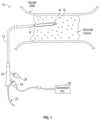
- FIG. 1is an illustration of a shock wave angioplasty catheter being used to treat an occlusion in a blood vessel, in accordance with some embodiments of the subject invention.
- FIG. 2 Ais an illustration of components at the distal end of a catheter, in accordance with some embodiments of the subject invention.
- FIG. 2 Bis an illustration of components at the distal end of the catheter, in accordance with some embodiments of the subject invention.
- FIG. 2 Cis an illustration of components at the distal end of the catheter, in accordance with some embodiments of the subject invention.
- FIG. 2 Dis an illustration of an exploded perspective view of the distal section of the catheter, in accordance with some embodiments of the subject invention.
- FIG. 3 Ais an illustration of a step in an exemplary process of manufacturing a catheter, in accordance with some embodiments of the subject invention.
- FIG. 3 Bis an illustration of a step in an exemplary process of manufacturing the catheter, in accordance with some embodiments of the subject invention.
- FIG. 3 Cis an illustration of a step in an exemplary process of manufacturing the catheter, in accordance with some embodiments of the subject invention.
- FIG. 3 Dis an illustration of a step in an exemplary process of manufacturing the catheter, in accordance with some embodiments of the subject invention.
- FIG. 3 Eis an illustration of a step in an exemplary process of manufacturing the catheter, in accordance with some embodiments of the subject invention.
- FIG. 4 Ais an illustration of components at the distal end of another exemplary catheter, in accordance with some embodiments of the subject invention.
- FIG. 4 Bis an illustration of components at the distal end of the catheter, in accordance with some embodiments of the subject invention.
- FIG. 4 Cis an illustration of components at the distal end of the catheter, in accordance with some embodiments of the subject invention.
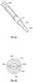
- FIG. 5 Ais an illustration of components at the distal end of another catheter, in accordance with some embodiments of the subject invention.
- FIG. 5 Bis a cross-section illustration of components at the distal end of the catheter, in accordance with some embodiments of the subject invention.
- FIG. 6 Ais an illustration of components at the distal end of another catheter in accordance with an embodiment of the subject invention.
- FIG. 6 Bis an illustration of components at the distal end of the catheter of FIG. 6 A in a later stage of manufacture
- FIG. 6 Cis an illustration of components at the distal end of the catheter of FIG. 6 B in a later stage of manufacture.
- FIG. 6 Dis a cross-sectional view of some of the components shown in FIG. 6 C .
- the assignee hereinhas developed a number of low-profile shock wave electrodes that may be suitable for use in angioplasty and/or valvuloplasty procedures.
- a low-profile electrode assemblyin which an outer electrode is formed by a conductive sheath, and an inner electrode is formed by removing a portion of an insulated wire (e.g., cutting a hole in the insulating layer near the end of the wire) to expose an electrically conductive portion of the insulated wire.
- the inner electrodeis placed a controlled distance apart from the side edge of the conductive sheath to allow for a reproducible arc for a given current and voltage.
- Pat. No. 10,555,744also incorporated herein by reference, the assignee discloses a tongue-and-groove electrode assembly in which electrode pairs are formed from a groove-shaped cut-out in a conductive sheath and a coplanar tongue-shaped protrusion extending into the groove-shaped cut-out.
- the catheters described hereininclude a low-profile cap or angioplasty balloon attached to the distal end of the catheter that can be positioned in a patient's vasculature without folding.
- the low profile of the no-fold cap or balloonadvantageously allows the catheter to advance into even tighter regions of vasculature, such as those that are partially or totally occluded.
- the elastomeric material properties of the low-profile cap or balloonallow the balloon to inflate with conductive fluid to increase the balloon's profile, i.e., in order to contact an occlusion and provide space in the balloon for conductive fluid to immerse the electrodes.
- the catheters described hereininclude additional low-profile elements, such as coplanar electrodes, which further reduce the diameter of the distal end of the catheter. Additionally or alternatively, the catheters may provide an electrical connection to the electrodes by way of a reinforced wire sheath wrapped circumferentially around the catheter shaft.
- the reinforced wire sheathprovides improved kink resistence, torqueability, and pushability to the catheter for more easily maneuvering the device within a patient's vasculature.
- FIG. 1illustrates an exemplary catheter 10 for treating occlusions in blood vessels according to an embodiment of the subject invention.
- the catheter 10is advanced into an occlusion in a patient's vasculature, such as the stenotic lesion depicted in FIG. 1 , over a guidewire 20 carried in a guidewire sheath.
- a distal end of the catheter 10includes a shock wave generator 16 that produces shock waves at a plurality of emitters (e.g., electrode pairs) to break up calcified lesions.
- the plurality of emittersinclude electrode pairs having first and second electrodes separated by a gap, at which shock waves are formed when a current flows across the gap between the electrodes of the pair (i.e., when a voltage is applied across the first and second electrodes).
- the electrodes pairsare arranged in a low-profile configuration that reduces the diameter of the distal end of the catheter 10 and permits the treatment of tight, hard-to-cross lesions.
- the shock wave generator 16includes one or more coplanar electrode pairs, or includes one or more electrodes at least partially recessed into the catheter 10 .
- a low-profile flexible cap or balloon 18is sealably attached to the distal end of the catheter 10 , forming an annular channel around the shaft 12 of the catheter.
- the flexible cap or balloon 18surrounds the shock wave generator 16 , such that the shock waves are produced in a closed system defined by the walls of the cap.
- the cap or balloon 18is filled with a conductive fluid, such as saline.
- the conductive fluidallows the acoustic shock waves to propagate from the electrode pairs of the shock wave generator 16 through the walls of the cap or balloon 18 and then into the target lesion.
- the conductive fluidmay also contain an x-ray contrast agent to permit fluoroscopic viewing of the catheter 10 during IVL treatment.
- the capis rigid and not flexible. In some embodiments, when inflated with conductive fluid, the diameter of the cap expands up to 10-15% maximum.
- the catheter 10also includes a proximal end or handle 22 that remains outside of a patient's vasculature during treatment.
- the proximal end 22includes an entry port for receiving the guidewire 20 .
- the proximal end 22also includes a fluid port 26 for receiving a conductive fluid for inflating and deflating the flexible cap 18 during treatment.
- An electrical connection port 24is also located on the proximal end 22 to provide an electrical connection between the distal shock wave generator 16 and an external pulsed high voltage source 28 , such as the intravascular lithotripsy (IVL) generator shown in FIG. 1 .
- the handleis a Y-adaptor.
- strain reliefis provided at junction of the handle.
- the catheter 10also includes a flexible shaft 12 that extends from the proximal handle 22 to the distal end of the catheter.
- the shaft 12comprises an inner member that provides various internal conduits connecting elements at the distal end with the handle 22 of the catheter.
- the inner memberincludes a guidewire lumen for receiving the guidewire 20 .
- the inner memberalso defines a number of further lumens extending longitudinally through the shaft 12 . For instance, one or more wire lumens can be included for carrying conductive wires that electrically connect the pulsed voltage source 28 with electrodes of the distal shock wave generator 16 .
- one or more fluid lumensare provided in the inner member for carrying conductive fluid from the fluid port 26 into the cap or balloon 18 .
- the same lumencan be used to carry both wire(s) and conductive fluid.
- the flexible shaft 12includes a reinforced wire sheath wrapped circumferentially around the inner member.
- the reinforced wire sheathprovides mechanical support to the flexible shaft 12 to facilitate torqueing, pushing, and maneuvering of the catheter 10 through a patient's blood vessel.
- a tubular outer jacket or a plastic linercovers the guidewire sheath and the reinforced wire sheath to provide a barrier between active elements of the catheter 10 and the in situ environment.
- additional proximal reinforcementcan be applied for added push-ability and torque-ability (by means of additional plastic, metal, or other potential strengthening components).
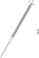
- FIG. 2 Ais an illustration of components at the distal end of a catheter (e.g., catheter 10 ), in accordance with some embodiments of the subject invention.
- the cathetercomprises an inner member 202 .
- the inner member 202comprises a base segment 202 a and a low-profile extension segment 202 b . Both the base segment 202 a and the extension segment 202 b are cylindrical, with the diameter of the extension segment 202 b smaller than the diameter of the base segment 202 a , thus creating a low-profile distal end.
- the low-profile extension segment 202 bcomprises a lumen for accommodating a guidewire (e.g., guidewire 20 ).
- the base segment 202 acarries two wires 206 and 208 .
- Wires 206 and 208are insulated wires (e.g., polyimide-insulated copper wires) with conductive distal ends.
- the insulating layer of the distal ends of the wiresare cut to expose the inner conductive cores of the wires.
- the two wires, together with a conductive sheath,form two electrode pairs for generating shockwaves, as described herein.
- the location, size, and shape of the removed portion of the insulationmay vary to control the location, direction, and/or magnitude of the shock wave.
- flat wiresrather than round wires are used to further reduce the crossing profile of the electrode assembly.
- the inner member 202further provides an inlet for conductive fluid.
- the base segmentaccommodates a tubing 210 as an inlet flush port for introducing conductive fluid to the distal end of the catheter.
- the tubing 210can be a polyimide tubing.
- the distal portion of the tubing 210extrudes out of the base segment.
- a mandrelcan be placed in the lumen instead of the tubing 210 as an inlet port.
- the inner member 202further provides an outlet for conductive fluid.
- the base segmentcomprises an outlet lumen 204 as an outlet flush port for carrying conductive fluid away from the distal end of the catheter.
- the lumen 204has two functions—in addition to being the outlet flush port, the lumen 204 also accommodates wire 206 of the electrode assembly, thereby saving space and further reducing the profile of the catheter at the distal end.
- a tubular reinforced wire sheath 220formed from at least one reinforced wire material such as metal or plastic.
- the wire materialcan braided, coiled, or both at varying pitches.
- the reinforced wire sheath 220may also provide favorable mechanical properties to the shaft of the catheter. For instance, the material composition of the reinforced wire sheath 220 could provide increased torqueability, pushability, or enhanced rigidity to the catheter shaft to facilitate maneuvering the catheter through a patient's vasculature.
- the material of the wire sheath 220can be radiopaque to facilitate visual tracking of the catheter.
- the reinforced sheath 220can be laminated with a plastic liner 222 .
- the plastic linercan be of varying materials or hardness to allow for improved mechanical properties such as pushability and torqueability.
- the sheath 220 and/or the plastic liner 222may be flattened to reduce the profile of the catheter and allow the catheter to more easily fit into tightly occluded vessels. As shown in FIG. 2 B , the reinforced sheath 220 and the plastic liner 222 do not extend to the distal end of the base segment 202 a ; thus, the distal segment of the base segment 202 a is exposed.
- a conductive sheath 212is positioned around the wires 206 and 208 and the flush port tubing 210 .
- the outer diameter of the conductive sheath 212is smaller than that of the base segment 202 a such that the proximal edge 212 b of the conductive sheath can lean against the distal surface of the base segment 202 a .
- adhesive or thermally bonded plasticcan be used to hold the wires, the conductive sheath, and flush tubing 210 in place.
- the tubing 210is optional.
- the conductive fluidcan be introduced into the conductive sheath 212 via the inlet tubing 210 , flushed out of the conductive sheath 212 at its distal end, then flow around the outside of the conductive sheath 212 , and finally exit via the outlet lumen 204 (e.g., via crack 205 ).
- the inlet tubing 210 and outlet lumen 204are positioned to maximize fluid flow across the electrode pairs, such that fluid flowed through the distal end of the catheter via the inlet and outlet flows across at least one of the electrode pairs.
- the return path of the conductive fluid outside/around the conductive sheath 212can be maintained in a number of ways.
- the conductive sheath 212can be flattened or oval shaped to allow a larger portion of the outlet lumen 204 (e.g., crack 205 ) to be accessible outside the conductive sheath.
- the conductive sheath 212can be offset from the central axis of the base segment 202 a .
- the portion of the outlet lumen 204 inside the conductive sheath 212can be sealed off such that the conductive fluid only enters via inlet tubing 210 and exits via the outside portion of the outlet lumen 204 (e.g., crack 205 ).
- the conductive sheath 212is formed at least partially from a radiopaque material such platinum, iridium, or stainless steel for creating lithotripsy and to permit fluoroscopic viewing of the catheter during use.
- a radiopaque materialsuch platinum, iridium, or stainless steel for creating lithotripsy and to permit fluoroscopic viewing of the catheter during use.
- the distal end of the cathetercomprises a no-fold cap 230 .
- the no-fold capis attached over the distal end of the catheter to close the flush path and encapsulate the emitter assembly.
- the proximal edge of the capis coupled to the distal edge of the plastic liner 222 to form a closed annular channel around the distal end of the catheter.
- the conductive fluidcan flow through the emitter assembly and exit via the outlet port.
- the space between the inner member and the plastic linercan be sealed off from the distal portion of the catheter such that the conductive fluid does not come into contact with the wire sheath 222 .
- the distal end of the capcan be coupled to the distal end of the extension segment 202 b to form a closed space to prevent the conductive fluid from leaking at the distal end.
- the lumen defined by the extension segment 202 bis unobstructed by the cap to allow a guidewire to pass through.
- the cap 230can be thermally or adhesively bonded in place.
- the cap 230is a “no-fold” cap because it does not contain material that needs to be folded before insertion into the cardiovascular system. Instead, the cap comprises a piece of extruded tubing (e.g., extruded polymer tubing) stretched and modified to the desired shape and bonded at the distal end of the catheter. Such a cap can be expanded a relatively small amount (e.g., up to 10-15% maximum) sufficient to immerse the electrodes in a conductive fluid before generating shock waves at the electrodes to treat an occlusion.
- extruded tubinge.g., extruded polymer tubing
- Such a capcan be expanded a relatively small amount (e.g., up to 10-15% maximum) sufficient to immerse the electrodes in a conductive fluid before generating shock waves at the electrodes to treat an occlusion.
- the capis preferably formed of a material (e.g., semi-compliant polymer) such that the cap can be minimally inflated during treatment of an occlusion, and then returns to a low profile state when deflated after treatment.
- a low-profile ballooncan be used. Additional details of the low-profile cap and balloon can be found in U.S. application Ser. No. 17/021,905, which is incorporated herein by reference.
- the cap 230maintains a very low profile both in expanded and unexpanded state.
- the cap 230 's profileis lower than 1.5 mm.
- the extremely low profile of the cap 230allows the distal end of the catheter to access tightly occluded regions of vasculature.
- the capWhen the cap is inflated with conductive fluid, the cap expands to provide additional space between the inner surface of the cap and the electrode pairs.
- the outer diameter of the extension segment 202 b of the inner memberis approximately 0.019 to 0.02 inches and the inner diameter of the inflated cap is less than 1.5 mm, providing a space between the inner member and the inner surface of the cap.
- the spaceensures that the electrode pairs are immersed in conductive fluid during shock wave generation and that the inner surface of the cap is sufficiently far from the electrode pairs that the cap material is not damaged by the shock waves.
- the diameter of the capis between 0.75 mm and 1.5 mm.
- the distal end of the cathetercan have an atraumatic profile.
- the atraumatic profilecan be the addition of a soft atraumatic tip (not depicted) via adhesive or thermal means.
- the soft tiptapers toward the distal tip of the catheter.
- the soft tipcan be formed from a polymer or any other suitable biocompatible material.
- the tipis formed at least partially from a radiopaque material such as platinum, iridium, or stainless steel to permit fluoroscopic viewing of the catheter during use. Providing a soft tip may prevent physical damage to blood vessel walls while facilitating contact with and entry into tight lesions in the vasculature.
- the catheter 10can be used to treat occlusions in vasculature, for example, stenotic lesions, calcified portions of an artery, or some other occlusion in a blood vessel.
- a physicianadvances the guidewire 20 from an entry site on a patient (e.g., an artery in the groin area of the leg) to the target region of a vessel (e.g., a region having an occlusion that needs to be broken up).
- the catheter 10is then advanced over the guidewire 20 to the target region of the vessel.
- the flexible cap 18 sealed to the distal endis a no-fold cap having a low profile, such that the cap can be freely advanced through the vasculature.
- a guide catheter or wire sheathmay be used to aid the entry and maneuvering of the catheter 10 within the vasculature.
- the wire sheathprovides tubular linear support to the catheter shaft 12 during pushing, crossing, and placement of the catheter 10 .
- the in situ location of the distal end of the catheter 10may be determined by x-ray imaging and/or fluoroscopy.
- the distal end of the catheter 10is advanced as far as possible inside the tight lesion.
- the flexible cap 18is then minimally inflated by a conductive fluid (e.g., saline and/or saline mixed with an image contrast agent) introduced via the fluid port 26 , allowing conductive fluid to expand the cap so that the outer surface of the cap contacts the target lesion.
- a conductive fluide.g., saline and/or saline mixed with an image contrast agent
- IVL pressurewhich is between approximately one atmosphere and approximately six atmospheres.
- the diameter of the flexible cap in an inflated statemay be up to 10-15% greater than the diameter of the flexible cap in a deflated state. However, in some examples the diameter of the cap in an inflated state is even less than 10% greater than the diameter of the cap in a deflated state.
- a voltage pulseis then applied by the pulsed high voltage source 28 across one or more electrode pairs (i.e., emitters of the shockwave generator 16 ).
- a physicianmay trigger the power supply which will supply current simultaneously across the wires 206 and 208 .
- currentwill flow from the voltage source, down the wire 206 , across the first gap between the insulation removed distal portion of the wire 206 and the edge of the conductive sheath 212 , creating a plasma arc that generates a shock wave at the first electrode pair.
- the currentalso flows across the conductive sheath 212 and across a second gap between the edge of the conductive sheath 212 and the insulation removed distal portion of the wire 208 , creating another plasma arc that generates a shock wave at the second electrode pair.
- the current return pathis along wire 208 to reach the negative lead or ground.
- Each pulseinitially ionizes the conducive fluid in the low-profile cap 230 ( FIG. 2 C ) to create small gas bubbles at the distal end of the catheter.
- Fluidcan be continuously flushed through the cap via the inlet lumen and outlet lumen during treatment at a constant rate to clear the bubbles and debris from the electrodes.
- the fluid flow ratemay be controlled throughout treatment, but is generally in the range of approximately 1 ml/min to approximately 3 ml/min.
- a plasma arcforms across the electrode pairs, creating a low impedance path where current flows freely.
- the heat from the plasma archeats the conductive fluid creating a rapidly expanding vapor bubble.
- the expansion of the vapor bubblecreates a shock wave that is conducted through the fluid, through walls of the low-profile cap, and into an occlusion where the energy breaks up the hardened lesion.
- the voltage pulse applied by the voltage pulse generator 28is typically in the range of approximately 2000 volts to approximately 3000 volts and preferably between 2300 and 3000 volts.
- the repetition rate or frequency of the applied voltage pulsesmay be between approximately 1 Hz and approximately 10 Hz.
- the preferred voltage and repetition ratemay vary depending on, e.g., the size of the lesion, the extent of calcification, the size of the blood vessel, the attributes of the patient, or the stage of treatment.
- a physicianmay start with low energy shock waves and increase the energy as needed during the procedure.
- the magnitude of the shock wavescan be controlled by controlling the voltage, current, duration, and repetition rate of the pulsed voltage from the pulsed voltage source 28 . More information about the physics of shock wave generation and their control can be found in U.S. Pat. Nos. 8,956,371; 8,728,091; 9,522,012; and 10,226,265, each of which is incorporated by reference.
- one or more cycles of shock wavescan be applied to create a more compliant vessel.
- the low-profile cap 230can be deflated and the distal end of the catheter can be advanced further into the occlusion.
- the flexible cap 230is then re-inflated and another cycle of shock waves can be applied. Further advancement of the cap 230 can be attempted after the completion of successive cycles.
- the cathetercan be used to treat a total occlusion in a blood vessel, for instance, a coronary total occlusion (CTO).
- CTOcoronary total occlusion
- the guidewireis advanced at least partially into the stenotic lesion.
- the catheteris then advanced through the patient's vasculature over the guidewire and at least partially into the lesion.
- the low-profile capis then inflated with a conductive fluid until the cap gently contacts the lesion.
- Voltage pulsesare then supplied by a pulsed voltage source to electrode pairs at the tip of the catheter to generate shock waves that break up or loosen the lesion.
- the guidewire and the cathetercan then be advanced further into the lesion and the shock wave treatment can be repeated until the total occlusion is cleared or until the diameter of the vessel permits the placement of a larger more conventional angioplasty device.
- the cathetercan be used in a small vessel that is partially blocked by a stenotic lesion.
- the guidewirecan be advanced much further into the lesion and, in some cases, all the way through the lesion.
- the catheteris advanced through the lesion in incremental stages.
- the low-profile capis inflated and shock waves are generated to break up the occlusion and increase the diameter of the blood vessel.
- a larger-diameter cathetermay be advanced through the vessel to complete the treatment.
- the progress of the proceduremay be monitored by x-ray and/or fluoroscopy. Shock wave cycles can be repeated until the occlusion has been cleared, or until a channel is formed in the lesion having a diameter sufficient to receive a second treatment device having a larger profile. For example, the enlarged channel can receive a different catheter having a more conventional angioplasty balloon or differently oriented shock wave sources. Catheters of this type are described in U.S. Pat. No. 8,747,416 and U.S. Publication No. 2019/0150960, cited above.
- FIGS. 3 A-Eillustrate steps in an exemplary process of manufacturing a catheter, in accordance with some embodiments of the subject invention.
- FIG. 3 Adepicts a tubular inner member 202 comprising 3 lumens (i.e., a tri-lumen shape).
- polyimide or etched PTFE tubingcan be used in one or more of the lumens.
- the lumen 201i.e., the lumen carrying the fluid inlet port
- the lumen 204i.e., the lumen acting as the fluid outlet
- eachcan include polyimide lining to prevent any cross-talking between the inflow and the outflow of the conductive fluid in the catheter.
- a tubular reinforced wire sheath 220is applied over the inner member.
- the wire sheath 220comprises reinforced braided wire structure threaded over inner member.
- the proximal and distal segments of the inner memberare not over-braided.
- the wire materialcan braided, coiled, or both at varying pitches and sizes.
- the reinforced wire sheath 230may also provide favorable mechanical properties to the shaft of the catheter.
- the material composition of the reinforced wire sheath 220could provide increased torqueability, pushability, or enhanced rigidity to the catheter shaft to facilitate maneuvering the catheter through a patient's vasculature.
- the reinforced sheath 220can be encompassed with a plastic liner 222 to create one assembly.
- the plastic linercan be of varying materials or hardness to allow for improved mechanical properties such as pushability and torqueability. As shown in FIG. 3 C , the reinforced sheath 220 and the plastic liner 222 do not extend to the distal end of the inner member 202 .
- the distal end of the inner memberis trimmed to form a base segment 202 a and an extension segment 202 b . As shown, at the extension segment 202 b , only one lumen remains for carrying a guidewire.
- the reduced outer diameter of the distal segment of the inner memberis used to house an emitter assembly as shown in FIG. 2 A-C .
- the two wires of the emitter assemblyare loaded down the lumens 201 and 204 .
- the two lumenseach can include polyimide lining to insulate the lumens and prevent any fluid connection between the two lumen (which may cause short-circuit).
- the inner membermay comprise additional lumens in the base segment 202 a for accommodating additional emitter assemblies. Additionally or alternatively, multiple wires (e.g., from multiple emitter assemblies) can be accommodated in one lumen in the inner member.
- a tubinge.g., a tubing 210 in FIG. 2 A
- the lumen 201is sealed with adhesive or thermally bonded, as shown in FIG. 2 A .
- a mandrelcan be placed in lumen 201 instead of tubing and then sealed with adhesive or thermally bonded.
- each wireis a polyimide insulated copper wire having a diameter between approximately 0.003 inches and approximately 0.007 inches.
- the wiresmay be flattened to reduce the profile of the catheter, with the flattened wires having a cross-section that is approximately 0.003 inches thick and approximately 0.010 inches wide.
- lumens in the inner membermay have any desired shape. The location, size, and shape of any of the lumens can be modified to reduce the profile of the catheter or to provide some other benefit. Further, the various lumens may be combined (e.g. by providing two or more insulated wires in the same lumen) or eliminated without departing from the scope of the present invention.
- FIGS. 4 A-Cillustrate the distal end of another exemplary catheter, in accordance with some embodiments of the subject invention.
- the cathetercomprises an oval-shaped conductive sheath to achieve a lower-profile and/or provide a larger portion of the fluid outlet port to be accessible outside the conductive sheath, as described below.
- the cathetercomprises an inner member 402 comprising a base segment 402 a and an extension segment 402 b .
- the inner membercan be manufactured in a similar process as described above with reference to FIGS. 2 A- 3 E , and can operate in a similar manner.
- the extension segment 402 bcarries a mandrel 420 , which acts as the guidewire lumen.
- an emitter assemblywhich comprises two wires and a conductive sheath 412 , is installed around the low-profile extension segment 402 b of the inner member.
- the two wiresare spaced circumferentially around the extension segment 402 b approximately 150 degrees apart to achieve a lower profile and to generate shock waves more evenly around the catheter.
- the conductive sheath 412is oval-shaped or flattened to achieve a lower-profile. Further, the oval shape provides a larger portion of the fluid outlet port 404 to be accessible outside the conductive sheath and allows the conductive fluid to flow over the conductive sheath.
- a low-profile capis attached over the distal end to close the flush path and encapsulate the emitter assembly.
- the capcan be attached with adhesive or thermally bonded to the inner member.
- the most distal tiphas an atraumatic profile applied, either by thermal means or the addition of a soft atraumatic tip via adhesive.
- the inner membercomprises three lumens: a first lumen (e.g., 201 in FIG. 3 D ) that both accommodates a first wire 208 and serves as an inlet flush port, a second lumen (e.g., 204 in FIG. 3 D ) that both accommodates a second wire 206 and serves as an outlet flush port, and a third lumen that accommodates a guidewire.
- a first lumene.g., 201 in FIG. 3 D
- a second lumene.g., 204 in FIG. 3 D
- a third lumenthat accommodates a guidewire.
- the design of the inner memberis not so limited.
- the inner membercan include additional lumens such that separate lumens can be used to accommodate a wire and serve as a flush port.
- the inner membercan include four lumens: a first lumen that accommodates a wire, a second lumen that serves as a flush port, a third lumen that both accommodates the other wire and serves as the other flush port, and a fourth lumen that accommodates a guidewire.
- the inner membercan include five lumens: two lumens for accommodating the two wires, two lumens for accommodating the two flush ports, and a fifth lumen for accommodating a guidewire.
- An exemplary inner member having five lumensis depicted in FIGS. 5 A- 5 B as described in detail below.
- FIGS. 2 A- 4 Cin a lumen that both accommodates a wire and serves as a flush port, there are two configurations.
- One configurationis illustrated by lumen 204 , where the lumen's distal end is not sealed and the entire distal opening serves as the flush port.
- the second configurationis illustrated by lumen 201 ( FIGS. 3 D and 2 A ), where the lumen's distal end is sealed to leave only a relatively small opening that serves as the flush port.
- an optional tubing 210can be attached to the small opening to control the precise position of the port. While the embodiments depicted in FIGS.
- an inner memberhaving a lumen of the first configuration and a lumen of the second configuration
- an inner membercan have two lumens that are both of the first configuration or both of the second configuration. It should be further appreciated that the choice of configuration(s) can affect the amount and distribution of the shockwaves.
- the extension segment(e.g., 202 b ) is an integral piece of the inner member and can be formed by trimming the distal end of the inner member as shown in FIGS. 3 C-D .
- the low-profile segmentcan be constructed via other means as described below.
- FIGS. 5 A-Billustrate components of another exemplary catheter, in accordance with some embodiments of the subject invention.
- a separate guidewire member 520is attached to the distal end of the inner member 502 .
- the proximal end of the guidewire member 520can be affixed (e.g., glued) to the distal end of the inner member.
- the lumen 521 in the guidewire member 520lines up with the central lumen of the inner member 502 such that a guidewire can extend through the inner member and the guidewire member.
- a small portion of the proximal end of the guidewire member(e.g., 2-3 mm) is inserted into the central lumen of the inner member.
- Heatcan be applied to melt the materials at the location of the insertion to bond the guidewire member to the inner member.
- mandrelscan be placed in the lumens of the inner member and/or the guidewire member during heating to prevent the lumens from being deformed by the heat.
- the outer surface of guidewire member 520includes grooves 520 a and 520 b . Because the wires 506 and 508 are flexible, the distal portions of the wires can be placed within the grooves to further secure the wires (e.g., via glue) and reduce the distal profile of the catheter.
- a conductive sheath 512is wrapped circumferentially around wires and the guidewire member. Lumens 504 and 505 define the two independent flush ports.
- the inner member 502comprises five lumens (two for accommodating the two wires, two for serving as flush ports, and one for accommodating the guidewire), it can instead comprise three lumens or four lumens as described above.
- FIGS. 6 A- 6 Dillustrate components of another exemplary catheter in accordance with an embodiment of the subject invention. This embodiment is similar to the embodiment of FIG. 5 with some changes as noted below.
- the inner member 620is formed from a single extrusion having four channels or flutes 640 , 642 (two visible in FIG. 6 A ) and a guidewire lumen 621 .
- the distal end of the member 620is necked down to provide a reduced diameter region at the distal end.
- the more proximal portion of the inner memberhas a larger diameter and includes the four channels.
- One polyimide tube 644 , 646(four total) is aligned with each of the four channels.
- Two of the tubesare used for carrying a wire.
- One of the tubesprovides an inlet for supplying a conductive fluid to the distal tip of the catheter and the fourth tube provides a return path for the fluid.
- the fourth tubecould be connected to a suction source.
- a jacket 648surrounds the polyimide tubes.
- a cylindrical insulating sleeve 650surrounds a portion of the inner member and can extend to the distal openings in the polyimide tubes.
- the sleeve 650can be formed from two pieces including a constant diameter distal potion and a tapered proximal portion. In the alternative, the sleeve may be formed of one piece as shown.
- FIG. 6 Balso shows two wires 606 and 608 , each extending out of a tube and along a portion of the insulating sleeve.
- FIG. 6 CA more complete assembly appears in FIG. 6 C and includes a cylindrical conductive sheath 612 surrounding the tips of wires 606 and 608 to define two electrode pairs.
- a voltageWhen a voltage is applied to the proximal ends of wires 606 and 608 , current will travel down wire 606 , jump the gap between the insulation removed distal end of the wire across to the sheath, then travel around the sheath and jump the gap to the insulation removed distal end of wire 608 where it will return to ground. Shock waves are generated at both gaps as discussed in detail above.
- wires and fluid channelsmay be varied from the illustrated configurations.
- the location of wire 608 and channel 605could be swapped.
- any two tubescan contain wires and any two channels can be used for fluid exchange.
- the angular spacing of the elementsmay be adjusted to improve performance.
Landscapes
- Health & Medical Sciences (AREA)
- Surgery (AREA)
- Life Sciences & Earth Sciences (AREA)
- Engineering & Computer Science (AREA)
- Heart & Thoracic Surgery (AREA)
- Nuclear Medicine, Radiotherapy & Molecular Imaging (AREA)
- Vascular Medicine (AREA)
- Biomedical Technology (AREA)
- Orthopedic Medicine & Surgery (AREA)
- Medical Informatics (AREA)
- Molecular Biology (AREA)
- Animal Behavior & Ethology (AREA)
- General Health & Medical Sciences (AREA)
- Public Health (AREA)
- Veterinary Medicine (AREA)
- Mechanical Engineering (AREA)
- Media Introduction/Drainage Providing Device (AREA)
Abstract
Description
Claims (10)
Priority Applications (10)
| Application Number | Priority Date | Filing Date | Title |
|---|---|---|---|
| US17/537,325US12232755B2 (en) | 2020-12-11 | 2021-11-29 | Lesion crossing shock wave catheter |
| CR20230304ACR20230304A (en) | 2020-12-11 | 2021-12-09 | SHOCKWAVE CATHETER PASSING THROUGH THE LESION |
| EP21844444.6AEP4259012A1 (en) | 2020-12-11 | 2021-12-09 | Lesion crossing shock wave catheter |
| MX2023006886AMX2023006886A (en) | 2020-12-11 | 2021-12-09 | Lesion crossing shock wave catheter. |
| CA3204915ACA3204915A1 (en) | 2020-12-11 | 2021-12-09 | Lesion crossing shock wave catheter |
| JP2023535464AJP2023553139A (en) | 2020-12-11 | 2021-12-09 | Translesional shockwave catheter |
| CN202180093276.7ACN116867445A (en) | 2020-12-11 | 2021-12-09 | Focus penetrating impact wave guide tube |
| PCT/US2021/062666WO2022125807A1 (en) | 2020-12-11 | 2021-12-09 | Lesion crossing shock wave catheter |
| AU2021396315AAU2021396315A1 (en) | 2020-12-11 | 2021-12-09 | Lesion crossing shock wave catheter |
| US19/025,239US20250186074A1 (en) | 2020-12-11 | 2025-01-16 | Lesion crossing shock wave catheter |
Applications Claiming Priority (2)
| Application Number | Priority Date | Filing Date | Title |
|---|---|---|---|
| US202063124639P | 2020-12-11 | 2020-12-11 | |
| US17/537,325US12232755B2 (en) | 2020-12-11 | 2021-11-29 | Lesion crossing shock wave catheter |
Related Child Applications (1)
| Application Number | Title | Priority Date | Filing Date |
|---|---|---|---|
| US19/025,239DivisionUS20250186074A1 (en) | 2020-12-11 | 2025-01-16 | Lesion crossing shock wave catheter |
Publications (2)
| Publication Number | Publication Date |
|---|---|
| US20220183708A1 US20220183708A1 (en) | 2022-06-16 |
| US12232755B2true US12232755B2 (en) | 2025-02-25 |
Family
ID=81943567
Family Applications (1)
| Application Number | Title | Priority Date | Filing Date |
|---|---|---|---|
| US17/537,325Active2043-03-23US12232755B2 (en) | 2020-12-11 | 2021-11-29 | Lesion crossing shock wave catheter |
Country Status (1)
| Country | Link |
|---|---|
| US (1) | US12232755B2 (en) |
Families Citing this family (14)
| Publication number | Priority date | Publication date | Assignee | Title |
|---|---|---|---|---|
| US10966737B2 (en) | 2017-06-19 | 2021-04-06 | Shockwave Medical, Inc. | Device and method for generating forward directed shock waves |
| WO2021061451A1 (en) | 2019-09-24 | 2021-04-01 | Shockwave Medical, Inc. | Lesion crossing shock wave catheter |
| US11484327B2 (en) | 2021-02-26 | 2022-11-01 | Fastwave Medical Inc. | Intravascular lithotripsy |
| US11911056B2 (en) | 2021-02-26 | 2024-02-27 | Fastwave Medical Inc. | Intravascular lithotripsy |
| US11944331B2 (en) | 2021-02-26 | 2024-04-02 | Fastwave Medical Inc. | Intravascular lithotripsy |
| CA3229200A1 (en)* | 2021-08-16 | 2023-02-23 | Alexander Carlo Buscaglia | Multi-modulus probe design and assembly |
| WO2024151281A1 (en)* | 2022-01-11 | 2024-07-18 | Covellus Llc | Intravascular lithotripsy catheter |
| US12193738B2 (en) | 2022-06-01 | 2025-01-14 | Fastwave Medical Inc. | Intravascular lithotripsy |
| AU2023280407A1 (en) | 2022-06-01 | 2024-11-07 | Fastwave Medical Inc. | Intravascular lithotripsy |
| CN117481743A (en)* | 2022-07-26 | 2024-02-02 | 苏州生科智能科技有限公司 | Shock wave sacculus catheter device |
| WO2024107470A1 (en)* | 2022-11-18 | 2024-05-23 | Nextern Innovation, Llc | Intravascular lithoplasty balloon systems and devices with sterile, disposable single-piece and unitary cable, handle, hub, catheter and balloon |
| US12035932B1 (en)* | 2023-04-21 | 2024-07-16 | Shockwave Medical, Inc. | Intravascular lithotripsy catheter with slotted emitter bands |
| WO2025171173A1 (en) | 2024-02-08 | 2025-08-14 | IV-X Medical, LLC | Intravascular lithotripsy system |
| US12178458B1 (en)* | 2024-05-16 | 2024-12-31 | Shockwave Medical, Inc. | Guidewireless shock wave catheters |
Citations (218)
| Publication number | Priority date | Publication date | Assignee | Title |
|---|---|---|---|---|
| US3412288A (en) | 1965-01-25 | 1968-11-19 | Gen Motors Corp | Arc suppression circuit for inductive loads |
| US3413976A (en) | 1963-07-29 | 1968-12-03 | G Elektrotekhnichesky Zd Vef | Arrangement for removal of concretions from urinary tract |
| US3785382A (en) | 1971-05-14 | 1974-01-15 | Wolf Gmbh Richard | Device for destroying stones in the bladder, in the ureter, in the kidneys and the like |
| US3902499A (en) | 1974-01-02 | 1975-09-02 | Hoffman Saul | Stone disintegrator |
| US4027674A (en) | 1975-06-06 | 1977-06-07 | Tessler Arthur N | Method and device for removing concretions within human ducts |
| US4030505A (en) | 1975-11-28 | 1977-06-21 | Calculus Instruments Ltd. | Method and device for disintegrating stones in human ducts |
| DE3038445A1 (en) | 1980-10-11 | 1982-05-27 | Dornier Gmbh, 7990 Friedrichshafen | Pressure wave generator for diagnosis and therapy - has spark gap in inflatable balloon at end of catheter |
| JPS60191353U (en) | 1984-05-25 | 1985-12-18 | 日立工機株式会社 | Ink ribbon feeding control device |
| JPS61135648A (en) | 1984-12-05 | 1986-06-23 | オリンパス光学工業株式会社 | Discharge stone crushing probe |
| US4662126A (en) | 1986-05-23 | 1987-05-05 | Fike Corporation | Vibration resistant explosion control vent |
| US4671254A (en) | 1985-03-01 | 1987-06-09 | Memorial Hospital For Cancer And Allied Diseases | Non-surgical method for suppression of tumor growth |
| JPS6299210U (en) | 1985-12-12 | 1987-06-24 | ||
| US4685458A (en) | 1984-03-01 | 1987-08-11 | Vaser, Inc. | Angioplasty catheter and method for use thereof |
| JPS62275446A (en) | 1986-05-21 | 1987-11-30 | オリンパス光学工業株式会社 | Discharge stone crushing apparatus |
| US4809682A (en) | 1985-12-12 | 1989-03-07 | Dornier Medizintechnik Gmbh | Underwater electrodes for contactless lithotripsy |
| US4813934A (en) | 1987-08-07 | 1989-03-21 | Target Therapeutics | Valved catheter device and method |
| US4878495A (en) | 1987-05-15 | 1989-11-07 | Joseph Grayzel | Valvuloplasty device with satellite expansion means |
| WO1989011307A1 (en) | 1988-05-26 | 1989-11-30 | The Regents Of The University Of California | Perfusion balloon catheter |
| US4890603A (en) | 1987-11-09 | 1990-01-02 | Filler William S | Extracorporeal shock wave lithotripsy employing non-focused, spherical-sector shock waves |
| US4900303A (en) | 1978-03-10 | 1990-02-13 | Lemelson Jerome H | Dispensing catheter and method |
| US4994032A (en) | 1987-12-01 | 1991-02-19 | Terumo Kabushiki Kaisha | Balloon catheter |
| JPH0363059A (en) | 1989-04-26 | 1991-03-19 | Advanced Cardiovascular Syst Inc | Blood flow measurement using self-irrigation catheter for blood vessel formation and its device |
| US5009232A (en) | 1988-08-17 | 1991-04-23 | Siemens Aktiengesellschaft | Extracorporeal lithotripsy apparatus using high intensity shock waves for calculus disintegration and low intensity shock waves for imaging |
| EP0442199A2 (en) | 1990-02-12 | 1991-08-21 | BS & B SAFETY SYSTEMS, INC. | Low pressure non-fragmenting rupture disks |
| US5057103A (en) | 1990-05-01 | 1991-10-15 | Davis Emsley A | Compressive intramedullary nail |
| US5057106A (en) | 1986-02-27 | 1991-10-15 | Kasevich Associates, Inc. | Microwave balloon angioplasty |
| US5061240A (en) | 1990-04-02 | 1991-10-29 | George Cherian | Balloon tip catheter for venous valve ablation |
| US5078717A (en) | 1989-04-13 | 1992-01-07 | Everest Medical Corporation | Ablation catheter with selectively deployable electrodes |
| WO1992003975A1 (en) | 1990-09-04 | 1992-03-19 | Cannon Robert L Iii | Catheter and apparatus for the treatment, inter alia, of pulmonary embolisms |
| US5102402A (en) | 1991-01-04 | 1992-04-07 | Medtronic, Inc. | Releasable coatings on balloon catheters |
| US5103804A (en) | 1990-07-03 | 1992-04-14 | Boston Scientific Corporation | Expandable tip hemostatic probes and the like |
| US5152768A (en) | 1991-02-26 | 1992-10-06 | Bhatta Krishna M | Electrohydraulic lithotripsy |
| US5152767A (en) | 1990-11-23 | 1992-10-06 | Northgate Technologies, Inc. | Invasive lithotripter with focused shockwave |
| US5154722A (en) | 1988-05-05 | 1992-10-13 | Circon Corporation | Electrohydraulic probe having a controlled discharge path |
| US5176675A (en) | 1985-04-24 | 1993-01-05 | The General Hospital Corporation | Use of lasers to break down objects for removal from within the body |
| US5195508A (en) | 1990-05-18 | 1993-03-23 | Dornier Medizintechnik Gmbh | Spark gap unit for lithotripsy |
| US5231976A (en) | 1989-03-21 | 1993-08-03 | Hans Wiksell | Apparatus for triggering shock waves |
| US5245988A (en) | 1989-11-15 | 1993-09-21 | Dormer Gmbh | Preparing a circuit for the production of shockwaves |
| US5246447A (en) | 1989-02-22 | 1993-09-21 | Physical Sciences, Inc. | Impact lithotripsy |
| US5254121A (en) | 1992-05-22 | 1993-10-19 | Meditron Devices, Inc. | Method and device for removing concretions within human ducts |
| EP0571306A1 (en) | 1992-05-22 | 1993-11-24 | LASER MEDICAL TECHNOLOGY, Inc. | Apparatus and method for removal of deposits from the walls of body passages |
| US5281231A (en) | 1989-02-22 | 1994-01-25 | Physical Sciences, Inc. | Impact lithotrypsy |
| US5295958A (en) | 1991-04-04 | 1994-03-22 | Shturman Cardiology Systems, Inc. | Method and apparatus for in vivo heart valve decalcification |
| JPH06125915A (en) | 1992-10-21 | 1994-05-10 | Inter Noba Kk | Catheter type medical instrument |
| US5321715A (en) | 1993-05-04 | 1994-06-14 | Coherent, Inc. | Laser pulse format for penetrating an absorbing fluid |
| US5324255A (en) | 1991-01-11 | 1994-06-28 | Baxter International Inc. | Angioplasty and ablative devices having onboard ultrasound components and devices and methods for utilizing ultrasound to treat or prevent vasopasm |
| US5336234A (en) | 1992-04-17 | 1994-08-09 | Interventional Technologies, Inc. | Method and apparatus for dilatation of a stenotic vessel |
| US5362309A (en) | 1992-09-14 | 1994-11-08 | Coraje, Inc. | Apparatus and method for enhanced intravascular phonophoresis including dissolution of intravascular blockage and concomitant inhibition of restenosis |
| EP0623360A1 (en) | 1993-02-05 | 1994-11-09 | The Joe W. And Dorothy Dorsett Brown Foundation | Ultrasonic angioplasty balloon catheter |
| US5364393A (en) | 1990-07-02 | 1994-11-15 | Heart Technology, Inc. | Tissue dissipative recanalization catheter |
| US5368591A (en) | 1988-10-28 | 1994-11-29 | Prutech Research And Development Partnership Ii | Heated balloon catheters |
| CA2104414A1 (en) | 1993-08-19 | 1995-02-20 | Krishna M. Bhatta | Electrohydraulic lithotripsy |
| US5395335A (en) | 1991-05-24 | 1995-03-07 | Jang; G. David | Universal mode vascular catheter system |
| EP0647435A1 (en) | 1993-10-12 | 1995-04-12 | Arrow International Investment Corporation | Electrode-carrying catheter and method of making same |
| US5425735A (en) | 1989-02-22 | 1995-06-20 | Psi Medical Products, Inc. | Shielded tip catheter for lithotripsy |
| US5431173A (en) | 1991-05-29 | 1995-07-11 | Origin Medsystems, Inc. | Method and apparatus for body structure manipulation and dissection |
| US5472406A (en) | 1991-10-03 | 1995-12-05 | The General Hospital Corporation | Apparatus and method for vasodilation |
| WO1996024297A1 (en) | 1995-02-09 | 1996-08-15 | C.R. Bard, Inc. | Angioplasty catheter used to expand and/or open up blood vessels |
| US5582578A (en) | 1995-08-01 | 1996-12-10 | Duke University | Method for the comminution of concretions |
| US5603731A (en) | 1994-11-21 | 1997-02-18 | Whitney; Douglass G. | Method and apparatus for thwarting thrombosis |
| JPH1099444A (en) | 1996-09-27 | 1998-04-21 | Advanced Cardeovascular Syst Inc | Vibratory stent to open calcified lesion part |
| JPH10314177A (en) | 1997-04-26 | 1998-12-02 | Convergenza Ag | Device with treating catheter |
| US5846218A (en) | 1996-09-05 | 1998-12-08 | Pharmasonics, Inc. | Balloon catheters having ultrasonically driven interface surfaces and methods for their use |
| CN1204242A (en) | 1995-10-13 | 1999-01-06 | 血管转换公司 | Methods and devices for bypassing and/or other transvascular procedures for arterial blockages |
| WO1999000060A1 (en) | 1997-06-26 | 1999-01-07 | Advanced Coronary Intervention | Electrosurgical catheter for resolving obstructions by radio frequency ablation |
| WO1999002096A1 (en) | 1997-07-08 | 1999-01-21 | The Regents Of The University Of California | Circumferential ablation device assembly and method |
| US5893840A (en) | 1991-01-04 | 1999-04-13 | Medtronic, Inc. | Releasable microcapsules on balloon catheters |
| US5931805A (en) | 1997-06-02 | 1999-08-03 | Pharmasonics, Inc. | Catheters comprising bending transducers and methods for their use |
| US6024718A (en) | 1996-09-04 | 2000-02-15 | The Regents Of The University Of California | Intraluminal directed ultrasound delivery device |
| US6080119A (en) | 1997-05-02 | 2000-06-27 | Hmt Holding Ag | Process and device for generating shock waves for medical uses |
| US6113560A (en) | 1994-09-21 | 2000-09-05 | Hmt High Medical Techologies | Method and device for generating shock waves for medical therapy, particularly for electro-hydraulic lithotripsy |
| WO2000056237A2 (en) | 1999-03-19 | 2000-09-28 | Atrionix, Inc. | Atrial annulus ablation device |
| US6146358A (en) | 1989-03-14 | 2000-11-14 | Cordis Corporation | Method and apparatus for delivery of therapeutic agent |
| US6186963B1 (en) | 1997-05-02 | 2001-02-13 | Hmt Holding Ag | Device for generating acoustic shock waves, especially for medical applications |
| US6210408B1 (en) | 1999-02-24 | 2001-04-03 | Scimed Life Systems, Inc. | Guide wire system for RF recanalization of vascular blockages |
| US6217531B1 (en) | 1997-10-24 | 2001-04-17 | Its Medical Technologies & Services Gmbh | Adjustable electrode and related method |
| US6267747B1 (en) | 1998-05-11 | 2001-07-31 | Cardeon Corporation | Aortic catheter with porous aortic root balloon and methods for inducing cardioplegic arrest |
| US6277138B1 (en) | 1999-08-17 | 2001-08-21 | Scion Cardio-Vascular, Inc. | Filter for embolic material mounted on expandable frame |
| US20010044596A1 (en) | 2000-05-10 | 2001-11-22 | Ali Jaafar | Apparatus and method for treatment of vascular restenosis by electroporation |
| US6352535B1 (en) | 1997-09-25 | 2002-03-05 | Nanoptics, Inc. | Method and a device for electro microsurgery in a physiological liquid environment |
| US6367203B1 (en) | 2000-09-11 | 2002-04-09 | Oklahoma Safety Equipment Co., Inc. | Rupture panel |
| US6371971B1 (en) | 1999-11-15 | 2002-04-16 | Scimed Life Systems, Inc. | Guidewire filter and methods of use |
| US20020045890A1 (en) | 1996-04-24 | 2002-04-18 | The Regents Of The University O F California | Opto-acoustic thrombolysis |
| US6398792B1 (en) | 1999-06-21 | 2002-06-04 | O'connor Lawrence | Angioplasty catheter with transducer using balloon for focusing of ultrasonic energy and method for use |
| US6406486B1 (en) | 1991-10-03 | 2002-06-18 | The General Hospital Corporation | Apparatus and method for vasodilation |
| US20020077643A1 (en)* | 1999-10-05 | 2002-06-20 | Robert Rabiner | Method of removing occlusions using ultrasonic medical device operating in a transverse mode |
| US6440124B1 (en) | 1998-07-22 | 2002-08-27 | Endovasix, Inc. | Flexible flow apparatus and method for the disruption of occlusions |
| US20030004434A1 (en) | 2001-06-29 | 2003-01-02 | Francesco Greco | Catheter system having disposable balloon |
| US6514203B2 (en) | 2001-02-12 | 2003-02-04 | Sonata Technologies Ltd. | Method for ultrasonic coronary thrombolysis |
| US6524251B2 (en) | 1999-10-05 | 2003-02-25 | Omnisonics Medical Technologies, Inc. | Ultrasonic device for tissue ablation and sheath for use therewith |
| US20030060813A1 (en) | 2001-09-22 | 2003-03-27 | Loeb Marvin P. | Devices and methods for safely shrinking tissues surrounding a duct, hollow organ or body cavity |
| US6589253B1 (en) | 1999-12-30 | 2003-07-08 | Advanced Cardiovascular Systems, Inc. | Ultrasonic angioplasty transmission wire |
| US6607003B1 (en) | 2001-04-23 | 2003-08-19 | Oklahoma Safety Equipment Co, | Gasket-lined rupture panel |
| US20030176873A1 (en) | 2002-03-12 | 2003-09-18 | Lithotech Medical Ltd. | Method for intracorporeal lithotripsy fragmentation and apparatus for its implementation |
| US6638246B1 (en) | 2000-11-28 | 2003-10-28 | Scimed Life Systems, Inc. | Medical device for delivery of a biologically active material to a lumen |
| US20030229370A1 (en) | 2002-06-11 | 2003-12-11 | Miller Paul James | Catheter balloon with ultrasonic microscalpel blades |
| JP2004081374A (en) | 2002-08-26 | 2004-03-18 | Dairin Kk | Instrument for removing sediment in tubular organ |
| US6736784B1 (en) | 1999-06-24 | 2004-05-18 | Ferton Holding S.A. | Medical instrument for treating biological tissue and method for transmitting pressure waves |
| US20040097996A1 (en) | 1999-10-05 | 2004-05-20 | Omnisonics Medical Technologies, Inc. | Apparatus and method of removing occlusions using an ultrasonic medical device operating in a transverse mode |
| US20040097963A1 (en) | 2002-11-19 | 2004-05-20 | Seddon J. Michael | Method and apparatus for disintegrating urinary tract stones |
| US6740081B2 (en) | 2002-01-25 | 2004-05-25 | Applied Medical Resources Corporation | Electrosurgery with improved control apparatus and method |
| US6755821B1 (en) | 1998-12-08 | 2004-06-29 | Cardiocavitational Systems, Inc. | System and method for stimulation and/or enhancement of myocardial angiogenesis |
| US20040162508A1 (en) | 2003-02-19 | 2004-08-19 | Walter Uebelacker | Shock wave therapy method and device |
| WO2004069072A2 (en) | 2003-02-03 | 2004-08-19 | Cardiofocus, Inc. | Coaxial catheter instruments for ablation with radiant energy |
| US20040249401A1 (en) | 1999-10-05 | 2004-12-09 | Omnisonics Medical Technologies, Inc. | Apparatus and method for an ultrasonic medical device with a non-compliant balloon |
| US20040254570A1 (en) | 2003-06-13 | 2004-12-16 | Andreas Hadjicostis | Endoscopic medical treatment involving acoustic ablation |
| JP2004357792A (en) | 2003-06-02 | 2004-12-24 | Keio Gijuku | Apparatus for preventing and treating vascular restenosis by sound pressure wave induced by high intensity pulsed light irradiation |
| JP2005501597A (en) | 2000-08-01 | 2005-01-20 | トラッカイ,サバ | Voltage threshold excision method and apparatus |
| US20050015953A1 (en) | 2003-07-21 | 2005-01-27 | Yaron Keidar | Method for making a spiral array ultrasound transducer |
| US20050021013A1 (en) | 1997-10-21 | 2005-01-27 | Endo Vasix, Inc. | Photoacoustic removal of occlusions from blood vessels |
| US20050059965A1 (en) | 2003-09-15 | 2005-03-17 | Scimed Life Systems, Inc. | Catheter balloons |
| US20050075662A1 (en) | 2003-07-18 | 2005-04-07 | Wesley Pedersen | Valvuloplasty catheter |
| JP2005095410A (en) | 2003-09-25 | 2005-04-14 | Keisei Ika Kogyo Kk | Catheter for thrombus removal |
| US20050090888A1 (en) | 2003-10-28 | 2005-04-28 | Hines Richard A. | Pleated stent assembly |
| US20050113822A1 (en) | 2002-07-23 | 2005-05-26 | Fuimaono Kristine B. | Ablation catheter having stabilizing array |
| US20050113722A1 (en) | 2003-03-14 | 2005-05-26 | Sws Shock Wave Systems Ag | Apparatus and process for optimized electro-hydraulic pressure pulse generation |
| US20050171527A1 (en) | 2003-12-31 | 2005-08-04 | Sumita Bhola | Circumferential ablation device assembly with an expandable member |
| US6939320B2 (en) | 1998-05-18 | 2005-09-06 | Boston Scientific Scimed., Inc. | Localized delivery of drug agents |
| US20050228372A1 (en) | 2000-08-01 | 2005-10-13 | Sciogen, Inc. | Voltage threshold ablation apparatus |
| WO2005099594A1 (en) | 2004-04-08 | 2005-10-27 | Boston Scientific Limited | Cutting balloon catheter and method for blade mounting |
| US20050240146A1 (en)* | 2004-04-27 | 2005-10-27 | Nash John E | Thrombectomy and soft debris removal device |
| WO2005102199A1 (en) | 2004-04-19 | 2005-11-03 | Prorhythm, Inc. | Ablation devices with sensor structures |
| US20050245866A1 (en) | 1996-05-20 | 2005-11-03 | Medtronic Vascular, Inc. | Exchange method for emboli containment |
| US20050251131A1 (en) | 1997-05-09 | 2005-11-10 | Lesh Michael D | Circumferential ablation device assembly |
| EP1596746A2 (en) | 2003-02-20 | 2005-11-23 | ProRhythm, Inc. | Cardiac ablation devices |
| US20060004286A1 (en) | 2004-04-21 | 2006-01-05 | Acclarent, Inc. | Methods and devices for performing procedures within the ear, nose, throat and paranasal sinuses |
| WO2006006169A2 (en) | 2004-07-14 | 2006-01-19 | By-Pass, Inc. | Material delivery system |
| US6989009B2 (en) | 2002-04-19 | 2006-01-24 | Scimed Life Systems, Inc. | Cryo balloon |
| US20060074484A1 (en) | 2004-10-02 | 2006-04-06 | Huber Christoph H | Methods and devices for repair or replacement of heart valves or adjacent tissue without the need for full cardiopulmonary support |
| US7066904B2 (en) | 1990-12-28 | 2006-06-27 | Boston Scientific Scimed, Inc. | Triggered release hydrogel drug delivery system |
| US20060184076A1 (en) | 2004-12-01 | 2006-08-17 | Gill Robert P | Ultrasonic device and method for treating stones within the body |
| US20060221528A1 (en) | 2005-04-05 | 2006-10-05 | Texas Instruments Incorporated | Systems and methods for providing over-current protection in a switching power supply |
| WO2006127158A2 (en) | 2005-05-23 | 2006-11-30 | Qi Yu | An intravascular ultrasound catheter device and method for ablating atheroma |
| DE202006014285U1 (en) | 2006-09-13 | 2006-12-28 | Walz Elektronik Gmbh | Probe for generating an electro-hydraulic pressure wave for shattering concrete bodies has coil electrode wound around rod electrode at the end of a sheath |
| US20070016112A1 (en) | 2005-06-09 | 2007-01-18 | Reiner Schultheiss | Shock Wave Treatment Device and Method of Use |
| US20070088380A1 (en) | 2005-10-14 | 2007-04-19 | Endocross Ltd. | Balloon catheter system for treating vascular occlusions |
| US20070156129A1 (en)* | 2006-01-03 | 2007-07-05 | Alcon, Inc. | System For Dissociation and Removal of Proteinaceous Tissue |
| WO2007088546A2 (en) | 2006-02-02 | 2007-08-09 | Releaf Medical Ltd. | Shock-wave generating device, such as for the treatment of calcific aortic stenosis |
| CN101043914A (en) | 2004-07-14 | 2007-09-26 | 旁路公司 | Material delivery system |
| US20070239082A1 (en) | 2006-01-27 | 2007-10-11 | General Patent, Llc | Shock Wave Treatment Device |
| US20070239253A1 (en) | 2006-04-06 | 2007-10-11 | Jagger Karl A | Oscillation assisted drug elution apparatus and method |
| US20070244423A1 (en) | 2002-05-29 | 2007-10-18 | Jona Zumeris | Acoustic add-on device for biofilm prevention in urinary catheter |
| US20070250052A1 (en) | 2006-04-24 | 2007-10-25 | Sherwood Services Ag | Arc based adaptive control system for an electrosurgical unit |
| US20070255270A1 (en) | 2006-04-27 | 2007-11-01 | Medtronic Vascular, Inc. | Intraluminal guidance system using bioelectric impedance |
| US20070282301A1 (en) | 2004-02-26 | 2007-12-06 | Segalescu Victor A | Dilatation Balloon Catheter Including External Means For Endoluminal Therapy And For Drug Activation |
| US20070299481A1 (en) | 2006-06-21 | 2007-12-27 | Intrapace, Inc. | Endoscopic device delivery system |
| WO2007149905A2 (en) | 2006-06-20 | 2007-12-27 | Aortx, Inc. | Prosthetic valve implant site preparation techniques |
| US20080097251A1 (en) | 2006-06-15 | 2008-04-24 | Eilaz Babaev | Method and apparatus for treating vascular obstructions |
| US20080188913A1 (en) | 2006-10-18 | 2008-08-07 | Minnow Medical, Inc. | Inducing desirable temperature effects on body tissue |
| US20080294037A1 (en) | 2007-05-23 | 2008-11-27 | Jacob Richter | Apparatus and Method for Guided Chronic Total Occlusion Penetration |
| US20090041833A1 (en) | 2005-04-18 | 2009-02-12 | Bracco Research S.A. | Composition comprising gas-filled microcapsules for ultrasound mediated delivery |
| US7505812B1 (en) | 1993-05-10 | 2009-03-17 | Arthrocare Corporation | Electrosurgical system for treating restenosis of body lumens |
| US20090234282A1 (en) | 2008-03-17 | 2009-09-17 | Medtronic Vascular, Inc. | Outer Catheter Shaft to Balloon Joint |
| US20090247945A1 (en) | 2006-10-13 | 2009-10-01 | Endocross | Balloons and balloon catheter systems for treating vascular occlusions |
| WO2009121017A1 (en) | 2008-03-27 | 2009-10-01 | The Regents Of The University Of California | Balloon catheter for reducing restenosis via irreversible electroporation |
| WO2009126544A1 (en) | 2008-04-08 | 2009-10-15 | Arizona Board Of Regents, A Body Corporate Of The State Of Arizona Acting For And On Behalf Of Arizona State University | Assemblies and methods for reducing warp and bow of a flexible substrate during semiconductor processing |
| WO2009136268A2 (en) | 2008-05-07 | 2009-11-12 | Northgate Technologies Inc. | Radially-firing electrohydraulic lithotripsy probe |
| US20090299447A1 (en) | 2005-07-01 | 2009-12-03 | Marc Jensen | Deployable epicardial electrode and sensor array |
| US20090312768A1 (en) | 2008-06-13 | 2009-12-17 | Aspen Medtech, Inc. | Shockwave balloon catheter system |
| US20100016862A1 (en) | 2008-07-16 | 2010-01-21 | Daniel Hawkins | Method of providing embolic protection and shockwave angioplasty therapy to a vessel |
| US20100022950A1 (en)* | 2008-07-23 | 2010-01-28 | Boston Scientific Scimed, Inc. | Catheter having electrically conductive pathways |
| WO2010014515A2 (en) | 2008-07-27 | 2010-02-04 | Klein, David | Fracturing calcifications in heart valves |
| US20100094209A1 (en) | 2008-10-10 | 2010-04-15 | Intervalve, Inc. | Valvuloplasty Catheter And Methods |
| US20100114020A1 (en) | 2008-11-05 | 2010-05-06 | Daniel Hawkins | Shockwave valvuloplasty catheter system |
| US20100114065A1 (en) | 2008-11-04 | 2010-05-06 | Daniel Hawkins | Drug delivery shockwave balloon catheter system |
| US20100121322A1 (en) | 2002-09-24 | 2010-05-13 | Endoscopic Technologies, Inc. (Estech) | Electrophysiology electrode having multiple power connections and electrophysiology devices including the same |
| US20100125244A1 (en) | 2008-11-14 | 2010-05-20 | Medtronic Vascular, Inc. | Balloon catheter for crossing a chronic total occlusion |
| US20100274189A1 (en) | 2009-04-22 | 2010-10-28 | Pressure Products Medical Supplies Inc. | Balloon catheter and method of manufacture of the same |
| EP2253884A1 (en) | 2008-03-14 | 2010-11-24 | Yantai Longyuan Power Technology Co. Ltd. | A method of reducing nitrogen oxides of a pulverized coal boiler using inner combustion type burners |
| WO2011006017A1 (en) | 2009-07-08 | 2011-01-13 | Sanuwave, Inc. | Usage of extracorporeal and intracorporeal pressure shock waves in medicine |
| US7873404B1 (en) | 2008-05-29 | 2011-01-18 | Seth Caplan | Method for performing angioplasty and angiography with a single catheter |
| CN102057422A (en) | 2008-04-14 | 2011-05-11 | 阿夫纳·斯佩科特 | Automatic adjustable voltage for pressure stabilization of shock wave medical therapy equipment |
| WO2011094111A2 (en) | 2010-01-29 | 2011-08-04 | Ethicon Endo-Surgery, Inc. | Surgical instrument comprising an electrode |
| US20110208185A1 (en) | 2010-02-24 | 2011-08-25 | Valery Diamant | Method and system for assisting a wire guide to cross occluded ducts |
| WO2011143468A2 (en) | 2010-05-12 | 2011-11-17 | Shifamed, Llc | Low profile electrode assembly |
| CN102355856A (en) | 2009-01-19 | 2012-02-15 | 美敦力 | System and method for monitoring bioimpedance and respiration |
| WO2012025833A2 (en) | 2010-08-27 | 2012-03-01 | Socpra- Sciences Et Génie, S.E.C. | Mechanical wave generator and method thereof |
| US20120095461A1 (en) | 2010-04-09 | 2012-04-19 | Minnow Medical, Inc. | Power generating and control apparatus for the treatment of tissue |
| US20120203255A1 (en) | 2011-02-04 | 2012-08-09 | Daniel Hawkins | High pressure balloon shockwave catheter and method |
| US20120221013A1 (en) | 2008-06-13 | 2012-08-30 | Daniel Hawkins | Non-cavitation shockwave balloon catheter system |
| US20120271339A1 (en) | 2011-04-21 | 2012-10-25 | Medtronic Vascular, Inc. | Balloon Catheter With Integrated Optical Sensor For Determining Balloon Diameter |
| CN102765785A (en) | 2012-07-16 | 2012-11-07 | 广州埔玛电气有限公司 | Device and method for sterilizing and disinfecting wastewater by pulsed liquid-phase discharge plasma |
| US20120289889A1 (en)* | 2011-05-11 | 2012-11-15 | Ekos Corporation | Ultrasound system |
| US20130030431A1 (en) | 2008-06-13 | 2013-01-31 | Adams John M | Shock wave balloon catheter system with off center shock wave generator |
| US20130041355A1 (en) | 2011-08-11 | 2013-02-14 | Tammo Heeren | Reducing Damage From A Dielectric Breakdown in Surgical Applications |
| WO2013059735A1 (en) | 2011-10-19 | 2013-04-25 | Mercator Medsystems, Inc. | Localized modulation of tissues and cells to enhance therapeutic effects including renal denervation |
| US8574247B2 (en) | 2011-11-08 | 2013-11-05 | Shockwave Medical, Inc. | Shock wave valvuloplasty device with moveable shock wave generator |
| WO2013169807A1 (en) | 2012-05-07 | 2013-11-14 | Djt, Llc. | Non-cavitation shockwave balloon catheter system |
| US20140005576A1 (en) | 2012-06-27 | 2014-01-02 | Shockwave Medical, Inc. | Shock wave balloon catheter with multiple shock wave sources |
| US20140039513A1 (en)* | 2012-08-06 | 2014-02-06 | Shockwave Medical, Inc. | Low profile electrodes for an angioplasty shock wave catheter |
| WO2014025620A1 (en) | 2012-08-06 | 2014-02-13 | Shockwave Medical, Inc. | Shockwave catheter |
| US20140052145A1 (en) | 2012-08-17 | 2014-02-20 | Shockwave Medical, Inc. | Shock wave catheter system with arc preconditioning |
| US20140074111A1 (en) | 2012-09-13 | 2014-03-13 | Shockwave Medical, Inc. | Shockwave catheter system with energy control |
| CN203564304U (en) | 2013-07-08 | 2014-04-30 | 刘京山 | Shock-wave guide tube of in-vivo electro-hydraulic lithotripsy electrode |
| US20140288570A1 (en) | 2012-09-13 | 2014-09-25 | Shockwave Medical, Inc. | Shockwave catheter system with energy control |
| US20140350401A1 (en) | 2012-06-30 | 2014-11-27 | Yegor D. Sinelnikov | Carotid body ablation via directed energy |
| WO2015017499A1 (en) | 2013-07-31 | 2015-02-05 | Shockwave Medical, Inc. | Device for generating shockwaves |
| US20150320432A1 (en) | 2014-05-08 | 2015-11-12 | Shockwave Medical, Inc. | Shock wave guide wire |
| US9198825B2 (en) | 2012-06-22 | 2015-12-01 | Sanuwave, Inc. | Increase electrode life in devices used for extracorporeal shockwave therapy (ESWT) |
| CN105188848A (en) | 2013-03-14 | 2015-12-23 | 瑞蔻医药有限公司 | Ultrasound-based neuromodulation system |
| US20160135828A1 (en)* | 2014-11-14 | 2016-05-19 | Shockwave Medical, Inc. | Shock wave valvuloplasty device and methods |
| US20160174995A1 (en) | 2014-12-22 | 2016-06-23 | Cognition Medical Corp | Post-conditioning suction catheter apparatus and methods |
| WO2016109739A1 (en) | 2014-12-30 | 2016-07-07 | The Spectranetics Corporation | Electrically-induced pressure wave emitting catheter sheath |
| US20170135709A1 (en) | 2015-11-18 | 2017-05-18 | Shockwave Medical, Inc. | Shock wave electrodes |
| US20170151415A1 (en) | 2014-09-04 | 2017-06-01 | Terumo Kabushiki Kaisha | Catheter |
| CN107072666A (en) | 2014-09-10 | 2017-08-18 | 血管解决方案公司 | Perfusion catheters and related methods |
| US20180098779A1 (en) | 2016-10-06 | 2018-04-12 | Shockwave Medical, Inc. | Aortic leaflet repair using shock wave applicators |
| US10154799B2 (en) | 2016-08-12 | 2018-12-18 | Elucent Medical, Inc. | Surgical device guidance and monitoring devices, systems, and methods |
| US20180360482A1 (en) | 2017-06-19 | 2018-12-20 | Shockwave Medical, Inc. | Device and method for generating forward directed shock waves |
| EP3434209A1 (en) | 2017-07-26 | 2019-01-30 | Boston Scientific Scimed, Inc. | Shockwave generating device |
| US10226265B2 (en) | 2016-04-25 | 2019-03-12 | Shockwave Medical, Inc. | Shock wave device with polarity switching |
| EP3473195A1 (en) | 2017-10-19 | 2019-04-24 | Medtronic Vascular Inc. | Catheter for generating pulse waves within vasculature |
| US20190150960A1 (en) | 2017-11-17 | 2019-05-23 | Shockwave Medical, Inc. | Low profile electrodes for a shock wave catheter |
| US20190365400A1 (en) | 2008-06-13 | 2019-12-05 | Shockwave Medical, Inc. | Two-stage method for treating calcified lesions within the wall of a blood vessel |
| CN111067591A (en) | 2019-06-14 | 2020-04-28 | 谱创医疗科技(上海)有限公司 | Shock wave generation system for traversing a lesion site |
| US20210085383A1 (en) | 2019-09-24 | 2021-03-25 | Shockwave Medical, Inc. | Low profile electrodes for a shock wave catheter |
| US20210085347A1 (en) | 2019-09-24 | 2021-03-25 | Shockwave Medical, Inc. | Lesion crossing shock wave catheter |
| US11534187B2 (en) | 2004-09-20 | 2022-12-27 | P Tech, Llc | Acoustic therapy device |
- 2021
- 2021-11-29USUS17/537,325patent/US12232755B2/enactiveActive
Patent Citations (348)
| Publication number | Priority date | Publication date | Assignee | Title |
|---|---|---|---|---|
| US3413976A (en) | 1963-07-29 | 1968-12-03 | G Elektrotekhnichesky Zd Vef | Arrangement for removal of concretions from urinary tract |
| US3412288A (en) | 1965-01-25 | 1968-11-19 | Gen Motors Corp | Arc suppression circuit for inductive loads |
| US3785382A (en) | 1971-05-14 | 1974-01-15 | Wolf Gmbh Richard | Device for destroying stones in the bladder, in the ureter, in the kidneys and the like |
| US3902499A (en) | 1974-01-02 | 1975-09-02 | Hoffman Saul | Stone disintegrator |
| US4027674A (en) | 1975-06-06 | 1977-06-07 | Tessler Arthur N | Method and device for removing concretions within human ducts |
| US4030505A (en) | 1975-11-28 | 1977-06-21 | Calculus Instruments Ltd. | Method and device for disintegrating stones in human ducts |
| US4900303A (en) | 1978-03-10 | 1990-02-13 | Lemelson Jerome H | Dispensing catheter and method |
| DE3038445A1 (en) | 1980-10-11 | 1982-05-27 | Dornier Gmbh, 7990 Friedrichshafen | Pressure wave generator for diagnosis and therapy - has spark gap in inflatable balloon at end of catheter |
| US4685458A (en) | 1984-03-01 | 1987-08-11 | Vaser, Inc. | Angioplasty catheter and method for use thereof |
| JPS60191353U (en) | 1984-05-25 | 1985-12-18 | 日立工機株式会社 | Ink ribbon feeding control device |
| JPS61135648A (en) | 1984-12-05 | 1986-06-23 | オリンパス光学工業株式会社 | Discharge stone crushing probe |
| US4671254A (en) | 1985-03-01 | 1987-06-09 | Memorial Hospital For Cancer And Allied Diseases | Non-surgical method for suppression of tumor growth |
| US5176675A (en) | 1985-04-24 | 1993-01-05 | The General Hospital Corporation | Use of lasers to break down objects for removal from within the body |
| JPS6299210U (en) | 1985-12-12 | 1987-06-24 | ||
| US4809682A (en) | 1985-12-12 | 1989-03-07 | Dornier Medizintechnik Gmbh | Underwater electrodes for contactless lithotripsy |
| US5057106A (en) | 1986-02-27 | 1991-10-15 | Kasevich Associates, Inc. | Microwave balloon angioplasty |
| JPS62275446A (en) | 1986-05-21 | 1987-11-30 | オリンパス光学工業株式会社 | Discharge stone crushing apparatus |
| US4662126A (en) | 1986-05-23 | 1987-05-05 | Fike Corporation | Vibration resistant explosion control vent |
| US4878495A (en) | 1987-05-15 | 1989-11-07 | Joseph Grayzel | Valvuloplasty device with satellite expansion means |
| US4813934A (en) | 1987-08-07 | 1989-03-21 | Target Therapeutics | Valved catheter device and method |
| US4813934B1 (en) | 1987-08-07 | 1992-05-12 | Target Therapeutics Inc | |
| US4890603A (en) | 1987-11-09 | 1990-01-02 | Filler William S | Extracorporeal shock wave lithotripsy employing non-focused, spherical-sector shock waves |
| US4994032A (en) | 1987-12-01 | 1991-02-19 | Terumo Kabushiki Kaisha | Balloon catheter |
| US5154722A (en) | 1988-05-05 | 1992-10-13 | Circon Corporation | Electrohydraulic probe having a controlled discharge path |
| WO1989011307A1 (en) | 1988-05-26 | 1989-11-30 | The Regents Of The University Of California | Perfusion balloon catheter |
| US5009232A (en) | 1988-08-17 | 1991-04-23 | Siemens Aktiengesellschaft | Extracorporeal lithotripsy apparatus using high intensity shock waves for calculus disintegration and low intensity shock waves for imaging |
| US5368591A (en) | 1988-10-28 | 1994-11-29 | Prutech Research And Development Partnership Ii | Heated balloon catheters |
| US5425735A (en) | 1989-02-22 | 1995-06-20 | Psi Medical Products, Inc. | Shielded tip catheter for lithotripsy |
| US5281231A (en) | 1989-02-22 | 1994-01-25 | Physical Sciences, Inc. | Impact lithotrypsy |
| US5246447A (en) | 1989-02-22 | 1993-09-21 | Physical Sciences, Inc. | Impact lithotripsy |
| US6146358A (en) | 1989-03-14 | 2000-11-14 | Cordis Corporation | Method and apparatus for delivery of therapeutic agent |
| US5231976A (en) | 1989-03-21 | 1993-08-03 | Hans Wiksell | Apparatus for triggering shock waves |
| US5078717A (en) | 1989-04-13 | 1992-01-07 | Everest Medical Corporation | Ablation catheter with selectively deployable electrodes |
| JPH0363059A (en) | 1989-04-26 | 1991-03-19 | Advanced Cardiovascular Syst Inc | Blood flow measurement using self-irrigation catheter for blood vessel formation and its device |
| US5046503A (en) | 1989-04-26 | 1991-09-10 | Advanced Cardiovascular Systems, Inc. | Angioplasty autoperfusion catheter flow measurement method and apparatus |
| US5245988A (en) | 1989-11-15 | 1993-09-21 | Dormer Gmbh | Preparing a circuit for the production of shockwaves |
| EP0442199A2 (en) | 1990-02-12 | 1991-08-21 | BS & B SAFETY SYSTEMS, INC. | Low pressure non-fragmenting rupture disks |
| US5061240A (en) | 1990-04-02 | 1991-10-29 | George Cherian | Balloon tip catheter for venous valve ablation |
| US5057103A (en) | 1990-05-01 | 1991-10-15 | Davis Emsley A | Compressive intramedullary nail |
| US5195508A (en) | 1990-05-18 | 1993-03-23 | Dornier Medizintechnik Gmbh | Spark gap unit for lithotripsy |
| US5364393A (en) | 1990-07-02 | 1994-11-15 | Heart Technology, Inc. | Tissue dissipative recanalization catheter |
| US5103804A (en) | 1990-07-03 | 1992-04-14 | Boston Scientific Corporation | Expandable tip hemostatic probes and the like |
| WO1992003975A1 (en) | 1990-09-04 | 1992-03-19 | Cannon Robert L Iii | Catheter and apparatus for the treatment, inter alia, of pulmonary embolisms |
| US5152767A (en) | 1990-11-23 | 1992-10-06 | Northgate Technologies, Inc. | Invasive lithotripter with focused shockwave |
| US7066904B2 (en) | 1990-12-28 | 2006-06-27 | Boston Scientific Scimed, Inc. | Triggered release hydrogel drug delivery system |
| US5893840A (en) | 1991-01-04 | 1999-04-13 | Medtronic, Inc. | Releasable microcapsules on balloon catheters |
| US5102402A (en) | 1991-01-04 | 1992-04-07 | Medtronic, Inc. | Releasable coatings on balloon catheters |
| US5324255A (en) | 1991-01-11 | 1994-06-28 | Baxter International Inc. | Angioplasty and ablative devices having onboard ultrasound components and devices and methods for utilizing ultrasound to treat or prevent vasopasm |
| US5152768A (en) | 1991-02-26 | 1992-10-06 | Bhatta Krishna M | Electrohydraulic lithotripsy |
| US5295958A (en) | 1991-04-04 | 1994-03-22 | Shturman Cardiology Systems, Inc. | Method and apparatus for in vivo heart valve decalcification |
| US5395335A (en) | 1991-05-24 | 1995-03-07 | Jang; G. David | Universal mode vascular catheter system |
| US5431173A (en) | 1991-05-29 | 1995-07-11 | Origin Medsystems, Inc. | Method and apparatus for body structure manipulation and dissection |
| US6406486B1 (en) | 1991-10-03 | 2002-06-18 | The General Hospital Corporation | Apparatus and method for vasodilation |
| US6033371A (en) | 1991-10-03 | 2000-03-07 | The General Hospital Corporation | Apparatus and method for vasodilation |
| US5662590A (en) | 1991-10-03 | 1997-09-02 | The General Hospital Corporation | Apparatus and method for vasodilation |
| US5472406A (en) | 1991-10-03 | 1995-12-05 | The General Hospital Corporation | Apparatus and method for vasodilation |
| US5336234A (en) | 1992-04-17 | 1994-08-09 | Interventional Technologies, Inc. | Method and apparatus for dilatation of a stenotic vessel |
| US5254121A (en) | 1992-05-22 | 1993-10-19 | Meditron Devices, Inc. | Method and device for removing concretions within human ducts |
| EP0571306A1 (en) | 1992-05-22 | 1993-11-24 | LASER MEDICAL TECHNOLOGY, Inc. | Apparatus and method for removal of deposits from the walls of body passages |
| JPH0889511A (en) | 1992-05-22 | 1996-04-09 | Laser Medical Technol Inc | Method and device to remove deposit from lumen |
| US5362309A (en) | 1992-09-14 | 1994-11-08 | Coraje, Inc. | Apparatus and method for enhanced intravascular phonophoresis including dissolution of intravascular blockage and concomitant inhibition of restenosis |
| JPH06125915A (en) | 1992-10-21 | 1994-05-10 | Inter Noba Kk | Catheter type medical instrument |
| JPH0747135A (en) | 1993-02-05 | 1995-02-21 | Joe W & Dorothy Dorsett Brown Found:The | Ultrasonic angioplasty balloon catheter |
| US5609606A (en) | 1993-02-05 | 1997-03-11 | Joe W. & Dorothy Dorsett Brown Foundation | Ultrasonic angioplasty balloon catheter |
| EP0623360A1 (en) | 1993-02-05 | 1994-11-09 | The Joe W. And Dorothy Dorsett Brown Foundation | Ultrasonic angioplasty balloon catheter |
| US5321715A (en) | 1993-05-04 | 1994-06-14 | Coherent, Inc. | Laser pulse format for penetrating an absorbing fluid |
| US7505812B1 (en) | 1993-05-10 | 2009-03-17 | Arthrocare Corporation | Electrosurgical system for treating restenosis of body lumens |
| CA2104414A1 (en) | 1993-08-19 | 1995-02-20 | Krishna M. Bhatta | Electrohydraulic lithotripsy |
| US5417208A (en) | 1993-10-12 | 1995-05-23 | Arrow International Investment Corp. | Electrode-carrying catheter and method of making same |
| EP0647435A1 (en) | 1993-10-12 | 1995-04-12 | Arrow International Investment Corporation | Electrode-carrying catheter and method of making same |
| US6113560A (en) | 1994-09-21 | 2000-09-05 | Hmt High Medical Techologies | Method and device for generating shock waves for medical therapy, particularly for electro-hydraulic lithotripsy |
| US5603731A (en) | 1994-11-21 | 1997-02-18 | Whitney; Douglass G. | Method and apparatus for thwarting thrombosis |
| JPH10513379A (en) | 1995-02-09 | 1998-12-22 | シー.アール.バード インコーポレイテッド | Angioplasty catheter for dilating and / or opening blood vessels |
| US6007530A (en) | 1995-02-09 | 1999-12-28 | C.R. Bard, Inc. | Angioplasty catheter for expanding and/or opening up blood vessels |
| WO1996024297A1 (en) | 1995-02-09 | 1996-08-15 | C.R. Bard, Inc. | Angioplasty catheter used to expand and/or open up blood vessels |
| US5582578A (en) | 1995-08-01 | 1996-12-10 | Duke University | Method for the comminution of concretions |
| CN1204242A (en) | 1995-10-13 | 1999-01-06 | 血管转换公司 | Methods and devices for bypassing and/or other transvascular procedures for arterial blockages |
| US20020045890A1 (en) | 1996-04-24 | 2002-04-18 | The Regents Of The University O F California | Opto-acoustic thrombolysis |
| US20050245866A1 (en) | 1996-05-20 | 2005-11-03 | Medtronic Vascular, Inc. | Exchange method for emboli containment |
| US6024718A (en) | 1996-09-04 | 2000-02-15 | The Regents Of The University Of California | Intraluminal directed ultrasound delivery device |
| US20020177889A1 (en) | 1996-09-05 | 2002-11-28 | Pharmasonics, Inc. | Ballon catheters having ultraonically driven interface surfaces and methods for their use |
| US5846218A (en) | 1996-09-05 | 1998-12-08 | Pharmasonics, Inc. | Balloon catheters having ultrasonically driven interface surfaces and methods for their use |
| US6287272B1 (en) | 1996-09-05 | 2001-09-11 | Pharmasonics, Inc. | Balloon catheters having ultrasonically driven interface surfaces and methods for their use |
| JPH1099444A (en) | 1996-09-27 | 1998-04-21 | Advanced Cardeovascular Syst Inc | Vibratory stent to open calcified lesion part |
| US6083232A (en) | 1996-09-27 | 2000-07-04 | Advanced Cardivascular Systems, Inc. | Vibrating stent for opening calcified lesions |
| US6689089B1 (en) | 1997-04-26 | 2004-02-10 | Convergenza Ag | Therapeutic catheter having sensor for monitoring distal environment |
| US20070129667A1 (en) | 1997-04-26 | 2007-06-07 | Convergenza Ag | Device with a therapeutic catheter |
| JPH10314177A (en) | 1997-04-26 | 1998-12-02 | Convergenza Ag | Device with treating catheter |
| US6186963B1 (en) | 1997-05-02 | 2001-02-13 | Hmt Holding Ag | Device for generating acoustic shock waves, especially for medical applications |
| US6080119A (en) | 1997-05-02 | 2000-06-27 | Hmt Holding Ag | Process and device for generating shock waves for medical uses |
| US20050251131A1 (en) | 1997-05-09 | 2005-11-10 | Lesh Michael D | Circumferential ablation device assembly |
| US5931805A (en) | 1997-06-02 | 1999-08-03 | Pharmasonics, Inc. | Catheters comprising bending transducers and methods for their use |
| WO1999000060A1 (en) | 1997-06-26 | 1999-01-07 | Advanced Coronary Intervention | Electrosurgical catheter for resolving obstructions by radio frequency ablation |
| WO1999002096A1 (en) | 1997-07-08 | 1999-01-21 | The Regents Of The University Of California | Circumferential ablation device assembly and method |
| CN1269708A (en) | 1997-07-08 | 2000-10-11 | 加利福尼亚大学董事会 | Circumferential ablation device assembly and method |
| US6352535B1 (en) | 1997-09-25 | 2002-03-05 | Nanoptics, Inc. | Method and a device for electro microsurgery in a physiological liquid environment |
| US20050021013A1 (en) | 1997-10-21 | 2005-01-27 | Endo Vasix, Inc. | Photoacoustic removal of occlusions from blood vessels |
| US6217531B1 (en) | 1997-10-24 | 2001-04-17 | Its Medical Technologies & Services Gmbh | Adjustable electrode and related method |
| US6267747B1 (en) | 1998-05-11 | 2001-07-31 | Cardeon Corporation | Aortic catheter with porous aortic root balloon and methods for inducing cardioplegic arrest |
| US6939320B2 (en) | 1998-05-18 | 2005-09-06 | Boston Scientific Scimed., Inc. | Localized delivery of drug agents |
| US6440124B1 (en) | 1998-07-22 | 2002-08-27 | Endovasix, Inc. | Flexible flow apparatus and method for the disruption of occlusions |
| US6755821B1 (en) | 1998-12-08 | 2004-06-29 | Cardiocavitational Systems, Inc. | System and method for stimulation and/or enhancement of myocardial angiogenesis |
| US6210408B1 (en) | 1999-02-24 | 2001-04-03 | Scimed Life Systems, Inc. | Guide wire system for RF recanalization of vascular blockages |
| US7241295B2 (en) | 1999-03-19 | 2007-07-10 | Astrionix | Circumferential ablation device assembly and methods of use and manufacture providing an ablative circumferential band along an expandable member |
| JP2002538932A (en) | 1999-03-19 | 2002-11-19 | アトリオニクス・インコーポレーテツド | Perimeter linear reformer assembly for providing a modifying perimeter linear band along an inflatable member and method of use and manufacture thereof |
| WO2000056237A2 (en) | 1999-03-19 | 2000-09-28 | Atrionix, Inc. | Atrial annulus ablation device |
| US6398792B1 (en) | 1999-06-21 | 2002-06-04 | O'connor Lawrence | Angioplasty catheter with transducer using balloon for focusing of ultrasonic energy and method for use |
| US6736784B1 (en) | 1999-06-24 | 2004-05-18 | Ferton Holding S.A. | Medical instrument for treating biological tissue and method for transmitting pressure waves |
| US6277138B1 (en) | 1999-08-17 | 2001-08-21 | Scion Cardio-Vascular, Inc. | Filter for embolic material mounted on expandable frame |
| US20040097996A1 (en) | 1999-10-05 | 2004-05-20 | Omnisonics Medical Technologies, Inc. | Apparatus and method of removing occlusions using an ultrasonic medical device operating in a transverse mode |
| US6652547B2 (en) | 1999-10-05 | 2003-11-25 | Omnisonics Medical Technologies, Inc. | Apparatus and method of removing occlusions using ultrasonic medical device operating in a transverse mode |
| US6524251B2 (en) | 1999-10-05 | 2003-02-25 | Omnisonics Medical Technologies, Inc. | Ultrasonic device for tissue ablation and sheath for use therewith |
| US20020077643A1 (en)* | 1999-10-05 | 2002-06-20 | Robert Rabiner | Method of removing occlusions using ultrasonic medical device operating in a transverse mode |
| US20040249401A1 (en) | 1999-10-05 | 2004-12-09 | Omnisonics Medical Technologies, Inc. | Apparatus and method for an ultrasonic medical device with a non-compliant balloon |
| US6371971B1 (en) | 1999-11-15 | 2002-04-16 | Scimed Life Systems, Inc. | Guidewire filter and methods of use |
| US6589253B1 (en) | 1999-12-30 | 2003-07-08 | Advanced Cardiovascular Systems, Inc. | Ultrasonic angioplasty transmission wire |
| US20010044596A1 (en) | 2000-05-10 | 2001-11-22 | Ali Jaafar | Apparatus and method for treatment of vascular restenosis by electroporation |
| US20050228372A1 (en) | 2000-08-01 | 2005-10-13 | Sciogen, Inc. | Voltage threshold ablation apparatus |
| JP2005501597A (en) | 2000-08-01 | 2005-01-20 | トラッカイ,サバ | Voltage threshold excision method and apparatus |
| US20100305565A1 (en) | 2000-08-01 | 2010-12-02 | Arqos Surgical, Inc. | Voltage threshold ablation apparatus |
| US6367203B1 (en) | 2000-09-11 | 2002-04-09 | Oklahoma Safety Equipment Co., Inc. | Rupture panel |
| US7569032B2 (en) | 2000-11-28 | 2009-08-04 | Boston Scientific Scimed, Inc. | Medical device for delivery of a biologically active material to a lumen |
| US20040044308A1 (en) | 2000-11-28 | 2004-03-04 | Scimed Life Systems, Inc. | Medical device for delivery of a biologically active material to a lumen |
| US6638246B1 (en) | 2000-11-28 | 2003-10-28 | Scimed Life Systems, Inc. | Medical device for delivery of a biologically active material to a lumen |
| US6514203B2 (en) | 2001-02-12 | 2003-02-04 | Sonata Technologies Ltd. | Method for ultrasonic coronary thrombolysis |
| US6607003B1 (en) | 2001-04-23 | 2003-08-19 | Oklahoma Safety Equipment Co, | Gasket-lined rupture panel |
| US20030004434A1 (en) | 2001-06-29 | 2003-01-02 | Francesco Greco | Catheter system having disposable balloon |
| US20030060813A1 (en) | 2001-09-22 | 2003-03-27 | Loeb Marvin P. | Devices and methods for safely shrinking tissues surrounding a duct, hollow organ or body cavity |
| JP2005515825A (en) | 2002-01-25 | 2005-06-02 | アプライド メディカル リソーシーズ コーポレイション | Electrosurgical instrument using improved control device and method of handling the same |
| US6740081B2 (en) | 2002-01-25 | 2004-05-25 | Applied Medical Resources Corporation | Electrosurgery with improved control apparatus and method |
| US20030176873A1 (en) | 2002-03-12 | 2003-09-18 | Lithotech Medical Ltd. | Method for intracorporeal lithotripsy fragmentation and apparatus for its implementation |
| US6989009B2 (en) | 2002-04-19 | 2006-01-24 | Scimed Life Systems, Inc. | Cryo balloon |
| US20070244423A1 (en) | 2002-05-29 | 2007-10-18 | Jona Zumeris | Acoustic add-on device for biofilm prevention in urinary catheter |
| US20030229370A1 (en) | 2002-06-11 | 2003-12-11 | Miller Paul James | Catheter balloon with ultrasonic microscalpel blades |
| US20050113822A1 (en) | 2002-07-23 | 2005-05-26 | Fuimaono Kristine B. | Ablation catheter having stabilizing array |
| JP2004081374A (en) | 2002-08-26 | 2004-03-18 | Dairin Kk | Instrument for removing sediment in tubular organ |
| US20100121322A1 (en) | 2002-09-24 | 2010-05-13 | Endoscopic Technologies, Inc. (Estech) | Electrophysiology electrode having multiple power connections and electrophysiology devices including the same |
| US20040097963A1 (en) | 2002-11-19 | 2004-05-20 | Seddon J. Michael | Method and apparatus for disintegrating urinary tract stones |
| JP2006516465A (en) | 2003-02-03 | 2006-07-06 | カーディオフォーカス・インコーポレイテッド | Coaxial catheter device for ablation with radiant energy |
| WO2004069072A2 (en) | 2003-02-03 | 2004-08-19 | Cardiofocus, Inc. | Coaxial catheter instruments for ablation with radiant energy |
| US20040162508A1 (en) | 2003-02-19 | 2004-08-19 | Walter Uebelacker | Shock wave therapy method and device |
| EP1596746A2 (en) | 2003-02-20 | 2005-11-23 | ProRhythm, Inc. | Cardiac ablation devices |
| US20050113722A1 (en) | 2003-03-14 | 2005-05-26 | Sws Shock Wave Systems Ag | Apparatus and process for optimized electro-hydraulic pressure pulse generation |
| JP2004357792A (en) | 2003-06-02 | 2004-12-24 | Keio Gijuku | Apparatus for preventing and treating vascular restenosis by sound pressure wave induced by high intensity pulsed light irradiation |
| US20040254570A1 (en) | 2003-06-13 | 2004-12-16 | Andreas Hadjicostis | Endoscopic medical treatment involving acoustic ablation |
| US20050075662A1 (en) | 2003-07-18 | 2005-04-07 | Wesley Pedersen | Valvuloplasty catheter |
| US20050015953A1 (en) | 2003-07-21 | 2005-01-27 | Yaron Keidar | Method for making a spiral array ultrasound transducer |
| US20050059965A1 (en) | 2003-09-15 | 2005-03-17 | Scimed Life Systems, Inc. | Catheter balloons |
| JP2005095410A (en) | 2003-09-25 | 2005-04-14 | Keisei Ika Kogyo Kk | Catheter for thrombus removal |
| US20050090888A1 (en) | 2003-10-28 | 2005-04-28 | Hines Richard A. | Pleated stent assembly |
| US20050171527A1 (en) | 2003-12-31 | 2005-08-04 | Sumita Bhola | Circumferential ablation device assembly with an expandable member |
| US20070282301A1 (en) | 2004-02-26 | 2007-12-06 | Segalescu Victor A | Dilatation Balloon Catheter Including External Means For Endoluminal Therapy And For Drug Activation |
| JP2007532182A (en) | 2004-04-08 | 2007-11-15 | ボストン サイエンティフィック リミテッド | Cutting balloon catheter and blade mounting method |
| WO2005099594A1 (en) | 2004-04-08 | 2005-10-27 | Boston Scientific Limited | Cutting balloon catheter and method for blade mounting |
| WO2005102199A1 (en) | 2004-04-19 | 2005-11-03 | Prorhythm, Inc. | Ablation devices with sensor structures |
| CN1942145A (en) | 2004-04-19 | 2007-04-04 | 普罗里森姆股份有限公司 | Ablation devices with sensor structures |
| US20060004286A1 (en) | 2004-04-21 | 2006-01-05 | Acclarent, Inc. | Methods and devices for performing procedures within the ear, nose, throat and paranasal sinuses |
| US20050240146A1 (en)* | 2004-04-27 | 2005-10-27 | Nash John E | Thrombectomy and soft debris removal device |
| US20060190022A1 (en) | 2004-07-14 | 2006-08-24 | By-Pass, Inc. | Material delivery system |
| WO2006006169A2 (en) | 2004-07-14 | 2006-01-19 | By-Pass, Inc. | Material delivery system |
| CN101043914A (en) | 2004-07-14 | 2007-09-26 | 旁路公司 | Material delivery system |
| JP2008506447A (en) | 2004-07-14 | 2008-03-06 | バイ−パス, インコーポレイテッド | Material delivery system |
| US11534187B2 (en) | 2004-09-20 | 2022-12-27 | P Tech, Llc | Acoustic therapy device |
| US20060074484A1 (en) | 2004-10-02 | 2006-04-06 | Huber Christoph H | Methods and devices for repair or replacement of heart valves or adjacent tissue without the need for full cardiopulmonary support |
| US20060184076A1 (en) | 2004-12-01 | 2006-08-17 | Gill Robert P | Ultrasonic device and method for treating stones within the body |
| US20060221528A1 (en) | 2005-04-05 | 2006-10-05 | Texas Instruments Incorporated | Systems and methods for providing over-current protection in a switching power supply |
| US20090041833A1 (en) | 2005-04-18 | 2009-02-12 | Bracco Research S.A. | Composition comprising gas-filled microcapsules for ultrasound mediated delivery |
| WO2006127158A2 (en) | 2005-05-23 | 2006-11-30 | Qi Yu | An intravascular ultrasound catheter device and method for ablating atheroma |
| US20070016112A1 (en) | 2005-06-09 | 2007-01-18 | Reiner Schultheiss | Shock Wave Treatment Device and Method of Use |
| US8162859B2 (en) | 2005-06-09 | 2012-04-24 | General Patent , LLC | Shock wave treatment device and method of use |
| US20090299447A1 (en) | 2005-07-01 | 2009-12-03 | Marc Jensen | Deployable epicardial electrode and sensor array |
| US20090254114A1 (en) | 2005-10-14 | 2009-10-08 | Eran Hirszowicz | Balloon catheter system for treating vascular occlusions |
| US20070088380A1 (en) | 2005-10-14 | 2007-04-19 | Endocross Ltd. | Balloon catheter system for treating vascular occlusions |
| US20070156129A1 (en)* | 2006-01-03 | 2007-07-05 | Alcon, Inc. | System For Dissociation and Removal of Proteinaceous Tissue |
| US20070239082A1 (en) | 2006-01-27 | 2007-10-11 | General Patent, Llc | Shock Wave Treatment Device |
| WO2007088546A2 (en) | 2006-02-02 | 2007-08-09 | Releaf Medical Ltd. | Shock-wave generating device, such as for the treatment of calcific aortic stenosis |
| US20090227992A1 (en) | 2006-02-02 | 2009-09-10 | Releaf Medical Ltd | Shock-Wave Generating Device, Such as for the Treatment of Calcific Aortic Stenosis |
| US20070239253A1 (en) | 2006-04-06 | 2007-10-11 | Jagger Karl A | Oscillation assisted drug elution apparatus and method |
| US20070250052A1 (en) | 2006-04-24 | 2007-10-25 | Sherwood Services Ag | Arc based adaptive control system for an electrosurgical unit |
| JP2007289707A (en) | 2006-04-24 | 2007-11-08 | Sherwood Services Ag | Arc-based adaptive control system for electrosurgical units |
| US20070255270A1 (en) | 2006-04-27 | 2007-11-01 | Medtronic Vascular, Inc. | Intraluminal guidance system using bioelectric impedance |
| US20080097251A1 (en) | 2006-06-15 | 2008-04-24 | Eilaz Babaev | Method and apparatus for treating vascular obstructions |
| WO2007149905A2 (en) | 2006-06-20 | 2007-12-27 | Aortx, Inc. | Prosthetic valve implant site preparation techniques |
| US20070299481A1 (en) | 2006-06-21 | 2007-12-27 | Intrapace, Inc. | Endoscopic device delivery system |
| DE202006014285U1 (en) | 2006-09-13 | 2006-12-28 | Walz Elektronik Gmbh | Probe for generating an electro-hydraulic pressure wave for shattering concrete bodies has coil electrode wound around rod electrode at the end of a sheath |
| US20090247945A1 (en) | 2006-10-13 | 2009-10-01 | Endocross | Balloons and balloon catheter systems for treating vascular occlusions |
| US20080188913A1 (en) | 2006-10-18 | 2008-08-07 | Minnow Medical, Inc. | Inducing desirable temperature effects on body tissue |
| US20080294037A1 (en) | 2007-05-23 | 2008-11-27 | Jacob Richter | Apparatus and Method for Guided Chronic Total Occlusion Penetration |
| EP2253884A1 (en) | 2008-03-14 | 2010-11-24 | Yantai Longyuan Power Technology Co. Ltd. | A method of reducing nitrogen oxides of a pulverized coal boiler using inner combustion type burners |
| JP2011513694A (en) | 2008-03-14 | 2011-04-28 | 煙台竜源電力技術股▲ふん▼有限公司 | Method for reducing nitrogen oxides in pulverized coal boilers using an internal combustion burner |
| US20090234282A1 (en) | 2008-03-17 | 2009-09-17 | Medtronic Vascular, Inc. | Outer Catheter Shaft to Balloon Joint |
| WO2009121017A1 (en) | 2008-03-27 | 2009-10-01 | The Regents Of The University Of California | Balloon catheter for reducing restenosis via irreversible electroporation |
| WO2009126544A1 (en) | 2008-04-08 | 2009-10-15 | Arizona Board Of Regents, A Body Corporate Of The State Of Arizona Acting For And On Behalf Of Arizona State University | Assemblies and methods for reducing warp and bow of a flexible substrate during semiconductor processing |
| JP2011520248A (en) | 2008-04-08 | 2011-07-14 | アリゾナ ボード オブ リージェンツ ア ボディー コーポレート アクティング オン ビハーフ オブ アリゾナ ステイト ユニバーシティ | Assembly and method for reducing warp and bow of a flexible substrate during semiconductor processing |
| CN102057422A (en) | 2008-04-14 | 2011-05-11 | 阿夫纳·斯佩科特 | Automatic adjustable voltage for pressure stabilization of shock wave medical therapy equipment |
| US20100036294A1 (en) | 2008-05-07 | 2010-02-11 | Robert Mantell | Radially-Firing Electrohydraulic Lithotripsy Probe |
| US20120071889A1 (en) | 2008-05-07 | 2012-03-22 | Northgate Technologies Inc. | Radially-firing electrohydraulic lithotripsy probe |
| WO2009136268A2 (en) | 2008-05-07 | 2009-11-12 | Northgate Technologies Inc. | Radially-firing electrohydraulic lithotripsy probe |
| US7873404B1 (en) | 2008-05-29 | 2011-01-18 | Seth Caplan | Method for performing angioplasty and angiography with a single catheter |
| US20120221013A1 (en) | 2008-06-13 | 2012-08-30 | Daniel Hawkins | Non-cavitation shockwave balloon catheter system |
| US10702293B2 (en) | 2008-06-13 | 2020-07-07 | Shockwave Medical, Inc. | Two-stage method for treating calcified lesions within the wall of a blood vessel |
| US20150238208A1 (en) | 2008-06-13 | 2015-08-27 | Shockwave Medical, Inc. | Shockwave balloon catheter system |
| US9072534B2 (en) | 2008-06-13 | 2015-07-07 | Shockwave Medical, Inc. | Non-cavitation shockwave balloon catheter system |
| US9011462B2 (en) | 2008-06-13 | 2015-04-21 | Shockwave Medical, Inc. | Shockwave balloon catheter system |
| US20090312768A1 (en) | 2008-06-13 | 2009-12-17 | Aspen Medtech, Inc. | Shockwave balloon catheter system |
| US8956371B2 (en) | 2008-06-13 | 2015-02-17 | Shockwave Medical, Inc. | Shockwave balloon catheter system |
| US20130030447A1 (en) | 2008-06-13 | 2013-01-31 | Adams John M | Shockwave balloon catheter system |
| US8956374B2 (en) | 2008-06-13 | 2015-02-17 | Shockwave Medical, Inc. | Shockwave balloon catheter system |
| US20130030431A1 (en) | 2008-06-13 | 2013-01-31 | Adams John M | Shock wave balloon catheter system with off center shock wave generator |
| US11771449B2 (en) | 2008-06-13 | 2023-10-03 | Shockwave Medical, Inc. | Shockwave balloon catheter system |
| WO2009152352A2 (en) | 2008-06-13 | 2009-12-17 | Aspen Medtech, Inc. | Shockwave balloon catheter system |
| US10959743B2 (en) | 2008-06-13 | 2021-03-30 | Shockwave Medical, Inc. | Shockwave balloon catheter system |
| US20110166570A1 (en) | 2008-06-13 | 2011-07-07 | Daniel Hawkins | Shockwave balloon catheter system |
| US20190365400A1 (en) | 2008-06-13 | 2019-12-05 | Shockwave Medical, Inc. | Two-stage method for treating calcified lesions within the wall of a blood vessel |
| JP2014208305A (en) | 2008-06-13 | 2014-11-06 | ディージェイティー、 エルエルシー | Shockwave balloon catheter device |
| US10039561B2 (en) | 2008-06-13 | 2018-08-07 | Shockwave Medical, Inc. | Shockwave balloon catheter system |
| JP2011524203A (en) | 2008-06-13 | 2011-09-01 | ダニエル ホーキンス、 | Shock wave balloon catheter device |
| US20100016862A1 (en) | 2008-07-16 | 2010-01-21 | Daniel Hawkins | Method of providing embolic protection and shockwave angioplasty therapy to a vessel |
| US20100022950A1 (en)* | 2008-07-23 | 2010-01-28 | Boston Scientific Scimed, Inc. | Catheter having electrically conductive pathways |
| WO2010014515A2 (en) | 2008-07-27 | 2010-02-04 | Klein, David | Fracturing calcifications in heart valves |
| JP2011528963A (en) | 2008-07-27 | 2011-12-01 | ゴラン、エレズ | Fracture of calcified part in heart valve |
| US20110118634A1 (en) | 2008-07-27 | 2011-05-19 | Erez Golan | Fracturing calcifications in heart valves |
| WO2010014515A3 (en) | 2008-07-27 | 2010-08-12 | Klein, David | Fracturing calcifications in heart valves |
| US7951111B2 (en) | 2008-10-10 | 2011-05-31 | Intervalve, Inc. | Valvuloplasty catheter and methods |
| JP2012505050A (en) | 2008-10-10 | 2012-03-01 | インターバルブ, インコーポレイテッド | Valvuloplasty catheter and method |
| US20100094209A1 (en) | 2008-10-10 | 2010-04-15 | Intervalve, Inc. | Valvuloplasty Catheter And Methods |
| US20100114065A1 (en) | 2008-11-04 | 2010-05-06 | Daniel Hawkins | Drug delivery shockwave balloon catheter system |
| AU2009313507B2 (en) | 2008-11-05 | 2014-11-27 | Djt, Llc | Shockwave valvuloplasty catheter system |
| JP6029828B2 (en) | 2008-11-05 | 2016-11-24 | ショックウェーブ メディカル, インコーポレイテッド | Shock wave valve forming catheter system |
| US9421025B2 (en) | 2008-11-05 | 2016-08-23 | Shockwave Medical, Inc. | Shockwave valvuloplasty catheter system |
| US20150238209A1 (en) | 2008-11-05 | 2015-08-27 | Shockwave Medical, Inc. | Shockwave valvuloplasty catheter system |
| WO2010054048A3 (en) | 2008-11-05 | 2010-09-02 | Daniel Hawkins | Shockwave valvuloplasty catheter system |
| US20100114020A1 (en) | 2008-11-05 | 2010-05-06 | Daniel Hawkins | Shockwave valvuloplasty catheter system |
| US20110295227A1 (en) | 2008-11-05 | 2011-12-01 | Daniel Hawkins | Shockwave valvuloplasty catheter system |
| JP2012508042A (en) | 2008-11-05 | 2012-04-05 | ダニエル ホーキンス、 | Shock wave valve forming catheter system |
| US20160324534A1 (en) | 2008-11-05 | 2016-11-10 | Shockwave Medical, Inc. | Shockwave valvuloplasty catheter system |
| EP2362798B1 (en) | 2008-11-05 | 2014-04-09 | Djt, Llc. | Shockwave valvuloplasty catheter system |
| US9044618B2 (en) | 2008-11-05 | 2015-06-02 | Shockwave Medical, Inc. | Shockwave valvuloplasty catheter system |
| CN102271748A (en) | 2008-11-05 | 2011-12-07 | 丹尼尔·霍金斯 | Shockwave Valvuloplasty Catheter System |
| US9044619B2 (en) | 2008-11-05 | 2015-06-02 | Shockwave Medical, Inc. | Shockwave valvuloplasty catheter system |
| US11000299B2 (en) | 2008-11-05 | 2021-05-11 | Shockwave Medical, Inc. | Shockwave valvuloplasty catheter system |
| US20210338258A1 (en) | 2008-11-05 | 2021-11-04 | Shockwave Medical, Inc. | Shockwave valvuloplasty catheter system |
| JP6081510B2 (en) | 2008-11-05 | 2017-02-15 | ショックウェーブ メディカル, インコーポレイテッド | Shock wave valve forming catheter system |
| WO2010054048A2 (en) | 2008-11-05 | 2010-05-14 | Daniel Hawkins | Shockwave valvuloplasty catheter system |
| US20100125244A1 (en) | 2008-11-14 | 2010-05-20 | Medtronic Vascular, Inc. | Balloon catheter for crossing a chronic total occlusion |
| CN102355856A (en) | 2009-01-19 | 2012-02-15 | 美敦力 | System and method for monitoring bioimpedance and respiration |
| US20100274189A1 (en) | 2009-04-22 | 2010-10-28 | Pressure Products Medical Supplies Inc. | Balloon catheter and method of manufacture of the same |
| WO2011006017A1 (en) | 2009-07-08 | 2011-01-13 | Sanuwave, Inc. | Usage of extracorporeal and intracorporeal pressure shock waves in medicine |
| US8556813B2 (en) | 2009-07-08 | 2013-10-15 | Sanuwave, Inc. | Extracorporeal pressure shock wave device |
| US20110034832A1 (en) | 2009-07-08 | 2011-02-10 | Iulian Cioanta | Usage of Extracorporeal and Intracorporeal Pressure Shock Waves in Medicine |
| WO2011094111A2 (en) | 2010-01-29 | 2011-08-04 | Ethicon Endo-Surgery, Inc. | Surgical instrument comprising an electrode |
| US20110208185A1 (en) | 2010-02-24 | 2011-08-25 | Valery Diamant | Method and system for assisting a wire guide to cross occluded ducts |
| CN103068330A (en) | 2010-04-09 | 2013-04-24 | Vessix血管股份有限公司 | Power generation and control devices for treating tissue |
| US20120095461A1 (en) | 2010-04-09 | 2012-04-19 | Minnow Medical, Inc. | Power generating and control apparatus for the treatment of tissue |
| WO2011143468A2 (en) | 2010-05-12 | 2011-11-17 | Shifamed, Llc | Low profile electrode assembly |
| WO2012025833A2 (en) | 2010-08-27 | 2012-03-01 | Socpra- Sciences Et Génie, S.E.C. | Mechanical wave generator and method thereof |
| US20120203255A1 (en) | 2011-02-04 | 2012-08-09 | Daniel Hawkins | High pressure balloon shockwave catheter and method |
| US20120271339A1 (en) | 2011-04-21 | 2012-10-25 | Medtronic Vascular, Inc. | Balloon Catheter With Integrated Optical Sensor For Determining Balloon Diameter |
| US20120289889A1 (en)* | 2011-05-11 | 2012-11-15 | Ekos Corporation | Ultrasound system |
| US20130041355A1 (en) | 2011-08-11 | 2013-02-14 | Tammo Heeren | Reducing Damage From A Dielectric Breakdown in Surgical Applications |
| WO2013059735A1 (en) | 2011-10-19 | 2013-04-25 | Mercator Medsystems, Inc. | Localized modulation of tissues and cells to enhance therapeutic effects including renal denervation |
| US20160151081A1 (en) | 2011-11-08 | 2016-06-02 | Shockwave Medical, Inc. | Shock wave valvuloplasty device with moveable shock wave generator |
| US8574247B2 (en) | 2011-11-08 | 2013-11-05 | Shockwave Medical, Inc. | Shock wave valvuloplasty device with moveable shock wave generator |
| WO2013169807A1 (en) | 2012-05-07 | 2013-11-14 | Djt, Llc. | Non-cavitation shockwave balloon catheter system |
| US9198825B2 (en) | 2012-06-22 | 2015-12-01 | Sanuwave, Inc. | Increase electrode life in devices used for extracorporeal shockwave therapy (ESWT) |
| US9642673B2 (en) | 2012-06-27 | 2017-05-09 | Shockwave Medical, Inc. | Shock wave balloon catheter with multiple shock wave sources |
| US20140005576A1 (en) | 2012-06-27 | 2014-01-02 | Shockwave Medical, Inc. | Shock wave balloon catheter with multiple shock wave sources |
| US9011463B2 (en) | 2012-06-27 | 2015-04-21 | Shockwave Medical, Inc. | Shock wave balloon catheter with multiple shock wave sources |
| US20230310073A1 (en) | 2012-06-27 | 2023-10-05 | Shockwave Medical, Inc. | Shock wave balloon catheter with multiple shock wave sources |
| US11696799B2 (en) | 2012-06-27 | 2023-07-11 | Shockwave Medical, Inc. | Shock wave balloon catheter with multiple shock wave sources |
| US10682178B2 (en) | 2012-06-27 | 2020-06-16 | Shockwave Medical, Inc. | Shock wave balloon catheter with multiple shock wave sources |
| US9993292B2 (en) | 2012-06-27 | 2018-06-12 | Shockwave Medical, Inc. | Shock wave balloon catheter with multiple shock wave sources |
| AU2013284490B2 (en) | 2012-06-27 | 2018-05-17 | Shockwave Medical, Inc. | Shock wave balloon catheter with multiple shock wave sources |
| US20140243820A1 (en) | 2012-06-27 | 2014-08-28 | Shockwave Medical, Inc. | Shock wave balloon catheter with multiple shock wave sources |
| US20140350401A1 (en) | 2012-06-30 | 2014-11-27 | Yegor D. Sinelnikov | Carotid body ablation via directed energy |
| CN102765785A (en) | 2012-07-16 | 2012-11-07 | 广州埔玛电气有限公司 | Device and method for sterilizing and disinfecting wastewater by pulsed liquid-phase discharge plasma |
| US20150073430A1 (en) | 2012-08-06 | 2015-03-12 | Shockwave Medical, Inc. | Low profile electrodes for an angioplasty shock wave catheter |
| US20220015785A1 (en) | 2012-08-06 | 2022-01-20 | Shockwave Medical, Inc. | Low profile electrodes for an angioplasty shock wave catheter |
| JP2015528327A (en) | 2012-08-06 | 2015-09-28 | ショックウェーブ メディカル, インコーポレイテッド | Thin electrodes for shock wave catheters for angioplasty |
| US8747416B2 (en) | 2012-08-06 | 2014-06-10 | Shockwave Medical, Inc. | Low profile electrodes for an angioplasty shock wave catheter |
| US11076874B2 (en) | 2012-08-06 | 2021-08-03 | Shockwave Medical, Inc. | Low profile electrodes for an angioplasty shock wave catheter |
| US10206698B2 (en) | 2012-08-06 | 2019-02-19 | Shockwave Medical, Inc. | Low profile electrodes for an angioplasty shock wave catheter |
| US20140039513A1 (en)* | 2012-08-06 | 2014-02-06 | Shockwave Medical, Inc. | Low profile electrodes for an angioplasty shock wave catheter |
| US20140052147A1 (en) | 2012-08-06 | 2014-02-20 | Shockwave Medical, Inc. | Low profile electrodes for an angioplasty shock wave catheter |
| WO2014025620A1 (en) | 2012-08-06 | 2014-02-13 | Shockwave Medical, Inc. | Shockwave catheter |
| US8888788B2 (en) | 2012-08-06 | 2014-11-18 | Shockwave Medical, Inc. | Low profile electrodes for an angioplasty shock wave catheter |
| WO2014025397A1 (en) | 2012-08-06 | 2014-02-13 | Shockwave Medical, Inc. | Low profile electrodes for an angioplasty shock wave catheter |
| CN104582621A (en) | 2012-08-06 | 2015-04-29 | 冲击波医疗公司 | Low profile electrode for an angioplasty shock waveguide |
| US9433428B2 (en) | 2012-08-06 | 2016-09-06 | Shockwave Medical, Inc. | Low profile electrodes for an angioplasty shock wave catheter |
| CN104736073A (en) | 2012-08-06 | 2015-06-24 | 冲击波医疗公司 | Shockwave catheter |
| US20140052145A1 (en) | 2012-08-17 | 2014-02-20 | Shockwave Medical, Inc. | Shock wave catheter system with arc preconditioning |
| JP2015525657A (en) | 2012-08-17 | 2015-09-07 | ショックウェーブ メディカル, インコーポレイテッド | Shock wave catheter system with arc preconditioning |
| US9138249B2 (en) | 2012-08-17 | 2015-09-22 | Shockwave Medical, Inc. | Shock wave catheter system with arc preconditioning |
| US9333000B2 (en) | 2012-09-13 | 2016-05-10 | Shockwave Medical, Inc. | Shockwave catheter system with energy control |
| US20140074111A1 (en) | 2012-09-13 | 2014-03-13 | Shockwave Medical, Inc. | Shockwave catheter system with energy control |
| US10517620B2 (en) | 2012-09-13 | 2019-12-31 | Shockwave Medical, Inc. | Shock wave catheter system with energy control |
| US10517621B1 (en) | 2012-09-13 | 2019-12-31 | Shockwave Medical, Inc. | Method of managing energy delivered by a shockwave through dwell time compensation |
| US20230043475A1 (en) | 2012-09-13 | 2023-02-09 | Shockwave Medical, Inc. | Shock wave catheter system with energy control |
| US20140074113A1 (en) | 2012-09-13 | 2014-03-13 | Shockwave Medical, Inc. | Shockwave catheter system with energy control |
| US10973538B2 (en) | 2012-09-13 | 2021-04-13 | Shockwave Medical, Inc. | Shockwave catheter system with energy control |
| US20160183957A1 (en) | 2012-09-13 | 2016-06-30 | Shockwave Medical, Inc. | Shockwave catheter system with energy control |
| US20140288570A1 (en) | 2012-09-13 | 2014-09-25 | Shockwave Medical, Inc. | Shockwave catheter system with energy control |
| US20140243847A1 (en) | 2012-09-13 | 2014-08-28 | Shockwave Medical, Inc. | Shockwave catheter system with energy control |
| US11432834B2 (en) | 2012-09-13 | 2022-09-06 | Shockwave Medical, Inc. | Shock wave catheter system with energy control |
| US8728091B2 (en) | 2012-09-13 | 2014-05-20 | Shockwave Medical, Inc. | Shockwave catheter system with energy control |
| US10159505B2 (en) | 2012-09-13 | 2018-12-25 | Shockwave Medical, Inc. | Shockwave catheter system with energy control |
| US9005216B2 (en) | 2012-09-13 | 2015-04-14 | Shockwave Medical, Inc. | Shockwave catheter system with energy control |
| US20230329731A1 (en) | 2012-09-13 | 2023-10-19 | Shockwave Medical, Inc. | Shockwave catheter system with energy control |
| US9522012B2 (en) | 2012-09-13 | 2016-12-20 | Shockwave Medical, Inc. | Shockwave catheter system with energy control |
| US11596424B2 (en) | 2012-09-13 | 2023-03-07 | Shockwave Medical, Inc. | Shockwave catheter system with energy control |
| CN105188848A (en) | 2013-03-14 | 2015-12-23 | 瑞蔻医药有限公司 | Ultrasound-based neuromodulation system |
| CN203564304U (en) | 2013-07-08 | 2014-04-30 | 刘京山 | Shock-wave guide tube of in-vivo electro-hydraulic lithotripsy electrode |
| WO2015017499A1 (en) | 2013-07-31 | 2015-02-05 | Shockwave Medical, Inc. | Device for generating shockwaves |
| US20170311965A1 (en) | 2014-05-08 | 2017-11-02 | Shockwave Medical, Inc. | Shock wave guide wire |
| US9730715B2 (en) | 2014-05-08 | 2017-08-15 | Shockwave Medical, Inc. | Shock wave guide wire |
| US20150320432A1 (en) | 2014-05-08 | 2015-11-12 | Shockwave Medical, Inc. | Shock wave guide wire |
| US20170151415A1 (en) | 2014-09-04 | 2017-06-01 | Terumo Kabushiki Kaisha | Catheter |
| CN107072666A (en) | 2014-09-10 | 2017-08-18 | 血管解决方案公司 | Perfusion catheters and related methods |
| US20160135828A1 (en)* | 2014-11-14 | 2016-05-19 | Shockwave Medical, Inc. | Shock wave valvuloplasty device and methods |
| WO2016077627A1 (en) | 2014-11-14 | 2016-05-19 | Shockwave Medical, Inc. | Shock wave valvuloplasty device and methods |
| US20160174995A1 (en) | 2014-12-22 | 2016-06-23 | Cognition Medical Corp | Post-conditioning suction catheter apparatus and methods |
| WO2016109739A1 (en) | 2014-12-30 | 2016-07-07 | The Spectranetics Corporation | Electrically-induced pressure wave emitting catheter sheath |
| US10555744B2 (en) | 2015-11-18 | 2020-02-11 | Shockware Medical, Inc. | Shock wave electrodes |
| US20170135709A1 (en) | 2015-11-18 | 2017-05-18 | Shockwave Medical, Inc. | Shock wave electrodes |
| US20220240958A1 (en) | 2015-11-18 | 2022-08-04 | Shockwave Medical, Inc. | Shock wave electrodes |
| US11337713B2 (en) | 2015-11-18 | 2022-05-24 | Shockwave Medical, Inc. | Shock wave electrodes |
| US10226265B2 (en) | 2016-04-25 | 2019-03-12 | Shockwave Medical, Inc. | Shock wave device with polarity switching |
| US10154799B2 (en) | 2016-08-12 | 2018-12-18 | Elucent Medical, Inc. | Surgical device guidance and monitoring devices, systems, and methods |
| US20180098779A1 (en) | 2016-10-06 | 2018-04-12 | Shockwave Medical, Inc. | Aortic leaflet repair using shock wave applicators |
| US11602363B2 (en) | 2017-06-19 | 2023-03-14 | Shockwave Medical, Inc. | Device and method for generating forward directed shock waves |
| US20230190316A1 (en) | 2017-06-19 | 2023-06-22 | Shockwave Medical, Inc. | Device and method for generating forward directed shock waves |
| US20180360482A1 (en) | 2017-06-19 | 2018-12-20 | Shockwave Medical, Inc. | Device and method for generating forward directed shock waves |
| US20210177445A1 (en) | 2017-06-19 | 2021-06-17 | Shockwave Medical, Inc. | Device and method for generating forward directed shock waves |
| US10966737B2 (en) | 2017-06-19 | 2021-04-06 | Shockwave Medical, Inc. | Device and method for generating forward directed shock waves |
| US11950793B2 (en) | 2017-06-19 | 2024-04-09 | Shockwave Medical, Inc. | Device and method for generating forward directed shock waves |
| JP2020524032A (en) | 2017-06-19 | 2020-08-13 | ショックウェーブ メディカル, インコーポレイテッド | Device and method for generating forward-directed shock waves |
| EP3434209A1 (en) | 2017-07-26 | 2019-01-30 | Boston Scientific Scimed, Inc. | Shockwave generating device |
| EP3473195A1 (en) | 2017-10-19 | 2019-04-24 | Medtronic Vascular Inc. | Catheter for generating pulse waves within vasculature |
| CN109674508A (en) | 2017-10-19 | 2019-04-26 | 美敦力瓦斯科尔勒公司 | For generating the conduit of impulse wave in vascular |
| US20230293197A1 (en) | 2017-11-17 | 2023-09-21 | Shockwave Medical, Inc. | Low profile electrodes for a shock wave catheter |
| US11622780B2 (en) | 2017-11-17 | 2023-04-11 | Shockwave Medical, Inc. | Low profile electrodes for a shock wave catheter |
| US10709462B2 (en) | 2017-11-17 | 2020-07-14 | Shockwave Medical, Inc. | Low profile electrodes for a shock wave catheter |
| WO2019099218A1 (en) | 2017-11-17 | 2019-05-23 | Shockwave Medical, Inc. | Low profile electrodes for a shock wave catheter |
| US20190150960A1 (en) | 2017-11-17 | 2019-05-23 | Shockwave Medical, Inc. | Low profile electrodes for a shock wave catheter |
| CN111067591A (en) | 2019-06-14 | 2020-04-28 | 谱创医疗科技(上海)有限公司 | Shock wave generation system for traversing a lesion site |
| US20210085383A1 (en) | 2019-09-24 | 2021-03-25 | Shockwave Medical, Inc. | Low profile electrodes for a shock wave catheter |
| US20210085347A1 (en) | 2019-09-24 | 2021-03-25 | Shockwave Medical, Inc. | Lesion crossing shock wave catheter |
| US20240268842A1 (en) | 2019-09-24 | 2024-08-15 | Shockwave Medical, Inc. | Lesion crossing shock wave catheter |
Non-Patent Citations (158)
| Title |
|---|
| Advisory Action Received for U.S. Appl. No. 12/482,995, mailed on Jun. 2, 2014, 3 pages. |
| Advisory Action Received for U.S. Appl. No. 12/482,995, mailed on Sep. 29, 2011, 2 pages. |
| Advisory Action Received for U.S. Appl. No. 12/581,295, mailed on Jul. 3, 2014, 3 pages. |
| Advisory Action Received for U.S. Appl. No. 13/049,199, mailed on Jun. 7, 2012, 3 pages. |
| Advisory Action received for U.S. Appl. No. 13/267,383, mailed on Jan. 6, 2014, 4 pages. |
| Advisory Action received for U.S. Appl. No. 13/615,107, mailed on Nov. 6, 2015, 3 pages. |
| Advisory Action received for U.S. Appl. No. 17/021,905, mailed on Nov. 22, 2022, 4 pages. |
| Decision of Appeals Notice received for Japanese Patent Application No. 2011-534914, mailed on Oct. 17, 2016, 2 pages of Official Copy only. |
| Decision to Grant received for European Patent Application No. 09825393.3, mailed on Mar. 13, 2014, 2 pages. |
| Decision to Grant received for European Patent Application No. 13756766.5, mailed on May 27, 2016, 2 pages. |
| Extended European Search Report (includes Supplementary European Search Report and Search Opinion) received for European Patent Application No. 09763640.1, mailed on Oct. 10, 2013, 5 pages. |
| Extended European Search Report and Search Opinion received for European Patent Application No. 09825393.3, mailed on Feb. 28, 2013, 6 pages. |
| Extended European Search Report received for European Patent Application No. 13827971.6, mailed on Apr. 12, 2016, 8 pages. |
| Extended European Search Report received for European Patent Application No. 21191690.3, mailed on Jan. 17, 2022, 3 pages. |
| Final Office Action received for U.S. Appl. No. 12/482,995, mailed on Feb. 20, 2014, 11 pages. |
| Final Office Action received for U.S. Appl. No. 12/482,995, mailed on Jul. 22, 2011, 14 pages. |
| Final Office Action received for U.S. Appl. No. 12/501,619, mailed on Feb. 21, 2012, 12 pages. |
| Final Office Action received for U.S. Appl. No. 12/581,295, mailed on Jun. 5, 2014, 14 pages. |
| Final Office Action received for U.S. Appl. No. 12/611,997, mailed on Dec. 11, 2012, 9 pages. |
| Final Office Action received for U.S. Appl. No. 12/611,997, mailed on Nov. 10, 2011, 15 pages. |
| Final Office Action received for U.S. Appl. No. 12/611,997, mailed on Oct. 24, 2013 10 pages. |
| Final Office Action received for U.S. Appl. No. 13/049,199 mailed on Aug. 11, 2014, 8 pages. |
| Final Office Action received for U.S. Appl. No. 13/049,199, mailed on Apr. 4, 2012, 10 pages. |
| Final Office Action received for U.S. Appl. No. 13/207,381, mailed on Nov. 2, 2012, 7 pages. |
| Final Office Action received for U.S. Appl. No. 13/207,381, mailed on Nov. 7, 2013, 7 pages. |
| Final Office Action Received for U.S. Appl. No. 13/267,383, mailed on May 28, 2015, 12 pages. |
| Final Office Action received for U.S. Appl. No. 13/267,383, mailed on Oct. 25, 2013, 8 pages. |
| Final Office Action received for U.S. Appl. No. 13/534,658, mailed on Aug. 23, 2016, 11 pages. |
| Final Office Action received for U.S. Appl. No. 13/615,107 mailed on Sep. 1, 2015, 9 pages. |
| Final Office Action received for U.S. Appl. No. 13/646,570, mailed on Dec. 23, 2014, 10 pages. |
| Final Office Action received for U.S. Appl. No. 14/229,735, mailed on Aug. 27, 2015, 7 pages. |
| Final Office Action received for U.S. Appl. No. 14/271,342 mailed on Feb. 27, 2015, 7 pages. |
| Final Office Action received for U.S. Appl. No. 14/273,063, mailed on Dec. 28, 2016, 11 pages. |
| Final Office Action received for U.S. Appl. No. 14/660,539, mailed on Aug. 3, 2017, 11 pages. |
| Final Office Action received for U.S. Appl. No. 17/021,905, mailed on Sep. 12, 2022, 11 pages. |
| Intention to Grant received for European Patent Application No. 13756766.5, mailed on Jan. 8, 2016, 5 pages. |
| International Preliminary Report on Patentability received for PCT Patent Application No. PCT/US2009/047070, mailed on Dec. 23, 2010, 7 pages. |
| International Preliminary Report on Patentability received for PCT Patent Application No. PCT/US2009/063354, mailed on May 19, 2011, 6 pages. |
| International Preliminary Report on Patentability received for PCT Patent Application No. PCT/US2011/047070, mailed on Feb. 21, 2013, 7 pages. |
| International Preliminary Report on Patentability received for PCT Patent Application No. PCT/US2012/023172, mailed on Aug. 15, 2013, 6 pages. |
| International Preliminary Report on Patentability received for PCT Patent Application No. PCT/US2013/031805, mailed on Feb. 19, 2015, 11 pages. |
| International Preliminary Report on Patentability received for PCT Patent Application No. PCT/US2013/039987 issued on Nov. 20, 2014, 11 pages. |
| International Preliminary Report on Patentability received for PCT Patent Application No. PCT/US2013/048277 mailed on Jan. 8, 2015, 9 pages. |
| International Preliminary Report on Patentability received for PCT Patent Application No. PCT/US2013/055431, mailed on Feb. 26, 2015, 7 pages. |
| International Preliminary Report on Patentability received for PCT Patent Application No. PCT/US2013/059533 mailed on Mar. 26, 2015, 10 pages. |
| International Preliminary Report on Patentability received for PCT Patent Application No. PCT/US2015/029088, mailed on Nov. 17, 2016, 8 pages. |
| International Search Report and Written Opinion Received for PCT Application No. PCT/US2018/034855, mailed on Aug. 23, 2018, 13 pages. |
| International Search Report and Written Opinion received for PCT Patent Application No. PCT/US2013/031805 mailed on May 20, 2013, 13 pages. |
| International Search Report and Written Opinion received for PCT Patent Application No. PCT/US2013/039987, mailed on Sep. 23, 2013, 15 pages. |
| International Search Report and Written Opinion received for PCT Patent Application No. PCT/US2013/048277, mailed on Oct. 2, 2013, 14 pages. |
| International Search Report and Written Opinion received for PCT Patent Application No. PCT/US2013/055431, mailed on Nov. 12, 2013, 9 pages. |
| International Search Report and Written Opinion received for PCT Patent Application No. PCT/US2013/059533, mailed on Nov. 7, 2013, 14 pages. |
| International Search Report and Written Opinion received for PCT Patent Application No. PCT/US2015/029088 mailed on Jul. 16, 2015, 13 pages. |
| International Search Report and Written Opinion received for PCT Patent Application No. PCT/US2020/050899 mailed on Feb. 2, 2021, 19 pages. |
| International Search Report and Written Opinion received for PCT Patent Application No. PCT/US2021/062666 mailed on Mar. 25, 2022, 9 pages. |
| International Search Report received for PCT Patent Application No. PCT/US2009/047070, mailed on Jan. 19, 2010, 4 pages. |
| International Search Report received for PCT Patent Application No. PCT/US2009/063354, mailed on Jun. 11, 2010, 3 pages. |
| International Search Report received for PCT Patent Application No. PCT/US2012/023172, mailed on Sep. 28, 2012, 3 pages. |
| International Written Opinion received for PCT Patent Application No. PCT/US2009/063354, mailed on Jun. 11, 2010, 4 pages. |
| International Written Opinion received for PCT Patent Application No. PCT/US2011/047070, mailed on May 1, 2012, 5 pages. |
| Invitation to Pay Additional Fees for PCT Patent Application No. PCT/US2020/050899, mailed on Nov. 5, 2020, 16 pages. |
| Non Final Office Action received for U.S. Appl. No. 12/482,995, mailed on Aug. 13, 2014, 10 pages. |
| Non Final Office Action received for U.S. Appl. No. 12/482,995, mailed on Feb. 11, 2011, 27 pages. |
| Non Final Office Action received for U.S. Appl. No. 12/482,995, mailed on Jul. 12, 2013, 11 pages. |
| Non Final Office Action received for U.S. Appl. No. 12/501,619, mailed on Nov. 3, 2011, 10 pages. |
| Non Final Office Action received for U.S. Appl. No. 12/611,997, mailed on Apr. 8, 2013, 9 pages. |
| Non Final Office Action received for U.S. Appl. No. 12/611,997, mailed on Aug. 24, 2012, 11 pages. |
| Non Final Office Action received for U.S. Appl. No. 12/611,997, mailed on Jun. 21, 2011, 13 pages. |
| Non Final Office Action received for U.S. Appl. No. 12/611,997, mailed on Nov. 26, 2014, 8 pages. |
| Non Final Office Action received for U.S. Appl. No. 13/049,199, mailed on Dec. 12, 2011, 10 pages. |
| Non Final Office Action received for U.S. Appl. No. 13/207,381, mailed on Feb. 22, 2013, 7 pages. |
| Non Final Office Action received for U.S. Appl. No. 13/207,381, mailed on Jun. 12, 2012, 6 pages. |
| Non Final Office Action received for U.S. Appl. No. 13/207,381, mailed on Nov. 25, 2014, 5 pages. |
| Non Final Office Action received for U.S. Appl. No. 13/465,264, mailed on Oct. 29, 2014, 13 pages. |
| Non Final Office Action received for U.S. Appl. No. 13/534,658, mailed on Mar. 11, 2016, 12 pages. |
| Non Final Office Action received for U.S. Appl. No. 13/646,570, mailed on Oct. 29, 2014, 10 pages. |
| Non Final Office Action received for U.S. Appl. No. 14/079,463, mailed on Mar. 4, 2014, 9 pages. |
| Non Final Office Action received for U.S. Appl. No. 14/218,858, mailed on Mar. 30, 2016, 13 pages. |
| Non Final Office Action received for U.S. Appl. No. 14/515,130, mailed on Jan. 14, 2016, 16 pages. |
| Non-Final Office Action received for U.S. Appl. No. 12/501,619, mailed on Jan. 28, 2014, 10 pages. |
| Non-Final Office Action received for U.S. Appl. No. 12/581,295, mailed on Jan. 15, 2015, 14 pages. |
| Non-Final Office Action received for U.S. Appl. No. 12/581,295, mailed on Mar. 10, 2014, 11 pages. |
| Non-Final Office Action received for U.S. Appl. No. 12/611,997, mailed on Feb. 13, 2014, 9 pages. |
| Non-Final Office Action received for U.S. Appl. No. 13/049,199, mailed on Feb. 4, 2014, 8 pages. |
| Non-Final Office Action received for U.S. Appl. No. 13/207,381, mailed on Feb. 25, 2014, 8 pages. |
| Non-Final Office Action received for U.S. Appl. No. 13/267,383, mailed on Feb. 25, 2015, 9 pages. |
| Non-Final Office Action received for U.S. Appl. No. 13/465,264, mailed on Dec. 23, 2014, 13 pages. |
| Non-Final Office Action received for U.S. Appl. No. 13/615,107, mailed on Apr. 24, 2015, 9 pages. |
| Non-Final Office Action received for U.S. Appl. No. 13/646,583, mailed on Oct. 31, 2014, 8 pages. |
| Non-Final Office Action received for U.S. Appl. No. 14/061,554, mailed on Mar. 12, 2014, 14 pages. |
| Non-Final Office Action received for U.S. Appl. No. 14/271,276, mailed on Aug. 4, 2014, 7 pages. |
| Non-Final Office Action received for U.S. Appl. No. 14/271,342, mailed on Sep. 2, 2014, 6 pages. |
| Non-Final Office Action received for U.S. Appl. No. 14/273,063, mailed on Jun. 3, 2016, 9 pages. |
| Non-Final Office Action received for U.S. Appl. No. 14/660,539, mailed on Mar. 6, 2017, 14 pages. |
| Non-Final Office Action received for U.S. Appl. No. 14/660,539, mailed on Nov. 24, 2017, 10 pages. |
| Non-Final Office Action received for U.S. Appl. No. 14/693,155, mailed on Jan. 15, 2016, 6 pages. |
| Non-Final Office Action received for U.S. Appl. No. 17/021,905, mailed on Apr. 8, 2022, 11 pages. |
| Notice of Acceptance Received for Australian Patent Application No. 2009257368, mailed on Aug. 28, 2014, 2 pages. |
| Notice of Acceptance Received for Australian Patent Application No. 2009313507, mailed on Nov. 17, 2014, 2 pages. |
| Notice of Allowance received for Canadian Patent Application No. 2,727,429, mailed on May 26, 2015, 1 page. |
| Notice of Allowance received for Canadian Patent Application No. 2,779,600, mailed on Jul. 7, 2017, 1 page. |
| Notice of Allowance received for Japanese Patent Application No. 2015-036444, mailed on Jan. 13, 2017, 3 pages (Official Copy Only). |
| Notice of Allowance received for U.S. Appl. No. 12/482,995, mailed on Dec. 24, 2014, 6 pages. |
| Notice of Allowance received for U.S. Appl. No. 12/581,295, mailed on Jul. 10, 2015, 15 pages. |
| Notice of Allowance received for U.S. Appl. No. 12/581,295, mailed on Jul. 29, 2015, 7 pages. |
| Notice of Allowance received for U.S. Appl. No. 12/611,997, mailed on Apr. 15, 2015, 7 pages. |
| Notice of Allowance received for U.S. Appl. No. 13/049,199, mailed on Dec. 15, 2014, 7 pages. |
| Notice of Allowance received for U.S. Appl. No. 13/049,199, mailed on Jan. 13, 2015, 4 pages. |
| Notice of Allowance received for U.S. Appl. No. 13/207,381, mailed on Apr. 14, 2015, 7 pages. |
| Notice of Allowance received for U.S. Appl. No. 13/465,264, mailed on May 8, 2015, 7 pages. |
| Notice of Allowance received for U.S. Appl. No. 13/615,107, mailed on Dec. 31, 2015, 10 pages. |
| Notice of Allowance received for U.S. Appl. No. 13/646,570, mailed on Mar. 11, 2015, 7 pages. |
| Notice of Allowance received for U.S. Appl. No. 13/777,807, mailed on May 19, 2015, 13 pages. |
| Notice of Allowance received for U.S. Appl. No. 13/831,543, mailed on Oct. 8, 2014, 14 pages. |
| Notice of Allowance received for U.S. Appl. No. 13/957,276, mailed on Aug. 28, 2015, 9 pages. |
| Notice of Allowance received for U.S. Appl. No. 14/061,554, mailed on Apr. 25, 2014, 8 pages. |
| Notice of Allowance received for U.S. Appl. No. 14/079,463, mailed on Apr. 1, 2014, 5 pages. |
| Notice of Allowance received for U.S. Appl. No. 14/218,858, mailed on Aug. 26, 2016, 8 pages. |
| Notice of Allowance received for U.S. Appl. No. 14/271,276, mailed on Feb. 25, 2015, 8 pages. |
| Notice of Allowance received for U.S. Appl. No. 14/271,342, mailed on Mar. 13, 2015, 5 pages. |
| Notice of Allowance received for U.S. Appl. No. 14/273,063, mailed on Apr. 12, 2017, 7 pages. |
| Notice of Allowance received for U.S. Appl. No. 14/515,130, mailed on May 2, 2016, 8 pages. |
| Notice of Allowance received for U.S. Appl. No. 14/515,130, mailed on May 25, 2016, 3 pages. |
| Notice of Allowance received for U.S. Appl. No. 14/660,539, mailed on Apr. 6, 2018, 7 pages. |
| Notice of Allowance received for U.S. Appl. No. 14/693,155, mailed on Apr. 26, 2016, 9 pages. |
| Notice of Allowance received for U.S. Appl. No. 17/185,276, mailed on Jan. 4, 2023, 8 pages. |
| Notice of Allowance received for U.S. Appl. No. 17/185,276, mailed on Oct. 26, 2022, 10 pages. |
| Office Action received for Australian Patent Application No. 2009257368, issued on Apr. 28, 2014, 4 pages. |
| Office Action received for Australian Patent Application No. 2009257368, issued on Jul. 31, 2013, 4 pages. |
| Office Action received for Australian Patent Application No. 2009313507, mailed on Nov. 13, 2013, 3 pages. |
| Office Action received for Canadian Patent Application No. 2,727,429, mailed on Apr. 14, 2015, 4 pages. |
| Office Action received for Canadian Patent Application No. 2,779,600, mailed on Jan. 4, 2016, 6 pages. |
| Office Action received for Canadian Patent Application No. 2,779,600, mailed on Oct. 19, 2016, 3 pages. |
| Office Action received for Chinese Patent Application No. 200980153687.X, mailed on Dec. 26, 2012, 11 pages of Official copy only. |
| Office Action received for Chinese Patent Application No. 200980153687.X, mailed on Jul. 11, 2013, 11 pages (Official copy only). |
| Office Action received for Chinese Patent Application No. 201380033808.3, mailed on Jul. 5, 2016, 9 pages (3 pages of English translation and 6 pages of Official copy). |
| Office Action received for Chinese Patent Application No. 201380041656.1, mailed on Jul. 5, 2016, 9 pages (4 pages of English translation and 5 pages of Official copy). |
| Office Action received for Chinese Patent Application No. 201380042887.4, mailed on Aug. 8, 2016, 9 pages (4 pages of English translation and 5 pages of Official copy). |
| Office Action received for Chinese Patent Application No. 201880040835.6, mailed on Oct. 14, 2022, 8 pages. |
| Office Action received for European Patent Application No. 09763640.1, mailed on Dec. 2, 2016, 4 pages. |
| Office Action received for Japanese Patent Application No. 2011-513694, mailed on Aug. 27, 2013, 6 pages (3 pages of English Translation and 3 pages of Official copy). |
| Office Action Received for Japanese Patent Application No. 2011-513694, mailed on Jun. 10, 2014, 4 pages total (2 pages of Official Copy and 2 pages of English Translation). |
| Office Action Received for Japanese Patent Application No. 2011-534914, mailed on Jan. 13, 2015, 9 pages (7 pages of English Translation and 2 pages of Official Copy). |
| Office Action received for Japanese Patent Application No. 2011-534914, mailed on May 10, 2016, 10 pages (4 pages of Official Copy and 6 pages of English Translation). |
| Office Action received for Japanese Patent Application No. 2011-534914, mailed on Oct. 1, 2013, 5 pages (2 pages of English Translation and 3 pages of Official copy). |
| Office Action received for Japanese Patent Application No. 2014-158517, mailed on Feb. 15, 2017, 8 pages (5 pages of English Translation and 3 pages of Official Copy Only). |
| Office Action Received for Japanese Patent Application No. 2014-158517, mailed on Jun. 22, 2017, 14 pages of official Copy only. |
| Office Action Received for Japanese Patent Application No. 2014-158517, mailed on May 19, 2015, 5 pages (2 pages of English Translation and 3 pages of Official Copy). |
| Office Action received for Japanese Patent Application No. 2015-036444, mailed on Feb. 23, 2016, 3 pages of English translation only. |
| Office Action received for Japanese Patent Application No. 2015-036444, mailed on Sep. 14, 2016, 5 pages (3 Pages of English Translation and 2 Pages of Official Copy). |
| Office Action received for Japanese Patent Application No. 2016-094326, mailed on Dec. 2, 2016, 4 pages (2 pages of English Translation and 2 pages Official Copy Only). |
| Office Action received for Japanese Patent Application No. 2016-094326, mailed on Jul. 6, 2017, 2 pages (Official Copy Only). |
| Office Action received for Japanese Patent Application No. 2016-143049, mailed on Apr. 24, 2017, 5 pages (2 pages of English Translation and 3 pages of Official copy). |
| Office Action received for Japanese Patent Application No. 2019-569918, mailed on Feb. 14, 2022, 6 pages. |
| Requirement for Restriction/Election received for U.S. Appl. No. 17/021,905 mailed on Nov. 8, 2021, 5 pages. |
| Rosenschein et al., (1992). "Shock-Wave Thrombus Ablation, a New Method for Noninvasive Mechanical Thrombolysis," The American Journal of Cardiology, 70:1358-1361. |
| Third Party Preissuance Submission for U.S. Appl. No. 15/989,016, filed Mar. 8, 2019, 3 pages. |
| Zhong et al., (1997). "Transient Oscillation of Cavitation Bubbles Near Stone Surface During Electrohydraulic Lithotripsy," Journal of Endourology, 11:55-61. |
Also Published As
| Publication number | Publication date |
|---|---|
| US20220183708A1 (en) | 2022-06-16 |
Similar Documents
| Publication | Publication Date | Title |
|---|---|---|
| US12232755B2 (en) | Lesion crossing shock wave catheter | |
| US12274460B2 (en) | Lesion crossing shock wave catheter | |
| US12426938B2 (en) | Low profile electrodes for a shock wave catheter | |
| EP1596746A2 (en) | Cardiac ablation devices | |
| US20250186074A1 (en) | Lesion crossing shock wave catheter | |
| US20240260982A1 (en) | Intravascular lithotripsy catheter with movable emitters | |
| US20240099773A1 (en) | Lithotripsy balloon catheter | |
| US20250160862A1 (en) | Low-profile shock wave catheters | |
| US20240350154A1 (en) | Intravascular lithotripsy catheter with slotted emitter bands | |
| CN116867445A (en) | Focus penetrating impact wave guide tube |
Legal Events
| Date | Code | Title | Description |
|---|---|---|---|
| FEPP | Fee payment procedure | Free format text:ENTITY STATUS SET TO UNDISCOUNTED (ORIGINAL EVENT CODE: BIG.); ENTITY STATUS OF PATENT OWNER: LARGE ENTITY | |
| STPP | Information on status: patent application and granting procedure in general | Free format text:DOCKETED NEW CASE - READY FOR EXAMINATION | |
| AS | Assignment | Owner name:SHOCKWAVE MEDICAL, INC., CALIFORNIA Free format text:ASSIGNMENT OF ASSIGNORS INTEREST;ASSIGNORS:PHAN, HUY;NGUYEN, HOA;LONG, CHI;AND OTHERS;SIGNING DATES FROM 20220106 TO 20220110;REEL/FRAME:058800/0532 | |
| AS | Assignment | Owner name:WELLS FARGO BANK, NATIONAL ASSOCIATION, NORTH CAROLINA Free format text:SECURITY AGREEMENT;ASSIGNOR:SHOCKWAVE MEDICAL, INC.;REEL/FRAME:061728/0132 Effective date:20221019 | |
| STPP | Information on status: patent application and granting procedure in general | Free format text:NON FINAL ACTION MAILED | |
| AS | Assignment | Owner name:SHOCKWAVE MEDICAL, INC., CALIFORNIA Free format text:TERMINATION OF PATENT SECURITY AGREEMENT;ASSIGNOR:WELLS FARGO BANK, NATIONAL ASSOCIATION, AS ADMINISTRATIVE AGENT;REEL/FRAME:067605/0799 Effective date:20240531 | |
| STPP | Information on status: patent application and granting procedure in general | Free format text:RESPONSE TO NON-FINAL OFFICE ACTION ENTERED AND FORWARDED TO EXAMINER | |
| STPP | Information on status: patent application and granting procedure in general | Free format text:NOTICE OF ALLOWANCE MAILED -- APPLICATION RECEIVED IN OFFICE OF PUBLICATIONS | |
| STPP | Information on status: patent application and granting procedure in general | Free format text:PUBLICATIONS -- ISSUE FEE PAYMENT RECEIVED | |
| STPP | Information on status: patent application and granting procedure in general | Free format text:PUBLICATIONS -- ISSUE FEE PAYMENT VERIFIED | |
| STCF | Information on status: patent grant | Free format text:PATENTED CASE |