US12232722B2 - Coined suture passing drill - Google Patents
Coined suture passing drillDownload PDFInfo
- Publication number
- US12232722B2 US12232722B2US17/052,998US201917052998AUS12232722B2US 12232722 B2US12232722 B2US 12232722B2US 201917052998 AUS201917052998 AUS 201917052998AUS 12232722 B2US12232722 B2US 12232722B2
- Authority
- US
- United States
- Prior art keywords
- suture
- drill
- elongated shaft
- diameter
- suture passing
- Prior art date
- Legal status (The legal status is an assumption and is not a legal conclusion. Google has not performed a legal analysis and makes no representation as to the accuracy of the status listed.)
- Active, expires
Links
Images


Classifications
- A—HUMAN NECESSITIES
- A61—MEDICAL OR VETERINARY SCIENCE; HYGIENE
- A61B—DIAGNOSIS; SURGERY; IDENTIFICATION
- A61B17/00—Surgical instruments, devices or methods
- A61B17/04—Surgical instruments, devices or methods for suturing wounds; Holders or packages for needles or suture materials
- A61B17/0401—Suture anchors, buttons or pledgets, i.e. means for attaching sutures to bone, cartilage or soft tissue; Instruments for applying or removing suture anchors
- A—HUMAN NECESSITIES
- A61—MEDICAL OR VETERINARY SCIENCE; HYGIENE
- A61B—DIAGNOSIS; SURGERY; IDENTIFICATION
- A61B17/00—Surgical instruments, devices or methods
- A61B17/04—Surgical instruments, devices or methods for suturing wounds; Holders or packages for needles or suture materials
- A61B17/0485—Devices or means, e.g. loops, for capturing the suture thread and threading it through an opening of a suturing instrument or needle eyelet
- A—HUMAN NECESSITIES
- A61—MEDICAL OR VETERINARY SCIENCE; HYGIENE
- A61B—DIAGNOSIS; SURGERY; IDENTIFICATION
- A61B17/00—Surgical instruments, devices or methods
- A61B17/04—Surgical instruments, devices or methods for suturing wounds; Holders or packages for needles or suture materials
- A61B17/06—Needles ; Sutures; Needle-suture combinations; Holders or packages for needles or suture materials
- A61B17/06066—Needles, e.g. needle tip configurations
- A—HUMAN NECESSITIES
- A61—MEDICAL OR VETERINARY SCIENCE; HYGIENE
- A61B—DIAGNOSIS; SURGERY; IDENTIFICATION
- A61B17/00—Surgical instruments, devices or methods
- A61B17/16—Instruments for performing osteoclasis; Drills or chisels for bones; Trepans
- A61B17/1613—Component parts
- A61B17/1615—Drill bits, i.e. rotating tools extending from a handpiece to contact the worked material
- A—HUMAN NECESSITIES
- A61—MEDICAL OR VETERINARY SCIENCE; HYGIENE
- A61B—DIAGNOSIS; SURGERY; IDENTIFICATION
- A61B17/00—Surgical instruments, devices or methods
- A61B17/16—Instruments for performing osteoclasis; Drills or chisels for bones; Trepans
- A61B17/1613—Component parts
- A61B17/1631—Special drive shafts, e.g. flexible shafts
- A—HUMAN NECESSITIES
- A61—MEDICAL OR VETERINARY SCIENCE; HYGIENE
- A61B—DIAGNOSIS; SURGERY; IDENTIFICATION
- A61B17/00—Surgical instruments, devices or methods
- A61B17/16—Instruments for performing osteoclasis; Drills or chisels for bones; Trepans
- A61B17/1662—Instruments for performing osteoclasis; Drills or chisels for bones; Trepans for particular parts of the body
- A61B17/1682—Instruments for performing osteoclasis; Drills or chisels for bones; Trepans for particular parts of the body for the foot or ankle
- A—HUMAN NECESSITIES
- A61—MEDICAL OR VETERINARY SCIENCE; HYGIENE
- A61B—DIAGNOSIS; SURGERY; IDENTIFICATION
- A61B17/00—Surgical instruments, devices or methods
- A61B2017/00526—Methods of manufacturing
- A—HUMAN NECESSITIES
- A61—MEDICAL OR VETERINARY SCIENCE; HYGIENE
- A61B—DIAGNOSIS; SURGERY; IDENTIFICATION
- A61B17/00—Surgical instruments, devices or methods
- A61B2017/00831—Material properties
- A61B2017/00867—Material properties shape memory effect
- A—HUMAN NECESSITIES
- A61—MEDICAL OR VETERINARY SCIENCE; HYGIENE
- A61B—DIAGNOSIS; SURGERY; IDENTIFICATION
- A61B17/00—Surgical instruments, devices or methods
- A61B17/04—Surgical instruments, devices or methods for suturing wounds; Holders or packages for needles or suture materials
- A61B17/0401—Suture anchors, buttons or pledgets, i.e. means for attaching sutures to bone, cartilage or soft tissue; Instruments for applying or removing suture anchors
- A61B2017/0404—Buttons
- A—HUMAN NECESSITIES
- A61—MEDICAL OR VETERINARY SCIENCE; HYGIENE
- A61B—DIAGNOSIS; SURGERY; IDENTIFICATION
- A61B17/00—Surgical instruments, devices or methods
- A61B17/04—Surgical instruments, devices or methods for suturing wounds; Holders or packages for needles or suture materials
- A61B17/0401—Suture anchors, buttons or pledgets, i.e. means for attaching sutures to bone, cartilage or soft tissue; Instruments for applying or removing suture anchors
- A61B2017/0409—Instruments for applying suture anchors
- A—HUMAN NECESSITIES
- A61—MEDICAL OR VETERINARY SCIENCE; HYGIENE
- A61B—DIAGNOSIS; SURGERY; IDENTIFICATION
- A61B17/00—Surgical instruments, devices or methods
- A61B17/04—Surgical instruments, devices or methods for suturing wounds; Holders or packages for needles or suture materials
- A61B2017/0496—Surgical instruments, devices or methods for suturing wounds; Holders or packages for needles or suture materials for tensioning sutures
Definitions
- the present inventionis directed generally to a surgical drill and, more particularly, to a drill for passing suture through bone.
- Surgical procedures that require the repair of torn or damaged soft tissueare fairly common.
- many orthopedic surgeriesrequire suspension created between two bodies, such as between two bones or between soft tissue and bone.
- the purpose of the suspensionis to hold the first body in a desirable location relative to the second body.
- a plantar plate repair, a torn or otherwise damaged ligament in the footis re-approximated to a bone in the toe. This procedure is typically done by drilling two holes in the bone, pulling one limb of suture through each hole, and tying a knot in each limb outside each bone hole.
- two bone holesmust be drilled through the bone in order to create a bone bridge for tying off the suture and creating the required suspension between the torn tissue and the bone.
- drilling two bone holescreates at least twice as much trauma at the surgical repair site.
- the trauma created by the bone holesis exacerbated in surgical procedures such as the plantar plate repair where the bone is a relatively small bone in the extremities. In such situations where the surgical repair site is located in an extremity, drilling two bone holes can cause an intolerable amount of damage to the bones.
- a trapeziectomy for thumb arthritisrequires suspension of the CMC joint between the carpal (i.e. wrist bone) and the metacarpal (i.e. proximal thumb bone).
- the suspension of the CMC jointis performed by first, drilling a tunnel between the carpal and metacarpal, and then, using a pair of metal buttons with suture tied in between.
- the drills used to create the bone tunnelhave a drill tip or bit that is the same size or smaller than the remainder of the drill.
- Embodiments of the present inventionare directed to a suture passing drill that is optimal for passing suture through bone.
- the suture passing drillincludes a proximal end and a distal end with an elongated shaft extending therebetween.
- a first portion of the elongated shafthas a first diameter.
- the drillalso includes a wire loop extending from the proximal end of the elongated shaft and a drill tip at the distal end of the elongated shaft.
- the elongated shafthas a narrow portion with a second diameter, which is smaller than the first diameter. The narrow portion is proximally adjacent relative to the drill tip and distally adjacent to the portion of the elongated shaft with the first diameter.
- the narrow portioncan be positioned between two portions of the elongated shaft with the first diameter, or at the very proximal end of the elongated shaft with a portion of the elongated shaft with the first diameter immediately proximately adjacent thereto.
- the present inventionis a method for tensioning a first body relative to a second body.
- the methodincludes the steps of: (i) providing a suture passing drill comprising a proximal end and a distal end with an elongated shaft extending therebetween, the elongated shaft having a first portion with a first diameter, a wire loop extending from the proximal end of the elongated shaft, a drill tip at the distal end of the elongated shaft, a narrow portion on the elongated shaft having a second diameter, the narrow portion being proximally adjacent relative to the drill tip, wherein the second diameter is smaller than the first diameter; (ii) attaching a length of suture to the wire loop; (iii) drilling a first hole in a first body with the drill tip of the suture passing drill; (iv) drilling a second hole in a second body with the drill tip of the suture passing drill; and (v) pulling the suture passing drill through the second hole such that the length
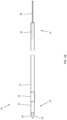
- FIG. 1 Ais a side view schematic representation of a suture passing drill, according to an embodiment
- FIG. 1 Bis a top view schematic representation of a suture passing drill, according to an embodiment
- FIG. 2 Ais a detail view schematic representation of the narrow portion of the suture passing drill, according to an embodiment
- FIG. 2 Bis a front view schematic representation of the drill tip, according to an embodiment
- FIG. 3is a top perspective view schematic representation of the free limbs of suture threaded in loading loops, according to an embodiment
- FIG. 4is a side view schematic representation of the suture suspension system, according to an embodiment
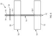
- FIG. 5is a side view schematic representation of the suture suspension system with the all-suture button in a compressed position, according to an embodiment
- FIG. 6is a side view schematic representation of the suture suspension system with the all-suture button in the compressed position and the all-suture backstop in the expanded position, according to an embodiment
- FIG. 7is a side view schematic representation of the deployed configuration of the suture suspension system, according to an embodiment.
- FIGS. 1 A and 1 Bshow side and top views schematic representations of a suture passing drill 10 , according to an embodiment.
- the suture passing drill 10comprises a proximal end 14 and a distal end 16 with an elongated shaft 12 extending therebetween.
- a first portion of the elongated shaft 12has a first diameter d 1 .
- the elongated shaft 12can be composed of metal, such as stainless steel, for example.
- FIG. 2 Bthere is shown a front view schematic representation of the drill tip 18 .
- the drill tip 18comprises one or more cutting edges 24 , each having a leading edge 20 ( FIGS. 1 A- 1 B ) and each extending at an angle ⁇ ′ relative to each other.
- the drill tip 18comprises three cutting edges 24 .
- the leading edge 20 ( FIGS. 1 A- 1 B ) of each of the three cutting edges 24extends at the angle ⁇ ( FIG. 1 A ) relative to the surface 22 of the elongated shaft.
- the angle ⁇( FIG. 1 A ) is within the range of 10°-30° and in the depicted embodiment, the angle ⁇ is the same for all three cutting edges 24 .
- the three cutting edges 24are substantially equidistant, such that any one of the three cutting edges 24 is approximately or equal to 120° relative to any of the other cutting edges 24 .
- the cutting edges 24are not necessarily substantially equidistant, such that any one of the three cutting edges 24 is different than at least one of the other cutting edges 24 .
- the angle ⁇ ′ between each of the cutting edges 24may vary by up to 15° as long as the angles ⁇ ′ between all three cutting edges 24 add up to 360°.
- the elongated shaft 12comprises a narrow portion 26 at the distal end 16 of the suture passing drill 10 adjacent to the drill tip 18 .
- the narrow portion 26is proximally located on the elongated shaft 12 relative to the drill tip 18 .
- the narrow portion 26has a second diameter d 2 , which is smaller than the first diameter d 1 of the elongated shaft 12 , as also shown in FIG. 2 A .
- the narrow portion 26can be created by any known methods, such as coining the area of the elongated shaft 12 designated for the narrow portion 26 .
- Coiningis a preferred method for creating the narrow portion 26 in the elongated shaft 12 because it prevents the need for machining the outer diameter (or surface 22 ) of the elongated shaft 12 proximal to the drill tip 18 in order to create a larger drill tip 18 .
- the suture passing drill 10additionally comprises a loop 28 at its proximal end 14 .
- the loop 28is composed of wire, such as nitinol.
- the loop 28is diamond-shaped.
- the loop 28can comprise a width w, which, at its largest point, is larger than the first diameter d 1 of the elongated shaft 12 .
- the width w of the loop 28can be opened or otherwise expanded because it is composed of an elastic material and it will return to the original width w if nothing is positioned through the loop 28 .
- at least a portion 30 of the loop 28is attached to or within the elongated shaft 12 .
- the loop 28can be attached within the elongated shaft 12 such that the loop 28 meets a minimum pullout strength of 6 lbs.
- the portion 30 of the loop 28 within the elongated shaft 12is twisted in order to maintain the shape of the loop 28 .
- the suture passing drill 10 in FIGS. 1 A- 1 Bcan be used to drill and form a bone tunnel.
- the suture passing drill 10can also be used to pass suture through the bone tunnel in order to create the suspension required in certain orthopedic procedures, as should be understood by a person of ordinary skill in the art in conjunction with a review of this disclosure.
- FIG. 3there is shown a side views schematic representation of a suture backstop system 100 installed by the suture passing drill 10 ( FIGS. 1 A- 1 B ).
- the suture passing drill 10is used to drill a single hole 118 - 1 through a first body 118 .
- the first body 118is preferably bone, but may also be soft tissue or a graft.
- the usermay then continue to drive the suture passing drill 10 to drill a single hole 120 - 1 through a second body 120 .
- the second body 120may also be a bone, soft tissue, or a graft. As shown in FIG. 3 , the second body 120 is positioned adjacent distally relative to the first body 118 .
- a length of suture 114Prior to drilling the holes 118 - 1 , 120 - 1 in the first and second bodies 118 , 120 , a length of suture 114 is attached to the loop 28 of the suture passing drill 10 .
- the suture passing drill 10creates the hole 118 - 1 in the first body 118 and moves distally to create the hole 120 - 1 in the second body 120
- the length of suture 14is pulled through the hole 118 - 1 in the first body 118 .
- the length of suture 114is woven through the second body 120 and advanced back through the bone holes 120 - 1 , 118 - 1 to form the partial or undeployed configuration of the suture backstop system 100 shown in FIG.
- first body 118where the length of suture 114 is shown with two free limbs 116 extending proximally from the first body 118 .
- the portion of the length of suture 114 (including, but not limited to both limbs 116 ) positioned between first body 118 and second body 120can be considered a bridge, as discussed with respect to the suture suspension system 100 below (although, the “bridge” in this embodiment can be relatively shorter).
- FIG. 4there is shown a side schematic view representation of the suture suspension system 100 in a partial or undeployed configuration, according to an alternative embodiment.
- the length of suture 114is woven through an anchoring body 112 .
- the anchoring body 112is an all-suture button in an expanded position.
- the anchoring body 112can be a suspensory fixation device as described in U.S. Pat. No. 9,700,403 assigned to the assignee hereof and incorporated by reference herein in its entirety.
- an embodiment of the suspensory fixation devicecan include an elongated anchor member (which may or may not have preformed suture receiving apertures, where at least one of which can, but doesn't have to be, recessed within a surface of the elongated anchor member), and a suture threaded through at least one of the apertures.
- the anchoring body 112can be any soft suture anchor material (as should be understood by a person of ordinary skill in the art in conjunction with a review of this disclosure).
- soft anchorsare commonly made entirely of suture materials, they are sometimes called “all-suture” anchors, and generally include a fibrous construct anchor body portion (or fibrous, braided or woven fabric-type structure such as a flexible web, as described in U.S. Pat. No. 9,173,652) along with a suture or filament portion.
- fibrous construct anchor body portionor fibrous, braided or woven fabric-type structure such as a flexible web, as described in U.S. Pat. No. 9,173,652
- Another example of a “soft” all-suture anchoris the Y-Knot® device. See, e.g., U.S. Pat. No. 9,826,971.
- Such all-suture anchorscan take advantage of Poisson's ratio, which captures the following cause/effect relationship: compressing a material in a first direction causes the material to expand in direction perpendicular to the first direction (i.e., if compressed in the x-direction, the material will expand in the y-direction and/or z-direction), and stretching/lengthening a material in a first direction causes the material to contract in directions perpendicular to the first direction.
- the suture 114is woven through the anchoring body 112 such that two free limbs 116 of suture 114 extend from the anchoring body 112 .
- a length of suture 114 attached to the anchoring body 112is threaded through the loop 28 in the suture passing drill 10 of FIG. 1 A .
- the suture passing drill 10is then used to create the single hole 118 - 1 through the first body 118 and the single hole 120 - 1 in the second body 120 .
- the suture passing drill 10advances distally, it pulls the length of suture 114 through the bone holes 118 - 1 , 120 - 1 , and through an all suture button 112 , and advanced back through bone holes 120 - 1 , 118 - 1 to form the partial or undeployed configuration shown in FIGS.
- suture 114is shown with two free limbs 116 extending proximally from the opposite/proximal/top surface 128 of bone 118 .
- the all-suture button 112extends distally from the distal surface 122 of second bone 120 , and a section of suture 114 forms a bridge between the first bone 118 and the second bone 120 .
- the free limbs 116 of the suture 114are pulled proximally from the first bone 118 to set the all-suture button 112 against the distal surface 122 of the second bone 120 .
- the all-suture button 112moves from the expanded position (in FIG. 4 ) to a compressed position (in FIG. 5 ).
- the all-suture button 112covers a surface area on the distal side 122 of the second bone 120 larger than the diameter of the bone hole 120 - 1 in the second bone 120 .
- tension in the suture 114can be used to create a suspension configuration between the first bone 118 and the second bone 120 by deploying a backstop from an expanded position to a compressed position.
- a backstop 124is shown being moved distally along the suture 114 until it is against the proximal side 128 of the first bone 118 .
- the backstop 124may be a suspensory fixation device and/or comprised of any soft suture anchor material. Additionally, the backstop 124 may be comprised of radiopaque fiber so that the backstop 124 can be seen in x-ray photographs.
- a purpose of using an all-suture anchor backstop 124 and the all-suture button 112is to minimize irritation and discomfort to the patient at the surgical site.
- Purposes of the backstop 124 structure, configuration, positioning and related functionalityis to prevent the suture 114 from pulling out from the first bone hole 118 - 1 and to maintain the tension in the suture 114 between the backstop 124 and the all-suture button 112 .
- FIG. 7there is shown a side schematic view of a knot 130 formed in the free limbs 116 of suture 114 proximally over the backstop 124 , i.e., the deployed configuration of the suture suspension system 100 . Tying the knot 130 in the free limbs 116 secures the backstop 124 in the compressed and deployed position. Excess portions of the free limbs 116 of suture 114 that extend from the knot 130 can be trimmed and removed to decrease the potential for irritation and discomfort.
- a method or device that “comprises”, “has”, “includes” or “contains” one or more steps or elementsLikewise, a step of method or an element of a device that “comprises”, “has”, “includes” or “contains” one or more features possesses those one or more features, but is not limited to possessing only those one or more features. Furthermore, a device or structure that is configured in a certain way is configured in at least that way, but may also be configured in ways that are not listed.
Landscapes
- Health & Medical Sciences (AREA)
- Surgery (AREA)
- Life Sciences & Earth Sciences (AREA)
- Biomedical Technology (AREA)
- Medical Informatics (AREA)
- Veterinary Medicine (AREA)
- Public Health (AREA)
- Engineering & Computer Science (AREA)
- General Health & Medical Sciences (AREA)
- Heart & Thoracic Surgery (AREA)
- Nuclear Medicine, Radiotherapy & Molecular Imaging (AREA)
- Molecular Biology (AREA)
- Animal Behavior & Ethology (AREA)
- Dentistry (AREA)
- Oral & Maxillofacial Surgery (AREA)
- Orthopedic Medicine & Surgery (AREA)
- Rheumatology (AREA)
- Surgical Instruments (AREA)
Abstract
Description
Claims (20)
Priority Applications (1)
| Application Number | Priority Date | Filing Date | Title |
|---|---|---|---|
| US17/052,998US12232722B2 (en) | 2018-05-09 | 2019-05-07 | Coined suture passing drill |
Applications Claiming Priority (3)
| Application Number | Priority Date | Filing Date | Title |
|---|---|---|---|
| US201862668900P | 2018-05-09 | 2018-05-09 | |
| US17/052,998US12232722B2 (en) | 2018-05-09 | 2019-05-07 | Coined suture passing drill |
| PCT/US2019/030995WO2019217345A1 (en) | 2018-05-09 | 2019-05-07 | Coined suture passing drill |
Related Parent Applications (1)
| Application Number | Title | Priority Date | Filing Date |
|---|---|---|---|
| PCT/US2019/030995A-371-Of-InternationalWO2019217345A1 (en) | 2018-05-09 | 2019-05-07 | Coined suture passing drill |
Related Child Applications (1)
| Application Number | Title | Priority Date | Filing Date |
|---|---|---|---|
| US19/061,128ContinuationUS20250186042A1 (en) | 2018-05-09 | 2025-02-24 | Coined suture passing drill |
Publications (2)
| Publication Number | Publication Date |
|---|---|
| US20210068815A1 US20210068815A1 (en) | 2021-03-11 |
| US12232722B2true US12232722B2 (en) | 2025-02-25 |
Family
ID=66625309
Family Applications (2)
| Application Number | Title | Priority Date | Filing Date |
|---|---|---|---|
| US17/052,998Active2039-05-21US12232722B2 (en) | 2018-05-09 | 2019-05-07 | Coined suture passing drill |
| US19/061,128PendingUS20250186042A1 (en) | 2018-05-09 | 2025-02-24 | Coined suture passing drill |
Family Applications After (1)
| Application Number | Title | Priority Date | Filing Date |
|---|---|---|---|
| US19/061,128PendingUS20250186042A1 (en) | 2018-05-09 | 2025-02-24 | Coined suture passing drill |
Country Status (8)
| Country | Link |
|---|---|
| US (2) | US12232722B2 (en) |
| EP (1) | EP3790476A1 (en) |
| JP (1) | JP2021520953A (en) |
| KR (2) | KR102590796B1 (en) |
| CN (1) | CN112236092A (en) |
| AU (1) | AU2019267531B2 (en) |
| CA (1) | CA3097947C (en) |
| WO (1) | WO2019217345A1 (en) |
Families Citing this family (1)
| Publication number | Priority date | Publication date | Assignee | Title |
|---|---|---|---|---|
| US11083472B2 (en)* | 2018-03-17 | 2021-08-10 | Warren Windram | Single-use plantar plate graft augmentation kit and method of repairing plantar plate tears through graft augmentation |
Citations (71)
| Publication number | Priority date | Publication date | Assignee | Title |
|---|---|---|---|---|
| US4182341A (en) | 1977-10-05 | 1980-01-08 | American Cyanamid Company | Eyed needle converted from a drilled end or channel end needle |
| US4345899A (en)* | 1979-07-12 | 1982-08-24 | Vlock D G | Dental twist drill |
| US4373518A (en)* | 1980-09-26 | 1983-02-15 | Zimmer, Inc. | Method of drilling living bone |
| US4990088A (en)* | 1988-03-24 | 1991-02-05 | Weissman Bernard B | Dental tool combining reamer and router |
| US5055105A (en)* | 1989-10-11 | 1991-10-08 | Bowen & Company, Ltd. | Bone drill bit |
| US5257996A (en)* | 1991-12-13 | 1993-11-02 | Mcguire David A | Surgical pin passer |
| US5788699A (en)* | 1993-03-18 | 1998-08-04 | Endocare Ag | Drill section, as well as kirschner wires, bone routers and the like equipped with such a drill section |
| US6045551A (en) | 1998-02-06 | 2000-04-04 | Bonutti; Peter M. | Bone suture |
| US6117160A (en) | 1998-02-06 | 2000-09-12 | Bonutti; Peter M. | Bone suture |
| US6132433A (en)* | 1997-02-12 | 2000-10-17 | Arthrex, Inc. | Apparatus of loading tendons into the knee |
| US20040243135A1 (en) | 2003-05-28 | 2004-12-02 | Tomoaki Koseki | Hand drill |
| WO2006009471A1 (en) | 2004-07-20 | 2006-01-26 | Enztec Limited | Improved surgical drill |
| US6991636B2 (en) | 2002-08-26 | 2006-01-31 | Arthrex, Inc. | Nitinol loop suture passer |
| US7066956B2 (en) | 1997-02-12 | 2006-06-27 | Arthrex, Inc. | Transverse fixation technique for ACL reconstruction using bone-tendon-bone graft |
| US7077863B2 (en) | 1997-02-12 | 2006-07-18 | Arthrex, Inc. | Transverse fixation technique for ACL reconstruction using bone-tendon-bone graft with loop at end |
| US7235091B2 (en) | 2002-06-20 | 2007-06-26 | Brian Thornes | Apparatus and method for fixation of ankle syndesmosis |
| US7588595B2 (en) | 2002-10-29 | 2009-09-15 | Stryker Endoscopy | Graft fixation device and method |
| US7713300B2 (en) | 2002-01-31 | 2010-05-11 | Biomet Sports Medicince, LLC | Apparatus and method for manipulating a flexible strand and soft tissue replacement during surgery |
| US20100152752A1 (en)* | 2008-12-16 | 2010-06-17 | Arthrex, Inc. | Suture passing k-wire |
| US20100217315A1 (en)* | 2009-02-19 | 2010-08-26 | Jolly Jacob A | Drill pin for suture passing |
| US7905903B2 (en) | 2006-02-03 | 2011-03-15 | Biomet Sports Medicine, Llc | Method for tissue fixation |
| US7905904B2 (en) | 2006-02-03 | 2011-03-15 | Biomet Sports Medicine, Llc | Soft tissue repair device and associated methods |
| US20110087248A1 (en) | 2009-10-14 | 2011-04-14 | Steffen Dennis L | Flexor Tendon Suture Passer |
| US20110238071A1 (en) | 2010-03-24 | 2011-09-29 | Alain Fernandez-Scoma | Drill assistance kit for implant hole in a bone structure |
| US20120003057A1 (en) | 2010-07-02 | 2012-01-05 | Leyba Frank L | Wrenchable drill bit |
| US20120016428A1 (en) | 2010-06-28 | 2012-01-19 | Mtp Solutions, Llc | Bunion correction method and device |
| US20120071878A1 (en) | 2010-09-22 | 2012-03-22 | David Cowin | Fracture management tool and method |
| US20120197396A1 (en) | 2011-01-31 | 2012-08-02 | Berg Jeffrey H | Hybrid solid-flexible passing pin and anterior cruciate ligament repair using the pin |
| US20120197395A1 (en) | 2011-01-31 | 2012-08-02 | Berg Jeffrey H | Hybrid solid-flexible passing pin and anterior cruciate ligament repair using the pin |
| US8298262B2 (en) | 2006-02-03 | 2012-10-30 | Biomet Sports Medicine, Llc | Method for tissue fixation |
| US8398678B2 (en) | 2010-03-15 | 2013-03-19 | Arthrex, Inc. | Hallux valgus repairs using suture-button construct |
| US8409225B2 (en) | 2006-04-21 | 2013-04-02 | Medical Device Innovations Limited | Tendon repair |
| US20130090658A1 (en) | 2011-09-08 | 2013-04-11 | Linvatec Corporation | Guide Pin Gauge |
| US8449552B2 (en) | 2009-06-04 | 2013-05-28 | Quantum Surgical | Surgical drill guide with awl and method of use |
| US8500809B2 (en) | 2011-01-10 | 2013-08-06 | Ceterix Orthopaedics, Inc. | Implant and method for repair of the anterior cruciate ligament |
| US8506597B2 (en) | 2011-10-25 | 2013-08-13 | Biomet Sports Medicine, Llc | Method and apparatus for interosseous membrane reconstruction |
| US8512375B2 (en) | 1999-12-02 | 2013-08-20 | Smith & Nephew, Inc. | Closure device and method for tissue repair |
| US8512376B2 (en) | 2002-08-30 | 2013-08-20 | Arthrex, Inc. | Method and apparatus for internal fixation of an acromioclavicular joint dislocation of the shoulder |
| US8562647B2 (en) | 2006-09-29 | 2013-10-22 | Biomet Sports Medicine, Llc | Method and apparatus for securing soft tissue to bone |
| US8579553B2 (en) | 2011-02-04 | 2013-11-12 | Ray Charles Pierce | Method and apparatus for installing cable |
| US8621961B2 (en) | 2009-04-28 | 2014-01-07 | Milwaukee Electric Tool Corporation | Multi-purpose tool |
| US8734491B2 (en) | 2011-08-24 | 2014-05-27 | Instratek, Inc. | Method and apparatus for the stabilization of the trapeziometacarpal joint |
| US20140243893A1 (en)* | 2013-02-26 | 2014-08-28 | Smith & Nephew, Inc. | Flexible deformable suture anchor |
| US20140330307A1 (en) | 2013-05-01 | 2014-11-06 | Dennis L. Steffen | Surgical Passer and Retrieval Device |
| US8888795B2 (en) | 2007-09-07 | 2014-11-18 | Boston Scientific Scimed, Inc. | Suture passer |
| US8888815B2 (en) | 2007-01-17 | 2014-11-18 | Arthrex, Inc. | Bone fixation using suture-button construct |
| US8961575B2 (en) | 2012-03-14 | 2015-02-24 | Arthrex, Inc. | CMC repair using suture-button construct |
| US9005287B2 (en) | 2006-02-03 | 2015-04-14 | Biomet Sports Medicine, Llc | Method for bone reattachment |
| US9005245B2 (en) | 2002-08-30 | 2015-04-14 | Arthrex, Inc. | Acromioclavicular joint fixation technique |
| US9173652B2 (en) | 2013-03-11 | 2015-11-03 | Linvatec Corporation | All-suture anchor inserter |
| US9320512B2 (en) | 2012-08-17 | 2016-04-26 | Arthrex, Inc. | Self-cinching soft anchors |
| US9421008B2 (en) | 2011-09-23 | 2016-08-23 | Arthrex, Inc. | Soft suture-based anchors |
| US9445803B2 (en) | 2011-11-23 | 2016-09-20 | Howmedica Osteonics Corp. | Filamentary suture anchor |
| US9463011B2 (en) | 2012-08-17 | 2016-10-11 | Arthrex, Inc. | Soft anchors with soft eyelets |
| US9468433B2 (en) | 2006-02-03 | 2016-10-18 | Biomet Sports Medicine, Llc | Method and apparatus for forming a self-locking adjustable loop |
| US9538998B2 (en) | 2006-02-03 | 2017-01-10 | Biomet Sports Medicine, Llc | Method and apparatus for fracture fixation |
| US9700291B2 (en) | 2014-06-03 | 2017-07-11 | Biomet Sports Medicine, Llc | Capsule retractor |
| US9800027B1 (en) | 2011-02-04 | 2017-10-24 | Ray Charles Pierce | Method and apparatus for installing a plurality of cables |
| US9795398B2 (en) | 2011-04-13 | 2017-10-24 | Howmedica Osteonics Corp. | Flexible ACL instrumentation, kit and method |
| US9826971B2 (en) | 2011-05-06 | 2017-11-28 | Linvatec Corporation | Soft anchor made from suture filament and suture tape |
| US9848868B2 (en) | 2011-01-10 | 2017-12-26 | Ceterix Orthopaedics, Inc. | Suture methods for forming locking loops stitches |
| US20180049775A1 (en) | 2007-02-14 | 2018-02-22 | William R. Krause | Flexible spine components having multiple slots |
| US20180049734A1 (en) | 2016-08-16 | 2018-02-22 | Conmed Corporation | Method and Device for Securing Suture to an Anchor Body of a Suture Anchor |
| US9913638B2 (en) | 2011-01-10 | 2018-03-13 | Ceterix Orthopaedics, Inc. | Transosteal anchoring methods for tissue repair |
| US9918826B2 (en) | 2006-09-29 | 2018-03-20 | Biomet Sports Medicine, Llc | Scaffold for spring ligament repair |
| US9962150B2 (en) | 2013-12-20 | 2018-05-08 | Arthrocare Corporation | Knotless all suture tissue repair |
| US9974534B2 (en) | 2015-03-31 | 2018-05-22 | Biomet Sports Medicine, Llc | Suture anchor with soft anchor of electrospun fibers |
| US10251637B2 (en) | 2006-02-03 | 2019-04-09 | Biomet Sports Medicine, Llc | Soft tissue repair device and associated methods |
| US10299802B2 (en) | 2006-08-16 | 2019-05-28 | Arthrex, Inc. | Drill pin for fixation of ligaments using button/loop construct |
| US10702259B2 (en) | 2006-02-03 | 2020-07-07 | Biomet Sports Medicine, Llc | Soft tissue repair assembly and associated method |
| US10758221B2 (en) | 2013-03-14 | 2020-09-01 | Biomet Sports Medicine, Llc | Scaffold for spring ligament repair |
Family Cites Families (6)
| Publication number | Priority date | Publication date | Assignee | Title |
|---|---|---|---|---|
| JP2004283457A (en)* | 2003-03-24 | 2004-10-14 | Kazumasa Itokazu | Steel wire for bone suture having thin periphery part of steel wire with hole for bone suture and having "notch" circumferentially for manual cutting |
| EP2615982B1 (en)* | 2010-09-17 | 2014-08-13 | Synthes GmbH | Device for anchoring a suture |
| AU2013277412B2 (en)* | 2012-06-18 | 2018-04-12 | Smith & Nephew, Inc. | Modular reamer retrograde attachment |
| US9700403B2 (en) | 2014-01-16 | 2017-07-11 | Linvatec Corporation | Suspensory graft fixation with adjustable loop length |
| US10182808B2 (en)* | 2015-04-23 | 2019-01-22 | DePuy Synthes Products, Inc. | Knotless suture anchor guide |
| US11723646B2 (en)* | 2017-07-24 | 2023-08-15 | Conmed Corporation | Self-drilling all-suture anchor |
- 2019
- 2019-05-07KRKR1020207034554Apatent/KR102590796B1/enactiveActive
- 2019-05-07USUS17/052,998patent/US12232722B2/enactiveActive
- 2019-05-07AUAU2019267531Apatent/AU2019267531B2/enactiveActive
- 2019-05-07WOPCT/US2019/030995patent/WO2019217345A1/ennot_activeCeased
- 2019-05-07KRKR1020237034954Apatent/KR102776132B1/enactiveActive
- 2019-05-07CNCN201980036962.3Apatent/CN112236092A/enactivePending
- 2019-05-07CACA3097947Apatent/CA3097947C/enactiveActive
- 2019-05-07JPJP2020562116Apatent/JP2021520953A/enactivePending
- 2019-05-07EPEP19725500.3Apatent/EP3790476A1/enactivePending
- 2025
- 2025-02-24USUS19/061,128patent/US20250186042A1/enactivePending
Patent Citations (99)
| Publication number | Priority date | Publication date | Assignee | Title |
|---|---|---|---|---|
| US4182341A (en) | 1977-10-05 | 1980-01-08 | American Cyanamid Company | Eyed needle converted from a drilled end or channel end needle |
| US4345899A (en)* | 1979-07-12 | 1982-08-24 | Vlock D G | Dental twist drill |
| US4373518A (en)* | 1980-09-26 | 1983-02-15 | Zimmer, Inc. | Method of drilling living bone |
| US4990088A (en)* | 1988-03-24 | 1991-02-05 | Weissman Bernard B | Dental tool combining reamer and router |
| US5055105A (en)* | 1989-10-11 | 1991-10-08 | Bowen & Company, Ltd. | Bone drill bit |
| US5257996A (en)* | 1991-12-13 | 1993-11-02 | Mcguire David A | Surgical pin passer |
| US5788699A (en)* | 1993-03-18 | 1998-08-04 | Endocare Ag | Drill section, as well as kirschner wires, bone routers and the like equipped with such a drill section |
| US7066956B2 (en) | 1997-02-12 | 2006-06-27 | Arthrex, Inc. | Transverse fixation technique for ACL reconstruction using bone-tendon-bone graft |
| US20090171360A1 (en) | 1997-02-12 | 2009-07-02 | Whelan Jeffery M | Apparatus for loading tendons into the knee |
| US7306626B2 (en) | 1997-02-12 | 2007-12-11 | Arthrex, Inc. | Method of loading tendons into the knee |
| US6132433A (en)* | 1997-02-12 | 2000-10-17 | Arthrex, Inc. | Apparatus of loading tendons into the knee |
| US7077863B2 (en) | 1997-02-12 | 2006-07-18 | Arthrex, Inc. | Transverse fixation technique for ACL reconstruction using bone-tendon-bone graft with loop at end |
| US6045551A (en) | 1998-02-06 | 2000-04-04 | Bonutti; Peter M. | Bone suture |
| US6117160A (en) | 1998-02-06 | 2000-09-12 | Bonutti; Peter M. | Bone suture |
| US7481825B2 (en) | 1998-02-06 | 2009-01-27 | Marctec, Llc. | Apparatus and method for treating a fracture of a bone |
| US6638279B2 (en) | 1998-02-06 | 2003-10-28 | Bonutti 2003 Trust-A | Method of positioning body tissue relative to a bone |
| US8512375B2 (en) | 1999-12-02 | 2013-08-20 | Smith & Nephew, Inc. | Closure device and method for tissue repair |
| US9072510B2 (en) | 2001-08-30 | 2015-07-07 | Arthrex, Inc. | Acromioclavicular joint fixation technique |
| US7713300B2 (en) | 2002-01-31 | 2010-05-11 | Biomet Sports Medicince, LLC | Apparatus and method for manipulating a flexible strand and soft tissue replacement during surgery |
| US7235091B2 (en) | 2002-06-20 | 2007-06-26 | Brian Thornes | Apparatus and method for fixation of ankle syndesmosis |
| US20130331886A1 (en) | 2002-06-20 | 2013-12-12 | Arthrex, Inc. | Method and apparatus for internal fixation of an acromioclavicular joint dislocation of the shoulder |
| US10390816B2 (en) | 2002-06-20 | 2019-08-27 | Arthrex, Inc. | Apparatuses and methods for fixation of ankle syndesmosis or acromioclavicular joint dislocations of the shoulder |
| US10206670B2 (en) | 2002-06-20 | 2019-02-19 | Arthrex, Inc. | Apparatuses and methods for fixation of ankle syndesmosis or acromioclavicular joint dislocations of the shoulder |
| US6991636B2 (en) | 2002-08-26 | 2006-01-31 | Arthrex, Inc. | Nitinol loop suture passer |
| US9005245B2 (en) | 2002-08-30 | 2015-04-14 | Arthrex, Inc. | Acromioclavicular joint fixation technique |
| US8512376B2 (en) | 2002-08-30 | 2013-08-20 | Arthrex, Inc. | Method and apparatus for internal fixation of an acromioclavicular joint dislocation of the shoulder |
| US7988697B2 (en) | 2002-10-29 | 2011-08-02 | Stryker Endoscopy | Graft fixation device and method |
| US7588595B2 (en) | 2002-10-29 | 2009-09-15 | Stryker Endoscopy | Graft fixation device and method |
| US20040243135A1 (en) | 2003-05-28 | 2004-12-02 | Tomoaki Koseki | Hand drill |
| US20070276395A1 (en) | 2004-07-20 | 2007-11-29 | Enztec Limited | Surgical Drill |
| WO2006009471A1 (en) | 2004-07-20 | 2006-01-26 | Enztec Limited | Improved surgical drill |
| US7905903B2 (en) | 2006-02-03 | 2011-03-15 | Biomet Sports Medicine, Llc | Method for tissue fixation |
| US10702259B2 (en) | 2006-02-03 | 2020-07-07 | Biomet Sports Medicine, Llc | Soft tissue repair assembly and associated method |
| US9538998B2 (en) | 2006-02-03 | 2017-01-10 | Biomet Sports Medicine, Llc | Method and apparatus for fracture fixation |
| US9468433B2 (en) | 2006-02-03 | 2016-10-18 | Biomet Sports Medicine, Llc | Method and apparatus for forming a self-locking adjustable loop |
| US9402621B2 (en) | 2006-02-03 | 2016-08-02 | Biomet Sports Medicine, LLC. | Method for tissue fixation |
| US8298262B2 (en) | 2006-02-03 | 2012-10-30 | Biomet Sports Medicine, Llc | Method for tissue fixation |
| US10251637B2 (en) | 2006-02-03 | 2019-04-09 | Biomet Sports Medicine, Llc | Soft tissue repair device and associated methods |
| US7905904B2 (en) | 2006-02-03 | 2011-03-15 | Biomet Sports Medicine, Llc | Soft tissue repair device and associated methods |
| US10321906B2 (en) | 2006-02-03 | 2019-06-18 | Biomet Sports Medicine, Llc | Method for tissue fixation |
| US9005287B2 (en) | 2006-02-03 | 2015-04-14 | Biomet Sports Medicine, Llc | Method for bone reattachment |
| US9561025B2 (en) | 2006-02-03 | 2017-02-07 | Biomet Sports Medicine, Llc | Soft tissue repair device and associated methods |
| US8409225B2 (en) | 2006-04-21 | 2013-04-02 | Medical Device Innovations Limited | Tendon repair |
| US20130218273A1 (en) | 2006-04-21 | 2013-08-22 | Medical Device Innovations Limited | Tendon repair |
| US10299802B2 (en) | 2006-08-16 | 2019-05-28 | Arthrex, Inc. | Drill pin for fixation of ligaments using button/loop construct |
| US8562647B2 (en) | 2006-09-29 | 2013-10-22 | Biomet Sports Medicine, Llc | Method and apparatus for securing soft tissue to bone |
| US9918826B2 (en) | 2006-09-29 | 2018-03-20 | Biomet Sports Medicine, Llc | Scaffold for spring ligament repair |
| US10695045B2 (en) | 2006-09-29 | 2020-06-30 | Biomet Sports Medicine, Llc | Method and apparatus for attaching soft tissue to bone |
| US8888815B2 (en) | 2007-01-17 | 2014-11-18 | Arthrex, Inc. | Bone fixation using suture-button construct |
| US9642609B2 (en) | 2007-01-17 | 2017-05-09 | Arthrex, Inc. | Bunion repair using suture-button construct |
| US20180049775A1 (en) | 2007-02-14 | 2018-02-22 | William R. Krause | Flexible spine components having multiple slots |
| US8888795B2 (en) | 2007-09-07 | 2014-11-18 | Boston Scientific Scimed, Inc. | Suture passer |
| US10143469B2 (en) | 2008-12-16 | 2018-12-04 | Arthrex, Inc. | Suture passing K-wire |
| US9204874B2 (en) | 2008-12-16 | 2015-12-08 | Arthrex, Inc. | Suture passing K-wire |
| EP2198795A1 (en) | 2008-12-16 | 2010-06-23 | Arthrex Inc. | Suture passing K-wire |
| US20100152752A1 (en)* | 2008-12-16 | 2010-06-17 | Arthrex, Inc. | Suture passing k-wire |
| US8425554B2 (en) | 2008-12-16 | 2013-04-23 | Arthrex, Inc. | Suture passing K-wire |
| US9138223B2 (en) | 2009-02-19 | 2015-09-22 | Arthrex, Inc. | Drill pin for suture passing |
| US20100217315A1 (en)* | 2009-02-19 | 2010-08-26 | Jolly Jacob A | Drill pin for suture passing |
| US8621961B2 (en) | 2009-04-28 | 2014-01-07 | Milwaukee Electric Tool Corporation | Multi-purpose tool |
| US8449552B2 (en) | 2009-06-04 | 2013-05-28 | Quantum Surgical | Surgical drill guide with awl and method of use |
| US20110087248A1 (en) | 2009-10-14 | 2011-04-14 | Steffen Dennis L | Flexor Tendon Suture Passer |
| US20130138150A1 (en) | 2010-03-15 | 2013-05-30 | Arthrex, Inc. | Hallux valgus repairs using suture-button construct |
| US8398678B2 (en) | 2010-03-15 | 2013-03-19 | Arthrex, Inc. | Hallux valgus repairs using suture-button construct |
| US20110238071A1 (en) | 2010-03-24 | 2011-09-29 | Alain Fernandez-Scoma | Drill assistance kit for implant hole in a bone structure |
| US20120016428A1 (en) | 2010-06-28 | 2012-01-19 | Mtp Solutions, Llc | Bunion correction method and device |
| US20120003057A1 (en) | 2010-07-02 | 2012-01-05 | Leyba Frank L | Wrenchable drill bit |
| US20120071878A1 (en) | 2010-09-22 | 2012-03-22 | David Cowin | Fracture management tool and method |
| US9848868B2 (en) | 2011-01-10 | 2017-12-26 | Ceterix Orthopaedics, Inc. | Suture methods for forming locking loops stitches |
| US8500809B2 (en) | 2011-01-10 | 2013-08-06 | Ceterix Orthopaedics, Inc. | Implant and method for repair of the anterior cruciate ligament |
| US9913638B2 (en) | 2011-01-10 | 2018-03-13 | Ceterix Orthopaedics, Inc. | Transosteal anchoring methods for tissue repair |
| US8888848B2 (en) | 2011-01-10 | 2014-11-18 | Ceterix Orthopaedics, Inc. | Implant and method for repair of the anterior cruciate ligament |
| US20120197396A1 (en) | 2011-01-31 | 2012-08-02 | Berg Jeffrey H | Hybrid solid-flexible passing pin and anterior cruciate ligament repair using the pin |
| US20120197395A1 (en) | 2011-01-31 | 2012-08-02 | Berg Jeffrey H | Hybrid solid-flexible passing pin and anterior cruciate ligament repair using the pin |
| US8579553B2 (en) | 2011-02-04 | 2013-11-12 | Ray Charles Pierce | Method and apparatus for installing cable |
| US9800027B1 (en) | 2011-02-04 | 2017-10-24 | Ray Charles Pierce | Method and apparatus for installing a plurality of cables |
| US9795398B2 (en) | 2011-04-13 | 2017-10-24 | Howmedica Osteonics Corp. | Flexible ACL instrumentation, kit and method |
| US9826971B2 (en) | 2011-05-06 | 2017-11-28 | Linvatec Corporation | Soft anchor made from suture filament and suture tape |
| US10687798B2 (en) | 2011-05-06 | 2020-06-23 | Linvatec Corporation | Soft anchor made from suture filament and suture tape |
| US9918711B2 (en) | 2011-08-24 | 2018-03-20 | Howmedica Osteonics Corp. | Method and apparatus for the stabilization of the trapeziometacarpal joint |
| US8734491B2 (en) | 2011-08-24 | 2014-05-27 | Instratek, Inc. | Method and apparatus for the stabilization of the trapeziometacarpal joint |
| US20130090658A1 (en) | 2011-09-08 | 2013-04-11 | Linvatec Corporation | Guide Pin Gauge |
| US9421008B2 (en) | 2011-09-23 | 2016-08-23 | Arthrex, Inc. | Soft suture-based anchors |
| US8506597B2 (en) | 2011-10-25 | 2013-08-13 | Biomet Sports Medicine, Llc | Method and apparatus for interosseous membrane reconstruction |
| US9445803B2 (en) | 2011-11-23 | 2016-09-20 | Howmedica Osteonics Corp. | Filamentary suture anchor |
| US10448944B2 (en) | 2011-11-23 | 2019-10-22 | Howmedica Osteonics Corp. | Filamentary fixation device |
| US8961575B2 (en) | 2012-03-14 | 2015-02-24 | Arthrex, Inc. | CMC repair using suture-button construct |
| US9463011B2 (en) | 2012-08-17 | 2016-10-11 | Arthrex, Inc. | Soft anchors with soft eyelets |
| US9320512B2 (en) | 2012-08-17 | 2016-04-26 | Arthrex, Inc. | Self-cinching soft anchors |
| US10736620B2 (en) | 2012-08-17 | 2020-08-11 | Arthrex, Inc. | Soft anchors with soft eyelets |
| US10448942B2 (en) | 2013-02-26 | 2019-10-22 | Smith & Nephew, Inc. | Flexible deformable suture anchor |
| US20140243893A1 (en)* | 2013-02-26 | 2014-08-28 | Smith & Nephew, Inc. | Flexible deformable suture anchor |
| US9173652B2 (en) | 2013-03-11 | 2015-11-03 | Linvatec Corporation | All-suture anchor inserter |
| US10758221B2 (en) | 2013-03-14 | 2020-09-01 | Biomet Sports Medicine, Llc | Scaffold for spring ligament repair |
| US20140330307A1 (en) | 2013-05-01 | 2014-11-06 | Dennis L. Steffen | Surgical Passer and Retrieval Device |
| US9962150B2 (en) | 2013-12-20 | 2018-05-08 | Arthrocare Corporation | Knotless all suture tissue repair |
| US9700291B2 (en) | 2014-06-03 | 2017-07-11 | Biomet Sports Medicine, Llc | Capsule retractor |
| US9974534B2 (en) | 2015-03-31 | 2018-05-22 | Biomet Sports Medicine, Llc | Suture anchor with soft anchor of electrospun fibers |
| US20180049734A1 (en) | 2016-08-16 | 2018-02-22 | Conmed Corporation | Method and Device for Securing Suture to an Anchor Body of a Suture Anchor |
Non-Patent Citations (4)
| Title |
|---|
| International Search Report Form PCT/ISA/220, International Application No. PCT/US2019/030995, pp. 1-14, Dated Aug. 22, 2019. |
| JP Office Action, App. No. 2020-562116, dated Sep. 28, 2021, pp. 1-13. |
| Korean Final Office Action, Application No. 10-2020-7034554, dated Mar. 10, 2023, pp. 1-3. |
| Translated Chinese First Office Action, App. No. 201980036962.3, dated Nov. 28, 2023, Nov. 28, 2023, pp. 1-16. |
Also Published As
| Publication number | Publication date |
|---|---|
| CA3097947C (en) | 2023-11-14 |
| AU2019267531A1 (en) | 2020-11-26 |
| US20250186042A1 (en) | 2025-06-12 |
| KR102590796B1 (en) | 2023-10-17 |
| CN112236092A (en) | 2021-01-15 |
| AU2019267531B2 (en) | 2022-04-28 |
| KR20230150395A (en) | 2023-10-30 |
| EP3790476A1 (en) | 2021-03-17 |
| JP2021520953A (en) | 2021-08-26 |
| CA3097947A1 (en) | 2019-11-14 |
| WO2019217345A1 (en) | 2019-11-14 |
| KR102776132B1 (en) | 2025-03-07 |
| KR20210005715A (en) | 2021-01-14 |
| US20210068815A1 (en) | 2021-03-11 |
Similar Documents
| Publication | Publication Date | Title |
|---|---|---|
| JP5355840B2 (en) | Suture loop fastener | |
| US20250186042A1 (en) | Coined suture passing drill | |
| US20110022083A1 (en) | Methods and devices for repairing and anchoring damaged tissue | |
| US20230101286A1 (en) | Knotless instability anchor | |
| JP2005144180A5 (en) | ||
| CN1988851A (en) | Suture anchoring system and method | |
| JP2001505107A (en) | Apparatus and method for securing a self or artificial tendon graft to bone | |
| US20240374253A1 (en) | Suture system and related methods for connecting and creating suspension between at least two bodies | |
| CN111225620B (en) | Mixed suture anchor | |
| US11129607B2 (en) | Anchored loop-in-loop suture anchor | |
| US20210330315A1 (en) | Backstop loader | |
| CN112739291A (en) | Fixation device for tenodesis |
Legal Events
| Date | Code | Title | Description |
|---|---|---|---|
| AS | Assignment | Owner name:CONMED CORPORATION, NEW YORK Free format text:ASSIGNMENT OF ASSIGNORS INTEREST;ASSIGNORS:SUMMITT, MATTHEW;THIBODEAU, ROBERT A;SIGNING DATES FROM 20190501 TO 20190507;REEL/FRAME:054273/0682 | |
| FEPP | Fee payment procedure | Free format text:ENTITY STATUS SET TO UNDISCOUNTED (ORIGINAL EVENT CODE: BIG.); ENTITY STATUS OF PATENT OWNER: LARGE ENTITY | |
| STPP | Information on status: patent application and granting procedure in general | Free format text:APPLICATION DISPATCHED FROM PREEXAM, NOT YET DOCKETED | |
| STPP | Information on status: patent application and granting procedure in general | Free format text:DOCKETED NEW CASE - READY FOR EXAMINATION | |
| STPP | Information on status: patent application and granting procedure in general | Free format text:NON FINAL ACTION MAILED | |
| STPP | Information on status: patent application and granting procedure in general | Free format text:RESPONSE TO NON-FINAL OFFICE ACTION ENTERED AND FORWARDED TO EXAMINER | |
| STPP | Information on status: patent application and granting procedure in general | Free format text:FINAL REJECTION MAILED | |
| STPP | Information on status: patent application and granting procedure in general | Free format text:ADVISORY ACTION MAILED | |
| STPP | Information on status: patent application and granting procedure in general | Free format text:DOCKETED NEW CASE - READY FOR EXAMINATION | |
| STPP | Information on status: patent application and granting procedure in general | Free format text:NON FINAL ACTION MAILED | |
| STPP | Information on status: patent application and granting procedure in general | Free format text:RESPONSE TO NON-FINAL OFFICE ACTION ENTERED AND FORWARDED TO EXAMINER | |
| STPP | Information on status: patent application and granting procedure in general | Free format text:FINAL REJECTION MAILED | |
| STPP | Information on status: patent application and granting procedure in general | Free format text:RESPONSE AFTER FINAL ACTION FORWARDED TO EXAMINER | |
| STPP | Information on status: patent application and granting procedure in general | Free format text:ADVISORY ACTION MAILED | |
| STPP | Information on status: patent application and granting procedure in general | Free format text:DOCKETED NEW CASE - READY FOR EXAMINATION | |
| STPP | Information on status: patent application and granting procedure in general | Free format text:NON FINAL ACTION MAILED | |
| STPP | Information on status: patent application and granting procedure in general | Free format text:RESPONSE TO NON-FINAL OFFICE ACTION ENTERED AND FORWARDED TO EXAMINER | |
| STPP | Information on status: patent application and granting procedure in general | Free format text:FINAL REJECTION MAILED | |
| STPP | Information on status: patent application and granting procedure in general | Free format text:DOCKETED NEW CASE - READY FOR EXAMINATION | |
| STPP | Information on status: patent application and granting procedure in general | Free format text:NOTICE OF ALLOWANCE MAILED -- APPLICATION RECEIVED IN OFFICE OF PUBLICATIONS | |
| STPP | Information on status: patent application and granting procedure in general | Free format text:PUBLICATIONS -- ISSUE FEE PAYMENT RECEIVED | |
| STPP | Information on status: patent application and granting procedure in general | Free format text:PUBLICATIONS -- ISSUE FEE PAYMENT VERIFIED | |
| STCF | Information on status: patent grant | Free format text:PATENTED CASE | |
| AS | Assignment | Owner name:JPMORGAN CHASE BANK, N.A., AS ADMINISTRATIVE AGENT, ILLINOIS Free format text:SECURITY INTEREST;ASSIGNORS:CONMED CORPORATION;BIOREZ, INC.;BUFFALO FILTER LLC;AND OTHERS;REEL/FRAME:072097/0762 Effective date:20250610 |