US12232707B2 - Endoscope thermal reflector - Google Patents
Endoscope thermal reflectorDownload PDFInfo
- Publication number
- US12232707B2 US12232707B2US17/158,852US202117158852AUS12232707B2US 12232707 B2US12232707 B2US 12232707B2US 202117158852 AUS202117158852 AUS 202117158852AUS 12232707 B2US12232707 B2US 12232707B2
- Authority
- US
- United States
- Prior art keywords
- light
- light guide
- reflector
- endoscope
- endoscope system
- Prior art date
- Legal status (The legal status is an assumption and is not a legal conclusion. Google has not performed a legal analysis and makes no representation as to the accuracy of the status listed.)
- Active, expires
Links
- 230000005540biological transmissionEffects0.000claimsdescription6
- 239000000835fiberSubstances0.000description15
- 230000005855radiationEffects0.000description4
- 229910052751metalInorganic materials0.000description3
- 239000002184metalSubstances0.000description3
- 229910052782aluminiumInorganic materials0.000description2
- XAGFODPZIPBFFR-UHFFFAOYSA-NaluminiumChemical compound[Al]XAGFODPZIPBFFR-UHFFFAOYSA-N0.000description2
- 239000011248coating agentSubstances0.000description2
- 238000000576coating methodMethods0.000description2
- 239000011521glassSubstances0.000description2
- 238000012986modificationMethods0.000description2
- 230000004048modificationEffects0.000description2
- 229910052709silverInorganic materials0.000description2
- 239000004332silverSubstances0.000description2
- 238000000151depositionMethods0.000description1
- 238000010586diagramMethods0.000description1
- 238000002674endoscopic surgeryMethods0.000description1
- 238000005286illuminationMethods0.000description1
- 238000005457optimizationMethods0.000description1
- 238000005498polishingMethods0.000description1
- 239000007787solidSubstances0.000description1
- 238000004381surface treatmentMethods0.000description1
- 239000010409thin filmSubstances0.000description1
- 238000000427thin-film depositionMethods0.000description1
- 229910052724xenonInorganic materials0.000description1
- FHNFHKCVQCLJFQ-UHFFFAOYSA-Nxenon atomChemical compound[Xe]FHNFHKCVQCLJFQ-UHFFFAOYSA-N0.000description1
Images


Classifications
- A—HUMAN NECESSITIES
- A61—MEDICAL OR VETERINARY SCIENCE; HYGIENE
- A61B—DIAGNOSIS; SURGERY; IDENTIFICATION
- A61B1/00—Instruments for performing medical examinations of the interior of cavities or tubes of the body by visual or photographical inspection, e.g. endoscopes; Illuminating arrangements therefor
- A61B1/00112—Connection or coupling means
- A61B1/00117—Optical cables in or with an endoscope
- A—HUMAN NECESSITIES
- A61—MEDICAL OR VETERINARY SCIENCE; HYGIENE
- A61B—DIAGNOSIS; SURGERY; IDENTIFICATION
- A61B1/00—Instruments for performing medical examinations of the interior of cavities or tubes of the body by visual or photographical inspection, e.g. endoscopes; Illuminating arrangements therefor
- A61B1/06—Instruments for performing medical examinations of the interior of cavities or tubes of the body by visual or photographical inspection, e.g. endoscopes; Illuminating arrangements therefor with illuminating arrangements
- A61B1/0661—Endoscope light sources
- A—HUMAN NECESSITIES
- A61—MEDICAL OR VETERINARY SCIENCE; HYGIENE
- A61B—DIAGNOSIS; SURGERY; IDENTIFICATION
- A61B1/00—Instruments for performing medical examinations of the interior of cavities or tubes of the body by visual or photographical inspection, e.g. endoscopes; Illuminating arrangements therefor
- A61B1/00112—Connection or coupling means
- A61B1/00121—Connectors, fasteners and adapters, e.g. on the endoscope handle
- A61B1/00126—Connectors, fasteners and adapters, e.g. on the endoscope handle optical, e.g. for light supply cables
- A—HUMAN NECESSITIES
- A61—MEDICAL OR VETERINARY SCIENCE; HYGIENE
- A61B—DIAGNOSIS; SURGERY; IDENTIFICATION
- A61B1/00—Instruments for performing medical examinations of the interior of cavities or tubes of the body by visual or photographical inspection, e.g. endoscopes; Illuminating arrangements therefor
- A61B1/00163—Optical arrangements
- A61B1/00165—Optical arrangements with light-conductive means, e.g. fibre optics
- A—HUMAN NECESSITIES
- A61—MEDICAL OR VETERINARY SCIENCE; HYGIENE
- A61B—DIAGNOSIS; SURGERY; IDENTIFICATION
- A61B1/00—Instruments for performing medical examinations of the interior of cavities or tubes of the body by visual or photographical inspection, e.g. endoscopes; Illuminating arrangements therefor
- A61B1/06—Instruments for performing medical examinations of the interior of cavities or tubes of the body by visual or photographical inspection, e.g. endoscopes; Illuminating arrangements therefor with illuminating arrangements
- A61B1/07—Instruments for performing medical examinations of the interior of cavities or tubes of the body by visual or photographical inspection, e.g. endoscopes; Illuminating arrangements therefor with illuminating arrangements using light-conductive means, e.g. optical fibres
Definitions
- the present disclosurerelates to devices used in endoscopic surgery and, more particularly, to thermal reflectors for use in endoscopes.
- Light guidestransfer light from a light source to an endoscope.
- Light guidesare typically sized to work with the largest endoscopes. When light guides are used with smaller endoscopes there are unavoidable losses at the connection point, because the amount of light that can be concentrated into the smaller endoscope fiber bundle area is limited by geometric properties of light. This leads to heat buildup at the connection point which may lead to discomfort for a user and a dangerous surgical situation.
- an endoscope systemwith a reflector for reflecting some light back into a light guide to reduce heat in an endoscope.
- an endoscope system for use with a light guidehas an endoscope; and a reflector configured for placement between the endoscope and the light guide.
- the reflectorhas a translucent portion for transmitting light from the light guide and a reflective portion for reflecting light from the light guide back into the light guide.
- the endoscopemay have a light post and the reflector may be configured for placement between the light guide and the light post.
- the reflectormay have a flat reflective portion, an inwardly angled reflective portion or a curved reflective portion.
- the reflectormay have an annular shape.
- a light sourcemay be coupled to the light guide.
- an endoscope systemhas an endoscope with a body; and a light post coupled to the body, the light guide having a first active area of light transmission.
- the endoscope systemalso has a light guide, the light guide having a second active area of light transmission and a connector for connecting the light guide to the light post.
- the endoscope systemalso has a reflector configured for placement between the light guide and the light post.
- the reflectorhas a translucent portion for transmitting light from the light guide and a reflective portion for reflecting light from the light guide back into the light guide.
- the first active areahas a smaller diameter than the second active area.
- the translucent portionmay have a diameter corresponding to a diameter of the first active area.
- the reflectormay have an outer diameter that is smaller than a diameter of the connector.
- the translucent portionhas a diameter corresponding to a diameter of the first active area; and the reflector is configured to fit inside of the connector.
- the reflectorfurther may have a flat reflective portion, an inwardly angled reflective portion or a curved reflective portion.
- the reflectormay have an annular shape with an inner diameter corresponding to a diameter of the first active area.
- a light sourcemay be coupled to the light guide.
- a reflectorfor use in an endoscope system with an endoscope and a light guide, the reflector comprising a translucent portion for transmitting light from the light guide; and a reflective portion for reflecting light from the light guide back into the light guide.
- the reflectormay be configured for placement between the endoscope and the light guide.
- the reflective portionmay be flat, inwardly angled, or curved. Additionally, the reflector may have an annular shape.
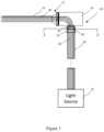
- FIG. 1is a schematic diagram of a endoscope system according to an implementation
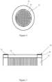
- FIG. 2is a cross sectional view of a light post taken along line 2 - 2 of FIG. 1 ;
- FIG. 3is a cross sectional elevation view of a light post with a thermal reflector according to an implementation
- FIG. 4is a cross sectional elevation view of a light post with a thermal reflector according to an implementation
- FIG. 5is a cross sectional elevation view of a light post with a thermal reflector according to an implementation.
- FIG. 6is a cross sectional elevation view of a light post with a thermal reflector according to an implementation.
- an endoscope system 10has an endoscope 12 with a shaft 14 and a body 16 .
- the body 16has a light post 18 for receiving light from a light guide 20 coupled to a light source 22 .
- the term “light post”is intended to include, for example and without limitation, standard and non-standard interfaces for accepting light from a light source.
- the light guide 20may be removably connected to the light post 18 using a connector 24 , for example, a threaded connector, a snap fit connector or a friction (push on) fit connector.
- the light source 22may produce visible light.
- the light source 22may also produce non-visible wavelengths of radiation, such as, for example, near infra-red radiation or ultraviolet radiation, that may be transmitted with or without visible light.
- the term “light”includes visible light as well as non-visible wavelengths of radiation.
- the light source 22may have, for example, a xenon lamp or a light emitting diode (LED) lamp.
- the term “light guide”includes any waveguide or cable for transmitting light from a light source to an endoscope.
- the light guide 20may be a flexible cable with fiber optics 26 for transmitting light from the light source 22 .
- Lightis transferred from the light guide fiber optics 26 into endoscope fiber optics 28 .
- Representative fiber optics 26 , 28are shown in FIG. 1 . Although fiber optics are used to illustrate certain implementations, this disclosure is intended to encompass other means of light transfer through the light guide 18 and through the endoscope 12 .
- the light guide 20may have an active diameter of light transmission (for example, the diameter of a fiber optic bundle) greater than an endoscope 12 active diameter of light transmission.
- some light guideshave an active diameter greater than about 4.5 mm and some endoscopes have an active diameter less than about 4 mm.
- Other endoscopesmay have an active diameter of less than about 3 mm or less than about 2 mm; with some endoscopes having an active diameter as small as 0.5 mm.
- a light guidehas a greater active diameter than the endoscope then some light is not transferred from the light guide fiber optics into the endoscope fiber optics, but rather is transferred onto the light source post 18 .
- this tapering from light guide to endoscopeexcites higher angles and broadens the field of view of the exiting illumination. This constraint prevents optimization for efficiency.
- a thermal reflector 30is configured for positioning proximal to an interface between the light guide fiber optics 26 and the endoscope fiber optics 28 .
- the thermal reflector 30is configured with a translucent portion 32 to allow light to pass through an area corresponding to the endoscope active diameter and a reflective portion 34 to reflect light directed to areas outside of the endoscope active diameter.
- the reflective portion 34may be flat (perpendicular to the direction of light from the light guide 20 ), angled or curved.
- the thermal reflector 30may be made of glass, clear plastic, or metal.
- the reflective portion 34may be manufactured by polishing metal or depositing a reflective coating of metal, such as aluminum or silver onto a portion of the glass or plastic. Thin film deposition may be used to create the reflective coating.
- the thermal reflector 30has an outer diameter 36 that is slightly smaller than an inner diameter of a light guide connector 24 so that the thermal reflector may sit within the connector when the connector is attached to the light post.
- the thermal reflector 30may have an outer diameter 36 of from about 3 mm to about 20 mm and more preferably from about 8 mm to about 13 mm.
- the thermal reflectormay have a height of from about 5 to about 15 mm and more preferably from about 7.5 mm to about 12.5 mm.
- the thermal reflector 30is specific to the endoscope fiber optics 28 and reflects light from about 10% to about 95% of the light guide fiber optics 26 .
- the reflective portion 34may have an inner diameter less than about 4 mm, and possibly less than about 2.3 mm, and possibly less than about 0.9 mm.
- a thermal reflector 38has a reflective portion 40 that is annularly shaped with a flat reflective surface.
- the thermal reflector 38has an inner diameter 42 that is slightly larger than the endoscope fiber optic active diameter.
- the thermal reflector 38has an outer diameter 43 that is slightly smaller than an inner diameter of a light guide connector 24 so that the thermal reflector may sit within the connector when the connector is attached to the light post.
- the reflective portion 34may be formed of, for example, aluminum or silver, or a thin film.
- a thermal reflector 44has a translucent portion 46 and an inwardly angled reflective surface 48 .
- the reflective surface 48may be at an angle less than about 10 degrees relative to an axis perpendicular to the direction of light from the light guide 20 so that light is reflected back into the light guide.
- the thermal reflector 44may also be formed as an annular shape with the translucent portion 46 being an opening.
- a thermal reflector 50is formed as an annular shape with a central opening 52 (translucent portion) formed by an inner wall 54 and a curved reflective surface 56 .
- the reflective surface 56may have a consistent radius of curvature or more complex conic or freeform shape.
- the reflective surfacemay have a radius of curvature less than about 10 mm.
- the thermal reflector 50may also be formed as an annular shape with the translucent portion 52 being an opening.
- the inner wall 54conically tapers from a larger diameter, such as proximal to the light guide, to a smaller diameter, such as proximal to the light post.
- the inner wall 54may also be reflective.
- the inner wall 54may be configured to totally internally reflect light so that a surface treatment of the inner wall 54 is not necessary.
- the thermal reflectormay also be formed as a cylindrical shape with a solid translucent portion (not shown).
- a converter(not shown) may be interposed between the light post 18 and the light guide connector 24 to allow for linkage of light posts and light guides having different diameters.
- a thermal reflector 34may be placed in the connection between the light post and the converter. The thermal reflector 34 may also be placed in the connection between the converter and the light guide connector 24 .
- the thermal reflectoris advantageous in reducing heat caused by light that is not transmitted into an endoscope and allows for greater combinations of endoscopes and light sources. Additionally, the thermal reflector may be used in existing endoscope light systems without substantial modifications. Additionally, the thermal reflector is a relatively low cost solutions.
Landscapes
- Health & Medical Sciences (AREA)
- Life Sciences & Earth Sciences (AREA)
- Surgery (AREA)
- Optics & Photonics (AREA)
- Physics & Mathematics (AREA)
- Nuclear Medicine, Radiotherapy & Molecular Imaging (AREA)
- Medical Informatics (AREA)
- Radiology & Medical Imaging (AREA)
- Biophysics (AREA)
- Engineering & Computer Science (AREA)
- Biomedical Technology (AREA)
- Heart & Thoracic Surgery (AREA)
- Pathology (AREA)
- Molecular Biology (AREA)
- Animal Behavior & Ethology (AREA)
- General Health & Medical Sciences (AREA)
- Public Health (AREA)
- Veterinary Medicine (AREA)
- Endoscopes (AREA)
Abstract
Description
Claims (26)
Priority Applications (2)
| Application Number | Priority Date | Filing Date | Title |
|---|---|---|---|
| US17/158,852US12232707B2 (en) | 2021-01-26 | 2021-01-26 | Endoscope thermal reflector |
| PCT/US2022/013089WO2022164704A1 (en) | 2021-01-26 | 2022-01-20 | Thermal reflector and endoscope system comprising such a thermal reflector |
Applications Claiming Priority (1)
| Application Number | Priority Date | Filing Date | Title |
|---|---|---|---|
| US17/158,852US12232707B2 (en) | 2021-01-26 | 2021-01-26 | Endoscope thermal reflector |
Publications (2)
| Publication Number | Publication Date |
|---|---|
| US20220233062A1 US20220233062A1 (en) | 2022-07-28 |
| US12232707B2true US12232707B2 (en) | 2025-02-25 |
Family
ID=80447827
Family Applications (1)
| Application Number | Title | Priority Date | Filing Date |
|---|---|---|---|
| US17/158,852Active2041-07-19US12232707B2 (en) | 2021-01-26 | 2021-01-26 | Endoscope thermal reflector |
Country Status (2)
| Country | Link |
|---|---|
| US (1) | US12232707B2 (en) |
| WO (1) | WO2022164704A1 (en) |
Families Citing this family (1)
| Publication number | Priority date | Publication date | Assignee | Title |
|---|---|---|---|---|
| US12232707B2 (en)* | 2021-01-26 | 2025-02-25 | Arthrex, Inc. | Endoscope thermal reflector |
Citations (43)
| Publication number | Priority date | Publication date | Assignee | Title |
|---|---|---|---|---|
| JPS6438062U (en) | 1987-08-27 | 1989-03-07 | ||
| US4953937A (en)* | 1988-05-17 | 1990-09-04 | Olympus Optical Co., Ltd. | Illumination optical system |
| US5718663A (en)* | 1995-07-17 | 1998-02-17 | Olympus Winter & Ibe Gmbh | Endoscope optical system with a window plate having a light screen |
| US5966210A (en)* | 1997-03-20 | 1999-10-12 | Hartford Hospital | Apparatus for evaluating the performance characteristics of endoscopes |
| US6124883A (en)* | 1996-02-26 | 2000-09-26 | Olympus Optical Co., Ltd. | TV observation system for endoscopes |
| US20010008485A1 (en)* | 2000-01-18 | 2001-07-19 | Hiroyuki Fuji | Spot light-source device excited by electromagentic energy |
| US6503196B1 (en)* | 1997-01-10 | 2003-01-07 | Karl Storz Gmbh & Co. Kg | Endoscope having a composite distal closure element |
| US20040064018A1 (en)* | 2002-03-22 | 2004-04-01 | Robert Dunki-Jacobs | Integrated visualization system |
| US20050020926A1 (en)* | 2003-06-23 | 2005-01-27 | Wiklof Christopher A. | Scanning endoscope |
| US20050096642A1 (en)* | 2003-10-31 | 2005-05-05 | Appling William M. | Endovascular treatment apparatus and method |
| US20050279354A1 (en)* | 2004-06-21 | 2005-12-22 | Harvey Deutsch | Structures and Methods for the Joint Delivery of Fluids and Light |
| US20060069314A1 (en)* | 2004-09-24 | 2006-03-30 | Mina Farr | Solid state illumination for endoscopy |
| US20060198418A1 (en)* | 2004-12-17 | 2006-09-07 | Nichia Corporation | Light emitting device |
| US20070093690A1 (en)* | 2005-10-07 | 2007-04-26 | Karl Storz Endovision | Endoscopic light source safety and control system with optical sensor |
| US20080089089A1 (en)* | 2004-10-01 | 2008-04-17 | Nichia Corporation | Light Emitting Device |
| US20080221388A1 (en)* | 2007-03-09 | 2008-09-11 | University Of Washington | Side viewing optical fiber endoscope |
| US20090221991A1 (en)* | 2005-03-21 | 2009-09-03 | Lieponis Jonas V | Multi-Purpose Surgical Instrument With Removable Component |
| FR2954087A1 (en) | 2009-12-21 | 2011-06-24 | Alliance Tech Ind | Medical probe for prostate disease of patient, has assembly melted to heat under controlled conditions on part of selected length, from front face of optical fiber for conferring bending to distal end with deviation angle of selected value |
| US20110282155A1 (en)* | 2009-11-06 | 2011-11-17 | Olympus Medical Systems Corp. | Endoscope |
| US20120053420A1 (en)* | 2010-08-31 | 2012-03-01 | Fujifilm Corporation | Endoscopic light guide and endoscope having the same |
| US20120099112A1 (en)* | 2010-10-25 | 2012-04-26 | Gerard Argant Alphonse | Multi-core low reflection lateral output fiber probe |
| US20130345517A1 (en)* | 2012-06-20 | 2013-12-26 | Fujifilm Corporation | Light source apparatus and endoscope system |
| US20140042467A1 (en)* | 2011-08-11 | 2014-02-13 | Goldeneye, Inc. | Solid state light sources with common luminescent and heat dissipating surfaces |
| US8672838B2 (en)* | 2011-08-12 | 2014-03-18 | Intuitive Surgical Operations, Inc. | Image capture unit in a surgical instrument |
| US20140092227A1 (en)* | 2012-05-22 | 2014-04-03 | Panasonic Corporation | Image capturing processor and endoscope |
| US20140107496A1 (en)* | 2011-06-06 | 2014-04-17 | Percuvision, Llc | Sensing catheter emitting radiant energy |
| US20160128557A1 (en) | 2014-11-06 | 2016-05-12 | Novartis Ag | Apparatus for removing infrared (ir) light from an ophthalmic illumination system |
| US9459415B2 (en) | 2008-11-18 | 2016-10-04 | Stryker Corporation | Endoscopic LED light source having a feedback control system |
| US20160374545A1 (en)* | 2014-03-31 | 2016-12-29 | Olympus Corporation | Endoscope system |
| US20170100023A1 (en) | 2005-04-04 | 2017-04-13 | Invuity, Inc. | Illuminated telescoping cannula |
| US20170188802A1 (en)* | 2013-01-17 | 2017-07-06 | Hannah LAWRENCE | System for altering functions of at least one surgical device dependent upon information saved in an endoscope related to the endoscope |
| JP6438062B2 (en) | 2017-03-15 | 2018-12-12 | 富士フイルム株式会社 | Endoscope system |
| US20190008376A1 (en)* | 2015-08-13 | 2019-01-10 | Koninklijke Philips N.V. | Radial illumination system |
| US20190033506A1 (en)* | 2016-01-29 | 2019-01-31 | Richard Wolf Gmbh | Illuminating device |
| WO2019049997A1 (en) | 2017-09-10 | 2019-03-14 | カイロス株式会社 | Endoscope system |
| WO2019077693A1 (en) | 2017-10-18 | 2019-04-25 | Meiji Seikaファルマ株式会社 | OPTICAL PROBE |
| US10524862B2 (en) | 2010-05-03 | 2020-01-07 | Neuwave Medical, Inc. | Energy delivery systems and uses thereof |
| US10667672B2 (en) | 2016-12-16 | 2020-06-02 | Olympus Winter & Ibe Gmbh | Endoscope |
| US20210149101A1 (en)* | 2019-11-14 | 2021-05-20 | Eric Swanson | Multicore Fiber Instrument with 3D-Printed Distal Optics |
| US20220061638A1 (en)* | 2020-09-03 | 2022-03-03 | Karl Storz Se & Co. Kg | Illumination device with light guide detection |
| US20220233062A1 (en)* | 2021-01-26 | 2022-07-28 | Arthrex, Inc. | Endoscope thermal reflector |
| US20230040005A1 (en)* | 2021-08-06 | 2023-02-09 | Alcon Inc. | Vitreoretinal instruments for illumination, fluid aspiration, and photocoagulation |
| US20230392996A1 (en)* | 2021-03-10 | 2023-12-07 | Olympus Corporation | Temperature measurement method, temperature measurement device, medical device system, and laser treatment method |
- 2021
- 2021-01-26USUS17/158,852patent/US12232707B2/enactiveActive
- 2022
- 2022-01-20WOPCT/US2022/013089patent/WO2022164704A1/ennot_activeCeased
Patent Citations (46)
| Publication number | Priority date | Publication date | Assignee | Title |
|---|---|---|---|---|
| JPS6438062U (en) | 1987-08-27 | 1989-03-07 | ||
| US4953937A (en)* | 1988-05-17 | 1990-09-04 | Olympus Optical Co., Ltd. | Illumination optical system |
| US5718663A (en)* | 1995-07-17 | 1998-02-17 | Olympus Winter & Ibe Gmbh | Endoscope optical system with a window plate having a light screen |
| US6124883A (en)* | 1996-02-26 | 2000-09-26 | Olympus Optical Co., Ltd. | TV observation system for endoscopes |
| US6503196B1 (en)* | 1997-01-10 | 2003-01-07 | Karl Storz Gmbh & Co. Kg | Endoscope having a composite distal closure element |
| US5966210A (en)* | 1997-03-20 | 1999-10-12 | Hartford Hospital | Apparatus for evaluating the performance characteristics of endoscopes |
| US20010008485A1 (en)* | 2000-01-18 | 2001-07-19 | Hiroyuki Fuji | Spot light-source device excited by electromagentic energy |
| US20040064018A1 (en)* | 2002-03-22 | 2004-04-01 | Robert Dunki-Jacobs | Integrated visualization system |
| US20050020926A1 (en)* | 2003-06-23 | 2005-01-27 | Wiklof Christopher A. | Scanning endoscope |
| US20050096642A1 (en)* | 2003-10-31 | 2005-05-05 | Appling William M. | Endovascular treatment apparatus and method |
| US20050279354A1 (en)* | 2004-06-21 | 2005-12-22 | Harvey Deutsch | Structures and Methods for the Joint Delivery of Fluids and Light |
| US8480566B2 (en) | 2004-09-24 | 2013-07-09 | Vivid Medical, Inc. | Solid state illumination for endoscopy |
| US9271637B2 (en) | 2004-09-24 | 2016-03-01 | Vivid Medical Inc. | Solid state illumination for endoscopy |
| US20060069314A1 (en)* | 2004-09-24 | 2006-03-30 | Mina Farr | Solid state illumination for endoscopy |
| US20080089089A1 (en)* | 2004-10-01 | 2008-04-17 | Nichia Corporation | Light Emitting Device |
| US20060198418A1 (en)* | 2004-12-17 | 2006-09-07 | Nichia Corporation | Light emitting device |
| US20090221991A1 (en)* | 2005-03-21 | 2009-09-03 | Lieponis Jonas V | Multi-Purpose Surgical Instrument With Removable Component |
| US20170100023A1 (en) | 2005-04-04 | 2017-04-13 | Invuity, Inc. | Illuminated telescoping cannula |
| US20070093690A1 (en)* | 2005-10-07 | 2007-04-26 | Karl Storz Endovision | Endoscopic light source safety and control system with optical sensor |
| US20080221388A1 (en)* | 2007-03-09 | 2008-09-11 | University Of Washington | Side viewing optical fiber endoscope |
| US9459415B2 (en) | 2008-11-18 | 2016-10-04 | Stryker Corporation | Endoscopic LED light source having a feedback control system |
| US20110282155A1 (en)* | 2009-11-06 | 2011-11-17 | Olympus Medical Systems Corp. | Endoscope |
| FR2954087A1 (en) | 2009-12-21 | 2011-06-24 | Alliance Tech Ind | Medical probe for prostate disease of patient, has assembly melted to heat under controlled conditions on part of selected length, from front face of optical fiber for conferring bending to distal end with deviation angle of selected value |
| US10524862B2 (en) | 2010-05-03 | 2020-01-07 | Neuwave Medical, Inc. | Energy delivery systems and uses thereof |
| US20120053420A1 (en)* | 2010-08-31 | 2012-03-01 | Fujifilm Corporation | Endoscopic light guide and endoscope having the same |
| US20120099112A1 (en)* | 2010-10-25 | 2012-04-26 | Gerard Argant Alphonse | Multi-core low reflection lateral output fiber probe |
| US20140107496A1 (en)* | 2011-06-06 | 2014-04-17 | Percuvision, Llc | Sensing catheter emitting radiant energy |
| US10786205B2 (en)* | 2011-06-06 | 2020-09-29 | Ake A. Hellstrom | Sensing catheter emitting radiant energy |
| US20140042467A1 (en)* | 2011-08-11 | 2014-02-13 | Goldeneye, Inc. | Solid state light sources with common luminescent and heat dissipating surfaces |
| US8672838B2 (en)* | 2011-08-12 | 2014-03-18 | Intuitive Surgical Operations, Inc. | Image capture unit in a surgical instrument |
| US20140092227A1 (en)* | 2012-05-22 | 2014-04-03 | Panasonic Corporation | Image capturing processor and endoscope |
| US20130345517A1 (en)* | 2012-06-20 | 2013-12-26 | Fujifilm Corporation | Light source apparatus and endoscope system |
| US20170188802A1 (en)* | 2013-01-17 | 2017-07-06 | Hannah LAWRENCE | System for altering functions of at least one surgical device dependent upon information saved in an endoscope related to the endoscope |
| US20160374545A1 (en)* | 2014-03-31 | 2016-12-29 | Olympus Corporation | Endoscope system |
| US20160128557A1 (en) | 2014-11-06 | 2016-05-12 | Novartis Ag | Apparatus for removing infrared (ir) light from an ophthalmic illumination system |
| US20190008376A1 (en)* | 2015-08-13 | 2019-01-10 | Koninklijke Philips N.V. | Radial illumination system |
| US20190033506A1 (en)* | 2016-01-29 | 2019-01-31 | Richard Wolf Gmbh | Illuminating device |
| US10667672B2 (en) | 2016-12-16 | 2020-06-02 | Olympus Winter & Ibe Gmbh | Endoscope |
| JP6438062B2 (en) | 2017-03-15 | 2018-12-12 | 富士フイルム株式会社 | Endoscope system |
| WO2019049997A1 (en) | 2017-09-10 | 2019-03-14 | カイロス株式会社 | Endoscope system |
| WO2019077693A1 (en) | 2017-10-18 | 2019-04-25 | Meiji Seikaファルマ株式会社 | OPTICAL PROBE |
| US20210149101A1 (en)* | 2019-11-14 | 2021-05-20 | Eric Swanson | Multicore Fiber Instrument with 3D-Printed Distal Optics |
| US20220061638A1 (en)* | 2020-09-03 | 2022-03-03 | Karl Storz Se & Co. Kg | Illumination device with light guide detection |
| US20220233062A1 (en)* | 2021-01-26 | 2022-07-28 | Arthrex, Inc. | Endoscope thermal reflector |
| US20230392996A1 (en)* | 2021-03-10 | 2023-12-07 | Olympus Corporation | Temperature measurement method, temperature measurement device, medical device system, and laser treatment method |
| US20230040005A1 (en)* | 2021-08-06 | 2023-02-09 | Alcon Inc. | Vitreoretinal instruments for illumination, fluid aspiration, and photocoagulation |
Non-Patent Citations (1)
| Title |
|---|
| The International Search Report and The Written Opinion, dated Apr. 19, 2022, pp. 1-14. |
Also Published As
| Publication number | Publication date |
|---|---|
| WO2022164704A1 (en) | 2022-08-04 |
| US20220233062A1 (en) | 2022-07-28 |
Similar Documents
| Publication | Publication Date | Title |
|---|---|---|
| US9122067B2 (en) | Endoscope | |
| US11109751B2 (en) | Illumination system for an endoscope | |
| US7783346B2 (en) | Illuminated infusion cannula | |
| US7798692B2 (en) | Illumination device | |
| US6554463B2 (en) | Optical waveguide concentrator and illuminating device | |
| JP2002521713A (en) | Device for coupling low numerical aperture light input to high numerical aperture optics | |
| US20090185392A1 (en) | Detachable illumination system | |
| US10436966B2 (en) | Illuminating device | |
| AU2018309165B2 (en) | Medical Illumination Device and Related Methods | |
| US12232707B2 (en) | Endoscope thermal reflector | |
| US20200289689A1 (en) | Disinfecting Methods and Apparatus | |
| WO2011100432A2 (en) | Light repositioning optics | |
| KR20210114068A (en) | lighting cannula system | |
| US11635604B2 (en) | Luminous flux collector for directing light into a light-diffusing fiber | |
| US7008071B2 (en) | Light collection system converting ultraviolet energy to visible light | |
| CN116269752A (en) | Medical lighting devices and systems for fluorescent image-guided surgery | |
| US8616751B2 (en) | Light guide for coupling differently shaped light source and receiver | |
| US10667672B2 (en) | Endoscope | |
| JP2941621B2 (en) | Wide-angle lighting device | |
| JP2000010021A (en) | Portable endoscopic system | |
| US4911511A (en) | Light ray radiation stand | |
| US9116262B2 (en) | High-efficiency illumination system | |
| TW200419103A (en) | Multiple output illumination using reflectors | |
| JPS6227692B2 (en) | ||
| TWM263457U (en) | Optical fiber illumination fastening device |
Legal Events
| Date | Code | Title | Description |
|---|---|---|---|
| AS | Assignment | Owner name:ARTHREX, INC., FLORIDA Free format text:ASSIGNMENT OF ASSIGNORS INTEREST;ASSIGNOR:HYGELUND, JOHN;REEL/FRAME:055038/0380 Effective date:20210118 | |
| FEPP | Fee payment procedure | Free format text:ENTITY STATUS SET TO UNDISCOUNTED (ORIGINAL EVENT CODE: BIG.); ENTITY STATUS OF PATENT OWNER: LARGE ENTITY | |
| STPP | Information on status: patent application and granting procedure in general | Free format text:NON FINAL ACTION MAILED | |
| STPP | Information on status: patent application and granting procedure in general | Free format text:RESPONSE TO NON-FINAL OFFICE ACTION ENTERED AND FORWARDED TO EXAMINER | |
| STPP | Information on status: patent application and granting procedure in general | Free format text:NON FINAL ACTION MAILED | |
| STPP | Information on status: patent application and granting procedure in general | Free format text:FINAL REJECTION MAILED | |
| STPP | Information on status: patent application and granting procedure in general | Free format text:RESPONSE AFTER FINAL ACTION FORWARDED TO EXAMINER | |
| STPP | Information on status: patent application and granting procedure in general | Free format text:ADVISORY ACTION MAILED | |
| STPP | Information on status: patent application and granting procedure in general | Free format text:DOCKETED NEW CASE - READY FOR EXAMINATION | |
| STPP | Information on status: patent application and granting procedure in general | Free format text:NON FINAL ACTION MAILED | |
| STPP | Information on status: patent application and granting procedure in general | Free format text:RESPONSE TO NON-FINAL OFFICE ACTION ENTERED AND FORWARDED TO EXAMINER | |
| STPP | Information on status: patent application and granting procedure in general | Free format text:FINAL REJECTION MAILED | |
| STCV | Information on status: appeal procedure | Free format text:NOTICE OF APPEAL FILED | |
| STPP | Information on status: patent application and granting procedure in general | Free format text:RESPONSE TO NON-FINAL OFFICE ACTION ENTERED AND FORWARDED TO EXAMINER | |
| STPP | Information on status: patent application and granting procedure in general | Free format text:NON FINAL ACTION MAILED | |
| STPP | Information on status: patent application and granting procedure in general | Free format text:RESPONSE TO NON-FINAL OFFICE ACTION ENTERED AND FORWARDED TO EXAMINER | |
| STPP | Information on status: patent application and granting procedure in general | Free format text:NOTICE OF ALLOWANCE MAILED -- APPLICATION RECEIVED IN OFFICE OF PUBLICATIONS | |
| STPP | Information on status: patent application and granting procedure in general | Free format text:PUBLICATIONS -- ISSUE FEE PAYMENT RECEIVED | |
| STPP | Information on status: patent application and granting procedure in general | Free format text:PUBLICATIONS -- ISSUE FEE PAYMENT VERIFIED | |
| STCF | Information on status: patent grant | Free format text:PATENTED CASE |