US12228662B2 - Off-set drive assembly for solar tracker - Google Patents
Off-set drive assembly for solar trackerDownload PDFInfo
- Publication number
- US12228662B2 US12228662B2US17/742,247US202217742247AUS12228662B2US 12228662 B2US12228662 B2US 12228662B2US 202217742247 AUS202217742247 AUS 202217742247AUS 12228662 B2US12228662 B2US 12228662B2
- Authority
- US
- United States
- Prior art keywords
- torque tube
- clamp member
- hat channel
- region
- solar
- Prior art date
- Legal status (The legal status is an assumption and is not a legal conclusion. Google has not performed a legal analysis and makes no representation as to the accuracy of the status listed.)
- Active, expires
Links
Images


Classifications
- G—PHYSICS
- G01—MEASURING; TESTING
- G01S—RADIO DIRECTION-FINDING; RADIO NAVIGATION; DETERMINING DISTANCE OR VELOCITY BY USE OF RADIO WAVES; LOCATING OR PRESENCE-DETECTING BY USE OF THE REFLECTION OR RERADIATION OF RADIO WAVES; ANALOGOUS ARRANGEMENTS USING OTHER WAVES
- G01S3/00—Direction-finders for determining the direction from which infrasonic, sonic, ultrasonic, or electromagnetic waves, or particle emission, not having a directional significance, are being received
- G01S3/78—Direction-finders for determining the direction from which infrasonic, sonic, ultrasonic, or electromagnetic waves, or particle emission, not having a directional significance, are being received using electromagnetic waves other than radio waves
- G01S3/782—Systems for determining direction or deviation from predetermined direction
- G01S3/785—Systems for determining direction or deviation from predetermined direction using adjustment of orientation of directivity characteristics of a detector or detector system to give a desired condition of signal derived from that detector or detector system
- G01S3/786—Systems for determining direction or deviation from predetermined direction using adjustment of orientation of directivity characteristics of a detector or detector system to give a desired condition of signal derived from that detector or detector system the desired condition being maintained automatically
- G01S3/7861—Solar tracking systems
- F—MECHANICAL ENGINEERING; LIGHTING; HEATING; WEAPONS; BLASTING
- F16—ENGINEERING ELEMENTS AND UNITS; GENERAL MEASURES FOR PRODUCING AND MAINTAINING EFFECTIVE FUNCTIONING OF MACHINES OR INSTALLATIONS; THERMAL INSULATION IN GENERAL
- F16C—SHAFTS; FLEXIBLE SHAFTS; ELEMENTS OR CRANKSHAFT MECHANISMS; ROTARY BODIES OTHER THAN GEARING ELEMENTS; BEARINGS
- F16C11/00—Pivots; Pivotal connections
- F16C11/04—Pivotal connections
- F16C11/045—Pivotal connections with at least a pair of arms pivoting relatively to at least one other arm, all arms being mounted on one pin
- F—MECHANICAL ENGINEERING; LIGHTING; HEATING; WEAPONS; BLASTING
- F16—ENGINEERING ELEMENTS AND UNITS; GENERAL MEASURES FOR PRODUCING AND MAINTAINING EFFECTIVE FUNCTIONING OF MACHINES OR INSTALLATIONS; THERMAL INSULATION IN GENERAL
- F16C—SHAFTS; FLEXIBLE SHAFTS; ELEMENTS OR CRANKSHAFT MECHANISMS; ROTARY BODIES OTHER THAN GEARING ELEMENTS; BEARINGS
- F16C23/00—Bearings for exclusively rotary movement adjustable for aligning or positioning
- F16C23/10—Bearings, parts of which are eccentrically adjustable with respect to each other
- F—MECHANICAL ENGINEERING; LIGHTING; HEATING; WEAPONS; BLASTING
- F16—ENGINEERING ELEMENTS AND UNITS; GENERAL MEASURES FOR PRODUCING AND MAINTAINING EFFECTIVE FUNCTIONING OF MACHINES OR INSTALLATIONS; THERMAL INSULATION IN GENERAL
- F16C—SHAFTS; FLEXIBLE SHAFTS; ELEMENTS OR CRANKSHAFT MECHANISMS; ROTARY BODIES OTHER THAN GEARING ELEMENTS; BEARINGS
- F16C25/00—Bearings for exclusively rotary movement adjustable for wear or play
- F16C25/02—Sliding-contact bearings
- F—MECHANICAL ENGINEERING; LIGHTING; HEATING; WEAPONS; BLASTING
- F16—ENGINEERING ELEMENTS AND UNITS; GENERAL MEASURES FOR PRODUCING AND MAINTAINING EFFECTIVE FUNCTIONING OF MACHINES OR INSTALLATIONS; THERMAL INSULATION IN GENERAL
- F16H—GEARING
- F16H19/00—Gearings comprising essentially only toothed gears or friction members and not capable of conveying indefinitely-continuing rotary motion
- F16H19/08—Gearings comprising essentially only toothed gears or friction members and not capable of conveying indefinitely-continuing rotary motion for interconverting rotary motion and oscillating motion
- F—MECHANICAL ENGINEERING; LIGHTING; HEATING; WEAPONS; BLASTING
- F24—HEATING; RANGES; VENTILATING
- F24S—SOLAR HEAT COLLECTORS; SOLAR HEAT SYSTEMS
- F24S25/00—Arrangement of stationary mountings or supports for solar heat collector modules
- F24S25/10—Arrangement of stationary mountings or supports for solar heat collector modules extending in directions away from a supporting surface
- F—MECHANICAL ENGINEERING; LIGHTING; HEATING; WEAPONS; BLASTING
- F24—HEATING; RANGES; VENTILATING
- F24S—SOLAR HEAT COLLECTORS; SOLAR HEAT SYSTEMS
- F24S30/00—Arrangements for moving or orienting solar heat collector modules
- F24S30/40—Arrangements for moving or orienting solar heat collector modules for rotary movement
- F24S30/42—Arrangements for moving or orienting solar heat collector modules for rotary movement with only one rotation axis
- F24S30/425—Horizontal axis
- H—ELECTRICITY
- H02—GENERATION; CONVERSION OR DISTRIBUTION OF ELECTRIC POWER
- H02S—GENERATION OF ELECTRIC POWER BY CONVERSION OF INFRARED RADIATION, VISIBLE LIGHT OR ULTRAVIOLET LIGHT, e.g. USING PHOTOVOLTAIC [PV] MODULES
- H02S20/00—Supporting structures for PV modules
- H02S20/10—Supporting structures directly fixed to the ground
- H—ELECTRICITY
- H02—GENERATION; CONVERSION OR DISTRIBUTION OF ELECTRIC POWER
- H02S—GENERATION OF ELECTRIC POWER BY CONVERSION OF INFRARED RADIATION, VISIBLE LIGHT OR ULTRAVIOLET LIGHT, e.g. USING PHOTOVOLTAIC [PV] MODULES
- H02S20/00—Supporting structures for PV modules
- H02S20/30—Supporting structures being movable or adjustable, e.g. for angle adjustment
- H02S20/32—Supporting structures being movable or adjustable, e.g. for angle adjustment specially adapted for solar tracking
- F—MECHANICAL ENGINEERING; LIGHTING; HEATING; WEAPONS; BLASTING
- F24—HEATING; RANGES; VENTILATING
- F24S—SOLAR HEAT COLLECTORS; SOLAR HEAT SYSTEMS
- F24S30/00—Arrangements for moving or orienting solar heat collector modules
- F24S2030/10—Special components
- F24S2030/15—Bearings
- Y—GENERAL TAGGING OF NEW TECHNOLOGICAL DEVELOPMENTS; GENERAL TAGGING OF CROSS-SECTIONAL TECHNOLOGIES SPANNING OVER SEVERAL SECTIONS OF THE IPC; TECHNICAL SUBJECTS COVERED BY FORMER USPC CROSS-REFERENCE ART COLLECTIONS [XRACs] AND DIGESTS
- Y02—TECHNOLOGIES OR APPLICATIONS FOR MITIGATION OR ADAPTATION AGAINST CLIMATE CHANGE
- Y02E—REDUCTION OF GREENHOUSE GAS [GHG] EMISSIONS, RELATED TO ENERGY GENERATION, TRANSMISSION OR DISTRIBUTION
- Y02E10/00—Energy generation through renewable energy sources
- Y02E10/40—Solar thermal energy, e.g. solar towers
- Y02E10/47—Mountings or tracking
- Y—GENERAL TAGGING OF NEW TECHNOLOGICAL DEVELOPMENTS; GENERAL TAGGING OF CROSS-SECTIONAL TECHNOLOGIES SPANNING OVER SEVERAL SECTIONS OF THE IPC; TECHNICAL SUBJECTS COVERED BY FORMER USPC CROSS-REFERENCE ART COLLECTIONS [XRACs] AND DIGESTS
- Y10—TECHNICAL SUBJECTS COVERED BY FORMER USPC
- Y10T—TECHNICAL SUBJECTS COVERED BY FORMER US CLASSIFICATION
- Y10T74/00—Machine element or mechanism
- Y10T74/18—Mechanical movements
- Y10T74/18568—Reciprocating or oscillating to or from alternating rotary
- Y10T74/18792—Reciprocating or oscillating to or from alternating rotary including worm
Definitions
- the present applicationrelates generally to a tracking system for solar panels. More specifically, embodiments of the present invention provide tracking systems that are suitable for solar panels. In a specific embodiment, a tracking system according to the present invention is fully adjustable in at each of the pillars, among other aspects. There are other embodiments as well.
- Solar energypossesses many characteristics that are very desirable! Solar energy is renewable, clean, abundant, and often widespread. Certain technologies have been developed to capture solar energy, concentrate it, store it, and convert it into other useful forms of energy.
- Solar panelshave been developed to convert sunlight into energy.
- solar thermal panelsoften convert electromagnetic radiation from the sun into thermal energy for heating homes, running certain industrial processes, or driving high grade turbines to generate electricity.
- solar photovoltaic panelsconvert sunlight directly into electricity for a variety of applications.
- Solar panelsare generally composed of an array of solar cells, which are interconnected to each other. The cells are often arranged in series and/or parallel groups of cells in series. Accordingly, solar panels have great potential to benefit our nation, security, and human users. They can even diversify our energy requirements and reduce the world's dependence on oil and other potentially detrimental sources of energy.
- the present applicationrelates generally to a tracking system for solar panels. More specifically, embodiments of the present invention provide tracking systems that are suitable for solar panels. In a specific embodiment, a tracking system according to the present invention is fully adjustable in at each of the pillars, among other aspects. There are other embodiments as well.
- the present inventionprovides a solar tracker apparatus configured with an off-set drive assembly.
- the apparatushas an inner race structure, which has a cylindrical region coupled to a main body region, the main body comprising an off-set open region.
- the cylindrical regionis an annular sleeve structure coupled to the main body region, which occupies the spatial region within the cylindrical region.
- the apparatushas an outer race structure coupled to enclose the inner race structure, and configured to couple the inner race structure to allow the inner race structure to move in a rotational manner about a spatial arc region; and configured to allow the inner race structure to pivot about a region normal to a direction of the spatial arc region.
- the apparatushas a torque tube sleeve configured in an off-set manner on a region between a center region and an outer region of the inter race structure, and configured to be inserted within the off-set open region; and a drive coupled to the inner race structure to cause the torque tube to move about an arc region.
- the solar trackerhas a clamp assembly that is configured to pivot a torque tube.
- the assemblyhas a support structure configured as a frame having configured by a first anchoring region and a second anchoring region.
- the support structureis configured from a thickness of metal material.
- the support structureis configured in an upright manner, and has a major plane region.
- the assemblyhas a pivot device configured on the support structure and a torque tube suspending on the pivot device and aligned within an opening of the support and configured to be normal to the plane region.
- the torque tubeis configured on the pivot device to move about an arc in a first direction or in a second direction such that the first direction is in a direction opposite to the second direction.
- the present inventionprovides a solar tracker apparatus.
- the apparatuscomprises a center of mass with an adjustable hanger assembly configured with a clam shell clamp assembly on the adjustable hanger assembly and a cylindrical torque tube comprising a plurality of torque tubes configured together in a continuous length from a first end to a second end such that the center of mass is aligned with a center of rotation of the cylindrical torque tubes to reduce a load of a drive motor operably coupled to the cylindrical torque tube.
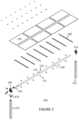
- FIG. 1is a simplified perspective view of a horizontal tracker apparatus configured with a plurality of solar modules according to an embodiment of the present invention.
- FIGS. 2 through 7illustrate a method of assembling the horizontal tracker apparatus of FIG. 1 .
- FIG. 8is a simplified perspective view of a pair of horizontal tracker apparatus configured together with a plurality of solar panels according to an embodiment of the present invention.
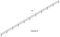
- FIG. 9is a simplified diagram of a plurality of horizontal tracker apparatus configured together according to an embodiment of the present invention.
- FIG. 10is a simplified diagram of an array of a plurality of horizontal tracker apparatus configured together according to an embodiment of the present invention.
- FIG. 11is a simplified diagram of a clamp assembly for the horizontal tracker of FIG. 1 according to an embodiment of the present invention.
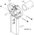
- FIGS. 12 through 14are simplified diagrams illustrating a method for assembling the clamp assembly of FIG. 11 .
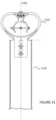
- FIG. 15is a simplified perspective diagram of a drive assembly configured on a pier member according to an embodiment of the present invention.
- FIGS. 16 through 19are simplified diagrams illustrating a method for assembling the drive assembly of FIG. 15 .
- FIG. 20is a simplified in-line view diagram illustrating a clamp assembly separate and apart from a pier member according to an embodiment of the present invention.
- FIG. 21is a simplified in-line view diagram illustrating a clamp assembly coupled to a pier member according to an embodiment of the present invention.
- FIG. 22is a simplified in-line view diagram illustrating a clamp assembly coupled to a pier member in a first orientation according to an embodiment of the present invention.
- FIG. 23is a simplified in-line view diagram illustrating a clamp assembly coupled to a pier member in a second orientation according to an embodiment of the present invention.
- FIG. 24is a simplified side view diagram illustrating a clamp assembly coupled to a pier member in a first orientation according to an embodiment of the present invention.
- FIG. 25is a simplified side view diagram illustrating a clamp assembly coupled to a pier member in a second orientation according to an embodiment of the present invention.
- FIG. 26is a simplified side view diagram illustrating a clamp assembly coupled to a pier member in a third orientation according to an embodiment of the present invention.
- FIG. 27is a simplified side view diagram illustrating a clamp assembly coupled to a pier member in a fourth orientation according to an embodiment of the present invention.
- FIG. 28is a simplified side view diagram illustrating a clamp assembly coupled to a pier member in a fifth orientation according to an embodiment of the present invention.
- FIG. 29is a simplified side view diagram illustrating a clamp assembly coupled to a pier member in a sixth orientation according to an embodiment of the present invention.
- FIGS. 30 through 32illustrate an in-line view of the clamp assembly and the drive assembly in multiple configurations according to embodiments of the present invention.
- FIG. 33is a side view diagram of the tracker apparatus according to an embodiment of the present invention.
- FIGS. 34 and 35are simplified side view diagrams of a torque tube according to an embodiment of the present invention.
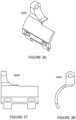
- FIGS. 36 , 37 , and 38are simplified perspective-view, side view, and front view diagrams of a clamp member according to an embodiment of the present invention.
- FIGS. 39 and 40are simplified perspective-view and side view diagrams of a clamp housing according to an embodiment of the present invention.
- FIGS. 41 , 42 , 43 , and 44are simplified diagrams of component(s) for a U-bolt member according to an embodiment of the present invention.
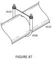
- FIGS. 45 , 46 , and 47are simplified diagrams illustrating a method of configuring a U-bolt member to a torque tube according to an embodiment of the present invention.
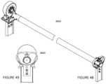
- FIGS. 48 and 49illustrate various views of a tracker apparatus according to an embodiment of the present invention.
- FIGS. 50 and 51illustrate views of a tracker apparatus according to an embodiment of the present invention.
- FIGS. 52 and 53illustrate an illustration of a torque tube according to an embodiment of the present invention.
- FIG. 54is a front view diagram of a clamp assembly according to an example of the present invention.
- FIG. 55is a front view diagram of a clamp assembly in a stop position according to an example of the present invention.
- FIG. 56is a perspective view of a frame structure to be configured for the clamp assembly according to an example of the present invention.
- FIG. 57illustrates a top view diagram, a front view diagram, and a side view diagram of the frame structure to be configured for the clamp assembly according to an example of the present invention.
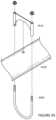
- FIG. 58illustrates a top view diagram, a front-view diagram, and a side view diagram of a U-bolt configured on a torque tube according to an example of the present invention.
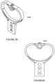
- FIG. 59illustrates a front view diagram of the U-bolt configured to a torque tube according to an example of the present invention.
- FIG. 60illustrate a perspective view of a support member for the U-bolt configured to a torque tube according to an example of the present invention.
- FIG. 61illustrates a front view diagram and a side view diagram of an off-set slew gear drive according to an example of the present invention.
- FIG. 62illustrates a front view diagram and a side view diagram of an off-set slew gear drive in a pivot position according to an example of the present invention.
- FIG. 63illustrates cross-sections of front view diagram and a side view diagram of an off-set slew gear drive according to an example of the present invention.
- FIG. 64illustrates cross sections of front view diagram and a side view diagram of an off-set slew gear drive in a pivot position according to an example of the present invention.
- FIG. 65is an exploded view of an off-set slew gear device in an example of the present invention.
- FIG. 66is a simplified diagram of a top view of an array of solar modules configured on a tracker apparatus according to an embodiment of the present invention.
- FIG. 67is a simplified diagram of a side-view of an array of solar modules configured on a torque tube for a tracker apparatus according to an embodiment of the present invention.
- FIG. 68is a simplified diagram of a front-view of an array of solar modules configured on a torque tube for a tracker apparatus according to an embodiment of the present invention.
- FIG. 69is a simplified diagram of a perspective-view of an array of solar modules configured on a tracker apparatus according to an embodiment of the present invention.
- FIG. 70is a simplified diagram of a perspective-view of an array of solar modules configured on a tracker apparatus according to an embodiment of the present invention.
- FIG. 71illustrates each of the clamp members configured to hold edges of at least a pair of solar modules together.
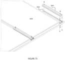
- FIG. 72illustrates a front view diagram of each of the clamp members configured to hold edges of at least a pair of solar modules together.
- FIG. 73is a simplified front-view diagram of a clamp assembly according to an example of the present invention.
- the present applicationrelates generally to a tracking system for solar panels. More specifically, embodiments of the present invention provide tracking systems that are suitable for solar panels. In a specific embodiment, a tracking system according to the present invention is fully adjustable in at each of the pillars, among other aspects. There are other embodiments as well.
- the present inventionprovides a tracker apparatus for solar modules.
- the tracker apparatushas a first pier comprising a first pivot device and a second pier comprising a drive mount.
- the drive mountis capable for construction tolerances in at least three-axis, and is configured to a drive device.
- the drive devicehas an off-set clamp device coupled to a cylindrical bearing device coupled to a clamp member.
- the apparatushas a cylindrical torque tube operably disposed on the first pier and the second pier.
- the cylindrical torque tubecomprises a first end and a second end, and a notch.
- the notchis one of a plurality of notches spatially disposed along a length of the cylindrical torque tube.
- the apparatushas a clamp configured around an annular portion of the cylindrical torque tube and mate with the notch to prevent movement of the clamp.
- the clampcomprises a support region configured to support a portion of a solar module.
- the present inventionprovides an alternative solar tracker apparatus.
- the apparatushas a drive device, a crank coupled to the drive device and configured in an offset manner to a frame assembly.
- the frame assemblyis coupled to a plurality of solar modules.
- the apparatushas a continuous torque tube spatially disposed from a first region to a second region.
- the crankcomprises a first crank coupled to a first side of the drive device and a second crank coupled to a second side of the drive device.
- the crankcomprises a first crank coupled to a first side of the drive device and a second crank coupled to a second side of the drive device; and further comprises a first torque tube coupled to the first crank and a second torque tube coupled to the second crank.
- the crankcomprises a first crank coupled to a first side of the drive device and a second crank coupled to a second side of the drive device; and further comprises a first torque tube coupled to the first crank and a second torque tube coupled to the second crank, and further comprises a first swage fitting coupling the first crank to the first torque tube and a second swage fitting coupling the second crank to the second torque tube.
- the apparatusalso has a pier coupled to the drive device.
- the apparatusalso has a drive mount coupled to a pier.
- the present inventionprovides an alternative solar tracker apparatus.
- the apparatushas a center of mass with an adjustable hanger assembly configured with a clam shell clamp assembly on the adjustable hanger assembly and a cylindrical torque tube comprising a plurality of torque tubes configured together in a continuous length from a first end to a second end such that the center of mass is aligned with a center of rotation of the cylindrical torque tubes to reduce a load of a drive motor operably coupled to the cylindrical torque tube.
- the drive motoris operable to move the torque tube about the center of rotation and is substantially free from a load.
- the center of rotationis offset from a center of the cylindrical torque tube.
- the present inventionprovides a solar tracker apparatus.
- the apparatushas a clamp housing member configured in an upright direction.
- the clamp housing membercomprises a lower region and an upper region.
- the lower regionis coupled to a pier structure, and the upper region comprises a spherical bearing device.
- the upright directionis away from a direction of gravity.
- the apparatushas a clam shell clamp member coupled to the cylindrical bearing and a torque tube coupled to the spherical bearing to support the torque tube from the upper region of the clamp housing member.
- the torque tubeis configured from an off-set position from a center region of rotation.
- the apparatusis configured substantially free from any welds during assembly. Reduced welding lowers cost, improves installation time, avoids errors in installation, improves manufacturability, and reduces component count through standardized parts.
- the torque tubeis coupled to another torque tube via a swage device within a vicinity of the clam shall clamp member.
- the connectionis low cost, and provides for strong axial and torsional loading.
- the apparatusis quick to install with the pokey-yoke design.
- the torque tubeis coupled to an elastomeric damper in line to dampen torque movement to be substantially free from formation of a harmonic waveform along any portion of a plurality of solar panels configured to the torque tube.
- the apparatusalso has a locking damper or rigid structure to configure a solar panel coupled to the torque tube in a fixed tilt position to prevent damage to stopper and lock into a foundation-in a position that is substantially free from fluttering in an environment with high movement of air.
- the apparatusfurther comprises a controller apparatus configured in an inserter box provided in an underground region to protect the controller apparatus.
- the apparatushas a drive device to linearly actuate the torque tube.
- the apparatususes an electrical connection coupled to a drive device.
- the spherical bearingallows for a construction tolerance, tracker movement, and acts as a bonding path of least resistance taking an electrical current to ground.
- the apparatuscan be one of a plurality of tracker apparatus configured in an array within a geographic region. Each of the plurality of tracker apparatus is driven independently of each other to cause each row to stow independently at a different or similar angle.
- the present inventionprovides a tracker apparatus comprising a clam shell apparatus, which has a first member operably coupled to a second member to hold a torque tube in place.
- the apparatusalso has a clamp housing operably coupled to the clam shell apparatus via a spherical bearing device such that the spherical bearing comprises an axis of rotation.
- the axis of rotationis different from a center of the torque tube.
- the apparatusfurther comprises a solar module coupled to the torque tube.
- the inventionprovides a tracker apparatus comprising a plurality of torque tubes comprising a first torque tube coupled to a second torque tube coupled to an Nth torque tube, whereupon N is an integer greater than 2.
- Nis an integer greater than 2.
- Each pair of torque tubesis coupled to each other free from any welds.
- each pair of torque tubesis swaged fitted together.
- Each of the torque tubesis cylindrical in shape.
- Each of the plurality of torque tubesis characterized by a length greater than 80 meters.
- Each of the torque tubescomprises a plurality of notches.
- the apparatusalso has a plurality of U-bolt devices coupled respectively to the plurality of notches.
- Each of the plurality of torque tubesare made of steel.
- the present inventionprovides a tracker apparatus having a pier member comprising a lower region and an upper region.
- a clamp holding memberis configured to the upper region and is capable of moving in at least a first direction, a second direction opposite to the first direction, a third direction normal to the first direction and the second direction, a fourth direction opposite of the third direction, a fifth direction normal to the first direction, the second direction, the third direction, and the fourth direction, and a sixth direction opposite of the fifth direction.
- the present inventionprovides a solar tracker apparatus.
- the apparatushas a clamp housing member configured in an upright direction.
- the clamp housing membercomprises a lower region and an upper region.
- the lower regionis coupled to a pier structure.
- the upper regioncomprises a spherical bearing device.
- the upright directionis away from a direction of gravity.
- the apparatushas a clam shell clamp member coupled to the cylindrical bearing and the clam shell clamp being suspended from the cylindrical bearing.
- the apparatushas a torque tube comprising a first end and a second end. The first end is coupled to the spherical bearing to support the torque tube from the upper region of the clamp housing member.
- the torque tubeis configured from an off-set position from a center region of rotation.
- the apparatushas a drive device coupled to the second end such that the drive device and the torque tube are configured to be substantially free from a twisting action while under a load, e.g., rotation, wind, other internal or external forces. Further details of the present examples can be found throughout the present specification and more particularly below.
- FIG. 1is a simplified perspective view of a horizontal tracker apparatus 100 configured with a plurality of solar modules according to an embodiment of the present invention.
- the present inventionprovides a tracker apparatus 100 for solar modules.
- the solar modulescan be a silicon based solar module, a polysilicon based solar module, a concentrated solar module, or a thin film solar module, including cadmium telluride (CdTe), copper indium gallium selenide (CuIn1-xGaxSe2 or CIGS), which is a direct bandgap semiconductor useful for the manufacture of solar cells, among others.
- CdTecadmium telluride
- CuIn1-xGaxSe2 or CIGScopper indium gallium selenide
- each of the solar panelscan be arranged in pairs, which form an array. Of course, there can be other variations.
- the first pier 121 and the second pier 122are provided on a sloped surface, an irregular surface, or a flat surface.
- the first pier 121 and the second pier 122are two of a plurality of piers provided for the apparatus 100 .
- the apparatus 100has a solar module 110 configured in a hanging position or a supporting position.
- the tracker apparatus 100has a first pier 121 comprising a first pivot device 131 and a second pier 122 comprising a drive mount 132 .
- the first pier 121is made of a solid or patterned metal structure, such as a wide beam flange or the like, as shown.
- each of the piersis inserted into the ground, and sealed, using cement or other attachment material.
- Each pieris provided in generally an upright position and in the direction of gravity, although there can be variations.
- each of the piersis spatially spaced along a region of the ground, which may be flat or along a hillside or other structure, according to an embodiment.
- the first pillarcomprises a wide flange beam.
- the first pillar and the second pillarcan be off-set and reconfigurable.
- the drive mount 132is capable for construction tolerances in at least three-axis, and is configured to a drive device 140 .
- the drive device 140has an off-set clamp device 141 coupled to a cylindrical bearing device coupled to a clamp member.
- the apparatushas a cylindrical torque tube 150 operably disposed on the first pier 121 and the second pier 122 .
- the cylindrical torque tube 150comprises a one to ten inch diameter pipe made of Hollow Structure Steel (HSS) steel.
- the cylindrical torque tube 150comprises a first end and a second end, and a notch 151 .
- the notch 151is one of a plurality of notches spatially disposed along a length of the cylindrical torque tube 150 .
- the apparatus 100has a clamp 170 configured around an annular portion of the cylindrical torque tube 150 and mate with the notch 151 to prevent movement of the clamp 170 .
- the clamp 170comprises a support region configured to support a portion of a solar module 110 .
- the clamp 170comprises a pin configured with the notch 151 .
- the apparatusalso has a rail 160 configured to the clamp 170 .
- the rail 160comprises a thread region configured to hold a bolt 171 , which is adapted to screw into the thread and bottom out against a portion of cylindrical torque tube 150 such that the clamp 170 is desirably torqued against the cylindrical torque tube 150 .
- the apparatushas a solar module 110 attached to the rail 160 or other attachment device-shared module claim or other devices.
- the cylindrical torque tube 150is one of a plurality of torque tubes configured in as a continuous structure and extends in length for 80 to 200 meters. Each pair of torque tubes is swage fitted together, and bolted for the configuration.
- the apparatusalso has a center of mass of along an axial direction is matched with a pivot point of the drive device 140 .
- the pivot point of the drive device 140is fixed in three dimensions while rotating along the center of mass.
- the off-set clamp 141comprises a crank device.
- the first pivot device 131comprises a spherical bearing configured a clam-shell clamp device to secure the first end to the cylindrical torque tube 150 .
- the drive device 140comprises a slew gear.
- the apparatusalso has an overrun device configured with the first pivot device 131 .
- the overrun devicecomprises a mechanical stop to allow the cylindrical torque tube 150 to rotate about a desired range. Further details of the present tracker apparatus 100 can be found throughout the present specification and more particularly below.
- FIGS. 2 through 7illustrate a method of assembling the horizontal tracker apparatus 100 of FIG. 1 .
- the methodincludes disposing a first pier 121 into a first ground structure.
- the methodalso includes disposing a second pier 122 into a second ground structure.
- Each of the piersis one of a plurality of piers to be spatially disposed along a ground structure for one row of solar modules configured to a tracker apparatus 100 .
- the methodincludes configuring a first pivot device 131 on the first pier 121 .
- the methodincludes configuring a drive mount 132 on the second pier 122 .
- the drive mount 132is capable for construction tolerances in at least three-axis.
- the drive mount 132is configured to a drive device 140 having an off-set clamp device 141 coupled to a cylindrical bearing device coupled to a clamp member.
- the methodincludes assembling a cylindrical torque tube 150 and operably disposing on the first pier 121 and the second pier 122 cylindrical torque tube 150 .
- the cylindrical torque tube 150comprises a first end and a second end, and a notch 151 .
- the notch 151is one of a plurality of notches spatially disposed along a length of the cylindrical torque tube 150 .
- the methodincludes assembling a plurality of clamps spatially disposed and configured around an annular portion of the cylindrical torque tube 150 .
- Each of the plurality of clampsis configured to mate with the notch 151 to prevent movement of the clamp 170 .
- the clamp 170comprises a support region configured to support a portion of a solar module 110 .
- the methodincludes attaching a rail 160 configured to each of the clamps, the rail 160 comprising a thread region configured to hold a bolt 171 .
- the bolt 171is adapted to screw into the thread and bottom out against a portion of cylindrical torque tube 150 such that the clamp 170 is desirably torqued against the cylindrical torque tube 150 .
- the methodincludes attaching a solar module 110 to the rail 160 or other attachment device. Further details of other examples can be found throughout the present specification and more particularly below.
- FIG. 8is a simplified perspective view of a pair of horizontal tracker apparatus 800 configured together with a plurality of solar panels according to an embodiment of the present invention.
- the tracker apparatus 800has a first pier 821 comprising a first pivot device 831 , a second pier 822 comprising a drive mount, and a third pier 823 comprising a second pivot device 832 .
- the second pier 822is between the first and third piers 821 and 823 , as shown in an example.
- additional pierscan be configured on each outer side of the first and third piers 821 and 823 .
- the drive mountis capable for construction tolerances in at least three-axis, and is configured to a drive device 840 .
- the drive device 840has an off-set clamp device coupled to a cylindrical bearing device coupled to a clamp member.
- the apparatushas a cylindrical torque tube operably disposed on the first pier 821 and the second pier 822 , and then on the third pier 823 .
- the cylindrical torque tubecomprises a first end and a second end, and a notch.
- the notchis one of a plurality of notches spatially disposed along a length of the cylindrical torque tube.
- the apparatushas a clamp configured around an annular portion of the cylindrical torque tube and mate with the notch to prevent movement of the clamp.
- the clampcomprises a support region configured to support a portion of a solar module.
- the cylindrical torque tubeis configured to the drive device 840 to rotate the cylindrical torque tube while each of the clamp members holds the tube in place. Further details of the present apparatus 800 can be found throughout the present specification and more particularly below.
- FIG. 9is a simplified diagram of a plurality of horizontal tracker apparatus 900 configured together according to an embodiment of the present invention.
- a solar tracker apparatushas a center of mass with an adjustable hanger assembly configured with a clam shell clamp assembly on the adjustable hanger assembly and a cylindrical torque tube comprising a plurality of torque tubes configured together in a continuous length from a first end to a second end such that the center of mass is aligned with a center of rotation of the cylindrical torque tubes to reduce a load of a drive motor operably coupled to the cylindrical torque tube.
- the drive motoris operable to move the torque tube about the center of rotation and is substantially free from a load.
- the center of rotationis offset from a center of the cylindrical torque tube.
- the inventionprovides a tracker apparatus comprising a plurality of torque tubes comprising a first torque tube coupled to a second torque tube coupled to an Nth torque tube, whereupon N is an integer greater than 2.
- Nis an integer greater than 2.
- Each pair of torque tubesis coupled to each other free from any welds.
- a single drive motorcan be coupled to a center region of the plurality of torque tubes to rotate the torque tube in a desirable manner to allow each of the solar modules to track a direction of electromagnetic radiation from the sun.
- each tracker apparatuscomprises a torque tube coupled to an array of solar panels, as shown.
- Each of the tracker apparatusis coupled to each other via the torque tube, and a pivot device.
- Each trackerhas a corresponding pair of piers, a torque tube, and one or more pivot devices, as shown. Further details of each of these elements are described in detail throughout the present specification.
- FIG. 10is a simplified diagram of an array of a plurality of horizontal tracker apparatus configured together according to an embodiment of the present invention. As shown are an array of horizontally configured tracker devices to form a plurality of rows of tracker devices 1000 arranged in a parallel manner. Each pair of rows of trackers has an avenue, which allows for other applications. That is, row crops or other things can be provided in the avenue, which extends along an entirety of each horizontal tracker row.
- the plurality of tracker apparatusare configured in an array within a geographic region. Each of the plurality of tracker apparatus is driven independently of each other to cause each row to stow independently at a different or similar angle.
- each of the avenuesis continuous from one end to the other end, as allows for a tractor or other vehicle to drive from one end to the other end in a preferred example.
- a tractor or other vehicleto drive from one end to the other end in a preferred example.
- the apparatusis configured substantially free from any welds during assembly, and can be assembled using conventional tools.
- the torque tubeis coupled to another torque tube via a swage device within a vicinity of the clam shell clamp member.
- the torque tubeis coupled to an elastomeric damper in line to dampen torque movement to be substantially free from formation of a harmonic waveform along any portion of a plurality of solar panels configured to the torque tube.
- the apparatusfurther comprising a locking damper or rigid structure to configure a solar panel coupled to the torque tube in a fixed tilt position to prevent damage to stopper and lock into a foundation-in a position that is substantially free from fluttering in an environment with high movement of air.
- the locking damperfixes each of the plurality of solar modules in a desirable angle relative to the direction of air or wind.
- the apparatushas a controller apparatus configured in an inserter box provided in an underground region to protect the controller apparatus.
- the inserter boxis made of a suitable material, which is sealed and/or environmentally suitable to protect the controller apparatus.
- the apparatushas a drive device to linearly actuate the torque tube to allow for desirable positions of each of the solar modules relative to incident electromagnetic radiation.
- a drive deviceto linearly actuate the torque tube to allow for desirable positions of each of the solar modules relative to incident electromagnetic radiation.
- an electrical connection and sourcee.g., 120V, 60 Hz, 240V
- a drive deviceis coupled to a drive device.
- FIG. 11is a simplified diagram of a clamp assembly 1100 for the horizontal tracker of FIG. 1 according to an embodiment of the present invention.
- the clamp assembly 1100has a clamp housing member 1120 configured in an upright direction, which is a direction away from a direction of gravity.
- the clamp housing member 1120comprises a lower region and an upper region.
- the lower regionis coupled to a pier structure 1110 .
- the lower regionhas a thickness of material comprising bolt openings, which align to openings on an upper portion of the pier structure 1110 .
- Locking nuts and boltsare configured to hold the lower region of the clamp housing to the pier structure 1110 in an upright manner. At least a pair of openings are provided in each of the lower region of the clamp housing and the pier structure 1110 , as shown.
- the upper regioncomprises a spherical bearing device.
- the upper regionhas a tongue structure, which has an opening that houses the spherical bearing 1130 between a pair of plates 1141 and 1142 , which hold the bearing 1130 in place.
- the spherical bearing 1130allows for rotational, and movement in each of the three axis directions within a desirable range.
- Each of the platesis disposed within a recessed region on each side of the tongue structure.
- Each of the platesmay include a fastener to hold such plate in place within the recessed region.
- clamp assembly 1100has a clam shell clamp member coupled to the spherical bearing 1130 and the clam shell clamp being suspended from the spherical bearing 1130 . That is, the clam shell clamp has a first side and a second side. Each side has an upper region comprising an opening. A pin is inserted through each of the openings, while an opening of the spherical bearing 1130 is provided as a third suspension region between each of the openings, as shown.
- Each side of the clam shellis shaped to conform or couple to at least one side of a portion of the torque tube 1160 , as shown.
- Each sidehas one or more opens, which align to one or more openings on the portion of the torque tube 1160 .
- a pin or boltis inserted through each of the openings to clamp the clam shell clamp to the portion of the torque tube 1160 and surround substantially an entirety of a peripheral region of the torque tube 1160 .
- the pin or bolt or pins or boltsalso holds the torque tube 1160 in a fixed position relative to the clam shell clamp to prevent the torque tube 1160 from slipping and/or twisting within the clam shell clamp.
- the spherical bearing 1130allows for a construction tolerance, tracker movement, and acts as a bonding path of least resistance taking an electrical current to ground.
- the bonding pathoccurs from any of the modules, through the frame, to each of the clamp assembly 1100 , to one or more piers, and then to ground.
- a torque tube 1160comprising a first end and a second end is coupled to the spherical bearing 1130 to support the torque tube 1160 from the upper region of the clamp housing member 1120 .
- the torque tube 1160is configured from an off-set position from a center region of rotation.
- a drive devicewhich will be described in more detail below, is coupled to the second end such that the drive device and the torque tube 1160 are configured to be substantially free from a twisting action while under a load.
- the clam shell apparatuscomprising a first member 1151 operably coupled to a second member 1152 to hold a torque tube 1160 in place.
- the apparatushas a clamp housing operably coupled to the clam shell apparatus via a spherical bearing device 1130 such that the spherical bearing 1130 comprises an axis of rotation, which is different from a center of the torque tube 1160 .
- FIGS. 12 through 14are simplified diagrams illustrating a method for assembling the clamp assembly 1100 of FIG. 11 .
- the present methodis for assembling a solar tracker apparatus.
- the methodincludes providing a clamp housing member 1120 configured in an upright direction.
- the clamp housing member 1120comprises a lower region and an upper region.
- the lower regionis coupled to a pier structure 1110 .
- the upper regioncomprises a spherical bearing device.
- the upright directionis away from a direction of gravity.
- the methodincludes coupling a first half clam shell clamp member 1151 and a second half clam shell clamp member 1152 (collectively a clam shell clamp member) to the cylindrical bearing.
- the methodalso includes supporting a torque tube 1160 between the first half clam shell clamp 1151 and the second half clam shell clamp 1152 , each of which is coupled to the spherical bearing 1130 to support the torque tube 1160 from the upper region of the clamp housing member 1120 , the torque tube 1160 being configured from an off-set position from a center region of rotation.
- the apparatusis configured substantially free from any welds during assembly.
- the torque tube 1160is coupled to another torque tube via a swage device within a vicinity of the clam shell clamp member.
- the torque tube 1160is coupled to an elastomeric damper in line to dampen torque movement to be substantially free from formation of a harmonic waveform along any portion of a plurality of solar panels configured to the torque tube 1160 .
- the methodincludes coupling a pin member to the first half clam shell clamp member 1151 , the second half clam shell clamp member 1152 , and the spherical bearing 1130 .
- the methodincludes coupling a first member 1151 and a second member 1152 to sandwich the spherical bearing 1130 to a tongue region of the upper region of the clamp housing member 1120 .
- the spherical bearing 1130is configured for rotation, and movement of the pin to pivot along a solid angle region.
- the housing clamp member 1120is a continuous structure made of cast or stamped or machined metal material.
- each of the first half clam shell member 1151 and the second half claim shell member 1152is made of a solid continuous structure that is cast or stamped or machined metal material.
- the spherical bearing 1130allows for a construction tolerance, tracker movement, and acting as a bonding path of least resistance taking an electrical current to ground. Further details of the present method and apparatus can be found throughout the present specification and more particularly below.
- FIG. 15is a simplified perspective diagram of a drive assembly 1500 configured on a pier member 1510 according to an embodiment of the present invention.
- the solar tracker apparatuscomprises a drive device 1520 .
- the drive device 1520is coupled to an electric motor 1550 , which can be DC or AC.
- the drive device 1520has a shaft, which rotates around a rotational point, and drives each crank, which is described below.
- the drive device 1520is provided on a support or drive mount 1560 , which is configured on an upper region of a pier, which has been described.
- the drive device 1520is coupled to a crank coupled to the drive device 1520 and configured in an offset manner to a frame assembly, which has a plurality of solar modules.
- the drive device 1520provides rotation to a continuous torque tube spatially disposed from a first region to a second region.
- the drive device 1520has a drive line, which couples via a gear box to drive a pair of cranks. Each crank is coupled to each side of the drive device 1520 , which causes rotational movement of each crank.
- the crankcomprises a first crank 1531 coupled to a first side of the drive device 1520 and a second crank 1532 coupled to a second side of the drive device 1520 .
- the crankcomprises a first crank 1531 coupled to a first side of the drive device 1520 and a second crank 1532 coupled to a second side of the drive device 1520 .
- each crankhas a flange having a plurality of bolt openings to couple to one side of the drive device 1520 .
- Each crankhas an arm, which is normal to each flange, and couples to cylindrical member that has one or more bolt openings.
- the apparatushas a first torque tube 1541 coupled to the first crank 1531 via the cylindrical member and a second torque tube 1542 coupled to the second crank 1532 via another cylindrical member.
- a first swage fittingis coupling the first crank 1531 to the first torque tube 1541
- a second swage fittingis coupling the second crank 1532 to the second torque tube 1542 .
- One or more boltsare inserted through the cylindrical members to secure a portion of the torque tube in place, and keep it free from rotation or twisting within the cylindrical member, and lock it into place, as shown.
- each of the cranksis made of a suitable metal material that may be cast, machined, or stamped.
- Each cylindrical memberis made of a suitable metal material to coupled to an end of the torque tube, as shown.
- a swage fittingcan be provided to couple or connect the end of the torque tube to each cylindrical member as shown.
- FIGS. 16 through 19are simplified diagrams illustrating a method for assembling the drive assembly 1500 of FIG. 15 .
- the methodincludes providing a drive device 1520 , as shown.
- the methodincludes coupling the drive device 1520 via a drive line or shaft to an electric motor 1550 , which can be DC or AC.
- the methodincludes coupling the drive device 1520 to a support or drive mount 1560 , which is configured on an upper region of a pier, which has been described.
- the piercomprising a plurality of support structures coupled to a drive device support.
- the drive device supporthaving a first member coupled to the plurality of support structures, and a second member coupled to the drive device 1520 .
- the methodincludes coupling the drive device 1520 a crank coupled to the drive device 1520 and configured in an offset manner to a frame assembly, which has a plurality of solar modules.
- the drive device 1520has the drive line, which couples via a gear box to drive a pair of cranks. Each crank is coupled to each side of the drive device, which causes rotational movement of each crank.
- the crankcomprises a first crank 1531 coupled to a first side of the drive device 1520 and a second crank 1532 coupled to a second side of the drive device 1520 .
- the crankcomprises a first crank 1531 coupled to a first side of the drive device 1520 and a second crank 1532 coupled to a second side of the drive device 1520 .
- each crankhas a flange having a plurality of bolt openings to couple to one side of the drive device 1520 .
- Each crankhas an arm, which is normal to each flange, and couples to cylindrical member that has one or more bolt openings.
- the apparatushas a first torque tube 1541 coupled to the first crank 1531 via the cylindrical member and a second torque tube 1542 coupled to the second crank 1532 via another cylindrical member.
- a first swage fittingis coupling the first crank 1531 to the first torque tube 1541 and a second swage fitting is coupling the second crank 1532 to the second torque tube 1542 .
- One or more boltsare inserted through the cylindrical members to secure a portion of the torque tube in place, and keep it free from rotation or twisting within the cylindrical member, and lock it into place, as shown.
- FIG. 20is a simplified in-line view diagram illustrating a clamp assembly 2000 separate and apart from a pier member 2010 according to an embodiment of the present invention.
- the clamp assembly 2000has a clamp housing member 2020 configured in an upright direction, which is a direction away from a direction of gravity.
- the clamp housing member 2020comprises a lower region and an upper region.
- the lower regionis coupled to a pier structure.
- the lower regionhas a thickness of material comprising bolt openings, which align to openings on an upper portion of the pier structure.
- Locking nuts and boltsare configured to hold the lower region of the clamp housing to the pier structure in an upright manner. At least a pair of openings are provided in each of the lower region of the clamp housing and the pier structure, as shown.
- Each of the openings in the lower region of the clamp housingis configured as a slot to allow for adjustment in a direction normal to the direction of the length of the pier structure.
- Each of the openings in the pier structureis configured as an elongated slot in the direction of the length of the pier structure to allow for adjustment in the same direction.
- the directions of the slotsare exchanged and/or combined.
- the upper regioncomprises a spherical bearing device.
- the upper regionhas a tongue structure, which has an opening that houses the spherical bearing between a pair of plates, which hold the bearing in place.
- the spherical bearingallows for rotational, and movement in each of the three axis directions within a desirable range.
- Each of the platesis disposed within a recessed region on each side of the tongue structure.
- Each of the platesmay include a fastener to hold such plate in place within the recessed region.
- the clamp housinghas a pair of openings and lower region that is designed like a heart like shape and a tongue region, which supports the spherical bearing assembly, as shown.
- Each lobe of the heart like shapeacts as a stop for movement of the torque tube in a lateral rotational movement in either direction depending upon the spatial orientation of the lobe. Further details of the clamp housing can be found further below.
- clamp assembly 2000has a clam shell clamp member coupled to the spherical bearing and the clam shell clamp being suspended from the spherical bearing. That is, the clam shell clamp has a first side and a second side. Each side has an upper region comprising an opening. A pin is inserted through each of the openings, while an opening of the spherical bearing is provided as a third suspension region between each of the openings, as shown.
- Each side of the clam shellis shaped to conform or couple to at least one side of a portion of the torque tube, as shown.
- Each sidehas one or more opens, which align to one or more openings on the portion of the torque tube.
- a pin or boltis inserted through each of the openings to clamp the clam shell clamp to the portion of the torque tube and surround substantially an entirety of a peripheral region of the torque tube.
- the pin or bolt or pins or boltsalso holds the torque tube in a fixed position relative to the clam shell clamp to prevent the torque tube from slipping and/or twisting within the clam shell clamp.
- the spherical bearingallows for a construction tolerance, tracker movement, and acts as a bonding path of least resistance taking an electrical current to ground.
- the bonding pathoccurs from any of the modules, through the frame, to each of the clamp assembly, to one or more piers, and then to ground.
- the clam shell apparatuscomprising a first member 2031 operably coupled to a second member 2032 to hold a torque tube in place.
- the apparatushas a clamp housing operably coupled to the clam shell apparatus via a spherical bearing device such that the spherical bearing comprises an axis of rotation, which is different from a center of the torque tube.
- FIG. 21is a simplified in-line view diagram illustrating a clamp assembly 2100 coupled to a pier member 2110 according to an embodiment of the present invention. As shown, a pair of nuts and bolts holds the pier structure to the clamp housing 2120 along the dotted line.
- FIG. 22is a simplified in-line view diagram illustrating a clamp assembly 2200 coupled to a pier member 2210 in a first orientation according to an embodiment of the present invention.
- the clamp housing 2220can be off-set in a vertical and lateral manner using the slots in each of the pier and housing structure 2220 facing the in-line view of the torque tube.
- FIG. 23is a simplified in-line view diagram illustrating a clamp assembly 2300 coupled to a pier member 2310 in a second orientation according to an embodiment of the present invention.
- the clamp housing 2320can be adjusted in a rotational manner (in either direction) using the same slots in each of the pier and housing structures facing the in-line view of the torque tube.
- FIG. 24is a simplified side view diagram illustrating a clamp assembly 2400 coupled to a pier member 2410 in a first orientation according to an embodiment of the present invention.
- the housing 2420 and pier structure, along with the torque tube 2450are arranged in a normal orientation using the pins configuring the torque tube 2450 to the clam shell clamp member 2430 .
- the clamp member 2430has an elongated opening to allow each of the pins to be adjusted in place, which allows the relationship of the clamp and torque tube 2450 to be adjusted.
- FIG. 25is a simplified side view diagram illustrating a clamp assembly 2500 coupled to a pier member 2510 in a second orientation according to an embodiment of the present invention. As shown, the torque tube 2550 is shifted in an in-line direction (either way) using the slots in the clamp, while the torque tube 2550 has a smaller opening for the pin, which does not allow for any adjustment, in an example.
- FIG. 26is a simplified side view diagram illustrating a clamp assembly 2600 coupled to a pier member 2610 in a third orientation according to an embodiment of the present invention.
- the torque tube 2650can be rotated or adjusted relative to the direction of the length of the pier using the movement of the spherical bearing assembly 2640 , explained and shown.
- the torque tube 2650is parallel to the direction of gravity in an example.
- FIG. 27is a simplified side view diagram illustrating a clamp assembly 2700 coupled to a pier member 2710 in a fourth orientation according to an embodiment of the present invention.
- the torque tube 2750can be rotated or adjusted relative to the direction of the length of the pier using the movement of the spherical bearing assembly 2740 , explained and shown.
- the torque tube 2750is not parallel to the direction of gravity in an example.
- FIG. 28is a simplified side view diagram illustrating a clamp assembly 2800 coupled to a pier member 2810 in a fifth orientation according to an embodiment of the present invention. As shown, the torque tube 2850 , housing 2820 , and clamp 2830 are aligned in this example.
- FIG. 29is a simplified side view diagram illustrating a clamp assembly 2900 coupled to a pier member 2910 in a sixth orientation according to an embodiment of the present invention.
- the torque tube 2950 , housing 2920 , and clamp 2930are aligned in this example.
- the position of the spherical bearing 2940 to pinhas shifted in one direction by sliding the pin in the same direction, although the pin can be slid in the other opposite direction in other examples.
- pin to clamp arrangementcan be moved along the pin from one spatial region to another spatial region.
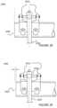
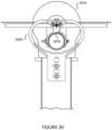
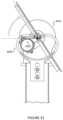
- FIGS. 30 through 32illustrate an in-line view of the clamp assembly 3000 and the drive assembly 3010 in multiple configurations according to embodiments of the present invention.
- the crankis in a lower position, which allows for the torque tube 3020 to be at its lowest position in an example.
- the torque tube 3020swings from the lowest position to an elevated position in a radial manner along a first direction or an elevated position in a radial manner along a second direction, as shown.
- the plurality of solar panels fixed to the torque tubealso rotate along a path from a first spatial region to a second spatial region.
- each of the inner regions of the lobesacts as a stop for the torque tube 3020 or an override for the torque tube 3020 .
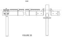
- FIG. 33is a side view diagram of the tracker apparatus 3300 according to an embodiment of the present invention. As shown is a side view diagram of the torque tube, solar panels with frames, and clamp housing and structure.
- FIGS. 34 and 35are simplified side view diagrams of a torque tube 3400 according to an embodiment of the present invention.
- each of the torque tubeshas a plurality of openings 3410 on each end for affixing to either the clamp or drive device cylinder.
- Each of the torque tubesalso has a plurality of openings 3410 for clamps configured to hold the tube to a frame coupled to the plurality of solar modules.
- FIGS. 36 , 37 , and 38are simplified perspective-view, side view, and front view diagrams of a clamp member or half clam shell member 3600 according to an embodiment of the present invention. As shown are the clam shell members, including pin opening to be coupled to the spherical bearing, and a plurality of slots for bolts to hold the torque tube in place and for adjustment.
- FIGS. 39 and 40are simplified perspective-view and side view diagrams of a clamp housing 3900 according to an embodiment of the present invention.
- the clamp housing 3900configured as a heart like shape, with tongue.
- the tonguehas a recessed region, and an opening or slot for the spherical bearing.
- the housing 3900also has a member to be coupled to the pier structure.
- FIGS. 41 , 42 , 43 , and 44are simplified diagrams of component(s) for a U-bolt member 4100 according to an embodiment of the present invention. As shown is a U-bolt member 4100 and a pair of nuts to secure the U-bolt.
- the componentsalso includes an upper clamp 4110 with a protrusion to be coupled to a notch or opening in the torque tube to prevent any movement between the torque tube and U-bolt member 4100 . That is, the protrusion acts as a stop to hold the U-bolt in place.
- FIGS. 45 , 46 , and 47are simplified diagrams illustrating a method of configuring a U-bolt member to a torque tube 4520 according to an embodiment of the present invention. As shown are U-bolt coupled to a periphery of the torque tube 4520 .
- the clamp member 4510including protrusion, which has a thinner portion and thicker portion, coupled to a notch in the torque tube.
- a pair of boltsfastens and secures the clamp member 4510 and U-bolt 4500 in place to hold the frame structure, which couples to the plurality of solar modules.
- FIGS. 48 and 49illustrate various views of a tracker apparatus 4800 according to an embodiment of the present invention. As shown, the torque tube and tracker apparatus 4800 are in a normal rest position.
- FIGS. 50 and 51illustrate views of a tracker apparatus 5000 according to an embodiment of the present invention. As shown, a lateral force is provided against a direction normal to the length of the torque tube, which causes one end of the torque tube to move in the lateral direction, while the other end remains fixed in an example.
- FIGS. 52 and 53illustrate an illustration of a torque tube 5200 according to an embodiment of the present invention. As shown, the torque tube 5200 rotates and swings in a radial manner upon being subjected to the lateral force, in an example. The torque tube 5200 stops against an inner side of one of the lobes of the clamp housing.
- FIG. 54is a front view diagram of a clamp assembly 5400 according to an example of the present invention.
- a clamp assembly 5400configured for a torque tube 5440 .
- the clamp assembly 5400has a support structure configured as a frame 5420 having configured by a first anchoring region and a second anchoring region.
- the first anchoring regionis coupled to a pier support 5430 using a nut and bolt fastener.
- the second anchoring regionis coupled to a pier support 5430 using a nut and bolt fastener.
- the frame structureis shaped as a loop that is symmetric and can also be non-symmetric in other examples.
- the support structurebeing configured from a thickness of metal material, such as high grade steel or other metal material with sufficient strength.
- the support structureis stamped from the thickness of metal material.
- the support structureis configured from a stamped steel comprising a Q345 steel or other suitable material.
- the support structurebeing configured in an upright manner, and has a major plane region configured within the frame structure. As shown, the major plane region has an opening to allow the torque tube 5440 and related support members to move within the opening.
- the torque tube 5440is coupled to a pivot device configured on the support structure.
- the torque tube 5440suspending on the pivot device and aligned within the opening of the support and configured to be normal to the plane region.
- the torque tube 5440is configured on the pivot device to move about an arc in a first direction or in a second direction such that the first direction is in a direction opposite to the second direction.
- the support structurecomprises the frame 5420 configured with the opening.
- the frame 5420has a first stop region within a first inner region of the frame 5420 and a second stop region within a second inner region of the frame 5420 and configured to allow the torque tube 5440 to swing in a first direction within the opening and stop against the first stop region and swing in a second direction within the opening and stop against the second stop region.
- the assemblyis coupled to a drive device configured to cause the torque tube 5440 to swing in the first direction and swing in the second direction.
- the pivot deviceis configured to allow the torque tube 5440 to move about an arc direction, while being fixed in other spatial domains.
- the pivot devicecomprises a pin structure configured in a sleeve or bearing assembly that is coupled to the frame structure.
- FIG. 55is a front view diagram of a clamp assembly 5400 in a stop position according to an example of the present invention.
- the frame 5420having a first stop region within a first inner region of the frame 5420 and a second stop region within a second inner region of the frame 5420 and configured to allow the torque tube 5440 to swing in a first direction within the opening and stop against the first stop region and swing in a second direction within the opening and stop against the second stop region; and further comprising a drive device configured to cause the torque tube 5440 to swing in the first direction and swing in the second direction.
- FIG. 56is a perspective view of a frame structure to be configured for the clamp assembly 5400 according to an example of the present invention.
- the frame structureis configured as the loop with an open region.
- the open regionis symmetric in shape.
- FIG. 57illustrates a top view diagram, a front view diagram, and a side view diagram of the frame structure to be configured for the clamp assembly according to an example of the present invention.
- the top view(as shown on the upper portion of the drawings) illustrates a member with constant width, while there can be variations.
- the front viewshows the open region configured within the loop structure or frame 5420 , and anchor regions, which have flats.
- the side viewis also shown (along right hand side of drawings). Further details of the present structures can be found throughout the present specification and more particularly below.
- FIG. 58illustrates a top view diagram, a front-view diagram, and a side view diagram of a U-bolt 5800 configured on a torque tube 5810 for a solar panel bracket (or frame structure) according to an example of the present invention.
- the top viewshows a clamp support 5820 with saddle region configured to the outer portion (not shown) of a portion of the torque tube 5810 .
- the saddle regionis coupled intimately with the portion of the torque tube 5810 .
- a flat region including a pair of openings on each endserve as a bracket for attachment of a solar panel or panels in an example.
- the front viewhas a clamping U-bolt coupling a portion of the torque tube 5810 and is configured to the clamp support 5820 .
- the side viewshows a leg or bolt of a U-bolt 5800 configured on one side of the torque tube 5810 and coupled to the clamp support 5820 .
- the other sidehas a similar configuration, including leg or bolt of the U-bolt 5800 and torque tube 5810 .
- FIG. 59illustrates a front view diagram of the U-bolt 5800 configured to a torque tube 5810 for a solar panel bracket according to an example of the present invention.
- the clamp support membercomprising a first end and a second end and has a length in between the first end and the second end. A width is also included.
- the clamp support memberbeing configured a saddle region having a first opening and a second opening and an inner opening such that a first leg of a U-bolt 5800 is inserted into the first opening and a second leg of the U-bolt 5800 is inserted into the second opening while a clamp member is positioned to hold the U-bolt 5800 in place to secure a portion of the torque tube 5810 to an opposite side of the saddle region while the clamp member is in intimate contact with the inner opening using a male portion provided within the inner opening to fit the male portion within the inner opening.
- FIG. 60illustrate a perspective view of a support member for the U-bolt 5800 configured to a torque tube 5810 for a solar panel bracket according to an example of the present invention.
- the support memberthe first end and the second end and has the length in between the first end and the second end. The width is also included.
- the clamp support member 5820has a saddle region having a first opening and a second opening and an inner opening such that a first leg of a U-bolt 5800 is inserted into the first opening and a second leg of the U-bolt 5800 is inserted into the second opening while a clamp member is positioned to hold the U-bolt 5800 in place to secure a portion of the torque tube 5810 to an opposite side of the saddle region while the clamp member is in intimate contact with the inner opening using a male portion provided within the inner opening to fit the male portion within the inner opening.
- the present parts and elementscan be made of suitable material, such as steel, aluminum, or other alloys. Additionally, such steel and/or alloys and/or aluminum can be cast, stamped, or welded, or combinations thereof. Of course, there can be other variations, modifications, and alternatives.
- the drive motoris operable to move the torque tube 5810 about the center of rotation and is substantially free from a load and move the torque tube 5810 about the center of rotation at substantially a same force from a first radial position to a second radial position.
- FIG. 61illustrates a front view diagram and a side view diagram of an off-set slew gear drive 6100 according to an example of the present invention.
- a solar tracker apparatusis shown.
- the left side diagramillustrates a front view diagram, while the right side diagram is a side view diagram.
- the apparatushas an inner race structure 6110 .
- the inner race structure 6110comprising a cylindrical region coupled to a main body region.
- the main bodycomprising an off-set open region (which is fitted with the torque tube sleeve).
- the apparatushas an outer race structure 6120 coupled to enclose the inner race structure 6110 , and configured to couple the inner race structure 6110 to allow the inner race structure 6110 to move in a rotational manner about a spatial arc region.
- the outer race structure 6120is also configured to allow the inner race structure 6110 to pivot about a region normal to a direction of the spatial arc region, as will be further described.
- the outer race structure 6120is configured from a rigid steel structure and shaped as an annular sleeve having a main hub region for a slew gear device and a support structure comprising a flat region for a pier structure.
- a torque tube sleeve 6130is configured in an off-set manner on a region between a center region and an outer region of the inter race structure 6110 .
- the torque tube sleeve 6130is also configured to be inserted within the off-set open region.
- the torque tube sleeve 6130has a plurality of openings for fasteners.
- the outer race structurehas a main hub configured with a drive 6140 coupled to the inner race structure 6110 to cause the torque tube to move about an arc region.
- the drive 6140comprises a slew gear device.
- the slew gear devicecomprising a worm gear operably coupled to a portion of the inner race structure 6110 comprising a plurality of gears, while other portions of the inner race structure 6110 are smooth.
- the drive 6140comprises a slew gear device that transfers torque for rotating the inter race structure from a first spatial region to a second spatial region and then from the first spatial region to the second spatial region in a rocking motion to track movement of a solar source. That is, the first spatial region to the second spatial region comprises 360 degrees, or can range up to 120 degrees or up to 140 degrees, although there can be variations.
- FIG. 62illustrates a front view diagram and a side view diagram of an off-set slew gear drive 6100 in a pivot position according to an example of the present invention.
- the inner race structure 6110is coupled to the outer race structure 6120 using a bearing or a bushing device to couple the inner race structure 6110 to the outer race structure 6120 for the radial movement about a direction substantially parallel to a length of the torque tube.
- the inner racecomprises a plurality of gear structures; and further comprises a bearing assembly or a bushing assembly configured within an inner region of the gear structure (not shown).
- the torque tube sleeve 6130is configured with the region using a cylindrical bearing assembly to facilitate movement of the about the spatial arc and facilitate movement normal to the spatial arc to pivot the inner race structure 6110 .
- the torque tubepivots and can also move about the radial movement in an arc, while accommodating changes in height on either end of the torque tube, among other variations.
- FIG. 63illustrates cross-sections of front view diagram and a side view diagram of an off-set slew gear drive 6100 according to an example of the present invention.
- cross-sections of the aforementioned diagramsare shown.
- the cut awayshows the plurality of gears on the inner race region operably coupled to the worm gear to facilitate movement of the inner race structure 6110 .
- As shownare both the front view cross-section and the side-view cross-section.
- FIG. 64illustrates cross sections of front view diagram and a side view diagram of an off-set slew gear drive 6100 in a pivot position according to an example of the present invention.
- cross-sections of the aforementioned diagramsare shown. The cut away shows the plurality of gears on the inner race region operably coupled to the worm gear to facilitate movement of the inner race structure 6110 .
- the cross-sectionsillustrate a pivot movement about a region to allow the torque tube to move about a solid conical space on each side of the inner race region in other examples.
- the front view cross-section and the side-view cross-sectionare both the front view cross-section and the side-view cross-section.
- FIG. 65is an exploded view of an off-set slew gear device 6100 in an example of the present invention.
- the assemblyhas an inner race structure 6110 shaped as a cylindrical drum.
- the assemblyhas an outer race structure 6120 coupled to enclose the inner race structure 6110 .
- the outer race structure 6120is shaped as an annular frame structure to enclose the inner race structure 6110 .
- the outer race structure 6120is configured from a rigid steel structure.
- the inner raceis coupled to the outer face using a bearing or a bushing device.
- the inner racecomprises a plurality of gear structure; and further comprises a bearing assembly or a bushing assembly configured within an inner region of the gear structure.
- the bearing or bushing assemblyoperably couples the outer race structure 6120 to the inner race structure 6110 to allow the inner face structure to rotate freely within the outer race structure 6120 .
- the assemblyhas a ring clamp member 6150 comprising a plurality of openings.
- the clamp member 6150is disposed on one side of the inner race member while a bearing or bushing assembly provided on the outer face member is disposed on the other side to sandwich the inter race member in between the clamp member 6150 and the outer face member.
- a plurality of bolts and/or other fastenerseach of which is firmly engaged to maintain the inner race member within the outer race member during operation.
- the torque tubecomprises a flange structure configured and firmly attached around a periphery of the torque tube, as shown.
- the flangehas a plurality of openings, each of which can include a bolt that firmly engages the flange structure along with the torque tube to the inner race structure 6110 . That is, the inner race structure 6110 is firmly engaged and fixed in place with the torque tube, which rotates along with the inner race structure 6110 .
- the torque tubeis driven by a drive motor, which turns the worm gear to facilitate movement of the inner race structure 6110 about an arc or even for 360 degrees, in one or more examples.
- a drive motorwhich turns the worm gear to facilitate movement of the inner race structure 6110 about an arc or even for 360 degrees, in one or more examples.
- the assemblyhas a torque tube sleeve 6130 configured in an off-set manner on a region between a center region of the inner race structure 6110 and an outer region of the inter race structure.
- the inner race structure 6110has an opening configured in an off-set manner to allow the torque tube sleeve 6130 to be inserted into the opening in a direction normal to the face of the inner race structure 6110 .
- a driveis coupled to the inner race structure 6110 to cause the torque tube to move about an arc region.
- a portion of the inner race structure 6110has a plurality of gears formed on the surface of the outer surface of the inner race structure 6110 .
- the drivecomprises a slew gear device, which is coupled to the plurality of gears.
- the drivecomprises a slew gear device that transfers torque for rotating the inter race structure about the outer race structure 6120 to cause the torque tube to rotate about an arc region that is continuous from a first spatial region to a second spatial region.
- the outer race structure 6120comprises a main hub region configured in a perpendicular direction to a worm gear assembly. As shown, the main hub region is configured on a lower portion of the inner race structure 6110 . In an example, the main hub region is configured with a shaft 6160 including a plurality of gears, which operably couple to the inner race structure 6110 comprising gears. The gears on the shaft 6160 cause the inner race structure 6110 to move in either direction in a rotational action. In an example, the worm gear assembly being coupled to an electric motor drive, which provides for the movement of the inner race structure 6110 .
- the torque tube sleeve 6130is configured with the region using a cylindrical bearing assembly fitted within the inner race structure 6110 .
- the cylindrical bearingallows the torque tube to pivot about a region to allow the torque tube to move freely about a conical spatial region on each side of the inner race structure 6110 .
- the torque tube sleeve 6130can pivot up to an angle range up to 10 degrees or 15 degrees relative to a face of the inner race structure 6110 .
- the regionis characterized by solid angle characterizing a cone having an acute angle of 20 to 30 degrees (as measured from each inner region of the cone along any point in a z-axis direction, where the apex is defined by a region where the torque tube is coupled to the inner race region), although there may be variations.
- the main hub regioncomprises a support structure.
- the support structurecomprises a flat region having a plurality of openings.
- the flat regionis provided to be assembled onto a pier structure, such as those previously noted, as well as outside of the present specification.
- a pier structuresuch as those previously noted, as well as outside of the present specification.
- the torque tubeis configured within a center region of the inner race structure 6110 , while the torque tube is configured in an off-set manner using an elbow and bend.
- FIG. 66is a simplified diagram of a top view of an array of solar modules configured on a tracker apparatus according to an embodiment of the present invention.
- a torque tubeis configured from a first end to a second end via a center region of the array of solar modules.
- Each column of solar modulescomprises at least four modules in a serial configuration.
- a second row of four modulesis disposed against the first row of solar modules.
- a plurality of rows numbered from 3 to Nform the remainder of the array of solar modules.
- a plurality of clampsare configured to hold the array together onto a frame assembly.
- the frame assemblyis coupled to the torque tube 6610 using a U-bolt assembly 6630 .
- the frame assemblycomprises a plurality of members running normal to a length of the torque tube 6610 , as shown. Each member also runs normal to a length of each of the clamps.
- the frame assemblycomprises a plurality of members running normal to a length of the torque tube 6610 , as shown. Each member also runs normal to a
- the frame member, clamp, and other memberscan be made of a suitable material such as rolled steel, stamped steel, cast steel, or others.
- the steel sheet metalcan include ASTM A572 Grade 50, among other materials, combinations of materials, and the like.
- the materialcan be coated or uncoated.
- FIG. 67is a simplified diagram of a side-view of an array of solar modules configured on a torque tube 6610 for a tracker apparatus according to an embodiment of the present invention.
- the torque tube 6610is configured from a first end to a second end via a center region of the array of solar modules.
- Each column of solar modulescomprises at least four modules in a serial configuration.
- a second row of four modulesis disposed against the first row of solar modules.
- a plurality of rows numbered from 3 to Nform the remainder of the array of solar modules.
- a plurality of clampsis configured to hold the array together onto a frame assembly.
- the frame assemblyis coupled to the torque tube 6610 using a U-bolt assembly 6630 , which couple each of the solar modules in place.
- a side view diagram of a U-bolthaving a bottom region configured around a portion of the torque tube 6610 while being pulled by a clamp member coupled to each member of the frame.
- a U-bolt clampis configured on each end of the U-bolt while the frame member is in between to secure the torque tube 6610 , frame member, and plurality of modules together.
- FIG. 68is a simplified diagram of a front-view of an array of solar modules configured on a torque tube 6610 for a tracker apparatus according to an embodiment of the present invention.
- the torque tube 6610is configured from a first end to a second end via a center region of the array of solar modules.
- Each column of solar modulescomprises at least four modules in a serial configuration.
- a second row of four modulesis disposed against the first row of solar modules.
- a plurality of rows numbered from 3 to Nform the remainder of the array of solar modules.
- a plurality of clampsis configured to hold the array together onto a frame assembly.
- the frame assemblyis coupled to the torque tube 6610 using a U-bolt assembly 6630 .
- a side view diagram of a U-bolthaving a bottom region configured around a portion of the torque tube 6610 while being pulled by a clamp member coupled to each member of the frame.
- a side view diagram of a U-bolthaving a bottom region configured around a portion of the torque
- FIG. 69is a simplified diagram of a perspective-view of an array of solar modules configured on a tracker apparatus according to an embodiment of the present invention. As shown, the perspective view emphasizes a top portion of the plurality of solar modules configured in an array.
- FIG. 70is a simplified diagram of a perspective-view of an array of solar modules configured on a tracker apparatus according to an embodiment of the present invention. As shown, the perspective view emphasizes a bottom portion of the plurality of solar modules configured in an array. As shown, a plurality of U-bolt clamp assemblies are spatially disposed along portions the torque tube 6610 . Each spacing between each pair of clamps has a similar or same distance for a length of the torque tube 6610 in an example. Each of the U-bolt clamp assemblies is configured on a frame member, which runs normal to a length of the torque tube 6610 .
- FIG. 71illustrates each of the clamp members configured to hold edges of at least a pair of solar modules together.
- the clamp memberscomprise a bottom hat channel clamp member 6641 and a top hat channel clamp member 6642 , which sandwich edges of the pair of solar panels.
- the bottom hat channel clamp 6641is disposed on a frame member. An edge or edges of a solar module 6600 or modules is placed on a brim region of the bottom hat channel member 6641 .
- the bottom hat channel member 6641is fixed to the frame member using a pair of nuts and bolts configured on each side of a channel region of the hat channel clamp.
- the top hat channel clamp member 6642which has a slightly larger inner width than a width of the bottom hat channel member 6641 , is configured to intimately couple a protruding channel or male portion with the bottom hat channel member 6641 with a slot or female portion of the top hat channel member 6642 while leaving a spatial gap between an upper surface of the bottom hat channel member 6641 and a bottom surface of the top hat channel member 6642 .
- the gapcan be used to form a spring action to cause force to increase as a nut member is secured form an outer region to an inner region. The increase in force leads to a secure attachment of edges of the solar modules between each of the hat channel members.
- the pair of hat channel memberscauses a mechanical load on each brim region of the top hat channel member 6642 to sandwich each of the edges between the top hat channel member 6642 and the bottom hat channel member 6641 .
- the top hat channel member 6642is made of a suitable material, which is different in thickness for example, to desirably compress edges of the solar modules between each of the hat channel members.
- each of the hat channel membersis configured with a compressible material such as a plastic or polymer, de-formal or conformal material, rubber or sponge like material, or other structure that facilitates friction in the sandwich structure to prevent movement or sliding of any of the solar modules.
- a compressible materialsuch as a plastic or polymer, de-formal or conformal material, rubber or sponge like material, or other structure that facilitates friction in the sandwich structure to prevent movement or sliding of any of the solar modules.
- FIG. 72illustrates a front view diagram of each of the clamp members configured to hold edges of at least a pair of solar modules together.
- each clamp membercan hold an edge of a single solar module or a pair.
- the clampcan hold up to four panels together, which have four corners together.
- the clamp memberscomprise a bottom hat channel clamp member 6641 and a top hat channel clamp member 6642 , which sandwich edges of the pair of solar panels.
- the bottom hat channel clamp 6641is disposed on a frame member.
- An edge or edges of a solar module 6600 or modulesis placed on a brim region of the bottom hat channel member 6641 .
- the bottom hat channel member 6641is fixed to the frame member using a pair of nuts and bolts configured on each side of a channel region of the hat channel clamp. As shown, a bolt inserted from a bottom portion of the frame member, extends through both hat channel members, and protrudes through an upper surface of the top hat channel member 6642 . A nut is configured on the bolt to firmly engage the structure together.
- a boltinserted from a bottom portion of the frame member, extends through both hat channel members, and protrudes through an upper surface of the top hat channel member 6642 .
- a nutis configured on the bolt to firmly engage the structure together.
- FIG. 73is a simplified front-view diagram of a clamp assembly according to an example of the present invention.
- the clamp memberscomprise a bottom hat channel clamp member 6641 and a top hat channel clamp member 6642 , which sandwich edges of the pair of solar panels.
- the bottom hat channel clamp 6641is disposed on a frame member.
- An edge or edges of a solar module 6600 or modulesis placed on a brim region of the bottom hat channel member 6641 .
- the bottom hat channel member 6641is fixed to the frame member using a pair of nuts and bolts configured on each side of a channel region of the hat channel clamp.
- a bolt inserted from a bottom portion of the frame memberextends through both hat channel members, and protrudes through an upper surface of the top hat channel member 6642 .
- a nutis configured on the bolt to firmly engage the structure together.
- a compressible materialsuch as a plastic or polymer, de-formal or conformal material, rubber or sponge like material, or other structure is disposed between each edge of the solar module edge overlying a portion of an edge of a channel region, and overlying an upper surface of each brim region.
- a thickness of compressive materialis also disposed between an underlying region of the brim on the top hat channel member 6642 and an upper edge portion of the solar module 6600 .
- Each of the compressive materials(on each side of the channel region-four total) provides friction in a sandwich structure to prevent movement or sliding of any of the solar modules among each other.
Landscapes
- Engineering & Computer Science (AREA)
- General Engineering & Computer Science (AREA)
- Mechanical Engineering (AREA)
- Sustainable Development (AREA)
- Life Sciences & Earth Sciences (AREA)
- Physics & Mathematics (AREA)
- Sustainable Energy (AREA)
- Combustion & Propulsion (AREA)
- Chemical & Material Sciences (AREA)
- Thermal Sciences (AREA)
- Electromagnetism (AREA)
- Remote Sensing (AREA)
- Radar, Positioning & Navigation (AREA)
- General Physics & Mathematics (AREA)
- Photovoltaic Devices (AREA)
Abstract
Description
Claims (12)
Priority Applications (1)
| Application Number | Priority Date | Filing Date | Title |
|---|---|---|---|
| US17/742,247US12228662B2 (en) | 2012-12-10 | 2022-05-11 | Off-set drive assembly for solar tracker |
Applications Claiming Priority (5)
| Application Number | Priority Date | Filing Date | Title |
|---|---|---|---|
| US201261735537P | 2012-12-10 | 2012-12-10 | |
| US14/101,273US9905717B2 (en) | 2012-12-10 | 2013-12-09 | Horizontal balanced solar tracker |
| US14/489,409US9766319B2 (en) | 2012-12-10 | 2014-09-17 | Off-set drive assembly for solar tracker |
| US15/694,647US11391809B2 (en) | 2012-12-10 | 2017-09-01 | Off-set drive assembly for solar tracker |
| US17/742,247US12228662B2 (en) | 2012-12-10 | 2022-05-11 | Off-set drive assembly for solar tracker |
Related Parent Applications (1)
| Application Number | Title | Priority Date | Filing Date |
|---|---|---|---|
| US15/694,647ContinuationUS11391809B2 (en) | 2012-12-10 | 2017-09-01 | Off-set drive assembly for solar tracker |
Publications (2)
| Publication Number | Publication Date |
|---|---|
| US20220276331A1 US20220276331A1 (en) | 2022-09-01 |
| US12228662B2true US12228662B2 (en) | 2025-02-18 |
Family
ID=52114412
Family Applications (4)
| Application Number | Title | Priority Date | Filing Date |
|---|---|---|---|
| US14/489,409ActiveUS9766319B2 (en) | 2012-12-10 | 2014-09-17 | Off-set drive assembly for solar tracker |
| US15/694,647Active2034-04-11US11391809B2 (en) | 2012-12-10 | 2017-09-01 | Off-set drive assembly for solar tracker |
| US16/234,723ActiveUS10379193B2 (en) | 2012-12-10 | 2018-12-28 | Off-set drive assembly for solar tracker |
| US17/742,247Active2034-05-20US12228662B2 (en) | 2012-12-10 | 2022-05-11 | Off-set drive assembly for solar tracker |
Family Applications Before (3)
| Application Number | Title | Priority Date | Filing Date |
|---|---|---|---|
| US14/489,409ActiveUS9766319B2 (en) | 2012-12-10 | 2014-09-17 | Off-set drive assembly for solar tracker |
| US15/694,647Active2034-04-11US11391809B2 (en) | 2012-12-10 | 2017-09-01 | Off-set drive assembly for solar tracker |
| US16/234,723ActiveUS10379193B2 (en) | 2012-12-10 | 2018-12-28 | Off-set drive assembly for solar tracker |
Country Status (1)
| Country | Link |
|---|---|
| US (4) | US9766319B2 (en) |
Families Citing this family (37)
| Publication number | Priority date | Publication date | Assignee | Title |
|---|---|---|---|---|
| US10277159B2 (en)* | 2008-11-17 | 2019-04-30 | Kbfx Llc | Finished multi-sensor units |
| US11063553B2 (en)* | 2008-11-17 | 2021-07-13 | Kbfx Llc | Solar carports, solar-tracking carports, and methods |
| JP2016504901A (en) | 2012-12-10 | 2016-02-12 | ネクストラッカー インコーポレイテッドNEXTracker Inc. | Horizontal balance solar tracking device |
| US9466749B1 (en)* | 2012-12-10 | 2016-10-11 | Nextracker Inc. | Balanced solar tracker clamp |
| US10008975B2 (en) | 2012-12-10 | 2018-06-26 | Nextracker Inc. | Clamp assembly for solar tracker |
| US9766319B2 (en) | 2012-12-10 | 2017-09-19 | Nextracker Inc. | Off-set drive assembly for solar tracker |
| US9543888B2 (en) | 2015-06-09 | 2017-01-10 | Nextracker Inc. | Frameless solar module mounting |
| US12294332B2 (en) | 2015-12-15 | 2025-05-06 | Kbfx Llc | Solar carports, solar-tracking carports, and methods |
| US10720877B2 (en)* | 2016-02-25 | 2020-07-21 | Solarcity Corporation | Photovoltaic mounting system for solar tracker array |
| US10931224B2 (en) | 2016-06-03 | 2021-02-23 | RBI Solar, Inc. | Single axis in-line gearbox modular tracker system |
| US10469025B2 (en) | 2016-09-01 | 2019-11-05 | Sunpower Corporation | Solar-tracking system drive having an offset gear |
| US10333459B2 (en)* | 2016-09-01 | 2019-06-25 | Sunpower Corporation | Photovoltaic module mounting assembly having a pin constraint |
| MX2019004417A (en)* | 2016-10-17 | 2019-08-14 | Nevados Eng Inc | Variable terrain solar tracker. |
| US11539325B2 (en) | 2017-03-07 | 2022-12-27 | Nevados Engineering, Inc. | Variable terrain solar tracker |
| US12301163B2 (en)* | 2018-08-08 | 2025-05-13 | OMCO Solar, LLC | Solar tracker bearing apparatus |
| US10615739B2 (en)* | 2018-09-05 | 2020-04-07 | Ojjo, Inc. | Optimized truss foundations, adapters for optimized truss foundations, and related systems and methods |
| US11121671B2 (en)* | 2018-09-05 | 2021-09-14 | Ojjo, Inc. | A-frame foundation system for single-axis trackers with weak axis support |
| US10845092B2 (en)* | 2018-09-19 | 2020-11-24 | Robert B. Dally | Panel mounting components |
| EP3942688A4 (en)* | 2019-03-21 | 2022-12-21 | Ojjo, Inc. | Moment optimized truss foundations for single-axis trackers |
| DE102019112201A1 (en)* | 2019-05-09 | 2020-11-12 | Robert Zimmermann | Solar module holding device and method for producing a solar module holding device |
| US11228275B2 (en) | 2019-06-27 | 2022-01-18 | National Oilwell Vareo, L.P. | Methods and apparatus for installing solar panels |
| AU2020375921A1 (en)* | 2019-10-29 | 2022-06-16 | Ojjo, Inc. | Adjustable bearing supports for single-axis trackers |
| US11296649B2 (en) | 2020-02-07 | 2022-04-05 | National Oilwell Varco, L.P. | Foldable solar panel assembly |
| US20210257964A1 (en)* | 2020-02-18 | 2021-08-19 | Ojjo, Inc. | Truss foundations for single-axis trackers |
| US11108353B1 (en) | 2020-07-14 | 2021-08-31 | FTC Solar, Inc. | Systems and methods for array level terrain based backtracking |
| US11139775B1 (en) | 2020-07-14 | 2021-10-05 | FTC Solar, Inc. | Systems and methods for terrain based backtracking for solar trackers |
| US11522491B2 (en) | 2020-08-26 | 2022-12-06 | FTC Solar, Inc. | Systems and methods for adaptive range of motion for solar trackers |
| CN116368729A (en) | 2020-09-14 | 2023-06-30 | 耐克斯特拉克尔有限责任公司 | Support frame for solar tracker |
| US10935992B1 (en) | 2020-09-16 | 2021-03-02 | FTC Solar, Inc. | Systems and methods for solar trackers with diffuse light tracking |
| WO2022125630A1 (en)* | 2020-12-11 | 2022-06-16 | Gamechange Solar Corp. | Wind break end plate for solar panel arrays |
| US11757402B2 (en)* | 2020-12-14 | 2023-09-12 | Nevados Engineering, Inc. | Integrated articulated bearing |
| EP4437649A4 (en) | 2021-11-24 | 2025-08-20 | Shoals Tech Group Llc | MECHANICAL POWER TRANSFER BETWEEN SUN FOLLOWERS |
| US20230327602A1 (en)* | 2022-04-06 | 2023-10-12 | Nextracker Llc | Improved c-channel for solar tracker |
| ES2973385B2 (en)* | 2022-11-07 | 2024-12-26 | Trina Solar Spain S L U | SOLAR TRACKER WITH ROTATION TRANSMISSION SUPPORT |
| WO2024238607A1 (en)* | 2023-05-16 | 2024-11-21 | Nextracker Llc | Linked solar trackers |
| ES1301542Y (en)* | 2023-05-22 | 2023-09-27 | Soltec Innovations Sl | WORM AND CROWN SCREW REDUCER, FOR SOLAR TRACKER |
| US12231078B1 (en)* | 2023-08-02 | 2025-02-18 | Nextracker Llc | Solar module mounting assemblies |
Citations (183)
| Publication number | Priority date | Publication date | Assignee | Title |
|---|---|---|---|---|
| US81805A (en) | 1868-09-01 | Thomas d | ||
| US1232048A (en) | 1916-10-11 | 1917-07-03 | Henry Kolkmeier | Gate-hinge. |
| US1683266A (en) | 1925-08-05 | 1928-09-04 | Lewis H Shipman | Solar heating apparatus |
| US1761497A (en) | 1929-07-16 | 1930-06-03 | Barney C Garoff | Supporter for fishing rods |
| US1897186A (en) | 1930-05-15 | 1933-02-14 | Thomas & Betts Corp | Grounding fitting |
| US2156965A (en) | 1937-09-13 | 1939-05-02 | Stephen W Borden | Ground fitting |
| US2164022A (en) | 1937-12-10 | 1939-06-27 | Trumbull Electric Mfg Co | Electric connector |
| US2894773A (en) | 1956-06-12 | 1959-07-14 | Kidde Textile Machinery Corp | Clamp |
| US3022536A (en) | 1959-06-09 | 1962-02-27 | Unitcast Corp | Torsion spring assembly |
| US3361944A (en) | 1964-04-24 | 1968-01-02 | Shell Oil Co | Probe assembly for capacitance type monitoring device |
| US3832072A (en) | 1973-04-23 | 1974-08-27 | Trw Inc | Clamp assembly |
| US3935987A (en) | 1973-01-17 | 1976-02-03 | Foster Sr Christopher J | Method for rotation of plates to facilitate weldment |
| US4023368A (en) | 1975-08-26 | 1977-05-17 | Kelly Donald A | High density-third dimension geometry solar panels |
| US4061130A (en) | 1975-04-28 | 1977-12-06 | Gonzalez Eduardo E | Solar energy device |
| US4135493A (en) | 1977-01-17 | 1979-01-23 | Acurex Corporation | Parabolic trough solar energy collector assembly |
| US4146784A (en) | 1976-01-08 | 1979-03-27 | Yeda Research & Development Co., Ltd. | Sun tracking device |
| US4158356A (en) | 1977-02-22 | 1979-06-19 | Wininger David V | Self-powered tracking solar collector |
| US4192583A (en) | 1977-10-21 | 1980-03-11 | The United States Of America As Represented By The United States Department Of Energy | Solar receiver heliostat reflector having a linear drive and position information system |
| US4205657A (en) | 1978-11-30 | 1980-06-03 | Kelly Donald A | Convertible modular tri-mode solar conversion system |
| US4226502A (en) | 1978-07-24 | 1980-10-07 | Thomas Gunzler | Self-contained solar tracking device |
| US4276872A (en) | 1978-11-13 | 1981-07-07 | Atlantic Richfield Company | Solar system employing ground level heliostats and solar collectors |
| US4306540A (en) | 1979-06-25 | 1981-12-22 | Solar Kinetics, Inc. | Solar collector mounting and support apparatus |
| US4317031A (en) | 1978-08-02 | 1982-02-23 | Max Findell | Central focus solar energy system |
| US4320882A (en) | 1978-03-29 | 1982-03-23 | General Signal Corporation | Clamp for grounding and clamping a conduit to a support member |
| US4340812A (en) | 1979-03-26 | 1982-07-20 | Kei Mori | Radiation energy collection and tracking apparatus |
| US4372017A (en) | 1980-09-17 | 1983-02-08 | Heckethorn Manufacturing Co. | U-Bolt exhaust system clamp with double saddle |
| US4429178A (en) | 1981-07-13 | 1984-01-31 | Acurex Solar Corporation | Solar tracking apparatus utilizing photovoltaic flat panels and method |
| US4429952A (en) | 1981-12-28 | 1984-02-07 | Dominguez Richard L | Tracking reflector assembly for a skylight |
| US4465252A (en) | 1983-04-08 | 1984-08-14 | Nickson Industries, Inc. | Compact universal hanger for tailpipes and the like |
| US4545166A (en) | 1983-11-21 | 1985-10-08 | Manville Service Corporation | Ceiling insulation system |
| US4602811A (en) | 1984-11-28 | 1986-07-29 | Heckethorn Manufacturing Company | U-bolt clamp construction |
| US4613171A (en) | 1984-10-18 | 1986-09-23 | Corcoran Daniel P | Junction coupling with unitary locking gasket and methods for their use |
| US4704038A (en) | 1982-06-07 | 1987-11-03 | Sherrill Industries, Inc. | Hanger bearing |
| US4815585A (en) | 1988-02-23 | 1989-03-28 | Custom Metalcraft, Inc. | Sanitary hanger bearing assembly |
| US4890599A (en) | 1987-04-16 | 1990-01-02 | Eiden Glenn E | Solar panel mounting assembly |
| US5092939A (en) | 1990-11-30 | 1992-03-03 | United Solar Systems Corporation | Photovoltaic roof and method of making same |
| US5181762A (en) | 1990-05-02 | 1993-01-26 | Revab B.V. | Biomechanical body support with tilting leg rest tilting seat and tilting and lowering backrest |
| US5274888A (en) | 1993-04-05 | 1994-01-04 | Gto, Inc. | Adjustable U-bolt type pipe clamp |
| US5281761A (en) | 1992-02-25 | 1994-01-25 | Burndy Corporation | Grounding pipe/water pipe with compression connectors |
| USD361561S (en) | 1994-01-18 | 1995-08-22 | Hewlett-Packard Company | Stand for a connection unit and computer write-on tablet |
| US5742448A (en) | 1991-12-11 | 1998-04-21 | Funai Electric Co., Ltd. | Device using cam-based movements to load and unload a tape cassette |
| US5816238A (en) | 1994-11-28 | 1998-10-06 | Minnesota Mining And Manufacturing Company | Durable fluorescent solar collectors |
| US5983746A (en) | 1995-08-31 | 1999-11-16 | Toyota Jidosha Kabushiki Kaisha | Supporting structure of a pedal device for a vehicle |
| US6058930A (en) | 1999-04-21 | 2000-05-09 | Shingleton; Jefferson | Solar collector and tracker arrangement |
| CA2315367A1 (en) | 1998-10-30 | 2000-05-11 | Plasturgie Du Centre S.A.R.L. | Bicycle trailer |
| US6106065A (en) | 1997-10-24 | 2000-08-22 | Reliance Medical Products, Inc. | Examination chair with lifting and tilting mechanism |
| USD438093S1 (en) | 1999-09-22 | 2001-02-27 | J. C. Mandujano | Electrical and aluminum tubing clamp |
| USD439833S1 (en) | 1999-12-21 | 2001-04-03 | Shinagawa Shoko Co., Ltd. | Bundling and holding clamp |
| US6269596B1 (en) | 1997-02-05 | 2001-08-07 | Canon Kabushiki Kaisha | Roof member and mounting method thereof |
| US6300555B1 (en) | 1997-07-29 | 2001-10-09 | Kaneka Corporation | Solar cell module |
| US20020024762A1 (en) | 2000-08-23 | 2002-02-28 | Seagate Technology Llc | Disc clamp having adjustable balance ring |
| US6389656B1 (en) | 1997-11-04 | 2002-05-21 | Agrarisch Loonbedrijf C. Pellikaan | Clip, as well as wire/clip assembly |
| US20020078945A1 (en) | 2000-07-06 | 2002-06-27 | Friedrich Funger | Apparatus for utilising solar energy |
| US6431502B1 (en) | 2000-03-11 | 2002-08-13 | All-Points Equipment Co., L.P. | Cable clamp |
| US6454035B1 (en) | 2000-01-25 | 2002-09-24 | Paccar Inc | Tilt mechanism and method for pivoting a vehicle body panel relative to a vehicle chassis |
| US20020179138A1 (en) | 2001-05-29 | 2002-12-05 | Paul Lawheed | Conversion of solar energy |
| US20030034029A1 (en) | 2001-08-15 | 2003-02-20 | Jefferson Shingleton | Fixed angle solar collector arrangement |
| US20030070368A1 (en) | 2001-10-12 | 2003-04-17 | Jefferson Shingleton | Solar module mounting method and clip |
| US6561473B1 (en) | 2001-03-30 | 2003-05-13 | Pirod, Inc. | Universal pipe mounting clamp and assembly |
| US20030226412A1 (en) | 2002-04-03 | 2003-12-11 | Cleaire Advanced Emission Controls | Apparatus and method for mounting a device to a pipe |
| JP2004525596A (en) | 2001-04-06 | 2004-08-19 | ベン,ウィリアム,エム. | Portable solar generator |
| US20040216410A1 (en) | 2003-04-30 | 2004-11-04 | Soi Shatzky | Clamp for Holding Solar Collectors on Roofs |
| US20040238025A1 (en) | 2003-03-18 | 2004-12-02 | Powerlight Corporation, A California Corporation | Tracking solar collector assembly |
| US20050048640A1 (en) | 2003-08-25 | 2005-03-03 | Gen-Probe Incorporated | Clamp and method of making same |
| US20050284467A1 (en) | 2002-10-17 | 2005-12-29 | Patterson Michael T | Solar tracking apparatus |
| US20060035740A1 (en) | 2001-12-05 | 2006-02-16 | Lehtovaara Jorma J | Timing belt tensioner with stops controlled by frictional brake |
| US20060086382A1 (en) | 2004-02-13 | 2006-04-27 | Plaisted Joshua R | Mechanism for mounting solar modules |
| US20070144575A1 (en) | 2003-08-20 | 2007-06-28 | Powerlight Corporation | Supported PV Module Assembly |
| USD547262S1 (en) | 2006-04-15 | 2007-07-24 | Ullman Stanley A | Solar panel fixed angle rack |
| US20070176059A1 (en) | 2005-12-20 | 2007-08-02 | Robert Roscetti | Beam-column clamp |
| US20080040990A1 (en) | 2006-06-29 | 2008-02-21 | Herb Vendig | Seasonally Adjustable Mounting System for Solar Panels |
| USD564958S1 (en) | 2007-03-23 | 2008-03-25 | Sunpower Corporation | Support base for solar collector assembly |
| US20080168981A1 (en) | 2006-08-25 | 2008-07-17 | Coolearth Solar | Rigging system for supporting and pointing solar concentrator arrays |
| US20080230047A1 (en) | 2007-03-23 | 2008-09-25 | Sunpower Corporation | Stackable Tracking Solar Collector Assembly |
| US20080236567A1 (en) | 2007-03-29 | 2008-10-02 | Hayden Herbert T | System for supporting energy conversion modules |
| US20080251115A1 (en) | 2005-09-28 | 2008-10-16 | Thompson Technology Industries, Inc. | Solar Panel Array Sun Tracking System |
| KR20080108640A (en) | 2007-06-11 | 2008-12-16 | 윤복현 | Solar tracker |
| US20080308091A1 (en) | 2007-06-15 | 2008-12-18 | Corio Ronald P | Single Axis Solar Tracking System |
| US20090025708A1 (en) | 2007-07-24 | 2009-01-29 | Sunpower Corporation | Rolling Motion Tracking Solar Assembly |
| US20090032014A1 (en) | 2007-07-31 | 2009-02-05 | Yevgeny Meydbray | Variable tilt tracker for photovoltaic arrays |
| US20090114211A1 (en) | 2006-12-15 | 2009-05-07 | Andrew Homyk | Automated Solar Tracking System |
| US7531741B1 (en)* | 2003-03-07 | 2009-05-12 | Sacred Power Corporation | Tracking solar shelter |
| US20090159778A1 (en) | 2007-12-24 | 2009-06-25 | Chia Hao Yeh | Solar energy absorption plate with angle adjusting assembly |
| USD606938S1 (en) | 2008-01-09 | 2009-12-29 | Johnson Controls Technology Company | Battery dust cover |
| US20100018570A1 (en) | 2008-05-16 | 2010-01-28 | Cashion Steven A | Concentrating photovoltaic solar panel |
| US7678168B2 (en) | 2006-12-14 | 2010-03-16 | Paccar Inc. | Multiple urethane tuned exhaust damper for vertical exhaust |
| US20100071683A1 (en) | 2005-08-20 | 2010-03-25 | Martin Selig | Fresnel solar collector arrangement |
| US20100101632A1 (en) | 2008-10-24 | 2010-04-29 | Emcore Solar Power, Inc. | Terrestrial Solar Tracking Photovoltaic Array With Offset Solar Cell Modules |
| US20100101630A1 (en) | 2008-10-24 | 2010-04-29 | Emcore Solar Power, Inc. | Terrestrial Solar Tracking Photovoltaic Array with Slew Speed Reducer |
| US20100147286A1 (en) | 2008-12-04 | 2010-06-17 | Xiao Dong Xiang | Systems and methods including features of synchronized movement across and array of solar collectors |
| US20100212714A1 (en) | 2009-02-20 | 2010-08-26 | Elie Rothschild | Modular solar racking system |
| US20100263297A1 (en) | 2003-02-26 | 2010-10-21 | Unirac, Inc. | Low profile mounting system |
| USD627717S1 (en) | 2010-01-08 | 2010-11-23 | JAC-Rack, Inc. | Support frame rail for supporting a photovoltaic panel on a surface |
| US7836879B2 (en) | 2004-08-10 | 2010-11-23 | Kevin Keith Mackamul | Tracker drive system and solar energy collection system |
| US20110023940A1 (en) | 2009-07-30 | 2011-02-03 | Skyline Solar, Inc. | Solar energy collection system |
| US20110041834A1 (en) | 2009-08-24 | 2011-02-24 | Liao Henry H | Two-Axes Solar Tracker System and Apparatus for Solar Panel and Likes |
| US20110073161A1 (en) | 2010-03-29 | 2011-03-31 | Sedona Energy Labs, Limited Company | High efficiency counterbalanced dual axis solar tracking array frame system |
| US20110073104A1 (en) | 2008-04-18 | 2011-03-31 | Sopogy, Inc. | Parabolic trough solar energy collection system |
| US20110088740A1 (en) | 2009-10-15 | 2011-04-21 | Sunlink Corporation. | Photovoltaic panel clamp |
| US20110094088A1 (en) | 2009-10-23 | 2011-04-28 | Chevron U.S.A. Inc. | Solar canopy construction method |
| US20110099923A1 (en) | 2009-11-05 | 2011-05-05 | Ventura Mark C | Solar Array Foundation and Installation |
| US20110132353A1 (en) | 2009-12-04 | 2011-06-09 | SunPOD,S INC. | Transportable multi-configurable self-ballasted modular solar power unit |
| US20110138584A1 (en) | 2009-12-16 | 2011-06-16 | Union Metal Corporation | Clamp device for telescopic poles |
| US20110156380A1 (en) | 2008-09-01 | 2011-06-30 | Maximilian Dietz | Adjustable steering column for a motor vehicle |
| US20110232631A1 (en) | 2008-12-08 | 2011-09-29 | Boehmer Jon | Mosaic solar collector |
| US20110240006A1 (en) | 2010-04-01 | 2011-10-06 | Linke Edward J | Solar Tracking System and Method |
| US20110253195A1 (en) | 2010-04-19 | 2011-10-20 | Youil Ensys Co., Ltd. | Torque tube supporter and solar tracker using the same |
| US20110279918A1 (en) | 2010-05-17 | 2011-11-17 | Skywatch Energy, Inc. | Concentrating solar energy collector |
| US20110278411A1 (en) | 2010-05-17 | 2011-11-17 | Hilti Aktiengesellschaft | Mounting foot for solar modules and mounting system having a plurality of such mounting feet |
| USD651970S1 (en) | 2011-09-06 | 2012-01-10 | Turk Michael F | Cross bracket support for a concentrating photovoltaic system module |
| USD651969S1 (en) | 2011-08-30 | 2012-01-10 | Turk Michael F | Cross bracket support for a concentrating photovoltaic system module |
| US20120006386A1 (en) | 2010-07-12 | 2012-01-12 | Christopher Stephen Klinga | Junction Cover for Photovoltaic Panel Modules |
| US20120031077A1 (en) | 2009-04-27 | 2012-02-09 | Toyota Jidosha Kabushiki Kaisha | Pm sensor, pm amount sensing device for exhaust gas, and abnormality detection apparatus for internal combustion engine |
| US20120048341A1 (en) | 2010-08-24 | 2012-03-01 | University Of Central Florida Research Foundation, Inc. | Iterative adaptive solar tracking having variable step size |
| US20120072041A1 (en) | 2010-02-16 | 2012-03-22 | Greenvolts, Inc | Integrated electronics housing for a solar array |
| US20120073565A1 (en) | 2009-05-11 | 2012-03-29 | Soltec Energias Renovables, S.L. | Single-axis solar tracker and solar power installation |
| US20120091077A1 (en) | 2011-05-09 | 2012-04-19 | Michael Zuritis | Solar array column cap |
| US8168931B1 (en) | 2009-12-09 | 2012-05-01 | Concrete Systems, Inc. | Solar tracking device |
| US8181926B2 (en) | 2010-01-22 | 2012-05-22 | Thomas & Betts International, Inc. | Panel clamp |
| US20120132258A1 (en) | 2009-05-19 | 2012-05-31 | Emanuele ALBANESE | Solar collector |
| US20120132262A1 (en) | 2009-08-07 | 2012-05-31 | Kenichi Sagayama | Structure installation rack, method for installing the same, structure connecting structure, connection member and method for installing this structure connecting structure, and solar cell system |
| US20120138764A1 (en) | 2010-12-03 | 2012-06-07 | Hilti Aktiengesellschaft | Clamp for a plate element, especially for a photovoltaic module |
| WO2012076949A1 (en) | 2010-12-07 | 2012-06-14 | Electrotherm Renewables | A solar parabolic trough collector or reflector system |
| US8203110B2 (en) | 2007-01-23 | 2012-06-19 | Dionisio Silvestre Mata | Dual axle solar tracker |
| US20120152311A1 (en) | 2010-12-17 | 2012-06-21 | Greenvolts, Inc | Components of a two-axis tracking assembly in a concentrated photovoltaic system |
| US20120180845A1 (en) | 2011-01-14 | 2012-07-19 | Sunpower Corporation | Support for solar energy collectors |
| US20120216852A1 (en) | 2011-02-22 | 2012-08-30 | Sunpower Corporation | Solar tracker drive |
| US8274028B2 (en) | 2008-02-27 | 2012-09-25 | Sunedison, Llc | Counterweighted active tracking solar panel rack |
| US20120269752A1 (en) | 2009-07-20 | 2012-10-25 | L'oreal | Emulsion containing a dispersion of bismuth oxychloride |
| US20120279489A1 (en) | 2009-08-29 | 2012-11-08 | Robert Bosch Gmbh | Tracking Device |
| US20130000632A1 (en) | 2011-06-29 | 2013-01-03 | Advanced Technology & Research Corp. (ATR) | Sun tracking solar power collection system |
| US20130006435A1 (en) | 2011-07-01 | 2013-01-03 | Berrios Javier C | Solar-Powered Apparatus for Wireless Network Control of an Array of Solar Tracking Devices and Systems Based Thereon |
| US20130026308A1 (en) | 2011-07-25 | 2013-01-31 | Holm-Quist Designs Llc | Mounting bracket means for solar arrays and the like |
| US8407950B2 (en) | 2011-01-21 | 2013-04-02 | First Solar, Inc. | Photovoltaic module support system |
| US8419130B2 (en) | 2010-09-30 | 2013-04-16 | Permobil Ab | Seat tilt apparatus |
| US20130160816A1 (en) | 2011-12-21 | 2013-06-27 | Sunpower Corporation | Support for solar energy collectors |
| US20130220395A1 (en) | 2012-02-28 | 2013-08-29 | Francis John Babineau, Jr. | Apparatus and methods for mounting a photovoltaic module on a roof |
| USD689434S1 (en) | 2012-08-10 | 2013-09-10 | Dr. Ing. H.C. F. Porsche Aktiengesellschaft | Battery cover for motor vehicle |
| US20130240008A1 (en) | 2012-03-16 | 2013-09-19 | Christopher Baker | System and method for mounting photovoltaic modules |
| US20130269753A1 (en) | 2012-04-17 | 2013-10-17 | Ronald P. Corio | Mounting assemblies, solar trackers, and related methods |
| US20140048124A1 (en) | 2011-03-30 | 2014-02-20 | Gi Ju Park | Solar cell module support structure |
| US8671930B2 (en) | 2010-02-02 | 2014-03-18 | The Liao's Family Limited Partnership | One-axis solar tracker system and apparatus with wind lock devices |
| US20140130847A1 (en) | 2012-02-22 | 2014-05-15 | Zep Solar, Inc. | PV Array Mounting for Trapezoidal Metal and Low-Slope Roofs |
| US8727288B2 (en) | 2012-04-03 | 2014-05-20 | Commscope, Inc. Of North Carolina | Snap-in bracket for attaching cabling to a support |
| US20140182577A1 (en) | 2012-12-28 | 2014-07-03 | Sunpower Corporation | Drive with integrated inclination sensor |
| US20140182654A1 (en) | 2012-12-28 | 2014-07-03 | Sunpower Corporation | Support for solar energy collection |
| US20140216522A1 (en) | 2012-12-10 | 2014-08-07 | Solaria Corporation | Horizontal balanced solar tracker |
| US8807129B2 (en) | 2004-08-10 | 2014-08-19 | Kevin Keith Mackamul | Tracker drive system and solar energy collection system |
| US20140259397A1 (en) | 2013-03-15 | 2014-09-18 | China Motors And Components, Inc. | Methods and apparatus for securing actuators to structures |
| USD713784S1 (en) | 2013-06-20 | 2014-09-23 | Ecolibrium Solar, Inc. | Support member for photovoltaic modules |
| US8839573B2 (en) | 2011-02-11 | 2014-09-23 | Northern States Metals Company | Spring clip |
| US20140290716A1 (en) | 2013-03-29 | 2014-10-02 | Unirac, Inc. | Photovoltaic module mounting assembly |
| US20150000722A1 (en) | 2012-12-10 | 2015-01-01 | Nextracker Inc. | Off-set swivel drive assembly for solar tracker |
| US20150001356A1 (en) | 2012-12-10 | 2015-01-01 | Nextracker Inc. | Clamp assembly for solar tracker |
| US20150000721A1 (en) | 2012-12-10 | 2015-01-01 | Nextracker Inc. | Off-set drive assembly for solar tracker |
| US8939648B2 (en) | 2011-08-12 | 2015-01-27 | First Solar, Inc. | Solar tracking bearing and solar tracking system employing same |
| US20150082924A1 (en) | 2013-09-19 | 2015-03-26 | Brent Morgan | Slew drive gearbox and clamp |
| US20150092383A1 (en) | 2013-10-02 | 2015-04-02 | Array Technologies, Inc. | Mounting bracket assemblies and methods |
| US20150129516A1 (en) | 2013-08-28 | 2015-05-14 | D Three Enterprises, Llc | Attachment device |
| US20150236636A1 (en) | 2010-07-06 | 2015-08-20 | Rovshan Sade | Solar Tracker |
| USD744417S1 (en) | 2013-03-13 | 2015-12-01 | Nextracker Inc. | Solar tracker clamp |
| US20150375643A1 (en) | 2014-06-26 | 2015-12-31 | Fisher & Company, Incorporated | Power Seat Assembly |
| US20160056759A1 (en) | 2014-08-21 | 2016-02-25 | Spinlectrix, Inc. | Photovoltaic energy sources |
| US9303684B2 (en) | 2012-11-22 | 2016-04-05 | Grupo Clavijio Elt, S.L. | Swivel mount for solar tracker shafts |
| US9347691B2 (en) | 2013-02-26 | 2016-05-24 | Solarcity Corporation | Torque Tube Mounted Photovoltaic Apparatus, System, and Method |
| USD758834S1 (en) | 2013-08-30 | 2016-06-14 | Cooper Technologies Company | Rooftop support |
| US9466749B1 (en) | 2012-12-10 | 2016-10-11 | Nextracker Inc. | Balanced solar tracker clamp |
| US20160308488A1 (en) | 2012-12-10 | 2016-10-20 | Nextracker Inc. | Self-powered solar tracker apparatus |
| US20160365827A1 (en) | 2015-06-09 | 2016-12-15 | Nextracker Inc. | Frameless solar module mounting |
| US20160365828A1 (en) | 2015-06-09 | 2016-12-15 | Nextracker Inc. | Mass damper for solar tracker |
| US20170102168A1 (en) | 2015-10-13 | 2017-04-13 | Isaac Riley Joseph Childress | Bearing assembly for solar trackers |
| US20170353146A1 (en) | 2016-06-03 | 2017-12-07 | SunDrive Technologies, LLC | Single axis in-line gearbox modular tracker system |
| US9845824B2 (en) | 2014-11-03 | 2017-12-19 | First Solar, Inc. | Mounting device for a photovoltaic module |
| US9921289B2 (en) | 2012-11-28 | 2018-03-20 | Imo Holding Gmbh | Tracking device comprising a receiving structure which can be adjusted about at least one axis, for mounting at least one element that is sensitive to electromagnetic waves and has a preferential radiation direction |
| US9954127B1 (en) | 2012-12-04 | 2018-04-24 | Nextracker Inc. | Solar module clamp |
| US20180347859A1 (en) | 2017-05-31 | 2018-12-06 | Soltec Energias Renovables, S.L. | Support device for a rotating shaft of a solar tracker |
| US20190101206A1 (en) | 2017-09-29 | 2019-04-04 | Kinematics, Llc | Integrated slew drive |
| US20190292823A1 (en) | 2018-03-25 | 2019-09-26 | Robert B. Dally | Bearing and coupler-journal devices for panels |
| US20190341878A1 (en) | 2018-05-04 | 2019-11-07 | Nextracker Inc. | Solar module mounting system |
| US20200076354A1 (en) | 2018-09-05 | 2020-03-05 | Ojjo, Inc. | Optimized truss foundations, adapters for optimized truss foundations, and related systems and methods |
| US20200284293A1 (en) | 2019-03-06 | 2020-09-10 | Ojjo, Inc. | Bearing adapters for single-axis trackers |
| US20210359149A1 (en) | 2018-06-29 | 2021-11-18 | Nextracker Inc. | Solar module tracker system optimized for bifacial solar panels |
| US20220325736A1 (en) | 2019-10-31 | 2022-10-13 | Soltec Innovations, Sl | Construction tube |
Family Cites Families (3)
| Publication number | Priority date | Publication date | Assignee | Title |
|---|---|---|---|---|
| KR100522616B1 (en)* | 2003-03-31 | 2005-10-20 | 김응필 | Power generation device using solar energy, magnetic force and wind force |
| JP5508039B2 (en)* | 2010-01-15 | 2014-05-28 | 據義 内川 | Solar panel installation structure |
| CN103426944A (en)* | 2012-05-17 | 2013-12-04 | 杜邦太阳能有限公司 | A solar panel support system |
- 2014
- 2014-09-17USUS14/489,409patent/US9766319B2/enactiveActive
- 2017
- 2017-09-01USUS15/694,647patent/US11391809B2/enactiveActive
- 2018
- 2018-12-28USUS16/234,723patent/US10379193B2/enactiveActive
- 2022
- 2022-05-11USUS17/742,247patent/US12228662B2/enactiveActive
Patent Citations (207)
| Publication number | Priority date | Publication date | Assignee | Title |
|---|---|---|---|---|
| US81805A (en) | 1868-09-01 | Thomas d | ||
| US1232048A (en) | 1916-10-11 | 1917-07-03 | Henry Kolkmeier | Gate-hinge. |
| US1683266A (en) | 1925-08-05 | 1928-09-04 | Lewis H Shipman | Solar heating apparatus |
| US1761497A (en) | 1929-07-16 | 1930-06-03 | Barney C Garoff | Supporter for fishing rods |
| US1897186A (en) | 1930-05-15 | 1933-02-14 | Thomas & Betts Corp | Grounding fitting |
| US2156965A (en) | 1937-09-13 | 1939-05-02 | Stephen W Borden | Ground fitting |
| US2164022A (en) | 1937-12-10 | 1939-06-27 | Trumbull Electric Mfg Co | Electric connector |
| US2894773A (en) | 1956-06-12 | 1959-07-14 | Kidde Textile Machinery Corp | Clamp |
| US3022536A (en) | 1959-06-09 | 1962-02-27 | Unitcast Corp | Torsion spring assembly |
| US3361944A (en) | 1964-04-24 | 1968-01-02 | Shell Oil Co | Probe assembly for capacitance type monitoring device |
| US3935987A (en) | 1973-01-17 | 1976-02-03 | Foster Sr Christopher J | Method for rotation of plates to facilitate weldment |
| US3832072A (en) | 1973-04-23 | 1974-08-27 | Trw Inc | Clamp assembly |
| US4061130A (en) | 1975-04-28 | 1977-12-06 | Gonzalez Eduardo E | Solar energy device |
| US4023368A (en) | 1975-08-26 | 1977-05-17 | Kelly Donald A | High density-third dimension geometry solar panels |
| US4146784A (en) | 1976-01-08 | 1979-03-27 | Yeda Research & Development Co., Ltd. | Sun tracking device |
| US4135493A (en) | 1977-01-17 | 1979-01-23 | Acurex Corporation | Parabolic trough solar energy collector assembly |
| US4158356A (en) | 1977-02-22 | 1979-06-19 | Wininger David V | Self-powered tracking solar collector |
| US4192583A (en) | 1977-10-21 | 1980-03-11 | The United States Of America As Represented By The United States Department Of Energy | Solar receiver heliostat reflector having a linear drive and position information system |
| US4320882A (en) | 1978-03-29 | 1982-03-23 | General Signal Corporation | Clamp for grounding and clamping a conduit to a support member |
| US4226502A (en) | 1978-07-24 | 1980-10-07 | Thomas Gunzler | Self-contained solar tracking device |
| US4317031A (en) | 1978-08-02 | 1982-02-23 | Max Findell | Central focus solar energy system |
| US4276872A (en) | 1978-11-13 | 1981-07-07 | Atlantic Richfield Company | Solar system employing ground level heliostats and solar collectors |
| US4205657A (en) | 1978-11-30 | 1980-06-03 | Kelly Donald A | Convertible modular tri-mode solar conversion system |
| US4340812A (en) | 1979-03-26 | 1982-07-20 | Kei Mori | Radiation energy collection and tracking apparatus |
| US4306540A (en) | 1979-06-25 | 1981-12-22 | Solar Kinetics, Inc. | Solar collector mounting and support apparatus |
| US4372017A (en) | 1980-09-17 | 1983-02-08 | Heckethorn Manufacturing Co. | U-Bolt exhaust system clamp with double saddle |
| US4429178A (en) | 1981-07-13 | 1984-01-31 | Acurex Solar Corporation | Solar tracking apparatus utilizing photovoltaic flat panels and method |
| US4429952A (en) | 1981-12-28 | 1984-02-07 | Dominguez Richard L | Tracking reflector assembly for a skylight |
| US4704038A (en) | 1982-06-07 | 1987-11-03 | Sherrill Industries, Inc. | Hanger bearing |
| US4465252A (en) | 1983-04-08 | 1984-08-14 | Nickson Industries, Inc. | Compact universal hanger for tailpipes and the like |
| US4545166A (en) | 1983-11-21 | 1985-10-08 | Manville Service Corporation | Ceiling insulation system |
| US4613171A (en) | 1984-10-18 | 1986-09-23 | Corcoran Daniel P | Junction coupling with unitary locking gasket and methods for their use |
| US4602811A (en) | 1984-11-28 | 1986-07-29 | Heckethorn Manufacturing Company | U-bolt clamp construction |
| US4890599A (en) | 1987-04-16 | 1990-01-02 | Eiden Glenn E | Solar panel mounting assembly |
| US4815585A (en) | 1988-02-23 | 1989-03-28 | Custom Metalcraft, Inc. | Sanitary hanger bearing assembly |
| US5181762A (en) | 1990-05-02 | 1993-01-26 | Revab B.V. | Biomechanical body support with tilting leg rest tilting seat and tilting and lowering backrest |
| US5092939A (en) | 1990-11-30 | 1992-03-03 | United Solar Systems Corporation | Photovoltaic roof and method of making same |
| US5742448A (en) | 1991-12-11 | 1998-04-21 | Funai Electric Co., Ltd. | Device using cam-based movements to load and unload a tape cassette |
| US5281761A (en) | 1992-02-25 | 1994-01-25 | Burndy Corporation | Grounding pipe/water pipe with compression connectors |
| US5274888A (en) | 1993-04-05 | 1994-01-04 | Gto, Inc. | Adjustable U-bolt type pipe clamp |
| USD361561S (en) | 1994-01-18 | 1995-08-22 | Hewlett-Packard Company | Stand for a connection unit and computer write-on tablet |
| US5816238A (en) | 1994-11-28 | 1998-10-06 | Minnesota Mining And Manufacturing Company | Durable fluorescent solar collectors |
| US5983746A (en) | 1995-08-31 | 1999-11-16 | Toyota Jidosha Kabushiki Kaisha | Supporting structure of a pedal device for a vehicle |
| US6269596B1 (en) | 1997-02-05 | 2001-08-07 | Canon Kabushiki Kaisha | Roof member and mounting method thereof |
| US6300555B1 (en) | 1997-07-29 | 2001-10-09 | Kaneka Corporation | Solar cell module |
| US6106065A (en) | 1997-10-24 | 2000-08-22 | Reliance Medical Products, Inc. | Examination chair with lifting and tilting mechanism |
| US6389656B1 (en) | 1997-11-04 | 2002-05-21 | Agrarisch Loonbedrijf C. Pellikaan | Clip, as well as wire/clip assembly |
| CA2315367A1 (en) | 1998-10-30 | 2000-05-11 | Plasturgie Du Centre S.A.R.L. | Bicycle trailer |
| US6058930A (en) | 1999-04-21 | 2000-05-09 | Shingleton; Jefferson | Solar collector and tracker arrangement |
| USD438093S1 (en) | 1999-09-22 | 2001-02-27 | J. C. Mandujano | Electrical and aluminum tubing clamp |
| USD439833S1 (en) | 1999-12-21 | 2001-04-03 | Shinagawa Shoko Co., Ltd. | Bundling and holding clamp |
| US6454035B1 (en) | 2000-01-25 | 2002-09-24 | Paccar Inc | Tilt mechanism and method for pivoting a vehicle body panel relative to a vehicle chassis |
| US6431502B1 (en) | 2000-03-11 | 2002-08-13 | All-Points Equipment Co., L.P. | Cable clamp |
| US20020078945A1 (en) | 2000-07-06 | 2002-06-27 | Friedrich Funger | Apparatus for utilising solar energy |
| US20020024762A1 (en) | 2000-08-23 | 2002-02-28 | Seagate Technology Llc | Disc clamp having adjustable balance ring |
| US6561473B1 (en) | 2001-03-30 | 2003-05-13 | Pirod, Inc. | Universal pipe mounting clamp and assembly |
| JP2004525596A (en) | 2001-04-06 | 2004-08-19 | ベン,ウィリアム,エム. | Portable solar generator |
| US20020179138A1 (en) | 2001-05-29 | 2002-12-05 | Paul Lawheed | Conversion of solar energy |
| US20030034029A1 (en) | 2001-08-15 | 2003-02-20 | Jefferson Shingleton | Fixed angle solar collector arrangement |
| US20030070368A1 (en) | 2001-10-12 | 2003-04-17 | Jefferson Shingleton | Solar module mounting method and clip |
| US20060035740A1 (en) | 2001-12-05 | 2006-02-16 | Lehtovaara Jorma J | Timing belt tensioner with stops controlled by frictional brake |
| US20030226412A1 (en) | 2002-04-03 | 2003-12-11 | Cleaire Advanced Emission Controls | Apparatus and method for mounting a device to a pipe |
| US20050284467A1 (en) | 2002-10-17 | 2005-12-29 | Patterson Michael T | Solar tracking apparatus |
| US20100263297A1 (en) | 2003-02-26 | 2010-10-21 | Unirac, Inc. | Low profile mounting system |
| US7531741B1 (en)* | 2003-03-07 | 2009-05-12 | Sacred Power Corporation | Tracking solar shelter |
| US20040238025A1 (en) | 2003-03-18 | 2004-12-02 | Powerlight Corporation, A California Corporation | Tracking solar collector assembly |
| US20040216410A1 (en) | 2003-04-30 | 2004-11-04 | Soi Shatzky | Clamp for Holding Solar Collectors on Roofs |
| US20070144575A1 (en) | 2003-08-20 | 2007-06-28 | Powerlight Corporation | Supported PV Module Assembly |
| US20050048640A1 (en) | 2003-08-25 | 2005-03-03 | Gen-Probe Incorporated | Clamp and method of making same |
| US20060086382A1 (en) | 2004-02-13 | 2006-04-27 | Plaisted Joshua R | Mechanism for mounting solar modules |
| US8807129B2 (en) | 2004-08-10 | 2014-08-19 | Kevin Keith Mackamul | Tracker drive system and solar energy collection system |
| US7836879B2 (en) | 2004-08-10 | 2010-11-23 | Kevin Keith Mackamul | Tracker drive system and solar energy collection system |
| US20100071683A1 (en) | 2005-08-20 | 2010-03-25 | Martin Selig | Fresnel solar collector arrangement |
| US20080251115A1 (en) | 2005-09-28 | 2008-10-16 | Thompson Technology Industries, Inc. | Solar Panel Array Sun Tracking System |
| US20070176059A1 (en) | 2005-12-20 | 2007-08-02 | Robert Roscetti | Beam-column clamp |
| USD547262S1 (en) | 2006-04-15 | 2007-07-24 | Ullman Stanley A | Solar panel fixed angle rack |
| US20080040990A1 (en) | 2006-06-29 | 2008-02-21 | Herb Vendig | Seasonally Adjustable Mounting System for Solar Panels |
| US20080168981A1 (en) | 2006-08-25 | 2008-07-17 | Coolearth Solar | Rigging system for supporting and pointing solar concentrator arrays |
| US7678168B2 (en) | 2006-12-14 | 2010-03-16 | Paccar Inc. | Multiple urethane tuned exhaust damper for vertical exhaust |
| US20090114211A1 (en) | 2006-12-15 | 2009-05-07 | Andrew Homyk | Automated Solar Tracking System |
| US8203110B2 (en) | 2007-01-23 | 2012-06-19 | Dionisio Silvestre Mata | Dual axle solar tracker |
| USD564958S1 (en) | 2007-03-23 | 2008-03-25 | Sunpower Corporation | Support base for solar collector assembly |
| US20080230047A1 (en) | 2007-03-23 | 2008-09-25 | Sunpower Corporation | Stackable Tracking Solar Collector Assembly |
| US7647924B2 (en) | 2007-03-29 | 2010-01-19 | Arizona Public Service Company | System for supporting energy conversion modules |
| US20080236567A1 (en) | 2007-03-29 | 2008-10-02 | Hayden Herbert T | System for supporting energy conversion modules |
| KR100896332B1 (en) | 2007-06-11 | 2009-05-07 | 윤복현 | Solar tracker |
| KR20080108640A (en) | 2007-06-11 | 2008-12-16 | 윤복현 | Solar tracker |
| US20080308091A1 (en) | 2007-06-15 | 2008-12-18 | Corio Ronald P | Single Axis Solar Tracking System |
| US8459249B2 (en) | 2007-06-15 | 2013-06-11 | Ronald P. Corio | Single axis solar tracking system |
| US20090025708A1 (en) | 2007-07-24 | 2009-01-29 | Sunpower Corporation | Rolling Motion Tracking Solar Assembly |
| US20090032014A1 (en) | 2007-07-31 | 2009-02-05 | Yevgeny Meydbray | Variable tilt tracker for photovoltaic arrays |
| US20090159778A1 (en) | 2007-12-24 | 2009-06-25 | Chia Hao Yeh | Solar energy absorption plate with angle adjusting assembly |
| USD606938S1 (en) | 2008-01-09 | 2009-12-29 | Johnson Controls Technology Company | Battery dust cover |
| US8274028B2 (en) | 2008-02-27 | 2012-09-25 | Sunedison, Llc | Counterweighted active tracking solar panel rack |
| US20110073104A1 (en) | 2008-04-18 | 2011-03-31 | Sopogy, Inc. | Parabolic trough solar energy collection system |
| US20100018570A1 (en) | 2008-05-16 | 2010-01-28 | Cashion Steven A | Concentrating photovoltaic solar panel |
| US20110156380A1 (en) | 2008-09-01 | 2011-06-30 | Maximilian Dietz | Adjustable steering column for a motor vehicle |
| US20100101630A1 (en) | 2008-10-24 | 2010-04-29 | Emcore Solar Power, Inc. | Terrestrial Solar Tracking Photovoltaic Array with Slew Speed Reducer |
| US20100101632A1 (en) | 2008-10-24 | 2010-04-29 | Emcore Solar Power, Inc. | Terrestrial Solar Tracking Photovoltaic Array With Offset Solar Cell Modules |
| US20100147286A1 (en) | 2008-12-04 | 2010-06-17 | Xiao Dong Xiang | Systems and methods including features of synchronized movement across and array of solar collectors |
| US20110232631A1 (en) | 2008-12-08 | 2011-09-29 | Boehmer Jon | Mosaic solar collector |
| US20100212714A1 (en) | 2009-02-20 | 2010-08-26 | Elie Rothschild | Modular solar racking system |
| US20120031077A1 (en) | 2009-04-27 | 2012-02-09 | Toyota Jidosha Kabushiki Kaisha | Pm sensor, pm amount sensing device for exhaust gas, and abnormality detection apparatus for internal combustion engine |
| US20120073565A1 (en) | 2009-05-11 | 2012-03-29 | Soltec Energias Renovables, S.L. | Single-axis solar tracker and solar power installation |
| US20120132258A1 (en) | 2009-05-19 | 2012-05-31 | Emanuele ALBANESE | Solar collector |
| US20120269752A1 (en) | 2009-07-20 | 2012-10-25 | L'oreal | Emulsion containing a dispersion of bismuth oxychloride |
| US20110023940A1 (en) | 2009-07-30 | 2011-02-03 | Skyline Solar, Inc. | Solar energy collection system |
| US20120132262A1 (en) | 2009-08-07 | 2012-05-31 | Kenichi Sagayama | Structure installation rack, method for installing the same, structure connecting structure, connection member and method for installing this structure connecting structure, and solar cell system |
| US20110041834A1 (en) | 2009-08-24 | 2011-02-24 | Liao Henry H | Two-Axes Solar Tracker System and Apparatus for Solar Panel and Likes |
| US20120279489A1 (en) | 2009-08-29 | 2012-11-08 | Robert Bosch Gmbh | Tracking Device |
| US20110088740A1 (en) | 2009-10-15 | 2011-04-21 | Sunlink Corporation. | Photovoltaic panel clamp |
| US20110094088A1 (en) | 2009-10-23 | 2011-04-28 | Chevron U.S.A. Inc. | Solar canopy construction method |
| US20110099923A1 (en) | 2009-11-05 | 2011-05-05 | Ventura Mark C | Solar Array Foundation and Installation |
| US20110132353A1 (en) | 2009-12-04 | 2011-06-09 | SunPOD,S INC. | Transportable multi-configurable self-ballasted modular solar power unit |
| US8168931B1 (en) | 2009-12-09 | 2012-05-01 | Concrete Systems, Inc. | Solar tracking device |
| US20110138584A1 (en) | 2009-12-16 | 2011-06-16 | Union Metal Corporation | Clamp device for telescopic poles |
| USD627717S1 (en) | 2010-01-08 | 2010-11-23 | JAC-Rack, Inc. | Support frame rail for supporting a photovoltaic panel on a surface |
| US8181926B2 (en) | 2010-01-22 | 2012-05-22 | Thomas & Betts International, Inc. | Panel clamp |
| US8671930B2 (en) | 2010-02-02 | 2014-03-18 | The Liao's Family Limited Partnership | One-axis solar tracker system and apparatus with wind lock devices |
| US20120072041A1 (en) | 2010-02-16 | 2012-03-22 | Greenvolts, Inc | Integrated electronics housing for a solar array |
| US20110073161A1 (en) | 2010-03-29 | 2011-03-31 | Sedona Energy Labs, Limited Company | High efficiency counterbalanced dual axis solar tracking array frame system |
| US20110240006A1 (en) | 2010-04-01 | 2011-10-06 | Linke Edward J | Solar Tracking System and Method |
| US20110253195A1 (en) | 2010-04-19 | 2011-10-20 | Youil Ensys Co., Ltd. | Torque tube supporter and solar tracker using the same |
| US20110278411A1 (en) | 2010-05-17 | 2011-11-17 | Hilti Aktiengesellschaft | Mounting foot for solar modules and mounting system having a plurality of such mounting feet |
| US20110279918A1 (en) | 2010-05-17 | 2011-11-17 | Skywatch Energy, Inc. | Concentrating solar energy collector |
| US20150236636A1 (en) | 2010-07-06 | 2015-08-20 | Rovshan Sade | Solar Tracker |
| US20120006386A1 (en) | 2010-07-12 | 2012-01-12 | Christopher Stephen Klinga | Junction Cover for Photovoltaic Panel Modules |
| US20120048341A1 (en) | 2010-08-24 | 2012-03-01 | University Of Central Florida Research Foundation, Inc. | Iterative adaptive solar tracking having variable step size |
| US8419130B2 (en) | 2010-09-30 | 2013-04-16 | Permobil Ab | Seat tilt apparatus |
| US20120138764A1 (en) | 2010-12-03 | 2012-06-07 | Hilti Aktiengesellschaft | Clamp for a plate element, especially for a photovoltaic module |
| WO2012076949A1 (en) | 2010-12-07 | 2012-06-14 | Electrotherm Renewables | A solar parabolic trough collector or reflector system |
| US20120152311A1 (en) | 2010-12-17 | 2012-06-21 | Greenvolts, Inc | Components of a two-axis tracking assembly in a concentrated photovoltaic system |
| US20120180845A1 (en) | 2011-01-14 | 2012-07-19 | Sunpower Corporation | Support for solar energy collectors |
| US8407950B2 (en) | 2011-01-21 | 2013-04-02 | First Solar, Inc. | Photovoltaic module support system |
| US9413287B2 (en) | 2011-01-21 | 2016-08-09 | First Solar, Inc. | Photovoltaic module support system |
| US8839573B2 (en) | 2011-02-11 | 2014-09-23 | Northern States Metals Company | Spring clip |
| US20120216852A1 (en) | 2011-02-22 | 2012-08-30 | Sunpower Corporation | Solar tracker drive |
| US20140048124A1 (en) | 2011-03-30 | 2014-02-20 | Gi Ju Park | Solar cell module support structure |
| US20120091077A1 (en) | 2011-05-09 | 2012-04-19 | Michael Zuritis | Solar array column cap |
| US20130000632A1 (en) | 2011-06-29 | 2013-01-03 | Advanced Technology & Research Corp. (ATR) | Sun tracking solar power collection system |
| US20130006435A1 (en) | 2011-07-01 | 2013-01-03 | Berrios Javier C | Solar-Powered Apparatus for Wireless Network Control of an Array of Solar Tracking Devices and Systems Based Thereon |
| US20130026308A1 (en) | 2011-07-25 | 2013-01-31 | Holm-Quist Designs Llc | Mounting bracket means for solar arrays and the like |
| US8939648B2 (en) | 2011-08-12 | 2015-01-27 | First Solar, Inc. | Solar tracking bearing and solar tracking system employing same |
| USD651969S1 (en) | 2011-08-30 | 2012-01-10 | Turk Michael F | Cross bracket support for a concentrating photovoltaic system module |
| USD651970S1 (en) | 2011-09-06 | 2012-01-10 | Turk Michael F | Cross bracket support for a concentrating photovoltaic system module |
| US20130160816A1 (en) | 2011-12-21 | 2013-06-27 | Sunpower Corporation | Support for solar energy collectors |
| US20140130847A1 (en) | 2012-02-22 | 2014-05-15 | Zep Solar, Inc. | PV Array Mounting for Trapezoidal Metal and Low-Slope Roofs |
| US20130220395A1 (en) | 2012-02-28 | 2013-08-29 | Francis John Babineau, Jr. | Apparatus and methods for mounting a photovoltaic module on a roof |
| US20130240008A1 (en) | 2012-03-16 | 2013-09-19 | Christopher Baker | System and method for mounting photovoltaic modules |
| US8727288B2 (en) | 2012-04-03 | 2014-05-20 | Commscope, Inc. Of North Carolina | Snap-in bracket for attaching cabling to a support |
| US20130269752A1 (en) | 2012-04-17 | 2013-10-17 | Ronald P. Corio | Mounting assemblies, solar trackers, and related methods |
| US20130269753A1 (en) | 2012-04-17 | 2013-10-17 | Ronald P. Corio | Mounting assemblies, solar trackers, and related methods |
| USD689434S1 (en) | 2012-08-10 | 2013-09-10 | Dr. Ing. H.C. F. Porsche Aktiengesellschaft | Battery cover for motor vehicle |
| US9303684B2 (en) | 2012-11-22 | 2016-04-05 | Grupo Clavijio Elt, S.L. | Swivel mount for solar tracker shafts |
| US9921289B2 (en) | 2012-11-28 | 2018-03-20 | Imo Holding Gmbh | Tracking device comprising a receiving structure which can be adjusted about at least one axis, for mounting at least one element that is sensitive to electromagnetic waves and has a preferential radiation direction |
| US9954127B1 (en) | 2012-12-04 | 2018-04-24 | Nextracker Inc. | Solar module clamp |
| US20150000721A1 (en) | 2012-12-10 | 2015-01-01 | Nextracker Inc. | Off-set drive assembly for solar tracker |
| US9970686B2 (en) | 2012-12-10 | 2018-05-15 | Nextracker Inc. | Balanced solar tracker clamp |
| US20150000722A1 (en) | 2012-12-10 | 2015-01-01 | Nextracker Inc. | Off-set swivel drive assembly for solar tracker |
| US20210293455A1 (en) | 2012-12-10 | 2021-09-23 | Nextracker Inc. | Balanced solar tracker clamp |
| US10985690B2 (en) | 2012-12-10 | 2021-04-20 | Nextracker Inc. | Clamp assembly for solar tracker |
| US10928100B2 (en) | 2012-12-10 | 2021-02-23 | Nextracker Inc. | Balanced solar tracker clamp |
| US10379193B2 (en) | 2012-12-10 | 2019-08-13 | Nextracker Inc. | Off-set drive assembly for solar tracker |
| US10222446B2 (en) | 2012-12-10 | 2019-03-05 | Nextracker Inc | Off-set swivel drive assembly for solar tracker |
| US20190036478A1 (en) | 2012-12-10 | 2019-01-31 | Nextracker Inc. | Self-powered solar tracker apparatus |
| US10075125B2 (en) | 2012-12-10 | 2018-09-11 | Nextracker Inc. | Self-powered solar tracker apparatus |
| US10008975B2 (en) | 2012-12-10 | 2018-06-26 | Nextracker Inc. | Clamp assembly for solar tracker |
| US20170336105A1 (en) | 2012-12-10 | 2017-11-23 | Nextracker Inc. | Balanced solar tracker clamp |
| US20150001356A1 (en) | 2012-12-10 | 2015-01-01 | Nextracker Inc. | Clamp assembly for solar tracker |
| US9766319B2 (en) | 2012-12-10 | 2017-09-19 | Nextracker Inc. | Off-set drive assembly for solar tracker |
| US20140216522A1 (en) | 2012-12-10 | 2014-08-07 | Solaria Corporation | Horizontal balanced solar tracker |
| US9466749B1 (en) | 2012-12-10 | 2016-10-11 | Nextracker Inc. | Balanced solar tracker clamp |
| US20160308488A1 (en) | 2012-12-10 | 2016-10-20 | Nextracker Inc. | Self-powered solar tracker apparatus |
| US9863667B2 (en) | 2012-12-10 | 2018-01-09 | Nextracker Inc. | Balanced solar tracker clamp |
| US9923510B2 (en) | 2012-12-10 | 2018-03-20 | Nextracker Inc. | Clamp assembly for solar tracker |
| US20160377325A1 (en) | 2012-12-10 | 2016-12-29 | Nextracker Inc. | Balanced solar tracker clamp |
| US9905717B2 (en) | 2012-12-10 | 2018-02-27 | Nextracker Inc. | Horizontal balanced solar tracker |
| US20180024222A1 (en) | 2012-12-10 | 2018-01-25 | Nextracker Inc. | Off-set drive assembly for solar tracker |
| US20140182654A1 (en) | 2012-12-28 | 2014-07-03 | Sunpower Corporation | Support for solar energy collection |
| US20140182577A1 (en) | 2012-12-28 | 2014-07-03 | Sunpower Corporation | Drive with integrated inclination sensor |
| US9347691B2 (en) | 2013-02-26 | 2016-05-24 | Solarcity Corporation | Torque Tube Mounted Photovoltaic Apparatus, System, and Method |
| USD777098S1 (en) | 2013-03-13 | 2017-01-24 | Nextracker Inc. | Solar tracker clamp |
| USD744417S1 (en) | 2013-03-13 | 2015-12-01 | Nextracker Inc. | Solar tracker clamp |
| US20140259397A1 (en) | 2013-03-15 | 2014-09-18 | China Motors And Components, Inc. | Methods and apparatus for securing actuators to structures |
| US20140290716A1 (en) | 2013-03-29 | 2014-10-02 | Unirac, Inc. | Photovoltaic module mounting assembly |
| USD713784S1 (en) | 2013-06-20 | 2014-09-23 | Ecolibrium Solar, Inc. | Support member for photovoltaic modules |
| US20150129516A1 (en) | 2013-08-28 | 2015-05-14 | D Three Enterprises, Llc | Attachment device |
| USD758834S1 (en) | 2013-08-30 | 2016-06-14 | Cooper Technologies Company | Rooftop support |
| US20150082924A1 (en) | 2013-09-19 | 2015-03-26 | Brent Morgan | Slew drive gearbox and clamp |
| US20150092383A1 (en) | 2013-10-02 | 2015-04-02 | Array Technologies, Inc. | Mounting bracket assemblies and methods |
| US20150375643A1 (en) | 2014-06-26 | 2015-12-31 | Fisher & Company, Incorporated | Power Seat Assembly |
| US20160056759A1 (en) | 2014-08-21 | 2016-02-25 | Spinlectrix, Inc. | Photovoltaic energy sources |
| US9845824B2 (en) | 2014-11-03 | 2017-12-19 | First Solar, Inc. | Mounting device for a photovoltaic module |
| US9998068B2 (en) | 2015-06-09 | 2018-06-12 | Nextracker Inc. | Mass damper for solar tracker |
| US20170099030A1 (en) | 2015-06-09 | 2017-04-06 | Nextracker Inc. | Frameless solar module mounting |
| US20160365827A1 (en) | 2015-06-09 | 2016-12-15 | Nextracker Inc. | Frameless solar module mounting |
| US20160365828A1 (en) | 2015-06-09 | 2016-12-15 | Nextracker Inc. | Mass damper for solar tracker |
| US20170102168A1 (en) | 2015-10-13 | 2017-04-13 | Isaac Riley Joseph Childress | Bearing assembly for solar trackers |
| US20170353146A1 (en) | 2016-06-03 | 2017-12-07 | SunDrive Technologies, LLC | Single axis in-line gearbox modular tracker system |
| US20180347859A1 (en) | 2017-05-31 | 2018-12-06 | Soltec Energias Renovables, S.L. | Support device for a rotating shaft of a solar tracker |
| US20190101206A1 (en) | 2017-09-29 | 2019-04-04 | Kinematics, Llc | Integrated slew drive |
| US20190292823A1 (en) | 2018-03-25 | 2019-09-26 | Robert B. Dally | Bearing and coupler-journal devices for panels |
| US20190341878A1 (en) | 2018-05-04 | 2019-11-07 | Nextracker Inc. | Solar module mounting system |
| US20210359149A1 (en) | 2018-06-29 | 2021-11-18 | Nextracker Inc. | Solar module tracker system optimized for bifacial solar panels |
| US20200076354A1 (en) | 2018-09-05 | 2020-03-05 | Ojjo, Inc. | Optimized truss foundations, adapters for optimized truss foundations, and related systems and methods |
| US20200284293A1 (en) | 2019-03-06 | 2020-09-10 | Ojjo, Inc. | Bearing adapters for single-axis trackers |
| US20220325736A1 (en) | 2019-10-31 | 2022-10-13 | Soltec Innovations, Sl | Construction tube |
Non-Patent Citations (23)
| Title |
|---|
| Advisory Action issued in U.S. Appl. No. 15/694,647 dated Jan. 28, 2021, 12 pages. |
| Advisory Action issued in U.S. Appl. No. 15/948,960 dated Sep. 12, 2019, 5 pages. |
| Final Office Action issued in U.S. Appl. No. 15/694,647 dated Dec. 27, 2021. |
| Final Office Action issued in U.S. Appl. No. 17/306,954 dated Mar. 17, 2022. |
| India Office Action for application No. 4839/DELNP/2015 dated May 25, 2018, 6 pages. |
| International Search Report and Written Opinion for PCT/US2013/073948 dated Apr. 3, 2014. |
| International Search Report and Written Opinion for PCT/US2013/073948, filed on Dec. 9, 2013. |
| Non Final Office Action issued in U.S. Appl. No. 15/640,322 dated Sep. 25, 2019, 36 pages. |
| Non-Final Office Action issued in U.S. Appl. No. 15/890,934 dated Apr. 25, 2019. |
| Non-Final Office Action issued in U.S. Appl. No. 15/890,934 on Apr. 25, 2019. |
| Non-Final Office Action issued in U.S. Appl. No. 17/234,766 dated May 24, 2022. |
| Non-Final Office Action issued in U.S. Appl. No. 17/347,393 dated Oct. 21, 2021. |
| Notice of Allowance issued in U.S. Appl. No. 15/974,553 dated Dec. 17, 2020, 8 pages. |
| Notice of Allowance issued in U.S. Appl. No. 16/234,723 dated Jun. 5, 2019, 22 pages. |
| Office Action from Chinese Patent Office for Application No. 201380072577.7 dated Aug. 23, 2017. |
| Office Action from Japanese Patent Office for Application No. 2015-545918 dated Jun. 9, 2017. |
| Office Action issued in U.S. Appl. No. 17/306,954 dated Nov. 23, 2021. |
| U.S. Final Office Action issued in U.S. Appl. No. 15/640,322 dated Mar. 23, 2020, 23 pages. |
| U.S. Office Action issued in U.S. Appl. No. 15/694,647 dated Aug. 16, 2021. |
| U.S. Office Action issued in U.S. Appl. No. 15/694,647 dated Jun. 25, 2019, 31 pages. |
| U.S. Office Action issued in U.S. Appl. No. 15/890,934 dated Jun. 29, 2020, 22 pages. |
| U.S. Office Action issued in U.S. Appl. No. 15/948,960 dated Jun. 16, 2020. |
| U.S. Patent Office Action issued in U.S. Appl. No. 15/974,553 dated Mar. 5, 2020. |
Also Published As
| Publication number | Publication date |
|---|---|
| US11391809B2 (en) | 2022-07-19 |
| US20150000721A1 (en) | 2015-01-01 |
| US10379193B2 (en) | 2019-08-13 |
| US20190212410A1 (en) | 2019-07-11 |
| US9766319B2 (en) | 2017-09-19 |
| US20220276331A1 (en) | 2022-09-01 |
| US20180024222A1 (en) | 2018-01-25 |
Similar Documents
| Publication | Publication Date | Title |
|---|---|---|
| US12228662B2 (en) | Off-set drive assembly for solar tracker | |
| US12376420B2 (en) | Horizontal balanced solar tracker | |
| US12331961B2 (en) | Balanced solar tracker clamp | |
| US12218625B2 (en) | Clamp assembly for solar tracker | |
| US10222446B2 (en) | Off-set swivel drive assembly for solar tracker | |
| US12341468B2 (en) | Frameless solar module mounting |
Legal Events
| Date | Code | Title | Description |
|---|---|---|---|
| FEPP | Fee payment procedure | Free format text:ENTITY STATUS SET TO UNDISCOUNTED (ORIGINAL EVENT CODE: BIG.); ENTITY STATUS OF PATENT OWNER: LARGE ENTITY | |
| STPP | Information on status: patent application and granting procedure in general | Free format text:DOCKETED NEW CASE - READY FOR EXAMINATION | |
| AS | Assignment | Owner name:NEXTRACKER LLC, CALIFORNIA Free format text:CHANGE OF NAME;ASSIGNOR:NEXTRACKER INC.;REEL/FRAME:060441/0707 Effective date:20220131 Owner name:NEXTRACKER INC., CALIFORNIA Free format text:ASSIGNMENT OF ASSIGNORS INTEREST;ASSIGNOR:AU, ALEXANDER W.;REEL/FRAME:060441/0704 Effective date:20141203 | |
| STPP | Information on status: patent application and granting procedure in general | Free format text:NON FINAL ACTION MAILED | |
| STPP | Information on status: patent application and granting procedure in general | Free format text:NON FINAL ACTION MAILED | |
| STPP | Information on status: patent application and granting procedure in general | Free format text:RESPONSE TO NON-FINAL OFFICE ACTION ENTERED AND FORWARDED TO EXAMINER | |
| STPP | Information on status: patent application and granting procedure in general | Free format text:NOTICE OF ALLOWANCE MAILED -- APPLICATION RECEIVED IN OFFICE OF PUBLICATIONS | |
| STPP | Information on status: patent application and granting procedure in general | Free format text:DOCKETED NEW CASE - READY FOR EXAMINATION | |
| STPP | Information on status: patent application and granting procedure in general | Free format text:NOTICE OF ALLOWANCE MAILED -- APPLICATION RECEIVED IN OFFICE OF PUBLICATIONS | |
| STPP | Information on status: patent application and granting procedure in general | Free format text:PUBLICATIONS -- ISSUE FEE PAYMENT VERIFIED | |
| STCF | Information on status: patent grant | Free format text:PATENTED CASE |