US12228360B2 - Firearm compensator - Google Patents
Firearm compensatorDownload PDFInfo
- Publication number
- US12228360B2 US12228360B2US17/901,814US202217901814AUS12228360B2US 12228360 B2US12228360 B2US 12228360B2US 202217901814 AUS202217901814 AUS 202217901814AUS 12228360 B2US12228360 B2US 12228360B2
- Authority
- US
- United States
- Prior art keywords
- vent
- vents
- sectional area
- cross
- row
- Prior art date
- Legal status (The legal status is an assumption and is not a legal conclusion. Google has not performed a legal analysis and makes no representation as to the accuracy of the status listed.)
- Active
Links
Images


Classifications
- F—MECHANICAL ENGINEERING; LIGHTING; HEATING; WEAPONS; BLASTING
- F41—WEAPONS
- F41A—FUNCTIONAL FEATURES OR DETAILS COMMON TO BOTH SMALLARMS AND ORDNANCE, e.g. CANNONS; MOUNTINGS FOR SMALLARMS OR ORDNANCE
- F41A21/00—Barrels; Gun tubes; Muzzle attachments; Barrel mounting means
- F41A21/32—Muzzle attachments or glands
- F41A21/36—Muzzle attachments or glands for recoil reduction ; Stabilisators; Compensators, e.g. for muzzle climb prevention
Definitions
- This inventionrelates generally to firearms and more specifically to muzzle devices for firearms.
- Firearm muzzle devicesare generally known in the art.
- a muzzle devicecan provide various benefits such as reduction of visible flash at target, reduction of audible report at target, reduction of recoil felt by the firearm operator, etc.
- a firearm muzzle devicecomprises a body comprising an internal passageway comprising a first portion and a second portion.
- the first portioncomprises a larger cross-sectional area than the second portion.
- a plurality of first ventsare each in fluid communication with the first portion.
- a plurality of second ventsare each in fluid communication with the second portion.
- the passagewaycomprises a tapered portion oriented between the first portion and the second portion.
- each first ventcomprises a slot.
- each first ventcomprises a tube.
- a cross-sectional area of the first portionis at least 3 times a cross-sectional area of the second portion.
- a total cross-sectional area of the plurality of first ventsis greater than a cross-sectional area of the first portion.
- a total cross-sectional area of the plurality of second ventsis greater than a total cross-sectional area of the plurality of first vents.
- a total cross-sectional area of the plurality of second ventsis at least 1.5 times a total cross-sectional area of the plurality of first vents.
- the internal passagewaycomprises a transition surface oriented between the first portion and the second portion. In some embodiments, the transition surface is not in direct fluid communication with the first vents or the second vents.
- each first ventcomprises a longitudinal axis oriented at an angle to a central axis of the internal passageway.
- each second ventcomprises a longitudinal axis oriented at an angle to the central axis of the internal passageway.
- the longitudinal axis of a first ventis parallel to a longitudinal axis of a second vent.
- each first ventis parallel to a longitudinal axis of a second vent.
- the plurality of second ventscomprises a first row of second vents and a second row of second vents. In some embodiments, a cross-sectional area of each second vent in the first row is less than a cross-sectional area of each second vent in the second row.
- the deviceis symmetrical across a longitudinal midplane.
- FIG. 1shows an embodiment of a muzzle device on a firearm.
- FIG. 2shows a cross-sectional view of the muzzle device of FIG. 1 .
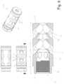
- FIG. 3shows several views of the embodiment of a muzzle device shown in FIG. 1 .
- FIG. 4shows additional views of the embodiment of a muzzle device shown in FIG. 1 .
- FIG. 5shows another embodiment of a muzzle device.
- FIG. 6shows another embodiment of a muzzle device.
- FIG. 1shows an embodiment of a firearm 10 comprising an embodiment of a compensator 20 .
- a firearm 10comprises a muzzle device 18 .
- the firearm 10comprises a barrel 12 and the muzzle device 18 is oriented at the end of the barrel 12 .
- the muzzle device 18is attached to the barrel 12 .
- the muzzle device 18is supported by the barrel 12 .
- the muzzle device 18comprises a compensator 20 arranged to control propellant gasses exiting the barrel 12 .
- FIG. 2shows a cross-sectional view of the embodiment of a compensator 20 shown in FIG. 1 .
- FIGS. 3 and 4show additional views of the embodiment of a compensator 20 shown in FIG. 1 , including another cross-sectional view taken along a different axis.
- a compensator 20comprises a body 22 .
- the compensator 20comprises an internal passageway 30 through the body 22 .
- the passageway 30comprises a bore 31 .
- the internal passageway 30extends from a first end 23 of the body 22 to a second end 25 .
- the body 22comprises a sidewall 24 that surrounds the internal passageway 30 .
- a central axis 28 of the body 22is colinear with a central axis 38 of the passageway 30 .
- the body 22comprises helical threads 38 , for example arranged to engage a portion of a firearm 10 , such as a barrel 12 .
- the threads 38comprise a surface of the sidewall 24 .
- the threads 38are located near the first end 23 of the body 22 .
- the body 22comprises a mounting portion that occupies an engagement length portion 41 .
- the engagement length portion 41will overlap a portion of a firearm 10 , such as a barrel 12 .
- the passageway 30comprises a first portion 32 and a second portion 36 .
- the first portion 32 and second portion 26are arranged to receive propellant gasses, for example from a barrel 12 .
- the first portion 32comprises a first length portion 42 of the body 22 .
- the second portion 36comprises a second length portion 46 of the body 22 .
- a cross-sectional area of the first portion 32is larger than a cross-sectional area of the second portion 36 .
- the passageway 30can comprise any suitable cross-sectional shape.
- the passageway 30comprises a circular cross-sectional shape.
- a diameter of the first portion 32is larger than a diameter of the second portion 36 .
- a cross-sectional size of the passageway 30is reduced as the body 22 is traversed in the direction of bullet travel (for example traveling from the first end 23 toward the second end 25 ).
- the second portion 36can have any suitable cross-sectional size. In some embodiments, the second portion 36 can be made as small as possible, for example being safely larger than a bullet expected to traverse the passageway 30 . In some embodiments, a cross-sectional area of the second portion 36 is substantially constant.
- the first portion 32can have any suitable cross-sectional size. In some embodiments, a cross-sectional area of the first portion 32 is at least 1.2 times a cross-sectional area of the second portion 36 . In some embodiments, a cross-sectional area of the first portion 32 is at least 2 times a cross-sectional area of the second portion 36 . In some embodiments, a cross-sectional area of the first portion 32 is at least 3 times a cross-sectional area of the second portion 36 . In some embodiments, a cross-sectional area of the first portion 32 is substantially constant. In some embodiments, an inner diameter of the first portion 32 is approximately equal to a thread diameter of the threads 26 .
- the body 22comprises a transition surface 34 oriented between the first portion 32 and the second portion 36 .
- a transition surface 34occupies an intermediate length portion 44 of the body 22 oriented between the first length portion 42 and the second length portion 46 .
- the transition surface 34can have any suitable shape.
- the transition surface 34is conical.
- the transition surface 34comprises curvature.
- the transition surface 34is oriented at an angle to the central axis 38 .
- a compensator 20comprises a plurality of vents 21 .
- a vent 21comprises an aperture extending through the sidewall 24 of the body 22 .
- a vent 21provides fluid communication between the passageway 30 and the outside airspace surrounding the body 22 .
- a port 40comprises the opening between the passageway 30 and the vent 21 .
- an axis 47 of a vent 21is oriented at an angle to the central axis 28 .
- an axis 47 of a vent 21can be oriented at any suitable angle to the central axis 28 , for example ranging from greater than 1 degree to 90 degrees.
- an axis 47 of a vent 21comprises its central longitudinal axis.
- each vent 21 of a compensator 20is oriented at a common angle to the central axis 28 .
- a vent 21comprises a vent tube 48 .
- a vent tube 48comprises a constant cross-sectional shape.
- a vent tube 48comprises a circular cross-sectional shape.
- a vent tube 48comprises a constant cross-sectional area.
- An axis 47 of a vent tubecan be oriented at any suitable angle to the central axis 28 .
- a compensator 20comprises a plurality of first vents 50 .
- each first vent 50is in fluid communication with the first portion 32 of the passageway 30 .
- the first vents 50are oriented in the first length portion 42 .
- FIGS. 3 and 4show an embodiment of a compensator 20 comprising six first vents 50 .
- a plurality of the first vents 50are aligned with one another along the length of the body 22 .
- all the first vents 50are aligned with one another along the length of the body 22 .
- each first vent 50comprises a port 40 in fluid communication with the first portion 32 of the passageway 30 .
- a total cross-sectional area of all the first vents 50is greater than the cross-sectional area of the first portion 32 of the passageway 30 .
- an axis 47 of each first vent 50is oriented at a common angle to the central axis 28 .
- a compensator 20comprises a plurality of second vents 60 .
- each second vent 60is in fluid communication with the second portion 36 of the passageway 30 .
- a plurality of the second vents 60are aligned with one another along the length of the body 22 .
- a compensator 20comprises a first row 62 of second vents 60 and a second row 64 of second vents 60 .
- the first row 62is offset from the second row 64 along the length of the body 22 .
- the second row 64is located closer to the second end 25 than the first row 62 .
- each second vent 60 included in the first row 62is aligned with one another along the length of the body 22 . In some embodiments, each second vent 60 included in the first row 62 comprises a similar cross-sectional area. In some embodiments, an axis 47 of each second vent 60 included in the first row 62 is oriented at a common angle to the central axis 28 .
- each second vent 60 included in the second row 64is aligned with one another along the length of the body 22 . In some embodiments, each second vent 60 included in the first row 62 comprises a similar cross-sectional area.
- a cross-sectional area of a vent 21 in the first row 62is different from a cross-sectional area of a vent 21 in the second row 64 . In some embodiments, the cross-sectional area of a vent 21 in the first row 62 is less than a cross-sectional area of a vent 21 in the second row 64 .
- the first row 62comprises a different number of vents 21 than the second row 64 .
- FIGS. 3 and 4show an embodiment of a compensator 20 comprising eight second vents 60 arranged in a first row 62 and six second vents 60 arranged in a second row 64 .
- each second vent 60comprises a port 40 in fluid communication with the second portion 36 of the passageway 30 .
- a total cross-sectional area of all the second vents 60is greater than the cross-sectional area of the first portion 32 of the passageway 30 .
- a total cross-sectional area of all the second vents 60is greater than a total cross-sectional area of all the first vents 50 .
- an axis 47 of each second vent 60is oriented at a common angle to the central axis 28 .
- the vents 21are arranged in pairs that are located across the central axis 38 from one another. In some embodiments, each vent 21 is located across the central axis 38 from another vent 21 .
- the first vents 50comprise three pairs of vents 21 .
- the first row 62 of second vents 60comprises four pairs of vents 21 .
- the second row 64 of second vents 60comprises three pairs of vents 21 .
- each vent 21 in a given rowcomprises a longitudinal axis 47 that is nonparallel to the longitudinal axis 47 of all other vents 21 of that same row.
- no vent 21is in direct fluid communication with a transition surface 34 of the passageway 30 .
- no port 40is located on the transition surface 34 .
- no port 40is located in the intermediate length portion 44 .
- no vent 21extends through the second end 25 of the body 22 .
- a ratio of cross-sectional area between the first portion 32 and second portion 36 of the passageway 30is inversely proportional to a ratio of cross-sectional area between the first vents 50 and the second vents 60 .
- a cross-sectional area of the first portion 32is at least twice the cross-sectional area of the second portion 36 of the passageway 30 , and the ratio is at least 2:1.
- the resulting inverse ratio between the first vents 50 and second vents 60is 1:2, wherein the total cross-sectional area of the second vents 60 is at least twice the total cross-sectional area of the first vents 50 .
- FIG. 5shows another embodiment of a compensator 20 .
- a vent 21comprises a vent slot 49 .
- a vent slot 49comprises an axis oriented at an angle to the central axis 28 .
- the first vents 50can comprise vent slots 49 and the second vents 60 can comprise vent slots 49 .
- FIG. 6shows another embodiment of a compensator 20 .
- a length of the second portion 36 of the passageway 30is at least 3 times the length of the first portion 32 of the passageway 30 .
- any dependent claim which followsshould be taken as alternatively written in a multiple dependent form from all prior claims which possess all antecedents referenced in such dependent claim if such multiple dependent format is an accepted format within the jurisdiction (e.g. each claim depending directly from claim 1 should be alternatively taken as depending from all previous claims).
- each claim depending directly from claim 1should be alternatively taken as depending from all previous claims.
- the following dependent claimsshould each be also taken as alternatively written in each singly dependent claim format which creates a dependency from a prior antecedent-possessing claim other than the specific claim listed in such dependent claim below.
Landscapes
- Engineering & Computer Science (AREA)
- General Engineering & Computer Science (AREA)
- Electron Beam Exposure (AREA)
Abstract
Description
Claims (17)
Priority Applications (1)
| Application Number | Priority Date | Filing Date | Title |
|---|---|---|---|
| US17/901,814US12228360B2 (en) | 2021-09-01 | 2022-09-01 | Firearm compensator |
Applications Claiming Priority (2)
| Application Number | Priority Date | Filing Date | Title |
|---|---|---|---|
| US202163239938P | 2021-09-01 | 2021-09-01 | |
| US17/901,814US12228360B2 (en) | 2021-09-01 | 2022-09-01 | Firearm compensator |
Publications (2)
| Publication Number | Publication Date |
|---|---|
| US20230168058A1 US20230168058A1 (en) | 2023-06-01 |
| US12228360B2true US12228360B2 (en) | 2025-02-18 |
Family
ID=86499837
Family Applications (1)
| Application Number | Title | Priority Date | Filing Date |
|---|---|---|---|
| US17/901,814ActiveUS12228360B2 (en) | 2021-09-01 | 2022-09-01 | Firearm compensator |
Country Status (1)
| Country | Link |
|---|---|
| US (1) | US12228360B2 (en) |
Families Citing this family (2)
| Publication number | Priority date | Publication date | Assignee | Title |
|---|---|---|---|---|
| USD1032768S1 (en)* | 2021-06-11 | 2024-06-25 | 22 Evolution Llc | Firearm blast compensator |
| US20240151485A1 (en)* | 2022-11-04 | 2024-05-09 | Angled Spade Technologies, Llc | Muzzle device and methods of manufacturing |
Citations (76)
| Publication number | Priority date | Publication date | Assignee | Title |
|---|---|---|---|---|
| US785973A (en)* | 1904-01-26 | 1905-03-28 | Samuel N Mcclean | Device for counteracting recoil in guns. |
| US785972A (en)* | 1903-05-08 | 1905-03-28 | Samuel N Mcclean | Means for preventing recoil of guns. |
| US786230A (en)* | 1904-01-26 | 1905-03-28 | Samuel N Mcclean | Recoil-controlling means for guns. |
| US811595A (en) | 1901-03-20 | 1906-02-06 | Knox Taylor | Gas-operated mechanism for firearms. |
| US1242890A (en) | 1917-02-27 | 1917-10-09 | Us Ordnance Co | Barrel-cooling device. |
| US1413903A (en) | 1920-05-21 | 1922-04-25 | Us Ordnance Co | Gun |
| US1527585A (en) | 1923-05-02 | 1925-02-24 | Hamilton Laurens Morgan | Means for cooling machine guns |
| US2212686A (en)* | 1937-04-27 | 1940-08-27 | Milton Roberts | Recoil construction |
| GB614464A (en) | 1938-10-13 | 1948-12-16 | Raymond Tassoul | Improvements in means for ensuring the silent discharge of compressed fluids |
| US3115060A (en)* | 1961-06-20 | 1963-12-24 | Clifford L Ashbrook | Gas inertia controller |
| US3141376A (en)* | 1955-06-13 | 1964-07-21 | George M Chinn | Flame-out eliminator |
| US4322999A (en) | 1979-08-13 | 1982-04-06 | Aston Thomas M | Stabilizing vent system for gun barrels |
| USD279812S (en) | 1983-03-02 | 1985-07-23 | Vito Cellini | Barrel for firearms |
| US4545285A (en) | 1982-06-15 | 1985-10-08 | Mclain Clifford E | Matched expansion muzzle brake |
| DE3430521A1 (en) | 1984-08-18 | 1986-02-27 | Rudolf Lampe | Front attachment cooling turbine for tubular bodies which carry compressed gas or pressurised liquid |
| US4685534A (en) | 1983-08-16 | 1987-08-11 | Burstein A Lincoln | Method and apparatus for control of fluids |
| US4691614A (en)* | 1986-05-30 | 1987-09-08 | Leffel Leon E | Nonsymmetrical compensator for handgun |
| USD296350S (en) | 1985-10-15 | 1988-06-21 | Vito Cellini | Recoil controller for firearms |
| US4869151A (en) | 1987-08-19 | 1989-09-26 | Chahin Eduardo A | Noise and recoil suppressor apparatus for high powered rifles |
| US4879942A (en)* | 1984-10-09 | 1989-11-14 | Cave James B | Muzzle brake with improved stabilization and blast control |
| US4930396A (en)* | 1989-06-15 | 1990-06-05 | Johnson Sam E | Gun muzzle brake |
| US5020416A (en) | 1988-03-02 | 1991-06-04 | Pantera Armory, Inc. | Muzzle brake for firearms |
| US5036747A (en) | 1987-08-11 | 1991-08-06 | Mcclain Iii Harry T | Muzzle brake |
| US5092223A (en) | 1991-01-22 | 1992-03-03 | Hudson Lee C | Muzzle brake and flash hider |
| US5119716A (en) | 1990-08-11 | 1992-06-09 | Rheinmetall Gmbh | Muzzle brake for a large caliber tubular weapon |
| US5367940A (en) | 1993-06-03 | 1994-11-29 | Taylor; Henry A. | Combined muzzle brake, muzzle climb controller and noise redirector for firearms |
| US5631438A (en) | 1995-04-17 | 1997-05-20 | Martel; Phillip C. | Adjustable gas pressure deflector |
| US5811714A (en) | 1996-10-08 | 1998-09-22 | Hull; Harold L. | Gun muzzle brake |
| US5814757A (en) | 1996-07-15 | 1998-09-29 | Buss; Richard A. | Muzzle brake |
| US20030106417A1 (en) | 2001-12-07 | 2003-06-12 | Vais George M. | Extended chamber muzzle brake |
| US20030106416A1 (en) | 2001-12-07 | 2003-06-12 | Vais George M. | Muzzle brake |
| US6578462B1 (en) | 2000-09-25 | 2003-06-17 | The United States Of America As Represented By The Secretary Of The Army | Radial-venting baffled muzzle brake |
| US20030154849A1 (en) | 2002-02-21 | 2003-08-21 | Heinz-Gunter Breuer | Gun barrel having a muzzle brake |
| US20040244571A1 (en) | 2003-04-08 | 2004-12-09 | Bender Terrence Dwight | Recoil and muzzle blast dissipator |
| US20050188829A1 (en) | 2002-09-19 | 2005-09-01 | Hanslick Paul J. | Adjustable muzzle stabilizer for repeating firearm |
| USD515169S1 (en) | 2004-09-27 | 2006-02-14 | Roger Bounds | Lateral projection muzzle brake |
| US20100224054A1 (en) | 2009-03-06 | 2010-09-09 | Langner F Richard | Muzzle brake and method |
| US7854297B2 (en) | 2004-12-10 | 2010-12-21 | The United States Of America As Represented By The Secretary Of The Army | Muffler and related systems |
| US8087337B1 (en)* | 2009-03-03 | 2012-01-03 | Cary William R | Recoil compensation and climb arrester |
| US20120180352A1 (en) | 2011-01-14 | 2012-07-19 | Addis Michael A | Systems and Methods for Attaching and Detaching Firearm Accessories |
| USD666687S1 (en) | 2010-11-11 | 2012-09-04 | Grip Holdings, LLC | Rifle brake |
| US8342071B2 (en)* | 2009-05-21 | 2013-01-01 | Colt Canada Corporation | Firearm flash suppressor |
| US8522662B2 (en) | 2007-09-18 | 2013-09-03 | Flodesign, Inc. | Controlled-unaided surge and purge suppressors for firearm muzzles |
| US20130227871A1 (en)* | 2012-01-06 | 2013-09-05 | Ra Brands, L.L.C. | Cancellation muzzle brake assembly |
| USD692086S1 (en) | 2011-11-07 | 2013-10-22 | Grip Holdings, LLC | Rifle brake |
| USD694355S1 (en) | 2012-08-20 | 2013-11-26 | Karl Hormann | Muzzle brake |
| US8695475B2 (en) | 2010-05-06 | 2014-04-15 | Rheinmetall Waffe Munition Gmbh | Signature-reduced muzzle brake |
| USD711491S1 (en) | 2013-02-05 | 2014-08-19 | Robert Chester Nierenberg | Rifle brake |
| USD716408S1 (en) | 2013-12-18 | 2014-10-28 | Paul Oglesby | Finned muzzle device |
| USD729894S1 (en) | 2014-01-22 | 2015-05-19 | John DeLuca | Muzzle brake for an assault rifle |
| USD737922S1 (en) | 2013-09-30 | 2015-09-01 | William Pope Pace | Suppressor baffle |
| US20150308778A1 (en)* | 2013-11-19 | 2015-10-29 | Stephen Paul Vossler | Muzzle Brake |
| US9228789B1 (en) | 2013-05-14 | 2016-01-05 | Paul Oglesby | Muzzle brake |
| USD746937S1 (en)* | 2014-09-29 | 2016-01-05 | Rock River Arms, Inc. | Muzzle brake |
| USD747429S1 (en)* | 2014-09-29 | 2016-01-12 | Rock River Arms, Inc. | Muzzle brake |
| US20160169606A1 (en) | 2014-12-15 | 2016-06-16 | Jered S. Joplin | Recoil Compensator for Firearm |
| USD763395S1 (en) | 2014-12-15 | 2016-08-09 | Jered S. Joplin | Recoil compensator |
| USD765209S1 (en)* | 2015-02-20 | 2016-08-30 | Yongming Sui | Muzzle brake |
| USD765210S1 (en)* | 2015-02-24 | 2016-08-30 | Yongming Sui | Muzzle brake |
| USD767074S1 (en) | 2015-02-17 | 2016-09-20 | Yongming Sui | Muzzle brake |
| USD767076S1 (en) | 2015-05-07 | 2016-09-20 | H & H Tool Shop, Llc | Muzzle brake |
| WO2016205838A1 (en) | 2015-06-17 | 2016-12-22 | Meiring Johannes Tobias | Barrel or suppressor cooling device |
| USD779019S1 (en) | 2015-10-01 | 2017-02-14 | Gamo Outdoor, S.L. | Muzzle brake |
| USD783758S1 (en)* | 2015-09-04 | 2017-04-11 | Robert Campbell Clark | Spiked muzzle brake for firearm |
| CN106871719A (en) | 2017-04-13 | 2017-06-20 | 福建清流汽枪厂有限公司 | A kind of adapter of firearm suppressor |
| US9739296B2 (en) | 2008-09-25 | 2017-08-22 | Parafluidics Llc | Channeling fluidic waveguide surfaces and tubes |
| US9772157B2 (en) | 2013-01-23 | 2017-09-26 | John Arthur Yoakam | Projectile launching device |
| USD807980S1 (en) | 2016-01-19 | 2018-01-16 | Wiph, Llc | Muzzle brake for firearm |
| RU2646980C1 (en) | 2017-01-30 | 2018-03-12 | Сергей Андреевич Корягин | Channel cooling axial fan |
| USD835226S1 (en) | 2017-03-07 | 2018-12-04 | F-1 Research LLC | Muzzle brake |
| USD842960S1 (en) | 2018-01-02 | 2019-03-12 | Daniel Liu | Muzzle brake |
| USD868197S1 (en) | 2017-12-13 | 2019-11-26 | In Ovation, LLC | Firearm compensator |
| US20210164748A1 (en)* | 2016-03-10 | 2021-06-03 | James Norman Griffitts | Barrel stabilizing and recoil reducing muzzle brake with guiding ribs |
| US11118857B2 (en) | 2020-01-22 | 2021-09-14 | The Boeing Company | Spin-stabilizing assembly for a cylindrical barrel using harvested propellant energy |
| US11480405B2 (en) | 2017-10-23 | 2022-10-25 | In Ovation Llc | Firearm turbine suppressor |
| US20230032661A1 (en)* | 2021-08-02 | 2023-02-02 | WHG Properties, LLC | Firearm muzzle brake |
- 2022
- 2022-09-01USUS17/901,814patent/US12228360B2/enactiveActive
Patent Citations (78)
| Publication number | Priority date | Publication date | Assignee | Title |
|---|---|---|---|---|
| US811595A (en) | 1901-03-20 | 1906-02-06 | Knox Taylor | Gas-operated mechanism for firearms. |
| US785972A (en)* | 1903-05-08 | 1905-03-28 | Samuel N Mcclean | Means for preventing recoil of guns. |
| US785973A (en)* | 1904-01-26 | 1905-03-28 | Samuel N Mcclean | Device for counteracting recoil in guns. |
| US786230A (en)* | 1904-01-26 | 1905-03-28 | Samuel N Mcclean | Recoil-controlling means for guns. |
| US1242890A (en) | 1917-02-27 | 1917-10-09 | Us Ordnance Co | Barrel-cooling device. |
| US1413903A (en) | 1920-05-21 | 1922-04-25 | Us Ordnance Co | Gun |
| US1527585A (en) | 1923-05-02 | 1925-02-24 | Hamilton Laurens Morgan | Means for cooling machine guns |
| US2212686A (en)* | 1937-04-27 | 1940-08-27 | Milton Roberts | Recoil construction |
| GB614464A (en) | 1938-10-13 | 1948-12-16 | Raymond Tassoul | Improvements in means for ensuring the silent discharge of compressed fluids |
| US3141376A (en)* | 1955-06-13 | 1964-07-21 | George M Chinn | Flame-out eliminator |
| US3115060A (en)* | 1961-06-20 | 1963-12-24 | Clifford L Ashbrook | Gas inertia controller |
| US4322999A (en) | 1979-08-13 | 1982-04-06 | Aston Thomas M | Stabilizing vent system for gun barrels |
| US4545285A (en) | 1982-06-15 | 1985-10-08 | Mclain Clifford E | Matched expansion muzzle brake |
| USD279812S (en) | 1983-03-02 | 1985-07-23 | Vito Cellini | Barrel for firearms |
| US4685534A (en) | 1983-08-16 | 1987-08-11 | Burstein A Lincoln | Method and apparatus for control of fluids |
| DE3430521A1 (en) | 1984-08-18 | 1986-02-27 | Rudolf Lampe | Front attachment cooling turbine for tubular bodies which carry compressed gas or pressurised liquid |
| US4879942A (en)* | 1984-10-09 | 1989-11-14 | Cave James B | Muzzle brake with improved stabilization and blast control |
| USD296350S (en) | 1985-10-15 | 1988-06-21 | Vito Cellini | Recoil controller for firearms |
| US4691614A (en)* | 1986-05-30 | 1987-09-08 | Leffel Leon E | Nonsymmetrical compensator for handgun |
| US5036747A (en) | 1987-08-11 | 1991-08-06 | Mcclain Iii Harry T | Muzzle brake |
| US4869151A (en) | 1987-08-19 | 1989-09-26 | Chahin Eduardo A | Noise and recoil suppressor apparatus for high powered rifles |
| US5020416A (en) | 1988-03-02 | 1991-06-04 | Pantera Armory, Inc. | Muzzle brake for firearms |
| US4930396A (en)* | 1989-06-15 | 1990-06-05 | Johnson Sam E | Gun muzzle brake |
| US5119716A (en) | 1990-08-11 | 1992-06-09 | Rheinmetall Gmbh | Muzzle brake for a large caliber tubular weapon |
| US5092223A (en) | 1991-01-22 | 1992-03-03 | Hudson Lee C | Muzzle brake and flash hider |
| US5367940A (en) | 1993-06-03 | 1994-11-29 | Taylor; Henry A. | Combined muzzle brake, muzzle climb controller and noise redirector for firearms |
| US5631438A (en) | 1995-04-17 | 1997-05-20 | Martel; Phillip C. | Adjustable gas pressure deflector |
| US5814757A (en) | 1996-07-15 | 1998-09-29 | Buss; Richard A. | Muzzle brake |
| US5811714A (en) | 1996-10-08 | 1998-09-22 | Hull; Harold L. | Gun muzzle brake |
| US6578462B1 (en) | 2000-09-25 | 2003-06-17 | The United States Of America As Represented By The Secretary Of The Army | Radial-venting baffled muzzle brake |
| US20030106416A1 (en) | 2001-12-07 | 2003-06-12 | Vais George M. | Muzzle brake |
| US20030106417A1 (en) | 2001-12-07 | 2003-06-12 | Vais George M. | Extended chamber muzzle brake |
| US20030154849A1 (en) | 2002-02-21 | 2003-08-21 | Heinz-Gunter Breuer | Gun barrel having a muzzle brake |
| US20050188829A1 (en) | 2002-09-19 | 2005-09-01 | Hanslick Paul J. | Adjustable muzzle stabilizer for repeating firearm |
| US20040244571A1 (en) | 2003-04-08 | 2004-12-09 | Bender Terrence Dwight | Recoil and muzzle blast dissipator |
| US7143680B2 (en) | 2003-04-08 | 2006-12-05 | Bender Terrence D | Recoil and muzzle blast dissipator |
| USD515169S1 (en) | 2004-09-27 | 2006-02-14 | Roger Bounds | Lateral projection muzzle brake |
| US7854297B2 (en) | 2004-12-10 | 2010-12-21 | The United States Of America As Represented By The Secretary Of The Army | Muffler and related systems |
| US8522662B2 (en) | 2007-09-18 | 2013-09-03 | Flodesign, Inc. | Controlled-unaided surge and purge suppressors for firearm muzzles |
| US9739296B2 (en) | 2008-09-25 | 2017-08-22 | Parafluidics Llc | Channeling fluidic waveguide surfaces and tubes |
| US8087337B1 (en)* | 2009-03-03 | 2012-01-03 | Cary William R | Recoil compensation and climb arrester |
| US20100224054A1 (en) | 2009-03-06 | 2010-09-09 | Langner F Richard | Muzzle brake and method |
| US8342071B2 (en)* | 2009-05-21 | 2013-01-01 | Colt Canada Corporation | Firearm flash suppressor |
| US8695475B2 (en) | 2010-05-06 | 2014-04-15 | Rheinmetall Waffe Munition Gmbh | Signature-reduced muzzle brake |
| USD666687S1 (en) | 2010-11-11 | 2012-09-04 | Grip Holdings, LLC | Rifle brake |
| US20120180352A1 (en) | 2011-01-14 | 2012-07-19 | Addis Michael A | Systems and Methods for Attaching and Detaching Firearm Accessories |
| USD692086S1 (en) | 2011-11-07 | 2013-10-22 | Grip Holdings, LLC | Rifle brake |
| US20130227871A1 (en)* | 2012-01-06 | 2013-09-05 | Ra Brands, L.L.C. | Cancellation muzzle brake assembly |
| USD694355S1 (en) | 2012-08-20 | 2013-11-26 | Karl Hormann | Muzzle brake |
| US9772157B2 (en) | 2013-01-23 | 2017-09-26 | John Arthur Yoakam | Projectile launching device |
| USD711491S1 (en) | 2013-02-05 | 2014-08-19 | Robert Chester Nierenberg | Rifle brake |
| US9228789B1 (en) | 2013-05-14 | 2016-01-05 | Paul Oglesby | Muzzle brake |
| USD737922S1 (en) | 2013-09-30 | 2015-09-01 | William Pope Pace | Suppressor baffle |
| US20150308778A1 (en)* | 2013-11-19 | 2015-10-29 | Stephen Paul Vossler | Muzzle Brake |
| USD716408S1 (en) | 2013-12-18 | 2014-10-28 | Paul Oglesby | Finned muzzle device |
| USD729894S1 (en) | 2014-01-22 | 2015-05-19 | John DeLuca | Muzzle brake for an assault rifle |
| USD787621S1 (en) | 2014-09-29 | 2017-05-23 | Rock River Arms, Inc. | Muzzle brake |
| USD746937S1 (en)* | 2014-09-29 | 2016-01-05 | Rock River Arms, Inc. | Muzzle brake |
| USD747429S1 (en)* | 2014-09-29 | 2016-01-12 | Rock River Arms, Inc. | Muzzle brake |
| USD763395S1 (en) | 2014-12-15 | 2016-08-09 | Jered S. Joplin | Recoil compensator |
| US20160169606A1 (en) | 2014-12-15 | 2016-06-16 | Jered S. Joplin | Recoil Compensator for Firearm |
| USD767074S1 (en) | 2015-02-17 | 2016-09-20 | Yongming Sui | Muzzle brake |
| USD765209S1 (en)* | 2015-02-20 | 2016-08-30 | Yongming Sui | Muzzle brake |
| USD765210S1 (en)* | 2015-02-24 | 2016-08-30 | Yongming Sui | Muzzle brake |
| USD767076S1 (en) | 2015-05-07 | 2016-09-20 | H & H Tool Shop, Llc | Muzzle brake |
| WO2016205838A1 (en) | 2015-06-17 | 2016-12-22 | Meiring Johannes Tobias | Barrel or suppressor cooling device |
| USD783758S1 (en)* | 2015-09-04 | 2017-04-11 | Robert Campbell Clark | Spiked muzzle brake for firearm |
| USD779019S1 (en) | 2015-10-01 | 2017-02-14 | Gamo Outdoor, S.L. | Muzzle brake |
| USD807980S1 (en) | 2016-01-19 | 2018-01-16 | Wiph, Llc | Muzzle brake for firearm |
| US20210164748A1 (en)* | 2016-03-10 | 2021-06-03 | James Norman Griffitts | Barrel stabilizing and recoil reducing muzzle brake with guiding ribs |
| RU2646980C1 (en) | 2017-01-30 | 2018-03-12 | Сергей Андреевич Корягин | Channel cooling axial fan |
| USD835226S1 (en) | 2017-03-07 | 2018-12-04 | F-1 Research LLC | Muzzle brake |
| CN106871719A (en) | 2017-04-13 | 2017-06-20 | 福建清流汽枪厂有限公司 | A kind of adapter of firearm suppressor |
| US11480405B2 (en) | 2017-10-23 | 2022-10-25 | In Ovation Llc | Firearm turbine suppressor |
| USD868197S1 (en) | 2017-12-13 | 2019-11-26 | In Ovation, LLC | Firearm compensator |
| USD842960S1 (en) | 2018-01-02 | 2019-03-12 | Daniel Liu | Muzzle brake |
| US11118857B2 (en) | 2020-01-22 | 2021-09-14 | The Boeing Company | Spin-stabilizing assembly for a cylindrical barrel using harvested propellant energy |
| US20230032661A1 (en)* | 2021-08-02 | 2023-02-02 | WHG Properties, LLC | Firearm muzzle brake |
Non-Patent Citations (4)
| Title |
|---|
| Best 3—Gen Rifle Compensators [2019], PewPewTactical.com, May 27, 2017, Written by Travis Pike, [online], [site visited Mar. 26, 2019]. (Year: 2017). |
| Dissident Arms 4-Port Phoenix Compensator, DissidentArms.com, [online], [site visited Mar. 26, 2019]. (Year: 2019). |
| Muzzle Brakes, Compensators, and Flash Hiders, Range365.com, by T. Logan Metesh, Oct. 10, 2018, [online], [site visited Mar. 26, 2019]. (Year: 2018). |
| Warrior East 19—Mad Minute Suppressors, Jul. 15, 2019, Solider Systems, p. 1 (Year: 2019). |
Also Published As
| Publication number | Publication date |
|---|---|
| US20230168058A1 (en) | 2023-06-01 |
Similar Documents
| Publication | Publication Date | Title |
|---|---|---|
| US12228360B2 (en) | Firearm compensator | |
| US11656049B2 (en) | Multi-core firearm suppressor | |
| US10782083B2 (en) | Muzzle device | |
| US10900734B2 (en) | Firearm suppressor | |
| US12018905B2 (en) | Evacuating entrance chamber via blast baffle | |
| US11927411B2 (en) | Hybrid suppressor baffle structure | |
| US6752062B2 (en) | Muzzle brake | |
| US8863637B2 (en) | Adjustable gas cyclic regulator for an autoloading firearm | |
| US9080829B1 (en) | Stabilizer brake for firearm | |
| US20230003478A1 (en) | Expansion chamber assembly and a method of manufacturing the same | |
| US9803946B2 (en) | Flash, noise and smoke suppression device | |
| US12055356B2 (en) | Modular firearm muzzle device | |
| US6295752B1 (en) | Projectile guide | |
| US20200182578A1 (en) | Multi-Configuration Suppressor | |
| WO2023064649A3 (en) | Firearm suppressor and self-torquing feature | |
| US10024618B1 (en) | Muzzle brake for a combat rifle | |
| WO2021216240A3 (en) | Muzzle signature management device | |
| US20180238654A1 (en) | Compensator for a firearm | |
| US12253322B1 (en) | Muzzle device clamping mechanism | |
| US8453634B2 (en) | Initial velocity accelerating tube | |
| US20190086174A1 (en) | Muzzle device for a projectile-firing device | |
| GB2032070A (en) | Cartridges | |
| US9631887B2 (en) | Gun barrel rifling | |
| US20150135935A1 (en) | Rifle Noise Suppressor | |
| US20120180362A1 (en) | Gun barrel rifling |
Legal Events
| Date | Code | Title | Description |
|---|---|---|---|
| FEPP | Fee payment procedure | Free format text:ENTITY STATUS SET TO UNDISCOUNTED (ORIGINAL EVENT CODE: BIG.); ENTITY STATUS OF PATENT OWNER: SMALL ENTITY | |
| FEPP | Fee payment procedure | Free format text:ENTITY STATUS SET TO SMALL (ORIGINAL EVENT CODE: SMAL); ENTITY STATUS OF PATENT OWNER: SMALL ENTITY | |
| STPP | Information on status: patent application and granting procedure in general | Free format text:DOCKETED NEW CASE - READY FOR EXAMINATION | |
| AS | Assignment | Owner name:IN OVATION, MINNESOTA Free format text:ASSIGNMENT OF ASSIGNORS INTEREST;ASSIGNOR:BENDER, TERRENCE D.;REEL/FRAME:065460/0605 Effective date:20220901 | |
| STPP | Information on status: patent application and granting procedure in general | Free format text:NON FINAL ACTION MAILED | |
| STPP | Information on status: patent application and granting procedure in general | Free format text:RESPONSE TO NON-FINAL OFFICE ACTION ENTERED AND FORWARDED TO EXAMINER | |
| STPP | Information on status: patent application and granting procedure in general | Free format text:FINAL REJECTION MAILED | |
| STPP | Information on status: patent application and granting procedure in general | Free format text:RESPONSE AFTER FINAL ACTION FORWARDED TO EXAMINER | |
| STPP | Information on status: patent application and granting procedure in general | Free format text:NOTICE OF ALLOWANCE MAILED -- APPLICATION RECEIVED IN OFFICE OF PUBLICATIONS | |
| STPP | Information on status: patent application and granting procedure in general | Free format text:PUBLICATIONS -- ISSUE FEE PAYMENT VERIFIED | |
| STCF | Information on status: patent grant | Free format text:PATENTED CASE |