US12228214B2 - Nine port cooling valve - Google Patents
Nine port cooling valveDownload PDFInfo
- Publication number
- US12228214B2 US12228214B2US17/686,641US202217686641AUS12228214B2US 12228214 B2US12228214 B2US 12228214B2US 202217686641 AUS202217686641 AUS 202217686641AUS 12228214 B2US12228214 B2US 12228214B2
- Authority
- US
- United States
- Prior art keywords
- port
- stemshell
- ports
- valve
- array
- Prior art date
- Legal status (The legal status is an assumption and is not a legal conclusion. Google has not performed a legal analysis and makes no representation as to the accuracy of the status listed.)
- Active, expires
Links
- 238000001816coolingMethods0.000titledescription4
- 239000012530fluidSubstances0.000claimsdescription25
- 230000008901benefitEffects0.000description4
- 238000003491arrayMethods0.000description3
- 238000010276constructionMethods0.000description3
- 238000007789sealingMethods0.000description2
- 230000004075alterationEffects0.000description1
- 230000009286beneficial effectEffects0.000description1
- 239000002826coolantSubstances0.000description1
- 238000012986modificationMethods0.000description1
- 230000004048modificationEffects0.000description1
Images


Classifications
- F—MECHANICAL ENGINEERING; LIGHTING; HEATING; WEAPONS; BLASTING
- F16—ENGINEERING ELEMENTS AND UNITS; GENERAL MEASURES FOR PRODUCING AND MAINTAINING EFFECTIVE FUNCTIONING OF MACHINES OR INSTALLATIONS; THERMAL INSULATION IN GENERAL
- F16K—VALVES; TAPS; COCKS; ACTUATING-FLOATS; DEVICES FOR VENTING OR AERATING
- F16K11/00—Multiple-way valves, e.g. mixing valves; Pipe fittings incorporating such valves
- F16K11/02—Multiple-way valves, e.g. mixing valves; Pipe fittings incorporating such valves with all movable sealing faces moving as one unit
- F16K11/08—Multiple-way valves, e.g. mixing valves; Pipe fittings incorporating such valves with all movable sealing faces moving as one unit comprising only taps or cocks
- F16K11/085—Multiple-way valves, e.g. mixing valves; Pipe fittings incorporating such valves with all movable sealing faces moving as one unit comprising only taps or cocks with cylindrical plug
- F16K11/0856—Multiple-way valves, e.g. mixing valves; Pipe fittings incorporating such valves with all movable sealing faces moving as one unit comprising only taps or cocks with cylindrical plug having all the connecting conduits situated in more than one plane perpendicular to the axis of the plug
- F—MECHANICAL ENGINEERING; LIGHTING; HEATING; WEAPONS; BLASTING
- F16—ENGINEERING ELEMENTS AND UNITS; GENERAL MEASURES FOR PRODUCING AND MAINTAINING EFFECTIVE FUNCTIONING OF MACHINES OR INSTALLATIONS; THERMAL INSULATION IN GENERAL
- F16K—VALVES; TAPS; COCKS; ACTUATING-FLOATS; DEVICES FOR VENTING OR AERATING
- F16K27/00—Construction of housing; Use of materials therefor
- F16K27/06—Construction of housing; Use of materials therefor of taps or cocks
- F16K27/065—Construction of housing; Use of materials therefor of taps or cocks with cylindrical plugs
Definitions
- the present inventionrelates to valves, and more particularly to multiport valves having lateral and longitudinal flow paths internal to as stem shell based on flow position, and more particular to a nine-port cooling valve having multiple, such as four, different flow configurations.
- An eight-port valvewas designed for a customer having a 2 ⁇ 4 array of ports with a stemshell internal to the valve configured to provide specific flow paths for specific positions of the stemshell. However, another port was needed for a new use outside of the 2 ⁇ 4 array of ports, and a new flow path requirement was deemed to be necessary.
- the eight-port valvehas a stemshell oriented with a rotational axis parallel to the 2 port axis (a width direction) and perpendicular to the 4 port axis (a length direction) whereby the length is longer than the width.
- valvesare believed to benefit various industries. Some coolant valves and other valves can benefit by re-orienting the axis of rotation of the stemshell to be along a longer lengthwise direction than a shorter width direction. This may be particularly beneficial when providing flow to and from an array of ports such as having at least two rows and at least three columns, such as four columns.
- many embodiments of the present inventionprovide at least one external to the array, but preferably planar with the other ports. For at least some embodiments, this extra port outside of the array can provide a flow path at least for some of the flow configurations of the valve which would not be possible with the array of ports.
- an extra portmay be added to be coplanar with the array, but outside of the array.
- One possibilityis to provide the extra port on what would be another row, if it completed the array, which it does not since it is only one space of what would require 4 to become a 3 ⁇ 4 array.
- the extra port for the preferred embodimentis colinear with a column of the ports for at least some embodiments but need not necessarily be so for all embodiments. Furthermore, the extra port(s) need not be coplanar with the array of ports for all embodiments.
- the extra portdoes not have flow for all flow configurations, but instead selectively provides for input and/or output flow under certain conditions (while presumably another port in the array may have flow secured therethrough).
- FIG. 1is a front perspective view of an eight port valve
- FIG. 2is an exploded view of a nine port valve of a presently preferred embodiment of the present invention.
- FIG. 3is a side perspective view of the presently preferred embodiment of the valve of FIG. 2 ;
- FIG. 4is a side plan view of the presently preferred embodiment of the valve of FIGS. 2 - 3 ;
- FIG. 5is a front plan view of the valve of the valve of FIGS. 2 - 4 ;
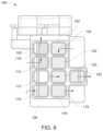
- FIG. 6is a top plan view of the valve of FIGS. 2 - 5 showing a first flow configuration
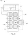
- FIG. 7is a top plan view of the valve of FIGS. 2 - 5 showing a second flow configuration
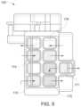
- FIG. 8is a top plan view of the valve of FIGS. 2 - 5 showing a third flow configuration
- FIG. 9is a top plan view of the valve of FIGS. 2 - 5 showing a fourth flow configuration.
- FIG. 1is an eight port valve 10 .
- This valve 10has an actuator 12 driving a stemshell (not shown) along rotation axis 14 .
- the valve 10has eight inlet/outlet ports 16 , 18 , 20 , 22 , 24 , 26 , 28 , 30 .
- the ports 16 - 30provide a 2 ⁇ 4 array with two rows of four columns of the ports 16 - 30 with the rows and columns being linearly disposed relative to each other as would be expected for an array: the first row has ports 16 - 22 , the second row has ports 24 - 30 .
- the two rowscomprise width 32 and the four stations comprise length 34 .
- the rotation axis 14is parallel to the width 32 .
- the actuator 12can receive a signal to rotate to provide specific flow patterns through at least some of the ports 16 - 30 depending on the rotational position of the stemshell (obscured from view) about the rotational axis 14 . Due to the geometries involved, the plate 36 with the ports 16 - 30 has an area extending well beyond the area of the stemshell, and the housing 38 about the stemshell such as by roughly a factor of 2 as can be seen with reference to FIG. 1 .
- FIGS. 2 - 9provide a nine port valve 100 which has a different operational rotational axis 102 than the eight port valve 10 .
- spindle or stemshell 104rotates about rotational axis 102 .
- the valve 100can have an array of linear rows and linear columns such as could be similar or dissimilar to valve 10 along a width 106 and length 108 .
- the rotational axis 102is parallel to the length 108 for the illustrated embodiment.
- the length 108is greater than the width 106 .
- the length 108has four stations while the width has two rows of input/output ports 110 , 112 , 114 , 116 , 118 , 120 , 122 , 124 .
- the input/output ports 110 - 124may be located along a planar plate 126 , possibly somewhat similarly to the plate 36 of the eight port valve 10 .
- valve body 128One of ordinary skill in the art will quickly see that by orienting the rotational axis 102 of the stemshell 104 lengthwise rather than widthwise, different flow options may be accommodated with valve body 128 .
- the valve 100may have a seal 130 to assist in sealing the stemshell 104 relative to the valve body 128 .
- a cover 132may assist in sealing an end 134 of the valve body 128 while directing a rotator 136 to an actuator 138 .
- the actuator 138may receive positional instructions from various sources, such as a processor, not shown providing instructions through communications port 140 , a pin connector or other port 140 .
- the valve 100also has a ninth port 142 which is located outside of the array of ports 110 - 124 of the length 108 and width 106 .
- the extra port 142is oriented in a plane with plate 126 , but outside of the array, such as in a row by itself although linearly disposed with ports 112 and 120 .
- Extra port 142may be included in plate 126 for some embodiments. Still other embodiments may orient the extra port 142 outside of the plane of a port 110 - 124 , such as at an angle thereto while being adjacent to at least some of the ports 110 - 124 or otherwise disposed.
- FIGS. 6 - 9various flow configurations can be provided through the various inlet/outlet ports 110 - 124 and 142 .
- FIG. 6shows a first flow configuration with flow from the sixth port 110 being directed to the fifth port 118 through a first lateral channel 144 extending into an exterior surface 146 of the stemshell 104 .
- a second lateral channel 148communicates an eighth port 120 with the seventh port 142 .
- the ninth port 112is not receiving or sending fluid in this flow configuration.
- a second port 114sends fluid to a first port 116 along a first longitudinal channel 150 (oriented parallel to the rotation axis 102 ) extending into the exterior surface 146 of the stemshell 104 .
- a second lateral channel 150communicates the fourth port 124 with the third port 122 .
- the stemshell 104 of FIG. 7has been rotated ninety degrees relative the first flow configuration of FIG. 6 .
- a third lateral channel 154communicates the sixth port 110 with the fifth port 118 .
- a fourth lateral channel 156communicates the eighth port 120 with the ninth port 112 .
- a fifth lateral channel 158communicates the second port 114 with the third port 122 .
- a sixth lateral channel 160communicates the fourth port 125 with the first port 116 . There is no flow through the seventh port 142 in this second flow configuration.
- fluidmay enter at sixth port 110 and exit through a third longitudinal channel 162 out ninth port 112 .
- a fourth longitudinal channel 164may direct flow from the eighth ort 120 to the fifth port 118 .
- the seventh portmay not have flow in or out in this configuration.
- the second port 114directs flow to the third port 122 through seventh lateral port 166 and the fourth port 124 directs flow to the first port 116 through eighth lateral port 168 .
- FIG. 9shows a fourth flow configuration, such as by continuing to rotate the stemshell 104 about the rotational axis 102 another ninety degrees from the third flow configuration (or two hundred seventy degrees from the first flow configuration).
- Flowmay proceed into the sixth port 110 and through a first bore 170 in the stemshell 104 which communicates with a second bore 171 in the stemshell 104 and out the seventh port 142 .
- the eight port 120can communicate through fifth longitudinal channel 172 to direct flow out of fifth port 118 .
- the ninth port 112has no flow in this embodiment.
- the second port 114sends fluid through the ninth lateral channel 174 to the third port 122 .
- the fourth port 124sends fluid through the tenth lateral channel 176 to the first port 116 .
- the first, third, fifth ports 116 , 122 , 118are always outlet ports and the second, fourth, sixth and eight ports 114 , 124 , 110 and 120 are always inlet ports.
- the ninth and seventh ports 112 , 142are always outlet ports when flow proceeds through them, but only one of the ninth and seventh port 112 , 142 is open at a particular flow configuration.
- Other embodimentsmay have other flow configurations at different rotational positions of a stemshell 104 .
- Actuators 138may control the positioning of the stemshell relative to rotational axis 102 so as to provide specific flow paths under certain conditions as directed by a processor or other device.
- Other embodimentsmay have other flow paths amongst the various inlet/outlet ports 110 - 124 , 142 under various situations.
- Still other embodimentsmay have other arrays other than 2 ⁇ 4 arrays with an extra port 142 .
- the extra port 142may be in addition to other arrays, such as 2 ⁇ 2, 2 ⁇ 3, 1 ⁇ 4, etc.
- the extra portBy providing the extra port, particularly along a length 108 , for many embodiments up to four different flow configurations can be achieved, or even more depending on the arrangement of channels, passages or bores about the stemshell 104 .
- the extra port 142is shown co-planar with the array of ports 110 - 124 , it may be angled otherwise non-coplanar therewith for other embodiments.
- the housing 128may assist in directing flow from the various flow paths dictated by the stemshell 104 in cooperation with the housing 128 .
- the housing 128is substantially cylinder over at least half or two-thirds or more of its exterior shape with it then directing flow to the planar plate 126 . With this construction, a particularly compact valve 100 can be provided to customers.
- the stemshell 104 of valve 100is longer than with the construction of valve 10 , and thus the plate 126 does not have an area that completely covers the cross section of the housing 127 as seen from above in FIGS. 6 - 9 which is different than the eight port valve 10 of FIG. 1 .
- lateral channelBy lateral channel, the applicant means that the channel into the exterior surface 146 of the stemshell 104 proceeds about a circumference of the stemshell 104 along an arc thereof.
- the channelsproceed along the length (parallel to the rotation axis 102 ). While channels are useful for many embodiments of stemshells 104 , passages, bores, or other flow paths through various portions of the stemshell 104 can achieve various flow paths at various rotational positions of the stemshell 104 about the rotation axis 102 .
Landscapes
- Engineering & Computer Science (AREA)
- General Engineering & Computer Science (AREA)
- Mechanical Engineering (AREA)
- Multiple-Way Valves (AREA)
Abstract
Description
Claims (20)
Priority Applications (1)
| Application Number | Priority Date | Filing Date | Title |
|---|---|---|---|
| US17/686,641US12228214B2 (en) | 2021-04-01 | 2022-03-04 | Nine port cooling valve |
Applications Claiming Priority (2)
| Application Number | Priority Date | Filing Date | Title |
|---|---|---|---|
| US202163169558P | 2021-04-01 | 2021-04-01 | |
| US17/686,641US12228214B2 (en) | 2021-04-01 | 2022-03-04 | Nine port cooling valve |
Publications (2)
| Publication Number | Publication Date |
|---|---|
| US20220316607A1 US20220316607A1 (en) | 2022-10-06 |
| US12228214B2true US12228214B2 (en) | 2025-02-18 |
Family
ID=83450039
Family Applications (1)
| Application Number | Title | Priority Date | Filing Date |
|---|---|---|---|
| US17/686,641Active2043-01-11US12228214B2 (en) | 2021-04-01 | 2022-03-04 | Nine port cooling valve |
Country Status (1)
| Country | Link |
|---|---|
| US (1) | US12228214B2 (en) |
Cited By (1)
| Publication number | Priority date | Publication date | Assignee | Title |
|---|---|---|---|---|
| US20240084903A1 (en)* | 2021-09-27 | 2024-03-14 | Zhejiang Geely Holding Group Co., Ltd | Multi-way valve |
Families Citing this family (4)
| Publication number | Priority date | Publication date | Assignee | Title |
|---|---|---|---|---|
| JP7510017B2 (en)* | 2021-02-10 | 2024-07-02 | 浙江吉利控股集団有限公司 | Integrated multi-way motorized valve and vehicle thermal management system |
| US11932078B2 (en)* | 2021-03-31 | 2024-03-19 | Tesla, Inc. | Electric vehicle heat pump using enhanced valve unit |
| CN114001175B (en)* | 2021-10-28 | 2022-11-25 | 浙江银轮机械股份有限公司 | Multi-way valve |
| US20230220918A1 (en)* | 2022-01-13 | 2023-07-13 | Illinois Tool Works Inc. | Multi-Passage Valve |
Citations (14)
| Publication number | Priority date | Publication date | Assignee | Title |
|---|---|---|---|---|
| US3090396A (en)* | 1960-02-10 | 1963-05-21 | Bruner Corp | Rotatable spindle valve |
| US3636981A (en)* | 1970-05-04 | 1972-01-25 | Frederick D Henry | Flow valve |
| US4345622A (en)* | 1978-11-24 | 1982-08-24 | Ingenjorsfirma T. Henningsson Ab | Control and cut-off device for flowing media |
| US4445540A (en)* | 1981-10-27 | 1984-05-01 | Water Services Of America, Inc. | Sleeve-type fluid flow diverter |
| US4574840A (en)* | 1984-12-28 | 1986-03-11 | Uop Inc. | Multiport axial valve with balanced rotor |
| US5152321A (en)* | 1991-10-07 | 1992-10-06 | Ecowater Systems, Inc. | Bypass valve |
| US20080029168A1 (en)* | 2006-08-02 | 2008-02-07 | Kinlaw John A | Multi-port fluid distribution |
| US20130074961A1 (en)* | 2011-09-22 | 2013-03-28 | Chu-Wan Hong | Mixed Water Control Valve |
| US20150260298A1 (en)* | 2014-03-15 | 2015-09-17 | Diehl Aerospace Gmbh | Multiway valve |
| US20160243743A1 (en)* | 2015-02-20 | 2016-08-25 | Processing Technologies International, LLC | Diverter valve |
| US20170254425A1 (en)* | 2014-08-22 | 2017-09-07 | Mitsubishi Electric Corporation | Compound valve |
| US20180372235A1 (en)* | 2017-06-27 | 2018-12-27 | Hayward Industries, Inc. | Multi-Position Valve |
| US10543148B1 (en)* | 2019-07-15 | 2020-01-28 | Wexco Incorporated | Integrated manifold and valve assembly |
| US20200049263A1 (en)* | 2017-03-17 | 2020-02-13 | Yamada Manufacturing Co., Ltd. | Control valve |
- 2022
- 2022-03-04USUS17/686,641patent/US12228214B2/enactiveActive
Patent Citations (14)
| Publication number | Priority date | Publication date | Assignee | Title |
|---|---|---|---|---|
| US3090396A (en)* | 1960-02-10 | 1963-05-21 | Bruner Corp | Rotatable spindle valve |
| US3636981A (en)* | 1970-05-04 | 1972-01-25 | Frederick D Henry | Flow valve |
| US4345622A (en)* | 1978-11-24 | 1982-08-24 | Ingenjorsfirma T. Henningsson Ab | Control and cut-off device for flowing media |
| US4445540A (en)* | 1981-10-27 | 1984-05-01 | Water Services Of America, Inc. | Sleeve-type fluid flow diverter |
| US4574840A (en)* | 1984-12-28 | 1986-03-11 | Uop Inc. | Multiport axial valve with balanced rotor |
| US5152321A (en)* | 1991-10-07 | 1992-10-06 | Ecowater Systems, Inc. | Bypass valve |
| US20080029168A1 (en)* | 2006-08-02 | 2008-02-07 | Kinlaw John A | Multi-port fluid distribution |
| US20130074961A1 (en)* | 2011-09-22 | 2013-03-28 | Chu-Wan Hong | Mixed Water Control Valve |
| US20150260298A1 (en)* | 2014-03-15 | 2015-09-17 | Diehl Aerospace Gmbh | Multiway valve |
| US20170254425A1 (en)* | 2014-08-22 | 2017-09-07 | Mitsubishi Electric Corporation | Compound valve |
| US20160243743A1 (en)* | 2015-02-20 | 2016-08-25 | Processing Technologies International, LLC | Diverter valve |
| US20200049263A1 (en)* | 2017-03-17 | 2020-02-13 | Yamada Manufacturing Co., Ltd. | Control valve |
| US20180372235A1 (en)* | 2017-06-27 | 2018-12-27 | Hayward Industries, Inc. | Multi-Position Valve |
| US10543148B1 (en)* | 2019-07-15 | 2020-01-28 | Wexco Incorporated | Integrated manifold and valve assembly |
Cited By (2)
| Publication number | Priority date | Publication date | Assignee | Title |
|---|---|---|---|---|
| US20240084903A1 (en)* | 2021-09-27 | 2024-03-14 | Zhejiang Geely Holding Group Co., Ltd | Multi-way valve |
| US12345340B2 (en)* | 2021-09-27 | 2025-07-01 | Zhejiang Geely Holding Group Co., Ltd. | Multi-way valve |
Also Published As
| Publication number | Publication date |
|---|---|
| US20220316607A1 (en) | 2022-10-06 |
Similar Documents
| Publication | Publication Date | Title |
|---|---|---|
| US12228214B2 (en) | Nine port cooling valve | |
| US11168797B2 (en) | Combination multi-port valve | |
| US11629791B2 (en) | Combination multi-port valve | |
| US11156300B2 (en) | Multi-port valve with partial circumferential seal arrangement | |
| CN113227620B (en) | Multiport multi-plane valve | |
| EP2113080B1 (en) | Rotary selection valve | |
| US7322375B2 (en) | High bandwidth rotary servo valves | |
| US6672336B2 (en) | Dual random access, three-way rotary valve apparatus | |
| US4294285A (en) | Multi-port valve | |
| US11703135B2 (en) | Multi-port coolant flow control valve assembly | |
| US11796073B2 (en) | Six port valve | |
| US11592116B2 (en) | Five port valve | |
| US20180335057A1 (en) | Open Center Control Valve | |
| US20220235870A1 (en) | Six Port Valve | |
| US20230078460A1 (en) | Multi-port valve assembly | |
| US5111840A (en) | Modular valve | |
| JP6783061B2 (en) | Flow switching valve | |
| GB2207982A (en) | Valve base with integral flow controls | |
| JP2017160927A (en) | Flow passage selector valve | |
| US7328921B1 (en) | Fluid rotary joint | |
| CA2348970A1 (en) | Dual isolation valve with rectangular flow passageways | |
| US12338915B2 (en) | Coolant flow control valve seal assembly | |
| JP7741554B2 (en) | Combined Valve | |
| JP6783631B2 (en) | Three-way valve | |
| CN118242463A (en) | Hydraulic valve or pneumatic valve |
Legal Events
| Date | Code | Title | Description |
|---|---|---|---|
| FEPP | Fee payment procedure | Free format text:ENTITY STATUS SET TO UNDISCOUNTED (ORIGINAL EVENT CODE: BIG.); ENTITY STATUS OF PATENT OWNER: LARGE ENTITY | |
| STPP | Information on status: patent application and granting procedure in general | Free format text:DOCKETED NEW CASE - READY FOR EXAMINATION | |
| AS | Assignment | Owner name:ACQUIOM AGENCY SERVICES LLC, COLORADO Free format text:SECURITY INTEREST;ASSIGNORS:ROBERTSHAW CONTROLS COMPANY;ROBERTSHAW US HOLDINGS CORP.;BURNER SYSTEMS INTERNATIONAL, INC.;REEL/FRAME:063632/0614 Effective date:20230509 | |
| AS | Assignment | Owner name:DELAWARE TRUST COMPANY, DELAWARE Free format text:OMNIBUS ASSIGNMENT OF INTELLECTUAL PROPERTY SECURITY AGREEMENTS;ASSIGNOR:ACQUIOM AGENCY SERVICES LLC;REEL/FRAME:066493/0146 Effective date:20240131 | |
| STPP | Information on status: patent application and granting procedure in general | Free format text:NON FINAL ACTION MAILED | |
| STPP | Information on status: patent application and granting procedure in general | Free format text:RESPONSE TO NON-FINAL OFFICE ACTION ENTERED AND FORWARDED TO EXAMINER | |
| STPP | Information on status: patent application and granting procedure in general | Free format text:NOTICE OF ALLOWANCE MAILED -- APPLICATION RECEIVED IN OFFICE OF PUBLICATIONS | |
| AS | Assignment | Owner name:CSC DELAWARE TRUST COMPANY, DELAWARE Free format text:TERM LOAN PATENT SECURITY AGREEMENT;ASSIGNOR:RANGE RED OPERATING, INC.;REEL/FRAME:069084/0281 Effective date:20241001 Owner name:BURNER SYSTEMS INTERNATIONAL, INC., ILLINOIS Free format text:OMNIBUS TERMINATION AND RELEASE OF DEBTOR-IN-POSSESSION SECURITY INTEREST IN INTELLECTUAL PROPERTY;ASSIGNOR:CSC DELAWARE TRUST COMPANY (F/K/A DELAWARE TRUST COMPANY);REEL/FRAME:069084/0266 Effective date:20241001 Owner name:ROBERTSHAW CONTROLS COMPANY, ILLINOIS Free format text:OMNIBUS TERMINATION AND RELEASE OF DEBTOR-IN-POSSESSION SECURITY INTEREST IN INTELLECTUAL PROPERTY;ASSIGNOR:CSC DELAWARE TRUST COMPANY (F/K/A DELAWARE TRUST COMPANY);REEL/FRAME:069084/0266 Effective date:20241001 Owner name:ROBERTSHAW US HOLDING CORP., ILLINOIS Free format text:OMNIBUS TERMINATION AND RELEASE OF DEBTOR-IN-POSSESSION SECURITY INTEREST IN INTELLECTUAL PROPERTY;ASSIGNOR:CSC DELAWARE TRUST COMPANY (F/K/A DELAWARE TRUST COMPANY);REEL/FRAME:069084/0266 Effective date:20241001 Owner name:BURNER SYSTEMS INTERNATIONAL, INC., ILLINOIS Free format text:OMNIBUS TERMINATION AND RELEASE OF SECURITY INTEREST IN INTELLECTUAL PROPERTY;ASSIGNOR:CSC DELAWARE TRUST COMPANY (F/K/A DELAWARE TRUST COMPANY AND SUCCESSOR AGENT TO ACQUIOM AGENCY SERVICES LLC);REEL/FRAME:069084/0150 Effective date:20241001 Owner name:ROBERTSHAW CONTROLS COMPANY, ILLINOIS Free format text:OMNIBUS TERMINATION AND RELEASE OF SECURITY INTEREST IN INTELLECTUAL PROPERTY;ASSIGNOR:CSC DELAWARE TRUST COMPANY (F/K/A DELAWARE TRUST COMPANY AND SUCCESSOR AGENT TO ACQUIOM AGENCY SERVICES LLC);REEL/FRAME:069084/0150 Effective date:20241001 Owner name:ROBERTSHAW US HOLDING CORP., ILLINOIS Free format text:OMNIBUS TERMINATION AND RELEASE OF SECURITY INTEREST IN INTELLECTUAL PROPERTY;ASSIGNOR:CSC DELAWARE TRUST COMPANY (F/K/A DELAWARE TRUST COMPANY AND SUCCESSOR AGENT TO ACQUIOM AGENCY SERVICES LLC);REEL/FRAME:069084/0150 Effective date:20241001 | |
| AS | Assignment | Owner name:JPMORGAN CHASE BANK, N.A., AS ADMINISTRATIVE AGENT, ILLINOIS Free format text:SECURITY INTEREST;ASSIGNOR:RANGE RED OPERATING, INC.;REEL/FRAME:069092/0195 Effective date:20241001 | |
| AS | Assignment | Owner name:ROBERTSHAW CONTROLS COMPANY, ILLINOIS Free format text:ASSIGNMENT OF ASSIGNORS INTEREST;ASSIGNORS:SURVE, SHUBHADA;PEARSON, JAMES;REEL/FRAME:069329/0042 Effective date:20210402 | |
| STPP | Information on status: patent application and granting procedure in general | Free format text:PUBLICATIONS -- ISSUE FEE PAYMENT RECEIVED | |
| STPP | Information on status: patent application and granting procedure in general | Free format text:PUBLICATIONS -- ISSUE FEE PAYMENT VERIFIED | |
| STCF | Information on status: patent grant | Free format text:PATENTED CASE | |
| CC | Certificate of correction |