US12227181B2 - Simulating braking when speeding on cruise control to facilitate use of ISA system - Google Patents
Simulating braking when speeding on cruise control to facilitate use of ISA systemDownload PDFInfo
- Publication number
- US12227181B2 US12227181B2US16/947,456US202016947456AUS12227181B2US 12227181 B2US12227181 B2US 12227181B2US 202016947456 AUS202016947456 AUS 202016947456AUS 12227181 B2US12227181 B2US 12227181B2
- Authority
- US
- United States
- Prior art keywords
- vehicle
- speed
- mcm
- cruise control
- module
- Prior art date
- Legal status (The legal status is an assumption and is not a legal conclusion. Google has not performed a legal analysis and makes no representation as to the accuracy of the status listed.)
- Active, expires
Links
- 238000004891communicationMethods0.000claimsdescription23
- 230000001133accelerationEffects0.000claimsdescription12
- 238000005286illuminationMethods0.000claims2
- 235000021178picnicNutrition0.000description22
- 241000220225MalusSpecies0.000description17
- 238000000034methodMethods0.000description17
- 230000000737periodic effectEffects0.000description10
- 235000013351cheeseNutrition0.000description9
- 230000006870functionEffects0.000description9
- 230000008901benefitEffects0.000description6
- 238000005516engineering processMethods0.000description6
- 230000005540biological transmissionEffects0.000description4
- 230000004048modificationEffects0.000description4
- 238000012986modificationMethods0.000description4
- 230000008569processEffects0.000description4
- 241000295126CascadiaSpecies0.000description3
- 230000006978adaptationEffects0.000description3
- 239000000446fuelSubstances0.000description3
- 230000000116mitigating effectEffects0.000description3
- 230000001419dependent effectEffects0.000description2
- 230000006872improvementEffects0.000description2
- 238000012544monitoring processMethods0.000description2
- 238000004088simulationMethods0.000description2
- 230000002123temporal effectEffects0.000description2
- 230000009471actionEffects0.000description1
- 230000004913activationEffects0.000description1
- 230000003044adaptive effectEffects0.000description1
- 238000004378air conditioningMethods0.000description1
- 235000021016applesNutrition0.000description1
- 230000010267cellular communicationEffects0.000description1
- 230000008859changeEffects0.000description1
- 238000010276constructionMethods0.000description1
- 230000008878couplingEffects0.000description1
- 238000010168coupling processMethods0.000description1
- 238000005859coupling reactionMethods0.000description1
- 230000000881depressing effectEffects0.000description1
- 230000000694effectsEffects0.000description1
- 238000010438heat treatmentMethods0.000description1
- 230000003993interactionEffects0.000description1
- 238000007726management methodMethods0.000description1
- 239000000203mixtureSubstances0.000description1
- 230000003287optical effectEffects0.000description1
- 230000011664signalingEffects0.000description1
- 239000000126substanceSubstances0.000description1
- 239000000725suspensionSubstances0.000description1
- 230000036962time dependentEffects0.000description1
- 238000012546transferMethods0.000description1
- 238000009423ventilationMethods0.000description1
Images


Classifications
- B—PERFORMING OPERATIONS; TRANSPORTING
- B60—VEHICLES IN GENERAL
- B60W—CONJOINT CONTROL OF VEHICLE SUB-UNITS OF DIFFERENT TYPE OR DIFFERENT FUNCTION; CONTROL SYSTEMS SPECIALLY ADAPTED FOR HYBRID VEHICLES; ROAD VEHICLE DRIVE CONTROL SYSTEMS FOR PURPOSES NOT RELATED TO THE CONTROL OF A PARTICULAR SUB-UNIT
- B60W30/00—Purposes of road vehicle drive control systems not related to the control of a particular sub-unit, e.g. of systems using conjoint control of vehicle sub-units
- B60W30/18—Propelling the vehicle
- B60W30/182—Selecting between different operative modes, e.g. comfort and performance modes
- B—PERFORMING OPERATIONS; TRANSPORTING
- B60—VEHICLES IN GENERAL
- B60W—CONJOINT CONTROL OF VEHICLE SUB-UNITS OF DIFFERENT TYPE OR DIFFERENT FUNCTION; CONTROL SYSTEMS SPECIALLY ADAPTED FOR HYBRID VEHICLES; ROAD VEHICLE DRIVE CONTROL SYSTEMS FOR PURPOSES NOT RELATED TO THE CONTROL OF A PARTICULAR SUB-UNIT
- B60W30/00—Purposes of road vehicle drive control systems not related to the control of a particular sub-unit, e.g. of systems using conjoint control of vehicle sub-units
- B60W30/14—Adaptive cruise control
- B60W30/143—Speed control
- B60W30/146—Speed limiting
- B—PERFORMING OPERATIONS; TRANSPORTING
- B60—VEHICLES IN GENERAL
- B60W—CONJOINT CONTROL OF VEHICLE SUB-UNITS OF DIFFERENT TYPE OR DIFFERENT FUNCTION; CONTROL SYSTEMS SPECIALLY ADAPTED FOR HYBRID VEHICLES; ROAD VEHICLE DRIVE CONTROL SYSTEMS FOR PURPOSES NOT RELATED TO THE CONTROL OF A PARTICULAR SUB-UNIT
- B60W10/00—Conjoint control of vehicle sub-units of different type or different function
- B60W10/18—Conjoint control of vehicle sub-units of different type or different function including control of braking systems
- B—PERFORMING OPERATIONS; TRANSPORTING
- B60—VEHICLES IN GENERAL
- B60W—CONJOINT CONTROL OF VEHICLE SUB-UNITS OF DIFFERENT TYPE OR DIFFERENT FUNCTION; CONTROL SYSTEMS SPECIALLY ADAPTED FOR HYBRID VEHICLES; ROAD VEHICLE DRIVE CONTROL SYSTEMS FOR PURPOSES NOT RELATED TO THE CONTROL OF A PARTICULAR SUB-UNIT
- B60W30/00—Purposes of road vehicle drive control systems not related to the control of a particular sub-unit, e.g. of systems using conjoint control of vehicle sub-units
- B60W30/14—Adaptive cruise control
- B60W30/143—Speed control
- B—PERFORMING OPERATIONS; TRANSPORTING
- B60—VEHICLES IN GENERAL
- B60W—CONJOINT CONTROL OF VEHICLE SUB-UNITS OF DIFFERENT TYPE OR DIFFERENT FUNCTION; CONTROL SYSTEMS SPECIALLY ADAPTED FOR HYBRID VEHICLES; ROAD VEHICLE DRIVE CONTROL SYSTEMS FOR PURPOSES NOT RELATED TO THE CONTROL OF A PARTICULAR SUB-UNIT
- B60W2510/00—Input parameters relating to a particular sub-units
- B60W2510/18—Braking system
- B—PERFORMING OPERATIONS; TRANSPORTING
- B60—VEHICLES IN GENERAL
- B60W—CONJOINT CONTROL OF VEHICLE SUB-UNITS OF DIFFERENT TYPE OR DIFFERENT FUNCTION; CONTROL SYSTEMS SPECIALLY ADAPTED FOR HYBRID VEHICLES; ROAD VEHICLE DRIVE CONTROL SYSTEMS FOR PURPOSES NOT RELATED TO THE CONTROL OF A PARTICULAR SUB-UNIT
- B60W2520/00—Input parameters relating to overall vehicle dynamics
- B60W2520/10—Longitudinal speed
- B—PERFORMING OPERATIONS; TRANSPORTING
- B60—VEHICLES IN GENERAL
- B60W—CONJOINT CONTROL OF VEHICLE SUB-UNITS OF DIFFERENT TYPE OR DIFFERENT FUNCTION; CONTROL SYSTEMS SPECIALLY ADAPTED FOR HYBRID VEHICLES; ROAD VEHICLE DRIVE CONTROL SYSTEMS FOR PURPOSES NOT RELATED TO THE CONTROL OF A PARTICULAR SUB-UNIT
- B60W2555/00—Input parameters relating to exterior conditions, not covered by groups B60W2552/00, B60W2554/00
- B60W2555/60—Traffic rules, e.g. speed limits or right of way
- B—PERFORMING OPERATIONS; TRANSPORTING
- B60—VEHICLES IN GENERAL
- B60W—CONJOINT CONTROL OF VEHICLE SUB-UNITS OF DIFFERENT TYPE OR DIFFERENT FUNCTION; CONTROL SYSTEMS SPECIALLY ADAPTED FOR HYBRID VEHICLES; ROAD VEHICLE DRIVE CONTROL SYSTEMS FOR PURPOSES NOT RELATED TO THE CONTROL OF A PARTICULAR SUB-UNIT
- B60W2556/00—Input parameters relating to data
- B60W2556/45—External transmission of data to or from the vehicle
- B60W2556/50—External transmission of data to or from the vehicle of positioning data, e.g. GPS [Global Positioning System] data
Definitions
- the present inventiongenerally relates to electronic speed management systems for vehicles that are designed to further compliance by drivers with speed limits.
- the vehiclemay be a motor vehicle such as, for example, an automobile, truck, or semi-truck. It is further contemplated that at least some embodiments of the present invention have utilization with not only motor vehicles but also electric vehicles.
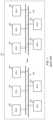
- FIG. 1is a schematic representation of an exemplary electronic network 100 of a motor vehicle.
- the network 100preferably is a controller area network (CAN) comprising a data bus 102 and a plurality of electronic control units (ECUs) 104 connected to the data bus for electronic communications between the ECUs.
- CANcontroller area network
- ECUselectronice control units
- Each ECUdefines a node of the network, and the complexity of the node can range from a simple I/O device to an embedded computer with a CAN interface and sophisticated software.
- a nodealso may comprise a gateway enabling other electronic devices to communicate over a port, such as a USB or Ethernet port, to the devices on the CAN network.
- Such other electronic devicesmay comprise, for example, wireless communication interfaces, including cellular communications, for wirelessly communicating with servers and other computing devices connected to the Internet. This enables real time communications between one or more nodes of the controller area network of the vehicle and a remotely located computer, such as a server.
- the data bus 102 connecting the nodesmay comprise two wires as schematically seen in FIG. 1 and preferably comprises a twisted pair in actual implementation.
- a vehiclecommonly has a large number of ECUs connected by the data bus 102 .
- Communications utilizing basic CAN protocolsare preferred but other higher level protocols and network technologies are contemplated, including by way of example and not limitation CAN FD, CAN OPEN, OBD2, and SAE J1939, J1708, as well as other communications protocols and technologies whether invented or hereinafter arising.
- the inventionis not limited by any specific protocol or network technology, although preferred embodiments preferably are implemented using one or more of the aforementioned technologies.
- PCMpowertrain control module
- ECMengine control module
- engine control unitbecause such unit controls engine functions such as spark timing, fuel mixture, and emissions.
- PCMhas become a more descriptive term because the PCM on many vehicles also controls the transmission, which is part of the powertrain.
- a transmission control moduleusually is a separate control module responsible for the transmission.
- the TCMinteracts with the PCM/ECM for transmission shifting at appropriate speeds and loads.
- BCMbody control module
- the functions and specific modules in a vehiclecan vary greatly depending on the year, make and model of vehicle, and even its list of options.
- MCMmain control module
- the MCMcommonly will be the PCM or ECM.
- ECUsinclude: ABS/traction control/stability control modules; airbag (SRS) modules; alarm modules (or chime modules) for anti-theft system; cruise control modules; electronic steering modules; fuel pump control modules; injector driver modules; instrument cluster control modules; keyless entry modules; lighting modules; remote start/immobilizer modules; suspension control modules; transfer case modules for four-wheel drives; wiper motor control modules; and vehicle communication modules.
- SRSairbag
- alarm modulesor chime modules
- cruise control moduleselectronic steering modules
- fuel pump control modulesinjector driver modules
- instrument cluster control moduleskeyless entry modules
- lighting modulesremote start/immobilizer modules
- suspension control modulestransfer case modules for four-wheel drives; wiper motor control modules
- vehicle communication modulesThere also can be modules for power windows, power seats, heated/cooled seats, power sliding doors, door locks, sunroofs, and air flow control doors inside the heating ventilation air conditioning (HVAC) system.
- HVACheating ventilation air conditioning
- controllers, sensors and actuatorstypically are or form part of the types of devices connected by a controller area network 100 .
- a node of a controller area networkmay comprise a subsystem of devices each having one or more electronic or electromechanical components, that a node may consist of a single such component, or any combination thereof.
- ADAdriver assistance
- ADAadvanced driver assistance
- Some ADA systemsmanage braking, such as collision mitigation systems, and others manage speed.
- Those that manage speedoften are referred to as intelligent speed adaptor (ISA) systems—or sometimes as intelligent speed adaptation systems or intelligent speed assistance systems.
- ISA systemsare in-vehicle systems that commonly are intended and used to increase speed-limit compliance by drivers.
- Open ISA systemsprovide an alert (visible and/or audible) to a driver when a speed limit is exceed and rely upon the driver to decrease the vehicle's speed; half-open ISA systems provide an alert and also temporarily limit the vehicle's capability to exceed the speed limit or make it more difficult to exceed the speed limit by the driver, such as by increasing the force countering depression of an accelerator pedal by a driver; and closed ISA systems limit the speed automatically, overriding a driver's actions causing the speeding, such as by controlling fuel delivery, or by altering acceleration control signals that are sent from an acceleration pedal to an electronic throttle controller and/or to the ECM.
- Basic ISA systemslimit speed of a vehicle to a preset maximum speed independent of extraneous factors including location of the vehicle.
- the more advanced ISA systemsuse information regarding location of the vehicle and a speed limit in force at such location in limiting the vehicle's speed to the then current speed limit.
- Advanced ISA systemsmay identify dynamic speed limits and limit a vehicle's speed to the then current speed limit for a given time at a given location.
- Dynamic speed limitsmay change based on time-dependent factors such as traffic flow and weather conditions.
- Informationcan be obtained in advanced ISA systems through use of digital maps incorporating roadway coordinates as well as from databases containing speed limits for road segments in a geographical area, or through other technologies such as optical recognition technology that detects and interprets roadside speed limit signage.
- Advanced ISA systemsthus assists a driver in keeping to the lawful speed limits at all times, particularly as the vehicle travels through different speed zones. This is particularly useful when drivers are in unfamiliar areas or when they pass through areas where dynamic speed limits are in use.
- GPS-based ISA systemsare believed to be perhaps the most effective ISA systems. In such a system, a GPS device detects a vehicle's current location which information is then used to determine the applicable speed limit from, for example, a preloaded database.
- FIG. 2An embodiment in accordance with the disclosure of the '133 Patent is illustrated in FIG. 2 .
- an actual throttle sensor signal from the throttle position sensor to the engine control unitis modified by a speed controller or intelligent speed limiter (ISL) 20 in order to prevent the user from driving the vehicle at a speed beyond the actual allowed maximum speed limit.
- ISLintelligent speed limiter
- the ISA systemcomprises a number of modules defining nodes of the controller area network including: a user identification device 12 for identifying a driver of the vehicle; a navigation device 14 , such as a navigation device including global positioning system (GPS) capabilities for determining a position of the vehicle on a road map (map matching); and a speed limit database 16 or cartography database of posted speed limits for respective segments of roads of the map, which database 16 may be updated in real time or provided from an external provider over wireless communications.
- GPSglobal positioning system
- Map matchingglobal positioning system
- speed limit database 16 or cartography database of posted speed limits for respective segments of roads of the mapwhich database 16 may be updated in real time or provided from an external provider over wireless communications.
- These componentsare connected for communications with the ISL module 20 , which executes an allowed maximum speed algorithm.
- the allowed maximum speed algorithmdetermines in real time an actual allowed maximum speed limit by adding the posted speed limit of the actual road segment, obtained by map matching (matching the GPS data with the speed limit database), to the corresponding user over-speed parameter
- the user identification device 12includes a data input interface to receive a user identification code from the driver, either via a keypad 32 (user identification and/or password) or a wireless device 32 ′ (RFID—radio frequency identification) worn by the driver, or the like.
- a keypad 32user identification and/or password
- RFIDradio frequency identification
- the ISL module 20also preferably has access to a user database 18 typically including, for each user, a respective user over-speed parameter corresponding to each respective road segment, which parameter could be provided for different types of roads or could be dependent on the corresponding posted speed limits, typically provided in the form of a driver speed profile table or the like.
- the ISL module 20further communicates with: a main control module of the vehicle comprising an engine control module 22 ; a vehicle speed source 24 , such as a vehicle speed sensor; and a throttle position sensor (TPS) 26 .
- a vehicle speed source 24such as a vehicle speed sensor
- TPSthrottle position sensor
- a customized speed limit database 30defining additional road(s), road segment(s) or even drivable road network of an entire restricted zone area, or the like, usually not shown nor available in typical cartography databases, could be incorporated into the ISL module 20 via speed limit database 30 .
- the ISA systempreferably prevents the vehicle from being moved by either preventing the starting of the vehicle engine or by preventing the signal of the throttle position sensor 26 from being sent to the engine control unit 22 in the absence of a valid user identification.
- the ISL module 20 and the main control module 22each form a node of the controller area network of the vehicle.
- the throttle position sensor 26 and vehicle speed source 24also constitute nodes.
- the ISL module 20controls the signals sent by the throttle position sensor 26 . This is schematically represented by control line 23 .
- FIG. 3An alternative embodiment of the ISA system in accordance with the disclosure of the '133 Patent is illustrated in FIG. 3 .
- the throttle position sensor module 26preferably is coupled for communication with the ISL module 20 rather than the CAN bus so that the signals sent from the throttle position sensor 26 are not received by the main control module 22 until after the ISL module 20 has had the opportunity to modify such signals, if necessary, in order to reduce the speed of the vehicle or limit acceleration of the vehicle so as not to exceed the maximum allowed speed.
- the aforementioned embodiments of the ISA system of the '133 Patentneed to function to prevent speeding regardless of whether cruise control is engaged by a driver; cruise control cannot be permitted to be a workaround for speeding.
- Cruise control functionalityis provided by a cruise control module 28 that ordinarily would be coupled in communication with the main control module 22 via the CAN bus.
- FIG. 2is representative of this arrangement.
- the ISL module 20takes over control of the cruise control module 28 and allows the setting of the cruise control only at a vehicle speed at or below the actual allowed maximum speed limit and prevents the setting of the cruise control at any vehicle speed above the actual allowed maximum speed limit.
- This embodimentis represented in FIG. 2 , and such control is schematically represented by control line 25 therein.
- the cruise control module 28is coupled for communication with the ISL module 20 rather than the CAN bus so that the signals sent from the control module 28 are not received by the main control module 22 until after the ISL module 20 has had the opportunity to modify such signals, if necessary, which is similar to the arrangement of the throttle position sensor module 26 .
- a driveris prevented from exceeding the maximum allowed speed using cruise control.
- embodiments of the ISA system disclosed in the '133 Patentcan be commercially difficult to implement due to the required interactions between the ISL module 20 and the cruise control module 28 .
- cruise control modulesthere are many different manufacturers and models of cruise control modules, each module of which can vary significantly in its operation and control. Each manufacturer and model thus needs to be taken into consideration in either of the implementations of the ISA system of FIGS. 2 and 3 .
- the present inventionincludes many aspects and features. Moreover, while many aspects and features relate to, and are described in the context of, ADA systems and ISA systems in particular, the present invention also has utility outside of such systems, as will become apparent to the Ordinary Artisan from the disclosure herein.
- a vehiclecomprises: a controller area network, a node of the controller area network comprising a main control module and another node of the controller area network comprising a cruise control module; and a controller configured to cause an indication to be made to the MCM that a driver of the vehicle is braking even when a driver of the vehicle is not braking.
- the MCMdisengages cruise control upon such indication being made to the MCM.
- the controlleris configured to cause the indication to be made to the MCM that a driver of the vehicle is braking as a function of determining that the vehicle is speeding.
- the controllerindicates to the MCM that a driver of the vehicle is braking preferably as a function of also determining that cruise control is engaged.
- the controllercomprises a microcontroller.
- the controllercomprises an application specific integrated circuit.
- a vehiclecomprises: a controller area network, a node of the controller area network comprising a main control module (MCM) and another node of the controller area network comprising a cruise control module; a brake switch forming part of a brake switch circuit with the MCM which brake switch, when closed, indicates to the MCM that a driver of the vehicle is braking; and a controller arranged in parallel with the brake switch and configured to bypass the brake switch to simulate the closing of the brake switch thereby indicating to the MCM that a driver of the vehicle is braking even when the brake switch is not closed.
- the MCMdisengages cruise control upon the indication to the MCM that a driver of the vehicle is braking.
- the controllerindicates to the MCM that a driver of the vehicle is braking as a function of determining that the vehicle is speeding.
- the controllerindicates to the MCM that a driver of the vehicle is braking preferably as a function of also determining that cruise control is engaged.
- the controllercomprises a microcontroller.
- the controllercomprises an application specific integrated circuit.
- a vehiclecomprises: an advanced driver assistance (ADA) system; and means for causing a signal to be received by a main control module (MCM) in a controller area network of the vehicle which signal indicates to the MCM that a driver of the vehicle is braking.
- the signalis caused by said means to be received by the MCM when the vehicle is determined to be speeding regardless of whether the driver of the vehicle is actually braking.
- ADAadvanced driver assistance
- MCMmain control module
- the ADA systemcomprises an intelligent speed adaptor (ISA) system.
- ISAintelligent speed adaptor
- the ADA systemcomprises a collision mitigation system.
- the vehiclecomprises a cruise control module and the ADA system operates without regard to the cruise control module.
- the signalis caused by said means to be received by the MCM when it is determined also that cruise control is engaged.
- a method for simulating braking of a vehicle so as to disengage cruise controlcomprises the steps of: monitoring whether cruise control is engaged; determining a current speed of the vehicle; determining a currently allowed speed of the vehicle; comparing the determined currently allowed speed of the vehicle to the determined current speed of the vehicle; and when cruise control is determined to be engaged and the determined current speed of the vehicle is within a predetermined range of or exceeds the determined currently allowed speed, causing one or more signals to be sent to a main control module of the vehicle simulating braking by a driver of the vehicle causing the main control module to disengage the cruise control.
- a method for simulating braking of a vehicle so as to disengage cruise controlcomprises the steps of: monitoring whether cruise control is engaged; determining a current set speed of the cruise control; determining a currently allowed speed of the vehicle; comparing the determined currently allowed speed of the vehicle to the determined current set speed of the vehicle; and when cruise control is determined to be engaged and the determined current set speed of the cruise control is within a predetermined range of or exceeds the determined currently allowed speed, causing one or more signals to be sent to a main control module of the vehicle simulating braking by a driver of the vehicle causing the main control module to disengage the cruise control.
- a method for simulating braking of a vehicle so as to disengage cruise controlcomprises the steps of determining a current speed of the vehicle; determining a currently allowed speed of the vehicle; comparing the determined currently allowed speed of the vehicle to the determined current speed of the vehicle; and when the determined current speed of the vehicle is within a predetermined range of or exceeds the determined currently allowed speed, causing one or more signals to be sent to a main control module of the vehicle simulating braking by a driver of the vehicle causing the main control module to disengage any cruise control that may be engaged.
- the currently allowed speedis a speed limit for the vehicle.
- the currently allowed speedis a fixed speed limit for a current location of the vehicle.
- the currently allowed speedis a dynamic speed limit for a current location of the vehicle.
- the currently allowed speedis a predetermined variance from a speed limit for a current location of the vehicle.
- the currently allowed speedis determined from a database using GPS coordinates of the vehicle.
- FIG. 1is a schematic illustration of a prior art electronic network of a motor vehicle.
- FIG. 2is a schematic illustration of an embodiment of a prior art ISA system in accordance with the disclosure of the '133 Patent.
- FIG. 3is a schematic illustration of another embodiment of a prior art ISA system in accordance with the disclosure of the '133 Patent.
- FIG. 4is a schematic illustration of an embodiment in accordance with one or more aspects and features of the present invention.
- FIG. 5is a schematic illustration of another embodiment in accordance with one or more aspects and features of the present invention.
- FIG. 6is a schematic illustration of yet another embodiment in accordance with one or more aspects and features of the present invention.
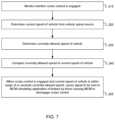
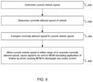
- FIG. 7is a schematic illustration of a sequence of steps that are performed in accordance with one or more aspects and features of the present invention.
- FIG. 8is a schematic illustration of another sequence of steps that are performed in accordance with one or more aspects and features of the present invention.
- FIG. 9is a schematic illustration of yet another sequence of steps that are performed in accordance with one or more aspects and features of the present invention.
- any sequence(s) and/or temporal order of steps of various processes or methods that are described hereinare illustrative and not restrictive. Accordingly, it should be understood that, although steps of various processes or methods may be shown and described as being in a sequence or temporal order, the steps of any such processes or methods are not limited to being carried out in any particular sequence or order, absent an indication otherwise. Indeed, the steps in such processes or methods generally may be carried out in various different sequences and orders while still falling within the scope of the invention. Accordingly, it is intended that the scope of patent protection afforded the invention be defined by the issued claim(s) rather than the description set forth herein.
- a picnic basket having an appleis the same as “a picnic basket comprising an apple” and “a picnic basket including an apple”, each of which identically describes “a picnic basket having at least one apple” as well as “a picnic basket having apples”; the picnic basket further may contain one or more other items beside an apple.
- a picnic basket having a single appledescribes “a picnic basket having only one apple”; the picnic basket further may contain one or more other items beside an apple.
- a picnic basket consisting of an applehas only a single item contained therein, i.e., one apple; the picnic basket contains no other item.
- picnic basket having cheese or crackersWhen used herein to join a list of items, “or” denotes “at least one of the items” but does not exclude a plurality of items of the list.
- reference to “a picnic basket having cheese or crackers”describes “a picnic basket having cheese without crackers”, “a picnic basket having crackers without cheese”, and “a picnic basket having both cheese and crackers”; the picnic basket further may contain one or more other items beside cheese and crackers.
- picnic basket having cheese and crackersWhen used herein to join a list of items, “and” denotes “all of the items of the list”.
- a picnic basket having cheese and crackersdescribes “a picnic basket having cheese, wherein the picnic basket further has crackers”, as well as describes “a picnic basket having crackers, wherein the picnic basket further has cheese”; the picnic basket further may contain one or more other items beside cheese and crackers.
- “at least one” followed by a list of items joined by “and”denotes an item of the list but does not require every item of the list.
- “at least one of an apple and an orange”encompasses the following mutually exclusive scenarios: there is an apple but no orange; there is an orange but no apple; and there is both an apple and an orange. In these scenarios if there is an apple, there may be more than one apple, and if there is an orange, there may be more than one orange.
- the phrase “one or more” followed by a list of items joined by “and”is the equivalent of “at least one” followed by the list of items joined by “and”.
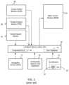
- FIG. 4is a schematic illustration of an embodiment in accordance with one or more aspects and features of the present invention.
- the embodiment of FIG. 4includes many of the same elements as the ISA system of FIGS. 2 and 3 , including an identification device 12 for identifying a driver; a navigation device (e.g. GPS device) 14 ; a cartography or speed limit database 16 ; a user database 18 of drivers; an intelligent speed limiter (ISL) module 20 ; a main control module (MCM) 22 ; a vehicle speed source 24 ; a throttle position sensor (TPS) module 26 ; and a cruise control module 28 .
- a customized speed limit database 30 ; a keypad 32 ; and a wireless RFID reader 32 ′also may be included as shown. Operation of these elements when the cruise control is not engaged may be as described above with regard to the ISA systems of FIGS. 2 and 3 .
- the ISL module 20 in FIG. 4does not control the cruise control module 28 and the signals that are sent from the cruise control module 28 to the MCM, which is done in the ISA system of FIG. 2 .
- the cruise control module 28separately connected to the ISL module 20 like in the ISA system of FIG. 3 .
- the cruise control module 28 in FIG. 4is connected to the data bus of the controller area network of the vehicle for communication via the data bus with the main control module 22 .
- controller 120may be communicatively coupled to the vehicle speed source 24 via the controller area network whereby a current speed of the vehicle is determined by the controller 120 .
- a current speed of the vehicleis determined by the controller 120 .
- the vehicle speedis obtained by the controller 120 from the ISL module 20 , as indicated by line 29 .
- the currently allowed speed limitalso preferably is obtained or otherwise determined by the controller 120 from information acquired from the ISL module 20 .
- the controller 120also monitors the data bus for whether the cruise control module 28 is active and cruise control is currently engaged.
- the ISL moduledetermines whether the vehicle is speeding and informs the simulating controller 120 .
- the simulating controller 120determines that the cruise control is engaged and that the current speed of vehicle is within a range of or exceeds the currently allowed speed
- the simulating controller 120causes one or more signals to be sent to MCM 22 , which one or more signals indicate to the MCM 22 that the brakes are being applied by the driver, thus simulating driver braking.
- This mimicking of driver brakingresults in consequent disengagement by the MCM 22 of the cruise control.
- the ISL module 20Due to the operation of the simulating controller 128 , the ISL module 20 is able to operate in a mode corresponding to operation as if there were no cruise control module 28 . Nor is the resulting effectiveness of the ISL module 20 impacted by the presence and operation of the cruise control module—a benefit of the embodiment of the present invention for FIG. 4 .
- FIG. 5is a schematic illustration of another embodiment in accordance with one or more aspects and features of the present invention.
- the embodiment of FIG. 5includes many of same elements as that of FIG. 4 and principally differs in the arrangement of the throttle position sensor 26 relative to the ISL module 20 .
- this arrangement of the throttle position sensor 26 and ISL module 20corresponds to that of FIG. 3 .
- the arrangement of the throttle position sensor 26 and ISL module 20 of FIG. 2similarly corresponds to that of FIG. 4 .
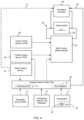
- FIG. 6is similar to that of FIG. 5 .
- the embodiment of FIG. 6 in accordance with one or more aspects and features of the present inventiondiffers from that of FIGS. 4 and 5 in how the simulating controller 120 simulates braking by the driver.
- the simulating controllerpreferably bypasses operation of a brake switch of the vehicle.
- the simulating controller 120closes the brake switch circuit 132 causing a signal to be generated indicating braking even though the brake switch 130 may not be in a closed position so as to complete the circuit 132 itself.
- the brake switch circuit 132is connected to the MCM 22 whereby closing of the brake switch circuit 132 signals the MCM 22 that the driver is applying the brakes.
- the simulating controller 120will maintain the closed circuit with current flowing therethrough so long as the simulating controller 120 determines that speeding is occurring.
- the MCM 22also preferably causes the brake lights to be illuminated, too.
- the simulating controller 120interacts with the brake switch through ECU 140 which itself is communicatively coupled with the MCM 22 via the data bus of the controller area network.
- step 210whether cruise control is engaged is monitored.
- the steppreferably is continuously performed.
- step 220the current speed of the vehicle is determined from the vehicle speed source. This step preferably is performed at short periodic intervals.
- step 230the currently allowed speed of the vehicle is determined, which also is performed at short periodic intervals.
- step 240the currently allowed speed of the vehicle is compared to the current speed of vehicle, which step is preferably performed at short periodic intervals.
- a signalis caused to be sent to the MCM in step 250 that simulates application of the brakes by the driver, thereby resulting in disengagement by the MCM of the cruise control.
- steps 210 , 220 , 230may be performed in any order or concurrently, and the sequence of steps shown in FIG. 7 is not limiting.
- the simulating controlleris able to determine a set speed of the cruise control. This preferably is determined by communication with the MCM via the data bus. It is also contemplated that, while not preferred, this may be accomplished by communicatively coupling the simulating controller to the cruise control module such that a current set speed of the cruise control is thereby determined by the simulating controller. Such connection may be accomplished via the data bus.
- the simulating controllerdetermines that the cruise control is engaged and that the current cruise control set speed of vehicle is within a range of or exceeds the currently allowed speed
- the simulating controllercauses one or more signals to be sent to MCM which signals indicate to the MCM that the brakes are being applied by the driver, thereby simulating driver braking. Again, such mimicking of driver braking results in disengagement by the MCM of cruise control.
- step 310whether cruise control is engaged is monitored. This step preferably is continuously performed.
- step 320the current set speed of the cruise control for the vehicle is determined whether or not the cruise control is engaged. This step preferably is performed at short periodic intervals.
- step 330the currently allowed speed of the vehicle is determined, which also is performed at short periodic intervals.
- step 340the currently allowed speed of the vehicle is compared to the current set speed, which step is preferably performed at short periodic intervals.
- a signalis caused to be sent to the MCM in step 350 that simulates application of the brakes by the driver, thereby resulting in disengagement by the MCM of the cruise control.
- This sequence of stepsis believed to be preferential over the sequence of steps of FIG. 7 because there is no ambiguity whether the speeding is momentary due to the vehicle being on a downhill slope as opposed to being set at a speed that is over the currently allowed speed.
- steps 310 , 320 , 330may be performed in any order or concurrently, and the sequence of steps shown in FIG. 8 is not limiting.
- the simulating controlleris not communicatively coupled to the cruise control module and does not monitor whether the cruise control is actually engaged.
- the simulation of brakingis performed only when cruise control is determined to be engaged. In this particular embodiment, however, the simulation of braking is not dependent on determination that cruise control is engaged. Instead, the simulating controller simply determines at short periodic intervals whether the current speed of the vehicle is within a range of or exceeds the currently allowed speed, and the simulating controller causes one or more signals to be sent to MCM which one or more signals indicate to the MCM that the brakes are being applied by the driver, thereby simulating driver braking. This mimicking of driver braking results in disengagement by the MCM of cruise control—if engaged.
- such simulated brakingalso results in brake override, wherein conflicting signals being received by the MCM from the throttle position sensor are ignored by the MCM resulting in a decrease of or loss of acceleration in vehicle speed and consequent slowing of the vehicle until the detected speeding is abated.
- step 420the current vehicle speed is determined irrespective of whether the cruise control is engaged. This step preferably is performed at short periodic intervals.
- step 430the currently allowed speed of the vehicle is determined irrespective of whether the cruise control is engaged, which also is performed at short periodic intervals.
- step 440the currently allowed speed of the vehicle is compared to the current vehicle speed irrespective of whether the cruise control is engaged, which step is preferably performed at short periodic intervals.
- a signalis caused to be sent to the MCM in step 450 that simulates application of the brakes by the driver irrespective of whether the cruise control is engaged; however, if cruise control is engaged, then such simulated braking results in disengagement of the cruise control.
- steps 420 , 430may be performed in any order or concurrently, and the sequence of steps shown in FIG. 9 is not limiting.
- the simulating controlleris preprogrammed with one or more allowed speeds, or otherwise is able to determine an allowed speed (such as in the same or a similar way as the ISL module described with reference to FIGS. 2 and 3 ), then the operation of the simulating controller in accordance with FIG. 9 may result in limiting of the speed of the vehicle when used without and independent of the ISL module.
- the simulating controllerdoes not cause one or more signals to be sent to MCM simulating braking until after a predetermined period of time in which such determinations indicating speeding are made.
- the simulating controllerdoes not cause one or more signals to be sent to MCM simulating braking until after a predetermined distance has been traveled, during which travel the determinations made by the simulating controller indicate speeding.
- Such time or distance bufferwill avoid disengagement of the cruise control too quickly, which could annoy a driver.
- a time or distance bufferis usefully used to prevent disengaging the cruise control during a short period of time or over a short distance that the vehicle is traveling downhill.
- minor speeding transgressions on a limited basispreferably will not result in disengagement of cruise control.
- a significant magnitude in a transgression regardless of a time or distance bufferpreferably will result in disengagement of cruise control.
- Such a magnitude of speedingwould be something that is not the result of simply traveling downhill or something that would legally be deemed reckless driving. For example, speeding by more than 50 km/hr in Canada—or 15 m/hr in the United States—of the currently allowed speed may be deemed to be such a magnitude of transgression so as to ignore any otherwise applicable time or distance buffer.
- embodiments of the present inventionprovide many benefits and advantages.
- One such advantageis that one or more embodiments of the present invention work well and are compatible with other ADA systems, including other ISA systems and including collision mitigation systems and lane departure systems, for example.
- many embodiments of the present inventiondo not try to override such other systems and will act only if the vehicle is exceeding the configured speed limit while cruise control is engaged.
- this method of disengaging the cruise controlavoids directly sending a message on the data bus to the MCM/ECM to disengage the cruise control.
- Sending messages on the data bus, as opposed to only reading messages from the data bus,is disfavored by OEMs and systems that only read message are favored.
- the simulating controlleronly reads data from the data bus and thus would be a favored system by such OEMs.
- the advantage of using the brake switch method to disengage the cruise controlis that the simulating controller only need to cause current to flow through the brake switch circuit, thereby causing the MCM to disengage the cruise control without the simulating circuit signaling the MCM itself via the data bus.
- the simulating controllerdoes communicate with the MCM/ECM, sending commands directly to the MCM/ECM to disengage the cruise control, but requires an understanding of the protocol of each different vehicle model. Also sending a wrong signal to the MCM/ECM can have undesired consequences, such as creating an engine code. Going through the brake switch circuit is therefore believed to be both safer for the MCM/ECM and more universal in commercial applications.
- Another benefitis that by avoiding taking over control of the cruise control (as in a disclosed ISA system of the '133 Patent), difficulties can be avoided where other ADA systems that work with the OEM cruise control, such as adaptive cruise control, would likely no longer work and would be overridden. Such incompatibility with other ADA systems is believed to be a serious hinderance to adoption and commercialization of such ISA system of the '133 Patent.
- the cruise controlcan be disengaged by simply simulating a brake switch signal. Simulating the brake switch signal will automatically disengage any cruise control and allow ISA systems and other ADA systems to continue properly functioning should the driver try to bypass such systems through the cruise control, while not having to program or otherwise account for different cruise control systems. By simply simulating the brake switch signal, the cruise control is disengaged when the vehicle goes above the configured speed limit while continuing to limit the accelerator pedal.
- FIG. 10 of U.S. patent application publication 2021/0031765which is the publication of Ser. No. 16/947,456 (the current application; hereinafter the ‘765 Publication”), and which is incorporated herein by reference, shows a modification to a brake switch that has been installed on a Volvo tractor in accordance with one or more aspects and features of an embodiment of the present invention.
- FIG. 11 of the ‘765 Publicationshows an alternative modification that has been installed on a Freightliner New Cascadia truck in accordance with one or more aspects and features of an embodiment of the present invention.
- a simulating controllercannot be connected directly to a brake switch and, in those situations, a simulating controller is connected to an ECU with which the brake switch is connected whereby the simulating controller still is able to cause a signal to be generated indicating braking by a driver to the MCM.
- An exemplary ECUis a surrogate safety assessment model (SSAM) of the Freightliner New Cascadia.
- simulating controllerhas been described in connection with embodiments of an ISA system of the '133 Patent, it will be appreciated that embodiments of the present invention are not limited to use with or incorporate of such an ISA system.
Landscapes
- Engineering & Computer Science (AREA)
- Transportation (AREA)
- Mechanical Engineering (AREA)
- Automation & Control Theory (AREA)
- Chemical & Material Sciences (AREA)
- Combustion & Propulsion (AREA)
- Controls For Constant Speed Travelling (AREA)
- Traffic Control Systems (AREA)
Abstract
Description
Claims (18)
Priority Applications (2)
| Application Number | Priority Date | Filing Date | Title |
|---|---|---|---|
| US16/947,456US12227181B2 (en) | 2019-08-01 | 2020-08-03 | Simulating braking when speeding on cruise control to facilitate use of ISA system |
| US18/977,923US20250108803A1 (en) | 2019-08-01 | 2024-12-12 | Simulating braking when speeding on cruise control to facilitate use of isa system |
Applications Claiming Priority (2)
| Application Number | Priority Date | Filing Date | Title |
|---|---|---|---|
| US201962881934P | 2019-08-01 | 2019-08-01 | |
| US16/947,456US12227181B2 (en) | 2019-08-01 | 2020-08-03 | Simulating braking when speeding on cruise control to facilitate use of ISA system |
Related Child Applications (1)
| Application Number | Title | Priority Date | Filing Date |
|---|---|---|---|
| US18/977,923ContinuationUS20250108803A1 (en) | 2019-08-01 | 2024-12-12 | Simulating braking when speeding on cruise control to facilitate use of isa system |
Publications (2)
| Publication Number | Publication Date |
|---|---|
| US20210031765A1 US20210031765A1 (en) | 2021-02-04 |
| US12227181B2true US12227181B2 (en) | 2025-02-18 |
Family
ID=74259019
Family Applications (2)
| Application Number | Title | Priority Date | Filing Date |
|---|---|---|---|
| US16/947,456Active2040-11-03US12227181B2 (en) | 2019-08-01 | 2020-08-03 | Simulating braking when speeding on cruise control to facilitate use of ISA system |
| US18/977,923PendingUS20250108803A1 (en) | 2019-08-01 | 2024-12-12 | Simulating braking when speeding on cruise control to facilitate use of isa system |
Family Applications After (1)
| Application Number | Title | Priority Date | Filing Date |
|---|---|---|---|
| US18/977,923PendingUS20250108803A1 (en) | 2019-08-01 | 2024-12-12 | Simulating braking when speeding on cruise control to facilitate use of isa system |
Country Status (1)
| Country | Link |
|---|---|
| US (2) | US12227181B2 (en) |
Families Citing this family (3)
| Publication number | Priority date | Publication date | Assignee | Title |
|---|---|---|---|---|
| US11572067B2 (en) | 2019-08-30 | 2023-02-07 | 7980302 Canada Inc. | Using ISA system to decelerate truck upon entering geofenced area |
| US11702083B2 (en) | 2020-06-11 | 2023-07-18 | 7980302 Canada Inc. | Using ISA system to implement a speed policy identified based on profile of a driving instance |
| US12391308B2 (en)* | 2023-08-23 | 2025-08-19 | Toyota Jidosha Kabushiki Kaisha | False positive request detection |
Citations (86)
| Publication number | Priority date | Publication date | Assignee | Title |
|---|---|---|---|---|
| JPS60163735A (en)* | 1984-02-07 | 1985-08-26 | Jidosha Denki Kogyo Co Ltd | Automatically controlling device of car speed |
| US4947953A (en)* | 1987-08-31 | 1990-08-14 | Fuji Jukogyo Kabushiki Kaisha | Drive speed control system for a motor vehicle having a continuously variable transmission |
| US5031716A (en) | 1988-06-16 | 1991-07-16 | Wabco Standard Gmbh | Vehicle drive engagement control and speed governor system |
| US5774820A (en) | 1994-09-23 | 1998-06-30 | Mercedes-Benz Ag | Method and apparatus for limiting the speed of a motor vehicle |
| DE19907372C1 (en) | 1999-02-20 | 2000-07-13 | Opel Adam Ag | Arrangement for securing motor vehicles against theft blocks operation of controller during electronically stored times when vehicle is not in use, even if a release signal is received |
| US20010003808A1 (en) | 1999-12-14 | 2001-06-14 | Yong-Won Jeon | Vehicle speed control system using wireless communications and method for controlling the same |
| US20010047236A1 (en)* | 2000-05-25 | 2001-11-29 | Masahiro Iriyama | Vehicle driving control system |
| US20020040842A1 (en)* | 2000-01-18 | 2002-04-11 | Caterpillar Inc | Parking brake switch for an electro-hydraulic brake system |
| US20020065599A1 (en) | 2000-11-23 | 2002-05-30 | Heino Hameleers | Traffic management system based on packet switching technology |
| US20020190854A1 (en)* | 2001-06-13 | 2002-12-19 | Grant Swan | Deceleration light indicator and method therefor |
| US20030130783A1 (en)* | 2000-03-28 | 2003-07-10 | Manfred Hellmann | Method and device for releasing a take-over request for cruise controlled vehicles |
| US6749269B1 (en) | 1999-02-03 | 2004-06-15 | Toyota Jidosha Kabushiki Kaisha | Braking system having switching device for supplying energy to electrically controlled through brake controller upon operation of brake operating member |
| US6778074B1 (en) | 2002-03-18 | 2004-08-17 | Giuseppe A. Cuozzo | Speed limit indicator and method for displaying speed and the relevant speed limit |
| US20040212506A1 (en) | 2001-06-19 | 2004-10-28 | Cherouny Peter Herbert | Electronic programmable speed limiter |
| US20050075829A1 (en)* | 2003-08-08 | 2005-04-07 | James Polimadei | Vehicle usage tracking system and highway/city mileage odometer |
| US20050146208A1 (en) | 2001-11-09 | 2005-07-07 | The Regents Of The University Of California | Apparatus and method for stopping a vehicle |
| WO2006015425A1 (en) | 2004-08-12 | 2006-02-16 | Stephen Petrik | Gps monitoring, biometric smartcard, intelligent speed management |
| US20060081697A1 (en) | 2001-09-11 | 2006-04-20 | Zonar Compliance Systems, Llc | Ensuring the performance of mandated inspections combined with the collection of ancillary data |
| US20060095190A1 (en)* | 2004-11-02 | 2006-05-04 | Currie Joseph E | Automotive speed control disable switch |
| US20070001830A1 (en)* | 2005-06-30 | 2007-01-04 | Dagci Oguz H | Vehicle speed monitoring system |
| US7184873B1 (en) | 2006-05-05 | 2007-02-27 | Stanox Technologies Inc. | Vehicle speed limiting device |
| US7272469B2 (en) | 2004-03-03 | 2007-09-18 | Magtec Products Inc. | Immobilizer system for vehicles |
| US20080091309A1 (en)* | 1998-01-15 | 2008-04-17 | Walker Richard C | Electrically controlled automated devices to operate, slow, guide, stop and secure, equipment and machinery for the purpose of controlling their unsafe, unattended, unauthorized, unlawful hazardous and/or legal use, with remote control and accountability worldwide |
| CA2610548A1 (en) | 2006-11-16 | 2008-05-16 | Jean-Francois Aussillou | Fuel economy system and method for a vehicle |
| US20080270519A1 (en) | 2004-05-12 | 2008-10-30 | Hans Ekdahl | Method in a Communication Network for Distributing Vehicle Driving Information and System Implementing the Method |
| US7457693B2 (en) | 2004-01-09 | 2008-11-25 | United Parcel Service Of America, Inc. | System, method, and apparatus for collecting telematics and sensor information in a delivery vehicle |
| US20100045451A1 (en)* | 2008-08-25 | 2010-02-25 | Neeraj Periwal | Speed reduction, alerting, and logging system |
| US7706953B1 (en)* | 2006-10-30 | 2010-04-27 | Sun Jun-Shi | Speed stabilizer for automatically turning conventional cruise controls on/off in dense low speed traffic to save fuel |
| US20100280728A1 (en)* | 2009-04-29 | 2010-11-04 | Gm Global Technology Operations, Inc. | Driver inputs allowing full speed range adaptive cruise control to release brake hold |
| US7957882B2 (en) | 2006-03-10 | 2011-06-07 | Magtec Products, Inc. | Onboard controller system |
| US20110137520A1 (en) | 2009-12-07 | 2011-06-09 | At&T Mobility Ii Llc | Devices, Systems and Methods for Controlling Permitted Settings on a Vehicle |
| US20110160978A1 (en) | 2008-08-28 | 2011-06-30 | Nissan Motor Co., Ltd. | Vehicle speed limit control device and method for controlling vehicle speed limit |
| US8000877B2 (en) | 2006-11-16 | 2011-08-16 | Jean-François Aussilou | Fuel economy system and method for a vehicle |
| US8204646B2 (en) | 2006-03-10 | 2012-06-19 | Magtec Products, Inc. | Onboard controller system |
| CA2768484A1 (en) | 2011-02-17 | 2012-08-17 | Jean Poulin | Speed limiter system and method for a vehicle |
| JP5018291B2 (en)* | 2007-07-10 | 2012-09-05 | トヨタ自動車株式会社 | Travel control device |
| US20120226390A1 (en) | 2011-03-03 | 2012-09-06 | Nathan Adams | History timeline display for vehicle fleet management |
| WO2012117419A2 (en)* | 2011-03-02 | 2012-09-07 | Eralil Abi Noby | System and method for regulating vehicle speed |
| US20120283928A1 (en) | 2009-11-30 | 2012-11-08 | Volvo Lastvagnar Ab | Method and system for controlling a vehicle cruise control |
| US8330620B2 (en) | 2006-11-02 | 2012-12-11 | Continental Teves Ag & Co. Ohg | Method for producing a localized warning of dangerous situations for vehicles |
| US20120330522A1 (en) | 2011-06-22 | 2012-12-27 | Ford Global Technologies, Llc | Method and system for engine control |
| US20130157647A1 (en) | 2011-12-20 | 2013-06-20 | Cellco Partnership D/B/A Verizon Wireless | In-vehicle tablet |
| US20130164715A1 (en) | 2011-12-24 | 2013-06-27 | Zonar Systems, Inc. | Using social networking to improve driver performance based on industry sharing of driver performance data |
| US20140046585A1 (en) | 2012-08-10 | 2014-02-13 | Telogis, Inc. | Real-time computation of vehicle service routes |
| US20140282917A1 (en) | 2013-03-15 | 2014-09-18 | Dt Labs, Llc | System, Method and Apparatus for Increasing Website Relevance While Protecting Privacy |
| US20150081399A1 (en) | 2013-09-16 | 2015-03-19 | Fleetmatics Irl Limited | Vehicle independent employee/driver tracking and reporting |
| US20150120178A1 (en) | 2013-10-30 | 2015-04-30 | Ford Global Technologies, Llc | System for determining clearance of approaching overhead structure |
| KR20150047213A (en)* | 2013-10-24 | 2015-05-04 | 현대모비스 주식회사 | Variable cruise control apparatus and method |
| US20150246676A1 (en) | 2012-09-19 | 2015-09-03 | Yakov Keren | Personal profiles based system for speed limit enforcing and methods of use thereof |
| US20150336581A1 (en) | 2014-05-20 | 2015-11-26 | Paccar Inc | Point-of-Sale Vehicle Parameter Configuration |
| US20150355637A1 (en) | 2014-06-10 | 2015-12-10 | Magtec Products, Inc. | Remote speed management system for vehicles |
| US9240018B2 (en) | 2011-11-16 | 2016-01-19 | Autoconnect Holdings Llc | Method and system for maintaining and reporting vehicle occupant information |
| US9396656B2 (en) | 2013-12-19 | 2016-07-19 | Cellco Partnership | Accident prevention system |
| US20160255575A1 (en)* | 2011-11-16 | 2016-09-01 | Autoconnect Holdings Llc | Network selector in a vehicle infotainment system |
| US20170068245A1 (en) | 2014-03-03 | 2017-03-09 | Inrix Inc. | Driving profiles for autonomous vehicles |
| US9630590B2 (en) | 2014-03-13 | 2017-04-25 | Tracknstop Limited | Control method, device and system for a vehicle |
| US20170129492A1 (en)* | 2015-11-09 | 2017-05-11 | Cummins Inc. | Systems and methods for pre-hill cruise speed adjustment |
| US20170282917A1 (en)* | 2016-03-29 | 2017-10-05 | Ford Global Technologies, Llc | System and methods for adaptive cruise control based on user defined parameters |
| US20170361840A1 (en)* | 2016-06-21 | 2017-12-21 | Robert Valentine | Aftermarket controls for vehicles retrofitted with a non-original powertrain |
| US20180059687A1 (en) | 2016-08-25 | 2018-03-01 | Allstate Insurance Company | Fleet Vehicle Feature Activation |
| US9932038B1 (en) | 2016-11-30 | 2018-04-03 | Baidu Usa Llc | Speed control for a full stop of an autonomous driving vehicle |
| US20180130095A1 (en) | 2014-03-28 | 2018-05-10 | Joseph Khoury | Methods and systems for collecting driving information and classifying drivers and self-driving systems |
| US9971348B1 (en) | 2015-09-29 | 2018-05-15 | Amazon Technologies, Inc. | Passenger profiles for autonomous vehicles |
| US20180308295A1 (en) | 2017-04-25 | 2018-10-25 | TrueLite Trace, Inc. | Commercial Driver Electronic Logging Rule Compliance and Vehicle Inspection Voice Assistant System |
| US20180357841A1 (en) | 2012-03-14 | 2018-12-13 | Zonar Systems, Inc. | Event based gps tracking |
| US20190016341A1 (en) | 2017-07-17 | 2019-01-17 | Here Global B.V. | Roadway regulation compliance |
| WO2019043446A1 (en) | 2017-09-04 | 2019-03-07 | Nng Software Developing And Commercial Llc | A method and apparatus for collecting and using sensor data from a vehicle |
| US20190138021A1 (en) | 2015-04-13 | 2019-05-09 | Matthew Gage Merzig | Airspeed Adaptive Cruise Control for Ground Vehicles |
| US20190236863A1 (en) | 2018-01-31 | 2019-08-01 | TrueLite Trace, Inc. | Vehicle Electronic Logging Device (ELD) Hour-of-Service (HoS) Audit and Correction Guidance System and Method of Operating Thereof |
| US10373257B1 (en) | 2014-02-21 | 2019-08-06 | Arity International Limited | Vehicle telematics and account management |
| US10388161B2 (en) | 2015-09-16 | 2019-08-20 | Truck-Lite Co., Llc | Telematics road ready system with user interface |
| US10392023B2 (en) | 2014-10-06 | 2019-08-27 | Jaguar Land Rover Limited | System and method for determining whether a trailer is attached to a vehicle |
| US20190339692A1 (en) | 2017-02-28 | 2019-11-07 | Panasonic Intellectual Property Management Co., Ltd. | Management device and management method |
| US10479200B2 (en) | 2016-04-19 | 2019-11-19 | Magtec Products, Inc. | Throttle control system and method |
| US20190383627A1 (en) | 2018-06-13 | 2019-12-19 | Skip Transport, Inc. | System and method for vehicle operation control |
| US10593205B1 (en) | 2015-12-13 | 2020-03-17 | Timothy Jones | GPS and warning system |
| US20200104790A1 (en) | 2018-10-02 | 2020-04-02 | Avante International Technology, Inc. | Smart terminal facility and method suitable for the handling of cargo containers |
| US20200125117A1 (en)* | 2018-10-23 | 2020-04-23 | Peloton Technology, Inc. | Systems and methods for platooning and automation safety |
| US20200156630A1 (en) | 2018-11-19 | 2020-05-21 | Toyota Motor Engineering & Manufacturing North America, Inc. | Vehicle height detection and environmental warning system |
| US20200317184A1 (en)* | 2019-04-08 | 2020-10-08 | GM Global Technology Operations LLC | Method for suggesting activation of an exhaust brake |
| US20210031782A1 (en) | 2019-08-01 | 2021-02-04 | 7980302 Canada Inc. | Using ISA System to Immobilize Truck for Security, Regulatory Compliance, or Maintenance |
| US10940862B1 (en)* | 2019-09-05 | 2021-03-09 | Cummins Inc. | Speed limiting of vehicles equipped with engine brakes |
| US20210387629A1 (en) | 2020-06-11 | 2021-12-16 | 7980302 Canada Inc. | Using isa system to implement a speed policy identified based on profile of a driving instance |
| US11407420B2 (en)* | 2019-04-02 | 2022-08-09 | Subaru Corporation | Vehicle control apparatus and method of controlling vehicle-control force |
| US20230014274A1 (en)* | 2021-07-13 | 2023-01-19 | Subaru Corporation | Vehicle travel assistance system |
| US11572067B2 (en) | 2019-08-30 | 2023-02-07 | 7980302 Canada Inc. | Using ISA system to decelerate truck upon entering geofenced area |
- 2020
- 2020-08-03USUS16/947,456patent/US12227181B2/enactiveActive
- 2024
- 2024-12-12USUS18/977,923patent/US20250108803A1/enactivePending
Patent Citations (94)
| Publication number | Priority date | Publication date | Assignee | Title |
|---|---|---|---|---|
| JPS60163735A (en)* | 1984-02-07 | 1985-08-26 | Jidosha Denki Kogyo Co Ltd | Automatically controlling device of car speed |
| US4947953A (en)* | 1987-08-31 | 1990-08-14 | Fuji Jukogyo Kabushiki Kaisha | Drive speed control system for a motor vehicle having a continuously variable transmission |
| US5031716A (en) | 1988-06-16 | 1991-07-16 | Wabco Standard Gmbh | Vehicle drive engagement control and speed governor system |
| US5774820A (en) | 1994-09-23 | 1998-06-30 | Mercedes-Benz Ag | Method and apparatus for limiting the speed of a motor vehicle |
| US20080091309A1 (en)* | 1998-01-15 | 2008-04-17 | Walker Richard C | Electrically controlled automated devices to operate, slow, guide, stop and secure, equipment and machinery for the purpose of controlling their unsafe, unattended, unauthorized, unlawful hazardous and/or legal use, with remote control and accountability worldwide |
| US6749269B1 (en) | 1999-02-03 | 2004-06-15 | Toyota Jidosha Kabushiki Kaisha | Braking system having switching device for supplying energy to electrically controlled through brake controller upon operation of brake operating member |
| DE19907372C1 (en) | 1999-02-20 | 2000-07-13 | Opel Adam Ag | Arrangement for securing motor vehicles against theft blocks operation of controller during electronically stored times when vehicle is not in use, even if a release signal is received |
| US20010003808A1 (en) | 1999-12-14 | 2001-06-14 | Yong-Won Jeon | Vehicle speed control system using wireless communications and method for controlling the same |
| US20020040842A1 (en)* | 2000-01-18 | 2002-04-11 | Caterpillar Inc | Parking brake switch for an electro-hydraulic brake system |
| US20030130783A1 (en)* | 2000-03-28 | 2003-07-10 | Manfred Hellmann | Method and device for releasing a take-over request for cruise controlled vehicles |
| US20010047236A1 (en)* | 2000-05-25 | 2001-11-29 | Masahiro Iriyama | Vehicle driving control system |
| US20020065599A1 (en) | 2000-11-23 | 2002-05-30 | Heino Hameleers | Traffic management system based on packet switching technology |
| US20020190854A1 (en)* | 2001-06-13 | 2002-12-19 | Grant Swan | Deceleration light indicator and method therefor |
| US20040212506A1 (en) | 2001-06-19 | 2004-10-28 | Cherouny Peter Herbert | Electronic programmable speed limiter |
| US20060081697A1 (en) | 2001-09-11 | 2006-04-20 | Zonar Compliance Systems, Llc | Ensuring the performance of mandated inspections combined with the collection of ancillary data |
| US20050146208A1 (en) | 2001-11-09 | 2005-07-07 | The Regents Of The University Of California | Apparatus and method for stopping a vehicle |
| US6778074B1 (en) | 2002-03-18 | 2004-08-17 | Giuseppe A. Cuozzo | Speed limit indicator and method for displaying speed and the relevant speed limit |
| US20050075829A1 (en)* | 2003-08-08 | 2005-04-07 | James Polimadei | Vehicle usage tracking system and highway/city mileage odometer |
| US7457693B2 (en) | 2004-01-09 | 2008-11-25 | United Parcel Service Of America, Inc. | System, method, and apparatus for collecting telematics and sensor information in a delivery vehicle |
| US7272469B2 (en) | 2004-03-03 | 2007-09-18 | Magtec Products Inc. | Immobilizer system for vehicles |
| US20080270519A1 (en) | 2004-05-12 | 2008-10-30 | Hans Ekdahl | Method in a Communication Network for Distributing Vehicle Driving Information and System Implementing the Method |
| US20070168125A1 (en) | 2004-08-12 | 2007-07-19 | Stephen Petrik | Gps monitoring biometric smartcard, intelligent speed managment |
| WO2006015425A1 (en) | 2004-08-12 | 2006-02-16 | Stephen Petrik | Gps monitoring, biometric smartcard, intelligent speed management |
| US20060095190A1 (en)* | 2004-11-02 | 2006-05-04 | Currie Joseph E | Automotive speed control disable switch |
| US20070001830A1 (en)* | 2005-06-30 | 2007-01-04 | Dagci Oguz H | Vehicle speed monitoring system |
| US8204646B2 (en) | 2006-03-10 | 2012-06-19 | Magtec Products, Inc. | Onboard controller system |
| US8290680B2 (en) | 2006-03-10 | 2012-10-16 | Magtec Products, Inc. | Onboard controller system |
| US7957882B2 (en) | 2006-03-10 | 2011-06-07 | Magtec Products, Inc. | Onboard controller system |
| US7184873B1 (en) | 2006-05-05 | 2007-02-27 | Stanox Technologies Inc. | Vehicle speed limiting device |
| US7706953B1 (en)* | 2006-10-30 | 2010-04-27 | Sun Jun-Shi | Speed stabilizer for automatically turning conventional cruise controls on/off in dense low speed traffic to save fuel |
| US8330620B2 (en) | 2006-11-02 | 2012-12-11 | Continental Teves Ag & Co. Ohg | Method for producing a localized warning of dangerous situations for vehicles |
| CA2610548A1 (en) | 2006-11-16 | 2008-05-16 | Jean-Francois Aussillou | Fuel economy system and method for a vehicle |
| US8000877B2 (en) | 2006-11-16 | 2011-08-16 | Jean-François Aussilou | Fuel economy system and method for a vehicle |
| JP5018291B2 (en)* | 2007-07-10 | 2012-09-05 | トヨタ自動車株式会社 | Travel control device |
| US20100045451A1 (en)* | 2008-08-25 | 2010-02-25 | Neeraj Periwal | Speed reduction, alerting, and logging system |
| US20110160978A1 (en) | 2008-08-28 | 2011-06-30 | Nissan Motor Co., Ltd. | Vehicle speed limit control device and method for controlling vehicle speed limit |
| US20100280728A1 (en)* | 2009-04-29 | 2010-11-04 | Gm Global Technology Operations, Inc. | Driver inputs allowing full speed range adaptive cruise control to release brake hold |
| US20120283928A1 (en) | 2009-11-30 | 2012-11-08 | Volvo Lastvagnar Ab | Method and system for controlling a vehicle cruise control |
| US20110137520A1 (en) | 2009-12-07 | 2011-06-09 | At&T Mobility Ii Llc | Devices, Systems and Methods for Controlling Permitted Settings on a Vehicle |
| US20120215416A1 (en)* | 2011-02-17 | 2012-08-23 | Jean Poulin | Speed limiter system and method for a vehicle |
| CA2768484A1 (en) | 2011-02-17 | 2012-08-17 | Jean Poulin | Speed limiter system and method for a vehicle |
| US8751133B2 (en)* | 2011-02-17 | 2014-06-10 | 7980302 Canada Inc. | Speed limiter system and method for a vehicle |
| WO2012117419A2 (en)* | 2011-03-02 | 2012-09-07 | Eralil Abi Noby | System and method for regulating vehicle speed |
| US20120226390A1 (en) | 2011-03-03 | 2012-09-06 | Nathan Adams | History timeline display for vehicle fleet management |
| US20120330522A1 (en) | 2011-06-22 | 2012-12-27 | Ford Global Technologies, Llc | Method and system for engine control |
| US9240018B2 (en) | 2011-11-16 | 2016-01-19 | Autoconnect Holdings Llc | Method and system for maintaining and reporting vehicle occupant information |
| US20160255575A1 (en)* | 2011-11-16 | 2016-09-01 | Autoconnect Holdings Llc | Network selector in a vehicle infotainment system |
| US20130157647A1 (en) | 2011-12-20 | 2013-06-20 | Cellco Partnership D/B/A Verizon Wireless | In-vehicle tablet |
| US20130164715A1 (en) | 2011-12-24 | 2013-06-27 | Zonar Systems, Inc. | Using social networking to improve driver performance based on industry sharing of driver performance data |
| US20180357841A1 (en) | 2012-03-14 | 2018-12-13 | Zonar Systems, Inc. | Event based gps tracking |
| US20140046585A1 (en) | 2012-08-10 | 2014-02-13 | Telogis, Inc. | Real-time computation of vehicle service routes |
| US20150246676A1 (en) | 2012-09-19 | 2015-09-03 | Yakov Keren | Personal profiles based system for speed limit enforcing and methods of use thereof |
| US20140282917A1 (en) | 2013-03-15 | 2014-09-18 | Dt Labs, Llc | System, Method and Apparatus for Increasing Website Relevance While Protecting Privacy |
| US20150081399A1 (en) | 2013-09-16 | 2015-03-19 | Fleetmatics Irl Limited | Vehicle independent employee/driver tracking and reporting |
| KR20150047213A (en)* | 2013-10-24 | 2015-05-04 | 현대모비스 주식회사 | Variable cruise control apparatus and method |
| US20150120178A1 (en) | 2013-10-30 | 2015-04-30 | Ford Global Technologies, Llc | System for determining clearance of approaching overhead structure |
| US9396656B2 (en) | 2013-12-19 | 2016-07-19 | Cellco Partnership | Accident prevention system |
| US10373257B1 (en) | 2014-02-21 | 2019-08-06 | Arity International Limited | Vehicle telematics and account management |
| US20170068245A1 (en) | 2014-03-03 | 2017-03-09 | Inrix Inc. | Driving profiles for autonomous vehicles |
| US9630590B2 (en) | 2014-03-13 | 2017-04-25 | Tracknstop Limited | Control method, device and system for a vehicle |
| US20180130095A1 (en) | 2014-03-28 | 2018-05-10 | Joseph Khoury | Methods and systems for collecting driving information and classifying drivers and self-driving systems |
| US20150336581A1 (en) | 2014-05-20 | 2015-11-26 | Paccar Inc | Point-of-Sale Vehicle Parameter Configuration |
| US20150355637A1 (en) | 2014-06-10 | 2015-12-10 | Magtec Products, Inc. | Remote speed management system for vehicles |
| US10392023B2 (en) | 2014-10-06 | 2019-08-27 | Jaguar Land Rover Limited | System and method for determining whether a trailer is attached to a vehicle |
| US20190138021A1 (en) | 2015-04-13 | 2019-05-09 | Matthew Gage Merzig | Airspeed Adaptive Cruise Control for Ground Vehicles |
| US10388161B2 (en) | 2015-09-16 | 2019-08-20 | Truck-Lite Co., Llc | Telematics road ready system with user interface |
| US20180210446A1 (en) | 2015-09-29 | 2018-07-26 | Amazon Technologies, Inc. | Passenger profiles for autonomous vehicles |
| US9971348B1 (en) | 2015-09-29 | 2018-05-15 | Amazon Technologies, Inc. | Passenger profiles for autonomous vehicles |
| US20170129492A1 (en)* | 2015-11-09 | 2017-05-11 | Cummins Inc. | Systems and methods for pre-hill cruise speed adjustment |
| US10593205B1 (en) | 2015-12-13 | 2020-03-17 | Timothy Jones | GPS and warning system |
| US20170282917A1 (en)* | 2016-03-29 | 2017-10-05 | Ford Global Technologies, Llc | System and methods for adaptive cruise control based on user defined parameters |
| US10479200B2 (en) | 2016-04-19 | 2019-11-19 | Magtec Products, Inc. | Throttle control system and method |
| US20170361840A1 (en)* | 2016-06-21 | 2017-12-21 | Robert Valentine | Aftermarket controls for vehicles retrofitted with a non-original powertrain |
| US20180059687A1 (en) | 2016-08-25 | 2018-03-01 | Allstate Insurance Company | Fleet Vehicle Feature Activation |
| US9932038B1 (en) | 2016-11-30 | 2018-04-03 | Baidu Usa Llc | Speed control for a full stop of an autonomous driving vehicle |
| US20190339692A1 (en) | 2017-02-28 | 2019-11-07 | Panasonic Intellectual Property Management Co., Ltd. | Management device and management method |
| US20180308295A1 (en) | 2017-04-25 | 2018-10-25 | TrueLite Trace, Inc. | Commercial Driver Electronic Logging Rule Compliance and Vehicle Inspection Voice Assistant System |
| US20190016341A1 (en) | 2017-07-17 | 2019-01-17 | Here Global B.V. | Roadway regulation compliance |
| WO2019043446A1 (en) | 2017-09-04 | 2019-03-07 | Nng Software Developing And Commercial Llc | A method and apparatus for collecting and using sensor data from a vehicle |
| US20200294401A1 (en) | 2017-09-04 | 2020-09-17 | Nng Software Developing And Commercial Llc. | A Method and Apparatus for Collecting and Using Sensor Data from a Vehicle |
| US20190236863A1 (en) | 2018-01-31 | 2019-08-01 | TrueLite Trace, Inc. | Vehicle Electronic Logging Device (ELD) Hour-of-Service (HoS) Audit and Correction Guidance System and Method of Operating Thereof |
| US20190383627A1 (en) | 2018-06-13 | 2019-12-19 | Skip Transport, Inc. | System and method for vehicle operation control |
| US20200104790A1 (en) | 2018-10-02 | 2020-04-02 | Avante International Technology, Inc. | Smart terminal facility and method suitable for the handling of cargo containers |
| US20200125117A1 (en)* | 2018-10-23 | 2020-04-23 | Peloton Technology, Inc. | Systems and methods for platooning and automation safety |
| US20200156630A1 (en) | 2018-11-19 | 2020-05-21 | Toyota Motor Engineering & Manufacturing North America, Inc. | Vehicle height detection and environmental warning system |
| US11407420B2 (en)* | 2019-04-02 | 2022-08-09 | Subaru Corporation | Vehicle control apparatus and method of controlling vehicle-control force |
| US20200317184A1 (en)* | 2019-04-08 | 2020-10-08 | GM Global Technology Operations LLC | Method for suggesting activation of an exhaust brake |
| US20210031782A1 (en) | 2019-08-01 | 2021-02-04 | 7980302 Canada Inc. | Using ISA System to Immobilize Truck for Security, Regulatory Compliance, or Maintenance |
| US11572067B2 (en) | 2019-08-30 | 2023-02-07 | 7980302 Canada Inc. | Using ISA system to decelerate truck upon entering geofenced area |
| US20230249684A1 (en) | 2019-08-30 | 2023-08-10 | 7980302 Canada Inc. | Using isa system to decelerate truck upon entering geofenced area |
| US10940862B1 (en)* | 2019-09-05 | 2021-03-09 | Cummins Inc. | Speed limiting of vehicles equipped with engine brakes |
| US20210387629A1 (en) | 2020-06-11 | 2021-12-16 | 7980302 Canada Inc. | Using isa system to implement a speed policy identified based on profile of a driving instance |
| US11945449B2 (en) | 2020-06-11 | 2024-04-02 | 7980302 Canada Inc. | Using ISA system to implement a speed policy identified based on behaivor parameters of a driving instance |
| US20230014274A1 (en)* | 2021-07-13 | 2023-01-19 | Subaru Corporation | Vehicle travel assistance system |
Non-Patent Citations (7)
| Title |
|---|
| Application-specific integrated circuit—Wikipedia (Year: 2019).* |
| Machine translation of JP 60163735 A retrieved from JPlatPat on Jun. 30, 2022 (Year: 2022) (Year: 2022).* |
| Machine Translation of JP-5018291-B2 retreived from Espacenet on Apr. 23, 2024 (Year: 2024).* |
| Machine Translation of KR 20150047213 A retreived from Espacenet on Jul. 31, 2023 (Year: 2023).* |
| Machine Translation of WO-2012117419-A2 retreived from Espacenet on Jul. 31, 2023 (Year: 2023).* |
| Transtex "E-Smart" Marketing Flyer. http://transtex-llc.com/wp-content/uploads/2018/06/Transtex-MKTG-Flyer-E-SMART-Combo-Web-20180618.pdf. Published on the Internet by Transtex Jul. 23, 2018, 2 pages. |
| What Intelligent Speed Limiter UX looks like on a 2017 Range Rover (Year: 2017).* |
Also Published As
| Publication number | Publication date |
|---|---|
| US20250108803A1 (en) | 2025-04-03 |
| US20210031765A1 (en) | 2021-02-04 |
Similar Documents
| Publication | Publication Date | Title |
|---|---|---|
| US20250108803A1 (en) | Simulating braking when speeding on cruise control to facilitate use of isa system | |
| US20210031782A1 (en) | Using ISA System to Immobilize Truck for Security, Regulatory Compliance, or Maintenance | |
| US11572067B2 (en) | Using ISA system to decelerate truck upon entering geofenced area | |
| CA2768484C (en) | Speed limiter system and method for a vehicle | |
| US9573601B2 (en) | Automatic engagement of a driver assistance system | |
| JP6877368B2 (en) | Adapting vehicle control strategies based on historical data about geographic zones | |
| US8330620B2 (en) | Method for producing a localized warning of dangerous situations for vehicles | |
| US8131442B2 (en) | Method for operating a cruise control system for a vehicle | |
| CN107305741A (en) | Remote interrupt and override are used for automated driving system | |
| CN111914237B (en) | Automobile driver biometric authentication and GPS services | |
| US20200191588A1 (en) | System and method for providing optimal-fuel-efficiency driving pattern according to travel route | |
| CN111845778B (en) | Vehicle control interfaces, vehicle systems and autonomous driving platforms | |
| CN106080606A (en) | For the method and apparatus controlling automatic driving vehicle | |
| CN113727898B (en) | Automatic motor vehicle travel speed control based on driver driving behavior | |
| CN104590274A (en) | Driving behavior self-adaptation system and method | |
| EP2595848A1 (en) | System and method for optimizing fuel economy using predictive environment and driver behavior information | |
| KR20190054640A (en) | A terminal and a method of collecting CAN date of vehicle using a OBD-Ⅱ | |
| DE112012004771T5 (en) | Method and system for vehicle data collection with regard to traffic | |
| CN108074409A (en) | Road safety driving assistance system | |
| JP2002319087A (en) | Method, system and device for diagnosing vehicle driving characteristic device for controlling vehicle, and computer program therefor | |
| US20200117188A1 (en) | Autonomous driving control apparatus, vehicle having the apparatus, and method of controlling the apparatus | |
| US11945449B2 (en) | Using ISA system to implement a speed policy identified based on behaivor parameters of a driving instance | |
| CN110509928B (en) | A kind of driving assistance method and device | |
| CN109204297B (en) | Vehicle speed control method and device | |
| CA3053687A1 (en) | Intelligent speed adaptor system to decelerate truck upon entering geofenced area |
Legal Events
| Date | Code | Title | Description |
|---|---|---|---|
| FEPP | Fee payment procedure | Free format text:ENTITY STATUS SET TO UNDISCOUNTED (ORIGINAL EVENT CODE: BIG.); ENTITY STATUS OF PATENT OWNER: LARGE ENTITY | |
| AS | Assignment | Owner name:BDC CAPITAL INC., CANADA Free format text:SECURITY INTEREST;ASSIGNOR:7980302 CANADA INC.;REEL/FRAME:057181/0292 Effective date:20210802 | |
| STPP | Information on status: patent application and granting procedure in general | Free format text:DOCKETED NEW CASE - READY FOR EXAMINATION | |
| STPP | Information on status: patent application and granting procedure in general | Free format text:NON FINAL ACTION MAILED | |
| STPP | Information on status: patent application and granting procedure in general | Free format text:RESPONSE TO NON-FINAL OFFICE ACTION ENTERED AND FORWARDED TO EXAMINER | |
| STPP | Information on status: patent application and granting procedure in general | Free format text:FINAL REJECTION MAILED | |
| STPP | Information on status: patent application and granting procedure in general | Free format text:DOCKETED NEW CASE - READY FOR EXAMINATION | |
| STPP | Information on status: patent application and granting procedure in general | Free format text:NON FINAL ACTION MAILED | |
| STPP | Information on status: patent application and granting procedure in general | Free format text:RESPONSE TO NON-FINAL OFFICE ACTION ENTERED AND FORWARDED TO EXAMINER | |
| STPP | Information on status: patent application and granting procedure in general | Free format text:NOTICE OF ALLOWANCE MAILED -- APPLICATION RECEIVED IN OFFICE OF PUBLICATIONS | |
| ZAAB | Notice of allowance mailed | Free format text:ORIGINAL CODE: MN/=. | |
| STPP | Information on status: patent application and granting procedure in general | Free format text:PUBLICATIONS -- ISSUE FEE PAYMENT RECEIVED | |
| STPP | Information on status: patent application and granting procedure in general | Free format text:AWAITING TC RESP, ISSUE FEE PAYMENT VERIFIED | |
| STPP | Information on status: patent application and granting procedure in general | Free format text:PUBLICATIONS -- ISSUE FEE PAYMENT VERIFIED | |
| STCF | Information on status: patent grant | Free format text:PATENTED CASE |