US12226643B2 - External pulse generator device and affixation device for trial nerve stimulation and methods of use - Google Patents
External pulse generator device and affixation device for trial nerve stimulation and methods of useDownload PDFInfo
- Publication number
- US12226643B2 US12226643B2US17/667,453US202217667453AUS12226643B2US 12226643 B2US12226643 B2US 12226643B2US 202217667453 AUS202217667453 AUS 202217667453AUS 12226643 B2US12226643 B2US 12226643B2
- Authority
- US
- United States
- Prior art keywords
- epg
- neurostimulation
- pulse generator
- connector
- lead
- Prior art date
- Legal status (The legal status is an assumption and is not a legal conclusion. Google has not performed a legal analysis and makes no representation as to the accuracy of the status listed.)
- Active, expires
Links
Images


Classifications
- A—HUMAN NECESSITIES
- A61—MEDICAL OR VETERINARY SCIENCE; HYGIENE
- A61N—ELECTROTHERAPY; MAGNETOTHERAPY; RADIATION THERAPY; ULTRASOUND THERAPY
- A61N1/00—Electrotherapy; Circuits therefor
- A61N1/18—Applying electric currents by contact electrodes
- A61N1/32—Applying electric currents by contact electrodes alternating or intermittent currents
- A61N1/36—Applying electric currents by contact electrodes alternating or intermittent currents for stimulation
- A61N1/372—Arrangements in connection with the implantation of stimulators
- A61N1/378—Electrical supply
- A61N1/3787—Electrical supply from an external energy source
- A—HUMAN NECESSITIES
- A61—MEDICAL OR VETERINARY SCIENCE; HYGIENE
- A61N—ELECTROTHERAPY; MAGNETOTHERAPY; RADIATION THERAPY; ULTRASOUND THERAPY
- A61N1/00—Electrotherapy; Circuits therefor
- A61N1/02—Details
- A61N1/04—Electrodes
- A61N1/05—Electrodes for implantation or insertion into the body, e.g. heart electrode
- A61N1/0502—Skin piercing electrodes
- A—HUMAN NECESSITIES
- A61—MEDICAL OR VETERINARY SCIENCE; HYGIENE
- A61N—ELECTROTHERAPY; MAGNETOTHERAPY; RADIATION THERAPY; ULTRASOUND THERAPY
- A61N1/00—Electrotherapy; Circuits therefor
- A61N1/02—Details
- A61N1/04—Electrodes
- A61N1/05—Electrodes for implantation or insertion into the body, e.g. heart electrode
- A61N1/0551—Spinal or peripheral nerve electrodes
- A61N1/0558—Anchoring or fixation means therefor
- A—HUMAN NECESSITIES
- A61—MEDICAL OR VETERINARY SCIENCE; HYGIENE
- A61N—ELECTROTHERAPY; MAGNETOTHERAPY; RADIATION THERAPY; ULTRASOUND THERAPY
- A61N1/00—Electrotherapy; Circuits therefor
- A61N1/18—Applying electric currents by contact electrodes
- A61N1/32—Applying electric currents by contact electrodes alternating or intermittent currents
- A61N1/36—Applying electric currents by contact electrodes alternating or intermittent currents for stimulation
- A61N1/36014—External stimulators, e.g. with patch electrodes
- A61N1/36017—External stimulators, e.g. with patch electrodes with leads or electrodes penetrating the skin
- A—HUMAN NECESSITIES
- A61—MEDICAL OR VETERINARY SCIENCE; HYGIENE
- A61N—ELECTROTHERAPY; MAGNETOTHERAPY; RADIATION THERAPY; ULTRASOUND THERAPY
- A61N1/00—Electrotherapy; Circuits therefor
- A61N1/18—Applying electric currents by contact electrodes
- A61N1/32—Applying electric currents by contact electrodes alternating or intermittent currents
- A61N1/36—Applying electric currents by contact electrodes alternating or intermittent currents for stimulation
- A61N1/372—Arrangements in connection with the implantation of stimulators
- A61N1/37211—Means for communicating with stimulators
- A61N1/37235—Aspects of the external programmer
- A61N1/37241—Aspects of the external programmer providing test stimulations
- A—HUMAN NECESSITIES
- A61—MEDICAL OR VETERINARY SCIENCE; HYGIENE
- A61N—ELECTROTHERAPY; MAGNETOTHERAPY; RADIATION THERAPY; ULTRASOUND THERAPY
- A61N1/00—Electrotherapy; Circuits therefor
- A61N1/18—Applying electric currents by contact electrodes
- A61N1/32—Applying electric currents by contact electrodes alternating or intermittent currents
- A61N1/36—Applying electric currents by contact electrodes alternating or intermittent currents for stimulation
- A61N1/372—Arrangements in connection with the implantation of stimulators
- A61N1/375—Constructional arrangements, e.g. casings
- A—HUMAN NECESSITIES
- A61—MEDICAL OR VETERINARY SCIENCE; HYGIENE
- A61N—ELECTROTHERAPY; MAGNETOTHERAPY; RADIATION THERAPY; ULTRASOUND THERAPY
- A61N1/00—Electrotherapy; Circuits therefor
- A61N1/18—Applying electric currents by contact electrodes
- A61N1/32—Applying electric currents by contact electrodes alternating or intermittent currents
- A61N1/36—Applying electric currents by contact electrodes alternating or intermittent currents for stimulation
- A61N1/36014—External stimulators, e.g. with patch electrodes
- A61N1/3603—Control systems
- A—HUMAN NECESSITIES
- A61—MEDICAL OR VETERINARY SCIENCE; HYGIENE
- A61N—ELECTROTHERAPY; MAGNETOTHERAPY; RADIATION THERAPY; ULTRASOUND THERAPY
- A61N1/00—Electrotherapy; Circuits therefor
- A61N1/18—Applying electric currents by contact electrodes
- A61N1/32—Applying electric currents by contact electrodes alternating or intermittent currents
- A61N1/36—Applying electric currents by contact electrodes alternating or intermittent currents for stimulation
- A61N1/372—Arrangements in connection with the implantation of stimulators
- A61N1/375—Constructional arrangements, e.g. casings
- A61N1/3752—Details of casing-lead connections
Definitions
- the present inventionrelates to neurostimulation treatment systems, and in particular a neurostimulation treatment system having an EPG with a multi-purpose connector receptacle and affixation devices on which the EPG is releasably mounted and that are secured to the patient during a trial neurostimulation treatment.
- a trial neurostimulation treatmentincludes a partly implanted neurostimulation lead extending to an external pulse generator for conducting a trial neurostimulation treatment for assessing viability of a fully implanted system.
- the systemincludes a partly implanted neurostimulation lead that extends from one or more implanted neurostimulation electrodes to an external pulse generator (EPG) supported in an affixation device secured to the patient.
- EPGexternal pulse generator
- the trial periodmay be as little as 4-7 days, while in other aspects the trial period may extend two weeks or more, typically about two weeks.
- an external pulse generatorin one aspect, includes an outer housing having at least one port and a connector receptacle accessed via the port.
- the receptaclecan be adapted for receivably coupling with a proximal portion of an implantable neurostimulation lead to electrically couple the external pulse generator with one or more neurostimulation electrodes of the neurostimulation lead implanted at a target tissue.
- the external pulse generatorfurther includes a pulse generator electrically coupled with the connector receptacle and adapted for generating neurostimulation pulses to one or more neurostimulation electrodes of the lead.
- the connector receptaclecan be configured to support various types of neurostimulation lead, including a Peripheral Nerve Evaluation (PNE) lead (bilateral or unilateral) as well as a tined lead.
- PNEPeripheral Nerve Evaluation
- the external pulse generatorcan further include a rechargeable battery electrically coupled to the pulse generator and connector receptacle that is configured for recharging by electrical power delivered via the connector receptacle.
- the external pulse generatorcan include electrical circuitry coupling each of the pulse generator, the rechargeable battery and the connector receptacle.
- the circuitryis configured, by programmable instructions recorded on a memory thereof, to power the pulse generator with the charged battery and charge the battery with electrical power delivered via the connector receptacle.
- the circuitrycan further be configured to switch between differing operating modes of the external pulse generator, which can include a therapy mode and a charging mode.
- the circuitryis configured to switch to the charging mode when the connector receptacle is coupled to power connector of a charging cord coupled to an external power source.
- the circuitrycan also be configured to switch to the therapy mode when the connector receptacle is coupled to the proximal connector of the neurostimulation lead.
- the circuitrycan further be adapted for suspending pulse generation in response to disconnecting the neurostimulation lead. Suspending pulse generation can be performed in response to a detection of loss of electrical connectivity within the connector receptacle while in the therapy mode. This capability serves as a safety feature and can be included in any EPG, including multi-port EPGs, regardless of whether a rechargeable or a permanent battery is used.
- an external pulse generatorscan include circuitry configured for switching to the charging mode by electrically connecting the battery to the receptacle while operatively disconnecting the battery from the pulse generator, and switching to the therapy mode by operatively connecting the pulse generator to the battery and electrically disconnecting the battery from the receptacle.
- the external pulse generatorincludes one or more stimulation programs operable within the therapy mode for use in one or more trial stimulation periods.
- the external pulse generatoris reusable such that it can be reused in multiple trials and/or with multiple patients.
- such a trial systemcan include an external pulse generator with a multi-purpose connector receptacle.
- Such an external pulse generatorcan be configured with a single connector receptacle.
- the connector receptaclecan be adapted for alternatingly connecting with a plurality of differing connectors, which can include a proximal lead connector of a neurostimulation lead and a power connector of a charging cord.
- the circuitryis adapted for charging the battery when the charging cord is electrically coupled with a standard 120 volt outlet.
- the differing types of connectorscan further include multiple differing connectors associated with differing cable sets, each suited for a particular purpose.
- Such differing connectorscan include a first connector on a proximal portion of the neurostimulation lead; a second connector coupled in parallel to each of a ground and one or more proximal connectors of one or more implantable neurostimulation leads each having one or more neurostimulation electrodes, typically one or two proximal connectors of one or two neurostimulation leads; a third connector coupled in parallel to two or more proximal connectors of neurostimulation leads; and a fourth connector coupled with a charging cord and adapted for use in charging a rechargeable battery of the external pulse generator.
- Such a methodcan include, first, electrically coupling a neurostimulation lead to an external pulse generator, the lead including one or more neurostimulation electrodes implanted at or near a targeted tissue within the patient.
- the neurostimulation treatmentcan then be delivered to the one or more neurostimulation electrodes with the external pulse generator.
- a rechargeable battery of the external pulse generatorcan be electrically coupled with an external power source via the first receptacle port of the external pulse generator, after which the battery is charged with the external power source.
- delivering the neurostimulation leadcan be performed in a neurostimulation operating mode of the external pulse generator, while charging of the external pulse generator can be performed in a charging operating mode.
- Such methodscan further include: switching to the neurostimulation mode upon connection of the neurostimulation lead; and switching to the charging mode upon connection of a charging cord connected to an external power source and/or grounding.
- an external pulse generator affixation devicefor securing an external pulse generator on a patient.
- Such affixation devicescan include a substrate having a patient coupling feature disposed along a first side and a mounting portion disposed along a second side opposite the first side.
- the mounting portioncan include a plurality of tabs that engage the external pulse generator along an outer perimeter thereof so as to releasably couple the external pulse generator with the substrate.
- the plurality of tabscan be dimensioned and arranged so that a majority of the outer perimeter remains exposed to allow a patient to readily detach the external pulse generator from the adhesive patch while coupled to the patient.
- the tabsare dimensioned and arranged so that about 2 ⁇ 3 or more of the outer perimeter remains exposed, or so that about 4 ⁇ 5 or more of the outer perimeter remains exposed, or so that about 9/10 or more of the perimeter remains exposed.
- the multiple tabscan be arranged such that at least two diagonally opposing corners, or even all four corners, of the substantially rectangular EPG are exposed so that the EPG can be removed by grasping and engaging the corners of the EPG while secured within the affixation device.
- the mounting portionis non-electrically conductive.
- the affixation deviceis without any electrodes or electrically conductive path by which stimulation can be delivered to a skin of the patient.
- the affixation deviceincludes a mounting portion with multiple tabs that include at least two resiliently deflectable tabs, each having a retention feature that engages an outer housing of an external pulse generator so as to releasably secure the external pulse generator to the substrate.
- the retention features of each of the at least two deflectable tabscan be adapted to be received within corresponding retention features on opposite sides of the external pulse generator.
- the retention features of each tabcomprises a contoured or stepped portion of each tab and the retention feature of the external pulse generator includes a retention recess having a corresponding contour or stepped portion for receiving the retention features of the at least two tabs.
- the at least two resiliently deflectable tabscan be adapted to engage opposing sides of the external pulse generator along a length dimension of the external pulse generator.
- the mounting portioncan include at least two additional tabs that engage opposing sides of the external pulse generator along a width dimension.
- the at least two deflectable tabs and/or the at least two additional tabsengage the external pulse generator along a mid-portion thereof so that the external pulse generator can be removed by grasping the exposed sides and/or corners and twisting the external pulse generator along one or more axes.
- the affixation deviceincludes an EPG mounting portion with multiple tabs that include a first pair of deflectable tabs adapted to engage opposite sides of the external pulse generator along a first axis to constrain movement along the first axis and a second pair of deflectable tabs adapted to engage opposite sides of the external pulse generator along a second axis substantially orthogonal to the first axis to constrain movement along the second axis.
- the second pair of deflectable tabscan each include a retention feature that engages a corresponding retention feature of the external pulse generator to constrain movement along a third axis orthogonal to each of the first and second axis.
- the plurality of tabsconstrain movement of the external pulse generator relative the substrate in all three dimensions.
- the substratecan be substantially rigid or semi-rigid between the multiple tabs so as to maintain the relative position and orientations of the tabs.
- the patient coupling feature of the affixation deviceis a flexible adhesive patch having a pressure-sensitive adhesive with sufficient strength to support an external pulse generator mounted on the adhesive patch adhered to a skin of the patient.
- the patient coupling featureis a clip having an elongate member extending along and separable from the substrate. The clip can be biased towards the substrate so that the device is securable by insertion of a portion of a garment or belt between the elongate member and the substrate. The elongate clip member can be pivotally coupled to the substrate and biased toward the substrate is loaded with a spring.
- the EPGincludes a pulse generator electrically configured for generating neurostimulation pulses along multiple stimulation channels, a battery electrically coupled to the pulse generator, an outer housing enclosing the pulse generator and battery, and a multi-pin connector electrically coupled with the pulse generator through an external cable extending from the housing.
- the multi-pin connectorincludes multiple pins that correspond to the multiple channels.
- the external cableis permanently attached to the housing such that any electrical connections between the multi-pin connector and the pulse generator are permanently sealed. Typically, the external cable is between 1 inch and 12 inches in length.
- the batteryis non-removable by the patient. In some embodiments, the battery is non-rechargeable.
- the EPGincludes an actuatable user interface feature, such as a button or switch, that is disposed on the housing and configured for initiating wireless communication with an external programmer when actuated.
- the actuatable user interfaceis configured such that actuation while the pulse generator is off or in a hibernation state causes the EPG to be receptive to or initiate wireless communication with the external programmer for a pre-determined period of time, and operation or communication by the EPG remains unchanged when actuation occurs while the pulse generator is operating or communicating.
- the pre-determined period of timecan be any suitable period of time, for example 30 seconds or more, typically about 60 to 90 seconds.
- the EPGis configured such that if no communication is established with the external programmer during the pre-determined period of time, the EPG returns to a hibernation or off state.
- the EPGis wirelessly coupleable with a patient remote and configured to turn off stimulation during operation in response to a command received from the patient remote.
- the EPGfurther includes a status indicator interface disposed on the housing and configured to indicate status of: a communication between the EPG and an external programmer, an operating state, a battery level, an error state, or any combination thereof.
- the EPG housinghas opposing major faces, a contoured top surface and a flattened underside surface for placement against the patient when the EPG is worn during a trial period.
- the status indicator interface and the actuatable user interfaceare disposed on the underside surface of the housing of the EPG.
- the trial systemincludes an EPG having a multi-pin connector and multiple connectors selectively coupleable within the multi-pin connector.
- the multiple connectorsincluding at least two of: a first connector on a proximal portion of the neurostimulation lead, a second connector coupled in parallel to each of a ground and one or more proximal connectors of one or more implantable neurostimulation leads, each having one or more neurostimulation electrodes on a distal portion thereof, and a third connector coupled in parallel to two or more proximal connectors of two or more neurostimulation leads.
- the trial systemincludes one or more connector cables coupleable with the multi-pin connector and one or more neurostimulation leads.
- the one or more connectorscan include a lead extension cable extending between a corresponding multi-pin connector and at least one implantable lead connector having a receptacle configured for receiving a proximal lead connector of a fully implantable neurostimulation lead.
- the one or more connectorsinclude a multi-lead cable extending between a corresponding multi-pin connector and multiple lead connectors, each having a lead receptacle for coupling with a neurostimulation lead, and at least one ground connector for coupling with a ground patch.
- FIG. 1is a schematic illustration of a trial neurostimulation system having a partly implanted lead extending to an EPG patch adhered to the skin of the patient, in accordance with some embodiments of the invention.
- FIGS. 2 A and 2 Bare example overviews of the neurostimulation system of FIG. 1 .
- FIG. 3 Ais an alternative configuration of a trial neurostimulation system, in accordance with some embodiments.
- FIG. 3 Bis yet another alternative configuration of a trial neurostimulation system, in accordance with some embodiments.
- FIG. 3 Cis a detail of the neurostimulation system in FIG. 3 .
- FIGS. 4 A- 4 Care overhead and side views of an example EPG affixation patch, in accordance with some embodiments.
- FIG. 5illustrates an EPG and an associated schematic in accordance with some embodiments.
- FIG. 6shows a schematic of an EPG in accordance with some embodiments.
- FIGS. 7 A- 7 Billustrate an alternative EPG in accordance with some embodiments.
- FIG. 7 Cshows an exploded view of the EPG in FIGS. 7 A- 7 B .
- FIGS. 8 A- 8 Billustrate an EPG and affixation device for use in a trial neurostimulation system in accordance with some embodiments.
- FIGS. 9 A- 9 Billustrate an EPG and affixation device for use in a trial neurostimulation system in accordance with some embodiments.
- FIG. 10illustrates an example EPG supported in a pouch of a belt for use in a trial neurostimulation system in accordance with some embodiments.
- FIG. 11illustrates an example EPG covered by an adhesive patch or tape for use in a trial neurostimulation system in accordance with some embodiments.
- FIGS. 12 A- 12 Fillustrate an example EPG and alternate connector cables adapted for varying uses in accordance with some embodiments.
- FIG. 13illustrates an alternative percutaneous extension cable in accordance with some embodiments.
- FIG. 14illustrates an alternative basic trial cable in accordance with some embodiments.
- FIG. 15schematically illustrates a use of a trial neurostimulation system utilizing an EPG affixation device in accordance with some embodiments.
- FIGS. 16 - 17illustrate methods of performing a trial neurostimulation therapy in accordance with some embodiments.
- Neurostimulationhas been used for many years to treat a variety of conditions, from chronic pain, to erectile dysfunction and various urinary dysfunctions. While neurostimulation has proven effective in many applications, effective therapy often relies on consistently delivering therapeutic activation by one or more neurostimulation electrodes to particular nerves or targeted regions with a pulse generator. In recent years, fully implantable neurostimulation have become increasingly more commonplace. Although such implantable systems provide patients with greater freedom and mobility, the neurostimulation electrodes of such systems are more difficult to adjust once they are implanted.
- the neurostimulation electrodesare typically provided on a distal end of an implantable lead that is advanced through a tunnel formed in a patient tissue.
- FIG. 1schematically illustrates a use of a trial neurostimulation system utilizing an EPG affixation device, in accordance with aspect of the invention.
- a trial neurostimulation systemcan be used to assess viability of a fully implantable neurostimulation system.
- Implantable neurostimulation systemscan be used in treating patients with, for example, chronic, severe, refractory neuropathic pain originating from peripheral nerves or various urinary and bowel dysfunctions.
- Implantable neurostimulation systemscan be used to either stimulate a target peripheral nerve or the posterior epidural space of the spine.
- An implantable neurostimulation systemincludes an implanted pulse generator, typically implanted in a lower back region.
- the pulse generatorcan generate one or more non-ablative electrical pulses that are delivered to a nerve to control pain or cause some other desired effect.
- the pulseshaving a pulse amplitude of between 0-1,000 mA, 0-100 mA, 0-50 mA, 0-25 mA, and/or any other or intermediate range of amplitudes may be used.
- One or more of the pulse generatorscan include a processor and/or memory adapted to provide instructions to and receive information from the other components of the implantable neurostimulation system.
- the processorcan include a microprocessor, such as a microprocessor from Intel® or Advanced Micro Devices, Inc.®, or the like.
- An implantable pulse generatormay implement an energy storage feature, such as one or more capacitors or a battery, and typically includes a wireless charging unit.
- the electrical pulses generated by the pulse generatorare delivered to one or more nerves and/or to a target location via one or more leads that include one or more neurostimulation electrodes at or near the distal end.
- the leadscan have a variety of shapes, can be a variety of sizes, and can be made from a variety of materials, which size, shape, and materials can be dictated by the application or other factors.
- the leadsmay be implanted to extend along the spine or through one of the foramen of the sacrum, such as shown in FIG. 1 , such as in sacral nerve stimulation.
- the leadsmay be implanted in a peripheral portion of the patient's body, such as in the arms or legs, and can be configured to deliver one or more electrical pulses to the peripheral nerve such as may be used to relieve chronic pain.
- One or more properties of the electrical pulsescan be controlled via a controller of the implanted pulse generator.
- these propertiescan include, for example, the frequency, strength, pattern, duration, or other aspects of the timing and magnitude of the electrical pulses.
- These propertiescan include, for example, a voltage, a current, or the like.
- This control of the electrical pulsescan include the creation of one or more electrical pulse programs, plans, or patterns, and in some embodiments, this can include the selection of one or more pre-existing electrical pulse programs, plans, or patterns.
- the implantable neurostimulation system 100includes a controller in the implantable pulse generator having one or more pulse programs, plans, or patterns and/or to select one or more of the created pulse programs, plans, or patterns.
- Sacral neuromodulationalso known as sacral nerve stimulation (SNS) is defined as the delivery of mild electrical pulses to the sacral nerve to modulate the neural pathways controlling bladder and rectal function.
- SNMsacral nerve stimulation
- This policyaddresses use of SNM in the treatment of urinary or fecal incontinence, urinary or fecal nonobstructive retention, or chronic pelvic pain in patients with intact neural innervation of the bladder and/or rectum.
- SNMTreatment using SNM, also known as SNS, is one of several alternative modalities for patients with fecal incontinence, r overactive bladder (urge incontinence, significant symptoms of urgency-frequency) or nonobstructive urinary retention who have failed behavioral (e.g., prompted voiding) and/or pharmacologic therapies.
- Urge incontinenceis defined as leakage of urine when there is a strong urge to void.
- Urgency-frequencyis an uncontrollable urge to urinate, resulting in very frequent small volumes.
- Urinary retentionis the inability to completely empty the bladder of urine.
- Fecal incontinenceis the inability to control bowel movements resulting in unexpected leakage of fecal matter.
- the SNM deviceconsists of an implantable pulse generator that delivers controlled electrical impulses.
- This pulse generatoris attached to wire leads that connect to the sacral nerves, most commonly the S3 nerve root.
- Two external components of the systemhelp control the electrical stimulation.
- a patient remote controlmay be kept by the patient and can be used to control any of the variety of operational aspects of the EPG and its stimulation parameters. In one such embodiment, the patient remote control may be used to turn the device on or return the EPG to a hibernation state or to adjust stimulation intensity.
- a console programmeris kept by the physician and used to adjust the settings of the pulse generator.
- PNEpercutaneous nerve evaluation
- This procedureis done under local anesthesia, using a test needle to identify the appropriate sacral nerve(s).
- a temporary wire leadis inserted through the test needle and left in place for 4 to 7 days.
- This leadis connected to an external stimulator, which can be carried by patients in their pocket, secured against the skin under surgical dressings, or worn in a belt.
- the results of this test phaseare used to determine whether patients are appropriate candidates for the permanent implanted device. For example, for overactive bladder, if patients show a 50 percent or greater reduction in symptom frequency, they are deemed eligible for the permanent device.
- the second type of testingis a 2-stage surgical procedure.
- Stage 1a quadripolar-tined lead is implanted (stage 1).
- the testing phasecan last as long as several weeks, and if patients show a specified reduction in symptom frequency, they can proceed to Stage 2 of the surgery, which is permanent implantation of the neuromodulation device.
- the 2-stage surgical procedurehas been used in various ways. These include its use instead of PNE, for patients who failed PNE, for patients with an inconclusive PNE, or for patients who had a successful PNE to further refine patient selection.
- the duration of battery life of the EPGis at least four weeks for a tined lead at nominal impedance (e.g. about 1200 Ohms), an amplitude of about 4.2 mA, and a pulse width of about 210 us, or the duration of battery life can be at least seven days for a PNE lead.
- the batteryis rechargeable and can be recharged by coupling the battery with a standard 120 V wall outlet, and may optionally utilize the same power cables or adapter as used by other system components (e.g. clinician programmer).
- the EPGis current controlled.
- the EPGcan be configured with a pulse width between 60-450 ⁇ s, a maximum stimulation rate between 2 and 130 Hz, a maximum amplitude between 0 and 12.5 mA, a stimulation waveform that is biphasic charge-balanced assymetric, minimum amplitude steps of about 0.05 mA, continuous or cycling operating modes, a set number of neurostimulation programs (e.g. two programs), ramping capability, and optional alert built into the EPG.
- the permanent deviceis implanted under local or general anesthesia. An incision is made over the lower back and the electrical leads are placed in contact with the sacral nerve root(s). The wire leads are extended underneath the skin to a pocket incision where the pulse generator is inserted and connected to the wire leads. Following implantation, the physician programs the pulse generator to the optimal settings for that patient.
- One example of a common process for treating bladder dysfunctionis to employ a trial period of sacral neuromodulation with either a percutaneous lead or a fully implanted lead in patients that meet all of the following criteria: (1) a diagnosis of at least one of the following: urge incontinence; urgency-frequency syndrome; non-obstructive urinary retention; (2) there is documented failure or intolerance to at least two conventional therapies (e.g., behavioral training such as bladder training, prompted voiding, or pelvic muscle exercise training, pharmacologic treatment for at least a sufficient duration to fully assess its efficacy, and/or surgical corrective therapy); (3) the patient is an appropriate surgical candidate; and (4) incontinence is not related to a neurologic condition.
- conventional therapiese.g., behavioral training such as bladder training, prompted voiding, or pelvic muscle exercise training, pharmacologic treatment for at least a sufficient duration to fully assess its efficacy, and/or surgical corrective therapy
- the patientis an appropriate surgical candidate
- incontinenceis not related to
- Permanent implantation of a sacral neuromodulation devicemay be considered medically necessary in patients who meet all of the following criteria: (1) all of the criteria (1) through (4) in the previous paragraph are met; and (2) trial stimulation period demonstrates at least 50% improvement in symptoms over a period of at least one week.
- sacral nerve neuromodulationis considered investigational, including but not limited to treatment of stress incontinence or urge incontinence due to a neurologic condition, e.g., detrusor hyperreflexia, multiple sclerosis, spinal cord injury, or other types of chronic voiding dysfunction.
- a neurologic conditione.g., detrusor hyperreflexia, multiple sclerosis, spinal cord injury, or other types of chronic voiding dysfunction.
- peripheral neurostimulationa similar method is used in peripheral neurostimulation (PNS) treatment systems.
- PNSperipheral neurostimulation
- candidates for peripheral neurostimulationare assessed to determine their suitability for undergoing the PNS procedure.
- the patientPrior to the surgery, the patient will undergo pre-surgical testing that includes routine blood tests as well as neuropsychological evaluation.
- the PNS procedureitself is typically performed in two separate stages. Each stage takes about one hour, and the patient can go home the same day.
- Stage 1involves implanting of trial electrodes, via small needles, which are connected to an external pulse generator (EPG), typically worn on a belt of the patient. A number of stimulation programs are administered over the next few days. If this trial demonstrates a significant improvement in the patient's headache or facial pain, permanent implantation can take place.
- EPGexternal pulse generator
- Stage 2a new set of electrodes, the width of angel-hair pasta, are implanted under the skin. These are connected to a smaller implantable pulse generator implanted under the skin in the chest, abdomen, or back.
- the inventionallows for improved assessment of efficacy during trial periods by providing a trial system having improved patient comfort so that patients can more easily recognize the benefits and effectiveness of treatment.
- the portions of the EPG delivering the therapyare substantially the same as the IPG in the permanent system such that the effects in permanent treatment should be more consistent with those seen in the trial system.
- the inventionprovides an EPG patch worn on a skin of the patient so as to improve patient comfort.
- the EPG used in Stage 1may be smaller than the IPG used in the corresponding Stage 2 so that the EPG can easily be supported by and sealed against contamination by an adherent patch that covers the EPG.
- the EPGis a modified version of the implantable IPG used in Stage 2.
- the IPGmay be modified by removal of one or more components, such as removal of a remote charging coil with a smaller battery and associated components.
- the EPGmay use a thinner, lighter housing than the IPG, since the EPG is not required to last for many years, such as the IPG would be.
- the EPGtherefore, may be configured to be disposable.
- FIG. 1illustrates an example trial neurostimulation system 100 having an EPG patch 10 .
- the neurostimulation systemis adapted to stimulate a sacral nerve root.
- the neurostimulation system 100includes an implantable pulse generator (IPG) implanted in a lower back region, from which a neurostimulation lead 20 extends through a foramen of the sacrum to electrodes (not shown) disposed near the sacral root.
- IPGimplantable pulse generator
- the neurostimulation lead 20further includes an anchor 10 disposed on a dorsal side of the sacrum. It is appreciated, however, that the anchor may be disposed on a ventral side of the sacrum as well, or within the foramen itself.
- the EPG 40is disposable and discarded after the trial is complete.
- the trialmay last anywhere from 4 days to 8 weeks.
- an initial assessmentmay be obtained after 4-7 days and, if needed, effectiveness of treatment may be examined after a few weeks, typically about 2 weeks.
- the EPG 40 of the EPG patch 10is of a substantially similar design as the IPG that would be implanted if the trial proves successful, however, one or more components may be removed to allow the EPG to be smaller in size, lower in mass, and/or differing materials are used since the device may be intended for one time use.
- FIG. 2 Ashows an embodiment of neurostimulation system 100 , similar to that in FIG. 1 , in more detail.
- the neurostimulation lead 20 ′includes a neurostimulation electrode 30 at a distal end configured for PNE use.
- the EPG 40is supported within an adherent patch 11 when attached to a skin of the patient.
- FIG. 2 Billustrates an alternate embodiment of neurostimulation system 100 , similar to that in FIG. 1 , in more detail.
- Neurostimulation lead 20is attached to EPG 40 via extension cable 22 and connector 21 .
- the neurostimulation lead 20includes a plurality of neurostimulation electrodes 30 at a distal end of the lead and an anchor 50 having a plurality of tines disposed just proximal of the electrodes 30 .
- the anchoris disposed near and proximal of the plurality of electrodes so as to provide anchoring of the lead relatively close to the electrodes.
- the EPG 40is supported within an adherent patch 11 when attached to a skin of the patient.
- additional adherent patches 16may be used to cover and seal the percutaneous incision in the skin of the patient through which the percutaneous portion of the neurostimulation lead is inserted.
- the leadmay be secured at the percutaneous incision with surgical tape 17 and further secured and sealed with an adherent patch covering the lead and percutaneous incision.
- the percutaneous incisioncan be sealed and protected from contamination or infection and its position maintained by the additional adherent patches 16 .
- This configurationreduces the likelihood of infection and prevents movement of the lead, both internal and external, such that the patient's awareness of the patch and lead is minimized, thereby allowing the patient to resume relatively normal daily activities.
- the systemmay use a lead extension 22 coupled with the lead 20 by an implanted connector 21 .
- the lead extension 22may optionally be hardwired into the EPG so as to eliminate potential disconnection and allow the connection to be sealed or encapsulated within the adherent patch so as to be water resistant or water proof. This allows the patient to perform routine daily activities, such as showering without removing the device.
- the length of lead 20may be a suitable length for the permanently implanted system, while the length of extension 22 allows the lead to EPG patch to be positioned in a location that provide improved comfort and minimized interference with daily activities.
- FIG. 3 Aillustrates an alternate configuration in which the lead is sufficiently long to allow the EPG patch 10 to be placed to allow the patient more mobility and freedom to resume daily activities that does not interfere with sitting or sleeping.
- Excess leadcan be secured by an additional adherent patch 16 , as shown by the center patch in FIG. 3 A .
- the leadis hardwired to the EPG, while in another the lead is removable connected to the EPG through a port or aperture in the top surface of the flexible patch 11 .
- the EPG patch and extension cableare disposable such that the implanted lead can be disconnected and used in a permanently implanted system without removing the distal end of the lead from the target location.
- the entire trial systemcan be disposable and replaced with a permanent lead and IPG.
- the EPG unitmay be wirelessly controlled by a patient remote in a similar or identical manner as the IPG of a permanently implanted system would be.
- the physicianmay alter treatment provided by the EPG through use of a portable clinician unit and the treatments delivered are recorded on a memory of the device for use in determining a treatment suitable for use in a permanently implanted system.
- FIG. 3 Billustrates an alternate configuration in which the lead 20 is connected to a lead extension 21 through a connector 21 .
- Thisallows for the implanted lead to be used for both the trial and permanent system.
- Thisalso allows the lead 20 of a length suitable for implantation in a permanent system to be used.
- Three access locationsare shown: two percutaneous puncture sites, one for the lead implantation over the sacral area, and one for the extension exit site, while in between the puncture locations an incision (>1 cm) is made for the site of the connection of the lead 20 and the extension cable 22 .
- the lead extension 22can be removed along with the connector 21 and the implanted lead 20 attached to an IPG that is placed permanently implanted in a location at or near the site of the first percutaneous incision.
- the connector 21may include a connector similar in design to the connector on the IPG. This allows the proximal end of the lead 20 to be coupled to the lead extension 22 through the connector 21 and easily detached and coupled to the IPG during conversion to a permanently implanted system.
- FIG. 3 Cillustrates a detailed view of an EPG patch adhered to the skin of the patient, an additional adherent patch 16 disposed over the percutaneous incision through the lead extends into the patient and another additional patch 16 covering a loop of excess lead, the patch overlapping the first additional patch and the edge of the EPG patch 10 .
- This configurationis advantageous as it substantially covers and seals the EPG and the lead from contamination and prevents accidental disconnection or migration of the lead by the patient, and streamlines the external portions of the system so as to improve patient comfort and allow a patient's subjective experience to more closely match what the patient would experience in a permanently implanted system.
- FIGS. 4 A- 4 Cillustrates an overhead view and side views of an embodiment of EPG 40 that is smaller than a subsequently used IPG.
- EPGcan be situated within an EPG adherent patch affixation device 10 , or in any other affixation device described herein.
- the EPGis smaller than the IPG in the corresponding fully implantable permanent system.
- the outside width (w 2 ) of the adherent patch 11is between 2 and 5 inches, preferably about 2.5 inches, while the outside length (l 2 ) of the patch 11 is between 3 and 6 inches, preferably about 4 inches; the width of the EPG (w 1 ) is between 0.5 and 2 inches, preferably about 1 inch, while the length (l 1 ) is between 1 and 3 inches, preferably about 2 inches; and the thickness (t) of the entire EPG patch 10 is less than 1 inches, preferably 0.8 inches or less.
- This designis considerably smaller than EPGs in conventional systems and thus interferes less with the daily activities of the patient during the trial period.
- the above described dimensionscan be applicable to any of the embodiments described herein.
- adherent patch 11encapsulates the EPG within an interior cavity
- the EPGcould be coupled with an adherent patch in any number of ways, including use of various coupling features.
- the EPGis supported within a pouch of a belt or covered by an adhesive patch or surgical tape.
- such coupling featurescan be configured to allow for ready removal of the EPG from the affixation device.
- the underside of the adherent patch affixation device 11is covered with a skin-compatible adhesive.
- the adhesive surfacemay be configured with any adhesive or adherent material suitable for continuous adhesion to a patient for the direction of the trial period.
- a breathable strip having skin-compatible adhesivewould allow the patch 12 to remain attached to the patient continuously for over a week, typically two weeks to four weeks, or even longer.
- FIG. 5illustrates an example EPG 40 for use in a neurostimulation trial in accordance with various aspects of the invention.
- EPG 40includes a substantially rigid outer shell or housing 41 , in which is encased a stimulation pulse generator, a battery and associated circuitry.
- EPG 40also includes a connector receptacle 42 accessed through an opening or port in the outer housing 41 and adapted to electrically connect with a proximal lead connector 24 of a neurostimulation lead 20 ′.
- Connector receptacle 42includes multiple electrical contacts (e.g.
- Connector receptacle 42could be configured according to varying types of connector standards beyond that shown, for example, a USB or lightning cable connector.
- Lead connector 24can include a proximal plug or boot 25 that sealingly engages the port when lead connector 24 is matingly connected within connector receptacle 42 to further secure the mated connectors and seal the port from intrusion of water, humidity or debris.
- Boot 25can be formed of a pliable material, such as an elastomeric polymer material, that is fitting received within the port so as to provide ingress protection.
- this configurationprovides an ingress protection rating (IPR) is provided at IP24 or better.
- IPRingress protection rating
- connector receptacle 42includes multiple electrical contacts, each operatively coupled with the stimulation pulse generator, so that the EPG can deliver neurostimulation pulses to multiple neurostimulation electrodes of the lead when coupled to the connector receptacle 42 .
- EPG 40is configured with a multi-purpose connector receptacle 24 .
- connector receptacle 42can be coupled with either a neurostimulation lead 20 ′ as described above, or can be coupled with a power connector of a charging cord to allow recharging of an internal battery of EPG 40 .
- Such a configurationis advantageous as it allows the EPG housing 41 to be designed with a single opening or access port, which further reduces the potential exposure of internal components to water and debris, since the port is sealingly occupied by the lead connector during delivery of therapy during the trial period.
- a device having a separate charging portwould likely either remain open or may require use of a removable plug or cover to seal the additional port.
- EPG 40can further be configured with multiple operating modes, each mode suited for a different purpose for which connector receptacle 42 can be used. Such modes can include a therapy operating mode in which the stimulation pulse generator of EPG 40 delivers stimulation pulses to the neurostimulation lead connected to connector receptacle 24 , and a charging mode in which a rechargeable battery within EPG 40 receives power. In some embodiments, EPG 40 includes only two operating modes, the therapy mode and charging mode. In other embodiments, EPG 40 can include various other operating modes, including but not limited to, various testing modes, a dual lead mode, a bipolar mode, and a monopolar mode. Such modes can correspond to differing connectors of a specialized cable set, such as any of those shown in FIG. 12 B- 12 F .
- EPG 40can further include an indicator 44 , such as an LED, that indicates a status of the EPG 40 , which can include an ON/OFF state, a hibernation state, a mode, or a charge state (e.g. “charging needed,” “low”, “fully charged”, “charging”).
- indicator 44is configured with differing colored LEDs that indicate differing states by displaying different colors. For example, a red light output can indicate “charging needed”, an orange light output can indicate “low” charge, and a green light output can indicate a “fully charged” status). Differing modes or status of EPG 40 could also be indicated by use of multiple lights or flashing or blinking patterns (e.g., flashing green indicates the EPG is “charging”).
- EPG 40is designed as a substantially planar polygonal prism having parallel major surfaces that are positioned flat against the patient's body when affixed to the patient during the trial period, such as the rectangular prism shown in FIG. 5 .
- EPG 40is a substantially rectangular shape with rounded corners and curved edges, the x-axis extending along a lengthwise direction of the rectangle, they-axis extending along a widthwise direction of the rectangle and the z-axis (not shown) extending along a thickness direction.
- the corners and edgesare rounded or chamfered for improved patient comfort when worn against the patient's abdomen or on the patient's belt.
- EPG 40can be formed in various other shapes (e.g. circular, triangular, square, symmetrical or non-symmetrical shapes), and still be suited for use with affixation devices according to the principles described herein.
- FIG. 6shows a schematic of the example EPG 40 having a multi-purpose connector receptacle 42 .
- EPG 40includes the stimulation pulse generator 46 and rechargeable battery 48 each coupled to connector receptacle 42 via associated circuitry 47 that controls delivery of power to and from the rechargeable battery 48 and the stimulation pulse generator 46 and connector receptacle 42 .
- Circuitry 47can include one or more processors, controllers and a recordable memory having programmable instructions recorded thereon to effect control of the stimulation pulse generation, rechargeable battery discharge and charging, and indicator 44 .
- memoryincludes pre-programmable instructions configured to effect multiple different operating modes, for example the therapy mode and charging mode.
- circuitry 47uses the rechargeable battery 48 to power the stimulation pulse generator 46 , which produces stimulation pulses that are delivered to a connected neurostimulation lead via the connector receptacle 42 .
- circuitry 47controls delivery of power delivered via the connector receptacle 42 to rechargeable battery 48 .
- circuitry 47includes a controller that switches between differing modes, which can be effected upon connection of a certain connector types into connector receptacle 42 .
- EPG 40can include a detector that can detects a certain type of connector (e.g. lead connector, charging connector). In other embodiments, a connector type can be determined by measurement or detection of electrical characteristics of the connection.
- a charging connectionmay require electrically connectivity with only a certain number of electrical contacts (e.g. one, two, etc.) and a ground, while a neurostimulation lead may connect with all of the designated electrical contacts without any grounding required.
- the modecan be set be manually or wirelessly set by a user as needed.
- EPG 40is configured to suspend generation of stimulation pulses upon disconnection of any connector within the connector receptacle. Configuring the EPG with a detachable cable improves safety of the device by preventing stimulation pulse output through the connector receptacle if the neurostimulation lead or associated cable should become accidentally caught and dislodged or intentionally removed by the user. This aspect may be effected by detection of a loss of connectivity or any other means of determining that the connector has been removed.
- the EPGdoes not include any built-in cable, but can include one or more connectors that allow the patient to readily attach and detach cables as needed.
- trial neurostimulation system 100includes an affixation device that secures EPG 40 to the patient while connected to a neurostimulation lead implanted at a target tissue within the patient.
- the affixation deviceis configured to secure the EPG on a mid-portion (e.g. lower back region) or hip of the patient, either through an adherent patch applied directly to a skin of the patient or a clip device that can be releasably attached to a garment of the patient.
- a mid-portione.g. lower back region
- hip of the patienteither through an adherent patch applied directly to a skin of the patient or a clip device that can be releasably attached to a garment of the patient.
- such an affixation devicecan be configured to allow the user to readily remove the EPG device.
- Such a configurationmay be useful for certain activities, such as bathing or sleeping, and can improve patient compliance during the trial period.
- patientsare subjected to a trial therapy in which an EPG is fixedly secured to the skin with an adhesive patch, some patients may find the presence of the EPG to be too invasive or uncomfortable to continue with the trial, which prevents a determination of the suitability of neurostimulation therapy and greatly reduces the likelihood that the patient will proceed with a fully implanted system, even though the fully implanted system would not present the same discomfort.
- providing an affixation device that secures the EPG to the patient but still allows for ready removal of the EPG (assuming a removable, detachable EPG)can further improve the success rate of the trial period and improve determinations of whether a patient is a candidate for a permanently implanted neurostimulation system.
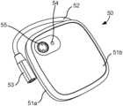
- FIGS. 7 A- 7 Billustrate an alternative EPG 50 that includes a housing 51 from which a short cable connector 52 extends to a lead connector 53 .
- lead connector 53is a multi-pin connector suitable for electrically connecting to a neurostimulation lead having multiple electrodes through an intermediate adapter or lead extension cable (see FIG. 13 ).
- cable connector 52is relatively short, for example a length between 1 and 12 inches, preferably 3 and 6 inches.
- the multi-pin connectoris a 4-pin connector suitable for connecting to a neurostimulation lead having four electrodes, however, it is appreciated that lead connector could include differing numbers of pins so as to be suitable for connection with neurostimulation leads having greater or fewer neurostimulation electrodes.
- the lead connectorcan be configured with a receptacle 42 for connecting with a proximal lead connector of a neurostimulation lead, such as described previously in other embodiments.
- the EPGcan be used with a tined lead trial or a temporary lead (PNE lead) trial. Configuring the connection to the lead external of the housing allows the EPG to be even smaller and lighter than those with the connection integrated within the device. Such a configuration also allows for some movement for adjustment or handling of the EPG while minimizing movement of the proximal lead connector, which can be secured by tape to the patient's body just proximal of the connector.
- the short cable connector 52 or “pigtail connector”is integrated with the EPG such that the electrical connections between the cable and the internal electronics of the EPG are permanently attached and sealed. This allows the EPG to further withstand intrusion of fluids and moisture during the trial stimulation period.
- the EPGmay be used with a PNE lead (which may have one or more than one electrode and conductor), or a permanent lead.
- the EPGmay be used for bilateral stimulation (the use of two leads, one for each for a patient's left and right sides) when a bilateral connector cable is used between the EPG and leads.
- the EPGincludes a non-rechargeable single-use power source (e.g. battery) having sufficient power for operation of the EPG for at least the duration of the trial period (e.g. days, weeks, months).
- the power sourcecan be integrated and non-removable or non-replaceable by the patient.
- EPG housing 51can be defined as two interfacing shells, top shell 51 a defining the outer major surface and a majority of the side surfaces and bottom shell 52 b defining an underside surface.
- EPGhas a substantially rectangular (e.g. square) prism with rounded edges.
- the top major surfacecan be shaped with a slightly convex contour, while the underside includes a substantially flattened surface for placement against the patient.
- the interfacing shells 51 a , 52 bare formed of a rigid or semi-rigid material, such as hardened polymer, so as to protect and seal the electronics within.
- EPG 50includes top housing shell 51 a , compressible foam sheet 56 a , battery 57 , double-sided adhesive disc 56 b , short electrical connector cable 52 , printed circuit board 58 , O-ring 51 c for sealing top housing shell 51 a with bottom shell 51 b , and serial number label 59 a and outer label 59 b , which are affixed to the underside of bottom shell 51 b . It is appreciated that this arrangement of elements is exemplary and various other arrangements are within the scope of the invention.
- the EPGincludes one or more user interface features.
- Such user interface featurescan include any of a button, switch, light, touch screen, or an audio or haptic feature.
- EPG 50includes a button 55 and an LED indicator 54 .
- Button 55is configured to turn EPG 50 on from an off or hibernation state.
- EPGcan communicate with an external device, such as a clinician programmer to receive programming instructions, and can deliver stimulation to a connected neurostimulation lead while in an operating state. While button 55 can be used by the patient to turn EPG 50 on, it is appreciated that this functionality can be concurrent with any other functionality described herein.
- EPG 50can be further configured to be turned on from an off or hibernation state by use of a patient remote or can be configured to suspend delivery of stimulation upon detachment of the neurostimulation lead.
- a buttonis described in this embodiment, any actuatable user interface feature could be used (e.g. switch, toggle, touch sensor) that is typically actuatable between at least two states.
- EPG 50is configured such that pressing button 55 turns on a communication function of the EPG.
- the EPGhas a pre-determined period of time (e.g. 60 seconds, 90 seconds) to wirelessly connect to an external programmer (e.g. Clinican Programmer). If the EPG connects to the clinician programmer, the EPG stays on to facilitate programming and operating to deliver of stimulation per programming instructions. If connection is not successful, the EPG automatically turns of. If button 50 is pressed when EPG is on, nothing happens and the communication or operating remains unchanged. If a patient desires to turn off stimulation, the patient remote could be used or alternatively, detachment of the neurostimulation lead could also suspend stimulation.
- a pre-determined period of timee.g. 60 seconds, 90 seconds
- an external programmere.g. Clinican Programmer
- button 55can be positioned on an underside of the EPG that is placed against the patient when worn during the trial stimulation period, although it is appreciated that the button could be disposed anywhere on the housing of the EPG.
- the functionality of button 55facilitates initial programming during set-up of the trial period or for reprogramming, but does not require interaction by the patient during the trial period.
- control or adjustment of stimulation by the patientwould be performed by use of the patient remote.
- the EPGis provided in a hibernation mode and communication can be initiated by actuation of a button on the EPG to facilitate programming with the CP.
- the EPGwhen the patient remote is used to turn stimulation off, the EPG returns to the hibernation state and only the CP can fully turn the EPG to an off-state.
- EPG 50further includes a LED indicator 54 that indicates a status of the EPG.
- the statuscan include a status of communication between the EPG and a programmer device, a battery status, an error status, or any combination thereof.
- LED indicator 54can be configured with differing colors or blinking patterns to indicate differing status.
- the EPGcan be configured such that a flashing green light indicates communication is on; a solid green light indicates EPG is in operating mode and the battery is good; a solid orange or yellow indicates battery is at an acceptable charge; a flashing orange or yellow indicates the battery is low; and a red light indicates an error state.
- LED indicator 54can be situated on an underside of the EPG placed against the patient when worn during the trial period, although it is appreciated that the LED could be disposed anywhere on the housing of the EPG.
- FIGS. 8 A- 8 B and 9 A- 9 Billustrate examples of affixation devices that secure the EPG to the patient while still allowing for ready removal.
- FIGS. 8 A- 8 Billustrate an adherent patch affixation device 11
- FIGS. 9 A- 9 Billustrate an adjustable clip affixation device 12 .
- lead 20 ′by way of example, however, any lead capable of connecting to the EPG may be used, for example lead 20 , 22 , 26 , or 27 may also be used.
- FIG. 8 Aillustrates adherent patch affixation device 11 before mounting of EPG 40 thereto.
- Adherent patch affixation device 11includes a support substrate 13 that includes a patient coupling portion on a first side and an EPG mounting portion on a second, opposite side.
- the mounting portionis formed of a non-electrically conductive material, such as an insulative polymer material such that the affixation device is without any separate electrodes or electrically conductive path for delivering stimulation directly to the skin of the patient.
- the patient coupling portionincludes an adhesive patch 11 a disposed along a major surface of the first side of the substrate.
- Adhesive patch 11 atypically includes a flexible breathable material having a pressure sensitive adhesive suitable for securing to a skin of the patient for an extended duration of time, for example, for part or all of the trial period. While the adhesive patch 11 a may be flexible and breathable for patient comfort, support substrate 13 is typically substantially rigid or semi-rigid so as to support one or more EPG mounting features and maintain the EPG mounted thereto. In this embodiment, the EPG mounting portion includes multiple outwardly extending tabs that engage an outer housing of the EPG along an outer perimeter, typically at least one tab on each major side of the EPG or distributed about the perimeter of the EPG housing.
- the multiple tabscan include two pairs of tabs.
- a first pair of tabs 14are adapted to engage opposite sides of EPG 40 along the widthwise direction, while a second pair of tabs 15 engage opposite sides of EPG 40 along the lengthwise direction.
- the second pair of tabsare resiliently deflectable to outwardly deflect upon pressing EPG 40 in between tabs 15 so that tabs 15 retain EPG 40 therebetween.
- EPG 40can further include corresponding coupling features that fittingly engage each of the pairs of tabs 14 , 15 .
- EPG 40can include recessed notches (not visible) that fittingly receive the first pair of tabs 14 .
- the first pair of tabs 14can constrain movement of EGP 40 in both x and y directions.
- EPG 40can further include retention features that engage corresponding retention features of the mounting portion of the affixation device.
- the second pair of tabs 15can be defined with an inwardly curved, contoured or stepped-in portion that fits within a correspondingly shaped retention recess 45 within the lengthwise sides of EPG 40 .
- the second pair of tabsfurther constrains movement of EPG 40 in a z-direction, as well as the x and y-directions.
- the first and second pair of tabssecure and support EPG 40 within the affixation device in a particular orientation so that the proximal lead connector 24 can be securely maintained within lead connector receptacle 42 .
- the multiple tabscan be dimensioned so that a majority of an outer perimeter of EPG 40 remains exposed so that a patient can readily grasp outer edges of EPG 40 and remove from the affixation device as needed. By leaving a majority of the perimeter exposed, this configuration allows the patient to grasp the EPG for ready release even when the EPG is affixed in a lower back region, where the patient cannot readily view the device during detachment.
- the multiple tabsare dimensioned so that 3 ⁇ 4 or more of the perimeter of EPG 40 remains exposed. In other embodiments, the multiple tabs are dimensioned so that 4 ⁇ 5 or more, or even 9/10 or more of the outer perimeter is exposed, so as to further facilitate ready grasping by the patient to facilitate ready removal.
- the multiple tabsare configured to engage each side of EPG 40 at or near a mid-portion.
- This configurationallows for improved support and retention of EPG 40 while allowing at least two diagonally opposed corners, typically all four corners, to remain exposed.
- This arrangementallows the patient to effect release by grasping the edges and/or corners of EPG 40 and twisting along one or more axis (x, y or z) so as to release the second pair of retaining tabs 15 from corresponding retention recesses 45 for ready removal of EPG 40 .
- the patientcan then detach lead connector 24 from connector receptacle 42 and charge or store EPG 40 as needed.
- FIG. 9 Aillustrates a spring-clip affixation device 12 for releasably securing EPG 40 to the patient.
- Affixation device 12includes a substantially rigid or semi-rigid support substrate 13 having a patient coupling portion (e.g. spring-clip) on one side and an EPG mounting portion with one or more coupling features on an opposite side. Similar to the embodiment in FIG.
- the EPG mounting portionincludes two pairs of tabs, a first pair of tabs 14 and a second pair of tabs 15 with retention features, each pair of tabs adapted to fittingly engage with corresponding features in the outer housing 41 of EPG 40 so as to securely mount EPG 40 to the substrate while allowing the patient to grasp and readily release EPG 40 from the affixation device 12 , as described above with respect to the embodiment of FIG. 8 A .
- the patient coupling featureincludes clip 16 that extends along the backside of substrate 13 and is separable from and biased towards substrate 13 so that a piece of the patient's garment or belt can be inserted therebetween.
- clip 16is pivotally coupled to substrate by a pivotal coupling 17 that is loaded with a spring to bias clip 16 towards the substrate.
- Clip 16can further include a grasping feature 18 on an outer facing surface near a base of clip 16 so that the patient can readily grasp clip 16 and remove the clip by pressingly engaging the base and separate clip 16 from substrate 14 to release the garment or belt from the clip.
- the patientcould grasp and release EPG 40 from the mounting portion of the clip affixation device 12 , as described above, while leaving the clip 16 attached to the belt or garment.
- substrate 13 and clip 16are formed of a substantially rigid or semi-rigid formable material, such as plastic. Clip 16 can be further configured to fit into a specialized belt.
- any of the EPG devices described hereincan be supported by an adherent patch, as described previously, or can be supported by various affixation devices, such as any of those described.
- EPG 50can be supported in a pouch 61 of an adjustable belt 60 worn by the patient. Pouch 61 can be formed of a flexible compliant or non-compliant material to improve patient comfort during the trial period.
- EPG 50can be supported by covering the EPG with an adhesive patch 16 or surgical tape. Since, in some embodiments, the EPG does not require patient interaction with the device during the trial period, the EPG can be completely covered during the trial period. Any adjustment or suspension of EPG operation by the patient during the trial period can be made by the patient remote.
- affixation devices having an EPG mounting portioncould include only the two retention tabs or could include four retention tabs to provide varying levels of support and retention as needed for a particular EPG configuration.
- the multiple tabscould dimensioned and arranged to engage the EPG at various other locations depending on the size and shape of the EPG device.
- trial system 100can include differing connector cable sets for use with EPG 40 having a multi-purpose connector receptacle, such as that shown in FIG. 12 A . It is appreciated that these cables could also be used with various other EPG devices, such as EPG 50 , by use of an adapter or lead extension cable. These differing connector cable sets can include any of those depicted in the examples shown in FIGS. 12 B- 12 F , or various other configuration as desired.
- FIG. 12 Bdepicts a lead extension 22 , which includes a proximal lead connector 24 similar or identical to that on the implantable neurostimulation lead 20 and an implantable lead connector receptacle 21 , which can be connected to a proximal lead connector 24 of a fully implanted neurostimulation lead 20 .
- a lead extensioncan be useful as it allows a neurostimulation lead of a length suitable for permanent implantation to be used during the trial period and remain implanted if converted to a permanent neurostimulation system.
- FIG. 12 Cdepicts a grounded neurostimulation therapy cable set 26 , which includes a proximal lead connector 24 and boot 25 that is connected in parallel to an external connector receptacle 26 a and a ground connector 26 b , which can be coupled to a ground pad applied to the patient's skin.
- Ground connector 26can be an alligator or J-clip that can be attached to an adhesive ground pad, while the external connector receptacle 26 a can be attached to a neurostimulation device 20 ′ having one or more neurostimulation leads.
- FIG. 12 Ddepicts a dual neurostimulation lead cable set 27 , which includes a proximal lead connector 24 and boot 25 that is connected in parallel to two neurostimulation lead proximal connectors 27 a , 27 b , which can be identical or different.
- each electrical contact of the lead connector receptacle 24can be electrically connected to a corresponding contact within the lead connectors 27 a , 27 b such that two identical neurostimulation leads can be coupled thereto and receive parallel stimulations along corresponding neurostimulation electrodes or be used as a bipolar pair.
- proximal lead connectors 27 a , 27 bcan be configured differently, for example, each electrical contact within lead connector 27 a , 27 b can be electrically connected to a dedicated electrical contact within connector receptacle 24 such that two leads 20 ′, 20 ′′ can simultaneously deliver differing neurostimulation stimulations. It is further appreciated that such a cable set could be modified for connection of additional neurostimulation leads or devices (e.g. three or more leads).
- FIG. 12 Edepicts a charging cable set 28 , which includes a proximal lead connector 24 and boot 25 coupled with a charging cord, which can be connected to a power adapter and plugged directly into an external power source, such as a standard wall outlet.
- lead connector 24could be included as an adapter and used with the same power cord as is used to charge the CP and external charger of the IPG
- FIG. 12 Fdepicts a multi-lead cable set 29 , which includes a proximal lead connector 24 and boot 25 that is connected in parallel to two neurostimulation lead proximal connectors 29 a , 29 b , which can be identical or different.
- each electrical contact of the lead connector receptacle 24can be electrically connected to a corresponding contact within the lead connectors 29 a , 29 b such that two identical neurostimulation leads can be coupled thereto and receive parallel stimulations along corresponding neurostimulation electrodes or be used as a bipolar pair.
- proximal lead connectors 29 a , 29 bcan be configured differently, for example, each electrical contact within lead connector 29 a , 29 b can be electrically connected to a dedicated electrical contact within connector receptacle 24 such that two leads 20 ′, 20 ′′ can simultaneously deliver differing neurostimulation stimulations. It is further appreciated that such a cable set could be modified for connection of additional neurostimulation leads or devices (e.g. three or more leads).
- Ground connector 29 cis configured to couple with a ground pad affixed externally on the patient.
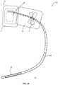
- FIG. 13illustrates an alternative percutaneous extension cable 22 ′ electrically connecting a multi-pin receptacle connector 25 ′ to a proximal lead connector 21 , which can be connected to a proximal lead connector 24 of a trial neurostimulation lead or a fully implanted neurostimulation lead 20 .
- Multi-pin receptacle connector 25 ′is configured to connect with a multi-pin plug connector, for example lead connector 53 of EPG 50 .
- This cable setis particularly useful for use in an advanced trial (e.g. with a tined lead) in which the lead connector 21 is implanted and the tined lead remains implanted when the trial system is converted to a permanently implanted system.
- FIG. 14illustrates an alternative multi-lead cable set 29 ′, which includes a multi-pin receptacle connector 25 ′ that is connected in parallel to two neurostimulation lead proximal connectors 29 a , 29 b , which can be identical or different.
- Multi-pin receptacle connector 25 ′is configured to connect with a multi-pin plug connector, for example lead connector 53 of EPG 50 . It is appreciated that multiple leads can be electrically connected to the multi-pin receptacle connector 25 ′ according to various configurations.
- each electrical contact of the lead connector 25 ′can be electrically connected to a corresponding contact within the lead connectors 29 a , 29 b such that two identical neurostimulation leads can be coupled thereto and receive parallel stimulations along corresponding neurostimulation electrodes or be used as a bipolar pair.
- the proximal lead connectors 29 a , 29 bcan be configured differently, for example, each electrical contact within lead connector 29 a , 29 b can be electrically connected to a dedicated electrical contact within lead connector 25 ′ such that two leads 20 ′, 20 ′′ can simultaneously deliver differing neurostimulation stimulations. It is further appreciated that such a cable set could be modified for connection of additional neurostimulation leads or devices (e.g. three or more leads).
- Ground connector 29 cis configured to couple with a ground pad affixed externally on the patient. This connector set is more suited for a basic trial, such as a PNE trial.
- FIG. 15illustrates a schematic of a trial system 100 , in accordance with aspect of the invention, and a permanent system 200 .
- each of the trial and permanent systemare compatible for use with a wireless clinician programmer and a patient remote.
- the communication unit by which EPG wirelessly communicates with the clinician programmer and patient remotecan utilize MedRadio or Bluetooth capability, which can provide a communication range of about two meters.
- the clinician programmercan be used in lead placement, programming and stimulation control in each of the trial and permanent systems.
- eachallows the patient to control stimulation or monitor battery status with the patient remote. This configuration is advantageous as it allows for an almost seamless transition between the trial system and the permanent system.
- the systemswill operate in the same manner and be controlled in the same manner, such that the patient's subjective experience in using the trial system more closely matches what would be experienced in using the permanently implanted system.
- this configurationreduces any uncertainties the patient may have as to how the system will operate and be controlled such that the patient will be more likely to convert a trial system to a permanent system.
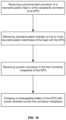
- FIGS. 16 - 17illustrate methods of controlling operation of an EPG having a multi-purpose port in accordance with aspects of the invention.
- the method of FIG. 16includes steps of: receiving a proximal lead connector of a neurostimulation lead in a first connector receptacle of an EPG; delivering neurostimulation therapy to one or more neurostimulation electrodes of the lead with the EPG; receiving a power connector in the first connector receptacle of the EPG; and charging a rechargeable battery of the EPG with power received via the first connector receptacle.
- Such operating modescan include but are not limited to a therapy mode corresponding to a proximal lead connector of a trial neurostimulation lead and a charging mode corresponding to a power connector coupled with a power source. It is appreciated that such methods can further include various other types of operating modes that correspond to various other types of connectors and connections as desired.
- affixation devicecould include similar releasable mounting feature on a support substrate that allows the EPG to be readily detached by the patient.
- the mounting features described abovecould be incorporated into a belt worn, a holster worn around a mid-section of the patient, or worn around the neck similar to a neck badge.
Landscapes
- Health & Medical Sciences (AREA)
- Life Sciences & Earth Sciences (AREA)
- Public Health (AREA)
- Veterinary Medicine (AREA)
- Radiology & Medical Imaging (AREA)
- Biomedical Technology (AREA)
- Animal Behavior & Ethology (AREA)
- General Health & Medical Sciences (AREA)
- Engineering & Computer Science (AREA)
- Nuclear Medicine, Radiotherapy & Molecular Imaging (AREA)
- Heart & Thoracic Surgery (AREA)
- Cardiology (AREA)
- Neurology (AREA)
- Neurosurgery (AREA)
- Orthopedic Medicine & Surgery (AREA)
- Biophysics (AREA)
- Electrotherapy Devices (AREA)
Abstract
Description
Claims (6)
Priority Applications (2)
| Application Number | Priority Date | Filing Date | Title |
|---|---|---|---|
| US17/667,453US12226643B2 (en) | 2016-02-12 | 2022-02-08 | External pulse generator device and affixation device for trial nerve stimulation and methods of use |
| US19/029,739US20250161700A1 (en) | 2016-02-12 | 2025-01-17 | External pulse generator device and associated methods for trial nerve stimulation |
Applications Claiming Priority (4)
| Application Number | Priority Date | Filing Date | Title |
|---|---|---|---|
| US201662294639P | 2016-02-12 | 2016-02-12 | |
| US15/431,475US10376704B2 (en) | 2016-02-12 | 2017-02-13 | External pulse generator device and associated methods for trial nerve stimulation |
| US16/513,165US11260236B2 (en) | 2016-02-12 | 2019-07-16 | External pulse generator device and affixation device for trial nerve stimulation and methods of use |
| US17/667,453US12226643B2 (en) | 2016-02-12 | 2022-02-08 | External pulse generator device and affixation device for trial nerve stimulation and methods of use |
Related Parent Applications (1)
| Application Number | Title | Priority Date | Filing Date |
|---|---|---|---|
| US16/513,165ContinuationUS11260236B2 (en) | 2016-02-12 | 2019-07-16 | External pulse generator device and affixation device for trial nerve stimulation and methods of use |
Related Child Applications (1)
| Application Number | Title | Priority Date | Filing Date |
|---|---|---|---|
| US19/029,739ContinuationUS20250161700A1 (en) | 2016-02-12 | 2025-01-17 | External pulse generator device and associated methods for trial nerve stimulation |
Publications (2)
| Publication Number | Publication Date |
|---|---|
| US20220233871A1 US20220233871A1 (en) | 2022-07-28 |
| US12226643B2true US12226643B2 (en) | 2025-02-18 |
Family
ID=59563997
Family Applications (4)
| Application Number | Title | Priority Date | Filing Date |
|---|---|---|---|
| US15/431,475ActiveUS10376704B2 (en) | 2016-02-12 | 2017-02-13 | External pulse generator device and associated methods for trial nerve stimulation |
| US16/513,165Active2037-07-07US11260236B2 (en) | 2016-02-12 | 2019-07-16 | External pulse generator device and affixation device for trial nerve stimulation and methods of use |
| US17/667,453Active2037-02-23US12226643B2 (en) | 2016-02-12 | 2022-02-08 | External pulse generator device and affixation device for trial nerve stimulation and methods of use |
| US19/029,739PendingUS20250161700A1 (en) | 2016-02-12 | 2025-01-17 | External pulse generator device and associated methods for trial nerve stimulation |
Family Applications Before (2)
| Application Number | Title | Priority Date | Filing Date |
|---|---|---|---|
| US15/431,475ActiveUS10376704B2 (en) | 2016-02-12 | 2017-02-13 | External pulse generator device and associated methods for trial nerve stimulation |
| US16/513,165Active2037-07-07US11260236B2 (en) | 2016-02-12 | 2019-07-16 | External pulse generator device and affixation device for trial nerve stimulation and methods of use |
Family Applications After (1)
| Application Number | Title | Priority Date | Filing Date |
|---|---|---|---|
| US19/029,739PendingUS20250161700A1 (en) | 2016-02-12 | 2025-01-17 | External pulse generator device and associated methods for trial nerve stimulation |
Country Status (8)
| Country | Link |
|---|---|
| US (4) | US10376704B2 (en) |
| EP (1) | EP3413970B1 (en) |
| JP (1) | JP7072510B2 (en) |
| CN (1) | CN108697897B (en) |
| AU (1) | AU2017218157B2 (en) |
| CA (2) | CA3241636A1 (en) |
| ES (1) | ES2883179T3 (en) |
| WO (1) | WO2017139784A1 (en) |
Families Citing this family (23)
| Publication number | Priority date | Publication date | Assignee | Title |
|---|---|---|---|---|
| WO2015196164A2 (en) | 2014-06-21 | 2015-12-23 | Accelemed, Llc | Method and apparatus for neuromodulation treatments of pain and other conditions |
| WO2017139784A1 (en) | 2016-02-12 | 2017-08-17 | Axonics Modulation Technologies, Inc. | External pulse generator device and associated methods for trial nerve stimulation |
| WO2017165410A1 (en)* | 2016-03-21 | 2017-09-28 | Nalu Medical, Inc. | Devices and methods for positioning external devices in relation to implanted devices |
| WO2018126062A1 (en) | 2016-12-30 | 2018-07-05 | Nalu Medical, Inc. | Stimulation apparatus |
| US11534612B2 (en)* | 2017-03-16 | 2022-12-27 | Medtronic, Inc. | Adapter assemblies for implantable medical electrical systems |
| AU2018265016B2 (en) | 2017-05-09 | 2023-01-05 | Nalu Medical, Inc. | Stimulation apparatus |
| CA3079849A1 (en) | 2017-10-25 | 2019-05-02 | Epineuron Technologies Inc. | Systems and methods for delivering neuroregenerative therapy |
| US10589089B2 (en) | 2017-10-25 | 2020-03-17 | Epineuron Technologies Inc. | Systems and methods for delivering neuroregenerative therapy |
| US10690863B1 (en)* | 2017-12-13 | 2020-06-23 | Amazon Technologies, Inc. | Communication cable identification |
| CN107952171A (en)* | 2017-12-19 | 2018-04-24 | 北京品驰医疗设备有限公司 | A kind of neuromodulation external pulse generator |
| US11724116B2 (en)* | 2018-02-15 | 2023-08-15 | West Affum Holdings Dac | Wearable cardioverter defibrillator latching connector |
| WO2019165108A1 (en)* | 2018-02-22 | 2019-08-29 | Axonics Modulation Technologies, Inc. | Neurostimulation leads for trial nerve stimulation and methods of use |
| GB2580330B (en)* | 2018-12-31 | 2021-01-20 | Emda Ltd | Device to electromagnetically stimulate new organic cell proliferation |
| US11247043B2 (en) | 2019-10-01 | 2022-02-15 | Epineuron Technologies Inc. | Electrode interface devices for delivery of neuroregenerative therapy |
| CN115461935B (en)* | 2020-03-13 | 2025-08-05 | Spr治疗股份有限公司 | Stimulation lead connection system |
| CN114006197A (en)* | 2020-07-28 | 2022-02-01 | 上海神奕医疗科技有限公司 | Medical system and connector assembly |
| KR102354779B1 (en)* | 2020-07-31 | 2022-01-24 | 서울대학교병원 | Connecting device having magnifier for spinal cord stimulator, kit for spinal cord stimulator including the same and method for connecting spinal cord stimulator lead and extension cable using the same |
| CN116322896A (en)* | 2020-08-14 | 2023-06-23 | 萨鲁达医疗有限公司 | Rechargeable neuromodulation device |
| DE102021100682B4 (en) | 2021-01-14 | 2024-06-13 | Osypka Ag | External electromedical pulse generator |
| DE102021100685A1 (en)* | 2021-01-14 | 2022-07-14 | Osypka Ag | Electromedical Electrode |
| DE102021100681A1 (en) | 2021-01-14 | 2022-07-14 | Osypka Ag | External electromedical pulse generator |
| US20230094184A1 (en)* | 2021-09-23 | 2023-03-30 | Medtronic, Inc. | System and method to hold trialing system |
| WO2024044339A1 (en)* | 2022-08-24 | 2024-02-29 | Neuronoff, Inc. | Injectrode system |
Citations (467)
| Publication number | Priority date | Publication date | Assignee | Title |
|---|---|---|---|---|
| US3057356A (en) | 1960-07-22 | 1962-10-09 | Wilson Greatbatch Inc | Medical cardiac pacemaker |
| US3348548A (en) | 1965-04-26 | 1967-10-24 | William M Chardack | Implantable electrode with stiffening stylet |
| US3646940A (en) | 1969-07-15 | 1972-03-07 | Univ Minnesota | Implantable electronic stimulator electrode and method |
| US3824129A (en) | 1973-03-14 | 1974-07-16 | Mallory & Co Inc P R | Heart pacer rechargeable cell and protective control system |
| US3825015A (en) | 1972-12-14 | 1974-07-23 | American Optical Corp | Single catheter for atrial and ventricular stimulation |
| US3888260A (en) | 1972-06-28 | 1975-06-10 | Univ Johns Hopkins | Rechargeable demand inhibited cardiac pacer and tissue stimulator |
| US3902501A (en) | 1973-06-21 | 1975-09-02 | Medtronic Inc | Endocardial electrode |
| US3939843A (en) | 1974-03-04 | 1976-02-24 | Medtronic, Inc. | Transvenous electrode |
| US3942535A (en) | 1973-09-27 | 1976-03-09 | G. D. Searle & Co. | Rechargeable tissue stimulating system |
| US3970912A (en) | 1973-08-28 | 1976-07-20 | Hoffman Philip A | Battery charging circuit |
| US3995623A (en) | 1974-12-23 | 1976-12-07 | American Hospital Supply Corporation | Multipurpose flow-directed catheter |
| US4019518A (en) | 1975-08-11 | 1977-04-26 | Medtronic, Inc. | Electrical stimulation system |
| US4044774A (en) | 1976-02-23 | 1977-08-30 | Medtronic, Inc. | Percutaneously inserted spinal cord stimulation lead |
| US4082097A (en) | 1976-05-20 | 1978-04-04 | Pacesetter Systems Inc. | Multimode recharging system for living tissue stimulators |
| US4141365A (en) | 1977-02-24 | 1979-02-27 | The Johns Hopkins University | Epidural lead electrode and insertion needle |
| US4166469A (en) | 1977-12-13 | 1979-09-04 | Littleford Philip O | Apparatus and method for inserting an electrode |
| US4269198A (en) | 1979-12-26 | 1981-05-26 | Medtronic, Inc. | Body implantable lead |
| US4285347A (en) | 1979-07-25 | 1981-08-25 | Cordis Corporation | Stabilized directional neural electrode lead |
| US4340062A (en) | 1978-11-06 | 1982-07-20 | Medtronic, Inc. | Body stimulator having selectable stimulation energy levels |
| US4379462A (en) | 1980-10-29 | 1983-04-12 | Neuromed, Inc. | Multi-electrode catheter assembly for spinal cord stimulation |
| DE3146182A1 (en) | 1981-11-21 | 1983-06-01 | Peter Dr. 7850 Lörrach Osypka | Electrode for pacemaker |
| US4407303A (en) | 1980-04-21 | 1983-10-04 | Siemens Aktiengesellschaft | Endocardial electrode arrangement |
| US4437475A (en) | 1981-08-28 | 1984-03-20 | Medtronic, Inc. | Transvenous cardiovascular integrated lead anchoring sleeve, protector, and permanent lead introducer stop gap |
| US4512351A (en) | 1982-11-19 | 1985-04-23 | Cordis Corporation | Percutaneous lead introducing system and method |
| US4550731A (en) | 1984-03-07 | 1985-11-05 | Cordis Corporation | Acquisition circuit for cardiac pacer |
| US4553702A (en) | 1982-02-05 | 1985-11-19 | Imperial Chemical Industries Plc | Spraying system |
| US4558702A (en) | 1983-01-21 | 1985-12-17 | Cordis Corporation | Cardiac pacer having input/output circuit programmable for use with unipolar and bipolar pacer leads |
| US4654880A (en) | 1983-12-09 | 1987-03-31 | Minnesota Mining And Manufacturing Company | Signal transmission system |
| US4662382A (en) | 1985-01-16 | 1987-05-05 | Intermedics, Inc. | Pacemaker lead with enhanced sensitivity |
| US4719919A (en) | 1983-01-21 | 1988-01-19 | Ramm Associates, A Partnership | Implantable hyperthermia device and system |
| US4721118A (en) | 1981-04-20 | 1988-01-26 | Cordis Leads, Inc. | Pervenous electrical pacing lead with foldable fins |
| US4722353A (en) | 1985-09-16 | 1988-02-02 | Intermedics, Inc. | Stabilizer for implantable electrode |
| US4744371A (en) | 1987-04-27 | 1988-05-17 | Cordis Leads, Inc. | Multi-conductor lead assembly for temporary use |
| US4800898A (en) | 1983-10-07 | 1989-01-31 | Cordis Corporation | Neural stimulator electrode element and lead |
| US4848352A (en) | 1987-02-13 | 1989-07-18 | Telectronics, N.V. | Method for cardiac pacing and sensing using combination of electrodes |
| US4860446A (en) | 1988-02-16 | 1989-08-29 | Medtronic, Inc. | Medical electrical lead and method of manufacture |
| US4957118A (en) | 1988-01-15 | 1990-09-18 | Jay Erlebacher | Electrode lead |
| US4989617A (en) | 1989-07-14 | 1991-02-05 | Case Western Reserve University | Intramuscular electrode for neuromuscular stimulation system |
| US5012176A (en) | 1990-04-03 | 1991-04-30 | Baxter International, Inc. | Apparatus and method for calorimetrically determining battery charge state |
| US5052407A (en) | 1988-04-14 | 1991-10-01 | Mieczyslaw Mirowski | Cardiac defibrillation/cardioversion spiral patch electrode |
| US5197466A (en) | 1983-01-21 | 1993-03-30 | Med Institute Inc. | Method and apparatus for volumetric interstitial conductive hyperthermia |
| US5204611A (en) | 1991-03-13 | 1993-04-20 | Norvik Technologies Inc. | Charging circuits for rechargeable batteries and cells |
| US5255691A (en) | 1991-11-13 | 1993-10-26 | Medtronic, Inc. | Percutaneous epidural lead introducing system and method |
| US5257634A (en) | 1992-07-16 | 1993-11-02 | Angeion Corporation | Low impedence defibrillation catheter electrode |
| US5342408A (en) | 1993-01-07 | 1994-08-30 | Incontrol, Inc. | Telemetry system for an implantable cardiac device |
| EP0656218A1 (en) | 1993-12-03 | 1995-06-07 | Pacesetter AB | Electrode system |
| US5439485A (en) | 1993-09-24 | 1995-08-08 | Ventritex, Inc. | Flexible defibrillation electrode of improved construction |
| US5484445A (en) | 1993-10-12 | 1996-01-16 | Medtronic, Inc. | Sacral lead anchoring system |
| US5571148A (en) | 1994-08-10 | 1996-11-05 | Loeb; Gerald E. | Implantable multichannel stimulator |
| US5592070A (en) | 1994-01-28 | 1997-01-07 | Sanyo Electric Co., Ltd. | Battery charger having a temperature sensor and a rechargeable battery charging method |
| US5637981A (en) | 1993-05-14 | 1997-06-10 | Sony Corporation | Method for charging a secondary battery and charger used therefor using constant current and constant voltage |
| US5676162A (en) | 1992-08-06 | 1997-10-14 | Electric Boat Corporation | Reciprocating pump and linear motor arrangement |
| US5690693A (en) | 1995-06-07 | 1997-11-25 | Sulzer Intermedics Inc. | Transcutaneous energy transmission circuit for implantable medical device |
| US5702431A (en) | 1995-06-07 | 1997-12-30 | Sulzer Intermedics Inc. | Enhanced transcutaneous recharging system for battery powered implantable medical device |
| US5702428A (en) | 1992-05-23 | 1997-12-30 | Axelgaard Manufacturing Company, Ltd. | Electrical stimulation for treatment of incontinence and other neuro-muscular disorders |
| US5712795A (en) | 1995-10-02 | 1998-01-27 | Alaris Medical Systems, Inc. | Power management system |
| US5713939A (en) | 1996-09-16 | 1998-02-03 | Sulzer Intermedics Inc. | Data communication system for control of transcutaneous energy transmission to an implantable medical device |
| US5733313A (en) | 1996-08-01 | 1998-03-31 | Exonix Corporation | RF coupled, implantable medical device with rechargeable back-up power source |
| US5735887A (en) | 1996-12-10 | 1998-04-07 | Exonix Corporation | Closed-loop, RF-coupled implanted medical device |
| US5741316A (en) | 1996-12-02 | 1998-04-21 | Light Sciences Limited Partnership | Electromagnetic coil configurations for power transmission through tissue |
| WO1998020933A1 (en) | 1996-11-13 | 1998-05-22 | Pacesetter Ab | Implantable electrode lead |
| US5871532A (en) | 1997-05-22 | 1999-02-16 | Sulzer Intermedics Inc. | Epicardial lead for minimally invasive implantation |
| US5876423A (en) | 1996-06-04 | 1999-03-02 | Biotronik Mess- Und Therapiegeraete Gmbh & Co. Ingenieurbuero Berlin | Implantable stimulator with terminal voltage control of a depletable voltage source |
| WO1999018879A1 (en) | 1997-10-13 | 1999-04-22 | Light Sciences Limited Partnership | Alignment of external device relative to implanted device |
| US5902331A (en) | 1998-03-10 | 1999-05-11 | Medtronic, Inc. | Arrangement for implanting an endocardial cardiac lead |
| WO1999034870A1 (en) | 1998-01-08 | 1999-07-15 | Karl Storz Gmbh & Co. Kg. | Device for treating body tissue, especially soft tissue located near the surface, by means of ultrasound |
| WO1999042173A1 (en) | 1998-02-23 | 1999-08-26 | Medtronic, Inc. | Rf coupled, implantable medical device with rechargeable back-up power source |
| US5949632A (en) | 1998-12-01 | 1999-09-07 | Exonix Corporation | Power supply having means for extending the operating time of an implantable medical device |
| US5948006A (en) | 1998-10-14 | 1999-09-07 | Advanced Bionics Corporation | Transcutaneous transmission patch |
| US5957965A (en) | 1997-03-03 | 1999-09-28 | Medtronic, Inc. | Sacral medical electrical lead |
| US5974344A (en) | 1998-03-02 | 1999-10-26 | Shoemaker, Ii; Charles | Wound care electrode |
| US5991665A (en) | 1997-09-18 | 1999-11-23 | Sulzer Intermedics Inc. | Self-cooling transcutaneous energy transfer system for battery powered implantable device |
| US6027456A (en) | 1998-07-10 | 2000-02-22 | Advanced Neuromodulation Systems, Inc. | Apparatus and method for positioning spinal cord stimulation leads |
| US6035237A (en) | 1995-05-23 | 2000-03-07 | Alfred E. Mann Foundation | Implantable stimulator that prevents DC current flow without the use of discrete output coupling capacitors |
| US6052624A (en) | 1999-01-07 | 2000-04-18 | Advanced Bionics Corporation | Directional programming for implantable electrode arrays |
| US6055456A (en) | 1999-04-29 | 2000-04-25 | Medtronic, Inc. | Single and multi-polar implantable lead for sacral nerve electrical stimulation |
| US6057513A (en) | 1997-01-29 | 2000-05-02 | Ngk Insulators, Ltd. | Joint structure of metal member and ceramic member and method of producing the same |
| US6067474A (en) | 1997-08-01 | 2000-05-23 | Advanced Bionics Corporation | Implantable device with improved battery recharging and powering configuration |
| US6075339A (en) | 1993-08-16 | 2000-06-13 | Chartec Laboratories A/S | Battery system providing indicia of a charging parameter |
| US6076017A (en) | 1997-04-30 | 2000-06-13 | Medtronic, Inc. | Method of centerless ground finishing of feedthrough pins for an implantable medical device |
| US6081097A (en) | 1998-01-19 | 2000-06-27 | Matsushita Electric Industrial Co., Ltd. | Method for charging lithium secondary battery |
| US6083247A (en) | 1998-08-10 | 2000-07-04 | Medtronic, Inc. | Perpendicular atrial fixation/stimulation loop |
| US6104957A (en) | 1998-08-21 | 2000-08-15 | Alo; Kenneth M. | Epidural nerve root stimulation with lead placement method |
| US6104960A (en) | 1998-07-13 | 2000-08-15 | Medtronic, Inc. | System and method for providing medical electrical stimulation to a portion of the nervous system |
| WO2000056677A1 (en) | 1999-03-24 | 2000-09-28 | Alfred E. Mann Foundation | Method and apparatus of a strong metal-ceramic braze bond |
| WO2000065682A1 (en) | 1999-04-26 | 2000-11-02 | Exonix Corporation | Self contained transportable power source maintenance and charge system |
| CA2371378A1 (en) | 1999-04-26 | 2000-11-16 | Exonix Corporation | Implantable power management system |
| US6165180A (en) | 1997-05-28 | 2000-12-26 | Transneuronix, Inc. | Medical device handle for use in laparoscopic surgery |
| US6169387B1 (en) | 1997-12-22 | 2001-01-02 | Lifecor, Inc. | Battery management apparatus for portable electronic devices |
| US6172556B1 (en) | 1999-03-04 | 2001-01-09 | Intersil Corporation, Inc. | Feedback-controlled low voltage current sink/source |
| US6178353B1 (en) | 1998-07-27 | 2001-01-23 | Advanced Bionics Corporation | Laminated magnet keeper for implant device |
| US6191365B1 (en) | 1997-05-02 | 2001-02-20 | General Science And Technology Corp | Medical devices incorporating at least one element made from a plurality of twisted and drawn wires |
| US6208894B1 (en) | 1997-02-26 | 2001-03-27 | Alfred E. Mann Foundation For Scientific Research And Advanced Bionics | System of implantable devices for monitoring and/or affecting body parameters |
| US6212431B1 (en) | 1998-09-08 | 2001-04-03 | Advanced Bionics Corporation | Power transfer circuit for implanted devices |
| US6212430B1 (en) | 1999-05-03 | 2001-04-03 | Abiomed, Inc. | Electromagnetic field source with detection of position of secondary coil in relation to multiple primary coils |
| US6221513B1 (en) | 1998-05-12 | 2001-04-24 | Pacific Coast Technologies, Inc. | Methods for hermetically sealing ceramic to metallic surfaces and assemblies incorporating such seals |
| US6227204B1 (en) | 1998-08-21 | 2001-05-08 | Implex Aktiengesellschaft Hearing Technology | Device and process for charging of rechargeable batteries of implants |
| US6243608B1 (en) | 1998-06-12 | 2001-06-05 | Intermedics Inc. | Implantable device with optical telemetry |
| US6246911B1 (en) | 1999-02-08 | 2001-06-12 | Peter Seligman | Cochlear implants with offset coils for transmission of radio frequency links |
| US6249703B1 (en) | 1994-07-08 | 2001-06-19 | Medtronic, Inc. | Handheld patient programmer for implantable human tissue stimulator |
| US6265789B1 (en) | 1997-11-20 | 2001-07-24 | Seiko Epson Corporation | Electronic apparatus |
| US6269270B1 (en)* | 1998-10-26 | 2001-07-31 | Birinder Bob Boveja | Apparatus and method for adjunct (add-on) therapy of Dementia and Alzheimer's disease utilizing an implantable lead and external stimulator |
| US6275737B1 (en) | 1998-10-14 | 2001-08-14 | Advanced Bionics Corporation | Transcutaneous transmission pouch |
| US6306100B1 (en) | 1997-12-16 | 2001-10-23 | Richard L. Prass | Intraoperative neurophysiological monitoring system |
| US6305381B1 (en) | 1998-02-02 | 2001-10-23 | Medtronic Inc. | System for locating implantable medical device |
| WO2001083029A1 (en) | 2000-04-28 | 2001-11-08 | Medtronic, Inc. | Battery recharge management for an implantable medical device |
| US6316909B1 (en) | 1998-03-24 | 2001-11-13 | Seiko Epson Corporation | Electronic device, control method for electronic device, recharge-rate estimating method for secondary battery, and charging control method for secondary battery |
| US6321118B1 (en) | 1999-01-28 | 2001-11-20 | Advanced Bionics Corporation | Method and apparatus for power link detection with implantable medical devices |
| US6327504B1 (en) | 2000-05-10 | 2001-12-04 | Thoratec Corporation | Transcutaneous energy transfer with circuitry arranged to avoid overheating |
| WO2002009808A1 (en) | 2000-07-26 | 2002-02-07 | Advanced Bionics Corporation | Rechargeable spinal cord stimulator system |
| US20020016617A1 (en) | 1996-06-13 | 2002-02-07 | Oldham Jacqueline A. | Stimulation of muscles |
| US6354991B1 (en) | 1998-10-06 | 2002-03-12 | Bio Control Medical Ltd | Incontinence treatment device |
| US20020040185A1 (en) | 1996-04-25 | 2002-04-04 | Ergin Atalar | Systems and methods for evaluating the urethra and the periurethral tissues |
| US6381496B1 (en) | 1999-10-01 | 2002-04-30 | Advanced Bionics Corporation | Parameter context switching for an implanted device |
| US20020051550A1 (en) | 2000-08-25 | 2002-05-02 | Hans Leysieffer | Implantable hermetically sealed housing for an implantable medical device and process for producing the same |
| US20020051551A1 (en) | 2000-08-25 | 2002-05-02 | Hans Leysieffer | Implantable medical device comprising an hermetically sealed housing |
| US6393325B1 (en) | 1999-01-07 | 2002-05-21 | Advanced Bionics Corporation | Directional programming for implantable electrode arrays |
| US6438423B1 (en) | 2000-01-20 | 2002-08-20 | Electrocore Technique, Llc | Method of treating complex regional pain syndromes by electrical stimulation of the sympathetic nerve chain |
| US6442434B1 (en) | 1999-10-19 | 2002-08-27 | Abiomed, Inc. | Methods and apparatus for providing a sufficiently stable power to a load in an energy transfer system |
| US6453198B1 (en) | 2000-04-28 | 2002-09-17 | Medtronic, Inc. | Power management for an implantable medical device |
| US6466817B1 (en) | 1999-11-24 | 2002-10-15 | Nuvasive, Inc. | Nerve proximity and status detection system and method |
| US6473652B1 (en) | 2000-03-22 | 2002-10-29 | Nac Technologies Inc. | Method and apparatus for locating implanted receiver and feedback regulation between subcutaneous and external coils |
| US20020177884A1 (en) | 2001-05-23 | 2002-11-28 | Ahn Tae Young | Apparatus for contactless power transfer for implantable medical device |
| US6505075B1 (en) | 1999-05-29 | 2003-01-07 | Richard L. Weiner | Peripheral nerve stimulation method |
| US6505077B1 (en) | 2000-06-19 | 2003-01-07 | Medtronic, Inc. | Implantable medical device with external recharging coil electrical connection |
| US6510347B2 (en) | 2000-08-17 | 2003-01-21 | William N. Borkan | Spinal cord stimulation leads |
| US6516227B1 (en) | 1999-07-27 | 2003-02-04 | Advanced Bionics Corporation | Rechargeable spinal cord stimulator system |
| US6517227B2 (en) | 1997-04-25 | 2003-02-11 | Britax Vision Systems (North America) Inc. | Exterior rear view mirror integral warning light |
| US20030040291A1 (en) | 2001-08-21 | 2003-02-27 | Brewer Samuel Joseph | Transmitter system for wireless communication with implanted devices |
| US6542846B1 (en) | 2000-11-09 | 2003-04-01 | Koninklijke Philips Electronics N.V. | Thermal management system for a portable ultrasound imaging device |
| US6553263B1 (en) | 1999-07-30 | 2003-04-22 | Advanced Bionics Corporation | Implantable pulse generators using rechargeable zero-volt technology lithium-ion batteries |
| US20030114899A1 (en) | 1999-07-27 | 2003-06-19 | Woods Carla Mann | Patient programmer for implantable devices |
| US6584355B2 (en) | 2001-04-10 | 2003-06-24 | Cardiac Pacemakers, Inc. | System and method for measuring battery current |
| US6600954B2 (en) | 2001-01-25 | 2003-07-29 | Biocontrol Medical Bcm Ltd. | Method and apparatus for selective control of nerve fibers |
| US6609031B1 (en) | 1996-06-07 | 2003-08-19 | Advanced Neuromodulation Systems, Inc. | Multiprogrammable tissue stimulator and method |
| US6609945B2 (en) | 2001-02-08 | 2003-08-26 | Plexus, Inc. | Radio-controlled toy blimp with infrared beam weapons for staging a gun battle |
| US20030212440A1 (en) | 2002-05-09 | 2003-11-13 | Boveja Birinder R. | Method and system for modulating the vagus nerve (10th cranial nerve) using modulated electrical pulses with an inductively coupled stimulation system |
| US6662051B1 (en) | 2000-03-31 | 2003-12-09 | Stephen A. Eraker | Programmable pain reduction device |
| US6685638B1 (en) | 2002-12-23 | 2004-02-03 | Codman & Shurtleff, Inc. | Acoustic monitoring system |
| WO2004021876A1 (en) | 2002-09-04 | 2004-03-18 | Cochlear Limited | Method and apparatus for measurement of transmitter/receiver separation |
| US6721603B2 (en) | 2002-01-25 | 2004-04-13 | Cyberonics, Inc. | Nerve stimulation as a treatment for pain |
| US6735474B1 (en) | 1998-07-06 | 2004-05-11 | Advanced Bionics Corporation | Implantable stimulator system and method for treatment of incontinence and pain |
| US20040098068A1 (en) | 2002-06-28 | 2004-05-20 | Rafael Carbunaru | Chair pad charging and communication system for a battery-powered microstimulator |
| US6745077B1 (en) | 2000-10-11 | 2004-06-01 | Advanced Bionics Corporation | Electronic impedance transformer for inductively-coupled load stabilization |
| US20040210290A1 (en) | 2003-04-08 | 2004-10-21 | Omar Omar-Pasha | Catheter |
| US6809701B2 (en) | 2001-08-03 | 2004-10-26 | Cardiac Pacemakers, Inc. | Circumferential antenna for an implantable medical device |
| WO2004103465A1 (en) | 2003-05-16 | 2004-12-02 | Medtronic, Inc. | Headset recharger for cranially implantable medical devices |
| US20040250820A1 (en) | 2002-09-25 | 2004-12-16 | Potencia Medical Ag | Detection of implanted wireless energy receiving device |
| US6836684B1 (en) | 1998-10-30 | 2004-12-28 | Neurocon Aps | Method to control an overactive bladder |
| US20040267137A1 (en) | 2003-06-27 | 2004-12-30 | Michael Peszynski | Apparatus and method for IC-based ultrasound transducer temperature sensing |
| US20050004621A1 (en) | 2002-05-09 | 2005-01-06 | Boveja Birinder R. | Method and system for modulating the vagus nerve (10th cranial nerve) with electrical pulses using implanted and external componants, to provide therapy for neurological and neuropsychiatric disorders |
| US6845271B2 (en)* | 1998-06-03 | 2005-01-18 | Neurocontrol Corporation | Treatment of shoulder dysfunction using a percutaneous intramuscular stimulation system |
| US6847849B2 (en) | 2000-11-15 | 2005-01-25 | Medtronic, Inc. | Minimally invasive apparatus for implanting a sacral stimulation lead |
| US20050075694A1 (en) | 2003-10-02 | 2005-04-07 | Medtronic, Inc. | External power source, charger and system for an implantable medical device having thermal characteristics and method therefore |
| US20050075696A1 (en) | 2003-10-02 | 2005-04-07 | Medtronic, Inc. | Inductively rechargeable external energy source, charger, system and method for a transcutaneous inductive charger for an implantable medical device |
| US20050075693A1 (en) | 2003-10-02 | 2005-04-07 | Medtronic, Inc. | Driver circuitry switchable between energy transfer and telemetry for an implantable medical device |
| US20050075697A1 (en) | 2003-10-02 | 2005-04-07 | Medtronic, Inc. | External power source for an implantable medical device having an adjustable carrier frequency and system and method related therefore |
| US20050075700A1 (en) | 2003-10-02 | 2005-04-07 | Medtronic, Inc. | External power source for an implantable medical device having an adjustable magnetic core and system and method related therefore |
| US20050075698A1 (en) | 2003-10-02 | 2005-04-07 | Medtronic, Inc. | Ambulatory energy transfer system for an implantable medical device and method therefore |
| US20050075699A1 (en) | 2003-10-02 | 2005-04-07 | Medtronic, Inc. | System and method for transcutaneous energy transfer achieving high efficiency |
| US6892098B2 (en) | 2001-04-26 | 2005-05-10 | Biocontrol Medical Ltd. | Nerve stimulation for treating spasticity, tremor, muscle weakness, and other motor disorders |
| US20050104577A1 (en) | 1997-02-26 | 2005-05-19 | Eusebiu Matei | System for determining relative distance(s) and/or angle(s) between at least two points |
| US6896651B2 (en) | 1998-10-06 | 2005-05-24 | Biocontrol Medical Ltd. | Mechanical and electrical sensing for incontinence treatment |
| US6901287B2 (en) | 2001-02-09 | 2005-05-31 | Medtronic, Inc. | Implantable therapy delivery element adjustable anchor |
| US20050187590A1 (en) | 2003-05-11 | 2005-08-25 | Boveja Birinder R. | Method and system for providing therapy for autism by providing electrical pulses to the vagus nerve(s) |
| CA2554676A1 (en) | 2004-02-12 | 2005-09-01 | Ndi Medical, Llc | Portable assemblies, systems and methods for providing functional or therapeutic neuromuscular stimulation |
| US6941171B2 (en) | 1998-07-06 | 2005-09-06 | Advanced Bionics Corporation | Implantable stimulator methods for treatment of incontinence and pain |
| WO2005081740A2 (en) | 2004-02-12 | 2005-09-09 | Ndi Medical, Llc | Portable percutaneous assemblies providing therapeutic neuromuscular stimulation |
| US6971393B1 (en) | 2000-11-15 | 2005-12-06 | George Mamo | Minimally invasive method for implanting a sacral stimulation lead |
| US6989200B2 (en) | 2003-10-30 | 2006-01-24 | Alfred E. Mann Foundation For Scientific Research | Ceramic to noble metal braze and method of manufacture |
| US6990376B2 (en) | 2002-12-06 | 2006-01-24 | The Regents Of The University Of California | Methods and systems for selective control of bladder function |
| US6999819B2 (en) | 2001-08-31 | 2006-02-14 | Medtronic, Inc. | Implantable medical electrical stimulation lead fixation method and apparatus |
| US20060041283A1 (en) | 2004-08-19 | 2006-02-23 | Mark Gelfand | Implantable device and method for treatment of hypertension |
| US7054689B1 (en) | 2000-08-18 | 2006-05-30 | Advanced Bionics Corporation | Fully implantable neurostimulator for autonomic nerve fiber stimulation as a therapy for urinary and bowel dysfunction |
| US7051419B2 (en) | 1999-09-16 | 2006-05-30 | Micronet Medical, Inc. | Neurostimulating lead |
| US20060122660A1 (en) | 1998-10-26 | 2006-06-08 | Boveja Birinder R | Method and system for modulating sacral nerves and/or its branches in a patient to provide therapy for urological disorders and/or fecal incontinence, using rectangular and/or complex electrical pulses |
| US7069081B2 (en) | 2001-02-08 | 2006-06-27 | Wilson Greatbatch Ltd. | One piece header assembly for an implantable medical device |
| US20060142822A1 (en) | 2002-12-12 | 2006-06-29 | Metin Tulgar | Externally activated neuro-implant which directly transmits therapeutic signals |
| US20060149345A1 (en) | 2003-09-12 | 2006-07-06 | Ndi Medical, Llc | Neuromodulation stimulation for the restoration of sexual function |
| US20060200205A1 (en) | 2005-03-01 | 2006-09-07 | Haller Matthew I | Systems and methods for treating a patient with multiple stimulation therapies |
| US7127298B1 (en) | 2002-10-18 | 2006-10-24 | Advanced Bionics Corporation | Switched-matrix output for multi-channel implantable stimulator |
| US7131996B2 (en) | 1999-03-18 | 2006-11-07 | Helmut Wasserman | Artificial urinary diversion device |
| US7142925B1 (en) | 1998-09-16 | 2006-11-28 | Axon Engineering, Inc. | Combined stimulation of ventral and dorsal sacral roots for control of bladder function |
| US7146219B2 (en) | 2002-10-31 | 2006-12-05 | Medtronic, Inc. | Applying filter information to identify combinations of electrodes |
| US7167749B2 (en) | 2002-11-05 | 2007-01-23 | Wilson Greatbatch Technologies, Inc. | One piece header assembly for an implantable medical device |
| US7181286B2 (en) | 2002-10-31 | 2007-02-20 | Medtronic, Inc. | Distributed system for neurostimulation therapy programming |
| US7187978B2 (en) | 2001-11-01 | 2007-03-06 | Medtronic, Inc. | Method and apparatus for programming an implantable medical device |
| US20070055322A1 (en) | 2005-09-08 | 2007-03-08 | Medtronic, Inc. | External presentation of electrical stimulation parameters |
| US20070060980A1 (en) | 2004-06-10 | 2007-03-15 | Ndi Medical, Llc | Implantable pulse generator systems and methods for providing functional and/or therapeutic stimulation of muscles and/or nerves and/or central nervous system tissue |
| US7212110B1 (en) | 2004-04-19 | 2007-05-01 | Advanced Neuromodulation Systems, Inc. | Implantable device and system and method for wireless communication |
| US7225028B2 (en) | 2004-05-28 | 2007-05-29 | Advanced Bionics Corporation | Dual cochlear/vestibular stimulator with control signals derived from motion and speech signals |
| US7231254B2 (en) | 1998-08-05 | 2007-06-12 | Bioneuronics Corporation | Closed-loop feedback-driven neuromodulation |
| US7234853B2 (en) | 2000-08-07 | 2007-06-26 | Luminex S.P.A. | Textile product with illuminated fibers manufacturing process |
| US7239918B2 (en) | 2004-06-10 | 2007-07-03 | Ndi Medical Inc. | Implantable pulse generator for providing functional and/or therapeutic stimulation of muscles and/or nerves and/or central nervous system tissue |
| US7245972B2 (en) | 2004-04-29 | 2007-07-17 | Alfred E. Mann Foundation For Scientific Research | Electrical treatment to treat shoulder subluxation |
| US20070239224A1 (en) | 2004-02-12 | 2007-10-11 | Ndi Medical, Inc. | Systems and methods for bilateral stimulation of left and right branches of the dorsal genital nerves to treat urologic dysfunctions |
| US7295878B1 (en) | 1999-07-30 | 2007-11-13 | Advanced Bionics Corporation | Implantable devices using rechargeable zero-volt technology lithium-ion batteries |
| US20070265675A1 (en) | 2006-05-09 | 2007-11-15 | Ams Research Corporation | Testing Efficacy of Therapeutic Mechanical or Electrical Nerve or Muscle Stimulation |
| US7305268B2 (en) | 2000-07-13 | 2007-12-04 | Northstar Neurscience, Inc. | Systems and methods for automatically optimizing stimulus parameters and electrode configurations for neuro-stimulators |
| US7317948B1 (en) | 2002-02-12 | 2008-01-08 | Boston Scientific Scimed, Inc. | Neural stimulation system providing auto adjustment of stimulus output as a function of sensed impedance |
| US7324852B2 (en) | 2004-02-25 | 2008-01-29 | Giancarlo Barolat | System and method for neurological stimulation of peripheral nerves to treat low back pain |
| US7328068B2 (en) | 2003-03-31 | 2008-02-05 | Medtronic, Inc. | Method, system and device for treating disorders of the pelvic floor by means of electrical stimulation of the pudendal and associated nerves, and the optional delivery of drugs in association therewith |
| WO2008021524A2 (en) | 2006-08-18 | 2008-02-21 | Second Sight Medical Products, Inc. | Package for an implantable neural stimulation device |
| US20080065182A1 (en) | 2004-02-12 | 2008-03-13 | Ndi Medical, Llc. | Portable assemblies, systems, and methods for providing functional or therapeutic neurostimulation |
| EP1904153A1 (en) | 2005-04-29 | 2008-04-02 | Medtronic, Inc. | Alignment indication for transcutaneous energy transfer |
| US20080081962A1 (en) | 2006-09-08 | 2008-04-03 | Miller Donald J | Physiological data acquisition and management system for use with an implanted wireless sensor |
| US7359751B1 (en) | 2004-05-05 | 2008-04-15 | Advanced Neuromodulation Systems, Inc. | Clinician programmer for use with trial stimulator |
| US7369894B2 (en) | 2002-09-06 | 2008-05-06 | Medtronic, Inc. | Method, system and device for treating disorders of the pelvic floor by electrical stimulation of the sacral and/or pudendal nerves |
| US20080132969A1 (en) | 2004-02-12 | 2008-06-05 | Ndi Medical, Inc. | Systems and methods for bilateral stimulation of left and right branches of the dorsal genital nerves to treat urologic dysfunctions |
| US7386348B2 (en) | 1999-09-29 | 2008-06-10 | Medtronic, Inc. | Patient interactive neurostimulation system and method |
| US20080161874A1 (en)* | 2004-02-12 | 2008-07-03 | Ndi Medical, Inc. | Systems and methods for a trial stage and/or long-term treatment of disorders of the body using neurostimulation |
| US7396265B2 (en) | 2002-09-30 | 2008-07-08 | Cochlear Limited | Feedthrough for electrical connectors |
| US7415308B2 (en) | 2005-02-23 | 2008-08-19 | Medtronic, Inc. | Implantable medical device providing adaptive neurostimulation therapy for incontinence |
| US7444184B2 (en) | 2003-05-11 | 2008-10-28 | Neuro And Cardial Technologies, Llc | Method and system for providing therapy for bulimia/eating disorders by providing electrical pulses to vagus nerve(s) |
| US7444181B2 (en) | 2005-12-14 | 2008-10-28 | Boston Scientific Neuromodulation Corporation | Techniques for sensing and adjusting a compliance voltage in an implantable stimulator device |
| US7450991B2 (en) | 2004-05-28 | 2008-11-11 | Advanced Neuromodulation Systems, Inc. | Systems and methods used to reserve a constant battery capacity |
| US7460911B2 (en) | 1997-02-26 | 2008-12-02 | Alfred E. Mann Foundation For Scientific Research | System and method suitable for treatment of a patient with a neurological deficit by sequentially stimulating neural pathways using a system of discrete implantable medical devices |
| US7463928B2 (en) | 2003-04-25 | 2008-12-09 | Medtronic, Inc. | Identifying combinations of electrodes for neurostimulation therapy |
| US7470236B1 (en) | 1999-11-24 | 2008-12-30 | Nuvasive, Inc. | Electromyography system |
| US7483752B2 (en) | 2001-03-02 | 2009-01-27 | Cardiac Pacemakers, Inc. | Antenna for an implantable medical device |
| US7486048B2 (en) | 2001-11-07 | 2009-02-03 | Quallion Llc | Implantable power module for powering a medical device |
| US20090105693A1 (en)* | 2007-10-22 | 2009-04-23 | B. Braun Medical Inc. | Catheter switch and method of using a catheter switch in administering a nerve or plexus block |
| US20090118796A1 (en) | 2007-11-05 | 2009-05-07 | Advanced Bionics Corporation | External controller for an implantable medical device system with coupleable external charging coil assembly |
| US7532936B2 (en) | 2004-04-20 | 2009-05-12 | Advanced Neuromodulation Systems, Inc. | Programmable switching device for implantable device |
| US7539538B2 (en) | 2004-05-28 | 2009-05-26 | Boston Science Neuromodulation Corporation | Low power loss current digital-to-analog converter used in an implantable pulse generator |
| US7551960B2 (en) | 2005-09-08 | 2009-06-23 | Medtronic, Inc. | External presentation of electrical stimulation parameters |
| US7555346B1 (en) | 1999-01-07 | 2009-06-30 | Boston Scientific Neuromodulation Corporation | Implantable pulse generator having current steering means |
| US7565203B2 (en) | 1999-03-24 | 2009-07-21 | Second Sight Medical Products, Inc. | Package for an implantable medical device |
| US7578819B2 (en) | 2005-05-16 | 2009-08-25 | Baxano, Inc. | Spinal access and neural localization |
| US7617002B2 (en) | 2003-09-15 | 2009-11-10 | Medtronic, Inc. | Selection of neurostimulator parameter configurations using decision trees |
| US20100010578A1 (en) | 2008-07-11 | 2010-01-14 | Medtronic, Inc. | Patient assignment of therapy parameter to posture state |
| US7650192B2 (en) | 2005-12-02 | 2010-01-19 | Medtronic, Inc. | Passive charge of implantable medical device utilizing external power source and method |
| WO2010014259A1 (en) | 2008-08-01 | 2010-02-04 | Ndi Medical, Llc | Portable assemblies, systems, and methods for providing functional or therapeutic neurostimulation |
| US20100076534A1 (en) | 2006-10-25 | 2010-03-25 | William Alan Mock | Malleable needle having a plurality of electrodes for facilitating implantation of stimulation lead and method of implanting an electrical stimulation lead |
| US20100076254A1 (en) | 2006-06-05 | 2010-03-25 | Ams Research Corporation | Electrical muscle stimulation to treat fecal incontinence and/or pelvic prolapse |
| US7706889B2 (en) | 2006-04-28 | 2010-04-27 | Medtronic, Inc. | Tree-based electrical stimulator programming |
| US7720547B2 (en) | 2006-01-04 | 2010-05-18 | Kenergy, Inc. | Extracorporeal power supply with a wireless feedback system for an implanted medical device |
| US7734355B2 (en) | 2001-08-31 | 2010-06-08 | Bio Control Medical (B.C.M.) Ltd. | Treatment of disorders by unidirectional nerve stimulation |
| US7738963B2 (en) | 2004-03-04 | 2010-06-15 | Advanced Neuromodulation Systems, Inc. | System and method for programming an implantable pulse generator |
| US7738965B2 (en) | 2006-04-28 | 2010-06-15 | Medtronic, Inc. | Holster for charging pectorally implanted medical devices |
| US7747330B2 (en) | 2006-03-09 | 2010-06-29 | Medtronic, Inc. | Global parameter adjustment for multiple stimulation programs |
| US7771838B1 (en) | 2004-10-12 | 2010-08-10 | Boston Scientific Neuromodulation Corporation | Hermetically bonding ceramic and titanium with a Ti-Pd braze interface |
| US20100228324A1 (en) | 2009-03-09 | 2010-09-09 | Boston Scientific Neuromodulation Corporation | Electronic Identification of External Cables for External Medical Devices |
| US7813803B2 (en) | 2005-06-09 | 2010-10-12 | Medtronic, Inc. | Regional therapies for treatment of pain |
| US7878207B2 (en) | 2004-07-20 | 2011-02-01 | Medtronic, Inc. | Locating an implanted object based on external antenna loading |
| WO2011046586A1 (en) | 2009-10-13 | 2011-04-21 | Incumed Llc | Neural stimulator with percutaneous connectivity |
| US7932696B2 (en) | 2007-05-14 | 2011-04-26 | Boston Scientific Neuromodulation Corporation | Charger alignment indicator with adjustable threshold |
| US7935051B2 (en) | 2002-06-26 | 2011-05-03 | Nuvasive, Inc. | Surgical access system and related methods |
| WO2011059565A1 (en) | 2009-11-11 | 2011-05-19 | Boston Scientific Neuromodulation Corporation | Structure for an implantable medical device having telemetry and charging coils within a case |
| US7952349B2 (en) | 2002-12-09 | 2011-05-31 | Ferro Solutions, Inc. | Apparatus and method utilizing magnetic field |
| US7957818B2 (en) | 2008-06-26 | 2011-06-07 | Greatbatch Ltd. | Stimulation lead design and method of manufacture |
| US20110152987A1 (en) | 2009-12-18 | 2011-06-23 | Ethicon, Inc. | Placement devices that enable patients to accurately position medical patches at target locations and methods therefor |
| US7979119B2 (en) | 2005-04-26 | 2011-07-12 | Boston Scientific Neuromodulation Corporation | Display graphics for use in stimulation therapies |
| US7979126B2 (en) | 2006-10-18 | 2011-07-12 | Boston Scientific Neuromodulation Corporation | Orientation-independent implantable pulse generator |
| US8000800B2 (en) | 2002-05-23 | 2011-08-16 | Limited Company Tm | Contactless charging system for an artificial organ, a storage device and a feeding device for use with this system |
| US8000782B2 (en) | 2001-09-25 | 2011-08-16 | Nuvasive, Inc. | System and methods for performing surgical procedures and assessments |
| US8005550B2 (en) | 2007-09-13 | 2011-08-23 | Medtronic, Inc. | Medical electrical lead |
| JP2011160893A (en) | 2010-02-05 | 2011-08-25 | Terumo Corp | Electrostimulator |
| US8019423B2 (en) | 2006-02-17 | 2011-09-13 | Marc Possover | Laparoscopic implantation of neurostimulators |
| US20110251662A1 (en) | 2010-04-13 | 2011-10-13 | Medtronic Vascular, Inc. | Slidable Fixation Device for Securing a Medical Implant |
| US8050769B2 (en) | 2001-07-11 | 2011-11-01 | Nuvasive, Inc. | System and methods for determining nerve proximity, direction, and pathology during surgery |
| US8055337B2 (en) | 2008-07-24 | 2011-11-08 | Boston Scientific Neuromodulation Corporation | System and method for maintaining a distribution of currents in an electrode array using independent voltage sources |
| US20110282416A1 (en) | 2010-05-11 | 2011-11-17 | Hamann Jason J | Systems for patient control of implantable medical device therapy |
| US20110313427A1 (en) | 2007-07-10 | 2011-12-22 | Gindele Paul J | Deployable electrode lead anchor |
| US20110319947A1 (en) | 2010-06-29 | 2011-12-29 | Elbio Co., Ltd. | Portable Low-Frequency Electrotherapy Apparatus |
| US8103360B2 (en) | 2008-05-09 | 2012-01-24 | Foster Arthur J | Medical lead coil conductor with spacer element |
| US8116862B2 (en) | 2006-06-08 | 2012-02-14 | Greatbatch Ltd. | Tank filters placed in series with the lead wires or circuits of active medical devices to enhance MRI compatibility |
| US8129942B2 (en) | 2005-07-30 | 2012-03-06 | Ls Cable & System Ltd. | Contactless charging method for charging battery |
| US8140167B2 (en) | 2007-05-31 | 2012-03-20 | Enteromedics, Inc. | Implantable therapy system with external component having multiple operating modes |
| US20120071951A1 (en) | 2010-03-23 | 2012-03-22 | John Swanson | Connector design for implantable pulse generator for neurostimulation, implantable stimulation lead, and methods of fabrication |
| US8145324B1 (en) | 2001-04-13 | 2012-03-27 | Greatbatch Ltd. | Implantable lead bandstop filter employing an inductive coil with parasitic capacitance to enhance MRI compatibility of active medical devices |
| US8150530B2 (en) | 2005-04-28 | 2012-04-03 | Medtronic, Inc. | Activity sensing for stimulator control |
| US8175717B2 (en) | 2005-09-06 | 2012-05-08 | Boston Scientific Neuromodulation Corporation | Ultracapacitor powered implantable pulse generator with dedicated power supply |
| US8180452B2 (en) | 2000-04-20 | 2012-05-15 | Cochlear Limited | Transcutaneous power optimization circuit for a medical implant |
| US8214042B2 (en) | 2009-05-26 | 2012-07-03 | Boston Scientific Neuromodulation Corporation | Techniques for controlling charging of batteries in an external charger and an implantable medical device |
| US8219202B2 (en) | 2006-04-28 | 2012-07-10 | Medtronic, Inc. | Electrical stimulation of ilioinguinal nerve to alleviate chronic pelvic pain |
| US8219196B2 (en) | 2008-10-31 | 2012-07-10 | Medtronic, Inc. | Determination of stimulation output capabilities throughout power source voltage range |
| US8224460B2 (en) | 2008-04-01 | 2012-07-17 | Boston Scientific Neuromodulation Corporation | Anchoring units for leads of implantable electric stimulation systems and methods of making and using |
| US20120210223A1 (en) | 2011-02-16 | 2012-08-16 | Eppolito Aaron M | Audio Panning with Multi-Channel Surround Sound Decoding |
| JP2012157493A (en) | 2011-01-31 | 2012-08-23 | Terumo Corp | Electric stimulation device |
| US8255057B2 (en) | 2009-01-29 | 2012-08-28 | Nevro Corporation | Systems and methods for producing asynchronous neural responses to treat pain and/or other patient conditions |
| US20120221074A1 (en) | 2011-02-24 | 2012-08-30 | Boston Scientific Neuromodulation Corporation | Implantable medical device for providing stimulation therapy |
| US20120232615A1 (en) | 2011-03-07 | 2012-09-13 | Giancarlo Barolat | Modular Limb Peripheral Nerve Stimulation System and Method of Use |
| US20120235634A1 (en) | 2008-09-27 | 2012-09-20 | Hall Katherine L | Wireless energy transfer with variable size resonators for medical applications |
| US20120276856A1 (en) | 2011-04-29 | 2012-11-01 | Cyberonics, Inc. | Implantable medical device antenna |
| US20120276854A1 (en) | 2011-04-29 | 2012-11-01 | Cyberonics, Inc. | Slot Antenna For An Implantable Device |
| US8314594B2 (en) | 2008-04-30 | 2012-11-20 | Medtronic, Inc. | Capacity fade adjusted charge level or recharge interval of a rechargeable power source of an implantable medical device, system and method |
| US8332040B1 (en) | 2008-03-10 | 2012-12-11 | Advanced Neuromodulation Systems, Inc. | External charging device for charging an implantable medical device and methods of regulating duty of cycle of an external charging device |
| US20130006331A1 (en) | 2011-07-01 | 2013-01-03 | Greatbatch Ltd. | Active Current Control Using the Enclosure of an Implanted Pulse Generator |
| US20130006330A1 (en) | 2011-06-28 | 2013-01-03 | Greatbatch, Ltd. | Dual patient controllers |
| US20130004925A1 (en) | 2011-06-28 | 2013-01-03 | Greatbatch, Ltd. | Key fob controller for an implantable neurostimulator |
| US8362742B2 (en) | 2007-10-26 | 2013-01-29 | Medtronic, Inc. | Method and apparatus for dynamic adjustment of recharge parameters |
| US8369943B2 (en) | 2006-06-06 | 2013-02-05 | Cardiac Pacemakers, Inc. | Method and apparatus for neural stimulation via the lymphatic system |
| US8386048B2 (en) | 2002-06-28 | 2013-02-26 | Boston Scientific Neuromodulation Corporation | Systems and methods for communicating with or providing power to an implantable stimulator |
| US8382059B2 (en) | 2008-09-09 | 2013-02-26 | Zero Chroma, LLC | Holder for electronic device with support |
| US8417346B2 (en) | 2006-04-28 | 2013-04-09 | Medtronic, Inc. | Electrical stimulation of iliohypogastric nerve to alleviate chronic pelvic pain |
| US8423146B2 (en) | 2006-01-31 | 2013-04-16 | Medtronic, Inc. | Electrical stimulation to alleviate chronic pelvic pain |
| US8447402B1 (en) | 2006-03-31 | 2013-05-21 | Alfred E. Mann Foundation For Scientific Research | Zirconia to platinum assembly using a titanium connector |
| US8447408B2 (en) | 2002-10-31 | 2013-05-21 | Medtronic, Inc. | Neurostimulation therapy manipulation |
| US8452409B2 (en) | 2008-01-07 | 2013-05-28 | Empi Inc. | Systems and methods for therapeutic electrical stimulation |
| US8457756B2 (en) | 2009-11-11 | 2013-06-04 | Boston Scientific Neuromodulation Corporation | Using the case of an implantable medical device to broaden communication bandwidth |
| US20130150925A1 (en) | 2003-06-11 | 2013-06-13 | Boston Scientific Neuromodulation Corporation | Remote control for implantable medical device |
| US20130172956A1 (en) | 2011-12-28 | 2013-07-04 | Advanced Neuromodulation Systems, Inc. | Method and apparatus for controlling stimulation pulses during the programming of an implantable pulse generator |
| US8480437B2 (en) | 2008-04-11 | 2013-07-09 | Bal Seal Engineering, Inc. | Connector cartridge stack for electrical transmission |
| US8494625B2 (en) | 2002-02-04 | 2013-07-23 | Cerephex Corporation | Methods and apparatus for electrical stimulation of tissues using signals that minimize the effects of tissue impedance |
| US20130197608A1 (en) | 2012-01-27 | 2013-08-01 | Greatbatch, Ltd. | Heat dispersion for implantable medical devices |
| US20130207863A1 (en) | 2011-04-29 | 2013-08-15 | Cyberonics, Inc. | Antenna shield for an implantable medical device |
| US8515545B2 (en) | 2011-04-29 | 2013-08-20 | Greatbatch Ltd. | Current steering neurostimulator device with unidirectional current sources |
| US8538530B1 (en) | 2008-11-19 | 2013-09-17 | Advanced Bionics | Hermetically sealed feedthrough case |
| US8543223B2 (en) | 2011-03-11 | 2013-09-24 | Greatbach Ltd. | Implantable lead with braided conductors |
| US8549015B2 (en) | 2007-05-01 | 2013-10-01 | Giancarlo Barolat | Method and system for distinguishing nociceptive pain from neuropathic pain |
| US8544322B2 (en) | 2009-02-27 | 2013-10-01 | National University Corporation Tokyo Medical And Dental University | Jaw motion measuring system |
| US8555894B2 (en) | 1997-02-26 | 2013-10-15 | Alfred E. Mann Foundation For Scientific Research | System for monitoring temperature |
| US20130274823A1 (en)* | 2011-05-06 | 2013-10-17 | Obensen Ltd. | Vaginal rehabilitative device |
| US8571677B2 (en) | 2009-10-21 | 2013-10-29 | Medtronic, Inc. | Programming techniques for stimulation with utilization of case electrode |
| US8583253B1 (en) | 2009-12-17 | 2013-11-12 | Advanced Neuromodulation Systems, Inc. | Implantable neurostimulation system and method for estimating electrode impedance values for neurostimulation systems |
| US20130310630A1 (en) | 2012-05-21 | 2013-11-21 | University Of Washington Through Its Center For Commercialization | Method and system for powering implantable devices |
| JP2013542835A (en) | 2010-11-17 | 2013-11-28 | ボストン サイエンティフィック ニューロモデュレイション コーポレイション | External test stimulator that can be used within an implantable neural stimulation system |
| US20130325097A1 (en) | 2010-12-03 | 2013-12-05 | Hagen Loest | Wound dressing for electrical stimulation, and method for producing such a wound dressing |
| US20130331909A1 (en) | 2005-02-23 | 2013-12-12 | Medtronic, Inc. | Implantable neurostimulator supporting trial and chronic modes |
| US8620454B2 (en) | 2004-03-30 | 2013-12-31 | Medtronic, Inc | MRI-safe implantable medical device |
| US20140046398A1 (en) | 2007-03-09 | 2014-02-13 | Mainstay Medical Limited | Systems and methods for restoring muscle function to the lumbar spine |
| US8655453B2 (en) | 2008-08-14 | 2014-02-18 | Medtronic, Inc. | Connecting electrical sources to electrode nodes in a medical device |
| US8700177B2 (en) | 2008-08-01 | 2014-04-15 | Ndi Medical, Llc | Systems and methods for providing percutaneous electrical stimulation |
| US8700175B2 (en) | 2011-07-19 | 2014-04-15 | Greatbatch Ltd. | Devices and methods for visually indicating the alignment of a transcutaneous energy transfer device over an implanted medical device |
| US20140106617A1 (en)* | 2012-03-14 | 2014-04-17 | Lex Products Corporation | Electrical Connector Having a Reinforced Spin Ring and a Method for Manufacturing Same |
| US20140128937A1 (en) | 2012-11-02 | 2014-05-08 | Sapiens Steering Brain Stimulation B.V. | Active Electronics Module For A System For Brain Applications |
| EP2731673A1 (en) | 2011-07-14 | 2014-05-21 | Cyberonics, Inc. | Far field radiative powering of implantable medical therapy delivery devices |
| US8738141B2 (en) | 2011-04-07 | 2014-05-27 | Greatbatch, Ltd. | Contact assembly for implantable pulse generator and method of use |
| WO2014087337A1 (en) | 2012-12-06 | 2014-06-12 | Bluewind Medical Ltd. | Delivery of implantable neurostimulators |
| US20140163579A1 (en) | 2012-12-07 | 2014-06-12 | Medtronic, Inc. | Minimally invasive implantable neurostimulation system |
| US8761897B2 (en) | 2012-08-31 | 2014-06-24 | Greatbatch Ltd. | Method and system of graphical representation of lead connector block and implantable pulse generators on a clinician programmer |
| US8768452B2 (en) | 2005-02-23 | 2014-07-01 | Medtronic, Inc. | Implantable neurostimulator supporting trial and chronic modes |
| US8774942B2 (en) | 2007-07-10 | 2014-07-08 | Ams Research Corporation | Tissue anchor |
| US20140207220A1 (en) | 2009-04-22 | 2014-07-24 | Carl Lance Boling | Implantable Neurostimulator with Integral Hermetic Electronic Enclosure, Circuit Substrate, Monolithic Feed-Through, Lead Assembly and Anchoring Mechanism |
| US20140243926A1 (en) | 2013-02-22 | 2014-08-28 | Boston Scientific Neuromodulation Corporation | Neurostimulation system and method for automatically adjusting stimulation and reducing energy requirements using evoked action potential |
| US8855767B2 (en) | 2009-12-23 | 2014-10-07 | Setpoint Medical Corporation | Neural stimulation devices and systems for treatment of chronic inflammation |
| US8892217B2 (en) | 2006-08-03 | 2014-11-18 | Medtronic, Inc. | Implantable medical lead with proximal retrieval wire |
| US20150012061A1 (en) | 2013-07-02 | 2015-01-08 | Greatbatch Ltd. | Circuit for discriminating between battery charging signals and rf telemetry signals received by a single coil in an implantable medical device |
| US20150028798A1 (en) | 2013-07-29 | 2015-01-29 | Alfred E. Mann Foundation For Scientific Research | High efficiency magnetic link for implantable devices |
| US8989861B2 (en) | 2010-06-07 | 2015-03-24 | Medtronic, Inc. | Stimulation therapy for bladder dysfunction |
| US20150088227A1 (en) | 2012-04-26 | 2015-03-26 | Medtronic, Inc. | Trial stimulation systems |
| US20150094790A1 (en) | 2012-04-26 | 2015-04-02 | Medtronic, Inc | Trial stimulation systems |
| US20150100106A1 (en)* | 2012-04-26 | 2015-04-09 | Medtronic Inc. | Trial stimulation systems |
| US20150134027A1 (en) | 2013-11-08 | 2015-05-14 | Greatbatch Ltd. | Methods, systems and devices for determining optimal placement for pudendal nerve stimulation lead using patient feedback |
| US9044592B2 (en) | 2007-01-29 | 2015-06-02 | Spinal Modulation, Inc. | Sutureless lead retention features |
| US9089712B2 (en) | 2011-04-29 | 2015-07-28 | Cyberonics, Inc. | Implantable medical device without antenna feedthrough |
| US20150214604A1 (en) | 2014-01-24 | 2015-07-30 | Medtronic, Inc. | Implantable medical devices having cofire ceramic modules and methods of fabricating the same |
| US20150231402A1 (en) | 2014-02-14 | 2015-08-20 | Boston Scientific Neuromodulation Corporation | Plug-In Accessory for Configuring a Mobile Device into an External Controller for an Implantable Medical Device |
| US9144680B2 (en) | 2011-05-31 | 2015-09-29 | Greatbatch Ltd. | System and method of establishing a protocol for providing electrical stimulation with a stimulation system to treat a patient |
| US9149635B2 (en) | 2012-04-27 | 2015-10-06 | Medtronic, Inc. | Stimulation waveform generator for an implantable medical device |
| US9155885B2 (en) | 2009-04-24 | 2015-10-13 | Medtronic, Inc. | Incontinence therapy |
| US9168374B2 (en) | 2011-01-28 | 2015-10-27 | Medtronic, Inc. | Intra-burst pulse variation for stimulation therapy |
| US9197173B2 (en) | 2007-01-31 | 2015-11-24 | Medtronic, Inc. | Chopper-stabilized instrumentation amplifier for impedance measurement |
| US20150335893A1 (en) | 2014-05-20 | 2015-11-26 | Nevro Corporation | Implanted pulse generators with reduced power consumption via signal strength/duration characteristics, and associated systems and methods |
| US9199075B1 (en) | 2008-02-07 | 2015-12-01 | Respicardia, Inc. | Transvascular medical lead |
| US9205255B2 (en) | 2004-06-10 | 2015-12-08 | Medtronic Urinary Solutions, Inc. | Implantable pulse generator systems and methods for providing functional and/or therapeutic stimulation of muscles and/or nerves and/or central nervous system tissue |
| US9209634B2 (en) | 2012-09-07 | 2015-12-08 | Greatbatch Ltd. | Method of improving battery recharge efficiency by statistical analysis |
| US9216294B2 (en) | 2004-06-10 | 2015-12-22 | Medtronic Urinary Solutions, Inc. | Systems and methods for clinician control of stimulation systems |
| US9227076B2 (en) | 2011-11-04 | 2016-01-05 | Nevro Corporation | Molded headers for implantable signal generators, and associated systems and methods |
| US9238135B2 (en) | 2008-04-30 | 2016-01-19 | Medtronic, Inc. | Flagging of electrodes of an implantable medical device, controller, system and method therefore |
| US9242090B2 (en) | 2001-04-13 | 2016-01-26 | MRI Interventions Inc. | MRI compatible medical leads |
| US9248292B2 (en) | 2011-04-07 | 2016-02-02 | Greatbatch Ltd. | Arbitrary waveform generator and neural stimulation application with scalable waveform feature |
| US9259578B2 (en) | 2010-04-27 | 2016-02-16 | Medtronic, Inc. | Electrical stimulator with voltage mode emulation using regulated current |
| US20160045745A1 (en) | 2014-08-15 | 2016-02-18 | Axonics Modulation Technologies, Inc. | External Pulse Generator Device and Associated Methods for Trial Nerve Stimulation |
| US9270134B2 (en) | 2012-01-27 | 2016-02-23 | Medtronic, Inc. | Adaptive rate recharging system |
| US9283394B2 (en) | 2002-06-20 | 2016-03-15 | Boston Scientific Neuromodulation Corporation | Implantable microstimulators and methods for unidirectional propagation of action potentials |
| US9295851B2 (en) | 2013-03-14 | 2016-03-29 | Medtronic, Inc. | Implantable medical device having power supply for generating a regulated power supply |
| US9308022B2 (en) | 2012-12-10 | 2016-04-12 | Nevro Corporation | Lead insertion devices and associated systems and methods |
| US9314616B2 (en) | 2010-04-14 | 2016-04-19 | Medtronic, Inc. | Temporary implantable medical electrical leads |
| US9352150B2 (en) | 2012-01-16 | 2016-05-31 | Greatbatch Ltd. | EMI filtered co-connected hermetic feedthrough, feedthrough capacitor and leadwire assembly for an active implantable medical device |
| US9352148B2 (en) | 2013-02-27 | 2016-05-31 | Greatbatch Ltd. | Header block for an AIMD with an abandoned lead connector cavity |
| US9358039B2 (en) | 2012-05-08 | 2016-06-07 | Greatbatch Ltd. | Transseptal needle apparatus |
| US9364658B2 (en) | 2014-03-03 | 2016-06-14 | Boston Scientific Neuromodulation Corporation | Electrical stimulation leads with multiple anchoring units and methods of making and using |
| WO2016097731A2 (en) | 2014-12-16 | 2016-06-23 | Applied Microcurrent Technology Limited | Treatment apparatus |
| US9375574B2 (en) | 2011-05-31 | 2016-06-28 | Nuvectra Corporation | System and method of providing computer assisted stimulation programming (CASP) |
| US9393423B2 (en) | 2008-05-15 | 2016-07-19 | Boston Scientific Neuromodulation Corporation | Fractionalized stimulation pulses in an implantable stimulator device |
| US9399137B2 (en) | 2009-07-08 | 2016-07-26 | Nevro Corporation | Systems and methods for adjusting electrical therapy based on impedance changes |
| US9427571B2 (en) | 2012-06-29 | 2016-08-30 | Nuvectra Corporation | Dynamic coil for implantable stimulation leads |
| US9436481B2 (en) | 2012-04-23 | 2016-09-06 | Medtronic, Inc. | Restoration of medical device programming |
| US9446245B2 (en) | 2001-03-30 | 2016-09-20 | Case Western Reserve University | Systems and methods for selectively stimulating components in, on, or near the pudendal nerve or its branches to achieve selectively physiological responses |
| US9468755B2 (en) | 2009-09-30 | 2016-10-18 | Respicardia, Inc. | Medical lead with preformed bias |
| US9471753B2 (en) | 2012-08-31 | 2016-10-18 | Nuvectra Corporation | Programming and virtual reality representation of stimulation parameter Groups |
| US9480846B2 (en) | 2006-05-17 | 2016-11-01 | Medtronic Urinary Solutions, Inc. | Systems and methods for patient control of stimulation systems |
| US9498628B2 (en) | 2014-11-21 | 2016-11-22 | Medtronic, Inc. | Electrode selection for electrical stimulation therapy |
| US9517338B1 (en) | 2016-01-19 | 2016-12-13 | Axonics Modulation Technologies, Inc. | Multichannel clip device and methods of use |
| US9522282B2 (en) | 2012-03-29 | 2016-12-20 | Cyberonics, Inc. | Powering multiple implantable medical therapy delivery devices using far field radiative powering at multiple frequencies |
| US20170056682A1 (en)* | 2014-02-24 | 2017-03-02 | Element Science, Inc. | External defibrillator |
| US9592389B2 (en) | 2011-05-27 | 2017-03-14 | Boston Scientific Neuromodulation Corporation | Visualization of relevant stimulation leadwire electrodes relative to selected stimulation information |
| US9610449B2 (en) | 2013-05-16 | 2017-04-04 | Nuvectra Corporation | Method and apparatus for displaying a graphical impedance history for output channels of a lead |
| US9615744B2 (en) | 2007-01-31 | 2017-04-11 | Medtronic, Inc. | Chopper-stabilized instrumentation amplifier for impedance measurement |
| US9623257B2 (en) | 2011-04-18 | 2017-04-18 | Medtronic, Inc. | Recharge tuning techniques for an implantable device |
| US9643004B2 (en) | 2006-10-31 | 2017-05-09 | Medtronic, Inc. | Implantable medical elongated member with adhesive elements |
| US9653935B2 (en) | 2012-04-20 | 2017-05-16 | Medtronic, Inc. | Sensing temperature within medical devices |
| US9656076B2 (en) | 2011-04-07 | 2017-05-23 | Nuvectra Corporation | Arbitrary waveform generator and neural stimulation application with scalable waveform feature and charge balancing |
| US9656074B2 (en) | 2013-11-04 | 2017-05-23 | ElectroCore, LLC | Nerve stimulator system |
| US9656089B2 (en) | 2012-12-14 | 2017-05-23 | Boston Scientific Neuromodulation Corporation | Method for automation of therapy-based programming in a tissue stimulator user interface |
| US9675809B2 (en) | 2011-07-14 | 2017-06-13 | Cyberonics, Inc. | Circuit, system and method for far-field radiative powering of an implantable medical device |
| US9687649B2 (en) | 2013-06-28 | 2017-06-27 | Nevro Corp. | Neurological stimulation lead anchors and associated systems and methods |
| US20170197079A1 (en) | 2015-12-31 | 2017-07-13 | Nevro Corp. | Controller for nerve stimulation circuit and associated systems and methods |
| US9713706B2 (en) | 2006-10-31 | 2017-07-25 | Medtronic, Inc. | Implantable medical elongated member including intermediate fixation |
| US9717900B2 (en) | 2012-06-29 | 2017-08-01 | Nuvectra Corporation | Lead positioning and finned fixation system |
| WO2017139784A1 (en) | 2016-02-12 | 2017-08-17 | Axonics Modulation Technologies, Inc. | External pulse generator device and associated methods for trial nerve stimulation |
| US9757555B2 (en) | 2014-04-24 | 2017-09-12 | Medtronic, Inc. | Pre-molded sub-assemblies for implantable medical leads |
| US9767255B2 (en) | 2012-09-05 | 2017-09-19 | Nuvectra Corporation | Predefined input for clinician programmer data entry |
| US9764147B2 (en) | 2009-04-24 | 2017-09-19 | Medtronic, Inc. | Charge-based stimulation intensity programming with pulse amplitude and width adjusted according to a function |
| US9776007B2 (en) | 2012-08-31 | 2017-10-03 | Nuvectra Corporation | Method and system of quick neurostimulation electrode configuration and positioning |
| US9776002B2 (en) | 2011-11-04 | 2017-10-03 | Nevro Corp. | Medical device communication and charging assemblies for use with implantable signal generators, and associated systems and methods |
| US9814884B2 (en) | 2011-11-04 | 2017-11-14 | Nevro Corp. | Systems and methods for detecting faults and/or adjusting electrical therapy based on impedance changes |
| US9827415B2 (en) | 2006-11-09 | 2017-11-28 | Greatbatch Ltd. | Implantable lead having multi-planar spiral inductor filter |
| US9833614B1 (en) | 2012-06-22 | 2017-12-05 | Nevro Corp. | Autonomic nervous system control via high frequency spinal cord modulation, and associated systems and methods |
| US9855438B2 (en) | 2011-07-20 | 2018-01-02 | Boston Scientific Neuromodulation Corporation | Battery management for an implantable medical device |
| US9872988B2 (en) | 2015-06-09 | 2018-01-23 | Nuvectra Corporation | Systems, methods, and devices for evaluating lead placement based on patient physiological responses |
| US9884198B2 (en) | 2014-10-22 | 2018-02-06 | Nevro Corp. | Systems and methods for extending the life of an implanted pulse generator battery |
| US9889306B2 (en) | 2012-01-16 | 2018-02-13 | Greatbatch Ltd. | Hermetically sealed feedthrough with co-fired filled via and conductive insert for an active implantable medical device |
| US9899778B2 (en) | 2013-03-14 | 2018-02-20 | Medtronic, Inc. | Distal connector assemblies for medical lead extensions |
| US9901740B2 (en) | 2012-08-31 | 2018-02-27 | Nuvectra Corporation | Clinician programming system and method |
| US9901284B2 (en) | 2010-04-16 | 2018-02-27 | Medtronic, Inc. | Coordination of functional MRI scanning and electrical stimulation therapy |
| US9907955B2 (en) | 2014-11-25 | 2018-03-06 | Medtronic Bakken Research Center B.V. | Disturbing magnetic resonance imaging (MRI) images using implantable medical device |
| US9907476B2 (en) | 2006-04-28 | 2018-03-06 | Medtronic, Inc. | Multi-electrode peripheral nerve evaluation lead and related system and method of use |
| US9924904B2 (en) | 2014-09-02 | 2018-03-27 | Medtronic, Inc. | Power-efficient chopper amplifier |
| US9931513B2 (en) | 2011-03-29 | 2018-04-03 | Nuvectra Corporation | Feed-through connector assembly for implantable pulse generator and method of use |
| US9931514B2 (en) | 2013-06-30 | 2018-04-03 | Greatbatch Ltd. | Low impedance oxide resistant grounded capacitor for an AIMD |
| US9950171B2 (en) | 2014-10-31 | 2018-04-24 | Medtronic, Inc. | Paired stimulation pulses based on sensed compound action potential |
| US9974108B2 (en) | 2012-02-06 | 2018-05-15 | Nuvectra Corporation | Paired communication between an implanted medical device and an external control device |
| US9974949B2 (en) | 2015-10-16 | 2018-05-22 | Cyberonics, Inc. | MRI-safe implantable lead assembly |
| US9981121B2 (en) | 2014-04-28 | 2018-05-29 | Medtronic, Inc. | Implantable medical devices, systems and components thereof |
| US9987493B2 (en) | 2008-10-28 | 2018-06-05 | Medtronic, Inc. | Medical devices and methods for delivery of current-based electrical stimulation therapy |
| US9999765B2 (en) | 2013-03-13 | 2018-06-19 | Greatbatch Ltd. | Surrogate implanted medical device for energy dissipation of existing implanted leads during MRI scans |
| US10004910B2 (en) | 2008-11-26 | 2018-06-26 | Medtronic, Inc. | Automated verification of MRI compatibility of active implantable medical device |
| US10016596B2 (en) | 2008-03-20 | 2018-07-10 | Greatbatch Ltd. | MLCC filter on an AIMD circuit board having an external ground plate adjacent to the hermetic seal insulator |
| US10027157B2 (en) | 2012-09-07 | 2018-07-17 | Nuvectra Corporation | Implant current controlled battery charging based on temperature |
| US10047782B2 (en) | 2013-09-20 | 2018-08-14 | Nuvectra Corporation | Set screw apparatus |
| US10052490B2 (en) | 2015-06-09 | 2018-08-21 | Nuvectra Corporation | Systems, methods, and devices for performing electronically controlled test stimulation |
| US10071247B2 (en) | 2011-07-12 | 2018-09-11 | Boston Scientific Scimed, Inc. | Electronic stimulator device pulse generator circuit |
| US10076661B2 (en) | 2009-03-27 | 2018-09-18 | Medtronic, Inc. | Conditional electrical stimulation |
| US10076667B2 (en) | 2015-06-09 | 2018-09-18 | Nuvectra Corporation | System and method of performing computer assisted stimulation programming (CASP) with a non-zero starting value customized to a patient |
| US10083261B2 (en) | 2012-08-31 | 2018-09-25 | Nuvectra Corporation | Method and system of simulating a pulse generator on a clinician programmer |
| US10086191B2 (en) | 2012-04-19 | 2018-10-02 | Medtronic, Inc. | Medical leads having a distal body and an openly coiled filar |
| US10086203B2 (en) | 2014-03-03 | 2018-10-02 | Medtronic, Inc. | Therapeutic window determination |
| US10095837B2 (en) | 2014-11-21 | 2018-10-09 | Medtronic, Inc. | Real-time phase detection of frequency band |
| US10092747B2 (en) | 2014-05-02 | 2018-10-09 | Nevro Corporation | MRI compatible medical devices |
| US10092749B2 (en) | 2011-03-01 | 2018-10-09 | Greatbatch Ltd. | Low equivalent series resistance RF filter for an AIMD |
| US10109844B2 (en) | 2016-11-02 | 2018-10-23 | Greatbatch Ltd. | Dual weld plug for an electrochemical cell |
| US10124179B2 (en) | 2010-01-24 | 2018-11-13 | Medtronic, Inc. | Implantable medical devices with low volume batteries, and systems |
| US10141545B2 (en) | 2010-12-29 | 2018-11-27 | Greatbatch Ltd. | Mechanical conditioning by bead blasting lithium iodine cell case |
| US10179244B2 (en) | 2016-01-15 | 2019-01-15 | Stimwave Technologies Incorporated | Implantable relay module |
| US10183162B2 (en) | 2015-01-02 | 2019-01-22 | Greatbatch Ltd. | Coiled, closed-loop RF current attenuator configured to be placed about an implantable lead conductor |
| US10188857B2 (en) | 2011-08-31 | 2019-01-29 | Nuvectra Corporation | Lead identification system |
| US10195419B2 (en) | 2012-06-13 | 2019-02-05 | Mainstay Medical Limited | Electrode leads for use with implantable neuromuscular electrical stimulator |
| US10206710B2 (en) | 2011-11-10 | 2019-02-19 | Medtronic, Inc. | Introduction and anchoring tool for an implantable medical device element |
| US10220210B2 (en) | 2009-07-28 | 2019-03-05 | Nevro Corp. | Linked area parameter adjustment for spinal cord stimulation and associated systems and methods |
| US10226636B2 (en) | 2015-04-24 | 2019-03-12 | Medtronic, Inc. | Managing recharge power for implantable medical devices |
| US10226617B2 (en) | 2014-08-01 | 2019-03-12 | Nuvectra Corporation | Apparatus with unencapsulated reinforcement |
| US10236709B2 (en) | 2016-05-05 | 2019-03-19 | Greatbatch Ltd. | Apparatus, system, and method for wireless charging of a device within a sterilizable vessel |
| US10244956B2 (en) | 2016-02-12 | 2019-04-02 | Nuvectra Corporation | Stimulation needle apparatus and method |
| US10258800B2 (en) | 2014-05-12 | 2019-04-16 | Stimwave Technologies Incorporated | Remote RF power system with low profile transmitting antenna |
| US10265532B2 (en) | 2012-08-28 | 2019-04-23 | Boston Scientific Neuromodulation Corporation | Point-and-click programming for deep brain stimulation using real-time monopolar review trendlines |
| US10277055B2 (en) | 2015-02-26 | 2019-04-30 | Greatbatch Ltd. | Battery wireless charging system |
| US10328253B2 (en) | 2011-11-30 | 2019-06-25 | Medtronic, Inc. | Medical electrical stimulation lead including expandable coiled fixation element |
| US10376701B2 (en) | 2012-08-31 | 2019-08-13 | Nuvectra Corporation | Touch screen safety controls for clinician programmer |
| US10448889B2 (en) | 2011-04-29 | 2019-10-22 | Medtronic, Inc. | Determining nerve location relative to electrodes |
| US10471262B2 (en) | 2011-01-28 | 2019-11-12 | Stimwave Technologies Incorporated | Neural stimulator system |
| US10485970B2 (en) | 2011-04-29 | 2019-11-26 | Medtronic, Inc. | Dual prophylactic and abortive electrical stimulation |
| US10493287B2 (en) | 2017-02-27 | 2019-12-03 | Medtronic, Inc. | Facilitating trusted pairing of an implantable device and an external device |
| US10493282B2 (en) | 2009-02-10 | 2019-12-03 | Nevro Corp. | Systems and methods for delivering neural therapy correlated with patient status |
| US10561835B2 (en) | 2006-10-31 | 2020-02-18 | Medtronic, Inc. | Implantable medical lead with threaded fixation |
Family Cites Families (2)
| Publication number | Priority date | Publication date | Assignee | Title |
|---|---|---|---|---|
| US9166321B2 (en) | 2011-03-22 | 2015-10-20 | Greatbatch Ltd. | Thin profile stacked layer contact |
| AT520440B1 (en) | 2018-01-31 | 2019-04-15 | Ing Josef Scharmueller | STRIPPER PLATE |
- 2017
- 2017-02-13WOPCT/US2017/017699patent/WO2017139784A1/ennot_activeCeased
- 2017-02-13CNCN201780013207.4Apatent/CN108697897B/enactiveActive
- 2017-02-13AUAU2017218157Apatent/AU2017218157B2/enactiveActive
- 2017-02-13JPJP2018541681Apatent/JP7072510B2/enactiveActive
- 2017-02-13ESES17750976Tpatent/ES2883179T3/enactiveActive
- 2017-02-13USUS15/431,475patent/US10376704B2/enactiveActive
- 2017-02-13EPEP17750976.7Apatent/EP3413970B1/enactiveActive
- 2017-02-13CACA3241636Apatent/CA3241636A1/enactivePending
- 2017-02-13CACA3014195Apatent/CA3014195A1/enactivePending
- 2019
- 2019-07-16USUS16/513,165patent/US11260236B2/enactiveActive
- 2022
- 2022-02-08USUS17/667,453patent/US12226643B2/enactiveActive
- 2025
- 2025-01-17USUS19/029,739patent/US20250161700A1/enactivePending
Patent Citations (654)
| Publication number | Priority date | Publication date | Assignee | Title |
|---|---|---|---|---|
| US3057356A (en) | 1960-07-22 | 1962-10-09 | Wilson Greatbatch Inc | Medical cardiac pacemaker |
| US3348548A (en) | 1965-04-26 | 1967-10-24 | William M Chardack | Implantable electrode with stiffening stylet |
| US3646940A (en) | 1969-07-15 | 1972-03-07 | Univ Minnesota | Implantable electronic stimulator electrode and method |
| US3888260A (en) | 1972-06-28 | 1975-06-10 | Univ Johns Hopkins | Rechargeable demand inhibited cardiac pacer and tissue stimulator |
| US3825015A (en) | 1972-12-14 | 1974-07-23 | American Optical Corp | Single catheter for atrial and ventricular stimulation |
| US3824129A (en) | 1973-03-14 | 1974-07-16 | Mallory & Co Inc P R | Heart pacer rechargeable cell and protective control system |
| US3902501A (en) | 1973-06-21 | 1975-09-02 | Medtronic Inc | Endocardial electrode |
| US3970912A (en) | 1973-08-28 | 1976-07-20 | Hoffman Philip A | Battery charging circuit |
| US3942535A (en) | 1973-09-27 | 1976-03-09 | G. D. Searle & Co. | Rechargeable tissue stimulating system |
| US3939843A (en) | 1974-03-04 | 1976-02-24 | Medtronic, Inc. | Transvenous electrode |
| US3995623A (en) | 1974-12-23 | 1976-12-07 | American Hospital Supply Corporation | Multipurpose flow-directed catheter |
| US4019518A (en) | 1975-08-11 | 1977-04-26 | Medtronic, Inc. | Electrical stimulation system |
| US4044774A (en) | 1976-02-23 | 1977-08-30 | Medtronic, Inc. | Percutaneously inserted spinal cord stimulation lead |
| US4082097A (en) | 1976-05-20 | 1978-04-04 | Pacesetter Systems Inc. | Multimode recharging system for living tissue stimulators |
| US4141365A (en) | 1977-02-24 | 1979-02-27 | The Johns Hopkins University | Epidural lead electrode and insertion needle |
| US4166469A (en) | 1977-12-13 | 1979-09-04 | Littleford Philip O | Apparatus and method for inserting an electrode |
| US4340062A (en) | 1978-11-06 | 1982-07-20 | Medtronic, Inc. | Body stimulator having selectable stimulation energy levels |
| US4285347A (en) | 1979-07-25 | 1981-08-25 | Cordis Corporation | Stabilized directional neural electrode lead |
| US4269198A (en) | 1979-12-26 | 1981-05-26 | Medtronic, Inc. | Body implantable lead |
| US4407303A (en) | 1980-04-21 | 1983-10-04 | Siemens Aktiengesellschaft | Endocardial electrode arrangement |
| US4379462A (en) | 1980-10-29 | 1983-04-12 | Neuromed, Inc. | Multi-electrode catheter assembly for spinal cord stimulation |
| US4721118A (en) | 1981-04-20 | 1988-01-26 | Cordis Leads, Inc. | Pervenous electrical pacing lead with foldable fins |
| US4437475A (en) | 1981-08-28 | 1984-03-20 | Medtronic, Inc. | Transvenous cardiovascular integrated lead anchoring sleeve, protector, and permanent lead introducer stop gap |
| DE3146182A1 (en) | 1981-11-21 | 1983-06-01 | Peter Dr. 7850 Lörrach Osypka | Electrode for pacemaker |
| US4553702A (en) | 1982-02-05 | 1985-11-19 | Imperial Chemical Industries Plc | Spraying system |
| US4512351A (en) | 1982-11-19 | 1985-04-23 | Cordis Corporation | Percutaneous lead introducing system and method |
| US4558702A (en) | 1983-01-21 | 1985-12-17 | Cordis Corporation | Cardiac pacer having input/output circuit programmable for use with unipolar and bipolar pacer leads |
| US5197466A (en) | 1983-01-21 | 1993-03-30 | Med Institute Inc. | Method and apparatus for volumetric interstitial conductive hyperthermia |
| US4719919A (en) | 1983-01-21 | 1988-01-19 | Ramm Associates, A Partnership | Implantable hyperthermia device and system |
| US4800898A (en) | 1983-10-07 | 1989-01-31 | Cordis Corporation | Neural stimulator electrode element and lead |
| US4654880A (en) | 1983-12-09 | 1987-03-31 | Minnesota Mining And Manufacturing Company | Signal transmission system |
| US4550731A (en) | 1984-03-07 | 1985-11-05 | Cordis Corporation | Acquisition circuit for cardiac pacer |
| US4662382A (en) | 1985-01-16 | 1987-05-05 | Intermedics, Inc. | Pacemaker lead with enhanced sensitivity |
| US4722353A (en) | 1985-09-16 | 1988-02-02 | Intermedics, Inc. | Stabilizer for implantable electrode |
| US4848352A (en) | 1987-02-13 | 1989-07-18 | Telectronics, N.V. | Method for cardiac pacing and sensing using combination of electrodes |
| US4744371A (en) | 1987-04-27 | 1988-05-17 | Cordis Leads, Inc. | Multi-conductor lead assembly for temporary use |
| US4957118A (en) | 1988-01-15 | 1990-09-18 | Jay Erlebacher | Electrode lead |
| US4860446A (en) | 1988-02-16 | 1989-08-29 | Medtronic, Inc. | Medical electrical lead and method of manufacture |
| US5052407A (en) | 1988-04-14 | 1991-10-01 | Mieczyslaw Mirowski | Cardiac defibrillation/cardioversion spiral patch electrode |
| US4989617A (en) | 1989-07-14 | 1991-02-05 | Case Western Reserve University | Intramuscular electrode for neuromuscular stimulation system |
| US5012176A (en) | 1990-04-03 | 1991-04-30 | Baxter International, Inc. | Apparatus and method for calorimetrically determining battery charge state |
| US5204611A (en) | 1991-03-13 | 1993-04-20 | Norvik Technologies Inc. | Charging circuits for rechargeable batteries and cells |
| US5255691A (en) | 1991-11-13 | 1993-10-26 | Medtronic, Inc. | Percutaneous epidural lead introducing system and method |
| US5702428A (en) | 1992-05-23 | 1997-12-30 | Axelgaard Manufacturing Company, Ltd. | Electrical stimulation for treatment of incontinence and other neuro-muscular disorders |
| US5257634A (en) | 1992-07-16 | 1993-11-02 | Angeion Corporation | Low impedence defibrillation catheter electrode |
| US5676162A (en) | 1992-08-06 | 1997-10-14 | Electric Boat Corporation | Reciprocating pump and linear motor arrangement |
| US5342408A (en) | 1993-01-07 | 1994-08-30 | Incontrol, Inc. | Telemetry system for an implantable cardiac device |
| US5637981A (en) | 1993-05-14 | 1997-06-10 | Sony Corporation | Method for charging a secondary battery and charger used therefor using constant current and constant voltage |
| US6075339A (en) | 1993-08-16 | 2000-06-13 | Chartec Laboratories A/S | Battery system providing indicia of a charging parameter |
| US5439485A (en) | 1993-09-24 | 1995-08-08 | Ventritex, Inc. | Flexible defibrillation electrode of improved construction |
| US5484445A (en) | 1993-10-12 | 1996-01-16 | Medtronic, Inc. | Sacral lead anchoring system |
| EP0656218A1 (en) | 1993-12-03 | 1995-06-07 | Pacesetter AB | Electrode system |
| US5476499A (en) | 1993-12-03 | 1995-12-19 | Pacesetter Ab | Medical electrode lead with atrial electrode at the distal and ventricular electrode between the distal and proximal ends |
| US5592070A (en) | 1994-01-28 | 1997-01-07 | Sanyo Electric Co., Ltd. | Battery charger having a temperature sensor and a rechargeable battery charging method |
| US6249703B1 (en) | 1994-07-08 | 2001-06-19 | Medtronic, Inc. | Handheld patient programmer for implantable human tissue stimulator |
| US5571148A (en) | 1994-08-10 | 1996-11-05 | Loeb; Gerald E. | Implantable multichannel stimulator |
| US6035237A (en) | 1995-05-23 | 2000-03-07 | Alfred E. Mann Foundation | Implantable stimulator that prevents DC current flow without the use of discrete output coupling capacitors |
| US5690693A (en) | 1995-06-07 | 1997-11-25 | Sulzer Intermedics Inc. | Transcutaneous energy transmission circuit for implantable medical device |
| US5702431A (en) | 1995-06-07 | 1997-12-30 | Sulzer Intermedics Inc. | Enhanced transcutaneous recharging system for battery powered implantable medical device |
| US5712795A (en) | 1995-10-02 | 1998-01-27 | Alaris Medical Systems, Inc. | Power management system |
| US20020040185A1 (en) | 1996-04-25 | 2002-04-04 | Ergin Atalar | Systems and methods for evaluating the urethra and the periurethral tissues |
| US5876423A (en) | 1996-06-04 | 1999-03-02 | Biotronik Mess- Und Therapiegeraete Gmbh & Co. Ingenieurbuero Berlin | Implantable stimulator with terminal voltage control of a depletable voltage source |
| US6609031B1 (en) | 1996-06-07 | 2003-08-19 | Advanced Neuromodulation Systems, Inc. | Multiprogrammable tissue stimulator and method |
| US20020016617A1 (en) | 1996-06-13 | 2002-02-07 | Oldham Jacqueline A. | Stimulation of muscles |
| US5733313A (en) | 1996-08-01 | 1998-03-31 | Exonix Corporation | RF coupled, implantable medical device with rechargeable back-up power source |
| US5713939A (en) | 1996-09-16 | 1998-02-03 | Sulzer Intermedics Inc. | Data communication system for control of transcutaneous energy transmission to an implantable medical device |
| WO1998020933A1 (en) | 1996-11-13 | 1998-05-22 | Pacesetter Ab | Implantable electrode lead |
| US5741316A (en) | 1996-12-02 | 1998-04-21 | Light Sciences Limited Partnership | Electromagnetic coil configurations for power transmission through tissue |
| US5735887A (en) | 1996-12-10 | 1998-04-07 | Exonix Corporation | Closed-loop, RF-coupled implanted medical device |
| US6057513A (en) | 1997-01-29 | 2000-05-02 | Ngk Insulators, Ltd. | Joint structure of metal member and ceramic member and method of producing the same |
| US6315721B2 (en) | 1997-02-26 | 2001-11-13 | Alfred E. Mann Foundation For Scientific Research | System of implantable devices for monitoring and/or affecting body parameters |
| US7460911B2 (en) | 1997-02-26 | 2008-12-02 | Alfred E. Mann Foundation For Scientific Research | System and method suitable for treatment of a patient with a neurological deficit by sequentially stimulating neural pathways using a system of discrete implantable medical devices |
| US6208894B1 (en) | 1997-02-26 | 2001-03-27 | Alfred E. Mann Foundation For Scientific Research And Advanced Bionics | System of implantable devices for monitoring and/or affecting body parameters |
| US20050104577A1 (en) | 1997-02-26 | 2005-05-19 | Eusebiu Matei | System for determining relative distance(s) and/or angle(s) between at least two points |
| US8555894B2 (en) | 1997-02-26 | 2013-10-15 | Alfred E. Mann Foundation For Scientific Research | System for monitoring temperature |
| US5957965A (en) | 1997-03-03 | 1999-09-28 | Medtronic, Inc. | Sacral medical electrical lead |
| US6517227B2 (en) | 1997-04-25 | 2003-02-11 | Britax Vision Systems (North America) Inc. | Exterior rear view mirror integral warning light |
| US6076017A (en) | 1997-04-30 | 2000-06-13 | Medtronic, Inc. | Method of centerless ground finishing of feedthrough pins for an implantable medical device |
| US6191365B1 (en) | 1997-05-02 | 2001-02-20 | General Science And Technology Corp | Medical devices incorporating at least one element made from a plurality of twisted and drawn wires |
| US5871532A (en) | 1997-05-22 | 1999-02-16 | Sulzer Intermedics Inc. | Epicardial lead for minimally invasive implantation |
| US6165180A (en) | 1997-05-28 | 2000-12-26 | Transneuronix, Inc. | Medical device handle for use in laparoscopic surgery |
| US6067474A (en) | 1997-08-01 | 2000-05-23 | Advanced Bionics Corporation | Implantable device with improved battery recharging and powering configuration |
| US5991665A (en) | 1997-09-18 | 1999-11-23 | Sulzer Intermedics Inc. | Self-cooling transcutaneous energy transfer system for battery powered implantable device |
| US6138681A (en) | 1997-10-13 | 2000-10-31 | Light Sciences Limited Partnership | Alignment of external medical device relative to implanted medical device |
| WO1999018879A1 (en) | 1997-10-13 | 1999-04-22 | Light Sciences Limited Partnership | Alignment of external device relative to implanted device |
| US6265789B1 (en) | 1997-11-20 | 2001-07-24 | Seiko Epson Corporation | Electronic apparatus |
| US6306100B1 (en) | 1997-12-16 | 2001-10-23 | Richard L. Prass | Intraoperative neurophysiological monitoring system |
| US6169387B1 (en) | 1997-12-22 | 2001-01-02 | Lifecor, Inc. | Battery management apparatus for portable electronic devices |
| WO1999034870A1 (en) | 1998-01-08 | 1999-07-15 | Karl Storz Gmbh & Co. Kg. | Device for treating body tissue, especially soft tissue located near the surface, by means of ultrasound |
| US6500141B1 (en) | 1998-01-08 | 2002-12-31 | Karl Storz Gmbh & Co. Kg | Apparatus and method for treating body tissue, in particular soft surface tissue with ultrasound |
| US6081097A (en) | 1998-01-19 | 2000-06-27 | Matsushita Electric Industrial Co., Ltd. | Method for charging lithium secondary battery |
| US6305381B1 (en) | 1998-02-02 | 2001-10-23 | Medtronic Inc. | System for locating implantable medical device |
| WO1999042173A1 (en) | 1998-02-23 | 1999-08-26 | Medtronic, Inc. | Rf coupled, implantable medical device with rechargeable back-up power source |
| US5974344A (en) | 1998-03-02 | 1999-10-26 | Shoemaker, Ii; Charles | Wound care electrode |
| US5902331A (en) | 1998-03-10 | 1999-05-11 | Medtronic, Inc. | Arrangement for implanting an endocardial cardiac lead |
| US6316909B1 (en) | 1998-03-24 | 2001-11-13 | Seiko Epson Corporation | Electronic device, control method for electronic device, recharge-rate estimating method for secondary battery, and charging control method for secondary battery |
| US6221513B1 (en) | 1998-05-12 | 2001-04-24 | Pacific Coast Technologies, Inc. | Methods for hermetically sealing ceramic to metallic surfaces and assemblies incorporating such seals |
| US6845271B2 (en)* | 1998-06-03 | 2005-01-18 | Neurocontrol Corporation | Treatment of shoulder dysfunction using a percutaneous intramuscular stimulation system |
| US6243608B1 (en) | 1998-06-12 | 2001-06-05 | Intermedics Inc. | Implantable device with optical telemetry |
| US6735474B1 (en) | 1998-07-06 | 2004-05-11 | Advanced Bionics Corporation | Implantable stimulator system and method for treatment of incontinence and pain |
| US6941171B2 (en) | 1998-07-06 | 2005-09-06 | Advanced Bionics Corporation | Implantable stimulator methods for treatment of incontinence and pain |
| US6027456A (en) | 1998-07-10 | 2000-02-22 | Advanced Neuromodulation Systems, Inc. | Apparatus and method for positioning spinal cord stimulation leads |
| US6104960A (en) | 1998-07-13 | 2000-08-15 | Medtronic, Inc. | System and method for providing medical electrical stimulation to a portion of the nervous system |
| US6178353B1 (en) | 1998-07-27 | 2001-01-23 | Advanced Bionics Corporation | Laminated magnet keeper for implant device |
| US7231254B2 (en) | 1998-08-05 | 2007-06-12 | Bioneuronics Corporation | Closed-loop feedback-driven neuromodulation |
| US6083247A (en) | 1998-08-10 | 2000-07-04 | Medtronic, Inc. | Perpendicular atrial fixation/stimulation loop |
| US6104957A (en) | 1998-08-21 | 2000-08-15 | Alo; Kenneth M. | Epidural nerve root stimulation with lead placement method |
| US6227204B1 (en) | 1998-08-21 | 2001-05-08 | Implex Aktiengesellschaft Hearing Technology | Device and process for charging of rechargeable batteries of implants |
| US6212431B1 (en) | 1998-09-08 | 2001-04-03 | Advanced Bionics Corporation | Power transfer circuit for implanted devices |
| US7142925B1 (en) | 1998-09-16 | 2006-11-28 | Axon Engineering, Inc. | Combined stimulation of ventral and dorsal sacral roots for control of bladder function |
| US7387603B2 (en) | 1998-10-06 | 2008-06-17 | Ams Research Corporation | Incontinence treatment device |
| US7582053B2 (en) | 1998-10-06 | 2009-09-01 | Ams Research Corporation | Control of urge incontinence |
| US6652449B1 (en) | 1998-10-06 | 2003-11-25 | Bio Control Medical, Ltd. | Control of urge incontinence |
| US8340786B2 (en) | 1998-10-06 | 2012-12-25 | Ams Research Corporation | Incontinence treatment device |
| US8083663B2 (en) | 1998-10-06 | 2011-12-27 | Ams Research Corporation | Pelvic disorder treatment |
| US6896651B2 (en) | 1998-10-06 | 2005-05-24 | Biocontrol Medical Ltd. | Mechanical and electrical sensing for incontinence treatment |
| US6354991B1 (en) | 1998-10-06 | 2002-03-12 | Bio Control Medical Ltd | Incontinence treatment device |
| US5948006A (en) | 1998-10-14 | 1999-09-07 | Advanced Bionics Corporation | Transcutaneous transmission patch |
| US6275737B1 (en) | 1998-10-14 | 2001-08-14 | Advanced Bionics Corporation | Transcutaneous transmission pouch |
| US20060122660A1 (en) | 1998-10-26 | 2006-06-08 | Boveja Birinder R | Method and system for modulating sacral nerves and/or its branches in a patient to provide therapy for urological disorders and/or fecal incontinence, using rectangular and/or complex electrical pulses |
| US6269270B1 (en)* | 1998-10-26 | 2001-07-31 | Birinder Bob Boveja | Apparatus and method for adjunct (add-on) therapy of Dementia and Alzheimer's disease utilizing an implantable lead and external stimulator |
| US6836684B1 (en) | 1998-10-30 | 2004-12-28 | Neurocon Aps | Method to control an overactive bladder |
| US5949632A (en) | 1998-12-01 | 1999-09-07 | Exonix Corporation | Power supply having means for extending the operating time of an implantable medical device |
| US6609032B1 (en) | 1999-01-07 | 2003-08-19 | Advanced Bionics Corporation | Fitting process for a neural stimulation system |
| US9050473B2 (en) | 1999-01-07 | 2015-06-09 | Boston Sceintific Neuromodulation Corporation | System for normalizing amplitude programming of a tissue stimulator |
| US6052624A (en) | 1999-01-07 | 2000-04-18 | Advanced Bionics Corporation | Directional programming for implantable electrode arrays |
| US20120130448A1 (en) | 1999-01-07 | 2012-05-24 | Boston Scientific Neuromodulation Corporation | System and method for displaying stimulation field generated by electrode array |
| US20120046712A1 (en) | 1999-01-07 | 2012-02-23 | Boston Scientific Neuromodulation Corporation | Implantable pulse generator having current steering means |
| US6393325B1 (en) | 1999-01-07 | 2002-05-21 | Advanced Bionics Corporation | Directional programming for implantable electrode arrays |
| US8805524B2 (en) | 1999-01-07 | 2014-08-12 | Boston Scientific Neuromodulation Corporation | System and method for displaying stimulation field generated by electrode array |
| US8121701B2 (en) | 1999-01-07 | 2012-02-21 | Boston Scientific Neuromodulation Corporation | System and method for displaying stimulation field generated by electrode array |
| US7555346B1 (en) | 1999-01-07 | 2009-06-30 | Boston Scientific Neuromodulation Corporation | Implantable pulse generator having current steering means |
| US6321118B1 (en) | 1999-01-28 | 2001-11-20 | Advanced Bionics Corporation | Method and apparatus for power link detection with implantable medical devices |
| US6246911B1 (en) | 1999-02-08 | 2001-06-12 | Peter Seligman | Cochlear implants with offset coils for transmission of radio frequency links |
| US6172556B1 (en) | 1999-03-04 | 2001-01-09 | Intersil Corporation, Inc. | Feedback-controlled low voltage current sink/source |
| US7131996B2 (en) | 1999-03-18 | 2006-11-07 | Helmut Wasserman | Artificial urinary diversion device |
| WO2000056677A1 (en) | 1999-03-24 | 2000-09-28 | Alfred E. Mann Foundation | Method and apparatus of a strong metal-ceramic braze bond |
| US7565203B2 (en) | 1999-03-24 | 2009-07-21 | Second Sight Medical Products, Inc. | Package for an implantable medical device |
| US7725191B2 (en) | 1999-03-24 | 2010-05-25 | Second Sight Medical Products, Inc. | Package for an implantable device |
| US6181105B1 (en) | 1999-04-26 | 2001-01-30 | Exonix Corporation | Self contained transportable power source maintenance and charge |
| US6166518A (en) | 1999-04-26 | 2000-12-26 | Exonix Corporation | Implantable power management system |
| US6278258B1 (en) | 1999-04-26 | 2001-08-21 | Exonix Corporation | Implantable power management system |
| AU5123800A (en) | 1999-04-26 | 2000-11-21 | Exonix Corporation | Implantable power management system |
| WO2000069012A1 (en) | 1999-04-26 | 2000-11-16 | Exonix Corporation | Implantable power management system |
| EP1205004A1 (en) | 1999-04-26 | 2002-05-15 | Exonix Corporation | Implantable power management system |
| CA2371378A1 (en) | 1999-04-26 | 2000-11-16 | Exonix Corporation | Implantable power management system |
| US6664763B2 (en) | 1999-04-26 | 2003-12-16 | Exonix Corporation | System for managing power to an implanted device based on operating time, current drain and battery capacity |
| US20020140399A1 (en) | 1999-04-26 | 2002-10-03 | Exonix Corporation | Implantable power management system |
| AU4664800A (en) | 1999-04-26 | 2000-11-10 | Exonix Corporation | Self contained transportable power source maintenance and charge system |
| WO2000065682A1 (en) | 1999-04-26 | 2000-11-02 | Exonix Corporation | Self contained transportable power source maintenance and charge system |
| US6360750B1 (en) | 1999-04-29 | 2002-03-26 | Medtronic, Inc. | Minimally invasive surgical techniques for implanting devices that deliver stimulant to the nervous system |
| US6055456A (en) | 1999-04-29 | 2000-04-25 | Medtronic, Inc. | Single and multi-polar implantable lead for sacral nerve electrical stimulation |
| US6212430B1 (en) | 1999-05-03 | 2001-04-03 | Abiomed, Inc. | Electromagnetic field source with detection of position of secondary coil in relation to multiple primary coils |
| US8774924B2 (en) | 1999-05-29 | 2014-07-08 | Richard L. Weiner | Peripheral nerve stimulation |
| US20060206166A1 (en) | 1999-05-29 | 2006-09-14 | Medtronic, Inc. | Peripheral nerve stimulation |
| US6505075B1 (en) | 1999-05-29 | 2003-01-07 | Richard L. Weiner | Peripheral nerve stimulation method |
| US9333339B2 (en) | 1999-05-29 | 2016-05-10 | Richard L. Weiner | Peripheral nerve stimulation |
| US20120041512A1 (en) | 1999-05-29 | 2012-02-16 | Weiner Richard L | Peripheral Nerve Stimulation |
| US7177690B2 (en) | 1999-07-27 | 2007-02-13 | Advanced Bionics Corporation | Implantable system having rechargeable battery indicator |
| US20030114899A1 (en) | 1999-07-27 | 2003-06-19 | Woods Carla Mann | Patient programmer for implantable devices |
| US6516227B1 (en) | 1999-07-27 | 2003-02-04 | Advanced Bionics Corporation | Rechargeable spinal cord stimulator system |
| US6895280B2 (en) | 1999-07-27 | 2005-05-17 | Advanced Bionics Corporation | Rechargeable spinal cord stimulator system |
| US20070293914A1 (en) | 1999-07-27 | 2007-12-20 | Advanced Bionics Corporation | Patient programmer for implantable devices |
| US8918174B2 (en) | 1999-07-27 | 2014-12-23 | Boston Scientific Neuromodulation Corporation | Patient programmer for implantable devices |
| US9907957B2 (en) | 1999-07-27 | 2018-03-06 | Boston Scientific Neuromodulation Corporation | Patient programmer for implantable devices |
| US7496404B2 (en) | 1999-07-27 | 2009-02-24 | Boston Scientific Neuromodulation Corporation | Rechargeable spinal cord stimulator system |
| US6553263B1 (en) | 1999-07-30 | 2003-04-22 | Advanced Bionics Corporation | Implantable pulse generators using rechargeable zero-volt technology lithium-ion batteries |
| US7295878B1 (en) | 1999-07-30 | 2007-11-13 | Advanced Bionics Corporation | Implantable devices using rechargeable zero-volt technology lithium-ion batteries |
| US7184836B1 (en) | 1999-07-30 | 2007-02-27 | Advanced Bionics Corporation | Implantable devices using rechargeable zero-volt technology lithium-ion batteries |
| US7051419B2 (en) | 1999-09-16 | 2006-05-30 | Micronet Medical, Inc. | Neurostimulating lead |
| US7386348B2 (en) | 1999-09-29 | 2008-06-10 | Medtronic, Inc. | Patient interactive neurostimulation system and method |
| US6381496B1 (en) | 1999-10-01 | 2002-04-30 | Advanced Bionics Corporation | Parameter context switching for an implanted device |
| US6442434B1 (en) | 1999-10-19 | 2002-08-27 | Abiomed, Inc. | Methods and apparatus for providing a sufficiently stable power to a load in an energy transfer system |
| US7470236B1 (en) | 1999-11-24 | 2008-12-30 | Nuvasive, Inc. | Electromyography system |
| US6466817B1 (en) | 1999-11-24 | 2002-10-15 | Nuvasive, Inc. | Nerve proximity and status detection system and method |
| US8562539B2 (en) | 1999-11-24 | 2013-10-22 | Nuvasive, Inc. | Electromyography system |
| US6438423B1 (en) | 2000-01-20 | 2002-08-20 | Electrocore Technique, Llc | Method of treating complex regional pain syndromes by electrical stimulation of the sympathetic nerve chain |
| US6473652B1 (en) | 2000-03-22 | 2002-10-29 | Nac Technologies Inc. | Method and apparatus for locating implanted receiver and feedback regulation between subcutaneous and external coils |
| US6662051B1 (en) | 2000-03-31 | 2003-12-09 | Stephen A. Eraker | Programmable pain reduction device |
| US8180452B2 (en) | 2000-04-20 | 2012-05-15 | Cochlear Limited | Transcutaneous power optimization circuit for a medical implant |
| US9492675B2 (en) | 2000-04-28 | 2016-11-15 | Medtronic, Inc. | Method of recharging a power source for implantable medical device |
| US6453198B1 (en) | 2000-04-28 | 2002-09-17 | Medtronic, Inc. | Power management for an implantable medical device |
| US7167756B1 (en) | 2000-04-28 | 2007-01-23 | Medtronic, Inc. | Battery recharge management for an implantable medical device |
| WO2001083029A1 (en) | 2000-04-28 | 2001-11-08 | Medtronic, Inc. | Battery recharge management for an implantable medical device |
| US6327504B1 (en) | 2000-05-10 | 2001-12-04 | Thoratec Corporation | Transcutaneous energy transfer with circuitry arranged to avoid overheating |
| US6505077B1 (en) | 2000-06-19 | 2003-01-07 | Medtronic, Inc. | Implantable medical device with external recharging coil electrical connection |
| US7305268B2 (en) | 2000-07-13 | 2007-12-04 | Northstar Neurscience, Inc. | Systems and methods for automatically optimizing stimulus parameters and electrode configurations for neuro-stimulators |
| WO2002009808A1 (en) | 2000-07-26 | 2002-02-07 | Advanced Bionics Corporation | Rechargeable spinal cord stimulator system |
| US7234853B2 (en) | 2000-08-07 | 2007-06-26 | Luminex S.P.A. | Textile product with illuminated fibers manufacturing process |
| US6510347B2 (en) | 2000-08-17 | 2003-01-21 | William N. Borkan | Spinal cord stimulation leads |
| US8588917B2 (en) | 2000-08-18 | 2013-11-19 | Boston Scientific Neuromodulation Corporation | Fully implantable neurostimulator for autonomic nerve fiber stimulation as a therapy for urinary and bowel dysfunction |
| US8214048B1 (en) | 2000-08-18 | 2012-07-03 | Boston Scientific Neuromodulation Corporation | Fully implantable neurostimulator for autonomic nerve fiber stimulation as a therapy for urinary and bowel dysfunction |
| US7054689B1 (en) | 2000-08-18 | 2006-05-30 | Advanced Bionics Corporation | Fully implantable neurostimulator for autonomic nerve fiber stimulation as a therapy for urinary and bowel dysfunction |
| US20020051550A1 (en) | 2000-08-25 | 2002-05-02 | Hans Leysieffer | Implantable hermetically sealed housing for an implantable medical device and process for producing the same |
| US20020051551A1 (en) | 2000-08-25 | 2002-05-02 | Hans Leysieffer | Implantable medical device comprising an hermetically sealed housing |
| US6745077B1 (en) | 2000-10-11 | 2004-06-01 | Advanced Bionics Corporation | Electronic impedance transformer for inductively-coupled load stabilization |
| US6542846B1 (en) | 2000-11-09 | 2003-04-01 | Koninklijke Philips Electronics N.V. | Thermal management system for a portable ultrasound imaging device |
| US6971393B1 (en) | 2000-11-15 | 2005-12-06 | George Mamo | Minimally invasive method for implanting a sacral stimulation lead |
| US8180461B2 (en) | 2000-11-15 | 2012-05-15 | Medtronics, Inc. | Minimally invasive apparatus for implanting a sacral stimulation lead |
| US6847849B2 (en) | 2000-11-15 | 2005-01-25 | Medtronic, Inc. | Minimally invasive apparatus for implanting a sacral stimulation lead |
| US6600954B2 (en) | 2001-01-25 | 2003-07-29 | Biocontrol Medical Bcm Ltd. | Method and apparatus for selective control of nerve fibers |
| US7069081B2 (en) | 2001-02-08 | 2006-06-27 | Wilson Greatbatch Ltd. | One piece header assembly for an implantable medical device |
| US6609945B2 (en) | 2001-02-08 | 2003-08-26 | Plexus, Inc. | Radio-controlled toy blimp with infrared beam weapons for staging a gun battle |
| US6901287B2 (en) | 2001-02-09 | 2005-05-31 | Medtronic, Inc. | Implantable therapy delivery element adjustable anchor |
| US7483752B2 (en) | 2001-03-02 | 2009-01-27 | Cardiac Pacemakers, Inc. | Antenna for an implantable medical device |
| US9446245B2 (en) | 2001-03-30 | 2016-09-20 | Case Western Reserve University | Systems and methods for selectively stimulating components in, on, or near the pudendal nerve or its branches to achieve selectively physiological responses |
| US6584355B2 (en) | 2001-04-10 | 2003-06-24 | Cardiac Pacemakers, Inc. | System and method for measuring battery current |
| US7191005B2 (en) | 2001-04-10 | 2007-03-13 | Cardiac Pacemakers, Inc. | System and method for measuring battery current |
| US9242090B2 (en) | 2001-04-13 | 2016-01-26 | MRI Interventions Inc. | MRI compatible medical leads |
| US8145324B1 (en) | 2001-04-13 | 2012-03-27 | Greatbatch Ltd. | Implantable lead bandstop filter employing an inductive coil with parasitic capacitance to enhance MRI compatibility of active medical devices |
| US7324853B2 (en) | 2001-04-26 | 2008-01-29 | Biocontrol Medical Ltd. | Nerve stimulation for treating spasticity, tremor, muscle weakness, and other motor disorders |
| US6892098B2 (en) | 2001-04-26 | 2005-05-10 | Biocontrol Medical Ltd. | Nerve stimulation for treating spasticity, tremor, muscle weakness, and other motor disorders |
| US20020177884A1 (en) | 2001-05-23 | 2002-11-28 | Ahn Tae Young | Apparatus for contactless power transfer for implantable medical device |
| US8068912B2 (en) | 2001-07-11 | 2011-11-29 | Nuvasive, Inc. | System and methods for determining nerve proximity, direction, and pathology during surgery |
| US8050769B2 (en) | 2001-07-11 | 2011-11-01 | Nuvasive, Inc. | System and methods for determining nerve proximity, direction, and pathology during surgery |
| US6809701B2 (en) | 2001-08-03 | 2004-10-26 | Cardiac Pacemakers, Inc. | Circumferential antenna for an implantable medical device |
| US20030040291A1 (en) | 2001-08-21 | 2003-02-27 | Brewer Samuel Joseph | Transmitter system for wireless communication with implanted devices |
| US7151914B2 (en) | 2001-08-21 | 2006-12-19 | Medtronic, Inc. | Transmitter system for wireless communication with implanted devices |
| US8036756B2 (en) | 2001-08-31 | 2011-10-11 | Medtronics Inc | Implantable medical electrical stimulation lead fixation method and apparatus |
| US7912555B2 (en) | 2001-08-31 | 2011-03-22 | Medtronic, Inc. | Implantable medical electrical stimulation lead fixation method and apparatus |
| US8000805B2 (en) | 2001-08-31 | 2011-08-16 | Medtronic, Inc. | Implantable medical lead including tine markers |
| US6999819B2 (en) | 2001-08-31 | 2006-02-14 | Medtronic, Inc. | Implantable medical electrical stimulation lead fixation method and apparatus |
| US7734355B2 (en) | 2001-08-31 | 2010-06-08 | Bio Control Medical (B.C.M.) Ltd. | Treatment of disorders by unidirectional nerve stimulation |
| US8626314B2 (en) | 2001-08-31 | 2014-01-07 | Medtronic, Inc. | Implantable medical lead including a plurality of tine elements |
| US7330764B2 (en) | 2001-08-31 | 2008-02-12 | Medtronic, Inc. | Implantable medical electrical stimulation lead fixation method and apparatus |
| US8000782B2 (en) | 2001-09-25 | 2011-08-16 | Nuvasive, Inc. | System and methods for performing surgical procedures and assessments |
| US8005535B2 (en) | 2001-09-25 | 2011-08-23 | Nuvasive, Inc. | System and methods for performing surgical procedures and assessments |
| US7187978B2 (en) | 2001-11-01 | 2007-03-06 | Medtronic, Inc. | Method and apparatus for programming an implantable medical device |
| US7486048B2 (en) | 2001-11-07 | 2009-02-03 | Quallion Llc | Implantable power module for powering a medical device |
| US6721603B2 (en) | 2002-01-25 | 2004-04-13 | Cyberonics, Inc. | Nerve stimulation as a treatment for pain |
| US8494625B2 (en) | 2002-02-04 | 2013-07-23 | Cerephex Corporation | Methods and apparatus for electrical stimulation of tissues using signals that minimize the effects of tissue impedance |
| US7317948B1 (en) | 2002-02-12 | 2008-01-08 | Boston Scientific Scimed, Inc. | Neural stimulation system providing auto adjustment of stimulus output as a function of sensed impedance |
| US20050004621A1 (en) | 2002-05-09 | 2005-01-06 | Boveja Birinder R. | Method and system for modulating the vagus nerve (10th cranial nerve) with electrical pulses using implanted and external componants, to provide therapy for neurological and neuropsychiatric disorders |
| US20030212440A1 (en) | 2002-05-09 | 2003-11-13 | Boveja Birinder R. | Method and system for modulating the vagus nerve (10th cranial nerve) using modulated electrical pulses with an inductively coupled stimulation system |
| US8000800B2 (en) | 2002-05-23 | 2011-08-16 | Limited Company Tm | Contactless charging system for an artificial organ, a storage device and a feeding device for use with this system |
| US9283394B2 (en) | 2002-06-20 | 2016-03-15 | Boston Scientific Neuromodulation Corporation | Implantable microstimulators and methods for unidirectional propagation of action potentials |
| US7935051B2 (en) | 2002-06-26 | 2011-05-03 | Nuvasive, Inc. | Surgical access system and related methods |
| US20040098068A1 (en) | 2002-06-28 | 2004-05-20 | Rafael Carbunaru | Chair pad charging and communication system for a battery-powered microstimulator |
| US8655451B2 (en) | 2002-06-28 | 2014-02-18 | Boston Scientific Neuromodulation Corporation | Telemetry system for use with microstimulator |
| US20050021108A1 (en) | 2002-06-28 | 2005-01-27 | Klosterman Daniel J. | Bi-directional telemetry system for use with microstimulator |
| US8386048B2 (en) | 2002-06-28 | 2013-02-26 | Boston Scientific Neuromodulation Corporation | Systems and methods for communicating with or providing power to an implantable stimulator |
| US7904167B2 (en) | 2002-06-28 | 2011-03-08 | Boston Scientific Neuromodulation Corporation | Telemetry system for use with microstimulator |
| US7177698B2 (en) | 2002-06-28 | 2007-02-13 | Advanced Bionics Corporation | Telemetry system for use with microstimulator |
| WO2004021876A1 (en) | 2002-09-04 | 2004-03-18 | Cochlear Limited | Method and apparatus for measurement of transmitter/receiver separation |
| US9272140B2 (en) | 2002-09-06 | 2016-03-01 | Medtronic, Inc. | Method, system and device for treating disorders of the pelvic floor by electrical stimulation of the sacral and/or pudendal nerves |
| US7369894B2 (en) | 2002-09-06 | 2008-05-06 | Medtronic, Inc. | Method, system and device for treating disorders of the pelvic floor by electrical stimulation of the sacral and/or pudendal nerves |
| US20080183236A1 (en) | 2002-09-06 | 2008-07-31 | Medtronic, Inc. | Method, system and device for treating disorders of the pelvic floor by electrical stimulation of the sacral and/or pudendal nerves |
| US20040250820A1 (en) | 2002-09-25 | 2004-12-16 | Potencia Medical Ag | Detection of implanted wireless energy receiving device |
| US7396265B2 (en) | 2002-09-30 | 2008-07-08 | Cochlear Limited | Feedthrough for electrical connectors |
| US7988507B2 (en) | 2002-09-30 | 2011-08-02 | Cochlear Limited | Feedthrough for electrical connectors |
| US7127298B1 (en) | 2002-10-18 | 2006-10-24 | Advanced Bionics Corporation | Switched-matrix output for multi-channel implantable stimulator |
| US7146219B2 (en) | 2002-10-31 | 2006-12-05 | Medtronic, Inc. | Applying filter information to identify combinations of electrodes |
| US8214051B2 (en) | 2002-10-31 | 2012-07-03 | Medtronic, Inc. | Distributed system for neurostimulation therapy programming |
| US7181286B2 (en) | 2002-10-31 | 2007-02-20 | Medtronic, Inc. | Distributed system for neurostimulation therapy programming |
| US8447408B2 (en) | 2002-10-31 | 2013-05-21 | Medtronic, Inc. | Neurostimulation therapy manipulation |
| US7933656B2 (en) | 2002-10-31 | 2011-04-26 | Medtronic, Inc. | Distributed system for neurostimulation therapy programming |
| US7167749B2 (en) | 2002-11-05 | 2007-01-23 | Wilson Greatbatch Technologies, Inc. | One piece header assembly for an implantable medical device |
| US7643880B2 (en) | 2002-12-06 | 2010-01-05 | The Regents Of The University Of California | Methods and systems for selectively inhibiting neural transmission of somatic fibers |
| US6990376B2 (en) | 2002-12-06 | 2006-01-24 | The Regents Of The University Of California | Methods and systems for selective control of bladder function |
| US7952349B2 (en) | 2002-12-09 | 2011-05-31 | Ferro Solutions, Inc. | Apparatus and method utilizing magnetic field |
| US20060142822A1 (en) | 2002-12-12 | 2006-06-29 | Metin Tulgar | Externally activated neuro-implant which directly transmits therapeutic signals |
| US6685638B1 (en) | 2002-12-23 | 2004-02-03 | Codman & Shurtleff, Inc. | Acoustic monitoring system |
| US7328068B2 (en) | 2003-03-31 | 2008-02-05 | Medtronic, Inc. | Method, system and device for treating disorders of the pelvic floor by means of electrical stimulation of the pudendal and associated nerves, and the optional delivery of drugs in association therewith |
| US20040210290A1 (en) | 2003-04-08 | 2004-10-21 | Omar Omar-Pasha | Catheter |
| US7463928B2 (en) | 2003-04-25 | 2008-12-09 | Medtronic, Inc. | Identifying combinations of electrodes for neurostimulation therapy |
| US7826901B2 (en) | 2003-04-25 | 2010-11-02 | Medtronic, Inc. | Generation of therapy programs and program groups |
| US20050187590A1 (en) | 2003-05-11 | 2005-08-25 | Boveja Birinder R. | Method and system for providing therapy for autism by providing electrical pulses to the vagus nerve(s) |
| US7444184B2 (en) | 2003-05-11 | 2008-10-28 | Neuro And Cardial Technologies, Llc | Method and system for providing therapy for bulimia/eating disorders by providing electrical pulses to vagus nerve(s) |
| WO2004103465A1 (en) | 2003-05-16 | 2004-12-02 | Medtronic, Inc. | Headset recharger for cranially implantable medical devices |
| US20050004619A1 (en) | 2003-05-16 | 2005-01-06 | Wahlstrand Carl D. | Headset recharger for cranially implantable medical devices |
| US9492672B2 (en) | 2003-06-11 | 2016-11-15 | Boston Scientific Neuromodulation Corporation | Server for communication with an implantable medical device |
| US9244898B2 (en) | 2003-06-11 | 2016-01-26 | Boston Scientific Neuromodulation Corporation | Server for communication with an implantable medical device |
| US20130150925A1 (en) | 2003-06-11 | 2013-06-13 | Boston Scientific Neuromodulation Corporation | Remote control for implantable medical device |
| US8706254B2 (en) | 2003-06-11 | 2014-04-22 | Boston Scientific Neuromodulation Corporation | Server for a communication with an implantable medical device |
| US9782596B2 (en) | 2003-06-11 | 2017-10-10 | Boston Scientific Neuromodulation Corporation | Server for communication with an implantable medical device |
| US20040267137A1 (en) | 2003-06-27 | 2004-12-30 | Michael Peszynski | Apparatus and method for IC-based ultrasound transducer temperature sensing |
| US20060149345A1 (en) | 2003-09-12 | 2006-07-06 | Ndi Medical, Llc | Neuromodulation stimulation for the restoration of sexual function |
| US7617002B2 (en) | 2003-09-15 | 2009-11-10 | Medtronic, Inc. | Selection of neurostimulator parameter configurations using decision trees |
| US8233990B2 (en) | 2003-09-15 | 2012-07-31 | Medtronic, Inc. | Selection of neurostimulator parameter configurations using decision trees |
| US20120139485A1 (en) | 2003-10-02 | 2012-06-07 | Medtronic, Inc. | External power source for an implantable medical device having an adjustable carrier frequency and system and method related therefore |
| US8140168B2 (en) | 2003-10-02 | 2012-03-20 | Medtronic, Inc. | External power source for an implantable medical device having an adjustable carrier frequency and system and method related therefore |
| US20110301667A1 (en) | 2003-10-02 | 2011-12-08 | Medtronic, Inc. | Inductively rechargeable external energy source, charger, system and method for a transcutaneous inductive charger for an implantable medical device |
| US20050075697A1 (en) | 2003-10-02 | 2005-04-07 | Medtronic, Inc. | External power source for an implantable medical device having an adjustable carrier frequency and system and method related therefore |
| US7286880B2 (en) | 2003-10-02 | 2007-10-23 | Medtronic, Inc. | System and method for transcutaneous energy transfer achieving high efficiency |
| EP1680182A1 (en) | 2003-10-02 | 2006-07-19 | Medtronic, Inc. | External power source for an implantable medical device having an adjustable carrier frequency and system and method related therefore |
| US8554322B2 (en) | 2003-10-02 | 2013-10-08 | Medtronic, Inc. | Inductively rechargeable external energy source, charger, system and method for a transcutaneous inductive charger for an implantable medical device |
| US20050075700A1 (en) | 2003-10-02 | 2005-04-07 | Medtronic, Inc. | External power source for an implantable medical device having an adjustable magnetic core and system and method related therefore |
| US9463324B2 (en) | 2003-10-02 | 2016-10-11 | Medtronic, Inc. | Inductively rechargeable external energy source, charger, system and method for a transcutaneous inductive charger for an implantable medical device |
| US20050075693A1 (en) | 2003-10-02 | 2005-04-07 | Medtronic, Inc. | Driver circuitry switchable between energy transfer and telemetry for an implantable medical device |
| US8725262B2 (en) | 2003-10-02 | 2014-05-13 | Medtronic, Inc. | Inductively rechargeable external energy source, charger, system and method for a transcutaneous inductive charger for an implantable medical device |
| US20180036477A1 (en) | 2003-10-02 | 2018-02-08 | Medtronic, Inc. | Inductively rechargeable external energy source, charger, system and method for a transcutaneous inductive charger for an implantable medical device |
| US20050075696A1 (en) | 2003-10-02 | 2005-04-07 | Medtronic, Inc. | Inductively rechargeable external energy source, charger, system and method for a transcutaneous inductive charger for an implantable medical device |
| US9821112B2 (en) | 2003-10-02 | 2017-11-21 | Medtronic, Inc. | Inductively rechargeable external energy source, charger, system and method for a transcutaneous inductive charger for an implantable medical device |
| US20050075694A1 (en) | 2003-10-02 | 2005-04-07 | Medtronic, Inc. | External power source, charger and system for an implantable medical device having thermal characteristics and method therefore |
| EP1680182B1 (en) | 2003-10-02 | 2013-05-22 | Medtronic, Inc. | External power source for an implantable medical device having an adjustable carrier frequency |
| US7515967B2 (en) | 2003-10-02 | 2009-04-07 | Medtronic, Inc. | Ambulatory energy transfer system for an implantable medical device and method therefore |
| US20190358395A1 (en) | 2003-10-02 | 2019-11-28 | Medtronic, Inc. | Inductively rechargeable external energy source, charger, system and method for a transcutaneous inductive charger for an implantable medical device |
| US7225032B2 (en) | 2003-10-02 | 2007-05-29 | Medtronic Inc. | External power source, charger and system for an implantable medical device having thermal characteristics and method therefore |
| US20050075698A1 (en) | 2003-10-02 | 2005-04-07 | Medtronic, Inc. | Ambulatory energy transfer system for an implantable medical device and method therefore |
| US9108063B2 (en) | 2003-10-02 | 2015-08-18 | Medtronic, Inc. | Inductively rechargeable external energy source, charger, system and method for a transcutaneous inductive charger for an implantable medical device |
| US10369275B2 (en) | 2003-10-02 | 2019-08-06 | Medtronic, Inc. | Inductively rechargeable external energy source, charger, system and method for a transcutaneous inductive charger for an implantable medical device |
| US20050075699A1 (en) | 2003-10-02 | 2005-04-07 | Medtronic, Inc. | System and method for transcutaneous energy transfer achieving high efficiency |
| US6989200B2 (en) | 2003-10-30 | 2006-01-24 | Alfred E. Mann Foundation For Scientific Research | Ceramic to noble metal braze and method of manufacture |
| US20070032836A1 (en) | 2004-02-12 | 2007-02-08 | Ndi Medical, Llc | Percutaneous electrode assemblies, systems, and methods for providing highly selective functional or therapeutic neuromuscular stimulation |
| US20080132969A1 (en) | 2004-02-12 | 2008-06-05 | Ndi Medical, Inc. | Systems and methods for bilateral stimulation of left and right branches of the dorsal genital nerves to treat urologic dysfunctions |
| US20070239224A1 (en) | 2004-02-12 | 2007-10-11 | Ndi Medical, Inc. | Systems and methods for bilateral stimulation of left and right branches of the dorsal genital nerves to treat urologic dysfunctions |
| US20080161874A1 (en)* | 2004-02-12 | 2008-07-03 | Ndi Medical, Inc. | Systems and methods for a trial stage and/or long-term treatment of disorders of the body using neurostimulation |
| JP2007268293A (en) | 2004-02-12 | 2007-10-18 | Ndi Medical Llc | Portable assembly, system and method for providing functional or therapeutic neuromuscular stimulation |
| US20080154335A1 (en) | 2004-02-12 | 2008-06-26 | Ndi Medical, Llc | Portable assemblies, systems and methods for providing functional or therapeutic neuromuscular stimulation |
| US20100100158A1 (en) | 2004-02-12 | 2010-04-22 | Ndi Medical, Llc | Percutaneous electrode assemblies, systems, and methods for providing highly selective functional or therapeutic neuromuscular stimulation |
| JP4125357B2 (en) | 2004-02-12 | 2008-07-30 | エヌディーアイ メディカル, エルエルシー | Portable assembly, system and method for providing functional or therapeutic neuromuscular stimulation |
| HK1098715A1 (en) | 2004-02-12 | 2007-07-27 | Spr Therapeutics, Inc. | Portable assemblies and systems for providing functional or therapeutic neuromuscular stimulation |
| US20110257701A1 (en) | 2004-02-12 | 2011-10-20 | Ndi Medical, Llc | Portable assemblies, systems and methods for providing functional or therapeutic neurostimulation |
| WO2005081740A2 (en) | 2004-02-12 | 2005-09-09 | Ndi Medical, Llc | Portable percutaneous assemblies providing therapeutic neuromuscular stimulation |
| WO2005079295A2 (en) | 2004-02-12 | 2005-09-01 | Ndi Medical, Llc | Portable assemblies, systems and methods for providing functional or therapeutic neuromuscular stimulation |
| ES2395128T3 (en) | 2004-02-12 | 2013-02-08 | Ndi Medical, Llc | Portable sets and systems to provide functional or therapeutic neuromuscular stimulation |
| US20080065182A1 (en) | 2004-02-12 | 2008-03-13 | Ndi Medical, Llc. | Portable assemblies, systems, and methods for providing functional or therapeutic neurostimulation |
| US8467875B2 (en) | 2004-02-12 | 2013-06-18 | Medtronic, Inc. | Stimulation of dorsal genital nerves to treat urologic dysfunctions |
| CA2554676A1 (en) | 2004-02-12 | 2005-09-01 | Ndi Medical, Llc | Portable assemblies, systems and methods for providing functional or therapeutic neuromuscular stimulation |
| US7848818B2 (en) | 2004-02-25 | 2010-12-07 | Giancarlo Barolat | System and method for neurological stimulation of peripheral nerves to treat low back pain |
| US7324852B2 (en) | 2004-02-25 | 2008-01-29 | Giancarlo Barolat | System and method for neurological stimulation of peripheral nerves to treat low back pain |
| US8180451B2 (en) | 2004-03-04 | 2012-05-15 | Advanced Neuromodulation Systems, Inc. | System and method for programming an implantable pulse generator |
| US7738963B2 (en) | 2004-03-04 | 2010-06-15 | Advanced Neuromodulation Systems, Inc. | System and method for programming an implantable pulse generator |
| US9227055B2 (en) | 2004-03-30 | 2016-01-05 | Medtronic, Inc. | MRI-safe implantable medical device |
| US9737704B2 (en) | 2004-03-30 | 2017-08-22 | Medtronic, Inc. | MRI-safe implantable medical device |
| US20170340878A1 (en) | 2004-03-30 | 2017-11-30 | Medtronic, Inc. | Mri-safe implantable medical device |
| US20140107743A1 (en) | 2004-03-30 | 2014-04-17 | Medtronic, Inc. | MRI-Safe Implantable Medical Device |
| US8620454B2 (en) | 2004-03-30 | 2013-12-31 | Medtronic, Inc | MRI-safe implantable medical device |
| US7212110B1 (en) | 2004-04-19 | 2007-05-01 | Advanced Neuromodulation Systems, Inc. | Implantable device and system and method for wireless communication |
| US7532936B2 (en) | 2004-04-20 | 2009-05-12 | Advanced Neuromodulation Systems, Inc. | Programmable switching device for implantable device |
| US7245972B2 (en) | 2004-04-29 | 2007-07-17 | Alfred E. Mann Foundation For Scientific Research | Electrical treatment to treat shoulder subluxation |
| US7359751B1 (en) | 2004-05-05 | 2008-04-15 | Advanced Neuromodulation Systems, Inc. | Clinician programmer for use with trial stimulator |
| US7937158B2 (en) | 2004-05-05 | 2011-05-03 | Advanced Neuromodulation Systems, Inc. | Multi-programmable trial stimulator |
| US20140277270A1 (en) | 2004-05-28 | 2014-09-18 | Boston Scientific Neuromodulation Corporation | Low Power Loss Current Digital-to-Analog Converter Used in an Implantable Pulse Generator |
| US7450991B2 (en) | 2004-05-28 | 2008-11-11 | Advanced Neuromodulation Systems, Inc. | Systems and methods used to reserve a constant battery capacity |
| US8750985B2 (en) | 2004-05-28 | 2014-06-10 | Boston Scientific Neuromodulation Corporation | Low power loss current digital-to-analog converter used in an implantable pulse generator |
| US7539538B2 (en) | 2004-05-28 | 2009-05-26 | Boston Science Neuromodulation Corporation | Low power loss current digital-to-analog converter used in an implantable pulse generator |
| US9320899B2 (en) | 2004-05-28 | 2016-04-26 | Boston Scientific Neuromodulation Corporation | Low power loss current digital-to-analog converter used in an implantable pulse generator |
| US7225028B2 (en) | 2004-05-28 | 2007-05-29 | Advanced Bionics Corporation | Dual cochlear/vestibular stimulator with control signals derived from motion and speech signals |
| US7813809B2 (en) | 2004-06-10 | 2010-10-12 | Medtronic, Inc. | Implantable pulse generator for providing functional and/or therapeutic stimulation of muscles and/or nerves and/or central nervous system tissue |
| US9205255B2 (en) | 2004-06-10 | 2015-12-08 | Medtronic Urinary Solutions, Inc. | Implantable pulse generator systems and methods for providing functional and/or therapeutic stimulation of muscles and/or nerves and/or central nervous system tissue |
| US20180021587A1 (en) | 2004-06-10 | 2018-01-25 | Medtronic Urinary Solutions, Inc. | Implantable pulse generator systems and methods for providing functional and/or therapeutic stimulation of muscles and/or nerves and/or central nervous system tissue |
| US9724526B2 (en) | 2004-06-10 | 2017-08-08 | Medtronic Urinary Solutions, Inc. | Implantable pulse generator systems and methods for operating the same |
| US9216294B2 (en) | 2004-06-10 | 2015-12-22 | Medtronic Urinary Solutions, Inc. | Systems and methods for clinician control of stimulation systems |
| US20070060980A1 (en) | 2004-06-10 | 2007-03-15 | Ndi Medical, Llc | Implantable pulse generator systems and methods for providing functional and/or therapeutic stimulation of muscles and/or nerves and/or central nervous system tissue |
| US7239918B2 (en) | 2004-06-10 | 2007-07-03 | Ndi Medical Inc. | Implantable pulse generator for providing functional and/or therapeutic stimulation of muscles and/or nerves and/or central nervous system tissue |
| US9308382B2 (en) | 2004-06-10 | 2016-04-12 | Medtronic Urinary Solutions, Inc. | Implantable pulse generator systems and methods for providing functional and/or therapeutic stimulation of muscles and/or nerves and/or central nervous system tissue |
| US10293168B2 (en) | 2004-06-10 | 2019-05-21 | Medtronic Urinary Solutions, Inc. | Systems and methods for clinician control of stimulation systems |
| US7878207B2 (en) | 2004-07-20 | 2011-02-01 | Medtronic, Inc. | Locating an implanted object based on external antenna loading |
| US20060041283A1 (en) | 2004-08-19 | 2006-02-23 | Mark Gelfand | Implantable device and method for treatment of hypertension |
| US7771838B1 (en) | 2004-10-12 | 2010-08-10 | Boston Scientific Neuromodulation Corporation | Hermetically bonding ceramic and titanium with a Ti-Pd braze interface |
| US9192763B2 (en) | 2005-02-23 | 2015-11-24 | Medtronic, Inc. | Implantable medical device providing adaptive neurostimulation therapy |
| US8774912B2 (en) | 2005-02-23 | 2014-07-08 | Medtronic, Inc. | Implantable neurostimulator supporting trial and chronic modes |
| US8768452B2 (en) | 2005-02-23 | 2014-07-01 | Medtronic, Inc. | Implantable neurostimulator supporting trial and chronic modes |
| US7580752B2 (en) | 2005-02-23 | 2009-08-25 | Medtronic, Inc. | Implantable medical device providing adaptive neurostimulation therapy for incontinence |
| US10046164B2 (en) | 2005-02-23 | 2018-08-14 | Medtronic, Inc. | Implantable neurostimulator supporting trial and chronic modes |
| US20130331909A1 (en) | 2005-02-23 | 2013-12-12 | Medtronic, Inc. | Implantable neurostimulator supporting trial and chronic modes |
| US7415308B2 (en) | 2005-02-23 | 2008-08-19 | Medtronic, Inc. | Implantable medical device providing adaptive neurostimulation therapy for incontinence |
| US20060200205A1 (en) | 2005-03-01 | 2006-09-07 | Haller Matthew I | Systems and methods for treating a patient with multiple stimulation therapies |
| US7979119B2 (en) | 2005-04-26 | 2011-07-12 | Boston Scientific Neuromodulation Corporation | Display graphics for use in stimulation therapies |
| US8150530B2 (en) | 2005-04-28 | 2012-04-03 | Medtronic, Inc. | Activity sensing for stimulator control |
| EP1904153A1 (en) | 2005-04-29 | 2008-04-02 | Medtronic, Inc. | Alignment indication for transcutaneous energy transfer |
| US8738148B2 (en) | 2005-04-29 | 2014-05-27 | Medtronic, Inc. | Alignment indication for transcutaneous energy transfer |
| EP2243509A1 (en) | 2005-04-29 | 2010-10-27 | Medtronic, Inc. | Alignment indication for transcutaneous energy transfer |
| US7774069B2 (en) | 2005-04-29 | 2010-08-10 | Medtronic, Inc. | Alignment indication for transcutaneous energy transfer |
| US8024047B2 (en) | 2005-04-29 | 2011-09-20 | Medtronic, Inc. | Alignment indication for transcutaneous energy transfer |
| US8457758B2 (en) | 2005-04-29 | 2013-06-04 | Medtronic, Inc. | Alignment indication for transcutaneous energy transfer |
| US7578819B2 (en) | 2005-05-16 | 2009-08-25 | Baxano, Inc. | Spinal access and neural localization |
| US7813803B2 (en) | 2005-06-09 | 2010-10-12 | Medtronic, Inc. | Regional therapies for treatment of pain |
| US8129942B2 (en) | 2005-07-30 | 2012-03-06 | Ls Cable & System Ltd. | Contactless charging method for charging battery |
| US8175717B2 (en) | 2005-09-06 | 2012-05-08 | Boston Scientific Neuromodulation Corporation | Ultracapacitor powered implantable pulse generator with dedicated power supply |
| US7640059B2 (en) | 2005-09-08 | 2009-12-29 | Medtronic, Inc. | External presentation of electrical stimulation parameters |
| US20070055322A1 (en) | 2005-09-08 | 2007-03-08 | Medtronic, Inc. | External presentation of electrical stimulation parameters |
| US7551960B2 (en) | 2005-09-08 | 2009-06-23 | Medtronic, Inc. | External presentation of electrical stimulation parameters |
| US7650192B2 (en) | 2005-12-02 | 2010-01-19 | Medtronic, Inc. | Passive charge of implantable medical device utilizing external power source and method |
| US7444181B2 (en) | 2005-12-14 | 2008-10-28 | Boston Scientific Neuromodulation Corporation | Techniques for sensing and adjusting a compliance voltage in an implantable stimulator device |
| US7720547B2 (en) | 2006-01-04 | 2010-05-18 | Kenergy, Inc. | Extracorporeal power supply with a wireless feedback system for an implanted medical device |
| US8423146B2 (en) | 2006-01-31 | 2013-04-16 | Medtronic, Inc. | Electrical stimulation to alleviate chronic pelvic pain |
| US8019423B2 (en) | 2006-02-17 | 2011-09-13 | Marc Possover | Laparoscopic implantation of neurostimulators |
| US8725269B2 (en) | 2006-03-09 | 2014-05-13 | Medtronic, Inc. | Global parameter adjustment for multiple stimulation programs |
| US7747330B2 (en) | 2006-03-09 | 2010-06-29 | Medtronic, Inc. | Global parameter adjustment for multiple stimulation programs |
| US8447402B1 (en) | 2006-03-31 | 2013-05-21 | Alfred E. Mann Foundation For Scientific Research | Zirconia to platinum assembly using a titanium connector |
| US8311636B2 (en) | 2006-04-28 | 2012-11-13 | Medtronic, Inc. | Tree-based electrical stimulator programming |
| US7925357B2 (en) | 2006-04-28 | 2011-04-12 | Medtronic, Inc. | Holster for charging pectorally implanted medical devices |
| US7738965B2 (en) | 2006-04-28 | 2010-06-15 | Medtronic, Inc. | Holster for charging pectorally implanted medical devices |
| US8417346B2 (en) | 2006-04-28 | 2013-04-09 | Medtronic, Inc. | Electrical stimulation of iliohypogastric nerve to alleviate chronic pelvic pain |
| US8219202B2 (en) | 2006-04-28 | 2012-07-10 | Medtronic, Inc. | Electrical stimulation of ilioinguinal nerve to alleviate chronic pelvic pain |
| US9907476B2 (en) | 2006-04-28 | 2018-03-06 | Medtronic, Inc. | Multi-electrode peripheral nerve evaluation lead and related system and method of use |
| US7706889B2 (en) | 2006-04-28 | 2010-04-27 | Medtronic, Inc. | Tree-based electrical stimulator programming |
| US7801619B2 (en) | 2006-04-28 | 2010-09-21 | Medtronic, Inc. | Tree-based electrical stimulator programming for pain therapy |
| US20070265675A1 (en) | 2006-05-09 | 2007-11-15 | Ams Research Corporation | Testing Efficacy of Therapeutic Mechanical or Electrical Nerve or Muscle Stimulation |
| US9480846B2 (en) | 2006-05-17 | 2016-11-01 | Medtronic Urinary Solutions, Inc. | Systems and methods for patient control of stimulation systems |
| US20100076254A1 (en) | 2006-06-05 | 2010-03-25 | Ams Research Corporation | Electrical muscle stimulation to treat fecal incontinence and/or pelvic prolapse |
| US8369943B2 (en) | 2006-06-06 | 2013-02-05 | Cardiac Pacemakers, Inc. | Method and apparatus for neural stimulation via the lymphatic system |
| US8116862B2 (en) | 2006-06-08 | 2012-02-14 | Greatbatch Ltd. | Tank filters placed in series with the lead wires or circuits of active medical devices to enhance MRI compatibility |
| US8892217B2 (en) | 2006-08-03 | 2014-11-18 | Medtronic, Inc. | Implantable medical lead with proximal retrieval wire |
| WO2008021524A2 (en) | 2006-08-18 | 2008-02-21 | Second Sight Medical Products, Inc. | Package for an implantable neural stimulation device |
| US20080081962A1 (en) | 2006-09-08 | 2008-04-03 | Miller Donald J | Physiological data acquisition and management system for use with an implanted wireless sensor |
| US7979126B2 (en) | 2006-10-18 | 2011-07-12 | Boston Scientific Neuromodulation Corporation | Orientation-independent implantable pulse generator |
| US20100076534A1 (en) | 2006-10-25 | 2010-03-25 | William Alan Mock | Malleable needle having a plurality of electrodes for facilitating implantation of stimulation lead and method of implanting an electrical stimulation lead |
| US10561835B2 (en) | 2006-10-31 | 2020-02-18 | Medtronic, Inc. | Implantable medical lead with threaded fixation |
| US9713706B2 (en) | 2006-10-31 | 2017-07-25 | Medtronic, Inc. | Implantable medical elongated member including intermediate fixation |
| US9643004B2 (en) | 2006-10-31 | 2017-05-09 | Medtronic, Inc. | Implantable medical elongated member with adhesive elements |
| US9827415B2 (en) | 2006-11-09 | 2017-11-28 | Greatbatch Ltd. | Implantable lead having multi-planar spiral inductor filter |
| US9044592B2 (en) | 2007-01-29 | 2015-06-02 | Spinal Modulation, Inc. | Sutureless lead retention features |
| US9197173B2 (en) | 2007-01-31 | 2015-11-24 | Medtronic, Inc. | Chopper-stabilized instrumentation amplifier for impedance measurement |
| US9615744B2 (en) | 2007-01-31 | 2017-04-11 | Medtronic, Inc. | Chopper-stabilized instrumentation amplifier for impedance measurement |
| US20140046398A1 (en) | 2007-03-09 | 2014-02-13 | Mainstay Medical Limited | Systems and methods for restoring muscle function to the lumbar spine |
| US8549015B2 (en) | 2007-05-01 | 2013-10-01 | Giancarlo Barolat | Method and system for distinguishing nociceptive pain from neuropathic pain |
| US8044635B2 (en) | 2007-05-14 | 2011-10-25 | Boston Scientific Neuromodulation Corporation | Charger alignment indicator with adjustable threshold |
| US7932696B2 (en) | 2007-05-14 | 2011-04-26 | Boston Scientific Neuromodulation Corporation | Charger alignment indicator with adjustable threshold |
| US8140167B2 (en) | 2007-05-31 | 2012-03-20 | Enteromedics, Inc. | Implantable therapy system with external component having multiple operating modes |
| US8774942B2 (en) | 2007-07-10 | 2014-07-08 | Ams Research Corporation | Tissue anchor |
| US9889292B2 (en) | 2007-07-10 | 2018-02-13 | Boston Scientific Scimed, Inc. | Deployable electrode lead anchor |
| US9427573B2 (en) | 2007-07-10 | 2016-08-30 | Astora Women's Health, Llc | Deployable electrode lead anchor |
| US20110313427A1 (en) | 2007-07-10 | 2011-12-22 | Gindele Paul J | Deployable electrode lead anchor |
| US8005549B2 (en) | 2007-09-13 | 2011-08-23 | Medtronic, Inc. | Medical electrical lead |
| US8005550B2 (en) | 2007-09-13 | 2011-08-23 | Medtronic, Inc. | Medical electrical lead |
| US20090105693A1 (en)* | 2007-10-22 | 2009-04-23 | B. Braun Medical Inc. | Catheter switch and method of using a catheter switch in administering a nerve or plexus block |
| US8362742B2 (en) | 2007-10-26 | 2013-01-29 | Medtronic, Inc. | Method and apparatus for dynamic adjustment of recharge parameters |
| US20090118796A1 (en) | 2007-11-05 | 2009-05-07 | Advanced Bionics Corporation | External controller for an implantable medical device system with coupleable external charging coil assembly |
| US8452409B2 (en) | 2008-01-07 | 2013-05-28 | Empi Inc. | Systems and methods for therapeutic electrical stimulation |
| US9199075B1 (en) | 2008-02-07 | 2015-12-01 | Respicardia, Inc. | Transvascular medical lead |
| US8332040B1 (en) | 2008-03-10 | 2012-12-11 | Advanced Neuromodulation Systems, Inc. | External charging device for charging an implantable medical device and methods of regulating duty of cycle of an external charging device |
| US10124164B2 (en) | 2008-03-20 | 2018-11-13 | Greatbatch Ltd. | MLCC filter on an AIMD circuit board with conductive ground pin attached to a hermetic feedthrough ferrule |
| US10016596B2 (en) | 2008-03-20 | 2018-07-10 | Greatbatch Ltd. | MLCC filter on an AIMD circuit board having an external ground plate adjacent to the hermetic seal insulator |
| US10099051B2 (en) | 2008-03-20 | 2018-10-16 | Greatbatch Ltd. | MLCC filter on an AIMD circuit board with direct connect to the gold braze hermetically sealing a feed through insulator to a ferrule |
| US8224460B2 (en) | 2008-04-01 | 2012-07-17 | Boston Scientific Neuromodulation Corporation | Anchoring units for leads of implantable electric stimulation systems and methods of making and using |
| US8480437B2 (en) | 2008-04-11 | 2013-07-09 | Bal Seal Engineering, Inc. | Connector cartridge stack for electrical transmission |
| US8314594B2 (en) | 2008-04-30 | 2012-11-20 | Medtronic, Inc. | Capacity fade adjusted charge level or recharge interval of a rechargeable power source of an implantable medical device, system and method |
| US9238135B2 (en) | 2008-04-30 | 2016-01-19 | Medtronic, Inc. | Flagging of electrodes of an implantable medical device, controller, system and method therefore |
| US8103360B2 (en) | 2008-05-09 | 2012-01-24 | Foster Arthur J | Medical lead coil conductor with spacer element |
| US9393423B2 (en) | 2008-05-15 | 2016-07-19 | Boston Scientific Neuromodulation Corporation | Fractionalized stimulation pulses in an implantable stimulator device |
| US7957818B2 (en) | 2008-06-26 | 2011-06-07 | Greatbatch Ltd. | Stimulation lead design and method of manufacture |
| US20100010578A1 (en) | 2008-07-11 | 2010-01-14 | Medtronic, Inc. | Patient assignment of therapy parameter to posture state |
| US8131358B2 (en) | 2008-07-24 | 2012-03-06 | Boston Scientific Neuromodulation Corporation | System and method for maintaining a distribution of currents in an electrode array using independent voltage sources |
| US8055337B2 (en) | 2008-07-24 | 2011-11-08 | Boston Scientific Neuromodulation Corporation | System and method for maintaining a distribution of currents in an electrode array using independent voltage sources |
| US8700177B2 (en) | 2008-08-01 | 2014-04-15 | Ndi Medical, Llc | Systems and methods for providing percutaneous electrical stimulation |
| WO2010014259A1 (en) | 2008-08-01 | 2010-02-04 | Ndi Medical, Llc | Portable assemblies, systems, and methods for providing functional or therapeutic neurostimulation |
| JP2011529718A (en) | 2008-08-01 | 2011-12-15 | エヌディーアイ メディカル, エルエルシー | Portable assembly, system and method for providing functional or therapeutic neural stimulation |
| US20140194948A1 (en) | 2008-08-01 | 2014-07-10 | Ndi Medical, Llc | Systems and methods for providing percutaneous electrical stimulation |
| US20100036445A1 (en) | 2008-08-01 | 2010-02-11 | Ndi Medical Llc. | Portable assemblies, systems, and methods for providing functional or therapeutic neurostimulation |
| US8655453B2 (en) | 2008-08-14 | 2014-02-18 | Medtronic, Inc. | Connecting electrical sources to electrode nodes in a medical device |
| US8382059B2 (en) | 2008-09-09 | 2013-02-26 | Zero Chroma, LLC | Holder for electronic device with support |
| US20120235634A1 (en) | 2008-09-27 | 2012-09-20 | Hall Katherine L | Wireless energy transfer with variable size resonators for medical applications |
| US9987493B2 (en) | 2008-10-28 | 2018-06-05 | Medtronic, Inc. | Medical devices and methods for delivery of current-based electrical stimulation therapy |
| US8219196B2 (en) | 2008-10-31 | 2012-07-10 | Medtronic, Inc. | Determination of stimulation output capabilities throughout power source voltage range |
| US8538530B1 (en) | 2008-11-19 | 2013-09-17 | Advanced Bionics | Hermetically sealed feedthrough case |
| US10004910B2 (en) | 2008-11-26 | 2018-06-26 | Medtronic, Inc. | Automated verification of MRI compatibility of active implantable medical device |
| US10179241B2 (en) | 2009-01-29 | 2019-01-15 | Nevro Corp. | Systems and methods for producing asynchronous neural responses to treat pain and/or other patient conditions |
| US8255057B2 (en) | 2009-01-29 | 2012-08-28 | Nevro Corporation | Systems and methods for producing asynchronous neural responses to treat pain and/or other patient conditions |
| US10493282B2 (en) | 2009-02-10 | 2019-12-03 | Nevro Corp. | Systems and methods for delivering neural therapy correlated with patient status |
| US8544322B2 (en) | 2009-02-27 | 2013-10-01 | National University Corporation Tokyo Medical And Dental University | Jaw motion measuring system |
| US20100228324A1 (en) | 2009-03-09 | 2010-09-09 | Boston Scientific Neuromodulation Corporation | Electronic Identification of External Cables for External Medical Devices |
| US10076661B2 (en) | 2009-03-27 | 2018-09-18 | Medtronic, Inc. | Conditional electrical stimulation |
| US20140207220A1 (en) | 2009-04-22 | 2014-07-24 | Carl Lance Boling | Implantable Neurostimulator with Integral Hermetic Electronic Enclosure, Circuit Substrate, Monolithic Feed-Through, Lead Assembly and Anchoring Mechanism |
| US9433783B2 (en) | 2009-04-24 | 2016-09-06 | Medtronic, Inc. | Incontinence therapy |
| US9155885B2 (en) | 2009-04-24 | 2015-10-13 | Medtronic, Inc. | Incontinence therapy |
| US9764147B2 (en) | 2009-04-24 | 2017-09-19 | Medtronic, Inc. | Charge-based stimulation intensity programming with pulse amplitude and width adjusted according to a function |
| US8644933B2 (en) | 2009-05-26 | 2014-02-04 | Boston Scientific Neuromodulation Corporation | Techniques for controlling charging of batteries in an external charger and an implantable medical device |
| US8214042B2 (en) | 2009-05-26 | 2012-07-03 | Boston Scientific Neuromodulation Corporation | Techniques for controlling charging of batteries in an external charger and an implantable medical device |
| US9776006B2 (en) | 2009-07-08 | 2017-10-03 | Nevro Corp. | Systems and methods for adjusting electrical therapy based on impedance changes |
| US9399137B2 (en) | 2009-07-08 | 2016-07-26 | Nevro Corporation | Systems and methods for adjusting electrical therapy based on impedance changes |
| US10220210B2 (en) | 2009-07-28 | 2019-03-05 | Nevro Corp. | Linked area parameter adjustment for spinal cord stimulation and associated systems and methods |
| US9468755B2 (en) | 2009-09-30 | 2016-10-18 | Respicardia, Inc. | Medical lead with preformed bias |
| WO2011046586A1 (en) | 2009-10-13 | 2011-04-21 | Incumed Llc | Neural stimulator with percutaneous connectivity |
| US8655455B2 (en) | 2009-10-13 | 2014-02-18 | Incumed, Llc | Neural stimulator with percutaneous connectivity |
| US8571677B2 (en) | 2009-10-21 | 2013-10-29 | Medtronic, Inc. | Programming techniques for stimulation with utilization of case electrode |
| US8577474B2 (en) | 2009-11-11 | 2013-11-05 | Boston Scientific Neuromodulation Corporation | Minimizing interference between charging and telemetry coils in an implantable medical device |
| WO2011059565A1 (en) | 2009-11-11 | 2011-05-19 | Boston Scientific Neuromodulation Corporation | Structure for an implantable medical device having telemetry and charging coils within a case |
| US8457756B2 (en) | 2009-11-11 | 2013-06-04 | Boston Scientific Neuromodulation Corporation | Using the case of an implantable medical device to broaden communication bandwidth |
| US8583253B1 (en) | 2009-12-17 | 2013-11-12 | Advanced Neuromodulation Systems, Inc. | Implantable neurostimulation system and method for estimating electrode impedance values for neurostimulation systems |
| US20110152987A1 (en) | 2009-12-18 | 2011-06-23 | Ethicon, Inc. | Placement devices that enable patients to accurately position medical patches at target locations and methods therefor |
| US8855767B2 (en) | 2009-12-23 | 2014-10-07 | Setpoint Medical Corporation | Neural stimulation devices and systems for treatment of chronic inflammation |
| US10124179B2 (en) | 2010-01-24 | 2018-11-13 | Medtronic, Inc. | Implantable medical devices with low volume batteries, and systems |
| JP2011160893A (en) | 2010-02-05 | 2011-08-25 | Terumo Corp | Electrostimulator |
| US20120071951A1 (en) | 2010-03-23 | 2012-03-22 | John Swanson | Connector design for implantable pulse generator for neurostimulation, implantable stimulation lead, and methods of fabrication |
| US20110251662A1 (en) | 2010-04-13 | 2011-10-13 | Medtronic Vascular, Inc. | Slidable Fixation Device for Securing a Medical Implant |
| US9314616B2 (en) | 2010-04-14 | 2016-04-19 | Medtronic, Inc. | Temporary implantable medical electrical leads |
| US9901284B2 (en) | 2010-04-16 | 2018-02-27 | Medtronic, Inc. | Coordination of functional MRI scanning and electrical stimulation therapy |
| US9259578B2 (en) | 2010-04-27 | 2016-02-16 | Medtronic, Inc. | Electrical stimulator with voltage mode emulation using regulated current |
| US20110282416A1 (en) | 2010-05-11 | 2011-11-17 | Hamann Jason J | Systems for patient control of implantable medical device therapy |
| US8989861B2 (en) | 2010-06-07 | 2015-03-24 | Medtronic, Inc. | Stimulation therapy for bladder dysfunction |
| US20110319947A1 (en) | 2010-06-29 | 2011-12-29 | Elbio Co., Ltd. | Portable Low-Frequency Electrotherapy Apparatus |
| JP2013542835A (en) | 2010-11-17 | 2013-11-28 | ボストン サイエンティフィック ニューロモデュレイション コーポレイション | External test stimulator that can be used within an implantable neural stimulation system |
| US20130325097A1 (en) | 2010-12-03 | 2013-12-05 | Hagen Loest | Wound dressing for electrical stimulation, and method for producing such a wound dressing |
| US10141545B2 (en) | 2010-12-29 | 2018-11-27 | Greatbatch Ltd. | Mechanical conditioning by bead blasting lithium iodine cell case |
| US10471262B2 (en) | 2011-01-28 | 2019-11-12 | Stimwave Technologies Incorporated | Neural stimulator system |
| US9168374B2 (en) | 2011-01-28 | 2015-10-27 | Medtronic, Inc. | Intra-burst pulse variation for stimulation therapy |
| JP2012157493A (en) | 2011-01-31 | 2012-08-23 | Terumo Corp | Electric stimulation device |
| US20120210223A1 (en) | 2011-02-16 | 2012-08-16 | Eppolito Aaron M | Audio Panning with Multi-Channel Surround Sound Decoding |
| US20120221074A1 (en) | 2011-02-24 | 2012-08-30 | Boston Scientific Neuromodulation Corporation | Implantable medical device for providing stimulation therapy |
| US8738138B2 (en) | 2011-02-24 | 2014-05-27 | Boston Scientific Neuromodulation Corporation | Implantable medical device for providing stimulation therapy |
| US10092749B2 (en) | 2011-03-01 | 2018-10-09 | Greatbatch Ltd. | Low equivalent series resistance RF filter for an AIMD |
| US20120232615A1 (en) | 2011-03-07 | 2012-09-13 | Giancarlo Barolat | Modular Limb Peripheral Nerve Stimulation System and Method of Use |
| US8543223B2 (en) | 2011-03-11 | 2013-09-24 | Greatbach Ltd. | Implantable lead with braided conductors |
| US9931513B2 (en) | 2011-03-29 | 2018-04-03 | Nuvectra Corporation | Feed-through connector assembly for implantable pulse generator and method of use |
| US9656076B2 (en) | 2011-04-07 | 2017-05-23 | Nuvectra Corporation | Arbitrary waveform generator and neural stimulation application with scalable waveform feature and charge balancing |
| US8738141B2 (en) | 2011-04-07 | 2014-05-27 | Greatbatch, Ltd. | Contact assembly for implantable pulse generator and method of use |
| US9248292B2 (en) | 2011-04-07 | 2016-02-02 | Greatbatch Ltd. | Arbitrary waveform generator and neural stimulation application with scalable waveform feature |
| US20140237806A1 (en) | 2011-04-07 | 2014-08-28 | Greatbatch Ltd. | Contact assembly for implantable pulse generator and method of use |
| US9623257B2 (en) | 2011-04-18 | 2017-04-18 | Medtronic, Inc. | Recharge tuning techniques for an implantable device |
| US20120276854A1 (en) | 2011-04-29 | 2012-11-01 | Cyberonics, Inc. | Slot Antenna For An Implantable Device |
| US20120276856A1 (en) | 2011-04-29 | 2012-11-01 | Cyberonics, Inc. | Implantable medical device antenna |
| US10485970B2 (en) | 2011-04-29 | 2019-11-26 | Medtronic, Inc. | Dual prophylactic and abortive electrical stimulation |
| US20130310894A1 (en) | 2011-04-29 | 2013-11-21 | Greatbatch Ltd. | Current Steering Neurostimulator Device with Unidirectional Current Sources |
| US9240630B2 (en) | 2011-04-29 | 2016-01-19 | Cyberonics, Inc. | Antenna shield for an implantable medical device |
| US10448889B2 (en) | 2011-04-29 | 2019-10-22 | Medtronic, Inc. | Determining nerve location relative to electrodes |
| US9265958B2 (en) | 2011-04-29 | 2016-02-23 | Cyberonics, Inc. | Implantable medical device antenna |
| US20130207863A1 (en) | 2011-04-29 | 2013-08-15 | Cyberonics, Inc. | Antenna shield for an implantable medical device |
| US8515545B2 (en) | 2011-04-29 | 2013-08-20 | Greatbatch Ltd. | Current steering neurostimulator device with unidirectional current sources |
| US9259582B2 (en) | 2011-04-29 | 2016-02-16 | Cyberonics, Inc. | Slot antenna for an implantable device |
| US9089712B2 (en) | 2011-04-29 | 2015-07-28 | Cyberonics, Inc. | Implantable medical device without antenna feedthrough |
| US20130274823A1 (en)* | 2011-05-06 | 2013-10-17 | Obensen Ltd. | Vaginal rehabilitative device |
| US9592389B2 (en) | 2011-05-27 | 2017-03-14 | Boston Scientific Neuromodulation Corporation | Visualization of relevant stimulation leadwire electrodes relative to selected stimulation information |
| US20160022996A1 (en) | 2011-05-31 | 2016-01-28 | Greatbatch Ltd. | System and method of establishing a protocol for providing electrical stimulation with a stimulation system to treat a patient |
| US9827424B2 (en) | 2011-05-31 | 2017-11-28 | Nuvectra Corporation | System and method of establishing a protocol for providing electrical stimulation with a stimulation system to treat a patient |
| US9375574B2 (en) | 2011-05-31 | 2016-06-28 | Nuvectra Corporation | System and method of providing computer assisted stimulation programming (CASP) |
| US9144680B2 (en) | 2011-05-31 | 2015-09-29 | Greatbatch Ltd. | System and method of establishing a protocol for providing electrical stimulation with a stimulation system to treat a patient |
| US20130006330A1 (en) | 2011-06-28 | 2013-01-03 | Greatbatch, Ltd. | Dual patient controllers |
| US9878165B2 (en) | 2011-06-28 | 2018-01-30 | Nuvectra Corporation | Patient programmer having a key-fob-sized form factor |
| US8954148B2 (en) | 2011-06-28 | 2015-02-10 | Greatbatch, Ltd. | Key fob controller for an implantable neurostimulator |
| US20130004925A1 (en) | 2011-06-28 | 2013-01-03 | Greatbatch, Ltd. | Key fob controller for an implantable neurostimulator |
| US20130006331A1 (en) | 2011-07-01 | 2013-01-03 | Greatbatch Ltd. | Active Current Control Using the Enclosure of an Implanted Pulse Generator |
| US10071247B2 (en) | 2011-07-12 | 2018-09-11 | Boston Scientific Scimed, Inc. | Electronic stimulator device pulse generator circuit |
| US9675809B2 (en) | 2011-07-14 | 2017-06-13 | Cyberonics, Inc. | Circuit, system and method for far-field radiative powering of an implantable medical device |
| EP2731673A1 (en) | 2011-07-14 | 2014-05-21 | Cyberonics, Inc. | Far field radiative powering of implantable medical therapy delivery devices |
| US9492678B2 (en) | 2011-07-14 | 2016-11-15 | Cyberonics, Inc. | Far field radiative powering of implantable medical therapy delivery devices |
| US8700175B2 (en) | 2011-07-19 | 2014-04-15 | Greatbatch Ltd. | Devices and methods for visually indicating the alignment of a transcutaneous energy transfer device over an implanted medical device |
| US20140222112A1 (en) | 2011-07-19 | 2014-08-07 | Greatbatch Ltd. | Devices and methods for visually indicating the alignment of a transcutaneous energy transfer device over an implanted medical device |
| US9855438B2 (en) | 2011-07-20 | 2018-01-02 | Boston Scientific Neuromodulation Corporation | Battery management for an implantable medical device |
| US10188857B2 (en) | 2011-08-31 | 2019-01-29 | Nuvectra Corporation | Lead identification system |
| US9776002B2 (en) | 2011-11-04 | 2017-10-03 | Nevro Corp. | Medical device communication and charging assemblies for use with implantable signal generators, and associated systems and methods |
| US9814884B2 (en) | 2011-11-04 | 2017-11-14 | Nevro Corp. | Systems and methods for detecting faults and/or adjusting electrical therapy based on impedance changes |
| US9227076B2 (en) | 2011-11-04 | 2016-01-05 | Nevro Corporation | Molded headers for implantable signal generators, and associated systems and methods |
| US10206710B2 (en) | 2011-11-10 | 2019-02-19 | Medtronic, Inc. | Introduction and anchoring tool for an implantable medical device element |
| US10328253B2 (en) | 2011-11-30 | 2019-06-25 | Medtronic, Inc. | Medical electrical stimulation lead including expandable coiled fixation element |
| US20130172956A1 (en) | 2011-12-28 | 2013-07-04 | Advanced Neuromodulation Systems, Inc. | Method and apparatus for controlling stimulation pulses during the programming of an implantable pulse generator |
| US9352150B2 (en) | 2012-01-16 | 2016-05-31 | Greatbatch Ltd. | EMI filtered co-connected hermetic feedthrough, feedthrough capacitor and leadwire assembly for an active implantable medical device |
| US9889306B2 (en) | 2012-01-16 | 2018-02-13 | Greatbatch Ltd. | Hermetically sealed feedthrough with co-fired filled via and conductive insert for an active implantable medical device |
| US9993650B2 (en) | 2012-01-16 | 2018-06-12 | Greatbatch Ltd. | Hermetic filter feedthrough including MLCC-type capacitors for use with an active implantable medical device |
| US20130197608A1 (en) | 2012-01-27 | 2013-08-01 | Greatbatch, Ltd. | Heat dispersion for implantable medical devices |
| US9270134B2 (en) | 2012-01-27 | 2016-02-23 | Medtronic, Inc. | Adaptive rate recharging system |
| US9981137B2 (en) | 2012-01-27 | 2018-05-29 | Nuvectra Corporation | Heat dispersion for implantable medical devices |
| US9974108B2 (en) | 2012-02-06 | 2018-05-15 | Nuvectra Corporation | Paired communication between an implanted medical device and an external control device |
| US20140106617A1 (en)* | 2012-03-14 | 2014-04-17 | Lex Products Corporation | Electrical Connector Having a Reinforced Spin Ring and a Method for Manufacturing Same |
| US9522282B2 (en) | 2012-03-29 | 2016-12-20 | Cyberonics, Inc. | Powering multiple implantable medical therapy delivery devices using far field radiative powering at multiple frequencies |
| US10086191B2 (en) | 2012-04-19 | 2018-10-02 | Medtronic, Inc. | Medical leads having a distal body and an openly coiled filar |
| US9882420B2 (en) | 2012-04-20 | 2018-01-30 | Medtronic, Inc. | Sensing temperature within medical devices |
| US9653935B2 (en) | 2012-04-20 | 2017-05-16 | Medtronic, Inc. | Sensing temperature within medical devices |
| US9436481B2 (en) | 2012-04-23 | 2016-09-06 | Medtronic, Inc. | Restoration of medical device programming |
| US9707405B2 (en) | 2012-04-26 | 2017-07-18 | Medtronic, Inc. | Trial stimulation systems |
| US20150100106A1 (en)* | 2012-04-26 | 2015-04-09 | Medtronic Inc. | Trial stimulation systems |
| US20150088227A1 (en) | 2012-04-26 | 2015-03-26 | Medtronic, Inc. | Trial stimulation systems |
| US20150094790A1 (en) | 2012-04-26 | 2015-04-02 | Medtronic, Inc | Trial stimulation systems |
| US20190351244A1 (en) | 2012-04-26 | 2019-11-21 | Medtronic, Inc. | Trial stimulation systems |
| US9878168B2 (en) | 2012-04-26 | 2018-01-30 | Medtronic, Inc. | Trial stimulation systems |
| US10369370B2 (en) | 2012-04-26 | 2019-08-06 | Medtronic, Inc. | Trial stimulation systems |
| US9149635B2 (en) | 2012-04-27 | 2015-10-06 | Medtronic, Inc. | Stimulation waveform generator for an implantable medical device |
| US9358039B2 (en) | 2012-05-08 | 2016-06-07 | Greatbatch Ltd. | Transseptal needle apparatus |
| US20130310630A1 (en) | 2012-05-21 | 2013-11-21 | University Of Washington Through Its Center For Commercialization | Method and system for powering implantable devices |
| US10195419B2 (en) | 2012-06-13 | 2019-02-05 | Mainstay Medical Limited | Electrode leads for use with implantable neuromuscular electrical stimulator |
| US9833614B1 (en) | 2012-06-22 | 2017-12-05 | Nevro Corp. | Autonomic nervous system control via high frequency spinal cord modulation, and associated systems and methods |
| US9717900B2 (en) | 2012-06-29 | 2017-08-01 | Nuvectra Corporation | Lead positioning and finned fixation system |
| US9427571B2 (en) | 2012-06-29 | 2016-08-30 | Nuvectra Corporation | Dynamic coil for implantable stimulation leads |
| US10265532B2 (en) | 2012-08-28 | 2019-04-23 | Boston Scientific Neuromodulation Corporation | Point-and-click programming for deep brain stimulation using real-time monopolar review trendlines |
| US9901740B2 (en) | 2012-08-31 | 2018-02-27 | Nuvectra Corporation | Clinician programming system and method |
| US10376701B2 (en) | 2012-08-31 | 2019-08-13 | Nuvectra Corporation | Touch screen safety controls for clinician programmer |
| US10083261B2 (en) | 2012-08-31 | 2018-09-25 | Nuvectra Corporation | Method and system of simulating a pulse generator on a clinician programmer |
| US8761897B2 (en) | 2012-08-31 | 2014-06-24 | Greatbatch Ltd. | Method and system of graphical representation of lead connector block and implantable pulse generators on a clinician programmer |
| US9471753B2 (en) | 2012-08-31 | 2016-10-18 | Nuvectra Corporation | Programming and virtual reality representation of stimulation parameter Groups |
| US9776007B2 (en) | 2012-08-31 | 2017-10-03 | Nuvectra Corporation | Method and system of quick neurostimulation electrode configuration and positioning |
| US9767255B2 (en) | 2012-09-05 | 2017-09-19 | Nuvectra Corporation | Predefined input for clinician programmer data entry |
| US10027157B2 (en) | 2012-09-07 | 2018-07-17 | Nuvectra Corporation | Implant current controlled battery charging based on temperature |
| US9209634B2 (en) | 2012-09-07 | 2015-12-08 | Greatbatch Ltd. | Method of improving battery recharge efficiency by statistical analysis |
| US10103559B2 (en) | 2012-09-07 | 2018-10-16 | Nuvectra Corporation | Method of improving battery recharge efficiency by statistical analysis |
| US20140128937A1 (en) | 2012-11-02 | 2014-05-08 | Sapiens Steering Brain Stimulation B.V. | Active Electronics Module For A System For Brain Applications |
| WO2014087337A1 (en) | 2012-12-06 | 2014-06-12 | Bluewind Medical Ltd. | Delivery of implantable neurostimulators |
| US10238863B2 (en) | 2012-12-06 | 2019-03-26 | Bluewind Medical Ltd. | Delivery of implantable neurostimulators |
| US10045764B2 (en) | 2012-12-07 | 2018-08-14 | Medtronic, Inc. | Minimally invasive implantable neurostimulation system |
| US20140163579A1 (en) | 2012-12-07 | 2014-06-12 | Medtronic, Inc. | Minimally invasive implantable neurostimulation system |
| US9308022B2 (en) | 2012-12-10 | 2016-04-12 | Nevro Corporation | Lead insertion devices and associated systems and methods |
| US10213229B2 (en) | 2012-12-10 | 2019-02-26 | Nevro Corp. | Lead insertion devices and associated systems and methods |
| US9656089B2 (en) | 2012-12-14 | 2017-05-23 | Boston Scientific Neuromodulation Corporation | Method for automation of therapy-based programming in a tissue stimulator user interface |
| US20140243926A1 (en) | 2013-02-22 | 2014-08-28 | Boston Scientific Neuromodulation Corporation | Neurostimulation system and method for automatically adjusting stimulation and reducing energy requirements using evoked action potential |
| US9352148B2 (en) | 2013-02-27 | 2016-05-31 | Greatbatch Ltd. | Header block for an AIMD with an abandoned lead connector cavity |
| US9999765B2 (en) | 2013-03-13 | 2018-06-19 | Greatbatch Ltd. | Surrogate implanted medical device for energy dissipation of existing implanted leads during MRI scans |
| US9295851B2 (en) | 2013-03-14 | 2016-03-29 | Medtronic, Inc. | Implantable medical device having power supply for generating a regulated power supply |
| US9899778B2 (en) | 2013-03-14 | 2018-02-20 | Medtronic, Inc. | Distal connector assemblies for medical lead extensions |
| US10065044B2 (en) | 2013-05-03 | 2018-09-04 | Nevro Corp. | Molded headers for implantable signal generators, and associated systems and methods |
| US9610449B2 (en) | 2013-05-16 | 2017-04-04 | Nuvectra Corporation | Method and apparatus for displaying a graphical impedance history for output channels of a lead |
| US9687649B2 (en) | 2013-06-28 | 2017-06-27 | Nevro Corp. | Neurological stimulation lead anchors and associated systems and methods |
| US9931514B2 (en) | 2013-06-30 | 2018-04-03 | Greatbatch Ltd. | Low impedance oxide resistant grounded capacitor for an AIMD |
| US9731116B2 (en) | 2013-07-02 | 2017-08-15 | Greatbatch, Ltd | Charge pump system, devices and methods for an implantable stimulator |
| US9744347B2 (en) | 2013-07-02 | 2017-08-29 | Greatbatch, Ltd. | Systems and methods for reducing power consumption in an implantable medical device |
| US20150012061A1 (en) | 2013-07-02 | 2015-01-08 | Greatbatch Ltd. | Circuit for discriminating between battery charging signals and rf telemetry signals received by a single coil in an implantable medical device |
| US9750930B2 (en) | 2013-07-02 | 2017-09-05 | Greatbatch Ltd. | Circuit for discriminating between battery charging signals and RF telemetry signals received by a single coil in an implantable medical device |
| US9636497B2 (en) | 2013-07-02 | 2017-05-02 | Greatbatch Ltd. | System and method for selective and maintained activation of sensory peripheral nerve fibers |
| US10456574B2 (en) | 2013-07-02 | 2019-10-29 | Greatbatch, Ltd. | Systems and methods for reducing power consumption in an implantable medical device |
| US9415211B2 (en) | 2013-07-02 | 2016-08-16 | Greatbatch Ltd. | System and method for selective and maintained activation of sensory peripheral nerve fibers |
| US20150028798A1 (en) | 2013-07-29 | 2015-01-29 | Alfred E. Mann Foundation For Scientific Research | High efficiency magnetic link for implantable devices |
| US10047782B2 (en) | 2013-09-20 | 2018-08-14 | Nuvectra Corporation | Set screw apparatus |
| US9656074B2 (en) | 2013-11-04 | 2017-05-23 | ElectroCore, LLC | Nerve stimulator system |
| US10363419B2 (en) | 2013-11-04 | 2019-07-30 | Electrocore, Inc. | Nerve stimulator system |
| US10238877B2 (en) | 2013-11-08 | 2019-03-26 | Nuvectra Corporation | Methods, systems and devices for determining optimal placement for pudendal nerve stimulation lead using patient feedback |
| US9889293B2 (en) | 2013-11-08 | 2018-02-13 | Nuvectra Corporation | Implantable medical lead for stimulation of multiple nerves |
| US9849278B2 (en) | 2013-11-08 | 2017-12-26 | Nuvectra Corporation | Implantable medical lead with collapsible fixation member |
| US9504830B2 (en) | 2013-11-08 | 2016-11-29 | Nuvectra Corporation | Methods, systems and devices for determining optimal placement for pudendal nerve stimulation lead using patient feedback |
| US20150134027A1 (en) | 2013-11-08 | 2015-05-14 | Greatbatch Ltd. | Methods, systems and devices for determining optimal placement for pudendal nerve stimulation lead using patient feedback |
| US9895532B2 (en) | 2013-11-08 | 2018-02-20 | Nuvectra Corporation | Pudendal and sacral nerve stimulation sweep algorithm and method |
| US9502754B2 (en) | 2014-01-24 | 2016-11-22 | Medtronic, Inc. | Implantable medical devices having cofire ceramic modules and methods of fabricating the same |
| US20150214604A1 (en) | 2014-01-24 | 2015-07-30 | Medtronic, Inc. | Implantable medical devices having cofire ceramic modules and methods of fabricating the same |
| US20150231402A1 (en) | 2014-02-14 | 2015-08-20 | Boston Scientific Neuromodulation Corporation | Plug-In Accessory for Configuring a Mobile Device into an External Controller for an Implantable Medical Device |
| US20170056682A1 (en)* | 2014-02-24 | 2017-03-02 | Element Science, Inc. | External defibrillator |
| US9364658B2 (en) | 2014-03-03 | 2016-06-14 | Boston Scientific Neuromodulation Corporation | Electrical stimulation leads with multiple anchoring units and methods of making and using |
| US10086203B2 (en) | 2014-03-03 | 2018-10-02 | Medtronic, Inc. | Therapeutic window determination |
| US9757555B2 (en) | 2014-04-24 | 2017-09-12 | Medtronic, Inc. | Pre-molded sub-assemblies for implantable medical leads |
| US9981121B2 (en) | 2014-04-28 | 2018-05-29 | Medtronic, Inc. | Implantable medical devices, systems and components thereof |
| US10092747B2 (en) | 2014-05-02 | 2018-10-09 | Nevro Corporation | MRI compatible medical devices |
| US10258800B2 (en) | 2014-05-12 | 2019-04-16 | Stimwave Technologies Incorporated | Remote RF power system with low profile transmitting antenna |
| US10173062B2 (en) | 2014-05-20 | 2019-01-08 | Nevro Corp. | Implanted pulse generators with reduced power consumption via signal strength/duration characteristics, and associated systems and methods |
| US9409020B2 (en) | 2014-05-20 | 2016-08-09 | Nevro Corporation | Implanted pulse generators with reduced power consumption via signal strength/duration characteristics, and associated systems and methods |
| US20150335893A1 (en) | 2014-05-20 | 2015-11-26 | Nevro Corporation | Implanted pulse generators with reduced power consumption via signal strength/duration characteristics, and associated systems and methods |
| US20190269918A1 (en) | 2014-05-20 | 2019-09-05 | Nevro Corp. | Implanted pulse generators with reduced power consumption via signal strength/duration characteristics, and associated systems and methods |
| US10226617B2 (en) | 2014-08-01 | 2019-03-12 | Nuvectra Corporation | Apparatus with unencapsulated reinforcement |
| US20160045745A1 (en) | 2014-08-15 | 2016-02-18 | Axonics Modulation Technologies, Inc. | External Pulse Generator Device and Associated Methods for Trial Nerve Stimulation |
| US9924904B2 (en) | 2014-09-02 | 2018-03-27 | Medtronic, Inc. | Power-efficient chopper amplifier |
| US9884198B2 (en) | 2014-10-22 | 2018-02-06 | Nevro Corp. | Systems and methods for extending the life of an implanted pulse generator battery |
| US9950171B2 (en) | 2014-10-31 | 2018-04-24 | Medtronic, Inc. | Paired stimulation pulses based on sensed compound action potential |
| US10095837B2 (en) | 2014-11-21 | 2018-10-09 | Medtronic, Inc. | Real-time phase detection of frequency band |
| US9498628B2 (en) | 2014-11-21 | 2016-11-22 | Medtronic, Inc. | Electrode selection for electrical stimulation therapy |
| US9907955B2 (en) | 2014-11-25 | 2018-03-06 | Medtronic Bakken Research Center B.V. | Disturbing magnetic resonance imaging (MRI) images using implantable medical device |
| WO2016097731A2 (en) | 2014-12-16 | 2016-06-23 | Applied Microcurrent Technology Limited | Treatment apparatus |
| US10183162B2 (en) | 2015-01-02 | 2019-01-22 | Greatbatch Ltd. | Coiled, closed-loop RF current attenuator configured to be placed about an implantable lead conductor |
| US10277055B2 (en) | 2015-02-26 | 2019-04-30 | Greatbatch Ltd. | Battery wireless charging system |
| US10226636B2 (en) | 2015-04-24 | 2019-03-12 | Medtronic, Inc. | Managing recharge power for implantable medical devices |
| US9872988B2 (en) | 2015-06-09 | 2018-01-23 | Nuvectra Corporation | Systems, methods, and devices for evaluating lead placement based on patient physiological responses |
| US10076667B2 (en) | 2015-06-09 | 2018-09-18 | Nuvectra Corporation | System and method of performing computer assisted stimulation programming (CASP) with a non-zero starting value customized to a patient |
| US10124171B2 (en) | 2015-06-09 | 2018-11-13 | Nuvectra Corporation | Systems, methods, and devices for automatically enabling different workflows based on selected medical devices |
| US10245434B2 (en) | 2015-06-09 | 2019-04-02 | Nuvectra Corporation | Systems, methods, and devices for evaluating lead placement based on patient physiological responses |
| US10118037B2 (en) | 2015-06-09 | 2018-11-06 | Nuvectra Corporation | System, method, and device for providing feedback to a patient during electrical stimulation |
| US10052490B2 (en) | 2015-06-09 | 2018-08-21 | Nuvectra Corporation | Systems, methods, and devices for performing electronically controlled test stimulation |
| US9974949B2 (en) | 2015-10-16 | 2018-05-22 | Cyberonics, Inc. | MRI-safe implantable lead assembly |
| US20170197079A1 (en) | 2015-12-31 | 2017-07-13 | Nevro Corp. | Controller for nerve stimulation circuit and associated systems and methods |
| US10179244B2 (en) | 2016-01-15 | 2019-01-15 | Stimwave Technologies Incorporated | Implantable relay module |
| US9517338B1 (en) | 2016-01-19 | 2016-12-13 | Axonics Modulation Technologies, Inc. | Multichannel clip device and methods of use |
| WO2017139784A1 (en) | 2016-02-12 | 2017-08-17 | Axonics Modulation Technologies, Inc. | External pulse generator device and associated methods for trial nerve stimulation |
| US20170239483A1 (en) | 2016-02-12 | 2017-08-24 | Axonics Modulation Technologies, Inc. | External pulse generator device and associated methods for trial nerve stimulation |
| US10376704B2 (en) | 2016-02-12 | 2019-08-13 | Axonics Modulation Technologies, Inc. | External pulse generator device and associated methods for trial nerve stimulation |
| US10244956B2 (en) | 2016-02-12 | 2019-04-02 | Nuvectra Corporation | Stimulation needle apparatus and method |
| US11260236B2 (en) | 2016-02-12 | 2022-03-01 | Axonics, Inc. | External pulse generator device and affixation device for trial nerve stimulation and methods of use |
| US10236709B2 (en) | 2016-05-05 | 2019-03-19 | Greatbatch Ltd. | Apparatus, system, and method for wireless charging of a device within a sterilizable vessel |
| US10109844B2 (en) | 2016-11-02 | 2018-10-23 | Greatbatch Ltd. | Dual weld plug for an electrochemical cell |
| US10493287B2 (en) | 2017-02-27 | 2019-12-03 | Medtronic, Inc. | Facilitating trusted pairing of an implantable device and an external device |
Non-Patent Citations (60)
| Title |
|---|
| "BU-802a: How does Rising Internal Resistance Affect Performance? Understanding the importance of low conductivity", BatteryUniversity.com, Available Online at https://batteryuniversity.com/learn/article/rising_internal_resistance, Accessed from Internet on: May 15, 2020, 10 pages. |
| "DOE Handbook: Primer on Lead-Acid Storage Batteries", U.S. Dept. of Energy, Available Online at htt12s://www.stan dards.doe.gov/standards- documents/ l 000/1084-bhdbk-1995/@@images/file, Sep. 1995, 54 pages. |
| "Medical Electrical Equipment—Part 1: General Requirements for Safety", British Standard, BS EN 60601-1:1990-BS5724-1:1989, Mar. 1979, 200 pages. |
| "Summary of Safety and Effectiveness", Medtronic InterStim System for Urinary Control, Apr. 15, 1999, Available Online at: https://www.accessdata.fda.gov/cdrh_docs/pdf/P970004S004b.pdf, pp. 1-18. |
| "The Advanced Bionics PRECISION™ Spinal Cord Stimulator System", Advanced Bionics Corporation, Apr. 27, 2004, pp. 1-18. |
| "UL Standard for Safety for Medical and Dental Equipment", UL 544, 4th edition, Dec. 30, 1998, 128 pages. |
| Barnhart et al., "A Fixed-Rate Rechargeable Cardiac Pacemaker", APL Technical Digest, Jan.-Feb. 1970, pp. 2-9. |
| Benditt et al., "A Combined Atrial/Ventricular Lead for Permanent Dual-Chamber Cardiac Pacing Applications", Chest, vol. 83, 1983, pp. 929-931. |
| Bosch et al., Sacral (S3) Segmental Nerve Stimulation As A Treatment For Urge Incontinence In Patients With Detrusor Instability: Results Of Chronic Electrical Stimulation Using An Implantable Neural Prosthesis, The Journal of Urology, vol. 154, Aug. 1995, pp. 504-507. |
| Boyce et al., "Research Related to the Development of an Artificial Electrical Stimulator for the Paralyzed Human Bladder: a Review", The Journal of Urology, vol. 91, No. 1, Jan. 1964, pp. 41-51. |
| Bradley et al., "Further Experience With the Radio Transmitter Receiver Unit for the Neurogenic Bladder", Journal of Neurosurgery, vol. 20, No. 11, Nov. 1963, pp. 953-960. |
| Broggi et al., "Electrical Stimulation of the Gasserian Ganglion for Facial Pain: Preliminary Results", Acta Neurochirurgica, vol. 39, 1987, pp. 144-146. |
| Cameron et al., "Effects of Posture on Stimulation Parameters in Spinal Cord Stimulation", Neuromodulation, vol. 1, No. 4, 1998, pp. 177-183. |
| Connelly et al., "Atrial Pacing Leads Following Open Heart Surgery: Active or Passive Fixation?", Pacing and Clinical Electrophysiology, vol. 20, No. 10, Oct. 1997, pp. 2429-2433. |
| Fischell , "The Development of Implantable Medical Devices at the Applied Physics Laboratory", Johns Hopkins APL Technical Digest, vol. 13 No. 1, 1992, pp. 233-243. |
| Gaunt et al., "Control of Urinary Bladder Function With Devices: Successes and Failures", Progress in Brain Research, vol. 152, 2006, pp. 1-24. |
| Ghovanloo et al., A Small Size Large Voltage Compliance Programmable Current Source for Biomedical Implantable Microstimulators, Proceedings of the 25th Annual International Conference of the IEEE EMBS, Sep. 17-21, 2003, pp. 1979-1982. |
| Helland , "Technical Improvements to be Achieved by the Year 2000: Leads and Connector Technology", Rate Adaptive Cardiac Pacing, Springer Verlag, 1993, pp. 279-292. |
| Hidefjall , "The Pace of Innovation- Patterns of Innovation in the Cardiac Pacemaker Industry", Linkoping University Press, 1997, 398 pages. |
| Ishihara et al., "A Comparative Study of Endocardial Pacemaker Leads", Cardiovascular Surgery, Nagoya Ekisaikai Hospital, 1st Dept. of Surgery, Nagoya University School of Medicine, 1981, pp. 132-135. |
| Jonas et al., "Studies on the Feasibility of Urinary Bladder Evacuation by Direct Spinal Cord Stimulation. I. Parameters of Most Effective Stimulation", Investigative urology, vol. 13, No. 2, 1975, pp. 142-150. |
| Kakuta et al., "In Vivo Long Term Evaluation of Transcutaneous Energy Transmission for Totally Implantable Artificial Heart", ASAIO Journal, Mar.-Apr. 2000, pp. 1-2. |
| Kester et al., "Voltage-to-Frequency Converters", Available Online at https://www.analog.com/media/cn/training-seminars/tutorials/MT-028.pdf, 7 pages. |
| Lazorthes et al., "Chronic Stimulation of the Gasserian Ganglion for Treatment of Atypical Facial Neuralgia", Pacing and Clinical Electrophysiology, vol. 10, Jan.-Feb. 1987, pp. 257-265. |
| Lewis et al., "Early Clinical Experience with the Rechargeable Cardiac Pacemaker", The Annals of Thoracic Surgery, vol. 18, No. 5, Nov. 1974, pp. 490-493. |
| Love , "Pacemaker Troubleshooting and Follow-up", Clinical Cardiac Pacing, Defibrillation, and Resynchronization Therapy, Chapter 24, 2007, pp. 1005-1062. |
| Love et al., "Experimental Testing of a Permanent Rechargeable Cardiac Pacemaker", The Annals of Thoracic Surgery, vol. 17, No. 2, Feb. 1, 1974, pp. 152-156. |
| Madigan et al., "Difficulty of Extraction of Chronically Implanted Tined Ventricular Endocardial Leads", Journal of the American College of Cardiology, vol. 3, No. 3, Mar. 1984, pp. 724-731. |
| Meglio , "Percutaneously Implantable Chronic Electrode for Radiofrequency Stimulation of the Gasserian Ganglion. A Perspective in the Management of Trigeminal Pain", Acta Neurochirurgica, vol. 33, 1984, pp. 521-525. |
| Meyerson , "Alleviation of Atypical Trigeminal Pain by Stimulation of the Gasserian Ganglion via an Implanted Electrode", Acta Neurochirurgica Supplementum , vol. 30, 1980, pp. 303-309. |
| Mitamura et al., "Development of Transcutaneous Energy Transmission System", Available Online at https://www.researchgate.net/publication/312810915 Ch.28, Jan. 1988, pp. 265-270. |
| Nakamura et al., "Biocompatibility and Practicality Evaluations of Transcutaneous Energy Transmission Unit for the Totally Implantable Artifical Heart System", Journal of Artificial Organs, vol. 27, No. 2, 1998, pp. 347-351. |
| Nashold et al., "Electromicturition in Paraplegia. Implantation of a Spinal Neuroprosthesis", Arch Surg., vol. 104, Feb. 1972, pp. 195-202. |
| Painter et al., "Implantation of an Endocardial Tined Lead to Prevent Early Dislodgement", The Journal of Thoracic and Cardiovascular Surgery, vol. 77, No. 2, Feb. 1979, pp. 249-251. |
| Perez , "Lead-Acid Battery State of Charge vs. Voltage", Available Online at http://www.rencobattery.com/resources/SOC vs-Voltage.pdf, Aug.-Sep. 1993, 5 pages. |
| Schaldach et al., "A Long-Lived, Reliable, Rechargeable Cardiac Pacemaker", Engineering in Medicine, vol. 1: Advances in Pacemaker Technology, 1975, 34 pages. |
| Scheuer-Leeser et al., "Polyurethane Leads: Facts and Controversy", PACE, vol. 6, Mar.-Apr. 1983, pp. 454-458. |
| Smith , "Changing Standards for Medical Equipment", UL 544 and UL 187 vs. UL 2601 ("Smith"), 2002, 8 pages. |
| Tanagho , "Neuromodulation and Neurostimulation: Overview and Future Potential", Translational Androl Urol, vol. 1, No. 1, 2012, pp. 44-49. |
| Tanagho et al., Bladder Pacemaker: Scientific Basis And Clinical Future, Urology, vol. 20, No. 6, Dec. 1982, pp. 614-619. |
| Torres et al., "Electrostatic Energy-Harvesting and Battery-Charging CMOS System Prototype", Available Online at :http://rincon mora.gatech.edu/12ublicat/jrnls/tcasi09_hrv_sys.pdf, pp. 1-10. |
| U.S. Appl. No. 14/827,067, filed Aug. 14, 2015. |
| U.S. Appl. No. 14/827,074, filed Aug. 14, 2015. |
| U.S. Appl. No. 14/827,081, filed Aug. 14, 2015. |
| U.S. Appl. No. 14/827,095, filed Aug. 14, 2015. |
| U.S. Appl. No. 14/827,108, filed Aug. 14, 2015. |
| U.S. Appl. No. 14/991,649, filed Jan. 8, 2016. |
| U.S. Appl. No. 14/991,752, filed Jan. 8, 2016. |
| U.S. Appl. No. 14/991,784, filed Jan. 8, 2016. |
| U.S. Appl. No. 62/038,122, filed Aug. 15, 2014. |
| U.S. Appl. No. 62/101,666, filed Jan. 9, 2015. |
| U.S. Appl. No. 62/101,782, filed Jan. 9, 2015. |
| U.S. Appl. No. 62/101,884, filed Jan. 9, 2015. |
| U.S. Appl. No. 62/101,888, filed Jan. 9, 2015. |
| U.S. Appl. No. 62/101,897, filed Jan. 9, 2015. |
| U.S. Appl. No. 62/101,899, filed Jan. 9, 2015. |
| U.S. Appl. No. 62/110,274, filed Jan. 30, 2015. |
| U.S. Appl. No. 62/191,134, filed Jul. 10, 2015. |
| US 9,601,939 B2, 03/2017, Cong et al. (withdrawn) |
| Young , "Electrical Stimulation of the Trigeminal Nerve Root for the Treatment of Chronic Facial Pain", Journal of Neurosurgery, vol. 83, No. 1, Jul. 1995, pp. 72-78. |
Also Published As
| Publication number | Publication date |
|---|---|
| US20250161700A1 (en) | 2025-05-22 |
| US10376704B2 (en) | 2019-08-13 |
| US20220233871A1 (en) | 2022-07-28 |
| CA3241636A1 (en) | 2017-08-17 |
| CN108697897B (en) | 2023-01-13 |
| WO2017139784A1 (en) | 2017-08-17 |
| EP3413970A4 (en) | 2019-11-06 |
| CN108697897A (en) | 2018-10-23 |
| JP7072510B2 (en) | 2022-05-20 |
| EP3413970A1 (en) | 2018-12-19 |
| JP2019504707A (en) | 2019-02-21 |
| AU2017218157B2 (en) | 2022-09-29 |
| AU2017218157A1 (en) | 2018-08-23 |
| EP3413970B1 (en) | 2021-06-30 |
| CA3014195A1 (en) | 2017-08-17 |
| US20170239483A1 (en) | 2017-08-24 |
| US20200046985A1 (en) | 2020-02-13 |
| US11260236B2 (en) | 2022-03-01 |
| ES2883179T3 (en) | 2021-12-07 |
Similar Documents
| Publication | Publication Date | Title |
|---|---|---|
| US12226643B2 (en) | External pulse generator device and affixation device for trial nerve stimulation and methods of use | |
| US20230158312A1 (en) | External Pulse Generator Device and Associated Methods for Trial Nerve Stimulation | |
| US11484723B2 (en) | Attachment devices and associated methods of use with a nerve stimulation charging device | |
| US10682521B2 (en) | Attachment devices and associated methods of use with a nerve stimulation charging device |
Legal Events
| Date | Code | Title | Description |
|---|---|---|---|
| FEPP | Fee payment procedure | Free format text:ENTITY STATUS SET TO UNDISCOUNTED (ORIGINAL EVENT CODE: BIG.); ENTITY STATUS OF PATENT OWNER: LARGE ENTITY | |
| STPP | Information on status: patent application and granting procedure in general | Free format text:DOCKETED NEW CASE - READY FOR EXAMINATION | |
| STPP | Information on status: patent application and granting procedure in general | Free format text:RESPONSE TO NON-FINAL OFFICE ACTION ENTERED AND FORWARDED TO EXAMINER | |
| STPP | Information on status: patent application and granting procedure in general | Free format text:NON FINAL ACTION MAILED | |
| STPP | Information on status: patent application and granting procedure in general | Free format text:RESPONSE TO NON-FINAL OFFICE ACTION ENTERED AND FORWARDED TO EXAMINER | |
| STPP | Information on status: patent application and granting procedure in general | Free format text:FINAL REJECTION MAILED | |
| AS | Assignment | Owner name:AXONICS, INC., CALIFORNIA Free format text:CHANGE OF NAME;ASSIGNOR:AXONICS MODULATION TECHNOLOGIES, INC.;REEL/FRAME:066158/0685 Effective date:20210325 Owner name:AXONICS MODULATION TECHNOLOGIES, INC., CALIFORNIA Free format text:ASSIGNMENT OF ASSIGNORS INTEREST;ASSIGNORS:MATHUR, PRABODH;SCHROEDER, DENNIS;WOOCK, JOHN;SIGNING DATES FROM 20160511 TO 20160512;REEL/FRAME:065976/0239 | |
| STCV | Information on status: appeal procedure | Free format text:NOTICE OF APPEAL FILED | |
| STPP | Information on status: patent application and granting procedure in general | Free format text:RESPONSE TO NON-FINAL OFFICE ACTION ENTERED AND FORWARDED TO EXAMINER | |
| STPP | Information on status: patent application and granting procedure in general | Free format text:NON FINAL ACTION MAILED | |
| STPP | Information on status: patent application and granting procedure in general | Free format text:RESPONSE TO NON-FINAL OFFICE ACTION ENTERED AND FORWARDED TO EXAMINER | |
| STPP | Information on status: patent application and granting procedure in general | Free format text:NOTICE OF ALLOWANCE MAILED -- APPLICATION RECEIVED IN OFFICE OF PUBLICATIONS | |
| STPP | Information on status: patent application and granting procedure in general | Free format text:PUBLICATIONS -- ISSUE FEE PAYMENT VERIFIED | |
| STCF | Information on status: patent grant | Free format text:PATENTED CASE |