US12226111B2 - Low profile electrodes for an angioplasty shock wave catheter - Google Patents
Low profile electrodes for an angioplasty shock wave catheterDownload PDFInfo
- Publication number
- US12226111B2 US12226111B2US17/361,941US202117361941AUS12226111B2US 12226111 B2US12226111 B2US 12226111B2US 202117361941 AUS202117361941 AUS 202117361941AUS 12226111 B2US12226111 B2US 12226111B2
- Authority
- US
- United States
- Prior art keywords
- electrode
- shockwave
- wire
- elongate member
- sheath
- Prior art date
- Legal status (The legal status is an assumption and is not a legal conclusion. Google has not performed a legal analysis and makes no representation as to the accuracy of the status listed.)
- Active, expires
Links
Images


Classifications
- A—HUMAN NECESSITIES
- A61—MEDICAL OR VETERINARY SCIENCE; HYGIENE
- A61B—DIAGNOSIS; SURGERY; IDENTIFICATION
- A61B17/00—Surgical instruments, devices or methods
- A61B17/22—Implements for squeezing-off ulcers or the like on inner organs of the body; Implements for scraping-out cavities of body organs, e.g. bones; for invasive removal or destruction of calculus using mechanical vibrations; for removing obstructions in blood vessels, not otherwise provided for
- A61B17/22004—Implements for squeezing-off ulcers or the like on inner organs of the body; Implements for scraping-out cavities of body organs, e.g. bones; for invasive removal or destruction of calculus using mechanical vibrations; for removing obstructions in blood vessels, not otherwise provided for using mechanical vibrations, e.g. ultrasonic shock waves
- A61B17/22012—Implements for squeezing-off ulcers or the like on inner organs of the body; Implements for scraping-out cavities of body organs, e.g. bones; for invasive removal or destruction of calculus using mechanical vibrations; for removing obstructions in blood vessels, not otherwise provided for using mechanical vibrations, e.g. ultrasonic shock waves in direct contact with, or very close to, the obstruction or concrement
- A61B17/22022—Implements for squeezing-off ulcers or the like on inner organs of the body; Implements for scraping-out cavities of body organs, e.g. bones; for invasive removal or destruction of calculus using mechanical vibrations; for removing obstructions in blood vessels, not otherwise provided for using mechanical vibrations, e.g. ultrasonic shock waves in direct contact with, or very close to, the obstruction or concrement using electric discharge
- A—HUMAN NECESSITIES
- A61—MEDICAL OR VETERINARY SCIENCE; HYGIENE
- A61B—DIAGNOSIS; SURGERY; IDENTIFICATION
- A61B17/00—Surgical instruments, devices or methods
- A61B17/22—Implements for squeezing-off ulcers or the like on inner organs of the body; Implements for scraping-out cavities of body organs, e.g. bones; for invasive removal or destruction of calculus using mechanical vibrations; for removing obstructions in blood vessels, not otherwise provided for
- A61B17/22004—Implements for squeezing-off ulcers or the like on inner organs of the body; Implements for scraping-out cavities of body organs, e.g. bones; for invasive removal or destruction of calculus using mechanical vibrations; for removing obstructions in blood vessels, not otherwise provided for using mechanical vibrations, e.g. ultrasonic shock waves
- A61B17/22012—Implements for squeezing-off ulcers or the like on inner organs of the body; Implements for scraping-out cavities of body organs, e.g. bones; for invasive removal or destruction of calculus using mechanical vibrations; for removing obstructions in blood vessels, not otherwise provided for using mechanical vibrations, e.g. ultrasonic shock waves in direct contact with, or very close to, the obstruction or concrement
- A61B17/2202—Implements for squeezing-off ulcers or the like on inner organs of the body; Implements for scraping-out cavities of body organs, e.g. bones; for invasive removal or destruction of calculus using mechanical vibrations; for removing obstructions in blood vessels, not otherwise provided for using mechanical vibrations, e.g. ultrasonic shock waves in direct contact with, or very close to, the obstruction or concrement the ultrasound transducer being inside patient's body at the distal end of the catheter
- A—HUMAN NECESSITIES
- A61—MEDICAL OR VETERINARY SCIENCE; HYGIENE
- A61B—DIAGNOSIS; SURGERY; IDENTIFICATION
- A61B17/00—Surgical instruments, devices or methods
- A61B17/22—Implements for squeezing-off ulcers or the like on inner organs of the body; Implements for scraping-out cavities of body organs, e.g. bones; for invasive removal or destruction of calculus using mechanical vibrations; for removing obstructions in blood vessels, not otherwise provided for
- A61B2017/22001—Angioplasty, e.g. PCTA
- A—HUMAN NECESSITIES
- A61—MEDICAL OR VETERINARY SCIENCE; HYGIENE
- A61B—DIAGNOSIS; SURGERY; IDENTIFICATION
- A61B17/00—Surgical instruments, devices or methods
- A61B17/22—Implements for squeezing-off ulcers or the like on inner organs of the body; Implements for scraping-out cavities of body organs, e.g. bones; for invasive removal or destruction of calculus using mechanical vibrations; for removing obstructions in blood vessels, not otherwise provided for
- A61B17/22004—Implements for squeezing-off ulcers or the like on inner organs of the body; Implements for scraping-out cavities of body organs, e.g. bones; for invasive removal or destruction of calculus using mechanical vibrations; for removing obstructions in blood vessels, not otherwise provided for using mechanical vibrations, e.g. ultrasonic shock waves
- A61B17/22012—Implements for squeezing-off ulcers or the like on inner organs of the body; Implements for scraping-out cavities of body organs, e.g. bones; for invasive removal or destruction of calculus using mechanical vibrations; for removing obstructions in blood vessels, not otherwise provided for using mechanical vibrations, e.g. ultrasonic shock waves in direct contact with, or very close to, the obstruction or concrement
- A61B17/2202—Implements for squeezing-off ulcers or the like on inner organs of the body; Implements for scraping-out cavities of body organs, e.g. bones; for invasive removal or destruction of calculus using mechanical vibrations; for removing obstructions in blood vessels, not otherwise provided for using mechanical vibrations, e.g. ultrasonic shock waves in direct contact with, or very close to, the obstruction or concrement the ultrasound transducer being inside patient's body at the distal end of the catheter
- A61B2017/22021—Implements for squeezing-off ulcers or the like on inner organs of the body; Implements for scraping-out cavities of body organs, e.g. bones; for invasive removal or destruction of calculus using mechanical vibrations; for removing obstructions in blood vessels, not otherwise provided for using mechanical vibrations, e.g. ultrasonic shock waves in direct contact with, or very close to, the obstruction or concrement the ultrasound transducer being inside patient's body at the distal end of the catheter electric leads passing through the catheter
- A—HUMAN NECESSITIES
- A61—MEDICAL OR VETERINARY SCIENCE; HYGIENE
- A61B—DIAGNOSIS; SURGERY; IDENTIFICATION
- A61B17/00—Surgical instruments, devices or methods
- A61B17/22—Implements for squeezing-off ulcers or the like on inner organs of the body; Implements for scraping-out cavities of body organs, e.g. bones; for invasive removal or destruction of calculus using mechanical vibrations; for removing obstructions in blood vessels, not otherwise provided for
- A61B17/22004—Implements for squeezing-off ulcers or the like on inner organs of the body; Implements for scraping-out cavities of body organs, e.g. bones; for invasive removal or destruction of calculus using mechanical vibrations; for removing obstructions in blood vessels, not otherwise provided for using mechanical vibrations, e.g. ultrasonic shock waves
- A61B17/22012—Implements for squeezing-off ulcers or the like on inner organs of the body; Implements for scraping-out cavities of body organs, e.g. bones; for invasive removal or destruction of calculus using mechanical vibrations; for removing obstructions in blood vessels, not otherwise provided for using mechanical vibrations, e.g. ultrasonic shock waves in direct contact with, or very close to, the obstruction or concrement
- A61B2017/22025—Implements for squeezing-off ulcers or the like on inner organs of the body; Implements for scraping-out cavities of body organs, e.g. bones; for invasive removal or destruction of calculus using mechanical vibrations; for removing obstructions in blood vessels, not otherwise provided for using mechanical vibrations, e.g. ultrasonic shock waves in direct contact with, or very close to, the obstruction or concrement applying a shock wave
- A—HUMAN NECESSITIES
- A61—MEDICAL OR VETERINARY SCIENCE; HYGIENE
- A61B—DIAGNOSIS; SURGERY; IDENTIFICATION
- A61B17/00—Surgical instruments, devices or methods
- A61B17/22—Implements for squeezing-off ulcers or the like on inner organs of the body; Implements for scraping-out cavities of body organs, e.g. bones; for invasive removal or destruction of calculus using mechanical vibrations; for removing obstructions in blood vessels, not otherwise provided for
- A61B17/22004—Implements for squeezing-off ulcers or the like on inner organs of the body; Implements for scraping-out cavities of body organs, e.g. bones; for invasive removal or destruction of calculus using mechanical vibrations; for removing obstructions in blood vessels, not otherwise provided for using mechanical vibrations, e.g. ultrasonic shock waves
- A61B2017/22027—Features of transducers
- A61B2017/22028—Features of transducers arrays, e.g. phased arrays
- A—HUMAN NECESSITIES
- A61—MEDICAL OR VETERINARY SCIENCE; HYGIENE
- A61B—DIAGNOSIS; SURGERY; IDENTIFICATION
- A61B17/00—Surgical instruments, devices or methods
- A61B17/22—Implements for squeezing-off ulcers or the like on inner organs of the body; Implements for scraping-out cavities of body organs, e.g. bones; for invasive removal or destruction of calculus using mechanical vibrations; for removing obstructions in blood vessels, not otherwise provided for
- A61B2017/22051—Implements for squeezing-off ulcers or the like on inner organs of the body; Implements for scraping-out cavities of body organs, e.g. bones; for invasive removal or destruction of calculus using mechanical vibrations; for removing obstructions in blood vessels, not otherwise provided for with an inflatable part, e.g. balloon, for positioning, blocking, or immobilisation
- A61B2017/22062—Implements for squeezing-off ulcers or the like on inner organs of the body; Implements for scraping-out cavities of body organs, e.g. bones; for invasive removal or destruction of calculus using mechanical vibrations; for removing obstructions in blood vessels, not otherwise provided for with an inflatable part, e.g. balloon, for positioning, blocking, or immobilisation to be filled with liquid
Definitions
- angioplasty balloonsare used to open calcified lesions in the wall of an artery.
- the inflation pressurestores a tremendous amount of energy in the balloon until the calcified lesion breaks or cracks. That stored energy is then released and may stress and injure the wall of the blood vessel.
- Electrohydraulic lithotripsyhas been typically used for breaking calcified deposits or “stones” in the urinary or biliary track. Recent work by the assignee shows that lithotripsy electrodes may similarly be useful for breaking calcified plaques in the wall of a vascular structure. Shockwaves generated by lithotripsy electrodes may be used to controllably fracture a calcified lesion to help prevent sudden stress and injury to the vessel or valve wall when it is dilated using a balloon. A method and system for treating stenotic or calcified vessels is described in co-pending U.S. application Ser. No. 12/482,995, filed Jun. 11, 2009.
- a method and system for treating stenotic or calcified aortic valvesis described in co-pending U.S. application Ser. No. 13/534,658, filed Jun. 27, 2012.
- a balloonis placed adjacent leaflets of a valve to be treated and is inflatable with a liquid.
- a shock wave generatorthat produces shock waves that propagate through the liquid and impinge upon the valve.
- the impinging shock wavessoften, break and/or loosen the calcified regions for removal or displacement to open the valve or enlarge the valve opening.
- Additional improved lithotripsy or shockwave electrodesthat can readily access and treat various locations in the vasculature for angioplasty and/or valvuloplasty procedures may be desirable.
- a low-profile electrode assemblymay have an inner electrode, an insulating layer disposed over the inner electrode such that an opening in the insulating layer is aligned with the inner electrode, and an outer electrode disposed over the insulating sheath such that an opening in the outer electrode is coaxially aligned with the opening in the insulating layer.
- This layered configurationallows for the generation of shockwaves that initiate and/or propagate outward from a side of the catheter.
- the electrode assemblymay have at least a second inner electrode, and the insulating layer and outer electrode may each have at least a second opening that are coaxially aligned with the second inner electrode.
- An angioplasty shockwave cathetermay have a plurality of such low-profile electrode assemblies along its length to break up calcified plaques along a length of a vessel.
- a device for generating shockwavesmay comprise an axially extending catheter, a balloon surrounding a portion of the catheter, said balloon being fillable with a conductive fluid, an insulating layer wrapped around a portion of the catheter within the balloon, the insulating layer having a first aperture therein, a first inner electrode carried within the catheter and aligned with the first aperture of the insulating layer, and an outer electrode mounted on the insulating layer and having a first aperture coaxially aligned with the first aperture in the insulating layer and arranged so that when the balloon is filled with fluid and a voltage is applied across the electrodes, a first shockwave will be initiated from a first side location of the catheter.
- the insulating layermay be an insulating sheath and the outer electrode may be in the form of a sheath that is circumferentially mounted around the insulating sheath.
- the size of the first aperture in the outer electrodemay be larger than the size of the first aperture in the insulating sheath.
- the devicemay further comprise a first wire and a second wire, where the first and second wires extend along the length of the catheter, and where the first wire may be connected to the first inner electrode, and the second wire may be connected to the outer electrode.
- the cathetermay have first and second grooves that extend along the length of the catheter, and the first wire is slidably disposed within the first groove and the second wire is slidably disposed within the second groove.
- first and second wiresmay be partially secured within the first and second grooves.
- the first inner electrode and the outer electrodemay be crimped over an electrically conductive portion of the first and second wires, respectively.
- the first inner electrodemay be a hypotube that is crimped over the first wire.
- the insulating sheathmay have a second aperture circumferentially opposite the first aperture in the insulating sheath and the device may further comprise a second inner electrode aligned with the second aperture in the insulating sheath and the outer electrode sheath may have a second aperture coaxially aligned with the second aperture in the insulating sheath and arranged so that when the balloon is filled with a fluid and a voltage is applied across the second inner electrode and the outer electrode, a second shockwave will be initiated from a second side location of the catheter that is opposite to the first side location.
- the devicemay comprise a first wire, a second wire, and a third wire, where the first, second and third wires that extend along the length of the catheter, where the first wire is connected to the first inner electrode, the second wire is connected to the outer electrode, and the third wire is connected to the second inner electrode.
- the cathetermay have first, second and third grooves that extend along the length of the catheter, and the first wire may be slidably disposed within the first groove, the second wire may be slidably disposed within the second groove, and the third wire may be slidably disposed within the third groove.
- the first inner electrode and the second inner electrodemay be crimped over an electrically conductive portion of the first and third wires, respectively.
- the first inner electrode and the second inner electrodemay be first and second hypotubes that are each crimped over the first and third wires, respectively.
- the surface of the first and second crimped hypotubeseach circumferentially spans a portion of the elongate member.
- the first and second crimped hypotubesmay each circumferentially span at least 1 ⁇ 6 of the way around the circumference of the elongate member.
- the insulating sheathmay have a third aperture circumferentially 90 degrees from the first aperture in the insulating sheath and may further comprise a third inner electrode aligned with the third aperture in the insulating sheath.
- the outer electrode sheathmay have a third aperture coaxially aligned with the third aperture in the insulating sheath and arranged so that when the balloon is filled with a fluid and a voltage is applied across the third inner electrode and the outer electrode, a third shockwave will be initiated from a third side location that is 90 degrees offset from the first side location.
- the insulating sheathmay have a fourth aperture circumferentially opposite the third aperture in the insulating sheath and the device may further comprise a fourth inner electrode aligned with the fourth aperture in the insulating sheath.
- the outer electrode sheathmay have a fourth aperture coaxially aligned with the fourth aperture in the insulating sheath and arranged so that when the balloon is filled with a fluid and a voltage is applied across the fourth inner electrode and the outer electrode, a fourth shockwave will be initiated from a fourth side location that is opposite to the third side location.
- a device for generating shockwavesmay comprise an axially extending catheter, a balloon surrounding a portion of the catheter, the balloon being fillable with a conductive fluid, a first inner electrode mounted on the side of the catheter, an insulating layer having an aperture disposed over the first inner electrode such that the aperture is coaxially aligned with the first inner electrode, and an outer electrode having an aperture disposed over insulating layer such that the outer electrode aperture is coaxially aligned with the insulating layer aperture.
- the first inner electrode, insulating layer and outer electrodedo not protrude more than 0.015 inch from the outer surface of the catheter.
- the devicemay further comprise a second inner electrode mounted on the side of the catheter at a location that is circumferentially opposite to the first inner electrode, where the insulating layer may have a second aperture coaxially aligned with the second inner electrode and the outer electrode may have a second aperture that is coaxially aligned with the second aperture of the insulating layer.
- a system for generating shockwavesmay comprise an axially extending catheter, a balloon surrounding a portion of the catheter, the balloon being fillable with a conductive fluid, a first electrode assembly at a first location along the length of the catheter, the first electrode assembly comprising a first inner electrode, a second inner electrode, and an outer electrode and configured to initiate shockwaves at two circumferentially opposite locations, a second electrode assembly at a second location along the length of the catheter, the second electrode assembly comprising a first inner electrode, a second inner electrode, and an outer electrode and configured to initiate shockwaves at two circumferentially opposite locations, a third electrode assembly at a third location along the length of the catheter, the third electrode assembly comprising a first inner electrode, a second inner electrode, and an outer electrode and configured to initiate shockwaves at two circumferentially opposite locations, a fourth electrode assembly at a fourth location along the length of the catheter, the fourth electrode assembly comprising a first inner electrode, a second inner electrode, and an outer electrode and configured to initiate shockwaves at
- the first inner electrode of the first electrode assemblymay be connected is a first output of the voltage pulse generator
- the second inner electrode of the first electrode assemblymay be connected to the first inner electrode of the second electrode assembly
- the first inner electrode of the third electrode assemblymay be connected to a second output of the voltage pulse generator
- the second inner electrode of the third electrode assemblymay be connected to a third output of the voltage pulse generator
- the first inner electrode of the fourth electrode assemblymay be connected to a fourth output of the voltage pulse generator
- the second inner electrode of the fourth electrode assemblymay be connected to the first inner electrode of the fifth electrode assembly
- the second inner electrode of the second electrode assembly, the outer electrode of the third electrode assembly, and the second inner electrode of the fifth electrode assemblymay all be connected to a fifth output of the voltage pulse generator.
- a device for generating shockwavesmay comprise an elongate member, a first electrode assembly located along the side of the elongate member at a first longitudinal location, where the first electrode assembly is configured to initiate shockwaves at a first side location on the elongate member, a second electrode assembly circumferentially opposite the first electrode assembly, where the second electrode assembly is configured to initiate shockwaves at a second side location that is circumferentially opposite the first side location of the elongate member, and a balloon surrounding a portion of the elongate member, the balloon being fillable with a conductive fluid.
- a system for generating shockwavesmay comprise a high voltage pulse generator having a plurality of high voltage output channels, a catheter, a plurality of shockwave sources located along a length of the catheter, where the number of high voltage output channels driving the plurality of shockwave sources is less than the number of shockwave sources, and a balloon surrounding the length of the catheter that has the shockwave sources, the balloon being fillable with a conductive fluid.
- FIG. 1depicts a shockwave angioplasty device developed by the assignee.
- FIG. 2is a cross-sectional view of a low-profile electrode.
- FIGS. 3 A- 3 Eschematically depicts the assembly of another variation of a low-profile electrode.
- FIG. 4depicts one variation of a shockwave angioplasty device.
- FIG. 5 Adepicts another variation of a shockwave angioplasty device.
- FIGS. 5 B and 5 Care perspective views of a plurality of low-profile shockwave electrode assemblies that may be used in a shockwave angioplasty device.
- FIGS. 5 D and 5 Eare perspective and side views of a proximal hub of a shockwave angioplasty device.
- FIG. 5 Fis a side view of a high-voltage connector of a shockwave angioplasty device.
- FIG. 6 Adepicts a top view of one variation of a low-profile shockwave electrode assembly and one variation of an inner electrode.
- FIGS. 6 B and 6 Cdepict various views of one variation of an outer electrode sheath of a shockwave electrode assembly.
- FIG. 6 Ddepicts one variation of an insulating sheath of a shockwave electrode assembly.
- FIGS. 6 E- 6 Gdepict other variations of an outer electrode sheath and insulating sheath.
- FIG. 6 Hdepicts another variation of an inner electrode of a shockwave electrode assembly.
- FIGS. 7 A- 7 Ddepict one method of assembling a low-profile shockwave electrode assembly.
- FIG. 8 Adepicts a side view of a catheter of a shockwave device.
- FIG. 8 Bis a cross-sectional view of the catheter of FIG. 8 A .
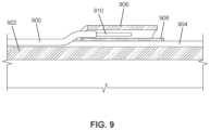
- FIG. 9is a cross-sectional view depicting the connectivity between a grooved wire and an outer electrode sheath of a shockwave electrode assembly.
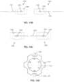
- FIG. 10 Aschematically depicts a shockwave electrode assembly having two inner electrodes that are in a direct connect configuration.
- FIGS. 10 B- 10 Ddepict the connectivity between the inner electrodes and outer electrodes to attain the configuration of FIG. 10 A .
- FIG. 11 Aschematically depicts a shockwave electrode assembly configured in series.
- FIGS. 11 B- 11 Ddepict the connectivity between the inner electrodes and outer electrodes to attain the configuration of FIG. 11 A .
- FIG. 12 Aschematically depicts two shockwave electrode assemblies that are in a direct connect configuration.
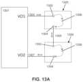
- FIG. 13 Aschematically depicts two shockwave electrode assemblies configured in series.
- FIGS. 13 B- 13 Ddepict the connectivity between the inner electrodes and outer electrodes to attain the configuration of FIG. 13 A .
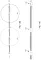
- FIG. 14 Aschematically depicts the connectivity of five shockwave electrode assemblies.
- FIGS. 14 B- 14 Gdepict the connectivity between the inner electrodes and outer electrodes and intermediate nodes (e.g., a distal marker band) to attain the configuration of FIG. 14 A .
- intermediate nodese.g., a distal marker band
- Lithotripsy or shockwave electrodesmay be sealed within an angioplasty or valvuloplasty balloon that is inflated with a fluid (e.g., saline and/or imaging contrast agent).
- a shockwave electrodemay be attached to a source of high voltage pulses, ranging from 100 to 10,000 volts for various pulse durations. This may generate a gas bubble at the surface of the electrode causing a plasma arc of electric current to traverse the bubble and create a rapidly expanding and collapsing bubble, which in turn creates a mechanical shockwave in the balloon.
- Shockwavesmay be mechanically conducted through the fluid and through the balloon to apply mechanical force or pressure to break apart any calcified plaques on, or in, the vasculature walls.
- the size, rate of expansion and collapse of the bubble(and therefore, the magnitude, duration, and distribution of the mechanical force) may vary based on the magnitude and duration of the voltage pulse, as well as the distance between a shockwave electrode and the return electrode.
- Shockwave electrodesmay be made of materials that can withstand high voltage levels and intense mechanical forces (e.g., about 1000-2000 psi or 20-200 ATM in a few microseconds) that are generated during use.
- shockwave electrodesmay be made of stainless steel, tungsten, nickel, iron, steel, and the like.
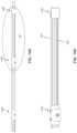
- FIG. 1depicting an example of a shockwave assembly 100 comprising a balloon 106 , a coaxial electrode 102 attached in parallel with a catheter 104 .
- a coaxial electrode 102may have a cross-sectional diameter of about 0.025 inch to about 0.065 inch, and a catheter 104 may have a cross-sectional diameter of about 0.035 inch, which would result in the assembly 100 having a total cross-sectional diameter of at least about 0.06 inch.
- a large crossing profilemay limit the ability of the shockwave system to treat tortuous vascular areas and also limit the number of patients that may be treated.
- Described hereinare low-profile shockwave electrodes that may be located along the outer surface of an elongate member (such as a catheter having a guide wire lumen) that do not protrude more than 0.015 inch from the outer surface of the elongate member.
- the low-profile shockwave electrodes described belowmay increase the crossing-profile of the elongate member by only about 0.005 inch to about 0.015 inch, thereby minimally affecting the ability of the elongate member to access and treat target vascular tissue.
- shockwave deviceswith a plurality of electrodes along the side of an elongate member that are sealably enclosed in a balloon (i.e., sealed in an enclosed balloon). Since the magnitude, duration and distribution of the mechanical force impinging on a portion of tissue depends at least in part on the location and distance between the shockwave source and the tissue portion, a shockwave device having multiple shockwave electrodes at various locations along the length of the elongate member may help to provide consistent or uniform mechanical force to a region of tissue.
- the plurality of electrodesmay be distributed across the device (e.g., along a longitudinal length of the elongate member) to minimize the distance between the shockwave source(s) and the tissue location being treated.
- a calcified region of a vein or arterymay extend over some longitudinal distance of the vein or artery, and a point source shockwave electrode would not be effective across the full extent of the calcified region because of the varying distance from the shockwave source to the various portions of the calcified region.
- shockwave devicesthat comprise a plurality of low-profile shockwave electrodes located along a longitudinal length of an elongate member to distribute shockwaves across a length of calcified plaque.
- the low-profile shockwave electrodesmay be located along the circumference of an elongate member.
- the elongate membermay also be sized and shaped to distribute shockwave forces to a non-linear anatomical region.
- the elongate membermay be curved, having a radius of curvature that approximates the radius of curvature of a valve (e.g., an aortic valve).
- a shockwave device with a curved elongate membermay be suitable for applying shockwaves to break calcified plaques in the vicinity of a valve and/or valve leaflets as part of a valvuloplasty procedure.
- a low-profile shockwave electrode assemblymay comprise a first electrode, a second electrode stacked over the first electrode, and an insulating layer between them. Stacking the second electrode over the first electrode may form a layered electrode assembly that may be formed on the side of a catheter without substantially increasing the cross-sectional profile of the catheter. A stacked or layered electrode assembly located on the side of a catheter may also be able to generate shockwaves that propagate from the side of the catheter without perpendicularly protruding from the catheter (which would increase the cross-sectional profile of the catheter).
- the insulating layermay have a first opening and the second electrode may have a second opening that is coaxially aligned with the first opening.
- Coaxial alignment between the first opening in the insulating layer and the second opening in the second electrodemay comprise aligning the center of each of the openings along the same axis.
- the opening in the insulating layer and the opening in the second electrodemay be concentric, such that the center of the insulating layer opening is aligned with the center of the second electrode opening.
- a shockwave devicemay comprise an elongate member (such as a catheter) and a shockwave electrode assembly having a first electrode that is substantially co-planar with the outer surface of the elongate member.
- the first electrodemay be a pronged electrode that is inserted into the elongate member and connected to a high voltage source via wires within the elongate member.
- the first electrodemay be a hypotube crimped to an electrically conductive portion of a wire, where the wire is located within a longitudinal channel or groove of the elongate member.
- the wiremay have one or more electrically insulated portions and one or more electrically conductive portions, where the conductive portions may align with a first opening of the insulating layer and a second opening of the second electrode.
- the insulating layermay be a sheet or sheath that wraps at least partially around the circumference of the elongate member and overlaps the first electrode. The insulating layer may overlap the first electrode such that the first electrode is electrically isolated from the environment external to the elongate member but for the opening in the insulating layer.
- the second electrodemay be a ring, sheet, or sheath having a second opening that stacks and/or overlaps with the insulating layer such that the second opening is coaxially aligned with the first opening of the insulating layer.
- the second electrodemay be circumferentially wrapped over the insulating layer. Stacking the first electrode, insulating layer, and second electrode along the outer surface of the elongate member may allow for a shockwave electrode assembly to have a low profile with respect to the elongate member, and coaxially aligning the opening of the insulating layer with the opening of the second electrode may allow for the generation of shockwaves that propagate from the side of the elongate member.
- FIG. 2depicts a cut away perspective view of a low-profile coaxial shockwave electrode assembly 200 that may be located on an elongate member 20 (e.g., a catheter) and enclosed in a balloon (e.g., an angioplasty or valvuloplasty balloon).
- the electrode assembly 200may comprise a first electrode 1 , an insulating layer 2 overlaying the first electrode, and a second electrode 3 .
- the first electrode 1may be a positive electrode and the second electrode 3 may be a negative electrode (or vice versa).
- the elongate member 20may have a guide wire lumen extending along a length of its longitudinal axis.
- the first electrode 1may have a thickness from about 0.001 inch to about 0.01 inch, e.g., 0.002 inch, and may be attached along the outer surface of the elongate member 20 .
- the insulating layer 2may be made of any material with a high breakdown voltage, such as Kapton, ceramic, polyimide or Teflon.
- the insulating layer 2may be about 0.001 inch to about 0.006 inch, e.g., 0.0015 inch, 0.0025 inch, and may have an opening 7 that is aligned over the first electrode 1 .
- the second electrode 3is depicted as having a ring shape, it should be understood that the second electrode may be a planar sheet or layer.
- the second electrode 3may have a central opening 8 and stacked over the insulating layer 2 such that the second electrode opening 8 is coaxially aligned with the insulating layer opening 7 .
- the openings 7 , 8may be in the shape of a circle, oval, ellipse, rectangular, or any desired shape.
- the second electrode 3may have a thickness from about 0.001 inch to about 0.015 inch, e.g., 0.0025 inch, 0.004 inch.
- the total thickness of the shockwave electrode assembly 200may be from about 0.002 inch to about 0.03 inch e.g., 0.005 inch, 0.007 inch, 0.008 inch. Layering and stacking the first electrode, insulating layer and second electrode as depicted in FIG.
- Electrode assembly 200may have a small enough thickness such that it does not extend more than 0.015 inch from the outer diameter of the elongate member 20 .
- the gap that the current must crossmay be at least partially determined by the size and location of the opening 7 in the insulating layer 2 and the size and location of the opening 8 in the second electrode 3 .
- the opening 7 in the insulating layermay be larger than the opening 8 in the second electrode.
- the opening 7 in the insulating layermay have a diameter from about 0.004 inch to about 0.010 inch, e.g., about 0.008 inch, and the opening 8 in the second electrode may have a diameter from about 0.010 inch to about 0.02 inch, e.g., about 0.012 inch, 0.016 inch, 0.018 inch.
- the ratio of the diameters between the openings 7 , 8may be varied to adjust the force and duration of the generated shockwave.
- the ratio between the diameter of the opening 7 in the insulating layer and the diameter of the opening 8 in the second electrodemay be about 0.5, e.g., 0.56.
- the gap between the openings 7 , 8may be related to the thickness of the insulating layer.
- the gap between the openingsmay be 0.5*(diameter of opening 8 ⁇ diameter of opening 7 )+thickness of the insulating layer 2 .
- the desired gap sizemay vary according to the magnitude of the high voltage pulse applied to the first electrode 1 . For example, a gap of about 0.004 inch to about 0.006 inch may be effective for shockwave generation using voltage pulses of about 3,000 V.
- a layered or stacked shockwave electrode assemblymay comprise an inner electrode located along or recessed within the outer surface of an elongate member, an insulating layer or sheath that circumferentially wraps the elongate member, and an outer electrode that circumferentially wraps around the elongate member and over the insulating sheath.
- the first electrodemay be pressed into the outer surface of the elongate member, and attached to the elongate member by an adhesive (e.g., a conductive adhesive such as conductive epoxy), crimping, welding, and/or pinching.
- an adhesivee.g., a conductive adhesive such as conductive epoxy
- 3 A- 3 Edepict one variation of a low profile shockwave device 300 comprising an elongate member 320 , an inner electrode 306 pressed into and/or recessed within the outer wall of the elongate member 320 , an insulating layer 302 disposed over the first electrode 306 such that a first opening 307 a in the insulating layer is located over the first electrode, and an outer electrode 308 disposed over the insulating layer 302 such that a first opening 317 a in the outer electrode is coaxially aligned with the first opening 307 a in the insulating layer.
- the insulating layer 302 and the outer electrode 308may each be in the form of a sheath or band, where the insulating sheath may be placed and/or wrapped over the inner electrode and the second electrode sheath may be placed and/or wrapped over the insulating sheath such that the openings in the insulating sheath and outer electrode sheath are coaxially aligned.
- the openings in the insulating sheath and outer electrode sheathare circular and are coaxially aligned such that the centers of the openings are aligned along the same axis and/or concentric.
- the insulating layer, outer electrode, and second inner electrodemay be stacked such that the center of the first opening in the insulating layer, the center of the first opening in the outer electrode, and the first inner electrode are aligned on the same axis.
- the elongate membermay comprise a longitudinal lumen 304 along at least a portion of its length, where the lumen 304 may be configured for passing various instruments and/or a guide wire therethrough.
- the elongate membermay be a catheter with a guide wire lumen.
- the elongate membermay also comprise one or more conductors that may extend along the length of the elongate member to connect the inner and/or outer electrode to a high voltage pulse generator.
- the elongate membermay comprise a first wire 305 and a second wire 310 that may be extruded within the walls of the elongate member 320 , as depicted in FIG. 3 B .
- the wirescould be located in additional longitudinal lumens of the elongate member and/or be located in longitudinal grooves along the outer surface of the elongate member.
- the wires 305 and 310may be surrounded by the insulating material of the elongate member and are therefore electrically insulated from each other.
- the wiresmay each have insulating sleeves that wrap around them. The conductive portion of the wires may be exposed at certain locations along its length to contact the inner and outer electrodes.
- the wiresmay contact the inner and outer electrodes by soldering, crimping, stapling, pinching, welding, conductive adhesive (e.g., using conductive epoxy), and the like, as further described below.
- the inner electrodemay be a hypotube that is crimped to the wire.
- the connectivity between the conductors and the inner and outer electrodesmay be such that the inner electrode is the positive terminal and the outer electrode is the negative terminal (or vice versa). Such a configuration may allow a shockwave generated between the inner and outer electrodes to propagate outward from the side of the elongate member.
- a shockwave devicemay have more than one low-profile electrode assembly along the side of the elongate member.
- a first electrode assemblymay be located along a side of the elongate member while a second electrode assembly may be located on the opposite side of the elongate member (i.e., 180 degrees from each other).
- the shockwave device 300may comprise a second inner electrode 330 pressed into and/or recessed within the outer wall of the elongate member 320 , opposite the first electrode 306 .
- the elongate membermay further comprise a third wire 309 to connect the second inner electrode 330 to a high voltage pulse generator.
- the insulating layer 302 and the outer electrodemay each have an additional opening 307 b , 317 b (respectively) that are coaxially aligned with each other and with the second inner electrode 330 .
- the insulating layer, outer electrode, and second inner electrodemay be stacked such that the center of the second opening in the insulating layer, the center of the second opening in the outer electrode, and the second inner electrode are aligned on the same axis.
- the first electrode assembly 340may comprise the first inner electrode 306 , the insulating layer 302 with the first opening 307 a aligned over the first inner electrode, and the outer electrode 308 with the first opening 317 a coaxially aligned with the first opening 307 a of the insulating layer.
- the second electrode assembly 350may comprise the second inner electrode 330 , the insulating layer 302 with the second opening 307 b aligned over the second inner electrode, and the outer electrode 308 with the second opening 317 b coaxially aligned with the second opening 307 b of the insulating layer.
- the first coaxial electrode assembly and the second coaxial electrode assemblymay be located at the same longitudinal position along the elongate member.
- a shockwave devicecomprising two or more low-profile electrode assemblies located at the same longitudinal position may allow for shockwaves to propagate outward from the elongate member with various angular spread (e.g., up to 360 degree angular spread).
- a first shockwave generated by the first electrode assemblymay propagate outward with an angular spread of about 180 degrees around the elongate member and a second shockwave generated by the second electrode assembly located opposite the first electrode assembly (e.g., 180 degrees from the first electrode assembly) may propagate outward with an angular spread of about 180 degrees around the other side of elongate member, for a cumulative spread of 360 degrees around the elongate member.
- a shockwave devicemay comprise three or more electrode assemblies, where the three or more electrode assemblies may also be located at the same longitudinal location, but located at different circumferential locations. For example, there may be an additional third electrode and fourth inner electrode around the circumference of the elongate member.
- the insulating layermay have additional openings aligned over the additional third and fourth inner electrodes, and the outer electrode may have additional openings aligned over the openings of the insulating layer.
- the third and fourth electrode assemblies formed by the third and fourth inner electrodes and the additional openings in the insulating layer and outer electrodemay allow for the generation of four shockwaves from the same longitudinal location along the elongate member.
- the first, second, third and fourth electrode assembliesmay be at the same position along the length of the elongate member, but be circumferentially distributed around the elongate member 90 degrees apart from each other (i.e., the first electrode assembly may be at position 0 degrees, the second electrode assembly may be a position 180 degrees, the third electrode assembly may be at position 90 degrees, and the fourth electrode assembly may be at 270 degrees). This may give rise to four shockwaves that propagate outward, each fanning out with an angular spread of about 90 degrees.
- shockwave devicewith two low-profile electrode assemblies at the same position along the length of the elongate member is described below, but it should be understood that similar methods may be used to assemble shockwave devices with three or more low-profile electrode assemblies at the same longitudinal position along the length of the elongate member.
- the first inner and second inner electrodes 306 , 330may be pronged electrodes 306 a , 330 a and may be shaped to be pressed into the wall of the insulating material of the elongate member. Electrical contact between the first inner and second inner electrodes and the first and third wires may be attained via finger extensions of the pronged electrodes.
- the pronged electrodes 306 a , 330 amay have finger extensions 306 b , 330 b that pinch the first and third wires 305 , 309 (respectively) in the wedge of the fingers.
- the pronged electrodesmay also be electrically connected to the wires by any suitable method, for example, soldering, crimping, welding, conductive adhesives (e.g., using conductive epoxies), pressure fit, interference fit, etc.
- FIG. 3 Cdepicts the first inner and second inner electrode pressed into the side of the elongate member such that the first inner electrode and second inner electrode make electrical contact with the first and third wires within the elongate member.
- the pronged electrodes 306 a , 330 amay form the first layer of a stacked low-profile shockwave electrode assembly (e.g., similar to the layered or stacked configuration of the electrode assembly depicted in FIG. 2 ).
- the pronged electrodesmay comprise tungsten, stainless steel, platinum iridium, nickel, iron, steel, and/or other electrically conductive material.
- the insulating sheath 302may circumferentially wrap around the elongate member 320 such that it overlaps with and overlays the first inner electrode and second inner electrode, as depicted in FIG. 3 D .
- the insulating sheath 302may overlap and stack on top of the first inner electrode and second inner electrode 306 and 330 such that the first opening 307 a is coaxially aligned with the first inner electrode and the second opening 307 b is aligned with the second inner electrode.
- the insulating sheath 302may be made of any material that has a high breakdown voltage, such as Kapton, polyimide, ceramic, Teflon, or any combination of such materials.
- the insulating sheath 302may be placed over the elongate member by sliding it from one end of the elongate member to the desired location.
- the insulating sheath 302may be secured in the desired location by friction fit, adhesive, welding, crimping, or any other suitable method.
- the outer electrode 308may be a sheath or band that may be configured to stack on top of and/or wrap over the insulating layer 302 , as shown in FIG. 3 E .
- the outer electrode 308may have an extension 319 with pointed fingers 318 configured to penetrate the elongate member to contact the second wire 310 (e.g., by crimping the fingers 318 so that the fingers are pressed into and on the wire 310 ).
- the outer electrode 308may be a metallic sheath or band that may wrap or enclose the elongate member.
- the outer electrode 308may be positioned such that the first opening 317 a is coaxially aligned with the first opening 307 a of the insulating sheath 302 and the second opening 317 b is coaxially aligned with the second opening 307 b of the insulating sheath.
- the outer electrode 308may be slid over one end of the elongate member and moved longitudinally into the desired position, after which it may be secured by friction fit, conductive adhesive (e.g., using conductive epoxy), welding, soldering, crimping, or any other suitable method.
- the outer electrode 308may be made of copper, stainless steel, platinum/iridium or other electrically conductive materials.
- the first inner electrodemay be connected to the first wire 305 and the second inner electrode may be connected to the third wire 309 .
- the high voltage pulse generatormay drive the first wire 305 and third wire 309 together or independently.
- the pulse generatormay apply voltage pulses simultaneously to both wires, and/or may apply voltage pulses sequentially (e.g., a voltage pulse is applied to the first wire without applying a pulse to the third wire, or vice versa).
- the voltage pulses applied to the third wiremay be delayed with respect to the voltage pulses applied to the first wire.
- a multiplexormay be used with the high voltage pulse generator to control application of pulses between the first and third wires.
- shockwaves with different frequency, magnitude, and timingmay be generated on either side of the elongate member.
- it may be desirable to apply shockwaves on one side of the elongate member but not on the other sidee.g., in an angioplasty procedure where there is a calcified lesion in one portion of the vessel but not in other portions of the vessel.
- the first, second, and third wiresmay be directly connected to a high voltage pulse generator, or may first connect to a connector that is then plugged into the high voltage pulse generator.
- shockwave device 400may comprise a catheter 402 , a first low-profile coaxial electrode assembly 404 , a second low-profile coaxial electrode assembly 406 (not visible in this view), and a balloon 408 enclosing the portion of the elongate member where the first and second electrode assemblies are located.
- the balloonmay be made of an electrically insulating material that may be rigid (e.g., PET, etc.), semi-rigid (e.g., PBAX, nylon, PEBA, polyethylene, etc.), or flexible (e.g., polyurethane, silicone, etc.).
- the first and second electrode assembliesmay be located radially across from each other such that the shockwaves they each generate propagate in opposite directions. The shockwaves generated by each of the electrode assemblies may propagate outward, with an angular spread of 180 degrees.
- the inner electrodes of each of the electrode assembliesmay be connected to conductors within the catheter 402 , which may be connect to a high voltage pulse generator.
- the high voltage pulse generatormay be a 2 kV to 6 kV, e.g., 3 kV, pulsed power supply.
- the inner electrode of the first electrode assemblymay be connected to a first positive lead of the pulse generator while the inner electrode of the second electrode assembly may be connected to a second positive lead of the pulse generator.
- the outer electrodemay be connected to a negative lead of the pulse generator, or to ground.
- the first and second positive leads of the pulse generatormay be pulsed simultaneously or separately, and may be controlled together or separately controlled (e.g. using a multiplexor), as described previously.
- Additional low-profile shockwave electrode assembliesmay alternatively or additionally be located along a plurality of locations along the length of the elongate member.
- the low-profile coaxial shockwave electrode assemblies described abovemay be linearly arranged along the longitudinal length of the elongate member. Additional variations of shockwave devices with a plurality of electrode assemblies are described below.
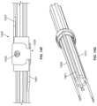
- Shockwave angioplasty system 520may comprise a catheter 522 , a proximal hub 524 , one or more shockwave electrode assemblies 526 at a distal portion of the catheter, a high-voltage connector 530 for connecting the shockwave assemblies to a pulse generator, and an angioplasty balloon 528 configured to be inflated with a fluid.
- a proximal portion of the wires from the shockwave assembliesmay form a cable 576 that may be enclosed in a jacket. The cable may extend from a lumen of the proximal hub 524 and connect to the high-voltage connector 530 .
- Pins within the high-voltage connectormay connect each of the wires from the shockwave assemblies to the appropriate channel on a high voltage pulse generator.
- the system 520may additional comprise a strain relief tube 532 connected to the hub 524 .
- the catheter 522may have a guide wire lumen therethrough.
- shockwave electrode assemblieslocated at the distal end of the catheter and enclosed by the balloon. For example, there may be one shockwave electrode, two shockwave electrode assemblies, four shockwave electrode assemblies, five shockwave electrode assemblies or more.
- FIGS. 5 B and 5 Cdepict the distal portions of shockwave devices with two electrode assemblies and five electrode assemblies.
- FIG. 5 Bdepicts one variation of a shockwave device 500 comprising an elongate member 502 , a first electrode assembly 504 at a first location along the length of the elongate member, a second electrode assembly 506 at a second location along the length of the elongate member, and a balloon 508 configured to be filled with a fluid to sealably enclose the first and second electrode assemblies.
- the balloon 508may be made of an electrically insulating material that may be rigid (e.g., PET, etc.), semi-rigid (e.g., PBAX, nylon, PEBA, polyethylene, etc.), or flexible (e.g., polyurethane, silicone, etc.).
- the first and second electrode assembliesmay be spaced apart along the length of the elongate member, and may be from about 3 mm to about 20 mm apart from each other, e.g., about 5 mm, 7 mm, 10 mm.
- the length of the balloonmay vary depending on the number of electrode assemblies and the spacing between each of the electrode assemblies. For example, a balloon for a shockwave device with two electrode assemblies spaced about 7 mm apart (e.g., 6.7 mm) may have a length of about 20 mm.
- a balloon for a shockwave device with five electrode assemblies spaced about 10 mm apartmay have a length of about 60 mm.
- the electrode assemblies 504 , 506each comprise two inner electrodes that are positioned circumferentially opposite each other, an insulating sheath with two openings aligned over the two inner electrodes, and an outer electrode sheath with two openings that are coaxially aligned with the two openings of the insulating sheath.
- Each of the electrode assemblies 504 , 506are configured to generate a pair of directed shockwaves, where the shockwaves resulting from a high voltage pulse to the first inner electrode propagate in a direction that is opposite to the direction of the shockwaves resulting from a high voltage pulse to the second inner electrode.
- the electrode assemblies 504 , 506may generate shockwaves that propagate outward from different locations around the circumference of elongate member 502 .
- the electrode assembly 504may generate shockwaves that propagate from the left and right longitudinal side of the elongate member, while the electrode assembly 506 may generate shockwaves that propagate from the top and bottom longitudinal side of the elongate member.
- the electrode assembly 504may generate a pair of shockwaves that propagate outward from positions at 0 degrees and 180 degrees around the circumference of the elongate member 502
- the electrode assembly 506may generate a pair of shockwaves that propagate outward from positions at 60 degrees and 240 degrees around the circumference of the elongate member.
- electrode assemblies 504 , 506may each generate a pair of shockwaves that propagate outward at the same locations around the circumference of the elongate member, but from different locations along the length of the elongate member.
- a radiopaque marker bandsmay be provided along the length of the elongate member to allow a practitioner to identify the location and/or orientation of the shockwave device as it is inserted through the vasculature of a patient. For example, there may be a first marker band proximal to the first electrode assembly and a second marker band distal to the second electrode assembly.
- one or more marker bandsmay be located proximal to the proximal-most electrode assembly, and/or distal to the distal-most electrode assembly, and/or in the center of the elongate member and/or any other location along the length of the elongate member.
- FIG. 5 Cdepicts another shockwave device 550 comprising an elongate member 552 , a first electrode assembly 554 , a second electrode assembly 556 , a third electrode assembly 558 , a fourth electrode assembly 560 , a fifth electrode assembly 562 , and a balloon 564 configured to be filled with a fluid to sealably enclose the first, second, third, fourth, and fifth electrode assemblies.
- the balloon 564may be made of an electrically insulating material that may be rigid (e.g., PET, etc.), semi-rigid (e.g., PBAX, nylon, PEBA, polyethylene, etc.), or flexible (e.g., polyurethane, silicone, etc.).
- the electrode assemblies of shockwave device 550may be similar to the ones described in FIG. 5 B , and/or may be similar to any of the electrodes described herein.
- the elongate membermay be a catheter with a longitudinal guide wire lumen.
- Each of the electrode assembliesare configured to generate a pair of shockwaves that propagate in two opposite directions from the side of the elongate member.
- the electrode assemblies of FIG. 5 Cmay be configured to generate shockwaves that propagate outward from different locations around the circumference of elongate member, as described above for FIG. 5 B .
- the figures hereinmay depict shockwave devices with two or five electrode assemblies, it should be understood that a shockwave device may have any number of electrode assemblies, for example, 3, 4, 6, 7, 8, 9, 10, 15, 20, etc.
- the electrode assembliesmay be spaced apart along the length of the elongate member, and may be from about 3 mm to about 10 mm apart from each other, e.g., about 5 mm, 8 mm, 10 mm, etc. depending on the number of electrode assemblies and the length of the elongate member that is enclosed within the balloon.
- Shockwave devices with a plurality of electrode assemblies distributed along the length of a cathetermay be suitable for use in angioplasty procedures to break up calcified plaques that may be located along a length of a vessel.
- Shockwave devices with a plurality of electrode assemblies along the length of a curved elongate membermay be suitable for use in valvuloplasty procedures to break up calcified plaques that may be located around the circumference of a valve (e.g., at or around the leaflets of a valve).
- the electrode assemblies of FIGS. 5 A- 5 Cmay be similar to the electrode assemblies described above and depicted in FIGS. 3 A- 3 E , and/or may be any of the electrode assemblies described below.
- FIGS. 5 D and 5 Eare detailed views of the proximal hub 524 .
- proximal hub 524may comprise a central shaft 542 , a first side shaft 540 and a second side shaft 544 .
- the first and second side shaftsare attached to either side of the central shaft 542 .
- the central shaft 542may have a proximal opening 548 that is connected to an inner lumen 543 that extends through the length of the central shaft and terminates at a distal opening 546 that is configured to interface with the strain relief and the catheter 522 .
- the inner lumen 543may be in communication and/or continuous with the guide wire lumen of the catheter 522 .
- the first side shaft 540may have an opening 547 that is connected to an inner lumen 541 , which is in communication and/or continuous with the inner lumen 543 of the central shaft 542 .
- the second side shaft 544may have an opening 549 that is connected to an inner lumen 545 .
- the inner lumen 545 of the second side shaft 544may not be connected to the central inner lumen 543 .
- the inner lumens 541 , 543 , 545may each have a wider proximal region and a narrower distal region, which may act as a stop for the devices inserted into the shafts.
- the central shaft 548 and its inner lumen 543may function as a port for the insertion of a guidewire and/or to deliver an imaging contrast agent to the distal end of the catheter 522 .
- the first side shaft 540 and inner lumen 541may function as an inflation port for saline and/or imaging contrast agent.
- the second side shaft 549 and inner lumen 545may function as a port through which the cable 576 may extend and connect to the high voltage connector 530 to electrically connect a high voltage pulse generator to the shockwave electrode assemblies at the distal end of the catheter.
- the cable 576may be bonded to the connector 530 and/or the hub.
- the proximal hub 524may be made of injection molded polycarbonate.
- the length L 1 of the central shaft 542may be from about 2 inches to about 4 inches, e.g., about 2.3 inches or 2.317 inches, while the length L 2 of the side shafts 540 , 544 may be from about 1 inch to about 2 inches, e.g., about 1.4 inches or 1.378 inches.
- the diameter D 1 of the narrowest portion of the central inner lumen D 1may be from about 0.05 inch to about 0.1 inch, e.g., about 0.08 inch to about 0.082 inch.
- FIG. 5 Fis a detailed view of the high voltage connector 530 that may be inserted through at least one of the ports of the proximal hub, and configured to connect the shockwave electrode assemblies 526 to a high voltage pulse generator.
- the high voltage connector 530may have a proximal port 570 that is configured to connect with a port of a high voltage pulse generator, a first shaft region 572 , and a second shaft region 574 that is narrower than the first shaft region 572 that may connect to cable 576 .
- the first shaft region 572may have a diameter D 3 that is greater than the diameter of the narrower portion of an inner lumen of the proximal hub, but smaller than the diameter of the wider portion of the inner lumen.
- the second shaft region 574 distal to the first shaft regionmay be configured for strain relief.
- the cable 576may provide connections for both the high voltage pulse(s) and the return path between the voltage pulse generator and the electrode assemblies.
- the cablemay provide one or more high voltage supply connections to the electrode assemblies, with one or more return connections.
- the cablemay provide for a single high voltage supply connection and a single return connection to the electrode assemblies.
- the cablemay provide for a plurality of high voltage supply connections (e.g., four) and one or more return connections to the electrode assemblies.
- the proximal port 570may have a length L 3 from about 1.5 inches to about 3 inches, e.g., about 2 inches or 2.059 inches, and a diameter D 2 from about 0.2 inch to about 1 inch, e.g., about 0.7 inch or 0.72 inch.
- the diameter D 3 of the first shaft region 572may be from about 0.05 in to about 0.2 inch, e.g., about 0.1 inch or 0.112 inch.
- FIG. 6 Adepicts another variation of a low-profile coaxial shockwave electrode assembly that may be used in any of the shockwave devices described herein.
- the electrode assembly 600may comprise a first inner electrode 604 , an insulating layer or sheath 606 disposed over the first inner electrode and circumferentially wrapped around an elongate member 602 (e.g., a catheter with a guidewire lumen), and an outer electrode sheath 608 disposed over the insulating sheath. While the insulating sheath is depicted as fully circumscribing the elongate member, it should be understood that in other variations, an insulating layer may not fully circumscribe the elongate member, and may instead be disposed over certain portions of the elongate member.
- the insulating sheath 606may have a first opening 607 a that is coaxially aligned over the first inner electrode 604
- the outer electrode sheath 608may have a first opening 609 a that is coaxially aligned over the first opening of the insulating sheath.
- the electrode assembly 600may also comprise a second inner electrode that is circumferentially opposite (or otherwise displaced from) the first inner electrode (and therefore not depicted in the view shown in FIG. 6 A ).
- the insulating sheathmay have a second opening 607 b that is coaxially aligned over the second inner electrode, and the outer electrode sheath may have a second opening 609 b that is coaxially aligned over the second opening of the insulating sheath.
- the first inner electrode coaxial with the first openings in the insulating sheath and the outer electrode sheathmay generate a first shockwave that propagates outwards in a first direction and the second inner electrode coaxial with the second openings in the insulating sheath and the outer electrode sheath may generate a second shockwave that propagates outwards in a second direction that is opposite to the first direction.
- the diameter of the openings in the outer electrode sheathmay be larger than the diameter of the openings in the insulating sheath.
- the size of and ratio between the diameter of the openings in the outer electrode and the openings in the insulating sheathmay be adjusted to attain the desired shockwave characteristics, as described above.
- the edges of the openings in any of the outer electrodes described hereinmay be electropolished.
- some variations of an electrode assemblymay not have an insulating sheath or layer disposed over the elongate member, but may instead comprise an inner electrode having an insulating coating directly applied over the inner electrode (e.g., disposed over the crimped hypotube of the inner electrode).
- the insulating coatingmay cover the inner electrode such that a region of the conductive portion of the inner electrode is exposed, while the rest of the inner electrode is covered by the coating.
- the opening in the outer electrode sheathmay be coaxially aligned with the exposed region of the inner electrode.
- the thickness and/or material of the insulating coatingmay be varied depending on the magnitude of the voltage to be applied on the electrode. Examples of insulating coatings may be Teflon, polyimide, etc. Using an insulating coating on the inner electrode instead of an insulating layer disposed over the elongate body may further reduce the crossing profile of the electrode assembly, and may allow for more bending or a tighter turning radius than an electrode assembly having an insulating sheath.
- the inner electrodes and the outer electrodemay each be connected to a high voltage pulse generator via a plurality of wires 610 that may be located within a plurality of longitudinal grooves 601 along the outer surface of the elongate member 602 (e.g., a catheter having a guidewire lumen) of the shockwave device.
- the wiresmay be electrically insulated along its length (e.g., by an insulating coating or sheath made of, for example, polyimide, PEBA, PET, FEP, PTFE, etc.) except for one or more regions where the electrically conductive core of the wire is exposed to contact a portion of the inner and/or outer electrode.
- the insulating coating or sheath at the distal tip of the wiremay be stripped to expose the conductive portion.
- the wiresmay be made of any conductive material, for example, free oxygen copper or copper or silver.
- the inner electrode 604may be a hypotube that is crimped over the distal tip of the wire 610 , where the wire 610 is enclosed within one of a plurality of grooves 601 of the elongate member.
- the hypotubemay be made of stainless steel, tungsten, a platinum-iridium alloy, or any other material with similar hardness.
- a portion of the hypotubemay be coated with an insulating material as described above.
- Each groove of the elongate membermay partially enclose a single wire.
- the wire 610may be half enclosed within a groove of the elongate member, such that half of the wire is recessed or embedded within the groove and half of the wire protrudes outside of the groove.
- the wire 610may be slidably disposed within the groove.
- the wiremay slide within the groove to accommodate changes in the radius of curvature as the elongate member bends, thereby minimally interfering with the flexibility of the elongate member.
- one or more shrink tubesmay be provided to retain the wire within the groove without impinging on its ability to move and shift as the elongate member bends or curves.
- one or more bands of shrink tubesmay be located circumferentially around the distal portion of the elongate member.
- dots of epoxymay be applied along a distal length of the wires to partially secure or retain the wires within the grooves while still maintaining the ability of the wires to partially move and shift as the elongate member bends or curves.
- the wiresmay slide within the grooves without any retaining elements. Additional details regarding the longitudinal grooves of the elongate member are provided below.
- FIGS. 6 B and 6 Cdepict perspective and side view of the outer electrode sheath 608 .
- the outer electrodemay be a radiopaque marker band (e.g., marker band used in angioplasty procedures).
- the first opening 609 amay be located directly across from the second opening 609 b .
- FIG. 6 Ddepicts a perspective view of the insulating sheath 606 having a first opening 607 a and a second opening 607 b located directed across from the first opening 607 a .
- each of these openingsmay be coaxially aligned with the openings of the insulating sheath 606 and first and second inner electrodes to form two shockwave sources capable of generating two shockwaves that propagate outward from the side of the elongate member in two opposite directions.
- the diameter of each of the openings 622 a , 622 bmay be from about 0.010 inch to about 0.024 inch, e.g., about 0.014 inch.
- FIG. 6 Gdepicts a variation of an insulating sheath 630 that comprises two openings 632 a , 632 b that are circumferentially across each other, but laterally offset.
- the diameter of each of the openings 632 a , 632 bmay be from about 0.004 inch to about 0.01 inch, e.g., about 0.008 inch.
- the size and ratio of the openings in the insulating sheath and the outer electrodemay be similar to those described previously (see FIG. 2 and accompanying description).
- the openings 622 a , 622 b of the outer electrode sheathmay be coaxially aligned with the openings 632 a , 632 b of the insulating sheath 630 , respectively.
- the outer electrode sheath 620 and the insulating sheath 630may be used with a pair of inner electrodes that are similarly circumferentially across each other, but laterally offset such that the two inner electrodes are each coaxially aligned with the each of the openings in the insulating sheath and the outer electrode sheath. This may functionally create two shockwave sources configured to generate two shockwaves that propagate outward in two directions that are opposite each other but laterally offset.
- the inner electrodeis retained within a longitudinal groove of a catheter, and the openings of an insulating sheath and outer electrode are coaxially aligned with the inner electrode.
- the circumferential position of the openings in the insulating sheath and the outer electrodemay be constrained by the circumferential position of the longitudinal groove that retains the inner electrode.
- FIG. 6 HA cross-section of such shockwave electrode assembly is depicted in FIG. 6 H .
- a catheter 640with a central guide wire lumen 641 and first and second grooves 642 a , 642 b that are located circumferentially opposite each other (e.g., 180 degrees around the catheter).
- First and second wires 644 a , 644 bare retained within the grooves 642 a , 642 b and are connected to first and second inner electrodes 646 a , 646 b .
- the first and section wire 644 a , 644 b and grooves 642 a , 642 bare aligned along axis 654 .
- a shockwave sourceit may be desirable to have a shockwave source be located at a location that is offset from a first axis 654 , for example at a location that is radially offset by angle A 1 (which may be from about 1 degree to about 179 degrees).
- the first and second inner electrodes 646 a , 646 bmay each be a hypotube that is asymmetrically crimped so that a length of the hypotube circumferentially spans a portion of the catheter.
- the inner electrodes 646 a , 646 bmay span at least an angle A 1 along the circumference of the catheter 640 .
- the first and second openings 647 a , 647 b of the insulating sheath 648may be coaxially aligned over the first and second inner electrodes at the radially offset location, and the first and second openings 651 a , 651 b of the outer electrode 650 may be coaxially aligned over first and second openings 647 a , 647 b of the insulating sheath 648 .
- first and second openings 647 a , 647 b of the insulating sheath 648 , the first and second openings 651 a , 651 b of the outer electrode 650 , and a portion of the first and second inner electrodes 646 a , 646 bmay be coaxially aligned along a second axis 652 that is offset by angle A 1 from the first axis 654 .
- Such configurationmay allow for the placement of a shockwave source anywhere along the circumference of a catheter without necessarily being aligned with the circumferential location of the one more longitudinal grooves of the catheter.
- FIGS. 7 A- 7 Ddepict an example of a method for making a low-profile shockwave electrode assembly that is located along a length of an elongate member (which for clarity purposes, is not shown here).
- the inner electrode 700may be a hypotube that is placed over an exposed core of a wire 702 and crimped and flattened, as illustrated in FIGS. 7 A and 7 B .
- the inner electrode 700may be crimped and flattened with a slight curve to approximate and/or match the radius of curvature of the elongate member.
- the inner electrode 700 and the wire 702are then placed within a longitudinal groove of the elongate member (see FIG.
- An insulating layer or sheath 704may be slid over the elongate member and positioned over the inner electrode 700 such that an opening 705 of the insulating sheath 704 is coaxially aligned over the inner electrode, as shown in FIG. 7 C .
- An outer electrode sheath 706may be slid over the elongate member and positioned over the insulating sheath 704 such that an opening 707 of the outer electrode sheath 706 is coaxially aligned over the opening 705 of the insulating sheath 704 , as shown in FIG. 7 D .
- aligning the openings of the insulating sheath and the outer electrode over the first inner electrodemay also align a second set of openings of the insulating sheath and the outer electrode over the second inner electrode.
- FIGS. 8 A and 8 Bdepict side and cross-sectional view (taken along line 8 B- 8 B) of one variation of a grooved elongate member (e.g., a catheter) that may be used in any of the shockwave devices described herein.
- the elongate member 802may have any number of longitudinal grooves or channels configured for retaining a wire and/or inner electrode, and may for instance have 1, 2, 3, 4, 5, 6, 7, 8, 10, etc. grooves.
- the elongate member 602has six grooves that surround a central guide wire lumen 603 .
- the elongate member 802may have a radius of about 0.014 inch and the each of the grooves may have a radius of curvature of about 0.005 inch to about 0.010 inch. Where the grooves may have a semi-elliptical shape, the minor axis may be about 0.008 inch and the minor axis may be about 0.015 inch.
- the elongate member 802may also comprise a guide wire lumen 803 , where the guide wire lumen may have a radius of about 0.0075 inch to about 0.018 inch, e.g., about 0.02 inch or 0.0175 inch.
- shrink tubingmay be provided over each of the wires to help retain the wire within the groove while still allowing the wires to slide and move within the grooves to accommodate bending of the elongate member 602 .
- Wires slidably disposed within longitudinal grooves on the outer surface of the elongate membermay retain the flexibility of the elongate member such that the elongate member may easily navigate and access tortuous vasculature. While the variations here depict wires that are slidably disposed within grooves of the elongate member to accommodate bending of the elongate member, in other variations, the wires may be conductive elements that are co-extruded with the elongate member and therefore unable to slide with respect to the elongate member.
- co-extruding conductive elements with the elongate membermay stiffen the elongate member, thereby limiting its flexibility and ability to navigate to and access tortuous vasculature.
- the smallest radius of curvature attainable by an elongate member with co-extruded conductive elementsmay be larger than the smallest radius of curvature attainable by an elongate member with wires slidably disposed in grooves along its outer surface.
- the turning radius of an elongate member that has wires slidably disposed within longitudinal grooves along its outer surfacemay be tighter than the turning radius of the same elongate member if the wires were unable to slide with respect to the elongate member.
- the wires retained within the longitudinal grooves of an elongate membermay be connected to inner electrodes, as described above, and/or may be connected to outer electrode sheaths.
- a wire that is retained within a longitudinal groovemay be connected to an outer electrode sheath using any suitable method, for example, by friction fit and/or adhesives.
- the wiremay be friction fit between the outer electrode sheath and the insulating sheath, and optionally further secured in contact with the outer electrode sheath with an adhesive, as depicted in FIG. 9 .
- a wire 900 retained within a groove 904 of an elongate member 902may contact an outer electrode sheath 906 via a stripped portion 910 that is drawn out of the groove 904 and inserted between the outer electrode sheath and insulating sheath 908 (for clarity, the inner electrode of this this shockwave electrode assembly is not shown).
- the wiremay be secured between the outer electrode sheath and the insulating sheath friction fit and may optionally be further secured and electrically insulated by an adhesive, such as conductive epoxy or laser welded or spot welded.
- Inserting the stripped portion 910 (where the electrically conductive portion is exposed) between the outer electrode sheath and the insulating sheath and further sealing it with an adhesivemay help to ensure that the wire does not inadvertently contact an inner electrode or any other conductive medium (e.g., the fluid that may be used to fill a shockwave angioplasty balloon).
- any other conductive mediume.g., the fluid that may be used to fill a shockwave angioplasty balloon.
- the first and second inner electrodes of an electrode assemblymay be connected such that they are each independently voltage-controlled, e.g., each directly connect to separate positive channels of a high voltage pulse generator. They may be independently controlled (e.g., capable of being pulsed separately) or may be controlled together.
- An example of direct connectivity between the first and second inner electrodes of a shockwave electrode assembly 1000is depicted in FIGS. 10 A- 10 D .
- the shockwave electrode assembly 1000may be any of the electrode assemblies described herein, and may comprise a first inner electrode 1002 , a second inner electrode 1004 and an outer electrode 1006 . As schematically depicted in FIG.
- a first wire 1003may connect the first inner electrode 1002 to a first voltage output port VO 1 of a pulse generator 1001 .
- a second wire 1005may connect the second inner electrode 1004 to a second voltage output port VO 2 of the pulse generator 1001 .
- a third wire 1006may connect the outer electrode to a third voltage output port VO 3 (a ground channel or negative terminal).
- the first voltage output port VO 1 and the second voltage output port VO 2may be positive channels while the third voltage output port VO 3 may be a negative channel (or vice versa).
- a high voltage pulse on the first and/or second voltage output ports VO 1 , VO 2current may flow in the direction of the arrows in the first and/or second wires 1003 , 1005 from the voltage outputs VO 1 , VO 2 to the first and second inner electrodes 1002 , 1004 .
- the high voltage pulse generatormay apply a voltage pulse on output port VO 1 such that the potential difference between the first inner electrode 1002 and the outer electrode 1006 is high enough to form a plasma arc between them, generating a bubble that gives rise to a shockwave.
- the high voltage pulse generatormay simultaneously or sequentially apply a voltage pulse on output port VO 2 such that the potential difference between the second inner electrode 1004 and the outer electrode 1006 is high enough to form a plasma arc between them, generating a bubble that gives rise to a different shockwave.
- the shockwaves generated by the first and second inner electrodesmay propagate in opposite directions, extending outward from the side of the elongate member.
- Voltage output ports VO 1 and VO 2may be independently addressed (e.g., voltage and current may be applied to one output but not necessarily the other), or may be not be independently addressed (e.g., activating one output necessarily activates the other).
- a connector(not shown) may be provided between the wires 1003 , 1005 , 1007 and the voltage pulse generator 1001 so that the wires of the elongate member may be easily connected to the output ports of the high voltage generator.
- FIGS. 10 B- 10 Ddepict one variation of how the circuit of FIG. 10 A may be implemented in a shockwave device that comprises the shockwave electrode assembly 1000 .
- the shockwave devicemay comprise a catheter 1010 with a central guide wire lumen 1011 and six longitudinal grooves (G 1 -G 6 ) arranged around the guide wire lumen.
- FIG. 10 Bis a top view of the electrode assembly 1000 where the first inner electrode 1002 is visible and
- FIG. 10 Ca bottom view of the electrode assembly 1000 where the second inner electrode 1004 is visible.
- the first and second inner electrodesare located circumferentially opposite each other (i.e., 180 degrees apart).
- FIG. 10 Ddepicts the grooves in which each of the inner electrodes and/or wires may be retained.
- the return wire 1007may be connected to the outer electrode sheath 1006 in any of the configurations described above and may be retained in groove G 3 .
- the wire 1003connects the first inner electrode 1002 with the first voltage output VO 1 , and may be retained in groove G 1 .
- the wire 1005connects the second inner electrode 1004 with the second voltage output VO 2 , and may be retained in groove G 4 , directly opposite groove G 1 . While the example depicted here uses grooves G 1 , G 3 , and G 4 , it should be understood that any three of the six grooves may be used to retain the wires 1003 , 1005 and 1007 to attain the connectivity depicted in FIG. 10 A .
- the wires 1003 , 1005 and 1007may be retained in grooves G 2 , G 5 and G 6 respectively, or grooves G 3 , G 6 and G 5 respectively, or grooves G 1 , G 3 , and G 2 respectively, grooves G 1 , G 3 , and G 5 respectively, etc.
- FIGS. 11 A- 11 Ddepict one example of a shockwave electrode assembly 1100 that is configured such that first inner electrode 1102 is in series with the second inner electrode 1104 .
- the shockwave electrode assembly 1100may be any of the electrode assemblies described herein, and may comprise a first inner electrode 1102 , a second inner electrode 1104 and an outer electrode 1106 . As schematically depicted in FIG.
- a first wire 1103may connect the first inner electrode 1102 to a first voltage output port VO 1 of a pulse generator 1101 .
- a second wire 1105may connect the second inner electrode 1104 to a second voltage output port VO 2 (a ground channel or negative terminal).
- the first voltage output port VO 1may be a positive channel while the second voltage output port VO 2 may be a negative channel (or vice versa).
- currentmay flow in the direction of the arrow in the first wire 1103 from the voltage output VO 1 to the first inner electrode 1102 .
- the high voltage pulse generatormay apply a voltage pulse on output port VO 1 such that the potential difference between the first inner electrode 1102 and the outer electrode 1106 is high enough to form a plasma arc between them, generating a bubble that gives rise to a shockwave.
- the current that traverses the bubble from the first inner electrode 1102 to the outer electrode 1106may set up a potential difference between the outer electrode 1106 and the second inner electrode 1004 that is high enough to form a plasma arc between them, generating a bubble that gives rise to a different shockwave.
- the shockwaves generated by the first and second inner electrodesmay propagate in opposite directions, extending outward from the side of the elongate member.
- the currentthen returns to the voltage source generator via wire 1105 to voltage output port VO 2 (which may be a negative channel or a ground channel).
- VO 2which may be a negative channel or a ground channel.
- a connector(not shown) may be provided between the wires 1103 , 1105 and the voltage pulse generator 1101 so that the wires of the elongate member may be easily connected to the output ports of the high voltage generator.
- FIGS. 11 B- 11 Ddepict one variation of how the circuit of FIG. 11 A may be implemented in a shockwave device that comprises the shockwave electrode assembly 1100 .
- the shockwave devicemay comprise a catheter 1110 with a central guide wire lumen 1111 and six longitudinal grooves (G 1 -G 6 ) arranged around the guide wire lumen.
- FIG. 11 Bis a top view of the electrode assembly 1100 where the first inner electrode 1102 is visible
- FIG. 11 Ca bottom view of the electrode assembly 1100 where the second inner electrode 1104 is visible.
- the first and second inner electrodesare located circumferentially opposite each other (i.e., 180 degrees apart).
- FIG. 11 Ddepicts the grooves in which each of the inner electrodes and/or wires may be retained.
- the wire 1103connects the first inner electrode 1102 with the first voltage output VO 1 , and may be retained in groove G 1 .
- the wire 1105connects the second inner electrode 1104 with the second voltage output VO 2 , and may be retained in groove G 4 , directly opposite groove G 1 . While the example depicted here uses grooves G 1 and G 4 , it should be understood that any two of the six grooves may be used to retain the wires 1103 , 1105 to attain the connectivity depicted in FIG. 11 A .
- the wires 1103 and 1105may be retained in grooves G 2 and G 5 respectively, or grooves G 3 and G 6 respectively, etc.
- shockwave devicesmay comprise two or more shockwave electrode assemblies.
- the shockwave angioplasty system 520 depicted in FIG. 5 Acomprises two electrode assemblies where each electrode assembly has two inner electrodes circumferentially opposite to each other and is configured to generate two shockwaves that propagate outward from the side of the catheter in opposite directions.
- the two shockwave electrode assembliesmay be connected such that each of the inner electrodes of the two electrode assemblies (i.e., for a total of four inner electrodes) are each connected to separate voltage channels.
- each of the inner electrodesmay each be directly connected to different voltage channels in a direct connect configuration.
- the inner electrodesmay be individually addressable and/or can be activated by separate ports on a high voltage pulse generator.
- the shockwave electrode assemblies 1200 , 1250may be any of the electrode assemblies described herein.
- the first shockwave electrode assembly 1200may comprise a first inner electrode 1202 , a second inner electrode 1204 and an outer electrode 1206 .
- the second shockwave electrode assembly 1250may comprise a first inner electrode 1252 , a second inner electrode 1254 and an outer electrode 1256 . As schematically depicted in FIG.
- a first wire 1203may connect the first inner electrode 1202 of the first electrode assembly 1200 to a first voltage output port VO 1 of a pulse generator 1201 .
- a second wire 1205may connect the second inner electrode 1204 of the first electrode assembly 1200 to a second voltage output port VO 2 of the pulse generator 1201 .
- a third wire 1207may connect the outer electrode 1206 of the first electrode assembly to a third voltage output port VO 3 (a ground channel or negative terminal).
- the first voltage output port VO 1 and the second voltage output port VO 2may be positive channels while the third voltage output port VO 3 may be a negative channel (or vice versa).
- a fourth wire 1253may connect the first inner electrode 1252 of the second electrode assembly 1250 to a fourth voltage output port VO 4 of the pulse generator 1201 .
- a fifth wire 1255may connect the second inner electrode 1254 of the second electrode assembly 1250 to a fifth voltage output port VO 5 of the pulse generator 1201 .
- the outer electrode 1256 of the second electrode assemblymay also contact the third wire 1207 and be connected to the third voltage output port VO 3 .
- the first voltage output port VO 1 , the second voltage output port VO 2 , the fourth voltage output VO 4 and the fifth voltage output VO 5may each be positive channels while the third voltage output port VO 3 may be a negative channel.
- currentmay flow in the direction of the arrows in the first and/or second and/or fourth and/or fifth wires 1203 , 1205 , 1253 , 1255 from the voltage outputs VO 1 , VO 2 , VO 4 , VO 5 to the first and second inner electrodes of the first and second electrode assemblies 1202 , 1204 , 1252 , 1254 of the first and second electrode assemblies.
- the high voltage pulse generatormay apply a voltage pulse on any one of the output ports such that the potential difference between any one of the inner electrodes and the corresponding outer electrode 1206 , 1256 is high enough to form a plasma arc between them, generating a bubble that gives rise to a shockwave.
- Each of the plasma arcs formed between an inner electrode and an outer electrodemay generate a bubble that gives rise to a different shockwave.
- the shockwaves generated by the first and second inner electrodesmay propagate in opposite directions, extending outward from the side of the elongate member.
- the current that traverses the bubble from the inner electrodes to the corresponding outer electrodereturns via wire 1207 to voltage output port VO 3 (which may be a negative channel or a ground channel).
- the return current from any one of the outer electrodesmay be connected to an intermediate node (e.g., an optional outer electrode band or sheath, and/or optional interconnect wire) before it is connected to the wire 1207 .
- the voltage output portsmay be independently addressed or may be not be independently addressed, as previously described.
- a connector(not shown) may be provided between the wires and the voltage pulse generator 1201 so that the wires of the elongate member may be easily connected to the output ports of the high voltage generator.
- FIGS. 12 B- 12 Cdepict one variation of how the circuit of FIG. 12 A may be implemented in a shockwave device that comprises the first shockwave assembly 1200 and second shockwave electrode assembly 1250 .
- the shockwave devicemay comprise a catheter 1210 with a central guide wire lumen 1211 and six longitudinal grooves (G 1 -G 6 ) arranged around the guide wire lumen.
- FIG. 12 Bis a perspective view of the distal portion of the shockwave device with the first electrode assembly 1200 and second electrode assembly 1250 each at different longitudinal locations along the catheter 1210 .
- the first and second inner electrodesare located circumferentially opposite each other (i.e., 180 degrees apart).
- the return wire 1207may be connected to the outer electrode sheaths 1206 , 1256 in any of the configurations described above and may be retained in groove G 3 .
- the wire 1203connects the first inner electrode 1202 of the first electrode assembly with the first voltage output VO 1 , and may be retained in groove G 2 .
- the wire 1205connects the second inner electrode 1204 of the first electrode assembly with the second voltage output VO 2 , and may be retained in groove G 5 , directly opposite groove G 2 .
- the wire 1253connects the first inner electrode 1252 of the second electrode assembly with the fourth voltage output VO 4 , and may be retained in groove G 1 .
- the wire 1255connects the second inner electrode 1254 of the second electrode assembly with the fifth voltage output VO 5 , and may be retained in groove G 3 , directly opposite groove G 1 . While the example depicted here uses grooves G 1 -G 5 , it should be understood that any five of the six grooves may be used to retain the wires to attain the connectivity depicted in FIG. 12 A .
- the wires 1203 , 1205 , 1253 , 1255 and 1207may be retained in grooves G 1 , G 4 , G 2 , G 5 , G 3 respectively, or grooves G 5 , G 3 , G 1 , G 4 , G 5 respectively, etc.
- the circumferential locations of the inner electrodes of the first electrode assemblyare different from the circumferential locations of the inner electrodes of the second electrode assembly, i.e., they are offset from each other by an angle, which angle may be any value of about 1 degree to about 179 degrees, e.g., about 60 degrees, as determined by the location of the groove in which the inner electrode is retained.
- the inner electrodemay span a circumferential length of the catheter (such as described and depicted in FIG. 6 H ), which may allow for the electrode assemblies to be rotated such that shockwaves may be generated from a desired circumferential location.
- the orientation of the first and second electrode assembliesmay be the same (i.e., shockwaves may be generated from the same circumferential location around the catheter, but longitudinally offset by the distance between the electrode assemblies).
- two electrode assembliesmay be connected in series with respect to each other such that activating a first electrode assembly also activates a second electrode assembly.
- connecting two electrode assemblies in seriesmay allow the shockwave device to simultaneously generate up to four different shockwaves using just two voltage output ports (e.g., one positive channel and one negative channel).
- reducing the number of wires that extend along the length of the elongate memberwould allow the elongate member to bend and flex more freely as it is advanced through the vasculature of a patient (e.g., may allow for a tighter turning radius).
- FIGS. 13 A- 13 DOne example of a series connection between two electrode assemblies 1300 , 1350 is depicted in FIGS. 13 A- 13 D .
- a first wire 1303may connect the first inner electrode 1302 of the first electrode assembly to a first voltage output port VO 1 of a pulse generator 1301 .
- a second wire 1305(e.g., an interconnect wire) may connect the second inner electrode 1304 of the first electrode assembly 1300 to a first inner electrode 1352 of the second electrode assembly 1350 .
- a third wire 1307may connect the second inner electrode 1354 to a second voltage output port VO 2 (a ground channel or negative terminal).
- the first voltage output port VO 1may be a positive channel while the second voltage output port VO 2 may be a negative channel (or vice versa).
- currentmay flow in the direction of the arrow in the first wire 1303 from the voltage output VO 1 to the first inner electrode 1302 of the first electrode assembly 1200 .
- the high voltage pulse generatormay apply a voltage pulse on output port VO 1 such that the potential difference between the first inner electrode 1302 and the outer electrode 1306 of the first electrode assembly 1300 is high enough to form a plasma arc between them, generating a bubble that gives rise to a shockwave.
- the current that traverses the bubble from the first inner electrode 1302 to the outer electrode 1306may set up a potential difference between the outer electrode 1306 and the second inner electrode 1304 that is high enough to form a plasma arc between them, generating a bubble that gives rise to a different shockwave (i.e., a second shockwave).
- a different shockwavei.e., a second shockwave.
- the shockwaves generated by the first and second inner electrodesmay propagate in opposite directions, extending outward from the side of the elongate member.
- the currentthen flows in the second wire 1305 to the first inner electrode 1352 of the second electrode assembly 1350 and may set up a potential difference between the first inner electrode 1352 and the outer electrode 1356 that is high enough to form a plasma arc between them, generating a bubble that gives rise to another shockwave (i.e., a third shockwave).
- the current that traverses the bubble from the first inner electrode 1352 to the outer electrode 1356may set up a potential difference between the outer electrode 1356 and the second inner electrode 1354 of the second electrode assembly 1350 that is high enough to form a plasma arc between them, generating a bubble that gives rise to an additional shockwave (i.e., a fourth shockwave).
- the currentthen returns to the voltage source generator via wire 1307 to voltage output port VO 2 (which may be a negative channel or a ground channel).
- a connector(not shown) may be provided between the wires 1303 , 1307 and the voltage pulse generator 1301 so that the wires of the elongate member may be easily connected to the output ports of the high voltage generator.
- FIGS. 13 B- 13 Ddepict one variation of how the circuit of FIG. 13 A may be implemented in a shockwave device that comprises the first shockwave electrode assembly 1300 and the second shockwave electrode assembly 1350 .
- the shockwave devicemay comprise a catheter 1310 with a central guide wire lumen 1311 and six longitudinal grooves (G 1 -G 6 ) arranged around the guide wire lumen.
- FIG. 13 Bis a top view of the first and second electrode assemblies 1300 , 1350 where the first inner electrode 1302 of the first electrode assembly 1300 and the second inner electrode 1354 of the second electrode assembly 1352 are visible.
- FIG. 13 Bis a top view of the first and second electrode assemblies 1300 , 1350 where the first inner electrode 1302 of the first electrode assembly 1300 and the second inner electrode 1354 of the second electrode assembly 1352 are visible.
- FIG. 13 Ca bottom view of the first and second electrode assemblies 1300 , 1350 where the second inner electrode 1304 of the first electrode assembly 1300 and the first inner electrode 1356 of the second electrode assembly 1352 are visible.
- the first and second inner electrodes of each electrode assemblyare located circumferentially opposite each other (i.e., 180 degrees apart).
- FIG. 11 Ddepicts the grooves in which each of the inner electrodes and/or wires may be retained.
- the wire 1303connects the first inner electrode 1302 with the first voltage output VO 1 , and may be retained in a proximal length of groove G 4 (i.e., the length of the longitudinal groove that is proximal to the first electrode assembly).
- the wire 1305connects the second inner electrode 1304 of the first electrode assembly with the first inner electrode 1352 of the second electrode assembly and may be retained in groove G 1 , directly opposite groove G 4 .
- the wire 1307connects the second electrode 1354 of the second electrode assembly with the second voltage output VO 2 , and may be retained in a distal length of groove G 4 (i.e., the length of the longitudinal groove that is distal to the second electrode assembly).
- the wire 1307does not directly connect to the second voltage output port VO 2 , but instead connects with an additional electrode (e.g., an outer electrode sheath), which is then connected by an additional wire to the second voltage output port.
- any two of the six groovesmay be used to retain the wires 1303 , 1305 , 1307 to attain the connectivity depicted in FIG. 13 A .
- the wires 1303 , 1305 , 1307may be retained in grooves G 2 and G 5 respectively, or grooves G 3 and G 6 respectively, etc.
- shockwave devicescomprise a plurality of electrode assemblies, where some of the electrode assemblies are connected in series, while other electrode assemblies are configured such that the first inner electrode and the second inner electrode are each independently voltage-controlled (e.g., each connected to separate ports on a high voltage pulse generator in a direct connect configuration). This may allow for more shockwaves to be simultaneously generated using fewer wires than if all the electrode assemblies were connected to separate voltage channels. Reducing the number of wires along the longitudinal length of the elongate member may help to maintain the ability of the elongate member to bend and flex (e.g., to navigate through tortuous vasculature).
- the shockwave force that is generated from electrode assemblies that are connected to a plurality of high voltage channelsmay be greater than the shockwave force that is generated from electrode assemblies that are configured in series.
- the voltage applied to electrode assemblies connected in seriesneeds to be greater than the voltage applied to electrode assemblies where each inner electrode is directly connected to a separate voltage channel in order to attain a shockwave of similar magnitude.
- the voltage pulse applied to electrodes in a series configurationmay be longer than the voltage pulse applied to electrodes in a direct connect configuration in order to generate shockwaves of similar magnitude.
- a shockwave device that has a combination of electrode assemblies in both series and direct connect circuit configurationsmay provide the ability to apply a stronger shockwave when desired, but also have the ability to simultaneously apply many shockwaves without substantially compromising the flexibility and turning capability of the catheter by minimizing the number of wires.
- Some shockwave devicesmay have at least one electrode assembly configured such that its two inner electrodes are connected to separate high voltage channels (i.e., a direct connect configuration) and at least one electrode assembly configured such that its two inner electrodes are connected in series.
- a shockwave devicemay have at least one electrode assembly configured such that its two inner electrodes are connected to separate high voltage channels and two or more electrode assemblies that are connected in series.
- FIGS. 14 A- 14 GA schematic of a shockwave device that uses both electrode assemblies that are connected in series and in a direct connect configuration is depicted in FIGS. 14 A- 14 G .
- a shockwave devicemay have five electrode assemblies located along its length and an elongate member (e.g., a catheter with a longitudinal guide wire lumen) with six grooves extending along its length.
- the electrode assembliesmay be any of the electrode assemblies described herein, and may, for example, each have a first and second inner electrode, an insulating sheath disposed over the inner electrodes, the insulating sheath having first and second openings aligned over the first and second inner electrodes, and an outer electrode sheath disposed over the insulating sheath, the outer electrode sheath having first and second openings aligned over the first and second inner openings of the insulating sheath.
- the openings of the outer electrodemay be larger than the openings of the insulating sheath, and may be coaxially aligned with the openings of the insulating sheath such that the center of the openings are aligned along the same axis.
- the first and second electrode assemblies 1400 , 1420may be connected in series and controlled together as a pair, and the fourth and fifth electrode assemblies 1440 , 1450 may be connected in series and controlled together as a pair, separately from the first and second electrodes.
- the series connectionsmay be similar to the connection described and depicted in FIGS. 13 A- 13 D .
- the inner electrodes of the third electrode assembly(which may be located in between the two pairs of series connected electrode assemblies, with the first and second electrode assemblies on one side and the fourth and fifth electrode assemblies on the other side) may be connected in a direct connect configuration, similar to the connected described and depicted in FIGS. 10 A- 10 D .
- the series connections between the first electrode assembly 1400 and the second electrode assembly 1420may comprise a first wire 1403 connecting a first voltage output port VO 1 to the first inner electrode 1402 of the first electrode assembly 1400 , a second wire 1405 (e.g., an interconnect wire) connecting the second inner electrode 1404 of the first electrode assembly to the first inner electrode 1422 of the second electrode assembly 1420 , and a third wire 1407 connecting the second inner electrode 1424 of the second electrode assembly to a voltage output port VO 5 .
- the third wire 1407may be part of the current return path to the voltage pulse generator.
- the series connections between the fourth electrode assembly 1440 and the fifth electrode assembly 1450may comprise a sixth wire 1413 connecting a fourth voltage output port VO 4 to the first inner electrode 1442 of the fourth electrode assembly 1440 , a seventh wire 1415 (e.g., an interconnect wire) connecting the second inner electrode 1444 of the fourth electrode assembly to the first inner electrode 1452 of the fifth electrode assembly 1450 , and the third wire 1407 connecting the second inner electrode 1454 of the fifth electrode assembly to the voltage output port VO 5 .
- the direct connect configuration of the third electrode assembly 1430may comprise a fourth wire 1409 connecting a second voltage output port VO 2 to the first inner electrode 1432 and a fifth wire 1411 connecting a third voltage output port VO 3 to the second inner electrode 1434 .
- the outer electrode 1436may be connected to the voltage output port VO 5 via the wire 1407 .
- FIGS. 14 B- 14 Gdepict one variation of how the circuit of FIG. 14 A may be implemented in a shockwave device comprising five shockwave electrode assemblies 1400 , 1420 , 1430 , 1440 , 1450 .
- the shockwave devicemay comprise a catheter with a central guide wire lumen and six longitudinal grooves arranged around the guide wire lumen.
- FIG. 14 Bis perspective view of the five shockwave assemblies 1400 , 1420 , 1430 , 1440 , 1450 along the distal portion of the catheter.
- the shockwave device depicted theremay have a proximal marker band and a distal marker band (e.g., such as angioplasty marker bands).
- first and second electrode assemblies 1400 , 1420may be connected in series, where the wires 1403 , 1405 , 1407 and inner electrodes 1402 , 1404 , 1422 , 1424 are retained within two of the six grooves, and may for example, be similar to the configuration depicted in FIGS. 13 B- 13 D .
- Applying a high voltage pulse on wire 1403may generate four radial shockwaves propagating from circumferentially opposite sides of the catheter.
- FIG. 14 Dis a close-up view of the fourth shockwave electrode assembly 1440 , the fifth shockwave electrode assembly 1450 , and a distal radiopaque marker band 1460 .
- the fourth and fifth electrode assemblies 1440 , 1450may be connected in series, where the wires 1413 , 1415 , 1407 and inner electrodes 1442 , 1444 , 1452 , 1454 are retained within two of the six grooves, and may for example, be similar to the configuration depicted in FIGS.
- the wires and inner electrodesmay be in a pair of grooves that are different from the pair of grooves retaining the wires and inner electrodes of the first and second electrode assemblies.
- Applying a high voltage pulse on wire 1413may generate four radial shockwaves propagating from circumferentially opposite sides of the catheter. Two of the shockwaves may originate at a longitudinal location along the catheter corresponding to the location of the fourth electrode assembly 1440 and the other two shockwaves may originate at a longitudinal location along the catheter corresponding to the location of the fifth electrode assembly 1450 .
- FIG. 14 Eis a close-up view of the fifth electrode assembly 1450 and the distal marker band 1460 .
- the wire connected to the second inner electrode 1454 of the fifth electrode assembly 1450may be connected to the distal marker band 1460 .
- the distal marker band 1460may act as a common node for wires that carry the return currents from the electrode assemblies, which may help reduce the number of wires carrying a return current back to the high voltage pulse generator. There may be several of such return path nodes along the length of the catheter, and may be, for example, one or more additional radiopaque marker bands, and/or one or more outer electrode sheaths of certain electrode assemblies.
- FIG. 14 Fis a close-up view of the third electrode assembly 1430 .
- the inner electrode 1432 and inner electrode 1434may be in a direct connect configuration such that they may be individually driven by separate outputs from the voltage generator.
- the currents from the inner electrodesmay flow to the outer electrode 1436 , which may return the current to the high voltage pulse generator via the third wire 1407 .
- the current from the outer electrode 1436may return to the high voltage pulse generator via an eighth wire 1461 .
- the eighth wire 1461may be retained in a groove that is opposite the groove that retains the third wire 1407 .
- 14 Gdepicts the wires 1409 , 1411 , 1461 retained within three grooves of the catheter, where the wires 1409 , 1411 are connected to the inner electrodes 1432 , 1434 , and retained in grooves that are opposite to each other.
- the wire 1461may contact the outer electrode 1436 and may be retained in a third groove (similar to the configuration described and depicted in FIGS. 10 A- 10 D ).
- FIGS. 14 A- 14 Fdepict a shockwave device with five electrode assemblies located along the length of the elongate member
- a shockwave devicemay have any number of electrode assemblies connected in any combination of series and direct connect configurations.
- a shockwave devicemay have two electrode assemblies that are connected to each other in series, which may allow for the synchronized generation of four different shockwaves simultaneously.
- a shockwave devicemay have two electrode assemblies where the two inner electrodes of each assembly are each connected to separate high voltage channels in a direct connect configuration, which may allow for the independent generation of four different shockwaves, either simultaneously or sequentially.
- the number of electrode assemblies along the length of the elongate member of a shockwave devicemay be selected according to the geometry of the target tissue region. For example, a shockwave device intended for breaking up calcified plaques along a long vessel segment may have five electrode assemblies along its length, while a device for breaking up plaques in a shorter vessel segment may have two electrode assemblies along its length.
- shockwave assemblies described hereinmay be used in an angioplasty procedure for breaking up calcified plaques accumulated along the walls of a vessel.
- One variation of a methodmay comprise advancing a guide wire from an entry site on a patient (e.g., an artery in the groin area of the leg) to the target region of a vessel (e.g., a region having calcified plaques that need to be broken up).
- a shockwave devicecomprising a catheter with a guide wire lumen, one or more low-profile electrode assemblies located along a length of the catheter, and a balloon may be advanced over the guide wire to the target region of the vessel.
- the shockwave electrode assembliesmay be any of the low-profile electrode assemblies described herein.
- the balloonmay be collapsed over the catheter while the device is advanced through the vasculature.
- the location of the shockwave devicemay be determined by x-ray imaging and/or fluoroscopy.
- the balloonmay be inflated by a fluid (e.g., saline and/or saline mixed with an image contrast agent).
- the one or more electrode assembliesmay then be activated to generate shockwaves to break up the calcified plaques.
- the progress of the plaque break-upmay be monitored by x-ray and/or fluoroscopy.
- the shockwave devicemay be moved along the length of the vessel if the calcified region is longer than the length of the catheter with the electrode assemblies, and/or if the calcified region is too far away from the electrode assemblies to receive the full force of the generated shockwaves.
- the shockwave devicemay be stepped along the length of a calcified vessel region to sequentially break up the plaque.
- the electrode assemblies of the shockwave devicemay be connected in series and/or may be connected such that each inner electrode is connected to separate high voltage channels, and may be activated simultaneously and/or sequentially, as described above.
- a pair of electrode assembliesmay be connected in series and activated simultaneously, while another electrode assembly may be connected such that each inner electrode is connected to separate high voltage channels, and activated sequentially and/or simultaneously.
Landscapes
- Health & Medical Sciences (AREA)
- Surgery (AREA)
- Engineering & Computer Science (AREA)
- Life Sciences & Earth Sciences (AREA)
- Biomedical Technology (AREA)
- Molecular Biology (AREA)
- Vascular Medicine (AREA)
- Orthopedic Medicine & Surgery (AREA)
- Mechanical Engineering (AREA)
- Heart & Thoracic Surgery (AREA)
- Medical Informatics (AREA)
- Nuclear Medicine, Radiotherapy & Molecular Imaging (AREA)
- Animal Behavior & Ethology (AREA)
- General Health & Medical Sciences (AREA)
- Public Health (AREA)
- Veterinary Medicine (AREA)
- Media Introduction/Drainage Providing Device (AREA)
- Surgical Instruments (AREA)
- Measurement And Recording Of Electrical Phenomena And Electrical Characteristics Of The Living Body (AREA)
Abstract
Description
Claims (13)
Priority Applications (2)
| Application Number | Priority Date | Filing Date | Title |
|---|---|---|---|
| US17/361,941US12226111B2 (en) | 2012-08-06 | 2021-06-29 | Low profile electrodes for an angioplasty shock wave catheter |
| US19/025,297US20250228578A1 (en) | 2012-08-06 | 2025-01-16 | Low profile electrodes for an angioplasty shock wave catheter |
Applications Claiming Priority (6)
| Application Number | Priority Date | Filing Date | Title |
|---|---|---|---|
| US201261680033P | 2012-08-06 | 2012-08-06 | |
| US13/831,543US8888788B2 (en) | 2012-08-06 | 2013-03-14 | Low profile electrodes for an angioplasty shock wave catheter |
| US14/515,130US9433428B2 (en) | 2012-08-06 | 2014-10-15 | Low profile electrodes for an angioplasty shock wave catheter |
| US15/220,999US10206698B2 (en) | 2012-08-06 | 2016-07-27 | Low profile electrodes for an angioplasty shock wave catheter |
| US16/240,556US11076874B2 (en) | 2012-08-06 | 2019-01-04 | Low profile electrodes for an angioplasty shock wave catheter |
| US17/361,941US12226111B2 (en) | 2012-08-06 | 2021-06-29 | Low profile electrodes for an angioplasty shock wave catheter |
Related Parent Applications (1)
| Application Number | Title | Priority Date | Filing Date |
|---|---|---|---|
| US16/240,556ContinuationUS11076874B2 (en) | 2012-08-06 | 2019-01-04 | Low profile electrodes for an angioplasty shock wave catheter |
Related Child Applications (1)
| Application Number | Title | Priority Date | Filing Date |
|---|---|---|---|
| US19/025,297ContinuationUS20250228578A1 (en) | 2012-08-06 | 2025-01-16 | Low profile electrodes for an angioplasty shock wave catheter |
Publications (2)
| Publication Number | Publication Date |
|---|---|
| US20220015785A1 US20220015785A1 (en) | 2022-01-20 |
| US12226111B2true US12226111B2 (en) | 2025-02-18 |
Family
ID=50026202
Family Applications (7)
| Application Number | Title | Priority Date | Filing Date |
|---|---|---|---|
| US13/831,543Active2033-08-08US8888788B2 (en) | 2012-08-06 | 2013-03-14 | Low profile electrodes for an angioplasty shock wave catheter |
| US14/061,554ActiveUS8747416B2 (en) | 2012-08-06 | 2013-10-23 | Low profile electrodes for an angioplasty shock wave catheter |
| US14/515,130Active2033-03-24US9433428B2 (en) | 2012-08-06 | 2014-10-15 | Low profile electrodes for an angioplasty shock wave catheter |
| US15/220,999Active2034-03-27US10206698B2 (en) | 2012-08-06 | 2016-07-27 | Low profile electrodes for an angioplasty shock wave catheter |
| US16/240,556Active2033-12-21US11076874B2 (en) | 2012-08-06 | 2019-01-04 | Low profile electrodes for an angioplasty shock wave catheter |
| US17/361,941Active2034-11-05US12226111B2 (en) | 2012-08-06 | 2021-06-29 | Low profile electrodes for an angioplasty shock wave catheter |
| US19/025,297PendingUS20250228578A1 (en) | 2012-08-06 | 2025-01-16 | Low profile electrodes for an angioplasty shock wave catheter |
Family Applications Before (5)
| Application Number | Title | Priority Date | Filing Date |
|---|---|---|---|
| US13/831,543Active2033-08-08US8888788B2 (en) | 2012-08-06 | 2013-03-14 | Low profile electrodes for an angioplasty shock wave catheter |
| US14/061,554ActiveUS8747416B2 (en) | 2012-08-06 | 2013-10-23 | Low profile electrodes for an angioplasty shock wave catheter |
| US14/515,130Active2033-03-24US9433428B2 (en) | 2012-08-06 | 2014-10-15 | Low profile electrodes for an angioplasty shock wave catheter |
| US15/220,999Active2034-03-27US10206698B2 (en) | 2012-08-06 | 2016-07-27 | Low profile electrodes for an angioplasty shock wave catheter |
| US16/240,556Active2033-12-21US11076874B2 (en) | 2012-08-06 | 2019-01-04 | Low profile electrodes for an angioplasty shock wave catheter |
Family Applications After (1)
| Application Number | Title | Priority Date | Filing Date |
|---|---|---|---|
| US19/025,297PendingUS20250228578A1 (en) | 2012-08-06 | 2025-01-16 | Low profile electrodes for an angioplasty shock wave catheter |
Country Status (8)
| Country | Link |
|---|---|
| US (7) | US8888788B2 (en) |
| EP (1) | EP2879607B1 (en) |
| JP (2) | JP6257625B2 (en) |
| CN (1) | CN104582621B (en) |
| AU (1) | AU2013300176B2 (en) |
| CA (1) | CA2881208C (en) |
| ES (1) | ES2715678T3 (en) |
| WO (1) | WO2014025397A1 (en) |
Families Citing this family (161)
| Publication number | Priority date | Publication date | Assignee | Title |
|---|---|---|---|---|
| US10702293B2 (en) | 2008-06-13 | 2020-07-07 | Shockwave Medical, Inc. | Two-stage method for treating calcified lesions within the wall of a blood vessel |
| US9072534B2 (en) | 2008-06-13 | 2015-07-07 | Shockwave Medical, Inc. | Non-cavitation shockwave balloon catheter system |
| WO2009152352A2 (en) | 2008-06-13 | 2009-12-17 | Aspen Medtech, Inc. | Shockwave balloon catheter system |
| US9180280B2 (en)* | 2008-11-04 | 2015-11-10 | Shockwave Medical, Inc. | Drug delivery shockwave balloon catheter system |
| US9044618B2 (en) | 2008-11-05 | 2015-06-02 | Shockwave Medical, Inc. | Shockwave valvuloplasty catheter system |
| US11311332B2 (en) | 2011-08-23 | 2022-04-26 | Magneto Thrombectomy Solutions Ltd. | Thrombectomy devices |
| US8574247B2 (en) | 2011-11-08 | 2013-11-05 | Shockwave Medical, Inc. | Shock wave valvuloplasty device with moveable shock wave generator |
| JP6441679B2 (en) | 2011-12-09 | 2018-12-19 | メタベンション インコーポレイテッド | Therapeutic neuromodulation of the liver system |
| US9642673B2 (en) | 2012-06-27 | 2017-05-09 | Shockwave Medical, Inc. | Shock wave balloon catheter with multiple shock wave sources |
| AU2013300176B2 (en) | 2012-08-06 | 2017-08-17 | Shockwave Medical, Inc. | Low profile electrodes for an angioplasty shock wave catheter |
| CA2881184C (en) | 2012-08-06 | 2019-06-04 | Shockwave Medical, Inc. | Shockwave catheter |
| US9554815B2 (en) | 2012-08-08 | 2017-01-31 | Shockwave Medical, Inc. | Shockwave valvuloplasty with multiple balloons |
| US9138249B2 (en) | 2012-08-17 | 2015-09-22 | Shockwave Medical, Inc. | Shock wave catheter system with arc preconditioning |
| US9333000B2 (en) | 2012-09-13 | 2016-05-10 | Shockwave Medical, Inc. | Shockwave catheter system with energy control |
| US9522012B2 (en) | 2012-09-13 | 2016-12-20 | Shockwave Medical, Inc. | Shockwave catheter system with energy control |
| US10842567B2 (en) | 2013-03-13 | 2020-11-24 | The Spectranetics Corporation | Laser-induced fluid filled balloon catheter |
| US9320530B2 (en) | 2013-03-13 | 2016-04-26 | The Spectranetics Corporation | Assisted cutting balloon |
| US10201387B2 (en) | 2013-03-13 | 2019-02-12 | The Spectranetics Corporation | Laser-induced fluid filled balloon catheter |
| AU2014274903B2 (en) | 2013-06-05 | 2019-03-07 | Medtronic Ireland Manufacturing Unlimited Company | Modulation of targeted nerve fibers |
| US9867629B2 (en) | 2013-07-31 | 2018-01-16 | Shockwave Medical, Inc. | Angioplasty balloon |
| US9370653B2 (en)* | 2013-12-05 | 2016-06-21 | Advanced Neuromodulation Systems, Inc. | Medical leads with segmented electrodes and methods of fabrication thereof |
| US9730715B2 (en) | 2014-05-08 | 2017-08-15 | Shockwave Medical, Inc. | Shock wave guide wire |
| US11246659B2 (en) | 2014-08-25 | 2022-02-15 | The Spectranetics Corporation | Liquid laser-induced pressure wave emitting catheter sheath |
| US20160135828A1 (en) | 2014-11-14 | 2016-05-19 | Shockwave Medical, Inc. | Shock wave valvuloplasty device and methods |
| CA2969129A1 (en) | 2014-12-03 | 2016-06-09 | Metavention, Inc. | Systems and methods for modulating nerves or other tissue |
| EP3240603B1 (en) | 2014-12-30 | 2019-05-01 | The Spectranetics Corporation | Laser-induced fluid filled balloon catheter |
| WO2016109739A1 (en)* | 2014-12-30 | 2016-07-07 | The Spectranetics Corporation | Electrically-induced pressure wave emitting catheter sheath |
| US11058492B2 (en) | 2014-12-30 | 2021-07-13 | The Spectranetics Corporation | Laser-induced pressure wave emitting catheter sheath |
| EP4233738B1 (en)* | 2015-05-29 | 2025-07-23 | Microvention, Inc. | Catheter circuit |
| US10327846B1 (en) | 2015-08-25 | 2019-06-25 | The Spectranetics Corporation | Methods for treating vascular stenoses including laser atherectomy and drug delivery via drug-coated balloons |
| WO2017087195A1 (en) | 2015-11-18 | 2017-05-26 | Shockwave Medical, Inc. | Shock wave electrodes |
| US10285752B2 (en) | 2015-12-07 | 2019-05-14 | Biosense Webster (Israel) Ltd. | Multilayer split ablation electrode |
| US10226265B2 (en) | 2016-04-25 | 2019-03-12 | Shockwave Medical, Inc. | Shock wave device with polarity switching |
| US10524859B2 (en) | 2016-06-07 | 2020-01-07 | Metavention, Inc. | Therapeutic tissue modulation devices and methods |
| US10912475B2 (en)* | 2016-08-24 | 2021-02-09 | Biosense Webster (Israel) Ltd | Catheter with split electrode sleeve and related methods |
| CN106214216B (en)* | 2016-08-31 | 2019-01-25 | 赵萍萍 | A kind of thrombus removing instrument |
| AU2017339980B2 (en) | 2016-10-06 | 2022-08-18 | Shockwave Medical, Inc. | Aortic leaflet repair using shock wave applicators |
| US10357264B2 (en)* | 2016-12-06 | 2019-07-23 | Shockwave Medical, Inc. | Shock wave balloon catheter with insertable electrodes |
| US20220211429A1 (en)* | 2017-01-05 | 2022-07-07 | Magneto Thrombectomy Solutions Ltd. | Electrode Assemblies for Measuring Impedance |
| ES3009062T3 (en)* | 2017-03-22 | 2025-03-25 | Magneto Thrombectomy Solutions Ltd | Thrombectomy using both electrostatic and suction forces |
| US12029475B2 (en) | 2017-03-22 | 2024-07-09 | Magneto Thrombectomy Solutions Ltd. | Thrombectomy using both electrostatic and suction forces |
| US10441300B2 (en) | 2017-04-19 | 2019-10-15 | Shockwave Medical, Inc. | Drug delivery shock wave balloon catheter system |
| US10561428B2 (en) | 2017-04-21 | 2020-02-18 | Boston Scientific Scimed, Inc. | Lithotripsy angioplasty devices and methods |
| WO2018194980A1 (en) | 2017-04-21 | 2018-10-25 | Boston Scientific Scimed, Inc. | Lithotripsy angioplasty devices and methods |
| US11020135B1 (en)* | 2017-04-25 | 2021-06-01 | Shockwave Medical, Inc. | Shock wave device for treating vascular plaques |
| US10966737B2 (en) | 2017-06-19 | 2021-04-06 | Shockwave Medical, Inc. | Device and method for generating forward directed shock waves |
| EP3648678A4 (en) | 2017-07-06 | 2021-03-24 | Raghuveer Basude | TISSUE GRIPPING DEVICES AND RELATED PROCEDURES |
| NL2019807B1 (en)* | 2017-10-26 | 2019-05-06 | Boston Scient Scimed Inc | Shockwave generating device |
| US11071557B2 (en) | 2017-10-19 | 2021-07-27 | Medtronic Vascular, Inc. | Catheter for creating pulse wave within vasculature |
| US10709462B2 (en) | 2017-11-17 | 2020-07-14 | Shockwave Medical, Inc. | Low profile electrodes for a shock wave catheter |
| EP3713507B1 (en) | 2017-11-23 | 2023-08-02 | Magneto Thrombectomy Solutions Ltd. | Tubular thrombectomy devices |
| US12004803B2 (en) | 2021-03-15 | 2024-06-11 | Covidien Lp | Thrombectomy treatment system |
| US12318126B2 (en) | 2021-06-25 | 2025-06-03 | Covidien Lp | Current generator for a medical treatment system |
| US11974752B2 (en) | 2019-12-12 | 2024-05-07 | Covidien Lp | Electrically enhanced retrieval of material from vessel lumens |
| US10709463B2 (en) | 2017-12-11 | 2020-07-14 | Covidien Lp | Electrically enhanced retrieval of material from vessel lumens |
| US11058444B2 (en) | 2017-12-11 | 2021-07-13 | Covidien Lp | Electrically enhanced retrieval of material from vessel lumens |
| US10874411B2 (en) | 2018-06-22 | 2020-12-29 | Covidien Lp | Electrically enhanced retrieval of material from vessel lumens |
| US11103262B2 (en) | 2018-03-14 | 2021-08-31 | Boston Scientific Scimed, Inc. | Balloon-based intravascular ultrasound system for treatment of vascular lesions |
| WO2019200201A1 (en) | 2018-04-12 | 2019-10-17 | The Regents Of The University Of Michigan | System for effecting and controlling oscillatory pressure within balloon catheters for fatigue fracture of calculi |
| US11819229B2 (en) | 2019-06-19 | 2023-11-21 | Boston Scientific Scimed, Inc. | Balloon surface photoacoustic pressure wave generation to disrupt vascular lesions |
| WO2019243992A1 (en)* | 2018-06-20 | 2019-12-26 | Magneto Thrombectomy Solutions Ltd. | Various thrombectomy devices |
| EP3809988B1 (en) | 2018-06-21 | 2023-06-07 | Shockwave Medical, Inc. | System for treating occlusions in body lumens |
| US11426575B2 (en)* | 2018-07-06 | 2022-08-30 | Sorin Crm Sas | Connection method for connecting an isolated micro-conductor |
| CN109223100A (en)* | 2018-09-03 | 2019-01-18 | 沛嘉医疗科技(苏州)有限公司 | It is a kind of for treating the device and its application method of heart valve and angiosteosis |
| WO2020086361A1 (en) | 2018-10-24 | 2020-04-30 | Boston Scientific Scimed, Inc. | Photoacoustic pressure wave generation for intravascular calcification disruption |
| US11266817B2 (en) | 2018-10-25 | 2022-03-08 | Medtronic Vascular, Inc. | Cavitation catheter |
| US20220071697A1 (en)* | 2019-02-25 | 2022-03-10 | Magneto Thrombectomy Solutions Ltd. | Multi-lumen thrombectomy devices |
| US11612430B2 (en) | 2019-03-19 | 2023-03-28 | Covidien Lp | Electrically enhanced retrieval of material from vessel lumens |
| CN111184553B (en)* | 2019-04-29 | 2023-05-09 | 谱创医疗科技(上海)有限公司 | High coverage low profile electrode assembly for angioplasty impact waveguides |
| US11523838B2 (en) | 2019-06-12 | 2022-12-13 | Covidien Lp | Retrieval of material from corporeal lumens |
| US11191558B2 (en) | 2019-06-12 | 2021-12-07 | Covidien Lp | Retrieval of material from corporeal lumens |
| US12402946B2 (en) | 2019-06-19 | 2025-09-02 | Boston Scientific Scimed, Inc. | Breakdown of laser pulse energy for breakup of vascular calcium |
| US11717139B2 (en) | 2019-06-19 | 2023-08-08 | Bolt Medical, Inc. | Plasma creation via nonaqueous optical breakdown of laser pulse energy for breakup of vascular calcium |
| US11399862B2 (en) | 2019-06-24 | 2022-08-02 | Boston Scientific Scimed, Inc. | Propulsion system for inertial energy transfer to disrupt vascular lesions |
| US11660427B2 (en) | 2019-06-24 | 2023-05-30 | Boston Scientific Scimed, Inc. | Superheating system for inertial impulse generation to disrupt vascular lesions |
| US12280223B2 (en) | 2019-06-26 | 2025-04-22 | Boston Scientific Scimed, Inc. | Focusing element for plasma system to disrupt vascular lesions |
| CN110604607A (en)* | 2019-08-06 | 2019-12-24 | 沛嘉医疗科技(苏州)有限公司 | Shock wave device for treating calcification of heart valve |
| CN110507407B (en)* | 2019-09-05 | 2021-02-02 | 孙岩军 | Plasma surgical knife head and plasma surgical device |
| EP4512350A3 (en) | 2019-09-24 | 2025-05-07 | Shockwave Medical, Inc. | Low profile electrodes for a shock wave catheter |
| WO2021061451A1 (en)* | 2019-09-24 | 2021-04-01 | Shockwave Medical, Inc. | Lesion crossing shock wave catheter |
| WO2021061523A1 (en) | 2019-09-24 | 2021-04-01 | Shockwave Medical, Inc. | System for treating thrombus in body lumens |
| US11583339B2 (en) | 2019-10-31 | 2023-02-21 | Bolt Medical, Inc. | Asymmetrical balloon for intravascular lithotripsy device and method |
| US12102384B2 (en) | 2019-11-13 | 2024-10-01 | Bolt Medical, Inc. | Dynamic intravascular lithotripsy device with movable energy guide |
| US11395668B2 (en) | 2019-12-12 | 2022-07-26 | Covidien Lp | Electrically enhanced retrieval of material from vessel lumens |
| US12274497B2 (en) | 2019-12-18 | 2025-04-15 | Bolt Medical, Inc. | Multiplexer for laser-driven intravascular lithotripsy device |
| US11672599B2 (en) | 2020-03-09 | 2023-06-13 | Bolt Medical, Inc. | Acoustic performance monitoring system and method within intravascular lithotripsy device |
| US20210290286A1 (en) | 2020-03-18 | 2021-09-23 | Bolt Medical, Inc. | Optical analyzer assembly and method for intravascular lithotripsy device |
| US11707323B2 (en) | 2020-04-03 | 2023-07-25 | Bolt Medical, Inc. | Electrical analyzer assembly for intravascular lithotripsy device |
| US12295654B2 (en) | 2020-06-03 | 2025-05-13 | Boston Scientific Scimed, Inc. | System and method for maintaining balloon integrity within intravascular lithotripsy device with plasma generator |
| CN111388086B (en)* | 2020-06-08 | 2020-08-25 | 上海微创医疗器械(集团)有限公司 | Electrode balloon catheter |
| US12207870B2 (en) | 2020-06-15 | 2025-01-28 | Boston Scientific Scimed, Inc. | Spectroscopic tissue identification for balloon intravascular lithotripsy guidance |
| CN111790046B (en)* | 2020-07-31 | 2024-09-27 | 深圳市赛禾医疗技术有限公司 | A pressure wave balloon catheter |
| US11992232B2 (en) | 2020-10-27 | 2024-05-28 | Shockwave Medical, Inc. | System for treating thrombus in body lumens |
| US12016610B2 (en) | 2020-12-11 | 2024-06-25 | Bolt Medical, Inc. | Catheter system for valvuloplasty procedure |
| US12232755B2 (en)* | 2020-12-11 | 2025-02-25 | Shockwave Medical, Inc. | Lesion crossing shock wave catheter |
| AU2021397309A1 (en) | 2020-12-11 | 2023-06-22 | Research Development Foundation | Systems and methods for laser-induced calcium fractures |
| MX2023006886A (en) | 2020-12-11 | 2023-07-18 | Shockwave Medical Inc | Lesion crossing shock wave catheter. |
| CN113951972A (en)* | 2020-12-16 | 2022-01-21 | 深圳市赛禾医疗技术有限公司 | Pressure wave sacculus pipe |
| CN112869827B (en)* | 2021-01-06 | 2022-09-20 | 苏州中荟医疗科技有限公司 | Electrode device for generating seismic waves and using method |
| CN112869825A (en)* | 2021-01-06 | 2021-06-01 | 苏州中荟医疗科技有限公司 | Electrode device for generating seismic waves and using method |
| US11672585B2 (en) | 2021-01-12 | 2023-06-13 | Bolt Medical, Inc. | Balloon assembly for valvuloplasty catheter system |
| EP4277548B1 (en) | 2021-01-12 | 2025-06-04 | Bolt Medical, Inc. | Balloon assembly for valvuloplasty catheter system |
| WO2022169778A1 (en) | 2021-02-04 | 2022-08-11 | Amplitude Vascular Systems, Inc. | Pulsatile balloon catheter systems and methods of using the same |
| CN114869400B (en)* | 2021-02-05 | 2025-02-18 | 沛嘉医疗科技(苏州)有限公司 | Electrode for shock wave device and shock wave device for treating heart valve or blood vessel calcification |
| CN114869401B (en)* | 2021-02-05 | 2023-09-22 | 沛嘉医疗科技(苏州)有限公司 | Shock wave device |
| US11484327B2 (en)* | 2021-02-26 | 2022-11-01 | Fastwave Medical Inc. | Intravascular lithotripsy |
| US11911056B2 (en) | 2021-02-26 | 2024-02-27 | Fastwave Medical Inc. | Intravascular lithotripsy |
| US11944331B2 (en) | 2021-02-26 | 2024-04-02 | Fastwave Medical Inc. | Intravascular lithotripsy |
| CN112932651B (en)* | 2021-03-24 | 2025-02-21 | 上海微创旋律医疗科技有限公司 | Electrode components and electrode balloon catheters |
| CN112971915B (en)* | 2021-05-08 | 2021-08-20 | 上海百心安生物技术股份有限公司 | A pulsed balloon and its application |
| US11648057B2 (en) | 2021-05-10 | 2023-05-16 | Bolt Medical, Inc. | Optical analyzer assembly with safety shutdown system for intravascular lithotripsy device |
| US11963713B2 (en) | 2021-06-02 | 2024-04-23 | Covidien Lp | Medical treatment system |
| US11806075B2 (en) | 2021-06-07 | 2023-11-07 | Bolt Medical, Inc. | Active alignment system and method for laser optical coupling |
| CN113648048A (en)* | 2021-07-15 | 2021-11-16 | 深圳市赛禾医疗技术有限公司 | Shock wave balloon catheter system with controllable discharge |
| US11877761B2 (en) | 2021-08-05 | 2024-01-23 | Nextern Innovation, Llc | Systems, devices and methods for monitoring voltage and current and controlling voltage of voltage pulse generators |
| US11801066B2 (en) | 2021-08-05 | 2023-10-31 | Nextern Innovation, Llc | Systems, devices and methods for selection of arc location within a lithoplasty balloon spark gap |
| US11896248B2 (en) | 2021-08-05 | 2024-02-13 | Nextern Innovation, Llc | Systems, devices and methods for generating subsonic pressure waves in intravascular lithotripsy |
| US12089861B2 (en) | 2021-08-05 | 2024-09-17 | Nextern Innovation, Llc | Intravascular lithotripsy system and device |
| US11957369B2 (en) | 2021-08-05 | 2024-04-16 | Nextern Innovation, Llc | Intravascular lithotripsy systems and methods |
| US20240307081A1 (en)* | 2021-08-05 | 2024-09-19 | Nextern Innovation, Llc | Intravascular lithoplasty balloon systems, devices and methods |
| DE112022003823T5 (en)* | 2021-08-05 | 2024-05-23 | Nextern Innovation, Llc | Lithoplasty balloon systems, devices and procedures with multiple spark gap electrode pairs |
| CN113598878B (en)* | 2021-08-13 | 2025-02-25 | 苏州中荟医疗科技有限公司 | A catheter and shock wave generating system |
| US11944374B2 (en) | 2021-08-30 | 2024-04-02 | Covidien Lp | Electrical signals for retrieval of material from vessel lumens |
| US12023098B2 (en) | 2021-10-05 | 2024-07-02 | Shockwave Medical, Inc. | Lesion crossing shock wave catheter |
| CR20240179A (en) | 2021-10-19 | 2024-06-12 | Shockwave Medical Inc | Intravascular lithotripsy catheter with interfering shock waves |
| CN113855162B (en)* | 2021-11-03 | 2024-10-29 | 上海精诚医疗科技有限公司 | Small electrode device capable of generating shock wave for internal intervention |
| CN113855163B (en)* | 2021-11-09 | 2024-03-22 | 上海蓝帆博元医疗科技有限公司 | Shock wave electrode assembly, balloon catheter device and medical equipment |
| CN116322534A (en)* | 2021-11-18 | 2023-06-23 | 科塞尔医疗科技(苏州)有限公司 | Balloon catheter |
| US12076020B2 (en) | 2021-11-18 | 2024-09-03 | Covidien Lp | Retrieval of material from corporeal lumens |
| US20230165598A1 (en) | 2021-11-30 | 2023-06-01 | Shockwave Medical, Inc. | Electrode design for directional lithotripsy catheters |
| US11839391B2 (en) | 2021-12-14 | 2023-12-12 | Bolt Medical, Inc. | Optical emitter housing assembly for intravascular lithotripsy device |
| CN114903558B (en)* | 2022-05-19 | 2023-11-10 | 杭州天路医疗器械有限公司 | Shock wave generating device for molding body cavity channel |
| AU2023280407A1 (en) | 2022-06-01 | 2024-11-07 | Fastwave Medical Inc. | Intravascular lithotripsy |
| US12193738B2 (en) | 2022-06-01 | 2025-01-14 | Fastwave Medical Inc. | Intravascular lithotripsy |
| CN115054318A (en)* | 2022-06-21 | 2022-09-16 | 杭州天路医疗器械有限公司 | Composite balloon type shock wave generation system and directional medicine feeding method thereof |
| CN114983519B (en)* | 2022-07-01 | 2025-07-25 | 深圳市赛禾医疗技术有限公司 | Annular discharge electrode pair array and shock wave balloon catheter |
| US20240016545A1 (en)* | 2022-07-14 | 2024-01-18 | Bolt Medical, Inc. | Multiple emitter assembly for firing sequences for intravascular lithotripsy device |
| CN117503265B (en)* | 2022-07-26 | 2025-08-22 | 苏州生科智能科技有限公司 | Shock wave balloon catheter device |
| CN115245373B (en)* | 2022-09-26 | 2023-06-23 | 上海百心安生物技术股份有限公司 | Pulse saccule dilating catheter capable of being crushed uniformly |
| EP4615345A2 (en)* | 2022-11-11 | 2025-09-17 | Cardiovascular Systems, Inc. | Control of ivl systems, devices and methods thereof |
| CN115553869A (en)* | 2022-11-15 | 2023-01-03 | 南京沃福曼医疗科技有限公司 | A ring-shaped discharge electrode pair array and balloon catheter |
| CN115778485B (en)* | 2022-12-02 | 2023-11-07 | 鑫易舟(上海)医疗器械有限公司 | Shock wave generating device, shock wave generating system and method |
| CN115887876A (en)* | 2022-12-27 | 2023-04-04 | 为泰医疗器械(深圳)有限公司 | Peripheral blood vessel overlength guidable shock wave balloon catheter |
| CN116392199A (en)* | 2023-03-30 | 2023-07-07 | 上海佳沐垚医疗科技有限公司 | A shock wave balloon catheter and its feedback system |
| US12290268B2 (en) | 2023-03-31 | 2025-05-06 | Shockwave Medical, Inc. | Shockwave catheters for treating rhinosinusitis |
| CN116392200A (en)* | 2023-04-10 | 2023-07-07 | 飞依诺科技股份有限公司 | Shock wave electrode assembly, balloon catheter and medical equipment |
| US12035932B1 (en) | 2023-04-21 | 2024-07-16 | Shockwave Medical, Inc. | Intravascular lithotripsy catheter with slotted emitter bands |
| CN116920247A (en)* | 2023-07-07 | 2023-10-24 | 为泰医疗器械(深圳)有限公司 | Shock wave balloon dilation catheter for tricuspid valve opening |
| CN116637277A (en)* | 2023-05-17 | 2023-08-25 | 为泰医疗器械(深圳)有限公司 | Valve shock wave saccule dilating catheter |
| CN116392203B (en) | 2023-06-06 | 2023-09-22 | 上海佳沐垚医疗科技有限公司 | Shock wave catheter, electrode connection structure and control system |
| US12220141B2 (en) | 2023-06-29 | 2025-02-11 | Shockwave Medical, Inc. | Catheter system with independently controllable bubble and arc generation |
| US20250064471A1 (en)* | 2023-08-24 | 2025-02-27 | Shockwave Medical, Inc. | Lithotripsy catheters having electrodes formed in metallization layers |
| US20250064470A1 (en)* | 2023-08-25 | 2025-02-27 | Shockwave Medical, Inc. | Intravascular lithotripsy catheters with laterally movable and positionable emitters |
| CN117297712A (en)* | 2023-09-06 | 2023-12-29 | 深圳高性能医疗器械国家研究院有限公司 | Electrode Balloon Catheter |
| US12426904B2 (en) | 2023-11-17 | 2025-09-30 | Shockwave Medical, Inc. | Intravascular lithotripsy catheter with oscillating impactor |
| US12402899B2 (en) | 2023-11-30 | 2025-09-02 | Shockwave Medical, Inc. | Systems, devices, and methods for generating shock waves in a forward direction |
| US20250176986A1 (en)* | 2023-11-30 | 2025-06-05 | Shockwave Medical, Inc. | Shock wave catheter with shock absorber |
| WO2025171173A1 (en) | 2024-02-08 | 2025-08-14 | IV-X Medical, LLC | Intravascular lithotripsy system |
| US12433620B2 (en) | 2024-02-23 | 2025-10-07 | Shockwave Medical, Inc. | Locus emitter shock wave catheter devices with increased longevity and higher sonic output |
| US12178458B1 (en) | 2024-05-16 | 2024-12-31 | Shockwave Medical, Inc. | Guidewireless shock wave catheters |
| CN118356232B (en)* | 2024-06-18 | 2024-11-15 | 苏州中荟医疗科技有限公司 | An electrode catheter structure capable of superimposing energy release |
Citations (229)
| Publication number | Priority date | Publication date | Assignee | Title |
|---|---|---|---|---|
| US2916647A (en) | 1959-03-18 | 1959-12-08 | Roscoe H George | Spark gap impulse generator |
| US3412288A (en) | 1965-01-25 | 1968-11-19 | Gen Motors Corp | Arc suppression circuit for inductive loads |
| US3413976A (en) | 1963-07-29 | 1968-12-03 | G Elektrotekhnichesky Zd Vef | Arrangement for removal of concretions from urinary tract |
| US3524101A (en) | 1963-10-28 | 1970-08-11 | Comp Generale Electricite | Triggering device for spark-gap |
| US3583766A (en) | 1969-05-22 | 1971-06-08 | Louis R Padberg Jr | Apparatus for facilitating the extraction of minerals from the ocean floor |
| US3785382A (en) | 1971-05-14 | 1974-01-15 | Wolf Gmbh Richard | Device for destroying stones in the bladder, in the ureter, in the kidneys and the like |
| US3902499A (en) | 1974-01-02 | 1975-09-02 | Hoffman Saul | Stone disintegrator |
| US3942531A (en) | 1973-10-12 | 1976-03-09 | Dornier System Gmbh | Apparatus for breaking-up, without contact, concrements present in the body of a living being |
| US4027674A (en) | 1975-06-06 | 1977-06-07 | Tessler Arthur N | Method and device for removing concretions within human ducts |
| US4030505A (en) | 1975-11-28 | 1977-06-21 | Calculus Instruments Ltd. | Method and device for disintegrating stones in human ducts |
| DE3038445A1 (en) | 1980-10-11 | 1982-05-27 | Dornier Gmbh, 7990 Friedrichshafen | Pressure wave generator for diagnosis and therapy - has spark gap in inflatable balloon at end of catheter |
| US4445509A (en) | 1982-02-04 | 1984-05-01 | Auth David C | Method and apparatus for removal of enclosed abnormal deposits |
| JPS6125915A (en) | 1984-07-14 | 1986-02-05 | Fuji Heavy Ind Ltd | Intake-air device in internal-combustion engine |
| US4662375A (en) | 1985-04-04 | 1987-05-05 | Dornier System Gmbh | Alleviating pain during extracoporal lithotripsy |
| US4662126A (en) | 1986-05-23 | 1987-05-05 | Fike Corporation | Vibration resistant explosion control vent |
| US4671254A (en) | 1985-03-01 | 1987-06-09 | Memorial Hospital For Cancer And Allied Diseases | Non-surgical method for suppression of tumor growth |
| JPS6299210U (en) | 1985-12-12 | 1987-06-24 | ||
| US4685458A (en) | 1984-03-01 | 1987-08-11 | Vaser, Inc. | Angioplasty catheter and method for use thereof |
| JPS62275446A (en) | 1986-05-21 | 1987-11-30 | オリンパス光学工業株式会社 | Discharge stone crushing apparatus |
| US4741405A (en) | 1987-01-06 | 1988-05-03 | Tetra Corporation | Focused shock spark discharge drill using multiple electrodes |
| US4809682A (en) | 1985-12-12 | 1989-03-07 | Dornier Medizintechnik Gmbh | Underwater electrodes for contactless lithotripsy |
| US4813934A (en) | 1987-08-07 | 1989-03-21 | Target Therapeutics | Valved catheter device and method |
| US4878495A (en) | 1987-05-15 | 1989-11-07 | Joseph Grayzel | Valvuloplasty device with satellite expansion means |
| WO1989011307A1 (en) | 1988-05-26 | 1989-11-30 | The Regents Of The University Of California | Perfusion balloon catheter |
| US4890603A (en) | 1987-11-09 | 1990-01-02 | Filler William S | Extracorporeal shock wave lithotripsy employing non-focused, spherical-sector shock waves |
| US4900303A (en) | 1978-03-10 | 1990-02-13 | Lemelson Jerome H | Dispensing catheter and method |
| US4990134A (en) | 1986-01-06 | 1991-02-05 | Heart Technology, Inc. | Transluminal microdissection device |
| US4994032A (en) | 1987-12-01 | 1991-02-19 | Terumo Kabushiki Kaisha | Balloon catheter |
| JPH0363059A (en) | 1989-04-26 | 1991-03-19 | Advanced Cardiovascular Syst Inc | Blood flow measurement using self-irrigation catheter for blood vessel formation and its device |
| US5009232A (en) | 1988-08-17 | 1991-04-23 | Siemens Aktiengesellschaft | Extracorporeal lithotripsy apparatus using high intensity shock waves for calculus disintegration and low intensity shock waves for imaging |
| EP0442199A2 (en) | 1990-02-12 | 1991-08-21 | BS & B SAFETY SYSTEMS, INC. | Low pressure non-fragmenting rupture disks |
| US5057106A (en) | 1986-02-27 | 1991-10-15 | Kasevich Associates, Inc. | Microwave balloon angioplasty |
| US5057103A (en) | 1990-05-01 | 1991-10-15 | Davis Emsley A | Compressive intramedullary nail |
| US5061240A (en) | 1990-04-02 | 1991-10-29 | George Cherian | Balloon tip catheter for venous valve ablation |
| US5078717A (en) | 1989-04-13 | 1992-01-07 | Everest Medical Corporation | Ablation catheter with selectively deployable electrodes |
| US5102402A (en) | 1991-01-04 | 1992-04-07 | Medtronic, Inc. | Releasable coatings on balloon catheters |
| US5103804A (en) | 1990-07-03 | 1992-04-14 | Boston Scientific Corporation | Expandable tip hemostatic probes and the like |
| US5116227A (en) | 1991-03-01 | 1992-05-26 | Endo Technic Corporation | Process for cleaning and enlarging passages |
| US5152767A (en) | 1990-11-23 | 1992-10-06 | Northgate Technologies, Inc. | Invasive lithotripter with focused shockwave |
| US5152768A (en) | 1991-02-26 | 1992-10-06 | Bhatta Krishna M | Electrohydraulic lithotripsy |
| US5154722A (en) | 1988-05-05 | 1992-10-13 | Circon Corporation | Electrohydraulic probe having a controlled discharge path |
| US5176675A (en) | 1985-04-24 | 1993-01-05 | The General Hospital Corporation | Use of lasers to break down objects for removal from within the body |
| US5195508A (en) | 1990-05-18 | 1993-03-23 | Dornier Medizintechnik Gmbh | Spark gap unit for lithotripsy |
| US5246447A (en) | 1989-02-22 | 1993-09-21 | Physical Sciences, Inc. | Impact lithotripsy |
| US5245988A (en) | 1989-11-15 | 1993-09-21 | Dormer Gmbh | Preparing a circuit for the production of shockwaves |
| US5254121A (en) | 1992-05-22 | 1993-10-19 | Meditron Devices, Inc. | Method and device for removing concretions within human ducts |
| EP0571306A1 (en) | 1992-05-22 | 1993-11-24 | LASER MEDICAL TECHNOLOGY, Inc. | Apparatus and method for removal of deposits from the walls of body passages |
| US5281231A (en) | 1989-02-22 | 1994-01-25 | Physical Sciences, Inc. | Impact lithotrypsy |
| US5295958A (en) | 1991-04-04 | 1994-03-22 | Shturman Cardiology Systems, Inc. | Method and apparatus for in vivo heart valve decalcification |
| US5304134A (en) | 1992-01-17 | 1994-04-19 | Danforth Biomedical, Inc. | Lubricious yet bondable catheter channel sleeve for over-the-wire catheters |
| US5321715A (en) | 1993-05-04 | 1994-06-14 | Coherent, Inc. | Laser pulse format for penetrating an absorbing fluid |
| US5324255A (en) | 1991-01-11 | 1994-06-28 | Baxter International Inc. | Angioplasty and ablative devices having onboard ultrasound components and devices and methods for utilizing ultrasound to treat or prevent vasopasm |
| US5336234A (en) | 1992-04-17 | 1994-08-09 | Interventional Technologies, Inc. | Method and apparatus for dilatation of a stenotic vessel |
| US5362309A (en) | 1992-09-14 | 1994-11-08 | Coraje, Inc. | Apparatus and method for enhanced intravascular phonophoresis including dissolution of intravascular blockage and concomitant inhibition of restenosis |
| EP0623360A1 (en) | 1993-02-05 | 1994-11-09 | The Joe W. And Dorothy Dorsett Brown Foundation | Ultrasonic angioplasty balloon catheter |
| US5364393A (en) | 1990-07-02 | 1994-11-15 | Heart Technology, Inc. | Tissue dissipative recanalization catheter |
| US5368591A (en) | 1988-10-28 | 1994-11-29 | Prutech Research And Development Partnership Ii | Heated balloon catheters |
| CA2104414A1 (en) | 1993-08-19 | 1995-02-20 | Krishna M. Bhatta | Electrohydraulic lithotripsy |
| US5395335A (en) | 1991-05-24 | 1995-03-07 | Jang; G. David | Universal mode vascular catheter system |
| EP0647435A1 (en) | 1993-10-12 | 1995-04-12 | Arrow International Investment Corporation | Electrode-carrying catheter and method of making same |
| US5425735A (en) | 1989-02-22 | 1995-06-20 | Psi Medical Products, Inc. | Shielded tip catheter for lithotripsy |
| US5454809A (en) | 1989-01-06 | 1995-10-03 | Angioplasty Systems, Inc. | Electrosurgical catheter and method for resolving atherosclerotic plaque by radio frequency sparking |
| US5472406A (en) | 1991-10-03 | 1995-12-05 | The General Hospital Corporation | Apparatus and method for vasodilation |
| WO1996024297A1 (en) | 1995-02-09 | 1996-08-15 | C.R. Bard, Inc. | Angioplasty catheter used to expand and/or open up blood vessels |
| US5582578A (en) | 1995-08-01 | 1996-12-10 | Duke University | Method for the comminution of concretions |
| US5584843A (en) | 1994-12-20 | 1996-12-17 | Boston Scientific Corporation | Shaped wire multi-burr rotational ablation device |
| US5603731A (en) | 1994-11-21 | 1997-02-18 | Whitney; Douglass G. | Method and apparatus for thwarting thrombosis |
| US5709676A (en) | 1990-02-14 | 1998-01-20 | Alt; Eckhard | Synergistic treatment of stenosed blood vessels using shock waves and dissolving medication |
| JPH1099444A (en) | 1996-09-27 | 1998-04-21 | Advanced Cardeovascular Syst Inc | Vibratory stent to open calcified lesion part |
| JPH10314177A (en) | 1997-04-26 | 1998-12-02 | Convergenza Ag | Device with treating catheter |
| US5846218A (en) | 1996-09-05 | 1998-12-08 | Pharmasonics, Inc. | Balloon catheters having ultrasonically driven interface surfaces and methods for their use |
| CN1204242A (en) | 1995-10-13 | 1999-01-06 | 血管转换公司 | Methods and devices for bypassing and/or other transvascular procedures for arterial blockages |
| WO1999000060A1 (en) | 1997-06-26 | 1999-01-07 | Advanced Coronary Intervention | Electrosurgical catheter for resolving obstructions by radio frequency ablation |
| WO1999002096A1 (en) | 1997-07-08 | 1999-01-21 | The Regents Of The University Of California | Circumferential ablation device assembly and method |
| US5891089A (en) | 1994-05-17 | 1999-04-06 | Hadasit Medical Research Services & Development | System and method for coronary angioplasty |
| US5893840A (en) | 1991-01-04 | 1999-04-13 | Medtronic, Inc. | Releasable microcapsules on balloon catheters |
| US5931805A (en) | 1997-06-02 | 1999-08-03 | Pharmasonics, Inc. | Catheters comprising bending transducers and methods for their use |
| US6056722A (en) | 1997-09-18 | 2000-05-02 | Iowa-India Investments Company Limited Of Douglas | Delivery mechanism for balloons, drugs, stents and other physical/mechanical agents and methods of use |
| US6080119A (en) | 1997-05-02 | 2000-06-27 | Hmt Holding Ag | Process and device for generating shock waves for medical uses |
| US6090104A (en) | 1995-06-07 | 2000-07-18 | Cordis Webster, Inc. | Catheter with a spirally wound flat ribbon electrode |
| US6113560A (en) | 1994-09-21 | 2000-09-05 | Hmt High Medical Techologies | Method and device for generating shock waves for medical therapy, particularly for electro-hydraulic lithotripsy |
| WO2000056237A2 (en) | 1999-03-19 | 2000-09-28 | Atrionix, Inc. | Atrial annulus ablation device |
| US6132444A (en) | 1997-08-14 | 2000-10-17 | Shturman Cardiology Systems, Inc. | Eccentric drive shaft for atherectomy device and method for manufacture |
| US6146358A (en) | 1989-03-14 | 2000-11-14 | Cordis Corporation | Method and apparatus for delivery of therapeutic agent |
| US6186963B1 (en) | 1997-05-02 | 2001-02-13 | Hmt Holding Ag | Device for generating acoustic shock waves, especially for medical applications |
| US6210408B1 (en) | 1999-02-24 | 2001-04-03 | Scimed Life Systems, Inc. | Guide wire system for RF recanalization of vascular blockages |
| US6215734B1 (en) | 1996-08-05 | 2001-04-10 | Tetra Corporation | Electrohydraulic pressure wave projectors |
| US6217531B1 (en) | 1997-10-24 | 2001-04-17 | Its Medical Technologies & Services Gmbh | Adjustable electrode and related method |
| US6267747B1 (en) | 1998-05-11 | 2001-07-31 | Cardeon Corporation | Aortic catheter with porous aortic root balloon and methods for inducing cardioplegic arrest |
| US6277138B1 (en) | 1999-08-17 | 2001-08-21 | Scion Cardio-Vascular, Inc. | Filter for embolic material mounted on expandable frame |
| US20010044596A1 (en) | 2000-05-10 | 2001-11-22 | Ali Jaafar | Apparatus and method for treatment of vascular restenosis by electroporation |
| US6352535B1 (en) | 1997-09-25 | 2002-03-05 | Nanoptics, Inc. | Method and a device for electro microsurgery in a physiological liquid environment |
| US6364894B1 (en) | 2000-06-12 | 2002-04-02 | Cordis Corporation | Method of making an angioplasty balloon catheter |
| US6367203B1 (en) | 2000-09-11 | 2002-04-09 | Oklahoma Safety Equipment Co., Inc. | Rupture panel |
| US6371971B1 (en) | 1999-11-15 | 2002-04-16 | Scimed Life Systems, Inc. | Guidewire filter and methods of use |
| US20020045890A1 (en) | 1996-04-24 | 2002-04-18 | The Regents Of The University O F California | Opto-acoustic thrombolysis |
| US6398792B1 (en) | 1999-06-21 | 2002-06-04 | O'connor Lawrence | Angioplasty catheter with transducer using balloon for focusing of ultrasonic energy and method for use |
| US6406486B1 (en) | 1991-10-03 | 2002-06-18 | The General Hospital Corporation | Apparatus and method for vasodilation |
| US20020082553A1 (en) | 2000-12-22 | 2002-06-27 | Advanced Cardiovascular Systems, Inc. | Balloon designs for angioplasty |
| US6440124B1 (en) | 1998-07-22 | 2002-08-27 | Endovasix, Inc. | Flexible flow apparatus and method for the disruption of occlusions |
| US6494890B1 (en) | 1997-08-14 | 2002-12-17 | Shturman Cardiology Systems, Inc. | Eccentric rotational atherectomy device |
| US20030004434A1 (en) | 2001-06-29 | 2003-01-02 | Francesco Greco | Catheter system having disposable balloon |
| US6514203B2 (en) | 2001-02-12 | 2003-02-04 | Sonata Technologies Ltd. | Method for ultrasonic coronary thrombolysis |
| US6524251B2 (en) | 1999-10-05 | 2003-02-25 | Omnisonics Medical Technologies, Inc. | Ultrasonic device for tissue ablation and sheath for use therewith |
| US6589253B1 (en) | 1999-12-30 | 2003-07-08 | Advanced Cardiovascular Systems, Inc. | Ultrasonic angioplasty transmission wire |
| US6607003B1 (en) | 2001-04-23 | 2003-08-19 | Oklahoma Safety Equipment Co, | Gasket-lined rupture panel |
| US20030176873A1 (en) | 2002-03-12 | 2003-09-18 | Lithotech Medical Ltd. | Method for intracorporeal lithotripsy fragmentation and apparatus for its implementation |
| US6638246B1 (en) | 2000-11-28 | 2003-10-28 | Scimed Life Systems, Inc. | Medical device for delivery of a biologically active material to a lumen |
| US6652547B2 (en) | 1999-10-05 | 2003-11-25 | Omnisonics Medical Technologies, Inc. | Apparatus and method of removing occlusions using ultrasonic medical device operating in a transverse mode |
| US20030229370A1 (en) | 2002-06-11 | 2003-12-11 | Miller Paul James | Catheter balloon with ultrasonic microscalpel blades |
| US6666834B2 (en) | 2001-01-11 | 2003-12-23 | Hmt High Medical Technologies Ag | Method and apparatus for generating shock waves |
| US20040006333A1 (en) | 1994-09-09 | 2004-01-08 | Cardiofocus, Inc. | Coaxial catheter instruments for ablation with radiant energy |
| US20040010249A1 (en) | 2000-08-01 | 2004-01-15 | Csaba Truckai | Voltage threshold ablation apparatus |
| JP2004081374A (en) | 2002-08-26 | 2004-03-18 | Dairin Kk | Instrument for removing sediment in tubular organ |
| US6736784B1 (en) | 1999-06-24 | 2004-05-18 | Ferton Holding S.A. | Medical instrument for treating biological tissue and method for transmitting pressure waves |
| US20040097963A1 (en) | 2002-11-19 | 2004-05-20 | Seddon J. Michael | Method and apparatus for disintegrating urinary tract stones |
| US20040097996A1 (en) | 1999-10-05 | 2004-05-20 | Omnisonics Medical Technologies, Inc. | Apparatus and method of removing occlusions using an ultrasonic medical device operating in a transverse mode |
| US6740081B2 (en) | 2002-01-25 | 2004-05-25 | Applied Medical Resources Corporation | Electrosurgery with improved control apparatus and method |
| US6755821B1 (en) | 1998-12-08 | 2004-06-29 | Cardiocavitational Systems, Inc. | System and method for stimulation and/or enhancement of myocardial angiogenesis |
| US20040162508A1 (en) | 2003-02-19 | 2004-08-19 | Walter Uebelacker | Shock wave therapy method and device |
| US20040249401A1 (en) | 1999-10-05 | 2004-12-09 | Omnisonics Medical Technologies, Inc. | Apparatus and method for an ultrasonic medical device with a non-compliant balloon |
| US20040254570A1 (en) | 2003-06-13 | 2004-12-16 | Andreas Hadjicostis | Endoscopic medical treatment involving acoustic ablation |
| JP2004357792A (en) | 2003-06-02 | 2004-12-24 | Keio Gijuku | Apparatus for preventing and treating vascular restenosis by sound pressure wave induced by high intensity pulsed light irradiation |
| US20050015953A1 (en) | 2003-07-21 | 2005-01-27 | Yaron Keidar | Method for making a spiral array ultrasound transducer |
| US20050021013A1 (en) | 1997-10-21 | 2005-01-27 | Endo Vasix, Inc. | Photoacoustic removal of occlusions from blood vessels |
| US20050059965A1 (en) | 2003-09-15 | 2005-03-17 | Scimed Life Systems, Inc. | Catheter balloons |
| US20050075662A1 (en) | 2003-07-18 | 2005-04-07 | Wesley Pedersen | Valvuloplasty catheter |
| JP2005095410A (en) | 2003-09-25 | 2005-04-14 | Keisei Ika Kogyo Kk | Catheter for thrombus removal |
| US20050090888A1 (en) | 2003-10-28 | 2005-04-28 | Hines Richard A. | Pleated stent assembly |
| US20050113722A1 (en) | 2003-03-14 | 2005-05-26 | Sws Shock Wave Systems Ag | Apparatus and process for optimized electro-hydraulic pressure pulse generation |
| US20050113822A1 (en) | 2002-07-23 | 2005-05-26 | Fuimaono Kristine B. | Ablation catheter having stabilizing array |
| US20050171527A1 (en) | 2003-12-31 | 2005-08-04 | Sumita Bhola | Circumferential ablation device assembly with an expandable member |
| US6939320B2 (en) | 1998-05-18 | 2005-09-06 | Boston Scientific Scimed., Inc. | Localized delivery of drug agents |
| US20050228372A1 (en) | 2000-08-01 | 2005-10-13 | Sciogen, Inc. | Voltage threshold ablation apparatus |
| WO2005099594A1 (en) | 2004-04-08 | 2005-10-27 | Boston Scientific Limited | Cutting balloon catheter and method for blade mounting |
| US20050245866A1 (en) | 1996-05-20 | 2005-11-03 | Medtronic Vascular, Inc. | Exchange method for emboli containment |
| WO2005102199A1 (en) | 2004-04-19 | 2005-11-03 | Prorhythm, Inc. | Ablation devices with sensor structures |
| US20050251131A1 (en) | 1997-05-09 | 2005-11-10 | Lesh Michael D | Circumferential ablation device assembly |
| US20060004286A1 (en) | 2004-04-21 | 2006-01-05 | Acclarent, Inc. | Methods and devices for performing procedures within the ear, nose, throat and paranasal sinuses |
| WO2006006169A2 (en) | 2004-07-14 | 2006-01-19 | By-Pass, Inc. | Material delivery system |
| US6989009B2 (en) | 2002-04-19 | 2006-01-24 | Scimed Life Systems, Inc. | Cryo balloon |
| US20060069424A1 (en) | 2004-09-27 | 2006-03-30 | Xtent, Inc. | Self-constrained segmented stents and methods for their deployment |
| US20060074484A1 (en) | 2004-10-02 | 2006-04-06 | Huber Christoph H | Methods and devices for repair or replacement of heart valves or adjacent tissue without the need for full cardiopulmonary support |
| US7066904B2 (en) | 1990-12-28 | 2006-06-27 | Boston Scientific Scimed, Inc. | Triggered release hydrogel drug delivery system |
| US20060184076A1 (en) | 2004-12-01 | 2006-08-17 | Gill Robert P | Ultrasonic device and method for treating stones within the body |
| US20060221528A1 (en) | 2005-04-05 | 2006-10-05 | Texas Instruments Incorporated | Systems and methods for providing over-current protection in a switching power supply |
| WO2006127158A2 (en) | 2005-05-23 | 2006-11-30 | Qi Yu | An intravascular ultrasound catheter device and method for ablating atheroma |
| DE202006014285U1 (en) | 2006-09-13 | 2006-12-28 | Walz Elektronik Gmbh | Probe for generating an electro-hydraulic pressure wave for shattering concrete bodies has coil electrode wound around rod electrode at the end of a sheath |
| US20070016112A1 (en) | 2005-06-09 | 2007-01-18 | Reiner Schultheiss | Shock Wave Treatment Device and Method of Use |
| US20070088380A1 (en) | 2005-10-14 | 2007-04-19 | Endocross Ltd. | Balloon catheter system for treating vascular occlusions |
| US20070156129A1 (en) | 2006-01-03 | 2007-07-05 | Alcon, Inc. | System For Dissociation and Removal of Proteinaceous Tissue |
| WO2007088546A2 (en) | 2006-02-02 | 2007-08-09 | Releaf Medical Ltd. | Shock-wave generating device, such as for the treatment of calcific aortic stenosis |
| CN101043914A (en) | 2004-07-14 | 2007-09-26 | 旁路公司 | Material delivery system |
| US20070239253A1 (en) | 2006-04-06 | 2007-10-11 | Jagger Karl A | Oscillation assisted drug elution apparatus and method |
| US20070239082A1 (en) | 2006-01-27 | 2007-10-11 | General Patent, Llc | Shock Wave Treatment Device |
| US20070244423A1 (en) | 2002-05-29 | 2007-10-18 | Jona Zumeris | Acoustic add-on device for biofilm prevention in urinary catheter |
| US20070250052A1 (en) | 2006-04-24 | 2007-10-25 | Sherwood Services Ag | Arc based adaptive control system for an electrosurgical unit |
| US20070255270A1 (en) | 2006-04-27 | 2007-11-01 | Medtronic Vascular, Inc. | Intraluminal guidance system using bioelectric impedance |
| US20070282301A1 (en) | 2004-02-26 | 2007-12-06 | Segalescu Victor A | Dilatation Balloon Catheter Including External Means For Endoluminal Therapy And For Drug Activation |
| US7309324B2 (en) | 2004-10-15 | 2007-12-18 | Futuremed Interventional, Inc. | Non-compliant medical balloon having an integral woven fabric layer |
| US20070299481A1 (en) | 2006-06-21 | 2007-12-27 | Intrapace, Inc. | Endoscopic device delivery system |
| WO2007149905A2 (en) | 2006-06-20 | 2007-12-27 | Aortx, Inc. | Prosthetic valve implant site preparation techniques |
| US20080097251A1 (en) | 2006-06-15 | 2008-04-24 | Eilaz Babaev | Method and apparatus for treating vascular obstructions |
| US7389148B1 (en) | 2004-05-05 | 2008-06-17 | Pacesetter, Inc. | Electrode design for defibrillation and/or sensing capabilities |
| US20080188913A1 (en) | 2006-10-18 | 2008-08-07 | Minnow Medical, Inc. | Inducing desirable temperature effects on body tissue |
| US20090041833A1 (en) | 2005-04-18 | 2009-02-12 | Bracco Research S.A. | Composition comprising gas-filled microcapsules for ultrasound mediated delivery |
| US7505812B1 (en) | 1993-05-10 | 2009-03-17 | Arthrocare Corporation | Electrosurgical system for treating restenosis of body lumens |
| US20090230822A1 (en) | 2008-03-13 | 2009-09-17 | Leonid Kushculey | Patterned ultrasonic transducers |
| WO2009121017A1 (en) | 2008-03-27 | 2009-10-01 | The Regents Of The University Of California | Balloon catheter for reducing restenosis via irreversible electroporation |
| US20090247945A1 (en) | 2006-10-13 | 2009-10-01 | Endocross | Balloons and balloon catheter systems for treating vascular occlusions |
| WO2009126544A1 (en) | 2008-04-08 | 2009-10-15 | Arizona Board Of Regents, A Body Corporate Of The State Of Arizona Acting For And On Behalf Of Arizona State University | Assemblies and methods for reducing warp and bow of a flexible substrate during semiconductor processing |
| WO2009136268A2 (en) | 2008-05-07 | 2009-11-12 | Northgate Technologies Inc. | Radially-firing electrohydraulic lithotripsy probe |
| US20090299447A1 (en) | 2005-07-01 | 2009-12-03 | Marc Jensen | Deployable epicardial electrode and sensor array |
| US20090312768A1 (en) | 2008-06-13 | 2009-12-17 | Aspen Medtech, Inc. | Shockwave balloon catheter system |
| US20100016862A1 (en) | 2008-07-16 | 2010-01-21 | Daniel Hawkins | Method of providing embolic protection and shockwave angioplasty therapy to a vessel |
| WO2010014515A2 (en) | 2008-07-27 | 2010-02-04 | Klein, David | Fracturing calcifications in heart valves |
| US20100094209A1 (en) | 2008-10-10 | 2010-04-15 | Intervalve, Inc. | Valvuloplasty Catheter And Methods |
| US20100114065A1 (en) | 2008-11-04 | 2010-05-06 | Daniel Hawkins | Drug delivery shockwave balloon catheter system |
| US20100114020A1 (en) | 2008-11-05 | 2010-05-06 | Daniel Hawkins | Shockwave valvuloplasty catheter system |
| US20100121322A1 (en) | 2002-09-24 | 2010-05-13 | Endoscopic Technologies, Inc. (Estech) | Electrophysiology electrode having multiple power connections and electrophysiology devices including the same |
| US20100179424A1 (en) | 2009-01-09 | 2010-07-15 | Reinhard Warnking | Methods and apparatus for treatment of mitral valve insufficiency |
| US20100286709A1 (en) | 2007-12-12 | 2010-11-11 | Lithotech Medical Ltd. | Device and method for fragmenting and removing concretions from body ducts and cavities |
| EP2253884A1 (en) | 2008-03-14 | 2010-11-24 | Yantai Longyuan Power Technology Co. Ltd. | A method of reducing nitrogen oxides of a pulverized coal boiler using inner combustion type burners |
| US7850685B2 (en) | 2005-06-20 | 2010-12-14 | Medtronic Ablation Frontiers Llc | Ablation catheter |
| US7853332B2 (en) | 2005-04-29 | 2010-12-14 | Medtronic, Inc. | Lead electrode for use in an MRI-safe implantable medical device |
| WO2011006017A1 (en) | 2009-07-08 | 2011-01-13 | Sanuwave, Inc. | Usage of extracorporeal and intracorporeal pressure shock waves in medicine |
| US7873404B1 (en) | 2008-05-29 | 2011-01-18 | Seth Caplan | Method for performing angioplasty and angiography with a single catheter |
| CN102057422A (en) | 2008-04-14 | 2011-05-11 | 阿夫纳·斯佩科特 | Automatic adjustable voltage for pressure stabilization of shock wave medical therapy equipment |
| WO2011094111A2 (en) | 2010-01-29 | 2011-08-04 | Ethicon Endo-Surgery, Inc. | Surgical instrument comprising an electrode |
| US20110208185A1 (en) | 2010-02-24 | 2011-08-25 | Valery Diamant | Method and system for assisting a wire guide to cross occluded ducts |
| US20110257523A1 (en) | 2010-04-14 | 2011-10-20 | Roger Hastings | Focused ultrasonic renal denervation |
| WO2011143468A2 (en) | 2010-05-12 | 2011-11-17 | Shifamed, Llc | Low profile electrode assembly |
| CN102355856A (en) | 2009-01-19 | 2012-02-15 | 美敦力 | System and method for monitoring bioimpedance and respiration |
| WO2012025833A2 (en) | 2010-08-27 | 2012-03-01 | Socpra- Sciences Et Génie, S.E.C. | Mechanical wave generator and method thereof |
| US20120095461A1 (en) | 2010-04-09 | 2012-04-19 | Minnow Medical, Inc. | Power generating and control apparatus for the treatment of tissue |
| US20120116289A1 (en) | 2010-11-09 | 2012-05-10 | Daniel Hawkins | Shockwave valvuloplasty device with guidewire and debris basket |
| US8177801B2 (en) | 2008-04-18 | 2012-05-15 | Cardiovascular Systems, Inc. | Method and apparatus for increasing rotational amplitude of abrasive element on high-speed rotational atherectomy device |
| US20120143177A1 (en) | 2010-12-07 | 2012-06-07 | Boaz Avitall | Catheter Systems for Cardiac Arrhythmia Ablation |
| US20120157991A1 (en) | 2010-12-17 | 2012-06-21 | Christian Steven C | Irrigant distribution system for flexible electrodes |
| US20120203255A1 (en) | 2011-02-04 | 2012-08-09 | Daniel Hawkins | High pressure balloon shockwave catheter and method |
| US20120221013A1 (en) | 2008-06-13 | 2012-08-30 | Daniel Hawkins | Non-cavitation shockwave balloon catheter system |
| US20120253358A1 (en) | 2009-12-05 | 2012-10-04 | Erez Golan | Fracturing calcifications in heart valves |
| CN102765785A (en) | 2012-07-16 | 2012-11-07 | 广州埔玛电气有限公司 | Device and method for sterilizing and disinfecting wastewater by pulsed liquid-phase discharge plasma |
| US8353923B2 (en) | 2005-05-26 | 2013-01-15 | Cardiovascular Systems, Inc. | Rotational device with eccentric abrasive element and method of use |
| US20130030431A1 (en) | 2008-06-13 | 2013-01-31 | Adams John M | Shock wave balloon catheter system with off center shock wave generator |
| US20130041355A1 (en) | 2011-08-11 | 2013-02-14 | Tammo Heeren | Reducing Damage From A Dielectric Breakdown in Surgical Applications |
| WO2013059735A1 (en) | 2011-10-19 | 2013-04-25 | Mercator Medsystems, Inc. | Localized modulation of tissues and cells to enhance therapeutic effects including renal denervation |
| US20130116714A1 (en) | 2011-11-08 | 2013-05-09 | John M. Adams | Shock wave valvuloplasty device with moveable shock wave generator |
| US20130123694A1 (en) | 2010-09-17 | 2013-05-16 | Angiometrix Corporation | Diagnostic kit and method for measuring balloon dimension in vivo |
| US20130150874A1 (en) | 2011-12-12 | 2013-06-13 | Kassab Kughn Endovascular Devices Llc | Catheter system with balloon-mounted plaque-modifying elements |
| US20130253622A1 (en) | 2010-12-01 | 2013-09-26 | Michael D. Hooven | Method and apparatus for remodeling/profiling a tissue lumen, particularly in the urethral lumen in the prostate gland |
| US20140005576A1 (en) | 2012-06-27 | 2014-01-02 | Shockwave Medical, Inc. | Shock wave balloon catheter with multiple shock wave sources |
| US20140039513A1 (en) | 2012-08-06 | 2014-02-06 | Shockwave Medical, Inc. | Low profile electrodes for an angioplasty shock wave catheter |
| WO2014025620A1 (en) | 2012-08-06 | 2014-02-13 | Shockwave Medical, Inc. | Shockwave catheter |
| US20140046229A1 (en) | 2012-08-10 | 2014-02-13 | Shockwave Medical, Inc. | Shockwave nerve therapy system and method |
| US20140052145A1 (en) | 2012-08-17 | 2014-02-20 | Shockwave Medical, Inc. | Shock wave catheter system with arc preconditioning |
| US20140074113A1 (en) | 2012-09-13 | 2014-03-13 | Shockwave Medical, Inc. | Shockwave catheter system with energy control |
| CN203564304U (en) | 2013-07-08 | 2014-04-30 | 刘京山 | Shock-wave guide tube of in-vivo electro-hydraulic lithotripsy electrode |
| US20140288570A1 (en) | 2012-09-13 | 2014-09-25 | Shockwave Medical, Inc. | Shockwave catheter system with energy control |
| WO2015017499A1 (en) | 2013-07-31 | 2015-02-05 | Shockwave Medical, Inc. | Device for generating shockwaves |
| US20150320432A1 (en) | 2014-05-08 | 2015-11-12 | Shockwave Medical, Inc. | Shock wave guide wire |
| US9198825B2 (en) | 2012-06-22 | 2015-12-01 | Sanuwave, Inc. | Increase electrode life in devices used for extracorporeal shockwave therapy (ESWT) |
| US20170135709A1 (en) | 2015-11-18 | 2017-05-18 | Shockwave Medical, Inc. | Shock wave electrodes |
| US10118015B2 (en) | 2010-06-16 | 2018-11-06 | St. Jude Medical, Atrial Fibrillation Division, Inc. | Catheter having flexible tip with multiple flexible segments |
| US10154799B2 (en) | 2016-08-12 | 2018-12-18 | Elucent Medical, Inc. | Surgical device guidance and monitoring devices, systems, and methods |
| WO2019099218A1 (en) | 2017-11-17 | 2019-05-23 | Shockwave Medical, Inc. | Low profile electrodes for a shock wave catheter |
| US10702293B2 (en) | 2008-06-13 | 2020-07-07 | Shockwave Medical, Inc. | Two-stage method for treating calcified lesions within the wall of a blood vessel |
| US20210085383A1 (en) | 2019-09-24 | 2021-03-25 | Shockwave Medical, Inc. | Low profile electrodes for a shock wave catheter |
| US11534187B2 (en) | 2004-09-20 | 2022-12-27 | P Tech, Llc | Acoustic therapy device |
Family Cites Families (1)
| Publication number | Priority date | Publication date | Assignee | Title |
|---|---|---|---|---|
| JPH06125915A (en) | 1992-10-21 | 1994-05-10 | Inter Noba Kk | Catheter type medical instrument |
- 2013
- 2013-03-14AUAU2013300176Apatent/AU2013300176B2/enactiveActive
- 2013-03-14CNCN201380041656.1Apatent/CN104582621B/enactiveActive
- 2013-03-14USUS13/831,543patent/US8888788B2/enactiveActive
- 2013-03-14JPJP2015526523Apatent/JP6257625B2/enactiveActive
- 2013-03-14CACA2881208Apatent/CA2881208C/enactiveActive
- 2013-03-14EPEP13827971.6Apatent/EP2879607B1/enactiveActive
- 2013-03-14WOPCT/US2013/031805patent/WO2014025397A1/enactiveApplication Filing
- 2013-03-14ESES13827971Tpatent/ES2715678T3/enactiveActive
- 2013-10-23USUS14/061,554patent/US8747416B2/enactiveActive
- 2014
- 2014-10-15USUS14/515,130patent/US9433428B2/enactiveActive
- 2016
- 2016-07-27USUS15/220,999patent/US10206698B2/enactiveActive
- 2017
- 2017-06-19JPJP2017119616Apatent/JP2017176883A/ennot_activeWithdrawn
- 2019
- 2019-01-04USUS16/240,556patent/US11076874B2/enactiveActive
- 2021
- 2021-06-29USUS17/361,941patent/US12226111B2/enactiveActive
- 2025
- 2025-01-16USUS19/025,297patent/US20250228578A1/enactivePending
Patent Citations (348)
| Publication number | Priority date | Publication date | Assignee | Title |
|---|---|---|---|---|
| US2916647A (en) | 1959-03-18 | 1959-12-08 | Roscoe H George | Spark gap impulse generator |
| US3413976A (en) | 1963-07-29 | 1968-12-03 | G Elektrotekhnichesky Zd Vef | Arrangement for removal of concretions from urinary tract |
| US3524101A (en) | 1963-10-28 | 1970-08-11 | Comp Generale Electricite | Triggering device for spark-gap |
| US3412288A (en) | 1965-01-25 | 1968-11-19 | Gen Motors Corp | Arc suppression circuit for inductive loads |
| US3583766A (en) | 1969-05-22 | 1971-06-08 | Louis R Padberg Jr | Apparatus for facilitating the extraction of minerals from the ocean floor |
| US3785382A (en) | 1971-05-14 | 1974-01-15 | Wolf Gmbh Richard | Device for destroying stones in the bladder, in the ureter, in the kidneys and the like |
| US3942531A (en) | 1973-10-12 | 1976-03-09 | Dornier System Gmbh | Apparatus for breaking-up, without contact, concrements present in the body of a living being |
| US3902499A (en) | 1974-01-02 | 1975-09-02 | Hoffman Saul | Stone disintegrator |
| US4027674A (en) | 1975-06-06 | 1977-06-07 | Tessler Arthur N | Method and device for removing concretions within human ducts |
| US4030505A (en) | 1975-11-28 | 1977-06-21 | Calculus Instruments Ltd. | Method and device for disintegrating stones in human ducts |
| US4900303A (en) | 1978-03-10 | 1990-02-13 | Lemelson Jerome H | Dispensing catheter and method |
| DE3038445A1 (en) | 1980-10-11 | 1982-05-27 | Dornier Gmbh, 7990 Friedrichshafen | Pressure wave generator for diagnosis and therapy - has spark gap in inflatable balloon at end of catheter |
| US4445509A (en) | 1982-02-04 | 1984-05-01 | Auth David C | Method and apparatus for removal of enclosed abnormal deposits |
| US4685458A (en) | 1984-03-01 | 1987-08-11 | Vaser, Inc. | Angioplasty catheter and method for use thereof |
| JPS6125915A (en) | 1984-07-14 | 1986-02-05 | Fuji Heavy Ind Ltd | Intake-air device in internal-combustion engine |
| US4671254A (en) | 1985-03-01 | 1987-06-09 | Memorial Hospital For Cancer And Allied Diseases | Non-surgical method for suppression of tumor growth |
| US4662375A (en) | 1985-04-04 | 1987-05-05 | Dornier System Gmbh | Alleviating pain during extracoporal lithotripsy |
| US5176675A (en) | 1985-04-24 | 1993-01-05 | The General Hospital Corporation | Use of lasers to break down objects for removal from within the body |
| JPS6299210U (en) | 1985-12-12 | 1987-06-24 | ||
| US4809682A (en) | 1985-12-12 | 1989-03-07 | Dornier Medizintechnik Gmbh | Underwater electrodes for contactless lithotripsy |
| US4990134B1 (en) | 1986-01-06 | 1996-11-05 | Heart Techn Inc | Transluminal microdissection device |
| US4990134A (en) | 1986-01-06 | 1991-02-05 | Heart Technology, Inc. | Transluminal microdissection device |
| US5057106A (en) | 1986-02-27 | 1991-10-15 | Kasevich Associates, Inc. | Microwave balloon angioplasty |
| JPS62275446A (en) | 1986-05-21 | 1987-11-30 | オリンパス光学工業株式会社 | Discharge stone crushing apparatus |
| US4662126A (en) | 1986-05-23 | 1987-05-05 | Fike Corporation | Vibration resistant explosion control vent |
| US4741405A (en) | 1987-01-06 | 1988-05-03 | Tetra Corporation | Focused shock spark discharge drill using multiple electrodes |
| US4878495A (en) | 1987-05-15 | 1989-11-07 | Joseph Grayzel | Valvuloplasty device with satellite expansion means |
| US4813934A (en) | 1987-08-07 | 1989-03-21 | Target Therapeutics | Valved catheter device and method |
| US4813934B1 (en) | 1987-08-07 | 1992-05-12 | Target Therapeutics Inc | |
| US4890603A (en) | 1987-11-09 | 1990-01-02 | Filler William S | Extracorporeal shock wave lithotripsy employing non-focused, spherical-sector shock waves |
| US4994032A (en) | 1987-12-01 | 1991-02-19 | Terumo Kabushiki Kaisha | Balloon catheter |
| US5154722A (en) | 1988-05-05 | 1992-10-13 | Circon Corporation | Electrohydraulic probe having a controlled discharge path |
| WO1989011307A1 (en) | 1988-05-26 | 1989-11-30 | The Regents Of The University Of California | Perfusion balloon catheter |
| US5009232A (en) | 1988-08-17 | 1991-04-23 | Siemens Aktiengesellschaft | Extracorporeal lithotripsy apparatus using high intensity shock waves for calculus disintegration and low intensity shock waves for imaging |
| US5368591A (en) | 1988-10-28 | 1994-11-29 | Prutech Research And Development Partnership Ii | Heated balloon catheters |
| US5454809A (en) | 1989-01-06 | 1995-10-03 | Angioplasty Systems, Inc. | Electrosurgical catheter and method for resolving atherosclerotic plaque by radio frequency sparking |
| US5425735A (en) | 1989-02-22 | 1995-06-20 | Psi Medical Products, Inc. | Shielded tip catheter for lithotripsy |
| US5246447A (en) | 1989-02-22 | 1993-09-21 | Physical Sciences, Inc. | Impact lithotripsy |
| US5281231A (en) | 1989-02-22 | 1994-01-25 | Physical Sciences, Inc. | Impact lithotrypsy |
| US6146358A (en) | 1989-03-14 | 2000-11-14 | Cordis Corporation | Method and apparatus for delivery of therapeutic agent |
| US5078717A (en) | 1989-04-13 | 1992-01-07 | Everest Medical Corporation | Ablation catheter with selectively deployable electrodes |
| JPH0363059A (en) | 1989-04-26 | 1991-03-19 | Advanced Cardiovascular Syst Inc | Blood flow measurement using self-irrigation catheter for blood vessel formation and its device |
| US5046503A (en) | 1989-04-26 | 1991-09-10 | Advanced Cardiovascular Systems, Inc. | Angioplasty autoperfusion catheter flow measurement method and apparatus |
| US5245988A (en) | 1989-11-15 | 1993-09-21 | Dormer Gmbh | Preparing a circuit for the production of shockwaves |
| EP0442199A2 (en) | 1990-02-12 | 1991-08-21 | BS & B SAFETY SYSTEMS, INC. | Low pressure non-fragmenting rupture disks |
| US5709676A (en) | 1990-02-14 | 1998-01-20 | Alt; Eckhard | Synergistic treatment of stenosed blood vessels using shock waves and dissolving medication |
| US5061240A (en) | 1990-04-02 | 1991-10-29 | George Cherian | Balloon tip catheter for venous valve ablation |
| US5057103A (en) | 1990-05-01 | 1991-10-15 | Davis Emsley A | Compressive intramedullary nail |
| US5195508A (en) | 1990-05-18 | 1993-03-23 | Dornier Medizintechnik Gmbh | Spark gap unit for lithotripsy |
| US5364393A (en) | 1990-07-02 | 1994-11-15 | Heart Technology, Inc. | Tissue dissipative recanalization catheter |
| US5103804A (en) | 1990-07-03 | 1992-04-14 | Boston Scientific Corporation | Expandable tip hemostatic probes and the like |
| US5152767A (en) | 1990-11-23 | 1992-10-06 | Northgate Technologies, Inc. | Invasive lithotripter with focused shockwave |
| US7066904B2 (en) | 1990-12-28 | 2006-06-27 | Boston Scientific Scimed, Inc. | Triggered release hydrogel drug delivery system |
| US5893840A (en) | 1991-01-04 | 1999-04-13 | Medtronic, Inc. | Releasable microcapsules on balloon catheters |
| US5102402A (en) | 1991-01-04 | 1992-04-07 | Medtronic, Inc. | Releasable coatings on balloon catheters |
| US5324255A (en) | 1991-01-11 | 1994-06-28 | Baxter International Inc. | Angioplasty and ablative devices having onboard ultrasound components and devices and methods for utilizing ultrasound to treat or prevent vasopasm |
| US5152768A (en) | 1991-02-26 | 1992-10-06 | Bhatta Krishna M | Electrohydraulic lithotripsy |
| US5116227A (en) | 1991-03-01 | 1992-05-26 | Endo Technic Corporation | Process for cleaning and enlarging passages |
| US5295958A (en) | 1991-04-04 | 1994-03-22 | Shturman Cardiology Systems, Inc. | Method and apparatus for in vivo heart valve decalcification |
| US5395335A (en) | 1991-05-24 | 1995-03-07 | Jang; G. David | Universal mode vascular catheter system |
| US6406486B1 (en) | 1991-10-03 | 2002-06-18 | The General Hospital Corporation | Apparatus and method for vasodilation |
| US6033371A (en) | 1991-10-03 | 2000-03-07 | The General Hospital Corporation | Apparatus and method for vasodilation |
| US5662590A (en) | 1991-10-03 | 1997-09-02 | The General Hospital Corporation | Apparatus and method for vasodilation |
| US5472406A (en) | 1991-10-03 | 1995-12-05 | The General Hospital Corporation | Apparatus and method for vasodilation |
| US5304134A (en) | 1992-01-17 | 1994-04-19 | Danforth Biomedical, Inc. | Lubricious yet bondable catheter channel sleeve for over-the-wire catheters |
| US5336234A (en) | 1992-04-17 | 1994-08-09 | Interventional Technologies, Inc. | Method and apparatus for dilatation of a stenotic vessel |
| US5254121A (en) | 1992-05-22 | 1993-10-19 | Meditron Devices, Inc. | Method and device for removing concretions within human ducts |
| JPH0889511A (en) | 1992-05-22 | 1996-04-09 | Laser Medical Technol Inc | Method and device to remove deposit from lumen |
| EP0571306A1 (en) | 1992-05-22 | 1993-11-24 | LASER MEDICAL TECHNOLOGY, Inc. | Apparatus and method for removal of deposits from the walls of body passages |
| US5362309A (en) | 1992-09-14 | 1994-11-08 | Coraje, Inc. | Apparatus and method for enhanced intravascular phonophoresis including dissolution of intravascular blockage and concomitant inhibition of restenosis |
| EP0623360A1 (en) | 1993-02-05 | 1994-11-09 | The Joe W. And Dorothy Dorsett Brown Foundation | Ultrasonic angioplasty balloon catheter |
| JPH0747135A (en) | 1993-02-05 | 1995-02-21 | Joe W & Dorothy Dorsett Brown Found:The | Ultrasonic angioplasty balloon catheter |
| US5609606A (en) | 1993-02-05 | 1997-03-11 | Joe W. & Dorothy Dorsett Brown Foundation | Ultrasonic angioplasty balloon catheter |
| US5321715A (en) | 1993-05-04 | 1994-06-14 | Coherent, Inc. | Laser pulse format for penetrating an absorbing fluid |
| US7505812B1 (en) | 1993-05-10 | 2009-03-17 | Arthrocare Corporation | Electrosurgical system for treating restenosis of body lumens |
| CA2104414A1 (en) | 1993-08-19 | 1995-02-20 | Krishna M. Bhatta | Electrohydraulic lithotripsy |
| US5417208A (en) | 1993-10-12 | 1995-05-23 | Arrow International Investment Corp. | Electrode-carrying catheter and method of making same |
| EP0647435A1 (en) | 1993-10-12 | 1995-04-12 | Arrow International Investment Corporation | Electrode-carrying catheter and method of making same |
| US5891089A (en) | 1994-05-17 | 1999-04-06 | Hadasit Medical Research Services & Development | System and method for coronary angioplasty |
| US20040006333A1 (en) | 1994-09-09 | 2004-01-08 | Cardiofocus, Inc. | Coaxial catheter instruments for ablation with radiant energy |
| US6113560A (en) | 1994-09-21 | 2000-09-05 | Hmt High Medical Techologies | Method and device for generating shock waves for medical therapy, particularly for electro-hydraulic lithotripsy |
| US5603731A (en) | 1994-11-21 | 1997-02-18 | Whitney; Douglass G. | Method and apparatus for thwarting thrombosis |
| US5584843A (en) | 1994-12-20 | 1996-12-17 | Boston Scientific Corporation | Shaped wire multi-burr rotational ablation device |
| JPH10513379A (en) | 1995-02-09 | 1998-12-22 | シー.アール.バード インコーポレイテッド | Angioplasty catheter for dilating and / or opening blood vessels |
| US6007530A (en) | 1995-02-09 | 1999-12-28 | C.R. Bard, Inc. | Angioplasty catheter for expanding and/or opening up blood vessels |
| WO1996024297A1 (en) | 1995-02-09 | 1996-08-15 | C.R. Bard, Inc. | Angioplasty catheter used to expand and/or open up blood vessels |
| US6090104A (en) | 1995-06-07 | 2000-07-18 | Cordis Webster, Inc. | Catheter with a spirally wound flat ribbon electrode |
| US5582578A (en) | 1995-08-01 | 1996-12-10 | Duke University | Method for the comminution of concretions |
| CN1204242A (en) | 1995-10-13 | 1999-01-06 | 血管转换公司 | Methods and devices for bypassing and/or other transvascular procedures for arterial blockages |
| US20020045890A1 (en) | 1996-04-24 | 2002-04-18 | The Regents Of The University O F California | Opto-acoustic thrombolysis |
| US20050245866A1 (en) | 1996-05-20 | 2005-11-03 | Medtronic Vascular, Inc. | Exchange method for emboli containment |
| US6215734B1 (en) | 1996-08-05 | 2001-04-10 | Tetra Corporation | Electrohydraulic pressure wave projectors |
| US6287272B1 (en) | 1996-09-05 | 2001-09-11 | Pharmasonics, Inc. | Balloon catheters having ultrasonically driven interface surfaces and methods for their use |
| US5846218A (en) | 1996-09-05 | 1998-12-08 | Pharmasonics, Inc. | Balloon catheters having ultrasonically driven interface surfaces and methods for their use |
| US20020177889A1 (en) | 1996-09-05 | 2002-11-28 | Pharmasonics, Inc. | Ballon catheters having ultraonically driven interface surfaces and methods for their use |
| US6083232A (en) | 1996-09-27 | 2000-07-04 | Advanced Cardivascular Systems, Inc. | Vibrating stent for opening calcified lesions |
| JPH1099444A (en) | 1996-09-27 | 1998-04-21 | Advanced Cardeovascular Syst Inc | Vibratory stent to open calcified lesion part |
| JPH10314177A (en) | 1997-04-26 | 1998-12-02 | Convergenza Ag | Device with treating catheter |
| US6689089B1 (en) | 1997-04-26 | 2004-02-10 | Convergenza Ag | Therapeutic catheter having sensor for monitoring distal environment |
| US20070129667A1 (en) | 1997-04-26 | 2007-06-07 | Convergenza Ag | Device with a therapeutic catheter |
| US6186963B1 (en) | 1997-05-02 | 2001-02-13 | Hmt Holding Ag | Device for generating acoustic shock waves, especially for medical applications |
| US6080119A (en) | 1997-05-02 | 2000-06-27 | Hmt Holding Ag | Process and device for generating shock waves for medical uses |
| US20050251131A1 (en) | 1997-05-09 | 2005-11-10 | Lesh Michael D | Circumferential ablation device assembly |
| US5931805A (en) | 1997-06-02 | 1999-08-03 | Pharmasonics, Inc. | Catheters comprising bending transducers and methods for their use |
| WO1999000060A1 (en) | 1997-06-26 | 1999-01-07 | Advanced Coronary Intervention | Electrosurgical catheter for resolving obstructions by radio frequency ablation |
| WO1999002096A1 (en) | 1997-07-08 | 1999-01-21 | The Regents Of The University Of California | Circumferential ablation device assembly and method |
| CN1269708A (en) | 1997-07-08 | 2000-10-11 | 加利福尼亚大学董事会 | Circumferential ablation device assembly and method |
| US6132444A (en) | 1997-08-14 | 2000-10-17 | Shturman Cardiology Systems, Inc. | Eccentric drive shaft for atherectomy device and method for manufacture |
| US6494890B1 (en) | 1997-08-14 | 2002-12-17 | Shturman Cardiology Systems, Inc. | Eccentric rotational atherectomy device |
| US6056722A (en) | 1997-09-18 | 2000-05-02 | Iowa-India Investments Company Limited Of Douglas | Delivery mechanism for balloons, drugs, stents and other physical/mechanical agents and methods of use |
| US6352535B1 (en) | 1997-09-25 | 2002-03-05 | Nanoptics, Inc. | Method and a device for electro microsurgery in a physiological liquid environment |
| US20050021013A1 (en) | 1997-10-21 | 2005-01-27 | Endo Vasix, Inc. | Photoacoustic removal of occlusions from blood vessels |
| US6217531B1 (en) | 1997-10-24 | 2001-04-17 | Its Medical Technologies & Services Gmbh | Adjustable electrode and related method |
| US6267747B1 (en) | 1998-05-11 | 2001-07-31 | Cardeon Corporation | Aortic catheter with porous aortic root balloon and methods for inducing cardioplegic arrest |
| US6939320B2 (en) | 1998-05-18 | 2005-09-06 | Boston Scientific Scimed., Inc. | Localized delivery of drug agents |
| US6440124B1 (en) | 1998-07-22 | 2002-08-27 | Endovasix, Inc. | Flexible flow apparatus and method for the disruption of occlusions |
| US6755821B1 (en) | 1998-12-08 | 2004-06-29 | Cardiocavitational Systems, Inc. | System and method for stimulation and/or enhancement of myocardial angiogenesis |
| US6210408B1 (en) | 1999-02-24 | 2001-04-03 | Scimed Life Systems, Inc. | Guide wire system for RF recanalization of vascular blockages |
| JP2002538932A (en) | 1999-03-19 | 2002-11-19 | アトリオニクス・インコーポレーテツド | Perimeter linear reformer assembly for providing a modifying perimeter linear band along an inflatable member and method of use and manufacture thereof |
| US7241295B2 (en) | 1999-03-19 | 2007-07-10 | Astrionix | Circumferential ablation device assembly and methods of use and manufacture providing an ablative circumferential band along an expandable member |
| WO2000056237A2 (en) | 1999-03-19 | 2000-09-28 | Atrionix, Inc. | Atrial annulus ablation device |
| US6398792B1 (en) | 1999-06-21 | 2002-06-04 | O'connor Lawrence | Angioplasty catheter with transducer using balloon for focusing of ultrasonic energy and method for use |
| US6736784B1 (en) | 1999-06-24 | 2004-05-18 | Ferton Holding S.A. | Medical instrument for treating biological tissue and method for transmitting pressure waves |
| US6277138B1 (en) | 1999-08-17 | 2001-08-21 | Scion Cardio-Vascular, Inc. | Filter for embolic material mounted on expandable frame |
| US20040097996A1 (en) | 1999-10-05 | 2004-05-20 | Omnisonics Medical Technologies, Inc. | Apparatus and method of removing occlusions using an ultrasonic medical device operating in a transverse mode |
| US6652547B2 (en) | 1999-10-05 | 2003-11-25 | Omnisonics Medical Technologies, Inc. | Apparatus and method of removing occlusions using ultrasonic medical device operating in a transverse mode |
| US6524251B2 (en) | 1999-10-05 | 2003-02-25 | Omnisonics Medical Technologies, Inc. | Ultrasonic device for tissue ablation and sheath for use therewith |
| US20040249401A1 (en) | 1999-10-05 | 2004-12-09 | Omnisonics Medical Technologies, Inc. | Apparatus and method for an ultrasonic medical device with a non-compliant balloon |
| US6371971B1 (en) | 1999-11-15 | 2002-04-16 | Scimed Life Systems, Inc. | Guidewire filter and methods of use |
| US6589253B1 (en) | 1999-12-30 | 2003-07-08 | Advanced Cardiovascular Systems, Inc. | Ultrasonic angioplasty transmission wire |
| US20010044596A1 (en) | 2000-05-10 | 2001-11-22 | Ali Jaafar | Apparatus and method for treatment of vascular restenosis by electroporation |
| US6364894B1 (en) | 2000-06-12 | 2002-04-02 | Cordis Corporation | Method of making an angioplasty balloon catheter |
| US20100305565A1 (en) | 2000-08-01 | 2010-12-02 | Arqos Surgical, Inc. | Voltage threshold ablation apparatus |
| JP2005501597A (en) | 2000-08-01 | 2005-01-20 | トラッカイ,サバ | Voltage threshold excision method and apparatus |
| US20050228372A1 (en) | 2000-08-01 | 2005-10-13 | Sciogen, Inc. | Voltage threshold ablation apparatus |
| US20040010249A1 (en) | 2000-08-01 | 2004-01-15 | Csaba Truckai | Voltage threshold ablation apparatus |
| US6367203B1 (en) | 2000-09-11 | 2002-04-09 | Oklahoma Safety Equipment Co., Inc. | Rupture panel |
| US7569032B2 (en) | 2000-11-28 | 2009-08-04 | Boston Scientific Scimed, Inc. | Medical device for delivery of a biologically active material to a lumen |
| US20040044308A1 (en) | 2000-11-28 | 2004-03-04 | Scimed Life Systems, Inc. | Medical device for delivery of a biologically active material to a lumen |
| US6638246B1 (en) | 2000-11-28 | 2003-10-28 | Scimed Life Systems, Inc. | Medical device for delivery of a biologically active material to a lumen |
| US20020082553A1 (en) | 2000-12-22 | 2002-06-27 | Advanced Cardiovascular Systems, Inc. | Balloon designs for angioplasty |
| US6666834B2 (en) | 2001-01-11 | 2003-12-23 | Hmt High Medical Technologies Ag | Method and apparatus for generating shock waves |
| US6514203B2 (en) | 2001-02-12 | 2003-02-04 | Sonata Technologies Ltd. | Method for ultrasonic coronary thrombolysis |
| US6607003B1 (en) | 2001-04-23 | 2003-08-19 | Oklahoma Safety Equipment Co, | Gasket-lined rupture panel |
| US20030004434A1 (en) | 2001-06-29 | 2003-01-02 | Francesco Greco | Catheter system having disposable balloon |
| US6740081B2 (en) | 2002-01-25 | 2004-05-25 | Applied Medical Resources Corporation | Electrosurgery with improved control apparatus and method |
| JP2005515825A (en) | 2002-01-25 | 2005-06-02 | アプライド メディカル リソーシーズ コーポレイション | Electrosurgical instrument using improved control device and method of handling the same |
| US7087061B2 (en) | 2002-03-12 | 2006-08-08 | Lithotech Medical Ltd | Method for intracorporeal lithotripsy fragmentation and apparatus for its implementation |
| US20030176873A1 (en) | 2002-03-12 | 2003-09-18 | Lithotech Medical Ltd. | Method for intracorporeal lithotripsy fragmentation and apparatus for its implementation |
| US6989009B2 (en) | 2002-04-19 | 2006-01-24 | Scimed Life Systems, Inc. | Cryo balloon |
| US20070244423A1 (en) | 2002-05-29 | 2007-10-18 | Jona Zumeris | Acoustic add-on device for biofilm prevention in urinary catheter |
| US20030229370A1 (en) | 2002-06-11 | 2003-12-11 | Miller Paul James | Catheter balloon with ultrasonic microscalpel blades |
| US20050113822A1 (en) | 2002-07-23 | 2005-05-26 | Fuimaono Kristine B. | Ablation catheter having stabilizing array |
| JP2004081374A (en) | 2002-08-26 | 2004-03-18 | Dairin Kk | Instrument for removing sediment in tubular organ |
| US20100121322A1 (en) | 2002-09-24 | 2010-05-13 | Endoscopic Technologies, Inc. (Estech) | Electrophysiology electrode having multiple power connections and electrophysiology devices including the same |
| US20040097963A1 (en) | 2002-11-19 | 2004-05-20 | Seddon J. Michael | Method and apparatus for disintegrating urinary tract stones |
| WO2004069072A2 (en) | 2003-02-03 | 2004-08-19 | Cardiofocus, Inc. | Coaxial catheter instruments for ablation with radiant energy |
| JP2006516465A (en) | 2003-02-03 | 2006-07-06 | カーディオフォーカス・インコーポレイテッド | Coaxial catheter device for ablation with radiant energy |
| US20040162508A1 (en) | 2003-02-19 | 2004-08-19 | Walter Uebelacker | Shock wave therapy method and device |
| US20050113722A1 (en) | 2003-03-14 | 2005-05-26 | Sws Shock Wave Systems Ag | Apparatus and process for optimized electro-hydraulic pressure pulse generation |
| JP2004357792A (en) | 2003-06-02 | 2004-12-24 | Keio Gijuku | Apparatus for preventing and treating vascular restenosis by sound pressure wave induced by high intensity pulsed light irradiation |
| US20040254570A1 (en) | 2003-06-13 | 2004-12-16 | Andreas Hadjicostis | Endoscopic medical treatment involving acoustic ablation |
| US20050075662A1 (en) | 2003-07-18 | 2005-04-07 | Wesley Pedersen | Valvuloplasty catheter |
| US20050015953A1 (en) | 2003-07-21 | 2005-01-27 | Yaron Keidar | Method for making a spiral array ultrasound transducer |
| US20050059965A1 (en) | 2003-09-15 | 2005-03-17 | Scimed Life Systems, Inc. | Catheter balloons |
| JP2005095410A (en) | 2003-09-25 | 2005-04-14 | Keisei Ika Kogyo Kk | Catheter for thrombus removal |
| US20050090888A1 (en) | 2003-10-28 | 2005-04-28 | Hines Richard A. | Pleated stent assembly |
| US20050171527A1 (en) | 2003-12-31 | 2005-08-04 | Sumita Bhola | Circumferential ablation device assembly with an expandable member |
| US20070282301A1 (en) | 2004-02-26 | 2007-12-06 | Segalescu Victor A | Dilatation Balloon Catheter Including External Means For Endoluminal Therapy And For Drug Activation |
| WO2005099594A1 (en) | 2004-04-08 | 2005-10-27 | Boston Scientific Limited | Cutting balloon catheter and method for blade mounting |
| JP2007532182A (en) | 2004-04-08 | 2007-11-15 | ボストン サイエンティフィック リミテッド | Cutting balloon catheter and blade mounting method |
| CN1942145A (en) | 2004-04-19 | 2007-04-04 | 普罗里森姆股份有限公司 | Ablation devices with sensor structures |
| WO2005102199A1 (en) | 2004-04-19 | 2005-11-03 | Prorhythm, Inc. | Ablation devices with sensor structures |
| US20060004286A1 (en) | 2004-04-21 | 2006-01-05 | Acclarent, Inc. | Methods and devices for performing procedures within the ear, nose, throat and paranasal sinuses |
| US7389148B1 (en) | 2004-05-05 | 2008-06-17 | Pacesetter, Inc. | Electrode design for defibrillation and/or sensing capabilities |
| CN101043914A (en) | 2004-07-14 | 2007-09-26 | 旁路公司 | Material delivery system |
| US20060190022A1 (en) | 2004-07-14 | 2006-08-24 | By-Pass, Inc. | Material delivery system |
| WO2006006169A2 (en) | 2004-07-14 | 2006-01-19 | By-Pass, Inc. | Material delivery system |
| JP2008506447A (en) | 2004-07-14 | 2008-03-06 | バイ−パス, インコーポレイテッド | Material delivery system |
| US11534187B2 (en) | 2004-09-20 | 2022-12-27 | P Tech, Llc | Acoustic therapy device |
| US20060069424A1 (en) | 2004-09-27 | 2006-03-30 | Xtent, Inc. | Self-constrained segmented stents and methods for their deployment |
| US20060074484A1 (en) | 2004-10-02 | 2006-04-06 | Huber Christoph H | Methods and devices for repair or replacement of heart valves or adjacent tissue without the need for full cardiopulmonary support |
| US7309324B2 (en) | 2004-10-15 | 2007-12-18 | Futuremed Interventional, Inc. | Non-compliant medical balloon having an integral woven fabric layer |
| US20060184076A1 (en) | 2004-12-01 | 2006-08-17 | Gill Robert P | Ultrasonic device and method for treating stones within the body |
| US20060221528A1 (en) | 2005-04-05 | 2006-10-05 | Texas Instruments Incorporated | Systems and methods for providing over-current protection in a switching power supply |
| US20090041833A1 (en) | 2005-04-18 | 2009-02-12 | Bracco Research S.A. | Composition comprising gas-filled microcapsules for ultrasound mediated delivery |
| US7853332B2 (en) | 2005-04-29 | 2010-12-14 | Medtronic, Inc. | Lead electrode for use in an MRI-safe implantable medical device |
| WO2006127158A2 (en) | 2005-05-23 | 2006-11-30 | Qi Yu | An intravascular ultrasound catheter device and method for ablating atheroma |
| US8353923B2 (en) | 2005-05-26 | 2013-01-15 | Cardiovascular Systems, Inc. | Rotational device with eccentric abrasive element and method of use |
| US20070016112A1 (en) | 2005-06-09 | 2007-01-18 | Reiner Schultheiss | Shock Wave Treatment Device and Method of Use |
| US8162859B2 (en) | 2005-06-09 | 2012-04-24 | General Patent , LLC | Shock wave treatment device and method of use |
| US7850685B2 (en) | 2005-06-20 | 2010-12-14 | Medtronic Ablation Frontiers Llc | Ablation catheter |
| US20090299447A1 (en) | 2005-07-01 | 2009-12-03 | Marc Jensen | Deployable epicardial electrode and sensor array |
| US20090254114A1 (en) | 2005-10-14 | 2009-10-08 | Eran Hirszowicz | Balloon catheter system for treating vascular occlusions |
| US20070088380A1 (en) | 2005-10-14 | 2007-04-19 | Endocross Ltd. | Balloon catheter system for treating vascular occlusions |
| US20070156129A1 (en) | 2006-01-03 | 2007-07-05 | Alcon, Inc. | System For Dissociation and Removal of Proteinaceous Tissue |
| US20070239082A1 (en) | 2006-01-27 | 2007-10-11 | General Patent, Llc | Shock Wave Treatment Device |
| WO2007088546A2 (en) | 2006-02-02 | 2007-08-09 | Releaf Medical Ltd. | Shock-wave generating device, such as for the treatment of calcific aortic stenosis |
| US20090227992A1 (en) | 2006-02-02 | 2009-09-10 | Releaf Medical Ltd | Shock-Wave Generating Device, Such as for the Treatment of Calcific Aortic Stenosis |
| US20070239253A1 (en) | 2006-04-06 | 2007-10-11 | Jagger Karl A | Oscillation assisted drug elution apparatus and method |
| US20070250052A1 (en) | 2006-04-24 | 2007-10-25 | Sherwood Services Ag | Arc based adaptive control system for an electrosurgical unit |
| JP2007289707A (en) | 2006-04-24 | 2007-11-08 | Sherwood Services Ag | Arc-based adaptive control system for electrosurgical units |
| US20070255270A1 (en) | 2006-04-27 | 2007-11-01 | Medtronic Vascular, Inc. | Intraluminal guidance system using bioelectric impedance |
| US20080097251A1 (en) | 2006-06-15 | 2008-04-24 | Eilaz Babaev | Method and apparatus for treating vascular obstructions |
| WO2007149905A2 (en) | 2006-06-20 | 2007-12-27 | Aortx, Inc. | Prosthetic valve implant site preparation techniques |
| US20070299481A1 (en) | 2006-06-21 | 2007-12-27 | Intrapace, Inc. | Endoscopic device delivery system |
| DE202006014285U1 (en) | 2006-09-13 | 2006-12-28 | Walz Elektronik Gmbh | Probe for generating an electro-hydraulic pressure wave for shattering concrete bodies has coil electrode wound around rod electrode at the end of a sheath |
| US20090247945A1 (en) | 2006-10-13 | 2009-10-01 | Endocross | Balloons and balloon catheter systems for treating vascular occlusions |
| US20080188913A1 (en) | 2006-10-18 | 2008-08-07 | Minnow Medical, Inc. | Inducing desirable temperature effects on body tissue |
| US20100286709A1 (en) | 2007-12-12 | 2010-11-11 | Lithotech Medical Ltd. | Device and method for fragmenting and removing concretions from body ducts and cavities |
| US20090230822A1 (en) | 2008-03-13 | 2009-09-17 | Leonid Kushculey | Patterned ultrasonic transducers |
| JP2011513694A (en) | 2008-03-14 | 2011-04-28 | 煙台竜源電力技術股▲ふん▼有限公司 | Method for reducing nitrogen oxides in pulverized coal boilers using an internal combustion burner |
| EP2253884A1 (en) | 2008-03-14 | 2010-11-24 | Yantai Longyuan Power Technology Co. Ltd. | A method of reducing nitrogen oxides of a pulverized coal boiler using inner combustion type burners |
| WO2009121017A1 (en) | 2008-03-27 | 2009-10-01 | The Regents Of The University Of California | Balloon catheter for reducing restenosis via irreversible electroporation |
| JP2011520248A (en) | 2008-04-08 | 2011-07-14 | アリゾナ ボード オブ リージェンツ ア ボディー コーポレート アクティング オン ビハーフ オブ アリゾナ ステイト ユニバーシティ | Assembly and method for reducing warp and bow of a flexible substrate during semiconductor processing |
| WO2009126544A1 (en) | 2008-04-08 | 2009-10-15 | Arizona Board Of Regents, A Body Corporate Of The State Of Arizona Acting For And On Behalf Of Arizona State University | Assemblies and methods for reducing warp and bow of a flexible substrate during semiconductor processing |
| CN102057422A (en) | 2008-04-14 | 2011-05-11 | 阿夫纳·斯佩科特 | Automatic adjustable voltage for pressure stabilization of shock wave medical therapy equipment |
| US8177801B2 (en) | 2008-04-18 | 2012-05-15 | Cardiovascular Systems, Inc. | Method and apparatus for increasing rotational amplitude of abrasive element on high-speed rotational atherectomy device |
| WO2009136268A2 (en) | 2008-05-07 | 2009-11-12 | Northgate Technologies Inc. | Radially-firing electrohydraulic lithotripsy probe |
| US20120071889A1 (en) | 2008-05-07 | 2012-03-22 | Northgate Technologies Inc. | Radially-firing electrohydraulic lithotripsy probe |
| US20100036294A1 (en) | 2008-05-07 | 2010-02-11 | Robert Mantell | Radially-Firing Electrohydraulic Lithotripsy Probe |
| US7873404B1 (en) | 2008-05-29 | 2011-01-18 | Seth Caplan | Method for performing angioplasty and angiography with a single catheter |
| WO2009152352A2 (en) | 2008-06-13 | 2009-12-17 | Aspen Medtech, Inc. | Shockwave balloon catheter system |
| US8956374B2 (en) | 2008-06-13 | 2015-02-17 | Shockwave Medical, Inc. | Shockwave balloon catheter system |
| US10039561B2 (en) | 2008-06-13 | 2018-08-07 | Shockwave Medical, Inc. | Shockwave balloon catheter system |
| US11771449B2 (en) | 2008-06-13 | 2023-10-03 | Shockwave Medical, Inc. | Shockwave balloon catheter system |
| US20120221013A1 (en) | 2008-06-13 | 2012-08-30 | Daniel Hawkins | Non-cavitation shockwave balloon catheter system |
| US20090312768A1 (en) | 2008-06-13 | 2009-12-17 | Aspen Medtech, Inc. | Shockwave balloon catheter system |
| US20130030447A1 (en) | 2008-06-13 | 2013-01-31 | Adams John M | Shockwave balloon catheter system |
| US20110166570A1 (en) | 2008-06-13 | 2011-07-07 | Daniel Hawkins | Shockwave balloon catheter system |
| US20130030431A1 (en) | 2008-06-13 | 2013-01-31 | Adams John M | Shock wave balloon catheter system with off center shock wave generator |
| US10959743B2 (en) | 2008-06-13 | 2021-03-30 | Shockwave Medical, Inc. | Shockwave balloon catheter system |
| US20150238208A1 (en) | 2008-06-13 | 2015-08-27 | Shockwave Medical, Inc. | Shockwave balloon catheter system |
| JP2011524203A (en) | 2008-06-13 | 2011-09-01 | ダニエル ホーキンス、 | Shock wave balloon catheter device |
| US9072534B2 (en) | 2008-06-13 | 2015-07-07 | Shockwave Medical, Inc. | Non-cavitation shockwave balloon catheter system |
| US9011462B2 (en) | 2008-06-13 | 2015-04-21 | Shockwave Medical, Inc. | Shockwave balloon catheter system |
| US10702293B2 (en) | 2008-06-13 | 2020-07-07 | Shockwave Medical, Inc. | Two-stage method for treating calcified lesions within the wall of a blood vessel |
| US8956371B2 (en) | 2008-06-13 | 2015-02-17 | Shockwave Medical, Inc. | Shockwave balloon catheter system |
| US20100016862A1 (en) | 2008-07-16 | 2010-01-21 | Daniel Hawkins | Method of providing embolic protection and shockwave angioplasty therapy to a vessel |
| JP2011528963A (en) | 2008-07-27 | 2011-12-01 | ゴラン、エレズ | Fracture of calcified part in heart valve |
| US20110118634A1 (en) | 2008-07-27 | 2011-05-19 | Erez Golan | Fracturing calcifications in heart valves |
| WO2010014515A2 (en) | 2008-07-27 | 2010-02-04 | Klein, David | Fracturing calcifications in heart valves |
| US7951111B2 (en) | 2008-10-10 | 2011-05-31 | Intervalve, Inc. | Valvuloplasty catheter and methods |
| JP2012505050A (en) | 2008-10-10 | 2012-03-01 | インターバルブ, インコーポレイテッド | Valvuloplasty catheter and method |
| US20100094209A1 (en) | 2008-10-10 | 2010-04-15 | Intervalve, Inc. | Valvuloplasty Catheter And Methods |
| US20100114065A1 (en) | 2008-11-04 | 2010-05-06 | Daniel Hawkins | Drug delivery shockwave balloon catheter system |
| JP6029828B2 (en) | 2008-11-05 | 2016-11-24 | ショックウェーブ メディカル, インコーポレイテッド | Shock wave valve forming catheter system |
| US20210338258A1 (en) | 2008-11-05 | 2021-11-04 | Shockwave Medical, Inc. | Shockwave valvuloplasty catheter system |
| EP2362798B1 (en) | 2008-11-05 | 2014-04-09 | Djt, Llc. | Shockwave valvuloplasty catheter system |
| US9421025B2 (en) | 2008-11-05 | 2016-08-23 | Shockwave Medical, Inc. | Shockwave valvuloplasty catheter system |
| US20160324534A1 (en) | 2008-11-05 | 2016-11-10 | Shockwave Medical, Inc. | Shockwave valvuloplasty catheter system |
| US9044619B2 (en) | 2008-11-05 | 2015-06-02 | Shockwave Medical, Inc. | Shockwave valvuloplasty catheter system |
| WO2010054048A2 (en) | 2008-11-05 | 2010-05-14 | Daniel Hawkins | Shockwave valvuloplasty catheter system |
| US9044618B2 (en) | 2008-11-05 | 2015-06-02 | Shockwave Medical, Inc. | Shockwave valvuloplasty catheter system |
| JP2012508042A (en) | 2008-11-05 | 2012-04-05 | ダニエル ホーキンス、 | Shock wave valve forming catheter system |
| JP6081510B2 (en) | 2008-11-05 | 2017-02-15 | ショックウェーブ メディカル, インコーポレイテッド | Shock wave valve forming catheter system |
| US20100114020A1 (en) | 2008-11-05 | 2010-05-06 | Daniel Hawkins | Shockwave valvuloplasty catheter system |
| US20110295227A1 (en) | 2008-11-05 | 2011-12-01 | Daniel Hawkins | Shockwave valvuloplasty catheter system |
| CN102271748A (en) | 2008-11-05 | 2011-12-07 | 丹尼尔·霍金斯 | Shockwave Valvuloplasty Catheter System |
| US11000299B2 (en) | 2008-11-05 | 2021-05-11 | Shockwave Medical, Inc. | Shockwave valvuloplasty catheter system |
| AU2009313507B2 (en) | 2008-11-05 | 2014-11-27 | Djt, Llc | Shockwave valvuloplasty catheter system |
| US10149690B2 (en) | 2008-11-05 | 2018-12-11 | Shockwave Medical, Inc. | Shockwave valvuloplasty catheter system |
| US20100179424A1 (en) | 2009-01-09 | 2010-07-15 | Reinhard Warnking | Methods and apparatus for treatment of mitral valve insufficiency |
| CN102355856A (en) | 2009-01-19 | 2012-02-15 | 美敦力 | System and method for monitoring bioimpedance and respiration |
| US8556813B2 (en) | 2009-07-08 | 2013-10-15 | Sanuwave, Inc. | Extracorporeal pressure shock wave device |
| WO2011006017A1 (en) | 2009-07-08 | 2011-01-13 | Sanuwave, Inc. | Usage of extracorporeal and intracorporeal pressure shock waves in medicine |
| US20110034832A1 (en) | 2009-07-08 | 2011-02-10 | Iulian Cioanta | Usage of Extracorporeal and Intracorporeal Pressure Shock Waves in Medicine |
| US20120253358A1 (en) | 2009-12-05 | 2012-10-04 | Erez Golan | Fracturing calcifications in heart valves |
| WO2011094111A2 (en) | 2010-01-29 | 2011-08-04 | Ethicon Endo-Surgery, Inc. | Surgical instrument comprising an electrode |
| US20110208185A1 (en) | 2010-02-24 | 2011-08-25 | Valery Diamant | Method and system for assisting a wire guide to cross occluded ducts |
| US20120095461A1 (en) | 2010-04-09 | 2012-04-19 | Minnow Medical, Inc. | Power generating and control apparatus for the treatment of tissue |
| US20110257523A1 (en) | 2010-04-14 | 2011-10-20 | Roger Hastings | Focused ultrasonic renal denervation |
| WO2011143468A2 (en) | 2010-05-12 | 2011-11-17 | Shifamed, Llc | Low profile electrode assembly |
| US10118015B2 (en) | 2010-06-16 | 2018-11-06 | St. Jude Medical, Atrial Fibrillation Division, Inc. | Catheter having flexible tip with multiple flexible segments |
| WO2012025833A2 (en) | 2010-08-27 | 2012-03-01 | Socpra- Sciences Et Génie, S.E.C. | Mechanical wave generator and method thereof |
| US20130123694A1 (en) | 2010-09-17 | 2013-05-16 | Angiometrix Corporation | Diagnostic kit and method for measuring balloon dimension in vivo |
| US20120116289A1 (en) | 2010-11-09 | 2012-05-10 | Daniel Hawkins | Shockwave valvuloplasty device with guidewire and debris basket |
| US20130253622A1 (en) | 2010-12-01 | 2013-09-26 | Michael D. Hooven | Method and apparatus for remodeling/profiling a tissue lumen, particularly in the urethral lumen in the prostate gland |
| US20120143177A1 (en) | 2010-12-07 | 2012-06-07 | Boaz Avitall | Catheter Systems for Cardiac Arrhythmia Ablation |
| US20120157991A1 (en) | 2010-12-17 | 2012-06-21 | Christian Steven C | Irrigant distribution system for flexible electrodes |
| US20120203255A1 (en) | 2011-02-04 | 2012-08-09 | Daniel Hawkins | High pressure balloon shockwave catheter and method |
| US20130041355A1 (en) | 2011-08-11 | 2013-02-14 | Tammo Heeren | Reducing Damage From A Dielectric Breakdown in Surgical Applications |
| WO2013059735A1 (en) | 2011-10-19 | 2013-04-25 | Mercator Medsystems, Inc. | Localized modulation of tissues and cells to enhance therapeutic effects including renal denervation |
| US20140214061A1 (en) | 2011-11-08 | 2014-07-31 | Shockwave Medical, Inc. | Shock wave valvuloplasty device with moveable shock wave generator |
| US20130116714A1 (en) | 2011-11-08 | 2013-05-09 | John M. Adams | Shock wave valvuloplasty device with moveable shock wave generator |
| US20160151081A1 (en) | 2011-11-08 | 2016-06-02 | Shockwave Medical, Inc. | Shock wave valvuloplasty device with moveable shock wave generator |
| US8574247B2 (en) | 2011-11-08 | 2013-11-05 | Shockwave Medical, Inc. | Shock wave valvuloplasty device with moveable shock wave generator |
| US20130150874A1 (en) | 2011-12-12 | 2013-06-13 | Kassab Kughn Endovascular Devices Llc | Catheter system with balloon-mounted plaque-modifying elements |
| US9198825B2 (en) | 2012-06-22 | 2015-12-01 | Sanuwave, Inc. | Increase electrode life in devices used for extracorporeal shockwave therapy (ESWT) |
| US9011463B2 (en) | 2012-06-27 | 2015-04-21 | Shockwave Medical, Inc. | Shock wave balloon catheter with multiple shock wave sources |
| AU2013284490B2 (en) | 2012-06-27 | 2018-05-17 | Shockwave Medical, Inc. | Shock wave balloon catheter with multiple shock wave sources |
| US20140005576A1 (en) | 2012-06-27 | 2014-01-02 | Shockwave Medical, Inc. | Shock wave balloon catheter with multiple shock wave sources |
| US11696799B2 (en) | 2012-06-27 | 2023-07-11 | Shockwave Medical, Inc. | Shock wave balloon catheter with multiple shock wave sources |
| US9993292B2 (en) | 2012-06-27 | 2018-06-12 | Shockwave Medical, Inc. | Shock wave balloon catheter with multiple shock wave sources |
| US20230310073A1 (en) | 2012-06-27 | 2023-10-05 | Shockwave Medical, Inc. | Shock wave balloon catheter with multiple shock wave sources |
| US20200383724A1 (en) | 2012-06-27 | 2020-12-10 | Shockwave Medical, Inc. | Shock wave balloon catheter with multiple shock wave sources |
| US10682178B2 (en) | 2012-06-27 | 2020-06-16 | Shockwave Medical, Inc. | Shock wave balloon catheter with multiple shock wave sources |
| US9642673B2 (en) | 2012-06-27 | 2017-05-09 | Shockwave Medical, Inc. | Shock wave balloon catheter with multiple shock wave sources |
| CN102765785A (en) | 2012-07-16 | 2012-11-07 | 广州埔玛电气有限公司 | Device and method for sterilizing and disinfecting wastewater by pulsed liquid-phase discharge plasma |
| US11076874B2 (en) | 2012-08-06 | 2021-08-03 | Shockwave Medical, Inc. | Low profile electrodes for an angioplasty shock wave catheter |
| US10206698B2 (en) | 2012-08-06 | 2019-02-19 | Shockwave Medical, Inc. | Low profile electrodes for an angioplasty shock wave catheter |
| US20140039513A1 (en) | 2012-08-06 | 2014-02-06 | Shockwave Medical, Inc. | Low profile electrodes for an angioplasty shock wave catheter |
| US9433428B2 (en) | 2012-08-06 | 2016-09-06 | Shockwave Medical, Inc. | Low profile electrodes for an angioplasty shock wave catheter |
| WO2014025620A1 (en) | 2012-08-06 | 2014-02-13 | Shockwave Medical, Inc. | Shockwave catheter |
| US20150073430A1 (en) | 2012-08-06 | 2015-03-12 | Shockwave Medical, Inc. | Low profile electrodes for an angioplasty shock wave catheter |
| US8888788B2 (en) | 2012-08-06 | 2014-11-18 | Shockwave Medical, Inc. | Low profile electrodes for an angioplasty shock wave catheter |
| US8747416B2 (en) | 2012-08-06 | 2014-06-10 | Shockwave Medical, Inc. | Low profile electrodes for an angioplasty shock wave catheter |
| WO2014025397A1 (en) | 2012-08-06 | 2014-02-13 | Shockwave Medical, Inc. | Low profile electrodes for an angioplasty shock wave catheter |
| US20190269426A1 (en) | 2012-08-06 | 2019-09-05 | Shockwave Medical, Inc. | Low profile electrodes for an angioplasty shock wave catheter |
| JP2015528327A (en) | 2012-08-06 | 2015-09-28 | ショックウェーブ メディカル, インコーポレイテッド | Thin electrodes for shock wave catheters for angioplasty |
| US20140046229A1 (en) | 2012-08-10 | 2014-02-13 | Shockwave Medical, Inc. | Shockwave nerve therapy system and method |
| US20140052145A1 (en) | 2012-08-17 | 2014-02-20 | Shockwave Medical, Inc. | Shock wave catheter system with arc preconditioning |
| JP2015525657A (en) | 2012-08-17 | 2015-09-07 | ショックウェーブ メディカル, インコーポレイテッド | Shock wave catheter system with arc preconditioning |
| US9138249B2 (en) | 2012-08-17 | 2015-09-22 | Shockwave Medical, Inc. | Shock wave catheter system with arc preconditioning |
| US9333000B2 (en) | 2012-09-13 | 2016-05-10 | Shockwave Medical, Inc. | Shockwave catheter system with energy control |
| US8728091B2 (en) | 2012-09-13 | 2014-05-20 | Shockwave Medical, Inc. | Shockwave catheter system with energy control |
| US10159505B2 (en) | 2012-09-13 | 2018-12-25 | Shockwave Medical, Inc. | Shockwave catheter system with energy control |
| US20230329731A1 (en) | 2012-09-13 | 2023-10-19 | Shockwave Medical, Inc. | Shockwave catheter system with energy control |
| US20140074113A1 (en) | 2012-09-13 | 2014-03-13 | Shockwave Medical, Inc. | Shockwave catheter system with energy control |
| US20140074111A1 (en) | 2012-09-13 | 2014-03-13 | Shockwave Medical, Inc. | Shockwave catheter system with energy control |
| US11596424B2 (en) | 2012-09-13 | 2023-03-07 | Shockwave Medical, Inc. | Shockwave catheter system with energy control |
| US10517620B2 (en) | 2012-09-13 | 2019-12-31 | Shockwave Medical, Inc. | Shock wave catheter system with energy control |
| US10517621B1 (en) | 2012-09-13 | 2019-12-31 | Shockwave Medical, Inc. | Method of managing energy delivered by a shockwave through dwell time compensation |
| US20230043475A1 (en) | 2012-09-13 | 2023-02-09 | Shockwave Medical, Inc. | Shock wave catheter system with energy control |
| US11432834B2 (en) | 2012-09-13 | 2022-09-06 | Shockwave Medical, Inc. | Shock wave catheter system with energy control |
| US9522012B2 (en) | 2012-09-13 | 2016-12-20 | Shockwave Medical, Inc. | Shockwave catheter system with energy control |
| US20160183957A1 (en) | 2012-09-13 | 2016-06-30 | Shockwave Medical, Inc. | Shockwave catheter system with energy control |
| US20140243847A1 (en) | 2012-09-13 | 2014-08-28 | Shockwave Medical, Inc. | Shockwave catheter system with energy control |
| US20140288570A1 (en) | 2012-09-13 | 2014-09-25 | Shockwave Medical, Inc. | Shockwave catheter system with energy control |
| US10973538B2 (en) | 2012-09-13 | 2021-04-13 | Shockwave Medical, Inc. | Shockwave catheter system with energy control |
| US9005216B2 (en) | 2012-09-13 | 2015-04-14 | Shockwave Medical, Inc. | Shockwave catheter system with energy control |
| CN203564304U (en) | 2013-07-08 | 2014-04-30 | 刘京山 | Shock-wave guide tube of in-vivo electro-hydraulic lithotripsy electrode |
| WO2015017499A1 (en) | 2013-07-31 | 2015-02-05 | Shockwave Medical, Inc. | Device for generating shockwaves |
| US20150320432A1 (en) | 2014-05-08 | 2015-11-12 | Shockwave Medical, Inc. | Shock wave guide wire |
| US20170311965A1 (en) | 2014-05-08 | 2017-11-02 | Shockwave Medical, Inc. | Shock wave guide wire |
| US10555744B2 (en) | 2015-11-18 | 2020-02-11 | Shockware Medical, Inc. | Shock wave electrodes |
| US11337713B2 (en) | 2015-11-18 | 2022-05-24 | Shockwave Medical, Inc. | Shock wave electrodes |
| US20220240958A1 (en) | 2015-11-18 | 2022-08-04 | Shockwave Medical, Inc. | Shock wave electrodes |
| US20200085458A1 (en) | 2015-11-18 | 2020-03-19 | Shockwave Medical, Inc. | Shock wave electrodes |
| US20170135709A1 (en) | 2015-11-18 | 2017-05-18 | Shockwave Medical, Inc. | Shock wave electrodes |
| US10154799B2 (en) | 2016-08-12 | 2018-12-18 | Elucent Medical, Inc. | Surgical device guidance and monitoring devices, systems, and methods |
| US11622780B2 (en) | 2017-11-17 | 2023-04-11 | Shockwave Medical, Inc. | Low profile electrodes for a shock wave catheter |
| US10709462B2 (en) | 2017-11-17 | 2020-07-14 | Shockwave Medical, Inc. | Low profile electrodes for a shock wave catheter |
| US20230293197A1 (en) | 2017-11-17 | 2023-09-21 | Shockwave Medical, Inc. | Low profile electrodes for a shock wave catheter |
| US20190150960A1 (en) | 2017-11-17 | 2019-05-23 | Shockwave Medical, Inc. | Low profile electrodes for a shock wave catheter |
| WO2019099218A1 (en) | 2017-11-17 | 2019-05-23 | Shockwave Medical, Inc. | Low profile electrodes for a shock wave catheter |
| US20200297366A1 (en) | 2017-11-17 | 2020-09-24 | Shockwave Medical, Inc. | Low profile electrodes for a shock wave catheter |
| US20210085383A1 (en) | 2019-09-24 | 2021-03-25 | Shockwave Medical, Inc. | Low profile electrodes for a shock wave catheter |
Non-Patent Citations (121)
| Title |
|---|
| Abraham et al. (1992). "Effect of Humidity and on the dc Breakdown and Rod-Plane Temperature of Rod-Rod Gaps," IEEE Transactions on Electrical Insulation, 27(2):207-213. |
| Allen et al. (1993). "Dielectric Breakdown in Nonuniform Field Air Gaps: Ranges of Applicability to do Voltage Measurement," IEEE Transactions on Electrical Insulation, 28(2):183-191. |
| Allibone et al. (1972). "Influence of Humidity on the Breakdown of Sphere and Rod Gaps Under Impulse Voltages of Short and Long Wavefronts," Proceedings of the Institution of Electrical Engineers, 119(9):1417-1422. |
| Amighi et al. (2005). "Impact of the Rapid-Exchange Versus Over-the-Wire Technique on Procedural Complications of Renal Artery Angioplasty," J Endovasc Ther., vol. 12, pp. 233-239. |
| Anvari et al. (1973). "Study of a 40 KV Multistage Spark Gap Operated in Air at Atmospheric Pressure," Journal of Physics E: Scientific Instruments, 6:113-115. |
| Armstrong, Ehrin, "Responses to Question 6 by Patent Owner's Declarants Ehrin Armstrong," Jan. 29, 2020, 5 pages. |
| Armstrong, Ehrin, "Responses to Questions 1-5 by Patent Owner's Declarants Ehrin Armstrong," Jan. 24, 2020, 4 pages. |
| Athanasoulis (1980). "Percutaneous Transluminal Angioplasty: General Principles," American journal of Roentgenology, 135(5):893-900. |
| Bank of America Merrill Lynch, "A Simple Solution to a Difficult (and Large) Problem—Initiating Coverage of SWAV," Shockwave Medical Inc., Apr. 1, 2019, pp. 1-22. |
| Becker et al. (1988). "Radiofrequency Balloon Angioplasty. Rationale and Proof of Principle," Investigative Radiology, 23(11):810-817. |
| Belmouss (2015). "Effect of Electrode Geometry on High Energy Spark Discharges in Air," Purdue University Open Access Theses, 216 pages. |
| Bittl et al. (1993). "Coronary Artery Perforation during Excimer Laser Coronary Angioplasty," Journal of the American College of Cardiology, 21(5):1158-1165. |
| Brace et al. (2009). "Pulmonary Thermal Ablation: Comparison of Radiofrequency and Microwave Devices by Using Gross Pathologic and CT Findings in a Swine Model," Radiology, 251(3):705-711. |
| Brinton et al. (2016). "Publication Information—TCT-777 Safety and Performance of the Shockwave Medical Lithoplasty® System in Treating Calcified Peripheral Vascular Lesions: 6-Month Results from the Two-Phase Disrupt Pad Study," Journal of the American College of Cardiology, 68, No. 18, Supplement, pp. 1-5. |
| Brinton et al. (2016). "TCT-777 Safety and Performance of the Shockwave Medical Lithoplasty® System in Treating Calcified Peripheral Vascular Lesions: 6-Month Results from the Two-Phase Disrupt Pad Study," Journal of the American College of Cardiology, 68(18):B314. |
| Cardiology Today's Intervention, "Shockwave Attracts Additional Investment from Abiomed, has IPO," Available Online at <https://www.healio.com/cardiac-vascular-intervention/peripheral/news/online/%7Bf96c1e20-b4a9-4167-bdb8-254e86a8182a%7D/shockwave-attracts-additional-investment-from-abiomed-has-ipo>, Mar. 12, 2019, pp. 1-2. |
| Cleveland et al. (2000). "Design and Characterization of a Research Electrohydraulic Lithotripter Patterned after the Dornier HM3," Review of Scientific Instruments, 71(6):2514-2525. |
| Cleveland et al. (2000). "Publication Information—Design and Characterization of a Research Electrohydraulic Lithotripter Patterned after the Dornier HM3," Review of Scientific Instruments, 71, No. 6, 4 pages. |
| Concise Description of Relevance Accompanying Third Party Preissuance Submission Under 37 CFR 1.290 for U.S. Appl. No. 15/817,073, filed Aug. 5, 2019, 31 pages. |
| Concise Description of Relevance Accompanying Third Party Preissuance Submission Under 37 CFR 1.290 U.S. Appl. No. 16/240,556, filed Sep. 20, 2019, 14 pages. |
| Deagon (2019). "Technology - Shockwave Medical IPO Soars on First Day of Trading," Investor's Business Daily, Available Online at <https://www.investors.com/news/technology/shockwave-medical-ipo-soars-trading/>, pp. 1-15. |
| Decision Instituting Inter Partes Review of U.S. Pat. No. 9,642,673, by the Patent Trial and Appeal Board dated Jul. 22, 2019, 22 pages. |
| Decision to Grant received for European Patent Application No. 13827971.6, mailed on Jan. 31, 2019, 2 pages. |
| Declaration of Dr. Morten Olgaard Jensen, Dec. 6, 2018, pp. 1-113. |
| Declaration of Juanita DeLoach, Exhibit 1236, Case IPR2019-00408 Feb. 18, 2020, 4 pages. |
| Declaration of Natalie J. Grace, Apr. 22, 2019, pp. 1-5. |
| Declaration of William Patrick Stephens, Apr. 22, 2019, pp. 1-6. |
| Dodd (1842). "Two Cases of Calculus in the Bladder, in Which Lithotripsy Was Performed," Provincial Medical & Surgical Journal, 3(71):368-370. |
| Drilling Research on the Electrical Detonation and Subsequent Cavitation in a Liquid Technique (Spark Drilling), Drilling Research Division—5718, Sandia Laboratories, Status Report Jul. 1-Dec. 31, 1975, 53 pages. |
| Extended European Search Report received for European Patent Application No. 21175094.8, mailed on Oct. 20, 2021, 7 pages. |
| FDA Clears Lithoplasty Balloon That Shatters Calcified Lesions With Ultrasound, Diagnostic and Interventional Cardiology, Available Online at <https://www.dicardiology.com/product/fda-clearslithoplasty-balloon-shatters-calcified-lesions-ultrasound>, Sep. 16, 2016, pp. 1-5. |
| File History for U.S. Pat. No. 9,642,673, May 9, 2017, pp. 1-1789. |
| Final Office Action received for U.S. Appl. No. 15/346,132, mailed on Jun. 5, 2019, 12 pages. |
| Final Office Action received for U.S. Appl. No. 15/979,182, mailed on Oct. 21, 2019, 6 pages. |
| Final Written Decision for IPR2019-00408 dated Jul. 20, 2020, 62 pages. |
| Fung (1993). "Biomechanics—Mechanical Properties of Living Tissues," Second Edition, Springer, 14 pages. |
| Goryachev et al. "Mechanism of Electrode Erosion in Pulsed Discharges in Water with a Pulse Energy of ˜1 J," Tech. Phys. Lett. vol. 23(5):386-387. |
| Gottlieb (2018). "U.S. Department of Health and Human Services, Food and Drug Administration Report to Congress by Scott Gottlieb," Exhibit 1217, 10 pages. |
| Grocela et al. (1997). "Intracorporeal Lithotripsy. Instrumentation and Development," Urologic Clinics of North America, 24(1):13-23. |
| Hawkins et al. U.S. Appl. No. 61/061,170, filed Jun. 13, 2008, titled "Shockwave Balloon Catheter System". pp. 1-50. |
| Hill (2019). "Deposition Transcript (compressed) of Jonathan M. Hill, M.d.," Exhibit 1211, Case No. IPR2019-00408, U.S. Pat. No. 9,642,673, 63 pages. |
| International Preliminary Report on Patentability received for PCT Patent Application No. PCT/US2018/059083, mailed on May 28, 2020, 6 pages. |
| International Search Report and Written Opinion Received for PCT Application No. PCT/US2018/059083, mailed on Jan. 22, 2019, 8 pages. |
| International Search Report and Written Opinion received for PCT Patent Application No. PCT/US2020/046134, mailed on Oct. 26, 2020, 18 pages. |
| Jacob (1993). "Applications and Design with Analog Integrated Circuits," Second Edition, Prentice-Hall International Editions, pp. 1-8. |
| Jahnke et al. (2008). "Retrospective Study of Rapid-Exchange Monorail Versus Over-the-Wire Technique for Femoropopliteal Angioplasty," Cardiovascular and Interventional Radiology, 31:854-859. |
| Jensen, Morten O. "Supplemental Declaration of Dr. Morten Olgaard Jensen in Support of Petitioner's Reply," Case IPR2019-00408, U.S. Pat. No. 9,642,673 B2, Feb. 18, 2020, 54 pages. |
| Johnson et al. (1992). "Electric Circuit Analysis—Second Edition," Prentice-Hall International Editions, pp. 1-17. |
| Kaplan et al. (1993). "Healing after Arterial Dilatation with Radiofrequency Thermal and Nonthermal Balloon Angioplasty Systems," Journal of Investigative Surgery, 6(1):33-52. |
| Kereiakes, Dean J. "Deposition Transcript (compressed) of Dean J. Kereiakes", Exhibit 1213, Cases No. 2019-00405, 00408 and 00409, Jan. 7, 2020., 65 pages. |
| Laeseke et al. (2006). "Multiple-Electrode RF Ablation Creates Confluent Areas of Necrosis: Results in in vivo Porcine Liver," Radiology, 241(1):116-124. |
| Linnemeier et al. (1993). "Radiation Exposure: Comparison of Rapid Exchange and Conventional Over-the-Wire Coronary Angioplasty Systems," Catheterization and Cardiovascular Diagnosis, vol. 30, pp. 11-14. |
| Liu et al. (2015). "Current Understanding of Coronary Artery Calcification," Journal of Geriatric Cardiology, 12(6):668-675. |
| Llewellyn-Jones (1963). "The Mechanism of Electrode Erosion in Electrical Discharges," Platinum Metals Rev. vol. 7(2):58-65. |
| Loske (2007). "Shock Wave Physics for Urologists," Universidad Nacional Autónoma de México, 185 pages. |
| Millman et al. (1987). "Microelectronics—Second Edition," McGraw-Hill International Editions, pp. 1-15. |
| Mills et al. (2019). "Cracking the Code on Calcium; Initiate with BUY, $39 Target," Canaccord Genuity—Capital Markets, US Equity Research, pp. 1-63. |
| Mitomo (2018). "Intravascular lithotripsy: A Novel Technology for Treating Calcified Coronary Stenoses," Cardiovascular News, Online Available at <https://cardiovascularnews.com/intravascular-lithotripsy-anovel-technology-for-treating-calcified-coronary-stenoses>, pp. 1-4. |
| Mooney et al. (1990). "Monorail Piccolino Catheter: A New Rapid Exchange/Ultralow Profile Coronary Angioplasty System," Catheterization and Cardiovascular Diagnosis, 20(2):114-119. |
| Nichols et al. (2005). "McDonald's Blood Flow in Arteries: Theoretical, Experimental and Clinical Principles," 5th Edition, Oxford University Press, pp. 1-9. |
| Nisonson et al. (1986). "Ambulatory Extracorporeal Shockwave Lithotripsy," Urology, 28(5):381-384. |
| Non-Final Office Action received for U.S. Appl. No. 13/534,658, mailed on Mar. 11, 2016, 12 pages. |
| Non-Final Office Action received for U.S. Appl. No. 14/218,858, mailed on Mar. 30, 2016, 13 pages. |
| Non-Final Office Action received for U.S. Appl. No. 15/817,073, mailed on Nov. 12, 2019, 18 pages. |
| Non-Final Office Action received for U.S. Appl. No. 15/979,182, mailed on Aug. 9, 2019, 6 pages. |
| Non-Final Office Action received for U.S. Appl. No. 16/893,400, mailed on Aug. 1, 2022, 9 pages. |
| Notice of Acceptance received for Australian Patent Application No. 2018204691, mailed on Jun. 18, 2019, 3 pages. |
| Notice of Allowance received for Canadian Patent Application No. 2,881,208, mailed on Oct. 24, 2019, 1 page. |
| Notice of Allowance received for Chinese Patent Application No. 201380033808.3, mailed on Dec. 29, 2016, 3 pages. English translation. |
| Notice of Allowance received for European Patent Application No. 18804877.1, mailed on May 24, 2022, 5 pages. |
| Notice of Allowance received for U.S. Appl. No. 13/615,107, mailed on Dec. 31, 2015, 10 pages. |
| Notice of Allowance received for U.S. Appl. No. 13/957,276, mailed on Aug. 28, 2015, 9 pages. |
| Notice of Allowance received for U.S. Appl. No. 15/346,132, mailed on Aug. 21, 2019, 8 pages. |
| Notice of Allowance received for U.S. Appl. No. 15/346,132, mailed on Dec. 17, 2019, 7 pages. |
| Notice of Allowance received for U.S. Appl. No. 15/817,073, mailed on Mar. 13, 2020, 8 pages. |
| Office Action received for Canadian Patent Application No. 2,877, 160, mailed on Feb. 7, 2019, 4 pages. |
| Office Action received for Canadian Patent Application No. 2,881,208, mailed on Feb. 12, 2019, 4 pages. |
| Opening Brief of Appellant Shockwave Medical, Inc. for Case No. 20-2314 dated Feb. 3, 2021, 158 pages. |
| Patent Owner Preliminary Response for U.S. Pat. No. 9,642,673, by the Patent Trial and Appeal Board dated Apr. 24, 2019, 56 pages. |
| Patterson et al. (1985). "The Etiology and Treatment of delayed Bleeding following Percutaneous Lithotripsy," The Journal of Urology, vol. 133, pp. 447-451. |
| Petition for Inter Partes Review of U.S. Pat. No. 9,642,673, issued on May 9, 2017, 77 pages. |
| Petitioner Power of Attorney for U.S. Pat. No. 9,642,673, dated Dec. 6, 2018, pp. 1-2. |
| Petitioner's Reply Brief, Dated Feb. 18, 2020, 32 pages. |
| Publicly Available Professional & Educational Background Summary for Actus Medical, Nov. 2, 2020, 9 pages. |
| Publicly Available Professional & Educational Background Summary for Alex Asconeguy, Nov. 2, 2020, 4 pages. |
| Publicly Available Professional & Educational Background Summary for Chris Kunis, 2012, 3 pages. |
| Publicly Available Professional & Educational Background Summary for Clifton Alferness, 2013, 3 pages. |
| Publicly Available Professional & Educational Background Summary for Daniel Hawkins, 2018, 2 pages. |
| Publicly Available Professional & Educational Background Summary for Doug Hakala, 2016, 5 pages. |
| Publicly Available Professional & Educational Background Summary for J. Christopher Flaherty, Nov. 2, 2020, 2 pages. |
| Publicly Available Professional & Educational Background Summary for John Adams, 2009, 2 pages. |
| Publicly Available Professional & Educational Background Summary for Michael D. Lesh, 2017, 4 pages. |
| Publicly Available Professional & Educational Background Summary for Randy Werneth, Nov. 2, 2020, 3 pages. |
| Publicly Available Professional & Educational Background Summary for Tom Goff, 2017, 3 pages. |
| Ricks (2019). "Long Island Doctors Using Sound Waves to Loosen Calcium Deposits from Arteries, Restore Blood Flow," News/Health, Available Online at <https://www.newsday.com/news/health/calcium-treatment-st-francis-hospital-1.27314331>, pp. 1-4. |
| Rocha-Singh et al. (2014). "Peripheral Arterial Calcification: Prevalence, Mechanism, Detection, and Clinical Implications," Catheterization and Cardiovascular Interventions, 83(6):E212-E220. |
| Shockwavemedical.com, "Intravascular Lithotripsy (IVL)," Available Online at <https://shockwavemedical.com/technology/intravascular-lithotripsy-ivl/?country=Egypt>, 2019, pp. 1-4. |
| Simpson et al. (1962). "A New Catheter System for Coronary Angioplasty," The American Journal of Cardiology, 49(5):1216-1222. |
| Soukas, Peter, "Deposition Transcript (compressed) of Peter Soukas," Cases: IPR2019-00405, IPR2019-00408, IPR2019-00409, Dec. 30, 2019, 81 pages. |
| Stephens, William, "Deposition Transcript (compressed) of William Patrick Stephens," Case No. IPR2019-00408, Jan. 22, 2020, 55 pages. |
| Summons to attend oral proceedings received for European Patent Application No. 18804877.1 mailed on Dec. 23, 2021, 7 pages. |
| Sweers et al. (2012). "Lightning Strikes: Protection, Inspection, and Repair," Aero Magazine, Quarter 4, pp. 19-28. |
| Tanaka et al. (2001). "A New Radiofrequency Thermal Balloon Catheter for Pulmonary Vein Isolation," Journal of the American College of Cardiology, 38(7):2079-2086. |
| Third Party Preissuance Submission for U.S. Appl. No. 15/817,073, filed Aug. 5, 2019, 3 pages. |
| Third-Party Submission Under 37 CFR 1.290 Concise Description of Relevance for U.S. Appl. No. 15/817,073, filed Aug. 5, 2019, 3 pages. |
| Third-Party Submission Under 37 CFR 1.290 Concise Description of Relevance for U.S. Appl. No. 16/240,556, filed Sep. 20, 2019, 4 pages. |
| Tomlinson (1991). "Electrical Networks and Filters: Theory and Design," Prentice Hall, pp. 1-9. |
| Top Cardiovascular Innovation Award, Cardiovascular Research Technologies (CRT), 2015, p. 1. |
| Viljoen (2008). "Flashover Performance of a Rod-Rod Gap Containing a Floating Rod Under Switching Impulses with Critical and Near Critical Times to Crest," A Dissertation Submitted to the Faculty of Engineering and the Built Environment, University of the Witwatersrand, 128 pages. |
| Vorreuther et al. (1992). "Impact of Voltage and Capacity on the Electrical and Acoustic Output of Intracorporeal Electrohydraulic Lithotripsy," Urological Research, 20(5):355-359. |
| Wagner et al. (1961). "Mechanism of Breakdown of Laboratory Gaps," Transactions of the American Institute of Electrical Engineers. Part III: Power Apparatus and Systems, 80(3):604-618. |
| Wakerly (1990). "Digital Design: Principles and Practices," Prentice Hall Inc., pp. 1-19. |
| Weide, Daniel, "Deposition Transcript (compressed) of Daniel Van Der Weide, Ph.d.," Exhibit 1203, Case No. IPR2019-00408, U.S. Pat. No. 9,642,673 B2, Jan. 13, 2020, 94 pages. |
| Weide, Daniel, "Exhibit 1116 to Deposition of Daniel Van Der Weide, Ph.d." Jan. 13, 2020, 1 page. |
| Weide, Daniel, "Exhibit to 1117 Deposition of Daniel Van Der Weide, Ph.d.," Jan. 13, 2020, 1 page. |
| Weide, Daniel, "Exhibit to 1118 Deposition of Daniel Van Der Weide, Ph.d.," Jan. 13, 2020, 1 page. |
| Wells Fargo Securities LLC, "Swav: Initiating With A Market Perform Rating," Shockwave Medical Inc., Apr. 1, 2019, pp. 1-34. |
| Whitaker (2001). "Modelling of Three-Dimensional Field Around Lightning Rods," University of Tasmania, pp. 1-64. |
| Whitaker (2001). "Publication Information—Modelling of Three-Dimensional Field Around Lightning Rods," University of Tasmania, 1 page. |
| Written Opinion received for PCT Patent Application No. PCT/US2009/047070, mailed on Jan. 19, 2010, 5 pages. |
| Written Opinion received for PCT Patent Application No. PCT/US2012/023172, mailed on Sep. 28, 2012, 4 pages. |
Also Published As
| Publication number | Publication date |
|---|---|
| US8888788B2 (en) | 2014-11-18 |
| US20140039513A1 (en) | 2014-02-06 |
| US20220015785A1 (en) | 2022-01-20 |
| EP2879607A4 (en) | 2016-05-11 |
| JP2015528327A (en) | 2015-09-28 |
| JP2017176883A (en) | 2017-10-05 |
| US9433428B2 (en) | 2016-09-06 |
| JP6257625B2 (en) | 2018-01-10 |
| US10206698B2 (en) | 2019-02-19 |
| EP2879607B1 (en) | 2019-02-27 |
| EP2879607A1 (en) | 2015-06-10 |
| CA2881208A1 (en) | 2014-02-13 |
| US20150073430A1 (en) | 2015-03-12 |
| US20160331389A1 (en) | 2016-11-17 |
| AU2013300176A1 (en) | 2015-02-12 |
| CN104582621A (en) | 2015-04-29 |
| WO2014025397A1 (en) | 2014-02-13 |
| US20250228578A1 (en) | 2025-07-17 |
| US20140052147A1 (en) | 2014-02-20 |
| CA2881208C (en) | 2020-06-30 |
| CN104582621B (en) | 2017-04-12 |
| US8747416B2 (en) | 2014-06-10 |
| AU2013300176B2 (en) | 2017-08-17 |
| US20190269426A1 (en) | 2019-09-05 |
| ES2715678T3 (en) | 2019-06-05 |
| US11076874B2 (en) | 2021-08-03 |
Similar Documents
| Publication | Publication Date | Title |
|---|---|---|
| US12226111B2 (en) | Low profile electrodes for an angioplasty shock wave catheter | |
| US12232752B2 (en) | Low profile electrodes for a shock wave catheter | |
| CN118139590B (en) | Intravascular lithotripsy catheter with interference shock waves | |
| EP4295788B1 (en) | Low profile electrodes for a shock wave catheter |
Legal Events
| Date | Code | Title | Description |
|---|---|---|---|
| FEPP | Fee payment procedure | Free format text:ENTITY STATUS SET TO UNDISCOUNTED (ORIGINAL EVENT CODE: BIG.); ENTITY STATUS OF PATENT OWNER: LARGE ENTITY | |
| AS | Assignment | Owner name:SHOCKWAVE MEDICAL, INC., CALIFORNIA Free format text:ASSIGNMENT OF ASSIGNORS INTEREST;ASSIGNORS:HAKALA, DOUG;ADAMS, JOHN M.;LE, KHOI T.;AND OTHERS;SIGNING DATES FROM 20130624 TO 20130625;REEL/FRAME:057069/0464 | |
| STPP | Information on status: patent application and granting procedure in general | Free format text:DOCKETED NEW CASE - READY FOR EXAMINATION | |
| AS | Assignment | Owner name:WELLS FARGO BANK, NATIONAL ASSOCIATION, NORTH CAROLINA Free format text:SECURITY AGREEMENT;ASSIGNOR:SHOCKWAVE MEDICAL, INC.;REEL/FRAME:061728/0132 Effective date:20221019 | |
| STPP | Information on status: patent application and granting procedure in general | Free format text:NON FINAL ACTION MAILED | |
| STPP | Information on status: patent application and granting procedure in general | Free format text:RESPONSE TO NON-FINAL OFFICE ACTION ENTERED AND FORWARDED TO EXAMINER | |
| AS | Assignment | Owner name:SHOCKWAVE MEDICAL, INC., CALIFORNIA Free format text:TERMINATION OF PATENT SECURITY AGREEMENT;ASSIGNOR:WELLS FARGO BANK, NATIONAL ASSOCIATION, AS ADMINISTRATIVE AGENT;REEL/FRAME:067605/0799 Effective date:20240531 | |
| STPP | Information on status: patent application and granting procedure in general | Free format text:FINAL REJECTION MAILED | |
| STPP | Information on status: patent application and granting procedure in general | Free format text:RESPONSE AFTER FINAL ACTION FORWARDED TO EXAMINER | |
| STPP | Information on status: patent application and granting procedure in general | Free format text:NOTICE OF ALLOWANCE MAILED -- APPLICATION RECEIVED IN OFFICE OF PUBLICATIONS | |
| STPP | Information on status: patent application and granting procedure in general | Free format text:PUBLICATIONS -- ISSUE FEE PAYMENT RECEIVED | |
| STPP | Information on status: patent application and granting procedure in general | Free format text:PUBLICATIONS -- ISSUE FEE PAYMENT VERIFIED | |
| STCF | Information on status: patent grant | Free format text:PATENTED CASE |