US12222791B2 - Method and apparatus for performing power analytics of a storage system - Google Patents
Method and apparatus for performing power analytics of a storage systemDownload PDFInfo
- Publication number
- US12222791B2 US12222791B2US17/112,933US202017112933AUS12222791B2US 12222791 B2US12222791 B2US 12222791B2US 202017112933 AUS202017112933 AUS 202017112933AUS 12222791 B2US12222791 B2US 12222791B2
- Authority
- US
- United States
- Prior art keywords
- power
- storage device
- state
- storage
- determining
- Prior art date
- Legal status (The legal status is an assumption and is not a legal conclusion. Google has not performed a legal analysis and makes no representation as to the accuracy of the status listed.)
- Active
Links
Images


Classifications
- G—PHYSICS
- G06—COMPUTING OR CALCULATING; COUNTING
- G06F—ELECTRIC DIGITAL DATA PROCESSING
- G06F1/00—Details not covered by groups G06F3/00 - G06F13/00 and G06F21/00
- G06F1/26—Power supply means, e.g. regulation thereof
- G06F1/32—Means for saving power
- G06F1/3203—Power management, i.e. event-based initiation of a power-saving mode
- G06F1/3234—Power saving characterised by the action undertaken
- G06F1/325—Power saving in peripheral device
- G06F1/3275—Power saving in memory, e.g. RAM, cache
- G—PHYSICS
- G06—COMPUTING OR CALCULATING; COUNTING
- G06F—ELECTRIC DIGITAL DATA PROCESSING
- G06F11/00—Error detection; Error correction; Monitoring
- G06F11/30—Monitoring
- G06F11/3003—Monitoring arrangements specially adapted to the computing system or computing system component being monitored
- G06F11/3034—Monitoring arrangements specially adapted to the computing system or computing system component being monitored where the computing system component is a storage system, e.g. DASD based or network based
- G—PHYSICS
- G06—COMPUTING OR CALCULATING; COUNTING
- G06F—ELECTRIC DIGITAL DATA PROCESSING
- G06F1/00—Details not covered by groups G06F3/00 - G06F13/00 and G06F21/00
- G06F1/26—Power supply means, e.g. regulation thereof
- G06F1/32—Means for saving power
- G06F1/3203—Power management, i.e. event-based initiation of a power-saving mode
- G06F1/3206—Monitoring of events, devices or parameters that trigger a change in power modality
- G06F1/3215—Monitoring of peripheral devices
- G06F1/3221—Monitoring of peripheral devices of disk drive devices
- G—PHYSICS
- G06—COMPUTING OR CALCULATING; COUNTING
- G06F—ELECTRIC DIGITAL DATA PROCESSING
- G06F1/00—Details not covered by groups G06F3/00 - G06F13/00 and G06F21/00
- G06F1/26—Power supply means, e.g. regulation thereof
- G06F1/32—Means for saving power
- G06F1/3203—Power management, i.e. event-based initiation of a power-saving mode
- G06F1/3206—Monitoring of events, devices or parameters that trigger a change in power modality
- G06F1/3215—Monitoring of peripheral devices
- G06F1/3225—Monitoring of peripheral devices of memory devices
- G—PHYSICS
- G06—COMPUTING OR CALCULATING; COUNTING
- G06F—ELECTRIC DIGITAL DATA PROCESSING
- G06F1/00—Details not covered by groups G06F3/00 - G06F13/00 and G06F21/00
- G06F1/26—Power supply means, e.g. regulation thereof
- G06F1/32—Means for saving power
- G06F1/3203—Power management, i.e. event-based initiation of a power-saving mode
- G06F1/3234—Power saving characterised by the action undertaken
- G06F1/325—Power saving in peripheral device
- G06F1/3268—Power saving in hard disk drive
- G—PHYSICS
- G06—COMPUTING OR CALCULATING; COUNTING
- G06F—ELECTRIC DIGITAL DATA PROCESSING
- G06F1/00—Details not covered by groups G06F3/00 - G06F13/00 and G06F21/00
- G06F1/26—Power supply means, e.g. regulation thereof
- G06F1/32—Means for saving power
- G06F1/3203—Power management, i.e. event-based initiation of a power-saving mode
- G06F1/3234—Power saving characterised by the action undertaken
- G06F1/3287—Power saving characterised by the action undertaken by switching off individual functional units in the computer system
- G—PHYSICS
- G06—COMPUTING OR CALCULATING; COUNTING
- G06F—ELECTRIC DIGITAL DATA PROCESSING
- G06F11/00—Error detection; Error correction; Monitoring
- G06F11/30—Monitoring
- G06F11/3058—Monitoring arrangements for monitoring environmental properties or parameters of the computing system or of the computing system component, e.g. monitoring of power, currents, temperature, humidity, position, vibrations
- G06F11/3062—Monitoring arrangements for monitoring environmental properties or parameters of the computing system or of the computing system component, e.g. monitoring of power, currents, temperature, humidity, position, vibrations where the monitored property is the power consumption
- G—PHYSICS
- G06—COMPUTING OR CALCULATING; COUNTING
- G06F—ELECTRIC DIGITAL DATA PROCESSING
- G06F11/00—Error detection; Error correction; Monitoring
- G06F11/30—Monitoring
- G06F11/34—Recording or statistical evaluation of computer activity, e.g. of down time, of input/output operation ; Recording or statistical evaluation of user activity, e.g. usability assessment
- G06F11/3466—Performance evaluation by tracing or monitoring
- G06F11/3476—Data logging
- G—PHYSICS
- G06—COMPUTING OR CALCULATING; COUNTING
- G06F—ELECTRIC DIGITAL DATA PROCESSING
- G06F3/00—Input arrangements for transferring data to be processed into a form capable of being handled by the computer; Output arrangements for transferring data from processing unit to output unit, e.g. interface arrangements
- G06F3/06—Digital input from, or digital output to, record carriers, e.g. RAID, emulated record carriers or networked record carriers
- G—PHYSICS
- G06—COMPUTING OR CALCULATING; COUNTING
- G06F—ELECTRIC DIGITAL DATA PROCESSING
- G06F1/00—Details not covered by groups G06F3/00 - G06F13/00 and G06F21/00
- G06F1/26—Power supply means, e.g. regulation thereof
- G06F1/263—Arrangements for using multiple switchable power supplies, e.g. battery and AC
- G—PHYSICS
- G06—COMPUTING OR CALCULATING; COUNTING
- G06F—ELECTRIC DIGITAL DATA PROCESSING
- G06F1/00—Details not covered by groups G06F3/00 - G06F13/00 and G06F21/00
- G06F1/26—Power supply means, e.g. regulation thereof
- G06F1/28—Supervision thereof, e.g. detecting power-supply failure by out of limits supervision
- G—PHYSICS
- G06—COMPUTING OR CALCULATING; COUNTING
- G06F—ELECTRIC DIGITAL DATA PROCESSING
- G06F1/00—Details not covered by groups G06F3/00 - G06F13/00 and G06F21/00
- G06F1/26—Power supply means, e.g. regulation thereof
- G06F1/30—Means for acting in the event of power-supply failure or interruption, e.g. power-supply fluctuations
- G—PHYSICS
- G06—COMPUTING OR CALCULATING; COUNTING
- G06F—ELECTRIC DIGITAL DATA PROCESSING
- G06F11/00—Error detection; Error correction; Monitoring
- G06F11/07—Responding to the occurrence of a fault, e.g. fault tolerance
- G06F11/16—Error detection or correction of the data by redundancy in hardware
- G06F11/20—Error detection or correction of the data by redundancy in hardware using active fault-masking, e.g. by switching out faulty elements or by switching in spare elements
- G06F11/2015—Redundant power supplies
- G—PHYSICS
- G06—COMPUTING OR CALCULATING; COUNTING
- G06F—ELECTRIC DIGITAL DATA PROCESSING
- G06F2201/00—Indexing scheme relating to error detection, to error correction, and to monitoring
- G06F2201/81—Threshold
- Y—GENERAL TAGGING OF NEW TECHNOLOGICAL DEVELOPMENTS; GENERAL TAGGING OF CROSS-SECTIONAL TECHNOLOGIES SPANNING OVER SEVERAL SECTIONS OF THE IPC; TECHNICAL SUBJECTS COVERED BY FORMER USPC CROSS-REFERENCE ART COLLECTIONS [XRACs] AND DIGESTS
- Y02—TECHNOLOGIES OR APPLICATIONS FOR MITIGATION OR ADAPTATION AGAINST CLIMATE CHANGE
- Y02D—CLIMATE CHANGE MITIGATION TECHNOLOGIES IN INFORMATION AND COMMUNICATION TECHNOLOGIES [ICT], I.E. INFORMATION AND COMMUNICATION TECHNOLOGIES AIMING AT THE REDUCTION OF THEIR OWN ENERGY USE
- Y02D10/00—Energy efficient computing, e.g. low power processors, power management or thermal management
- Y—GENERAL TAGGING OF NEW TECHNOLOGICAL DEVELOPMENTS; GENERAL TAGGING OF CROSS-SECTIONAL TECHNOLOGIES SPANNING OVER SEVERAL SECTIONS OF THE IPC; TECHNICAL SUBJECTS COVERED BY FORMER USPC CROSS-REFERENCE ART COLLECTIONS [XRACs] AND DIGESTS
- Y02—TECHNOLOGIES OR APPLICATIONS FOR MITIGATION OR ADAPTATION AGAINST CLIMATE CHANGE
- Y02D—CLIMATE CHANGE MITIGATION TECHNOLOGIES IN INFORMATION AND COMMUNICATION TECHNOLOGIES [ICT], I.E. INFORMATION AND COMMUNICATION TECHNOLOGIES AIMING AT THE REDUCTION OF THEIR OWN ENERGY USE
- Y02D30/00—Reducing energy consumption in communication networks
- Y02D30/50—Reducing energy consumption in communication networks in wire-line communication networks, e.g. low power modes or reduced link rate
Definitions
- Ethernet-attached solid state driveseSSDs
- NVMeNon-Volatile Memory Express
- NVMe-oFNVMe Over Fabrics
- Cloud-based storage providerstypically charge users for storing their data on a monthly or annual basis based on the total storage space allocated to the user and either the average cost of energy consumed by all users or the maximum power consumption capable of being consumed by the user based on the system. For example, for two users who have purchased the same amount of cloud storage space, a user who stores only a small amount of data relative to the total purchased storage space and only stores data on an infrequent basis will be charged the same as a user who is regularly removing and added new data and using the majority of his/her purchased storage space. Ideally, users should be charged for storage based on the energy resources actually consumed. However, there is no accurate method for calculating the power consumption of individual users, or calculating power consumption in real time.
- aspects of embodiments of the present inventionare directed to a storage system, and a method of operating the same, capable of managing (e.g., optimizing) operation of the power supplies of the system by dynamically monitoring their operation and ensuring that active power supplies operate in their high power-efficiency range.
- aspects of embodiments of the present inventionare directed to a storage system, and a method of operating the same, capable of managing (e.g., optimizing) power usage of storage devices of a storage bank by dynamically adjusting their maximum power caps based on the workload of the storage bank.
- a storage systemcomprising: one or more storage devices; a plurality of power supplies configured to supply power to the storage device; a processor; and a memory having stored thereon instructions that, when executed by the processor, cause the processor to perform: determining whether multiple power supplies of the plurality of power supplies are active; in response to determining that multiple power supplies are active: determining a total power consumption of the one or more storage devices; in response to determining that the total power consumption is less than a first percentage threshold of a load of active ones of the power supplies, deactivating the active ones of the power supplies one by one until the total power consumption is equal to or greater than the first percentage threshold of a load of each of the active ones of the power supplies; and in response to determining that the total power consumption is equal to or greater than a second percentage threshold of a load of each of the active ones of the power supplies, activating deactivated ones of the power supplies one by one until the total power consumption is less than the second percentage threshold of the load of each of the active
- the determining the total power consumption of the one or more storage devicescomprises: obtaining an actual power consumption of each storage device of the one or more storage devices from the storage device or a corresponding power meter; and summing the actual power consumption of each storage device to obtain the total power consumption.
- the obtaining the actual power consumption of each storage devicecomprises: retrieving power measurement information from a power log corresponding to the storage device, wherein the power measurement information is measured, and recorded in the power log, by the corresponding power meter.
- the corresponding power meteris internal to the storage device.
- the corresponding power meteris external to and coupled to the storage device.
- the first percentage threshold of the load of each of the active ones of the power suppliesis 40% of the load of each of the active ones of the power supplies.
- the second percentage threshold of the load of each of the active ones of the power suppliesis 90% of the load of each of the active ones of the power supplies.
- the instructionsfurther cause the processor to perform: determining whether only one power supply of the plurality of power supplies is in a high availability mode; and in response to determining that only one power supply of the plurality of power supplies is in a high-availability mode, generating a warning message indicating that the one power supply is in high-availability mode.
- the deactivating the active ones of the power supplies one by onecomprises: deactivating an active power supply of the active ones of the power supplies; determining that the total power consumption of the one or more storage devices is less than the first percentage threshold of a load of the active ones of the power supplies; and in response to the determining, deactivating an other active power supply of the active ones of the power supplies.
- the activating the deactivated ones of the power supplies one by onecomprises: activating a deactivated power supply of the power supplies; determining that the total power consumption of the one or more storage devices is equal to or greater than the second percentage threshold of a load of the active ones of the power supplies; and in response to the determining, enabling an other deactivated power supply of the power supplies.
- a method of managing a storage systemcomprising one or more storage devices and a plurality of power supplies configured to supply power to the storage device, the method comprising: determining, by a processor of the storage device, whether multiple power supplies of the plurality of power supplies are active; in response to determining that multiple power supplies are active: determining, by the processor, a total power consumption of the one or more storage devices; in response to determining that the total power consumption is less than a first percentage threshold of a load of active ones of the power supplies, deactivating, by the processor, the active ones of the power supplies one by one until the total power consumption is equal to or greater than the first percentage threshold of a load of each of the active ones of the power supplies; and in response to determining that the total power consumption is equal to or greater than a second percentage threshold of a load of each of the active ones of the power supplies, activating, by the processor, deactivated ones of the power supplies one by one until the total power consumption is less than the second percentage threshold of
- a storage systemcomprising: a plurality of storage devices, each storage device of the plurality of storage devices being configured to measure a power consumption of the storage device; a processor in communication with the plurality of storage devices; and a memory having stored thereon instructions that, when executed by the processor, cause the processor to perform: determining whether one or more first storage devices of the plurality of storage devices are idle or are in an idle state; in response to determining that the one or more first storage devices are in an idle state, instructing the one or more first storage devices to operate at lower power caps; determining whether one or more second storage devices of the plurality of storage devices are consuming power under a threshold power level; and in response to determining that the one or more second storage devices are consuming power under the threshold power level, instructing the one or more second storage devices to operate at or below the threshold power level.
- the determining whether one or more first storage devices are in idle stateobtaining power consumption of each storage device of the plurality of storage devices by retrieving a corresponding power log from the storage device; comparing the power consumption of each storage device with an idle power level; and determining whether the one or more first storage devices have power consumptions that are at or below the idle power level.
- the power logstores actual power consumption of the corresponding storage device as measured by a corresponding power meter.
- instructing the one or more first storage devices to operate at the lower power capscomprises: instructing the one or more first storage devices to change power states to a power state having a lower maximum power rating.
- determining whether the one or more second storage devices of the plurality of storage devices are consuming power under a threshold power levelcomprises: obtaining power consumption of each storage device of the plurality of storage devices by retrieving a corresponding power log from the storage device; comparing the power consumption of each storage device with the threshold power level; and determining whether the one or more first storage devices have power consumptions that below the threshold power level.
- instructing the one or more second storage devices to operate at or below the threshold power levelcomprises: instructing the one or more second storage devices to change power states to a power state having a maximum power rating corresponding to the threshold power level.
- the instructionsfurther cause the processor to perform: determining whether one or more storage slots are not occupied by any storage device; and in response to determining that the one or more storage slots are not occupied by any storage device: identifying one or more power meters associated with the one or more storage slots; and instructing the identified one or more power meters to operate at lower power cap.
- instructing the identified one or more power meters to operate at lower power capcomprises: instructing the one or more power meters to operate at a lowest power state.
- instructing the identified one or more power meters to operate at lower power capcomprises: instructing the one or more power meters to deactivate.
- FIG. 1is an internal block diagram of a storage device according to an embodiment of the present invention.
- FIG. 2is a flow chart of a method for collecting power consumption measurements from a power measurement unit in the storage device of FIG. 1 .
- FIG. 3is a schematic diagram of a storage system incorporating multiple storage devices that are capable of providing power measurements.
- FIG. 4is a block diagram of an embodiment of the storage system of FIG. 3 in which a PCIe switch is used.
- FIG. 5is a diagram depicting an embodiment in which power measurements are transferred to a local service processor based on a query from the local service processor.
- FIG. 6is a diagram depicting an embodiment in which power measurements are set by the local service processor.
- FIG. 7shows an example of a power policy which can be used to by the local service processor 50 to control power consumption of a storage device.
- FIG. 8is a diagram depicting an embodiment in which power measurements are stored in a controller memory buffer until fetched by the local service processor.
- FIG. 9is a diagram depicting an embodiment in which power measurements taken by a power measurement unit are directly accessible to the local service processor.
- FIG. 10is an example of a power log according to an embodiment of the present invention.
- FIG. 11is an illustrative method of how a storage system manages the power reporting of multiple storage devices in its chassis using the power log of FIG. 10 .
- FIG. 12is a block diagram illustrating a storage system utilizing a storage bank and a power distribution unit, according to some exemplary embodiments of the present invention.
- FIGS. 13 A- 13 Dillustrate histograms of power consumption of a storage system as generated by the local service processor, according to some exemplary embodiments of the present invention.
- FIG. 14is flow diagram illustrating a process of managing the operation of the power supplies of a storage system, according to some exemplary embodiments of the present invention.
- FIG. 15is flow diagram illustrating a process of managing the storage devices of the storage system, according to some exemplary embodiments of the present invention.
- the term “substantially,” “about,” and similar termsare used as terms of approximation and not as terms of degree, and are intended to account for the inherent deviations in measured or calculated values that would be recognized by those of ordinary skill in the art. Further, the use of “may” when describing embodiments of the present invention refers to “one or more embodiments of the present invention.” As used herein, the terms “use,” “using,” and “used” may be considered synonymous with the terms “utilize,” “utilizing,” and “utilized,” respectively. Also, the term “exemplary” is intended to refer to an example or illustration.
- the electronic or electric devices and/or any other relevant devices or components according to embodiments of the present invention described hereinmay be implemented utilizing any suitable hardware, firmware (e.g. an application-specific integrated circuit), software, or a combination of software, firmware, and hardware.
- the various components of these devicesmay be formed on one integrated circuit (IC) chip or on separate IC chips.
- the various components of these devicesmay be implemented on a flexible printed circuit film, a tape carrier package (TCP), a printed circuit board (PCB), or formed on one substrate.
- the various components of these devicesmay be a process or thread, running on one or more processors, in one or more computing devices, executing computer program instructions and interacting with other system components for performing the various functionalities described herein.
- the computer program instructionsare stored in a memory which may be implemented in a computing device using a standard memory device, such as, for example, a random access memory (RAM).
- the computer program instructionsmay also be stored in other non-transitory computer readable media such as, for example, a CD-ROM, flash drive, or the like.
- a person of skill in the artshould recognize that the functionality of various computing devices may be combined or integrated into a single computing device, or the functionality of a particular computing device may be distributed across one or more other computing devices without departing from the spirit and scope of the exemplary embodiments of the present invention.
- Embodiments of the present inventioninclude a storage device, such as an SSD (e.g., NVMe or NVMe-oF SSD), that is capable of reporting its actual power consumption to the local service processor, for example, a baseboard management controller (BMC).
- BMCbaseboard management controller
- the storage devicecan report to the local service processor or BMC via a system management bus (SMBus) or a Peripheral Component Interconnect Express (PCIe), and can report by one of various protocols, such as by a Management Component Transport Protocol (MCTP) or by a NVMe Management Interface protocol for NVMe SSDs storage devices.
- the storage systemmay be an NVMe-oF based system.
- Further embodimentsinclude a storage system including several storage devices in which each storage device is capable of reporting its actual power consumption to the local service processor. In such a system, the local service processor can provide power profiles and analytics of the storage system and individual storage devices in the system.
- FIG. 1depicts an internal block diagram of a storage device 10 according to an embodiment of the present invention. While diagram depicts features relevant to the illustrated embodiment of the invention, the storage device 10 may include additional components.
- the storage device 10may be an SSD, an Ethernet SSD (eSSD), an NVMe SSD, an NVMe-oF SSD, a SAS or SATA SSD.
- the storage device 10includes internal components, including a controller 11 , a memory 12 , flash dies 13 , a power metering unit (PMU) 14 and a connector 15 .
- the controller 11as known as the processor, implements firmware to retrieve and store data in the memory 12 and flash dies 13 and to communicate with a host computer.
- the controller 11may be an SSD controller, an ASIC SSD controller, or an NVMe-oF/EdgeSSD controller.
- the memory 12can be a random access memory such as DRAM or MRAM and the flash dies 13 may be NAND flash memory devices, though the invention is not limited thereto.
- the controller 11can be connected to the memory 12 via memory channel 22 and can be connected to the flash dies 13 via flash channels 23 .
- the controller 11can communicate with a host computer via a host interface 20 that connects the controller 11 to the host computer through the connector 15 .
- the host interface 20may be a PCIe connection, an Ethernet connection or other suitable connection.
- the connector 15may be U.2/M.2 connectors or other suitable connector(s).
- the PMU 14allows the storage device 10 to support power management capabilities by measuring actual power consumption of the storage device 10 .
- the storage device 10is supplied power through the connector 15 via power rails or pins 30 .
- the pins 30may be 12 V and 30 V pins.
- the pins 30may be 5 V and 12 V pins (an NVMe SSD may only use the 12 V pin, while a SAS or SATA SSD may use both rails).
- Power rails 30supply power to the various components of the storage device 10 .
- the power railmay supply power to the various components of the storage device 10 via the PMU 14 and various intermediary voltage rails. An embodiment of this is shown in FIG.
- the power rails 30supply power to the PMU 14 , which then distributes power to other components of the storage device 10 .
- the PMU 14drives power to the flash dies 13 via flash voltage rails 33 .
- the PMU 14may similarly drive all power rails to the memory 12 via memory voltage rails 32 .
- Powercan be supplied to the controller 11 by the PMU 14 through multiple voltage rails, such as, for example, a core voltage rail 34 , an I/O voltage rail 35 and one or more other voltage rails 36 .
- Additional voltage rails, such as an additional voltage rail 37may be included to connect other various components that may be included in the storage device 10 .
- the various voltage rails 30 , 33 , 34 , 35 , 36 , 37 used in the storage device 10can be in a range of from 12V down to 0.6V, including 12V and/or 3.3V rails, for example, when the storage device 10 is an NVMe SSD. While, in the embodiments shown in FIG. 1 , the voltage regulators are built into (or integrated with) the PMU 14 , embodiments of the present invention are not limited thereto, and the voltage regulators may be external to the PMU 14 .
- power supply rails 20are provided by the PMU 14 inside the storage device 10 to generate power consumption measurements (“power measurements”) of the various voltages rails used by the components of the storage device 10 , for example, used by components such as the controller 11 , the flash dies 13 , the memory 12 and other various components that may be included in the storage device 10 .
- the PMU 14can be programmed to support get/set Power State by Power Info from the host computer or BMC.
- the PMU 14can measure the amount of current drawn on various voltage rails it is driving, for example, voltage rails 32 , 33 , 34 , 35 , 36 and 37 .
- the PMUcan output power measurements including the average, minimum and maximum voltage usage by the voltage rails 32 , 33 , 34 , 35 , 36 and 37 of the storage device 10 .
- the PMU 14can meter each voltage rail 32 , 33 , 34 , 35 , 36 and 37 individually, with the summation of all voltage rails 32 , 33 , 34 , 35 , 36 and 37 used by the storage device 10 being the total power consumed by the storage device 10 .
- the power measurements metered at the PMU 14can be read by the controller 11 using a PMU/controller interface 41 .
- the PMU/controller interface 41may be an I2C/SMBus.
- the controller 11can then provide these power measurements to a local service processor 50 (see FIG. 3 ), such as a BMC, via either the host interface 20 or a separate controller/host interface 42 . If a separate controller/host interface or side band bus 42 is used, that interface may be an I2C/SMBus. If the controller/host interface 42 is a PCIe connection, the controller 11 can provide power measurements to the local service processor 50 via NVMe-MI or MCTP protocols, as shown in FIG. 4 . The PMU 14 can report/output the power measurements periodically as specified by the local service processor 50 or passively keep track via internal counters which are accessible to the local service processor 50 .
- FIG. 2is a flow chart of a method for collecting power consumption measurements from the PMU 14 of the storage device 10 .
- power measurementscan be read at predetermined intervals.
- the power measurementscan be read from the PMU 14 of the storage device 10 at the user's configurable frequency such as 1 second, 5 seconds, more than 5 seconds, or every few minutes.
- that storage device 10can read the power measurements only as needed (see, e.g., FIGS. 8 and 9 ), for example, at the completion of a specific job.
- the frequency at which the power measurements are readis hereinafter called a time unit.
- the controller 11For every time unit, the controller 11 prepares (S 1 ) to receive power measurements from the PMU 14 for the various voltage rails 30 , 33 , 34 , 35 , 36 , 37 .
- the power measurementis then annotated with a timestamp (S 4 ) and a Host ID (S 5 ).
- the received power measurementis then saved (S 6 ) to a power log.
- the power logmay include internal register(s) or may be included as part of the PMU's embedded non-volatile memory.
- the PMU 14is again queried (S 7 ) until all power measurements are received from the various voltage rails 30 , 33 , 34 , 35 , 36 , 37 . Once all power measurements are complete and the annotated power measurements are saved in the power log, these power measurements persist (S 8 ) in the power log through resets and power cycles.
- the power log pagescan also include any or all of the following: Namespace ID, NMV Set, read I/Os, write I/Os, SQ ID, Stream ID, and other suitable parameters.
- the controller 11also implements actual power (AP) registers which are accessible by the local service processor 50 . This allows a variety of parameters associated with the storage device and the power measurements to be mapped with fine granularity.
- the power logcan be special proprietary or vendor defined log pages.
- the power logcan be read by the local service processor 50 using existing standard protocols through either the host interface 20 or the separate controller/host interface or side-band bus 42 , whichever is used.
- the power logcan be read by a BMC using the NVMe-MI protocol via the controller/host interface 42 , which may be a SMBus or PCIe.
- the above methodprovides dynamic, real-time output of actual power consumption measurements without affecting the I/O of the storage device.
- the local service processorcan implement power budgets and allocate power to the storage device based on its actual power usage.
- the local service processorcan implement power budgets similar to existing industry standards for allocated power budget registers.
- the storage devicecan report real time power consumption to system management software, such as Samsung's DCP or Redfish.
- FIG. 3is a block diagram of a storage system 100 incorporating multiple storage devices 10 .
- the storage system 100includes the local service processor 50 attached to multiple storage devices 10 .
- Each storage device 10has a PMU 14 to measure power consumption as described above with respect to FIGS. 1 and 2 .
- the storage devices 10provide power measurements to the local service processor 50 via the controller/host interface 42 .
- the controller/host interface 42may be an I2C/SMBus or PCIe bus.
- the power measurementsmay be transferred to the local service processor 50 using NVMe protocols, such as NVMe-MI, MCTP over PCI-e, or I2C Bus protocols. If the storage device 10 is connected via a SMBus/I2C connection, the local service processor 50 can even access the power log during a power failure using these existing standard protocols.
- FIG. 4is a block diagram of an embodiment of the storage system 100 of FIG. 3 in which a PCIe switch 60 is used.
- the storage devices 10are connected to the local processor 50 via the PCIe switch 60 .
- the power measurementsmay be transferred to the local service processor 50 via the PCIe switch 60 using suitable protocols such as, for example, NVMe-MI and/or MCTP.
- the local service processor 50 and the multiple storage devices 10can be housed within the same chassis allowing the local service processor 50 to process the power measurements of the multiple storage devices 10 according to chassis power management requirements; however, the invention is not limited thereto. For example, power measurements can also be processed at the individual storage device level.
- NVMe specificationscan define power measurements and their process mechanism. Based on this mechanism, the storage devices 10 (e.g., an NVMe SSD) can support power management either queried by the local service processor 50 ( FIG. 5 ) or set by the local service processor 50 ( FIG. 6 ).
- FIG. 5is a diagram depicting an embodiment in which power measurements are transferred to the local service processor 50 based on a query from the local service processor 50 .
- the controller's firmwarethen fetches (S 11 ) the power measurement information from the PMU 14 .
- the firmware of the controller 11receives the information and sends (S 12 ) that information via direct memory access (DMA) to the local service processor 50 .
- the controller's firmwarethen sends (S 13 ) a completion notice to the local service processor 50 to signal completion of the query.
- This embodimentallows for real-time retrieval of power measurements from the storage device 10 .
- FIG. 6is a diagram depicting an embodiment in which power measurements are set by the local service processor 50 .
- the controller's firmwarethen uses DMA to request (S 21 ) the power measurement budget from the local service processor 50 .
- the firmware of the controller 11receives the information and sets (S 22 ) the power measurement budget of the PMU 14 . In response, the controller's firmware processes the new power state transaction.
- the controller's firmwarequeries the current power state job in the PMU 14 to ensure that all tasks that rely on the current power state are fully completed successfully. Then, the firmware changes the current power state from the current one to the next one required by the power measurement budget. The controller's firmware starts to process new tasks which rely on the power state using the allocated power measurement budget. The controller's firmware then sends (S 23 ) a completion notice to the local service processor 50 to signal that the new power state has been set.
- the local service processor 50can control and throttle the power consumption of a particular storage device 10 to meet an allocated power budget of the local service processor 50 .
- the controller 11can enforce the power budget allocations programmed by the local service processor 50 . If the actual power consumption exceeds the set threshold, the controller 11 can throttle the I/O performance for that parameter in order to minimize power consumption and to stay within the allocated power budget.
- the controller 11can, for example, self-adjust by lowering the internal power state automatically when exceeding the allocated power budget.
- the controller 11can then report back to the local service processor 50 so that the local service processor 50 can reallocate the available power to some other devices which may need additional power.
- the controller 11may also collect statistics about such performance throttling on a fine granularity.
- FIG. 7shows an example of a power policy which can be used by the local service processor 50 to control power consumption of a storage device 10 .
- the local service processor 50can manage the power policy by monitoring each storage device 10 in the storage system and instructing each storage device 10 to maintain its respective allocated power budget. For example, if a storage device 10 changes from operating at normal 61 to operating at greater than 90% of its allocated power budget, as shown at 62 , the controller 11 may throttle I/O performance by, for example, introducing additional latency of a small percentage (e.g., 10% or 20% of idle or overhead).
- a small percentagee.g. 10% or 20% of idle or overhead
- the controller 11may introduce a much bigger latency (e.g., 50% or larger) or may introduce delays to NAND cycles, etc., in order to throttle the storage device 10 to meet its allocated budget. If the storage device 10 continues to exceed its allocated budget despite the introduced latencies, the local service processor 50 may execute shutdown instructions 64 to shutdown the device 10 or the controller 11 may shutdown itself.
- a much bigger latencye.g. 50% or larger
- the local service processor 50may execute shutdown instructions 64 to shutdown the device 10 or the controller 11 may shutdown itself.
- the local service processor 50can also monitor and detect thermal load increases (temperature rises) or operate the resource during peak utility rate such as hot day times or during brown-out periods to ensure that each storage device 10 is behaving as intended performance-wise.
- the above featuremakes the storage device capable of autonomous optimizing power vs. performance vs. assigned power budget/state.
- FIG. 8is a diagram depicting a further embodiment in which power measurements are stored in the controller memory buffer until fetched by the local service processor 50 .
- the controller 11can store the power measurements locally in its own memory 12 until requested by the local service processor 50 .
- the controller 11could store the power measurement information in a controller memory buffer of the memory 12 in an embodiment in which the storage device 10 is an NVMe SSD.
- the NVMe specificationdefine the controller memory buffer (CMB), which is a portion of the storage device's memory, but is assigned by the host/local service processor and owned by the host/local service processor logically.
- CMBcontroller memory buffer
- the firmware of the controller 11can fetch power measurement information from the PMU 14 and store it in the control memory buffer of the memory 12 .
- the control memory buffercan be updated at any designated time unit.
- the local service processor 50can then query the power measurement information by reading the power measurements directly from the controller memory buffer of the memory 12 .
- the power measurementscan be read from the control memory buffer via the controller/host interface 42 . If the controller/host interface 42 is PCIe, the power measurement information can go through the PCIe to directly process memRd/memWr based on the BAR configuration in order to read from the control memory buffer. In other embodiments, the power measurement information can go through side band such as SMBus or I2C to directly access the control memory buffer.
- the storage device 10can be configured so that the PMU 14 is directly accessible by the local service processor 50 in order for the local service processor to be able to access the power measurement information when desired/needed and in real-time.
- FIG. 9is a diagram depicting an embodiment in which power measurements taken by the PMU 14 are directly accessible to the local service processor 50 .
- the storage device 10can be configured with an assistant bus, such as, for example, I2C or AXI, to allow direct access to the PMU 14 by the local service processor 50 .
- an assistant bussuch as, for example, I2C or AXI
- FIG. 10is an example of a power log 70 according to an embodiment of the present invention.
- a storage device 10may have, for example, up to 32 Power States (PowerState) 71 , which are recorded in the power log 70 .
- PowerState 71has predefined performance information, a Maximum Power (MP) 72 capable of being utilized in that Power State 71 and an Actual Power (AP) 73 actually being used at that PowerState.
- MP 72capable of being utilized in that Power State 71
- AP 73is a measured period according to the time unit (e.g., 1 minute) and Workload/QoS.
- each row in the power log 70represents a power state which has been defined in the NVMe Specifications 1.3. For example, there are total 32 Power State defined in NVMe Specifications.
- a vendor-specific definitioncan be used for each PowerState 71 .
- the power log 70can include in its table entries the various PowerStates 71 and each PowerState's respective MP 72 , AP 73 and additional information for identifying the power measurements and a relationship among Max Power/Power State, Actual Power, and QoS.
- QoS informationcan include, for example, current Entry Latency (ENTLAT), current Exit Latency (EXTLAT), RRT (Relative Read Throughput), RWT (Relative Write Throughput) and other suitable variables.
- An expected power statei.e. power measurement budget
- can be set by the local service processor 50 through the SetFeature (FeatureID0x2), as discussed with respect to FIG. 6 .
- Other power-related informationcan be managed by local service processor 50 through VUCmd (Vendor Unique Cmd) or directly accessed through the local service processor 50 . For example, if the user would like to get power measurement information which is not defined in the NVMe specification, a VUCmd can be used to allow host retrieve such non-standard power information, similar to LogPage.
- FIG. 11is an illustrative method of how a storage system 200 manages the power reporting of multiple storage devices 10 in its chassis.
- each PMU 14 of each storage device 10measures the current AP 73 and stores the information in the power log 70 , which is queried and/or retrieved (S 50 ) by the local service processor 50 .
- the local service processor 50then updates/uploads (S 51 ) the power log 70 from the local service processor 50 to the storage system 200 .
- Various applications 80 in the storage system 200can analyze (S 52 ) the power logs 70 of the storage devices 10 in the chassis at the local service processor 50 .
- the results of these analysescan determine how to allocate power for better performance, e.g., whether more power needs to be allocated to a particular PowerState 71 or whether power should be reallocated from one PowerState 71 to another to meet QoS demands.
- the local service processor 50can request (S 53 ) that the storage device 10 , as illustrated with respect to the center storage device 10 shown in FIG. 10 , transfer Max Power State, in this example, from PowerState 3 to PowerState 0.
- the local service processor 50can then either assign a new MP 72 to the storage devices 10 or can request (S 54 ) a power distribution unit (PDU) 90 to assign a new MP 72 budget to the storage devices 10 , i.e. redistributing power allocations.
- PDUpower distribution unit
- the PDU 90will then assign (S 55 ) the new MP 72 to the storage devices 10 .
- the PDU 90may be an independent component located in the chassis and may responsible for distributing MP to each storage device 10 .
- the local service processor 50then updates (S 56 ) the power log 70 with the changes.
- the local service processor 50can then use that information to create graphs or histograms to trend projections and to run diagnostics.
- Embodiments of the present inventionalso enable the local service processor to provide individual actual power profiles of each storage devices in the system to software developers, cloud service providers, users and others by allowing them to know the actual power consumption of their workloads consumed on each storage device. This provides the ability for software developers/users to optimize performance based on the actual cost of energy and also allows cloud service providers to provide more accurate billing of storage system users based on actual power consumption. Embodiments of the present invention can also provide better policing and tracking of storage devices violating an allocated power budget.
- Embodiments of the present inventionmay be used in a variety of areas.
- the embodiments of the present inventionprovide building blocks of crucial information that may be used for analysis purposes for artificial intelligence software, such as Samsung's DCP.
- the embodimentsalso provide information that may be useful to an ADRC (Active Disturbance Rejection) High Efficient Thermal control based system.
- ADRCActive Disturbance Rejection
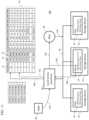
- FIG. 12is a block diagram illustrating a storage system 300 utilizing a storage bank 302 and a power distribution unit (PDU) 90 , according to some exemplary embodiments of the present invention.
- PDUpower distribution unit
- the storage bank (e.g., an Ethernet SSD chassis or Just-a-bunch-of-flashes (JBOF)) 302includes a plurality of storage devices 10
- the PDU 90includes a plurality of power supply units (PSUs or power supplies) 304 for supplying power to the storage devices 10 of the storage bank 302 under the direction of the local service processor (or BMC) 50
- the PSUs 304are interchangeable, that is, each may have the same form factor and the same power supply capacity (e.g., have same output wattage); however, embodiments of the present invention are not limited thereto, and one or more of the PSUs 304 may have a power supply capacity that is different from other PSUs 304 .
- the plurality of PSUs 304may be in an N+1 configuration in which N (an integer greater than or equal to 1) PSUs are sufficient to service the power needs of the storage bank 302 , and an additional PSU 304 is provided as redundancy, which may be activated in the event that any of the PSUs experiences a failure.
- the PSUs 304may be coupled together using a switch network (e.g., a FET network) 305 , rather than directly connected to the power bus 306 , in order to protect the power bus 306 from electrical short circuits and transients when other PSUs 304 are connected.
- the switch networkmay include a plurality of switches (e.g., transistors) that are connected to the plurality of PSUs 304 , on one end, and connected to the power bus 306 , at the other end.
- the switchesare independently controlled by the local service provider (BMC) 50 , so that ny one of the PSUs 304 may be connected to, or disconnected from, the power bus 306 , based on a control signal from the local service provider 50 .
- each storage devices 10is configured to report its actual power consumption to the local service processor 50 via, for example, SMBus or PCI-e, and by, for example, NVMe-MI or MCTP protocols.
- the actual power consumptionis measured by the PMU (i.e., power meter) 14 , which may be internal to (e.g., integrated within) the storage device 10 (as shown in FIG. 12 ) or be external to, but coupled to, the storage device 10 .
- the power consumption reportingenables the local service processor 50 to provide power profiles and perform analytics on the storage bank 302 , which can in turn be used for diagnostics as well as offering value added services. This also allows each storage device 10 to more flexibly manage its own power usage as dictated by the system administrator 308 , via the local service processor 50 .
- FIGS. 13 A- 13 Dillustrate histograms of power consumption of a storage system as generated by the local service processor 50 , according to some exemplary embodiments of the present invention.
- the local service processor 50reads the power measurements periodically from the storage devices 10 .
- local service processor 50may use NVMe-MI protocol over SMBus or PCIe to read the power log 70 pages, according to some examples.
- the local service processor 50may then process the read power data to generate power usage trends, such as whole power usage of the storage bank 302 over time (e.g., per hour, during day time, night time, weekdays, or weekends, etc.), each storage device's 10 power consumption over time, relative power consumption of the storage devices 10 in a storage bank 302 , and/or the like.
- the local service processor 50may generate many derivative/additional graphs to learn about the power consumption behavior with respect to time, user, activity, etc.
- the local service processor 50may also utilize such data for diagnostics purposes, power provisioning, future needs, cooling, and planning, etc.
- FIG. 13 Aillustrates the power consumption of a single storage device 10 over time.
- the Y axisrepresents power consumption in terms of Watts
- the X axisrepresents time in terms of hours.
- the local service processor 50manages host access policies, and receives raw power data and host IDs of active storage devices.
- the local service processor 50is cognizant/aware of which host or application is accessing each storage device 10 at any given time, and is able to combine this information with power usage metrics to profile the power consumption by various hosts or applications. Such information can provide deeper insights into storage power needs to various applications and can be used to calculate the storage costs per host or application more accurately.
- FIG. 13 Billustrates power consumption by different hosts or applications.
- the Y axisrepresents average power consumption in Watts over a period of time (e.g., per hour, day, etc.)
- the X axisrepresents the host ID or application ID.
- the local service processor 50is capable of using power usage metrics for diagnostic purposes.
- the local service processor 50may alert the storage administrator 308 .
- the abnormal power consumptionmay be a result of a fault within the storage device 10 , or may be due to anomalous activity of the host or application that is accessing the storage device 10 .
- the faultsmay be a result of flash die or flash channel failures, which may initiate RAID like recovery mechanism consuming excess power; or higher bit rate errors in the media or volatile memory, which may cause error correction algorithms not to converge and spend more time and energy on a process.
- the local service processor 50may query storage device health and status logs, such as SMART Logs, as well as proprietary diagnostic logs to assess abnormal behavior. Based on the policies set by the administrator 308 , some of the abnormal behavior may be alerted to the administrator 308 for further action.
- storage device health and status logssuch as SMART Logs, as well as proprietary diagnostic logs to assess abnormal behavior.
- FIG. 13 Cillustrates a potential fault detected in a storage device 10 when the power consumption per hour suddenly spikes about normal levels (e.g., 3-10 W/hr) to close to maximum values (e.g., around 25 W).
- the Y axisrepresents average power consumption in Watts
- the X axisrepresents time in terms of hours.
- the criterion for fault detectionmay be the derivative of power consumption being greater than a set threshold.
- the actual power consumptionmay be measured against storage device performance to determine if a fault has occurred or not.
- the fault detection criteria/policymay be set by the administrator 308 .
- FIG. 13 Dillustrates an example, in which a potential fault is detected in a storage device 10 (e.g., the storage device in slot #8).
- the storage device 10may be expected to consume a maximum power of about 25 W at 1 MIOPS (one million input/output operations per second) of performance.
- MIOPSone million input/output operations per second
- the local service processormay tag the storage device in slot #8 as potentially faulty or at least a good candidate for further fault analysis.
- aspects of the present inventionprovide the building block of crucial information for other artificial intelligence SW to analyze.
- italso provides useful information for an ADRC (active disturbance rejection control), high-efficiency, thermal-control based system to take advantage of.
- ADRCactive disturbance rejection control
- FIG. 14is flow diagram illustrating the process 400 of managing operations of the PDU 90 , according to some exemplary embodiments of the present invention.
- the local service provider 50manages (e.g., optimizes) operations of the PDU 90 by dynamically monitoring the operation of the PSUs 304 of the PDU 90 and ensuring that active PSUs 304 operate in their high power-efficiency range. In so doing, the local service provider 50 determines (S 100 ) whether the PDU 90 includes multiple active PSUs 304 or not.
- the active PSUs 304may be connected to the power bus 306 through the switch network (i.e., have the corresponding witches turned on), and the deactivated PSUs 304 may be disconnected from the power bus 306 (e.g., by having the corresponding switches turned off).
- the local service provider 50determines the status of each PSU 304 in the PDU 90 through a bus (e.g., SMBus/PMBus), and is thus able to determine the number of PSUs 304 at the PDU 90 .
- the local service provider 50reads the PSU status register of each PSU 304 present in the PDU 90 to determine its status (i.e., active/enabled or deactivated/disabled). If only one active PSU 304 is present, the local service provider 50 proceed to determine (S 114 ) if the active PSU 304 is the only one PSU 304 present and is in HA mode (more on this below).
- the local service provider 50determines (S 102 ) whether the total power consumption of the storage bank 302 is less than a first percentage threshold (e.g., 40% or a value between 30% to 50%) of the load of each of the active PSUs 304 .
- a first percentage thresholde.g., 40% or a value between 30% to 50%
- the local power processor 50does so by obtaining the actual power consumption of each storage device 10 , as measured by the corresponding PMU 14 , and adding together the actual power consumptions.
- the local service provider 50may obtain the actual power consumption of each storage device 10 by querying/retrieving the power log 70 from the storage device 10 or the PMU 14 corresponding to the storage device 10 (which may be internal to or external to the storage device 10 ).
- the local service provider 50disables an active PSU 304 (S 104 ), waits (S 106 ) for a period of time (e.g., seconds or minutes), and rechecks (S 102 ) whether the total power consumption of the storage bank 302 is still less than the first percentage threshold of the load of each of the active PSUs 304 . If so, the loop continues and the local service provider 50 continues to disable the active PSUs 304 one by one until the total power consumption is equal to or greater than the first percentage threshold of the load of each of the active PSUs 304 .
- the local service provider 50proceeds to determine (S 108 ) whether the total power consumption of the storage bank 302 is greater than a second percentage threshold (e.g., about 90% or a value between 85% and 95%) of the load of each of the active PSUs 304 . If so, the active PSUs 304 may be operating in high-power state, which may be detrimental to the longevity of the PSUs 304 if prolonged.
- a second percentage thresholde.g., about 90% or a value between 85% and 95
- the local service provider 50enables (i.e., activates) a disabled (i.e., a deactivated) PSU 304 (S 110 ), waits (S 112 ) for a period of time (e.g., seconds or minutes), and rechecks (S 108 ) whether the total power consumption of the storage bank 302 is still equal to or greater than the second percentage threshold of the load of each of the active PSUs 304 . If so, the loop continues and the local service provider 50 continues to enable the active PSUs 304 one by one until the total power consumption is less than the second percentage threshold of the load of each of the active PSUs 304 .
- the local service provider 50proceeds to determine (S 114 ) if only one PSU 304 is present in the PDU 90 while the storage system 300 is in high availability (HA) mode, which indicates multi-path 10 mode and N+1 redundant PSUs.
- HA modethe storage system 300 is in multi-path 10 mode and N+1 redundant PSUs are present to ensure that there is no single point of failure.
- the local service provider 50issues a warning (e.g., a critical warning) message (S 116 ) to the system administrator 308 to install another redundant PSU 304 in the PDU 90 . Otherwise, the system is operating normally and no warning message is sent to the system administrator 308 .
- a warninge.g., a critical warning
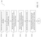
- FIG. 15is flow diagram illustrating a process 500 of managing the storage devices 10 of the storage system 300 , according to some exemplary embodiments of the present invention.
- the local service provider 50manages (e.g., optimizes) storage devices 10 by dynamically adjusting (e.g., lowering) their maximum power range or power cap based on the current workload of the storage bank 302 .
- the local service provider 50identifies (S 118 ) which storage devices 10 of the storage bank 302 are in an idle state or consume near-idle power.
- an idle statemay refer to an operational state in which a storage device 10 does not have any active or outstanding host commands such as read or write in its command queue for a period of time. That is to say that the host command queues of the storage device controller have been empty for a period of time, which may be programmable (e.g., by the system administrator 308 ).
- Near-idle powermay be any power consumption that is below a set threshold, which may be programmable (e.g., by the system administrator 308 ).
- the local power processor 50obtains the actual power consumption of each storage device 10 , which is measured by the corresponding PMU 14 , by querying/retrieving the power log 70 from the storage device 10 .
- the local service provider 50compares the actual power consumption with an idle power level. If consumed power of the storage device 10 is at or below the idle power level, the storage device is identified as being in an idle state.
- the local service provider 50then instructs (S 120 ) the identified storage devices 10 to operate at a lower power cap.
- the local service processor 50may instruct each of the identified storage devices 10 to change power states to a power state having a lower maximum power rating (e.g., change from PowerState 2 to PowerState 5). This may be done based on a power policy that is implemented by the local service provider 50 (and is, e.g., defined by the system administrator 308 ), which associates each power state to a range of actual power consumption.
- the local service provider 50identifies (S 122 ) which storage devices 10 consume power at a level less than a threshold power level.
- the thresholdmay be set at 75% of maximum power, which may be 25 W, or 75 W, etc., depending on the kind of PSUs and/or power connectors used.
- the local power processor 50obtains the actual power consumption of each storage device 10 , which is measured by the corresponding PMU 14 , by querying/retrieving the power log 70 from the storage device 10 .
- the local service provider 50compares the actual power consumption with threshold power level to determine if consumed power of the storage device 10 is below the threshold power level.
- the local service provider 50then dynamically instructs the identified storage devices 10 to operate at a power cap corresponding to the first level (e.g., at 75% or 80% of maximum power), as opposed to the default power cap of 100% maximum power.
- lowering the power cap of the storage devices 10may bring down the overall power usage of the storage bank 302 , thus allowing the PSU to operate at a lower power level and at a higher (e.g., peak) power efficiency range. This may be particularly desirable in large data centers, where overall power usage and cooling is a great concern.
- the local service provider 50may dynamically instruct each of the identified storage devices 10 to operate at a lower power cap by instructing them to change their power state to one where the maximum power corresponds to (e.g., is at or less than) the threshold power level (e.g., the power states may be changed from PowerState 0 to PowerState 1).
- the local service provider 50identifies (S 126 ) which storage device slots are empty (i.e., not occupied by, or connected to, any storage device 10 ).
- each storage device 10may have a presence pin on the slot connector 15 , which is used by the service provider 50 to determine whether the slot is empty or occupied by a storage device 10 .
- the local service provider 50instructs (S 128 ) that these PMUs 14 operate at lower power caps (e.g., operate at the lowest power state, PowerState 31 ) or disable/deactivate altogether. This will allow the storage bank 302 to eliminate or reduce unnecessary power usage.
- operations S 118 -S 120 , S 122 -S 124 , and S 126 -S 128are ordered in a particular sequence in FIG. 15 , embodiments of the present invention are not limited thereto.
- the operations S 118 -S 120can be performed after either or both of operations S 122 -S 124 and S 126 -S 128
- operations S 126 -S 128may be performed before either or both of operations S 118 -S 120 and S 122 -S 124 .
- the operations performed by the local service provider 50may be described in terms of a software routine executed by one or more processors in the local service provider 50 based on computer program instructions stored in memory.
- the routinemay be executed via hardware, firmware (e.g. via an ASIC), or in combination of software, firmware, and/or hardware.
- the sequence of steps of the processis not fixed, but may be altered into any desired sequence as recognized by a person of skill in the art.
Landscapes
- Engineering & Computer Science (AREA)
- Theoretical Computer Science (AREA)
- General Engineering & Computer Science (AREA)
- Physics & Mathematics (AREA)
- General Physics & Mathematics (AREA)
- Computing Systems (AREA)
- Quality & Reliability (AREA)
- Computer Hardware Design (AREA)
- Mathematical Physics (AREA)
- Human Computer Interaction (AREA)
- Power Sources (AREA)
- Power Engineering (AREA)
Abstract
Description
Claims (17)
Priority Applications (1)
| Application Number | Priority Date | Filing Date | Title |
|---|---|---|---|
| US17/112,933US12222791B2 (en) | 2018-03-02 | 2020-12-04 | Method and apparatus for performing power analytics of a storage system |
Applications Claiming Priority (5)
| Application Number | Priority Date | Filing Date | Title |
|---|---|---|---|
| US201862638035P | 2018-03-02 | 2018-03-02 | |
| US15/975,463US11481016B2 (en) | 2018-03-02 | 2018-05-09 | Method and apparatus for self-regulating power usage and power consumption in ethernet SSD storage systems |
| US201862713466P | 2018-08-01 | 2018-08-01 | |
| US16/167,306US11500439B2 (en) | 2018-03-02 | 2018-10-22 | Method and apparatus for performing power analytics of a storage system |
| US17/112,933US12222791B2 (en) | 2018-03-02 | 2020-12-04 | Method and apparatus for performing power analytics of a storage system |
Related Parent Applications (1)
| Application Number | Title | Priority Date | Filing Date |
|---|---|---|---|
| US16/167,306DivisionUS11500439B2 (en) | 2018-03-02 | 2018-10-22 | Method and apparatus for performing power analytics of a storage system |
Publications (2)
| Publication Number | Publication Date |
|---|---|
| US20210089102A1 US20210089102A1 (en) | 2021-03-25 |
| US12222791B2true US12222791B2 (en) | 2025-02-11 |
Family
ID=67768612
Family Applications (4)
| Application Number | Title | Priority Date | Filing Date |
|---|---|---|---|
| US16/167,306ActiveUS11500439B2 (en) | 2018-03-02 | 2018-10-22 | Method and apparatus for performing power analytics of a storage system |
| US17/112,933ActiveUS12222791B2 (en) | 2018-03-02 | 2020-12-04 | Method and apparatus for performing power analytics of a storage system |
| US17/233,303ActiveUS12204395B2 (en) | 2018-03-02 | 2021-04-16 | Method and apparatus for performing power analytics of a storage system |
| US18/055,331AbandonedUS20230071775A1 (en) | 2018-03-02 | 2022-11-14 | Method and apparatus for performing power analytics of a storage system |
Family Applications Before (1)
| Application Number | Title | Priority Date | Filing Date |
|---|---|---|---|
| US16/167,306ActiveUS11500439B2 (en) | 2018-03-02 | 2018-10-22 | Method and apparatus for performing power analytics of a storage system |
Family Applications After (2)
| Application Number | Title | Priority Date | Filing Date |
|---|---|---|---|
| US17/233,303ActiveUS12204395B2 (en) | 2018-03-02 | 2021-04-16 | Method and apparatus for performing power analytics of a storage system |
| US18/055,331AbandonedUS20230071775A1 (en) | 2018-03-02 | 2022-11-14 | Method and apparatus for performing power analytics of a storage system |
Country Status (3)
| Country | Link |
|---|---|
| US (4) | US11500439B2 (en) |
| KR (1) | KR102385766B1 (en) |
| CN (2) | CN119988128A (en) |
Families Citing this family (19)
| Publication number | Priority date | Publication date | Assignee | Title |
|---|---|---|---|---|
| JP6919538B2 (en)* | 2017-12-05 | 2021-08-18 | 富士通株式会社 | Power control system and power control program |
| US11481016B2 (en) | 2018-03-02 | 2022-10-25 | Samsung Electronics Co., Ltd. | Method and apparatus for self-regulating power usage and power consumption in ethernet SSD storage systems |
| US11500439B2 (en) | 2018-03-02 | 2022-11-15 | Samsung Electronics Co., Ltd. | Method and apparatus for performing power analytics of a storage system |
| US10983852B2 (en)* | 2019-01-30 | 2021-04-20 | Micron Technology, Inc. | Power management component for memory sub-system voltage regulation |
| US11334135B1 (en)* | 2019-03-28 | 2022-05-17 | Amazon Technologies, Inc. | Power supply optimization using backup battery power supplementation |
| US11449245B2 (en)* | 2019-06-13 | 2022-09-20 | Western Digital Technologies, Inc. | Power target calibration for controlling drive-to-drive performance variations in solid state drives (SSDs) |
| US11050294B1 (en) | 2019-06-28 | 2021-06-29 | Amazon Technologies, Inc. | Power supply shedding for power efficiency optimization |
| US11314315B2 (en) | 2020-01-17 | 2022-04-26 | Samsung Electronics Co., Ltd. | Performance control of a device with a power metering unit (PMU) |
| CN111309132B (en)* | 2020-02-21 | 2021-10-29 | 苏州浪潮智能科技有限公司 | A method for server multi-level power supply redundancy |
| US11977425B2 (en)* | 2021-01-29 | 2024-05-07 | Astrodyne TDI | Highly adaptable power system |
| US11592894B2 (en)* | 2021-04-12 | 2023-02-28 | Dell Products L.P. | Increasing power efficiency for an information handling system |
| JP7535663B2 (en)* | 2021-06-01 | 2024-08-16 | 長江存儲科技有限責任公司 | Memory System Power Management |
| CN113504823A (en)* | 2021-06-16 | 2021-10-15 | 新华三信息安全技术有限公司 | Method and device for reducing power consumption of frame type communication equipment |
| US12045468B2 (en) | 2021-11-12 | 2024-07-23 | Samsung Electronics Co., Ltd. | Storage devices configured to obtain data of external devices for debugging |
| TW202324096A (en)* | 2021-11-12 | 2023-06-16 | 南韓商三星電子股份有限公司 | Storage device |
| US12093538B2 (en)* | 2022-04-12 | 2024-09-17 | Dell Products L.P. | Selective powering of storage drive components in a storage node based on system performance limits |
| JP2024033475A (en)* | 2022-08-30 | 2024-03-13 | 株式会社日立製作所 | storage system |
| US20240329724A1 (en)* | 2023-03-31 | 2024-10-03 | Lenovo Enterprise Solutions (Singapore) Pte Ltd. | Operating a voltage regulator at peak efficiency |
| US12307224B2 (en)* | 2023-06-14 | 2025-05-20 | International Business Machines Corporation | Cross-layer power optimization of program code and/or software architecture |
Citations (102)
| Publication number | Priority date | Publication date | Assignee | Title |
|---|---|---|---|---|
| US20030088798A1 (en) | 1998-06-26 | 2003-05-08 | Kenichiro Ono | System having devices connected via communication lines |
| US6574740B1 (en)* | 1998-12-07 | 2003-06-03 | International Business Machines Corporation | Dynamic power consumption control for a computer or other electronic apparatus |
| US6785827B2 (en) | 2000-11-29 | 2004-08-31 | Dell Products L.P. | System for determining servers power supply requirement by sampling power usage values thereof at a rate based upon the criticality of its availability |
| US20040215912A1 (en) | 2003-04-24 | 2004-10-28 | George Vergis | Method and apparatus to establish, report and adjust system memory usage |
| US20050102544A1 (en)* | 2003-11-10 | 2005-05-12 | Dell Products L.P. | System and method for throttling power in one or more information handling systems |
| US20050268121A1 (en)* | 2004-05-26 | 2005-12-01 | Intel Corporation | Power management of storage units in a storage array |
| US7064994B1 (en)* | 2004-01-30 | 2006-06-20 | Sun Microsystems, Inc. | Dynamic memory throttling for power and thermal limitations |
| US20060149975A1 (en) | 2004-12-30 | 2006-07-06 | Intel Corporation | Operating point management in multi-core architectures |
| US20060288241A1 (en)* | 2005-06-16 | 2006-12-21 | Felter Wesley M | Performance conserving method for reducing power consumption in a server system |
| CN1887003A (en) | 2003-12-19 | 2006-12-27 | 艾利森电话股份有限公司 | Adaptive power supply management for a node of a mobile telecommunications network |
| US20070028130A1 (en) | 2005-07-29 | 2007-02-01 | Schumacher Derek S | Power budgeting for computers |
| US20070067657A1 (en)* | 2005-09-22 | 2007-03-22 | Parthasarathy Ranganathan | Power consumption management among compute nodes |
| US7269751B2 (en) | 2003-07-29 | 2007-09-11 | Hewlett-Packard Development Company, L.P. | Supplying power to at least one electrical device based on an efficient operating point of a power supply |
| US20080043556A1 (en) | 2006-08-01 | 2008-02-21 | Nale William H | Dynamic power control of a memory device thermal sensor |
| US20080147918A1 (en) | 2006-12-19 | 2008-06-19 | Hanebutte Ulf R | Method and apparatus for maintaining synchronization of audio in a computing system |
| US7426597B1 (en) | 2003-05-07 | 2008-09-16 | Nvidia Corporation | Apparatus, system, and method for bus link width optimization of a graphics system |
| US20080320322A1 (en) | 2007-06-25 | 2008-12-25 | Green Alan M | Dynamic Converter Control for Efficient Operation |
| US7539881B2 (en)* | 2006-04-15 | 2009-05-26 | Hewlett-Packard Development Company, L.P. | System and method for dynamically adjusting power caps for electronic components based on power consumption |
| CN101477399A (en) | 2007-12-28 | 2009-07-08 | 英特尔公司 | Power management in electronic systems |
| US20090287947A1 (en)* | 2008-05-13 | 2009-11-19 | Igo, Inc. | Circuit and method for ultra-low idle power |
| US20100019576A1 (en) | 2008-07-24 | 2010-01-28 | International Business Machines Corporation | Dynamically Configuring Current Sharing And Fault Monitoring In Redundant Power Supply Modules |
| US20100077243A1 (en) | 2008-09-25 | 2010-03-25 | Ren Wang | Conserving power in a computer system |
| US20100153590A1 (en) | 2007-09-17 | 2010-06-17 | Chih-Fan Hsin | Dma (direct memory access) coalescing |
| US20100164292A1 (en) | 2008-12-30 | 2010-07-01 | International Business Machines Corporation | Apparatus, system, and method for reducing power consumption on devices with multiple power supplies |
| US20100264741A1 (en) | 2009-04-17 | 2010-10-21 | Radhakrishna Togare | Adaptation of an active power supply set using an event trigger |
| US20110029788A1 (en) | 2009-07-31 | 2011-02-03 | Domingo Reynaldo P | Power Limiting In Redundant Power Supply Systems |
| US20110144818A1 (en)* | 2009-12-14 | 2011-06-16 | Cong Li | Method and apparatus for dynamically allocating power in a data center |
| US20110178652A1 (en)* | 2010-01-15 | 2011-07-21 | International Business Machines Corporation | Dynamically Adjusting an Operating State of a Data Processing System Running Under a Power Cap |
| US8051316B2 (en) | 2008-06-09 | 2011-11-01 | Dell Products L.P. | System and method for managing power supply units |
| CN102290854A (en) | 2011-07-01 | 2011-12-21 | 创新科存储技术(深圳)有限公司 | Method and device for performing state control on redundant power module |
| US20120030489A1 (en) | 2010-07-27 | 2012-02-02 | Sanjay Bhagwan Patil | Power supply control within an integrated circuit |
| US20120117399A1 (en) | 2010-11-04 | 2012-05-10 | International Business Machines Corporation | Saving power by managing the state of inactive computing devices |
| US20120137172A1 (en) | 2010-11-30 | 2012-05-31 | International Business Machines Corporation | Balancing power consumption and high availability in an information technology system |
| US20120210149A1 (en)* | 2011-02-10 | 2012-08-16 | International Business Machines Corporation | Techniques for performing storage power management |
| US20120303993A1 (en) | 2011-05-26 | 2012-11-29 | Cisco Technology, Inc. | Method and apparatus for improved power efficiency for server platforms |
| US20130085623A1 (en) | 2011-09-29 | 2013-04-04 | International Business Machines Corporation | Power supply device and control method therefor |
| US20130185583A1 (en) | 2011-01-28 | 2013-07-18 | Christopher H. Stewart | Distributing information |
| JP2013257650A (en) | 2012-06-11 | 2013-12-26 | Nec Corp | Input-output control device, storage system, power control method, and computer program |
| US20140003180A1 (en)* | 2012-06-29 | 2014-01-02 | Fujitsu Limited | Storage device, connection device, and storage control method |
| US20140101475A1 (en)* | 2012-10-08 | 2014-04-10 | Dell Products L.P. | Power management system |
| US20140100706A1 (en) | 2012-10-05 | 2014-04-10 | Dell Products L.P. | Power system utilizing processor core performance state control |
| US20140149760A1 (en)* | 2012-11-27 | 2014-05-29 | International Business Machines Corporation | Distributed power budgeting |
| US20140181560A1 (en) | 2012-12-26 | 2014-06-26 | Rajeev D. Muralidhar | Platform power consumption reduction via power state switching |
| US20140208136A1 (en) | 2013-01-21 | 2014-07-24 | Dell Products L.P. | Systems And Methods For Power Supply Configuration And Control |
| US20140281606A1 (en)* | 2013-03-15 | 2014-09-18 | Silicon Graphics International Corp. | Data storage power consumption threshold |
| US20140344947A1 (en) | 2013-05-20 | 2014-11-20 | Advanced Micro Devices, Inc. | Method and apparatus for handling storage of context information |
| US20150026495A1 (en) | 2013-07-18 | 2015-01-22 | Qualcomm Incorporated | System and method for idle state optimization in a multi-processor system on a chip |
| US20150120874A1 (en) | 2013-10-25 | 2015-04-30 | Samsung Electronics Co., Ltd | Server system and storage system |
| US20150121113A1 (en) | 2013-10-28 | 2015-04-30 | Virtual Power Systems, Inc. | Energy control via power requirement analysis and power source enablement |
| US20150177814A1 (en) | 2013-12-23 | 2015-06-25 | Dell, Inc. | Predictive power capping and power allocation to computing nodes in a rack-based information handling system |
| US20150200566A1 (en) | 2014-01-10 | 2015-07-16 | Zippy Technology Corp. | Redundant power supply system for reducing standby power consumption |
| CN104798004A (en) | 2012-12-21 | 2015-07-22 | 英特尔公司 | Control bias based on power balance, dynamic power balancing across multiple processor domains |
| US20150249363A1 (en) | 2012-09-27 | 2015-09-03 | Hewlett-Packard Development Company, L.P. | Balancing a load between power supplies to increase efficiency |
| US20150261287A1 (en) | 2014-03-13 | 2015-09-17 | Fujitsu Limited | Consumed electric power analyzing apparatus, method for analyzing consumed electric power, and non-transitory computer-readable recording medium having stored therein consumed electric power analyzing program |
| CN104951384A (en) | 2015-06-16 | 2015-09-30 | 浪潮电子信息产业股份有限公司 | Monitoring system based on NVME SSD, substrate management controller and monitoring method |
| US20150309752A1 (en)* | 2014-04-29 | 2015-10-29 | Sandisk Enterprise Ip Llc | Storage System Power Management Using Controlled Execution of Pending Memory Commands |
| US20150331473A1 (en) | 2014-05-15 | 2015-11-19 | Dell Products, L.P. | NON-VOLATILE MEMORY EXPRESS (NVMe) DEVICE POWER MANAGEMENT |
| US20150338910A1 (en)* | 2014-05-23 | 2015-11-26 | International Business Machines Corporation | Dynamic Power and Thermal Capping for Flash Storage |
| US20150347325A1 (en) | 2014-05-28 | 2015-12-03 | SanDisk Technologies, Inc. | Obtaining diagnostic information through host interfaces |
| US20150355704A1 (en) | 2013-03-14 | 2015-12-10 | Knut S. Grimsrud | Method for reducing power consumption in solid-state storage device |
| US20150362985A1 (en)* | 2014-06-11 | 2015-12-17 | Eldon Technology Limited | Systems and methods for facilitating device control, device protection, and power savings |
| US20160014045A1 (en) | 2013-02-26 | 2016-01-14 | Kyocera Corporation | Transmission apparatus and transmission method |
| CN105359057A (en) | 2013-09-18 | 2016-02-24 | 联想企业解决方案(新加坡)有限公司 | Setting computer parameters to operate the power supply within a range based on a peak power efficiency of the power supply |
| US20160085288A1 (en)* | 2014-09-22 | 2016-03-24 | HGST Netherlands B.V. | Data storage devices with performance-aware power capping |
| CN105487814A (en) | 2014-09-22 | 2016-04-13 | Hgst荷兰公司 | Performance-aware power capping control of data storage devices |
| KR20160059430A (en) | 2014-11-18 | 2016-05-26 | 에이취지에스티 네덜란드 비.브이. | Resource allocation and deallocation for power management in devices |
| US20160179117A1 (en) | 2014-12-23 | 2016-06-23 | Intel Corporation | Systems and methods for dynamic temporal power steering |
| US20160282892A1 (en) | 2015-03-25 | 2016-09-29 | Cisco Technology, Inc. | Power Distribution Management |
| US20160370843A1 (en) | 2015-06-16 | 2016-12-22 | Dell Products, Lp | Method and Apparatus for Customized Energy Policy based on Energy Demand Estimation for Client Systems |
| US20160378631A1 (en) | 2015-06-25 | 2016-12-29 | International Business Machines Corporation | Validating power paths to it equipment |
| US20170011150A1 (en) | 2012-11-06 | 2017-01-12 | Cenergistic Llc | Adjustment simulation method for energy consumption |
| US20170031409A1 (en)* | 2015-07-28 | 2017-02-02 | HGST Netherlands B.V. | Enhanced power control of data storage arrays |
| US20170031431A1 (en)* | 2015-08-02 | 2017-02-02 | Dell Products, L.P. | Dynamic peak power limiting to processing nodes in an information handling system |
| US20170031857A1 (en) | 2014-09-12 | 2017-02-02 | Huawei Technologies Co., Ltd. | Device Management Method and Apparatus |
| US9652027B2 (en) | 2015-04-01 | 2017-05-16 | Microsoft Technology Licensing, Llc | Thread scheduling based on performance state and idle state of processing units |
| US20170160781A1 (en)* | 2015-12-04 | 2017-06-08 | Advanced Micro Devices, Inc. | Balancing computation and communication power in power constrained clusters |
| US20170177262A1 (en)* | 2015-12-22 | 2017-06-22 | Intel Corporation | Technologies for managing an operational characteristic of a solid state drive |
| US20170187186A1 (en) | 2014-09-15 | 2017-06-29 | Sma Solar Technology Ag | Method and apparatus for the operation of a power station of fluctuating performance connected, besides a system former and at least one load, to a limited ac system |
| US20170235519A1 (en) | 2014-12-31 | 2017-08-17 | Huawei Technologies Co., Ltd. | Device Management Method, Device, and Device Management Controller |
| US20170315599A1 (en) | 2016-05-02 | 2017-11-02 | Samsung Electronics Co., Ltd. | Ssd driven system level thermal management |
| US20170322613A1 (en) | 2016-05-06 | 2017-11-09 | Quanta Computer Inc. | Server rack power management |
| US20180107258A1 (en)* | 2016-10-17 | 2018-04-19 | Lenovo Enterprise Solutions (Singapore) Pte. Ltd. | Power delivery optimization based on system capability |
| US20180232303A1 (en) | 2017-02-16 | 2018-08-16 | Hyperstone Gmbh | Method and Apparatus for Controlling a Non-Volatile Digital Information Memory |
| US20190018611A1 (en) | 2017-07-17 | 2019-01-17 | SK Hynix Inc. | Memory system and method of operating the same |
| US20190018474A1 (en)* | 2015-12-21 | 2019-01-17 | Hewlett Packard Enterprise Development Lp | Memory throttling |
| US20190065089A1 (en) | 2017-08-31 | 2019-02-28 | Micron Technology, Inc. | Memory device with power management |
| US20190065243A1 (en) | 2016-09-19 | 2019-02-28 | Advanced Micro Devices, Inc. | Dynamic memory power capping with criticality awareness |
| US10324642B2 (en)* | 2013-06-07 | 2019-06-18 | Sanmina Corporation | Peripheral component interconnect express (PCIe) solid state drive (SSD) accelerator |
| US20190196742A1 (en) | 2017-12-21 | 2019-06-27 | Advanced Micro Devices, Inc. | Extreme-bandwidth scalable performance-per-watt gpu architecture |
| US20190214829A1 (en) | 2018-01-06 | 2019-07-11 | Aic Inc. | Power-outputting management method for power-supplying apparatus |
| US20190272012A1 (en) | 2018-03-02 | 2019-09-05 | Samsung Electronics Co., Ltd. | Method and apparatus for performing power analytics of a storage system |
| US20190272021A1 (en) | 2018-03-02 | 2019-09-05 | Samsung Electronics Co., Ltd. | Method and apparatus for self-regulating power usage and power consumption in ethernet ssd storage systems |
| US10424938B2 (en) | 2013-11-15 | 2019-09-24 | Boe Technology Group Co., Ltd. | Power supply system |
| US20190310786A1 (en) | 2018-03-06 | 2019-10-10 | Western Digital Technologies, Inc. | Energy optimized power state declarations for solid state drives |
| US20200125159A1 (en) | 2018-10-22 | 2020-04-23 | Dell Products L.P. | System and Method of Managing Throttling of Information Handling Systems |
| US20200310886A1 (en)* | 2019-03-27 | 2020-10-01 | International Business Machines Corporation | Cloud data center with reduced energy consumption |
| US20200333870A1 (en)* | 2018-01-24 | 2020-10-22 | Western Digital Technologies, Inc. | Low Power State Staging |
| US20210026428A1 (en)* | 2019-07-26 | 2021-01-28 | Samsung Electronics Co., Ltd. | Systems, methods, and devices for providing power to devices through connectors |
| US20210223851A1 (en)* | 2020-01-17 | 2021-07-22 | Samsung Electronics Co., Ltd. | Performance control of a device with a power metering unit (pmu) |
| US11093135B1 (en)* | 2019-04-11 | 2021-08-17 | Seagate Technology Llc | Drive performance, power, and temperature management |
| US20220229483A1 (en) | 2021-01-20 | 2022-07-21 | Dell Products, Lp | System and method for closed-loop memory power capping |
| US20230161494A1 (en)* | 2021-11-24 | 2023-05-25 | Western Digital Technologies, Inc. | Selective Device Power State Recovery Method |
- 2018
- 2018-10-22USUS16/167,306patent/US11500439B2/enactiveActive
- 2019
- 2019-01-08KRKR1020190002496Apatent/KR102385766B1/enactiveActive
- 2019-03-04CNCN202411949371.4Apatent/CN119988128A/enactivePending
- 2019-03-04CNCN201910159333.1Apatent/CN110221946B/enactiveActive
- 2020
- 2020-12-04USUS17/112,933patent/US12222791B2/enactiveActive
- 2021
- 2021-04-16USUS17/233,303patent/US12204395B2/enactiveActive
- 2022
- 2022-11-14USUS18/055,331patent/US20230071775A1/ennot_activeAbandoned
Patent Citations (116)
| Publication number | Priority date | Publication date | Assignee | Title |
|---|---|---|---|---|
| US20030088798A1 (en) | 1998-06-26 | 2003-05-08 | Kenichiro Ono | System having devices connected via communication lines |
| US6574740B1 (en)* | 1998-12-07 | 2003-06-03 | International Business Machines Corporation | Dynamic power consumption control for a computer or other electronic apparatus |
| US6785827B2 (en) | 2000-11-29 | 2004-08-31 | Dell Products L.P. | System for determining servers power supply requirement by sampling power usage values thereof at a rate based upon the criticality of its availability |
| US20040215912A1 (en) | 2003-04-24 | 2004-10-28 | George Vergis | Method and apparatus to establish, report and adjust system memory usage |
| KR20060009264A (en) | 2003-04-24 | 2006-01-31 | 인텔 코오퍼레이션 | Method and apparatus for establishing, reporting, and adjusting system memory usage |
| US7426597B1 (en) | 2003-05-07 | 2008-09-16 | Nvidia Corporation | Apparatus, system, and method for bus link width optimization of a graphics system |
| US7269751B2 (en) | 2003-07-29 | 2007-09-11 | Hewlett-Packard Development Company, L.P. | Supplying power to at least one electrical device based on an efficient operating point of a power supply |
| US20050102544A1 (en)* | 2003-11-10 | 2005-05-12 | Dell Products L.P. | System and method for throttling power in one or more information handling systems |
| US7904115B2 (en) | 2003-12-19 | 2011-03-08 | Telefonaktiebolaget L M Ericsson (Publ) | Adaptive power management for a node of a mobile telecommunications network |
| CN1887003A (en) | 2003-12-19 | 2006-12-27 | 艾利森电话股份有限公司 | Adaptive power supply management for a node of a mobile telecommunications network |
| US7064994B1 (en)* | 2004-01-30 | 2006-06-20 | Sun Microsystems, Inc. | Dynamic memory throttling for power and thermal limitations |
| US20050268121A1 (en)* | 2004-05-26 | 2005-12-01 | Intel Corporation | Power management of storage units in a storage array |
| US20060149975A1 (en) | 2004-12-30 | 2006-07-06 | Intel Corporation | Operating point management in multi-core architectures |
| US20060288241A1 (en)* | 2005-06-16 | 2006-12-21 | Felter Wesley M | Performance conserving method for reducing power consumption in a server system |
| US20070028130A1 (en) | 2005-07-29 | 2007-02-01 | Schumacher Derek S | Power budgeting for computers |
| US20070067657A1 (en)* | 2005-09-22 | 2007-03-22 | Parthasarathy Ranganathan | Power consumption management among compute nodes |
| US7539881B2 (en)* | 2006-04-15 | 2009-05-26 | Hewlett-Packard Development Company, L.P. | System and method for dynamically adjusting power caps for electronic components based on power consumption |
| US20080043556A1 (en) | 2006-08-01 | 2008-02-21 | Nale William H | Dynamic power control of a memory device thermal sensor |
| US20080147918A1 (en) | 2006-12-19 | 2008-06-19 | Hanebutte Ulf R | Method and apparatus for maintaining synchronization of audio in a computing system |
| US20080320322A1 (en) | 2007-06-25 | 2008-12-25 | Green Alan M | Dynamic Converter Control for Efficient Operation |
| US20100153590A1 (en) | 2007-09-17 | 2010-06-17 | Chih-Fan Hsin | Dma (direct memory access) coalescing |
| CN101477399A (en) | 2007-12-28 | 2009-07-08 | 英特尔公司 | Power management in electronic systems |
| US7971084B2 (en) | 2007-12-28 | 2011-06-28 | Intel Corporation | Power management in electronic systems |
| US20090287947A1 (en)* | 2008-05-13 | 2009-11-19 | Igo, Inc. | Circuit and method for ultra-low idle power |
| US8051316B2 (en) | 2008-06-09 | 2011-11-01 | Dell Products L.P. | System and method for managing power supply units |
| US20100019576A1 (en) | 2008-07-24 | 2010-01-28 | International Business Machines Corporation | Dynamically Configuring Current Sharing And Fault Monitoring In Redundant Power Supply Modules |
| US20100077243A1 (en) | 2008-09-25 | 2010-03-25 | Ren Wang | Conserving power in a computer system |
| US20100164292A1 (en) | 2008-12-30 | 2010-07-01 | International Business Machines Corporation | Apparatus, system, and method for reducing power consumption on devices with multiple power supplies |
| US20100264741A1 (en) | 2009-04-17 | 2010-10-21 | Radhakrishna Togare | Adaptation of an active power supply set using an event trigger |
| US20110029788A1 (en) | 2009-07-31 | 2011-02-03 | Domingo Reynaldo P | Power Limiting In Redundant Power Supply Systems |
| US20110144818A1 (en)* | 2009-12-14 | 2011-06-16 | Cong Li | Method and apparatus for dynamically allocating power in a data center |
| US20110178652A1 (en)* | 2010-01-15 | 2011-07-21 | International Business Machines Corporation | Dynamically Adjusting an Operating State of a Data Processing System Running Under a Power Cap |
| US20120030489A1 (en) | 2010-07-27 | 2012-02-02 | Sanjay Bhagwan Patil | Power supply control within an integrated circuit |
| US20120117399A1 (en) | 2010-11-04 | 2012-05-10 | International Business Machines Corporation | Saving power by managing the state of inactive computing devices |
| US20120137172A1 (en) | 2010-11-30 | 2012-05-31 | International Business Machines Corporation | Balancing power consumption and high availability in an information technology system |
| US20130185583A1 (en) | 2011-01-28 | 2013-07-18 | Christopher H. Stewart | Distributing information |
| US20120210149A1 (en)* | 2011-02-10 | 2012-08-16 | International Business Machines Corporation | Techniques for performing storage power management |
| US20120303993A1 (en) | 2011-05-26 | 2012-11-29 | Cisco Technology, Inc. | Method and apparatus for improved power efficiency for server platforms |
| CN102290854A (en) | 2011-07-01 | 2011-12-21 | 创新科存储技术(深圳)有限公司 | Method and device for performing state control on redundant power module |
| US20130085623A1 (en) | 2011-09-29 | 2013-04-04 | International Business Machines Corporation | Power supply device and control method therefor |
| JP2013257650A (en) | 2012-06-11 | 2013-12-26 | Nec Corp | Input-output control device, storage system, power control method, and computer program |
| US20140003180A1 (en)* | 2012-06-29 | 2014-01-02 | Fujitsu Limited | Storage device, connection device, and storage control method |
| US20150249363A1 (en) | 2012-09-27 | 2015-09-03 | Hewlett-Packard Development Company, L.P. | Balancing a load between power supplies to increase efficiency |
| US20140100706A1 (en) | 2012-10-05 | 2014-04-10 | Dell Products L.P. | Power system utilizing processor core performance state control |
| US20140101475A1 (en)* | 2012-10-08 | 2014-04-10 | Dell Products L.P. | Power management system |
| US20170011150A1 (en) | 2012-11-06 | 2017-01-12 | Cenergistic Llc | Adjustment simulation method for energy consumption |
| US20140149760A1 (en)* | 2012-11-27 | 2014-05-29 | International Business Machines Corporation | Distributed power budgeting |
| US9235252B2 (en) | 2012-12-21 | 2016-01-12 | Intel Corporation | Dynamic balancing of power across a plurality of processor domains according to power policy control bias |
| CN104798004A (en) | 2012-12-21 | 2015-07-22 | 英特尔公司 | Control bias based on power balance, dynamic power balancing across multiple processor domains |
| US20140181560A1 (en) | 2012-12-26 | 2014-06-26 | Rajeev D. Muralidhar | Platform power consumption reduction via power state switching |
| US20140208136A1 (en) | 2013-01-21 | 2014-07-24 | Dell Products L.P. | Systems And Methods For Power Supply Configuration And Control |
| US20160014045A1 (en) | 2013-02-26 | 2016-01-14 | Kyocera Corporation | Transmission apparatus and transmission method |
| US20150355704A1 (en) | 2013-03-14 | 2015-12-10 | Knut S. Grimsrud | Method for reducing power consumption in solid-state storage device |
| US20140281606A1 (en)* | 2013-03-15 | 2014-09-18 | Silicon Graphics International Corp. | Data storage power consumption threshold |
| US20140344947A1 (en) | 2013-05-20 | 2014-11-20 | Advanced Micro Devices, Inc. | Method and apparatus for handling storage of context information |
| US10324642B2 (en)* | 2013-06-07 | 2019-06-18 | Sanmina Corporation | Peripheral component interconnect express (PCIe) solid state drive (SSD) accelerator |
| US20150026495A1 (en) | 2013-07-18 | 2015-01-22 | Qualcomm Incorporated | System and method for idle state optimization in a multi-processor system on a chip |
| US9292064B2 (en) | 2013-09-18 | 2016-03-22 | Lenovo Enterprise Solutions (Singapore) Pte. Ltd. | Changing output power to be within a range based on a power use efficiency peak |
| CN105359057A (en) | 2013-09-18 | 2016-02-24 | 联想企业解决方案(新加坡)有限公司 | Setting computer parameters to operate the power supply within a range based on a peak power efficiency of the power supply |
| US20150120874A1 (en) | 2013-10-25 | 2015-04-30 | Samsung Electronics Co., Ltd | Server system and storage system |
| US20150121113A1 (en) | 2013-10-28 | 2015-04-30 | Virtual Power Systems, Inc. | Energy control via power requirement analysis and power source enablement |
| US10424938B2 (en) | 2013-11-15 | 2019-09-24 | Boe Technology Group Co., Ltd. | Power supply system |
| US20150177814A1 (en) | 2013-12-23 | 2015-06-25 | Dell, Inc. | Predictive power capping and power allocation to computing nodes in a rack-based information handling system |
| US20150200566A1 (en) | 2014-01-10 | 2015-07-16 | Zippy Technology Corp. | Redundant power supply system for reducing standby power consumption |
| JP2015175630A (en) | 2014-03-13 | 2015-10-05 | 富士通株式会社 | Power consumption analyzer, power consumption analysis method, and power consumption analysis program |
| US20150261287A1 (en) | 2014-03-13 | 2015-09-17 | Fujitsu Limited | Consumed electric power analyzing apparatus, method for analyzing consumed electric power, and non-transitory computer-readable recording medium having stored therein consumed electric power analyzing program |
| US20150309752A1 (en)* | 2014-04-29 | 2015-10-29 | Sandisk Enterprise Ip Llc | Storage System Power Management Using Controlled Execution of Pending Memory Commands |
| US9477295B2 (en) | 2014-05-15 | 2016-10-25 | Dell Products, L.P. | Non-volatile memory express (NVMe) device power management |
| US20150331473A1 (en) | 2014-05-15 | 2015-11-19 | Dell Products, L.P. | NON-VOLATILE MEMORY EXPRESS (NVMe) DEVICE POWER MANAGEMENT |
| US20150338910A1 (en)* | 2014-05-23 | 2015-11-26 | International Business Machines Corporation | Dynamic Power and Thermal Capping for Flash Storage |
| US20150347325A1 (en) | 2014-05-28 | 2015-12-03 | SanDisk Technologies, Inc. | Obtaining diagnostic information through host interfaces |
| US20150362985A1 (en)* | 2014-06-11 | 2015-12-17 | Eldon Technology Limited | Systems and methods for facilitating device control, device protection, and power savings |
| US20170031857A1 (en) | 2014-09-12 | 2017-02-02 | Huawei Technologies Co., Ltd. | Device Management Method and Apparatus |
| US20170187186A1 (en) | 2014-09-15 | 2017-06-29 | Sma Solar Technology Ag | Method and apparatus for the operation of a power station of fluctuating performance connected, besides a system former and at least one load, to a limited ac system |
| CN105487814A (en) | 2014-09-22 | 2016-04-13 | Hgst荷兰公司 | Performance-aware power capping control of data storage devices |
| US20160085288A1 (en)* | 2014-09-22 | 2016-03-24 | HGST Netherlands B.V. | Data storage devices with performance-aware power capping |
| US10146293B2 (en) | 2014-09-22 | 2018-12-04 | Western Digital Technologies, Inc. | Performance-aware power capping control of data storage devices |
| KR20160059430A (en) | 2014-11-18 | 2016-05-26 | 에이취지에스티 네덜란드 비.브이. | Resource allocation and deallocation for power management in devices |
| US9417961B2 (en) | 2014-11-18 | 2016-08-16 | HGST Netherlands B.V. | Resource allocation and deallocation for power management in devices |
| US20160179117A1 (en) | 2014-12-23 | 2016-06-23 | Intel Corporation | Systems and methods for dynamic temporal power steering |
| US20170235519A1 (en) | 2014-12-31 | 2017-08-17 | Huawei Technologies Co., Ltd. | Device Management Method, Device, and Device Management Controller |
| US20160282892A1 (en) | 2015-03-25 | 2016-09-29 | Cisco Technology, Inc. | Power Distribution Management |
| US9652027B2 (en) | 2015-04-01 | 2017-05-16 | Microsoft Technology Licensing, Llc | Thread scheduling based on performance state and idle state of processing units |
| US20160370843A1 (en) | 2015-06-16 | 2016-12-22 | Dell Products, Lp | Method and Apparatus for Customized Energy Policy based on Energy Demand Estimation for Client Systems |
| CN104951384A (en) | 2015-06-16 | 2015-09-30 | 浪潮电子信息产业股份有限公司 | Monitoring system based on NVME SSD, substrate management controller and monitoring method |
| US20160378631A1 (en) | 2015-06-25 | 2016-12-29 | International Business Machines Corporation | Validating power paths to it equipment |
| US20170031409A1 (en)* | 2015-07-28 | 2017-02-02 | HGST Netherlands B.V. | Enhanced power control of data storage arrays |
| US20170031431A1 (en)* | 2015-08-02 | 2017-02-02 | Dell Products, L.P. | Dynamic peak power limiting to processing nodes in an information handling system |
| US10268262B2 (en)* | 2015-08-02 | 2019-04-23 | Dell Products, L.P. | Dynamic peak power limiting to processing nodes in an information handling system |
| US20170160781A1 (en)* | 2015-12-04 | 2017-06-08 | Advanced Micro Devices, Inc. | Balancing computation and communication power in power constrained clusters |
| US20190018474A1 (en)* | 2015-12-21 | 2019-01-17 | Hewlett Packard Enterprise Development Lp | Memory throttling |
| US20170177262A1 (en)* | 2015-12-22 | 2017-06-22 | Intel Corporation | Technologies for managing an operational characteristic of a solid state drive |
| US20170315599A1 (en) | 2016-05-02 | 2017-11-02 | Samsung Electronics Co., Ltd. | Ssd driven system level thermal management |
| US20170322613A1 (en) | 2016-05-06 | 2017-11-09 | Quanta Computer Inc. | Server rack power management |
| US20190065243A1 (en) | 2016-09-19 | 2019-02-28 | Advanced Micro Devices, Inc. | Dynamic memory power capping with criticality awareness |
| US20180107258A1 (en)* | 2016-10-17 | 2018-04-19 | Lenovo Enterprise Solutions (Singapore) Pte. Ltd. | Power delivery optimization based on system capability |
| US20180232303A1 (en) | 2017-02-16 | 2018-08-16 | Hyperstone Gmbh | Method and Apparatus for Controlling a Non-Volatile Digital Information Memory |
| US20190018611A1 (en) | 2017-07-17 | 2019-01-17 | SK Hynix Inc. | Memory system and method of operating the same |
| US20190065089A1 (en) | 2017-08-31 | 2019-02-28 | Micron Technology, Inc. | Memory device with power management |
| US20190196742A1 (en) | 2017-12-21 | 2019-06-27 | Advanced Micro Devices, Inc. | Extreme-bandwidth scalable performance-per-watt gpu architecture |
| US20190214829A1 (en) | 2018-01-06 | 2019-07-11 | Aic Inc. | Power-outputting management method for power-supplying apparatus |
| US20200333870A1 (en)* | 2018-01-24 | 2020-10-22 | Western Digital Technologies, Inc. | Low Power State Staging |
| US20190272021A1 (en) | 2018-03-02 | 2019-09-05 | Samsung Electronics Co., Ltd. | Method and apparatus for self-regulating power usage and power consumption in ethernet ssd storage systems |
| US11500439B2 (en) | 2018-03-02 | 2022-11-15 | Samsung Electronics Co., Ltd. | Method and apparatus for performing power analytics of a storage system |
| US20190272012A1 (en) | 2018-03-02 | 2019-09-05 | Samsung Electronics Co., Ltd. | Method and apparatus for performing power analytics of a storage system |
| US20210089102A1 (en) | 2018-03-02 | 2021-03-25 | Samsung Electronics Co., Ltd. | Method and apparatus for performing power analytics of a storage system |
| US20210232198A1 (en)* | 2018-03-02 | 2021-07-29 | Samsung Electronics Co., Ltd. | Method and apparatus for performing power analytics of a storage system |
| US20190310786A1 (en) | 2018-03-06 | 2019-10-10 | Western Digital Technologies, Inc. | Energy optimized power state declarations for solid state drives |
| US20200125159A1 (en) | 2018-10-22 | 2020-04-23 | Dell Products L.P. | System and Method of Managing Throttling of Information Handling Systems |
| US20200310886A1 (en)* | 2019-03-27 | 2020-10-01 | International Business Machines Corporation | Cloud data center with reduced energy consumption |
| US11093135B1 (en)* | 2019-04-11 | 2021-08-17 | Seagate Technology Llc | Drive performance, power, and temperature management |
| US20210026428A1 (en)* | 2019-07-26 | 2021-01-28 | Samsung Electronics Co., Ltd. | Systems, methods, and devices for providing power to devices through connectors |
| US11921555B2 (en)* | 2019-07-26 | 2024-03-05 | Samsung Electronics Co., Ltd. | Systems, methods, and devices for providing power to devices through connectors |
| US20210223851A1 (en)* | 2020-01-17 | 2021-07-22 | Samsung Electronics Co., Ltd. | Performance control of a device with a power metering unit (pmu) |
| US20220229483A1 (en) | 2021-01-20 | 2022-07-21 | Dell Products, Lp | System and method for closed-loop memory power capping |
| US20230161494A1 (en)* | 2021-11-24 | 2023-05-25 | Western Digital Technologies, Inc. | Selective Device Power State Recovery Method |
Non-Patent Citations (30)
| Title |
|---|
| "Samsung SSD 950 PRO". 2015. Samsung Electronics Co. Ltd. (Year: 2015); Advisory Action issued in U.S. Appl. No. 17/233,303. |
| 1 U.S. Notice of Allowance dated Jul. 25, 2022, issued in U.S. Appl. No. 15/975,463 (8 pages). |
| Advisory Action for U.S. Appl. No. 18/055,331 dated Nov. 7, 2023, 3 pages. |
| Chinese Office Action dated Apr. 3, 2024, issued in Chinese Patent Application No. 201910159333.1, 12 pages. |
| Chinese Office Action dated May 11, 2024, issued in Chinese Patent Application No. 201910145834.4 (8 pages). |
| Final Rejection for U.S. Appl. No. 18/055,331 dated Aug. 2, 2023, 37 pages. |
| Korean Examination report dated Dec. 26, 2023, issued in Korean Patent Application No. 10-2019-0005440 (5 pages). |
| MPS, The Future of Analog IC Technology, "PMU for SSD Evaluation Board", EV5505A-L-00A, Rev. 1.1, Mar. 24, 2015, 6 pages, www.MonolithicPower.com. |
| Notice of Allowance for U.S. Appl. No. 16/167,306 dated May 3, 2022, 9 pages. |
| Notice of Allowance for U.S. Appl. No. 17/233,303 dated Nov. 15, 2023, 9 pages. |
| Office Action for U.S. Appl. No. 17/233,303 dated Apr. 27, 2022, 28 pages. |
| Office Action for U.S. Appl. No. 17/233,303 dated Aug. 2, 2023, 23 pages. |
| Strass, Hermann. "An Introduction to NVMe". 2016. Seagate Technology LLC. (Year: 2016). |
| U.S. Advisory Action dated Mar. 21, 2023, issued in U.S. Appl. No. 17/233,303 (4 pages). |
| U.S. Final Office Action dated Aug. 5, 2021, issued in U.S. Appl. No. 15/975,463 (23 pages). |
| U.S. Final Office Action dated Dec. 5, 2022, issued in U.S. Appl. No. 17/233,303 (33 pages). |
| U.S. Final Office Action dated Jan. 11, 2021, issued in U.S. Appl. No. 15/975,463 (19 pages). |
| U.S. Notice of Allowance dated Aug. 18, 2022, issued in U.S. Appl. No. 16/167,306 (8 pages). |
| U.S. Notice of Allowance dated Aug. 23, 2022, issued in U.S. Appl. No. 15/975,463 (7 pages). |
| U.S. Notice of Allowance dated Mar. 10, 2021, issued in U.S. Appl. No. 16/167,306 (10 pages). |
| U.S. Notice of Allowance dated May 4, 2023, issued in U.S. Appl. No. 17/233,303 (10 pages). |
| U.S. Office Action dated Apr. 23, 2021, issued in U.S. Appl. No. 15/975,463 (20 pages). |
| U.S. Office Action dated Jul. 31, 2020, issued in U.S. Appl. No. 15/975,463 (17 pages). |
| U.S. Office Action dated Mar. 9, 2023, issued in U.S. Appl. No. 18/055,331 (17 pages). |
| U.S. Office Action from U.S. Appl. No. 15/975,463, dated Dec. 7, 2021, 25 pages. |
| US Advisory Action dated Jul. 26, 2024, issued in U.S. Appl. No. 18/055,331 (4 pages). |
| US Final Office Action dated May 15, 2024, issued in U.S. Appl. No. 18/055,331 (40 pages). |
| US Notice of Allowance dated Feb. 26, 2024, issued in U.S. Appl. No. 17/233,303 (10 pages). |
| US Office Action dated Jan. 30, 2024, issued in U.S. Appl. No. 18/055,331 (51 pages). |
| US Office Action dated Oct. 30, 2024, issued in U.S. Appl. No. 18/055,331 (41 pages). |
Also Published As
| Publication number | Publication date |
|---|---|
| US20210232198A1 (en) | 2021-07-29 |
| KR20190104867A (en) | 2019-09-11 |
| US20190272012A1 (en) | 2019-09-05 |
| US11500439B2 (en) | 2022-11-15 |
| CN119988128A (en) | 2025-05-13 |
| CN110221946B (en) | 2024-12-17 |
| US20210089102A1 (en) | 2021-03-25 |
| CN110221946A (en) | 2019-09-10 |
| US12204395B2 (en) | 2025-01-21 |
| KR102385766B1 (en) | 2022-04-12 |
| US20230071775A1 (en) | 2023-03-09 |
Similar Documents
| Publication | Publication Date | Title |
|---|---|---|
| US12204395B2 (en) | Method and apparatus for performing power analytics of a storage system | |
| US9195588B2 (en) | Solid-state disk (SSD) management | |
| US20240288920A1 (en) | Systems, methods, and devices for providing power to devices through connectors | |
| CN110221771B (en) | Method and apparatus for self-regulating power usage and power consumption in SSD storage system | |
| US8129946B2 (en) | Method and system for regulating current discharge during battery discharge conditioning cycle | |
| US20080222435A1 (en) | Power management in a power-constrained processing system | |
| US20050125701A1 (en) | Method and system for energy management via energy-aware process scheduling | |
| US8806256B2 (en) | Power consumption monitor and method therefor | |
| CN117441145A (en) | Dynamic power management for SoC-based electronic devices | |
| CN112969978B (en) | Method and apparatus for providing peak-optimized power supply unit | |
| US20150304177A1 (en) | Processor management based on application performance data | |
| US20210141441A1 (en) | Method and apparatus for improving power management by controlling a system input current in a power supply unit | |
| TWI805855B (en) | A power assisted information handling system, a power assist unit and a method for regulating power to a load thereof | |
| US20250279670A1 (en) | Storage apparatus, power supplying method, and program |
Legal Events
| Date | Code | Title | Description |
|---|---|---|---|
| FEPP | Fee payment procedure | Free format text:ENTITY STATUS SET TO UNDISCOUNTED (ORIGINAL EVENT CODE: BIG.); ENTITY STATUS OF PATENT OWNER: LARGE ENTITY | |
| AS | Assignment | Owner name:SAMSUNG ELECTRONICS CO., LTD., KOREA, REPUBLIC OF Free format text:ASSIGNMENT OF ASSIGNORS INTEREST;ASSIGNORS:KACHARE, RAMDAS P.;WU, WENTAO;OLARIG, SOMPONG PAUL;REEL/FRAME:055545/0941 Effective date:20181019 | |
| STPP | Information on status: patent application and granting procedure in general | Free format text:DOCKETED NEW CASE - READY FOR EXAMINATION | |
| STPP | Information on status: patent application and granting procedure in general | Free format text:NON FINAL ACTION MAILED | |
| STPP | Information on status: patent application and granting procedure in general | Free format text:RESPONSE TO NON-FINAL OFFICE ACTION ENTERED AND FORWARDED TO EXAMINER | |
| STPP | Information on status: patent application and granting procedure in general | Free format text:FINAL REJECTION MAILED | |
| STPP | Information on status: patent application and granting procedure in general | Free format text:NON FINAL ACTION MAILED | |
| STPP | Information on status: patent application and granting procedure in general | Free format text:FINAL REJECTION MAILED | |
| STPP | Information on status: patent application and granting procedure in general | Free format text:RESPONSE AFTER FINAL ACTION FORWARDED TO EXAMINER | |
| STPP | Information on status: patent application and granting procedure in general | Free format text:NOTICE OF ALLOWANCE MAILED -- APPLICATION RECEIVED IN OFFICE OF PUBLICATIONS | |
| ZAAA | Notice of allowance and fees due | Free format text:ORIGINAL CODE: NOA | |
| ZAAB | Notice of allowance mailed | Free format text:ORIGINAL CODE: MN/=. | |
| STPP | Information on status: patent application and granting procedure in general | Free format text:DOCKETED NEW CASE - READY FOR EXAMINATION | |
| STPP | Information on status: patent application and granting procedure in general | Free format text:NOTICE OF ALLOWANCE MAILED -- APPLICATION RECEIVED IN OFFICE OF PUBLICATIONS | |
| ZAAA | Notice of allowance and fees due | Free format text:ORIGINAL CODE: NOA | |
| ZAAB | Notice of allowance mailed | Free format text:ORIGINAL CODE: MN/=. | |
| STPP | Information on status: patent application and granting procedure in general | Free format text:NOTICE OF ALLOWANCE MAILED -- APPLICATION RECEIVED IN OFFICE OF PUBLICATIONS | |
| ZAAA | Notice of allowance and fees due | Free format text:ORIGINAL CODE: NOA | |
| STPP | Information on status: patent application and granting procedure in general | Free format text:DOCKETED NEW CASE - READY FOR EXAMINATION | |
| STPP | Information on status: patent application and granting procedure in general | Free format text:NOTICE OF ALLOWANCE MAILED -- APPLICATION RECEIVED IN OFFICE OF PUBLICATIONS | |
| STPP | Information on status: patent application and granting procedure in general | Free format text:NOTICE OF ALLOWANCE MAILED -- APPLICATION RECEIVED IN OFFICE OF PUBLICATIONS | |
| STPP | Information on status: patent application and granting procedure in general | Free format text:NOTICE OF ALLOWANCE MAILED -- APPLICATION RECEIVED IN OFFICE OF PUBLICATIONS | |
| ZAAB | Notice of allowance mailed | Free format text:ORIGINAL CODE: MN/=. | |
| STPP | Information on status: patent application and granting procedure in general | Free format text:DOCKETED NEW CASE - READY FOR EXAMINATION | |
| STPP | Information on status: patent application and granting procedure in general | Free format text:NOTICE OF ALLOWANCE MAILED -- APPLICATION RECEIVED IN OFFICE OF PUBLICATIONS | |
| ZAAB | Notice of allowance mailed | Free format text:ORIGINAL CODE: MN/=. | |
| STPP | Information on status: patent application and granting procedure in general | Free format text:PUBLICATIONS -- ISSUE FEE PAYMENT RECEIVED | |
| STPP | Information on status: patent application and granting procedure in general | Free format text:PUBLICATIONS -- ISSUE FEE PAYMENT VERIFIED | |
| STCF | Information on status: patent grant | Free format text:PATENTED CASE |