US12220528B2 - Patient interface with venting - Google Patents
Patient interface with ventingDownload PDFInfo
- Publication number
- US12220528B2 US12220528B2US17/134,995US202017134995AUS12220528B2US 12220528 B2US12220528 B2US 12220528B2US 202017134995 AUS202017134995 AUS 202017134995AUS 12220528 B2US12220528 B2US 12220528B2
- Authority
- US
- United States
- Prior art keywords
- vent
- flow
- vent hole
- patient interface
- holes
- Prior art date
- Legal status (The legal status is an assumption and is not a legal conclusion. Google has not performed a legal analysis and makes no representation as to the accuracy of the status listed.)
- Active, expires
Links
- 238000013022ventingMethods0.000titledescription9
- 239000007789gasSubstances0.000claimsdescription47
- 239000000463materialSubstances0.000claimsdescription19
- 230000001815facial effectEffects0.000claims1
- 239000012530fluidSubstances0.000abstractdescription91
- 238000013461designMethods0.000abstractdescription27
- 238000002560therapeutic procedureMethods0.000abstract1
- 230000008878couplingEffects0.000description22
- 238000010168coupling processMethods0.000description22
- 238000005859coupling reactionMethods0.000description22
- CURLTUGMZLYLDI-UHFFFAOYSA-NCarbon dioxideChemical compoundO=C=OCURLTUGMZLYLDI-UHFFFAOYSA-N0.000description18
- 230000000694effectsEffects0.000description10
- 238000000034methodMethods0.000description10
- 229910002092carbon dioxideInorganic materials0.000description9
- 239000001569carbon dioxideSubstances0.000description9
- 210000001061foreheadAnatomy0.000description8
- 238000004519manufacturing processMethods0.000description7
- 238000000465mouldingMethods0.000description7
- 230000000241respiratory effectEffects0.000description6
- 239000000853adhesiveSubstances0.000description5
- 230000001070adhesive effectEffects0.000description5
- 230000007613environmental effectEffects0.000description5
- 238000003466weldingMethods0.000description5
- 230000007246mechanismEffects0.000description4
- 239000007779soft materialSubstances0.000description4
- 238000011282treatmentMethods0.000description4
- 230000008901benefitEffects0.000description3
- 230000008859changeEffects0.000description3
- 230000037361pathwayEffects0.000description3
- 229920001296polysiloxanePolymers0.000description3
- 230000009467reductionEffects0.000description3
- 238000002644respiratory therapyMethods0.000description3
- 230000007704transitionEffects0.000description3
- 238000009825accumulationMethods0.000description2
- 230000009286beneficial effectEffects0.000description2
- 238000004891communicationMethods0.000description2
- 238000009833condensationMethods0.000description2
- 230000005494condensationEffects0.000description2
- 229920001971elastomerPolymers0.000description2
- 239000006260foamSubstances0.000description2
- 210000003128headAnatomy0.000description2
- 239000007788liquidSubstances0.000description2
- 238000012986modificationMethods0.000description2
- 230000004048modificationEffects0.000description2
- 208000001797obstructive sleep apneaDiseases0.000description2
- 239000004033plasticSubstances0.000description2
- 229920003023plasticPolymers0.000description2
- 230000008569processEffects0.000description2
- 239000000243solutionSubstances0.000description2
- 229920000742CottonPolymers0.000description1
- NIXOWILDQLNWCW-UHFFFAOYSA-Nacrylic acid groupChemical groupC(C=C)(=O)ONIXOWILDQLNWCW-UHFFFAOYSA-N0.000description1
- 238000005452bendingMethods0.000description1
- 238000004140cleaningMethods0.000description1
- 230000000295complement effectEffects0.000description1
- 238000010276constructionMethods0.000description1
- 230000008602contractionEffects0.000description1
- 238000011161developmentMethods0.000description1
- -1feltPolymers0.000description1
- 238000011010flushing procedureMethods0.000description1
- 231100001261hazardousToxicity0.000description1
- 229920001903high density polyethylenePolymers0.000description1
- 239000004700high-density polyethyleneSubstances0.000description1
- 238000010348incorporationMethods0.000description1
- 238000001746injection mouldingMethods0.000description1
- 230000003993interactionEffects0.000description1
- 238000005259measurementMethods0.000description1
- 239000002184metalSubstances0.000description1
- 229920000515polycarbonatePolymers0.000description1
- 239000004417polycarbonateSubstances0.000description1
- 229920000728polyesterPolymers0.000description1
- XLYOFNOQVPJJNP-UHFFFAOYSA-NwaterSubstancesOXLYOFNOQVPJJNP-UHFFFAOYSA-N0.000description1
- 210000002268woolAnatomy0.000description1
Images


Classifications
- A—HUMAN NECESSITIES
- A61—MEDICAL OR VETERINARY SCIENCE; HYGIENE
- A61M—DEVICES FOR INTRODUCING MEDIA INTO, OR ONTO, THE BODY; DEVICES FOR TRANSDUCING BODY MEDIA OR FOR TAKING MEDIA FROM THE BODY; DEVICES FOR PRODUCING OR ENDING SLEEP OR STUPOR
- A61M16/00—Devices for influencing the respiratory system of patients by gas treatment, e.g. ventilators; Tracheal tubes
- A61M16/0003—Accessories therefor, e.g. sensors, vibrators, negative pressure
- A—HUMAN NECESSITIES
- A61—MEDICAL OR VETERINARY SCIENCE; HYGIENE
- A61M—DEVICES FOR INTRODUCING MEDIA INTO, OR ONTO, THE BODY; DEVICES FOR TRANSDUCING BODY MEDIA OR FOR TAKING MEDIA FROM THE BODY; DEVICES FOR PRODUCING OR ENDING SLEEP OR STUPOR
- A61M16/00—Devices for influencing the respiratory system of patients by gas treatment, e.g. ventilators; Tracheal tubes
- A61M16/06—Respiratory or anaesthetic masks
- A61M16/0683—Holding devices therefor
- A—HUMAN NECESSITIES
- A61—MEDICAL OR VETERINARY SCIENCE; HYGIENE
- A61M—DEVICES FOR INTRODUCING MEDIA INTO, OR ONTO, THE BODY; DEVICES FOR TRANSDUCING BODY MEDIA OR FOR TAKING MEDIA FROM THE BODY; DEVICES FOR PRODUCING OR ENDING SLEEP OR STUPOR
- A61M16/00—Devices for influencing the respiratory system of patients by gas treatment, e.g. ventilators; Tracheal tubes
- A61M16/08—Bellows; Connecting tubes ; Water traps; Patient circuits
- A61M16/0816—Joints or connectors
- A61M16/0825—Joints or connectors with ball-sockets
- A—HUMAN NECESSITIES
- A61—MEDICAL OR VETERINARY SCIENCE; HYGIENE
- A61M—DEVICES FOR INTRODUCING MEDIA INTO, OR ONTO, THE BODY; DEVICES FOR TRANSDUCING BODY MEDIA OR FOR TAKING MEDIA FROM THE BODY; DEVICES FOR PRODUCING OR ENDING SLEEP OR STUPOR
- A61M16/00—Devices for influencing the respiratory system of patients by gas treatment, e.g. ventilators; Tracheal tubes
- A61M16/10—Preparation of respiratory gases or vapours
- A61M16/105—Filters
- A61M16/106—Filters in a path
- A61M16/1065—Filters in a path in the expiratory path
- A—HUMAN NECESSITIES
- A61—MEDICAL OR VETERINARY SCIENCE; HYGIENE
- A61M—DEVICES FOR INTRODUCING MEDIA INTO, OR ONTO, THE BODY; DEVICES FOR TRANSDUCING BODY MEDIA OR FOR TAKING MEDIA FROM THE BODY; DEVICES FOR PRODUCING OR ENDING SLEEP OR STUPOR
- A61M16/00—Devices for influencing the respiratory system of patients by gas treatment, e.g. ventilators; Tracheal tubes
- A61M16/06—Respiratory or anaesthetic masks
- A61M16/0605—Means for improving the adaptation of the mask to the patient
- A61M16/0616—Means for improving the adaptation of the mask to the patient with face sealing means comprising a flap or membrane projecting inwards, such that sealing increases with increasing inhalation gas pressure
- A—HUMAN NECESSITIES
- A61—MEDICAL OR VETERINARY SCIENCE; HYGIENE
- A61M—DEVICES FOR INTRODUCING MEDIA INTO, OR ONTO, THE BODY; DEVICES FOR TRANSDUCING BODY MEDIA OR FOR TAKING MEDIA FROM THE BODY; DEVICES FOR PRODUCING OR ENDING SLEEP OR STUPOR
- A61M16/00—Devices for influencing the respiratory system of patients by gas treatment, e.g. ventilators; Tracheal tubes
- A61M16/06—Respiratory or anaesthetic masks
- A61M16/0605—Means for improving the adaptation of the mask to the patient
- A61M16/0633—Means for improving the adaptation of the mask to the patient with forehead support
- A—HUMAN NECESSITIES
- A61—MEDICAL OR VETERINARY SCIENCE; HYGIENE
- A61M—DEVICES FOR INTRODUCING MEDIA INTO, OR ONTO, THE BODY; DEVICES FOR TRANSDUCING BODY MEDIA OR FOR TAKING MEDIA FROM THE BODY; DEVICES FOR PRODUCING OR ENDING SLEEP OR STUPOR
- A61M16/00—Devices for influencing the respiratory system of patients by gas treatment, e.g. ventilators; Tracheal tubes
- A61M16/08—Bellows; Connecting tubes ; Water traps; Patient circuits
- A61M16/0866—Passive resistors therefor
- A—HUMAN NECESSITIES
- A61—MEDICAL OR VETERINARY SCIENCE; HYGIENE
- A61M—DEVICES FOR INTRODUCING MEDIA INTO, OR ONTO, THE BODY; DEVICES FOR TRANSDUCING BODY MEDIA OR FOR TAKING MEDIA FROM THE BODY; DEVICES FOR PRODUCING OR ENDING SLEEP OR STUPOR
- A61M16/00—Devices for influencing the respiratory system of patients by gas treatment, e.g. ventilators; Tracheal tubes
- A61M16/20—Valves specially adapted to medical respiratory devices
- A61M16/208—Non-controlled one-way valves, e.g. exhalation, check, pop-off non-rebreathing valves
- A—HUMAN NECESSITIES
- A61—MEDICAL OR VETERINARY SCIENCE; HYGIENE
- A61M—DEVICES FOR INTRODUCING MEDIA INTO, OR ONTO, THE BODY; DEVICES FOR TRANSDUCING BODY MEDIA OR FOR TAKING MEDIA FROM THE BODY; DEVICES FOR PRODUCING OR ENDING SLEEP OR STUPOR
- A61M2202/00—Special media to be introduced, removed or treated
- A61M2202/02—Gases
- A61M2202/0225—Carbon oxides, e.g. Carbon dioxide
- A—HUMAN NECESSITIES
- A61—MEDICAL OR VETERINARY SCIENCE; HYGIENE
- A61M—DEVICES FOR INTRODUCING MEDIA INTO, OR ONTO, THE BODY; DEVICES FOR TRANSDUCING BODY MEDIA OR FOR TAKING MEDIA FROM THE BODY; DEVICES FOR PRODUCING OR ENDING SLEEP OR STUPOR
- A61M2205/00—General characteristics of the apparatus
- A61M2205/42—Reducing noise
- A—HUMAN NECESSITIES
- A61—MEDICAL OR VETERINARY SCIENCE; HYGIENE
- A61M—DEVICES FOR INTRODUCING MEDIA INTO, OR ONTO, THE BODY; DEVICES FOR TRANSDUCING BODY MEDIA OR FOR TAKING MEDIA FROM THE BODY; DEVICES FOR PRODUCING OR ENDING SLEEP OR STUPOR
- A61M2205/00—General characteristics of the apparatus
- A61M2205/75—General characteristics of the apparatus with filters
Definitions
- the present inventiongenerally relates to patient interfaces for respiratory therapy. More particularly, certain aspects of the present disclosure relate to various systems and methods for venting gases from patient interfaces.
- CPAPcontinuous positive airway pressure
- washout ventsalso known as bias flow vents
- bias flow ventswhich enable a flow of gases to be exhausted to the atmosphere and provides a mechanism for reducing or removing the accumulation of carbon dioxide gases.
- ventswhile providing a mechanism for removing carbon dioxide, also have trade-offs.
- the ventscan create a disturbance for the patient and/or the patient's bed partner. This disturbance typically manifests itself in two forms: noise and the creation of a draft.
- a patient interfacecomprising a body portion sized and shaped to surround the nose and/or mouth of a user and adapted to create at least a substantial seal with the user's face, a coupling that permits the patient interface to be coupled to a gas delivery system, and a vent that allows the passage of gas from an interior of the body portion to an exterior of the body portion, the vent comprising a plurality of exit holes arranged in an array.
- a diameter of each of the plurality of exit holescan be between about 0.5 mm and about 1.5 mm.
- a length to diameter ratio of each of the plurality of exit holescan be at least about 2.
- a ratio of a pitch distance between each of the plurality of exit holes to the diametercan be at least about 4.
- An exit radius of each of the plurality of exit holescan be at least about 0.5 mm.
- An entry radius of each of the plurality of exit holescan be at least about 0.5 mm.
- the gas that exits the vententers directly into a plenum chamber defined by the patient interface.
- the plenum chambercan be defined between the body portion and a frame portion or a shroud of the patient interface.
- the plenum spacecan also contain a fibrous media.
- the ventis located on the coupling and the plenum chamber is defined between the coupling and a shroud that at least partially surrounds the coupling.
- the couplingcan be a ball-jointed elbow or a swiveling joint.
- the gas that exits the vententers a diffuser.
- the diffusercan be frustoconical in shape.
- the diffusercan have an expansion angle of at least about 4 degrees and/or less than or equal to about 8 degrees.
- the length to root diameter ratio of the diffusercan be at least about 1.5 to 1.
- a patient interfacecomprising a body portion sized and shaped to surround the nose and/or mouth of a user and adapted to create at least a substantial seal with the user's face, a coupling that permits the patient interface to be coupled to a gas delivery system, a vent that allows the passage of gas from an interior of the body portion to an exterior of the body portion, the vent comprising a plurality of exit holes arranged in an array, and a plenum chamber that receives the gas exiting the vent.
- the plenum chamberis configured to return the exit gas flow back on itself.
- the plenum chambercan have a cone angle of between about 4 degrees and about 8 degrees.
- the plenum chambercan have a length to root diameter ratio of at least about 1.5 to 1.
- the plenum chamberis defined between the body portion and a frame portion or a shroud of the patient interface.
- the frame portion or the shroudcan be positioned between about 3 to about 5 hole diameters from the vent.
- the frame portion or the shroudcan define a textured surface facing the vent.
- the ventis located on the coupling and the plenum chamber is defined between the coupling and a shroud that at least partially surrounds the coupling.
- the couplingcan be a ball-jointed elbow.
- the shroudcan be positioned between about 3 to about 5 hole diameters from the vent.
- the shroudcan define a textured surface facing the vent.
- the plenum chamberre-directs the gas flow through an angle of between 45 degrees and about 135 degrees.
- the plenum chamber at the exit point of the gas flow to ambientcan form a sharp corner between the inner surface and the adjoining surface.
- the plenum chamber at the exit point of the gas flow to ambientcan have a radius applied to the corner between the inner surface and the adjoining surface.
- the plenum chamberis defined as the space between the body portion or cap and a frame portion of the patient interface.
- the plenum chambercan be in the shape of an annulus.
- the plenum spacealso contains a fibrous media. All of the vented gas exiting the plenum space into the ambient space can pass through the fibrous media.
- a patient interfacecomprising a body portion sized and shaped to surround the nose and/or mouth of a user and adapted to create at least a substantial seal with the user's face, a coupling that permits the patient interface to be coupled to a gas delivery system, a vent that allows the passage of gas from an interior of the body portion to an exterior of the body portion, the vent comprising a plurality of exit holes arranged in an array, and a textured/fibrous surface defined by a component of the patient interface located in front of and facing the vent.
- the componentis a shroud or a frame portion or an extra component.
- the textured surfacecan be located between about 3 hole diameters and about 5 hole diameters from the vent.
- a patient interfacecomprising a body portion sized and shaped to surround the nose and/or mouth of a user and adapted to create at least a substantial seal with the user's face, a coupling that permits the patient interface to be coupled to a gas delivery system, wherein the coupling comprises a rotational joint, and a vent that allows the passage of gas from an interior of the body portion to an exterior of the body portion, wherein the vent comprises a plurality of passages incorporated in the rotational joint of the coupling.
- the rotational jointcan be a swivel joint. In other configurations, the rotational joint can be a ball joint.
- the plurality of passagescan be formed in the female portion of the coupling.
- the plurality of passages that are formed in the female portion of the couplingcan be combined with a gutter or leak channel.
- the plurality of passagescan be formed on the male portion of the coupling.
- the plurality of passages that are formed on the male portion of the couplingcan extend sufficiently to prevent occlusion when the coupling is positioned at the extremes of motion.
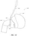
- FIG. 1is a perspective view of a respiratory interface on a patient's head.
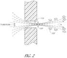
- FIG. 2shows an example of a fluid flow through a vent hole.
- FIG. 3is a cross-sectional view of vent holes according to an embodiment of the present disclosure.
- FIG. 4shows a graphical representation of a design envelope for exit radius versus hole diameter for vent holes.
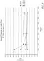
- FIG. 5is a graph showing sound pressure versus exit radii for a 1 mm vent hole.
- FIG. 6shows a graphical representation of a design envelope for hole length/diameter ratio versus hole pitch/diameter ratio for vent holes.
- FIG. 7is a graph showing sound pressure versus length/diameter ratio for a 1 mm vent hole having a 0.5 mm exit radius.
- FIG. 8is a graph showing sound pressure versus hole pitch for a 1 mm vent hole having a 0.5 mm exit radius.
- FIG. 9is a cross-sectional view of a respiratory interface according to an embodiment of the present disclosure.
- FIG. 10is a cross-sectional view of a respiratory interface according to another embodiment of the present disclosure.
- FIG. 11is a cross-sectional view of a diffuser according to an embodiment of the present disclosure.
- FIG. 12is a cross-sectional view of a vent having fibrous media, according to an embodiment of the present disclosure.
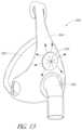
- FIG. 13is a perspective view of a respiratory interface according to another embodiment of the present disclosure.
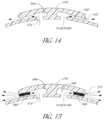
- FIG. 14is a cross-sectional view of an annulus cap according to an embodiment of the present disclosure.
- FIG. 15is a cross-sectional view of an annulus cap with fibrous media according to an embodiment of the present disclosure.
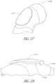
- FIG. 16is a side view of a respiratory interface according to another embodiment of the present disclosure.
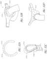
- FIG. 17is a cross-sectional view of a ball socket with grooves according to an embodiment of the present disclosure.
- FIG. 18is a side view of a connection port assembly with a ball end having grooves according to an embodiment of the present disclosure.
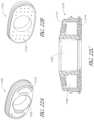
- FIG. 19is a cross-sectional view of a ball joint according to an embodiment of the present disclosure.
- FIG. 20is a cross-sectional view of a ball joint according to another embodiment of the present disclosure.
- FIGS. 21 A-Lare perspective views of ball socket components with groove patterns, according to various embodiments of the present disclosure.
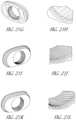
- FIG. 22 Ais a front perspective view of a ball socket component with a plenum space, according to an embodiment of the present disclosure.
- FIG. 22 Bis a back perspective view of the ball socket component of FIG. 22 A .
- FIG. 22 Cis a cross-sectional view of the ball socket component of FIG. 22 A .
- FIG. 23is a perspective view of a vent module, according to an embodiment of the present disclosure.
- FIG. 24is a perspective view of an interface with the vent module of FIG. 23 .
- FIG. 25is a perspective view of a mask frame, according to an embodiment of the present disclosure.
- FIG. 26is a perspective view of the interface of FIG. 24 and the mask frame of FIG. 25 .
- FIG. 27is a perspective view of a connection port assembly having a vent, according to an embodiment of the present disclosure.
- FIG. 28is a close-up perspective view of the vent of FIG. 27 .
- FIG. 29is a perspective view of the connection port assembly of FIG. 27 without the vent cover.
- FIG. 30is a perspective view of the vent cover of FIG. 27 .
- FIG. 31 Ais a perspective view of a vent module, according to an embodiment of the present disclosure.
- FIG. 31 Bis a perspective view of the vent module of FIG. 31 A , in a curved configuration.
- FIG. 31 Cis a perspective view of the vent module of FIG. 31 A attached to a connection port assembly.
- FIG. 32 A-Eare perspective view of bendable vent modules, according to various embodiments of the present disclosure.
- FIG. 33 Ais an exploded view of an interface with slots, according to an embodiment of the present disclosure.
- FIG. 33 Bis a cross-sectional view of the interface of FIG. 33 A .
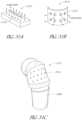
- FIG. 34 Ais an exploded view of an interface with slots, according to another embodiment of the present disclosure.
- FIG. 34 Bis a cross-sectional view of the interface of FIG. 34 A .
- FIG. 35 Ais a perspective view of a connection port assembly with slots, according to an embodiment of the present disclosure.
- FIG. 35 Bis a cross-sectional view of the connection port assembly of FIG. 35 A .
- FIGS. 36 A-Fare cross-sectional view of various embodiments of slots.
- an embodiment of an interface 100is illustrated on a user U.
- the interface 100can be used in the field of respiratory therapy.
- the interface 100has particular utility with forms of positive pressure respiratory therapy.
- the interface 100can be used for administering continuous positive airway pressure (“CPAP”) treatments, variable positive airway pressure (“VPAP”) treatments and/or bi-level positive airway pressure (“BiPAP”) treatments.
- CPAPcontinuous positive airway pressure
- VPAPvariable positive airway pressure
- BiPAPbi-level positive airway pressure
- the interfacecan be compatible with one or more different types of suitable CPAP systems.
- the interface 100can comprise any of a plurality of different types of suitable mask configurations. For example, certain features, aspects and advantages of the present invention can be utilized with nasal masks, full face masks, oronasal masks or any other positive pressure mask. Although the illustrated mask is a full face mask, the scope of the present disclosure should not be limited by the particular embodiments described.
- the interface 100comprises a mask body 102 , a mask frame 104 and a connection port assembly 106 .
- the mask body 102is configured to cover the user's mouth and/or nose to deliver respiratory gases to the user.
- the mask body 102can be secured to the mask frame 104 .
- the mask frame 104is held in place by a headgear assembly that wraps around the user's head.
- a connection port assembly 106can be connected to the mask body 102 and/or mask frame 104 , preferably with a releasable connection.
- the connection port assembly 106can include a ball joint to improve flexibility and comfort.
- the mask frame 104can couple to the mask body 102 and help stabilize the interface 100 on the user's face.
- the mask frame 104can be any shape and size to functionally secure the interface 100 to the user's face.
- the mask frame 104can be attached to the mask body 102 with interlocking clips, tabs or other functional couplers.
- the mask frame 104can be rigid, substantially rigid or semi-rigid to provide support for the mask body 102 .
- the mask frame 104can be at least partially made of a metal or rigid plastic, such as acrylic, polycarbonate or high-density polyethylene.
- the mask frame 104can extend to the user's forehead and include a forehead rest 108 .
- the forehead rest 108can help stabilize the interface 100 to the user's face by providing a support point for the interface 100 and connection points for the headgear assembly.
- a frame bridge 110extends from the main body of the frame and is connected to the forehead rest 108 .
- the frame bridge 110can be integrally formed or molded with the rest of the mask frame 104 from the same rigid material.
- the forehead rest 108can be a separate flexible piece that is attached or overmoulded onto the mask frame 104 .
- the forehead rest 108can be made of a flexible silicone that is overmoulded onto the frame bridge 110 .
- the flexible materialadvantageously conforms to the user's forehead anatomy and helps improve comfort to the user with soft material contact.
- the forehead rest 108can be attached or integrally formed as part of the mask frame 104 and can be made of the same material as the mask frame 104 and frame bridge 110 .
- the typical method of passively venting carbon dioxide (CO2)is via the use of a hole or a hole array that is incorporated into the mask body or gas path componentry that, for example, is directly connected to the mask.
- the interface 100has vents 112 for expelling gases from inside the mask to the environment.
- the vents 112can help expel carbon dioxide gases from the user to reduce the rebreathing of the carbon dioxide gases.
- the vents 112create a controlled or known leak to enable the exhausting of the user's exhaled carbon dioxide gases.
- bias flowrefers to the flow of gases to the environment through the vents.
- the flow rate of the bias flow and the design geometry of the vent holescan have an effect on the noise level and draft that the bias flow produces, as well as the amount of entrainment that the exiting gas flow may cause, as discussed further below.
- the vents 112comprise a plurality of through holes on the mask body 102 that expel gases through a cutout 116 in the mask frame 104 .
- the ventscan be slits or large openings instead of or in addition to small through holes.
- the ventscan be disposed on other portions of the interface, such as the connection port assembly or connection joints, as discussed below.
- relatively smaller hole sizesproduce less airflow noises compared to a larger hole size given the same flow velocity through both hole sizes.
- the plurality of holeshelps reduce airflow noises compared to having one or a few holes with the same vent area when expelling a given volume of gas.
- the vents 112can be formed as a separate component from the mask body or mask frame.
- the separate vent modulecan be permanently or releasably assembled to the mask body or mask frame.
- the vent modulecan have threads that mate with complementary threads on the mask body.
- the air vent modulecan have any type of functional coupler to mate the vent module to the mask body or mask frame. In these configurations, the vent module can be removed easily for service, cleaning or replacement.
- the vent modulecan be overmoulded to the mask body or mask frame for a permanent attachment.
- the overmouldingcan include a flexible gusset between the vent module and the mask that helps with flexibility.
- the vent modulecan be permanently attached using, for example, adhesives or ultrasonic welding.
- the vents 112can be formed of a different material than the mask body or mask frame. This can advantageously allow the vents to be made of a material that is suitable for forming apertures.
- the ventscan be made of a soft and/or flexible material while the mask body and/or mask frame are made of a more rigid material.
- the soft and/or flexible materiale.g., silicone, rubber, foam and the like
- the vents 112can be formed of the same material as the mask body and/or mask frame while providing acceptable noise and draft levels.
- a separate vent moduleadvantageously allows improved manufacturing and product quality.
- the vents in a separate componentthe moulding of the small and detailed vent apertures can be better controlled.
- the part tolerancescan be better controlled and result in more consistent hole dimensions having a more consistent flow rate performance between parts.
- Moulding a separate vent modulemay allow for production of more complex vent designs as a result of not having to accommodate undercuts and other geometric restrictions of other components, such as the mask body for example.
- Improved control of the part dimensionsmay also improve control of noise levels, such as by controlling the part contours to produce a smooth air flow through the holes.
- sound powercan be used to quantify the sound levels. This is the measure of the amount of energy from a particular sound source. The measurement is independent of distance from the sound source.
- sound pressurecan be used to quantify sound levels. This is the measure of the intensity of the sound at a particular distance from the sound source. This is typically measured in decibels (i.e., dB or dBa).
- a third method of quantifying sound levelsis a sound field.
- a sound fieldis a graphical representation (i.e., a contour map) of the pressure levels of a particular sound as a function of position from the sound source.
- FIG. 2illustrates an example of a fluid flow passing through a vent hole 114 .
- the term fluidis used to refer to liquids, gases or a combination of liquids and gases.
- a complex set of fluid dynamicsoccurs, for which there is considerable digital and experimental based data sets to describe its behaviour.
- the flowcontracts through a minimum cross-section called the vena contracta 120 , as illustrated in FIG. 2 .
- the position of the vena contracta 120is downstream of the vent hole 114 entrance. Substantially all the fluids that passes through the vent hole 114 will pass through the vena contracta 120 and this location is also the location of highest flow velocity and lowest pressure.
- the vena contracta 120As the fluid flow exits the vena contracta 120 , it progressively reduces in velocity and increases in pressure, until it reaches a velocity of approximately zero and a pressure of approximately atmospheric pressure.
- vortices 122may form at the boundary between the exiting fluid flow and the stationary atmospheric air, which are caused by viscous effects between the two fluids being at different velocities. This effect is known as vortex shedding.
- the vortex sheddingmay produce rapid random fluctuations which occur across a range of frequencies. Typically, the frequencies can range from at least approximately 1 kHz to less than or equal to 10 kHz, with wavelengths in the range of at least approximately 1 mm to less than or equal to 4000 mm.
- the variablescan include: (1) The flow rate through the vent hole 114 , which is a function of the hole diameter 130 and the pressure drop from the entrance to the exit of the vent hole; (2) The quality of the vent hole, which can be characterised by the smoothness of the hole and the absence of debris in the hole; (3) The geometry of the hole, particularly the entrance radius 132 and exit radius 134 of the hole, and the hole length 136 to diameter 130 ratio of the hole; (4) The geometry of the hole array, for example the hole pitch 138 (i.e, the distance between vent holes).
- the two most commonly understood flow typesare laminar flow and turbulent flow, which can be quantified by a Reynolds number.
- the Reynolds number at which the transition between laminar flow and turbulent flow occursis approximately 2300.
- turbulent flowoccurs at the vena contracta, there is usually an increase in sound level.
- debris or surface imperfections exist in the vent holesthis can create a mechanism that promotes an earlier transition from laminar flow to turbulent flow compared to smooth surface vent holes.
- ventsBeing able to adjust the geometry of the vents offers the ability to control the sound levels produced by the vents to be within an acceptable range for use as part of a CPAP system.
- Some design envelopeshave been developed that achieve acceptable sound levels.
- One of the design envelopesis for the vent hole diameter 130 versus the exit radius 134 .
- a graphical representation of the design envelope showing vent hole diameter versus the exit radiusis illustrated in FIG. 4 .
- the contour of the exit radius 134can affect the noise levels that are created by the fluid flow.
- the exit radius 134can be at least approximately 0.25 mm and/or less than or equal to approximately 0.75 mm. As discussed below, this range is preferable for reducing or minimizing the noise levels created by a 1 mm vent hole.
- the contour of the entrance radiuscan affect the noise levels that are created by the fluid flow.
- the entrance radiuscan be at least approximately 0.25 mm. In some configurations, the entrance radius can be at least approximately 0.1 mm and/or less than or equal to approximately 1 mm.
- FIG. 5illustrates a graph illustrating sound pressure versus exit radius for a 1 mm vent hole. As shown in the graph, sound levels are relatively high when the exit radius is zero. The sound levels steadily decrease to a minimum sound level at approximately 0.5 mm exit radius. The sound levels slowly increase as the exit radius is increased. A range of approximately 0.25 mm and/or less than or equal to approximately 0.75 mm has been found to be a range that provides acceptable noise levels.
- the contour of the exit radius 134can also substantially reduce the variation in the noise level that is created as the flow rate is changed.
- the noise levelcan have minimal variation as the driving pressure from the CPAP unit changes. Accordingly, the vent can have a substantially constant sound output that is predictable throughout a range of driving pressures.
- the entrance radius 132has similar effects on the sound power level, although a less pronounced effect compared to the exit radius 134 .
- the hole diameter 130can be at least approximately 0.5 mm and/or less than or equal to approximately 1.5 mm. Producing vent hole diameters smaller than 0.5 mm can be difficult or impractical using conventional injection molding techniques. With vent hole diameters larger than 1.5 mm, the sound power created by the gas flow can produce sound pressure levels larger than what is acceptable for some applications.
- FIG. 4illustrates a preferable design envelope to achieve desirable sound levels produced by the vents
- the ranges for vent hole diameter and exit radiuscan be broader while still achieving acceptable sound levels.
- the exit radiuscan be at least approximately 0.1 mm and/or less than or equal to approximately 1 mm.
- the hole diametercan be at least approximately 0.25 mm and/or less than or equal to approximately 2 mm.
- Another design envelopeis for hole pitch/diameter ratio versus the hole length/diameter ratio.
- a graphical representation of the design envelope showing hole pitch/diameter ratio versus the hole length/diameter ratiois illustrated in FIG. 6 .
- the vent hole length to diameter ratiocan be at least approximately 2. Having a hole length to diameter ratio below 2 may significant increase the sound power level for a given hole size. For example, a hole length to diameter ratio of 1.5 can approximately doubles the decibel sound output compared to a ratio of 2. However, in some configurations, the vent hole length to diameter ratio can be at least approximately 1 while still providing acceptable sound levels.
- FIG. 7is a graph showing sound pressure versus length/diameter ratio for a 1 mm vent hole having a 0.5 mm exit radius.
- sound levelsare relatively low at a length/diameter ratio of approximately 1.
- the sound levelsrapidly increase to a maximum sound level at a ratio of approximately 1.5.
- the sound levelsrapidly decrease to a minimum at a ratio of approximately 2.
- the sound levelsslowly increase as the ratio increases above 2. Accordingly, a range for the length/diameter ratio of greater than approximately 2 has been found to be an acceptable range for minimizing noise levels.
- vent hole pitchi.e, the distance between holes
- diameter ratiocan be at least approximately 4.
- the fluid flows from the individual holescan have a strong interaction with each other, which multiplies the sound output.
- the vent hole pitch to diameter ratiocan be at least approximately 3.
- FIG. 8is a graph showing sound pressure versus hole pitch for a 1 mm vent hole having a 0.5 mm exit radius. As shown in the graph, sound levels are relatively high when the hole pitch is approximately 2. The sound levels decrease to a minimum sound level at a pitch of approximately 4. The sound levels slightly increase as the hole pitch is increased. Accordingly, a range for the hole pitch of at least approximately 4 has been found to be an acceptable range for minimizing noise levels.
- the fluid flow exiting the vent holesare at a relatively high velocity, typically 20-50 m/sec. Due to conservation of energy and momentum, the exiting fluid flow entrains the surrounding environmental air. The fluid flow is at a lower pressure than the surrounding air and the pressure differential causes a portion of the surrounding environmental air to be entrained and moved along with fluid flow, which multiplies many times the effective draft from the vent holes.
- the experimentally determined increase of the effective draftmay be in the order of 6-10 times.
- a vent hole array with a 10 cm H2O change in pressure from the entrance to exitwill create a bias flow of approximately 15-20 liters/min.
- the effect of the entrainmentcan result in approximately 90-120 liters/min of total flow being projected towards the user or bed partner. Accordingly, the ability to control the rate of entrainment can directly affect the ability to minimize the disturbance caused by the effective draft.
- the draft and noise from the ventscan be reduced or minimized by using a plenum chamber that enables the energy present in the exiting fluid flow to dissipate.
- the plenum chambercan enable the fluid velocity to slow and the fluid pressure to increase to reduce or prevent entrainment.
- the plenum chambercan have any of a plurality of different types of shapes or designs.
- the plenum chambercan be an expansion chamber that substantially reduces or prevents environmental air from being entrained, as illustrated in FIGS. 9 and 10 .
- FIG. 9illustrates a cross-section view through an interface 200 with vent holes 214 disposed in a forward-facing surface of the mask body 202 that is above the connection port assembly 206 .
- the mask frame 204is positioned in front of the mask body 202 , such that the venting fluid flow passes through the vent holes 214 and into a plenum space 240 created between the mask body 202 and the mask frame 204 .
- the plenum space 240causes the fluid flow to change direction, which reduces the velocity and increases the pressure of the fluid flow. After the energy in the fluid flow is reduced, the vented fluids can exit the plenum space 240 into the environment with minimized or reduced noise levels.
- FIG. 10illustrates a cross-sectional view of an embodiment of an interface 300 having vent holes 314 on the connection port assembly 306 , disposed between the mask body 302 and the connection end 318 for the gas delivery circuit.
- the vent holes 314are disposed around the entire circumference of the connection port assembly 306 in the illustrated configuration. In other configurations, the vent holes may be disposed on only a portion of the circumference, such as the front side or only half of the circumference of the connection port assembly 306 .
- the connection port assembly 306can have an outer shell 342 that surrounds the vent holes 314 . In the illustrated embodiment, the outer shell 342 extends to cover approximately the upper half of the connection port assembly 306 . In other embodiments, the outer shell can cover more or less of the connection port assembly than illustrated, but preferably covers the vent holes.
- the space between the outer shell 314 and the inner surface of the connection port assembly 306is the plenum space 340 .
- the venting fluidpasses through the vent holes 314 and into the plenum space 340 , which in some configurations is designed to turn the fluid flow back on itself.
- the plenum space 340reduces the velocity and increases the pressure of the fluid flow. After the energy in the fluid flow is reduced, the vented fluids can exit the plenum space 340 into the surrounding environment with minimized or reduced noise levels.
- FIG. 11illustrates a cross-section of a diffuser 460 that is effective at reducing the fluid flow velocity, which reduces the draft and noise levels.
- the smaller end of the diffuser 460surrounds the vents 412 and the wider end of the diffuser 460 can be open to the environment.
- the diffusercan have a conical shape, or other shape that has an increasing cross-sectional area. Some examples include a pyramid-shaped cone, a triangular cone and a polygonal cone.
- Some geometric design considerations that can help to reduce the fluid flow velocityinclude the expansion angle ⁇ and the ratio of the diffuser length 462 to the root diameter 464 . Diffusers with geometries similar to those described below have resulted in a reduction of the fluid flow velocity from approximately 6-8 meters per second to less than 0.8 meters per second in some embodiments.
- the diffuser 460can have an expansion angle ⁇ of at least approximately 4 degrees and/or less than or equal to approximately 8 degrees, or geometry that has the same effective cross sectional area behaviour. It has been discovered that angles greater than about 8 degrees are generally not very effective at reducing draft and noise levels in some applications. However, in some configurations, the diffuser can have an expansion angle ⁇ of at least approximately 1 degrees and/or less than or equal to approximately 15 degrees.
- the length of the diffusershould be long enough to provide sufficient distance for the fluid flow velocity to decrease to a desirable level, while not protruding too much from the mask to where it causes an obstruction. For larger vents, the diffuser length can be proportionately larger to achieve the desired reduction in draft and noise levels.
- the ratio of the diffuser length 462 to the root diameter 464can be at least approximately 1.4:1. In some embodiments, the ratio of the diffuser length 462 to the root diameter 464 can be at least approximately 1.25:1 and/or less than or equal to approximately 1.9:1.
- a textured or fibrous media 166is positioned in front of the vent holes 114 such that the fluid flow exiting the vent holes impinges on the media 166 .
- textured or fibrous mediacan include wool, cotton, felt, polyester, open cell foam and the like.
- the media 166helps to reduce the fluid flow velocity and diffuse the fluid flow, which reduces the draft and noise levels.
- the media 166is preferably positioned between the exit of the vent holes 114 and a distance from the vent holes 114 at which the exiting fluid flow produces sound.
- the media distance ⁇can be at least approximately 3 times the vent hole diameter and/or less than or equal to approximately 5 times the vent hole diameter.
- the media distance ⁇can be at least approximately 1 time the vent hole diameter and/or less than or equal to approximately 10 times the vent hole diameter.
- Another advantage of positioning the media 166 a distance ⁇ from the vent hole exitsis that it can prevent accumulation of water around the vent holes caused from condensation of the fluid flow.
- the condensationcan occlude the vent hole exits and undesirably increase the resistance to flow (i.e., drop in bias or leak flow rate).
- FIG. 13illustrates an embodiment of an interface 500 with an annulus cap 570 that vents the fluid flow radially outward, reducing the fluid flow velocity, the draft and noise levels.
- the annulus cap 570is located on the mask frame 504 above the connection port assembly 506 .
- the annulus capcan be disposed on the mask body 502 or the connection port assembly 506 instead of or in addition to the mask frame 504 .
- FIG. 14illustrates a cross-section of an annulus cap 570 showing the fluid flow through the cap.
- the annulus cap 570covers vent holes 514 that are in fluid communication with the inside of the mask body.
- the fluidscan flow through the vent holes 514 and are directed through a plenum space 540 .
- the direction of the fluid flowis also redirected to exhaust radially outward.
- the fluidsflow through the vent holes 514 at a relative high velocity and low pressure.
- the walls of the annulus cap 570As the fluids enter the plenum space 540 , they are redirected by the walls of the annulus cap 570 , which reduces the fluid flow velocity and increases the fluid pressure.
- the fluidsflow through the plenum space 540 and exit to the environment in a radial direction.
- the annulus cap 570reduces or minimises the sound creation from the fluid flow.
- the annulus cap 570is integrally formed with one of the interface components, such as the mask body, mask frame or connection port assembly.
- the annulus capcan be a separate component that is fastened over the top of the vents with a functional coupler, such as threaded fasteners, clips or an interference fit.
- the profile of the plenum space 540can be configured to slow down the fluid velocity and help reduce noise levels.
- the plenum space 540includes pockets 544 adjacent the outlet side of the vent hole 514 . When the fluid flow enters the pocket 544 , it can create turbulence that slow down the fluid flow, which can help reduce noise levels of the fluid flow exiting the annulus cap.
- the fluid flow exiting the annulus cap 570are at a relatively high velocity. Due to conservation of energy and momentum, the exiting fluid flow entrains the surrounding environmental air. The fluid flow is at a lower pressure than the surrounding air and the pressure differential causes a portion of the surrounding environmental air to be entrained and moved along with fluid flow, which multiplies many times the effective draft from the vent holes. The ability to control the rate of entrainment can directly affect the ability to minimize the disturbance caused by the effective draft.
- the rate of entrainmentcan be reduced by the use of a fibrous media 566 positioned in the flow path, as illustrated in FIG. 15 .
- the fibrous media 566is toward the exit of the plenum space 540 .
- the fibrous media 566can be positioned anywhere along the flow path through the annulus cap 570 .
- the fibrous media 566can provide a tortuous path for the fluid flow to pass through, which produces friction and reduces the fluid velocity.
- the fluid velocitycan be reduced to a level of sufficiently low energy that the velocity difference between the fluid flow exiting the annulus cap 570 and the surrounding air is at a point that there is minimal or reduced entrainment of the surrounding air.
- the bias flowcan be incorporated into the leak rate that normally occurs through a ball joint or swiveling joints present in some interfaces.
- Some interfaceshave either a ball joint or a swivel joint to help reduce or minimize the effect of torque that the delivery tube may induce on the interface and user. These joints provide free motion with low or minimal leak rate.
- the descriptions belowrelate to an interface having a ball joint. However, it should be understood that the same design concepts can be applied to swivel joints.
- connection port assembly 206can be connected to the mask body 202 with a ball joint 250 , as illustrated in FIG. 9 .
- the connection port assembly 206can be connected to the mask frame 204 instead of or in addition to the mask body 202 .
- the mask body 202has a ball socket 252 with a concave surface configuration that can receive a ball end 254 of a connection port assembly 206 .
- the ball end 254has an outer surface that is contoured to be snap fit into the ball socket 252 .
- the ball joint 250can allow the surfaces to slide relatively freely with each other such that the angle between the connection port assembly 206 and mask body 202 can be easily changed.
- an interface 600having a ball joint 650 between the connection port assembly 606 and mask body 602 .
- the ball joint 650includes grooves 656 that allow the fluids in the mask to exhaust to the environment in a controlled, predictable manner.
- the quantity and cross-sectional area of the grooves 656can affect the flow rate of fluids venting through the ball joint.
- the groovescan be disposed on either or both components of the ball joint.
- FIG. 17illustrates grooves 756 on the interior surface of the ball socket 752 .
- the ball socket 752can be a part of the mask body 702 , as illustrated, or the mask frame.
- the grooves 856can be disposed on the exterior surface of the ball end 854 of the connection port assembly 806 , as illustrated in FIG. 18 .
- the groovesprovide fluid communication between the inside of the mask to the environment while also providing a mechanism to reduce the friction between the ball and the socket. The reduced friction is advantageous for further reducing the effect of tube torque on the interface.
- the ball jointcan provide a consistent, reliable leak rate independent of the orientation of the ball socket.
- the cross-sectional areas of each groovecan be substantially the same so that the leak rate is the substantially the same no matter which orientation the ball socket is in.
- FIG. 19illustrates a ball joint 950 with a ball socket 952 and ball end 952 .
- the grooves 956are disposed on the outer surface of the ball end 952 and extend to or beyond the neck 957 of the ball end. Because the grooves 956 extend to or beyond the neck 957 , the socket edge 958 does not occlude the flow path of the exhaust fluid when the ball joint is flexed to its extremes, which can lead to unstable flow rates and noise level changes.
- FIG. 20illustrates a configuration of a ball joint 1050 having a gutter 1059 on the socket edge 1058 .
- the ball joint 1050has a ball socket 1052 and ball end 1054 , with grooves 1056 disposed on the ball end 1054 .
- the illustrated gutter 1059provides clearance for a fluid pathway when the ball joint is flexed to its extremes.
- the interfacecan have a separate ball socket component that can be separately made and coupled to the mask body or mask frame.
- a separate ball socket componentcan advantageously allow improved manufacturing and product quality. The small and detailed features, such as the grooves, can be better controlled and the part tolerances can be better controlled and result in more consistent dimensions having a more consistent flow rate performance. Moulding a separate ball socket component may also allow for production of more complex groove designs as a result of not having to accommodate undercuts and other geometric restrictions of other components.
- the ball socket componentcan be attached to the mask body or mask frame through any type of functional coupling, such as overmoulding, adhesives, clips, welding and interference fit.
- FIGS. 21 A-Lillustrate some examples of ball socket components with some possible groove patterns for the ball joint.
- FIGS. 21 A-Billustrate front and rear perspective views, respectively, of a groove pattern.
- FIGS. 21 C-Dillustrate front and rear perspective views, respectively, of another groove pattern.
- FIGS. 21 E-Fillustrate front and rear perspective views, respectively, of a groove pattern having four large grooves.
- FIGS. 21 G-Fillustrate a front perspective and close-up view of another embodiment of a ball socket component with a groove pattern.
- FIGS. 21 I-Jillustrate a front perspective and close-up view of a groove pattern with a 30 degree twist.
- FIGS. 21 K-Lillustrate a front perspective and close-up view of a groove pattern with an increased number of grooves, 75 grooves in the illustrated embodiment.
- FIGS. 22 A-Cillustrate a ball socket component 1151 having a plenum space 1140 .
- the ball socket component 1151has a ball socket 1152 for accepting a ball end.
- the ball socketcan be smooth or have grooves, as discussed above.
- the rear side of the ball socket component 1151can have vent holes 1114 and the front side can have slots 1115 .
- the front sidemay have openings in other shapes other than slits as shown in the illustrated embodiment. Between the vent holes 1114 and slots 1115 can be a plenum space 1140 that reduces the fluid flow velocity, and reduces the draft and noise levels.
- the vent holescan be disposed on a separate insert that is coupled to the interface.
- FIG. 23illustrates an example of a vent module 2112 having a plurality of vent holes 2114 .
- the separate vent module 2112advantageously allows improved manufacturing and product quality.
- the moulding of the small and detailed vent aperturescan be better controlled, and the part tolerances can be better controlled and result in more consistent hole dimensions having a more consistent flow rate performance.
- Moulding a separate vent module 2112may also allow for production of more complex vent designs as a result of not having to accommodate undercuts and other geometric restrictions of other components, such as the mask body for example.
- Improved control of the part dimensionsmay also improve control of noise levels, such as by controlling the hole contours to produce a smooth air flow through the holes.
- FIG. 24illustrates the vent module 2112 coupled to a mask body 2102 .
- the vent module 2112can be attached to the mask body 2102 or mask frame through any type of functional coupling, such as overmoulding, adhesives, clips, welding and interference fit.
- a mask frame 2104can be coupled to the mask body 2102 .
- the mask frame 2104can have a cutout 2116 that is configured to be positioned over the vent module 2112 .
- a vent cover 2117can be disposed across the cutout 2116 to reduce the draft from the vent holes 2114 .
- the space between the vent module 2112 and the vent cover 2117can act as a plenum space to reduce the fluid flow velocity, and reduce the draft and noise levels.
- FIGS. 27 and 28illustrate an embodiment of a connection port assembly 3106 having a vent 3112 with a vent cover 3117 .
- the vent 3112can be a single opening through the wall of the connection port assembly 3106 , as illustrated in FIG. 29 , or can be a plurality of holes or slots, as discussed previously.
- FIG. 30illustrates the vent cover 3117 , which can be a separate component that is coupled to the connection port assembly 3106 through any type of functional coupling, such as overmoulding, adhesives, welding, clips and interference fit.
- the vent coveris integrally formed or moulded with the connection port assembly.
- the vent cover 3117can help to reduce the draft from the vent 3112 .
- the plenum space 3140 between the connection port assembly 3106 and the vent cover 3117can help reduce the fluid flow velocity, and reduce the draft and noise levels as discussed previously.
- vent holes in a radial configurationis beneficial in reducing or minimizing the amount of draft that is felt by the user or bed partner.
- moulding radial holes, or holes on a curved surfacecan be difficult from a process point of view.
- the vent holescan be formed on a vent module made of soft material and then attached to the interface.
- the soft materialcan allow for the vent module to be wrapped around or contoured onto the interface.
- the soft material of the vent modulecan be rubber, plastic, silicone or any other suitably flexible material. In some embodiments, however, the material can be a harder material and can have some functional means of being bent, such as with hinges or reliefs that promote bending.
- FIG. 31 Aillustrates a vent module 3112 that is moulded from a flat piece of material. As illustrated, the fluid flows in generally the same direction as it flows out of the vent holes 3114 .
- FIG. 31 Billustrates the vent module 3112 in a curved configuration. The vent holes 3114 are in a radial pattern and the fluid flows from the vent holes 3114 in divergent directions. In other words, when the vent module is curved, there are no two columns of holes at the same angle. This makes it harder for the fluid flow to entrain air and therefore reduces the draft effect, which can reduce the noise level as well.
- FIG. 31 Cillustrates the vent module 3112 coupled to a connection port assembly 3106 .
- the vent module 3112can be overmoulded with the interface or attached by other means, such as for example adhesives or welding.
- FIGS. 32 A-Eillustrate various examples of a vent module that is bent and attached to different portions of interfaces.
- FIG. 32 Aillustrates a flat circular vent module 3112 that can be curved into a frustoconical shape and attached to the interface 3000 .
- the vent module 3112is disposed around the ball joint.
- the vent holes 3114are pointed in a divergent direction relative to the centre of the circular vent module 3112 , which helps diffuse the fluid flow and reduce draft.
- FIG. 32 Cillustrates a horseshoe-shaped vent module 3112 that can fit around the contours of the connection port assembly.
- FIG. 32 Dillustrates a vent module 3112 that can cover the front portion of the mask. In this configuration, the large surface area of the front portion can be used for vent holes 3114 , allowing for a large venting flow rate.
- FIG. 32 Eillustrates another embodiment of a vent module 3112 that is configured to fit across the front portion of the interface. In the illustrated embodiment, the vent module 3112 includes strips with vent holes 3114 that extend around the ball joint.
- slotscan be used to vent the fluids. Slots have some advantages over vent holes, which may include more venting flow rate, better manufacturability and lower noise levels. The slots may produce less noise compared to holes because the slots have less surface structures for the fluid to flow past, which is a contributor to noise production.
- FIG. 33 Aillustrates an exploded view of an interface 4000 having slots 4114 for venting.
- the slots 4114can be disposed on a vent module 4112 and a slot cover 4115 can be positioned over the vent module 4112 to form a flow path through the slots 4114 , as illustrated in FIG. 33 B .
- the slot cover 4115includes the ball socket 4152 such that the connection port assembly 4106 can connect to the slot cover 4115 .
- the vent module 4112can have an inner radius 4113 , which can help provide a smoother flow path through the slot and help reduce noise levels. It has been discovered that placing a tab 4117 at the exit of the slots 4114 can help to reduce noise levels. In experimentation, an optimal tab 4117 length was found to be approximately 2 mm long. However, in some embodiments, the tab length can be any length that provides suitable noise reduction.
- the illustrated configurationhas 4 slots spaced equal distances apart. In some configurations, the number of slots can be at least 1 and/or less than or equal to 8 slots.
- the exhausting fluid flowis shown flowing radially outward from the interface. In other configurations, the exhaust can be directed in any suitable direction to control the draft from the fluid flow.
- FIGS. 34 A-Billustrate another configuration having two slots 5114 .
- the vent module 5112 of this interface 5000has two slots 5114 about 180 degrees apart.
- the slot cover 5115fits over the vent module 5112 , forming the flow path through the slots 5114 .
- This configurationalso shows a connection port assembly 5106 that is configured to connect with the slot cover 5115 .
- FIGS. 35 A-Billustrate an embodiment having slots 6114 on the connection port assembly 6106 .
- the connection port assembly 6106has two components. A first component with the ball socket 6152 and a second component with the connection end 6118 . When the two components are assembled, a space between the two components can form the slot 6114 .
- the slot 6114can have the same features as discussed above in other embodiments.
- FIGS. 36 A-Fillustrate various embodiments of slot designs.
- FIG. 36 Aillustrates radially outward facing slots 7114 at the end of a flared flow path.
- the radial direction of the slotscan help to reduce the draft effects and disturbance to the user and bed partner.
- a slot width of approximately 0.35 mmprovides good performance in minimizing the noise levels.
- the slot widthcan be at least approximately 0.2 mm and/or less than or equal to approximately 0.5 mm.
- FIG. 36 Billustrates radially outward facing slots 7114 at the end of a straight flow path.
- FIG. 36 Cillustrates radially inward facing slots 7114 at the end of a bulbous flow path.
- FIG. 36 Dillustrates outward facing slots 7114 that are tiered. The illustrated embodiment has three tiers of slots 7114 . In other embodiments, there can be one, two or more than three tiers.
- FIG. 36 Eillustrates slots 7114 at the end of a flared flow path which includes an internal curve 7119 .
- the internal curvecan encourage the flow direction out through the slots rather than flowing into a capped surface.
- the internal curvecan provide a smoother fluid flow, which can result in reduced noise levels.
- FIG. 36 Fillustrates radially outward facing slots 7114 at the end of a straight flow path which includes an internal curve 7119 .
Landscapes
- Health & Medical Sciences (AREA)
- Emergency Medicine (AREA)
- Pulmonology (AREA)
- Engineering & Computer Science (AREA)
- Anesthesiology (AREA)
- Biomedical Technology (AREA)
- Heart & Thoracic Surgery (AREA)
- Hematology (AREA)
- Life Sciences & Earth Sciences (AREA)
- Animal Behavior & Ethology (AREA)
- General Health & Medical Sciences (AREA)
- Public Health (AREA)
- Veterinary Medicine (AREA)
- Respiratory Apparatuses And Protective Means (AREA)
- External Artificial Organs (AREA)
- Devices For Medical Bathing And Washing (AREA)
Abstract
Description
Claims (8)
Priority Applications (2)
| Application Number | Priority Date | Filing Date | Title |
|---|---|---|---|
| US17/134,995US12220528B2 (en) | 2013-02-21 | 2020-12-28 | Patient interface with venting |
| US18/821,987US20240416056A1 (en) | 2013-02-21 | 2024-08-30 | Patient interface with venting |
Applications Claiming Priority (5)
| Application Number | Priority Date | Filing Date | Title |
|---|---|---|---|
| US201361767586P | 2013-02-21 | 2013-02-21 | |
| US201361845102P | 2013-07-11 | 2013-07-11 | |
| PCT/NZ2014/000021WO2014129913A1 (en) | 2013-02-21 | 2014-02-21 | Patient interface with venting |
| US201514769674A | 2015-08-21 | 2015-08-21 | |
| US17/134,995US12220528B2 (en) | 2013-02-21 | 2020-12-28 | Patient interface with venting |
Related Parent Applications (2)
| Application Number | Title | Priority Date | Filing Date |
|---|---|---|---|
| PCT/NZ2014/000021ContinuationWO2014129913A1 (en) | 2013-02-21 | 2014-02-21 | Patient interface with venting |
| US14/769,674ContinuationUS10898662B2 (en) | 2013-02-21 | 2014-02-21 | Patient interface with venting |
Related Child Applications (1)
| Application Number | Title | Priority Date | Filing Date |
|---|---|---|---|
| US18/821,987ContinuationUS20240416056A1 (en) | 2013-02-21 | 2024-08-30 | Patient interface with venting |
Publications (2)
| Publication Number | Publication Date |
|---|---|
| US20210113788A1 US20210113788A1 (en) | 2021-04-22 |
| US12220528B2true US12220528B2 (en) | 2025-02-11 |
Family
ID=51391591
Family Applications (3)
| Application Number | Title | Priority Date | Filing Date |
|---|---|---|---|
| US14/769,674Active2037-02-01US10898662B2 (en) | 2013-02-21 | 2014-02-21 | Patient interface with venting |
| US17/134,995Active2034-05-23US12220528B2 (en) | 2013-02-21 | 2020-12-28 | Patient interface with venting |
| US18/821,987PendingUS20240416056A1 (en) | 2013-02-21 | 2024-08-30 | Patient interface with venting |
Family Applications Before (1)
| Application Number | Title | Priority Date | Filing Date |
|---|---|---|---|
| US14/769,674Active2037-02-01US10898662B2 (en) | 2013-02-21 | 2014-02-21 | Patient interface with venting |
Family Applications After (1)
| Application Number | Title | Priority Date | Filing Date |
|---|---|---|---|
| US18/821,987PendingUS20240416056A1 (en) | 2013-02-21 | 2024-08-30 | Patient interface with venting |
Country Status (4)
| Country | Link |
|---|---|
| US (3) | US10898662B2 (en) |
| EP (5) | EP3892319B1 (en) |
| AU (6) | AU2014219520B2 (en) |
| WO (1) | WO2014129913A1 (en) |
Cited By (1)
| Publication number | Priority date | Publication date | Assignee | Title |
|---|---|---|---|---|
| US20240245876A1 (en)* | 2014-05-09 | 2024-07-25 | Fisher & Paykel Healthcare Limited | Diffuser arrangements for a vent of a respiratory interface |
Families Citing this family (77)
| Publication number | Priority date | Publication date | Assignee | Title |
|---|---|---|---|---|
| WO2005079726A1 (en) | 2004-02-23 | 2005-09-01 | Fisher & Paykel Healthcare Limited | Breathing assistance apparatus |
| EP3936180B1 (en) | 2004-04-02 | 2023-11-29 | Fisher & Paykel Healthcare Limited | Breathing assistance apparatus |
| DE202007019687U1 (en) | 2006-07-14 | 2015-07-14 | Fisher & Paykel Healthcare Ltd. | Respiratory support device |
| US10792451B2 (en) | 2008-05-12 | 2020-10-06 | Fisher & Paykel Healthcare Limited | Patient interface and aspects thereof |
| US10258757B2 (en) | 2008-05-12 | 2019-04-16 | Fisher & Paykel Healthcare Limited | Patient interface and aspects thereof |
| US11660413B2 (en) | 2008-07-18 | 2023-05-30 | Fisher & Paykel Healthcare Limited | Breathing assistance apparatus |
| EP2349428B1 (en) | 2008-10-10 | 2017-09-20 | Fisher & Paykel Healthcare Limited | Nasal pillows for a patient interface |
| EP2501423A4 (en) | 2009-11-18 | 2014-10-29 | Fisher & Paykel Healthcare Ltd | Nasal interface |
| GB2489379B (en) | 2009-12-23 | 2016-01-13 | Fisher & Paykel Healthcare Ltd | Patient interface and headgear |
| EP2624903B1 (en) | 2010-10-08 | 2018-05-16 | Fisher & Paykel Healthcare Limited | Breathing assistance apparatus |
| GB2529079B (en) | 2011-04-15 | 2016-06-22 | Fisher & Paykel Healthcare Ltd | An elbow assembly for a mask |
| US10603456B2 (en) | 2011-04-15 | 2020-03-31 | Fisher & Paykel Healthcare Limited | Interface comprising a nasal sealing portion |
| EP3566736B1 (en) | 2011-07-01 | 2020-12-09 | Fisher & Paykel Healthcare Limited | Nasal mask interface assembly |
| USD693459S1 (en) | 2011-09-16 | 2013-11-12 | Fisher & Paykel Healthcare Limited | Patient interface assembly |
| EP2830690B1 (en)* | 2012-03-27 | 2017-08-02 | Koninklijke Philips N.V. | User interface device providing for improved cooling of the skin |
| GB2553475B8 (en) | 2012-08-08 | 2019-01-02 | Fisher & Paykel Healthcare Ltd | Headgear for patient interface |
| EP4279106A3 (en) | 2012-09-04 | 2024-01-17 | Fisher & Paykel Healthcare Limited | Valsalva mask |
| EP3892319B1 (en) | 2013-02-21 | 2022-12-28 | Fisher & Paykel Healthcare Limited | Patient interface with venting |
| NZ718810A (en) | 2013-10-03 | 2017-10-27 | Resmed Ltd | Mask vent with side wall |
| US10159813B2 (en) | 2014-05-21 | 2018-12-25 | Atom Medical Corporation | Gas supply mask apparatus |
| SG11201700351VA (en) | 2014-07-18 | 2017-02-27 | Fisher & Paykel Healthcare Ltd | Headgear clip arrangement |
| WO2016032343A1 (en)* | 2014-08-25 | 2016-03-03 | Fisher & Paykel Healthcare Limited | Respiratory mask and related portions, components or sub-assemblies |
| US10828452B2 (en) | 2014-09-16 | 2020-11-10 | Fisher & Paykel Healthcare Limited | Intramold headgear |
| JP6931326B2 (en) | 2014-09-16 | 2021-09-01 | フィッシャー アンド ペイケル ヘルスケア リミテッド | Headgear assembly and interface assembly with headgear |
| JP7091401B2 (en)* | 2014-09-18 | 2022-06-27 | レスメド・プロプライエタリー・リミテッド | Gas wash vent for patient interface |
| CN107073236B (en)* | 2014-09-18 | 2020-05-05 | 瑞思迈私人有限公司 | Gas washout vent for patient interface |
| US10646680B2 (en) | 2014-09-19 | 2020-05-12 | Fisher & Paykel Healthcare Limited | Headgear assemblies and interface assemblies with headgear |
| US10765824B2 (en) | 2015-01-30 | 2020-09-08 | ResMed Pty Ltd | Patient interface comprising a gas washout vent |
| CA2977729A1 (en)* | 2015-03-04 | 2016-09-09 | Fisher & Paykel Healthcare Limited | Mask system headgear |
| USD838838S1 (en)* | 2015-06-03 | 2019-01-22 | Intersurgical Ag | Respiratory mask |
| CN104906676B (en)* | 2015-06-23 | 2017-11-14 | 北京怡和嘉业医疗科技股份有限公司 | A kind of face shield assembly |
| CN105079933B (en)* | 2015-06-23 | 2018-05-29 | 北京怡和嘉业医疗科技股份有限公司 | A kind of face shield assembly |
| CN108025154B (en)* | 2015-07-20 | 2021-03-23 | 费雪派克医疗保健有限公司 | Exhalation port |
| CN119345550A (en) | 2015-09-11 | 2025-01-24 | 费雪派克医疗保健有限公司 | Nasal seals, masks and respiratory interface assemblies |
| CN112755355B (en)* | 2015-09-23 | 2024-12-27 | 瑞思迈私人有限公司 | Bending pipe components |
| EP4293255B1 (en)* | 2015-09-23 | 2025-03-05 | ResMed Pty Ltd | Vent adaptor for a respiratory therapy system |
| USD790054S1 (en) | 2015-09-25 | 2017-06-20 | Fisher & Paykel Healthcare Limitied | Swivel connector |
| USD784515S1 (en) | 2015-09-25 | 2017-04-18 | Fisher & Paykel Healthcare Limited | Headgear |
| USD784516S1 (en)* | 2015-09-25 | 2017-04-18 | Fisher & Paykel Healthcare Limited | Face mask frame |
| USD800895S1 (en) | 2015-09-25 | 2017-10-24 | Fisher & Paykel Healthcare Limited | Face mask cushion |
| USD828917S1 (en) | 2015-09-25 | 2018-09-18 | Fisher & Paykel Healthcare Limited | Vent diffuser |
| USD782030S1 (en)* | 2015-09-25 | 2017-03-21 | Fisher & Paykel Healthcare Limited | Face mask |
| USD782031S1 (en)* | 2015-09-25 | 2017-03-21 | Fisher & Paykel Healthcare Limited | Face mask cushion and frame assembly |
| SG11201807699TA (en) | 2016-03-16 | 2018-10-30 | Fisher & Paykel Healthcare Ltd | Strap assembly, strap connector, headgear, headgear assembly, method of forming headgear, tubular connector, patient interface and method of joining straps |
| EP3430284B1 (en) | 2016-03-16 | 2021-07-14 | Fisher & Paykel Healthcare Limited | Directional lock for interface headgear arrangement |
| AU2017234345B2 (en) | 2016-03-16 | 2022-03-03 | Fisher & Paykel Healthcare Limited | Intra-mould substrate |
| USD882066S1 (en) | 2016-05-13 | 2020-04-21 | Fisher & Paykel Healthcare Limited | Frame for a breathing mask |
| WO2018009080A1 (en) | 2016-07-08 | 2018-01-11 | Fisher & Paykel Healthcare Limited | A vent for a component of a respiratory therapy system |
| USD821569S1 (en) | 2016-09-06 | 2018-06-26 | Fisher & Paykel Healthcare Limited | Face mask frame for a respiratory interface |
| USD814020S1 (en)* | 2016-09-06 | 2018-03-27 | Fisher & Paykel Healthcare Limited | Face mask frame for a respiratory interface |
| USD809649S1 (en)* | 2016-09-06 | 2018-02-06 | Fisher & Paykel Healthcare Limited | Face mask frame for a respiratory interface |
| USD809132S1 (en)* | 2016-09-06 | 2018-01-30 | Fish & Paykel Healthcare Limited | Face mask frame for a respiratory interface |
| CN118001537A (en)* | 2016-09-21 | 2024-05-10 | 瑞思迈私人有限公司 | Transfer port and transfer port adapter for patient interface |
| CN114632241A (en)* | 2016-11-11 | 2022-06-17 | 瑞思迈私人有限公司 | Gas washout vent for patient interface |
| USD817478S1 (en) | 2017-01-25 | 2018-05-08 | Fisher & Paykel Healthcare Limited | Exhalation port for breathing circuit |
| USD823454S1 (en)* | 2017-02-23 | 2018-07-17 | Fisher & Paykel Healthcare Limited | Cushion assembly for breathing mask assembly |
| USD823455S1 (en)* | 2017-02-23 | 2018-07-17 | Fisher & Paykel Healthcare Limited | Cushion assembly for breathing mask assembly |
| USD824020S1 (en) | 2017-02-23 | 2018-07-24 | Fisher & Paykel Healthcare Limited | Cushion assembly for breathing mask assembly |
| CN109125874B (en)* | 2017-06-19 | 2023-09-15 | 律维施泰因医学技术股份有限公司 | Respiratory mask with breathing gas opening in mask body |
| US12102764B2 (en) | 2017-06-26 | 2024-10-01 | Fisher & Paykel Healthcare Limited | Respiratory mask system |
| WO2019123348A1 (en) | 2017-12-21 | 2019-06-27 | Fisher & Paykel Healthcare Limited | Respiratory mask system |
| EP3765135B1 (en) | 2018-03-16 | 2024-11-27 | Fisher & Paykel Healthcare Limited | Headgear with lock disengagement mechanism |
| EP3593846B1 (en) | 2018-07-12 | 2021-12-29 | Löwenstein Medical Technology S.A. | Breathing mask and method for manufacturing same |
| US20200197650A1 (en)* | 2018-12-21 | 2020-06-25 | Koninklijke Philips N.V. | Flexible airway and seal and patient interface device including same |
| CN109568756A (en)* | 2018-12-29 | 2019-04-05 | 天津觉明科技有限公司 | Breathing mask and ventilation therapy equipment |
| EP3927406B1 (en) | 2019-02-22 | 2023-12-27 | ResMed Pty Ltd | Textile vent assembly |
| US11906097B2 (en) | 2019-09-04 | 2024-02-20 | Vyaire Medical, Inc. | Ventilation leak component |
| US11819612B2 (en) | 2019-10-10 | 2023-11-21 | Fisher & Paykel Healthcare Limited | Respiratory mask system |
| EP3892868B1 (en)* | 2020-04-09 | 2023-03-01 | Löwenstein Medical Technology S.A. | Gas flow guiding device for a ventilation apparatus for ventilation of a living organism |
| US20240042153A1 (en)* | 2020-05-28 | 2024-02-08 | Fisher & Paykel Healthcare Limited | Mask |
| DE102022106734A1 (en)* | 2021-04-09 | 2022-10-13 | Löwenstein Medical Technology S.A. | Exhalation system and ball joint for a patient interface |
| USD1047135S1 (en) | 2021-06-18 | 2024-10-15 | Fisher & Paykel Healthcare Limited | Exhalation port for breathing circuit |
| CN117897193A (en)* | 2021-07-14 | 2024-04-16 | 瑞思迈私人有限公司 | Flow connector for pressurized masks |
| KR102497332B1 (en)* | 2021-07-19 | 2023-02-08 | 엘지전자 주식회사 | Mask apparatus |
| CN113842533B (en)* | 2021-09-30 | 2024-08-13 | 北京怡和嘉业医疗科技股份有限公司 | Exhaust components, ventilation components and mask systems |
| USD1026210S1 (en) | 2022-03-04 | 2024-05-07 | Fisher & Paykel Healthcare Limited | Exhalation port for breathing circuit |
| WO2025109476A1 (en)* | 2023-11-20 | 2025-05-30 | Fisher & Paykel Healthcare Limited | Methods and systems for providing respiratory support |
Citations (69)
| Publication number | Priority date | Publication date | Assignee | Title |
|---|---|---|---|---|
| US2225509A (en) | 1936-11-21 | 1940-12-17 | Schober Helene | Apparatus for use with telephone mouthpieces |
| US3850171A (en) | 1973-05-16 | 1974-11-26 | Vickers Ltd | Medical face masks |
| US4190045A (en) | 1978-04-24 | 1980-02-26 | Bourns Medical Systems, Inc. | Noise reducing exhalation valve and diaphragm |
| US4454893A (en) | 1981-11-30 | 1984-06-19 | Puritan-Bennett Corp. | Low-noise diaphragm for use in exhalation valve |
| US4454881A (en) | 1981-08-21 | 1984-06-19 | Moldex/Metric Products, Inc. | Multi-layer face mask with molded edge bead |
| US4538607A (en) | 1984-02-06 | 1985-09-03 | Ab Fixfabriken | Tracheostomy valve |
| US4574799A (en) | 1982-08-20 | 1986-03-11 | Dragerwerk Aktiengesellschaft | Gas mask construction |
| US4790306A (en) | 1987-09-25 | 1988-12-13 | Minnesota Mining And Manufacturing Company | Respiratory mask having a rigid or semi-rigid, insert-molded filtration element and method of making |
| US4971054A (en) | 1988-01-22 | 1990-11-20 | Respaid Ab | Breathing valve |
| US5195952A (en) | 1992-02-25 | 1993-03-23 | Albert Solnit | Noise reducing aspirator |
| US5243971A (en) | 1990-05-21 | 1993-09-14 | The University Of Sydney | Nasal mask for CPAP having ballooning/moulding seal with wearer's nose and facial contours |
| US5460174A (en) | 1994-01-24 | 1995-10-24 | Chang; Huang | Oxygen supplying system having flow control throttle |
| EP0697225A2 (en) | 1994-07-22 | 1996-02-21 | GOTTLIEB WEINMANN GERÄTE FÜR MEDIZIN UND ARBEITSSCHUTZ GMBH & CO. | Gas feed conduit |
| US5542929A (en) | 1990-01-27 | 1996-08-06 | Laabs; Walter | Suction device for medical use |
| US5657752A (en) | 1996-03-28 | 1997-08-19 | Airways Associates | Nasal positive airway pressure mask and method |
| DE29723101U1 (en) | 1997-04-05 | 1998-05-28 | Gottlieb Weinmann Geräte für Medizin und Arbeitsschutz GmbH + Co. KG, 22525 Hamburg | Device for coupling to ventilation masks |
| US5769702A (en) | 1996-02-01 | 1998-06-23 | Sorenson Critical Care, Inc. | Variable positioning gaseous conduit orifice and method of use |
| WO1998034665A1 (en) | 1997-02-10 | 1998-08-13 | Resmed Limited | A mask and a vent assembly therefor |
| WO1998048878A2 (en) | 1997-04-29 | 1998-11-05 | Morgenstern Juergen | Breathing mask |
| WO1999017840A1 (en) | 1997-10-03 | 1999-04-15 | Minnesota Mining And Manufacturing Company | Drop-down face mask assembly |
| WO1999021603A1 (en) | 1997-10-27 | 1999-05-06 | Georges Boussignac | Respiratory aid |
| KR19990043274A (en) | 1997-11-29 | 1999-06-15 | 양재신 | Noise reduction exhaust pipe of bus |
| US5921239A (en) | 1997-01-07 | 1999-07-13 | Sunrise Medical Hhg Inc. | Face mask for patient breathing |
| US5924420A (en) | 1996-09-24 | 1999-07-20 | Minnesota Mining And Manufacturing Company | Full face respirator mask having integral connectors disposed in lens area |
| US5937851A (en) | 1997-02-27 | 1999-08-17 | Respironics, Inc. | Swivel device utilizing bearing clearance to allow carbon dioxide laden exhaust |
| US6112745A (en) | 1998-09-07 | 2000-09-05 | Map Medizintechnik Fur Arzt Und Patient Gmbh | Sound absorber for a respirator |
| US6192886B1 (en) | 1996-10-17 | 2001-02-27 | Hans Rudolph, Inc. | Nasal mask |
| US20030037788A1 (en) | 2001-06-01 | 2003-02-27 | Pari Gmbh Spezialisten Fur Effektive Inhalation | Inhalation mask |
| US20030094177A1 (en) | 2001-11-20 | 2003-05-22 | Smith Nicholas Charles Alan | Patient interfaces |
| US6581594B1 (en) | 2000-05-15 | 2003-06-24 | Resmed Limited | Respiratory mask having gas washout vent and gas washout vent for respiratory mask |
| US6584976B2 (en) | 1998-07-24 | 2003-07-01 | 3M Innovative Properties Company | Face mask that has a filtered exhalation valve |
| US6584977B1 (en) | 2000-04-06 | 2003-07-01 | Respironics, Inc. | Combined patient interface and exhaust assembly |
| US20030196658A1 (en) | 2002-04-23 | 2003-10-23 | Ging Anthony M. | Ergonomic and adjustable respiratory mask assembly with frame |
| US6659102B1 (en) | 2002-07-23 | 2003-12-09 | Anthony L. Sico | Oxygen mask filter system |
| US6662803B2 (en) | 2000-06-14 | 2003-12-16 | Fisher & Paykel Healthcare Limited | Nasal mask |
| US20040094157A1 (en) | 2000-12-22 | 2004-05-20 | Dantanarayana Muditha Pradeep | Flow regulation vent |
| WO2005021075A1 (en) | 2003-09-03 | 2005-03-10 | Fisher & Paykel Healthcare Limited | A mask |
| WO2005032634A1 (en) | 2003-10-08 | 2005-04-14 | Fisher & Paykel Healthcare Limited | Breathing assistance apparatus |
| US6907882B2 (en) | 2002-04-23 | 2005-06-21 | Resmed Limited | Ergonomic and adjustable respiratory mask assembly with headgear assembly |
| US20060042629A1 (en) | 2004-09-01 | 2006-03-02 | Vital Signs Inc. | Mask, mask shell and seal with improved mounting, mask seal, method of mask manufacture and mask with reduced exhalation noise |
| WO2006024288A2 (en) | 2004-09-03 | 2006-03-09 | Weinmann Geräte für Medizin GmbH & Co. KG | Respiratory mask |
| WO2006069415A1 (en) | 2004-12-30 | 2006-07-06 | Resmed Limited | Respiratory mask having gas washout vent and gas washout vent assembly for respiratory mask |
| WO2007012140A1 (en) | 2005-07-29 | 2007-02-01 | Resmed Limited | Method and apparatus for managing moisture buildup in pressurised breathing systems |
| WO2007147088A2 (en) | 2006-06-16 | 2007-12-21 | Ric Investments, Llc | Chin pivot patient interface device |
| US20080083412A1 (en) | 2006-09-21 | 2008-04-10 | Resmed Limited | Headgear tensioning for respiratory mask |
| EP2027880A1 (en) | 2007-08-24 | 2009-02-25 | Resmed Limited | Mask vent |
| US20090151729A1 (en) | 2005-11-08 | 2009-06-18 | Resmed Limited | Nasal Assembly |
| US20100006101A1 (en) | 2004-04-02 | 2010-01-14 | Mcauley Alastair Edwin | Breathing assistance apparatus |
| US20100051034A1 (en)* | 2006-11-14 | 2010-03-04 | Resmed Limited | Frame and vent assembly for mask assembly |
| US20100319700A1 (en)* | 2008-03-04 | 2010-12-23 | Resmed Limited | Mask system |
| WO2011014931A1 (en) | 2009-08-07 | 2011-02-10 | Resmed Ltd | Patient interface systems |
| WO2011060479A1 (en) | 2009-11-20 | 2011-05-26 | Resmed Ltd | Mask system |
| US20110146685A1 (en) | 2008-05-12 | 2011-06-23 | Olivia Marie Allan | Patient interface and aspects thereof |
| US8109271B2 (en) | 2006-09-07 | 2012-02-07 | Nellcor Puritan Bennett Llc | Method and apparatus for securing a patient interface to a patient's face |
| US20120067349A1 (en)* | 2008-12-15 | 2012-03-22 | Resmed Limited | Unobtrusive nasal mask |
| WO2012052902A2 (en) | 2010-10-22 | 2012-04-26 | Koninklijke Philips Electronics N.V. | Exhaust gas assembly for a patient interface device cross-reference to related applications |
| WO2012052906A1 (en) | 2010-10-22 | 2012-04-26 | Koninklijke Philips Electronics N.V. | Fluid coupling conduit with exhaust gas noise reduction |
| EP2457518A1 (en) | 2008-02-14 | 2012-05-30 | Ethicon Endo-Surgery, Inc. | Motorized surgical cutting and fastening instrument having a magnetic drive train torque limiting device |
| US20120138061A1 (en) | 2009-05-29 | 2012-06-07 | Resmed Limited | Nasal mask system |
| US20120266884A1 (en)* | 2009-12-28 | 2012-10-25 | Koninklijke Philips Electronics N.V. | Exhaust port assembly that minimizes noise |
| US20120285457A1 (en) | 2011-05-11 | 2012-11-15 | Khalid Said Mansour | Non-invasive ventilation exhaust gas venting |
| WO2013006899A1 (en) | 2011-07-08 | 2013-01-17 | Resmed Limited | Swivel elbow and connector assembly for patient interface systems |
| WO2013170290A1 (en) | 2012-05-18 | 2013-11-21 | Resmed Limited | Nasal mask system |
| WO2014015382A1 (en) | 2012-07-27 | 2014-01-30 | Resmed Limited | Patient interface and method for making same |
| WO2014110622A1 (en) | 2013-01-18 | 2014-07-24 | Resmed Limited | Patient interface and method for making same |
| WO2014129913A1 (en) | 2013-02-21 | 2014-08-28 | Fisher & Paykel Healthcare Limited | Patient interface with venting |
| US20150352306A1 (en)* | 2013-01-16 | 2015-12-10 | Resmed Limited | Patient interface and method for making same |
| US20160213876A1 (en) | 2004-02-23 | 2016-07-28 | Fisher & Paykel Healthcare Limited | Breathing assistance apparatus |
| US20170296770A1 (en) | 1999-06-18 | 2017-10-19 | Resmed Limited | Connector for a respiratory mask and a respiratory mask |
- 2014
- 2014-02-21EPEP21177409.6Apatent/EP3892319B1/enactiveActive
- 2014-02-21EPEP18163847.9Apatent/EP3372268B1/enactiveActive
- 2014-02-21WOPCT/NZ2014/000021patent/WO2014129913A1/enactiveApplication Filing
- 2014-02-21EPEP14754816.8Apatent/EP2958613B1/enactiveActive
- 2014-02-21EPEP21168090.5Apatent/EP3878500B1/enactiveActive
- 2014-02-21AUAU2014219520Apatent/AU2014219520B2/enactiveActive
- 2014-02-21EPEP24166372.3Apatent/EP4414015A3/enactivePending
- 2014-02-21USUS14/769,674patent/US10898662B2/enactiveActive
- 2018
- 2018-10-01AUAU2018236891Apatent/AU2018236891B2/enactiveActive
- 2020
- 2020-06-16AUAU2020204010Apatent/AU2020204010B2/enactiveActive
- 2020-12-28USUS17/134,995patent/US12220528B2/enactiveActive
- 2021
- 2021-02-26AUAU2021201267Apatent/AU2021201267B2/enactiveActive
- 2022
- 2022-08-05AUAU2022211904Apatent/AU2022211904B2/enactiveActive
- 2024
- 2024-08-30USUS18/821,987patent/US20240416056A1/enactivePending
- 2024-10-04AUAU2024227112Apatent/AU2024227112A1/enactivePending
Patent Citations (84)
| Publication number | Priority date | Publication date | Assignee | Title |
|---|---|---|---|---|
| US2225509A (en) | 1936-11-21 | 1940-12-17 | Schober Helene | Apparatus for use with telephone mouthpieces |
| US3850171A (en) | 1973-05-16 | 1974-11-26 | Vickers Ltd | Medical face masks |
| US4190045A (en) | 1978-04-24 | 1980-02-26 | Bourns Medical Systems, Inc. | Noise reducing exhalation valve and diaphragm |
| US4454881A (en) | 1981-08-21 | 1984-06-19 | Moldex/Metric Products, Inc. | Multi-layer face mask with molded edge bead |
| US4454893A (en) | 1981-11-30 | 1984-06-19 | Puritan-Bennett Corp. | Low-noise diaphragm for use in exhalation valve |
| US4574799A (en) | 1982-08-20 | 1986-03-11 | Dragerwerk Aktiengesellschaft | Gas mask construction |
| US4538607A (en) | 1984-02-06 | 1985-09-03 | Ab Fixfabriken | Tracheostomy valve |
| US4790306A (en) | 1987-09-25 | 1988-12-13 | Minnesota Mining And Manufacturing Company | Respiratory mask having a rigid or semi-rigid, insert-molded filtration element and method of making |
| US4971054A (en) | 1988-01-22 | 1990-11-20 | Respaid Ab | Breathing valve |
| US5542929A (en) | 1990-01-27 | 1996-08-06 | Laabs; Walter | Suction device for medical use |
| US5243971A (en) | 1990-05-21 | 1993-09-14 | The University Of Sydney | Nasal mask for CPAP having ballooning/moulding seal with wearer's nose and facial contours |
| US5195952A (en) | 1992-02-25 | 1993-03-23 | Albert Solnit | Noise reducing aspirator |
| US5460174A (en) | 1994-01-24 | 1995-10-24 | Chang; Huang | Oxygen supplying system having flow control throttle |
| EP0697225A2 (en) | 1994-07-22 | 1996-02-21 | GOTTLIEB WEINMANN GERÄTE FÜR MEDIZIN UND ARBEITSSCHUTZ GMBH & CO. | Gas feed conduit |
| US5769702A (en) | 1996-02-01 | 1998-06-23 | Sorenson Critical Care, Inc. | Variable positioning gaseous conduit orifice and method of use |
| US5657752A (en) | 1996-03-28 | 1997-08-19 | Airways Associates | Nasal positive airway pressure mask and method |
| US5924420A (en) | 1996-09-24 | 1999-07-20 | Minnesota Mining And Manufacturing Company | Full face respirator mask having integral connectors disposed in lens area |
| US6192886B1 (en) | 1996-10-17 | 2001-02-27 | Hans Rudolph, Inc. | Nasal mask |
| US5921239A (en) | 1997-01-07 | 1999-07-13 | Sunrise Medical Hhg Inc. | Face mask for patient breathing |
| US20070101998A1 (en) | 1997-02-10 | 2007-05-10 | Resmed Limited | Respiratory mask assembly with vent |
| WO1998034665A1 (en) | 1997-02-10 | 1998-08-13 | Resmed Limited | A mask and a vent assembly therefor |
| US5937851A (en) | 1997-02-27 | 1999-08-17 | Respironics, Inc. | Swivel device utilizing bearing clearance to allow carbon dioxide laden exhaust |
| DE29723101U1 (en) | 1997-04-05 | 1998-05-28 | Gottlieb Weinmann Geräte für Medizin und Arbeitsschutz GmbH + Co. KG, 22525 Hamburg | Device for coupling to ventilation masks |
| WO1998048878A2 (en) | 1997-04-29 | 1998-11-05 | Morgenstern Juergen | Breathing mask |
| WO1999017840A1 (en) | 1997-10-03 | 1999-04-15 | Minnesota Mining And Manufacturing Company | Drop-down face mask assembly |
| US6457473B1 (en) | 1997-10-03 | 2002-10-01 | 3M Innovative Properties Company | Drop-down face mask assembly |
| WO1999021603A1 (en) | 1997-10-27 | 1999-05-06 | Georges Boussignac | Respiratory aid |
| KR19990043274A (en) | 1997-11-29 | 1999-06-15 | 양재신 | Noise reduction exhaust pipe of bus |
| US6584976B2 (en) | 1998-07-24 | 2003-07-01 | 3M Innovative Properties Company | Face mask that has a filtered exhalation valve |
| US6112745A (en) | 1998-09-07 | 2000-09-05 | Map Medizintechnik Fur Arzt Und Patient Gmbh | Sound absorber for a respirator |
| US20170296770A1 (en) | 1999-06-18 | 2017-10-19 | Resmed Limited | Connector for a respiratory mask and a respiratory mask |
| US6584977B1 (en) | 2000-04-06 | 2003-07-01 | Respironics, Inc. | Combined patient interface and exhaust assembly |
| US6581594B1 (en) | 2000-05-15 | 2003-06-24 | Resmed Limited | Respiratory mask having gas washout vent and gas washout vent for respiratory mask |
| US6662803B2 (en) | 2000-06-14 | 2003-12-16 | Fisher & Paykel Healthcare Limited | Nasal mask |
| US20040094157A1 (en) | 2000-12-22 | 2004-05-20 | Dantanarayana Muditha Pradeep | Flow regulation vent |
| US20030037788A1 (en) | 2001-06-01 | 2003-02-27 | Pari Gmbh Spezialisten Fur Effektive Inhalation | Inhalation mask |
| US7255106B2 (en) | 2001-06-01 | 2007-08-14 | Pari Gmbh Spezialisten Fur Effektive Inhalation | Inhalation mask |
| US20030094177A1 (en) | 2001-11-20 | 2003-05-22 | Smith Nicholas Charles Alan | Patient interfaces |
| US6892729B2 (en) | 2001-11-20 | 2005-05-17 | Fisher & Paykel Healthcare Limited | Patient interfaces |
| US6907882B2 (en) | 2002-04-23 | 2005-06-21 | Resmed Limited | Ergonomic and adjustable respiratory mask assembly with headgear assembly |
| US20030196658A1 (en) | 2002-04-23 | 2003-10-23 | Ging Anthony M. | Ergonomic and adjustable respiratory mask assembly with frame |
| US6659102B1 (en) | 2002-07-23 | 2003-12-09 | Anthony L. Sico | Oxygen mask filter system |
| WO2005021075A1 (en) | 2003-09-03 | 2005-03-10 | Fisher & Paykel Healthcare Limited | A mask |
| US20070062536A1 (en) | 2003-09-03 | 2007-03-22 | Mcauley Alastair E | Mask |
| WO2005032634A1 (en) | 2003-10-08 | 2005-04-14 | Fisher & Paykel Healthcare Limited | Breathing assistance apparatus |
| US20160213876A1 (en) | 2004-02-23 | 2016-07-28 | Fisher & Paykel Healthcare Limited | Breathing assistance apparatus |
| US20100006101A1 (en) | 2004-04-02 | 2010-01-14 | Mcauley Alastair Edwin | Breathing assistance apparatus |
| US20060042629A1 (en) | 2004-09-01 | 2006-03-02 | Vital Signs Inc. | Mask, mask shell and seal with improved mounting, mask seal, method of mask manufacture and mask with reduced exhalation noise |
| WO2006024288A2 (en) | 2004-09-03 | 2006-03-09 | Weinmann Geräte für Medizin GmbH & Co. KG | Respiratory mask |
| US20080210241A1 (en) | 2004-09-03 | 2008-09-04 | Gerd Schulz | Respiratory Mask |
| WO2006069415A1 (en) | 2004-12-30 | 2006-07-06 | Resmed Limited | Respiratory mask having gas washout vent and gas washout vent assembly for respiratory mask |
| WO2007012140A1 (en) | 2005-07-29 | 2007-02-01 | Resmed Limited | Method and apparatus for managing moisture buildup in pressurised breathing systems |
| US20090151729A1 (en) | 2005-11-08 | 2009-06-18 | Resmed Limited | Nasal Assembly |
| WO2007147088A2 (en) | 2006-06-16 | 2007-12-21 | Ric Investments, Llc | Chin pivot patient interface device |
| US8109271B2 (en) | 2006-09-07 | 2012-02-07 | Nellcor Puritan Bennett Llc | Method and apparatus for securing a patient interface to a patient's face |
| US20080083412A1 (en) | 2006-09-21 | 2008-04-10 | Resmed Limited | Headgear tensioning for respiratory mask |
| US20100051034A1 (en)* | 2006-11-14 | 2010-03-04 | Resmed Limited | Frame and vent assembly for mask assembly |
| US8397727B2 (en) | 2007-08-24 | 2013-03-19 | Resmed Limited | Mask vent |
| US20130160769A1 (en) | 2007-08-24 | 2013-06-27 | Resmed Limited | Mask vent |
| US20090050156A1 (en)* | 2007-08-24 | 2009-02-26 | Resmed Limited | Mask vent |
| EP2027880A1 (en) | 2007-08-24 | 2009-02-25 | Resmed Limited | Mask vent |
| EP2457518A1 (en) | 2008-02-14 | 2012-05-30 | Ethicon Endo-Surgery, Inc. | Motorized surgical cutting and fastening instrument having a magnetic drive train torque limiting device |
| US20140338672A1 (en) | 2008-03-04 | 2014-11-20 | Resmed Limited | Mask system |
| US20100319700A1 (en)* | 2008-03-04 | 2010-12-23 | Resmed Limited | Mask system |
| US20110146685A1 (en) | 2008-05-12 | 2011-06-23 | Olivia Marie Allan | Patient interface and aspects thereof |
| US20120067349A1 (en)* | 2008-12-15 | 2012-03-22 | Resmed Limited | Unobtrusive nasal mask |
| US20140174448A1 (en) | 2009-05-29 | 2014-06-26 | Resmed Limited | Nasal mask system |
| US20120138061A1 (en) | 2009-05-29 | 2012-06-07 | Resmed Limited | Nasal mask system |
| US9044564B2 (en) | 2009-05-29 | 2015-06-02 | Resmed Limited | Nasal mask system |
| WO2011014931A1 (en) | 2009-08-07 | 2011-02-10 | Resmed Ltd | Patient interface systems |
| WO2011060479A1 (en) | 2009-11-20 | 2011-05-26 | Resmed Ltd | Mask system |
| US20120266884A1 (en)* | 2009-12-28 | 2012-10-25 | Koninklijke Philips Electronics N.V. | Exhaust port assembly that minimizes noise |
| WO2012052906A1 (en) | 2010-10-22 | 2012-04-26 | Koninklijke Philips Electronics N.V. | Fluid coupling conduit with exhaust gas noise reduction |
| WO2012052902A2 (en) | 2010-10-22 | 2012-04-26 | Koninklijke Philips Electronics N.V. | Exhaust gas assembly for a patient interface device cross-reference to related applications |
| US20120285457A1 (en) | 2011-05-11 | 2012-11-15 | Khalid Said Mansour | Non-invasive ventilation exhaust gas venting |
| WO2013006899A1 (en) | 2011-07-08 | 2013-01-17 | Resmed Limited | Swivel elbow and connector assembly for patient interface systems |
| US20150151071A1 (en) | 2012-05-18 | 2015-06-04 | Resmed Limited | Nasal mask system |
| WO2013170290A1 (en) | 2012-05-18 | 2013-11-21 | Resmed Limited | Nasal mask system |
| US20150217074A1 (en)* | 2012-07-27 | 2015-08-06 | Resmed Limited | Patient interface and method for making same |
| WO2014015382A1 (en) | 2012-07-27 | 2014-01-30 | Resmed Limited | Patient interface and method for making same |
| US20150352306A1 (en)* | 2013-01-16 | 2015-12-10 | Resmed Limited | Patient interface and method for making same |
| WO2014110622A1 (en) | 2013-01-18 | 2014-07-24 | Resmed Limited | Patient interface and method for making same |
| WO2014129913A1 (en) | 2013-02-21 | 2014-08-28 | Fisher & Paykel Healthcare Limited | Patient interface with venting |
| US10898662B2 (en) | 2013-02-21 | 2021-01-26 | Fisher & Paykel Healthcare Limited | Patient interface with venting |
Non-Patent Citations (11)
| Title |
|---|
| Australian examination report in patent application No. 2018236891, dated Jun. 25, 2019, 3 pages. |
| Australian examination report in patent application No. 2018236891, dated Jun. 9, 2020, 3 pages. |
| European examination report dated Jun. 16, 2020 in patent application No. 18163847.9, 5 pp. |
| European examination report dated Sep. 5, 2019 in patent application No. 18163847.9, 5 pp. |
| European extended search report dated Jul. 23, 2018 in patent application No. 18163847.9. 7 pp. |
| Fisher & Paykel Healthcare, 2003, FlexiFIt Series, HC405, How to fit your HC405 Nasal Mask, 1 p. |
| Fisher & Paykel Healthcare, Aug. 29, 2003, FlexiFit Series, HC405 Nasal Mask, Patient Instructions for Use, 4 pp. |
| Fluid or Air Entrainment, Oct. 31, 2009, SoftChalk (https://media.lanecc.edu/users/driscolln/RT112/Air_Flow_Fluidics/Air_Flow_Fluidics7.html) (Year: 2009).* |
| Fluid or Air Entrainment, Oct. 31, 2009, SoftChalk (Year: 2009).* |
| International Search Report for International application No. PCT/NZ2014/000021, Aug. 28, 2014. |
| Written Opinion for International application No. PCT/NZ2014/000021, dated May 20, 2014, 9 pp. |
Cited By (2)
| Publication number | Priority date | Publication date | Assignee | Title |
|---|---|---|---|---|
| US20240245876A1 (en)* | 2014-05-09 | 2024-07-25 | Fisher & Paykel Healthcare Limited | Diffuser arrangements for a vent of a respiratory interface |
| US12357785B2 (en)* | 2014-05-09 | 2025-07-15 | Fisher & Paykel Healthcare Limited | Diffuser arrangements for a vent of a respiratory interface |
Also Published As
| Publication number | Publication date |
|---|---|
| AU2024227112A1 (en) | 2024-10-24 |
| EP2958613A4 (en) | 2016-10-19 |
| WO2014129913A1 (en) | 2014-08-28 |
| EP3372268B1 (en) | 2021-10-06 |
| EP2958613A1 (en) | 2015-12-30 |
| EP3372268A1 (en) | 2018-09-12 |
| AU2021201267B2 (en) | 2022-05-12 |
| AU2018236891A1 (en) | 2018-10-18 |
| US10898662B2 (en) | 2021-01-26 |
| AU2021201267A1 (en) | 2021-03-18 |
| AU2014219520B2 (en) | 2018-07-12 |
| EP3878500B1 (en) | 2024-04-03 |
| AU2018236891B2 (en) | 2020-07-09 |
| US20210113788A1 (en) | 2021-04-22 |
| EP3892319A1 (en) | 2021-10-13 |
| EP4414015A3 (en) | 2024-11-06 |
| AU2022211904B2 (en) | 2024-11-14 |
| AU2014219520A1 (en) | 2015-09-17 |
| AU2020204010B2 (en) | 2021-08-26 |
| US20240416056A1 (en) | 2024-12-19 |
| EP3878500A1 (en) | 2021-09-15 |
| AU2020204010A1 (en) | 2020-07-02 |
| EP2958613B1 (en) | 2018-03-28 |
| AU2022211904A1 (en) | 2022-09-01 |
| EP4414015A2 (en) | 2024-08-14 |
| US20160008558A1 (en) | 2016-01-14 |
| EP3892319B1 (en) | 2022-12-28 |
Similar Documents
| Publication | Publication Date | Title |
|---|---|---|
| US12220528B2 (en) | Patient interface with venting | |
| AU2023202385B2 (en) | A vent for a component of a respiratory therapy system | |
| US12318542B2 (en) | Mask vent | |
| CN102245251B (en) | Vent structure | |
| EP1625868A1 (en) | A connector for a respiratory mask and a respiratory mask | |
| CN106456930B (en) | Pressure controlled exhaust vent |
Legal Events
| Date | Code | Title | Description |
|---|---|---|---|
| FEPP | Fee payment procedure | Free format text:ENTITY STATUS SET TO UNDISCOUNTED (ORIGINAL EVENT CODE: BIG.); ENTITY STATUS OF PATENT OWNER: LARGE ENTITY | |
| STPP | Information on status: patent application and granting procedure in general | Free format text:RESPONSE TO NON-FINAL OFFICE ACTION ENTERED AND FORWARDED TO EXAMINER | |
| STPP | Information on status: patent application and granting procedure in general | Free format text:NON FINAL ACTION MAILED | |
| STPP | Information on status: patent application and granting procedure in general | Free format text:FINAL REJECTION MAILED | |
| STPP | Information on status: patent application and granting procedure in general | Free format text:DOCKETED NEW CASE - READY FOR EXAMINATION | |
| STPP | Information on status: patent application and granting procedure in general | Free format text:FINAL REJECTION MAILED | |
| STPP | Information on status: patent application and granting procedure in general | Free format text:RESPONSE AFTER FINAL ACTION FORWARDED TO EXAMINER | |
| STPP | Information on status: patent application and granting procedure in general | Free format text:ADVISORY ACTION MAILED | |
| STPP | Information on status: patent application and granting procedure in general | Free format text:ADVISORY ACTION MAILED | |
| STCV | Information on status: appeal procedure | Free format text:APPEAL BRIEF (OR SUPPLEMENTAL BRIEF) ENTERED AND FORWARDED TO EXAMINER | |
| STCV | Information on status: appeal procedure | Free format text:EXAMINER'S ANSWER TO APPEAL BRIEF MAILED | |
| STCV | Information on status: appeal procedure | Free format text:ON APPEAL -- AWAITING DECISION BY THE BOARD OF APPEALS | |
| FEPP | Fee payment procedure | Free format text:PETITION RELATED TO MAINTENANCE FEES GRANTED (ORIGINAL EVENT CODE: PTGR); ENTITY STATUS OF PATENT OWNER: LARGE ENTITY | |
| STPP | Information on status: patent application and granting procedure in general | Free format text:NOTICE OF ALLOWANCE MAILED -- APPLICATION RECEIVED IN OFFICE OF PUBLICATIONS | |
| ZAAB | Notice of allowance mailed | Free format text:ORIGINAL CODE: MN/=. | |
| STPP | Information on status: patent application and granting procedure in general | Free format text:AWAITING TC RESP., ISSUE FEE NOT PAID | |
| AS | Assignment | Owner name:FISHER & PAYKEL HEALTHCARE LIMITED, NEW ZEALAND Free format text:ASSIGNMENT OF ASSIGNORS INTEREST;ASSIGNORS:HUDDART, BRETT JOHN;GANE, RONALD;GORDON, CALLUM ROSS;AND OTHERS;SIGNING DATES FROM 20151123 TO 20151207;REEL/FRAME:069703/0283 | |
| STPP | Information on status: patent application and granting procedure in general | Free format text:AWAITING TC RESP, ISSUE FEE PAYMENT VERIFIED | |
| STPP | Information on status: patent application and granting procedure in general | Free format text:PUBLICATIONS -- ISSUE FEE PAYMENT VERIFIED | |
| STCF | Information on status: patent grant | Free format text:PATENTED CASE |