US12220300B2 - Partially transparent wound dressing - Google Patents
Partially transparent wound dressingDownload PDFInfo
- Publication number
- US12220300B2 US12220300B2US17/424,009US202017424009AUS12220300B2US 12220300 B2US12220300 B2US 12220300B2US 202017424009 AUS202017424009 AUS 202017424009AUS 12220300 B2US12220300 B2US 12220300B2
- Authority
- US
- United States
- Prior art keywords
- layer
- fluid management
- fluid
- extensions
- dressing
- Prior art date
- Legal status (The legal status is an assumption and is not a legal conclusion. Google has not performed a legal analysis and makes no representation as to the accuracy of the status listed.)
- Active, expires
Links
- 239000012530fluidSubstances0.000claimsabstractdescription320
- 230000002745absorbentEffects0.000claimsabstractdescription53
- 239000002250absorbentSubstances0.000claimsabstractdescription53
- 230000004888barrier functionEffects0.000claimsabstractdescription49
- 238000004891communicationMethods0.000claimsabstractdescription36
- 239000000463materialSubstances0.000claimsabstractdescription12
- 238000000034methodMethods0.000claimsdescription23
- 238000005304joiningMethods0.000claimsdescription5
- 238000004519manufacturing processMethods0.000claimsdescription5
- 230000008878couplingEffects0.000claimsdescription4
- 238000010168coupling processMethods0.000claimsdescription4
- 238000005859coupling reactionMethods0.000claimsdescription4
- 238000007639printingMethods0.000claimsdescription4
- 238000007726management methodMethods0.000description188
- 206010052428WoundDiseases0.000description66
- 208000027418Wounds and injuryDiseases0.000description66
- 229920000247superabsorbent polymerPolymers0.000description11
- 239000000853adhesiveSubstances0.000description9
- 230000001070adhesive effectEffects0.000description9
- 230000008901benefitEffects0.000description8
- 210000000416exudates and transudateAnatomy0.000description8
- 239000002002slurrySubstances0.000description6
- CSCPPACGZOOCGX-UHFFFAOYSA-NAcetoneChemical compoundCC(C)=OCSCPPACGZOOCGX-UHFFFAOYSA-N0.000description4
- 239000008187granular materialSubstances0.000description4
- 238000009581negative-pressure wound therapyMethods0.000description4
- 230000000007visual effectEffects0.000description4
- PEDCQBHIVMGVHV-UHFFFAOYSA-NGlycerineChemical compoundOCC(O)COPEDCQBHIVMGVHV-UHFFFAOYSA-N0.000description3
- 238000000151depositionMethods0.000description3
- 230000035876healingEffects0.000description3
- 239000000203mixtureSubstances0.000description3
- 238000012986modificationMethods0.000description3
- 230000004048modificationEffects0.000description3
- 230000037361pathwayEffects0.000description3
- 239000004014plasticizerSubstances0.000description3
- 229920000036polyvinylpyrrolidonePolymers0.000description3
- 235000013855polyvinylpyrrolidoneNutrition0.000description3
- 239000001267polyvinylpyrrolidoneSubstances0.000description3
- 239000002243precursorSubstances0.000description3
- 230000008569processEffects0.000description3
- 229920003169water-soluble polymerPolymers0.000description3
- 239000004433Thermoplastic polyurethaneSubstances0.000description2
- 238000010276constructionMethods0.000description2
- 238000011109contaminationMethods0.000description2
- 239000000499gelSubstances0.000description2
- 230000002209hydrophobic effectEffects0.000description2
- 239000003960organic solventSubstances0.000description2
- 229920000642polymerPolymers0.000description2
- 229920002635polyurethanePolymers0.000description2
- 239000004814polyurethaneSubstances0.000description2
- 229920006264polyurethane filmPolymers0.000description2
- 229920002803thermoplastic polyurethanePolymers0.000description2
- XLYOFNOQVPJJNP-UHFFFAOYSA-NwaterSubstancesOXLYOFNOQVPJJNP-UHFFFAOYSA-N0.000description2
- 238000003466weldingMethods0.000description2
- SMZOUWXMTYCWNB-UHFFFAOYSA-N2-(2-methoxy-5-methylphenyl)ethanamineChemical compoundCOC1=CC=C(C)C=C1CCNSMZOUWXMTYCWNB-UHFFFAOYSA-N0.000description1
- XHZPRMZZQOIPDS-UHFFFAOYSA-N2-Methyl-2-[(1-oxo-2-propenyl)amino]-1-propanesulfonic acidChemical compoundOS(=O)(=O)CC(C)(C)NC(=O)C=CXHZPRMZZQOIPDS-UHFFFAOYSA-N0.000description1
- NIXOWILDQLNWCW-UHFFFAOYSA-N2-Propenoic acidNatural productsOC(=O)C=CNIXOWILDQLNWCW-UHFFFAOYSA-N0.000description1
- 239000004677NylonSubstances0.000description1
- 238000003848UV Light-CuringMethods0.000description1
- 238000010521absorption reactionMethods0.000description1
- 239000000654additiveSubstances0.000description1
- 230000005540biological transmissionEffects0.000description1
- 230000000903blocking effectEffects0.000description1
- 238000000576coating methodMethods0.000description1
- 239000003086colorantSubstances0.000description1
- 238000007906compressionMethods0.000description1
- 230000006835compressionEffects0.000description1
- 238000005520cutting processMethods0.000description1
- 230000008021depositionEffects0.000description1
- 230000000994depressogenic effectEffects0.000description1
- 238000010586diagramMethods0.000description1
- 238000002845discolorationMethods0.000description1
- 230000009429distressEffects0.000description1
- 238000009826distributionMethods0.000description1
- 238000009472formulationMethods0.000description1
- 238000007646gravure printingMethods0.000description1
- 125000001475halogen functional groupChemical group0.000description1
- 230000036541healthEffects0.000description1
- 239000000017hydrogelSubstances0.000description1
- 229920001477hydrophilic polymerPolymers0.000description1
- 208000014674injuryDiseases0.000description1
- 238000002803macerationMethods0.000description1
- 239000011159matrix materialSubstances0.000description1
- 229920001778nylonPolymers0.000description1
- 230000003204osmotic effectEffects0.000description1
- 230000000737periodic effectEffects0.000description1
- 229920006254polymer filmPolymers0.000description1
- 229920001296polysiloxanePolymers0.000description1
- BDERNNFJNOPAEC-UHFFFAOYSA-Npropan-1-olChemical compoundCCCOBDERNNFJNOPAEC-UHFFFAOYSA-N0.000description1
- 229920006395saturated elastomerPolymers0.000description1
- 238000007650screen-printingMethods0.000description1
- 238000006467substitution reactionMethods0.000description1
- 239000000725suspensionSubstances0.000description1
- 239000004753textileSubstances0.000description1
- 238000003856thermoformingMethods0.000description1
- 239000012780transparent materialSubstances0.000description1
- 230000008733traumaEffects0.000description1
- 239000002699waste materialSubstances0.000description1
Images


Classifications
- A—HUMAN NECESSITIES
- A61—MEDICAL OR VETERINARY SCIENCE; HYGIENE
- A61F—FILTERS IMPLANTABLE INTO BLOOD VESSELS; PROSTHESES; DEVICES PROVIDING PATENCY TO, OR PREVENTING COLLAPSING OF, TUBULAR STRUCTURES OF THE BODY, e.g. STENTS; ORTHOPAEDIC, NURSING OR CONTRACEPTIVE DEVICES; FOMENTATION; TREATMENT OR PROTECTION OF EYES OR EARS; BANDAGES, DRESSINGS OR ABSORBENT PADS; FIRST-AID KITS
- A61F13/00—Bandages or dressings; Absorbent pads
- A61F13/01—Non-adhesive bandages or dressings
- A61F13/01021—Non-adhesive bandages or dressings characterised by the structure of the dressing
- A61F13/01029—Non-adhesive bandages or dressings characterised by the structure of the dressing made of multiple layers
- A—HUMAN NECESSITIES
- A61—MEDICAL OR VETERINARY SCIENCE; HYGIENE
- A61F—FILTERS IMPLANTABLE INTO BLOOD VESSELS; PROSTHESES; DEVICES PROVIDING PATENCY TO, OR PREVENTING COLLAPSING OF, TUBULAR STRUCTURES OF THE BODY, e.g. STENTS; ORTHOPAEDIC, NURSING OR CONTRACEPTIVE DEVICES; FOMENTATION; TREATMENT OR PROTECTION OF EYES OR EARS; BANDAGES, DRESSINGS OR ABSORBENT PADS; FIRST-AID KITS
- A61F13/00—Bandages or dressings; Absorbent pads
- A61F13/01—Non-adhesive bandages or dressings
- A61F13/01034—Non-adhesive bandages or dressings characterised by a property
- A—HUMAN NECESSITIES
- A61—MEDICAL OR VETERINARY SCIENCE; HYGIENE
- A61F—FILTERS IMPLANTABLE INTO BLOOD VESSELS; PROSTHESES; DEVICES PROVIDING PATENCY TO, OR PREVENTING COLLAPSING OF, TUBULAR STRUCTURES OF THE BODY, e.g. STENTS; ORTHOPAEDIC, NURSING OR CONTRACEPTIVE DEVICES; FOMENTATION; TREATMENT OR PROTECTION OF EYES OR EARS; BANDAGES, DRESSINGS OR ABSORBENT PADS; FIRST-AID KITS
- A61F13/00—Bandages or dressings; Absorbent pads
- A61F13/02—Adhesive bandages or dressings
- A61F13/0203—Adhesive bandages or dressings with fluid retention members
- A61F13/0206—Adhesive bandages or dressings with fluid retention members with absorbent fibrous layers, e.g. woven or non-woven absorbent pads or island dressings
- A—HUMAN NECESSITIES
- A61—MEDICAL OR VETERINARY SCIENCE; HYGIENE
- A61F—FILTERS IMPLANTABLE INTO BLOOD VESSELS; PROSTHESES; DEVICES PROVIDING PATENCY TO, OR PREVENTING COLLAPSING OF, TUBULAR STRUCTURES OF THE BODY, e.g. STENTS; ORTHOPAEDIC, NURSING OR CONTRACEPTIVE DEVICES; FOMENTATION; TREATMENT OR PROTECTION OF EYES OR EARS; BANDAGES, DRESSINGS OR ABSORBENT PADS; FIRST-AID KITS
- A61F13/00—Bandages or dressings; Absorbent pads
- A61F13/02—Adhesive bandages or dressings
- A61F13/0203—Adhesive bandages or dressings with fluid retention members
- A61F13/022—Adhesive bandages or dressings with fluid retention members having more than one layer with different fluid retention characteristics
- A—HUMAN NECESSITIES
- A61—MEDICAL OR VETERINARY SCIENCE; HYGIENE
- A61F—FILTERS IMPLANTABLE INTO BLOOD VESSELS; PROSTHESES; DEVICES PROVIDING PATENCY TO, OR PREVENTING COLLAPSING OF, TUBULAR STRUCTURES OF THE BODY, e.g. STENTS; ORTHOPAEDIC, NURSING OR CONTRACEPTIVE DEVICES; FOMENTATION; TREATMENT OR PROTECTION OF EYES OR EARS; BANDAGES, DRESSINGS OR ABSORBENT PADS; FIRST-AID KITS
- A61F13/00—Bandages or dressings; Absorbent pads
- A61F13/02—Adhesive bandages or dressings
- A61F13/0203—Adhesive bandages or dressings with fluid retention members
- A61F13/0223—Adhesive bandages or dressings with fluid retention members characterized by parametric properties of the fluid retention layer, e.g. absorbency, wicking capacity, liquid distribution
- A—HUMAN NECESSITIES
- A61—MEDICAL OR VETERINARY SCIENCE; HYGIENE
- A61F—FILTERS IMPLANTABLE INTO BLOOD VESSELS; PROSTHESES; DEVICES PROVIDING PATENCY TO, OR PREVENTING COLLAPSING OF, TUBULAR STRUCTURES OF THE BODY, e.g. STENTS; ORTHOPAEDIC, NURSING OR CONTRACEPTIVE DEVICES; FOMENTATION; TREATMENT OR PROTECTION OF EYES OR EARS; BANDAGES, DRESSINGS OR ABSORBENT PADS; FIRST-AID KITS
- A61F13/00—Bandages or dressings; Absorbent pads
- A61F13/02—Adhesive bandages or dressings
- A61F13/0276—Apparatus or processes for manufacturing adhesive dressings or bandages
- A—HUMAN NECESSITIES
- A61—MEDICAL OR VETERINARY SCIENCE; HYGIENE
- A61F—FILTERS IMPLANTABLE INTO BLOOD VESSELS; PROSTHESES; DEVICES PROVIDING PATENCY TO, OR PREVENTING COLLAPSING OF, TUBULAR STRUCTURES OF THE BODY, e.g. STENTS; ORTHOPAEDIC, NURSING OR CONTRACEPTIVE DEVICES; FOMENTATION; TREATMENT OR PROTECTION OF EYES OR EARS; BANDAGES, DRESSINGS OR ABSORBENT PADS; FIRST-AID KITS
- A61F13/00—Bandages or dressings; Absorbent pads
- A61F2013/00089—Wound bandages
- A61F2013/00182—Wound bandages with transparent part
Definitions
- the present disclosurerelates generally to wound dressings. More specifically, the present disclosure relates to a partially transparent wound dressing.
- condition of a woundcan be determined through visual assessment by a caregiver or trained clinician.
- the condition of the woundmay be determined, in part, by the color and surface texture of the wound along with the amount of discharge present at the wound site.
- a caregiverIn order to visually assess the wound site, a caregiver must first remove the dressing from the wound site.
- Conventional wound dressingsare opaque and include materials that become discolored during use, preventing the caregiver from visually inspecting the wound site. The periodic examination and redressing of the wound may cause patient discomfort and distress. Additionally, in many cases the dressing is removed before it is fully saturated, leading to waste and increasing the cost of care.
- the dressingincludes a fluid management core having a first side and a second, wound-facing side.
- the fluid management coreincludes an absorbent material and a plurality of windows.
- the second sideincludes a fluid communication port.
- the dressingalso includes a barrier layer and a patient interface layer.
- the barrier layeris coupled to the first side of the fluid management core.
- the patient interface layeris coupled to the second side of the fluid management core.
- the patient interface layerincludes an opening configured to receive fluid from a wound.
- each window of the plurality of windowsmay be configured to provide partial visibility through the fluid management core.
- the fluid management coreincludes a first fluid management layer and a second fluid management layer.
- the absorbent materialmay be sandwiched between the first fluid management layer and the second fluid management layer.
- the first fluid management layerincludes a first plurality of extensions extending toward the second fluid management layer.
- the second fluid management layermay be coupled to the first plurality of extensions.
- the plurality of extensionsmay include a plurality of geodesic structures.
- the second fluid management layermay include a second plurality of extensions aligned with the first plurality of extensions.
- the first plurality of extensionsmay be coupled to the second plurality of extensions.
- the first fluid management layer and the second fluid management layermay be substantially identical.
- each window of the plurality of windowsmay have a diameter within a range between approximately 3 mm and 15 mm.
- the fluid communication portmay include a fenestration configured to receive fluid from the opening in the patient interface layer.
- the barrier layermay include an aperture.
- the aperturemay be substantially centered over the first fluid management layer.
- the fluid management coremay be centered over the patient interface layer.
- the barrier layermay be coupled to the patient interface layer.
- the dressingincludes a wicking layer sandwiched between the fluid management core and the patient interface layer.
- the wicking layermay include a plurality of perforations that are substantially aligned with the windows.
- the dressingincludes a fluid removal port disposed in the first side of the fluid management core.
- the fluid removal portmay be configured to allow fluid to be removed from the fluid management core.
- the dressingincludes a barrier layer, a first fluid management layer, and a second fluid management layer.
- the first fluid management layeris coupled to the barrier layer.
- the first fluid management layerincludes a first plurality of extensions.
- the second fluid management layeris coupled to a first plurality of extensions.
- One of the fluid management layersincludes a fluid communication port.
- the dressingalso includes an absorbent layer disposed in a cavity between the first fluid management layer and the second fluid management layer.
- the dressingfurther includes a patient interface layer coupled to one of the fluid management layers.
- the patient interface layerincludes an opening that is at least partially aligned with the fluid communication port.
- the first plurality of extensionsincludes a plurality of geodesic structures.
- the second fluid management layerincludes a second plurality of extensions coupled to the first plurality of extensions.
- the first fluid management layer and the second fluid management layermay be substantially identical except for the fluid communication port.
- a contact area between each extension of the first plurality of extensions and the second fluid management layerforms a window having a diameter within a range between approximately 3 mm and 15 mm.
- the dressingfurther includes a wicking layer sandwiched between the patient interface layer and one of the fluid management layers.
- the wicking layermay include a plurality of perforations substantially aligned with the first plurality of extensions.
- the dressingfurther includes a fluid removal port disposed in one of the fluid management layers.
- the fluid removal portmay be configured to allow fluid to be removed from the absorbent layer.
- Another implementation of the present disclosureis a method of making a dressing.
- the methodincludes providing a barrier layer, providing a first fluid management layer having a first plurality of extensions, providing an absorbent layer, providing a second fluid management layer having a fluid communication port, and providing a patient interface layer having an opening.
- the methodincludes placing the absorbent layer onto one of the fluid management layers and joining the fluid management layers to form a fluid management core.
- the methodalso includes placing the fluid management core onto the patient interface layer.
- the methodfurther includes placing the barrier layer onto the fluid management core opposite the patient interface layer.
- the methodincludes aligning a first plurality of extensions on the first fluid management core with a second plurality of extensions on the second fluid management core.
- the methodincludes aligning the opening with the fluid communication port.
- the methodincludes printing the absorbent layer onto one of the fluid management layers.
- the methodincludes bonding the fluid management core to the patient interface layer and the barrier layer.
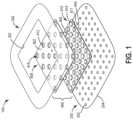
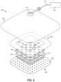
- FIG. 1is an exploded view of a dressing, according to an exemplary embodiment
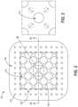
- FIG. 2is a top view of a dressing, according to an exemplary embodiment
- FIG. 3is a top view of a central region of a wound dressing, according to an exemplary embodiment
- FIG. 4is a sectional view of a wound dressing, according to an exemplary embodiment
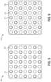
- FIG. 5is a top view of a first fluid management layer, according to an exemplary embodiment
- FIG. 6is a top view of a lower fluid management layer, according to an exemplary embodiment
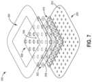
- FIG. 7is an exploded view of a dressing, according to another exemplary embodiment.
- FIG. 8is an exploded view of a dressing including a negative pressure wound therapy system, according to an exemplary embodiment
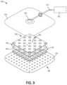
- FIG. 9is an exploded view of a dressing including a negative pressure wound therapy system, according to another exemplary embodiment.
- FIG. 10is a block diagram of a method of making a dressing, according to an exemplary embodiment.
- a partially transparent dressingthat allows a caregiver to view a wound site without having to remove and replace the dressing.
- the dressingincludes a patient interface layer, a barrier layer, and a fluid management core.
- the fluid management coreis “sandwiched” or otherwise disposed between the patient interface layer and the barrier layer.
- the fluid management coreincludes a plurality of windows through which the wound site may be visually examined.
- the fluid management coreincludes a first fluid management layer and a second fluid management layer.
- the first fluid management layeris coupled to the second fluid management layer.
- the fluid management layersare spaced apart from one another by a plurality of extensions.
- the extensionsmay be formed into one or both of the fluid management layers.
- the extensionsmay include cylindrical depressions or another geodesic structure formed into the fluid management layers.
- a contact area between each pair of extensions, or between each extension and the first or second fluid management layerforms an optically transparent window through which the wound bed can be observed.
- the fluid management coreincludes an absorbent material deposited in a cavity between the fluid management layers.
- the absorbent materialis configured to absorb and remove wound exudate from the wound site. Fluids are received from the wound site through a fluid communication port disposed in the second side of the fluid management core.
- the fluid communication portis substantially aligned with an opening in the patient interface layer.
- the space in between the fluid management layersprovides room for the absorbent material to expand as fluid enters the dressing.
- the extensionsprovide pressure relieving benefits to the dressing, preventing significant structural deformation or collapse of the fluid management core under compression, helping to retain fluid in the absorbent layer, and reducing the risk of maceration associated with fluid retention at the wound site.
- the dressingBy providing continuous visual access to the wound site, the dressing allows a caregiver to identify potential risks and signs of poor wound health at a much earlier stage of progression, while limiting the amount of patient trauma associated with wound redressing.
- FIG. 1provides an optically transparent dressing, shown as dressing 100 , according to an exemplary embodiment.
- the dressing 100is configured to provide visual access to a wound site throughout the duration of treatment.
- the dressing 100includes a patient interface layer 200 , a barrier layer 300 , and a fluid management core 400 .
- the fluid management core 400is sandwiched between the patient interface layer 200 and the barrier layer 300 .
- the fluid management core 400is centered over the patient interface layer 200 .
- the fluid management core 400includes a first side 402 and a second, wound-facing side, shown as second side 404 .
- the first side 402 of the fluid management core 400is coupled to the barrier layer 300 .
- the second side 404 of the fluid management core 400is coupled to the patient interface layer 200 .
- the dressing 100includes a plurality of fluid communication ports 406 disposed in the second side 404 of the fluid management core 400 .
- Each of the fluid communication ports 406is configured to receive fluid (e.g., wound exudate) from
- the opposing membersinclude a first fluid management layer 408 and second fluid management layer 410 .
- the first fluid management layer 408includes a first plurality of extensions 412 oriented substantially normal to the first fluid management layer 408 .
- the first plurality of extensions 412include substantially cylindrical depressions in the first fluid management layer 408 .
- the extensions 412extend from an inner surface of the first fluid management layer 408 toward the second fluid management layer 410 .
- the second fluid management layer 410is substantially similar to the first fluid management layer 408 .
- the second fluid management layer 410includes a second plurality of extensions 414 , each one of the second plurality of extensions 414 aligned with a corresponding one of the first plurality of extensions 412 .
- the fluid management core 400includes an absorbent layer 417 configured to absorb and remove wound exudate from a wound (e.g., a wound bed, a wound site, etc.).
- the absorbent layer 417is coupled to at least one of the fluid management layers 408 , 410 .
- the absorbent layer 417is deposited interstitially between adjacent ones of the second plurality of extensions 414 .
- the patient interface layer 200includes a plurality of openings 202 , each opening 202 aligned with a corresponding one of the fluid communication ports 406 in the fluid management core 400 .
- FIGS. 2 - 3a top view of the dressing 100 is shown, according to an exemplary embodiment.
- the fluid communication ports 406include fenestrations (e.g., substantially linear slits or cuts, etc.) disposed mid-way between adjacent pairs of extensions 414 on the second fluid management layer 410 .
- the spacing between fenestrationsis substantially the same as the spacing between openings 202 in the patient interface layer 200 .
- the openings 202are configured to fluidly couple the fluid management core 400 to the wound bed. Fluid passing through the openings 202 is received in a cavity (e.g., fluid pathway, etc.) formed between the fluid management layers 408 , 410 .
- the fluid management core 400is formed by a layered arrangement of the first fluid management layer 408 , the absorbent layer 417 , and the second fluid management layer 410 . As shown in FIG. 2 , each one of the first plurality of extensions 412 is configured to engage with a corresponding one of the second plurality of extensions 414 . According to an exemplary embodiment, the first plurality of extensions 412 is coupled to the second plurality of extensions 414 .
- the surfaces of the extensions 412 , 414e.g., outer surfaces, surfaces oriented substantially parallel to the fluid management layers 408 , 410 , etc. may be pretreated with a transparent adhesive prior to joining the fluid management layers 408 , 410 .
- the surfacesmay be coupled via welding, heat bonding, or another suitable joining process.
- a contact area between each one of the first plurality of extensions 412 and each one of the second plurality of extensions 414forms an optically transparent (or translucent) window 418 .
- the number of windows 418is approximately equal to the number of extensions 412 , 414 .
- a diameter of each window 418is approximately equal to a diameter of a circular depression defining the surface of each extension 412 , 414 .
- the diameter of each window 418may vary within a range between 3 mm and 15 mm. In alternative embodiments, the number, shape, size, and arrangement of windows 418 may be different.
- FIG. 4a side view of the dressing 100 is shown, at a cross-section through a row of extensions 412 , 414 , according to an exemplary embodiment.
- the fluid management layers 408 , 410define a cavity 420 (e.g., a fluid pathway, etc.) configured to receive fluid from the wound site.
- Dashed arrows 422indicate the flow direction of wound exudate entering the fluid management core 400 .
- an outer, wound-facing side, shown as outer surface 204 of the patient interface layer 200is configured to be placed in contact with a wound bed.
- Fluid from the wound bedpasses through the openings 202 in the patient interface layer 200 and the fluid communication ports 406 on the second side 404 of the fluid management core 400 (e.g., fenestrations in the second fluid management layer 410 ). Fluid entering the cavity 420 is absorbed by the absorbent layer 417 , which expands to fill the cavity 420 .
- the bonde.g., joint, connection, etc.
- the bondprevents fluid from blocking the windows 418 . As shown in FIG.
- the bond(e.g., joint, connection, etc.) between the second side 404 of the fluid management core 400 and the patient interface layer 200 prevents fluid from entering depressed areas 421 on the second side 404 of the fluid management core 400 (e.g., hollow spaces defined by each one of the second plurality of extensions 414 ).
- the barrier layer 300is configured as a barrier film to protect both the wound site and any external surfaces from contamination.
- the barrier layer 300includes an aperture 302 disposed centrally on the barrier layer 300 .
- the aperture 302is substantially centered over the fluid management core 400 .
- the barrier layer 300engages with the fluid management core 400 proximate to a perimeter of the first fluid management layer 408 .
- the barrier layer 300also engages with an outer portion of the patient interface layer 200 (e.g., a portion of the patient interface layer 200 that extends outward from the perimeter of the second fluid management layer 410 ).
- the barrier layer 300substantially covers the openings 202 in the outer portion of the patient interface layer 200 so as to prevent fluid from leaking out from the edges of the dressing 100 and protect the wound site and tissue surrounding the wound.
- the outer dimensions of the barrier layer 300are identical or substantially similar to the outer dimensions of the patient interface layer 200 .
- the extensionsmay be formed into only one of the first fluid management layer and the second fluid management layer.
- the extensionsmay engage with an inner surface of the opposing fluid management layer, rather than an opposing set of extensions.
- the windowsmay be formed within a region of contact (e.g., a contact area, etc.) between the extensions and the inner surface.
- the number, shape, size, and/or arrangement of extensionsmay be different in various alternative embodiments.
- FIG. 5provides a fluid management layer, shown as first fluid management layer 408 , according to an exemplary embodiment.
- the first fluid management layer 408is configured as an upper fluid management layer for a fluid management core 400 .
- the first fluid management layer 408may be made from a thermoplastic polyurethane (TPU) film, such as Vacive 3 mil polyurethane, or another formable and optically transparent material.
- TPUthermoplastic polyurethane
- the first fluid management layer 408includes a first plurality of extensions 414 .
- the first plurality of extensions 414may be thermoformed or otherwise formed into the first fluid management layer 408 .
- the first plurality of extensions 414may be formed in a variety of different shapes, for example, cylinders, domes, triangular depressions, or another geodesic shape.
- each one of the first plurality of extensions 414is substantially cylindrical.
- the extensions 414provide structural support to the fluid management core 400 and help to prevent the cavity 420 from collapsing when external pressure is applied to the dressing 100 .
- the extensions 414also help to reposition the fluid management layers 408 , 410 after the pressure is removed from the dressing 100 .
- a size of each individual extension 414e.g., a diameter of a planar surface of each extension 414 , a cross-sectional area of a planar surface of each extension 414 , etc.
- a number of extensions 414may be modified as needed to balance visual access to the wound site with fluid retention and structural support against compressive loading (e.g., pressure relieving benefits).
- the first fluid management layer 408is configured to allow fluid to evaporate into the surroundings.
- the material thickness and typemay be selected based on a target moisture vapor transmission rate (MVTR), which maximizes the healing benefits of the dressing 100 .
- MVTRtarget moisture vapor transmission rate
- the MVTRmay be within a range between 250 g/m 2 /day to 400 g/m 2 /day or greater.
- the MVTRmay increase as part of the thermoforming process.
- FIG. 6provides another fluid management layer, shown as second fluid management layer 410 .
- the second fluid management layer 410is configured as a lower, wound-facing fluid management layer for the fluid management core 400 .
- the second fluid management layer 410includes a second plurality of extensions 414 .
- the second fluid management layer 410is substantially identical (e.g., similar) to the first fluid management layer 408 , including the size, shape, number, and arrangement of extensions 414 .
- the second fluid management layer 410includes a plurality of fluid communication ports 406 extending through the fluid management layer 410 , from a first side of the fluid management layer 410 to a second, wound-facing side of the fluid management layer 410 .
- the fluid communication ports 406are configured to fluidly couple a cavity 420 between the fluid management layers 408 , 410 to openings 202 in the patient interface layer 200 (see also FIG. 1 ).
- the fluid communication ports 406include fenestrations configured to receive fluid from the openings 202 in the patient interface layer 200 .
- the fluid communication ports 406are disposed between adjacent pairs of extensions 414 so as to more fully expose the cavity 420 to fluid from the wound bed.
- the dressing 100includes an absorbent layer 417 configured to absorb wound exudate and remove it from the wound bed.
- the absorbent layer 417includes a superabsorbent polymer (SAP).
- the absorbent layer 417includes a plurality of nodules, dots, bumps, lumps, islands, protuberances, or other suitable form of deposition.
- absorbent layer 417may be formed from or otherwise include a superabsorbent polymer in the form of granules.
- the superabsorbent polymermay include Luquasorb 1160 or 1161, such as may be commercially available from BASF.
- the granulesmay be contained in a water-soluble carrier polymer.
- the water-soluble carrier polymeris polyvinylpyrrolidone (PVP).
- PVPpolyvinylpyrrolidone
- the superabsorbent polymer and the water-soluble polymermay be formed into a slurry or a suspension using an organic solvent.
- the organic solventmay include propanone or propanol and may aid in delivery of the absorbent layer 417 to a side of the of the fluid management layers 408 , 410 .
- a plasticizermay be added to the slurry.
- the plasticizermay be water.
- the slurry to form the absorbent layer 417may have a formulation of 20 parts by mass of PVP, 10 parts by mass of a superabsorbent polymer, 1 part by mass of glycerol, and 100 parts by mass of propanone.
- 1 part to 2 parts by mass of watermay be added to the slurry mixture.
- a water-soluble polymer superabsorbent precursorsuch as acrylic acid or 2-acrylamido-2-methyl-propanesulfonic acid (AMPS), with suitable UV curing additives, may replace the superabsorbent polymer.
- AMPS2-acrylamido-2-methyl-propanesulfonic acid
- Such a precursormay be a relatively low viscosity solution and can be printed onto the fluid management layers 408 , 410 and exposed to UV light to form a soft gel, eliminating the need for a plasticizer.
- the water-soluble polymer superabsorbent precursormay be similar to that used for preparing hydrogel coatings.
- the slurry mixtureis applied to one side of fluid management layers 408 , 410 to form the absorbent layer 417 .
- the slurrymay be applied to the fluid management layers 408 , 410 through standard printing methods, such as silk screen printing, gravure printing, or by x-y plotter printing.
- the absorbent layer 417may be in any non-contiguous shapes such as circles, squares, hexagons, hoops/halos, stars, crosses, a range of lines, or any combination of shapes disposed about the cylindrical protrusions.
- the absorbent layer 417may be printed such it is substantially evenly distributed on the fluid management layers 408 , 410 in between the extensions 412 , 414 .
- the absorbent layer 417may be printed in an uneven (e.g. non-uniform, random, etc.) pattern on the fluid management layers 408 , 410 .
- the absorbent layer 417may include a flexible plasticized hydrophilic polymer matrix having a substantially continuous internal structure. The absorbent layer 417 may be configured to swell upon absorption of fluid, such as wound fluid exudate, and expand within the space between the fluid management layers 408 , 410 .
- the absorbent layer 417is deposited onto the first fluid management layer 408 and second fluid management layer 410 . In some embodiments, the absorbent layer 417 is only deposited on the second fluid management layer 410 .
- the absorbent layer 417is printed in a regular pattern (e.g., an ordered pattern) and spaced approximately equally across an inner surface of the fluid management layers 408 , 410 .
- the absorbent layer 417includes a plurality of substantially cylindrical protrusions extending from the inner surface of the fluid management layers 408 , 410 .
- Each one of the cylindrical protrusionsis disposed approximately mid-way between adjacent pairs of extensions 412 , 414 on the fluid management layers 408 , 410 .
- the shape, quantity, and distribution of the absorbent layer 417may be different.
- the absorbent layer 417is printed or otherwise formed as a perforated sheet, where the perforations are sized to accommodate the extensions 412 , 414 on either layer, so as to occupy a greater portion of the cavity 420 .
- the patient interface layer 200is configured to engage with a wound bed.
- the patient interface layer 200includes an inner surface, and an outer, wound-facing surface.
- the inner surfaceis coupled to the fluid management core 400 .
- the outer surfaceis coupled to the wound bed.
- the patient interface layer 200may be made from a polymer film (e.g., polyurethane film) or a medical textile (e.g., Asahi nylon).
- the patient interface layer 200may include a suitable low tack adhesive (e.g., silicone or polyurethane gel) to facilitate bonding with the skin surrounding the wound.
- the adhesivemay be applied to the outer surface of the patient interface layer 200 proximate to a perimeter of the patient interface layer 200 , or at any other suitable location along the outer surface. In some embodiments, the adhesive may be distributed evenly across the outer surface.
- the patient interface layer 200extends laterally beyond an outer perimeter of the fluid management core 400 .
- the patient interface layer 200may be substantially the same size and shape as the fluid management core 400 (as the second fluid management layer 410 , etc.).
- the patient interface layer 200includes a plurality of openings 202 configured to receive fluid from a wound.
- the openings 202include substantially circular holes disposed in a regular pattern across the patient interface layer 200 . The size, shape, number, and arrangement of holes may be different in various alternative embodiments.
- the barrier layer 300is configured to protect both the wound bed and any external surfaces from contamination.
- the barrier layer 300may be made from a thin high MVTR adhesive coated polyurethane film such as Inspire 2327 / 2317 .
- the barrier layer 300may be fully coated in adhesive.
- the barrier layer 300may be pattern coated with adhesive so as to increase the MVTR of the dressing 100 (e.g., to improve breathability, to improve the healing effect provided by the dressing 100 , etc.).
- the barrier layer 300includes an aperture 302 disposed centrally on the barrier layer 300 .
- the aperture 302is substantially rectangular (e.g., substantially similar to the shape of the fluid management core 400 ).
- a width of the aperture 302is slightly less than a width of the fluid management core 400 .
- a length of the aperture 302is slightly less than a length of the fluid management core 400 .
- the aperture 302helps to ensure maximum visibility through the windows 418 in the fluid management core 400 .
- FIG. 7provides a dressing 500 including a wicking layer 502 (e.g., a wicking scrim layer, etc.), according to an exemplary embodiment.
- the wicking layer 502is configured to distribute fluid evenly throughout a cavity (e.g., fluid pathway, etc.) between the first and second fluid management layers.
- the wicking layer 502includes a plurality of perforations 504 .
- the perforationsmay be formed 504 via die cutting operation or another suitable forming operation.
- a shape of the perforations 504may be substantially similar to a cross-sectional shape of the extensions.
- the perforations 504may be alignable with the extensions.
- the wicking layerincludes depressions configured to receive the absorbent layer.
- the wicking layerincludes multiple layers configured to receive an absorbent layer therebetween.
- the dressing 500additionally includes a fluid removal port 506 disposed in the first side of the fluid management core.
- the fluid removal port 506is configured to allow fluid to be removed from the fluid management core.
- the fluid removal port 506may be fluidly coupled to a negative pressure wound therapy system as shown in FIG. 8 , which may, advantageously, increase the healing benefits provided by the dressing 500 .
- the systemmay include a drape 508 coupled to the first side of the fluid management core, a hydrophobic filter 510 , a tube set 512 , and a negative pressure pump 514 .
- FIG. 8the dressing 500 additionally includes a fluid removal port 506 disposed in the first side of the fluid management core.
- the fluid removal port 506is configured to allow fluid to be removed from the fluid management core.
- the fluid removal port 506may be fluidly coupled to a negative pressure wound therapy system as shown in FIG. 8 , which may, advantageously, increase the healing benefits provided by the dressing 500 .
- the systemmay include a drape 508 coupled to the first
- the barrier layer 516may be reconfigured to function as a drape; for example, by removing the aperture from the barrier layer 516 such that the barrier layer 516 substantially covers the fluid management core. Using the barrier layer 516 as the drape would reduce the overall complexity of the dressing.
- the fluid removal port 506includes a plurality of openings such as slots, slits, holes, etc. in the first side of the fluid management core. In some embodiments, the fluid removal port 506 is substantially similar to the fluid communication ports in the second fluid management layer.
- the negative pressure wound therapy systemincludes a canister configured to receive and store fluids from the wound bed.
- the canistereliminates the need for the hydrophobic filter 510 and the absorbent layer in the fluid management core, thereby reducing the number of layers that might otherwise obscure the view of the wound bed.
- the dressing 500may additionally include an osmotic layer configured to filter the wound exudate before the fluid reaches the absorbent layer (e.g., to remove particulate from the wound exudate, etc.). Fluid received by the absorbent layer would be substantially clear/transparent and would allow the caregiver greater window of clarity across the dressing 500 .
- the osmostic layermay be disposed in between the absorbent layer and the wound site to prevent any discoloration of the absorbent layer.
- the method 600includes providing a barrier layer 602 , providing a first fluid management layer 604 , providing a second fluid management layer 606 , providing an absorbent layer 608 , and providing a patient interface layer 610 .
- the first fluid management layermay include a first plurality of extensions.
- the second fluid management layermay include a second plurality of extensions.
- At least one of the fluid management layersmay include a fluid communication point. The fluid communication point may be configured to receive fluid from an opening in the patient interface layer.
- the layersmay be joined (e.g., connected, etc.) prior to applying the dressing to a wound site.
- the method 600includes placing the absorbent layer onto one of the fluid management layers 612 .
- Operation 612may include depositing an SAP onto the second fluid management layer.
- the SAPmay be deposited onto the same side of the second fluid management layer as the extensions.
- the SAPmay be deposited in between the extensions.
- Operation 612may also include depositing an SAP onto the first fluid management layer.
- the methodalso includes joining (e.g., connecting, coupling, etc.) the first fluid management layer and the second fluid management layer 612 so as to form a fluid management core.
- Operation 612may include aligning the first plurality of extensions with the second plurality of extensions.
- operation 612may include aligning an outer edge of the fluid management layers.
- the fluid management layersmay be joined by bonding (e.g., welding, heat bonding, etc.) the first plurality of extension pieces to the second plurality of extension pieces.
- a contact area between the extension piecesmay form an optically transparent window.
- the method 600includes placing the fluid management core onto the patient interface layer 614 .
- Operation 614may include centering the fluid management core above the patient interface layer.
- Operation 614may include aligning the fluid communication point with the opening on the patient interface layer.
- Operation 614may include coupling (e.g., bonding using a suitable adhesive, etc.) a second, wound-facing side of the fluid management core to the patient interface layer.
- the patient interface layermay at least partially seal the back side of second fluid management layer (e.g., the second side of the fluid management core) so as to prevent fluid from entering depressions formed into the second side by the second plurality of extensions.
- the method 600further includes placing the barrier layer onto the fluid management core 616 .
- Operation 616may include centering an aperture of the barrier layer over the fluid management core.
- Operation 616may include coupling (e.g., bonding using a suitable adhesive, etc.) the barrier layer to both the fluid management core and the patient interface layer. Together, the barrier layer and the patient interface layer may form a joint proximate to an outer perimeter of the fluid management core, thereby preventing fluid from entering or leaving the fluid management core through a side of the fluid management core.
- more or fewer operationsmay be performed to produce (e.g., make, manufacture, etc.) the dressing.
Landscapes
- Health & Medical Sciences (AREA)
- Engineering & Computer Science (AREA)
- Biomedical Technology (AREA)
- Heart & Thoracic Surgery (AREA)
- Vascular Medicine (AREA)
- Life Sciences & Earth Sciences (AREA)
- Animal Behavior & Ethology (AREA)
- General Health & Medical Sciences (AREA)
- Public Health (AREA)
- Veterinary Medicine (AREA)
- Manufacturing & Machinery (AREA)
- Media Introduction/Drainage Providing Device (AREA)
- External Artificial Organs (AREA)
Abstract
Description
Barrier Layer
Claims (23)
Priority Applications (1)
| Application Number | Priority Date | Filing Date | Title |
|---|---|---|---|
| US17/424,009US12220300B2 (en) | 2019-02-01 | 2020-01-27 | Partially transparent wound dressing |
Applications Claiming Priority (3)
| Application Number | Priority Date | Filing Date | Title |
|---|---|---|---|
| US201962799998P | 2019-02-01 | 2019-02-01 | |
| US17/424,009US12220300B2 (en) | 2019-02-01 | 2020-01-27 | Partially transparent wound dressing |
| PCT/US2020/015188WO2020159859A1 (en) | 2019-02-01 | 2020-01-27 | Partially transparent wound dressing |
Publications (2)
| Publication Number | Publication Date |
|---|---|
| US20220079815A1 US20220079815A1 (en) | 2022-03-17 |
| US12220300B2true US12220300B2 (en) | 2025-02-11 |
Family
ID=69724127
Family Applications (1)
| Application Number | Title | Priority Date | Filing Date |
|---|---|---|---|
| US17/424,009Active2041-11-18US12220300B2 (en) | 2019-02-01 | 2020-01-27 | Partially transparent wound dressing |
Country Status (4)
| Country | Link |
|---|---|
| US (1) | US12220300B2 (en) |
| EP (1) | EP3917474B1 (en) |
| CN (1) | CN113365588B (en) |
| WO (1) | WO2020159859A1 (en) |
Families Citing this family (15)
| Publication number | Priority date | Publication date | Assignee | Title |
|---|---|---|---|---|
| GB0808376D0 (en) | 2008-05-08 | 2008-06-18 | Bristol Myers Squibb Co | Wound dressing |
| GB201020236D0 (en) | 2010-11-30 | 2011-01-12 | Convatec Technologies Inc | A composition for detecting biofilms on viable tissues |
| ES2748519T3 (en) | 2010-12-08 | 2020-03-17 | Convatec Technologies Inc | Wound exudate system accessory |
| WO2012078724A1 (en) | 2010-12-08 | 2012-06-14 | Convatec Technologies Inc. | Apparatus and method for applying pressure to a wound site |
| JP2016507663A (en) | 2012-12-20 | 2016-03-10 | コンバテック・テクノロジーズ・インコーポレイテッドConvatec Technologies Inc | Processing of chemically modified cellulosic fibers |
| CN111836655A (en) | 2017-11-16 | 2020-10-27 | 康沃特克有限公司 | fluid collection equipment |
| EP3923878A4 (en) | 2019-02-13 | 2022-11-09 | Brian H. Silver | Forward osmosis medical and wound care devices |
| EP4295869A3 (en) | 2019-06-03 | 2024-03-20 | Convatec Limited | Methods and devices to disrupt and contain pathogens |
| US11331221B2 (en) | 2019-12-27 | 2022-05-17 | Convatec Limited | Negative pressure wound dressing |
| US11771819B2 (en) | 2019-12-27 | 2023-10-03 | Convatec Limited | Low profile filter devices suitable for use in negative pressure wound therapy systems |
| USD993424S1 (en)* | 2020-09-16 | 2023-07-25 | Mölnlycke Health Care Ab | Wound dressing |
| WO2022234471A1 (en)* | 2021-05-06 | 2022-11-10 | Kci Manufacturing Unlimited Company | Dressing with selective viewing access and reclosure system |
| USD999385S1 (en)* | 2021-10-18 | 2023-09-19 | Dbv Technologies | Patch assembly |
| USD999384S1 (en)* | 2021-10-18 | 2023-09-19 | Dbv Technologies | Patch assembly |
| USD1014764S1 (en)* | 2021-11-16 | 2024-02-13 | Raymond Lovell Francis | Skin-attachable block set that provides no-touch protection for skin insults |
Citations (130)
| Publication number | Priority date | Publication date | Assignee | Title |
|---|---|---|---|---|
| US1355846A (en) | 1920-02-06 | 1920-10-19 | David A Rannells | Medical appliance |
| US2547758A (en) | 1949-01-05 | 1951-04-03 | Wilmer B Keeling | Instrument for treating the male urethra |
| US2632443A (en) | 1949-04-18 | 1953-03-24 | Eleanor P Lesher | Surgical dressing |
| GB692578A (en) | 1949-09-13 | 1953-06-10 | Minnesota Mining & Mfg | Improvements in or relating to drape sheets for surgical use |
| US2682873A (en) | 1952-07-30 | 1954-07-06 | Johnson & Johnson | General purpose protective dressing |
| US2910763A (en) | 1955-08-17 | 1959-11-03 | Du Pont | Felt-like products |
| US2969057A (en) | 1957-11-04 | 1961-01-24 | Brady Co W H | Nematodic swab |
| US3066672A (en) | 1960-09-27 | 1962-12-04 | Jr William H Crosby | Method and apparatus for serial sampling of intestinal juice |
| US3367332A (en) | 1965-08-27 | 1968-02-06 | Gen Electric | Product and process for establishing a sterile area of skin |
| US3520300A (en) | 1967-03-15 | 1970-07-14 | Amp Inc | Surgical sponge and suction device |
| US3568675A (en) | 1968-08-30 | 1971-03-09 | Clyde B Harvey | Fistula and penetrating wound dressing |
| US3648692A (en) | 1970-12-07 | 1972-03-14 | Parke Davis & Co | Medical-surgical dressing for burns and the like |
| US3682180A (en) | 1970-06-08 | 1972-08-08 | Coilform Co Inc | Drain clip for surgical drain |
| US3826254A (en) | 1973-02-26 | 1974-07-30 | Verco Ind | Needle or catheter retaining appliance |
| DE2640413A1 (en) | 1976-09-08 | 1978-03-09 | Wolf Gmbh Richard | CATHETER MONITORING DEVICE |
| US4080970A (en) | 1976-11-17 | 1978-03-28 | Miller Thomas J | Post-operative combination dressing and internal drain tube with external shield and tube connector |
| US4096853A (en) | 1975-06-21 | 1978-06-27 | Hoechst Aktiengesellschaft | Device for the introduction of contrast medium into an anus praeter |
| US4139004A (en) | 1977-02-17 | 1979-02-13 | Gonzalez Jr Harry | Bandage apparatus for treating burns |
| US4165748A (en) | 1977-11-07 | 1979-08-28 | Johnson Melissa C | Catheter tube holder |
| US4184510A (en) | 1977-03-15 | 1980-01-22 | Fibra-Sonics, Inc. | Valued device for controlling vacuum in surgery |
| WO1980002182A1 (en) | 1979-04-06 | 1980-10-16 | J Moss | Portable suction device for collecting fluids from a closed wound |
| US4233969A (en) | 1976-11-11 | 1980-11-18 | Lock Peter M | Wound dressing materials |
| US4245630A (en) | 1976-10-08 | 1981-01-20 | T. J. Smith & Nephew, Ltd. | Tearable composite strip of materials |
| US4256109A (en) | 1978-07-10 | 1981-03-17 | Nichols Robert L | Shut off valve for medical suction apparatus |
| US4261363A (en) | 1979-11-09 | 1981-04-14 | C. R. Bard, Inc. | Retention clips for body fluid drains |
| US4275721A (en) | 1978-11-28 | 1981-06-30 | Landstingens Inkopscentral Lic, Ekonomisk Forening | Vein catheter bandage |
| US4284079A (en) | 1979-06-28 | 1981-08-18 | Adair Edwin Lloyd | Method for applying a male incontinence device |
| US4297995A (en) | 1980-06-03 | 1981-11-03 | Key Pharmaceuticals, Inc. | Bandage containing attachment post |
| US4333468A (en) | 1980-08-18 | 1982-06-08 | Geist Robert W | Mesentery tube holder apparatus |
| US4373519A (en) | 1981-06-26 | 1983-02-15 | Minnesota Mining And Manufacturing Company | Composite wound dressing |
| US4382441A (en) | 1978-12-06 | 1983-05-10 | Svedman Paul | Device for treating tissues, for example skin |
| US4392858A (en) | 1981-07-16 | 1983-07-12 | Sherwood Medical Company | Wound drainage device |
| US4392853A (en) | 1981-03-16 | 1983-07-12 | Rudolph Muto | Sterile assembly for protecting and fastening an indwelling device |
| US4419097A (en) | 1981-07-31 | 1983-12-06 | Rexar Industries, Inc. | Attachment for catheter tube |
| EP0100148A1 (en) | 1982-07-06 | 1984-02-08 | Dow Corning Limited | Medical-surgical dressing and a process for the production thereof |
| US4465485A (en) | 1981-03-06 | 1984-08-14 | Becton, Dickinson And Company | Suction canister with unitary shut-off valve and filter features |
| EP0117632A2 (en) | 1983-01-27 | 1984-09-05 | Johnson & Johnson Products Inc. | Adhesive film dressing |
| US4475909A (en) | 1982-05-06 | 1984-10-09 | Eisenberg Melvin I | Male urinary device and method for applying the device |
| US4480638A (en) | 1980-03-11 | 1984-11-06 | Eduard Schmid | Cushion for holding an element of grafted skin |
| US4525166A (en) | 1981-11-21 | 1985-06-25 | Intermedicat Gmbh | Rolled flexible medical suction drainage device |
| US4525374A (en) | 1984-02-27 | 1985-06-25 | Manresa, Inc. | Treating hydrophobic filters to render them hydrophilic |
| US4540412A (en) | 1983-07-14 | 1985-09-10 | The Kendall Company | Device for moist heat therapy |
| US4543100A (en) | 1983-11-01 | 1985-09-24 | Brodsky Stuart A | Catheter and drain tube retainer |
| US4548202A (en) | 1983-06-20 | 1985-10-22 | Ethicon, Inc. | Mesh tissue fasteners |
| US4551139A (en) | 1982-02-08 | 1985-11-05 | Marion Laboratories, Inc. | Method and apparatus for burn wound treatment |
| EP0161865A2 (en) | 1984-05-03 | 1985-11-21 | Smith and Nephew Associated Companies p.l.c. | Adhesive wound dressing |
| US4569348A (en) | 1980-02-22 | 1986-02-11 | Velcro Usa Inc. | Catheter tube holder strap |
| AU550575B2 (en) | 1981-08-07 | 1986-03-27 | Richard Christian Wright | Wound drainage device |
| US4605399A (en) | 1984-12-04 | 1986-08-12 | Complex, Inc. | Transdermal infusion device |
| US4608041A (en) | 1981-10-14 | 1986-08-26 | Frese Nielsen | Device for treatment of wounds in body tissue of patients by exposure to jets of gas |
| US4640688A (en) | 1985-08-23 | 1987-02-03 | Mentor Corporation | Urine collection catheter |
| US4655754A (en) | 1984-11-09 | 1987-04-07 | Stryker Corporation | Vacuum wound drainage system and lipids baffle therefor |
| US4664662A (en) | 1984-08-02 | 1987-05-12 | Smith And Nephew Associated Companies Plc | Wound dressing |
| WO1987004626A1 (en) | 1986-01-31 | 1987-08-13 | Osmond, Roger, L., W. | Suction system for wound and gastro-intestinal drainage |
| US4710165A (en) | 1985-09-16 | 1987-12-01 | Mcneil Charles B | Wearable, variable rate suction/collection device |
| US4733659A (en) | 1986-01-17 | 1988-03-29 | Seton Company | Foam bandage |
| GB2195255A (en) | 1986-09-30 | 1988-04-07 | Vacutec Uk Limited | Method and apparatus for vacuum treatment of an epidermal surface |
| US4743232A (en) | 1986-10-06 | 1988-05-10 | The Clinipad Corporation | Package assembly for plastic film bandage |
| GB2197789A (en) | 1986-11-28 | 1988-06-02 | Smiths Industries Plc | Anti-foaming disinfectants used in surgical suction apparatus |
| US4758220A (en) | 1985-09-26 | 1988-07-19 | Alcon Laboratories, Inc. | Surgical cassette proximity sensing and latching apparatus |
| US4787888A (en) | 1987-06-01 | 1988-11-29 | University Of Connecticut | Disposable piezoelectric polymer bandage for percutaneous delivery of drugs and method for such percutaneous delivery (a) |
| US4826494A (en) | 1984-11-09 | 1989-05-02 | Stryker Corporation | Vacuum wound drainage system |
| US4838883A (en) | 1986-03-07 | 1989-06-13 | Nissho Corporation | Urine-collecting device |
| US4840187A (en) | 1986-09-11 | 1989-06-20 | Bard Limited | Sheath applicator |
| US4863449A (en) | 1987-07-06 | 1989-09-05 | Hollister Incorporated | Adhesive-lined elastic condom cathether |
| US4872450A (en) | 1984-08-17 | 1989-10-10 | Austad Eric D | Wound dressing and method of forming same |
| US4878901A (en) | 1986-10-10 | 1989-11-07 | Sachse Hans Ernst | Condom catheter, a urethral catheter for the prevention of ascending infections |
| GB2220357A (en) | 1988-05-28 | 1990-01-10 | Smiths Industries Plc | Medico-surgical containers |
| US4897081A (en) | 1984-05-25 | 1990-01-30 | Thermedics Inc. | Percutaneous access device |
| US4906233A (en) | 1986-05-29 | 1990-03-06 | Terumo Kabushiki Kaisha | Method of securing a catheter body to a human skin surface |
| US4906240A (en) | 1988-02-01 | 1990-03-06 | Matrix Medica, Inc. | Adhesive-faced porous absorbent sheet and method of making same |
| US4919654A (en) | 1988-08-03 | 1990-04-24 | Kalt Medical Corporation | IV clamp with membrane |
| CA2005436A1 (en) | 1988-12-13 | 1990-06-13 | Glenda G. Kalt | Transparent tracheostomy tube dressing |
| US4941882A (en) | 1987-03-14 | 1990-07-17 | Smith And Nephew Associated Companies, P.L.C. | Adhesive dressing for retaining a cannula on the skin |
| US4953565A (en) | 1986-11-26 | 1990-09-04 | Shunro Tachibana | Endermic application kits for external medicines |
| WO1990010424A1 (en) | 1989-03-16 | 1990-09-20 | Smith & Nephew Plc | Absorbent devices and precursors therefor |
| US4969880A (en) | 1989-04-03 | 1990-11-13 | Zamierowski David S | Wound dressing and treatment method |
| US4985019A (en) | 1988-03-11 | 1991-01-15 | Michelson Gary K | X-ray marker |
| GB2235877A (en) | 1989-09-18 | 1991-03-20 | Antonio Talluri | Closed wound suction apparatus |
| US5037397A (en) | 1985-05-03 | 1991-08-06 | Medical Distributors, Inc. | Universal clamp |
| US5086170A (en) | 1989-01-16 | 1992-02-04 | Roussel Uclaf | Process for the preparation of azabicyclo compounds |
| US5092858A (en) | 1990-03-20 | 1992-03-03 | Becton, Dickinson And Company | Liquid gelling agent distributor device |
| US5100396A (en) | 1989-04-03 | 1992-03-31 | Zamierowski David S | Fluidic connection system and method |
| US5134994A (en) | 1990-02-12 | 1992-08-04 | Say Sam L | Field aspirator in a soft pack with externally mounted container |
| US5149331A (en) | 1991-05-03 | 1992-09-22 | Ariel Ferdman | Method and device for wound closure |
| US5167613A (en) | 1992-03-23 | 1992-12-01 | The Kendall Company | Composite vented wound dressing |
| US5176663A (en) | 1987-12-02 | 1993-01-05 | Pal Svedman | Dressing having pad with compressibility limiting elements |
| WO1993009727A1 (en) | 1991-11-14 | 1993-05-27 | Wake Forest University | Method and apparatus for treating tissue damage |
| US5215522A (en) | 1984-07-23 | 1993-06-01 | Ballard Medical Products | Single use medical aspirating device and method |
| US5232453A (en) | 1989-07-14 | 1993-08-03 | E. R. Squibb & Sons, Inc. | Catheter holder |
| US5261893A (en) | 1989-04-03 | 1993-11-16 | Zamierowski David S | Fastening system and method |
| US5278100A (en) | 1991-11-08 | 1994-01-11 | Micron Technology, Inc. | Chemical vapor deposition technique for depositing titanium silicide on semiconductor wafers |
| US5279550A (en) | 1991-12-19 | 1994-01-18 | Gish Biomedical, Inc. | Orthopedic autotransfusion system |
| US5298015A (en) | 1989-07-11 | 1994-03-29 | Nippon Zeon Co., Ltd. | Wound dressing having a porous structure |
| US5342376A (en) | 1993-05-03 | 1994-08-30 | Dermagraphics, Inc. | Inserting device for a barbed tissue connector |
| US5344415A (en) | 1993-06-15 | 1994-09-06 | Deroyal Industries, Inc. | Sterile system for dressing vascular access site |
| DE4306478A1 (en) | 1993-03-02 | 1994-09-08 | Wolfgang Dr Wagner | Drainage device, in particular pleural drainage device, and drainage method |
| WO1994020041A1 (en) | 1993-03-09 | 1994-09-15 | Wake Forest University | Wound treatment employing reduced pressure |
| US5358494A (en) | 1989-07-11 | 1994-10-25 | Svedman Paul | Irrigation dressing |
| US5437622A (en) | 1992-04-29 | 1995-08-01 | Laboratoire Hydrex (Sa) | Transparent adhesive dressing with reinforced starter cuts |
| US5437651A (en) | 1993-09-01 | 1995-08-01 | Research Medical, Inc. | Medical suction apparatus |
| DE29504378U1 (en) | 1995-03-15 | 1995-09-14 | MTG Medizinisch, technische Gerätebau GmbH, 66299 Friedrichsthal | Electronically controlled low-vacuum pump for chest and wound drainage |
| WO1996005873A1 (en) | 1994-08-22 | 1996-02-29 | Kinetic Concepts Inc. | Wound drainage equipment |
| US5527293A (en) | 1989-04-03 | 1996-06-18 | Kinetic Concepts, Inc. | Fastening system and method |
| US5549584A (en) | 1994-02-14 | 1996-08-27 | The Kendall Company | Apparatus for removing fluid from a wound |
| US5556375A (en) | 1994-06-16 | 1996-09-17 | Hercules Incorporated | Wound dressing having a fenestrated base layer |
| US5607388A (en) | 1994-06-16 | 1997-03-04 | Hercules Incorporated | Multi-purpose wound dressing |
| WO1997018007A1 (en) | 1995-11-14 | 1997-05-22 | Kci Medical Limited | Portable wound treatment apparatus |
| GB2329127A (en) | 1997-09-12 | 1999-03-17 | Kci Medical Ltd | Suction head and drape wound treatment assembly |
| US6071267A (en) | 1998-02-06 | 2000-06-06 | Kinetic Concepts, Inc. | Medical patient fluid management interface system and method |
| US6135116A (en) | 1997-07-28 | 2000-10-24 | Kci Licensing, Inc. | Therapeutic method for treating ulcers |
| US6241747B1 (en) | 1993-05-03 | 2001-06-05 | Quill Medical, Inc. | Barbed Bodily tissue connector |
| US6287316B1 (en) | 1999-03-26 | 2001-09-11 | Ethicon, Inc. | Knitted surgical mesh |
| US20020077661A1 (en) | 2000-12-20 | 2002-06-20 | Vahid Saadat | Multi-barbed device for retaining tissue in apposition and methods of use |
| US20020115951A1 (en) | 2001-02-22 | 2002-08-22 | Core Products International, Inc. | Ankle brace providing upper and lower ankle adjustment |
| US20020120185A1 (en) | 2000-05-26 | 2002-08-29 | Kci Licensing, Inc. | System for combined transcutaneous blood gas monitoring and vacuum assisted wound closure |
| US20020143286A1 (en) | 2001-03-05 | 2002-10-03 | Kci Licensing, Inc. | Vacuum assisted wound treatment apparatus and infection identification system and method |
| US6488643B1 (en) | 1998-10-08 | 2002-12-03 | Kci Licensing, Inc. | Wound healing foot wrap |
| US6493568B1 (en) | 1994-07-19 | 2002-12-10 | Kci Licensing, Inc. | Patient interface system |
| AU755496B2 (en) | 1997-09-12 | 2002-12-12 | Kci Licensing, Inc. | Surgical drape and suction head for wound treatment |
| WO2005079718A1 (en) | 2004-02-13 | 2005-09-01 | Bristol-Myers Squibb Company | Multi layered wound dressing |
| GB2412589A (en)* | 2004-04-02 | 2005-10-05 | Inotec Amd Ltd | Hyperbaric dressing |
| US20060173434A1 (en)* | 2005-02-02 | 2006-08-03 | Zoromski Paula K | Ultra thin absorbent article including a hot melt superabsorbent polymer composition |
| JP4129536B2 (en) | 2000-02-24 | 2008-08-06 | ヴェネテック インターナショナル,インコーポレイテッド | Highly compatible catheter anchoring system |
| US20100030170A1 (en)* | 2008-08-01 | 2010-02-04 | Keith Alan Keller | Absorptive Pad |
| WO2012125530A1 (en)* | 2011-03-16 | 2012-09-20 | Avery Dennison Corporation | Window dressings via hybrid casting sheets |
| WO2014020443A2 (en) | 2012-08-01 | 2014-02-06 | Smith & Nephew Pcl | Wound dressing and method of treatment |
| WO2015193257A1 (en)* | 2014-06-18 | 2015-12-23 | Smith & Nephew Plc | Wound dressing |
| GB2527617A (en)* | 2014-05-14 | 2015-12-30 | Brightwake Ltd | Wound dressing |
| US20160144084A1 (en)* | 2013-03-15 | 2016-05-26 | Smith & Nephew Plc | Wound dressing and method of treatment |
Family Cites Families (11)
| Publication number | Priority date | Publication date | Assignee | Title |
|---|---|---|---|---|
| US6264976B1 (en)* | 1999-11-29 | 2001-07-24 | 3M Innovative Properties Company | Absorbent pad dressing frame delivery system |
| US10363344B2 (en)* | 2002-12-31 | 2019-07-30 | Kci Licensing, Inc. | Externally-applied patient interface system and method with a controlled region for implanted or buried bio-reactor |
| GB0723874D0 (en)* | 2007-12-06 | 2008-01-16 | Smith & Nephew | Dressing |
| US9358158B2 (en)* | 2010-03-16 | 2016-06-07 | Kci Licensing, Inc. | Patterned neo-epithelialization dressings, systems, and methods |
| US20120253302A1 (en)* | 2011-04-04 | 2012-10-04 | Tyco Healthcare Group Lp | Negative Pressure Wound Therapy Dressing |
| CN107252383A (en)* | 2011-07-14 | 2017-10-17 | 史密夫及内修公开有限公司 | Wound dressing and treatment method |
| TWM456182U (en)* | 2013-02-21 | 2013-07-01 | Oriental Inst Technology | Diaper capable of displaying urine pH value |
| CN103876895A (en)* | 2014-03-11 | 2014-06-25 | 朱新生 | Liquid absorption wound dressing enabling wound surface to be observable |
| US10576250B2 (en)* | 2016-12-13 | 2020-03-03 | Becton, Dickinson And Company | Securement dressing for vascular access device with skin adhesive application window |
| CN207950229U (en)* | 2017-05-25 | 2018-10-12 | 复旦大学附属金山医院 | A kind of negative pressure drainage trauma care instrument of improved observable wound |
| CN107753180A (en)* | 2017-07-13 | 2018-03-06 | 江苏创铭医疗器械有限公司 | A kind of visual waterproof dressing |
- 2020
- 2020-01-27EPEP20707958.3Apatent/EP3917474B1/enactiveActive
- 2020-01-27CNCN202080011285.2Apatent/CN113365588B/enactiveActive
- 2020-01-27WOPCT/US2020/015188patent/WO2020159859A1/ennot_activeCeased
- 2020-01-27USUS17/424,009patent/US12220300B2/enactiveActive
Patent Citations (141)
| Publication number | Priority date | Publication date | Assignee | Title |
|---|---|---|---|---|
| US1355846A (en) | 1920-02-06 | 1920-10-19 | David A Rannells | Medical appliance |
| US2547758A (en) | 1949-01-05 | 1951-04-03 | Wilmer B Keeling | Instrument for treating the male urethra |
| US2632443A (en) | 1949-04-18 | 1953-03-24 | Eleanor P Lesher | Surgical dressing |
| GB692578A (en) | 1949-09-13 | 1953-06-10 | Minnesota Mining & Mfg | Improvements in or relating to drape sheets for surgical use |
| US2682873A (en) | 1952-07-30 | 1954-07-06 | Johnson & Johnson | General purpose protective dressing |
| US2910763A (en) | 1955-08-17 | 1959-11-03 | Du Pont | Felt-like products |
| US2969057A (en) | 1957-11-04 | 1961-01-24 | Brady Co W H | Nematodic swab |
| US3066672A (en) | 1960-09-27 | 1962-12-04 | Jr William H Crosby | Method and apparatus for serial sampling of intestinal juice |
| US3367332A (en) | 1965-08-27 | 1968-02-06 | Gen Electric | Product and process for establishing a sterile area of skin |
| US3520300A (en) | 1967-03-15 | 1970-07-14 | Amp Inc | Surgical sponge and suction device |
| US3568675A (en) | 1968-08-30 | 1971-03-09 | Clyde B Harvey | Fistula and penetrating wound dressing |
| US3682180A (en) | 1970-06-08 | 1972-08-08 | Coilform Co Inc | Drain clip for surgical drain |
| US3648692A (en) | 1970-12-07 | 1972-03-14 | Parke Davis & Co | Medical-surgical dressing for burns and the like |
| US3826254A (en) | 1973-02-26 | 1974-07-30 | Verco Ind | Needle or catheter retaining appliance |
| US4096853A (en) | 1975-06-21 | 1978-06-27 | Hoechst Aktiengesellschaft | Device for the introduction of contrast medium into an anus praeter |
| DE2640413A1 (en) | 1976-09-08 | 1978-03-09 | Wolf Gmbh Richard | CATHETER MONITORING DEVICE |
| US4245630A (en) | 1976-10-08 | 1981-01-20 | T. J. Smith & Nephew, Ltd. | Tearable composite strip of materials |
| US4233969A (en) | 1976-11-11 | 1980-11-18 | Lock Peter M | Wound dressing materials |
| US4080970A (en) | 1976-11-17 | 1978-03-28 | Miller Thomas J | Post-operative combination dressing and internal drain tube with external shield and tube connector |
| US4139004A (en) | 1977-02-17 | 1979-02-13 | Gonzalez Jr Harry | Bandage apparatus for treating burns |
| US4184510A (en) | 1977-03-15 | 1980-01-22 | Fibra-Sonics, Inc. | Valued device for controlling vacuum in surgery |
| US4165748A (en) | 1977-11-07 | 1979-08-28 | Johnson Melissa C | Catheter tube holder |
| US4256109A (en) | 1978-07-10 | 1981-03-17 | Nichols Robert L | Shut off valve for medical suction apparatus |
| US4275721A (en) | 1978-11-28 | 1981-06-30 | Landstingens Inkopscentral Lic, Ekonomisk Forening | Vein catheter bandage |
| US4382441A (en) | 1978-12-06 | 1983-05-10 | Svedman Paul | Device for treating tissues, for example skin |
| WO1980002182A1 (en) | 1979-04-06 | 1980-10-16 | J Moss | Portable suction device for collecting fluids from a closed wound |
| US4284079A (en) | 1979-06-28 | 1981-08-18 | Adair Edwin Lloyd | Method for applying a male incontinence device |
| US4261363A (en) | 1979-11-09 | 1981-04-14 | C. R. Bard, Inc. | Retention clips for body fluid drains |
| US4569348A (en) | 1980-02-22 | 1986-02-11 | Velcro Usa Inc. | Catheter tube holder strap |
| US4480638A (en) | 1980-03-11 | 1984-11-06 | Eduard Schmid | Cushion for holding an element of grafted skin |
| US4297995A (en) | 1980-06-03 | 1981-11-03 | Key Pharmaceuticals, Inc. | Bandage containing attachment post |
| US4333468A (en) | 1980-08-18 | 1982-06-08 | Geist Robert W | Mesentery tube holder apparatus |
| US4465485A (en) | 1981-03-06 | 1984-08-14 | Becton, Dickinson And Company | Suction canister with unitary shut-off valve and filter features |
| US4392853A (en) | 1981-03-16 | 1983-07-12 | Rudolph Muto | Sterile assembly for protecting and fastening an indwelling device |
| US4373519A (en) | 1981-06-26 | 1983-02-15 | Minnesota Mining And Manufacturing Company | Composite wound dressing |
| US4392858A (en) | 1981-07-16 | 1983-07-12 | Sherwood Medical Company | Wound drainage device |
| US4419097A (en) | 1981-07-31 | 1983-12-06 | Rexar Industries, Inc. | Attachment for catheter tube |
| AU550575B2 (en) | 1981-08-07 | 1986-03-27 | Richard Christian Wright | Wound drainage device |
| US4608041A (en) | 1981-10-14 | 1986-08-26 | Frese Nielsen | Device for treatment of wounds in body tissue of patients by exposure to jets of gas |
| US4525166A (en) | 1981-11-21 | 1985-06-25 | Intermedicat Gmbh | Rolled flexible medical suction drainage device |
| US4551139A (en) | 1982-02-08 | 1985-11-05 | Marion Laboratories, Inc. | Method and apparatus for burn wound treatment |
| US4475909A (en) | 1982-05-06 | 1984-10-09 | Eisenberg Melvin I | Male urinary device and method for applying the device |
| EP0100148A1 (en) | 1982-07-06 | 1984-02-08 | Dow Corning Limited | Medical-surgical dressing and a process for the production thereof |
| EP0117632A2 (en) | 1983-01-27 | 1984-09-05 | Johnson & Johnson Products Inc. | Adhesive film dressing |
| US4548202A (en) | 1983-06-20 | 1985-10-22 | Ethicon, Inc. | Mesh tissue fasteners |
| US4540412A (en) | 1983-07-14 | 1985-09-10 | The Kendall Company | Device for moist heat therapy |
| US4543100A (en) | 1983-11-01 | 1985-09-24 | Brodsky Stuart A | Catheter and drain tube retainer |
| US4525374A (en) | 1984-02-27 | 1985-06-25 | Manresa, Inc. | Treating hydrophobic filters to render them hydrophilic |
| EP0161865A2 (en) | 1984-05-03 | 1985-11-21 | Smith and Nephew Associated Companies p.l.c. | Adhesive wound dressing |
| US4897081A (en) | 1984-05-25 | 1990-01-30 | Thermedics Inc. | Percutaneous access device |
| US5215522A (en) | 1984-07-23 | 1993-06-01 | Ballard Medical Products | Single use medical aspirating device and method |
| US4664662A (en) | 1984-08-02 | 1987-05-12 | Smith And Nephew Associated Companies Plc | Wound dressing |
| US4872450A (en) | 1984-08-17 | 1989-10-10 | Austad Eric D | Wound dressing and method of forming same |
| US4655754A (en) | 1984-11-09 | 1987-04-07 | Stryker Corporation | Vacuum wound drainage system and lipids baffle therefor |
| US4826494A (en) | 1984-11-09 | 1989-05-02 | Stryker Corporation | Vacuum wound drainage system |
| US4605399A (en) | 1984-12-04 | 1986-08-12 | Complex, Inc. | Transdermal infusion device |
| US5037397A (en) | 1985-05-03 | 1991-08-06 | Medical Distributors, Inc. | Universal clamp |
| US4640688A (en) | 1985-08-23 | 1987-02-03 | Mentor Corporation | Urine collection catheter |
| US4710165A (en) | 1985-09-16 | 1987-12-01 | Mcneil Charles B | Wearable, variable rate suction/collection device |
| US4758220A (en) | 1985-09-26 | 1988-07-19 | Alcon Laboratories, Inc. | Surgical cassette proximity sensing and latching apparatus |
| US4733659A (en) | 1986-01-17 | 1988-03-29 | Seton Company | Foam bandage |
| WO1987004626A1 (en) | 1986-01-31 | 1987-08-13 | Osmond, Roger, L., W. | Suction system for wound and gastro-intestinal drainage |
| US4838883A (en) | 1986-03-07 | 1989-06-13 | Nissho Corporation | Urine-collecting device |
| US4906233A (en) | 1986-05-29 | 1990-03-06 | Terumo Kabushiki Kaisha | Method of securing a catheter body to a human skin surface |
| US4840187A (en) | 1986-09-11 | 1989-06-20 | Bard Limited | Sheath applicator |
| GB2195255A (en) | 1986-09-30 | 1988-04-07 | Vacutec Uk Limited | Method and apparatus for vacuum treatment of an epidermal surface |
| US4743232A (en) | 1986-10-06 | 1988-05-10 | The Clinipad Corporation | Package assembly for plastic film bandage |
| US4878901A (en) | 1986-10-10 | 1989-11-07 | Sachse Hans Ernst | Condom catheter, a urethral catheter for the prevention of ascending infections |
| US4953565A (en) | 1986-11-26 | 1990-09-04 | Shunro Tachibana | Endermic application kits for external medicines |
| GB2197789A (en) | 1986-11-28 | 1988-06-02 | Smiths Industries Plc | Anti-foaming disinfectants used in surgical suction apparatus |
| US4941882A (en) | 1987-03-14 | 1990-07-17 | Smith And Nephew Associated Companies, P.L.C. | Adhesive dressing for retaining a cannula on the skin |
| US4787888A (en) | 1987-06-01 | 1988-11-29 | University Of Connecticut | Disposable piezoelectric polymer bandage for percutaneous delivery of drugs and method for such percutaneous delivery (a) |
| US4863449A (en) | 1987-07-06 | 1989-09-05 | Hollister Incorporated | Adhesive-lined elastic condom cathether |
| US5176663A (en) | 1987-12-02 | 1993-01-05 | Pal Svedman | Dressing having pad with compressibility limiting elements |
| US4906240A (en) | 1988-02-01 | 1990-03-06 | Matrix Medica, Inc. | Adhesive-faced porous absorbent sheet and method of making same |
| US4985019A (en) | 1988-03-11 | 1991-01-15 | Michelson Gary K | X-ray marker |
| EP0358302A2 (en) | 1988-05-28 | 1990-03-14 | Smiths Industries Public Limited Company | Medico-surgical suction container |
| GB2220357A (en) | 1988-05-28 | 1990-01-10 | Smiths Industries Plc | Medico-surgical containers |
| US4919654A (en) | 1988-08-03 | 1990-04-24 | Kalt Medical Corporation | IV clamp with membrane |
| CA2005436A1 (en) | 1988-12-13 | 1990-06-13 | Glenda G. Kalt | Transparent tracheostomy tube dressing |
| US5086170A (en) | 1989-01-16 | 1992-02-04 | Roussel Uclaf | Process for the preparation of azabicyclo compounds |
| WO1990010424A1 (en) | 1989-03-16 | 1990-09-20 | Smith & Nephew Plc | Absorbent devices and precursors therefor |
| US5261893A (en) | 1989-04-03 | 1993-11-16 | Zamierowski David S | Fastening system and method |
| US5100396A (en) | 1989-04-03 | 1992-03-31 | Zamierowski David S | Fluidic connection system and method |
| US5527293A (en) | 1989-04-03 | 1996-06-18 | Kinetic Concepts, Inc. | Fastening system and method |
| US4969880A (en) | 1989-04-03 | 1990-11-13 | Zamierowski David S | Wound dressing and treatment method |
| US5298015A (en) | 1989-07-11 | 1994-03-29 | Nippon Zeon Co., Ltd. | Wound dressing having a porous structure |
| US5358494A (en) | 1989-07-11 | 1994-10-25 | Svedman Paul | Irrigation dressing |
| US5232453A (en) | 1989-07-14 | 1993-08-03 | E. R. Squibb & Sons, Inc. | Catheter holder |
| GB2235877A (en) | 1989-09-18 | 1991-03-20 | Antonio Talluri | Closed wound suction apparatus |
| US5134994A (en) | 1990-02-12 | 1992-08-04 | Say Sam L | Field aspirator in a soft pack with externally mounted container |
| US5092858A (en) | 1990-03-20 | 1992-03-03 | Becton, Dickinson And Company | Liquid gelling agent distributor device |
| US5149331A (en) | 1991-05-03 | 1992-09-22 | Ariel Ferdman | Method and device for wound closure |
| US5278100A (en) | 1991-11-08 | 1994-01-11 | Micron Technology, Inc. | Chemical vapor deposition technique for depositing titanium silicide on semiconductor wafers |
| US5645081A (en) | 1991-11-14 | 1997-07-08 | Wake Forest University | Method of treating tissue damage and apparatus for same |
| WO1993009727A1 (en) | 1991-11-14 | 1993-05-27 | Wake Forest University | Method and apparatus for treating tissue damage |
| US5636643A (en) | 1991-11-14 | 1997-06-10 | Wake Forest University | Wound treatment employing reduced pressure |
| US5279550A (en) | 1991-12-19 | 1994-01-18 | Gish Biomedical, Inc. | Orthopedic autotransfusion system |
| US5167613A (en) | 1992-03-23 | 1992-12-01 | The Kendall Company | Composite vented wound dressing |
| US5437622A (en) | 1992-04-29 | 1995-08-01 | Laboratoire Hydrex (Sa) | Transparent adhesive dressing with reinforced starter cuts |
| DE4306478A1 (en) | 1993-03-02 | 1994-09-08 | Wolfgang Dr Wagner | Drainage device, in particular pleural drainage device, and drainage method |
| WO1994020041A1 (en) | 1993-03-09 | 1994-09-15 | Wake Forest University | Wound treatment employing reduced pressure |
| US5342376A (en) | 1993-05-03 | 1994-08-30 | Dermagraphics, Inc. | Inserting device for a barbed tissue connector |
| US6241747B1 (en) | 1993-05-03 | 2001-06-05 | Quill Medical, Inc. | Barbed Bodily tissue connector |
| US5344415A (en) | 1993-06-15 | 1994-09-06 | Deroyal Industries, Inc. | Sterile system for dressing vascular access site |
| US5437651A (en) | 1993-09-01 | 1995-08-01 | Research Medical, Inc. | Medical suction apparatus |
| US5549584A (en) | 1994-02-14 | 1996-08-27 | The Kendall Company | Apparatus for removing fluid from a wound |
| US5607388A (en) | 1994-06-16 | 1997-03-04 | Hercules Incorporated | Multi-purpose wound dressing |
| US5556375A (en) | 1994-06-16 | 1996-09-17 | Hercules Incorporated | Wound dressing having a fenestrated base layer |
| US6493568B1 (en) | 1994-07-19 | 2002-12-10 | Kci Licensing, Inc. | Patient interface system |
| WO1996005873A1 (en) | 1994-08-22 | 1996-02-29 | Kinetic Concepts Inc. | Wound drainage equipment |
| DE29504378U1 (en) | 1995-03-15 | 1995-09-14 | MTG Medizinisch, technische Gerätebau GmbH, 66299 Friedrichsthal | Electronically controlled low-vacuum pump for chest and wound drainage |
| WO1997018007A1 (en) | 1995-11-14 | 1997-05-22 | Kci Medical Limited | Portable wound treatment apparatus |
| US6135116A (en) | 1997-07-28 | 2000-10-24 | Kci Licensing, Inc. | Therapeutic method for treating ulcers |
| WO1999013793A1 (en) | 1997-09-12 | 1999-03-25 | Kci Medical Limited | Surgical drape and suction head for wound treatment |
| EP1018967A1 (en) | 1997-09-12 | 2000-07-19 | KCI Medical Ltd. | Surgical drape and suction head for wound treatment |
| GB2333965A (en) | 1997-09-12 | 1999-08-11 | Kci Medical Ltd | Surgical drape |
| US6814079B2 (en) | 1997-09-12 | 2004-11-09 | Kci Licensing, Inc. | Surgical drape and suction head for wound treatment |
| US6345623B1 (en) | 1997-09-12 | 2002-02-12 | Keith Patrick Heaton | Surgical drape and suction head for wound treatment |
| AU745271B2 (en) | 1997-09-12 | 2002-03-14 | Kci Licensing, Inc. | Surgical drape and suction head for wound treatment |
| US6553998B2 (en) | 1997-09-12 | 2003-04-29 | Kci Licensing, Inc. | Surgical drape and suction head for wound treatment |
| AU755496B2 (en) | 1997-09-12 | 2002-12-12 | Kci Licensing, Inc. | Surgical drape and suction head for wound treatment |
| GB2329127A (en) | 1997-09-12 | 1999-03-17 | Kci Medical Ltd | Suction head and drape wound treatment assembly |
| US6071267A (en) | 1998-02-06 | 2000-06-06 | Kinetic Concepts, Inc. | Medical patient fluid management interface system and method |
| US6488643B1 (en) | 1998-10-08 | 2002-12-03 | Kci Licensing, Inc. | Wound healing foot wrap |
| US6287316B1 (en) | 1999-03-26 | 2001-09-11 | Ethicon, Inc. | Knitted surgical mesh |
| JP4129536B2 (en) | 2000-02-24 | 2008-08-06 | ヴェネテック インターナショナル,インコーポレイテッド | Highly compatible catheter anchoring system |
| US20020120185A1 (en) | 2000-05-26 | 2002-08-29 | Kci Licensing, Inc. | System for combined transcutaneous blood gas monitoring and vacuum assisted wound closure |
| US20020077661A1 (en) | 2000-12-20 | 2002-06-20 | Vahid Saadat | Multi-barbed device for retaining tissue in apposition and methods of use |
| US20020115951A1 (en) | 2001-02-22 | 2002-08-22 | Core Products International, Inc. | Ankle brace providing upper and lower ankle adjustment |
| US20020143286A1 (en) | 2001-03-05 | 2002-10-03 | Kci Licensing, Inc. | Vacuum assisted wound treatment apparatus and infection identification system and method |
| WO2005079718A1 (en) | 2004-02-13 | 2005-09-01 | Bristol-Myers Squibb Company | Multi layered wound dressing |
| GB2412589A (en)* | 2004-04-02 | 2005-10-05 | Inotec Amd Ltd | Hyperbaric dressing |
| US20060173434A1 (en)* | 2005-02-02 | 2006-08-03 | Zoromski Paula K | Ultra thin absorbent article including a hot melt superabsorbent polymer composition |
| US20100030170A1 (en)* | 2008-08-01 | 2010-02-04 | Keith Alan Keller | Absorptive Pad |
| WO2012125530A1 (en)* | 2011-03-16 | 2012-09-20 | Avery Dennison Corporation | Window dressings via hybrid casting sheets |
| WO2014020443A2 (en) | 2012-08-01 | 2014-02-06 | Smith & Nephew Pcl | Wound dressing and method of treatment |
| US20160144084A1 (en)* | 2013-03-15 | 2016-05-26 | Smith & Nephew Plc | Wound dressing and method of treatment |
| GB2527617A (en)* | 2014-05-14 | 2015-12-30 | Brightwake Ltd | Wound dressing |
| WO2015193257A1 (en)* | 2014-06-18 | 2015-12-23 | Smith & Nephew Plc | Wound dressing |
| CN106659590A (en) | 2014-06-18 | 2017-05-10 | 史密夫及内修公开有限公司 | Wound dressing |
Non-Patent Citations (42)
| Title |
|---|
| A.A. Safronov, Dissertation Abstract, Vacuum Therapy of Trophic Ulcers of the Lower Leg with Simultaneous Autoplasty of the Skin (Central Scientific Research Institute of Traumatology and Orthopedics, Moscow, U.S.S.R. 1967) (copy and certified translation). |
| Arnljots, Bjöm et al.: "Irrigation Treatment in Split-Thickness Skin Grafting of Intractable Leg Ulcers", Scand J. Plast Reconstr. Surg., No. 19, 1985, pp. 211-213. |
| C.E. Tennants, "The Use of Hypermia in the Postoperative Treatment of Lesions of the Extremities and Thorax," Journal of the American Medical Association 64 (1915), pp. 1548-1549. |
| Chariker, Mark E., M.D., et al; "Effective Management of incisional and cutaneous fistulae with closed suction wound drainage"; Contemporary Surgery, vol. 34, Jun. 1989, pp. 59-63. |
| Chinese Office Action for Corresponding Application No. 2020800112852, mailed Jan. 12, 2022. |
| Chinn, Steven D. et al.: "Closed Wound Suction Drainage", The Journal of Foot Surgery, vol. 24, No. 1, 1985, pp. 76-81. |
| D.E. Tribble, An Improved Sump Drain-Irrigation Device of Simple Construction, Archives of Surgery 105 (1972) pp. 511-513. |
| Dattilo, Philip P., Jr., et al; "Medical Textiles: Application of an Absorbable Barbed Bi-directional Surgical Suture"; Journal of Textile and Apparel, Technology and Management, vol. 2, Issue 2, Spring 2002, pp. 1-5. |
| Davydov, Yu. A., et al; "Vacuum Therapy in the Treatment of Purulent Lactation Mastitis"; Vestnik Khirurgi, May 14, 1986, pp. 66-70, and 9 page English translation thereof. |
| Davydov, Yu.A., et al; "Bacteriological and Cytological Assessment of Vacuum Therapy for Purulent Wounds"; Vestnik Khirugi, Oct. 1988, pp. 48-52, and 8 page English translation thereof. |
| Davydov, Yu.A., et al; "Concepts for the Clinical-Biological Management of the Wound Process in the Treatment of Purulent Wounds by Means of Vacuum Therapy"; Vestnik Khirurgi, Jul. 7, 1980, pp. 132-136, and 8 page English translation thereof. |
| Egnell Minor, Instruction Book, First Edition, 300 7502, Feb. 1975, pp. 24. |
| Egnell Minor: Addition to the Users Manual Concerning Overflow Protection—Concerns all Egnell Pumps, Feb. 3, 1983, pp. 2. |
| F.E. Johnson, "An Improved Technique for Skin Graft Placement Using a Suction Drain," Surgery, Gynecology, and Obstetrics 159 (1984), pp. 584-585. |
| G. Živadinovi?, V. ?uki?, Ž. Maksimovi?, ?. Radak, and P. Peška, "Vacuum Therapy in the Treatment of Peripheral Blood Vessels," Timok Medical Journal 11 (1986), pp. 161-164 (copy and certified translation). |
| George V. Letsou, MD., et al; "Stimulation of Adenylate Cyclase Activity in Cultured Endothelial Cells Subjected to Cyclic Stretch"; Journal of Cardiovascular Surgery, 31, 1990, pp. 634-639. |
| International Search Report and Written Opinion on International Patent Application No. PCT/US2020/015188 dated Apr. 23, 2020 (9 pages). |
| International Search Report for PCT International Application PCT/GB95/01983; Nov. 23, 1995. |
| James H. Blackburn II, MD et al.: Negative-Pressure Dressings as a Bolster for Skin Grafts; Annals of Plastic Surgery, vol. 40, No. 5, May 1998, pp. 453-457; Lippincott Williams & Wilkins, Inc., Philidelphia, PA, USA. |
| John Masters; "Reliable, Inexpensive and Simple Suction Dressings"; Letter to the Editor, British Journal of Plastic Surgery, 1998, vol. 51 (3), p. 267; Elsevier Science/The British Association of Plastic Surgeons, UK. |
| K.F. Jeter, T.E. Tintle, and M. Chariker, "Managing Draining Wounds and Fistulae: New and Established Methods," Chronic Wound Care, edited by D. Krasner (Health Management Publications, Inc., King of Prussia, PA 1990), pp. 240-246. |
| Kostyuchenok, B.M., et al; "Vacuum Treatment in the Surgical Management of Purulent Wounds"; Vestnik Khirurgi, Sep. 1986, pp. 18-21 and 6 page English translation thereof. |
| Louis C. Argenta, MD and Michael J. Morykwas, PHD; Vacuum-Assisted Closure: A New Method for Wound Control and Treatment: Clinical Experience; Annals of Plastic Surgery; vol. 38, No. 6, Jun. 1997; pp. 563-576. |
| M. Schein, R. Saadia, J.R. Jamieson, and G.A.G. Decker, "The ‘Sandwich Technique’ in the Management of the Open Abdomen," British Journal of Surgery 73 (1986), pp. 369-370. |
| M.J. Morykwas, L.C. Argenta, E.I. Shelton-Brown, and W. McGuirt, "Vacuum-Assisted Closure: A New Method for Wound Control and Treatment: Animal Studies and Basic Foundation," Annals of Plastic Surgery 38 (1997), pp. 553-562 (Morykwas I). |
| N.A. Bagautdinov, "Variant of External Vacuum Aspiration in the Treatment of Purulent Diseases of Soft Tissues," Current Problems in Modern Clinical Surgery: Interdepartmental Collection, edited by V. Ye Volkov et al. (Chuvashia State University, Cheboksary, U.S.S.R. 1986); pp. 94-96 (copy and certified translation). |
| Orringer, Jay, et al; "Management of Wounds in Patients with Complex Enterocutaneous Fistulas"; Surgery, Gynecology & Obstetrics, Jul. 1987, vol. 165, pp. 79-80. |
| PCT International Examination and Search Report, PCT International Application PCT/GB96/02802; Jan. 15, 1998 & Apr. 29, 1997. |
| PCT International Search Report for PCT International Application PCT/GB98/02713; Jan. 8, 1999. |
| PCT Written Opinion, PCT International Application PCT/GB96/02802; Sep. 3, 1997. |
| PCT Written Opinion; PCT International Application PCT/GB98/02713; Jun. 8, 1999. |
| S.E. Greer, et al. "The Use of Subatmospheric Pressure Dressing Therapy to Close Lymphocutaneous Fistulas of the Groin" British Journal of Plastic Surgery (2000), 53, pp. 484-487. |
| Selections from W. Meyer and V. Schmieden, Bier's Hyperemic Treatment in Surgery, Medicine, and the Specialties: A Manual of Its Practical Application, (W.B. Saunders Co., Philadelphia, PA 1909), pp. 17-25, 44-64, 90-96, 167-170, and 210-211. |
| Susan Mendez-Eatmen, RN; "When wounds Won't Heal" RN Jan. 1998, vol. 61 (1); Medical Economics Company, Inc., Montvale, NJ, USA; pp. 20-24. |
| Svedman, P. et al: "A Dressing System Providing Fluid Supply and Suction Drainage Used for Continuous of Intermittent Irrigation", Annals of Plastic Surgery, vol. 17, No. 2, Aug. 1986, pp. 125-133. |
| Svedman, P.: "A Dressing Allowing Continuous Treatment of a Biosurface", IRCS Medical Science: Biomedical Technology, Clinical Medicine, Surgery and Transplantation, vol. 7, 1979, p. 221. |
| Svedman, P.: "Irrigation Treatment of Leg Ulcers", The Lancet, Sep. 3, 1983, pp. 532-534. |
| V.A. Kuznetsov & N.a. Bagautdinov, "Vacuum and Vacuum-Sorption Treatment of Open Septic Wounds," in II All-Union Conference on Wounds and Wound Infections: Presentation Abstracts, edited by B.M. Kostyuchenok et al. (Moscow, U.S.S.R. Oct. 28-29, 1986) pp. 91-92 ("Bagautdinov II"). |
| V.A. Solovev et al., Guidelines, The Method of Treatment of Immature External Fistulas in the Upper Gastrointestinal Tract, editor-in-chief Prov. V.I. Parahonyak (S.M. Kirov Gorky State Medical Institute, Gorky, U.S.S.R. 1987) ("Solovev Guidelines"). |
| V.A. Solovev, Dissertation Abstract, Treatment and Prevention of Suture Failures after Gastric Resection (S.M. Kirov Gorky State Medical Institute, Gorky, U.S.S.R. 1988) ("Solovev Abstract"). |
| V.A.C.® Therapy Clinical Guidelines: A Reference Source for Clinicians; Jul. 2007. |
| Yusupov. Yu.N., et al; "Active Wound Drainage", Vestnki Khirurgi, vol. 138, Issue 4, 1987, and 7 page English translation thereof. |
Also Published As
| Publication number | Publication date |
|---|---|
| CN113365588A (en) | 2021-09-07 |
| US20220079815A1 (en) | 2022-03-17 |
| EP3917474A1 (en) | 2021-12-08 |
| CN113365588B (en) | 2022-08-30 |
| EP3917474B1 (en) | 2022-09-21 |
| WO2020159859A1 (en) | 2020-08-06 |
Similar Documents
| Publication | Publication Date | Title |
|---|---|---|
| US12220300B2 (en) | Partially transparent wound dressing | |
| CN110868969B (en) | Composite dressing for improving granulation growth and reducing maceration by negative pressure therapy | |
| JP7204685B2 (en) | A composite dressing that promotes granulation formation and reduces maceration in negative pressure therapy | |
| US12102511B2 (en) | Dressing with variable contraction zones | |
| US20200093646A1 (en) | Super-absorbent, low trauma, advanced wound dressing | |
| JP5933639B2 (en) | Thin decompression treatment system | |
| CA2726815C (en) | Negative pressure wound therapy device | |
| WO2020014310A1 (en) | Advanced wound dressing with compression and increased total fluid handling | |
| CN110831553A (en) | Composite dressing for improving granulation growth and reducing maceration by negative pressure therapy | |
| CA2826575C (en) | Adaptive and optionally also otherwise adaptable wound dressing | |
| CN114173726A (en) | Negative pressure wound dressing | |
| JP2022536285A (en) | Composite dressing for tissue closure using negative pressure | |
| US20220296435A1 (en) | Novel Absorbent Wound Dressing Construct That Allows Wound Fluid Assessment In Use | |
| US12350128B2 (en) | Advanced wound dressing for incisional wounds that provides apposition forces as a result of fluid absorption | |
| JP7505092B2 (en) | Peel-and-stick dressing for thick exudates and drips | |
| WO2021070049A1 (en) | Low-profile superabsorbent dressing | |
| CN116831814A (en) | A frame dressing combined with ointment |
Legal Events
| Date | Code | Title | Description |
|---|---|---|---|
| AS | Assignment | Owner name:KCI LICENSING, INC., TEXAS Free format text:ASSIGNMENT OF ASSIGNORS INTEREST;ASSIGNORS:EDWARDS, THOMAS A.;LOCKE, CHRISTOPHER B.;ROBINSON, TIMOTHY M.;AND OTHERS;REEL/FRAME:056901/0571 Effective date:20190204 | |
| FEPP | Fee payment procedure | Free format text:ENTITY STATUS SET TO UNDISCOUNTED (ORIGINAL EVENT CODE: BIG.); ENTITY STATUS OF PATENT OWNER: LARGE ENTITY | |
| STPP | Information on status: patent application and granting procedure in general | Free format text:DOCKETED NEW CASE - READY FOR EXAMINATION | |
| AS | Assignment | Owner name:3M INNOVATIVE PROPERTIES COMPANY, MINNESOTA Free format text:ASSIGNMENT OF ASSIGNORS INTEREST;ASSIGNOR:KCI LICENSING, INC.;REEL/FRAME:064788/0823 Effective date:20230830 | |
| AS | Assignment | Owner name:3M INNOVATIVE PROPERTIES COMPANY, MINNESOTA Free format text:CORRECTIVE ASSIGNMENT TO CORRECT THE APPLICATION LISTED ON SCHEDULE OF IP RIGHTS ATTACHED TO ASSIGNMENT AT LINES 55: 71; 89; 116-129; AND 131 NEED TO BE DELETED PREVIOUSLY RECORDED AT REEL: 064788 FRAME: 0823. ASSIGNOR(S) HEREBY CONFIRMS THE ASSIGNMENT;ASSIGNOR:KCI LICENSING, INC.;REEL/FRAME:064886/0479 Effective date:20230830 | |
| STPP | Information on status: patent application and granting procedure in general | Free format text:NON FINAL ACTION MAILED | |
| AS | Assignment | Owner name:SOLVENTUM INTELLECTUAL PROPERTIES COMPANY, MINNESOTA Free format text:ASSIGNMENT OF ASSIGNORS INTEREST;ASSIGNOR:3M INNOVATIVE PROPERTIES COMPANY;REEL/FRAME:066436/0225 Effective date:20240201 | |
| STPP | Information on status: patent application and granting procedure in general | Free format text:RESPONSE TO NON-FINAL OFFICE ACTION ENTERED AND FORWARDED TO EXAMINER | |
| STPP | Information on status: patent application and granting procedure in general | Free format text:FINAL REJECTION MAILED | |
| STPP | Information on status: patent application and granting procedure in general | Free format text:RESPONSE AFTER FINAL ACTION FORWARDED TO EXAMINER | |
| ZAAB | Notice of allowance mailed | Free format text:ORIGINAL CODE: MN/=. | |
| STPP | Information on status: patent application and granting procedure in general | Free format text:NOTICE OF ALLOWANCE MAILED -- APPLICATION RECEIVED IN OFFICE OF PUBLICATIONS | |
| STPP | Information on status: patent application and granting procedure in general | Free format text:PUBLICATIONS -- ISSUE FEE PAYMENT RECEIVED | |
| STPP | Information on status: patent application and granting procedure in general | Free format text:PUBLICATIONS -- ISSUE FEE PAYMENT VERIFIED | |
| STCF | Information on status: patent grant | Free format text:PATENTED CASE |