US12220130B2 - Electrolytic detachment with fluid electrical connection - Google Patents
Electrolytic detachment with fluid electrical connectionDownload PDFInfo
- Publication number
- US12220130B2 US12220130B2US16/948,740US202016948740AUS12220130B2US 12220130 B2US12220130 B2US 12220130B2US 202016948740 AUS202016948740 AUS 202016948740AUS 12220130 B2US12220130 B2US 12220130B2
- Authority
- US
- United States
- Prior art keywords
- catheter
- detachment zone
- electrode
- delivery
- implant
- Prior art date
- Legal status (The legal status is an assumption and is not a legal conclusion. Google has not performed a legal analysis and makes no representation as to the accuracy of the status listed.)
- Active, expires
Links
Images


Classifications
- A—HUMAN NECESSITIES
- A61—MEDICAL OR VETERINARY SCIENCE; HYGIENE
- A61B—DIAGNOSIS; SURGERY; IDENTIFICATION
- A61B17/00—Surgical instruments, devices or methods
- A61B17/12—Surgical instruments, devices or methods for ligaturing or otherwise compressing tubular parts of the body, e.g. blood vessels or umbilical cord
- A61B17/12022—Occluding by internal devices, e.g. balloons or releasable wires
- A61B17/12099—Occluding by internal devices, e.g. balloons or releasable wires characterised by the location of the occluder
- A61B17/12109—Occluding by internal devices, e.g. balloons or releasable wires characterised by the location of the occluder in a blood vessel
- A—HUMAN NECESSITIES
- A61—MEDICAL OR VETERINARY SCIENCE; HYGIENE
- A61B—DIAGNOSIS; SURGERY; IDENTIFICATION
- A61B17/00—Surgical instruments, devices or methods
- A61B17/12—Surgical instruments, devices or methods for ligaturing or otherwise compressing tubular parts of the body, e.g. blood vessels or umbilical cord
- A61B17/12022—Occluding by internal devices, e.g. balloons or releasable wires
- A61B17/12027—Type of occlusion
- A61B17/12031—Type of occlusion complete occlusion
- A—HUMAN NECESSITIES
- A61—MEDICAL OR VETERINARY SCIENCE; HYGIENE
- A61B—DIAGNOSIS; SURGERY; IDENTIFICATION
- A61B17/00—Surgical instruments, devices or methods
- A61B17/12—Surgical instruments, devices or methods for ligaturing or otherwise compressing tubular parts of the body, e.g. blood vessels or umbilical cord
- A61B17/12022—Occluding by internal devices, e.g. balloons or releasable wires
- A61B17/12099—Occluding by internal devices, e.g. balloons or releasable wires characterised by the location of the occluder
- A61B17/12109—Occluding by internal devices, e.g. balloons or releasable wires characterised by the location of the occluder in a blood vessel
- A61B17/12113—Occluding by internal devices, e.g. balloons or releasable wires characterised by the location of the occluder in a blood vessel within an aneurysm
- A—HUMAN NECESSITIES
- A61—MEDICAL OR VETERINARY SCIENCE; HYGIENE
- A61B—DIAGNOSIS; SURGERY; IDENTIFICATION
- A61B17/00—Surgical instruments, devices or methods
- A61B17/12—Surgical instruments, devices or methods for ligaturing or otherwise compressing tubular parts of the body, e.g. blood vessels or umbilical cord
- A61B17/12022—Occluding by internal devices, e.g. balloons or releasable wires
- A61B17/12131—Occluding by internal devices, e.g. balloons or releasable wires characterised by the type of occluding device
- A61B17/1214—Coils or wires
- A61B17/12145—Coils or wires having a pre-set deployed three-dimensional shape
- A—HUMAN NECESSITIES
- A61—MEDICAL OR VETERINARY SCIENCE; HYGIENE
- A61B—DIAGNOSIS; SURGERY; IDENTIFICATION
- A61B17/00—Surgical instruments, devices or methods
- A61B17/12—Surgical instruments, devices or methods for ligaturing or otherwise compressing tubular parts of the body, e.g. blood vessels or umbilical cord
- A61B17/12022—Occluding by internal devices, e.g. balloons or releasable wires
- A61B17/12131—Occluding by internal devices, e.g. balloons or releasable wires characterised by the type of occluding device
- A61B17/12168—Occluding by internal devices, e.g. balloons or releasable wires characterised by the type of occluding device having a mesh structure
- A61B17/12172—Occluding by internal devices, e.g. balloons or releasable wires characterised by the type of occluding device having a mesh structure having a pre-set deployed three-dimensional shape
- A—HUMAN NECESSITIES
- A61—MEDICAL OR VETERINARY SCIENCE; HYGIENE
- A61F—FILTERS IMPLANTABLE INTO BLOOD VESSELS; PROSTHESES; DEVICES PROVIDING PATENCY TO, OR PREVENTING COLLAPSING OF, TUBULAR STRUCTURES OF THE BODY, e.g. STENTS; ORTHOPAEDIC, NURSING OR CONTRACEPTIVE DEVICES; FOMENTATION; TREATMENT OR PROTECTION OF EYES OR EARS; BANDAGES, DRESSINGS OR ABSORBENT PADS; FIRST-AID KITS
- A61F2/00—Filters implantable into blood vessels; Prostheses, i.e. artificial substitutes or replacements for parts of the body; Appliances for connecting them with the body; Devices providing patency to, or preventing collapsing of, tubular structures of the body, e.g. stents
- A61F2/95—Instruments specially adapted for placement or removal of stents or stent-grafts
- A61F2/962—Instruments specially adapted for placement or removal of stents or stent-grafts having an outer sleeve
- A61F2/966—Instruments specially adapted for placement or removal of stents or stent-grafts having an outer sleeve with relative longitudinal movement between outer sleeve and prosthesis, e.g. using a push rod
- A—HUMAN NECESSITIES
- A61—MEDICAL OR VETERINARY SCIENCE; HYGIENE
- A61M—DEVICES FOR INTRODUCING MEDIA INTO, OR ONTO, THE BODY; DEVICES FOR TRANSDUCING BODY MEDIA OR FOR TAKING MEDIA FROM THE BODY; DEVICES FOR PRODUCING OR ENDING SLEEP OR STUPOR
- A61M5/00—Devices for bringing media into the body in a subcutaneous, intra-vascular or intramuscular way; Accessories therefor, e.g. filling or cleaning devices, arm-rests
- A61M5/14—Infusion devices, e.g. infusing by gravity; Blood infusion; Accessories therefor
- A61M5/142—Pressure infusion, e.g. using pumps
- A—HUMAN NECESSITIES
- A61—MEDICAL OR VETERINARY SCIENCE; HYGIENE
- A61B—DIAGNOSIS; SURGERY; IDENTIFICATION
- A61B17/00—Surgical instruments, devices or methods
- A61B2017/00017—Electrical control of surgical instruments
- A—HUMAN NECESSITIES
- A61—MEDICAL OR VETERINARY SCIENCE; HYGIENE
- A61B—DIAGNOSIS; SURGERY; IDENTIFICATION
- A61B17/00—Surgical instruments, devices or methods
- A61B2017/00831—Material properties
- A61B2017/00867—Material properties shape memory effect
- A—HUMAN NECESSITIES
- A61—MEDICAL OR VETERINARY SCIENCE; HYGIENE
- A61B—DIAGNOSIS; SURGERY; IDENTIFICATION
- A61B17/00—Surgical instruments, devices or methods
- A61B2017/00831—Material properties
- A61B2017/00929—Material properties isolating electrical current
- A—HUMAN NECESSITIES
- A61—MEDICAL OR VETERINARY SCIENCE; HYGIENE
- A61B—DIAGNOSIS; SURGERY; IDENTIFICATION
- A61B17/00—Surgical instruments, devices or methods
- A61B17/12—Surgical instruments, devices or methods for ligaturing or otherwise compressing tubular parts of the body, e.g. blood vessels or umbilical cord
- A61B17/12022—Occluding by internal devices, e.g. balloons or releasable wires
- A61B2017/1205—Introduction devices
- A61B2017/12054—Details concerning the detachment of the occluding device from the introduction device
- A61B2017/12063—Details concerning the detachment of the occluding device from the introduction device electrolytically detachable
- A—HUMAN NECESSITIES
- A61—MEDICAL OR VETERINARY SCIENCE; HYGIENE
- A61B—DIAGNOSIS; SURGERY; IDENTIFICATION
- A61B90/00—Instruments, implements or accessories specially adapted for surgery or diagnosis and not covered by any of the groups A61B1/00 - A61B50/00, e.g. for luxation treatment or for protecting wound edges
- A61B90/39—Markers, e.g. radio-opaque or breast lesions markers
- A61B2090/3966—Radiopaque markers visible in an X-ray image
- A—HUMAN NECESSITIES
- A61—MEDICAL OR VETERINARY SCIENCE; HYGIENE
- A61B—DIAGNOSIS; SURGERY; IDENTIFICATION
- A61B2217/00—General characteristics of surgical instruments
- A61B2217/002—Auxiliary appliance
- A61B2217/007—Auxiliary appliance with irrigation system
Definitions
- the subject technologyrelates to the delivery of implantable medical devices and systems for delivering implantable medical devices.
- vascular aneurysmscan be occluded with an implantable medical device that is introduced to the vasculature with a delivery wire through a catheter. Once advanced to the treatment site, the medical device can be inserted into the aneurysm cavity to occlude the aneurysm and then detached from the delivery wire.
- Detachment of a medical device or implant from the delivery wirecan be problematic. It is essential that the implant can be collapsed to form as small a profile as possible to be guided through the fine bore of the catheter, and it must bring about a reliable severance of the implant from the wire. Absent a reliable severance of the implant, withdrawal of the delivery wire and catheter may cause unintended removal of the implant from the aneurysm, and thus injure and/or rupture of the wall of the aneurysm or vessel.
- Electrolytic detachment of an implantable medical devicecan involve using an electrolytically corrodible region on the end of a delivery wire at the connection between the delivery wire and the medical device.
- Known methods of electrolytic detachmentcan employ an electrolytically corrodible region on the end of the delivery wire at the connection between the delivery wire and the implant.
- the connection of the implant to the delivery wireis limited by the requirements of the electrolytically corrodible region. For example, only materials that have a sufficiently high degree of strength to enable reliable guidance of the implant can be utilized in delivery wire material selection.
- a delivery systemcomprising:
- a method of delivering an implantcomprising:
- positioning the implantcomprises:
- applying the voltage potentialcomprises:
- applying the voltage potentialcomprises applying a voltage potential between the delivery electrode and the infusion electrode.
- applying the voltage potentialcomprises applying the voltage potential until the detachment zone has corroded.
- FIG. 1shows a perspective view of a delivery system having an electrical return path, in accordance with one or more embodiments of the present disclosure.
- FIG. 2shows a perspective side view of a braid ball implant, in accordance with one or more embodiments of the present disclosure.
- FIG. 3shows a side-sectional view of the braid ball implant of FIG. 2 deployed within a bifurcation aneurysm, in accordance with one or more embodiments of the present disclosure.
- FIG. 4shows a sectional view of a distal end of the delivery system of FIG. 1 , in accordance with one or more embodiments of the present disclosure.
- FIG. 5shows a side view of the delivery system of FIG. 1 , in accordance with one or more embodiments of the present disclosure.
- FIG. 6shows a sectional view of the delivery system of FIGS. 1 and 5 , in accordance with one or more embodiments of the present disclosure.
- FIG. 7shows a partial sectional view of an implant detachment zone at a stage of implant deployment within a bifurcation aneurysm, in accordance with one or more embodiments of the present disclosure.
- FIG. 8shows a partial sectional view of an implant detachment zone at a stage of implant deployment within a bifurcation aneurysm, in accordance with one or more embodiments of the present disclosure.
- FIG. 9shows a partial sectional view of an implant detachment zone at a stage of implant deployment within a bifurcation aneurysm, in accordance with one or more embodiments of the present disclosure.
- Implantscan be implanted in body cavities, including blood vessels. Implants can be delivered to a target body cavity using a delivery system, and detached from the delivery system when positioned within the body cavity.
- a delivery systemcan comprise a delivery wire having an electrolytically corrodible detachment zone between the implant and the delivery system. When a voltage potential is applied across the detachment zone while in an electrolyte, such as blood for example, the detachment zone corrodes. When sufficiently corroded, the detachment zone is severed, releasing the implant from the delivery system.
- the voltage potentialcan be generated using a power supply electrically connected to the delivery system.
- the power supply or groundcan be electrically connected to a patient on the surface of the patient's skin to provide a conductive pathway from a detachment zone at or near the implant.
- the conductive pathwaycan require a secure connection, such as with a transcutaneous needle or other device that punctures the patient. The current would then flow through the patient and the needle between the detachment zone and the ground or power supply.
- electrolytic detachmentcan be facilitated by a closed circuit of electrical current entirely within a delivery system, thereby avoiding the need to insert a needle into the patient to complete a circuit through the patient's tissue.
- patient comfortis improved and resistance within the circuit is reduced, thereby improving detachment time and reliability.
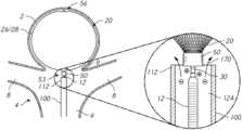
- FIG. 1illustrates a view of a delivery system 10 according to one or more embodiments of the subject technology.
- the delivery system 10can include an implant 20 , a pusher assembly 12 , and a delivery catheter 100 connected to a handle 42 .
- the handle 42 shownprovides proximal access to a delivery wire 44 of the pusher assembly 12 that engages the implant 20 at a distal end thereof.
- the delivery wire 44can be connected to the implant at a detachment zone 30 forming a detachment junction between the delivery wire 44 and the implant 20 at or near the implant 20 .
- the delivery catheter 100can be positioned over the pusher assembly 12 .
- the power supply 46can be coupled to a proximal portion of the delivery wire 44 , and the power supply 46 also can be coupled (e.g., to the handle 42 ) such that one of the terminals of the power supply 46 is in electrical connection with a fluid and/or fluid flow 170 in a vicinity of the implant 20 , as described further herein.
- the power supply 46can include an electrical generator configured to output medically useful electrical current.
- the power supply 46may be a direct current power supply, an alternating current power supply, or a power supply switchable between a direct current and an alternating current.
- the power supply 46can include a suitable controller that can be used to control various parameters of the energy output by the generator, such as intensity, amplitude, duration, frequency, duty cycle, and polarity.
- the power supply 46can provide a voltage of about 12 volts to about 28 volts and a current of about 1 mA to about 2 mA.
- a fluid source 150may be provided in fluid connection with a pump 160 for infusion of the fluid via the delivery catheter 100 .
- the fluid source 150can include saline or another sterile, electrolytic, biocompatible solution.
- the fluidcan be infused together with a drug, such as heparin.
- the pumpcan draw fluid from the fluid source 150 and advance the fluid into and through a lumen 124 ( FIG. 6 ) of the delivery catheter 100 .
- the pump 160can be an infusion pump, a syringe, a compressor, a pressurized container, and/or a gravity-based infusion mechanism.
- an implant 20 delivered by the delivery system 10can be a braid ball implant.
- the implant 20can be formed from tubular braid stock including a resilient material, such as nitinol, that defines an open volume in an uncompressed/unconstrained state.
- the size of the implantcan be selected to fill an aneurysm 2 when expanded therein.
- the implant 20can include a hub 50 and layers 26 , 28 .
- the hubcan be located at a proximal end 53 of the implant.
- the hub 50can be fixedly attached to the remainder of the implant 20 .
- the hub 50can grasp braided filaments of the layers 26 , 28 of the implant 20 .
- the implant 20can include the layers 26 , 28 at least where impacted by flow at the neck 9 of the aneurysm 2 .
- the implant 20 illustrated hereinis a braided ball
- the implant 20can be any well-known treatment device including, but not limited to, vasoocclusive coils, stents, filters, or flow diverters.
- the implant 20can be set within an aneurysm 2 at a vascular bifurcation 4 , formed by trunk vessel 6 and branch vessels 8 , for example as illustrated in FIG. 3 .
- the implant 20can be delivered by access through the trunk vessel 6 (e.g., the basilar artery), preferably through a commercially available microcatheter with a delivery system as detailed below.
- the pusher assembly 12is positioned such that the implant 20 can be delivered at least partially into the aneurysm 2 .
- the implant 20is separated from the remainder of the pusher assembly 12 by electrolytic corrosion at the detachment zone 30 , and the remainder of the pusher assembly 12 is withdrawn into the delivery catheter 100 .
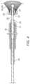
- FIG. 4illustrates a sectional view of a pusher assembly 12 according to one or more embodiments of the subject technology.
- a pusher assembly 12includes a delivery wire 44 having a proximal region 31 , a distal region 33 , and a detachment zone 30 between the proximal region 31 and the distal region 33 .
- the delivery wire 44can form a single, monolith component across the proximal region 31 , the distal region 33 , and the detachment zone 30 , or the delivery wire 44 can be formed of separate segments joined together.
- portions of the delivery wire 44can be coated with a nonconductive material so that only a limited portion of surface area of the delivery wire is exposed to, and in electrical communication with, the electrolyte for corrosion when a voltage potential is applied. Limiting the size of the exposed portion of the surface area of the delivery wire can concentrate electrolytic activity to expedite corrosion through and severance of the delivery wire.
- a proximal insulating layer 34can be provided over at least a portion of an outer surface of the proximal region 31 .
- the proximal insulating layer 34can circumferentially surround an outer surface of the proximal region 31 extending proximally from a proximal end of the detachment zone 30 to a location at or near a proximal end of the delivery wire 44 .
- a distal insulating layer 32can be provided over at least a portion of an outer surface of the distal region 33 extending distally from a distal end of the detachment zone 30 to a distal terminal end of the delivery wire 44 .
- the distal insulating layer 32can circumferentially surround and cover the entire outer surface of the distal region 33 .
- proximal and distal insulating layers 34 , 32leave exposed the portion of the delivery wire 44 forming the detachment zone 30 between the proximal region 31 and the distal region 33 .
- the fluidWhen in contact with a body fluid, such as blood, the fluid serves as an electrolyte allowing current to be focused on the non-coated detachment zone 30 .
- the proximal and distal insulating layers 34 , 32prevent exposure of the proximal region 31 and the distal region 33 to the fluid. Accordingly, electrical energy conducted along the delivery wire 44 is concentrated at the detachment zone 30 , thereby reducing the time required to erode away the detachment zone 30 .
- the proximal and distal insulating layers 34 , 32can be over-molded, co-extruded, sprayed on, or dip-coated with respect to the proximal region 31 and/or the distal region 33 .
- the distal insulating layer 32also prevents electrical connection between the delivery wire 44 and the implant. As shown in FIG. 4 , the distal insulating layer 32 electrically isolates the implant 20 from an electrical current conducted along a length of the delivery wire, from the proximal region 31 to the distal region 33 .
- a proximal end of the distal insulating layer 32may be positioned at or proximal to the hub 50 , and a distal end of the distal insulating layer 32 may be positioned at or distal to the hub 50 Likewise, a proximal end of the distal region 33 may be positioned proximal to the hub 50 , and a distal end of the distal region 33 may be positioned within or distal to the hub 50 .
- the distal insulating layer 32insulates the distal region 33 from the hub 50 to prevent the electrical current from being conducted to the implant 20 .
- the proximal and distal insulating layers 34 , 32can comprise an electrically nonconductive or insulative polymer, such as polyimide, polypropylene, polyolefins, or combinations thereof.
- the proximal and distal insulating layers 34 , 32can be applied as a single coating with a portion thereof subsequently removed to expose the detachment zone 30 .
- Laser ablationcan be employed to selectively remove the coating to a controlled length, minimizing the time required to erode through the component. Lengths as small as 0.0005′′ and as large as 0.1′′ or longer can be removed.
- lengths of detachment zone 30can be greater than 0.005′′ and/or less than 0.010′′ to provide sufficient exposure to achieve detachment times of less than 30 seconds.
- the delivery wire 44(including some or all of the proximal region 31 , the distal region 33 , or the detachment zone 30 ) can comprise one or more of the following materials: ceramic materials, plastics, base metals or alloys thereof, or combinations thereof.
- Some of the most suitable material combinations for forming the electrolytically corrodible pointscan include one or more of the following: stainless steels, preferably of the type AISI 301, 304, 316, or subgroups thereof; Ti or TiNi alloys; Co-based alloys; noble metals; or noble metal alloys, such as Pt, Pt metals, Pt alloys, Au alloys, or Sn alloys.
- the electrolytically corrodible detachment zonecan be pre-corroded by etching or other methods.
- a marker coil 36is wound helically about an outer surface of the proximal insulating layer 34 .
- the marker coil 36can be of a radiopaque material, such as platinum, gold, palladium, iridium, and alloys thereof.
- the proximal insulating layer 34can be provided about an outer surface of the marker coil 36 .
- the proximal insulating layer 34can extend over an entire length of the marker coil 36 and distally beyond the marker coil 36 , such that every portion of the marker coil 36 is covered by the proximal insulating layer 34 .
- the delivery wire 44can be continuous through the proximal region 31 . Accordingly, an electric potential applied to the proximal end of the delivery wire 44 can induce an electrical current conducted through the delivery wire 44 along the proximal region 31 to the detachment zone 30 . Furthermore, an axial force applied to the delivery wire 44 can result in an axial movement of the detachment zone 30 and the implant 20 .
- FIGS. 5 and 6illustrate various views of a delivery system 10 according to some embodiments of the subject technology.
- FIG. 5depicts a side view of a delivery system 10
- FIG. 6depicts a sectional view of the delivery system 10 as shown in FIG. 5 .
- the delivery system 10 illustrated in FIGS. 5 and 6is similar in some respects to the delivery system 10 of FIG. 1 and can be understood with reference thereto, where like numerals indicate like elements or components not described again in detail.
- FIGS. 5 and 6illustrate electrical connection of a power supply 46 to a delivery wire 44 and a fluid and/or fluid flow 170 in a vicinity of the detachment zone 30 of the delivery wire 44 .
- An electrical pathwaycan pass from a first terminal 48 of the power supply to the delivery wire 44 and into a fluid/fluid flow 170 at the detachment zone 30 , and then return to a second terminal 47 of the power supply 46 through the fluid/fluid flow.
- the delivery catheter 100can be formed as a generally tubular member with a body extending from a proximal end 110 and terminating in a distal end 112 .
- An inner lumen 124extends from a proximal port 45 of the delivery catheter 100 .
- the delivery catheter 100can generally track over a conventional guidewire and may be any commercially available microcatheter appropriate for such applications.
- Inner lumen 124 of the delivery cathetergenerally has an inner diameter between about 0.01 inch and about 0.098 inch (0.25-2.49 mm). Other designs and dimensions are contemplated.
- Commercially available microcatheterswhich may be suitable for use as delivery catheters include the REBARTM Reinforced Micro Catheter, which is available from Medtronic, Inc. and the MARKSMANTM Catheter, which is available from Medtronic, Inc.
- the proximal port 45 of the delivery catheter 100may be provided with an adapter (not shown) having a hemostatic valve.
- the proximal port 45may comprise a valve or other sealable mechanism for receiving at least a portion of the pusher assembly 12 while preventing passage of the fluid flow 170 proximally past the proximal port 45 in the presence or absence of the delivery wire 44 .
- the proximal port 45can include a split septum, slit valve, duckbill valve, dome valve, donut valve, multi-cuspid valve, or combinations thereof.
- the proximal port 45can include a hydrophobic coating.
- the delivery catheter 100is generally constructed to bridge between a femoral artery access site and a cervical region of the carotid or vertebral artery and may be chosen according to several standard designs that are generally available. Accordingly, the delivery catheter 100 may be at least 85 cm long, and more particularly may be between about 95 cm and about 175 cm long. For example, a distance between (a) the proximal port 45 and/or the infusion port 60 ( FIG. 5 ) and (b) the distal end 112 can be at least 85 cm, and more particularly may be between about 95 cm and about 175 cm long.
- a delivery electrode 82is configured to be coupled to the delivery wire 44 .
- a variety of coupling mechanismsmay be employed to selectively secure the delivery electrode 82 to the delivery wire 44 such that an electrical connection is established.
- the delivery electrode 82can include a clamp, pin, ring, clasp, or combinations thereof to engage a complementary structure of the delivery wire 44 .
- the delivery electrode 82is further configured to be coupled to the first terminal 48 (e.g., cathode or anode) of the power supply 46 .
- An electrical potential generated at the first terminal 48can induce an electrical current through the delivery electrode 82 and the delivery wire 44 to the detachment zone 30 .
- Flow of electrical current between the delivery wire and the immediately surrounding environmente.g., the fluid and/or fluid flow 170
- At least a portion of the proximal insulating layer 34may extend to the proximal port 45 and/or proximally thereof to insulate the delivery wire 44 from the fluid flow 170 within the lumen 124 of the delivery catheter 100 .
- an infusion connector 62can provide a connection to the infusion port 60 for infusion of fluid and electrical connections.
- the infusion connector 62can connect to an interface with the infusion port 60 on a first end.
- the infusion connector 62can further provide an electrode connector 140 and a fluid connector 162 .
- the infusion connector 62can define a lumen that divides and connects to both an electrode port 142 of the electrode connector 140 and the pump 160 and fluid source 150 of the fluid connector 162 .
- the entirety or a portion of the infusion connector 62 and components thereofcan be located outside a body of the patient.
- the fluid connector 162 , the electrode connector 140 , the electrode port 142 , the pump 160 , and/or the fluid source 150can be located outside a body of the patient during use.
- components interfacing with the infusion connector 62 and components thereofcan be located outside a body of the patient.
- the infusion connector 62can take the form of a Y-connector. Additional connectors can be provided in addition to the electrode connector 140 and the fluid connector 162 .
- the interior lumens of the infusion connector 62provide fluid communication and electrical connection through the fluid and between the infusion port 60 , the electrode port 142 , and the fluid source 150 .
- the components of the infusion connector 62can be placed in fluid communication and electrical connection with the lumen 124 of the delivery catheter 100 , as well as components residing in and near the lumen 124 , including the detachment zone 30 .
- the electrode connector 140is configured to receive an infusion electrode 80 .
- at least a portion of the infusion electrode 80extends distally through the electrode port 142 and at least a portion of the lumen of the electrode connector 140 .
- the infusion electrode 80extends through the electrode connector 140 and into the lumen of the infusion connector 62 .
- the infusion electrode 80may extend through the infusion connector 62 and through the infusion port 60 .
- the infusion electrode 80may extend into the lumen 124 of the delivery catheter 100 such that the distal tip of the infusion electrode 80 terminates within the lumen 124 .
- the infusion electrode 80extends distally along the length of the delivery catheter 100 within the lumen 124 such that the distal tip of the infusion electrode 80 terminates within 2 inches of the detachment zone 30 , and in some embodiments within 1 inch of the detachment zone 30 .
- at least a portion of the infusion electrode 80 between the second terminal 47 and a region adjacent the detachment zone 30may be electrically insulated so long as the portion of the infusion electrode 80 within 2 inches of the detachment zone 30 is exposed (e.g., in electrical communication with the fluid pathway).
- the infusion electrode 80is configured to pass through the electrode port 142 to contact and/or be in electrical connection with the fluid 170 within the infusion connector 62 and/or the delivery catheter 100 .
- the infusion electrode 80can comprise a needle or other elongate member.
- the electrode port 142may comprise a valve or other sealable mechanism for receiving at least a portion of the infusion electrode 80 while preventing passage of the fluid flow 170 proximally past the electrode port 142 in the presence or absence of the infusion electrode 80 .
- the electrode port 142can include a split septum, slit valve, duckbill valve, dome valve, donut valve, multi-cuspid valve, or combinations thereof.
- the electrode port 142can include a hydrophobic coating.
- the infusion electrode 80can be placed in electrical connection with the fluid 170 without directly contacting the fluid 170 .
- the infusion electrode 80can include a clamp, pin, ring, clasp, or combinations thereof to engage the electrode port 142 , thereby placing the infusion electrode 80 in electrical connection with the fluid 170 .
- the infusion electrode 80is further configured to be coupled to the second terminal 47 (e.g., cathode or anode) of the power supply 46 .
- An electrical potential generated at the second terminal 47can induce an electrical current through the infusion electrode 80 and the fluid 170 (e.g., along the lumen 124 ) to the vicinity of the detachment zone 30 .
- the infusion electrode 80can be a “painted” electrode on a surface of a non-conductive material.
- the infusion electrode 80can include platinum, platinum alloys (e.g., 92% platinum and 8% tungsten, 90% platinum and 10% iridium), gold, cobalt-chrome, stainless steel (e.g., 304 or 316), and combinations thereof.
- an electrical pathwaycan pass through one or more of the first terminal 48 of the power supply 46 , the delivery electrode 82 , the proximal region 31 of the delivery wire 44 , the detachment zone 30 , the fluid 170 in the lumen 124 of the delivery catheter 100 , the fluid 170 in the infusion port 60 , the fluid 170 in the fluid connector 162 , the fluid 170 in the electrode connector 140 , the infusion electrode 80 , the electrode port 142 , and the second terminal 47 of the power supply 46 .
- Other pathways completing a circuitcan include other components or regions.
- an infusion fluid 170can be provided from the fluid source 150 to the infusion port 60 , shown in FIGS. 5 and 6 , to provide fluid communication to the distal end 112 of the delivery catheter 100 .
- the fluidcan be biocompatible and generally conductive. Infusion may be accomplished by the pump 160 or other flow-inducing device.
- the infusion port 60can be provided in fluid communication with and electrical connection with a distal end 112 of the delivery catheter 100 .
- the infusion electrode 80may be integrated with the body of the delivery catheter 100 such that the infusion electrode 80 extends distally within the sidewall 190 of the delivery catheter 100 rather than within the lumen 124 of the delivery catheter 100 .
- the infusion electrode 80may extend distally from the proximal end 110 of the delivery catheter 100 to a transmission portion adjacent the detachment zone 30 .
- At least a region of the transmission portionmay be exposed to the lumen 124 such that, when fluid 170 flows through the lumen 124 and the power supply 46 is providing a voltage across the first and second terminals 48 , 47 , an electrical current passes through the first terminal 48 of the power supply 46 , the delivery electrode 82 , the proximal region 31 of the delivery wire 44 , the detachment zone 30 , the fluid 170 in the lumen 124 of the delivery catheter 100 , the transmission portion, the infusion electrode 80 , and the second terminal 47 of the power supply 46 .
- the exposed region of the transmission portionis located along the length of the delivery catheter 100 within 2 inches of the detachment zone 30 . In some embodiments, the exposed region of the transmission portion is located along the length of the delivery catheter 100 within 1-2 inches of the detachment zone 30 . In some embodiments, the exposed region of the transmission portion is located along the length of the delivery catheter 100 within 1 inch of the detachment zone 30 .
- the transmission portion and the infusion electrode 80are a single, continuous component or material (e.g., integral with one another), and the transmission portion may be a portion of the infusion electrode 80 that is exposed to the lumen 124 .
- the infusion electrode 80may be an elongated, conductive member (e.g., a wire) that is insulated within the sidewall 190 of the delivery catheter 100 , and the transmission portion is a portion of the conductive member that is exposed to the lumen 124 through the sidewall 190 within 2 inches of the detachment zone 30 .
- the sidewall 190 of the delivery catheter 100includes a coil and/or braid along its length that include one or more conductive materials.
- a proximal end portion of the coil and/or braidcan be electrically coupled to the second terminal 47 of the power source (directly or indirectly via one or more connectors) and a distal end portion of the braid and/or coil may be exposed through the sidewall 190 to the lumen 124 within 2 inches of the detachment zone.
- a distal end portion of the braid and/or coilmay be exposed through the sidewall 190 to the lumen 124 within 1-2 inches of the detachment zone, and in some embodiments within 1 inch of the detachment zone.
- the transmission portionmay be the exposed length of the coil and/or braid
- the infusion electrode 80may be the length of the coil and/or braid between the second terminal 47 and the exposed portion.
- the transmission portion and the infusion electrode 80are separate components that are electrically coupled to one another.
- the infusion electrode 80may be a first conductive element (e.g., a wire, a braid, a coil, etc.) that is insulated within the sidewall 190 of the delivery catheter 100
- the transmission portionis a second conductive element (e.g., all or part of a marker band, a braid, a coil, etc.) having at least a region exposed to the lumen 124 through the sidewall 190 within 2 inches of the detachment zone 30 .
- the second conductive elementhas at least a region exposed to the lumen 124 through the sidewall 190 within 1-2 inches of the detachment zone 30 , and in some embodiments within 1 inch of the detachment zone.
- a distal end portion of the infusion electrode 80may be electrically coupled to a proximal end portion of the transmission portion.
- FIGS. 7 - 9illustrate various stages of an exemplifying method according to one or more embodiments of the subject technology.
- FIG. 7illustrates an implant 20 inserted within the aneurysm 2 .
- FIG. 8illustrates a stage of detachment in progress
- FIG. 9illustrates a stage following detachment of the implant 20 from the pusher assembly 12 .
- the delivery catheter 100is advanced to place its distal end 112 in the vicinity of a target site (e.g., an aneurysm 2 ).
- a target sitee.g., an aneurysm 2
- other components and stagesmay also be employed.
- the delivery catheter 100may be guided to the target site by a guide wire and/or a guide catheter, according to known techniques.
- the implant 20can be advanced over a guidewire (not shown) through the lumen 124 to the target site.
- the implant 20can be placed within the aneurysm and deployed.
- the implant 20is advanced from the delivery catheter 100 to the target site.
- the implant 20may be placed at the target site, and the delivery catheter 100 may be subsequently advanced or retracted relative to the pusher assembly 12 while the pusher assembly 12 holds the implant 20 steady.
- the delivery catheter 100may be positioned such that the detachment zone is entirely exposed, partially exposed, or not exposed by the delivery catheter 100 .
- the detachment zone 30may be distal to, overlapping with, or proximal to the distal end 112 of the delivery catheter 100 .
- the detachment zone 30can be longitudinally aligned with the distal end of the delivery catheter 100 .
- Positioning of the delivery catheter 100 relative to the pusher assembly 12 (e.g., relative to the detachment zone 30 ) and/or implant 20may be facilitated by components providing visualization.
- a radiopaque marker of the delivery catheter 100can be longitudinally aligned with a radiopaque marker of the pusher assembly 12 and/or the implant 20 to provide confirmation that the implant 20 is positioned outside of the delivery catheter 100 .
- electrolytic detachment of the implant 20 from the pusher assembly 12can be achieved.
- One or both of the detachment zone 30 and the infusion electrode 80can be energized to apply electrical energy.
- the detachment zone 30 and the infusion electrode 80can be energized with electrical energy of opposite polarity to create a voltage potential and pass electrical current through the fluid 170 between the detachment zone 30 and the infusion electrode 80 . While the electrical current can pass predominantly through the fluid 170 , current induced by the voltage potential may also pass along other pathways. Fluids other than the fluid 170 from the fluid source 150 can contribute to an electrical pathway. For example, blood from the body of the patient may mix with the fluid 170 and form a portion of the pathway.
- a current sourcee.g., the power supply 46
- a current source connected to the infusion electrode 80is activated. While one of the detachment zone 30 and the infusion electrode 80 are energized, the other can be energized with an opposite polarity or grounded.
- the detachment zone 30 and the infusion electrode 80can each be multifunctional. For example, each can serve as either an active electrode or a ground electrode at different points in time as the treatment proceeds. By further example, each can serve as either a cathode or an anode at different points in time as the treatment proceeds. If desired, during the period of time that a voltage potential is formed, the polarity can be switched once or repeatedly, to create currents traveling in either direction across the gap between the detachment zone 30 and the infusion electrode 80 .
- fluid flow 170can be provided during electrolytic detachment of the implant 20 from the pusher assembly 12 .
- an infusion of fluid from the fluid source 150 by the pump 160can be provided via the delivery catheter 100 past the detachment zone 30 .
- the fluid flow 170can be directed distally from the lumen 124 to a region distal to the distal end 112 of the delivery catheter 100 .
- the fluid flow 170can be directed proximally into the lumen 124 from a region distal to the distal end 112 of the delivery catheter 100 .
- the fluid flow 170may evacuate any bubbles that form near the detachment zone 30 .
- the formation of bubblescan also change the dielectric characteristics of the vicinity of the detachment zone 30 .
- bubblescan serve as a dielectric material and electrically insulate the detachment zone 30 from the infusion electrode 80 .
- Such a conditioncan create a dielectric region with an undesirably high breakdown voltage.
- the fluid flow 170can refresh the fluid composition within the gap to maintain a clear conduction path.
- the fluid flow 170may evacuate debris from the vicinity of the detachment zone 30 .
- the debriscan form or facilitate a short circuit from the detachment zone 30 to other structures, thereby creating a conductive bridge and reducing the rate of electrolytic detachment of the detachment zone 30 .
- the fluid flow 170can remove the debris to maintain a clear pathway for electrical current between the detachment zone 30 and the infusion electrode 80 .
- the fluid flow 170can be provided during part or all of an electrolytic detachment operation.
- the fluid flow 170may commence before, during, or after initial application of a voltage potential between the detachment zone 30 and the delivery catheter 100 .
- the fluid flow 170may cease before, during, or after termination of the voltage potential.
- the fluid flow 170can be provided intermittently based on conditions existing during the electrolytic detachment process.
- the fluid flow 170can be provided when and/or only when the power supply 46 outputs a voltage and/or current above and/or below a threshold.
- a controller of the power supply 46detects an increase (e.g., short circuit) or decrease (e.g. open circuit) of current flow between the detachment zone 30 and the infusion electrode 80
- the fluid flow 170can be controllably provided until the current flow normalizes to a desired value or range of values, representative of efficient electrolytic corrosion.
- the flow of fluidcan be continuous throughout a stage or an entirety of a process.
- the flowcan have an increased rate during portions of a process to remove debris and reduce thrombus formation.
- full corrosion of the detachment zone 30results in the implant 20 being entirely separated from the pusher assembly 12 .
- the fluid flow 170can cease, and the pusher assembly 12 and the delivery catheter 100 can be retracted away from the target site and out of the patient, leaving the implant 20 at the target site.
- Embodiments disclosed hereincan be used in veterinary or human medicine and more particularly, for the endovascular treatment of intracranial aneurysms and acquired or innate arteriovenous blood vessel deformities and/or fistulas and/or for the embolization of tumors.
- vesselscan include arteries or veins.
- the vesselscan be suprathoracic vessels (e.g., vessels in the neck or above), intrathoracic vessels (e.g., vessels in the thorax), subthoracic vessels (e.g., vessels in the abdominal area or below), lateral thoracic vessels (e.g., vessels to the sides of the thorax such as vessels in the shoulder area and beyond), or other types of vessels and/or branches thereof.
- the stent delivery systems disclosed hereincan be deployed within superthoracic vessels.
- the suprathoracic vesselscan include at least one of intracranial vessels, cerebral arteries, and/or any branches thereof.
- the stent delivery systems disclosed hereincan be deployed within intrathoracic vessels.
- the intrathoracic vesselscan include the aorta or branches thereof.
- the stent delivery systems disclosed hereincan be deployed within subthoracic vessels.
- the stent delivery systems disclosed hereincan be deployed within lateral thoracic vessels.
- a phrase such as “an aspect”does not imply that such aspect is essential to the subject technology or that such aspect applies to all configurations of the subject technology.
- a disclosure relating to an aspectmay apply to all configurations, or one or more configurations.
- An aspectmay provide one or more examples of the disclosure.
- a phrase such as “an aspect”may refer to one or more aspects and vice versa.
- a phrase such as “an embodiment”does not imply that such embodiment is essential to the subject technology or that such embodiment applies to all configurations of the subject technology.
- a disclosure relating to an embodimentmay apply to all embodiments, or one or more embodiments.
- An embodimentmay provide one or more examples of the disclosure.
- a phrase such “an embodiment”may refer to one or more embodiments and vice versa.
- a phrase such as “a configuration”does not imply that such configuration is essential to the subject technology or that such configuration applies to all configurations of the subject technology.
- a disclosure relating to a configurationmay apply to all configurations, or one or more configurations.
- a configurationmay provide one or more examples of the disclosure.
- a phrase such as “a configuration”may refer to one or more configurations and vice versa.
Landscapes
- Health & Medical Sciences (AREA)
- Life Sciences & Earth Sciences (AREA)
- Surgery (AREA)
- Engineering & Computer Science (AREA)
- Biomedical Technology (AREA)
- Public Health (AREA)
- Veterinary Medicine (AREA)
- Heart & Thoracic Surgery (AREA)
- Vascular Medicine (AREA)
- Animal Behavior & Ethology (AREA)
- General Health & Medical Sciences (AREA)
- Nuclear Medicine, Radiotherapy & Molecular Imaging (AREA)
- Reproductive Health (AREA)
- Medical Informatics (AREA)
- Molecular Biology (AREA)
- Transplantation (AREA)
- Neurosurgery (AREA)
- Oral & Maxillofacial Surgery (AREA)
- Cardiology (AREA)
- Anesthesiology (AREA)
- Hematology (AREA)
- Media Introduction/Drainage Providing Device (AREA)
- Surgical Instruments (AREA)
Abstract
Description
- a catheter having a proximal end region, a distal end region, and a lumen extending from the proximal end region to the distal end region along a length that facilitates access from an entry region outside of a patient to a target location within the patient;
- a delivery wire extending through at least a portion of the lumen;
- an implant attached to the delivery wire by an electrolytically corrodible detachment zone;
- a fluid source disposed outside of the lumen and in fluid communication with the distal end region via the proximal end region and the lumen;
- a delivery electrode contacting the delivery wire and electrically connected to the electrolytically corrodible detachment zone via the delivery wire; and
- an infusion electrode contacting fluid within the lumen, the infusion electrode electrically connected to the electrolytically corrodible detachment zone via the fluid within the lumen.
- positioning the implant at a target location within a patient, the implant being attached to a delivery wire by an electrolytically corrodible detachment zone;
- applying a voltage potential between (i) a delivery electrode electrically connected to the electrolytically corrodible detachment zone via the delivery wire and (ii) an infusion electrode disposed outside of the patient and electrically connected to the electrolytically corrodible detachment zone via a fluid from a fluid source disposed outside of the patient; and
- while applying the voltage potential, flushing the fluid from the fluid source past the electrolytically corrodible detachment zone.
- positioning a catheter with a proximal end region outside the patient and a distal end region at the target location; and
- advancing the implant through a lumen of the catheter.
- connecting the delivery electrode to a portion of the delivery wire disposed outside of the patient; and
- connecting the infusion electrode to a portion of the catheter disposed outside of the patient.
- connecting the delivery electrode to a portion of the delivery wire disposed outside of the patient; and
- connecting the infusion electrode to a portion of the fluid source disposed outside of the patient.
Claims (12)
Priority Applications (1)
| Application Number | Priority Date | Filing Date | Title |
|---|---|---|---|
| US16/948,740US12220130B2 (en) | 2016-06-27 | 2020-09-30 | Electrolytic detachment with fluid electrical connection |
Applications Claiming Priority (3)
| Application Number | Priority Date | Filing Date | Title |
|---|---|---|---|
| US201662354939P | 2016-06-27 | 2016-06-27 | |
| US15/619,774US10828037B2 (en) | 2016-06-27 | 2017-06-12 | Electrolytic detachment with fluid electrical connection |
| US16/948,740US12220130B2 (en) | 2016-06-27 | 2020-09-30 | Electrolytic detachment with fluid electrical connection |
Related Parent Applications (1)
| Application Number | Title | Priority Date | Filing Date |
|---|---|---|---|
| US15/619,774DivisionUS10828037B2 (en) | 2016-06-27 | 2017-06-12 | Electrolytic detachment with fluid electrical connection |
Publications (2)
| Publication Number | Publication Date |
|---|---|
| US20210007753A1 US20210007753A1 (en) | 2021-01-14 |
| US12220130B2true US12220130B2 (en) | 2025-02-11 |
Family
ID=60675762
Family Applications (2)
| Application Number | Title | Priority Date | Filing Date |
|---|---|---|---|
| US15/619,774Active2037-08-17US10828037B2 (en) | 2016-06-27 | 2017-06-12 | Electrolytic detachment with fluid electrical connection |
| US16/948,740Active2039-06-14US12220130B2 (en) | 2016-06-27 | 2020-09-30 | Electrolytic detachment with fluid electrical connection |
Family Applications Before (1)
| Application Number | Title | Priority Date | Filing Date |
|---|---|---|---|
| US15/619,774Active2037-08-17US10828037B2 (en) | 2016-06-27 | 2017-06-12 | Electrolytic detachment with fluid electrical connection |
Country Status (2)
| Country | Link |
|---|---|
| US (2) | US10828037B2 (en) |
| WO (1) | WO2018005113A1 (en) |
Families Citing this family (19)
| Publication number | Priority date | Publication date | Assignee | Title |
|---|---|---|---|---|
| US10828037B2 (en) | 2016-06-27 | 2020-11-10 | Covidien Lp | Electrolytic detachment with fluid electrical connection |
| US11051824B2 (en)* | 2017-09-28 | 2021-07-06 | Microvention, Inc. | Embolic delivery |
| US11974752B2 (en) | 2019-12-12 | 2024-05-07 | Covidien Lp | Electrically enhanced retrieval of material from vessel lumens |
| US10874411B2 (en) | 2018-06-22 | 2020-12-29 | Covidien Lp | Electrically enhanced retrieval of material from vessel lumens |
| US12318126B2 (en) | 2021-06-25 | 2025-06-03 | Covidien Lp | Current generator for a medical treatment system |
| US11058444B2 (en) | 2017-12-11 | 2021-07-13 | Covidien Lp | Electrically enhanced retrieval of material from vessel lumens |
| US12004803B2 (en) | 2021-03-15 | 2024-06-11 | Covidien Lp | Thrombectomy treatment system |
| US10709463B2 (en) | 2017-12-11 | 2020-07-14 | Covidien Lp | Electrically enhanced retrieval of material from vessel lumens |
| US11612430B2 (en) | 2019-03-19 | 2023-03-28 | Covidien Lp | Electrically enhanced retrieval of material from vessel lumens |
| US11523838B2 (en) | 2019-06-12 | 2022-12-13 | Covidien Lp | Retrieval of material from corporeal lumens |
| US11191558B2 (en) | 2019-06-12 | 2021-12-07 | Covidien Lp | Retrieval of material from corporeal lumens |
| WO2021092618A1 (en)* | 2019-11-04 | 2021-05-14 | Covidien Lp | Devices, systems, and methods for treatment of intracranial aneurysms |
| US11395668B2 (en) | 2019-12-12 | 2022-07-26 | Covidien Lp | Electrically enhanced retrieval of material from vessel lumens |
| US11963713B2 (en) | 2021-06-02 | 2024-04-23 | Covidien Lp | Medical treatment system |
| US11944374B2 (en) | 2021-08-30 | 2024-04-02 | Covidien Lp | Electrical signals for retrieval of material from vessel lumens |
| US12076020B2 (en) | 2021-11-18 | 2024-09-03 | Covidien Lp | Retrieval of material from corporeal lumens |
| CN114246711A (en)* | 2021-12-02 | 2022-03-29 | 微创神通医疗科技(上海)有限公司 | Push rod, releasing device and medical device |
| US12262895B2 (en)* | 2022-02-03 | 2025-04-01 | Covidien Lp | Occlusive devices with spiral struts for treating vascular defects |
| US12070221B2 (en)* | 2022-07-30 | 2024-08-27 | Covidien Lp | Devices, systems, and methods for treating aneurysms |
Citations (204)
| Publication number | Priority date | Publication date | Assignee | Title |
|---|---|---|---|---|
| US5108407A (en) | 1990-06-08 | 1992-04-28 | Rush-Presbyterian St. Luke's Medical Center | Method and apparatus for placement of an embolic coil |
| US5122136A (en) | 1990-03-13 | 1992-06-16 | The Regents Of The University Of California | Endovascular electrolytically detachable guidewire tip for the electroformation of thrombus in arteries, veins, aneurysms, vascular malformations and arteriovenous fistulas |
| US5250071A (en) | 1992-09-22 | 1993-10-05 | Target Therapeutics, Inc. | Detachable embolic coil assembly using interlocking clasps and method of use |
| US5354295A (en) | 1990-03-13 | 1994-10-11 | Target Therapeutics, Inc. | In an endovascular electrolytically detachable wire and tip for the formation of thrombus in arteries, veins, aneurysms, vascular malformations and arteriovenous fistulas |
| US5370653A (en) | 1993-07-22 | 1994-12-06 | Micro Therapeutics, Inc. | Thrombectomy method and apparatus |
| US5423829A (en) | 1993-11-03 | 1995-06-13 | Target Therapeutics, Inc. | Electrolytically severable joint for endovascular embolic devices |
| US5509411A (en) | 1993-01-29 | 1996-04-23 | Cardima, Inc. | Intravascular sensing device |
| US5522836A (en) | 1994-06-27 | 1996-06-04 | Target Therapeutics, Inc. | Electrolytically severable coil assembly with movable detachment point |
| DE4445715A1 (en) | 1994-12-22 | 1996-06-27 | Henkes Hans Dr Med | Arrangement for inserting implant into blood vessel or body chamber |
| US5624449A (en) | 1993-11-03 | 1997-04-29 | Target Therapeutics | Electrolytically severable joint for endovascular embolic devices |
| US5658308A (en) | 1995-12-04 | 1997-08-19 | Target Therapeutics, Inc. | Bioactive occlusion coil |
| US5669931A (en) | 1995-03-30 | 1997-09-23 | Target Therapeutics, Inc. | Liquid coils with secondary shape |
| US5690667A (en) | 1996-09-26 | 1997-11-25 | Target Therapeutics | Vasoocclusion coil having a polymer tip |
| US5733329A (en) | 1996-12-30 | 1998-03-31 | Target Therapeutics, Inc. | Vaso-occlusive coil with conical end |
| US5743905A (en) | 1995-07-07 | 1998-04-28 | Target Therapeutics, Inc. | Partially insulated occlusion device |
| US5749894A (en) | 1996-01-18 | 1998-05-12 | Target Therapeutics, Inc. | Aneurysm closure method |
| US5766629A (en) | 1995-08-25 | 1998-06-16 | Sangstat Medical Corporation | Oral cyclosporin formulations |
| US5800455A (en) | 1993-04-19 | 1998-09-01 | Target Therapeutics, Inc. | Detachable embolic coil assembly |
| US5851206A (en) | 1990-03-13 | 1998-12-22 | The Regents Of The University Of California | Method and apparatus for endovascular thermal thrombosis and thermal cancer treatment |
| US5853418A (en) | 1995-06-30 | 1998-12-29 | Target Therapeutics, Inc. | Stretch resistant vaso-occlusive coils (II) |
| US5855578A (en) | 1990-03-13 | 1999-01-05 | The Regents Of The University Of California | Endovascular electrolytically detachable wire and tip for the formation of thrombus in arteries, veins, aneurysms, vascular malformations and arteriovenous fistulas |
| US5891128A (en)* | 1994-12-30 | 1999-04-06 | Target Therapeutics, Inc. | Solderless electrolytically severable joint for detachable devices placed within the mammalian body |
| US5916235A (en) | 1997-08-13 | 1999-06-29 | The Regents Of The University Of California | Apparatus and method for the use of detachable coils in vascular aneurysms and body cavities |
| US5925059A (en) | 1993-04-19 | 1999-07-20 | Target Therapeutics, Inc. | Detachable embolic coil assembly |
| US5935145A (en) | 1998-02-13 | 1999-08-10 | Target Therapeutics, Inc. | Vaso-occlusive device with attached polymeric materials |
| US5941888A (en)* | 1998-02-18 | 1999-08-24 | Target Therapeutics, Inc. | Vaso-occlusive member assembly with multiple detaching points |
| US5944114A (en) | 1997-01-27 | 1999-08-31 | Farley; Brent L. | Devices for constraining wildfires |
| US5951599A (en) | 1997-07-09 | 1999-09-14 | Scimed Life Systems, Inc. | Occlusion system for endovascular treatment of an aneurysm |
| US5964797A (en) | 1996-08-30 | 1999-10-12 | Target Therapeutics, Inc. | Electrolytically deployable braided vaso-occlusion device |
| US5984929A (en) | 1997-08-29 | 1999-11-16 | Target Therapeutics, Inc. | Fast detaching electronically isolated implant |
| US6013084A (en) | 1995-06-30 | 2000-01-11 | Target Therapeutics, Inc. | Stretch resistant vaso-occlusive coils (II) |
| US6059779A (en)* | 1995-04-28 | 2000-05-09 | Target Therapeutics, Inc. | Delivery catheter for electrolytically detachable implant |
| US6063104A (en) | 1998-06-24 | 2000-05-16 | Target Therapeutics, Inc. | Detachable, varying flexibility, aneurysm neck bridge |
| US6063070A (en) | 1997-08-05 | 2000-05-16 | Target Therapeutics, Inc. | Detachable aneurysm neck bridge (II) |
| US6077260A (en) | 1998-02-19 | 2000-06-20 | Target Therapeutics, Inc. | Assembly containing an electrolytically severable joint for endovascular embolic devices |
| US6136015A (en) | 1998-08-25 | 2000-10-24 | Micrus Corporation | Vasoocclusive coil |
| US6146373A (en) | 1997-10-17 | 2000-11-14 | Micro Therapeutics, Inc. | Catheter system and method for injection of a liquid embolic composition and a solidification agent |
| US6156061A (en) | 1997-08-29 | 2000-12-05 | Target Therapeutics, Inc. | Fast-detaching electrically insulated implant |
| US6168615B1 (en) | 1998-05-04 | 2001-01-02 | Micrus Corporation | Method and apparatus for occlusion and reinforcement of aneurysms |
| US6168618B1 (en) | 1998-01-27 | 2001-01-02 | Endotex Interventional Systems, Inc. | Electrolytic stent delivery system and methods of use |
| US6168592B1 (en) | 1996-07-26 | 2001-01-02 | Target Therapeutics, Inc. | Aneurysm closure device assembly |
| US20010000797A1 (en) | 1996-01-24 | 2001-05-03 | Microvena Corporation | Method and apparatus for occluding aneurysms |
| US20010001835A1 (en) | 1998-07-06 | 2001-05-24 | Greene George R. | Vascular embolization with an expansible implant |
| US6238403B1 (en) | 1999-10-04 | 2001-05-29 | Microvention, Inc. | Filamentous embolic device with expansible elements |
| US6241691B1 (en) | 1997-12-05 | 2001-06-05 | Micrus Corporation | Coated superelastic stent |
| US6280457B1 (en) | 1999-06-04 | 2001-08-28 | Scimed Life Systems, Inc. | Polymer covered vaso-occlusive devices and methods of producing such devices |
| US6296622B1 (en) | 1998-12-21 | 2001-10-02 | Micrus Corporation | Endoluminal device delivery system using axially recovering shape memory material |
| US6309367B1 (en) | 1999-07-23 | 2001-10-30 | Neurovasx, Inc. | Aneurysm shield |
| US6416373B1 (en) | 2000-10-12 | 2002-07-09 | Bombardier Motor Corporation Of America | Oil system vent with remote oil reservoir |
| US6425893B1 (en) | 1990-03-13 | 2002-07-30 | The Regents Of The University Of California | Method and apparatus for fast electrolytic detachment of an implant |
| US6468301B1 (en) | 2000-03-27 | 2002-10-22 | Aga Medical Corporation | Repositionable and recapturable vascular stent/graft |
| US6478773B1 (en) | 1998-12-21 | 2002-11-12 | Micrus Corporation | Apparatus for deployment of micro-coil using a catheter |
| US6485524B2 (en) | 1997-01-31 | 2002-11-26 | Ernst-Peter Strecker | Stent for treating pathological body vessels |
| US6486266B2 (en) | 1998-05-11 | 2002-11-26 | Nisshinbo Industries, Inc. | Thermosetting resin composition |
| US20030018294A1 (en) | 2001-07-20 | 2003-01-23 | Cox Brian J. | Aneurysm treatment device and method of use |
| US6511468B1 (en) | 1997-10-17 | 2003-01-28 | Micro Therapeutics, Inc. | Device and method for controlling injection of liquid embolic composition |
| US20030028209A1 (en) | 2001-07-31 | 2003-02-06 | Clifford Teoh | Expandable body cavity liner device |
| US20030040772A1 (en) | 1999-02-01 | 2003-02-27 | Hideki Hyodoh | Delivery devices |
| US20030060833A1 (en) | 2001-09-27 | 2003-03-27 | Carrison Harold F. | Medical retrieval device |
| US20030120300A1 (en)* | 2001-12-20 | 2003-06-26 | Scimed Life Systems, Inc. | Detachable device with electrically responsive element |
| US6585748B1 (en)* | 1997-07-18 | 2003-07-01 | King's Healthcare Nhs Trust Of King's College | Device for treating aneurysms |
| US6602261B2 (en) | 1999-10-04 | 2003-08-05 | Microvention, Inc. | Filamentous embolic device with expansile elements |
| US6605101B1 (en) | 2000-09-26 | 2003-08-12 | Microvention, Inc. | Microcoil vaso-occlusive device with multi-axis secondary configuration |
| US20030176857A1 (en) | 2000-07-26 | 2003-09-18 | Lee Kyu Ho | Assembly for embolic treatments |
| US20030212426A1 (en) | 2002-05-08 | 2003-11-13 | Olson, Stanley W. | Tactical detachable anatomic containment device and therapeutic treatment system |
| US20040002731A1 (en) | 2002-06-27 | 2004-01-01 | Nestor Aganon | Anchor assemblies in stretch-resistant vaso-occlusive coils |
| US6723112B2 (en) | 1998-11-10 | 2004-04-20 | Scimed Life Systems, Inc. | Bioactive three loop coil |
| US6743251B1 (en) | 2000-11-15 | 2004-06-01 | Scimed Life Systems, Inc. | Implantable devices with polymeric detachment junction |
| US20040225279A1 (en) | 2001-06-01 | 2004-11-11 | Jean Raymond | Detachable tip microcatheter for use of liquid embolic agents |
| US20040236344A1 (en) | 2001-08-27 | 2004-11-25 | Hermann Monstadt | Device for the implantation of occulusion means |
| US6835185B2 (en) | 1998-12-21 | 2004-12-28 | Micrus Corporation | Intravascular device deployment mechanism incorporating mechanical detachment |
| US6878384B2 (en) | 2001-03-13 | 2005-04-12 | Microvention, Inc. | Hydrogels that undergo volumetric expansion in response to changes in their environment and their methods of manufacture and use |
| US20050079196A1 (en) | 2001-11-12 | 2005-04-14 | Hans Henkes | Medical implant |
| US6905503B2 (en) | 2001-02-09 | 2005-06-14 | Concentric Medical, Inc. | Methods and devices for delivering occlusion elements |
| US6936055B1 (en) | 1997-08-05 | 2005-08-30 | Scime Life Systems, Inc. | Detachable aneurysm neck bridge (III) |
| US20050267511A1 (en) | 1999-06-02 | 2005-12-01 | Marks Michael P | Intracorporeal occlusive device and method |
| US20060036281A1 (en) | 2004-05-21 | 2006-02-16 | Micro Therapeutics, Inc. | Metallic coils enlaced with biological or biodegradable or synthetic polymers or fibers for embolization of a body cavity |
| US7014645B2 (en) | 1999-10-04 | 2006-03-21 | Microvention Inc. | Method of manufacturing expansile filamentous embolization devices |
| US20060100602A1 (en) | 2001-01-26 | 2006-05-11 | William Cook Europe Aps | Endovascular medical device with plurality of wires |
| US20060135986A1 (en) | 2004-12-22 | 2006-06-22 | Scimed Life Systems, Inc. | Vaso-occlusive device having pivotable coupling |
| US20060155323A1 (en) | 2005-01-07 | 2006-07-13 | Porter Stephen C | Intra-aneurysm devices |
| US7083567B2 (en) | 1993-09-15 | 2006-08-01 | Michel E. Mawad | Retrievable, shielded radiotherapy implant |
| US20060200234A1 (en) | 2005-03-03 | 2006-09-07 | Hines Richard A | Endovascular aneurysm treatment device and delivery system |
| US20060206199A1 (en) | 2005-03-12 | 2006-09-14 | Churchwell Stacey D | Aneurysm treatment devices |
| US7128736B1 (en) | 1998-09-04 | 2006-10-31 | Boston Scientific Scimed, Inc. | Detachable aneurysm neck closure patch |
| US20060271097A1 (en) | 2005-05-31 | 2006-11-30 | Kamal Ramzipoor | Electrolytically detachable implantable devices |
| US7169172B2 (en) | 2002-11-01 | 2007-01-30 | Counter Clockwise, Inc. | Method and apparatus for caged stent delivery |
| US20070073334A1 (en) | 2005-09-29 | 2007-03-29 | Kamal Ramzipoor | Combined electrolytic and mechanical separation background |
| US20070100426A1 (en) | 2004-03-31 | 2007-05-03 | Leon Rudakov | Medical device |
| US7229461B2 (en) | 1997-07-10 | 2007-06-12 | Boston Scientific Scimed, Inc. | Removable occlusion system for aneurysm neck |
| US7238194B2 (en) | 2001-04-10 | 2007-07-03 | Dendron Gmbh | Device for implanting occlusion spirals |
| US20070175536A1 (en) | 2005-11-17 | 2007-08-02 | Microvention, Inc. | Three-Dimensional Complex Coil |
| US20070191924A1 (en) | 2004-03-21 | 2007-08-16 | Leon Rudakov | Method for treating aneurysms |
| US7300458B2 (en) | 2002-07-19 | 2007-11-27 | Micro Therapeutics, Inc. | Medical implant having a curlable matrix structure |
| US7323000B2 (en) | 1999-10-30 | 2008-01-29 | Dendron Gmbh | Device for implanting of occlusion spirals |
| EP1884208A1 (en) | 2005-05-24 | 2008-02-06 | Kaneka Corporation | Medical wire |
| US20080051803A1 (en) | 2000-10-30 | 2008-02-28 | Dendron Gmbh | Device for the implantation of occlusion spirals |
| US20080103585A1 (en) | 2004-09-22 | 2008-05-01 | Dendron Gmbh | Micro-Spiral Implantation Device |
| US20080221666A1 (en) | 2006-12-15 | 2008-09-11 | Cardiomind, Inc. | Stent systems |
| US20080228215A1 (en) | 2007-03-13 | 2008-09-18 | Micro Therapeutics, Inc. | Implant including a coil and a stretch-resistant member |
| US20080228216A1 (en) | 2007-03-13 | 2008-09-18 | Micro Therapeutics Inc. | Implant, a mandrel, and a method of forming an implant |
| US20080319532A1 (en) | 2004-09-22 | 2008-12-25 | Ev3, Inc. | Medical Implant |
| US20090062726A1 (en) | 2007-05-18 | 2009-03-05 | Bsoton Scientific Scimed, Inc. | Medical implant detachment systems and methods |
| US20090143786A1 (en) | 2007-12-03 | 2009-06-04 | Boston Scientific Scimed, Inc. | Implantable device with electrolytically detachable junction having multiple fine wires and method of introduction |
| US20090227976A1 (en) | 2008-03-05 | 2009-09-10 | Calabria Marie F | Multiple biocompatible polymeric strand aneurysm embolization system and method |
| US20090254111A1 (en) | 2005-04-28 | 2009-10-08 | Hermann Monstadt | Device for implanting occlusion spirals comprising an interior securing element |
| US7601160B2 (en) | 2005-02-04 | 2009-10-13 | Zuli Holdings, Ltd | Device and methods for non-surgical clipping of aneurysms |
| USRE41029E1 (en) | 1990-03-13 | 2009-12-01 | The Regents Of The University Of California | Endovascular electrolytically detachable wire and tip for the formation of thrombus in arteries, veins, aneurysms, vascular malformations and arteriovenous fistulas |
| US7651513B2 (en) | 2003-04-03 | 2010-01-26 | Boston Scientific Scimed, Inc. | Flexible embolic device delivery system |
| US20100023105A1 (en) | 2008-07-22 | 2010-01-28 | Micro Therapeutics, Inc. | Vascular remodeling device |
| US20100030200A1 (en) | 2006-04-17 | 2010-02-04 | Micro Therapeutics, Inc. | System and method for mechanically positioning intravascular implants |
| US20100049165A1 (en) | 2008-08-19 | 2010-02-25 | Micro Therapeutics, Inc | Detachable tip microcatheter |
| US20100063572A1 (en) | 2008-09-09 | 2010-03-11 | Boston Scientific Scimed, Inc. | Composite detachment mechanisms |
| US20100076479A1 (en) | 2004-01-21 | 2010-03-25 | Hermann Monstadt | Device for implanting electrically isolated occlusion helixes |
| US20100094395A1 (en)* | 2008-10-13 | 2010-04-15 | Boston Scientific Scimed, Inc. | Vaso-occlusive coil delivery system |
| US20100144895A1 (en) | 2001-08-20 | 2010-06-10 | Boston Scientific Scimed, Inc. | Embolic compositions with non-cyanoacrylate rheology modifying agents |
| US20100256666A1 (en) | 2009-04-06 | 2010-10-07 | Boston Scientific Scimed, Inc. | Delivery wire for occlusive device delivery system |
| US20100268204A1 (en) | 2009-04-15 | 2010-10-21 | Microvention, Inc. | Implant Delivery System |
| US20100331948A1 (en) | 2009-06-26 | 2010-12-30 | Cardiomind, Inc. | Implant delivery apparatus and methods with electrolytic release |
| US20110106128A1 (en) | 2009-11-02 | 2011-05-05 | Boston Scientific Scimed, Inc. | Delivery wire assembly for occlusive device delivery system |
| US20110118768A1 (en) | 2003-01-07 | 2011-05-19 | Tri Tran | Occlusive cinching devices and methods of use |
| US20110137405A1 (en) | 2003-10-02 | 2011-06-09 | Lawrence Livermore National Security, Llc | Stent with Expandable Foam |
| WO2011066962A1 (en) | 2009-12-01 | 2011-06-09 | Acandis Gmbh & Co. Kg | Medical device |
| US20110184453A1 (en) | 2010-01-28 | 2011-07-28 | Micro Therapeutics, Inc. | Vascular remodeling device |
| USRE42625E1 (en) | 1990-03-13 | 2011-08-16 | The Regents Of The University Of California | Endovascular electrolytically detachable wire and tip for the formation of thrombus in arteries, veins, aneurysms, vascular malformations and arteriovenous fistulas |
| US8002789B2 (en) | 2005-05-31 | 2011-08-23 | Stryker Corporation | Stretch-resistant vaso-occlusive devices with flexible detachment junctions |
| US8016869B2 (en) | 2003-03-26 | 2011-09-13 | Biosensors International Group, Ltd. | Guidewire-less stent delivery methods |
| US8021416B2 (en) | 1999-12-10 | 2011-09-20 | Stryker Corporation | Methods for delivering a prosthesis to a site in a body |
| US8043326B2 (en) | 2000-03-22 | 2011-10-25 | Abbott Cardiobascular Systems, Inc. | Self-expanding pseudo-braided intravascular device |
| US8157855B2 (en) | 2003-12-05 | 2012-04-17 | Boston Scientific Scimed, Inc. | Detachable segment stent |
| US8221396B2 (en) | 2009-08-27 | 2012-07-17 | Silver Bullet Therapeutics, Inc. | Bone implants for the treatment of infection |
| US20120209310A1 (en) | 2011-02-10 | 2012-08-16 | Stryker Nv Operations Limited | Vaso-occlusive device delivery system |
| US8273116B2 (en) | 2005-11-02 | 2012-09-25 | Biosensors International Group, Ltd. | Indirect-release electrolytic implant delivery systems |
| US8298256B2 (en) | 2000-02-09 | 2012-10-30 | Micrus Endovascular Corporation | Apparatus and method for deployment of a therapeutic device using a catheter |
| US20120316632A1 (en) | 2011-06-13 | 2012-12-13 | Bulang Gao | Retrievable covered stent for bifurcation aneurysms |
| US8398671B2 (en) | 2009-04-16 | 2013-03-19 | Stryker Corporation | Electrical contact for occlusive device delivery system |
| US8425541B2 (en) | 2007-04-27 | 2013-04-23 | Wisconsin Alumni Research Foundation | Aneurysm occlusion device containing bioactive and biocompatible copolymer shell and a liquid embolic agent |
| US20130138198A1 (en) | 2010-05-28 | 2013-05-30 | Carsten Aporta | Device for inserting an implant |
| US8470013B2 (en) | 2008-10-20 | 2013-06-25 | Imds Corporation | Systems and methods for aneurysm treatment and vessel occlusion |
| US20130184743A1 (en) | 2009-04-16 | 2013-07-18 | Stryker Nv Operations Limited | Electrical contact for occlusive device delivery system |
| US20130211492A1 (en) | 2010-09-08 | 2013-08-15 | Manuel Schneider | Implant for influencing the blood flow in arteriovenous defects |
| US20130274866A1 (en) | 2007-06-04 | 2013-10-17 | Sequent Medical Inc. | Methods and devices for treatment of vascular defects |
| US20130296917A1 (en)* | 2012-05-04 | 2013-11-07 | Interventco Llc | Device and Method for Filling of Aneurysm or Body Cavity |
| EP2668914A1 (en) | 2012-06-01 | 2013-12-04 | Acandis GmbH & Co. KG | Implant system |
| US20140005651A1 (en) | 2011-03-02 | 2014-01-02 | Joe Michael Eskridge | Apparatus and method for positioning an implantable device |
| US20140012307A1 (en) | 2011-01-17 | 2014-01-09 | Novita Therapeutics, Llc | Detachable metal balloon delivery device and method |
| US8641777B2 (en) | 2011-06-03 | 2014-02-04 | Reverse Medical Corporation | Embolic implant and method of use |
| US8641746B2 (en) | 2005-05-31 | 2014-02-04 | J.W. Medical Systems Ltd. | In situ stent formation |
| US20140039535A1 (en) | 2012-08-03 | 2014-02-06 | Tyco Healthcare Group Lp | Device for implantation of medical devices |
| US20140058420A1 (en) | 2011-02-22 | 2014-02-27 | Ralf Hannes | Implant, especially for the occlusion of bifurcation aneurysms |
| US8715317B1 (en) | 2013-07-29 | 2014-05-06 | Insera Therapeutics, Inc. | Flow diverting devices |
| US8715312B2 (en) | 2001-07-20 | 2014-05-06 | Microvention, Inc. | Aneurysm treatment device and method of use |
| WO2014078286A1 (en) | 2012-11-16 | 2014-05-22 | W. L. Gore & Associates, Inc | Implantable medical device deployment system |
| US20140142608A1 (en) | 2005-10-19 | 2014-05-22 | Pulsar Vascular, Inc. | Methods and systems for endovascularly clipping and repairing lumen and tissue defects |
| US8777979B2 (en) | 2006-04-17 | 2014-07-15 | Covidien Lp | System and method for mechanically positioning intravascular implants |
| US20140277094A1 (en) | 2013-03-14 | 2014-09-18 | Stryker Nv Operations Limited | Vaso-occlusive device delivery system |
| US20140277092A1 (en) | 2013-03-14 | 2014-09-18 | Stryker Nv Operations Limited | Vaso-occlusive device delivery system |
| US20140316012A1 (en) | 2013-03-15 | 2014-10-23 | Toby Freyman | In-Situ Forming Foams for Embolizing or Occluding a Cavity |
| US8870909B2 (en) | 2001-07-20 | 2014-10-28 | Microvention, Inc. | Aneurysm treatment device and method of use |
| US8906057B2 (en) | 2010-01-04 | 2014-12-09 | Aneuclose Llc | Aneurysm embolization by rotational accumulation of mass |
| US20140371734A1 (en) | 2003-06-05 | 2014-12-18 | Dfine, Inc. | Polymer composites for biomedical applications and methods of making |
| US8915950B2 (en) | 2010-12-06 | 2014-12-23 | Covidien Lp | Vascular remodeling device |
| US20150005804A1 (en) | 2011-01-17 | 2015-01-01 | Nicholas Franano | Expandable body device and method of use |
| US20150057700A1 (en) | 2013-08-20 | 2015-02-26 | Stryker Corporation | Vaso-occlusive device delivery system |
| US20150066073A1 (en) | 2013-09-03 | 2015-03-05 | Jianlu Ma | Detachment mechanisms for implantable devices |
| US8998926B2 (en) | 2006-04-06 | 2015-04-07 | DePuy Synthes Products, LLC | Heat detachable coil |
| US20150105817A1 (en) | 2008-05-02 | 2015-04-16 | Sequent Medical Inc. | Filamentary devices for treatment of vascular defects |
| US20150133990A1 (en) | 2013-11-13 | 2015-05-14 | Covidien Lp | Galvanically assisted attachment of medical devices to thrombus |
| US9039749B2 (en) | 2010-10-01 | 2015-05-26 | Covidien Lp | Methods and apparatuses for flow restoration and implanting members in the human body |
| US9055948B2 (en) | 2004-11-09 | 2015-06-16 | Stryker Corporation | Vaso-occlusive devices comprising complex-shape proximal portion and smaller diameter distal portion |
| US20150173772A1 (en)* | 2013-12-20 | 2015-06-25 | Microvention, Inc. | Device Delivery System |
| US20150216684A1 (en) | 2012-08-17 | 2015-08-06 | The Regents Of The University Of California | Dual rotational stent apparatus and method for endovascular treatment of aneurysms |
| US20150250628A1 (en) | 2012-08-22 | 2015-09-10 | Phenox Gmbh | Implant |
| US20150313737A1 (en) | 2012-10-31 | 2015-11-05 | Evysio Medical Devices Ulc | Endovascular prosthesis and method for delivery of an endovascular prosthesis |
| US20150327843A1 (en) | 2014-05-16 | 2015-11-19 | Silk Road Medical, Inc. | Vessel access and closure assist system and method |
| US9211202B2 (en) | 2008-10-24 | 2015-12-15 | Wisconsin Alumni Research Foundation | Apparatus and method for treating an aneurysm |
| US20160066921A1 (en) | 2014-02-21 | 2016-03-10 | Neuravi Limited | DEVICE AND METHOD FOR ENDOVASCULAR TREATMENT OF ANEURYSMS USING EMBOLIC ePTFE |
| US20160135984A1 (en) | 2010-06-29 | 2016-05-19 | Artventive Medical Group, Inc. | Reversible occlusion device |
| US20160206321A1 (en) | 2008-05-01 | 2016-07-21 | Aneuclose Llc | Aneurysm Occlusion Device with Sequence of Shape-Changing Embolic Members |
| US20160206320A1 (en) | 2008-05-01 | 2016-07-21 | Aneuclose Llc | Coils with a Series of Proximally-and-Distally-Connected Loops for Occluding a Cerebral Aneurysm |
| US9486224B2 (en) | 2007-12-11 | 2016-11-08 | Cornell University | Method and apparatus for restricting flow through an opening in the side wall of a body lumen, and/or for reinforcing a weakness in the side wall of a body lumen, while still maintaining substantially normal flow through the body lumen |
| US20160331377A1 (en) | 2015-05-11 | 2016-11-17 | Covidien Lp | Electrolytic detachment with flush system for implant delivery |
| WO2017074411A1 (en) | 2015-10-30 | 2017-05-04 | Blockade Medical, LLC | Devices and methods for aneurysm treatment |
| US20170150971A1 (en) | 2006-05-12 | 2017-06-01 | Electroformed Stents, Inc. | Exclusion Device and System for Delivery |
| US20170156903A1 (en) | 2014-02-19 | 2017-06-08 | Biomedical Solutions Inc. | Highly flexible stent |
| US20170189035A1 (en) | 2015-12-30 | 2017-07-06 | Stryker Corporation | Embolic devices and methods of manufacturing same |
| US20170266023A1 (en) | 2014-05-12 | 2017-09-21 | Jeffrey E. Thomas | Photo-Activatable Gel Coated Intracranial Stent and Embolic Coil |
| US20170340333A1 (en) | 2015-02-25 | 2017-11-30 | Galaxy Therapeutics, Llc | System for and method of treating aneurysms |
| US9833309B2 (en) | 2009-03-06 | 2017-12-05 | The Regents Of The University Of California | Thin film vascular stent and biocompatible surface treatment |
| US9844380B2 (en) | 2013-11-15 | 2017-12-19 | Cook Medical Technologies Llc | Aneurysm closure device |
| US20170367708A1 (en) | 2014-12-31 | 2017-12-28 | Endostream Medical Ltd. | Device for restricting blood flow to aneurysms |
| US20180049859A1 (en) | 2016-08-16 | 2018-02-22 | Spartan Micro, Inc. | Intravascular flow diversion devices |
| US9907684B2 (en) | 2013-05-08 | 2018-03-06 | Aneuclose Llc | Method of radially-asymmetric stent expansion |
| WO2018051187A1 (en) | 2016-09-14 | 2018-03-22 | Medinol Ltd. | Aneurysm closure device |
| US9962146B2 (en) | 2015-01-20 | 2018-05-08 | Neurogami Medical, Inc. | Micrograft for the treatment of intracranial aneurysms and method for use |
| US20180125686A1 (en) | 2016-11-08 | 2018-05-10 | Yiran LU | Stent delivery system, corresponding flow diversion device, and assembly method of flow diversion device |
| US20180140305A1 (en) | 2008-05-01 | 2018-05-24 | Aneuclose Llc | Janjua Aneurysm Net with a Resilient Neck-Bridging Portion for Occluding a Cerebral Aneurysm |
| US20180161185A1 (en) | 2016-12-14 | 2018-06-14 | eLum Technologies, Inc. | Electrospun stents, flow diverters, and occlusion devices and methods of making the same |
| US20180193025A1 (en) | 2016-12-05 | 2018-07-12 | Daniel E. Walzman | Alternative use for hydrogel intrasaccular occlusion device with an umbrella member for structural support |
| US20180193026A1 (en) | 2017-01-06 | 2018-07-12 | Incept, Llc | Thromboresistant coatings for aneurysm treatment devices |
| US10028745B2 (en) | 2011-03-30 | 2018-07-24 | Noha, Llc | Advanced endovascular clip and method of using same |
| US20180206852A1 (en) | 2017-01-20 | 2018-07-26 | Cook Medical Technologies Llc | Aneurysm treatment apparatus |
| US20190053811A1 (en) | 2017-08-17 | 2019-02-21 | Incumedx, Inc. | Flow attenuation device |
| US10828037B2 (en) | 2016-06-27 | 2020-11-10 | Covidien Lp | Electrolytic detachment with fluid electrical connection |
Family Cites Families (2)
| Publication number | Priority date | Publication date | Assignee | Title |
|---|---|---|---|---|
| DE69606845T2 (en)* | 1995-04-28 | 2000-06-15 | Target Therapeutics, Inc. | High performance catheter with braided element |
| US20080287982A1 (en)* | 2007-05-16 | 2008-11-20 | Boston Scientific Scimed, Inc. | Catheters for electrolytically detachable embolic devices |
- 2017
- 2017-06-12USUS15/619,774patent/US10828037B2/enactiveActive
- 2017-06-15WOPCT/US2017/037683patent/WO2018005113A1/ennot_activeCeased
- 2020
- 2020-09-30USUS16/948,740patent/US12220130B2/enactiveActive
Patent Citations (295)
| Publication number | Priority date | Publication date | Assignee | Title |
|---|---|---|---|---|
| US5925037A (en) | 1990-03-13 | 1999-07-20 | The Regents Of The University Of California | Endovascular electrolytically detachable wire and tip for the formation of thrombus in arteries, veins, aneurysms, vascular malformations and arteriovenous fistulas |
| US5928226A (en) | 1990-03-13 | 1999-07-27 | The Regents Of The University Of California | Endovascular electrolytically detachable wire and tip for the formation of thrombus in arteries, veins, aneurysms, vascular malformations and arteriovenous fistulas |
| US5976126A (en) | 1990-03-13 | 1999-11-02 | The Regents Of The University Of California | Endovascular electrolytically detachable wire and tip formation of thrombus in arteries, veins, aneurysms, vascular malformations and arteriovenous fistulas |
| US5354295A (en) | 1990-03-13 | 1994-10-11 | Target Therapeutics, Inc. | In an endovascular electrolytically detachable wire and tip for the formation of thrombus in arteries, veins, aneurysms, vascular malformations and arteriovenous fistulas |
| US5947962A (en) | 1990-03-13 | 1999-09-07 | The Regents Of The University Of California | Endovascular electrolytically detachable wire and tip for the formation of thrombus in arteries veins aneurysms vascular malformations and arteriovenous fistulas |
| USRE41029E1 (en) | 1990-03-13 | 2009-12-01 | The Regents Of The University Of California | Endovascular electrolytically detachable wire and tip for the formation of thrombus in arteries, veins, aneurysms, vascular malformations and arteriovenous fistulas |
| US5947963A (en) | 1990-03-13 | 1999-09-07 | The Regents Of The University Of California | Endovascular electrolytically detachable wire and tip for the formation of thrombus in arteries, veins, aneurysms, vascular malformations and arteriovenous fistulas |
| US6066133A (en) | 1990-03-13 | 2000-05-23 | The Regents Of The University Of California | Endovascular electrolytically detachable wire and tip for the formation of thrombus in arteries, veins, aneurysms, vascular malformations and arteriovenous fistulas |
| US6083220A (en) | 1990-03-13 | 2000-07-04 | The Regents Of The University Of California | Endovascular electrolytically detachable wire and tip for the formation of thrombus in arteries, veins, aneurysms, vascular malformations and arteriovenous fistulas |
| US5540680A (en) | 1990-03-13 | 1996-07-30 | The Regents Of The University Of California | Endovascular electrolytically detachable wire and tip for the formation of thrombus in arteries, veins, aneurysms, vascular malformations and arteriovenous fistulas |
| US6010498A (en) | 1990-03-13 | 2000-01-04 | The Regents Of The University Of California | Endovascular electrolytically detachable wire and tip for the formation of thrombus in arteries, veins, aneurysms, vascular malformations and arteriovenous fistulas |
| USRE42756E1 (en) | 1990-03-13 | 2011-09-27 | The Regents Of The University Of California | Endovascular electrolytically detachable wire and tip for the formation of thrombus in arteries, veins, aneurysms, vascular malformations and arteriovenous fistulas |
| US5919187A (en) | 1990-03-13 | 1999-07-06 | The Regents Of The University Of California | Method and apparatus for endovascular thermal thrombosis and thermal cancer treatment |
| US20020151883A1 (en) | 1990-03-13 | 2002-10-17 | Guido Guglielmi | Method and apparatus for fast electrolyitic detachment of an implant |
| US6425893B1 (en) | 1990-03-13 | 2002-07-30 | The Regents Of The University Of California | Method and apparatus for fast electrolytic detachment of an implant |
| US5895385A (en) | 1990-03-13 | 1999-04-20 | The Regents Of The University Of California | Endovascular electrolytically detachable wire and tip for the formation of thrombus in arteries, veins, aneurysms, vascular malformations and arteriovenous fistulas |
| USRE42625E1 (en) | 1990-03-13 | 2011-08-16 | The Regents Of The University Of California | Endovascular electrolytically detachable wire and tip for the formation of thrombus in arteries, veins, aneurysms, vascular malformations and arteriovenous fistulas |
| US6620152B2 (en) | 1990-03-13 | 2003-09-16 | The Regents Of The University Of California | Method and apparatus for fast electrolyitic detachment of an implant |
| US5122136A (en) | 1990-03-13 | 1992-06-16 | The Regents Of The University Of California | Endovascular electrolytically detachable guidewire tip for the electroformation of thrombus in arteries, veins, aneurysms, vascular malformations and arteriovenous fistulas |
| US5851206A (en) | 1990-03-13 | 1998-12-22 | The Regents Of The University Of California | Method and apparatus for endovascular thermal thrombosis and thermal cancer treatment |
| US5855578A (en) | 1990-03-13 | 1999-01-05 | The Regents Of The University Of California | Endovascular electrolytically detachable wire and tip for the formation of thrombus in arteries, veins, aneurysms, vascular malformations and arteriovenous fistulas |
| US5108407A (en) | 1990-06-08 | 1992-04-28 | Rush-Presbyterian St. Luke's Medical Center | Method and apparatus for placement of an embolic coil |
| US5250071A (en) | 1992-09-22 | 1993-10-05 | Target Therapeutics, Inc. | Detachable embolic coil assembly using interlocking clasps and method of use |
| US5509411A (en) | 1993-01-29 | 1996-04-23 | Cardima, Inc. | Intravascular sensing device |
| US5925059A (en) | 1993-04-19 | 1999-07-20 | Target Therapeutics, Inc. | Detachable embolic coil assembly |
| US5800455A (en) | 1993-04-19 | 1998-09-01 | Target Therapeutics, Inc. | Detachable embolic coil assembly |
| US5370653A (en) | 1993-07-22 | 1994-12-06 | Micro Therapeutics, Inc. | Thrombectomy method and apparatus |
| US7083567B2 (en) | 1993-09-15 | 2006-08-01 | Michel E. Mawad | Retrievable, shielded radiotherapy implant |
| US5624449A (en) | 1993-11-03 | 1997-04-29 | Target Therapeutics | Electrolytically severable joint for endovascular embolic devices |
| US5423829A (en) | 1993-11-03 | 1995-06-13 | Target Therapeutics, Inc. | Electrolytically severable joint for endovascular embolic devices |
| US5522836A (en) | 1994-06-27 | 1996-06-04 | Target Therapeutics, Inc. | Electrolytically severable coil assembly with movable detachment point |
| DE4445715A1 (en) | 1994-12-22 | 1996-06-27 | Henkes Hans Dr Med | Arrangement for inserting implant into blood vessel or body chamber |
| US6123714A (en) | 1994-12-30 | 2000-09-26 | Target Therapeutics, Inc. | System for detaching an occlusive device within a body using a solderless, electrolytically severable joint |
| US6589230B2 (en) | 1994-12-30 | 2003-07-08 | Target Therapeutics, Inc. | System for detaching an occlusive device within a mammalian body using a solderless, electrolytically severable joint |
| US5891128A (en)* | 1994-12-30 | 1999-04-06 | Target Therapeutics, Inc. | Solderless electrolytically severable joint for detachable devices placed within the mammalian body |
| US5669931A (en) | 1995-03-30 | 1997-09-23 | Target Therapeutics, Inc. | Liquid coils with secondary shape |
| US6059779A (en)* | 1995-04-28 | 2000-05-09 | Target Therapeutics, Inc. | Delivery catheter for electrolytically detachable implant |
| US6013084A (en) | 1995-06-30 | 2000-01-11 | Target Therapeutics, Inc. | Stretch resistant vaso-occlusive coils (II) |
| US6193728B1 (en) | 1995-06-30 | 2001-02-27 | Target Therapeutics, Inc. | Stretch resistant vaso-occlusive coils (II) |
| US5853418A (en) | 1995-06-30 | 1998-12-29 | Target Therapeutics, Inc. | Stretch resistant vaso-occlusive coils (II) |
| US5743905A (en) | 1995-07-07 | 1998-04-28 | Target Therapeutics, Inc. | Partially insulated occlusion device |
| US5766629A (en) | 1995-08-25 | 1998-06-16 | Sangstat Medical Corporation | Oral cyclosporin formulations |
| US5658308A (en) | 1995-12-04 | 1997-08-19 | Target Therapeutics, Inc. | Bioactive occlusion coil |
| US5749894A (en) | 1996-01-18 | 1998-05-12 | Target Therapeutics, Inc. | Aneurysm closure method |
| US20010000797A1 (en) | 1996-01-24 | 2001-05-03 | Microvena Corporation | Method and apparatus for occluding aneurysms |
| US6168592B1 (en) | 1996-07-26 | 2001-01-02 | Target Therapeutics, Inc. | Aneurysm closure device assembly |
| US5964797A (en) | 1996-08-30 | 1999-10-12 | Target Therapeutics, Inc. | Electrolytically deployable braided vaso-occlusion device |
| US5690667A (en) | 1996-09-26 | 1997-11-25 | Target Therapeutics | Vasoocclusion coil having a polymer tip |
| US5733329A (en) | 1996-12-30 | 1998-03-31 | Target Therapeutics, Inc. | Vaso-occlusive coil with conical end |
| US5944114A (en) | 1997-01-27 | 1999-08-31 | Farley; Brent L. | Devices for constraining wildfires |
| US6485524B2 (en) | 1997-01-31 | 2002-11-26 | Ernst-Peter Strecker | Stent for treating pathological body vessels |
| US5951599A (en) | 1997-07-09 | 1999-09-14 | Scimed Life Systems, Inc. | Occlusion system for endovascular treatment of an aneurysm |
| US7229461B2 (en) | 1997-07-10 | 2007-06-12 | Boston Scientific Scimed, Inc. | Removable occlusion system for aneurysm neck |
| US6585748B1 (en)* | 1997-07-18 | 2003-07-01 | King's Healthcare Nhs Trust Of King's College | Device for treating aneurysms |
| US6936055B1 (en) | 1997-08-05 | 2005-08-30 | Scime Life Systems, Inc. | Detachable aneurysm neck bridge (III) |
| US6063070A (en) | 1997-08-05 | 2000-05-16 | Target Therapeutics, Inc. | Detachable aneurysm neck bridge (II) |
| US5916235A (en) | 1997-08-13 | 1999-06-29 | The Regents Of The University Of California | Apparatus and method for the use of detachable coils in vascular aneurysms and body cavities |
| US6468266B1 (en) | 1997-08-29 | 2002-10-22 | Scimed Life Systems, Inc. | Fast detaching electrically isolated implant |
| US6165178A (en) | 1997-08-29 | 2000-12-26 | Scimed Life Systems, Inc. | Fast detaching electrically isolated implant |
| US6425914B1 (en) | 1997-08-29 | 2002-07-30 | Target Therapeutics, Inc. | Fast-detaching electrically insulated implant |
| US6156061A (en) | 1997-08-29 | 2000-12-05 | Target Therapeutics, Inc. | Fast-detaching electrically insulated implant |
| US5984929A (en) | 1997-08-29 | 1999-11-16 | Target Therapeutics, Inc. | Fast detaching electronically isolated implant |
| USRE43311E1 (en) | 1997-08-29 | 2012-04-10 | Stryker Corporation | Fast-detaching electrically insulated implant |
| US20030014073A1 (en) | 1997-08-29 | 2003-01-16 | Scimed Life Systems, Inc. | Fast detaching electrically isolated implant |
| US6146373A (en) | 1997-10-17 | 2000-11-14 | Micro Therapeutics, Inc. | Catheter system and method for injection of a liquid embolic composition and a solidification agent |
| US20080045922A1 (en) | 1997-10-17 | 2008-02-21 | Micro Therapeutics, Inc. | Device and method for controlling injection of liquid embolic composition |
| US6511468B1 (en) | 1997-10-17 | 2003-01-28 | Micro Therapeutics, Inc. | Device and method for controlling injection of liquid embolic composition |
| US20030225365A1 (en) | 1997-10-17 | 2003-12-04 | Greff Richard J. | Catheter system and method for injection of a liquid embolic composition and a solidification agent |
| US20030040733A1 (en) | 1997-10-17 | 2003-02-27 | Cragg Andrew H. | Device and method for controlling injection of liquid embolic composition |
| US6558367B1 (en) | 1997-10-17 | 2003-05-06 | Micro Therapeutics, Inc. | Catheter system and method for injection of a liquid embolic composition and a solidification agent |
| US6964657B2 (en) | 1997-10-17 | 2005-11-15 | Micro Therapeutics, Inc. | Catheter system and method for injection of a liquid embolic composition and a solidification agent |
| US6241691B1 (en) | 1997-12-05 | 2001-06-05 | Micrus Corporation | Coated superelastic stent |
| US6168618B1 (en) | 1998-01-27 | 2001-01-02 | Endotex Interventional Systems, Inc. | Electrolytic stent delivery system and methods of use |
| US5935145A (en) | 1998-02-13 | 1999-08-10 | Target Therapeutics, Inc. | Vaso-occlusive device with attached polymeric materials |
| US5941888A (en)* | 1998-02-18 | 1999-08-24 | Target Therapeutics, Inc. | Vaso-occlusive member assembly with multiple detaching points |
| US6371972B1 (en) | 1998-02-18 | 2002-04-16 | Target Therapeutics, Inc. | Vaso-occlusive member assembly with multiple detaching points |
| US6533801B2 (en) | 1998-02-18 | 2003-03-18 | Target Therapeutics, Inc. | Vaso-occlusive member assembly with multiple detaching points |
| US6623493B2 (en) | 1998-02-18 | 2003-09-23 | Target Therapeutics, Inc. | Vaso-occlusive member assembly with multiple detaching points |
| US6589236B2 (en) | 1998-02-19 | 2003-07-08 | E. Thomas Wheelock | Assembly containing an electrolytically severable joint for endovascular embolic devices |
| US6077260A (en) | 1998-02-19 | 2000-06-20 | Target Therapeutics, Inc. | Assembly containing an electrolytically severable joint for endovascular embolic devices |
| US6409721B1 (en) | 1998-02-19 | 2002-06-25 | Target Therapeutics, Inc. | Process for forming an occlusion in a body cavity |
| US6168615B1 (en) | 1998-05-04 | 2001-01-02 | Micrus Corporation | Method and apparatus for occlusion and reinforcement of aneurysms |
| US6486266B2 (en) | 1998-05-11 | 2002-11-26 | Nisshinbo Industries, Inc. | Thermosetting resin composition |
| US6063104A (en) | 1998-06-24 | 2000-05-16 | Target Therapeutics, Inc. | Detachable, varying flexibility, aneurysm neck bridge |
| US20010001835A1 (en) | 1998-07-06 | 2001-05-24 | Greene George R. | Vascular embolization with an expansible implant |
| US6306153B1 (en) | 1998-08-25 | 2001-10-23 | Micrus Corporation | Vasoocclusive coil |
| US6136015A (en) | 1998-08-25 | 2000-10-24 | Micrus Corporation | Vasoocclusive coil |
| US7128736B1 (en) | 1998-09-04 | 2006-10-31 | Boston Scientific Scimed, Inc. | Detachable aneurysm neck closure patch |
| US6723112B2 (en) | 1998-11-10 | 2004-04-20 | Scimed Life Systems, Inc. | Bioactive three loop coil |
| US6478773B1 (en) | 1998-12-21 | 2002-11-12 | Micrus Corporation | Apparatus for deployment of micro-coil using a catheter |
| US6966892B2 (en) | 1998-12-21 | 2005-11-22 | Micrus Corporation | Apparatus for deployment of micro-coil using a catheter |
| US7255707B2 (en) | 1998-12-21 | 2007-08-14 | Micrus Endovascular Corporation | Intravascular device deployment mechanism incorporating mechanical detachment |
| US6296622B1 (en) | 1998-12-21 | 2001-10-02 | Micrus Corporation | Endoluminal device delivery system using axially recovering shape memory material |
| US6835185B2 (en) | 1998-12-21 | 2004-12-28 | Micrus Corporation | Intravascular device deployment mechanism incorporating mechanical detachment |
| US20030040772A1 (en) | 1999-02-01 | 2003-02-27 | Hideki Hyodoh | Delivery devices |
| US20050267511A1 (en) | 1999-06-02 | 2005-12-01 | Marks Michael P | Intracorporeal occlusive device and method |
| US8932317B2 (en) | 1999-06-02 | 2015-01-13 | Microvention, Inc. | Intracorporeal occlusive device and method |
| US20150173771A1 (en) | 1999-06-02 | 2015-06-25 | Microvention, Inc. | Intracorporeal Occlusive Device And Method |
| US7695484B2 (en) | 1999-06-04 | 2010-04-13 | Boston Scientific Scimed, Inc. | Polymer covered vaso-occlusive devices and methods of producing such devices |
| US6280457B1 (en) | 1999-06-04 | 2001-08-28 | Scimed Life Systems, Inc. | Polymer covered vaso-occlusive devices and methods of producing such devices |
| US6309367B1 (en) | 1999-07-23 | 2001-10-30 | Neurovasx, Inc. | Aneurysm shield |
| US6299619B1 (en) | 1999-10-04 | 2001-10-09 | Microvention, Inc. | Methods for embolizing a target vascular site |
| US7014645B2 (en) | 1999-10-04 | 2006-03-21 | Microvention Inc. | Method of manufacturing expansile filamentous embolization devices |
| US6602261B2 (en) | 1999-10-04 | 2003-08-05 | Microvention, Inc. | Filamentous embolic device with expansile elements |
| US6238403B1 (en) | 1999-10-04 | 2001-05-29 | Microvention, Inc. | Filamentous embolic device with expansible elements |
| US7323000B2 (en) | 1999-10-30 | 2008-01-29 | Dendron Gmbh | Device for implanting of occlusion spirals |
| US8597321B2 (en) | 1999-10-30 | 2013-12-03 | Covidien Lp | Device for the implantation of occlusion spirals |
| US20120010648A1 (en) | 1999-10-30 | 2012-01-12 | Tyco Healthcare Group, LP, as successor in interest to Dendron GmbH, Inc. | Device for the implantation of occlusion spirals |
| US8021416B2 (en) | 1999-12-10 | 2011-09-20 | Stryker Corporation | Methods for delivering a prosthesis to a site in a body |
| US8298256B2 (en) | 2000-02-09 | 2012-10-30 | Micrus Endovascular Corporation | Apparatus and method for deployment of a therapeutic device using a catheter |
| US8652163B2 (en) | 2000-02-09 | 2014-02-18 | DePuy Synthes Products, LLC | Apparatus and method for deployment of a therapeutic device using a catheter |
| US20140236217A1 (en) | 2000-02-09 | 2014-08-21 | Depuy Synthes Products, Ll | Apparatus for deployment of micro-coil using a catheter |
| US20140135818A1 (en) | 2000-02-09 | 2014-05-15 | DePuy Synthes Products, LLC | Apparatus and method for deployment of a therapeutic device using a catheter |
| US8728142B2 (en) | 2000-02-09 | 2014-05-20 | DePuy Synthes Products, LLC | Apparatus for deployment of micro-coil using a catheter |
| US7198613B2 (en) | 2000-02-09 | 2007-04-03 | Micrus Endovascular Corporation | Apparatus for deployment of micro-coil using a catheter |
| US8043326B2 (en) | 2000-03-22 | 2011-10-25 | Abbott Cardiobascular Systems, Inc. | Self-expanding pseudo-braided intravascular device |
| US6468301B1 (en) | 2000-03-27 | 2002-10-22 | Aga Medical Corporation | Repositionable and recapturable vascular stent/graft |
| US20030176857A1 (en) | 2000-07-26 | 2003-09-18 | Lee Kyu Ho | Assembly for embolic treatments |
| US6605101B1 (en) | 2000-09-26 | 2003-08-12 | Microvention, Inc. | Microcoil vaso-occlusive device with multi-axis secondary configuration |
| US7331974B2 (en) | 2000-09-26 | 2008-02-19 | Microvention, Inc. | Microcoil vaso-occlusive device with multi-axis secondary configuration |
| US6416373B1 (en) | 2000-10-12 | 2002-07-09 | Bombardier Motor Corporation Of America | Oil system vent with remote oil reservoir |
| US8048104B2 (en) | 2000-10-30 | 2011-11-01 | Dendron Gmbh | Device for the implantation of occlusion spirals |
| US20080051803A1 (en) | 2000-10-30 | 2008-02-28 | Dendron Gmbh | Device for the implantation of occlusion spirals |
| US6743251B1 (en) | 2000-11-15 | 2004-06-01 | Scimed Life Systems, Inc. | Implantable devices with polymeric detachment junction |
| US20060100602A1 (en) | 2001-01-26 | 2006-05-11 | William Cook Europe Aps | Endovascular medical device with plurality of wires |
| US8721625B2 (en) | 2001-01-26 | 2014-05-13 | Cook Medical Technologies Llc | Endovascular medical device with plurality of wires |
| US6905503B2 (en) | 2001-02-09 | 2005-06-14 | Concentric Medical, Inc. | Methods and devices for delivering occlusion elements |
| US6878384B2 (en) | 2001-03-13 | 2005-04-12 | Microvention, Inc. | Hydrogels that undergo volumetric expansion in response to changes in their environment and their methods of manufacture and use |
| US7238194B2 (en) | 2001-04-10 | 2007-07-03 | Dendron Gmbh | Device for implanting occlusion spirals |
| US20040225279A1 (en) | 2001-06-01 | 2004-11-11 | Jean Raymond | Detachable tip microcatheter for use of liquid embolic agents |
| US20030018294A1 (en) | 2001-07-20 | 2003-01-23 | Cox Brian J. | Aneurysm treatment device and method of use |
| US20140288633A1 (en) | 2001-07-20 | 2014-09-25 | Microvention, Inc. | Aneurysm Treatment Device And Method Of Use |
| US8870909B2 (en) | 2001-07-20 | 2014-10-28 | Microvention, Inc. | Aneurysm treatment device and method of use |
| US8715312B2 (en) | 2001-07-20 | 2014-05-06 | Microvention, Inc. | Aneurysm treatment device and method of use |
| US20150142042A1 (en) | 2001-07-20 | 2015-05-21 | Microvention, Inc. | Aneurysm Treatment Device And Method Of Use |
| US8562667B2 (en) | 2001-07-20 | 2013-10-22 | Microvention, Inc. | Aneurysm treatment device and method of use |
| US20030028209A1 (en) | 2001-07-31 | 2003-02-06 | Clifford Teoh | Expandable body cavity liner device |
| US20100144895A1 (en) | 2001-08-20 | 2010-06-10 | Boston Scientific Scimed, Inc. | Embolic compositions with non-cyanoacrylate rheology modifying agents |
| US20040236344A1 (en) | 2001-08-27 | 2004-11-25 | Hermann Monstadt | Device for the implantation of occulusion means |
| US7524322B2 (en) | 2001-08-27 | 2009-04-28 | Dendron Gmbh | Device for the implantation of occlusion means |
| US20030060833A1 (en) | 2001-09-27 | 2003-03-27 | Carrison Harold F. | Medical retrieval device |
| US20050079196A1 (en) | 2001-11-12 | 2005-04-14 | Hans Henkes | Medical implant |
| US6953473B2 (en) | 2001-12-20 | 2005-10-11 | Boston Scientific Scimed, Inc. | Detachable device with electrically responsive element |
| US20030120300A1 (en)* | 2001-12-20 | 2003-06-26 | Scimed Life Systems, Inc. | Detachable device with electrically responsive element |
| US20030212426A1 (en) | 2002-05-08 | 2003-11-13 | Olson, Stanley W. | Tactical detachable anatomic containment device and therapeutic treatment system |
| US7938845B2 (en) | 2002-06-27 | 2011-05-10 | Stryker Corporation | Anchor assemblies in stretch-resistant vaso-occlusive coils |
| US7485122B2 (en) | 2002-06-27 | 2009-02-03 | Boston Scientific Scimed, Inc. | Integrated anchor coil in stretch-resistant vaso-occlusive coils |
| US20040002731A1 (en) | 2002-06-27 | 2004-01-01 | Nestor Aganon | Anchor assemblies in stretch-resistant vaso-occlusive coils |
| US7166122B2 (en) | 2002-06-27 | 2007-01-23 | Boston Scientific Scimed, Inc. | Anchor assemblies in stretch-resistant vaso-occlusive coils |
| US8632584B2 (en) | 2002-07-19 | 2014-01-21 | Dendron Gmbh | Medical implant having a curlable matrix structure and method of use |
| US20080125855A1 (en) | 2002-07-19 | 2008-05-29 | Hans Henkes | Medical implant having a curlable matrix structure |
| US7300458B2 (en) | 2002-07-19 | 2007-11-27 | Micro Therapeutics, Inc. | Medical implant having a curlable matrix structure |
| US20140371839A1 (en) | 2002-07-19 | 2014-12-18 | Covidien Lp | Medical implant having a curlable matrix structure and method of use |
| US7169172B2 (en) | 2002-11-01 | 2007-01-30 | Counter Clockwise, Inc. | Method and apparatus for caged stent delivery |
| US20110118768A1 (en) | 2003-01-07 | 2011-05-19 | Tri Tran | Occlusive cinching devices and methods of use |
| US8016869B2 (en) | 2003-03-26 | 2011-09-13 | Biosensors International Group, Ltd. | Guidewire-less stent delivery methods |
| US7651513B2 (en) | 2003-04-03 | 2010-01-26 | Boston Scientific Scimed, Inc. | Flexible embolic device delivery system |
| US20140371734A1 (en) | 2003-06-05 | 2014-12-18 | Dfine, Inc. | Polymer composites for biomedical applications and methods of making |
| US20110137405A1 (en) | 2003-10-02 | 2011-06-09 | Lawrence Livermore National Security, Llc | Stent with Expandable Foam |
| US8157855B2 (en) | 2003-12-05 | 2012-04-17 | Boston Scientific Scimed, Inc. | Detachable segment stent |
| US20100076479A1 (en) | 2004-01-21 | 2010-03-25 | Hermann Monstadt | Device for implanting electrically isolated occlusion helixes |
| US20140163604A1 (en) | 2004-01-21 | 2014-06-12 | Covidien Lp | Device for implanting electrically isolated occlusion helixes |
| US8480701B2 (en) | 2004-01-21 | 2013-07-09 | Dendron Gmbh | Device for implanting electrically isolated occlusion helixes |
| US20070191924A1 (en) | 2004-03-21 | 2007-08-16 | Leon Rudakov | Method for treating aneurysms |
| US20070100426A1 (en) | 2004-03-31 | 2007-05-03 | Leon Rudakov | Medical device |
| US20060036281A1 (en) | 2004-05-21 | 2006-02-16 | Micro Therapeutics, Inc. | Metallic coils enlaced with biological or biodegradable or synthetic polymers or fibers for embolization of a body cavity |
| US7896899B2 (en) | 2004-05-21 | 2011-03-01 | Micro Therapeutics, Inc. | Metallic coils enlaced with biological or biodegradable or synthetic polymers or fibers for embolization of a body cavity |
| US20110118777A1 (en) | 2004-05-21 | 2011-05-19 | Micro Therapeutics, Inc. | Metallic coils enlaced with fibers for embolization of a body cavity |
| US20110098814A1 (en) | 2004-09-22 | 2011-04-28 | Micro Therapeutics, Inc. | Medical implant |
| US20080103585A1 (en) | 2004-09-22 | 2008-05-01 | Dendron Gmbh | Micro-Spiral Implantation Device |
| US20080319532A1 (en) | 2004-09-22 | 2008-12-25 | Ev3, Inc. | Medical Implant |
| US8845676B2 (en) | 2004-09-22 | 2014-09-30 | Micro Therapeutics | Micro-spiral implantation device |
| US9050095B2 (en) | 2004-09-22 | 2015-06-09 | Covidien Lp | Medical implant |
| US8372110B2 (en) | 2004-09-22 | 2013-02-12 | Covidien Lp | Medical implant |
| US7879064B2 (en) | 2004-09-22 | 2011-02-01 | Micro Therapeutics, Inc. | Medical implant |
| US9055948B2 (en) | 2004-11-09 | 2015-06-16 | Stryker Corporation | Vaso-occlusive devices comprising complex-shape proximal portion and smaller diameter distal portion |
| US20060135986A1 (en) | 2004-12-22 | 2006-06-22 | Scimed Life Systems, Inc. | Vaso-occlusive device having pivotable coupling |
| US7608089B2 (en) | 2004-12-22 | 2009-10-27 | Boston Scientific Scimed, Inc. | Vaso-occlusive device having pivotable coupling |
| US20060155323A1 (en) | 2005-01-07 | 2006-07-13 | Porter Stephen C | Intra-aneurysm devices |
| US7601160B2 (en) | 2005-02-04 | 2009-10-13 | Zuli Holdings, Ltd | Device and methods for non-surgical clipping of aneurysms |
| US20060200234A1 (en) | 2005-03-03 | 2006-09-07 | Hines Richard A | Endovascular aneurysm treatment device and delivery system |
| US20060206199A1 (en) | 2005-03-12 | 2006-09-14 | Churchwell Stacey D | Aneurysm treatment devices |
| US20090254111A1 (en) | 2005-04-28 | 2009-10-08 | Hermann Monstadt | Device for implanting occlusion spirals comprising an interior securing element |
| EP1884208A1 (en) | 2005-05-24 | 2008-02-06 | Kaneka Corporation | Medical wire |
| US8002789B2 (en) | 2005-05-31 | 2011-08-23 | Stryker Corporation | Stretch-resistant vaso-occlusive devices with flexible detachment junctions |
| US8641746B2 (en) | 2005-05-31 | 2014-02-04 | J.W. Medical Systems Ltd. | In situ stent formation |
| US20060271097A1 (en) | 2005-05-31 | 2006-11-30 | Kamal Ramzipoor | Electrolytically detachable implantable devices |
| US20070073334A1 (en) | 2005-09-29 | 2007-03-29 | Kamal Ramzipoor | Combined electrolytic and mechanical separation background |
| US20140142608A1 (en) | 2005-10-19 | 2014-05-22 | Pulsar Vascular, Inc. | Methods and systems for endovascularly clipping and repairing lumen and tissue defects |
| US8974509B2 (en) | 2005-11-02 | 2015-03-10 | Biosensors International Group, Ltd. | Pass-through restraint electrolytic implant delivery systems |
| US8273116B2 (en) | 2005-11-02 | 2012-09-25 | Biosensors International Group, Ltd. | Indirect-release electrolytic implant delivery systems |
| US8900285B2 (en) | 2005-11-02 | 2014-12-02 | Biosensors International Group, Ltd. | Covering electrolytic restraint implant delivery systems |
| US20070175536A1 (en) | 2005-11-17 | 2007-08-02 | Microvention, Inc. | Three-Dimensional Complex Coil |
| US8998926B2 (en) | 2006-04-06 | 2015-04-07 | DePuy Synthes Products, LLC | Heat detachable coil |
| US8777978B2 (en) | 2006-04-17 | 2014-07-15 | Covidien Lp | System and method for mechanically positioning intravascular implants |
| US8777979B2 (en) | 2006-04-17 | 2014-07-15 | Covidien Lp | System and method for mechanically positioning intravascular implants |
| US20100030200A1 (en) | 2006-04-17 | 2010-02-04 | Micro Therapeutics, Inc. | System and method for mechanically positioning intravascular implants |
| US8795320B2 (en) | 2006-04-17 | 2014-08-05 | Covidien Lp | System and method for mechanically positioning intravascular implants |
| US8795321B2 (en) | 2006-04-17 | 2014-08-05 | Covidien Lp | System and method for mechanically positioning intravascular implants |
| US8864790B2 (en) | 2006-04-17 | 2014-10-21 | Covidien Lp | System and method for mechanically positioning intravascular implants |
| US20170150971A1 (en) | 2006-05-12 | 2017-06-01 | Electroformed Stents, Inc. | Exclusion Device and System for Delivery |
| US20080221666A1 (en) | 2006-12-15 | 2008-09-11 | Cardiomind, Inc. | Stent systems |
| US20080228216A1 (en) | 2007-03-13 | 2008-09-18 | Micro Therapeutics Inc. | Implant, a mandrel, and a method of forming an implant |
| US8801747B2 (en) | 2007-03-13 | 2014-08-12 | Covidien Lp | Implant, a mandrel, and a method of forming an implant |
| US8328860B2 (en) | 2007-03-13 | 2012-12-11 | Covidien Lp | Implant including a coil and a stretch-resistant member |
| US20080228215A1 (en) | 2007-03-13 | 2008-09-18 | Micro Therapeutics, Inc. | Implant including a coil and a stretch-resistant member |
| US8425541B2 (en) | 2007-04-27 | 2013-04-23 | Wisconsin Alumni Research Foundation | Aneurysm occlusion device containing bioactive and biocompatible copolymer shell and a liquid embolic agent |
| US20090062726A1 (en) | 2007-05-18 | 2009-03-05 | Bsoton Scientific Scimed, Inc. | Medical implant detachment systems and methods |
| US8221483B2 (en) | 2007-05-18 | 2012-07-17 | Stryker Corporation | Medical implant detachment systems and methods |
| US20120271344A1 (en) | 2007-05-18 | 2012-10-25 | Stryker Nv Operations Limited | Medical implant detachment systems and methods |
| US8974513B2 (en) | 2007-05-18 | 2015-03-10 | Stryker Corporation | Medical implant detachment systems and methods |
| US20130274866A1 (en) | 2007-06-04 | 2013-10-17 | Sequent Medical Inc. | Methods and devices for treatment of vascular defects |
| US20090143786A1 (en) | 2007-12-03 | 2009-06-04 | Boston Scientific Scimed, Inc. | Implantable device with electrolytically detachable junction having multiple fine wires and method of introduction |
| US9486224B2 (en) | 2007-12-11 | 2016-11-08 | Cornell University | Method and apparatus for restricting flow through an opening in the side wall of a body lumen, and/or for reinforcing a weakness in the side wall of a body lumen, while still maintaining substantially normal flow through the body lumen |
| US20090227976A1 (en) | 2008-03-05 | 2009-09-10 | Calabria Marie F | Multiple biocompatible polymeric strand aneurysm embolization system and method |
| US20160206321A1 (en) | 2008-05-01 | 2016-07-21 | Aneuclose Llc | Aneurysm Occlusion Device with Sequence of Shape-Changing Embolic Members |
| US20180140305A1 (en) | 2008-05-01 | 2018-05-24 | Aneuclose Llc | Janjua Aneurysm Net with a Resilient Neck-Bridging Portion for Occluding a Cerebral Aneurysm |
| US20160206320A1 (en) | 2008-05-01 | 2016-07-21 | Aneuclose Llc | Coils with a Series of Proximally-and-Distally-Connected Loops for Occluding a Cerebral Aneurysm |
| US20150105817A1 (en) | 2008-05-02 | 2015-04-16 | Sequent Medical Inc. | Filamentary devices for treatment of vascular defects |
| US20150150563A1 (en) | 2008-05-02 | 2015-06-04 | Sequent Medical Inc. | Filamentary devices for treatment of vascular defects |
| US20100023105A1 (en) | 2008-07-22 | 2010-01-28 | Micro Therapeutics, Inc. | Vascular remodeling device |
| US20100049165A1 (en) | 2008-08-19 | 2010-02-25 | Micro Therapeutics, Inc | Detachable tip microcatheter |
| US8940011B2 (en) | 2008-09-09 | 2015-01-27 | Boston Scientific Scimed, Inc. | Composite detachment mechanisms |
| US20100063572A1 (en) | 2008-09-09 | 2010-03-11 | Boston Scientific Scimed, Inc. | Composite detachment mechanisms |
| US8202292B2 (en) | 2008-10-13 | 2012-06-19 | Stryker Corporation | Vaso-occlusive coil delivery system |
| US20100094395A1 (en)* | 2008-10-13 | 2010-04-15 | Boston Scientific Scimed, Inc. | Vaso-occlusive coil delivery system |
| US8470013B2 (en) | 2008-10-20 | 2013-06-25 | Imds Corporation | Systems and methods for aneurysm treatment and vessel occlusion |
| US9211202B2 (en) | 2008-10-24 | 2015-12-15 | Wisconsin Alumni Research Foundation | Apparatus and method for treating an aneurysm |
| US9833309B2 (en) | 2009-03-06 | 2017-12-05 | The Regents Of The University Of California | Thin film vascular stent and biocompatible surface treatment |
| US20100256666A1 (en) | 2009-04-06 | 2010-10-07 | Boston Scientific Scimed, Inc. | Delivery wire for occlusive device delivery system |
| US20100268204A1 (en) | 2009-04-15 | 2010-10-21 | Microvention, Inc. | Implant Delivery System |
| US20130184743A1 (en) | 2009-04-16 | 2013-07-18 | Stryker Nv Operations Limited | Electrical contact for occlusive device delivery system |
| US8398671B2 (en) | 2009-04-16 | 2013-03-19 | Stryker Corporation | Electrical contact for occlusive device delivery system |
| US8657870B2 (en) | 2009-06-26 | 2014-02-25 | Biosensors International Group, Ltd. | Implant delivery apparatus and methods with electrolytic release |
| US20100331948A1 (en) | 2009-06-26 | 2010-12-30 | Cardiomind, Inc. | Implant delivery apparatus and methods with electrolytic release |
| US8221396B2 (en) | 2009-08-27 | 2012-07-17 | Silver Bullet Therapeutics, Inc. | Bone implants for the treatment of infection |
| US20110106128A1 (en) | 2009-11-02 | 2011-05-05 | Boston Scientific Scimed, Inc. | Delivery wire assembly for occlusive device delivery system |
| US8992563B2 (en) | 2009-11-02 | 2015-03-31 | Boston Scientific Scimed, Inc. | Delivery wire assembly for occlusive device delivery system |
| WO2011066962A1 (en) | 2009-12-01 | 2011-06-09 | Acandis Gmbh & Co. Kg | Medical device |
| US8906057B2 (en) | 2010-01-04 | 2014-12-09 | Aneuclose Llc | Aneurysm embolization by rotational accumulation of mass |
| US8926681B2 (en) | 2010-01-28 | 2015-01-06 | Covidien Lp | Vascular remodeling device |
| US20150157331A1 (en) | 2010-01-28 | 2015-06-11 | Covidien Lp | Vascular remodeling device |
| US20110184453A1 (en) | 2010-01-28 | 2011-07-28 | Micro Therapeutics, Inc. | Vascular remodeling device |
| US20130138198A1 (en) | 2010-05-28 | 2013-05-30 | Carsten Aporta | Device for inserting an implant |
| US20160135984A1 (en) | 2010-06-29 | 2016-05-19 | Artventive Medical Group, Inc. | Reversible occlusion device |
| US20130211492A1 (en) | 2010-09-08 | 2013-08-15 | Manuel Schneider | Implant for influencing the blood flow in arteriovenous defects |
| US9039749B2 (en) | 2010-10-01 | 2015-05-26 | Covidien Lp | Methods and apparatuses for flow restoration and implanting members in the human body |
| US8915950B2 (en) | 2010-12-06 | 2014-12-23 | Covidien Lp | Vascular remodeling device |
| US20150164665A1 (en) | 2010-12-06 | 2015-06-18 | Covidien Lp | Vascular remodeling device |
| US20150005804A1 (en) | 2011-01-17 | 2015-01-01 | Nicholas Franano | Expandable body device and method of use |
| US20140012307A1 (en) | 2011-01-17 | 2014-01-09 | Novita Therapeutics, Llc | Detachable metal balloon delivery device and method |
| US20120209310A1 (en) | 2011-02-10 | 2012-08-16 | Stryker Nv Operations Limited | Vaso-occlusive device delivery system |
| US20140058420A1 (en) | 2011-02-22 | 2014-02-27 | Ralf Hannes | Implant, especially for the occlusion of bifurcation aneurysms |
| US20140005651A1 (en) | 2011-03-02 | 2014-01-02 | Joe Michael Eskridge | Apparatus and method for positioning an implantable device |
| US8876863B2 (en) | 2011-03-02 | 2014-11-04 | Joe Michael Eskridge | Endovascular closure device |
| US10028745B2 (en) | 2011-03-30 | 2018-07-24 | Noha, Llc | Advanced endovascular clip and method of using same |
| US20140148843A1 (en) | 2011-06-03 | 2014-05-29 | Reverse Medical Corporation | Embolic Implant and Method of Use |
| US8641777B2 (en) | 2011-06-03 | 2014-02-04 | Reverse Medical Corporation | Embolic implant and method of use |
| US20120316632A1 (en) | 2011-06-13 | 2012-12-13 | Bulang Gao | Retrievable covered stent for bifurcation aneurysms |
| US20130296917A1 (en)* | 2012-05-04 | 2013-11-07 | Interventco Llc | Device and Method for Filling of Aneurysm or Body Cavity |
| EP2668914A1 (en) | 2012-06-01 | 2013-12-04 | Acandis GmbH & Co. KG | Implant system |
| US20140039535A1 (en) | 2012-08-03 | 2014-02-06 | Tyco Healthcare Group Lp | Device for implantation of medical devices |
| US20150216684A1 (en) | 2012-08-17 | 2015-08-06 | The Regents Of The University Of California | Dual rotational stent apparatus and method for endovascular treatment of aneurysms |
| US20150250628A1 (en) | 2012-08-22 | 2015-09-10 | Phenox Gmbh | Implant |
| US20150313737A1 (en) | 2012-10-31 | 2015-11-05 | Evysio Medical Devices Ulc | Endovascular prosthesis and method for delivery of an endovascular prosthesis |
| WO2014078286A1 (en) | 2012-11-16 | 2014-05-22 | W. L. Gore & Associates, Inc | Implantable medical device deployment system |
| US20140277092A1 (en) | 2013-03-14 | 2014-09-18 | Stryker Nv Operations Limited | Vaso-occlusive device delivery system |
| US20140277094A1 (en) | 2013-03-14 | 2014-09-18 | Stryker Nv Operations Limited | Vaso-occlusive device delivery system |
| US20140316012A1 (en) | 2013-03-15 | 2014-10-23 | Toby Freyman | In-Situ Forming Foams for Embolizing or Occluding a Cavity |
| US9907684B2 (en) | 2013-05-08 | 2018-03-06 | Aneuclose Llc | Method of radially-asymmetric stent expansion |
| US8715317B1 (en) | 2013-07-29 | 2014-05-06 | Insera Therapeutics, Inc. | Flow diverting devices |
| US20150057700A1 (en) | 2013-08-20 | 2015-02-26 | Stryker Corporation | Vaso-occlusive device delivery system |
| US20150066073A1 (en) | 2013-09-03 | 2015-03-05 | Jianlu Ma | Detachment mechanisms for implantable devices |
| US20150133990A1 (en) | 2013-11-13 | 2015-05-14 | Covidien Lp | Galvanically assisted attachment of medical devices to thrombus |
| US9844380B2 (en) | 2013-11-15 | 2017-12-19 | Cook Medical Technologies Llc | Aneurysm closure device |
| US20150173772A1 (en)* | 2013-12-20 | 2015-06-25 | Microvention, Inc. | Device Delivery System |
| US20170156903A1 (en) | 2014-02-19 | 2017-06-08 | Biomedical Solutions Inc. | Highly flexible stent |
| US20160066921A1 (en) | 2014-02-21 | 2016-03-10 | Neuravi Limited | DEVICE AND METHOD FOR ENDOVASCULAR TREATMENT OF ANEURYSMS USING EMBOLIC ePTFE |
| US20170266023A1 (en) | 2014-05-12 | 2017-09-21 | Jeffrey E. Thomas | Photo-Activatable Gel Coated Intracranial Stent and Embolic Coil |
| US20150327843A1 (en) | 2014-05-16 | 2015-11-19 | Silk Road Medical, Inc. | Vessel access and closure assist system and method |
| US20170367708A1 (en) | 2014-12-31 | 2017-12-28 | Endostream Medical Ltd. | Device for restricting blood flow to aneurysms |
| US9962146B2 (en) | 2015-01-20 | 2018-05-08 | Neurogami Medical, Inc. | Micrograft for the treatment of intracranial aneurysms and method for use |
| US20170340333A1 (en) | 2015-02-25 | 2017-11-30 | Galaxy Therapeutics, Llc | System for and method of treating aneurysms |
| US20160331377A1 (en) | 2015-05-11 | 2016-11-17 | Covidien Lp | Electrolytic detachment with flush system for implant delivery |
| WO2017074411A1 (en) | 2015-10-30 | 2017-05-04 | Blockade Medical, LLC | Devices and methods for aneurysm treatment |
| US20170189035A1 (en) | 2015-12-30 | 2017-07-06 | Stryker Corporation | Embolic devices and methods of manufacturing same |
| US10828037B2 (en) | 2016-06-27 | 2020-11-10 | Covidien Lp | Electrolytic detachment with fluid electrical connection |
| US20180049859A1 (en) | 2016-08-16 | 2018-02-22 | Spartan Micro, Inc. | Intravascular flow diversion devices |
| WO2018051187A1 (en) | 2016-09-14 | 2018-03-22 | Medinol Ltd. | Aneurysm closure device |
| US20180125686A1 (en) | 2016-11-08 | 2018-05-10 | Yiran LU | Stent delivery system, corresponding flow diversion device, and assembly method of flow diversion device |
| US20180193025A1 (en) | 2016-12-05 | 2018-07-12 | Daniel E. Walzman | Alternative use for hydrogel intrasaccular occlusion device with an umbrella member for structural support |
| US20180161185A1 (en) | 2016-12-14 | 2018-06-14 | eLum Technologies, Inc. | Electrospun stents, flow diverters, and occlusion devices and methods of making the same |
| US20180193026A1 (en) | 2017-01-06 | 2018-07-12 | Incept, Llc | Thromboresistant coatings for aneurysm treatment devices |
| US20180206852A1 (en) | 2017-01-20 | 2018-07-26 | Cook Medical Technologies Llc | Aneurysm treatment apparatus |
| US20190053811A1 (en) | 2017-08-17 | 2019-02-21 | Incumedx, Inc. | Flow attenuation device |
Also Published As
| Publication number | Publication date |
|---|---|
| US20170367707A1 (en) | 2017-12-28 |
| WO2018005113A1 (en) | 2018-01-04 |
| US20210007753A1 (en) | 2021-01-14 |
| US10828037B2 (en) | 2020-11-10 |
Similar Documents
| Publication | Publication Date | Title |
|---|---|---|
| US12220130B2 (en) | Electrolytic detachment with fluid electrical connection | |
| EP3092957A1 (en) | Electrolytic detachment with flush system for implant delivery | |
| US20220022900A1 (en) | Electrically enhanced retrieval of material from vessel lumens | |
| CN108065981B (en) | Inflatable body device and method of use | |
| US12064119B2 (en) | Electrolytic detachment for implantable devices | |
| AU2016256789A1 (en) | Detachable metal balloon delivery device and method | |
| JPH08322941A (en) | Transmitting catheter for electrolytically releasable implant | |
| EP4059451A1 (en) | Medical treatment system | |
| US20090306701A1 (en) | Vascular access sheath with integrated return electrode | |
| HK1255924B (en) | Expandable body device and method of use | |
| KR20220149561A (en) | Endovascular prosthesis delivery system | |
| HK1220891B (en) | Expandable body device and method of use |
Legal Events
| Date | Code | Title | Description |
|---|---|---|---|
| AS | Assignment | Owner name:COVIDIEN LP, MASSACHUSETTS Free format text:ASSIGNMENT OF ASSIGNORS INTEREST;ASSIGNOR:DIVINO, VINCENT;REEL/FRAME:053934/0187 Effective date:20160627 | |
| FEPP | Fee payment procedure | Free format text:ENTITY STATUS SET TO UNDISCOUNTED (ORIGINAL EVENT CODE: BIG.); ENTITY STATUS OF PATENT OWNER: LARGE ENTITY | |
| STPP | Information on status: patent application and granting procedure in general | Free format text:APPLICATION DISPATCHED FROM PREEXAM, NOT YET DOCKETED | |
| STPP | Information on status: patent application and granting procedure in general | Free format text:DOCKETED NEW CASE - READY FOR EXAMINATION | |
| STPP | Information on status: patent application and granting procedure in general | Free format text:NON FINAL ACTION MAILED | |
| STPP | Information on status: patent application and granting procedure in general | Free format text:RESPONSE TO NON-FINAL OFFICE ACTION ENTERED AND FORWARDED TO EXAMINER | |
| STPP | Information on status: patent application and granting procedure in general | Free format text:FINAL REJECTION MAILED | |
| STPP | Information on status: patent application and granting procedure in general | Free format text:ADVISORY ACTION MAILED | |
| STPP | Information on status: patent application and granting procedure in general | Free format text:DOCKETED NEW CASE - READY FOR EXAMINATION | |
| STPP | Information on status: patent application and granting procedure in general | Free format text:NON FINAL ACTION MAILED | |
| STPP | Information on status: patent application and granting procedure in general | Free format text:RESPONSE TO NON-FINAL OFFICE ACTION ENTERED AND FORWARDED TO EXAMINER | |
| STPP | Information on status: patent application and granting procedure in general | Free format text:NOTICE OF ALLOWANCE MAILED -- APPLICATION RECEIVED IN OFFICE OF PUBLICATIONS | |
| STPP | Information on status: patent application and granting procedure in general | Free format text:PUBLICATIONS -- ISSUE FEE PAYMENT VERIFIED | |
| STCF | Information on status: patent grant | Free format text:PATENTED CASE |