US12215499B2 - Multi-purpose structural panels and systems for assembling structures - Google Patents
Multi-purpose structural panels and systems for assembling structuresDownload PDFInfo
- Publication number
- US12215499B2 US12215499B2US17/946,274US202217946274AUS12215499B2US 12215499 B2US12215499 B2US 12215499B2US 202217946274 AUS202217946274 AUS 202217946274AUS 12215499 B2US12215499 B2US 12215499B2
- Authority
- US
- United States
- Prior art keywords
- panel
- panel member
- present
- ridge
- recited
- Prior art date
- Legal status (The legal status is an assumption and is not a legal conclusion. Google has not performed a legal analysis and makes no representation as to the accuracy of the status listed.)
- Active
Links
Images


Classifications
- E—FIXED CONSTRUCTIONS
- E04—BUILDING
- E04B—GENERAL BUILDING CONSTRUCTIONS; WALLS, e.g. PARTITIONS; ROOFS; FLOORS; CEILINGS; INSULATION OR OTHER PROTECTION OF BUILDINGS
- E04B1/00—Constructions in general; Structures which are not restricted either to walls, e.g. partitions, or floors or ceilings or roofs
- E04B1/02—Structures consisting primarily of load-supporting, block-shaped, or slab-shaped elements
- E04B1/08—Structures consisting primarily of load-supporting, block-shaped, or slab-shaped elements the elements consisting of metal
- E—FIXED CONSTRUCTIONS
- E04—BUILDING
- E04B—GENERAL BUILDING CONSTRUCTIONS; WALLS, e.g. PARTITIONS; ROOFS; FLOORS; CEILINGS; INSULATION OR OTHER PROTECTION OF BUILDINGS
- E04B1/00—Constructions in general; Structures which are not restricted either to walls, e.g. partitions, or floors or ceilings or roofs
- E04B1/38—Connections for building structures in general
- E04B1/388—Separate connecting elements
- E—FIXED CONSTRUCTIONS
- E04—BUILDING
- E04C—STRUCTURAL ELEMENTS; BUILDING MATERIALS
- E04C2/00—Building elements of relatively thin form for the construction of parts of buildings, e.g. sheet materials, slabs, or panels
- E04C2/02—Building elements of relatively thin form for the construction of parts of buildings, e.g. sheet materials, slabs, or panels characterised by specified materials
- E04C2/08—Building elements of relatively thin form for the construction of parts of buildings, e.g. sheet materials, slabs, or panels characterised by specified materials of metal, e.g. sheet metal
- E—FIXED CONSTRUCTIONS
- E04—BUILDING
- E04C—STRUCTURAL ELEMENTS; BUILDING MATERIALS
- E04C2/00—Building elements of relatively thin form for the construction of parts of buildings, e.g. sheet materials, slabs, or panels
- E04C2/30—Building elements of relatively thin form for the construction of parts of buildings, e.g. sheet materials, slabs, or panels characterised by the shape or structure
- E04C2/34—Building elements of relatively thin form for the construction of parts of buildings, e.g. sheet materials, slabs, or panels characterised by the shape or structure composed of two or more spaced sheet-like parts
- E04C2/36—Building elements of relatively thin form for the construction of parts of buildings, e.g. sheet materials, slabs, or panels characterised by the shape or structure composed of two or more spaced sheet-like parts spaced apart by transversely-placed strip material, e.g. honeycomb panels
- E—FIXED CONSTRUCTIONS
- E04—BUILDING
- E04C—STRUCTURAL ELEMENTS; BUILDING MATERIALS
- E04C2/00—Building elements of relatively thin form for the construction of parts of buildings, e.g. sheet materials, slabs, or panels
- E04C2/44—Building elements of relatively thin form for the construction of parts of buildings, e.g. sheet materials, slabs, or panels characterised by the purpose
- E04C2/46—Building elements of relatively thin form for the construction of parts of buildings, e.g. sheet materials, slabs, or panels characterised by the purpose specially adapted for making walls
- E—FIXED CONSTRUCTIONS
- E04—BUILDING
- E04C—STRUCTURAL ELEMENTS; BUILDING MATERIALS
- E04C2/00—Building elements of relatively thin form for the construction of parts of buildings, e.g. sheet materials, slabs, or panels
- E04C2/44—Building elements of relatively thin form for the construction of parts of buildings, e.g. sheet materials, slabs, or panels characterised by the purpose
- E04C2/50—Self-supporting slabs specially adapted for making floors ceilings, or roofs, e.g. able to be loaded
- E—FIXED CONSTRUCTIONS
- E04—BUILDING
- E04C—STRUCTURAL ELEMENTS; BUILDING MATERIALS
- E04C2/00—Building elements of relatively thin form for the construction of parts of buildings, e.g. sheet materials, slabs, or panels
- E04C2/44—Building elements of relatively thin form for the construction of parts of buildings, e.g. sheet materials, slabs, or panels characterised by the purpose
- E04C2/52—Building elements of relatively thin form for the construction of parts of buildings, e.g. sheet materials, slabs, or panels characterised by the purpose with special adaptations for auxiliary purposes, e.g. serving for locating conduits
- E04C2/521—Building elements of relatively thin form for the construction of parts of buildings, e.g. sheet materials, slabs, or panels characterised by the purpose with special adaptations for auxiliary purposes, e.g. serving for locating conduits serving for locating conduits; for ventilating, heating or cooling
- E04C2/523—Building elements of relatively thin form for the construction of parts of buildings, e.g. sheet materials, slabs, or panels characterised by the purpose with special adaptations for auxiliary purposes, e.g. serving for locating conduits serving for locating conduits; for ventilating, heating or cooling for ventilating
- E—FIXED CONSTRUCTIONS
- E04—BUILDING
- E04B—GENERAL BUILDING CONSTRUCTIONS; WALLS, e.g. PARTITIONS; ROOFS; FLOORS; CEILINGS; INSULATION OR OTHER PROTECTION OF BUILDINGS
- E04B1/00—Constructions in general; Structures which are not restricted either to walls, e.g. partitions, or floors or ceilings or roofs
- E04B1/38—Connections for building structures in general
- E04B1/388—Separate connecting elements
- E04B2001/389—Brackets
- E—FIXED CONSTRUCTIONS
- E04—BUILDING
- E04B—GENERAL BUILDING CONSTRUCTIONS; WALLS, e.g. PARTITIONS; ROOFS; FLOORS; CEILINGS; INSULATION OR OTHER PROTECTION OF BUILDINGS
- E04B2103/00—Material constitution of slabs, sheets or the like
- E04B2103/06—Material constitution of slabs, sheets or the like of metal
- E—FIXED CONSTRUCTIONS
- E04—BUILDING
- E04C—STRUCTURAL ELEMENTS; BUILDING MATERIALS
- E04C2/00—Building elements of relatively thin form for the construction of parts of buildings, e.g. sheet materials, slabs, or panels
- E04C2/02—Building elements of relatively thin form for the construction of parts of buildings, e.g. sheet materials, slabs, or panels characterised by specified materials
- E04C2/26—Building elements of relatively thin form for the construction of parts of buildings, e.g. sheet materials, slabs, or panels characterised by specified materials composed of materials covered by two or more of groups E04C2/04, E04C2/08, E04C2/10 or of materials covered by one of these groups with a material not specified in one of the groups
- E04C2/284—Building elements of relatively thin form for the construction of parts of buildings, e.g. sheet materials, slabs, or panels characterised by specified materials composed of materials covered by two or more of groups E04C2/04, E04C2/08, E04C2/10 or of materials covered by one of these groups with a material not specified in one of the groups at least one of the materials being insulating
- E04C2/292—Building elements of relatively thin form for the construction of parts of buildings, e.g. sheet materials, slabs, or panels characterised by specified materials composed of materials covered by two or more of groups E04C2/04, E04C2/08, E04C2/10 or of materials covered by one of these groups with a material not specified in one of the groups at least one of the materials being insulating composed of insulating material and sheet metal
- E—FIXED CONSTRUCTIONS
- E04—BUILDING
- E04C—STRUCTURAL ELEMENTS; BUILDING MATERIALS
- E04C2/00—Building elements of relatively thin form for the construction of parts of buildings, e.g. sheet materials, slabs, or panels
- E04C2002/001—Mechanical features of panels
- E04C2002/004—Panels with profiled edges, e.g. stepped, serrated
- E—FIXED CONSTRUCTIONS
- E04—BUILDING
- E04C—STRUCTURAL ELEMENTS; BUILDING MATERIALS
- E04C2/00—Building elements of relatively thin form for the construction of parts of buildings, e.g. sheet materials, slabs, or panels
- E04C2/30—Building elements of relatively thin form for the construction of parts of buildings, e.g. sheet materials, slabs, or panels characterised by the shape or structure
- E04C2/34—Building elements of relatively thin form for the construction of parts of buildings, e.g. sheet materials, slabs, or panels characterised by the shape or structure composed of two or more spaced sheet-like parts
- E04C2002/3477—Building elements of relatively thin form for the construction of parts of buildings, e.g. sheet materials, slabs, or panels characterised by the shape or structure composed of two or more spaced sheet-like parts spaced apart by tubular elements parallel to the sheets
Definitions
- the present inventionis directed to a multi-purpose structural panel which can be used for any surface or support member within a building or structure.
- the present inventionalso provides construction systems for assembling buildings and structures from the inventive panel member, the system including a variety of other components to facilitate assembly.
- the present inventionis also directed to systems and methods for assembling buildings and structures from prefabricated, extruded alloy components.
- the “Structural Insulated Panel”(also referred to as “SIP”) is a relatively new building material consisting of a foam core and two layers of sheathing, typically this is expanded polystyrene sandwiched between two thin metal veneers or oriented strand board. While they present some improvement over the typical lumber frame construction, there are several key issues. One major issue is durability and corrosion resistance. Because the panels are glued together, they tend to delaminate in poor conditions. SIPs also present difficulties when running mechanical, electrical, or plumbing lines through them as cuts through the SIP can reduce the strength of the panel. SIPs also have inadequate fire safety ratings and must be surrounded by a separate fire-rated product.
- Intermodal shipping containershave also been utilized as an alloy-based construction system. However, they tend to be difficult to work with and are only manufactured in a few standard sizes, leading to limited options for building configurations made from shipping containers. Therefore, the present invention presents substantial improvements in these and other areas.
- the present inventionis directed to improvements in construction technology by way of an inventive, multi-purpose structural panel member and systems and methods for its use.
- the inventive panel memberis an improved rectangular profile for aluminum extrusions that can be utilized as virtually any surface or support member within a building or structure.
- the panelis capable of withstanding load in any direction and includes interior channels for insulation and ventilation. As such, it may be employed as walls, ceilings, roofs, structural supports, girders, lintels, and the like.
- the panelis monolithically extruded from aluminum, such as 6082 T6 aluminum alloy.
- aluminumsuch as 6082 T6 aluminum alloy.
- Other materials and construction methodsmay be employed, however.
- the particular alloycan be customized based on the location or use of the structure, such has high corrosion resistance for marine environments or low thermal coefficient for environments with extreme temperatures.
- Non-metal materialssuch as carbon fiber or basalt may be suitable as well.
- the panelmay also be assembled from components, rather than monolithically formed.
- the panelmay be dimensioned to suit any desired construction element, however, the inventor has determined that an optimum dimension, suitable for a variety of construction techniques, is a rectangular profile approximately 4 inches in thickness by 24.5 inches in width.
- the length of the panelcan also be as long as desired, particularly if the panel is extruded, but a maximum length of 60 feet allows the panel members to be transported on roadways.
- the panelcan include a plurality of interior channels, approximately 4 inches by 6 inches, separated by webs spanning the two faces of the panel.
- the wall thickness of the panel membermay be uniform in order to facilitate extrusion.
- the inventorhas determined that an aluminum alloy of 6082 T6 need only 1 ⁇ 8 th inch uniform wall thickness in order to provide the strength and load resistance for hurricanes, high wind speeds, snow loading, and earthquakes.
- the panel membersinclude male and female interlocking components, which are not critical, but facilitate alignment of the panel members.
- Tracksmay be used to fasten the panel members to foundations and to one another in order to form ceiling, floor, and roof structures.
- Frame elementsmay be employed to cap off panel members in order to create flat surfaces on the edge of panel members, which facilitates openings for door jambs or windows.
- the panelsare substantially hollow or have channels within them and can accommodate a variety of purposes.
- the channelscan be utilized to run mechanical, electrical, or plumbing lines.
- the channelsmay be utilized as ducting for air conditioning. Not only does this contribute to more efficient construction but conditioning the air within the panel will more efficiently heat or cool the structure. This is due in part to the fact that conduction of heat from one side of the panel to the other (and therefore heat loss or heat gain from one side of the panel to the other) can be tempered by conditioning the air within the panel.
- Such a structurecan virtually eliminate the need for drop ceiling construction because of the space saving design.
- the channelscan also store and/or act as conduits for a variety of future home technologies.
- the channelscan be configured to collect, transport, and/or store rainwater.
- inventive panelsare used as roof members, apertures can be selectively created to facilitate introduction of rainwater into the channels.
- the channels of roof memberscan also be disposed in communication with channels of other panel members, such as walls or ceilings, to facilitate transportation and/or storage of collected rain water.
- Another feature of the present inventionis the ability to create buildings which are electromagnetically insulated due to the use of aluminum panels for all surfaces of the building. This can provide benefits in certain scenarios, such as where it may be desirable to prevent radio frequency transmissions from entering or leaving a building.
- the present inventionmay also block radio transmissions between various rooms in the same building. In this scenario a wired mesh network or similar may be desired to promote coverage of WiFi, cellular, and other signals throughout the building.
- Yet another feature of the inventionis the ability to utilize certain panels in an electrically conductive fashion. While using the panels to conduct main electrical voltage (e.g., in the range of 100-240 V) should be done with extreme caution, low voltage electrical transmission can be accomplished relatively easily, and with less safety concern. Therefore, a variety of low voltage electronic equipment can be powered merely through contact with the surface of the panel. This can facilitate placement of such household items as air conditioning thermostats, smoke detectors, security alarm panels and sensors, cameras, and other items, including, but certainly not limited to, internet connected and/or “Internet of Things” devices. Additionally, the aluminum panels themselves can be utilized as transducers to more accurately and more efficiently determine temperatures within the building. As is known, the resistivity of aluminum changes with temperature fluctuations.
- each aluminum panelcan be utilized as a temperature sensor if the fluctuations in low voltage current applied across the panel are monitored. Therefore, the temperature of each room in a building can be monitored with far more granularity than is currently possible. “Smart” air conditioning systems can then direct cooled or heated air where necessary, such as by opening or closing diffuser grills in certain rooms. It will be appreciated that the use of the panels as sensors and/or transducers is not strictly limited to use as a temperature sensor.
- the panel members of the present inventionare not limited to use in buildings or enclosures, and instead may be utilized as virtually any structural member. As such, bridges and other spans may be rapidly assembled from the system of the present invention.
- the present inventionmay find particular suitability where a temporary and/or reusable structural member is desired, such as pedestrian bridges, staging for event venues, or possibly even as a structural pool cover providing additional floor space to hotels.
- Yet another advantage of the present inventionis that building components may be sold by weight, instead of per piece. Given that all of the components of the system may be made from extruded aluminum, a total mass of aluminum required to assemble any structure can be calculated from the known quantities of components required for the structure. Therefore, the material cost to construct a particular structure can be estimated with ease.
- FIG. 1is a perspective view of a panel member in accordance with one embodiment of the present invention.
- FIG. 2is a front isometric view of the panel member depicted in FIG. 1 .
- FIG. 3is a perspective view of a corner bracket according to one embodiment of the present invention.
- FIG. 4is a front isometric view of the corner bracket depicted in FIG. 3 .
- FIG. 5is a perspective view of a corner bracket according to another embodiment of the present invention.
- FIG. 6is a front isometric view of the corner bracket depicted in FIG. 6 .
- FIG. 7is a perspective view of a track according to one embodiment of the present invention.
- FIG. 8is a perspective view of a frame according to one embodiment of the present invention.
- FIG. 9is a perspective view of a pair of ridge plates in accordance with one embodiment of the present invention.
- FIG. 10is a perspective view of a reinforcement insert according to one embodiment of the present invention.
- FIG. 11is a partial cutaway perspective view showing various components assembled according to a system of the present invention.
- FIG. 12is a partial cutaway perspective view showing various components assembled according to a system of the present invention.
- FIG. 13is a partial cutaway perspective view showing various components assembled according to a system of the present invention.
- FIG. 14is a partial cutaway perspective view showing various components assembled according to a system of the present invention.
- FIG. 15is a partial cutaway perspective view showing various components assembled according to a system of the present invention.
- FIG. 16is a partial cutaway perspective view showing various components assembled according to a system of the present invention.
- FIG. 17is a detail partial cutaway perspective view showing various components assembled according to a system of the present invention.
- FIG. 18is a detail cutaway perspective view showing various components assembled according to a system of the present invention.
- FIG. 19is a detail partial cutaway perspective view showing various components assembled according to a system of the present invention.
- FIG. 20is a detail partial cutaway perspective view showing various components assembled according to a system of the present invention.
- FIG. 21is a partial cutaway perspective view showing various components assembled according to a system of the present invention.
- FIG. 21 Ais an exploded view of FIG. 20 .
- FIG. 22is a partial cutaway perspective view showing various components assembled according to a system of the present invention.
- FIG. 23is a partial cutaway perspective view showing various components assembled according to a system of the present invention.
- FIG. 24is a partial cutaway perspective view showing various components assembled according to a system of the present invention.
- FIG. 25is a partial cutaway perspective view showing various components assembled according to a system of the present invention.
- FIG. 26is a partial cutaway perspective view showing various components assembled according to a system of the present invention.
- FIG. 27is a partial cutaway perspective view showing various components assembled according to a system of the present invention.
- FIG. 28is a partial cutaway perspective view showing various components assembled according to a system of the present invention.
- FIG. 29is a partial cutaway perspective view showing various components assembled according to a system of the present invention.
- FIG. 30is a partial cutaway perspective view showing various components assembled according to a system of the present invention.
- FIG. 31is a partial cutaway perspective view showing various components assembled according to a system of the present invention.
- FIG. 32is a partial cutaway perspective view showing various components assembled according to a system of the present invention.
- FIG. 33is a partial cutaway perspective view showing various components assembled according to a system of the present invention.
- FIG. 34is a partial cutaway perspective view showing various components assembled according to a system of the present invention.
- FIG. 35is a partial cutaway perspective view showing various components assembled according to a system of the present invention.
- FIG. 35 Ais a detail view of the embodiment presented in FIG. 35 .
- FIG. 35 Bis a detail view of the embodiment presented in FIG. 35 .
- FIG. 35 Cis a detail view of the embodiment presented in FIG. 35 .
- FIG. 35 Dis a detail view of the embodiment presented in FIG. 35 .
- FIG. 36is a partial cutaway perspective view showing various components assembled according to a system of the present invention.
- FIG. 37is a partial cutaway perspective view showing various components assembled according to a system of the present invention.
- FIG. 38is a partial cutaway perspective view showing various components assembled according to a system of the present invention.
- FIG. 39is a partial cutaway perspective view showing various components assembled according to a system of the present invention.
- FIG. 40is a partial cutaway perspective view showing various components assembled according to a system of the present invention.
- FIG. 41is a partial cutaway perspective view showing various components assembled according to a system of the present invention.
- FIG. 42is a partial cutaway perspective view showing various components assembled according to a system of the present invention.
- FIG. 43is a perspective view of several components according to one embodiment of the present invention.
- FIG. 44is a partial cutaway perspective view showing various components assembled according to a system of the present invention.
- FIG. 45is a section view of two panel members according to another embodiment of the presentation invention.
- FIG. 46is a perspective view of a panel member according to the embodiment of FIG. 45 .
- FIG. 47is a perspective view of a track according to another embodiment of the present invention.
- FIG. 48is a section view of a track according to FIG. 47 .
- FIG. 49is a perspective view of a track according to yet another embodiment of the present invention.
- FIG. 50is a section view of a track according to FIG. 49 .
- FIG. 51is a partially constructed structure utilizing panel members according to one embodiment of the present invention.
- FIG. 52is a perspective view of a gusset plate according to one embodiment of the present invention.
- FIG. 53is a perspective detail view showing the use of a gusset plate adjoining two panel members according to one embodiment of the present invention.
- FIG. 54is a perspective view of an insert plate according to one embodiment of the present invention.
- FIG. 55is a section view of the insert plate according to FIG. 54 .
- FIG. 56is a perspective view showing an insert plate disposed within a channel of a panel member according to one embodiment of the present invention, where the panel member is depicted as partially transparent to aid disclosure.
- FIG. 57is a front isometric view of a panel according to another embodiment of the present invention.
- FIG. 58is a front perspective view of a panel according to the embodiment of FIG. 57 .
- FIG. 59is a front isometric view of a track according to another embodiment of the present invention.
- FIG. 60is a front isometric view of a track according to yet another embodiment of the present invention.
- FIGS. 1 and 2a preferred embodiment of a panel member or panel 10 is depicted.
- the panel 10is preferably formed monolithically, such as by extrusion, but assembly of a panel 10 from a plurality of components may be possible.
- the panel 10includes two oppositely disposed faces 12 supported by a plurality of webs 15 .
- the faces 12also define a long edge 1 of the profile of the panel 10 .
- the panel 10also includes a ridge member 13 and a valley member 14 defining a short edge 2 of the profile of the panel 10 .
- the ridge member 13 and valley member 14also serve to facilitate a mating relationship between consecutive, adjoining panel members 10 when utilized for construction of a wall, floor, or ceiling, for example. It will be understood that the precise shape of the ridge member 13 and valley member 14 are not critical, so long as they can facilitate a mating relationship. In the Figures, they are represented as simple shapes.
- the webs 15at least partially define a plurality of channels 11 that run lengthwise along the panel 10 and terminate in open ends 16 at each end of the panel 10 .
- the panels 10may also include a plurality of mounting apertures 17 located where desired, and as discussed further below, may be placed to coordinate with other mounting apertures on the various components of the system of the present invention.
- FIGS. 3 through 6two corner brackets 20 , 20 ′ are presented which may be employed with one embodiment of the present invention, though they are not required or necessary.
- the corner bracket 20 , 20 ′is essentially an enclosed channel 21 , 21 ′ with a ridge member 23 , 23 ′ and valley member 24 , 24 ′ disposed on faces to facilitate the adjoining of panels 10 at angles other than zero (i.e., not in a straight line).
- a relatively standard corner angle in building constructionis ninety degrees, which is represented in FIGS. 3 and 4 .
- the ridge member 23 and valley member 24are orthogonal to each other, which facilitates the adjoining of consecutive panel member 10 at ninety degree angles. However, virtually an adjoinment angle may be accommodated as represented by FIGS. 5 and 6 .
- FIG. 7represents a track 30 according to a preferred embodiment of the present invention.
- the trackincludes a channel 33 at least partially defined by two webs 31 , as well as an external flange 32 .
- Panel members 10may be inserted into the channel 33 to facilitate alignment and fastening when construction walls, floors, or ceilings.
- the mounting apertures 35may be aligned with the mounting apertures 17 of the panel members (as depicted in FIG. 1 ) in order to facilitate fastening of a panel 10 to the track 30 .
- the frame 40may serve as an end cap when required, such as when framing window openings with panels 10 . As such it includes a channel 42 at least partially defined by webs 41 , and is distinguished from the track by the lack of an external flange.
- the frame 40may also include a plurality of mounting apertures 43 in order to facilitate fastening to a panel 10 .
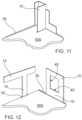
- FIG. 9depicts a ridge plate 50 to facilitate adjoinment of panel members along the ridge of a gabled roof.
- FIG. 10depicts an insert 60 , essentially an enclosed channel or box beam, which may be inserted into a channel 11 of a panel 10 in order to provide structural reinforcement for the panel 10 , e.g., when used as a support beam or girder.
- the insert 60may also be used to increase the safety margin for a free-standing span or cantilevered configuration of panels 10 .
- FIGS. 11 through 16several partial, detail views of assemblies created with the foregoing components can be seen.
- a plurality of panels 10 , tracks 30 , and frames 40are disposed in various configurations on top of a foundation 500 for a structure such as a home or building.
- the panelsare used to form the various external and internal walls, ceilings, upper story floors, and the roof of the building.
- the tracks 30are utilized to secure the panels 10 to the foundation 500 and to each other when two panels are joined to form a ceiling/floor or roof connection with a wall.
- the frames 40serve as an “end cap” when framing a window, otherwise the interior opening of the window would not be a uniform, flat surface given the existence of the valleys 14 and ridges 13 on the panels 10 .
- a plurality of tracks 30are fastened to a foundation 500 and are being utilized to support a plurality of panel members 10 in a vertical orientation to be utilized as wall members.
- two panel memberscan be seen in a “T” configuration to show that the panel members may also be used as columns and support beams.
- the panels 10have been arranged to form a window by suspending a panel 10 as a lintel across two other panels 10 acting as columns. It may also be seen that frames 40 are fastened to the interior of the window in order to prepare a flat surface for installation of the window and/or window jamb.
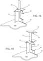
- FIG. 13depicts a plurality of tracks 30 that have been fastened to the top of a plurality of vertically oriented panel members 10 .
- the structureis being prepared for the addition of a second story or flat roof.
- FIG. 14shows a panel member 10 in a horizontal orientation employed as a first story ceiling and second story floor.
- the horizontal panel member 10is secured to the tracks 30 by fasteners, such as self-drilling screws, bolts, or rivets inserted through the external flange 32 .
- FIG. 15it can be seen that another vertically oriented panel member 10 ′ has been installed in the track 30 to create a second story wall.
- the horizontally oriented panel member 10is cantilevered outside of the structure, and may act as an awning or balcony.
- FIG. 16it can be seen that yet another panel member 10 has been mounted in an angled configuration in order to create a peak or gabled roof. It is secured to the vertically oriented panel member 10 via a track 30 .
- FIGS. 17 and 18show detail views of a corner configuration according to one embodiment of the present invention.
- FIG. 17depicts the interconnection between two adjoining panels 10 via a ninety degree corner bracket 20 , along with the associated mating interface between the panel 10 ridge and valley members 13 , 14 and the ridge and valley members 23 , 24 , of the corner bracket 10 .
- FIG. 18shows a plurality of tracks 30 fastened to a foundation 500 via fasteners 600 through the external flange 32 .
- the track 30is made of aluminum, galvanic corrosion may occur over time.
- a neoprene gasket or washermay be used to insulate the fastener 600 from the track 30 to avoid electrical contact between the fastener 600 and the track 30 . Additionally, a plurality of fasteners 600 are disposed through the corresponding mounting apertures in each of the tracks 30 and panels 10 in order to secure the panels 10 to the tracks 30 .
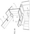
- FIGS. 19 and 20provide a detail view of the system of the present invention utilized to construct a multi-story building.
- a plurality of panels 10are utilized to construct the walls as well as the ceiling of the first floor and floor of the second floor.
- the panel 10 serving as a ceiling/flooris sandwiched between two tracks 30 disposed on the panels 10 serving as walls.
- fasteners 600are disposed through the external flanges 32 of the tracks and into the panel 10 serving as a floor. Therefore, the panel serving as a floor can be securely retained in place.
- FIGS. 21 and 21 Ashow a partially completed structure in both constructed and exploded form for further exemplification.
- several panel members 10are adjoined together to create a gabled roof.
- two ridge plates 50are employed to facilitate the connection of each panel 10 at the ridge of the roof.
- FIG. 22depicts a partially completed structure utilizing a membrane 100 between consecutive panels 10 .
- the membrane 100is self-adhering and water resistant. Therefore, particularly with regard to roof construction, the system of the present invention can be employed where resistance to water intrusion is a concern.
- the membrane 100may be applied at the intersection of any two consecutive panels 10 in order to ensure that water does not weep between the crevice formed therein.
- panel members 10may be employed in a cantilevered configuration to create awnings and balconies. Caulking may be employed in addition to, or in lieu of, the membrane 100 , particularly between adjoining panels 10 .
- FIGS. 23 through 28show how traditional interior and exterior finishes can be used in conjunction with the system by applying them on top of the panel members 10 .
- the exterior finishesmay include sheathing, housewrap/mesh, and stucco ( FIG. 23 ), rigid insulation, fiberglass mesh, and stucco ( FIG. 24 ), or sheathing, high-density polyethylene paper, and siding ( FIG. 25 ).
- Non-limiting examples for interior finishinclude drywall and paint ( FIG. 26 ), cement board and stucco ( FIG. 27 ), and furring strips, cement board, and wall tiles ( FIG. 28 ).
- FIGS. 29 through 34show how traditional roof and floor finishes may be used in conjunction with the system.
- roof finishesmay include rigid insulation, sheathing, and TPO ( FIG. 29 ), rigid insulation, a moisture barrier, and metal tiles ( FIG. 30 ), or rigid insulation, plywood, and asphalt shingles ( FIG. 31 ).
- Flooring finishesmay include, by way of non-limiting example building paper/mesh and tile flooring ( FIG. 32 ), plastic barrier, foam pad, and laminate wood ( FIG. 33 ), or furring strips, foam padding, and hard wood ( FIG. 34 ).
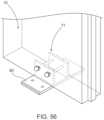
- FIGS. 35 through 35 Ddepict how traditional mechanical, electrical, and plumbing lines may be integrated with the present invention.
- water lines 1000 and electrical conduits 2000may be simply routed through the channels 11 within the panels 10 .
- the channels 11may be used as air conditioning ducts 300 as shown in FIG. 35 B .
- FIGS. 36 through 41show various insulation options that may be applied to the surface of a panel or disposed within the channel 11 of a panel 10 .
- FIG. 36is a depiction of pre-formed or pre-cut insulation 3000 , such as foam, that may be slid into the channels 11 during construction.
- FIG. 37depicts a spray insulation 4000 that may be applied to the face 12 of a panel 10 .
- FIG. 38depicts an injection foam insulation 5000 that can be utilized in channels 11 where electrical or plumbing lines are utilized.
- FIGS. 40 and 41show that the insulation may be added in-situ due to the open ends 16 of the panels 10 .
- FIGS. 42 and 44provides a schematic depiction of how the present invention may be utilized to route cooled air more efficiently from an air conditioning unit via the channels 11 of the panels 10 .
- FIG. 43depicts additional components to facilitate this aim.
- connectors 330 and elbows 320may be used to route the cooled air from the air conditioning unit 6000 into one or more channels 11 and between channels 11 in consecutive panels. While it may be possible to simply provide apertures in the tracks 30 (and ends of panels 10 ) to facilitate air flow between successive panels 10 and tracks 30 , that may hinder construction of the overall structure.
- the elbows 320 and connectors 330allow for implementation of this benefit after construction.
- Diffuser grills 310can also be employed to introduce cooled air into the room via the wall panels 10 or ceiling panels 10 .
- FIGS. 45 and 46another embodiment of a panel 10 ′ is depicted therein.
- This embodimentfinds particular suitability for utilizing the panel 10 ′ as a roof member.
- the panel member 10 ′contains the same structure as in previous embodiments, including opposite faces 12 ′ spaced by a plurality of webs 15 ′, which at least partially define channels 11 ′ traversing the open ends 16 ′ of the panel 10 ′.
- the panel 10 ′also includes a ridge member 13 ′ and a valley member 14 ′.
- the additional structure of the present embodimentis a flanged extension 19 traversing the length of the panel 10 .
- Each flanged extension 19includes a flange which extends inwardly toward the panel 10 ′.
- FIGS. 47 and 48depict an alternative embodiment of a track 30 ′ that may be utilized to facilitate construction of a gabled roof.
- the webs 31 ′are angled relative to the external flange 32 ′. Therefore, when a panel member 10 or 10 ′ is positioned at an angle to be used for a gabled roof, it may sit flush against the external flange 32 ′, which facilitates better fastening.
- FIGS. 49 and 50depict yet another embodiment of a track 30 ′′ which includes two external flanges 32 ′′, each projecting perpendicularly from the two webs 31 ′′.
- This embodiment of a track 30 ′′is suitable for certain installation scenarios, such as when an interior wall is used to support a ceiling. The wall can be inserted into the channel between the two webs 31 ′′, while the ceiling panels can be secured to each of the two flanges 32 ′′.
- FIG. 51depicts a partially completed structure wherein the panels 10 are used in a vertically oriented configuration to support longer spans between panels acting as columns.
- the vertically oriented panelsare denoted as 10 ′
- horizontally oriented panelsare denoted as 10 ′′.
- the vertically oriented panels 10 ′can also be referred to as those supporting loads in the plane of the panel
- the horizontally oriented panels 10 ′′can be referred to as those supporting loads out of the plan of the panel. It will be appreciated that the bending strength of the panel is much greater around its short edge than its long edge.
- the vertically oriented panels 10 ′are capable of withstanding much greater loads when cantilevered, suspended between two or more points, or otherwise not continuously supported, as compared to the horizontally oriented panels 10 ′′.
- the panels 10 acting as columnsare configured to support axial loading.
- FIG. 51also depicts a configuration to support a peaked roof using panel members 10 ′ disposed in vertical orientation.
- a gusset plate 70can be used to facilitate the angled and vertically oriented connection between panel members 10 and 10 ′.
- the gusset plate 70may include mounting apertures 71 to support the use of bolts or other fasteners.
- FIGS. 54 and 55depict an insert plate 80 in accordance with one embodiment of the invention.
- the insert plateincludes two webs 81 at least partially defining an interior channel 83 .
- Two flanges 82project exteriorly of the insert plate 80 .
- the flanges 82are orthogonal to the webs 81 , but they may be disposed at any angle that is desired.
- FIG. 56it can be seen that the insert plate 80 is to be inserted within a channel 11 of a panel member 10 . Therefore, the length of the insert plate 80 distance between the two webs 81 should be correspondingly configured and dimensioned with the channel 11 . In a most preferred embodiment, this is approximately a 4 inch square (as disclosed above).
- the insert plate 80can be used in a similar fashion to the track 30 , 30 ′, and 30 ′′ in any scenario where it is more desirable to have the webs disposed within the panel 10 . This can be for aesthetic purposes, for water proofing, or other reasons. Additionally, the insert plate 80 can also be useful for installations where a full length track member may not be suitable, such as when some of the channels 11 of a panel member 10 , are used for mechanical, electrical, or plumbing conduits, or a variety of other purposes. Using a plurality of single channel-sized insert plates 80 may be preferable to cutting a track 30 to the desired size.
- FIGS. 57 and 58yet another embodiment of a panel 10 ′ is depicted which includes protrusions or bosses 3 along the inner faces of the panel.
- the bosses 3provide additional material for a fastener to grip, which can reduce the total number of fasteners per panel necessary to securely retain the panels 10 ′′′′.
- the bosses 3can take on virtually and size, dimension, or placement that is desired for the purpose.
- the bosses 3are arranged approximately 1 ⁇ 2 inch from the side of each panel 10 “ ” and are approximately 1 ⁇ 4 inch in thickness.
- the bosses 3may run the entire length of the panel or may be truncated to the desired length.
- a visual marker 4can be provided on the outer surface to assist users with accurate placement of fasteners.
- FIGS. 59 and 60further embodiments of tracks 30 ′′′ and 30 ′′′′ are depicted, respectively.
- Each track 30 ′′′, 30 ′′′′contains additional flanges 32 ′′′, 32 ′′′′ relative to previously disclosed embodiments to provide a more structurally secure fitment of panels within the channels 33 ′′′, 33 ′′′′ of the tracks 30 ′′′, 30 ′′′′. This is due to the fact that fasteners can be driven into both flanges 32 ′′′′, 32 ′′′′ instead of relying on a single flange as previously disclosed.
- FIG. 59shows a “T” shaped track 30 ′′′ which can accommodate three panels at each of the three channels 33 ′′′.
- the 60shows an “L” shaped track 30 ′′′′ which accommodates two panels.
- the tracks 30 ′′′, 30 ′′′′may be dimensioned and configured to suit any orientation or load capacity.
- the flanges 32 ′′′, 32 ′′′′may be lengthened to provide additional support.
Landscapes
- Engineering & Computer Science (AREA)
- Architecture (AREA)
- Civil Engineering (AREA)
- Structural Engineering (AREA)
- Physics & Mathematics (AREA)
- Electromagnetism (AREA)
- Mechanical Engineering (AREA)
- Panels For Use In Building Construction (AREA)
- Finishing Walls (AREA)
- Laminated Bodies (AREA)
- Rod-Shaped Construction Members (AREA)
Abstract
Description
Claims (10)
Priority Applications (1)
| Application Number | Priority Date | Filing Date | Title |
|---|---|---|---|
| US17/946,274US12215499B2 (en) | 2020-09-21 | 2022-09-16 | Multi-purpose structural panels and systems for assembling structures |
Applications Claiming Priority (4)
| Application Number | Priority Date | Filing Date | Title |
|---|---|---|---|
| US202063081041P | 2020-09-21 | 2020-09-21 | |
| US202163161678P | 2021-03-16 | 2021-03-16 | |
| US17/221,061US11680403B2 (en) | 2020-09-21 | 2021-04-02 | Multi-purpose structural panels and systems for assembling structures |
| US17/946,274US12215499B2 (en) | 2020-09-21 | 2022-09-16 | Multi-purpose structural panels and systems for assembling structures |
Related Parent Applications (1)
| Application Number | Title | Priority Date | Filing Date |
|---|---|---|---|
| US17/221,061DivisionUS11680403B2 (en) | 2020-09-21 | 2021-04-02 | Multi-purpose structural panels and systems for assembling structures |
Publications (2)
| Publication Number | Publication Date |
|---|---|
| US20230014278A1 US20230014278A1 (en) | 2023-01-19 |
| US12215499B2true US12215499B2 (en) | 2025-02-04 |
Family
ID=77897472
Family Applications (2)
| Application Number | Title | Priority Date | Filing Date |
|---|---|---|---|
| US17/221,061ActiveUS11680403B2 (en) | 2020-09-21 | 2021-04-02 | Multi-purpose structural panels and systems for assembling structures |
| US17/946,274ActiveUS12215499B2 (en) | 2020-09-21 | 2022-09-16 | Multi-purpose structural panels and systems for assembling structures |
Family Applications Before (1)
| Application Number | Title | Priority Date | Filing Date |
|---|---|---|---|
| US17/221,061ActiveUS11680403B2 (en) | 2020-09-21 | 2021-04-02 | Multi-purpose structural panels and systems for assembling structures |
Country Status (6)
| Country | Link |
|---|---|
| US (2) | US11680403B2 (en) |
| EP (1) | EP3971355A1 (en) |
| JP (1) | JP2023542443A (en) |
| BR (1) | BR112022003327A2 (en) |
| CA (1) | CA3148844A1 (en) |
| WO (1) | WO2022061269A1 (en) |
Cited By (1)
| Publication number | Priority date | Publication date | Assignee | Title |
|---|---|---|---|---|
| US20240191890A1 (en)* | 2019-02-12 | 2024-06-13 | Vacek Llc | Systems and methods for controlling air properties in structures and inhibiting moisture accumulation and mold propagation in structures |
Families Citing this family (7)
| Publication number | Priority date | Publication date | Assignee | Title |
|---|---|---|---|---|
| US12312810B2 (en)* | 2019-12-03 | 2025-05-27 | Wall to Wall, LLC | Prefabricated multi-conduit building panel design |
| US12286789B2 (en) | 2019-12-03 | 2025-04-29 | Wall to Wall, LLC | Prefabricated above-door cavity conduit routing |
| US12286788B2 (en) | 2019-12-03 | 2025-04-29 | Wall to Wall, LLC | Modular pre-wired dwelling panel design |
| US11680403B2 (en) | 2020-09-21 | 2023-06-20 | Amp Ip Llc | Multi-purpose structural panels and systems for assembling structures |
| US12054936B1 (en)* | 2021-02-02 | 2024-08-06 | Bmic Llc | Building manufacturing using layered materials |
| US12385248B2 (en)* | 2021-11-24 | 2025-08-12 | New Village Initiative Llc | Structural units for building construction and methods of use thereof |
| US12305388B2 (en)* | 2022-07-15 | 2025-05-20 | STARC Systems, Inc. | Cap for a temporary wall system providing fire barrier protection |
Citations (109)
| Publication number | Priority date | Publication date | Assignee | Title |
|---|---|---|---|---|
| US1086031A (en) | 1909-02-08 | 1914-02-03 | Lewis K Davis | Ventilated wall structure. |
| US1622664A (en) | 1923-04-21 | 1927-03-29 | Thomas E Murray | Hollow structure and method of making the same |
| US1972570A (en) | 1931-01-29 | 1934-09-04 | Insulated Steel Construction C | Metal building panel |
| US1974767A (en) | 1931-04-06 | 1934-09-25 | Insulated Steel Construction C | Heating system for metal building |
| US2039601A (en) | 1934-11-14 | 1936-05-05 | London Bernard | Building construction |
| US2065433A (en) | 1934-12-01 | 1936-12-22 | Dercum Hermann | Building construction |
| US2143288A (en) | 1936-02-24 | 1939-01-10 | Owen M Stolz | Fabricated metal building |
| US2427780A (en) | 1944-06-10 | 1947-09-23 | Mcdowell & Torrence Lumber Com | Air conditioning of buildings by passing air through hollow foundation blocks |
| US2762472A (en) | 1952-02-08 | 1956-09-11 | Pittsburgh Des Moines Company | Hollow sheet metal panels and method of making the sections from which such panels are made |
| US3304680A (en)* | 1963-12-13 | 1967-02-21 | Anel Engineering Ind Inc | Interlocking structural system for buildings |
| DE2235322A1 (en) | 1972-07-19 | 1974-01-31 | Bruno Reinhold | HOUSE, ESPECIALLY GREENHOUSE |
| US4135342A (en)* | 1977-10-26 | 1979-01-23 | Field Form, Inc. | Insulated metal roofing and siding system |
| US4155206A (en)* | 1978-04-19 | 1979-05-22 | Howmet Corporation | Insulated metal roofing system |
| US4177615A (en)* | 1977-08-27 | 1979-12-11 | H. H. Robertson Company | Fastening device for roof panel joints |
| US4299070A (en)* | 1978-06-30 | 1981-11-10 | Heinrich Oltmanns | Box formed building panel of extruded plastic |
| US4389823A (en)* | 1981-06-28 | 1983-06-28 | Howmet Aluminum Corporation | Modular roof skylight |
| US4454694A (en) | 1980-01-23 | 1984-06-19 | Robert Davanture | Protective enclosure for a stationary or movable machine |
| US4476659A (en)* | 1981-06-22 | 1984-10-16 | Player Wayne H | Insulated roofing system with slidable roof to ceiling clips |
| US4535684A (en)* | 1984-08-22 | 1985-08-20 | Guu Perng | Ventilation system for an enclosed space |
| US4557091A (en)* | 1982-02-10 | 1985-12-10 | Corflex International, Inc. | Extruded structural system |
| US4649684A (en)* | 1985-10-04 | 1987-03-17 | Mm Systems Corporation | Panel systems and installations |
| US4671038A (en)* | 1986-04-30 | 1987-06-09 | Porter William H | Roof sandwich panel juncture running with the pitch |
| US4790112A (en)* | 1987-07-17 | 1988-12-13 | Cheh Wang | Assembly of two interconnected similar plastic planks and a framework |
| US4823523A (en) | 1987-01-06 | 1989-04-25 | Donald N. Coupard | Electromagnetic radiation shielding enclosure and shielding components |
| US4891923A (en) | 1985-04-10 | 1990-01-09 | Ericsson Karl Gustav | Building structure |
| US4936078A (en)* | 1988-12-02 | 1990-06-26 | Porter William H | Interconnecting panels |
| US5010777A (en) | 1987-12-28 | 1991-04-30 | American Environmental Systems, Inc. | Apparatus and method for establishing selected environmental characteristics |
| US5216863A (en)* | 1988-08-15 | 1993-06-08 | Nils Nessa | Formwork comprising a plurality of interconnectable formwork elements |
| EP0558767A1 (en) | 1991-12-31 | 1993-09-08 | Röder GmbH | Flooring system |
| WO1993023629A1 (en) | 1992-05-20 | 1993-11-25 | Maupin James H | Panel system and method for building construction |
| US5483778A (en) | 1991-04-03 | 1996-01-16 | Scrivener; Paul | Modular panel system having a releasable tongue member |
| US5729944A (en)* | 1993-05-28 | 1998-03-24 | Royal Building Systems (Cdn) Limited | Thermoplastic structural components and structures formed therefrom |
| US5737892A (en)* | 1996-05-17 | 1998-04-14 | Crown Partnership | Channel-mounted interlocking panel roofing structure |
| US5943775A (en)* | 1995-11-13 | 1999-08-31 | Qb Technology | Synthetic panel and method |
| US5953880A (en)* | 1994-11-02 | 1999-09-21 | Royal Building Systems (Cdn) Limited | Fire rated modular building system |
| US6189269B1 (en)* | 1992-05-29 | 2001-02-20 | Royal Building Systems (Cdn) Limited | Thermoplastic wall forming member with wiring channel |
| US6260323B1 (en) | 1999-06-04 | 2001-07-17 | Charles R. Hockey | Wall panel support unit and wall system |
| US6282858B1 (en) | 1999-03-04 | 2001-09-04 | Andrew C. Swick | Roofing panel system and method for making same |
| EP1196668A1 (en) | 1999-07-02 | 2002-04-17 | Jores Arkitektkantor | Building system |
| US6412243B1 (en) | 1997-04-30 | 2002-07-02 | Franklin S. Sutelan | Ultra-lite modular composite building system |
| US6502357B1 (en)* | 2000-02-24 | 2003-01-07 | The Gsi Group | PVC wall panel system |
| US6584735B2 (en)* | 2000-12-29 | 2003-07-01 | Cobblestone Construction Finishes, Inc. | Ventilated wall drainage system and apparatus therefore |
| US6584740B2 (en) | 1999-07-23 | 2003-07-01 | Leading Edge Earth Products, Inc. | Frameless building system |
| US6615945B2 (en) | 2000-09-06 | 2003-09-09 | Honda Giken Kogyo Kabushiki Kaisha | Motorcycle having a housing box and storage space arranged to increase the capacity of the intake system |
| USD485373S1 (en)* | 2003-01-27 | 2004-01-13 | Dayton Technologies, L.L.C. | Deck plank extrusion |
| US20040031230A1 (en) | 2002-08-19 | 2004-02-19 | Pabedinskas Arunas Antanas | Hollow flanged joist for deck framing |
| US20040074206A1 (en)* | 2002-09-20 | 2004-04-22 | Yamaha Corporation | Hollow panel |
| US6739106B2 (en)* | 2002-09-12 | 2004-05-25 | Royal Group Technologies Limited | Reversible plastic building board with different colored sides |
| JP2004324267A (en) | 2003-04-25 | 2004-11-18 | Sanki Eng Co Ltd | Prefabricated house, and fabrication method of prefabricated house |
| USD523780S1 (en)* | 2004-08-10 | 2006-06-27 | Mac Trailer Manufacturing, Inc. | Combined trailer construction member and joint |
| US7127865B2 (en) | 2002-10-11 | 2006-10-31 | Douglas Robert B | Modular structure for building panels and methods of making and using same |
| ES2267389A1 (en) | 2005-06-21 | 2007-03-01 | Juan Pundik Knapheis | Construction system for house, uses light concrete, hollow square modules and prefabricated panels to assemble sections of house e.g. outer wall, inner partition, pavement, ceiling |
| US20070102960A1 (en) | 2001-06-22 | 2007-05-10 | Booher Howard D | Trailer and trailer body construction and extruded panel for same |
| US20070189920A1 (en) | 2004-04-15 | 2007-08-16 | Gimzewski James K | Calorimeter and methods of use thereof |
| US20070266655A1 (en) | 2006-03-16 | 2007-11-22 | Ian Howe | Frame system with releasable couplers |
| US20080010924A1 (en) | 2006-07-12 | 2008-01-17 | Pietruczynik Christopher B | Exterior building material having a hollow thin wall profile and an embossed low gloss surface |
| ES2289881A1 (en) | 2005-07-19 | 2008-02-01 | Andres Lopez Fernandez | ALUMINUM PANEL SYSTEM FOR COATINGS AND PARAMENTATION COMFORMATION. |
| US20090049771A1 (en)* | 2003-06-27 | 2009-02-26 | Konvin Associates Limited Partnership | Light Transmission Panels, Retaining Clip and a Combination Thereof |
| US7533500B2 (en)* | 2003-01-27 | 2009-05-19 | Deceuninck North America, Llc | Deck plank and method of production |
| US8065846B2 (en) | 2003-04-17 | 2011-11-29 | Mcdonald Frank | Modular building panels, method of assembly of building panels and method of making building panels |
| US20120011798A1 (en)* | 2010-07-16 | 2012-01-19 | Ernest Rivellino | Building system and components therefor |
| US20120317923A1 (en) | 2011-06-15 | 2012-12-20 | The Regents Of The University Of Colorado, A Body Corporate | Structural insulated building panel |
| US20130025220A1 (en)* | 2011-07-26 | 2013-01-31 | Haworth, Inc. | Reusable Architectural Wall |
| CN103094790A (en) | 2013-01-25 | 2013-05-08 | 奇瑞汽车股份有限公司 | Current connector capable of automatically disconnecting under high temperature |
| USD684705S1 (en)* | 2012-01-05 | 2013-06-18 | Mid Atlantic Vinyl Products, Inc. | Deck board |
| US8490355B2 (en) | 2010-08-24 | 2013-07-23 | James Walker | Ventilated structural panels and method of construction with ventilated structural panels |
| US8534018B2 (en) | 2010-08-24 | 2013-09-17 | James Walker | Ventilated structural panels and method of construction with ventilated structural panels |
| US8539732B2 (en) | 2009-06-29 | 2013-09-24 | Charles H. Leahy | Structural building panels with seamless corners |
| US8590264B2 (en) | 2009-06-29 | 2013-11-26 | Charles H. Leahy | Structural building panels with multi-laminate interlocking seams |
| US8590235B2 (en)* | 2009-06-03 | 2013-11-26 | Garland Industries, Inc. | Anchoring system for a roof panel system |
| US8677713B1 (en)* | 2013-03-06 | 2014-03-25 | Epi 04, Inc. | Extruded wall panel system and method of forming |
| US8677698B2 (en) | 2008-03-06 | 2014-03-25 | Stuart C. Segall | Relocatable habitat unit |
| US8769904B1 (en)* | 2005-03-24 | 2014-07-08 | Barrette Outdoor Living, Inc. | Interlock panel, panel assembly, and method for shipping |
| EP2781866A1 (en) | 2013-03-22 | 2014-09-24 | Sturm Maschinen- & Anlagenbau GmbH | Wall panel for a drying plant and method for producing the wall panel |
| US8869492B2 (en) | 2009-06-29 | 2014-10-28 | Charles H. Leahy | Structural building panels with interlocking seams |
| US8997436B2 (en)* | 2012-05-18 | 2015-04-07 | Douglas B. Spear | Wall panel system |
| US9016002B2 (en) | 2008-03-06 | 2015-04-28 | Stuart Charles Segall | Relocatable habitat unit having interchangeable panels |
| US9050766B2 (en) | 2013-03-01 | 2015-06-09 | James Walker | Variations and methods of producing ventilated structural panels |
| US20150176274A1 (en)* | 2013-12-19 | 2015-06-25 | Iframe Building Solutions, Llc | System and method for lateral transfer plate having a punched tab |
| US9068372B2 (en) | 2012-08-14 | 2015-06-30 | Premium Steel Building Systems, Inc. | Systems and methods for constructing temporary, re-locatable structures |
| US9091049B2 (en) | 2010-08-24 | 2015-07-28 | James Walker | Ventilated structural panels and method of construction with ventilated structural panels |
| US9206606B2 (en)* | 2013-08-06 | 2015-12-08 | Green Span Profiles | Insulated standing seam roof panel |
| CN204850694U (en) | 2015-08-28 | 2015-12-09 | 广东兴发铝业有限公司 | Aluminium alloy ex -trusions combination prevention waterlogging anti -flood wall |
| US9249572B2 (en) | 2010-10-11 | 2016-02-02 | Michael Neumayr | Prefabricated shear wall system with integrated channels |
| US9340243B2 (en)* | 2011-12-22 | 2016-05-17 | Marty Williams | Modular structure and method of creating modular structures |
| US9366018B1 (en)* | 2014-12-04 | 2016-06-14 | Dant Clayton Corporation | Long span stadium riser system |
| CN105696706A (en) | 2016-02-04 | 2016-06-22 | 中清大科技股份有限公司 | A plug-in composite house |
| US9382703B2 (en) | 2012-08-14 | 2016-07-05 | Premium Steel Building Systems, Inc. | Systems and methods for constructing temporary, re-locatable structures |
| US9604428B2 (en) | 2010-08-24 | 2017-03-28 | James Walker | Ventilated structural panels and method of construction with ventilated structural panels |
| US9719251B2 (en)* | 2012-02-29 | 2017-08-01 | Dirtt Environmental Solutions, Ltd. | Modular in-wall functional conduits |
| US9790684B2 (en) | 2010-10-11 | 2017-10-17 | Michael Neumayr | Modular wall system with integrated channels |
| US20180038103A1 (en) | 2010-10-11 | 2018-02-08 | Michael Neumayr | Modular wall system with integrated channels |
| US9988806B2 (en) | 2013-03-15 | 2018-06-05 | Stuart Charles Segall | Relocatable habitat unit |
| US10041243B2 (en)* | 2014-10-21 | 2018-08-07 | Venture Holdings B.V. | Modular building unit, system and method |
| WO2018158986A1 (en) | 2017-03-03 | 2018-09-07 | 真俊 玉置 | Panel, three-dimensional panel, panel coupling structure, panel unit, air conditioning panel wall device, and snow-melting panel device |
| US20180283664A1 (en) | 2015-02-17 | 2018-10-04 | Chocolate Lighting Company Ltd | Track lighting system |
| US20190210317A1 (en) | 2010-08-24 | 2019-07-11 | James Walker | Frameless construction using single and double plenum panels |
| US20190219307A1 (en) | 2008-08-29 | 2019-07-18 | Werner Extrusion Solutions, Llc | Node, Apparatus, System and Method Regarding a Frame Support for Solar Mirrors |
| WO2019173279A1 (en) | 2018-03-05 | 2019-09-12 | Fluxus Llc | Prefabricated building system |
| WO2019195874A1 (en) | 2018-04-13 | 2019-10-17 | Building IP Holdings Pty Ltd | Modular building system |
| USD888286S1 (en)* | 2018-08-23 | 2020-06-23 | Doug Spear | Extruded wall panel |
| US10787803B2 (en) | 2008-02-02 | 2020-09-29 | Charles H. Leahy | Methods and systems for modular buildings |
| USD898952S1 (en)* | 2018-08-23 | 2020-10-13 | Doug Spear | Tongue and groove for wall panel |
| US11060282B2 (en)* | 2018-08-23 | 2021-07-13 | Doug Spear | Modular wall system |
| US20210340764A1 (en)* | 2018-08-10 | 2021-11-04 | Heka Graphit.Technology Gmbh | Construction panel |
| US11248814B2 (en)* | 2019-02-12 | 2022-02-15 | Vacek Llc | Systems and methods for controlling air properties in structures and inhibiting moisture accumulation and mold propagation in structures |
| EP3971355A1 (en) | 2020-09-21 | 2022-03-23 | Alain Perez | Multi-purpose structural panels and systems for assembling structures |
| US11371243B2 (en)* | 2016-11-26 | 2022-06-28 | Armour Wall Group Pty Limited | Building panel |
| US11371730B2 (en)* | 2016-12-23 | 2022-06-28 | Ziehl-Abegg Se | Fan system and arrangement of one or more such fan systems in a flow duct |
Family Cites Families (4)
| Publication number | Priority date | Publication date | Assignee | Title |
|---|---|---|---|---|
| JP3076289B2 (en)* | 1997-11-25 | 2000-08-14 | 日本軽金属株式会社 | Building slabs |
| EP2289881A1 (en)* | 2009-08-06 | 2011-03-02 | Boehringer Ingelheim International GmbH | Method for stereoselective synthesis of bicyclical heterocycles |
| KR200485238Y1 (en)* | 2017-04-19 | 2018-01-18 | 주식회사 용일 | Aluminum blind panel with continuous connection |
| AU2020210211B2 (en)* | 2019-09-18 | 2022-09-08 | Innovatus Design Pty Ltd | A modular partition and fabrication thereof |
- 2021
- 2021-04-02USUS17/221,061patent/US11680403B2/enactiveActive
- 2021-09-21CACA3148844Apatent/CA3148844A1/enactivePending
- 2021-09-21WOPCT/US2021/051216patent/WO2022061269A1/ennot_activeCeased
- 2021-09-21JPJP2022516693Apatent/JP2023542443A/enactivePending
- 2021-09-21BRBR112022003327Apatent/BR112022003327A2/ennot_activeApplication Discontinuation
- 2021-09-21EPEP21198022.2Apatent/EP3971355A1/enactivePending
- 2022
- 2022-09-16USUS17/946,274patent/US12215499B2/enactiveActive
Patent Citations (113)
| Publication number | Priority date | Publication date | Assignee | Title |
|---|---|---|---|---|
| US1086031A (en) | 1909-02-08 | 1914-02-03 | Lewis K Davis | Ventilated wall structure. |
| US1622664A (en) | 1923-04-21 | 1927-03-29 | Thomas E Murray | Hollow structure and method of making the same |
| US1972570A (en) | 1931-01-29 | 1934-09-04 | Insulated Steel Construction C | Metal building panel |
| US1974767A (en) | 1931-04-06 | 1934-09-25 | Insulated Steel Construction C | Heating system for metal building |
| US2039601A (en) | 1934-11-14 | 1936-05-05 | London Bernard | Building construction |
| US2065433A (en) | 1934-12-01 | 1936-12-22 | Dercum Hermann | Building construction |
| US2143288A (en) | 1936-02-24 | 1939-01-10 | Owen M Stolz | Fabricated metal building |
| US2427780A (en) | 1944-06-10 | 1947-09-23 | Mcdowell & Torrence Lumber Com | Air conditioning of buildings by passing air through hollow foundation blocks |
| US2762472A (en) | 1952-02-08 | 1956-09-11 | Pittsburgh Des Moines Company | Hollow sheet metal panels and method of making the sections from which such panels are made |
| US3304680A (en)* | 1963-12-13 | 1967-02-21 | Anel Engineering Ind Inc | Interlocking structural system for buildings |
| DE2235322A1 (en) | 1972-07-19 | 1974-01-31 | Bruno Reinhold | HOUSE, ESPECIALLY GREENHOUSE |
| US4177615A (en)* | 1977-08-27 | 1979-12-11 | H. H. Robertson Company | Fastening device for roof panel joints |
| US4135342A (en)* | 1977-10-26 | 1979-01-23 | Field Form, Inc. | Insulated metal roofing and siding system |
| US4155206A (en)* | 1978-04-19 | 1979-05-22 | Howmet Corporation | Insulated metal roofing system |
| US4299070A (en)* | 1978-06-30 | 1981-11-10 | Heinrich Oltmanns | Box formed building panel of extruded plastic |
| US4454694A (en) | 1980-01-23 | 1984-06-19 | Robert Davanture | Protective enclosure for a stationary or movable machine |
| US4476659A (en)* | 1981-06-22 | 1984-10-16 | Player Wayne H | Insulated roofing system with slidable roof to ceiling clips |
| US4389823A (en)* | 1981-06-28 | 1983-06-28 | Howmet Aluminum Corporation | Modular roof skylight |
| US4557091A (en)* | 1982-02-10 | 1985-12-10 | Corflex International, Inc. | Extruded structural system |
| US4535684A (en)* | 1984-08-22 | 1985-08-20 | Guu Perng | Ventilation system for an enclosed space |
| US4891923A (en) | 1985-04-10 | 1990-01-09 | Ericsson Karl Gustav | Building structure |
| US4649684A (en)* | 1985-10-04 | 1987-03-17 | Mm Systems Corporation | Panel systems and installations |
| US4671038A (en)* | 1986-04-30 | 1987-06-09 | Porter William H | Roof sandwich panel juncture running with the pitch |
| US4823523A (en) | 1987-01-06 | 1989-04-25 | Donald N. Coupard | Electromagnetic radiation shielding enclosure and shielding components |
| US4790112A (en)* | 1987-07-17 | 1988-12-13 | Cheh Wang | Assembly of two interconnected similar plastic planks and a framework |
| US5010777A (en) | 1987-12-28 | 1991-04-30 | American Environmental Systems, Inc. | Apparatus and method for establishing selected environmental characteristics |
| US5216863A (en)* | 1988-08-15 | 1993-06-08 | Nils Nessa | Formwork comprising a plurality of interconnectable formwork elements |
| US4936078A (en)* | 1988-12-02 | 1990-06-26 | Porter William H | Interconnecting panels |
| US5483778A (en) | 1991-04-03 | 1996-01-16 | Scrivener; Paul | Modular panel system having a releasable tongue member |
| EP0558767A1 (en) | 1991-12-31 | 1993-09-08 | Röder GmbH | Flooring system |
| WO1993023629A1 (en) | 1992-05-20 | 1993-11-25 | Maupin James H | Panel system and method for building construction |
| US6189269B1 (en)* | 1992-05-29 | 2001-02-20 | Royal Building Systems (Cdn) Limited | Thermoplastic wall forming member with wiring channel |
| US5729944A (en)* | 1993-05-28 | 1998-03-24 | Royal Building Systems (Cdn) Limited | Thermoplastic structural components and structures formed therefrom |
| US5953880A (en)* | 1994-11-02 | 1999-09-21 | Royal Building Systems (Cdn) Limited | Fire rated modular building system |
| US5943775A (en)* | 1995-11-13 | 1999-08-31 | Qb Technology | Synthetic panel and method |
| US5737892A (en)* | 1996-05-17 | 1998-04-14 | Crown Partnership | Channel-mounted interlocking panel roofing structure |
| US6412243B1 (en) | 1997-04-30 | 2002-07-02 | Franklin S. Sutelan | Ultra-lite modular composite building system |
| US6282858B1 (en) | 1999-03-04 | 2001-09-04 | Andrew C. Swick | Roofing panel system and method for making same |
| US6260323B1 (en) | 1999-06-04 | 2001-07-17 | Charles R. Hockey | Wall panel support unit and wall system |
| EP1196668A1 (en) | 1999-07-02 | 2002-04-17 | Jores Arkitektkantor | Building system |
| US6584740B2 (en) | 1999-07-23 | 2003-07-01 | Leading Edge Earth Products, Inc. | Frameless building system |
| US6502357B1 (en)* | 2000-02-24 | 2003-01-07 | The Gsi Group | PVC wall panel system |
| US6615945B2 (en) | 2000-09-06 | 2003-09-09 | Honda Giken Kogyo Kabushiki Kaisha | Motorcycle having a housing box and storage space arranged to increase the capacity of the intake system |
| US6584735B2 (en)* | 2000-12-29 | 2003-07-01 | Cobblestone Construction Finishes, Inc. | Ventilated wall drainage system and apparatus therefore |
| US20070102960A1 (en) | 2001-06-22 | 2007-05-10 | Booher Howard D | Trailer and trailer body construction and extruded panel for same |
| US20040031230A1 (en) | 2002-08-19 | 2004-02-19 | Pabedinskas Arunas Antanas | Hollow flanged joist for deck framing |
| US6739106B2 (en)* | 2002-09-12 | 2004-05-25 | Royal Group Technologies Limited | Reversible plastic building board with different colored sides |
| US20040074206A1 (en)* | 2002-09-20 | 2004-04-22 | Yamaha Corporation | Hollow panel |
| US7127865B2 (en) | 2002-10-11 | 2006-10-31 | Douglas Robert B | Modular structure for building panels and methods of making and using same |
| USD485373S1 (en)* | 2003-01-27 | 2004-01-13 | Dayton Technologies, L.L.C. | Deck plank extrusion |
| US7533500B2 (en)* | 2003-01-27 | 2009-05-19 | Deceuninck North America, Llc | Deck plank and method of production |
| US8065846B2 (en) | 2003-04-17 | 2011-11-29 | Mcdonald Frank | Modular building panels, method of assembly of building panels and method of making building panels |
| JP2004324267A (en) | 2003-04-25 | 2004-11-18 | Sanki Eng Co Ltd | Prefabricated house, and fabrication method of prefabricated house |
| US20090049771A1 (en)* | 2003-06-27 | 2009-02-26 | Konvin Associates Limited Partnership | Light Transmission Panels, Retaining Clip and a Combination Thereof |
| US20070189920A1 (en) | 2004-04-15 | 2007-08-16 | Gimzewski James K | Calorimeter and methods of use thereof |
| USD523780S1 (en)* | 2004-08-10 | 2006-06-27 | Mac Trailer Manufacturing, Inc. | Combined trailer construction member and joint |
| US8769904B1 (en)* | 2005-03-24 | 2014-07-08 | Barrette Outdoor Living, Inc. | Interlock panel, panel assembly, and method for shipping |
| ES2267389A1 (en) | 2005-06-21 | 2007-03-01 | Juan Pundik Knapheis | Construction system for house, uses light concrete, hollow square modules and prefabricated panels to assemble sections of house e.g. outer wall, inner partition, pavement, ceiling |
| ES2289881A1 (en) | 2005-07-19 | 2008-02-01 | Andres Lopez Fernandez | ALUMINUM PANEL SYSTEM FOR COATINGS AND PARAMENTATION COMFORMATION. |
| US20070266655A1 (en) | 2006-03-16 | 2007-11-22 | Ian Howe | Frame system with releasable couplers |
| US20080010924A1 (en) | 2006-07-12 | 2008-01-17 | Pietruczynik Christopher B | Exterior building material having a hollow thin wall profile and an embossed low gloss surface |
| US10787803B2 (en) | 2008-02-02 | 2020-09-29 | Charles H. Leahy | Methods and systems for modular buildings |
| US9016002B2 (en) | 2008-03-06 | 2015-04-28 | Stuart Charles Segall | Relocatable habitat unit having interchangeable panels |
| US9920513B2 (en) | 2008-03-06 | 2018-03-20 | Stuart Charles Segall | Relocatable habitat unit |
| US8677698B2 (en) | 2008-03-06 | 2014-03-25 | Stuart C. Segall | Relocatable habitat unit |
| US10036157B2 (en) | 2008-03-06 | 2018-07-31 | Stuart Charles Segall | Relocatable habitat unit |
| US20190219307A1 (en) | 2008-08-29 | 2019-07-18 | Werner Extrusion Solutions, Llc | Node, Apparatus, System and Method Regarding a Frame Support for Solar Mirrors |
| US8590235B2 (en)* | 2009-06-03 | 2013-11-26 | Garland Industries, Inc. | Anchoring system for a roof panel system |
| US8539732B2 (en) | 2009-06-29 | 2013-09-24 | Charles H. Leahy | Structural building panels with seamless corners |
| US8590264B2 (en) | 2009-06-29 | 2013-11-26 | Charles H. Leahy | Structural building panels with multi-laminate interlocking seams |
| US8869492B2 (en) | 2009-06-29 | 2014-10-28 | Charles H. Leahy | Structural building panels with interlocking seams |
| US20120011798A1 (en)* | 2010-07-16 | 2012-01-19 | Ernest Rivellino | Building system and components therefor |
| US9091049B2 (en) | 2010-08-24 | 2015-07-28 | James Walker | Ventilated structural panels and method of construction with ventilated structural panels |
| US8534018B2 (en) | 2010-08-24 | 2013-09-17 | James Walker | Ventilated structural panels and method of construction with ventilated structural panels |
| US8490355B2 (en) | 2010-08-24 | 2013-07-23 | James Walker | Ventilated structural panels and method of construction with ventilated structural panels |
| US20190210317A1 (en) | 2010-08-24 | 2019-07-11 | James Walker | Frameless construction using single and double plenum panels |
| US9604428B2 (en) | 2010-08-24 | 2017-03-28 | James Walker | Ventilated structural panels and method of construction with ventilated structural panels |
| US10077553B2 (en) | 2010-10-11 | 2018-09-18 | Michael Neumayr | Modular wall system with integrated channels |
| US20180038103A1 (en) | 2010-10-11 | 2018-02-08 | Michael Neumayr | Modular wall system with integrated channels |
| US9790684B2 (en) | 2010-10-11 | 2017-10-17 | Michael Neumayr | Modular wall system with integrated channels |
| US9249572B2 (en) | 2010-10-11 | 2016-02-02 | Michael Neumayr | Prefabricated shear wall system with integrated channels |
| US20120317923A1 (en) | 2011-06-15 | 2012-12-20 | The Regents Of The University Of Colorado, A Body Corporate | Structural insulated building panel |
| US20130025220A1 (en)* | 2011-07-26 | 2013-01-31 | Haworth, Inc. | Reusable Architectural Wall |
| US9340243B2 (en)* | 2011-12-22 | 2016-05-17 | Marty Williams | Modular structure and method of creating modular structures |
| USD684705S1 (en)* | 2012-01-05 | 2013-06-18 | Mid Atlantic Vinyl Products, Inc. | Deck board |
| US9719251B2 (en)* | 2012-02-29 | 2017-08-01 | Dirtt Environmental Solutions, Ltd. | Modular in-wall functional conduits |
| US8997436B2 (en)* | 2012-05-18 | 2015-04-07 | Douglas B. Spear | Wall panel system |
| US9382703B2 (en) | 2012-08-14 | 2016-07-05 | Premium Steel Building Systems, Inc. | Systems and methods for constructing temporary, re-locatable structures |
| US9068372B2 (en) | 2012-08-14 | 2015-06-30 | Premium Steel Building Systems, Inc. | Systems and methods for constructing temporary, re-locatable structures |
| CN103094790A (en) | 2013-01-25 | 2013-05-08 | 奇瑞汽车股份有限公司 | Current connector capable of automatically disconnecting under high temperature |
| US9050766B2 (en) | 2013-03-01 | 2015-06-09 | James Walker | Variations and methods of producing ventilated structural panels |
| US8677713B1 (en)* | 2013-03-06 | 2014-03-25 | Epi 04, Inc. | Extruded wall panel system and method of forming |
| US9988806B2 (en) | 2013-03-15 | 2018-06-05 | Stuart Charles Segall | Relocatable habitat unit |
| EP2781866A1 (en) | 2013-03-22 | 2014-09-24 | Sturm Maschinen- & Anlagenbau GmbH | Wall panel for a drying plant and method for producing the wall panel |
| US9206606B2 (en)* | 2013-08-06 | 2015-12-08 | Green Span Profiles | Insulated standing seam roof panel |
| US20150176274A1 (en)* | 2013-12-19 | 2015-06-25 | Iframe Building Solutions, Llc | System and method for lateral transfer plate having a punched tab |
| US10041243B2 (en)* | 2014-10-21 | 2018-08-07 | Venture Holdings B.V. | Modular building unit, system and method |
| US9366018B1 (en)* | 2014-12-04 | 2016-06-14 | Dant Clayton Corporation | Long span stadium riser system |
| US20180283664A1 (en) | 2015-02-17 | 2018-10-04 | Chocolate Lighting Company Ltd | Track lighting system |
| CN204850694U (en) | 2015-08-28 | 2015-12-09 | 广东兴发铝业有限公司 | Aluminium alloy ex -trusions combination prevention waterlogging anti -flood wall |
| CN105696706A (en) | 2016-02-04 | 2016-06-22 | 中清大科技股份有限公司 | A plug-in composite house |
| US11371243B2 (en)* | 2016-11-26 | 2022-06-28 | Armour Wall Group Pty Limited | Building panel |
| US11371730B2 (en)* | 2016-12-23 | 2022-06-28 | Ziehl-Abegg Se | Fan system and arrangement of one or more such fan systems in a flow duct |
| WO2018158986A1 (en) | 2017-03-03 | 2018-09-07 | 真俊 玉置 | Panel, three-dimensional panel, panel coupling structure, panel unit, air conditioning panel wall device, and snow-melting panel device |
| WO2019173279A1 (en) | 2018-03-05 | 2019-09-12 | Fluxus Llc | Prefabricated building system |
| WO2019195874A1 (en) | 2018-04-13 | 2019-10-17 | Building IP Holdings Pty Ltd | Modular building system |
| US20210340764A1 (en)* | 2018-08-10 | 2021-11-04 | Heka Graphit.Technology Gmbh | Construction panel |
| USD888286S1 (en)* | 2018-08-23 | 2020-06-23 | Doug Spear | Extruded wall panel |
| USD898952S1 (en)* | 2018-08-23 | 2020-10-13 | Doug Spear | Tongue and groove for wall panel |
| US11060282B2 (en)* | 2018-08-23 | 2021-07-13 | Doug Spear | Modular wall system |
| US11248814B2 (en)* | 2019-02-12 | 2022-02-15 | Vacek Llc | Systems and methods for controlling air properties in structures and inhibiting moisture accumulation and mold propagation in structures |
| EP3971355A1 (en) | 2020-09-21 | 2022-03-23 | Alain Perez | Multi-purpose structural panels and systems for assembling structures |
| US11680403B2 (en) | 2020-09-21 | 2023-06-20 | Amp Ip Llc | Multi-purpose structural panels and systems for assembling structures |
Non-Patent Citations (1)
| Title |
|---|
| AGT Products, Dricore Smartwall 1,3, . . . https://dricore.com/products/smartwall/, Aug. 11, 2020. |
Cited By (2)
| Publication number | Priority date | Publication date | Assignee | Title |
|---|---|---|---|---|
| US20240191890A1 (en)* | 2019-02-12 | 2024-06-13 | Vacek Llc | Systems and methods for controlling air properties in structures and inhibiting moisture accumulation and mold propagation in structures |
| US12416420B2 (en)* | 2019-02-12 | 2025-09-16 | Vacek Llc | Systems and methods for controlling air properties in structures and inhibiting moisture accumulation and mold propagation in structures |
Also Published As
| Publication number | Publication date |
|---|---|
| EP3971355A1 (en) | 2022-03-23 |
| US11680403B2 (en) | 2023-06-20 |
| US20230014278A1 (en) | 2023-01-19 |
| WO2022061269A1 (en) | 2022-03-24 |
| JP2023542443A (en) | 2023-10-10 |
| US20220090379A1 (en) | 2022-03-24 |
| CA3148844A1 (en) | 2022-03-21 |
| BR112022003327A2 (en) | 2023-04-11 |
Similar Documents
| Publication | Publication Date | Title |
|---|---|---|
| US12215499B2 (en) | Multi-purpose structural panels and systems for assembling structures | |
| US4628650A (en) | Structural insulated panel system | |
| US20140090321A1 (en) | Modular building system utilizing composite, foam core panels | |
| US4478018A (en) | Thermal break exterior insulated wall framing system | |
| US20070125042A1 (en) | Structural insulated panel construction for building structures | |
| US9121168B2 (en) | Modular housing | |
| US7735282B2 (en) | Fully insulated frame building panel system | |
| US4068434A (en) | Composite wall panel assembly and method of production | |
| US9587399B2 (en) | Insulating wall, a column assembly therefore and a method of constructing such an insulating wall | |
| US20170030072A1 (en) | System and method for panelized, superinsulated building envelopes | |
| US20090311932A1 (en) | Structural insulated panel construction for building structures | |
| CA1124482A (en) | Panel structure and building structures made therefrom | |
| US20190100917A1 (en) | Panelized Building System Utilizing Integrated Insulation | |
| AU2022275500A1 (en) | Modular building system | |
| CN110629885A (en) | A prefabricated light steel structure house | |
| US7603822B2 (en) | Panelized wall system with foam core insulation | |
| US4265061A (en) | Building system | |
| KR20010012388A (en) | Modular Sandwich Panel and Method for Housing Construction | |
| US9834923B1 (en) | Building construction method | |
| US6145263A (en) | Light gauge sheet metal building construction system | |
| WO2020210890A1 (en) | Insulated panel and methods of installation | |
| US20240117628A1 (en) | Modular complete thermal break foundation, wall and roof assemblies for buildings | |
| WO2010015042A2 (en) | Modular building construction system | |
| WO2003004786A2 (en) | Structural apparatus and method | |
| JP3370253B2 (en) | Thermal insulation panels and thermal insulation panel structures for buildings |
Legal Events
| Date | Code | Title | Description |
|---|---|---|---|
| FEPP | Fee payment procedure | Free format text:ENTITY STATUS SET TO UNDISCOUNTED (ORIGINAL EVENT CODE: BIG.); ENTITY STATUS OF PATENT OWNER: SMALL ENTITY | |
| FEPP | Fee payment procedure | Free format text:ENTITY STATUS SET TO SMALL (ORIGINAL EVENT CODE: SMAL); ENTITY STATUS OF PATENT OWNER: SMALL ENTITY | |
| STPP | Information on status: patent application and granting procedure in general | Free format text:NON FINAL ACTION MAILED | |
| AS | Assignment | Owner name:AMP IP LLC, FLORIDA Free format text:ASSIGNMENT OF ASSIGNORS INTEREST;ASSIGNOR:PEREZ, ALAIN;REEL/FRAME:063056/0464 Effective date:20230315 | |
| STPP | Information on status: patent application and granting procedure in general | Free format text:RESPONSE TO NON-FINAL OFFICE ACTION ENTERED AND FORWARDED TO EXAMINER | |
| STPP | Information on status: patent application and granting procedure in general | Free format text:FINAL REJECTION MAILED | |
| STPP | Information on status: patent application and granting procedure in general | Free format text:DOCKETED NEW CASE - READY FOR EXAMINATION | |
| STPP | Information on status: patent application and granting procedure in general | Free format text:NON FINAL ACTION MAILED | |
| STPP | Information on status: patent application and granting procedure in general | Free format text:RESPONSE TO NON-FINAL OFFICE ACTION ENTERED AND FORWARDED TO EXAMINER | |
| STPP | Information on status: patent application and granting procedure in general | Free format text:NOTICE OF ALLOWANCE MAILED -- APPLICATION RECEIVED IN OFFICE OF PUBLICATIONS | |
| ZAAB | Notice of allowance mailed | Free format text:ORIGINAL CODE: MN/=. | |
| STPP | Information on status: patent application and granting procedure in general | Free format text:NOTICE OF ALLOWANCE MAILED -- APPLICATION RECEIVED IN OFFICE OF PUBLICATIONS | |
| STPP | Information on status: patent application and granting procedure in general | Free format text:PUBLICATIONS -- ISSUE FEE PAYMENT RECEIVED | |
| STCF | Information on status: patent grant | Free format text:PATENTED CASE |