US12214665B2 - Vibration dampening engine mount and modular vibration dampening engine mount system - Google Patents
Vibration dampening engine mount and modular vibration dampening engine mount systemDownload PDFInfo
- Publication number
- US12214665B2 US12214665B2US17/538,598US202117538598AUS12214665B2US 12214665 B2US12214665 B2US 12214665B2US 202117538598 AUS202117538598 AUS 202117538598AUS 12214665 B2US12214665 B2US 12214665B2
- Authority
- US
- United States
- Prior art keywords
- bolt
- vibration dampening
- engine mount
- pair
- receivers
- Prior art date
- Legal status (The legal status is an assumption and is not a legal conclusion. Google has not performed a legal analysis and makes no representation as to the accuracy of the status listed.)
- Active, expires
Links
Images


Classifications
- B—PERFORMING OPERATIONS; TRANSPORTING
- B60—VEHICLES IN GENERAL
- B60K—ARRANGEMENT OR MOUNTING OF PROPULSION UNITS OR OF TRANSMISSIONS IN VEHICLES; ARRANGEMENT OR MOUNTING OF PLURAL DIVERSE PRIME-MOVERS IN VEHICLES; AUXILIARY DRIVES FOR VEHICLES; INSTRUMENTATION OR DASHBOARDS FOR VEHICLES; ARRANGEMENTS IN CONNECTION WITH COOLING, AIR INTAKE, GAS EXHAUST OR FUEL SUPPLY OF PROPULSION UNITS IN VEHICLES
- B60K5/00—Arrangement or mounting of internal-combustion or jet-propulsion units
- B60K5/12—Arrangement of engine supports
- B60K5/1208—Resilient supports
- B60K5/1216—Resilient supports characterised by the location of the supports relative to the motor or to each other
- B—PERFORMING OPERATIONS; TRANSPORTING
- B60—VEHICLES IN GENERAL
- B60K—ARRANGEMENT OR MOUNTING OF PROPULSION UNITS OR OF TRANSMISSIONS IN VEHICLES; ARRANGEMENT OR MOUNTING OF PLURAL DIVERSE PRIME-MOVERS IN VEHICLES; AUXILIARY DRIVES FOR VEHICLES; INSTRUMENTATION OR DASHBOARDS FOR VEHICLES; ARRANGEMENTS IN CONNECTION WITH COOLING, AIR INTAKE, GAS EXHAUST OR FUEL SUPPLY OF PROPULSION UNITS IN VEHICLES
- B60K5/00—Arrangement or mounting of internal-combustion or jet-propulsion units
- B60K5/12—Arrangement of engine supports
- B60K5/1241—Link-type support
- F—MECHANICAL ENGINEERING; LIGHTING; HEATING; WEAPONS; BLASTING
- F16—ENGINEERING ELEMENTS AND UNITS; GENERAL MEASURES FOR PRODUCING AND MAINTAINING EFFECTIVE FUNCTIONING OF MACHINES OR INSTALLATIONS; THERMAL INSULATION IN GENERAL
- F16F—SPRINGS; SHOCK-ABSORBERS; MEANS FOR DAMPING VIBRATION
- F16F7/00—Vibration-dampers; Shock-absorbers
- F16F7/10—Vibration-dampers; Shock-absorbers using inertia effect
- F—MECHANICAL ENGINEERING; LIGHTING; HEATING; WEAPONS; BLASTING
- F16—ENGINEERING ELEMENTS AND UNITS; GENERAL MEASURES FOR PRODUCING AND MAINTAINING EFFECTIVE FUNCTIONING OF MACHINES OR INSTALLATIONS; THERMAL INSULATION IN GENERAL
- F16F—SPRINGS; SHOCK-ABSORBERS; MEANS FOR DAMPING VIBRATION
- F16F2230/00—Purpose; Design features
- F16F2230/32—Modular design
- F—MECHANICAL ENGINEERING; LIGHTING; HEATING; WEAPONS; BLASTING
- F16—ENGINEERING ELEMENTS AND UNITS; GENERAL MEASURES FOR PRODUCING AND MAINTAINING EFFECTIVE FUNCTIONING OF MACHINES OR INSTALLATIONS; THERMAL INSULATION IN GENERAL
- F16F—SPRINGS; SHOCK-ABSORBERS; MEANS FOR DAMPING VIBRATION
- F16F7/00—Vibration-dampers; Shock-absorbers
- F16F7/10—Vibration-dampers; Shock-absorbers using inertia effect
- F16F7/104—Vibration-dampers; Shock-absorbers using inertia effect the inertia member being resiliently mounted
- F16F7/108—Vibration-dampers; Shock-absorbers using inertia effect the inertia member being resiliently mounted on plastics springs
Definitions
- This disclosurerelates to an integrated engine mount that is configured to dampen engine vibrations and a modular system of vibration dampening engine mounts configured to dampen engine vibrations.
- An engineis mounted to a vehicle frame at multiple locations using engine, or motor, mounts.
- Engine mountsfunction to keep excess movement and vibrations to a minimum.
- Engine mount designswill vary depending on the vehicle model, engine model and mounting location.
- To further function as a vibration dampener, engine mountsmust be designed to counter the vibrations created when the engine is running, the vibrations changing as the engine idles, accelerates and decelerates.
- Some engine mountscan be difficult and costly to manufacture due to the criteria necessary to perform its functions.
- a vibration dampening engine mountconfigured to mount an engine to a vehicle frame includes: a first bolt receiver having a first through hole configured to receive a first bolt; a second bolt receiver having a second through hole configured to receive a second bolt; and a mass damper connector integrally connecting the first bolt receiver and the second bolt receiver, wherein the vibration dampening engine mount has a predetermined mass.
- the first bolt receiver and the second bolt receiverare typically of the same size and weight.
- the mass damper connectorcan have varying shapes as necessary to accommodate structures between and/or near the bolt locations.
- the mass damper connectorcan have a mass that, in combination with the mass of the first and second bolt receivers, is sufficient to dampen the engine vibrations.
- the modular systemcomprises multiple vibration dampening engine mounts of the same or varying mass and shape that, when used together at a mounting point, provide the necessary mass to dampen the engine vibrations and accommodate any structures between and/or near the mounting bolts.
- a modular vibration dampening engine mount systemcomprises a first vibration dampening engine mount comprising: a first pair of bolt receivers, each of the first pair of bolt receivers having a through hole configured to receive a respective bolt; and a first mass damper connector integrally connecting the first pair of bolt receivers, wherein the first vibration dampening engine mount has a first predetermined mass.
- a second vibration dampening engine mountcomprises: a second pair of bolt receivers, each of the second pair of bolt receivers having a through hole configured to receive the respective bolt; and a second mass damper connector integrally connecting the second pair of bolt receivers.
- the second vibration dampening engine mounthas a second predetermined mass different from the first predetermined mass.
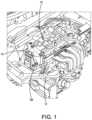
- FIG. 1is a schematic illustrating beneath the hood of a vehicle, showing an engine, a frame and an implementation of a vibration dampening engine mount as disclosed herein.
- FIG. 2is an exploded view of the engine, frame and the implementation of the vibration dampening engine mount.
- FIG. 3is a perspective view of an implementation of the vibration dampening engine mount as disclosed herein.
- FIG. 4is a front elevation view of the vibration dampening engine mount illustrating the vibration dampening engine mount attached to the engine with bolts.
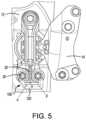
- FIG. 5is a plan view of FIG. 4 with the frame included.
- FIG. 6 Ais a plan view of another implementation of a vibration dampening engine mount and FIG. 6 B is a side elevation view of the vibration dampening engine mount of FIG. 7 A .
- FIG. 7 Ais a plan view of another implementation of a vibration dampening engine mount and FIG. 7 B is a side elevation view of the vibration dampening engine mount of FIG. 8 A .
- FIG. 8is a side elevation view of an implementation of a modular vibration dampening engine mount system shown with bolts as disclosed herein.
- FIG. 9is a side elevation view of another implementation of a modular vibration dampening engine mount system shown with bolts as disclosed herein.
- Engine mountsfunction to position and fix the engine to the vehicle's frame, minimizing movement of the engine. Minimizing movement in turn minimizes (i.e., dampens) or eliminates noises due to vibration, such as “kata/kata” noise.
- Engine mount designswill vary depending on the vehicle model, engine model and mounting location. To further function as a vibration dampener, engine mounts must be designed to counter the vibrations created when the engine is running, the vibrations changing as the engine idles, accelerates and decelerates.
- each engine mountis configured for a single bolt, and is fabricated with a specific profile configured to fit in a particular engine mount location, as well as a specific mass that has proven during testing to dampen vibrations of the particular vehicle at that particular location. With an engine mount for each bolt, the number of parts required increases. Fabrication costs increase due to the specificity of the application.
- FIG. 1is a schematic illustrating beneath the hood of a vehicle, showing an engine 10 , a frame 12 , an intermediate mounting member 14 and an implementation of a vibration dampening engine mount 100 as disclosed herein.
- FIG. 2is an exploded view illustrating how the intermediate mounting member 14 has multiple attachment points 16 to the engine 10 as well as attachment points 18 to the frame 12 .
- the vibration dampening engine mount 100attaches the engine 10 to the frame 12 via the intermediate mounting member 14 using bolts 20 .
- FIG. 3One implementation of a vibration dampening engine mount 100 configured to mount the engine 10 to the vehicle frame 12 is shown in FIG. 3 .
- the vibration dampening engine mount 100has a first bolt receiver 102 having a first through hole 104 configured to receive a first bolt 106 (shown in FIG. 4 ) and a second bolt receiver 110 having a second through hole 112 configured to receive a second bolt 114 (shown in FIG. 4 ).
- a mass damper connector 120integrally connects the first bolt receiver 102 and the second bolt receiver 110 .
- the term “integrally connects”indicates that the connected pieces are a unitary structure.
- the vibration dampening engine mount 100has a predetermined mass, predetermined through testing during manufacture to ensure effective vibration dampening for the specific mounting location.
- the implementation of the vibration dampening engine mount 100 used in FIGS. 1 , 2 , 4 and 5is approximately 600 grams.
- the implementations of the vibration dampening engine mounts disclosed hereincan have mass damper connectors of different configurations depending on the specific mounting location as the location may have structures or be near other components that form obstacles near or between the attachment points 18 .
- the vibration dampening engine mount 100 in FIG. 3is a non-limiting example wherein the mass damper connector 120 has a particular shape.
- the vibration dampening engine mount 100 of FIG. 3is shown installed on the intermediate mounting member 14 in FIG. 4 looking in a direction from the front of the vehicle to the rear of the vehicle.
- FIG. 5is a plan view of FIG. 4 and also includes the frame 12 .
- the mass damper connector 120extends from a forward-facing surface 122 of each of the first bolt receiver 102 and the second bolt receiver 110 . More particularly, the mass damper connector 120 may have one end that is a first leg 124 extending from the forward-facing surface 122 of the first bolt receiver 102 , its other end being a second leg 126 extending from the forward-facing surface 122 of the second bolt receiver 110 , and a bridge portion 128 extending between the first leg 124 and the second leg 126 .
- Such a configurationallows for means to connect the first and second bolt receivers 102 , 110 and provide the necessary mass even when there is an obstruction 30 (shown in FIG. 5 ) between the attachment points 18 .
- the first leg 124can extend from the forward-facing surface 122 of the first bolt receiver 102 and toward the second leg 126 at an obtuse angle ⁇ best illustrated in FIG. 5 .
- This configurationprovides clearance for another component, such as an air conditioning line.
- the second leg 126 and the bridge portion 128meet at a ninety-degree angle ⁇ , also best shown in FIG. 5 .
- a vibration dampening engine mount 200may be implemented as illustrated in FIGS. 6 A and 6 B .
- the vibration dampening engine mount 200has a first bolt receiver 202 having a first through hole 204 configured to receive a first bolt (not shown) and a second bolt receiver 210 having a second through hole 212 configured to receive a second bolt (not shown).
- a mass damper connector 220integrally connects the first bolt receiver 202 and the second bolt receiver 210 . In this implementation, the mass damper connector 220 spans a shortest distance between the first bolt receiver 202 and the second bolt receiver 210 .
- the mass of the vibration dampening engine mounts 100 , 200can be changed by changing a wall thickness of the first bolt receiver 102 , 202 and the second bolt receiver 102 , 202 and/or by changing a height and/or thickness of the mass damper connector 120 , 220 .
- a vibration dampening engine mount 300 shown in FIGS. 7 A and 7 Bhas a first bolt receiver 302 and a second bolt receiver 310 with thinner walls than those in FIGS. 6 A and 6 B while the mass damper connector 320 is the same size as that in FIGS. 6 A and 6 B .
- a modular vibration dampening engine mount systemhaving two or more of the vibration dampening engine mounts 100 , 200 , 300 used in combination.
- the modular systemallows for easily made and readily accessible vibration dampening engine mounts to be used to vary the mass at the attachment points until the necessary total mass is achieved, i.e., the predetermined mass.
- the solutionis more “off the shelf” than conventionally known, providing many benefits over the costly, difficult to manufacture engine mounts.
- FIG. 8illustrates a modular vibration dampening engine mount system 400 using two or more of the same vibration dampening engine mounts to achieve the requisite vibration dampening. Three are shown in FIG. 8 by means of example only.
- the modular vibration dampening engine mount system 400comprises two or more vibration dampening engine mounts 410 .
- the vibration dampening engine mounts 410can be any of the implementations 100 , 200 , 300 disclosed herein.
- Each vibration dampening engine mount 410has a pair of bolt receivers 412 , each of the pair of bolt receivers 412 having a through hole 414 configured to receive a respective bolt 420 .
- a mass damper connector 420is integrally connecting the pair of bolt receivers 412 .
- each vibration dampening engine mounthas the same predetermined mass.
- FIG. 9illustrates a modular vibration dampening engine mount system 500 using two or more vibration dampening engine mounts, at least two of the vibration dampening engine mounts being different in shape and/or mass to achieve the requisite vibration dampening.
- Three different vibration dampening engine mounts 510 , 512 , 514are shown in FIG. 9 by means of example only in this implementation of the modular vibration dampening engine mount system 500 .
- the vibration dampening engine mounts 510 , 512 , 514can be any combination of the implementations 100 , 200 , 300 disclosed herein.
- Each vibration dampening engine mount 510 , 512 , 514has a pair of bolt receivers 516 , 518 , 520 , respectively, with each of the pair of bolt receivers 516 , 518 , 520 having a through hole 522 configured to receive a respective bolt 524 .
- a mass damper connector 530 , 532 , 534is integrally connecting the respective pair of bolt receivers 516 , 518 , 520 .
- each vibration dampening engine mounthas a different predetermined mass. For example, vibration dampening engine mount 510 has less mass that vibration dampening engine mount 512 , which in turn has less mass than vibration dampening engine mount 514 .
- the vibration dampening engine mountshave the same distance X, shown in FIG. 6 A , between the central axis of the through holes. This distance X can be, as a non-limiting example, 400 mm.
- any implementation of the vibration dampening engine mounts disclosed hereincan include one or more alignment members.
- the alignment membersassist in obtaining a close stacking structure when used in the modular vibration dampening engine mount systems disclosed herein.
- a first alignment member 230is formed on a top surface 232 of the first bolt receiver 202
- another first alignment member 240formed on a top surface 242 of the second bolt receiver 210 .
- the first alignment members 230 , 240can be grooves formed in the respective top surfaces 232 , 242 . The groove can be sized to receive the bottom of the bolt receivers of an adjacent vibration dampening engine mount.
- FIG. 7 Ais similarly illustrated with optional first alignment members 330 , 340 .
- vibration dampening engine mount 100 in FIG. 3can also include first alignment members.
- a second alignment member 250can be formed on a bottom surface 252 of the first bolt receiver 202
- another second alignment member 260can be formed on a bottom surface 262 of the second bolt receiver 210
- the second alignment members 250 , 260can be tongues extending from the respective bottom surfaces 252 , 262 and configured to sit in grooves of an adjacent vibration dampening engine mount.
- FIG. 7 Bis similarly illustrated with optional second alignment members 350 , 360 .
- vibration dampening engine mount 100 in FIG. 3can also include second alignment members.
Landscapes
- Engineering & Computer Science (AREA)
- Mechanical Engineering (AREA)
- Chemical & Material Sciences (AREA)
- Combustion & Propulsion (AREA)
- Transportation (AREA)
- General Engineering & Computer Science (AREA)
- Arrangement Or Mounting Of Propulsion Units For Vehicles (AREA)
Abstract
Description
Claims (16)
Priority Applications (1)
| Application Number | Priority Date | Filing Date | Title |
|---|---|---|---|
| US17/538,598US12214665B2 (en) | 2021-11-30 | 2021-11-30 | Vibration dampening engine mount and modular vibration dampening engine mount system |
Applications Claiming Priority (1)
| Application Number | Priority Date | Filing Date | Title |
|---|---|---|---|
| US17/538,598US12214665B2 (en) | 2021-11-30 | 2021-11-30 | Vibration dampening engine mount and modular vibration dampening engine mount system |
Publications (2)
| Publication Number | Publication Date |
|---|---|
| US20230166590A1 US20230166590A1 (en) | 2023-06-01 |
| US12214665B2true US12214665B2 (en) | 2025-02-04 |
Family
ID=86500743
Family Applications (1)
| Application Number | Title | Priority Date | Filing Date |
|---|---|---|---|
| US17/538,598Active2042-12-09US12214665B2 (en) | 2021-11-30 | 2021-11-30 | Vibration dampening engine mount and modular vibration dampening engine mount system |
Country Status (1)
| Country | Link |
|---|---|
| US (1) | US12214665B2 (en) |
Cited By (1)
| Publication number | Priority date | Publication date | Assignee | Title |
|---|---|---|---|---|
| US12313141B2 (en)* | 2022-05-30 | 2025-05-27 | Hyundai Motor Company | Roll-rod for vehicle |
Citations (22)
| Publication number | Priority date | Publication date | Assignee | Title |
|---|---|---|---|---|
| US2713485A (en)* | 1952-05-28 | 1955-07-19 | Miner Inc W H | Rubber cushioning units for shock absorbers |
| US3311331A (en)* | 1965-10-07 | 1967-03-28 | Lowell Ind Inc | Vibration absorbing combination |
| US3730509A (en)* | 1970-04-15 | 1973-05-01 | R Jorn | Composite spring element for use as a motor mount |
| US4026534A (en)* | 1976-02-02 | 1977-05-31 | Department Of Mechanical Engineering Louisiana Tech University | Shock absorber |
| US4433834A (en)* | 1978-11-24 | 1984-02-28 | Midland-Ross Corporation | Composite cushion pad |
| US4610420A (en)* | 1984-02-16 | 1986-09-09 | Nissan Motor Company, Limited | Apparatus for mounting power unit |
| US4779834A (en)* | 1987-08-07 | 1988-10-25 | General Motors Corporation | Engine displacement limiter |
| US4817909A (en)* | 1987-12-07 | 1989-04-04 | Gencorp Inc. | Elastomeric hanger structure |
| JPH10267084A (en)* | 1997-03-25 | 1998-10-06 | Nissan Motor Co Ltd | Anti-vibration device |
| US6113058A (en)* | 1997-04-21 | 2000-09-05 | Bridgestone Corporation | Coupling device |
| US6129177A (en)* | 1998-10-23 | 2000-10-10 | Lord Corporation | Pivoting tuned vibration absorber and system utilizing same |
| WO2002042660A1 (en)* | 2000-11-22 | 2002-05-30 | Toyo Tire & Rubber Co., Ltd. | Connecting rod |
| US7263806B2 (en)* | 2005-04-11 | 2007-09-04 | Ridg-U-Rak, Inc. | Storage rack vibration isolators and related storage racks |
| US20080093186A1 (en)* | 2006-10-24 | 2008-04-24 | Honda Motor Co., Ltd. | Vibration damping member |
| US9630484B1 (en)* | 2016-03-28 | 2017-04-25 | Nissan North America, Inc. | Vehicle engine mount structure |
| US9689457B2 (en)* | 2010-08-23 | 2017-06-27 | Bridgestone Corporation | Torque rod and engine mounting system for using same |
| KR101846784B1 (en) | 2017-06-28 | 2018-04-06 | 현대자동차주식회사 | Active damping device for vehicle |
| US10046634B2 (en)* | 2016-03-16 | 2018-08-14 | Honda Motor Co., Ltd. | Engine mount structure |
| US10518623B2 (en)* | 2017-01-19 | 2019-12-31 | Honda Motor Co., Ltd. | Dynamic damper mounting structure |
| WO2020239279A1 (en)* | 2019-05-28 | 2020-12-03 | Zf Friedrichshafen Ag | Segmented vibration absorber |
| US10933727B2 (en) | 2017-11-24 | 2021-03-02 | Hyundai Motor Company | Engine mount embedded with damper |
| US20220128119A1 (en)* | 2020-10-23 | 2022-04-28 | Hyundai Motor Company | Modular mounting structure and combination method for manufacturing vehicle |
- 2021
- 2021-11-30USUS17/538,598patent/US12214665B2/enactiveActive
Patent Citations (22)
| Publication number | Priority date | Publication date | Assignee | Title |
|---|---|---|---|---|
| US2713485A (en)* | 1952-05-28 | 1955-07-19 | Miner Inc W H | Rubber cushioning units for shock absorbers |
| US3311331A (en)* | 1965-10-07 | 1967-03-28 | Lowell Ind Inc | Vibration absorbing combination |
| US3730509A (en)* | 1970-04-15 | 1973-05-01 | R Jorn | Composite spring element for use as a motor mount |
| US4026534A (en)* | 1976-02-02 | 1977-05-31 | Department Of Mechanical Engineering Louisiana Tech University | Shock absorber |
| US4433834A (en)* | 1978-11-24 | 1984-02-28 | Midland-Ross Corporation | Composite cushion pad |
| US4610420A (en)* | 1984-02-16 | 1986-09-09 | Nissan Motor Company, Limited | Apparatus for mounting power unit |
| US4779834A (en)* | 1987-08-07 | 1988-10-25 | General Motors Corporation | Engine displacement limiter |
| US4817909A (en)* | 1987-12-07 | 1989-04-04 | Gencorp Inc. | Elastomeric hanger structure |
| JPH10267084A (en)* | 1997-03-25 | 1998-10-06 | Nissan Motor Co Ltd | Anti-vibration device |
| US6113058A (en)* | 1997-04-21 | 2000-09-05 | Bridgestone Corporation | Coupling device |
| US6129177A (en)* | 1998-10-23 | 2000-10-10 | Lord Corporation | Pivoting tuned vibration absorber and system utilizing same |
| WO2002042660A1 (en)* | 2000-11-22 | 2002-05-30 | Toyo Tire & Rubber Co., Ltd. | Connecting rod |
| US7263806B2 (en)* | 2005-04-11 | 2007-09-04 | Ridg-U-Rak, Inc. | Storage rack vibration isolators and related storage racks |
| US20080093186A1 (en)* | 2006-10-24 | 2008-04-24 | Honda Motor Co., Ltd. | Vibration damping member |
| US9689457B2 (en)* | 2010-08-23 | 2017-06-27 | Bridgestone Corporation | Torque rod and engine mounting system for using same |
| US10046634B2 (en)* | 2016-03-16 | 2018-08-14 | Honda Motor Co., Ltd. | Engine mount structure |
| US9630484B1 (en)* | 2016-03-28 | 2017-04-25 | Nissan North America, Inc. | Vehicle engine mount structure |
| US10518623B2 (en)* | 2017-01-19 | 2019-12-31 | Honda Motor Co., Ltd. | Dynamic damper mounting structure |
| KR101846784B1 (en) | 2017-06-28 | 2018-04-06 | 현대자동차주식회사 | Active damping device for vehicle |
| US10933727B2 (en) | 2017-11-24 | 2021-03-02 | Hyundai Motor Company | Engine mount embedded with damper |
| WO2020239279A1 (en)* | 2019-05-28 | 2020-12-03 | Zf Friedrichshafen Ag | Segmented vibration absorber |
| US20220128119A1 (en)* | 2020-10-23 | 2022-04-28 | Hyundai Motor Company | Modular mounting structure and combination method for manufacturing vehicle |
Cited By (1)
| Publication number | Priority date | Publication date | Assignee | Title |
|---|---|---|---|---|
| US12313141B2 (en)* | 2022-05-30 | 2025-05-27 | Hyundai Motor Company | Roll-rod for vehicle |
Also Published As
| Publication number | Publication date |
|---|---|
| US20230166590A1 (en) | 2023-06-01 |
Similar Documents
| Publication | Publication Date | Title |
|---|---|---|
| JP4508499B2 (en) | Mounting structure | |
| US6511059B2 (en) | Antivibration device and mechanical assembly comprising such antivibration device | |
| US7165645B2 (en) | Fixing device for an automobile muffler | |
| CN111278717A (en) | Rear axle subframe with support for drive unit | |
| US20050098374A1 (en) | Mount assembly for automotive power plant | |
| US12214665B2 (en) | Vibration dampening engine mount and modular vibration dampening engine mount system | |
| KR20070120159A (en) | Supporting device for supporting the vehicle mounted object | |
| US8177171B2 (en) | Piping installation structure for vehicle | |
| CN216356283U (en) | Support bracket, mounting bracket and bracket assembly | |
| US7458594B2 (en) | Lower arm mounting structure of vehicle suspension | |
| JP6866767B2 (en) | Powertrain mounting device | |
| CA2548012A1 (en) | Universal running board mounting bracket | |
| JP2003011680A (en) | Radiator support structure | |
| KR100499774B1 (en) | Engine mounting system with dynamic damper | |
| KR20120061675A (en) | Transmission mounting structure of vehicles | |
| US7104256B2 (en) | Throttle body fixing structure | |
| JPH11351329A (en) | Square elastic suspension device | |
| CN223148362U (en) | Mounting bracket and vehicle | |
| KR100925954B1 (en) | Bracket assembly for transmission mounting and side members | |
| KR100911394B1 (en) | Car Roll Mount Device | |
| JP4885047B2 (en) | Vibration isolator | |
| KR100610121B1 (en) | Top mounting bracket of rear strut assembly | |
| US20190084398A1 (en) | Mounting structure of engine mount | |
| KR100559016B1 (en) | Transmission mounting structure | |
| KR20230032075A (en) | Rear cross member of vehicle |
Legal Events
| Date | Code | Title | Description |
|---|---|---|---|
| FEPP | Fee payment procedure | Free format text:ENTITY STATUS SET TO UNDISCOUNTED (ORIGINAL EVENT CODE: BIG.); ENTITY STATUS OF PATENT OWNER: LARGE ENTITY | |
| AS | Assignment | Owner name:NISSAN NORTH AMERICA, INC., TENNESSEE Free format text:ASSIGNMENT OF ASSIGNORS INTEREST;ASSIGNORS:VALENZUELA, JENNIFER;VALDEZ, MARCO ANTONIO FLORES;SIGNING DATES FROM 20211207 TO 20211213;REEL/FRAME:058371/0734 | |
| STPP | Information on status: patent application and granting procedure in general | Free format text:DOCKETED NEW CASE - READY FOR EXAMINATION | |
| STPP | Information on status: patent application and granting procedure in general | Free format text:NON FINAL ACTION MAILED | |
| STPP | Information on status: patent application and granting procedure in general | Free format text:NON FINAL ACTION MAILED | |
| STPP | Information on status: patent application and granting procedure in general | Free format text:RESPONSE TO NON-FINAL OFFICE ACTION ENTERED AND FORWARDED TO EXAMINER | |
| STPP | Information on status: patent application and granting procedure in general | Free format text:FINAL REJECTION MAILED | |
| STPP | Information on status: patent application and granting procedure in general | Free format text:RESPONSE AFTER FINAL ACTION FORWARDED TO EXAMINER | |
| STPP | Information on status: patent application and granting procedure in general | Free format text:NOTICE OF ALLOWANCE MAILED -- APPLICATION RECEIVED IN OFFICE OF PUBLICATIONS | |
| ZAAB | Notice of allowance mailed | Free format text:ORIGINAL CODE: MN/=. | |
| STCF | Information on status: patent grant | Free format text:PATENTED CASE | |
| AS | Assignment | Owner name:NISSAN MOTOR CO., LTD., JAPAN Free format text:ASSIGNMENT OF ASSIGNORS INTEREST;ASSIGNOR:NISSAN NORTH AMERICA, INC.;REEL/FRAME:071948/0684 Effective date:20250731 |