US12214162B2 - Infusion pump with valve compensation - Google Patents
Infusion pump with valve compensationDownload PDFInfo
- Publication number
- US12214162B2 US12214162B2US17/433,388US202017433388AUS12214162B2US 12214162 B2US12214162 B2US 12214162B2US 202017433388 AUS202017433388 AUS 202017433388AUS 12214162 B2US12214162 B2US 12214162B2
- Authority
- US
- United States
- Prior art keywords
- infusion
- valve
- plunger
- distal valve
- descending
- Prior art date
- Legal status (The legal status is an assumption and is not a legal conclusion. Google has not performed a legal analysis and makes no representation as to the accuracy of the status listed.)
- Active, expires
Links
Images

Classifications
- A—HUMAN NECESSITIES
- A61—MEDICAL OR VETERINARY SCIENCE; HYGIENE
- A61M—DEVICES FOR INTRODUCING MEDIA INTO, OR ONTO, THE BODY; DEVICES FOR TRANSDUCING BODY MEDIA OR FOR TAKING MEDIA FROM THE BODY; DEVICES FOR PRODUCING OR ENDING SLEEP OR STUPOR
- A61M5/00—Devices for bringing media into the body in a subcutaneous, intra-vascular or intramuscular way; Accessories therefor, e.g. filling or cleaning devices, arm-rests
- A61M5/14—Infusion devices, e.g. infusing by gravity; Blood infusion; Accessories therefor
- A61M5/168—Means for controlling media flow to the body or for metering media to the body, e.g. drip meters, counters ; Monitoring media flow to the body
- A61M5/16877—Adjusting flow; Devices for setting a flow rate
- A61M5/16881—Regulating valves
- A—HUMAN NECESSITIES
- A61—MEDICAL OR VETERINARY SCIENCE; HYGIENE
- A61M—DEVICES FOR INTRODUCING MEDIA INTO, OR ONTO, THE BODY; DEVICES FOR TRANSDUCING BODY MEDIA OR FOR TAKING MEDIA FROM THE BODY; DEVICES FOR PRODUCING OR ENDING SLEEP OR STUPOR
- A61M5/00—Devices for bringing media into the body in a subcutaneous, intra-vascular or intramuscular way; Accessories therefor, e.g. filling or cleaning devices, arm-rests
- A61M5/14—Infusion devices, e.g. infusing by gravity; Blood infusion; Accessories therefor
- A61M5/142—Pressure infusion, e.g. using pumps
- A61M5/14212—Pumping with an aspiration and an expulsion action
- A61M5/14216—Reciprocating piston type
- A—HUMAN NECESSITIES
- A61—MEDICAL OR VETERINARY SCIENCE; HYGIENE
- A61M—DEVICES FOR INTRODUCING MEDIA INTO, OR ONTO, THE BODY; DEVICES FOR TRANSDUCING BODY MEDIA OR FOR TAKING MEDIA FROM THE BODY; DEVICES FOR PRODUCING OR ENDING SLEEP OR STUPOR
- A61M5/00—Devices for bringing media into the body in a subcutaneous, intra-vascular or intramuscular way; Accessories therefor, e.g. filling or cleaning devices, arm-rests
- A61M5/14—Infusion devices, e.g. infusing by gravity; Blood infusion; Accessories therefor
- A61M5/168—Means for controlling media flow to the body or for metering media to the body, e.g. drip meters, counters ; Monitoring media flow to the body
- A61M5/16831—Monitoring, detecting, signalling or eliminating infusion flow anomalies
- A61M5/16854—Monitoring, detecting, signalling or eliminating infusion flow anomalies by monitoring line pressure
- A61M5/16859—Evaluation of pressure response, e.g. to an applied pulse
- A—HUMAN NECESSITIES
- A61—MEDICAL OR VETERINARY SCIENCE; HYGIENE
- A61M—DEVICES FOR INTRODUCING MEDIA INTO, OR ONTO, THE BODY; DEVICES FOR TRANSDUCING BODY MEDIA OR FOR TAKING MEDIA FROM THE BODY; DEVICES FOR PRODUCING OR ENDING SLEEP OR STUPOR
- A61M5/00—Devices for bringing media into the body in a subcutaneous, intra-vascular or intramuscular way; Accessories therefor, e.g. filling or cleaning devices, arm-rests
- A61M5/14—Infusion devices, e.g. infusing by gravity; Blood infusion; Accessories therefor
- A61M2005/1401—Functional features
- A61M2005/1406—Minimizing backflow along the delivery catheter track
- A—HUMAN NECESSITIES
- A61—MEDICAL OR VETERINARY SCIENCE; HYGIENE
- A61M—DEVICES FOR INTRODUCING MEDIA INTO, OR ONTO, THE BODY; DEVICES FOR TRANSDUCING BODY MEDIA OR FOR TAKING MEDIA FROM THE BODY; DEVICES FOR PRODUCING OR ENDING SLEEP OR STUPOR
- A61M2205/00—General characteristics of the apparatus
- A61M2205/33—Controlling, regulating or measuring
- A61M2205/332—Force measuring means
- A—HUMAN NECESSITIES
- A61—MEDICAL OR VETERINARY SCIENCE; HYGIENE
- A61M—DEVICES FOR INTRODUCING MEDIA INTO, OR ONTO, THE BODY; DEVICES FOR TRANSDUCING BODY MEDIA OR FOR TAKING MEDIA FROM THE BODY; DEVICES FOR PRODUCING OR ENDING SLEEP OR STUPOR
- A61M2205/00—General characteristics of the apparatus
- A61M2205/33—Controlling, regulating or measuring
- A61M2205/3331—Pressure; Flow
- A61M2205/3334—Measuring or controlling the flow rate
- A—HUMAN NECESSITIES
- A61—MEDICAL OR VETERINARY SCIENCE; HYGIENE
- A61M—DEVICES FOR INTRODUCING MEDIA INTO, OR ONTO, THE BODY; DEVICES FOR TRANSDUCING BODY MEDIA OR FOR TAKING MEDIA FROM THE BODY; DEVICES FOR PRODUCING OR ENDING SLEEP OR STUPOR
- A61M5/00—Devices for bringing media into the body in a subcutaneous, intra-vascular or intramuscular way; Accessories therefor, e.g. filling or cleaning devices, arm-rests
- A61M5/14—Infusion devices, e.g. infusing by gravity; Blood infusion; Accessories therefor
- A61M5/142—Pressure infusion, e.g. using pumps
- A61M5/14212—Pumping with an aspiration and an expulsion action
- A61M5/14228—Pumping with an aspiration and an expulsion action with linear peristaltic action, i.e. comprising at least three pressurising members or a helical member
Definitions
- the present inventionrelates generally to the field of medical devices for providing fluid to a patient. More specifically, the present invention relates to infusion pumps configured to inhibit bolus liquid flow and/or reverse flow by compensation for the descending and/or ascending of the pump's downstream valve.
- Infusion pumpsare configured to administer fluid to a patient via a conduit, such as an infusion tube or a cassette at high accuracy and often for a prolonged period of time.
- Infusion tubesare accommodated in the infusion pump in such manner that a plunger can squeeze the surface of the infusion tube, thereby causing delivery of the infusion fluid.
- an infusion pump assemblymay repeatedly administer small quantities of an infusible fluid (e.g., 0.1 mL per hour).
- a problem of infusion pumpsis an unwanted suction of a patient's blood as a result of an ascending of the pump's downstream valve and/or an undesired bolus being provided to the patient as a result of a descending of the pump's downstream valve.
- the herein disclosed infusion pumpadvantageously includes a controller configured to control the descending/ascending of the plunger along with the ascending/descending of the pump's distal valve, such that the flow caused by the ascending/descending of the pump's distal valve is compensated for by the plunger.
- the plungerbefore or with opening the distal valve (also referred to herein as the downstream valve), the plunger is lowered, such that a volume of liquid, equal to the volume of blood that would otherwise be sucked into the infusion tube as a result of the ascending of the distal valve, is pumped towards the patient's open vein, thus counteracting/compensating for the unwanted backflow of blood.
- the valvemay ascend and descend at a velocity that is correlated with a set flow rate. This may advantageously ensure that the volume pushed towards the patient by the descent of the downstream valve as well as the volume sucked by the ascent of the downstream valve do not momentarily alter the flow rate.
- the upper position of the downstream/distal valvemay be set such that while in its upper position the distal valve still squeezes the infusion tube in order to reduce boluses caused by the descending of the downstream valve.
- the distal valve still squeezing the infusion tube while in its upper positionalso minimizes power consumption, and thus cost of use.
- the distal valve still squeezing the infusion tube while in its upper positionensures that the delivery of the infusion fluid is at an essentially constant volume regardless of a potential degradation of the infusion tube as well as inhibiting or at least reducing tube degradation.
- an infusion pumpincluding:
- a plungerconfigured to squeeze a section of an infusion tube
- a proximal valvelocated proximally to said plunger, said proximal valve configured to:
- a distal valvelocated distally to said plunger, said distal valve configured to:
- a controllerconfigured to control said plunger, said proximal valve, and said distal valve and thereby, to control infusion fluid intake from the reservoir and infusion fluid delivery to a subject
- a rate selected from the group consisting of: a rate of the ascending of the distal valve, and a rate of the descending of the distal valvedepends on a set flow rate of the infusion fluid.
- a rate of descending of the distal valveis determined based on a set flow rate and volume delivered as a result of the descending of the distal valve, wherein the volume delivered as a result of the descending of the distal valve is accounted for as a part of a total infusion fluid volume to be delivered.
- a motion of the plunger selected from the group consisting of: descending of the plunger, and ascending of the plunger,is continuous.
- a motion of the plunger selected from the group consisting of: descending of the plunger, and ascending of the plunger,is pulsatory.
- a motion selected from the group consisting of: the descending of the proximal valve, the ascending of the proximal valve, the descending of the distal valve, and the ascending of the distal valveis continuous.
- a motion selected from the group consisting of: the descending of the proximal valve, the ascending of the proximal valve, the descending of the distal valve, and the ascending of the distal valveis pulsatory.
- a rate selected from the group consisting of: a rate of ascending of the plunger, and a rate of descending of the plungerdepends on the set flow rate of the infusion fluid.
- a force sensorconfigured to measure the pressure in the part of the infusion tube extends between the proximal valve and the distal valve, and wherein the controller is configured to set a rate of the descending of the plunger based on the pressure measured by the force sensor.
- the distal valveis configured to ascend from a lower position to an upper position, wherein at both the upper position and the lower position, said distal valve is configured to squeeze a section of the infusion tube.
- the plungeris configured to descend from an upper position to a lower position, wherein at both the upper position and the lower position, said plunger is configured to squeeze a section of the infusion tube.
- a component of the infusion pumpselected from the group consisting of: said plunger and said distal valve, is configured to contact an outer surface of the infusion tube from completion of intake to completion of delivery.
- the apparatusfurther includes a motor in communication with said controller, said motor configured to operate said plunger.
- said motoris further configured to operate at least one valve selected from the group consisting of: said proximal valve, and said distal valve.
- the apparatusfurther includes a second motor configured to operate at least one valve selected from the group consisting of: said proximal valve, and said distal valve.
- infusion tubeis a DEHP-free PVC infusion tube, DEHP containing infusion tube, a polyethylene (PE) tube, a silicone tube, a thermoplastic elastomer (TPE) tube, a polypropylene (PP) tube, or a polyurethane tube.
- PEpolyethylene
- TPEthermoplastic elastomer
- PPpolypropylene
- an infusion pumpincluding:
- a plungerconfigured to squeeze a section of an infusion tube
- a proximal valvelocated proximally to said plunger, said proximal valve configured to ascend and to descend and thereby allowing and disabling, respectively, infusion fluid intake from a reservoir to the infusion tube;
- a distal valvelocated distally to said plunger, said distal valve configured to:
- a controllerconfigured to control said plunger, said proximal valve and said distal valve and thereby to control infusion fluid delivery to a subject and infusion fluid intake from an infusion source
- the ascending of the distal valve from the lower position to the upper positionis an ascending from a complete tube occlusion position to a position where greater than 30%, but less than complete occlusion, of the area of the inner tube cross section of the infusion tube is squeezed.
- the ascending of the distal valve from the lower position to the upper positionis performed at a predetermined rate.
- the ascending of the distal valve from a lower position to an upper positionis an ascending from a position where less than 30% of the area of the inner tube cross section of the infusion tube is open to a position where 30%-98% of the area of the inner tube cross section is open.
- the ascending of the distal valveis performed concurrently with the descending of the plunger.
- a rate of the ascending of the distal valvedepends on a set flow rate of the infusion fluid.
- a component of the infusion pumpselected from the group consisting of: said plunger and said distal valve, is configured to contact an outer surface of the infusion tube from completion of intake to completion of delivery.
- an infusion pumpincluding:
- a plungerconfigured to squeeze a section of an infusion tube
- a proximal valvelocated proximally to said plunger, said proximal valve configured to ascend and to descend and thereby allowing and disabling, respectively, infusion fluid intake from a reservoir to the infusion tube;
- a distal valvelocated distally to said plunger, said distal valve configured to:
- a force sensorconfigured to measure the pressure in the part of the infusion tube extending between the proximal valve and the distal valve
- a controllerconfigured to control said plunger, said proximal valve and said distal valve and thereby to control infusion fluid delivery to a subject and infusion fluid intake from an infusion source
- a component of the infusion pumpselected from the group consisting of: said plunger and said distal valve, is configured to contact an outer surface of the infusion tube from completion of intake to completion of delivery.
- the descending of said plunger prior to an initial partial ascending of the distal valveis conducted at a predetermined rate.
- the descending of said plungeris conducted at a predetermined rate until a reduction of pressure in the infusion tube is detected upon ascending of the distal valve and opening of the infusion tube.
- the controlleris configured to cause said plunger to descend concurrently with the continued ascending of the distal valve.
- a rate of the descending of the plungeris determined based on the pressure measured by the force sensor.
- a rate of the descending of the plungeris determined by the set flow rate for the delivery.
- Certain embodiments of the present disclosuremay include some, all, or none of the above advantages.
- One or more technical advantagesmay be readily apparent to those skilled in the art from the figures, descriptions and claims included herein.
- specific advantageshave been enumerated above, various embodiments may include all, some or none of the enumerated advantages.
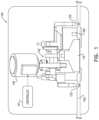
- FIG. 1schematically illustrates an infusion pump, according to some embodiments.
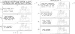
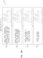
- FIGS. 2 A-Bare, combined, an illustrative flowchart for operating an infusion pump, according to some embodiments.
- an infusion pumpcomprising: a plunger configured to squeeze a section of an infusion tube; a proximal valve (also referred to herein as the “upstream valve”) located proximally to the plunger; and a distal valve (also referred to herein as the “downstream valve”) located distally to the plunger, wherein the distal valve is configured to ascend and thereby allow infusion fluid flow past the distal valve and to descend and thereby inhibit infusion fluid flow past the distal valve; and a controller configured to control the plunger, the proximal valve and the distal valve and thereby to control infusion fluid delivery to a subject and infusion fluid intake from an infusion source.
- the infusion pumpfurther comprises a pressure sensor.
- the controlleris configured to control movement of the plunger based on pressure measurements obtained from the pressure sensor.
- the controlleris configured to initiate an initial descending of the plunger prior to the ascending of the distal valve so as to create a positive pressure prior to the distal valve opening (while the proximal valve is closed) to compensate immediately for negative fluid flow that would otherwise result from ascending of the distal valve.
- the controlleris configured to initiate a partial initial ascending of the distal valve.
- a partial initial ascending of the distal valvemay form a discrete fluid path opening in accordance with a set flow rate requirement.
- Such partial initial ascending of the distal valvemay better couple the negative and positive infusion fluid flows and thus reduce boluses.
- the controlleris configured to initiate a partial descending of the plunger concurrently with the continued ascending of the distal valve (while the proximal valve is closed).
- this partial descending of the plungerdepends on pressure in the section of an infusion tube measured by the pressure sensor.
- the above described descending of the plunger before or concurrently with the ascending of the distal valvemay be referred to herein as a “compensatory” descending of the plunger that compensates for vacuum produced by the ascending of the distal valve, thereby reducing backflow of fluid from the subject.
- the descending of the plunger required for delivering the infusion fluidmay be initiated once the distal valve reaches its upper position.
- the term “upper position” of the distal valvesrefers to the maximum upper position of the distal valve in any given pump cycle, i.e., the upper limit of the distal valve stroke in any given pump cycle.
- the descending of the plunger required for delivering the infusion fluidmay be initiated concurrently with the continued ascending of the distal valve to its upper position.
- this distal valve upper positionmay be dictated by pressure in the section of an infusion tube as measured by the pressure sensor.
- the compensatory descending of the plungermay be performed separately from the descending of the plunger required for delivering the infusion fluid.
- the compensatory descending rate of the plungermay be same or different than the descending rate of the plunger required for delivering the infusion fluid.
- the compensatory descending of the plungermay be less than the descending of the plunger required for delivering the infusion fluid.
- the compensatory descending of the plungermay be coextensive with (an integral part of) the descending of the plunger required for delivering the infusion fluid.
- the descending of the plungerbeing either (a) the compensatory descending of the plunger or (b) the descending of the plunger required for delivering the infusion fluid, depends on the state of the distal valve. While the distal valve is occluding the tube, the descending of the plunger is compensatory and acts to increase pressure in the isolated segment of the tube i.e., between the proximal and distal valves, thereby preparing a bolus that compensates for the suction that occurs when the distal valve is opened. For some set flow rates (e.g., less than 300 mL/h), the rate of the compensatory descending of the plunger is typically higher than the rate of the descending of the plunger required for delivering the infusion fluid.
- the compensatory descending of the plungeris typically dependent on a predetermined volume of the bolus that compensates for the suction due to the ascending of the distal valve, which relates to parameters of the distal valve, e.g., the geometry of the distal valve, the stroke of the distal valve, and/or the size of the distal valve.
- the volume of the bolus prepared during the compensatory descending of the plungeris independent of the “set flow rate” of the infusion fluid (i.e., the flow rate which is set by an operator or programmer of the infusion pump). Contrary to the compensatory descending of the plunger, the descending of the plunger required for delivering the infusion fluid depends on the set flow rate of the infusion fluid.
- the volume of the prepared bolus during the compensatory descending of the plungermay be calculated and accounted for as a part of the total delivered volume of infusion fluid.
- the compensatory descending of the plungermay be calculated according to pressure in the section of the infusion tube between the proximal and distal valves.
- the term “compensation” with regards to the plungerrefers to a movement of the plunger which counteracts, nullifies, reverses, evens out or otherwise inhibits an undesired flow of infusion fluid to the patient's vein or reverse fluid/blood flow from the patient, caused by movement of the distal valve.
- the distal valveis configured to ascend from a lower position, at which fluid delivery to the patient is essentially blocked, to an upper position, at which fluid delivery to the patient is facilitated.
- the ascending of the distal valve to the upper positionmay be minor such that the opening of the tube for delivery remains narrow (e.g. up to 30% area of the inner cross section of the infusion tube).
- the distal valveat both the upper position and the lower position, the distal valve at least partially squeezes a section of the infusion tube, thereby reducing the volume of backflow caused by the ascending of the distal valve as well as enhancing the compensation for vacuum produced by the ascending of the distal valve and reducing power consumption.
- the smaller descending range of the valvereduces the positive flow bolus size.
- descending of the plunger required for delivering the infusion fluidmay be a descending of the plunger from an upper squeezing position to a lower squeezing position, wherein at both the upper squeezing position and the lower squeezing position, the plunger is squeezing a section of an infusion tube, such that an opposite side of an inner surface of the section does not contact the squeezed side, thus ensuring that the delivery of the infusion fluid is at an essentially constant volume regardless of a potential degradation of the infusion tube as well as inhibiting or at least reducing tube degradation.
- fusion fluidmay refer to any fluid delivered to the patient such as, but not limited to, insulin, nutrients, saline solution, antibiotics, analgesics, anesthetics, hormones, vasoactive drugs, and chelation drugs, and any other therapeutic fluids or combination of fluids.
- the term “upper squeezing position” with regards to the plungerrefers to a position of a plunger at which an infusion tube is mildly squeezed (i.e. lower than a position at which the tube is not squeezed), without having the opposite sides of an inner surface of the squeezed section contacting one another.
- the delivery phase of the infusion pumpis initiated at the “upper squeezing position” or at “after compensation” position.
- the upper squeezing positionis higher (less squeezing of the tube) than the position of the plunger when descended to compensate for the backflow caused by the ascending of the distal valve.
- the term “lower squeezing position” with regards to the plungerrefers to a position of the plunger at which an infusion tube is squeezed to a larger extent as compared to the upper squeezing position, yet still without having the opposite sides of an inner surface of the squeezed section contacting one another.
- the term “degradation”may refer to the tube losing its springiness, becoming deformed, bottoming out, or otherwise changing its shape or consistency in a manner affecting the drug delivery accuracy.
- the infusion tubemay be a DEHP-free PVC infusion tube, a DEHP containing infusion tube, a polyethylene (PE) tube, a silicone tube, a polyurethane tube or the like. Each possibility is a separate embodiment.
- the velocity of the ascending and descending of the distal valve and/or of the plungerdepends on the set flow rate of the infusion fluid.
- the ascending and/or descending of the plungermay be continuous, i.e. at a constant rate.
- the ascending and/or descending of the plungermay be pulsatory, i.e. in small steps.
- the ascending and/or descending of the distal valvemay be continuous, i.e. at a constant rate.
- the ascending and/or descending of the distal valvemay be pulsatory, i.e. in small steps.
- the velocity of the ascending and descending of the distal valve and/or of the plungermay likewise be high, and at low set flow rates, the velocity of the ascending and descending of the distal valve and/or of the plunger may likewise be low.
- the controllermay be configured to automatically adjust the velocity of the ascending and descending of the distal valve and/or of the plunger according to the set flow rate. This ascending/descending sequence and control of movement allow continued fluid delivery flow.
- the controllermay adjust the rate of the descending of the distal valve based on the set flow rate in order to avoid a bolus delivery upon descending of the distal valve, i.e., the rate of the descending of the distal valve is controlled by the controller such that as the distal valve descends the distal valve pushes infusion fluid to the subject at the set flow rate.
- the rate of the descending of the distal valveis controlled by the controller such that as the distal valve descends the distal valve pushes infusion fluid to the subject at the set flow rate.
- a faster descending of the distal valvemay be set
- lower flow ratesi.e., slower descending of the plunger
- the extra volume of fluid pushed to the subject during the descending of the distal valvemay be calculated and accounted for as part of the volume of infusion fluid delivered per pump cycle.
- the “upper position” of the distal valverefers to a position of the distal valve at which an infusion tube is squeezed (i.e. lower than a position at which the tube is not squeezed), without having the opposite sides of an inner surface of the squeezed section contacting one another. That is, at the upper position the distal valve engages the infusion tube.
- the term “lower position” with reference to the distal valverefers to a position of the distal valve at which the infusion tube is squeezed to such extent that delivery of infusion fluid to the patient is essentially avoided.
- the inner tube cross section of the infusion tube when the distal valve is in its upper positionis 30%-98% (e.g., a preset value, e.g., 50%) of the area of the inner tube cross section of the infusion tube, when non-squeezed.
- a preset valuee.g. 50%
- the distal valvemay be used, affecting the percentage of the squeezed area, for different set flow rates. For example, while in its upper position the distal valve still squeezes the infusion tube in order to reduce the bolus that is caused by the descending of the distal valve. Nevertheless, while in its upper position the distal valve should be open enough so as not to inhibit delivery of the infusion fluid during the descending of the plunger.
- a typical upper position, of the distal valveis about 0.3 mm to 2.8 mm, lower than the diameter of a non-squeezed tube.
- the infusion pumpis configured to maintain an essentially constant flow rate during the entire delivery of an infusion fluid.
- the infusion pumpis configured to maintain a delivery of an infusion fluid at a set flow rate of 1 ⁇ 0.05 mL/hour for at least 20, at least 36 or at least 96 hours.
- the pumpfurther includes a motor in communication with the controller, the motor configured to operate the plunger.
- the motormay further be configured to operate the proximal valve, the distal valve or both.
- the pumpmay include one or two additional motors configured to operate the proximal valve, the distal valve or both.
- the controllermay control the operation of the motor, thereby determining the exact position of the plunger and/or the distal valve.
- the controllermay control the operation of the motor, by determining a velocity/rate of the ascending/descending of the plunger, the proximal valve and/or the distal valve.
- the controllermay control the operation of the motor, by determining the increments of the ascending/descending of the plunger, the proximal valve and/or the distal valve. According to some embodiments, the controller may control the operation of the motor, by determining the value of the ascending/descending of the plunger, the proximal valve and/or the distal valve.
- the controllermay further be configured to determine a “wait” period, during which the plunger remains at the upper squeezing position, thereby ensuring full engagement of the infusion tube with the plunger, prior to the closing of the infusion pump's upstream valve. This advantageously increases the accuracy of infusion fluid delivery in that the volume delivered remains constant even if the infusion tube has undergone degradation.
- the length of the waitdepends on the flow continuity requirements and the set flow rate. For low set flow rates (0.1-1 mL/hr) and flow continuity of bolus every 20 sec, the wait can last up to 18 sec. For higher set flow rates, the wait time can be shorter (e.g. about 10 sec) and for very high flow rates (999 mL/hr) it may last less than 1 second.
- the long waitis particularly advantageous for low set flow rates where the tube squeeze duty cycle is very long.
- the long wait timesare essentially a no movement of plunger and valves in the specific position while for high set flow rates the “wait” equals pump's check-in time—the time the pump goes through the encoders that leave the plunger in the upper position while the proximal valve is open.
- a method of operation of an infusion pumpcomprising utilizing the infusion pump, as essentially described herein.
- FIG. 1schematically illustrates an infusion pump 100 with a plunger 110 , a proximal/upstream valve 120 , also referred to herein as an inlet valve, positioned proximally/upstream to plunger 110 and configured to allow flow of infusion fluid from a reservoir (not shown) to an infusion tube 150 and a distal/downstream valve 125 , also referred to herein as an outlet valve, positioned distally/downstream to plunger 110 and configured to allow flow of infusion fluid from infusion tube 150 to a patient (not shown).
- a proximal/upstream valve 120also referred to herein as an inlet valve
- a distal/downstream valve 125also referred to herein as an outlet valve
- plunger 110 , proximal valve 120 and distal valve 125are carried out by motor 140 and associated cam shaft 142 , although other embodiments, according to which positioning of plunger 110 , proximal valve 120 and distal valve 125 is executed by separate motors, are also possible and within the scope of this disclosure.
- Motor 140is typically controlled by a controller 141 .
- Infusion pump 100further includes a force sensor 160 configured to measure the pressure in the part of infusion tube 150 extending between proximal valve 120 and distal valve 125 .
- the figureillustrates the pump at a state when proximal valve 120 is at a tube releasing position, distal valve 125 is at a tube occluding position and plunger 110 is at a tube squeezing position.
- FIGS. 2 A-Bare, combined, an illustrative flowchart 200 for operating an infusion pump, according to some embodiments.
- an infusion tubeis positioned within an infusion pump, the infusion pump comprising a plunger, a proximal valve located proximally to the plunger, and a distal valve located distally to the plunger.
- Steps 220 to 240are steps associated with intake of infusion fluid from a reservoir (also referred to herein as infusion source).
- step 220an opening of the proximal valve is initiated (while the distal valve is closed), thereby establishing a fluid flow connection between the reservoir and the infusion tube.
- step 230the plunger is caused to ascend, thereby causing intake of fluid from a reservoir.
- the ascending of the plunger, causing intake of the infusion fluid from the reservoir,is only initiated once the distal valve has reached its lower position at which the fluid flow connection between the infusion tube and the patient's vein has been closed.
- step 240descending of the proximal valve is initiated to occlude the fluid line to terminate the fluid intake.
- the occlusion of the fluid line by proximal valveis completed before the distal valve starts ascending, thereby providing a phase where both valves are closed, during which the compensation step is carried out.
- Steps 250 to 280are steps associated with delivery of the infusion fluid to a patient.
- step 250a partial, compensatory descending of the plunger is initiated prior to or concurrently with an initial ascending of the distal valve, thereby generating a positive pressure in the tube.
- the compensatory descending of the plungeris configured to ensure that backflow of blood from the patient's vein into the infusion tube, as a result of the ascending of the distal valve, is reduced or inhibited.
- the methodalternatively may include two separate steps; a first step (e.g. step 250 a ) of partial compensatory descending of the plunger prior to the initial ascending of the distal valve and a second step (e.g.
- step 250 bof additional compensatory descending of the plunger concurrently with the ascending of the distal valve.
- the pressure in the infusion tube between the valvesis measured by the force sensor. If a decrease in pressure is observed, indicating that the distal valve has opened and downstream flow of infusion fluid is facilitated, the plunger transitions to descending at a rate corresponding to the set flow rate of the infusion fluid.
- the plunger and the distal valveappear to be in the same position as they are in the illustrative figure of step 240 .
- the partial compensatory descending of the plungeris small and therefore not noticeably shown in the figure. Additionally, the distal valve is shown closed, since the partial compensatory descending of the plunger may occur prior to the initial ascending of the distal valve.
- step 260the ascending of the distal valve and the descending of the plunger is continued.
- the rate of the ascending of the distal valveincreases with the set flow rate, e.g., for higher set flow rates the distal valve ascends at a higher rate.
- step 270the plunger is further lowered thereby causing the infusion fluid to be delivered to the patient.
- the continuous ascending of the distal valve in step 260may be very slow and prolonged, such that the delivery of the infusion fluid becomes an integral part of step 260 .
- step 280upon the plunger having completed the squeezing of the infusion tube, a descending of the distal valve is initiated to occlude the infusion line.
- the volume delivered due to descending of the distal valvemay be determined and taken into account as part of the total volume of infusion fluid delivered, as described hereinabove.
- the rate of the descending of the distal valvemay be adjusted to match the set flow rate of delivery.
- Embodiments of the present inventionmay include apparatus for performing the operations herein.
- This apparatusmay be specially constructed for the desired purposes, or it may comprise a general-purpose computer selectively activated or reconfigured by a computer program stored in the computer.
- a computer programmay be stored in a computer readable storage medium, such as, but not limited to, any type of Non-volatile memory (NVM), or any other type of media suitable for storing electronic instructions, and capable of being coupled to a computer system bus.
- NVMNon-volatile memory
- Embodiments of the inventionmay be described in the general context of computer-executable instructions, such as program modules, being executed by a computer.
- program modulesinclude routines, programs, objects, components, data structures, and so forth, which perform particular tasks or implement particular abstract data types.
- Embodiments of the inventionmay also be practiced in distributed computing environments where tasks are performed by remote processing devices that are linked through a communications network.
- program modulesmay be located in both local and remote computer storage media including memory storage devices.
Landscapes
- Health & Medical Sciences (AREA)
- Biomedical Technology (AREA)
- Hematology (AREA)
- Vascular Medicine (AREA)
- Engineering & Computer Science (AREA)
- Anesthesiology (AREA)
- Veterinary Medicine (AREA)
- Heart & Thoracic Surgery (AREA)
- Public Health (AREA)
- Life Sciences & Earth Sciences (AREA)
- Animal Behavior & Ethology (AREA)
- General Health & Medical Sciences (AREA)
- Fluid Mechanics (AREA)
- Physics & Mathematics (AREA)
- Infusion, Injection, And Reservoir Apparatuses (AREA)
Abstract
Description
- ascend and thereby allow infusion fluid intake from a reservoir to the infusion tube, and
- descend and thereby inhibit infusion fluid intake from the reservoir to the infusion tube;
- ascend and thereby allow infusion fluid flow past the distal valve, and
- descend and thereby inhibit infusion fluid flow past the distal valve; and
- wherein controlling delivery of infusion fluid to the subject includes initiating descending of said plunger concurrently with or prior to the ascending of said distal valve, such that the descending of said plunger compensates for suction produced by the ascending of said distal valve, thereby reducing backflow of fluid from the subject.
- ascend and thereby allow infusion fluid flow past the distal valve, and
- descend and thereby inhibit infusion fluid flow past the distal valve; and
- wherein the distal valve is configured to ascend from a lower position to a maximum upper position, wherein at both the maximum upper position and the lower position, said distal valve is configured to squeeze a section of an infusion tube.
- ascend and thereby allow infusion fluid flow past the distal valve, and
- descend and thereby inhibit infusion fluid flow past the distal valve thereof;
- wherein controlling delivery of infusion fluid to the subject comprises:
- initiating descending of said plunger prior to or concurrently with an initial, partial ascending of said distal valve, wherein the initial partial ascending of the distal valve is independent of the set flow rate; and
- initiating a continued ascending of the distal valve, wherein a rate of the continued ascending of the distal valve depends on a set flow rate set for the delivery of the infusion fluid and the pressure measured by the force sensor, such that an essentially constant delivery of infusion fluid is obtained.
- wherein controlling delivery of infusion fluid to the subject comprises:
Claims (19)
Priority Applications (1)
| Application Number | Priority Date | Filing Date | Title |
|---|---|---|---|
| US17/433,388US12214162B2 (en) | 2019-03-05 | 2020-03-04 | Infusion pump with valve compensation |
Applications Claiming Priority (3)
| Application Number | Priority Date | Filing Date | Title |
|---|---|---|---|
| US201962813897P | 2019-03-05 | 2019-03-05 | |
| US17/433,388US12214162B2 (en) | 2019-03-05 | 2020-03-04 | Infusion pump with valve compensation |
| PCT/IL2020/050246WO2020178824A1 (en) | 2019-03-05 | 2020-03-04 | Infusion pump with valve compensation |
Publications (2)
| Publication Number | Publication Date |
|---|---|
| US20220054745A1 US20220054745A1 (en) | 2022-02-24 |
| US12214162B2true US12214162B2 (en) | 2025-02-04 |
Family
ID=69811446
Family Applications (1)
| Application Number | Title | Priority Date | Filing Date |
|---|---|---|---|
| US17/433,388Active2042-06-17US12214162B2 (en) | 2019-03-05 | 2020-03-04 | Infusion pump with valve compensation |
Country Status (3)
| Country | Link |
|---|---|
| US (1) | US12214162B2 (en) |
| EP (1) | EP3934714A1 (en) |
| WO (1) | WO2020178824A1 (en) |
Families Citing this family (7)
| Publication number | Priority date | Publication date | Assignee | Title |
|---|---|---|---|---|
| EP3749387A4 (en) | 2018-02-11 | 2021-11-10 | Eitan Medical Ltd. | INFUSION PUMP WITH FLEXIBLE STROKE |
| IL273061B2 (en) | 2019-03-04 | 2024-01-01 | Avoset Health Ltd | In cycle pressure measurement |
| US12318576B2 (en) | 2019-03-05 | 2025-06-03 | Eitan Medical Ltd. | Infusion pump with toggling capability |
| EP3934714A1 (en) | 2019-03-05 | 2022-01-12 | Eitan Medical Ltd. | Infusion pump with valve compensation |
| ES2989157T3 (en) | 2019-03-05 | 2024-11-25 | Eitan Medical Ltd | Infusion pump cassette closure |
| ES3033347T3 (en) | 2019-03-05 | 2025-08-01 | Eitan Medical Ltd | Anti-free-flow valve |
| ES2946490T3 (en) | 2020-09-08 | 2023-07-19 | Eitan Medical Ltd | Switchable infusion pump |
Citations (153)
| Publication number | Priority date | Publication date | Assignee | Title |
|---|---|---|---|---|
| US3379950A (en) | 1965-07-06 | 1968-04-23 | Bailey Meter Co | Load control circuit including means responsive to load current in excess of a predetermined amount for increasing said load current |
| US4236880A (en) | 1979-03-09 | 1980-12-02 | Archibald Development Labs, Inc. | Nonpulsating IV pump and disposable pump chamber |
| US4322668A (en) | 1976-11-12 | 1982-03-30 | Canadian General Electric Company Ltd. | Power control of a stalling motor |
| US4391600A (en) | 1979-03-09 | 1983-07-05 | Avi, Inc. | Nonpulsating IV pump and disposable pump chamber |
| FR2553151A1 (en) | 1983-10-10 | 1985-04-12 | Mueszeripari Muevek Lab | PERISTALTIC PUMP |
| EP0182502A2 (en) | 1984-10-19 | 1986-05-28 | Pharmacia Deltec, Inc. | Drug delivery system |
| US4650469A (en) | 1984-10-19 | 1987-03-17 | Deltec Systems, Inc. | Drug delivery system |
| US5018945A (en) | 1989-12-14 | 1991-05-28 | Baxter International Inc. | Accurate peristaltic pump |
| US5049047A (en) | 1988-12-16 | 1991-09-17 | Polaschegg Hans Dietrich | Infusion pump with means for measuring the tube internal diameter |
| US5096385A (en) | 1989-11-08 | 1992-03-17 | Ivac Corporation | Method and system for upstream occlusion detection |
| US5116203A (en) | 1990-03-15 | 1992-05-26 | Abbott Laboratories | Detecting occlusion of proximal or distal lines of an IV pump |
| US5340951A (en) | 1991-06-14 | 1994-08-23 | Mettler-Toledo Ag | Device for reducing the force in a force-measuring apparatus, in particular in a scale |
| US5567119A (en) | 1993-10-28 | 1996-10-22 | Sims Deltec, Inc. | Bag/syringe enclosure arrangements and methods |
| US5807322A (en) | 1994-03-21 | 1998-09-15 | Graseby Medical Limited | Pumping and pressure detection using flexible tubes |
| US5807075A (en) | 1993-11-23 | 1998-09-15 | Sarcos, Inc. | Disposable ambulatory microprocessor controlled volumetric pump |
| US5843035A (en) | 1996-04-10 | 1998-12-01 | Baxter International Inc. | Air detector for intravenous infusion system |
| US6312227B1 (en) | 1988-05-17 | 2001-11-06 | I-Flow Corp. | Infusion device with disposable elements |
| WO2002068018A2 (en) | 2001-02-23 | 2002-09-06 | Stryker Instruments | Integrated medication delivery system |
| US6494864B1 (en) | 2000-08-29 | 2002-12-17 | Sherwood Services, Ag | Inner lumen anti-free flow device |
| US6523414B1 (en) | 2001-04-16 | 2003-02-25 | Zevex, Inc. | Optical pressure monitoring system |
| US6531708B1 (en) | 2001-04-16 | 2003-03-11 | Zevex, Inc. | Optical bubble detection system |
| US6554806B2 (en) | 2001-02-05 | 2003-04-29 | Alaris Medical Systems, Inc. | Burette safety valve |
| US6659976B2 (en) | 2001-04-16 | 2003-12-09 | Zevek, Inc. | Feeding set adaptor |
| US6702779B2 (en) | 2000-08-18 | 2004-03-09 | Becton, Dickinson And Company | Constant rate fluid delivery device with selectable flow rate and titratable bolus button |
| US6889556B2 (en) | 2002-04-24 | 2005-05-10 | B. Braun Melsungen Ag | Pressure sensor |
| US20050107923A1 (en) | 2003-11-14 | 2005-05-19 | Vanderveen Timothy W. | System and method for verifying connection of correct fluid supply to an infusion pump |
| US6979311B2 (en) | 2000-05-11 | 2005-12-27 | Zevex, Inc. | Apparatus and method for preventing free flow in an infusion line |
| US7059840B2 (en) | 2002-04-05 | 2006-06-13 | Sigma International | Energy-saving, anti-free flow portable pump for use with standard PVC IV tubing |
| US20060173412A1 (en) | 2002-06-17 | 2006-08-03 | Susi Roger E | Liquid infusion apparatus |
| US20060173421A1 (en) | 2004-12-14 | 2006-08-03 | Scimed Life Systems, Inc. | Applications of LIPSS in polymer medical devices |
| US20060189926A1 (en) | 2005-02-14 | 2006-08-24 | Hall W D | Apparatus and methods for analyzing body fluid samples |
| US20060206054A1 (en) | 2001-11-26 | 2006-09-14 | Nilimedix Ltd. | Drug delivery device and method |
| US7163381B1 (en) | 2003-07-24 | 2007-01-16 | Caesarea Medical Electronics | Pump and method of pump control |
| US20070123781A1 (en) | 2005-11-28 | 2007-05-31 | Tyco Healthcare Group Lp | Surgical anastomosis leak detection system |
| US20070179435A1 (en) | 2005-12-21 | 2007-08-02 | Braig James R | Analyte detection system with periodic sample draw and body fluid analyzer |
| US7384408B2 (en) | 2001-04-04 | 2008-06-10 | Caesarea Medical Electronics Ltd. | Flow set including an identifying key member having two projections cooperating to define a unique code |
| US20080283296A1 (en) | 2007-05-17 | 2008-11-20 | M-I Llc | Liquid and solids analysis of drilling fluids using fractionation and imaging |
| WO2009042061A2 (en) | 2007-09-21 | 2009-04-02 | Cosense, Inc. | Non-invasive multi-function sensor system |
| WO2009047721A2 (en) | 2007-10-11 | 2009-04-16 | Ecolab Inc. | Optical product detection sensor |
| US20090240201A1 (en) | 2006-11-13 | 2009-09-24 | Q-Core Medical Ltd | Magnetically balanced finger-type peristaltic pump |
| US20090293588A1 (en) | 2006-10-24 | 2009-12-03 | Riley Timothy A | Universal air bubble detector |
| US7695448B2 (en) | 2004-05-28 | 2010-04-13 | General Electric Company | Flow control in an intravenous fluid delivery system |
| US20100106082A1 (en)* | 2008-10-24 | 2010-04-29 | Baxter International Inc. | In situ tubing measurements for infusion pumps |
| US20100114001A1 (en) | 2004-12-03 | 2010-05-06 | Chf Solutions, Inc. | Extracorporeal blood treatment and system having reversible blood pumps |
| US7758551B2 (en) | 2006-03-02 | 2010-07-20 | Covidien Ag | Pump set with secure loading features |
| US20100212407A1 (en) | 2009-02-06 | 2010-08-26 | Mark Stringham | Air bubble detector |
| WO2010096449A2 (en) | 2009-02-17 | 2010-08-26 | Pharmanova, Inc. | Implantable drug delivery devices |
| US7819838B2 (en) | 2008-09-02 | 2010-10-26 | Hospira, Inc. | Cassette for use in a medication delivery flow sensor assembly and method of making the same |
| US20100280446A1 (en) | 2009-04-30 | 2010-11-04 | Medtronic, Inc. | Automated catheter length determination for implantable fluid delivery device |
| US7875004B2 (en) | 2006-06-08 | 2011-01-25 | Medingo Ltd. | Method and system for detecting an occlusion in a tube |
| US7881883B2 (en) | 2004-04-20 | 2011-02-01 | Roche Diagnostics International Ag | Device and method for the detection of an occlusion |
| US7892199B2 (en) | 2007-05-21 | 2011-02-22 | Asante Solutions, Inc. | Occlusion sensing for an infusion pump |
| US7896197B2 (en) | 2003-11-20 | 2011-03-01 | Millipore Corporation | Fluid dispensing device |
| US7922700B2 (en) | 2008-10-30 | 2011-04-12 | Acist Medical Systems, Inc. | Pinch valve mechanism for a medical fluid injection device |
| US20110087165A1 (en) | 2009-10-13 | 2011-04-14 | Chad Amborn | Two piece medication cassette closure apparatus and method |
| US20110152772A1 (en) | 2009-12-22 | 2011-06-23 | Q-Core Medical Ltd | Peristaltic Pump with Bi-Directional Pressure Sensor |
| US7981082B2 (en) | 2007-08-21 | 2011-07-19 | Hospira, Inc. | System and method for reducing air bubbles in a fluid delivery line |
| US20110190606A1 (en) | 2005-02-14 | 2011-08-04 | Optiscan Biomedical Corporation | Fluid handling cassette |
| US8034020B2 (en) | 2008-06-19 | 2011-10-11 | Carefusion 303, Inc. | Optical flow sensor |
| US8048022B2 (en) | 2009-01-30 | 2011-11-01 | Hospira, Inc. | Cassette for differential pressure based medication delivery flow sensor assembly for medication delivery monitoring and method of making the same |
| US8081069B2 (en) | 2006-02-13 | 2011-12-20 | Roche Diagnostics International Ag | Method and device for identifying a change in pressure in the liquid path of a microdosing device |
| US8167832B2 (en) | 2006-12-09 | 2012-05-01 | The Alfred E. Mann Foundation For Scientific Research | Ambulatory infusion devices and methods including occlusion monitoring |
| US8182461B2 (en) | 2003-11-04 | 2012-05-22 | Smiths Medical Asd, Inc. | Syringe pump rapid occlusion detection system |
| US8232484B2 (en) | 2006-01-19 | 2012-07-31 | Wipotec Wiege-Und Positioniersysteme Gmbh | Weighing sensor with a serial arrangement of force transfer levers to obtain a compact load cell |
| US20120205312A1 (en) | 2008-07-25 | 2012-08-16 | Baxter Healthcare S.A. | System and method for detecting access disconnection |
| WO2012126744A1 (en) | 2011-03-18 | 2012-09-27 | Gambro Lundia Ab | Infusion system and method of integrity testing and leak detection |
| US8286505B2 (en) | 2008-12-23 | 2012-10-16 | Honeywell International Inc. | Method and system for measuring flow at patient utilizing differential force sensor |
| US8287495B2 (en) | 2009-07-30 | 2012-10-16 | Tandem Diabetes Care, Inc. | Infusion pump system with disposable cartridge having pressure venting and pressure feedback |
| WO2012151077A2 (en) | 2011-05-05 | 2012-11-08 | Carefusion 303, Inc. | Fluid infusion method and apparatus |
| US20120330574A1 (en) | 2008-11-26 | 2012-12-27 | Ruiter Karl A | Pump tester |
| US8343111B2 (en) | 2008-04-01 | 2013-01-01 | Zevex, Inc. | Anti-free flow mechanism for enteral feeding pumps |
| US20130035659A1 (en) | 2011-08-02 | 2013-02-07 | Sigma International General Medical Apparatus, Llc | Infusion pump with independently controllable valves and low power operation and methods thereof |
| US8378837B2 (en) | 2009-02-20 | 2013-02-19 | Hospira, Inc. | Occlusion detection system |
| US8394051B2 (en) | 2008-11-14 | 2013-03-12 | Roche Diagnostics International Ag | Micro-fluidic dead-end channel structure for pressure measurement within a fluid channel on the basis of the change of the volume of a trapped gas bubble |
| US8448523B2 (en) | 2008-09-22 | 2013-05-28 | Fraunhofer-Gesellschaft Zur Foerderung Der Angewandten Forschung E.V. | Device and method for determining at least one flow parameter |
| US8486020B2 (en) | 2010-08-11 | 2013-07-16 | Zevex, Inc. | Pressure sensor and method of use |
| US20130226129A1 (en) | 2012-02-29 | 2013-08-29 | B. Braun Medical Inc. | Split and multiple air bubble sensors for automated infusion systems |
| US8539672B2 (en) | 2010-10-01 | 2013-09-24 | Zevex, Inc. | Method for improving accuracy in a peristaltic pump system based on tubing material properties |
| US8567235B2 (en) | 2010-06-29 | 2013-10-29 | Baxter International Inc. | Tube measurement technique using linear actuator and pressure sensor |
| WO2013184646A2 (en) | 2012-06-05 | 2013-12-12 | Synagile Corporation | Dosing regimens for subcutaneously infusible acidic compositions |
| US20130336814A1 (en) | 2011-12-21 | 2013-12-19 | Deka Products Limited Partnership | Apparatus for Infusing Fluid |
| US20140066850A1 (en) | 2012-09-04 | 2014-03-06 | Renee Robert | Infusion pump pressure plate adapter system |
| US8690860B2 (en) | 2011-01-10 | 2014-04-08 | CareFusion, Inc. | Intravenous infusion tubing fitment and set |
| CN103727021A (en) | 2008-10-22 | 2014-04-16 | 生物技术公司 | Method for detecting abnormality of at least one function of infusion assembly |
| US20140121639A1 (en) | 2012-10-29 | 2014-05-01 | Michael G. Lowery | Fluid flow passage to improve air-in-line detection |
| US20140119954A1 (en) | 2011-06-27 | 2014-05-01 | Q-Core Medical Ltd. | Methods, Circuits, Devices, Apparatuses, Encasements and Systems for Identifying if a Medical Infusion System is Decalibrated |
| US8733178B2 (en) | 2012-02-01 | 2014-05-27 | Baxter Healthcare S.A. | Pressure sensing assembly and method for an infusion pump |
| US8752436B2 (en) | 2010-10-01 | 2014-06-17 | Zevex, Inc. | Pressure sensor seal and method of use |
| US20140214010A1 (en) | 2011-04-18 | 2014-07-31 | Youti Kuo | Drug delivery device with compressible fluid chambers |
| US8795225B2 (en) | 2008-09-29 | 2014-08-05 | Covidien Lp | Fluid detection in an enteral feeding set |
| US20140228755A1 (en) | 2009-12-26 | 2014-08-14 | Athena Gtx, Inc. | Fluid Balance Monitoring System with Fluid Infusion Pump for Medical Treatment |
| US8808230B2 (en) | 2011-09-07 | 2014-08-19 | Asante Solutions, Inc. | Occlusion detection for an infusion pump system |
| US8859972B2 (en) | 2009-08-26 | 2014-10-14 | Nestec S.A. | Infra-red reflective occlusion sensors |
| US20150005699A1 (en) | 2012-03-23 | 2015-01-01 | Nxstage Medical, Inc. | Peritoneal dialysis systems, devices, and methods |
| US20150005732A1 (en) | 2013-06-26 | 2015-01-01 | Carefusion 303, Inc. | Fluid line occlusion detection system and methods |
| US8945064B2 (en) | 2002-02-18 | 2015-02-03 | Cequr Sa | Device for administering of medication in fluid form |
| US8974415B2 (en) | 2012-04-10 | 2015-03-10 | Smiths Medical Asd, Inc. | Flow stop insert apparatus and methods |
| US8986253B2 (en) | 2008-01-25 | 2015-03-24 | Tandem Diabetes Care, Inc. | Two chamber pumps and related methods |
| WO2015048093A2 (en) | 2013-09-24 | 2015-04-02 | Replenish, Inc. | Drug-delivery pump with intelligent control |
| US9004886B2 (en) | 2010-10-01 | 2015-04-14 | Zevex, Inc. | Pressure monitoring system for infusion pumps |
| US9005153B2 (en) | 2008-08-21 | 2015-04-14 | Fresenius Medical Care Deutschland Gmbh | Method and apparatus for monitoring a peristaltic hose pump for conducting a fluid in a tubing |
| US9017296B2 (en) | 2008-04-01 | 2015-04-28 | Zevex, Inc. | Safety occluder and method of use |
| US9033923B2 (en) | 2011-07-25 | 2015-05-19 | Nestec S.A. | Infrared reflective air-in-line sensor system |
| EP2902052A1 (en) | 2012-09-26 | 2015-08-05 | Terumo Kabushiki Kaisha | Medical fluid administration device |
| US9101712B2 (en) | 2012-03-09 | 2015-08-11 | Zevex, Inc. | Occlusion detection method |
| US9109966B2 (en) | 2010-12-22 | 2015-08-18 | Aktiebolaget Skf | Two dimension external force sensor |
| US20150238689A1 (en) | 2012-09-27 | 2015-08-27 | Terumo Kabushiki Kaisha | Infusion pump |
| US9132230B2 (en) | 2006-08-03 | 2015-09-15 | Smiths Medical Asd, Inc. | Interface for medical infusion pump |
| US20150292500A1 (en) | 2012-11-09 | 2015-10-15 | Fresenius Vial Sas | Method for operating a peristaltic pump |
| US9173998B2 (en) | 2013-03-14 | 2015-11-03 | Tandem Diabetes Care, Inc. | System and method for detecting occlusions in an infusion pump |
| US20150367120A1 (en) | 2014-06-19 | 2015-12-24 | Fenwal, Inc. | Apparatus and method for opening and/or evaluating connection site |
| US9227008B2 (en) | 2012-08-02 | 2016-01-05 | Debiotech S.A. | Pressure measurement unit for determining fluid pressure within a medical fluid dispensing device |
| US9234850B2 (en) | 2013-03-14 | 2016-01-12 | Baxter International Inc. | Drip chamber with integrated optics |
| US9248230B2 (en) | 2011-03-22 | 2016-02-02 | Roche Diagnostics International Ag | Sensor device for use in a medical fluid delivery system |
| US9285324B2 (en) | 2010-06-28 | 2016-03-15 | Roche Diabetes Care, Inc. | Sensor for use in a liquid medication delivery system |
| US9308323B2 (en) | 2011-11-15 | 2016-04-12 | Smiths Medical Asd, Inc. | Systems and methods for illuminated medical tubing detection and management indicating a characteristic of at least one infusion pump |
| US9375531B2 (en) | 2011-10-27 | 2016-06-28 | Zyno Medical, Llc | Syringe pump with improved flow monitoring |
| US9408968B2 (en) | 2012-06-24 | 2016-08-09 | Zevex, Inc. | Method and apparatus for detection and management of air-in-line |
| US9415158B2 (en) | 2007-09-07 | 2016-08-16 | Bigfoot Biomedical, Inc. | Power management techniques for an infusion pump system |
| US9468713B2 (en) | 2012-10-30 | 2016-10-18 | Hospira, Inc. | Apparatus and method of mitigating free flow in a fluid administration set |
| US9480794B2 (en) | 2012-10-12 | 2016-11-01 | Becton, Dickinson And Company | System and method for detecting occlusions in a medication infusion system using pulsewise pressure signals |
| US9561323B2 (en) | 2013-03-14 | 2017-02-07 | Fresenius Medical Care Holdings, Inc. | Medical fluid cassette leak detection methods and devices |
| US9603998B2 (en) | 2009-09-11 | 2017-03-28 | Roche Diagnostics International Ag | Micro-fluidic chambers for use in liquid medicament delivery systems |
| US9662437B2 (en) | 2014-04-28 | 2017-05-30 | Smiths Medical Asd, Inc. | Infusion pump pressure plate |
| US9677555B2 (en) | 2011-12-21 | 2017-06-13 | Deka Products Limited Partnership | System, method, and apparatus for infusing fluid |
| US9682192B2 (en) | 2013-03-04 | 2017-06-20 | Bayer Healthcare Llc | Methods and systems for dosing control in an automated fluid delivery system |
| US9683562B2 (en) | 2011-09-08 | 2017-06-20 | Carefusion 303, Inc. | Low-force pumping segment |
| US9757517B2 (en) | 2012-03-19 | 2017-09-12 | B. Braun Melsungen Ag | Piston pump |
| WO2017184777A1 (en) | 2016-04-19 | 2017-10-26 | Sprout Medical, Inc. | Rapid assist device for iv fluid infusion |
| US9839744B2 (en) | 2014-06-30 | 2017-12-12 | Minebea Co., Ltd. | Occlusion detection device, transfusion apparatus, and occlusion detection method |
| US9879668B2 (en) | 2015-06-22 | 2018-01-30 | Medtronic Minimed, Inc. | Occlusion detection techniques for a fluid infusion device having a rotary pump mechanism and an optical sensor |
| US9901676B2 (en) | 2013-06-17 | 2018-02-27 | Illinois Tool Works Inc. | Bidirectional valve with improved threshold pressure accuracy |
| US9932977B2 (en) | 2012-10-15 | 2018-04-03 | Smiths Medical Asd, Inc. | Infusion system disposable alignment system |
| US9958344B2 (en) | 2016-02-19 | 2018-05-01 | Mettler-Toledo Gmbh | Force-transmitting mechanism with a separate lever arm extending to a position sensor |
| US20180140770A1 (en) | 2015-06-01 | 2018-05-24 | Smiths Medical Asd, Inc. | Infusate tubing clamp systems for infusion pumps |
| WO2018096534A1 (en) | 2016-11-22 | 2018-05-31 | Sorrel Medical Ltd. | Apparatus for delivering a therapeutic substance |
| US9987424B2 (en) | 2013-07-09 | 2018-06-05 | Young Mu KIM | Regulator for drug infusion and drug infusion device including same |
| US9995642B2 (en) | 2014-10-06 | 2018-06-12 | The University Of Tokyo | Cantilever pressure sensor with division portions for dividing lever resistance and having piezoresistor element |
| US10004847B2 (en) | 2012-05-25 | 2018-06-26 | Smiths Medical Asd, Inc. | Occlusion detection |
| US10022494B2 (en) | 2012-09-27 | 2018-07-17 | Terumo Kabushiki Kaisha | Infusion pump |
| US20180200456A1 (en) | 2015-06-29 | 2018-07-19 | Q-Core Medical Ltd. | Methods circuits devices assemblies systems and associated computer executable code for sensing and analyzing fluid characteristics within a conduit of a medical device and air bubbles therein |
| US10046112B2 (en) | 2013-05-24 | 2018-08-14 | Icu Medical, Inc. | Multi-sensor infusion system for detecting air or an occlusion in the infusion system |
| US10080836B2 (en) | 2014-01-23 | 2018-09-25 | Zevex, Inc. | Absorption-based optical sensor for detecting infusion pump cassette |
| US10092697B2 (en) | 2012-10-29 | 2018-10-09 | Sanofi-Aventis Deutschland Gmbh | Drug delivery device with drug container comprising a sensor and optical data transmission system |
| US10112009B2 (en) | 2010-12-29 | 2018-10-30 | Baxter International Inc. | Intravenous pumping air management systems and methods |
| US20180318505A1 (en) | 2015-08-20 | 2018-11-08 | Q-Core Medical Ltd. | Automatic Catheter Recognition and Associated Methods, Systems and Circuits |
| US10151646B2 (en) | 2016-02-23 | 2018-12-11 | i2A Systems Co., Ltd. | Force sensor using displacement amplification mechanism and apparatus having the same for measuring weight |
| WO2019155453A1 (en) | 2018-02-11 | 2019-08-15 | Avoset Health Ltd. | Flex-stroke infusion pump |
| US10539453B2 (en) | 2016-04-02 | 2020-01-21 | Minebea Intec Aachen GmbH & Co. KG | Weighing sensor for a scale |
| EP3705148A1 (en) | 2019-03-04 | 2020-09-09 | Avoset Health Ltd. | In cycle pressure measurement |
| WO2020178824A1 (en) | 2019-03-05 | 2020-09-10 | Avoset Health Ltd. | Infusion pump with valve compensation |
| EP3834862A1 (en) | 2019-12-11 | 2021-06-16 | Avoset Health Ltd. | Tube diameter recognition |
| US20210386931A1 (en) | 2019-03-05 | 2021-12-16 | Q-Core Medical Ltd. | Infusion pump with toggling capability |
- 2020
- 2020-03-04EPEP20711335.8Apatent/EP3934714A1/enactivePending
- 2020-03-04USUS17/433,388patent/US12214162B2/enactiveActive
- 2020-03-04WOPCT/IL2020/050246patent/WO2020178824A1/ennot_activeCeased
Patent Citations (220)
| Publication number | Priority date | Publication date | Assignee | Title |
|---|---|---|---|---|
| US3379950A (en) | 1965-07-06 | 1968-04-23 | Bailey Meter Co | Load control circuit including means responsive to load current in excess of a predetermined amount for increasing said load current |
| US4322668A (en) | 1976-11-12 | 1982-03-30 | Canadian General Electric Company Ltd. | Power control of a stalling motor |
| US4236880A (en) | 1979-03-09 | 1980-12-02 | Archibald Development Labs, Inc. | Nonpulsating IV pump and disposable pump chamber |
| US4391600A (en) | 1979-03-09 | 1983-07-05 | Avi, Inc. | Nonpulsating IV pump and disposable pump chamber |
| FR2553151A1 (en) | 1983-10-10 | 1985-04-12 | Mueszeripari Muevek Lab | PERISTALTIC PUMP |
| GB2150644A (en) | 1983-10-10 | 1985-07-03 | Mueszeripari Muevek Lab | Peristaltic pump |
| EP0182502A2 (en) | 1984-10-19 | 1986-05-28 | Pharmacia Deltec, Inc. | Drug delivery system |
| US4650469A (en) | 1984-10-19 | 1987-03-17 | Deltec Systems, Inc. | Drug delivery system |
| US6312227B1 (en) | 1988-05-17 | 2001-11-06 | I-Flow Corp. | Infusion device with disposable elements |
| US5049047A (en) | 1988-12-16 | 1991-09-17 | Polaschegg Hans Dietrich | Infusion pump with means for measuring the tube internal diameter |
| US5096385A (en) | 1989-11-08 | 1992-03-17 | Ivac Corporation | Method and system for upstream occlusion detection |
| US5018945A (en) | 1989-12-14 | 1991-05-28 | Baxter International Inc. | Accurate peristaltic pump |
| US5116203A (en) | 1990-03-15 | 1992-05-26 | Abbott Laboratories | Detecting occlusion of proximal or distal lines of an IV pump |
| US5340951A (en) | 1991-06-14 | 1994-08-23 | Mettler-Toledo Ag | Device for reducing the force in a force-measuring apparatus, in particular in a scale |
| US5567119A (en) | 1993-10-28 | 1996-10-22 | Sims Deltec, Inc. | Bag/syringe enclosure arrangements and methods |
| US5807075A (en) | 1993-11-23 | 1998-09-15 | Sarcos, Inc. | Disposable ambulatory microprocessor controlled volumetric pump |
| US5807322A (en) | 1994-03-21 | 1998-09-15 | Graseby Medical Limited | Pumping and pressure detection using flexible tubes |
| US5843035A (en) | 1996-04-10 | 1998-12-01 | Baxter International Inc. | Air detector for intravenous infusion system |
| US6979311B2 (en) | 2000-05-11 | 2005-12-27 | Zevex, Inc. | Apparatus and method for preventing free flow in an infusion line |
| US6702779B2 (en) | 2000-08-18 | 2004-03-09 | Becton, Dickinson And Company | Constant rate fluid delivery device with selectable flow rate and titratable bolus button |
| US9937290B2 (en) | 2000-08-18 | 2018-04-10 | Becton, Dickinson And Company | Constant rate fluid delivery device with selectable flow rate and titratable bolus button |
| US8771227B2 (en) | 2000-08-18 | 2014-07-08 | Becton, Dickinson And Company | Constant rate fluid delivery device with selectable flow rate and titratable bolus button |
| US6494864B1 (en) | 2000-08-29 | 2002-12-17 | Sherwood Services, Ag | Inner lumen anti-free flow device |
| US6554806B2 (en) | 2001-02-05 | 2003-04-29 | Alaris Medical Systems, Inc. | Burette safety valve |
| US6679862B2 (en) | 2001-02-23 | 2004-01-20 | Stryker Instruments | Integrated medication delivery system |
| US7497842B2 (en) | 2001-02-23 | 2009-03-03 | Stryker Corporation | Medication delivery system comprising a combined medication reservoir, pump assembly and an actuator allowing continuous fluid communication through the pump assembly |
| US8328786B2 (en) | 2001-02-23 | 2012-12-11 | Stryker Corporation | Method of controlling a medication delivery system with a removable label containing instructions for setting medication delivery rate overlying a second label with patient instructions |
| WO2002068018A2 (en) | 2001-02-23 | 2002-09-06 | Stryker Instruments | Integrated medication delivery system |
| US7048715B2 (en) | 2001-02-23 | 2006-05-23 | Stryker Instruments | Pump assembly for an integrated medication delivery system |
| US6908452B2 (en) | 2001-02-23 | 2005-06-21 | Stryker Instruments | Port assembly for an integrated medication delivery system |
| US7384408B2 (en) | 2001-04-04 | 2008-06-10 | Caesarea Medical Electronics Ltd. | Flow set including an identifying key member having two projections cooperating to define a unique code |
| US8025654B2 (en) | 2001-04-04 | 2011-09-27 | Medrad, Inc. | Method of identifying a flow set for use with a pump |
| US6750468B2 (en) | 2001-04-16 | 2004-06-15 | Zeuex, Inc. | Optical bubble detection system |
| US7921718B2 (en) | 2001-04-16 | 2011-04-12 | Zevex, Inc. | Optical pressure monitoring system |
| EP2570826A2 (en) | 2001-04-16 | 2013-03-20 | Zevex, Inc. | Optical pressure monitoring system |
| US6531708B1 (en) | 2001-04-16 | 2003-03-11 | Zevex, Inc. | Optical bubble detection system |
| US6852094B2 (en) | 2001-04-16 | 2005-02-08 | Zevex, Inc. | Infusion set adaptor |
| US6659976B2 (en) | 2001-04-16 | 2003-12-09 | Zevek, Inc. | Feeding set adaptor |
| US7070575B2 (en) | 2001-04-16 | 2006-07-04 | Zevex, Inc. | Adaptor for feeding sets |
| US6907788B2 (en) | 2001-04-16 | 2005-06-21 | Zevex, Inc. | Optical pressure monitoring system |
| US6523414B1 (en) | 2001-04-16 | 2003-02-25 | Zevex, Inc. | Optical pressure monitoring system |
| US20030141468A1 (en) | 2001-04-16 | 2003-07-31 | Malmstrom James A. | Optical bubble detection system |
| EP2040056A2 (en) | 2001-04-16 | 2009-03-25 | Zevex Incorporated | Optical bubble detection system |
| EP1381889A2 (en) | 2001-04-16 | 2004-01-21 | Zevex, Inc. | Optical pressure monitoring system |
| US7121143B2 (en) | 2001-04-16 | 2006-10-17 | Zevex, Inc. | Optical pressure monitoring system |
| EP1381843A1 (en) | 2001-04-16 | 2004-01-21 | Zevex, Inc. | Optical bubble detection system |
| US20060206054A1 (en) | 2001-11-26 | 2006-09-14 | Nilimedix Ltd. | Drug delivery device and method |
| US8945064B2 (en) | 2002-02-18 | 2015-02-03 | Cequr Sa | Device for administering of medication in fluid form |
| US7059840B2 (en) | 2002-04-05 | 2006-06-13 | Sigma International | Energy-saving, anti-free flow portable pump for use with standard PVC IV tubing |
| US6889556B2 (en) | 2002-04-24 | 2005-05-10 | B. Braun Melsungen Ag | Pressure sensor |
| US20060173412A1 (en) | 2002-06-17 | 2006-08-03 | Susi Roger E | Liquid infusion apparatus |
| US7163381B1 (en) | 2003-07-24 | 2007-01-16 | Caesarea Medical Electronics | Pump and method of pump control |
| US9427521B2 (en) | 2003-11-04 | 2016-08-30 | Smiths Medical Asd, Inc. | Syringe pump rapid occlusion detection system |
| US8182461B2 (en) | 2003-11-04 | 2012-05-22 | Smiths Medical Asd, Inc. | Syringe pump rapid occlusion detection system |
| US8900213B2 (en) | 2003-11-04 | 2014-12-02 | Brian Pope | Syringe pump rapid occlusion detection system |
| US7356382B2 (en) | 2003-11-14 | 2008-04-08 | Cardinal Health 303, Inc. | System and method for verifying connection of correct fluid supply to an infusion pump |
| US20050107923A1 (en) | 2003-11-14 | 2005-05-19 | Vanderveen Timothy W. | System and method for verifying connection of correct fluid supply to an infusion pump |
| US7092796B2 (en) | 2003-11-14 | 2006-08-15 | Cardinal Health 303, Inc. | System and method for verifying connection of correct fluid supply to an infusion pump |
| US7896197B2 (en) | 2003-11-20 | 2011-03-01 | Millipore Corporation | Fluid dispensing device |
| US7881883B2 (en) | 2004-04-20 | 2011-02-01 | Roche Diagnostics International Ag | Device and method for the detection of an occlusion |
| US7695448B2 (en) | 2004-05-28 | 2010-04-13 | General Electric Company | Flow control in an intravenous fluid delivery system |
| US20100114001A1 (en) | 2004-12-03 | 2010-05-06 | Chf Solutions, Inc. | Extracorporeal blood treatment and system having reversible blood pumps |
| US20060173421A1 (en) | 2004-12-14 | 2006-08-03 | Scimed Life Systems, Inc. | Applications of LIPSS in polymer medical devices |
| US20060189926A1 (en) | 2005-02-14 | 2006-08-24 | Hall W D | Apparatus and methods for analyzing body fluid samples |
| US20110190606A1 (en) | 2005-02-14 | 2011-08-04 | Optiscan Biomedical Corporation | Fluid handling cassette |
| US20070123781A1 (en) | 2005-11-28 | 2007-05-31 | Tyco Healthcare Group Lp | Surgical anastomosis leak detection system |
| US20070179435A1 (en) | 2005-12-21 | 2007-08-02 | Braig James R | Analyte detection system with periodic sample draw and body fluid analyzer |
| US8232484B2 (en) | 2006-01-19 | 2012-07-31 | Wipotec Wiege-Und Positioniersysteme Gmbh | Weighing sensor with a serial arrangement of force transfer levers to obtain a compact load cell |
| US8081069B2 (en) | 2006-02-13 | 2011-12-20 | Roche Diagnostics International Ag | Method and device for identifying a change in pressure in the liquid path of a microdosing device |
| US8690014B2 (en) | 2006-02-13 | 2014-04-08 | Roche Diagnostics International Ag | Method and device for identifying a change in pressure in the liquid path of a microdosing device |
| US7758551B2 (en) | 2006-03-02 | 2010-07-20 | Covidien Ag | Pump set with secure loading features |
| US8486005B2 (en) | 2006-06-08 | 2013-07-16 | Medingo Ltd. | Method and system for detecting an occlusion in a tube |
| US7875004B2 (en) | 2006-06-08 | 2011-01-25 | Medingo Ltd. | Method and system for detecting an occlusion in a tube |
| US9132230B2 (en) | 2006-08-03 | 2015-09-15 | Smiths Medical Asd, Inc. | Interface for medical infusion pump |
| US8225639B2 (en) | 2006-10-24 | 2012-07-24 | Zevex, Inc. | Universal air bubble detector |
| US20090293588A1 (en) | 2006-10-24 | 2009-12-03 | Riley Timothy A | Universal air bubble detector |
| US7726174B2 (en) | 2006-10-24 | 2010-06-01 | Zevex, Inc. | Universal air bubble detector |
| US20090240201A1 (en) | 2006-11-13 | 2009-09-24 | Q-Core Medical Ltd | Magnetically balanced finger-type peristaltic pump |
| US8961453B2 (en) | 2006-12-09 | 2015-02-24 | Medallion Therapeutics, Inc. | Ambulatory infusion devices and methods |
| US8167832B2 (en) | 2006-12-09 | 2012-05-01 | The Alfred E. Mann Foundation For Scientific Research | Ambulatory infusion devices and methods including occlusion monitoring |
| US20080283296A1 (en) | 2007-05-17 | 2008-11-20 | M-I Llc | Liquid and solids analysis of drilling fluids using fractionation and imaging |
| US7892199B2 (en) | 2007-05-21 | 2011-02-22 | Asante Solutions, Inc. | Occlusion sensing for an infusion pump |
| US9480793B2 (en) | 2007-05-21 | 2016-11-01 | Bigfoot Biomedical, Inc. | Occlusion sensing for an infusion pump |
| US9717849B2 (en) | 2007-05-21 | 2017-08-01 | Bigfoot Biomedical, Inc. | Occlusion sensing for an infusion pump |
| US8852141B2 (en) | 2007-05-21 | 2014-10-07 | Asante Solutions, Inc. | Occlusion sensing for an infusion pump |
| US9474854B2 (en) | 2007-05-21 | 2016-10-25 | Bigfoot Biomedical, Inc. | Occlusion sensing for an infusion pump |
| US8361021B2 (en) | 2007-08-21 | 2013-01-29 | Hospira, Inc. | System for reducing air bubbles in a fluid delivery line |
| US7981082B2 (en) | 2007-08-21 | 2011-07-19 | Hospira, Inc. | System and method for reducing air bubbles in a fluid delivery line |
| US9415158B2 (en) | 2007-09-07 | 2016-08-16 | Bigfoot Biomedical, Inc. | Power management techniques for an infusion pump system |
| WO2009042061A2 (en) | 2007-09-21 | 2009-04-02 | Cosense, Inc. | Non-invasive multi-function sensor system |
| WO2009047721A2 (en) | 2007-10-11 | 2009-04-16 | Ecolab Inc. | Optical product detection sensor |
| US8986253B2 (en) | 2008-01-25 | 2015-03-24 | Tandem Diabetes Care, Inc. | Two chamber pumps and related methods |
| US8343111B2 (en) | 2008-04-01 | 2013-01-01 | Zevex, Inc. | Anti-free flow mechanism for enteral feeding pumps |
| US8876787B2 (en) | 2008-04-01 | 2014-11-04 | Zevex, Inc. | Anti-free-flow mechanism for enteral feeding pumps |
| US9017296B2 (en) | 2008-04-01 | 2015-04-28 | Zevex, Inc. | Safety occluder and method of use |
| US8034020B2 (en) | 2008-06-19 | 2011-10-11 | Carefusion 303, Inc. | Optical flow sensor |
| US20120205312A1 (en) | 2008-07-25 | 2012-08-16 | Baxter Healthcare S.A. | System and method for detecting access disconnection |
| US9005153B2 (en) | 2008-08-21 | 2015-04-14 | Fresenius Medical Care Deutschland Gmbh | Method and apparatus for monitoring a peristaltic hose pump for conducting a fluid in a tubing |
| US8657778B2 (en) | 2008-09-02 | 2014-02-25 | Hospira, Inc. | Cassette for use in a medication delivery flow sensor assembly and method of making the same |
| US7819838B2 (en) | 2008-09-02 | 2010-10-26 | Hospira, Inc. | Cassette for use in a medication delivery flow sensor assembly and method of making the same |
| US8448523B2 (en) | 2008-09-22 | 2013-05-28 | Fraunhofer-Gesellschaft Zur Foerderung Der Angewandten Forschung E.V. | Device and method for determining at least one flow parameter |
| US9642777B2 (en) | 2008-09-29 | 2017-05-09 | Covidien Lp | Fluid detection in an enteral feeding set |
| US8795225B2 (en) | 2008-09-29 | 2014-08-05 | Covidien Lp | Fluid detection in an enteral feeding set |
| CN103727021A (en) | 2008-10-22 | 2014-04-16 | 生物技术公司 | Method for detecting abnormality of at least one function of infusion assembly |
| US8105269B2 (en) | 2008-10-24 | 2012-01-31 | Baxter International Inc. | In situ tubing measurements for infusion pumps |
| US8496613B2 (en) | 2008-10-24 | 2013-07-30 | Baxter International Inc. | In situ tubing measurements for infusion pumps |
| US20100106082A1 (en)* | 2008-10-24 | 2010-04-29 | Baxter International Inc. | In situ tubing measurements for infusion pumps |
| US8152780B2 (en) | 2008-10-30 | 2012-04-10 | Acist Medical Systems, Inc. | Pinch valve mechanism for a medical fluid injection device |
| US8419676B2 (en) | 2008-10-30 | 2013-04-16 | Acist Medical Systems, Inc. | Pinch valve mechanism for a medical fluid injection device |
| US7922700B2 (en) | 2008-10-30 | 2011-04-12 | Acist Medical Systems, Inc. | Pinch valve mechanism for a medical fluid injection device |
| US8943894B2 (en) | 2008-11-14 | 2015-02-03 | Roche Diagnostics International Ag | Micro-fluidic dead-end channel structure for pressure measurement within a fluid channel on the basis of the change of the volume of a trapped gas bubble |
| US8394051B2 (en) | 2008-11-14 | 2013-03-12 | Roche Diagnostics International Ag | Micro-fluidic dead-end channel structure for pressure measurement within a fluid channel on the basis of the change of the volume of a trapped gas bubble |
| US20120330574A1 (en) | 2008-11-26 | 2012-12-27 | Ruiter Karl A | Pump tester |
| US8286505B2 (en) | 2008-12-23 | 2012-10-16 | Honeywell International Inc. | Method and system for measuring flow at patient utilizing differential force sensor |
| US8048022B2 (en) | 2009-01-30 | 2011-11-01 | Hospira, Inc. | Cassette for differential pressure based medication delivery flow sensor assembly for medication delivery monitoring and method of making the same |
| US20100212407A1 (en) | 2009-02-06 | 2010-08-26 | Mark Stringham | Air bubble detector |
| WO2010096449A2 (en) | 2009-02-17 | 2010-08-26 | Pharmanova, Inc. | Implantable drug delivery devices |
| US8378837B2 (en) | 2009-02-20 | 2013-02-19 | Hospira, Inc. | Occlusion detection system |
| US20100280446A1 (en) | 2009-04-30 | 2010-11-04 | Medtronic, Inc. | Automated catheter length determination for implantable fluid delivery device |
| US20120238949A1 (en) | 2009-04-30 | 2012-09-20 | Medtronic, Inc. | Automated catheter length determination for implantable fluid delivery device |
| US9211377B2 (en) | 2009-07-30 | 2015-12-15 | Tandem Diabetes Care, Inc. | Infusion pump system with disposable cartridge having pressure venting and pressure feedback |
| US8287495B2 (en) | 2009-07-30 | 2012-10-16 | Tandem Diabetes Care, Inc. | Infusion pump system with disposable cartridge having pressure venting and pressure feedback |
| US8758323B2 (en) | 2009-07-30 | 2014-06-24 | Tandem Diabetes Care, Inc. | Infusion pump system with disposable cartridge having pressure venting and pressure feedback |
| US8298184B2 (en) | 2009-07-30 | 2012-10-30 | Tandem Diabetes Care, Inc. | Infusion pump system with disposable cartridge having pressure venting and pressure feedback |
| US8641671B2 (en) | 2009-07-30 | 2014-02-04 | Tandem Diabetes Care, Inc. | Infusion pump system with disposable cartridge having pressure venting and pressure feedback |
| US8926561B2 (en) | 2009-07-30 | 2015-01-06 | Tandem Diabetes Care, Inc. | Infusion pump system with disposable cartridge having pressure venting and pressure feedback |
| US8859972B2 (en) | 2009-08-26 | 2014-10-14 | Nestec S.A. | Infra-red reflective occlusion sensors |
| US9603998B2 (en) | 2009-09-11 | 2017-03-28 | Roche Diagnostics International Ag | Micro-fluidic chambers for use in liquid medicament delivery systems |
| US7967773B2 (en) | 2009-10-13 | 2011-06-28 | Smiths Medical Asd, Inc. | Two piece medication cassette closure apparatus and method |
| US20110087165A1 (en) | 2009-10-13 | 2011-04-14 | Chad Amborn | Two piece medication cassette closure apparatus and method |
| US20110152772A1 (en) | 2009-12-22 | 2011-06-23 | Q-Core Medical Ltd | Peristaltic Pump with Bi-Directional Pressure Sensor |
| US8142400B2 (en) | 2009-12-22 | 2012-03-27 | Q-Core Medical Ltd. | Peristaltic pump with bi-directional pressure sensor |
| US20140228755A1 (en) | 2009-12-26 | 2014-08-14 | Athena Gtx, Inc. | Fluid Balance Monitoring System with Fluid Infusion Pump for Medical Treatment |
| US9285324B2 (en) | 2010-06-28 | 2016-03-15 | Roche Diabetes Care, Inc. | Sensor for use in a liquid medication delivery system |
| US8567235B2 (en) | 2010-06-29 | 2013-10-29 | Baxter International Inc. | Tube measurement technique using linear actuator and pressure sensor |
| US8486020B2 (en) | 2010-08-11 | 2013-07-16 | Zevex, Inc. | Pressure sensor and method of use |
| US9004886B2 (en) | 2010-10-01 | 2015-04-14 | Zevex, Inc. | Pressure monitoring system for infusion pumps |
| US8752436B2 (en) | 2010-10-01 | 2014-06-17 | Zevex, Inc. | Pressure sensor seal and method of use |
| US8539672B2 (en) | 2010-10-01 | 2013-09-24 | Zevex, Inc. | Method for improving accuracy in a peristaltic pump system based on tubing material properties |
| US9109966B2 (en) | 2010-12-22 | 2015-08-18 | Aktiebolaget Skf | Two dimension external force sensor |
| US10112009B2 (en) | 2010-12-29 | 2018-10-30 | Baxter International Inc. | Intravenous pumping air management systems and methods |
| US9545478B2 (en) | 2011-01-10 | 2017-01-17 | Carefusion Corporation | Intravenous infusion tubing fitment and set |
| US8690860B2 (en) | 2011-01-10 | 2014-04-08 | CareFusion, Inc. | Intravenous infusion tubing fitment and set |
| WO2012126744A1 (en) | 2011-03-18 | 2012-09-27 | Gambro Lundia Ab | Infusion system and method of integrity testing and leak detection |
| US10022496B2 (en) | 2011-03-22 | 2018-07-17 | Roche Diabetes Care, Inc. | Sensor device for use in a medical fluid delivery system |
| US9248230B2 (en) | 2011-03-22 | 2016-02-02 | Roche Diagnostics International Ag | Sensor device for use in a medical fluid delivery system |
| US20140214010A1 (en) | 2011-04-18 | 2014-07-31 | Youti Kuo | Drug delivery device with compressible fluid chambers |
| WO2012151077A2 (en) | 2011-05-05 | 2012-11-08 | Carefusion 303, Inc. | Fluid infusion method and apparatus |
| US9162023B2 (en) | 2011-05-05 | 2015-10-20 | Carefusion 303, Inc. | Automated pressure limit setting method and apparatus |
| US20140119954A1 (en) | 2011-06-27 | 2014-05-01 | Q-Core Medical Ltd. | Methods, Circuits, Devices, Apparatuses, Encasements and Systems for Identifying if a Medical Infusion System is Decalibrated |
| US9770552B2 (en) | 2011-07-25 | 2017-09-26 | Nestec S.A. | Infrared reflective air-in-line sensor system |
| US9033923B2 (en) | 2011-07-25 | 2015-05-19 | Nestec S.A. | Infrared reflective air-in-line sensor system |
| US20130035659A1 (en) | 2011-08-02 | 2013-02-07 | Sigma International General Medical Apparatus, Llc | Infusion pump with independently controllable valves and low power operation and methods thereof |
| US9610404B2 (en) | 2011-09-07 | 2017-04-04 | Bigfoot Biomedical, Inc. | Method for occlusion detection for an infusion pump system |
| US8808230B2 (en) | 2011-09-07 | 2014-08-19 | Asante Solutions, Inc. | Occlusion detection for an infusion pump system |
| US9683562B2 (en) | 2011-09-08 | 2017-06-20 | Carefusion 303, Inc. | Low-force pumping segment |
| US9375531B2 (en) | 2011-10-27 | 2016-06-28 | Zyno Medical, Llc | Syringe pump with improved flow monitoring |
| US9308323B2 (en) | 2011-11-15 | 2016-04-12 | Smiths Medical Asd, Inc. | Systems and methods for illuminated medical tubing detection and management indicating a characteristic of at least one infusion pump |
| US20130336814A1 (en) | 2011-12-21 | 2013-12-19 | Deka Products Limited Partnership | Apparatus for Infusing Fluid |
| US9677555B2 (en) | 2011-12-21 | 2017-06-13 | Deka Products Limited Partnership | System, method, and apparatus for infusing fluid |
| US9675756B2 (en) | 2011-12-21 | 2017-06-13 | Deka Products Limited Partnership | Apparatus for infusing fluid |
| US8733178B2 (en) | 2012-02-01 | 2014-05-27 | Baxter Healthcare S.A. | Pressure sensing assembly and method for an infusion pump |
| US8821432B2 (en) | 2012-02-29 | 2014-09-02 | B. Braun Medical Inc. | Split and multiple air bubble sensors for automated infusion systems |
| US20130226129A1 (en) | 2012-02-29 | 2013-08-29 | B. Braun Medical Inc. | Split and multiple air bubble sensors for automated infusion systems |
| US9101712B2 (en) | 2012-03-09 | 2015-08-11 | Zevex, Inc. | Occlusion detection method |
| US9937291B2 (en) | 2012-03-19 | 2018-04-10 | B. Braun Melsungen Ag | Piston pump |
| US9757517B2 (en) | 2012-03-19 | 2017-09-12 | B. Braun Melsungen Ag | Piston pump |
| US20150005699A1 (en) | 2012-03-23 | 2015-01-01 | Nxstage Medical, Inc. | Peritoneal dialysis systems, devices, and methods |
| US8974415B2 (en) | 2012-04-10 | 2015-03-10 | Smiths Medical Asd, Inc. | Flow stop insert apparatus and methods |
| US9789251B2 (en) | 2012-04-10 | 2017-10-17 | Smiths Medical Asd, Inc. | Flow stop insert apparatus and methods |
| US10004847B2 (en) | 2012-05-25 | 2018-06-26 | Smiths Medical Asd, Inc. | Occlusion detection |
| WO2013184646A2 (en) | 2012-06-05 | 2013-12-12 | Synagile Corporation | Dosing regimens for subcutaneously infusible acidic compositions |
| US9408968B2 (en) | 2012-06-24 | 2016-08-09 | Zevex, Inc. | Method and apparatus for detection and management of air-in-line |
| US9227008B2 (en) | 2012-08-02 | 2016-01-05 | Debiotech S.A. | Pressure measurement unit for determining fluid pressure within a medical fluid dispensing device |
| US20140066850A1 (en) | 2012-09-04 | 2014-03-06 | Renee Robert | Infusion pump pressure plate adapter system |
| EP2902052A1 (en) | 2012-09-26 | 2015-08-05 | Terumo Kabushiki Kaisha | Medical fluid administration device |
| US20150238689A1 (en) | 2012-09-27 | 2015-08-27 | Terumo Kabushiki Kaisha | Infusion pump |
| US10022494B2 (en) | 2012-09-27 | 2018-07-17 | Terumo Kabushiki Kaisha | Infusion pump |
| US9775947B2 (en) | 2012-10-12 | 2017-10-03 | Becton, Dickinson And Company | System and method for detecting occlusions in a medication infusion system using pulsewise pressure signals |
| US9480794B2 (en) | 2012-10-12 | 2016-11-01 | Becton, Dickinson And Company | System and method for detecting occlusions in a medication infusion system using pulsewise pressure signals |
| US9932977B2 (en) | 2012-10-15 | 2018-04-03 | Smiths Medical Asd, Inc. | Infusion system disposable alignment system |
| US10092697B2 (en) | 2012-10-29 | 2018-10-09 | Sanofi-Aventis Deutschland Gmbh | Drug delivery device with drug container comprising a sensor and optical data transmission system |
| US20140121639A1 (en) | 2012-10-29 | 2014-05-01 | Michael G. Lowery | Fluid flow passage to improve air-in-line detection |
| US9468713B2 (en) | 2012-10-30 | 2016-10-18 | Hospira, Inc. | Apparatus and method of mitigating free flow in a fluid administration set |
| US20150292500A1 (en) | 2012-11-09 | 2015-10-15 | Fresenius Vial Sas | Method for operating a peristaltic pump |
| US10006453B2 (en) | 2012-11-09 | 2018-06-26 | Fresenius Vial Sas | Method for operating a peristaltic pump |
| US9682192B2 (en) | 2013-03-04 | 2017-06-20 | Bayer Healthcare Llc | Methods and systems for dosing control in an automated fluid delivery system |
| US9234850B2 (en) | 2013-03-14 | 2016-01-12 | Baxter International Inc. | Drip chamber with integrated optics |
| US9173998B2 (en) | 2013-03-14 | 2015-11-03 | Tandem Diabetes Care, Inc. | System and method for detecting occlusions in an infusion pump |
| US9561323B2 (en) | 2013-03-14 | 2017-02-07 | Fresenius Medical Care Holdings, Inc. | Medical fluid cassette leak detection methods and devices |
| US9962486B2 (en) | 2013-03-14 | 2018-05-08 | Tandem Diabetes Care, Inc. | System and method for detecting occlusions in an infusion pump |
| US10046112B2 (en) | 2013-05-24 | 2018-08-14 | Icu Medical, Inc. | Multi-sensor infusion system for detecting air or an occlusion in the infusion system |
| US9901676B2 (en) | 2013-06-17 | 2018-02-27 | Illinois Tool Works Inc. | Bidirectional valve with improved threshold pressure accuracy |
| US9272087B2 (en) | 2013-06-26 | 2016-03-01 | Carefusion 303, Inc. | Fluid line occlusion detection system and methods |
| US20150005732A1 (en) | 2013-06-26 | 2015-01-01 | Carefusion 303, Inc. | Fluid line occlusion detection system and methods |
| US10022495B2 (en) | 2013-06-26 | 2018-07-17 | Carefusion 303, Inc. | Fluid line occlusion detection system and methods |
| US9987424B2 (en) | 2013-07-09 | 2018-06-05 | Young Mu KIM | Regulator for drug infusion and drug infusion device including same |
| WO2015048093A2 (en) | 2013-09-24 | 2015-04-02 | Replenish, Inc. | Drug-delivery pump with intelligent control |
| US10080836B2 (en) | 2014-01-23 | 2018-09-25 | Zevex, Inc. | Absorption-based optical sensor for detecting infusion pump cassette |
| US9662437B2 (en) | 2014-04-28 | 2017-05-30 | Smiths Medical Asd, Inc. | Infusion pump pressure plate |
| US20150367120A1 (en) | 2014-06-19 | 2015-12-24 | Fenwal, Inc. | Apparatus and method for opening and/or evaluating connection site |
| US9839744B2 (en) | 2014-06-30 | 2017-12-12 | Minebea Co., Ltd. | Occlusion detection device, transfusion apparatus, and occlusion detection method |
| US9995642B2 (en) | 2014-10-06 | 2018-06-12 | The University Of Tokyo | Cantilever pressure sensor with division portions for dividing lever resistance and having piezoresistor element |
| US20180140770A1 (en) | 2015-06-01 | 2018-05-24 | Smiths Medical Asd, Inc. | Infusate tubing clamp systems for infusion pumps |
| US9879668B2 (en) | 2015-06-22 | 2018-01-30 | Medtronic Minimed, Inc. | Occlusion detection techniques for a fluid infusion device having a rotary pump mechanism and an optical sensor |
| US20180200456A1 (en) | 2015-06-29 | 2018-07-19 | Q-Core Medical Ltd. | Methods circuits devices assemblies systems and associated computer executable code for sensing and analyzing fluid characteristics within a conduit of a medical device and air bubbles therein |
| US11033681B2 (en) | 2015-08-20 | 2021-06-15 | Q-Core Medical Ltd. | Automatic catheter recognition and associated methods, systems and circuits |
| US20180318505A1 (en) | 2015-08-20 | 2018-11-08 | Q-Core Medical Ltd. | Automatic Catheter Recognition and Associated Methods, Systems and Circuits |
| US9958344B2 (en) | 2016-02-19 | 2018-05-01 | Mettler-Toledo Gmbh | Force-transmitting mechanism with a separate lever arm extending to a position sensor |
| US10151646B2 (en) | 2016-02-23 | 2018-12-11 | i2A Systems Co., Ltd. | Force sensor using displacement amplification mechanism and apparatus having the same for measuring weight |
| US10539453B2 (en) | 2016-04-02 | 2020-01-21 | Minebea Intec Aachen GmbH & Co. KG | Weighing sensor for a scale |
| WO2017184777A1 (en) | 2016-04-19 | 2017-10-26 | Sprout Medical, Inc. | Rapid assist device for iv fluid infusion |
| WO2018096534A1 (en) | 2016-11-22 | 2018-05-31 | Sorrel Medical Ltd. | Apparatus for delivering a therapeutic substance |
| WO2019155453A1 (en) | 2018-02-11 | 2019-08-15 | Avoset Health Ltd. | Flex-stroke infusion pump |
| EP3705148A1 (en) | 2019-03-04 | 2020-09-09 | Avoset Health Ltd. | In cycle pressure measurement |
| US20200282138A1 (en) | 2019-03-04 | 2020-09-10 | Avoset Health Ltd. | In cycle pressure measurement |
| WO2020178824A1 (en) | 2019-03-05 | 2020-09-10 | Avoset Health Ltd. | Infusion pump with valve compensation |
| US20210386931A1 (en) | 2019-03-05 | 2021-12-16 | Q-Core Medical Ltd. | Infusion pump with toggling capability |
| EP3834862A1 (en) | 2019-12-11 | 2021-06-16 | Avoset Health Ltd. | Tube diameter recognition |
| US20210178062A1 (en) | 2019-12-11 | 2021-06-17 | Avoset Health Ltd. | Tube diameter recognition |
Non-Patent Citations (20)
| Title |
|---|
| An Advisory Action dated Jan. 13, 2021, which issued during the prosecution of U.S. Appl. No. 15/990,658. |
| An International Preliminary Report on Patentability dated May 28, 2019, which issued during the prosecution of Applicant's PCT/IL2017/051276. |
| An International Search Report and a Written Opinion both dated Aug. 5, 2018, which issued during the prosecution of Applicant's PCT/IL2018/050409. |
| An International Search Report and a Written Opinion both dated Jan. 19, 2018, which issued during the prosecution of Applicant's PCT/IL2017/051276. |
| An International Search Report and a Written Opinion both dated Jun. 9, 2020, which issued during the prosecution of Applicant's PCT/IL2020/050246. |
| An Office Action dated Aug. 12, 2020, which issued during the prosecution of U.S. Appl. No. 15/990,658. |
| An Office Action dated Jun. 22, 2020, which issued during the prosecution of U.S. Appl. No. 15/740,365. |
| An Office Action dated Mar. 26, 2020, which issued during the prosecution of U.S. Appl. No. 15/990,658. |
| An Office Action dated Sep. 30, 2019, which issued during the prosecution of U.S. Appl. No. 15/740,365. |
| An Office Action together with an English summary dated Jun. 23, 2020, which issued during the prosecution of Chinese Patent Application No. 201690050050.8. |
| European Search Report dated Apr. 22, 2021 which issued during the prosecution of Applicant's European App No. 20208122.0. |
| European Search Report dated Jun. 21, 2019 which issued during the prosecution of European Application No. 16817348.2. |
| European Search Report dated Jun. 4, 2020, which issued during the prosecution of Applicant's European App No. 20160966.6. |
| European Search Report dated May 12, 2021 which issued during the prosecution of Applicant's European App No. 20212979.7. |
| European Search Report dated Oct. 8, 2021 which issued during the prosecution of Applicant's European App No. 18905766.4. |
| Extended European Search Report for European Application No. 21194042.4, Dated Feb. 17, 2022., 7 pp. |
| Notice of Allowance dated Aug. 4, 2021, which issued during the prosecution of U.S. Appl. No. 16/808,652. |
| Notice of Allowance dated Mar. 4, 2021, which issued during the prosecution of U.S. Appl. No. 15/990,658. |
| Notice of Allowance dated May 12, 2021, which issued during the prosecution of U.S. Appl. No. 15/990,658. |
| U.S. Appl. No. 62/813,897, filed Mar. 5, 2019. |
Also Published As
| Publication number | Publication date |
|---|---|
| WO2020178824A1 (en) | 2020-09-10 |
| US20220054745A1 (en) | 2022-02-24 |
| EP3934714A1 (en) | 2022-01-12 |
Similar Documents
| Publication | Publication Date | Title |
|---|---|---|
| US12214162B2 (en) | Infusion pump with valve compensation | |
| US11951282B2 (en) | Volume-based flow rate compensation technique for infusion therapy | |
| EP3544658B1 (en) | Apparatus for delivering a therapeutic substance | |
| US12011567B2 (en) | Flex-stroke infusion pump | |
| US12214155B2 (en) | Fluid injector system volume compensation system and method | |
| CN110809483A (en) | System and method with transition stages in a multi-stage injection scheme | |
| CN110869071A (en) | Method of dynamic pressure control in a fluid injector system | |
| US12318576B2 (en) | Infusion pump with toggling capability | |
| EP3970768B1 (en) | Infusion pump with toggling capability | |
| US20240123139A1 (en) | Compensation of pressure driven leakage while using high precision volumetric pumps | |
| JP7208250B2 (en) | Dosing unit refill scheduling | |
| WO2021119101A1 (en) | Flowrate control for self-pressurized reservoir of a device for delivering medication | |
| NZ755823B2 (en) | Volume-based flow rate compensation technique for infusion therapy | |
| EP3790608A1 (en) | Peristaltic pump of an infusion system for delivery of small volumes of fluid |
Legal Events
| Date | Code | Title | Description |
|---|---|---|---|
| FEPP | Fee payment procedure | Free format text:ENTITY STATUS SET TO UNDISCOUNTED (ORIGINAL EVENT CODE: BIG.); ENTITY STATUS OF PATENT OWNER: LARGE ENTITY | |
| STPP | Information on status: patent application and granting procedure in general | Free format text:APPLICATION UNDERGOING PREEXAM PROCESSING | |
| AS | Assignment | Owner name:EITAN MEDICAL LTD., ISRAEL Free format text:CHANGE OF NAME;ASSIGNOR:Q-CORE MEDICAL LTD;REEL/FRAME:057774/0807 Effective date:20210824 | |
| STPP | Information on status: patent application and granting procedure in general | Free format text:DOCKETED NEW CASE - READY FOR EXAMINATION | |
| AS | Assignment | Owner name:EITAN MEDICAL LTD., ISRAEL Free format text:ASSIGNMENT OF ASSIGNORS INTEREST;ASSIGNORS:EITAN, BOAZ;RASOWSKY, AMIR;PESACH, GIDI;AND OTHERS;SIGNING DATES FROM 20220112 TO 20230228;REEL/FRAME:063850/0639 | |
| STPP | Information on status: patent application and granting procedure in general | Free format text:NON FINAL ACTION MAILED | |
| STPP | Information on status: patent application and granting procedure in general | Free format text:RESPONSE TO NON-FINAL OFFICE ACTION ENTERED AND FORWARDED TO EXAMINER | |
| ZAAB | Notice of allowance mailed | Free format text:ORIGINAL CODE: MN/=. | |
| STPP | Information on status: patent application and granting procedure in general | Free format text:AWAITING TC RESP., ISSUE FEE NOT PAID | |
| STPP | Information on status: patent application and granting procedure in general | Free format text:AWAITING TC RESP, ISSUE FEE PAYMENT RECEIVED | |
| STPP | Information on status: patent application and granting procedure in general | Free format text:PUBLICATIONS -- ISSUE FEE PAYMENT VERIFIED | |
| STCF | Information on status: patent grant | Free format text:PATENTED CASE |