US12213533B2 - Vaporizer devices - Google Patents
Vaporizer devicesDownload PDFInfo
- Publication number
- US12213533B2 US12213533B2US17/347,980US202117347980AUS12213533B2US 12213533 B2US12213533 B2US 12213533B2US 202117347980 AUS202117347980 AUS 202117347980AUS 12213533 B2US12213533 B2US 12213533B2
- Authority
- US
- United States
- Prior art keywords
- vaporizer
- flexible sensor
- vaporizer device
- user
- sensor
- Prior art date
- Legal status (The legal status is an assumption and is not a legal conclusion. Google has not performed a legal analysis and makes no representation as to the accuracy of the status listed.)
- Active, expires
Links
Images


Classifications
- A—HUMAN NECESSITIES
- A24—TOBACCO; CIGARS; CIGARETTES; SIMULATED SMOKING DEVICES; SMOKERS' REQUISITES
- A24F—SMOKERS' REQUISITES; MATCH BOXES; SIMULATED SMOKING DEVICES
- A24F40/00—Electrically operated smoking devices; Component parts thereof; Manufacture thereof; Maintenance or testing thereof; Charging means specially adapted therefor
- A24F40/50—Control or monitoring
- A24F40/51—Arrangement of sensors
- A—HUMAN NECESSITIES
- A24—TOBACCO; CIGARS; CIGARETTES; SIMULATED SMOKING DEVICES; SMOKERS' REQUISITES
- A24F—SMOKERS' REQUISITES; MATCH BOXES; SIMULATED SMOKING DEVICES
- A24F40/00—Electrically operated smoking devices; Component parts thereof; Manufacture thereof; Maintenance or testing thereof; Charging means specially adapted therefor
- A24F40/60—Devices with integrated user interfaces
- A—HUMAN NECESSITIES
- A61—MEDICAL OR VETERINARY SCIENCE; HYGIENE
- A61M—DEVICES FOR INTRODUCING MEDIA INTO, OR ONTO, THE BODY; DEVICES FOR TRANSDUCING BODY MEDIA OR FOR TAKING MEDIA FROM THE BODY; DEVICES FOR PRODUCING OR ENDING SLEEP OR STUPOR
- A61M15/00—Inhalators
- A61M15/06—Inhaling appliances shaped like cigars, cigarettes or pipes
- G—PHYSICS
- G01—MEASURING; TESTING
- G01L—MEASURING FORCE, STRESS, TORQUE, WORK, MECHANICAL POWER, MECHANICAL EFFICIENCY, OR FLUID PRESSURE
- G01L1/00—Measuring force or stress, in general
- G01L1/04—Measuring force or stress, in general by measuring elastic deformation of gauges, e.g. of springs
- G01L1/044—Measuring force or stress, in general by measuring elastic deformation of gauges, e.g. of springs of leaf springs
- G—PHYSICS
- G01—MEASURING; TESTING
- G01L—MEASURING FORCE, STRESS, TORQUE, WORK, MECHANICAL POWER, MECHANICAL EFFICIENCY, OR FLUID PRESSURE
- G01L1/00—Measuring force or stress, in general
- G01L1/16—Measuring force or stress, in general using properties of piezoelectric devices
- A—HUMAN NECESSITIES
- A24—TOBACCO; CIGARS; CIGARETTES; SIMULATED SMOKING DEVICES; SMOKERS' REQUISITES
- A24F—SMOKERS' REQUISITES; MATCH BOXES; SIMULATED SMOKING DEVICES
- A24F40/00—Electrically operated smoking devices; Component parts thereof; Manufacture thereof; Maintenance or testing thereof; Charging means specially adapted therefor
- A24F40/10—Devices using liquid inhalable precursors
- A—HUMAN NECESSITIES
- A24—TOBACCO; CIGARS; CIGARETTES; SIMULATED SMOKING DEVICES; SMOKERS' REQUISITES
- A24F—SMOKERS' REQUISITES; MATCH BOXES; SIMULATED SMOKING DEVICES
- A24F40/00—Electrically operated smoking devices; Component parts thereof; Manufacture thereof; Maintenance or testing thereof; Charging means specially adapted therefor
- A24F40/40—Constructional details, e.g. connection of cartridges and battery parts
- A24F40/42—Cartridges or containers for inhalable precursors
- A—HUMAN NECESSITIES
- A24—TOBACCO; CIGARS; CIGARETTES; SIMULATED SMOKING DEVICES; SMOKERS' REQUISITES
- A24F—SMOKERS' REQUISITES; MATCH BOXES; SIMULATED SMOKING DEVICES
- A24F40/00—Electrically operated smoking devices; Component parts thereof; Manufacture thereof; Maintenance or testing thereof; Charging means specially adapted therefor
- A24F40/40—Constructional details, e.g. connection of cartridges and battery parts
- A24F40/48—Fluid transfer means, e.g. pumps
- A24F40/485—Valves; Apertures
- A—HUMAN NECESSITIES
- A61—MEDICAL OR VETERINARY SCIENCE; HYGIENE
- A61M—DEVICES FOR INTRODUCING MEDIA INTO, OR ONTO, THE BODY; DEVICES FOR TRANSDUCING BODY MEDIA OR FOR TAKING MEDIA FROM THE BODY; DEVICES FOR PRODUCING OR ENDING SLEEP OR STUPOR
- A61M11/00—Sprayers or atomisers specially adapted for therapeutic purposes
- A61M11/04—Sprayers or atomisers specially adapted for therapeutic purposes operated by the vapour pressure of the liquid to be sprayed or atomised
- A61M11/041—Sprayers or atomisers specially adapted for therapeutic purposes operated by the vapour pressure of the liquid to be sprayed or atomised using heaters
- A61M11/042—Sprayers or atomisers specially adapted for therapeutic purposes operated by the vapour pressure of the liquid to be sprayed or atomised using heaters electrical
- A—HUMAN NECESSITIES
- A61—MEDICAL OR VETERINARY SCIENCE; HYGIENE
- A61M—DEVICES FOR INTRODUCING MEDIA INTO, OR ONTO, THE BODY; DEVICES FOR TRANSDUCING BODY MEDIA OR FOR TAKING MEDIA FROM THE BODY; DEVICES FOR PRODUCING OR ENDING SLEEP OR STUPOR
- A61M16/00—Devices for influencing the respiratory system of patients by gas treatment, e.g. ventilators; Tracheal tubes
- A61M16/0003—Accessories therefor, e.g. sensors, vibrators, negative pressure
- A61M2016/0015—Accessories therefor, e.g. sensors, vibrators, negative pressure inhalation detectors
- A61M2016/0018—Accessories therefor, e.g. sensors, vibrators, negative pressure inhalation detectors electrical
- A—HUMAN NECESSITIES
- A61—MEDICAL OR VETERINARY SCIENCE; HYGIENE
- A61M—DEVICES FOR INTRODUCING MEDIA INTO, OR ONTO, THE BODY; DEVICES FOR TRANSDUCING BODY MEDIA OR FOR TAKING MEDIA FROM THE BODY; DEVICES FOR PRODUCING OR ENDING SLEEP OR STUPOR
- A61M2205/00—General characteristics of the apparatus
- A61M2205/82—Internal energy supply devices
- A61M2205/8206—Internal energy supply devices battery-operated
- G—PHYSICS
- G01—MEASURING; TESTING
- G01F—MEASURING VOLUME, VOLUME FLOW, MASS FLOW OR LIQUID LEVEL; METERING BY VOLUME
- G01F1/00—Measuring the volume flow or mass flow of fluid or fluent solid material wherein the fluid passes through a meter in a continuous flow
- G01F1/05—Measuring the volume flow or mass flow of fluid or fluent solid material wherein the fluid passes through a meter in a continuous flow by using mechanical effects
- G01F1/20—Measuring the volume flow or mass flow of fluid or fluent solid material wherein the fluid passes through a meter in a continuous flow by using mechanical effects by detection of dynamic effects of the flow
- G01F1/28—Measuring the volume flow or mass flow of fluid or fluent solid material wherein the fluid passes through a meter in a continuous flow by using mechanical effects by detection of dynamic effects of the flow by drag-force, e.g. vane type or impact flowmeter
- G—PHYSICS
- G01—MEASURING; TESTING
- G01F—MEASURING VOLUME, VOLUME FLOW, MASS FLOW OR LIQUID LEVEL; METERING BY VOLUME
- G01F1/00—Measuring the volume flow or mass flow of fluid or fluent solid material wherein the fluid passes through a meter in a continuous flow
- G01F1/05—Measuring the volume flow or mass flow of fluid or fluent solid material wherein the fluid passes through a meter in a continuous flow by using mechanical effects
- G01F1/20—Measuring the volume flow or mass flow of fluid or fluent solid material wherein the fluid passes through a meter in a continuous flow by using mechanical effects by detection of dynamic effects of the flow
- G01F1/32—Measuring the volume flow or mass flow of fluid or fluent solid material wherein the fluid passes through a meter in a continuous flow by using mechanical effects by detection of dynamic effects of the flow using swirl flowmeters
- G01F1/3236—Measuring the volume flow or mass flow of fluid or fluent solid material wherein the fluid passes through a meter in a continuous flow by using mechanical effects by detection of dynamic effects of the flow using swirl flowmeters using guide vanes as swirling means
- G—PHYSICS
- G01—MEASURING; TESTING
- G01F—MEASURING VOLUME, VOLUME FLOW, MASS FLOW OR LIQUID LEVEL; METERING BY VOLUME
- G01F1/00—Measuring the volume flow or mass flow of fluid or fluent solid material wherein the fluid passes through a meter in a continuous flow
- G01F1/05—Measuring the volume flow or mass flow of fluid or fluent solid material wherein the fluid passes through a meter in a continuous flow by using mechanical effects
- G01F1/34—Measuring the volume flow or mass flow of fluid or fluent solid material wherein the fluid passes through a meter in a continuous flow by using mechanical effects by measuring pressure or differential pressure
- G01F1/36—Measuring the volume flow or mass flow of fluid or fluent solid material wherein the fluid passes through a meter in a continuous flow by using mechanical effects by measuring pressure or differential pressure the pressure or differential pressure being created by the use of flow constriction
- G01F1/38—Measuring the volume flow or mass flow of fluid or fluent solid material wherein the fluid passes through a meter in a continuous flow by using mechanical effects by measuring pressure or differential pressure the pressure or differential pressure being created by the use of flow constriction the pressure or differential pressure being measured by means of a movable element, e.g. diaphragm, piston, Bourdon tube or flexible capsule
Definitions
- the subject matter described hereinrelates to vaporizer devices, including a flexible sensor that is configured to detect a puff or a tap on the device.
- Vaporizer deviceswhich can also be referred to as vaporizers, electronic vaporizer devices, or e-vaporizer devices, can be used for delivery of an aerosol (for example, a vapor-phase and/or condensed-phase material suspended in a stationary or moving mass of air or some other gas carrier) containing one or more active ingredients by inhalation of the aerosol by a user of the vaporizing device.
- an aerosolfor example, a vapor-phase and/or condensed-phase material suspended in a stationary or moving mass of air or some other gas carrier
- active ingredientsby inhalation of the aerosol by a user of the vaporizing device.
- electronic nicotine delivery systemsinclude a class of vaporizer devices that are battery powered and that can be used to simulate the experience of smoking, but without burning of tobacco or other substances.
- Vaporizer devicesare gaining increasing popularity both for prescriptive medical use, in delivering medicaments, and for consumption of tobacco, nicotine, and other plant-based materials. Vaporizer devices can be portable, self
- a vaporizer deviceIn use of a vaporizer device, the user inhales an aerosol, colloquially referred to as “vapor,” which can be generated by a heating element that vaporizes (e.g., causes a liquid or solid to at least partially transition to the gas phase) a vaporizable material, which can be liquid, a solution, a solid, a paste, a wax, and/or any other form compatible for use with a specific vaporizer device.
- the vaporizable material used with a vaporizer devicecan be provided within a vaporizer cartridge (for example, a separable part of the vaporizer device that contains vaporizable material) that includes an outlet (for example, a mouthpiece) for inhalation of the aerosol by a user.
- a usermay, in certain examples, activate the vaporizer device by taking a puff, by pressing a button, and/or by some other approach.
- a puff as used hereincan refer to inhalation by the user in a manner that causes a volume of air to be drawn into the vaporizer device such that the inhalable aerosol is generated by a combination of the vaporized vaporizable material with the volume of air.
- Vaporizer devicescan be controlled by one or more controllers, electronic circuits (for example, sensors, heating elements), and/or the like on the vaporizer device. Vaporizer devices can also wirelessly communicate with an external controller for example, a computing device such as a smartphone).
- a computing devicesuch as a smartphone
- a vaporizer devicegenerates an inhalable aerosol from a vaporizable material involves heating the vaporizable material in a vaporization chamber (e.g., a heater chamber) to cause the vaporizable material to be converted to the gas (or vapor) phase.
- a vaporization chambercan refer to an area or volume in the vaporizer device within which a heat source (for example, a conductive, convective, and/or radiative heat source) causes heating of a vaporizable material to produce a mixture of air and vaporized material to form a vapor for inhalation of the vaporizable material by a user of the vaporizer device.
- a heat sourcefor example, a conductive, convective, and/or radiative heat source
- the vaporizable materialcan be drawn out of a reservoir and into the vaporization chamber via a wicking element (e.g., a wick). Drawing of the vaporizable material into the vaporization chamber can be at least partially due to capillary action provided by the wick as the wick pulls the vaporizable material along the wick in the direction of the vaporization chamber.
- a wicking elemente.g., a wick
- the heating elementcan be activated once airflow consistent with a user puffing on or drawing air through an outlet of the vaporizer device (e.g., an outlet of a vaporizer cartridge or of a mouthpiece of the device) is detected, typically by a pressure sensor.
- the pressure sensoris generally an analog pressure sensor that is surface mounted onto a rigid printed circuit board within the device.
- the longevity and sensing accuracy of these pressure sensorscan be compromised. This is because such pressure sensors are typically designed to function in a fairly clean and dry environment, however, the environment within or around a vaporizer device can become dirty and/or moist throughout device use.
- pressure sensorsmay come into contact with fluids (e.g., water and/or the vaporizable material), particulates, heat, and/or other complicating environmental factors whenever it is in use.
- fluidse.g., water and/or the vaporizable material
- these pressure sensorstypically include a small orifice.
- the small orificecan become clogged with viscous material (e.g., condensate), thereby causing the sensors to fail.
- vaporizer devicescan also include a motion sensor, typically an accelerometer.
- the accelerometeris generally surface mounted onto a rigid printed circuit board of the device.
- the implementation of the accelerometerprovides a sensing mechanism to detect tapping on the vaporizer device.
- Tap detectioncan be used for a variety of mechanisms. For example, tap detection can prompt a visual indication of the real-time battery charge of the device. Alternatively, or in addition, tap detection can be used to toggle between different modes of the device, such as a normal mode and an entertainment mode, and/or to lock and unlock the device.
- the incorporation of the accelerometerparticularly in conjunction with a pressure sensor, can lead to an increase in device manufacturing costs.
- aspects of the current subject matterrelate to vaporizer devices and sensor assemblies for use in the vaporizer devices that include a dual function sensor that is configured to detect both puffing and tapping activity on the device by a user.
- a vaporizer deviceincludes a vaporizer body including a first airflow path at least partially extending therethrough, and a sensor assembly residing at least partially within the vaporizer body.
- the sensor assemblyincludes a flexible sensor that is in communication with the first airflow path.
- the flexible sensoris configured to reversibly deflect from an initial state to a first state in response to a first user-activated force representing air being drawn through the first airflow path, and configured to reversibly deflect from the initial state to a second state in response to a second user-activated force representing an acceleration of the vaporizer body.
- the accelerationcan occur in response to a user tapping the vaporizer body.
- the flexible sensorcan at least partially reside within the first airflow path.
- the vaporizer bodycan include at least one inlet that can be configured to allow a portion of ambient air outside of the vaporizer body to pass into the vaporizer body and travel along the first airflow path.
- the sensor assemblycan include a substrate residing within the vaporizer body in which a first end of the flexible sensor is coupled to the substrate and a second, opposing end of the flexible sensor is positioned in the first airflow path.
- the substratecan include a printed circuit board assembly.
- the substratecan be coupled to a printed circuit board assembly that at least partially resides within the vaporizer body.
- the sensor assemblycan include a first substrate and a second substrate that each reside within the vaporizer body.
- a first end of the flexible sensorcan be coupled to the first substrate and a second, opposing end of the flexible sensor can be coupled to the second substrate such that the flexible sensor defines a portion of the first airflow path.
- the flexible sensorcan be configured to at least partially deflect at a first rate of deflection while the first user-activated force is being applied. In such embodiments, the flexible sensor can be configured to at least partially deflect at a second rate of deflection while the second-user activated force is being applied.
- the flexible sensorcan deflect at a first frequency while the flexible sensor is in the first state and at a second frequency that is different than the first frequency while the flexible sensor is in the second state.
- the flexible sensorcan have a variety of configurations.
- the flexible sensor in the initial statecan be straight.
- the flexible sensor in the initial statecan be curved.
- the flexiblecan be configured as a cantilever.
- the flexible sensorcan include a strain gauge.
- the flexible sensorcan be formed of at least one conductive polymer.
- the flexible sensorcan be formed of at least one piezoelectric material.
- the vaporizer devicecan include a weight element.
- the weight elementcan be coupled to an end of the flexible sensor that resides within a portion of the first airflow path.
- the vaporizer devicecan include a controller.
- the controllercan be configured to receive a deflection signal in response to deflection of the flexible sensor, maintain a first user-activated force threshold and a second user-activated force threshold, compare the deflection signal to the first and second user-activated force thresholds, output a first signal when the deflection signal is less than the first user-activated force threshold, and output a second signal when the deflection signal is greater than the second user-activated force threshold.
- the deflection of the flexible sensorcan be from the initial state to the first state. In another embodiment, the deflection of the flexible sensor can be from the initial state to the second state.
- the vaporizer devicecan include a heating element.
- the output of the first signalcan be operable to cause an activation of the heating element to vaporize at least a portion of vaporizable material within a reservoir of the vaporizer device.
- the vaporizer devicecan include a light source, and the vaporizer body can include a power source.
- the output of the second signalcan be operable to cause activation of the light source representing a power condition of the power source.
- the vaporizer devicecan include a cartridge that is selectively coupled to and removable from the vaporizer body.
- the cartridgecan include a second airflow path that extends therethrough and a reservoir chamber that is configured to hold a vaporizable material.
- the second airflow pathcan be in fluid communication with the first airflow path.
- a sensor assemblyincludes at least one substrate and a flexible sensor having at least one end coupled to the at least one substrate.
- the flexible sensoris configured to reversibly deflect from an initial state to a first state in response to a first user-activated force representing air being drawn through an airflow path of a vaporizer device, and configured to reversibly deflect from the initial state to a second state in response to a second user-activated force representing acceleration of the vaporizer device.
- the accelerationcan occur in response to a user tapping the vaporizer device.
- the at least one substratecan have a variety of configurations.
- the substratecan include a printed circuit board assembly that resides within the vaporizer device.
- the at least one substratecan be coupled to a printed circuit board assembly that resides within the vaporizer device.
- the flexible sensorcan have a variety of configurations.
- the flexible sensor in the initial statecan be straight.
- the flexible sensor in the initial statecan be curved.
- the flexiblecan be configured as a cantilever.
- the flexible sensorcan include a strain gauge.
- the flexible sensorcan be formed of at least one conductive polymer.
- the flexible sensorcan be formed of at least one piezoelectric material.
- the sensor assemblycan include a controller.
- the controllercan be configured to receive a deflection signal in response to deflection of the flexible sensor, maintain a first user-activated force threshold and a second user-activated force threshold, compare the deflection signal to the first and second user-activated force thresholds, output a first signal when the deflection signal is less than the first user-activated force threshold, and output a second signal when the deflection signal is greater than the second user-activated force threshold.
- the deflection of the flexible sensorcan be from the initial state to the first state. In another embodiment, the deflection of the flexible sensor can be from the initial state to the second state.
- the output of the first signalcan be operable to cause activation of a heating element for vaporization of at least a portion of vaporizable material within a reservoir of the vaporizer device.
- the output of the second signalcan be operable to cause activation of a light source representing a power condition of a power source of the vaporizer device.
- FIG. 1is a partially transparent top view of a vaporizer device that includes a first embodiment of a flexible sensor
- FIG. 2is a magnified view of the flexible sensor in FIG. 1 when in an initial state (solid line) and in a deflected state (dashed line);
- FIG. 3is a schematic of a second embodiment of a flexible sensor when in an initial state (solid line) and in a deflected state (dashed line);
- FIG. 4is a schematic of a third embodiment of a flexible sensor when in an initial state (solid line) and in a deflected state (dashed line);
- FIG. 5is a schematic of a fourth embodiment of a flexible sensor when in an initial state (solid line) and in a deflected state (dashed line);
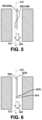
- FIG. 6is a schematic of a fifth embodiment of a flexible sensor
- FIG. 7is a schematic of a sixth embodiment of a flexible sensor when in an initial state (solid line) and in a deflected state (dashed line);
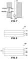
- FIG. 8is a schematic of a seventh embodiment of a flexible sensor
- FIG. 9is a schematic of an eighth embodiment of a flexible sensor
- FIG. 10is a schematic of a ninth embodiment of a flexible sensor
- FIG. 11 Ais a schematic of a tenth embodiment of a flexible sensor when in an initial state
- FIG. 11 Bis the flexible sensor in FIG. 11 A when in a deflected state
- FIG. 12is a schematic of an eleventh embodiment of a flexible sensor.
- Implementations of the current subject matterinclude methods, apparatuses, articles of manufacture, and systems relating to vaporization of one or more materials for inhalation by a user.
- Example implementationsinclude vaporizer devices and systems including vaporizer devices.
- the term “vaporizer device” as used in the following description and claimsrefers to any of a self-contained apparatus, an apparatus that includes two or more separable parts (for example, a vaporizer body that includes a battery and other hardware, and a vaporizer cartridge that includes a vaporizable material), and/or the like.
- a “vaporizer system,” as used herein,can include one or more components, such as a vaporizer device.
- vaporizer devicesconsistent with implementations of the current subject matter include electronic vaporizers, electronic nicotine delivery systems (ENDS), and/or the like.
- electronic vaporizerselectronic vaporizers
- EDSelectronic nicotine delivery systems
- vaporizer devicesare hand-held devices that heat (such as by convection, conduction, radiation, and/or some combination thereof) a vaporizable material to provide an inhalable dose of the material.
- the vaporizable material used with a vaporizer devicecan be provided within a vaporizer cartridge (for example, a part of the vaporizer device that contains the vaporizable material in a reservoir or other container) which can be refillable when empty, or disposable such that a new vaporizer cartridge containing additional vaporizable material of a same or different type can be used).
- a vaporizer devicecan be a cartridge-using vaporizer device, a cartridge-less vaporizer device, or a multi-use vaporizer device capable of use with or without a vaporizer cartridge.
- a vaporizer devicecan include a heating chamber (for example, an oven or other region in which material is heated by a heating element) configured to receive a vaporizable material directly into the heating chamber, and/or a reservoir or the like for containing the vaporizable material.
- a heating chamberfor example, an oven or other region in which material is heated by a heating element
- a reservoir or the likefor containing the vaporizable material.
- a vaporizer devicecan be configured for use with a liquid vaporizable material.
- the liquid vaporizable materialmay include a carrier solution in which an active and/or inactive ingredient(s) are suspended or held in solution.
- the liquid vaporizable materialmay be a liquid form of the vaporizable material itself.
- the liquid vaporizable materialcan be capable of being completely vaporized. Alternatively, at least a portion of the liquid vaporizable material can remain after all of the material suitable for inhalation has been vaporized.
- vaporizer devicesinclude a pressure sensor and an accelerometer that are configured to detect puffing and tapping on the device, respectfully.
- a pressure sensoris generally positioned within the vaporizer body and exposed to an airflow path delivering air to a vaporization chamber of the vaporizer device. It is common for vaporizer devices to employ an analog pressure sensor that includes a capacitive membrane, such as a capacitive membrane similar to those used in microphones.
- a capacitive membrane or a similar analog pressure sensormay be susceptible to malfunctions when contaminated with liquids that may be present within the airflow path including, for example, liquid vaporizable material, water, and/or the like.
- liquidsthat may be present within the airflow path including, for example, liquid vaporizable material, water, and/or the like.
- being in contact with a liquidcan dramatically change the capacitive properties of the capacitive membrane, thereby causing it to fail to perform as designed and preventing proper detection of a puff.
- Various features and devicesare described below that improve upon or overcome these foregoing issues.
- the vaporizer devices described hereinutilize a flexible sensor that is configured to reversibly deflect in response to either a user puffing or tapping on the device. That is, a single sensor resides within the vaporizer device that can function as both a puff detector and a tap detector. As a result, this eliminates the need to include two different elements (e.g., a pressure sensor and accelerometer) to detect puffing and tapping activity. Further, the detection mechanism is associated with the mechanical properties of the flexible sensor. As such, the mechanical properties of the flexible sensor can be tailored for different devices and/or airflow paths of a device to effect a more accurate response during puffing and/or tapping on respective devices.
- the flexible sensors described hereinare more robust, particularly when exposed to adverse environmental conditions. This is at least because during use of a vaporizer device, the mechanical response(s) of the flexible sensor (e.g., rate of deflection, frequency of deflection, and the like) are used to trigger detection of a puff or tap on the device.
- the mechanical response(s) of the flexible sensore.g., rate of deflection, frequency of deflection, and the like
- a puffing activitycan be associated with a user puffing on an outlet of the vaporizer device.
- the outlet of the devicecan be an outlet of a vaporizer cartridge coupled to a vaporizer body of the vaporizer device, whereas in other embodiments, the outlet is a mouthpiece coupled to an end of the vaporizer cartridge or of the vaporizer body.
- a tapping activitycan be associated with a user tapping on the vaporizer device.
- the usercan tap on a vaporizer body of the vaporizer device, on a vaporizer cartridge selectively coupled to and removable from the vaporizer body, or both.
- the present vaporizer devicesgenerally include a vaporizer body and a sensor assembly that resides at least partially within the vaporizer body.
- the sensor assemblyincludes a flexible sensor that is in communication with a first airflow path that at least partially extends through the vaporizer body.
- at least a portion of the flexible sensorresides within the first airflow path, whereas in other embodiments, the flexible sensor can define a portion of the first airflow path.
- the flexible sensoris configured to reversibly deflect from an initial state (e.g., when the vaporizer device is in a resting or standby mode) to a first state in response to a first user-activated force representing air being drawn through the first airflow path.
- an initial statee.g., when the vaporizer device is in a resting or standby mode
- a first user-activated forcerepresenting air being drawn through the first airflow path.
- deflection of the flexible sensorcan be used to trigger detection a puff or tap on the device by a user.
- a deflection of the flexible sensorcan include stretching, bending, and/or vibrating of the flexible sensor, or any other possible movement of the flexible sensor to effect a deflection signal.
- the flexible sensorcan be straight when in the initial state.
- the flexible sensorcan be mechanically amplified.
- a weight elementcan be coupled to an end of the flexible that resides within a portion of the first airflow path. Mechanical amplification can help enable the detection of small amplitude taps on the device, which may otherwise go undetected due to the deflection of the flexible sensor being imperceptibly minimal.
- the flexible sensorcan be mechanically dampened.
- the flexible sensorcan be curved, and thus preloaded, when in the initial state. Mechanical dampening can help prevent false positives in detecting puffing and tapping activity.
- the flexible sensormay be mechanically dampened to avoid the vaporizer device from being activated by de minimis deflections of the flexible sensor that do not correspond to actual puffing or tapping activity.
- the flexible sensorcan have a variety of configuration.
- the flexible sensoris in the form of a beam.
- the beamcan have a first end fixedly attached to the vaporizer body and a second end (e.g., a free end), can be located within the first airflow path.
- the beamcan function similar to a cantilever in which the free end can move within the first airflow path to cause the flexible sensor to reversibly deflection in response to a puffing or tapping activity on the device. As described in more detail below, this deflection of the beam can be used as puff and tap detection mechanisms for the device.
- the first and second ends of the beamcan be fixedly attached to the vaporizer body so as to define a portion of the first airflow path.
- the beamcan function similar to an elastic diaphragm in response to a puffing activity (e.g., expand outward in response to a pressure increase as air flows through the first airflow pathway).
- the beamcan also vibrate along at least a portion of its length in response to a tapping activity. As described in more detail below, these types of deflection of can be used as puff and tap detection mechanisms for the device.
- the beamcan be reside completely within the first airflow path.
- airflow passing through the first airflow path, and thus across the flexible sensorcauses the flexible sensor to vibrate.
- aerodynamic flutterThis effect is known as aerodynamic flutter, which occurs as a result of interactions between aerodynamics, stiffness of the flexible sensor, and inertial forces.
- the flexible sensorcan be a strain gauge.
- the strain gaugecan include a metallic trace coupled to an insulating flexible substrate, away from a principle axis. As such, in use, the strain gauge can be stretched causing the trace to become narrower and longer. As a result, the electrical resistance increases, which can be measured using an electrical circuit (e.g., a Wheatstone bridge, and the like).
- the flexible sensorcan be formed of at least one conductive polymer.
- a surface of the flexible sensorcan be printed with a polymer containing conductive particles that are configured to move apart when the flexible sensor deflects (e.g., bends in one direction). The movement of the conductive particles causes an increase in electrical resistance. This increase in electrical resistance can be measured using a voltage divider.
- the flexible sensorcan be formed of at least one piezoelectric material.
- the sensor assemblycan include at least one substrate residing within the vaporizer body in which a first end of the flexible sensor is coupled to the first substrate and a second, opposing end of the flexible sensor is positioned in the first airflow path.
- a first end of the flexible sensorcan be coupled to a first substrate of the at least one substrate and a second, opposing end of the flexible sensor can be coupled to a second substrate of the at least one substrate such that the flexible sensor defines a portion of the first airflow path.
- the at least one substratecan include and/or be coupled with a printed circuit board assembly (PCBA) that at least partially resides within the vaporizer body.
- PCBAprinted circuit board assembly
- the printed circuit board assemblymay include circuitry configured to detect a deflection of the flexible sensor. Furthermore, the printed circuit board assembly (PCBA) may include circuitry configured to respond to the deflection of the flexible sensor by generating a corresponding deflection signal.
- the flexible sensorcan be configured to at least partially deflect at a first rate of deflection while the first user-activated force is being applied. Additionally, the flexible sensor can also be configured to at least partially deflect at a second rate of deflection while the second-user activated force is being applied. As such, the flexible sensor can deflect at a first frequency while the flexible sensor is in the first state and at a second frequency that is different than the first frequency while the flexible sensor is in the second state.
- the first and second rates of deflection and/or the resulting frequenciescan be used to differentiate between a puffing activity and a tapping activity.
- the vaporizer devicecan also include a power source (for example, a battery, which can be a rechargeable battery), and a controller (for example, a processor, circuitry, etc. capable of executing logic) for controlling delivery of heat from the heating element to cause a vaporizable material to be converted from a condensed form (for example, a solid-phase material, such as wax or the like, a liquid, a solution, a suspension, etc.) to the gas phase.
- a power sourcefor example, a battery, which can be a rechargeable battery
- a controllerfor example, a processor, circuitry, etc. capable of executing logic
- the controllercan be part of one or more printed circuit boards (PCBs) consistent with certain implementations of the current subject matter.
- the printed circuit board assemblymay include circuitry configured to generate, upon detecting a deflection of the flexible sensor, a corresponding deflection signal.
- the circuitry included in the printed circuit board assemblymay be further configured to send, to the controller (e.g., a processor, circuitry, etc. capable of executing logic), the deflection signal for analysis by the controller to determine whether a puff or tap on the device has occurred.
- the controllere.g., a processor, circuitry, etc. capable of executing logic
- the controllercan be configured to receive a deflection signal in response to deflection of the flexible sensor, maintain a first user-activated force threshold and a second user-activated force threshold, compare the deflection signal to the first and second user-activated force thresholds, output a first signal when the deflection signal is less than the first user-activated force threshold, and output a second signal when the deflection signal is greater than the second user-activated force threshold.
- the first user-activated force threshold and the second user-activated force thresholdcan be predetermined and stored within a memory of the controller.
- the controllercan also include electrical circuitry that is configured to filter the received deflection signal so that unwanted frequencies can be attenuated. For example, the controller may apply a high-pass filter configured to remove above-threshold frequencies before evaluating the filtered signal to determine whether a tapping activity has occurred. Alternatively and/or additionally, the controller may apply a low-pass filter configured to remove below-threshold frequencies before evaluating the filtered signal to determine whether a puffing activity has occurred.
- the filtering of the deflection signalmay increase the reliability of the controller detecting a tapping activity and/or a puffing activity including by eliminating noise that may be present in the deflection signal. As a result, the filtration can minimize false positives in detecting a user's puffing or tapping activity. Further, such filtration can help distinguish between a deflection signal associated with a puff and a deflection signal associated with a tap
- the controllercan prompt a power source (for example, a battery, which can be a rechargeable battery) to deliver electric current to a heating element (e.g., a resistive heater) of the vaporizer device.
- a power sourcefor example, a battery, which can be a rechargeable battery
- the heating elementcan be activated in association with a user puffing (e.g., drawing, inhaling, etc.) on the vaporizer device.
- a user puffinge.g., drawing, inhaling, etc.
- Vaporizer devices for use with liquid vaporizable materialscan include an atomizer.
- the atomizercan include a wicking element (i.e., a wick) configured to convey an amount of the vaporizable material to a part of the atomizer that includes a heating element.
- the wicking elementcan be configured to draw the vaporizable material from a reservoir configured to contain the vaporizable material, such that the vaporizable material can be vaporized by heat delivered from a heating element.
- the wicking elementcan also optionally allow air to enter the reservoir and replace the volume of vaporizable material removed.
- capillary actioncan pull vaporizable material into the wick for vaporization by the heating element, and air can return to the reservoir through the wick to at least partially equalize pressure in the reservoir. Other methods of allowing air back into the reservoir to equalize pressure are also within the scope of the current subject matter.
- wickor “wicking element” include any material capable of causing fluid motion via capillary pressure.
- the heating elementcan include one or more of a conductive heater, a radiative heater, and/or a convective heater.
- a resistive heating elementwhich can include a material (such as a metal or alloy, for example a nickel-chromium alloy, or a non-metallic resistor) configured to dissipate electrical power in the form of heat when electrical current is passed through one or more resistive segments of the heating element.
- the atomizercan include a heating element which includes a resistive coil or other heating element wrapped around, positioned within, integrated into a bulk shape of, pressed into thermal contact with, or otherwise arranged to deliver heat to a wicking element, to cause the vaporizable material drawn from the reservoir by the wicking element to be vaporized for subsequent inhalation by a user in a gas and/or a condensed (for example, aerosol particles or droplets) phase.
- wicking elements, heating elements, and/or atomizer assembly configurationsare also possible.
- the vaporizable material in the gas phasecan condense to form particulate matter in at least a partial local equilibrium with a portion of the vaporizable material that remains in the gas phase.
- the vaporizable material in the gas phase as well as the condensed phaseare part of an aerosol, which can form some or all of an inhalable dose provided by the vaporizer device during a user's puff or draw on the vaporizer device.
- the interplay between the gas phase and condensed phase in an aerosol generated by a vaporizer devicecan be complex and dynamic, due to factors such as ambient temperature, relative humidity, chemistry, flow conditions in airflow paths (both inside the vaporizer device and in the airways of a human or other animal), and/or mixing of the vaporizable material in the gas phase or in the aerosol phase with other air streams, which can affect one or more physical parameters of an aerosol.
- the inhalable dosecan exist predominantly in the gas phase (for example, formation of condensed phase particles can be very limited).
- the controllercan also prompt the power source to deliver electric current to an output feature or device of the vaporizer device that provides information to the user.
- the output devicecan be a light source that, when actuated, represents a power condition of the power source at the time of the tapping.
- the power sourceis a battery
- the actuation of the light sourcecan represent the real-time charge of the battery at the time of tapping.
- the actuation of the light sourcecan provide feedback to a user based on a status and/or mode of operation of the vaporizer device at the time of tapping.
- the vaporizer deviceconsistent with implementations of the current subject matter can be configured to connect (such as, for example, wirelessly or via a wired connection) to a computing device (or optionally two or more devices) in communication with the vaporizer device.
- the controllercan include communication hardware.
- the controllercan also include a memory.
- the communication hardwarecan include firmware and/or can be controlled by software for executing one or more cryptographic protocols for the communication.
- a computing devicecan be a component of a vaporizer system that also includes the vaporizer device, and can include its own hardware for communication, which can establish a wireless communication channel with the communication hardware of the vaporizer device.
- a computing device used as part of a vaporizer systemcan include a general-purpose computing device (such as a smartphone, a tablet, a personal computer, some other portable device such as a smartwatch, or the like) that executes software to produce a user interface for enabling a user to interact with the vaporizer device.
- such a device used as part of a vaporizer systemcan be a dedicated piece of hardware such as a remote control or other wireless or wired device having one or more physical or soft (i.e., configurable on a screen or other display device and selectable via user interaction with a touch-sensitive screen or some other input device like a mouse, pointer, trackball, cursor buttons, or the like) interface controls.
- a remote control or other wireless or wired devicehaving one or more physical or soft (i.e., configurable on a screen or other display device and selectable via user interaction with a touch-sensitive screen or some other input device like a mouse, pointer, trackball, cursor buttons, or the like) interface controls.
- a computing deviceprovides signals related to activation of the resistive heating element
- the computing deviceexecutes one or more computer instruction sets to provide a user interface and underlying data handling.
- detection by the computing device of user interaction with one or more user interface elementscan cause the computing device to signal the vaporizer device to activate the heating element to reach an operating temperature for creation of an inhalable dose of vapor/aerosol.
- Other functions of the vaporizer devicecan be controlled by interaction of a user with a user interface on a computing device in communication with the vaporizer device 100 .
- the temperature of a resistive heating element of the vaporizer devicecan depend on a number of factors, including an amount of electrical power delivered to the resistive heating element and/or a duty cycle at which the electrical power is delivered, conductive heat transfer to other parts of the electronic vaporizer device and/or to the environment, latent heat losses due to vaporization of the vaporizable material from the wicking element and/or the atomizer as a whole, and convective heat losses due to airflow (i.e., air moving across the heating element or the atomizer as a whole when a user inhales on the vaporizer device).
- a vaporizer devicemakes use of signals from a flexible sensor to determine when a user is inhaling.
- the sealwhich can be a gasket, can be configured to at least partially surround the flexible sensor such that connections of the flexible sensor to the internal circuitry of the vaporizer device are separated from a part of the flexible sensor exposed to the airflow path.
- the sealcan also separate parts of one or more electrical connections between the vaporizer body and the vaporizer cartridge.
- Such arrangements of the seal in the vaporizer devicecan be helpful in mitigating against potentially disruptive impacts on vaporizer components resulting from interactions with environmental factors such as water in the vapor or liquid phases, other fluids such as the vaporizable material, etc., and/or to reduce the escape of air from the designated airflow path in the vaporizer device.
- Unwanted air, liquid or other fluid passing and/or contacting circuitry of the vaporizer devicecan cause various unwanted effects, such as altered pressure readings, and/or can result in the buildup of unwanted material, such as moisture, excess vaporizable material, etc., in parts of the vaporizer device where they can result in poor pressure signal, degradation of the flexible sensor or other components, and/or a shorter life of the vaporizer device.
- Leaks in the sealcan also result in a user inhaling air that has passed over parts of the vaporizer device containing, or constructed of, materials that may not be desirable to be inhaled.
- the vaporizer devicecan include a cartridge that includes reservoir chamber that is configured to hold a vaporizable material.
- the cartridgecan also include a second airflow path that extends therethrough and in fluid communication with the first airflow path.
- the cartridgecan be selectively coupled to a vaporizer body, as discussed below.
- the vaporizer bodyincludes a cartridge receptacle that is configured to receive at least a portion of the cartridge.
- the vaporizer devicein which the power source is part of the vaporizer body, and a heating element is disposed in the vaporizer cartridge and configured to couple with the vaporizer body, the vaporizer device can include electrical connection features (for example, means for completing a circuit) for completing a circuit that includes the controller (for example, a printed circuit board, a microcontroller, or the like), the power source, and the heating element (for example, a heating element within the atomizer).
- the controllerfor example, a printed circuit board, a microcontroller, or the like
- the heating elementfor example, a heating element within the atomizer.
- These featurescan include one or more contacts (referred to herein as cartridge contacts) on a bottom surface of the vaporizer cartridge and at least two contacts (referred to herein as receptacle contacts and) disposed near a base of the cartridge receptacle of the vaporizer device such that the cartridge contacts and the receptacle contacts make electrical connections when the vaporizer cartridge is inserted into and coupled with the cartridge receptacle.
- the circuit completed by these electrical connectionscan allow delivery of electrical current to a heating element and can further be used for additional functions, such as measuring a resistance of the heating element for use in determining and/or controlling a temperature of the heating element based on a thermal coefficient of resistivity of the heating element.
- the cartridge contacts and the receptacle contactscan be configured to electrically connect in either of at least two orientations.
- one or more circuits necessary for operation of the vaporizer devicecan be completed by insertion of the vaporizer cartridge into the cartridge receptacle in a first rotational orientation (around an axis along which the vaporizer cartridge is inserted into the cartridge receptacle of the vaporizer body) such that a first cartridge contact is electrically connected to a first receptacle contact and a second cartridge contact is electrically connected to a second receptacle contact.
- the one or more circuits necessary for operation of the vaporizer devicecan be completed by insertion of the vaporizer cartridge in the cartridge receptacle in a second rotational orientation such the first cartridge contact is electrically connected to the second receptacle contact and the second cartridge contact is electrically connected to the first receptacle contact.
- the vaporizer bodyincludes one or more detents (for example, dimples, protrusions, etc.) protruding inwardly from an inner surface of the cartridge receptacle, additional material (such as metal, plastic, etc.) formed to include a portion protruding into the cartridge receptacle, and/or the like.
- detentsfor example, dimples, protrusions, etc.
- additional materialsuch as metal, plastic, etc.
- One or more exterior surfaces of the vaporizer cartridgecan include corresponding recesses that can fit and/or otherwise snap over such detents or protruding portions when the vaporizer cartridge is inserted into the cartridge receptacle on the vaporizer body.
- the detents or protrusions of the vaporizer bodycan fit within and/or otherwise be held within the recesses of the vaporizer cartridge, to hold the vaporizer cartridge in place when assembled.
- Such an assemblycan provide enough support to hold the vaporizer cartridge in place to ensure good contact between the cartridge contacts and the receptacle contacts, while allowing release of the vaporizer cartridge from the vaporizer body when a user pulls with reasonable force on the vaporizer cartridge to disengage the vaporizer cartridge from the cartridge receptacle.
- the vaporizer cartridgeor at least an insertable end of the vaporizer cartridge configured for insertion in the cartridge receptacle, can have a non-circular cross section transverse to the axis along which the vaporizer cartridge is inserted into the cartridge receptacle.
- the non-circular cross sectioncan be approximately rectangular, approximately elliptical (i.e., have an approximately oval shape), non-rectangular but with two sets of parallel or approximately parallel opposing sides (i.e., having a parallelogram-like shape), or other shapes having rotational symmetry of at least order two.
- approximate shapeindicates that a basic likeness to the described shape is apparent, but that sides of the shape in question need not be completely linear and vertices need not be completely sharp. Rounding of both or either of the edges or the vertices of the cross-sectional shape is contemplated in the description of any non-circular cross section referred to herein.
- the cartridge contacts and the receptacle contactscan take various forms.
- one or both sets of contactscan include conductive pins, tabs, posts, receiving holes for pins or posts, or the like.
- Some types of contactscan include springs or other features to facilitate better physical and electrical contact between the contacts on the vaporizer cartridge and the vaporizer body.
- the electrical contactscan optionally be gold-plated, and/or include other materials.
- the shape of the vaporizer cartridge, or at least a shape of the insertable end of the vaporizer cartridge that is configured for insertion into the cartridge receptaclecan have rotational symmetry of at least order two.
- the vaporizer cartridge or at least the insertable end of the vaporizer cartridgecan be symmetrical upon a rotation of 180° around an axis along which the vaporizer cartridge is inserted into the cartridge receptacle.
- the circuitry of the vaporizer devicecan support identical operation regardless of which symmetrical orientation of the vaporizer cartridge occurs.
- FIG. 1illustrates a schematic of an exemplary vaporizer device 100 that includes a vaporizer body 102 , a vaporizer cartridge 104 that can be selectively coupled to and removable from the vaporizer body 102 , and a sensor assembly 109 residing at least partially within the vaporizer body 102 .
- the sensor assembly 109can include a flexible sensor 106 configured to deflect in response to forces corresponding to, for example, a tapping activity, a puffing activity, and/or the like. For purposes of simplicity only, certain components of the vaporizer device 100 are not illustrated.
- the vaporizer body 102can have a variety of configurations. As shown in FIG. 1 , the vaporizer body 102 includes a sleeve 108 that defines a cartridge receptacle 110 within the vaporizer body 102 that is configured to receive at least a portion of the vaporizer cartridge 104 . Once the vaporizer cartridge 104 is coupled to the vaporizer body 102 , a first airflow path 112 is created between a first wall 108 a of the sleeve 108 that defines the cartridge receptacle 110 and an end surface 104 a of the of the vaporizer cartridge 104 . Further, as shown in FIG.
- an air inlet 114extends through a second wall 108 b of the sleeve 108 .
- This air inlet 114is configured to allow at least a portion of ambient air outside of the vaporizer body 102 to be drawn into the vaporizer device 100 and along at least the first airflow path 112 .
- the vaporizer cartridge 104includes a reservoir chamber 116 that is configured to hold a vaporizable material (not shown). While the reservoir chamber 116 can have a variety of sizes and shapes, the reservoir chamber 116 , as shown in FIG. 1 , is substantially rectangular in shape. In other embodiments, the reservoir chamber 116 can have any other possible shape.
- the vaporizer cartridge 104also includes an internal channel 118 that extends from an inlet 120 to an outlet 122 of the vaporizer cartridge 104 .
- the internal channel 118is configured to direct air and vaporized material through the vaporizer cartridge 104 and exit the outlet 122 for inhalation by a user.
- a usercan puff on an end 105 of the vaporizer cartridge 104 such that the air and vaporized material within the vaporizer cartridge 104 can be delivered directly to the user from the outlet 122 for inhalation.
- a mouthpiece(not shown) can be coupled to the end 105 of the vaporizer cartridge 104 , in which case the user can puff on the mouthpiece rather than directly on the end 105 of the vaporizer cartridge 104 .
- the air and vaporized material within the vaporizer cartridge 104can travel from the outlet 122 into the mouthpiece for inhalation by the user.
- the vaporizer cartridge 104also includes an atomizer 124 .
- the atomizer 124includes a heating element 125 a and a wicking element 125 b .
- the wicking element 125 bis in fluid communication with the reservoir chamber 116 to draw vaporizable material (not shown) therefrom.
- the heating element 125 ais activated via a user puffing on the end 105 of the vaporizer cartridge 104 , at least a portion of the vaporizable material within the wicking element 125 b is vaporized into vaporized material.
- the vaporized materialjoins at least a portion of the air within the first airflow path 112 to form a mixture.
- the mixturetravels through the remaining portion of the first airflow path 112 and then through a second airflow path 126 defined by the internal channel 118 of the vaporizer cartridge 104 .
- a second airflow path 126defined by the internal channel 118 of the vaporizer cartridge 104 .
- the flexible sensor 106is in the form of a beam and extends from a first end 107 a to a second end 107 b .
- the first end 107 ais fixedly attached to a substrate 128
- the second end 107 bis positioned within the first airflow path 112 .
- the substrate 128is coupled to a printed circuit board assembly 129 .
- the printed circuit board assembly 129may be a part of the substrate 128 .
- the flexible sensor 106is configured to reversibly deflect in response to a first user-activated force representing air being drawn through the first airflow path 112 (e.g., a puff activity) and in response to a second user-activated force representing acceleration of the vaporizer body 102 (e.g., a tap activity).
- a puffing activity or a tapping activitycan cause the flexible sensor 106 to reversibly deflect from an initial state to a first state (e.g., during a puff on the device) or a second state (e.g., during a tap on the device), respectively.
- FIG. 2depicts an exemplary initial state of the flexible sensor 106 as a solid line 106 a and an exemplary deflection state (e.g., a first state or a second state) as a dashed line 106 b .
- an exemplary deflection statee.g., a first state or a second state
- dashed line 106 be.g., a dashed line
- the flexible sensor 106can be positioned anywhere along the first airflow path 112 that allows the flexible sensor 106 to reversibly deflect. However, in some embodiments, it may be desirable to position the flexible sensor 106 proximate to the air inlet 114 , as shown in FIG. 1 . In one embodiment, the flexible sensor 106 can be designed to and/or positioned within the first airflow path 112 such that the flexible sensor 106 can substantially seal the first airflow path 112 at least between puffing activities. This can increase puff detection sensitivity of the flexible sensor 106 .
- the substrate 108 and/or the printed circuit board assembly 129may include circuitry configured to respond to the a deflection of the flexible sensor 106 by generating a corresponding deflection signal. Moreover, with the substrate 108 and/or the printed circuit board assembly 129 may include circuitry configured to send, to the controller 130 residing within the vaporizer body 102 , the deflection signal. The controller 130 is configured to receive and analyze the deflection signal to determine whether a puff or tap on the vaporizer device 100 has occurred.
- the controller 130also includes a memory 132 that is configured to maintain a threshold frequency value associated with a puff activity (e.g., a first user-activated force threshold) and a threshold frequency value associated with a tapping activity (e.g., a first user-activated force threshold).
- a threshold frequency value associated with a puff activitye.g., a first user-activated force threshold
- a threshold frequency value associated with a tapping activitye.g., a first user-activated force threshold
- the circuitry included in the substrate 108 and/or the printed circuit board assembly 129may, upon detecting a deflection of the flexible sensor 106 , send the corresponding deflection signal to the controller 130 .
- the deflection signalis processed by the controller 130 and compared to threshold frequency values stored in the memory 132 . In instances when the frequency value(s) associated with the deflection signal is less than the first frequency threshold, the controller 130 determines that a puff activity is occurring. As a result, the controller 130 sends a signal to a power source 134 residing within the vaporizer body 102 to cause the power source 134 to deliver elective current to the heating element 125 a of the atomizer 124 .
- the controller 130determines that a tapping activity is occurring. As a result, the controller 130 sends a signal to the power source 134 to cause the power source 134 to deliver electric current to an output feature or device 136 (e.g., a light) within the vaporizer body 102 to indicate a real-time power condition of the power source 134 .
- an output feature or device 136e.g., a light
- the controller 130may filter the deflection signal corresponding to the deflection of the flexible sensor 106 .
- the controller 130may apply a high-pass filter configured to remove above-threshold frequencies before evaluating the filtered signal to determine whether a tapping activity has occurred.
- the controller 130may apply a low-pass filter configured to remove below-threshold frequencies before evaluating the filtered signal to determine whether a puffing activity has occurred.
- the filtering of the deflection signalmay eliminate noise that may be present in the deflection signal, thereby increasing the reliability of the controller 130 detecting a tapping activity and/or a puffing activity.
- the reliability of the controller 130 detecting a tapping activity and/or a puffing activitymay be increased by mechanically amplifying the flexible sensor to at least enable the detection of small amplitude taps on the vaporizer device 100 .
- a second end 207 b of a flexible sensor 206includes a weight element 238 coupled thereto.
- FIG. 3For illustration purposes only, FIG.
- FIG. 3depicts an exemplary initial state of the flexible sensor 206 (e.g., prior to a puff or tap on the vaporizer device) as a solid line 206 a and an exemplary deflection state (e.g., during a puff or a tap on the vaporizer device) of the flexible sensor 206 as a dashed line 206 b with an arrow 240 depicting the direction of airflow along the first airflow path 212 .
- the flexible sensorcan be mechanically dampened, which may increase the reliability of the controller 130 detecting a tapping activity and/or a puffing activity by avoiding false negatives triggered by de minimis deflections of the flexible sensor.
- a flexible sensor 306has a curved configuration in the initial state (e.g., prior to a puff or tap on the vaporizer device) such the flexible sensor 306 is preloaded.
- a cartridge wall 303includes a cutout portion 342 such that a free end 307 b of the flexible sensor 306 extends laterally across a first airflow path 312 so as to seal the first airflow path 312 between puffing and/or tapping on the vaporizer device.
- FIG. 4depicts an exemplary initial state of the flexible sensor 306 (e.g., prior to a puff or tap on the vaporizer device) as a solid line 306 a and an exemplary deflection state (e.g., during a puff or a tap on the vaporizer device) of the flexible sensor 306 as a dashed line 306 b with an arrow 340 depicting the direction of airflow through the first airflow path 312 .
- FIG. 5illustrates another exemplary flexible sensor 406 in which the entire flexible sensor 406 resides with a first airflow path 412 .
- airflow passing along the first airflow path 412causes the flexible sensor 406 to vibrate.
- this effectis known as aerodynamic flutter.
- FIG. 5depicts an exemplary initial state of the flexible sensor 406 (e.g., prior to a puff or tap on the vaporizer device) as a solid line 406 a and an exemplary deflection state (e.g., during a puff or a tap on the vaporizer device) of the flexible sensor 406 as a dashed line 406 b with an arrow 440 depicting the direction of airflow through the first airflow path 412 .
- additional signal processingmay be needed (e.g., filtering) to determine a puffing activity and/or a tapping activity.
- additional signal processingcan include bandpass filtering or a combination of low and/or high pass filtering, followed by examining the transient behavior of the generated signal of the flexible sensor 406 to determine if the signal spikes then decays quickly for a tapping activity, or remains high for a puffing activity.
- the flexible sensorcan include a bluff feature.
- a flexible sensor 506extends from a first end 507 a to a second end 507 b , in which the second end 507 b is downstream of the first end 507 a within the first airflow path 512 .
- the second end 507 bincludes a bluff feature 544 that is configured such that vortex shedding occurs as air passes along the flexible sensor 506 during a puffing activity.
- the air that passes in the direction of airflow 540and thus through the first airflow path 512 , causes alternating vortices to form at a certain frequency.
- the bluff feature 544can have a variety of configurations. For example, as shown in FIG. 6 , the bluff feature 544 is spherical in shape, whereas in other embodiments, the bluff feature 544 can have any other suitable shape, e.g., a rectangular shape.
- FIG. 7illustrates another exemplary flexible sensor 606 .
- each end 607 a , 607 b of the flexible sensor 606is fixedly attached to first and second substrates such that the flexible sensor 606 defines a portion of a first airflow path 612 .
- the flexible sensor 606can reversibly bend in response to a puff or tap on the device.
- FIG. 7depicts an exemplary initial state of the flexible sensor 606 (e.g., prior to a puff or tap on the vaporizer device) as a solid line 606 a and an exemplary deflection state (e.g., during a puff or a tap on the vaporizer device) of the flexible sensor 606 as a dashed line 606 b with an arrow 640 depicting the direction of airflow through the first airflow path 612 .
- a piezoelectric film 700can be a three-layered laminate that includes a piezoelectric layer 702 of piezoelectric material(s) interposed between two conductive layers 704 , 706 .
- the piezoelectric layer 702can be formed of one or more piezoelectric materials.
- suitable piezoelectric materialsinclude polyvinylidene fluoride (PVDF) and the like.
- the two conductive layers 704 , 706can each be formed of one or more conductive materials.
- one or more conductive materialsinclude conductive inks infused with silver, graphite, and/or other conductive metals, conductive metal flakes or powders, and the like.
- each of the two conductive layers 704 , 706can be formed of the same one or more conductive materials relative to one another, whereas in other embodiments, each of the two conductive layers 704 , 706 can each be formed of different one or more conductive materials relative to one another.
- a piezoelectric filmcan be laminated to a substrate, for example, as shown in FIG. 9 , in which piezoelectric film 700 is laminated to substrate 708 , thereby forming flexible sensor 1100 .
- the piezoelectric film 700is positioned off the neutral axis of the flexible sensor 1100 .
- the substratecan be formed of any suitable material.
- suitable substrate materialsinclude one or more polymers, such as polyethylene terephthalate.
- the piezoelectric layer 702may be configured to generate, in response to the deflection of the flexible sensor, an electric current that is conveyed to a printed circuit board assembly coupled with the flexible sensor by the conductive layer 704 and/or the conductive layer 706 .
- the printed circuit board assemblymay include circuitry configured to generate, based on one or more characteristics of the electric current, a corresponding deflection signal indicative of whether a tapping activity or a puffing activity has occurred at the vaporizer device, like vaporizer device 100 shown in FIG. 1 .
- the printed circuit board assemblymay include circuitry configured to determine, based on an amplitude and/or frequency of the electric current, whether a tapping activity or a puffing activity has occurred at the vaporizer device, like vaporizer device shown in FIG. 1 .
- a flexible sensorcan include at least one conductive polymer.
- the flexible sensor 806can include a base layer 802 and a conductive layer 804 that is printed on a surface 802 a of the base layer 802 .
- the base layer 802can be formed of one or more polymers or elastomers loaded with conductive material such as graphite, carbon, metal flakes or powders, and/or any combination thereof.
- the conductive layer 804can be formed of a polymer containing conductive particles that are configured to move apart when the flexible sensor deflects (e.g., bends in one direction) in response to a puffing or taping activity.
- Non-limiting examples of suitable conductive particlesinclude carbon, graphite, and metal particles. Deflection of the flexible sensor, which changes the organization of the conductive particles, may change the conductivity of the flexible sensor 806 .
- a printed circuit board assembly coupled with the flexible sensor 806may include circuitry that is configured to detect a deflection of the flexible sensor 806 based on a conductivity profile of the flexible sensor 806 , which may include, for example, a change in the conductivity of the flexible sensor 806 , a rate of change in the conductivity of the flexible sensor 806 , and/or the like. Alternatively and/or additionally, the circuitry may be configured to detect the occurrence of a tapping activity or a puffing activity based on the conductivity profile of the flexible sensor 806 .
- FIGS. 11 A- 11 Billustrates another exemplary flexible sensor 906 that extends through a first airflow path 912 .
- the first airflow path 912is defined by a first substrate 956 a and a second, opposing substrate 956 b .
- the structural dimensions of the first airflow path 912e.g., length and width
- the flexible sensor 906extends from a first end 906 a to a second, opposing end 906 b .
- the first end 906 ais coupled to a support 958 and the second end 906 b is a free end so that the flexible sensor 906 can deflect in response to puffing and tapping activities.
- the support 958is coupled to and extends from the second substrate 956 b and into the first airflow path 912 . As such, the entire flexible sensor 906 resides within the first airflow path 912 .
- a sounding board elementis coupled to and extends along a portion of the first substrate 956 a such that at least a portion of an edge 962 of the sounding board element extends parallel to a portion of the flexible sensor 906 when the flexible sensor 906 is an exemplary initial state (e.g., prior to a puff or tap on the vaporizer device), as shown in FIG. 11 A .
- the sounding board elementcan be formed as part of the first substrate 956 a.
- the flexible sensor 906In use, during a puffing activity, as air flows through the first airflow path 912 , at least a portion of the flexible sensor 906 deflects away from the edge 962 of the sounding board element thereby creating a wider gap 964 therebetween, as shown in FIG. 11 B , which in turn produces a standing wave having a first frequency.
- the first frequencydepends at least in part on the length of the first airflow path 912 and the space of the gap 964 .
- This first frequencycan then be detected and sent by the printed circuit board assembly 929 to a controller, like controller 130 shown in FIG. 1 , such that the controller can communicate with a power source, like power source 134 , as discussed above.
- the flexible sensor 906deflects at a second, different frequency that is different than the first frequency. This second frequency can then be detected and sent by the printed circuit board assembly 929 to the controller, such that the controller can communicate with the power source, as discussed above.
- FIG. 12illustrates another exemplary flexible sensor 1006 that is in the form of a strain gauge that is coupled to a portion of a beam 1007 that is coupled to a substrate 1028 .
- the illustrated strain gaugeincludes a metallic trace coupled to an insulating flexible substrate, away from a principle axis, that is coupled to the beam 1007 .
- a printed circuit board assemblye.g., like printed circuit board assembly 129 shown in FIG. 1
- the printed circuit board assemblymay be configured to generate the one or more signals based on the resistance across the strain gauge, a change in the resistance across the strain gauge, a frequency of the change in the resistance across the strain gauge, and/or the like.
- the controllercan control, based at least on these signals, the operations of a power source, like power source 134 .
- the term “substantially”is utilized herein to represent the inherent degree of uncertainty that may be attributed to any quantitative comparison, value, measurement, or other representation.
- the term “substantially”is also utilized herein to represent the degree by which a quantitative representation may vary from a stated reference without resulting in a change in the basic function of the subject matter at issue.
- references to a structure or feature that is disposed “adjacent” another featuremay have portions that overlap or underlie the adjacent feature.
- phrases such as “at least one of” or “one or more of”may occur followed by a conjunctive list of elements or features.
- the term “and/or”may also occur in a list of two or more elements or features. Unless otherwise implicitly or explicitly contradicted by the context in which it used, such a phrase is intended to mean any of the listed elements or features individually or any of the recited elements or features in combination with any of the other recited elements or features.
- the phrases “at least one of A and B;” “one or more of A and B;” and “A and/or B”are each intended to mean “A alone, B alone, or A and B together.”
- a similar interpretationis also intended for lists including three or more items.
- the phrases “at least one of A, B, and C;” “one or more of A, B, and C;” and “A, B, and/or C”are each intended to mean “A alone, B alone, C alone, A and B together, A and C together, B and C together, or A and B and C together.”
- Use of the term “based on,” above and in the claimsis intended to mean, “based at least in part on,” such that an unrecited feature or element is also permissible.
- spatially relative termssuch as “forward”, “rearward”, “under”, “below”, “lower”, “over”, “upper” and the like, may be used herein for ease of description to describe one element or feature's relationship to another element(s) or feature(s) as illustrated in the figures. It will be understood that the spatially relative terms are intended to encompass different orientations of the device in use or operation in addition to the orientation depicted in the figures. For example, if a device in the figures is inverted, elements described as “under” or “beneath” other elements or features would then be oriented “over” the other elements or features. Thus, the exemplary term “under” can encompass both an orientation of over and under.
- the devicemay be otherwise oriented (rotated 90 degrees or at other orientations) and the spatially relative descriptors used herein interpreted accordingly.
- the terms “upwardly”, “downwardly”, “vertical”, “horizontal” and the likeare used herein for the purpose of explanation only unless specifically indicated otherwise.
- first and secondmay be used herein to describe various features/elements (including steps), these features/elements should not be limited by these terms, unless the context indicates otherwise. These terms may be used to distinguish one feature/element from another feature/element. Thus, a first feature/element discussed below could be termed a second feature/element, and similarly, a second feature/element discussed below could be termed a first feature/element without departing from the teachings provided herein.
- a numeric valuemay have a value that is +/ ⁇ 0.1% of the stated value (or range of values), +/ ⁇ 1% of the stated value (or range of values), +/ ⁇ 2% of the stated value (or range of values), +/ ⁇ 5% of the stated value (or range of values), +/ ⁇ 10% of the stated value (or range of values), etc.
- Any numerical values given hereinshould also be understood to include about or approximately that value, unless the context indicates otherwise. For example, if the value “10” is disclosed, then “about 10” is also disclosed. Any numerical range recited herein is intended to include all sub-ranges subsumed therein.
- One or more aspects or features of the subject matter described hereincan be realized in digital electronic circuitry, integrated circuitry, specially designed application specific integrated circuits (ASICs), field programmable gate arrays (FPGAs) computer hardware, firmware, software, and/or combinations thereof.
- ASICsapplication specific integrated circuits
- FPGAsfield programmable gate arrays
- These various aspects or featurescan include implementation in one or more computer programs that are executable and/or interpretable on a programmable system including at least one programmable processor, which can be special or general purpose, coupled to receive data and instructions from, and to transmit data and instructions to, a storage system, at least one input device, and at least one output device.
- the programmable system or computing systemmay include clients and servers.
- a client and serverare generally remote from each other and typically interact through a communication network. The relationship of client and server arises by virtue of computer programs running on the respective computers and having a client-server relationship to each other.
- machine-readable signalrefers to any signal used to provide machine instructions and/or data to a programmable processor.
- the machine-readable mediumcan store such machine instructions non-transitorily, such as for example as would a non-transient solid-state memory or a magnetic hard drive or any equivalent storage medium.
- the machine-readable mediumcan alternatively or additionally store such machine instructions in a transient manner, such as for example as would a processor cache or other random access memory associated with one or more physical processor cores.
Landscapes
- Engineering & Computer Science (AREA)
- Health & Medical Sciences (AREA)
- Human Computer Interaction (AREA)
- Physics & Mathematics (AREA)
- General Physics & Mathematics (AREA)
- Biomedical Technology (AREA)
- Pulmonology (AREA)
- Anesthesiology (AREA)
- Bioinformatics & Cheminformatics (AREA)
- Heart & Thoracic Surgery (AREA)
- Hematology (AREA)
- Life Sciences & Earth Sciences (AREA)
- Animal Behavior & Ethology (AREA)
- General Health & Medical Sciences (AREA)
- Public Health (AREA)
- Veterinary Medicine (AREA)
- Infusion, Injection, And Reservoir Apparatuses (AREA)
- Filling Or Discharging Of Gas Storage Vessels (AREA)
Abstract
Description
Claims (20)
Priority Applications (2)
| Application Number | Priority Date | Filing Date | Title |
|---|---|---|---|
| US17/347,980US12213533B2 (en) | 2019-01-15 | 2021-06-15 | Vaporizer devices |
| US19/020,326US20250143379A1 (en) | 2019-01-15 | 2025-01-14 | Vaporizer Devices |
Applications Claiming Priority (3)
| Application Number | Priority Date | Filing Date | Title |
|---|---|---|---|
| US201962792659P | 2019-01-15 | 2019-01-15 | |
| PCT/US2020/013758WO2020150400A1 (en) | 2019-01-15 | 2020-01-15 | Vaporizer devices |
| US17/347,980US12213533B2 (en) | 2019-01-15 | 2021-06-15 | Vaporizer devices |
Related Parent Applications (1)
| Application Number | Title | Priority Date | Filing Date |
|---|---|---|---|
| PCT/US2020/013758ContinuationWO2020150400A1 (en) | 2019-01-15 | 2020-01-15 | Vaporizer devices |
Related Child Applications (1)
| Application Number | Title | Priority Date | Filing Date |
|---|---|---|---|
| US19/020,326ContinuationUS20250143379A1 (en) | 2019-01-15 | 2025-01-14 | Vaporizer Devices |
Publications (2)
| Publication Number | Publication Date |
|---|---|
| US20210307402A1 US20210307402A1 (en) | 2021-10-07 |
| US12213533B2true US12213533B2 (en) | 2025-02-04 |
Family
ID=69591734
Family Applications (2)
| Application Number | Title | Priority Date | Filing Date |
|---|---|---|---|
| US17/347,980Active2042-03-09US12213533B2 (en) | 2019-01-15 | 2021-06-15 | Vaporizer devices |
| US19/020,326PendingUS20250143379A1 (en) | 2019-01-15 | 2025-01-14 | Vaporizer Devices |
Family Applications After (1)
| Application Number | Title | Priority Date | Filing Date |
|---|---|---|---|
| US19/020,326PendingUS20250143379A1 (en) | 2019-01-15 | 2025-01-14 | Vaporizer Devices |
Country Status (4)
| Country | Link |
|---|---|
| US (2) | US12213533B2 (en) |
| EP (1) | EP3911185B1 (en) |
| CN (1) | CN113939203A (en) |
| WO (1) | WO2020150400A1 (en) |
Families Citing this family (8)
| Publication number | Priority date | Publication date | Assignee | Title |
|---|---|---|---|---|
| US12029237B2 (en) | 2018-05-29 | 2024-07-09 | Pax Labs, Inc. | Identification of a cartridge for a vaporizer device |
| WO2020154690A1 (en) | 2019-01-25 | 2020-07-30 | Juul Labs, Inc. | Vaporizer device and cartridge |
| EP4051036B1 (en) | 2019-10-31 | 2024-12-04 | Juul Labs, Inc. | Self-cleaning thermal flow sensor |
| KR102621737B1 (en)* | 2021-04-28 | 2024-01-04 | 주식회사 케이티앤지 | Device for generating aerosol |
| KR102708760B1 (en)* | 2021-06-23 | 2024-09-24 | 주식회사 케이티앤지 | Aerosol generating device and method of operation thereof |
| WO2023111086A1 (en) | 2021-12-15 | 2023-06-22 | Solvay Specialty Polymers Usa, Llc | Personal electronic devices comprising polyamide composition |
| WO2024226930A2 (en)* | 2023-04-27 | 2024-10-31 | Alphascale Technologies, Inc. | Airflow sensor-based electronic cigarette |
| WO2025021664A1 (en)* | 2023-07-24 | 2025-01-30 | Philip Morris Products S.A. | Aerosol-generating system with airflow cavity |
Citations (209)
| Publication number | Priority date | Publication date | Assignee | Title |
|---|---|---|---|---|
| US2867706A (en)* | 1954-05-17 | 1959-01-06 | Statham Instrument Inc | Pressure sensitive resistor |
| US2935710A (en)* | 1957-09-09 | 1960-05-03 | Bell & Howell Co | Electric transducer |
| US4810854A (en) | 1987-05-26 | 1989-03-07 | Sunbeam Corporation | Compact portable vaporizer |
| EP0358114A2 (en) | 1988-09-08 | 1990-03-14 | R.J. Reynolds Tobacco Company | Aerosol delivery articles utilizing electrical energy |
| US4947874A (en) | 1988-09-08 | 1990-08-14 | R. J. Reynolds Tobacco Company | Smoking articles utilizing electrical energy |
| US4947875A (en) | 1988-09-08 | 1990-08-14 | R. J. Reynolds Tobacco Company | Flavor delivery articles utilizing electrical energy |
| US5649554A (en) | 1995-10-16 | 1997-07-22 | Philip Morris Incorporated | Electrical lighter with a rotatable tobacco supply |
| US5666978A (en) | 1992-09-11 | 1997-09-16 | Philip Morris Incorporated | Electrical smoking system for delivering flavors and method for making same |
| US6513524B1 (en) | 1998-01-29 | 2003-02-04 | Markus H. Storz | Inhaler for production of aroma- and/or active substance-containing vapors of plant materials and/or fluids |
| US6516796B1 (en) | 1998-10-14 | 2003-02-11 | Chrysalis Technologies Incorporated | Aerosol generator and methods of making and using an aerosol generator |
| JP2005034021A (en) | 2003-07-17 | 2005-02-10 | Seiko Epson Corp | Electronic Cigarette |
| US20050268911A1 (en) | 2004-06-03 | 2005-12-08 | Alexza Molecular Delivery Corporation | Multiple dose condensation aerosol devices and methods of forming condensation aerosols |
| WO2007146893A2 (en)* | 2006-06-12 | 2007-12-21 | Precision Pumping Systems, Inc. | Fluid sensor with mechanical positional feedback |
| US20080105257A1 (en) | 2006-11-08 | 2008-05-08 | Resmed Limited | Humidifier for respiratory apparatus |
| CN100589726C (en) | 2004-04-14 | 2010-02-17 | 韩力 | Atomized electronic cigarette |
| WO2011033396A2 (en)* | 2009-09-18 | 2011-03-24 | Minilogic Device Corporation Ltd. | Electronic smoke |
| CN101557728B (en) | 2006-10-18 | 2011-04-06 | R.J.雷诺兹烟草公司 | Tobacco-containing smoking article |
| WO2012134117A2 (en) | 2011-03-25 | 2012-10-04 | 주식회사 에바코 | Suction device, contamination-sensing member applied to the suction device, suction sensor, selection member, evaporation member, outer case for the suction device, unit for supplying electricity to the suction device, eyelash-curling unit connected to the unit for supplying electricity to the suction device, and mobile phone connection unit connected to the unit for supplying electricity to the suction device |
| WO2013020220A1 (en) | 2011-08-11 | 2013-02-14 | Wisplite Technology Group Inc. | Portable electronic vapor-producing device and method |
| CN103221084A (en) | 2010-09-22 | 2013-07-24 | 克拉弗席德股份有限公司 | therapeutic vaporizer |
| US20130255702A1 (en) | 2012-03-28 | 2013-10-03 | R.J. Reynolds Tobacco Company | Smoking article incorporating a conductive substrate |
| US20140096781A1 (en) | 2012-10-08 | 2014-04-10 | R. J. Reynolds Tobacco Company | Electronic smoking article and associated method |
| US20140096782A1 (en) | 2012-10-08 | 2014-04-10 | R.J. Reynolds Tobacco Company | Electronic smoking article and associated method |
| WO2014068504A2 (en) | 2012-10-31 | 2014-05-08 | South Ostrich Ltd. | Systems and methods for administering pulmonary medication |
| US20140150785A1 (en) | 2012-12-05 | 2014-06-05 | Vire, L.L.C. | Electronic cigarette or inhaler |
| WO2014144678A2 (en) | 2013-03-15 | 2014-09-18 | Lewis Michael W | Electronic smoking device systems and methods |
| US20140276536A1 (en) | 2013-03-14 | 2014-09-18 | Asante Solutions, Inc. | Infusion Pump System and Methods |
| US20140261486A1 (en) | 2013-03-12 | 2014-09-18 | R.J. Reynolds Tobacco Company | Electronic smoking article having a vapor-enhancing apparatus and associated method |
| US20140355969A1 (en) | 2013-05-28 | 2014-12-04 | Sis Resources, Ltd. | One-way valve for atomizer section in electronic cigarettes |
| US20140360516A1 (en) | 2013-06-07 | 2014-12-11 | Qiuming Liu | Electronic cigarette |
| US8910639B2 (en) | 2012-09-05 | 2014-12-16 | R. J. Reynolds Tobacco Company | Single-use connector and cartridge for a smoking article and related method |
| WO2015003327A1 (en) | 2013-07-09 | 2015-01-15 | 吉瑞高新科技股份有限公司 | Electronic cigarette |
| WO2015006929A1 (en) | 2013-07-16 | 2015-01-22 | 吉瑞高新科技股份有限公司 | Electronic cigarette |
| JP2015504653A (en) | 2011-12-08 | 2015-02-16 | フィリップ・モーリス・プロダクツ・ソシエテ・アノニム | Aerosol generating device with air flow nozzle |
| US9004073B2 (en) | 2012-01-31 | 2015-04-14 | Altria Client Services Inc. | Electronic cigarette |
| US20150114409A1 (en) | 2013-10-31 | 2015-04-30 | R.J. Reynolds Tobacco Company | Aerosol Delivery Device Including a Bubble Jet Head and Related Method |
| WO2015077998A1 (en) | 2013-11-29 | 2015-06-04 | 吉瑞高新科技股份有限公司 | Battery apparatus, electronic cigarette, and assembly method therefor |
| WO2015120588A1 (en) | 2014-02-12 | 2015-08-20 | 吉瑞高新科技股份有限公司 | Electronic cigarette and airflow control method thereof |
| WO2015123831A1 (en) | 2014-02-19 | 2015-08-27 | 吉瑞高新科技股份有限公司 | Electronic cigarette and method for assembling same |
| WO2015149368A1 (en) | 2014-04-04 | 2015-10-08 | 刘水根 | Air flow sensing assembly of electronic cigarette and electronic cigarette |
| US20150282527A1 (en)* | 2014-04-04 | 2015-10-08 | R.J. Reynolds Tobacco Company | Sensor for an aerosol delivery device |
| US20150289567A1 (en) | 2014-04-15 | 2015-10-15 | Kimree Hi-Tech Inc. | Electronic cigarette |
| WO2015157893A1 (en) | 2014-04-14 | 2015-10-22 | 吉瑞高新科技股份有限公司 | Electronic cigarette |
| US20150313284A1 (en) | 2012-10-05 | 2015-11-05 | Smart Chip Microelectronic Co. Limited | Electronic smoke apparatus |
| WO2015168912A1 (en) | 2014-05-08 | 2015-11-12 | 吉瑞高新科技股份有限公司 | Electronic cigarette |
| WO2015180061A1 (en) | 2014-05-28 | 2015-12-03 | 吉瑞高新科技股份有限公司 | Electronic cigarette and air intake volume regulating method therefor |
| WO2015180027A1 (en) | 2014-05-27 | 2015-12-03 | 吉瑞高新科技股份有限公司 | Electronic cigarette |
| WO2015180062A1 (en) | 2014-05-28 | 2015-12-03 | 吉瑞高新科技股份有限公司 | Electronic cigarette and atomization control method for electronic cigarette |
| US20150351455A1 (en) | 2012-12-11 | 2015-12-10 | Kimree Hi-Tech Inc. | Electronic cigarette and electronic cigarette device thereof |
| WO2015192326A1 (en) | 2014-06-17 | 2015-12-23 | 吉瑞高新科技股份有限公司 | Electronic cigarette |
| WO2016009202A1 (en)* | 2014-07-16 | 2016-01-21 | Cambridge Design Partnership Llp | Inhalers |
| US20160044965A1 (en) | 2014-08-14 | 2016-02-18 | Huizhou Kimree Technology Co., Ltd | Atomizer and electronic cigarette |
| US20160088874A1 (en) | 2014-09-25 | 2016-03-31 | Peter Lipowicz | Electronic inhalation device including an abrasive element |
| WO2016049855A1 (en) | 2014-09-30 | 2016-04-07 | 惠州市吉瑞科技有限公司 | Electronic cigarette |
| US9326550B2 (en) | 2006-05-16 | 2016-05-03 | Fontem Holdings 1 B.V. | Electronic cigarette |
| CN102655773B (en) | 2009-10-27 | 2016-05-04 | 菲利普莫里斯生产公司 | Smoking system with liquid storage portion and improved airflow characteristics |
| WO2016065532A1 (en) | 2014-10-28 | 2016-05-06 | 惠州市吉瑞科技有限公司 | Electronic cigarette |
| WO2016065606A1 (en) | 2014-10-31 | 2016-05-06 | 惠州市吉瑞科技有限公司 | Atomizer and electronic cigarette |
| WO2016074228A1 (en) | 2014-11-14 | 2016-05-19 | 惠州市吉瑞科技有限公司 | Electronic cigarette and atomization control method thereof |
| WO2016074237A1 (en) | 2014-11-14 | 2016-05-19 | 惠州市吉瑞科技有限公司 | Electronic cigarette and electronic cigarette atomization control method |
| WO2016074229A1 (en) | 2014-11-14 | 2016-05-19 | 惠州市吉瑞科技有限公司 | Electronic cigarette and atomization control method thereof |
| WO2016079151A1 (en) | 2014-11-17 | 2016-05-26 | Mcneil Ab | Child-resistant container for nicotine-containing cartridges |
| WO2016082217A1 (en) | 2014-11-28 | 2016-06-02 | 惠州市吉瑞科技有限公司 | Electronic cigarette |
| WO2016090601A1 (en) | 2014-12-11 | 2016-06-16 | 惠州市吉瑞科技有限公司 | Atomisation assembly, electronic cigarette, and method for preventing child from smoking electronic cigarette by accident |
| WO2016090602A1 (en) | 2014-12-11 | 2016-06-16 | 惠州市吉瑞科技有限公司 | Atomisation assembly, electronic cigarette, and method for preventing child from smoking electronic cigarette by accident |
| WO2016108694A1 (en) | 2014-12-31 | 2016-07-07 | UTVG Global IP B.V. | Personal electronic delivery system, atomizer assembly, use thereof and corresponding production method |
| US20160206002A1 (en) | 2015-01-21 | 2016-07-21 | Fontem Holdings 2 B.V. | Electronic smoking device |
| WO2016118005A1 (en) | 2015-01-22 | 2016-07-28 | UTVG Global IP B.V. | Electronic delivery unit and cartridge, an e-cigarette comprising the unit and cartridge, and method for delivering a delivery fluid |
| WO2016119099A1 (en) | 2015-01-26 | 2016-08-04 | 惠州市吉瑞科技有限公司 | Electronic cigarette |
| WO2016127401A1 (en) | 2015-02-13 | 2016-08-18 | 惠州市吉瑞科技有限公司 | Electronic cigarette |
| WO2016128562A1 (en) | 2015-02-13 | 2016-08-18 | Fontem Ventures B.V. | Filling system for electronic smoking devices |
| WO2016131755A1 (en) | 2015-02-16 | 2016-08-25 | Fontem Holdings 1 B.V. | Electronic smoking device with snap-in locking connection |
| US9427026B2 (en) | 2010-12-09 | 2016-08-30 | Shenzhen Smaco Technology Limited | Electronic cigarette for convenient battery charging and atomizer starting |
| US20160249684A1 (en) | 2014-11-14 | 2016-09-01 | Huizhou Kimree Technology Co., Ltd | Electronic cigarette and method for controlling atomization thereof |
| WO2016138689A1 (en) | 2015-03-03 | 2016-09-09 | 云南中烟工业有限责任公司 | Cigarette smoking device having electronic atomization function and method for improving cigarette smoking quality |
| US20160262453A1 (en) | 2015-03-09 | 2016-09-15 | R.J. Reynolds Tobacco Company | Aerosol Delivery Device Including a Wave Guide and Related Method |
| WO2016150019A1 (en) | 2015-03-23 | 2016-09-29 | 云南中烟工业有限责任公司 | Electric heating type cigarette smoking device having electronic cigarette smoking function |
| WO2016166456A1 (en) | 2015-04-14 | 2016-10-20 | Cai Thierry | Device for assembling a battery element with the cartridge, with which it is associated, of an electronic cigarette |
| US20160309785A1 (en) | 2015-04-23 | 2016-10-27 | Arie Holtz | Unitary heating element and heater assemblies, cartridges, and e-vapor devices including a unitary heating element |
| US20160309786A1 (en) | 2015-04-23 | 2016-10-27 | Arie Holtz | Unitary heating element and heater assemblies, cartridges, and e-vapor devices including a unitary heating element |
| US20160331913A1 (en) | 2014-01-31 | 2016-11-17 | Cannakorp, Inc. | Methods and apparatus for producing herbal vapor |
| US20160331030A1 (en) | 2015-05-15 | 2016-11-17 | R.J. Reynolds Tobacco Company | Aerosol delivery device and methods of formation thereof |
| US20160356751A1 (en) | 2015-06-08 | 2016-12-08 | Lunatech, Llc | Respiration Simulating Analysis And Distribution Device |
| KR101682319B1 (en) | 2012-09-28 | 2016-12-12 | 킴르 하이테크 인코퍼레이티드 | Electronic cigarette and electronic cigarette device thereof |
| US20160360784A1 (en) | 2014-02-12 | 2016-12-15 | Kimree Hi-Tech Inc. | Battery rod assembly and electronic cigarette |
| WO2016198879A1 (en) | 2015-06-11 | 2016-12-15 | The Technology Partnership | Spray delivery device |
| US20160366725A1 (en) | 2015-06-10 | 2016-12-15 | Altria Client Services Inc. | E-vaping device |
| US20160363570A1 (en) | 2015-06-11 | 2016-12-15 | Lunatech, Llc | Calibrating Electronic Vapor Device |
| US20160363917A1 (en) | 2015-06-11 | 2016-12-15 | Lunatech, Llc | User Interface For An Analysis And Vapor Dispensing Apparatus |
| US20160367925A1 (en) | 2015-06-16 | 2016-12-22 | Lunatech, Llc | Air Analyzer, Treatment And Peer Networking Apparatus |
| US20160370335A1 (en) | 2015-06-16 | 2016-12-22 | Lunatech, Llc | Vapor Device For Security Screening |
| US20160366940A1 (en) | 2014-02-28 | 2016-12-22 | Kimree Hi-Tech Inc. | Electronic cigarette and electronic cigarette atomization control method |
| WO2017001818A1 (en) | 2015-06-29 | 2017-01-05 | Nicoventures Holdings Limited | Electronic aerosol provision systems |
| WO2017001819A1 (en) | 2015-06-29 | 2017-01-05 | Nicoventures Holdings Limited | Electronic aerosol provision systems |
| WO2017001817A1 (en) | 2015-07-01 | 2017-01-05 | Nicoventures Holdings Limited | Electronic aerosol provision system |
| US20170006919A1 (en) | 2014-01-20 | 2017-01-12 | Kimree Hi-Tech Inc. | Battery stick, electronic cigarette, and method for assembly of battery stick |
| US20170006917A1 (en) | 2015-07-07 | 2017-01-12 | Altria Client Services Inc. | E-vapor device including capsule containing pre-vapor formulation |
| US20170018000A1 (en) | 2015-07-14 | 2017-01-19 | Lunatech, Llc | Electronic Vapor Recommendation System And Method |
| US20170020196A1 (en) | 2015-07-22 | 2017-01-26 | Lunatech, Llc | Electronic Vapor Device With Integrated Audio |
| US20170020195A1 (en) | 2015-07-20 | 2017-01-26 | Lunatech, Llc | Electronic Vaporizer Testing |
| US20170020188A1 (en) | 2015-07-21 | 2017-01-26 | Lunatech, Llc | Skinning For Electronic Vapor Devices |
| US20170020197A1 (en) | 2015-07-22 | 2017-01-26 | Lunatech, Llc | Electronic Vapor Device For Simulating A Traditional Smoking Implement |
| US20170027229A1 (en) | 2015-07-28 | 2017-02-02 | Lunatech, Llc | Inhalation puff counter gauge and display system |
| US20170046738A1 (en) | 2015-08-10 | 2017-02-16 | Lunatech, Llc | System And Method For Providing An E-Vapor Club |
| US20170042225A1 (en) | 2014-04-16 | 2017-02-16 | Kimree Hi-Tech Inc. | Electronic cigarette and assembly method therefor |
| US20170042231A1 (en) | 2015-08-11 | 2017-02-16 | Lunatech, Llc | Demonstrative interface for electronic vaporizing device |
| US20170042230A1 (en) | 2015-08-10 | 2017-02-16 | Lunatech, Llc | Intuitive Interface For Electronic Vaporizing Device |
| US20170046357A1 (en) | 2015-08-10 | 2017-02-16 | Lunatech, Llc | Collecting And Providing Data For Electronic Vaporizers |
| WO2017033007A1 (en) | 2015-08-25 | 2017-03-02 | Nicoventures Holdings Limited | Electronic vapour provision system |
| US20170055588A1 (en) | 2015-08-31 | 2017-03-02 | Lunatech, Llc | Methods And Systems For Vapor Cooling |
| US20170091853A1 (en) | 2015-09-24 | 2017-03-30 | Lunatech, Llc | Methods And Systems For Matching Products With Users |
| US20170086496A1 (en) | 2015-09-24 | 2017-03-30 | Lunatech, Llc | Electronic Vapor Device Multitool |
| US20170093960A1 (en) | 2015-09-24 | 2017-03-30 | Lunatech, Llc | Vapor Device Ecosystem |
| US20170086503A1 (en) | 2015-09-24 | 2017-03-30 | Lunatech, Llc | Battery System For Electronic Vapor Communication Device |
| US20170086504A1 (en) | 2015-09-24 | 2017-03-30 | Lunatech, Llc | Evapor Mask Delivery System |
| US20170092106A1 (en) | 2015-09-24 | 2017-03-30 | Lunatech, Llc | Methods And Systems For Locating Devices |
| US20170093981A1 (en) | 2015-09-24 | 2017-03-30 | Lunatech, Llc | Monocle Communication Evapor Device |
| US20170086497A1 (en) | 2015-09-24 | 2017-03-30 | Lunatech, Llc | Methods And Systems For Vaping And Presenting Audio |
| WO2017055793A1 (en) | 2015-09-28 | 2017-04-06 | Nicoventures Holdings Limited | Electronic vapour provision system |
| WO2017055866A1 (en) | 2015-10-01 | 2017-04-06 | Nicoventures Holdings Limited | Aerosol provision system |
| WO2017064324A1 (en) | 2015-10-16 | 2017-04-20 | Fontem Holdings 1 B.V. | Slide-on attachment for electronic smoking devices |
| US20170119052A1 (en) | 2015-10-30 | 2017-05-04 | R.J. Reynolds Tobacco Company | Application specific integrated circuit (asic) for an aerosol delivery device |
| US20170119058A1 (en) | 2015-10-28 | 2017-05-04 | Lunatech, Llc | Methods and systems for a dual function vapor device |
| WO2017072239A1 (en) | 2015-10-28 | 2017-05-04 | Fontem Holdings 1 B.V. | Electronic smoking device |
| US20170135407A1 (en) | 2015-11-17 | 2017-05-18 | Lunatech, Llc | Voice responsive electronic vapor system |
| US20170135409A1 (en) | 2015-11-17 | 2017-05-18 | Lunatech, Llc | Methods and systems for smooth vapor delivery |
| US20170135408A1 (en) | 2015-11-17 | 2017-05-18 | Lunatech, Llc | Electronic vapor device warning system |
| US20170135401A1 (en) | 2014-06-09 | 2017-05-18 | Nicoventures Holdings Limited | Electronic vapour provision system |
| US20170135411A1 (en) | 2015-11-17 | 2017-05-18 | Lunatech, Llc | Computing device with enabled electronic vapor device |
| US20170136301A1 (en) | 2015-11-17 | 2017-05-18 | Lunatech, Llc | Electronic vapor device enabled exercise system |
| US20170136194A1 (en) | 2015-11-17 | 2017-05-18 | Lunatech, Llc | Electronic vapor device enabled aromatic distribution system |
| US20170136196A1 (en) | 2014-06-30 | 2017-05-18 | Syqe Medical Ltd. | Method and device for vaporization and inhalation of isolated substances |
| US20170136193A1 (en) | 2015-11-17 | 2017-05-18 | Lunatech, Llc | Next generation electronic vapor device |
| US20170135412A1 (en) | 2015-11-17 | 2017-05-18 | Lunatech, Llc | Advanced microprocessor for electronic vapor device |
| WO2017082728A1 (en) | 2015-11-10 | 2017-05-18 | UTVG Global IP B.V. | Cartridge for a personal electronic delivery system, such system, use and method there for |
| US20170143038A1 (en) | 2014-06-13 | 2017-05-25 | Nicoventures Holdings Limited | Aerosol provision system |
| US9687027B2 (en) | 2012-09-10 | 2017-06-27 | Ght Global Heating Technologies Ag | Device for vaporizing liquid for inhalation |
| US20170197046A1 (en) | 2008-10-23 | 2017-07-13 | Batmark Limited | Inhaler |
| US20170214261A1 (en) | 2014-07-29 | 2017-07-27 | Nicoventures Holdings Limited | E-cigarette and re-charging pack |
| US20170208866A1 (en) | 2014-07-31 | 2017-07-27 | Huizhou Kimree Technology Co., Ltd. | Electronic cigarette |
| US20170215476A1 (en) | 2014-07-25 | 2017-08-03 | Nicoventures Holdings Limited | Aerosol provision system |
| US9723876B2 (en) | 2013-03-15 | 2017-08-08 | Altria Client Services Llc | Electronic smoking article |
| US20170224014A1 (en) | 2014-07-22 | 2017-08-10 | Nicoventures Holdings Limited | Electronic vapour provision system |
| US20170231284A1 (en) | 2014-08-05 | 2017-08-17 | Nicoventures Holdings Limited | Electronic vapor provision system |
| WO2017137554A1 (en) | 2016-02-12 | 2017-08-17 | Fontem Holdings 1 B.V. | Filling system for electronic smoking devices |
| US20170251725A1 (en) | 2014-08-26 | 2017-09-07 | Nicoventures Holdings Limited | Electronic aerosol provision system |
| US20170251718A1 (en) | 2016-03-07 | 2017-09-07 | Mohannad A. Armoush | Inductive heating apparatus and related method |
| US20170258138A1 (en) | 2016-03-11 | 2017-09-14 | Altria Client Services Llc | Multiple dispersion generator e-vaping device |
| US20170258140A1 (en) | 2016-03-11 | 2017-09-14 | Altria Client Services Llc | Multiple dispersion generator e-vaping device |
| US9772216B2 (en) | 2005-11-21 | 2017-09-26 | Mannkind Corporation | Powder dispensing and sensing apparatus and methods |
| US9770055B2 (en) | 2015-05-15 | 2017-09-26 | Lunatech, Llc | Vaporizable material handling for electronic vapor device |
| CN104055223B (en) | 2014-05-26 | 2017-10-10 | 深圳麦克韦尔股份有限公司 | Electronic cigarette |
| US20170301898A1 (en) | 2015-09-10 | 2017-10-19 | Guangrong Lin | Rod-shaped Battery Assembly and Electronic Cigarette Having the Same |
| US20170325289A1 (en) | 2014-11-14 | 2017-11-09 | Huizhou Kimree Technology Co., Ltd. | Electronic cigarette and atomization control method thereof |
| US20170325504A1 (en) | 2014-10-31 | 2017-11-16 | Huizhou Kimree Technology Co., Ltd. | Disposable electronic cigarette |
| US9820508B2 (en) | 2014-03-24 | 2017-11-21 | Scott M. Arnel | Wearable electronic simulated smoking device |
| US20170367407A1 (en) | 2014-11-17 | 2017-12-28 | Mcneil Ab | Disposable cartridge for use in an electronic nicotine delivery system |
| US20170367402A1 (en) | 2016-06-24 | 2017-12-28 | Raymond Lau | Cartridge for e-vaping device with open-microchannels |
| US20180007741A1 (en) | 2014-12-31 | 2018-01-04 | Metalmembranes.Com B.V. | Heater element, device provided therewith and method for manufacturing such element |
| US20180020728A1 (en) | 2016-07-25 | 2018-01-25 | Fontem Holdings 1 B.V. | Electronic cigarette with mass air flow sensor |
| US20180027877A1 (en) | 2016-07-29 | 2018-02-01 | Altria Client Services Llc | Method of making a heater of an electronic vaping device |
| US20180043114A1 (en) | 2016-05-25 | 2018-02-15 | Juul Labs, Inc. | Control of an electronic vaporizer |
| US20180042306A1 (en) | 2016-08-05 | 2018-02-15 | Juul Labs, Inc. | Anemometric-assisted control of a vaporizer |
| US20180064169A1 (en) | 2015-04-10 | 2018-03-08 | Fontem Holdings 1 B.V. | Electronic cigarette with woven fiber tube atomizer |
| US20180077967A1 (en) | 2016-09-22 | 2018-03-22 | Pax Labs, Inc. | Leak-resistant vaporizer device |
| US20180103685A1 (en) | 2015-04-22 | 2018-04-19 | Fontem Holdings 1 B.V. | Electronic smoking device |
| CA2935072C (en) | 2014-01-29 | 2018-05-15 | Batmark Limited | Aerosol-forming member |
| US9974338B2 (en) | 2016-07-25 | 2018-05-22 | Fontem Holdings 1 B.V. | Electronic cigarette with illuminated tip |
| US20180146715A1 (en) | 2015-07-28 | 2018-05-31 | Japan Tobacco Inc. | Non-burning type flavor inhaler |
| US9986762B2 (en) | 2014-09-17 | 2018-06-05 | Fontem Holdings 4 B.V. | Device for storing and vaporizing liquid media |
| US20180160735A1 (en) | 2015-06-02 | 2018-06-14 | Fontem Holdings 1 B.V. | Electronic smoking device |
| US10004259B2 (en) | 2012-06-28 | 2018-06-26 | Rai Strategic Holdings, Inc. | Reservoir and heater system for controllable delivery of multiple aerosolizable materials in an electronic smoking article |
| US20180199627A1 (en) | 2015-07-10 | 2018-07-19 | Juul Labs, Inc. | Wickless vaporizing devices and methods |
| US20180220707A1 (en) | 2015-08-06 | 2018-08-09 | Fontem Holdings 1 B.V. | Electronic smoking device with a glass capillary tube |
| US10058122B2 (en) | 2012-10-25 | 2018-08-28 | Matthew Steingraber | Electronic cigarette |
| US10058128B2 (en) | 2015-11-17 | 2018-08-28 | Lunatech, Llc | Portable wireless electronic vapor device |
| US10085486B2 (en) | 2015-09-24 | 2018-10-02 | Lunatech, Llc | Electronic vapor device with film assembly |
| US10090693B2 (en) | 2014-05-13 | 2018-10-02 | Fontem Holdings 4 B.V. | Method, system and device for controlling charging of batteries in electronic cigarettes |
| US20180279682A1 (en) | 2017-03-29 | 2018-10-04 | Joyetech Europe Holding Gmbh | Cartridge, battery assembly and electronic cigarette |
| US20180296777A1 (en) | 2010-05-15 | 2018-10-18 | Rai Strategic Holdings, Inc. | Vaporizer related systems, methods, and apparatus |
| US10111467B1 (en) | 2014-03-24 | 2018-10-30 | Scott M. Arnel | Wearable electronic simulated smoking device with interchangeable vaporization cartridges |
| US10130123B2 (en) | 2013-03-15 | 2018-11-20 | Juul Labs, Inc. | Vaporizer devices with blow discrimination |
| US20180333547A1 (en)* | 2015-12-07 | 2018-11-22 | Daniel Freeman | Inhalation device with consumption metering including one or more airflow sensors |
| KR101924068B1 (en) | 2013-10-18 | 2018-11-30 | 니코벤처스 홀딩스 리미티드 | Electronic vapour provision system |
| US10143233B2 (en) | 2011-12-08 | 2018-12-04 | Philip Morris Products S.A. | Aerosol generating device having an internal heater |
| US10188148B2 (en) | 2014-11-17 | 2019-01-29 | Mcneil Ab | Electronic nicotine delivery system |
| US10194693B2 (en) | 2013-09-20 | 2019-02-05 | Fontem Holdings 1 B.V. | Aerosol generating device |
| US20190104767A1 (en) | 2016-02-11 | 2019-04-11 | Juul Labs, Inc. | Vaporizer devices with blow discrimination |
| US10276898B2 (en) | 2014-07-29 | 2019-04-30 | Nicoventures Holdings Limited | E-cigarette and re-charging pack |
| US10292435B2 (en) | 2016-06-08 | 2019-05-21 | Joyetech Europe Holding Gmbh | Electronic cigarette |
| US20190159519A1 (en) | 2017-11-24 | 2019-05-30 | Juul Labs, Inc. | Puff Sensing And Power Circuitry For Vaporizer Devices |
| US20190166913A1 (en) | 2017-12-02 | 2019-06-06 | Michael Alexander Trzecieski | Vaporizer device with removable cartridge and apparatus and method for filling removable cartridge |
| US10327478B2 (en) | 2003-04-29 | 2019-06-25 | Fontem Holdings 1 B.V. | Electronic cigarette |
| US10357060B2 (en) | 2016-03-11 | 2019-07-23 | Altria Client Services Llc | E-vaping device cartridge holder |
| GB2566857B (en) | 2014-07-29 | 2019-08-14 | Nicoventures Holdings Ltd | E-cigarette and re-charging pack |
| US10383367B2 (en) | 2016-07-25 | 2019-08-20 | Fontem Holdings 1 B.V. | Electronic cigarette power supply portion |
| KR102017873B1 (en) | 2014-06-27 | 2019-09-03 | 배트마크 리미티드 | Vaporizer assembly |
| WO2019173923A1 (en) | 2018-03-14 | 2019-09-19 | Canopy Growth Corporation | Vape devices, including cartridges, tablets, sensors, and controls for vape devices, and methods for making and using the same |
| US10420374B2 (en) | 2009-09-18 | 2019-09-24 | Altria Client Services Llc | Electronic smoke apparatus |
| WO2019232086A1 (en) | 2018-05-29 | 2019-12-05 | Pax Labs, Inc. | Vaporizer device with cartridge |
| US10517331B2 (en) | 2016-06-16 | 2019-12-31 | Juul Labs, Inc. | On-demand, portable convection vaporizer |
| US20200000146A1 (en) | 2018-06-27 | 2020-01-02 | Juul Labs, Inc. | Vaporizer device |
| WO2020006305A1 (en) | 2018-06-27 | 2020-01-02 | Juul Labs, Inc. | Vaporizer device |
| WO2020023547A1 (en) | 2018-07-23 | 2020-01-30 | Wellness Insight Technologies, Inc. | System for analyzing and controlling consumable media dosing information |
| US20200114094A1 (en) | 2018-10-15 | 2020-04-16 | Juul Labs, Inc. | Heating element |
| US20200113245A1 (en) | 2018-10-15 | 2020-04-16 | Juul Labs, Inc. | Cartridges for Vaporizer Devices |
| US20200127475A1 (en) | 2018-10-19 | 2020-04-23 | Juul Labs, Inc. | Charging adapter for vaporizer device |
| US20200128874A1 (en) | 2018-10-17 | 2020-04-30 | Juul Labs, Inc. | Cartridge for a vaporizer device |
| US20200130911A1 (en) | 2018-10-30 | 2020-04-30 | Juul Labs, Inc. | Cartridge packaging for vaporizer cartridges |
- 2020
- 2020-01-15CNCN202080009162.5Apatent/CN113939203A/enactivePending
- 2020-01-15WOPCT/US2020/013758patent/WO2020150400A1/ennot_activeCeased
- 2020-01-15EPEP20705557.5Apatent/EP3911185B1/enactiveActive
- 2021
- 2021-06-15USUS17/347,980patent/US12213533B2/enactiveActive
- 2025
- 2025-01-14USUS19/020,326patent/US20250143379A1/enactivePending
Patent Citations (223)
| Publication number | Priority date | Publication date | Assignee | Title |
|---|---|---|---|---|
| US2867706A (en)* | 1954-05-17 | 1959-01-06 | Statham Instrument Inc | Pressure sensitive resistor |
| US2935710A (en)* | 1957-09-09 | 1960-05-03 | Bell & Howell Co | Electric transducer |
| US4810854A (en) | 1987-05-26 | 1989-03-07 | Sunbeam Corporation | Compact portable vaporizer |
| EP0358114A2 (en) | 1988-09-08 | 1990-03-14 | R.J. Reynolds Tobacco Company | Aerosol delivery articles utilizing electrical energy |
| US4947874A (en) | 1988-09-08 | 1990-08-14 | R. J. Reynolds Tobacco Company | Smoking articles utilizing electrical energy |
| US4947875A (en) | 1988-09-08 | 1990-08-14 | R. J. Reynolds Tobacco Company | Flavor delivery articles utilizing electrical energy |
| US5666978A (en) | 1992-09-11 | 1997-09-16 | Philip Morris Incorporated | Electrical smoking system for delivering flavors and method for making same |
| US5649554A (en) | 1995-10-16 | 1997-07-22 | Philip Morris Incorporated | Electrical lighter with a rotatable tobacco supply |
| US6513524B1 (en) | 1998-01-29 | 2003-02-04 | Markus H. Storz | Inhaler for production of aroma- and/or active substance-containing vapors of plant materials and/or fluids |
| US6516796B1 (en) | 1998-10-14 | 2003-02-11 | Chrysalis Technologies Incorporated | Aerosol generator and methods of making and using an aerosol generator |
| US10327478B2 (en) | 2003-04-29 | 2019-06-25 | Fontem Holdings 1 B.V. | Electronic cigarette |
| US10342264B2 (en) | 2003-04-29 | 2019-07-09 | Fontem Holdings 1 B.V. | Electronic cigarette |
| JP2005034021A (en) | 2003-07-17 | 2005-02-10 | Seiko Epson Corp | Electronic Cigarette |
| CN100589726C (en) | 2004-04-14 | 2010-02-17 | 韩力 | Atomized electronic cigarette |
| US20050268911A1 (en) | 2004-06-03 | 2005-12-08 | Alexza Molecular Delivery Corporation | Multiple dose condensation aerosol devices and methods of forming condensation aerosols |
| US9772216B2 (en) | 2005-11-21 | 2017-09-26 | Mannkind Corporation | Powder dispensing and sensing apparatus and methods |
| US9326550B2 (en) | 2006-05-16 | 2016-05-03 | Fontem Holdings 1 B.V. | Electronic cigarette |
| US9339062B2 (en) | 2006-05-16 | 2016-05-17 | Fontem Holdings 1 B.V. | Electronic cigarette |
| WO2007146893A2 (en)* | 2006-06-12 | 2007-12-21 | Precision Pumping Systems, Inc. | Fluid sensor with mechanical positional feedback |
| CN101557728B (en) | 2006-10-18 | 2011-04-06 | R.J.雷诺兹烟草公司 | Tobacco-containing smoking article |
| US20080105257A1 (en) | 2006-11-08 | 2008-05-08 | Resmed Limited | Humidifier for respiratory apparatus |
| US20170197046A1 (en) | 2008-10-23 | 2017-07-13 | Batmark Limited | Inhaler |
| US10420374B2 (en) | 2009-09-18 | 2019-09-24 | Altria Client Services Llc | Electronic smoke apparatus |
| US9072321B2 (en) | 2009-09-18 | 2015-07-07 | Minilogic Device Corporation Ltd. | Electronic smoke |
| WO2011033396A2 (en)* | 2009-09-18 | 2011-03-24 | Minilogic Device Corporation Ltd. | Electronic smoke |
| CN102655773B (en) | 2009-10-27 | 2016-05-04 | 菲利普莫里斯生产公司 | Smoking system with liquid storage portion and improved airflow characteristics |
| US20180296777A1 (en) | 2010-05-15 | 2018-10-18 | Rai Strategic Holdings, Inc. | Vaporizer related systems, methods, and apparatus |
| CN103221084A (en) | 2010-09-22 | 2013-07-24 | 克拉弗席德股份有限公司 | therapeutic vaporizer |
| US9427026B2 (en) | 2010-12-09 | 2016-08-30 | Shenzhen Smaco Technology Limited | Electronic cigarette for convenient battery charging and atomizer starting |
| WO2012134117A2 (en) | 2011-03-25 | 2012-10-04 | 주식회사 에바코 | Suction device, contamination-sensing member applied to the suction device, suction sensor, selection member, evaporation member, outer case for the suction device, unit for supplying electricity to the suction device, eyelash-curling unit connected to the unit for supplying electricity to the suction device, and mobile phone connection unit connected to the unit for supplying electricity to the suction device |
| WO2013020220A1 (en) | 2011-08-11 | 2013-02-14 | Wisplite Technology Group Inc. | Portable electronic vapor-producing device and method |
| JP2015504653A (en) | 2011-12-08 | 2015-02-16 | フィリップ・モーリス・プロダクツ・ソシエテ・アノニム | Aerosol generating device with air flow nozzle |
| US10143233B2 (en) | 2011-12-08 | 2018-12-04 | Philip Morris Products S.A. | Aerosol generating device having an internal heater |
| US9282772B2 (en) | 2012-01-31 | 2016-03-15 | Altria Client Services Llc | Electronic vaping device |
| US9004073B2 (en) | 2012-01-31 | 2015-04-14 | Altria Client Services Inc. | Electronic cigarette |
| US9474306B2 (en) | 2012-01-31 | 2016-10-25 | Altria Client Services Llc | Electronic cigarette |
| US10405583B2 (en) | 2012-01-31 | 2019-09-10 | Altria Client Services Llc | Electronic cigarette |
| US9854839B2 (en) | 2012-01-31 | 2018-01-02 | Altria Client Services Llc | Electronic vaping device and method |
| US9668523B2 (en) | 2012-01-31 | 2017-06-06 | Altria Client Services Llc | Electronic cigarette |
| US9326547B2 (en) | 2012-01-31 | 2016-05-03 | Altria Client Services Llc | Electronic vaping article |
| US20130255702A1 (en) | 2012-03-28 | 2013-10-03 | R.J. Reynolds Tobacco Company | Smoking article incorporating a conductive substrate |
| US10004259B2 (en) | 2012-06-28 | 2018-06-26 | Rai Strategic Holdings, Inc. | Reservoir and heater system for controllable delivery of multiple aerosolizable materials in an electronic smoking article |
| US8910639B2 (en) | 2012-09-05 | 2014-12-16 | R. J. Reynolds Tobacco Company | Single-use connector and cartridge for a smoking article and related method |
| US9687027B2 (en) | 2012-09-10 | 2017-06-27 | Ght Global Heating Technologies Ag | Device for vaporizing liquid for inhalation |
| KR101682319B1 (en) | 2012-09-28 | 2016-12-12 | 킴르 하이테크 인코퍼레이티드 | Electronic cigarette and electronic cigarette device thereof |
| US20150313284A1 (en) | 2012-10-05 | 2015-11-05 | Smart Chip Microelectronic Co. Limited | Electronic smoke apparatus |
| US20140096781A1 (en) | 2012-10-08 | 2014-04-10 | R. J. Reynolds Tobacco Company | Electronic smoking article and associated method |
| US20140096782A1 (en) | 2012-10-08 | 2014-04-10 | R.J. Reynolds Tobacco Company | Electronic smoking article and associated method |
| US20180303169A1 (en) | 2012-10-08 | 2018-10-25 | Rai Strategic Holdings, Inc. | Aerosol delivery device |
| US10058122B2 (en) | 2012-10-25 | 2018-08-28 | Matthew Steingraber | Electronic cigarette |
| WO2014068504A2 (en) | 2012-10-31 | 2014-05-08 | South Ostrich Ltd. | Systems and methods for administering pulmonary medication |
| US20140150785A1 (en) | 2012-12-05 | 2014-06-05 | Vire, L.L.C. | Electronic cigarette or inhaler |
| US20150351455A1 (en) | 2012-12-11 | 2015-12-10 | Kimree Hi-Tech Inc. | Electronic cigarette and electronic cigarette device thereof |
| US20140261486A1 (en) | 2013-03-12 | 2014-09-18 | R.J. Reynolds Tobacco Company | Electronic smoking article having a vapor-enhancing apparatus and associated method |
| US20140276536A1 (en) | 2013-03-14 | 2014-09-18 | Asante Solutions, Inc. | Infusion Pump System and Methods |
| WO2014144678A2 (en) | 2013-03-15 | 2014-09-18 | Lewis Michael W | Electronic smoking device systems and methods |
| US9723876B2 (en) | 2013-03-15 | 2017-08-08 | Altria Client Services Llc | Electronic smoking article |
| US10130123B2 (en) | 2013-03-15 | 2018-11-20 | Juul Labs, Inc. | Vaporizer devices with blow discrimination |
| US20140355969A1 (en) | 2013-05-28 | 2014-12-04 | Sis Resources, Ltd. | One-way valve for atomizer section in electronic cigarettes |
| US20140360516A1 (en) | 2013-06-07 | 2014-12-11 | Qiuming Liu | Electronic cigarette |
| WO2015003327A1 (en) | 2013-07-09 | 2015-01-15 | 吉瑞高新科技股份有限公司 | Electronic cigarette |
| WO2015006929A1 (en) | 2013-07-16 | 2015-01-22 | 吉瑞高新科技股份有限公司 | Electronic cigarette |
| US10194693B2 (en) | 2013-09-20 | 2019-02-05 | Fontem Holdings 1 B.V. | Aerosol generating device |
| KR101924068B1 (en) | 2013-10-18 | 2018-11-30 | 니코벤처스 홀딩스 리미티드 | Electronic vapour provision system |
| US20150114409A1 (en) | 2013-10-31 | 2015-04-30 | R.J. Reynolds Tobacco Company | Aerosol Delivery Device Including a Bubble Jet Head and Related Method |
| WO2015077998A1 (en) | 2013-11-29 | 2015-06-04 | 吉瑞高新科技股份有限公司 | Battery apparatus, electronic cigarette, and assembly method therefor |
| US20170006919A1 (en) | 2014-01-20 | 2017-01-12 | Kimree Hi-Tech Inc. | Battery stick, electronic cigarette, and method for assembly of battery stick |
| CA2935072C (en) | 2014-01-29 | 2018-05-15 | Batmark Limited | Aerosol-forming member |
| US20160331913A1 (en) | 2014-01-31 | 2016-11-17 | Cannakorp, Inc. | Methods and apparatus for producing herbal vapor |
| US20160360784A1 (en) | 2014-02-12 | 2016-12-15 | Kimree Hi-Tech Inc. | Battery rod assembly and electronic cigarette |
| WO2015120588A1 (en) | 2014-02-12 | 2015-08-20 | 吉瑞高新科技股份有限公司 | Electronic cigarette and airflow control method thereof |
| WO2015123831A1 (en) | 2014-02-19 | 2015-08-27 | 吉瑞高新科技股份有限公司 | Electronic cigarette and method for assembling same |
| US20160366940A1 (en) | 2014-02-28 | 2016-12-22 | Kimree Hi-Tech Inc. | Electronic cigarette and electronic cigarette atomization control method |
| US9820508B2 (en) | 2014-03-24 | 2017-11-21 | Scott M. Arnel | Wearable electronic simulated smoking device |
| US10111467B1 (en) | 2014-03-24 | 2018-10-30 | Scott M. Arnel | Wearable electronic simulated smoking device with interchangeable vaporization cartridges |
| US20150282527A1 (en)* | 2014-04-04 | 2015-10-08 | R.J. Reynolds Tobacco Company | Sensor for an aerosol delivery device |
| WO2015149368A1 (en) | 2014-04-04 | 2015-10-08 | 刘水根 | Air flow sensing assembly of electronic cigarette and electronic cigarette |
| WO2015157893A1 (en) | 2014-04-14 | 2015-10-22 | 吉瑞高新科技股份有限公司 | Electronic cigarette |
| US20150289567A1 (en) | 2014-04-15 | 2015-10-15 | Kimree Hi-Tech Inc. | Electronic cigarette |
| US20170042225A1 (en) | 2014-04-16 | 2017-02-16 | Kimree Hi-Tech Inc. | Electronic cigarette and assembly method therefor |
| WO2015168912A1 (en) | 2014-05-08 | 2015-11-12 | 吉瑞高新科技股份有限公司 | Electronic cigarette |
| US10090693B2 (en) | 2014-05-13 | 2018-10-02 | Fontem Holdings 4 B.V. | Method, system and device for controlling charging of batteries in electronic cigarettes |
| CN104055223B (en) | 2014-05-26 | 2017-10-10 | 深圳麦克韦尔股份有限公司 | Electronic cigarette |
| WO2015180027A1 (en) | 2014-05-27 | 2015-12-03 | 吉瑞高新科技股份有限公司 | Electronic cigarette |
| WO2015180062A1 (en) | 2014-05-28 | 2015-12-03 | 吉瑞高新科技股份有限公司 | Electronic cigarette and atomization control method for electronic cigarette |
| WO2015180061A1 (en) | 2014-05-28 | 2015-12-03 | 吉瑞高新科技股份有限公司 | Electronic cigarette and air intake volume regulating method therefor |
| US20170135401A1 (en) | 2014-06-09 | 2017-05-18 | Nicoventures Holdings Limited | Electronic vapour provision system |
| US20170143038A1 (en) | 2014-06-13 | 2017-05-25 | Nicoventures Holdings Limited | Aerosol provision system |
| WO2015192326A1 (en) | 2014-06-17 | 2015-12-23 | 吉瑞高新科技股份有限公司 | Electronic cigarette |
| KR102017873B1 (en) | 2014-06-27 | 2019-09-03 | 배트마크 리미티드 | Vaporizer assembly |
| US20170136196A1 (en) | 2014-06-30 | 2017-05-18 | Syqe Medical Ltd. | Method and device for vaporization and inhalation of isolated substances |
| WO2016009202A1 (en)* | 2014-07-16 | 2016-01-21 | Cambridge Design Partnership Llp | Inhalers |
| US20170224014A1 (en) | 2014-07-22 | 2017-08-10 | Nicoventures Holdings Limited | Electronic vapour provision system |
| US20170215476A1 (en) | 2014-07-25 | 2017-08-03 | Nicoventures Holdings Limited | Aerosol provision system |
| US20170214261A1 (en) | 2014-07-29 | 2017-07-27 | Nicoventures Holdings Limited | E-cigarette and re-charging pack |
| GB2566857B (en) | 2014-07-29 | 2019-08-14 | Nicoventures Holdings Ltd | E-cigarette and re-charging pack |
| US10276898B2 (en) | 2014-07-29 | 2019-04-30 | Nicoventures Holdings Limited | E-cigarette and re-charging pack |
| US20170208866A1 (en) | 2014-07-31 | 2017-07-27 | Huizhou Kimree Technology Co., Ltd. | Electronic cigarette |
| US20170231284A1 (en) | 2014-08-05 | 2017-08-17 | Nicoventures Holdings Limited | Electronic vapor provision system |
| US20160044965A1 (en) | 2014-08-14 | 2016-02-18 | Huizhou Kimree Technology Co., Ltd | Atomizer and electronic cigarette |
| US20170251725A1 (en) | 2014-08-26 | 2017-09-07 | Nicoventures Holdings Limited | Electronic aerosol provision system |
| US9986762B2 (en) | 2014-09-17 | 2018-06-05 | Fontem Holdings 4 B.V. | Device for storing and vaporizing liquid media |
| US20160088874A1 (en) | 2014-09-25 | 2016-03-31 | Peter Lipowicz | Electronic inhalation device including an abrasive element |
| WO2016049855A1 (en) | 2014-09-30 | 2016-04-07 | 惠州市吉瑞科技有限公司 | Electronic cigarette |
| WO2016065532A1 (en) | 2014-10-28 | 2016-05-06 | 惠州市吉瑞科技有限公司 | Electronic cigarette |
| US20170325504A1 (en) | 2014-10-31 | 2017-11-16 | Huizhou Kimree Technology Co., Ltd. | Disposable electronic cigarette |
| WO2016065606A1 (en) | 2014-10-31 | 2016-05-06 | 惠州市吉瑞科技有限公司 | Atomizer and electronic cigarette |
| WO2016074237A1 (en) | 2014-11-14 | 2016-05-19 | 惠州市吉瑞科技有限公司 | Electronic cigarette and electronic cigarette atomization control method |
| WO2016074228A1 (en) | 2014-11-14 | 2016-05-19 | 惠州市吉瑞科技有限公司 | Electronic cigarette and atomization control method thereof |
| US20170325289A1 (en) | 2014-11-14 | 2017-11-09 | Huizhou Kimree Technology Co., Ltd. | Electronic cigarette and atomization control method thereof |
| WO2016074229A1 (en) | 2014-11-14 | 2016-05-19 | 惠州市吉瑞科技有限公司 | Electronic cigarette and atomization control method thereof |
| US20160249684A1 (en) | 2014-11-14 | 2016-09-01 | Huizhou Kimree Technology Co., Ltd | Electronic cigarette and method for controlling atomization thereof |
| US20170367407A1 (en) | 2014-11-17 | 2017-12-28 | Mcneil Ab | Disposable cartridge for use in an electronic nicotine delivery system |
| WO2016079151A1 (en) | 2014-11-17 | 2016-05-26 | Mcneil Ab | Child-resistant container for nicotine-containing cartridges |
| US10188148B2 (en) | 2014-11-17 | 2019-01-29 | Mcneil Ab | Electronic nicotine delivery system |
| WO2016082217A1 (en) | 2014-11-28 | 2016-06-02 | 惠州市吉瑞科技有限公司 | Electronic cigarette |
| WO2016090601A1 (en) | 2014-12-11 | 2016-06-16 | 惠州市吉瑞科技有限公司 | Atomisation assembly, electronic cigarette, and method for preventing child from smoking electronic cigarette by accident |
| WO2016090602A1 (en) | 2014-12-11 | 2016-06-16 | 惠州市吉瑞科技有限公司 | Atomisation assembly, electronic cigarette, and method for preventing child from smoking electronic cigarette by accident |
| US20180007741A1 (en) | 2014-12-31 | 2018-01-04 | Metalmembranes.Com B.V. | Heater element, device provided therewith and method for manufacturing such element |
| WO2016108694A1 (en) | 2014-12-31 | 2016-07-07 | UTVG Global IP B.V. | Personal electronic delivery system, atomizer assembly, use thereof and corresponding production method |
| US20160206002A1 (en) | 2015-01-21 | 2016-07-21 | Fontem Holdings 2 B.V. | Electronic smoking device |
| WO2016118005A1 (en) | 2015-01-22 | 2016-07-28 | UTVG Global IP B.V. | Electronic delivery unit and cartridge, an e-cigarette comprising the unit and cartridge, and method for delivering a delivery fluid |
| WO2016119099A1 (en) | 2015-01-26 | 2016-08-04 | 惠州市吉瑞科技有限公司 | Electronic cigarette |
| WO2016128562A1 (en) | 2015-02-13 | 2016-08-18 | Fontem Ventures B.V. | Filling system for electronic smoking devices |
| WO2016127401A1 (en) | 2015-02-13 | 2016-08-18 | 惠州市吉瑞科技有限公司 | Electronic cigarette |
| WO2016131755A1 (en) | 2015-02-16 | 2016-08-25 | Fontem Holdings 1 B.V. | Electronic smoking device with snap-in locking connection |
| WO2016138689A1 (en) | 2015-03-03 | 2016-09-09 | 云南中烟工业有限责任公司 | Cigarette smoking device having electronic atomization function and method for improving cigarette smoking quality |
| US20160262453A1 (en) | 2015-03-09 | 2016-09-15 | R.J. Reynolds Tobacco Company | Aerosol Delivery Device Including a Wave Guide and Related Method |
| WO2016150019A1 (en) | 2015-03-23 | 2016-09-29 | 云南中烟工业有限责任公司 | Electric heating type cigarette smoking device having electronic cigarette smoking function |
| US20180064169A1 (en) | 2015-04-10 | 2018-03-08 | Fontem Holdings 1 B.V. | Electronic cigarette with woven fiber tube atomizer |
| WO2016166456A1 (en) | 2015-04-14 | 2016-10-20 | Cai Thierry | Device for assembling a battery element with the cartridge, with which it is associated, of an electronic cigarette |
| US20180103685A1 (en) | 2015-04-22 | 2018-04-19 | Fontem Holdings 1 B.V. | Electronic smoking device |
| US20160309785A1 (en) | 2015-04-23 | 2016-10-27 | Arie Holtz | Unitary heating element and heater assemblies, cartridges, and e-vapor devices including a unitary heating element |
| US20160309786A1 (en) | 2015-04-23 | 2016-10-27 | Arie Holtz | Unitary heating element and heater assemblies, cartridges, and e-vapor devices including a unitary heating element |
| US20160331030A1 (en) | 2015-05-15 | 2016-11-17 | R.J. Reynolds Tobacco Company | Aerosol delivery device and methods of formation thereof |
| US9770055B2 (en) | 2015-05-15 | 2017-09-26 | Lunatech, Llc | Vaporizable material handling for electronic vapor device |
| US20180160735A1 (en) | 2015-06-02 | 2018-06-14 | Fontem Holdings 1 B.V. | Electronic smoking device |
| US20160356751A1 (en) | 2015-06-08 | 2016-12-08 | Lunatech, Llc | Respiration Simulating Analysis And Distribution Device |
| US20160366725A1 (en) | 2015-06-10 | 2016-12-15 | Altria Client Services Inc. | E-vaping device |
| WO2016198879A1 (en) | 2015-06-11 | 2016-12-15 | The Technology Partnership | Spray delivery device |
| US20160363570A1 (en) | 2015-06-11 | 2016-12-15 | Lunatech, Llc | Calibrating Electronic Vapor Device |
| US20160363917A1 (en) | 2015-06-11 | 2016-12-15 | Lunatech, Llc | User Interface For An Analysis And Vapor Dispensing Apparatus |
| US20160367925A1 (en) | 2015-06-16 | 2016-12-22 | Lunatech, Llc | Air Analyzer, Treatment And Peer Networking Apparatus |
| US20160370335A1 (en) | 2015-06-16 | 2016-12-22 | Lunatech, Llc | Vapor Device For Security Screening |
| CN107708452A (en) | 2015-06-29 | 2018-02-16 | 尼科创业控股有限公司 | Electron Aerosol Delivery System |
| WO2017001819A1 (en) | 2015-06-29 | 2017-01-05 | Nicoventures Holdings Limited | Electronic aerosol provision systems |
| WO2017001818A1 (en) | 2015-06-29 | 2017-01-05 | Nicoventures Holdings Limited | Electronic aerosol provision systems |
| WO2017001817A1 (en) | 2015-07-01 | 2017-01-05 | Nicoventures Holdings Limited | Electronic aerosol provision system |
| US20180184711A1 (en)* | 2015-07-01 | 2018-07-05 | c/o Nicoventures Holdings Limited | Electronic aerosol provision system |
| US20170006917A1 (en) | 2015-07-07 | 2017-01-12 | Altria Client Services Inc. | E-vapor device including capsule containing pre-vapor formulation |
| US20180199627A1 (en) | 2015-07-10 | 2018-07-19 | Juul Labs, Inc. | Wickless vaporizing devices and methods |
| US20170018000A1 (en) | 2015-07-14 | 2017-01-19 | Lunatech, Llc | Electronic Vapor Recommendation System And Method |
| US20170020195A1 (en) | 2015-07-20 | 2017-01-26 | Lunatech, Llc | Electronic Vaporizer Testing |
| US20170020188A1 (en) | 2015-07-21 | 2017-01-26 | Lunatech, Llc | Skinning For Electronic Vapor Devices |
| US20170020197A1 (en) | 2015-07-22 | 2017-01-26 | Lunatech, Llc | Electronic Vapor Device For Simulating A Traditional Smoking Implement |
| US20170020196A1 (en) | 2015-07-22 | 2017-01-26 | Lunatech, Llc | Electronic Vapor Device With Integrated Audio |
| US20180146715A1 (en) | 2015-07-28 | 2018-05-31 | Japan Tobacco Inc. | Non-burning type flavor inhaler |
| US20170027229A1 (en) | 2015-07-28 | 2017-02-02 | Lunatech, Llc | Inhalation puff counter gauge and display system |
| US20180220707A1 (en) | 2015-08-06 | 2018-08-09 | Fontem Holdings 1 B.V. | Electronic smoking device with a glass capillary tube |
| US20170046357A1 (en) | 2015-08-10 | 2017-02-16 | Lunatech, Llc | Collecting And Providing Data For Electronic Vaporizers |
| US20170042230A1 (en) | 2015-08-10 | 2017-02-16 | Lunatech, Llc | Intuitive Interface For Electronic Vaporizing Device |
| US20170046738A1 (en) | 2015-08-10 | 2017-02-16 | Lunatech, Llc | System And Method For Providing An E-Vapor Club |
| US20170042231A1 (en) | 2015-08-11 | 2017-02-16 | Lunatech, Llc | Demonstrative interface for electronic vaporizing device |
| WO2017033007A1 (en) | 2015-08-25 | 2017-03-02 | Nicoventures Holdings Limited | Electronic vapour provision system |
| US20170055588A1 (en) | 2015-08-31 | 2017-03-02 | Lunatech, Llc | Methods And Systems For Vapor Cooling |
| US20170301898A1 (en) | 2015-09-10 | 2017-10-19 | Guangrong Lin | Rod-shaped Battery Assembly and Electronic Cigarette Having the Same |
| US20170086503A1 (en) | 2015-09-24 | 2017-03-30 | Lunatech, Llc | Battery System For Electronic Vapor Communication Device |
| US20170092106A1 (en) | 2015-09-24 | 2017-03-30 | Lunatech, Llc | Methods And Systems For Locating Devices |
| US20170093981A1 (en) | 2015-09-24 | 2017-03-30 | Lunatech, Llc | Monocle Communication Evapor Device |
| US20170086497A1 (en) | 2015-09-24 | 2017-03-30 | Lunatech, Llc | Methods And Systems For Vaping And Presenting Audio |
| US20170086504A1 (en) | 2015-09-24 | 2017-03-30 | Lunatech, Llc | Evapor Mask Delivery System |
| US20170093960A1 (en) | 2015-09-24 | 2017-03-30 | Lunatech, Llc | Vapor Device Ecosystem |
| US10085486B2 (en) | 2015-09-24 | 2018-10-02 | Lunatech, Llc | Electronic vapor device with film assembly |
| US20170091853A1 (en) | 2015-09-24 | 2017-03-30 | Lunatech, Llc | Methods And Systems For Matching Products With Users |
| US20170086496A1 (en) | 2015-09-24 | 2017-03-30 | Lunatech, Llc | Electronic Vapor Device Multitool |
| WO2017055793A1 (en) | 2015-09-28 | 2017-04-06 | Nicoventures Holdings Limited | Electronic vapour provision system |
| WO2017055866A1 (en) | 2015-10-01 | 2017-04-06 | Nicoventures Holdings Limited | Aerosol provision system |
| WO2017064324A1 (en) | 2015-10-16 | 2017-04-20 | Fontem Holdings 1 B.V. | Slide-on attachment for electronic smoking devices |
| US20170119058A1 (en) | 2015-10-28 | 2017-05-04 | Lunatech, Llc | Methods and systems for a dual function vapor device |
| WO2017072239A1 (en) | 2015-10-28 | 2017-05-04 | Fontem Holdings 1 B.V. | Electronic smoking device |
| US20170119052A1 (en) | 2015-10-30 | 2017-05-04 | R.J. Reynolds Tobacco Company | Application specific integrated circuit (asic) for an aerosol delivery device |
| WO2017082728A1 (en) | 2015-11-10 | 2017-05-18 | UTVG Global IP B.V. | Cartridge for a personal electronic delivery system, such system, use and method there for |
| US20170135408A1 (en) | 2015-11-17 | 2017-05-18 | Lunatech, Llc | Electronic vapor device warning system |
| US20170136193A1 (en) | 2015-11-17 | 2017-05-18 | Lunatech, Llc | Next generation electronic vapor device |
| US20170135412A1 (en) | 2015-11-17 | 2017-05-18 | Lunatech, Llc | Advanced microprocessor for electronic vapor device |
| US10058128B2 (en) | 2015-11-17 | 2018-08-28 | Lunatech, Llc | Portable wireless electronic vapor device |
| US20170135407A1 (en) | 2015-11-17 | 2017-05-18 | Lunatech, Llc | Voice responsive electronic vapor system |
| US20170136194A1 (en) | 2015-11-17 | 2017-05-18 | Lunatech, Llc | Electronic vapor device enabled aromatic distribution system |
| US20170135409A1 (en) | 2015-11-17 | 2017-05-18 | Lunatech, Llc | Methods and systems for smooth vapor delivery |
| US20170136301A1 (en) | 2015-11-17 | 2017-05-18 | Lunatech, Llc | Electronic vapor device enabled exercise system |
| US20170135411A1 (en) | 2015-11-17 | 2017-05-18 | Lunatech, Llc | Computing device with enabled electronic vapor device |
| US20180333547A1 (en)* | 2015-12-07 | 2018-11-22 | Daniel Freeman | Inhalation device with consumption metering including one or more airflow sensors |
| US20190104767A1 (en) | 2016-02-11 | 2019-04-11 | Juul Labs, Inc. | Vaporizer devices with blow discrimination |
| WO2017137554A1 (en) | 2016-02-12 | 2017-08-17 | Fontem Holdings 1 B.V. | Filling system for electronic smoking devices |
| US20170251718A1 (en) | 2016-03-07 | 2017-09-07 | Mohannad A. Armoush | Inductive heating apparatus and related method |
| US20170258138A1 (en) | 2016-03-11 | 2017-09-14 | Altria Client Services Llc | Multiple dispersion generator e-vaping device |
| US20170258140A1 (en) | 2016-03-11 | 2017-09-14 | Altria Client Services Llc | Multiple dispersion generator e-vaping device |
| US10357060B2 (en) | 2016-03-11 | 2019-07-23 | Altria Client Services Llc | E-vaping device cartridge holder |
| US20180043114A1 (en) | 2016-05-25 | 2018-02-15 | Juul Labs, Inc. | Control of an electronic vaporizer |
| US10292435B2 (en) | 2016-06-08 | 2019-05-21 | Joyetech Europe Holding Gmbh | Electronic cigarette |
| US10517331B2 (en) | 2016-06-16 | 2019-12-31 | Juul Labs, Inc. | On-demand, portable convection vaporizer |
| US20170367402A1 (en) | 2016-06-24 | 2017-12-28 | Raymond Lau | Cartridge for e-vaping device with open-microchannels |
| US10383367B2 (en) | 2016-07-25 | 2019-08-20 | Fontem Holdings 1 B.V. | Electronic cigarette power supply portion |
| US20180020728A1 (en) | 2016-07-25 | 2018-01-25 | Fontem Holdings 1 B.V. | Electronic cigarette with mass air flow sensor |
| US9974338B2 (en) | 2016-07-25 | 2018-05-22 | Fontem Holdings 1 B.V. | Electronic cigarette with illuminated tip |
| US20180027877A1 (en) | 2016-07-29 | 2018-02-01 | Altria Client Services Llc | Method of making a heater of an electronic vaping device |
| US20180042306A1 (en) | 2016-08-05 | 2018-02-15 | Juul Labs, Inc. | Anemometric-assisted control of a vaporizer |
| TW201808127A (en) | 2016-08-05 | 2018-03-16 | 美商尤爾實驗室有限公司 | Anemometric-assisted control of a vaporizer |
| US20180077967A1 (en) | 2016-09-22 | 2018-03-22 | Pax Labs, Inc. | Leak-resistant vaporizer device |
| US20180279682A1 (en) | 2017-03-29 | 2018-10-04 | Joyetech Europe Holding Gmbh | Cartridge, battery assembly and electronic cigarette |
| US20190159519A1 (en) | 2017-11-24 | 2019-05-30 | Juul Labs, Inc. | Puff Sensing And Power Circuitry For Vaporizer Devices |
| US20190166913A1 (en) | 2017-12-02 | 2019-06-06 | Michael Alexander Trzecieski | Vaporizer device with removable cartridge and apparatus and method for filling removable cartridge |
| WO2019173923A1 (en) | 2018-03-14 | 2019-09-19 | Canopy Growth Corporation | Vape devices, including cartridges, tablets, sensors, and controls for vape devices, and methods for making and using the same |
| WO2019232086A1 (en) | 2018-05-29 | 2019-12-05 | Pax Labs, Inc. | Vaporizer device with cartridge |
| WO2020006305A1 (en) | 2018-06-27 | 2020-01-02 | Juul Labs, Inc. | Vaporizer device |
| US20200000146A1 (en) | 2018-06-27 | 2020-01-02 | Juul Labs, Inc. | Vaporizer device |
| WO2020023547A1 (en) | 2018-07-23 | 2020-01-30 | Wellness Insight Technologies, Inc. | System for analyzing and controlling consumable media dosing information |
| US20200114094A1 (en) | 2018-10-15 | 2020-04-16 | Juul Labs, Inc. | Heating element |
| US20200113245A1 (en) | 2018-10-15 | 2020-04-16 | Juul Labs, Inc. | Cartridges for Vaporizer Devices |
| US20200128874A1 (en) | 2018-10-17 | 2020-04-30 | Juul Labs, Inc. | Cartridge for a vaporizer device |
| US20200127475A1 (en) | 2018-10-19 | 2020-04-23 | Juul Labs, Inc. | Charging adapter for vaporizer device |
| US20200130911A1 (en) | 2018-10-30 | 2020-04-30 | Juul Labs, Inc. | Cartridge packaging for vaporizer cartridges |
| WO2020091827A1 (en) | 2018-10-30 | 2020-05-07 | Juul Labs, Inc. | Cartridge packaging for vaporizer cartridges |
Non-Patent Citations (2)
| Title |
|---|
| Goniewicz, et al (Jan. 31, 2013), "Nicotine Levels in Electronic Cigarettes", Nicotine & Tobacco Research, 15(1):158-166. |
| PCT/US2020/013758, Jan. 15, 2020, WO 2020/150400. |
Also Published As
| Publication number | Publication date |
|---|---|
| WO2020150400A1 (en) | 2020-07-23 |
| EP3911185B1 (en) | 2024-04-24 |
| US20210307402A1 (en) | 2021-10-07 |
| EP3911185A1 (en) | 2021-11-24 |
| US20250143379A1 (en) | 2025-05-08 |
| CN113939203A (en) | 2022-01-14 |
Similar Documents
| Publication | Publication Date | Title |
|---|---|---|
| US12213533B2 (en) | Vaporizer devices | |
| US12349242B2 (en) | Cartridge-based heat not burn vaporizer | |
| WO2020086617A1 (en) | Vaporizer heater and temperature sensing element | |
| US12133951B2 (en) | Cartridges for vaporizer devices with combined wicking and heating element | |
| US12256773B2 (en) | Vaporizable material insert for vaporizer device | |
| US11564287B2 (en) | Cartridges with vaporizable material including at least one ionic component | |
| US20230309615A1 (en) | Vaporizable material insert with internal airflow pathway | |
| US20200127475A1 (en) | Charging adapter for vaporizer device | |
| US12233200B2 (en) | Cartridges for vaporizer devices | |
| US11980710B2 (en) | Cartridges with uninterrupted airflow and vapor paths for vaporizer devices | |
| US12349727B2 (en) | Aerosol dispensing device with disposable container | |
| WO2020205811A1 (en) | Vaporizer devices with integrated sensors | |
| WO2020247857A1 (en) | Vaporizer device | |
| US12220002B2 (en) | Self-cleaning thermal flow sensor | |
| US20230056548A1 (en) | Vaporizer device with variable booster circuit |
Legal Events
| Date | Code | Title | Description |
|---|---|---|---|
| FEPP | Fee payment procedure | Free format text:ENTITY STATUS SET TO UNDISCOUNTED (ORIGINAL EVENT CODE: BIG.); ENTITY STATUS OF PATENT OWNER: LARGE ENTITY | |
| STPP | Information on status: patent application and granting procedure in general | Free format text:DOCKETED NEW CASE - READY FOR EXAMINATION | |
| AS | Assignment | Owner name:CAMBRIDGE CONSULTANTS LTD., UNITED KINGDOM Free format text:ASSIGNMENT OF ASSIGNORS INTEREST;ASSIGNORS:BATLEY, OLIVER J.;DE GROMOBOY DABROWICKI, JOSHUA A.;GEE, ALEX M.;AND OTHERS;SIGNING DATES FROM 20210113 TO 20210118;REEL/FRAME:057531/0503 | |
| AS | Assignment | Owner name:JUUL LABS, INC., CALIFORNIA Free format text:ASSIGNMENT OF ASSIGNORS INTEREST;ASSIGNOR:CAMBRIDGE CONSULTANTS INC.;REEL/FRAME:057540/0847 Effective date:20210118 Owner name:CAMBRIDGE CONSULTANTS INC., MASSACHUSETTS Free format text:ASSIGNMENT OF ASSIGNORS INTEREST;ASSIGNOR:CAMBRIDGE CONSULTANTS LTD.;REEL/FRAME:057540/0471 Effective date:20210118 Owner name:CAMBRIDGE CONSULTANTS LTD., UNITED KINGDOM Free format text:ASSIGNMENT OF ASSIGNORS INTEREST;ASSIGNORS:BATLEY, OLIVER J.;GEE, ALEX M.;LIN, ZHENQIANG;AND OTHERS;SIGNING DATES FROM 20210113 TO 20210118;REEL/FRAME:057540/0416 | |
| AS | Assignment | Owner name:CORTLAND CAPITAL MARKET SERVICES LLC, ILLINOIS Free format text:SECURITY INTEREST;ASSIGNOR:JUUL LABS, INC.;REEL/FRAME:060376/0271 Effective date:20220429 | |
| AS | Assignment | Owner name:ALTER DOMUS (US) LLC, ILLINOIS Free format text:SECURITY INTEREST;ASSIGNOR:JUUL LABS, INC.;REEL/FRAME:061578/0865 Effective date:20220930 | |
| AS | Assignment | Owner name:JUUL LABS, INC., DISTRICT OF COLUMBIA Free format text:RELEASE BY SECURED PARTY;ASSIGNOR:CORTLAND CAPITAL MARKET SERVICES LLC;REEL/FRAME:061282/0887 Effective date:20220930 | |
| AS | Assignment | Owner name:JLI NATIONAL SETTLEMENT TRUST, CALIFORNIA Free format text:SECURITY INTEREST;ASSIGNOR:JUUL LABS, INC.;REEL/FRAME:062114/0195 Effective date:20221207 | |
| AS | Assignment | Owner name:JLI NATIONAL SETTLEMENT TRUST, CALIFORNIA Free format text:CORRECTIVE ASSIGNMENT TO CORRECT THE THE ASSIGNEE ADDRESS PREVIOUSLY RECORDED AT REEL: 062114 FRAME: 0196. ASSIGNOR(S) HEREBY CONFIRMS THE ASSIGNMENT;ASSIGNOR:JUUL LABS, INC.;REEL/FRAME:062214/0142 Effective date:20221207 | |
| AS | Assignment | Owner name:ALTER DOMUS (US) LLC, ILLINOIS Free format text:SECURITY INTEREST;ASSIGNORS:JUUL LABS, INC.;VMR PRODUCTS LLC;ENVENIO INC.;REEL/FRAME:064252/0225 Effective date:20230706 | |
| STPP | Information on status: patent application and granting procedure in general | Free format text:NON FINAL ACTION MAILED | |
| STPP | Information on status: patent application and granting procedure in general | Free format text:RESPONSE TO NON-FINAL OFFICE ACTION ENTERED AND FORWARDED TO EXAMINER | |
| STPP | Information on status: patent application and granting procedure in general | Free format text:FINAL REJECTION MAILED | |
| STPP | Information on status: patent application and granting procedure in general | Free format text:RESPONSE AFTER FINAL ACTION FORWARDED TO EXAMINER | |
| STPP | Information on status: patent application and granting procedure in general | Free format text:NOTICE OF ALLOWANCE MAILED -- APPLICATION RECEIVED IN OFFICE OF PUBLICATIONS | |
| AS | Assignment | Owner name:ENVENIO INC., CANADA Free format text:RELEASE BY SECURED PARTY;ASSIGNOR:ALTER DOMUS (US) LLC;REEL/FRAME:069185/0228 Effective date:20240912 Owner name:VMR PRODUCTS LLC, FLORIDA Free format text:RELEASE BY SECURED PARTY;ASSIGNOR:ALTER DOMUS (US) LLC;REEL/FRAME:069185/0228 Effective date:20240912 Owner name:JUUL LABS, INC., DISTRICT OF COLUMBIA Free format text:RELEASE BY SECURED PARTY;ASSIGNOR:ALTER DOMUS (US) LLC;REEL/FRAME:069185/0228 Effective date:20240912 | |
| STPP | Information on status: patent application and granting procedure in general | Free format text:PUBLICATIONS -- ISSUE FEE PAYMENT VERIFIED | |
| STCF | Information on status: patent grant | Free format text:PATENTED CASE | |
| AS | Assignment | Owner name:JLI NATIONAL SETTLEMENT TRUST, CALIFORNIA Free format text:SECURITY INTEREST;ASSIGNOR:JUUL LABS, INC.;REEL/FRAME:072224/0075 Effective date:20250214 |