US12212053B2 - Nozzle cap multi-band antenna assembly - Google Patents
Nozzle cap multi-band antenna assemblyDownload PDFInfo
- Publication number
- US12212053B2 US12212053B2US17/683,090US202217683090AUS12212053B2US 12212053 B2US12212053 B2US 12212053B2US 202217683090 AUS202217683090 AUS 202217683090AUS 12212053 B2US12212053 B2US 12212053B2
- Authority
- US
- United States
- Prior art keywords
- nozzle cap
- antenna
- cap assembly
- wall
- base
- Prior art date
- Legal status (The legal status is an assumption and is not a legal conclusion. Google has not performed a legal analysis and makes no representation as to the accuracy of the status listed.)
- Active
Links
- 238000004891communicationMethods0.000claimsabstractdescription18
- 125000006850spacer groupChemical group0.000claimsdescription35
- BWWVXHRLMPBDCK-UHFFFAOYSA-N1,2,4-trichloro-5-(2,6-dichlorophenyl)benzeneChemical compoundC1=C(Cl)C(Cl)=CC(Cl)=C1C1=C(Cl)C=CC=C1ClBWWVXHRLMPBDCK-UHFFFAOYSA-N0.000description39
- 150000003071polychlorinated biphenylsChemical class0.000description30
- 239000012530fluidSubstances0.000description15
- RYGMFSIKBFXOCR-UHFFFAOYSA-NCopperChemical compound[Cu]RYGMFSIKBFXOCR-UHFFFAOYSA-N0.000description12
- 229910052802copperInorganic materials0.000description12
- 239000010949copperSubstances0.000description12
- 230000001413cellular effectEffects0.000description11
- 230000008878couplingEffects0.000description11
- 238000010168coupling processMethods0.000description11
- 238000005859coupling reactionMethods0.000description11
- 235000014676Phragmites communisNutrition0.000description10
- 229910000679solderInorganic materials0.000description9
- XLYOFNOQVPJJNP-UHFFFAOYSA-NwaterSubstancesOXLYOFNOQVPJJNP-UHFFFAOYSA-N0.000description8
- 239000000463materialSubstances0.000description7
- 238000004382pottingMethods0.000description7
- 230000007246mechanismEffects0.000description6
- 238000000034methodMethods0.000description5
- 238000007789sealingMethods0.000description5
- 230000000712assemblyEffects0.000description4
- 238000000429assemblyMethods0.000description4
- 230000008901benefitEffects0.000description4
- 239000003990capacitorSubstances0.000description4
- 230000006855networkingEffects0.000description4
- 230000005855radiationEffects0.000description4
- 238000012986modificationMethods0.000description3
- 230000004048modificationEffects0.000description3
- 229910001018Cast ironInorganic materials0.000description2
- 239000000853adhesiveSubstances0.000description2
- 230000001070adhesive effectEffects0.000description2
- 238000005516engineering processMethods0.000description2
- 230000006870functionEffects0.000description2
- 238000007373indentationMethods0.000description2
- 238000009434installationMethods0.000description2
- 238000012423maintenanceMethods0.000description2
- -1polyethylene terephthalatePolymers0.000description2
- 229920000139polyethylene terephthalatePolymers0.000description2
- 239000005020polyethylene terephthalateSubstances0.000description2
- 238000012545processingMethods0.000description2
- 239000000126substanceSubstances0.000description2
- 229910001141Ductile ironInorganic materials0.000description1
- 239000004642PolyimideSubstances0.000description1
- 239000004743PolypropyleneSubstances0.000description1
- 230000003213activating effectEffects0.000description1
- 230000006978adaptationEffects0.000description1
- 230000009286beneficial effectEffects0.000description1
- 230000005540biological transmissionEffects0.000description1
- 239000000428dustSubstances0.000description1
- 230000001939inductive effectEffects0.000description1
- 229920001721polyimidePolymers0.000description1
- 229920001155polypropylenePolymers0.000description1
- 229920002635polyurethanePolymers0.000description1
- 239000004814polyurethaneSubstances0.000description1
- 230000000007visual effectEffects0.000description1
- 239000011800void materialSubstances0.000description1
Images


Classifications
- H—ELECTRICITY
- H01—ELECTRIC ELEMENTS
- H01Q—ANTENNAS, i.e. RADIO AERIALS
- H01Q1/00—Details of, or arrangements associated with, antennas
- H01Q1/42—Housings not intimately mechanically associated with radiating elements, e.g. radome
- H—ELECTRICITY
- H01—ELECTRIC ELEMENTS
- H01Q—ANTENNAS, i.e. RADIO AERIALS
- H01Q1/00—Details of, or arrangements associated with, antennas
- H01Q1/36—Structural form of radiating elements, e.g. cone, spiral, umbrella; Particular materials used therewith
- H—ELECTRICITY
- H01—ELECTRIC ELEMENTS
- H01Q—ANTENNAS, i.e. RADIO AERIALS
- H01Q1/00—Details of, or arrangements associated with, antennas
- H01Q1/36—Structural form of radiating elements, e.g. cone, spiral, umbrella; Particular materials used therewith
- H01Q1/38—Structural form of radiating elements, e.g. cone, spiral, umbrella; Particular materials used therewith formed by a conductive layer on an insulating support
- H—ELECTRICITY
- H01—ELECTRIC ELEMENTS
- H01Q—ANTENNAS, i.e. RADIO AERIALS
- H01Q1/00—Details of, or arrangements associated with, antennas
- H01Q1/44—Details of, or arrangements associated with, antennas using equipment having another main function to serve additionally as an antenna, e.g. means for giving an antenna an aesthetic aspect
- H—ELECTRICITY
- H01—ELECTRIC ELEMENTS
- H01Q—ANTENNAS, i.e. RADIO AERIALS
- H01Q21/00—Antenna arrays or systems
- H01Q21/28—Combinations of substantially independent non-interacting antenna units or systems
- E—FIXED CONSTRUCTIONS
- E03—WATER SUPPLY; SEWERAGE
- E03B—INSTALLATIONS OR METHODS FOR OBTAINING, COLLECTING, OR DISTRIBUTING WATER
- E03B9/00—Methods or installations for drawing-off water
- E03B9/02—Hydrants; Arrangements of valves therein; Keys for hydrants
- E03B9/04—Column hydrants
- E03B9/06—Covers
Definitions
- This applicationrelates to antenna assemblies for electromagnetic communication, and more particularly, to antenna assemblies for multi-band electromagnetic communication.
- Wireless communication technologyhas advanced significantly over the past several years.
- a non-exhaustive list of examples of wireless communication systemsincludes radio broadcasting, television broadcasting, satellite television, two-way radio devices (e.g., CB radio, amateur radio, etc.), cellular phones, cordless phones, wireless local area networking, global positioning system (GPS) receivers, garage door openers, television remote control devices, and others.
- Each type of wireless communication systemoperates in specific frequency bands in compliance with various communication standards.
- Some wireless communication devicesare able to operate over two or more frequency bands to provide multiple services.
- many wireless devices operating in multiple bandsinclude a single antenna, such that only one service can be provided at a time.
- conventional multi-band antennasare large and bulky, which prevents their application in many settings.
- a nozzle cap assemblycan be configured for mounting an antenna assembly.
- a nozzle cap assemblycan comprise a nozzle cap housing configured to mount on a hydrant, the nozzle cap housing defining an upper rim and a lower rim, the nozzle cap housing defining an interior cavity extending inward from the upper rim toward the lower rim, the nozzle cap housing defining an antenna mounting portion extending from the upper rim toward the lower rim; an antenna cover mounted on the nozzle cap housing, the antenna cover positioned over at least a portion of the antenna mounting portion, the antenna cover defining an inner cover surface facing the antenna mounting portion, an antenna cover cavity at least partially defined between the inner cover surface and the antenna mounting portion; and an antenna assembly positioned in the antenna cover cavity, the antenna assembly secured to the inner cover surface.
- a smart fluid systemcan comprise a fluid system; a hydrant connected in fluid communication to the fluid system, the hydrant comprising a nozzle; a sensing node mounted on the nozzle of the hydrant, the sensing node comprising a nozzle cap housing defining an upper rim and a lower rim, the nozzle cap housing defining an interior cavity extending inward from the upper rim toward the lower rim, the nozzle cap housing defining an antenna mounting portion extending from the upper rim toward the lower rim; a sensor attached to the nozzle cap housing, the sensor configured to collect data for a parameter of the fluid system; an antenna cover mounted on the nozzle cap housing, the antenna cover positioned over at least a portion of the antenna mounting portion, the antenna cover defining an inner cover surface facing the antenna mounting portion, an antenna cover cavity at least partially defined between the inner cover surface and the antenna mounting portion; and an antenna assembly positioned in the antenna cover cavity, the antenna assembly secured to the inner cover surface, the antenna assembly configured to transmit the data collected by
- a nozzle cap assemblycan comprise a nozzle cap cover; a nozzle cap housing comprising an upper rim at least partially defining an interior cavity, the nozzle cap cover mounted on the upper rim, the nozzle cap cover enclosing the interior cavity; a divider wall at least partially defining the interior cavity, the interior cavity extending into the nozzle cap housing from the upper rim to the divider wall; and a lower rim positioned opposite from the upper rim; and an acoustic sensor positioned within the interior cavity.
- a nozzle cap assemblycan comprise a nut positioned at a first end of the nozzle cap assembly; a base positioned at a second end of the nozzle cap assembly, the base configured to mount on a nozzle of a fire hydrant; an enclosure positioned between the nut and the base, the enclosure defining a cavity; and an antenna, a modem, and a power source positioned within the cavity, the modem connected in electrical communication with the antenna and the power source.
- a smart fluid systemcan comprise a fire hydrant comprising a nozzle; and a nozzle cap assembly comprising: a nut positioned at a first end of the nozzle cap assembly; a base positioned at a second end of the nozzle cap assembly, the nozzle received by the base to secure the nozzle cap assembly to the fire hydrant; an enclosure positioned between the nut and the base, the enclosure defining a cavity; and an antenna, a modem, and a power source positioned within the cavity, the modem connected in electrical communication with the antenna and the power source.
- FIG. 1is a top view of an antenna assembly according to one aspect of the present disclosure.
- FIG. 2is a top view of a base layer of the antenna assembly of FIG. 1 .
- FIG. 3is a top view of a copper layer of the antenna assembly of FIG. 1 .
- FIG. 4is a top view of a cover layer of the antenna assembly of FIG. 1 .
- FIG. 5is a bottom view of the antenna assembly of FIG. 1 .
- FIG. 6is a top view of an antenna assembly according to another aspect of the present disclosure.
- FIG. 7is a perspective view of an antenna assembly according to another aspect of the present disclosure.
- FIG. 8is a perspective view of a nozzle cap assembly including the antenna assembly of FIG. 1 according to another aspect of the present disclosure.
- FIG. 9is a perspective view of a nozzle cap of the nozzle cap assembly of FIG. 8 .
- FIG. 10is a perspective view of a spacer of the nozzle cap assembly of FIG. 8 .
- FIG. 11is a perspective view of the spacer of FIG. 10 mounted on the nozzle cap of FIG. 9 .
- FIG. 12is another perspective view of the assembled spacer and nozzle cap of FIG. 11 .
- FIG. 13is a perspective view of the antenna assembly of FIG. 1 mounted on the spacer and nozzle cap of FIG. 11 .
- FIG. 15is a perspective view of a nozzle cap of the nozzle cap assembly of FIG. 14 .
- FIG. 16is a perspective view of an antenna cover and a mounting plate of the nozzle cap assembly of FIG. 14 .
- FIG. 17is a perspective view of the antenna cover of FIG. 16 .
- FIG. 18is a perspective view of the antenna assembly of FIG. 6 secured to the mounting plate of FIG. 16 .
- FIG. 19is a perspective view of the antenna assembly of FIG. 6 secured to the mounting plate of FIG. 16 and positioned on the nozzle cap of FIG. 15 .
- FIG. 21is a perspective view of the antenna of FIG. 7 positioned in the antenna cover of FIG. 14 .
- FIG. 22is a perspective view of a nozzle cap assembly including the antenna assembly of FIG. 1 according to another aspect of the present disclosure.
- FIG. 23is a perspective view of a nozzle cap of the nozzle cap assembly of FIG. 22 .
- FIG. 24is a perspective view of the antenna assembly of FIG. 1 positioned in an antenna cover of the nozzle cap assembly of FIG. 22 .
- FIG. 25is a perspective view of a spacer of the nozzle cap assembly of FIG. 22 positioned within the antenna cover of FIG. 24 .
- FIG. 26is a perspective view of another aspect of the nozzle cap assembly of FIG. 22 with a coupling.
- FIG. 28is a perspective view of an antenna structure of the coupling of FIG. 26 .
- FIG. 30is a perspective view of a radio canister with a coupling configured to communicate with the coupling of FIG. 26 .
- FIG. 31is an exploded view of an antenna assembly according to another aspect of the present disclosure.
- FIG. 32is a partially-exploded view of a printed circuit board (PCB) assembly and an antenna cover having a cover radio frequency (RF) connector of the antenna assembly of FIG. 31 .
- PCBprinted circuit board
- RFradio frequency
- FIG. 33is a perspective view of the cover RF connector of FIG. 32 .
- FIG. 34is a perspective view of the cover RF connector and PCB assembly of FIG. 32 .
- FIG. 35is a perspective view of the PCB assembly of FIG. 32 disassembled.
- FIG. 36is a perspective view of a hydrant with a nozzle cap assembly including an antenna assembly according to another aspect of the present disclosure.
- FIG. 37is a perspective view of the hydrant with the nozzle cap assembly of FIG. 36 with an additional view of the nozzle cap assembly of FIG. 36 with a nozzle cap cover removed to show an interior of the nozzle cap assembly.
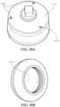
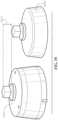
- FIGS. 38 A and 38 Bshow two perspective views of the nozzle cap assembly of FIG. 36 in another aspect.
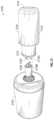
- FIG. 39is a perspective view showing a depth comparison between the nozzle cap assembly of FIG. 36 and a standard nozzle cap.
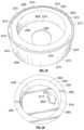
- FIG. 40shows perspective views of various aspects of the nozzle cap assembly of FIG. 36 .
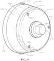
- FIG. 41shows a perspective view of the nozzle cap assembly of FIG. 36 .
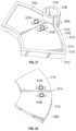
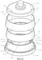
- FIG. 42shows an exploded perspective view of the nozzle cap assembly of FIG. 36 .
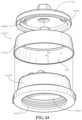
- FIG. 43shows another exploded perspective view of the nozzle cap assembly of FIG. 36 with the antenna assembly of the nozzle cap assembly nested in an antenna cover of the nozzle cap assembly.
- FIG. 44is another exploded perspective view of the nozzle cap assembly of FIG. 36 with the antenna assembly nested in the antenna cover.
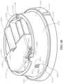
- FIG. 45is a perspective view of the nozzle cap assembly of FIG. 36 with the nozzle cap cover removed.
- FIG. 46is a perspective view of the nozzle cap assembly of FIG. 36 with the nozzle cap cover removed and with the antenna cover shown transparent to show the antenna assembly between the antenna cover and a nozzle cap housing.
- FIG. 47is a perspective view of one aspect of a nozzle cap assembly with a nozzle cap cover removed showing an interior cavity of a nozzle cap housing with an inner cover installed over a PCB.
- FIG. 48is a perspective view of the nozzle cap assembly of FIG. 47 with the nozzle cap cover, an antenna cover, and an antenna assembly removed showing a Reed sensor positioned within a port.
- FIG. 49is a top view of an aspect of the nozzle cap assembly of FIG. 47 with the nozzle cap cover, the antenna cover, the antenna assembly, and the inner cover removed showing the PCB.
- FIG. 50is a perspective view of the nozzle cap assembly of FIG. 47 with the nozzle cap cover, the antenna cover, the antenna assembly, the inner cover, capacitors, and batteries removed showing the PCB supported on PCB standoffs and an acoustic sensor mounted to the nozzle cap housing.
- Rangescan be expressed herein as from “about” one particular value, and/or to “about” another particular value. When such a range is expressed, another aspect includes from the one particular value and/or to the other particular value. Similarly, when values are expressed as approximations, by use of the antecedent “about,” it will be understood that the particular value forms another aspect. It will be further understood that the endpoints of each of the ranges are significant both in relation to the other endpoint, and independently of the other endpoint.
- the terms “optional” or “optionally”mean that the subsequently described event or circumstance can or cannot occur, and that the description includes instances where said event or circumstance occurs and instances where it does not.
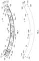
- the antenna assemblycan comprise a curved printed circuit board (PCB) and a plurality of antenna structures configured to provide directional radiation in at least one frequency band. It would be understood by one of skill in the art that the disclosed antenna assembly is described in but a few exemplary aspects among many.
- PCBprinted circuit board
- an antenna assembly 100can comprise a PCB 102 and a plurality of antenna structures 104 .
- the PCB 102can be a flexible PCB.
- the material used to construct the PCB 102can be selected from the group including, but not limited to, polyimide, polyethylene terephthalate (PET), and various other conventional materials used to construct flexible PCBs.
- FIG. 1shows the PCB 102 in an unwrapped configuration.
- the curved PCB 102can be bent into a wrapped configuration, for example as shown in FIG. 13 , and can be mounted or positioned around a curved surface, such as a fire hydrant, light poles, various utility structures having curved surfaces, decorative columns, curved structural supports, and various other types of structures having curved surfaces.
- the PCB 102can comprise a body 120 , which can comprise a top end 106 , a bottom end 108 distal from the top end 106 , a first side end 110 adjacent to the top end 106 and the bottom end 108 , and a second side end 112 distal from the first side end 110 and adjacent to the top end 106 and the bottom end 108 .
- the top end 106 and the bottom end 108can define curved edges extending from the first side end 110 to the second side end 112 .
- the type of edges formed by the top end 106 and the bottom end 108should not be considered limiting on the current disclosure as it is also contemplated that the top end 106 and the bottom end 108 can define straight edges, jagged edges, and various other shapes of edges.
- the PCB 102can comprise an outward-facing side 114 and an inward-facing side 502 (shown in FIG. 5 ).
- the antenna assembly 100can comprise solder pads 116 A-E which can be configured to be soldered to various cables (not shown), respectively, such as coaxial cables, which may be connected to various connectors or transceivers (not shown).
- various other types of connectorscan be utilized in place of the solder pads 116 .
- the number or location of the solder pads 116should not be considered limiting on the current disclosure as it is also contemplated that the number or location of the solder pads 116 may be varied depending on a particular use, purpose, or configuration of the antenna assembly 100 .
- the PCB 102can also define a number of through holes 118 A-G, which may be utilized to mount various components onto the PCB 102 or secure the curved PCB 102 to various other items or devices.
- the number of through holes 118should not be considered limiting on the current disclosure.
- the antenna assembly 100can comprise two or more antenna structures 104 .
- the multiple antenna structures 104are contained on a single medium, such as the PCB 102 .
- the multiple antenna structures 104can be designed or configured to operate in different frequency ranges to allow multiple types of services.
- An antenna assembly 100 having multiple antenna structures 104 operating in multiple frequency bandscan be referred to as a “multi-band antenna assembly.”
- multi-band antenna assembliescan also be formed on a single PCB to allow communication in multiple frequency ranges.
- the antenna structures 104can be configured to provide directional radiation in at least one frequency band.
- the antenna structures 104can be disposed on the outward-facing side 114 of the PCB 102 .
- the antenna structures 104can be disposed on at least one of the outward-facing side 114 and the inward-facing side 502 of the PCB 102 .
- the antenna assembly 100can comprise: a plurality of first antenna structures 104 A configured to operate within a first set of frequency bands; a plurality of second antenna structures 104 B configured to operate within a second set of frequency bands; and a plurality of third antenna structures 104 C configured to operate within a third set of frequency bands. It is contemplated that the antenna structures 104 A-C can have various designs and configurations for operating within various frequency bands. Optionally, various other antenna structures configured to operate in additional or different sets of frequency bands can be utilized.
- the plurality of antenna structures 104can be all first antenna structures 104 A, all second antenna structures 104 B, all third antenna structures 104 C, all other types of antenna structures not currently shown, a combination of first antenna structures 104 A and second antenna structures 104 B, a combination of first antenna structures 104 A and third antenna structures 104 C, a combination of second antenna structures 104 B and third antenna structures 104 C, a combination of first antenna structures 104 A and additional antenna structures configured to operate within different or additional frequency bands, etc.
- the antenna structures 104can be configured to provide 360° directional radiation around a perimeter of a curved surface when the PCB 102 is mounted on the curved surface.
- each one of the antenna structures 104can be disposed on the PCB 102 such that each antenna structure provides a degreed section of radio coverage.
- the number and or type of antenna structures 104 disposed on the PCB 102can be varied to provide different sections of radio coverage.
- the eight antenna structures 104can be disposed and spaced on the PCB 102 where each one of the plurality of antenna structures 104 provides a 45° section of radio coverage.
- each of the antenna structures 104can be disposed and spaced on the PCB 102 where each of the antenna structures 104 provides a 120° section of radio coverage. It is contemplated that various other sections of radio coverage can be provided by changing at least one of the number of antenna structures 104 , the spacing of antenna structures 104 on the PCB 102 , and the type of antenna structures 104 utilized.
- all of the antenna structures 104 in sumcan provide 360° radio coverage while each set of frequency bands covered by the antenna structures 104 may not have 360° coverage.
- an antenna assembly 100comprising one first antenna structure 104 A, one second antenna structure 104 B, and one third antenna structure 104 C, each antenna structure 104 A-C can provide a 120° section of radio coverage in each of the corresponding set of frequency bands, respectively, to, in sum, provide 360° radio coverage while each set of frequency bands only has a 120° section of radio coverage.
- each set of frequency bands covered by the antenna structures 104may have 360° coverage around the curved surface.
- each antenna structure 104 A-Ccan provide 360° radio coverage in 120° sections of radio coverage in each of the corresponding set of frequency bands, respectively.
- three first antenna structures 104 Acan be disposed on the PCB 102 to provide 360° coverage in 120° sections of radio coverage in at least one frequency band of the first set of frequency bands around the curved surface when the PCB 102 is bent.
- three second antenna structures 104 Bcan be disposed on the PCB 102 to provide 360° coverage in 120° sections of radio coverage in at least one of the second set of frequency bands around the curved surface when the PCB 102 is bent.
- three third antenna structures 104 Ccan be disposed on the PCB 102 to provide 360° coverage in 120° sections of radio coverage for at least one of the third set of frequency bands around the curved surface when the PCB 102 is bent.
- the antenna structures 104can be configured to provide directional radiation in various sets of frequency bands currently developed or that may be developed in the future.
- the sets of frequency bandscan be ranging from about 600 MHz to about 6 GHz; however, it is contemplated that the antenna structures 104 can be configured to operate at various other frequency bands below about 600 MHz or above about 6 GHz.
- the antenna structures 104can be configured to provide radio coverage for Cellular, Cellular LTE, ISM 900, ISM 2400, GPS, and various other bands already developed or that may be developed in the future.
- the antenna structurescan be configured to operate in various cellular bands such as 700, 800, 900, 1700, 1800, 1900, and 2100 MHz, as well as additional cellular bands currently developed or that can be developed in the future (e.g. cellular bands between 2 GHz and 6 GHz).
- the antenna structures 104can be configured to operate in GPS bands, such as 1575.42 (L1) and 1227.60 MHz (L2), or in a wideband frequency range for wireless local area communication (e.g. Wi-Fi communication), such as a range from about 1.5 GHz to about 5.0 GHz, such as from about 2.0 GHz to about 5.0 GHz, any of which are currently developed bands or bands that may be developed in the future.
- the first antenna structures 104 Acan be cellular antenna structures configured to provide radio coverage for Cellular/ISM bands ranging from about 600 MHz to about 6 GHz
- the second antenna structures 104 Bcan be cellular antenna structures configured to provide radio coverage for Cellular/LTE bands ranging from about 600 MHz to about 6 GHz
- the third antenna structures 104 Ccan be wireless local area antenna structures configured to provide radio coverage for GPS bands ranging from about 1.5 GHz to about 5.0 GHz.
- the antenna structures 104 A-Ccan provide radio coverage for various other sets of frequency bands.
- the PCB 102can comprise a base layer 202 , a copper layer 302 , and a cover layer 402 .
- the antenna structures 104can be components of the copper layer 302 , which can be disposed between the base layer 202 and the cover layer 402 of the assembled PCB 102 .
- an adhesive(not shown) can be utilized between the copper layer 302 and the base layer 202 and between the copper layer 302 and the cover layer 402 , respectively, to attach the copper layer 302 to the base layer 202 and the cover layer 402 .
- the base layer 202can comprise a body 204 having an outward-facing side 208 and an inward-facing side 504 (shown in FIG. 5 ).
- the inward-facing side 504can be the inward-facing side 502 of the PCB 102 .
- the body 204can define the through holes 118 A-G extending through the body 204 from the outward-facing side 208 to the inward-facing side 504 .
- the body 204can also define solder pad holes 206 A-E extending through the body 204 from the outward-facing side 208 to the inward-facing side 504 . It is contemplated that the number of solder pad holes 206 defined by the body 204 can correspond with the number of solder pads 116 of the antenna assembly 100 .
- the copper layer 302can comprise a body 304 having an outward-facing side 306 and an inward-facing side (not shown).
- the copper layer 302can define the antenna structures 104 .
- the body 404can also define the through hole 118 D.
- the copper layer 302can define notches 308 A-F.
- the notch 308 Acan be aligned with the through hole 118 A
- the notch 308 Bcan be aligned with the through hole 118 B
- the notch 308 Ccan be aligned with the through hole 118 C
- the notch 308 Dcan be aligned with the through hole 118 E
- the notch 308 Ecan be aligned with the through hole 118 F
- the notch 308 Fcan be aligned with the through hole 118 G.
- the number of notches 308 defined by the copper layer 302should not be considered limiting on the current disclosure.
- the inward-facing side of the copper layer 302can be positioned on the outward-facing side 208 of the base layer 202 to assemble the PCB 102 .
- the cover layer 402can comprise a body 404 having an outward facing side 404 and an inward-facing side (not shown).
- the cover layer 402can define the through holes 118 A-G.
- the inward-facing side of the cover layer 402can be positioned on the outward-facing side 306 of the copper layer 302 to assemble the PCB 102 .
- the outward facing side 406 of the cover layer 402can be the outward-facing side 114 of the PCB 102 .
- portions of the solder pads 116can extend through the PCB 102 to the inward-facing side 502 .
- the antenna assembly 100can comprise the antenna structures 104 D-F, which can be configured to operate within different frequency bands, additional frequency bands, or the same frequency bands, respectively, as those of antenna structures 104 A-C.
- the antenna assembly 100can comprise a securing tab 606 connected to the body 120 via a bend line 608 .
- the bend line 608can be a designed weakened region at which the securing tab 606 can be bent relative to the body 120 .
- the securing tab 606can comprise electrical connectors 610 A,B in electrical communication with the antennas 104 D-F such that the antennas 104 D-F can be connected to various connectors or transceivers (not shown).
- the securing tab 606can comprise mechanical connectors or fasteners 612 A,B, which can be utilized to mechanically connect or secure the antenna assembly 100 to various structures or devices.
- the mechanical connectors or fasteners 612 A,Bcan be, for example and without limitation, nuts and bolts, screws, pins, and various other types of connectors which can be utilized to secure the antenna assembly 100 to the various other structures or devices.
- the number of electrical connectors 610 or mechanical connectors 612should not be considered limiting on the current disclosure as it is also contemplated that any desired number of electrical connectors 610 or mechanical connectors 612 can be utilized.
- the antenna assembly 700can comprise a PCB 702 and antenna structures 104 .
- Antenna structures 104 G,Hcan be configured to operate within different frequency bands, additional frequency bands, or the same frequency bands, respectively, as those of antenna structures 104 A-E.
- the antenna assembly 700includes two antenna structures 104 E.
- the PCB 702can comprise a body 704 having a top side 706 and a bottom side 708 . As shown in FIG. 7 , the body 704 can optionally have a substantially circular shape that defines a substantially circular-shaped bore 710 . One skilled in the art will appreciate that other geometric shapes of the body 704 or the bore 710 can be present.
- the PCB 702can comprise electrical connectors 710 A,B, which can be substantially similar to the electrical connectors 610 A,B of the antenna assembly 600 . In one aspect, the electrical connectors 710 A,B can be connected to the antenna structures 104 .
- various additional structures or componentscan be positioned or secured to the antenna assembly 700 .
- the additional structures or components positioned or secured to the antenna assembly 700can be a modem 712 , power supplies 714 A,B such as batteries or various other power sources, sensors (not shown), or various other structures or components as desired.
- the nozzle cap assembly 800can comprise a nozzle cap 802 , a spacer 1002 (shown in FIG. 10 ), the antenna assembly 100 , and an antenna cover 804 .
- the nozzle cap 802can be configured to mount on a nozzle of a node of an infrastructure system, such as on a fire hydrant (not shown).
- the nozzle cap 802can comprise attachment mechanisms, such as threading, pins, fasteners, clips, and various other types of attachment mechanisms such that the nozzle cap 802 can be removable from the fire hydrant.
- the nozzle cap 802can comprise a body 902 having a top end 912 and a bottom end 914 .
- the nozzle cap 802can comprise a base 904 at the top end 912 and a curved side wall 906 extending from the base 904 to the bottom end 914 .
- the base 904can have an inner surface 1202 (shown in FIG. 12 ) and an outer surface 908 .
- the curved side wall 906can have an inner surface 1204 (shown in FIG. 12 ) and an outer surface 910 .
- the outer surface 910can define spacer tabs 918 A,B for attachment of the nozzle cap 802 to the spacer 1002 .
- the inner surface 1202 and the inner surface 1204 togethercan define a nozzle cap cavity 1206 having a nozzle cap cavity opening 1210 at the bottom end 914 .
- the inner surface 1204can define threading 1208 , which can provide an attachment mechanism for the nozzle cap 802 that engages with threading on the fire hydrant such that the nozzle cap 802 may be removably attached to the fire hydrant.
- threading 1208can provide an attachment mechanism for the nozzle cap 802 that engages with threading on the fire hydrant such that the nozzle cap 802 may be removably attached to the fire hydrant.
- various other types of attachment mechanisms other than the threading 1208may be utilized.
- the nozzle cap 802can comprise a nut base 806 extending axially upwards from the outer surface 908 of the base 904 .
- the nut base 806can be utilized by an operator to aid in removing the nozzle cap 802 from the fire hydrant or securing the nozzle cap 802 to the fire hydrant.
- the base 904 of the nozzle cap 802can define a plurality of cable holes 916 proximate to the nut base 806 that extend from the inner surface 1202 to the outer surface 908 . Four cable holes 916 are shown in the base 904 , though any number of cable holes 916 can be present in other aspects.
- the cable holes 916are sized to accept one or more antenna coaxial cables connected to a radio canister (not shown) housed within the nozzle cap 802 .
- the one or more coaxial cablesextend through the cable holes 916 to connect with the antenna assembly 100 at any of the solder pads 116 .
- the antenna cover 804can comprise a body 808 having a top end 822 and a bottom end 824 .
- the antenna cover 804can comprise a base 810 at the top end 822 and a curved side wall 812 extending from the base 810 to the bottom end 824 .
- the base 810can have an inner surface (not shown) and an outer surface 814 .
- the curved side wall 812can have an inner surface (not shown) and an outer surface 816 .
- the inner surface of the base 810 and the inner surface of the curved side wall 812together can define an antenna cover cavity (not shown), into which the nozzle cap 802 , the spacer 1002 , and antenna assembly 100 can optionally be positioned.
- the base 810can define a cover bore 818 at the top end 822 extending through the antenna cover 804 from the inner surface to the outer surface 814 .
- the nut base 806can extend through the cover bore 818 such that the nut base 806 may be accessed by the operator when the antenna cover 804 is positioned on the nozzle cap 802 .
- the spacer 1002can comprise a hollow body 1004 having a top end 1006 , a bottom end 1008 , a curved inner surface 1010 , and a curved outer surface 1012 .
- the hollow body 1004can be shaped like a truncated cone.
- the spacer 1002can comprise a top lip 1014 at the top end 1006 and a bottom lip 1016 at the bottom end 1008 .
- the top lip 1014can extend radially inward from the top end 1006 towards a center axis 1018 of the spacer 1002 .
- the bottom lip 1016can extend radially inward from the bottom end 1008 towards the center axis 1018 of the spacer 1002 .
- FIG. 11shows the spacer 1002 mounted on the nozzle cap 802 .
- the spacer 1002can be sized to approximate a width or diameter of the nozzle cap 802 .
- the spacer 1002can be mounted on the nozzle cap 802 such that the curved inner surface 1010 of the body 1004 of the spacer 1002 faces the outer surface 910 of the curved side wall 906 of the nozzle cap 802 .
- a distance from the top lip 1014 to the bottom lip 1016 of the spacer 1002can be greater than a distance from the top end 912 to the bottom end 914 of the nozzle cap 802 .
- the top lip 1014 and the bottom lip 1016can be utilized to retain the spacer 1002 on the nozzle cap 802 via a snap-fit configuration by positioning the nozzle cap 802 between the top lip 1014 and the bottom lip 1016 , with the top lip 1014 engaging the spacer tabs 918 A,B and the bottom lip 1016 engaging the bottom end 824 of the nozzle cap 802 .
- the antenna cover 804can be placed over the spacer 1002 mounted on the nozzle cap 802 .
- the base 904can define a raised portion 1102 .
- FIG. 12shows another view of the spacer 1002 mounted on the nozzle cap 802 .
- FIG. 12also shows the threading 1208 and the nozzle cap cavity 1206 of the nozzle cap 802 .
- the PCB 102can be bent or formed into an annular shape to form a curved PCB.
- the PCB 102can be bent to form a hollow cylindrical shape, as shown for example and without limitation in FIG. 13 .
- the PCB 102can be bent to form other geometric shapes, such as, for example and without limitation, a truncated cone shape as shown in FIG. 13 .
- the PCB 102 of the antenna assembly 100can be formed into a curved shape and mounted around the curved side wall 906 of the nozzle cap 802 of the fire hydrant. As previously described, it is contemplated that the PCB 102 can be configured to be mounted around various other curved surfaces such as around light poles, various utility structures having curved surfaces, decorative columns, curved structural supports, and various other types of structures. In the aspect where the antenna assembly 100 is mounted on the nozzle cap 802 , the antenna assembly 100 can maintain at least one section of the antenna assembly 100 facing upwards, regardless of the rotation end stop of the nozzle cap 802 when mounted on the hydrant.
- fasteners(not shown) can be utilized with the through holes 118 to secure the PCB 102 to the antenna assembly 100 .
- the PCB 102can be secured to the antenna assembly 100 through various other fastening mechanisms that may or may not utilize the through holes 118 .
- the antenna assembly 100can be mounted such that the spacer 1002 can be between the nozzle cap 802 and the antenna assembly 100 .
- the inward-facing side 502 of the antenna assembly 100can face the curved outer surface 1012 of the spacer 1002 .
- the outward-facing side 114can face the inner surface of the curved side wall 812 of the antenna cover 804 .
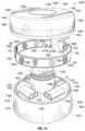
- the nozzle cap assembly 1400can comprise a nozzle cap 1402 , a mounting plate 1404 , an antenna cover 1406 , and the antenna assembly 100 .
- the nozzle cap 1402can define an alignment groove 1418 in the body 1408 at the top end 1410 .
- the alignment groove 1418can extend around a perimeter of the base 1422 .
- the alignment groove 1418can be utilized by the operator to position and lock the antenna cover 1406 on the nozzle cap 1402 .
- the nozzle cap 1402can comprise a nut base 1420 extending axially upwards from the base 1422 .
- the nut base 1420can be elongated to accommodate the antenna cover 1406 , mounting plate 1404 , and antenna assembly 100 at a position axially above the base 1422 .
- the nut base 1420can also be a conventionally-sized nut base that may not be elongated.
- the nozzle cap 1402can comprise various devices or structures mounted at various locations on the body 1408 .
- the nozzle cap 1402can comprise a sensor 1426 , such as a leak sensor, vibration sensor, tamper sensor, or various other types of sensors, secured on the base 1422 .
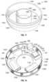
- the mounting plate 1404can comprise a body 1428 with a top surface 1430 and a bottom surface 1602 .
- the body 1428can be an annular shape defining a substantially circular shaped bore 1432 .
- the bore 1432can be dimensioned such that the mounting plate 1404 can be positioned on the nozzle cap 1402 with the nut base 1420 extending through the bore 1432 .
- the mounting plate 1404can define various other bores to accommodate any devices or structures mounted on the base 1422 of the nozzle cap 1402 .
- the mounting plate 1404can define a sensor bore 1434 through which the sensor 1426 can extend.
- the mounting plate 1404can comprise various additional structures or components positioned or secured to the mounting plate 1404 .
- the additional structures or components positioned or secured to the mounting plate 1404can be the modem 712 , the power supplies 714 A,B, an additional PCB 1458 , or various other structures or components as desired.
- the antenna cover 1406can be similar to the antenna cover 804 and can comprise a body 1436 having a top end 1438 and a bottom end 1440 .
- the antenna cover 1406can comprise a base 1442 at the top end 1438 and an outer wall 1444 extending from the base 1442 to the bottom end 1440 .
- the base 1442can have an outer surface 1446 and an inner surface 1702 and the outer curved wall 1444 can have an outer surface 1448 and an inner surface 1604 .
- the inner surface 1702 and the inner surface 1604together can define an antenna cover cavity 1606 .
- the outer wall 1444can be a cylindrical shape; however, it will be appreciated that other geometric shapes of the outer wall 1444 can be present.
- an alignment lip 1454can extend axially downwards from the outer wall 1444 at the bottom end 1440 .
- the alignment lip 1454can be dimensioned and shaped such that the alignment lip 1454 can be positioned within the alignment groove 1418 .
- the alignment lip 1454 within the alignment groove 1418can position and secure the antenna cover 804 on the nozzle cap 1402 .
- the base 1442can define a cover bore 1450 in one aspect.
- the antenna cover 1406can comprise an inner wall 1452 surrounding the cover bore 1450 and extending axially downwards from the inner surface 1702 of the base 1442 into the antenna cover cavity 1606 to a bottom end 1608 , as shown in FIG. 16 .
- the inner wall 1452can comprise an inner surface 1456 and an outer surface 1704 , as shown in FIG. 17 .
- the cover bore 1450can be a substantially circular-shaped bore and the inner wall 1452 can be a cylindrical shape; however, one skilled in the art will appreciate that other geometric shapes of the cover bore 1450 and inner wall 1452 can be present.
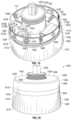
- the mounting plate 1404can be positioned on the nozzle cap 1402 such that the nut base 1420 extends through the bore 1432 .
- the bottom surface 1602can face and can be in contact with the outer surface 1424 of the base 1422 of the nozzle cap 1402 .
- the antenna cover 1406can be positioned on the nozzle cap 1402 such that the nut base 1420 extends through the cover bore 1450 .
- the alignment lip 1454can be positioned in the alignment groove 1418 .
- the antenna assembly 100 and mounting plate 1404can be housing within the antenna cover cavity 1606 when the antenna cover 1406 is positioned on the nozzle cap 1402 .
- the antenna assembly 700can be used with the antenna cover 1406 .
- the antenna assembly 700can be positioned in the antenna cover cavity 1606 .
- the bottom side 708 of the PCB 702can be facing and can be in contact with the inner surface 1702 of the base 1442 of the antenna cover 1406 , and can be attached to the inner surface 1702 by screws, pressure-fitted tabs, melted tabs or stubs, adhesives, or any similar fastening devices.
- the inner wall 1452 of the antenna cover 1406can extend through the bore 710 of the antenna assembly 700 .
- the antenna assembly 700 and antenna cover 1406can be mounted on the nozzle cap 1402 in a similar manner as described above to form a nozzle cap assembly that looks like the nozzle cap assembly 1400 shown in FIG. 20 .
- the nozzle cap assembly 2200can comprise a nozzle cap 2202 , an antenna cover 2204 , and a spacer 2502 .
- the nozzle cap 2202can comprise a body 2302 having a top end 2304 and a bottom end 2306 .
- the nozzle cap 2202can comprise a base 2308 at the top end 2304 and a curved side wall 2310 extending from the base 2308 to the bottom end 2306 .
- the base 2308can comprise an inner surface 2602 and an outer surface 2312 and the curved side wall 2310 can comprise an inner surface 2604 and an outer surface 2314 .
- the inner surfaces of the base 2308 and curved side wall 2310can together define a nozzle cap cavity 2606 .
- the nozzle cap 2202can comprise a nut base 2206 extending axially upwards from the base 2308 .
- the nozzle cap 2202optionally can define a through hole 2316 in the base 2308 .
- the through hole 2316can be utilized to guide a cable through the nozzle cap 2202 .
- the antenna cover 2204can comprise a body 2208 having a top end 2210 and a bottom end 2212 .
- the antenna cover 2204can comprise a base 2214 at the top end 2210 and a curved side wall 2216 extending from the base 2214 to the bottom end 2212 .
- the base 2214can have an inner surface 2402 and an outer surface 2218 .
- the curved side wall 2216can have an inner surface 2404 and an outer surface 2220 .
- the inner surface of the base 2214 and the inner surface of the curved side wall 2216together can define an antenna cover cavity 2406 , into which the nozzle cap 2202 , the spacer 2502 , and the antenna assembly 100 can optionally be positioned.
- the base 2214can define a cover bore 2222 at the top end 2210 extending from the inner surface 2404 to the outer surface 2218 .
- the nut base 2206can extend through the cover bore 2222 such that the nut base 2206 may be accessed by the operator when the antenna cover 2204 is positioned on the nozzle cap 2202 .
- the antenna cover 2204can optionally define a cable guide 2224 .
- a portion of the cable guide 2224can extend upwards from the base 2214 as shown in FIG. 22 .
- the cable guide 2224can define a guide opening 2408 that can be matched and aligned with the through hole 2316 to guide the cable through the antenna cover 2204 .
- the cable guide 2224allows the nozzle cap 2202 to be positioned closer to the antenna cover 2204 and protects the cable from damage or pinching between the nozzle cap 2202 and the antenna cover 2204 .
- the cablecan connect to an external antenna (not shown) or various other structures or devices external to the nozzle cap assembly 2200 at one end and to a radio canister (not shown) or other structures at another end.
- the antenna assembly 100can be positioned and secured within the antenna cover 2204 such that the outward-facing side 114 faces the inner surface 2404 of the curved side wall 2216 .
- the antenna cover 2204can optionally define a plurality of locking tabs 2410 extending inwards from the bottom end 2212 .
- the locking tabs 2410can be substantially perpendicular to the curved side wall 2216 ; however, it is also contemplated that the locking tabs 2410 can have various other configurations relative to the curved side wall 2216 .
- the number or the shape of the locking tabs 2410should not be considered limiting on the current disclosure as it is contemplated that any number of locking tabs 2410 having any desired shape may be utilized.
- the antenna cover 2204can define a single, continuous locking tab 2410 extending inward from the bottom end 2212 .
- the antenna cover 2204can optionally define an inner wall 2412 extending downwards from the base 2214 into the antenna cover cavity 2406 .
- a spacer alignment groove 2414can be defined between the inner wall 2412 and the inner surface 2404 of the curved side wall 2216 .
- the spacer 2502can comprise a hollow body 2504 having a top end 2506 , a bottom end 2508 , a curved inner surface 2510 , and a curved outer surface (not shown).
- the hollow body 2504can be a substantially cylindrical shape; however, one skilled in the art will appreciate that other geometric shapes can be present.
- the locking tabs 2410 and the spacer alignment groove 2414can be utilized by the operator to position and secure the spacer 2502 within the antenna cover 2204 , as shown in FIG. 25 .
- the nozzle cap assembly 2200in place of the cable that can be guided through the through hole 2316 and cable guide 2224 , can comprise a coupling 2608 mounted on the nozzle cap 2202 .
- a portion of the coupling 2608can be positioned within the through hole 2316 .
- the coupling 2608can be connected to the external antenna and can be wirelessly coupled to a radio canister 3002 , which is shown in FIG. 30 .
- the coupling 2608can comprise a body 2702 having a top side 2710 and a bottom side 2712 .
- the body 2702can define an antenna assembly indentation 2704 into which an antenna assembly 2714 can be positioned.
- the body 2702can also comprise a securing stem 2706 .
- the stem 2706can be a substantially cylindrical shape defining a circular bore 2708 ; however, the shape of the stem 2706 or the bore 2708 should not be considered limiting on the current disclosure as it is contemplated that other geometric shapes of the stem 2706 and the bore 2708 can be present.
- the stem 2706does not define the bore 2708 .
- the stem 2706can extend upwards from the top side 2710 .
- the stem 2706can be configured to be positioned within the through hole 2316 .
- the shape of the body 2702should not be considered limiting on the current disclosure as it is contemplated that various geometric shapes of the body 2702 can be present.
- the antenna assembly 2714can comprise a PCB 2716 and an antenna structure 2902 (shown in FIG. 29 ).
- the PCB 2716can comprise a top side 2718 and a bottom side 2802 (shown in FIG. 28 ).
- the PCB 2716can comprise the electrical connectors 610 A,B.
- the electrical connectors 610 A,Bcan be disposed on at least one of the top side 2718 and the bottom side 2802 of the PCB 2716 .
- the shape of the PCB 2716should not be considered limiting on the current disclosure as it is contemplated that various other geometric shapes of the PCB 2716 can be present.
- the PCB 2716can be shaped such that the PCB 2716 can be positioned within the antenna assembly indentation 2704 .
- the antenna assembly 2714can be a multi-frequency PCB trace coil pad.
- the antenna structure 2902can be disposed on the bottom side 2802 of the PCB 2716 .
- the antenna structure 2902can be disposed on at least one of the top side 2718 and the bottom side 2802 of the PCB 2716 .
- the PCB 2716can be configured for wireless communication with the radio canister 3002 , such as through the use of inductive coupling, to eliminate the use of cables and allow for easier service and maintenance on the nozzle cap assembly 2200 .
- the radio canister 2002can comprise an antenna assembly 3004 that can be communicatively coupled to the antenna assembly 2714 .
- the antenna assembly 2714can be a multi-frequency PCB trace coil pad.
- the antenna structures of the antenna assemblies 2714 , 3004can be similar to the antenna structures 104 or different from the antenna structures 104 , depending on application.
- the antenna assembly 3100can comprise a radio canister 3102 having a canister radio frequency (RF) connector 3108 , a PCB assembly 3202 (shown in FIG. 32 ), and an antenna cover 3104 having a cover RF connector 3106 .
- the antenna cover 3104can comprise a first end 3112 , a second end 3114 , an outer surface 3110 , and an inner surface 3204 .
- the inner surface 3204can define an antenna cover cavity 3206 .
- the antenna cover 3104can comprise an antenna cover opening 3222 providing access to the cover cavity 3206 at the first end 3112 .
- the antenna cover 3104can be configured to receive the PCB assembly 3202 within the antenna cover cavity 3206 .
- the cover RF connector 3106can define a body 3210 .
- the bodycan comprise a canister-connecting portion 3212 and a PCB-connecting portion 3214 .
- the canister-connecting portion 3212can comprise connectors 3208 A,B configured to engage with connectors 3116 A,B of the canister RF connector 3108 .
- the number of connectors 3208 or connectors 3116should not be considered limiting on the current disclosure as it is contemplated that any number of connectors 3208 or connectors 3116 can be present.
- the PCB-connecting portion 3214can define slots 3216 A,B configured to engage and receive the PCB assembly 3202 .
- the PCB assembly 3202can comprise two PCBs 3218 A,B coupled together, as described in greater detail below. It is contemplated that the number of slots 3216 can correspond with the number of PCBs 3218 in various aspects.
- the cover RF connector 3106can be positioned such that the PCB-connecting portion 3214 can be within the antenna cover cavity 3206 and an engagement edge 3220 of the canister-connecting portion 3212 engages the first end 3112 of the antenna cover 3104 .
- each engagement slot 3406 A,Bcan define a slot surface 3502 A,B, respectively.
- the shape of the engagement slots 3406should not be considered limiting on the current disclosure as it is contemplated that various shaped slots can be defined.
- the slots 3406 A,Bcan be dimensioned to accept the PCBs 3218 A,B within the slots 3406 A,B, respectively.
- the slot surface 3502 Acan cover a portion of the top side 3408 B and a portion of the bottom side 3410 B of the PCB 3218 B.
- the slot surface 3502 Bcan cover a portion of the top side 3408 A and a portion of the bottom side 3410 A of the PCB 3218 A.
- the PCBs 3218 A,Bcan be combined such that the PCB assembly 3202 can have a general “x” shape.
- the PCB assembly 3202can be positioned within the slots 3216 A,B of the PCB-connecting portion 3214 of the cover RF connector 3106 .
- the cover RF connector 3106can be positioned such that the PCB-connecting portion 3214 and the PCB assembly 3202 is within the antenna cover cavity 3206 .
- the shape of the PCBs 3218 A,Bcan allow the PCB assembly 3202 to fit in the antenna cover opening 3222 and into the antenna cover cavity 3206 .
- the PCBs 3218 A,B combined via positioning in the slots 3405 A,Bcan allow the antenna structures 3404 to face multiple directions without being bent or wrapped.
- FIGS. 36 - 46show another aspect of a nozzle cap assembly 4100 mounted on an outlet of the hydrant 3600 .
- the nozzle cap assembly 4100can be a pre-assembled and factory-tested node and, in various aspects, can comprise any of a cast iron hydrant cap, an acoustic sensor, a data processor, network hardware, batteries, or an antenna.
- the nozzle cap assembly 4100can be configured as a sensing node which may comprise a sensor configured to monitor parameters of a fluid system such as pressure, temperature, pH, chemical concentration, acoustic vibrations, or other fluid characteristics.
- a fluid systemsuch as pressure, temperature, pH, chemical concentration, acoustic vibrations, or other fluid characteristics.
- the nozzle cap assembly 4100can be a wireless sensing node, such as an acoustic node comprising an antenna, acoustic sensor, processor and battery.
- the wireless acoustic nodecan be mounted on the hydrant 3600 and identify any leaks in a water main or distribution main 3601 connected to the hydrant 3600 .
- the acoustic nodeis capable of wireless transmission. Installation of the sensing nodes onto the hydrants of a fluid distribution network, or fluid system 3602 , can create a smart fluid system.
- an acoustic nodecan be mounted onto the hydrants of a water distribution main to create a smart water system or a smart water network when the acoustic node communicates with other devices wirelessly.
- the nozzle cap assembly 4100can be designed to replace 4-inch or 4.5-inch pumper nozzle caps, or any other size pumper nozzle caps or other nozzle caps on a hydrant 3600 or on any other structure having a nozzle cap.
- the nozzle cap assemblyis compatible with both wet- and dry-barrel fire hydrants.
- FIG. 39shows a depth comparison between the nozzle cap assembly 4100 and a standard version of a nozzle cap 3900 . As shown in FIG.
- the nozzle cap assemblycan be approximately 1.5 inches taller than the standard nozzle cap, i.e., there can exist a height difference 3910 , though in other aspects the height difference 3910 can be larger or smaller than 1.5 inches.
- the nozzle cap assemblycan be similar in appearance to the standard nozzle cap which can be desirable in some applications.
- the nozzle cap assembly 4100 and any other nozzle cap assemblycan also be customized to adapt the appearance to any hydrant color scheme as shown in FIG. 40 .
- the nozzle cap assembly 4100can comprise a nozzle cap cover 4110 , an antenna cover 4120 , a nozzle cap housing 4130 , and the antenna assembly 100 .
- the nozzle cap cover 4110 , the antenna cover 4120 , and the nozzle cap housing 4130can define a smooth outer side surface 4101 .
- the nozzle cap cover 4110can optionally define fastener holes 4111 therethrough.
- the fastener holes 4111are sized to accept bolts 3801 (shown in FIG. 38 A ).
- the boltscan have a standard Phillips-head, a slotted head, or any other type of head, including tamper-proof bolt heads.
- the nozzle cap cover 4110can also comprise a nut base 4116 .
- the nut base 4116can have a hex, square (shown in FIG. 38 A ), or any other desired shape configured to allow the nozzle cap assembly 4100 to be installed or removed on the hydrant outlet to allow use of the hydrant 3600 .
- the nozzle cap housing 4130can also comprise tabs 4131 for manipulation such as installation or removal of the nozzle cap assembly 4100 or for visual alignment of the nozzle cap assembly 4100 in a particular orientation on the hydrant 3600 .
- the antenna cover 4120has a frustoconical shape, though other shapes, such as a cylindrical shape, can be present in various other aspects.
- the antenna cover 4120is positioned and held securely in place between the nozzle cap cover 4110 and the nozzle cap housing 4130 .
- the nozzle cap housing 4131can comprise an antenna mounting portion 4132 and a lower rim 4133 .
- the antenna mounting portion 4132defines an antenna mounting surface 4134 having a frustoconical shape, though other shapes, including other curved shapes, such as a cylindrical shape, can be present in various other aspects.
- the antenna cover 4120can fit around and cover the antenna mounting surface 4134 and can have a curved shape complimentary to the shape of the antenna mounting surface 4134 .
- the lower rim 4133can comprise a shoulder 4135 against which the antenna cover 4120 can be positioned to securely hold the antenna cover 4120 in place.
- the lower rim 4133can define an antenna cover alignment tab 4830 (shown in FIG. 48 ) which can engage a complimentary notch (not shown) in the antenna cover to prevent rotation of the antenna cover 4120 .
- the antenna mounting portion 4132can comprise fastener attachment tabs 4136 defining threaded fastener holes 4137 aligned with the fastener holes 4111 of the nozzle cap cover 4110 .
- the nozzle cap cover 4110can thereby be secured to the nozzle cap housing 4130 by the bolts 3801 extending through the fastener holes 4111 into the fastener holes 4137 and engaging the threads therein, thereby securing the antenna cover 4120 and the antenna assembly 100 between the nozzle cap cover 4110 and the nozzle cap housing 4130 .
- the nozzle cap assembly 4100can also comprise a flat sealing gasket 4210 .
- the sealing gasket 4210can extend around an upper rim 4138 and on an inner side of each fastener attachment tabs 4136 to seal between the nozzle cap cover 4110 and the nozzle cap housing 4130 and thereby prevent fluid such as rainwater from entering an interior cavity 4310 (shown in FIG. 43 ) of the nozzle cap housing 4130 .
- the nozzle cap housing 4130can define a plurality of PCB mounting holes 4220 , which can be threaded.
- the PCB mounting holesare configured to receive a threaded male end of each of a plurality of standoffs 5021 (shown in FIG. 50 ), which are used to mount and position the PCB.
- the antenna assembly 100fits within the antenna cover 4120 and is curved around an inner surface of the antenna cover 4120 .
- the antenna assembly 100can be adhered or otherwise fastened or secured to either or both of the inner surface of the antenna cover 4120 or the antenna mounting surface 4134 .
- the antenna cover 4120can define a top lip and a bottom lip similar to top lip 1014 and bottom lip 1016 , respectively, to secure the antenna assembly 100 in place within the antenna cover 4120 .
- various electrical components operatively associated with the antenna assembly 100can be housed within the nozzle cap housing 4130 .
- These electrical componentscan comprise a PCB 4320 , batteries 4330 , and capacitors 4340 .
- the nozzle cap housing 4130can also house other components, including but not limited to an acoustic sensor or other sensor, antennas other than the antenna structure 104 on the antenna assembly 100 , or other data processors or network hardware that can be operatively associated with the PCB 4320 , the batteries 4330 , the capacitors 4340 , or the antenna assembly 100 .
- the nozzle cap housing 4130can also define internal threading 4410 to allow the nozzle cap assembly 4100 on the outlet of the hydrant 3600 .
- the nozzle cap housing 4130can also comprise a divider wall 4420 to separate the internal threading 4410 , and thereby the outlet of the fire hydrant 3600 , from the electrical components housed within the nozzle cap housing 4130 .
- the nozzle cap cover 4110can also define tab receiving hole 4440 sized to receive the fastener attachment tabs 4136 therein. The tab receiving holes 4440 and the fastener attachment tabs 4136 thereby mate to prevent stress on the bolts 3801 during engagement of the nut base 4116 to rotate the nozzle cap assembly 4100 .
- the antenna assembly 100is secured between the inner surface of the antenna cover 4120 and the antenna mounting surface 4134 in an antenna cover cavity 4506 .
- the nozzle cap cover 4110 and the nozzle cap housing 4130can comprise cast or ductile iron or any other desired material for attachment to the fire hydrant 3600 .
- the antenna covercan comprise polypropylene or other desired materials to allow signals to pass therethrough to and from the antenna assembly 100 .
- the nozzle cap housing 4130can further comprise an inner cover 4710 , which can be configured to protect the PCB 4320 and an acoustic sensor 5010 (shown in FIG. 50 ).
- the inner cover 4710can define an access port 4720 which can be used to connect to the PCB 4320 for purposes such as to calibrate the acoustic sensor 5010 or install software.
- the inner cover 4710is held in place by a pair of inner cover fasteners 4712 which engage a pair of inner cover fastener holes 4912 (shown in FIG. 49 ).
- the nozzle cap housing 4130can also define threaded strap mounting holes 4714 which are configured for mounting a strap (not shown) which secures the capacitors 4340 and the batteries 4330 in place.
- the nozzle cap housing 4130can define a port 4810 positioned on the antenna mounting surface 4134 .
- the port 4810can be positioned beneath the antenna assembly 100 and the antenna cover 4120 .
- the port 4810can define a bore 4812 and a port shoulder 4814 .
- a sensorsuch as a Reed switch 4820 can be mounted in the port 4810 .
- the Reed switch 4820can be connected to the PCB 4320 by cables (not shown).
- the inner cover 4710can further define a second access port 4850 which can provide clearance for the cables connecting the Reed switch 4820 to the PCB 4320 .
- the Reed switch 4820can provide a mechanism for externally activating and deactivating the nozzle cap assembly 4100 without positioning an externally accessible switch on the nozzle cap assembly 4100 .
- the Reed switch 4820can be activated by exposing the nozzle cap assembly 4100 to a magnetic field such as waiving a magnet over the installed antenna cover 4120 .
- the ability to activate and deactivate the nozzle cap assembly 4100 externallycan be desirable because it can save time for maintenance personnel and can prevent unnecessary wear on the sealing gasket 4210 by reducing the need for access to the interior cavity 4310 .
- the absence of an externally accessible switchcan be desirable because it can prevent tampering with the device and can make the nozzle cap assembly 4100 less distinguishable from a standard version of a nozzle cap 3900 .
- the port 4810can also provide a conduit for the cables (not shown) connecting the antenna assembly 100 to the PCB 4320 .
- the port 4810can be plugged with potting 4910 .
- the potting 4910is a material which can be applied around the Reed switch 4820 as well as the cables (not shown) connecting the Reed switch 4820 and an antenna assembly 100 to the PCB 4320 . The material can then harden or dry, and the potting 4910 can secure the Reed switch 4910 and cables in place while sealing the port 4810 from the elements.
- a tool that engages the port shoulder 4814 and the bore 4812can be used to position the Reed switch 4820 when the potting 4910 is applied to the port 4810 .
- the acoustic sensor 5010can be mounted to the nozzle cap housing 4130 .
- the acoustic sensorcan be mounted by a threaded connection.
- the PCB 4320can be mounted on a plurality of standoffs 5021 .
- the PCB 4320can further comprise a networking board 5020 configured to perform functions including but not limited to processing, sending signals to the antenna assembly, and receiving signals from the antenna assembly.
- the PCB 4320can further comprise a sensor board 5030 which can be connected to the acoustic sensor 5010 or any other sensors and can perform functions including but not limited to processing the signal received from the acoustic sensor 5010 .
- a sensorsuch as the acoustic sensor 5010
- the fluid systemcan comprise a water main.
- the sensorcan transmit a signal to the sensor board 5030 , where the data can be processed to determine if the vibrations or sounds are indicative of a potential leak in the water main.
- the datacan then be processed by the networking board 5020 and wirelessly transmitted by the antenna assembly 100 .
- the data transmitted in the signalcan indicate the presence of a detected leak.
- a receiving devicecan wirelessly receive this signal, thereby allowing the hydrant and water main to be remotely monitored for leaks.
- the senorcan collect data for a parameter of the fluid system such as pressure, temperature, acidity (pH), chemical content, flow rate or other measurable conditions.
- the collected data for the parametercould then be transmitted wirelessly with the networking board 5020 and the antenna assembly 100 .
Landscapes
- Details Of Aerials (AREA)
- Support Of Aerials (AREA)
- Waveguide Aerials (AREA)
Abstract
Description
Claims (17)
Priority Applications (2)
| Application Number | Priority Date | Filing Date | Title |
|---|---|---|---|
| US17/683,090US12212053B2 (en) | 2016-02-12 | 2022-02-28 | Nozzle cap multi-band antenna assembly |
| US19/022,949US20250158273A1 (en) | 2016-02-12 | 2025-01-15 | Nozzle cap multi-band antenna assembly |
Applications Claiming Priority (4)
| Application Number | Priority Date | Filing Date | Title |
|---|---|---|---|
| US201662294973P | 2016-02-12 | 2016-02-12 | |
| US15/255,795US10305178B2 (en) | 2016-02-12 | 2016-09-02 | Nozzle cap multi-band antenna assembly |
| US16/352,045US11336004B2 (en) | 2016-02-12 | 2019-03-13 | Nozzle cap multi-band antenna assembly |
| US17/683,090US12212053B2 (en) | 2016-02-12 | 2022-02-28 | Nozzle cap multi-band antenna assembly |
Related Parent Applications (1)
| Application Number | Title | Priority Date | Filing Date |
|---|---|---|---|
| US16/352,045ContinuationUS11336004B2 (en) | 2016-02-12 | 2019-03-13 | Nozzle cap multi-band antenna assembly |
Related Child Applications (1)
| Application Number | Title | Priority Date | Filing Date |
|---|---|---|---|
| US19/022,949DivisionUS20250158273A1 (en) | 2016-02-12 | 2025-01-15 | Nozzle cap multi-band antenna assembly |
Publications (2)
| Publication Number | Publication Date |
|---|---|
| US20220190471A1 US20220190471A1 (en) | 2022-06-16 |
| US12212053B2true US12212053B2 (en) | 2025-01-28 |
Family
ID=59562324
Family Applications (4)
| Application Number | Title | Priority Date | Filing Date |
|---|---|---|---|
| US15/255,795Active2036-09-12US10305178B2 (en) | 2016-02-12 | 2016-09-02 | Nozzle cap multi-band antenna assembly |
| US16/352,045Active2036-12-15US11336004B2 (en) | 2016-02-12 | 2019-03-13 | Nozzle cap multi-band antenna assembly |
| US17/683,090ActiveUS12212053B2 (en) | 2016-02-12 | 2022-02-28 | Nozzle cap multi-band antenna assembly |
| US19/022,949PendingUS20250158273A1 (en) | 2016-02-12 | 2025-01-15 | Nozzle cap multi-band antenna assembly |
Family Applications Before (2)
| Application Number | Title | Priority Date | Filing Date |
|---|---|---|---|
| US15/255,795Active2036-09-12US10305178B2 (en) | 2016-02-12 | 2016-09-02 | Nozzle cap multi-band antenna assembly |
| US16/352,045Active2036-12-15US11336004B2 (en) | 2016-02-12 | 2019-03-13 | Nozzle cap multi-band antenna assembly |
Family Applications After (1)
| Application Number | Title | Priority Date | Filing Date |
|---|---|---|---|
| US19/022,949PendingUS20250158273A1 (en) | 2016-02-12 | 2025-01-15 | Nozzle cap multi-band antenna assembly |
Country Status (4)
| Country | Link |
|---|---|
| US (4) | US10305178B2 (en) |
| EP (2) | EP3449062B1 (en) |
| CA (3) | CA3177216A1 (en) |
| WO (1) | WO2017139030A1 (en) |
Families Citing this family (44)
| Publication number | Priority date | Publication date | Assignee | Title |
|---|---|---|---|---|
| US8931505B2 (en) | 2010-06-16 | 2015-01-13 | Gregory E. HYLAND | Infrastructure monitoring devices, systems, and methods |
| US9291520B2 (en) | 2011-08-12 | 2016-03-22 | Mueller International, Llc | Fire hydrant leak detector |
| US10305178B2 (en) | 2016-02-12 | 2019-05-28 | Mueller International, Llc | Nozzle cap multi-band antenna assembly |
| US10283857B2 (en) | 2016-02-12 | 2019-05-07 | Mueller International, Llc | Nozzle cap multi-band antenna assembly |
| US20170336380A1 (en)* | 2016-05-23 | 2017-11-23 | John C. Kupferle Foundry Company | Portable flushing monitor |
| USD852787S1 (en)* | 2017-05-18 | 2019-07-02 | Omix-Ada, Inc. | Antenna base |
| KR20190085266A (en)* | 2018-01-10 | 2019-07-18 | 주식회사 만도 | Radar device for vehicle |
| US11733115B2 (en) | 2018-06-08 | 2023-08-22 | Orbis Intelligent Systems, Inc. | Detection devices for determining one or more pipe conditions via at least one acoustic sensor and including connection features to connect with an insert |
| US11698314B2 (en) | 2018-06-08 | 2023-07-11 | Orbis Intelligent Systems, Inc. | Detection device for a fluid conduit or fluid dispensing device |
| EP3803312A1 (en) | 2018-06-08 | 2021-04-14 | Orbis Intelligent Systems, Inc. | Pipe sensors |
| US12152954B2 (en) | 2018-06-08 | 2024-11-26 | Orbis Intelligent Systems, Inc. | Detection device for a fluid conduit or fluid dispensing device |
| CN108619649B (en)* | 2018-07-10 | 2023-04-28 | 南京瑞源环保科技有限公司 | Intelligent fire-fighting NBIOT automatic inspection device and control system thereof |
| US10859462B2 (en)* | 2018-09-04 | 2020-12-08 | Mueller International, Llc | Hydrant cap leak detector with oriented sensor |
| US11342656B2 (en) | 2018-12-28 | 2022-05-24 | Mueller International, Llc | Nozzle cap encapsulated antenna system |
| US11067464B2 (en)* | 2019-01-18 | 2021-07-20 | Mueller International, Llc | Wet barrel hydrant with pressure monitoring and leak detection |
| US11313748B2 (en)* | 2019-01-18 | 2022-04-26 | Mueller International, Llc | Pressure monitor housing with cap-engaging projection |
| EP4215677A1 (en)* | 2019-04-30 | 2023-07-26 | Mueller International, LLC | Outer housing for a pressure monitoring system |
| US11473993B2 (en) | 2019-05-31 | 2022-10-18 | Mueller International, Llc | Hydrant nozzle cap |
| US10968609B2 (en) | 2019-06-07 | 2021-04-06 | Mueller International, Llc | Self-contained hydrant monitoring system |
| US10934693B2 (en)* | 2019-06-07 | 2021-03-02 | Mueller International, Llc | Hydrant monitoring system |
| US10941545B2 (en)* | 2019-06-07 | 2021-03-09 | Mueller International, Llc | Hydrant monitoring system |
| US11400328B2 (en) | 2019-06-07 | 2022-08-02 | Mueller International, Llc | Hydrant monitoring communications hub |
| CN110281709B (en)* | 2019-06-12 | 2024-01-16 | 深圳市永奥图电子有限公司 | External tire pressure monitor |
| USD928644S1 (en) | 2019-06-25 | 2021-08-24 | Orbis Intelligent Systems, Inc. | Detection device for a fluid conduit or fluid dispensing device |
| CH716396A2 (en)* | 2019-07-10 | 2021-01-15 | Hawle Armaturen Ag | Closure cap for a hydrant. |
| CN110284558B (en)* | 2019-07-11 | 2020-12-15 | 浙江创力电子股份有限公司 | An intelligent method of fire hydrant |
| FR3101929B1 (en)* | 2019-10-10 | 2021-09-10 | A Raymond Et Cie | BLOCKING DEVICE FOR A DUCT EQUIPPED WITH A MEASURING DEVICE INCLUDING A TRANSMITTER |
| US11248367B2 (en)* | 2020-03-03 | 2022-02-15 | Mueller International, Llc | Hydrant nozzle cap spacer |
| US11542690B2 (en) | 2020-05-14 | 2023-01-03 | Mueller International, Llc | Hydrant nozzle cap adapter |
| EP4184935B1 (en)* | 2021-11-19 | 2025-10-01 | Cthings.Co Spolka Z Ograniczona Odpowiedzialnoscia | A smart hydrant cap and a system for monitoring |
| AT525564B1 (en)* | 2022-04-22 | 2023-05-15 | E Hawle Armaturenwerke Gmbh | Device for monitoring a hydrant |
| USD1027615S1 (en) | 2022-07-25 | 2024-05-21 | Elevation Lab, Inc. | Device mount |
| USD1028752S1 (en) | 2022-10-07 | 2024-05-28 | Elevation Lab, Inc. | Tracking device mount |
| USD1054886S1 (en) | 2023-01-30 | 2024-12-24 | Elevation Lab, Inc. | Tracker housing |
| USD1054887S1 (en) | 2023-01-30 | 2024-12-24 | Elevation Lab, Inc. | Tracker housing |
| USD1003747S1 (en) | 2023-02-21 | 2023-11-07 | Elevation Lab, Inc. | Tracker housing |
| USD1003748S1 (en) | 2023-02-21 | 2023-11-07 | Elevation Lab, Inc. | Tracker housing |
| USD1046651S1 (en) | 2023-06-29 | 2024-10-15 | Elevation Lab, Inc. | Tracking device mount |
| US11910888B1 (en) | 2023-06-30 | 2024-02-27 | Elevation Lab, Inc. | Mounts for tracking devices |
| US11931643B1 (en)* | 2023-08-21 | 2024-03-19 | Elevation Lab, Inc. | Mounts for tracking devices |
| USD1068510S1 (en) | 2023-08-21 | 2025-04-01 | Elevation Lab, Inc. | Tracker housing |
| WO2025072553A1 (en)* | 2023-09-26 | 2025-04-03 | Parsec Technologies, Inc. | Antenna systems |
| US12264773B1 (en) | 2024-01-05 | 2025-04-01 | Elevation Lab, Inc. | Tripod mounting plates for housing tracking devices |
| US12393817B1 (en) | 2025-01-07 | 2025-08-19 | Elevation Lab, Inc. | Housings for tracking devices |
Citations (366)
| Publication number | Priority date | Publication date | Assignee | Title |
|---|---|---|---|---|
| US1738094A (en) | 1928-12-03 | 1929-12-03 | Caldwell | Sound-locating apparatus |
| US2171173A (en) | 1936-12-11 | 1939-08-29 | Frederick C Coyer | Sound pick-up unit |
| US3254528A (en) | 1962-11-23 | 1966-06-07 | Paul L Michael | Transducer mount |
| US3592967A (en) | 1968-05-20 | 1971-07-13 | George A Harris | Ultrasonic detector |
| US3612922A (en) | 1970-11-10 | 1971-10-12 | Gen Motors Corp | Method of mounting a piezoelectric device |
| US3662600A (en) | 1969-11-05 | 1972-05-16 | Gamon Calmet Ind Inc | Fluid meter |
| US3673856A (en) | 1970-01-20 | 1972-07-04 | Pier L Panigati | Fluid operated sensor |
| US3731534A (en) | 1970-11-18 | 1973-05-08 | Rockwell Mfg Co | Housing structure for meters |
| US3815129A (en) | 1970-08-20 | 1974-06-04 | Mallory & Co Inc P R | Piezoelectric transducer and noise making device utilizing same |
| US4000753A (en) | 1975-07-29 | 1977-01-04 | Mueller Co. | Means for locking replaceable nozzles to fire hydrants |
| US4056970A (en) | 1975-10-30 | 1977-11-08 | Yeda Research And Development Co., Ltd. | Ultrasonic velocity and thickness gage |
| US4083229A (en) | 1976-09-28 | 1978-04-11 | Plaunt & Anderson Company, Inc. | Method and apparatus for detecting and locating fluid leaks |
| FR2439990A1 (en) | 1978-10-25 | 1980-05-23 | Gaz De France | Detecting leakage from gas pipeline - requires hollow cylindrical element to isolate section while allowing continuing gas flow |
| US4333028A (en) | 1980-04-21 | 1982-06-01 | Milltronics Ltd. | Damped acoustic transducers with piezoelectric drivers |
| JPS595856B2 (en) | 1975-03-14 | 1984-02-07 | 株式会社日立製作所 | Fouct Kouka Omochiita Bunko Bunseki Kei |
| US4431873A (en) | 1981-01-09 | 1984-02-14 | Her Majesty The Queen In Right Of Canada, As Represented By The Minister Of National Defence | Diaphragm design for a bender type acoustic sensor |
| US4462249A (en) | 1981-03-13 | 1984-07-31 | Adams Thomas E | Tank leakage detection method |
| US4467236A (en) | 1981-01-05 | 1984-08-21 | Piezo Electric Products, Inc. | Piezoelectric acousto-electric generator |
| JPS59170739A (en) | 1983-03-16 | 1984-09-27 | Tokiko Yuki Kk | Leak inspecting method of tank |
| JPS60111132A (en) | 1983-11-18 | 1985-06-17 | Tokiko Yuki Kk | Leakage inspecting method of tank |
| US4543817A (en) | 1982-03-31 | 1985-10-01 | Hitachi, Ltd. | Method of detecting a leakage of fluid |
| US4638314A (en) | 1984-01-12 | 1987-01-20 | American Science And Engineering, Inc. | Meter transponder hybrid |
| US4763686A (en) | 1988-01-22 | 1988-08-16 | Halliburton Company | Hydrant and components thereof |
| US4796466A (en) | 1987-02-17 | 1989-01-10 | Ed Farmer | System for monitoring pipelines |
| US4827969A (en) | 1988-09-30 | 1989-05-09 | Peter Lyasko | Cover for a hydrant |
| US4844396A (en) | 1987-02-20 | 1989-07-04 | Badger Meter, Inc. | Strap on pipe mounting |
| US4893679A (en) | 1988-03-01 | 1990-01-16 | Grinnell Corporation | Heat-responsive element for fire protection sprinklers or the like |
| US4930358A (en) | 1987-03-27 | 1990-06-05 | Tokyo Keiki Co., Ltd. | Method of and apparatus for measuring flow velocity by using ultrasonic waves |
| US4984498A (en) | 1987-10-26 | 1991-01-15 | Lawrence Fishman | Percussion transducer |
| US5038614A (en) | 1989-08-10 | 1991-08-13 | Atlantic Richfield Company | Acoustic vibration detection of fluid leakage from conduits |
| US5052215A (en) | 1990-10-18 | 1991-10-01 | Lewis Donald E | Leak detection in storage tank bottoms by pneumatic enhancement of acoustic emissions |
| US5078006A (en) | 1990-08-30 | 1992-01-07 | Vista Research, Inc. | Methods for detection of leaks in pressurized pipeline systems |
| US5085082A (en) | 1990-10-24 | 1992-02-04 | The Babcock & Wilcox Company | Apparatus and method of discriminating flaw depths in the inspection of tubular products |
| US5090234A (en) | 1990-08-30 | 1992-02-25 | Vista Research, Inc. | Positive displacement pump apparatus and methods for detection of leaks in pressurized pipeline systems |
| US5118464A (en) | 1991-03-15 | 1992-06-02 | General Electric Company | Method of ultrasonic inspection of materials through opaque barriers |
| US5117676A (en) | 1991-02-25 | 1992-06-02 | Hughes Aircraft Company | Leak detector for natural gas pipelines |
| GB2250820A (en) | 1990-12-12 | 1992-06-17 | Christopher David Hill | Method of and apparatus for detecting leaks in liquid storage tanks acoustically |
| US5163314A (en) | 1990-08-30 | 1992-11-17 | Vista Research, Inc. | Temperature compensated methods for detection of leaks in pressurized pipeline systems using gas controlled apparatus |
| US5165280A (en) | 1990-08-28 | 1992-11-24 | Nukem Gmbh | Device for testing of oblong objects by means of ultrasonic waves |
| US5170657A (en) | 1990-08-30 | 1992-12-15 | Vista Research, Inc. | Temperature compensated methods for detection of leaks in pressurized pipeline systems |
| US5174155A (en) | 1990-03-07 | 1992-12-29 | Mitsubishi Denki Kabushiki Kaisha | Ultrasonic pipe inspection system |
| US5184851A (en) | 1991-09-25 | 1993-02-09 | Fred Sparling | Coupling with auxiliary latch and release mechanism |
| US5187973A (en) | 1989-05-19 | 1993-02-23 | Silvia Kunze | Leak monitor for hydraulic drive systems |
| US5189904A (en) | 1990-08-30 | 1993-03-02 | Vista Research, Inc. | Temperature compensated methods for detection of leaks in pressurized pipeline systems using piston displacement apparatus |
| US5201226A (en) | 1990-07-20 | 1993-04-13 | Westinghouse Electric Corp. | Ultrasonic tube inspection station for a rapid changeover multi-diameter tube inspection system |
| US5203202A (en) | 1992-02-25 | 1993-04-20 | W. L. Gore & Associates, Inc. | Apparatus for detecting leaks in circuits |
| US5205173A (en) | 1991-06-21 | 1993-04-27 | Palmer Environmental Services | Method and apparatus for detecting leaks in pipelines using cross-correlation techniques |
| US5209125A (en) | 1989-12-22 | 1993-05-11 | The Foxboro Company | Piezoelectric pressure sensor |
| US5218859A (en) | 1989-02-15 | 1993-06-15 | Danfoss A/S | Method and apparatus for monitoring a conduit system for an incompressible fluid for leaks |
| US5243862A (en) | 1991-06-04 | 1993-09-14 | The Babcock & Wilcox Company | Confirmation of hydrogen damage in boiler tubes by refracted shear waves |
| DE4211038A1 (en) | 1992-04-02 | 1993-10-07 | Karl Rekers Maschinenbau Fa Di | Leak testing system for pipes - has generator for producing pressure difference between inside and outside of pipe and microphones for detecting noises typical of leaks inside pipe and correction microphones outside. |
| US5254944A (en) | 1992-04-16 | 1993-10-19 | Westinghouse Electric Corp. | Inspection probe for inspecting irregularly-shaped tubular members for anomalies |
| US5272646A (en) | 1991-04-11 | 1993-12-21 | Farmer Edward J | Method for locating leaks in a fluid pipeline and apparatus therefore |
| US5279160A (en) | 1990-08-07 | 1994-01-18 | Nukem Gmbh | Array for non-destructive material testing of cylindrical workpieces by means of electrodynamic ultrasonic measurement |
| US5287884A (en) | 1992-07-24 | 1994-02-22 | Cohen Jeffrey D | Water flow monitoring system for determining the presence of leaks and stopping flow in plumbing pipes |
| GB2269900A (en) | 1992-08-19 | 1994-02-23 | Christopher David Hill | Acoustic leak detection method for liquid storage tanks |
| US5298894A (en) | 1992-06-17 | 1994-03-29 | Badger Meter, Inc. | Utility meter transponder/antenna assembly for underground installations |
| US5301985A (en) | 1993-03-05 | 1994-04-12 | Angus Fire Armour Corp. | Double point supported locking lever for a hose coupling assembly |
| US5303592A (en) | 1991-12-05 | 1994-04-19 | Livingston Waylon A | Method and apparatus for coiled tubing inspection |
| US5319956A (en) | 1991-10-07 | 1994-06-14 | Tanknology Corporation International | Method of confirming the presence of a leak in a liquid storage tank |
| US5333501A (en) | 1989-09-19 | 1994-08-02 | Tokyo Gas Co., Ltd. | Abnormality monitoring apparatus for a pipeline |
| US5335547A (en) | 1989-08-21 | 1994-08-09 | Hitachi Construction Machinery Co., Ltd. | Ultrasonic flaw detector |
| US5343737A (en) | 1992-09-22 | 1994-09-06 | Joseph Baumoel | Method and apparatus for leak detection and pipeline temperature modelling method and apparatus |
| US5349568A (en) | 1993-09-27 | 1994-09-20 | The University Of Chicago | Leak locating microphone, method and system for locating fluid leaks in pipes |
| US5351655A (en) | 1994-01-18 | 1994-10-04 | The Babcock & Wilcox Company | Acoustic emission signal collector manifold |
| US5361636A (en) | 1992-09-23 | 1994-11-08 | Columbia Gas Of Ohio, Inc. | Apparatus and process for measuring the magnitude of leaks |
| US5367911A (en) | 1991-03-21 | 1994-11-29 | Halliburton Logging Services, Inc. | Device for sensing fluid behavior |
| US5385049A (en) | 1990-11-22 | 1995-01-31 | Hunt; Hugh E. M. | Pipeline pig and method of pipeline inspection |
| US5396800A (en) | 1993-03-17 | 1995-03-14 | Westinghouse Electric Corporation | Apparatus and method for inspecting a control rod drive mechanism penetration tube for degradation |
| US5408883A (en) | 1992-06-09 | 1995-04-25 | Westinghouse Electric Corporation | Remotely operated diagnostic tube sampling device and method of sampling |
| US5416724A (en) | 1992-10-09 | 1995-05-16 | Rensselaer Polytechnic Institute | Detection of leaks in pipelines |
| EP0711986A2 (en) | 1994-11-09 | 1996-05-15 | AT&T Corp. | Underground conduit defect localization |
| US5519184A (en) | 1994-05-20 | 1996-05-21 | Litton Systems, Inc. | Reusable laser welded hermetic enclosure and method |
| US5526691A (en) | 1993-07-12 | 1996-06-18 | The Babcock & Wilcox Company | Detection of corrosion fatigue cracks in membrane boiler tubes |
| US5548530A (en) | 1995-04-24 | 1996-08-20 | Baumoel; Joseph | High-precision leak detector and locator |
| JPH08250777A (en) | 1995-03-10 | 1996-09-27 | Chichibu Onoda Cement Corp | Coupled multilayer piezoelectric actuator element |
| US5581037A (en) | 1992-11-06 | 1996-12-03 | Southwest Research Institute | Nondestructive evaluation of pipes and tubes using magnetostrictive sensors |
| US5591912A (en) | 1995-03-10 | 1997-01-07 | The United States Of America As Represented By The United States Department Of Energy | Method and apparatus for inspecting conduits |
| CA2154433A1 (en) | 1995-07-21 | 1997-01-22 | Mario Parisi | Freeze and water detector for a fire hydrant |
| US5602327A (en) | 1993-02-12 | 1997-02-11 | Fuji Tecom, Inc. | Leakage-sound detecting apparatus |
| US5611948A (en) | 1994-10-31 | 1997-03-18 | Westinghouse Electric Corporation | Apparatus and method for remotely positioning a probe in a tubular member |
| US5619423A (en) | 1994-01-21 | 1997-04-08 | Scrantz; Leonard | System, method and apparatus for the ultrasonic inspection of liquid filled tubulars and vessels |
| US5623203A (en) | 1994-08-01 | 1997-04-22 | Tokyo Gas Co., Ltd. | Remote field flaw sensor including an energizing coil, first and second receiving coil groups oriented perpendicular and a third receiving coil oriented parallel to pipe |
| US5633467A (en) | 1993-06-04 | 1997-05-27 | Pure Technologies Inc. | Apparatus and method for non-destructive testing of structures |
| US5639958A (en) | 1993-03-29 | 1997-06-17 | Ingenjorsfirma Ultrac Ab | Device and a method for localizing leakages in conduit networks |
| US5655561A (en) | 1995-11-27 | 1997-08-12 | Wendel; A. Christopher | Wireless system for detecting and stopping water leaks |
| US5686828A (en) | 1995-12-19 | 1997-11-11 | New York State Electric & Gas Corporation | Method for locating the joints and fracture points of underground jointed metallic pipes and cast-iron-gas-main-pipeline joint locator system |
| JPH102744A (en) | 1996-06-17 | 1998-01-06 | Fujitsu Ten Ltd | Hydrant display system and hydrant and navigation device |
| US5708211A (en) | 1996-05-28 | 1998-01-13 | Ohio University | Flow regime determination and flow measurement in multiphase flow pipelines |
| US5708195A (en) | 1995-07-06 | 1998-01-13 | Hitachi, Ltd. | Pipeline breakage sensing system and sensing method |
| US5746611A (en) | 1996-07-15 | 1998-05-05 | The Whitaker Corporation | Electrical connector seal cap assembly |
| US5754101A (en) | 1994-12-22 | 1998-05-19 | Pacific Industrial Co., Ltd. | Tire air pressure warning apparatus |
| US5760306A (en) | 1996-08-30 | 1998-06-02 | Framatome Technologies, Inc. | Probe head orientation indicator |
| DE19757581A1 (en) | 1996-12-27 | 1998-07-02 | Von Roll Armaturen Ag | Water or gas tap with integrated leakage monitoring |
| US5789720A (en) | 1992-12-30 | 1998-08-04 | Westinghouse Electric Corporation | Method of repairing a discontinuity on a tube by welding |
| US5798457A (en) | 1993-06-25 | 1998-08-25 | Pure Technologies Inc. | Continuous monitoring of reinforcements in structures |
| WO1998050771A1 (en) | 1997-05-06 | 1998-11-12 | Paul Lander | Improved method for detecting leaks in pipelines |
| US5838633A (en) | 1997-01-27 | 1998-11-17 | Schlumberger Technology Corporation | Method for estimating formation in-situ stress magnitudes using a sonic borehole tool |
| US5866820A (en) | 1996-09-20 | 1999-02-02 | Camplin; Kenneth R. | Coil volumetric and surface defect detection system |
| US5892163A (en) | 1998-01-27 | 1999-04-06 | Geophysical Survey Systems, Inc. | Sewer and pipeline inspection transporter tool |
| US5898412A (en) | 1996-08-02 | 1999-04-27 | Ericsson Inc. | Transmit/receive antenna mounting enclosure |
| US5907100A (en) | 1997-06-30 | 1999-05-25 | Gas Research Institute | Method and system for detecting and displaying defects in piping |
| US5917454A (en) | 1997-08-22 | 1999-06-29 | Trimble Navigation Limited | Slotted ring shaped antenna |
| JPH11201859A (en) | 1998-01-13 | 1999-07-30 | Mitsui Eng & Shipbuild Co Ltd | Piping leak detection method by frequency band division |
| JPH11210028A (en) | 1998-01-26 | 1999-08-03 | Miyata:Kk | Fire hydrant |
| US5965818A (en) | 1998-01-15 | 1999-10-12 | Shell Oil Company | Ultrasonic Lamb wave technique for measurement of pipe wall thickness at pipe supports |
| US5970434A (en) | 1998-01-29 | 1999-10-19 | Southwest Research Institute | Method for determining average wall thickness for pipes and tubes using guided waves |
| US5987990A (en) | 1997-05-13 | 1999-11-23 | Pipeline Technologies, Inc. | System of autonomous sensors for pipeline inspection |
| US6000277A (en) | 1998-06-05 | 1999-12-14 | Southwest Research Institute | Method for the prediction of rupture in corroded transmission pipes subjected to combined loads |
| US6000288A (en) | 1998-04-21 | 1999-12-14 | Southwest Research Institute | Determining average wall thickness and wall-thickness variation of a liquid-carrying pipe |
| US6003376A (en) | 1998-06-11 | 1999-12-21 | Vista Research, Inc. | Acoustic system for measuring the location and depth of underground pipe |
| US6023986A (en) | 1997-03-24 | 2000-02-15 | Bj Services Company | Magnetic flux leakage inspection tool for pipelines |
| US6035717A (en) | 1998-05-12 | 2000-03-14 | Krautkramer Branson, Inc. | Method and apparatus for measuring the thickness of a coated material |
| US6058957A (en) | 1997-09-08 | 2000-05-09 | Honigsbaum; Richard | Water saver fire hydrant |
| JP2000131179A (en) | 1998-10-22 | 2000-05-12 | Sonoda Engineering:Kk | Method and device for detecting leakage position of conduct |
| US6076407A (en) | 1998-05-15 | 2000-06-20 | Framatome Technologies, Inc. | Pipe inspection probe |
| US6082193A (en) | 1997-04-11 | 2000-07-04 | Pure Technologies Ltd. | Pipeline monitoring array |
| US6089253A (en) | 1999-06-16 | 2000-07-18 | Hydra-Shield Manufacturing, Inc. | Fire hydrant security systems |
| US6104349A (en) | 1995-08-09 | 2000-08-15 | Cohen; Nathan | Tuning fractal antennas and fractal resonators |
| US6102444A (en) | 1998-07-09 | 2000-08-15 | Kochek Company, Inc. | Storz type coupling |
| US6125703A (en) | 1998-06-26 | 2000-10-03 | Mcdermott Technology, Inc. | Detection of corrosion fatigue in boiler tubes using a spike EMAT pulser |
| US6127987A (en) | 1997-05-09 | 2000-10-03 | Nippon Telegraph And Telephone Corporation | Antenna and manufacturing method therefor |
| US6127823A (en) | 1997-10-08 | 2000-10-03 | Atherton; David L. | Electromagnetic method for non-destructive testing of prestressed concrete pipes for broken prestressing wires |
| US6133885A (en) | 1998-11-03 | 2000-10-17 | Motorola, Inc. | Non-telescoping antenna assembly for a wireless communication device |
| US6138514A (en) | 1997-09-30 | 2000-10-31 | Mitsubishi Heavy Industries, Ltd. | Tube flaw detecting method using two probes |
| US6138512A (en) | 1997-07-30 | 2000-10-31 | Iowa State University Research Foundation, Inc. | Method and apparatus for determining source location of energy carried in the form of propagating waves through a conducting medium |
| EP1052492A1 (en) | 1999-05-10 | 2000-11-15 | Wagamet AG | Arrangement and system for detecting leaks |
| US6164137A (en) | 1999-02-03 | 2000-12-26 | Mcdermott Technology, Inc. | Electromagnetic acoustic transducer (EMAT) inspection of tubes for surface defects |
| US6175380B1 (en) | 1996-08-28 | 2001-01-16 | Peninsular Technologies, Llc | Method for randomly accessing stored imagery and a field inspection system employing the same |
| US6181294B1 (en) | 1998-03-17 | 2001-01-30 | Transdata, Inc. | Antenna for electric meter and method of manufacture thereof |
| US6192352B1 (en) | 1998-02-20 | 2001-02-20 | Tennessee Valley Authority | Artificial neural network and fuzzy logic based boiler tube leak detection systems |
| EP1077370A2 (en) | 1999-08-14 | 2001-02-21 | WT Thermo TEC Ltd. | A method of testing for a leak |
| EP1077371A1 (en) | 1999-08-14 | 2001-02-21 | Hinni AG | Procedure, device and fitting for monitoring a pipeline system |
| US6243657B1 (en) | 1997-12-23 | 2001-06-05 | Pii North America, Inc. | Method and apparatus for determining location of characteristics of a pipeline |
| WO2001051904A2 (en) | 2000-01-14 | 2001-07-19 | National Research Council Of Canada | Pc multimedia-based leak detection system for water transmission and distribution pipes |
| US6267000B1 (en) | 1996-10-25 | 2001-07-31 | Aw Creative Technologies Limited | Leak location |
| US6276213B1 (en) | 1999-12-23 | 2001-08-21 | Maars, Incorporated | Signal conditioner for a vibration sensor |
| US6296066B1 (en) | 1997-10-27 | 2001-10-02 | Halliburton Energy Services, Inc. | Well system |
| US20010045129A1 (en) | 2000-01-05 | 2001-11-29 | Williams Andrew John | Apparatus for determining the position of a signal from a pipe |
| US6343510B1 (en) | 1999-04-22 | 2002-02-05 | Vn Instruments Limited | Ultrasonic testing using synthetic impulses |
| US6363788B1 (en) | 2000-06-07 | 2002-04-02 | Digital Wave Corporation | Noninvasive detection of corrosion, mic, and foreign objects in containers, using guided ultrasonic waves |
| GB2367362A (en) | 2000-06-07 | 2002-04-03 | Metrika Ltd | Detecting leaks in water distribution systems |
| US20020043549A1 (en) | 2000-10-02 | 2002-04-18 | Russell Taylor | Sealant against potting compound |
| US6389881B1 (en) | 1999-05-27 | 2002-05-21 | Acoustic Systems, Inc. | Method and apparatus for pattern match filtering for real time acoustic pipeline leak detection and location |
| US6401525B1 (en) | 1998-05-29 | 2002-06-11 | I.P.R. Co. (21) Limited | Leak detection in liquid carrying conduits |
| US6404343B1 (en) | 1999-06-25 | 2002-06-11 | Act Lsi Inc. | Water leakage monitoring apparatus |
| JP2002206965A (en) | 2001-01-10 | 2002-07-26 | Oki Electric Ind Co Ltd | Underwater acoustic sensor and its method of manufacture |
| US6442999B1 (en) | 2001-03-22 | 2002-09-03 | Joseph Baumoel | Leak locator for pipe systems |
| US6450542B1 (en) | 2001-06-01 | 2002-09-17 | Mccue David N. | Fire hydrant hose adapter |
| JP2002310840A (en) | 2001-04-10 | 2002-10-23 | Noriyuki Uto | Control system for water pipe |
| US6470749B1 (en) | 2001-05-08 | 2002-10-29 | Halliburton Energy Services, Inc. | Method and apparatus for pulsed ultrasonic doppler measurement of wall deposition |
| US20020159584A1 (en) | 2001-03-29 | 2002-10-31 | Vladimir Sindalovsky | Low power signal detection |
| US6530263B1 (en) | 2000-09-29 | 2003-03-11 | Radcom Technologies Ltd | Method and system for localizing and correlating leaks in fluid conveying conduits |
| US6561032B1 (en) | 2000-05-15 | 2003-05-13 | National Research Council Of Canada | Non-destructive measurement of pipe wall thickness |
| US6567006B1 (en) | 1999-11-19 | 2003-05-20 | Flow Metrix, Inc. | Monitoring vibrations in a pipeline network |
| US20030107485A1 (en)* | 2001-12-07 | 2003-06-12 | Michael Zoratti | Fire hydrant anti-tamper device |
| US6578422B2 (en) | 2001-08-14 | 2003-06-17 | Varco I/P, Inc. | Ultrasonic detection of flaws in tubular members |
| US6606059B1 (en) | 2000-08-28 | 2003-08-12 | Intel Corporation | Antenna for nomadic wireless modems |
| US20030150488A1 (en) | 2002-02-08 | 2003-08-14 | Fleury Leo W. | Hydrant security device |
| US6624628B1 (en) | 1999-03-17 | 2003-09-23 | Southwest Research Institute | Method and apparatus generating and detecting torsional waves for long range inspection of pipes and tubes |
| US20030193193A1 (en) | 2002-04-12 | 2003-10-16 | Harrington David T. | Coupling assembly for fluid delivery |
| US6639562B2 (en) | 2001-12-17 | 2003-10-28 | Centurion Wireless Tech., Inc. | GSM/DCS stubby antenna |
| US6647762B1 (en) | 1998-03-05 | 2003-11-18 | Palmer Environmental Limited | Detecting leaks in pipes |
| US6651503B2 (en) | 2001-05-25 | 2003-11-25 | Ngks International Corp. | Method of in-tube ultrasonic flaw detection |
| US6666095B2 (en) | 2001-11-30 | 2003-12-23 | The Regents Of The University Of California | Ultrasonic pipe assessment |
| US6667709B1 (en) | 2003-01-14 | 2003-12-23 | Witten Technologies Inc. | Method and apparatus for detecting leaks in buried pipes by using a selected combination of geophysical instruments |
| US6707762B1 (en) | 2002-11-12 | 2004-03-16 | U-E Systems, Inc. | System and method for heterodyning an ultrasonic signal |
| US6710600B1 (en) | 1994-08-01 | 2004-03-23 | Baker Hughes Incorporated | Drillpipe structures to accommodate downhole testing |
| US6725705B1 (en) | 2003-05-15 | 2004-04-27 | Gas Technology Institute | Enhanced acoustic detection of gas leaks in underground gas pipelines |
| US6734674B1 (en) | 2000-08-14 | 2004-05-11 | Jared H. Struse | Method for locating and inspecting underground or other non-visible non-electrically conductive pipes |
| US6745136B2 (en) | 2002-07-02 | 2004-06-01 | Varco I/P, Inc. | Pipe inspection systems and methods |
| US6751560B1 (en) | 2000-08-01 | 2004-06-15 | The Charles Stark Draper Laboratory, Inc. | Non-invasive pipeline inspection system |
| US20040129312A1 (en) | 2003-01-03 | 2004-07-08 | Joseph Cuzzo | Water system tampering sensing device |
| US6763730B1 (en) | 1999-05-25 | 2004-07-20 | Abb Limited | Vibrating tube meter |
| US6772636B2 (en) | 2002-11-06 | 2004-08-10 | Varco I/P, Inc. | Pipe flaw detector |
| US6772637B2 (en) | 2001-09-18 | 2004-08-10 | Ngks International Corp. | Method for in-tube flaw detection |
| US6772638B2 (en) | 2001-10-30 | 2004-08-10 | Framatome Anp, Inc. | UT detection and sizing method for thin wall tubes |
| US6781369B2 (en) | 2001-01-29 | 2004-08-24 | Pure Technologies Ltd. | Electromagnetic analysis of concrete tensioning wires |
| WO2004073115A1 (en) | 2003-02-14 | 2004-08-26 | Nortel Networks Limited | Multibeam planar antenna structure and method of fabrication |
| US6782751B2 (en) | 2002-09-13 | 2004-08-31 | Ctes, L.C. | Pipe inspection systems and methods |
| US20040173006A1 (en) | 2003-03-06 | 2004-09-09 | Mccoy Fred Grant | Method and apparatus for detecting leaks |
| US6789427B2 (en) | 2002-09-16 | 2004-09-14 | General Electric Company | Phased array ultrasonic inspection method for industrial applications |
| US20040187922A1 (en) | 2002-12-20 | 2004-09-30 | Fleury Leo W. | Wet barrel fire hydrant flow preventer |
| US6799466B2 (en) | 2001-03-22 | 2004-10-05 | The Regents Of The University Of California | Guided acoustic wave inspection system |
| US6799455B1 (en) | 2001-08-09 | 2004-10-05 | Edward F. Neefeldt | Vehicle tire air monitor |
| US20040201215A1 (en) | 2003-04-10 | 2004-10-14 | Steingass Robert W. | Safety lock for a hose coupling |
| US6813949B2 (en) | 2001-03-21 | 2004-11-09 | Mirant Corporation | Pipeline inspection system |
| US6813950B2 (en) | 2002-07-25 | 2004-11-09 | R/D Tech Inc. | Phased array ultrasonic NDT system for tubes and pipes |
| US6820016B2 (en) | 2000-06-26 | 2004-11-16 | Palmer Environmental Limited | Leak detection apparatus and method |
| US6822742B1 (en) | 2003-12-19 | 2004-11-23 | Eastman Kodak Company | System and method for remote quantitative detection of fluid leaks from a natural gas or oil pipeline |
| JP3595856B2 (en) | 1994-10-17 | 2004-12-02 | 三省電機株式会社 | Method for connecting antenna for mobile communication device and connection structure |
| US20050005680A1 (en) | 2002-09-17 | 2005-01-13 | Neutronics, Inc. | Sensing unit for detecting refrigerant leak sealant additive |
| US6843131B2 (en) | 2002-04-29 | 2005-01-18 | Mannesmannröhren | Method of detecting discontinuities on elongated workpieces |
| US6848313B2 (en) | 2002-01-22 | 2005-02-01 | Pii Pipetronix Gmbh | Method and device for inspecting pipelines |
| US6851319B2 (en) | 2000-09-27 | 2005-02-08 | Digital Wave Corporation | Device and method designed for ultrasonically inspecting cylinders for longitudinal and circumferential defects and to measure wall thickness |
| US20050067022A1 (en) | 2003-09-25 | 2005-03-31 | Roy Istre | Sexless coupling for fire hydrant-fire hose connection |
| US20050072214A1 (en) | 2003-09-18 | 2005-04-07 | Michigan Aqua Tech | Leak detection system |
| US6889703B2 (en) | 1999-09-07 | 2005-05-10 | Wrc Plc | Deployment of equipment into fluid containers and conduits |
| WO2005052573A1 (en) | 2003-11-15 | 2005-06-09 | Intelisys Ltd | Fluid monitoring apparatus and method |
| US20050121880A1 (en) | 2003-12-04 | 2005-06-09 | Anthony Santangelo | Receiver tube mounted trailer hitch cover |
| US6904818B2 (en) | 2002-04-05 | 2005-06-14 | Vetco Gray Inc. | Internal riser inspection device |
| US6912472B2 (en) | 2002-11-08 | 2005-06-28 | Enegene Co., Ltd. | Method of estimating location of abnormality in fluid feed pipeline network |
| US20050153586A1 (en) | 2004-01-08 | 2005-07-14 | Airbus France | Electrical connection device to make a metallisation point, support equipped with such a connection device and aircraft equipped with such a support |
| US6920792B2 (en) | 2003-05-05 | 2005-07-26 | John H. Flora | Transducer guided wave electromagnetic acoustic |
| US6931931B2 (en) | 2001-07-05 | 2005-08-23 | Mannesmannröhren-Werke Ag | Device for ultrasonic weld seam testing of longitudinally welded pipes for longitudinal and transversal errors |
| US6935178B2 (en) | 2001-08-29 | 2005-08-30 | Ge Inspections Technologies Systems Gmbh | Device for inspecting pipes using ultrasound |
| US6945113B2 (en) | 2002-08-02 | 2005-09-20 | Siverling David E | End-to-end ultrasonic inspection of tubular goods |
| US6957157B2 (en) | 2002-11-12 | 2005-10-18 | Flow Metrix, Inc. | Tracking vibrations in a pipeline network |
| JP2005315663A (en) | 2004-04-27 | 2005-11-10 | Kyocera Corp | Water leakage detection device, electronic device and water leakage detection method |
| JP2005321935A (en) | 2004-05-07 | 2005-11-17 | Toyo Seikan Kaisha Ltd | Ic tag incorporated cap |
| US6968727B2 (en) | 2003-04-29 | 2005-11-29 | Southwest Research Institute | Calibration method and device for long range guided wave inspection of piping |
| US20050279169A1 (en) | 2002-11-12 | 2005-12-22 | Paul Lander | Tracking vibrations in a pipeline network |
| US6978832B2 (en) | 2002-09-09 | 2005-12-27 | Halliburton Energy Services, Inc. | Downhole sensing with fiber in the formation |
| JP2006062716A (en) | 2004-08-27 | 2006-03-09 | Nec Tokin Corp | Cap type rf-id and rf-id system using the same |
| JP2006062414A (en) | 2004-08-24 | 2006-03-09 | Honda Motor Co Ltd | Sensor unit |
| US20060101915A1 (en) | 2002-12-27 | 2006-05-18 | Martin Thompson | Leak locator |
| US7051577B2 (en) | 2003-12-12 | 2006-05-30 | Radiaulics, Inc. | Multi-functional leak detection instrument along with sensor mounting assembly and methodology utilizing the same |
| GB2421311A (en) | 2004-11-16 | 2006-06-21 | Metrika Ltd | Assessing the size of a leak in a pipeline by detecting leak noise and pressure |
| US7080557B2 (en) | 2003-04-08 | 2006-07-25 | Schlumberger Technology Corp. | Method and apparatus for inspecting a tubular using acoustic signals |
| US20060173648A1 (en) | 2005-02-01 | 2006-08-03 | Hung-Sen Chang | Wireless tire-pressure monitor |
| US20060174707A1 (en) | 2005-02-09 | 2006-08-10 | Zhang Jack K | Intelligent valve control methods and systems |
| CN1831478A (en) | 2005-02-28 | 2006-09-13 | 索尼株式会社 | Method for manufacturing vibrating gyrosensor and vibrating element |
| US20060201550A1 (en) | 2005-03-14 | 2006-09-14 | Blyth Peter C | Polymeric fire hydrant |
| US7109929B1 (en) | 2003-09-19 | 2006-09-19 | The United States Of America As Represented By The Secretary Of The Navy | TM microstrip antenna |
| US7111516B2 (en) | 2001-10-25 | 2006-09-26 | Ngks International Corporation | In-tube ultrasonic device for wall thickness metering |
| US7140253B2 (en) | 2003-06-23 | 2006-11-28 | Zumbach Electronic Ag | Device for the ultrasound measuring of cylindrical test models |
| US7143659B2 (en) | 2002-12-17 | 2006-12-05 | Pinnacle West Capital Corporation | Pipe-inspection system |
| US20060284784A1 (en) | 2005-06-17 | 2006-12-21 | Norman Smith | Universal antenna housing |
| US20060283251A1 (en) | 2005-06-21 | 2006-12-21 | National Research Council Of Canada | Non-destructive testing of pipes |
| US7171854B2 (en) | 2003-06-20 | 2007-02-06 | Hitachi, Ltd. | Nondestructive inspection apparatus and nondestructive inspection method using elastic guided wave |
| JP2007047139A (en) | 2005-08-05 | 2007-02-22 | Ripuro:Kk | Marking pile |
| US20070044552A1 (en) | 2005-08-31 | 2007-03-01 | Teng-Wen Huang | Tire pressure detector |
| US20070051187A1 (en) | 2005-09-06 | 2007-03-08 | The Timken Company | Load-sensing bearing |
| US20070113618A1 (en) | 2005-11-22 | 2007-05-24 | Mitsubishi Denki Kabushiki Kaisha | Knock sensor |
| US7231331B2 (en) | 2001-07-16 | 2007-06-12 | Kinder Morgan, Inc. | Method and system to detect stress corrosion cracking in pipeline systems |
| US7234355B2 (en) | 2004-12-27 | 2007-06-26 | General Electric Company | Method and system for inspecting flaws using ultrasound scan data |
| US7240574B2 (en) | 2002-03-28 | 2007-07-10 | Caleste Hills Trading Limited | Sensors carrier for in-tube inspection scraper |
| US7255007B2 (en) | 2003-01-14 | 2007-08-14 | Fluor Technologies Corporation | Configurations and methods for ultrasound time of flight diffraction analysis |
| US7261002B1 (en) | 1999-07-02 | 2007-08-28 | Cidra Corporation | Flow rate measurement for industrial sensing applications using unsteady pressures |
| US7266992B2 (en) | 2001-11-30 | 2007-09-11 | The Victoria University Of Manchester | Remote pipeline acoustic inspection |
| US7274996B2 (en) | 2003-10-20 | 2007-09-25 | Genscape Intangible Holding, Inc. | Method and system for monitoring fluid flow |
| US7283063B2 (en) | 2005-07-07 | 2007-10-16 | Mars Company | Above ground antenna and transmitter for utility meters |
| US7284433B2 (en) | 2002-06-17 | 2007-10-23 | Swagelok Company | Ultrasonic testing of fitting assembly for fluid conduits with a hand-held apparatus |
| US7293461B1 (en) | 2003-10-22 | 2007-11-13 | Richard Girndt | Ultrasonic tubulars inspection device |
| US7299697B2 (en) | 2005-03-31 | 2007-11-27 | General Electric Company | Method and system for inspecting objects using ultrasound scan data |
| US7310877B2 (en) | 2003-08-29 | 2007-12-25 | Thermal Power Research Institute | Method of producing sensors for monitoring corrosion of heat-exchanger tubes |
| US20070295406A1 (en) | 2006-06-21 | 2007-12-27 | Mueller International, Inc. | Hydrant shoe with backflow prevention assembly |
| US7331215B2 (en) | 1999-09-07 | 2008-02-19 | Wrc Plc | Deployment of equipment into fluid containers and conduits |
| US20080068216A1 (en) | 2006-09-15 | 2008-03-20 | Vladimir Borisov | RF local area network antenna design |
| US20080079640A1 (en) | 2006-10-02 | 2008-04-03 | Airgain, Inc. | Compact multi-element antenna with phase shift |
| US20080078567A1 (en) | 2006-09-08 | 2008-04-03 | Miller Donald J | Antenna cable |
| US7356444B2 (en) | 2000-09-28 | 2008-04-08 | Kenneth Gerald Blemel | Embedded system for diagnostics and prognostics of conduits |
| US7360462B2 (en) | 2002-05-08 | 2008-04-22 | Sekisui Chemical Co., Ltd. | Method and equipment for inspecting reinforced concrete pipe |
| WO2008047159A1 (en) | 2006-10-18 | 2008-04-24 | Intelisys Limited | A fluid monitoring apparatus and a method of operating the same |
| US7373808B2 (en) | 2005-06-01 | 2008-05-20 | Daniel Measurement And Control, Inc. | Method and ultrasonic meter system for determining pipe roughness |
| US7380466B2 (en) | 2005-08-18 | 2008-06-03 | Halliburton Energy Services, Inc. | Apparatus and method for determining mechanical properties of cement for a well bore |
| US20080129536A1 (en) | 2006-11-03 | 2008-06-05 | Smartsynch, Inc. | Forward throw antenna utility meter |
| US7383721B2 (en) | 2002-06-24 | 2008-06-10 | Arichell Technologies Inc. | Leak Detector |
| US7392709B2 (en) | 2005-05-16 | 2008-07-01 | Endress + Hauser Flowtec Ag | Inline measuring device with a vibration-type measurement pickup |
| US20080168840A1 (en) | 2007-01-12 | 2008-07-17 | Lockheed Martin Corporation | Low-power shock and vibration sensors and methods of making sensors |
| US7405391B2 (en) | 2004-12-15 | 2008-07-29 | Fuji Jukogyo Kabushiki Kaisha | Modular sensor for damage detection, manufacturing method, and structural composite material |
| US20080189056A1 (en) | 2006-08-08 | 2008-08-07 | Heidl Jeremy N | Portable hydrant meter and system of use thereof |
| US7412890B1 (en) | 2003-12-31 | 2008-08-19 | General Electric Company | Methods and apparatus for detecting cracks in welds |
| US7414395B2 (en) | 2006-03-27 | 2008-08-19 | General Electric Company | Method and apparatus inspecting pipelines using magnetic flux sensors |
| US7412882B2 (en) | 2006-02-14 | 2008-08-19 | Badger Meter, Inc. | Meter with integral register having no visual display of consumption |
| US20080238711A1 (en) | 2007-04-02 | 2008-10-02 | Robert Kent Payne | Automated meter reader direct mount endpoint module |
| US20080281534A1 (en) | 2007-05-07 | 2008-11-13 | Hurley Lyndon J | Flow testing system for fluid networks |
| US7458267B2 (en) | 2004-11-17 | 2008-12-02 | Halliburton Energy Services, Inc. | Acoustic emission inspection of coiled tubing |
| US20080307623A1 (en) | 2007-06-12 | 2008-12-18 | Mitsumi Electric Co., Ltd. | Method of manufacturing an ultrasonic sensor |
| CA2634739A1 (en) | 2007-06-21 | 2008-12-21 | National Research Council Of Canada | Monitoring of leakage in wastewater force mains and other pipes carrying fluid under pressure |
| US20090025798A1 (en) | 2007-07-23 | 2009-01-29 | Rodoleo Garcia | Adaptable water connection for fire fighting equipment and connection device |
| US20090044628A1 (en) | 2006-04-03 | 2009-02-19 | Vonroll Infratec (Investment) Ag | Vibration Sensor Array |
| US7493817B2 (en) | 2005-06-23 | 2009-02-24 | Operations Technology Development, Nfp | Underground pipe inspection device and method |
| US7526944B2 (en) | 2004-01-07 | 2009-05-05 | Ashok Sabata | Remote monitoring of pipelines using wireless sensor network |
| WO2009057214A1 (en) | 2007-11-01 | 2009-05-07 | Renesas Technology Corp. | Automobile control system and valve |
| US20090133887A1 (en) | 2007-07-23 | 2009-05-28 | Rodolfo Garcia | Adaptable water connection for fire fighting equipment and connection device |
| US20090139336A1 (en) | 2005-11-14 | 2009-06-04 | Trowbridge Jr Jack I | Systems and methods for monitoring system performance |
| US7543500B2 (en) | 2005-10-21 | 2009-06-09 | Rolls-Royce Deutschland Ltd & Co Kg | Method and apparatus for non-destructive testing of components of gas turbine engines made of monocrystalline materials |
| US7554345B2 (en) | 2007-12-03 | 2009-06-30 | Detec Systems Llc | Method and apparatus to detect and locate damage and breaches in roof membranes |
| US20090182099A1 (en) | 2006-02-16 | 2009-07-16 | Noriko Noro | Curable composition |
| US7564540B2 (en) | 2004-05-21 | 2009-07-21 | Pure Technologies Ltd. | Fibre optic sensor method and apparatus |
| US20090214941A1 (en) | 2006-10-13 | 2009-08-27 | Derrick Scott Buck | Battery assembly |
| US7587942B2 (en) | 2006-11-29 | 2009-09-15 | General Electric Company | Ultrasonic inspection crawler and method for inspecting welds of jet pumps in a nuclear reactor vessel |
| US7607351B2 (en) | 2007-06-26 | 2009-10-27 | General Electric Company | Acoustic impact detection and monitoring system |
| US20090278293A1 (en) | 2005-08-29 | 2009-11-12 | Satoshi Yoshinaka | Damping material and method for production thereof |
| US7623427B2 (en) | 2006-01-18 | 2009-11-24 | Seagate Technology Llc | Surface inspection by amplitude modulated specular light detection |
| US20090301571A1 (en) | 2008-06-04 | 2009-12-10 | Jack Ruhs | Fire hydrant security cap closure system |
| US7647829B2 (en) | 2005-11-28 | 2010-01-19 | Westinghouse Electric Co. Llc | Steam generator nondestructive examination method |
| US7650790B2 (en) | 2006-08-15 | 2010-01-26 | Rolls-Royce Plc | Method of inspecting a component and an apparatus for inspecting a component |
| US7657403B2 (en) | 2005-02-05 | 2010-02-02 | Forschungszentrum Karlsruhe Gmbh | Method for reducing digital data in an EMAT pig |
| JP2010068017A (en) | 2008-09-08 | 2010-03-25 | Hitachi Kokusai Electric Inc | Cover for potable communication device |
| US20100077234A1 (en) | 2007-02-01 | 2010-03-25 | Nxp, B.V. | Control of awake time in mobile device |
| US7690258B2 (en) | 2004-07-26 | 2010-04-06 | Sekisui Chemical Co., Ltd. | Buried pipe examining method |
| US7694564B2 (en) | 2007-05-21 | 2010-04-13 | Alstom Technology Ltd. | Boiler tube inspection probe with centering mechanism and method of operating the same |
| US7696940B1 (en) | 2005-05-04 | 2010-04-13 | hField Technologies, Inc. | Wireless networking adapter and variable beam width antenna |
| US7711217B2 (en) | 2007-04-13 | 2010-05-04 | Kabushiki Kaisha Toshiba | Active sensor, multipoint active sensor, method for diagnosing deterioration of pipe, and apparatus for diagnosing deterioration of pipe, and apparatus for diagnosis deterioration of pipe |
| US20100156632A1 (en) | 2008-10-27 | 2010-06-24 | Mueller International, Inc. | Infrastructure monitoring system and method |
| US7751989B2 (en) | 2006-11-30 | 2010-07-06 | Fbs, Inc. | Guided wave pipeline inspection system with enhanced focusing capability |
| US20100259461A1 (en) | 2007-05-17 | 2010-10-14 | Clyde Thomas Eisenbeis | Antenna apparatus for explosive environments |
| US20100290201A1 (en) | 2009-05-13 | 2010-11-18 | Hitoshi Takeuchi | Electronic component, manufacturing method for electronic component, and electronic device |
| US20100295672A1 (en) | 2009-05-22 | 2010-11-25 | Mueller International, Inc. | Infrastructure monitoring devices, systems, and methods |
| US20100302111A1 (en) | 2009-05-27 | 2010-12-02 | Casio Computer Co., Ltd. | Multiband planar antenna and electronic equipment |
| WO2011021039A1 (en) | 2009-08-19 | 2011-02-24 | Severn Trent Water Limited | Leak detector |
| US20110066297A1 (en) | 2008-05-20 | 2011-03-17 | LiveMeters, Inc. | Remote monitoring and control system comprising mesh and time synchronization technology |
| US20110063124A1 (en) | 2009-09-11 | 2011-03-17 | Elster Amco Water, Inc. | Pit mount interface device |
| US20110063172A1 (en)* | 2009-09-14 | 2011-03-17 | Podduturi Bharadvaj R | Optimized conformal-to-meter antennas |
| US20110079402A1 (en) | 2009-10-02 | 2011-04-07 | Bj Services Company | Apparatus And Method For Directionally Disposing A Flexible Member In A Pressurized Conduit |
| US20110102281A1 (en) | 2009-10-29 | 2011-05-05 | Silitek Electronic (Guangzhou) Co., Ltd. | Multi-loop antenna module with wide beamwidth |
| WO2011058561A2 (en) | 2009-11-16 | 2011-05-19 | Aquarius Spectrum Ltd. | System method and device for leak detection and localization in a pipe network |
| TW201117974A (en) | 2009-11-23 | 2011-06-01 | Kuender Co Ltd | Air faucet lid type tire pressure detector |
| US20110162463A1 (en) | 2010-01-06 | 2011-07-07 | Daniel Measurement And Control, Inc. | Ultrasonic Flow Meter Having A Port Cover Assembly |
| US7980317B1 (en) | 2007-03-15 | 2011-07-19 | F.C. Patents | Smart monitor for fire hydrants |
| CA3023529A1 (en) | 2010-06-16 | 2011-12-22 | Mueller International, Llc | Infrastructure monitoring devices, systems, and methods |
| WO2012000088A1 (en) | 2010-06-30 | 2012-01-05 | 2236128 Ontario Inc. | Non interrupting on-line water distribution pressure monitoring system for compression type wet and dry barrel fire hydrants |
| US20120049021A1 (en) | 2010-08-25 | 2012-03-01 | General Electric Company | Antenna attachment scheme for mounting an antenna to a meter |
| US20120098710A1 (en) | 2006-11-03 | 2012-04-26 | Smartsynch, Inc. | Forward Throw Antenna Utility Meter with Antenna Mounting Bracket |
| US20120169560A1 (en) | 2009-10-30 | 2012-07-05 | Laird Technologies, Inc. | Omnidirectional multi-band antennas |
| WO2012153147A1 (en) | 2011-05-11 | 2012-11-15 | Syrinix Limited | Pipeline fault detection system, sensor head and method of detecting pipeline faults |
| US20120296580A1 (en) | 2011-05-16 | 2012-11-22 | Dov Barkay | Method and system for identifying leaks in liquid pipe construction |
| US8319508B2 (en) | 2007-08-17 | 2012-11-27 | Detec Systems Llc | Method and apparatus to detect and locate roof leaks |
| US20120324985A1 (en) | 2011-06-23 | 2012-12-27 | General Electric Company | Fluid leak detection system |
| US8353309B1 (en) | 2010-04-16 | 2013-01-15 | Joel Embry | Hydrant lock |
| US20130041601A1 (en)* | 2011-08-12 | 2013-02-14 | Mueller International, Llc | Leak detector |
| US20130211797A1 (en) | 2012-02-13 | 2013-08-15 | TaKaDu Ltd. | System and method for analyzing gis data to improve operation and monitoring of water distribution networks |
| US20130229262A1 (en) | 2012-03-05 | 2013-09-05 | Symbol Technologies, Inc. | Radio frequency identification reader antenna arrangement with multiple linearly-polarized elements |
| US20130298664A1 (en) | 2012-05-08 | 2013-11-14 | Logimesh IP, LLC | Pipe with vibrational analytics |
| US20130321231A1 (en) | 2010-11-23 | 2013-12-05 | Taoglas Group Holdings | Coupled Dual-Band Dipole Antenna with Interference Cancellation Gap, Method of Manufacture and Kits Therefor |
| US8614745B1 (en) | 2013-02-04 | 2013-12-24 | Wasmeyyah M. A. S. Al Azemi | Fire hydrant monitoring system |
| WO2014016625A2 (en) | 2012-07-23 | 2014-01-30 | Ignac Igor | Telemetric hydrant for measuring, collecting and wireless transfer of measured values to the database on the remote computer |
| US8657021B1 (en) | 2004-11-16 | 2014-02-25 | Joseph Frank Preta | Smart fire hydrants |
| US8668206B2 (en) | 2009-06-11 | 2014-03-11 | Mueller International, Llc | Face seal gasket |
| US8674830B2 (en) | 2009-12-21 | 2014-03-18 | Mcgard Llc | Manhole security cover |
| US20140118202A1 (en) | 2012-11-01 | 2014-05-01 | Wistron Neweb Corp. | Smart electric meter |
| US20140206210A1 (en) | 2012-05-31 | 2014-07-24 | Hi Rel Connectors, Inc. | Apparatus for Electrically Connecting a Flexible Circuit to a Receiver |
| US20140225787A1 (en) | 2011-02-11 | 2014-08-14 | Pulse Finland Oy | Chassis-excited antenna apparatus and methods |
| US20140261699A1 (en)* | 2013-03-15 | 2014-09-18 | Mueller International, Llc | Main valve with internal rigid structure |
| US20140373941A1 (en) | 2011-09-12 | 2014-12-25 | Raziel Varman | Protective fire hydrant casing and method of use thereof |
| US20150070221A1 (en) | 2013-09-06 | 2015-03-12 | Centurylink Intellectual Property Llc | Wireless Distribution Using Cabinets, Pedestals, and Hand Holes |
| US20150128714A1 (en) | 2013-10-18 | 2015-05-14 | Dwyer Instruments Inc. | Ruggedized pressure transducer with integrated wireless antenna and rechargable battery system |
| AU2015202550A1 (en) | 2010-06-16 | 2015-05-28 | Mueller International, Llc | Infrastructure monitoring devices, systems, and methods |
| US20160013565A1 (en) | 2014-07-14 | 2016-01-14 | Mueller International, Llc | Multi-band antenna assembly |
| US20160097696A1 (en) | 2014-10-01 | 2016-04-07 | Mueller International, Llc | Piezoelectric vibration sensor for fluid leak detection |
| US20160187157A1 (en) | 2014-09-18 | 2016-06-30 | Arad Measuring Technologies Ltd. | Utility Meter Having a Meter Register Utilizing a Multiple Resonance Antenna |
| US9496943B2 (en) | 2012-04-20 | 2016-11-15 | Mueller International, Llc | Tamper-resistant relay modules for communication within a mesh network |
| US20170018837A1 (en) | 2014-03-07 | 2017-01-19 | General Electric Company | Utility meter with insulated extenral antenna |
| US9562623B2 (en) | 2012-05-25 | 2017-02-07 | Mueller International, Llc | Position indicator for valves |
| US20170072238A1 (en) | 2013-05-21 | 2017-03-16 | Silversmith, Inc. | Hydrant monitoring system and method |
| US20170130431A1 (en)* | 2015-11-09 | 2017-05-11 | Sensus Spectrum Llc | Fire hydrant monitoring system |
| CA3010333A1 (en) | 2016-02-12 | 2017-08-17 | Mueller International, Llc | Nozzle cap multi-band antenna assembly |
| CA3010345A1 (en) | 2016-02-12 | 2017-08-17 | Mueller International, Llc | Nozzle cap multi-band antenna assembly |
| KR101785664B1 (en) | 2017-04-28 | 2017-11-06 | (주)선진전력기술단 | a Outdoor fire hydrant |
| GB2550908A (en) | 2016-05-27 | 2017-12-06 | Perkins Engines Co Ltd | Engine data logger |
| US20170358856A1 (en) | 2016-06-10 | 2017-12-14 | Aclara Technologies Llc | Capacitively coupled external antenna system and method for electric meters |
| EP3293315A1 (en) | 2016-09-09 | 2018-03-14 | Hawle Service GmbH | Device for monitoring a hydrant |
| US20180080849A1 (en) | 2016-09-22 | 2018-03-22 | Itron, Inc. | Mounting Device for Acoustic Leak Detection Sensors |
| US9970805B2 (en) | 2014-09-18 | 2018-05-15 | Mueller International, Llc | Adjustable meter with tamper detection |
| US20190024352A1 (en) | 2017-07-21 | 2019-01-24 | Albert Glenn Ozburn | Protective devices, silicone sleeves and related systems |
| US10317384B2 (en) | 2015-09-21 | 2019-06-11 | AMI Investments, L.L.C. | Remote monitoring of water distribution system |
| CA3113517A1 (en) | 2019-05-31 | 2019-12-06 | Mueller International, Llc | Hydrant nozzle cap |
| CA3105683A1 (en) | 2018-09-04 | 2019-12-06 | Mueller International, Llc | Hydrant cap leak detector with oriented sensor |
| CA3057224A1 (en) | 2018-12-28 | 2020-04-21 | Mueller International, Llc | Nozzle cap encapsulated antenna system |
| US20200232863A1 (en) | 2019-01-18 | 2020-07-23 | Mueller International, Llc | Pressure monitoring system for wet barrel hydrant |
| US20200232864A1 (en) | 2019-01-18 | 2020-07-23 | Mueller International, Llc | Pressure monitoring system and housing therefor |
| US11047761B1 (en) | 2018-02-08 | 2021-06-29 | Moen Incorporated | Integrated leak detection |
| US20210355661A1 (en) | 2020-05-14 | 2021-11-18 | Mueller International, Llc | Hydrant nozzle cap adapter |
| US20240142331A1 (en) | 2022-10-28 | 2024-05-02 | Mueller International, Llc | Self-leveling sensor assembly |
Family Cites Families (2)
| Publication number | Priority date | Publication date | Assignee | Title |
|---|---|---|---|---|
| JPS50111132A (en) | 1974-02-14 | 1975-09-01 | ||
| JPS595856A (en) | 1982-07-01 | 1984-01-12 | Nippon Denso Co Ltd | Auxiliary air supplying device for engine |
- 2016
- 2016-09-02USUS15/255,795patent/US10305178B2/enactiveActive
- 2016-12-20CACA3177216Apatent/CA3177216A1/enactivePending
- 2016-12-20EPEP16890115.5Apatent/EP3449062B1/enactiveActive
- 2016-12-20CACA3119150Apatent/CA3119150C/enactiveActive
- 2016-12-20EPEP23154819.9Apatent/EP4194624A1/enactivePending
- 2016-12-20CACA3010345Apatent/CA3010345C/enactiveActive
- 2016-12-20WOPCT/US2016/067692patent/WO2017139030A1/ennot_activeCeased
- 2019
- 2019-03-13USUS16/352,045patent/US11336004B2/enactiveActive
- 2022
- 2022-02-28USUS17/683,090patent/US12212053B2/enactiveActive
- 2025
- 2025-01-15USUS19/022,949patent/US20250158273A1/enactivePending
Patent Citations (490)
| Publication number | Priority date | Publication date | Assignee | Title |
|---|---|---|---|---|
| US1738094A (en) | 1928-12-03 | 1929-12-03 | Caldwell | Sound-locating apparatus |
| US2171173A (en) | 1936-12-11 | 1939-08-29 | Frederick C Coyer | Sound pick-up unit |
| US3254528A (en) | 1962-11-23 | 1966-06-07 | Paul L Michael | Transducer mount |
| US3592967A (en) | 1968-05-20 | 1971-07-13 | George A Harris | Ultrasonic detector |
| US3662600A (en) | 1969-11-05 | 1972-05-16 | Gamon Calmet Ind Inc | Fluid meter |
| US3673856A (en) | 1970-01-20 | 1972-07-04 | Pier L Panigati | Fluid operated sensor |
| US3815129A (en) | 1970-08-20 | 1974-06-04 | Mallory & Co Inc P R | Piezoelectric transducer and noise making device utilizing same |
| US3612922A (en) | 1970-11-10 | 1971-10-12 | Gen Motors Corp | Method of mounting a piezoelectric device |
| US3731534A (en) | 1970-11-18 | 1973-05-08 | Rockwell Mfg Co | Housing structure for meters |
| JPS595856B2 (en) | 1975-03-14 | 1984-02-07 | 株式会社日立製作所 | Fouct Kouka Omochiita Bunko Bunseki Kei |
| US4000753A (en) | 1975-07-29 | 1977-01-04 | Mueller Co. | Means for locking replaceable nozzles to fire hydrants |
| US4056970A (en) | 1975-10-30 | 1977-11-08 | Yeda Research And Development Co., Ltd. | Ultrasonic velocity and thickness gage |
| US4083229A (en) | 1976-09-28 | 1978-04-11 | Plaunt & Anderson Company, Inc. | Method and apparatus for detecting and locating fluid leaks |
| US4083229B1 (en) | 1976-09-28 | 1983-02-01 | ||
| US4083229B2 (en) | 1976-09-28 | 1984-09-11 | Method and apparatus for detecting and locating fluid leaks | |
| FR2439990A1 (en) | 1978-10-25 | 1980-05-23 | Gaz De France | Detecting leakage from gas pipeline - requires hollow cylindrical element to isolate section while allowing continuing gas flow |
| US4333028A (en) | 1980-04-21 | 1982-06-01 | Milltronics Ltd. | Damped acoustic transducers with piezoelectric drivers |
| US4467236A (en) | 1981-01-05 | 1984-08-21 | Piezo Electric Products, Inc. | Piezoelectric acousto-electric generator |
| US4431873A (en) | 1981-01-09 | 1984-02-14 | Her Majesty The Queen In Right Of Canada, As Represented By The Minister Of National Defence | Diaphragm design for a bender type acoustic sensor |
| US4462249A (en) | 1981-03-13 | 1984-07-31 | Adams Thomas E | Tank leakage detection method |
| US4543817A (en) | 1982-03-31 | 1985-10-01 | Hitachi, Ltd. | Method of detecting a leakage of fluid |
| JPS59170739A (en) | 1983-03-16 | 1984-09-27 | Tokiko Yuki Kk | Leak inspecting method of tank |
| JPS60111132A (en) | 1983-11-18 | 1985-06-17 | Tokiko Yuki Kk | Leakage inspecting method of tank |
| US4638314A (en) | 1984-01-12 | 1987-01-20 | American Science And Engineering, Inc. | Meter transponder hybrid |
| US4796466A (en) | 1987-02-17 | 1989-01-10 | Ed Farmer | System for monitoring pipelines |
| US4844396A (en) | 1987-02-20 | 1989-07-04 | Badger Meter, Inc. | Strap on pipe mounting |
| US4930358A (en) | 1987-03-27 | 1990-06-05 | Tokyo Keiki Co., Ltd. | Method of and apparatus for measuring flow velocity by using ultrasonic waves |
| US4984498A (en) | 1987-10-26 | 1991-01-15 | Lawrence Fishman | Percussion transducer |
| US4763686A (en) | 1988-01-22 | 1988-08-16 | Halliburton Company | Hydrant and components thereof |
| US4893679A (en) | 1988-03-01 | 1990-01-16 | Grinnell Corporation | Heat-responsive element for fire protection sprinklers or the like |
| US4827969A (en) | 1988-09-30 | 1989-05-09 | Peter Lyasko | Cover for a hydrant |
| US5218859A (en) | 1989-02-15 | 1993-06-15 | Danfoss A/S | Method and apparatus for monitoring a conduit system for an incompressible fluid for leaks |
| US5187973A (en) | 1989-05-19 | 1993-02-23 | Silvia Kunze | Leak monitor for hydraulic drive systems |
| US5038614A (en) | 1989-08-10 | 1991-08-13 | Atlantic Richfield Company | Acoustic vibration detection of fluid leakage from conduits |
| US5335547A (en) | 1989-08-21 | 1994-08-09 | Hitachi Construction Machinery Co., Ltd. | Ultrasonic flaw detector |
| US5333501A (en) | 1989-09-19 | 1994-08-02 | Tokyo Gas Co., Ltd. | Abnormality monitoring apparatus for a pipeline |
| US5209125A (en) | 1989-12-22 | 1993-05-11 | The Foxboro Company | Piezoelectric pressure sensor |
| US5174155A (en) | 1990-03-07 | 1992-12-29 | Mitsubishi Denki Kabushiki Kaisha | Ultrasonic pipe inspection system |
| US5201226A (en) | 1990-07-20 | 1993-04-13 | Westinghouse Electric Corp. | Ultrasonic tube inspection station for a rapid changeover multi-diameter tube inspection system |
| US5279160A (en) | 1990-08-07 | 1994-01-18 | Nukem Gmbh | Array for non-destructive material testing of cylindrical workpieces by means of electrodynamic ultrasonic measurement |
| US5165280A (en) | 1990-08-28 | 1992-11-24 | Nukem Gmbh | Device for testing of oblong objects by means of ultrasonic waves |
| US5189904A (en) | 1990-08-30 | 1993-03-02 | Vista Research, Inc. | Temperature compensated methods for detection of leaks in pressurized pipeline systems using piston displacement apparatus |
| US5163314A (en) | 1990-08-30 | 1992-11-17 | Vista Research, Inc. | Temperature compensated methods for detection of leaks in pressurized pipeline systems using gas controlled apparatus |
| US5170657A (en) | 1990-08-30 | 1992-12-15 | Vista Research, Inc. | Temperature compensated methods for detection of leaks in pressurized pipeline systems |
| US5078006A (en) | 1990-08-30 | 1992-01-07 | Vista Research, Inc. | Methods for detection of leaks in pressurized pipeline systems |
| US5090234A (en) | 1990-08-30 | 1992-02-25 | Vista Research, Inc. | Positive displacement pump apparatus and methods for detection of leaks in pressurized pipeline systems |
| US5052215A (en) | 1990-10-18 | 1991-10-01 | Lewis Donald E | Leak detection in storage tank bottoms by pneumatic enhancement of acoustic emissions |
| US5085082A (en) | 1990-10-24 | 1992-02-04 | The Babcock & Wilcox Company | Apparatus and method of discriminating flaw depths in the inspection of tubular products |
| US5385049A (en) | 1990-11-22 | 1995-01-31 | Hunt; Hugh E. M. | Pipeline pig and method of pipeline inspection |
| GB2250820A (en) | 1990-12-12 | 1992-06-17 | Christopher David Hill | Method of and apparatus for detecting leaks in liquid storage tanks acoustically |
| US5117676A (en) | 1991-02-25 | 1992-06-02 | Hughes Aircraft Company | Leak detector for natural gas pipelines |
| US5118464A (en) | 1991-03-15 | 1992-06-02 | General Electric Company | Method of ultrasonic inspection of materials through opaque barriers |
| US5367911A (en) | 1991-03-21 | 1994-11-29 | Halliburton Logging Services, Inc. | Device for sensing fluid behavior |
| US5272646A (en) | 1991-04-11 | 1993-12-21 | Farmer Edward J | Method for locating leaks in a fluid pipeline and apparatus therefore |
| US5243862A (en) | 1991-06-04 | 1993-09-14 | The Babcock & Wilcox Company | Confirmation of hydrogen damage in boiler tubes by refracted shear waves |
| US5205173A (en) | 1991-06-21 | 1993-04-27 | Palmer Environmental Services | Method and apparatus for detecting leaks in pipelines using cross-correlation techniques |
| US5184851A (en) | 1991-09-25 | 1993-02-09 | Fred Sparling | Coupling with auxiliary latch and release mechanism |
| US5461906A (en) | 1991-10-07 | 1995-10-31 | Tanknology Corporation International | Apparatus for confirming the presence of a leak in a liquid storage tank |
| US5319956A (en) | 1991-10-07 | 1994-06-14 | Tanknology Corporation International | Method of confirming the presence of a leak in a liquid storage tank |
| US5303592A (en) | 1991-12-05 | 1994-04-19 | Livingston Waylon A | Method and apparatus for coiled tubing inspection |
| US5203202A (en) | 1992-02-25 | 1993-04-20 | W. L. Gore & Associates, Inc. | Apparatus for detecting leaks in circuits |
| DE4211038A1 (en) | 1992-04-02 | 1993-10-07 | Karl Rekers Maschinenbau Fa Di | Leak testing system for pipes - has generator for producing pressure difference between inside and outside of pipe and microphones for detecting noises typical of leaks inside pipe and correction microphones outside. |
| US5254944A (en) | 1992-04-16 | 1993-10-19 | Westinghouse Electric Corp. | Inspection probe for inspecting irregularly-shaped tubular members for anomalies |
| US5408883A (en) | 1992-06-09 | 1995-04-25 | Westinghouse Electric Corporation | Remotely operated diagnostic tube sampling device and method of sampling |
| US5298894A (en) | 1992-06-17 | 1994-03-29 | Badger Meter, Inc. | Utility meter transponder/antenna assembly for underground installations |
| US5287884A (en) | 1992-07-24 | 1994-02-22 | Cohen Jeffrey D | Water flow monitoring system for determining the presence of leaks and stopping flow in plumbing pipes |
| GB2269900A (en) | 1992-08-19 | 1994-02-23 | Christopher David Hill | Acoustic leak detection method for liquid storage tanks |
| US5343737A (en) | 1992-09-22 | 1994-09-06 | Joseph Baumoel | Method and apparatus for leak detection and pipeline temperature modelling method and apparatus |
| US5361636A (en) | 1992-09-23 | 1994-11-08 | Columbia Gas Of Ohio, Inc. | Apparatus and process for measuring the magnitude of leaks |
| US5416724A (en) | 1992-10-09 | 1995-05-16 | Rensselaer Polytechnic Institute | Detection of leaks in pipelines |
| US5581037A (en) | 1992-11-06 | 1996-12-03 | Southwest Research Institute | Nondestructive evaluation of pipes and tubes using magnetostrictive sensors |
| US5789720A (en) | 1992-12-30 | 1998-08-04 | Westinghouse Electric Corporation | Method of repairing a discontinuity on a tube by welding |
| US5602327A (en) | 1993-02-12 | 1997-02-11 | Fuji Tecom, Inc. | Leakage-sound detecting apparatus |
| US5301985A (en) | 1993-03-05 | 1994-04-12 | Angus Fire Armour Corp. | Double point supported locking lever for a hose coupling assembly |
| US5396800A (en) | 1993-03-17 | 1995-03-14 | Westinghouse Electric Corporation | Apparatus and method for inspecting a control rod drive mechanism penetration tube for degradation |
| US5639958A (en) | 1993-03-29 | 1997-06-17 | Ingenjorsfirma Ultrac Ab | Device and a method for localizing leakages in conduit networks |
| US5633467A (en) | 1993-06-04 | 1997-05-27 | Pure Technologies Inc. | Apparatus and method for non-destructive testing of structures |
| US5798457A (en) | 1993-06-25 | 1998-08-25 | Pure Technologies Inc. | Continuous monitoring of reinforcements in structures |
| US6170334B1 (en) | 1993-06-25 | 2001-01-09 | Pure Technologies, Ltd. | Continuous monitoring of reinforcements in structures |
| US5526691A (en) | 1993-07-12 | 1996-06-18 | The Babcock & Wilcox Company | Detection of corrosion fatigue cracks in membrane boiler tubes |
| US5349568A (en) | 1993-09-27 | 1994-09-20 | The University Of Chicago | Leak locating microphone, method and system for locating fluid leaks in pipes |
| US5351655A (en) | 1994-01-18 | 1994-10-04 | The Babcock & Wilcox Company | Acoustic emission signal collector manifold |
| US5619423A (en) | 1994-01-21 | 1997-04-08 | Scrantz; Leonard | System, method and apparatus for the ultrasonic inspection of liquid filled tubulars and vessels |
| US5519184A (en) | 1994-05-20 | 1996-05-21 | Litton Systems, Inc. | Reusable laser welded hermetic enclosure and method |
| US6710600B1 (en) | 1994-08-01 | 2004-03-23 | Baker Hughes Incorporated | Drillpipe structures to accommodate downhole testing |
| US5623203A (en) | 1994-08-01 | 1997-04-22 | Tokyo Gas Co., Ltd. | Remote field flaw sensor including an energizing coil, first and second receiving coil groups oriented perpendicular and a third receiving coil oriented parallel to pipe |
| JP3595856B2 (en) | 1994-10-17 | 2004-12-02 | 三省電機株式会社 | Method for connecting antenna for mobile communication device and connection structure |
| US5611948A (en) | 1994-10-31 | 1997-03-18 | Westinghouse Electric Corporation | Apparatus and method for remotely positioning a probe in a tubular member |
| US5531099A (en) | 1994-11-09 | 1996-07-02 | At&T Corp. | Underground conduit defect localization |
| EP0711986A2 (en) | 1994-11-09 | 1996-05-15 | AT&T Corp. | Underground conduit defect localization |
| US5754101A (en) | 1994-12-22 | 1998-05-19 | Pacific Industrial Co., Ltd. | Tire air pressure warning apparatus |
| JPH08250777A (en) | 1995-03-10 | 1996-09-27 | Chichibu Onoda Cement Corp | Coupled multilayer piezoelectric actuator element |
| US5591912A (en) | 1995-03-10 | 1997-01-07 | The United States Of America As Represented By The United States Department Of Energy | Method and apparatus for inspecting conduits |
| US5548530A (en) | 1995-04-24 | 1996-08-20 | Baumoel; Joseph | High-precision leak detector and locator |
| US5708195A (en) | 1995-07-06 | 1998-01-13 | Hitachi, Ltd. | Pipeline breakage sensing system and sensing method |
| CA2154433A1 (en) | 1995-07-21 | 1997-01-22 | Mario Parisi | Freeze and water detector for a fire hydrant |
| US6104349A (en) | 1995-08-09 | 2000-08-15 | Cohen; Nathan | Tuning fractal antennas and fractal resonators |
| US5655561A (en) | 1995-11-27 | 1997-08-12 | Wendel; A. Christopher | Wireless system for detecting and stopping water leaks |
| US5686828A (en) | 1995-12-19 | 1997-11-11 | New York State Electric & Gas Corporation | Method for locating the joints and fracture points of underground jointed metallic pipes and cast-iron-gas-main-pipeline joint locator system |
| US5708211A (en) | 1996-05-28 | 1998-01-13 | Ohio University | Flow regime determination and flow measurement in multiphase flow pipelines |
| JPH102744A (en) | 1996-06-17 | 1998-01-06 | Fujitsu Ten Ltd | Hydrant display system and hydrant and navigation device |
| US5746611A (en) | 1996-07-15 | 1998-05-05 | The Whitaker Corporation | Electrical connector seal cap assembly |
| US5898412A (en) | 1996-08-02 | 1999-04-27 | Ericsson Inc. | Transmit/receive antenna mounting enclosure |
| US6175380B1 (en) | 1996-08-28 | 2001-01-16 | Peninsular Technologies, Llc | Method for randomly accessing stored imagery and a field inspection system employing the same |
| US5760306A (en) | 1996-08-30 | 1998-06-02 | Framatome Technologies, Inc. | Probe head orientation indicator |
| US5866820A (en) | 1996-09-20 | 1999-02-02 | Camplin; Kenneth R. | Coil volumetric and surface defect detection system |
| US6267000B1 (en) | 1996-10-25 | 2001-07-31 | Aw Creative Technologies Limited | Leak location |
| DE19757581A1 (en) | 1996-12-27 | 1998-07-02 | Von Roll Armaturen Ag | Water or gas tap with integrated leakage monitoring |
| US5838633A (en) | 1997-01-27 | 1998-11-17 | Schlumberger Technology Corporation | Method for estimating formation in-situ stress magnitudes using a sonic borehole tool |
| US6023986A (en) | 1997-03-24 | 2000-02-15 | Bj Services Company | Magnetic flux leakage inspection tool for pipelines |
| US6082193A (en) | 1997-04-11 | 2000-07-04 | Pure Technologies Ltd. | Pipeline monitoring array |
| WO1998050771A1 (en) | 1997-05-06 | 1998-11-12 | Paul Lander | Improved method for detecting leaks in pipelines |
| US5974862A (en) | 1997-05-06 | 1999-11-02 | Flow Metrix, Inc. | Method for detecting leaks in pipelines |
| US6127987A (en) | 1997-05-09 | 2000-10-03 | Nippon Telegraph And Telephone Corporation | Antenna and manufacturing method therefor |
| US5987990A (en) | 1997-05-13 | 1999-11-23 | Pipeline Technologies, Inc. | System of autonomous sensors for pipeline inspection |
| US5907100A (en) | 1997-06-30 | 1999-05-25 | Gas Research Institute | Method and system for detecting and displaying defects in piping |
| US6138512A (en) | 1997-07-30 | 2000-10-31 | Iowa State University Research Foundation, Inc. | Method and apparatus for determining source location of energy carried in the form of propagating waves through a conducting medium |
| US5917454A (en) | 1997-08-22 | 1999-06-29 | Trimble Navigation Limited | Slotted ring shaped antenna |
| US6058957A (en) | 1997-09-08 | 2000-05-09 | Honigsbaum; Richard | Water saver fire hydrant |
| US6138514A (en) | 1997-09-30 | 2000-10-31 | Mitsubishi Heavy Industries, Ltd. | Tube flaw detecting method using two probes |
| US6127823A (en) | 1997-10-08 | 2000-10-03 | Atherton; David L. | Electromagnetic method for non-destructive testing of prestressed concrete pipes for broken prestressing wires |
| US6296066B1 (en) | 1997-10-27 | 2001-10-02 | Halliburton Energy Services, Inc. | Well system |
| US6243657B1 (en) | 1997-12-23 | 2001-06-05 | Pii North America, Inc. | Method and apparatus for determining location of characteristics of a pipeline |
| JPH11201859A (en) | 1998-01-13 | 1999-07-30 | Mitsui Eng & Shipbuild Co Ltd | Piping leak detection method by frequency band division |
| US5965818A (en) | 1998-01-15 | 1999-10-12 | Shell Oil Company | Ultrasonic Lamb wave technique for measurement of pipe wall thickness at pipe supports |
| JPH11210028A (en) | 1998-01-26 | 1999-08-03 | Miyata:Kk | Fire hydrant |
| US5892163A (en) | 1998-01-27 | 1999-04-06 | Geophysical Survey Systems, Inc. | Sewer and pipeline inspection transporter tool |
| US5970434A (en) | 1998-01-29 | 1999-10-19 | Southwest Research Institute | Method for determining average wall thickness for pipes and tubes using guided waves |
| US6192352B1 (en) | 1998-02-20 | 2001-02-20 | Tennessee Valley Authority | Artificial neural network and fuzzy logic based boiler tube leak detection systems |
| US6647762B1 (en) | 1998-03-05 | 2003-11-18 | Palmer Environmental Limited | Detecting leaks in pipes |
| US6181294B1 (en) | 1998-03-17 | 2001-01-30 | Transdata, Inc. | Antenna for electric meter and method of manufacture thereof |
| US6000288A (en) | 1998-04-21 | 1999-12-14 | Southwest Research Institute | Determining average wall thickness and wall-thickness variation of a liquid-carrying pipe |
| US6035717A (en) | 1998-05-12 | 2000-03-14 | Krautkramer Branson, Inc. | Method and apparatus for measuring the thickness of a coated material |
| US6076407A (en) | 1998-05-15 | 2000-06-20 | Framatome Technologies, Inc. | Pipe inspection probe |
| US6401525B1 (en) | 1998-05-29 | 2002-06-11 | I.P.R. Co. (21) Limited | Leak detection in liquid carrying conduits |
| US6000277A (en) | 1998-06-05 | 1999-12-14 | Southwest Research Institute | Method for the prediction of rupture in corroded transmission pipes subjected to combined loads |
| US6003376A (en) | 1998-06-11 | 1999-12-21 | Vista Research, Inc. | Acoustic system for measuring the location and depth of underground pipe |
| US6125703A (en) | 1998-06-26 | 2000-10-03 | Mcdermott Technology, Inc. | Detection of corrosion fatigue in boiler tubes using a spike EMAT pulser |
| US6102444A (en) | 1998-07-09 | 2000-08-15 | Kochek Company, Inc. | Storz type coupling |
| JP2000131179A (en) | 1998-10-22 | 2000-05-12 | Sonoda Engineering:Kk | Method and device for detecting leakage position of conduct |
| US6133885A (en) | 1998-11-03 | 2000-10-17 | Motorola, Inc. | Non-telescoping antenna assembly for a wireless communication device |
| US6164137A (en) | 1999-02-03 | 2000-12-26 | Mcdermott Technology, Inc. | Electromagnetic acoustic transducer (EMAT) inspection of tubes for surface defects |
| US6624628B1 (en) | 1999-03-17 | 2003-09-23 | Southwest Research Institute | Method and apparatus generating and detecting torsional waves for long range inspection of pipes and tubes |
| US6343510B1 (en) | 1999-04-22 | 2002-02-05 | Vn Instruments Limited | Ultrasonic testing using synthetic impulses |
| EP1052492A1 (en) | 1999-05-10 | 2000-11-15 | Wagamet AG | Arrangement and system for detecting leaks |
| US6763730B1 (en) | 1999-05-25 | 2004-07-20 | Abb Limited | Vibrating tube meter |
| US20020124633A1 (en) | 1999-05-27 | 2002-09-12 | Bao-Wen Yang | Method and apparatus for pattern match filtering for real time acoustic pipeline leak detection and location |
| US6389881B1 (en) | 1999-05-27 | 2002-05-21 | Acoustic Systems, Inc. | Method and apparatus for pattern match filtering for real time acoustic pipeline leak detection and location |
| US6089253A (en) | 1999-06-16 | 2000-07-18 | Hydra-Shield Manufacturing, Inc. | Fire hydrant security systems |
| US6404343B1 (en) | 1999-06-25 | 2002-06-11 | Act Lsi Inc. | Water leakage monitoring apparatus |
| US7261002B1 (en) | 1999-07-02 | 2007-08-28 | Cidra Corporation | Flow rate measurement for industrial sensing applications using unsteady pressures |
| EP1077371A1 (en) | 1999-08-14 | 2001-02-21 | Hinni AG | Procedure, device and fitting for monitoring a pipeline system |
| EP1077370A2 (en) | 1999-08-14 | 2001-02-21 | WT Thermo TEC Ltd. | A method of testing for a leak |
| US6889703B2 (en) | 1999-09-07 | 2005-05-10 | Wrc Plc | Deployment of equipment into fluid containers and conduits |
| US7331215B2 (en) | 1999-09-07 | 2008-02-19 | Wrc Plc | Deployment of equipment into fluid containers and conduits |
| US6567006B1 (en) | 1999-11-19 | 2003-05-20 | Flow Metrix, Inc. | Monitoring vibrations in a pipeline network |
| US6276213B1 (en) | 1999-12-23 | 2001-08-21 | Maars, Incorporated | Signal conditioner for a vibration sensor |
| US20010045129A1 (en) | 2000-01-05 | 2001-11-29 | Williams Andrew John | Apparatus for determining the position of a signal from a pipe |
| US6595038B2 (en) | 2000-01-05 | 2003-07-22 | Palmer Environmental Limited | Apparatus for determining the position of a signal from a pipe |
| WO2001051904A2 (en) | 2000-01-14 | 2001-07-19 | National Research Council Of Canada | Pc multimedia-based leak detection system for water transmission and distribution pipes |
| CA2397174A1 (en) | 2000-01-14 | 2001-07-19 | National Research Council Of Canada | Pc multimedia-based leak detection system for water transmission and distribution pipes |
| US6453247B1 (en) | 2000-01-14 | 2002-09-17 | National Research Council Of Canada | PC multimedia-based leak detection system for water transmission and distribution pipes |
| US6561032B1 (en) | 2000-05-15 | 2003-05-13 | National Research Council Of Canada | Non-destructive measurement of pipe wall thickness |
| US6363788B1 (en) | 2000-06-07 | 2002-04-02 | Digital Wave Corporation | Noninvasive detection of corrosion, mic, and foreign objects in containers, using guided ultrasonic waves |
| GB2367362A (en) | 2000-06-07 | 2002-04-03 | Metrika Ltd | Detecting leaks in water distribution systems |
| US6820016B2 (en) | 2000-06-26 | 2004-11-16 | Palmer Environmental Limited | Leak detection apparatus and method |
| US6751560B1 (en) | 2000-08-01 | 2004-06-15 | The Charles Stark Draper Laboratory, Inc. | Non-invasive pipeline inspection system |
| US6734674B1 (en) | 2000-08-14 | 2004-05-11 | Jared H. Struse | Method for locating and inspecting underground or other non-visible non-electrically conductive pipes |
| US6606059B1 (en) | 2000-08-28 | 2003-08-12 | Intel Corporation | Antenna for nomadic wireless modems |
| US6851319B2 (en) | 2000-09-27 | 2005-02-08 | Digital Wave Corporation | Device and method designed for ultrasonically inspecting cylinders for longitudinal and circumferential defects and to measure wall thickness |
| US7590496B2 (en) | 2000-09-28 | 2009-09-15 | Kenneth Gerald Blemel | Embedded system for diagnostics and prognostics of conduits |
| US7356444B2 (en) | 2000-09-28 | 2008-04-08 | Kenneth Gerald Blemel | Embedded system for diagnostics and prognostics of conduits |
| US6530263B1 (en) | 2000-09-29 | 2003-03-11 | Radcom Technologies Ltd | Method and system for localizing and correlating leaks in fluid conveying conduits |
| US20020043549A1 (en) | 2000-10-02 | 2002-04-18 | Russell Taylor | Sealant against potting compound |
| JP2002206965A (en) | 2001-01-10 | 2002-07-26 | Oki Electric Ind Co Ltd | Underwater acoustic sensor and its method of manufacture |
| US6781369B2 (en) | 2001-01-29 | 2004-08-24 | Pure Technologies Ltd. | Electromagnetic analysis of concrete tensioning wires |
| US6791318B2 (en) | 2001-01-29 | 2004-09-14 | Pure Technologies Ltd. | Electromagnetic analysis of concrete tensioning wires |
| US6813949B2 (en) | 2001-03-21 | 2004-11-09 | Mirant Corporation | Pipeline inspection system |
| US6799466B2 (en) | 2001-03-22 | 2004-10-05 | The Regents Of The University Of California | Guided acoustic wave inspection system |
| US6442999B1 (en) | 2001-03-22 | 2002-09-03 | Joseph Baumoel | Leak locator for pipe systems |
| US20020159584A1 (en) | 2001-03-29 | 2002-10-31 | Vladimir Sindalovsky | Low power signal detection |
| JP2002310840A (en) | 2001-04-10 | 2002-10-23 | Noriyuki Uto | Control system for water pipe |
| US6470749B1 (en) | 2001-05-08 | 2002-10-29 | Halliburton Energy Services, Inc. | Method and apparatus for pulsed ultrasonic doppler measurement of wall deposition |
| US6651503B2 (en) | 2001-05-25 | 2003-11-25 | Ngks International Corp. | Method of in-tube ultrasonic flaw detection |
| US6450542B1 (en) | 2001-06-01 | 2002-09-17 | Mccue David N. | Fire hydrant hose adapter |
| US6931931B2 (en) | 2001-07-05 | 2005-08-23 | Mannesmannröhren-Werke Ag | Device for ultrasonic weld seam testing of longitudinally welded pipes for longitudinal and transversal errors |
| US7231331B2 (en) | 2001-07-16 | 2007-06-12 | Kinder Morgan, Inc. | Method and system to detect stress corrosion cracking in pipeline systems |
| US6799455B1 (en) | 2001-08-09 | 2004-10-05 | Edward F. Neefeldt | Vehicle tire air monitor |
| US6578422B2 (en) | 2001-08-14 | 2003-06-17 | Varco I/P, Inc. | Ultrasonic detection of flaws in tubular members |
| US6935178B2 (en) | 2001-08-29 | 2005-08-30 | Ge Inspections Technologies Systems Gmbh | Device for inspecting pipes using ultrasound |
| US6772637B2 (en) | 2001-09-18 | 2004-08-10 | Ngks International Corp. | Method for in-tube flaw detection |
| US7111516B2 (en) | 2001-10-25 | 2006-09-26 | Ngks International Corporation | In-tube ultrasonic device for wall thickness metering |
| US6772638B2 (en) | 2001-10-30 | 2004-08-10 | Framatome Anp, Inc. | UT detection and sizing method for thin wall tubes |
| US7266992B2 (en) | 2001-11-30 | 2007-09-11 | The Victoria University Of Manchester | Remote pipeline acoustic inspection |
| US6666095B2 (en) | 2001-11-30 | 2003-12-23 | The Regents Of The University Of California | Ultrasonic pipe assessment |
| US6816072B2 (en) | 2001-12-07 | 2004-11-09 | Michael Zoratti | Fire hydrant anti-tamper device |
| WO2003049528A2 (en) | 2001-12-07 | 2003-06-19 | Michael Zoratti | Fire hydrant anti-tamper device |
| US20030107485A1 (en)* | 2001-12-07 | 2003-06-12 | Michael Zoratti | Fire hydrant anti-tamper device |
| US6639562B2 (en) | 2001-12-17 | 2003-10-28 | Centurion Wireless Tech., Inc. | GSM/DCS stubby antenna |
| US6848313B2 (en) | 2002-01-22 | 2005-02-01 | Pii Pipetronix Gmbh | Method and device for inspecting pipelines |
| US20030150488A1 (en) | 2002-02-08 | 2003-08-14 | Fleury Leo W. | Hydrant security device |
| US7240574B2 (en) | 2002-03-28 | 2007-07-10 | Caleste Hills Trading Limited | Sensors carrier for in-tube inspection scraper |
| US6904818B2 (en) | 2002-04-05 | 2005-06-14 | Vetco Gray Inc. | Internal riser inspection device |
| US20030193193A1 (en) | 2002-04-12 | 2003-10-16 | Harrington David T. | Coupling assembly for fluid delivery |
| US6843131B2 (en) | 2002-04-29 | 2005-01-18 | Mannesmannröhren | Method of detecting discontinuities on elongated workpieces |
| US7426879B2 (en) | 2002-05-08 | 2008-09-23 | Sekisui Chemical Co., Ltd. | Inspection method and inspection apparatus of reinforced concrete pipe |
| US7530270B2 (en) | 2002-05-08 | 2009-05-12 | Sekisui Chemical Co., Ltd. | Inspection method and inspection apparatus of reinforced concrete pipe |
| US7360462B2 (en) | 2002-05-08 | 2008-04-22 | Sekisui Chemical Co., Ltd. | Method and equipment for inspecting reinforced concrete pipe |
| US7284433B2 (en) | 2002-06-17 | 2007-10-23 | Swagelok Company | Ultrasonic testing of fitting assembly for fluid conduits with a hand-held apparatus |
| US7383721B2 (en) | 2002-06-24 | 2008-06-10 | Arichell Technologies Inc. | Leak Detector |
| US6745136B2 (en) | 2002-07-02 | 2004-06-01 | Varco I/P, Inc. | Pipe inspection systems and methods |
| US6813950B2 (en) | 2002-07-25 | 2004-11-09 | R/D Tech Inc. | Phased array ultrasonic NDT system for tubes and pipes |
| US6945113B2 (en) | 2002-08-02 | 2005-09-20 | Siverling David E | End-to-end ultrasonic inspection of tubular goods |
| US6978832B2 (en) | 2002-09-09 | 2005-12-27 | Halliburton Energy Services, Inc. | Downhole sensing with fiber in the formation |
| US6782751B2 (en) | 2002-09-13 | 2004-08-31 | Ctes, L.C. | Pipe inspection systems and methods |
| US6789427B2 (en) | 2002-09-16 | 2004-09-14 | General Electric Company | Phased array ultrasonic inspection method for industrial applications |
| US20050005680A1 (en) | 2002-09-17 | 2005-01-13 | Neutronics, Inc. | Sensing unit for detecting refrigerant leak sealant additive |
| US6772636B2 (en) | 2002-11-06 | 2004-08-10 | Varco I/P, Inc. | Pipe flaw detector |
| US6912472B2 (en) | 2002-11-08 | 2005-06-28 | Enegene Co., Ltd. | Method of estimating location of abnormality in fluid feed pipeline network |
| US6957157B2 (en) | 2002-11-12 | 2005-10-18 | Flow Metrix, Inc. | Tracking vibrations in a pipeline network |
| US7668670B2 (en) | 2002-11-12 | 2010-02-23 | Itron, Inc. | Tracking vibrations in a pipeline network |
| US20050279169A1 (en) | 2002-11-12 | 2005-12-22 | Paul Lander | Tracking vibrations in a pipeline network |
| US6707762B1 (en) | 2002-11-12 | 2004-03-16 | U-E Systems, Inc. | System and method for heterodyning an ultrasonic signal |
| US20070130317A1 (en) | 2002-11-12 | 2007-06-07 | Flow Metrix, Inc. | Tracking vibrations in a pipeline network |
| US7596458B2 (en) | 2002-11-12 | 2009-09-29 | Flow Metrix, Inc. | Tracking vibrations in a pipeline network |
| US7143659B2 (en) | 2002-12-17 | 2006-12-05 | Pinnacle West Capital Corporation | Pipe-inspection system |
| US7128083B2 (en) | 2002-12-20 | 2006-10-31 | James Jones Company | Wet barrel fire hydrant flow preventer |
| US20040187922A1 (en) | 2002-12-20 | 2004-09-30 | Fleury Leo W. | Wet barrel fire hydrant flow preventer |
| US7523666B2 (en) | 2002-12-27 | 2009-04-28 | Advnaced Engineering Solutions Ltd. | Leak locator |
| US20060101915A1 (en) | 2002-12-27 | 2006-05-18 | Martin Thompson | Leak locator |
| US20040129312A1 (en) | 2003-01-03 | 2004-07-08 | Joseph Cuzzo | Water system tampering sensing device |
| US7255007B2 (en) | 2003-01-14 | 2007-08-14 | Fluor Technologies Corporation | Configurations and methods for ultrasound time of flight diffraction analysis |
| US6667709B1 (en) | 2003-01-14 | 2003-12-23 | Witten Technologies Inc. | Method and apparatus for detecting leaks in buried pipes by using a selected combination of geophysical instruments |
| WO2004073115A1 (en) | 2003-02-14 | 2004-08-26 | Nortel Networks Limited | Multibeam planar antenna structure and method of fabrication |
| US20040173006A1 (en) | 2003-03-06 | 2004-09-09 | Mccoy Fred Grant | Method and apparatus for detecting leaks |
| US7080557B2 (en) | 2003-04-08 | 2006-07-25 | Schlumberger Technology Corp. | Method and apparatus for inspecting a tubular using acoustic signals |
| US20040201215A1 (en) | 2003-04-10 | 2004-10-14 | Steingass Robert W. | Safety lock for a hose coupling |
| US6968727B2 (en) | 2003-04-29 | 2005-11-29 | Southwest Research Institute | Calibration method and device for long range guided wave inspection of piping |
| US6920792B2 (en) | 2003-05-05 | 2005-07-26 | John H. Flora | Transducer guided wave electromagnetic acoustic |
| US6725705B1 (en) | 2003-05-15 | 2004-04-27 | Gas Technology Institute | Enhanced acoustic detection of gas leaks in underground gas pipelines |
| US7171854B2 (en) | 2003-06-20 | 2007-02-06 | Hitachi, Ltd. | Nondestructive inspection apparatus and nondestructive inspection method using elastic guided wave |
| US7140253B2 (en) | 2003-06-23 | 2006-11-28 | Zumbach Electronic Ag | Device for the ultrasound measuring of cylindrical test models |
| US7310877B2 (en) | 2003-08-29 | 2007-12-25 | Thermal Power Research Institute | Method of producing sensors for monitoring corrosion of heat-exchanger tubes |
| US20050072214A1 (en) | 2003-09-18 | 2005-04-07 | Michigan Aqua Tech | Leak detection system |
| US7109929B1 (en) | 2003-09-19 | 2006-09-19 | The United States Of America As Represented By The Secretary Of The Navy | TM microstrip antenna |
| US20050067022A1 (en) | 2003-09-25 | 2005-03-31 | Roy Istre | Sexless coupling for fire hydrant-fire hose connection |
| US7274996B2 (en) | 2003-10-20 | 2007-09-25 | Genscape Intangible Holding, Inc. | Method and system for monitoring fluid flow |
| US7293461B1 (en) | 2003-10-22 | 2007-11-13 | Richard Girndt | Ultrasonic tubulars inspection device |
| WO2005052573A1 (en) | 2003-11-15 | 2005-06-09 | Intelisys Ltd | Fluid monitoring apparatus and method |
| US20050121880A1 (en) | 2003-12-04 | 2005-06-09 | Anthony Santangelo | Receiver tube mounted trailer hitch cover |
| US7051577B2 (en) | 2003-12-12 | 2006-05-30 | Radiaulics, Inc. | Multi-functional leak detection instrument along with sensor mounting assembly and methodology utilizing the same |
| US6822742B1 (en) | 2003-12-19 | 2004-11-23 | Eastman Kodak Company | System and method for remote quantitative detection of fluid leaks from a natural gas or oil pipeline |
| US7412890B1 (en) | 2003-12-31 | 2008-08-19 | General Electric Company | Methods and apparatus for detecting cracks in welds |
| US7526944B2 (en) | 2004-01-07 | 2009-05-05 | Ashok Sabata | Remote monitoring of pipelines using wireless sensor network |
| US20050153586A1 (en) | 2004-01-08 | 2005-07-14 | Airbus France | Electrical connection device to make a metallisation point, support equipped with such a connection device and aircraft equipped with such a support |
| JP2005315663A (en) | 2004-04-27 | 2005-11-10 | Kyocera Corp | Water leakage detection device, electronic device and water leakage detection method |
| JP2005321935A (en) | 2004-05-07 | 2005-11-17 | Toyo Seikan Kaisha Ltd | Ic tag incorporated cap |
| US7564540B2 (en) | 2004-05-21 | 2009-07-21 | Pure Technologies Ltd. | Fibre optic sensor method and apparatus |
| US7690258B2 (en) | 2004-07-26 | 2010-04-06 | Sekisui Chemical Co., Ltd. | Buried pipe examining method |
| JP2006062414A (en) | 2004-08-24 | 2006-03-09 | Honda Motor Co Ltd | Sensor unit |
| JP2006062716A (en) | 2004-08-27 | 2006-03-09 | Nec Tokin Corp | Cap type rf-id and rf-id system using the same |
| US8657021B1 (en) | 2004-11-16 | 2014-02-25 | Joseph Frank Preta | Smart fire hydrants |
| GB2421311A (en) | 2004-11-16 | 2006-06-21 | Metrika Ltd | Assessing the size of a leak in a pipeline by detecting leak noise and pressure |
| US7458267B2 (en) | 2004-11-17 | 2008-12-02 | Halliburton Energy Services, Inc. | Acoustic emission inspection of coiled tubing |
| US7405391B2 (en) | 2004-12-15 | 2008-07-29 | Fuji Jukogyo Kabushiki Kaisha | Modular sensor for damage detection, manufacturing method, and structural composite material |
| US7234355B2 (en) | 2004-12-27 | 2007-06-26 | General Electric Company | Method and system for inspecting flaws using ultrasound scan data |
| US20060173648A1 (en) | 2005-02-01 | 2006-08-03 | Hung-Sen Chang | Wireless tire-pressure monitor |
| US7657403B2 (en) | 2005-02-05 | 2010-02-02 | Forschungszentrum Karlsruhe Gmbh | Method for reducing digital data in an EMAT pig |
| US20060174707A1 (en) | 2005-02-09 | 2006-08-10 | Zhang Jack K | Intelligent valve control methods and systems |
| CN1831478A (en) | 2005-02-28 | 2006-09-13 | 索尼株式会社 | Method for manufacturing vibrating gyrosensor and vibrating element |
| US20060201550A1 (en) | 2005-03-14 | 2006-09-14 | Blyth Peter C | Polymeric fire hydrant |
| US7299697B2 (en) | 2005-03-31 | 2007-11-27 | General Electric Company | Method and system for inspecting objects using ultrasound scan data |
| US7696940B1 (en) | 2005-05-04 | 2010-04-13 | hField Technologies, Inc. | Wireless networking adapter and variable beam width antenna |
| US7392709B2 (en) | 2005-05-16 | 2008-07-01 | Endress + Hauser Flowtec Ag | Inline measuring device with a vibration-type measurement pickup |
| US7373808B2 (en) | 2005-06-01 | 2008-05-20 | Daniel Measurement And Control, Inc. | Method and ultrasonic meter system for determining pipe roughness |
| US20060284784A1 (en) | 2005-06-17 | 2006-12-21 | Norman Smith | Universal antenna housing |
| US7328618B2 (en) | 2005-06-21 | 2008-02-12 | National Research Council Of Canada | Non-destructive testing of pipes |
| US7475596B2 (en) | 2005-06-21 | 2009-01-13 | National Research Council Of Canada | Non-destructive testing of pipes |
| US20060283251A1 (en) | 2005-06-21 | 2006-12-21 | National Research Council Of Canada | Non-destructive testing of pipes |
| US7493817B2 (en) | 2005-06-23 | 2009-02-24 | Operations Technology Development, Nfp | Underground pipe inspection device and method |
| US7283063B2 (en) | 2005-07-07 | 2007-10-16 | Mars Company | Above ground antenna and transmitter for utility meters |
| JP2007047139A (en) | 2005-08-05 | 2007-02-22 | Ripuro:Kk | Marking pile |
| US7380466B2 (en) | 2005-08-18 | 2008-06-03 | Halliburton Energy Services, Inc. | Apparatus and method for determining mechanical properties of cement for a well bore |
| US20090278293A1 (en) | 2005-08-29 | 2009-11-12 | Satoshi Yoshinaka | Damping material and method for production thereof |
| US20070044552A1 (en) | 2005-08-31 | 2007-03-01 | Teng-Wen Huang | Tire pressure detector |
| US20070051187A1 (en) | 2005-09-06 | 2007-03-08 | The Timken Company | Load-sensing bearing |
| US7543500B2 (en) | 2005-10-21 | 2009-06-09 | Rolls-Royce Deutschland Ltd & Co Kg | Method and apparatus for non-destructive testing of components of gas turbine engines made of monocrystalline materials |
| US20090139336A1 (en) | 2005-11-14 | 2009-06-04 | Trowbridge Jr Jack I | Systems and methods for monitoring system performance |
| US7680625B2 (en) | 2005-11-14 | 2010-03-16 | Macsema, Inc. | Systems and methods for monitoring system performance |
| US20070113618A1 (en) | 2005-11-22 | 2007-05-24 | Mitsubishi Denki Kabushiki Kaisha | Knock sensor |
| US7647829B2 (en) | 2005-11-28 | 2010-01-19 | Westinghouse Electric Co. Llc | Steam generator nondestructive examination method |
| US7623427B2 (en) | 2006-01-18 | 2009-11-24 | Seagate Technology Llc | Surface inspection by amplitude modulated specular light detection |
| US7412882B2 (en) | 2006-02-14 | 2008-08-19 | Badger Meter, Inc. | Meter with integral register having no visual display of consumption |
| US20090182099A1 (en) | 2006-02-16 | 2009-07-16 | Noriko Noro | Curable composition |
| US7414395B2 (en) | 2006-03-27 | 2008-08-19 | General Electric Company | Method and apparatus inspecting pipelines using magnetic flux sensors |
| US20090044628A1 (en) | 2006-04-03 | 2009-02-19 | Vonroll Infratec (Investment) Ag | Vibration Sensor Array |
| US20070295406A1 (en) | 2006-06-21 | 2007-12-27 | Mueller International, Inc. | Hydrant shoe with backflow prevention assembly |
| US20080189056A1 (en) | 2006-08-08 | 2008-08-07 | Heidl Jeremy N | Portable hydrant meter and system of use thereof |
| US7650790B2 (en) | 2006-08-15 | 2010-01-26 | Rolls-Royce Plc | Method of inspecting a component and an apparatus for inspecting a component |
| US20080078567A1 (en) | 2006-09-08 | 2008-04-03 | Miller Donald J | Antenna cable |
| US20080068216A1 (en) | 2006-09-15 | 2008-03-20 | Vladimir Borisov | RF local area network antenna design |
| US20080079640A1 (en) | 2006-10-02 | 2008-04-03 | Airgain, Inc. | Compact multi-element antenna with phase shift |
| US20090214941A1 (en) | 2006-10-13 | 2009-08-27 | Derrick Scott Buck | Battery assembly |
| WO2008047159A1 (en) | 2006-10-18 | 2008-04-24 | Intelisys Limited | A fluid monitoring apparatus and a method of operating the same |
| US20120098710A1 (en) | 2006-11-03 | 2012-04-26 | Smartsynch, Inc. | Forward Throw Antenna Utility Meter with Antenna Mounting Bracket |
| US20080129536A1 (en) | 2006-11-03 | 2008-06-05 | Smartsynch, Inc. | Forward throw antenna utility meter |
| US7587942B2 (en) | 2006-11-29 | 2009-09-15 | General Electric Company | Ultrasonic inspection crawler and method for inspecting welds of jet pumps in a nuclear reactor vessel |
| US7751989B2 (en) | 2006-11-30 | 2010-07-06 | Fbs, Inc. | Guided wave pipeline inspection system with enhanced focusing capability |
| US20080168840A1 (en) | 2007-01-12 | 2008-07-17 | Lockheed Martin Corporation | Low-power shock and vibration sensors and methods of making sensors |
| US20100077234A1 (en) | 2007-02-01 | 2010-03-25 | Nxp, B.V. | Control of awake time in mobile device |
| US7980317B1 (en) | 2007-03-15 | 2011-07-19 | F.C. Patents | Smart monitor for fire hydrants |
| US20080238711A1 (en) | 2007-04-02 | 2008-10-02 | Robert Kent Payne | Automated meter reader direct mount endpoint module |
| US7711217B2 (en) | 2007-04-13 | 2010-05-04 | Kabushiki Kaisha Toshiba | Active sensor, multipoint active sensor, method for diagnosing deterioration of pipe, and apparatus for diagnosing deterioration of pipe, and apparatus for diagnosis deterioration of pipe |
| US20080281534A1 (en) | 2007-05-07 | 2008-11-13 | Hurley Lyndon J | Flow testing system for fluid networks |
| US8009108B2 (en) | 2007-05-17 | 2011-08-30 | Fisher Controls International Llc | Antenna apparatus for explosive environments |
| US20100259461A1 (en) | 2007-05-17 | 2010-10-14 | Clyde Thomas Eisenbeis | Antenna apparatus for explosive environments |
| US7694564B2 (en) | 2007-05-21 | 2010-04-13 | Alstom Technology Ltd. | Boiler tube inspection probe with centering mechanism and method of operating the same |
| US20080307623A1 (en) | 2007-06-12 | 2008-12-18 | Mitsumi Electric Co., Ltd. | Method of manufacturing an ultrasonic sensor |
| US20080314122A1 (en) | 2007-06-21 | 2008-12-25 | National Research Council Of Canada | Monitoring of leakage in wastewater force mains and other pipes carrying fluid under pressure |
| CA2634739A1 (en) | 2007-06-21 | 2008-12-21 | National Research Council Of Canada | Monitoring of leakage in wastewater force mains and other pipes carrying fluid under pressure |
| US7810378B2 (en) | 2007-06-21 | 2010-10-12 | National Research Council Of Canada | Monitoring of leakage in wastewater force mains and other pipes carrying fluid under pressure |
| US7607351B2 (en) | 2007-06-26 | 2009-10-27 | General Electric Company | Acoustic impact detection and monitoring system |
| US20090025798A1 (en) | 2007-07-23 | 2009-01-29 | Rodoleo Garcia | Adaptable water connection for fire fighting equipment and connection device |
| US20090133887A1 (en) | 2007-07-23 | 2009-05-28 | Rodolfo Garcia | Adaptable water connection for fire fighting equipment and connection device |
| US8319508B2 (en) | 2007-08-17 | 2012-11-27 | Detec Systems Llc | Method and apparatus to detect and locate roof leaks |
| WO2009057214A1 (en) | 2007-11-01 | 2009-05-07 | Renesas Technology Corp. | Automobile control system and valve |
| US7554345B2 (en) | 2007-12-03 | 2009-06-30 | Detec Systems Llc | Method and apparatus to detect and locate damage and breaches in roof membranes |
| US20110066297A1 (en) | 2008-05-20 | 2011-03-17 | LiveMeters, Inc. | Remote monitoring and control system comprising mesh and time synchronization technology |
| US8843241B2 (en) | 2008-05-20 | 2014-09-23 | LiveMeters, Inc. | Remote monitoring and control system comprising mesh and time synchronization technology |
| US8020579B2 (en) | 2008-06-04 | 2011-09-20 | Jack Ruhs | Fire hydrant security cap closure system |
| US20090301571A1 (en) | 2008-06-04 | 2009-12-10 | Jack Ruhs | Fire hydrant security cap closure system |
| JP2010068017A (en) | 2008-09-08 | 2010-03-25 | Hitachi Kokusai Electric Inc | Cover for potable communication device |
| US20100156632A1 (en) | 2008-10-27 | 2010-06-24 | Mueller International, Inc. | Infrastructure monitoring system and method |
| US20100290201A1 (en) | 2009-05-13 | 2010-11-18 | Hitoshi Takeuchi | Electronic component, manufacturing method for electronic component, and electronic device |
| WO2010135587A1 (en) | 2009-05-22 | 2010-11-25 | Mueller International, Inc. | Infrastructure monitoring devices, systems, and methods |
| US8823509B2 (en) | 2009-05-22 | 2014-09-02 | Mueller International, Llc | Infrastructure monitoring devices, systems, and methods |
| US9799204B2 (en) | 2009-05-22 | 2017-10-24 | Mueller International, Llc | Infrastructure monitoring system and method and particularly as related to fire hydrants and water distribution |
| US20100295672A1 (en) | 2009-05-22 | 2010-11-25 | Mueller International, Inc. | Infrastructure monitoring devices, systems, and methods |
| US20100302111A1 (en) | 2009-05-27 | 2010-12-02 | Casio Computer Co., Ltd. | Multiband planar antenna and electronic equipment |
| US8668206B2 (en) | 2009-06-11 | 2014-03-11 | Mueller International, Llc | Face seal gasket |
| WO2011021039A1 (en) | 2009-08-19 | 2011-02-24 | Severn Trent Water Limited | Leak detector |
| US20120007744A1 (en) | 2009-08-19 | 2012-01-12 | Maninder Pal | Leak detector |
| US20110063124A1 (en) | 2009-09-11 | 2011-03-17 | Elster Amco Water, Inc. | Pit mount interface device |
| US20110063172A1 (en)* | 2009-09-14 | 2011-03-17 | Podduturi Bharadvaj R | Optimized conformal-to-meter antennas |
| US20140197999A1 (en) | 2009-09-14 | 2014-07-17 | World Products, Inc. | Optimized conformal-to-meter antennas |
| US20110079402A1 (en) | 2009-10-02 | 2011-04-07 | Bj Services Company | Apparatus And Method For Directionally Disposing A Flexible Member In A Pressurized Conduit |
| US20110102281A1 (en) | 2009-10-29 | 2011-05-05 | Silitek Electronic (Guangzhou) Co., Ltd. | Multi-loop antenna module with wide beamwidth |
| US20120169560A1 (en) | 2009-10-30 | 2012-07-05 | Laird Technologies, Inc. | Omnidirectional multi-band antennas |
| US20120007743A1 (en) | 2009-11-16 | 2012-01-12 | Aquarius Spectrum Ltd. | System method and device for leak detection and localization in a pipe network |
| WO2011058561A2 (en) | 2009-11-16 | 2011-05-19 | Aquarius Spectrum Ltd. | System method and device for leak detection and localization in a pipe network |
| TW201117974A (en) | 2009-11-23 | 2011-06-01 | Kuender Co Ltd | Air faucet lid type tire pressure detector |
| US8674830B2 (en) | 2009-12-21 | 2014-03-18 | Mcgard Llc | Manhole security cover |
| US20110162463A1 (en) | 2010-01-06 | 2011-07-07 | Daniel Measurement And Control, Inc. | Ultrasonic Flow Meter Having A Port Cover Assembly |
| US8353309B1 (en) | 2010-04-16 | 2013-01-15 | Joel Embry | Hydrant lock |
| US20150082868A1 (en) | 2010-06-16 | 2015-03-26 | Mueller International, Llc | Infrastructure monitoring devices, systems, and methods |
| US10881888B2 (en) | 2010-06-16 | 2021-01-05 | Mueller International, Llc | Infrastructure monitoring devices, systems, and methods |
| US20230108605A1 (en) | 2010-06-16 | 2023-04-06 | Mueller International, Llc | Infrastructure monitoring devices, systems, and methods |
| US11590376B2 (en) | 2010-06-16 | 2023-02-28 | Mueller International, Llc | Infrastructure monitoring devices, systems, and methods |
| US20210023408A1 (en) | 2010-06-16 | 2021-01-28 | Mueller International, Llc | Infrastructure monitoring devices, systems, and methods |
| US10857403B2 (en) | 2010-06-16 | 2020-12-08 | Mueller International, Llc | Infrastructure monitoring devices, systems, and methods |
| US20200069987A1 (en) | 2010-06-16 | 2020-03-05 | Mueller International, Llc | Infrastructure monitoring devices, systems, and methods |
| US20180093117A1 (en) | 2010-06-16 | 2018-04-05 | Mueller International, Llc | Infrastructure monitoring devices, systems, and methods |
| US9861848B2 (en) | 2010-06-16 | 2018-01-09 | Mueller International, Llc | Infrastructure monitoring devices, systems, and methods |
| US9849322B2 (en) | 2010-06-16 | 2017-12-26 | Mueller International, Llc | Infrastructure monitoring devices, systems, and methods |
| AU2017248541A1 (en) | 2010-06-16 | 2017-11-09 | Mueller International, Llc | Infrastructure monitoring devices, systems, and methods |
| CA3023529A1 (en) | 2010-06-16 | 2011-12-22 | Mueller International, Llc | Infrastructure monitoring devices, systems, and methods |
| JP2013528732A (en) | 2010-06-16 | 2013-07-11 | ミューラー インターナショナル エルエルシー | Infrastructure monitoring apparatus, system, and method |
| US20160001114A1 (en) | 2010-06-16 | 2016-01-07 | Mueller International, Llc | Infrastructure monitoring devices, systems, and methods |
| AU2015202550A1 (en) | 2010-06-16 | 2015-05-28 | Mueller International, Llc | Infrastructure monitoring devices, systems, and methods |
| US20110308638A1 (en) | 2010-06-16 | 2011-12-22 | Mueller International, Llc | Infrastructure monitoring devices, systems, and methods |
| US8931505B2 (en) | 2010-06-16 | 2015-01-13 | Gregory E. HYLAND | Infrastructure monitoring devices, systems, and methods |
| WO2011159403A1 (en) | 2010-06-16 | 2011-12-22 | Mueller International, Llc | Infrastructure monitoring devices, systems, and methods |
| CA2766850A1 (en) | 2010-06-16 | 2011-12-22 | Mueller International, Llc | Infrastructure monitoring devices, systems, and methods |
| CA3116787A1 (en) | 2010-06-16 | 2011-12-22 | Mueller International, Llc | Infrastructure monitoring devices, systems, and methods |
| AU2011265675A1 (en) | 2010-06-16 | 2012-02-02 | Mueller International, Llc | Infrastructure monitoring devices, systems, and methods |
| CA3060512A1 (en) | 2010-06-16 | 2011-12-22 | Mueller International, Llc | Infrastructure monitoring devices, systems, and methods |
| US8589092B2 (en) | 2010-06-30 | 2013-11-19 | 2236128 Ontario Inc. | Non interrupting on-line water distribution pressure monitoring system for compression type wet and dry barrel fire hydrants |
| WO2012000088A1 (en) | 2010-06-30 | 2012-01-05 | 2236128 Ontario Inc. | Non interrupting on-line water distribution pressure monitoring system for compression type wet and dry barrel fire hydrants |
| US20120049021A1 (en) | 2010-08-25 | 2012-03-01 | General Electric Company | Antenna attachment scheme for mounting an antenna to a meter |
| US20130321231A1 (en) | 2010-11-23 | 2013-12-05 | Taoglas Group Holdings | Coupled Dual-Band Dipole Antenna with Interference Cancellation Gap, Method of Manufacture and Kits Therefor |
| US20140225787A1 (en) | 2011-02-11 | 2014-08-14 | Pulse Finland Oy | Chassis-excited antenna apparatus and methods |
| WO2012153147A1 (en) | 2011-05-11 | 2012-11-15 | Syrinix Limited | Pipeline fault detection system, sensor head and method of detecting pipeline faults |
| US20120296580A1 (en) | 2011-05-16 | 2012-11-22 | Dov Barkay | Method and system for identifying leaks in liquid pipe construction |
| US20120324985A1 (en) | 2011-06-23 | 2012-12-27 | General Electric Company | Fluid leak detection system |
| US20130036796A1 (en) | 2011-08-12 | 2013-02-14 | Mueller International, Llc | Enclosure for leak detector |
| WO2013025526A1 (en) | 2011-08-12 | 2013-02-21 | Mueller International, Llc | Fire hydrant leak detector |
| US10386257B2 (en) | 2011-08-12 | 2019-08-20 | Mueller International, Llc | Enclosure for leak detector |
| US20130049968A1 (en) | 2011-08-12 | 2013-02-28 | Mueller International, Llc | Fire hydrant leak detector |
| US20190316983A1 (en) | 2011-08-12 | 2019-10-17 | Mueller International, Llc | Enclosure for leak detector |
| US20180224349A1 (en) | 2011-08-12 | 2018-08-09 | Mueller International, Llc | Leak detection in water distribution systems using acoustic signals |
| US11630021B2 (en) | 2011-08-12 | 2023-04-18 | Mueller International, Llc | Enclosure for leak detector |
| CA2842042A1 (en) | 2011-08-12 | 2013-02-21 | Mueller International, Llc | Fire hydrant leak detector |
| US20130145826A1 (en) | 2011-08-12 | 2013-06-13 | Mueller International, Llc | Leak detector and sensor |
| US20160018283A1 (en) | 2011-08-12 | 2016-01-21 | Mueller International Llc | Leak detector |
| US9291520B2 (en) | 2011-08-12 | 2016-03-22 | Mueller International, Llc | Fire hydrant leak detector |
| US9772250B2 (en) | 2011-08-12 | 2017-09-26 | Mueller International, Llc | Leak detector and sensor |
| US20170121949A1 (en) | 2011-08-12 | 2017-05-04 | Mueller International, Llc | Enclosure for leak detector |
| US11680865B2 (en) | 2011-08-12 | 2023-06-20 | Mueller International, Llc | Leak detection in water distribution systems using acoustic signals |
| US20130041601A1 (en)* | 2011-08-12 | 2013-02-14 | Mueller International, Llc | Leak detector |
| CA3102529A1 (en) | 2011-08-12 | 2013-02-21 | Mueller International, Llc | Fire hydrant leak detector |
| US10175135B2 (en) | 2011-08-12 | 2019-01-08 | Mueller International, Llc | Leak detector |
| US20220082467A1 (en) | 2011-08-12 | 2022-03-17 | Mueller International, Llc | Leak detection in water distribution systems using acoustic signals |
| US9593999B2 (en) | 2011-08-12 | 2017-03-14 | Mueller International, Llc | Enclosure for leak detector |
| US20140373941A1 (en) | 2011-09-12 | 2014-12-25 | Raziel Varman | Protective fire hydrant casing and method of use thereof |
| US9315973B2 (en) | 2011-09-12 | 2016-04-19 | Miltel Communication Ltd. | Fire hydrant cover including a controller coupled with a transceiver and a lock mechanism |
| US20130211797A1 (en) | 2012-02-13 | 2013-08-15 | TaKaDu Ltd. | System and method for analyzing gis data to improve operation and monitoring of water distribution networks |
| US9053519B2 (en) | 2012-02-13 | 2015-06-09 | TaKaDu Ltd. | System and method for analyzing GIS data to improve operation and monitoring of water distribution networks |
| US20130229262A1 (en) | 2012-03-05 | 2013-09-05 | Symbol Technologies, Inc. | Radio frequency identification reader antenna arrangement with multiple linearly-polarized elements |
| US9496943B2 (en) | 2012-04-20 | 2016-11-15 | Mueller International, Llc | Tamper-resistant relay modules for communication within a mesh network |
| US20130298664A1 (en) | 2012-05-08 | 2013-11-14 | Logimesh IP, LLC | Pipe with vibrational analytics |
| US9562623B2 (en) | 2012-05-25 | 2017-02-07 | Mueller International, Llc | Position indicator for valves |
| US20140206210A1 (en) | 2012-05-31 | 2014-07-24 | Hi Rel Connectors, Inc. | Apparatus for Electrically Connecting a Flexible Circuit to a Receiver |
| WO2014016625A2 (en) | 2012-07-23 | 2014-01-30 | Ignac Igor | Telemetric hydrant for measuring, collecting and wireless transfer of measured values to the database on the remote computer |
| US20140118202A1 (en) | 2012-11-01 | 2014-05-01 | Wistron Neweb Corp. | Smart electric meter |
| US8614745B1 (en) | 2013-02-04 | 2013-12-24 | Wasmeyyah M. A. S. Al Azemi | Fire hydrant monitoring system |
| US20140261699A1 (en)* | 2013-03-15 | 2014-09-18 | Mueller International, Llc | Main valve with internal rigid structure |
| US20170072238A1 (en) | 2013-05-21 | 2017-03-16 | Silversmith, Inc. | Hydrant monitoring system and method |
| US20150070221A1 (en) | 2013-09-06 | 2015-03-12 | Centurylink Intellectual Property Llc | Wireless Distribution Using Cabinets, Pedestals, and Hand Holes |
| US9780433B2 (en) | 2013-09-06 | 2017-10-03 | Centurylink Intellectual Property Llc | Wireless distribution using cabinets, pedestals, and hand holes |
| US20150128714A1 (en) | 2013-10-18 | 2015-05-14 | Dwyer Instruments Inc. | Ruggedized pressure transducer with integrated wireless antenna and rechargable battery system |
| US20170018837A1 (en) | 2014-03-07 | 2017-01-19 | General Electric Company | Utility meter with insulated extenral antenna |
| US20160013565A1 (en) | 2014-07-14 | 2016-01-14 | Mueller International, Llc | Multi-band antenna assembly |
| US20160187157A1 (en) | 2014-09-18 | 2016-06-30 | Arad Measuring Technologies Ltd. | Utility Meter Having a Meter Register Utilizing a Multiple Resonance Antenna |
| US9970805B2 (en) | 2014-09-18 | 2018-05-15 | Mueller International, Llc | Adjustable meter with tamper detection |
| US20160097696A1 (en) | 2014-10-01 | 2016-04-07 | Mueller International, Llc | Piezoelectric vibration sensor for fluid leak detection |
| US9528903B2 (en) | 2014-10-01 | 2016-12-27 | Mueller International, Llc | Piezoelectric vibration sensor for fluid leak detection |
| US10317384B2 (en) | 2015-09-21 | 2019-06-11 | AMI Investments, L.L.C. | Remote monitoring of water distribution system |
| US9670650B2 (en) | 2015-11-09 | 2017-06-06 | Sensus Spectrum Llc | Fire hydrant monitoring system |
| US20170130431A1 (en)* | 2015-11-09 | 2017-05-11 | Sensus Spectrum Llc | Fire hydrant monitoring system |
| US10283857B2 (en) | 2016-02-12 | 2019-05-07 | Mueller International, Llc | Nozzle cap multi-band antenna assembly |
| US20220302580A1 (en) | 2016-02-12 | 2022-09-22 | Mueller International, Llc | Nozzle cap assembly |
| WO2017139029A1 (en) | 2016-02-12 | 2017-08-17 | Mueller International, Llc | Nozzle cap multi-band antenna assembly |
| EP3449062A1 (en) | 2016-02-12 | 2019-03-06 | Mueller International, LLC | Nozzle cap multi-band antenna assembly |
| US11336004B2 (en) | 2016-02-12 | 2022-05-17 | Mueller International, Llc | Nozzle cap multi-band antenna assembly |
| US10305178B2 (en) | 2016-02-12 | 2019-05-28 | Mueller International, Llc | Nozzle cap multi-band antenna assembly |
| US20170237158A1 (en) | 2016-02-12 | 2017-08-17 | Mueller International, Llc | Nozzle cap multi-band antenna assembly |
| US20190214718A1 (en) | 2016-02-12 | 2019-07-11 | Mueller International, Llc | Nozzle cap multi-band antenna assembly |
| US20190214717A1 (en) | 2016-02-12 | 2019-07-11 | Mueller International, Llc | Nozzle cap multi-band antenna assembly |
| CA3119150A1 (en) | 2016-02-12 | 2017-08-17 | Mueller International, Llc | Nozzle cap multi-band antenna assembly |
| WO2017139030A1 (en) | 2016-02-12 | 2017-08-17 | Mueller International, Llc | Nozzle cap multi-band antenna assembly |
| US11837782B2 (en) | 2016-02-12 | 2023-12-05 | Mueller International, Llc | Nozzle cap assembly |
| US20230352825A1 (en) | 2016-02-12 | 2023-11-02 | Mueller International, Llc | Nozzle cap assembly |
| CA3010333A1 (en) | 2016-02-12 | 2017-08-17 | Mueller International, Llc | Nozzle cap multi-band antenna assembly |
| US11652284B2 (en) | 2016-02-12 | 2023-05-16 | Mueller International, Llc | Nozzle cap assembly |
| US20220294104A1 (en) | 2016-02-12 | 2022-09-15 | Mueller International, Llc | Nozzle cap assembly |
| US20170237165A1 (en) | 2016-02-12 | 2017-08-17 | Mueller International, Llc | Nozzle cap multi-band antenna assembly |
| CA3095465A1 (en) | 2016-02-12 | 2017-08-17 | Mueller International, Llc | Nozzle cap multi-band antenna assembly |
| CA3010345A1 (en) | 2016-02-12 | 2017-08-17 | Mueller International, Llc | Nozzle cap multi-band antenna assembly |
| CA3070690A1 (en) | 2016-02-12 | 2017-08-17 | Mueller International, Llc | Nozzle cap multi-band antenna assembly |
| US11527821B2 (en) | 2016-02-12 | 2022-12-13 | Mueller International, Llc | Nozzle cap assembly |
| US11469494B2 (en) | 2016-02-12 | 2022-10-11 | Mueller International, Llc | Nozzle cap multi-band antenna assembly |
| US20210249765A1 (en) | 2016-02-12 | 2021-08-12 | Mueller International, Llc | Nozzle cap assembly |
| GB2550908A (en) | 2016-05-27 | 2017-12-06 | Perkins Engines Co Ltd | Engine data logger |
| US20170358856A1 (en) | 2016-06-10 | 2017-12-14 | Aclara Technologies Llc | Capacitively coupled external antenna system and method for electric meters |
| EP3293315A1 (en) | 2016-09-09 | 2018-03-14 | Hawle Service GmbH | Device for monitoring a hydrant |
| US20180080849A1 (en) | 2016-09-22 | 2018-03-22 | Itron, Inc. | Mounting Device for Acoustic Leak Detection Sensors |
| KR101785664B1 (en) | 2017-04-28 | 2017-11-06 | (주)선진전력기술단 | a Outdoor fire hydrant |
| US20190024352A1 (en) | 2017-07-21 | 2019-01-24 | Albert Glenn Ozburn | Protective devices, silicone sleeves and related systems |
| US11047761B1 (en) | 2018-02-08 | 2021-06-29 | Moen Incorporated | Integrated leak detection |
| US20200072697A1 (en) | 2018-09-04 | 2020-03-05 | Mueller International, Llc | Hydrant cap leak detector with oriented sensor |
| CA3057167A1 (en) | 2018-09-04 | 2019-12-06 | Mueller International, Llc | Hydrant cap leak detector with oriented sensor |
| US11692901B2 (en) | 2018-09-04 | 2023-07-04 | Mueller International, Llc | Hydrant cap leak detector with oriented sensor |
| CA3105683A1 (en) | 2018-09-04 | 2019-12-06 | Mueller International, Llc | Hydrant cap leak detector with oriented sensor |
| WO2020050946A1 (en) | 2018-09-04 | 2020-03-12 | Mueller International, Llc | Hydrant cap leak detector with oriented sensor |
| EP3837400A1 (en) | 2018-09-04 | 2021-06-23 | Mueller International, LLC | Hydrant cap leak detector with oriented sensor |
| US20210041323A1 (en) | 2018-09-04 | 2021-02-11 | Mueller International, Llc | Hydrant cap leak detector with oriented sensor |
| US20220291073A1 (en) | 2018-09-04 | 2022-09-15 | Mueller International, Llc | Hydrant cap leak detector with oriented sensor |
| US11422054B2 (en) | 2018-09-04 | 2022-08-23 | Mueller International, Llc | Hydrant cap leak detector with oriented sensor |
| US10859462B2 (en) | 2018-09-04 | 2020-12-08 | Mueller International, Llc | Hydrant cap leak detector with oriented sensor |
| US20200212549A1 (en) | 2018-12-28 | 2020-07-02 | Mueller International, Llc | Nozzle cap encapsulated antenna system |
| US11342656B2 (en) | 2018-12-28 | 2022-05-24 | Mueller International, Llc | Nozzle cap encapsulated antenna system |
| US20220320721A1 (en) | 2018-12-28 | 2022-10-06 | Mueller International, Llc | Nozzle cap encapsulated antenna system |
| CA3057224A1 (en) | 2018-12-28 | 2020-04-21 | Mueller International, Llc | Nozzle cap encapsulated antenna system |
| US11067464B2 (en) | 2019-01-18 | 2021-07-20 | Mueller International, Llc | Wet barrel hydrant with pressure monitoring and leak detection |
| US20200232864A1 (en) | 2019-01-18 | 2020-07-23 | Mueller International, Llc | Pressure monitoring system and housing therefor |
| US20200232863A1 (en) | 2019-01-18 | 2020-07-23 | Mueller International, Llc | Pressure monitoring system for wet barrel hydrant |
| US20230184617A1 (en) | 2019-05-31 | 2023-06-15 | Mueller International, Llc | Hydrant nozzle cap |
| CA3057202A1 (en) | 2019-05-31 | 2019-12-06 | Mueller International, Llc | Hydrant nozzle cap |
| US11473993B2 (en) | 2019-05-31 | 2022-10-18 | Mueller International, Llc | Hydrant nozzle cap |
| US11624674B2 (en) | 2019-05-31 | 2023-04-11 | Mueller International, Llc | Hydrant nozzle cap with antenna |
| US20240369438A1 (en) | 2019-05-31 | 2024-11-07 | Mueller International, Llc | Hydrant nozzle cap and method of assembling the same |
| US20210247261A1 (en) | 2019-05-31 | 2021-08-12 | Mueller International, Llc | Hydrant nozzle cap with antenna |
| US12078572B2 (en) | 2019-05-31 | 2024-09-03 | Mueller International, Llc | Hydrant nozzle cap |
| CA3113517A1 (en) | 2019-05-31 | 2019-12-06 | Mueller International, Llc | Hydrant nozzle cap |
| US20200378859A1 (en) | 2019-05-31 | 2020-12-03 | Mueller International, Llc | Hydrant nozzle cap |
| WO2021231163A1 (en) | 2020-05-14 | 2021-11-18 | Mueller International, Llc | Hydrant nozzle cap adapter |
| US20210355661A1 (en) | 2020-05-14 | 2021-11-18 | Mueller International, Llc | Hydrant nozzle cap adapter |
| US11542690B2 (en) | 2020-05-14 | 2023-01-03 | Mueller International, Llc | Hydrant nozzle cap adapter |
| US20230092513A1 (en) | 2020-05-14 | 2023-03-23 | Mueller International, Llc | Hydrant nozzle cap adapter |
| US20240142331A1 (en) | 2022-10-28 | 2024-05-02 | Mueller International, Llc | Self-leveling sensor assembly |
Non-Patent Citations (270)
| Title |
|---|
| (191322-1870) Richarz, Werner Guenther; Issue Notification for U.S. Appl. No. 13/492,792, filed Jun. 8, 2012, mailed Sep. 6, 2017, 1 pg. |
| Abt, Inc., Installation Instructions Belleville Washer springs (Year: 2014). |
| Abt, Inc.; Installation Instructions for Belleville washer springs (Year: 2014), 1 pg. |
| Antenna. Merriam-Webster Dictionary, 2014 [retrieved on Jun. 1, 2014]. Retrieved from the Internet: <URL: www.merriam-webster.com/dictionary/antenna>. |
| Chou, et al.; Article entitled: "Non-invasive Acceleration-based Methodology for Damage Detection and Assessment of Water Distribution System", Mar. 2010, 17 pgs. |
| Dintakurti, Ganapathi Deva Varma; Corrected Notice of Allowance for U.S. Appl. No. 13/492,794, filed Jun. 8, 2012, mailed Dec. 6, 2018, 6 pgs. |
| Dintakurti, Ganapathi Deva Varma; Final Office Action for U.S. Appl. No. 13/492,794, filed Jun. 8, 2012, mailed Jun. 22, 2018, 39 pgs. |
| Dintakurti, Ganapathi Deva Varma; Final Office Action for U.S. Appl. No. 13/492,794, filed Jun. 8, 2012, mailed Nov. 8, 2016, 31 pgs. |
| Dintakurti, Ganapathi Deva Varma; Final Office Action for U.S. Appl. No. 13/492,794, filed Jun. 8, 2012, mailed Oct. 18, 2017, 38 pgs. |
| Dintakurti, Ganapathi Deva Varma; Issue Notification for U.S. Appl. No. 13/492,794, filed Jun. 8, 2012, mailed Dec. 19, 2018, 1 pg. |
| Dintakurti, Ganapathi Deva Varma; Non-Final Office Action for U.S. Appl. No. 13/492,794, filed Jun. 8, 2012, mailed Jan. 11, 2018, 38 pgs. |
| Dintakurti, Ganapathi Deva Varma; Non-Final Office Action for U.S. Appl. No. 13/492,794, filed Jun. 8, 2012, mailed Jan. 16, 2015, 60 pgs. |
| Dintakurti, Ganapathi Deva Varma; Non-Final Office Action for U.S. Appl. No. 13/492,794, filed Jun. 8, 2012, mailed Mar. 16, 2017, 30 pgs. |
| Dintakurti, Ganapathi Deva Varma; Non-Final Office Action for U.S. Appl. No. 13/492,794, filed Jun. 8, 2012, mailed May 17, 2016, 48 pgs. |
| Dintakurti, Ganapathi Deva Varma; Notice of Allowance for U.S. Appl. No. 13/492,794, filed Jun. 8, 2012, mailed Sep. 24, 2018, 21 pgs. |
| Endeavour Tools; Catalogue for Security fasteners (Year: 2007), 52 pgs. |
| Fleury Jr, Leo W.; Non-Final Office Action for U.S. Appl. No. 13/492,795, filed Jun. 8, 2012, mailed Sep. 23, 2013; 35 pgs. |
| Fleury Jr., Leo W., Advisory Action for U.S. Appl. No. 15/939,942, filed Mar. 29, 2018, mailed Dec. 7, 2021, 2 pgs. |
| Fleury Jr., Leo W.; European Search Report for U.S. Appl. No. 12/823,594, filed Aug. 10, 2012, mailed Dec. 21, 2017, 4 pgs. |
| Fleury Jr., Leo W.; European Search Report for U.S. Appl. No. 12/823,594, filed Aug. 10, 2012, mailed Jun. 8, 2015, 11 pgs. |
| Fleury Jr., Leo W.; European Search Report for U.S. Appl. No. 12/823,594, filed Aug. 10, 2012, mailed May 10, 2017, 4 pgs. |
| Fleury Jr., Leo W.; Final Office Action for U.S. Appl. No. 16/453,318, filed Jun. 26, 2019, mailed Aug. 8, 2022, 53 pgs. |
| Fleury Jr., Leo W.; Non-Final Office Action for U.S. Appl. No. 13/492,790, filed Jun. 8, 2012, mailed Nov. 5, 2014, 30 pgs. |
| Fleury Jr., Leo W.; Notice of Allowance for U.S. Appl. No. 16/453,318, filed Jun. 26, 2019, mailed Dec. 5, 2022, 146 pgs. |
| Fleury Jr., Leo W.; Notice of Allowance for U.S. Appl. No. 16/453,318, filed Jun. 26, 2019, mailed Oct. 25, 2022, 43 pgs. |
| Fleury Jr., Leo.; Notice of Allowance for U.S. Appl. No. 17/536,292, filed Nov. 29, 2021, mailed Feb. 28, 2023, 108 pgs. |
| Fleury, et al.; Supplemental European Search Report for application No. 12823594.2, filed Aug. 20, 2012, mailed Feb. 18, 2015, 6 pgs. |
| Fleury, Jr., Leo W.; Advisory Action for U.S. Appl. No. 13/492,790, filed Jun. 8, 2012, mailed Jul. 9, 2014, 3 pgs. |
| Fleury, Jr., Leo W.; Advisory Action for U.S. Appl. No. 13/492,795, filed Jun. 8, 2012, mailed Jun. 18, 2014, 4 pgs. |
| Fleury, Jr., Leo W.; Advisory Action for U.S. Appl. No. 13/492,795, filed Jun. 8, 2012, mailed Sep. 9, 2015, 3 pgs. |
| Fleury, Jr., Leo W.; Corrected Notice of Allowability for U.S. Appl. No. 13/492,795, filed Jun. 8, 2012, mailed Feb. 14, 2017; 8 pgs. |
| Fleury, Jr., Leo W.; Corrected Notice of Allowance for U.S. Appl. No. 15/401,457, filed Jan. 9, 2017, mailed Jun. 26, 2019, 55 pgs. |
| Fleury, Jr., Leo W.; Final Office Action for U.S. Appl. No. 13/492,790, filed Jun. 8, 2012, mailed Mar. 12, 2014; 19 pgs. |
| Fleury, Jr., Leo W.; Final Office Action for U.S. Appl. No. 13/492,795, filed Jun. 8, 2012, mailed Apr. 23, 2014, 19 pgs. |
| Fleury, Jr., Leo W.; Final Office Action for U.S. Appl. No. 13/492,795, filed Jun. 8, 2012, mailed May 22, 2015, 28 pgs. |
| Fleury, Jr., Leo W.; Final Office Action for U.S. Appl. No. 15/939,942, filed Mar. 29, 2018, mailed Feb. 19, 2020, 29 pgs. |
| Fleury, Jr., Leo W.; Final Office Action for U.S. Appl. No. 15/939,942, filed Mar. 29, 2018, mailed Nov. 25, 2020, 37 pgs. |
| Fleury, Jr., Leo W.; Issue Notification for U.S. Appl. No. 13/492,790, filed Jun. 8, 2012, mailed Mar. 2, 2016, 1 pg. |
| Fleury, Jr., Leo W.; Issue Notification for U.S. Appl. No. 13/492,795, filed Jun. 8, 2012, mailed Feb. 22, 2017; 1 page. |
| Fleury, Jr., Leo W.; Non-Final Office Action for U.S. Appl. No. 13/492,790, filed Jun. 8, 2012, mailed Sep. 12, 2013; 37 pgs. |
| Fleury, Jr., Leo W.; Non-Final Office Action for U.S. Appl. No. 13/492,795, filed Jun. 8, 2012, mailed Mar. 1, 2016, 42 pgs. |
| Fleury, Jr., Leo W.; Non-Final Office Action for U.S. Appl. No. 13/492,795, filed Jun. 8, 2012, mailed Oct. 21, 2014, 37 pgs. |
| Fleury, Jr., Leo W.; Non-Final Office Action for U.S. Appl. No. 15/939,942, filed Mar. 29, 2018, mailed Mar. 24, 2021, 32 pgs. |
| Fleury, Jr., Leo W.; Non-Final Office Action for U.S. Appl. No. 15/939,942, filed Mar. 29, 2018, mailed May 27, 2020, 23 pgs. |
| Fleury, Jr., Leo W.; Non-Final Office Action for U.S. Appl. No. 15/939,942, filed Mar. 29, 2018, mailed Sep. 25, 2019, 92 pgs. |
| Fleury, Jr., Leo W.; Notice of Allowability for U.S. Appl. No. 13/492,795, filed Jun. 8, 2012, mailed Oct. 24, 2016, 13 pgs. |
| Fleury, Jr., Leo W.; Notice of Allowance for U.S. Appl. No. 13/492,790, filed Jun. 8, 2012, mailed Feb. 2, 2016, 9 pgs. |
| Fleury, Jr., Leo W.; Notice of Allowance for U.S. Appl. No. 13/492,790, filed Jun. 8, 2012, mailed May 12, 2015, 9 pgs. |
| Fleury, Jr., Leo W.; Notice of Allowance for U.S. Appl. No. 13/492,790, filed Jun. 8, 2012, mailed Sep. 23, 2015, 11 pgs. |
| Fleury, Jr., Leo W.; Notice of Allowance for U.S. Appl. No. 13/492,795, filed Jun. 8, 2012, mailed Sep. 21, 2016, 18 pgs. |
| Fleury, Jr., Leo W.; Notice of Allowance for U.S. Appl. No. 15/401,457, filed Jan. 9, 2017, mailed Apr. 16, 2019, 88 pgs. |
| Fleury, Jr., Leo W.; Office Action for Canadian patent application No. 3,161,900, filed Aug. 10, 2012, mailed Aug. 28, 2023, 3 pgs. |
| Fleury, Jr., Leo W.; Office Action for Canadian patent application No. 3,161,913, filed Aug. 10, 2012, mailed Aug. 22, 2023, 4 pgs. |
| Fleury, Jr., Leo W.; Office Action for Canadian patent application No. 3,161,913, filed Aug. 10, 2012, mailed Jun. 17, 2024, 3 pgs. |
| Fleury, Jr., Leo W.; Supplemental Notice of Allowance for U.S. Appl. No. 13/492,795, filed Jun. 8, 2012, mailed Nov. 22, 2016; 8 pgs. |
| Fleury, Jr.; Non-Final Office Action for U.S. Appl. No. 16/453,318, filed Jun. 26, 2019, mailed Mar. 2, 2022, 129 pgs. |
| Fleury, Leo W. Jr.; Office Action for Canadian patent application No. 3,161,904, filed Aug. 10, 2012, mailed Aug. 22, 2023, 4 pgs. |
| Fleury, Leo W., Jr.; Office Action for Canadian patent application No. 3, 102,529, filed Aug. 10, 2012, mailed Oct. 25, 2022, 4 pgs. |
| Fleury, Leo W., Jr.; Office Action for Canadian patent application No. 3,102,529, filed Aug. 10, 2012, mailed Mar. 16, 2022, 4 pgs. |
| Fleury, Leo W., U.S. Provisional Patent Application Entitled: Hydrant Leak Detector Communication Device, System, and Method under U.S. Appl. No. 61/523,274, filed Aug. 12, 2011; 35 pgs. |
| Fleury, Leo W.; Applicant-Initiated Interview Summary for U.S. Appl. No. 14/870,070, filed Sep. 30, 2015, mailed Feb. 28, 2018, 4 pgs. |
| Fleury, Leo W.; Final Office Action for U.S. Appl. No. 14/870,070, filed Sep. 30, 2015, mailed Dec. 29, 2017, 24 pgs. |
| Fleury, Leo W.; International Preliminary Report on Patentability for serial No. PCT/US12/50390 filed Aug. 10, 2012, mailed Feb. 18, 2014, 14 pgs. |
| Fleury, Leo W.; International Search Report and Written Opinion for serial No. PCT/US12/50390 filed Aug. 10, 2012, mailed Dec. 17, 2012, 18 pgs. |
| Fleury, Leo W.; Office Action for Canadian application No. 2,842,042, filed Aug. 10, 2012, mailed Apr. 24, 2018, 3 pgs. |
| Fleury, Leo W.; Office Action for Canadian application No. 2,842,042, filed Aug. 10, 2012, mailed Feb. 28, 2019, 3 pgs. |
| Fleury, Leo W.; Office Action for Canadian patent application No. 2,842,042, filed Aug. 10, 2012, mailed Dec. 5, 82019, 3 pgs. |
| Fleury, Leo; Non-Final Office Action for U.S. Appl. No. 14/870,070, filed Sep. 30, 2015, mailed Jun. 21, 2017, 88 pgs. |
| FleuryJr., Leo W.; Final Office Action for U.S. Appl. No. 15/939,942, filed Mar. 29, 2018, mailed Aug. 27, 2021, 30 pgs. |
| Gibson, Daryl Lee; Applicant-Initiated Interview Summary for U.S. Appl. No. 16/234,715, filed Dec. 28, 2018, mailed Oct. 14, 2021, 2 pgs. |
| Gibson, Daryl Lee; Applicant-Initiated Interview Summary for U.S. Appl. No. 17/079,642, filed Oct. 26, 2020, mailed Feb. 9, 2022, 2 pgs. |
| Gibson, Daryl Lee; Applicant-Initiated Interview Summary for U.S. Appl. No. 17/245,419, filed Apr. 30, 2021, mailed Mar. 8, 2022, 2 pgs. |
| Gibson, Daryl Lee; Applicant-Initiated Interview Summary for U.S. Appl. No. 17/245,419, filed Jan. 30, 2021, mailed Dec. 2, 2021, 2 pgs. |
| Gibson, Daryl Lee; Corrected Notice of Allowance for U.S. Appl. No. 15/255,795, filed Sep. 2, 2016, mailed Mar. 21, 2019, 6 pgs. |
| Gibson, Daryl Lee; Corrected Notice of Allowance for U.S. Appl. No. 16/121,136, filed Sep. 4, 2018, mailed Nov. 9, 2020, 6 pgs. |
| Gibson, Daryl Lee; Extended European Search Report for 16890115.5, filed Dec. 20, 2016, mailed Jan. 24, 2020, 10 pgs. |
| Gibson, Daryl Lee; Extended European Search Report for application No. 19857477.4, filed Aug. 7, 2019, mailed Jan. 5, 2022, 7 pgs. |
| Gibson, Daryl Lee; Extended European Search Report for application No. 21180958.7, filed Aug. 7, 2019, mailed Oct. 5, 2021, 8 pgs. |
| Gibson, Daryl Lee; Extended European Search Report for application No. 23154819.9, filed Dec. 20, 2016, mailed Apr. 28, 2023, 16 pgs. |
| Gibson, Daryl Lee; Final Office Action for U.S. Appl. No. 15/255,795, filed Sep. 2, 2016, mailed Aug. 31, 2018, 33 pgs. |
| Gibson, Daryl Lee; Final Office Action for U.S. Appl. No. 16/234,715, filed Dec. 28, 2018, mailed Aug. 5, 2021, 21 pgs. |
| Gibson, Daryl Lee; Final Office Action for U.S. Appl. No. 16/352,045, filed Mar. 13, 2019, mailed May 4, 2021, 33 pgs. |
| Gibson, Daryl Lee; Final Office Action for U.S. Appl. No. 17/079,642, filed Oct. 26, 2020, mailed Dec. 14, 2021, 17 pgs. |
| Gibson, Daryl Lee; Final Office Action for U.S. Appl. No. 17/245,419, filed Apr. 30, 2021, mailed Apr. 8, 2022, 31 pgs. |
| Gibson, Daryl Lee; Final Office Action for U.S. Appl. No. 17/245,419, filed Apr. 30, 2021, mailed Oct. 25, 2021, 27 pgs. |
| Gibson, Daryl Lee; Final Office Action for U.S. Appl. No. 17/683,127, filed Feb. 28, 2022, mailed Jan. 19, 2024, 36 pgs. |
| Gibson, Daryl Lee; International Preliminary Report on Patentability for PCT Application No. PCT/US19/45451, filed Aug. 7, 2019, mailed Mar. 18, 2021, 8 pgs. |
| Gibson, Daryl Lee; International Preliminary Report on Patentability for PCT Application No. PCT/US2016/067692, filed Dec. 20, 2016, mailed Aug. 23, 2018, 9 pgs. |
| Gibson, Daryl Lee; International Preliminary Report on Patentability for PCT Application No. PCT/US21/31033, filed May 6, 2021, mailed Nov. 24, 2022, 9 pgs. |
| Gibson, Daryl Lee; International Search Report and Written Opinion for PCT Application No. PCT/US19/45451, filed Aug. 7, 2019, mailed Feb. 3, 2020, 11 pgs. |
| Gibson, Daryl Lee; International Search Report and Written Opinion for PCT Application No. PCT/US2016/067692, filed Dec. 20, 2016, mailed Mar. 2, 2017, 10 pgs. |
| Gibson, Daryl Lee; International Search Report and Written Opinion for PCT Application No. PCT/US21/31033, filed May 6, 2021, mailed Sep. 24, 2021, 12 pgs. |
| Gibson, Daryl Lee; Invitation to Pay Additional Fees for PCT/US19/45451, filed Aug. 7, 2019, mailed Oct. 10, 2019, 2 pgs. |
| Gibson, Daryl Lee; Invitation to Pay Additional Fees for PCT/US21/31033, filed May 6, 2021, mailed Jul. 15, 2021, 2 pgs. |
| Gibson, Daryl Lee; Non-Final Office Action for U.S. Appl. No. 15/255,795, filed Sep. 2, 2016, mailed Feb. 23, 2018, 86 pgs. |
| Gibson, Daryl Lee; Non-Final Office Action for U.S. Appl. No. 16/121,136, filed Sep. 4, 2018, mailed Jun. 22, 2020, 94 pgs. |
| Gibson, Daryl Lee; Non-Final Office Action for U.S. Appl. No. 16/234,715, filed Dec. 28, 2018, mailed Jan. 1, 2021, 105 pgs. |
| Gibson, Daryl Lee; Non-Final Office Action for U.S. Appl. No. 16/352,045, filed Mar. 13, 2019, mailed Aug. 13, 2021, 20 pgs. |
| Gibson, Daryl Lee; Non-Final Office Action for U.S. Appl. No. 16/352,045, filed Mar. 13, 2019, mailed Nov. 25, 2020, 106 pgs. |
| Gibson, Daryl Lee; Non-Final Office Action for U.S. Appl. No. 16/428,744, filed May 31, 2019, mailed Aug. 2, 2021, 121 pgs. |
| Gibson, Daryl Lee; Non-Final Office Action for U.S. Appl. No. 16/874,340, filed May 14, 2020, mailed May 27, 2022, 126 pgs. |
| Gibson, Daryl Lee; Non-Final Office Action for U.S. Appl. No. 17/079,642, filed Oct. 26, 2020, mailed Mar. 30, 2021, 84 pgs. |
| Gibson, Daryl Lee; Non-Final Office Action for U.S. Appl. No. 17/245,419, filed Apr. 30, 2021, mailed Jan. 14, 2022, 27 pgs. |
| Gibson, Daryl Lee; Non-Final Office Action for U.S. Appl. No. 17/245,419, filed Apr. 30, 2021, mailed Jul. 20, 2022, 37 pgs. |
| Gibson, Daryl Lee; Non-Final Office Action for U.S. Appl. No. 17/245,419, filed Apr. 30, 2021, mailed Sep. 2, 2021, 82 pgs. |
| Gibson, Daryl Lee; Non-Final Office Action for U.S. Appl. No. 17/683,127, filed Feb. 28, 2022, mailed Aug. 30, 2023, 121 pgs. |
| Gibson, Daryl Lee; Non-Final Office Action for U.S. Appl. No. 17/683,127, filed Feb. 28, 2022, mailed Oct. 16, 2024, 30 pgs. |
| Gibson, Daryl Lee; Non-Final Office Action for U.S. Appl. No. 18/071,359, filed Nov. 29, 2022, mailed Feb. 8, 2024, 154 pgs. |
| Gibson, Daryl Lee; Non-Final Office Action for U.S. Appl. No. 18/106,190, filed Feb. 6, 2023, mailed Dec. 13, 2023, 122 pgs. |
| Gibson, Daryl Lee; Notice of Allowance for U.S. Appl. No. 15/255,795, filed Sep. 2, 2016, mailed Jan. 17, 2019, 17 pgs. |
| Gibson, Daryl Lee; Notice of Allowance for U.S. Appl. No. 16/121,136, filed Sep. 4, 2018, mailed Sep. 29, 2020, 15 pgs. |
| Gibson, Daryl Lee; Notice of Allowance for U.S. Appl. No. 16/234,715, filed Dec. 28, 2018, mailed Dec. 7, 2021, 23 pgs. |
| Gibson, Daryl Lee; Notice of Allowance for U.S. Appl. No. 16/352,045, filed Mar. 13, 2019, mailed Dec. 1, 2021, 24 pgs. |
| Gibson, Daryl Lee; Notice of Allowance for U.S. Appl. No. 16/428,744, filed May 31, 2019, mailed Mar. 16, 2022, 34 pgs. |
| Gibson, Daryl Lee; Notice of Allowance for U.S. Appl. No. 16/428,744, filed May 31, 2019, mailed Sep. 14, 2022, 12 pgs. |
| Gibson, Daryl Lee; Notice of Allowance for U.S. Appl. No. 16/874,340, filed May 14, 2020, mailed Sep. 12, 2022, 16 pgs. |
| Gibson, Daryl Lee; Notice of Allowance for U.S. Appl. No. 17/079,642, filed Oct. 26, 2020, mailed Mar. 1, 2022, 11 pgs. |
| Gibson, Daryl Lee; Notice of Allowance for U.S. Appl. No. 17/245,419, filed Apr. 30, 2021, mailed Feb. 23, 2023, 15 pgs. |
| Gibson, Daryl Lee; Notice of Allowance for U.S. Appl. No. 17/245,419, filed Apr. 30, 2021, mailed Nov. 4, 2022, 22 pgs. |
| Gibson, Daryl Lee; Notice of Allowance for U.S. Appl. No. 17/827,468, filed May 27, 2022, mailed May 15, 2023, 99 pgs. |
| Gibson, Daryl Lee; Notice of Allowance for U.S. Appl. No. 18/071,359, filed Nov. 29, 2022, mailed May 14, 2024, 17 pgs. |
| Gibson, Daryl Lee; Notice of Allowance for U.S. Appl. No. 18/106,190, filed Feb. 6, 2023, mailed Apr. 12, 2024, 13 pgs. |
| Gibson, Daryl Lee; Office Action for Canadian application No. 3,057,202, filed Oct. 1, 2019, mailed Apr. 2, 2020, 4 pgs. |
| Gibson, Daryl Lee; Office Action for Canadian application No. 3,057,202, filed Oct. 1, 2019, mailed Aug. 31, 2020, 4 pgs. |
| Gibson, Daryl Lee; Office Action for Canadian application No. 3,057,202, filed Oct. 1, 2019, mailed Dec. 19, 2019, 3 pgs. |
| Gibson, Daryl Lee; Office Action for Canadian patent application No. 3,010,345, filed Dec. 20, 2016, mailed Dec. 16, 2019, 4 pgs. |
| Gibson, Daryl Lee; Office Action for Canadian patent application No. 3,010,345, filed Dec. 20, 2016, mailed Oct. 6, 2020, 4 pgs. |
| Gibson, Daryl Lee; Office Action for Canadian patent application No. 3,057, 167, filed Aug. 7, 2019, mailed Nov. 19, 2019, 7 ogs. |
| Gibson, Daryl Lee; Office Action for Canadian patent application No. 3,057,167, filed Aug. 7, 2019, mailed May 25, 2020, 3 pgs. |
| Gibson, Daryl Lee; Office Action for Canadian patent application No. 3,057,224, filed Oct. 1, 2019, mailed Nov. 10, 2020, 4 pgs. |
| Gibson, Daryl Lee; Office Action for Canadian patent application No. 3,105,683, filed Aug. 7, 2019, mailed Dec. 1, 2022, 3 pgs. |
| Gibson, Daryl Lee; Office Action for Canadian patent application No. 3,105,683, filed Aug. 7, 2019, mailed Mar. 8, 2022, 4 pgs. |
| Gibson, Daryl Lee; Office Action for Canadian patent application No. 3,113,517, filed Oct. 1, 2019, mailed Jul. 8, 2022, 5 pgs. |
| Gibson, Daryl Lee; Office Action for Canadian patent application No. 3,119, 150, filed Dec. 20, 2016, mailed Sep. 15, 2022, 6 pgs. |
| Gibson, Daryl Lee; Office Action for Canadian patent application No. 3,177,216, filed Dec. 20, 2016, mailed Apr. 2, 2024, 5 pgs. |
| Gibson, Daryl Lee; Office Action for European patent application No. 19857477.4, filed Aug. 7, 2019, mailed Jul. 31, 2023, 3 pgs. |
| Gibson, Daryl Lee; Office Action for European patent application No. 21180958.7, filed Aug. 7, 2019, mailed Apr. 26, 2023, 4 pgs. |
| Gibson, Daryl Lee; Requirement for Restriction/Election for U.S. Appl. No. 16/121,136, filed Sep. 14, 2018, mailed May 7, 2020, 5 pgs. |
| Gibson, Daryl Lee; Supplementary Examination Written Opinion for Singapore patent application No. 11202101803V, filed Jul. 8, 2019, mailed Nov. 2, 2022, 4 pgs. |
| Gibson, Daryl Lee; U.S. Provisional Application entitled: Nozzle Cap Multi-Band Antenna Assembly having U.S. Appl. No. 62/294,973, filed Feb. 12, 2016, 54 pgs. |
| Gibson, Daryl; Office Action for U.S. Patent application No. 3,057,224, filed Oct. 1, 2019, mailed Jun. 23, 2021, 4 pgs. |
| Hunaidi, Osama; Issue Notification for U.S. Appl. No. 11/766,288, filed Jun. 21, 2007, mailed Sep. 22, 2010, 1 pg. |
| Hunaidi, Osama; Non-final Office Action for U.S. Appl. No. 09/482,317, filed Jan. 14, 2000, mailed Dec. 17, 2001, 6 pgs. |
| Hunaidi, Osama; Non-Final Office Action for U.S. Appl. No. 11/766,288, filed Jun. 21, 2007, mailed Jan. 20, 2010, 50 pgs. |
| Hunaidi, Osama; Notice of Allowance for U.S. Appl. No. 09/482,317, filed Jan. 14, 2000, mailed May 13, 2002, 4 pgs. |
| Hunaidi, Osama; Notice of Allowance for U.S. Appl. No. 11/766,288, filed Jun. 21, 2007, mailed Jun. 24, 2010, 8 pgs. |
| Hyland, Gregory E., Non-Final Office Action for U.S. Appl. No. 13/101,235, filed May 5, 2011, mailed Jul. 31, 2013; 57 pgs. |
| Hyland, Gregory E..; Office Action for Canadian Patent Application No. 2,766,850, filed May 5, 2011, mailed Mar. 13, 2017, 4 pgs. |
| Hyland, Gregory E.; Applicant-Initiated Interview Summary for U.S. Appl. No. 14/557,754, filed Dec. 2, 2014, mailed Apr. 19, 2017, 4 pgs. |
| Hyland, Gregory E.; Australian Examination Report for serial No. 2015202550, filed May 5, 2011, mailed Aug. 12, 2016, 4 pgs. |
| Hyland, Gregory E.; Australian Examination Report for serial No. 2015202550, filed May 5, 2011, mailed Feb. 9, 2017, 4 pgs. |
| Hyland, Gregory E.; Australian Examination Report for Serial No. 2015202550, filed May 5, 2011, mailed Jul. 5, 2017, 4 pgs. |
| Hyland, Gregory E.; Australian Examination Report for Serial No. 2015202550, filed May 5, 2011, mailed May 16, 2017, 5 pgs. |
| Hyland, Gregory E.; Australian Patent Examination Report for serial No. 2011265675, filed Jan. 21, 2012, mailed Oct. 1, 2014, 3 pgs. |
| Hyland, Gregory E.; Examination Report for Australian patent application No. 2017248541, filed Oct. 20, 2017, mailed Apr. 20, 2018, 5 pgs. |
| Hyland, Gregory E.; Final Office Action for U.S. Appl. No. 13/101,235, filed May 5, 2011, mailed Feb. 20, 2014; 29 pgs. |
| Hyland, Gregory E.; Final Office Action for U.S. Appl. No. 14/557,754, filed Dec. 2, 2014, mailed Apr. 5, 2017, 23 pgs. |
| Hyland, Gregory E.; Final Office Action for U.S. Appl. No. 14/557,754, filed Dec. 2, 2014, mailed Jun. 30, 2016, 24 pgs. |
| Hyland, Gregory E.; Final Office Action for U.S. Appl. No. 14/848,676, filed Sep. 9, 2015, mailed Aug. 19, 2016; 20 pgs. |
| Hyland, Gregory E.; Final Office Action for U.S. Appl. No. 15/817,172, filed Nov. 18, 2017, mailed Jun. 11, 2020, 33 pgs. |
| Hyland, Gregory E.; Final Office Action for U.S. Appl. No. 16/675,507, filed Nov. 6, 2019, mailed Jun. 26, 2020, 70 pgs. |
| Hyland, Gregory E.; Final Office Action for U.S. Appl. No. 18/070,154, filed Nov. 28, 2022, mailed Sep. 30, 2024, 30 pgs. |
| Hyland, Gregory E.; Issue Notification for U.S. Appl. No. 13/101,235, filed May 5, 2011, mailed Dec. 23, 2014, 1 pg. |
| Hyland, Gregory E.; Issue Notification for U.S. Appl. No. 14/848,676, filed Sep. 9, 2015, mailed Dec. 6, 2017, 1 pg. |
| Hyland, Gregory E.; Japanese Office Action for serial No. 2013515338, filed Jan. 30, 2012, mailed Jun. 10, 2014, 8 pgs. |
| Hyland, Gregory E.; Japanese Office Action for serial No. 2014-234642, filed May 5, 2011, mailed Jul. 7, 2015, 9 pgs. |
| Hyland, Gregory E.; Japanese Office Action for serial No. 2014-234642, filed May 5, 2011, mailed Nov. 4, 2015,9 pgs. |
| Hyland, Gregory E.; Mexico Office Action for serial No. MX/a/2012/000347, filed May 5, 2011, mailed Aug. 31, 2016, 4 pgs. |
| Hyland, Gregory E.; Mexico Office Action for serial No. MX/a/2012/000347, filed May 5, 2011, mailed Dec. 13, 2016, 5 pgs. |
| Hyland, Gregory E.; Mexico Office Action for serial No. MX/a/2012/000347, filed May 5, 2011, mailed May 30, 2016, 4 pgs. |
| Hyland, Gregory E.; Non-Final Office Action for U.S. Appl. No. 13/101,235, filed May 5, 2011, mailed Jun. 5, 2014, 29 pgs. |
| Hyland, Gregory E.; Non-Final Office Action for U.S. Appl. No. 14/557,754, filed Dec. 2, 2014, mailed Jan. 19, 2016, 101 pgs. |
| Hyland, Gregory E.; Non-Final Office Action for U.S. Appl. No. 14/557,754, filed Dec. 2, 2014, mailed Nov. 8, 2016, 48 pgs. |
| Hyland, Gregory E.; Non-Final Office Action for U.S. Appl. No. 14/848,676, filed Sep. 9, 2015, mailed Dec. 13, 2016, 52 pgs. |
| Hyland, Gregory E.; Non-Final Office Action for U.S. Appl. No. 15/817,172, filed Nov. 18, 2017, mailed Dec. 17, 2019, 23 pgs. |
| Hyland, Gregory E.; Non-Final Office Action for U.S. Appl. No. 15/817,172, filed Nov. 18, 2017, mailed Jul. 10, 2019, 74 pgs. |
| Hyland, Gregory E.; Non-Final Office Action for U.S. Appl. No. 16/675,507, filed Nov. 6, 2019, mailed Jan. 28, 2020, 18 pgs. |
| Hyland, Gregory E.; Non-Final Office Action for U.S. Appl. No. 17/071,632, filed Oct. 15, 2020, mailed Mar. 30, 2022, 89 pgs. |
| Hyland, Gregory E.; Non-Final Office Action of U.S. Appl. No. 18/070,154, filed Nov. 28, 2022, mailed Mar. 27, 2024, 105 pgs. |
| Hyland, Gregory E.; Notice of Allowance for U.S. Appl. No. 13/101,235, filed May 5, 2011, mailed Sep. 11, 2014, 11 pgs. |
| Hyland, Gregory E.; Notice of Allowance for U.S. Appl. No. 14/557,754, filed Dec. 2, 2014, mailed Jul. 17, 2017, 14 pgs. |
| Hyland, Gregory E.; Notice of Allowance for U.S. Appl. No. 14/848,676, filed Sep. 9, 2015, mailed Sep. 6, 2017, 12 pgs. |
| Hyland, Gregory E.; Notice of Allowance for U.S. Appl. No. 15/817,172, filed Nov. 18, 2017, mailed Aug. 21, 2020, 9 pgs. |
| Hyland, Gregory E.; Notice of Allowance for U.S. Appl. No. 16/675,507, filed Nov. 6, 2019, mailed Oct. 23, 2020, 16 pgs. |
| Hyland, Gregory E.; Notice of Allowance for U.S. Appl. No. 17/071,632, filed Oct. 15, 2020, mailed Aug. 29, 2022, 10 pgs. |
| Hyland, Gregory E.; Notice of Allowance for U.S. Appl. No. 17/071,632, filed Oct. 15, 2020, mailed Jun. 24, 2022, 11 pgs. |
| Hyland, Gregory E.; Notice of Decision from Post-Prosecution Pilot Program (P3) Conference for U.S. Appl. No. 14/557,754, filed Dec. 2, 2014, mailed Sep. 14, 2016, 4 pgs. |
| Hyland, Gregory E.; Office Action for Canadian application No. 2,766,850, filed May 5, 2011, mailed Aug. 16, 2018, 4 pgs. |
| Hyland, Gregory E.; Office Action for Canadian patent application No. 2,766,850, filed May 5, 2011, mailed Jun. 19, 2019, 4 pgs. |
| Hyland, Gregory E.; Office Action for Canadian patent application No. 3,023,529, filed May 5, 2011, mailed Nov. 26, 2019, 4 pgs. |
| Hyland, Gregory E.; Office Action for Canadian patent application No. 3,116,787, filed Apr. 29, 2020, mailed Aug. 15, 2022, 4 pgs. |
| Hyland, Gregory E.; Office Action for Canadian patent application No. 3,177,996, filed Apr. 29, 2020, mailed Apr. 9, 2024, 4 pgs. |
| Hyland, Gregory E.; Office Action for European patent application No. 11796120.1, filed May 5, 2011, mailed Feb. 9, 2018, 4 pgs. |
| Hyland, Gregory E.; Office Action for Mexico Patent Application No. MX/a/2017/006090, filed May 5, 2011, mailed Sep. 26, 2018, 4 pgs. |
| Hyland, Gregory E.; Supplemental Notice of Allowability for U.S. Appl. No. 13/101,235, filed May 5, 2011, mailed Nov. 25, 2014, 5 pgs. |
| Hyland, Gregory E.; Supplemental Notice of Allowability for U.S. Appl. No. 14/557,754, filed Dec. 2, 2014, mailed Oct. 20, 2017, 11 pgs. |
| Hyland, Gregory E.; Supplemental Notice of Allowability for U.S. Appl. No. 14/848,676, filed Sep. 9, 2015, mailed Nov. 27, 2017, 6 pgs. |
| Hyland, Gregory E.; Supplemental Notice of Allowability for U.S. Appl. No. 14/848,676, filed Sep. 9, 2015, mailed Sep. 19, 2017, 8 pgs. |
| Hyland, Gregory E.; Supplemental Notice of Allowance for U.S. Appl. No. 15/817,172, filed Nov. 18, 2017, mailed Dec. 7, 2020, 4 pgs. |
| Hyland, Gregory E.; Supplemental Notice of Allowance for U.S. Appl. No. 15/817,172, filed Nov. 18, 2017, mailed Oct. 28, 2020, 4 pgs. |
| Hyland, Gregory E.; Supplemental Notice of Allowance for U.S. Appl. No. 16/675,507, filed Nov. 6, 2019, mailed Nov. 10, 2020, 4 pgs. |
| Hyland, Gregory; Extended European Search Report for serial No. 11796120.1, filed May 5, 2011, mailed Nov. 4, 2016, 8 pgs. |
| Hyland, Gregory; Final Office Action for U.S. Appl. No. 14/848,676, filed Sep. 9, 2015, mailed Jun. 7, 2017, 25 pgs. |
| Hyland, Gregory; Issue Notification for U.S. Appl. No. 14/557,754, filed Dec. 2, 2014, mailed Dec. 20, 2017, 1 pg. |
| Hyland, Gregory; Non-Final Office Action for U.S. Appl. No. 14/848,676, filed Sep. 9, 2015, mailed Mar. 4, 2016, 94 pgs. |
| Hyland, Gregory; Supplemental Notice of Allowance for U.S. Appl. No. 15/817,172, filed Nov. 18, 2017, mailed Oct. 9, 2020, 4 pgs. |
| Hyland; International Preliminary Report on Patentability for serial No. PCT/US2011/035374, filed May 5, 2011, mailed Dec. 19, 2012; 5 pgs. |
| Hyland; International Search Report and Written Opinion for serial No. PCT/US2011/035374, filed May 5, 2011, mailed Sep. 13, 2011; 7 pgs. |
| J.A. Gallego-Juarez, G. Rodriguez-Corral and L. Gaete-Garreton, An ultrasonic transducer for high power applications in gases, Nov. 1978, Ultrasonics, published by IPC Business Press, p. 267-271. |
| Keefe, Robert Paul, Office Action for Canadian application No. 3,060,512, filed May 5, 2011, mailed Apr. 22, 2020, 5 pgs. |
| Keefe, Robert Paul, Office Action for Canadian application No. 3,060,512, filed May 5, 2011, mailed Jul. 13, 2020, 6 pgs. |
| Non-Patent Literature "Radiodetection Water Leak Detection Products", 2008, Radiodetection Ltd.—SPX Corporation. |
| Non-Patent Literature Bimorph (entitled "Bimoprh actuators"), accessed at http://web.archive.org/web/20080122050424/http://www.elpapiezo.ru/eng/curve_e.shtml, archived on Jan. 22, 2008. |
| Non-Patent Literature Murata (entitled "Piezoelectric Sounds Components"), accessed at http:/web.archive.org/web/20030806141815/http://www.murata.com/catalog/p37e17.pdf, archived on Aug. 6, 2003. |
| Non-Patent Literature NerdKits, accessed at http://web.archive.org/web/20090510051850/http://www.nerdkits.com/videos/sound_meter/, archived on May 10, 2009. |
| Oritz, Jorge Isaac; Office Action for Canadian patent application No. 3,070,690, filed Dec. 20, 2016, mailed Mar. 10, 2020, 3 pgs. |
| Ortiz, Jorge Isaac, Notice of Allowance for U.S. Appl. No. 16/354,939, filed Mar. 15, 2019, mailed Jun. 9, 2022, 10 pgs. |
| Ortiz, Jorge Isaac; Extended European Search Report for serial No. 16890114.8, filed Dec. 20, 2016, mailed Sep. 26, 2019, 11 pgs. |
| Ortiz, Jorge Isaac; Final Office Action for U.S. Appl. No. 15/043,057, filed Feb. 12, 2016, mailed Dec. 12, 2018, 25 pgs. |
| Ortiz, Jorge Isaac; Final Office Action for U.S. Appl. No. 16/354,939, filed Mar. 15, 2019, mailed Mar. 17, 2022, 10 pgs. |
| Ortiz, Jorge Isaac; Final Office Action for U.S. Appl. No. 17/245,181, filed Apr. 30, 2021, mailed Dec. 7, 2021, 28 pgs. |
| Ortiz, Jorge Isaac; Final Office Action for U.S. Appl. No. 17/833,230, filed Jun. 6, 2022, mailed Feb. 10, 2023, 30 pgs. |
| Ortiz, Jorge Isaac; International Preliminary Report on Patentability for PCT Application No. PCT/US2016/067689, filed Dec. 20, 2016, mailed Aug. 23, 2018, 8 pgs. |
| Ortiz, Jorge Isaac; Issue Notification for U.S. Appl. No. 15/043,057, filed Feb. 12, 2016, mailed Apr. 17, 2019, 11 pg. |
| Ortiz, Jorge Isaac; Non-Final Office Action for U.S. Appl. No. 15/043,057, filed Feb. 12, 2016, mailed Jun. 4, 2018, 94 pgs. |
| Ortiz, Jorge Isaac; Non-Final Office Action for U.S. Appl. No. 16/354,939, filed Mar. 15, 2019, mailed Aug. 10, 2021, 126 pgs. |
| Ortiz, Jorge Isaac; Non-Final Office Action for U.S. Appl. No. 17/245,181, filed Apr. 30, 2021, mailed Sep. 16, 2021, 82 pgs. |
| Ortiz, Jorge Isaac; Non-Final Office Action for U.S. Appl. No. 17/829,759, filed Jun. 1, 2022, mailed Oct. 24, 2022, 92 pgs. |
| Ortiz, Jorge Isaac; Non-Final Office Action for U.S. Appl. No. 17/833,230, filed Jun. 6, 2022, mailed Oct. 25, 2022, 98 pgs. |
| Ortiz, Jorge Isaac; Notice of Allowance for U.S. Appl. No. 15/043,057, filed Feb. 12, 2016, mailed Feb. 19, 2019, 8 pgs. |
| Ortiz, Jorge Isaac; Notice of Allowance for U.S. Appl. No. 16/354,939, filed Mar. 15, 2019, mailed Sep. 2, 2022, 9 pgs. |
| Ortiz, Jorge Isaac; Notice of Allowance for U.S. Appl. No. 17/245, 81, filed Apr. 30, 2021, mailed Sep. 19, 2022, 11 pgs. |
| Ortiz, Jorge Isaac; Notice of Allowance for U.S. Appl. No. 17/245,181, filed Apr. 30, 2021, mailed Mar. 7, 2022, 13 pgs. |
| Ortiz, Jorge Isaac; Notice of Allowance for U.S. Appl. No. 17/829,759, filed Jun. 1, 2022, mailed Feb. 15, 2023, 17 pgs. |
| Ortiz, Jorge Isaac; Notice of Allowance for U.S. Appl. No. 17/833,230, filed Jun. 6, 2022, mailed Apr. 10, 2023, 7 pgs. |
| Ortiz, Jorge Isaac; Office Action for Canadian patent application No. 3,010,333, filed Dec. 20, 2016, mailed Dec. 6, 2019, 4 pgs. |
| Ortiz, Jorge Isaac; Office Action for Canadian patent application No. 3,095,465, filed Dec. 20, 2016, mailed Nov. 8, 2021, 4 pgs. |
| Ortiz, Jorge Isaac; Office Action for Canadian patent application No. 3,168,445, filed Dec. 20, 2016, mailed Sep. 22, 2023, 4 pgs. |
| Ortiz, Jorge Isaac; Office Action for Canadian patent application No. 3,168,447, filed Dec. 20, 2016, mailed Sep. 25, 2023, 4 pgs. |
| Ortiz, Jorge Isaac; Office Action for European patent application No. 16890114.8, filed Dec. 20, 2016, mailed Oct. 4, 2021, 7 pgs. |
| Ortiz, Jorge Isaac; Office Action for European patent application No. 16890114.8, filed Dec. 20, 2016, mailed Sep. 11, 2023, 7 pgs. |
| Ortiz, Jorge Isaac; Requirement for Restriction/Election for U.S. Appl. No. 17/245,181, filed Apr. 30, 2021, mailed Jul. 22, 2021, 6 pgs. |
| Ortiz, Jorge Isaac; Supplemental Notice of Allowance for U.S. Appl. No. 15/043,057, filed Feb. 12, 2016, mailed Mar. 13, 2019, 6 pgs. |
| Ortiz, Jorge; International Search Report and Written Opinion for PCT/US16/67689, filed Dec. 20, 2016, mailed Mar. 8, 2017, 9 pgs. |
| Peter, Russo Anthony; European Search Report for Patent Application No. EP95307807, filed Nov. 1, 1995, mailed Jul. 22, 1998, 5 pgs. |
| QRFS, Storz FDCs and fire Hydrant Storz connections: Adapters or integral Storz, Mar. 2019 (Year: 2019). |
| Richarz, Werner Guenther, Corrected Notice of Allowability for U.S. Appl. No. 13/492,792, filed Jun. 8, 2012, mailed Aug. 29, 2017, 6 pgs. |
| Richarz, Werner Guenther; Final Office Action for U.S. Appl. No. 13/492,792, filed Jun. 8, 2012, mailed Oct. 20, 2014, 17 pgs. |
| Richarz, Werner Guenther; Final Office Action for U.S. Appl. No. 13/492,792, filed Jun. 8, 2012, mailed Sep. 10, 2015, 20 pgs. |
| Richarz, Werner Guenther; Final Office Action for U.S. Appl. No. 13/492,792, filed Jun. 8, 2012, mailed Sep. 8, 2016, 36 pgs. |
| Richarz, Werner Guenther; Non-Final Office Action for U.S. Appl. No. 13/492,792, filed Jun. 8, 2012, mailed Feb. 27, 2015, 15 pgs. |
| Richarz, Werner Guenther; Non-Final Office Action for U.S. Appl. No. 13/492,792, filed Jun. 8, 2012, mailed Jun. 4, 2014, 24 pgs. |
| Richarz, Werner Guenther; Non-Final Office Action for U.S. Appl. No. 13/492,792, filed Jun. 8, 2012, mailed Mar. 8, 2016, 27 pgs. |
| Richarz, Werner Guenther; Non-Final Office Action for U.S. Appl. No. 13/492,792, filed Jun. 8, 2012, mailed Nov. 6, 2013, 39 pgs. |
| Richarz, Werner Guenther; Notice of Allowance for U.S. Appl. No. 13/492,792, filed Jun. 8, 2012, mailed Jun. 13, 2017, 31 pgs. |
| Richarz, Werner Guenther; Restriction Requirement for U.S. Appl. No. 13/492,792, filed Jun. 8, 2012, mailed Sep. 27, 2013; 5 pgs. |
| Sansei Denki KK; Translation for JP3595856(B2), published on Dec. 2, 2004, 12 pgs. |
| Speacialinsert, Inserts for plastic (Year: 2016). |
| Tan, John; Notice of Eligibility and Examination Report for Singapore Patent Application No. 10202105366P, filed Aug. 7, 2019, mailed Nov. 15, 2024, 4 pgs. |
| US 11,296,403 B2, 04/2022, Gibson et al. (withdrawn) |
| US 11,309,624 B2, 04/2022, Gibson et al. (withdrawn) |
| US 11,378,481 B2, 07/2022, Gibson et al. (withdrawn) |
| US 11,378,482 B2, 07/2022, Gibson et al. (withdrawn) |
| US 11,404,772 B2, 08/2022, Ortiz et al. (withdrawn) |
| US 11,495,879 B2, 11/2022, Ortiz et al. (withdrawn) |
| US 11,554,278 B2, 01/2023, Hyland et al. (withdrawn) |
| US 11,621,483 B2, 04/2023, Ortiz et al. (withdrawn) |
| Wallace & Tiernan; Brochure for Hydraclam continuous water quality monitoring via hydrants, Allegedly Available as Early as 2008, 3 pgs. |
| Wallace & Tiernan; Brochure for Hydraclam Distribution Water Quality Monitoring SB.50.700GE, Allegedly Available as Early as 2008, 8 pgs. |
| Wallace & Tiernan; Product Sheet for Wallace & Tiernan Analysers and Controllers-HydraClam Water Quality Monitor with Remote Communications, Allegedly Available as Early as 2008, 4 pgs. |
Also Published As
| Publication number | Publication date |
|---|---|
| EP4194624A1 (en) | 2023-06-14 |
| CA3119150A1 (en) | 2017-08-17 |
| US20220190471A1 (en) | 2022-06-16 |
| CA3177216A1 (en) | 2017-08-17 |
| EP3449062A1 (en) | 2019-03-06 |
| US10305178B2 (en) | 2019-05-28 |
| CA3010345C (en) | 2021-07-06 |
| CA3119150C (en) | 2023-08-22 |
| US20170237158A1 (en) | 2017-08-17 |
| US20250158273A1 (en) | 2025-05-15 |
| EP3449062B1 (en) | 2023-06-28 |
| EP3449062A4 (en) | 2020-02-26 |
| CA3010345A1 (en) | 2017-08-17 |
| US11336004B2 (en) | 2022-05-17 |
| WO2017139030A1 (en) | 2017-08-17 |
| US20190214717A1 (en) | 2019-07-11 |
Similar Documents
| Publication | Publication Date | Title |
|---|---|---|
| US12212053B2 (en) | Nozzle cap multi-band antenna assembly | |
| US11837782B2 (en) | Nozzle cap assembly | |
| US8378847B2 (en) | Pit mount interface device | |
| US20220320721A1 (en) | Nozzle cap encapsulated antenna system | |
| US6378817B1 (en) | Kit and method for mounting a transmitter in subsurface meter pits | |
| US10564061B2 (en) | Adjustable hydrant strap | |
| US9912038B2 (en) | Pit lid antenna and casing | |
| US10637146B2 (en) | Through-the-lid pit antenna | |
| JP6504902B2 (en) | Manhole cover antenna | |
| GB2353142A (en) | Communicating meter reading | |
| CN211606603U (en) | Image pickup apparatus | |
| TWM519820U (en) | Antenna translating apparatus |
Legal Events
| Date | Code | Title | Description |
|---|---|---|---|
| FEPP | Fee payment procedure | Free format text:ENTITY STATUS SET TO UNDISCOUNTED (ORIGINAL EVENT CODE: BIG.); ENTITY STATUS OF PATENT OWNER: LARGE ENTITY | |
| STPP | Information on status: patent application and granting procedure in general | Free format text:DOCKETED NEW CASE - READY FOR EXAMINATION | |
| STPP | Information on status: patent application and granting procedure in general | Free format text:NON FINAL ACTION MAILED | |
| STPP | Information on status: patent application and granting procedure in general | Free format text:RESPONSE TO NON-FINAL OFFICE ACTION ENTERED AND FORWARDED TO EXAMINER | |
| STPP | Information on status: patent application and granting procedure in general | Free format text:NON FINAL ACTION MAILED | |
| STPP | Information on status: patent application and granting procedure in general | Free format text:RESPONSE TO NON-FINAL OFFICE ACTION ENTERED AND FORWARDED TO EXAMINER | |
| STPP | Information on status: patent application and granting procedure in general | Free format text:FINAL REJECTION MAILED | |
| STPP | Information on status: patent application and granting procedure in general | Free format text:DOCKETED NEW CASE - READY FOR EXAMINATION | |
| STPP | Information on status: patent application and granting procedure in general | Free format text:NOTICE OF ALLOWANCE MAILED -- APPLICATION RECEIVED IN OFFICE OF PUBLICATIONS | |
| STPP | Information on status: patent application and granting procedure in general | Free format text:NOTICE OF ALLOWANCE MAILED -- APPLICATION RECEIVED IN OFFICE OF PUBLICATIONS | |
| STPP | Information on status: patent application and granting procedure in general | Free format text:PUBLICATIONS -- ISSUE FEE PAYMENT VERIFIED | |
| STCF | Information on status: patent grant | Free format text:PATENTED CASE |