US12211370B2 - Fire detection system - Google Patents
Fire detection systemDownload PDFInfo
- Publication number
- US12211370B2 US12211370B2US16/699,677US201916699677AUS12211370B2US 12211370 B2US12211370 B2US 12211370B2US 201916699677 AUS201916699677 AUS 201916699677AUS 12211370 B2US12211370 B2US 12211370B2
- Authority
- US
- United States
- Prior art keywords
- smoke
- light
- light source
- photodetector
- optical
- Prior art date
- Legal status (The legal status is an assumption and is not a legal conclusion. Google has not performed a legal analysis and makes no representation as to the accuracy of the status listed.)
- Active
Links
Images


Classifications
- G—PHYSICS
- G08—SIGNALLING
- G08B—SIGNALLING OR CALLING SYSTEMS; ORDER TELEGRAPHS; ALARM SYSTEMS
- G08B29/00—Checking or monitoring of signalling or alarm systems; Prevention or correction of operating errors, e.g. preventing unauthorised operation
- G08B29/18—Prevention or correction of operating errors
- G08B29/20—Calibration, including self-calibrating arrangements
- G08B29/24—Self-calibration, e.g. compensating for environmental drift or ageing of components
- G—PHYSICS
- G01—MEASURING; TESTING
- G01J—MEASUREMENT OF INTENSITY, VELOCITY, SPECTRAL CONTENT, POLARISATION, PHASE OR PULSE CHARACTERISTICS OF INFRARED, VISIBLE OR ULTRAVIOLET LIGHT; COLORIMETRY; RADIATION PYROMETRY
- G01J3/00—Spectrometry; Spectrophotometry; Monochromators; Measuring colours
- G01J3/28—Investigating the spectrum
- G01J3/44—Raman spectrometry; Scattering spectrometry ; Fluorescence spectrometry
- G01J3/4412—Scattering spectrometry
- G—PHYSICS
- G01—MEASURING; TESTING
- G01N—INVESTIGATING OR ANALYSING MATERIALS BY DETERMINING THEIR CHEMICAL OR PHYSICAL PROPERTIES
- G01N21/00—Investigating or analysing materials by the use of optical means, i.e. using sub-millimetre waves, infrared, visible or ultraviolet light
- G01N21/17—Systems in which incident light is modified in accordance with the properties of the material investigated
- G01N21/25—Colour; Spectral properties, i.e. comparison of effect of material on the light at two or more different wavelengths or wavelength bands
- G01N21/27—Colour; Spectral properties, i.e. comparison of effect of material on the light at two or more different wavelengths or wavelength bands using photo-electric detection ; circuits for computing concentration
- G01N21/274—Calibration, base line adjustment, drift correction
- G—PHYSICS
- G01—MEASURING; TESTING
- G01N—INVESTIGATING OR ANALYSING MATERIALS BY DETERMINING THEIR CHEMICAL OR PHYSICAL PROPERTIES
- G01N21/00—Investigating or analysing materials by the use of optical means, i.e. using sub-millimetre waves, infrared, visible or ultraviolet light
- G01N21/17—Systems in which incident light is modified in accordance with the properties of the material investigated
- G01N21/47—Scattering, i.e. diffuse reflection
- G01N21/49—Scattering, i.e. diffuse reflection within a body or fluid
- G01N21/53—Scattering, i.e. diffuse reflection within a body or fluid within a flowing fluid, e.g. smoke
- G—PHYSICS
- G01—MEASURING; TESTING
- G01N—INVESTIGATING OR ANALYSING MATERIALS BY DETERMINING THEIR CHEMICAL OR PHYSICAL PROPERTIES
- G01N21/00—Investigating or analysing materials by the use of optical means, i.e. using sub-millimetre waves, infrared, visible or ultraviolet light
- G01N21/17—Systems in which incident light is modified in accordance with the properties of the material investigated
- G01N21/59—Transmissivity
- G01N21/61—Non-dispersive gas analysers
- G—PHYSICS
- G01—MEASURING; TESTING
- G01N—INVESTIGATING OR ANALYSING MATERIALS BY DETERMINING THEIR CHEMICAL OR PHYSICAL PROPERTIES
- G01N21/00—Investigating or analysing materials by the use of optical means, i.e. using sub-millimetre waves, infrared, visible or ultraviolet light
- G01N21/84—Systems specially adapted for particular applications
- G01N21/88—Investigating the presence of flaws or contamination
- G01N21/94—Investigating contamination, e.g. dust
- G—PHYSICS
- G08—SIGNALLING
- G08B—SIGNALLING OR CALLING SYSTEMS; ORDER TELEGRAPHS; ALARM SYSTEMS
- G08B17/00—Fire alarms; Alarms responsive to explosion
- G08B17/10—Actuation by presence of smoke or gases, e.g. automatic alarm devices for analysing flowing fluid materials by the use of optical means
- G08B17/103—Actuation by presence of smoke or gases, e.g. automatic alarm devices for analysing flowing fluid materials by the use of optical means using a light emitting and receiving device
- G08B17/107—Actuation by presence of smoke or gases, e.g. automatic alarm devices for analysing flowing fluid materials by the use of optical means using a light emitting and receiving device for detecting light-scattering due to smoke
- G—PHYSICS
- G08—SIGNALLING
- G08B—SIGNALLING OR CALLING SYSTEMS; ORDER TELEGRAPHS; ALARM SYSTEMS
- G08B17/00—Fire alarms; Alarms responsive to explosion
- G08B17/12—Actuation by presence of radiation or particles, e.g. of infrared radiation or of ions
- G—PHYSICS
- G01—MEASURING; TESTING
- G01J—MEASUREMENT OF INTENSITY, VELOCITY, SPECTRAL CONTENT, POLARISATION, PHASE OR PULSE CHARACTERISTICS OF INFRARED, VISIBLE OR ULTRAVIOLET LIGHT; COLORIMETRY; RADIATION PYROMETRY
- G01J5/00—Radiation pyrometry, e.g. infrared or optical thermometry
- G01J5/0014—Radiation pyrometry, e.g. infrared or optical thermometry for sensing the radiation from gases, flames
- G—PHYSICS
- G01—MEASURING; TESTING
- G01N—INVESTIGATING OR ANALYSING MATERIALS BY DETERMINING THEIR CHEMICAL OR PHYSICAL PROPERTIES
- G01N27/00—Investigating or analysing materials by the use of electric, electrochemical, or magnetic means
- G01N27/02—Investigating or analysing materials by the use of electric, electrochemical, or magnetic means by investigating impedance
- G01N27/22—Investigating or analysing materials by the use of electric, electrochemical, or magnetic means by investigating impedance by investigating capacitance
- G01N27/223—Investigating or analysing materials by the use of electric, electrochemical, or magnetic means by investigating impedance by investigating capacitance for determining moisture content, e.g. humidity
- G—PHYSICS
- G01—MEASURING; TESTING
- G01N—INVESTIGATING OR ANALYSING MATERIALS BY DETERMINING THEIR CHEMICAL OR PHYSICAL PROPERTIES
- G01N27/00—Investigating or analysing materials by the use of electric, electrochemical, or magnetic means
- G01N27/26—Investigating or analysing materials by the use of electric, electrochemical, or magnetic means by investigating electrochemical variables; by using electrolysis or electrophoresis
Definitions
- This disclosurerelates in general to the field of smoke detection, and more particularly, though not exclusively, to various embodiments of complete fire detection systems.
- a smoke detectoris a device that senses smoke, typically as an indicator of fire.
- Commercial security devicesissue a signal to a fire alarm control panel as part of a fire alarm system, while household smoke detectors, also known as smoke alarms, generally issue a local audible or visual alarm from the detector itself.
- Smoke detectorsare housed in plastic enclosures, typically shaped like a disk about 150 millimeters (6 in) in diameter and 25 millimeters (1 in) thick, but shape and size vary. Smoke can be detected either optically (photoelectric) or by physical process (ionization), detectors may use either or both methods. Sensitive alarms can be used to detect, and thus deter, smoking in areas where it is banned. Smoke detectors in large commercial, industrial, and residential buildings are usually powered by a central fire alarm system, which is powered by the building power with a battery backup.
- Domestic smoke detectorsrange from individual battery-powered units, to several interlinked mains-powered units with battery backup; with these interlinked units, if any unit detects smoke, all trigger even if household power has gone out. Optical smoke detectors tend to be larger in size. And consequently, 90% of domestic smoke detectors uses ionization technology.
- smoldering firesWhile ionization smoke alarms are generally more responsive to flaming fires, photoelectric smoke alarms are generally more responsive to fires that begin with a long period of smoldering (called “smoldering fires”). For each type of smoke alarm, the advantage it provides may be critical to life safety in some fire situations. Home fatal fires, day or night, include a large number of smoldering fires and a large number of flaming fires. One cannot predict the type of fire one may have in a home or when it will occur. Any smoke alarm technology, to be acceptable, must perform acceptably for both types of fires in order to provide early warning of fire at all times of the day or night and whether one is asleep or awake.
- An ionization smoke detectoruses a radioisotope, typically americium-241, to ionize air; a difference due to smoke is detected and an alarm is generated.
- the smoke detectorhas two ionization chambers, one open to the air, and a reference chamber which does not allow the entry of particles.
- the radioactive sourceemits alpha particles into both chambers, which ionizes some air molecules.
- a photoelectric, or optical smoke detectorcontains a source of infrared, visible, or ultraviolet light (typically an incandescent light bulb or light-emitting diode), a lens, and a photoelectric receiver (typically a photodiode).
- a source of infrared, visible, or ultraviolet lighttypically an incandescent light bulb or light-emitting diode
- a lenstypically a lens
- a photoelectric receivertypically a photodiode
- spot-type detectorsall of these components are arranged inside a chamber where air, which may contain smoke from a nearby fire, flows.
- optical beam or projected-beam smoke detectorsare used instead of a chamber within the unit: a wall-mounted unit emits a beam of infrared or ultraviolet light which is either received and processed by a separate device, or reflected back to the receiver by a reflector.
- the light emitted by the light sourcepasses through the air being tested and reaches the photosensor.
- the received light intensitywill be reduced by absorption due to smoke, air-borne dust, or other substances; the circuitry detects the light intensity and generates the alarm if it is below a specified threshold, potentially due to smoke.
- the lightis not directed at the sensor, which is not illuminated in the absence of particles. If the air in the chamber contains particles (smoke or dust), the light is scattered and some of it reaches the sensor, triggering the alarm.
- ionization detectorsare more sensitive to the flaming stage of fires than optical detectors, while optical detectors are more sensitive to fires in the early smoldering stage.
- Fire safety experts and the National Fire Protection Agencyrecommend installing what are called combination alarms, which are alarms that either detect both heat and smoke, or use both the ionization and photoelectric processes.
- Combination alarms that include both technologies in a single deviceare available, with some even including a carbon monoxide detection capability.
- optical smoke detectorsUnfortunately, the size and/or footprint of optical smoke detectors make them impermissible for the vast majority of home use, as well as a large proportion of business use.
- the inventor of the present disclosurehas identified these shortcomings and recognized a need for a more compact, robust optical smoke detector system. That is, an optical smoke detector which is small enough for ubiquitous use while being robust enough for years of long life maintaining a sensitive state.
- the disclosed systemcombines and optimizes optical, electrical, and sensor sub-systems to provide the functionality demanded by the market. While many of the individual functions exist separately, none of the existing products combine elements from different sub-systems to provide a much higher level of functionality.
- the present disclosureshows how to build a very compact housing around the smoke detector while keeping the reflections from the housing structure to a very low value. This also satisfies the other peripheral needs of fast response to smoke and preventing ambient light. This allows very small measurements of light scattering of the smoke particles to be reliable in a device resistant to the negative effects of dust.
- the present disclosureis an apparatus for identifying smoke using optical analysis techniques described herein.
- the apparatusis disposed in an optical smoke detector and identification is executed within.
- lightis transmitted through the air through which it is scattered by the smoke particles.
- the scattered lightis incident upon on or more detectors, each of which are disposed at various distance relative to a light source from the light was transmitted.
- the ratio(s) of detected lightis used to determine the presence of smoke.
- the apparatusutilizes logic which when executed performs the steps in receiving the light information and making a smoke determination.
- the apparatusfurther comprises a cap disposed substantially orthogonal to the first light source.
- the capis shaped substantially like a conic section, at least in part.
- the cap of the conic sectionis a parabola, at least in part.
- the cap of the conic sectionis an ellipse, at least in part.
- the apparatusfurther comprises a first light emitting diode have a spectral intensity centered about a first wavelength, ⁇ 1 .
- the apparatusfurther comprises an array of optical deflection elements disposed substantially in a circle around the outer radius of the cap.
- the apparatusfurther comprises an anti-reflective coating disposed on at least one of cap and array of optical deflection elements.
- the coatingis centered about the first wavelength, ⁇ 1 .
- the apparatusfurther comprises a substrate in which the cap is mechanically coupled thereto.
- the array of optical deflection elementsis substantially wing-shaped.
- the present disclosurecomprises an analog front-end in electrical communication with one or more photodetectors.
- more than one light sourceis used, each having wavelengths centered at different frequencies.
- each wavelengthcontributes to the determination of the presence of smoke.
- a plurality of lossy memberssurrounds the center of the detector chamber.
- the plurality of lossy membersis substantially configured to be columns.
- the plurality of lossy membersis substantially configured to be wing-like features resembling cooling fins.
- the plurality of lossy membersis substantially configured to have an index of refraction close to that of household dust.
- the plurality of lossy membersalso has an imaginary part of the complex impedance which is lossy. This serves not only to mitigate reflections (impedance matching) but absorb power (lossy medium) from ambient light which can give false smoke detector positives.
- the compact smoke detectorcan be comprised by a single analog front-end (AFE).
- AFEanalog front-end
- the compact smoke detector and single analog front-endcan be fabricated from a plurality of dies on a substrate.
- the compact smoke detectorcan use one or more optical filters.
- the compact smoke detectorcan use the one or more optical filters.
- the optical filtercan include an absorptive filter and/or interference or dichroic filters.
- a compact systemcomprising at one or more LEDs, one or more photodetectors, and an AFE designed to provide stimulus and measure optical scattering.
- direct measurement of the type of smokecan be from both wavelength and angle dependence of optical scattering.
- the aforementioned AFEalso provides a measurement of condensing from steam to reduce false alarm using a strip line to measure changes in capacitance due to presence of water on the surface.
- the aforementioned AFEalso provides a measurement of one or more air temperature sensors.
- the aforementioned AFEalso provides a measurement of one or more MWIR sensors.
- the aforementioned AFEalso provides a measurement of one or more electrochemical cells to measure gases such as CO, Nitrous compounds etc.
- auxiliary sensorssuch as condensing water measurement using strip line, temperature, IR radiation, or an EC
- the drawingsshow exemplary smoke detector circuits and configurations. Variations of these circuits, for example, changing the positions of, adding, or removing certain elements from the circuits are not beyond the scope of the present invention.
- the illustrated smoke detectors, configurations, and complementary devicesare intended to be complementary to the support found in the detailed description.
- FIG. 1shows a side view of an exemplary smoke detector system, in accordance with some embodiments of the disclosure provided herein;
- FIG. 2illustrates light scattering in an exemplary smoke detector, in accordance with one or more embodiments of the disclosure provided herein;
- FIG. 3demonstrates how to account for dust and other slowly varying changes, in accordance with some embodiments of the disclosure provided herein;
- FIG. 4graphically illustrates dust measurement in chamber as a function of time, in accordance with some embodiments of the disclosure provided herein;
- FIGS. 5 A-Bdemonstrate the detection and measurement of water within the exemplary fire detection system, in accordance with some embodiments of the disclosure provided herein;
- FIG. 6depicts the orthogonal view of an optical deflector comprised by an exemplary fire detection system, in accordance with some embodiments of the disclosure provided herein.
- the present disclosurerelates to smoke detection. More specifically, this disclosure describes apparatus and techniques relating to the optical boundary surfaces within a compact smoke detector.
- Firescan occur in a variety of ways. The two most common forms of fires are slow smoldering fires and fast flaming fires. A smoldering fire is a slow, low-temperature, flameless form of combustion. These fires develop slowly and generate a significant amount of smoke which is easily detected by an optical smoke detector. Smoldering fires are typically initiated on upholstered furniture by weak heat sources such as cigarettes or an electrical short-circuit.
- Fast flaming firesdevelop rapidly, typically generating black smoke and toxic fumes and leave little time for escape.
- the characteristic temperature and heat released during smoldering(typically 600° C.) are low compared to those in a fast flaming fire (typically 1500° C.).
- Fast flaming firespropagate typically about ten times faster than smoldering fires.
- smoldering firesemit a high level of toxic gases such as carbon monoxide. These gases are highly inflammable and could later be ignited in the gas phase, triggering the transition to flaming combustion.
- the light trapis disposed in front of the photo emitter and the photo detector. Therefore, light emitted from the photo emitter is reflected in a direction parallel to a virtual plane including an optical axis of the photo emitter and that of the photo detector. Accordingly, since noise light is easily incident to a light detecting region, occurrence of a false alarm remains highly possible.
- Some smoke detectorsemploy a labyrinth structure for inhibiting light from entering the dark chamber. Since light emitted from the photo emitter is reflected by edge sections of wall members constituting the labyrinth structure, irregular noise light of an amount that cannot be sufficiently attenuated by the light trap is generated. Therefore, the noise light may enter the light detecting region, to thus cause a false alarm.
- optical detection devicesIn addition to larger footprints, relative to ionization alarms, optical detection devices suffer from confirmation during the course of their service. Both optical smoke alarms which use an infra-red emitter LED and ionization type smoke alarms are used in the detection of both types of fires and rely upon a flux of ambient air passing through them. In some devices (as in one or more of the foregoing embodiments), fans are employed to facilitate the passage of air through them. However, dust and particulate matter can collect and contaminate some of their device elements. These surfaces become more reflective in all directions so that any light falling on these surfaces can now be scattered into the photodetector in a manner similar to the smoke.
- optical detection systemsare favored over ionization type systems in certain circumstances. For example, optical systems better detect smoldering fires.
- ionization alarmshave the disadvantage that, as they contain radioactive isotopes in their sensors, they are subject to regulations concerning their manufacture and disposal. These regulations depend upon the country but can place a considerable burden on the manufacturer.
- Optical smoke detectorstend to be large, expensive devices which degrade with age from contamination, giving off false positives.
- the inventor of the present disclosurehas recognized the need for a more robust optical smoke detector, which is on the size order with that of the ubiquitous household ionization unit and is relatively insensitive to the threat of dust and other particulate contamination. Furthermore, the optical surfaces within the chamber itself play an important part to this this end.
- a small optical modulethat accommodates multiple color LEDs and multiple photodiodes with a flexible sensor measuring analog integrated chip (AFE) to provide multi-wavelength, multi-angle optical scattering measurement as well as measurement of other electrical and electro-chemical sensors.
- AFEanalog integrated chip
- Multi-wavelength and multi-angle scatteringallow one to distinguish different particle types.
- An optical module containing molded optical surfaceswhich improves light scattering and collection efficiency for long battery life or low power operation.
- a chamber surrounding the modulethat provides:
- An analog front end (AFE)that electrically communicates with and/or controls with not only photodiodes (PDs) and light emitting diodes (LEDs) but also one or more:
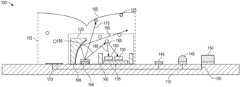
- FIG. 1shows a side view of an exemplary smoke detector system 100 , in accordance with some embodiments of the disclosure provided herein.
- Smoke detector system 100comprises chamber walls 115 , chamber cap 105 , optical module 190 , condensation sensor 170 , LEDs 165 , septum 160 , PDs 130 , AFE 135 , traces 155 , temperature sensor 140 , radiation sensor 145 , substrate 110 , and gas sensor 150 .
- chamber walls 115are bug screens or air vents which allow for ambient air flow but mitigate ambient light pollution.
- chamber walls 115 and chamber cap 105can be any of those described in U.S. patent application Ser. No. 16/206,268 entitled, “SMOKE DETECTOR CHAMBER BOUNDARY SURFACES” filed on Nov. 30, 2018, which is hereby incorporated by reference.
- chamber walls 115may be an array of optical blocking member whereby no direct ambient light may travel inside the smoke detection chamber.
- Chamber cap 105can be any suitable geometric shape which reflects light which isn't absorbed in a direction other than towards PDs 130 . This will become clearer once the operation has been discussed in greater detail later in the disclosure.
- Optical module 190serves a similar purpose to that of chamber cap 105 in that it is also a geometrical shape which redirects the light emitted from LEDs 165 .
- the exceptionis that optical module 190 reflects light to be in close proximity to PDs 130 to achieve a better signal to noise ration. This will also be discussed in greater detail later in the disclosure.
- optical module 190can have one or more optical coatings on their respective surfaces—either reflective or anti-reflective depending on the wavelength of the LEDs, the ambient light, and application.
- condensation sensor 170is a monolithic integrated micro-sensor for the detection of humidity.
- the modulesconsist of a silicon integrated stray field capacitor including condensation detection area, a temperature sensor as well as a capacity frequency converter.
- the componentsare mounted on substrate 110 .
- condensation sensor 170In practice, steam particles often produce false positives.
- An integrated condensation sensor 170would allow a user to compensate particle detection by steam exposure.
- condensation sensor 170is a capacitive strip line which can be printed into a printed circuit board (PCB), laminate, or substrate 110 . All humidity and condensate sensors are not beyond the scope of the present invention.
- one of LEDs 165is an off-the-shelf green (495 nm-570 nm) light emitting diode, with the other LEDs 165 having a longer wavelength, such as that in the infrared regime.
- any suitable, compact light producing deviceis not beyond the scope of the present disclosure—whether coherent, incandescent, or even thermal black-body radiation, etc.
- Septum 160is an opto-isolator which traverses the entire span between the LEDs 165 side and the photodetectors 130 side of the device, which will be explained in greater detail later in the disclosure.
- the function of the septumis to block light from being directly received by photodetectors 130 .
- septum 160are made from an opaque polymer and/or lossy material having a thickness much greater than the average skin depth, according to some embodiments of the present invention. High conductivity (mirrored) are also not beyond the scope of the present disclosure, however, this is not a preferred embodiment as will be clear later in the disclosure.
- Photodetectors (PDs) 130are sensors of light or other electromagnetic energy.
- photodetectors 130have p-n junctions that converts light photons into current. The absorbed photons make electron-hole pairs in the depletion region, which is used to detect received light intensity.
- photodetectors 130are photodiodes or phototransistors. However, any light detecting means, e.g., avalanche, photo-multiplier tube, etc. is not beyond the scope of the present disclosure.
- PDs 130can be modified to accommodate the detection thereof.
- PDs 130can be covered with different optical filters.
- photodetectors 130can be covered with dichroic filters, at least in part.
- a dichroic filter, thin-film filter, or interference filteris a very accurate color filter used to selectively pass light of a small range of colors while reflecting other colors.
- dichroic mirrors and dichroic reflectorstend to be characterized by the color(s) of light that they reflect, rather than the color(s) they pass.
- interference filtersare used in the present embodiment, other optical filters are not beyond the scope of the present invention, such as, interference, absorption, diffraction, grating, Fabry-Perot, etc.
- An interference filterconsists of multiple thin layers of dielectric material having different refractive indices. There also may be metallic layers.
- interference filterscomprise also etalons that could be implemented as tunable interference filters. Interference filters are wavelength-selective by virtue of the interference effects that take place between the incident and reflected waves at the thin-film boundaries.
- a plurality of detectorsis implemented, e.g., at least two for wavelength such that each of the pair of the plurality is wavelength specific. For example, there are at least two detectors (PD1, PD2) for every light emitting diode for a particular lambda.
- Analog front-end 135is a set of analog signal conditioning circuitry that uses sensitive analog amplifiers, operational amplifiers, filters, and application-specific integrated circuits as needed to interface with sensors to analog to digital converter and/or microcontroller.
- AFE 135is in electrical communication with photodetectors 130 , condensation sensor 170 , temperature sensor 140 , radiation sensor 145 , and gas sensor 150 via traces 155 through substrate 110 .
- photodetectors 130 , LEDs 165 and AFE 135are packed together and then assembled to a PCB with other associated sensors. However, in other embodiments, they are integrated at the wafer level communicating through traces and vertical interconnect access (VIA) or through silicon VIA (TSV).
- VIAvertical interconnect access
- TSVsilicon VIA
- AFE pin-outcan be in electrical communication with a microcontroller unit (MCU), field programmable gate array (FPGA), bus, or other computer platform, such as, PC or Raspberry Pi, etc.—all of which are not beyond the scope of the present disclosure.
- MCUmicrocontroller unit
- FPGAfield programmable gate array
- busor other computer platform, such as, PC or Raspberry Pi, etc.—all of which are not beyond the scope of the present disclosure.
- smoke detector system 100works as follows.
- Light raysphotons
- LEDs 165By way of example, light rays take disparate paths each of which are explained as follows.
- Light ray 195represents a light path which impinges on optical module 190 and gets reflected over the PDs 130 such that the area above PDs 130 have a higher concentration of light. This increases the smoke detector sensitivity by augmenting the SnR.
- Light ray 175is incident on dust particle(s) 125 adsorbed to chamber cap 105 .
- the material properties of chamber cap 105are suitably chosen such that light ray 175 is either absorbed by chamber cap 105 or reflected therefrom. In either event, neither are scattered back to PDs 130 . Finally, light ray 180 is scattered off of smoke particle(s) and receive by PDs 130 .
- the region marked by dashed box 120may represent a single optical module containing multiple LEDs 165 , multiple photodiodes 130 , AFE 135 to read all the sensors and store calibration data, and optical surfaces. This is used for optical isolation between photodiodes 130 and LEDs 165 as well as light directing surfaces to improve detection of smoke and reduce scattering from chamber walls.
- the commercially available Analog Devices ADPD188BI(Shown in FIG. 1 ) does contain septum separating LED and PD but does not contain curved optical surfaces to substantially redirect light towards smoke near the detector surface. It also reduces LED light radiated into regions that contribute to background from chamber wall. These regions are to also eschewed because they do not significant contribute measurement to scattering from smoke particles.
- FIG. 1simply represents a simple modification of ADPD188BI to improve performance.
- These curved surfacescan provide between two to three times the smoke signal while reducing the background signal from the chamber.
- Detailed ray-trace simulationshave been carried out by the inventor.
- the surfacetakes a form of ellipsoidal or off-axis paraboloid shape, in preferred embodiments.
- other embodimentsrepresent inverse or other mathematical functions are not beyond the scope of the present disclosure.
- the chamber designitself has been described in detail in the above identified patent application. It is designed to minimize back-reflection to the detector and consists of smooth mirror like surfaces with light being absorbed in the bulk of the material. With these chamber designs, an effective chamber reflection coefficient has been achieved which is comparable to the light scattered by low density of smoke particles that cause smoke alarm.
- AFE 135 shown in FIG. 1is one such AFE. While AFE 135 is shown as part of the optical PD and LED assembly, such an AFE may be separate and placed directly on the laminate or PCB and remain connected to all the sensors shown in FIG. 1 .
- the AFEis expected to measure synchronous LED light received by the photodetectors. Each LED is flashed, and the optical return is measured by one or two photodiodes. This allows measurement at one or more wavelengths and at one or more average angles of scattering. As is described herein, such measurements allow for smoke particle classification which is very useful in setting appropriate thresholds for smoke alarm as is often required by the regulations. Furthermore, this AFE is also expected to read capacitance changes from stripline as well as measure midwave infrared (MWIR) photodetectors, electrochemical cells, and temperature sensors.
- MWIRmidwave infrared
- FIG. 2illustrates light scattering in an exemplary smoke detector, in accordance with one or more embodiments of the disclosure provided herein.
- FIG. 2depicts a log plot of the light collected from the scattering by smoke particles.
- FIG. 2also illustrates an exemplary packaged smoke detector 210 complete with bond pad wiring and optical covers, in accordance with one or more embodiments of the disclosure provided herein.
- relative signal strengthsare measured as a function of the scattering angle 220 , 230 , 240 .
- the chamber designshave yielded optical power transfer ratio (PTR) of ⁇ 0.1-1 nW of received power for a mW of LED power.
- PTRoptical power transfer ratio
- Typical smoke PTRs at the alarm thresholdare also in the range of 0.1-1 nW/mW.
- this geometrical arrangementprovides the benefit of measuring dust accumulation while barely changing smoke sensitivity until some critical level of dust is formed. At that point, software can sound an alarm specifically suggesting need for cleaning or replacing the detector system. This critical level of dust may be determined empirically and simply stored as part of the alarm system.
- FIG. 3demonstrates how to account for dust and other slowly varying changes, in accordance with some embodiments of the disclosure provided herein.
- the accumulation of dust represented as D in FIG. 3may be used to correct the LED and PD's transfer functions, change the software alarm thresholds, or simply used to detect the critical dust level beyond which the performance of the system is not guaranteed.
- measurement of dust D as described in FIG. 3will be different at the two or more wavelengths and it will be wavelength dependent. Thus, it can be used to assess the type of dust or scattering material on the chamber walls. This in turn can inform us about the quality of all optical surfaces assuming similar rates of deposition and inform the software about setting critical levels of D. This critical dust level and the changes in the PTR of the smoke and the chamber over time are shown in FIG. 4 .
- FIG. 4graphically illustrates dust measurement in a smoke chamber as a function of time, in accordance with some embodiments of the disclosure provided herein.
- at least two LED wavelengthsallows us to measure chamber scattering including dust as well as smoke and both the “DC” and the “AC” values of the PTR at two or more wavelengths.
- a simple ratiomay be formed but for more wavelengths, one may use Mie scattering as a guide in making combination functions of ratios of different LED wavelengths that allow for easy smoke classification.
- a further advantagecan be gained by having more than one detector.
- APDP188BIhas the capacity to measure scattered signal separately on the two detectors of unequal areas with area ratio of 2. Since these PDs are at different distances from the LED, each PD receives a different average angle of scattering and light intensity from the smoke particles. But the average angle of scattering from the chamber walls as well as intensity received from the walls are roughly the same which makes the signals almost exactly proportional to the PD area.
- the chamber signal(whether “DC” or “AC”) is directly proportional to the geometrical area while the signal from the smoke has a complex dependence that depends on the relative positions of PDs with respect to the LED and the three-dimensional optical intensity profile above the LED and PDs as well as on the type of smoke particle. Since scattering theory allows one the possibility to do smoke classification, using either wavelength or angles is possible. The two effective angles of scattering correspond to the two detectors.
- FIG. 4shows a module that is specifically designed with two PDs with substantially different scattering angles.
- a d1 or A d2are the areas of the PD d 1 or d 2
- ⁇ (S)is angle and smoke type “S” dependent factor for each of the wavelengths. This immediately suggests that for ⁇ (S) is substantially different than unity, and one can solve for the smoke and the chamber PTR ratios.
- This parameter Dwill be different for each wavelength and depending on the chamber design, slightly different for each detector.
- Eq. 3 and Eq. 4can be combined to determine ⁇ (S).
- the ration R ⁇ dis the wavelength ratio when output of both detectors is combined. From the measured dust parameters D, ⁇ ⁇ (S) at two or more wavelengths and the ratios R, both the state of the chamber—amount of dust, changes in reflectance from grime etc.—and type of smoke and amplitude of scattering from smoke can be found.
- a dipole field between the strip linesallows one to measure the presence of water between the strip lines by changes in the capacitance.
- Waterhas a high dielectric constant of around 70 (at low frequencies used in this case) and thus formation of liquid water on a PCB surface will immediately modify the electric field and consequently capacitance.
- condensation and steamcan easily create very confusing optical measurements.
- Condensing watermay form a thin film (and mix with dust already present) or form droplets on the chamber walls or on other optics. This creates strong scattering from the chamber walls which will be changing on the time scale as scattering from the steam droplets. This may make the idea of rejecting this strong scattering signal as not from smoke with high degree of confidence very difficult.
- the auxiliary strip line measurement of condensing waterone can correlate the changes in the optical signal with steam. Software can then determine to not sound an alarm and reduce false alarm rate from steam.
- the AFEmay also provide an easy means to measure electric current that flows from electrochemical cells (EC).
- ECelectrochemical cells
- One of the most popular ECis the one used to measure CO. It is well known that incomplete combustion in fire causes elevated levels of CO. If the smoke detector happens to have a line of sight to the hot surface caused by fire or to fire itself, then a photodetector can measure the blackbody radiation coming from hot (300-1000 C) surfaces. This radiation will predominantly increase in the 3-7 ⁇ m region of EM radiation (often called the mid-wave infrared region or MWIR). Such an IR measuring photodetector can provide additional direct measurement of the existence of fire in the surroundings.
- AFEmay also measure conventional temperature sensors which can provide data on changes in the air temperature.
- All the above sensorsare read out to provide a comprehensive view of the environment in order to provide an accurate alarm for fire while reducing probability of false alarm.
- the AFEcan be programmed to repeat the following sequence: (1) blink LED 1 and measure response to two detectors, (2) blink LED 2 and measure response of two detectors, (3) measure strip line, (4) measure one or more temperature sensors, (5) measure CO sensor, (6) measure one or more IR sensors pointed in different directions, etc.
- the same AFEcan be configured to make all these measurements.
- One such AFE and its architectureis discussed in U.S. Pat. No. 9,733,275, which is hereby incorporated by reference. Some of the sensors may be measured more often than the others depending on the algorithmic need to provide most accurate alarm and conserve battery.
- a microprocessor attached to the AFEcan analyze the data according to the method presented here and form a good judgement on the amount and type of smoke, accumulation of dust, and presence of steam. It can also correlate these parameters with other environmental parameters such as sudden increase in MWIR radiation or sudden changes in air temperature.
- a smoldering firecan generate copious amounts of CO, while producing little smoke and CO measuring sensor can provide warning about the fire.
- CO detectorsare relatively common as part of the smoke alarm system, they are usually read by separate AFE which leads to increased cost and footprint of the smoke detector assembly.
- FIG. 5demonstrates the detection and measurement of water within the exemplary fire detection system, in accordance with some embodiments of the disclosure provided herein.
- condensation sensor 500comprises PCB 560 , dielectric coating 570 and electrodes 530 , 540 .
- Electrodes 530 , 540can be single capacitive elements suitable for detecting the presence of moisture. However, in the present embodiment, electrodes 530 , 540 are dipole capacitive elements. In operation, varying electrical fields 520 can be measured and determined.
- condensation sensor 510comprises PCB 560 , dielectric coating 570 and electrodes 530 , 540 .
- Electrodes 530 , 540measure changes in the electric field 520 in the presence of water and/or steam. As can be appreciated by one skilled in the art, the capacitive change is significant and readily detectable.
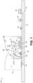
- FIG. 6depicts the orthogonal view of an optical deflector comprised by an exemplary fire detector 600 , in accordance with some embodiments of the disclosure provided herein.
- Smoke detector 600comprises optical module 610 , LEDs 620 , septum 630 , PDs 650 , 660 , AFE 640 , disposed on a PCB, laminate or other suitable substrate.
- the PHOSITAwill appreciate that they may readily use the present disclosure as a basis for designing or modifying other processes, structures, or variations for carrying out the same purposes and/or achieving the same advantages of the embodiments introduced herein.
- the PHOSITAwill also recognize that such equivalent constructions do not depart from the spirit and scope of the present disclosure, and that they may make various changes, substitutions, and alterations herein without departing from the spirit and scope of the present disclosure.
- One or more aspects and embodiments of the present application involving the performance of processes or methodsmay utilize program instructions executable by a device (e.g., a computer, a processor, or other device) to perform, or control performance of, the processes or methods.
- a devicee.g., a computer, a processor, or other device
- inventive conceptsmay be embodied as a computer readable storage medium (or multiple computer readable storage media) (e.g., a computer memory, one or more floppy discs, compact discs, optical discs, magnetic tapes, flash memories, circuit configurations in Field Programmable Gate Arrays or other semiconductor devices, or other tangible computer storage medium) encoded with one or more programs that, when executed on one or more computers or other processors, perform methods that implement one or more of the various embodiments described above.
- a computer readable storage mediume.g., a computer memory, one or more floppy discs, compact discs, optical discs, magnetic tapes, flash memories, circuit configurations in Field Programmable Gate Arrays or other semiconductor devices, or other tangible computer storage medium
- the computer readable medium or mediamay be transportable, such that the program or programs stored thereon may be loaded onto one or more different computers or other processors to implement various ones of the aspects described above.
- computer readable mediamay be non-transitory media.
- teachings of the present disclosuremay be encoded into one or more tangible, non-transitory computer-readable mediums having stored thereon executable instructions that, when executed, instruct a programmable device (such as a processor or DSP) to perform the methods or functions disclosed herein.
- a programmable devicesuch as a processor or DSP
- a non-transitory mediumcould include a hardware device hardware-programmed with logic to perform the methods or functions disclosed herein.
- the teachingscould also be practiced in the form of Register Transfer Level (RTL) or other hardware description language such as VHDL or Verilog, which can be used to program a fabrication process to produce the hardware elements disclosed.
- RTLRegister Transfer Level
- VHDLVerilog
- processing activities outlined hereinmay also be implemented in software.
- one or more of these featuresmay be implemented in hardware provided external to the elements of the disclosed figures, or consolidated in any appropriate manner to achieve the intended functionality.
- the various componentsmay include software (or reciprocating software) that can coordinate in order to achieve the operations as outlined herein.
- these elementsmay include any suitable algorithms, hardware, software, components, modules, interfaces, or objects that facilitate the operations thereof.
- Any suitably-configured processor componentcan execute any type of instructions associated with the data to achieve the operations detailed herein.
- Any processor disclosed hereincould transform an element or an article (for example, data) from one state or thing to another state or thing.
- some activities outlined hereinmay be implemented with fixed logic or programmable logic (for example, software and/or computer instructions executed by a processor) and the elements identified herein could be some type of a programmable processor, programmable digital logic (for example, an FPGA, an erasable programmable read only memory (EPROM), an electrically erasable programmable read only memory (EEPROM)), an ASIC that includes digital logic, software, code, electronic instructions, flash memory, optical disks, CD-ROMs, DVD ROMs, magnetic or optical cards, other types of machine-readable mediums suitable for storing electronic instructions, or any suitable combination thereof.
- EPROMerasable programmable read only memory
- EEPROMelectrically erasable programmable read only memory
- processorsmay store information in any suitable type of non-transitory storage medium (for example, random access memory (RAM), read only memory (ROM), FPGA, EPROM, electrically erasable programmable ROM (EEPROM), etc.), software, hardware, or in any other suitable component, device, element, or object where appropriate and based on particular needs.
- RAMrandom access memory
- ROMread only memory
- FPGAfield-programmable gate array
- EPROMelectrically erasable programmable ROM
- EEPROMelectrically erasable programmable ROM
- any of the memory items discussed hereinshould be construed as being encompassed within the broad term ‘memory.’
- any of the potential processing elements, modules, and machines described hereinshould be construed as being encompassed within the broad term ‘microprocessor’ or ‘processor.’
- the processors, memories, network cards, buses, storage devices, related peripherals, and other hardware elements described hereinmay be realized by a processor, memory, and other related devices configured by software or firmware to emulate or virtualize the functions of those hardware elements.
- a computermay be embodied in any of a number of forms, such as a rack-mounted computer, a desktop computer, a laptop computer, or a tablet computer, as non-limiting examples. Additionally, a computer may be embedded in a device not generally regarded as a computer but with suitable processing capabilities, including a personal digital assistant (PDA), a smart phone, a mobile phone, an iPad, or any other suitable portable or fixed electronic device.
- PDApersonal digital assistant
- a computermay have one or more input and output devices. These devices can be used, among other things, to present a user interface. Examples of output devices that may be used to provide a user interface include printers or display screens for visual presentation of output and speakers or other sound generating devices for audible presentation of output. Examples of input devices that may be used for a user interface include keyboards, and pointing devices, such as mice, touch pads, and digitizing tablets. As another example, a computer may receive input information through speech recognition or in other audible formats.
- Such computersmay be interconnected by one or more networks in any suitable form, including a local area network or a wide area network, such as an enterprise network, and intelligent network (IN) or the Internet.
- networksmay be based on any suitable technology and may operate according to any suitable protocol and may include wireless networks or wired networks.
- Computer-executable instructionsmay be in many forms, such as program modules, executed by one or more computers or other devices.
- program modulesinclude routines, programs, objects, components, data structures, etc. that performs particular tasks or implement particular abstract data types.
- functionality of the program modulesmay be combined or distributed as desired in various embodiments.
- programor “software” are used herein in a generic sense to refer to any type of computer code or set of computer-executable instructions that may be employed to program a computer or other processor to implement various aspects as described above. Additionally, it should be appreciated that according to one aspect, one or more computer programs that when executed perform methods of the present application need not reside on a single computer or processor, but may be distributed in a modular fashion among a number of different computers or processors to implement various aspects of the present application.
- data structuresmay be stored in computer-readable media in any suitable form.
- data structuresmay be shown to have fields that are related through location in the data structure. Such relationships may likewise be achieved by assigning storage for the fields with locations in a computer-readable medium that convey relationship between the fields.
- any suitable mechanismmay be used to establish a relationship between information in fields of a data structure, including through the use of pointers, tags or other mechanisms that establish relationship between data elements.
- the software codeWhen implemented in software, the software code may be executed on any suitable processor or collection of processors, whether provided in a single computer or distributed among multiple computers.
- Computer program logic implementing all or part of the functionality described hereinis embodied in various forms, including, but in no way limited to, a source code form, a computer executable form, a hardware description form, and various intermediate forms (for example, mask works, or forms generated by an assembler, compiler, linker, or locator).
- source codeincludes a series of computer program instructions implemented in various programming languages, such as an object code, an assembly language, or a high-level language such as OpenCL, RTL, Verilog, VHDL, Fortran, C, C++, JAVA, or HTML for use with various operating systems or operating environments.
- the source codemay define and use various data structures and communication messages.
- the source codemay be in a computer executable form (e.g., via an interpreter), or the source code may be converted (e.g., via a translator, assembler, or compiler) into a computer executable form.
- any number of electrical circuits of the FIGURESmay be implemented on a board of an associated electronic device.
- the boardcan be a general circuit board that can hold various components of the internal electronic system of the electronic device and, further, provide connectors for other peripherals. More specifically, the board can provide the electrical connections by which the other components of the system can communicate electrically.
- Any suitable processors(inclusive of digital signal processors, microprocessors, supporting chipsets, etc.), memory elements, etc. can be suitably coupled to the board based on particular configuration needs, processing demands, computer designs, etc.
- FIGURESmay be implemented as standalone modules (e.g., a device with associated components and circuitry configured to perform a specific application or function) or implemented as plug-in modules into application-specific hardware of electronic devices.
- some aspectsmay be embodied as one or more methods.
- the acts performed as part of the methodmay be ordered in any suitable way. Accordingly, embodiments may be constructed in which acts are performed in an order different than illustrated, which may include performing some acts simultaneously, even though shown as sequential acts in illustrative embodiments.
- references to “A and/or B”, when used in conjunction with open-ended language such as “comprising”may refer, in one embodiment, to A only (optionally including elements other than B); in another embodiment, to B only (optionally including elements other than A); in yet another embodiment, to both A and B (optionally including other elements); etc.
- the phrase “at least one,” in reference to a list of one or more elements,should be understood to mean at least one element selected from any one or more of the elements in the list of elements, but not necessarily including at least one of each and every element specifically listed within the list of elements and not excluding any combinations of elements in the list of elements.
- This definitionalso allows that elements may optionally be present other than the elements specifically identified within the list of elements to which the phrase “at least one” refers, whether related or unrelated to those elements specifically identified.
- “at least one of A and B”may refer, in one embodiment, to at least one, optionally including more than one, A, with no B present (and optionally including elements other than B); in another embodiment, to at least one, optionally including more than one, B, with no A present (and optionally including elements other than A); in yet another embodiment, to at least one, optionally including more than one, A, and at least one, optionally including more than one, B (and optionally including other elements); etc.
- the term “between”is to be inclusive unless indicated otherwise.
- “between A and B”includes A and B unless indicated otherwise.
Landscapes
- Physics & Mathematics (AREA)
- General Physics & Mathematics (AREA)
- Analytical Chemistry (AREA)
- Chemical & Material Sciences (AREA)
- Biochemistry (AREA)
- Immunology (AREA)
- Health & Medical Sciences (AREA)
- Life Sciences & Earth Sciences (AREA)
- Pathology (AREA)
- General Health & Medical Sciences (AREA)
- Business, Economics & Management (AREA)
- Emergency Management (AREA)
- Spectroscopy & Molecular Physics (AREA)
- Engineering & Computer Science (AREA)
- Computer Security & Cryptography (AREA)
- Mathematical Physics (AREA)
- Theoretical Computer Science (AREA)
- Fire-Detection Mechanisms (AREA)
- Investigating Or Analysing Materials By Optical Means (AREA)
Abstract
Description
- (a) a small optical reflection—even though it presents a large surface area and is very close to the module—comparable to that from the smoke. This persistent reflection provides positive test that the system is working. As is shown, this also allows us to measure slow dust accumulation on the chamber surfaces over time and thus provide warning that more than a critical level of dust may have accumulated impairing the smoke alarm function;
- (b) a place to hold bug-screen or may have bug-screen molded into it; and,
- (c) provide significant attenuation of ambient light while allowing smoke to enter the chamber.
- (a) temperature sensor to provide temperature measurement—perhaps more than one pointed in different directions;
- (b) a water condensation sensor that warns of condensing humidity especially from a large volume of steam coming from a bathroom after shower;
- (c) an electrochemical or an optical gas sensor to measure concentration of CO and other gases; and,
- (d) other sensors such as pressure, humidity etc.
PTRd1λ1(t)=PTRd1λ1chamber(t)+PTRd1λ1smoke(t)
PTRd2λ1(t)=PTRd2λ1chamber(t)+PTRd2λ1smoke(t) Eq. 1
But we know that:
PTRsmoke(t)=PTR(t)−


D=
- “comprise,” “comprising,” and the like are to be construed in an inclusive sense, as opposed to an exclusive or exhaustive sense; that is to say, in the sense of “including, but not limited to”.
- “connected,” “coupled,” or any variant thereof, means any connection or coupling, either direct or indirect, between two or more elements; the coupling or connection between the elements can be physical, logical, or a combination thereof.
- “herein,” “above,” “below,” and words of similar import, when used to describe this specification shall refer to this specification as a whole and not to any particular portions of this specification.
- “or,” in reference to a list of two or more items, covers all of the following interpretations of the word: any of the items in the list, all of the items in the list, and any combination of the items in the list.
- the singular forms “a”, “an” and “the” also include the meaning of any appropriate plural forms.
Claims (23)
Priority Applications (2)
| Application Number | Priority Date | Filing Date | Title |
|---|---|---|---|
| US16/699,677US12211370B2 (en) | 2018-12-02 | 2019-12-01 | Fire detection system |
| CN202010151441.7ACN111665200B (en) | 2019-03-06 | 2020-03-06 | Stable measurement of sensor methods and systems |
Applications Claiming Priority (2)
| Application Number | Priority Date | Filing Date | Title |
|---|---|---|---|
| US201862774305P | 2018-12-02 | 2018-12-02 | |
| US16/699,677US12211370B2 (en) | 2018-12-02 | 2019-12-01 | Fire detection system |
Publications (2)
| Publication Number | Publication Date |
|---|---|
| US20200175848A1 US20200175848A1 (en) | 2020-06-04 |
| US12211370B2true US12211370B2 (en) | 2025-01-28 |
Family
ID=70850341
Family Applications (1)
| Application Number | Title | Priority Date | Filing Date |
|---|---|---|---|
| US16/699,677ActiveUS12211370B2 (en) | 2018-12-02 | 2019-12-01 | Fire detection system |
Country Status (1)
| Country | Link |
|---|---|
| US (1) | US12211370B2 (en) |
Families Citing this family (8)
| Publication number | Priority date | Publication date | Assignee | Title |
|---|---|---|---|---|
| US10921367B2 (en)* | 2019-03-06 | 2021-02-16 | Analog Devices, Inc. | Stable measurement of sensors methods and systems |
| US11913864B2 (en)* | 2020-11-24 | 2024-02-27 | Pixart Imaging Inc. | Smoke detector with increased scattered light intensity |
| US11615684B2 (en)* | 2020-11-24 | 2023-03-28 | Pixart Imaging Inc. | Smoke detector |
| GB202113796D0 (en)* | 2021-09-27 | 2021-11-10 | Ams Ag | Minaturized particulate matter sensor |
| CN115985037B (en)* | 2022-12-05 | 2024-10-22 | 郑州海为电子科技有限公司 | Detection method of smoke sensor based on alternating current coupling AFE circuit design |
| WO2024141778A1 (en)* | 2022-12-28 | 2024-07-04 | Bosch Security Systems - Sistemas De Segurança, S.A | Method and smoke detector arranged to detect a gas or gases released in an ambient by a sanitation procedure |
| WO2025090129A1 (en)* | 2023-10-25 | 2025-05-01 | Microchip Technology Incorporated | Proximity detection for life safety devices |
| CN118629184B (en)* | 2024-08-01 | 2025-02-11 | 罗定市宝捷电子有限公司 | A smoke alarm testing method and device |
Citations (132)
| Publication number | Priority date | Publication date | Assignee | Title |
|---|---|---|---|---|
| US3488492A (en) | 1968-03-28 | 1970-01-06 | Honeywell Inc | Directional radiation sensing apparatus |
| US4004146A (en) | 1975-04-15 | 1977-01-18 | H. Maihak A.G. | Infrared gas analyzing photometer with chopper designed to avoid radiation waste |
| US4075614A (en) | 1976-06-16 | 1978-02-21 | White Donald A | Christmas tree fire detector and alarm |
| GB2000282A (en) | 1977-06-27 | 1979-01-04 | Nittan Co Ltd | Light scattering smoke detector |
| US4148022A (en) | 1977-04-28 | 1979-04-03 | Honeywell Inc. | Chemical smoke or pollutant detector |
| US4181439A (en)* | 1976-04-01 | 1980-01-01 | Cerberus Ag | Smoke detector with a conical ring-shaped radiation region |
| US4238679A (en) | 1978-12-07 | 1980-12-09 | Conrac Corporation | Dual-chamber ionization smoke detector assembly |
| US4306230A (en) | 1979-12-10 | 1981-12-15 | Honeywell Inc. | Self-checking photoelectric smoke detector |
| USD269161S (en) | 1981-03-25 | 1983-05-31 | Pittway Corporation | Smoke detector |
| US4430646A (en) | 1980-12-31 | 1984-02-07 | American District Telegraph Company | Forward scatter smoke detector |
| USRE32105E (en) | 1980-12-31 | 1986-04-01 | American District Telegraph Company | Forward scatter smoke detector |
| USD283989S (en) | 1984-08-09 | 1986-05-27 | Laurence Chen | Heat collector for smoke alarm |
| USD284272S (en) | 1984-08-09 | 1986-06-17 | Laurence Chen | Ionization chamber for a smoke detector |
| US4618771A (en) | 1983-11-14 | 1986-10-21 | Beckman Industrial Corporation | Non-dispersive infrared analyzer having improved infrared source and detecting assemblies |
| US4728801A (en) | 1985-01-31 | 1988-03-01 | Thorn Emi Protech Limited | Light scattering smoke detector having conical and concave surfaces |
| USD297318S (en) | 1986-08-06 | 1988-08-23 | Dicon Systems Limited | Smoke detector chamber |
| US4857895A (en) | 1987-08-31 | 1989-08-15 | Kaprelian Edward K | Combined scatter and light obscuration smoke detector |
| US4906978A (en) | 1986-12-24 | 1990-03-06 | Cerberus Ag | Optical smoke detector |
| USD328875S (en) | 1990-10-30 | 1992-08-25 | C & K Systems, Inc. | Infrared detector mirror |
| US5181439A (en) | 1988-08-02 | 1993-01-26 | Schwartz Jimmy R | Communicative tools and fasteners |
| GB2270157A (en) | 1992-08-28 | 1994-03-02 | Hochiki Co | Light scattering type smoke detector |
| US5351034A (en) | 1990-09-05 | 1994-09-27 | Esser Sicherheitstechnik Gmbh | Fire detector |
| US5381130A (en) | 1991-09-06 | 1995-01-10 | Cerberus Ag | Optical smoke detector with active self-monitoring |
| US5382341A (en) | 1992-09-10 | 1995-01-17 | Aroutiounian; Vladimir M. | Method of making smoke detector |
| US5400014A (en) | 1993-07-12 | 1995-03-21 | Detection Systems, Inc. | Smoke detector with dark chamber |
| US5420440A (en)* | 1994-02-28 | 1995-05-30 | Rel-Tek Corporation | Optical obscruation smoke monitor having a shunt flow path located between two access ports |
| US5444249A (en) | 1994-02-14 | 1995-08-22 | Telaire Systems, Inc. | NDIR gas sensor |
| US5451931A (en) | 1992-09-14 | 1995-09-19 | Cerberus Ag | Optical smoke detector |
| US5497144A (en) | 1993-07-07 | 1996-03-05 | Cerberus Ag | Testing and adjustment of scattered-light smoke detectors |
| US5568129A (en)* | 1994-09-08 | 1996-10-22 | Sisselman; Ronald | Alarm device including a self-test reminder circuit |
| USD382217S (en) | 1996-02-02 | 1997-08-12 | Nittan Company, Limited | Fire detector |
| JPH09229858A (en) | 1996-02-20 | 1997-09-05 | Horiba Ltd | Infrared gas analyzer |
| US5689114A (en) | 1995-04-28 | 1997-11-18 | Jasco Corporation | Gas analyzing apparatus |
| US5781291A (en) | 1996-10-22 | 1998-07-14 | Pittway Corporation | Smoke detectors utilizing a hydrophilic substance |
| GB2327752A (en) | 1997-07-26 | 1999-02-03 | Rafiki Protection Limited | Calibrating smoke detector |
| EP0896216A2 (en) | 1997-08-04 | 1999-02-10 | Texas Instruments Incorporated | Method and apparatus for infrared sensing of gas |
| USD407033S (en) | 1996-09-20 | 1999-03-23 | Mw International Ltd. | Thief protecting alarm tag for goods in shops |
| WO1999014576A2 (en) | 1997-09-17 | 1999-03-25 | Oridion Medical Ltd. | Isotopic gas analyzer |
| US5966077A (en) | 1996-01-29 | 1999-10-12 | Engelhard Sensor Technologies Inc. | Fire detector |
| US5973326A (en) | 1996-08-10 | 1999-10-26 | Eev Limited | Gas monitors |
| USD434686S (en) | 1999-06-08 | 2000-12-05 | Philip Denman | Security unit |
| US6194735B1 (en) | 1996-08-28 | 2001-02-27 | Martin Hans Goeran Evald | Gas sensor |
| US6225910B1 (en) | 1999-12-08 | 2001-05-01 | Gentex Corporation | Smoke detector |
| US20010038338A1 (en) | 1999-12-08 | 2001-11-08 | Kadwell Brian J. | Compact particle sensor |
| WO2001095279A1 (en) | 1999-03-05 | 2001-12-13 | Brk Brands, Inc. | Ultra-short wavelength photoelectric smoke detector |
| US6396405B1 (en) | 1993-08-19 | 2002-05-28 | General Electric Corporation | Automatic verification of smoke detector operation within calibration limits |
| JP2002162626A (en) | 2000-11-22 | 2002-06-07 | Sony Corp | Heat radiating device of light source for liquid crystal display and its manufacturing method |
| US20020089426A1 (en) | 2001-01-09 | 2002-07-11 | Simplexgrinnell Lp | Smoke chamber |
| US6476910B1 (en) | 2000-08-29 | 2002-11-05 | The Regents Of The University Of California | Light scattering apparatus and method for determining radiation exposure to plastic detectors |
| US6521907B1 (en) | 1999-04-29 | 2003-02-18 | Pittway Corporation | Miniature photoelectric sensing chamber |
| US20030058117A1 (en) | 2001-09-21 | 2003-03-27 | Hoichiki Corporation | Fire sensor |
| US20030209670A1 (en) | 2002-05-13 | 2003-11-13 | Precision Instrument Development Center, National Science Council | Sensitivity adjusting equipment of photoelectric smoke detector |
| KR20040021772A (en) | 2002-09-04 | 2004-03-11 | 삼성전자주식회사 | Non-volatile memory device having dummy pattern |
| US20040063154A1 (en) | 2002-08-23 | 2004-04-01 | Booth David K. | Rapidly responding, false detection immune alarm signal producing smoke detector |
| US20040072535A1 (en)* | 2002-07-19 | 2004-04-15 | Mestek, Inc. | Air circulation system |
| US6756905B2 (en) | 1999-12-31 | 2004-06-29 | Digital Security Controls Ltd. | Photoelectric smoke detector and chamber therefor |
| GB2397122A (en) | 2003-01-03 | 2004-07-14 | David Appleby | Smoke detector with a low false alarm rate |
| US20040188598A1 (en) | 2003-03-25 | 2004-09-30 | Sharp Kabushiki Kaisha | Optoelectronic dust sensor and air conditioning equipment in which such optoelectronic dust sensor is installed |
| US20050077489A1 (en) | 2003-10-09 | 2005-04-14 | Knapp David J. | Liquid filled conformal windows and domes |
| US20050173638A1 (en) | 2002-05-27 | 2005-08-11 | Kidde Ip Holdings Limited | Smoke detector |
| US20070013883A1 (en)* | 2005-07-15 | 2007-01-18 | Park Il-Jung | Semiconductor manufacturing device and particle monitoring method |
| US7248173B2 (en) | 2004-04-21 | 2007-07-24 | Nittan Company, Limited | Smoke detector |
| US20070221848A1 (en) | 1995-08-03 | 2007-09-27 | Johnson Edward A | Infrared radiation sources, sensors and source combinations, and methods of manufacture |
| US20070242269A1 (en) | 2004-03-06 | 2007-10-18 | Michael Trainer | Methods and apparatus for determining characteristics of particles |
| US20080246623A1 (en) | 2003-11-17 | 2008-10-09 | Tetsuya Nagashima | Light Scattering Type Smoke Detector |
| US20080258903A1 (en) | 2007-04-22 | 2008-10-23 | Kevin Le | Multifunctional Powerline Sensor Network |
| US20080266558A1 (en) | 2002-06-20 | 2008-10-30 | Siemens Building Technologies Ag | Scattered Light Smoke Detector |
| US20080316489A1 (en) | 2003-12-20 | 2008-12-25 | Ronny Ludwig | Gas Sensor |
| US20090213380A1 (en) | 2008-02-21 | 2009-08-27 | Dirk Appel | Gas analyzer system |
| US20090235720A1 (en) | 2006-02-06 | 2009-09-24 | Gas Sensing Solutions Limited | Dome Gas Sensor |
| US20090268204A1 (en) | 2008-04-24 | 2009-10-29 | Bah Holdings Llc | Optical absorption gas analyser |
| US7806085B1 (en) | 2007-03-17 | 2010-10-05 | Jude Michael Waddy | P.E.T. PT -pet exercise toy physical therapy |
| JP2011014593A (en) | 2009-06-30 | 2011-01-20 | Hitachi High-Technologies Corp | Led light source, its manufacturing method, and led-based photolithography apparatus and method source |
| US20110042570A1 (en) | 2009-08-21 | 2011-02-24 | Airware, Inc. | Absorption Biased NDIR Gas Sensing Methodology |
| US20110149198A1 (en) | 2009-12-23 | 2011-06-23 | Youngmin Kim | Display device |
| US20110178420A1 (en) | 2010-01-18 | 2011-07-21 | Trent Ridder | Methods and apparatuses for improving breath alcohol testing |
| DE102010031139A1 (en) | 2010-07-09 | 2012-01-12 | Robert Bosch Gmbh | Fire alarm device i.e. fire alarm, for installation at e.g. wall in closed room of e.g. building for detecting combustion gas and combustion gas particles, has discharge opening arranged within protective cap that exhibits openings |
| USD653578S1 (en) | 2011-02-09 | 2012-02-07 | Robert Bosch Gmbh | Detector |
| US20120135405A1 (en)* | 2009-05-26 | 2012-05-31 | Invitrox, Inc | Instrument and method for optical particle sensing |
| US20120140231A1 (en)* | 2009-05-01 | 2012-06-07 | Xtrails Technologies Ltd | particle detectors |
| US8232885B2 (en) | 2008-10-01 | 2012-07-31 | Nohmi Bosai Ltd. | Photoelectric smoke detector |
| EP2492882A1 (en) | 2011-02-28 | 2012-08-29 | Hager Controls | Device for detecting obstacles concealing a smoke detector |
| TW201237811A (en) | 2011-03-11 | 2012-09-16 | Panasonic Corp | Smoke detector |
| US20120267532A1 (en) | 2010-01-21 | 2012-10-25 | Cambridge Cmos Sensors Limited | Ir emitter and ndir sensor |
| KR20120130957A (en) | 2011-05-24 | 2012-12-04 | 엘지이노텍 주식회사 | Light emitting device package |
| US20130008787A1 (en) | 2010-01-21 | 2013-01-10 | Hochiki Corporation | Detector |
| TWD151506S (en) | 2011-12-19 | 2013-01-21 | 陳秀瑛; | Frameless impeller |
| US20130051062A1 (en) | 2011-08-30 | 2013-02-28 | Song Eun Lee | Light emitting module and backlight unit having the same |
| US20130071290A1 (en) | 2006-04-13 | 2013-03-21 | Quantum Group, Inc. | Carbon monoxide sensor system and related methods |
| US20130135607A1 (en) | 2011-11-25 | 2013-05-30 | Gerd WEDLER | Scattered radiation fire detector and method for the automatic detection of a fire situation |
| US20130286393A1 (en)* | 2012-04-29 | 2013-10-31 | Matthew Erdtmann | Smoke detector utilizing broadband light |
| US20140070101A1 (en) | 2011-04-11 | 2014-03-13 | Panasonic Corporation | Gas component detection device |
| US20140168647A1 (en)* | 2012-12-18 | 2014-06-19 | Excelitas Canada, Inc. | Integrated smoke cell |
| US8970387B2 (en) | 2010-04-21 | 2015-03-03 | Sprue Safety Products Ltd. | Smoke detector |
| DE202015000820U1 (en) | 2014-12-01 | 2015-03-04 | Siemens Schweiz Ag | Scattered light smoke detector with two two-color LEDs and a common photosensor or with a two-color LED and with two photosensors each in a forward and backward scattering light arrangement |
| US9013317B2 (en) | 2010-04-21 | 2015-04-21 | Sprue Safety Products Ltd. | Optical smoke detector |
| US20150129767A1 (en) | 2013-11-11 | 2015-05-14 | General Electric Company | Optical gas sensor |
| US20150219491A1 (en) | 2014-02-03 | 2015-08-06 | Korea National University Of Transportation Industry-Academic Cooperation Foundation | Optical wave guide having multiple independent optical path and optical gas sensor using that |
| US9140646B2 (en) | 2012-04-29 | 2015-09-22 | Valor Fire Safety, Llc | Smoke detector with external sampling volume using two different wavelengths and ambient light detection for measurement correction |
| US9164735B2 (en) | 2012-09-27 | 2015-10-20 | Intel Corporation | Enabling polymorphic objects across devices in a heterogeneous platform |
| US20150300938A1 (en) | 2014-04-21 | 2015-10-22 | Buglab Llc | Particle Sensor with Interferent Discrimination |
| US9196141B1 (en) | 2015-05-15 | 2015-11-24 | Google, Inc. | Smoke detector chamber |
| US20150377711A1 (en) | 2014-06-26 | 2015-12-31 | MP High Tech Solutions Pty Ltd | Apparatus and method for electromagnetic radiation sensing |
| US20160033307A1 (en) | 2014-08-04 | 2016-02-04 | Kabushiki Kaisha Topcon | Angle detection device and survey instrument including the same |
| US20160042638A1 (en)* | 2014-08-05 | 2016-02-11 | Google Inc. | Systems and methods for compensating for sensor drift in a hazard detection system |
| US9267885B2 (en) | 2010-09-14 | 2016-02-23 | Finsecur | Smoke detection circuit, smoke detector comprising said circuit and alarm device comprising both the circuit and the detector |
| US20160153905A1 (en) | 2014-12-01 | 2016-06-02 | Siemens Schweiz Ag | Scattered-Light Smoke Detector With A Two-Color Light-Emitting Diode |
| WO2016150613A1 (en) | 2015-03-23 | 2016-09-29 | Siemens Schweiz Ag | Fire detector with a scattered light arrangement in the region of a smoke inlet opening for monitoring pollution |
| US9459208B2 (en) | 2013-10-04 | 2016-10-04 | Tyco Fire & Security Gmbh | Duct detector with remote airflow test capability |
| USD769756S1 (en) | 2014-01-30 | 2016-10-25 | Cavius Aps | Heat detector |
| WO2016186884A1 (en) | 2015-05-15 | 2016-11-24 | Google Inc. | Smoke detector chamber architecture and related methods |
| CN205786299U (en) | 2016-05-18 | 2016-12-07 | 宁波科赛迪电子科技有限公司 | A kind of labyrinth of smoke alarm |
| WO2017021217A1 (en) | 2015-08-06 | 2017-02-09 | Siemens Schweiz Ag | Light-scattering smoke detector having an optical measurement chamber accommodated in the detector housing and having a mirror surface on an inner face of a detector hood as part of the detector housing |
| US20170046935A1 (en) | 2015-08-13 | 2017-02-16 | Siemens Schweiz Ag | Optical Smoke Detection Unit For A Smoke Detector, With Two Light-Emitting Diodes Optically Coupled Together And With An Associated Control Unit For The Deduction Of Aging Information And A Smoke Detector |
| US20170169682A1 (en) | 2015-12-14 | 2017-06-15 | Honeywell International Inc. | Aspirated smoke detector with improved optical chamber |
| US20170180147A1 (en) | 2015-12-21 | 2017-06-22 | Hartford Fire Insurance Company | Sensors and system for accessing and validating sensor data |
| US20170191930A1 (en)* | 2015-12-31 | 2017-07-06 | Google Inc. | Systems and methods for optically coupling optoelectronic components of a hazard detection system to determine a smoke condition of an environment |
| US20170241904A1 (en) | 2016-02-18 | 2017-08-24 | Commissariat à l'Energie Atomique et aux Energies Alternatives | Nondispersive infrared gas detection sensor |
| CN206441309U (en) | 2017-02-22 | 2017-08-25 | 宁波金盾电子工业股份有限公司 | A kind of labyrinth structure of smoke alarm with radome |
| US20170261425A1 (en) | 2016-03-14 | 2017-09-14 | Analog Devices, Inc. | Optical evaluation of skin type and condition |
| EP3270362A1 (en) | 2017-02-07 | 2018-01-17 | Siemens Schweiz AG | Fire alarm with a measurement chamber and a switch holder for joint assembly of a fire sensor of the measuring chamber and at least one further sensor for detecting a measured variable in the environment outside the fire detector |
| US10019891B1 (en)* | 2017-03-29 | 2018-07-10 | Google Llc | Smoke detector for distinguishing between an alarm condition and a nuisance condition |
| TWM565384U (en) | 2018-04-20 | 2018-08-11 | 蕭文富 | Converting and adjusting device of karaoke machine |
| US20180348121A1 (en) | 2017-05-30 | 2018-12-06 | Analog Devices, Inc. | Compact optical gas detection system and apparatus |
| US20180365955A1 (en) | 2017-06-14 | 2018-12-20 | Google Llc | Smoke detector for event classification and methods of making and using same |
| USD874964S1 (en) | 2018-11-06 | 2020-02-11 | Analog Devices, Inc. | Blocking members in a smoke detector chamber |
| TWM596351U (en) | 2019-12-31 | 2020-06-01 | 亞達科技股份有限公司 | Augmented reality and artificial intelligence integrated interactive display platform |
| US10674711B2 (en) | 2013-11-15 | 2020-06-09 | Amanda E. Hutton | Edible spinning top for domesticated animal |
| US10697880B1 (en) | 2019-04-07 | 2020-06-30 | Everday Technology Co., Ltd. | Smoke detecting device |
| US20200209158A1 (en)* | 2017-06-16 | 2020-07-02 | Sumitomo Chemical Company Limited | Analytical test device |
| US20210072082A1 (en) | 2017-12-13 | 2021-03-11 | Trinamix Gmbh | Spectrometer device and system |
| US11796445B2 (en) | 2019-05-15 | 2023-10-24 | Analog Devices, Inc. | Optical improvements to compact smoke detectors, systems and apparatus |
- 2019
- 2019-12-01USUS16/699,677patent/US12211370B2/enactiveActive
Patent Citations (138)
| Publication number | Priority date | Publication date | Assignee | Title |
|---|---|---|---|---|
| US3488492A (en) | 1968-03-28 | 1970-01-06 | Honeywell Inc | Directional radiation sensing apparatus |
| US4004146A (en) | 1975-04-15 | 1977-01-18 | H. Maihak A.G. | Infrared gas analyzing photometer with chopper designed to avoid radiation waste |
| US4181439A (en)* | 1976-04-01 | 1980-01-01 | Cerberus Ag | Smoke detector with a conical ring-shaped radiation region |
| US4075614A (en) | 1976-06-16 | 1978-02-21 | White Donald A | Christmas tree fire detector and alarm |
| US4148022A (en) | 1977-04-28 | 1979-04-03 | Honeywell Inc. | Chemical smoke or pollutant detector |
| GB2000282A (en) | 1977-06-27 | 1979-01-04 | Nittan Co Ltd | Light scattering smoke detector |
| US4238679A (en) | 1978-12-07 | 1980-12-09 | Conrac Corporation | Dual-chamber ionization smoke detector assembly |
| US4306230A (en) | 1979-12-10 | 1981-12-15 | Honeywell Inc. | Self-checking photoelectric smoke detector |
| USRE32105E (en) | 1980-12-31 | 1986-04-01 | American District Telegraph Company | Forward scatter smoke detector |
| US4430646A (en) | 1980-12-31 | 1984-02-07 | American District Telegraph Company | Forward scatter smoke detector |
| USD269161S (en) | 1981-03-25 | 1983-05-31 | Pittway Corporation | Smoke detector |
| US4618771A (en) | 1983-11-14 | 1986-10-21 | Beckman Industrial Corporation | Non-dispersive infrared analyzer having improved infrared source and detecting assemblies |
| USD283989S (en) | 1984-08-09 | 1986-05-27 | Laurence Chen | Heat collector for smoke alarm |
| USD284272S (en) | 1984-08-09 | 1986-06-17 | Laurence Chen | Ionization chamber for a smoke detector |
| US4728801A (en) | 1985-01-31 | 1988-03-01 | Thorn Emi Protech Limited | Light scattering smoke detector having conical and concave surfaces |
| USD297318S (en) | 1986-08-06 | 1988-08-23 | Dicon Systems Limited | Smoke detector chamber |
| US4906978A (en) | 1986-12-24 | 1990-03-06 | Cerberus Ag | Optical smoke detector |
| US4857895A (en) | 1987-08-31 | 1989-08-15 | Kaprelian Edward K | Combined scatter and light obscuration smoke detector |
| US5181439A (en) | 1988-08-02 | 1993-01-26 | Schwartz Jimmy R | Communicative tools and fasteners |
| US5351034A (en) | 1990-09-05 | 1994-09-27 | Esser Sicherheitstechnik Gmbh | Fire detector |
| USD328875S (en) | 1990-10-30 | 1992-08-25 | C & K Systems, Inc. | Infrared detector mirror |
| US5381130A (en) | 1991-09-06 | 1995-01-10 | Cerberus Ag | Optical smoke detector with active self-monitoring |
| GB2270157A (en) | 1992-08-28 | 1994-03-02 | Hochiki Co | Light scattering type smoke detector |
| US5382341A (en) | 1992-09-10 | 1995-01-17 | Aroutiounian; Vladimir M. | Method of making smoke detector |
| US5451931A (en) | 1992-09-14 | 1995-09-19 | Cerberus Ag | Optical smoke detector |
| US5497144A (en) | 1993-07-07 | 1996-03-05 | Cerberus Ag | Testing and adjustment of scattered-light smoke detectors |
| US5400014A (en) | 1993-07-12 | 1995-03-21 | Detection Systems, Inc. | Smoke detector with dark chamber |
| US6396405B1 (en) | 1993-08-19 | 2002-05-28 | General Electric Corporation | Automatic verification of smoke detector operation within calibration limits |
| US5444249A (en) | 1994-02-14 | 1995-08-22 | Telaire Systems, Inc. | NDIR gas sensor |
| US5420440A (en)* | 1994-02-28 | 1995-05-30 | Rel-Tek Corporation | Optical obscruation smoke monitor having a shunt flow path located between two access ports |
| US5568129A (en)* | 1994-09-08 | 1996-10-22 | Sisselman; Ronald | Alarm device including a self-test reminder circuit |
| US5689114A (en) | 1995-04-28 | 1997-11-18 | Jasco Corporation | Gas analyzing apparatus |
| US20070221848A1 (en) | 1995-08-03 | 2007-09-27 | Johnson Edward A | Infrared radiation sources, sensors and source combinations, and methods of manufacture |
| US5966077A (en) | 1996-01-29 | 1999-10-12 | Engelhard Sensor Technologies Inc. | Fire detector |
| USD382217S (en) | 1996-02-02 | 1997-08-12 | Nittan Company, Limited | Fire detector |
| JPH09229858A (en) | 1996-02-20 | 1997-09-05 | Horiba Ltd | Infrared gas analyzer |
| US5973326A (en) | 1996-08-10 | 1999-10-26 | Eev Limited | Gas monitors |
| US6194735B1 (en) | 1996-08-28 | 2001-02-27 | Martin Hans Goeran Evald | Gas sensor |
| USD407033S (en) | 1996-09-20 | 1999-03-23 | Mw International Ltd. | Thief protecting alarm tag for goods in shops |
| US5781291A (en) | 1996-10-22 | 1998-07-14 | Pittway Corporation | Smoke detectors utilizing a hydrophilic substance |
| GB2327752A (en) | 1997-07-26 | 1999-02-03 | Rafiki Protection Limited | Calibrating smoke detector |
| EP0896216A2 (en) | 1997-08-04 | 1999-02-10 | Texas Instruments Incorporated | Method and apparatus for infrared sensing of gas |
| WO1999014576A2 (en) | 1997-09-17 | 1999-03-25 | Oridion Medical Ltd. | Isotopic gas analyzer |
| WO2001095279A1 (en) | 1999-03-05 | 2001-12-13 | Brk Brands, Inc. | Ultra-short wavelength photoelectric smoke detector |
| US6521907B1 (en) | 1999-04-29 | 2003-02-18 | Pittway Corporation | Miniature photoelectric sensing chamber |
| USD434686S (en) | 1999-06-08 | 2000-12-05 | Philip Denman | Security unit |
| US20010038338A1 (en) | 1999-12-08 | 2001-11-08 | Kadwell Brian J. | Compact particle sensor |
| US6225910B1 (en) | 1999-12-08 | 2001-05-01 | Gentex Corporation | Smoke detector |
| US6756905B2 (en) | 1999-12-31 | 2004-06-29 | Digital Security Controls Ltd. | Photoelectric smoke detector and chamber therefor |
| US6476910B1 (en) | 2000-08-29 | 2002-11-05 | The Regents Of The University Of California | Light scattering apparatus and method for determining radiation exposure to plastic detectors |
| JP2002162626A (en) | 2000-11-22 | 2002-06-07 | Sony Corp | Heat radiating device of light source for liquid crystal display and its manufacturing method |
| US20020089426A1 (en) | 2001-01-09 | 2002-07-11 | Simplexgrinnell Lp | Smoke chamber |
| US20030058117A1 (en) | 2001-09-21 | 2003-03-27 | Hoichiki Corporation | Fire sensor |
| TW566634U (en) | 2002-05-13 | 2003-12-11 | Prec Instr Developement Ct Nat | Sensitivity adjustment device of photoelectric smoke detector |
| US20030209670A1 (en) | 2002-05-13 | 2003-11-13 | Precision Instrument Development Center, National Science Council | Sensitivity adjusting equipment of photoelectric smoke detector |
| US20050173638A1 (en) | 2002-05-27 | 2005-08-11 | Kidde Ip Holdings Limited | Smoke detector |
| US20080266558A1 (en) | 2002-06-20 | 2008-10-30 | Siemens Building Technologies Ag | Scattered Light Smoke Detector |
| US20040072535A1 (en)* | 2002-07-19 | 2004-04-15 | Mestek, Inc. | Air circulation system |
| US20040063154A1 (en) | 2002-08-23 | 2004-04-01 | Booth David K. | Rapidly responding, false detection immune alarm signal producing smoke detector |
| KR20040021772A (en) | 2002-09-04 | 2004-03-11 | 삼성전자주식회사 | Non-volatile memory device having dummy pattern |
| GB2397122A (en) | 2003-01-03 | 2004-07-14 | David Appleby | Smoke detector with a low false alarm rate |
| US20040188598A1 (en) | 2003-03-25 | 2004-09-30 | Sharp Kabushiki Kaisha | Optoelectronic dust sensor and air conditioning equipment in which such optoelectronic dust sensor is installed |
| US20050077489A1 (en) | 2003-10-09 | 2005-04-14 | Knapp David J. | Liquid filled conformal windows and domes |
| US20080246623A1 (en) | 2003-11-17 | 2008-10-09 | Tetsuya Nagashima | Light Scattering Type Smoke Detector |
| US20080316489A1 (en) | 2003-12-20 | 2008-12-25 | Ronny Ludwig | Gas Sensor |
| US20070242269A1 (en) | 2004-03-06 | 2007-10-18 | Michael Trainer | Methods and apparatus for determining characteristics of particles |
| US7248173B2 (en) | 2004-04-21 | 2007-07-24 | Nittan Company, Limited | Smoke detector |
| US20070013883A1 (en)* | 2005-07-15 | 2007-01-18 | Park Il-Jung | Semiconductor manufacturing device and particle monitoring method |
| US20090235720A1 (en) | 2006-02-06 | 2009-09-24 | Gas Sensing Solutions Limited | Dome Gas Sensor |
| US20130071290A1 (en) | 2006-04-13 | 2013-03-21 | Quantum Group, Inc. | Carbon monoxide sensor system and related methods |
| US7806085B1 (en) | 2007-03-17 | 2010-10-05 | Jude Michael Waddy | P.E.T. PT -pet exercise toy physical therapy |
| US20080258903A1 (en) | 2007-04-22 | 2008-10-23 | Kevin Le | Multifunctional Powerline Sensor Network |
| US20090213380A1 (en) | 2008-02-21 | 2009-08-27 | Dirk Appel | Gas analyzer system |
| US20090268204A1 (en) | 2008-04-24 | 2009-10-29 | Bah Holdings Llc | Optical absorption gas analyser |
| US8232885B2 (en) | 2008-10-01 | 2012-07-31 | Nohmi Bosai Ltd. | Photoelectric smoke detector |
| US20120140231A1 (en)* | 2009-05-01 | 2012-06-07 | Xtrails Technologies Ltd | particle detectors |
| US20120135405A1 (en)* | 2009-05-26 | 2012-05-31 | Invitrox, Inc | Instrument and method for optical particle sensing |
| JP2011014593A (en) | 2009-06-30 | 2011-01-20 | Hitachi High-Technologies Corp | Led light source, its manufacturing method, and led-based photolithography apparatus and method source |
| US20110042570A1 (en) | 2009-08-21 | 2011-02-24 | Airware, Inc. | Absorption Biased NDIR Gas Sensing Methodology |
| US20110149198A1 (en) | 2009-12-23 | 2011-06-23 | Youngmin Kim | Display device |
| US20110178420A1 (en) | 2010-01-18 | 2011-07-21 | Trent Ridder | Methods and apparatuses for improving breath alcohol testing |
| US20130008787A1 (en) | 2010-01-21 | 2013-01-10 | Hochiki Corporation | Detector |
| US20120267532A1 (en) | 2010-01-21 | 2012-10-25 | Cambridge Cmos Sensors Limited | Ir emitter and ndir sensor |
| US9013317B2 (en) | 2010-04-21 | 2015-04-21 | Sprue Safety Products Ltd. | Optical smoke detector |
| US8970387B2 (en) | 2010-04-21 | 2015-03-03 | Sprue Safety Products Ltd. | Smoke detector |
| DE102010031139A1 (en) | 2010-07-09 | 2012-01-12 | Robert Bosch Gmbh | Fire alarm device i.e. fire alarm, for installation at e.g. wall in closed room of e.g. building for detecting combustion gas and combustion gas particles, has discharge opening arranged within protective cap that exhibits openings |
| US9267885B2 (en) | 2010-09-14 | 2016-02-23 | Finsecur | Smoke detection circuit, smoke detector comprising said circuit and alarm device comprising both the circuit and the detector |
| USD653578S1 (en) | 2011-02-09 | 2012-02-07 | Robert Bosch Gmbh | Detector |
| USD653577S1 (en) | 2011-02-09 | 2012-02-07 | Robert Bosch Gmbh | Detector |
| USD653576S1 (en) | 2011-02-09 | 2012-02-07 | Robert Bosch Gmbh | Detector |
| USD665289S1 (en) | 2011-02-09 | 2012-08-14 | Robert Bosch Gmbh | Detector |
| EP2492882A1 (en) | 2011-02-28 | 2012-08-29 | Hager Controls | Device for detecting obstacles concealing a smoke detector |
| TW201237811A (en) | 2011-03-11 | 2012-09-16 | Panasonic Corp | Smoke detector |
| US20140070101A1 (en) | 2011-04-11 | 2014-03-13 | Panasonic Corporation | Gas component detection device |
| KR20120130957A (en) | 2011-05-24 | 2012-12-04 | 엘지이노텍 주식회사 | Light emitting device package |
| US20130051062A1 (en) | 2011-08-30 | 2013-02-28 | Song Eun Lee | Light emitting module and backlight unit having the same |
| US20130135607A1 (en) | 2011-11-25 | 2013-05-30 | Gerd WEDLER | Scattered radiation fire detector and method for the automatic detection of a fire situation |
| TWD151506S (en) | 2011-12-19 | 2013-01-21 | 陳秀瑛; | Frameless impeller |
| US20130286393A1 (en)* | 2012-04-29 | 2013-10-31 | Matthew Erdtmann | Smoke detector utilizing broadband light |
| US9140646B2 (en) | 2012-04-29 | 2015-09-22 | Valor Fire Safety, Llc | Smoke detector with external sampling volume using two different wavelengths and ambient light detection for measurement correction |
| US9164735B2 (en) | 2012-09-27 | 2015-10-20 | Intel Corporation | Enabling polymorphic objects across devices in a heterogeneous platform |
| US20140168647A1 (en)* | 2012-12-18 | 2014-06-19 | Excelitas Canada, Inc. | Integrated smoke cell |
| TW201434015A (en) | 2012-12-18 | 2014-09-01 | Excelitas Technologies Philippines Inc | Integrated smoke cell |
| US9459208B2 (en) | 2013-10-04 | 2016-10-04 | Tyco Fire & Security Gmbh | Duct detector with remote airflow test capability |
| US20150129767A1 (en) | 2013-11-11 | 2015-05-14 | General Electric Company | Optical gas sensor |
| US10674711B2 (en) | 2013-11-15 | 2020-06-09 | Amanda E. Hutton | Edible spinning top for domesticated animal |
| USD769756S1 (en) | 2014-01-30 | 2016-10-25 | Cavius Aps | Heat detector |
| US20150219491A1 (en) | 2014-02-03 | 2015-08-06 | Korea National University Of Transportation Industry-Academic Cooperation Foundation | Optical wave guide having multiple independent optical path and optical gas sensor using that |
| US20150300938A1 (en) | 2014-04-21 | 2015-10-22 | Buglab Llc | Particle Sensor with Interferent Discrimination |
| US20150377711A1 (en) | 2014-06-26 | 2015-12-31 | MP High Tech Solutions Pty Ltd | Apparatus and method for electromagnetic radiation sensing |
| US20160033307A1 (en) | 2014-08-04 | 2016-02-04 | Kabushiki Kaisha Topcon | Angle detection device and survey instrument including the same |
| US20160042638A1 (en)* | 2014-08-05 | 2016-02-11 | Google Inc. | Systems and methods for compensating for sensor drift in a hazard detection system |
| DE202015000820U1 (en) | 2014-12-01 | 2015-03-04 | Siemens Schweiz Ag | Scattered light smoke detector with two two-color LEDs and a common photosensor or with a two-color LED and with two photosensors each in a forward and backward scattering light arrangement |
| US20160153905A1 (en) | 2014-12-01 | 2016-06-02 | Siemens Schweiz Ag | Scattered-Light Smoke Detector With A Two-Color Light-Emitting Diode |
| WO2016150613A1 (en) | 2015-03-23 | 2016-09-29 | Siemens Schweiz Ag | Fire detector with a scattered light arrangement in the region of a smoke inlet opening for monitoring pollution |
| WO2016186884A1 (en) | 2015-05-15 | 2016-11-24 | Google Inc. | Smoke detector chamber architecture and related methods |
| US9196141B1 (en) | 2015-05-15 | 2015-11-24 | Google, Inc. | Smoke detector chamber |
| WO2017021217A1 (en) | 2015-08-06 | 2017-02-09 | Siemens Schweiz Ag | Light-scattering smoke detector having an optical measurement chamber accommodated in the detector housing and having a mirror surface on an inner face of a detector hood as part of the detector housing |
| US20170046935A1 (en) | 2015-08-13 | 2017-02-16 | Siemens Schweiz Ag | Optical Smoke Detection Unit For A Smoke Detector, With Two Light-Emitting Diodes Optically Coupled Together And With An Associated Control Unit For The Deduction Of Aging Information And A Smoke Detector |
| US9824564B2 (en) | 2015-12-14 | 2017-11-21 | Honeywell International Inc. | Aspirated smoke detector with improved optical chamber |
| US20170169682A1 (en) | 2015-12-14 | 2017-06-15 | Honeywell International Inc. | Aspirated smoke detector with improved optical chamber |
| US20170180147A1 (en) | 2015-12-21 | 2017-06-22 | Hartford Fire Insurance Company | Sensors and system for accessing and validating sensor data |
| US20170191930A1 (en)* | 2015-12-31 | 2017-07-06 | Google Inc. | Systems and methods for optically coupling optoelectronic components of a hazard detection system to determine a smoke condition of an environment |
| US20170241904A1 (en) | 2016-02-18 | 2017-08-24 | Commissariat à l'Energie Atomique et aux Energies Alternatives | Nondispersive infrared gas detection sensor |
| US20170261425A1 (en) | 2016-03-14 | 2017-09-14 | Analog Devices, Inc. | Optical evaluation of skin type and condition |
| CN205786299U (en) | 2016-05-18 | 2016-12-07 | 宁波科赛迪电子科技有限公司 | A kind of labyrinth of smoke alarm |
| EP3270362A1 (en) | 2017-02-07 | 2018-01-17 | Siemens Schweiz AG | Fire alarm with a measurement chamber and a switch holder for joint assembly of a fire sensor of the measuring chamber and at least one further sensor for detecting a measured variable in the environment outside the fire detector |
| CN206441309U (en) | 2017-02-22 | 2017-08-25 | 宁波金盾电子工业股份有限公司 | A kind of labyrinth structure of smoke alarm with radome |
| US10019891B1 (en)* | 2017-03-29 | 2018-07-10 | Google Llc | Smoke detector for distinguishing between an alarm condition and a nuisance condition |
| US20180348121A1 (en) | 2017-05-30 | 2018-12-06 | Analog Devices, Inc. | Compact optical gas detection system and apparatus |
| US20180365955A1 (en) | 2017-06-14 | 2018-12-20 | Google Llc | Smoke detector for event classification and methods of making and using same |
| US20200209158A1 (en)* | 2017-06-16 | 2020-07-02 | Sumitomo Chemical Company Limited | Analytical test device |
| US20210072082A1 (en) | 2017-12-13 | 2021-03-11 | Trinamix Gmbh | Spectrometer device and system |
| TWM565384U (en) | 2018-04-20 | 2018-08-11 | 蕭文富 | Converting and adjusting device of karaoke machine |
| USD874964S1 (en) | 2018-11-06 | 2020-02-11 | Analog Devices, Inc. | Blocking members in a smoke detector chamber |
| US10697880B1 (en) | 2019-04-07 | 2020-06-30 | Everday Technology Co., Ltd. | Smoke detecting device |
| US11796445B2 (en) | 2019-05-15 | 2023-10-24 | Analog Devices, Inc. | Optical improvements to compact smoke detectors, systems and apparatus |
| TWM596351U (en) | 2019-12-31 | 2020-06-01 | 亞達科技股份有限公司 | Augmented reality and artificial intelligence integrated interactive display platform |
Non-Patent Citations (9)
| Title |
|---|
| Extended European Search Report in EP21178744.5, dated Dec. 10, 2021, 8 pages. |
| International Search Report and Written Opinion issued International Patent Application Serial No. PCT/US18/35203 dated Aug. 29, 2018, 11 pages. |
| Non-Final Office Action mailed May 19, 2021 in U.S. Appl. No. 16/825,339, 40 pages. |
| Office Action in JP2019011841, dated Sep. 27, 2022, 4 pages. |
| Office Action in KR20197034036, dated Aug. 26, 2022, 5 pages. |
| Search Report in TW107144950, dated Sep. 5, 2019, 2 pages. |
| Search Report in TW108303224, dated Oct. 4, 2019, 1 page. |
| Search Report in TW108303226, dated Oct. 3, 2019, 1 page. |
| Search Report in TW109301973, dated Dec. 4, 2019, 1 page. |
Also Published As
| Publication number | Publication date |
|---|---|
| US20200175848A1 (en) | 2020-06-04 |
Similar Documents
| Publication | Publication Date | Title |
|---|---|---|
| US12211370B2 (en) | Fire detection system | |
| US12379305B2 (en) | Optical improvements to compact smoke detectors, systems and apparatus | |
| US10809173B2 (en) | Smoke detector chamber boundary surfaces | |
| KR102638998B1 (en) | Compact optical smoke detector system and apparatus | |
| US11788942B2 (en) | Compact optical smoke detector system and apparatus | |
| US20230349807A1 (en) | Compact optical smoke detector system and apparatus | |
| US6166647A (en) | Fire detector | |
| CA2318110C (en) | Flame and smoke detector | |
| US5767776A (en) | Fire detector | |
| CN114550405B (en) | Smoke detector | |
| JP2000504132A (en) | Dynamic adjustment of fire detection criteria | |
| US11087605B2 (en) | Smoke detection methodology | |
| EP2592609B1 (en) | Photoelectric detector combined with MOS gas sensor | |
| WO2020113198A1 (en) | Smoke detector chamber boundary surfaces | |
| Stöttinger et al. | Optical simulation supported development of a dual channel photoelectric smoke detector | |
| Holmstedt et al. | Detector environment and detector response: a survey | |
| JPS63311149A (en) | smoke detector |
Legal Events
| Date | Code | Title | Description |
|---|---|---|---|
| FEPP | Fee payment procedure | Free format text:ENTITY STATUS SET TO UNDISCOUNTED (ORIGINAL EVENT CODE: BIG.); ENTITY STATUS OF PATENT OWNER: LARGE ENTITY | |
| STPP | Information on status: patent application and granting procedure in general | Free format text:NON FINAL ACTION MAILED | |
| STPP | Information on status: patent application and granting procedure in general | Free format text:RESPONSE TO NON-FINAL OFFICE ACTION ENTERED AND FORWARDED TO EXAMINER | |
| STPP | Information on status: patent application and granting procedure in general | Free format text:FINAL REJECTION MAILED | |
| STPP | Information on status: patent application and granting procedure in general | Free format text:RESPONSE AFTER FINAL ACTION FORWARDED TO EXAMINER | |
| STPP | Information on status: patent application and granting procedure in general | Free format text:ADVISORY ACTION MAILED | |
| STPP | Information on status: patent application and granting procedure in general | Free format text:DOCKETED NEW CASE - READY FOR EXAMINATION | |
| STPP | Information on status: patent application and granting procedure in general | Free format text:NON FINAL ACTION MAILED | |
| STPP | Information on status: patent application and granting procedure in general | Free format text:RESPONSE TO NON-FINAL OFFICE ACTION ENTERED AND FORWARDED TO EXAMINER | |
| STPP | Information on status: patent application and granting procedure in general | Free format text:FINAL REJECTION MAILED | |
| STCV | Information on status: appeal procedure | Free format text:NOTICE OF APPEAL FILED | |
| STCV | Information on status: appeal procedure | Free format text:APPEAL BRIEF (OR SUPPLEMENTAL BRIEF) ENTERED AND FORWARDED TO EXAMINER | |
| STCV | Information on status: appeal procedure | Free format text:EXAMINER'S ANSWER TO APPEAL BRIEF MAILED | |
| STCV | Information on status: appeal procedure | Free format text:ON APPEAL -- AWAITING DECISION BY THE BOARD OF APPEALS | |
| STCV | Information on status: appeal procedure | Free format text:BOARD OF APPEALS DECISION RENDERED | |
| STPP | Information on status: patent application and granting procedure in general | Free format text:DOCKETED NEW CASE - READY FOR EXAMINATION | |
| STPP | Information on status: patent application and granting procedure in general | Free format text:NON FINAL ACTION MAILED | |
| STPP | Information on status: patent application and granting procedure in general | Free format text:RESPONSE TO NON-FINAL OFFICE ACTION ENTERED AND FORWARDED TO EXAMINER | |
| STPP | Information on status: patent application and granting procedure in general | Free format text:NOTICE OF ALLOWANCE MAILED -- APPLICATION RECEIVED IN OFFICE OF PUBLICATIONS | |
| STPP | Information on status: patent application and granting procedure in general | Free format text:PUBLICATIONS -- ISSUE FEE PAYMENT VERIFIED | |
| STCF | Information on status: patent grant | Free format text:PATENTED CASE |