US12211161B2 - Reset modeling based on reset and object properties - Google Patents
Reset modeling based on reset and object propertiesDownload PDFInfo
- Publication number
- US12211161B2 US12211161B2US17/849,540US202217849540AUS12211161B2US 12211161 B2US12211161 B2US 12211161B2US 202217849540 AUS202217849540 AUS 202217849540AUS 12211161 B2US12211161 B2US 12211161B2
- Authority
- US
- United States
- Prior art keywords
- virtual
- virtual object
- reset
- image
- user interface
- Prior art date
- Legal status (The legal status is an assumption and is not a legal conclusion. Google has not performed a legal analysis and makes no representation as to the accuracy of the status listed.)
- Active
Links
Images


Classifications
- G—PHYSICS
- G06—COMPUTING OR CALCULATING; COUNTING
- G06T—IMAGE DATA PROCESSING OR GENERATION, IN GENERAL
- G06T19/00—Manipulating 3D models or images for computer graphics
- G06T19/20—Editing of 3D images, e.g. changing shapes or colours, aligning objects or positioning parts
- G—PHYSICS
- G06—COMPUTING OR CALCULATING; COUNTING
- G06F—ELECTRIC DIGITAL DATA PROCESSING
- G06F3/00—Input arrangements for transferring data to be processed into a form capable of being handled by the computer; Output arrangements for transferring data from processing unit to output unit, e.g. interface arrangements
- G06F3/01—Input arrangements or combined input and output arrangements for interaction between user and computer
- G06F3/011—Arrangements for interaction with the human body, e.g. for user immersion in virtual reality
- G—PHYSICS
- G06—COMPUTING OR CALCULATING; COUNTING
- G06F—ELECTRIC DIGITAL DATA PROCESSING
- G06F3/00—Input arrangements for transferring data to be processed into a form capable of being handled by the computer; Output arrangements for transferring data from processing unit to output unit, e.g. interface arrangements
- G06F3/01—Input arrangements or combined input and output arrangements for interaction between user and computer
- G06F3/048—Interaction techniques based on graphical user interfaces [GUI]
- G06F3/0481—Interaction techniques based on graphical user interfaces [GUI] based on specific properties of the displayed interaction object or a metaphor-based environment, e.g. interaction with desktop elements like windows or icons, or assisted by a cursor's changing behaviour or appearance
- G06F3/04815—Interaction with a metaphor-based environment or interaction object displayed as three-dimensional, e.g. changing the user viewpoint with respect to the environment or object
- G—PHYSICS
- G06—COMPUTING OR CALCULATING; COUNTING
- G06F—ELECTRIC DIGITAL DATA PROCESSING
- G06F3/00—Input arrangements for transferring data to be processed into a form capable of being handled by the computer; Output arrangements for transferring data from processing unit to output unit, e.g. interface arrangements
- G06F3/01—Input arrangements or combined input and output arrangements for interaction between user and computer
- G06F3/048—Interaction techniques based on graphical user interfaces [GUI]
- G06F3/0484—Interaction techniques based on graphical user interfaces [GUI] for the control of specific functions or operations, e.g. selecting or manipulating an object, an image or a displayed text element, setting a parameter value or selecting a range
- G06F3/04845—Interaction techniques based on graphical user interfaces [GUI] for the control of specific functions or operations, e.g. selecting or manipulating an object, an image or a displayed text element, setting a parameter value or selecting a range for image manipulation, e.g. dragging, rotation, expansion or change of colour
- G—PHYSICS
- G06—COMPUTING OR CALCULATING; COUNTING
- G06T—IMAGE DATA PROCESSING OR GENERATION, IN GENERAL
- G06T19/00—Manipulating 3D models or images for computer graphics
- G06T19/006—Mixed reality
- G—PHYSICS
- G06—COMPUTING OR CALCULATING; COUNTING
- G06T—IMAGE DATA PROCESSING OR GENERATION, IN GENERAL
- G06T2219/00—Indexing scheme for manipulating 3D models or images for computer graphics
- G06T2219/20—Indexing scheme for editing of 3D models
- G06T2219/2004—Aligning objects, relative positioning of parts
- G—PHYSICS
- G06—COMPUTING OR CALCULATING; COUNTING
- G06T—IMAGE DATA PROCESSING OR GENERATION, IN GENERAL
- G06T2219/00—Indexing scheme for manipulating 3D models or images for computer graphics
- G06T2219/20—Indexing scheme for editing of 3D models
- G06T2219/2016—Rotation, translation, scaling
Definitions
- This disclosuregenerally relates to three-dimensional (3D) modeling in support of virtual and/or augmented reality applications. More specifically, but not by way of limitation, this disclosure relates to 3D modeling of objects and arrangements of such objects for virtual and/or augmented reality applications.
- Modeling objects for display in computer-based simulated environmentscan be useful for applications in the physical world.
- virtual models of physical resetse.g., shelves including stacked or otherwise arranged objects
- conventional virtual modeling systems for creating virtual objectsare typically complex, time consuming, rely on special equipment, and may not result in accurate, real-world like virtual objects. For instance, a user may have difficulty identifying a physical object corresponding to a conventionally-generated virtual model when such a model does not provide an adequate visual representation of the physical object.
- the conventionally-generated virtual modelmay also not provide physical object specific properties to aid with the identification.
- the conventional virtual modeling systemspermit generation of a virtual model for which a physical object may not feasible to assemble or arrange in the physical world. In some instances, it may be physically impossible to assemble a physical reset according to a virtual model because of weight or dimensional limitations. For example, a shelf in a physical reset may not support a weight of items prescribed in the virtual model to be placed on top of the shelf.
- the present disclosuredescribes techniques for generating, by a virtual modeling system, virtual models of real-world objects and a virtual reset including an arrangement of such virtual objects.
- the modeling systemreceives, via a user interface of a device, a selection of a three-dimensional shape that includes a plurality of faces.
- the modeling systemgenerates a virtual object by: receiving an image showing a portion of a real-world object, determining an area of the image that corresponds to the portion of the real-world object, associating, in the virtual object, the area of the image with a face of the plurality of faces of the three-dimensional shape, and associating, in the virtual object or in metadata of the virtual object, properties of the three-dimensional shape with the virtual object.
- the virtual modeling systempresents the virtual object in the user interface by at least showing the area of the image superimposed on the face and showing the properties.
- the modeling systemreceives, in association with generating a three-dimensional (3D) virtual reset, a selection of a 3D virtual object.
- the modeling systempresents, at a user interface, the 3D virtual object in the 3D virtual reset at a first position.
- the modeling systemreceives, via the user interface, an edit to the 3D virtual object in the 3D virtual reset.
- the modeling systemupdates the presentation of the 3D virtual reset by showing the edit.
- the modeling systemstores the 3D virtual reset by including, in the 3D virtual reset, information about the 3D virtual object and information about the edit.
- the modeling systemreceives, via a user interface of a device, a selection of a three-dimensional shape that includes a plurality of faces.
- the modeling systemgenerates a virtual object by receiving an image showing a portion of a real-world object, determining an area of the image that corresponds to the portion of the real-world object, associating, in the virtual object, the area of the image with a face of the plurality of faces of the three-dimensional shape, and associating, in the virtual object or in metadata of the virtual object, properties of the three-dimensional shape with the virtual object.
- the modeling systempresents the virtual object in the user interface by at least showing the area of the image superimposed on the face and showing the properties.
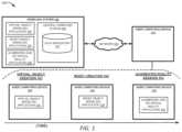
- FIG. 1depicts an example of a computing environment for generating, by a modeling system, virtual objects and virtual resets including such virtual objects in support of a computer-based simulated environment, according to certain embodiments disclosed herein.
- FIG. 2depicts an example of a computing environment for generating, by a modeling system, a virtual reset including virtual objects which accurately model corresponding physical objects of a physical reset, according to certain embodiments disclosed herein.
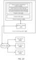
- FIG. 3depicts an example of a method for generating a virtual object, according to certain embodiments disclosed herein.
- FIG. 4 Adepicts an illustration of a user interface for generating a virtual object, including requesting a new virtual object, according to certain embodiments disclosed herein.
- FIG. 4 Bdepicts an example user interface for receiving properties information defining the virtual object requested in FIG. 4 A , including a selection of a shape selected from a set of shapes, according to certain embodiments disclosed herein.
- FIG. 4 Cdepicts an illustration of a user interface for receiving properties information defining the virtual object requested in FIG. 4 A , including displaying an interface object for selecting a face upon which to impose a facial image, according to certain embodiments disclosed herein.
- FIG. 4 Ddepicts an illustration of a user interface for generating a virtual object, including a facial image imposed to a face selected via the user interface of FIG. 4 C and resizing objects that are selectable to resize an area of the facial image, according to certain embodiments disclosed herein.
- FIG. 4 Edepicts an illustration of a user interface for generating a virtual object, including a display of a virtual object, according to certain embodiments disclosed herein.
- FIG. 5depicts an illustration of a method for generating a virtual reset, according to certain embodiments disclosed herein.
- FIG. 6depicts an illustration of a user interface tool for applying edits to a virtual reset which can be used with the method of FIG. 5 , according to certain embodiments disclosed herein.
- FIG. 7depicts a method for rendering a virtual reset in an augmented reality scene, according to certain embodiments disclosed herein.
- FIG. 8 Adepicts an illustration of a user interface for instructing a computing system to display a virtual reset within an augmented reality scene, according to certain embodiments disclosed herein.
- FIG. 8 Bdepicts an illustration of a user interface for viewing the display of the virtual reset of FIG. 8 A within an augmented reality scene, according to certain embodiments disclosed herein.
- FIG. 9depicts an example of a computing system that performs certain operations described herein, according to certain embodiments described in the present disclosure.
- FIG. 10depicts an example of a cloud computing system that performs certain operations described herein, according to certain embodiments described in the present disclosure.
- a computing environmentmay include a modeling system, which can include a number of computing devices, modeling applications, and a data store.
- the modeling systemmay be configured to generate, responsive to inputs received via a user interface, virtual objects corresponding to real-world objects.
- the modeling systemmay also be configured to generate a virtual reset, which is a virtual space including an arrangement of virtual objects.
- the virtual resetcan be presented in a computer-based simulated environment, such as in a virtual reality environment and/or an augmented reality environment.
- a modeling systemprovides a user interface for creation of virtual objects, creation and editing of virtual resets, and presentation of virtual resets in a computer-based simulated environment.
- the modeling systemcan receive, via the user interface, a request to create a virtual object that corresponds to a real-world object.
- the modeling systemcan present, via the user interface, a set of three-dimensional (3D) shapes and receive a selection of a shape from the set of shapes for the virtual object. Because the shape is three dimensional, the shape can have multiple faces.
- the modeling systemcan also receive, via the user interface, a set of properties of the real-world object to be applied to the virtual object.
- Propertiescould include a name, an identifier, a weight, dimensions, a quantity, a price, and/or any other property that can describe an attribute of the real-world object. For example, if the user desires to create a virtual object that models a physical, boxed product, the user can select a ‘cuboid’ shape and input dimensions corresponding to the dimensions of the physical, boxed product.
- the modeling systemcan also request and receive, for each face of the 3D shape, an image that shows a corresponding portion of the real-world object. For example, images of the different sides of the physical, boxed product are generated via a camera and provided to the modeling system that then associates each of these images with the corresponding face of the 3D shape.
- the modeling systemcan generate the virtual object based on the 3D shape, the images, and the properties and store the virtual object in a data store.
- the modeling systemcan receive, via a user interface, a request to generate a virtual reset and a selection of one or more virtual objects stored in the data store.
- the modeling systemcan present the virtual objects in the virtual reset, allow movement of the virtual objects within the reset (e.g., to change their positions) responsive to inputs received via the user interface, and prohibit positioning or a change to a position based on properties of the virtual objects.
- the generated virtual object(the boxed product), which is associated with a property of a weight of 20 kilograms, cannot be moved on top of a second virtual object (e.g., a virtual shelf) associated with a property of a weight capacity of 15 kilograms.
- the modeling systemcan constrain the generation and editing of virtual resets so that virtual resets generated via the modeling system are physically possible to implement.
- the modeling systemcan present, in a virtual and/or augmented reality scene of the user interface, the virtual reset at a location in the virtual and/or augmented reality scene corresponding to a desired physical location of a physical reset modeled by the virtual reset.
- the modeling systemcan also present, in the user interface, properties associated with a particular virtual object of the virtual reset responsive to detecting a selection of the virtual object.
- the virtual resetcan also be stored in the data store (or in another data store). During an augmented reality session, the information about the virtual reset can be retrieved from the data store and used. In particular, the virtual reset can be shown superimposed at the corresponding location in the physical environment.
- embodiments of the present disclosureprovide a modeling system that enables accurate 3D modeling of real-world objects in accurate manners and without the need for specialized equipment.
- Such virtual modelscan be arranged to create virtual resets.
- Certain embodiments described hereinaddress the limitations of conventional modeling systems by constraining editing operations within a user interface for generating virtual resets that conform to physical constraints of corresponding physical resets. The arrangement of virtual objects within a virtual reset itself can be properly replicated in the physical world.
- the modeling system described hereinmay only allow a set of virtual objects to be stacked on a shelf of the virtual reset if a combined weight of the corresponding real-world objects is less than a load capacity of the corresponding real-world shelf.
- the modeling system described hereinmay allow a virtual object to be placed under a shelf of the virtual reset only if a clearance height under the shelf is greater than or equal to a height of the virtual object.
- the modeling system described hereinenables association of properties information (e.g., height, weight, identifier, name) with virtual objects within the virtual reset during generation of the virtual objects, which conventional systems do not provide, thereby enabling the presentation of object-level properties information during the presentation of the virtual reset in an augmented and/or virtual reality scene.
- real-world objectAs used herein, the terms “real-world object,” “physical object,” or “physical product” are synonymously used and refer to a tangible object that exists in the real-world.
- This objectin some embodiments, can be a product, a decoration, a support structure (e.g., a shelf, a rack, a stand, etc.), an object attached to another object or support structure (e.g., signage), or any other tangible object.
- a physical resetrefers to an assembly or other arrangement of physical products or other physical objects.
- a physical resetcan be a set of shelves with physical products arranged thereon at a physical location (e.g., at a store).
- virtual objector “three-dimensional (3D) virtual object” refers to a virtual model or a 3D model of a physical object.
- a set of virtual objectscan be used to generate a virtual reset within a virtual space.
- virtual object propertiesrefer to properties assigned to a virtual object based on properties of the corresponding physical object.
- the term “virtual shape”refers to a particular property of a virtual object and can be a 3D shape.
- the virtual shapecan be any of a number of predefined shapes including a cube, a rectangular prism (e.g., a cuboid), a sphere, a cylinder, a triangular prism, a pyramid.
- the virtual shapecan be selected to model a shape of the corresponding physical object. For example, a user may select a rectangular prism virtual object to model a boxed physical product.
- facial imagerefers to a property of a virtual object and includes an image to associate with a face of the virtual shape that forms the virtual object.
- a usercaptures, via a camera device, a facial image of each side of the corresponding real-world object and a modeling system imposes or otherwise associates, in the virtual object, each of the facial images with the corresponding face of the virtual shape.
- a stored imagecan be used instead of capturing a facial image via a camera device.
- a virtual resetrefers to an arranged set of virtual objects within a virtual space.
- a virtual reset modelis a virtual model of a physical reset.
- a usercan construct a virtual reset by selecting one or more virtual objects via a user interface and moving, rotating, stacking, or otherwise manipulating the virtual objects within the virtual space until the virtual reset is constructed.
- the virtual resetcan include a virtual object that models a structural support (e.g., a virtual shelf) with one or more virtual objects representing products (e.g., boxed products) stacked or otherwise arranged thereon.
- virtual spaceor “3D virtual space” refers to a space within which virtual objects can be placed to construct a virtual reset. In some instances, the virtual space can model a corresponding physical space.
- augmented reality sceneor “virtual reality scene” refers to a scene of a real-world environment in which a virtual reset is overlaid.
- the virtual resetis presented, within the augmented and/or virtual reality scene, at a location that corresponds to a location of a corresponding physical reset to be assembled.
- FIG. 1depicts an example of a computing environment 100 for generating, by a modeling system 130 , virtual objects and virtual resets including such virtual objects in support of a computer-based simulated environment, in accordance with certain embodiments described herein.
- the modeling system 130can include one or more processing devices that execute one or more modeling applications.
- the modeling system 130includes a network server and/or one or more computing devices communicatively coupled via a network 120 .
- the modeling system 130may be implemented using software (e.g., code, instructions, program) executed by one or more processing units (e.g., processors, cores), hardware, or combinations thereof.
- the softwaremay be stored on a non-transitory storage medium (e.g., on a memory device).
- the modeling system 130provides a service that enables generation of virtual objects based on physical objects, generation and editing of virtual resets, and display of virtual resets in an augmented and/or virtual reality environment for users, for example, including a user associated with a user computing device 110 .
- the modeling system 130includes a central computer system 136 , which supports a plurality of applications, including a virtual object modeling application 131 , a reset object modeling application 133 , and an augmented and/or virtual reality application 135 .
- the virtual object modeling application 131is an application that enables users to generate virtual objects.
- the reset object modeling application 133is an application that enables users to generate virtual resets that include arrangements of virtual objects.
- the augmented reality application 135is an application that enables a presentation of virtual resets in an augmented and/or virtual reality scene.
- the plurality of applicationsincluding the virtual object modeling application 131 , reset object modeling application 133 , and the augmented and/or virtual reality application 135 may be accessed by and executed on a user computing device 110 associated with a user of one or more services of the modeling system 130 .
- the useraccesses one or more of the applications 131 , 133 , and 135 via web browser application of the user computing device 110 .
- one or more of the applications 131 , 133 , and 135is provided by the modeling system 130 for download on the user computing device 110 .
- a single application which supports each of the applications 131 , 133 , and 135is provided for access by (and execution via) the user computing device 110 or is provided for download by the user computing device 110 .
- the user computing device 110communicates with the central computer 136 via the network 120 .
- each of the applicationscan be provided to a different computing device.
- the modeling system 130comprises a data repository 137 .
- the data repository 137could include a local or remote data store accessible to the central computer system 136 .
- the data repository 137is configured to store virtual objects and associated properties generated via the virtual object modeling application in a virtual object creation process.
- the data repository 137is configured to store virtual resets, which define an arrangement of virtual objects arranged in a virtual space, generated via the reset object modeling application 133 .
- the data repository 137is configured to provide virtual objects and/or virtual resets in support of augmented reality scenes generated via the augmented reality application 135 .
- the user computing device 110also communicates with the data repository 137 via the network 120 .
- the user computing device 110executes the applications 131 , 133 , 135 in an order indicated by the timeline depicted in FIG. 1 .
- a userconducts a virtual object creation process using the virtual object modeling application 131 executed on or otherwise accessed via the user computing device 110 .
- the userconducts a reset creation process using the reset object modeling application 133 executed on or otherwise accessed via the user computing device 110 .
- the userinitiates an augmented and/or virtual reality session using the augmented and/or virtual reality application 135 executed on or otherwise accessed via the user computing device 110 .
- a different computing devicecan be (but does not necessarily need to be) used for some or each of the virtual object creation process, the reset creation process, and the augmented reality session. Additionally, a different user can initiate each application.
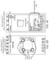
- FIG. 2depicts an example of a computing environment 100 for generating, by a modeling system, a virtual reset including virtual objects which accurately model corresponding physical objects of a physical reset, in accordance with certain embodiments described herein.
- the computing environment 100 of FIG. 2provides further details concerning the computing environment 100 of FIG. 1 . Elements that are found in FIG. 1 are further described in FIG. 2 and referred thereto using the same element numbers.
- the computing environment 100includes the modeling system 130 .
- the modeling system 130in certain embodiments, including a virtual object generator subsystem 231 , a reset modeling subsystem 233 , and an augmented reality (AR) and/or virtual reality (VR) reset rendering subsystem 235 .
- ARaugmented reality
- VRvirtual reality
- the virtual object generator subsystem 231is configured to generate, store, and/or render virtual objects 201 .
- the virtual object generator subsystem 231communicates, via the network 120 , with the computing device 110 upon an execution of a modeling application 212 on the computing device 110 .
- the modeling application 212can include the virtual object modeling application 131 .
- the virtual object generator subsystem 231can receive, from the computing device 110 , a selection of a virtual shape for a virtual object 201 , properties 202 for the virtual object 201 , and facial images for faces of the virtual shape.
- the virtual object generator subsystem 231can generate the virtual object 201 based on the selected virtual shape, the properties 202 , and facial images and store the virtual object 201 in a data repository 137 .
- the virtual object generator subsystem 231can associate, in the data repository 137 , the virtual object 201 with its associated shape, facial images, and other properties 202 . Additional details about generating a virtual object 201 are provided below, and example illustrations of user interface 211 interactions to generate a virtual object 201 are provided below with respect to FIGS. 4 A, 4 B, 4 C, 4 D, and 4 E .
- the reset modeling subsystem 233is configured to generate, store, and/or render virtual resets 203 .
- the virtual object generator subsystem 231communicates, via the network 120 , with the computing device 110 upon the execution of the modeling application 212 .
- the modeling application 212can include the reset object modeling application 133 .
- the virtual object generator subsystem 231can receive, from the computing device 110 , a selection of virtual objects 201 and an arrangement of the virtual objects 201 with respect to other virtual objects in a virtual space.
- the reset modeling subsystem 233can generate the virtual reset 203 that defines the arrangement of the virtual objects 201 within the virtual space.
- the reset modeling subsystem 233can store the virtual reset 203 in the data repository 137 including an identity of each virtual object 201 in the virtual reset 203 and a position of each virtual object 203 within the virtual space. Additional details about generating and/or editing a virtual reset 203 are provided below with respect to FIG. 5 , and example illustrations of user interface 211 interactions to generate a virtual reset 203 are provided below with respect to FIG. 6 .
- the AR and/or VR reset rendering subsystem 235is configured to present a selected virtual reset 203 within an AR and/or VR scene 215 .
- the AR and/or VR reset rendering subsystem 235is configured to communicate the AR and/or VR scene 215 to the user computing device 110 for presentation via the user interface 211 . Additional details about rendering a virtual reset 203 are provided below with respect to FIG. 7 , and example illustrations of user interface 211 interactions to render an AR and/or VR scene 215 including a virtual reset 203 are provided below with respect to FIG. 8 A and FIG. 8 B .
- the various subsystemse.g., the virtual object generator subsystem 231 , the reset modeling subsystem 233 , the AR and/or VR reset rendering subsystem 235
- the various subsystemscan be implemented as one or more of program code, program code executed by processing hardware (e.g., a programmable logic array, a field-programmable gate array, etc.), firmware, or some combination thereof.
- one or more processes described herein as being performed by the modeling system 130can be performed by the user computing device 110 , for example, by the modeling application 212 .
- the user computing device 110can generate a virtual object 201 by performing one or more steps of the method of FIG. 3 , can construct and/or modify a virtual reset 203 by performing one or more steps of the method of FIG. 5 , and/or can render a virtual reset 203 in an AR and/or VR scene 215 via the user interface 211 by performing one or more steps of the method of FIG. 7 without having to communicate with the modeling system 130 via the network 120 .
- the data repository 137could include a local or remote data store accessible to the modeling system 130 .
- the data repository 137is configured to store virtual objects 201 and associated properties 202 .
- the data repository 137is configured to store virtual resets 203 , which define an arrangement of virtual objects 201 (and associated properties 202 ) within a virtual space.
- the user computing device 110includes a user interface 211 , a modeling application 212 , a camera device 213 , and a data storage unit 214 .
- An operator of the user computing device 110may be a user of the modeling system 130 .
- the operatormay download the modeling application 212 to the user computing device 110 via a network 120 and/or may start an application session with the modeling system 130 .
- the modeling system 130may provide the modeling application 212 for download via the network 120 , for example, directly via a website of the modeling system 130 or via a third-party system (e.g., a service system that provides applications for download).
- the user interface 211enables the user of the user computing device 110 to interact with the modeling application 212 and/or the modeling system 130 .
- the user interface 211could be provided on a display device (e.g., a display monitor), a touchscreen interface, or other user interface that can present one or more outputs of the modeling application 212 and/or modeling system 130 and receive one or more inputs of the user of the user computing device 110 .
- the user interface 211can include an augmented reality view which can present virtual resets 203 within an augmented reality (AR) and/or virtual reality (VR) scene 215 such that the virtual reset 203 appears to be displayed within a physical environment of a user when viewed by the user through the user interface 211 in the augmented reality view.
- ARaugmented reality
- VRvirtual reality
- the user interface 211can include a virtual reality view which can present virtual resets 203 within a virtual reality (VR) scene such that the virtual resets 203 appear to be displayed within the virtual reality scene and wherein the virtual reality scene represents a physical environment (e.g., a retail store) where physical counterparts of the virtual resets 203 can be physically located.
- VRvirtual reality
- the user computing device 110 modeling application 212is configured to provide, via the user interface 211 , an interface for generating and editing virtual objects 201 and virtual resets 203 and for presenting AR and/or VR scenes.
- the modeling application 212can include one of, a combination of, or all of the applications 131 , 133 , and 135 .
- the camera device 213can capture one or more facial images of a physical product 201 X to be associated with faces of a virtual shape selected for constructing a virtual object 201 that represents the physical object 201 X.
- the camera device 213is either a component of the user computing device 110 or otherwise is communicatively coupled to the user computing device 110 .
- a camera application of the camera device 213in some instances, exchanges data (e.g., image data) with the modeling application 212 .
- the data storage unit 214could include a local or remote data store accessible to the user computing device 110 .
- the data storage unit 214is configured to store virtual objects 201 and associated properties 202 .
- the data storage unit 214is configured to store virtual resets 203 , which define an arrangement of virtual objects 201 (and associated properties 202 ) within a virtual space.
- the usercan use user interface 211 to generate a new virtual object 201 - 1 .
- the uservia the user computing device 110 , accesses or otherwise executes (e.g., via the modeling application 122 ) the virtual object modeling application 131 to generate the new virtual object 201 - 1 for a physical object.
- the user computing device 110receives, via the user interface 211 , properties 202 - 1 to define a virtual object 201 - 1 .
- the properties 202 - 1include a selection of a shape (e.g., a rectangular prism) for the virtual object 201 - 1 as well as a definition of other properties 202 - 1 (e.g., a weight, dimensions, etc.) for the virtual object 201 - 1 .
- the properties 202 - 1further include one or more facial images showing respective one or more sides of the physical object 210 X, where each side corresponds to a face of the selected shape.
- the usermay define properties 202 - 1 via one or more interactions with the user interface 211 .
- the usermay select the shape via a drop-down menu or other user interface 211 object that enables the user to select the shape (e.g., the rectangular prism) from among a set of possible shapes (e.g., rectangular prism, cube, sphere, cylinder, pyramid, etc.).
- the usermay enter other information defining the properties 202 - 1 for the shape via one or more fields, menus, or other user interface 211 objects.
- the usermay enter a weight, a price, an identifier, one or more dimensions, a name, a quantity, or other properties 202 - 1 via the user interface 211 .
- the usermay select one or more user interface 211 objects to select a face of the selected shape for the virtual object 201 - 1 and upload or otherwise capture, for the selected face of the virtual object 201 - 1 , a facial image of a corresponding side of the physical object 201 X.
- the modeling system 130receives, from the user computing device 110 (e.g., from the modeling application 212 ) via the network 120 , the properties 202 - 1 that define the virtual object 201 - 1 and generates the virtual object 201 - 1 based on the properties 202 - 1 .
- the virtual object generator subsystem 231generates a virtual object 201 - 1 as a rectangular prism having dimensions of 1 ⁇ 1.5 ⁇ 0.5 meters specified by the properties 202 - 1 and associates other properties 202 - 1 with the rectangular prism including each facial image to impose or otherwise associate with each face of the rectangular prism as well as data such as a weight, an item identifier, a name, or other information in the properties 202 - 1 information.
- the virtual object generator subsystem 231may store the virtual object 201 - 1 in the data repository 137 of the modeling system 130 and/or, as depicted in FIG. 2 , in the data storage unit 214 of the user computing device 110 .
- One or more steps for generating the virtual object 201 - 1 in this example described as being performed by the modeling system 130 (or a subsystem thereof)can instead be performed, in certain embodiments, by the computing device 110 .
- one or more of the properties 202 of a virtual object 201may be derived from the facial images of a physical object.
- the images of the physical objectmay also incorporate a scaling object in the frame, such as a ruler, allowing dimensions of the physical object to be attributed to the virtual object 201 without the user having to manually enter the dimensions in the user interface 211 .
- a usercan use an example user interface 211 - 1 to generate a new virtual reset 203 - 1 and/or edit an existing virtual reset 203 - 1 .
- the uservia the user computing device 110 , accesses or otherwise executes (e.g., via the modeling application 212 ) the reset object modeling application 133 to generate the new virtual reset 203 - 1 and/or edit the existing virtual reset 203 - 1 .
- the reset modeling subsystem 233may generate user interface 211 - 1 which enables construction or editing of virtual resets 203 - 1 .
- the reset modeling subsystem 233may receive, in user interface 211 - 1 , a request to generate a new reset 203 - 1 and a selection of stored virtual object 201 - 1 and a stored virtual object 201 - 2 .
- the user computing device 110may receive, in the user interface 211 - 1 , a request to access a stored virtual reset 203 - 1 , which includes an arrangement of virtual object 201 - 1 and virtual object 201 - 2 .
- the usermay arrange and/or rearrange a position, a rotation, or other spatial feature of the virtual objects 201 - 1 and 201 - 2 within the virtual space of the virtual reset 203 - 1 until a desired arrangement of the virtual objects 201 - 1 and 201 - 2 is achieved.
- the reset modeling subsystem 233moves and/or otherwise rearranges the virtual objects 201 within the virtual reset 203 - 1 responsive to inputs received at the user interface 211 - 1 .
- the virtual reset 203 - 1 shown in FIG. 2is an example and includes only virtual objects 201 - 1 and 202 - 1 , however, the virtual reset can include any number of virtual objects 201 . In the example depicted in FIG.
- the virtual object 201 - 2could represent a structural support object (e.g., a shelf) and the virtual object 201 - 1 stacked on top of the structural support object could be a product (e.g., a boxed product).
- the reset modeling subsystem 233saves the virtual reset 203 - 1 including the virtual objects 201 - 1 and 201 - 2 arranged as instructed via the inputs received via the user interface 211 - 1 in the data repository 137 and/or, as depicted in FIG. 2 , in the data storage unit 214 of the user computing device 110 .
- One or more steps for generating the new virtual reset 203 - or editing the existing virtual reset 203 - 1 described in this example as being performed by the modeling system 130 (or a subsystem thereof)can instead be performed, in certain embodiments, by the computing device 110 .
- the virtual model object modeling application and reset object modeling applicationhave the ability to periodically save a current state of a virtual object or virtual reset while it is being worked on, in persistent memory to be uploaded when network connectivity is achieved.
- a usercan use an example user interface 211 - 2 to render a virtual reset 203 - 1 (e.g., the virtual reset generated based on inputs to user interface 211 - 1 ) in an AR and/or VR scene 215 .
- a virtual reset 203 - 1e.g., the virtual reset generated based on inputs to user interface 211 - 1
- the uservia the user computing device 110 , accesses or otherwise executes (e.g., via the modeling application 122 ) the augmented reality and/or virtual reality application 135 to render the virtual reset 203 - 1 in the AR and/or VR scene 215 .
- the user interface 211 - 2is displayed by the user computing device 110 in an augmented reality display mode.
- the user interface 211 - 2is displayed via an augmented reality viewing device (e.g., AR glasses, an AR headset, etc.) that is communicatively coupled to one or more of the user computing device 110 and/or the modeling system 130 .
- the AR and/or VR reset rendering subsystem 235may render the AR and/or VR scene 215 including virtual reset 203 - 1 within the user interface 211 - 2 responsive to receiving, via the user interface 211 - 2 , a selection of stored virtual reset 203 - 1 and a request to render the virtual reset 203 - 1 in an augmented reality view.
- the AR and/or VR reset rendering subsystem 235can access the data repository 137 or, as depicted in FIG.
- the AR and/or VR reset rendering subsystem 235renders the AR scene 215 so that the user viewing the user interface 211 - 2 can view the virtual reset 203 - 1 in the AR scene 215 in an overlay over the physical environment.
- An example of a virtual reset displayed in an AR scene 215is depicted in FIG. 7 B .
- One or more steps for rendering the virtual reset 203 - 1 in an AR scene 215 described in this example as being performed by the modeling system 130 (or a subsystem thereof)can instead be performed, in certain embodiments, by the computing device 110 .
- FIG. 3depicts an example of a method 300 for generating a virtual object 201 , according to certain embodiments disclosed herein.
- One or more computing devicese.g., the modeling system 130 or the virtual object generator subsystem 231 included therein
- the method 300is described with reference to certain examples depicted in the figures. Other implementations, however, are possible.
- the userinteracts with a modeling application 212 executing on a computing device 110 via a user interface 211 to provide information as a basis to generate a virtual object 201 .
- the modeling system 130 or one or more subsystems thereofperforms the steps of method 300 by receiving the information input via the user interface 211 and generating the virtual object 201 .
- the steps of method 300can be performed by the user computing device 110 without the user computing device 110 needing to communicate with a modeling system 130 via the network 120 .
- the method 300involves receiving, by a virtual object generator subsystem 231 , a request to create a virtual object 201 .
- a user of the user computing device 110accesses the modeling application 212 via the user interface 211 and interacts therewith to instruct the modeling application 212 to create a new virtual object 201 .
- the userwants to generate a virtual object 201 that models a physical object 201 X.
- the virtual object generator subsystem 231communicates with the user computing device 110 via the network 120 and receives the request to generate the new virtual object 201 responsive to the one or more inputs of the user.
- FIG. 4 Adepicts an example user interface 211 for receiving a request to generate a new virtual object 201 .
- the method 300involves receiving properties 202 information to define the virtual object 201 .
- the virtual object generator subsystem 231may display, via the user interface 211 and responsive to receiving the request to generate a new virtual object 201 , one or more user interface fields to receive properties 202 information to define the new virtual object 201 .
- the user interface 211 fields to receive the properties 202 informationcan include one or more of drop down menus, check boxes, input fields, an interface object to receive a file upload from the user computing device 110 , an interface object to receive an image captured by a camera device 213 , or other user interface fields via which property information including one or more of text, files, item selections from a set of items, or other user inputs may be received.
- the method 300 at block 320involves implementing blocks 321 , 323 , and 325 , in which the user inputs properties 202 information to define the virtual object 201 .
- the userinputs properties 202 information so that the virtual object 201 models a physical object 201 X.
- the method 300involves receiving a selection of a shape of a set of shapes, the shape including a set of faces.
- the virtual object generator subsystem 231can display one or more user interface 211 objects to receive a selection of a shape.
- the virtual object generator subsystem 231can display a drop down menu that enables a selection of a shape from a set of shapes listed in the drop down menu.
- the virtual object generator subsystem 231displays another type of input field to receive the selection of the shape.
- the set of shapescould include a set of one or more of a cube, a rectangular prism, a cylinder, a pyramid, a cone, a sphere, or other shape. Each shape is associated with a respective set of faces.
- a cubehas six faces of equal area.
- the facescomprise a region of surface area.
- a cylindercould comprise a top circular face, a bottom circular face, and one or more curved portions of surface area around a circumference of the cylinder which runs perpendicular to each of the top and bottom faces.
- FIG. 4 Bdepicts an example user interface 211 for receiving a selection of a shape selected from a set of shapes.
- the method 300involves receiving an input of further properties 202 defining the virtual object 201 .
- the virtual object generator subsystem 231can display one or more user interface 211 objects to receive a selection and/or other input of further properties 202 (in addition to the shape selection) to define the virtual object 201 .
- the virtual object generator subsystem 231displays a combined user interface to receive both the selection of the shape as well as the input and/or selection of further properties 202 .
- Further properties 202can include one or more of a name, an identifier (e.g., an item number), a description, dimensions, weight, or any other property 202 that describes the virtual object 201 such that the virtual object 201 can correspond to the physical object.
- the userinputs, in some instances, property information that accurately represents the physical object 201 X which the user wants to model using the virtual object 201 .
- FIG. 4 Bdepicts an example user interface 211 for receiving properties 202 information to define a virtual object 201 .
- the method 300involves receiving, for each of a set of faces corresponding to the shape selected in block 321 , an image of a portion (e.g., a side, a face, a surface, etc.) of the physical object 201 X corresponding to the face.
- the virtual object generator subsystem 231may display a user interface 211 via which to receive images of each of a number of faces associated with the shape selected at block 221 .
- a cubecomprises six faces and the virtual object generator subsystem 231 could provide a user interface 211 to request and receive images to use for the six faces.
- the virtual object generator subsystem 231can enable a capture, via the camera device 213 , of a corresponding facial image of the physical object 201 X or enable a selection of a stored image stored on the data storage unit 214 and/or the data repository 137 .
- the camera device 213captures an image and transmits the image to the virtual object generator subsystem 231 , which associates the captured image with the particular face.
- the virtual object generator subsystem 231may receive a respective facial image for each face of the selected shape.
- the virtual object generator subsystem 231presents a wizard or other program that requests, sequentially, the camera device 213 to capture or upload a respective facial image for each respective face of the selected shape.
- the virtual object generator subsystem 231can display, via the user interface 211 , a request for a subsequent image corresponding to a subsequent face of the plurality of faces of the 3D shape.
- the virtual object generator subsystem 231can receive the subsequent image showing a subsequent portion of the physical object 201 X.
- the virtual object generator subsystem 231can determine an area of the subsequent image that corresponds to another portion of the physical object 201 X.
- the virtual object generator subsystem 231can associate, in the virtual object 201 , the area of the subsequent image with the subsequent face.
- the virtual object generator subsystem 231can determine that a face of the set of faces of the selected three-dimensional shape does not have an associated image and, responsive to this determination, display, via the user interface 211 , a request for the image, wherein the image is received responsive to requesting the image.
- the properties 202 information of the virtual object 201comprise the received facial images.
- FIG. 4 Cdepicts an illustration of a user interface for receiving properties information defining the virtual object requested in FIG. 4 A , including displaying an interface object for selecting a face upon which to impose a facial image, according to certain embodiments disclosed herein.
- boundaries of an area of a facial image uploaded or captured by the user computing device 110do not correspond to boundaries of a face of the virtual object 201 .
- the virtual object generator subsystem 231may provide one or more user interface objects for performing image manipulations. Image manipulations could include scaled resizing, unscaled resizing, cropping, rotating, warping, or otherwise manipulating the facial image so that boundaries of the facial image are changed.
- the user interfaceprovides for the user to zoom in on various portions of the image for finer and more precise control of the image manipulations.
- the virtual object generator subsystem 231receives, via the user interface 211 one or more adjustments to the boundaries of the facial image and applies the adjustments to the facial image.
- the virtual object generator subsystem 231can save a manipulated image responsive to receiving a selection of a user interface object 211 (e.g., the user clicks an interface object entitled “save image”).
- the virtual object generator subsystem 231can determine an area of the image that corresponds to the portion of the physical object 201 X.
- the portioncan include a side, a surface, a face, or other region of the physical object 201 X able to be captured in an image of the physical object 201 X.
- the virtual object generator subsystem 231can associate, in the virtual object 201 , the area of the image with a face of the set of faces of the selected 3D shape.
- the usercan resize, edit, rotate, warp, or otherwise manipulate an uploaded or captured image so that boundaries of a portion of the physical object 201 X in the image correspond to boundaries of the face of the selected three-dimensional shape.
- the virtual object generator subsystem 231can display, via the user interface 211 , the image imposed on the face, the image showing, in addition to the portion of the physical object 201 X, a portion of a space (e.g., in an environment of the physical object 201 X) where the physical object 201 X is located.
- the virtual object generator subsystem 231can provide, via the user interface 211 , resizing objects selectable to enable resizing of the image, wherein the resizing objects are placed on detectable boundaries in the image between the physical object 201 X and the space.
- the virtual object generator subsystem 231can resize the image to correspond to an area of the face responsive to receiving inputs including a change in position of one or more of the resizing objects. For example, the user can resize the image so that the boundaries of the portion of the physical object 201 X in the image correspond to boundaries of the face of the selected three-dimensional shape.
- the virtual object generator subsystem 231can display, via the user interface 211 , a rotation interface object and can rotate, responsive to a manipulation of the rotation interface object, the image so that the boundaries of the portion of the physical object 201 X in the image correspond to boundaries of the face of the selected three-dimensional shape.
- the virtual object generator subsystem 231can display, via the user interface 211 , an editing interface object and can edit, responsive to a manipulation of the editing interface object, the image so that the boundaries of the portion of the physical object 201 X in the image correspond to boundaries of the face of the selected three-dimensional shape.
- the editingcould include warping, stretching, cropping, or other manipulation of the image.
- the virtual object generator subsystem 231can display, via the user interface 211 , the boundaries of the portion of the physical object 201 X in the image and the boundaries of the face of the selected three-dimensional shape to aid the user in manipulating the image using the interface objects.
- FIG. 4 Ddepicts an illustration of a user interface for generating a virtual object, including a facial image imposed to a face selected via the user interface of FIG. 4 C and resizing objects that are selectable to resize an area of the facial image, according to certain embodiments disclosed herein.
- the method 300involves presenting the virtual object 201 in a virtual space based on the properties 202 information defined in block 320 .
- the properties 202 informationcan include the selection in block 321 of the shape from a set of shapes, the input in block 323 of further properties 202 information (e.g., weight, dimensions, identifier, name, price, etc.), and the input in block 325 of facial images for each of a number of faces of the shape selected in block 321 .
- the virtual object generator subsystem 231can superimpose an image received (and, in some instances, the image is subsequently edited, as described herein) for each face of the shape.
- Superimposing the image on the facecomprises superimposing the portion of the image defined by the boundaries of the physical object 201 X in the image onto the face.
- the virtual object generator subsystem 231can present a preview of the virtual object 201 in the user interface 211 and can allow a rotation of the virtual object to display various views of the virtual object 201 .
- the item being modeledis a physical box of pool shock and the selected shape is a cube, the dimensions specified are 3 ft ⁇ 3 ft ⁇ 3 ft, the name specified is “Merchant X pool shock,” the price specified is “$35.00,” and the identifier specified is “1268439383.”
- the virtual object generator subsystem 231can display the virtual object 201 that models the box of pool shock including the properties 102 information and can rotate the virtual object 201 , responsive to inputs to the user interface 211 , to display various views of the virtual object 201 . For example, in one view, the user can view three of six faces of the virtual object 201 model of the box of pool shock and, in another view, the user can view a different three of the six faces of the virtual object 201 model.
- the method 300involves storing the virtual object 201 .
- the virtual object generator subsystem 231may associate each of the captured facial images with respective faces of the virtual object 201 so that, when displayed, the modeling system 130 may display the virtual object 201 with the facial images imposed or otherwise displayed on top of the associated faces of the virtual object 201 .
- the virtual object generator subsystem 231may associate further properties 202 information with the virtual object 201 (e.g., price, name, identifier, description, etc.), for example, in metadata of the virtual object 201 .
- the virtual object 201may be represented as the shape selected by the user and to scale within the virtual space based on dimensions properties 202 specified by the user.
- the virtual object generator subsystem 231can update the 3D shape to include the images (edited as needed) and the remaining properties.
- the virtual object generator subsystem 231stores links between each face and a corresponding image (edited as needed), where the links are to storage location of these images.
- the remaining propertiescan be stored in the 3D shape or linked thereto (e.g., stored in metadata that has a storage location link).
- the virtual object generator subsystem 231can retrieve the virtual object 201 from the data repository 137 or from the data storage unit 114 .
- the virtual object generator subsystem 231can present the virtual object in the user interface 211 , including displaying the 3D shape associated with the virtual object 201 including a quantity of faces and, for each of the quantity of faces, an image superimposed upon the face.
- the virtual object generator subsystem 231can present further properties 202 of the virtual object 201 , for example, a name, a price, a weight, an identifier, a description, or other properties 202 information associated with the virtual object 201 .
- the virtual object generator subsystem 231may associate an image superimposed upon one or more of the faces of the virtual object, but not every face of the virtual object.
- FIG. 4 Edepicts an illustration of a user interface for generating a virtual object, including a display of a virtual object, according to certain embodiments disclosed herein.
- FIG. 4 Adepicts an example user interface 211 for receiving a request to generate a new virtual object 201 , in accordance with certain embodiments disclosed herein.
- the example user interface 211 of FIG. 4 Aincludes a user interface object 401 .
- the modeling system 130receives a request to generate a new virtual object 201 responsive to the modeling application 212 detecting a selection of the user interface object 401 .
- the user interface 211 of FIG. 4 Aalso depicts further user interface objects for selecting an existing virtual object. For example, a search field that reads “Search items” is depicted in FIG. 4 A that enables a user to search and retrieve an existing virtual object 201 that is stored by the modeling system 130 .
- FIG. 4 Bdepicts an example user interface 211 for receiving properties information defining the virtual object 201 requested in FIG. 4 A , including a selection of a shape selected from a set of shapes, in accordance with certain embodiments disclosed herein.
- user interface objects 402 - 409are displayed and enable an input of properties 202 information defining the virtual object 201 .
- user interface object 402enables receiving an input of a name
- user interface object 403enables receiving an input of an identifier
- user interface object 404enables receiving an input of a description
- user interface object 405enables selection of a shape from a set of shapes
- user interface objects 406 , 407 , 408 , and 409enable indication of dimensions and a measurement unit for the dimensions.
- the user interface objects depicted hereinare example and additional, less, and/or different interface objects may be displayed to receive properties 202 information from the ones depicted in FIG. 4 B .
- an interface objectmay be displayed to receive a weight of the virtual object 201 or a price of the virtual object 201 . As depicted in FIG.
- the userhas input values in the interface objects (e.g., objects 402 , 403 , 404 , 406 , 408 , 409 ) and/or made a menu selection (e.g., objects 405 , 407 ) to define properties 202 information for the virtual object 201 .
- the interface objectse.g., objects 402 , 403 , 404 , 406 , 408 , 409
- a menu selectione.g., objects 405 , 407
- FIG. 4 Cdepicts an illustration of a user interface for receiving properties information defining the virtual object requested in FIG. 4 A , including displaying an interface object for selecting a face upon which to impose a facial image, according to certain embodiments disclosed herein.
- a user interface 211displays, in a virtual space 414 , a virtual shape 413 (a cube) selected by the user using interface object 405 of FIG. 4 B .
- the user interface 211 of FIG. 4 Cdepicts a display of interface objects on each side of the shape selected in FIG. 4 B .
- interface objects 410 , 411 , and 412are selectable via the user interface 211 .
- the modeling system 130can activate or cause the camera device 213 to enable a user to capture a facial image of a corresponding face of a physical object 201 X or can display one or more user interface objects that enable the user to access an image file to upload as the facial image.
- FIG. 4 Ddepicts an illustration of a user interface for generating a virtual object, including a facial image imposed to a face selected via the user interface of FIG. 4 C and resizing objects that are selectable to resize an area of the facial image, according to certain embodiments disclosed herein.
- an imageis superimposed over a face of a virtual object.
- User interface objects 415 , 416 , 417 , and 418are provided at each of four corners of the facial image and enable, via selection and/or dragging of the user interface objects 415 , 416 , 417 , and 418 , the virtual object generator subsystem 231 to change one or more boundaries of the facial image with respect to the face of the virtual object 201 .
- User interface object 419enables saving of the modified facial image subsequent to application of image modification operations instructed via interface objects 415 , 416 , 417 , and 418 .
- the user interface objects depicted in FIG. 4 Dare example and other types of user interface 211 objects may be used to perform additional or different facial image manipulations.
- FIG. 4 Efurther depicts a user interface object 420 , selection of user interface object 420 causing the virtual object generator subsystem 231 to store the virtual object 201 on the data repository 137 and/or the data storage unit 214 of the user computing device 110 .
- the stored virtual object 201includes the properties 202 information (e.g., shape, further properties information, facial images) provided by the user via the user interfaces of FIGS. 4 A, 4 B, 4 C, and 4 D .
- properties 202 informatione.g., shape, further properties information, facial images
- FIG. 5depicts a method 500 for generating a virtual reset, according to certain embodiments disclosed herein.
- One or more computing devicese.g., the modeling system 130 and/or the reset modeling subsystem 233 ) implement operations depicted in FIG. 5 .
- the method 500is described with reference to certain examples depicted in the figures. Other implementations, however, are possible.
- the method 500begins at block 510 .
- the method 500involves receiving, by a reset modeling subsystem 233 , a selection of a 3D virtual object 201 in association with generating a 3D virtual reset 203 .
- the reset modeling subsystem 233receives a request to generate a new virtual reset 203 from the reset object modeling application 133 executing on the user computing device 110 responsive to receiving one or more inputs to the user interface 211 .
- the reset object modeling application 133receives a selection of at least one virtual object 201 to include within the virtual reset 103 .
- the user of the user computing device 110accesses the reset object modeling application 133 (e.g., via the application 112 ), selects an option to generate a new virtual reset 203 , and selects at least one virtual object 201 to include within the virtual reset 103 .
- the reset modeling subsystem 233via the reset object modeling application 133 , may provide menus, fields, or other user interface 211 objects to enable the user to request the new virtual reset 203 and select the at least one virtual object for inclusion within the new virtual reset 203 .
- the userretrieves a stored virtual reset 203 .
- the reset modeling subsystem 233receives a request to retrieve a stored virtual reset 203 from the reset object modeling application 133 executing on the user computing device 110 responsive to receiving one or more inputs to the user interface 211 .
- the reset object modeling application 133can access a selected stored virtual reset 203 from the data repository 137 of the modeling system 130 or from the data storage unit 214 of the user computing device 110 .
- the user of the user computing device 110accesses the reset object modeling application 133 (e.g., via the application 112 ), selects an option to retrieve a stored virtual reset 203 , and selects the stored virtual reset 203 from a list of stored virtual resets 203 .
- the reset modeling subsystem 233via the reset object modeling application 133 , may provide menus, fields, or other user interface 211 objects to enable the user to request the stored virtual reset 203 .
- the stored virtual reset 203includes at least one virtual object 201 .
- the method 500involves presenting, by the reset modeling subsystem 233 at the user interface 211 , the 3D virtual object 201 in the 3D virtual reset 203 at a first position.
- the new virtual reset 201 or the stored virtual reset 201includes at least one virtual object 201 arranged in a virtual space at the first position within the virtual reset 203 .
- the virtual reset 203may include, in some instances, multiple virtual objects 201 at respective positions within the virtual reset 203 .
- the virtual reset 203can include first, second, third, or subsequent virtual objects 201 within the virtual reset 203 at first, second, third, or subsequent respective positions within a virtual space within the virtual reset 203 .
- the method 500involves receiving, by the reset modeling subsystem 233 via the user interface 211 , an edit to the 3D virtual object 201 in the 3D virtual reset 203 .
- the reset object modeling application 133may provide a user interface 211 which the user can visualize edits as well as tools via which the user can apply edits to the virtual objects 203 of the virtual reset 203 .
- a position toolenables a user to select the virtual object 201 and change a position of the virtual object 201 within the virtual reset 203 .
- a rotation toolenables a user to select the virtual object 201 and rotate the virtual object 201 .
- FIG. 6depicts an illustration of a user interface 211 tool for applying edits to a virtual reset 203 which can be used with the method 500 of FIG. 5 , according to certain embodiments disclosed herein.
- implementing block 530comprises performing one or more iterations of one or more of block 530 A or block 530 B.
- block 530 Acan be repeated multiple times to receive edits including changes in position for one or more virtual objects 201 in the virtual reset 203 .
- Block 530 Bcan be repeated multiple times to receive edits including changes to characteristics of one or more virtual objects 201 in the virtual reset 203 .
- the reset modeling subsystem 233receives the edits requested by the user via the reset object modeling application 133 .
- the method 500involves receiving, by the reset modeling subsystem 233 , an edit that includes changing a position of the virtual object 201 to a second position within the virtual reset 203 .
- a virtual resetmodels a corresponding physical reset and a user of the user computing device 110 (e.g., a reset designer), as part of a process of designing a virtual reset 203 corresponding to the physical reset, interacts with the reset object modeling application 133 to change a position of the virtual object from a first position to a second position within the virtual reset 203 .
- Changing the positioncan include moving, rotating, stacking, or otherwise manipulating the virtual object 203 within the virtual space of the virtual reset 203 .
- the first positioncan include a first location (e.g., within an x, y, z coordinate system within a virtual space) and a first orientation (e.g., default configuration) and the second position can include a second location and a second orientation (e.g., rotated 90 degrees about the y axis).
- the usermay use the reset object modeling application 133 to construct a virtual reset 203 that accurately models a physical reset.
- the virtual reset 203can include a virtual object 201 that models a structural support (e.g., a virtual shelf) with one or more other virtual objects 201 representing products (e.g., boxed products), signage (a sign that can be placed on or otherwise attached to a surface of the structural support), or other objects.
- the usermay move, within the virtual reset 203 , the structural support to a desired position and orientation, move and/or orient one or more of the products to stack or otherwise arrange the products on the structural support, and move and/or orient the signage to place the signage at desired location(s) on the structural support.
- a first virtual object 201has first boundaries
- a second virtual object 201has second boundaries
- the editincludes a request to move the first virtual object 201 so that the first virtual object 201 is stacked on or beside and against (e.g., packed tightly next to) the second virtual object 201 .
- the editinstructs moving the first virtual object 201 so that a first portion of the first boundaries of the first 3D virtual object is adjacent to a second portion of the second boundaries of the second 3D virtual object.
- the method 500involves receiving, by the reset modeling subsystem 233 , an edit that includes editing a characteristic of the virtual object 201 .
- the characteristiccan include images associated with one or more faces of the 3D virtual object 201 and editing the characteristic can include changing one or more of the images.
- the characteristiccan include properties 202 , such as dimensions of the virtual object 201 , and editing the characteristic can include resizing or otherwise changing the dimensions.
- editing the characteristic of the virtual object 201comprises duplicating the virtual object 201 within the virtual reset 203 .
- the userinstead of and/or in addition to editing a characteristic of the virtual object 201 , the user adds a new virtual object 201 to the virtual reset and/or deletes one or more virtual objects 201 from the virtual reset 203 .
- the method 500involves updating, by the reset modeling subsystem 233 , the presentation of the 3D virtual reset 203 by showing the edit received in block 530 .
- the reset modeling subsystem 233displays, in the user interface 211 , the virtual object 201 in a second position responsive to receiving the edit instructing to move the virtual object 201 from a first position to the second position.
- the reset modeling subsystem 233can present a rotation of the virtual object 201 , a change in position of the virtual object 201 , a change in one or more images of faces of the virtual object 201 , a resizing or other change in dimensions of the virtual object 201 , a duplication of the virtual object 201 , or other edits to the virtual object 201 .
- the reset modeling subsystem 233can present, via the user interface 211 , an addition of a virtual object 201 and a deletion of a virtual object 201 in the virtual reset 203 .
- FIG. 6depicts an illustration of a user interface 211 tool for applying edits to a virtual reset 203 which can be used with the method 500 of FIG. 5 , according to certain embodiments disclosed herein.
- block 530 and block 540can be repeated, allowing the user, for example, to change the position of the virtual object in the virtual reset after seeing the virtual object's position in the virtual reset.
- the reset modeling subsystem 233can constrain editing operations with respect to the virtual reset 203 .
- editing operationsare constrained based on a weight capacity property 202 and/or weight property 202 of virtual objects 201 within the virtual reset 203 .
- a first virtual object 201is a boxed product having a weight of 200 kg and a second virtual object 201 is a shelf having a weight capacity of 100 kg.
- the reset modeling subsystem 233receives an edit requesting a change in position of the first virtual object 201 such that it is stacked on top of the second virtual object 201 .
- the reset modeling subsystem 233determines that a weight of the first virtual object 201 (200 kg) is greater than the weight capacity of the second virtual object (100 kg) upon which the first virtual object 201 is to be stacked.
- the reset modeling subsystem 233denies and reverses the editing operation.
- the reset modeling subsystem 233may indicate, via the user interface 211 , that the editing operation is not allowed and may display a reason or reason code to the user (e.g., “selected object is too heavy to stack on this shelf.”). Reversing the editing operation can include returning the virtual object 201 from the requested second position (e.g., the position in which it is stacked on the shelf) to its original first position within the virtual reset 203 .
- the reset modeling subsystem 233can deny and reverse a requested editing operation based on a weight capacity of a structural support virtual object 201 in view of a combined weight of multiple virtual objects 201 stacked upon the structural support virtual object 201 .
- the weight capacity of the structural support virtual object 201is 100 kg
- a first virtual object 201 stacked on the structural support virtual object 201is 60 kg
- the reset modeling subsystem 233receives a request to stack an additional virtual object 201 having a weight property 202 of 50 kg upon the structural support object 201 .
- the reset modeling subsystem 233responsive to determining that a combined weight of 110 kg is greater than the weight capacity of 100 kg, the reset modeling subsystem 233 does not allow the edit and reverses the edit.
- editing operationsare constrained based on dimension properties 202 and/or clearances (e.g., height/length/width clearances) between virtual objects 201 within the virtual reset 203 .
- a first virtual object 201is a first shelf object
- a second virtual object 201is a second shelf object that is 3 ft above the first shelf object within the virtual reset 203
- a third virtual objectis a boxed product having a height of 3.5 ft.
- the reset modeling subsystem 233receives an edit requesting a change in position of the third virtual object 201 such that it is placed above the first shelf and below the second shelf within the virtual reset 203 .
- the reset modeling subsystem 233determines that a height clearance (3 ft) between the shelves is less than a height (3.5 ft) of the third virtual object 201 which the edit specifies to place between the shelves. In this example, responsive to determining that the height clearance does not enable the requested editing operation, the reset modeling subsystem 233 denies and reverses the editing operation. In this example, the reset modeling subsystem 233 may indicate, via the user interface 211 , that the editing operation is not allowed and may display a reason or reason code to the user (e.g., “selected object is too tall/wide/long to stack in this location.”). Reversing the editing operation can include returning the third virtual object 201 from the requested second position (e.g., the position in which it is stacked between the shelves) to its original first position within the virtual reset 203 .
- the reset modeling subsystem 233determines that a height clearance (3 ft) between the shelves is less than a height (3.5 ft) of the third virtual object 201 which the edit specifies to place
- the reset modeling subsystem 233can indicate, via the user interface 211 , where a virtual object 211 can or cannot be repositioned based on weight and clearance constraints of virtual objects 201 within the virtual reset 203 .
- the reset modeling subsystem 233can determine, responsive to a selection of a virtual object 201 , a set of possible locations within the virtual reset 203 where the virtual object 201 can be moved without violating one or more constraints associated with weight capacity and/or clearances and can indicate the locations in the user interface 211 .
- the rest modeling systemcan determine, responsive to a selection of a virtual object 201 , a set of possible locations within the virtual reset 203 where the virtual object 201 cannot be moved without violating one or more constraints associated with weight capacity and/or clearances and can indicate the locations in the user interface 211 .
- the method 500involves storing, by the reset modeling subsystem 233 , the 3D virtual reset 203 by including, in the 3D virtual reset, information about the 3D virtual object 201 and information about the edit received in block 530 .
- the reset modeling subsystem 233can store an edited virtual object 201 and/or an edit at a storage location in a data storage unit (e.g., data repository 137 and/or data storage unit 214 ), including storing information about the virtual object 201 and information about the edit.
- the stored edit virtual object 201could include the edited virtual object itself or a link to the storage location of the edited virtual object 201 .
- the stored editcould include the edit itself or a link to the storage location of the edit.
- the reset modeling subsystem 233can store, for multiple edited virtual objects 201 and/or edits in a virtual reset 203 , edited virtual objects 201 and/or an edits at respective storage locations in the data storage unit, including storing information about the respective virtual objects 201 and/or information about the respective edits.
- the reset modeling subsystem 233can display, via the user interface 211 , the virtual reset 203 in an augmented reality user interface 211 .
- the reset modeling subsystem 233responsive to receiving a selection of a virtual object 201 of the virtual reset 203 , can display properties 202 information associated with the virtual object 201 of the virtual reset 203 .
- associated property 202 informationcould be associated in metadata of the virtual object 201 and could include a weight, dimensions, brand information, a price, an item identifier, or other property.
- the virtual object 201could be signage and displaying the virtual reset 203 in the augmented reality environment includes presenting the signage.
- FIG. 7depicts a method for rendering a reset in an augmented reality scene, according to certain embodiments disclosed herein.
- FIG. 6depicts an illustration of a user interface 211 tool for applying edits to a virtual reset 203 , which can be used with the method 500 of FIG. 5 , according to certain embodiments disclosed herein.
- FIG. 6depicts a view of a user interface 211 - 1 for generating and/or editing a virtual reset 203 using the reset object modeling application 133 .
- a depicted virtual reset 601includes the following virtual objects 201 : VO 602 , VO 603 , VO 604 , VO 605 , VO 606 , and VO 607 .
- VO 605has been selected by the user.
- the user interface 211 - 1includes tools for editing the selected VO 605 .
- user interface 211 objects 608 and 609enable rotation of the selected VO 605 in a counterclockwise or clockwise direction, respectively.
- User interface 211 objects 610 , 611 , and 612enable duplication of the selected VO 605 via duplication in a horizontal direction (“stack width”), in a vertical direction (“stack height”), or in a direction behind (“stack depth”) the selected VO 605 .
- User interface 211 objects 613enable further rotation operations, for example, via an x-axis, y-axis, or z-axis.
- User interface 211 objects 614enables deletion of the selected VO 605 .
- User interface 211 object 615enables addition of an additional virtual object 201 to the virtual reset 601 .
- the tools depicted in FIG. 6are examples and further tools could be added or different tools may be displayed. For example, a tool for moving the selected VO 605 from its current depicted position to a subsequent position could be provided.
- FIG. 7depicts a method for rendering a virtual reset in an augmented reality scene, according to certain embodiments disclosed herein.
- One or more computing devicese.g., the modeling system 130 or the AR and/or VR reset rendering subsystem 235 ) implement operations depicted in FIG. 7 .
- the method 700is described with reference to certain examples depicted in the figures. Other implementations, however, are possible.
- the method 700involves storing, by the modeling system 130 , a 3D virtual object 201 that corresponds to a real-world object 201 X, the 3D virtual object 201 including a superimposition of an image area showing a portion of the real-world object 201 X on a face of a 3D shape.
- the 3D virtual object 201can be defined per the method 300 of FIG. 3 .
- the virtual object generator subsystem 231receives, via the user interface 211 , a selection of a 3D shape (e.g., a cube), from a plurality of shapes (e.g., a cube, a rectangular prism, a cylinder, a sphere, a spheroid, a cone, a pyramid, etc.) that includes a plurality of faces including the face.
- the virtual object generator subsystem 231further receives a selection of the face and an image to superimpose on the face showing a portion of the real-world object 201 X.
- the virtual object generator subsystem 231can determine an area of the image that corresponds to the portion of the real-world object and associate the area of the image with the face.
- the virtual object generator subsystem 231can receive an input indicating further properties 102 for the 3D shape, for example, dimensions and/or a weight to associate with the virtual object 201 .
- the virtual object generator subsystem 231can associate properties 202 information with the virtual object including the selected 3D shape, the associated area of the image (for the face), and the input further properties 202 for the 3D shape.
- the properties 202 informationcan be included in the virtual object 201 or in metadata of the virtual object 201 .
- associating the area of the image with the selected face of the 3D shapecan include presenting the image imposed on the selected face and providing an editing interface object so that a user can change boundaries of the portion of the real-world object 201 X to correspond with boundaries of the face. Further details about generating a virtual object 201 are described in FIG. 3 and FIGS. 4 A, 4 B, 4 C, 4 D, and 4 E .
- the method 700involves storing, by the modeling system, a virtual reset 203 that includes information about the 3D virtual object 201 and a position of the 3D virtual object 201 in the virtual reset 203 .
- the virtual reset 203can be defined per the method 500 of FIG. 5 .
- generating the 3D virtual resetcan include presenting, at the user interface 211 , the virtual object 201 in the virtual object 203 at a first position, receiving an edit to the virtual object 201 in the virtual reset 203 , and updating the presentation of the virtual reset 203 by showing the edit, and storing the virtual reset 203 by including information about the virtual object 201 and information about the edit in the virtual reset 203 .
- the information about the virtual object 201can include the virtual object 201 itself or a link to the virtual object 201 .
- the edit to the virtual object 201could include a change in position of the virtual object 201 from a first position to a second position.
- the edit to the virtual object 201could include a rotation of the virtual object 201 .
- the edit to the virtual object 201includes a change to images of one or more of the faces of the virtual object 201 .
- the edit to the virtual object 201includes a resizing or other change in dimensions of the virtual object 201 .
- the reset modeling subsystem 233can store the edited virtual object 201 at a storage location in a data storage unit, including the information about the virtual object 201 and/or the information about the edit.
- the information about the virtual object 201 and the information about the editcan include the edited virtual object 201 or a link to the storage location of the edited virtual object 201 .
- the information about the virtual object 201includes the virtual object 201 or a link to the virtual object 201 and the information about the edit includes the edit or a link to the storage location of the edit. Further examples of generating and/or editing a virtual reset 203 are described herein in FIG. 5 and FIG. 6 .
- the method 700involves presenting, by the modeling system, the virtual reset 203 in an augmented reality and/or virtual reality environment, the presentation showing the 3D virtual object 201 at the position.
- the user interface 211can include an augmented reality view which can display virtual resets 203 within an augmented reality (AR) and/or virtual reality (VR) scene 215 such that the virtual reset 203 appears to be displayed within a physical environment of a user when viewed by user through the user interface 211 in the augmented reality view.
- ARaugmented reality
- VRvirtual reality
- the AR and/or VR reset rendering subsystem 235moves the virtual reset 203 within the augmented reality environment, responsive to receiving an input in the augmented reality environment, so that a location within the augmented reality environment of the virtual reset 203 corresponds to a physical location in a physical environment of a physical reset to be assembled.
- the useruses the displayed virtual reset 203 , which includes an arrangement of virtual object 201 in virtual space, as a guide to assemble a corresponding physical reset which includes a like arrangement of physical objects 201 X in a physical environment of the user.
- the reset modeling subsystem 233responsive to receiving a selection of a virtual object 201 of the virtual reset 203 , can display properties 202 information associated with the virtual object 201 of the virtual reset 203 within the augmented reality view.
- associated property 202 informationcould be associated in metadata of the virtual object 201 and could include a weight, dimensions, brand information, a price, an item identifier, object material, restrictions on placement, or other property 202 .
- FIG. 8 Adepicts an illustration of a user interface 211 for instructing a display of a virtual reset 203 within an augmented reality scene 215 , according to certain embodiments disclosed herein.
- FIG. 8 Adepicts a user interface 211 - 1 display of a reset 801 .
- the user interface 211 - 1includes a user interface object 802 for enabling display of an augmented reality view of the reset 801 as depicted in FIG. 8 B .
- FIG. 8 Bdepicts an illustration of a user interface 211 for viewing the display of the virtual reset 203 of FIG. 8 A within an augmented reality scene 215 , according to certain embodiments disclosed herein.
- the user interface 211 - 2 of FIG. 8 Bis displayed responsive to detecting a selection of user interface 802 of FIG. 8 A , which requested display of the reset 801 in the augmented reality view.
- FIG. 8 Bdepicts an augmented reality scene 215 which includes the displayed reset 801 .
- the virtual objects and virtual resets described herein as well as the methods to create the virtual objects and virtual resets described hereincan be utilized outside of a virtual or augmented reality environment.
- a virtual object and/or virtual resetmay simply be presented as an image or a rotatable 3D object, independent of an virtual or augmented reality environment.
- FIG. 9depicts an example of a computer system 900 .
- the depicted example of the computer system 900includes a processor 902 communicatively coupled to one or more memory devices 904 .
- the processor 902executes computer-executable program code stored in a memory device 904 , accesses information stored in the memory device 904 , or both.
- Examples of the processor 902include a microprocessor, an application-specific integrated circuit (“ASIC”), a field-programmable gate array (“FPGA”), or any other suitable processing device.
- the processor 902can include any number of processing devices, including a single processing device.
- the memory device 904includes any suitable non-transitory computer-readable medium for storing program code 906 , program data 908 , or both.
- a computer-readable mediumcan include any electronic, optical, magnetic, or other storage device capable of providing a processor with computer-readable instructions or other program code.
- Non-limiting examples of a computer-readable mediuminclude a magnetic disk, a memory chip, a ROM, a RAM, an ASIC, optical storage, magnetic tape or other magnetic storage, or any other medium from which a processing device can read instructions.
- the instructionsmay include processor-specific instructions generated by a compiler or an interpreter from code written in any suitable computer-programming language, including, for example, C, C++, C #, Visual Basic, Java, Python, Perl, JavaScript, and ActionScript.
- the memory device 804can be volatile memory, non-volatile memory, or a combination thereof.
- the computer system 900executes program code 906 that configures the processor 902 to perform one or more of the operations described herein.
- Examples of the program code 906include, in various embodiments, the modeling system 130 and subsystems thereof (including the virtual object generator subsystem 231 , the reset modeling subsystem 233 , and the AR and/or VR reset rendering subsystem 235 ) of FIG. 1 , which may include any other suitable systems or subsystems that perform one or more operations described herein (e.g., one or more neural networks, encoders, attention propagation subsystem and segmentation subsystem).
- the program code 906may be resident in the memory device 904 or any suitable computer-readable medium and may be executed by the processor 902 or any other suitable processor.
- the processor 902is an integrated circuit device that can execute the program code 906 .
- the program code 906can be for executing an operating system, an application system or subsystem, or both.
- the instructionsWhen executed by the processor 902 , the instructions cause the processor 902 to perform operations of the program code 906 .
- the instructionsare stored in a system memory, possibly along with data being operated on by the instructions.
- the system memorycan be a volatile memory storage type, such as a Random Access Memory (RAM) type.
- RAMRandom Access Memory
- the system memoryis sometimes referred to as Dynamic RAM (DRAM) though need not be implemented using a DRAM-based technology. Additionally, the system memory can be implemented using non-volatile memory types, such as flash memory.
- one or more memory devices 904store the program data 908 that includes one or more datasets described herein.
- one or more of data setsare stored in the same memory device (e.g., one of the memory devices 904 ).
- one or more of the programs, data sets, models, and functions described hereinare stored in different memory devices 904 accessible via a data network.
- One or more buses 810are also included in the computer system 900 .
- the buses 910communicatively couple one or more components of a respective one of the computer system 900 .
- the computer system 900also includes a network interface device 912 .
- the network interface device 912includes any device or group of devices suitable for establishing a wired or wireless data connection to one or more data networks.
- Non-limiting examples of the network interface device 912include an Ethernet network adapter, a modem, and/or the like.
- the computer system 900is able to communicate with one or more other computing devices via a data network using the network interface device 912 .
- the computer system 900may also include a number of external or internal devices, an input device 914 , a presentation device 916 , or other input or output devices.
- the computer system 900is shown with one or more input/output (“I/O”) interfaces 918 .
- An I/O interface 918can receive input from input devices or provide output to output devices.
- An input device 914can include any device or group of devices suitable for receiving visual, auditory, or other suitable input that controls or affects the operations of the processor 902 .
- Non-limiting examples of the input device 914include a touchscreen, a mouse, a keyboard, a microphone, a separate mobile computing device, etc.
- a presentation device 916can include any device or group of devices suitable for providing visual, auditory, or other suitable sensory output.
- Non-limiting examples of the presentation device 916include a touchscreen, a monitor, a speaker, a separate mobile computing device, etc.
- FIG. 9depicts the input device 914 and the presentation device 916 as being local to the computer system 900 , other implementations are possible.
- one or more of the input device 914 and the presentation device 916can include a remote client-computing device (e.g., user computing device 110 ) that communicates with computing system 900 via the network interface device 912 using one or more data networks described herein.
- a remote client-computing devicee.g., user computing device 110
- Embodimentsmay comprise a computer program that embodies the functions described and illustrated herein, wherein the computer program is implemented in a computer system that comprises instructions stored in a machine-readable medium and a processor that executes the instructions.
- the embodimentsshould not be construed as limited to any one set of computer program instructions.
- a skilled programmerwould be able to write such a computer program to implement an embodiment of the disclosed embodiments based on the appended flow charts and associated description in the application text. Therefore, disclosure of a particular set of program code instructions is not considered necessary for an adequate understanding of how to make and use embodiments.
- the example embodiments described hereincan be used with computer hardware and software that perform the methods and processing functions described previously.
- the systems, methods, and procedures described hereincan be embodied in a programmable computer, computer-executable software, or digital circuitry.
- the softwarecan be stored on computer-readable media.
- computer-readable mediacan include a floppy disk, RAM, ROM, hard disk, removable media, flash memory, memory stick, optical media, magneto-optical media, CD-ROM, etc.
- Digital circuitrycan include integrated circuits, gate arrays, building block logic, field programmable gate arrays (FPGA), etc.
- the functionality provided by computer system 900may be offered as cloud services by a cloud service provider.
- FIG. 10depicts an example of a cloud computer system 1000 offering a service for generation of virtual objects 201 , generation of virtual resets 203 , and display of virtual resets 203 in an augmented reality view that can be used by a number of user subscribers using user devices 1004 A, 1004 B, and 1004 C across a data network 1006 .
- the service for generation of virtual objects 201 , generation of virtual resets 203 , and display of virtual resets 203 in an augmented reality viewmay be offered under a Software as a Service (SaaS) model.
- SaaSSoftware as a Service
- One or more usersmay subscribe to the service for generation of virtual objects 201 , generation of virtual resets 203 , and display of virtual resets 203 in an augmented reality view and the cloud computer system 1000 performs the processing to provide the service for generation of virtual objects 201 , generation of virtual resets 203 , and display of virtual resets 203 in an augmented reality view to subscribers.
- the cloud computer system 1000may include one or more remote server computers 1008 .
- the remote server computers 1008include any suitable non-transitory computer-readable medium for storing program code 1010 (e.g., the modeling system 130 and the virtual object generator subsystem 231 , the reset modeling subsystem 233 , and the AR and/or VR reset rendering subsystem 235 of FIG. 1 ) and program data 1012 , or both, which is used by the cloud computer system 800 for providing the cloud services.
- a computer-readable mediumcan include any electronic, optical, magnetic, or other storage device capable of providing a processor with computer-readable instructions or other program code.
- Non-limiting examples of a computer-readable mediuminclude a magnetic disk, a memory chip, a ROM, a RAM, an ASIC, optical storage, magnetic tape or other magnetic storage, or any other medium from which a processing device can read instructions.
- the instructionsmay include processor-specific instructions generated by a compiler or an interpreter from code written in any suitable computer-programming language, including, for example, C, C++, C #, Visual Basic, Java, Python, Perl, JavaScript, and ActionScript.
- the server computers 1008can include volatile memory, non-volatile memory, or a combination thereof.
- One or more of the server computers 1008execute the program code 1010 that configures one or more processors of the server computers 1008 to perform one or more of the operations that provide virtual object generation, virtual reset generation, and augmented-reality-view display of virtual reset services.
- the one or more servers providing the services for generation of virtual objects 201 , generation of virtual resets 203 , and display of virtual resets 203 in an augmented reality viewmay implement the modeling system 130 and the virtual object generator subsystem 231 , the reset modeling subsystem 233 , and the AR and/or VR reset rendering subsystem 235 .
- Any other suitable systems or subsystems that perform one or more operations described hereincan also be implemented by the cloud computer system 1000 .
- the cloud computer system 1000may implement the services by executing program code and/or using program data 1012 , which may be resident in a memory device of the server computers 1008 or any suitable computer-readable medium and may be executed by the processors of the server computers 808 or any other suitable processor.
- the program data 1012includes one or more datasets and models described herein. In some embodiments, one or more of data sets, models, and functions are stored in the same memory device. In additional or alternative embodiments, one or more of the programs, data sets, models, and functions described herein are stored in different memory devices accessible via the data network 1006 .
- the cloud computer system 1000also includes a network interface device 1014 that enable communications to and from cloud computer system 1000 .
- the network interface device 1014includes any device or group of devices suitable for establishing a wired or wireless data connection to the data networks 1006 .
- Non-limiting examples of the network interface device 1014include an Ethernet network adapter, a modem, and/or the like.
- the service for generation of virtual objects 101 , generation of virtual resets 103 , and display of virtual resets 103 in an augmented reality viewis able to communicate with the user devices 1004 A, 1004 B, and 1004 C via the data network 1006 using the network interface device 1014 .
- a computing devicecan include any suitable arrangement of components that provide a result conditioned on one or more inputs.
- Suitable computing devicesinclude multi-purpose microprocessor-based computer systems accessing stored software that programs or configures the computer system from a general purpose computing apparatus to a specialized computing apparatus implementing one or more embodiments of the present subject matter. Any suitable programming, scripting, or other type of language or combinations of languages may be used to implement the teachings contained herein in software to be used in programming or configuring a computing device.
- Embodiments of the methods disclosed hereinmay be performed in the operation of such computing devices.
- the order of the blocks presented in the examples abovecan be varied—for example, blocks can be re-ordered, combined, and/or broken into sub-blocks. Certain blocks or processes can be performed in parallel.
- adapted to or configured toherein is meant as an open and inclusive language that does not foreclose devices adapted to or configured to perform additional tasks or steps.
- devices, systems, components or modulesare described as being configured to perform certain operations or functions, such configuration can be accomplished, for example, by designing electronic circuits to perform the operation, by programming programmable electronic circuits (such as microprocessors) to perform the operation such as by executing computer instructions or code, or processors or cores programmed to execute code or instructions stored on a non-transitory memory medium, or any combination thereof.
- Processescan communicate using a variety of techniques including but not limited to conventional techniques for inter-process communications, and different pairs of processes may use different techniques, or the same pair of processes may use different techniques at different times.
Landscapes
- Engineering & Computer Science (AREA)
- General Engineering & Computer Science (AREA)
- Theoretical Computer Science (AREA)
- Physics & Mathematics (AREA)
- General Physics & Mathematics (AREA)
- Human Computer Interaction (AREA)
- Computer Graphics (AREA)
- Computer Hardware Design (AREA)
- Software Systems (AREA)
- Architecture (AREA)
- Processing Or Creating Images (AREA)
Abstract
Description
Claims (17)
Priority Applications (3)
| Application Number | Priority Date | Filing Date | Title |
|---|---|---|---|
| US17/849,540US12211161B2 (en) | 2022-06-24 | 2022-06-24 | Reset modeling based on reset and object properties |
| CA3199127ACA3199127A1 (en) | 2022-06-24 | 2023-05-09 | Reset modeling based on reset and object properties |
| PCT/US2023/068372WO2023250265A1 (en) | 2022-06-24 | 2023-06-13 | Reset modeling based on reset and object properties |
Applications Claiming Priority (1)
| Application Number | Priority Date | Filing Date | Title |
|---|---|---|---|
| US17/849,540US12211161B2 (en) | 2022-06-24 | 2022-06-24 | Reset modeling based on reset and object properties |
Publications (2)
| Publication Number | Publication Date |
|---|---|
| US20230419628A1 US20230419628A1 (en) | 2023-12-28 |
| US12211161B2true US12211161B2 (en) | 2025-01-28 |
Family
ID=89323236
Family Applications (1)
| Application Number | Title | Priority Date | Filing Date |
|---|---|---|---|
| US17/849,540ActiveUS12211161B2 (en) | 2022-06-24 | 2022-06-24 | Reset modeling based on reset and object properties |
Country Status (3)
| Country | Link |
|---|---|
| US (1) | US12211161B2 (en) |
| CA (1) | CA3199127A1 (en) |
| WO (1) | WO2023250265A1 (en) |
Cited By (1)
| Publication number | Priority date | Publication date | Assignee | Title |
|---|---|---|---|---|
| US20240112420A1 (en)* | 2022-10-03 | 2024-04-04 | Digs Space, Inc. | Augmented reality enhanced building model viewer |
Citations (367)
| Publication number | Priority date | Publication date | Assignee | Title |
|---|---|---|---|---|
| JPS47739U (en) | 1971-01-19 | 1972-08-05 | ||
| JPS609669B2 (en) | 1979-11-09 | 1985-03-12 | シ−メンス・アクチエンゲゼルシヤフト | thyristor |
| US5251156A (en) | 1990-08-25 | 1993-10-05 | Carl-Zeiss-Stiftung, Heidenheim/Brenz | Method and apparatus for non-contact measurement of object surfaces |
| DE4229349A1 (en) | 1992-09-05 | 1994-03-17 | Schoeller Felix Jun Papier | Measurement of light reflection, transmission, and dispersion qualities of web materials - by measuring the amt. of fleck beam reflected from the material |
| US5862252A (en) | 1993-09-03 | 1999-01-19 | Canon Kabushiki Kaisha | Shape measuring apparatus |
| US5949373A (en) | 1998-06-03 | 1999-09-07 | At & T Corp | Automated cable installation method and apparatus |
| US6025847A (en) | 1997-12-23 | 2000-02-15 | Auto Desk, Inc. | Three dimensional modeling system with visual feedback |
| US6175647B1 (en) | 1997-05-26 | 2001-01-16 | Daimler-Benz Aktiengesellschaft | Method and system for three-dimensional spatial position detection of surface points |
| US6195455B1 (en) | 1998-07-01 | 2001-02-27 | Intel Corporation | Imaging device orientation information through analysis of test images |
| US6201546B1 (en) | 1998-05-29 | 2001-03-13 | Point Cloud, Inc. | Systems and methods for generating three dimensional, textured models |
| US6252538B1 (en) | 1996-01-25 | 2001-06-26 | Richard J. Chignell | Underground pipe locating system |
| WO2002023918A2 (en) | 2000-09-13 | 2002-03-21 | Nextengine, Inc. | Mehthod and device for measuring three-dimensional shapes |
| US20020140695A1 (en) | 2000-11-02 | 2002-10-03 | Sun Microsystems, Inc. | Methods and systems for producing A 3-D rotational image from A 2-D image |
| US20030030636A1 (en) | 2000-03-31 | 2003-02-13 | Olympus Optical Co., Ltd. | 3D image data publishing method and 3D image production system |
| US20030071194A1 (en) | 1996-10-25 | 2003-04-17 | Mueller Frederick F. | Method and apparatus for scanning three-dimensional objects |
| US20030110099A1 (en) | 2001-12-11 | 2003-06-12 | Philips Electronics North America Corporation | Virtual wearing of clothes |
| US20030137506A1 (en) | 2001-11-30 | 2003-07-24 | Daniel Efran | Image-based rendering for 3D viewing |
| US6611617B1 (en) | 1995-07-26 | 2003-08-26 | Stephen James Crampton | Scanning apparatus and method |
| US20030174179A1 (en) | 2002-03-12 | 2003-09-18 | Suermondt Henri Jacques | Tool for visualizing data patterns of a hierarchical classification structure |
| US6661914B2 (en) | 1997-07-29 | 2003-12-09 | Koninklijke Philips Electronics N.V. | Method of reconstruction of tridimensional scenes and corresponding reconstruction device and decoding system |
| US6748340B2 (en) | 2002-09-20 | 2004-06-08 | Ntt Infrastructure Network Corporation | Cable position information management system, facility information management system, cable core wire management system, and methods and programs thereof |
| US6816819B1 (en) | 1997-12-16 | 2004-11-09 | Xactware, Inc. | Graphical method and system for modeling and estimating construction parameters |
| JP3609669B2 (en) | 1999-11-10 | 2005-01-12 | 島根県 | Image photographing device for 3D display device |
| US20050021499A1 (en) | 2000-03-31 | 2005-01-27 | Microsoft Corporation | Cluster-and descriptor-based recommendations |
| US20050035980A1 (en) | 2003-08-15 | 2005-02-17 | Lonsing Werner Gerhard | Method and apparatus for producing composite images which contain virtual objects |
| US20050286799A1 (en) | 2004-06-23 | 2005-12-29 | Jincheng Huang | Method and apparatus for converting a photo to a caricature image |
| US6983064B2 (en) | 2001-04-19 | 2006-01-03 | Samuel Moon-Ho Song | Method and apparatus for visualization and manipulation of real 3-D objects in networked environments |
| JP2006098065A (en) | 2004-09-28 | 2006-04-13 | Sanyo Electric Co Ltd | Calibration device and method, and three-dimensional modelling device and system capable of using the same |
| US20060149634A1 (en) | 2004-12-30 | 2006-07-06 | Kimberly-Clark Worldwide, Inc. | Method and system for determining product assortment for retail placement |
| US20060200518A1 (en)* | 2005-03-04 | 2006-09-07 | Microsoft Corporation | Method and system for presenting a video conference using a three-dimensional object |
| US7127378B2 (en) | 1998-01-24 | 2006-10-24 | Quantapoint, Inc. | Method and apparatus for establishing the layout of a building |
| US20070035539A1 (en) | 2003-08-21 | 2007-02-15 | Koichi Matsumura | Image acquisition system for generation of three-dimensional models |
| US20070253618A1 (en) | 2006-03-20 | 2007-11-01 | Samsung Electronics Co., Ltd | Camera calibration method and medium and 3D object reconstruction method and medium using the same |
| US20070285560A1 (en) | 2006-06-07 | 2007-12-13 | Rearden, Inc. | System and method for three dimensional capture of stop-motion animated characters |
| US20080082426A1 (en) | 2005-05-09 | 2008-04-03 | Gokturk Salih B | System and method for enabling image recognition and searching of remote content on display |
| US20080144934A1 (en) | 2006-11-23 | 2008-06-19 | Raynaud Jean-Philippe | Process for the analysis of the positioning of products on store shelves |
| US20080246759A1 (en) | 2005-02-23 | 2008-10-09 | Craig Summers | Automatic Scene Modeling for the 3D Camera and 3D Video |
| US20080252640A1 (en) | 2007-04-13 | 2008-10-16 | Jeffrey Williams | Systems and methods for interactive real estate viewing |
| US20080273801A1 (en) | 2006-12-06 | 2008-11-06 | D&S Consultants, Inc. | Method and System for Searching a Database of Graphical Data |
| US7474803B2 (en) | 2000-03-28 | 2009-01-06 | Enliven Marketing Technologies Corporation | System and method of three-dimensional image capture and modeling |
| US20090067706A1 (en) | 2007-09-12 | 2009-03-12 | Artec Ventures | System and Method for Multiframe Surface Measurement of the Shape of Objects |
| US20090094260A1 (en) | 2007-10-08 | 2009-04-09 | Microsoft Corporation | Image-based wish list population |
| US7523411B2 (en) | 2000-08-22 | 2009-04-21 | Bruce Carlin | Network-linked interactive three-dimensional composition and display of saleable objects in situ in viewer-selected scenes for purposes of object promotion and procurement, and generation of object advertisements |
| US7551760B2 (en) | 2001-05-24 | 2009-06-23 | Astra Tech Inc. | Registration of 3D imaging of 3D objects |
| WO2009105126A1 (en) | 2008-02-22 | 2009-08-27 | Pixar | Mesh transfer |
| US7699226B2 (en) | 2005-07-28 | 2010-04-20 | Industrial Technology Research Institute | Automatic plan-o-gram system |
| US7710420B2 (en) | 2004-06-28 | 2010-05-04 | Dassault Systemes | Method and system for graphically navigating among stored objects |
| US7728833B2 (en) | 2004-08-18 | 2010-06-01 | Sarnoff Corporation | Method for generating a three-dimensional model of a roof structure |
| US20100191770A1 (en) | 2009-01-27 | 2010-07-29 | Apple Inc. | Systems and methods for providing a virtual fashion closet |
| US7768656B2 (en) | 2007-08-28 | 2010-08-03 | Artec Group, Inc. | System and method for three-dimensional measurement of the shape of material objects |
| US20100231692A1 (en) | 2006-07-31 | 2010-09-16 | Onlive, Inc. | System and method for performing motion capture and image reconstruction with transparent makeup |
| US20100275018A1 (en) | 2007-12-20 | 2010-10-28 | Pedersen Thomas Jam | System and method for conversion and distribution of graphical objects |
| US20100290697A1 (en) | 2006-11-21 | 2010-11-18 | Benitez Ana B | Methods and systems for color correction of 3d images |
| US20100290032A1 (en) | 2007-11-22 | 2010-11-18 | Integrated Optoelectronics As | Method and system for measuring and determining/identifying different materials |
| US20100315422A1 (en) | 2009-06-16 | 2010-12-16 | Apple Inc. | Method and apparatus for surface contour mapping |
| US20100321386A1 (en) | 2009-06-17 | 2010-12-23 | Disney Enterprises, Inc. | Indirect Binding With Segmented Thin Layers to Provide Shape-Preserving Deformations in Computer Animation |
| US7873643B2 (en) | 2000-10-16 | 2011-01-18 | University Of North Carolina At Charlotte | Incremental clustering classifier and predictor |
| US7885865B2 (en) | 2004-05-11 | 2011-02-08 | The Kroger Co. | System and method for mapping of planograms |
| US20110040539A1 (en) | 2009-08-12 | 2011-02-17 | Szymczyk Matthew | Providing a simulation of wearing items such as garments and/or accessories |
| WO2011055245A1 (en) | 2009-11-04 | 2011-05-12 | Koninklijke Philips Electronics N.V. | Collision avoidance and detection using distance sensors |
| US7957998B2 (en) | 2005-01-28 | 2011-06-07 | Target Brands, Inc. | Systems and method for generating planogram images |
| JP4700739B2 (en) | 2009-02-09 | 2011-06-15 | 株式会社ユウシステム | Automatic multi-angle shooting system |
| US20110187713A1 (en) | 2010-02-01 | 2011-08-04 | Eagle View Technologies, Inc. | Geometric correction of rough wireframe models derived from photographs |
| DE102010010296A1 (en) | 2010-03-04 | 2011-09-08 | Aicon 3D Systems Gmbh | System for setting photogrammetric measuring instrument, has counter structure releasably, angle and position-stably connected with interconnect structure at sensor housing of one of optoelectronic sensors and arranged at stand |
| US8054460B2 (en) | 2008-05-12 | 2011-11-08 | GM Global Technology Operations LLC | Methodology for evaluating the start and profile of a thread with a vision-based system |
| US8107086B2 (en) | 2008-07-24 | 2012-01-31 | Massachusetts Institute Of Technology | Three-dimensional imaging using absorption |
| US20120062596A1 (en) | 2010-09-14 | 2012-03-15 | International Business Machines Corporation | Providing augmented reality information |
| US20120120113A1 (en) | 2010-11-15 | 2012-05-17 | Eduardo Hueso | Method and apparatus for visualizing 2D product images integrated in a real-world environment |
| US8189963B2 (en) | 2007-11-13 | 2012-05-29 | Microsoft Corporation | Matching advertisements to visual media objects |
| US8207963B2 (en) | 2006-07-31 | 2012-06-26 | Onlive, Inc. | System and method for performing motion capture and image reconstruction |
| US8244508B1 (en) | 2008-09-26 | 2012-08-14 | SpaceClaim Corporation | Method for modifying a piece of 3D geometry |
| US8249941B2 (en) | 2007-07-31 | 2012-08-21 | Style Du Jour | Fashion matching algorithm solution |
| US20120223943A1 (en) | 2011-03-01 | 2012-09-06 | Joshua Allen Williams | Displaying data for a physical retail environment on a virtual illustration of the physical retail environment |
| US20120242795A1 (en) | 2011-03-24 | 2012-09-27 | Paul James Kane | Digital 3d camera using periodic illumination |
| US8345252B2 (en) | 2005-04-25 | 2013-01-01 | X-Rite, Inc. | Method and system for enhanced formulation and visualization rendering |
| US20130004060A1 (en) | 2011-06-29 | 2013-01-03 | Matthew Bell | Capturing and aligning multiple 3-dimensional scenes |
| US8358201B1 (en) | 2012-07-06 | 2013-01-22 | Alan Haddy | Storage and recall of buried asset data over communications networks for damage avoidance and mapping |
| US20130083064A1 (en) | 2011-09-30 | 2013-04-04 | Kevin A. Geisner | Personal audio/visual apparatus providing resource management |
| US8429004B2 (en) | 2005-04-13 | 2013-04-23 | Store Eyes, Inc. | Method and system for automatically measuring retail store display compliance |
| US8427656B2 (en) | 2008-04-21 | 2013-04-23 | Max-Planck-Gesellschaft Zur Foderung Der Wissenschaften E.V. | Robust three-dimensional shape acquisition method and system |
| US20130103608A1 (en) | 2011-10-21 | 2013-04-25 | Ebay Inc. | Location Determination and Map Building |
| US20130135450A1 (en) | 2010-06-23 | 2013-05-30 | The Trustees Of Dartmouth College | 3d Scanning Laser Systems And Methods For Determining Surface Geometry Of An Immersed Object In A Transparent Cylindrical Glass Tank |
| US8463025B2 (en) | 2011-04-26 | 2013-06-11 | Nec Laboratories America, Inc. | Distributed artificial intelligence services on a cell phone |
| US20130147839A1 (en) | 2010-08-31 | 2013-06-13 | Ns Solutions Corporation | Augmented reality providing system, information processing terminal, information processing apparatus, augmented reality providing method, information processing method, and program |
| US8488877B1 (en) | 2009-12-02 | 2013-07-16 | Hrl Laboratories, Llc | System for object recognition in colorized point clouds |
| US20130196772A1 (en) | 2012-01-31 | 2013-08-01 | Stephen Latta | Matching physical locations for shared virtual experience |
| US8510338B2 (en) | 2006-05-22 | 2013-08-13 | International Business Machines Corporation | Indexing information about entities with respect to hierarchies |
| US20130215235A1 (en) | 2011-04-29 | 2013-08-22 | Austin Russell | Three-dimensional imager and projection device |
| US8525846B1 (en) | 2011-11-11 | 2013-09-03 | Google Inc. | Shader and material layers for rendering three-dimensional (3D) object data models |
| US8538128B2 (en) | 2011-04-11 | 2013-09-17 | The Procter & Gamble Company | Method for determining the location of an additive in an article |
| US20130249948A1 (en) | 2011-08-26 | 2013-09-26 | Reincloud Corporation | Providing interactive travel content at a display device |
| US8547247B1 (en) | 2012-07-06 | 2013-10-01 | Alan Haddy | Detecting, locating and tracing of buried assets using distributed processing over communications networks |
| US20130275089A1 (en) | 2012-04-13 | 2013-10-17 | IntegrityWare, Inc. | Systems and Methods of Retopologizing Graphical Data |
| US20130293539A1 (en) | 2012-05-04 | 2013-11-07 | Intermec Ip Corp. | Volume dimensioning systems and methods |
| US20130317950A1 (en) | 2012-05-23 | 2013-11-28 | International Business Machines Corporation | Customizing a three dimensional virtual store based on user shopping behavior |
| US8611694B2 (en) | 2009-12-16 | 2013-12-17 | Hewlett-Packard Development Company, L.P. | Estimating 3D structure from a 2D image |
| KR20130137968A (en) | 2012-06-08 | 2013-12-18 | 김용천 | System, apparatus, method and computer readable recording medium for providing an event on the augmented reality using a user terminal |
| US20140012503A1 (en) | 2012-07-06 | 2014-01-09 | Alan Haddy | Detecting, locating and tracing of buried assets using mobile computing device integrated with antenna accessory wand |
| US20140022355A1 (en) | 2012-07-20 | 2014-01-23 | Google Inc. | Systems and Methods for Image Acquisition |
| US20140043436A1 (en) | 2012-02-24 | 2014-02-13 | Matterport, Inc. | Capturing and Aligning Three-Dimensional Scenes |
| US8654121B1 (en) | 2009-10-02 | 2014-02-18 | Pixar | Structured polygonal mesh retesselation |
| US20140049559A1 (en) | 2012-08-17 | 2014-02-20 | Rod G. Fleck | Mixed reality holographic object development |
| US8668498B2 (en) | 2011-03-08 | 2014-03-11 | Bank Of America Corporation | Real-time video image analysis for providing virtual interior design |
| US20140072213A1 (en) | 2012-09-13 | 2014-03-13 | Los Alamos National Security, Llc | Object detection approach using generative sparse, hierarchical networks with top-down and lateral connections for combining texture/color detection and shape/contour detection |
| US20140082610A1 (en) | 2012-09-14 | 2014-03-20 | DewMobile Inc. | Mesh network and mesh network node application |
| US8682045B2 (en) | 1997-02-25 | 2014-03-25 | Wake Forest University Health Sciences | Virtual endoscopy with improved image segmentation and lesion detection |
| US8687104B2 (en) | 2012-03-27 | 2014-04-01 | Amazon Technologies, Inc. | User-guided object identification |
| WO2014049301A1 (en) | 2012-09-28 | 2014-04-03 | Sqi3 Solutions Limited | Method and apparatus for spatially locating a unit in a multi dimensional space |
| US20140118402A1 (en) | 2012-10-25 | 2014-05-01 | Nvidia Corporation | Techniques for registering and warping image stacks |
| US20140125654A1 (en) | 2003-02-14 | 2014-05-08 | Everyscape, Inc. | Modeling and Editing Image Panoramas |
| WO2014074003A1 (en) | 2012-11-07 | 2014-05-15 | Артек Европа С.А.Р.Л. | Method for monitoring linear dimensions of three-dimensional objects |
| US20140172553A1 (en) | 2012-12-14 | 2014-06-19 | Wal-Mart Stores Inc. | Techniques for using a heat map of a retail location to promote the sale of products |
| US20140171039A1 (en) | 2012-10-04 | 2014-06-19 | Bernt Erik Bjontegard | Contextually intelligent communication systems and processes |
| KR20140081729A (en) | 2012-12-21 | 2014-07-01 | 다솔 시스템즈 델미아 코포레이션 | Location correction of virtual objects |
| KR20140082610A (en) | 2014-05-20 | 2014-07-02 | (주)비투지 | Method and apaaratus for augmented exhibition contents in portable terminal |
| US8787679B1 (en) | 2010-09-30 | 2014-07-22 | A9.Com, Inc. | Shape-based search of a collection of content |
| US20140207420A1 (en) | 2013-01-18 | 2014-07-24 | Intergraph Corporation | Associating a Point Cloud Image With a Piping Line Drawing and Applying Dimensions Regarding the Same |
| US20140210856A1 (en) | 2013-01-30 | 2014-07-31 | F3 & Associates, Inc. | Coordinate Geometry Augmented Reality Process for Internal Elements Concealed Behind an External Element |
| US8797354B2 (en) | 2011-01-06 | 2014-08-05 | Nintendo Co., Ltd. | Computer-readable storage medium having image processing program stored therein, image processing apparatus, image processing system, and image processing method |
| US20140225978A1 (en) | 2005-03-01 | 2014-08-14 | EyesMatch Ltd. | Method for image transformation, augmented reality, and teleperence |
| US20140225814A1 (en) | 2013-02-14 | 2014-08-14 | Apx Labs, Llc | Method and system for representing and interacting with geo-located markers |
| US20140282220A1 (en) | 2013-03-14 | 2014-09-18 | Tim Wantland | Presenting object models in augmented reality images |
| US20140267228A1 (en) | 2013-03-14 | 2014-09-18 | Microsoft Corporation | Mapping augmented reality experience to various environments |
| US20140267717A1 (en) | 2013-03-15 | 2014-09-18 | Robert Bosch Gmbh | System and Method for Generation of a Room Model |
| US8848201B1 (en) | 2012-10-20 | 2014-09-30 | Google Inc. | Multi-modal three-dimensional scanning of objects |
| US20140293011A1 (en) | 2013-03-28 | 2014-10-02 | Phasica, LLC | Scanner System for Determining the Three Dimensional Shape of an Object and Method for Using |
| KR101450133B1 (en) | 2013-09-05 | 2014-10-13 | 순천향대학교 산학협력단 | System and Method for Providing Underground Utilities Cross Section Information based on Augmented Reality |
| US8878648B2 (en) | 2012-07-06 | 2014-11-04 | Alan Haddy | Generation of buffer zones for buried assets |
| US20140333615A1 (en) | 2013-05-11 | 2014-11-13 | Mitsubishi Electric Research Laboratories, Inc. | Method For Reconstructing 3D Scenes From 2D Images |
| US8897578B2 (en) | 2011-11-02 | 2014-11-25 | Panasonic Intellectual Property Corporation Of America | Image recognition device, image recognition method, and integrated circuit |
| US20140351078A1 (en) | 2013-05-24 | 2014-11-27 | Wal-Mart Stores, Inc. | Systems and Methods for Recommending Products |
| US20150003723A1 (en) | 2013-06-27 | 2015-01-01 | Chevron U.S.A. Inc. | System and method of detecting objects in scene point cloud |
| US8941641B2 (en) | 2009-03-31 | 2015-01-27 | Microsoft Corporation | Annotating or editing three dimensional space |
| US8943420B2 (en) | 2009-06-18 | 2015-01-27 | Microsoft Corporation | Augmenting a field of view |
| US8941645B2 (en) | 2012-05-11 | 2015-01-27 | Dassault Systemes | Comparing virtual and real images in a shopping experience |
| US8953037B2 (en) | 2011-10-14 | 2015-02-10 | Microsoft Corporation | Obtaining spatially varying bidirectional reflectance distribution function |
| US20150043225A1 (en) | 2013-08-09 | 2015-02-12 | Makerbot Industries, Llc | Laser scanning systems and methods |
| US20150049170A1 (en) | 2013-08-16 | 2015-02-19 | Indiana University Research And Technology Corp. | Method and apparatus for virtual 3d model generation and navigation using opportunistically captured images |
| US20150058116A1 (en) | 2013-08-26 | 2015-02-26 | Google Inc. | In-market classification for online content item placement campaigns |
| US20150073947A1 (en) | 2013-09-12 | 2015-03-12 | Sears Brands, Llc | Planogram attribute resolution |
| US8989440B2 (en) | 2012-03-27 | 2015-03-24 | Way Out Ip, Llc | System and method of room decoration for use with a mobile device |
| US20150095196A1 (en) | 2013-09-30 | 2015-04-02 | Jewel Burks | Method for Identifying Replacement Parts and Extracting Features Via a Sequence of Images |
| US9001154B2 (en) | 2009-10-12 | 2015-04-07 | Metaio Gmbh | Method for representing virtual information in a view of a real environment |
| US20150116509A1 (en) | 2013-10-31 | 2015-04-30 | InsideMaps Inc. | Methods and apparatuses for capturing images used for generating 3d models of rooms |
| US20150138320A1 (en) | 2013-11-21 | 2015-05-21 | Antoine El Daher | High Accuracy Automated 3D Scanner With Efficient Scanning Pattern |
| US20150147460A1 (en) | 2012-05-21 | 2015-05-28 | Cmo Di Sodini Dino & C. S.N.C. | Method and apparatus for painting objects |
| US20150153444A1 (en) | 2013-12-04 | 2015-06-04 | Trimble Navigation Limited | System and methods for data point detection and spatial modeling |
| US9053392B2 (en) | 2013-08-28 | 2015-06-09 | Adobe Systems Incorporated | Generating a hierarchy of visual pattern classes |
| US20150161818A1 (en) | 2012-07-30 | 2015-06-11 | Zinemath Zrt. | System And Method For Generating A Dynamic Three-Dimensional Model |
| US20150164335A1 (en) | 2012-06-27 | 2015-06-18 | 3Shape A/S | 3d intraoral scanner measuring fluorescence |
| US20150169994A1 (en) | 2012-08-24 | 2015-06-18 | Google Inc. | Providing image search templates |
| US20150170260A1 (en) | 2012-02-29 | 2015-06-18 | Google Inc. | Methods and Systems for Using a Mobile Device to Visualize a Three-Dimensional Physical Object Placed Within a Three-Dimensional Environment |
| US20150178986A1 (en) | 2013-02-20 | 2015-06-25 | Google Inc. | Method and System for Generating and Storing Data Objects for Multi-Resolution Geometry in a Three Dimensional Model |
| US20150186894A1 (en) | 2013-12-31 | 2015-07-02 | Stake Center Locating, Inc. | Locate ticket management |
| US9074986B2 (en) | 2013-05-02 | 2015-07-07 | General Electric Company | System and method for reducing high density artifacts in computed tomography imaging |
| CN104765915A (en) | 2015-03-30 | 2015-07-08 | 中南大学 | Three-dimensional laser scanning data modeling method and system |
| US20150193971A1 (en) | 2014-01-03 | 2015-07-09 | Motorola Mobility Llc | Methods and Systems for Generating a Map including Sparse and Dense Mapping Information |
| US20150208043A1 (en) | 2011-07-29 | 2015-07-23 | Panasonic Intellectual Property Management Co., Ltd. | Computer system and method for managing in-store aisle |
| US9102055B1 (en) | 2013-03-15 | 2015-08-11 | Industrial Perception, Inc. | Detection and reconstruction of an environment to facilitate robotic interaction with the environment |
| CN104866691A (en) | 2015-06-18 | 2015-08-26 | 上海斐讯数据通信技术有限公司 | Home design system and home design method |
| US20150242542A1 (en) | 2012-08-13 | 2015-08-27 | Auto-Measure Pty Limited | Building modelling system |
| US20150256813A1 (en) | 2014-03-07 | 2015-09-10 | Aquifi, Inc. | System and method for 3d reconstruction using multiple multi-channel cameras |
| US9137511B1 (en) | 2011-12-15 | 2015-09-15 | Rawles Llc | 3D modeling with depth camera and surface normals |
| US20150269785A1 (en) | 2014-03-19 | 2015-09-24 | Matterport, Inc. | Selecting two-dimensional imagery data for display within a three-dimensional model |
| US20150288951A1 (en) | 2014-04-08 | 2015-10-08 | Lucasfilm Entertainment Company, Ltd. | Automated camera calibration methods and systems |
| US9157855B2 (en) | 2013-09-06 | 2015-10-13 | Canon Kabushiki Kaisha | Material classification |
| US20150302027A1 (en) | 2014-02-14 | 2015-10-22 | Nant Holdings Ip, Llc | Object ingestion through canonical shapes, systems and methods |
| US20150312550A1 (en) | 2014-04-28 | 2015-10-29 | Autodesk, Inc. | Combining two-dimensional images with depth data to detect junctions or edges |
| US9189854B2 (en) | 2010-09-30 | 2015-11-17 | A9.Com, Inc. | Contour detection and image classification |
| US20150331970A1 (en) | 2014-05-13 | 2015-11-19 | Spaceview Inc. | Method for forming walls to align 3d objects in 2d environment |
| US20150332513A1 (en) | 2012-08-07 | 2015-11-19 | Microsoft Technology Licensing, Llc | Augmented reality display of scene behind surface |
| US20150339853A1 (en) | 2013-01-02 | 2015-11-26 | Embodee Corp. | Footwear digitization system and method |
| US9208401B2 (en) | 2011-11-14 | 2015-12-08 | W.W. Grainger, Inc. | System and method for using an image to provide search results |
| WO2015192117A1 (en) | 2014-06-14 | 2015-12-17 | Magic Leap, Inc. | Methods and systems for creating virtual and augmented reality |
| US20160005228A1 (en) | 2013-05-01 | 2016-01-07 | Legend3D, Inc. | Method of converting 2d video to 3d video using 3d object models |
| US9245382B2 (en) | 2008-10-04 | 2016-01-26 | Microsoft Technology Licensing, Llc | User-guided surface reconstruction |
| US9245170B1 (en) | 2010-02-24 | 2016-01-26 | The Boeing Company | Point cloud data clustering and classification using implicit geometry representation |
| US20160035538A1 (en) | 2012-12-28 | 2016-02-04 | Hitachi High-Technologies Corporation | Pattern Shape Evaluation Method, Semiconductor Device Manufacturing Method, and Pattern Shape Evaluation Device |
| US20160048497A1 (en) | 2014-08-18 | 2016-02-18 | Brinda Goswami | System and method for generating an interior design |
| US20160055268A1 (en) | 2014-06-06 | 2016-02-25 | Matterport, Inc. | Semantic understanding of 3d data |
| KR20160023161A (en) | 2014-08-21 | 2016-03-03 | 디게이트 주식회사 | Apparatus for rendering 3D object using optic parameter |
| US9280560B1 (en) | 2013-12-18 | 2016-03-08 | A9.Com, Inc. | Scalable image matching |
| US20160071318A1 (en) | 2014-09-10 | 2016-03-10 | Vangogh Imaging, Inc. | Real-Time Dynamic Three-Dimensional Adaptive Object Recognition and Model Reconstruction |
| US9292969B2 (en) | 2012-05-07 | 2016-03-22 | Intermec Ip Corp. | Dimensioning system calibration systems and methods |
| US20160086078A1 (en) | 2014-09-22 | 2016-03-24 | Zhengping Ji | Object recognition with reduced neural network weight precision |
| US20160088275A1 (en) | 2014-02-18 | 2016-03-24 | Panasonic Intellectual Property Corporation Of America | Projection system and semiconductor integrated circuit |
| US20160092608A1 (en) | 2013-05-31 | 2016-03-31 | Panasonic Intellectual Property Management Co., Ltd. | Modeling device, three-dimensional model generation device, modeling method, program and layout simulator |
| US9307231B2 (en) | 2014-04-08 | 2016-04-05 | Lucasfilm Entertainment Company Ltd. | Calibration target for video processing |
| US9325966B2 (en) | 2012-07-30 | 2016-04-26 | Canon Kabushiki Kaisha | Depth measurement using multispectral binary coded projection and multispectral image capture |
| US9324179B2 (en) | 2010-07-19 | 2016-04-26 | Lucasfilm Entertainment Company Ltd. | Controlling a virtual camera |
| US9329305B2 (en) | 2010-04-06 | 2016-05-03 | Jeffrey M. Sieracki | Inspection of hidden structure |
| US20160125650A1 (en) | 2014-10-31 | 2016-05-05 | IntegrityWare, Inc. | Constraint of a subdivided model |
| WO2016075081A1 (en) | 2014-11-10 | 2016-05-19 | Lego A/S | System and method for toy recognition |
| US9349200B2 (en) | 2008-06-20 | 2016-05-24 | New BIS Safe Luxco Sàrl | System and method of identifying and visually representing adjustable data |
| US20160147408A1 (en) | 2014-11-25 | 2016-05-26 | Johnathan Bevis | Virtual measurement tool for a wearable visualization device |
| US20160149123A1 (en) | 2014-11-25 | 2016-05-26 | Jongchul PARK | Method of forming a pattern using ion beams of bilateral symmetry, a method of forming a magnetic memory device using the same, and an ion beam apparatus generating ion beams of bilateral symmetry |
| US9359880B2 (en) | 2011-04-07 | 2016-06-07 | Infosys Limited | Methods and systems for managing underground assets |
| US9367909B2 (en) | 2013-07-10 | 2016-06-14 | Canon Kabushiki Kaisha | Devices, systems, and methods for classifying materials based on a bidirectional reflectance distribution function |
| US9373195B2 (en) | 2011-03-31 | 2016-06-21 | Sony Corporation | Display control device, display control method, and program |
| KR20160072547A (en) | 2014-12-15 | 2016-06-23 | 삼성전자주식회사 | 3d rendering method and apparatus |
| US20160180193A1 (en) | 2014-12-22 | 2016-06-23 | Amazon Technologies, Inc. | Image-based complementary item selection |
| US20160174902A1 (en) | 2013-10-17 | 2016-06-23 | Siemens Aktiengesellschaft | Method and System for Anatomical Object Detection Using Marginal Space Deep Neural Networks |
| WO2016099471A1 (en) | 2014-12-17 | 2016-06-23 | Carestream Health, Inc. | Intra-oral 3-d fluorescence imaging |
| US9378065B2 (en) | 2013-03-15 | 2016-06-28 | Advanced Elemental Technologies, Inc. | Purposeful computing |
| US20160189426A1 (en) | 2014-12-30 | 2016-06-30 | Mike Thomas | Virtual representations of real-world objects |
| US9384594B2 (en) | 2011-03-29 | 2016-07-05 | Qualcomm Incorporated | Anchoring virtual images to real world surfaces in augmented reality systems |
| US20160202048A1 (en) | 2015-01-09 | 2016-07-14 | Ricoh Company, Ltd. | Estimating Surface Properties Using a Plenoptic Camera |
| US20160217615A1 (en) | 2015-01-28 | 2016-07-28 | CCP hf. | Method and System for Implementing a Multi-User Virtual Environment |
| US20160217225A1 (en) | 2015-01-28 | 2016-07-28 | Matterport, Inc. | Classifying, separating and displaying individual stories of a three-dimensional model of a multi-story structure based on captured image data of the multi-story structure |
| WO2016116780A1 (en) | 2015-01-23 | 2016-07-28 | Playsight Interactive Ltd. | Ball game training |
| WO2016127173A1 (en) | 2015-02-06 | 2016-08-11 | The University Of Akron | Optical imaging system and methods thereof |
| US9417185B1 (en) | 2012-10-21 | 2016-08-16 | Google Inc. | Controlling light arrays to determine properties of an object |
| KR101650011B1 (en) | 2015-04-02 | 2016-08-22 | 주식회사 쓰리디시스템즈코리아 | Method of setting inspection criteria coordinate by aligning geometry created by 3D scanner |
| US9433350B2 (en) | 2009-06-10 | 2016-09-06 | W.O.M. World Of Medicine Gmbh | Imaging system and method for the fluorescence-optical visualization of an object |
| US9444977B2 (en) | 2010-07-26 | 2016-09-13 | Sony Corporation | Method and device for adaptive noise measurement of a video signal |
| US20160275376A1 (en) | 2015-03-20 | 2016-09-22 | Netra, Inc. | Object detection and classification |
| US20160284121A1 (en) | 2015-03-23 | 2016-09-29 | Ronald T. Azuma | Facilitating true three-dimensional virtual representation of real objects using dynamic three-dimensional shapes |
| US20160284116A1 (en) | 2015-03-27 | 2016-09-29 | PartPic, Inc. | Imaging system for imaging replacement parts |
| US20160292592A1 (en) | 2015-04-03 | 2016-10-06 | Oracle International Corporation | Method and system for implementing machine learning classifications |
| KR20160117704A (en) | 2015-03-30 | 2016-10-11 | 경북대학교 산학협력단 | Apparatus and method for generating 3d facility layout data from point-cloud data |
| US20160300293A1 (en) | 2013-11-19 | 2016-10-13 | Ron Nagar | Device, system and method for designing a space |
| US9473747B2 (en) | 2013-07-25 | 2016-10-18 | Ncr Corporation | Whole store scanner |
| US20160343140A1 (en) | 2015-05-24 | 2016-11-24 | Pointivo, Inc. | Surveying and measurement methods and devices |
| US9509905B2 (en) | 2013-12-17 | 2016-11-29 | Google Inc. | Extraction and representation of three-dimensional (3D) and bidirectional reflectance distribution function (BRDF) parameters from lighted image sequences |
| US9516278B1 (en) | 2014-04-10 | 2016-12-06 | Smartvue, Inc. | Systems and methods for automated cloud-based analytics and 3-dimensional (3D) playback for surveillance systems |
| US20160364793A1 (en) | 2011-10-27 | 2016-12-15 | Ebay Inc. | System and method for visualization of items in an environment using augmented reality |
| US20160364874A1 (en) | 2011-04-15 | 2016-12-15 | Faro Technologies, Inc. | Three-dimensional coordinate scanner and method of operation |
| US9524547B2 (en) | 2013-03-15 | 2016-12-20 | Siemens Aktiengesellschaft | Method for artifact-free rendering of metal parts in three-dimensionally reconstructed images |
| US20160371846A1 (en) | 2012-03-19 | 2016-12-22 | Google Inc. | Apparatus and method for spatially referencing images |
| US20170011558A1 (en) | 2007-09-25 | 2017-01-12 | Metaio Gmbh | Method and apparatus for representing a virtual object in a real environment |
| US9547838B2 (en) | 2013-11-06 | 2017-01-17 | Oracle International Corporation | Automated generation of a three-dimensional space representation and planogram verification |
| US20170018120A1 (en) | 2015-07-15 | 2017-01-19 | Oracle International Corporation | System and method for superimposing spatially correlated data over live real-world images |
| US9552650B2 (en) | 2014-08-29 | 2017-01-24 | Fujifilm Corporation | Image combining apparatus, image combining method and recording medium storing control program for image combining apparatus |
| US20170021273A1 (en) | 2015-07-23 | 2017-01-26 | At&T Intellectual Property I, L.P. | Coordinating multiple virtual environments |
| US9563825B2 (en) | 2014-11-20 | 2017-02-07 | Adobe Systems Incorporated | Convolutional neural network using a binarized convolution layer |
| US20170039613A1 (en) | 2015-06-24 | 2017-02-09 | Magic Leap, Inc. | Augmented reality devices, systems and methods for purchasing |
| US20170039986A1 (en) | 2015-08-07 | 2017-02-09 | Microsoft Technology Licensing, Llc | Mixed Reality Social Interactions |
| US20170046868A1 (en) | 2015-08-14 | 2017-02-16 | Samsung Electronics Co., Ltd. | Method and apparatus for constructing three dimensional model of object |
| US20170046873A1 (en) | 2015-04-14 | 2017-02-16 | ETAK Systems, LLC | Systems and methods for obtaining accurate 3d modeling data using uavs for cell sites |
| US20170046844A1 (en) | 2012-12-15 | 2017-02-16 | Intel Corporation | Enabling use of three-dimensional locations of features with two-dimensional images |
| CN106446033A (en) | 2016-08-31 | 2017-02-22 | 青岛市勘察测绘研究院 | Potential safety hazard information management system and method for underground pipelines |
| US20170054954A1 (en) | 2011-04-04 | 2017-02-23 | EXTEND3D GmbH | System and method for visually displaying information on real objects |
| US20170053042A1 (en) | 2015-08-19 | 2017-02-23 | Benjamin John Sugden | Holographic building information update |
| US20170061286A1 (en) | 2015-08-27 | 2017-03-02 | Skytree, Inc. | Supervised Learning Based Recommendation System |
| US20170059305A1 (en) | 2015-08-25 | 2017-03-02 | Lytro, Inc. | Active illumination for enhanced depth map generation |
| JP6095664B2 (en) | 2011-08-31 | 2017-03-15 | ディージェービー グループ エルエルシー | Shelf monitoring system, method thereof, composite shelf assembly, and sales shelf |
| US20170085863A1 (en) | 2015-09-17 | 2017-03-23 | Legend3D, Inc. | Method of converting 2d video to 3d video using machine learning |
| US9607226B2 (en) | 2014-04-25 | 2017-03-28 | Google Inc. | Methods and systems for object detection using multiple sensors |
| US9607422B1 (en) | 2011-12-22 | 2017-03-28 | Msc.Software Corporation | Interactive vertex manipulation system and methods for geometry repair |
| US20170092014A1 (en) | 2015-09-26 | 2017-03-30 | Boston Scientific Scimed Inc. | Systems and methods for anatomical shell editing |
| US9613300B2 (en) | 2015-06-17 | 2017-04-04 | Canon Kabushiki Kaisha | Material classification using multiview capture |
| US20170103510A1 (en) | 2015-10-08 | 2017-04-13 | Hewlett-Packard Development Company, L.P. | Three-dimensional object model tagging |
| US9626801B2 (en) | 2013-12-31 | 2017-04-18 | Daqri, Llc | Visualization of physical characteristics in augmented reality |
| US20170109874A1 (en) | 2014-07-01 | 2017-04-20 | Trumpf Werkzeugmaschinen Gmbh + Co. Kg | Determining a Material Type and/or a Surface Condition of a Workpiece |
| US20170109931A1 (en) | 2014-03-25 | 2017-04-20 | Metaio Gmbh | Method and sytem for representing a virtual object in a view of a real environment |
| US20170109924A1 (en) | 2015-10-14 | 2017-04-20 | IntegrityWare, Inc. | Object retopologizer hole refiller and method of retopologizing hole refilling |
| KR101730296B1 (en) | 2016-03-23 | 2017-04-25 | 최준석 | Mobile mapping system for generating buried object 3D space information data and method for generating buried objects 3D space information data using the mobile mapping system |
| US20170123750A1 (en) | 2015-10-28 | 2017-05-04 | Paypal, Inc. | Private virtual object handling |
| US9645237B2 (en) | 2014-01-08 | 2017-05-09 | Stolar, Inc. | Registered multi-layer underground and surface images in land surveys |
| US20170132497A1 (en) | 2014-12-17 | 2017-05-11 | Amazon Technologies, Inc. | Identification of item attributes using artificial intelligence |
| CA2825498C (en) | 2012-08-31 | 2017-05-16 | Accenture Global Services Limited | Hybrid recommendation system |
| US20170140236A1 (en) | 2015-11-18 | 2017-05-18 | Adobe Systems Incorporated | Utilizing interactive deep learning to select objects in digital visual media |
| US20170154425A1 (en) | 2015-11-30 | 2017-06-01 | Pilot Al Labs, Inc. | System and Method for Improved General Object Detection Using Neural Networks |
| US9672497B1 (en) | 2013-11-04 | 2017-06-06 | Snap-On Incorporated | Methods and systems for using natural language processing and machine-learning to produce vehicle-service content |
| US20170161592A1 (en) | 2015-12-04 | 2017-06-08 | Pilot Ai Labs, Inc. | System and method for object detection dataset application for deep-learning algorithm training |
| US20170161960A1 (en) | 2015-12-04 | 2017-06-08 | Wal-Mart Stores, Inc. | Three dimensional printing for consumers |
| US20170161590A1 (en) | 2015-12-07 | 2017-06-08 | Dassault Systemes | Recognition of a 3d modeled object from a 2d image |
| WO2017100658A1 (en) | 2015-12-09 | 2017-06-15 | Xactware Solutions, Inc. | System and method for generating computerized models of structures using geometry extraction and reconstruction techniques |
| US20170168488A1 (en) | 2015-12-15 | 2017-06-15 | Qualcomm Incorporated | Autonomous visual navigation |
| US20170176979A1 (en) | 2014-08-29 | 2017-06-22 | Microsoft Technology Licensing, Llc | Fabricating Three Dimensional Objects |
| US20170178272A1 (en) | 2015-12-16 | 2017-06-22 | WorldViz LLC | Multi-user virtual reality processing |
| KR101750546B1 (en) | 2017-03-29 | 2017-06-26 | (주)디에스정보기술 | A Device of providing underground facility information using high precision GPS based on AR |
| US9697416B2 (en) | 2014-11-21 | 2017-07-04 | Adobe Systems Incorporated | Object detection using cascaded convolutional neural networks |
| US20170193694A1 (en) | 2007-12-03 | 2017-07-06 | Pictometry International Corp. | Systems and methods for rapid three-dimensional modeling with real facade texture |
| US20170200313A1 (en) | 2016-01-07 | 2017-07-13 | Electronics And Telecommunications Research Institute | Apparatus and method for providing projection mapping-based augmented reality |
| US20170201735A1 (en) | 2014-07-08 | 2017-07-13 | Samsung Electronics Co., Ltd. | Electronic apparatus and method for processing three-dimensional information using image |
| US20170220887A1 (en) | 2016-01-29 | 2017-08-03 | Pointivo, Inc. | Systems and methods for extracting information about objects from scene information |
| US20170229154A1 (en) | 2010-08-26 | 2017-08-10 | Blast Motion Inc. | Multi-sensor event detection and tagging system |
| US20170272651A1 (en) | 2016-03-16 | 2017-09-21 | Analog Devices, Inc. | Reducing power consumption for time-of-flight depth imaging |
| US20170301104A1 (en) | 2015-12-16 | 2017-10-19 | Objectvideo, Inc. | Profile matching of buildings and urban structures |
| US20170318407A1 (en) | 2016-04-28 | 2017-11-02 | California Institute Of Technology | Systems and Methods for Generating Spatial Sound Information Relevant to Real-World Environments |
| KR20170132822A (en) | 2015-04-01 | 2017-12-04 | 오토이, 인크. | Creating 3D models with surface detail |
| WO2017206451A1 (en) | 2016-05-31 | 2017-12-07 | 深圳市元征科技股份有限公司 | Image information processing method and augmented reality device |
| US20180056801A1 (en) | 2016-09-01 | 2018-03-01 | Powerhydrant Llc | Robotic Charger Alignment |
| US20180060946A1 (en) | 2016-08-23 | 2018-03-01 | Derek A Devries | Method and system of augmented-reality simulations |
| US20180056515A1 (en) | 2015-01-29 | 2018-03-01 | Abb Schweiz Ag | 3d segmentation for robotic applications |
| US20180068489A1 (en) | 2015-04-20 | 2018-03-08 | Samsung Electronics Co., Ltd. | Server, user terminal device, and control method therefor |
| US9928438B2 (en) | 2016-03-10 | 2018-03-27 | Conduent Business Services, Llc | High accuracy localization system and method for retail store profiling via product image recognition and its corresponding dimension database |
| US20180121869A1 (en) | 2016-10-31 | 2018-05-03 | TeliVita, LLC | System and Apparatus for Virtual Reality Smart Inventory Management |
| US9972158B2 (en) | 2016-10-01 | 2018-05-15 | Cantaloupe Systems, Inc. | Method and device of automatically determining a planogram in vending |
| US20180144535A1 (en) | 2014-06-06 | 2018-05-24 | Matterport, Inc. | Optimal texture memory allocation |
| US9990767B1 (en) | 2017-10-24 | 2018-06-05 | Lowe's Companies, Inc. | Generation of 3D models using stochastic shape distribution |
| US10013506B2 (en) | 2015-11-20 | 2018-07-03 | Dassault Systems Solidworks Corporation | Annotating real-world objects |
| US10019803B2 (en) | 2016-10-17 | 2018-07-10 | Conduent Business Services, Llc | Store shelf imaging system and method using a vertical LIDAR |
| US20180204329A1 (en) | 2015-07-17 | 2018-07-19 | Heptagon Micro Optics Pte. Ltd. | Generating a Distance Map Based on Captured Images of a Scene |
| US10031974B1 (en) | 2014-10-03 | 2018-07-24 | Walgreen Co. | Systems and methods for conducting a planogram search |
| US20180218513A1 (en) | 2017-02-02 | 2018-08-02 | Intel Corporation | Method and system of automatic object dimension measurement by using image processing |
| US20180253895A1 (en) | 2017-03-03 | 2018-09-06 | Augray Pvt. Ltd. | System and method for creating a full head 3d morphable model |
| US10078826B2 (en) | 2007-08-31 | 2018-09-18 | Accenture Global Services Limited | Digital point-of-sale analyzer |
| US10122997B1 (en) | 2017-05-03 | 2018-11-06 | Lowe's Companies, Inc. | Automated matrix photo framing using range camera input |
| US20180330480A1 (en) | 2017-05-10 | 2018-11-15 | Babylon VR Inc. | System and methods for generating an optimized 3d model |
| US10157503B2 (en) | 2016-03-07 | 2018-12-18 | Bao Tran | Augmented reality system |
| US20180365495A1 (en) | 2017-06-19 | 2018-12-20 | Honeywell International Inc. | Augmented reality user interface on mobile device for presentation of information related to industrial process, control and automation system, or other system |
| US20180367835A1 (en) | 2015-12-17 | 2018-12-20 | Thomson Licensing | Personalized presentation enhancement using augmented reality |
| US10163271B1 (en) | 2016-04-04 | 2018-12-25 | Occipital, Inc. | System for multimedia spatial annotation, visualization, and recommendation |
| US20190007659A1 (en) | 2017-06-28 | 2019-01-03 | Sick Ag | Sensor for securing a machine |
| US20190025905A1 (en) | 2016-10-18 | 2019-01-24 | Raytheon Company | Avionics maintenance training |
| US10192115B1 (en) | 2017-12-13 | 2019-01-29 | Lowe's Companies, Inc. | Virtualizing objects using object models and object position data |
| US20190057551A1 (en) | 2017-08-17 | 2019-02-21 | Jpmorgan Chase Bank, N.A. | Systems and methods for combined augmented and virtual reality |
| US10235797B1 (en) | 2017-11-27 | 2019-03-19 | Lowe's Companies, Inc. | Inverse rendering of visual material properties |
| US10235810B2 (en) | 2015-09-22 | 2019-03-19 | 3D Product Imaging Inc. | Augmented reality e-commerce for in-store retail |
| US20190122425A1 (en) | 2017-10-24 | 2019-04-25 | Lowe's Companies, Inc. | Robot motion planning for photogrammetry |
| US10289990B2 (en) | 2016-10-17 | 2019-05-14 | Conduent Business Services, Llc | Store shelf imaging system and method |
| US20190156545A1 (en)* | 2017-11-21 | 2019-05-23 | Microsoft Technology Licensing, Llc | Animating three-dimensional models using preset combinations of animation features |
| US10304251B2 (en) | 2017-06-15 | 2019-05-28 | Microsoft Technology Licensing, Llc | Virtually representing spaces and objects while maintaining physical properties |
| US20190183577A1 (en) | 2017-12-15 | 2019-06-20 | Medtronic, Inc. | Augmented reality solution to optimize the directional approach and therapy delivery of interventional cardiology tools |
| US10387897B2 (en) | 2014-11-05 | 2019-08-20 | Panasonic Intellectual Property Management Co., Ltd. | Retail sales opportunity loss cause analysis based on image analysis of shelf display |
| US10395435B2 (en) | 2016-04-04 | 2019-08-27 | Occipital, Inc. | System for multimedia spatial annotation, visualization, and recommendation |
| US20190266793A1 (en) | 2018-02-23 | 2019-08-29 | Lowe's Companies, Inc. | Apparatus, systems, and methods for tagging building features in a 3d space |
| US20190279284A1 (en) | 2018-03-09 | 2019-09-12 | Walmart Apollo, Llc | Virtual reality haptic device |
| US10438165B2 (en) | 2017-03-07 | 2019-10-08 | Ricoh Company, Ltd. | Planogram generation |
| US20190311538A1 (en) | 2018-04-09 | 2019-10-10 | BuildNext Construction Solutions | Method and system for mapping of products to architectural design in real time |
| US20190362551A1 (en) | 2018-05-25 | 2019-11-28 | Lowe's Companies, Inc. | System and techniques for automated mesh retopology |
| US20190362513A1 (en) | 2018-05-24 | 2019-11-28 | Lowe's Companies, Inc. | Spatial construction using guided surface detection |
| US10521645B2 (en) | 2018-01-10 | 2019-12-31 | Trax Technololgy Solutions Pte Ltd. | Monitoring a display and shelf of the same product type |
| US20200034918A1 (en) | 2014-12-23 | 2020-01-30 | Ebay Inc. | Method System And Medium For Generating Virtual Contexts From Three Dimensional Models |
| US10565548B2 (en) | 2016-03-29 | 2020-02-18 | Bossa Nova Robotics Ip, Inc. | Planogram assisted inventory system and method |
| US10592855B2 (en) | 2015-12-18 | 2020-03-17 | Ricoh Co., Ltd. | Method, system, and computer program product for planogram generation |
| US10671856B1 (en) | 2014-12-19 | 2020-06-02 | Amazon Technologies, Inc. | Detecting item actions and inventory changes at an inventory location |
| US10679181B1 (en) | 2015-06-23 | 2020-06-09 | Amazon Technologies, Inc. | Inventory management using weight sensors and physical layout data |
| WO2020123114A1 (en) | 2018-12-11 | 2020-06-18 | Lowe's Companies, Inc. | Robot motion planning for photogrammetry |
| US10733661B1 (en) | 2015-05-22 | 2020-08-04 | Walgreen Co. | Automatic mapping of store layout using soft object recognition |
| US10755483B1 (en) | 2018-08-17 | 2020-08-25 | Bentley Systems, Incorporated | Techniques for accurate and faithful projections in an outdoor augmented reality view |
| US10769582B2 (en) | 2016-06-30 | 2020-09-08 | Bossa Nova Robotics Ip, Inc. | Multiple camera system for inventory tracking |
| US20200368616A1 (en) | 2017-06-09 | 2020-11-26 | Dean Lindsay DELAMONT | Mixed reality gaming system |
| US20200380457A1 (en) | 2012-11-02 | 2020-12-03 | Nant Holdings Ip, Llc | Virtual planogram management systems and methods |
| US10885577B2 (en) | 2016-06-17 | 2021-01-05 | Walmart Apollo, Llc | System and method for retail space management |
| US10885493B2 (en) | 2015-05-16 | 2021-01-05 | Tata Consultancy Services Limited | Method and system for planogram compliance check based on visual analysis |
| US20210073901A1 (en) | 2017-11-17 | 2021-03-11 | Ebay Inc. | Efficient Rendering of 3d Models Using Model Placement Metadata |
| US10956967B2 (en) | 2018-06-11 | 2021-03-23 | Adobe Inc. | Generating and providing augmented reality representations of recommended products based on style similarity in relation to real-world surroundings |
| US10970932B2 (en) | 2017-06-28 | 2021-04-06 | Nokia Technologies Oy | Provision of virtual reality content |
| US20210134072A1 (en)* | 2019-11-06 | 2021-05-06 | Ford Global Technologies, Llc | Manoeuvring items into a boot space |
| US20210137350A1 (en) | 2019-11-08 | 2021-05-13 | Aircraft Medical Limited | Steerable endoscope system with augmented view |
| US20210248811A1 (en)* | 2020-02-06 | 2021-08-12 | Apple Inc. | Neural rendering |
| US20210248823A1 (en) | 2017-06-19 | 2021-08-12 | Societe Bic | Method and kit for applying texture in augmented reality |
| US20210248669A1 (en) | 2020-02-06 | 2021-08-12 | Shopify Inc. | Systems and methods for generating augmented reality scenes for physical items |
| US11093785B1 (en) | 2019-06-27 | 2021-08-17 | Amazon Technologies, Inc. | Inferring facility planograms |
| WO2021165628A1 (en) | 2020-02-17 | 2021-08-26 | Ariel Ai Ltd | Generating three-dimensional object models from two-dimensional images |
| US11120459B2 (en) | 2019-03-01 | 2021-09-14 | International Business Machines Corporation | Product placement optimization using blind-spot analysis in retail environments |
| US11126961B2 (en) | 2019-07-02 | 2021-09-21 | Walmart Apollo, Llc | Methods and systems for generating a planogram at a retail facility |
| US11263795B1 (en) | 2015-03-13 | 2022-03-01 | Amazon Technologies, Inc. | Visualization system for sensor data and facility data |
| US11270510B2 (en) | 2017-04-04 | 2022-03-08 | David Peter Warhol | System and method for creating an augmented reality interactive environment in theatrical structure |
| US20220075907A1 (en) | 2020-09-09 | 2022-03-10 | Sap Se | Planogram management system |
| US20220155850A1 (en) | 2020-11-13 | 2022-05-19 | Inveris Training Solutions, Inc. | Method and system for an immersive and responsive enhanced reality |
| US11354549B2 (en) | 2019-07-16 | 2022-06-07 | Tata Consultancy Services Limited | Method and system for region proposal based object recognition for estimating planogram compliance |
| US11373320B1 (en) | 2016-09-29 | 2022-06-28 | Amazon Technologies, Inc. | Detecting inventory changes by comparing image data |
| US20220230216A1 (en) | 2018-07-16 | 2022-07-21 | Accel Robotics Corporation | Smart shelf that combines weight sensors and cameras to identify events |
| US11423075B2 (en) | 2015-08-31 | 2022-08-23 | Nielsen Consumer Llc | Product auditing in point-of-sale images |
| US11468500B2 (en) | 2014-05-12 | 2022-10-11 | Blackhawk Network, Inc. | Optimized planograms |
| US11481746B2 (en) | 2014-06-13 | 2022-10-25 | Conduent Business Services, Llc | Store shelf imaging system |
| US11514765B2 (en) | 2019-11-11 | 2022-11-29 | Mobile Tech, Inc. | Systems and methods for spatial sensing and tracking of objects in a space |
| US20220397862A1 (en) | 2019-11-12 | 2022-12-15 | Light Field Lab, Inc. | Relay systems |
| US11544668B2 (en) | 2016-05-19 | 2023-01-03 | Simbe Robotics, Inc. | Method for maintaining inventory in a store |
| US20230015235A1 (en) | 2021-07-15 | 2023-01-19 | Unl Network B.V. | System and method for geomodelling and pathfinding |
| US11562314B2 (en) | 2015-09-30 | 2023-01-24 | The Nielsen Company (Us), Llc | Interactive product auditing with a mobile device |
| US11568356B1 (en) | 2017-01-09 | 2023-01-31 | Blue Yonder Group, Inc. | System and method of augmented visualization of planograms |
| US20230393715A1 (en) | 2020-12-11 | 2023-12-07 | Snap Inc. | Electronic transaction activated augmented reality experiences |
- 2022
- 2022-06-24USUS17/849,540patent/US12211161B2/enactiveActive
- 2023
- 2023-05-09CACA3199127Apatent/CA3199127A1/enactivePending
- 2023-06-13WOPCT/US2023/068372patent/WO2023250265A1/ennot_activeCeased
Patent Citations (400)
| Publication number | Priority date | Publication date | Assignee | Title |
|---|---|---|---|---|
| JPS47739U (en) | 1971-01-19 | 1972-08-05 | ||
| JPS609669B2 (en) | 1979-11-09 | 1985-03-12 | シ−メンス・アクチエンゲゼルシヤフト | thyristor |
| US5251156A (en) | 1990-08-25 | 1993-10-05 | Carl-Zeiss-Stiftung, Heidenheim/Brenz | Method and apparatus for non-contact measurement of object surfaces |
| DE4229349A1 (en) | 1992-09-05 | 1994-03-17 | Schoeller Felix Jun Papier | Measurement of light reflection, transmission, and dispersion qualities of web materials - by measuring the amt. of fleck beam reflected from the material |
| US5862252A (en) | 1993-09-03 | 1999-01-19 | Canon Kabushiki Kaisha | Shape measuring apparatus |
| USRE43895E1 (en) | 1995-07-26 | 2013-01-01 | 3D Scanners Limited | Scanning apparatus and method |
| US6611617B1 (en) | 1995-07-26 | 2003-08-26 | Stephen James Crampton | Scanning apparatus and method |
| US6252538B1 (en) | 1996-01-25 | 2001-06-26 | Richard J. Chignell | Underground pipe locating system |
| US6858826B2 (en) | 1996-10-25 | 2005-02-22 | Waveworx Inc. | Method and apparatus for scanning three-dimensional objects |
| US20030071194A1 (en) | 1996-10-25 | 2003-04-17 | Mueller Frederick F. | Method and apparatus for scanning three-dimensional objects |
| US8682045B2 (en) | 1997-02-25 | 2014-03-25 | Wake Forest University Health Sciences | Virtual endoscopy with improved image segmentation and lesion detection |
| US6175647B1 (en) | 1997-05-26 | 2001-01-16 | Daimler-Benz Aktiengesellschaft | Method and system for three-dimensional spatial position detection of surface points |
| US6661914B2 (en) | 1997-07-29 | 2003-12-09 | Koninklijke Philips Electronics N.V. | Method of reconstruction of tridimensional scenes and corresponding reconstruction device and decoding system |
| US6816819B1 (en) | 1997-12-16 | 2004-11-09 | Xactware, Inc. | Graphical method and system for modeling and estimating construction parameters |
| US6025847A (en) | 1997-12-23 | 2000-02-15 | Auto Desk, Inc. | Three dimensional modeling system with visual feedback |
| US7127378B2 (en) | 1998-01-24 | 2006-10-24 | Quantapoint, Inc. | Method and apparatus for establishing the layout of a building |
| US6201546B1 (en) | 1998-05-29 | 2001-03-13 | Point Cloud, Inc. | Systems and methods for generating three dimensional, textured models |
| US5949373A (en) | 1998-06-03 | 1999-09-07 | At & T Corp | Automated cable installation method and apparatus |
| US6195455B1 (en) | 1998-07-01 | 2001-02-27 | Intel Corporation | Imaging device orientation information through analysis of test images |
| JP3609669B2 (en) | 1999-11-10 | 2005-01-12 | 島根県 | Image photographing device for 3D display device |
| US7474803B2 (en) | 2000-03-28 | 2009-01-06 | Enliven Marketing Technologies Corporation | System and method of three-dimensional image capture and modeling |
| US20030030636A1 (en) | 2000-03-31 | 2003-02-13 | Olympus Optical Co., Ltd. | 3D image data publishing method and 3D image production system |
| US20050021499A1 (en) | 2000-03-31 | 2005-01-27 | Microsoft Corporation | Cluster-and descriptor-based recommendations |
| US7523411B2 (en) | 2000-08-22 | 2009-04-21 | Bruce Carlin | Network-linked interactive three-dimensional composition and display of saleable objects in situ in viewer-selected scenes for purposes of object promotion and procurement, and generation of object advertisements |
| WO2002023918A2 (en) | 2000-09-13 | 2002-03-21 | Nextengine, Inc. | Mehthod and device for measuring three-dimensional shapes |
| US7873643B2 (en) | 2000-10-16 | 2011-01-18 | University Of North Carolina At Charlotte | Incremental clustering classifier and predictor |
| US20020140695A1 (en) | 2000-11-02 | 2002-10-03 | Sun Microsystems, Inc. | Methods and systems for producing A 3-D rotational image from A 2-D image |
| US6983064B2 (en) | 2001-04-19 | 2006-01-03 | Samuel Moon-Ho Song | Method and apparatus for visualization and manipulation of real 3-D objects in networked environments |
| US7551760B2 (en) | 2001-05-24 | 2009-06-23 | Astra Tech Inc. | Registration of 3D imaging of 3D objects |
| US20030137506A1 (en) | 2001-11-30 | 2003-07-24 | Daniel Efran | Image-based rendering for 3D viewing |
| US20030110099A1 (en) | 2001-12-11 | 2003-06-12 | Philips Electronics North America Corporation | Virtual wearing of clothes |
| US20030174179A1 (en) | 2002-03-12 | 2003-09-18 | Suermondt Henri Jacques | Tool for visualizing data patterns of a hierarchical classification structure |
| US6748340B2 (en) | 2002-09-20 | 2004-06-08 | Ntt Infrastructure Network Corporation | Cable position information management system, facility information management system, cable core wire management system, and methods and programs thereof |
| US20140125654A1 (en) | 2003-02-14 | 2014-05-08 | Everyscape, Inc. | Modeling and Editing Image Panoramas |
| US7391424B2 (en) | 2003-08-15 | 2008-06-24 | Werner Gerhard Lonsing | Method and apparatus for producing composite images which contain virtual objects |
| US20050035980A1 (en) | 2003-08-15 | 2005-02-17 | Lonsing Werner Gerhard | Method and apparatus for producing composite images which contain virtual objects |
| US20070035539A1 (en) | 2003-08-21 | 2007-02-15 | Koichi Matsumura | Image acquisition system for generation of three-dimensional models |
| US7885865B2 (en) | 2004-05-11 | 2011-02-08 | The Kroger Co. | System and method for mapping of planograms |
| US20050286799A1 (en) | 2004-06-23 | 2005-12-29 | Jincheng Huang | Method and apparatus for converting a photo to a caricature image |
| US7710420B2 (en) | 2004-06-28 | 2010-05-04 | Dassault Systemes | Method and system for graphically navigating among stored objects |
| US7728833B2 (en) | 2004-08-18 | 2010-06-01 | Sarnoff Corporation | Method for generating a three-dimensional model of a roof structure |
| JP2006098065A (en) | 2004-09-28 | 2006-04-13 | Sanyo Electric Co Ltd | Calibration device and method, and three-dimensional modelling device and system capable of using the same |
| US20060149634A1 (en) | 2004-12-30 | 2006-07-06 | Kimberly-Clark Worldwide, Inc. | Method and system for determining product assortment for retail placement |
| US7957998B2 (en) | 2005-01-28 | 2011-06-07 | Target Brands, Inc. | Systems and method for generating planogram images |
| US20080246759A1 (en) | 2005-02-23 | 2008-10-09 | Craig Summers | Automatic Scene Modeling for the 3D Camera and 3D Video |
| US20140225978A1 (en) | 2005-03-01 | 2014-08-14 | EyesMatch Ltd. | Method for image transformation, augmented reality, and teleperence |
| US20060200518A1 (en)* | 2005-03-04 | 2006-09-07 | Microsoft Corporation | Method and system for presenting a video conference using a three-dimensional object |
| US8429004B2 (en) | 2005-04-13 | 2013-04-23 | Store Eyes, Inc. | Method and system for automatically measuring retail store display compliance |
| US8345252B2 (en) | 2005-04-25 | 2013-01-01 | X-Rite, Inc. | Method and system for enhanced formulation and visualization rendering |
| US20080082426A1 (en) | 2005-05-09 | 2008-04-03 | Gokturk Salih B | System and method for enabling image recognition and searching of remote content on display |
| US8732025B2 (en) | 2005-05-09 | 2014-05-20 | Google Inc. | System and method for enabling image recognition and searching of remote content on display |
| US7699226B2 (en) | 2005-07-28 | 2010-04-20 | Industrial Technology Research Institute | Automatic plan-o-gram system |
| US20070253618A1 (en) | 2006-03-20 | 2007-11-01 | Samsung Electronics Co., Ltd | Camera calibration method and medium and 3D object reconstruction method and medium using the same |
| US8510338B2 (en) | 2006-05-22 | 2013-08-13 | International Business Machines Corporation | Indexing information about entities with respect to hierarchies |
| US20070285560A1 (en) | 2006-06-07 | 2007-12-13 | Rearden, Inc. | System and method for three dimensional capture of stop-motion animated characters |
| US20100231692A1 (en) | 2006-07-31 | 2010-09-16 | Onlive, Inc. | System and method for performing motion capture and image reconstruction with transparent makeup |
| US8207963B2 (en) | 2006-07-31 | 2012-06-26 | Onlive, Inc. | System and method for performing motion capture and image reconstruction |
| US20100290697A1 (en) | 2006-11-21 | 2010-11-18 | Benitez Ana B | Methods and systems for color correction of 3d images |
| US20080144934A1 (en) | 2006-11-23 | 2008-06-19 | Raynaud Jean-Philippe | Process for the analysis of the positioning of products on store shelves |
| US20080273801A1 (en) | 2006-12-06 | 2008-11-06 | D&S Consultants, Inc. | Method and System for Searching a Database of Graphical Data |
| US20080252640A1 (en) | 2007-04-13 | 2008-10-16 | Jeffrey Williams | Systems and methods for interactive real estate viewing |
| US8249941B2 (en) | 2007-07-31 | 2012-08-21 | Style Du Jour | Fashion matching algorithm solution |
| US7768656B2 (en) | 2007-08-28 | 2010-08-03 | Artec Group, Inc. | System and method for three-dimensional measurement of the shape of material objects |
| US10078826B2 (en) | 2007-08-31 | 2018-09-18 | Accenture Global Services Limited | Digital point-of-sale analyzer |
| US20090067706A1 (en) | 2007-09-12 | 2009-03-12 | Artec Ventures | System and Method for Multiframe Surface Measurement of the Shape of Objects |
| US20170011558A1 (en) | 2007-09-25 | 2017-01-12 | Metaio Gmbh | Method and apparatus for representing a virtual object in a real environment |
| US7627502B2 (en) | 2007-10-08 | 2009-12-01 | Microsoft Corporation | System, method, and medium for determining items to insert into a wishlist by analyzing images provided by a user |
| US20090094260A1 (en) | 2007-10-08 | 2009-04-09 | Microsoft Corporation | Image-based wish list population |
| US8189963B2 (en) | 2007-11-13 | 2012-05-29 | Microsoft Corporation | Matching advertisements to visual media objects |
| US20100290032A1 (en) | 2007-11-22 | 2010-11-18 | Integrated Optoelectronics As | Method and system for measuring and determining/identifying different materials |
| US20170193694A1 (en) | 2007-12-03 | 2017-07-06 | Pictometry International Corp. | Systems and methods for rapid three-dimensional modeling with real facade texture |
| US20100275018A1 (en) | 2007-12-20 | 2010-10-28 | Pedersen Thomas Jam | System and method for conversion and distribution of graphical objects |
| WO2009105126A1 (en) | 2008-02-22 | 2009-08-27 | Pixar | Mesh transfer |
| US8427656B2 (en) | 2008-04-21 | 2013-04-23 | Max-Planck-Gesellschaft Zur Foderung Der Wissenschaften E.V. | Robust three-dimensional shape acquisition method and system |
| US8054460B2 (en) | 2008-05-12 | 2011-11-08 | GM Global Technology Operations LLC | Methodology for evaluating the start and profile of a thread with a vision-based system |
| US9349200B2 (en) | 2008-06-20 | 2016-05-24 | New BIS Safe Luxco Sàrl | System and method of identifying and visually representing adjustable data |
| US8107086B2 (en) | 2008-07-24 | 2012-01-31 | Massachusetts Institute Of Technology | Three-dimensional imaging using absorption |
| US8244508B1 (en) | 2008-09-26 | 2012-08-14 | SpaceClaim Corporation | Method for modifying a piece of 3D geometry |
| US9245382B2 (en) | 2008-10-04 | 2016-01-26 | Microsoft Technology Licensing, Llc | User-guided surface reconstruction |
| US20100191770A1 (en) | 2009-01-27 | 2010-07-29 | Apple Inc. | Systems and methods for providing a virtual fashion closet |
| JP4700739B2 (en) | 2009-02-09 | 2011-06-15 | 株式会社ユウシステム | Automatic multi-angle shooting system |
| US8941641B2 (en) | 2009-03-31 | 2015-01-27 | Microsoft Corporation | Annotating or editing three dimensional space |
| US9433350B2 (en) | 2009-06-10 | 2016-09-06 | W.O.M. World Of Medicine Gmbh | Imaging system and method for the fluorescence-optical visualization of an object |
| US20100315422A1 (en) | 2009-06-16 | 2010-12-16 | Apple Inc. | Method and apparatus for surface contour mapping |
| US20100321386A1 (en) | 2009-06-17 | 2010-12-23 | Disney Enterprises, Inc. | Indirect Binding With Segmented Thin Layers to Provide Shape-Preserving Deformations in Computer Animation |
| US8943420B2 (en) | 2009-06-18 | 2015-01-27 | Microsoft Corporation | Augmenting a field of view |
| US20110040539A1 (en) | 2009-08-12 | 2011-02-17 | Szymczyk Matthew | Providing a simulation of wearing items such as garments and/or accessories |
| US8654121B1 (en) | 2009-10-02 | 2014-02-18 | Pixar | Structured polygonal mesh retesselation |
| US9001154B2 (en) | 2009-10-12 | 2015-04-07 | Metaio Gmbh | Method for representing virtual information in a view of a real environment |
| WO2011055245A1 (en) | 2009-11-04 | 2011-05-12 | Koninklijke Philips Electronics N.V. | Collision avoidance and detection using distance sensors |
| US8488877B1 (en) | 2009-12-02 | 2013-07-16 | Hrl Laboratories, Llc | System for object recognition in colorized point clouds |
| US8611694B2 (en) | 2009-12-16 | 2013-12-17 | Hewlett-Packard Development Company, L.P. | Estimating 3D structure from a 2D image |
| US20110187713A1 (en) | 2010-02-01 | 2011-08-04 | Eagle View Technologies, Inc. | Geometric correction of rough wireframe models derived from photographs |
| US9245170B1 (en) | 2010-02-24 | 2016-01-26 | The Boeing Company | Point cloud data clustering and classification using implicit geometry representation |
| DE102010010296A1 (en) | 2010-03-04 | 2011-09-08 | Aicon 3D Systems Gmbh | System for setting photogrammetric measuring instrument, has counter structure releasably, angle and position-stably connected with interconnect structure at sensor housing of one of optoelectronic sensors and arranged at stand |
| US9329305B2 (en) | 2010-04-06 | 2016-05-03 | Jeffrey M. Sieracki | Inspection of hidden structure |
| US20130135450A1 (en) | 2010-06-23 | 2013-05-30 | The Trustees Of Dartmouth College | 3d Scanning Laser Systems And Methods For Determining Surface Geometry Of An Immersed Object In A Transparent Cylindrical Glass Tank |
| US9324179B2 (en) | 2010-07-19 | 2016-04-26 | Lucasfilm Entertainment Company Ltd. | Controlling a virtual camera |
| US9444977B2 (en) | 2010-07-26 | 2016-09-13 | Sony Corporation | Method and device for adaptive noise measurement of a video signal |
| US20170229154A1 (en) | 2010-08-26 | 2017-08-10 | Blast Motion Inc. | Multi-sensor event detection and tagging system |
| US20130147839A1 (en) | 2010-08-31 | 2013-06-13 | Ns Solutions Corporation | Augmented reality providing system, information processing terminal, information processing apparatus, augmented reality providing method, information processing method, and program |
| US20120062596A1 (en) | 2010-09-14 | 2012-03-15 | International Business Machines Corporation | Providing augmented reality information |
| US8866847B2 (en) | 2010-09-14 | 2014-10-21 | International Business Machines Corporation | Providing augmented reality information |
| US9189854B2 (en) | 2010-09-30 | 2015-11-17 | A9.Com, Inc. | Contour detection and image classification |
| US8787679B1 (en) | 2010-09-30 | 2014-07-22 | A9.Com, Inc. | Shape-based search of a collection of content |
| US20120120113A1 (en) | 2010-11-15 | 2012-05-17 | Eduardo Hueso | Method and apparatus for visualizing 2D product images integrated in a real-world environment |
| US8797354B2 (en) | 2011-01-06 | 2014-08-05 | Nintendo Co., Ltd. | Computer-readable storage medium having image processing program stored therein, image processing apparatus, image processing system, and image processing method |
| US20120223943A1 (en) | 2011-03-01 | 2012-09-06 | Joshua Allen Williams | Displaying data for a physical retail environment on a virtual illustration of the physical retail environment |
| US8668498B2 (en) | 2011-03-08 | 2014-03-11 | Bank Of America Corporation | Real-time video image analysis for providing virtual interior design |
| US20120242795A1 (en) | 2011-03-24 | 2012-09-27 | Paul James Kane | Digital 3d camera using periodic illumination |
| US9384594B2 (en) | 2011-03-29 | 2016-07-05 | Qualcomm Incorporated | Anchoring virtual images to real world surfaces in augmented reality systems |
| US9373195B2 (en) | 2011-03-31 | 2016-06-21 | Sony Corporation | Display control device, display control method, and program |
| US20170054954A1 (en) | 2011-04-04 | 2017-02-23 | EXTEND3D GmbH | System and method for visually displaying information on real objects |
| US9359880B2 (en) | 2011-04-07 | 2016-06-07 | Infosys Limited | Methods and systems for managing underground assets |
| US8538128B2 (en) | 2011-04-11 | 2013-09-17 | The Procter & Gamble Company | Method for determining the location of an additive in an article |
| US20160364874A1 (en) | 2011-04-15 | 2016-12-15 | Faro Technologies, Inc. | Three-dimensional coordinate scanner and method of operation |
| US8463025B2 (en) | 2011-04-26 | 2013-06-11 | Nec Laboratories America, Inc. | Distributed artificial intelligence services on a cell phone |
| US20130215235A1 (en) | 2011-04-29 | 2013-08-22 | Austin Russell | Three-dimensional imager and projection device |
| US20130004060A1 (en) | 2011-06-29 | 2013-01-03 | Matthew Bell | Capturing and aligning multiple 3-dimensional scenes |
| US20150208043A1 (en) | 2011-07-29 | 2015-07-23 | Panasonic Intellectual Property Management Co., Ltd. | Computer system and method for managing in-store aisle |
| US20130249948A1 (en) | 2011-08-26 | 2013-09-26 | Reincloud Corporation | Providing interactive travel content at a display device |
| JP6095664B2 (en) | 2011-08-31 | 2017-03-15 | ディージェービー グループ エルエルシー | Shelf monitoring system, method thereof, composite shelf assembly, and sales shelf |
| US20130083064A1 (en) | 2011-09-30 | 2013-04-04 | Kevin A. Geisner | Personal audio/visual apparatus providing resource management |
| US8953037B2 (en) | 2011-10-14 | 2015-02-10 | Microsoft Corporation | Obtaining spatially varying bidirectional reflectance distribution function |
| US20130103608A1 (en) | 2011-10-21 | 2013-04-25 | Ebay Inc. | Location Determination and Map Building |
| US20160364793A1 (en) | 2011-10-27 | 2016-12-15 | Ebay Inc. | System and method for visualization of items in an environment using augmented reality |
| US8897578B2 (en) | 2011-11-02 | 2014-11-25 | Panasonic Intellectual Property Corporation Of America | Image recognition device, image recognition method, and integrated circuit |
| US8525846B1 (en) | 2011-11-11 | 2013-09-03 | Google Inc. | Shader and material layers for rendering three-dimensional (3D) object data models |
| US9208401B2 (en) | 2011-11-14 | 2015-12-08 | W.W. Grainger, Inc. | System and method for using an image to provide search results |
| US9137511B1 (en) | 2011-12-15 | 2015-09-15 | Rawles Llc | 3D modeling with depth camera and surface normals |
| US9607422B1 (en) | 2011-12-22 | 2017-03-28 | Msc.Software Corporation | Interactive vertex manipulation system and methods for geometry repair |
| US20130196772A1 (en) | 2012-01-31 | 2013-08-01 | Stephen Latta | Matching physical locations for shared virtual experience |
| US20140043436A1 (en) | 2012-02-24 | 2014-02-13 | Matterport, Inc. | Capturing and Aligning Three-Dimensional Scenes |
| US20150170260A1 (en) | 2012-02-29 | 2015-06-18 | Google Inc. | Methods and Systems for Using a Mobile Device to Visualize a Three-Dimensional Physical Object Placed Within a Three-Dimensional Environment |
| US20160371846A1 (en) | 2012-03-19 | 2016-12-22 | Google Inc. | Apparatus and method for spatially referencing images |
| US8989440B2 (en) | 2012-03-27 | 2015-03-24 | Way Out Ip, Llc | System and method of room decoration for use with a mobile device |
| US8687104B2 (en) | 2012-03-27 | 2014-04-01 | Amazon Technologies, Inc. | User-guided object identification |
| US20160196691A1 (en) | 2012-04-13 | 2016-07-07 | IntegrityWare, Inc. | Systems and methods of retopologizing graphical data |
| US20130275089A1 (en) | 2012-04-13 | 2013-10-17 | IntegrityWare, Inc. | Systems and Methods of Retopologizing Graphical Data |
| US20130293539A1 (en) | 2012-05-04 | 2013-11-07 | Intermec Ip Corp. | Volume dimensioning systems and methods |
| US9292969B2 (en) | 2012-05-07 | 2016-03-22 | Intermec Ip Corp. | Dimensioning system calibration systems and methods |
| US8941645B2 (en) | 2012-05-11 | 2015-01-27 | Dassault Systemes | Comparing virtual and real images in a shopping experience |
| US20150147460A1 (en) | 2012-05-21 | 2015-05-28 | Cmo Di Sodini Dino & C. S.N.C. | Method and apparatus for painting objects |
| US20130317950A1 (en) | 2012-05-23 | 2013-11-28 | International Business Machines Corporation | Customizing a three dimensional virtual store based on user shopping behavior |
| KR20130137968A (en) | 2012-06-08 | 2013-12-18 | 김용천 | System, apparatus, method and computer readable recording medium for providing an event on the augmented reality using a user terminal |
| US20150164335A1 (en) | 2012-06-27 | 2015-06-18 | 3Shape A/S | 3d intraoral scanner measuring fluorescence |
| US8878648B2 (en) | 2012-07-06 | 2014-11-04 | Alan Haddy | Generation of buffer zones for buried assets |
| US8358201B1 (en) | 2012-07-06 | 2013-01-22 | Alan Haddy | Storage and recall of buried asset data over communications networks for damage avoidance and mapping |
| US8547247B1 (en) | 2012-07-06 | 2013-10-01 | Alan Haddy | Detecting, locating and tracing of buried assets using distributed processing over communications networks |
| US20140012503A1 (en) | 2012-07-06 | 2014-01-09 | Alan Haddy | Detecting, locating and tracing of buried assets using mobile computing device integrated with antenna accessory wand |
| US20140022355A1 (en) | 2012-07-20 | 2014-01-23 | Google Inc. | Systems and Methods for Image Acquisition |
| US20150161818A1 (en) | 2012-07-30 | 2015-06-11 | Zinemath Zrt. | System And Method For Generating A Dynamic Three-Dimensional Model |
| US9325966B2 (en) | 2012-07-30 | 2016-04-26 | Canon Kabushiki Kaisha | Depth measurement using multispectral binary coded projection and multispectral image capture |
| US20150332513A1 (en) | 2012-08-07 | 2015-11-19 | Microsoft Technology Licensing, Llc | Augmented reality display of scene behind surface |
| US20150242542A1 (en) | 2012-08-13 | 2015-08-27 | Auto-Measure Pty Limited | Building modelling system |
| US20140049559A1 (en) | 2012-08-17 | 2014-02-20 | Rod G. Fleck | Mixed reality holographic object development |
| US20150169994A1 (en) | 2012-08-24 | 2015-06-18 | Google Inc. | Providing image search templates |
| CA2825498C (en) | 2012-08-31 | 2017-05-16 | Accenture Global Services Limited | Hybrid recommendation system |
| US20140072213A1 (en) | 2012-09-13 | 2014-03-13 | Los Alamos National Security, Llc | Object detection approach using generative sparse, hierarchical networks with top-down and lateral connections for combining texture/color detection and shape/contour detection |
| US20140082610A1 (en) | 2012-09-14 | 2014-03-20 | DewMobile Inc. | Mesh network and mesh network node application |
| WO2014049301A1 (en) | 2012-09-28 | 2014-04-03 | Sqi3 Solutions Limited | Method and apparatus for spatially locating a unit in a multi dimensional space |
| US20140171039A1 (en) | 2012-10-04 | 2014-06-19 | Bernt Erik Bjontegard | Contextually intelligent communication systems and processes |
| US8848201B1 (en) | 2012-10-20 | 2014-09-30 | Google Inc. | Multi-modal three-dimensional scanning of objects |
| US9417185B1 (en) | 2012-10-21 | 2016-08-16 | Google Inc. | Controlling light arrays to determine properties of an object |
| US20140118402A1 (en) | 2012-10-25 | 2014-05-01 | Nvidia Corporation | Techniques for registering and warping image stacks |
| US20200380457A1 (en) | 2012-11-02 | 2020-12-03 | Nant Holdings Ip, Llc | Virtual planogram management systems and methods |
| US11488104B2 (en) | 2012-11-02 | 2022-11-01 | Nant Holdings Ip, Llc | Virtual planogram management systems and methods |
| WO2014074003A1 (en) | 2012-11-07 | 2014-05-15 | Артек Европа С.А.Р.Л. | Method for monitoring linear dimensions of three-dimensional objects |
| US20140172553A1 (en) | 2012-12-14 | 2014-06-19 | Wal-Mart Stores Inc. | Techniques for using a heat map of a retail location to promote the sale of products |
| US20170046844A1 (en) | 2012-12-15 | 2017-02-16 | Intel Corporation | Enabling use of three-dimensional locations of features with two-dimensional images |
| KR20140081729A (en) | 2012-12-21 | 2014-07-01 | 다솔 시스템즈 델미아 코포레이션 | Location correction of virtual objects |
| US20160035538A1 (en) | 2012-12-28 | 2016-02-04 | Hitachi High-Technologies Corporation | Pattern Shape Evaluation Method, Semiconductor Device Manufacturing Method, and Pattern Shape Evaluation Device |
| US20150339853A1 (en) | 2013-01-02 | 2015-11-26 | Embodee Corp. | Footwear digitization system and method |
| US20140207420A1 (en) | 2013-01-18 | 2014-07-24 | Intergraph Corporation | Associating a Point Cloud Image With a Piping Line Drawing and Applying Dimensions Regarding the Same |
| US20140210856A1 (en) | 2013-01-30 | 2014-07-31 | F3 & Associates, Inc. | Coordinate Geometry Augmented Reality Process for Internal Elements Concealed Behind an External Element |
| US9619944B2 (en) | 2013-01-30 | 2017-04-11 | F3 & Associates, Inc. | Coordinate geometry augmented reality process for internal elements concealed behind an external element |
| US20140225814A1 (en) | 2013-02-14 | 2014-08-14 | Apx Labs, Llc | Method and system for representing and interacting with geo-located markers |
| US20150178986A1 (en) | 2013-02-20 | 2015-06-25 | Google Inc. | Method and System for Generating and Storing Data Objects for Multi-Resolution Geometry in a Three Dimensional Model |
| US20140282220A1 (en) | 2013-03-14 | 2014-09-18 | Tim Wantland | Presenting object models in augmented reality images |
| US20140267228A1 (en) | 2013-03-14 | 2014-09-18 | Microsoft Corporation | Mapping augmented reality experience to various environments |
| US20160266939A1 (en) | 2013-03-15 | 2016-09-15 | Advanced Elemental Technologies, Inc. | Purposeful computing |
| US9524547B2 (en) | 2013-03-15 | 2016-12-20 | Siemens Aktiengesellschaft | Method for artifact-free rendering of metal parts in three-dimensionally reconstructed images |
| US9102055B1 (en) | 2013-03-15 | 2015-08-11 | Industrial Perception, Inc. | Detection and reconstruction of an environment to facilitate robotic interaction with the environment |
| US20140267717A1 (en) | 2013-03-15 | 2014-09-18 | Robert Bosch Gmbh | System and Method for Generation of a Room Model |
| US9378065B2 (en) | 2013-03-15 | 2016-06-28 | Advanced Elemental Technologies, Inc. | Purposeful computing |
| US20140293011A1 (en) | 2013-03-28 | 2014-10-02 | Phasica, LLC | Scanner System for Determining the Three Dimensional Shape of an Object and Method for Using |
| US20160005228A1 (en) | 2013-05-01 | 2016-01-07 | Legend3D, Inc. | Method of converting 2d video to 3d video using 3d object models |
| US9074986B2 (en) | 2013-05-02 | 2015-07-07 | General Electric Company | System and method for reducing high density artifacts in computed tomography imaging |
| US20140333615A1 (en) | 2013-05-11 | 2014-11-13 | Mitsubishi Electric Research Laboratories, Inc. | Method For Reconstructing 3D Scenes From 2D Images |
| US20140351078A1 (en) | 2013-05-24 | 2014-11-27 | Wal-Mart Stores, Inc. | Systems and Methods for Recommending Products |
| US20160092608A1 (en) | 2013-05-31 | 2016-03-31 | Panasonic Intellectual Property Management Co., Ltd. | Modeling device, three-dimensional model generation device, modeling method, program and layout simulator |
| US20150003723A1 (en) | 2013-06-27 | 2015-01-01 | Chevron U.S.A. Inc. | System and method of detecting objects in scene point cloud |
| US9367909B2 (en) | 2013-07-10 | 2016-06-14 | Canon Kabushiki Kaisha | Devices, systems, and methods for classifying materials based on a bidirectional reflectance distribution function |
| US9473747B2 (en) | 2013-07-25 | 2016-10-18 | Ncr Corporation | Whole store scanner |
| US20150043225A1 (en) | 2013-08-09 | 2015-02-12 | Makerbot Industries, Llc | Laser scanning systems and methods |
| US20150049170A1 (en) | 2013-08-16 | 2015-02-19 | Indiana University Research And Technology Corp. | Method and apparatus for virtual 3d model generation and navigation using opportunistically captured images |
| US20150058116A1 (en) | 2013-08-26 | 2015-02-26 | Google Inc. | In-market classification for online content item placement campaigns |
| US9053392B2 (en) | 2013-08-28 | 2015-06-09 | Adobe Systems Incorporated | Generating a hierarchy of visual pattern classes |
| KR101450133B1 (en) | 2013-09-05 | 2014-10-13 | 순천향대학교 산학협력단 | System and Method for Providing Underground Utilities Cross Section Information based on Augmented Reality |
| US9157855B2 (en) | 2013-09-06 | 2015-10-13 | Canon Kabushiki Kaisha | Material classification |
| US20150073947A1 (en) | 2013-09-12 | 2015-03-12 | Sears Brands, Llc | Planogram attribute resolution |
| US20150095196A1 (en) | 2013-09-30 | 2015-04-02 | Jewel Burks | Method for Identifying Replacement Parts and Extracting Features Via a Sequence of Images |
| US20160174902A1 (en) | 2013-10-17 | 2016-06-23 | Siemens Aktiengesellschaft | Method and System for Anatomical Object Detection Using Marginal Space Deep Neural Networks |
| US20150116509A1 (en) | 2013-10-31 | 2015-04-30 | InsideMaps Inc. | Methods and apparatuses for capturing images used for generating 3d models of rooms |
| US9787904B2 (en) | 2013-10-31 | 2017-10-10 | InsideMaps Inc. | Methods and apparatuses for capturing images used for generating 3D models of rooms |
| US9672497B1 (en) | 2013-11-04 | 2017-06-06 | Snap-On Incorporated | Methods and systems for using natural language processing and machine-learning to produce vehicle-service content |
| US9547838B2 (en) | 2013-11-06 | 2017-01-17 | Oracle International Corporation | Automated generation of a three-dimensional space representation and planogram verification |
| US20160300293A1 (en) | 2013-11-19 | 2016-10-13 | Ron Nagar | Device, system and method for designing a space |
| US20150138320A1 (en) | 2013-11-21 | 2015-05-21 | Antoine El Daher | High Accuracy Automated 3D Scanner With Efficient Scanning Pattern |
| US20150153444A1 (en) | 2013-12-04 | 2015-06-04 | Trimble Navigation Limited | System and methods for data point detection and spatial modeling |
| US9509905B2 (en) | 2013-12-17 | 2016-11-29 | Google Inc. | Extraction and representation of three-dimensional (3D) and bidirectional reflectance distribution function (BRDF) parameters from lighted image sequences |
| US9280560B1 (en) | 2013-12-18 | 2016-03-08 | A9.Com, Inc. | Scalable image matching |
| US9626801B2 (en) | 2013-12-31 | 2017-04-18 | Daqri, Llc | Visualization of physical characteristics in augmented reality |
| US20150186894A1 (en) | 2013-12-31 | 2015-07-02 | Stake Center Locating, Inc. | Locate ticket management |
| US20150193971A1 (en) | 2014-01-03 | 2015-07-09 | Motorola Mobility Llc | Methods and Systems for Generating a Map including Sparse and Dense Mapping Information |
| US9645237B2 (en) | 2014-01-08 | 2017-05-09 | Stolar, Inc. | Registered multi-layer underground and surface images in land surveys |
| US20150302027A1 (en) | 2014-02-14 | 2015-10-22 | Nant Holdings Ip, Llc | Object ingestion through canonical shapes, systems and methods |
| US20160088275A1 (en) | 2014-02-18 | 2016-03-24 | Panasonic Intellectual Property Corporation Of America | Projection system and semiconductor integrated circuit |
| US20150256813A1 (en) | 2014-03-07 | 2015-09-10 | Aquifi, Inc. | System and method for 3d reconstruction using multiple multi-channel cameras |
| US20150269785A1 (en) | 2014-03-19 | 2015-09-24 | Matterport, Inc. | Selecting two-dimensional imagery data for display within a three-dimensional model |
| US20170109931A1 (en) | 2014-03-25 | 2017-04-20 | Metaio Gmbh | Method and sytem for representing a virtual object in a view of a real environment |
| US9307232B1 (en) | 2014-04-08 | 2016-04-05 | Lucasfilm Entertainment Company Ltd. | Calibration target for video processing |
| US20150288951A1 (en) | 2014-04-08 | 2015-10-08 | Lucasfilm Entertainment Company, Ltd. | Automated camera calibration methods and systems |
| US9307231B2 (en) | 2014-04-08 | 2016-04-05 | Lucasfilm Entertainment Company Ltd. | Calibration target for video processing |
| US9516278B1 (en) | 2014-04-10 | 2016-12-06 | Smartvue, Inc. | Systems and methods for automated cloud-based analytics and 3-dimensional (3D) playback for surveillance systems |
| US9607226B2 (en) | 2014-04-25 | 2017-03-28 | Google Inc. | Methods and systems for object detection using multiple sensors |
| US20150312550A1 (en) | 2014-04-28 | 2015-10-29 | Autodesk, Inc. | Combining two-dimensional images with depth data to detect junctions or edges |
| US11468500B2 (en) | 2014-05-12 | 2022-10-11 | Blackhawk Network, Inc. | Optimized planograms |
| US20150331970A1 (en) | 2014-05-13 | 2015-11-19 | Spaceview Inc. | Method for forming walls to align 3d objects in 2d environment |
| KR20140082610A (en) | 2014-05-20 | 2014-07-02 | (주)비투지 | Method and apaaratus for augmented exhibition contents in portable terminal |
| US20180144535A1 (en) | 2014-06-06 | 2018-05-24 | Matterport, Inc. | Optimal texture memory allocation |
| US20160055268A1 (en) | 2014-06-06 | 2016-02-25 | Matterport, Inc. | Semantic understanding of 3d data |
| US11481746B2 (en) | 2014-06-13 | 2022-10-25 | Conduent Business Services, Llc | Store shelf imaging system |
| WO2015192117A1 (en) | 2014-06-14 | 2015-12-17 | Magic Leap, Inc. | Methods and systems for creating virtual and augmented reality |
| US20170109874A1 (en) | 2014-07-01 | 2017-04-20 | Trumpf Werkzeugmaschinen Gmbh + Co. Kg | Determining a Material Type and/or a Surface Condition of a Workpiece |
| US20170201735A1 (en) | 2014-07-08 | 2017-07-13 | Samsung Electronics Co., Ltd. | Electronic apparatus and method for processing three-dimensional information using image |
| US20160048497A1 (en) | 2014-08-18 | 2016-02-18 | Brinda Goswami | System and method for generating an interior design |
| KR20160023161A (en) | 2014-08-21 | 2016-03-03 | 디게이트 주식회사 | Apparatus for rendering 3D object using optic parameter |
| US20170176979A1 (en) | 2014-08-29 | 2017-06-22 | Microsoft Technology Licensing, Llc | Fabricating Three Dimensional Objects |
| US9552650B2 (en) | 2014-08-29 | 2017-01-24 | Fujifilm Corporation | Image combining apparatus, image combining method and recording medium storing control program for image combining apparatus |
| US20160071318A1 (en) | 2014-09-10 | 2016-03-10 | Vangogh Imaging, Inc. | Real-Time Dynamic Three-Dimensional Adaptive Object Recognition and Model Reconstruction |
| US20160086078A1 (en) | 2014-09-22 | 2016-03-24 | Zhengping Ji | Object recognition with reduced neural network weight precision |
| US10031974B1 (en) | 2014-10-03 | 2018-07-24 | Walgreen Co. | Systems and methods for conducting a planogram search |
| US20160125650A1 (en) | 2014-10-31 | 2016-05-05 | IntegrityWare, Inc. | Constraint of a subdivided model |
| US10387897B2 (en) | 2014-11-05 | 2019-08-20 | Panasonic Intellectual Property Management Co., Ltd. | Retail sales opportunity loss cause analysis based on image analysis of shelf display |
| WO2016075081A1 (en) | 2014-11-10 | 2016-05-19 | Lego A/S | System and method for toy recognition |
| US9563825B2 (en) | 2014-11-20 | 2017-02-07 | Adobe Systems Incorporated | Convolutional neural network using a binarized convolution layer |
| US9697416B2 (en) | 2014-11-21 | 2017-07-04 | Adobe Systems Incorporated | Object detection using cascaded convolutional neural networks |
| US20160147408A1 (en) | 2014-11-25 | 2016-05-26 | Johnathan Bevis | Virtual measurement tool for a wearable visualization device |
| US20160149123A1 (en) | 2014-11-25 | 2016-05-26 | Jongchul PARK | Method of forming a pattern using ion beams of bilateral symmetry, a method of forming a magnetic memory device using the same, and an ion beam apparatus generating ion beams of bilateral symmetry |
| KR20160072547A (en) | 2014-12-15 | 2016-06-23 | 삼성전자주식회사 | 3d rendering method and apparatus |
| US20170132497A1 (en) | 2014-12-17 | 2017-05-11 | Amazon Technologies, Inc. | Identification of item attributes using artificial intelligence |
| WO2016099471A1 (en) | 2014-12-17 | 2016-06-23 | Carestream Health, Inc. | Intra-oral 3-d fluorescence imaging |
| US10671856B1 (en) | 2014-12-19 | 2020-06-02 | Amazon Technologies, Inc. | Detecting item actions and inventory changes at an inventory location |
| US20160180193A1 (en) | 2014-12-22 | 2016-06-23 | Amazon Technologies, Inc. | Image-based complementary item selection |
| US20200034918A1 (en) | 2014-12-23 | 2020-01-30 | Ebay Inc. | Method System And Medium For Generating Virtual Contexts From Three Dimensional Models |
| US9728010B2 (en) | 2014-12-30 | 2017-08-08 | Microsoft Technology Licensing, Llc | Virtual representations of real-world objects |
| US20160189426A1 (en) | 2014-12-30 | 2016-06-30 | Mike Thomas | Virtual representations of real-world objects |
| US20160202048A1 (en) | 2015-01-09 | 2016-07-14 | Ricoh Company, Ltd. | Estimating Surface Properties Using a Plenoptic Camera |
| WO2016116780A1 (en) | 2015-01-23 | 2016-07-28 | Playsight Interactive Ltd. | Ball game training |
| US20160217225A1 (en) | 2015-01-28 | 2016-07-28 | Matterport, Inc. | Classifying, separating and displaying individual stories of a three-dimensional model of a multi-story structure based on captured image data of the multi-story structure |
| US20160217615A1 (en) | 2015-01-28 | 2016-07-28 | CCP hf. | Method and System for Implementing a Multi-User Virtual Environment |
| US20180056515A1 (en) | 2015-01-29 | 2018-03-01 | Abb Schweiz Ag | 3d segmentation for robotic applications |
| WO2016127173A1 (en) | 2015-02-06 | 2016-08-11 | The University Of Akron | Optical imaging system and methods thereof |
| US11263795B1 (en) | 2015-03-13 | 2022-03-01 | Amazon Technologies, Inc. | Visualization system for sensor data and facility data |
| US20160275376A1 (en) | 2015-03-20 | 2016-09-22 | Netra, Inc. | Object detection and classification |
| US20160284121A1 (en) | 2015-03-23 | 2016-09-29 | Ronald T. Azuma | Facilitating true three-dimensional virtual representation of real objects using dynamic three-dimensional shapes |
| US20160284116A1 (en) | 2015-03-27 | 2016-09-29 | PartPic, Inc. | Imaging system for imaging replacement parts |
| KR20160117704A (en) | 2015-03-30 | 2016-10-11 | 경북대학교 산학협력단 | Apparatus and method for generating 3d facility layout data from point-cloud data |
| CN104765915A (en) | 2015-03-30 | 2015-07-08 | 中南大学 | Three-dimensional laser scanning data modeling method and system |
| KR20170132822A (en) | 2015-04-01 | 2017-12-04 | 오토이, 인크. | Creating 3D models with surface detail |
| KR101650011B1 (en) | 2015-04-02 | 2016-08-22 | 주식회사 쓰리디시스템즈코리아 | Method of setting inspection criteria coordinate by aligning geometry created by 3D scanner |
| US20160292592A1 (en) | 2015-04-03 | 2016-10-06 | Oracle International Corporation | Method and system for implementing machine learning classifications |
| US20170046873A1 (en) | 2015-04-14 | 2017-02-16 | ETAK Systems, LLC | Systems and methods for obtaining accurate 3d modeling data using uavs for cell sites |
| US20180068489A1 (en) | 2015-04-20 | 2018-03-08 | Samsung Electronics Co., Ltd. | Server, user terminal device, and control method therefor |
| US10885493B2 (en) | 2015-05-16 | 2021-01-05 | Tata Consultancy Services Limited | Method and system for planogram compliance check based on visual analysis |
| US10733661B1 (en) | 2015-05-22 | 2020-08-04 | Walgreen Co. | Automatic mapping of store layout using soft object recognition |
| US20160343140A1 (en) | 2015-05-24 | 2016-11-24 | Pointivo, Inc. | Surveying and measurement methods and devices |
| US9613300B2 (en) | 2015-06-17 | 2017-04-04 | Canon Kabushiki Kaisha | Material classification using multiview capture |
| CN104866691A (en) | 2015-06-18 | 2015-08-26 | 上海斐讯数据通信技术有限公司 | Home design system and home design method |
| US10679181B1 (en) | 2015-06-23 | 2020-06-09 | Amazon Technologies, Inc. | Inventory management using weight sensors and physical layout data |
| US20170039613A1 (en) | 2015-06-24 | 2017-02-09 | Magic Leap, Inc. | Augmented reality devices, systems and methods for purchasing |
| US20170018120A1 (en) | 2015-07-15 | 2017-01-19 | Oracle International Corporation | System and method for superimposing spatially correlated data over live real-world images |
| US20180204329A1 (en) | 2015-07-17 | 2018-07-19 | Heptagon Micro Optics Pte. Ltd. | Generating a Distance Map Based on Captured Images of a Scene |
| US20170021273A1 (en) | 2015-07-23 | 2017-01-26 | At&T Intellectual Property I, L.P. | Coordinating multiple virtual environments |
| US20170039986A1 (en) | 2015-08-07 | 2017-02-09 | Microsoft Technology Licensing, Llc | Mixed Reality Social Interactions |
| US20170046868A1 (en) | 2015-08-14 | 2017-02-16 | Samsung Electronics Co., Ltd. | Method and apparatus for constructing three dimensional model of object |
| US20170053042A1 (en) | 2015-08-19 | 2017-02-23 | Benjamin John Sugden | Holographic building information update |
| US20170059305A1 (en) | 2015-08-25 | 2017-03-02 | Lytro, Inc. | Active illumination for enhanced depth map generation |
| US20170061286A1 (en) | 2015-08-27 | 2017-03-02 | Skytree, Inc. | Supervised Learning Based Recommendation System |
| US11423075B2 (en) | 2015-08-31 | 2022-08-23 | Nielsen Consumer Llc | Product auditing in point-of-sale images |
| US20170085863A1 (en) | 2015-09-17 | 2017-03-23 | Legend3D, Inc. | Method of converting 2d video to 3d video using machine learning |
| US10235810B2 (en) | 2015-09-22 | 2019-03-19 | 3D Product Imaging Inc. | Augmented reality e-commerce for in-store retail |
| US20170092014A1 (en) | 2015-09-26 | 2017-03-30 | Boston Scientific Scimed Inc. | Systems and methods for anatomical shell editing |
| US11562314B2 (en) | 2015-09-30 | 2023-01-24 | The Nielsen Company (Us), Llc | Interactive product auditing with a mobile device |
| US20170103510A1 (en) | 2015-10-08 | 2017-04-13 | Hewlett-Packard Development Company, L.P. | Three-dimensional object model tagging |
| US20170109924A1 (en) | 2015-10-14 | 2017-04-20 | IntegrityWare, Inc. | Object retopologizer hole refiller and method of retopologizing hole refilling |
| US20170123750A1 (en) | 2015-10-28 | 2017-05-04 | Paypal, Inc. | Private virtual object handling |
| US20170140236A1 (en) | 2015-11-18 | 2017-05-18 | Adobe Systems Incorporated | Utilizing interactive deep learning to select objects in digital visual media |
| US10013506B2 (en) | 2015-11-20 | 2018-07-03 | Dassault Systems Solidworks Corporation | Annotating real-world objects |
| US20170154425A1 (en) | 2015-11-30 | 2017-06-01 | Pilot Al Labs, Inc. | System and Method for Improved General Object Detection Using Neural Networks |
| US20170161592A1 (en) | 2015-12-04 | 2017-06-08 | Pilot Ai Labs, Inc. | System and method for object detection dataset application for deep-learning algorithm training |
| US20170161960A1 (en) | 2015-12-04 | 2017-06-08 | Wal-Mart Stores, Inc. | Three dimensional printing for consumers |
| US20170161590A1 (en) | 2015-12-07 | 2017-06-08 | Dassault Systemes | Recognition of a 3d modeled object from a 2d image |
| WO2017100658A1 (en) | 2015-12-09 | 2017-06-15 | Xactware Solutions, Inc. | System and method for generating computerized models of structures using geometry extraction and reconstruction techniques |
| US20170168488A1 (en) | 2015-12-15 | 2017-06-15 | Qualcomm Incorporated | Autonomous visual navigation |
| US20170178272A1 (en) | 2015-12-16 | 2017-06-22 | WorldViz LLC | Multi-user virtual reality processing |
| US20170301104A1 (en) | 2015-12-16 | 2017-10-19 | Objectvideo, Inc. | Profile matching of buildings and urban structures |
| US20180367835A1 (en) | 2015-12-17 | 2018-12-20 | Thomson Licensing | Personalized presentation enhancement using augmented reality |
| US10592855B2 (en) | 2015-12-18 | 2020-03-17 | Ricoh Co., Ltd. | Method, system, and computer program product for planogram generation |
| US20170200313A1 (en) | 2016-01-07 | 2017-07-13 | Electronics And Telecommunications Research Institute | Apparatus and method for providing projection mapping-based augmented reality |
| US20170220887A1 (en) | 2016-01-29 | 2017-08-03 | Pointivo, Inc. | Systems and methods for extracting information about objects from scene information |
| US10157503B2 (en) | 2016-03-07 | 2018-12-18 | Bao Tran | Augmented reality system |
| US9928438B2 (en) | 2016-03-10 | 2018-03-27 | Conduent Business Services, Llc | High accuracy localization system and method for retail store profiling via product image recognition and its corresponding dimension database |
| US20170272651A1 (en) | 2016-03-16 | 2017-09-21 | Analog Devices, Inc. | Reducing power consumption for time-of-flight depth imaging |
| KR101730296B1 (en) | 2016-03-23 | 2017-04-25 | 최준석 | Mobile mapping system for generating buried object 3D space information data and method for generating buried objects 3D space information data using the mobile mapping system |
| US10565548B2 (en) | 2016-03-29 | 2020-02-18 | Bossa Nova Robotics Ip, Inc. | Planogram assisted inventory system and method |
| US10163271B1 (en) | 2016-04-04 | 2018-12-25 | Occipital, Inc. | System for multimedia spatial annotation, visualization, and recommendation |
| US10395435B2 (en) | 2016-04-04 | 2019-08-27 | Occipital, Inc. | System for multimedia spatial annotation, visualization, and recommendation |
| US20170318407A1 (en) | 2016-04-28 | 2017-11-02 | California Institute Of Technology | Systems and Methods for Generating Spatial Sound Information Relevant to Real-World Environments |
| US11544668B2 (en) | 2016-05-19 | 2023-01-03 | Simbe Robotics, Inc. | Method for maintaining inventory in a store |
| WO2017206451A1 (en) | 2016-05-31 | 2017-12-07 | 深圳市元征科技股份有限公司 | Image information processing method and augmented reality device |
| US10885577B2 (en) | 2016-06-17 | 2021-01-05 | Walmart Apollo, Llc | System and method for retail space management |
| US10769582B2 (en) | 2016-06-30 | 2020-09-08 | Bossa Nova Robotics Ip, Inc. | Multiple camera system for inventory tracking |
| US20180060946A1 (en) | 2016-08-23 | 2018-03-01 | Derek A Devries | Method and system of augmented-reality simulations |
| CN106446033A (en) | 2016-08-31 | 2017-02-22 | 青岛市勘察测绘研究院 | Potential safety hazard information management system and method for underground pipelines |
| US20180056801A1 (en) | 2016-09-01 | 2018-03-01 | Powerhydrant Llc | Robotic Charger Alignment |
| US11373320B1 (en) | 2016-09-29 | 2022-06-28 | Amazon Technologies, Inc. | Detecting inventory changes by comparing image data |
| US9972158B2 (en) | 2016-10-01 | 2018-05-15 | Cantaloupe Systems, Inc. | Method and device of automatically determining a planogram in vending |
| US10289990B2 (en) | 2016-10-17 | 2019-05-14 | Conduent Business Services, Llc | Store shelf imaging system and method |
| US10019803B2 (en) | 2016-10-17 | 2018-07-10 | Conduent Business Services, Llc | Store shelf imaging system and method using a vertical LIDAR |
| US20190025905A1 (en) | 2016-10-18 | 2019-01-24 | Raytheon Company | Avionics maintenance training |
| US20180121869A1 (en) | 2016-10-31 | 2018-05-03 | TeliVita, LLC | System and Apparatus for Virtual Reality Smart Inventory Management |
| US11568356B1 (en) | 2017-01-09 | 2023-01-31 | Blue Yonder Group, Inc. | System and method of augmented visualization of planograms |
| US20180218513A1 (en) | 2017-02-02 | 2018-08-02 | Intel Corporation | Method and system of automatic object dimension measurement by using image processing |
| US20180253895A1 (en) | 2017-03-03 | 2018-09-06 | Augray Pvt. Ltd. | System and method for creating a full head 3d morphable model |
| US10438165B2 (en) | 2017-03-07 | 2019-10-08 | Ricoh Company, Ltd. | Planogram generation |
| KR101750546B1 (en) | 2017-03-29 | 2017-06-26 | (주)디에스정보기술 | A Device of providing underground facility information using high precision GPS based on AR |
| US11270510B2 (en) | 2017-04-04 | 2022-03-08 | David Peter Warhol | System and method for creating an augmented reality interactive environment in theatrical structure |
| US10122997B1 (en) | 2017-05-03 | 2018-11-06 | Lowe's Companies, Inc. | Automated matrix photo framing using range camera input |
| WO2018204279A1 (en) | 2017-05-03 | 2018-11-08 | Lowe's Companies, Inc. | Automated matrix photo framing using range camera input |
| US20180324401A1 (en) | 2017-05-03 | 2018-11-08 | Lowe's Companies, Inc. | Automated matrix photo framing using range camera input |
| US20180330480A1 (en) | 2017-05-10 | 2018-11-15 | Babylon VR Inc. | System and methods for generating an optimized 3d model |
| US20200368616A1 (en) | 2017-06-09 | 2020-11-26 | Dean Lindsay DELAMONT | Mixed reality gaming system |
| US10304251B2 (en) | 2017-06-15 | 2019-05-28 | Microsoft Technology Licensing, Llc | Virtually representing spaces and objects while maintaining physical properties |
| US20180365495A1 (en) | 2017-06-19 | 2018-12-20 | Honeywell International Inc. | Augmented reality user interface on mobile device for presentation of information related to industrial process, control and automation system, or other system |
| US20210248823A1 (en) | 2017-06-19 | 2021-08-12 | Societe Bic | Method and kit for applying texture in augmented reality |
| US20190007659A1 (en) | 2017-06-28 | 2019-01-03 | Sick Ag | Sensor for securing a machine |
| US10970932B2 (en) | 2017-06-28 | 2021-04-06 | Nokia Technologies Oy | Provision of virtual reality content |
| US20190057551A1 (en) | 2017-08-17 | 2019-02-21 | Jpmorgan Chase Bank, N.A. | Systems and methods for combined augmented and virtual reality |
| US10366531B2 (en) | 2017-10-24 | 2019-07-30 | Lowe's Companies, Inc. | Robot motion planning for photogrammetry |
| US20190122425A1 (en) | 2017-10-24 | 2019-04-25 | Lowe's Companies, Inc. | Robot motion planning for photogrammetry |
| US20190122422A1 (en) | 2017-10-24 | 2019-04-25 | Lowe's Companies, Inc | Generation of 3d models using stochastic shape distribution |
| US9990767B1 (en) | 2017-10-24 | 2018-06-05 | Lowe's Companies, Inc. | Generation of 3D models using stochastic shape distribution |
| WO2019083832A1 (en) | 2017-10-24 | 2019-05-02 | Lowe's Companies, Inc. | Generation of 3d models using stochastic shape distribution |
| US10424110B2 (en) | 2017-10-24 | 2019-09-24 | Lowe's Companies, Inc. | Generation of 3D models using stochastic shape distribution |
| US20210073901A1 (en) | 2017-11-17 | 2021-03-11 | Ebay Inc. | Efficient Rendering of 3d Models Using Model Placement Metadata |
| US20190156545A1 (en)* | 2017-11-21 | 2019-05-23 | Microsoft Technology Licensing, Llc | Animating three-dimensional models using preset combinations of animation features |
| US10235797B1 (en) | 2017-11-27 | 2019-03-19 | Lowe's Companies, Inc. | Inverse rendering of visual material properties |
| US20190164335A1 (en) | 2017-11-27 | 2019-05-30 | Lowe's Companies, Inc. | Inverse rendering of visual material properties |
| WO2019104049A1 (en) | 2017-11-27 | 2019-05-31 | Lowe's Companies, Inc. | Inverse rendering of visual material properties |
| US10580202B2 (en) | 2017-11-27 | 2020-03-03 | Lowe's Companies, Inc. | Inverse rendering of visual material properties |
| US10192115B1 (en) | 2017-12-13 | 2019-01-29 | Lowe's Companies, Inc. | Virtualizing objects using object models and object position data |
| WO2019118599A3 (en) | 2017-12-13 | 2019-07-25 | Lowe's Companies, Inc. | Virtualizing objects using object models and object position data |
| US20210295052A1 (en) | 2017-12-13 | 2021-09-23 | Lowe's Companies, Inc. | Virtualizing objects using object models and object position data |
| WO2019118599A2 (en) | 2017-12-13 | 2019-06-20 | Lowe's Companies, Inc. | Virtualizing objects using object models and object position data |
| US20190180104A1 (en) | 2017-12-13 | 2019-06-13 | Lowe's Companies, Inc. | Virtualizing objects using object models and object position data |
| US11062139B2 (en) | 2017-12-13 | 2021-07-13 | Lowe's Conpanies, Inc. | Virtualizing objects using object models and object position data |
| US20190183577A1 (en) | 2017-12-15 | 2019-06-20 | Medtronic, Inc. | Augmented reality solution to optimize the directional approach and therapy delivery of interventional cardiology tools |
| US10521645B2 (en) | 2018-01-10 | 2019-12-31 | Trax Technololgy Solutions Pte Ltd. | Monitoring a display and shelf of the same product type |
| WO2019164830A1 (en) | 2018-02-23 | 2019-08-29 | Lowe's Companies, Inc. | Apparatus, systems, and methods for tagging building features in a 3d space |
| US20190266793A1 (en) | 2018-02-23 | 2019-08-29 | Lowe's Companies, Inc. | Apparatus, systems, and methods for tagging building features in a 3d space |
| US20190279284A1 (en) | 2018-03-09 | 2019-09-12 | Walmart Apollo, Llc | Virtual reality haptic device |
| US20190311538A1 (en) | 2018-04-09 | 2019-10-10 | BuildNext Construction Solutions | Method and system for mapping of products to architectural design in real time |
| WO2019226560A1 (en) | 2018-05-24 | 2019-11-28 | Lowe's Companies, Inc. | Spatial construction using guided surface detection |
| US10679372B2 (en) | 2018-05-24 | 2020-06-09 | Lowe's Companies, Inc. | Spatial construction using guided surface detection |
| US20190362513A1 (en) | 2018-05-24 | 2019-11-28 | Lowe's Companies, Inc. | Spatial construction using guided surface detection |
| US20200265599A1 (en) | 2018-05-24 | 2020-08-20 | Lowe's Companies, Inc. | Spatial construction using guided surface detection |
| US20190362551A1 (en) | 2018-05-25 | 2019-11-28 | Lowe's Companies, Inc. | System and techniques for automated mesh retopology |
| WO2019226702A1 (en) | 2018-05-25 | 2019-11-28 | Lowe's Companies, Inc. | System and techniques for automated mesh retopology |
| US10657712B2 (en) | 2018-05-25 | 2020-05-19 | Lowe's Companies, Inc. | System and techniques for automated mesh retopology |
| US10956967B2 (en) | 2018-06-11 | 2021-03-23 | Adobe Inc. | Generating and providing augmented reality representations of recommended products based on style similarity in relation to real-world surroundings |
| US20220230216A1 (en) | 2018-07-16 | 2022-07-21 | Accel Robotics Corporation | Smart shelf that combines weight sensors and cameras to identify events |
| US10755483B1 (en) | 2018-08-17 | 2020-08-25 | Bentley Systems, Incorporated | Techniques for accurate and faithful projections in an outdoor augmented reality view |
| WO2020123114A1 (en) | 2018-12-11 | 2020-06-18 | Lowe's Companies, Inc. | Robot motion planning for photogrammetry |
| US11120459B2 (en) | 2019-03-01 | 2021-09-14 | International Business Machines Corporation | Product placement optimization using blind-spot analysis in retail environments |
| US11093785B1 (en) | 2019-06-27 | 2021-08-17 | Amazon Technologies, Inc. | Inferring facility planograms |
| US11126961B2 (en) | 2019-07-02 | 2021-09-21 | Walmart Apollo, Llc | Methods and systems for generating a planogram at a retail facility |
| US11354549B2 (en) | 2019-07-16 | 2022-06-07 | Tata Consultancy Services Limited | Method and system for region proposal based object recognition for estimating planogram compliance |
| US20210134072A1 (en)* | 2019-11-06 | 2021-05-06 | Ford Global Technologies, Llc | Manoeuvring items into a boot space |
| US20210137350A1 (en) | 2019-11-08 | 2021-05-13 | Aircraft Medical Limited | Steerable endoscope system with augmented view |
| US11514765B2 (en) | 2019-11-11 | 2022-11-29 | Mobile Tech, Inc. | Systems and methods for spatial sensing and tracking of objects in a space |
| US20220397862A1 (en) | 2019-11-12 | 2022-12-15 | Light Field Lab, Inc. | Relay systems |
| US20210248811A1 (en)* | 2020-02-06 | 2021-08-12 | Apple Inc. | Neural rendering |
| US20210248669A1 (en) | 2020-02-06 | 2021-08-12 | Shopify Inc. | Systems and methods for generating augmented reality scenes for physical items |
| WO2021165628A1 (en) | 2020-02-17 | 2021-08-26 | Ariel Ai Ltd | Generating three-dimensional object models from two-dimensional images |
| US20220075907A1 (en) | 2020-09-09 | 2022-03-10 | Sap Se | Planogram management system |
| US20220155850A1 (en) | 2020-11-13 | 2022-05-19 | Inveris Training Solutions, Inc. | Method and system for an immersive and responsive enhanced reality |
| US20230393715A1 (en) | 2020-12-11 | 2023-12-07 | Snap Inc. | Electronic transaction activated augmented reality experiences |
| US20230015235A1 (en) | 2021-07-15 | 2023-01-19 | Unl Network B.V. | System and method for geomodelling and pathfinding |
Non-Patent Citations (121)
| Title |
|---|
| "3D Room Designer", Living Spaces, livingspaces.com, Jul. 2017, 5 pages. |
| "Augmented Reality for Subsurface Utilities", Available online at: https://www.youtube.com/watch?v=KS_5OHoHHuo, Jul. 20, 2013, 3 pages. |
| "Spacesmart Automated Retail Space Planning Software", Available Online at https://www.impactanalytics.co/solutions/retail-space-and-floor-planning/, Accessed from Internet on Feb. 16, 2023, 4 pages. |
| "ThincSoft Case Study", Available Online at https://download.oracle.com/otndocs/products/spatial/pdf/osuc2008_presentations/osuc2008_thincsoft.pdf, Accessed from Internet on Feb. 15, 2023, 14 pages. |
| "U.S. Appl. No. 15/586,207", Automated Matrix Photo Framing Using Range Camera Input, May 3, 2017, pp. 1-42. |
| "Utility Safety: 3D Data—Virtual reality for Electrical Utilities", Available Online: http://www.utilityproducts.com/articles/2015/03/utility-safety-3d-data-virtual-realityfor-electrical-utilities.html, Mar. 11, 2015, 6 pages. |
| Amadeo, "Google Tango Review: Promising Google Tech Debuts on Crappy Lenovo Hardware", Ars Technica, Available online at https://arstechnica.com/gadgets/2016/12/google-tango-review-promising-google-tech-debuts-on-crappy-lenovo-hardware/, Mar. 15, 2018, 9 pages. |
| Behzadan et al., "Visualization of Construction Graphics in Outdoor Augmented Reality", Proceedings of the 37th conference on Winter simulation. Winter Simulation Conference. Available Online: https://pdfs.semanticscholar.org/05d1/a790dbc744a616c84aebec5c642eac7959c0.pdf, 2005, pp. 1-115. |
| Blum et al., "Selection of Relevant Features and Examples in Machine Learning", Artificial intelligence, vol. 97, No. 1, Dec. 1997, 24 pages. |
| Brennan et al., "Virtualizing Living and Working Spaces: Proof of Concept For A Biomedical Space-Replication Methodology", Journal Of Biomedical Informatics vol. 57, Available online at: http://ac.els- cdn.com/S1532046415001471/1-s2.0-S1532046415001471-main.pdf?_tid=ccf847d4-7bc3-11e7-8930-00000aacb362&acdnat=1502146834_89e652ee1e1ee3672d9747963120432d, 2015, pp. 53-61. |
| Brennan, "New Jersey Utility Uses Augmented Reality to Visualise Underground Infrastructure", Available online at: https://www.roadtovr.com/utility-company-uses-augmented-reality-visualise-underground-infrastructure/, Mar. 27, 2018, 3 pages. |
| Cheng et al., "Locality-Sensitive Deconvolution Networks with Gated Fusion for RGB-D Indoor Semantic Segmentation", Computer Vision Foundation, 2017, pp. 3029-3037. |
| Chilton et al., "Cascade: Crowdsourcing Taxonomy Creation", Proceedings of the SIGCHI Conference on Human Factors in Computing Systems, ACM, Apr. 27-May 2, 2013, pp. 1999-2008. |
| Choi et al., "Robust Reconstruction of Indoor Scenes", Proceedings of the IEEE Conference on Computer Vision and Pattern Recognition Available online at: http://www.cv-foundation.org/openaccess/content_cvpr_2015/papers/Choi_Robust_Reconstruction_of_2015_CVPR_paper.pdf, 2015, 10 pages. |
| Couprie et al., "Indoor Semantic Segmentation Using Depth Information", Arxiv Preprint Arxiv:1301.3572 Available online at: https://arxiv.org/pdf/1301.3572.pdf, 2013, 8 pages. |
| Coxworth , "Lynx A Camera Generates 3D Models In Real Time", New Atlas, newatlas.com Available online at: http://newatlas.com/lynx-a-3D-modeling-camera/26149/, Feb. 8, 2013, 27 pages. |
| Delage et al., "Automatic Single-image 3D Reconstructions Of Indoor Manhattan World Scenes", Robotics Research Available online at: https://pdfs.semanticscholar.org/5ea3/e6ef1012b9e7f39451364d68312595b544b8.pdf, 2007, pp. 305-321. |
| Deng et al., "Imagenet: A Large-Scale Hierarchical Image Database", Institute of Electrical and Electronics Engineers Conference on Computer Vision and Pattern Recognition, Jun. 20-25, 2009, pp. 248-255. |
| Dorsey et al., "Modeling and Rendering of Metallic Patinas", ACM SIGGRAPH 2006 Courses., 2006, pp. 387-396. |
| Geiger et al., "Joint 3D Object and Layout Inference From A Single RGB-D Image", German Conference on Pattern Recognition. Springer, Cham, Available online at: http://ww.w.cvlibs.net/publications/Geiger2015GCPR.pdf, 2015, 12 pages. |
| Gupta et al., "Aligning 3D Models To RGB-D Images of Cluttered Scenes", Proceedings of the IEEE Conference on Computer Vision and Pattern Recognition Available online at: http://www.cv-foundation.org/openaccess/content_cvpr_2015/papers/Gupta_Aligning_3D_Models_2015_CVPR_paper.pdf, 2015, 10 pages. |
| Gupta et al., "Structured Light 3d Scanning in the Presence of Global Illumination", IEEE Conference on. IEEE, Computer Vision and Pattern Recognition (CVPR), 2011, 10 pages. |
| Hermans et al., "Dense 3D Semantic Mapping of Indoor Scenes From RGB-D Images", Robotics and Automation (ICRA), 2014 IEEE International Conference on IEEE, Available online at: http://web-info8.informatik.rwth-aachen.de/media/papers/hermans-icra-2014.pdf, 2014, 8 pages. |
| Izadi et al., "KinectFusion: Real-time 3D Reconstruction and Interaction Using a Moving Depth Camera", Proceedings Of The 24th Annual Acm Symposium On User Interface Software And Technology, ACM, Available online at: https://www.microsoft.com/en-us/research/wp-content/uploads/2016/02/kinectfusion-uist-comp.pdf, 2011, 10 pages. |
| Izadinia et al., "IM2CAD", arXiv preprint arXiv:1608.05137, 2016, 11 pages. |
| Job, "Incredible New Augmented Reality System by Augview.net", www.youtube.com/watch?v=Mc9BFlx4MKU, Feb. 19, 2014, 1 page. |
| Kang et al., "Discovering Object Instances From Scenes of Daily Living", Computer Vision (ICCV), IEEE International Conference, 2011, 9 pages. |
| Karsch et al., "Rendering Synthetic Objects Into Legacy Photographs", ACM Transactions On Graphics (TOG). vol. 30, No. 6 Available online at: http://www.cs.jhu.edu/˜misha/ReadingSeminar/Papers/Karsch11.pdf, 2011, 12 pages. |
| Lai et al., "A Large-Scale Hierarchical Multi-View rgb-d Object Dataset", Robotics and Automation (ICRA), IEEE International Conference on. IEEE, 2011, 8 pages. |
| Lai et al., "Detection-based Object Labeling In 3D Scenes", Robotics And Automation (Icra), 2012 IEEE International Conference On. IEEE Available online at: http://ftp.idiap.ch/pub/courses/EE-700/material/12-12-2012/3Dobject-labelingicra-12.pdf, 2012, 8 pages. |
| Li et al., "Rgb-d Scene Labeling With Long Short-term Memorized Fusion Model", arXiv preprint arXiv:1604.05000, 2016, 17 pages. |
| Liu et al., "Learning Discriminative Illumination and Filters for Raw Material Classification With Optimal Projections of Bidirectional Texture Functions", Proceedings of the IEEE Conference on Computer Vision and Pattern Recognition, 2013, pp. 1430-1437. |
| Luongo , "Modeling A Modern Interior Scene In Blender", Envotus Tuts+, cgi.tutsplus.com Available online at: https://cgi.tutsplus.com/tutorials/modeling-a-modern-interior-scene-in-blender--cg-15294, May 18, 2012, 59 pages. |
| Massa et al., "Deep Exemplar 2d-3d Detection by Adapting From Real to Rendered Views", Proceedings of the IEEE Conference on Computer Vision and Pattern Recognition, 2016, pp. 6024-6033. |
| McCormac et al., "Semanticfusion: Dense 3d Semantic Mapping With Convolutional Neural Networks", Robotics and Automation (ICRA), IEEE International Conference, 2017, 7 pages. |
| Meehan, "NJ Utility on Forefront with New Mixed Reality Application", Available online At: https://www.esri.com/about/newsroom/publications/wherenext/nj-utility-on-forefront-with-new-mixed-reality-application/, Jun. 14, 2017, 7 pages. |
| Meriaudeau et al., "Non-Conventional Imaging Systems For 3D Digitization of Transparent Objects: Shape From Polarization In The IR And Shape From Visible Fluorescence Induced UV", AIP Conference Proceedings, vol. 1537, Issue 1, Jul. 9, 2012, 1 page. |
| Olivier, "Infrared System for 3D Scanning of Metallic Surfaces", Machine Vision and Applications, Springer Verlag, vol. 24, Sep. 23, 2013, pp. 1513-1524. |
| Pastorius , "Structured Light vs. Laser Triangulation for 3D Scanning and Inspection", LMI Technologies, Imi3d.com, Dec. 7, 2015, pp. 1-6. |
| PCT/US2018/030283, "International Preliminary Report on Patentability", Nov. 14, 2019, 15 pages. |
| PCT/US2018/030283, "International Search Report and Written Opinion", Sep. 11, 2018, 20 pages. |
| PCT/US2018/030283, "Invitation to Pay Add'l Fees and Partial Search Report", Jul. 17, 2018, 18 pages. |
| PCT/US2018/056664, "International Preliminary Report on Patentability", May 7, 2020, 19 pages. |
| PCT/US2018/056664, "International Search Report and Written Opinion", Feb. 8, 2019, 22 pages. |
| PCT/US2018/062037, "International Preliminary Report on Patentability", Jun. 11, 2020, 6 pages. |
| PCT/US2018/062037, "International Search Report and Written Opinion", Mar. 11, 2019, 9 pages. |
| PCT/US2018/065208, "International Preliminary Report on Patentability", Jun. 25, 2020, 9 pages. |
| PCT/US2018/065208, "International Search Report and Written Opinion", Jul. 2, 2019, 12 pages. |
| PCT/US2019/018552, "International Preliminary Report on Patentability", Sep. 3, 2020, 9 pages. |
| PCT/US2019/018552, "International Search Report and Written Opinion", May 31, 2019, 12 pages. |
| PCT/US2019/033148, "International Preliminary Report on Patentability", Dec. 3, 2020, 11 pages. |
| PCT/US2019/033148, "International Search Report and Written Opinion", Sep. 9, 2019, 14 pages. |
| PCT/US2019/033394, "International Preliminary Report on Patentability", Dec. 10, 2020, 10 pages. |
| PCT/US2019/033394, "International Search Report and Written Opinion", Sep. 27, 2019, 14 pages. |
| PCT/US2019/062557, "International Preliminary Report on Patentability", Jun. 24, 2021, 7 pages. |
| PCT/US2019/062557, "International Search Report and Written Opinion", Mar. 11, 2020, 10 pages. |
| PCT/US2023/068364 , "International Search Report and Written Opinion", Oct. 10, 2023, 10 pages. |
| PCT/US2023/068367 , "International Search Report and Written Opinion", Oct. 3, 2023, 8 pages. |
| PCT/US2023/068372, "International Search Report and Written Opinion", Jul. 19, 2023, 11 pages. |
| Qi et al., "PointNet: Deep Learning on Point Sets for 3D Classification and Segmentation", In The IEEE Conference on Computer Vision and Pattern Recognition (CVPR), Apr. 10, 2017, 19 pages. |
| Raska et al., "Influence of Augmented Reality on Purchase Intention: The IKEA Case", Jonkoping University, May 2017, 100 pages. |
| Sairiala , "PBR workflows in Cycles Render Engine : PBR Workflows for Realistic Rendering in Cycles Render Engine", Thesis at Tampere University of Applied Sciences, Degree Programme in Media, 2015, 78 pages. |
| Sandu et al., "Augmented Reality Uses in Interior Design", Informatica Economica, vol. 22, No. 3, 2018, pp. 5-13. |
| Shao et al., "An Interactive Approach To Semantic Modeling Of Indoor Scenes With An Rgbd Camera", ACM Transactions On Graphics (TOG) vol. 31, No. 6, 2012, 12 pages. |
| Siewczyska, "Method for Determining the Parameters of Surface Roughness by Usage of a 3d Scanner", Archives of Civil and Mechanical Engineering, vol. 12, No. 1, 2012, pp. 83-89. |
| Talmaki et al., "Geospatial Databases and Augmented Reality Visualization for Improving Safety in Urban Excavation Operations", Construction Research Congress: Innovation for Reshaping Construction Practice. Available Online: http://www-personal.umich.edu/˜vkamat/documents/Talmaki&Dong&Kamat.CRC.2010.pdf, 2010, pp. 1-10. |
| Tang et al., "AR Interior Designer: Automatic Furniture Arrangement Using Spatial and Functional Relationships" International Conference on Virtual Systems & Multimedia (VSMM), Jun. 2015, 8 pages. |
| U.S. Appl. No. 15/586,207, "Advisory Action", Apr. 4, 2018, 3 pages. |
| U.S. Appl. No. 15/586,207, "Final Office Action", Jan. 8, 2018, 24 pages. |
| U.S. Appl. No. 15/586,207, "Non-Final Office Action", Jun. 28, 2017, 22 pages. |
| U.S. Appl. No. 15/586,207, "Notice of Allowance", Jun. 14, 2018, 8 Pages. |
| U.S. Appl. No. 15/791,940, "Notice of Allowance", Feb. 2, 2018, 10 pages. |
| U.S. Appl. No. 15/823,055, "Final Office Action", Jul. 11, 2018, 50 pages. |
| U.S. Appl. No. 15/823,055, "Non-Final Office Action", Feb. 9, 2018, 27 pages. |
| U.S. Appl. No. 15/823,055, "Notice of Allowance", Oct. 29, 2018, 8 pages. |
| U.S. Appl. No. 15/840,567, "Non-Final Office Action", Feb. 8, 2018, 35 pages. |
| U.S. Appl. No. 15/840,567, "Notice of Allowance", Sep. 17, 2018, 12 pages. |
| U.S. Appl. No. 15/903,501, "Final Office Action", Jul. 18, 2019, 25 pages. |
| U.S. Appl. No. 15/903,501, "Final Office Action", May 1, 2020, 33 pages. |
| U.S. Appl. No. 15/903,501, "Final Office Action", Sep. 14, 2018, 31 pages. |
| U.S. Appl. No. 15/903,501, "Non-Final Office Action", Apr. 24, 2018, 19 Pages. |
| U.S. Appl. No. 15/903,501, "Non-Final Office Action", Feb. 1, 2019, 23 pages. |
| U.S. Appl. No. 15/903,501, "Non-Final Office Action", Nov. 20, 2019, 29 pages. |
| U.S. Appl. No. 15/977,724, "Non-Final Office Action", Sep. 18, 2018, 10 pages. |
| U.S. Appl. No. 15/977,724, "Notice of Allowance", Mar. 19, 2019, 5 pages. |
| U.S. Appl. No. 15/977,724, "Notice of Allowance", May 15, 2019, 5 pages. |
| U.S. Appl. No. 15/988,891, "Final Office Action", Feb. 1, 2019, 30 pages. |
| U.S. Appl. No. 15/988,891, "Final Office Action", Oct. 23, 2019, 35 pages. |
| U.S. Appl. No. 15/988,891, "Non-Final Office Action", Aug. 27, 2018, 24 pages. |
| U.S. Appl. No. 15/988,891, "Non-Final Office Action", Jun. 21, 2019, 34 pages. |
| U.S. Appl. No. 15/988,891, "Notice of Allowance", Feb. 4, 2020, 8 pages. |
| U.S. Appl. No. 15/990,429, "Advisory Action", Dec. 9, 2019, 8 pages. |
| U.S. Appl. No. 15/990,429, "Final Office Action", Aug. 22, 2019, 9 pages. |
| U.S. Appl. No. 15/990,429, "Non-Final Office Action", Jan. 11, 2019, 19 pages. |
| U.S. Appl. No. 15/990,429, "Notice of Allowance", Jan. 16, 2020, 12 pages. |
| U.S. Appl. No. 15/990,429, "Restriction Requirement", Aug. 1, 2018, 7 Pages. |
| U.S. Appl. No. 16/216,476, "Notice of Allowance", Mar. 5, 2019, 9 pages. |
| U.S. Appl. No. 16/222,333, "Final Office Action", Jan. 15, 2021, 27 pages. |
| U.S. Appl. No. 16/222,333, "Non-Final Office Action", Jul. 14, 2020, 26 pages. |
| U.S. Appl. No. 16/222,333, "Notice of Allowance", Mar. 19, 2021, 12 pages. |
| U.S. Appl. No. 16/256,461, "Non-Final Office Action", Jul. 11, 2019, 24 pages. |
| U.S. Appl. No. 16/256,461, "Notice of Allowance", Oct. 28, 2019, 9 pages. |
| U.S. Appl. No. 16/866,801, "Final Office Action", Jun. 24, 2022, 29 pages. |
| U.S. Appl. No. 16/866,801, "Final Office Action", Oct. 29, 2021, 39 pages. |
| U.S. Appl. No. 16/866,801, "Non-Final Office Action", Feb. 16, 2022, 29 pages. |
| U.S. Appl. No. 16/866,801, "Non-Final Office Action", Mar. 4, 2021, 38 pages. |
| U.S. Appl. No. 17/849,533, titled "Object Modeling Based on Properties and Images of an Object", filed Jun. 24, 2022. |
| U.S. Appl. No. 17/849,544 , "Final Office Action", Jul. 16, 2024, 17 pages. |
| U.S. Appl. No. 17/849,544, titled "Simulated Environment for Presenting Virtual Objects and Virtual Resets", filed Jun. 24, 2022. |
| Unal et al., "Distant Augmented Reality: Bringing A New Dimension to User Experience Using Drones", Digital Applications in Archaeology and Cultural Heritage, vol. 17, 2020, pp. 1-12. |
| Wang et al., "Material Classification using BRDF Slices", IEEE Conference on Computer Vision and Pattern Recognition (CVPR), 2009, 7 pages. |
| Wu et al., "Single Image 3d Interpreter Network", European Conference on Computer Vision, Springer International Publishing, 2016, pp. 1-18. |
| Xiang et al., "Objectnet3d: A Large Scale Database for 3d Object Recognition", European Conference on Computer Vision, Springer International Publishing, 2016, 16 pages. |
| Yuekang et al., "The Aiming Error Analysis of Machine Vision Based on the Precision of Edge Detection", Institute of Quality and Safety Engineering, China Jiliang University, Oct. 10, 2009, pp. 706-709. |
| Yurieff, "This Shopping App Lets You See a Virtual Couch in Your Real Living Room", CNN Tech, money.cnn.com, May 3, 2017, 3 pages. |
| Zahavy et al., "Is a Picture Worth a Thousand Words? A Deep Multi-modal Fusion Architecture for Product Classification in E-commerce", arXiv preprint arXiv:1611.09534, 2016, pp. 1-10. |
| Zeiss, "Accelerating World Wide Initiatives to Map Underground Utilities", Linkedin, Available Online: https://www.linkedin.com/pulse/20140522175912-840956-accelerating-world-wideinitiatives-to-map-underground-utilities, May 22, 2014, 18 pages. |
| Zeiss, "Major New Initiatives to Enable Mapping Underground Utilities", Available Online: https://www.linkedin.com/pulse/major-new-initiatives-enable-mappingunderground-utilities-zeiss?published=t, Jul. 24, 2017. |
| Zhang et al., "Active Arrangement of Small Objects in 3D Indoor Scenes", IEEE Transactions on Visualization and Computer Graphics, vol. 27, No. 4, Oct. 25, 2019, pp. 1-16. |
| Zhao et al., "Image Parsing With Stochastic Scene Grammar", Advances in Neural Information Processing Systems, 2011, pp. 1-9. |
| Zhao et al., "Scene Parsing by Integrating Function, Geometry and Appearance Models", Proceedings of the IEEE Conference on Computer Vision and Pattern Recognition, 2013, pp. 3119-3126. |
Cited By (1)
| Publication number | Priority date | Publication date | Assignee | Title |
|---|---|---|---|---|
| US20240112420A1 (en)* | 2022-10-03 | 2024-04-04 | Digs Space, Inc. | Augmented reality enhanced building model viewer |
Also Published As
| Publication number | Publication date |
|---|---|
| US20230419628A1 (en) | 2023-12-28 |
| WO2023250265A1 (en) | 2023-12-28 |
| CA3199127A1 (en) | 2023-12-24 |
Similar Documents
| Publication | Publication Date | Title |
|---|---|---|
| US8749588B2 (en) | Positioning labels in an engineering drawing | |
| JP5991423B2 (en) | Display device, display method, display program, and position setting system | |
| WO2023250262A1 (en) | Simulated environment for presenting virtual objects and virtual resets | |
| WO2017092303A1 (en) | Virtual reality scenario model establishing method and device | |
| Pereira et al. | Using 360-degree interactive panoramas to develop virtual representation of construction sites | |
| CN107851333A (en) | Image generating device, image generating system, and image generating method | |
| US12211161B2 (en) | Reset modeling based on reset and object properties | |
| CN114928718B (en) | Video monitoring method, device, electronic equipment and storage medium | |
| CN113628323B (en) | Method for quickly constructing digital exhibition file and intelligent terminal | |
| US20230419627A1 (en) | Object modeling based on properties and images of an object | |
| JP7381556B2 (en) | Media content planning system | |
| CN117095135B (en) | Industrial three-dimensional scene modeling arrangement method and device capable of being edited online | |
| CN111213206A (en) | Method and system for providing a user interface for a three-dimensional environment | |
| US10726621B2 (en) | Traversal selection of components for a geometric model | |
| KR102730189B1 (en) | Automatic frame creation system for 2d artwork image in 3d virtual gallery space | |
| JP4137923B2 (en) | Image display method and apparatus | |
| JP2016122443A (en) | Information processing apparatus, control method thereof, program, information processing system, control method thereof, and program | |
| CN119006750A (en) | Man-machine interaction system, method and device for mixed reality | |
| US12354214B2 (en) | Digital image editing using a depth-aware system | |
| CN114913277A (en) | Method, device, equipment and medium for three-dimensional interactive display of object | |
| JP7475625B2 (en) | Method and program for receiving and displaying input in three-dimensional space, and device for receiving and displaying input in three-dimensional space | |
| KR102805512B1 (en) | Method and apparatus for providing three dimensional digital twin contents in which two dimensional image associated with a specific location is disposed on a corresponding location in the three dimensional digital twin contents | |
| JP7685297B1 (en) | PROGRAM, INFORMATION PROCESSING APPARATUS, METHOD, AND SYSTEM | |
| JP3540157B2 (en) | Shape modeling method using image and recording medium storing shape modeling program | |
| Borràs-Civil et al. | Bidirectional Exploration of 3D Cultural Heritage Models and Photo Collections |
Legal Events
| Date | Code | Title | Description |
|---|---|---|---|
| FEPP | Fee payment procedure | Free format text:ENTITY STATUS SET TO UNDISCOUNTED (ORIGINAL EVENT CODE: BIG.); ENTITY STATUS OF PATENT OWNER: LARGE ENTITY | |
| AS | Assignment | Owner name:LOWE'S COMPANIES, INC., NORTH CAROLINA Free format text:ASSIGNMENT OF ASSIGNORS INTEREST;ASSIGNORS:FAVALE, RYAN JAMES;CLARK, ERIN FREDERICK;BARNARD, JOSEPH JON;AND OTHERS;SIGNING DATES FROM 20220706 TO 20220726;REEL/FRAME:060657/0843 | |
| STPP | Information on status: patent application and granting procedure in general | Free format text:FINAL REJECTION MAILED | |
| STPP | Information on status: patent application and granting procedure in general | Free format text:ADVISORY ACTION MAILED | |
| STPP | Information on status: patent application and granting procedure in general | Free format text:DOCKETED NEW CASE - READY FOR EXAMINATION | |
| STPP | Information on status: patent application and granting procedure in general | Free format text:NON FINAL ACTION MAILED | |
| STPP | Information on status: patent application and granting procedure in general | Free format text:RESPONSE TO NON-FINAL OFFICE ACTION ENTERED AND FORWARDED TO EXAMINER | |
| STPP | Information on status: patent application and granting procedure in general | Free format text:FINAL REJECTION MAILED | |
| STPP | Information on status: patent application and granting procedure in general | Free format text:ADVISORY ACTION MAILED | |
| STPP | Information on status: patent application and granting procedure in general | Free format text:RESPONSE AFTER FINAL ACTION FORWARDED TO EXAMINER | |
| STPP | Information on status: patent application and granting procedure in general | Free format text:NOTICE OF ALLOWANCE MAILED -- APPLICATION RECEIVED IN OFFICE OF PUBLICATIONS | |
| STPP | Information on status: patent application and granting procedure in general | Free format text:PUBLICATIONS -- ISSUE FEE PAYMENT VERIFIED | |
| STCF | Information on status: patent grant | Free format text:PATENTED CASE |