US12209885B2 - Sensor and method for reducing an interference signal component in a measuring signal from a sensor - Google Patents
Sensor and method for reducing an interference signal component in a measuring signal from a sensorDownload PDFInfo
- Publication number
- US12209885B2 US12209885B2US17/772,236US202017772236AUS12209885B2US 12209885 B2US12209885 B2US 12209885B2US 202017772236 AUS202017772236 AUS 202017772236AUS 12209885 B2US12209885 B2US 12209885B2
- Authority
- US
- United States
- Prior art keywords
- signal
- sensor
- frequency range
- measuring
- feedback circuit
- Prior art date
- Legal status (The legal status is an assumption and is not a legal conclusion. Google has not performed a legal analysis and makes no representation as to the accuracy of the status listed.)
- Active, expires
Links
- 238000000034methodMethods0.000titleclaimsdescription9
- 230000005540biological transmissionEffects0.000claimsabstractdescription23
- 230000002238attenuated effectEffects0.000claimsabstractdescription7
- 230000003321amplificationEffects0.000claimsdescription12
- 238000003199nucleic acid amplification methodMethods0.000claimsdescription12
- 230000001133accelerationEffects0.000claimsdescription2
- 230000000694effectsEffects0.000description5
- 230000010355oscillationEffects0.000description4
- 238000012360testing methodMethods0.000description2
- 230000002411adverseEffects0.000description1
- 230000003466anti-cipated effectEffects0.000description1
- 230000000052comparative effectEffects0.000description1
- 238000010586diagramMethods0.000description1
- 238000011156evaluationMethods0.000description1
- 230000005284excitationEffects0.000description1
- 230000001939inductive effectEffects0.000description1
- 238000012545processingMethods0.000description1
- 230000001629suppressionEffects0.000description1
Images


Classifications
- G—PHYSICS
- G01—MEASURING; TESTING
- G01D—MEASURING NOT SPECIALLY ADAPTED FOR A SPECIFIC VARIABLE; ARRANGEMENTS FOR MEASURING TWO OR MORE VARIABLES NOT COVERED IN A SINGLE OTHER SUBCLASS; TARIFF METERING APPARATUS; MEASURING OR TESTING NOT OTHERWISE PROVIDED FOR
- G01D3/00—Indicating or recording apparatus with provision for the special purposes referred to in the subgroups
- G01D3/028—Indicating or recording apparatus with provision for the special purposes referred to in the subgroups mitigating undesired influences, e.g. temperature, pressure
- G01D3/032—Indicating or recording apparatus with provision for the special purposes referred to in the subgroups mitigating undesired influences, e.g. temperature, pressure affecting incoming signal, e.g. by averaging; gating undesired signals
- B—PERFORMING OPERATIONS; TRANSPORTING
- B81—MICROSTRUCTURAL TECHNOLOGY
- B81C—PROCESSES OR APPARATUS SPECIALLY ADAPTED FOR THE MANUFACTURE OR TREATMENT OF MICROSTRUCTURAL DEVICES OR SYSTEMS
- B81C1/00—Manufacture or treatment of devices or systems in or on a substrate
- B81C1/00015—Manufacture or treatment of devices or systems in or on a substrate for manufacturing microsystems
- B81C1/00222—Integrating an electronic processing unit with a micromechanical structure
- B81C1/00253—Processes for integrating an electronic processing unit with a micromechanical structure not provided for in B81C1/0023 - B81C1/00246
- G—PHYSICS
- G01—MEASURING; TESTING
- G01P—MEASURING LINEAR OR ANGULAR SPEED, ACCELERATION, DECELERATION, OR SHOCK; INDICATING PRESENCE, ABSENCE, OR DIRECTION, OF MOVEMENT
- G01P15/00—Measuring acceleration; Measuring deceleration; Measuring shock, i.e. sudden change of acceleration
- G01P15/02—Measuring acceleration; Measuring deceleration; Measuring shock, i.e. sudden change of acceleration by making use of inertia forces using solid seismic masses
- G01P15/08—Measuring acceleration; Measuring deceleration; Measuring shock, i.e. sudden change of acceleration by making use of inertia forces using solid seismic masses with conversion into electric or magnetic values
- G01P15/09—Measuring acceleration; Measuring deceleration; Measuring shock, i.e. sudden change of acceleration by making use of inertia forces using solid seismic masses with conversion into electric or magnetic values by piezoelectric pick-up
Definitions
- the present inventionrelates to a sensor and to a method for reducing an interference signal component in a measuring signal from a sensor.
- MEMS gyroscopescan by now be found in numerous portable electronic devices for the consumer, e.g., in smartphones or the like, in order to enable a navigation in the interior of buildings or the like.
- the MEMS gyroscopeis exposed to vibrations such as by a mechanical motor used in smartphones for generating a vibration alarm, or also by a loudspeaker.
- vibrationslead to imprecise measured values of the MEMS gyroscope.
- the present inventionprovides a sensor which comprises at least
- the sensor according to an example embodiment of the present inventionincludes a feedback circuit which feeds back the output signal of the readout circuit to the input of the readout circuit where the measuring signal is applied, the total transmission function H(s) of readout circuit and feedback circuit inducing an attenuation of the analog sensor signal in the interference signal frequency range, while the analog sensor signal in the useful signal frequency range is not attenuated.
- the measures according to the present inventionmake it possible to compensate for interference effects, e.g., vibrations, that occur in the measuring environment of the sensor, act on the sensor and superpose the actual measured variable, that is, a rotary movement in the case of a yaw rate sensor.
- Embodiments of the present inventionachieve this compensation with the aid of a feedback circuit which suppresses a certain frequency range of the measuring signal, i.e., the frequency range of the expected interference signal component.
- One of the advantages this achievesis that a demodulation of MEMS gyroscope signals is able to be carried out more precisely and easily, e.g., with the aid of a square wave signal, without components of the interference signal component falsifying the demodulation.
- Another advantageis that the signal integrity is ensured even in the case of large vibrations. The reliability is therefore increased.
- Another advantageis the reduction of undesired vibration signals or interference signal components in the following electronic further processing of the measuring signal. The signal-to-noise ratio is improved in addition.
- the feedback circuitis configured in such a way that the transmission function F(s) of the feedback circuit induces an attenuation of the analog sensor signal in the useful signal frequency range and an amplification of the analog sensor signal in the interference signal frequency range, and that the output signal of the readout circuit is fed back to the input of the readout circuit where it is subtracted from the measuring signal.
- the transmission function F(s) of the feedback circuithas different amplification factors for the useful signal frequency range and for the interference signal frequency range, the ratio between these different amplification factors amounting to at least 10.
- the ratiocould also range from 2 to 10, but preferably to at least 10, in particular at least 100. This allows for a reliable and adequate reduction of undesired signals, i.e., interference signal components, in the measuring signal outside the useful signal frequency range.
- the feedback circuitincludes a notch filter for the useful signal frequency range. Frequencies within a narrow frequency range are easily able to be filtered out with the aid of a notch filter.
- the feedback circuitincludes a resonator for the interference signal frequency range. This makes it possible to provide a simple and economical filter for signal components that have frequencies in the interference signal frequency range.
- the feedback circuitincludes a high-pass filter for a frequency range above the useful signal frequency range. This provides a particularly simple filter for signal components having frequencies above the useful signal frequency range.
- the measures according to the present inventionare especially suitable for sensors whose measuring signal acquisition is based on the mechanical deflection of at least one mechanically deflectable structural element.
- mechanical interference effectsthat are restricted to a defined frequency range are able to be compensated for by the measures according to the present invention in an especially simple and effective manner.
- the sensor elementis an MEMS sensor element, in particular a yaw rate sensor, an acceleration sensor, a pressure sensor or a microphone.
- MEMS sensor elementin particular a yaw rate sensor, an acceleration sensor, a pressure sensor or a microphone.
- the measuring signalis acquired capacitively and the readout circuit includes a capacitance-voltage converter, and the feedback circuit feeds back the output signal of the capacitance-voltage converter to the input of the capacity-voltage converter.
- FIG. 1shows a circuit diagram with components of a sensor according to an example embodiment of the present invention.
- FIG. 2shows a comparison of a conventional gyroscope measuring signal and a gyroscope measuring signal to which a method according to the present invention is applied.
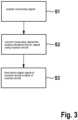
- FIG. 3shows steps of a method according to an example embodiment of the present invention.
- the deflection of the seismic mass caused by a rotary movement of sensor element 2is proportional to the yaw rate and is referred to as the useful signal component 11 in the following text.
- the frequency of this useful signal component 11is a function of the excitation frequency, that is, the frequency of the defined oscillation movement of the seismic mass.
- the frequency range of useful signal component 11which is termed the useful signal frequency range 30 , is therefore able to be defined very well.
- the measuring signalincludes at least one interference signal component 30 which superposes useful signal component 11 .
- an interference signal caused by a vibration of sensor element 2is superposed to the yaw rate signal. This is sketched in FIG. 1 by the frequency representation of vibration 20 acting on sensor element 2 .
- the measuring signal output by sensor element 2thus includes also undesired vibration signal 20 as an interference signal component.
- the frequency range of this vibration signal 20hereinafter referred to as interference signal frequency range, is likewise clearly defined, does not overlap with the useful signal frequency range and lies clearly above useful signal frequency range 30 , which may be gathered from the frequency representation 10 a of the measuring signal.
- Measuring signal 10 a acquired by sensor element 2is converted into an analog electrical measuring signal with the aid of readout circuit 3 .
- the acquisition of the measuring signaltakes place capacitively, and readout circuit 3 includes a capacitance-voltage converter having transmission function A(s) 3 ′ for converting measuring signal 10 into an analog electrical signal.
- a feedback circuit 5Situated between an output 3 b of capacitance-voltage converter 3 and an input 3 a of capacitance-voltage converter 3 is a feedback circuit 5 which applies a feedback circuit transmission function F(s) 5 ′ to the output signal of capacitance-voltage converter 3 that has the largest possible amplification outside the useful signal frequency range 30 , in particular in the interference signal frequency range.
- the amplificationthus occurs in the frequency range in which an undesired signal, e.g., vibration signal 20 or the like, appears.
- the lowest possible amplificationis used in the range of the useful signal frequency range 30 .
- the signal amplified in this wayis fed back to input 3 a of capacitance-voltage converter 3 by being subtracted from an input signal at input 3 a . This reduces undesired interference signal component 20 .
- the transmission functions A(s) 3 ′ and F(s) 5 ′result in a total transmission function H(s) for the two circuit components evaluation circuit 3 and feedback circuit 5 of sensor 1 according to
- H ⁇ ( s )A ⁇ ( s ) 1 + A ⁇ ( s ) ⁇ F ⁇ ( s )
- the total transmission function H(s)thus has the following characteristics:
- feedback circuit transmission function F(s) 5 ′is able to be provided with the aid of a notch filter in a useful signal frequency range 30 , a resonator at a frequency of an undesired interference signal to be expected, and/or with the aid of a high-pass filter for frequencies above useful signal frequency range 30 in feedback circuit 5 .
- the analog measuring signallargely purged of the interference signal component in the above-described manner, is then converted with the aid of an analog-to-digital converter 4 , ADC, into a digital signal that in essence is ultimately based on the useful signal component of the MEMS gyroscope.
- ADCanalog-to-digital converter 4
- FIG. 2shows the frequency representation of two gyroscope measuring signals that were recorded under identical test conditions, one without and one with the compensation according to the present invention of a vibration-related interference signal component.
- FIG. 2illustrates the effects of the measures by comparing frequency representations 20 and 20 ′ of two gyroscope measuring signals that were acquired under identical test conditions.
- the x-axisdenotes the frequency
- the y-axisdenotes the frequency components in the measuring signal.
- the gyroscopewas exposed to a mechanical vibration in this case, i.e., in a defined frequency range about the frequency X, in order to simulate an interference signal component in the gyroscope measuring signal.
- a DC voltagewas applied as the useful signal component so that the frequency range of useful signal component 11 lies at zero here.
- frequency representation 20no measures were taken to attenuate or compensate the vibration-related interference signal component in the gyroscope measuring signal.
- frequency representation 20 ′the measures for compensating for a vibration-related interference signal component as described in connection with the embodiments of FIG. 1 were applied, i.e., using an amplification factor of 100 in feedback circuit 5 .
- the comparative illustration of FIG. 2demonstrates that the measures attenuate the interference signal component by a factor of approximately 100 in each case while useful signal component 11 is essentially unaffected by feedback circuit 5 .
- FIG. 3shows steps of a method for reducing undesired signals in a sensor signal.
- the methodincludes the following steps:
- a measuring signalis acquired with the aid of the sensor, the measuring signal including at least one useful signal component in a useful signal frequency range and at least one interference signal component in an interference signal frequency range.
- the measuring signalis converted into an analog electrical sensor signal with the aid of a readout circuit.
- step S 3the output signal of the readout circuit is fed back to the input of the readout circuit at which the measuring signal is applied with the aid of a feedback circuit, and the total transmission function H(s) of the readout circuit and feedback circuit induces an attenuation of the analog electrical sensor signal in the interference signal frequency range, while the analog sensor signal in the useful signal frequency range is not attenuated.
- At least one of the embodiments of the present inventionoffers at least one of the following advantages:
Landscapes
- Engineering & Computer Science (AREA)
- Physics & Mathematics (AREA)
- General Physics & Mathematics (AREA)
- Manufacturing & Machinery (AREA)
- Microelectronics & Electronic Packaging (AREA)
- Gyroscopes (AREA)
Abstract
Description
- a. a sensor element for acquiring a measuring signal, the measuring signal including at least one useful signal component in a useful signal frequency range and at least one interference signal component in an interference signal frequency range, and
- b. a readout circuit for converting the measuring signal into an analog electrical sensor signal.
- Acquiring a measuring signal with the aid of the sensor, the measuring signal including at least one useful signal component in a useful signal frequency range and at least one interference signal component in an interference signal frequency range,
- converting the measuring signal into an analog electrical sensor signal with the aid of a readout circuit,
- feeding back the output signal of the readout circuit with the aid of a feedback circuit to the input of the readout circuit where the measuring signal is applied, the total transmission function H(s) of the readout circuit and feedback circuit causing an attenuation of the analog electrical sensor signal in the interference signal frequency range, while the analog sensor signal in the useful signal frequency range is not attenuated.
- a suppression of interference signals in a measuring signal essentially without an adverse effect on useful signals in the measuring signal,
- an improvement of the signal-to-noise ratio,
- an easier demodulation of sensor signals,
- an increased reliability of the sensor.
Claims (10)
Applications Claiming Priority (3)
| Application Number | Priority Date | Filing Date | Title |
|---|---|---|---|
| DE102019220545.3ADE102019220545A1 (en) | 2019-12-23 | 2019-12-23 | Sensor and method for reducing an interference signal component in a measurement signal of a sensor |
| DE102019220545.3 | 2019-12-23 | ||
| PCT/EP2020/082363WO2021129981A1 (en) | 2019-12-23 | 2020-11-17 | Sensor and method for reducing an interference signal component in a measurement signal of a sensor |
Publications (2)
| Publication Number | Publication Date |
|---|---|
| US20220381583A1 US20220381583A1 (en) | 2022-12-01 |
| US12209885B2true US12209885B2 (en) | 2025-01-28 |
Family
ID=73476130
Family Applications (1)
| Application Number | Title | Priority Date | Filing Date |
|---|---|---|---|
| US17/772,236Active2041-09-29US12209885B2 (en) | 2019-12-23 | 2020-11-17 | Sensor and method for reducing an interference signal component in a measuring signal from a sensor |
Country Status (4)
| Country | Link |
|---|---|
| US (1) | US12209885B2 (en) |
| CN (1) | CN114846299A (en) |
| DE (1) | DE102019220545A1 (en) |
| WO (1) | WO2021129981A1 (en) |
Citations (16)
| Publication number | Priority date | Publication date | Assignee | Title |
|---|---|---|---|---|
| AT274954B (en) | 1967-02-24 | 1969-10-10 | Wiener Schwachstromwerke Gmbh | LF signal generator for the optional output of sine or noise voltages |
| US4085361A (en)* | 1977-03-10 | 1978-04-18 | Wiltron Company | Measurement of frequency response with improved sensitivity and accuracy |
| WO1997028742A1 (en) | 1993-12-03 | 1997-08-14 | Hal Greenberger | Noise-reducing stethoscope |
| US5793230A (en)* | 1997-02-26 | 1998-08-11 | Sandia Corporation | Sensor readout detector circuit |
| CN101335501A (en) | 2007-06-26 | 2008-12-31 | 高林 | Current signal linear transmitting method |
| DE102008031643A1 (en) | 2008-07-04 | 2010-01-07 | Continental Automotive Gmbh | Receiver arrangement, in particular for use in motor vehicles |
| CN101742382A (en) | 2009-11-24 | 2010-06-16 | 北京中星微电子有限公司 | Active noise cancellation method and earphone |
| US20110172001A1 (en) | 2010-01-14 | 2011-07-14 | Austriamicrosystems Ag | Housing and Loudspeaker Module |
| US20120013351A1 (en) | 2008-09-19 | 2012-01-19 | Physical Logic Ag | Method for converting a sensor capacitance under parasitic capacitance conditions and a capacitance-to-voltage converter circuit |
| US20140314241A1 (en) | 2013-04-22 | 2014-10-23 | Vor Data Systems, Inc. | Frequency domain active noise cancellation system and method |
| US20150056940A1 (en) | 2013-08-23 | 2015-02-26 | Qualcomm Incorporated | Harmonic trap for common gate amplifier |
| CN106301259A (en) | 2016-08-17 | 2017-01-04 | 黎明职业大学 | A kind of pre-amplification circuit of D-type audio power amplifier |
| CN106461457A (en) | 2014-03-07 | 2017-02-22 | 激光和医药技术柏林有限责任公司 | Sensor device for high-resolution detection of target substances |
| US20170328713A1 (en) | 2015-02-09 | 2017-11-16 | Nxp Usa, Inc. | System comprising a mechanical resonator and method therefor |
| CN108827615A (en) | 2018-06-27 | 2018-11-16 | 哈尔滨工业大学 | Insertion Force Measurement System of Automotive Connectors |
| CN110380700A (en)* | 2019-08-23 | 2019-10-25 | 中国科学院地质与地球物理研究所 | Preamplifier, MEMS sensor reading circuit and MEMS sensor system |
Family Cites Families (8)
| Publication number | Priority date | Publication date | Assignee | Title |
|---|---|---|---|---|
| JPS5972600A (en)* | 1982-10-20 | 1984-04-24 | 防衛庁技術研究本部長 | Vehicle detection device |
| FR2595498B1 (en)* | 1986-03-07 | 1989-06-02 | Centre Nat Rech Scient | METHODS AND DEVICES FOR MITIGATING EXTERNAL NOISE ARISING AT TYMPAN AND IMPROVING THE INTELLIGIBILITY OF ELECTROACOUSTIC COMMUNICATIONS |
| CA2109755C (en)* | 1993-11-23 | 2004-11-02 | John Barry French | Composite bridge amplifier with output overload and thermal protection |
| DE102004064185B4 (en)* | 2004-03-03 | 2013-04-11 | Austriamicrosystems Ag | Sensor e.g. for magnetic field, has element which provides signal, containing interference signal for analyzer and connected to element with subtractor subtracts interference signal from signal |
| JP5071138B2 (en)* | 2008-02-13 | 2012-11-14 | 富士電機株式会社 | Negative current feedback circuit and DC-DC converter using the same |
| JP5517725B2 (en)* | 2009-05-15 | 2014-06-11 | キヤノン株式会社 | Fully differential amplifier circuit |
| US9136807B2 (en)* | 2013-07-16 | 2015-09-15 | Analog Devices, Inc. | Apparatus and methods for electronic amplification |
| WO2017195020A1 (en)* | 2016-05-11 | 2017-11-16 | Murata Manufacturing Co., Ltd. | A secondary sense loop with force feedback capability |
- 2019
- 2019-12-23DEDE102019220545.3Apatent/DE102019220545A1/enactivePending
- 2020
- 2020-11-17CNCN202080090027.8Apatent/CN114846299A/enactivePending
- 2020-11-17WOPCT/EP2020/082363patent/WO2021129981A1/ennot_activeCeased
- 2020-11-17USUS17/772,236patent/US12209885B2/enactiveActive
Patent Citations (16)
| Publication number | Priority date | Publication date | Assignee | Title |
|---|---|---|---|---|
| AT274954B (en) | 1967-02-24 | 1969-10-10 | Wiener Schwachstromwerke Gmbh | LF signal generator for the optional output of sine or noise voltages |
| US4085361A (en)* | 1977-03-10 | 1978-04-18 | Wiltron Company | Measurement of frequency response with improved sensitivity and accuracy |
| WO1997028742A1 (en) | 1993-12-03 | 1997-08-14 | Hal Greenberger | Noise-reducing stethoscope |
| US5793230A (en)* | 1997-02-26 | 1998-08-11 | Sandia Corporation | Sensor readout detector circuit |
| CN101335501A (en) | 2007-06-26 | 2008-12-31 | 高林 | Current signal linear transmitting method |
| DE102008031643A1 (en) | 2008-07-04 | 2010-01-07 | Continental Automotive Gmbh | Receiver arrangement, in particular for use in motor vehicles |
| US20120013351A1 (en) | 2008-09-19 | 2012-01-19 | Physical Logic Ag | Method for converting a sensor capacitance under parasitic capacitance conditions and a capacitance-to-voltage converter circuit |
| CN101742382A (en) | 2009-11-24 | 2010-06-16 | 北京中星微电子有限公司 | Active noise cancellation method and earphone |
| US20110172001A1 (en) | 2010-01-14 | 2011-07-14 | Austriamicrosystems Ag | Housing and Loudspeaker Module |
| US20140314241A1 (en) | 2013-04-22 | 2014-10-23 | Vor Data Systems, Inc. | Frequency domain active noise cancellation system and method |
| US20150056940A1 (en) | 2013-08-23 | 2015-02-26 | Qualcomm Incorporated | Harmonic trap for common gate amplifier |
| CN106461457A (en) | 2014-03-07 | 2017-02-22 | 激光和医药技术柏林有限责任公司 | Sensor device for high-resolution detection of target substances |
| US20170328713A1 (en) | 2015-02-09 | 2017-11-16 | Nxp Usa, Inc. | System comprising a mechanical resonator and method therefor |
| CN106301259A (en) | 2016-08-17 | 2017-01-04 | 黎明职业大学 | A kind of pre-amplification circuit of D-type audio power amplifier |
| CN108827615A (en) | 2018-06-27 | 2018-11-16 | 哈尔滨工业大学 | Insertion Force Measurement System of Automotive Connectors |
| CN110380700A (en)* | 2019-08-23 | 2019-10-25 | 中国科学院地质与地球物理研究所 | Preamplifier, MEMS sensor reading circuit and MEMS sensor system |
Non-Patent Citations (2)
| Title |
|---|
| Baali et al., "Empowering Technology Enabled Care Using IOT and Smart Devices: A Review," IEEE Sensors Journal, vol. 18, No. 5, 2018, pp. 1790-1809. |
| International Search Report for PCT/EP2020/082363, Issued Feb. 15, 2021. |
Also Published As
| Publication number | Publication date |
|---|---|
| CN114846299A (en) | 2022-08-02 |
| WO2021129981A1 (en) | 2021-07-01 |
| US20220381583A1 (en) | 2022-12-01 |
| DE102019220545A1 (en) | 2021-06-24 |
Similar Documents
| Publication | Publication Date | Title |
|---|---|---|
| Sung et al. | Design and performance test of a MEMS vibratory gyroscope with a novel AGC force rebalance control | |
| Sonmezoglu et al. | An automatically mode-matched MEMS gyroscope with wide and tunable bandwidth | |
| US8528403B2 (en) | Vibration compensation for yaw-rate sensors | |
| US10429405B2 (en) | Vibrating beam accelerometer | |
| US10018468B2 (en) | Physical-quantity detection circuit, physical-quantity sensor, and electronic device | |
| US9176165B2 (en) | Vibrating micro-system with automatic gain control loop, with integrated control of the quality factor | |
| US6467346B1 (en) | Coriolis sensor interface | |
| US20080148847A1 (en) | Vibration gyro sensor | |
| US8717575B2 (en) | Systems and methods for environmentally insensitive high-performance fiber-optic gyroscopes | |
| US11650055B2 (en) | MEMS gyroscope sensitivity compensation | |
| KR102064630B1 (en) | Transducer acceleration compensation using a delay to match phase characteristics | |
| JP2004526942A (en) | Method and apparatus for processing an analog output signal of a capacitive sensor | |
| US9846176B2 (en) | Acceleration sensor circuit | |
| KR20100069641A (en) | Absolute displacement detection method and absolute displacement sensor using the method | |
| US12209885B2 (en) | Sensor and method for reducing an interference signal component in a measuring signal from a sensor | |
| Saukoski et al. | Effects of synchronous demodulation in vibratory MEMS gyroscopes: A theoretical study | |
| RU2308682C1 (en) | Method of adjusting resonance frequency of suspension of movable mass of gyroscope | |
| US11513135B2 (en) | Method for automatic frequency adaptation of a filter in a closed loop | |
| JP3498209B2 (en) | External force detection sensor device | |
| DE102018121150B4 (en) | Method for detecting a frequency mismatch in a gyroscope and microelectromechanical (MEMS) devices | |
| RU2274833C1 (en) | Device for transforming signals of micro-mechanical vibration-type gyroscope | |
| JPH09145736A (en) | Acceleration and angular velocity composite sensor | |
| JP3750679B2 (en) | External force detection sensor device | |
| US3961535A (en) | Spin rate compensator | |
| US11719597B2 (en) | Measuring system and method for measuring the displacement of at least one point of a bridge |
Legal Events
| Date | Code | Title | Description |
|---|---|---|---|
| FEPP | Fee payment procedure | Free format text:ENTITY STATUS SET TO UNDISCOUNTED (ORIGINAL EVENT CODE: BIG.); ENTITY STATUS OF PATENT OWNER: LARGE ENTITY | |
| AS | Assignment | Owner name:ROBERT BOSCH GMBH, GERMANY Free format text:ASSIGNMENT OF ASSIGNORS INTEREST;ASSIGNORS:VISCONTI, ANDREA;DIAZZI, FRANCESCO;REEL/FRAME:060195/0820 Effective date:20220605 | |
| STPP | Information on status: patent application and granting procedure in general | Free format text:DOCKETED NEW CASE - READY FOR EXAMINATION | |
| STPP | Information on status: patent application and granting procedure in general | Free format text:NON FINAL ACTION MAILED | |
| STPP | Information on status: patent application and granting procedure in general | Free format text:RESPONSE TO NON-FINAL OFFICE ACTION ENTERED AND FORWARDED TO EXAMINER | |
| STPP | Information on status: patent application and granting procedure in general | Free format text:NOTICE OF ALLOWANCE MAILED -- APPLICATION RECEIVED IN OFFICE OF PUBLICATIONS | |
| STPP | Information on status: patent application and granting procedure in general | Free format text:AWAITING TC RESP., ISSUE FEE NOT PAID | |
| STPP | Information on status: patent application and granting procedure in general | Free format text:NOTICE OF ALLOWANCE MAILED -- APPLICATION RECEIVED IN OFFICE OF PUBLICATIONS | |
| STPP | Information on status: patent application and granting procedure in general | Free format text:PUBLICATIONS -- ISSUE FEE PAYMENT VERIFIED | |
| STCF | Information on status: patent grant | Free format text:PATENTED CASE |