US12208408B2 - Spray bottle having hinging and locking spray head assembly with replaceable components, and multi-label systems - Google Patents
Spray bottle having hinging and locking spray head assembly with replaceable components, and multi-label systemsDownload PDFInfo
- Publication number
- US12208408B2 US12208408B2US17/507,147US202117507147AUS12208408B2US 12208408 B2US12208408 B2US 12208408B2US 202117507147 AUS202117507147 AUS 202117507147AUS 12208408 B2US12208408 B2US 12208408B2
- Authority
- US
- United States
- Prior art keywords
- bottle
- spray head
- spray
- assembly
- neck
- Prior art date
- Legal status (The legal status is an assumption and is not a legal conclusion. Google has not performed a legal analysis and makes no representation as to the accuracy of the status listed.)
- Active, expires
Links
Images


Classifications
- B—PERFORMING OPERATIONS; TRANSPORTING
- B05—SPRAYING OR ATOMISING IN GENERAL; APPLYING FLUENT MATERIALS TO SURFACES, IN GENERAL
- B05B—SPRAYING APPARATUS; ATOMISING APPARATUS; NOZZLES
- B05B11/00—Single-unit hand-held apparatus in which flow of contents is produced by the muscular force of the operator at the moment of use
- B05B11/0005—Components or details
- B05B11/0008—Sealing or attachment arrangements between sprayer and container
- B—PERFORMING OPERATIONS; TRANSPORTING
- B05—SPRAYING OR ATOMISING IN GENERAL; APPLYING FLUENT MATERIALS TO SURFACES, IN GENERAL
- B05B—SPRAYING APPARATUS; ATOMISING APPARATUS; NOZZLES
- B05B11/00—Single-unit hand-held apparatus in which flow of contents is produced by the muscular force of the operator at the moment of use
- B05B11/0005—Components or details
- B05B11/0027—Means for neutralising the actuation of the sprayer ; Means for preventing access to the sprayer actuation means
- B—PERFORMING OPERATIONS; TRANSPORTING
- B05—SPRAYING OR ATOMISING IN GENERAL; APPLYING FLUENT MATERIALS TO SURFACES, IN GENERAL
- B05B—SPRAYING APPARATUS; ATOMISING APPARATUS; NOZZLES
- B05B11/00—Single-unit hand-held apparatus in which flow of contents is produced by the muscular force of the operator at the moment of use
- B05B11/0005—Components or details
- B05B11/0089—Dispensing tubes
- B05B11/0091—Dispensing tubes movable, e.g. articulated on the sprayer
- B—PERFORMING OPERATIONS; TRANSPORTING
- B05—SPRAYING OR ATOMISING IN GENERAL; APPLYING FLUENT MATERIALS TO SURFACES, IN GENERAL
- B05B—SPRAYING APPARATUS; ATOMISING APPARATUS; NOZZLES
- B05B11/00—Single-unit hand-held apparatus in which flow of contents is produced by the muscular force of the operator at the moment of use
- B05B11/01—Single-unit hand-held apparatus in which flow of contents is produced by the muscular force of the operator at the moment of use characterised by the means producing the flow
- B05B11/04—Deformable containers producing the flow, e.g. squeeze bottles
- B05B11/042—Deformable containers producing the flow, e.g. squeeze bottles the spray being effected by a gas or vapour flow in the nozzle, spray head, outlet or dip tube
- B05B11/043—Deformable containers producing the flow, e.g. squeeze bottles the spray being effected by a gas or vapour flow in the nozzle, spray head, outlet or dip tube designed for spraying a liquid
- B—PERFORMING OPERATIONS; TRANSPORTING
- B05—SPRAYING OR ATOMISING IN GENERAL; APPLYING FLUENT MATERIALS TO SURFACES, IN GENERAL
- B05B—SPRAYING APPARATUS; ATOMISING APPARATUS; NOZZLES
- B05B11/00—Single-unit hand-held apparatus in which flow of contents is produced by the muscular force of the operator at the moment of use
- B05B11/01—Single-unit hand-held apparatus in which flow of contents is produced by the muscular force of the operator at the moment of use characterised by the means producing the flow
- B05B11/04—Deformable containers producing the flow, e.g. squeeze bottles
- B05B11/047—Deformable containers producing the flow, e.g. squeeze bottles characterised by the outlet or venting means
- B—PERFORMING OPERATIONS; TRANSPORTING
- B05—SPRAYING OR ATOMISING IN GENERAL; APPLYING FLUENT MATERIALS TO SURFACES, IN GENERAL
- B05B—SPRAYING APPARATUS; ATOMISING APPARATUS; NOZZLES
- B05B11/00—Single-unit hand-held apparatus in which flow of contents is produced by the muscular force of the operator at the moment of use
- B05B11/01—Single-unit hand-held apparatus in which flow of contents is produced by the muscular force of the operator at the moment of use characterised by the means producing the flow
- B05B11/10—Pump arrangements for transferring the contents from the container to a pump chamber by a sucking effect and forcing the contents out through the dispensing nozzle
- B05B11/1001—Piston pumps
- B05B11/1009—Piston pumps actuated by a lever
- B05B11/1011—Piston pumps actuated by a lever without substantial movement of the nozzle in the direction of the pressure stroke
- B—PERFORMING OPERATIONS; TRANSPORTING
- B05—SPRAYING OR ATOMISING IN GENERAL; APPLYING FLUENT MATERIALS TO SURFACES, IN GENERAL
- B05B—SPRAYING APPARATUS; ATOMISING APPARATUS; NOZZLES
- B05B11/00—Single-unit hand-held apparatus in which flow of contents is produced by the muscular force of the operator at the moment of use
- B05B11/01—Single-unit hand-held apparatus in which flow of contents is produced by the muscular force of the operator at the moment of use characterised by the means producing the flow
- B05B11/10—Pump arrangements for transferring the contents from the container to a pump chamber by a sucking effect and forcing the contents out through the dispensing nozzle
- B05B11/1028—Pumps having a pumping chamber with a deformable wall
- B05B11/1029—Pumps having a pumping chamber with a deformable wall actuated by a lever
- B05B11/103—Pumps having a pumping chamber with a deformable wall actuated by a lever without substantial movement of the nozzle in the direction of the pressure stroke
- B—PERFORMING OPERATIONS; TRANSPORTING
- B05—SPRAYING OR ATOMISING IN GENERAL; APPLYING FLUENT MATERIALS TO SURFACES, IN GENERAL
- B05B—SPRAYING APPARATUS; ATOMISING APPARATUS; NOZZLES
- B05B15/00—Details of spraying plant or spraying apparatus not otherwise provided for; Accessories
- B05B15/14—Arrangements for preventing or controlling structural damage to spraying apparatus or its outlets, e.g. for breaking at desired places; Arrangements for handling or replacing damaged parts
- B05B15/18—Arrangements for preventing or controlling structural damage to spraying apparatus or its outlets, e.g. for breaking at desired places; Arrangements for handling or replacing damaged parts for improving resistance to wear, e.g. inserts or coatings; for indicating wear; for handling or replacing worn parts
- B—PERFORMING OPERATIONS; TRANSPORTING
- B05—SPRAYING OR ATOMISING IN GENERAL; APPLYING FLUENT MATERIALS TO SURFACES, IN GENERAL
- B05B—SPRAYING APPARATUS; ATOMISING APPARATUS; NOZZLES
- B05B15/00—Details of spraying plant or spraying apparatus not otherwise provided for; Accessories
- B05B15/60—Arrangements for mounting, supporting or holding spraying apparatus
- B05B15/63—Handgrips
- B—PERFORMING OPERATIONS; TRANSPORTING
- B05—SPRAYING OR ATOMISING IN GENERAL; APPLYING FLUENT MATERIALS TO SURFACES, IN GENERAL
- B05B—SPRAYING APPARATUS; ATOMISING APPARATUS; NOZZLES
- B05B15/00—Details of spraying plant or spraying apparatus not otherwise provided for; Accessories
- B05B15/60—Arrangements for mounting, supporting or holding spraying apparatus
- B05B15/65—Mounting arrangements for fluid connection of the spraying apparatus or its outlets to flow conduits
- B05B15/652—Mounting arrangements for fluid connection of the spraying apparatus or its outlets to flow conduits whereby the jet can be oriented
- B—PERFORMING OPERATIONS; TRANSPORTING
- B05—SPRAYING OR ATOMISING IN GENERAL; APPLYING FLUENT MATERIALS TO SURFACES, IN GENERAL
- B05B—SPRAYING APPARATUS; ATOMISING APPARATUS; NOZZLES
- B05B15/00—Details of spraying plant or spraying apparatus not otherwise provided for; Accessories
- B05B15/60—Arrangements for mounting, supporting or holding spraying apparatus
- B05B15/65—Mounting arrangements for fluid connection of the spraying apparatus or its outlets to flow conduits
- B05B15/658—Mounting arrangements for fluid connection of the spraying apparatus or its outlets to flow conduits the spraying apparatus or its outlet axis being perpendicular to the flow conduit
- B—PERFORMING OPERATIONS; TRANSPORTING
- B05—SPRAYING OR ATOMISING IN GENERAL; APPLYING FLUENT MATERIALS TO SURFACES, IN GENERAL
- B05B—SPRAYING APPARATUS; ATOMISING APPARATUS; NOZZLES
- B05B15/00—Details of spraying plant or spraying apparatus not otherwise provided for; Accessories
- B05B15/60—Arrangements for mounting, supporting or holding spraying apparatus
- B05B15/68—Arrangements for adjusting the position of spray heads
- G—PHYSICS
- G09—EDUCATION; CRYPTOGRAPHY; DISPLAY; ADVERTISING; SEALS
- G09F—DISPLAYING; ADVERTISING; SIGNS; LABELS OR NAME-PLATES; SEALS
- G09F3/00—Labels, tag tickets, or similar identification or indication means; Seals; Postage or like stamps
- G09F3/04—Labels, tag tickets, or similar identification or indication means; Seals; Postage or like stamps to be fastened or secured by the material of the label itself, e.g. by thermo-adhesion
- B—PERFORMING OPERATIONS; TRANSPORTING
- B05—SPRAYING OR ATOMISING IN GENERAL; APPLYING FLUENT MATERIALS TO SURFACES, IN GENERAL
- B05B—SPRAYING APPARATUS; ATOMISING APPARATUS; NOZZLES
- B05B11/00—Single-unit hand-held apparatus in which flow of contents is produced by the muscular force of the operator at the moment of use
- B05B11/0005—Components or details
- B05B11/0037—Containers
- B—PERFORMING OPERATIONS; TRANSPORTING
- B05—SPRAYING OR ATOMISING IN GENERAL; APPLYING FLUENT MATERIALS TO SURFACES, IN GENERAL
- B05B—SPRAYING APPARATUS; ATOMISING APPARATUS; NOZZLES
- B05B11/00—Single-unit hand-held apparatus in which flow of contents is produced by the muscular force of the operator at the moment of use
- B05B11/01—Single-unit hand-held apparatus in which flow of contents is produced by the muscular force of the operator at the moment of use characterised by the means producing the flow
- B05B11/10—Pump arrangements for transferring the contents from the container to a pump chamber by a sucking effect and forcing the contents out through the dispensing nozzle
- B05B11/1042—Components or details
- B05B11/1066—Pump inlet valves
- B05B11/1067—Pump inlet valves actuated by pressure
- B—PERFORMING OPERATIONS; TRANSPORTING
- B05—SPRAYING OR ATOMISING IN GENERAL; APPLYING FLUENT MATERIALS TO SURFACES, IN GENERAL
- B05B—SPRAYING APPARATUS; ATOMISING APPARATUS; NOZZLES
- B05B15/00—Details of spraying plant or spraying apparatus not otherwise provided for; Accessories
- B05B15/30—Dip tubes
- B—PERFORMING OPERATIONS; TRANSPORTING
- B05—SPRAYING OR ATOMISING IN GENERAL; APPLYING FLUENT MATERIALS TO SURFACES, IN GENERAL
- B05B—SPRAYING APPARATUS; ATOMISING APPARATUS; NOZZLES
- B05B3/00—Spraying or sprinkling apparatus with moving outlet elements or moving deflecting elements
- B05B3/02—Spraying or sprinkling apparatus with moving outlet elements or moving deflecting elements with rotating elements
- B05B3/04—Spraying or sprinkling apparatus with moving outlet elements or moving deflecting elements with rotating elements driven by the liquid or other fluent material discharged, e.g. the liquid actuating a motor before passing to the outlet
- B05B3/0417—Spraying or sprinkling apparatus with moving outlet elements or moving deflecting elements with rotating elements driven by the liquid or other fluent material discharged, e.g. the liquid actuating a motor before passing to the outlet comprising a liquid driven rotor, e.g. a turbine
- B05B3/0429—Spraying or sprinkling apparatus with moving outlet elements or moving deflecting elements with rotating elements driven by the liquid or other fluent material discharged, e.g. the liquid actuating a motor before passing to the outlet comprising a liquid driven rotor, e.g. a turbine the rotating outlet elements being directly attached to the rotor or being an integral part thereof
- B05B3/043—Rotor nozzles
- B05B3/0463—
- G—PHYSICS
- G09—EDUCATION; CRYPTOGRAPHY; DISPLAY; ADVERTISING; SEALS
- G09F—DISPLAYING; ADVERTISING; SIGNS; LABELS OR NAME-PLATES; SEALS
- G09F3/00—Labels, tag tickets, or similar identification or indication means; Seals; Postage or like stamps
- G09F3/02—Forms or constructions
- G09F2003/0272—Labels for containers
- G09F2003/0273—Labels for bottles, flasks
Definitions
- This disclosurerelates generally to janitorial-related products and services, and more particularly to spray bottle systems having hinging handle and spray head assemblies, serviceable or replaceable pump function components and a multi-label system.
- a typical conventional spray bottleused for dispensing liquids by trigger action by a user, may include a spray head that is rigidly attached to a bottle containing a solution.
- the spray headis typically mounted on a vertically extending neck.
- the spray headis typically directed to spray a solution along an axis perpendicular with a vertical bottle situated below the spray head.
- Such an arrangementreasonably serves when the intended target is easily reached by a horizontal spray trajectory.
- the vertical height of a rigidly upstanding neckcan prevent such a bottle from being used and stored in small spaces.
- tilting of the bottlecan cause the lower end of an internal liquid-drawing tube to rise above the solution in the reservoir, particularly as the solution is low in quantity.
- a spray bottle assemblyincludes: a bottle for containing a liquid, the bottle having a neck; and a spray head assembly having a base cap configured to removably attach to the neck of the bottle, and a spray head pivotally attached to the base cap, the base cap including at least one feature that rotationally locks the base cap relative to the neck of the bottle to constrain the spray head to pivoting in a predetermined vertical plane.
- the base capincludes an insert for placement in the neck of the bottle, and the at least one feature that rotationally locks the base cap includes at least one notch in the insert.
- the neck of the bottleincludes an interior protrusion received in the notch.
- the spray bottle assemblyfurther includes a collar that secures the base cap to the neck of the bottle by rotating the collar relative to the neck of the bottle.
- the protrusion received in the notchprevents the base cap from rotating relative to the neck of the bottle when the collar is rotated and thereby tightened.
- the spray head assemblymay include a handle to which the spray head is connected, the handle pivotally attached to the base cap by a hinge that permits pivoting of the handle and spray head in the predetermined vertical plane.
- the hingemay permit the spray head assembly to pivot to a stowed position for carrying or compact storage.
- the spray head and the bottlemay interact to include a security protrusion configured to lock the spray head assembly in the stowed position.
- the spray head assemblymay include a nozzle and an operable trigger, and actuation of the trigger causes dispensation of solution from the bottle through the nozzle.
- the triggermay be compressed side to side to make it easily removable.
- the spray head assemblymay include a spinner rotationally driven by fluid flow as the solution is dispensed, wherein the spinner facilitates an angularly even distribution of solution through the nozzle.
- a spinner carrierthat receives the spinner such that it seals, wherein the combination of the spinner and spinner carrier are housed within a pivoting assembly that allows the spinner carrier assembly to be easily removed.
- a pumping mechanismmay include: a unibody plunger having a sleeve section that variably inverts and overlaps, as the trigger is actuated, an end thereof thus defining an internal volume that varies with the disposition of the sleeve section relative to the end.
- the spray headmay hinge open for servicing.
- the spray headmay include a pivoting assembly that hinges away from the rearward end thereof, carrying a trigger and nozzle with the forward end permitting removal, servicing, or replacement of a spinner from the forward section when the spray head is hinged open.
- a multi-label system for a spray bottleincluding: at least one strip, the strip including multiple connected labels, each label including a ring for positioning on a neck of the spray bottle, each ring including at least one feature that rotationally locks the label thereof relative to the neck of the bottle, wherein the strip has preformed bends for folding, and wherein the strip has printed information on both of two sides thereof.
- the at least one feature that rotationally locks the labelmay be one of male and female, and the neck of the bottle may have a corresponding feature that engages the at least one feature, and wherein the corresponding feature may be the other of male and female.
- a flapmay be attached to each ring within the system by the preformed bend.
- the stripmay be folded in such a way as to present only a chosen label as visible when positioned on the neck of the spray bottle.
- the flapmay include information relating to contents that the user has chosen to use in the spray bottle.
- the at least one featurecaptures the folded flap of the label such that it is presented in a vertical plane.
- the at least one feature that rotationally locks the labelincludes a tab extending inward from the ring to be received in a recess in the neck of the bottle.
- At least one label of the multiple labelsmay include a QR code that provides access to detailed information.
- QR codes located on each individual label within the multi-label systemmay provide use and safety information that represents the type of chemical contained in the bottle, as chosen by the user.
- Multiple electronic markings, such as bar codes, located on each individual label within the multi-label systemmay provide coded information that may be read by an automated mixing and filling machine, thereby dispensing a proper mix and amount of chemical when the label system, attached to the bottle is placed in proximity to the machine sensor.
- Each individual label within the systemmay be color coded with specific colors indicating predetermined types of chemical for casual and instantaneous recognition of the contents.
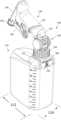
- FIG. 1is a perspective view of a spray bottle assembly, according to at least one embodiment, shown with the handle and spray head thereof hinged partially forward end downward.
- FIG. 2is a perspective view of a top portion of the spray bottle assembly of FIG. 1 , shown with the handle and spray head hinged fully downward and locked.
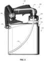
- FIG. 3is a cross-sectioned view of the spray bottle assembly of FIG. 1 taken approximately along a vertical mid plane about which the spray bottle assembly is approximately symmetric.
- FIG. 4is an exploded perspective view of the spray bottle assembly of FIG. 1 .
- FIG. 5is an exploded perspective view of the spray head assembly according to FIG. 1 .
- FIG. 6 Ais a perspective view of a spray head and pumping mechanism, according to another embodiment, having a flexible unibody plunger, shown in a solution-loaded position before actuation.
- FIG. 6 Bshows the spray head and pumping mechanism of FIG. 6 A after pressing of the trigger and actuation of the mechanism thereby dispensing the solution.
- FIG. 6 Cis a cross section view of the spray head and pumping mechanism as in FIG. 6 A .
- FIG. 6 Dis a cross section view of the spray head and pumping mechanism as in FIG. 6 B .
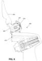
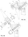
- FIG. 8is a cross sectional view of the spray head assembly of FIG. 7 , assembled with the pivoting assembly pivoted to an open position for access to the spinner carrier assembly.
- FIG. 9is a cross sectional exploded view of the spray head assembly as in FIG. 8 .
- FIG. 10 Bshows a second side of the multi-label strip of FIG. 10 A .
- FIG. 10 Dis an elevation view of either side of the multi-label strip of FIG. 10 C .
- FIG. 10 Eis an elevation view of either end of the multi-label strip of FIG. 10 C .
- FIG. 10 Gis a perspective view of the multi-label strip of FIG. 10 C in a multi-folded condition.
- FIG. 12is an exploded perspective view of the spray head assembly of FIG. 11 , with the pivoting assembly pivoted and snapped into its closed position thereby capturing the spinner carrier assembly.
- FIG. 13 Ais a cross sectional view of the spray head assembly of FIG. 11 as assembled with the spray head in its closed position thereby capturing the spinner carrier.
- FIG. 13 Bis a cross sectional view of the spray head assembly of FIG. 11 , with the spray head thereof pivoted to the open position and the spinner carrier removed.
- FIG. 1is a perspective view of an improved spray bottle assembly 100 according to at least one embodiment.
- the spray bottle assembly 100includes a bottle 110 in which a solution is contained in use.
- the bottle 110is shown as having a greater length 112 than width 114 and as having an upper neck 116 ( FIG. 4 ) having external threads that engage the internal threads of a collar 130 .
- a spray head assembly 140is mounted on the top of the bottle 110 .
- the spray head assemblyhas a base cap 142 , which caps the bottle 110 .
- the base cap 142has a lower portion referenced as an insert 144 ( FIG. 4 ) that slips partially into the neck 116 of the bottle 110 upon assembly, for example after refilling the bottle with a solution.
- a flange 146 around the insert 144is captured between the upper end of the neck 116 and the collar 130 , and the collar is tightened to securely mount the spray head assembly 140 on the bottle 110 .
- An O-ring 138 or other gasketmay be trapped between the flange 144 and neck 116 to assure a seal.
- the spray head assembly 140has a handle 150 , a trigger 180 , and a spray head 190 mounted on the handle.
- a pumping mechanism within the spray head 190is actuated, which draws solution through a tubular conduit path from the interior of the bottle 110 and squirts the solution from a forward nozzle 192 .
- the trajectory of the dispensed solutionvaries with the pivot position of the handle 150 , which is mounted on the base cap 142 portion of the spray head assembly 140 by an intermediate hinge 160 ( FIGS. 1 - 2 ).
- the hinge-mounted handle 150is shown rotated partially forward end downward, below a horizontal axis.
- the handle 150is hinged fully downward with the spray head 190 locked in a lowest and stowed position.
- the spray head assembly 140extends centrally from the top of the bottle with respect to the width 114 .
- the spray head assembly 140extends from the rear end of the top of the bottle 110 with respect to the length 112 .
- the elongated cantilevered form of the bottlecauses the bottle to rotate such that the bottom of the fill tube is always located at the lowermost part of the bottle volume, thereby funneling all fluid towards the end of the fill tube no matter the angled orientation of the spray head.
- the shorter form factor of the stored configurationis much more space efficient, saving transportation and storage costs.
- the forward nozzle 192is rotatable to vary the shape of discharged fluid flow from a widely dispersed cone or other pattern to a concentrated stream.
- the nozzlehas multiple outwardly extending security clips 194 by which the nozzle 192 engages the forward end of the bottle. In the lowered and locked position of the handle 150 , a clip 194 can engage an overhang 196 ( FIG. 2 ) extending forward from the top of bottle 110 .
- the multiple clips 194 of the nozzle 192advantageously permit the locking of the spray head assembly 140 in multiple rotational positions of the nozzle 192 , as any one of the clips 194 can be rotated or snapped into the groove 198 defined below the overhang 196 , locking the spray head assembly 140 into its stowed position for carrying or compact storage.
- the engaged clip 194Upon rotation of the nozzle, or flexing of the spray head, the engaged clip 194 exits the groove 198 and disengages the overhang 196 , releasing the spray head assembly 140 to be raised for use.
- the trigger 180In the stowed position of FIG. 2 , the trigger 180 is inaccessible such that accidental discharge is prevented.
- the clips 194constitute a child lock system preventing use of the spray bottle assembly 100 by a child when the spray head assembly 140 is locked into its stowed position.
- FIG. 3shows the spray bottle assembly 100 cross sectioned approximately along a vertical mid plane about which the spray bottle assembly is approximately symmetric.
- FIG. 4is an exploded view of the spray bottle assembly 100 in which the components of the hinge 160 ( FIGS. 1 - 2 ) that joins the proximal end 152 of the handle 150 with the upper end of the base cap 142 ( FIG. 4 ) are shown.
- a pair of laterally spaced annuli 154 extending from the proximal end 152 of the handle 150align with a mount 162 on the base cap 142 opposite the insert 144 .
- Laterally inserted hinge caps 164maintain a hinged engagement of the annuli 154 and mount 162 thereby pivotally attaching the handle 150 to the base cap 142 .
- a tubular conduit path for conveying solution from the bottle to the spray head 190is defined by a siphon tube 170 ( FIGS. 3 - 4 ) carried by and within the bottle 110 , and an upper tube 172 carried by the spray head assembly 140 , which are joined at the base cap 142 . The junction is maintained as the spray head assembly is pivoted into various in-use positions.
- the proximal end of the trigger 180has a slot 188 between the posts 184 , permitting the proximal end of the trigger to be squeezed laterally, compressed side to side, for example by hand. This narrows the slot and permits the posts 184 to enter or exit the mounting holes 186 .
- the trigger 180is shown compressed for example in FIGS. 7 and 11 . This permits the trigger 180 and pumping mechanism 200 to be removed, to be serviced or replaced in whole or in part, and returned for use. Release of the laterally squeezing force on the sides of the trigger permit the slot 188 to re-expand and thus pivotally mount the trigger 180 by way of the posts 184 in the mounting holes 186 .
- the easy removal of the triggerpermits access by the user to the piston for easy replacement and refurbishment of worn units.
- the pumping mechanism 200in the embodiment of FIG. 5 , has a trigger-return spring 202 , a rigid piston 204 , a flexible piston seal 206 , and piston backer 208 .
- the piston seal 206acts to seal with the surrounding cylindrical inner wall of the housing 210 .
- the rigid piston 204carries the piston seal 206 and provides a rigid part to provide rigid stability against the trigger pull.
- the piston backer 208holds the piston seal 206 against the cylinder wall, particularly when the piston is returning to its resting position, so that it doesn't draw air past the seal.
- the trigger 180When a user presses the trigger 180 , the trigger presses the rigid piston 204 into housing 210 of the mechanism 200 , which forces the rigid piston 206 and piston seal 208 toward the rear wall of the housing 210 thereby pumping solution into a conduit 212 toward the nozzle 192 .
- a spinner 230is rotationally driven by the fluid flow and regularizes the flow rate as the solution is expelled.
- the spinner 230facilitates an angularly even distribution of sprayed solution when a widely dispersed cone or other pattern is selected for fluid spray by user-selected rotational position of the nozzle.
- the rearward end of the nozzlehas internal threads that engage external threads of the forward end of the spray head 190 .
- the nozzle 192 and spinner 230can be removed by unscrewing the nozzle from the spray head in the embodiment of FIG. 5 .
- the nozzle 192can be easily removed, replaced, or serviced. Multiple nozzle options may be available for various spray pattern options.
- the forward end of the spinner 230has offset vents through which solution traveling along the conduit passes to reach the nozzle 192 .
- the flows through the ventscause the fluid passing through the spinner 230 to rotate around the axis of travel of the solution within the conduit 212 .
- the rearward end of the spinnerhas a loop 236 that provides spring force to seal the rearward end of the spinner to an adjacent surface within the receptacle that receives the spinner, thereby sealing the outlet and preventing the intake of air into the system when the trigger is released.
- FIGS. 6 A and 6 Bshow a spray head 260 with a pumping mechanism 262 according to an alternative embodiment.
- the illustrated embodimentincludes a flexible unibody plunger 264 , shown in a solution-loaded position before actuation in FIG. 6 A and FIG. 6 C ; and, in FIG. 6 B and FIG. 6 D , after pressing of the trigger 180 and actuation of the mechanism thereby dispensing the solution.
- the plunger 264can be termed as unibody in that it can be formed as a one-piece item of flexible contiguous material, for example as a molded elastomeric item.
- the unibody plunger 264can be described as a pistonless pressure element.
- a one-way ball seal 220permits filling of the housing 210 as the trigger-return spring 202 returns the trigger to the un-pressed position, readying the pumping mechanism for a next pumping cycle by pressing of the trigger again.
- the ball seal 220prevents back flow of the solution within the housing back toward the bottle.
- the pumped solutionenters the inner spray head conduit 212 from the rear of the housing 210 and travels forward toward the nozzle 192 .
- the trigger 180When a user presses the trigger 180 , transitioning the mechanism 262 from FIG. 6 C to FIG. 6 D , the trigger presses the support cap 270 into the housing of the mechanism, which forces the unibody plunger 264 to further invert, increasing the overlap of the sleeve section 266 around the forward end 268 , decreasing the defined internal volume, thereby pumping solution into the conduit 212 toward the nozzle 192 .
- FIGS. 7 - 9illustrate a spray head 400 , according to another embodiment, having a pivoting assembly 402 that hinges away from the rearward end of the spray head, carrying the trigger 180 , spinner carrier 404 , spinner 230 and nozzle 192 .
- the spinner carrier 404receives the spinner 230 such that it seals.
- the combination of the spinner 230 and spinner carrier 404referenced as the spinner carrier assembly 406 , are housed within the pivoting assembly 402 that allows the spinner carrier assembly 406 to be easily removed and replaced.
- the sealed fit of the spinner 230 to the spinner carrier 404is a precision fit that is critical to spray function. It is advantageous, therefore to replace them as a fitted pair versus precise consumer replacement of a spinner 230 alone.
- the pivoting assembly 402hinges open permitting removal, servicing, and/or replacement of the spinner 230 and spinner carrier 404 through the breach when the spray head is hinged open as in FIG. 8 .
- the nozzle 192can be unscrewed from the forward end of the pivoting assembly as in FIG. 9 .
- Components of the pump mechanismcan be conveniently replaced or serviced with the pivoting assembly hinged open.
- the pivoting assemblyhas a base 410 pivotally connected by a hinge 412 to the forward end of the spray head 400 , and a pair of hooks 414 at lateral sides of the base to snap into engagement into corresponding slots 416 of the spray head, thereby latching the pivoting assembly in the closed position.
- An O-ring 420 in a circular recess in the front face of the spray head 400seals with the pivoting assembly when in the closed position.
- FIGS. 10 A and 10 Bshow elements of a multi-label system for use, as a non-limiting example, with the above described embodiments of spray bottle assemblies and other spray bottles as well.
- a label strip 300in the illustrated embodiment, has two sides referenced nominally and respectively as a first side 300 A in FIG. 10 A , and second side 300 A ( FIG. 10 B ) opposite the first side.
- each side ( 300 A, 300 B) of the strip 300includes four labels 302 , any one of which can be selected for display by a user.
- the two sides 300 A and 300 Bthus provide the user with eight labels from which to choose in the illustrated embodiment.
- a usercan selectively fold the strip 300 to display a chosen label and mount the folded strip on the neck 116 of a bottle 110 .
- a usercan also separate a selected label from a strip and mount just the label on the neck of the bottle.
- adjacent labelsare connected by lines 280 or cusps 282 .
- the lines 280can be engineered lines of weakness or intended fold or separation lines, which may be perforated or thinned.
- the cusps 282are the junctions of tangentially connected neck rings 284 .
- Each labelincludes a neck ring 284 and a presentation flap 286 .
- a preformed bend or fold line 288is defined between each ring 284 and flap 286 to better present the flap when the label is mounted as shown in FIG. 1 , in which the example label 302 a is particularly illustrated.
- Each neck ringhas inward extending tabs 290 that are received by corresponding respective recesses 135 defined by the exterior of the neck 116 of the bottle 110 (see FIG. 4 ) as the ring is positioned onto the neck. This rotationally locks the label from rotating as the collar 130 is placed and tightened on the neck, capturing the neck ring 284 between the top of the bottle 110 and collar 130 .
- Each presentation flap 286may include respective text and/or graphical indicia for viewing by a user so as to provide information of the current contents of the bottle.
- Each presentation flapmay include a respective QR code, one of which is referenced as QR code 292 in FIGS. 1 and 10 A , for enabling automatic access to information, for example, via the internet, for material safety information, product ordering functions, and other uses.
- Each presentation flap 286may be color coded with specific colors indicating predetermined types of chemical for casual and instantaneous recognition of the contents.
- a QR code, bar code or other automated reference markingmay be included for the purposes of refilling the bottle using an automated filling station that automatically reads the reference marking and fills the bottle with a volume of chemical solution designated by the reference marking.
- the material portions of the neck that define the recesses 135 that rotationally lock the neck rings 284 of the labelsare the same as those that define the protrusions 134 that rotationally lock the insert 144 and spray head assembly 140 therewith.
- the engineered material feature that defines the exterior recesses 135 and interior protrusions 134is dual purpose, defining both a recess and a protrusion on opposite (exterior and interior) sides of the material of the neck.
- a capture feature 136formed as an indentation in the bottle exterior near the upper neck 116 , receives an edge of the flap 286 and locks the flap in a vertical plane for optimal visibility.
- the label 302 ahas text indicia 304 of “BATHROOM” indicating suggested use or contents of a spray bottle assembly on which the label 300 is mounted.
- the other labels expressly shown in FIGS. 10 A and 10 Bprovide further examples, and many others not expressly shown are within the scope of these descriptions and drawings.
- the presentation flap 286 thereofis blank. The user can choose from multiple preprinted labels to apply, the preprinted information corresponding to the type of chemical contained in the bottle by user choice. A blank is provided for custom user labeling.
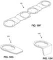
- FIG. 10 C- 10 Hshow a multi-label strip 430 in various views without text or graphical indicia to represent, for example, the label strip 300 before such indicia is applied or to represent a label strip generically with or without indicia.
- FIG. 10 Dcan be viewed as either side of the multi-label strip of FIG. 10 C .
- Another side viewis not expressly shown in the drawings, but would appear as a mirror image of that shown in FIG. 10 D , thus having a shape and appearance that would be evident from the one shown.
- FIG. 10 Ecan be viewed as either end of the multi-label strip of FIG. 10 C .
- Another end viewis not expressly shown in the drawings, but would appear as a mirror image of that shown in FIG. 10 E .
- the multi-label strip 430can be transitioned from a flat condition as in FIG. 10 F , to an in use condition, as represented in FIGS. 1 - 3 , by a user selecting a particular side and label thereof for presentation, and applying multiple folds accordingly.
- FIG. 10 Gthe label strip is folded to present a selected label.
- FIG. 10 Ha final bend is applied to prepare the label strip for mounting, as a non-limiting example, on a spray bottle assembly as in FIGS. 1 - 3 or other spray bottles.
- FIGS. 11 , 12 , and 13 A- 13 Bshow a spray head assembly 320 , according to another embodiment, having a pivoting assembly 322 that hinges away from the rearward end of the spray head 324 , carrying the trigger 180 , spinner carrier 326 , spinner 230 and nozzle 192 .
- the spinner carrier 326receives the spinner 230 such that it seals.
- the combination of the spinner 230 and spinner carrier 240referenced as the spinner carrier assembly 330 , are housed within the pivoting assembly 322 that allows the spinner carrier assembly 330 to be easily removed and replaced.
- An O-ring 332FIG.
- the pivoting assembly 322seals the rearward end of the spinner carrier assembly 330 against the forward end of the spray head 324 when the pivoting assembly 322 is snapped closed ( FIG. 12 ), thereby capturing the spinner carrier assembly 330 .
- the threaded forward end of the spinner carrier 326extends forward and the nozzle 192 can be screwed onto it.
- the proximal end of the trigger 180 in FIG. 11is compressed side to side, for example by hand as represented in FIG. 11 by arrows 238 , narrowing the slot 188 and permitting the posts 184 to enter or exit the mounting holes 186 .
- the pivoting of the pivoting assembly 322also allows easy access for the removal of the rigid piston 204 , a flexible piston seal 206 , piston backer 208 , and spring 202 for removal or replacement.
Landscapes
- Physics & Mathematics (AREA)
- General Physics & Mathematics (AREA)
- Engineering & Computer Science (AREA)
- Theoretical Computer Science (AREA)
- Containers And Packaging Bodies Having A Special Means To Remove Contents (AREA)
- Closures For Containers (AREA)
Abstract
Description
Claims (18)
Priority Applications (2)
| Application Number | Priority Date | Filing Date | Title |
|---|---|---|---|
| US17/507,147US12208408B2 (en) | 2021-10-21 | 2021-10-21 | Spray bottle having hinging and locking spray head assembly with replaceable components, and multi-label systems |
| PCT/US2022/078447WO2023070044A2 (en) | 2021-10-21 | 2022-10-20 | Spray bottle having hinging and locking spray head assembly with replaceable components, and multi-label systems |
Applications Claiming Priority (1)
| Application Number | Priority Date | Filing Date | Title |
|---|---|---|---|
| US17/507,147US12208408B2 (en) | 2021-10-21 | 2021-10-21 | Spray bottle having hinging and locking spray head assembly with replaceable components, and multi-label systems |
Publications (2)
| Publication Number | Publication Date |
|---|---|
| US20230129298A1 US20230129298A1 (en) | 2023-04-27 |
| US12208408B2true US12208408B2 (en) | 2025-01-28 |
Family
ID=86056985
Family Applications (1)
| Application Number | Title | Priority Date | Filing Date |
|---|---|---|---|
| US17/507,147Active2041-12-24US12208408B2 (en) | 2021-10-21 | 2021-10-21 | Spray bottle having hinging and locking spray head assembly with replaceable components, and multi-label systems |
Country Status (2)
| Country | Link |
|---|---|
| US (1) | US12208408B2 (en) |
| WO (1) | WO2023070044A2 (en) |
Citations (143)
| Publication number | Priority date | Publication date | Assignee | Title |
|---|---|---|---|---|
| US2685316A (en) | 1952-05-12 | 1954-08-03 | Louis R Krasno | Vacuum container |
| US3288334A (en) | 1965-05-28 | 1966-11-29 | Calmar Inc | Disppenser with collapsible container and pump |
| US3367380A (en) | 1964-03-05 | 1968-02-06 | Dev Consultants Inc | Collapsible container |
| US3559847A (en) | 1968-03-20 | 1971-02-02 | Eugene E Goodrich | Collapsible sanitary container with retractable spout |
| US3595441A (en) | 1968-09-03 | 1971-07-27 | Robert M Grosjean | Single-use container with dispensing spout |
| US3898945A (en) | 1972-03-28 | 1975-08-12 | American Can Co | Method for making a lap side seam on a metal tubular boby |
| US3926341A (en) | 1972-12-08 | 1975-12-16 | Rit Rech Ind Therapeut | Bottles in semi-rigid plastic material |
| US4018640A (en)* | 1974-10-15 | 1977-04-19 | Owens-Illinois, Inc. | Decorative neckband label for a bottle |
| US4032028A (en)* | 1976-09-13 | 1977-06-28 | Apl Corporation | Safety cap |
| US4035004A (en) | 1976-03-18 | 1977-07-12 | Hengesbach Robert W | Ball and socket connector and combination thereof with spray gun |
| US4044836A (en) | 1974-11-19 | 1977-08-30 | Martin Edward J | Axial compression powder dispenser |
| US4146133A (en) | 1976-10-22 | 1979-03-27 | Surgicot, Inc. | Sterile, heat sealable plastic bag |
| US4155487A (en) | 1977-09-09 | 1979-05-22 | Blake William S | Trigger sprayer |
| US4157103A (en) | 1977-11-28 | 1979-06-05 | Fleur George H | Container |
| US4193518A (en) | 1977-05-04 | 1980-03-18 | Holmes William A | Portable water carrier and dispenser |
| US4256154A (en) | 1979-07-09 | 1981-03-17 | Steven Black | Bottle with retractable funnel top |
| US4265374A (en) | 1979-04-02 | 1981-05-05 | Adam Sebalos | Pressure liquid dispenser |
| US4456134A (en) | 1982-01-22 | 1984-06-26 | Leonard Cooper | Apparatus for containment of carbonated beverages |
| US4492313A (en) | 1984-05-29 | 1985-01-08 | William Touzani | Collapsible bottle |
| US4526280A (en) | 1984-08-13 | 1985-07-02 | Taylor Sharon E | Bottle cover |
| US4558821A (en) | 1983-03-03 | 1985-12-17 | Canyon Corporation | Trigger-type sprayer with integrally formed housing, trigger, nozzle and cylinder |
| US4618076A (en) | 1983-07-20 | 1986-10-21 | The Dow Chemical Company | Dual dispensing bottle |
| US4686814A (en) | 1985-06-03 | 1987-08-18 | Yanase Waitch K.K. | Bag for containing flowable foodstuff |
| US4705191A (en) | 1984-08-04 | 1987-11-10 | Celamerck Gmbh & Co. Kg | Mixing and spraying device |
| US4781311A (en) | 1984-08-17 | 1988-11-01 | The Clorox Company | Angular positioned trigger sprayer with selective snap-screw container connection |
| US4790361A (en) | 1986-07-25 | 1988-12-13 | Containers Unlimited | Collapsible carbonated beverage container |
| US4830235A (en) | 1988-02-01 | 1989-05-16 | Miller Michael D | Siphon tube apparatus |
| US4850509A (en) | 1987-03-13 | 1989-07-25 | Hollenberg Dennis D | Quickly erectable containers |
| US4865211A (en) | 1988-03-04 | 1989-09-12 | Hollingsworth Elmont E | Collapsible article |
| US4867374A (en) | 1988-09-08 | 1989-09-19 | Container Corporation Of America | Paperboard drinking cup |
| US4925066A (en) | 1988-10-26 | 1990-05-15 | Mission Kleensweep Products, Inc. | Combined sprayer and refill container |
| US5031798A (en) | 1988-04-08 | 1991-07-16 | Indag Gesellschaft Fur Industriebedarf Mbh | Spraying device |
| US5054631A (en)* | 1989-09-25 | 1991-10-08 | Robbins Edward S Iii | Disposable beverage containers having integral drinking straws |
| US5083678A (en) | 1990-08-27 | 1992-01-28 | James River Corporation | Collapsible dispenser bottle |
| US5114011A (en) | 1990-08-31 | 1992-05-19 | Robbins Edward S Iii | Container assemblies with additive cups |
| US5152431A (en) | 1991-06-21 | 1992-10-06 | Sterling Drug, Inc. | Pump apparatus for dispensing a selected one of a plurality of liquids |
| US5156295A (en) | 1991-01-28 | 1992-10-20 | International Paper Company | Bag lined carton with pour spout |
| US5156299A (en) | 1990-03-19 | 1992-10-20 | The Procter & Gamble Company | Pump-type dispenser package with flexible disposable recharge |
| US5160071A (en) | 1991-10-15 | 1992-11-03 | Wright Keith D | Vertical spray bottle nozzle |
| US5174458A (en) | 1992-05-12 | 1992-12-29 | Colgate-Palmolive Company | Collapsible container |
| US5195664A (en) | 1992-04-03 | 1993-03-23 | Steven Rhea | All directional fluid pick-up |
| US5206037A (en) | 1990-08-31 | 1993-04-27 | Robbins Edward S Iii | Apparatus for collapsing a container |
| US5226551A (en) | 1991-11-12 | 1993-07-13 | Robbins Edward S Iii | Reusable and re-collapsible container |
| US5240130A (en) | 1989-02-03 | 1993-08-31 | Georg Osbakk | Compressible bottle |
| US5244125A (en) | 1991-11-12 | 1993-09-14 | Robbins Edward S Iii | Re-collapsible container with spray head |
| US5251820A (en) | 1992-08-19 | 1993-10-12 | Ho Tze H | Flexible angle spray bottle device |
| US5299700A (en) | 1991-08-02 | 1994-04-05 | Giacomo Beniacar | Container with composite structure |
| US5328055A (en) | 1992-11-27 | 1994-07-12 | Battle John R | Refillable liquid dispenser with diamond-shaped inner pliant bladder |
| US5337921A (en) | 1993-05-17 | 1994-08-16 | Dowbrands Inc. | Detachable receptacle and fitted pouches for refillable sprayer devices |
| US5370250A (en) | 1992-01-21 | 1994-12-06 | Gilbert; Neil Y. | Collapsible container |
| US5398846A (en) | 1993-08-20 | 1995-03-21 | S. C. Johnson & Son, Inc. | Assembly for simultaneous dispensing of multiple fluids |
| US5421485A (en) | 1992-12-01 | 1995-06-06 | Daiwa Gravure Co., Ltd. | Liquid dispensing utensil and bags for use with the utensil |
| US5429254A (en) | 1993-08-24 | 1995-07-04 | Inpaco | Aseptic infant feeding system |
| US5435464A (en) | 1994-05-17 | 1995-07-25 | Mobil Oil Corporation | System for the prevention of the jamming of pumps |
| US5439141A (en) | 1994-07-21 | 1995-08-08 | Scott Paper Company | Dual liquid spraying system |
| US5464129A (en) | 1994-05-27 | 1995-11-07 | Ho; Richard K. | Pump spray bottle |
| US5472119A (en) | 1994-08-22 | 1995-12-05 | S. C. Johnson & Son, Inc. | Assembly for dispensing fluids from multiple containers, while simultaneously and instantaneously venting the fluid containers |
| US5474212A (en) | 1994-02-03 | 1995-12-12 | Hosokawa Yoko Co., Ltd. | Liquid-pumping container |
| US5478015A (en) | 1994-06-23 | 1995-12-26 | Black; Robert D. | Backpack closed system sprayer |
| US5542581A (en) | 1994-11-25 | 1996-08-06 | Habora; Barbara M. | Dual service sprayer |
| US5558257A (en) | 1994-10-03 | 1996-09-24 | W. Braun Company | Oval integral slant pump |
| US5615791A (en) | 1994-08-10 | 1997-04-01 | Vatelot; Yves | System of a bottle and of an associated co-operating device |
| US5642826A (en) | 1991-11-01 | 1997-07-01 | Co2Pac Limited | Collapsible container |
| US5706984A (en)* | 1994-12-24 | 1998-01-13 | Canyon Corporation | Pump dispenser and a method of assembling the pump dispenser |
| US5711445A (en) | 1991-11-12 | 1998-01-27 | Robbins, Iii; Edward S. | Collapsible urine container |
| US5718383A (en) | 1996-02-29 | 1998-02-17 | Par Way Group | Viscous liquid spray dispensing systems |
| US5836479A (en) | 1994-07-25 | 1998-11-17 | Sprayex L.L.C. | Rechargeable containers and dispensers |
| US5839616A (en) | 1997-08-14 | 1998-11-24 | The Procter & Gamble Company | Blow molded container having pivotal connector for an actuation lever |
| US5871122A (en) | 1994-07-25 | 1999-02-16 | Sprayex L.L.C. | Rechargeable dispensers |
| US5890624A (en) | 1994-07-25 | 1999-04-06 | Sprayex L.L.C. | Rechargeable dispensers |
| US5934519A (en) | 1997-11-17 | 1999-08-10 | Kim; Hee Soo | Weighted dip tube |
| US5944223A (en) | 1994-07-25 | 1999-08-31 | Sprayex, Inc. | Rechargeable dispensers |
| US5947332A (en) | 1994-07-25 | 1999-09-07 | Sprayex, Inc. | Rechargeable dispensers |
| US5979715A (en) | 1998-03-26 | 1999-11-09 | Emrick; Kelly Wayne | Spray container having an extendable frustro-conical weight coupled to the siphoning tube |
| US5984199A (en) | 1995-07-31 | 1999-11-16 | The Fountainhead Group | Backpack sprayer with an expandable accumulator chamber |
| US6027041A (en) | 1992-11-10 | 2000-02-22 | Evnx Technologies, Inc. | Sprayer with swiveling spray head |
| US6059152A (en) | 1998-03-20 | 2000-05-09 | Mayfield; Todd A | Trigger spray container with integral straw guide |
| US6123230A (en) | 1998-05-21 | 2000-09-26 | Sprayex, Inc. | Probe for rechargeable dispensers |
| US6179142B1 (en) | 1998-04-13 | 2001-01-30 | The Coca-Cola Company | Wire-frame bottle and method of manufacturing same |
| US6206243B1 (en) | 1999-06-09 | 2001-03-27 | Alterra Holdings Corporation | Collapsible spray bottle |
| US6213358B1 (en) | 1999-08-16 | 2001-04-10 | Jeffrey M. Libit | Molded bottle with inclined spray tube |
| US6250511B1 (en) | 1999-11-05 | 2001-06-26 | Albert R. Kelly | Recharge insert for cleaning, sanitizing or disinfectant fluid spray system |
| US6253993B1 (en) | 1998-06-03 | 2001-07-03 | Stone Container Corporation | Self-erecting container apparatus |
| US20010011661A1 (en) | 1994-07-25 | 2001-08-09 | Sprayex, Inc. | Rechargeable dispensers |
| US6319453B1 (en) | 1994-07-25 | 2001-11-20 | Sprayex, Inc. | Method of making a multiple neck spray bottle |
| US6345774B1 (en) | 2000-05-12 | 2002-02-12 | Patricia D. Calhoun | Spray bottle spray head |
| US6394319B1 (en) | 2000-11-21 | 2002-05-28 | Robert Pucillo | Flexible liquid feeding assembly |
| US20020070244A1 (en) | 2000-12-08 | 2002-06-13 | Valois S.A. | Fluid dispenser |
| US6409103B1 (en) | 2000-10-24 | 2002-06-25 | 360 Enterprises | 360° rotational directional nozzle for trigger sprayers |
| US6412662B1 (en)* | 2001-09-07 | 2002-07-02 | Illinois Tool Works Inc. | Hot melt adhesive hand applicator |
| US6510965B1 (en) | 1999-04-23 | 2003-01-28 | Airlessystems | Product dispenser with a flexible pouch |
| US20030038186A1 (en) | 2000-06-13 | 2003-02-27 | Klima William L. | Rechargeable dispensers |
| US6530108B1 (en) | 2000-06-30 | 2003-03-11 | S. C. Johnson & Son, Inc. | Dusting mitt |
| US20030066843A1 (en) | 2001-08-13 | 2003-04-10 | Barry Richard Schwartz | Triangular feed system with external bottle |
| US6631830B2 (en) | 2001-08-20 | 2003-10-14 | Larami Limited | Snap action ball valve assembly and liquid dispenser using same |
| US6659670B1 (en) | 2002-01-14 | 2003-12-09 | Ams Industries, Inc. | Mop with sprayer |
| US20040035819A1 (en) | 2002-08-21 | 2004-02-26 | Dennison Robert A. | Flexible assembly for liquid spray bottle |
| US6732958B2 (en) | 2000-10-24 | 2004-05-11 | 360 Enterprises | 360 degree rotational directional nozzle for trigger sprayers |
| US20040104194A1 (en) | 2002-12-02 | 2004-06-03 | Dennison Robert A. | Bottle of sprayable liquid with flexible neck |
| US6789303B2 (en) | 1998-12-10 | 2004-09-14 | Afa Polytek, B.V. | Liquid dispenser and assembly methods therefor |
| US20040245208A1 (en) | 2002-12-02 | 2004-12-09 | Dennison Robert A. | Bottle of sprayable liquid with flexible neck |
| US6833072B1 (en) | 2003-10-31 | 2004-12-21 | Saint-Gobain Calmar Inc. | Flexible dip tube filter with weight |
| US6834815B2 (en) | 2003-05-16 | 2004-12-28 | Kenneth L. Appleby | Fluid dispensing device |
| US20050167442A1 (en) | 2004-01-08 | 2005-08-04 | Cuisinier Jarret P. | Backpack water gun with quick-draw holster |
| US7040510B1 (en) | 2005-01-24 | 2006-05-09 | Hester Kevin R | Extension arm for trigger pump spray containers |
| US20060143847A1 (en) | 2004-10-20 | 2006-07-06 | The Procter & Gamble Company | Cleaning articles |
| US20060237485A1 (en) | 2005-04-22 | 2006-10-26 | Iksoon An | All position spray bottle |
| US20070086683A1 (en) | 2005-10-18 | 2007-04-19 | Yeager James W | Package having recloseable pour spout |
| US7251839B2 (en) | 2005-12-15 | 2007-08-07 | Quickie Manufacturing Company | Cleaning mitt |
| US20070215645A1 (en) | 2006-03-15 | 2007-09-20 | Continental Afa Dispensing Company | Trigger sprayer with integral piston rod and bowed spring |
| US20070235472A1 (en) | 2006-04-05 | 2007-10-11 | Mcfarland C J | Spray Bottle Bladder |
| US20080011779A1 (en) | 1994-07-25 | 2008-01-17 | Klima William L | Dispensing devices, and systems |
| US20080023499A1 (en) | 2006-07-27 | 2008-01-31 | Knight John B | Dispensing package and methods of using and making |
| US20080279611A1 (en) | 2007-05-07 | 2008-11-13 | Jonas Graphenius | Spray bottle with extra refill opening and brush |
| US20080315018A1 (en) | 2005-08-04 | 2008-12-25 | Intellectual Property Development Corporation Pty Ltd | Spray Dispenser |
| US7478738B2 (en) | 2001-07-13 | 2009-01-20 | Edmak Limited | Trigger sprayers |
| US7513378B2 (en) | 2003-06-13 | 2009-04-07 | Akihide Mori | Extendable container |
| US7520447B2 (en) | 2002-10-10 | 2009-04-21 | Monsanto Europe S.A. | Spray bottle |
| US20090212077A1 (en) | 2008-02-27 | 2009-08-27 | Carden Kevin F | Spray mechanism |
| US7581273B2 (en) | 2003-03-10 | 2009-09-01 | The Procter & Gamble Company | Disposable nonwoven cleansing mitt |
| US20090277928A1 (en) | 2006-06-23 | 2009-11-12 | Brueckner Erik | Dispensing device for dispensing a plurality of different preparations |
| US7648083B2 (en) | 2003-12-18 | 2010-01-19 | S.C. Johnson & Son, Inc. | Power sprayer |
| US20100096414A1 (en) | 2008-10-20 | 2010-04-22 | Dennis Stephen R | Refillable Bottle Having Pour-Through Dispenser |
| US20100096415A1 (en) | 2008-10-20 | 2010-04-22 | Dennis Stephen R | Bottle With Integral Dip Tube |
| US7717306B2 (en) | 2005-09-28 | 2010-05-18 | White Sr Davis Asbury | Two-axis trigger actuator |
| US20100252573A1 (en) | 2007-12-19 | 2010-10-07 | Christoph Hetmaniok | Perfume bottle |
| US20110062185A1 (en) | 2006-04-05 | 2011-03-17 | Mcfarland C Justin | Spray bottle assembly |
| US20110121039A1 (en) | 2009-11-11 | 2011-05-26 | Dennis Stephen R | Remote Sprayer with Integral Dip Tube |
| US20110120992A1 (en) | 2007-01-08 | 2011-05-26 | Conagra Foods Rdm, Inc. | Microwave cooking package |
| US20110158740A1 (en) | 2009-08-27 | 2011-06-30 | Freudenberg Household Products Lp | Spray mop |
| US20110180101A1 (en) | 2010-01-25 | 2011-07-28 | The Dial Corporation | Multi-surface acidic bathroom cleaning system |
| US20110253813A1 (en)* | 2010-04-16 | 2011-10-20 | Yuan-Mei Corp. | Adjustable sprinkler |
| US20110315717A1 (en)* | 2010-06-24 | 2011-12-29 | Lewandowski Valerie R | Self-adjusting handle for spray bottles |
| US8157131B2 (en) | 2008-10-15 | 2012-04-17 | Sim Jae K | Spray bottle with refill cartridge |
| US20120097707A1 (en) | 2009-04-28 | 2012-04-26 | Lablabo | Pocket vial packaging and dispensing device |
| US8215509B2 (en) | 2008-03-27 | 2012-07-10 | The Coca-Cola Company | Soft PET bottle with a rigid top and bottom portion |
| US8272562B2 (en) | 2010-10-11 | 2012-09-25 | Andrew Ziegler | Promotional hang tag, tag, or label combined with promotional product sample, with interactive quick response (QR code, MS tag) or other scan-able interactive code linked to one or more internet uniform resource locators (URLs) for instantly delivering wide band digital content, promotions and infotainment brand engagement features between consumers and marketers |
| US8322631B2 (en)* | 2010-05-10 | 2012-12-04 | The Procter & Gamble Company | Trigger pump sprayer having favorable particle size distribution with specified liquids |
| US8322630B2 (en)* | 2010-05-10 | 2012-12-04 | The Procter & Gamble Company | Trigger pump sprayer |
| US8534478B2 (en) | 2010-02-19 | 2013-09-17 | Dr Pepper/Seven Up, Inc. | Collabsible container and method of using collapsible containers |
| US20130239449A1 (en) | 2010-11-22 | 2013-09-19 | Bedford Industries, Inc. | Labeling tag with expandable loop and pocket, and method of manufacture |
| US20140346252A1 (en) | 2013-05-23 | 2014-11-27 | Chris Davis | Spray container |
| US20170266677A1 (en)* | 2014-11-27 | 2017-09-21 | Guala Dispensing S.P.A. | Trigger dispensing device with an unremovable threaded ring-nut |
- 2021
- 2021-10-21USUS17/507,147patent/US12208408B2/enactiveActive
- 2022
- 2022-10-20WOPCT/US2022/078447patent/WO2023070044A2/ennot_activeCeased
Patent Citations (150)
| Publication number | Priority date | Publication date | Assignee | Title |
|---|---|---|---|---|
| US2685316A (en) | 1952-05-12 | 1954-08-03 | Louis R Krasno | Vacuum container |
| US3367380A (en) | 1964-03-05 | 1968-02-06 | Dev Consultants Inc | Collapsible container |
| US3288334A (en) | 1965-05-28 | 1966-11-29 | Calmar Inc | Disppenser with collapsible container and pump |
| US3559847A (en) | 1968-03-20 | 1971-02-02 | Eugene E Goodrich | Collapsible sanitary container with retractable spout |
| US3595441A (en) | 1968-09-03 | 1971-07-27 | Robert M Grosjean | Single-use container with dispensing spout |
| US3898945A (en) | 1972-03-28 | 1975-08-12 | American Can Co | Method for making a lap side seam on a metal tubular boby |
| US3926341A (en) | 1972-12-08 | 1975-12-16 | Rit Rech Ind Therapeut | Bottles in semi-rigid plastic material |
| US4018640A (en)* | 1974-10-15 | 1977-04-19 | Owens-Illinois, Inc. | Decorative neckband label for a bottle |
| US4044836A (en) | 1974-11-19 | 1977-08-30 | Martin Edward J | Axial compression powder dispenser |
| US4035004A (en) | 1976-03-18 | 1977-07-12 | Hengesbach Robert W | Ball and socket connector and combination thereof with spray gun |
| US4032028A (en)* | 1976-09-13 | 1977-06-28 | Apl Corporation | Safety cap |
| US4146133A (en) | 1976-10-22 | 1979-03-27 | Surgicot, Inc. | Sterile, heat sealable plastic bag |
| US4193518A (en) | 1977-05-04 | 1980-03-18 | Holmes William A | Portable water carrier and dispenser |
| US4155487A (en) | 1977-09-09 | 1979-05-22 | Blake William S | Trigger sprayer |
| US4157103A (en) | 1977-11-28 | 1979-06-05 | Fleur George H | Container |
| US4265374A (en) | 1979-04-02 | 1981-05-05 | Adam Sebalos | Pressure liquid dispenser |
| US4256154A (en) | 1979-07-09 | 1981-03-17 | Steven Black | Bottle with retractable funnel top |
| US4456134A (en) | 1982-01-22 | 1984-06-26 | Leonard Cooper | Apparatus for containment of carbonated beverages |
| US4558821A (en) | 1983-03-03 | 1985-12-17 | Canyon Corporation | Trigger-type sprayer with integrally formed housing, trigger, nozzle and cylinder |
| US4618076A (en) | 1983-07-20 | 1986-10-21 | The Dow Chemical Company | Dual dispensing bottle |
| US4492313A (en) | 1984-05-29 | 1985-01-08 | William Touzani | Collapsible bottle |
| US4705191A (en) | 1984-08-04 | 1987-11-10 | Celamerck Gmbh & Co. Kg | Mixing and spraying device |
| US4526280A (en) | 1984-08-13 | 1985-07-02 | Taylor Sharon E | Bottle cover |
| US4781311A (en) | 1984-08-17 | 1988-11-01 | The Clorox Company | Angular positioned trigger sprayer with selective snap-screw container connection |
| US4686814A (en) | 1985-06-03 | 1987-08-18 | Yanase Waitch K.K. | Bag for containing flowable foodstuff |
| US4790361A (en) | 1986-07-25 | 1988-12-13 | Containers Unlimited | Collapsible carbonated beverage container |
| US4850509A (en) | 1987-03-13 | 1989-07-25 | Hollenberg Dennis D | Quickly erectable containers |
| US4830235A (en) | 1988-02-01 | 1989-05-16 | Miller Michael D | Siphon tube apparatus |
| US4865211A (en) | 1988-03-04 | 1989-09-12 | Hollingsworth Elmont E | Collapsible article |
| US5056685A (en) | 1988-04-08 | 1991-10-15 | Indag Gesellschaft Fuer Industrie Bedarf Gmbh | Spraying device |
| US5031798A (en) | 1988-04-08 | 1991-07-16 | Indag Gesellschaft Fur Industriebedarf Mbh | Spraying device |
| US4867374A (en) | 1988-09-08 | 1989-09-19 | Container Corporation Of America | Paperboard drinking cup |
| US4925066A (en) | 1988-10-26 | 1990-05-15 | Mission Kleensweep Products, Inc. | Combined sprayer and refill container |
| US5240130A (en) | 1989-02-03 | 1993-08-31 | Georg Osbakk | Compressible bottle |
| US5054631A (en)* | 1989-09-25 | 1991-10-08 | Robbins Edward S Iii | Disposable beverage containers having integral drinking straws |
| US5156299A (en) | 1990-03-19 | 1992-10-20 | The Procter & Gamble Company | Pump-type dispenser package with flexible disposable recharge |
| US5083678A (en) | 1990-08-27 | 1992-01-28 | James River Corporation | Collapsible dispenser bottle |
| US5114011A (en) | 1990-08-31 | 1992-05-19 | Robbins Edward S Iii | Container assemblies with additive cups |
| US5206037A (en) | 1990-08-31 | 1993-04-27 | Robbins Edward S Iii | Apparatus for collapsing a container |
| US5156295A (en) | 1991-01-28 | 1992-10-20 | International Paper Company | Bag lined carton with pour spout |
| US5152431A (en) | 1991-06-21 | 1992-10-06 | Sterling Drug, Inc. | Pump apparatus for dispensing a selected one of a plurality of liquids |
| US5299700A (en) | 1991-08-02 | 1994-04-05 | Giacomo Beniacar | Container with composite structure |
| US5160071A (en) | 1991-10-15 | 1992-11-03 | Wright Keith D | Vertical spray bottle nozzle |
| US5642826A (en) | 1991-11-01 | 1997-07-01 | Co2Pac Limited | Collapsible container |
| US5226551A (en) | 1991-11-12 | 1993-07-13 | Robbins Edward S Iii | Reusable and re-collapsible container |
| US5244125A (en) | 1991-11-12 | 1993-09-14 | Robbins Edward S Iii | Re-collapsible container with spray head |
| US5711445A (en) | 1991-11-12 | 1998-01-27 | Robbins, Iii; Edward S. | Collapsible urine container |
| US5370250A (en) | 1992-01-21 | 1994-12-06 | Gilbert; Neil Y. | Collapsible container |
| US5195664A (en) | 1992-04-03 | 1993-03-23 | Steven Rhea | All directional fluid pick-up |
| US5174458A (en) | 1992-05-12 | 1992-12-29 | Colgate-Palmolive Company | Collapsible container |
| US5251820A (en) | 1992-08-19 | 1993-10-12 | Ho Tze H | Flexible angle spray bottle device |
| US6027041A (en) | 1992-11-10 | 2000-02-22 | Evnx Technologies, Inc. | Sprayer with swiveling spray head |
| US5328055A (en) | 1992-11-27 | 1994-07-12 | Battle John R | Refillable liquid dispenser with diamond-shaped inner pliant bladder |
| US5421485A (en) | 1992-12-01 | 1995-06-06 | Daiwa Gravure Co., Ltd. | Liquid dispensing utensil and bags for use with the utensil |
| US5337921A (en) | 1993-05-17 | 1994-08-16 | Dowbrands Inc. | Detachable receptacle and fitted pouches for refillable sprayer devices |
| US5398846A (en) | 1993-08-20 | 1995-03-21 | S. C. Johnson & Son, Inc. | Assembly for simultaneous dispensing of multiple fluids |
| US5429254A (en) | 1993-08-24 | 1995-07-04 | Inpaco | Aseptic infant feeding system |
| US5474212A (en) | 1994-02-03 | 1995-12-12 | Hosokawa Yoko Co., Ltd. | Liquid-pumping container |
| US5435464A (en) | 1994-05-17 | 1995-07-25 | Mobil Oil Corporation | System for the prevention of the jamming of pumps |
| US5464129A (en) | 1994-05-27 | 1995-11-07 | Ho; Richard K. | Pump spray bottle |
| US5478015A (en) | 1994-06-23 | 1995-12-26 | Black; Robert D. | Backpack closed system sprayer |
| US5439141A (en) | 1994-07-21 | 1995-08-08 | Scott Paper Company | Dual liquid spraying system |
| US5890624A (en) | 1994-07-25 | 1999-04-06 | Sprayex L.L.C. | Rechargeable dispensers |
| US5871122A (en) | 1994-07-25 | 1999-02-16 | Sprayex L.L.C. | Rechargeable dispensers |
| US20010011661A1 (en) | 1994-07-25 | 2001-08-09 | Sprayex, Inc. | Rechargeable dispensers |
| US6319453B1 (en) | 1994-07-25 | 2001-11-20 | Sprayex, Inc. | Method of making a multiple neck spray bottle |
| US20080011779A1 (en) | 1994-07-25 | 2008-01-17 | Klima William L | Dispensing devices, and systems |
| US5836479A (en) | 1994-07-25 | 1998-11-17 | Sprayex L.L.C. | Rechargeable containers and dispensers |
| US6540109B1 (en) | 1994-07-25 | 2003-04-01 | Sunpat L.L.C. | Rechargeable containers and dispensers |
| US5947332A (en) | 1994-07-25 | 1999-09-07 | Sprayex, Inc. | Rechargeable dispensers |
| US5944223A (en) | 1994-07-25 | 1999-08-31 | Sprayex, Inc. | Rechargeable dispensers |
| US20020031625A1 (en) | 1994-07-25 | 2002-03-14 | Sunpat L.L.C. | Multiple neck spray bottle, multiple neck spray bottle dispenser, and method of making and using |
| US5615791A (en) | 1994-08-10 | 1997-04-01 | Vatelot; Yves | System of a bottle and of an associated co-operating device |
| US5472119A (en) | 1994-08-22 | 1995-12-05 | S. C. Johnson & Son, Inc. | Assembly for dispensing fluids from multiple containers, while simultaneously and instantaneously venting the fluid containers |
| US5558257A (en) | 1994-10-03 | 1996-09-24 | W. Braun Company | Oval integral slant pump |
| US5542581A (en) | 1994-11-25 | 1996-08-06 | Habora; Barbara M. | Dual service sprayer |
| US5706984A (en)* | 1994-12-24 | 1998-01-13 | Canyon Corporation | Pump dispenser and a method of assembling the pump dispenser |
| US5984199A (en) | 1995-07-31 | 1999-11-16 | The Fountainhead Group | Backpack sprayer with an expandable accumulator chamber |
| US5718383A (en) | 1996-02-29 | 1998-02-17 | Par Way Group | Viscous liquid spray dispensing systems |
| US5839616A (en) | 1997-08-14 | 1998-11-24 | The Procter & Gamble Company | Blow molded container having pivotal connector for an actuation lever |
| US5934519A (en) | 1997-11-17 | 1999-08-10 | Kim; Hee Soo | Weighted dip tube |
| US6059152A (en) | 1998-03-20 | 2000-05-09 | Mayfield; Todd A | Trigger spray container with integral straw guide |
| US5979715A (en) | 1998-03-26 | 1999-11-09 | Emrick; Kelly Wayne | Spray container having an extendable frustro-conical weight coupled to the siphoning tube |
| US6179142B1 (en) | 1998-04-13 | 2001-01-30 | The Coca-Cola Company | Wire-frame bottle and method of manufacturing same |
| US6123230A (en) | 1998-05-21 | 2000-09-26 | Sprayex, Inc. | Probe for rechargeable dispensers |
| US6253993B1 (en) | 1998-06-03 | 2001-07-03 | Stone Container Corporation | Self-erecting container apparatus |
| US6789303B2 (en) | 1998-12-10 | 2004-09-14 | Afa Polytek, B.V. | Liquid dispenser and assembly methods therefor |
| US6510965B1 (en) | 1999-04-23 | 2003-01-28 | Airlessystems | Product dispenser with a flexible pouch |
| US6206243B1 (en) | 1999-06-09 | 2001-03-27 | Alterra Holdings Corporation | Collapsible spray bottle |
| US6213358B1 (en) | 1999-08-16 | 2001-04-10 | Jeffrey M. Libit | Molded bottle with inclined spray tube |
| US6250511B1 (en) | 1999-11-05 | 2001-06-26 | Albert R. Kelly | Recharge insert for cleaning, sanitizing or disinfectant fluid spray system |
| US6345774B1 (en) | 2000-05-12 | 2002-02-12 | Patricia D. Calhoun | Spray bottle spray head |
| US20030038186A1 (en) | 2000-06-13 | 2003-02-27 | Klima William L. | Rechargeable dispensers |
| US6530108B1 (en) | 2000-06-30 | 2003-03-11 | S. C. Johnson & Son, Inc. | Dusting mitt |
| US6409103B1 (en) | 2000-10-24 | 2002-06-25 | 360 Enterprises | 360° rotational directional nozzle for trigger sprayers |
| US6732958B2 (en) | 2000-10-24 | 2004-05-11 | 360 Enterprises | 360 degree rotational directional nozzle for trigger sprayers |
| US6394319B1 (en) | 2000-11-21 | 2002-05-28 | Robert Pucillo | Flexible liquid feeding assembly |
| US20020070244A1 (en) | 2000-12-08 | 2002-06-13 | Valois S.A. | Fluid dispenser |
| US7478738B2 (en) | 2001-07-13 | 2009-01-20 | Edmak Limited | Trigger sprayers |
| US20030066843A1 (en) | 2001-08-13 | 2003-04-10 | Barry Richard Schwartz | Triangular feed system with external bottle |
| US6631830B2 (en) | 2001-08-20 | 2003-10-14 | Larami Limited | Snap action ball valve assembly and liquid dispenser using same |
| US6412662B1 (en)* | 2001-09-07 | 2002-07-02 | Illinois Tool Works Inc. | Hot melt adhesive hand applicator |
| US6659670B1 (en) | 2002-01-14 | 2003-12-09 | Ams Industries, Inc. | Mop with sprayer |
| US20040035819A1 (en) | 2002-08-21 | 2004-02-26 | Dennison Robert A. | Flexible assembly for liquid spray bottle |
| US7520447B2 (en) | 2002-10-10 | 2009-04-21 | Monsanto Europe S.A. | Spray bottle |
| US20040245208A1 (en) | 2002-12-02 | 2004-12-09 | Dennison Robert A. | Bottle of sprayable liquid with flexible neck |
| US20040104194A1 (en) | 2002-12-02 | 2004-06-03 | Dennison Robert A. | Bottle of sprayable liquid with flexible neck |
| US7581273B2 (en) | 2003-03-10 | 2009-09-01 | The Procter & Gamble Company | Disposable nonwoven cleansing mitt |
| US6834815B2 (en) | 2003-05-16 | 2004-12-28 | Kenneth L. Appleby | Fluid dispensing device |
| US7513378B2 (en) | 2003-06-13 | 2009-04-07 | Akihide Mori | Extendable container |
| US6833072B1 (en) | 2003-10-31 | 2004-12-21 | Saint-Gobain Calmar Inc. | Flexible dip tube filter with weight |
| US7648083B2 (en) | 2003-12-18 | 2010-01-19 | S.C. Johnson & Son, Inc. | Power sprayer |
| US20050167442A1 (en) | 2004-01-08 | 2005-08-04 | Cuisinier Jarret P. | Backpack water gun with quick-draw holster |
| US20060143847A1 (en) | 2004-10-20 | 2006-07-06 | The Procter & Gamble Company | Cleaning articles |
| US7040510B1 (en) | 2005-01-24 | 2006-05-09 | Hester Kevin R | Extension arm for trigger pump spray containers |
| US20060237485A1 (en) | 2005-04-22 | 2006-10-26 | Iksoon An | All position spray bottle |
| US20080315018A1 (en) | 2005-08-04 | 2008-12-25 | Intellectual Property Development Corporation Pty Ltd | Spray Dispenser |
| US7717306B2 (en) | 2005-09-28 | 2010-05-18 | White Sr Davis Asbury | Two-axis trigger actuator |
| US20070086683A1 (en) | 2005-10-18 | 2007-04-19 | Yeager James W | Package having recloseable pour spout |
| US7251839B2 (en) | 2005-12-15 | 2007-08-07 | Quickie Manufacturing Company | Cleaning mitt |
| US20070215645A1 (en) | 2006-03-15 | 2007-09-20 | Continental Afa Dispensing Company | Trigger sprayer with integral piston rod and bowed spring |
| US20070235472A1 (en) | 2006-04-05 | 2007-10-11 | Mcfarland C J | Spray Bottle Bladder |
| US20110062185A1 (en) | 2006-04-05 | 2011-03-17 | Mcfarland C Justin | Spray bottle assembly |
| US20090277928A1 (en) | 2006-06-23 | 2009-11-12 | Brueckner Erik | Dispensing device for dispensing a plurality of different preparations |
| US20080023499A1 (en) | 2006-07-27 | 2008-01-31 | Knight John B | Dispensing package and methods of using and making |
| US20110120992A1 (en) | 2007-01-08 | 2011-05-26 | Conagra Foods Rdm, Inc. | Microwave cooking package |
| US20080279611A1 (en) | 2007-05-07 | 2008-11-13 | Jonas Graphenius | Spray bottle with extra refill opening and brush |
| US20100252573A1 (en) | 2007-12-19 | 2010-10-07 | Christoph Hetmaniok | Perfume bottle |
| US20090212077A1 (en) | 2008-02-27 | 2009-08-27 | Carden Kevin F | Spray mechanism |
| US8215509B2 (en) | 2008-03-27 | 2012-07-10 | The Coca-Cola Company | Soft PET bottle with a rigid top and bottom portion |
| US8157131B2 (en) | 2008-10-15 | 2012-04-17 | Sim Jae K | Spray bottle with refill cartridge |
| US20100096415A1 (en) | 2008-10-20 | 2010-04-22 | Dennis Stephen R | Bottle With Integral Dip Tube |
| US20100096414A1 (en) | 2008-10-20 | 2010-04-22 | Dennis Stephen R | Refillable Bottle Having Pour-Through Dispenser |
| US20120097707A1 (en) | 2009-04-28 | 2012-04-26 | Lablabo | Pocket vial packaging and dispensing device |
| US20110158740A1 (en) | 2009-08-27 | 2011-06-30 | Freudenberg Household Products Lp | Spray mop |
| US20110121039A1 (en) | 2009-11-11 | 2011-05-26 | Dennis Stephen R | Remote Sprayer with Integral Dip Tube |
| US20110180619A1 (en) | 2010-01-25 | 2011-07-28 | The Dial Corporation | Foaming hypochlorite cleaning system |
| US20110180101A1 (en) | 2010-01-25 | 2011-07-28 | The Dial Corporation | Multi-surface acidic bathroom cleaning system |
| US8534478B2 (en) | 2010-02-19 | 2013-09-17 | Dr Pepper/Seven Up, Inc. | Collabsible container and method of using collapsible containers |
| US20110253813A1 (en)* | 2010-04-16 | 2011-10-20 | Yuan-Mei Corp. | Adjustable sprinkler |
| US8833674B2 (en)* | 2010-04-16 | 2014-09-16 | Shun-Nan Lo | Adjustable sprinkler |
| US8322631B2 (en)* | 2010-05-10 | 2012-12-04 | The Procter & Gamble Company | Trigger pump sprayer having favorable particle size distribution with specified liquids |
| US8322630B2 (en)* | 2010-05-10 | 2012-12-04 | The Procter & Gamble Company | Trigger pump sprayer |
| US20110315717A1 (en)* | 2010-06-24 | 2011-12-29 | Lewandowski Valerie R | Self-adjusting handle for spray bottles |
| US8967434B2 (en)* | 2010-06-24 | 2015-03-03 | L&F Innoventions Llc | Self-adjusting handle for spray bottles |
| US8272562B2 (en) | 2010-10-11 | 2012-09-25 | Andrew Ziegler | Promotional hang tag, tag, or label combined with promotional product sample, with interactive quick response (QR code, MS tag) or other scan-able interactive code linked to one or more internet uniform resource locators (URLs) for instantly delivering wide band digital content, promotions and infotainment brand engagement features between consumers and marketers |
| US20130239449A1 (en) | 2010-11-22 | 2013-09-19 | Bedford Industries, Inc. | Labeling tag with expandable loop and pocket, and method of manufacture |
| US20140346252A1 (en) | 2013-05-23 | 2014-11-27 | Chris Davis | Spray container |
| US20170266677A1 (en)* | 2014-11-27 | 2017-09-21 | Guala Dispensing S.P.A. | Trigger dispensing device with an unremovable threaded ring-nut |
| US10046347B2 (en)* | 2014-11-27 | 2018-08-14 | Guala Dispensing S.P.A. | Trigger dispensing device with an unremovable threaded ring-nut |
Non-Patent Citations (2)
| Title |
|---|
| ISA/US, International Search Report and Written Opinion for International application No. PCT/US22/78447 dated Apr. 5, 2023, 12 pages. |
| Nexshift, "PIVOT | The Spray Bottle Reinvented", Kickstarter, retrieved from internet Dec. 16, 2022, https://www.kickstarter.com/projects/pivotspray/pivot-the-spray-bottle-reinvented/description, Apr. 6, 2021, 28 pages. |
Also Published As
| Publication number | Publication date |
|---|---|
| WO2023070044A3 (en) | 2023-06-08 |
| US20230129298A1 (en) | 2023-04-27 |
| WO2023070044A2 (en) | 2023-04-27 |
Similar Documents
| Publication | Publication Date | Title |
|---|---|---|
| AU768226B2 (en) | Compact fluid pump | |
| US7611033B2 (en) | Foam dispenser, housing and storage holder therefor | |
| US7832595B2 (en) | Household liquid dispenser with keyed spout fitment and refill | |
| RU2330729C2 (en) | Small-sized device for liquid supply | |
| US6186367B1 (en) | Metered liquid squeeze dispenser | |
| US4757922A (en) | Liquid dispenser | |
| US20100096414A1 (en) | Refillable Bottle Having Pour-Through Dispenser | |
| JP2001518041A (en) | Device for storing liquids, especially dilutable concentrates, which can cooperate with spray dispensers | |
| US20080283556A1 (en) | Keyed dispensing cartridge system | |
| US20080054018A1 (en) | Liquid dispenser with associated refill unit | |
| CN207449418U (en) | Ink adding container | |
| US20050092771A1 (en) | Universal collar key | |
| US20160249774A1 (en) | Liquid Dispenser With Removable Mobile Dispenser | |
| US8281960B1 (en) | Orbital bottle with pump | |
| SK10582002A3 (en) | Device for dispensing soap-solution in a dispenser | |
| CA2698915A1 (en) | Stationary stem pump | |
| US20080264974A1 (en) | Liquid dispenser | |
| JPS62271867A (en) | Liquid dispenser | |
| US7270250B2 (en) | Disposable dispenser | |
| EP3061374B1 (en) | Liquid dispenser with removable mobile dispenser | |
| US12208408B2 (en) | Spray bottle having hinging and locking spray head assembly with replaceable components, and multi-label systems | |
| US11772111B1 (en) | Dispenser | |
| US8220667B1 (en) | Dispensing unit for dispensing fluid material prepackaged in a container | |
| CN117202996A (en) | Fluid product dispenser | |
| JPH10323585A (en) | Container with refillable pump |
Legal Events
| Date | Code | Title | Description |
|---|---|---|---|
| FEPP | Fee payment procedure | Free format text:ENTITY STATUS SET TO UNDISCOUNTED (ORIGINAL EVENT CODE: BIG.); ENTITY STATUS OF PATENT OWNER: SMALL ENTITY | |
| FEPP | Fee payment procedure | Free format text:ENTITY STATUS SET TO SMALL (ORIGINAL EVENT CODE: SMAL); ENTITY STATUS OF PATENT OWNER: SMALL ENTITY | |
| AS | Assignment | Owner name:NEXSHIFT, INC., FLORIDA Free format text:ASSIGNMENT OF ASSIGNORS INTEREST;ASSIGNOR:FORREST, PAUL B.;REEL/FRAME:058987/0381 Effective date:20220124 | |
| STPP | Information on status: patent application and granting procedure in general | Free format text:RESPONSE TO NON-FINAL OFFICE ACTION ENTERED AND FORWARDED TO EXAMINER | |
| STPP | Information on status: patent application and granting procedure in general | Free format text:NON FINAL ACTION MAILED | |
| STPP | Information on status: patent application and granting procedure in general | Free format text:RESPONSE TO NON-FINAL OFFICE ACTION ENTERED AND FORWARDED TO EXAMINER | |
| STPP | Information on status: patent application and granting procedure in general | Free format text:NOTICE OF ALLOWANCE MAILED -- APPLICATION RECEIVED IN OFFICE OF PUBLICATIONS | |
| ZAAB | Notice of allowance mailed | Free format text:ORIGINAL CODE: MN/=. | |
| STPP | Information on status: patent application and granting procedure in general | Free format text:PUBLICATIONS -- ISSUE FEE PAYMENT RECEIVED | |
| STPP | Information on status: patent application and granting procedure in general | Free format text:PUBLICATIONS -- ISSUE FEE PAYMENT VERIFIED | |
| STCF | Information on status: patent grant | Free format text:PATENTED CASE |