US12207924B2 - Systems and methods for assessing fluids from a patient - Google Patents
Systems and methods for assessing fluids from a patientDownload PDFInfo
- Publication number
- US12207924B2 US12207924B2US18/045,532US202218045532AUS12207924B2US 12207924 B2US12207924 B2US 12207924B2US 202218045532 AUS202218045532 AUS 202218045532AUS 12207924 B2US12207924 B2US 12207924B2
- Authority
- US
- United States
- Prior art keywords
- receptacle
- fluids
- fluid
- image
- volume
- Prior art date
- Legal status (The legal status is an assumption and is not a legal conclusion. Google has not performed a legal analysis and makes no representation as to the accuracy of the status listed.)
- Active
Links
Images


Classifications
- A—HUMAN NECESSITIES
- A61—MEDICAL OR VETERINARY SCIENCE; HYGIENE
- A61B—DIAGNOSIS; SURGERY; IDENTIFICATION
- A61B5/00—Measuring for diagnostic purposes; Identification of persons
- A61B5/0033—Features or image-related aspects of imaging apparatus, e.g. for MRI, optical tomography or impedance tomography apparatus; Arrangements of imaging apparatus in a room
- A61B5/004—Features or image-related aspects of imaging apparatus, e.g. for MRI, optical tomography or impedance tomography apparatus; Arrangements of imaging apparatus in a room adapted for image acquisition of a particular organ or body part
- A—HUMAN NECESSITIES
- A61—MEDICAL OR VETERINARY SCIENCE; HYGIENE
- A61B—DIAGNOSIS; SURGERY; IDENTIFICATION
- A61B5/00—Measuring for diagnostic purposes; Identification of persons
- A61B5/02—Detecting, measuring or recording for evaluating the cardiovascular system, e.g. pulse, heart rate, blood pressure or blood flow
- A61B5/02042—Determining blood loss or bleeding, e.g. during a surgical procedure
- A—HUMAN NECESSITIES
- A61—MEDICAL OR VETERINARY SCIENCE; HYGIENE
- A61B—DIAGNOSIS; SURGERY; IDENTIFICATION
- A61B5/00—Measuring for diagnostic purposes; Identification of persons
- A61B5/103—Measuring devices for testing the shape, pattern, colour, size or movement of the body or parts thereof, for diagnostic purposes
- A61B5/1032—Determining colour of tissue for diagnostic purposes
- A—HUMAN NECESSITIES
- A61—MEDICAL OR VETERINARY SCIENCE; HYGIENE
- A61B—DIAGNOSIS; SURGERY; IDENTIFICATION
- A61B5/00—Measuring for diagnostic purposes; Identification of persons
- A61B5/145—Measuring characteristics of blood in vivo, e.g. gas concentration or pH-value ; Measuring characteristics of body fluids or tissues, e.g. interstitial fluid or cerebral tissue
- A61B5/1455—Measuring characteristics of blood in vivo, e.g. gas concentration or pH-value ; Measuring characteristics of body fluids or tissues, e.g. interstitial fluid or cerebral tissue using optical sensors, e.g. spectral photometrical oximeters
- A61B5/14551—Measuring characteristics of blood in vivo, e.g. gas concentration or pH-value ; Measuring characteristics of body fluids or tissues, e.g. interstitial fluid or cerebral tissue using optical sensors, e.g. spectral photometrical oximeters for measuring blood gases
- A—HUMAN NECESSITIES
- A61—MEDICAL OR VETERINARY SCIENCE; HYGIENE
- A61B—DIAGNOSIS; SURGERY; IDENTIFICATION
- A61B5/00—Measuring for diagnostic purposes; Identification of persons
- A61B5/15—Devices for taking samples of blood
- A61B5/150007—Details
- A61B5/150015—Source of blood
- A61B5/15003—Source of blood for venous or arterial blood
- A—HUMAN NECESSITIES
- A61—MEDICAL OR VETERINARY SCIENCE; HYGIENE
- A61B—DIAGNOSIS; SURGERY; IDENTIFICATION
- A61B5/00—Measuring for diagnostic purposes; Identification of persons
- A61B5/15—Devices for taking samples of blood
- A61B5/150007—Details
- A61B5/150053—Details for enhanced collection of blood or interstitial fluid at the sample site, e.g. by applying compression, heat, vibration, ultrasound, suction or vacuum to tissue; for reduction of pain or discomfort; Skin piercing elements, e.g. blades, needles, lancets or canulas, with adjustable piercing speed
- A61B5/150061—Means for enhancing collection
- A61B5/150099—Means for enhancing collection by negative pressure, other than vacuum extraction into a syringe by pulling on the piston rod or into pre-evacuated tubes
- A—HUMAN NECESSITIES
- A61—MEDICAL OR VETERINARY SCIENCE; HYGIENE
- A61B—DIAGNOSIS; SURGERY; IDENTIFICATION
- A61B5/00—Measuring for diagnostic purposes; Identification of persons
- A61B5/15—Devices for taking samples of blood
- A61B5/150007—Details
- A61B5/150206—Construction or design features not otherwise provided for; manufacturing or production; packages; sterilisation of piercing element, piercing device or sampling device
- A61B5/150221—Valves
- A—HUMAN NECESSITIES
- A61—MEDICAL OR VETERINARY SCIENCE; HYGIENE
- A61B—DIAGNOSIS; SURGERY; IDENTIFICATION
- A61B5/00—Measuring for diagnostic purposes; Identification of persons
- A61B5/15—Devices for taking samples of blood
- A61B5/150992—Blood sampling from a fluid line external to a patient, such as a catheter line, combined with an infusion line; Blood sampling from indwelling needle sets, e.g. sealable ports, luer couplings or valves
- A—HUMAN NECESSITIES
- A61—MEDICAL OR VETERINARY SCIENCE; HYGIENE
- A61B—DIAGNOSIS; SURGERY; IDENTIFICATION
- A61B5/00—Measuring for diagnostic purposes; Identification of persons
- A61B5/145—Measuring characteristics of blood in vivo, e.g. gas concentration or pH-value ; Measuring characteristics of body fluids or tissues, e.g. interstitial fluid or cerebral tissue
- A61B5/1455—Measuring characteristics of blood in vivo, e.g. gas concentration or pH-value ; Measuring characteristics of body fluids or tissues, e.g. interstitial fluid or cerebral tissue using optical sensors, e.g. spectral photometrical oximeters
- A61B5/14551—Measuring characteristics of blood in vivo, e.g. gas concentration or pH-value ; Measuring characteristics of body fluids or tissues, e.g. interstitial fluid or cerebral tissue using optical sensors, e.g. spectral photometrical oximeters for measuring blood gases
- A61B5/14552—Details of sensors specially adapted therefor
- A—HUMAN NECESSITIES
- A61—MEDICAL OR VETERINARY SCIENCE; HYGIENE
- A61B—DIAGNOSIS; SURGERY; IDENTIFICATION
- A61B5/00—Measuring for diagnostic purposes; Identification of persons
- A61B5/74—Details of notification to user or communication with user or patient; User input means
- A61B5/742—Details of notification to user or communication with user or patient; User input means using visual displays
- A61B5/7435—Displaying user selection data, e.g. icons in a graphical user interface
Definitions
- fluid losse.g., blood loss
- fluid losse.g., blood loss
- overestimation of patient blood lossresults in the unnecessary consumption of transfusion-grade blood, and may lead to shortages of transfusion-grade blood that is needed for other patients.
- underestimation of patient blood lossmay lead to delayed resuscitation and transfusion, increased risk of infections, tissue death, or even patient death, such as in the event of hemorrhage.
- a system for assessing fluids from a patientmay be operated in a fill mode and a flush mode.
- the systemmay include a receptacle including an inlet port, an outlet port, and a third port; a valve system in fluidic communication with the receptacle; and one or more features in the receptacle to aid in optical imaging of fluids.
- the valve systemmay direct suction from a vacuum source through the third port into the receptacle, thereby drawing fluid through the inlet port into the receptacle.
- the valve systemmay direct suction from the vacuum source through the outlet port, thereby drawing fluid through the outlet port out of the receptacle.
- the receptaclemay further include a fourth port, such that in the fill mode the valve system directs suction from the vacuum source to a fluid retrieval device coupled to the inlet port and closes the fourth port. Conversely, in the flush mode, the valve system may open the fourth port.
- the valve systemmay be configured to be automatically actuated or manually actuated.
- the systemmay include a controller configured to actuate the valve system to toggle between the fill mode and flush mode.
- the controllermay be configured to actuate the valve system based on a fluid level signal indicating a volume of fluids detected in the receptacle.
- the systemmay include one or more sensors coupled to the receptacle and configured to detect the volume of fluids in the receptacle, and to generate a fluid level signal based on the detection of volume of fluids in the receptacle. More specifically, the system may include a first sensor configured to detect a high threshold volume of fluids in the receptacle, and/or a second sensor configured to detect a low threshold volume of fluids in the receptacle.
- the one or more features in the receptacle to aid optical imaging of fluidsmay include an insert that cooperates with a surface of the receptacle to define a region of substantially uniform thickness.
- the insertmay be coupled to the receptacle or may be integrally formed with the receptacle.
- the one or more features in the receptaclemay include a surface of the receptacle that at least partially defines a region in which fluid has a color gradient.
- the systemmay include an optical fiducial on the receptacle.
- a method for assessing fluids from a patientmay use a receptacle including an inlet port, an outlet port, and a third port.
- the methodmay include collecting fluids from the patient in the receptacle by suctioning from a vacuum source through the third port of the receptacle to draw fluids through the inlet port into the receptacle, obtaining an image of the collected fluids with the aid of one or more features in the receptacle, and draining the collected fluids upon reaching a high threshold volume of fluids in the receptacle by suctioning from the vacuum source through the outlet port, thereby drawing fluids through the outlet port and out of the receptacle.
- the methodmay further include collecting fluids from the patient in the receptacle upon reaching a low threshold volume of fluids in the receptacle.
- the receptaclemay further include a fourth port, and the method may include closing the fourth port when collecting fluids and opening the fourth port when draining the collected fluids.
- the methodmay include actuating a valve system to toggle between collecting fluids and draining fluids.
- the methodmay include detecting the volume of fluids in the receptacle and generating a fluid level signal using one or more sensors based on the detection of volume of fluids in the receptacle.
- the valve systemmay be actuated based on the level signal indicating a volume of fluids detected in the receptacle.
- the methodmay further include identifying a receptacle image region in the obtained image and determining one or more pixel color values of at least a portion of the receptacle image region.
- An estimated concentration of a blood component in the receptaclemay be based on the one or more pixel color values.
- an estimated quantity of the blood component in the receptaclemay be based on the estimated concentration of the blood component in the receptacle and an estimated volume of fluids in the receptacle.
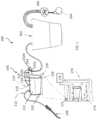
- FIG. 1is a schematic of one variation of the system for assessing fluids from a patient.
- FIG. 2is a schematic of another variation of the system for assessing fluids from a patient.
- FIGS. 3 A- 3 Care schematics of variations of an insert used to aid optical imaging.
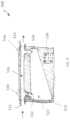
- FIGS. 4 A and 4 Bis a side view of one example of a receptacle in a system for assessing fluids from a patient.
- FIG. 4 Bis a cross-sectional view along line A-A of the exemplary receptacle shown in FIG. 4 A .
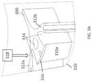
- FIG. 5is a schematic of a variation of a system with a flow divider for assessing fluids from a patient.
- FIG. 6is a schematic of one variation of a method for assessing fluids from a patient.
- FIG. 7is schematic of one variation of evaluating an image when assessing fluids from a patient.
- FIG. 8is an illustrative schematic of one variation of a method for assessing fluids from a patient.
- FIGS. 9 and 10are schematics of a variation of a method using a flow divider for assessing fluids from a patient.
- the systems and methods described herein for assessing fluids from a patientare used to assess fluids that are lost by a patient during a surgical procedure. Images of the fluids may be intermittently generated and evaluated in order to assess the fluids. For example, the systems and methods described herein may be used to track or otherwise estimate, based at least in part on the images of fluid, a quantity of fluid (e.g., blood) lost by the patient during the surgical procedure and/or quantity of a blood component (e.g., hemoglobin). In other examples, the systems and methods may additionally or alternatively be used to track or otherwise assess total mass, total volume, and/or aggregate concentration of red blood cells, platelets, plasma, and/or other blood components lost by the patient during the surgical procedure.
- These assessments, and other fluid-related information described in further detail belowmay be updated and displayed in substantially real-time during the surgical procedure and/or at the conclusion of the surgical procedure.
- fluids lost by the patientmay be collected and passed into a receptacle.
- the systemhas a valve system that alternates between a fill mode in which the fluids accumulate in the receptacle and a flush mode in which accumulated fluids drain out of the receptacle (e.g., to a sealed waste management system).
- a fluid retrieval device 108e.g., suction wand
- a fluid retrieval device 108may collect patient fluids from a surgical site, a canister, a surgical textile, and/or other fluid source containing fluids to be assessed.
- the collected patient fluidsmay be passed via tubing into a receptacle 110 , and may continue to flow into a second receptacle 102 (e.g., canister or waste management system).
- the receptacle 110may be placed in fluidic communication with the fluid retrieval device 108 (or other fluid source) and the second receptacle 102 .
- the receptacle 110receives and accumulates patient fluids from the fluid retrieval device 108 or other fluid source, allows the imaging of the accumulated patient fluids, and drains the patient fluids (e.g., into the second receptacle 102 ), in a repeatable cycle.
- the receptacle 110 and/or fluid retrieval device 108may be in fluidic communication with one or more vacuum sources (e.g., a vacuum pump 104 associated with the second receptacle 102 ) configured to provide suction to the fluid retrieval device 108 for collecting fluids.
- a filter for removing clot matter or other non-fluidic debrismay be placed in the fluidic path between the fluid retrieval device and second receptacle.
- this filtermay, optionally, be included in the fluid retrieval device.
- the filtermay be incorporated in any suitable component in the fluidic path between the fluid retrieval device and the second receptacle.
- the one or more vacuum sourcesmay additionally or alternatively be configured to provide suction for draining the receptacle 110 .
- the systems described hereincan be inserted into preexisting setups with waste management systems that collect patient fluids, without the need for extensive equipment additions or modifications.
- the systems and methods described hereinmay be used in a variety of settings, including in a hospital or clinic setting (e.g., operating or clinic setting), a military setting (e.g., battlefield) or other suitable medical treatment settings.
- This informationcan be used to improve medical treatment of patients, as well as reduce costs to medical institutions and patients.
- medical practitionerse.g., nurses, surgeons
- doctorswho receive this information during and/or after a surgical procedure can then make appropriate decisions for treatment of the patient (such as determining whether to provide a blood transfusion to the patient and how much blood is necessary) based on more accurate information on patient status.
- practitionerscan, for example, avoid providing unnecessary blood transfusions (which deplete inventory of blood transfusions and increase operating costs and medical bills), while also avoiding delayed blood transfusions (which would risk patient health).
- a system for assessing fluids from a patientmay have one or more components enabling a fill mode and a flush mode.
- the fill modepatient fluids are accumulated in the receptacle, while in the flush mode, the patient fluids are drained out of the receptacle.
- the systemmay have components that operate in the fill mode to accumulate patient fluids in the receptacle until the receptacle contains a predetermined threshold volume of fluid, upon which the components may operate in the flush mode to drain patient fluids from the receptacle.
- the componentsagain may operate in the fill mode to accumulate more patient fluids in the reservoir in another fill-flush cycle. In this manner, the components may toggle between the fill and flush modes to intermittently fill and empty the reservoir while the lost patient fluids continue to be collected and passed into the reservoir. Additionally, at one or more points in time while the patient fluids are in the receptacle (e.g., when a threshold volume of fluid has accumulated in the receptacle, before the system drains the patient fluids), a camera may generate one or more images of the fluid, which can be evaluated to assess fluid-related information.
- an example of a system 100 for assessing fluid from a patientmay include a receptacle 110 including an inlet port 112 , an outlet port 114 , and a third port 116 ; a valve system 140 in fluidic communication with the receptacle; and one or more features 150 in the receptacle to aid in optical imaging of fluids.
- the system 100may be operable in a fill mode and a flush mode.
- the valve system 140directs suction from a vacuum source 104 (associated with the second receptacle 102 ) through the third port 116 into the receptacle 110 , where suction is communicated into the receptacle and through the inlet port 112 , thereby drawing fluid through the inlet port 112 into the receptacle 110 .
- the valve system 140directs suction from the vacuum source through the outlet port 114 , thereby drawing fluid through the outlet port out of the receptacle.
- the valve systemmay be automatically actuated to toggle between the fill and flush modes, such as with a controller and sensor system, while in some variations the valve system may be additionally or alternatively manually actuated.
- the systemmay further include a camera 172 configured to intermittently generate images of the fluid accumulated in the receptacle 110 (e.g., periodically or whenever the receptacle is sufficiently full) and/or a processor 176 configured to evaluate images of the fluid to estimate fluid-related information or other characterization of the fluid (e.g., estimate fluid volume, estimate concentration of a blood component, estimate quantity of the blood component, etc.).
- the systemmay include a display 174 configured to display the images of the fluid and/or at least some of the fluid-related information estimated by evaluation of the images.
- the systemmay include one or more filters to remove clots, solids, and/or other non-fluidic debris out of the patient fluids.
- at least one filtermay be placed in the fluidic path before the receptacle 110 (e.g., in the fluid retrieval device or in tubing between the fluid retrieval device and the receptacle), in the receptacle (e.g., coupled to the inlet port or outlet port), before one or more components of the valve system 140 (e.g., in tubing between the receptacle and the valve system), and/or before or in the second receptacle 102 .
- one or more filtersmay be placed in any suitable location in the fluidic path between the fluid retrieval device and the second receptacle.
- At least some of the electronic components of the systemmay be in an integrated device and placed near the patient during the surgical procedure (e.g., in the operating room) to assess patient fluids that are collected and passed through the receptacle.
- a handheld or mobile electronic computing device 170e.g., that executes a native fluid analysis application program.
- Such a handheld or mobile devicemay, for example, be a tablet computer, laptop computer, mobile smartphone, etc. which may include a camera 172 , processor 176 , and a display 174 .
- some or all of these componentsmay be separated as discrete interconnected devices.
- the camera and displaymay be located substantially near the receptacle during the surgical procedure (e.g., in the operating room) while the processor may be located at a remote location (e.g., in the operating room separate from the camera and/or display, or outside the operating room), communicating with the camera and display through a wired or wireless connection or other network.
- the receptacleis configured to receive and accumulate patient fluids (e.g., from a fluid retrieval device, as well as to allow the accumulated patient fluids to drain.
- the receptaclemay include a body 220 defining an internal volume 222 that accumulates fluids, a top 224 , and a plurality of ports in fluid communication with the internal volume 222 .
- the body of the receptaclemay be substantially transparent or translucent to white light.
- the receptaclemay be made of blow-molded polyethylene terephthalate (PET) or injection-molded Poly(methyl methacrylate) (PMMA), though other plastics, glass, or other materials permitting visible light transmission may be used.
- PETpolyethylene terephthalate
- PMMAinjection-molded Poly(methyl methacrylate)
- the receptacle materialmay be rigid or semi-rigid so as to withstand suction forces without collapsing.
- An anti-glare coating, anti-glare finish, or an anti-glare stripmay be arranged on a surface of the receptacle.
- the internal volume 222may be generally frustoconical. Alternatively, the internal volume may be generally prismatic (e.g., generally rectangular prismatic as in FIG. 1 , cylindrical, etc.), generally bulbous, or have other suitable general shapes. In some examples, the internal volume 222 may have a capacity of between about 1.0 L and about 3.0 L (e.g., 1.0 mL, 1.5 mL, 3 mL), but it may have any suitable capacity. Furthermore, in some variations the receptacle may include multiple internal volumes or compartments, which may or may not be fluidically coupled. For example, as shown in FIGS. 4 A and 4 B , the receptacle 400 may include a first internal volume 422 a and a second internal volume 422 b that are adjacent to and fluidically coupled to one another.
- the receptacle 110may include one or more slopes that direct fluid volumes to pool in a particular region of the internal volume 122 , which may help to more completely drain the receptacle during the flush mode and/or accumulate smaller volumes of fluids together for more accurate analysis of the receptacle contents.
- the fluidsmay pool where a lower end of the slope encounters a receptacle wall or where the lower ends of multiple slopes intersect.
- a first slope in the receptaclemay generally encourage fluid to pool near one side of the bottom of the slope (e.g., toward sump 126 and sump pickup 128 , against the receptacle wall as shown in FIG. 1 ).
- a second additional slope in the receptaclemay generally encourage fluid to pool where the first and second slopes generally intersect (e.g., at central sump 426 near sump pickup 428 , as shown in FIG. 4 A ).
- the slopemay include a smooth taper as shown in FIG. 4 A , or include a series of discrete, stepped sections.
- the receptaclemay further include one or more internal baffles or other features to help prevent incoming fluids (e.g., entering through inlet port 112 ) from moving directly into the third port 116 during the fill mode.
- incoming fluidse.g., entering through inlet port 112
- the top 224may provide a substantially fluid-tight seal for the internal volume.
- the top 224may be integral with the body 220 of the receptacle, or alternatively may be coupled to the body 220 of the receptacle 210 .
- the lidmay be threaded for mating with the body 220 , or include locking tabs or other locking features that allow the lid to be snapped or otherwise sealed onto the body 220 .
- the top 224may include additional sealing features such as a gasket.
- the top 224may include caps or other covers to seal one or more of the ports before and/or after the receptacle is used during the surgical procedure (e.g., during storage or disposal of the receptacle 210 ).
- the systemmay further include a holder configured to receive the receptacle.
- the receptaclemay be a liner that is placed inside the holder, and, in some instances, the receptacle may be designed to be single-use or disposable while the holder may be designed to be reusable.
- the holdermay be substantially rigid or semi rigid, while the receptacle may be more flexible than the holder.
- the holdermay include a canister, cup, or other outer container with an internal recess that receives and holds the receptacle.
- the holdermay additionally or alternatively include a framework (e.g., lattice, one or more rings, etc.) creating an internal space that receives and holds the receptacle
- a frameworke.g., lattice, one or more rings, etc.
- the holdermay include a material that is substantially transparent or translucent to white light.
- the receptacle 110may include a plurality of ports, including an inlet port 112 , outlet port 114 , third port 116 , and/or fourth port 118 or more.
- One or more of the portsmay include a fitting that is configured to fluidically couple to tubing.
- the fittingmay include a member with a lumen, where tubing may telescopically and frictionally engage with the member such that contents of the tubing pass into the lumen of the fitting and vice versa.
- Some or all of the portsmay be located at or near the top of the receptacle, while additionally or alternatively at least one port may be located elsewhere in the receptacle.
- the inlet port 112 and third port 116are located in the top 224 of the receptacle, while the outlet port 114 is located near the bottom of the receptacle body 220 .
- the inlet portfunctions to pass fluids into the receptacle.
- the inlet port 112may be fluidically coupled via tubing to a fluid retrieval device 108 or other fluid source, and allow transfer of fluids from the fluid retrieval device 108 or other fluid source into the receptacle.
- the inlet portmay include a valve that opens and closes to regulate flow through the inlet port, and/or substantially prevents fluids from traveling in a reverse direction out of the receptacle through the inlet port (e.g., a one-way valve).
- the receptaclemay include multiple inlet ports, which may, for example, enable faster accumulation of fluids in the receptacle, performed in parallel.
- the outlet portfunctions to drain fluids from the receptacle when the system is operating in the flush mode.
- the outlet portmay be fluidically coupled via tubing to a second receptacle, such as for disposal of the fluids, and allow transfer of fluids from the first receptacle to the second receptacle.
- the outlet port 114may be located at or near the top of the receptacle 110 .
- the receptaclemay include a sump 126 in a lower region of the internal volume 122 where fluid tends to pool, and a sump pickup 128 that places the sump 126 in fluidic communication with the outlet 114 .
- the sump pickup 128may be tubing or other member with a lumen, having one end located adjacent to the sump 126 and another end coupled to the outlet port 114 . Upon application of suction to the outlet port 114 , fluid in the sump 126 may be drawn up the sump pickup 128 , and through the outlet port 114 out of the receptacle 110 .
- the outlet port 214may be located at or near the bottom of the receptacle 210 . Fluid collected in a lower region of the internal volume 222 may drain directly out the outlet port 214 out of the receptacle as a result of gravity and/or suction during the flush mode.
- the outlet portmay include a valve that opens and closes to regulate flow through the outlet port, and/or substantially prevent fluids from traveling in a reverse direction back into the receptacle through the outlet port (e.g., a one-way valve).
- the receptaclemay include multiple outlet ports.
- the outlet port arrangements shown in FIGS. 1 and 2may be combined, such as with a first outlet port arranged in combination with a sump pickup as shown in FIG. 1 and a second outlet port arranged as shown in FIG. 2 .
- Multiple outlet portsmay, for example, facilitate faster draining performed in parallel, provide redundancy in case of a clog, or provide different options that may be better for different kinds of fluids (e.g., fluids with different viscosities).
- the third portfunctions to pass suction from a vacuum source into the receptacle when the system is operating in the fill mode, where suction can thereby be communicated within the receptacle to draw fluids through the inlet port into the receptacle.
- suction from vacuum source 106(which may be communicated through second receptacle 102 ) is communicated via tubing through the third port 116 and into the receptacle 110 .
- the suction in receptacle 110is also communicated through inlet port 112 , such that fluid is drawn from fluid retrieval device 108 (or other fluid source) through the inlet port 112 and into the receptacle 110 .
- the receptaclemay further include a fourth port, which functions as a vent to facilitate draining of the fluid through the outlet port when the system is operating in the flush mode.
- the fourth portmay be located on the receptacle such that it is substantially opposite to the accumulated volume of fluid in the receptacle, in order to provide a pressure differential facilitating the draining of the fluid.
- the fourth port 118may be located at or near the top of the receptacle, while the fluid accumulates in the sump 126 .
- the fourth port 218may be located at or near the top of the receptacle, while the fluid accumulates in the body 220 .
- the receptaclemay include one or more optical fiducials 238 .
- the optical fiducialmay be coupled to or integral with the receptacle or the packaging of the receptacle, and be associated with receptacle-related information.
- the optical fiducialmay be adhered to a surface of the receptacle or packaging, printed onto a surface of the receptacle or packaging, molded or etched into the receptacle or packaging, or associated with the receptacle or packaging in any suitable manner.
- the fiducialcan, for example, include a quick-response (QR) code, a barcode, alphanumerical code, symbolic marker, or other optical identification marker suitable for identifying or communicating a receptacle type and/or receptacle-related information.
- QRquick-response
- Receptacle-related informationwhich may be accessed by scanning or looking up the fiducial in a database, may include, for instance, a type of the receptacle, geometry and/or dimensions of an internal volume of the receptacle, etc.
- the optical fiducialmay include a color fiducial.
- the color fiducialmay be coupled to or integral with the receptacle or its packaging, and be associated with color-related information to enable color normalization of the images of the fluid in the receptacle, such as to compensate for variations in lighting conditions.
- the color fiducialmay display one or more red hues, each of which has an assigned or known color value. For example, different hues may be displayed and arranged in different boxes or segments in a grid, strip, ring, color wheel, or any suitable shape for displaying color-normalizing information.
- the color fiducialmay be in the form of a decal, sticker, ring or other component configured to couple to the receptacle or receptacle packaging, or any component suitable for associating the color fiducial with the receptacle or its packaging.
- the images of fluid in the receptaclecan be color-adjusted (e.g., adjustment of exposure, contrast, saturation, temperature, tint, etc.) until an imaged color fiducial has a color value matching the assigned or known color value of the color fiducial.
- the valve systemfunctions to toggle the system between the fill mode and the flush mode.
- the valve systemincludes at least one valve that redirects suction from a vacuum source such that the suction may be used to alternately draw fluid into the receptacle during the fill mode, and to draw fluid out of the receptacle during the flush mode.
- the valve systemdirects suction from a vacuum source through the third port of the receptacle into the internal volume of the receptacle, thereby drawing fluid through the inlet port of the receptacle into the internal volume of the receptacle. Furthermore, generally in the flush mode, the valve system directs suction from the vacuum source through the outlet port of the receptacle, thereby drawing fluid through the outlet port out of the internal volume of the receptacle.
- valve system 140may include a valve 142 to direct suction from a vacuum source.
- Valve 142may be a three-port valve that has a first valve port 142 a coupled to a vacuum source 104 (providing a vacuum communicated through second receptacle 102 and controlled by vacuum regulator 106 ), a second valve port 142 b regulating a fluidic path to port 116 of the receptacle, and a third valve port 142 c regulating a fluidic path to the outlet port 114 of the receptacle.
- the valve 142selectively fluidically connects the first valve port 142 a with either the second valve port 142 b or the third valve port 142 c (to join with either the fluidic path to port 116 or the fluidic path to outlet port 114 ), depending on which mode the valve system is operating in.
- the valve systemmay include additional valves coupled to inlet 112 , outlet 114 and/or fourth port 118 , which are either closed or open, depending on which mode the valve system is operating in.
- the valve 142when the valve system is operating in the fill mode (shown in FIG. 1 ), the valve 142 fluidically connects the first valve port 142 a with the second valve port 142 b, thereby directing suction from the vacuum source 104 through port 116 of the receptacle.
- the valve coupled to the inlet port 112if present, is open to enable the fluid retrieval device, while the valve coupled to the outlet port 114 , if present, is closed. Additionally, the valve coupled to the fourth port 118 is closed, such that the suction is communicated through the internal volume 122 to inlet port 112 , which draws fluid from fluid retrieval device 108 (or other fluid source) into the internal volume 122 of the receptacle.
- valve 142is adjusted so as to fluidically connect the first valve port 142 a with the third valve port 142 c , thereby directing suction from the vacuum source 104 through the outlet port 114 of the receptacle.
- the valve coupled to the inlet 112if present, is closed to disable the fluid retrieval device, while the valve coupled to the outlet 114 , if present, is open.
- the valve coupled to the fourth port 118is open, such that the internal volume 122 is vented open to ambient pressure and there is a pressure differential facilitating the draining of the fluid through outlet port 114 .
- valve system 240may include more than one valve to direct suction from a vacuum source.
- valve system 240may include a flow divider 242 that is coupled to a vacuum source 204 (through second receptacle 202 ).
- the flow divider 242divides into one flow branch toward valve 244 regulating a fluidic path to port 216 of the receptacle, and another flow branch toward valve 246 regulating a fluidic path to outlet port 214 of the receptacle.
- Either one of the valve 244 or valve 246may be open, depending on which mode the valve system is operating in.
- the valve systemmay further include additional valves coupled to inlet port 212 , outlet port 214 and/or fourth port 218 , which are either closed or open, depending on which mode the valve system is operating in.
- valve 244when the valve system is operating in the fill mode, the valve 244 is open and the valve 246 is closed, thereby directing suction from the vacuum source 204 through valve 244 and port 216 of the receptacle.
- the valve coupled to the inlet port 212if present, is open to enable the fluid retrieval device, while the valve coupled to the outlet port 214 , if present, is closed.
- the valve coupled to the fourth port 218is closed, such that the suction is communicated through the internal volume 222 to inlet port 212 , which draws fluid from fluid retrieval device (or other fluid source) into the internal volume 222 of the receptacle.
- valve 244when the valve system is operating in the flush mode, the valve 244 is closed and the valve 246 is open, thereby directing suction from the vacuum source 204 through valve 246 and the outlet port 214 of the receptacle.
- the valve coupled to the inlet port 212if present, is closed to disable the fluid retrieval device, while the valve coupled to the outlet port 214 , if present, is open.
- the valve coupled to the fourth port 218is open, such that the internal volume 222 is vented open to ambient pressure and there is a pressure differential facilitating the draining of the fluid through outlet port 214 .
- both valves 244 and 246may be closed to suspend the communication of suction into the receptacle (e.g., during image capture of fluid in the receptacle).
- valve systemmay include other suitable combinations of valves that enable rerouting of suction from the vacuum source to fill and empty the receptacle.
- the valve systemmay be automatically controlled (e.g., by a controller as further described below).
- the valve systemmay include an electromagnetic actuator (e.g., solenoid) that selectively opens and closes one or more valves between valve configurations for the fill and flush modes.
- the valve systemmay include a passive, automatic mechanical or magnetic actuator.
- Such automatically controlled valve systemsmay be based on sensor signals that trigger the fill and/or flush modes, as further described below.
- any suitable actuating devicemay be used to automatically actuate one or more of the valves in the valve system.
- the valve systemmay additionally or alternatively be manually controlled by a user.
- the valve systemmay include a manual actuator (e.g., lever, handle, wheel, button, plunger, switch, etc.) in order to adjust one or more valves between valve configurations for the fill and flush modes.
- the particular kind of manual actuationmay vary, for example, on the type of valve (e.g., ball valve, butterfly valve, gate valve, diaphragm valve, etc.), though the valve system may include any suitable interface for actuating one or valves in the valve system based on user input.
- the systemmay provide audible and/or visual instructions or warnings that prompt a user to actuate the valve system between the fill and flush modes.
- the systemmay include a camera 172 that generates images of the fluid in the receptacle.
- the cameramay be configured to automatically generate images on a predetermined schedule (e.g., periodically or every time a predetermined volume of fluid has been added or accumulated in the receptacle), and/or generate images based on user input (e.g., whenever a user provides manual instructions for an image to be generated of the fluid, such by input on a user interface display).
- the cameramay include at least one optical image sensor (e.g., CCD, CMOS, etc.) that captures a color optical digital image with red, green, and blue (RGB) color components for the pixels, and/or other suitable optical components.
- the cameramay include a single image sensor paired with suitable corresponding optics and/or filters (e.g., color filter arrays such as a Bayer pattern filter).
- the cameramay include multiple image sensors paired with suitable corresponding optics, such as at least one prism or diffractive surface to divide white light into separate color channels (e.g., RGB), each of which is detected by a respective image sensor.
- the camera 172may include any suitable image sensors and other optics components to enable the camera to generate images of the fluid in the receptacle.
- the cameramay be configured to transmit the images to a processor for analysis, and/or to a database that stores the images, through a wired or wireless connection.
- the camera 172may be part of a handheld or mobile device (e.g., tablet, mobile smartphone, etc.), though in other variations the camera may a standalone device that communicates images to other separate computing devices or database using a wired or wireless connection.
- the systemmay further include one or more sensors configured to detect the volume of fluids in the receptacle and to generate a fluid level signal based on the detection of fluid volume or fluid level in the receptacle.
- the fluid level signalmay be used to trigger the actuation or toggling between the fill and flush modes of the valve system, and/or to estimate fluid volume in the receptacle (e.g., for estimation of current or cumulative quantity of blood volume and/or quantity of blood component lost by the patient).
- the sensorsmay include fluid level sensors coupled to the receptacle or near the receptacle. Additionally or alternatively, the camera generating images of the fluids in the receptacle may be treated as a sensor, in that the images may be analyzed to detect fluid level.
- the systemmay include one or more point-level sensors that indicate whether the fluid level in the receptacle is above or below a particular threshold sensing point.
- one or more fluid level sensorsmay include a binary fluid level sensor that outputs a fluid level signal (e.g., voltage) of one value when the sensor detects a fluid volume not satisfying a threshold, and outputs a fluid level signal of another value when the sensor detects a fluid volume satisfying the threshold.
- a fluid level signale.g., voltage
- the systemmay include one or more sensors configured to detect at a high threshold volume of fluids in the receptacle and generate a fluid level signal indicating the high threshold fluid volume.
- the systemmay include a fluid level sensor 262 a coupled to the receptacle 210 near or at the top of internal volume 222 , and configured to detect a fluid volume above the high threshold fluid volume (e.g., a fluid level above the location of the sensor 262 a ).
- a fluid level signal indicating the high threshold fluid volumemay be used to trigger the flush mode of the valve system and/or trigger the camera to generate an image of the fluid in the receptacle.
- the high threshold fluid volumecan be about full capacity of the receptacle or near full capacity, such as about 3 L, or any suitable value.
- the systemmay additionally or alternatively include one or more sensors configured to detect a low threshold volume of fluids in the receptacle and generate a fluid level signal indicating the low threshold fluid volume.
- the systemmay include a second fluid level sensor 262 b coupled to the receptacle 210 near or at the bottom of internal volume 222 , and configured to detect a low threshold volume of fluids in the receptacle below a low threshold volume of fluids in the receptacle (e.g., a fluid level below the location of the sensor 262 b ).
- a fluid level signal indicating the low threshold fluid volumemay be used to trigger the fill mode of the valve system.
- the low threshold fluid volumecan be about zero or near zero, or any suitable value.
- the systemmay include additional point-level sensors at discrete fluid level locations to provide additional information, such as regarding one or more intermediate fluid levels between a low threshold and a high threshold.
- Fluid level signals indicating intermediate fluid volumesmay be used to trigger the camera to generate an image of the fluid in the receptacle as the receptacle fills with fluid. Additionally or alternatively, fluid level signals indicating intermediate fluid volumes may provide more frequent updates for estimates of the volume of fluid in the receptacle.
- the systemmay include one or more continuous-level sensors that measure the fluid level in the receptacle and indicate a numerical value corresponding to fluid volume.
- a continuous-level sensormay output a fluid level signal (e.g., voltage) within a range corresponding to a measurable range of fluid volumes.
- a fluid level signale.g., voltage
- the particular value for the fluid level signalmay be continually compared to a high threshold fluid volume and/or a low threshold fluid volume to determine whether the fluid volume in the receptacle satisfies either threshold.
- the particular value for the fluid level signalmay be compared to other thresholds to trigger the camera to generate an image of the fluid in the receptacle, as the receptacle fills with fluid (e.g., every 5 mL added to the receptacle may trigger the camera).
- any suitable fluid level sensormay be used to detect fluid volume in the receptacle and generate a fluid level signal that indicates the detected fluid volume.
- capacitance level sensors, conductive level sensors, ultrasonic level sensors, and/or optical sensors, etc.may be appropriate as point-level and/or continuous-level sensors.
- the systemmay additionally or alternatively include a magnetic float having a magnet sealed within. As fluid accumulates in the receptacle, the float may rise relative to one or more magnetic sensing points corresponding to threshold fluid volumes, which may, for example automatically trigger via a magnetic “signal” that automatically (e.g., mechanically) triggers toggling of fill and flush modes.
- the systemmay additionally or alternatively include a mechanical sensor, such as a float mechanically coupled (e.g., with a lever) to the valve system such that as the float rises relative to one or more predetermined points corresponding to threshold fluid volumes, the float may automatically trigger via a mechanical “signal” that automatically triggers toggling of fill and flush modes.
- a mechanical sensorsuch as a float mechanically coupled (e.g., with a lever) to the valve system such that as the float rises relative to one or more predetermined points corresponding to threshold fluid volumes, the float may automatically trigger via a mechanical “signal” that automatically triggers toggling of fill and flush modes.
- fluid levelmay be detected by analyzing images of the fluid in the receptacle.
- the cameracan repeatedly capture images of the receptacle (e.g., every two seconds) and a processor may employ machine vision techniques, such as edge detection, to estimate fluid volume (e.g., determine whether the fluid volume depicted in each image satisfies a particular high or low threshold volume of fluids, and/or absolute quantity of fluid).
- the fluid level signalmay be generated by a processor embodied in, for example, a handheld or mobile device 170 that is separate from the receptacle.
- the systemmay detect the volume of fluids in the receptacle based on any suitable combination of the above-described techniques.
- the systemcan include a float having a color (e.g., green) generally contrasting to the color of patient fluids, which may enable identification of the float in an image using machine vision techniques.
- the identified position of the float in the imagescan be used, such as by comparing the float to optical fiducials, to estimate fluid volume and determine whether there is a high threshold fluid volume or low threshold volume fluid volume in the receptacle.
- the systemmay further include a controller configured to actuate the valve system to toggle between the fill mode and the flush mode. More specifically, the controller may be configured to actuate the valve system based on the fluid level signal generated by the one or more sensors in the sensor system.
- the systemmay include a controller 260 coupled to the valve system 240 , such that the controller 260 may receive fluid level signals wirelessly and/or through a wired connection.
- Controller 260may be configured to receive at least one fluid level signal from sensor 262 a , sensor 262 b , and/or from mobile device 270 , and actuate the valve system as described above based on a fluid level signal indicating a volume of fluids detected in the receptacle.
- the controller 260may actuate the valve system 240 such that the system is operating in the flush mode.
- the controller 260may maintain the system in the flush mode for a predetermined period of time (e.g., 30 seconds). In another variation, the controller 260 may maintain the system in the flush mode until the controller 260 receives at least one fluid level signal indicating a low threshold volume of fluids in the receptacle (e.g., zero or close to zero). Upon receiving a fluid level signal indicating a low threshold fluid volume in the receptacle, the controller 260 may actuate the valve system 240 such that the system is again operating in the fill mode. The controller 260 may similarly continue to toggle between the fill and flush modes based on the fluid level signals it receives.
- a predetermined period of timee.g. 30 seconds
- the controller 260may maintain the system in the flush mode until the controller 260 receives at least one fluid level signal indicating a low threshold volume of fluids in the receptacle (e.g., zero or close to zero).
- the controller 260may actuate the valve system 240 such that the system is
- the controllermay additionally or alternatively be configured to control when the camera generates images of the fluid in the receptacle.
- the controller 260may trigger the camera to generate images whenever the receptacle is sufficiently full of fluid. For example, upon receiving a fluid level signal indicating a high threshold volume of fluid, the controller 260 may trigger the camera to generate images of the fluids in the receptacle. In another variation, the controller 260 may trigger the camera to periodically or intermittently generate images (e.g., every two seconds, every 5 mL of fluid added to the receptacle).
- the controller 260may additionally actuate part of the valve system 240 (e.g., close a valve coupled to inlet port 212 to disable the fluid retrieval device, open a valve coupled to the port 218 to open the internal volume 222 to ambient pressure, etc.) and/or wait a predetermined period of time (e.g., five seconds) to allow fluids in the receptacle to settle before generating the image of the fluids.
- a predetermined period of timee.g., five seconds
- the systemmay include one or more features in or around the receptacle to aid in optical imaging of fluids.
- one feature to aid in optical imagingmay include an insert or light source arranged within the internal volume of the receptacle.
- the receptaclemay define one or more slopes that further define the internal volume.
- the systemmay include an insert arranged within the internal volume of receptacle, such as at or near a bottom of the internal volume.
- the insertmay, for example, backscatter light through the fluid and improve the quality of images from which fluid-related information may be derived.
- the insert and a surface of the receptaclemay cooperate to define a first region with substantially uniform thickness such that fluid in the first region exhibits substantially uniform color.
- Pixel color values in image portions depicting the first regionmay, for example, be correlated to a blood component concentration (e.g., with template matching techniques, parametric modeling techniques described in further detail below).
- the insertmay include a first feature that is substantially parallel to and offset from a surface of the receptacle, such that the first feature cooperates with the surface of the receptacle to form the first region of substantially uniform thickness.
- the first featuremay include an arcuate surface (e.g., the insert may be circular, semi-circular, or otherwise curved) in instances in which the receptacle surface is similarly arcuate (e.g., generally cylindrical).
- the first featuremay include a generally planar wall (e.g., the insert may be at least a segment of a polygonal prism) in instances in which the receptacle surface is planar (e.g., rectangular tank).
- the insertmay include any suitable features that generally track a surface of the receptacle so as to define a region of substantially uniform thickness between the insert and the surface of the receptacle.
- the insert and a surface of the receptaclemay additionally or alternatively cooperate to define a second region in which fluid exhibits a color gradient.
- Pixel color values in image portions depicting the second regionmay, for example, be correlated to a hemolysis level in the blood (e.g., with template matching techniques, parametric modeling techniques).
- algorithms and processes for evaluating imagesmay be adjusted based on the known hemolysis concentration.
- the insertmay include a second feature that generally tapers away from a surface of the receptacle, such that the second feature cooperates with the surface of the receptacle to form the second region in which fluid has a color gradient.
- the second featuremay have a surface with a linear profile, a non-linear profile, a stepwise function profile, etc. that generally angles away from the surface of the receptacle.
- the insertmay include any suitable features that generally taper or angle away from a surface of the receptacle so as to define a region in which fluid has a color gradient between the insert and the surface of the receptacle.
- the systemmay include an insert 250 that is proximate to a wall of the receptacle 210 .
- one variation of the insert 300 a(similar to insert 250 ) may cooperate with a wall of the receptacle to define a region of substantially uniform thickness.
- the insert 300 amay include an insert surface 310 offset from a receptacle surface 320 , such that a region of substantially uniform thickness is formed between the insert surface 310 a and the receptacle surface 320 .
- Fluids accumulated in the receptaclemay generally surround the insert 300 a (e.g., through gaps 314 ), including in the region of substantially uniform thickness, where fluids exhibit a substantially uniform color.
- Images of the fluid in the receptacleinclude an image region corresponding to the region of substantially uniform thickness, and the pixel color values in the image region may then be correlated to a blood component concentration estimate (e.g., using template techniques, parametric modeling techniques, etc. as further described below).
- the insert 300 amay be coupled to the receptacle.
- the members 312 a and 312 b (and/or other portions of the insert)may be coupled to the receptacle wall 320 with fasteners (e.g., epoxy, magnets, etc.).
- the members 312 a and 312 b (and/or other portions of the insert)may be coupled to the receptacle wall 320 without fasteners, such as by press-fit or snap-fit.
- the members 312 a and 312 b (and/or other portions of the insert)may include features that interlock with complementary features on the receptacle surface 320 (e.g., splines and notches, dovetails, etc.).
- Such couplingmay be substantially permanent or removable.
- the insertmay be removable from the receptacle for reuse.
- the insert 300 amay be integrally formed with the receptacle (e.g., by injection molding or blow molding techniques).
- the insert 300 bincludes a first insert surface 310 b and second insert surface 311 b (on frustoconical portion of 300 b ).
- the first insert surface 310 bis offset from a receptacle wall such that a first ring-shaped region of substantially uniform thickness is formed between the first insert surface 310 b and the receptacle wall.
- the fluidmay have a substantially uniform color.
- the second insert surface 311 bis tapered (e.g., with a linear or non-linear profile) toward a central axis of the receptacle, such that the second insert surface 311 b cooperates with the receptacle wall to provide a second region in which fluid exhibits a visual color gradient. In the second region, fluid appears progressively darker in a color gradient pattern as the thickness in the second region increases.
- the insert 300 cincludes a first insert surface 310 c offset from a receptacle surface, such that a first region of substantially uniform thickness is formed between the insert surface 310 c and the receptacle wall. In this first region, fluid may have a substantially uniform color.
- the insert 300 calso includes one or more second surfaces 311 c that cooperate with the receptacle wall to provide a second region in which fluid exhibits a visual color gradient. As with insert 300 b , in the second region, fluid appears progressively darker in a color gradient pattern as the thickness in the second region increases.
- the insertmay include a material or coating that is white, substantially opaque, and generally impermeable to fluid.
- the insertmay be made of injection-molded white plastic.
- the insertmay alternatively include a color or pattern (e.g., grid, matrix barcode, QR code) that is observable (e.g., on surfaces 310 ) through the fluid.
- a color grid or matrix bar codecoupled to the insert and observable through the receptacle surface 320 and fluid can be used to determine fluid parameters (e.g., fluid component concentrations) associated with fluid within the receptacle.
- a color grid including a set of regions of color, each region associated with a blood component concentration valuecan be applied to the insert.
- the blood component concentration value associated with that region of the color gridcan be taken as an estimated blood component concentration of the fluid.
- a color pattern exhibiting a gradient in colore.g., by including a pattern having successively blurrier edges between regions of the pattern
- the systemmay include a light source 318 configured to transmit light through a portion of fluid within the canister, which may, for example, help generate an optical image with a color gradient from which a hemolysis level of the fluid can be estimated.
- the light source 318may be coupled to the receptacle so as to direct light downward toward the bottom of the receptacle.
- Light incident on the surface of the fluidpenetrates the surface of the fluid and is absorbed by the fluid as a function of both depth and an absorption coefficient of the fluid, wherein the absorption coefficient of the fluid is affected by both a concentration of a substance in the fluid and a type or size of the substance (e.g., either a whole red blood cell or free hemoglobin and ruptured cell matter).
- the illuminated fluidmay appear visually lighter at the surface of the fluid and progressively darker at deeper portions of the fluid in a vertical color gradient pattern.
- the particular characteristics of the vertical color gradient patternmay be used to generate a metric of the absorption of light by the fluid, which can in turn be used to assess a level of hemolysis in the fluid.
- Similar color gradient patternsmay be generated elsewhere in the fluid volume, such as a horizontal color gradient pattern.
- the light source 318may be coupled to the insert described above, to generate a color gradient pattern along any suitable direction in the fluid.
- the color gradient patternmay be correlated to a level of hemolysis (e.g., percentage) in the fluid using template matching techniques, parametric modeling techniques, etc.
- the light sourcemay emit wavelengths of light spanning or otherwise associated with one or more absorbance peaks in an absorbance spectrum for one or more target components of fluid in the receptacle.
- the light source 318may be configured to provide a broad range, narrower range, or discrete waveband of light corresponding to absorbance peaks of one or more blood components.
- the light source 318may be configured to provide wavelengths of light from about 400 nm to about 700 nm and between about 800 nm to about 950 nm.
- the light source 318can be configured to provide wavelengths of light associated with absorbance peaks/spectra of one or more forms of hemoglobin (e.g., oxygenated hemoglobin, sulfhemoglobin, methemoglobin, etc.) in order to enable differentiation in colors of fluid and/or color gradients of fluid associated with different forms of hemoglobin.
- the light source 318may additionally or alternatively emit light of any suitable wavelengths corresponding to other types of blood component absorbance spectra.
- the insert 300 and/or light source 318may be similar to any of the variations described in U.S. Patent Pub. 2015/0294461, entitled “METHOD FOR ESTIMATING A QUANTITY OF A BLOOD COMPONENT IN A FLUID CANISTER,” which is hereby incorporated in its entirety by this reference.
- the internal volume of the receptaclemay have varying dimensions along one or more axes, to help improve the analysis of fluids of having high or low concentrations of red blood cells (RBC) or hemoglobin (or other blood component).
- RBCred blood cells
- hemoglobinor other blood component
- an internal volume 422 a and/or 422 b of the receptaclemay include a shallow section (as measured along the camera optical axis 472 ) so as to improve the analysis of fluids having a high concentration of RBCs or hemoglobin.
- This featuremay be helpful because in instances in which blood has a high RBC concentration, a deep or thick volume of the blood may be too opaque or optically “dark” for useful pixel color visualization in an image of the blood. This is because a deep or thick volume of blood having a high RBC concentration may scatter and/or absorb nearly all incident light, leading to insufficient light transmission through the blood.
- opacitymay limit the amount of blood component concentration information that may be derived from an image of the blood.
- blood with higher RBC concentrationsmust be imaged in shallower or thinner volumes in order to decrease opacity (i.e., the volume depth or thickness at which opacity is avoided is generally inversely proportional to the RBC concentration).
- the volume depth or thickness at which opacity is avoidedis generally inversely proportional to the RBC concentration.
- At least a portion of an internal volume (e.g., 422 a and/or 422 b ) of the receptacle 400may include a shallow section, as measured along the camera optical axis 472 (Z-axis as labeled in FIG. 4 B ).
- At least a portion of the internal volume 422 a and/or 422 b of the receptaclemay include a deep section (as measured along the camera optical axis 472 ) so as to improve the analysis of fluids having a low concentration of RBCs or hemoglobin.
- This featuremay be helpful because in instances in which blood has a low RBC concentration, a shallower or thinner volume may be too optically clear, akin to water or saline, for useful pixel color visualization in an image of the blood.
- a shallow or thin volume of blood having a low RBC concentrationmay not scatter and/or absorb enough incident light in order for the blood to be optically distinguishable from water, saline, or other low RBC concentration fluids. Consequently, such optical clarity may limit the amount of blood component concentration information that may be derived from an image of the blood. For example, in some instances a fluid with low RBC concentration may not have optically detectable blood components. Furthermore, blood with lower RBC concentrations may have to be imaged in deeper or thicker volumes in order to decrease optical clarity (i.e., the volume depth or thickness at which optical clarity is avoided is generally inversely proportional to the RBC concentration).
- both fluidsmay be substantially clear and optically indistinguishable.
- the two fluidsmay be visually distinct, as the first fluid with higher RBC concentration (which requires a deeper depth to appear colored or tinted red) is visually redder than the second fluid with lower RBC concentration, due to having greater aggregate light scattering and/or absorption in the deeper container.
- At least a portion of the internal volume of the receptacle 400may include a deeper section, as measured along the camera optical axis 472 (Z-axis as labeled in FIG. 4 B ).
- the transition between the shallower and deeper sections of an internal volume 422 a and/or 422 bmay be a smooth taper, as shown in FIG. 4 B . Additionally or alternatively, at least part of the transition between the shallower and deeper sections may include discrete, stepped sections (along the X-axis as labeled in FIG. 4 B ).
- the system 100may include or more processors 176 configured to evaluate images of fluid in the receptacle and estimate fluid-related information.
- the one or more processors 176may be configured to execute instructions that are stored in memory such that, when it executes the instructions, the processor 176 performs aspects of the methods described herein.
- the instructionsmay be executed by computer-executable components integrated with the application, applet, host, server, network, website, communication service, communication interface, hardware/firmware/software elements of a user computer or mobile device, wristband, smartphone, or any suitable combination thereof.
- the instructionsmay be stored on memory or other computer-readable medium such as RAMs, ROMs, flash memory, EEPROMs, optical devices (e.g., CD or DVD), hard drives, floppy drives, or any suitable device.
- the processormay transform the image of the fluid to a blood component concentration value by correlating the pixel color values of the fluid in the region to a blood component concentration (e.g., with template matching and/or parametric modeling techniques).
- the one or more processorsmay be integrated into a handheld or mobile device 170 .
- the one or more processors 176can be incorporated into a computing device or system, such as a cloud-based computer system, a mainframe computer system, a grid-computer system, or other suitable computer system.
- the one or more processorsmay be incorporated into a remote server that receives the images, analyzes the images to characterize fluids in the receptacle and provide fluid-related information, and/or transmit the fluid-related information to another computing device having a display for displaying the fluid-related information to a user.
- the displayfunctions to display or otherwise communicate to a user (e.g., doctor, nurse) information that is generated by the system, including but not limited to patient information, images of the receptacle/fluid, and/or fluid-related information estimated as described herein.
- a usere.g., doctor, nurse
- the display 174may include a screen on a handle or mobile device, a computer monitor, a television screen, a projector screen, or other suitable display.
- the display 174may be configured to display a user interface that enables the user to interact with displayed information.
- the user interfacemay enable the user to select display options (e.g., font, color, language) and/or content (e.g., patient information, fluid-related information, alerts).
- the displaymay be user-interactive and include a resistive or capacitive touch screen that is responsive to skin, a stylet, or other user contact.
- the displaymay be user-interactive via a cursor controlled by a mouse, keyboard, or other suitable user input device for receiving user commands.
- the systemmay additionally or alternatively include an audio system that communicates fluid-related information to the user.
- the display and/or the audio systemmay provide alerts upon one or more estimations meeting a threshold (e.g., estimated quantity of fluids or blood component exceeds a threshold), which may be useful to prompt certain actions in response, such as providing a blood transfusion.
- a thresholde.g., estimated quantity of fluids or blood component exceeds a threshold
- FIG. 1 and FIG. 2Other variations of systems for assessing fluids from a patient may be used in arrangements similar to those depicted in FIG. 1 and FIG. 2 (e.g., in series and in fluidic communication between a fluid retrieval device or other fluid source, and a waste management system or other receptacle).
- a system for assessing fluids from a patientmay include a manifold receptacle.
- the manifold receptaclemay be generally similar to the receptacle variations described above, except that the manifold receptacle is configured to be inserted into an inlet port of a sealed receptacle such as a waste management system.
- the manifold receptaclemay be configured to be single-use and disposable after use during a surgical procedure.
- a system 500 for assessing fluids from a patientmay include a flow divider.
- the flow divider system 500receives fluid collected by the fluid retrieval device (or from another fluid source), and consistently accumulates in a first receptacle a representative fraction of this fluid for analysis while the rest of the fluid is discarded or otherwise passed to a second receptacle (e.g., waste management system).
- a second receptaclee.g., waste management system
- the second receptaclereceives fluid of a particular composition (e.g., extracorporeal blood, saline, ascites, bile, irrigant, saliva, gastric fluid, mucus, pleural fluid, urine, etc.), the first receptacle receives a fluid sample having a substantially similar composition of fluids. Assessments of the representative fraction of fluid in the first receptacle may be projected or extended to provide assessments of the total fluid collected by the fluid retrieval device (or from another fluid source).
- a particular compositione.g., extracorporeal blood, saline, ascites, bile, irrigant, saliva, gastric fluid, mucus, pleural fluid, urine, etc.
- a flow divider system 500 for assessing fluids from a patientmay include: a receptacle 510 having an internal volume 522 for collecting fluids, and a bypass channel 516 extending between an inlet port 512 and an outlet port 514 ; and a flow divider 530 that diverts a first predetermined proportion of flow from the inlet port 512 into the internal volume 522 and a second predetermined portion of flow from the inlet port 512 into the bypass channel 516 .
- the first predetermined proportion of flow into the internal volume 522is smaller than the second predetermined portion of flow through the bypass channel 516 , but in some variations the first and second predetermined proportions may be substantially equal or the first predetermined proportion of flow may be larger than the second predetermined portion of flow.
- the flow divider system 500may include a camera and processor similar to those described above.
- the internal volume 522 of the receptacle 510 in the systemmay generally be similar to any of the variations of internal volumes of receptacles described above (e.g., with reference to FIGS. 1 - 4 ).
- the receptacle 510may include one or more slopes to pool fluids toward a particular region of the internal volume 522 .
- the receptacle 510may include one or more features to aid in optical imaging, such as a fluid insert.
- the bypass channel 516extends between an inlet port 512 configured to be in fluidic communication with a fluid retrieval device or other fluid source, and an outlet port 514 configured to be in fluidic communication with a second receptacle (e.g., waste management system). Additionally, the outlet port 514 may be coupled with a vacuum source, such as a vacuum source associated with a waste management system. Furthermore, in some variations, the inlet port 512 and/or outlet port 514 may include a valve that can be automatically and/or manually controlled to regulate flow in and out of the receptacle 510 . For instance, the valves in inlet port 512 and outlet port 514 may be open such that fluid may flow into the internal volume 522 and bypass channel 516 .
- valvesmay be closed to seal the contents of the receptacle 510 .
- Such sealingmay be useful, for example, before or after the surgical procedure for connection/disconnection from a fluid retrieval device and second receptacle, or during transport.
- the valvesmay be closed to allow a user (e.g., a nurse) to safely shake or agitate the receptacle 510 with lowered contamination risk, in order to achieve a more uniform mixing of contents of the receptacle prior to imaging the receptacle.
- caps or other coversmay be placed over the inlet port 512 and/or the outlet port 514 to seal the contents of the receptacle 510 .
- the receptacle 520may further define a first inner port 532 and a second inner port 534 .
- the first inner port 532is in fluidic communication with inlet port 512 and the internal volume 522 , and functions to pass the first predetermined portion of flow from the inlet port 512 into the internal volume 522 .
- the second inner port 534is in fluidic communication with the outlet port 514 and the internal volume 522 , and functions to pass suction from a vacuum source (coupled to the outlet port 514 ) into internal volume 522 , thereby drawing fluids into the receptacle 510 though the inlet port 512 .
- the flow divider 530may be located in the fluid path between (i) the inlet port 512 and (ii) the internal volume 522 and the bypass channel 516 .
- the flow dividerfunctions to consistently divide fluid flowing from inlet port 512 between the internal volume 522 and the bypass channel 516 according to a predetermined flow division ratio (e.g., about 1:20).
- a predetermined flow division ratioe.g., about 1:20.
- the flow divider 530diverts a first predetermined proportion of flow through first inner port 532 into the internal volume and a second predetermined proportion of flow into the bypass channel 516 .
- the flow divider 530may divert about twenty parts of incoming fluid into the bypass channel.
- the flow divider 530may generally divide flow between the internal volume and the bypass channel according to any suitable flow division ratio.
- the flow divider 530may accomplish consistently dividing fluids as a result of the ratio of an effective cross-sectional area of the first inner port 532 relative to the cross-sectional area of the bypass channel 516 (e.g., dimensionally and/or with use of a flow resistor).
- the cross-sectional area of the first inner port 532may be smaller than the cross-sectional area of the bypass channel 516 , resulting in proportionately less flow diverted through the first inner port 532 .
- the cross-sectional areas of the first inner port 532 and bypass channel 516may be substantially similar, but the effective cross-sectional area of the first inner port 532 may be reduced further by a flow resistor (e.g., defining a narrow neck) placed in the first inner port 532 .
- a flow resistore.g., defining a narrow neck
- the receptaclemay include an anti-clotting agent, such as heparin. Clotted blood and hemolyzed red blood cells may exhibit different optical characteristics than unclotted blood and whole red blood cells. In view of this difference, an anti-clotting agent, which preserves the integrity of red blood cells collected in the receptacle over time, may help to obtain better quality images from which fluid-related information may be more accurately derived.
- an anti-clotting agentwhich preserves the integrity of red blood cells collected in the receptacle over time, may help to obtain better quality images from which fluid-related information may be more accurately derived.
- the internal walls of the internal volumemay be coated with an anti-clotting agent, such that as fluid collects in the receptacle and rises up the walls of the internal volume, the fluid is exposed to additional amounts of anti-clotting agents to reduce hemolysis (and extracorporeal clotting) of red blood cells collected in the internal volume.
- the receptaclemay include a reservoir of anti-clotting agent that can passively drip into the internal volume of the receptacle, and/or be selectively dispensed based on parameters such as volume or “redness” of accumulated fluid in the internal volume, volumetric flow rate of fluid accumulation in the internal volume, etc.
- the receptaclemay include a hemolyzing agent instead of an anti-clotting agent in these arrangements, so as to fully hemolyze fluid in the internal volume, and image analysis (e.g., templates) may be adjusted for hemolyzed blood instead of non-hemolyzed blood.
- the fluid divider systemmay include one or more components enabling fill and flush modes as described in detail above, but may alternatively omit any components operable in such distinct fill and flush modes.
- a method for assessing fluids from a patientmay be performed with use of a receptacle including an inlet port, an outlet port, and a third port.
- a method 600 for assessing fluids from a patientincludes: collecting fluids from the patient in the receptacle 610 ; obtaining an image of the collected fluids 630 with the aid of one or more features in the receptacle; and draining the collected fluids 640 upon reaching a high threshold volume of fluids in the receptacle.
- the methodmay further include, upon reaching a low threshold volume of fluids in the receptacle, collecting fluids from the patient in the receptacle.
- the methodmay involve actuating a valve system to toggle between collecting fluids and draining fluids which cyclically fills and empties the reservoir, while intermittently obtaining images of the collected fluids.
- the method 600may include evaluating the image 700 to estimate fluid volume and a blood component quantity in the receptacle, updating a total estimated volume of lost patient fluids 760 , and updating a total estimated quantity of lost blood component 770 .
- the methodmay include displaying some or all of the fluid-related information 780 .
- Collecting fluids from the patient into a receptacle 610functions to accumulate a volume of lost patient fluids into the receptacle for evaluation.
- the valve systemmay be adjusted to place the vacuum source, the receptacle, and a fluid retrieval device (or other fluid source) in fluidic communication.
- suction from the vacuum sourcemay be routed throughout the system to draw fluids into the receptacle.
- collecting fluids 610may include suctioning from a vacuum source through the third port of the receptacle to draw fluids through the inlet port into the receptacle.
- Obtaining an image of the collected fluids 630functions to generate data which may be transformed into an estimate of blood volume and/or estimate of blood component concentration in the collected fluids.
- the imagemay include the entire receptacle or only a portion of the receptacle.
- the imagemay be an optical image that is obtained with the aid of one or more features in the receptacle.
- the imagemay capture a region of fluid having a substantially uniform thickness located between a fluid insert and a wall of the receptacle.
- the imagemay capture a region of fluid in which the fluid has a color gradient (e.g., due to a tapered surface of a fluid insert, walls of the receptacle, etc.).
- an image of the collected fluidsmay be obtained upon detecting a high threshold volume of fluids in the receptacle 620 with a fluid level sensor.
- the high threshold volumemay be correlated with the capacity of the receptacle, but need not be.
- the methodmay include halting collection of fluid in the receptacle (e.g., by disabling suction to the fluid retrieval device), and waiting a predetermined period of time (e.g., five seconds) to permit receptacle contents to settle.
- an image of the fluidsmay be obtained periodically or based on detection of intermediate threshold volumes of fluids in the receptacle. For example, an image of the fluids may be obtained every two seconds or five seconds. As another example, an image of the fluids may be obtained every time a fluid level sensor detects that an additional 5 mL has been added to the receptacle. Any suitable time increment and/or volume increment may be used to trigger image capture.
- the methodincludes draining the collected fluids from the receptacle 640 .
- draining fluids(“flush” mode)
- the valve systemmay be adjusted to place the vacuum source and the outlet port in fluidic communication.
- suction from the vacuum sourcemay be routed to draw fluids out of the receptacle.
- draining fluids 640may include suctioning from the vacuum source through the outlet port to draw fluids through the outlet port and out of the receptacle.
- the methodmay further include actuating a valve system.
- the valve systemmay, at least in part, suspend fluidic communication between the vacuum source, the inlet port of the receptacle, and a fluid retrieval device (or other fluid source).
- the valve systemmay open fluidic communication between the vacuum source and the outlet port of the receptacle.
- actuating the valve systemmay involve opening the receptacle to ambient pressure, such as by actuating open a valve coupled to a fourth port of the receptacle.
- the methodmay include actuating the valve system based on a fluid level signal indicating a volume of fluids detected in the receptacle. Such actuation may involve, for example, activating an electromagnetic actuator such as a solenoid coupled to one or more valves. Alternatively, in variations in which the valve system is manually actuated, the method may include alerting a user to actuate the valve system.
- the methodUpon detecting a low threshold volume of fluids in the receptacle 650 (or draining a sufficient amount of fluid from the receptacle), the method includes again collecting fluids from the patient in the receptacle 610 . As shown in FIGS. 7 and 8 , the above-described process may repeat in a cycle, until, for example, the surgical procedure is concluded and the patient is no longer losing fluids.
- the methodmay further include actuating a valve system.
- the valve systemmay, at least in part, restore fluidic communication between the vacuum source, the inlet port of the receptacle, and the fluid retrieval device (or other fluid source).
- the valve systemmay suspend fluidic communication between the vacuum source and the outlet port of the receptacle.
- actuating the valve systemmay involve closing the receptacle to ambient pressure, such as by actuating closed the valve coupled to the fourth port of the receptacle.
- the methodmay include evaluating each image. As shown in FIG. 7 , after each image is obtained ( 702 ), evaluating the image 700 may include processing the image 710 , identifying a receptacle image region in the image 720 , estimating a concentration of a blood component in the receptacle 730 , estimating a volume of fluids in the receptacle 740 , and estimating a quantity of the blood component in the receptacle 750 .
- Processing the imagemay include normalizing the color characteristics of the image based on one or more optical fiducials (e.g., a color fiducial). Normalization may utilize the color fiducial to adjust for lighting conditions. For example, normalizing the image may include identifying a color fiducial captured in the image, determining an assigned color value associated with the identified color fiducial, and adjusting the image such that the color value of the color fiducial in the image substantially matches the assigned color value associated with the color fiducial.
- the assigned color valuecan, for example, be determined by looking up the color fiducial in a database (e.g., identified by code, position within a set of colored fiducial, position relative to a known feature of the receptacle, etc.). Adjustments to the image can include, for example, adjustment of exposure, contrast, saturation, temperature, tint, etc. Evaluating the image 700 may then proceed using the adjusted image.
- Processing the imagemay additionally or alternatively include retrieving receptacle-related information associated with one or more optical fiducials and associating the image with the receptacle-related information.
- the optical fiducialmay be scanned from the receptacle or manually entered into settings for the image analysis, and may be used to identify receptacle-related information.
- Retrieving receptacle-related informationmay be performed before, after, or during the obtaining of the image. Some or all of the receptacle-related information may be used when proceeding with evaluating the image 700 .
- Identifying a receptacle image region 720functions to identify a portion of the image whose pixel color values will be transformed into a blood component concentration.
- the receptacle image regionmay include the entire receptacle in the image, or only a portion of the receptacle corresponding to an identified volume of fluid.
- the boundaries or outline of the receptacle image regionmay be detected using edge detection techniques, such as based on a pattern of pixels having biased red pixel color values (which suggests presence of blood) and other pixels without biased red pixel color values (which suggests absence of blood).
- the boundaries of the receptacle image regionmay be detected based on optical fiducials (e.g., coupled to the surface of the receptacle).
- the boundaries of the receptacle image regionmay be detected using template matching techniques and/or other machine vision techniques. Once the receptacle image region is detected, all areas other than the receptacle image region may be cropped out or otherwise disregarded.
- Evaluation of the imagesmay include estimating a blood component concentration 730 .
- the blood componentmay be red blood cells (e.g., by volume) or hemoglobin, but may additionally or alternatively include other suitable components of blood.
- the estimation of blood component concentrationmay be based on various template matching techniques and/or parametric modeling techniques, as described below.
- template matching techniquesmay include comparing a redness intensity of the receptacle image region against redness intensity from template images (e.g., a training set, samples analyzed previously).
- template imagese.g., a training set, samples analyzed previously.
- Each template imagemay be contained within a library of template images, and may be associated with a known blood, hemoglobin, red blood cell mass or volume, and/or other fluid characteristics.
- the redness intensity of the receptacle image regionis substantially similar to (and is paired with) a closest-matching template image
- the receptacle image regionmay be estimated as depicting the same blood component concentration as the closest-matching template image.
- K-nearest neighbor methodsmay be used for the template matching. More specifically, a K-nearest neighbor method may be used to compare the redness intensity of the receptacle image region with redness intensity values in the template images. Additionally or alternatively, a K-nearest neighbor method may be used to compare greenness intensity and/or a blueness intensity (e.g., in conjunction with a redness intensity) of pixels in the receptacle image region with greenness and/or blueness intensity values of the template images.
- the receptacle image regionmay be paired with the closest-matching template image identified with the K-nearest neighbor method, and the receptacle image region may be estimated as depicting the same blood component concentration associated with the closest-matching template image.
- absolute differences in pixel intensitiesmay be used for the template matching.
- Such an absolute difference in pixel intensitiesmay be calculated at a wavelength of light that correlates with the blood component (e.g., at about 400 nm for estimating hemoglobin concentration).
- a sum of absolute differences in pixel intensitiesmay be used to compare pixel intensities between the receptacle image region and each template image.
- the closest-matching template imageis identified when the sum of absolute differences is substantially minimal compared to other sums of absolute differences calculated for the receptacle image region and other template images.
- the receptacle image regionmay be paired with the closest-matching template image identified with the sum of absolute differences method, and the receptacle image region may be estimated as depicting the same blood component concentration associated with the closest-matching template image.
- parametric modelsmay be used to convert pixel color values in the receptacle image region to a blood component concentration.
- color values of the template imagesmay be used to train or generate a parametric model (mathematical function, curve, or algorithm etc.) that correlates a pixel color value to a blood component concentration.
- the parametric modelmay take an input of pixel intensities or color values (e.g., from the receptacle image region) and converted it into an output of estimated blood component concentration value.
- the methodmay employ techniques such as those described in U.S. Pat. No. 8,792,693 filed Jul. 9, 2012 and entitled “SYSTEM AND METHOD FOR ESTIMATING EXTRACORPOREAL BLOOD VOLUME IN A PHYSICAL SAMPLE” and U.S. Pat. No. 8,983,167 filed Jan. 10, 2013 and entitled “SYSTEM AND METHOD FOR ESTIMATING A QUANTITY OF A BLOOD COMPONENT IN A FLUID CANISTER,” each of which is hereby incorporated in its entirety by this reference.
- a parametric model similar to that depicted in FIG. 9may be employed.
- the entire receptacle image regionmay be compared to a set of template images.
- the template imagesmay capture exemplary receptacles containing different known concentrations of the blood component.
- a particular template imageis identified as a match (e.g., having pixel color values that are substantially similar to those in the receptacle image region)
- the fluid in the receptaclemay be assumed to have a blood component concentration equal to the known blood component concentration associated with the matched template image.
- the receptacle image regionmay be divided in multiple subregions (i.e., pixel or pixel clusters), each of which may be compared to a set of template color values.
- Each template color valuemay be associated with a respective blood component concentration value or range of values.
- estimating the blood component concentrationmay include dividing the receptacle image region into multiple subregions (e.g., arranged in a grid), determining a representative pixel color value for each subregion (e.g., by averaging all pixel color values for each subregion), correlating each subregion with a blood component concentration value based on a comparison between the representative pixel color value and a set of template color values having associated blood component concentration values, and combining the blood component concentration values for the subregions to generate single composite blood component concentration representative of the receptacle image region (e.g., by averaging the subregion blood component concentration values).
- Another similar variationmay use a parametric model, instead of template images, to correlate the representative pixel color value with a blood component concentration value for each subregion.
- estimating the blood component concentrationmay involve matching the color gradient (i.e., distribution of pixel color values) in the receptacle image region with a set of template images of known blood component concentration. Similar to the variation described above, the template images may capture exemplary color gradients in fluid with known blood component concentrations.
- estimating the blood component concentrationmay involve identifying the fluid volume thickness (as measured along the camera optical axis) corresponding to each subregion in the receptacle image region, determining a representative pixel color value for each subregion, applying a parametric model to each subregion to correlate the representative pixel color value and the fluid volume thickness for the subregion with a blood component concentration, and combining the blood component concentrations for the subregions into a single composite blood component concentration representative of the receptacle image region.
- the blood component concentrationcan generally be classified as high or low by comparing the redness intensity of at least some of the pixels in the receptacle image region with a threshold value. For example, blood component concentration may be classified as high if the redness intensity of pixels corresponding to the shallowest or thinnest region of fluid (as measured along the camera optical axis) in the receptacle exceeds a predetermined threshold. In contrast, blood component concentration may be classified as low if the redness intensity of pixels corresponding to the deepest or thickest region of fluid (as measured along the camera optical axis) in the receptacle less than a predetermined threshold.
- the redness intensity at the shallowest/thinnest region or the deepest/thickest region of fluidmay be used as representative pixel color values for the entire receptacle image region and correlated to a blood component concentration based on template matching and/or parametric modeling techniques.
- Evaluation of the imagesmay include estimating a volume of fluids in the receptacle 740 .
- the size of a receptacle image region(which has been cropped to isolate biased red pixels) may be correlated to an estimated volume.
- Other edge detection techniques, template matching techniques, and/or parametric modeling techniquesmay be used to estimate fluid volume in the receptacle.
- estimating a volume of fluids in the receptacle by evaluating the imagesmay not be necessary, since the fluid volume may be assumed to be equal to the high threshold volume value.
- Evaluation of the imagesmay include estimating a quantity of the blood component in the receptacle 750 .
- the quantity of blood componentmay be based on the estimated concentration of the blood component in the receptacle and the estimated volume of fluids in the receptacle.
- the volume of the blood componentmay be estimated by multiplying values for the concentration of the blood component and the volume of fluids in the receptacle.
- Other quantitative metricssuch as mass or weight, may be derived from the estimated volume of the blood component.
- the methodmay include updating a total estimated volume of lost patient fluids 760 , by summing the previous intermittent estimated volumes of fluids that have filled and drained from the receptacle. Similarly, the method may include updating a total estimated volume of lost blood component 770 by summing the previous intermittent estimated quantities of blood component lost by the patient.
- the updated total estimatesmay, for example, be stored in local memory on a handheld or mobile device or other computing device, communicated to a server or database for remote storage, etc. The update may occur during the surgical procedure (e.g., after each time a volume of fluids is estimated, or periodically such as every five seconds) to provide an estimate of cumulative or total blood loss and/or of cumulative or total blood component loss.
- the updatemay occur at the conclusion of the surgical procedure.
- a processore.g., for medical records, hospital administration purposes, etc.
- a databasee.g., for medical records, hospital administration purposes, etc.
- the methodmay include displaying some or all of the fluid-related information 780 (e.g., total estimated volume of lost patient fluids, total estimated quantity of lost blood component, etc.) on a display such as a monitor.
- the displaymay reflect, on a substantially real-time basis, the estimated metrics as they are updated throughout and/or after the surgical procedure.
- the methodmay include displaying some or all of the images of the receptacle/fluid as they are captured, alerts to the user (e.g., when estimated total volume of lost patient fluids or total estimated quantity of lost blood component exceeds a threshold) and/or other suitable information.
- a method 900 for assessing fluidsuses a flow divider system as described above with reference to FIG. 5 .
- the method 900may include: directing a first proportion of patient fluids into a receptacle (e.g., with a flow divider), directing a second proportion of patient fluids for discard (e.g., to a second receptacle) 920 in which the second proportion is greater than the first proportion according to a flow division ratio, and obtaining one or more images of the patient fluids in the receptacle 930 .
- the method 900may include evaluating the image 940 to estimate fluid volume and a blood component quantity in the receptacle, and estimating total volume of lost fluids and total quantity of lost blood component 950 based on flow division ratio. Additionally, the method 900 may include updating a total estimated volume of lost patient fluids 960 , and updating a total estimated quantity of lost blood component 970 . The method may include displaying some or all of the fluid-related information 980 .
- Portions of method 900may be substantially similar to similarly-named processes of method 600 described above.
- evaluating the image 940may be substantially similar to evaluating the image 700 .
- estimating total volume of lost fluids (Vblood, tot) and total quantity of lost blood component 950 (QBC, tot)may be particular to methods using a flow divider system. Since the patient fluid in the receptacle is a representative sample of all patient fluid collected, assessments of patient fluid in the receptacle may be projected or extended to provide assessments of the total patient fluid collected by the fluid retrieval device (or from another fluid source).
- the methodmay include estimating fluid volume that was discarded (V Blood, discard ) by multiplying the flow division ratio and the estimated fluid volume in the receptacle (V Blood, rec ).
- the methodmay include estimating blood component quantity that was discarded (Q BC, discard ) by multiplying the flow division ratio and the estimated blood component quantity in the receptacle (Q BC, rec ).
- total volume of lost fluidsV mood, tot
- Q BC, tottotal quantity of lost blood component
- Q BC, totcan be estimated as the sum of estimated blood component in the receptacle and estimated fluid volume that was discarded.
- FIG. 10An example of estimating total volume of lost fluids (V mood, tot ), is illustrated schematically in the method 1000 in FIG. 10 , which shows a flow divider system with an exemplary flow division ratio meaning that for every twenty given parts of incoming fluid that are diverted for discard, one part of incoming fluid is directed into the receptacle. For example, if the estimated fluid volume in the receptacle is about 12 mL, then in accordance with Equation 1, multiplying the 20:1 flow division ratio and the estimated fluid volume in the receptacle yields an estimate of about 240 mL of fluid that was discarded.
- the total volume of lost fluidsis the sum of the estimated fluid volume in the receptacle and estimated fluid volume that was discarded, or about 252 mL. As shown in FIG. 10 , some or all of this fluid-related information may be displayed on a display (e.g., handheld or mobile device) ( 980 ).
- a displaye.g., handheld or mobile device
- kitsmay include any pail of the systems described herein.
- a kitmay additionally or alternatively include a tangible non-transitory computer readable medium having computer-executable (readable) program code embedded thereon that may provide instructions for causing one or more processors, when executing the instructions, to perform one or more of the methods for assessing fluids from a patient as described herein.
- the kitmay include instructions for use of at least some of its components, including but not limited to: instructions for installation, use, and/or care of the receptacle, instructions for installing the computer-executable (readable) program code with instructions embedded thereon, etc.
Landscapes
- Health & Medical Sciences (AREA)
- Life Sciences & Earth Sciences (AREA)
- Physics & Mathematics (AREA)
- Engineering & Computer Science (AREA)
- Surgery (AREA)
- General Health & Medical Sciences (AREA)
- Biophysics (AREA)
- Biomedical Technology (AREA)
- Heart & Thoracic Surgery (AREA)
- Medical Informatics (AREA)
- Molecular Biology (AREA)
- Pathology (AREA)
- Animal Behavior & Ethology (AREA)
- Public Health (AREA)
- Veterinary Medicine (AREA)
- Nuclear Medicine, Radiotherapy & Molecular Imaging (AREA)
- Hematology (AREA)
- Radiology & Medical Imaging (AREA)
- Optics & Photonics (AREA)
- Spectroscopy & Molecular Physics (AREA)
- Dermatology (AREA)
- Pain & Pain Management (AREA)
- Manufacturing & Machinery (AREA)
- Cardiology (AREA)
- Physiology (AREA)
- Dentistry (AREA)
- Oral & Maxillofacial Surgery (AREA)
- External Artificial Organs (AREA)
- Infusion, Injection, And Reservoir Apparatuses (AREA)
- Computer Networks & Wireless Communication (AREA)
- Human Computer Interaction (AREA)
Abstract
Description
VBlood,tot=VBlood,rec+VBlood,discard=VBlood,rec+(ratio)(Vmood,rec) (1)
QBC,tot=QBC,rec+QBC,discard=QBC,rec+(ratio)(QBC,rec) (2)
Claims (18)
Priority Applications (2)
| Application Number | Priority Date | Filing Date | Title |
|---|---|---|---|
| US18/045,532US12207924B2 (en) | 2015-05-15 | 2022-10-11 | Systems and methods for assessing fluids from a patient |
| US19/003,125US20250127440A1 (en) | 2015-05-15 | 2024-12-27 | Systems And Methods For Assessing Fluids From A Patient |
Applications Claiming Priority (3)
| Application Number | Priority Date | Filing Date | Title |
|---|---|---|---|
| US201562162117P | 2015-05-15 | 2015-05-15 | |
| US15/154,917US11504037B2 (en) | 2015-05-15 | 2016-05-13 | Systems and methods for assessing fluids from a patient |
| US18/045,532US12207924B2 (en) | 2015-05-15 | 2022-10-11 | Systems and methods for assessing fluids from a patient |
Related Parent Applications (1)
| Application Number | Title | Priority Date | Filing Date |
|---|---|---|---|
| US15/154,917ContinuationUS11504037B2 (en) | 2015-05-15 | 2016-05-13 | Systems and methods for assessing fluids from a patient |
Related Child Applications (1)
| Application Number | Title | Priority Date | Filing Date |
|---|---|---|---|
| US19/003,125ContinuationUS20250127440A1 (en) | 2015-05-15 | 2024-12-27 | Systems And Methods For Assessing Fluids From A Patient |
Publications (2)
| Publication Number | Publication Date |
|---|---|
| US20230110782A1 US20230110782A1 (en) | 2023-04-13 |
| US12207924B2true US12207924B2 (en) | 2025-01-28 |
Family
ID=57275794
Family Applications (3)
| Application Number | Title | Priority Date | Filing Date |
|---|---|---|---|
| US15/154,917Active2039-11-19US11504037B2 (en) | 2015-05-15 | 2016-05-13 | Systems and methods for assessing fluids from a patient |
| US18/045,532ActiveUS12207924B2 (en) | 2015-05-15 | 2022-10-11 | Systems and methods for assessing fluids from a patient |
| US19/003,125PendingUS20250127440A1 (en) | 2015-05-15 | 2024-12-27 | Systems And Methods For Assessing Fluids From A Patient |
Family Applications Before (1)
| Application Number | Title | Priority Date | Filing Date |
|---|---|---|---|
| US15/154,917Active2039-11-19US11504037B2 (en) | 2015-05-15 | 2016-05-13 | Systems and methods for assessing fluids from a patient |
Family Applications After (1)
| Application Number | Title | Priority Date | Filing Date |
|---|---|---|---|
| US19/003,125PendingUS20250127440A1 (en) | 2015-05-15 | 2024-12-27 | Systems And Methods For Assessing Fluids From A Patient |
Country Status (2)
| Country | Link |
|---|---|
| US (3) | US11504037B2 (en) |
| WO (1) | WO2016187071A1 (en) |
Families Citing this family (23)
| Publication number | Priority date | Publication date | Assignee | Title |
|---|---|---|---|---|
| US10426356B2 (en) | 2011-07-09 | 2019-10-01 | Gauss Surgical, Inc. | Method for estimating a quantity of a blood component in a fluid receiver and corresponding error |
| US9652655B2 (en) | 2011-07-09 | 2017-05-16 | Gauss Surgical, Inc. | System and method for estimating extracorporeal blood volume in a physical sample |
| IN2014DN10121A (en) | 2012-05-14 | 2015-08-21 | Gauss Surgical | |
| CN109738621B (en) | 2012-05-14 | 2021-05-11 | 高斯外科公司 | System and method for estimating amount of blood component in liquid tank |
| US10424060B2 (en) | 2012-07-09 | 2019-09-24 | Gauss Surgical, Inc. | Method for estimating blood component quantities in surgical textiles |
| US10690684B2 (en)* | 2013-05-10 | 2020-06-23 | Majelco Medical, Inc. | Apparatus and system for measuring volume of blood loss |
| WO2015161003A1 (en) | 2014-04-15 | 2015-10-22 | Gauss Surgical, Inc. | Method for estimating a quantity of a blood component in a fluid canister |
| US11504037B2 (en) | 2015-05-15 | 2022-11-22 | Gauss Surgical, Inc. | Systems and methods for assessing fluids from a patient |
| US10789710B2 (en) | 2015-05-15 | 2020-09-29 | Gauss Surgical, Inc. | Methods and systems for characterizing fluids from a patient |
| EP3393539B1 (en) | 2015-12-23 | 2023-12-27 | Gauss Surgical, Inc. | System and method for estimating an amount of a blood component in a volume of fluid |
| WO2017180656A1 (en)* | 2016-04-11 | 2017-10-19 | Alfred Akerman | Apparatus and system for measuring volume of blood loss |
| WO2017190069A1 (en)* | 2016-04-28 | 2017-11-02 | Gorr Bryan | Automated fluid condition monitoring multi-sensor, transceiver and status display hub |
| RU2762936C2 (en) | 2016-10-28 | 2021-12-24 | Бекман Каултер, Инк. | System for assessing substance preparation |
| US11229368B2 (en) | 2017-01-13 | 2022-01-25 | Gauss Surgical, Inc. | Fluid loss estimation based on weight of medical items |
| EP3595737B1 (en) | 2017-03-17 | 2023-04-05 | Stryker Corporation | Manifold for a medical/surgical waste collection system with a material collection volume for collecting material entrained within fluid |
| JP6858672B2 (en)* | 2017-08-29 | 2021-04-14 | 富士フイルム株式会社 | Medical image processing system and endoscopic system |
| JP2021519668A (en)* | 2018-03-22 | 2021-08-12 | クライオライフ、インコーポレイテッド | Central Nervous System Local Hypothermia Devices and Methods |
| CN118303884A (en) | 2018-06-01 | 2024-07-09 | 克里特克技术有限责任公司 | Method for processing data from urine flow meter |
| JP7186544B2 (en)* | 2018-08-17 | 2022-12-09 | テルモ株式会社 | Blood level detection device, extracorporeal circulation device, and blood level detection method |
| US20210290123A1 (en)* | 2020-03-20 | 2021-09-23 | Sea Run Holdings, Inc. | Device and Method of Obtaining Aseptic Blood from Fish |
| US20220397442A1 (en)* | 2021-06-11 | 2022-12-15 | Deere & Company | Detecting and generating a rendering of fill level and distribution of material in receiving vehicle(s) |
| CN115790716A (en)* | 2022-11-25 | 2023-03-14 | 深圳诺博医疗科技有限公司 | Medical residual liquid recovery method and device |
| WO2024238303A2 (en)* | 2023-05-15 | 2024-11-21 | Siemens Healthcare Diagnostics Inc. | Automatic region of interest selection for imaging based urine analyzers |
Citations (218)
| Publication number | Priority date | Publication date | Assignee | Title |
|---|---|---|---|---|
| US2707955A (en) | 1953-07-17 | 1955-05-10 | Frederic W Borden | Blood-loss meter |
| US3182252A (en) | 1960-12-16 | 1965-05-04 | Berg Janwillem Van Den | Blood loss meter |
| US3199507A (en) | 1963-04-24 | 1965-08-10 | Michael L Kamm | Blood loss measure |
| US3367431A (en) | 1965-12-16 | 1968-02-06 | Dorothy H. Prindle Baker | Surgical sponge collector with means for counting and weighing sponges |
| US3646938A (en) | 1970-07-27 | 1972-03-07 | John N Haswell | Postpartum blood loss receptacle |
| US3687209A (en) | 1971-12-16 | 1972-08-29 | Revlon | Weighing device |
| US3832135A (en) | 1972-04-05 | 1974-08-27 | Becton Dickinson Co | Automatic clinical analyzer |
| US3864571A (en) | 1971-02-10 | 1975-02-04 | Wheeler International Inc | Method and Apparatus for Automatically, Identifying and Counting Various Cells in Body Fluids |
| US3863724A (en) | 1973-09-20 | 1975-02-04 | Jr Nichola Dalia | Inventory control system |
| US3948390A (en) | 1974-10-18 | 1976-04-06 | Ferreri John G | Laparotomy sponge package and counter |
| US4105019A (en) | 1976-02-11 | 1978-08-08 | Haswell John N | Method for collecting postpartum fluid loss |
| US4244369A (en) | 1979-02-26 | 1981-01-13 | The Kendall Company | Surgical sponge with visually detectable element |
| US4402373A (en) | 1982-01-26 | 1983-09-06 | Comeau Perry J | Blood loss analyzer |
| US4422548A (en) | 1982-01-18 | 1983-12-27 | Ritmed Limited | Surgical sponge counter and blood loss determination system |
| US4429789A (en) | 1982-11-22 | 1984-02-07 | Meridian Industries, Inc. | Surgical sponge counter |
| JPS59161801U (en) | 1983-04-14 | 1984-10-30 | 株式会社 大協器械製作所 | Bleeding measurement device |
| US4512431A (en) | 1983-08-29 | 1985-04-23 | Pennwalt Corporation | Weight sensing apparatus employing polymeric piezoelectric film |
| US4562842A (en) | 1984-02-21 | 1986-01-07 | Diane E. Morfeld | Blood-loss measurement apparatus |
| US4583546A (en) | 1983-11-18 | 1986-04-22 | Garde Patria P | Blood loss monitor |
| JPS61176357A (en) | 1985-01-29 | 1986-08-08 | シレイ・インコーポレーテツド | Vein return vessel used in incision of heart |
| JPS62144652A (en) | 1985-12-20 | 1987-06-27 | オリンパス光学工業株式会社 | Apparatus for measuring bleeding amount |
| US4681571A (en) | 1981-04-23 | 1987-07-21 | C. R. Bard, Inc. | Suction canister with disposable liner and check valve |
| JPS62144652U (en) | 1986-03-06 | 1987-09-11 | ||
| US4773423A (en) | 1986-04-18 | 1988-09-27 | Northstar Research Institute, Ltd. | Blood loss measurement |
| US4784267A (en) | 1987-07-20 | 1988-11-15 | Gessler Annette L | Surgical sponge counter and disposal container |
| US4832198A (en) | 1987-06-15 | 1989-05-23 | Raza Alikhan | Container for packaging and counting surgical sponges |
| US4917694A (en) | 1982-05-19 | 1990-04-17 | The Kendall Company | Surgical sponge |
| US4922922A (en) | 1988-04-12 | 1990-05-08 | Pollock Richard A | Fluid monitoring apparatus |
| US4961533A (en) | 1989-09-27 | 1990-10-09 | Viac Inc. | Inventory control system |
| US5014798A (en) | 1989-12-26 | 1991-05-14 | Tenax-Glynn Corporation | Patient compliance medicine cap |
| US5029584A (en) | 1989-09-21 | 1991-07-09 | Cornelius Smith | Method and apparatus for measuring patient blood loss |
| US5031642A (en) | 1989-04-06 | 1991-07-16 | Nosek Bettie L | Integrator - collector for surgical/medical procedures |
| US5048683A (en) | 1990-05-10 | 1991-09-17 | The Kendall Company | Sponge counter bag |
| US5119814A (en) | 1990-07-25 | 1992-06-09 | Minnich Thomas E | Method and apparatus for monitoring blood loss via retinal venous oxygen saturation |
| US5119830A (en) | 1991-04-03 | 1992-06-09 | Code Blue Medical Corporation | Analytical specimen cup with testing means |
| US5128036A (en) | 1990-09-24 | 1992-07-07 | Ron Svensson | Water container assembly for use on a water stand |
| US5132087A (en) | 1989-10-16 | 1992-07-21 | Kristen L Manion | Apparatus for measuring blood constituent counts |
| WO1992017787A1 (en) | 1991-04-08 | 1992-10-15 | University Of South Alabama | Method and apparatus for monitoring blood loss |
| US5190059A (en) | 1989-11-16 | 1993-03-02 | Fabian Carl E | Surgical implement detector utilizing a powered marker |
| US5231032A (en) | 1991-04-08 | 1993-07-27 | University Of South Alabama | Method of monitoring blood loss |
| US5285682A (en) | 1991-04-09 | 1994-02-15 | Micklish Clara J | Sponge absorbed fluid measuring unit |
| US5348533A (en) | 1992-08-27 | 1994-09-20 | Haemoentics Corporation | Pheresis apparatus |
| US5369713A (en) | 1992-07-09 | 1994-11-29 | Schwartz; Nira | Inspection method using area of interest (AOI) analysis |
| US5458566A (en) | 1993-03-24 | 1995-10-17 | Haemonetics, Inc. | Reservoir volume sensing systems for autologous blood recovery |
| JPH07308312A (en) | 1993-09-03 | 1995-11-28 | Ken Ishihara | Apparatus for noninvasive hemanalysis and method therefor |
| US5492537A (en) | 1994-05-03 | 1996-02-20 | Aquintel, Inc. | Surgical fluid monitor |
| US5522805A (en) | 1994-05-03 | 1996-06-04 | Aquintel, Inc. | Surgical fluid monitor |
| US5568262A (en) | 1994-05-31 | 1996-10-22 | Lachapelle; Joseph G. | Non-destructive fill volume measurement system |
| WO1996039927A1 (en) | 1995-06-07 | 1996-12-19 | Blackbox, Inc. | Method for noninvasive intermittent and/or continuous hemoglobin, arterial oxygen content, and hematocrit determination |
| US5595456A (en) | 1995-05-09 | 1997-01-21 | Xerxes Corporation | Water-tight riser for underground storage tank manway |
| WO1997010856A1 (en) | 1995-09-18 | 1997-03-27 | Pollock Richard A | Devices for monitoring fluids removed by suction |
| US5629498A (en) | 1995-01-18 | 1997-05-13 | Richard A. Pollock | Intraoperative tracking devices and processes |
| US5633166A (en) | 1995-01-19 | 1997-05-27 | Mds Health Group Limited | Method of analyzing medical specimens with improved length of analytical run determination |
| US5646788A (en) | 1995-04-06 | 1997-07-08 | Eastman Kodak Company | Dual aperture lens |
| US5650596A (en) | 1994-08-05 | 1997-07-22 | Surgical Resources, L.L.C. | Automatic surgical sponge counter and blood loss determination system |
| US5709670A (en) | 1994-05-03 | 1998-01-20 | Aquintel, Inc. | Surgical fluid and tissue loss monitor |
| US5774865A (en) | 1996-04-19 | 1998-06-30 | Ideal Ideas, Inc. | Patient compliance and monitoring system for multiple regimens using a movable bar code reader |
| US5807358A (en) | 1995-03-13 | 1998-09-15 | Atrium Medical Corporation | Dry suction regulator blood collection device |
| US5851835A (en) | 1995-12-18 | 1998-12-22 | Center For Laboratory Technology, Inc. | Multiparameter hematology apparatus and method |
| JPH1137845A (en) | 1997-07-22 | 1999-02-12 | Matsushita Electric Ind Co Ltd | Serum volume measurement device |
| US5923001A (en) | 1994-08-05 | 1999-07-13 | Surgical Resources, L.L.C. | Automatic surgical sponge counter and blood loss determination system |
| US5931824A (en) | 1996-09-04 | 1999-08-03 | Stewart; William W. | Identification and accountability system for surgical sponges |
| US5971948A (en) | 1995-12-13 | 1999-10-26 | Haemonetics Corporation | Apparatus for collection, washing, and reinfusion of shed blood |
| US5984893A (en) | 1997-03-27 | 1999-11-16 | Ward; Roger T. | Blood infusion control system |
| US5996889A (en) | 1996-04-15 | 1999-12-07 | Aesculap Ag & Co. Kg | Process and device for the monitoring and control of the flow of material in a hospital |
| US6006119A (en) | 1998-02-04 | 1999-12-21 | Polestar Technologies, Inc. | Non-invasive optical measurement of blood hematocrit |
| US6061583A (en) | 1995-12-27 | 2000-05-09 | Sysmex Corporation And Ken Ishihara | Noninvasive blood analyzer |
| JP2000227390A (en) | 1999-02-05 | 2000-08-15 | New Cosmos Electric Corp | Nozzle of gas sampling and supply tool for inspection |
| US6294999B1 (en) | 1999-12-29 | 2001-09-25 | Becton, Dickinson And Company | Systems and methods for monitoring patient compliance with medication regimens |
| US6359683B1 (en) | 2000-04-27 | 2002-03-19 | Becton, Dickinson And Company | Method for determining the volume of particles suspended in liquids |
| US20020124017A1 (en) | 2000-09-22 | 2002-09-05 | Mault James R. | Personal digital assistant with food scale accessory |
| JP2002331031A (en) | 2001-05-09 | 2002-11-19 | Univ Nihon | Appropriate blood transfusion support device, method and program |
| US6510330B1 (en) | 1998-11-30 | 2003-01-21 | Gambro Ab | Method and device for measuring blood parameters |
| JP2003075436A (en) | 2001-09-04 | 2003-03-12 | Daiken Iki Kk | Bleeding volume measurement device |
| US20030069509A1 (en) | 2001-10-10 | 2003-04-10 | David Matzinger | Devices for physiological fluid sampling and methods of using the same |
| US20030095197A1 (en) | 2001-09-20 | 2003-05-22 | Eastman Kodak Company | System and method for deciding when to correct image-specific defects based on camera, scene, display and demographic data |
| US20030130596A1 (en) | 2000-01-25 | 2003-07-10 | Von Der Goltz Volker Freiherr | Device and method for detecting the coagulation functions of global, especially primary hemostasis |
| US6641039B2 (en) | 2002-03-21 | 2003-11-04 | Alcon, Inc. | Surgical procedure identification system |
| US20040031626A1 (en) | 1994-08-05 | 2004-02-19 | Morris Sharon L. | Automatic surgical sponge counter and blood loss determination system |
| US6699231B1 (en) | 1997-12-31 | 2004-03-02 | Heartport, Inc. | Methods and apparatus for perfusion of isolated tissue structure |
| US6704500B2 (en) | 2001-11-05 | 2004-03-09 | Inon, Inc. | Control of light emission from flash lamp externally attached to digital camera |
| US6728561B2 (en) | 2001-08-14 | 2004-04-27 | University Of Alabama In Huntsville | Multispectral image processing method, apparatus and computer program product for determining the blood oxygen saturation in a vessel |
| US6730054B2 (en) | 1999-10-16 | 2004-05-04 | Baxter International Inc. | Blood collection systems and methods that derive estimated effects upon the donor's blood volume and hematocrit |
| US20040129678A1 (en) | 2002-09-07 | 2004-07-08 | Timothy Crowley | Integrated apparatus and methods for treating liquids |
| US6777623B2 (en) | 2002-04-17 | 2004-08-17 | M. Daniel Ballard | System and method of tracking surgical sponges |
| JP2005052288A (en) | 2003-08-01 | 2005-03-03 | Sanyo Electric Industries Co Ltd | Gauze counter for operation |
| US20050051466A1 (en) | 2003-07-02 | 2005-03-10 | Carter Lee F. | Monitoring and control system for blood processing |
| US20050163354A1 (en) | 2002-01-19 | 2005-07-28 | Michael Ziegler | Method and device for the analysis of body fluids |
| US20050209585A1 (en) | 2002-08-21 | 2005-09-22 | Biodrain Medical, Inc. | Method and apparatus for disposing of liquid surgical waste for protection of healthcare workers |
| US20050265996A1 (en) | 2004-04-30 | 2005-12-01 | Biopheresis Technologies, Inc. | Method and system to remove soluble TNFR1, TNFR2, and IL2 in patients |
| US20060058593A1 (en) | 2004-09-02 | 2006-03-16 | Drinan Darrel D | Monitoring platform for detection of hypovolemia, hemorrhage and blood loss |
| WO2006053208A1 (en) | 2004-11-10 | 2006-05-18 | Becton, Dickinson And Company | System and method for determining sample volume in a container |
| US20060178578A1 (en) | 2005-02-10 | 2006-08-10 | Dennis Tribble | Vision system to calculate a fluid volume in a container |
| US7112273B2 (en) | 2002-09-27 | 2006-09-26 | Nxstage Medical, Inc. | Volumetric fluid balance control for extracorporeal blood treatment |
| US20060224086A1 (en) | 2005-03-13 | 2006-10-05 | Harty Robert D | Device for collecting and measuring fluid loss |
| JP2006280445A (en) | 2005-03-31 | 2006-10-19 | Toshiba Corp | Indwelling prevention system and gauze |
| US20060241453A1 (en) | 2005-04-08 | 2006-10-26 | Vermon | Ultrasonic probe for scanning a volume |
| US7147626B2 (en) | 2004-09-23 | 2006-12-12 | Celgene Corporation | Cord blood and placenta collection kit |
| US7158030B2 (en) | 2001-09-19 | 2007-01-02 | Avante International Technology | Medical assistance and tracking system and method employing smart tags |
| US20070004959A1 (en) | 2003-05-11 | 2007-01-04 | Michel Carrier | Blood pump with frusto-conical bearing structure |
| US20070008622A1 (en) | 2004-08-12 | 2007-01-11 | Sommer Christopher W | Water viewing device and method for alternating depth perspectives |
| US7180014B2 (en) | 2003-03-20 | 2007-02-20 | Boris Farber | Method and equipment for automated tracking and identification of nonuniform items |
| US20070108129A1 (en) | 2005-11-11 | 2007-05-17 | Nikkiso Co., Ltd. | Hemodialysis apparatus and method for hemodialysis |
| US7274947B2 (en) | 2002-11-26 | 2007-09-25 | Interdigital Technology Corporation | Bias error compensated initial transmission power control for data services |
| US20070243137A1 (en) | 2006-04-18 | 2007-10-18 | Nanoprobes, Inc. | Cell and sub-cell methods for imaging and therapy |
| WO2007129948A1 (en) | 2006-05-05 | 2007-11-15 | Hemocue Ab | A method and a system for quantitative hemoglobin determination |
| US7297834B1 (en) | 2004-01-26 | 2007-11-20 | Michael Evan Shapiro | Surgical sponge identification system and method |
| US7299981B2 (en) | 2001-05-21 | 2007-11-27 | Scott Laboratories, Inc. | Smart supplies, components and capital equipment |
| US20070287182A1 (en) | 2006-08-08 | 2007-12-13 | Morris David A N | Method and apparatus for analyzing solutions |
| US20080030303A1 (en) | 2006-08-04 | 2008-02-07 | Myles Kobren | Surgical pad accounting system and method |
| US20080029416A1 (en) | 2006-08-04 | 2008-02-07 | Denise Paxton | Surgical sponge counting device and method |
| US20080045845A1 (en) | 2006-06-21 | 2008-02-21 | Iprm Intellectual Property Rights Management | Apparatus and computer program for determining a patient's volemic status represented by cardiopulmonary blood volume |
| US7364545B2 (en) | 2005-04-20 | 2008-04-29 | Klein Jeffrey A | Method of measuring bleeding volume |
| US7384399B2 (en) | 2004-02-11 | 2008-06-10 | Jamshid Ghajar | Cognition and motor timing diagnosis and training system and method |
| WO2008094703A2 (en) | 2007-01-31 | 2008-08-07 | Allegiance Corporation | Liquid collection system and related methods |
| US20080194906A1 (en) | 2004-10-27 | 2008-08-14 | General Electric Company | Measurement and treatment system and method |
| US7430478B2 (en) | 2000-03-01 | 2008-09-30 | Caridian Bct, Inc. | Blood processing information system with blood loss equivalency tracking |
| US7430047B2 (en) | 2004-03-09 | 2008-09-30 | Gerald Walter Budd | Small container fluid dynamics to produce optimized inspection conditions |
| US7557710B2 (en) | 2006-03-17 | 2009-07-07 | Med Wave, Llc | System for tracking surgical items in an operating room environment |
| CN101505813A (en) | 2006-08-23 | 2009-08-12 | B布劳恩阿维图姆公司 | Medical device for extracorporeal blood treatment |
| WO2009117652A1 (en) | 2008-03-21 | 2009-09-24 | Abbott Point Of Care, Inc. | Method and apparatus for determining the hematocrit of a blood sample utilizing the intrinsic pigmentation of hemoglobin contained within the red blood cells |
| US20090257632A1 (en) | 2008-04-09 | 2009-10-15 | Abbott Point Of Care, Inc. | Method for measuring the area of a sample disposed within an analysis chamber |
| US20090310123A1 (en) | 2008-06-16 | 2009-12-17 | Robert John Thomson | Blood concentrate detector |
| US20090317002A1 (en) | 2008-06-23 | 2009-12-24 | John Richard Dein | Intra-operative system for identifying and tracking surgical sharp objects, instruments, and sponges |
| US7641612B1 (en) | 2006-01-17 | 2010-01-05 | Mccall Kenneth Shawn | Blood loss detection for hemodialysis system |
| US20100007727A1 (en) | 2003-04-10 | 2010-01-14 | Torre-Bueno Jose De La | Automated measurement of concentration and/or amount in a biological sample |
| US20100027868A1 (en) | 2008-08-01 | 2010-02-04 | Sysmex Corporation | Blood sample analyzing apparatus, blood sample coagulation determining apparatus, blood sample coagulation determining method and computer program product |
| USD611731S1 (en) | 2007-03-12 | 2010-03-16 | Ian Levine | Sponge counter unit |
| US20100066996A1 (en) | 2008-08-01 | 2010-03-18 | Sysmex Corporation | Sample analyzer |
| US7703674B2 (en) | 2005-10-11 | 2010-04-27 | Patient Safety Technologies, Inc. | Systems and methods for counting surgical implements |
| US7711403B2 (en) | 2001-04-05 | 2010-05-04 | Rhode Island Hospital | Non-invasive determination of blood components |
| US20100150759A1 (en) | 2005-12-01 | 2010-06-17 | Mazur Daniel E | Pulsatile rotary ventricular pump |
| US7749217B2 (en) | 2002-05-06 | 2010-07-06 | Covidien Ag | Method and system for optically detecting blood and controlling a generator during electrosurgery |
| DE102009007733A1 (en) | 2009-02-05 | 2010-08-12 | Sartorius Ag | Scale i.e. portable pocket scale, for weighing goods e.g. gold, has weighing module comprising supporting surface for weighing goods, and display and operating part formed by mobile phone with wireless interface |
| US7819818B2 (en) | 2004-02-11 | 2010-10-26 | Jamshid Ghajar | Cognition and motor timing diagnosis using smooth eye pursuit analysis |
| US20100280117A1 (en) | 2009-04-30 | 2010-11-04 | Xanodyne Pharmaceuticals, Inc. | Menorrhagia Instrument and Method for the Treatment of Menstrual Bleeding Disorders |
| WO2011019576A1 (en) | 2009-08-13 | 2011-02-17 | Siemens Healthcare Diagnostics Inc. | Methods and apparatus for ascertaining interferents and physical dimensions in liquid samples and containers to be analyzed by a clinical analyzer |
| JP2011036371A (en) | 2009-08-10 | 2011-02-24 | Tohoku Otas Kk | Medical image recording apparatus |
| US20110066182A1 (en) | 2009-04-07 | 2011-03-17 | Biomedica Management Corp | Tissue Sealant for Use in Non Compressible Hemorrhage |
| US7909806B2 (en) | 2004-09-23 | 2011-03-22 | Anthrogenesis Corporation | Cord blood and placenta collection kit |
| US20110118647A1 (en) | 2008-07-09 | 2011-05-19 | Gambro Lundia Ab | extracorporeal blood treatment apparatus |
| US20110144595A1 (en) | 2009-12-11 | 2011-06-16 | Ting-Yuan Cheng | Intravenous drip monitoring method and related intravenous drip monitoring system |
| US7966269B2 (en) | 2005-10-20 | 2011-06-21 | Bauer James D | Intelligent human-machine interface |
| US7995816B2 (en) | 2007-09-24 | 2011-08-09 | Baxter International Inc. | Detecting access disconnect by pattern recognition |
| US20110192745A1 (en) | 2010-02-05 | 2011-08-11 | Kyungyoon Min | Medical containers for use in blood collection and processing and medical systems, methods and apparatus for use in blood collection and processing |
| US20110196321A1 (en) | 2009-06-10 | 2011-08-11 | Tyco Healthcare Group Lp | Fluid Collection Canister Including Canister Top with Filter Membrane and Negative Pressure Wound Therapy Systems Including Same |
| US20110200239A1 (en) | 2010-02-17 | 2011-08-18 | Levine Joshua D | Method and apparatus for remotely performing hematologic analysis utilizing a transmitted image of a centrifuged analysis tube |
| US8025173B2 (en) | 2006-09-07 | 2011-09-27 | Allegiance Corporation | Collapsible canister liner for medical fluid collection |
| US20110275957A1 (en) | 2010-05-06 | 2011-11-10 | Sachin Bhandari | Inertial Sensor Based Surgical Navigation System for Knee Replacement Surgery |
| WO2011145351A1 (en) | 2010-05-20 | 2011-11-24 | パナソニック株式会社 | Drug solution determination device and drug solution determination method |
| US20110305376A1 (en) | 2010-06-14 | 2011-12-15 | Siemens Medical Solutions Usa, Inc. | Automatic Patient and Device Recognition and Association System |
| JP2011252804A (en) | 2010-06-02 | 2011-12-15 | Hitachi High-Technologies Corp | Analysis method and analyzer of biological sample |
| US20110316973A1 (en) | 2009-03-10 | 2011-12-29 | Miller J Scott | Extended dynamic range and extended dimensionality image signal conversion and/or delivery via legacy video interfaces |
| US20120000297A1 (en) | 2009-03-19 | 2012-01-05 | Nobuya Hashizume | Liquid collecting system and a method therefor |
| US20120065482A1 (en) | 2005-04-08 | 2012-03-15 | Mark Ries Robinson | Determination of blood pump system performance and sample dilution using a property of fluid being transported |
| US20120064132A1 (en) | 2009-05-20 | 2012-03-15 | Keio University | Antibacterial medical equipment and method for producing the same |
| US8181860B2 (en) | 2006-09-13 | 2012-05-22 | Clearcount Medical Solutions, Inc. | Apparatus and methods for monitoring objects in a surgical field |
| US8241238B2 (en) | 2006-05-22 | 2012-08-14 | Hamamatsu Photonics K.K. | Cell selection apparatus |
| US20120210778A1 (en) | 2010-11-19 | 2012-08-23 | Becton, Dickinson And Company | Specimen Container Label for Automated Clinical Laboratory Processing Systems |
| US20120257188A1 (en) | 2011-04-08 | 2012-10-11 | William Marsh Rice University | Paper based spectrophotometric detection of blood hemoglobin concentration |
| US20120262704A1 (en) | 2011-04-15 | 2012-10-18 | Constitution Medical, Inc. | Measuring Volume and Constituents of Cells |
| US20120271170A1 (en) | 2009-11-02 | 2012-10-25 | Board Of Regents, The University Of Texas System | Catheter for intravascular ultrasound and photoacoustic imaging |
| US20120309636A1 (en) | 2011-01-21 | 2012-12-06 | Ian Gibbons | Systems and methods for sample use maximization |
| US20120327365A1 (en) | 2010-03-12 | 2012-12-27 | Canon Kabushiki Kaisha | Ophthalmologic apparatus and control method for the same |
| US20130010094A1 (en) | 2011-07-09 | 2013-01-10 | Siddarth Satish | System and method for estimating extracorporeal blood volume in a physical sample |
| WO2013009709A2 (en) | 2011-07-09 | 2013-01-17 | Gauss Surgical | Systems and methods for estimating extracorporeal blood volume and for counting surgical samples |
| US8398546B2 (en) | 2000-06-16 | 2013-03-19 | Bodymedia, Inc. | System for monitoring and managing body weight and other physiological conditions including iterative and personalized planning, intervention and reporting capability |
| US20130094996A1 (en) | 2011-10-13 | 2013-04-18 | Heartware Bvba | Cardiopulmonary bypass or cpb monitoring tool |
| US8472693B2 (en) | 2010-03-18 | 2013-06-25 | Abbott Point Of Care, Inc. | Method for determining at least one hemoglobin related parameter of a whole blood sample |
| US20130170729A1 (en) | 2008-03-21 | 2013-07-04 | Abbott Point Of Care, Inc. | Method and apparatus for identifying reticulocytes within a blood sample |
| US20130245599A1 (en)* | 2009-03-09 | 2013-09-19 | Thermedx, Llc | Fluid management system |
| CA2870635A1 (en) | 2012-04-17 | 2013-10-24 | Joel R. L. Ehrenkranz | Device for performing a diagnostic test and methods for use thereof |
| US20130301901A1 (en) | 2012-05-14 | 2013-11-14 | Gauss Surgical | System and method for estimating a quantity of a blood component in a fluid canister |
| US20130303870A1 (en) | 2012-05-14 | 2013-11-14 | Gauss Sergical | System and methods for managing blood loss of a patient |
| US20130308852A1 (en) | 2012-03-15 | 2013-11-21 | Qualcomm Incorporated | System and method for robust estimation of color dependent measurements |
| US20130305820A1 (en) | 2012-05-19 | 2013-11-21 | Oskar Lo Granstrand | Flow meter for the measuring of fluid volumes originating from a faucet |
| US8626268B2 (en) | 2001-03-14 | 2014-01-07 | Given Imaging Ltd. | Method and system for detecting colorimetric abnormalities in vivo |
| WO2014013213A1 (en) | 2012-07-19 | 2014-01-23 | Berger Blackwell Devices Limited | Apparatus for testing a liquid specimen |
| US20140063180A1 (en) | 2012-09-06 | 2014-03-06 | Bby Solutions, Inc. | Connected food scale system and method |
| US20140079297A1 (en) | 2012-09-17 | 2014-03-20 | Saied Tadayon | Application of Z-Webs and Z-factors to Analytics, Search Engine, Learning, Recognition, Natural Language, and Other Utilities |
| US8693753B2 (en) | 2011-09-30 | 2014-04-08 | Fujifilm Corporation | Medical image processing device, method and program |
| US8704178B1 (en) | 2013-03-15 | 2014-04-22 | Surgitrac Corporation | Container for surgical object and fluid monitoring system |
| US20140126788A1 (en)* | 2011-07-09 | 2014-05-08 | Gauss Surgical | Method for triggering blood salvage |
| US20140128838A1 (en) | 2011-07-09 | 2014-05-08 | Gauss Surgical | Method for setting a blood transfusion parameter |
| US20140207091A1 (en) | 2009-01-09 | 2014-07-24 | Smith & Nephew, Inc. | Canister for receiving wound exudate in a negative pressure therapy system |
| US8797439B1 (en) | 2011-06-22 | 2014-08-05 | Rawles Llc | High frame rate interleaved imagers |
| US20150294461A1 (en) | 2014-04-15 | 2015-10-15 | Gauss Surgical, Inc. | Method for estimating a quantity of a blood component in a fluid canister |
| US20150294460A1 (en) | 2014-04-15 | 2015-10-15 | Gauss Surgical, Inc. | Method for estimating a quantity of a blood component in a fluid canister |
| US20150310634A1 (en) | 2014-02-13 | 2015-10-29 | James Bennett Babcock | Cloud-based system for water analysis |
| US20150354780A1 (en) | 2013-01-10 | 2015-12-10 | Aurora Limited | Lens having densely-distributed convex facets on its entrance and exit surfaces |
| US20160015602A1 (en) | 2014-07-01 | 2016-01-21 | Philippe Panzini | Method and Apparatus for Medication Storage and Delivery |
| US20160123998A1 (en) | 2013-05-10 | 2016-05-05 | University Of Utah Research Foundation | Devices, Systems, and Methods for Measuring Blood Loss |
| US20160228639A1 (en) | 2015-02-10 | 2016-08-11 | Hyeon Cheol ZIN | System and method of giving an injection of ringer |
| US20160243314A1 (en) | 2013-10-31 | 2016-08-25 | José Javier RODIERA OLIVE | Device with cameras for monitoring the manual administration of medication |
| US20160327427A1 (en) | 2015-05-07 | 2016-11-10 | Performance Designed Products Llc | Load cell for smart cap |
| US20160331282A1 (en) | 2015-05-15 | 2016-11-17 | Gauss Surgical, Inc. | Systems and methods for assessing fluids from a patient |
| US20170011276A1 (en) | 2015-07-08 | 2017-01-12 | Intelleflex Corporation | Photo analytics calibration |
| US20170023446A1 (en) | 2015-02-20 | 2017-01-26 | Neoteryx, Llc. | Method and apparatus for acquiring blood for testing |
| US20170185739A1 (en) | 2015-12-28 | 2017-06-29 | Cerner Innovation, Inc. | Methods and system for hemorrhage-specific determinations |
| WO2017112913A1 (en) | 2015-12-23 | 2017-06-29 | Gauss Surgical, Inc. | System and method for estimating an amount of a blood component in a volume of fluid |
| WO2017111324A1 (en) | 2015-12-22 | 2017-06-29 | 서울대학교산학협력단 | Method for determining blood alcohol concentration, user terminal for performing same, and recording medium for recording same |
| US20170189621A1 (en) | 2014-09-23 | 2017-07-06 | Romaltek Medical, S.L. | Monitoring Manually Operated Syringes |
| US9870625B2 (en) | 2011-07-09 | 2018-01-16 | Gauss Surgical, Inc. | Method for estimating a quantity of a blood component in a fluid receiver and corresponding error |
| US20180104681A1 (en) | 2016-10-19 | 2018-04-19 | Bonraybio Co., Ltd. | Collection bottle and method for detecting characteristic of sample |
| US9981790B1 (en) | 2014-11-29 | 2018-05-29 | Isaac Ost | Container lid with electronic sensors system |
| US20180154088A1 (en) | 2016-12-01 | 2018-06-07 | Ebroselow, Llc | Method of verifying and logging syringe drug dosages in real time |
| WO2018125812A1 (en) | 2017-01-02 | 2018-07-05 | Gauss Surgical, Inc. | Tracking surgical items with prediction of duplicate imaging of items |
| US20180199827A1 (en) | 2017-01-13 | 2018-07-19 | Gauss Surgical, Inc. | Fluid loss estimation based on weight of medical items |
| US10424060B2 (en) | 2012-07-09 | 2019-09-24 | Gauss Surgical, Inc. | Method for estimating blood component quantities in surgical textiles |
| US10426356B2 (en) | 2011-07-09 | 2019-10-01 | Gauss Surgical, Inc. | Method for estimating a quantity of a blood component in a fluid receiver and corresponding error |
| US20200025822A1 (en) | 2018-07-20 | 2020-01-23 | Rohde & Schwarz Gmbh & Co. Kg | Test system and method with a thermally isolated hollow body inside an over the air measurement chamber |
| US10555675B2 (en) | 2015-05-15 | 2020-02-11 | Gauss Surgical, Inc. | Method for projecting blood loss of a patient during a surgery |
| WO2020069278A1 (en) | 2018-09-27 | 2020-04-02 | Gauss Surgical, Inc. | Systems and methods for inline fluid characterization |
| WO2020081435A1 (en) | 2018-10-15 | 2020-04-23 | Gauss Surgical, Inc. | Methods and systems for processing an image |
| US10789710B2 (en) | 2015-05-15 | 2020-09-29 | Gauss Surgical, Inc. | Methods and systems for characterizing fluids from a patient |
| WO2020247258A1 (en) | 2019-06-03 | 2020-12-10 | Gauss Surgical, Inc. | Systems and methods for tracking surgical items |
| WO2021003130A1 (en) | 2019-07-03 | 2021-01-07 | Gauss Surgical, Inc. | Providing guidance during a medical procedure |
| US20210236227A1 (en) | 2020-01-31 | 2021-08-05 | Gauss Surgical, Inc. | Instrument tracking machine |
Family Cites Families (3)
| Publication number | Priority date | Publication date | Assignee | Title |
|---|---|---|---|---|
| US458566A (en)* | 1891-09-01 | Carriage mechanism for type-writing machines | ||
| JPH01137845A (en) | 1987-11-25 | 1989-05-30 | Fujitsu Ltd | LAN configuration method of LAN control device |
| US8657746B2 (en)* | 2010-10-28 | 2014-02-25 | Medtronic Minimed, Inc. | Glucose sensor signal purity analysis |
- 2016
- 2016-05-13USUS15/154,917patent/US11504037B2/enactiveActive
- 2016-05-13WOPCT/US2016/032561patent/WO2016187071A1/ennot_activeCeased
- 2022
- 2022-10-11USUS18/045,532patent/US12207924B2/enactiveActive
- 2024
- 2024-12-27USUS19/003,125patent/US20250127440A1/enactivePending
Patent Citations (286)
| Publication number | Priority date | Publication date | Assignee | Title |
|---|---|---|---|---|
| US2707955A (en) | 1953-07-17 | 1955-05-10 | Frederic W Borden | Blood-loss meter |
| US3182252A (en) | 1960-12-16 | 1965-05-04 | Berg Janwillem Van Den | Blood loss meter |
| US3199507A (en) | 1963-04-24 | 1965-08-10 | Michael L Kamm | Blood loss measure |
| US3367431A (en) | 1965-12-16 | 1968-02-06 | Dorothy H. Prindle Baker | Surgical sponge collector with means for counting and weighing sponges |
| US3646938A (en) | 1970-07-27 | 1972-03-07 | John N Haswell | Postpartum blood loss receptacle |
| US3864571A (en) | 1971-02-10 | 1975-02-04 | Wheeler International Inc | Method and Apparatus for Automatically, Identifying and Counting Various Cells in Body Fluids |
| US3687209A (en) | 1971-12-16 | 1972-08-29 | Revlon | Weighing device |
| US3832135A (en) | 1972-04-05 | 1974-08-27 | Becton Dickinson Co | Automatic clinical analyzer |
| US3863724A (en) | 1973-09-20 | 1975-02-04 | Jr Nichola Dalia | Inventory control system |
| US3948390A (en) | 1974-10-18 | 1976-04-06 | Ferreri John G | Laparotomy sponge package and counter |
| US4105019A (en) | 1976-02-11 | 1978-08-08 | Haswell John N | Method for collecting postpartum fluid loss |
| US4149537A (en) | 1976-02-11 | 1979-04-17 | Haswell John N | Postpartum fluid loss receptacle |
| US4244369A (en) | 1979-02-26 | 1981-01-13 | The Kendall Company | Surgical sponge with visually detectable element |
| US4681571A (en) | 1981-04-23 | 1987-07-21 | C. R. Bard, Inc. | Suction canister with disposable liner and check valve |
| US4422548A (en) | 1982-01-18 | 1983-12-27 | Ritmed Limited | Surgical sponge counter and blood loss determination system |
| US4402373A (en) | 1982-01-26 | 1983-09-06 | Comeau Perry J | Blood loss analyzer |
| US4917694A (en) | 1982-05-19 | 1990-04-17 | The Kendall Company | Surgical sponge |
| US4429789A (en) | 1982-11-22 | 1984-02-07 | Meridian Industries, Inc. | Surgical sponge counter |
| JPS59161801U (en) | 1983-04-14 | 1984-10-30 | 株式会社 大協器械製作所 | Bleeding measurement device |
| US4512431A (en) | 1983-08-29 | 1985-04-23 | Pennwalt Corporation | Weight sensing apparatus employing polymeric piezoelectric film |
| US4583546A (en) | 1983-11-18 | 1986-04-22 | Garde Patria P | Blood loss monitor |
| US4562842A (en) | 1984-02-21 | 1986-01-07 | Diane E. Morfeld | Blood-loss measurement apparatus |
| JPS61176357A (en) | 1985-01-29 | 1986-08-08 | シレイ・インコーポレーテツド | Vein return vessel used in incision of heart |
| US4642089A (en) | 1985-01-29 | 1987-02-10 | Shiley, Inc. | Unitary venous return reservoir with cardiotomy filter |
| JPS62144652A (en) | 1985-12-20 | 1987-06-27 | オリンパス光学工業株式会社 | Apparatus for measuring bleeding amount |
| JPS62144652U (en) | 1986-03-06 | 1987-09-11 | ||
| US4773423A (en) | 1986-04-18 | 1988-09-27 | Northstar Research Institute, Ltd. | Blood loss measurement |
| US4832198A (en) | 1987-06-15 | 1989-05-23 | Raza Alikhan | Container for packaging and counting surgical sponges |
| US4784267A (en) | 1987-07-20 | 1988-11-15 | Gessler Annette L | Surgical sponge counter and disposal container |
| US4922922A (en) | 1988-04-12 | 1990-05-08 | Pollock Richard A | Fluid monitoring apparatus |
| US5031642A (en) | 1989-04-06 | 1991-07-16 | Nosek Bettie L | Integrator - collector for surgical/medical procedures |
| US5029584A (en) | 1989-09-21 | 1991-07-09 | Cornelius Smith | Method and apparatus for measuring patient blood loss |
| US4961533A (en) | 1989-09-27 | 1990-10-09 | Viac Inc. | Inventory control system |
| US5132087A (en) | 1989-10-16 | 1992-07-21 | Kristen L Manion | Apparatus for measuring blood constituent counts |
| US5190059A (en) | 1989-11-16 | 1993-03-02 | Fabian Carl E | Surgical implement detector utilizing a powered marker |
| US5014798A (en) | 1989-12-26 | 1991-05-14 | Tenax-Glynn Corporation | Patient compliance medicine cap |
| US5048683A (en) | 1990-05-10 | 1991-09-17 | The Kendall Company | Sponge counter bag |
| US5119814A (en) | 1990-07-25 | 1992-06-09 | Minnich Thomas E | Method and apparatus for monitoring blood loss via retinal venous oxygen saturation |
| US5128036A (en) | 1990-09-24 | 1992-07-07 | Ron Svensson | Water container assembly for use on a water stand |
| US5119830A (en) | 1991-04-03 | 1992-06-09 | Code Blue Medical Corporation | Analytical specimen cup with testing means |
| WO1992017787A1 (en) | 1991-04-08 | 1992-10-15 | University Of South Alabama | Method and apparatus for monitoring blood loss |
| US5231032A (en) | 1991-04-08 | 1993-07-27 | University Of South Alabama | Method of monitoring blood loss |
| US5236664A (en) | 1991-04-08 | 1993-08-17 | University Of South Alabama | Apparatus for monitoring blood loss |
| JPH06510210A (en) | 1991-04-08 | 1994-11-17 | ユニヴァーシティ オヴ サウスアラバマ | Blood loss monitoring method and device |
| US5285682A (en) | 1991-04-09 | 1994-02-15 | Micklish Clara J | Sponge absorbed fluid measuring unit |
| US5369713A (en) | 1992-07-09 | 1994-11-29 | Schwartz; Nira | Inspection method using area of interest (AOI) analysis |
| US5348533A (en) | 1992-08-27 | 1994-09-20 | Haemoentics Corporation | Pheresis apparatus |
| US5458566A (en) | 1993-03-24 | 1995-10-17 | Haemonetics, Inc. | Reservoir volume sensing systems for autologous blood recovery |
| JPH07308312A (en) | 1993-09-03 | 1995-11-28 | Ken Ishihara | Apparatus for noninvasive hemanalysis and method therefor |
| US5492537A (en) | 1994-05-03 | 1996-02-20 | Aquintel, Inc. | Surgical fluid monitor |
| US5522805A (en) | 1994-05-03 | 1996-06-04 | Aquintel, Inc. | Surgical fluid monitor |
| US5944668A (en) | 1994-05-03 | 1999-08-31 | Aquintel Corporation | Surgical fluid and tissue loss monitor |
| US5956130A (en) | 1994-05-03 | 1999-09-21 | Aquintel Corporation | Method of surgical fluid analysis |
| US5522805B1 (en) | 1994-05-03 | 1998-06-16 | Aquintel Inc | Surgical fluid monitor |
| US5709670A (en) | 1994-05-03 | 1998-01-20 | Aquintel, Inc. | Surgical fluid and tissue loss monitor |
| US5568262A (en) | 1994-05-31 | 1996-10-22 | Lachapelle; Joseph G. | Non-destructive fill volume measurement system |
| US5650596A (en) | 1994-08-05 | 1997-07-22 | Surgical Resources, L.L.C. | Automatic surgical sponge counter and blood loss determination system |
| US8576076B2 (en) | 1994-08-05 | 2013-11-05 | Clearcount Medical Solutions, Inc. | Automatic surgical sponge counter and blood loss determination system |
| US6998541B2 (en) | 1994-08-05 | 2006-02-14 | Clearcount Medical Solutions, Inc. | Automatic surgical sponge counter and blood loss determination system |
| US8279068B2 (en) | 1994-08-05 | 2012-10-02 | Clearcount Medical Solutions, Inc. | Automatic surgical sponge counter and blood loss determination system |
| US20040031626A1 (en) | 1994-08-05 | 2004-02-19 | Morris Sharon L. | Automatic surgical sponge counter and blood loss determination system |
| US8105296B2 (en) | 1994-08-05 | 2012-01-31 | Clearcount Medical Solutions, Inc. | Automatic surgical sponge counter and blood loss determination system |
| US5923001A (en) | 1994-08-05 | 1999-07-13 | Surgical Resources, L.L.C. | Automatic surgical sponge counter and blood loss determination system |
| US5629498A (en) | 1995-01-18 | 1997-05-13 | Richard A. Pollock | Intraoperative tracking devices and processes |
| US5633166A (en) | 1995-01-19 | 1997-05-27 | Mds Health Group Limited | Method of analyzing medical specimens with improved length of analytical run determination |
| US5807358A (en) | 1995-03-13 | 1998-09-15 | Atrium Medical Corporation | Dry suction regulator blood collection device |
| US5646788A (en) | 1995-04-06 | 1997-07-08 | Eastman Kodak Company | Dual aperture lens |
| US5595456A (en) | 1995-05-09 | 1997-01-21 | Xerxes Corporation | Water-tight riser for underground storage tank manway |
| WO1996039927A1 (en) | 1995-06-07 | 1996-12-19 | Blackbox, Inc. | Method for noninvasive intermittent and/or continuous hemoglobin, arterial oxygen content, and hematocrit determination |
| WO1997010856A1 (en) | 1995-09-18 | 1997-03-27 | Pollock Richard A | Devices for monitoring fluids removed by suction |
| US5971948A (en) | 1995-12-13 | 1999-10-26 | Haemonetics Corporation | Apparatus for collection, washing, and reinfusion of shed blood |
| US5851835A (en) | 1995-12-18 | 1998-12-22 | Center For Laboratory Technology, Inc. | Multiparameter hematology apparatus and method |
| JP3701031B2 (en) | 1995-12-27 | 2005-09-28 | シスメックス株式会社 | Noninvasive blood test equipment |
| US6061583A (en) | 1995-12-27 | 2000-05-09 | Sysmex Corporation And Ken Ishihara | Noninvasive blood analyzer |
| US5996889A (en) | 1996-04-15 | 1999-12-07 | Aesculap Ag & Co. Kg | Process and device for the monitoring and control of the flow of material in a hospital |
| US5774865A (en) | 1996-04-19 | 1998-06-30 | Ideal Ideas, Inc. | Patient compliance and monitoring system for multiple regimens using a movable bar code reader |
| US5931824A (en) | 1996-09-04 | 1999-08-03 | Stewart; William W. | Identification and accountability system for surgical sponges |
| US5984893A (en) | 1997-03-27 | 1999-11-16 | Ward; Roger T. | Blood infusion control system |
| JPH1137845A (en) | 1997-07-22 | 1999-02-12 | Matsushita Electric Ind Co Ltd | Serum volume measurement device |
| US6699231B1 (en) | 1997-12-31 | 2004-03-02 | Heartport, Inc. | Methods and apparatus for perfusion of isolated tissue structure |
| US6006119A (en) | 1998-02-04 | 1999-12-21 | Polestar Technologies, Inc. | Non-invasive optical measurement of blood hematocrit |
| US6510330B1 (en) | 1998-11-30 | 2003-01-21 | Gambro Ab | Method and device for measuring blood parameters |
| JP2000227390A (en) | 1999-02-05 | 2000-08-15 | New Cosmos Electric Corp | Nozzle of gas sampling and supply tool for inspection |
| US6730054B2 (en) | 1999-10-16 | 2004-05-04 | Baxter International Inc. | Blood collection systems and methods that derive estimated effects upon the donor's blood volume and hematocrit |
| US6294999B1 (en) | 1999-12-29 | 2001-09-25 | Becton, Dickinson And Company | Systems and methods for monitoring patient compliance with medication regimens |
| US20030130596A1 (en) | 2000-01-25 | 2003-07-10 | Von Der Goltz Volker Freiherr | Device and method for detecting the coagulation functions of global, especially primary hemostasis |
| US7430478B2 (en) | 2000-03-01 | 2008-09-30 | Caridian Bct, Inc. | Blood processing information system with blood loss equivalency tracking |
| US6359683B1 (en) | 2000-04-27 | 2002-03-19 | Becton, Dickinson And Company | Method for determining the volume of particles suspended in liquids |
| US20140330094A1 (en) | 2000-06-16 | 2014-11-06 | Bodymedia, Inc. | System for monitoring and presenting health, wellness and fitness utilizng multiple user trend data having user selectable parameters |
| US8398546B2 (en) | 2000-06-16 | 2013-03-19 | Bodymedia, Inc. | System for monitoring and managing body weight and other physiological conditions including iterative and personalized planning, intervention and reporting capability |
| US20020124017A1 (en) | 2000-09-22 | 2002-09-05 | Mault James R. | Personal digital assistant with food scale accessory |
| US8626268B2 (en) | 2001-03-14 | 2014-01-07 | Given Imaging Ltd. | Method and system for detecting colorimetric abnormalities in vivo |
| US7711403B2 (en) | 2001-04-05 | 2010-05-04 | Rhode Island Hospital | Non-invasive determination of blood components |
| JP2002331031A (en) | 2001-05-09 | 2002-11-19 | Univ Nihon | Appropriate blood transfusion support device, method and program |
| US7299981B2 (en) | 2001-05-21 | 2007-11-27 | Scott Laboratories, Inc. | Smart supplies, components and capital equipment |
| US6728561B2 (en) | 2001-08-14 | 2004-04-27 | University Of Alabama In Huntsville | Multispectral image processing method, apparatus and computer program product for determining the blood oxygen saturation in a vessel |
| JP2003075436A (en) | 2001-09-04 | 2003-03-12 | Daiken Iki Kk | Bleeding volume measurement device |
| US7158030B2 (en) | 2001-09-19 | 2007-01-02 | Avante International Technology | Medical assistance and tracking system and method employing smart tags |
| US20030095197A1 (en) | 2001-09-20 | 2003-05-22 | Eastman Kodak Company | System and method for deciding when to correct image-specific defects based on camera, scene, display and demographic data |
| US20030069509A1 (en) | 2001-10-10 | 2003-04-10 | David Matzinger | Devices for physiological fluid sampling and methods of using the same |
| US6704500B2 (en) | 2001-11-05 | 2004-03-09 | Inon, Inc. | Control of light emission from flash lamp externally attached to digital camera |
| US20050163354A1 (en) | 2002-01-19 | 2005-07-28 | Michael Ziegler | Method and device for the analysis of body fluids |
| US6641039B2 (en) | 2002-03-21 | 2003-11-04 | Alcon, Inc. | Surgical procedure identification system |
| US6777623B2 (en) | 2002-04-17 | 2004-08-17 | M. Daniel Ballard | System and method of tracking surgical sponges |
| US7001366B2 (en) | 2002-04-17 | 2006-02-21 | Ballard M Daniel | Radiologically trackable surgical sponges |
| US7749217B2 (en) | 2002-05-06 | 2010-07-06 | Covidien Ag | Method and system for optically detecting blood and controlling a generator during electrosurgery |
| US20090076470A1 (en) | 2002-08-21 | 2009-03-19 | Biodrain Medical, Inc. | Method and apparatus for disposing of liquid surgical waste for protection of healthcare workers |
| US20050209585A1 (en) | 2002-08-21 | 2005-09-22 | Biodrain Medical, Inc. | Method and apparatus for disposing of liquid surgical waste for protection of healthcare workers |
| US7469727B2 (en) | 2002-08-21 | 2008-12-30 | Biodrain Medical, Inc. | Method and apparatus for disposing of liquid surgical waste for protection of healthcare workers |
| US20040129678A1 (en) | 2002-09-07 | 2004-07-08 | Timothy Crowley | Integrated apparatus and methods for treating liquids |
| US7112273B2 (en) | 2002-09-27 | 2006-09-26 | Nxstage Medical, Inc. | Volumetric fluid balance control for extracorporeal blood treatment |
| US7274947B2 (en) | 2002-11-26 | 2007-09-25 | Interdigital Technology Corporation | Bias error compensated initial transmission power control for data services |
| US7180014B2 (en) | 2003-03-20 | 2007-02-20 | Boris Farber | Method and equipment for automated tracking and identification of nonuniform items |
| US20100007727A1 (en) | 2003-04-10 | 2010-01-14 | Torre-Bueno Jose De La | Automated measurement of concentration and/or amount in a biological sample |
| US20070004959A1 (en) | 2003-05-11 | 2007-01-04 | Michel Carrier | Blood pump with frusto-conical bearing structure |
| US20100025336A1 (en) | 2003-07-02 | 2010-02-04 | Caridianbct, Inc. | Predictive Method for Controlling a Blood Processing System |
| US20050051466A1 (en) | 2003-07-02 | 2005-03-10 | Carter Lee F. | Monitoring and control system for blood processing |
| JP2005052288A (en) | 2003-08-01 | 2005-03-03 | Sanyo Electric Industries Co Ltd | Gauze counter for operation |
| US7297834B1 (en) | 2004-01-26 | 2007-11-20 | Michael Evan Shapiro | Surgical sponge identification system and method |
| US7708700B2 (en) | 2004-02-11 | 2010-05-04 | Jamshid Ghajar | Training system and method for improving cognition and motor timing |
| US7384399B2 (en) | 2004-02-11 | 2008-06-10 | Jamshid Ghajar | Cognition and motor timing diagnosis and training system and method |
| US7819818B2 (en) | 2004-02-11 | 2010-10-26 | Jamshid Ghajar | Cognition and motor timing diagnosis using smooth eye pursuit analysis |
| US7430047B2 (en) | 2004-03-09 | 2008-09-30 | Gerald Walter Budd | Small container fluid dynamics to produce optimized inspection conditions |
| US20050265996A1 (en) | 2004-04-30 | 2005-12-01 | Biopheresis Technologies, Inc. | Method and system to remove soluble TNFR1, TNFR2, and IL2 in patients |
| US20070008622A1 (en) | 2004-08-12 | 2007-01-11 | Sommer Christopher W | Water viewing device and method for alternating depth perspectives |
| US20060058593A1 (en) | 2004-09-02 | 2006-03-16 | Drinan Darrel D | Monitoring platform for detection of hypovolemia, hemorrhage and blood loss |
| US7909806B2 (en) | 2004-09-23 | 2011-03-22 | Anthrogenesis Corporation | Cord blood and placenta collection kit |
| US7147626B2 (en) | 2004-09-23 | 2006-12-12 | Celgene Corporation | Cord blood and placenta collection kit |
| US20080194906A1 (en) | 2004-10-27 | 2008-08-14 | General Electric Company | Measurement and treatment system and method |
| JP2008519604A (en) | 2004-11-10 | 2008-06-12 | ベクトン・ディキンソン・アンド・カンパニー | System and method for determining the amount of sample in a container |
| US20100003714A1 (en) | 2004-11-10 | 2010-01-07 | Becton, Dickinson And Company | System and Method for Determining Fill Volume in a Container |
| WO2006053208A1 (en) | 2004-11-10 | 2006-05-18 | Becton, Dickinson And Company | System and method for determining sample volume in a container |
| US7499581B2 (en) | 2005-02-10 | 2009-03-03 | Forhealth Technologies, Inc. | Vision system to calculate a fluid volume in a container |
| US20060178578A1 (en) | 2005-02-10 | 2006-08-10 | Dennis Tribble | Vision system to calculate a fluid volume in a container |
| US20060224086A1 (en) | 2005-03-13 | 2006-10-05 | Harty Robert D | Device for collecting and measuring fluid loss |
| JP2006280445A (en) | 2005-03-31 | 2006-10-19 | Toshiba Corp | Indwelling prevention system and gauze |
| US20120065482A1 (en) | 2005-04-08 | 2012-03-15 | Mark Ries Robinson | Determination of blood pump system performance and sample dilution using a property of fluid being transported |
| US20060241453A1 (en) | 2005-04-08 | 2006-10-26 | Vermon | Ultrasonic probe for scanning a volume |
| US7364545B2 (en) | 2005-04-20 | 2008-04-29 | Klein Jeffrey A | Method of measuring bleeding volume |
| US7703674B2 (en) | 2005-10-11 | 2010-04-27 | Patient Safety Technologies, Inc. | Systems and methods for counting surgical implements |
| US7795491B2 (en) | 2005-10-11 | 2010-09-14 | Patient Safety Technologies, Inc. | Systems and methods for counting surgical implements |
| US7966269B2 (en) | 2005-10-20 | 2011-06-21 | Bauer James D | Intelligent human-machine interface |
| US20070108129A1 (en) | 2005-11-11 | 2007-05-17 | Nikkiso Co., Ltd. | Hemodialysis apparatus and method for hemodialysis |
| US20100150759A1 (en) | 2005-12-01 | 2010-06-17 | Mazur Daniel E | Pulsatile rotary ventricular pump |
| US7670289B1 (en) | 2006-01-17 | 2010-03-02 | Mccall Kenneth Shawn | Dressing and integrated system for detection of fluid loss |
| US7641612B1 (en) | 2006-01-17 | 2010-01-05 | Mccall Kenneth Shawn | Blood loss detection for hemodialysis system |
| US7557710B2 (en) | 2006-03-17 | 2009-07-07 | Med Wave, Llc | System for tracking surgical items in an operating room environment |
| US20070243137A1 (en) | 2006-04-18 | 2007-10-18 | Nanoprobes, Inc. | Cell and sub-cell methods for imaging and therapy |
| JP2009535639A (en) | 2006-05-05 | 2009-10-01 | ヘモク アクチボラゲット | Method and system for quantitative determination of hemoglobin |
| WO2007129948A1 (en) | 2006-05-05 | 2007-11-15 | Hemocue Ab | A method and a system for quantitative hemoglobin determination |
| US8241238B2 (en) | 2006-05-22 | 2012-08-14 | Hamamatsu Photonics K.K. | Cell selection apparatus |
| US20080045845A1 (en) | 2006-06-21 | 2008-02-21 | Iprm Intellectual Property Rights Management | Apparatus and computer program for determining a patient's volemic status represented by cardiopulmonary blood volume |
| JP2008055142A (en) | 2006-06-21 | 2008-03-13 | Iprm Intellectual Property Rights Management Ag | Apparatus and computer program for measuring a patient's volomic status indicated by cardiopulmonary blood volume |
| US20080029416A1 (en) | 2006-08-04 | 2008-02-07 | Denise Paxton | Surgical sponge counting device and method |
| US20080030303A1 (en) | 2006-08-04 | 2008-02-07 | Myles Kobren | Surgical pad accounting system and method |
| US20070287182A1 (en) | 2006-08-08 | 2007-12-13 | Morris David A N | Method and apparatus for analyzing solutions |
| US20100087770A1 (en) | 2006-08-23 | 2010-04-08 | B. Braun Avitum Ag | Medical apparatus for extracorporeal blood treatment |
| CN101505813A (en) | 2006-08-23 | 2009-08-12 | B布劳恩阿维图姆公司 | Medical device for extracorporeal blood treatment |
| US8025173B2 (en) | 2006-09-07 | 2011-09-27 | Allegiance Corporation | Collapsible canister liner for medical fluid collection |
| US8181860B2 (en) | 2006-09-13 | 2012-05-22 | Clearcount Medical Solutions, Inc. | Apparatus and methods for monitoring objects in a surgical field |
| US8479989B2 (en) | 2006-09-13 | 2013-07-09 | Clearcount Medical Solutions, Inc. | Apparatus and methods for monitoring objects in a surgical field |
| JP2010516429A (en) | 2007-01-31 | 2010-05-20 | アリージャンス コーポレーション | Liquid collection system and related methods |
| WO2008094703A2 (en) | 2007-01-31 | 2008-08-07 | Allegiance Corporation | Liquid collection system and related methods |
| USD611731S1 (en) | 2007-03-12 | 2010-03-16 | Ian Levine | Sponge counter unit |
| US7995816B2 (en) | 2007-09-24 | 2011-08-09 | Baxter International Inc. | Detecting access disconnect by pattern recognition |
| US20130170729A1 (en) | 2008-03-21 | 2013-07-04 | Abbott Point Of Care, Inc. | Method and apparatus for identifying reticulocytes within a blood sample |
| WO2009117652A1 (en) | 2008-03-21 | 2009-09-24 | Abbott Point Of Care, Inc. | Method and apparatus for determining the hematocrit of a blood sample utilizing the intrinsic pigmentation of hemoglobin contained within the red blood cells |
| JP2011515681A (en) | 2008-03-21 | 2011-05-19 | アボット ポイント オブ ケア インコーポレイテッド | Method and apparatus for measuring the hematocrit of a blood sample using the inherent dye of hemoglobin contained in erythrocytes |
| US20090257632A1 (en) | 2008-04-09 | 2009-10-15 | Abbott Point Of Care, Inc. | Method for measuring the area of a sample disposed within an analysis chamber |
| US20090310123A1 (en) | 2008-06-16 | 2009-12-17 | Robert John Thomson | Blood concentrate detector |
| US20090317002A1 (en) | 2008-06-23 | 2009-12-24 | John Richard Dein | Intra-operative system for identifying and tracking surgical sharp objects, instruments, and sponges |
| US20110118647A1 (en) | 2008-07-09 | 2011-05-19 | Gambro Lundia Ab | extracorporeal blood treatment apparatus |
| US20100027868A1 (en) | 2008-08-01 | 2010-02-04 | Sysmex Corporation | Blood sample analyzing apparatus, blood sample coagulation determining apparatus, blood sample coagulation determining method and computer program product |
| US20100066996A1 (en) | 2008-08-01 | 2010-03-18 | Sysmex Corporation | Sample analyzer |
| US8194235B2 (en) | 2008-08-01 | 2012-06-05 | Sysmex Corporation | Sample analyzer |
| US20140207091A1 (en) | 2009-01-09 | 2014-07-24 | Smith & Nephew, Inc. | Canister for receiving wound exudate in a negative pressure therapy system |
| DE102009007733A1 (en) | 2009-02-05 | 2010-08-12 | Sartorius Ag | Scale i.e. portable pocket scale, for weighing goods e.g. gold, has weighing module comprising supporting surface for weighing goods, and display and operating part formed by mobile phone with wireless interface |
| US20130245599A1 (en)* | 2009-03-09 | 2013-09-19 | Thermedx, Llc | Fluid management system |
| US20110316973A1 (en) | 2009-03-10 | 2011-12-29 | Miller J Scott | Extended dynamic range and extended dimensionality image signal conversion and/or delivery via legacy video interfaces |
| US20120000297A1 (en) | 2009-03-19 | 2012-01-05 | Nobuya Hashizume | Liquid collecting system and a method therefor |
| US20110066182A1 (en) | 2009-04-07 | 2011-03-17 | Biomedica Management Corp | Tissue Sealant for Use in Non Compressible Hemorrhage |
| US20100280117A1 (en) | 2009-04-30 | 2010-11-04 | Xanodyne Pharmaceuticals, Inc. | Menorrhagia Instrument and Method for the Treatment of Menstrual Bleeding Disorders |
| US20120064132A1 (en) | 2009-05-20 | 2012-03-15 | Keio University | Antibacterial medical equipment and method for producing the same |
| US20110196321A1 (en) | 2009-06-10 | 2011-08-11 | Tyco Healthcare Group Lp | Fluid Collection Canister Including Canister Top with Filter Membrane and Negative Pressure Wound Therapy Systems Including Same |
| JP2011036371A (en) | 2009-08-10 | 2011-02-24 | Tohoku Otas Kk | Medical image recording apparatus |
| WO2011019576A1 (en) | 2009-08-13 | 2011-02-17 | Siemens Healthcare Diagnostics Inc. | Methods and apparatus for ascertaining interferents and physical dimensions in liquid samples and containers to be analyzed by a clinical analyzer |
| US20120271170A1 (en) | 2009-11-02 | 2012-10-25 | Board Of Regents, The University Of Texas System | Catheter for intravascular ultrasound and photoacoustic imaging |
| US20110144595A1 (en) | 2009-12-11 | 2011-06-16 | Ting-Yuan Cheng | Intravenous drip monitoring method and related intravenous drip monitoring system |
| US20110192745A1 (en) | 2010-02-05 | 2011-08-11 | Kyungyoon Min | Medical containers for use in blood collection and processing and medical systems, methods and apparatus for use in blood collection and processing |
| US20110200239A1 (en) | 2010-02-17 | 2011-08-18 | Levine Joshua D | Method and apparatus for remotely performing hematologic analysis utilizing a transmitted image of a centrifuged analysis tube |
| US20120327365A1 (en) | 2010-03-12 | 2012-12-27 | Canon Kabushiki Kaisha | Ophthalmologic apparatus and control method for the same |
| US8472693B2 (en) | 2010-03-18 | 2013-06-25 | Abbott Point Of Care, Inc. | Method for determining at least one hemoglobin related parameter of a whole blood sample |
| US20110275957A1 (en) | 2010-05-06 | 2011-11-10 | Sachin Bhandari | Inertial Sensor Based Surgical Navigation System for Knee Replacement Surgery |
| WO2011145351A1 (en) | 2010-05-20 | 2011-11-24 | パナソニック株式会社 | Drug solution determination device and drug solution determination method |
| US20120127290A1 (en) | 2010-05-20 | 2012-05-24 | Tsuyoshi Tojo | Liquid medicine identification apparatus and liquid medicine identification method |
| JP2011252804A (en) | 2010-06-02 | 2011-12-15 | Hitachi High-Technologies Corp | Analysis method and analyzer of biological sample |
| US20110305376A1 (en) | 2010-06-14 | 2011-12-15 | Siemens Medical Solutions Usa, Inc. | Automatic Patient and Device Recognition and Association System |
| US20120210778A1 (en) | 2010-11-19 | 2012-08-23 | Becton, Dickinson And Company | Specimen Container Label for Automated Clinical Laboratory Processing Systems |
| US20120309636A1 (en) | 2011-01-21 | 2012-12-06 | Ian Gibbons | Systems and methods for sample use maximization |
| US20120257188A1 (en) | 2011-04-08 | 2012-10-11 | William Marsh Rice University | Paper based spectrophotometric detection of blood hemoglobin concentration |
| US20120262704A1 (en) | 2011-04-15 | 2012-10-18 | Constitution Medical, Inc. | Measuring Volume and Constituents of Cells |
| US8797439B1 (en) | 2011-06-22 | 2014-08-05 | Rawles Llc | High frame rate interleaved imagers |
| US10957179B2 (en) | 2011-07-09 | 2021-03-23 | Gauss Surgical, Inc. | Method for estimating a quantity of a blood component in a fluid receiver and corresponding error |
| US10528782B2 (en) | 2011-07-09 | 2020-01-07 | Gauss Surgical, Inc. | System and method for estimating extracorporeal blood volume in a physical sample |
| US9646375B2 (en) | 2011-07-09 | 2017-05-09 | Gauss Surgical, Inc. | Method for setting a blood transfusion parameter |
| US9652655B2 (en) | 2011-07-09 | 2017-05-16 | Gauss Surgical, Inc. | System and method for estimating extracorporeal blood volume in a physical sample |
| US20170351894A1 (en) | 2011-07-09 | 2017-12-07 | Gauss Surgical, Inc. | System and method for estimating extracorporeal blood volume in a physical sample |
| US9870625B2 (en) | 2011-07-09 | 2018-01-16 | Gauss Surgical, Inc. | Method for estimating a quantity of a blood component in a fluid receiver and corresponding error |
| US10426356B2 (en) | 2011-07-09 | 2019-10-01 | Gauss Surgical, Inc. | Method for estimating a quantity of a blood component in a fluid receiver and corresponding error |
| US20210192917A1 (en) | 2011-07-09 | 2021-06-24 | Gauss Surgical, Inc | Method for estimating a quantity of a blood component in a fluid receiver and corresponding error |
| US20200104560A1 (en) | 2011-07-09 | 2020-04-02 | Gauss Surgical, Inc. | System and method for estimating extracorporeal blood volume in a physical sample |
| US9047663B2 (en) | 2011-07-09 | 2015-06-02 | Gauss Surgical | Method for triggering blood salvage |
| US8897523B2 (en) | 2011-07-09 | 2014-11-25 | Gauss Surgical | System and method for counting surgical samples |
| US20130010094A1 (en) | 2011-07-09 | 2013-01-10 | Siddarth Satish | System and method for estimating extracorporeal blood volume in a physical sample |
| US20140126788A1 (en)* | 2011-07-09 | 2014-05-08 | Gauss Surgical | Method for triggering blood salvage |
| US20140128838A1 (en) | 2011-07-09 | 2014-05-08 | Gauss Surgical | Method for setting a blood transfusion parameter |
| WO2013009709A2 (en) | 2011-07-09 | 2013-01-17 | Gauss Surgical | Systems and methods for estimating extracorporeal blood volume and for counting surgical samples |
| US8792693B2 (en) | 2011-07-09 | 2014-07-29 | Gauss Surgical | System and method for estimating extracorporeal blood volume in a physical sample |
| US8693753B2 (en) | 2011-09-30 | 2014-04-08 | Fujifilm Corporation | Medical image processing device, method and program |
| US20130094996A1 (en) | 2011-10-13 | 2013-04-18 | Heartware Bvba | Cardiopulmonary bypass or cpb monitoring tool |
| US20130308852A1 (en) | 2012-03-15 | 2013-11-21 | Qualcomm Incorporated | System and method for robust estimation of color dependent measurements |
| CA2870635A1 (en) | 2012-04-17 | 2013-10-24 | Joel R. L. Ehrenkranz | Device for performing a diagnostic test and methods for use thereof |
| US20200311935A1 (en) | 2012-05-14 | 2020-10-01 | Gauss Surgical, Inc. | System and method for estimating a quantity of a blood component in a fluid canister |
| US10282839B2 (en) | 2012-05-14 | 2019-05-07 | Gauss Surgical, Inc. | System and method for estimating a quantity of a blood component in a fluid canister |
| US10706541B2 (en) | 2012-05-14 | 2020-07-07 | Gauss Surgical, Inc. | System and method for estimating a quantity of a blood component in a fluid canister |
| US9595104B2 (en) | 2012-05-14 | 2017-03-14 | Gauss Surgical, Inc. | System and method for estimating a quantity of a blood component in a fluid canister |
| US9171368B2 (en) | 2012-05-14 | 2015-10-27 | Gauss Surgical | System and method for estimating a quantity of a blood component in a fluid canister |
| US20130303870A1 (en) | 2012-05-14 | 2013-11-14 | Gauss Sergical | System and methods for managing blood loss of a patient |
| US8983167B2 (en) | 2012-05-14 | 2015-03-17 | Gauss Surgical | System and method for estimating a quantity of a blood component in a fluid canister |
| US20210059584A1 (en) | 2012-05-14 | 2021-03-04 | Gauss Surgical Inc | System and methods for managing blood loss of a patient |
| US20160027173A1 (en) | 2012-05-14 | 2016-01-28 | Gauss Surgical | System and method for estimating a quantity of a blood component in a fluid canister |
| US20190008427A1 (en) | 2012-05-14 | 2019-01-10 | Gauss Surgical, Inc. | System and methods for managing blood loss of a patient |
| US9936906B2 (en) | 2012-05-14 | 2018-04-10 | Gauss Surgical, Inc. | System and methods for managing blood loss of a patient |
| US20130301901A1 (en) | 2012-05-14 | 2013-11-14 | Gauss Surgical | System and method for estimating a quantity of a blood component in a fluid canister |
| US10863933B2 (en) | 2012-05-14 | 2020-12-15 | Gauss Surgical, Inc. | System and methods for managing blood loss of a patient |
| US20170352152A1 (en) | 2012-05-14 | 2017-12-07 | Gauss Surgical, Inc. | System and method for estimating a quantity of a blood component in a fluid canister |
| WO2013172874A1 (en) | 2012-05-14 | 2013-11-21 | Gauss Surgical | System and method for estimating a quantity of a blood component in a fluid canister |
| WO2013173356A1 (en) | 2012-05-14 | 2013-11-21 | Gauss Surgical | System and methods for managing blood loss of a patient |
| US20130305820A1 (en) | 2012-05-19 | 2013-11-21 | Oskar Lo Granstrand | Flow meter for the measuring of fluid volumes originating from a faucet |
| US20170184442A1 (en) | 2012-07-09 | 2017-06-29 | Gauss Surgical, Inc. | System and method for estimating an amount of a blood component in a volume of fluid |
| US10641644B2 (en) | 2012-07-09 | 2020-05-05 | Gauss Surgical, Inc. | System and method for estimating an amount of a blood component in a volume of fluid |
| US10424060B2 (en) | 2012-07-09 | 2019-09-24 | Gauss Surgical, Inc. | Method for estimating blood component quantities in surgical textiles |
| WO2014013213A1 (en) | 2012-07-19 | 2014-01-23 | Berger Blackwell Devices Limited | Apparatus for testing a liquid specimen |
| US20140063180A1 (en) | 2012-09-06 | 2014-03-06 | Bby Solutions, Inc. | Connected food scale system and method |
| US20140079297A1 (en) | 2012-09-17 | 2014-03-20 | Saied Tadayon | Application of Z-Webs and Z-factors to Analytics, Search Engine, Learning, Recognition, Natural Language, and Other Utilities |
| US20150354780A1 (en) | 2013-01-10 | 2015-12-10 | Aurora Limited | Lens having densely-distributed convex facets on its entrance and exit surfaces |
| US8704178B1 (en) | 2013-03-15 | 2014-04-22 | Surgitrac Corporation | Container for surgical object and fluid monitoring system |
| US20160123998A1 (en) | 2013-05-10 | 2016-05-05 | University Of Utah Research Foundation | Devices, Systems, and Methods for Measuring Blood Loss |
| US20160243314A1 (en) | 2013-10-31 | 2016-08-25 | José Javier RODIERA OLIVE | Device with cameras for monitoring the manual administration of medication |
| US20150310634A1 (en) | 2014-02-13 | 2015-10-29 | James Bennett Babcock | Cloud-based system for water analysis |
| US20150294460A1 (en) | 2014-04-15 | 2015-10-15 | Gauss Surgical, Inc. | Method for estimating a quantity of a blood component in a fluid canister |
| US9824441B2 (en) | 2014-04-15 | 2017-11-21 | Gauss Surgical, Inc. | Method for estimating a quantity of a blood component in a fluid canister |
| WO2015161003A1 (en) | 2014-04-15 | 2015-10-22 | Gauss Surgical, Inc. | Method for estimating a quantity of a blood component in a fluid canister |
| US9773320B2 (en) | 2014-04-15 | 2017-09-26 | Gauss Surgical, Inc. | Method for estimating a quantity of a blood component in a fluid canister |
| US20150294461A1 (en) | 2014-04-15 | 2015-10-15 | Gauss Surgical, Inc. | Method for estimating a quantity of a blood component in a fluid canister |
| US20160015602A1 (en) | 2014-07-01 | 2016-01-21 | Philippe Panzini | Method and Apparatus for Medication Storage and Delivery |
| US20170189621A1 (en) | 2014-09-23 | 2017-07-06 | Romaltek Medical, S.L. | Monitoring Manually Operated Syringes |
| US9981790B1 (en) | 2014-11-29 | 2018-05-29 | Isaac Ost | Container lid with electronic sensors system |
| US20160228639A1 (en) | 2015-02-10 | 2016-08-11 | Hyeon Cheol ZIN | System and method of giving an injection of ringer |
| US20170023446A1 (en) | 2015-02-20 | 2017-01-26 | Neoteryx, Llc. | Method and apparatus for acquiring blood for testing |
| US20160327427A1 (en) | 2015-05-07 | 2016-11-10 | Performance Designed Products Llc | Load cell for smart cap |
| WO2016187071A1 (en) | 2015-05-15 | 2016-11-24 | Gauss Surgical, Inc. | Systems and methods for assessing fluids from a patient |
| US20160331282A1 (en) | 2015-05-15 | 2016-11-17 | Gauss Surgical, Inc. | Systems and methods for assessing fluids from a patient |
| US11504037B2 (en) | 2015-05-15 | 2022-11-22 | Gauss Surgical, Inc. | Systems and methods for assessing fluids from a patient |
| US10555675B2 (en) | 2015-05-15 | 2020-02-11 | Gauss Surgical, Inc. | Method for projecting blood loss of a patient during a surgery |
| US20200113451A1 (en) | 2015-05-15 | 2020-04-16 | Gauss Surgical, Inc. | Method for projecting blood loss of a patient during a surgery |
| US20200380684A1 (en) | 2015-05-15 | 2020-12-03 | Gauss Surgical, Inc. | Methods and systems for characterizing fluids from a patient |
| US10789710B2 (en) | 2015-05-15 | 2020-09-29 | Gauss Surgical, Inc. | Methods and systems for characterizing fluids from a patient |
| US20170011276A1 (en) | 2015-07-08 | 2017-01-12 | Intelleflex Corporation | Photo analytics calibration |
| WO2017111324A1 (en) | 2015-12-22 | 2017-06-29 | 서울대학교산학협력단 | Method for determining blood alcohol concentration, user terminal for performing same, and recording medium for recording same |
| US20200232841A1 (en) | 2015-12-23 | 2020-07-23 | Gauss Surgical, Inc. | System and method for estimating an amount of a blood component in a volume of fluid |
| WO2017112913A1 (en) | 2015-12-23 | 2017-06-29 | Gauss Surgical, Inc. | System and method for estimating an amount of a blood component in a volume of fluid |
| US11176663B2 (en) | 2015-12-23 | 2021-11-16 | Gauss Surgical, Inc. | Method for estimating blood component quantities in surgical textiles |
| US20170185739A1 (en) | 2015-12-28 | 2017-06-29 | Cerner Innovation, Inc. | Methods and system for hemorrhage-specific determinations |
| US20180104681A1 (en) | 2016-10-19 | 2018-04-19 | Bonraybio Co., Ltd. | Collection bottle and method for detecting characteristic of sample |
| US20180154088A1 (en) | 2016-12-01 | 2018-06-07 | Ebroselow, Llc | Method of verifying and logging syringe drug dosages in real time |
| US11109941B2 (en) | 2017-01-02 | 2021-09-07 | Gauss Surgical, Inc. | Tracking surgical items with prediction of duplicate imaging of items |
| WO2018125812A1 (en) | 2017-01-02 | 2018-07-05 | Gauss Surgical, Inc. | Tracking surgical items with prediction of duplicate imaging of items |
| US20210353383A1 (en) | 2017-01-02 | 2021-11-18 | Gauss Surgical, Inc. | Tracking surgical items with prediction of duplicate imaging of items |
| US20180199827A1 (en) | 2017-01-13 | 2018-07-19 | Gauss Surgical, Inc. | Fluid loss estimation based on weight of medical items |
| US20200025822A1 (en) | 2018-07-20 | 2020-01-23 | Rohde & Schwarz Gmbh & Co. Kg | Test system and method with a thermally isolated hollow body inside an over the air measurement chamber |
| WO2020069278A1 (en) | 2018-09-27 | 2020-04-02 | Gauss Surgical, Inc. | Systems and methods for inline fluid characterization |
| WO2020081435A1 (en) | 2018-10-15 | 2020-04-23 | Gauss Surgical, Inc. | Methods and systems for processing an image |
| WO2020247258A1 (en) | 2019-06-03 | 2020-12-10 | Gauss Surgical, Inc. | Systems and methods for tracking surgical items |
| WO2021003130A1 (en) | 2019-07-03 | 2021-01-07 | Gauss Surgical, Inc. | Providing guidance during a medical procedure |
| US20210236227A1 (en) | 2020-01-31 | 2021-08-05 | Gauss Surgical, Inc. | Instrument tracking machine |
Non-Patent Citations (87)
| Title |
|---|
| "European Application Serial No. 12810640.8, Extended European Search Report dated Apr. 1, 2015", 8 pgs. |
| "European Application Serial No. 13790449.6, Extended European Search Report dated Nov. 17, 2015", 7 pgs. |
| "European Application Serial No. 13790688.9, Extended European Search Report dated Nov. 23, 2015", 9 pgs. |
| "European Application Serial No. 16183350.4, Extended European Search Report dated Nov. 4, 2016", 8 pgs. |
| "International Application Serial No. PCT/US2012/045969, International Search Report dated Sep. 17, 2012", 2 pgs. |
| "International Application Serial No. PCT/US2013/021075, International Search Report dated Mar. 26, 2013", 2 pgs. |
| "International Application Serial No. PCT/US2013/040976, International Search Report dated Sep. 24, 2013", 2 pgs. |
| "International Application Serial No. PCT/US2016/032561, International Preliminary Report on Patentability dated Nov. 30, 2017", 7 pgs. |
| "Optimizing protocols in obstetrics", ACOG, Series 2, (2012), 25 pgs. |
| "Quantification of blood loss: AWHONN practice brief No. 1", AWHONN Practice Brief, (2014), 1-3. |
| "U.S. Appl. No. 13/544,664, Final Office Action dated Feb. 12, 2016", 10 pgs. |
| "U.S. Appl. No. 13/894,054, Final Office Action dated Aug. 26, 2016", 7 pgs. |
| "U.S. Appl. No. 14/876,628, Final Office Action dated Jul. 26, 2016", 5 pgs. |
| "U.S. Appl. No. 15/154,917, Decision on Appeal Brief mailed May 27, 2020", U.S. Appl. No. 15/154,917, 2 pgs. |
| ACOG (2012). "Optimizing protocols in obstetrics," Series 2, 25 total pages. |
| Adkins, A R, et al., "Accuracy of blood loss estimations among anesthesia providers", AANA Journal 82, (2014), 300-306. |
| Adkins, A.R. et al. (2014). "Accuracy of blood loss estimations among anesthesia providers," <i>AANA Journal </i>82 (4):300-306. |
| Aklilu, A, "Gauss Surgical Measures Blood Loss with a Smartphone", [Online]. Retrieved from the Internet: <http://www.health2con.com/news/2012/06/14/gauss-surgical-measures-blood-loss-with-a-smartphone>, (Jun. 14, 2012). |
| Aklilu, A. Gauss Surgical Measures Blood Loss with a Smartphone. Jun. 14, 2012.<http://www.health2con.com/news/2012/06/14/gauss-surgical-measures-blood-loss-with-a-smartphone/>, 6 pages. |
| Al-Kadri, H M, et al., "Effect of education and clinical assessment on the accuracy of postpartum blood loss estimation", BMC Preq. Childbirth 14, 110, 7 pgs. |
| Al-Kadri, H.M. et al. (2014). "Effect of education and clinical assessment on the accuracy of post partum blood loss estimation," <i>BMC Preg. Childbirth </i>14:110, 7 total pages. |
| AWHONN Practice Brief (2014). "Quantification of blood loss: AWHONN practice brief No. 1," <i>AWHONN </i>p. 1-3. |
| Bellad, et al., "Standardized Visual Estimation of Blood Loss during Vaginal Delivery with its Correlation Hematocrit Changes—A Descriptive Study", South Asian Federation of Obstetrics and Gynecology 1.1, (2009), 29-34. |
| Bellad, M.B. et al. (2009). "Standardized Visual Estimation of Blood Loss during Vaginal Delivery with Its Correlation Hematocrit Changes—A Descriptive Study." South Asian Federation of Obstetrics and Gynecology 1:29-34. |
| Bose, P, et al., "Improving the accuracy of estimated blood loss at obstetric haemorrhage using clinical reconstructions", BJOG 113(8), (2006), 919-924. |
| Bose, P. et al. (2006). "Improving the accuracy of estimated blood loss at obstetric haemorrhage using clinical reconstructions," <i>BJOG </i>113(8):919-924. |
| Eipe, N, et al., "Perioperative blood loss assessment—How accurate?", Indian J. Anaesth. 50(1), (2006), 35-38. |
| Eipe, N. et al. (2006). "Perioperative blood loss assessment—How accurate?" <i>Indian J. Anaesth</i>. 50(1):35-38. |
| Extended European Search Report dated Apr. 1, 2015, for EP Application No. 12 810 640.8, filed on Jul. 9, 2012, 8 pages. |
| Extended European Search Report dated Jul. 12, 2019, for EP Application No. 19 156 549.8, filed on Jul. 9, 2012, 8 pages. |
| Extended European Search Report dated Nov. 17, 2015, for EP Application No. 13 790 449.6, filed on Jan. 10, 2013, 8 pages. |
| Extended European Search Report dated Nov. 23, 2015, for EP Application No. 13 790 688.9, filed on May 14, 2013, 9 pages. |
| Extended European Search Report dated Nov. 4, 2016, for EP Application No. 16 183 350.4, filed on Jul. 9, 2012, 9 pages. |
| Extended European Search Report dated Sep. 18, 2017, for EP Application No. 15 780 590.4, filed on Apr. 15, 2015, 8 pages. |
| Final Office Action dated Aug. 26, 2016, for U.S. Appl. No. 13/894,054, filed May 14, 2013, 7 pages. |
| Final Office Action dated Feb. 12, 2016, for U.S. Appl. No. 13/544,664, filed Jul. 9, 2012, 9 pages. |
| Final Office Action dated Feb. 4, 2019, for U.S. Appl. No. 15/389,365, filed Dec. 22, 2016, 22 pages. |
| Final Office Action dated Jul. 26, 2016, for U.S. Appl. No. 14/876,628, filed Oct. 6, 2015, 5 pages. |
| Habak, P J, et al., "A comparison of visual estimate versus calculated estimate of blood loss at vaginal delivery", British J. Med. Medical Res. 11(4), (2016), 1-7. |
| Habak, P.J. et al. (2016). "A comparison of visual estimate versus calculated estimate of blood loss at vaginal delivery," <i>British J. Med. Medical Res</i>. 11(4):1-7. |
| Holmes, A A, et al., "Clinical evaluation of a novel system for monitoring surgical hemoglobin loss", Anesth. Analg. 119, (2014), 588-594. |
| Holmes, A.A. et al. (2014). "Clinical evaluation of a novel system for monitoring surgical hemoglobin loss," <i>Anesth. Analg</i>. 119(3):588-594. |
| International Search Report dated Aug. 18, 2016, for PCT Application No. PCT/US2016/032561, filed on May 13, 2016, 2 pages. |
| International Search Report dated Jul. 8, 2015, for PCT Application No. PCT/US2015/026042, filed on Apr. 15, 2015, 2 pages. |
| International Search Report dated Mar. 26, 2013, for PCT Application No. PCT/US2013/021075, filed on Jan. 10, 2013, 2 pages. |
| International Search Report dated Mar. 8, 2017, for PCT Application No. PCT/US2016/068452, filed on Dec. 22, 2016, 3 pages. |
| International Search Report dated Sep. 17, 2012, for PCT Application No. PCT/US2012/045969, filed on Jul. 9, 2012, 2 pages. |
| International Search Report dated Sep. 24, 2013, for PCT Application No. PCT/US2013/040976, filed on May 14, 2013, 2 pages. |
| Jones, R. (2015). "Quantitative measurement of blood loss during delivery," <i>AWHONN </i>p. S41. |
| Kamiyoshihara, M. et al. (2008). "The Utility of an Autologous Blood Salvage System in Emergency Thoracotomy for a Hemothorax After Chest Trauma," <i>Gen. Thorac. Cardiovasc. Surg</i>. 56:222. |
| Lyndon, A. et al. (2010). "Blood loss: Clinical techniques for ongoing quantitative measurement," <i>CMQCC Obstetric Hemorrhage Toolkit</i>, pp. 1-7. |
| Lyndon, A. et al. (2015). "Cumulative quantitative assessment of blood loss," <i>CMQCC Obstetric Hemorrhage Toolkit Version 2.0</i>, pp. 80-85. |
| Manikandan, D. et al. (2015). "Measurement of blood loss during adenotonsillectomy in children and factors affecting t," <i>Case Reports in Clinical Medicine </i>4:151-156. |
| Merck for Mother's Program (2012). Blood loss measurement: Technology opportunity assessment, 9 total pages. |
| Non-Final Office Action dated Apr. 11, 2018, for U.S. Appl. No. 15/416,986, filed Jan. 26, 2017, 6 pages. |
| Non-Final Office Action dated Apr. 20, 2017, for U.S. Appl. No. 13/894,054, filed May 14, 2013, 7 pages. |
| Non-Final Office Action dated Aug. 13, 2015, for U.S. Appl. No. 13/544,664, filed Jul. 9, 2012, 8 pages. |
| Non-Final Office Action dated Aug. 2, 2016, for U.S. Appl. No. 13/544,664, filed Jul. 9, 2012, 6 pages. |
| Non-Final Office Action dated Dec. 15, 2015, for U.S. Appl. No. 14/876,628, filed Oct. 6, 2015, 8 pages. |
| Non-Final Office Action dated Feb. 21, 2019, for U.S. Appl. No. 15/594,017, filed May 12, 2017, 23 pages. |
| Non-Final Office Action dated Jul. 13, 2018, for U.S. Appl. No. 15/389,365, filed Dec. 22, 2016, 14 pages. |
| Non-Final Office Action dated Mar. 20, 2015, for U.S. Appl. No. 14/613,807, filed Feb. 4, 2015, 8 pages. |
| Non-Final Office Action dated Mar. 24, 2017, for U.S. Appl. No. 14/687,862, filed Apr. 15, 2015, 22 pages. |
| Non-Final Office Action dated Mar. 30, 2016, for U.S. Appl. No. 13/894,054, filed May 14, 2013, 9 pages. |
| Non-Final Office Action dated May 9, 2014, for U.S. Appl. No. 13/544,679, filed Jul. 9, 2012, 7 pages. |
| Non-Final Office Action dated Sep. 5, 2014, for U.S. Appl. No. 13/738,919, filed Jan. 10, 2013, 8 pages. |
| Notice of Allowance dated Aug. 8, 2017, for U.S. Appl. No. 14/687,862, filed Apr. 15, 2015, 6 pages. |
| Notice of Allowance dated Feb. 15, 2017, for U.S. Appl. No. 13/544,664, filed Jul. 9, 2012, 10 pages. |
| Notice of Allowance dated Jun. 25, 2015, for U.S. Appl. No. 14/613,807, filed Feb. 4, 2015, 10 pages. |
| Notice of Allowance dated May 12, 2014, for U.S. Appl. No. 13/544,646, filed Jul. 9, 2012, 10 pages. |
| Notice of Allowance dated Nov. 10, 2014, for U.S. Appl. No. 13/738,919, filed Jan. 10, 2013, 10 pages. |
| Notice of Allowance dated Oct. 26, 2016, for U.S. Appl. No. 14/876,628, filed Oct. 6, 2015, 11 pages. |
| Notice of Allowance dated Sep. 3, 2014, for U.S. Appl. No. 13/544,679, filed Jul. 9, 2012, 8 pages. |
| Pogorelc, D. iPads in the OR: New Mobile Platform to Monitor Blood Loss During Surgery. MedCityNews, Jun. 6, 2012. http://medcitynews.com/2012/06/ipads-in-the-or-new-mobile-platform-to-monitor-blood-loss-during-surgery, 2 pages. |
| Roston, A.B. et al. (2012). "Chapter 9: Blood loss: Accuracy of visual estimation," in <i>A comprehensive textbook of postpartum hemorrhage: An essential clinical reference for effective management</i>, 2.SUP.nd .edition, Sapiens publishing, pp. 71-72. |
| Sant et al. (2012). "Exsanguinated Blood Volume Estimation Using Fractal Analysis of Digital Images," <i>Journal of Forensic Sciences </i>57:610-617. |
| Schorn, M.N. (2010). "Measurement of blood loss: Review of the literature," <i>J. Midwifery and Women's Health </ >55(1):20-27. |
| Sukprasert, M. et al. (2006). "Increase accuracy of visual estimation of blood loss from education programme," <i>J. Med. Assoc. Thai </i>89(suppl. 4):S54-S59. |
| U.S. Appl. No. 15/416,986, filed Jan. 26, 2017, by Satish et al. |
| U.S. Appl. No. 15/594,017, filed May 12, 2017, by Satish et al. |
| U.S. Appl. No. 15/943,561, filed Apr. 2, 2018, by Satish et al. |
| Written Opinion of the International Searching Authority dated Jul. 8, 2015, for PCT Application No. PCT/US2015/026042, filed on Apr. 15, 2015, 4 pages. |
| Written Opinion of the International Searching Authority dated Mar. 26, 2013, for PCT Application No. PCT/US2013/021075, filed on Jan. 10, 2013, 6 pages. |
| Written Opinion of the International Searching Authority dated Mar. 8, 2017, for PCT Application No. PCT/US2016/068452, filed on Dec. 22, 2016, 9 pages. |
| Written Opinion of the International Searching Authority dated Sep. 17, 2012, for PCT Application No. PCT/US2012/045969, filed on Jul. 9, 2012, 4 pages. |
| Written Opinion of the International Searching Authority dated Sep. 24, 2013, for PCT Application No. PCT/US2013/040976, filed on May 14, 2013, 4 pages. |
| Written Opinion of the International Searching Authority mailed on Aug. 18, 2016, for PCT Application No. PCT/US2016/032561, filed on May 13, 2016, 5 pages. |
Also Published As
| Publication number | Publication date |
|---|---|
| WO2016187071A1 (en) | 2016-11-24 |
| US20160331282A1 (en) | 2016-11-17 |
| US20230110782A1 (en) | 2023-04-13 |
| US20250127440A1 (en) | 2025-04-24 |
| US11504037B2 (en) | 2022-11-22 |
Similar Documents
| Publication | Publication Date | Title |
|---|---|---|
| US12207924B2 (en) | Systems and methods for assessing fluids from a patient | |
| US12002211B2 (en) | Methods and systems for characterizing fluids from a patient | |
| CN109738621B (en) | System and method for estimating amount of blood component in liquid tank | |
| US20250164305A1 (en) | Systems And Methods For Estimating A Blood Component Within A Canister | |
| US9773320B2 (en) | Method for estimating a quantity of a blood component in a fluid canister | |
| CN119889573A (en) | Visual management system and method for nursing information | |
| US20240189493A1 (en) | Devices for detecting infection from peritoneal dialysis |
Legal Events
| Date | Code | Title | Description |
|---|---|---|---|
| FEPP | Fee payment procedure | Free format text:ENTITY STATUS SET TO UNDISCOUNTED (ORIGINAL EVENT CODE: BIG.); ENTITY STATUS OF PATENT OWNER: LARGE ENTITY | |
| AS | Assignment | Owner name:GAUSS SURGICAL, INC., CALIFORNIA Free format text:ASSIGNMENT OF ASSIGNORS INTEREST;ASSIGNORS:SATISH, SIDDARTH;HYOUNG, PETER;MILLER, KEVIN;AND OTHERS;SIGNING DATES FROM 20161111 TO 20170125;REEL/FRAME:061769/0683 | |
| STPP | Information on status: patent application and granting procedure in general | Free format text:DOCKETED NEW CASE - READY FOR EXAMINATION | |
| STPP | Information on status: patent application and granting procedure in general | Free format text:NON FINAL ACTION MAILED | |
| STPP | Information on status: patent application and granting procedure in general | Free format text:RESPONSE TO NON-FINAL OFFICE ACTION ENTERED AND FORWARDED TO EXAMINER | |
| STPP | Information on status: patent application and granting procedure in general | Free format text:NON FINAL ACTION MAILED | |
| STPP | Information on status: patent application and granting procedure in general | Free format text:NON FINAL ACTION MAILED | |
| AS | Assignment | Owner name:STRYKER CORPORATION, MICHIGAN Free format text:ASSIGNMENT OF ASSIGNORS INTEREST;ASSIGNOR:GAUSS SURGICAL, INC.;REEL/FRAME:068412/0122 Effective date:20240826 | |
| STPP | Information on status: patent application and granting procedure in general | Free format text:RESPONSE TO NON-FINAL OFFICE ACTION ENTERED AND FORWARDED TO EXAMINER | |
| STPP | Information on status: patent application and granting procedure in general | Free format text:NOTICE OF ALLOWANCE MAILED -- APPLICATION RECEIVED IN OFFICE OF PUBLICATIONS | |
| STPP | Information on status: patent application and granting procedure in general | Free format text:PUBLICATIONS -- ISSUE FEE PAYMENT VERIFIED | |
| AS | Assignment | Owner name:STRYKER CORPORATION, MICHIGAN Free format text:CHANGE OF ADDRESS;ASSIGNOR:STRYKER CORPORATION;REEL/FRAME:069737/0184 Effective date:20241217 | |
| STCF | Information on status: patent grant | Free format text:PATENTED CASE |