US12207870B2 - Spectroscopic tissue identification for balloon intravascular lithotripsy guidance - Google Patents
Spectroscopic tissue identification for balloon intravascular lithotripsy guidanceDownload PDFInfo
- Publication number
- US12207870B2 US12207870B2US17/343,059US202117343059AUS12207870B2US 12207870 B2US12207870 B2US 12207870B2US 202117343059 AUS202117343059 AUS 202117343059AUS 12207870 B2US12207870 B2US 12207870B2
- Authority
- US
- United States
- Prior art keywords
- energy
- guide
- balloon
- light
- tissue
- Prior art date
- Legal status (The legal status is an assumption and is not a legal conclusion. Google has not performed a legal analysis and makes no representation as to the accuracy of the status listed.)
- Active, expires
Links
Images


Classifications
- A—HUMAN NECESSITIES
- A61—MEDICAL OR VETERINARY SCIENCE; HYGIENE
- A61B—DIAGNOSIS; SURGERY; IDENTIFICATION
- A61B18/00—Surgical instruments, devices or methods for transferring non-mechanical forms of energy to or from the body
- A61B18/18—Surgical instruments, devices or methods for transferring non-mechanical forms of energy to or from the body by applying electromagnetic radiation, e.g. microwaves
- A61B18/20—Surgical instruments, devices or methods for transferring non-mechanical forms of energy to or from the body by applying electromagnetic radiation, e.g. microwaves using laser
- A61B18/22—Surgical instruments, devices or methods for transferring non-mechanical forms of energy to or from the body by applying electromagnetic radiation, e.g. microwaves using laser the beam being directed along or through a flexible conduit, e.g. an optical fibre; Couplings or hand-pieces therefor
- A61B18/24—Surgical instruments, devices or methods for transferring non-mechanical forms of energy to or from the body by applying electromagnetic radiation, e.g. microwaves using laser the beam being directed along or through a flexible conduit, e.g. an optical fibre; Couplings or hand-pieces therefor with a catheter
- A61B18/245—Surgical instruments, devices or methods for transferring non-mechanical forms of energy to or from the body by applying electromagnetic radiation, e.g. microwaves using laser the beam being directed along or through a flexible conduit, e.g. an optical fibre; Couplings or hand-pieces therefor with a catheter for removing obstructions in blood vessels or calculi
- A—HUMAN NECESSITIES
- A61—MEDICAL OR VETERINARY SCIENCE; HYGIENE
- A61B—DIAGNOSIS; SURGERY; IDENTIFICATION
- A61B18/00—Surgical instruments, devices or methods for transferring non-mechanical forms of energy to or from the body
- A61B18/04—Surgical instruments, devices or methods for transferring non-mechanical forms of energy to or from the body by heating
- A61B18/042—Surgical instruments, devices or methods for transferring non-mechanical forms of energy to or from the body by heating using additional gas becoming plasma
- A—HUMAN NECESSITIES
- A61—MEDICAL OR VETERINARY SCIENCE; HYGIENE
- A61B—DIAGNOSIS; SURGERY; IDENTIFICATION
- A61B18/00—Surgical instruments, devices or methods for transferring non-mechanical forms of energy to or from the body
- A61B18/04—Surgical instruments, devices or methods for transferring non-mechanical forms of energy to or from the body by heating
- A61B18/12—Surgical instruments, devices or methods for transferring non-mechanical forms of energy to or from the body by heating by passing a current through the tissue to be heated, e.g. high-frequency current
- A61B18/14—Probes or electrodes therefor
- A61B18/1492—Probes or electrodes therefor having a flexible, catheter-like structure, e.g. for heart ablation
- A—HUMAN NECESSITIES
- A61—MEDICAL OR VETERINARY SCIENCE; HYGIENE
- A61B—DIAGNOSIS; SURGERY; IDENTIFICATION
- A61B18/00—Surgical instruments, devices or methods for transferring non-mechanical forms of energy to or from the body
- A61B18/18—Surgical instruments, devices or methods for transferring non-mechanical forms of energy to or from the body by applying electromagnetic radiation, e.g. microwaves
- A61B18/20—Surgical instruments, devices or methods for transferring non-mechanical forms of energy to or from the body by applying electromagnetic radiation, e.g. microwaves using laser
- A61B18/22—Surgical instruments, devices or methods for transferring non-mechanical forms of energy to or from the body by applying electromagnetic radiation, e.g. microwaves using laser the beam being directed along or through a flexible conduit, e.g. an optical fibre; Couplings or hand-pieces therefor
- A61B18/26—Surgical instruments, devices or methods for transferring non-mechanical forms of energy to or from the body by applying electromagnetic radiation, e.g. microwaves using laser the beam being directed along or through a flexible conduit, e.g. an optical fibre; Couplings or hand-pieces therefor for producing a shock wave, e.g. laser lithotripsy
- A—HUMAN NECESSITIES
- A61—MEDICAL OR VETERINARY SCIENCE; HYGIENE
- A61B—DIAGNOSIS; SURGERY; IDENTIFICATION
- A61B5/00—Measuring for diagnostic purposes; Identification of persons
- A61B5/0059—Measuring for diagnostic purposes; Identification of persons using light, e.g. diagnosis by transillumination, diascopy, fluorescence
- A61B5/0075—Measuring for diagnostic purposes; Identification of persons using light, e.g. diagnosis by transillumination, diascopy, fluorescence by spectroscopy, i.e. measuring spectra, e.g. Raman spectroscopy, infrared absorption spectroscopy
- A—HUMAN NECESSITIES
- A61—MEDICAL OR VETERINARY SCIENCE; HYGIENE
- A61B—DIAGNOSIS; SURGERY; IDENTIFICATION
- A61B5/00—Measuring for diagnostic purposes; Identification of persons
- A61B5/0059—Measuring for diagnostic purposes; Identification of persons using light, e.g. diagnosis by transillumination, diascopy, fluorescence
- A61B5/0082—Measuring for diagnostic purposes; Identification of persons using light, e.g. diagnosis by transillumination, diascopy, fluorescence adapted for particular medical purposes
- A61B5/0084—Measuring for diagnostic purposes; Identification of persons using light, e.g. diagnosis by transillumination, diascopy, fluorescence adapted for particular medical purposes for introduction into the body, e.g. by catheters
- A—HUMAN NECESSITIES
- A61—MEDICAL OR VETERINARY SCIENCE; HYGIENE
- A61B—DIAGNOSIS; SURGERY; IDENTIFICATION
- A61B17/00—Surgical instruments, devices or methods
- A61B17/22—Implements for squeezing-off ulcers or the like on inner organs of the body; Implements for scraping-out cavities of body organs, e.g. bones; for invasive removal or destruction of calculus using mechanical vibrations; for removing obstructions in blood vessels, not otherwise provided for
- A61B17/22004—Implements for squeezing-off ulcers or the like on inner organs of the body; Implements for scraping-out cavities of body organs, e.g. bones; for invasive removal or destruction of calculus using mechanical vibrations; for removing obstructions in blood vessels, not otherwise provided for using mechanical vibrations, e.g. ultrasonic shock waves
- A61B17/22012—Implements for squeezing-off ulcers or the like on inner organs of the body; Implements for scraping-out cavities of body organs, e.g. bones; for invasive removal or destruction of calculus using mechanical vibrations; for removing obstructions in blood vessels, not otherwise provided for using mechanical vibrations, e.g. ultrasonic shock waves in direct contact with, or very close to, the obstruction or concrement
- A61B17/2202—Implements for squeezing-off ulcers or the like on inner organs of the body; Implements for scraping-out cavities of body organs, e.g. bones; for invasive removal or destruction of calculus using mechanical vibrations; for removing obstructions in blood vessels, not otherwise provided for using mechanical vibrations, e.g. ultrasonic shock waves in direct contact with, or very close to, the obstruction or concrement the ultrasound transducer being inside patient's body at the distal end of the catheter
- A—HUMAN NECESSITIES
- A61—MEDICAL OR VETERINARY SCIENCE; HYGIENE
- A61B—DIAGNOSIS; SURGERY; IDENTIFICATION
- A61B17/00—Surgical instruments, devices or methods
- A61B2017/00017—Electrical control of surgical instruments
- A61B2017/00022—Sensing or detecting at the treatment site
- A61B2017/00057—Light
- A61B2017/00061—Light spectrum
- A—HUMAN NECESSITIES
- A61—MEDICAL OR VETERINARY SCIENCE; HYGIENE
- A61B—DIAGNOSIS; SURGERY; IDENTIFICATION
- A61B17/00—Surgical instruments, devices or methods
- A61B2017/00017—Electrical control of surgical instruments
- A61B2017/00115—Electrical control of surgical instruments with audible or visual output
- A—HUMAN NECESSITIES
- A61—MEDICAL OR VETERINARY SCIENCE; HYGIENE
- A61B—DIAGNOSIS; SURGERY; IDENTIFICATION
- A61B17/00—Surgical instruments, devices or methods
- A61B17/22—Implements for squeezing-off ulcers or the like on inner organs of the body; Implements for scraping-out cavities of body organs, e.g. bones; for invasive removal or destruction of calculus using mechanical vibrations; for removing obstructions in blood vessels, not otherwise provided for
- A61B17/22004—Implements for squeezing-off ulcers or the like on inner organs of the body; Implements for scraping-out cavities of body organs, e.g. bones; for invasive removal or destruction of calculus using mechanical vibrations; for removing obstructions in blood vessels, not otherwise provided for using mechanical vibrations, e.g. ultrasonic shock waves
- A61B17/22012—Implements for squeezing-off ulcers or the like on inner organs of the body; Implements for scraping-out cavities of body organs, e.g. bones; for invasive removal or destruction of calculus using mechanical vibrations; for removing obstructions in blood vessels, not otherwise provided for using mechanical vibrations, e.g. ultrasonic shock waves in direct contact with, or very close to, the obstruction or concrement
- A61B2017/22025—Implements for squeezing-off ulcers or the like on inner organs of the body; Implements for scraping-out cavities of body organs, e.g. bones; for invasive removal or destruction of calculus using mechanical vibrations; for removing obstructions in blood vessels, not otherwise provided for using mechanical vibrations, e.g. ultrasonic shock waves in direct contact with, or very close to, the obstruction or concrement applying a shock wave
- A—HUMAN NECESSITIES
- A61—MEDICAL OR VETERINARY SCIENCE; HYGIENE
- A61B—DIAGNOSIS; SURGERY; IDENTIFICATION
- A61B18/00—Surgical instruments, devices or methods for transferring non-mechanical forms of energy to or from the body
- A61B2018/00053—Mechanical features of the instrument of device
- A61B2018/00107—Coatings on the energy applicator
- A61B2018/00154—Coatings on the energy applicator containing and delivering drugs
- A—HUMAN NECESSITIES
- A61—MEDICAL OR VETERINARY SCIENCE; HYGIENE
- A61B—DIAGNOSIS; SURGERY; IDENTIFICATION
- A61B18/00—Surgical instruments, devices or methods for transferring non-mechanical forms of energy to or from the body
- A61B2018/00053—Mechanical features of the instrument of device
- A61B2018/00166—Multiple lumina
- A—HUMAN NECESSITIES
- A61—MEDICAL OR VETERINARY SCIENCE; HYGIENE
- A61B—DIAGNOSIS; SURGERY; IDENTIFICATION
- A61B18/00—Surgical instruments, devices or methods for transferring non-mechanical forms of energy to or from the body
- A61B2018/00053—Mechanical features of the instrument of device
- A61B2018/00214—Expandable means emitting energy, e.g. by elements carried thereon
- A61B2018/0022—Balloons
- A—HUMAN NECESSITIES
- A61—MEDICAL OR VETERINARY SCIENCE; HYGIENE
- A61B—DIAGNOSIS; SURGERY; IDENTIFICATION
- A61B18/00—Surgical instruments, devices or methods for transferring non-mechanical forms of energy to or from the body
- A61B2018/00053—Mechanical features of the instrument of device
- A61B2018/00273—Anchoring means for temporary attachment of a device to tissue
- A61B2018/00279—Anchoring means for temporary attachment of a device to tissue deployable
- A61B2018/00285—Balloons
- A—HUMAN NECESSITIES
- A61—MEDICAL OR VETERINARY SCIENCE; HYGIENE
- A61B—DIAGNOSIS; SURGERY; IDENTIFICATION
- A61B18/00—Surgical instruments, devices or methods for transferring non-mechanical forms of energy to or from the body
- A61B2018/00315—Surgical instruments, devices or methods for transferring non-mechanical forms of energy to or from the body for treatment of particular body parts
- A61B2018/00345—Vascular system
- A61B2018/00351—Heart
- A61B2018/00369—Heart valves
- A—HUMAN NECESSITIES
- A61—MEDICAL OR VETERINARY SCIENCE; HYGIENE
- A61B—DIAGNOSIS; SURGERY; IDENTIFICATION
- A61B18/00—Surgical instruments, devices or methods for transferring non-mechanical forms of energy to or from the body
- A61B2018/00315—Surgical instruments, devices or methods for transferring non-mechanical forms of energy to or from the body for treatment of particular body parts
- A61B2018/00345—Vascular system
- A61B2018/00404—Blood vessels other than those in or around the heart
- A61B2018/00422—Angioplasty
- A—HUMAN NECESSITIES
- A61—MEDICAL OR VETERINARY SCIENCE; HYGIENE
- A61B—DIAGNOSIS; SURGERY; IDENTIFICATION
- A61B18/00—Surgical instruments, devices or methods for transferring non-mechanical forms of energy to or from the body
- A61B2018/00571—Surgical instruments, devices or methods for transferring non-mechanical forms of energy to or from the body for achieving a particular surgical effect
- A61B2018/00577—Ablation
- A61B2018/00583—Coblation, i.e. ablation using a cold plasma
- A—HUMAN NECESSITIES
- A61—MEDICAL OR VETERINARY SCIENCE; HYGIENE
- A61B—DIAGNOSIS; SURGERY; IDENTIFICATION
- A61B18/00—Surgical instruments, devices or methods for transferring non-mechanical forms of energy to or from the body
- A61B2018/00636—Sensing and controlling the application of energy
- A61B2018/0066—Sensing and controlling the application of energy without feedback, i.e. open loop control
- A—HUMAN NECESSITIES
- A61—MEDICAL OR VETERINARY SCIENCE; HYGIENE
- A61B—DIAGNOSIS; SURGERY; IDENTIFICATION
- A61B18/00—Surgical instruments, devices or methods for transferring non-mechanical forms of energy to or from the body
- A61B2018/00636—Sensing and controlling the application of energy
- A61B2018/00773—Sensed parameters
- A61B2018/00779—Power or energy
- A61B2018/00785—Reflected power
- A—HUMAN NECESSITIES
- A61—MEDICAL OR VETERINARY SCIENCE; HYGIENE
- A61B—DIAGNOSIS; SURGERY; IDENTIFICATION
- A61B18/00—Surgical instruments, devices or methods for transferring non-mechanical forms of energy to or from the body
- A61B2018/00636—Sensing and controlling the application of energy
- A61B2018/00904—Automatic detection of target tissue
- A—HUMAN NECESSITIES
- A61—MEDICAL OR VETERINARY SCIENCE; HYGIENE
- A61B—DIAGNOSIS; SURGERY; IDENTIFICATION
- A61B18/00—Surgical instruments, devices or methods for transferring non-mechanical forms of energy to or from the body
- A61B18/04—Surgical instruments, devices or methods for transferring non-mechanical forms of energy to or from the body by heating
- A61B18/12—Surgical instruments, devices or methods for transferring non-mechanical forms of energy to or from the body by heating by passing a current through the tissue to be heated, e.g. high-frequency current
- A61B18/1206—Generators therefor
- A61B2018/1213—Generators therefor creating an arc
- A—HUMAN NECESSITIES
- A61—MEDICAL OR VETERINARY SCIENCE; HYGIENE
- A61B—DIAGNOSIS; SURGERY; IDENTIFICATION
- A61B18/00—Surgical instruments, devices or methods for transferring non-mechanical forms of energy to or from the body
- A61B18/18—Surgical instruments, devices or methods for transferring non-mechanical forms of energy to or from the body by applying electromagnetic radiation, e.g. microwaves
- A61B18/20—Surgical instruments, devices or methods for transferring non-mechanical forms of energy to or from the body by applying electromagnetic radiation, e.g. microwaves using laser
- A61B18/22—Surgical instruments, devices or methods for transferring non-mechanical forms of energy to or from the body by applying electromagnetic radiation, e.g. microwaves using laser the beam being directed along or through a flexible conduit, e.g. an optical fibre; Couplings or hand-pieces therefor
- A61B2018/2205—Characteristics of fibres
- A61B2018/2211—Plurality of fibres
- A—HUMAN NECESSITIES
- A61—MEDICAL OR VETERINARY SCIENCE; HYGIENE
- A61B—DIAGNOSIS; SURGERY; IDENTIFICATION
- A61B18/00—Surgical instruments, devices or methods for transferring non-mechanical forms of energy to or from the body
- A61B18/18—Surgical instruments, devices or methods for transferring non-mechanical forms of energy to or from the body by applying electromagnetic radiation, e.g. microwaves
- A61B18/20—Surgical instruments, devices or methods for transferring non-mechanical forms of energy to or from the body by applying electromagnetic radiation, e.g. microwaves using laser
- A61B18/22—Surgical instruments, devices or methods for transferring non-mechanical forms of energy to or from the body by applying electromagnetic radiation, e.g. microwaves using laser the beam being directed along or through a flexible conduit, e.g. an optical fibre; Couplings or hand-pieces therefor
- A61B2018/2255—Optical elements at the distal end of probe tips
- A61B2018/2261—Optical elements at the distal end of probe tips with scattering, diffusion or dispersion of light
- A—HUMAN NECESSITIES
- A61—MEDICAL OR VETERINARY SCIENCE; HYGIENE
- A61B—DIAGNOSIS; SURGERY; IDENTIFICATION
- A61B18/00—Surgical instruments, devices or methods for transferring non-mechanical forms of energy to or from the body
- A61B18/18—Surgical instruments, devices or methods for transferring non-mechanical forms of energy to or from the body by applying electromagnetic radiation, e.g. microwaves
- A61B18/20—Surgical instruments, devices or methods for transferring non-mechanical forms of energy to or from the body by applying electromagnetic radiation, e.g. microwaves using laser
- A61B18/22—Surgical instruments, devices or methods for transferring non-mechanical forms of energy to or from the body by applying electromagnetic radiation, e.g. microwaves using laser the beam being directed along or through a flexible conduit, e.g. an optical fibre; Couplings or hand-pieces therefor
- A61B2018/2255—Optical elements at the distal end of probe tips
- A61B2018/2266—Optical elements at the distal end of probe tips with a lens, e.g. ball tipped
- A—HUMAN NECESSITIES
- A61—MEDICAL OR VETERINARY SCIENCE; HYGIENE
- A61B—DIAGNOSIS; SURGERY; IDENTIFICATION
- A61B18/00—Surgical instruments, devices or methods for transferring non-mechanical forms of energy to or from the body
- A61B18/18—Surgical instruments, devices or methods for transferring non-mechanical forms of energy to or from the body by applying electromagnetic radiation, e.g. microwaves
- A61B18/20—Surgical instruments, devices or methods for transferring non-mechanical forms of energy to or from the body by applying electromagnetic radiation, e.g. microwaves using laser
- A61B18/22—Surgical instruments, devices or methods for transferring non-mechanical forms of energy to or from the body by applying electromagnetic radiation, e.g. microwaves using laser the beam being directed along or through a flexible conduit, e.g. an optical fibre; Couplings or hand-pieces therefor
- A61B2018/2255—Optical elements at the distal end of probe tips
- A61B2018/2272—Optical elements at the distal end of probe tips with reflective or refractive surfaces for deflecting the beam
- A—HUMAN NECESSITIES
- A61—MEDICAL OR VETERINARY SCIENCE; HYGIENE
- A61B—DIAGNOSIS; SURGERY; IDENTIFICATION
- A61B18/00—Surgical instruments, devices or methods for transferring non-mechanical forms of energy to or from the body
- A61B18/18—Surgical instruments, devices or methods for transferring non-mechanical forms of energy to or from the body by applying electromagnetic radiation, e.g. microwaves
- A61B18/20—Surgical instruments, devices or methods for transferring non-mechanical forms of energy to or from the body by applying electromagnetic radiation, e.g. microwaves using laser
- A61B18/22—Surgical instruments, devices or methods for transferring non-mechanical forms of energy to or from the body by applying electromagnetic radiation, e.g. microwaves using laser the beam being directed along or through a flexible conduit, e.g. an optical fibre; Couplings or hand-pieces therefor
- A61B18/26—Surgical instruments, devices or methods for transferring non-mechanical forms of energy to or from the body by applying electromagnetic radiation, e.g. microwaves using laser the beam being directed along or through a flexible conduit, e.g. an optical fibre; Couplings or hand-pieces therefor for producing a shock wave, e.g. laser lithotripsy
- A61B2018/263—Surgical instruments, devices or methods for transferring non-mechanical forms of energy to or from the body by applying electromagnetic radiation, e.g. microwaves using laser the beam being directed along or through a flexible conduit, e.g. an optical fibre; Couplings or hand-pieces therefor for producing a shock wave, e.g. laser lithotripsy the conversion of laser energy into mechanical shockwaves taking place in a liquid
- A—HUMAN NECESSITIES
- A61—MEDICAL OR VETERINARY SCIENCE; HYGIENE
- A61B—DIAGNOSIS; SURGERY; IDENTIFICATION
- A61B18/00—Surgical instruments, devices or methods for transferring non-mechanical forms of energy to or from the body
- A61B18/18—Surgical instruments, devices or methods for transferring non-mechanical forms of energy to or from the body by applying electromagnetic radiation, e.g. microwaves
- A61B18/20—Surgical instruments, devices or methods for transferring non-mechanical forms of energy to or from the body by applying electromagnetic radiation, e.g. microwaves using laser
- A61B18/22—Surgical instruments, devices or methods for transferring non-mechanical forms of energy to or from the body by applying electromagnetic radiation, e.g. microwaves using laser the beam being directed along or through a flexible conduit, e.g. an optical fibre; Couplings or hand-pieces therefor
- A61B18/26—Surgical instruments, devices or methods for transferring non-mechanical forms of energy to or from the body by applying electromagnetic radiation, e.g. microwaves using laser the beam being directed along or through a flexible conduit, e.g. an optical fibre; Couplings or hand-pieces therefor for producing a shock wave, e.g. laser lithotripsy
- A61B2018/266—Surgical instruments, devices or methods for transferring non-mechanical forms of energy to or from the body by applying electromagnetic radiation, e.g. microwaves using laser the beam being directed along or through a flexible conduit, e.g. an optical fibre; Couplings or hand-pieces therefor for producing a shock wave, e.g. laser lithotripsy the conversion of laser energy into mechanical shockwaves taking place in a part of the probe
Definitions
- Vascular lesions within vessels in the bodycan be associated with an increased risk for major adverse events, such as myocardial infarction, embolism, deep vein thrombosis, stroke, and the like. Severe vascular lesions, such as severely calcified vascular lesions, can be difficult to treat and achieve patency for a physician in a clinical setting.
- vascular lesionsmay be treated using interventions such as drug therapy, balloon angioplasty, atherectomy, stent placement, vascular graft bypass, to name a few. Such interventions may not always be ideal or may require subsequent treatment to address the lesion.
- Intravascular lithotripsyis one method that has been recently used with some success for breaking up vascular lesions within vessels in the body.
- Intravascular lithotripsyutilizes a combination of shockwaves and bubble dynamics that are generated intravascularly in a fluid-filled balloon catheter.
- a high energy sourceis used to generate plasma and ultimately shockwaves as well as a rapid bubble expansion within a fluid-filled balloon to crack calcification at a lesion site within the vasculature.
- the associated rapid bubble formation from the plasma initiation and resulting localized fluid velocity within the balloontransfers mechanical energy though the incompressible fluid to impart a fracture force on the intravascular calcium, which is opposed to the balloon wall.
- the rapid change in fluid momentum upon hitting the balloon wallis known as hydraulic shock, or water hammer.
- the present inventionis directed toward a catheter system for placement within a treatment site at a vessel wall or a heart valve.
- the catheter systemcan be used for treating a treatment site within or adjacent to the vessel wall.
- the catheter systemincludes an energy source, a balloon, an energy guide, and a tissue identification system.
- the energy sourcegenerates energy.
- the balloonis positionable substantially adjacent to the treatment site, the balloon having a balloon wall that defines a balloon interior, the balloon being configured to retain a balloon fluid within the balloon interior.
- the energy guideis configured to receive energy from the energy source and guide the energy into the balloon interior so that plasma is formed in the balloon fluid within the balloon interior.
- the tissue identification systemis configured to spectroscopically analyze tissue within the treatment site.
- the tissue identification systemis configured to utilize spectroscopic tissue identification to provide real-time feedback regarding tissue type and quantity within the treatment site.
- the catheter systemfurther includes a plasma generator that is positioned at a guide distal end of the energy guide, the plasma generator being configured to generate the plasma in the balloon fluid within the balloon interior.
- the plasma formationcauses rapid bubble formation and imparts pressure waves upon the balloon wall adjacent to the treatment site.
- the energy sourcegenerates pulses of energy that are guided along the energy guide into the balloon interior to induce the plasma formation in the balloon fluid within the balloon interior.
- the energy sourceis a laser source that provides pulses of laser energy.
- the energy guidecan include an optical fiber.
- the energy sourceis a high voltage energy source that provides pulses of high voltage.
- the energy guidecan include an electrode pair including spaced apart electrodes that extend into the balloon interior; and pulses of high voltage from the energy source can be applied to the electrodes and form an electrical arc across the electrodes.
- the tissue identification systemincludes a spectroscopic light source that is configured to provide electromagnetic energy in the form of a spectroscopic source beam that is used to diagnostically interrogate the tissue within the vascular lesion.
- the spectroscopic light sourceis a broadband light source with a targeted wavelength range that is based at least in part on optical characteristics of the tissue being analyzed.
- the spectroscopic light sourceis a coherent, monochromatic light source with a targeted wavelength that is based at least in part on optical characteristics of the tissue being analyzed.
- the tissue identification systemincludes a light guide that receives the spectroscopic source beam and guides the spectroscopic source beam from a guide proximal end to a guide distal end that is positioned within the balloon interior.
- the tissue identification systemfurther includes a modulator that optically couples the spectroscopic source beam into the light guide.
- the modulatorcan further couple the energy from the energy source into the energy guide.
- the spectroscopic source beamis retained within an input fiber that is coupled to the spectroscopic light source.
- the input fiberis directly mechanically coupled to the light guide so that the spectroscopic source beam is optically coupled into the light guide.
- the tissue identification systemfurther includes coupling optics so that the spectroscopic source beam is optically coupled into the light guide.
- the light guideincludes a plurality of guide cores; and the spectroscopic source beam is optically coupled into a first guide core of the plurality of guide cores.
- the light guidedirects the spectroscopic source beam toward the treatment site.
- the light guideincludes a diverter that is coupled to the guide distal end to direct the spectroscopic source beam toward the treatment site.
- the spectroscopic source beamis returned by the tissue being analyzed as a returning identification beam that is directed back toward the guide distal end of the light guide.
- the returning identification beamcan be guided by the light guide from the guide distal end to the guide proximal end, and can then be directed toward a light detector that is configured to capture and quantify detected characteristics of the returning identification beam.
- the modulatordirects the returning identification beam toward the light detector.
- the returning identification beamis retained within an output fiber that is coupled to the light detector.
- the output fiberis directly mechanically coupled to the light guide so that the returning identification beam is optically coupled from the light guide into the output fiber.
- the tissue identification systemfurther includes coupling optics so that the returning identification beam is optically coupled from the light guide into the output fiber.
- the plurality of guide coresfurther includes a second guide core that is different than the first guide core; and the returning identification beam is optically coupled into the second guide core of the plurality of guide cores.
- the light detectorgenerates a signal based on the detected characteristics of the returning identification beam and sends the signal to control electronics. Subsequently, the control electronics can analyze the signal to determine the tissue type and quantity within the treatment site.
- the tissue identification systemutilizes at least one of specular reflectance spectroscopy, diffuse reflectance spectroscopy, fluorescence spectroscopy and Raman spectroscopy.
- the tissue identification systemutilizes at least two of specular reflectance spectroscopy, diffuse reflectance spectroscopy, fluorescence spectroscopy and Raman spectroscopy.
- the present inventionis also directed toward a method for treating a treatment site within or adjacent to a vessel wall or a heart valve utilizing any of the catheter systems described herein.
- the present inventionis directed toward a catheter system for treating a within or adjacent to a vessel wall, the catheter system including a light source that generates light energy; a balloon that is positionable substantially adjacent to the treatment site, the balloon having a balloon wall that defines a balloon interior, the balloon being configured to retain a balloon fluid within the balloon interior; a light guide that is configured to receive light energy from the light source and guide the light energy into the balloon interior so that plasma is formed in the balloon fluid within the balloon interior; and a tissue identification system that is configured to spectroscopically analyze tissue within the treatment site.
- the present inventionis also directed toward a method for treating a treatment site within or adjacent to a vessel wall or a heart valve, the method including the steps of generating energy with an energy source; positioning a balloon substantially adjacent to the treatment site, the balloon having a balloon wall that defines a balloon interior; retaining a balloon fluid within the balloon interior; receiving energy from the energy source with an energy guide; guiding the energy with the energy guide into the balloon interior so that plasma is formed in the balloon fluid within the balloon interior; and spectroscopically analyzing tissue within the treatment site with a tissue identification system.
- FIG. 1is a schematic cross-sectional view of an embodiment of a catheter system in accordance with various embodiments herein, the catheter system including a tissue identification system having features of the present invention
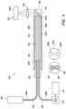
- FIG. 2is a simplified schematic view of a portion of an embodiment of the catheter system including an embodiment of the tissue identification system;
- FIG. 3is a simplified schematic view of a portion of another embodiment of the catheter system including another embodiment of the tissue identification system;
- FIG. 4is a simplified schematic view of a portion of still another embodiment of the tissue identification system.
- FIG. 5is a simplified schematic view of a portion of yet another embodiment of the tissue identification system.
- vascular lesionscan reduce major adverse events or death in affected subjects.
- a major adverse eventis one that can occur anywhere within the body due to the presence of a vascular lesion (also sometimes referred to herein as a treatment site.
- Major adverse eventscan include, but are not limited to, major adverse cardiac events, major adverse events in the peripheral or central vasculature, major adverse events in the brain, major adverse events in the musculature, or major adverse events in any of the internal organs.
- the catheter systems and related methods disclosed hereinare configured to enhance the intravascular lithotripsy therapeutic outcome by providing real-time feedback on vessel patency and optimization of the therapy delivery parameters. More particularly, the catheter systems and related methods disclosed herein include a feedback mechanism in the form of a tissue identification system that provides details on tissue type, quantity and location. Spectroscopic tissue identification methods have been demonstrated in literature, but have never been combined with a intravascular lithotripsy catheter. Utilizing ether dedicated fiber optics or existing therapy fiber optics, the intravascular lithotripsy catheter system utilizing such a tissue identification system that employs spectroscopic tissue identification can optimize treatment location and duration, energy and frequency, as well as provide therapy verification in real-time. Ultimately, a smart intravascular lithotripsy device with optical sensing, such as described herein, can improve patient outcomes while minimizing collateral damage to surrounding tissues.
- the catheter systems and related methods of the present inventionutilize an energy source, e.g., a light source such as a laser source or another suitable energy source, which provides energy that is guided by an energy guide, e.g., in certain embodiments, a light guide, to create a localized plasma in the balloon fluid that is retained within a balloon interior of an inflatable balloon of the catheter.
- an energy sourcee.g., a light source such as a laser source or another suitable energy source
- an energy guidee.g., in certain embodiments, a light guide
- the energy guidecan sometimes be referred to as, or can be said to incorporate a “plasma generator” at or near a guide distal end of the energy guide that is positioned within the balloon interior.
- the creation of the localized plasmainduces a high energy bubble inside the balloon interior to create pressure waves and/or pressure waves to impart pressure onto and induce fractures in a treatment site, such as a calcified vascular lesion or a fibrous vascular lesion, at a treatment site within or adjacent to a blood vessel wall within a body of a patient.
- a treatment sitesuch as a calcified vascular lesion or a fibrous vascular lesion, at a treatment site within or adjacent to a blood vessel wall within a body of a patient.
- the treatment sitecan include a vascular lesion such as a calcified vascular lesion or a fibrous vascular lesion, typically found in a blood vessel and/or a heart valve.
- the catheter systems of the present inventioninclude and/or incorporate a tissue identification system that is specifically configured to provide real-time feedback on tissue type, quantity and location as a means to enhance vessel patency and optimization of the therapy delivery parameters.
- the tissue identification systemcan provide advantages such as (i) tissue identification at the therapy location site provides an opportunity to optimize therapy parameters with the prospect of improved vessel patency, (ii) the spectroscopic identification methods are accurate and fast, with no additional procedure time required, (iii) in certain embodiments, no additional optical fibers are required, with the required optical fibers already included as part of the intravascular lithotripsy catheter system, (iv) the light source and the spectroscopic light detector of the tissue identification system are part of the reusable capital equipment, and (v) the cost of goods sold in such a single use device incorporating the tissue identification system are only negligibly increased.
- the catheter systemscan include a catheter configured to advance to the treatment site within or adjacent a blood vessel or a heart valve within the body of the patient.
- the catheterincludes a catheter shaft, and a balloon that is coupled and/or secured to the catheter shaft.
- the balloonsherein can include a balloon wall that defines a balloon interior.
- the balloonscan be configured to receive the balloon fluid within the balloon interior to expand from a deflated configuration suitable for advancing the catheter through a patient's vasculature, to an inflated configuration suitable for anchoring the catheter in position relative to the treatment site.
- the catheter systemsalso include one or more energy guides, e.g., in some embodiments, light guides, disposed along the catheter shaft and within the balloon.
- Each energy guidecan be configured for generating pressure waves within the balloon for disrupting the vascular lesions.
- the catheter systemsutilize energy from an energy source, e.g., light energy from a light source, to generate the plasma, i.e. via the plasma generator, within the balloon fluid at or near a guide distal end of the energy guide disposed within the balloon interior of the balloon located at the treatment site.
- the plasma formationcan initiate a pressure wave and can initiate the rapid formation of one or more bubbles that can rapidly expand to a maximum size and then dissipate through a cavitation event that can launch a pressure wave upon collapse.
- the rapid expansion of the plasma-induced bubblescan generate one or more pressure waves within the balloon fluid retained within the balloon and thereby impart pressure waves upon the treatment site.
- the energy sourcecan be configured to provide sub-millisecond pulses of energy, e.g., light energy, from the energy source to initiate plasma formation in the balloon fluid within the balloon to cause rapid bubble formation and to impart pressure waves upon the balloon wall at the treatment site.
- energye.g., light energy
- the pressure wavescan transfer mechanical energy through an incompressible balloon fluid to the treatment site to impart a fracture force on the intravascular lesion.
- intravascular lesionAs used herein, the terms “intravascular lesion”, “vascular lesion” or “treatment site” are used interchangeably unless otherwise noted. As such, the intravascular lesions and/or the vascular lesions are sometimes referred to herein simply as “lesions” or “treatment sites”.
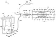
- FIG. 1a schematic cross-sectional view is shown of a catheter system 100 in accordance with various embodiments herein.
- the catheter system 100is suitable for imparting pressure to induce fractures in one or more vascular lesions within or adjacent a vessel wall of a blood vessel or a heart valve.
- the catheter system 100can include one or more of a catheter 102 , a light guide bundle 122 including one or more light guides 122 A, a source manifold 136 , a fluid pump 138 , a system console 123 including one or more of a light source 124 , a power source 125 , a system controller 126 , and a graphic user interface 127 (a “GUI”), a handle assembly 128 , and a tissue identification system 142 .
- the catheter system 100can have more components or fewer components than those specifically illustrated and described in relation to FIG. 1 .
- the catheter 102is configured to move to a treatment site 106 within or adjacent to a blood vessel 108 within a body 107 of a patient 109 .
- the treatment site 106can include one or more vascular lesions such as calcified vascular lesions, for example. Additionally, or in the alternative, the treatment site 106 can include vascular lesions such as fibrous vascular lesions.
- the catheter 102can include an inflatable balloon 104 (sometimes referred to herein simply as a “balloon”), a catheter shaft 110 and a guidewire 112 .
- the balloon 104can be coupled to the catheter shaft 110 .
- the balloon 104can include a balloon proximal end 104 P and a balloon distal end 104 D.
- the catheter shaft 110can extend from a proximal portion 114 of the catheter system 100 to a distal portion 116 of the catheter system 100 .
- the catheter shaft 110can include a longitudinal axis 144 .
- the catheter shaft 110can also include a guidewire lumen 118 which is configured to move over the guidewire 112 .
- the guidewire lumen 118is intended to define the structure that provides a conduit through which the guidewire extends.
- the catheter shaft 110can further include an inflation lumen (not shown).
- the catheter 102can have a distal end opening 120 and can accommodate and be tracked over the guidewire 112 as the catheter 102 is moved and positioned at or near the treatment site 106 .
- the tissue identification system 142is configured to provide real-time feedback on tissue type, quantity and location in order to effectively enhance vessel patency and optimization of therapy delivery parameters. More particularly, the tissue identification system 142 is configured to utilize optical sensing capabilities in order to improve patient outcomes while minimizing collateral damage to surrounding tissues.
- the catheter shaft 110 of the catheter 102can be coupled to the one or more light guides 122 A of the light guide bundle 122 that are in optical communication with the light source 124 .
- the light guide(s) 122 Acan be disposed along the catheter shaft 110 and within the balloon 104 .
- each light guide 122 Acan be an optical fiber and the light source 124 can be a laser.
- the light source 124can be in optical communication with the light guides 122 A at the proximal portion 114 of the catheter system 100 .
- the catheter shaft 110can be coupled to multiple light guides 122 A such as a first light guide, a second light guide, a third light guide, etc., which can be disposed at any suitable positions about the guidewire lumen 118 and/or the catheter shaft 110 .
- light guides 122 Asuch as a first light guide, a second light guide, a third light guide, etc., which can be disposed at any suitable positions about the guidewire lumen 118 and/or the catheter shaft 110 .
- two light guides 122 Acan be spaced apart by approximately 180 degrees about the circumference of the guidewire lumen 118 and/or the catheter shaft 110 ; three light guides 122 A can be spaced apart by approximately 120 degrees about the circumference of the guidewire lumen 118 and/or the catheter shaft 110 ; or four light guides 122 A can be spaced apart by approximately 90 degrees about the circumference of the guidewire lumen 118 and/or the catheter shaft 110 .
- multiple light guides 122 Aneed not be uniformly spaced apart from one another about the circumference of the guidewire lumen 118 and/or the catheter shaft 110 . More particularly, it is further appreciated that the light guides 122 A described herein can be disposed uniformly or non-uniformly about the guidewire lumen 118 and/or the catheter shaft 110 to achieve the desired effect in the desired locations.
- the balloon 104can include a balloon wall 130 that defines a balloon interior 146 , and can be inflated with a balloon fluid 132 to expand from a deflated configuration suitable for advancing the catheter 102 through a patient's vasculature, to an inflated configuration suitable for anchoring the catheter 102 in position relative to the treatment site 106 .
- the balloon wall 130 of the balloon 104is configured to be positioned substantially adjacent to the treatment site 106 , i.e. to the vascular lesion(s). It is appreciated that although FIG.
- FIG. 1illustrates the balloon wall 130 of the balloon 104 being shown spaced apart from the treatment site 106 of the blood vessel 108 , this is done merely for ease of illustration, and the balloon wall 130 of the balloon 104 will typically be substantially directly adjacent to the treatment site 106 when the balloon is in the inflated configuration.
- the light source 124 of the catheter system 100can be configured to provide sub-millisecond pulses of light from the light source 124 , along the light guides 122 A, to a location within the balloon interior 146 of the balloon 104 , thereby inducing plasma formation in the balloon fluid 132 within the balloon interior 146 of the balloon 104 , i.e. via a plasma generator 133 located at a guide distal end 122 D of the light guide 122 A.
- the plasma formationcauses rapid bubble formation, and imparts pressure waves upon the treatment site 106 . Exemplary plasma-induced bubbles are shown as bubbles 134 in FIG. 1 .
- the catheter systems 100 illustrated hereinare generally described as including a light source 124 and one or more light guides 122 A
- the catheter system 100can alternatively include any suitable energy source and energy guides for purposes of generating the desired plasma in the balloon fluid 132 within the balloon interior 146 .
- the energy source 124can be configured to provide high voltage pulses
- each energy guide 122 Acan include an electrode pair including spaced apart electrodes that extend into the balloon interior 146 .
- each pulse of high voltageis applied to the electrodes and forms an electrical arc across the electrodes, which, in turn, generates the plasma and forms the pressure waves within the balloon fluid 132 that are utilized to provide the fracture force onto the vascular lesions at the treatment site 106 .
- the energy source 124 and/or the energy guides 122 Acan have another suitable design and/or configuration.
- the balloons 104 suitable for use in the catheter systems 100 described in detail hereininclude those that can be passed through the vasculature of a patient when in the deflated configuration.
- the balloons 104 hereinare made from silicone.
- the balloons 104 hereinare made from polydimethylsiloxane (PDMS), polyurethane, polymers such as PEBAXTM material available from Arkema, which has a location at King of Prussia, Pennsylvania, USA, nylon, and the like.
- the balloons 104can include those having diameters ranging from one millimeter (mm) to 25 mm in diameter.
- the balloons 104can include those having diameters ranging from at least 1.5 mm to 14 mm in diameter.
- the balloons 104can include those having diameters ranging from at least one mm to five mm in diameter.
- the balloons 104 hereincan include those having a length ranging from at least three mm to 300 mm. More particularly, in some embodiments, the balloons 104 herein can include those having a length ranging from at least eight mm to 200 mm. It is appreciated that balloons 104 of greater length can be positioned adjacent to larger treatment sites 106 , and, thus, may be usable for imparting pressure onto and inducing fractures in larger vascular lesions or multiple vascular lesions at precise locations within the treatment site 106 . It is further appreciated that such longer balloons 104 can also be positioned adjacent to multiple treatment sites 106 at any given time.
- the balloons 104 hereincan be inflated to inflation pressures of between approximately one atmosphere (atm) and 70 atm. In some embodiments, the balloons 104 herein can be inflated to inflation pressures of from at least 20 atm to 70 atm. In other embodiments, the balloons 104 herein can be inflated to inflation pressures of from at least six atm to 20 atm. In still other embodiments, the balloons 104 herein can be inflated to inflation pressures of from at least three atm to 20 atm. In yet other embodiments, the balloons 104 herein can be inflated to inflation pressures of from at least two atm to ten atm.
- the balloons 104 hereincan include those having various shapes, including, but not to be limited to, a conical shape, a square shape, a rectangular shape, a spherical shape, a conical/square shape, a conical/spherical shape, an extended spherical shape, an oval shape, a tapered shape, a bone shape, a stepped diameter shape, an offset shape, or a conical offset shape.
- the balloons 104 hereincan include a drug eluting coating or a drug eluting stent structure.
- the drug elution coating or drug eluting stentcan include one or more therapeutic agents including anti-inflammatory agents, anti-neoplastic agents, anti-angiogenic agents, and the like.
- the balloon fluid 132can be a liquid or a gas.
- Exemplary balloon fluids 132 suitable for use hereincan include, but are not limited to one or more of water, saline, contrast medium, fluorocarbons, perfluorocarbons, gases, such as carbon dioxide, and the like.
- the balloon fluids 132 describedcan be used as base inflation fluids.
- the balloon fluids 132include a mixture of saline to contrast medium in a volume ratio of 50:50.
- the balloon fluids 132include a mixture of saline to contrast medium in a volume ratio of 25:75.
- the balloon fluids 132include a mixture of saline to contrast medium in a volume ratio of 75:25. Additionally, the balloon fluids 132 suitable for use herein can be tailored on the basis of composition, viscosity, and the like in order to manipulate the rate of travel of the pressure waves therein. In certain embodiments, the balloon fluids 132 suitable for use herein are biocompatible. A volume of balloon fluid 132 can be tailored by the chosen light source 124 and the type of balloon fluid 132 used.
- the contrast agents used in the contrast media hereincan include, but are not to be limited to, iodine-based contrast agents, such as ionic or non-ionic iodine-based contrast agents.
- ionic iodine-based contrast agentsinclude diatrizoate, metrizoate, iothalamate, and ioxaglate.
- non-ionic iodine-based contrast agentsinclude iopamidol, iohexol, ioxilan, iopromide, iodixanol, and ioversol. In other embodiments, non-iodine based contrast agents can be used.
- Suitable non-iodine containing contrast agentscan include gadolinium (III)-based contrast agents.
- Suitable fluorocarbon and perfluorocarbon agentscan include, but are not to be limited to, agents such as the perfluorocarbon dodecafluoropentane (DDFP, C5F12).
- the balloon fluids 132 hereincan include those that include absorptive agents that can selectively absorb light in the ultraviolet region (e.g., at least ten nanometers (nm) to 400 nm), the visible region (e.g., at least 400 nm to 780 nm), or the near-infrared region (e.g., at least 780 nm to 2.5 ⁇ m) of the electromagnetic spectrum.
- absorptive agentscan include those with absorption maxima along the spectrum from at least ten nm to 2.5 ⁇ m.
- the balloon fluids 132can include those that include absorptive agents that can selectively absorb light in the mid-infrared region (e.g., at least 2.5 ⁇ m to 15 ⁇ m), or the far-infrared region (e.g., at least 15 ⁇ m to one mm) of the electromagnetic spectrum.
- the absorptive agentcan be those that have an absorption maximum matched with the emission maximum of the laser used in the catheter system 100 .
- the absorptive agents used hereincan be water soluble. In other embodiments, the absorptive agents used herein are not water soluble. In some embodiments, the absorptive agents used in the balloon fluids 132 herein can be tailored to match the peak emission of the light source 124 .
- Various light sources 124 having emission wavelengths of at least ten nanometers to one millimeterare discussed elsewhere herein.
- the catheter system 100 and/or the light guide bundle 122 disclosed hereincan include any number of light guides 122 A in optical communication with the light source 124 at the proximal portion 114 , and with the balloon fluid 132 within the balloon interior 146 of the balloon 104 at the distal portion 116 .
- the catheter system 100 and/or the light guide bundle 122can include from one light guide 122 A to five light guides 122 A.
- the catheter system 100 and/or the light guide bundle 122can include from five light guides 122 A to fifteen light guides 122 A.
- the catheter system 100 and/or the light guide bundle 122can include from ten light guides 122 A to thirty light guides 122 A.
- the catheter system 100 and/or the light guide bundle 122can include greater than thirty light guides 122 A.
- the light guides 122 A hereincan include an optical fiber or flexible light pipe.
- the light guides 122 A hereincan be thin and flexible and can allow light signals to be sent with very little loss of strength.
- the light guides 122 A hereincan include a core surrounded by a cladding about its circumference.
- the corecan be a cylindrical core or a partially cylindrical core.
- the core and cladding of the light guides 122 Acan be formed from one or more materials, including but not limited to one or more types of glass, silica, or one or more polymers.
- the light guides 122 Amay also include a protective coating, such as a polymer. It is appreciated that the index of refraction of the core will be greater than the index of refraction of the cladding.
- Each light guide 122 Acan guide light along its length from a proximal portion, i.e. a guide proximal end 122 P, to a distal portion, i.e. the guide distal end 122 D, having at least one optical window (not shown) that is positioned within the balloon interior 146 .
- the light guides 122 Acan create a light path as a portion of an optical network including the light source 124 .
- the light path within the optical networkallows light to travel from one part of the network to another.
- Both the optical fiber and the flexible light pipecan provide a light path within the optical networks herein.
- the guide distal end 122 Dcan further include and/or incorporate a distal light receiver (not shown in FIG. 1 ) that enables light energy to be moved back into and through the light guide 122 A from the guide distal end 122 D to the guide proximal end 122 P.
- a distal light receivernot shown in FIG. 1
- the light energy emitted from the guide proximal end 122 P after being moved back through the light guide 122 Acan be separated and then optically detected and/or analyzed through use of the tissue identification system 142 .
- the light guides 122 A hereincan assume many configurations about and/or relative to the catheter shaft 110 of the catheters 102 described herein. In some embodiments, the light guides 122 A can run parallel to the longitudinal axis 144 of the catheter shaft 110 . In some embodiments, the light guides 122 A can be physically coupled to the catheter shaft 110 . In other embodiments, the light guides 122 A can be disposed along a length of an outer diameter of the catheter shaft 110 . In yet other embodiments, the light guides 122 A herein can be disposed within one or more light guide lumens within the catheter shaft 110 .
- the light guides 122 Acan be disposed at any suitable positions about the circumference of the guidewire lumen 118 and/or the catheter shaft 110 , and the guide distal end 122 D of each of the light guides 122 A can be disposed at any suitable longitudinal position relative to the length of the balloon 104 and/or relative to the length of the guidewire lumen 118 .
- the light guides 122 A hereincan include one or more photoacoustic transducers 154 , where each photoacoustic transducer 154 can be in optical communication with the light guide 122 A within which it is disposed.
- the photoacoustic transducers 154can be in optical communication with the guide distal end 122 D of the light guide 122 A.
- the photoacoustic transducers 154can have a shape that corresponds with and/or conforms to the guide distal end 122 D of the light guide 122 A.
- the photoacoustic transducer 154is configured to convert light energy into an acoustic wave at or near the guide distal end 122 D of the light guide 122 A. It is appreciated that the direction of the acoustic wave can be tailored by changing an angle of the guide distal end 122 D of the light guide 122 A.
- the photoacoustic transducers 154 disposed at the guide distal end 122 D of the light guide 122 A hereincan assume the same shape as the guide distal end 122 D of the light guide 122 A.
- the photoacoustic transducer 154 and/or the guide distal end 122 Dcan have a conical shape, a convex shape, a concave shape, a bulbous shape, a square shape, a stepped shape, a half-circle shape, an ovoid shape, and the like.
- the light guide 122 Acan further include additional photoacoustic transducers 154 disposed along one or more side surfaces of the length of the light guide 122 A.
- the light guides 122 A described hereincan further include one or more diverting features or “diverters” (not shown in FIG. 1 ) within the light guide 122 A that are configured to direct light to exit the light guide 122 A toward a side surface e.g., at or near the guide distal end 122 D of the light guide 122 A, and toward the balloon wall 130 .
- a diverting featurecan include any feature of the system herein that diverts light from the light guide 122 A away from its axial path toward a side surface of the light guide 122 A.
- the light guides 122 Acan each include one or more light windows disposed along the longitudinal or circumferential surfaces of each light guide 122 A and in optical communication with a diverting feature.
- the diverting features hereincan be configured to direct light in the light guide 122 A toward a side surface, e.g., at or near the guide distal end 122 D, where the side surface is in optical communication with a light window.
- the light windowscan include a portion of the light guide 122 A that allows light to exit the light guide 122 A from within the light guide 122 A, such as a portion of the light guide 122 A lacking a cladding material on or about the light guide 122 A.
- Examples of the diverting features suitable for use hereininclude a reflecting element, a refracting element, and a fiber diffuser. Additionally, the diverting features suitable for focusing light away from the tip of the light guides 122 A herein can include, but are not to be limited to, those having a convex surface, a gradient-index (GRIN) lens, and a mirror focus lens.
- the lightis diverted within the light guide 122 A to the plasma generator 133 and/or the photoacoustic transducer(s) 154 that are in optical communication with a side surface of the light guide 122 A.
- the plasma generator 133 and/or the photoacoustic transducer(s) 154then convert light energy into an acoustic pressure wave and bubble that extend away from the side surface of the light guide 122 A.
- the source manifold 136can be positioned at or near the proximal portion 114 of the catheter system 100 .
- the source manifold 136can include one or more proximal end openings that can receive the plurality of light guides 122 A of the light guide bundle 122 , the guidewire 112 , and/or an inflation conduit 140 that is coupled in fluid communication with the fluid pump 138 .
- the catheter system 100can also include the fluid pump 138 that is configured to inflate the balloon 104 with the balloon fluid 132 , i.e. via the inflation conduit 140 , as needed.
- the system console 123includes one or more of the light source 124 , the power source 125 , the system controller 126 , and the GUI 127 .
- the system console 123can include more components or fewer components than those specifically illustrated in FIG. 1 .
- the system console 123can be designed without the GUI 127 .
- one or more of the light source 124 , the power source 125 , the system controller 126 , and the GUI 127can be provided within the catheter system 100 without the specific need for the system console 123 .
- tissue identification system 142can also be positioned substantially within the system console 123 .
- components of the tissue identification system 142can be positioned in a different manner than what is specifically shown in FIG. 1 .
- the system console 123is operatively coupled to the catheter 102 , the light guide bundle 122 , and the remainder of the catheter system 100 .
- the system console 123can include a console connection aperture 148 (also sometimes referred to generally as a “socket”) by which the light guide bundle 122 is mechanically coupled to the system console 123 .
- the light guide bundle 122can include a guide coupling housing 150 (also sometimes referred to generally as a “ferrule”) that houses a portion, e.g., the guide proximal end 122 P, of each of the light guides 122 A.
- the guide coupling housing 150is configured to fit and be selectively retained within the console connection aperture 148 to provide the desired mechanical coupling between the light guide bundle 122 and the system console 123 .
- the light guide bundle 122can also include a guide bundler 152 (or “shell”) that brings each of the individual light guides 122 A closer together so that the light guides 122 A and/or the light guide bundle 122 can be in a more compact form as it extends with the catheter 102 into the blood vessel 108 during use of the catheter system 100 .
- a guide bundler 152or “shell” that brings each of the individual light guides 122 A closer together so that the light guides 122 A and/or the light guide bundle 122 can be in a more compact form as it extends with the catheter 102 into the blood vessel 108 during use of the catheter system 100 .
- the light source 124can be selectively and/or alternatively coupled in optical communication with each of the light guides 122 A, i.e. to the guide proximal end 122 P of each of the light guides 122 A, in the light guide bundle 122 .
- the light source 124is configured to generate light energy in the form of a source beam 124 A, e.g., a pulsed source beam that can be selectively and/or alternatively directed to and received by each of the light guides 122 A in the light guide bundle 122 as an individual guide beam 1248 .
- the catheter system 100can include more than one light source 124 .
- the catheter system 100can include a separate light source 124 for each of the light guides 122 A in the light guide bundle 122 .
- the light source 124can have any suitable design.
- the light source 124can be configured to provide sub-millisecond pulses of light from the light source 124 that are focused onto a small spot in order to couple it into the guide proximal end 122 P of the light guide 122 A. Such pulses of light energy are then directed along the light guides 122 A to a location within the balloon 104 , thereby inducing plasma formation in the balloon fluid 132 within the balloon interior 146 of the balloon 104 .
- the light energy emitted at the guide distal end 122 D of the light guide 122 Aenergizes the plasma generator 133 to form the plasma within the balloon fluid 132 within the balloon interior 146 .
- the sub-millisecond pulses of light from the light source 124can be delivered to the treatment site 106 at a frequency of between approximately one hertz (Hz) and 5000 Hz. In some embodiments, the sub-millisecond pulses of light from the light source 124 can be delivered to the treatment site 106 at a frequency of between approximately 30 Hz and 1000 Hz. In other embodiments, the sub-millisecond pulses of light from the light source 124 can be delivered to the treatment site 106 at a frequency of between approximately ten Hz and 100 Hz.
- the sub-millisecond pulses of light from the light source 124can be delivered to the treatment site 106 at a frequency of between approximately one Hz and 30 Hz.
- the sub-millisecond pulses of lightcan be delivered to the treatment site 106 at a frequency that can be greater than 5000 Hz.
- the light source 124is typically utilized to provide pulses of light energy, the light source 124 can still be described as providing a single source beam 124 A, i.e. a single pulsed source beam.
- the light sources 124 suitable for use hereincan include various types of light sources including lasers and lamps. Alternatively, as noted above, the light sources 124 , as referred to herein, can include any suitable type of energy source.
- Suitable laserscan include short pulse lasers on the sub-millisecond timescale.
- the light source 124can include lasers on the nanosecond (ns) timescale.
- the laserscan also include short pulse lasers on the picosecond (ps), femtosecond (fs), and microsecond (us) timescales. It is appreciated that there are many combinations of laser wavelengths, pulse widths and energy levels that can be employed to achieve plasma in the balloon fluid 132 of the catheters 102 described herein.
- the pulse widthscan include those falling within a range including from at least ten ns to 3000 ns. In some embodiments, the pulse widths can include those falling within a range including from at least 20 ns to 100 ns. In other embodiments, the pulse widths can include those falling within a range including from at least one ns to 500 ns.
- exemplary nanosecond laserscan include those within the UV to IR spectrum, spanning wavelengths of about ten nanometers (nm) to one millimeter (mm).
- the light sources 124 suitable for use in the catheter systems 100 hereincan include those capable of producing light at wavelengths of from at least 750 nm to 2000 nm.
- the light sources 124can include those capable of producing light at wavelengths of from at least 700 nm to 3000 nm.
- the light sources 124can include those capable of producing light at wavelengths of from at least 100 nm to ten micrometers ( ⁇ m).
- Nanosecond laserscan include those having repetition rates of up to 200 kHz.
- the lasercan include a Q-switched thulium:yttrium-aluminum-garnet (Tm:YAG) laser.
- the lasercan include a neodymium:yttrium-aluminum-garnet (Nd:YAG) laser, holmium:yttrium-aluminum-garnet (Ho:YAG) laser, erbium:yttrium-aluminum-garnet (Er:YAG) laser, excimer laser, helium-neon laser, carbon dioxide laser, as well as doped, pulsed, fiber lasers.
- Nd:YAGneodymium:yttrium-aluminum-garnet
- Ho:YAGholmium:yttrium-aluminum-garnet
- Er:YAGerbium:yttrium-aluminum-garnet
- excimer laserhelium-neon laser
- carbon dioxide laseras well as doped, pulsed,
- the catheter systems 100 disclosed hereincan generate pressure waves having maximum pressures in the range of at least one megapascal (MPa) to 100 MPa.
- MPamegapascal
- the maximum pressure generated by a particular catheter system 100will depend on the light source 124 , the absorbing material, the bubble expansion, the propagation medium, the balloon material, and other factors.
- the catheter systems 100 hereincan generate pressure waves having maximum pressures in the range of at least two MPa to 50 MPa.
- the catheter systems 100 hereincan generate pressure waves having maximum pressures in the range of at least two MPa to 30 MPa.
- the catheter systems 100 hereincan generate pressure waves having maximum pressures in the range of at least 15 MPa to 25 MPa.
- the pressure waves described hereincan be imparted upon the treatment site 106 from a distance within a range from at least 0.1 millimeters (mm) to 25 mm extending radially from the light guides 122 A when the catheter 102 is placed at the treatment site 106 .
- the pressure wavescan be imparted upon the treatment site 106 from a distance within a range from at least ten mm to 20 mm extending radially from the light guides 122 A when the catheter 102 is placed at the treatment site 106 .
- the pressure wavescan be imparted upon the treatment site 106 from a distance within a range from at least one mm to ten mm extending radially from the light guides 122 A when the catheter 102 is placed at the treatment site 106 . In yet other embodiments, the pressure waves can be imparted upon the treatment site 106 from a distance within a range from at least 1.5 mm to four mm extending radially from the light guides 122 A when the catheter 102 is placed at the treatment site 106 . In some embodiments, the pressure waves can be imparted upon the treatment site 106 from a range of at least two MPa to 30 MPa at a distance from 0.1 mm to ten mm. In some embodiments, the pressure waves can be imparted upon the treatment site 106 from a range of at least two MPa to 25 MPa at a distance from 0.1 mm to ten mm.
- the power source 125is electrically coupled to and is configured to provide necessary power to each of the light source 124 , the system controller 126 , the GUI 127 , the handle assembly 128 , and the tissue identification system 142 .
- the power source 125can have any suitable design for such purposes.
- the system controller 126is electrically coupled to and receives power from the power source 125 . Additionally, the system controller 126 is coupled to and is configured to control operation of each of the light source 124 , the GUI 127 and the tissue identification system 142 .
- the system controller 126can include one or more processors or circuits for purposes of controlling the operation of at least the light source 124 , the GUI 127 and the tissue identification system 142 .
- the system controller 126can control the light source 124 for generating pulses of light energy as desired, e.g., at any desired firing rate.
- the system controller 126can control and/or operate in conjunction with the tissue identification system 142 to effectively provide real-time feedback regarding the type, size and location of any tissue at or near the treatment site 106 in order to optimize treatment in real-time.
- system controller 126can further be configured to control operation of other components of the catheter system 100 , e.g., the positioning of the catheter 102 adjacent to the treatment site 106 , the inflation of the balloon 104 with the balloon fluid 132 , etc.
- the catheter system 100can include one or more additional controllers that can be positioned in any suitable manner for purposes of controlling the various operations of the catheter system 100 .
- an additional controller and/or a portion of the system controller 126can be positioned and/or incorporated within the handle assembly 128 .
- the GUI 127is accessible by the user or operator of the catheter system 100 . Additionally, the GUI 127 is electrically connected to the system controller 126 . With such design, the GUI 127 can be used by the user or operator to ensure that the catheter system 100 is employed as desired to impart pressure onto and induce fractures into the vascular lesions at the treatment site 106 . Additionally, the GUI 127 can provide the user or operator with information that can be used before, during and after use of the catheter system 100 . In one embodiment, the GUI 127 can provide static visual data and/or information to the user or operator.
- the GUI 127can provide dynamic visual data and/or information to the user or operator, such as video data or any other data that changes over time, e.g., during use of the catheter system 100 .
- the GUI 127can include one or more colors, different sizes, varying brightness, etc., that may act as alerts to the user or operator.
- the GUI 127can provide audio data or information to the user or operator. It is appreciated that the specifics of the GUI 127 can vary depending upon the design requirements of the catheter system 100 , or the specific needs, specifications and/or desires of the user or operator.
- the handle assembly 128can be positioned at or near the proximal portion 114 of the catheter system 100 , and/or near the source manifold 136 . Additionally, in this embodiment, the handle assembly 128 is coupled to the balloon 104 and is positioned spaced apart from the balloon 104 . Alternatively, the handle assembly 128 can be positioned at another suitable location.
- the handle assembly 128is handled and used by the user or operator to operate, position and control the catheter 102 .
- the design and specific features of the handle assembly 128can vary to suit the design requirements of the catheter system 100 .
- the handle assembly 128is separate from, but in electrical and/or fluid communication with one or more of the system controller 126 , the light source 124 , the fluid pump 138 , the GUI 127 and the tissue identification system 142 .
- the handle assembly 128can integrate and/or include at least a portion of the system controller 126 within an interior of the handle assembly 128 .
- the handle assembly 128can include circuitry 156 that can form at least a portion of the system controller 126 .
- the circuitry 156can receive electrical signals or data from the tissue identification system 142 . Further, or in the alternative, the circuitry 156 can transmit such electrical signals or otherwise provide data to the system controller 126 .
- the circuitry 156can include a printed circuit board having one or more integrated circuits, or any other suitable circuitry.
- the circuitry 156can be omitted, or can be included within the system controller 126 , which in various embodiments can be positioned outside of the handle assembly 128 , e.g., within the system console 123 . It is understood that the handle assembly 128 can include fewer or additional components than those specifically illustrated and described herein.
- the tissue identification system 142is configured to utilize spectroscopic tissue identification and analysis to effectively provide real-time feedback regarding the type, size, quantity and location of any tissue at or near the treatment site 106 in order to optimize treatment in real-time. Additionally, it is further appreciated that the tissue identification system 142 can have any suitable design and/or use any suitable types of spectroscopic methodologies for purposes of providing the desired real-time feedback regarding the type, size, quantity and location of any tissue at or near the treatment site 106 in order to optimize treatment in real-time.
- Spectroscopyis a genre of optical sensing methods. When light interacts with tissue, there are a multitude of optical properties that affect the light propagation path, wavelength, and energy state. Reflection, refraction, absorbance, scattering, anisotropy, phase change, and fluorescent properties of tissues are all elements that affect the trajectory, wavelength, and intensity of the photons in the tissue.
- the tissue identification system 142can utilize one or more of specular reflectance spectroscopy, diffuse reflectance spectroscopy, fluorescence spectroscopy, and Raman spectroscopy, which have each been utilized to exploit differences in optical properties and discriminate between tissue types. Additionally, or in the alternative, the tissue identification system 142 can utilize one or more other types of spectroscopy in order to provide the desired real-time feedback regarding the type, size, quantity and location of any tissue at or near the treatment site 106 in order to optimize treatment in real-time.
- Specular reflectance spectroscopyis designed to measure the reflecting efficiency of the tissue being analyzed, i.e. by analyzing the light that is purely reflected off the surface of the tissue.
- Diffuse reflectance spectroscopyis designed to measure the scattering effect of the tissue as a function of the light wavelength. More particularly, DRS projects a specific band of light (band size and wavelength dependent on tissue target) light into the tissue at a specific point(s) and collects the intensity of backscattered light at another specific location, returning this signal to a spectrometer to reconstruct the spectra of scattered light.
- Fluorescence spectroscopyis designed to recognize a specific wavelength of light that excites endogenous fluorophores found in intracellular molecules and tissue matrix molecules to an elevated singlet state.
- Raman spectroscopyis designed to utilize excitation light of a specific wavelength that enters the tissue and induces a dipole amongst the molecule's electrons via non-elastic scattering. The molecule then emits radiation at the dipole oscillating frequency. This signal can be very small, but it is directly correlated to the chemical bond strength of molecules found in the biological environment. The information given by Raman spectroscopy is very similar to the information from a chemical assay and enables chemical characterization of tissue.
- tissue identification system 142Certain non-exclusive examples of potential designs for the tissue identification system 142 are described in detail herein below.
- FIG. 2is a simplified schematic view of a portion of an embodiment of the catheter system 200 including an embodiment of the tissue identification system 242 .
- the design of the catheter system 200is substantially similar to the embodiments illustrated and described herein above. It is appreciated that various components of the catheter system 200 , such as are shown in FIG. 1 , are not illustrated in FIG. 2 for purposes of clarity and ease of illustration. However, it is appreciated that the catheter system 200 will likely include most, if not all, of such components.
- the catheter system 200again at least includes an energy source 224 , e.g., a light source or other suitable energy source, and one or more energy guides 222 A, e.g., light guides or other suitable energy guides.
- the energy guides 222 Aare configured to guide energy from the energy source 224 into the balloon interior 146 (illustrated in FIG. 1 ) to generate plasma within the balloon fluid 132 (illustrated in FIG. 1 ) at or near a guide distal end 222 D of the energy guide 222 A disposed within the balloon interior 146 of the balloon 104 (illustrated in FIG.
- the plasma formationcan initiate a pressure wave and can initiate the rapid formation of one or more bubbles that can rapidly expand to a maximum size and then dissipate through a cavitation event that can launch a pressure wave upon collapse.
- the rapid expansion of the plasma-induced bubblescan generate one or more pressure waves within the balloon fluid 132 retained within the balloon 104 and thereby impart pressure waves upon the treatment site 106 .
- FIG. 2also shows an embodiment of the tissue identification system 242 that is configured to utilize one or more spectroscopic tissue identification methodologies to identify the type, size, quantity and location of any tissue at or near the treatment site 106 in order to optimize treatment in real-time.
- the tissue identification system 242can have any suitable configuration pursuant to the requirements of the catheter system 200 .
- the tissue identification system 242can include one or more of a spectroscopic light source 260 , a filter assembly 262 , a beamsplitter 264 , an optical element 266 , a modulator 268 , a light detector 270 and control electronics 272 .
- the tissue identification system 242can further include one or more light guides 222 A, which can be the same light guides 222 A that are used to direct the energy from the energy source 224 , or can be dedicated light guides 222 A that are used only for purposes of tissue identification. Further, or in the alternative, the tissue identification system 242 can include more components or fewer components than those specifically illustrated in FIG. 2 .
- tissue identification system 242can be modified depending upon the specific type of spectroscopy being utilized within the catheter system 200 .
- the design and/or operation of the spectroscopic light source 260 , the filter assembly 262 , the beamsplitter 264 , the modulator 268 and the light detector 270can be modified depending on the particular spectroscopic methodologies being used at any given time within the catheter system 200 .
- the spectroscopic light source 260is configured to provide electromagnetic energy in the form of a spectroscopic source beam 260 A that is used to diagnostically interrogate the tissue of interest, e.g., within the vascular lesion 206 A at the treatment site 106 .
- the spectroscopic light source 260can be either a coherent laser source of a specific targeted wavelength (such as is required for fluorescence spectroscopy and Raman spectroscopy), or a broadband light source with a targeted wavelength range.
- the spectroscopic light source 260can be a broadband light source, which can use a halogen, deuterium, xenon, or tungsten lamp, white LED, or a monochromatic (laser) light source with a wavelength depending on the optical characteristics of the tissue of interest.
- the spectroscopic light source 260can also be a broadband light source, which can use a halogen, deuterium, xenon or tungsten lamp, white LED, or some combination thereof.
- the spectroscopic light source 260can be a monochromatic light source (usually a laser source) that is based on the characteristics (fluorescent characteristics in the case of fluorescence spectroscopy) of the tissue of interest.
- the spectroscopic source beam 260 A from the spectroscopic light source 260can be initially directed toward a first filter 262 A of the filter assembly 262 .
- the first filter 262 Ais an optical device that is configured to only transmit light in a specific wavelength range or polarity. It is appreciated that the use of the first filter 262 A enables targeted interrogation and detection based on the optical characteristics of the tissue(s) of interest for optimum identification.
- the spectroscopic source beam 260 Ais directed toward the beamsplitter 264 , which splits the spectroscopic source beam 260 A and reflects at least a portion of the spectroscopic source beam 260 A so that it is directed toward the optical element 266 .
- the beamsplitter 264is configured to split the spectroscopic source beam 260 A and a returning identification beam 260 B (as described herein below) so that both beams 260 A, 260 B can be coupled into the same light guide 222 A.
- the portion of the spectroscopic source beam 260 A that is directed toward the optical element 266e.g., a focusing lens, is focused by the optical element 266 in order to couple the spectroscopic source beam 260 A into one of the light guides 222 A with optimum transmission.
- the optical element 266e.g., a focusing lens
- the spectroscopic source beam 260 Ais directed toward the modulator 268 , e.g., an optical switch or splitter.
- the modulator 268is an optical device that enables multiple optical inputs to travel down one optical fiber, i.e. one light guide 222 A, by mechanically modulating the physical connections. More particularly, as illustrated, the modulator 268 enables the therapeutic pulsed beams from the energy source 224 to travel down the same optical fiber, i.e. the same light guide 222 A, that is used for transmitting the spectroscopic source beam 260 A for sensing the tissue between each pulse of the energy source 224 . Additionally, the modulator 268 also enables multiple tissue identification methodologies to be used with the same light guide 222 A.
- the modulator 268couples the spectroscopic source beam 260 A into the guide proximal end of the desired light guide 222 A, which guides the spectroscopic source beam 260 A into the balloon interior 146 .
- the light guide 222 Acan include a diverter 274 that is positioned at or near the guide distal end 222 D of the light guide 222 A and that is configured to more accurately and precisely direct the spectroscopic source beam 260 A toward the tissue of interest, e.g., the vascular lesion 206 A that is present at the treatment site 106 within and/or adjacent to the vessel wall 208 A of the blood vessel 108 .
- the spectroscopic source beam 260 Ais returned, e.g., reflected, refracted, scattered, phase changed, fluoresced, etc., by the tissue based on the properties of the tissue and is directed back toward the guide distal end 222 D of the light guide 222 A as the returning identification beam 260 B. More specifically, the returning identification beam 260 B can be received back into the guide distal end 222 D of the light guide 222 A via a distal light receiver 276 that is coupled to the guide distal end 222 D of the light guide 222 A.
- the light guide 222 Acan be a thin and flexible optical fiber that can be used to both introduce the spectroscopic source beam 260 A to the tissue of interest and collect the return spectra in the form of the returning identification beam 260 B.
- different fiber tip geometriesi.e. different diverters 274 , as well as fiber gratings, can be used to direct and focus the light as desired.
- different light guides 222 Acan be used for introducing the spectroscopic source beam 260 A to the tissue of interest and collecting the return spectra in the form of the returning identification beam 260 B.
- the light guides 222 Acan have a unique design, e.g., using a multicore optical fiber with two or more cores, to enable the light guides 222 A to more effectively both introduce the spectroscopic source beam 260 A to the tissue of interest and collect the return spectra in the form of the returning identification beam 260 B.
- the returning identification beam 260 Bis then guided back through the light guide 222 A from the guide distal end 222 D to the guide proximal end before being directed back toward and through the modulator 268 .
- the returning identification beam 260 Bis then directed back through the optical element 266 before being directed toward the beamsplitter 264 .
- the beamsplitter 264then transmits at least a portion of the returning identification beam 260 B, depending on the characteristics of the returning identification beam 260 B and the design of the beamsplitter 264 , toward a second filter 262 B of the filter assembly 262 .
- the second filter 262 Bis an optical device that is configured to only transmit light in a specific wavelength range or polarity.
- the desired portion of the returning identification beam 260 Bwhich is selected based on the particular spectroscopic methodology being utilized at any given time, is directed to the light detector 270 .
- the light detector 270is configured to capture and quantify the characteristics of the returning identification beam 260 B that has returned from the tissue of interest.
- the light detector 270may also separate and quantify the light within the returning identification beam 260 B by wavelength. More specifically, the light detector 270 can be provided in the form of a spectrometer that can separate the light of the returning identification beam 260 B into discrete wavelengths and then measure the intensity of each wavelength. The light detector 270 can then generate an appropriate signal based on the detected characteristics and measured wavelength intensity of the returning identification beam 260 B which is then sent to the control electronics 272 .
- the control electronics 272which can form a portion of the system controller 126 (illustrated in FIG. 1 ) or which can be provided separately from the system controller 126 and can be in electrical communication with the system controller 126 , analyzes the signal from the light detector 270 to provide an effective determination regarding the type, size, quantity and location of any tissue at or near the treatment site 106 in order to optimize treatment in real-time. More specifically, the control electronics 272 utilize an appropriate algorithm to effectively identify tissue type, size and location. Further, it is appreciated that the algorithm can be more robust if and when multiple spectroscopic methodologies are utilized.
- the tissue identification system 242is able to provide an initial analysis of the tissue type, size and location at the treatment site 106 , and also to provide a continuous sensing of the tissue type, size and location to monitor the efficacy of the intravascular lithotripsy procedure in real-time.
- the tissue identification system 242can utilize one or more of specular reflectance spectroscopy, diffuse reflectance spectroscopy, fluorescence spectroscopy, and Raman spectroscopy, or another spectroscopic methodology to provide an effective determination regarding the type, size, quantity and location of any tissue at or near the treatment site 106 . It is appreciated that certain methodologies have better sensitivity for different tissue types. Thus, the tissue identification system 242 can have better overall modality by combining two or more of the noted methodologies. Accordingly, any such combination of methodologies can provide increased fidelity in sensing options. Additionally, or in the alternative, the use of multiple methodologies can serve as a self-check to see if each methodology provides the same analysis.
- tissue identification system 242can be modified depending upon the specific type of spectroscopy being utilized within the catheter system 200 .
- the spectroscopic light source 260when utilizing specular reflectance spectroscopy, could be broadband (halogen, deuterium, xenon, or tungsten lamp, white LED) or monochromatic (laser) light with a wavelength depending on the optical characteristics of the tissue of interest.
- the detection characteristicsare dictated by the optical tissue of interest (wavelengths at which it is the most different from the surrounding tissues) and the wavelength(s) of the spectroscopic light source 260 . This could be a fairly wide range of wavelengths, or a very specific wavelength. In some embodiments, detection could be done by a CCD spectrometer, a photodiode with the proper filters, or a similar device.
- specular reflectance spectroscopymay also use a light polarizer and a polarization filter, as reflected polarized light maintains polarization while light that transmits below the surface of the tissue and returns to the surface loses its polarization.
- the spectroscopic light source 260can be broadband (halogen, deuterium, xenon, or tungsten lamp, white LED or some combination thereof). Additionally, for the light detector 270 , the detection characteristics are again dictated by the optical tissue of interest (wavelengths at which it is the most different from the surrounding tissues) and the wavelength(s) of the spectroscopic light source 260 . This could be a fairly wide range of wavelengths, or a very specific wavelength. Again, in some embodiments, detection could be done by a CCD spectrometer, a photodiode with the proper filters, or a similar device.
- the spectroscopic light source 260can utilize monochromatic light (usually laser) based on the fluorescent characteristics of the tissue of interest. Additionally, the light detector 270 can be configured to focus on a small, specific wavelength range based on the fluorescent characteristics of the tissue of interest.
- the spectroscopic light source 260can be a monochromatic light (usually laser) based on the characteristics of the tissue of interest.
- the light detector 270can be configured to focus on a wide spectral range, and may require high sensitivity sensing elements for the small signals.
- the tissue identification system 242may also require a laser rejection filter to selectively transmit only Raman scattered light.
- the light guides 222 A in the catheter system 200could also be utilized for optical imaging modalities.
- the light guides 222 Acan further be used for optical coherence tomography (OCT) and/or optical coherence elastography (OCE).
- OCToptical coherence tomography
- OOEoptical coherence elastography
- imagesare created by mapping the scattering properties of tissue. This method requires focusing optics and a reference to create the coherence interference signal.
- chirped pulse interferometrywhich is an extension of OCT, can also be utilized which entails imaging using oppositely-chirped laser pulses in order to avoid dispersion (providing more depth penetration).
- OCEimages are created by mapping the mechanical properties of a tissue. This method requires an applied force (balloon or possible acoustic/mechanical forces from pulsed laser) and an OCT imaging system. OCE data and images could be used to identify different plaque types before and after a intravascular lithotripsy procedure.
- FIG. 3is a simplified schematic view of a portion of another embodiment of the catheter system 300 including another embodiment of the tissue identification system 342 . More particularly, as illustrated in FIG. 3 , two or more spectroscopic methodologies can be combined into one device by multiplexing the optical signal and sensing location into one or more light guides 322 A at the treatment site 106 .
- the design of the catheter system 300is substantially similar to the embodiments illustrated and described herein above. It is appreciated that various components of the catheter system 300 , such as are shown in FIG. 1 , are not illustrated in FIG. 3 for purposes of clarity and ease of illustration. However, it is appreciated that the catheter system 300 will likely include most, if not all, of such components. As shown in FIG. 3 , the catheter system 300 again at least includes an energy source 324 , e.g., a light source or other suitable energy source, and one or more energy guides 322 A, e.g., light guides or other suitable energy guides. As above, the energy guides 322 A are configured to guide energy from the energy source 324 into the balloon interior 146 (illustrated in FIG.
- an energy source 324e.g., a light source or other suitable energy source
- energy guides 322 Ae.g., light guides or other suitable energy guides.
- the energy guides 322 Aare configured to guide energy from the energy source 324 into the balloon interior 146 (illustrated in FIG
- the plasma formationcan initiate a pressure wave and can initiate the rapid formation of one or more bubbles that can rapidly expand to a maximum size and then dissipate through a cavitation event that can launch a pressure wave upon collapse.
- the rapid expansion of the plasma-induced bubblescan generate one or more pressure waves within the balloon fluid 132 retained within the balloon 104 and thereby impart pressure waves upon the treatment site 106 .
- the tissue identification system 342is configured to utilize two or more spectroscopic tissue identification methodologies to identify the type, size, quantity and location of any tissue at or near the treatment site 106 in order to optimize treatment in real-time. More specifically, as shown, the tissue identification system 342 can incorporate two tissue identification system members, e.g., a first tissue identification system member 342 A and a second tissue identification system member 342 B, which are each substantially similar in design and function to the tissue identification system 242 illustrated and described herein above in relation to FIG. 2 .
- tissue identification system memberse.g., a first tissue identification system member 342 A and a second tissue identification system member 342 B, which are each substantially similar in design and function to the tissue identification system 242 illustrated and described herein above in relation to FIG. 2 .
- each of the tissue identification members 342 A, 342 Bcan include one or more of a spectroscopic light source 360 , a filter assembly 362 , a beamsplitter 364 , an optical element 366 , a modulator 368 , a light detector 370 and control electronics 372 .
- the tissue identification system members 342 A, 342 Bcan further include one or more light guides 322 A, which can be the same light guides 322 A that are used to direct the energy from the energy source 324 , or can be dedicated light guides 322 A that are used only for purposes of tissue identification.
- Each of the spectroscopic light source 360 , the filter assembly 362 , the beamsplitter 364 , the optical element 366 , the modulator 368 , the light detector 370 and the control electronics 372are substantially similar in design and function to what has been illustrated and described herein above in relation to FIG. 2 . Accordingly, such components will not be described in detail herein again in relation to FIG. 3 .
- the modulator 368can be configured to couple the spectroscopic source beam 360 A from the spectroscopic light sources 360 of each of the tissue identification system members 342 A, 342 B into the guide proximal end of a different light guide 322 A, which then guides the respective spectroscopic source beam 360 A into the balloon interior 146 .
- the spectroscopic source beam 360 A from each of the spectroscopic light sources 360is directed as desired toward the tissue of interest, at least a portion of the spectroscopic source beam 360 A will be returned, e.g., reflected, refracted, scattered, phase changed, fluoresced, etc., by the tissue based on the properties of the tissue and be directed back toward the guide distal end 322 D of the light guide 322 A as respective returning identification beams 360 B.
- the respective returning identification beams 360 Bare then guided back through the light guide 322 A from the guide distal end 322 D to the guide proximal end before being directed back toward and through the modulator 368 .
- the desired portion of the respective returning identification beams 360 Bwhich is selected based on the particular spectroscopic methodology being utilized at any given time, is directed to the respective light detector 370 .
- each tissue identification system member 342 A, 342 Bcaptures and quantifies the characteristics of the respective returning identification beam 360 B that has returned from the tissue of interest, and then generates an appropriate signal based on the detected characteristics and measured wavelength intensity of the respective returning identification beams 360 B which is then sent to the control electronics 372 of the respective tissue identification system member 342 A, 342 B.
- the control electronics 372then analyzes the signal from the light detector 370 to provide an effective determination regarding the type, size, quantity and location of any tissue at or near the treatment site 106 in order to optimize treatment in real-time. More specifically, the control electronics 372 utilize an appropriate algorithm to effectively identify tissue type, size and location.
- tissue identification system 342can be created to more effectively and accurately identify the type, size, quantity and location of any tissue at or near the treatment site 106 in order to optimize treatment in real-time.
- FIG. 4is a simplified schematic view of a portion of still another embodiment of the tissue identification system 442 .
- the tissue identification system 442is somewhat different than in the previous embodiments.
- the tissue identification system 442includes one or more of a spectroscopic light source 460 , an input fiber 478 , an output fiber 480 , a fiber housing 482 , a light guide 422 A, a coupling sleeve 484 , a redirector 486 , an optical element 488 , e.g., a coupling lens, a light detector 470 , and control electronics 472 .
- FIG. 4also shows a portion of the catheter shaft 410 .
- the tissue identification system 442can include more components or fewer components than those specifically illustrated in FIG. 4 .
- the spectroscopic light source 460is configured to provide electromagnetic energy in the form of a spectroscopic source beam 460 A that is used to diagnostically interrogate the tissue of interest, e.g., within a vascular lesion 406 A at a treatment site 106 .
- the spectroscopic source beam 460 Ais coupled into the input fiber 478 that is secured, at least in part, within the fiber housing 482 .
- the returning identification beam 460 Bis coupled into the output fiber 480 that is also secured, at least in part, within the fiber housing 482 .
- the fiber housing 482which holds at least a portion of both the input fiber 478 and the output fiber 480 , is directly mechanically coupled to the light guide 422 A, i.e. with the coupling sleeve 484 .
- the coupling sleeve 484can have any suitable design for purposes of providing the direct mechanical coupling between the fiber housing 482 and the light guide 422 A.
- the light guide 422 Aincludes a plurality of guide cores 490 , including at least a first guide core 490 A and a second guide core 490 B.
- the input fiber 478and thus the spectroscopic source beam 460 A retained therein, is coupled to the first guide core 490 A of the light guide 422 A
- the output fiber 482and thus the returning identification beam 460 B retained therein, is coupled to the second guide core 490 B of the light guide 422 A.
- the spectroscopic source beam 460 Ais directed through the input fiber 478 and then through the first guide core 490 A of the light guide 422 A from the guide proximal end 422 P to the guide distal end 422 D.
- the redirector 486e.g., an RA prism or other suitable type of diverter, is positioned at or near the guide distal end 422 D of the light guide 422 A and is configured to more accurately and precisely direct the spectroscopic source beam 460 A toward the tissue of interest, e.g., the vascular lesion 406 A that is present at the treatment site 106 .
- the tissue identification system 442further includes the optical element 488 , e.g., a focusing lens, to more accurately and precisely direct the spectroscopic source beam 460 A toward the tissue of interest.
- the spectroscopic source beam 460 Ais returned, e.g., reflected, refracted, scattered, phase changed, fluoresced, etc., by the tissue based on the properties of the tissue and is directed back toward the guide distal end 422 D of the light guide 422 A as the returning identification beam 460 B.
- the returning identification beam 460 Bis directed back through the optical element 488 and the redirector 486 , the returning identification beam 460 B is directed into the second guide core 490 B at the guide distal end 422 D of the light guide 422 A via a distal light receiver 476 that is coupled to the guide distal end 422 D of the light guide 422 A adjacent to the second guide core 490 B.
- the returning identification beam 460 Bis then guided through the second guide core 490 B from the guide distal end 422 D to the guide proximal end 422 P before being directed into the output fiber 480 that is directly mechanically coupled to the second guide core 490 B.
- the returning identification beam 460 Bis then transmitted through the output fiber 480 to the light detector 470 .
- the light detector 470then captures and quantifies the characteristics of the returning identification beam 460 B that has returned from the tissue of interest, and then generates an appropriate signal based on the detected characteristics and measured wavelength intensity of the returning identification beam 460 B which is then sent to the control electronics 472 .
- the control electronics 472then analyzes the signal from the light detector 470 to provide an effective determination regarding the type, size, quantity and location of any tissue at or near the treatment site 106 in order to optimize treatment in real-time. More specifically, the control electronics 472 utilize an appropriate algorithm to effectively identify tissue type, size and location.
- FIG. 4also illustrates simplified cutaway views of the fiber housing 482 and the light guide 422 A. More particularly, FIG. 4 illustrates a cutaway view of the fiber housing 482 which shows the input fiber 478 and the output fiber 480 being retained spaced apart from one another therein. Similarly, FIG. 4 also illustrates a cutaway view of the light guide 422 A which shows the first guide core 490 A and the second guide core 490 B being positioned spaced apart from one another therein.
- tissue identification system 442as illustrated in FIG. 4 provides a somewhat simplified overall tissue identification system 442 , by enabling much of the optics present at the proximal end in previous embodiments to be eliminated.
- FIG. 5is a simplified schematic view of a portion of yet another embodiment of the tissue identification system 542 .
- the tissue identification system 542is substantially similar to the embodiment that was illustrated and described in relation to FIG. 4 .
- the tissue identification system 542again includes one or more of a spectroscopic light source 560 , an input fiber 578 , an output fiber 580 , a fiber housing 582 , a light guide 522 A, a redirector 586 , an optical element 588 , e.g., a coupling lens, a light detector 570 , and control electronics 572 .
- FIG. 5also shows a portion of the catheter shaft 510 .
- the coupling sleeve 484has been replaced with coupling optics 592 .
- the spectroscopic light source 560is configured to provide electromagnetic energy in the form of a spectroscopic source beam 560 A that is used to diagnostically interrogate the tissue of interest, e.g., within a vascular lesion 506 A at a treatment site 106 .
- the spectroscopic source beam 560 Ais coupled into the input fiber 578 that is secured, at least in part, within the fiber housing 582 .
- the returning identification beam 560 Bis coupled into the output fiber 580 that is also secured, at least in part, within the fiber housing 582 .
- the light guide 522 Aagain includes a plurality of guide cores 590 , including at least a first guide core 590 A and a second guide core 590 B.
- the coupling optics 592are utilized to provide the desired optical coupling between the spectroscopic source beam 560 A as it emerges from the input fiber 578 and the first guide core 590 A of the light guide 522 A, as well as the desired optical coupling between the returning identification beam 560 B as it emerges from the second guide core 590 B of the light guide 522 A and the output fiber 580 .
- the spectroscopic source beam 560 Ais directed through the input fiber 578 and then through the first guide core 590 A of the light guide 522 A from the guide proximal end 522 P to the guide distal end 522 D.
- the redirector 586e.g., an RA prism or other suitable type of diverter, is positioned at or near the guide distal end 522 D of the light guide 522 A and is configured to more accurately and precisely direct the spectroscopic source beam 560 A toward the tissue of interest, e.g., the vascular lesion 506 A that is present at the treatment site 106 .
- the tissue identification system 542further includes the optical element 588 , e.g., a focusing lens, to more accurately and precisely direct the spectroscopic source beam 560 A toward the tissue of interest.
- the spectroscopic source beam 560 Ais returned, e.g., reflected, refracted, scattered, phase changed, fluoresced, etc., by the tissue based on the properties of the tissue and is directed back toward the guide distal end 522 D of the light guide 522 A as the returning identification beam 560 B.
- the returning identification beam 560 Bis directed back through the optical element 588 and the redirector 586 , the returning identification beam 560 B is directed into the second guide core 590 B at the guide distal end 522 D of the light guide 522 A via a distal light receiver 576 that is coupled to the guide distal end 522 D of the light guide 522 A adjacent to the second guide core 590 B.
- the returning identification beam 560 Bis then guided through the second guide core 590 B from the guide distal end 522 D to the guide proximal end 522 P before being directed into the output fiber 580 that is optically coupled to the second guide core 590 B.
- the returning identification beam 560 Bis then transmitted through the output fiber 580 to the light detector 570 .
- the light detector 570then captures and quantifies the characteristics of the returning identification beam 560 B that has returned from the tissue of interest, and then generates an appropriate signal based on the detected characteristics and measured wavelength intensity of the returning identification beam 560 B which is then sent to the control electronics 572 .
- the control electronics 572then analyzes the signal from the light detector 570 to provide an effective determination regarding the type, size, quantity and location of any tissue at or near the treatment site 106 in order to optimize treatment in real-time. More specifically, the control electronics 572 utilize an appropriate algorithm to effectively identify tissue type, size and location.
- FIG. 5also illustrates simplified cutaway views of the fiber housing 582 , with the input fiber 578 and the output fiber 580 being retained spaced apart from one another therein, and the light guide 522 A, with the first guide core 590 A and the second guide core 590 B being positioned spaced apart from one another therein.
- the phrase “configured”describes a system, apparatus, or other structure that is constructed or configured to perform a particular task or adopt a particular configuration.
- the phrase “configured”can be used interchangeably with other similar phrases such as arranged and configured, constructed and arranged, constructed, manufactured and arranged, and the like.
Landscapes
- Health & Medical Sciences (AREA)
- Life Sciences & Earth Sciences (AREA)
- Surgery (AREA)
- Physics & Mathematics (AREA)
- Engineering & Computer Science (AREA)
- Molecular Biology (AREA)
- General Health & Medical Sciences (AREA)
- Veterinary Medicine (AREA)
- Public Health (AREA)
- Biomedical Technology (AREA)
- Heart & Thoracic Surgery (AREA)
- Medical Informatics (AREA)
- Animal Behavior & Ethology (AREA)
- Otolaryngology (AREA)
- Nuclear Medicine, Radiotherapy & Molecular Imaging (AREA)
- Plasma & Fusion (AREA)
- Optics & Photonics (AREA)
- Biophysics (AREA)
- Pathology (AREA)
- Electromagnetism (AREA)
- Spectroscopy & Molecular Physics (AREA)
- Cardiology (AREA)
- Vascular Medicine (AREA)
- Laser Surgery Devices (AREA)
Abstract
Description
Claims (31)
Priority Applications (3)
| Application Number | Priority Date | Filing Date | Title |
|---|---|---|---|
| US17/343,059US12207870B2 (en) | 2020-06-15 | 2021-06-09 | Spectroscopic tissue identification for balloon intravascular lithotripsy guidance |
| PCT/US2021/037169WO2021257425A1 (en) | 2020-06-15 | 2021-06-14 | Spectroscopic tissue identification for balloon intravascular lithotripsy guidance |
| EP21737920.5AEP4164529A1 (en) | 2020-06-15 | 2021-06-14 | Spectroscopic tissue identification for balloon intravascular lithotripsy guidance |
Applications Claiming Priority (2)
| Application Number | Priority Date | Filing Date | Title |
|---|---|---|---|
| US202063039014P | 2020-06-15 | 2020-06-15 | |
| US17/343,059US12207870B2 (en) | 2020-06-15 | 2021-06-09 | Spectroscopic tissue identification for balloon intravascular lithotripsy guidance |
Publications (2)
| Publication Number | Publication Date |
|---|---|
| US20210386479A1 US20210386479A1 (en) | 2021-12-16 |
| US12207870B2true US12207870B2 (en) | 2025-01-28 |
Family
ID=78824074
Family Applications (1)
| Application Number | Title | Priority Date | Filing Date |
|---|---|---|---|
| US17/343,059Active2041-10-16US12207870B2 (en) | 2020-06-15 | 2021-06-09 | Spectroscopic tissue identification for balloon intravascular lithotripsy guidance |
Country Status (3)
| Country | Link |
|---|---|
| US (1) | US12207870B2 (en) |
| EP (1) | EP4164529A1 (en) |
| WO (1) | WO2021257425A1 (en) |
Families Citing this family (26)
| Publication number | Priority date | Publication date | Assignee | Title |
|---|---|---|---|---|
| US11819229B2 (en) | 2019-06-19 | 2023-11-21 | Boston Scientific Scimed, Inc. | Balloon surface photoacoustic pressure wave generation to disrupt vascular lesions |
| US11717139B2 (en) | 2019-06-19 | 2023-08-08 | Bolt Medical, Inc. | Plasma creation via nonaqueous optical breakdown of laser pulse energy for breakup of vascular calcium |
| US12402946B2 (en) | 2019-06-19 | 2025-09-02 | Boston Scientific Scimed, Inc. | Breakdown of laser pulse energy for breakup of vascular calcium |
| US11660427B2 (en) | 2019-06-24 | 2023-05-30 | Boston Scientific Scimed, Inc. | Superheating system for inertial impulse generation to disrupt vascular lesions |
| US12280223B2 (en) | 2019-06-26 | 2025-04-22 | Boston Scientific Scimed, Inc. | Focusing element for plasma system to disrupt vascular lesions |
| US11583339B2 (en) | 2019-10-31 | 2023-02-21 | Bolt Medical, Inc. | Asymmetrical balloon for intravascular lithotripsy device and method |
| US12102384B2 (en) | 2019-11-13 | 2024-10-01 | Bolt Medical, Inc. | Dynamic intravascular lithotripsy device with movable energy guide |
| US12274497B2 (en) | 2019-12-18 | 2025-04-15 | Bolt Medical, Inc. | Multiplexer for laser-driven intravascular lithotripsy device |
| US11672599B2 (en) | 2020-03-09 | 2023-06-13 | Bolt Medical, Inc. | Acoustic performance monitoring system and method within intravascular lithotripsy device |
| US20210290286A1 (en) | 2020-03-18 | 2021-09-23 | Bolt Medical, Inc. | Optical analyzer assembly and method for intravascular lithotripsy device |
| US11707323B2 (en) | 2020-04-03 | 2023-07-25 | Bolt Medical, Inc. | Electrical analyzer assembly for intravascular lithotripsy device |
| US12295654B2 (en) | 2020-06-03 | 2025-05-13 | Boston Scientific Scimed, Inc. | System and method for maintaining balloon integrity within intravascular lithotripsy device with plasma generator |
| US12207870B2 (en) | 2020-06-15 | 2025-01-28 | Boston Scientific Scimed, Inc. | Spectroscopic tissue identification for balloon intravascular lithotripsy guidance |
| US12016610B2 (en) | 2020-12-11 | 2024-06-25 | Bolt Medical, Inc. | Catheter system for valvuloplasty procedure |
| EP4277548B1 (en) | 2021-01-12 | 2025-06-04 | Bolt Medical, Inc. | Balloon assembly for valvuloplasty catheter system |
| US11672585B2 (en) | 2021-01-12 | 2023-06-13 | Bolt Medical, Inc. | Balloon assembly for valvuloplasty catheter system |
| US11648057B2 (en) | 2021-05-10 | 2023-05-16 | Bolt Medical, Inc. | Optical analyzer assembly with safety shutdown system for intravascular lithotripsy device |
| US11806075B2 (en) | 2021-06-07 | 2023-11-07 | Bolt Medical, Inc. | Active alignment system and method for laser optical coupling |
| US20230173252A1 (en)* | 2021-12-03 | 2023-06-08 | Abiomed, Inc. | Intravascular blood pump |
| US11839391B2 (en) | 2021-12-14 | 2023-12-12 | Bolt Medical, Inc. | Optical emitter housing assembly for intravascular lithotripsy device |
| EP4504087A1 (en)* | 2022-04-02 | 2025-02-12 | Bolt Medical, Inc. | Optical connector assembly for intravascular lithotripsy device |
| AU2023280407A1 (en) | 2022-06-01 | 2024-11-07 | Fastwave Medical Inc. | Intravascular lithotripsy |
| US12193738B2 (en) | 2022-06-01 | 2025-01-14 | Fastwave Medical Inc. | Intravascular lithotripsy |
| US20240016545A1 (en)* | 2022-07-14 | 2024-01-18 | Bolt Medical, Inc. | Multiple emitter assembly for firing sequences for intravascular lithotripsy device |
| CN115644989B (en)* | 2022-12-29 | 2023-09-15 | 南京沃福曼医疗科技有限公司 | Multi-channel impulse high-pressure parameter controllable shock wave lithotriptic balloon imaging system and catheter thereof |
| WO2025171173A1 (en) | 2024-02-08 | 2025-08-14 | IV-X Medical, LLC | Intravascular lithotripsy system |
Citations (485)
| Publication number | Priority date | Publication date | Assignee | Title |
|---|---|---|---|---|
| GB1082397A (en) | 1966-04-06 | 1967-09-06 | Oleg Gavrilovich Balaev | Instrument for crushing stones in the urinary bladder |
| DE3038445A1 (en) | 1980-10-11 | 1982-05-27 | Dornier Gmbh, 7990 Friedrichshafen | Pressure wave generator for diagnosis and therapy - has spark gap in inflatable balloon at end of catheter |
| EP0119296A1 (en) | 1983-02-18 | 1984-09-26 | Baylor College of Medicine | An apparatus for intra-aortic balloon monitoring and leak detection |
| US4649924A (en) | 1984-08-14 | 1987-03-17 | Consiglio Nazionale Delle Ricerche | Method for the detection of intracardiac electrical potential fields |
| US4699147A (en) | 1985-09-25 | 1987-10-13 | Cordis Corporation | Intraventricular multielectrode cardial mapping probe and method for using same |
| JPS62275446A (en) | 1986-05-21 | 1987-11-30 | オリンパス光学工業株式会社 | Discharge stone crushing apparatus |
| US4799479A (en) | 1984-10-24 | 1989-01-24 | The Beth Israel Hospital Association | Method and apparatus for angioplasty |
| US4913142A (en) | 1985-03-22 | 1990-04-03 | Massachusetts Institute Of Technology | Catheter for laser angiosurgery |
| DE3836337A1 (en) | 1988-10-25 | 1990-04-26 | Meessen Stephan Dr B | Method and device for recording intracorporally generated, laser-induced shock waves |
| US4932954A (en) | 1986-11-13 | 1990-06-12 | Messerschmitt-Bolkow-Blohm Gmbh | Apparatus for fragmentation of a solid body surrounded by a fluid |
| WO1990007904A1 (en) | 1989-01-23 | 1990-07-26 | Medilase, Incorporated | Acoustic monitoring and controlling of laser angioplasty |
| US4955895A (en) | 1986-12-23 | 1990-09-11 | Terumo Kabushiki Kaisha | Vasodilating catheter |
| US4960108A (en) | 1987-08-28 | 1990-10-02 | Leopold & Co. Chem. Pharm. Fabrik Gesellschaft M.B.H. | Laser-induced shockwave lithotripsy |
| DE3913027A1 (en) | 1989-04-20 | 1990-10-25 | Hohla Kristian | Shock wave transmission through optical fibre - sheathed in casing to prevent destruction at shock wave exit |
| US4994059A (en) | 1986-05-09 | 1991-02-19 | Gv Medical, Inc. | Laser catheter feedback system |
| WO1991005332A1 (en) | 1989-10-07 | 1991-04-18 | Laser-Medizin-Zentrum Gmbh Berlin | Process and device for generating laser-induced shock wave |
| US5034010A (en) | 1985-03-22 | 1991-07-23 | Massachusetts Institute Of Technology | Optical shield for a laser catheter |
| US5041121A (en) | 1988-12-21 | 1991-08-20 | Messerschmitt-Bolkow-Blohm Gmbh | Shock wave generator |
| US5082343A (en) | 1990-12-20 | 1992-01-21 | At&T Bell Laboratories | Isolated optical coupler |
| US5093877A (en) | 1990-10-30 | 1992-03-03 | Advanced Cardiovascular Systems | Optical fiber lasing apparatus lens |
| WO1992003095A1 (en) | 1990-08-21 | 1992-03-05 | Boston Scientific Corporation | Acoustic imaging catheter and the like |
| US5104391A (en) | 1990-10-30 | 1992-04-14 | Advanced Cardiovascular Systems | Optical fiber breakage detection system |
| US5104392A (en) | 1985-03-22 | 1992-04-14 | Massachusetts Institute Of Technology | Laser spectro-optic imaging for diagnosis and treatment of diseased tissue |
| US5116227A (en) | 1991-03-01 | 1992-05-26 | Endo Technic Corporation | Process for cleaning and enlarging passages |
| WO1992008515A2 (en) | 1990-11-09 | 1992-05-29 | C.R. Bard, Inc. | Angioplasty system having means for identification of atherosclerotic plaque |
| EP0261831B1 (en) | 1986-09-10 | 1992-06-03 | G. David Jang | Concentric independently inflatable/deflatable multiple diameter balloon angioplasty catheter systems and method of use |
| US5152768A (en) | 1991-02-26 | 1992-10-06 | Bhatta Krishna M | Electrohydraulic lithotripsy |
| US5173049A (en) | 1991-03-01 | 1992-12-22 | Endo Technic Corporation | Removing a post embedded in a tooth |
| US5181921A (en) | 1990-05-25 | 1993-01-26 | Kaken Co., Ltd. | Detachable balloon with two self-sealing valves |
| US5200838A (en) | 1988-05-27 | 1993-04-06 | The University Of Connecticut | Lateral effect imaging system |
| EP0558297A2 (en) | 1992-02-25 | 1993-09-01 | Japan Crescent Inc. | Heated balloon catheter |
| EP0571306A1 (en) | 1992-05-22 | 1993-11-24 | LASER MEDICAL TECHNOLOGY, Inc. | Apparatus and method for removal of deposits from the walls of body passages |
| US5290277A (en) | 1992-04-03 | 1994-03-01 | Angeion Corporation | Multi-fiber linear array laser catheter connector |
| US5324282A (en) | 1989-10-25 | 1994-06-28 | Dodick Jack M | Surgical instrument with input power transducer |
| US5372138A (en) | 1988-03-21 | 1994-12-13 | Boston Scientific Corporation | Acousting imaging catheters and the like |
| US5387225A (en) | 1988-02-29 | 1995-02-07 | Scimed Life Systems, Inc. | Dilatation catheter with transition member |
| US5400428A (en) | 1992-05-13 | 1995-03-21 | Spectranetics Corporation | Method and apparatus for linearly scanning energy over an optical fiber array and coupler for coupling energy to the optical fiber array |
| US5422926A (en) | 1990-09-05 | 1995-06-06 | Photoelectron Corporation | X-ray source with shaped radiation pattern |
| US5454809A (en) | 1989-01-06 | 1995-10-03 | Angioplasty Systems, Inc. | Electrosurgical catheter and method for resolving atherosclerotic plaque by radio frequency sparking |
| US5509917A (en) | 1994-06-28 | 1996-04-23 | Ceramoptec Industries, Inc. | Lensed caps for radial medical laser delivery devices |
| US5540679A (en) | 1992-10-05 | 1996-07-30 | Boston Scientific Corporation | Device and method for heating tissue in a patient's body |
| US5562657A (en) | 1994-09-19 | 1996-10-08 | Griffin; Stephen E. | Side fire laser catheter method and apparatus |
| US5598494A (en) | 1995-10-23 | 1997-01-28 | The United States Of America As Represented By The Secretary Of The Army | Multi-channel fiber optic connector |
| CA2229806A1 (en) | 1995-08-22 | 1997-03-06 | Board Of Regents, The University Of Texas System | A maneuverable electrophysiology catheter for percutaneous or intraoperative ablation of cardiac arrhythmias |
| US5609606A (en) | 1993-02-05 | 1997-03-11 | Joe W. & Dorothy Dorsett Brown Foundation | Ultrasonic angioplasty balloon catheter |
| US5697377A (en) | 1995-11-22 | 1997-12-16 | Medtronic, Inc. | Catheter mapping system and method |
| US5718241A (en) | 1995-06-07 | 1998-02-17 | Biosense, Inc. | Apparatus and method for treating cardiac arrhythmias with no discrete target |
| US5729583A (en) | 1995-09-29 | 1998-03-17 | The United States Of America As Represented By The Secretary Of Commerce | Miniature x-ray source |
| US5772609A (en) | 1993-05-11 | 1998-06-30 | Target Therapeutics, Inc. | Guidewire with variable flexibility due to polymeric coatings |
| US5860974A (en) | 1993-07-01 | 1999-01-19 | Boston Scientific Corporation | Heart ablation catheter with expandable electrode and method of coupling energy to an electrode on a catheter shaft |
| WO1999002095A1 (en) | 1997-07-09 | 1999-01-21 | Intraluminal Therapeutics, Inc. | Systems and methods for steering a catheter through body tissue |
| US5891135A (en) | 1996-01-19 | 1999-04-06 | Ep Technologies, Inc. | Stem elements for securing tubing and electrical wires to expandable-collapsible electrode structures |
| WO1999020189A1 (en) | 1997-10-21 | 1999-04-29 | The Regents Of The University Of California | Photoacoustic removal of occlusions from blood vessels |
| US5906611A (en) | 1997-07-28 | 1999-05-25 | Dodick; Jack Murray | Surgical instrument with laser target |
| US5944697A (en) | 1994-05-31 | 1999-08-31 | Universal Medical Instrument Corp. | Percutaneous catheter introducer |
| US6015404A (en) | 1996-12-02 | 2000-01-18 | Palomar Medical Technologies, Inc. | Laser dermatology with feedback control |
| US6080119A (en) | 1997-05-02 | 2000-06-27 | Hmt Holding Ag | Process and device for generating shock waves for medical uses |
| US6123923A (en) | 1997-12-18 | 2000-09-26 | Imarx Pharmaceutical Corp. | Optoacoustic contrast agents and methods for their use |
| US6139510A (en) | 1994-05-11 | 2000-10-31 | Target Therapeutics Inc. | Super elastic alloy guidewire |
| WO2000067648A1 (en) | 1999-05-11 | 2000-11-16 | Atrionix, Inc. | Apparatus and method incorporating an ultrasound transducer onto a delivery member |
| WO2001003599A2 (en) | 1999-07-14 | 2001-01-18 | Cardiofocus, Inc. | Photoablation system |
| US6186963B1 (en) | 1997-05-02 | 2001-02-13 | Hmt Holding Ag | Device for generating acoustic shock waves, especially for medical applications |
| US6203537B1 (en) | 1999-02-04 | 2001-03-20 | Sorin Adrian | Laser-driven acoustic ablation catheter |
| US6210404B1 (en) | 1998-10-28 | 2001-04-03 | John H. Shadduck | Microjoule electrical discharge catheter for thrombolysis in stroke patients |
| US20010016761A1 (en) | 1999-03-26 | 2001-08-23 | Rudie Eric N. | Thermal therapy catheter |
| US20010051784A1 (en) | 1996-09-05 | 2001-12-13 | Axel Brisken | Balloon catheters having ultrasonically driven interface surfaces and methods for their use |
| US6339470B1 (en) | 1999-04-26 | 2002-01-15 | Endovasix, Inc. | Apparatus and method for aligning an energy beam |
| US6356575B1 (en) | 1999-07-06 | 2002-03-12 | Raytheon Company | Dual cavity multifunction laser system |
| US6368318B1 (en) | 1998-01-23 | 2002-04-09 | The Regents Of The University Of California | Opto-acoustic recanilization delivery system |
| US20020045811A1 (en) | 1985-03-22 | 2002-04-18 | Carter Kittrell | Laser ablation process and apparatus |
| US20020065512A1 (en) | 2000-07-13 | 2002-05-30 | Todd Fjield | Thermal treatment methods and apparatus with focused energy application |
| US20020082553A1 (en) | 2000-12-22 | 2002-06-27 | Advanced Cardiovascular Systems, Inc. | Balloon designs for angioplasty |
| US20020183729A1 (en) | 1999-07-14 | 2002-12-05 | Farr Norman E. | Phototherapeutic wave guide apparatus |
| US20020188204A1 (en) | 2001-06-07 | 2002-12-12 | Mcnamara Edward I. | Fiber optic endoscopic gastrointestinal probe |
| US6500174B1 (en) | 1997-07-08 | 2002-12-31 | Atrionix, Inc. | Circumferential ablation device assembly and methods of use and manufacture providing an ablative circumferential band along an expandable member |
| US20030009157A1 (en) | 1998-07-22 | 2003-01-09 | Marc-Alan Levine | Flexible flow apparatus and method for the disruption of occlusions |
| US6514249B1 (en) | 1997-07-08 | 2003-02-04 | Atrionix, Inc. | Positioning system and method for orienting an ablation element within a pulmonary vein ostium |
| US6514203B2 (en) | 2001-02-12 | 2003-02-04 | Sonata Technologies Ltd. | Method for ultrasonic coronary thrombolysis |
| US6524251B2 (en) | 1999-10-05 | 2003-02-25 | Omnisonics Medical Technologies, Inc. | Ultrasonic device for tissue ablation and sheath for use therewith |
| US6538739B1 (en) | 1997-09-30 | 2003-03-25 | The Regents Of The University Of California | Bubble diagnostics |
| US20030065316A1 (en) | 1998-07-22 | 2003-04-03 | Marc-Alan Levine | Flexible flow apparatus and method for the disruption of occlusions |
| US20030114901A1 (en) | 2001-12-19 | 2003-06-19 | Loeb Marvin P. | Device for treatment of atrioventricular valve regurgitation |
| US20030125719A1 (en) | 2001-12-31 | 2003-07-03 | Furnish Simon M. | Multi-fiber catheter probe arrangement for tissue analysis or treatment |
| US20030176873A1 (en) | 2002-03-12 | 2003-09-18 | Lithotech Medical Ltd. | Method for intracorporeal lithotripsy fragmentation and apparatus for its implementation |
| US6652547B2 (en) | 1999-10-05 | 2003-11-25 | Omnisonics Medical Technologies, Inc. | Apparatus and method of removing occlusions using ultrasonic medical device operating in a transverse mode |
| US6666834B2 (en) | 2001-01-11 | 2003-12-23 | Hmt High Medical Technologies Ag | Method and apparatus for generating shock waves |
| US20040002677A1 (en) | 2001-12-11 | 2004-01-01 | Gentsler Curtis C. | Alternate site gene therapy |
| US20040073251A1 (en) | 2002-10-15 | 2004-04-15 | Jan Weber | Nanotube paper-based medical device |
| US20040097996A1 (en) | 1999-10-05 | 2004-05-20 | Omnisonics Medical Technologies, Inc. | Apparatus and method of removing occlusions using an ultrasonic medical device operating in a transverse mode |
| US20040133254A1 (en) | 2003-01-07 | 2004-07-08 | Fred Sterzer | Inflatable balloon catheter structural designs and methods for treating diseased tissue of a patient |
| US6773447B2 (en) | 2002-07-02 | 2004-08-10 | Sentient Engineering & Technology, Llc | Balloon catheter and treatment apparatus |
| US20040162508A1 (en) | 2003-02-19 | 2004-08-19 | Walter Uebelacker | Shock wave therapy method and device |
| US20040243119A1 (en) | 1999-08-23 | 2004-12-02 | Cryocath Technologies Inc. | Endovascular cryotreatment catheter |
| US20040249401A1 (en) | 1999-10-05 | 2004-12-09 | Omnisonics Medical Technologies, Inc. | Apparatus and method for an ultrasonic medical device with a non-compliant balloon |
| US20040254570A1 (en) | 2003-06-13 | 2004-12-16 | Andreas Hadjicostis | Endoscopic medical treatment involving acoustic ablation |
| US20050010095A1 (en) | 1999-04-05 | 2005-01-13 | Medtronic, Inc. | Multi-purpose catheter apparatus and method of use |
| US6849994B1 (en) | 2003-06-30 | 2005-02-01 | Healthtronics Surgical Services, Inc. | Electrode assembly for lithotripters |
| US20050080396A1 (en) | 2003-10-03 | 2005-04-14 | Michael Rontal | Method and apparatus for the ultrasonic cleaning of biofilm coated surfaces |
| US20050113722A1 (en) | 2003-03-14 | 2005-05-26 | Sws Shock Wave Systems Ag | Apparatus and process for optimized electro-hydraulic pressure pulse generation |
| US20050171437A1 (en) | 2004-01-14 | 2005-08-04 | Neptec Optical Solutions, Inc. | Optical switching system for catheter-based analysis and treatment |
| US20050171527A1 (en) | 2003-12-31 | 2005-08-04 | Sumita Bhola | Circumferential ablation device assembly with an expandable member |
| US6947785B1 (en) | 1993-09-23 | 2005-09-20 | Endocardial Solutions, Inc. | Interface system for endocardial mapping catheter |
| KR20050098932A (en) | 2003-02-14 | 2005-10-12 | 알렝 르베 | Single-blow shockwave generation device |
| US20050251131A1 (en) | 1997-05-09 | 2005-11-10 | Lesh Michael D | Circumferential ablation device assembly |
| US20050259319A1 (en) | 2004-05-19 | 2005-11-24 | Gary Brooker | Method and system for wide-field multi-photon microscopy having a confocal excitation plane |
| US20050273014A1 (en) | 2004-06-04 | 2005-12-08 | The Regents Of The University Of Michigan | Electromagnetic flow sensor device |
| US20050277839A1 (en) | 2004-06-10 | 2005-12-15 | Honeywell International, Inc. | Wireless flow measurement in arterial stent |
| US6978168B2 (en) | 1992-09-23 | 2005-12-20 | Endocardial Solutions, Inc. | Software for mapping potential distribution of a heart chamber |
| WO2006006169A2 (en) | 2004-07-14 | 2006-01-19 | By-Pass, Inc. | Material delivery system |
| US6990370B1 (en) | 1992-09-23 | 2006-01-24 | Endocardial Solutions, Inc. | Method for mapping heart electrophysiology |
| US20060033241A1 (en) | 2004-08-13 | 2006-02-16 | Scimed Life Systems, Inc. | Catheter balloon molding device |
| US20060084966A1 (en) | 1997-07-08 | 2006-04-20 | Maguire Mark A | Tissue ablation device assembly and method for electrically isolating a pulmonary vein ostium from an atrial wall |
| US20060098921A1 (en) | 2004-06-16 | 2006-05-11 | Benaron David A | Optical and electrical hybrid connector |
| US20060200039A1 (en) | 2005-02-16 | 2006-09-07 | Transoma Medical, Inc. | Impedance based sensor for monitoring leakage in AAA stent graft |
| US20060221528A1 (en) | 2005-04-05 | 2006-10-05 | Texas Instruments Incorporated | Systems and methods for providing over-current protection in a switching power supply |
| US20060241524A1 (en) | 2005-03-11 | 2006-10-26 | Qi Yu | Intravascular ultrasound catheter device and method for ablating atheroma |
| US20060241572A1 (en) | 2005-04-26 | 2006-10-26 | Gan Zhou | Image-guided laser catheter |
| US20060241733A1 (en) | 2005-04-25 | 2006-10-26 | Cardiac Pacemakers, Inc. | Atrial pacing lead |
| US20060270976A1 (en) | 2005-05-31 | 2006-11-30 | Prorhythm, Inc. | Steerable catheter |
| US20070043340A1 (en) | 2004-04-30 | 2007-02-22 | Reinhardt Thyzel | Method and device for preventing or reducing proliferation or migration of epithelial cells at the inside of a lens-capsule bag of a human or animal eye |
| US20070060990A1 (en) | 2003-12-22 | 2007-03-15 | Shutaro Satake | Radio-frequency thermal balloon catheter |
| US20070088380A1 (en) | 2005-10-14 | 2007-04-19 | Endocross Ltd. | Balloon catheter system for treating vascular occlusions |
| US20070118057A1 (en) | 2005-11-18 | 2007-05-24 | Moshe Ein-Gal | Acoustic wave energy delivery device |
| US20070142819A1 (en) | 2005-12-20 | 2007-06-21 | El-Nounou Fozan O | Bifurcated catheter for agent delivery and method of agent delivery |
| US20070179496A1 (en) | 2006-01-31 | 2007-08-02 | Medtronic, Inc. | Flexible catheter for ablation therapy |
| US20070239082A1 (en) | 2006-01-27 | 2007-10-11 | General Patent, Llc | Shock Wave Treatment Device |
| US20070255270A1 (en) | 2006-04-27 | 2007-11-01 | Medtronic Vascular, Inc. | Intraluminal guidance system using bioelectric impedance |
| US20070264353A1 (en) | 2006-05-10 | 2007-11-15 | Medtronic, Inc. | Extracellular polysaccharide solvating system for treatment of bacterial ear conditions |
| US20070270897A1 (en) | 2006-05-16 | 2007-11-22 | Wilson-Cook Medical Inc. | Balloon cuff |
| US20070280311A1 (en) | 2006-06-05 | 2007-12-06 | Cymer, Inc. | Device and method to create a low divergence, high power laser beam for material processing applications |
| US7309324B2 (en) | 2004-10-15 | 2007-12-18 | Futuremed Interventional, Inc. | Non-compliant medical balloon having an integral woven fabric layer |
| US20080086118A1 (en) | 2006-05-17 | 2008-04-10 | Applied Harmonics Corporation | Apparatus and method for diode-pumped laser ablation of soft tissue |
| US20080095714A1 (en) | 2006-10-20 | 2008-04-24 | Cardiospectra, Inc. | Method and apparatus to identify vulnerable plaques with thermal wave imaging of heated nanoparticles |
| US20080097251A1 (en) | 2006-06-15 | 2008-04-24 | Eilaz Babaev | Method and apparatus for treating vascular obstructions |
| KR20080040111A (en) | 2006-11-02 | 2008-05-08 | 조성찬 | Shock wave generator using piezoelectric ceramic elements |
| US20080108867A1 (en) | 2005-12-22 | 2008-05-08 | Gan Zhou | Devices and Methods for Ultrasonic Imaging and Ablation |
| US20080132810A1 (en) | 2006-11-30 | 2008-06-05 | Scoseria Jose P | Multiple lithotripter electrode |
| EP1946712A1 (en) | 2005-11-01 | 2008-07-23 | Japan Electel Inc. | Balloon catheter system |
| US20080214891A1 (en) | 2007-03-01 | 2008-09-04 | Slenker Dale E | Systems and methods for biofilm removal, including a biofilm removal endoscope for use therewith |
| US20080296152A1 (en) | 2006-03-16 | 2008-12-04 | Axel Voss | Apparatus for generating electrical discharge |
| US20080319356A1 (en) | 2005-09-22 | 2008-12-25 | Cain Charles A | Pulsed cavitational ultrasound therapy |
| US7470240B2 (en) | 2004-10-22 | 2008-12-30 | General Patent, Llc | Pressure pulse/shock wave therapy methods and an apparatus for conducting the therapeutic methods |
| US20090043300A1 (en) | 2007-04-17 | 2009-02-12 | Mts Europe Gmbh | Apparatus and method for clearance calibration of shock wave electrodes |
| US20090054881A1 (en) | 2007-06-14 | 2009-02-26 | Yosef Krespi | Mammalian biofilm treatment processes and instruments |
| DE202008016760U1 (en) | 2008-12-18 | 2009-03-12 | Switech Medical Ag | Device for generating shockwaves |
| DE102007046902A1 (en) | 2007-09-28 | 2009-04-09 | Hochschule Konstanz Technik, Wirtschaft Und Gestaltung | Impulse generator for shock-wave therapy device, has capacitors charged by charging units comprising switch such that charging voltages developed at capacitors are partially compensated based on polarity of capacitors by series connection |
| US20090097806A1 (en) | 2007-10-11 | 2009-04-16 | Mauna Kea Technologies | Modular imaging system, modules for this system and method implemented using this system |
| US20090125007A1 (en) | 2007-11-09 | 2009-05-14 | Spectranetics | Intra-Vascular Device With Pressure Detection Capabilities Using Pressure Sensitive Material |
| US7539231B1 (en) | 2005-07-15 | 2009-05-26 | Lockheed Martin Corporation | Apparatus and method for generating controlled-linewidth laser-seed-signals for high-powered fiber-laser amplifier systems |
| US20090192495A1 (en) | 2008-01-24 | 2009-07-30 | Boston Scientific Scimed, Inc. | Structure for use as part of a medical device |
| US7569032B2 (en) | 2000-11-28 | 2009-08-04 | Boston Scientific Scimed, Inc. | Medical device for delivery of a biologically active material to a lumen |
| US20090247945A1 (en) | 2006-10-13 | 2009-10-01 | Endocross | Balloons and balloon catheter systems for treating vascular occlusions |
| WO2009121017A1 (en) | 2008-03-27 | 2009-10-01 | The Regents Of The University Of California | Balloon catheter for reducing restenosis via irreversible electroporation |
| US7599588B2 (en) | 2005-11-22 | 2009-10-06 | Vascular Imaging Corporation | Optical imaging probe connector |
| US20090296751A1 (en) | 2007-01-26 | 2009-12-03 | Telaris Inc. | Electronically phase-locked laser systems |
| US20090299327A1 (en) | 2008-06-02 | 2009-12-03 | Lorna Vista Medical, Inc. | Inflatable medical devices |
| US20090306533A1 (en) | 2006-01-26 | 2009-12-10 | Rousche Patrick J | Stroke Inducing and Monitoring System and Method for Using the Same |
| WO2009149321A1 (en) | 2008-06-06 | 2009-12-10 | Ethicon, Inc. | Balloon catheter systems and methods for treating uterine disorders |
| US20090312768A1 (en) | 2008-06-13 | 2009-12-17 | Aspen Medtech, Inc. | Shockwave balloon catheter system |
| US20100016862A1 (en) | 2008-07-16 | 2010-01-21 | Daniel Hawkins | Method of providing embolic protection and shockwave angioplasty therapy to a vessel |
| DE102008034702A1 (en) | 2008-07-25 | 2010-01-28 | Siemens Aktiengesellschaft | Ultrasonic-shock wave head for patient during therapy i.e. lithotripsy, with shock waves, has electromagnetic shock wave source including electrical conductor arrangement having electrical conductor constructed from carbon-nano particles |
| US20100036294A1 (en) | 2008-05-07 | 2010-02-11 | Robert Mantell | Radially-Firing Electrohydraulic Lithotripsy Probe |
| EP2157569A2 (en) | 2008-08-18 | 2010-02-24 | Siemens Aktiengesellschaft | Method and shock wave head for generating focused ultrasound shock waves |
| WO2010042653A1 (en) | 2008-10-07 | 2010-04-15 | Mc10, Inc. | Catheter balloon having stretchable integrated circuitry and sensor array |
| US20100114020A1 (en) | 2008-11-05 | 2010-05-06 | Daniel Hawkins | Shockwave valvuloplasty catheter system |
| US20100114065A1 (en) | 2008-11-04 | 2010-05-06 | Daniel Hawkins | Drug delivery shockwave balloon catheter system |
| US7713260B2 (en) | 2003-09-11 | 2010-05-11 | Cook Incorporated | Catheter having an overmolded hub |
| US20100125268A1 (en) | 2008-11-17 | 2010-05-20 | Minnow Medical, Inc. | Selective Accumulation of Energy With or Without Knowledge of Tissue Topography |
| US20100160903A1 (en) | 2008-12-22 | 2010-06-24 | Yosef Krespi | Process and system for treating a vascular occlusion or other endoluminal structure |
| US20100168572A1 (en) | 2008-12-30 | 2010-07-01 | Sliwa John W | Apparatus and Methods for Acoustic Monitoring of Ablation Procedures |
| US20100179632A1 (en) | 2009-01-12 | 2010-07-15 | Medtronic Vascular, Inc. | Robotic Fenestration Device Having Impedance Measurement |
| US7758572B2 (en) | 2004-05-20 | 2010-07-20 | Boston Scientific Scimed, Inc. | Medical devices and methods including cooling balloons having nanotubes |
| US20100191089A1 (en) | 2007-07-09 | 2010-07-29 | Sis Medical Ag | Method and system to detect neointima coverage of a stent |
| US20100198114A1 (en) | 2009-02-02 | 2010-08-05 | Pavel Novak | Adjusting parameters of an apparatus for shockwave treatment |
| US20100199773A1 (en) | 2007-10-30 | 2010-08-12 | Tea Time Partners, L.P. | Method and apparatus for noise reduction in ultrasound detection |
| US20100222786A1 (en) | 2003-02-21 | 2010-09-02 | Kassab Ghassan S | Devices, systems, and methods for removing targeted lesions from vessels |
| US20100234875A1 (en) | 2008-10-30 | 2010-09-16 | R4 Vascular, Inc. | Rupture-resistant compliant radiopaque catheter balloon and methods for use of same in an intravascular surgical procedure |
| US20100256535A1 (en) | 2009-04-03 | 2010-10-07 | Pavel Novak | Method for preparing an apparatus for treating a human or animal body by mechanical shockwaves |
| US7810395B2 (en) | 2005-12-22 | 2010-10-12 | Total Wire Corporation | Ultrasonic pressure sensor and method of operating the same |
| DE202010009899U1 (en) | 2010-07-06 | 2010-10-14 | Zimmer Medizinsysteme Gmbh | Shock wave apparatus for generating mechanical shockwaves and shockwave device |
| US7850685B2 (en) | 2005-06-20 | 2010-12-14 | Medtronic Ablation Frontiers Llc | Ablation catheter |
| US7867178B2 (en) | 2003-02-26 | 2011-01-11 | Sanuwave, Inc. | Apparatus for generating shock waves with piezoelectric fibers integrated in a composite |
| US20110034832A1 (en) | 2009-07-08 | 2011-02-10 | Iulian Cioanta | Usage of Extracorporeal and Intracorporeal Pressure Shock Waves in Medicine |
| US20110059415A1 (en) | 2008-02-29 | 2011-03-10 | Dr. Anton Kasenbacher and Lumera Laser GmbH | Method and device for laser machining biological tissue |
| US20110082534A1 (en) | 2009-10-06 | 2011-04-07 | Wallace Michael P | Ultrasound-enhanced stenosis therapy |
| US20110082452A1 (en) | 2009-10-02 | 2011-04-07 | Cardiofocus, Inc. | Cardiac ablation system with automatic safety shut-off feature |
| CN102057422A (en) | 2008-04-14 | 2011-05-11 | 阿夫纳·斯佩科特 | Automatic adjustable voltage for pressure stabilization of shock wave medical therapy equipment |
| US20110118634A1 (en) | 2008-07-27 | 2011-05-19 | Erez Golan | Fracturing calcifications in heart valves |
| US20110144502A1 (en) | 2009-12-15 | 2011-06-16 | Tea Time Partners, L.P. | Imaging guidewire |
| US7972299B2 (en) | 2007-07-09 | 2011-07-05 | Cook Medical Technologies Llc | Balloon catheter with deflation mechanism |
| US7985189B1 (en) | 1996-03-29 | 2011-07-26 | Sanuwave, Inc. | Method for using acoustic shock waves in the treatment of medical conditions |
| US20110184244A1 (en) | 2010-01-28 | 2011-07-28 | Fujifilm Corporation | Medical equipment and endoscope apparatus |
| WO2011094379A1 (en) | 2010-01-28 | 2011-08-04 | Cook Medical Technologies Llc | Apparatus and method for destruction of vascular thrombus |
| US20110208185A1 (en) | 2010-02-24 | 2011-08-25 | Valery Diamant | Method and system for assisting a wire guide to cross occluded ducts |
| US20110213349A1 (en) | 2008-11-07 | 2011-09-01 | Joe Denton Brown | Apparatus and method for detecting overheating during laser surgery |
| US20110245740A1 (en) | 2010-01-19 | 2011-10-06 | Pavel Novak | Medical shockwave apparatus |
| WO2011126580A2 (en) | 2010-04-09 | 2011-10-13 | Minnow Medical, Inc. | Power generating and control apparatus for the treatment of tissue |
| US20110257641A1 (en) | 2010-04-14 | 2011-10-20 | Roger Hastings | Phototherapy for renal denervation |
| US20110263921A1 (en) | 2009-12-31 | 2011-10-27 | Anthony Vrba | Patterned Denervation Therapy for Innervated Renal Vasculature |
| US20110275990A1 (en) | 2008-07-02 | 2011-11-10 | Doron Besser | Balloon catheter system and methods of use thereof |
| WO2012025833A2 (en) | 2010-08-27 | 2012-03-01 | Socpra- Sciences Et Génie, S.E.C. | Mechanical wave generator and method thereof |
| US20120064141A1 (en)* | 2010-09-15 | 2012-03-15 | Abbott Laboratories | Drug-Coated Balloon With Location-Specific Plasma Treatment |
| US20120071867A1 (en) | 2010-03-18 | 2012-03-22 | Metalase, Inc. | Diode laser systems and methods for endoscopic treatment of tissue |
| US20120095335A1 (en) | 2010-10-18 | 2012-04-19 | CardioSonic Ltd. | Ultrasound transducer and uses thereof |
| US8162859B2 (en) | 2005-06-09 | 2012-04-24 | General Patent , LLC | Shock wave treatment device and method of use |
| WO2012052924A1 (en) | 2010-10-18 | 2012-04-26 | CardioSonic Ltd. | Separation device for ultrasound element |
| US20120116486A1 (en) | 2010-10-25 | 2012-05-10 | Medtronic Ardian Luxembourg S.A.R.L. | Microwave catheter apparatuses, systems, and methods for renal neuromodulation |
| US20120116289A1 (en) | 2010-11-09 | 2012-05-10 | Daniel Hawkins | Shockwave valvuloplasty device with guidewire and debris basket |
| US20120123399A1 (en) | 2009-12-31 | 2012-05-17 | Laser Abrasive Technologies, Llc | Dental surgical laser with feedback mechanisms |
| US8192368B2 (en) | 2008-06-09 | 2012-06-05 | Gentera Holdings, Llc | Pressure sensing catheter |
| WO2012099974A2 (en) | 2011-01-19 | 2012-07-26 | Fractyl Laboratories, Inc. | Devices and methods for the treatment of tissue |
| US20120197245A1 (en) | 2011-02-01 | 2012-08-02 | Channel Medsystems, Inc. | Methods and apparatus for cyrogenic treatment of a body cavity or lumen |
| US20120203255A1 (en) | 2011-02-04 | 2012-08-09 | Daniel Hawkins | High pressure balloon shockwave catheter and method |
| US20120221013A1 (en) | 2008-06-13 | 2012-08-30 | Daniel Hawkins | Non-cavitation shockwave balloon catheter system |
| US20120232409A1 (en) | 2010-12-15 | 2012-09-13 | Stahmann Jeffrey E | System and method for renal artery occlusion during renal denervation therapy |
| WO2012120495A2 (en) | 2011-03-04 | 2012-09-13 | Rainbow Medical Ltd. | Tissue treatment and monitoring by application of energy |
| US8292913B2 (en) | 2005-06-17 | 2012-10-23 | Abbott Laboratories | Method of reducing rigidity of angioplasty balloon sections |
| US20120296367A1 (en) | 2011-05-20 | 2012-11-22 | Boston Scientific Scimed, Inc. | Balloon catheter with improved pushability |
| US8328820B2 (en) | 2007-12-12 | 2012-12-11 | Lithotech Medical Ltd. | Device and method for fragmenting and removing concretions from body ducts and cavities |
| US20120330293A1 (en) | 2010-02-26 | 2012-12-27 | Keio University | Catheter for performing photodynamic ablation of cardiac muscle tissue via photochemical reaction |
| US8364235B2 (en) | 2011-04-22 | 2013-01-29 | Topera, Inc. | Basket style cardiac mapping catheter having an atraumatic basket tip for detection of cardiac rhythm disorders |
| US20130030431A1 (en) | 2008-06-13 | 2013-01-31 | Adams John M | Shock wave balloon catheter system with off center shock wave generator |
| US20130041355A1 (en) | 2011-08-11 | 2013-02-14 | Tammo Heeren | Reducing Damage From A Dielectric Breakdown in Surgical Applications |
| US20130046293A1 (en) | 2010-03-09 | 2013-02-21 | Keio University | System for preventing blood charring at laser beam emitting site of laser catheter |
| US20130046207A1 (en) | 2010-01-19 | 2013-02-21 | Board Of Regents Of The University Of Texas System | Apparatuses and systems for generating high-frequency shockwaves, and methods of use |
| US20130053762A1 (en)* | 2011-08-25 | 2013-02-28 | Michael Rontal | Method and apparatus for cold plasma treatment of internal organs |
| US8419613B2 (en) | 2005-02-02 | 2013-04-16 | Voyage Medical, Inc. | Tissue visualization device |
| US20130116714A1 (en) | 2011-11-08 | 2013-05-09 | John M. Adams | Shock wave valvuloplasty device with moveable shock wave generator |
| US20130190803A1 (en) | 2007-08-31 | 2013-07-25 | BiO2 Medical, Inc. | Ivc filter catheter with imaging modality |
| WO2013119662A1 (en) | 2012-02-06 | 2013-08-15 | Cornell University | Catheter based system and method for thrombus removal using time reversal acoustics |
| US20130226131A1 (en) | 2011-10-06 | 2013-08-29 | W.L. Gore & Associates, Inc. | Controlled porosity devices for tissue treatments, methods of use, and methods of manufacture |
| US20130253466A1 (en) | 2011-06-23 | 2013-09-26 | Carey V. Campbell | Controllable inflation profile balloon cover apparatus and methods |
| WO2013169807A1 (en) | 2012-05-07 | 2013-11-14 | Djt, Llc. | Non-cavitation shockwave balloon catheter system |
| US20130345617A1 (en) | 2009-10-06 | 2013-12-26 | Michael P. Wallace | Methods and devices for removal of tissue, blood clots and liquids from the patient |
| US20140005576A1 (en) | 2012-06-27 | 2014-01-02 | Shockwave Medical, Inc. | Shock wave balloon catheter with multiple shock wave sources |
| US20140005706A1 (en) | 2012-06-30 | 2014-01-02 | Mark Gelfand | Carotid Body Ablation Via Directed Energy |
| US20140012186A1 (en) | 2012-07-05 | 2014-01-09 | A.R.C. Laser Gmbh | Applicator and device for cell treatment |
| US20140039002A1 (en) | 2011-02-21 | 2014-02-06 | F. Hoffmann-La Roche Ag | Solid forms of a pharmaceutically active substance |
| WO2014022436A1 (en) | 2012-07-30 | 2014-02-06 | Fractyl Laboratories Inc. | Electrical energy ablation systems, devices and methods for the treatment of tissue |
| WO2014022867A1 (en) | 2012-08-03 | 2014-02-06 | Alumend, Llc | Endovascular multi-balloon cathethers with optical diffuser for treatment of vascular stenoses |
| US20140039513A1 (en) | 2012-08-06 | 2014-02-06 | Shockwave Medical, Inc. | Low profile electrodes for an angioplasty shock wave catheter |
| US20140039358A1 (en) | 2012-08-03 | 2014-02-06 | Muffin Incorporated | Weeping balloon catheter with ultrasound element |
| US20140046353A1 (en) | 2012-08-08 | 2014-02-13 | Shockwave Medical, Inc. | Shockwave valvuloplasty with multiple balloons |
| US20140046229A1 (en) | 2012-08-10 | 2014-02-13 | Shockwave Medical, Inc. | Shockwave nerve therapy system and method |
| US20140052146A1 (en) | 2012-08-17 | 2014-02-20 | Chip Curtis | Electrohydraulic Lithotripsy Probe and Electrical Source for an Electrohydraulic Lithotripsy Probe |
| US8657814B2 (en) | 2005-08-22 | 2014-02-25 | Medtronic Ablation Frontiers Llc | User interface for tissue ablation system |
| US20140074111A1 (en) | 2012-09-13 | 2014-03-13 | Shockwave Medical, Inc. | Shockwave catheter system with energy control |
| US20140114198A1 (en) | 2011-05-19 | 2014-04-24 | Konica Minolta, Inc. | Optical Connector Plug, Optical Probe, And Optical System |
| US20140155990A1 (en) | 2012-05-30 | 2014-06-05 | Neovasc Inc. | Methods and apparatus for loading a prosthesis onto a delivery system |
| US20140153087A1 (en) | 2011-07-29 | 2014-06-05 | Gloucestershire Hospitals Nhs Foundation Trust | Optical Device |
| US20140180134A1 (en) | 2012-12-21 | 2014-06-26 | Volcano Corporation | Imaging catheter for imaging from within balloon |
| US20140180069A1 (en) | 2012-12-21 | 2014-06-26 | Volcano Corporation | Intraluminal imaging system |
| US20140180126A1 (en) | 2012-12-20 | 2014-06-26 | Volcano Corporation | Catheter with balloon and imaging |
| US20140188094A1 (en) | 2012-12-31 | 2014-07-03 | Omni Medsci, Inc. | Focused near-infrared lasers for non-invasive varicose veins and other thermal coagulation or occlusion procedures |
| DE102013201928A1 (en) | 2013-02-06 | 2014-08-07 | Richard Wolf Gmbh | Electroacoustic transducer for producing acoustic waves e.g. shock waves in medical field, has piezoelectric elements whose one side is provided with electrode which is electrical insulated in relation to piezoelectric elements |
| US20140228829A1 (en) | 2013-02-13 | 2014-08-14 | St. Jude Medical, Cardiology Division, Inc. | Laser-based devices and methods for renal denervation |
| US20140257148A1 (en) | 2011-11-01 | 2014-09-11 | Fuzhou Secure Optic & Electronic Co., Ltd. | Ultrasound lithotrite |
| US20140257144A1 (en) | 2013-03-08 | 2014-09-11 | Board Of Regents, The University Of Texas System | Rapid Pulse Electrohydraulic (EH) Shockwave Generator Apparatus and Methods for Medical and Cosmetic Treatments |
| US20140276573A1 (en) | 2012-03-21 | 2014-09-18 | Medtronic, Inc. | Filling Methods and Apparatus for Implanted Medical Therapy Delivery Devices |
| US20140288570A1 (en) | 2012-09-13 | 2014-09-25 | Shockwave Medical, Inc. | Shockwave catheter system with energy control |
| US20140336632A1 (en) | 2009-11-13 | 2014-11-13 | Hermes Innovations Llc | Tissue ablation systems and method |
| US20140357997A1 (en) | 2013-05-30 | 2014-12-04 | Volcano Corporation | Intraluminal lead extraction with imaging |
| US20150005576A1 (en) | 2000-04-03 | 2015-01-01 | Intuitive Surgical Operations, Inc. | Steerable segmented endoscope and method of insertion |
| US20150039002A1 (en) | 2013-07-31 | 2015-02-05 | Shockwave Medical, Inc. | Angioplasty balloon |
| US20150080875A1 (en) | 2013-03-08 | 2015-03-19 | Symple Surgical Inc. | Balloon catheter apparatus with microwave emitter |
| US8992817B2 (en) | 2012-12-10 | 2015-03-31 | Abbott Cardiovascular Systems, Inc. | Process of making a medical balloon |
| US20150100048A1 (en) | 2012-04-26 | 2015-04-09 | Dornier Medtech Laser Gmbh | Method for Generating Shaped Laser Pulses in a Lithotripter and a Lithotripter |
| US20150105715A1 (en) | 2013-10-15 | 2015-04-16 | Boston Scientific Scimed, Inc. | Ultrasound ablation catheter with cooling infusion and centering basket |
| WO2015056662A1 (en) | 2013-10-15 | 2015-04-23 | ニプロ株式会社 | Ablation system and ablation device |
| US20150119870A1 (en) | 2013-10-25 | 2015-04-30 | Denervx LLC | Cooled microwave denervation catheter with insertion feature |
| US20150141764A1 (en) | 2012-06-08 | 2015-05-21 | Koninklijke Philips N.V. | Distributed sensing device for referencing of physiological features |
| WO2015097251A2 (en) | 2013-12-23 | 2015-07-02 | Eric Chevalier | Vibrating medical device for minimally invasive procedures |
| US20150250542A1 (en) | 2010-01-07 | 2015-09-10 | Omni Medsci, Inc. | Laser-based method and system for selectively processing target tissue material in a patient and optical catheter assembly for use therein |
| US9131949B2 (en) | 2009-03-31 | 2015-09-15 | Guys And St. Thomas's Nhs Foundation Trust | System and method for assessing lithotripsy |
| US9138249B2 (en) | 2012-08-17 | 2015-09-22 | Shockwave Medical, Inc. | Shock wave catheter system with arc preconditioning |
| US9138260B2 (en) | 2010-07-01 | 2015-09-22 | Zimmer, Inc. | Multi-locking external fixation clamp |
| US20150276689A1 (en) | 2014-03-26 | 2015-10-01 | Frontier Laboratories Ltd. | Gas phase component analyzer |
| US20150313732A1 (en) | 2009-08-13 | 2015-11-05 | Quadra Endovascular, Inc. | Method and Device for Treating a Target Site in a Vascular Body Channel |
| EP2944264A1 (en) | 2013-01-09 | 2015-11-18 | Fujifilm Corporation | Photoacoustic image generating device and insertion object |
| WO2015177790A1 (en) | 2014-05-18 | 2015-11-26 | Eximo Medical Ltd. | System for tissue ablation using pulsed laser |
| US20150359432A1 (en) | 2014-06-11 | 2015-12-17 | Sympara Medical, Inc. | Methods and devices for detecting nerve activity |
| US9220521B2 (en) | 2012-08-06 | 2015-12-29 | Shockwave Medical, Inc. | Shockwave catheter |
| US20160016016A1 (en) | 2013-03-14 | 2016-01-21 | Recor Medical, Inc. | Ultrasound-based neuromodulation system |
| US20160018602A1 (en) | 2014-07-18 | 2016-01-21 | Biosense Webster (Israel) Ltd. | Electro-optical connector with hot electrical contact protection |
| US20160038087A1 (en) | 2013-03-15 | 2016-02-11 | William L. Hunter | Stent monitoring assembly and method of use thereof |
| US9320530B2 (en) | 2013-03-13 | 2016-04-26 | The Spectranetics Corporation | Assisted cutting balloon |
| US20160135828A1 (en) | 2014-11-14 | 2016-05-19 | Shockwave Medical, Inc. | Shock wave valvuloplasty device and methods |
| US20160143522A1 (en) | 2014-11-25 | 2016-05-26 | LuxCath, LLC | Visualization Catheters |
| US20160151639A1 (en) | 2013-07-10 | 2016-06-02 | Oxys Ag | Devices and methods for delivery of therapeutic energy |
| WO2016089683A1 (en) | 2014-12-03 | 2016-06-09 | C.R. Bard, Inc. | Electro-hydraulically actuated lithotripters and related methods |
| WO2016090175A1 (en) | 2014-12-03 | 2016-06-09 | Metavention, Inc. | Systems and methods for modulating nerves or other tissue |
| US9375223B2 (en) | 2009-10-06 | 2016-06-28 | Cardioprolific Inc. | Methods and devices for endovascular therapy |
| US20160184020A1 (en)* | 2014-12-30 | 2016-06-30 | Regents Of The University Of Minnesota | Laser catheter with use of reflected light and force indication to determine material type in vascular system |
| US20160184022A1 (en) | 2013-03-13 | 2016-06-30 | The Spectranetics Corporation | Laser-induced pressure wave emitting catheter sheath |
| US20160184023A1 (en) | 2013-03-13 | 2016-06-30 | The Spectranetics Corporation | Laser-induced fluid filled balloon catheter |
| US20160184570A1 (en) | 2014-12-30 | 2016-06-30 | The Spectranetics Corporation | Electrically-induced fluid filled balloon catheter |
| US20160183819A1 (en) | 2013-06-27 | 2016-06-30 | Theranova, Llc | Sensing foley catheter |
| WO2016109739A1 (en) | 2014-12-30 | 2016-07-07 | The Spectranetics Corporation | Electrically-induced pressure wave emitting catheter sheath |
| KR20160090877A (en) | 2013-11-29 | 2016-08-01 | 엠씨10, 인크 | Systems, methods, and devices having stretchable integrated circuitry for sensing and delivering therapy |
| US20160234534A1 (en) | 2013-10-02 | 2016-08-11 | Sony Corporation | Transmission device, transmission method, reception device, reception method, and computer program |
| US20160270806A1 (en) | 2009-10-06 | 2016-09-22 | Cardioprolific Inc. | Methods and devices for endovascular therapy |
| WO2016151595A1 (en) | 2015-03-26 | 2016-09-29 | Vensica Medical Ltd. | Ultrasonic urinary bladder drug delivery |
| CA2983655A1 (en) | 2015-04-24 | 2016-10-27 | Les Solutions Medicales Soundbite Inc. | Method and system for generating mechanical pulses |
| US20160324564A1 (en) | 2013-12-27 | 2016-11-10 | Empire Technology Development Llc | Devices and techniques for ablative treatment |
| US20160331434A1 (en)* | 2015-05-11 | 2016-11-17 | Vytronus, Inc. | System and methods for ablating tissue |
| US9504809B2 (en) | 2011-07-01 | 2016-11-29 | Coloplast A/S | Catheter with a balloon |
| WO2017004432A1 (en) | 2015-07-01 | 2017-01-05 | Fractyl Laboratories, Inc. | Systems, devices and methods for performing medical procedures in the intestine |
| US9555267B2 (en) | 2014-02-17 | 2017-01-31 | Moshe Ein-Gal | Direct contact shockwave transducer |
| US9566209B2 (en) | 2012-06-22 | 2017-02-14 | Sanuwave, Inc. | Shock wave electrodes with fluid holes |
| US20170049463A1 (en) | 2014-02-26 | 2017-02-23 | Koninklijke Philips N.V. | System for performing intraluminal histotripsy and method of operation thereof |
| US20170056087A1 (en) | 2010-10-26 | 2017-03-02 | Medtronic Ardian Luxembourg S.A.R.L. | Neuromodulation Cryotherapeutic Devices and Associated Systems and Methods |
| US9629567B2 (en) | 2006-01-12 | 2017-04-25 | Biosense Webster, Inc. | Mapping of complex fractionated atrial electrogram |
| US20170119469A1 (en) | 2014-07-16 | 2017-05-04 | Terumo Kabushiki Kaisha | Treatment device and living body lumen treatment method |
| US20170119470A1 (en) | 2014-08-31 | 2017-05-04 | Lithotech Medical Ltd. | Device and method for fragmenting organo-mineral concretions |
| US20170135709A1 (en) | 2015-11-18 | 2017-05-18 | Shockwave Medical, Inc. | Shock wave electrodes |
| US9662069B2 (en) | 2008-10-07 | 2017-05-30 | Mc10, Inc. | Systems, methods, and devices having stretchable integrated circuitry for sensing and delivering therapy |
| US20170151421A1 (en) | 2015-11-26 | 2017-06-01 | Amram Asher | Angioplasty device |
| US9687166B2 (en) | 2013-10-14 | 2017-06-27 | Boston Scientific Scimed, Inc. | High resolution cardiac mapping electrode array catheter |
| US20170209050A1 (en) | 2016-01-26 | 2017-07-27 | Novadaq Technologies Inc. | Configurable platform |
| US9730715B2 (en) | 2014-05-08 | 2017-08-15 | Shockwave Medical, Inc. | Shock wave guide wire |
| US9764142B2 (en) | 2009-04-21 | 2017-09-19 | Incube Labs, Llc | Apparatus and method for the detection and treatment of atrial fibrillation |
| US20170265942A1 (en) | 2013-03-13 | 2017-09-21 | The Spectranetics Corporation | Laser-induced fluid filled balloon catheter |
| US20170303946A1 (en) | 2016-04-25 | 2017-10-26 | Shockwave Medical, Inc. | Shock wave device with polarity switching |
| WO2017192869A1 (en) | 2016-05-05 | 2017-11-09 | Brown Joe D | Protective caps or tips for surgical laser fibers |
| CN107411805A (en) | 2013-03-08 | 2017-12-01 | 林弗洛公司 | There is provided or maintain the method and system of the fluid stream by body passage |
| US9861377B2 (en) | 2013-03-11 | 2018-01-09 | Northgate Technologies, Inc. | Unfocused electrohydraulic lithotripter |
| US20180008348A1 (en) | 2014-08-25 | 2018-01-11 | The Spectranetics Corporation | Liquid laser-induced pressure wave emitting catheter sheath |
| WO2018022593A1 (en) | 2016-07-25 | 2018-02-01 | The Spectranetics Corporation | Laser-induced pressure wave emitting catheter sheath |
| WO2018022641A1 (en) | 2016-07-25 | 2018-02-01 | The Spectranetics Corporation | Liquid laser-induced pressure wave emitting catheter sheath |
| US9894756B2 (en) | 2015-12-08 | 2018-02-13 | Kardium Inc. | Circuits for flexible structures |
| US20180042661A1 (en) | 2012-08-15 | 2018-02-15 | Ethicon Llc | Electrosurgical system energy source |
| US20180042677A1 (en) | 2016-08-12 | 2018-02-15 | Boston Scientific Scimed, Inc. | Systems, devices, and related methods for laser lithotripsy |
| US20180049877A1 (en) | 2012-10-12 | 2018-02-22 | St. Jude Medical, Cardiology Division, Inc. | Sizing device and method of positioning a prosthetic heart valve |
| US20180085174A1 (en) | 2016-09-23 | 2018-03-29 | Acclarent, Inc. | Suction device for use in image-guided sinus medical procedure |
| US20180095287A1 (en) | 2016-09-30 | 2018-04-05 | National Taiwan University Of Science And Technology | Optical device |
| US20180092763A1 (en) | 2015-03-30 | 2018-04-05 | Enopace Biomedical Ltd. | Antenna for use with an intravascular device |
| US20180098779A1 (en) | 2016-10-06 | 2018-04-12 | Shockwave Medical, Inc. | Aortic leaflet repair using shock wave applicators |
| CN107899126A (en) | 2011-08-24 | 2018-04-13 | 消融系统有限公司 | For vascular wall injection and the conduit system of blood vessel week kidney denervation |
| US9955946B2 (en) | 2014-03-12 | 2018-05-01 | Cibiem, Inc. | Carotid body ablation with a transvenous ultrasound imaging and ablation catheter |
| EP3318204A1 (en) | 2016-11-08 | 2018-05-09 | Enraf Nonius B.V. | Shockwave generator |
| WO2018083666A1 (en) | 2016-11-04 | 2018-05-11 | Les Solutions Medicales Soundbite Inc. | Device for delivering mechanical waves through a balloon catheter |
| US9974970B2 (en) | 2013-10-15 | 2018-05-22 | Gloucestershire Hospitals Nhs Foundation Trust | Apparatus for artificial cardiac simulation and method of using the same |
| US20180152568A1 (en) | 2016-11-30 | 2018-05-31 | Microsoft Technology Licensing , LLC | Masking latency in usb photo capture |
| AU2017205323A1 (en) | 2016-01-04 | 2018-07-12 | Alcyone Therapeutics, Inc. | Methods and devices for treating stroke |
| US20180238675A1 (en) | 2017-01-19 | 2018-08-23 | Xiaoke Wan | Step-scanning sensing beam for imaging interferometer |
| WO2018175322A1 (en) | 2017-03-20 | 2018-09-27 | Precise Light Surgical, Inc. | Soft tissue selective ablation surgical systems |
| US20180280005A1 (en) | 2017-04-03 | 2018-10-04 | C.R. Bard, Inc. | Ultrasonic Endovascular Catheter with Expandable Portion |
| WO2018191013A1 (en) | 2017-04-11 | 2018-10-18 | Cryterion Medical, Inc. | Pressure control assembly for cryogenic balloon catheter system |
| US20180303501A1 (en) | 2017-04-19 | 2018-10-25 | Shockwave Medical, Inc. | Drug delivery shock wave balloon catheter system |
| US20180303503A1 (en) | 2017-04-21 | 2018-10-25 | Boston Scientific Scimed, Inc. | Lithotripsy Angioplasty Devices and Methods |
| US20180304053A1 (en) | 2017-04-21 | 2018-10-25 | Boston Scientific Scimed, Inc. | Lithotripsy Angioplasty Devices and Methods |
| US20180303504A1 (en) | 2017-04-21 | 2018-10-25 | Boston Scientific Scimed, Inc. | Lithotripsy Angioplasty Devices and Methods |
| US20180333043A1 (en) | 2010-03-09 | 2018-11-22 | Smart Medical Systems Ltd. | Balloon endoscope and methods of manufacture and use thereof |
| US10136829B2 (en) | 2014-02-25 | 2018-11-27 | St. Jude Medical, Cardiology Division, Inc. | Systems and methods for using electrophysiology properties for classifying arrhythmia sources |
| US20180360482A1 (en) | 2017-06-19 | 2018-12-20 | Shockwave Medical, Inc. | Device and method for generating forward directed shock waves |
| CN109223100A (en) | 2018-09-03 | 2019-01-18 | 沛嘉医疗科技(苏州)有限公司 | It is a kind of for treating the device and its application method of heart valve and angiosteosis |
| US20190029703A1 (en) | 2017-07-26 | 2019-01-31 | Boston Scientific Scimed, Inc. | Shockwave generating device |
| US20190029702A1 (en) | 2017-07-28 | 2019-01-31 | Koninklijke Philips N.V. | Intravascular ultrasound (ivus) and flow guided embolism therapy devices systems and methods |
| US10194994B2 (en) | 2015-05-12 | 2019-02-05 | St. Jude Medical, Cardiology Division, Inc. | Systems and methods for orientation independent sensing |
| CN109475378A (en) | 2016-05-19 | 2019-03-15 | 圣安娜技术有限公司 | Integrated Cooled Ablation Catheter |
| US20190097380A1 (en) | 2017-09-27 | 2019-03-28 | Apple Inc. | Controlling output power of a laser amplifier with variable pulse rate |
| US20190099588A1 (en) | 2017-10-02 | 2019-04-04 | Anlvr, Llc | Non-occluding balloon for cardiovascular drug delivery |
| US20190104933A1 (en) | 2016-06-06 | 2019-04-11 | Newuro, B.V. | Devices and method for far field bipolar ablation |
| EP3473195A1 (en) | 2017-10-19 | 2019-04-24 | Medtronic Vascular Inc. | Catheter for generating pulse waves within vasculature |
| US20190150960A1 (en) | 2017-11-17 | 2019-05-23 | Shockwave Medical, Inc. | Low profile electrodes for a shock wave catheter |
| US20190175111A1 (en) | 2017-12-04 | 2019-06-13 | 4C Medical Technologies, Inc. | Devices and methods for atrial mapping, sensing and treating cardiac arrhythmia |
| US20190175372A1 (en) | 2014-04-07 | 2019-06-13 | Massachusetts Institute Of Technology | Intravascular Device |
| US20190175300A1 (en) | 2017-12-12 | 2019-06-13 | Novartis Ag | Multiple-input-coupled illuminated multi-spot laser probe |
| US20190175407A1 (en) | 2017-12-12 | 2019-06-13 | Novartis Ag | Multiple-input-coupled illuminated multi-spot laser probe |
| US20190209368A1 (en) | 2016-05-13 | 2019-07-11 | Cryotherapeutics Gmbh | Balloon Catheter |
| US10357264B2 (en) | 2016-12-06 | 2019-07-23 | Shockwave Medical, Inc. | Shock wave balloon catheter with insertable electrodes |
| US20190232066A1 (en) | 2018-02-01 | 2019-08-01 | Pacesetter, Inc. | Implantable medical device having an electrode and antenna provided with a ceramic header |
| US20190247680A1 (en) | 2012-08-22 | 2019-08-15 | Energize Medical Llc | Therapeutic energy systems |
| US20190265419A1 (en) | 2014-02-26 | 2019-08-29 | Parviz Tayebati | Systems and methods for laser systems with variable beam parameter product |
| US20190262594A1 (en) | 2016-10-20 | 2019-08-29 | Asahi Medical Technologies, Inc. | Method and device for enhanced composition delivery |
| US20190282250A1 (en) | 2018-03-14 | 2019-09-19 | Boston Scientific Scimed, Inc. | Treatment of vascular lesions |
| US20190282249A1 (en) | 2018-03-14 | 2019-09-19 | Boston Scientific Scimed, Inc. | Balloon-based intravascular ultrasound system for treatment of vascular lesions |
| WO2019200201A1 (en) | 2018-04-12 | 2019-10-17 | The Regents Of The University Of Michigan | System for effecting and controlling oscillatory pressure within balloon catheters for fatigue fracture of calculi |
| US20190328259A1 (en) | 2018-04-26 | 2019-10-31 | St. Jude Medical, Cardiology Division, Inc. | System and Method for Mapping Arrhythmic Driver Sites |
| WO2019215869A1 (en) | 2018-05-10 | 2019-11-14 | オリンパス株式会社 | Control device for ablation treatment tool, ablation system, and ablation treatment method for ileal mucosa |
| WO2019222843A1 (en) | 2018-05-22 | 2019-11-28 | Interface Biologics, Inc. | Compositions and methods for delivering drugs to a vessel wall |
| US20190365400A1 (en) | 2008-06-13 | 2019-12-05 | Shockwave Medical, Inc. | Two-stage method for treating calcified lesions within the wall of a blood vessel |
| US20190388151A1 (en) | 2018-06-22 | 2019-12-26 | Avava, Inc. | Feedback detection for a treatment device |
| US20190388133A1 (en) | 2018-06-01 | 2019-12-26 | Santa Anna Tech Llc | Multi-Stage Vapor-Based Ablation Treatment Methods and Vapor Generation and Delivery Systems |
| US20190388002A1 (en) | 2016-04-11 | 2019-12-26 | Sensome SAS | Medical device making treatment recommendations based on sensed characteristics of a lesion |
| US20190388110A1 (en) | 2018-06-21 | 2019-12-26 | Shockwave Medical, Inc. | System for treating occlusions in body lumens |
| CN110638501A (en) | 2019-09-10 | 2020-01-03 | 丁·奥利弗 | An ultrasonic balloon catheter system for cardiovascular lithotripsy |
| US20200008856A1 (en) | 2017-03-31 | 2020-01-09 | Boston Scientific Scimed Inc. | Cryogenic balloon pressure sensor assembly |
| US10537287B2 (en) | 2014-08-18 | 2020-01-21 | St. Jude Medical, Cardiology Division, Inc. | Sensors for prosthetic heart devices |
| US20200022754A1 (en) | 2017-03-24 | 2020-01-23 | Robert J. Cottone | Systems and methods for tissue displacement |
| US20200061931A1 (en) | 2018-08-21 | 2020-02-27 | Optical Integrity, Inc. | Method of welding a protective structure to an optical fiber tip |
| US20200069371A1 (en) | 2018-05-16 | 2020-03-05 | Joe D. Brown | Fiber tip protective structure with scale indicator |
| WO2020056031A1 (en) | 2018-09-11 | 2020-03-19 | Aqua Heart, Inc. | Heated vapor ablation systems and methods for treating cardiac conditions |
| US20200108236A1 (en) | 2018-10-05 | 2020-04-09 | Acclarent, Inc. | Coupling assembly for variable diameter surgical instrument |
| US20200107960A1 (en) | 2018-10-05 | 2020-04-09 | Alcon Inc. | Occlusion sensing in ophthalmic laser probes |
| EP3643260A1 (en) | 2018-10-25 | 2020-04-29 | Medtronic Vascular Inc. | Cavitation catheter |
| US20200129195A1 (en) | 2018-10-24 | 2020-04-30 | Boston Scientific Scimed, Inc. | Photoacoustic pressure wave generation for intravascular calcification disruption |
| US20200129741A1 (en) | 2018-10-25 | 2020-04-30 | Medtronic Vascular, Inc. | Devices and techniques for cardiovascular intervention |
| WO2020089876A1 (en) | 2018-11-02 | 2020-05-07 | Med-Innov Sas | Devices for treating calcified heart valves |
| US20200155812A1 (en) | 2017-08-02 | 2020-05-21 | Hangzhou Weiqiang Medical Technology Co., Ltd. | Drug-Coated Balloon Catheter |
| US20200197019A1 (en) | 2017-08-17 | 2020-06-25 | Koninklijke Philips N.V. | Temporary occlusion balloon devices, systems and methods for preventing flow through a vascular perforation |
| US20200205890A1 (en) | 2017-07-25 | 2020-07-02 | Affera, Inc. | Ablation catheters and related systems and methods |
| WO2020157648A1 (en) | 2019-01-28 | 2020-08-06 | I-Vasc S.R.L. | Catheter handle, catheter and method |
| US20200289202A1 (en) | 2013-10-15 | 2020-09-17 | Nipro Corporation | Ablation system |
| US20200337717A1 (en) | 2018-01-16 | 2020-10-29 | Daniel Ezra Walzman | Torus balloon with energy emitters for intravascular lithotripsy |
| WO2020256898A1 (en) | 2019-06-19 | 2020-12-24 | Boston Scientific Scimed, Inc. | Balloon surface photoacoustic pressure wave generation to disrupt vascular lesions |
| US20200397230A1 (en) | 2019-06-19 | 2020-12-24 | Boston Scientific Scimed, Inc. | Plasma creation via nonaqueous optical breakdown of laser pulse energy for breakup of vascular calcium |
| WO2020256949A1 (en) | 2019-06-19 | 2020-12-24 | Boston Scientific Scimed, Inc. | Plasma creation via nonaqueous optical breakdown of laser pulse energy for breakup of vascular calcium |
| US20200398033A1 (en) | 2019-06-24 | 2020-12-24 | Boston Scientific Scimed, Inc. | Superheating system for inertial impulse generation to disrupt vascular lesions |
| WO2020263685A1 (en) | 2019-06-26 | 2020-12-30 | Boston Scientific Scimed, Inc. | Light guide protection structures for plasma system to disrupt vascular lesions |
| US20210085347A1 (en) | 2019-09-24 | 2021-03-25 | Shockwave Medical, Inc. | Lesion crossing shock wave catheter |
| US20210085348A1 (en) | 2019-09-24 | 2021-03-25 | Shockwave Medical, Inc. | System for treating thrombus in body lumens |
| US20210085383A1 (en) | 2019-09-24 | 2021-03-25 | Shockwave Medical, Inc. | Low profile electrodes for a shock wave catheter |
| US10967156B2 (en) | 2011-02-25 | 2021-04-06 | Microvention, Inc. | Reinforced balloon catheter |
| WO2021067563A1 (en) | 2019-10-02 | 2021-04-08 | Blaze Bioscience, Inc. | Systems and methods for vascular and structural imaging |
| US20210128241A1 (en) | 2019-10-31 | 2021-05-06 | Bolt Medical, Inc. | Asymmetrical balloon for lithoplasty device and method |
| US20210137598A1 (en) | 2019-11-13 | 2021-05-13 | Bolt Medical, Inc. | Dynamic lithoplasty device with movable energy guide |
| US20210153939A1 (en) | 2019-11-22 | 2021-05-27 | Bolt Medical, Inc. | Energy manifold for directing and concentrating energy within a lithoplasty device |
| US11020135B1 (en) | 2017-04-25 | 2021-06-01 | Shockwave Medical, Inc. | Shock wave device for treating vascular plaques |
| WO2021126762A1 (en) | 2019-12-18 | 2021-06-24 | Bolt Medical, Inc. | Multiplexer for laser-driven lithoplasty device |
| US11058492B2 (en) | 2014-12-30 | 2021-07-13 | The Spectranetics Corporation | Laser-induced pressure wave emitting catheter sheath |
| US20210212765A1 (en) | 2016-12-12 | 2021-07-15 | Koninklijke Philips N.V. | Light based tissue treatment device |
| US20210220053A1 (en) | 2020-01-22 | 2021-07-22 | Bolt Medical, Inc. | Lithoplasty device with advancing energy wavefront |
| US20210244473A1 (en) | 2020-02-10 | 2021-08-12 | Bolt Medical, Inc. | System and method for pressure monitoring within a catheter system |
| WO2021173417A1 (en) | 2020-02-27 | 2021-09-02 | Bolt Medical, Inc. | Fluid recirculation system for intravascular lithotripsy device |
| US20210275247A1 (en) | 2020-03-09 | 2021-09-09 | Bolt Medical, Inc. | Acoustic performance monitoring system and method within intravascular lithotripsy device |
| US20210275249A1 (en) | 2020-03-09 | 2021-09-09 | Boston Scientific Scimed, Inc. | Laser pulse shaping to enhance conversion efficiency and protect fiber optic delivery system for disruption of vascular calcium |
| US20210290305A1 (en) | 2020-03-18 | 2021-09-23 | Bolt Medical, Inc. | Optical analyzer assembly and method for intravascular lithotripsy device |
| US20210298603A1 (en) | 2014-09-12 | 2021-09-30 | Research Development Foundation | Systems and methods for imaging and manipulating tissue |
| WO2021202248A1 (en) | 2020-04-03 | 2021-10-07 | Bolt Medical, Inc. | Electrical analyzer assembly for intravascular lithotripsy device |
| US20210353359A1 (en) | 2020-05-12 | 2021-11-18 | Bolt Medical, Inc. | Active alignment system and method for optimizing optical coupling of multiplexer for laser-driven intravascular lithotripsy device |
| US20210369348A1 (en) | 2019-12-18 | 2021-12-02 | Bolt Medical, Inc. | Optical valve multiplexer for laser-driven pressure wave device |
| WO2021247685A1 (en) | 2020-06-03 | 2021-12-09 | Boston Scientific Scimed, Inc. | System and method for maintaining balloon integrity within intravascular lithotripsy device with plasma generator |
| US20210386479A1 (en) | 2020-06-15 | 2021-12-16 | Daniel Frank Massimini | Spectroscopic tissue identification for balloon intravascular lithotripsy guidance |
| CN215386905U (en) | 2021-06-04 | 2022-01-04 | 乐普(北京)医疗器械股份有限公司 | A shock wave assisted drug perfusion balloon catheter and medical equipment |
| US11213661B2 (en) | 2018-01-05 | 2022-01-04 | Cook Medical Technologies Llc | Expandable medical device and method of use thereof |
| CN113877044A (en) | 2021-11-03 | 2022-01-04 | 上海微创旋律医疗科技有限公司 | Medical device |
| CN113876388A (en) | 2020-07-02 | 2022-01-04 | 捷锐士阿希迈公司(以奥林巴斯美国外科技术名义) | Lithotripsy system with drill and lateral launcher |
| CN215384399U (en) | 2021-01-06 | 2022-01-04 | 苏州中荟医疗科技有限公司 | Shock wave generating device for cardiovascular stenosis |
| EP3076881B1 (en) | 2013-11-18 | 2022-01-05 | Koninklijke Philips N.V. | Guided thrombus dispersal catheter |
| US20220000505A1 (en) | 2004-03-25 | 2022-01-06 | Inari Medical, Inc. | Method for treating vascular occlusion |
| US20220000509A1 (en) | 2018-10-26 | 2022-01-06 | Applaud Medical, Inc. | Ultrasound Device for Use with Synthetic Cavitation Nuclei |
| US20220000551A1 (en) | 2018-05-30 | 2022-01-06 | Biosense Webster (Israel) Ltd. | Enhanced Large-Diameter Balloon Catheter |
| CN215458400U (en) | 2021-06-23 | 2022-01-11 | 苏州中荟医疗科技有限公司 | Shock wave generating system |
| CN215458401U (en) | 2021-06-23 | 2022-01-11 | 苏州中荟医疗科技有限公司 | Shock wave generating device for angiostenosis lesion |
| CN113907838A (en) | 2021-11-18 | 2022-01-11 | 郑州大学第一附属医院 | Urological calculus smashing and sucking device |
| EP3936140A1 (en) | 2017-01-24 | 2022-01-12 | Ekos Corporation | Method for the treatment of thromboembolism |
| WO2022008440A1 (en) | 2020-07-06 | 2022-01-13 | Karl Storz Se & Co. Kg | Lithotripsy device, and method for operating a lithotripsy device |
| WO2022007490A1 (en) | 2020-07-06 | 2022-01-13 | 上海鑫律通生命科技有限公司 | System for treating arrhythmias using pulsed electric field ablation technology |
| WO2022010767A1 (en) | 2020-07-09 | 2022-01-13 | Boston Scientific Scimed, Inc. | Acoustic tissue identification for balloon intravascular lithotripsy guidance |
| US20220008693A1 (en) | 2018-10-09 | 2022-01-13 | Limflow Gmbh | Devices and methods for catheter alignment |
| CN215505065U (en) | 2021-08-25 | 2022-01-14 | 苏州中荟医疗科技有限公司 | Balloon catheter |
| CN215537694U (en) | 2021-07-07 | 2022-01-18 | 苏州中荟医疗科技有限公司 | Seismic wave guide pipe system |
| CN215534803U (en) | 2021-08-24 | 2022-01-18 | 江苏朴芃医疗科技有限公司 | A stent system for endovascular calcification plaque treatment |
| AU2019452180A1 (en) | 2019-06-18 | 2022-01-20 | C.R. Bard, Inc. | Ultrasonic system and method having improved occlusion engagement during crossing and atherectomy procedures |
| US20220021190A1 (en) | 2018-12-31 | 2022-01-20 | Adm28 S.À.R.L. | Pulsed electric discharge device |
| CN113951972A (en) | 2020-12-16 | 2022-01-21 | 深圳市赛禾医疗技术有限公司 | Pressure wave sacculus pipe |
| CN113951973A (en) | 2020-12-16 | 2022-01-21 | 深圳市赛禾医疗技术有限公司 | Pressure wave sacculus pipe |
| CN215584286U (en) | 2021-08-13 | 2022-01-21 | 苏州中荟医疗科技有限公司 | Device for treating occlusive lesions |
| US11229776B2 (en) | 2005-09-12 | 2022-01-25 | Bridgepoint Medical, Inc. | Endovascular devices and methods |
| CN215606068U (en) | 2021-07-30 | 2022-01-25 | 苏州中荟医疗科技有限公司 | Shock wave generation conduit |
| US11229772B2 (en) | 2006-11-07 | 2022-01-25 | Flowcardia, Inc. | Ultrasound catheter having improved distal end |
| US20220022902A1 (en) | 2012-12-28 | 2022-01-27 | Bard Peripheral Vascular, Inc. | Drug delivery via mechanical vibration balloon |
| US20220022912A1 (en) | 2017-11-15 | 2022-01-27 | Pavel V. Efremkin | Devices and methods for intrabody surgery |
| US20220023528A1 (en) | 2016-01-11 | 2022-01-27 | Boston Scientific Scimed, Inc. | Irrigation devices, methods, and systems |
| CN215651394U (en) | 2021-08-13 | 2022-01-28 | 苏州中荟医疗科技有限公司 | Catheter and shock wave generation system |
| CN215651484U (en) | 2021-03-24 | 2022-01-28 | 上海微创旋律医疗科技有限公司 | Electrode balloon catheter and high-voltage generation treatment device |
| CN215653328U (en) | 2021-06-30 | 2022-01-28 | 苏州中荟医疗科技有限公司 | Shock wave generator for cardiovascular stenosis lesions |
| CN113974765A (en) | 2021-10-22 | 2022-01-28 | 清华大学 | Interventional thrombectomy device and thrombolysis-promoting module |
| CN215651393U (en) | 2021-05-21 | 2022-01-28 | 上海微创心通医疗科技有限公司 | Medical catheter and medical device |
| CN113974826A (en) | 2021-10-29 | 2022-01-28 | 深圳微量医疗科技有限公司 | High-adaptability interventional catheter |
| US20220071704A1 (en) | 2020-09-09 | 2022-03-10 | Bolt Medical, Inc. | Valvuloplasty treatment system and method |
| US20220183738A1 (en) | 2020-12-11 | 2022-06-16 | Bolt Medical, Inc. | Catheter system for valvuloplasty procedure |
| WO2022125525A1 (en) | 2020-12-11 | 2022-06-16 | Bolt Medical, Inc. | Catheter system for valvuloplasty procedure |
| US20220218402A1 (en) | 2021-01-12 | 2022-07-14 | Bolt Medical, Inc. | Balloon assembly for valvuloplasty catheter system |
| WO2022154954A1 (en) | 2021-01-12 | 2022-07-21 | Bolt Medical, Inc. | Balloon assembly for valvuloplasty catheter system |
| US20220249165A1 (en) | 2021-02-10 | 2022-08-11 | Bolt Medical, Inc. | Optical assemblies to improve energy coupling to pressure wave generator of an intravascular lithotripsy device |
| WO2022173719A1 (en) | 2021-02-10 | 2022-08-18 | Bolt Medical, Inc. | Optical assemblies to improve energy coupling to pressure wave generator of an intravascular lithotripsy device |
| US20220273324A1 (en) | 2021-03-01 | 2022-09-01 | Bolt Medical, Inc. | Valvuloplasty treatment assembly and method using directed bubble energy |
| WO2022187058A1 (en) | 2021-03-01 | 2022-09-09 | Bolt Medical, Inc. | Valvuloplasty treatment assembly and method using directed bubble energy |
| WO2022216488A1 (en) | 2021-04-06 | 2022-10-13 | Bolt Medical, Inc. | Intravascular lithotripsy balloon |
| US20220354578A1 (en) | 2021-05-10 | 2022-11-10 | Bolt Medical, Inc. | Optical analyzer assembly with safety shutdown system for intravascular lithotripsy device |
| WO2022240674A1 (en) | 2021-05-10 | 2022-11-17 | Bolt Medical, Inc. | Optical analyzer assembly with safety shutdown system for intravascular lithotripsy device |
| US20220387106A1 (en) | 2021-06-07 | 2022-12-08 | Bolt Medical, Inc. | Active alignment system and method for laser optical coupling |
| WO2022260932A1 (en) | 2021-06-07 | 2022-12-15 | Bolt Medical, Inc. | Active alignment system for laser optical coupling |
- 2021
- 2021-06-09USUS17/343,059patent/US12207870B2/enactiveActive
- 2021-06-14WOPCT/US2021/037169patent/WO2021257425A1/ennot_activeCeased
- 2021-06-14EPEP21737920.5Apatent/EP4164529A1/enactivePending
Patent Citations (643)
| Publication number | Priority date | Publication date | Assignee | Title |
|---|---|---|---|---|
| GB1082397A (en) | 1966-04-06 | 1967-09-06 | Oleg Gavrilovich Balaev | Instrument for crushing stones in the urinary bladder |
| DE3038445A1 (en) | 1980-10-11 | 1982-05-27 | Dornier Gmbh, 7990 Friedrichshafen | Pressure wave generator for diagnosis and therapy - has spark gap in inflatable balloon at end of catheter |
| EP0119296A1 (en) | 1983-02-18 | 1984-09-26 | Baylor College of Medicine | An apparatus for intra-aortic balloon monitoring and leak detection |
| US4649924A (en) | 1984-08-14 | 1987-03-17 | Consiglio Nazionale Delle Ricerche | Method for the detection of intracardiac electrical potential fields |
| US4799479A (en) | 1984-10-24 | 1989-01-24 | The Beth Israel Hospital Association | Method and apparatus for angioplasty |
| US4913142A (en) | 1985-03-22 | 1990-04-03 | Massachusetts Institute Of Technology | Catheter for laser angiosurgery |
| US20020045811A1 (en) | 1985-03-22 | 2002-04-18 | Carter Kittrell | Laser ablation process and apparatus |
| US5104392A (en) | 1985-03-22 | 1992-04-14 | Massachusetts Institute Of Technology | Laser spectro-optic imaging for diagnosis and treatment of diseased tissue |
| US5034010A (en) | 1985-03-22 | 1991-07-23 | Massachusetts Institute Of Technology | Optical shield for a laser catheter |
| US4699147A (en) | 1985-09-25 | 1987-10-13 | Cordis Corporation | Intraventricular multielectrode cardial mapping probe and method for using same |
| US4994059A (en) | 1986-05-09 | 1991-02-19 | Gv Medical, Inc. | Laser catheter feedback system |
| JPS62275446A (en) | 1986-05-21 | 1987-11-30 | オリンパス光学工業株式会社 | Discharge stone crushing apparatus |
| EP0261831B1 (en) | 1986-09-10 | 1992-06-03 | G. David Jang | Concentric independently inflatable/deflatable multiple diameter balloon angioplasty catheter systems and method of use |
| US4932954A (en) | 1986-11-13 | 1990-06-12 | Messerschmitt-Bolkow-Blohm Gmbh | Apparatus for fragmentation of a solid body surrounded by a fluid |
| US4955895A (en) | 1986-12-23 | 1990-09-11 | Terumo Kabushiki Kaisha | Vasodilating catheter |
| US4960108A (en) | 1987-08-28 | 1990-10-02 | Leopold & Co. Chem. Pharm. Fabrik Gesellschaft M.B.H. | Laser-induced shockwave lithotripsy |
| US5387225A (en) | 1988-02-29 | 1995-02-07 | Scimed Life Systems, Inc. | Dilatation catheter with transition member |
| US5372138A (en) | 1988-03-21 | 1994-12-13 | Boston Scientific Corporation | Acousting imaging catheters and the like |
| US5200838A (en) | 1988-05-27 | 1993-04-06 | The University Of Connecticut | Lateral effect imaging system |
| DE3836337A1 (en) | 1988-10-25 | 1990-04-26 | Meessen Stephan Dr B | Method and device for recording intracorporally generated, laser-induced shock waves |
| US5041121A (en) | 1988-12-21 | 1991-08-20 | Messerschmitt-Bolkow-Blohm Gmbh | Shock wave generator |
| US5454809A (en) | 1989-01-06 | 1995-10-03 | Angioplasty Systems, Inc. | Electrosurgical catheter and method for resolving atherosclerotic plaque by radio frequency sparking |
| WO1990007904A1 (en) | 1989-01-23 | 1990-07-26 | Medilase, Incorporated | Acoustic monitoring and controlling of laser angioplasty |
| DE3913027A1 (en) | 1989-04-20 | 1990-10-25 | Hohla Kristian | Shock wave transmission through optical fibre - sheathed in casing to prevent destruction at shock wave exit |
| WO1991005332A1 (en) | 1989-10-07 | 1991-04-18 | Laser-Medizin-Zentrum Gmbh Berlin | Process and device for generating laser-induced shock wave |
| US5324282A (en) | 1989-10-25 | 1994-06-28 | Dodick Jack M | Surgical instrument with input power transducer |
| US5181921A (en) | 1990-05-25 | 1993-01-26 | Kaken Co., Ltd. | Detachable balloon with two self-sealing valves |
| WO1992003095A1 (en) | 1990-08-21 | 1992-03-05 | Boston Scientific Corporation | Acoustic imaging catheter and the like |
| US5422926A (en) | 1990-09-05 | 1995-06-06 | Photoelectron Corporation | X-ray source with shaped radiation pattern |
| US5093877A (en) | 1990-10-30 | 1992-03-03 | Advanced Cardiovascular Systems | Optical fiber lasing apparatus lens |
| US5104391A (en) | 1990-10-30 | 1992-04-14 | Advanced Cardiovascular Systems | Optical fiber breakage detection system |
| WO1992008515A2 (en) | 1990-11-09 | 1992-05-29 | C.R. Bard, Inc. | Angioplasty system having means for identification of atherosclerotic plaque |
| US5082343A (en) | 1990-12-20 | 1992-01-21 | At&T Bell Laboratories | Isolated optical coupler |
| US5152768A (en) | 1991-02-26 | 1992-10-06 | Bhatta Krishna M | Electrohydraulic lithotripsy |
| US5116227A (en) | 1991-03-01 | 1992-05-26 | Endo Technic Corporation | Process for cleaning and enlarging passages |
| US5173049A (en) | 1991-03-01 | 1992-12-22 | Endo Technic Corporation | Removing a post embedded in a tooth |
| EP0558297A2 (en) | 1992-02-25 | 1993-09-01 | Japan Crescent Inc. | Heated balloon catheter |
| US5290277A (en) | 1992-04-03 | 1994-03-01 | Angeion Corporation | Multi-fiber linear array laser catheter connector |
| US5400428A (en) | 1992-05-13 | 1995-03-21 | Spectranetics Corporation | Method and apparatus for linearly scanning energy over an optical fiber array and coupler for coupling energy to the optical fiber array |
| EP0571306A1 (en) | 1992-05-22 | 1993-11-24 | LASER MEDICAL TECHNOLOGY, Inc. | Apparatus and method for removal of deposits from the walls of body passages |
| US6990370B1 (en) | 1992-09-23 | 2006-01-24 | Endocardial Solutions, Inc. | Method for mapping heart electrophysiology |
| US6978168B2 (en) | 1992-09-23 | 2005-12-20 | Endocardial Solutions, Inc. | Software for mapping potential distribution of a heart chamber |
| US5540679A (en) | 1992-10-05 | 1996-07-30 | Boston Scientific Corporation | Device and method for heating tissue in a patient's body |
| US5609606A (en) | 1993-02-05 | 1997-03-11 | Joe W. & Dorothy Dorsett Brown Foundation | Ultrasonic angioplasty balloon catheter |
| US5611807A (en) | 1993-02-05 | 1997-03-18 | The Joe W. & Dorothy Dorsett Brown Foundation | Ultrasonic angioplasty balloon catheter |
| US5772609A (en) | 1993-05-11 | 1998-06-30 | Target Therapeutics, Inc. | Guidewire with variable flexibility due to polymeric coatings |
| US5860974A (en) | 1993-07-01 | 1999-01-19 | Boston Scientific Corporation | Heart ablation catheter with expandable electrode and method of coupling energy to an electrode on a catheter shaft |
| US6947785B1 (en) | 1993-09-23 | 2005-09-20 | Endocardial Solutions, Inc. | Interface system for endocardial mapping catheter |
| US6139510A (en) | 1994-05-11 | 2000-10-31 | Target Therapeutics Inc. | Super elastic alloy guidewire |
| US5944697A (en) | 1994-05-31 | 1999-08-31 | Universal Medical Instrument Corp. | Percutaneous catheter introducer |
| US5509917A (en) | 1994-06-28 | 1996-04-23 | Ceramoptec Industries, Inc. | Lensed caps for radial medical laser delivery devices |
| US5562657A (en) | 1994-09-19 | 1996-10-08 | Griffin; Stephen E. | Side fire laser catheter method and apparatus |
| US5718241A (en) | 1995-06-07 | 1998-02-17 | Biosense, Inc. | Apparatus and method for treating cardiac arrhythmias with no discrete target |
| CA2229806A1 (en) | 1995-08-22 | 1997-03-06 | Board Of Regents, The University Of Texas System | A maneuverable electrophysiology catheter for percutaneous or intraoperative ablation of cardiac arrhythmias |
| US5729583A (en) | 1995-09-29 | 1998-03-17 | The United States Of America As Represented By The Secretary Of Commerce | Miniature x-ray source |
| US5598494A (en) | 1995-10-23 | 1997-01-28 | The United States Of America As Represented By The Secretary Of The Army | Multi-channel fiber optic connector |
| US5697377A (en) | 1995-11-22 | 1997-12-16 | Medtronic, Inc. | Catheter mapping system and method |
| US5891135A (en) | 1996-01-19 | 1999-04-06 | Ep Technologies, Inc. | Stem elements for securing tubing and electrical wires to expandable-collapsible electrode structures |
| US7985189B1 (en) | 1996-03-29 | 2011-07-26 | Sanuwave, Inc. | Method for using acoustic shock waves in the treatment of medical conditions |
| US20010051784A1 (en) | 1996-09-05 | 2001-12-13 | Axel Brisken | Balloon catheters having ultrasonically driven interface surfaces and methods for their use |
| US6015404A (en) | 1996-12-02 | 2000-01-18 | Palomar Medical Technologies, Inc. | Laser dermatology with feedback control |
| US6080119A (en) | 1997-05-02 | 2000-06-27 | Hmt Holding Ag | Process and device for generating shock waves for medical uses |
| US6186963B1 (en) | 1997-05-02 | 2001-02-13 | Hmt Holding Ag | Device for generating acoustic shock waves, especially for medical applications |
| US20050251131A1 (en) | 1997-05-09 | 2005-11-10 | Lesh Michael D | Circumferential ablation device assembly |
| US20060084966A1 (en) | 1997-07-08 | 2006-04-20 | Maguire Mark A | Tissue ablation device assembly and method for electrically isolating a pulmonary vein ostium from an atrial wall |
| US6514249B1 (en) | 1997-07-08 | 2003-02-04 | Atrionix, Inc. | Positioning system and method for orienting an ablation element within a pulmonary vein ostium |
| US6500174B1 (en) | 1997-07-08 | 2002-12-31 | Atrionix, Inc. | Circumferential ablation device assembly and methods of use and manufacture providing an ablative circumferential band along an expandable member |
| WO1999002095A1 (en) | 1997-07-09 | 1999-01-21 | Intraluminal Therapeutics, Inc. | Systems and methods for steering a catheter through body tissue |
| US5906611A (en) | 1997-07-28 | 1999-05-25 | Dodick; Jack Murray | Surgical instrument with laser target |
| US6538739B1 (en) | 1997-09-30 | 2003-03-25 | The Regents Of The University Of California | Bubble diagnostics |
| WO1999020189A1 (en) | 1997-10-21 | 1999-04-29 | The Regents Of The University Of California | Photoacoustic removal of occlusions from blood vessels |
| US20050021013A1 (en) | 1997-10-21 | 2005-01-27 | Endo Vasix, Inc. | Photoacoustic removal of occlusions from blood vessels |
| US6123923A (en) | 1997-12-18 | 2000-09-26 | Imarx Pharmaceutical Corp. | Optoacoustic contrast agents and methods for their use |
| US6368318B1 (en) | 1998-01-23 | 2002-04-09 | The Regents Of The University Of California | Opto-acoustic recanilization delivery system |
| US20030065316A1 (en) | 1998-07-22 | 2003-04-03 | Marc-Alan Levine | Flexible flow apparatus and method for the disruption of occlusions |
| US20030009157A1 (en) | 1998-07-22 | 2003-01-09 | Marc-Alan Levine | Flexible flow apparatus and method for the disruption of occlusions |
| US6210404B1 (en) | 1998-10-28 | 2001-04-03 | John H. Shadduck | Microjoule electrical discharge catheter for thrombolysis in stroke patients |
| US6607502B1 (en) | 1998-11-25 | 2003-08-19 | Atrionix, Inc. | Apparatus and method incorporating an ultrasound transducer onto a delivery member |
| US6203537B1 (en) | 1999-02-04 | 2001-03-20 | Sorin Adrian | Laser-driven acoustic ablation catheter |
| US20010016761A1 (en) | 1999-03-26 | 2001-08-23 | Rudie Eric N. | Thermal therapy catheter |
| US20050010095A1 (en) | 1999-04-05 | 2005-01-13 | Medtronic, Inc. | Multi-purpose catheter apparatus and method of use |
| US6339470B1 (en) | 1999-04-26 | 2002-01-15 | Endovasix, Inc. | Apparatus and method for aligning an energy beam |
| WO2000067648A1 (en) | 1999-05-11 | 2000-11-16 | Atrionix, Inc. | Apparatus and method incorporating an ultrasound transducer onto a delivery member |
| EP1179993A1 (en) | 1999-05-11 | 2002-02-20 | Atrionix, Inc. | Apparatus and method incorporating an ultrasound transducer onto a delivery member |
| US6356575B1 (en) | 1999-07-06 | 2002-03-12 | Raytheon Company | Dual cavity multifunction laser system |
| US20020183729A1 (en) | 1999-07-14 | 2002-12-05 | Farr Norman E. | Phototherapeutic wave guide apparatus |
| WO2001003599A2 (en) | 1999-07-14 | 2001-01-18 | Cardiofocus, Inc. | Photoablation system |
| US20080195088A1 (en) | 1999-07-14 | 2008-08-14 | Cardiofocus, Inc. | Method and device for cardiac tissue ablation |
| US20040243119A1 (en) | 1999-08-23 | 2004-12-02 | Cryocath Technologies Inc. | Endovascular cryotreatment catheter |
| US6524251B2 (en) | 1999-10-05 | 2003-02-25 | Omnisonics Medical Technologies, Inc. | Ultrasonic device for tissue ablation and sheath for use therewith |
| US20040097996A1 (en) | 1999-10-05 | 2004-05-20 | Omnisonics Medical Technologies, Inc. | Apparatus and method of removing occlusions using an ultrasonic medical device operating in a transverse mode |
| US6652547B2 (en) | 1999-10-05 | 2003-11-25 | Omnisonics Medical Technologies, Inc. | Apparatus and method of removing occlusions using ultrasonic medical device operating in a transverse mode |
| US20040249401A1 (en) | 1999-10-05 | 2004-12-09 | Omnisonics Medical Technologies, Inc. | Apparatus and method for an ultrasonic medical device with a non-compliant balloon |
| US20150005576A1 (en) | 2000-04-03 | 2015-01-01 | Intuitive Surgical Operations, Inc. | Steerable segmented endoscope and method of insertion |
| US20030050632A1 (en) | 2000-07-13 | 2003-03-13 | Transurgical, Inc. | Thermal treatment methods and apparatus with focused energy application |
| US20020065512A1 (en) | 2000-07-13 | 2002-05-30 | Todd Fjield | Thermal treatment methods and apparatus with focused energy application |
| US7569032B2 (en) | 2000-11-28 | 2009-08-04 | Boston Scientific Scimed, Inc. | Medical device for delivery of a biologically active material to a lumen |
| US20020082553A1 (en) | 2000-12-22 | 2002-06-27 | Advanced Cardiovascular Systems, Inc. | Balloon designs for angioplasty |
| US6666834B2 (en) | 2001-01-11 | 2003-12-23 | Hmt High Medical Technologies Ag | Method and apparatus for generating shock waves |
| US6514203B2 (en) | 2001-02-12 | 2003-02-04 | Sonata Technologies Ltd. | Method for ultrasonic coronary thrombolysis |
| US20020188204A1 (en) | 2001-06-07 | 2002-12-12 | Mcnamara Edward I. | Fiber optic endoscopic gastrointestinal probe |
| US20040002677A1 (en) | 2001-12-11 | 2004-01-01 | Gentsler Curtis C. | Alternate site gene therapy |
| US20030114901A1 (en) | 2001-12-19 | 2003-06-19 | Loeb Marvin P. | Device for treatment of atrioventricular valve regurgitation |
| US20030125719A1 (en) | 2001-12-31 | 2003-07-03 | Furnish Simon M. | Multi-fiber catheter probe arrangement for tissue analysis or treatment |
| US20030176873A1 (en) | 2002-03-12 | 2003-09-18 | Lithotech Medical Ltd. | Method for intracorporeal lithotripsy fragmentation and apparatus for its implementation |
| US6773447B2 (en) | 2002-07-02 | 2004-08-10 | Sentient Engineering & Technology, Llc | Balloon catheter and treatment apparatus |
| US20040073251A1 (en) | 2002-10-15 | 2004-04-15 | Jan Weber | Nanotube paper-based medical device |
| US20040133254A1 (en) | 2003-01-07 | 2004-07-08 | Fred Sterzer | Inflatable balloon catheter structural designs and methods for treating diseased tissue of a patient |
| KR20050098932A (en) | 2003-02-14 | 2005-10-12 | 알렝 르베 | Single-blow shockwave generation device |
| US20040162508A1 (en) | 2003-02-19 | 2004-08-19 | Walter Uebelacker | Shock wave therapy method and device |
| US20100222786A1 (en) | 2003-02-21 | 2010-09-02 | Kassab Ghassan S | Devices, systems, and methods for removing targeted lesions from vessels |
| US7867178B2 (en) | 2003-02-26 | 2011-01-11 | Sanuwave, Inc. | Apparatus for generating shock waves with piezoelectric fibers integrated in a composite |
| US20050113722A1 (en) | 2003-03-14 | 2005-05-26 | Sws Shock Wave Systems Ag | Apparatus and process for optimized electro-hydraulic pressure pulse generation |
| US20040254570A1 (en) | 2003-06-13 | 2004-12-16 | Andreas Hadjicostis | Endoscopic medical treatment involving acoustic ablation |
| US6849994B1 (en) | 2003-06-30 | 2005-02-01 | Healthtronics Surgical Services, Inc. | Electrode assembly for lithotripters |
| US7713260B2 (en) | 2003-09-11 | 2010-05-11 | Cook Incorporated | Catheter having an overmolded hub |
| US20050080396A1 (en) | 2003-10-03 | 2005-04-14 | Michael Rontal | Method and apparatus for the ultrasonic cleaning of biofilm coated surfaces |
| US20070060990A1 (en) | 2003-12-22 | 2007-03-15 | Shutaro Satake | Radio-frequency thermal balloon catheter |
| US20050171527A1 (en) | 2003-12-31 | 2005-08-04 | Sumita Bhola | Circumferential ablation device assembly with an expandable member |
| US20050171437A1 (en) | 2004-01-14 | 2005-08-04 | Neptec Optical Solutions, Inc. | Optical switching system for catheter-based analysis and treatment |
| US20220000507A1 (en) | 2004-03-25 | 2022-01-06 | Inari Medical, Inc. | Method for treating vascular occlusion |
| US20220000506A1 (en) | 2004-03-25 | 2022-01-06 | Inari Medical, Inc. | Method for treating vascular occlusion |
| US20220000505A1 (en) | 2004-03-25 | 2022-01-06 | Inari Medical, Inc. | Method for treating vascular occlusion |
| US20070043340A1 (en) | 2004-04-30 | 2007-02-22 | Reinhardt Thyzel | Method and device for preventing or reducing proliferation or migration of epithelial cells at the inside of a lens-capsule bag of a human or animal eye |
| US20080114341A1 (en) | 2004-04-30 | 2008-05-15 | Reinhardt Thyzel | Method and device for removing and/or inhibiting of molecular structures and/or cells from or at human or animal tissue |
| US20050259319A1 (en) | 2004-05-19 | 2005-11-24 | Gary Brooker | Method and system for wide-field multi-photon microscopy having a confocal excitation plane |
| US7758572B2 (en) | 2004-05-20 | 2010-07-20 | Boston Scientific Scimed, Inc. | Medical devices and methods including cooling balloons having nanotubes |
| US20050273014A1 (en) | 2004-06-04 | 2005-12-08 | The Regents Of The University Of Michigan | Electromagnetic flow sensor device |
| US20050277839A1 (en) | 2004-06-10 | 2005-12-15 | Honeywell International, Inc. | Wireless flow measurement in arterial stent |
| US20060098921A1 (en) | 2004-06-16 | 2006-05-11 | Benaron David A | Optical and electrical hybrid connector |
| US20060190022A1 (en) | 2004-07-14 | 2006-08-24 | By-Pass, Inc. | Material delivery system |
| US8439890B2 (en) | 2004-07-14 | 2013-05-14 | By-Pass, Inc. | Material delivery system |
| US20120071715A1 (en) | 2004-07-14 | 2012-03-22 | By-Pass, Inc. | Material delivery system |
| US20070299392A1 (en) | 2004-07-14 | 2007-12-27 | By-Pass, Inc. | Material Delivery System |
| WO2006006169A2 (en) | 2004-07-14 | 2006-01-19 | By-Pass, Inc. | Material delivery system |
| US20060033241A1 (en) | 2004-08-13 | 2006-02-16 | Scimed Life Systems, Inc. | Catheter balloon molding device |
| US7309324B2 (en) | 2004-10-15 | 2007-12-18 | Futuremed Interventional, Inc. | Non-compliant medical balloon having an integral woven fabric layer |
| US20090036803A1 (en) | 2004-10-22 | 2009-02-05 | General Patent, Llc | Pressure pulse/shock wave therapy methods and an apparatus for conducting the therapeutic methods |
| US7470240B2 (en) | 2004-10-22 | 2008-12-30 | General Patent, Llc | Pressure pulse/shock wave therapy methods and an apparatus for conducting the therapeutic methods |
| US8419613B2 (en) | 2005-02-02 | 2013-04-16 | Voyage Medical, Inc. | Tissue visualization device |
| US20060200039A1 (en) | 2005-02-16 | 2006-09-07 | Transoma Medical, Inc. | Impedance based sensor for monitoring leakage in AAA stent graft |
| US20060241524A1 (en) | 2005-03-11 | 2006-10-26 | Qi Yu | Intravascular ultrasound catheter device and method for ablating atheroma |
| US20060221528A1 (en) | 2005-04-05 | 2006-10-05 | Texas Instruments Incorporated | Systems and methods for providing over-current protection in a switching power supply |
| US20060241733A1 (en) | 2005-04-25 | 2006-10-26 | Cardiac Pacemakers, Inc. | Atrial pacing lead |
| US20060241572A1 (en) | 2005-04-26 | 2006-10-26 | Gan Zhou | Image-guided laser catheter |
| US20130197614A1 (en) | 2005-05-03 | 2013-08-01 | Vessix Vascular, Inc. | Selective accumulation of energy with or without knowledge of tissue topography |
| US20060270976A1 (en) | 2005-05-31 | 2006-11-30 | Prorhythm, Inc. | Steerable catheter |
| US8162859B2 (en) | 2005-06-09 | 2012-04-24 | General Patent , LLC | Shock wave treatment device and method of use |
| US8292913B2 (en) | 2005-06-17 | 2012-10-23 | Abbott Laboratories | Method of reducing rigidity of angioplasty balloon sections |
| US8986339B2 (en) | 2005-06-17 | 2015-03-24 | Abbott Laboratories | Method of reducing rigidity of angioplasty balloon sections |
| US7850685B2 (en) | 2005-06-20 | 2010-12-14 | Medtronic Ablation Frontiers Llc | Ablation catheter |
| US7539231B1 (en) | 2005-07-15 | 2009-05-26 | Lockheed Martin Corporation | Apparatus and method for generating controlled-linewidth laser-seed-signals for high-powered fiber-laser amplifier systems |
| US8657814B2 (en) | 2005-08-22 | 2014-02-25 | Medtronic Ablation Frontiers Llc | User interface for tissue ablation system |
| US11229776B2 (en) | 2005-09-12 | 2022-01-25 | Bridgepoint Medical, Inc. | Endovascular devices and methods |
| US20080319356A1 (en) | 2005-09-22 | 2008-12-25 | Cain Charles A | Pulsed cavitational ultrasound therapy |
| US20070088380A1 (en) | 2005-10-14 | 2007-04-19 | Endocross Ltd. | Balloon catheter system for treating vascular occlusions |
| US20120123331A1 (en) | 2005-11-01 | 2012-05-17 | Japan Electel Inc. | Balloon catheter system |
| EP1946712A1 (en) | 2005-11-01 | 2008-07-23 | Japan Electel Inc. | Balloon catheter system |
| US20070118057A1 (en) | 2005-11-18 | 2007-05-24 | Moshe Ein-Gal | Acoustic wave energy delivery device |
| US7599588B2 (en) | 2005-11-22 | 2009-10-06 | Vascular Imaging Corporation | Optical imaging probe connector |
| US20070142819A1 (en) | 2005-12-20 | 2007-06-21 | El-Nounou Fozan O | Bifurcated catheter for agent delivery and method of agent delivery |
| US20080108867A1 (en) | 2005-12-22 | 2008-05-08 | Gan Zhou | Devices and Methods for Ultrasonic Imaging and Ablation |
| US7810395B2 (en) | 2005-12-22 | 2010-10-12 | Total Wire Corporation | Ultrasonic pressure sensor and method of operating the same |
| US9629567B2 (en) | 2006-01-12 | 2017-04-25 | Biosense Webster, Inc. | Mapping of complex fractionated atrial electrogram |
| US20090306533A1 (en) | 2006-01-26 | 2009-12-10 | Rousche Patrick J | Stroke Inducing and Monitoring System and Method for Using the Same |
| US20070239082A1 (en) | 2006-01-27 | 2007-10-11 | General Patent, Llc | Shock Wave Treatment Device |
| US20070179496A1 (en) | 2006-01-31 | 2007-08-02 | Medtronic, Inc. | Flexible catheter for ablation therapy |
| US20080296152A1 (en) | 2006-03-16 | 2008-12-04 | Axel Voss | Apparatus for generating electrical discharge |
| US20070255270A1 (en) | 2006-04-27 | 2007-11-01 | Medtronic Vascular, Inc. | Intraluminal guidance system using bioelectric impedance |
| US20070264353A1 (en) | 2006-05-10 | 2007-11-15 | Medtronic, Inc. | Extracellular polysaccharide solvating system for treatment of bacterial ear conditions |
| US20070270897A1 (en) | 2006-05-16 | 2007-11-22 | Wilson-Cook Medical Inc. | Balloon cuff |
| US20080086118A1 (en) | 2006-05-17 | 2008-04-10 | Applied Harmonics Corporation | Apparatus and method for diode-pumped laser ablation of soft tissue |
| US20070280311A1 (en) | 2006-06-05 | 2007-12-06 | Cymer, Inc. | Device and method to create a low divergence, high power laser beam for material processing applications |
| US20080097251A1 (en) | 2006-06-15 | 2008-04-24 | Eilaz Babaev | Method and apparatus for treating vascular obstructions |
| US20090247945A1 (en) | 2006-10-13 | 2009-10-01 | Endocross | Balloons and balloon catheter systems for treating vascular occlusions |
| US20080095714A1 (en) | 2006-10-20 | 2008-04-24 | Cardiospectra, Inc. | Method and apparatus to identify vulnerable plaques with thermal wave imaging of heated nanoparticles |
| KR20080040111A (en) | 2006-11-02 | 2008-05-08 | 조성찬 | Shock wave generator using piezoelectric ceramic elements |
| US11229772B2 (en) | 2006-11-07 | 2022-01-25 | Flowcardia, Inc. | Ultrasound catheter having improved distal end |
| US20080132810A1 (en) | 2006-11-30 | 2008-06-05 | Scoseria Jose P | Multiple lithotripter electrode |
| US20090296751A1 (en) | 2007-01-26 | 2009-12-03 | Telaris Inc. | Electronically phase-locked laser systems |
| US20080214891A1 (en) | 2007-03-01 | 2008-09-04 | Slenker Dale E | Systems and methods for biofilm removal, including a biofilm removal endoscope for use therewith |
| US20090043300A1 (en) | 2007-04-17 | 2009-02-12 | Mts Europe Gmbh | Apparatus and method for clearance calibration of shock wave electrodes |
| US20120157892A1 (en) | 2007-04-20 | 2012-06-21 | Mts Europe Gmbh | Apparatus and Method for Clearance Calibration of Shock Wave Electrodes |
| US20090054881A1 (en) | 2007-06-14 | 2009-02-26 | Yosef Krespi | Mammalian biofilm treatment processes and instruments |
| US20100191089A1 (en) | 2007-07-09 | 2010-07-29 | Sis Medical Ag | Method and system to detect neointima coverage of a stent |
| US7972299B2 (en) | 2007-07-09 | 2011-07-05 | Cook Medical Technologies Llc | Balloon catheter with deflation mechanism |
| US20130190803A1 (en) | 2007-08-31 | 2013-07-25 | BiO2 Medical, Inc. | Ivc filter catheter with imaging modality |
| DE102007046902A1 (en) | 2007-09-28 | 2009-04-09 | Hochschule Konstanz Technik, Wirtschaft Und Gestaltung | Impulse generator for shock-wave therapy device, has capacitors charged by charging units comprising switch such that charging voltages developed at capacitors are partially compensated based on polarity of capacitors by series connection |
| US20090097806A1 (en) | 2007-10-11 | 2009-04-16 | Mauna Kea Technologies | Modular imaging system, modules for this system and method implemented using this system |
| US8166825B2 (en) | 2007-10-30 | 2012-05-01 | Tea Time Partners, L.P. | Method and apparatus for noise reduction in ultrasound detection |
| US20100199773A1 (en) | 2007-10-30 | 2010-08-12 | Tea Time Partners, L.P. | Method and apparatus for noise reduction in ultrasound detection |
| US20090125007A1 (en) | 2007-11-09 | 2009-05-14 | Spectranetics | Intra-Vascular Device With Pressure Detection Capabilities Using Pressure Sensitive Material |
| US8328820B2 (en) | 2007-12-12 | 2012-12-11 | Lithotech Medical Ltd. | Device and method for fragmenting and removing concretions from body ducts and cavities |
| US20090192495A1 (en) | 2008-01-24 | 2009-07-30 | Boston Scientific Scimed, Inc. | Structure for use as part of a medical device |
| US20110059415A1 (en) | 2008-02-29 | 2011-03-10 | Dr. Anton Kasenbacher and Lumera Laser GmbH | Method and device for laser machining biological tissue |
| WO2009121017A1 (en) | 2008-03-27 | 2009-10-01 | The Regents Of The University Of California | Balloon catheter for reducing restenosis via irreversible electroporation |
| CN102057422A (en) | 2008-04-14 | 2011-05-11 | 阿夫纳·斯佩科特 | Automatic adjustable voltage for pressure stabilization of shock wave medical therapy equipment |
| US20100036294A1 (en) | 2008-05-07 | 2010-02-11 | Robert Mantell | Radially-Firing Electrohydraulic Lithotripsy Probe |
| US9579114B2 (en) | 2008-05-07 | 2017-02-28 | Northgate Technologies Inc. | Radially-firing electrohydraulic lithotripsy probe |
| US20160095610A1 (en) | 2008-05-07 | 2016-04-07 | Northgate Technologies Inc. | Radially-Firing Electrohydraulic Lithotripsy Probe |
| US20120071889A1 (en) | 2008-05-07 | 2012-03-22 | Northgate Technologies Inc. | Radially-firing electrohydraulic lithotripsy probe |
| US20090299327A1 (en) | 2008-06-02 | 2009-12-03 | Lorna Vista Medical, Inc. | Inflatable medical devices |
| WO2009149321A1 (en) | 2008-06-06 | 2009-12-10 | Ethicon, Inc. | Balloon catheter systems and methods for treating uterine disorders |
| US8192368B2 (en) | 2008-06-09 | 2012-06-05 | Gentera Holdings, Llc | Pressure sensing catheter |
| US10702293B2 (en) | 2008-06-13 | 2020-07-07 | Shockwave Medical, Inc. | Two-stage method for treating calcified lesions within the wall of a blood vessel |
| US10959743B2 (en) | 2008-06-13 | 2021-03-30 | Shockwave Medical, Inc. | Shockwave balloon catheter system |
| US20130030447A1 (en) | 2008-06-13 | 2013-01-31 | Adams John M | Shockwave balloon catheter system |
| US8956371B2 (en) | 2008-06-13 | 2015-02-17 | Shockwave Medical, Inc. | Shockwave balloon catheter system |
| US10039561B2 (en) | 2008-06-13 | 2018-08-07 | Shockwave Medical, Inc. | Shockwave balloon catheter system |
| US20210282792A1 (en) | 2008-06-13 | 2021-09-16 | Shockwave Medical, Inc. | Shockwave balloon catheter system |
| US9011462B2 (en) | 2008-06-13 | 2015-04-21 | Shockwave Medical, Inc. | Shockwave balloon catheter system |
| US20130030431A1 (en) | 2008-06-13 | 2013-01-31 | Adams John M | Shock wave balloon catheter system with off center shock wave generator |
| US8956374B2 (en) | 2008-06-13 | 2015-02-17 | Shockwave Medical, Inc. | Shockwave balloon catheter system |
| US20090312768A1 (en) | 2008-06-13 | 2009-12-17 | Aspen Medtech, Inc. | Shockwave balloon catheter system |
| US20190365400A1 (en) | 2008-06-13 | 2019-12-05 | Shockwave Medical, Inc. | Two-stage method for treating calcified lesions within the wall of a blood vessel |
| US9072534B2 (en) | 2008-06-13 | 2015-07-07 | Shockwave Medical, Inc. | Non-cavitation shockwave balloon catheter system |
| WO2009152352A2 (en) | 2008-06-13 | 2009-12-17 | Aspen Medtech, Inc. | Shockwave balloon catheter system |
| US20120221013A1 (en) | 2008-06-13 | 2012-08-30 | Daniel Hawkins | Non-cavitation shockwave balloon catheter system |
| US20110275990A1 (en) | 2008-07-02 | 2011-11-10 | Doron Besser | Balloon catheter system and methods of use thereof |
| US20100016862A1 (en) | 2008-07-16 | 2010-01-21 | Daniel Hawkins | Method of providing embolic protection and shockwave angioplasty therapy to a vessel |
| DE102008034702A1 (en) | 2008-07-25 | 2010-01-28 | Siemens Aktiengesellschaft | Ultrasonic-shock wave head for patient during therapy i.e. lithotripsy, with shock waves, has electromagnetic shock wave source including electrical conductor arrangement having electrical conductor constructed from carbon-nano particles |
| US20110118634A1 (en) | 2008-07-27 | 2011-05-19 | Erez Golan | Fracturing calcifications in heart valves |
| EP2157569A2 (en) | 2008-08-18 | 2010-02-24 | Siemens Aktiengesellschaft | Method and shock wave head for generating focused ultrasound shock waves |
| US9289132B2 (en) | 2008-10-07 | 2016-03-22 | Mc10, Inc. | Catheter balloon having stretchable integrated circuitry and sensor array |
| WO2010042653A1 (en) | 2008-10-07 | 2010-04-15 | Mc10, Inc. | Catheter balloon having stretchable integrated circuitry and sensor array |
| US9662069B2 (en) | 2008-10-07 | 2017-05-30 | Mc10, Inc. | Systems, methods, and devices having stretchable integrated circuitry for sensing and delivering therapy |
| US20100234875A1 (en) | 2008-10-30 | 2010-09-16 | R4 Vascular, Inc. | Rupture-resistant compliant radiopaque catheter balloon and methods for use of same in an intravascular surgical procedure |
| US9180280B2 (en) | 2008-11-04 | 2015-11-10 | Shockwave Medical, Inc. | Drug delivery shockwave balloon catheter system |
| US20100114065A1 (en) | 2008-11-04 | 2010-05-06 | Daniel Hawkins | Drug delivery shockwave balloon catheter system |
| US20210338258A1 (en) | 2008-11-05 | 2021-11-04 | Shockwave Medical, Inc. | Shockwave valvuloplasty catheter system |
| US11000299B2 (en) | 2008-11-05 | 2021-05-11 | Shockwave Medical, Inc. | Shockwave valvuloplasty catheter system |
| US9421025B2 (en) | 2008-11-05 | 2016-08-23 | Shockwave Medical, Inc. | Shockwave valvuloplasty catheter system |
| US9044619B2 (en) | 2008-11-05 | 2015-06-02 | Shockwave Medical, Inc. | Shockwave valvuloplasty catheter system |
| US20190069916A1 (en) | 2008-11-05 | 2019-03-07 | Shockwave Medical, Inc. | Shockwave valvuloplasty catheter system |
| US9044618B2 (en) | 2008-11-05 | 2015-06-02 | Shockwave Medical, Inc. | Shockwave valvuloplasty catheter system |
| US20100114020A1 (en) | 2008-11-05 | 2010-05-06 | Daniel Hawkins | Shockwave valvuloplasty catheter system |
| US10149690B2 (en) | 2008-11-05 | 2018-12-11 | Shockwave Medical, Inc. | Shockwave valvuloplasty catheter system |
| US20110213349A1 (en) | 2008-11-07 | 2011-09-01 | Joe Denton Brown | Apparatus and method for detecting overheating during laser surgery |
| US20100125268A1 (en) | 2008-11-17 | 2010-05-20 | Minnow Medical, Inc. | Selective Accumulation of Energy With or Without Knowledge of Tissue Topography |
| DE202008016760U1 (en) | 2008-12-18 | 2009-03-12 | Switech Medical Ag | Device for generating shockwaves |
| US20100160903A1 (en) | 2008-12-22 | 2010-06-24 | Yosef Krespi | Process and system for treating a vascular occlusion or other endoluminal structure |
| US20100168572A1 (en) | 2008-12-30 | 2010-07-01 | Sliwa John W | Apparatus and Methods for Acoustic Monitoring of Ablation Procedures |
| US20100179632A1 (en) | 2009-01-12 | 2010-07-15 | Medtronic Vascular, Inc. | Robotic Fenestration Device Having Impedance Measurement |
| DE102009007129A1 (en) | 2009-02-02 | 2010-08-12 | Storz Medical Ag | Parameter setting for a device for pressure wave treatment |
| US20100198114A1 (en) | 2009-02-02 | 2010-08-05 | Pavel Novak | Adjusting parameters of an apparatus for shockwave treatment |
| US9131949B2 (en) | 2009-03-31 | 2015-09-15 | Guys And St. Thomas's Nhs Foundation Trust | System and method for assessing lithotripsy |
| US20100256535A1 (en) | 2009-04-03 | 2010-10-07 | Pavel Novak | Method for preparing an apparatus for treating a human or animal body by mechanical shockwaves |
| US9764142B2 (en) | 2009-04-21 | 2017-09-19 | Incube Labs, Llc | Apparatus and method for the detection and treatment of atrial fibrillation |
| US9974963B2 (en) | 2009-04-21 | 2018-05-22 | Incube Labs, Llc | Apparatus and method for the detection and treatment of atrial fibrillation |
| EP3461438A1 (en) | 2009-07-08 | 2019-04-03 | Sanuwave, Inc. | Combined intracorporeal and extracorporeal shock wave treatment system |
| US20160008016A1 (en) | 2009-07-08 | 2016-01-14 | Sanuwave, Inc. | Blood Vessel Treatment with Pressure Shock Waves |
| US20160022294A1 (en) | 2009-07-08 | 2016-01-28 | Sanuwave, Inc. | Occlusion and clot treatment with intracorporeal pressure shock waves |
| US20110034832A1 (en) | 2009-07-08 | 2011-02-10 | Iulian Cioanta | Usage of Extracorporeal and Intracorporeal Pressure Shock Waves in Medicine |
| US8556813B2 (en) | 2009-07-08 | 2013-10-15 | Sanuwave, Inc. | Extracorporeal pressure shock wave device |
| US20150313732A1 (en) | 2009-08-13 | 2015-11-05 | Quadra Endovascular, Inc. | Method and Device for Treating a Target Site in a Vascular Body Channel |
| US20110082452A1 (en) | 2009-10-02 | 2011-04-07 | Cardiofocus, Inc. | Cardiac ablation system with automatic safety shut-off feature |
| US20160367275A1 (en) | 2009-10-06 | 2016-12-22 | Cardioprolific Inc. | Methods and devices for endovascular therapy |
| US20130345617A1 (en) | 2009-10-06 | 2013-12-26 | Michael P. Wallace | Methods and devices for removal of tissue, blood clots and liquids from the patient |
| US20160270806A1 (en) | 2009-10-06 | 2016-09-22 | Cardioprolific Inc. | Methods and devices for endovascular therapy |
| US20110082534A1 (en) | 2009-10-06 | 2011-04-07 | Wallace Michael P | Ultrasound-enhanced stenosis therapy |
| US9375223B2 (en) | 2009-10-06 | 2016-06-28 | Cardioprolific Inc. | Methods and devices for endovascular therapy |
| US20160367274A1 (en) | 2009-10-06 | 2016-12-22 | Cardioprolific Inc. | Methods and devices for endovascular therapy |
| US20140336632A1 (en) | 2009-11-13 | 2014-11-13 | Hermes Innovations Llc | Tissue ablation systems and method |
| US20110144502A1 (en) | 2009-12-15 | 2011-06-16 | Tea Time Partners, L.P. | Imaging guidewire |
| US20120123399A1 (en) | 2009-12-31 | 2012-05-17 | Laser Abrasive Technologies, Llc | Dental surgical laser with feedback mechanisms |
| US20110263921A1 (en) | 2009-12-31 | 2011-10-27 | Anthony Vrba | Patterned Denervation Therapy for Innervated Renal Vasculature |
| US20150250542A1 (en) | 2010-01-07 | 2015-09-10 | Omni Medsci, Inc. | Laser-based method and system for selectively processing target tissue material in a patient and optical catheter assembly for use therein |
| US20130046207A1 (en) | 2010-01-19 | 2013-02-21 | Board Of Regents Of The University Of Texas System | Apparatuses and systems for generating high-frequency shockwaves, and methods of use |
| US20110245740A1 (en) | 2010-01-19 | 2011-10-06 | Pavel Novak | Medical shockwave apparatus |
| US20110184244A1 (en) | 2010-01-28 | 2011-07-28 | Fujifilm Corporation | Medical equipment and endoscope apparatus |
| WO2011094379A1 (en) | 2010-01-28 | 2011-08-04 | Cook Medical Technologies Llc | Apparatus and method for destruction of vascular thrombus |
| US20110208185A1 (en) | 2010-02-24 | 2011-08-25 | Valery Diamant | Method and system for assisting a wire guide to cross occluded ducts |
| US20120330293A1 (en) | 2010-02-26 | 2012-12-27 | Keio University | Catheter for performing photodynamic ablation of cardiac muscle tissue via photochemical reaction |
| US20130046293A1 (en) | 2010-03-09 | 2013-02-21 | Keio University | System for preventing blood charring at laser beam emitting site of laser catheter |
| US20180333043A1 (en) | 2010-03-09 | 2018-11-22 | Smart Medical Systems Ltd. | Balloon endoscope and methods of manufacture and use thereof |
| US20120071867A1 (en) | 2010-03-18 | 2012-03-22 | Metalase, Inc. | Diode laser systems and methods for endoscopic treatment of tissue |
| WO2011126580A3 (en) | 2010-04-09 | 2012-01-05 | Minnow Medical, Inc. | Power generating and control apparatus for the treatment of tissue |
| US20120095461A1 (en) | 2010-04-09 | 2012-04-19 | Minnow Medical, Inc. | Power generating and control apparatus for the treatment of tissue |
| WO2011126580A2 (en) | 2010-04-09 | 2011-10-13 | Minnow Medical, Inc. | Power generating and control apparatus for the treatment of tissue |
| US20110257641A1 (en) | 2010-04-14 | 2011-10-20 | Roger Hastings | Phototherapy for renal denervation |
| US9138260B2 (en) | 2010-07-01 | 2015-09-22 | Zimmer, Inc. | Multi-locking external fixation clamp |
| DE202010009899U1 (en) | 2010-07-06 | 2010-10-14 | Zimmer Medizinsysteme Gmbh | Shock wave apparatus for generating mechanical shockwaves and shockwave device |
| WO2012025833A2 (en) | 2010-08-27 | 2012-03-01 | Socpra- Sciences Et Génie, S.E.C. | Mechanical wave generator and method thereof |
| US20120064141A1 (en)* | 2010-09-15 | 2012-03-15 | Abbott Laboratories | Drug-Coated Balloon With Location-Specific Plasma Treatment |
| US20120095335A1 (en) | 2010-10-18 | 2012-04-19 | CardioSonic Ltd. | Ultrasound transducer and uses thereof |
| US20130218054A1 (en) | 2010-10-18 | 2013-08-22 | CardioSonic Ltd. | Separation device for ultrasound element |
| WO2012052924A1 (en) | 2010-10-18 | 2012-04-26 | CardioSonic Ltd. | Separation device for ultrasound element |
| US20120116486A1 (en) | 2010-10-25 | 2012-05-10 | Medtronic Ardian Luxembourg S.A.R.L. | Microwave catheter apparatuses, systems, and methods for renal neuromodulation |
| US20170056087A1 (en) | 2010-10-26 | 2017-03-02 | Medtronic Ardian Luxembourg S.A.R.L. | Neuromodulation Cryotherapeutic Devices and Associated Systems and Methods |
| US20120116289A1 (en) | 2010-11-09 | 2012-05-10 | Daniel Hawkins | Shockwave valvuloplasty device with guidewire and debris basket |
| US20120232409A1 (en) | 2010-12-15 | 2012-09-13 | Stahmann Jeffrey E | System and method for renal artery occlusion during renal denervation therapy |
| WO2012099974A2 (en) | 2011-01-19 | 2012-07-26 | Fractyl Laboratories, Inc. | Devices and methods for the treatment of tissue |
| US20120197245A1 (en) | 2011-02-01 | 2012-08-02 | Channel Medsystems, Inc. | Methods and apparatus for cyrogenic treatment of a body cavity or lumen |
| US9510887B2 (en) | 2011-02-01 | 2016-12-06 | Channel Medsystems, Inc. | Time-limited methods for cryogenic treatment systems |
| US20120203255A1 (en) | 2011-02-04 | 2012-08-09 | Daniel Hawkins | High pressure balloon shockwave catheter and method |
| US20140039002A1 (en) | 2011-02-21 | 2014-02-06 | F. Hoffmann-La Roche Ag | Solid forms of a pharmaceutically active substance |
| US10967156B2 (en) | 2011-02-25 | 2021-04-06 | Microvention, Inc. | Reinforced balloon catheter |
| WO2012120495A2 (en) | 2011-03-04 | 2012-09-13 | Rainbow Medical Ltd. | Tissue treatment and monitoring by application of energy |
| US20140058294A1 (en) | 2011-03-04 | 2014-02-27 | Rainbow Medical Ltd. | Tissue treatment and monitoring by application of energy |
| US8364235B2 (en) | 2011-04-22 | 2013-01-29 | Topera, Inc. | Basket style cardiac mapping catheter having an atraumatic basket tip for detection of cardiac rhythm disorders |
| US20140114198A1 (en) | 2011-05-19 | 2014-04-24 | Konica Minolta, Inc. | Optical Connector Plug, Optical Probe, And Optical System |
| US20120296367A1 (en) | 2011-05-20 | 2012-11-22 | Boston Scientific Scimed, Inc. | Balloon catheter with improved pushability |
| US20130253466A1 (en) | 2011-06-23 | 2013-09-26 | Carey V. Campbell | Controllable inflation profile balloon cover apparatus and methods |
| US9504809B2 (en) | 2011-07-01 | 2016-11-29 | Coloplast A/S | Catheter with a balloon |
| US20140153087A1 (en) | 2011-07-29 | 2014-06-05 | Gloucestershire Hospitals Nhs Foundation Trust | Optical Device |
| US20130041355A1 (en) | 2011-08-11 | 2013-02-14 | Tammo Heeren | Reducing Damage From A Dielectric Breakdown in Surgical Applications |
| CN107899126A (en) | 2011-08-24 | 2018-04-13 | 消融系统有限公司 | For vascular wall injection and the conduit system of blood vessel week kidney denervation |
| US20130053762A1 (en)* | 2011-08-25 | 2013-02-28 | Michael Rontal | Method and apparatus for cold plasma treatment of internal organs |
| US20130226131A1 (en) | 2011-10-06 | 2013-08-29 | W.L. Gore & Associates, Inc. | Controlled porosity devices for tissue treatments, methods of use, and methods of manufacture |
| US20140257148A1 (en) | 2011-11-01 | 2014-09-11 | Fuzhou Secure Optic & Electronic Co., Ltd. | Ultrasound lithotrite |
| US8709075B2 (en) | 2011-11-08 | 2014-04-29 | Shockwave Medical, Inc. | Shock wave valvuloplasty device with moveable shock wave generator |
| US9814476B2 (en) | 2011-11-08 | 2017-11-14 | Shockwave Medical, Inc. | Shock wave valvuloplasty device with moveable shock wave generator |
| US20130116714A1 (en) | 2011-11-08 | 2013-05-09 | John M. Adams | Shock wave valvuloplasty device with moveable shock wave generator |
| US9289224B2 (en) | 2011-11-08 | 2016-03-22 | Shockwave Medical, Inc. | Shock wave valvuloplasty device with moveable shock wave generator |
| US8574247B2 (en) | 2011-11-08 | 2013-11-05 | Shockwave Medical, Inc. | Shock wave valvuloplasty device with moveable shock wave generator |
| US10478202B2 (en) | 2011-11-08 | 2019-11-19 | Shockwave Medical, Inc. | Shock wave valvuloplasty device with moveable shock wave generator |
| WO2013119662A1 (en) | 2012-02-06 | 2013-08-15 | Cornell University | Catheter based system and method for thrombus removal using time reversal acoustics |
| US20140276573A1 (en) | 2012-03-21 | 2014-09-18 | Medtronic, Inc. | Filling Methods and Apparatus for Implanted Medical Therapy Delivery Devices |
| US20150100048A1 (en) | 2012-04-26 | 2015-04-09 | Dornier Medtech Laser Gmbh | Method for Generating Shaped Laser Pulses in a Lithotripter and a Lithotripter |
| WO2013169807A1 (en) | 2012-05-07 | 2013-11-14 | Djt, Llc. | Non-cavitation shockwave balloon catheter system |
| US20140155990A1 (en) | 2012-05-30 | 2014-06-05 | Neovasc Inc. | Methods and apparatus for loading a prosthesis onto a delivery system |
| US20150141764A1 (en) | 2012-06-08 | 2015-05-21 | Koninklijke Philips N.V. | Distributed sensing device for referencing of physiological features |
| US9566209B2 (en) | 2012-06-22 | 2017-02-14 | Sanuwave, Inc. | Shock wave electrodes with fluid holes |
| US20180256250A1 (en) | 2012-06-27 | 2018-09-13 | Shockwave Medical, Inc. | Shock wave balloon catheter with multiple shock wave sources |
| US9993292B2 (en) | 2012-06-27 | 2018-06-12 | Shockwave Medical, Inc. | Shock wave balloon catheter with multiple shock wave sources |
| US20140005576A1 (en) | 2012-06-27 | 2014-01-02 | Shockwave Medical, Inc. | Shock wave balloon catheter with multiple shock wave sources |
| US10682178B2 (en) | 2012-06-27 | 2020-06-16 | Shockwave Medical, Inc. | Shock wave balloon catheter with multiple shock wave sources |
| US9642673B2 (en) | 2012-06-27 | 2017-05-09 | Shockwave Medical, Inc. | Shock wave balloon catheter with multiple shock wave sources |
| US9011463B2 (en) | 2012-06-27 | 2015-04-21 | Shockwave Medical, Inc. | Shock wave balloon catheter with multiple shock wave sources |
| US20200383724A1 (en) | 2012-06-27 | 2020-12-10 | Shockwave Medical, Inc. | Shock wave balloon catheter with multiple shock wave sources |
| US20140005706A1 (en) | 2012-06-30 | 2014-01-02 | Mark Gelfand | Carotid Body Ablation Via Directed Energy |
| US10406031B2 (en) | 2012-07-05 | 2019-09-10 | A.R.C. Laser Gmbh | Applicator and device for cell treatment |
| US20140012186A1 (en) | 2012-07-05 | 2014-01-09 | A.R.C. Laser Gmbh | Applicator and device for cell treatment |
| WO2014022436A1 (en) | 2012-07-30 | 2014-02-06 | Fractyl Laboratories Inc. | Electrical energy ablation systems, devices and methods for the treatment of tissue |
| WO2014022867A1 (en) | 2012-08-03 | 2014-02-06 | Alumend, Llc | Endovascular multi-balloon cathethers with optical diffuser for treatment of vascular stenoses |
| US20140039358A1 (en) | 2012-08-03 | 2014-02-06 | Muffin Incorporated | Weeping balloon catheter with ultrasound element |
| EP2879595A1 (en) | 2012-08-03 | 2015-06-10 | Muffin Incorporated | Weeping balloon catheter with ultrasound element |
| US20160331389A1 (en) | 2012-08-06 | 2016-11-17 | Shockwave Medical, Inc. | Low profile electrodes for an angioplasty shock wave catheter |
| US8747416B2 (en) | 2012-08-06 | 2014-06-10 | Shockwave Medical, Inc. | Low profile electrodes for an angioplasty shock wave catheter |
| US20140039513A1 (en) | 2012-08-06 | 2014-02-06 | Shockwave Medical, Inc. | Low profile electrodes for an angioplasty shock wave catheter |
| US8888788B2 (en) | 2012-08-06 | 2014-11-18 | Shockwave Medical, Inc. | Low profile electrodes for an angioplasty shock wave catheter |
| US11076874B2 (en) | 2012-08-06 | 2021-08-03 | Shockwave Medical, Inc. | Low profile electrodes for an angioplasty shock wave catheter |
| WO2014025397A1 (en) | 2012-08-06 | 2014-02-13 | Shockwave Medical, Inc. | Low profile electrodes for an angioplasty shock wave catheter |
| US20150073430A1 (en) | 2012-08-06 | 2015-03-12 | Shockwave Medical, Inc. | Low profile electrodes for an angioplasty shock wave catheter |
| US20220015785A1 (en) | 2012-08-06 | 2022-01-20 | Shockwave Medical, Inc. | Low profile electrodes for an angioplasty shock wave catheter |
| US9433428B2 (en) | 2012-08-06 | 2016-09-06 | Shockwave Medical, Inc. | Low profile electrodes for an angioplasty shock wave catheter |
| US20140052147A1 (en) | 2012-08-06 | 2014-02-20 | Shockwave Medical, Inc. | Low profile electrodes for an angioplasty shock wave catheter |
| US9220521B2 (en) | 2012-08-06 | 2015-12-29 | Shockwave Medical, Inc. | Shockwave catheter |
| US10206698B2 (en) | 2012-08-06 | 2019-02-19 | Shockwave Medical, Inc. | Low profile electrodes for an angioplasty shock wave catheter |
| US9554815B2 (en) | 2012-08-08 | 2017-01-31 | Shockwave Medical, Inc. | Shockwave valvuloplasty with multiple balloons |
| US20140046353A1 (en) | 2012-08-08 | 2014-02-13 | Shockwave Medical, Inc. | Shockwave valvuloplasty with multiple balloons |
| US20170086867A1 (en) | 2012-08-08 | 2017-03-30 | Shockwave Medical, Inc. | Shock wave valvuloplasty with multiple balloons |
| US20210038237A1 (en) | 2012-08-08 | 2021-02-11 | Shockwave Medical, Inc. | Shock wave valvuloplasty with multiple balloons |
| US10758255B2 (en) | 2012-08-08 | 2020-09-01 | Shockwave Medical, Inc. | Shock wave valvuloplasty with multiple balloons |
| US20140046229A1 (en) | 2012-08-10 | 2014-02-13 | Shockwave Medical, Inc. | Shockwave nerve therapy system and method |
| US9237984B2 (en) | 2012-08-10 | 2016-01-19 | Shockwave Medical, Inc. | Shockwave nerve therapy system and method |
| US20180042661A1 (en) | 2012-08-15 | 2018-02-15 | Ethicon Llc | Electrosurgical system energy source |
| US9138249B2 (en) | 2012-08-17 | 2015-09-22 | Shockwave Medical, Inc. | Shock wave catheter system with arc preconditioning |
| US20140052146A1 (en) | 2012-08-17 | 2014-02-20 | Chip Curtis | Electrohydraulic Lithotripsy Probe and Electrical Source for an Electrohydraulic Lithotripsy Probe |
| US20190247680A1 (en) | 2012-08-22 | 2019-08-15 | Energize Medical Llc | Therapeutic energy systems |
| US20220168594A1 (en) | 2012-08-22 | 2022-06-02 | Energize Medical Llc | Therapeutic energy systems |
| US20140074111A1 (en) | 2012-09-13 | 2014-03-13 | Shockwave Medical, Inc. | Shockwave catheter system with energy control |
| US9333000B2 (en) | 2012-09-13 | 2016-05-10 | Shockwave Medical, Inc. | Shockwave catheter system with energy control |
| US10973538B2 (en) | 2012-09-13 | 2021-04-13 | Shockwave Medical, Inc. | Shockwave catheter system with energy control |
| US9522012B2 (en) | 2012-09-13 | 2016-12-20 | Shockwave Medical, Inc. | Shockwave catheter system with energy control |
| US9005216B2 (en) | 2012-09-13 | 2015-04-14 | Shockwave Medical, Inc. | Shockwave catheter system with energy control |
| US20200085459A1 (en) | 2012-09-13 | 2020-03-19 | Shockwave Medical, Inc. | Shock wave catheter system with energy control |
| US10159505B2 (en) | 2012-09-13 | 2018-12-25 | Shockwave Medical, Inc. | Shockwave catheter system with energy control |
| US20140288570A1 (en) | 2012-09-13 | 2014-09-25 | Shockwave Medical, Inc. | Shockwave catheter system with energy control |
| US10517621B1 (en) | 2012-09-13 | 2019-12-31 | Shockwave Medical, Inc. | Method of managing energy delivered by a shockwave through dwell time compensation |
| US10517620B2 (en) | 2012-09-13 | 2019-12-31 | Shockwave Medical, Inc. | Shock wave catheter system with energy control |
| US20210290259A1 (en) | 2012-09-13 | 2021-09-23 | Shockwave Medical, Inc. | Shockwave catheter system with energy control |
| US8728091B2 (en) | 2012-09-13 | 2014-05-20 | Shockwave Medical, Inc. | Shockwave catheter system with energy control |
| US20160183957A1 (en) | 2012-09-13 | 2016-06-30 | Shockwave Medical, Inc. | Shockwave catheter system with energy control |
| US20170056035A1 (en) | 2012-09-13 | 2017-03-02 | Shockwave Medical, Inc. | Shock wave catheter system with energy control |
| US20180049877A1 (en) | 2012-10-12 | 2018-02-22 | St. Jude Medical, Cardiology Division, Inc. | Sizing device and method of positioning a prosthetic heart valve |
| US8992817B2 (en) | 2012-12-10 | 2015-03-31 | Abbott Cardiovascular Systems, Inc. | Process of making a medical balloon |
| US20140180126A1 (en) | 2012-12-20 | 2014-06-26 | Volcano Corporation | Catheter with balloon and imaging |
| US20140180134A1 (en) | 2012-12-21 | 2014-06-26 | Volcano Corporation | Imaging catheter for imaging from within balloon |
| US20140180069A1 (en) | 2012-12-21 | 2014-06-26 | Volcano Corporation | Intraluminal imaging system |
| US20220022902A1 (en) | 2012-12-28 | 2022-01-27 | Bard Peripheral Vascular, Inc. | Drug delivery via mechanical vibration balloon |
| US20140188094A1 (en) | 2012-12-31 | 2014-07-03 | Omni Medsci, Inc. | Focused near-infrared lasers for non-invasive varicose veins and other thermal coagulation or occlusion procedures |
| EP2944264A1 (en) | 2013-01-09 | 2015-11-18 | Fujifilm Corporation | Photoacoustic image generating device and insertion object |
| DE102013201928A1 (en) | 2013-02-06 | 2014-08-07 | Richard Wolf Gmbh | Electroacoustic transducer for producing acoustic waves e.g. shock waves in medical field, has piezoelectric elements whose one side is provided with electrode which is electrical insulated in relation to piezoelectric elements |
| US20140228829A1 (en) | 2013-02-13 | 2014-08-14 | St. Jude Medical, Cardiology Division, Inc. | Laser-based devices and methods for renal denervation |
| WO2014138582A2 (en) | 2013-03-08 | 2014-09-12 | Soliton, Inc. | Rapid pulse electrohydraulic (eh) shockwave generator apparatus and methods for medical and cosmetic treatments |
| US20150080875A1 (en) | 2013-03-08 | 2015-03-19 | Symple Surgical Inc. | Balloon catheter apparatus with microwave emitter |
| US20140257144A1 (en) | 2013-03-08 | 2014-09-11 | Board Of Regents, The University Of Texas System | Rapid Pulse Electrohydraulic (EH) Shockwave Generator Apparatus and Methods for Medical and Cosmetic Treatments |
| CN107411805A (en) | 2013-03-08 | 2017-12-01 | 林弗洛公司 | There is provided or maintain the method and system of the fluid stream by body passage |
| US9861377B2 (en) | 2013-03-11 | 2018-01-09 | Northgate Technologies, Inc. | Unfocused electrohydraulic lithotripter |
| US9320530B2 (en) | 2013-03-13 | 2016-04-26 | The Spectranetics Corporation | Assisted cutting balloon |
| US20170265942A1 (en) | 2013-03-13 | 2017-09-21 | The Spectranetics Corporation | Laser-induced fluid filled balloon catheter |
| US10842567B2 (en) | 2013-03-13 | 2020-11-24 | The Spectranetics Corporation | Laser-induced fluid filled balloon catheter |
| US20160184022A1 (en) | 2013-03-13 | 2016-06-30 | The Spectranetics Corporation | Laser-induced pressure wave emitting catheter sheath |
| US10201387B2 (en) | 2013-03-13 | 2019-02-12 | The Spectranetics Corporation | Laser-induced fluid filled balloon catheter |
| US20160184023A1 (en) | 2013-03-13 | 2016-06-30 | The Spectranetics Corporation | Laser-induced fluid filled balloon catheter |
| US20160016016A1 (en) | 2013-03-14 | 2016-01-21 | Recor Medical, Inc. | Ultrasound-based neuromodulation system |
| US20160038087A1 (en) | 2013-03-15 | 2016-02-11 | William L. Hunter | Stent monitoring assembly and method of use thereof |
| US20140357997A1 (en) | 2013-05-30 | 2014-12-04 | Volcano Corporation | Intraluminal lead extraction with imaging |
| US20160183819A1 (en) | 2013-06-27 | 2016-06-30 | Theranova, Llc | Sensing foley catheter |
| US20160151639A1 (en) | 2013-07-10 | 2016-06-02 | Oxys Ag | Devices and methods for delivery of therapeutic energy |
| US9867629B2 (en) | 2013-07-31 | 2018-01-16 | Shockwave Medical, Inc. | Angioplasty balloon |
| US20150039002A1 (en) | 2013-07-31 | 2015-02-05 | Shockwave Medical, Inc. | Angioplasty balloon |
| US20160234534A1 (en) | 2013-10-02 | 2016-08-11 | Sony Corporation | Transmission device, transmission method, reception device, reception method, and computer program |
| US9687166B2 (en) | 2013-10-14 | 2017-06-27 | Boston Scientific Scimed, Inc. | High resolution cardiac mapping electrode array catheter |
| US20150105715A1 (en) | 2013-10-15 | 2015-04-16 | Boston Scientific Scimed, Inc. | Ultrasound ablation catheter with cooling infusion and centering basket |
| US20200289202A1 (en) | 2013-10-15 | 2020-09-17 | Nipro Corporation | Ablation system |
| WO2015056662A1 (en) | 2013-10-15 | 2015-04-23 | ニプロ株式会社 | Ablation system and ablation device |
| US9974970B2 (en) | 2013-10-15 | 2018-05-22 | Gloucestershire Hospitals Nhs Foundation Trust | Apparatus for artificial cardiac simulation and method of using the same |
| US20150119870A1 (en) | 2013-10-25 | 2015-04-30 | Denervx LLC | Cooled microwave denervation catheter with insertion feature |
| EP3076881B1 (en) | 2013-11-18 | 2022-01-05 | Koninklijke Philips N.V. | Guided thrombus dispersal catheter |
| KR20160090877A (en) | 2013-11-29 | 2016-08-01 | 엠씨10, 인크 | Systems, methods, and devices having stretchable integrated circuitry for sensing and delivering therapy |
| WO2015097251A2 (en) | 2013-12-23 | 2015-07-02 | Eric Chevalier | Vibrating medical device for minimally invasive procedures |
| US20160324564A1 (en) | 2013-12-27 | 2016-11-10 | Empire Technology Development Llc | Devices and techniques for ablative treatment |
| US9555267B2 (en) | 2014-02-17 | 2017-01-31 | Moshe Ein-Gal | Direct contact shockwave transducer |
| US10136829B2 (en) | 2014-02-25 | 2018-11-27 | St. Jude Medical, Cardiology Division, Inc. | Systems and methods for using electrophysiology properties for classifying arrhythmia sources |
| US20190265419A1 (en) | 2014-02-26 | 2019-08-29 | Parviz Tayebati | Systems and methods for laser systems with variable beam parameter product |
| US20170049463A1 (en) | 2014-02-26 | 2017-02-23 | Koninklijke Philips N.V. | System for performing intraluminal histotripsy and method of operation thereof |
| US9955946B2 (en) | 2014-03-12 | 2018-05-01 | Cibiem, Inc. | Carotid body ablation with a transvenous ultrasound imaging and ablation catheter |
| US20150276689A1 (en) | 2014-03-26 | 2015-10-01 | Frontier Laboratories Ltd. | Gas phase component analyzer |
| US20190175372A1 (en) | 2014-04-07 | 2019-06-13 | Massachusetts Institute Of Technology | Intravascular Device |
| US9730715B2 (en) | 2014-05-08 | 2017-08-15 | Shockwave Medical, Inc. | Shock wave guide wire |
| US10420569B2 (en) | 2014-05-08 | 2019-09-24 | Shockwave Medical, Inc. | Shock wave guide wire |
| US20170311965A1 (en) | 2014-05-08 | 2017-11-02 | Shockwave Medical, Inc. | Shock wave guide wire |
| CN106794043A (en) | 2014-05-18 | 2017-05-31 | 爱克斯莫医疗有限公司 | A system for tissue ablation using pulsed lasers |
| WO2015177790A1 (en) | 2014-05-18 | 2015-11-26 | Eximo Medical Ltd. | System for tissue ablation using pulsed laser |
| US20150359432A1 (en) | 2014-06-11 | 2015-12-17 | Sympara Medical, Inc. | Methods and devices for detecting nerve activity |
| US20170119469A1 (en) | 2014-07-16 | 2017-05-04 | Terumo Kabushiki Kaisha | Treatment device and living body lumen treatment method |
| US20160018602A1 (en) | 2014-07-18 | 2016-01-21 | Biosense Webster (Israel) Ltd. | Electro-optical connector with hot electrical contact protection |
| US10537287B2 (en) | 2014-08-18 | 2020-01-21 | St. Jude Medical, Cardiology Division, Inc. | Sensors for prosthetic heart devices |
| US11246659B2 (en) | 2014-08-25 | 2022-02-15 | The Spectranetics Corporation | Liquid laser-induced pressure wave emitting catheter sheath |
| US20180008348A1 (en) | 2014-08-25 | 2018-01-11 | The Spectranetics Corporation | Liquid laser-induced pressure wave emitting catheter sheath |
| US20170119470A1 (en) | 2014-08-31 | 2017-05-04 | Lithotech Medical Ltd. | Device and method for fragmenting organo-mineral concretions |
| US20210298603A1 (en) | 2014-09-12 | 2021-09-30 | Research Development Foundation | Systems and methods for imaging and manipulating tissue |
| US20160135828A1 (en) | 2014-11-14 | 2016-05-19 | Shockwave Medical, Inc. | Shock wave valvuloplasty device and methods |
| US20160143522A1 (en) | 2014-11-25 | 2016-05-26 | LuxCath, LLC | Visualization Catheters |
| EP3226795A1 (en) | 2014-12-03 | 2017-10-11 | Metavention, Inc. | Systems and methods for modulating nerves or other tissue |
| WO2016089683A1 (en) | 2014-12-03 | 2016-06-09 | C.R. Bard, Inc. | Electro-hydraulically actuated lithotripters and related methods |
| WO2016090175A1 (en) | 2014-12-03 | 2016-06-09 | Metavention, Inc. | Systems and methods for modulating nerves or other tissue |
| WO2016109739A1 (en) | 2014-12-30 | 2016-07-07 | The Spectranetics Corporation | Electrically-induced pressure wave emitting catheter sheath |
| US11058492B2 (en) | 2014-12-30 | 2021-07-13 | The Spectranetics Corporation | Laser-induced pressure wave emitting catheter sheath |
| US20160184020A1 (en)* | 2014-12-30 | 2016-06-30 | Regents Of The University Of Minnesota | Laser catheter with use of reflected light and force indication to determine material type in vascular system |
| US20160262784A1 (en) | 2014-12-30 | 2016-09-15 | The Spectranetics Corporation | Electrically-induced pressure wave emitting catheter sheath |
| US20160184570A1 (en) | 2014-12-30 | 2016-06-30 | The Spectranetics Corporation | Electrically-induced fluid filled balloon catheter |
| WO2016151595A1 (en) | 2015-03-26 | 2016-09-29 | Vensica Medical Ltd. | Ultrasonic urinary bladder drug delivery |
| US20180092763A1 (en) | 2015-03-30 | 2018-04-05 | Enopace Biomedical Ltd. | Antenna for use with an intravascular device |
| CA2983655A1 (en) | 2015-04-24 | 2016-10-27 | Les Solutions Medicales Soundbite Inc. | Method and system for generating mechanical pulses |
| US20160331434A1 (en)* | 2015-05-11 | 2016-11-17 | Vytronus, Inc. | System and methods for ablating tissue |
| US10194994B2 (en) | 2015-05-12 | 2019-02-05 | St. Jude Medical, Cardiology Division, Inc. | Systems and methods for orientation independent sensing |
| WO2017004432A1 (en) | 2015-07-01 | 2017-01-05 | Fractyl Laboratories, Inc. | Systems, devices and methods for performing medical procedures in the intestine |
| US20200085458A1 (en) | 2015-11-18 | 2020-03-19 | Shockwave Medical, Inc. | Shock wave electrodes |
| US10555744B2 (en) | 2015-11-18 | 2020-02-11 | Shockware Medical, Inc. | Shock wave electrodes |
| US20170135709A1 (en) | 2015-11-18 | 2017-05-18 | Shockwave Medical, Inc. | Shock wave electrodes |
| US20170151421A1 (en) | 2015-11-26 | 2017-06-01 | Amram Asher | Angioplasty device |
| US9894756B2 (en) | 2015-12-08 | 2018-02-13 | Kardium Inc. | Circuits for flexible structures |
| AU2017205323A1 (en) | 2016-01-04 | 2018-07-12 | Alcyone Therapeutics, Inc. | Methods and devices for treating stroke |
| US20220023528A1 (en) | 2016-01-11 | 2022-01-27 | Boston Scientific Scimed, Inc. | Irrigation devices, methods, and systems |
| US20170209050A1 (en) | 2016-01-26 | 2017-07-27 | Novadaq Technologies Inc. | Configurable platform |
| US20190388002A1 (en) | 2016-04-11 | 2019-12-26 | Sensome SAS | Medical device making treatment recommendations based on sensed characteristics of a lesion |
| US20170303946A1 (en) | 2016-04-25 | 2017-10-26 | Shockwave Medical, Inc. | Shock wave device with polarity switching |
| US11026707B2 (en) | 2016-04-25 | 2021-06-08 | Shockwave Medical, Inc. | Shock wave device with polarity switching |
| US10226265B2 (en) | 2016-04-25 | 2019-03-12 | Shockwave Medical, Inc. | Shock wave device with polarity switching |
| WO2017192869A1 (en) | 2016-05-05 | 2017-11-09 | Brown Joe D | Protective caps or tips for surgical laser fibers |
| US20190209368A1 (en) | 2016-05-13 | 2019-07-11 | Cryotherapeutics Gmbh | Balloon Catheter |
| CN109475378A (en) | 2016-05-19 | 2019-03-15 | 圣安娜技术有限公司 | Integrated Cooled Ablation Catheter |
| US20190104933A1 (en) | 2016-06-06 | 2019-04-11 | Newuro, B.V. | Devices and method for far field bipolar ablation |
| WO2018022593A1 (en) | 2016-07-25 | 2018-02-01 | The Spectranetics Corporation | Laser-induced pressure wave emitting catheter sheath |
| WO2018022641A1 (en) | 2016-07-25 | 2018-02-01 | The Spectranetics Corporation | Liquid laser-induced pressure wave emitting catheter sheath |
| US10405923B2 (en) | 2016-08-12 | 2019-09-10 | Boston Scientific Scimed, Inc. | Systems, devices, and related methods for laser lithotripsy |
| US20180042677A1 (en) | 2016-08-12 | 2018-02-15 | Boston Scientific Scimed, Inc. | Systems, devices, and related methods for laser lithotripsy |
| US20180085174A1 (en) | 2016-09-23 | 2018-03-29 | Acclarent, Inc. | Suction device for use in image-guided sinus medical procedure |
| US20180095287A1 (en) | 2016-09-30 | 2018-04-05 | National Taiwan University Of Science And Technology | Optical device |
| US20200246032A1 (en) | 2016-10-06 | 2020-08-06 | Shockwave Medical, Inc. | Aortic leaflet repair using shock wave applicators |
| US10646240B2 (en) | 2016-10-06 | 2020-05-12 | Shockwave Medical, Inc. | Aortic leaflet repair using shock wave applicators |
| US20180098779A1 (en) | 2016-10-06 | 2018-04-12 | Shockwave Medical, Inc. | Aortic leaflet repair using shock wave applicators |
| US20190262594A1 (en) | 2016-10-20 | 2019-08-29 | Asahi Medical Technologies, Inc. | Method and device for enhanced composition delivery |
| US20200054352A1 (en) | 2016-11-04 | 2020-02-20 | Les Solutions Medicales Soundbite Inc. | Device for delivering mechanical waves through a balloon catheter |
| WO2018083666A1 (en) | 2016-11-04 | 2018-05-11 | Les Solutions Medicales Soundbite Inc. | Device for delivering mechanical waves through a balloon catheter |
| EP3318204A1 (en) | 2016-11-08 | 2018-05-09 | Enraf Nonius B.V. | Shockwave generator |
| US20180152568A1 (en) | 2016-11-30 | 2018-05-31 | Microsoft Technology Licensing , LLC | Masking latency in usb photo capture |
| US10357264B2 (en) | 2016-12-06 | 2019-07-23 | Shockwave Medical, Inc. | Shock wave balloon catheter with insertable electrodes |
| US20210212765A1 (en) | 2016-12-12 | 2021-07-15 | Koninklijke Philips N.V. | Light based tissue treatment device |
| US20180238675A1 (en) | 2017-01-19 | 2018-08-23 | Xiaoke Wan | Step-scanning sensing beam for imaging interferometer |
| EP3936140A1 (en) | 2017-01-24 | 2022-01-12 | Ekos Corporation | Method for the treatment of thromboembolism |
| WO2018175322A1 (en) | 2017-03-20 | 2018-09-27 | Precise Light Surgical, Inc. | Soft tissue selective ablation surgical systems |
| US20200022754A1 (en) | 2017-03-24 | 2020-01-23 | Robert J. Cottone | Systems and methods for tissue displacement |
| US20200008856A1 (en) | 2017-03-31 | 2020-01-09 | Boston Scientific Scimed Inc. | Cryogenic balloon pressure sensor assembly |
| US20180280005A1 (en) | 2017-04-03 | 2018-10-04 | C.R. Bard, Inc. | Ultrasonic Endovascular Catheter with Expandable Portion |
| US20200038087A1 (en) | 2017-04-11 | 2020-02-06 | Boston Scientific Scimed Inc. | Pressure control assembly for cryogenic balloon catheter system |
| WO2018191013A1 (en) | 2017-04-11 | 2018-10-18 | Cryterion Medical, Inc. | Pressure control assembly for cryogenic balloon catheter system |
| US20180303501A1 (en) | 2017-04-19 | 2018-10-25 | Shockwave Medical, Inc. | Drug delivery shock wave balloon catheter system |
| US10441300B2 (en) | 2017-04-19 | 2019-10-15 | Shockwave Medical, Inc. | Drug delivery shock wave balloon catheter system |
| US20200000484A1 (en) | 2017-04-19 | 2020-01-02 | Shockwave Medical, Inc. | Drug delivery shock wave balloon catheter system |
| US20180303504A1 (en) | 2017-04-21 | 2018-10-25 | Boston Scientific Scimed, Inc. | Lithotripsy Angioplasty Devices and Methods |
| US20180303503A1 (en) | 2017-04-21 | 2018-10-25 | Boston Scientific Scimed, Inc. | Lithotripsy Angioplasty Devices and Methods |
| US20180304053A1 (en) | 2017-04-21 | 2018-10-25 | Boston Scientific Scimed, Inc. | Lithotripsy Angioplasty Devices and Methods |
| US10561428B2 (en) | 2017-04-21 | 2020-02-18 | Boston Scientific Scimed, Inc. | Lithotripsy angioplasty devices and methods |
| US11020135B1 (en) | 2017-04-25 | 2021-06-01 | Shockwave Medical, Inc. | Shock wave device for treating vascular plaques |
| US10966737B2 (en) | 2017-06-19 | 2021-04-06 | Shockwave Medical, Inc. | Device and method for generating forward directed shock waves |
| US20180360482A1 (en) | 2017-06-19 | 2018-12-20 | Shockwave Medical, Inc. | Device and method for generating forward directed shock waves |
| US20210177445A1 (en) | 2017-06-19 | 2021-06-17 | Shockwave Medical, Inc. | Device and method for generating forward directed shock waves |
| US20200205890A1 (en) | 2017-07-25 | 2020-07-02 | Affera, Inc. | Ablation catheters and related systems and methods |
| US20190029703A1 (en) | 2017-07-26 | 2019-01-31 | Boston Scientific Scimed, Inc. | Shockwave generating device |
| US20190029702A1 (en) | 2017-07-28 | 2019-01-31 | Koninklijke Philips N.V. | Intravascular ultrasound (ivus) and flow guided embolism therapy devices systems and methods |
| US20200155812A1 (en) | 2017-08-02 | 2020-05-21 | Hangzhou Weiqiang Medical Technology Co., Ltd. | Drug-Coated Balloon Catheter |
| US20200197019A1 (en) | 2017-08-17 | 2020-06-25 | Koninklijke Philips N.V. | Temporary occlusion balloon devices, systems and methods for preventing flow through a vascular perforation |
| US20190097380A1 (en) | 2017-09-27 | 2019-03-28 | Apple Inc. | Controlling output power of a laser amplifier with variable pulse rate |
| US20190099588A1 (en) | 2017-10-02 | 2019-04-04 | Anlvr, Llc | Non-occluding balloon for cardiovascular drug delivery |
| EP3473195A1 (en) | 2017-10-19 | 2019-04-24 | Medtronic Vascular Inc. | Catheter for generating pulse waves within vasculature |
| US20190117242A1 (en) | 2017-10-19 | 2019-04-25 | Medtronic Vascular, Inc. | Catheter for creating pulse wave within vasculature |
| US20220022912A1 (en) | 2017-11-15 | 2022-01-27 | Pavel V. Efremkin | Devices and methods for intrabody surgery |
| US20200297366A1 (en) | 2017-11-17 | 2020-09-24 | Shockwave Medical, Inc. | Low profile electrodes for a shock wave catheter |
| US20190150960A1 (en) | 2017-11-17 | 2019-05-23 | Shockwave Medical, Inc. | Low profile electrodes for a shock wave catheter |
| US10709462B2 (en) | 2017-11-17 | 2020-07-14 | Shockwave Medical, Inc. | Low profile electrodes for a shock wave catheter |
| US20190175111A1 (en) | 2017-12-04 | 2019-06-13 | 4C Medical Technologies, Inc. | Devices and methods for atrial mapping, sensing and treating cardiac arrhythmia |
| US20190175300A1 (en) | 2017-12-12 | 2019-06-13 | Novartis Ag | Multiple-input-coupled illuminated multi-spot laser probe |
| US20190175407A1 (en) | 2017-12-12 | 2019-06-13 | Novartis Ag | Multiple-input-coupled illuminated multi-spot laser probe |
| US11213661B2 (en) | 2018-01-05 | 2022-01-04 | Cook Medical Technologies Llc | Expandable medical device and method of use thereof |
| US20200337717A1 (en) | 2018-01-16 | 2020-10-29 | Daniel Ezra Walzman | Torus balloon with energy emitters for intravascular lithotripsy |
| US20190232066A1 (en) | 2018-02-01 | 2019-08-01 | Pacesetter, Inc. | Implantable medical device having an electrode and antenna provided with a ceramic header |
| US20190282250A1 (en) | 2018-03-14 | 2019-09-19 | Boston Scientific Scimed, Inc. | Treatment of vascular lesions |
| US20190282249A1 (en) | 2018-03-14 | 2019-09-19 | Boston Scientific Scimed, Inc. | Balloon-based intravascular ultrasound system for treatment of vascular lesions |
| US20200046949A1 (en) | 2018-04-12 | 2020-02-13 | The Regents Of The University Of Michigan | System for effecting and controlling oscillatory pressure within balloon catheters for fatigue fracture of calculi |
| WO2019200201A1 (en) | 2018-04-12 | 2019-10-17 | The Regents Of The University Of Michigan | System for effecting and controlling oscillatory pressure within balloon catheters for fatigue fracture of calculi |
| US20190328259A1 (en) | 2018-04-26 | 2019-10-31 | St. Jude Medical, Cardiology Division, Inc. | System and Method for Mapping Arrhythmic Driver Sites |
| WO2019215869A1 (en) | 2018-05-10 | 2019-11-14 | オリンパス株式会社 | Control device for ablation treatment tool, ablation system, and ablation treatment method for ileal mucosa |
| US20200069371A1 (en) | 2018-05-16 | 2020-03-05 | Joe D. Brown | Fiber tip protective structure with scale indicator |
| WO2019222843A1 (en) | 2018-05-22 | 2019-11-28 | Interface Biologics, Inc. | Compositions and methods for delivering drugs to a vessel wall |
| US20220000551A1 (en) | 2018-05-30 | 2022-01-06 | Biosense Webster (Israel) Ltd. | Enhanced Large-Diameter Balloon Catheter |
| US20190388133A1 (en) | 2018-06-01 | 2019-12-26 | Santa Anna Tech Llc | Multi-Stage Vapor-Based Ablation Treatment Methods and Vapor Generation and Delivery Systems |
| US20190388110A1 (en) | 2018-06-21 | 2019-12-26 | Shockwave Medical, Inc. | System for treating occlusions in body lumens |
| US20190388151A1 (en) | 2018-06-22 | 2019-12-26 | Avava, Inc. | Feedback detection for a treatment device |
| US20200061931A1 (en) | 2018-08-21 | 2020-02-27 | Optical Integrity, Inc. | Method of welding a protective structure to an optical fiber tip |
| CN109223100A (en) | 2018-09-03 | 2019-01-18 | 沛嘉医疗科技(苏州)有限公司 | It is a kind of for treating the device and its application method of heart valve and angiosteosis |
| WO2020056031A1 (en) | 2018-09-11 | 2020-03-19 | Aqua Heart, Inc. | Heated vapor ablation systems and methods for treating cardiac conditions |
| US20200108236A1 (en) | 2018-10-05 | 2020-04-09 | Acclarent, Inc. | Coupling assembly for variable diameter surgical instrument |
| US20200107960A1 (en) | 2018-10-05 | 2020-04-09 | Alcon Inc. | Occlusion sensing in ophthalmic laser probes |
| US20220008693A1 (en) | 2018-10-09 | 2022-01-13 | Limflow Gmbh | Devices and methods for catheter alignment |
| US20200129195A1 (en) | 2018-10-24 | 2020-04-30 | Boston Scientific Scimed, Inc. | Photoacoustic pressure wave generation for intravascular calcification disruption |
| WO2020086361A1 (en) | 2018-10-24 | 2020-04-30 | Boston Scientific Scimed, Inc. | Photoacoustic pressure wave generation for intravascular calcification disruption |
| US20200129741A1 (en) | 2018-10-25 | 2020-04-30 | Medtronic Vascular, Inc. | Devices and techniques for cardiovascular intervention |
| EP3643260A1 (en) | 2018-10-25 | 2020-04-29 | Medtronic Vascular Inc. | Cavitation catheter |
| US20220000509A1 (en) | 2018-10-26 | 2022-01-06 | Applaud Medical, Inc. | Ultrasound Device for Use with Synthetic Cavitation Nuclei |
| US20210378744A1 (en)* | 2018-11-02 | 2021-12-09 | Med-Innov Sas | Devices for treating calcified heart valves |
| WO2020089876A1 (en) | 2018-11-02 | 2020-05-07 | Med-Innov Sas | Devices for treating calcified heart valves |
| US20220021190A1 (en) | 2018-12-31 | 2022-01-20 | Adm28 S.À.R.L. | Pulsed electric discharge device |
| WO2020157648A1 (en) | 2019-01-28 | 2020-08-06 | I-Vasc S.R.L. | Catheter handle, catheter and method |
| AU2019452180A1 (en) | 2019-06-18 | 2022-01-20 | C.R. Bard, Inc. | Ultrasonic system and method having improved occlusion engagement during crossing and atherectomy procedures |
| WO2020256898A1 (en) | 2019-06-19 | 2020-12-24 | Boston Scientific Scimed, Inc. | Balloon surface photoacoustic pressure wave generation to disrupt vascular lesions |
| WO2020256949A1 (en) | 2019-06-19 | 2020-12-24 | Boston Scientific Scimed, Inc. | Plasma creation via nonaqueous optical breakdown of laser pulse energy for breakup of vascular calcium |
| US20200397230A1 (en) | 2019-06-19 | 2020-12-24 | Boston Scientific Scimed, Inc. | Plasma creation via nonaqueous optical breakdown of laser pulse energy for breakup of vascular calcium |
| US20200397453A1 (en) | 2019-06-19 | 2020-12-24 | Boston Scientific Scimed, Inc. | Balloon surface photoacoustic pressure wave generation to disrupt vascular lesions |
| WO2020263469A1 (en) | 2019-06-24 | 2020-12-30 | Boston Scientific Scimed, Inc. | Superheating system for inertial impulse generation to disrupt vascular lesions |
| US20200398033A1 (en) | 2019-06-24 | 2020-12-24 | Boston Scientific Scimed, Inc. | Superheating system for inertial impulse generation to disrupt vascular lesions |
| US20230013920A1 (en) | 2019-06-26 | 2023-01-19 | Boston Scientific Scimed, Inc. | Light guide protection structures for plasma system to disrupt vascular lesions |
| WO2020263689A1 (en) | 2019-06-26 | 2020-12-30 | Boston Scientific Scimed, Inc. | Fortified balloon inflation fluid for plasma system to disrupt vascular lesions |
| WO2020263685A1 (en) | 2019-06-26 | 2020-12-30 | Boston Scientific Scimed, Inc. | Light guide protection structures for plasma system to disrupt vascular lesions |
| WO2020263687A1 (en) | 2019-06-26 | 2020-12-30 | Boston Scientific Scimed, Inc. | Side light direction plasma system to disrupt vascular lesions |
| US20200406009A1 (en) | 2019-06-26 | 2020-12-31 | Boston Scientific Scimed, Inc. | Focusing element for plasma system to disrupt vascular lesions |
| US20200406010A1 (en) | 2019-06-26 | 2020-12-31 | Boston Scientific Scimed, Inc. | Side light direction plasma system to disrupt vascular lesions |
| US20200405333A1 (en) | 2019-06-26 | 2020-12-31 | Boston Scientific Scimed, Inc. | Fortified balloon inflation fluid for plasma system to disrupt vascular lesions |
| WO2020263688A1 (en) | 2019-06-26 | 2020-12-30 | Boston Scientific Scimed, Inc. | Focusing element for plasma system to disrupt vascular lesions |
| US20200405391A1 (en) | 2019-06-26 | 2020-12-31 | Boston Scientific Scimed, Inc. | Light guide protection structures for plasma system to disrupt vascular lesions |
| CN110638501A (en) | 2019-09-10 | 2020-01-03 | 丁·奥利弗 | An ultrasonic balloon catheter system for cardiovascular lithotripsy |
| US20210085383A1 (en) | 2019-09-24 | 2021-03-25 | Shockwave Medical, Inc. | Low profile electrodes for a shock wave catheter |
| US20210085347A1 (en) | 2019-09-24 | 2021-03-25 | Shockwave Medical, Inc. | Lesion crossing shock wave catheter |
| WO2021061451A1 (en) | 2019-09-24 | 2021-04-01 | Shockwave Medical, Inc. | Lesion crossing shock wave catheter |
| US20210085348A1 (en) | 2019-09-24 | 2021-03-25 | Shockwave Medical, Inc. | System for treating thrombus in body lumens |
| WO2021067563A1 (en) | 2019-10-02 | 2021-04-08 | Blaze Bioscience, Inc. | Systems and methods for vascular and structural imaging |
| US20210128241A1 (en) | 2019-10-31 | 2021-05-06 | Bolt Medical, Inc. | Asymmetrical balloon for lithoplasty device and method |
| EP4051154A1 (en) | 2019-10-31 | 2022-09-07 | Bolt Medical, Inc | Asymmetrical balloon for lithoplasty device |
| WO2021086571A1 (en) | 2019-10-31 | 2021-05-06 | Bolt Medical, Inc. | Asymmetrical balloon for lithoplasty device |
| US20210137598A1 (en) | 2019-11-13 | 2021-05-13 | Bolt Medical, Inc. | Dynamic lithoplasty device with movable energy guide |
| WO2021096922A1 (en) | 2019-11-13 | 2021-05-20 | Bolt Medical, Inc. | Dynamic lithoplasty device with movable energy guide |
| WO2021101766A1 (en) | 2019-11-22 | 2021-05-27 | Bolt Medical, Inc. | Energy manifold for directing and concentrating energy within a lithoplasty device |
| US20210153939A1 (en) | 2019-11-22 | 2021-05-27 | Bolt Medical, Inc. | Energy manifold for directing and concentrating energy within a lithoplasty device |
| US20210330384A1 (en) | 2019-12-18 | 2021-10-28 | Bolt Medical, Inc. | Multiplexer for laser-driven intravascular lithotripsy device |
| US20210186613A1 (en) | 2019-12-18 | 2021-06-24 | Bolt Medical, Inc. | Multiplexer for laser-driven intravascular lithotripsy device |
| WO2021126762A1 (en) | 2019-12-18 | 2021-06-24 | Bolt Medical, Inc. | Multiplexer for laser-driven lithoplasty device |
| US20210369348A1 (en) | 2019-12-18 | 2021-12-02 | Bolt Medical, Inc. | Optical valve multiplexer for laser-driven pressure wave device |
| US20210220052A1 (en) | 2020-01-22 | 2021-07-22 | Bolt Medical, Inc. | Lithoplasty device with advancing energy wavefront |
| US20210220053A1 (en) | 2020-01-22 | 2021-07-22 | Bolt Medical, Inc. | Lithoplasty device with advancing energy wavefront |
| WO2021162855A1 (en) | 2020-02-10 | 2021-08-19 | Bolt Medical, Inc. | System and method for pressure monitoring within a catheter system |
| US20210244473A1 (en) | 2020-02-10 | 2021-08-12 | Bolt Medical, Inc. | System and method for pressure monitoring within a catheter system |
| US20210267685A1 (en) | 2020-02-27 | 2021-09-02 | Bolt Medical, Inc. | Fluid recirculation system for intravascular lithotripsy device |
| WO2021173417A1 (en) | 2020-02-27 | 2021-09-02 | Bolt Medical, Inc. | Fluid recirculation system for intravascular lithotripsy device |
| WO2021183401A1 (en) | 2020-03-09 | 2021-09-16 | Bolt Medical, Inc. | Acoustic performance monitoring system and method within intravascular lithotripsy device |
| US20210275247A1 (en) | 2020-03-09 | 2021-09-09 | Bolt Medical, Inc. | Acoustic performance monitoring system and method within intravascular lithotripsy device |
| US20210275249A1 (en) | 2020-03-09 | 2021-09-09 | Boston Scientific Scimed, Inc. | Laser pulse shaping to enhance conversion efficiency and protect fiber optic delivery system for disruption of vascular calcium |
| WO2021183367A1 (en) | 2020-03-09 | 2021-09-16 | Boston Scientific Scimed, Inc. | Laser pulse shaping to enhance conversion efficiency and protect fiber optic delivery system for disruption of vascular calcium |
| US20210290286A1 (en) | 2020-03-18 | 2021-09-23 | Bolt Medical, Inc. | Optical analyzer assembly and method for intravascular lithotripsy device |
| US20210290305A1 (en) | 2020-03-18 | 2021-09-23 | Bolt Medical, Inc. | Optical analyzer assembly and method for intravascular lithotripsy device |
| WO2021188233A1 (en) | 2020-03-18 | 2021-09-23 | Bolt Medical, Inc. | Optical analyzer assembly and method for intravascular lithotripsy device |
| WO2021202248A1 (en) | 2020-04-03 | 2021-10-07 | Bolt Medical, Inc. | Electrical analyzer assembly for intravascular lithotripsy device |
| US20210307828A1 (en) | 2020-04-03 | 2021-10-07 | Bolt Medical, Inc. | Electrical analyzer assembly for intravascular lithotripsy device |
| US20210353359A1 (en) | 2020-05-12 | 2021-11-18 | Bolt Medical, Inc. | Active alignment system and method for optimizing optical coupling of multiplexer for laser-driven intravascular lithotripsy device |
| WO2021231178A1 (en) | 2020-05-12 | 2021-11-18 | Bolt Medical, Inc. | Active alignment system for improving optical coupling of multiplexer for laser-driven intravascular lithotripsy device |
| WO2021247685A1 (en) | 2020-06-03 | 2021-12-09 | Boston Scientific Scimed, Inc. | System and method for maintaining balloon integrity within intravascular lithotripsy device with plasma generator |
| US20210378743A1 (en) | 2020-06-03 | 2021-12-09 | Boston Scientific Scimed, Inc. | System and method for maintaining balloon integrity within intravascular lithotripsy device with plasma generator |
| WO2021257425A1 (en) | 2020-06-15 | 2021-12-23 | Boston Scientific Scimed, Inc. | Spectroscopic tissue identification for balloon intravascular lithotripsy guidance |
| US20210386479A1 (en) | 2020-06-15 | 2021-12-16 | Daniel Frank Massimini | Spectroscopic tissue identification for balloon intravascular lithotripsy guidance |
| CN113876388A (en) | 2020-07-02 | 2022-01-04 | 捷锐士阿希迈公司(以奥林巴斯美国外科技术名义) | Lithotripsy system with drill and lateral launcher |
| US20220000508A1 (en) | 2020-07-02 | 2022-01-06 | Gyrus Acmi, Inc. D/B/A Olympus Surgical Technologies America | Lithotripsy system having a drill and lateral emitter |
| EP3932342A1 (en) | 2020-07-02 | 2022-01-05 | Gyrus ACMI, Inc. d/b/a Olympus Surgical Technologies America | Lithotripsy system having a drill and lateral emitter |
| WO2022007490A1 (en) | 2020-07-06 | 2022-01-13 | 上海鑫律通生命科技有限公司 | System for treating arrhythmias using pulsed electric field ablation technology |
| DE102020117713A1 (en) | 2020-07-06 | 2022-01-13 | Karl Storz Se & Co. Kg | Lithotripsy device and method of operating a lithotripsy device |
| WO2022008440A1 (en) | 2020-07-06 | 2022-01-13 | Karl Storz Se & Co. Kg | Lithotripsy device, and method for operating a lithotripsy device |
| US20220008130A1 (en) | 2020-07-09 | 2022-01-13 | Boston Scientific Scimed, Inc. | Acoustic tissue identification for balloon intravascular lithotripsy guidance |
| WO2022010767A1 (en) | 2020-07-09 | 2022-01-13 | Boston Scientific Scimed, Inc. | Acoustic tissue identification for balloon intravascular lithotripsy guidance |
| US20220071704A1 (en) | 2020-09-09 | 2022-03-10 | Bolt Medical, Inc. | Valvuloplasty treatment system and method |
| WO2022055784A1 (en) | 2020-09-09 | 2022-03-17 | Bolt Medical, Inc. | Valvuloplasty treatment system and method |
| WO2022125525A1 (en) | 2020-12-11 | 2022-06-16 | Bolt Medical, Inc. | Catheter system for valvuloplasty procedure |
| US20220183738A1 (en) | 2020-12-11 | 2022-06-16 | Bolt Medical, Inc. | Catheter system for valvuloplasty procedure |
| CN113951973A (en) | 2020-12-16 | 2022-01-21 | 深圳市赛禾医疗技术有限公司 | Pressure wave sacculus pipe |
| CN113951972A (en) | 2020-12-16 | 2022-01-21 | 深圳市赛禾医疗技术有限公司 | Pressure wave sacculus pipe |
| CN215384399U (en) | 2021-01-06 | 2022-01-04 | 苏州中荟医疗科技有限公司 | Shock wave generating device for cardiovascular stenosis |
| US20220218402A1 (en) | 2021-01-12 | 2022-07-14 | Bolt Medical, Inc. | Balloon assembly for valvuloplasty catheter system |
| WO2022154954A1 (en) | 2021-01-12 | 2022-07-21 | Bolt Medical, Inc. | Balloon assembly for valvuloplasty catheter system |
| US20220249165A1 (en) | 2021-02-10 | 2022-08-11 | Bolt Medical, Inc. | Optical assemblies to improve energy coupling to pressure wave generator of an intravascular lithotripsy device |
| WO2022173719A1 (en) | 2021-02-10 | 2022-08-18 | Bolt Medical, Inc. | Optical assemblies to improve energy coupling to pressure wave generator of an intravascular lithotripsy device |
| WO2022187058A1 (en) | 2021-03-01 | 2022-09-09 | Bolt Medical, Inc. | Valvuloplasty treatment assembly and method using directed bubble energy |
| US20220273324A1 (en) | 2021-03-01 | 2022-09-01 | Bolt Medical, Inc. | Valvuloplasty treatment assembly and method using directed bubble energy |
| CN215651484U (en) | 2021-03-24 | 2022-01-28 | 上海微创旋律医疗科技有限公司 | Electrode balloon catheter and high-voltage generation treatment device |
| WO2022216488A1 (en) | 2021-04-06 | 2022-10-13 | Bolt Medical, Inc. | Intravascular lithotripsy balloon |
| WO2022240674A1 (en) | 2021-05-10 | 2022-11-17 | Bolt Medical, Inc. | Optical analyzer assembly with safety shutdown system for intravascular lithotripsy device |
| US20220354578A1 (en) | 2021-05-10 | 2022-11-10 | Bolt Medical, Inc. | Optical analyzer assembly with safety shutdown system for intravascular lithotripsy device |
| CN215651393U (en) | 2021-05-21 | 2022-01-28 | 上海微创心通医疗科技有限公司 | Medical catheter and medical device |
| CN215386905U (en) | 2021-06-04 | 2022-01-04 | 乐普(北京)医疗器械股份有限公司 | A shock wave assisted drug perfusion balloon catheter and medical equipment |
| WO2022260932A1 (en) | 2021-06-07 | 2022-12-15 | Bolt Medical, Inc. | Active alignment system for laser optical coupling |
| US20220387106A1 (en) | 2021-06-07 | 2022-12-08 | Bolt Medical, Inc. | Active alignment system and method for laser optical coupling |
| CN215458400U (en) | 2021-06-23 | 2022-01-11 | 苏州中荟医疗科技有限公司 | Shock wave generating system |
| CN215458401U (en) | 2021-06-23 | 2022-01-11 | 苏州中荟医疗科技有限公司 | Shock wave generating device for angiostenosis lesion |
| CN215653328U (en) | 2021-06-30 | 2022-01-28 | 苏州中荟医疗科技有限公司 | Shock wave generator for cardiovascular stenosis lesions |
| CN215537694U (en) | 2021-07-07 | 2022-01-18 | 苏州中荟医疗科技有限公司 | Seismic wave guide pipe system |
| CN215606068U (en) | 2021-07-30 | 2022-01-25 | 苏州中荟医疗科技有限公司 | Shock wave generation conduit |
| CN215651394U (en) | 2021-08-13 | 2022-01-28 | 苏州中荟医疗科技有限公司 | Catheter and shock wave generation system |
| CN215584286U (en) | 2021-08-13 | 2022-01-21 | 苏州中荟医疗科技有限公司 | Device for treating occlusive lesions |
| CN215534803U (en) | 2021-08-24 | 2022-01-18 | 江苏朴芃医疗科技有限公司 | A stent system for endovascular calcification plaque treatment |
| CN215505065U (en) | 2021-08-25 | 2022-01-14 | 苏州中荟医疗科技有限公司 | Balloon catheter |
| CN113974765A (en) | 2021-10-22 | 2022-01-28 | 清华大学 | Interventional thrombectomy device and thrombolysis-promoting module |
| CN113974826A (en) | 2021-10-29 | 2022-01-28 | 深圳微量医疗科技有限公司 | High-adaptability interventional catheter |
| CN113877044A (en) | 2021-11-03 | 2022-01-04 | 上海微创旋律医疗科技有限公司 | Medical device |
| CN113907838A (en) | 2021-11-18 | 2022-01-11 | 郑州大学第一附属医院 | Urological calculus smashing and sucking device |
Non-Patent Citations (198)
| Title |
|---|
| "Bubble Dynamics and Shock Waves", Springer, 2013, Springer-Verlag, Berlin Heildelberg. |
| "Damage threshold of fiber facets", NKT Photonics, 2012, pp. 1-4, Denmark. |
| "Polymicro Sculpted Silica Fiber Tips", Molex, 2013, Molex. |
| "The New Optiguide DCYL700 Fiber Optic Diffuser Series", Optiguide Fiber Optic Spec Sheet, Pinnacle Biologics, 2014, Pinnacle Biologics, Illinois, USA. |
| AccuCoat, "Beamsplitter: Divide, combine & conquer"; 2023. |
| Ali, Ziad A., et al. "Intravascular lithotripsy for treatment of stent underexpansion secondary to severe coronary calcification" 2018, European Society of Cardiology. |
| Ali, Ziad A., et al. "Optical Coherence Tomography Characterization of Coronary Lithoplasty for Treatment of Calcified Lesions", JACC: Cardiovascular Imaging, 2017, pp. 897-906, vol. 109, No. 8, Elsevier. |
| Ashok, Praveen C., et al. "Raman spectroscopy bio-sensor for tissue discrimination in surgical robotics—full article", Journal of Biophotonics, 2014, pp. 103-109, vol. 7, No. 1-2. |
| Ashok, Praveen C., et al. "Raman spectroscopy bio-sensor for tissue discrimination in surgical robotics—proof" Journal of Biophotonics 7, 2014, No. 1-2. |
| Asshauer, T., et al. "Acoustic transient generation by holmium-laser-induced cavitation bubbles", Journal of Applied Physics, Nov. 1, 1994, pp. 5007-5013, vol. 76, No. 9, American Institute of Physics. |
| Bian, D. C., et al. "Experimental Study of Pulsed Discharge Underwater Shock-Related Properties in Pressurized Liquid Water", Hindawi Advances in Materials Science and Engineering, Jan. 2018, 12 pages, vol. 2018, Article ID 8025708. |
| Bian, D. C., et al. "Study on Breakdown Delay Characteristics Based on High-voltage Pulse Discharge in Water with Hydrostatic Pressure", Journal of Power Technologies 97(2), 2017, pp. 89-102. |
| Blackmon, Richard L., et al. "Comparison of holmium: YAG and thulium fiber laser lithotripsy ablation thresholds, ablation rates, and retropulsion effects", Journal of Biomedical Optics, 2011, vol. 16(7), SPIE. |
| Blackmon, Richard L., et al. "Holmium: YAG Versus Thulium Fiber Laser Lithotripsy", Lasers in Surgery and Medicine, 2010, pp. 232-236, Wiley-Liss Inc. |
| Bonito, Valentina, "Effects of polarization, plasma and thermal initiation pathway on irradiance threshold of laser induced optical breakdown", Philips Research, 2013, The Netherlands. |
| Brodmann, Marianne et al. "Safety and Performance of Lithoplasty for Treatment of Calcified Peripheral Artery Lesions", JACC, 2017, vol. 70, No. 7. |
| Brouillette, M., "Shock Waves at Microscales", 2003, pp. 3-12, Springer-Verlag. |
| Calkins, Hugh. "Three dimensional mapping of atrial fibrillation: techniques and necessity." Journal of interventional cardiac electrophysiology 13.1 (2005): 53-59. |
| Chen, Sung-Liang, "Review of Laser-Generated Ultrasound Transmitters and their Applications to All-Optical Ultrasound Transducers and Imaging", Appl. Sci. 2017, 7, 25. |
| Claverie, A., et al. "Experimental characterization of plasma formation and shockwave propagation induced by high power pulsed underwater electrical discharge", Review of Scientific Instruments, 2014, American Institute of Physics. |
| Colchester, R., et al. "Laser-Generated ultrasound with optica fibres using functionalised carbon nanotube composite coatings", Appl. Phys. Lett., 2014, vol. 104, 173504, American Institute of Physics. |
| Communication Pursuant to Article 94(3) EPC, for European Patent Application No. 18185152.8, mailed Jan. 16, 2019. |
| Cook, Jason R., et al. "Tissue mimicking phantoms for photoacoustic and ultrasonic imaging", Biomedical Optics Express, 2011, vol. 2, No. 11, Optical Society of America. |
| Costanzo, F., "Underwater Explosion Phenomena and Shock Physics", Research Gate, 2011. |
| Cross, F., "Laser Angioplasty", Vascular Medicine Review, 1992, pp. 21-30, Edward Arnold. |
| Cummings, Joseph P., et al. "Q-Switched laser ablation of tissue: plume dynamics and the effect of tissue mechanical properties", SPIE, Laser-Tissue Interaction III, 1992, pp. 242-253, vol. 1646. |
| Davletshin, Yevgeniy R., "A Computational Analysis of Nanoparticle-Mediated Optical Breakdown", A dissertation presented to Ryerson University in Partial Fulfillment of the requirements for the degree of Doctor of Philosophy in the Program of Physics, Toronto, Ontario, CA 2017. |
| De Silva, K., et al. "A Calcific, Undilatable Stenosis Lithoplasty, a New Tool in the Box?", JACC: Cardiovascular Interventions, 2017, vol. 10, No. 3, Elsevier. |
| Debasis, P., et al. "Continuous-wave and quasi-continuous wave thulium-doped all-fiber laser: implementation on kidney stone fragmentations", Applied Optics, Aug. 10, 2016, vol. 55, No. 23, Optical Society of America. |
| Deckelbaum, L., "Coronary Laser Angioplasty", Lasers in Surgery and Medicine, 1994, pp. 101-110, vol. 14, Wiley-Liss Inc., Conneticuit, USA. |
| Deckelbaum, Lawrence I., "Coronary Laser Angioplasty", Lasers in Surgery and Medicine, 1994, pp. 101-110, Wiley-Liss Inc. |
| Doukas, A. G., et al. "Biological effects of laser induced shock waves: Structural and functional cell damage in vitro", Ultrasound in Medicine and Biology, 1993, pp. 137-146, vol. 19, Issue 2, Pergamon Press, USA. |
| Doukas, A. G., et al. "Laser-generated stress waves and their effects on the cell membrane", IEEE Journal of Selected Topics in Quantum Electronics, 1999, pp. 997-1003, vol. 5, Issue 4, IEEE. |
| Doukas, A. G., et al. "Physical characteristics and biological effects of laser-induced stress waves", Ultrasound in Medicine and Biology, 1996, pp. 151-164, vol. 22, Issue 2, World Federation for Ultrasound in Medicine and Biology, USA. |
| Doukas, A. G., et al. "Physical factors involved in stress-wave-induced cell injury: the effect of stress gradient", Ultrasound in Medicine and Biology, 1995, pp. 961-967, vol. 21, Issue 7, Elsevier Science Ltd., USA. |
| Dwyer, J. R., et al. "A study of X-ray emission from laboratory sparks in air at atmospheric pressure", Journal of Geophysical Research, 2008, vol. 113, American Geophysical Union. |
| Dwyer, P. J., et al. "Optically integrating balloon device for photodynamic therapy", Lasers in Surgery and Medicine, 2000, pp. 58-66, vol. 26, Issue 1, Wiley-Liss Inc., Boston MA USA. |
| Esch, E., et al. "A Simple Method for Fabricating Artificial Kidney Stones of Different Physical Properties", National Institute of Health Public Access Author Manuscript, Aug. 2010. |
| European Search Report, for European Patent Application No. 18185152, mailed Dec. 13, 2018. |
| European Search Report, for European Patent Application No. 18185152.8, mailed Dec. 20, 2018. |
| Forero, M., et al. "Coronary lithoplasty: a novel treatment for stent underexpansion", Cardiovascular Flashlight, 2018, European Society of Cardiology. |
| Ghanate, A. D., et al. "Comparative evaluation of spectroscopic models using different multivariate statistical tools in a multicancer scenario", Journal of Biomedical Optics, Feb. 2011, pp. 1-9, vol. 16(2), SPIE. |
| Hardy, L., et al. "Cavitation Bubble Dynamics during Thulium Fiber Laser Lithotripsy", SPIE BiOS, 2016, vol. 9689, SPIE. |
| Hardy, Luke A., et al. "Cavitation Bubble Dynamics During Thulium Fiber Laser Lithotripsy", SPIE, Feb. 29, 2016, vol. 9689, San Francisco, California, USA. |
| Hui, C., et al. "Research on sound fields generated by laser-induced liquid breakdown", Optica Applicata, 2010, pp. 898-907, vol. XL, No. 4, Xi'an, China. |
| Hutchens, Thomas C., et al. "Detachable fiber optic tips for use in thulium fiber laser lithotripsy", Journal of Biomedical Optics, Mar. 2013, vol. 18(3), SPIE. |
| International Preliminary Report on Patentability dated Sep. 15, 2020 in PCT Application Serial No. PCT/US2019/022009. |
| International Search Report and Written Opinion dated Apr. 12, 2021 in PCT Application Serial No. PCT/US2020/059960. |
| International Search Report and Written Opinion dated Apr. 13, 2021 in PCT Application Serial No. PCT/US2020/064846. |
| International Search Report and Written Opinion dated Apr. 13, 2021 in PCT Application Serial No. PCT/US2021/013944. |
| International Search Report and Written Opinion dated Apr. 4, 2022 in PCT Application Serial No. PCT/US2021/062170. |
| International Search Report and Written Opinion dated Apr. 4, 2022 in PCT Application Serial No. PCT/US2021/065073. |
| International Search Report and Written Opinion dated Aug. 20, 2021 in PCT Application Serial No. PCT/US2021/031130. |
| International Search Report and Written Opinion dated Aug. 25, 2022 in PCT Application Serial No. PCT US/2022/028035. |
| International Search Report and Written Opinion dated Jan. 20, 2020 in PCT Application Serial No. PCT/US2020/054792. |
| International Search Report and Written Opinion dated Jan. 29, 2020 in PCT Application Serial No. PCT/US2020/059961. |
| International Search Report and Written Opinion dated Jan. 3, 2020, in PCT Application Serial No. PCT/US2019/056579. |
| International Search Report and Written Opinion dated Jul. 13, 2021 in PCT Application Serial No. PCT/US2021/024216. |
| International Search Report and Written Opinion dated Jul. 20, 2018, in PCT Application Serial No. PCT/US2018/027784. |
| International Search Report and Written Opinion dated Jul. 20, 2018, in PCT Application Serial No. PCT/US2018/027801. |
| International Search Report and Written Opinion dated Jul. 29, 2020 in PCT Application Serial No. PCT/US2020/034005. |
| International Search Report and Written Opinion dated Jun. 17, 2021 in PCT Application Serial No. PCT/US2021/020934. |
| International Search Report and Written Opinion dated Jun. 2, 2021 in PCT Application Serial No. PCT/US2021/015204. |
| International Search Report and Written Opinion dated Jun. 2, 2021 in PCT Application Serial No. PCT/US2021/018522. |
| International Search Report and Written Opinion dated Jun. 22, 2018, in Application Serial No. NL2019807, issued by the European Patent Office. |
| International Search Report and Written Opinion dated Jun. 22, 2021 in PCT Application Serial No. PCT/US2021/020937. |
| International Search Report and Written Opinion dated Jun. 24, 2021 in PCT Application Serial No. PCT/US2021/021272. |
| International Search Report and Written Opinion dated Jun. 27, 2018, in PCT Application Serial No. PCT/US2018/027121. |
| International Search Report and Written Opinion dated Jun. 27, 2022, in PCT Application Serial No. PCT/US2022/022460. |
| International Search Report and Written Opinion dated Jun. 28, 2022, in PCT Application Serial No. PCT/US2022/015577. |
| International Search Report and Written Opinion dated May 13, 2022 in PCT Application Serial No. PCT/US2022/017562. |
| International Search Report and Written Opinion dated May 22, 2019, in PCT Application Serial No. PCT/US2019/022009. |
| International Search Report and Written Opinion dated May 25, 2021 in PCT Application Serial No. PCT/US2021/017604. |
| International Search Report and Written Opinion dated May 29, 2019, in PCT Application Serial No. PCT/US2019/022016. |
| International Search Report and Written Opinion dated Nov. 8, 2022 in PCT Application Serial No. PCT US/2022/039678. |
| International Search Report and Written Opinion dated Oct. 2, 2020 in PCT Application Serial No. PCT/US2020/036107. |
| International Search Report and Written Opinion dated Sep. 11, 2020 in PCT Application Serial No. PCT/US2020/038517. |
| International Search Report and Written Opinion dated Sep. 11, 2020 in PCT Application Serial No. PCT/US2020/038521. |
| International Search Report and Written Opinion dated Sep. 14, 2020 in PCT Application Serial No. PCT/US2020/038523. |
| International Search Report and Written Opinion dated Sep. 15, 2022 in PCT Application Serial No. PCT US/2022/032045. |
| International Search Report and Written Opinion dated Sep. 7, 2020 in PCT Application Serial No. PCT/US2020/034642. |
| International Search Report and Written Opinion dated Sep. 9, 2020 in PCT Application Serial No. PCT/US2020/038530. |
| International Search Report and Written Opinion issued by the European Patent Office, for Serial No. PCT/US2022/053775, dated Apr. 21, 2023. (Re 45PCT). |
| International Search Report and Written Opinion issued by the European Patent Office, for Serial No. PCT/US2023/011497, dated Apr. 28, 2023. (Re 54PCT). |
| International Search Report and Written Opinion issued by the European Patent Office, for Serial No. PCT/US2023/012599, dated May 19, 2023. (Re 57PCT). |
| International Search Report and Written Opinion, issued by the EP/ISA, in PCT/US2021/048819, dated Jan. 14, 2022. |
| International Search Report and Written Opinion, issued by the European Patent Office for PCT/2021/XXX, dated Sep. 30, 2021. |
| International Search Report and Written Opinion, issued in Application Serial No. PCT/US2023/016152, dated Jul. 12, 2023. |
| International Search Report and Written Opinion, PCT Application Serial No. PCT/US2022/047751 issued Feb. 10, 2023, by the European Patent Office. (56PCT). |
| Isner, Jeffrey M., et al. "Excimer Laser Atherectomy", Circulation, Jun. 1990, vol. 81, No. 6, American Heart Association, Dallas, TX, USA. |
| Israel, Douglas H., et al. "Excimer Laser-Facilitated Balloon Angioplasty of a Nondilateable Lesion", JACC, Oct. 1991, vol. 18, No. 4, American College of Cardiology, New York, USA. |
| Jansen, Duco E., et al. "Effect of Pulse Duration on Bubble Formation and Laser-Induced Pressure Waves During Holmium Laser Ablation", Lasers in Surgery and Medicine 18, 1996, pp. 278-293, Wiley-Liss Inc., Austin, TX, USA. |
| Jiang et al., "Multielectrode Catheter for Substrate Mapping for Scar-related VT Ablation: A Comparison Between Grid Versus Linear Configurations." UChicago Medicine, Center for Arrhythmia Care, Chicago IL (ID 1368). |
| Jiang et al., "Multielectrode Catheter for Substrate Mapping for Scar-related VT Ablation: A Comparison Between Grid Versus Linear Configurations." UChicago Medicine, Center for Arrhythmia Care, Chicago IL (ID 1368). Poster for conference in San Francisco, May 8-11, 2019. (This reference was cited in a prior Information Disclosure Statement. However, the relevant date was missing. The date has now been added.). |
| Jones, H. M., et al. "Pulsed dielectric breakdown of pressurized water and salt solutions", Journal of Applied Physics, Jun. 1998, pp. 795-805, vol. 77, No. 2, American Institute of Physics. |
| Kang, H., et al. "Enhanced photocoagulation with catheter-based diffusing optical device", Journal of Biomedical Optics, 2012, vol. 17, Issue 11, 118001, SPIE. |
| Kang, Hyun W., et al. "Enhanced photocoagulation with catheter based diffusing optical device", Journal of Biomedical Optics, Nov. 2012, vol. 17(11), SPIE. |
| Karsch, Karl R., et al. "Percutaneous Coronary Excimer Laser Angioplasty in Patients With Stable and Unstable Angina Pectoris", Circulation, 1990, pp. 1849-1859, vol. 81, No. 6, American Heart Association, Dallas TX, USA. |
| Kim, J., et al. "Optical Fiber Laser-Generated-Focused-Ultrasound Transducers for Intravascular Therapies", IEEE, 2017. |
| Kostanski, Kris L., et al. "Development of Novel Tunable Light Scattering Coating Materials for Fiber Optic Diffusers in Photodynamic Cancer Therapy", Journal of Applied Polymer Science, 2009, pp. 1516-1523, vol. 112, Wiley InterScience. |
| Kozulin, I., et al. "The dynamic of the water explosive vaporization on the flat microheater", Journal of Physics: Conference Series, 2018, pp. 1-4, IOP Publishing, Russia. |
| Kristiansen, M., et al. "High Voltage Water Breakdown Studies", DoD, 1998, Alexandria, VA, USA. |
| Lee, Seung H., et al. "Radial-firing optical fiber tip containing conical-shaped air-pocket for biomedical applications", Optics Express, 2015, vol. 23, No. 16, Optical Society of America. |
| Li, Xian-Dong, et al. "Influence of deposited energy on shock wave induced by underwater pulsed current discharge", Physics of Plasmas, 2016, vol. 23, American Institute of Physics. |
| Liang, Xiao-Xuan, et al. "Multi-Rate-Equation modeling of the energy spectrum of laser-induced conduction band electrons in water", Optics Express, 2019, vol. 27, No. 4, Optical Society of America. |
| Lin et al., "Photoacoustic imaging", Science Direct; 2021. |
| Linz, N., et al. "Wavelength dependence of nanosecond infrared laser-induced breakdown in water: Evidence for multiphoton initiation via an intermediate state", Physical Review, 2015, pp. 134114.1-1341141.10, vol. 91, American Physical Society. |
| Logunov, S., et al. "Light diffusing optical fiber illumination", Renewable Energy and the Environment Congress, 2013, Corning, NY, USA. |
| Maxwell, A. D., et al. "Cavitation clouds created by shock scattering from bubbles during histotripsy", Acoustical Society of America, 2011, pp. 1888-1898, vol. 130, No. 4, Acoustical Society of America. |
| Mayo, Michael E., "Interaction of Laser Radiation with Urinary Calculi", Cranfield University Defense and Security, PhD Thesis, 2009, Cranfield University. |
| McAteer, James A., et al. "Ultracal-30 Gypsum Artificial Stones for Research on the Mechinisms of Stone Breakage in Shock Wave Lithotripsy", 2005, pp. 429-434, Springer-Verlag. |
| Medlight, "Cylindircal light diffuser Model RD", Medlight S.A., Switzerland. |
| Medlight, "Cylindircal light diffuser Model RD", Medlight S.A., Switzerland. 2015. (This reference was cited in a prior Information Disclosure Statement. However, the relevant date was missing. The date has now been added.). |
| Medlight, "Cylindrical light diffuser Model RD-ML", Medlight S.A., Switzerland. |
| Medlight, "Cylindrical light diffuser Model RD-ML", Medlight S.A., Switzerland. 2015. (This reference was cited in a prior Information Disclosure Statement. However, the relevant date was missing. The date has now been added.). |
| Meng et al., "Accurate Recovery of Atrial Endocardial Potential Maps From Non-contact Electrode Data." Auckland Bioengineering Institute. (ID 1421). |
| Meng et al., "Accurate Recovery of Atrial Endocardial Potential Maps From Non-contact Electrode Data." Auckland Bioengineering Institute. (ID 1421). May 2019. (This reference was cited in a prior Information Disclosure Statement. However, the relevant date was missing. The date has now been added.). |
| Mirshekari, G., et al. "Microscale Shock Tube", Journal of Microelectromechanical Systems, 2012, pp. 739-747, vol. 21, No. 3, IEEE. |
| Mirshekari, G., et al. "Shock Waves in Microchannels", 2013, pp. 259-283, vol. 724, Cambridge University Press. |
| Mizeret, J. C., et al. "Cylindrical fiber optic light diffuser for medical applications", Lasers in Surgery and Medicine, 1996, pp. 159-167, vol. 19, Issue 2, Wiley-Liss Inc., Lausanne, Switzerland. |
| Mohammadzadeh, M., et al. "Photoacoustic Shock Wave Emission and Cavitation from Structured Optical Fiber Tips", Applied Physics Letters, 2016, vol. 108, American Institute of Physics Publishing LLC. |
| Murray, A., et al. "Peripheral laser angioplasty with pulsed dye laser and ball tipped optical fibres", The Lancet, 1989, pp. 1471-1474, vol. 2, Issue 8678-8679. |
| Nachabe, R., et al. "Diagnosis of breast cancer using diffuse optical spectroscopy from 500 to 1600 nm: comparison of classification methods", Journal of Biomedical Optics, 2011, vol. 16(8), SPIE. |
| Nademanee, Koonlawee, et al. "A new approach for catheter ablation of atrial fibrillation: mapping of the electrophysiologic substrate." Journal of the American College of Cardiology 43.11 (2004): 2044-2053. |
| Naugol'nykh, K. A., et al. "Spark Discharges in Water", Academy of Sciences USSR Institute of Acoustics, 1971, Nauka Publishing Co., Moscow, USSR. |
| Nguyen, H., et al. "Fabrication of multipoint side-firing optical fiber by laser micro-ablation", Optics Letters, May 1, 2017, vol. 42, No. 9, Optical Society of America. |
| Noack, J., "Influence of pulse duration on mechanical effects after laser-induced breakdown in water", Journal of Applied Physics, 1998, pp. 7488-EOA, vol. 83, American Institute of Physics. |
| Noack, J., et al. "Laser-Induced Plasma Formation in Water at Nanosecond to Femtosecond Time Scales: Calculation of Thresholds, Absorption Coefficients, and Energy Density", IEEE Journal of Quantum Electronics, 1999, pp. 1156-1167, vol. 35, No. 8, IEEE. |
| Noimark, Sacha, et al., "Carbon-Nanotube-PDMS Composite Coatings on Optical Fibers for All-Optical Ultrasound Imaging", Advanced Functional Materials, 2016, pp. 8390-8396, vol. 26, Wiley-Liss Inc. |
| Nyame, Yaw A., et al. "Kidney Stone Models for In Vitro Lithotripsy Research: A Comprehensive Review", Journal of Endourology, Oct. 2015, pp. 1106-1109, vol. 29, No. 10, Mary Ann Liebert Inc., Cleveland, USA. |
| Ohl, Siew-Wan, et al. "Bubbles with shock waves and ultrasound: a review", Interface Focus, pp. 1-15, vol. 5, The Royal Society Publishing. |
| Ohl, Siew-Wan, et al. "Bubbles with shock waves and ultrasound: a review", Interface Focus, pp. 1-15, vol. 5, The Royal Society Publishing. Oct. 2015. (This reference was cited in a prior Information Disclosure Statement. However, the relevant date was missing. The date has now been added.). |
| Oriel Instruments, "Introduction to Beam Splitters for Optical Research Applications", Apr. 2014, pp. 1-9, https://www.azoptics.com/Article.aspx?ArticaID=871. |
| Oshita, D., et al. "Characteristic of Cavitation Bubbles and Shock Waves Generated by Pulsed Electric Discharges with Different Voltages", IEEE, 2012, pp. 102-105, Kumamoto, Japan. |
| Park, Hee K., et al. "Pressure Generation and Measurement in the Rapid Vaporization of Water on a Pulsed-Laser-Heated Surface", Journal of Applied Physics, 1996, pp. 4072-4081, vol. 80, No. 7, American Institute of Physics. |
| Partial Search Report and Provisional Opinion dated Feb. 19, 2021 in PCT Application Serial No. PCT/US2020/059960. |
| Partial Search Report and Provisional Opinion dated May 3, 2022 in PCT Application No. PCT/ US2022/015577. |
| PathFinder Digital, "Free Space Optics vs. Fiber Optics", 2023. |
| Piedrahita, Francisco S., "Experimental Research Work on a Sub-Millimeter Spark-Gap for Sub Nanosecond Gas Breakdown", Thesis for Universidad Nacional De Colombia, 2012, Bogota, Colombia. |
| Poduval, R., et al. "Optical fiber ultrasound transmitter with electrospun carbon nanotube-polymer composite", Appl. Phys. Lett., 2017, vol. 110, 223701, American Institute of Physics. |
| Pratsos, A., "The use of Laser for the treatment of coronary artery disease", Bryn Mawr Hospital, 2010. |
| Preisack, M., et al. "Ultrafast imaging of tissue ablation by a XeCl excimer laser in saline", Lasers in Surgery and Medicine, 1992, pp. 520-527, vol. 12, Wiley-Liss Inc. |
| Reichel, E., et al. "A Special Irrigation Liquid to Increase the Reliability of Laser-Induced Shockwave Lithotripsy", Lasers in Surgery and Medicine, 1992, pp. 204-209, vol. 12, Wiley-Liss Inc., Graz, Austria. |
| Reichel, E., et al. "Bifunctional irrigation liquid as an ideal energy converter for laser lithotripsy with nanosecond laser pulses", SPIE Lasers in Urology, Laparoscopy, and General Surgery, 1991, pp. 129-133, vol. 1421, SPIE. |
| Reichel, E., et al. "Laser-induced Shock Wave Lithotripsy with a Regenerative Energy Converter", Lasers in Medical Science, 1992, pp. 423-425, vol. 7, Bailliere Tindall. |
| Riel, Louis-Philippe, et al. "Characterization of Calcified Plaques Retrieved From Occluded Arteries and Comparison with Potential Artificial Analogues", Proceedings of the ASME 2014 International Mechanical Engineering Congress and Exposition, 2014, pp. 1-11, ASME, Canada. |
| Roberts, Randy M., et al. "The Energy Partition of Underwater Sparks", The Journal of the Acoustical Society of America, 1996, pp. 3465-3475, vol. 99, No. 6, Acoustical Society of America. |
| Roberts, Randy M., et al. "The Energy Partition of Underwater Sparks", The Journal of the Acoustical Society of America, Jun. 1996, pp. 3465-3474, Acoustical Society of America, Austin, TX, USA. |
| Rocha, R., et al. "Fluorescence and Reflectance Spectroscopy for Identification of Atherosclerosis in Human Carotid Arteries Using Principal Components Analysis", Photomedicine and Lsser Surgery, 2008, pp. 329-335, vol. 26, No. 4, Mary Ann Liebert Inc. |
| Sacher et al., "Comparison of Manual Vs Automatic Annotation to Identify Abnormal Substrate for Scar Related VT Ablation." LIRYC Institute, Bordeaux University Hospital, France (ID 1336). |
| Sacher et al., "Comparison of Manual Vs Automatic Annotation to Identify Abnormal Substrate for Scar Related VT Ablation." LIRYC Institute, Bordeaux University Hospital, France (ID 1336). Poster for conference in San Francisco, May 8-11, 2019. (This reference was cited in a prior Information Disclosure Statement. However, the relevant date was missing. The date has now been added.). |
| Scepanovic, Obrad R., et al. "Multimodal spectroscopy detects features of vulnerable atherosclerotic plaque", Journal of Biomedical Optics, 2011, pp. 1-10, vol. 16, No. 1, SPIE. |
| Schafter+Kirchhoff, Laser Beam Couplers series 60SMS for coupling into single-mode and polarization-maintaining fiber cables, Schafter+Kirchhoff, pp. 1-5, Germany. |
| Schafter+Kirchhoff, Laser Beam Couplers series 60SMS for coupling into single-mode and polarization-maintaining fiber cables, Schafter+Kirchhoff, pp. 1-5, Germany. Dec. 2, 2021. (This reference was cited in a prior Information Disclosure Statement. However, the relevant date was missing. The date has now been added.). |
| Serruys, P. W., et al. "Shaking and Breaking Calcified Plaque Lithoplasty, a Breakthrough in Interventional Armamentarium?", JACC: Cardiovascular Imaging, 2017, pp. 907-911, vol. 10, No. 8, Elsevier. |
| Shangguan, H., et al. "Effects of Material Properties on Laser-induced Bubble Formation in Absorbing Liquids and on Submerged Targets", Diagnostic and Therapeutic Cardiovascular Interventions VII, SPIE, 1997, pp. 783-791, vol. 2869, SPIE. |
| Shangguan, HanQun et al. "Effects of Material Properties on Laser-induced Bubble Formation in Absorbing Liquids and on Submerged Targets", SPIE, 1997, pp. 783-791, vol. 2869. |
| Shariat, Mohammad H., et al. "Localization of the ectopic spiral electrical source using intracardiac electrograms during atrial fibrillation." 2015 IEEE 28th Canadian Conference on Electrical and Computer Engineering (CCECE). IEEE, 2015. |
| Shariat, Mohammad Hassan. Processing the intracardiac electrogram for atrial fibrillation ablation. Diss. Queen's University (Canada), 2016. |
| Shen, Y., et al. "Theoretical and experimental studies of directivity of sound field generated by pulsed laser induced breakdown in liquid water", SPIE, 2013, pp. 8796141-8796148, vol. 8796, SPIE. |
| Smith, A., et al. "Bulk and surface laser damage of silica by picosecond and nanosecond pulses at 1064 nm", Applied Optics, 2008, pp. 4812-4832, vol. 47, No. 26, Optical Society of America. |
| Smith, A., et al. "Deterministic Nanosecond Laser-Induced Breakdown Thresholds in Pure and Yb3 Doped Fused Silica", SPIE, 2007, pp. 6453171-64531712, vol. 6453, SPIE. |
| Smith, A., et al. "Nanosecond laser-induced breakdown in pure and Yb3 doped fused silica", SPIE, 2007, vol. 6403, SPIE. |
| Smith, A., et al. "Optical Damage Limits to Pulse Energy From Fibers", IEEE Journal of Selected Topics in Quantum Electronics, 2009, pp. 153-158, vol. 15, No. 1, IEEE. |
| Stelzle, F., et al. "Diffuse Reflectance Spectroscopy for Optical Soft Tissue Differentiation as Remote Feedback Control for Tissue-Specific Laser Surgery", Lasers in Surgery and Medicine, 2010, pp. 319-325, vol. 42, Wiley-Liss Inc. |
| Stelzle, F., et al. Tissue Discrimination by Uncorrected Autofluorescence Spectra: A Proof-of-Principle Study for Tissue-Specific Laser Surgery, Sensors, 2013, pp. 13717-13731, vol. 13, Basel, Switzerland. |
| Sun, X., et al. "Laser Induced Damage to Large Core Optical Fiber by High Peak Power Laser", Specialty Photonics Division, 2010. |
| Tagawa, Y., et al. "Structure of laser-induced shock wave in water", Japan Society for the Promotion of Science, 2016. |
| Tian, J., et al. "Distributed fiber-optic laser-ultrasound generation based on ghost-mode of tilted fiber Bragg gratings", Optics Express, Mar. 2013, pp. 6109-6114, vol. 21, No. 5, Optical Society of America. |
| Van Leeuwen, T., et al. "Excimer Laser Induced Bubble: Dimensions, Theory, and Implications for Laser Angioplasty", Lasers in Surgery and Medicine, 1996, pp. 381-390, vol. 18, Wiley-Liss Inc., The Netherlands. |
| Van Leeuwen, Ton G., et al. "Excimer Laser Induced Bubble: Dimensions,Theory, and Implications for Laser Angioplasty", Lasers in Surgery and Medicine 18, 1996, pp. 381-390, Wiley-Liss Inc., Utrecht, The Netherlands. |
| Van Leeuwen, Ton G., et al. "Intraluminal Vapor Bubble Induced by Excimer Laser Pulse Causes Microsecond Arterial Dilation and Invagination Leading to Extensive Wall Damage in the Rabbit", Circulation, Apr. 1993, vol. 87, No. 4, American Heart Association, Dallas, TX, USA. |
| Van Leeuwen, Ton G., et al. "Noncontact Tissue Ablation by Holmium: YSGG Laser Pulses in Blood", Lasers in Surgery and Medicine, 1991, vol. 11, pp. 26-34, Wiley-Liss Inc. |
| Van Leeuwen, Ton G., et al. "Origin of arterial wall dissections induced by pulsed excimer and mid-infared laser ablation in the pig", JACC, 1992, pp. 1610-1618, vol. 19, No. 7, American College of Cardiology. |
| Varghese, B., "Influence of absorption induced thermal initiation pathway on irradiance threshold for laser induced breakdown", Biomedical Optics Express, 2015, vol. 6, No. 4, Optical Society of America. |
| Varghese, B., et al. "Effects of polarization and absorption on laser induced optical breakdown threshold for skin rejuvenation", SPIE, Mar. 9, 2016, vol. 9740, SPIE, San Francisco, USA. |
| Varghese, B., et al. "Effects of polarization and apodization on laser induced optical breakdown threshold", Optics Express, Jul. 29, 2013, vol. 21, No. 15, Optical Society of America. |
| Varghese, B., et al. "Influence of absorption induced thermal initiation pathway on irradiance threshold for laser induced breakdown", Biomedical Optics Express, 2015, vol. 6, No. 4, Optical Society of America. |
| Versluis, M., et al. "How Snapping Shrimp Snap: Through Cavitating Bubbles", Science Mag, 2000, pp. 2114-2117, vol. 289, American Association for the Advancement of Science, Washington DC, USA. |
| Vesselov, L., et al. "Design and performance of thin cylindrical diffusers created in Ge-doped multimode optical fibers", Applied Optics, 2005, pp. 2754-2758, vol. 44, Issue 14, Optical Society of America. |
| Vogel, A. et al. "Energy balance of optical breakdown in water at nanosecond to femtosecond time scales", Applied Physics B 68, 1999, pp. 271-280, Springer-Verlag. |
| Vogel, A., et al. "Acoustic transient generation by laser-produced cavitation bubbles near solid boundaries", Journal Acoustical Society of America, 1988, pp. 719-731, vol. 84. |
| Vogel, A., et al. "Intraocular Photodisruption With Picosecond and Nanosecond Laser Pulses: Tissue Effects in Cornea, Lens, and Retina", Investigative Ophthalmology & Visual Science, Jun. 1994, pp. 3032-3044, vol. 35, No. 7, Association for Research in Vision and Ophthalmology. |
| Vogel, A., et al. "Mechanisms of Intraocular Photodisruption With Picosecond and Nanosecond Laser Pulses", Lasers in Surgery and Medicine, 1994, pp. 32-43, vol. 15, Wiley-Liss Inc., Lubeck, Germany. |
| Vogel, A., et al. "Mechanisms of Pulsed Laser Ablation of Biological Tissues", Chemical Reviews, 2003, pp. 577-644, vol. 103, No. 2, American Chemical Society. |
| Vogel, A., et al. "Minimization of Cavitation Effects in Pulsed Laser Ablation Illustrated on Laser Angioplasty", Applied Physics, 1996, pp. 173-182, vol. 62, Springer-Verlag. |
| Vogel, A., et al. "Plasma Formation in Water by Picosecond and Nanosecond Nd: YAG Laser Pulses—Part I: Optical Breakdown at Threshold and Superthreshold Irradiance", IEEE Journal of Selected Topics in Quantum Electronics, 1996, pp. 847-859, vol. 2, No. 4, IEEE. |
| Vogel, A., et al. "Shock Wave Emission and Cavitation Bubble Generation by Picosecond and Nanosecond Optical Breakdown in Water", The Journal of Acoustical Society of America, 1996, pp. 148-165, vol. 100, No. 1, The Acoustical Society of America. |
| Vogel, A., et al. "Shock wave emission and cavitation bubble generation by picosecond and nanosecond optical breakdown in water", The Journal of the Acoustical Society of America, 1996, pp. 148-165, vol. 100, No. 1, Acoustical Society of America. |
| Vogel, A., et al. "Shock-Wave Energy and Acoustic Energy Dissipation After Laser-induced Breakdown", SPIE, 1998, pp. 180-189, vol. 3254, SPIE. |
| Whitesides, George M., et al. "Fluidic Optics", 2006, vol. 6329, SPIE, Cambridge, MA, USA. |
| Yan, D., et al. "Study of the Electrical Characteristics, Shock-Wave Pressure Characteristics, and Attenuation Law Based on Pulse Discharge in Water", Shock and Vibration, 2016, pp. 1-11, vol. 2016, Article ID 6412309, Hindawi Publishing Corporation. |
| Zhang, Q., et al. "Improved Instruments and Methods for the Photographic Study of Spark-Induced Cavitation Bubbles", Water, 2018, pp. 1-12, vol. 10, No. 1683. |
| Zheng, W., "Optic Lenses Manufactured on Fiber Ends", 2015, IEEE, Duncan, SC, USA. |
| Zheng, W., "Optic Lenses Manufactured on Fiber Ends", 2015, Splicer Engineering AFL, Duncan, SC USA. |
| Zheng, W., "Optical Lenses Manufactured on Fiber Ends", IEEE, 2015, Splicer Engineering, Duncan SC USA. |
| Zhou et al., "Photoacoustic Imaging with fiber optic technology: A review", Science Direct; 2020. |
| Zhou, J., et al. "Optical Fiber Tips and Their Applications", Polymicro Technologies a Subsidiary of Molex, Nov. 2007. |
Also Published As
| Publication number | Publication date |
|---|---|
| WO2021257425A1 (en) | 2021-12-23 |
| EP4164529A1 (en) | 2023-04-19 |
| US20210386479A1 (en) | 2021-12-16 |
Similar Documents
| Publication | Publication Date | Title |
|---|---|---|
| US12207870B2 (en) | Spectroscopic tissue identification for balloon intravascular lithotripsy guidance | |
| JP7644138B2 (en) | Optical analyzer assembly and method for intravascular lithotripsy device - Patents.com | |
| US20220008130A1 (en) | Acoustic tissue identification for balloon intravascular lithotripsy guidance | |
| US20210353359A1 (en) | Active alignment system and method for optimizing optical coupling of multiplexer for laser-driven intravascular lithotripsy device | |
| US11583339B2 (en) | Asymmetrical balloon for intravascular lithotripsy device and method | |
| US11672599B2 (en) | Acoustic performance monitoring system and method within intravascular lithotripsy device | |
| US20230255688A1 (en) | Electrical analyzer assembly for intravascular lithotripsy device | |
| US11839391B2 (en) | Optical emitter housing assembly for intravascular lithotripsy device | |
| US20240382258A1 (en) | Inflatable Balloon and Vessel Diameter Correlation System for an Intravascular Lithotripsy Device | |
| US20230064371A1 (en) | Connector for multiplexer optical coupling | |
| US20230137107A1 (en) | High bandwidth energy source for improved transmission through optical fiber for intravascular lithotripsy | |
| US20230255635A1 (en) | Manifold integrated handle assembly for intravascular lithotripsy device | |
| US20240189030A1 (en) | High bandwidth energy source for improved transmission through optical fiber for intravascular lithotripsy | |
| JP7588278B1 (en) | Light emitter housing assembly for an intravascular lithotripsy device - Patent Application 20070233337 | |
| US20250261948A1 (en) | Manifold integrated handle assembly for intravascular lithotripsy device |
Legal Events
| Date | Code | Title | Description |
|---|---|---|---|
| FEPP | Fee payment procedure | Free format text:ENTITY STATUS SET TO UNDISCOUNTED (ORIGINAL EVENT CODE: BIG.); ENTITY STATUS OF PATENT OWNER: LARGE ENTITY | |
| STPP | Information on status: patent application and granting procedure in general | Free format text:DOCKETED NEW CASE - READY FOR EXAMINATION | |
| AS | Assignment | Owner name:BOLT MEDICAL, INC., CALIFORNIA Free format text:ASSIGNMENT OF ASSIGNORS INTEREST;ASSIGNORS:MASSIMINI, DANIEL FRANK;MCGOWAN, ROGER W.;SHAO, HAIPING;AND OTHERS;SIGNING DATES FROM 20210519 TO 20210527;REEL/FRAME:059399/0848 Owner name:BOSTON SCIENTIFIC SCIMED, INC., MINNESOTA Free format text:ASSIGNMENT OF ASSIGNORS INTEREST;ASSIGNORS:MASSIMINI, DANIEL FRANK;MCGOWAN, ROGER W.;SHAO, HAIPING;AND OTHERS;SIGNING DATES FROM 20210519 TO 20210527;REEL/FRAME:059399/0848 | |
| STPP | Information on status: patent application and granting procedure in general | Free format text:RESPONSE TO NON-FINAL OFFICE ACTION ENTERED AND FORWARDED TO EXAMINER | |
| STPP | Information on status: patent application and granting procedure in general | Free format text:FINAL REJECTION MAILED | |
| STPP | Information on status: patent application and granting procedure in general | Free format text:RESPONSE AFTER FINAL ACTION FORWARDED TO EXAMINER | |
| STPP | Information on status: patent application and granting procedure in general | Free format text:ADVISORY ACTION MAILED | |
| STPP | Information on status: patent application and granting procedure in general | Free format text:DOCKETED NEW CASE - READY FOR EXAMINATION | |
| STPP | Information on status: patent application and granting procedure in general | Free format text:NON FINAL ACTION MAILED | |
| STPP | Information on status: patent application and granting procedure in general | Free format text:RESPONSE TO NON-FINAL OFFICE ACTION ENTERED AND FORWARDED TO EXAMINER | |
| STPP | Information on status: patent application and granting procedure in general | Free format text:FINAL REJECTION MAILED | |
| STPP | Information on status: patent application and granting procedure in general | Free format text:RESPONSE AFTER FINAL ACTION FORWARDED TO EXAMINER | |
| STPP | Information on status: patent application and granting procedure in general | Free format text:NOTICE OF ALLOWANCE MAILED -- APPLICATION RECEIVED IN OFFICE OF PUBLICATIONS | |
| STPP | Information on status: patent application and granting procedure in general | Free format text:AWAITING TC RESP., ISSUE FEE NOT PAID | |
| STPP | Information on status: patent application and granting procedure in general | Free format text:NOTICE OF ALLOWANCE MAILED -- APPLICATION RECEIVED IN OFFICE OF PUBLICATIONS | |
| STPP | Information on status: patent application and granting procedure in general | Free format text:PUBLICATIONS -- ISSUE FEE PAYMENT VERIFIED | |
| STCF | Information on status: patent grant | Free format text:PATENTED CASE |