US12207816B2 - Anvil assembly with reduced deflection - Google Patents
Anvil assembly with reduced deflectionDownload PDFInfo
- Publication number
- US12207816B2 US12207816B2US18/278,716US202118278716AUS12207816B2US 12207816 B2US12207816 B2US 12207816B2US 202118278716 AUS202118278716 AUS 202118278716AUS 12207816 B2US12207816 B2US 12207816B2
- Authority
- US
- United States
- Prior art keywords
- axis
- pusher
- staples
- anvil plate
- longitudinal
- Prior art date
- Legal status (The legal status is an assumption and is not a legal conclusion. Google has not performed a legal analysis and makes no representation as to the accuracy of the status listed.)
- Active
Links
Images


Classifications
- A—HUMAN NECESSITIES
- A61—MEDICAL OR VETERINARY SCIENCE; HYGIENE
- A61B—DIAGNOSIS; SURGERY; IDENTIFICATION
- A61B17/00—Surgical instruments, devices or methods
- A61B17/068—Surgical staplers, e.g. containing multiple staples or clamps
- A61B17/072—Surgical staplers, e.g. containing multiple staples or clamps for applying a row of staples in a single action, e.g. the staples being applied simultaneously
- A61B2017/07214—Stapler heads
- A61B2017/07221—Stapler heads curved
- A—HUMAN NECESSITIES
- A61—MEDICAL OR VETERINARY SCIENCE; HYGIENE
- A61B—DIAGNOSIS; SURGERY; IDENTIFICATION
- A61B17/00—Surgical instruments, devices or methods
- A61B17/068—Surgical staplers, e.g. containing multiple staples or clamps
- A61B17/072—Surgical staplers, e.g. containing multiple staples or clamps for applying a row of staples in a single action, e.g. the staples being applied simultaneously
- A61B2017/07214—Stapler heads
- A61B2017/07257—Stapler heads characterised by its anvil
- A—HUMAN NECESSITIES
- A61—MEDICAL OR VETERINARY SCIENCE; HYGIENE
- A61B—DIAGNOSIS; SURGERY; IDENTIFICATION
- A61B17/00—Surgical instruments, devices or methods
- A61B17/068—Surgical staplers, e.g. containing multiple staples or clamps
- A61B17/072—Surgical staplers, e.g. containing multiple staples or clamps for applying a row of staples in a single action, e.g. the staples being applied simultaneously
- A61B2017/07214—Stapler heads
- A61B2017/07278—Stapler heads characterised by its sled or its staple holder
Definitions
- the present technologyis generally related to surgical stapling devices and, more particularly, to surgical stapling devices that have an anvil assembly that is supported on the stapling device in cantilevered fashion.
- Surgical stapling devicesare commonly used during a variety of surgical procedures to expedite dissection and suturing of tissue and minimize trauma to a patient.
- the stapling devicesinclude an end effector that includes a cartridge assembly and an anvil assembly.
- the cartridge assembly and the anvil assemblyare movable in relation to each other between open and clamped positions to clamp tissue therebetween.
- the stapling devicecan be fired to eject staples from the cartridge assembly into a staple forming surface of the anvil assembly to suture the tissue.
- the stapling devicesoften include a knife assembly that includes a cutting blade that is advanced from within the cartridge assembly into the anvil assembly to cut the tissue clamped between the cartridge and anvil assemblies.
- Surgical stapling devicesare available in a variety of types for performing a variety of different surgical procedures.
- One type of stapling deviceincludes a U-shaped end effector that has a body having a first transverse portion, a second transverse portion, and a longitudinal portion interconnecting the first transverse portion and the second transverse portion.
- Each of the first and second end portionshas a first end coupled to the longitudinal portion and a second end.
- the cartridge assemblyis supported adjacent the second transverse portion and is movable towards the first transverse portion to move the anvil and cartridge assemblies into juxtaposed alignment.
- the anvil assemblyis supported on the first transverse portion which extends from the longitudinal portion in cantilevered fashion.
- the second end of the first transverse portion supporting the anvil assemblytends to bend or deflect distally away from the cartridge assembly such that a gap defined between the anvil and cartridge assemblies changes along the length of the anvil assembly. This may result in nonuniform staple formation.
- This disclosureis directed to a surgical stapling device that includes an end effector having a cartridge assembly and anvil assembly that is supported adjacent the anvil assembly in cantilevered fashion.
- the end effector of the stapling deviceincludes a pusher that is configured to compensate for deflection of the anvil assembly and provide uniform staple formation along the length of the anvil assembly.
- the pusheris also configured to minimize firing forces required to fire staples from the cartridge assembly and cut tissue.
- an end effectorthat includes a frame, an anvil plate, and a cartridge assembly.
- the framehas a U-shaped configuration and includes a first transverse portion, a second transverse portion, and a longitudinal portion interconnecting the first transverse portion and the second transverse portion.
- the longitudinal portiondefines a longitudinal axis.
- the first transverse portionis spaced from the second transverse portion to define a recess.
- the first transverse portionis supported in cantilevered fashion on the longitudinal portion and has a first end coupled to the longitudinal portion of the frame and a second end spaced from the longitudinal portion of the frame.
- the anvil plateis supported on the first transverse portion of the frame and defines an axis that is substantially perpendicular to the longitudinal axis of the longitudinal portion of the frame.
- the cartridge assemblyis supported in the recess defined between the first and second transverse portions of the frame and is movable in relation to the anvil plate between spaced and clamped positions.
- the cartridge assemblyincludes a cartridge body, staples, and a pusher that is movable within the cartridge body from a retracted position to an advanced position.
- the cartridge bodydefines a plurality of staple receiving slots that receives the staples.
- the pusherincludes a base member and a plurality of fingers.
- Each of the plurality of fingersextends distally from the base member into one of the staple receiving slots and has a distal portion supporting one of the staples.
- the pusheris movable within the cartridge body from a retracted position towards an advanced position to eject the staples from the staple receiving slots.
- the distal portions of the plurality of fingersare aligned along an axis “P1” and the anvil shaft defines an axis “P2”, wherein the axis “P1” defines an angle of from about 2 degrees to about 10 degrees with the axis “P2” when the pusher is in a retracted position, and the axis “P1” is substantially parallel to the axis “P2” when the staples are ejected into the anvil plate.
- the elongate bodyhas a proximal portion coupled to the handle assembly and a distal portion.
- the end effectoris coupled to the distal portion of the elongate body and includes a frame, an anvil plate, and a cartridge assembly.
- the framehas a U-shaped configuration and includes a first transverse portion, a second transverse portion, and a longitudinal portion interconnecting the first transverse portion and the second transverse portion.
- the longitudinal portiondefines a longitudinal axis.
- the first transverse portionis spaced from the second transverse portion to define a recess.
- the first transverse portion of the frameis supported in cantilevered fashion on the longitudinal portion of the frame and has a first end coupled to the longitudinal portion and a second end spaced from the longitudinal portion.
- the anvil plateis supported on the first transverse portion of the frame and defines an axis that is substantially perpendicular to the longitudinal axis of the longitudinal portion of the frame.
- the cartridge assemblyis supported in the recess defined between the first and second transverse portions of the frame.
- the cartridge assemblyis movable in relation to the anvil plate between spaced and clamped positions.
- the cartridge assemblyincludes a cartridge body, staples, and a pusher that is movable within the cartridge body from a retracted position to an advanced position.
- the cartridge bodydefines a plurality of staple receiving slots and each of the staple receiving slots receives one of the staples.
- the pusherincludes a base member and a plurality of fingers. Each of the plurality of fingers extends distally from the base member into one of the staple receiving slots and has a distal portion that supports one of the staples.
- the pusheris movable within the cartridge body from a retracted position towards an advanced position to eject the staples from the staple receiving slots.
- the distal portions of the plurality of fingersare aligned along an axis “P1” and the anvil shaft defines an axis “P2”.
- the axis “P1”defines an angle of from about 2 degrees to about 10 degrees with the axis “P2” when the pusher is in a retracted position, and the axis “P1” is substantially parallel to the axis “P2” when the staples are ejected into the anvil plate.
- the framehas a U-shaped configuration and includes a first transverse portion, a second transverse portion, and a longitudinal portion interconnecting the first transverse portion and the second transverse portion.
- the longitudinal portiondefines a longitudinal axis.
- the first transverse portionis spaced from the second transverse portion to define a recess.
- the first transverse portion of the frameis supported in cantilevered fashion on the longitudinal portion and has a first end coupled to the longitudinal portion of the frame and a second end spaced from the longitudinal portion.
- the anvil plateis supported on the first transverse portion of the frame and defines an axis that is substantially perpendicular to the longitudinal axis of the longitudinal portion of the frame.
- the cartridge assemblyis supported in the recess defined between the first and second transverse portions of the frame.
- the cartridge assemblyis movable in relation to the anvil plate between spaced and clamped positions.
- the cartridge assemblyincludes a cartridge body, staples, and a pusher that is movable within the cartridge body from a retracted position to an advanced position.
- the cartridge bodydefines a plurality of staple receiving slots, and each of the staple receiving slots receives one of the staples.
- the pusherincludes a base member and a plurality of fingers.
- Each of the plurality of fingersextends distally from the base member into one of the staple receiving slots and has a distal portion that supports one of the staples.
- the pusheris movable within the cartridge body from a retracted position towards an advanced position to eject the staples from the staple receiving slots. When the pusher is in a retracted position, the plurality of staples is spaced from the anvil plate a distance that changes along the longitudinal axis of the anvil plate.
- the base member of the pusherdefines a longitudinal axis that is transverse to the longitudinal axis of the longitudinal portion of the frame, and the plurality of fingers each define a longitudinal axis that defines an angle ⁇ with the longitudinal axis of the longitudinal portion.
- the angle ⁇is from about 78 degrees to about 88 degrees.
- the angle ⁇is about 84 degrees.
- each of the plurality of fingers of the pusherhas the same length.
- each staple receiving slot of the plurality of staple receiving slotsdefines a longitudinal axis that is substantially parallel to the longitudinal axis of the longitudinal portion of the frame.
- the cartridge assemblyincludes a knife assembly that includes a knife holder and a knife blade.
- the pusher and the cartridge bodydefine knife slots that receive the knife blade.
- the plurality of stapleswhen the pusher is in a retracted position, the plurality of staples is spaced from the anvil plate a distance that changes along the longitudinal axis of the anvil plate.
- the distance between the plurality of staples and the anvil plateincreases progressively from the second end of the anvil plate towards the first end of the anvil plate such that the staples sequentially engage the anvil plate when the pusher moves from the retracted position towards the advanced position.
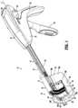
- FIG. 1is a side perspective view of a surgical stapling device according to aspects of the disclosure with an end effector in an open position;
- FIG. 2is a side perspective view from the distal end of a cartridge assembly of the surgical stapling device shown in FIG. 1 ;
- FIG. 3is an exploded perspective view of the cartridge assembly shown in FIG. 2 ;
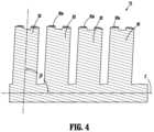
- FIG. 4is a cross-sectional view taken along section line 4 - 4 of FIG. 3 ;
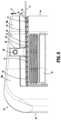
- FIG. 5is a side perspective view of a distal portion of the end effector of the surgical stapling device shown in FIG. 1 as the surgical stapling device begins to be fired and a plurality of staples are ejected from the cartridge assembly towards an anvil assembly of the end effector of the surgical stapling device;
- FIG. 5 Ais a schematic cutaway view of the end effector of the surgical stapling device shown in FIG. 1 as the surgical stapling device is fired before the staples engage the anvil assembly;
- FIG. 6is a side perspective view of the distal portion of the end effector of the surgical stapling device shown in FIG. 5 after the surgical stapling device has been fired.
- proximalis used generally to refer to that portion of the device that is closer to a clinician during use of the device in its customary manner
- distalis used generally to refer to that portion of the device that is farther from the clinician during use of the device in its customary manner.
- clinicalis used generally to refer to medical personnel including doctors, nurses, and support personnel.
- “About” or “approximately” or “substantially” as used hereinmay be inclusive of the stated value and means within an acceptable range of variation for a particular value as determined by one of ordinary skill in the art, considering the measurement in question and the error associated with measurement of the particular quantity (e.g., the limitations of the measurement system). For example, “about” may mean within one or more standard variations, within ⁇ 10% of the stated value, or within 2-3 degrees of the stated angle.
- FIG. 1illustrates the disclosed surgical stapling device shown generally as stapling device 10 .
- the stapling device 10includes a handle assembly 12 , an elongate body 14 that extends distally from the handle assembly 12 , and an end effector 16 that is supported on a distal portion of the elongate body 14 .
- the elongate body 14defines a longitudinal axis “X”.
- the handle assembly 12includes a housing 18 that defines a stationary handle 20 and supports a movable trigger 22 .
- the movable trigger 22is supported by the housing 18 to pivot towards the stationary handle 20 between non-actuated and actuated positions to operate the end effector 16 .
- the handle assembly 12also supports buttons 26 (only one is shown) that are positioned on each side of the housing 18 and are movable along the housing 18 to advance and retract an alignment pin pusher 27 .
- the alignment pin pusher 27is positioned and configured to engage an alignment pin (not shown) within the end effector 16 to move the alignment pin between retracted position and advanced positions.
- the handle assembly 12also includes a release button 28 that can be depressed to move the end effector 16 from a clamped position to an unclamped position.
- a suitable handle assembly 12see, e.g., U.S. Pat. No. 6,817,508 (“the '508 patent”).
- the stapling device 10includes a frame 32 that extends from the handle assembly 12 to the end effector 16 .
- the frame 32includes a distal frame portion 34 that has a U-shaped configuration that forms a portion of the end effector 16 .
- the distal frame portion 34( FIG. 3 ) has a first transverse portion 36 , a second transverse portion 38 , and a longitudinal portion 39 that interconnects the first transverse portion 36 and the second transverse portion 38 .
- the first and second transverse portions 36 and 38are spaced from each other to define a recess 40 that extends between the first and second transverse portions 36 and 38 .
- the first and second transverse portions 36 and 38are curved along axes transverse to the longitudinal axis “X” of the elongate body 14 of the stapling device 10 .
- the first and second transverse portionsmay be linear or comprised of a plurality of linear portions that are positioned at angles in relation to each other.
- Each of the first and second transverse portions 36 and 38has a first end 36 a and 38 a , respectively, that are coupled to (e.g., formed with) the longitudinal portion 39 of the distal frame portion 34 and a second end 36 b and 38 b , respectively.
- the second end 38 b of the second transverse portion 38is coupled to the frame 32 of the elongate body 14 .
- the second end 36 b of the first transverse portion 36 of the distal frame portion 34is spaced from the longitudinal portion 39 such that the first transverse portion 36 is supported on the longitudinal portion 39 in cantilevered fashion.
- the end effector 16includes an anvil assembly 42 and a cartridge assembly 44 .
- the cartridge assembly 44is removably supported on a clamp slide assembly 46 of the stapling device 10 and includes a body 47 that supports a plurality of staples (not shown).
- the clamp slide assembly 46includes a distal portion 46 a that is configured to releasably support the cartridge assembly 44 .
- the distal portion 46 ais positioned in the recess 40 and is movable between retracted and advanced positions to move the cartridge assembly 44 in relation to the anvil assembly 42 through the recess 40 between an unclamped position ( FIG. 1 ) located adjacent to the second transverse portion 38 of the distal frame portion 34 and a clamped position ( FIG. 5 ) located adjacent the first transverse portion 36 of the distal frame portion 34 .
- the anvil assembly 42is supported on the first transverse portion 36 of the distal frame portion 34 and includes a cutting plate 52 and an anvil plate 54 ( FIG. 5 A ) that defines a plurality of staple receiving deformations 54 a ( FIG. 5 A ).
- the cutting plate 52 and the anvil plate 54have configurations that correspond to the configuration of the first transverse portion 36 of the distal frame portion 34 .
- the cutting plate 52defines opposed cutouts 62 a .
- the anvil plate 54 of the anvil assembly 42includes flanges 66 that extend through the cutouts 62 a of the cutting plate 52 and are secured to the first transverse portion 36 with rivets or pins 68 to secure the anvil plate 54 and the cutting plate 52 to the first transverse portion 36 of the distal frame portion 34 with the cutting plate 52 sandwiched between the first transverse portion 36 of the distal frame portion 34 and the anvil plate 54 ( FIG. 5 A ).
- FIGS. 2 and 3illustrate the cartridge assembly 44 which includes the cartridge body 47 , a knife assembly 70 , a pusher 72 , and staples 74 .
- the cartridge body 47defines a cavity (not shown) that receives the knife assembly 70 and the pusher 72 such that the knife assembly 70 and the pusher 72 can move within the body 47 of the cartridge assembly 44 from a retracted position to an advanced position.
- the cartridge body 47defines a plurality of staple receiving slots 78 ( FIG. 2 ) and a knife slot 80 that extends between the staple receiving slots 78 .
- the staple receiving slots 78are aligned in curved rows on opposite sides of the knife slot 80
- the knife slot 80is curved and centrally located in the cartridge body 47 .
- the cartridge body 47is shown to have two rows of staple receiving slots 78 on each side of the knife slot 80 , one or more rows of staple receiving slots 78 can be provided on each side of the knife slot 80 , and the number of rows of staple receiving slots 80 on each side of the knife slot 80 need not be the same.
- two rows of staple receiving slots 78can be formed on one side of the knife slot 80 and three rows of staple receiving slots 80 can be formed on the other side of the knife slot 80 .
- the pusher 72includes a base member 81 and a plurality of pusher fingers 82 that extend distally from the base member 81 .
- Each of the plurality of fingers 82extends into one of the plurality of staple receiving slots 78 of the cartridge body 47 and includes a distal surface 82 a that supports one of the staples 74 within the respective staple receiving slot 78 .
- the base member 81 of the pusher 72defines a central knife slot (not shown) that is positioned between the rows of the fingers 82 and is aligned with the knife slot 80 in the cartridge body 47 .
- the knife assembly 70includes a knife holder 90 and a knife blade 92 that is secured to and extends distally from the knife holder 90 .
- the knife blade 92extends from the knife holder 90 through the central knife slot (not shown) in the base member 81 of the pusher 72 and is recessed within the knife slot 80 in the cartridge body 47 .
- FIG. 4illustrates the pusher 72 of the cartridge assembly 44 .
- the pusher 72includes a base member 81 and a plurality of fingers 82 .
- the base member 81defines a longitudinal axis “Z” that extends in a direction transverse to the longitudinal axis “X” of the elongate body 14 ( FIG. 1 ).
- Each of the plurality of fingers 82has substantially the same length and extends distally from the base member 81 .
- Each of the plurality of fingersdefines a longitudinal axis “Y” that defines an angle ⁇ with the longitudinal axis “Z” of the base member 81 .
- angle ⁇is from about 78 degrees to about 88 degrees.
- angle ⁇is about 84 degrees.
- the base member 81 and the plurality of fingers 82are integrally formed such as by molding. Alternately, the fingers 82 could be form separately from the base member 81 and secured to the base member 81 using any known fastening technique or device.
- FIGS. 5 and 5 Aillustrate the end effector 16 of the stapling device 10 in a clamped position as the stapling device 10 is fired.
- the pusher 72is positioned within the cartridge body 47 with the fingers 82 of the pusher 72 received within the staple receiving slots 78 ( FIG. 5 A ) of the cartridge body 47 .
- the staple receiving slots 78 in the cartridge body 47have axes that are substantially parallel to the longitudinal axis “X” of the elongate body 14 ( FIG. 1 ) of the stapling device 10 .
- the base member 81 of the pusher 72 from which the fingers 82 extendis angled in relation to the anvil plate 54 .
- the longitudinal axes defined by the fingers 82 of the pusher 72are substantially parallel to the longitudinal axis “X” of the elongate body 14 ( FIG. 1 ). In this orientation of the pusher 72 , the fingers 82 nearer the second end 36 b of the first transverse portion 36 of the distal frame portion 34 are closer to the anvil plate 54 than the fingers 82 of the pusher 72 nearer the first end 36 a of the first transverse portion 36 of the distal frame portion 34 .
- the fingers 32 of the pusher 72 and the staples 74 supported on the fingers 82are positioned closest to the anvil plate 54 adjacent the second end 36 b of the first transverse portion 36 of the distal frame portion 34 and become progressively further away from the anvil plate 54 towards the first end 36 a of the first transverse portion 36 of the distal frame portion 34 .
- a distal portion of the fingers 82 of the pusher 72extend along an axis “P1” that is substantially parallel to the longitudinal axis “Z” ( FIG. 4 ) of the base member 81 of the pusher 72 and defines the angle ⁇ with the longitudinal axes of the fingers 82 .
- an axis “P2”( FIG. 5 ) defined by the anvil plate 54 (which is substantially perpendicular to the longitudinal axis “X” of the elongate body 14 ) defines angle Q with the axis “P1” defined by the distal portion of the fingers 82 .
- the angle Qis from about 2 degrees to about 10 degrees, and in some aspects of the disclosure, about 6 degrees.
- Each of the staples 74have a uniform length.
- the staples 74 nearest the second end 36 b of the first transverse portion 36 of the distal frame portion 34are spaced more closely to the anvil plate 54 than are the staples 74 positioned nearer the first end 36 a of the distal frame portion 34 .
- FIG. 6illustrates the end effector 16 of the stapling device 10 as the stapling device 10 is fired to eject staples into the anvil plate 54 .
- the pusher 72is advanced in the direction of arrows “C” in FIG. 5 A to advance the fingers 82 within the staple receiving slots 78 of the cartridge body 47 .
- the staples 74nearer the second end 36 b of the first transverse portion 36 of the distal frame portion 34 engage and begin to deform against the anvil plate 54 before the staples 74 located closer to the second end 36 b of the first transverse portion 36 of the distal frame portion 34 .
- the staples 74will sequentially engage the anvil plate 54 beginning with the staples 74 nearer the second end 36 b of the first transverse portion 36 of the distal frame portion 34 and ending with the staples 74 nearer the first end 36 b of the first transverse portion 36 of the distal frame portion 34 . Because all the staples do not engage the anvil plate 54 simultaneously, the force required to fire the stapling device 10 is minimized.
- This deflectionwill move the axis “P2” defined by the anvil plate 54 into substantially parallel alignment with the axis “P1” defined by the distal portion of the fingers 82 of the pusher 72 .
- the gap between the distal portion of the fingers 82 of the pusher 72 and the anvil plate 54will be substantially uniform along the length of the anvil plate 54 such that the staples 74 will be formed uniformly along the length of the anvil plate 54 .
Landscapes
- Health & Medical Sciences (AREA)
- Life Sciences & Earth Sciences (AREA)
- Surgery (AREA)
- Heart & Thoracic Surgery (AREA)
- Engineering & Computer Science (AREA)
- Biomedical Technology (AREA)
- Nuclear Medicine, Radiotherapy & Molecular Imaging (AREA)
- Medical Informatics (AREA)
- Molecular Biology (AREA)
- Animal Behavior & Ethology (AREA)
- General Health & Medical Sciences (AREA)
- Public Health (AREA)
- Veterinary Medicine (AREA)
- Surgical Instruments (AREA)
Abstract
Description
Claims (20)
Applications Claiming Priority (1)
| Application Number | Priority Date | Filing Date | Title |
|---|---|---|---|
| PCT/CN2021/077893WO2022178758A1 (en) | 2021-02-25 | 2021-02-25 | Anvil assembly with reduced deflection |
Publications (2)
| Publication Number | Publication Date |
|---|---|
| US20240138832A1 US20240138832A1 (en) | 2024-05-02 |
| US12207816B2true US12207816B2 (en) | 2025-01-28 |
Family
ID=83047609
Family Applications (1)
| Application Number | Title | Priority Date | Filing Date |
|---|---|---|---|
| US18/278,716ActiveUS12207816B2 (en) | 2021-02-25 | 2021-02-25 | Anvil assembly with reduced deflection |
Country Status (4)
| Country | Link |
|---|---|
| US (1) | US12207816B2 (en) |
| EP (1) | EP4297660A1 (en) |
| CN (2) | CN117062573A (en) |
| WO (1) | WO2022178758A1 (en) |
Citations (167)
| Publication number | Priority date | Publication date | Assignee | Title |
|---|---|---|---|---|
| US1158111A (en) | 1914-10-07 | 1915-10-26 | Edward C Ahlheim | Rolling-pin. |
| US2891250A (en) | 1956-10-15 | 1959-06-23 | Hirata Yasuhiro | Bronchus seaming instrument |
| US3080564A (en) | 1959-09-10 | 1963-03-12 | Strekopitov Alexey Alexeevich | Instrument for stitching hollow organs |
| US3252643A (en) | 1962-12-24 | 1966-05-24 | Strekopytov Alexey Alexcevich | Instrument for suturing living tissue |
| US3269630A (en) | 1964-04-30 | 1966-08-30 | Fleischer Harry | Stapling instrument |
| US3275211A (en) | 1965-05-10 | 1966-09-27 | United States Surgical Corp | Surgical stapler with replaceable cartridge |
| US3315863A (en) | 1965-07-06 | 1967-04-25 | United States Surgical Corp | Medical instrument |
| US3494533A (en) | 1966-10-10 | 1970-02-10 | United States Surgical Corp | Surgical stapler for stitching body organs |
| US3589589A (en) | 1967-09-19 | 1971-06-29 | Ernest Mikhailovich Akopov | Surgical instrument for stitching tissues by means of staples |
| US3692224A (en) | 1970-10-14 | 1972-09-19 | Georgy Vasilievich Astafiev | Surgical apparatus for suturing tissue with staples |
| US3795034A (en) | 1971-05-03 | 1974-03-05 | S Eizenshteina | Surgical instrument for suturing tissues and organs with metal staples |
| US3822818A (en) | 1973-02-20 | 1974-07-09 | A Strekopytov | Surgical instrument for joining osseous tissues by staples |
| US3935981A (en) | 1973-07-31 | 1976-02-03 | Ernest Mikhailovich Akopov | Surgical apparatus for suturing organs and tissues with metal staples |
| US3949923A (en) | 1973-07-26 | 1976-04-13 | Ernest Mikhailovich Akopov | Surgical suturing instrument |
| US4047654A (en) | 1976-06-23 | 1977-09-13 | Alfredo Alvarado | Surgical stapler |
| US4216891A (en) | 1979-02-12 | 1980-08-12 | Behlke Harold O | Surgical stapler |
| US4244372A (en) | 1978-03-31 | 1981-01-13 | Kapitanov Nikolai N | Surgical instrument for suturing organs |
| US4296881A (en) | 1980-04-03 | 1981-10-27 | Sukoo Lee | Surgical stapler using cartridge |
| US4305539A (en) | 1979-03-26 | 1981-12-15 | Korolkov Ivan A | Surgical suturing instrument for application of a staple suture |
| US4354628A (en) | 1980-09-29 | 1982-10-19 | United States Surgical Corporation | Surgical stapler apparatus having pivotally related staple holder and anvil |
| US4378901A (en) | 1980-05-22 | 1983-04-05 | Akopov Ernest M | Apparatus for applying a staple suture |
| US4383634A (en) | 1981-05-26 | 1983-05-17 | United States Surgical Corporation | Surgical stapler apparatus with pivotally mounted actuator assemblies |
| US4402444A (en) | 1981-04-20 | 1983-09-06 | United States Surgical Corporation | Surgical stapling instrument with automatic frame reinforcement |
| US4415112A (en) | 1981-10-27 | 1983-11-15 | United States Surgical Corporation | Surgical stapling assembly having resiliently mounted anvil |
| US4442964A (en) | 1981-12-07 | 1984-04-17 | Senco Products, Inc. | Pressure sensitive and working-gap controlled surgical stapling instrument |
| USD273513S (en) | 1983-06-10 | 1984-04-17 | Senco Products, Inc. | Linear surgical stapling instrument |
| US4470533A (en) | 1982-08-13 | 1984-09-11 | Ethicon, Inc. | Surgical instrument for suturing tissues and organs |
| US4475679A (en) | 1981-08-07 | 1984-10-09 | Fleury Jr George J | Multi-staple cartridge for surgical staplers |
| US4485811A (en) | 1980-02-08 | 1984-12-04 | Vsesojuzny Nauchny Tsentr Khirurgii | Resection apparatus |
| US4506670A (en) | 1983-03-30 | 1985-03-26 | United States Surgical Corporation | Two-part surgical fastener applying apparatus with frangible member |
| US4506671A (en) | 1983-03-30 | 1985-03-26 | United States Surgical Corporation | Apparatus for applying two-part surgical fasteners |
| US4508253A (en) | 1983-10-04 | 1985-04-02 | United States Surgical Corporation | Surgical fastener applying apparatus |
| US4522327A (en) | 1983-05-18 | 1985-06-11 | United States Surgical Corporation | Surgical fastener applying apparatus |
| US4527724A (en) | 1983-06-10 | 1985-07-09 | Senmed, Inc. | Disposable linear surgical stapling instrument |
| US4530453A (en) | 1983-10-04 | 1985-07-23 | United States Surgical Corporation | Surgical fastener applying apparatus |
| US4550870A (en) | 1983-10-13 | 1985-11-05 | Alchemia Ltd. Partnership | Stapling device |
| US4566620A (en) | 1984-10-19 | 1986-01-28 | United States Surgical Corporation | Articulated surgical fastener applying apparatus |
| US4568009A (en) | 1984-01-20 | 1986-02-04 | United States Surgical Corporation | Surgical fastener applying apparatus |
| US4573622A (en) | 1984-10-19 | 1986-03-04 | United States Surgical Corporation | Surgical fastener applying apparatus with variable fastener arrays |
| US4580712A (en) | 1984-10-19 | 1986-04-08 | United States Surgical Corporation | Surgical fastener applying apparatus with progressive application of fastener |
| US4585153A (en) | 1984-07-16 | 1986-04-29 | Ethicon, Inc. | Surgical instrument for applying two-piece fasteners comprising frictionally held U-shaped staples and receivers (Case III) |
| US4589582A (en) | 1984-08-23 | 1986-05-20 | Senmed, Inc. | Cartridge and driver assembly for a surgical stapling instrument |
| US4602634A (en) | 1983-09-23 | 1986-07-29 | Ethicon, Inc. | Method and instrument for applying a fastener to a tissue using means to grasp, guide and pull the fastener through the tissue |
| US4605001A (en) | 1984-10-19 | 1986-08-12 | Senmed, Inc. | Surgical stapling instrument with dual staple height mechanism |
| US4605004A (en) | 1984-07-16 | 1986-08-12 | Ethicon, Inc. | Surgical instrument for applying fasteners said instrument including force supporting means (case IV) |
| US4606345A (en) | 1984-07-16 | 1986-08-19 | Ethicon, Inc. | Surgical instrument for applying two-piece fasteners comprising U-shaped staples and frictionally held receivers (Case II) |
| US4606344A (en) | 1984-07-16 | 1986-08-19 | Ethicon, Inc. | Surgical instrument for applying fasteners having improved gap indicating means (Case V) |
| US4607636A (en) | 1984-07-16 | 1986-08-26 | Ethicon, Inc. | Surgical instrument for applying fasteners having tissue locking means for maintaining the tissue in the instrument while applying the fasteners (case I) |
| US4612933A (en) | 1984-03-30 | 1986-09-23 | Senmed, Inc. | Multiple-load cartridge assembly for a linear surgical stapling instrument |
| US4617928A (en) | 1984-09-17 | 1986-10-21 | Alfranca Jose Maria P | Surgical instrument for practicing mechanical sutures and biopsies |
| US4632290A (en) | 1981-08-17 | 1986-12-30 | United States Surgical Corporation | Surgical stapler apparatus |
| US4665916A (en) | 1985-08-09 | 1987-05-19 | United States Surgical Corporation | Surgical stapler apparatus |
| US4684051A (en) | 1985-09-10 | 1987-08-04 | Akopov Ernest M | Surgical instrument |
| US4714187A (en) | 1986-11-26 | 1987-12-22 | United States Surgical Corporation | Reloading unit for surgical fastening instruments |
| US4715520A (en) | 1985-10-10 | 1987-12-29 | United States Surgical Corporation | Surgical fastener applying apparatus with tissue edge control |
| US4728020A (en) | 1985-08-30 | 1988-03-01 | United States Surgical Corporation | Articulated surgical fastener applying apparatus |
| US4767044A (en) | 1984-10-19 | 1988-08-30 | United States Surgical Corporation | Surgical fastener applying apparatus |
| US4788978A (en) | 1979-11-23 | 1988-12-06 | Strekopytov Alexei A | Surgical instrument for applying linear staple sutures and intersecting the tissue therebetween |
| US4802614A (en) | 1986-05-23 | 1989-02-07 | United States Surgical Corporation | Surgical stapling instrument and cartridge |
| US4805823A (en) | 1988-03-18 | 1989-02-21 | Ethicon, Inc. | Pocket configuration for internal organ staplers |
| US4819853A (en) | 1987-12-31 | 1989-04-11 | United States Surgical Corporation | Surgical fastener cartridge |
| US4848637A (en) | 1987-06-11 | 1989-07-18 | Pruitt J Crayton | Staple device for use on the mesenteries of the abdomen |
| US4881545A (en) | 1988-12-08 | 1989-11-21 | United States Surgical Corporation | Surgical fastener cartridge with improved body tissue cutting knife assembly |
| US4881544A (en) | 1988-12-19 | 1989-11-21 | United States Surgical Corporation | Surgical stapler apparatus with improved tissue shield |
| US4915100A (en) | 1988-12-19 | 1990-04-10 | United States Surgical Corporation | Surgical stapler apparatus with tissue shield |
| US4930503A (en) | 1987-06-11 | 1990-06-05 | Pruitt J Crayton | Stapling process and device for use on the mesenteries of the abdomen |
| US4938408A (en) | 1988-01-15 | 1990-07-03 | Ethicon, Inc. | Surgical stapler safety and sequencing mechanisms |
| US4941623A (en) | 1987-05-12 | 1990-07-17 | United States Surgical Corporation | Stapling process and device for use on the mesentery of the abdomen |
| US5005754A (en) | 1990-04-04 | 1991-04-09 | Ethicon, Inc. | Bladder and mandrel for use with surgical stapler |
| US5071052A (en) | 1988-09-22 | 1991-12-10 | United States Surgical Corporation | Surgical fastening apparatus with activation lockout |
| US5100042A (en) | 1990-03-05 | 1992-03-31 | United States Surgical Corporation | Surgical fastener apparatus |
| US5116349A (en) | 1990-05-23 | 1992-05-26 | United States Surgical Corporation | Surgical fastener apparatus |
| US5137198A (en) | 1991-05-16 | 1992-08-11 | Ethicon, Inc. | Fast closure device for linear surgical stapling instrument |
| US5172845A (en) | 1991-04-12 | 1992-12-22 | Tejeiro William V | Right angle articulated intestinal stapler |
| US5190203A (en) | 1990-10-05 | 1993-03-02 | United States Surgical Corporation | Controlled closure mechanism |
| US5219111A (en) | 1991-03-11 | 1993-06-15 | Ethicon, Inc. | Pneumatically actuated linear stapling device |
| US5240163A (en) | 1991-10-30 | 1993-08-31 | American Cyanamid Company | Linear surgical stapling instrument |
| US5368599A (en) | 1992-10-08 | 1994-11-29 | United States Surgical Corporation | Surgical fastening apparatus with suture array |
| US5405073A (en) | 1993-12-06 | 1995-04-11 | Ethicon, Inc. | Flexible support shaft assembly |
| US5413267A (en) | 1991-05-14 | 1995-05-09 | United States Surgical Corporation | Surgical stapler with spent cartridge sensing and lockout means |
| US5439155A (en) | 1993-10-07 | 1995-08-08 | United States Surgical Corporation | Cartridge for surgical fastener applying apparatus |
| US5452836A (en) | 1994-02-07 | 1995-09-26 | Ethicon Endo-Surgery, Inc. | Surgical stapling instrument with improved jaw closure and staple firing actuator mechanism |
| US5458279A (en) | 1991-05-14 | 1995-10-17 | Minnesota Mining And Manufacturing Company | Surgical stapler with safety feature |
| US5462215A (en) | 1991-10-18 | 1995-10-31 | United States Surgical Corporation | Locking device for an apparatus for applying surgical fasteners |
| US5464144A (en) | 1993-08-19 | 1995-11-07 | United States Surgical Corporation | Surgical apparatus with indicator |
| US5465894A (en) | 1993-12-06 | 1995-11-14 | Ethicon, Inc. | Surgical stapling instrument with articulated stapling head assembly on rotatable and flexible support shaft |
| US5470006A (en) | 1990-12-06 | 1995-11-28 | United States Surgical Corporation | Surgical fastening apparatus with locking mechanism |
| US5470008A (en) | 1993-12-20 | 1995-11-28 | United States Surgical Corporation | Apparatus for applying surgical fasteners |
| US5470009A (en) | 1990-12-06 | 1995-11-28 | United States Surgical Corporation | Surgical fastening apparatus with locking mechanism |
| US5509596A (en) | 1991-10-18 | 1996-04-23 | United States Surgical Corporation | Apparatus for applying surgical fasteners |
| US5542594A (en) | 1993-10-06 | 1996-08-06 | United States Surgical Corporation | Surgical stapling apparatus with biocompatible surgical fabric |
| US5547117A (en) | 1994-03-30 | 1996-08-20 | Ethicon Endo-Surgery | Handle actuator for surgical instrument having clamp lock and emergency release |
| US5558266A (en) | 1991-10-18 | 1996-09-24 | United States Surgical Corporation | Apparatus for applying surgical fasteners |
| US5571285A (en) | 1991-02-19 | 1996-11-05 | Ethicon, Inc. | Surgical staple for insertion into tissue |
| US5579978A (en) | 1991-10-18 | 1996-12-03 | United States Surgical Corporation | Apparatus for applying surgical fasteners |
| US5605272A (en) | 1996-03-12 | 1997-02-25 | Ethicon Endo-Surgery, Inc. | Trigger mechanism for surgical instruments |
| US5641111A (en) | 1995-06-28 | 1997-06-24 | Ethicon Endo-Surgery, Inc. | Surgical stapling instrument with anvil cutting guide |
| US5678748A (en) | 1995-05-24 | 1997-10-21 | Vir Engineering | Surgical stapler with improved safety mechanism |
| US5697543A (en) | 1996-03-12 | 1997-12-16 | Ethicon Endo-Surgery, Inc. | Linear stapler with improved firing stroke |
| US5706998A (en) | 1995-07-17 | 1998-01-13 | United States Surgical Corporation | Surgical stapler with alignment pin locking mechanism |
| US5735445A (en) | 1995-03-07 | 1998-04-07 | United States Surgical Corporation | Surgical stapler |
| US5810240A (en) | 1996-03-15 | 1998-09-22 | United States Surgical Corporation | Surgical fastener applying device |
| US5893506A (en) | 1994-03-01 | 1999-04-13 | United States Surgical Corporation | Surgical stapler with anvil sensor and lockout |
| US6638285B2 (en) | 2001-04-16 | 2003-10-28 | Shlomo Gabbay | Biological tissue strip and system and method to seal tissue |
| US20040164123A1 (en) | 2000-10-13 | 2004-08-26 | Racenet David C. | Surgical stapling device |
| US6805273B2 (en)* | 2002-11-04 | 2004-10-19 | Federico Bilotti | Surgical stapling instrument |
| US20050247753A1 (en)* | 2003-12-30 | 2005-11-10 | Kelly William D | Surgical stapler having a plastic closure plate |
| US6988650B2 (en)* | 2003-12-30 | 2006-01-24 | Ethicon Endo-Surgery, Inc. | Retaining pin lever advancement mechanism for a curved cutter stapler |
| US7070083B2 (en) | 2002-04-11 | 2006-07-04 | Tyco Healthcare Group Lp | Surgical stapling apparatus including an anvil and cartridge each having cooperating mating surfaces |
| US20060163312A1 (en) | 2002-10-04 | 2006-07-27 | Viola Frank J | Angled surgical fastener apparatus |
| US7134587B2 (en)* | 2003-12-30 | 2006-11-14 | Ethicon Endo-Surgery, Inc. | Knife retraction arm for a curved cutter stapler |
| US7147139B2 (en) | 2003-12-30 | 2006-12-12 | Ethicon Endo-Surgery, Inc | Closure plate lockout for a curved cutter stapler |
| US7147140B2 (en)* | 2003-12-30 | 2006-12-12 | Ethicon Endo - Surgery, Inc. | Cartridge retainer for a curved cutter stapler |
| US7204404B2 (en)* | 2003-12-30 | 2007-04-17 | Ethicon Endo-Surgery, Inc. | Slotted pins guiding knife in a curved cutter stapler |
| US7207472B2 (en)* | 2003-12-30 | 2007-04-24 | Ethicon Endo-Surgery, Inc. | Cartridge with locking knife for a curved cutter stapler |
| US7210609B2 (en) | 2004-07-30 | 2007-05-01 | Tools For Surgery, Llc | Stapling apparatus having a curved anvil and driver |
| CN101031246A (en) | 2004-09-30 | 2007-09-05 | 伊西康内外科公司 | Surgical stapling instrument |
| US7407076B2 (en) | 2000-10-13 | 2008-08-05 | Tyco Healthcare Group Lp | Surgical stapling device |
| US7431190B2 (en) | 2006-03-01 | 2008-10-07 | Ethicon Endo-Surgery, Inc. | Linear stapler with improved firing mechanism |
| US7522854B2 (en) | 2005-03-16 | 2009-04-21 | Kabushiki Kaisha Toshiba | Fixing device of image forming apparatus |
| US7549563B2 (en) | 2003-12-30 | 2009-06-23 | Ethicon Endo-Surgery, Inc. | Rotating curved cutter stapler |
| US7568605B2 (en)* | 2006-03-22 | 2009-08-04 | Ethicon Endo-Surgery, Inc. | Surgical stapler shaft cover |
| US7641092B2 (en) | 2005-08-05 | 2010-01-05 | Ethicon Endo - Surgery, Inc. | Swing gate for device lockout in a curved cutter stapler |
| US20100048988A1 (en) | 2006-07-07 | 2010-02-25 | Alessandro Pastorelli | A deployment system for introducing a surgical instrument in a patients body |
| US7717312B2 (en) | 2005-06-03 | 2010-05-18 | Tyco Healthcare Group Lp | Surgical instruments employing sensors |
| US7731073B2 (en) | 2006-05-19 | 2010-06-08 | Applied Medical Resources Corporation | Surgical stapler with firing lock mechanism |
| US7766207B2 (en) | 2003-12-30 | 2010-08-03 | Ethicon Endo-Surgery, Inc. | Articulating curved cutter stapler |
| US7810690B2 (en) | 2004-09-10 | 2010-10-12 | Ethicon Endo-Surgery, Inc. | Surgical stapling instrument |
| US7886953B2 (en)* | 2005-08-18 | 2011-02-15 | Ethicon Endo-Surgery, Inc. | Fired device lockout for a curved cutter stapler with a free moving trigger |
| US8016176B2 (en) | 2008-06-04 | 2011-09-13 | Tyco Healthcare Group, Lp | Surgical stapling instrument with independent sequential firing |
| US8029520B2 (en) | 2006-02-07 | 2011-10-04 | Ethicon Endo-Surgery, Inc. | Method for performing trans-anal resection with a curved cutter stapler |
| US8070038B2 (en) | 2008-10-10 | 2011-12-06 | Tyco Healthcare Group, Lp | Surgical instrument with pivotable jaw member |
| US8231041B2 (en) | 2008-04-14 | 2012-07-31 | Tyco Healthcare Group Lp | Variable compression surgical fastener cartridge |
| US8292904B2 (en) | 2006-02-15 | 2012-10-23 | Ethicon Endo-Surgery, Inc. | Device, clip, endoscope and method for the intraluminal treatment of tissue, e.g. hemorrhoids |
| US8328064B2 (en) | 2009-05-06 | 2012-12-11 | Covidien Lp | Pin locking mechanism for a surgical instrument |
| US8360296B2 (en) | 2010-09-09 | 2013-01-29 | Ethicon Endo-Surgery, Inc. | Surgical stapling head assembly with firing lockout for a surgical stapler |
| US8424738B2 (en) | 2008-06-04 | 2013-04-23 | Covidien Lp | Attachable clamp for surgical stapler |
| US8499994B2 (en) | 2006-09-08 | 2013-08-06 | Ethicon Endo-Surgery, Inc. | Surgical instrument and actuating movement transmitting device therefore |
| US20130206813A1 (en) | 2012-02-14 | 2013-08-15 | Ethicon Endo-Surgery, Inc. | Linear stapler |
| US8596515B2 (en) | 2010-06-18 | 2013-12-03 | Covidien Lp | Staple position sensor system |
| US8627994B2 (en) | 2009-08-11 | 2014-01-14 | Covidien Lp | Surgical stapling apparatus |
| US8757467B2 (en) | 2008-05-05 | 2014-06-24 | Covidien Lp | Surgical instrument with sequential clamping and cutting |
| US8955732B2 (en) | 2009-08-11 | 2015-02-17 | Covidien Lp | Surgical stapling apparatus |
| US8967446B2 (en) | 2008-05-09 | 2015-03-03 | Covidien Lp | Variable compression surgical fastener cartridge |
| US9022273B1 (en) | 2011-01-04 | 2015-05-05 | Covidien Lp | Surgical fastener-applying apparatuses with sequential firing |
| US9125651B2 (en)* | 2011-12-07 | 2015-09-08 | Ethicon Endo-Surgery, Inc. | Reusable linear stapler cartridge device for tissue thickness measurement |
| US9192387B1 (en) | 2005-08-15 | 2015-11-24 | Covidien Lp | Surgical stapling instruments including a cartridge having multiple staples sizes |
| CN103860230B (en) | 2014-04-04 | 2016-07-13 | 苏州天臣国际医疗科技有限公司 | Medical Stapler |
| CN104107077B (en) | 2014-07-09 | 2016-08-24 | 苏州天臣国际医疗科技有限公司 | Stapler and the nail bin groupware for this stapler |
| US20160249914A1 (en) | 2011-06-21 | 2016-09-01 | Ethicon Endo-Surgery, Inc. | Linear Stapler |
| US20160249923A1 (en) | 2011-10-26 | 2016-09-01 | Covidien Lp | Buttress release from surgical stapler by knife pushing |
| US20160270784A1 (en) | 2006-05-03 | 2016-09-22 | Datascope Corp. | Systems and methods of tissue closure |
| US20160270793A1 (en) | 2011-12-14 | 2016-09-22 | Covidien Lp | Surgical stapling apparatus including releasable surgical buttress |
| US9480474B2 (en) | 2012-03-31 | 2016-11-01 | Changzhou Kangdi Medical Stapler Co., Ltd. | Linear cutting element with E-shaped guiding element |
| US20170014134A1 (en) | 2014-04-04 | 2017-01-19 | Touchstone International Medical Science Co., Ltd. | Medical anastomosis device |
| US20170027573A1 (en) | 2015-07-30 | 2017-02-02 | Ethicon Endo-Surgery, Llc | Surgical instrument comprising systems for permitting the optional transection of tissue |
| US20170027572A1 (en) | 2015-07-30 | 2017-02-02 | Ethicon Endo-Surgery, Llc | Surgical instrument comprising separate tissue securing and tissue cutting systems |
| US20170128149A1 (en) | 2002-04-25 | 2017-05-11 | Covidien Lp | Surgical instruments including mems devices |
| US9814460B2 (en) | 2013-04-16 | 2017-11-14 | Ethicon Llc | Modular motor driven surgical instruments with status indication arrangements |
| US9888923B2 (en) | 2012-12-28 | 2018-02-13 | Touchstone International Medical Science Co., Ltd. | Firing assembly for surgical stapler and surgical stapler |
| US20180049739A1 (en) | 2009-05-06 | 2018-02-22 | Covidien Lp | Pin locking mechanism for a surgical instrument |
| CN107928733A (en) | 2017-12-21 | 2018-04-20 | 苏州英途康医疗科技有限公司 | Nail bin groupware and surgical operating instrument |
| US20180153544A1 (en)* | 2016-12-02 | 2018-06-07 | Covidien Lp | Surgical stapling instrument with curved end effector |
| US10004504B2 (en) | 2010-11-02 | 2018-06-26 | Covidien Lp | Adapter for powered surgical devices |
| US10085754B2 (en) | 2008-04-22 | 2018-10-02 | Covidien Lp | Cartridge for applying varying amounts of tissue compression |
| CN110381851A (en) | 2017-03-09 | 2019-10-25 | 柯惠有限合伙公司 | Operation stitching device with variable height staple propeller |
| WO2021022407A1 (en) | 2019-08-02 | 2021-02-11 | Covidien Lp | Surgical stapling device with curved tool assembly |
- 2021
- 2021-02-25WOPCT/CN2021/077893patent/WO2022178758A1/ennot_activeCeased
- 2021-02-25CNCN202180094531.XApatent/CN117062573A/enactivePending
- 2021-02-25EPEP21927198.8Apatent/EP4297660A1/ennot_activeWithdrawn
- 2021-02-25USUS18/278,716patent/US12207816B2/enactiveActive
- 2022
- 2022-02-24CNCN202220383395.8Upatent/CN218979053U/enactiveActive
Patent Citations (218)
| Publication number | Priority date | Publication date | Assignee | Title |
|---|---|---|---|---|
| US1158111A (en) | 1914-10-07 | 1915-10-26 | Edward C Ahlheim | Rolling-pin. |
| US2891250A (en) | 1956-10-15 | 1959-06-23 | Hirata Yasuhiro | Bronchus seaming instrument |
| US3080564A (en) | 1959-09-10 | 1963-03-12 | Strekopitov Alexey Alexeevich | Instrument for stitching hollow organs |
| US3252643A (en) | 1962-12-24 | 1966-05-24 | Strekopytov Alexey Alexcevich | Instrument for suturing living tissue |
| US3269630A (en) | 1964-04-30 | 1966-08-30 | Fleischer Harry | Stapling instrument |
| US3275211A (en) | 1965-05-10 | 1966-09-27 | United States Surgical Corp | Surgical stapler with replaceable cartridge |
| US3315863A (en) | 1965-07-06 | 1967-04-25 | United States Surgical Corp | Medical instrument |
| US3494533A (en) | 1966-10-10 | 1970-02-10 | United States Surgical Corp | Surgical stapler for stitching body organs |
| US3589589A (en) | 1967-09-19 | 1971-06-29 | Ernest Mikhailovich Akopov | Surgical instrument for stitching tissues by means of staples |
| US3692224A (en) | 1970-10-14 | 1972-09-19 | Georgy Vasilievich Astafiev | Surgical apparatus for suturing tissue with staples |
| US3795034A (en) | 1971-05-03 | 1974-03-05 | S Eizenshteina | Surgical instrument for suturing tissues and organs with metal staples |
| US3822818A (en) | 1973-02-20 | 1974-07-09 | A Strekopytov | Surgical instrument for joining osseous tissues by staples |
| US3949923A (en) | 1973-07-26 | 1976-04-13 | Ernest Mikhailovich Akopov | Surgical suturing instrument |
| US3935981A (en) | 1973-07-31 | 1976-02-03 | Ernest Mikhailovich Akopov | Surgical apparatus for suturing organs and tissues with metal staples |
| US4047654A (en) | 1976-06-23 | 1977-09-13 | Alfredo Alvarado | Surgical stapler |
| US4244372A (en) | 1978-03-31 | 1981-01-13 | Kapitanov Nikolai N | Surgical instrument for suturing organs |
| US4216891A (en) | 1979-02-12 | 1980-08-12 | Behlke Harold O | Surgical stapler |
| US4305539A (en) | 1979-03-26 | 1981-12-15 | Korolkov Ivan A | Surgical suturing instrument for application of a staple suture |
| US4788978A (en) | 1979-11-23 | 1988-12-06 | Strekopytov Alexei A | Surgical instrument for applying linear staple sutures and intersecting the tissue therebetween |
| US4485811A (en) | 1980-02-08 | 1984-12-04 | Vsesojuzny Nauchny Tsentr Khirurgii | Resection apparatus |
| US4296881A (en) | 1980-04-03 | 1981-10-27 | Sukoo Lee | Surgical stapler using cartridge |
| US4378901A (en) | 1980-05-22 | 1983-04-05 | Akopov Ernest M | Apparatus for applying a staple suture |
| US4354628A (en) | 1980-09-29 | 1982-10-19 | United States Surgical Corporation | Surgical stapler apparatus having pivotally related staple holder and anvil |
| US4402444A (en) | 1981-04-20 | 1983-09-06 | United States Surgical Corporation | Surgical stapling instrument with automatic frame reinforcement |
| US4383634A (en) | 1981-05-26 | 1983-05-17 | United States Surgical Corporation | Surgical stapler apparatus with pivotally mounted actuator assemblies |
| US4475679A (en) | 1981-08-07 | 1984-10-09 | Fleury Jr George J | Multi-staple cartridge for surgical staplers |
| US4632290A (en) | 1981-08-17 | 1986-12-30 | United States Surgical Corporation | Surgical stapler apparatus |
| US4415112A (en) | 1981-10-27 | 1983-11-15 | United States Surgical Corporation | Surgical stapling assembly having resiliently mounted anvil |
| US4442964A (en) | 1981-12-07 | 1984-04-17 | Senco Products, Inc. | Pressure sensitive and working-gap controlled surgical stapling instrument |
| US4470533A (en) | 1982-08-13 | 1984-09-11 | Ethicon, Inc. | Surgical instrument for suturing tissues and organs |
| US4506670A (en) | 1983-03-30 | 1985-03-26 | United States Surgical Corporation | Two-part surgical fastener applying apparatus with frangible member |
| US4506671A (en) | 1983-03-30 | 1985-03-26 | United States Surgical Corporation | Apparatus for applying two-part surgical fasteners |
| US4522327A (en) | 1983-05-18 | 1985-06-11 | United States Surgical Corporation | Surgical fastener applying apparatus |
| USD273513S (en) | 1983-06-10 | 1984-04-17 | Senco Products, Inc. | Linear surgical stapling instrument |
| US4527724A (en) | 1983-06-10 | 1985-07-09 | Senmed, Inc. | Disposable linear surgical stapling instrument |
| US4602634A (en) | 1983-09-23 | 1986-07-29 | Ethicon, Inc. | Method and instrument for applying a fastener to a tissue using means to grasp, guide and pull the fastener through the tissue |
| US4508253A (en) | 1983-10-04 | 1985-04-02 | United States Surgical Corporation | Surgical fastener applying apparatus |
| US4530453A (en) | 1983-10-04 | 1985-07-23 | United States Surgical Corporation | Surgical fastener applying apparatus |
| US4550870A (en) | 1983-10-13 | 1985-11-05 | Alchemia Ltd. Partnership | Stapling device |
| US4568009A (en) | 1984-01-20 | 1986-02-04 | United States Surgical Corporation | Surgical fastener applying apparatus |
| US4612933A (en) | 1984-03-30 | 1986-09-23 | Senmed, Inc. | Multiple-load cartridge assembly for a linear surgical stapling instrument |
| US4606344A (en) | 1984-07-16 | 1986-08-19 | Ethicon, Inc. | Surgical instrument for applying fasteners having improved gap indicating means (Case V) |
| US4585153A (en) | 1984-07-16 | 1986-04-29 | Ethicon, Inc. | Surgical instrument for applying two-piece fasteners comprising frictionally held U-shaped staples and receivers (Case III) |
| US4607636A (en) | 1984-07-16 | 1986-08-26 | Ethicon, Inc. | Surgical instrument for applying fasteners having tissue locking means for maintaining the tissue in the instrument while applying the fasteners (case I) |
| US4605004A (en) | 1984-07-16 | 1986-08-12 | Ethicon, Inc. | Surgical instrument for applying fasteners said instrument including force supporting means (case IV) |
| US4606345A (en) | 1984-07-16 | 1986-08-19 | Ethicon, Inc. | Surgical instrument for applying two-piece fasteners comprising U-shaped staples and frictionally held receivers (Case II) |
| US4589582A (en) | 1984-08-23 | 1986-05-20 | Senmed, Inc. | Cartridge and driver assembly for a surgical stapling instrument |
| US4617928A (en) | 1984-09-17 | 1986-10-21 | Alfranca Jose Maria P | Surgical instrument for practicing mechanical sutures and biopsies |
| US4605001A (en) | 1984-10-19 | 1986-08-12 | Senmed, Inc. | Surgical stapling instrument with dual staple height mechanism |
| US4566620A (en) | 1984-10-19 | 1986-01-28 | United States Surgical Corporation | Articulated surgical fastener applying apparatus |
| US4580712A (en) | 1984-10-19 | 1986-04-08 | United States Surgical Corporation | Surgical fastener applying apparatus with progressive application of fastener |
| US4573622A (en) | 1984-10-19 | 1986-03-04 | United States Surgical Corporation | Surgical fastener applying apparatus with variable fastener arrays |
| US4767044A (en) | 1984-10-19 | 1988-08-30 | United States Surgical Corporation | Surgical fastener applying apparatus |
| US4665916A (en) | 1985-08-09 | 1987-05-19 | United States Surgical Corporation | Surgical stapler apparatus |
| US4728020A (en) | 1985-08-30 | 1988-03-01 | United States Surgical Corporation | Articulated surgical fastener applying apparatus |
| US4869414A (en) | 1985-08-30 | 1989-09-26 | United States Surgical Corporation | Articulated surgical fastener applying apparatus |
| US4684051A (en) | 1985-09-10 | 1987-08-04 | Akopov Ernest M | Surgical instrument |
| US4715520A (en) | 1985-10-10 | 1987-12-29 | United States Surgical Corporation | Surgical fastener applying apparatus with tissue edge control |
| US4802614A (en) | 1986-05-23 | 1989-02-07 | United States Surgical Corporation | Surgical stapling instrument and cartridge |
| US4714187A (en) | 1986-11-26 | 1987-12-22 | United States Surgical Corporation | Reloading unit for surgical fastening instruments |
| US4941623A (en) | 1987-05-12 | 1990-07-17 | United States Surgical Corporation | Stapling process and device for use on the mesentery of the abdomen |
| US4848637A (en) | 1987-06-11 | 1989-07-18 | Pruitt J Crayton | Staple device for use on the mesenteries of the abdomen |
| US4930503A (en) | 1987-06-11 | 1990-06-05 | Pruitt J Crayton | Stapling process and device for use on the mesenteries of the abdomen |
| US4819853A (en) | 1987-12-31 | 1989-04-11 | United States Surgical Corporation | Surgical fastener cartridge |
| US5018657A (en) | 1988-01-15 | 1991-05-28 | Ethicon, Inc. | Pneumatically actuated surgical stapler head |
| US4964559A (en) | 1988-01-15 | 1990-10-23 | Ethicon, Inc. | Pneumatic surgical stapler connectors |
| US4951861A (en) | 1988-01-15 | 1990-08-28 | Ethicon, Inc. | Surgical stapler pressure regulator |
| US4938408A (en) | 1988-01-15 | 1990-07-03 | Ethicon, Inc. | Surgical stapler safety and sequencing mechanisms |
| US4805823A (en) | 1988-03-18 | 1989-02-21 | Ethicon, Inc. | Pocket configuration for internal organ staplers |
| US5071052A (en) | 1988-09-22 | 1991-12-10 | United States Surgical Corporation | Surgical fastening apparatus with activation lockout |
| US4881545A (en) | 1988-12-08 | 1989-11-21 | United States Surgical Corporation | Surgical fastener cartridge with improved body tissue cutting knife assembly |
| US4915100A (en) | 1988-12-19 | 1990-04-10 | United States Surgical Corporation | Surgical stapler apparatus with tissue shield |
| US4881544A (en) | 1988-12-19 | 1989-11-21 | United States Surgical Corporation | Surgical stapler apparatus with improved tissue shield |
| US5344060A (en) | 1990-03-05 | 1994-09-06 | United States Surgical Corporation | Surgical fastener apparatus |
| US5100042A (en) | 1990-03-05 | 1992-03-31 | United States Surgical Corporation | Surgical fastener apparatus |
| US5005754A (en) | 1990-04-04 | 1991-04-09 | Ethicon, Inc. | Bladder and mandrel for use with surgical stapler |
| US5116349A (en) | 1990-05-23 | 1992-05-26 | United States Surgical Corporation | Surgical fastener apparatus |
| US5190203A (en) | 1990-10-05 | 1993-03-02 | United States Surgical Corporation | Controlled closure mechanism |
| US5470009A (en) | 1990-12-06 | 1995-11-28 | United States Surgical Corporation | Surgical fastening apparatus with locking mechanism |
| US5470006A (en) | 1990-12-06 | 1995-11-28 | United States Surgical Corporation | Surgical fastening apparatus with locking mechanism |
| US5571285A (en) | 1991-02-19 | 1996-11-05 | Ethicon, Inc. | Surgical staple for insertion into tissue |
| US5219111A (en) | 1991-03-11 | 1993-06-15 | Ethicon, Inc. | Pneumatically actuated linear stapling device |
| US5172845A (en) | 1991-04-12 | 1992-12-22 | Tejeiro William V | Right angle articulated intestinal stapler |
| US5413267A (en) | 1991-05-14 | 1995-05-09 | United States Surgical Corporation | Surgical stapler with spent cartridge sensing and lockout means |
| US5458279A (en) | 1991-05-14 | 1995-10-17 | Minnesota Mining And Manufacturing Company | Surgical stapler with safety feature |
| US5137198A (en) | 1991-05-16 | 1992-08-11 | Ethicon, Inc. | Fast closure device for linear surgical stapling instrument |
| US5462215A (en) | 1991-10-18 | 1995-10-31 | United States Surgical Corporation | Locking device for an apparatus for applying surgical fasteners |
| US5558266A (en) | 1991-10-18 | 1996-09-24 | United States Surgical Corporation | Apparatus for applying surgical fasteners |
| US5878937A (en) | 1991-10-18 | 1999-03-09 | United States Surgical Corporation | Apparatus for applying surgical fasteners |
| US5706997A (en) | 1991-10-18 | 1998-01-13 | United States Surgical Corporation | Apparatus for applying surgical fasteners |
| US5579978A (en) | 1991-10-18 | 1996-12-03 | United States Surgical Corporation | Apparatus for applying surgical fasteners |
| US5509596A (en) | 1991-10-18 | 1996-04-23 | United States Surgical Corporation | Apparatus for applying surgical fasteners |
| US5240163A (en) | 1991-10-30 | 1993-08-31 | American Cyanamid Company | Linear surgical stapling instrument |
| US5368599A (en) | 1992-10-08 | 1994-11-29 | United States Surgical Corporation | Surgical fastening apparatus with suture array |
| US5464144A (en) | 1993-08-19 | 1995-11-07 | United States Surgical Corporation | Surgical apparatus with indicator |
| US7237708B1 (en) | 1993-08-19 | 2007-07-03 | United States Surgical Corp. | Surgical apparatus with indicator |
| US5497934A (en) | 1993-08-19 | 1996-03-12 | United States Surgical Corporation | Surgical apparatus with indicator |
| US5503320A (en) | 1993-08-19 | 1996-04-02 | United States Surgical Corporation | Surgical apparatus with indicator |
| US6045560A (en) | 1993-10-06 | 2000-04-04 | United States Surgical Corporation | Surgical stapling apparatus with biocompatible surgical fabric |
| US5542594A (en) | 1993-10-06 | 1996-08-06 | United States Surgical Corporation | Surgical stapling apparatus with biocompatible surgical fabric |
| US5615820A (en) | 1993-10-07 | 1997-04-01 | United States Surgical Corporation | Cartridge surgical fastener applying apparatus |
| US5439155A (en) | 1993-10-07 | 1995-08-08 | United States Surgical Corporation | Cartridge for surgical fastener applying apparatus |
| US5603443A (en) | 1993-12-06 | 1997-02-18 | Ethicon, Inc. | Surgical stapling instrument with articulated stapling head assembly on rotatable and flexible support shaft |
| US5465894A (en) | 1993-12-06 | 1995-11-14 | Ethicon, Inc. | Surgical stapling instrument with articulated stapling head assembly on rotatable and flexible support shaft |
| US5732871A (en) | 1993-12-06 | 1998-03-31 | Ethicon, Inc. | Surgical stapling instrument with articulated stapling head assembly on rotatable and flexible support shaft |
| US5405073A (en) | 1993-12-06 | 1995-04-11 | Ethicon, Inc. | Flexible support shaft assembly |
| US5607094A (en) | 1993-12-06 | 1997-03-04 | Ethicon, Inc. | Surgical stapling instrument with articulated stapling head assembly on rotatable and flexible support shaft |
| US5470008A (en) | 1993-12-20 | 1995-11-28 | United States Surgical Corporation | Apparatus for applying surgical fasteners |
| US5452836A (en) | 1994-02-07 | 1995-09-26 | Ethicon Endo-Surgery, Inc. | Surgical stapling instrument with improved jaw closure and staple firing actuator mechanism |
| US5894979A (en) | 1994-03-01 | 1999-04-20 | United States Surgical Corporation | Surgical stapler with anvil sensor and lockout |
| US5893506A (en) | 1994-03-01 | 1999-04-13 | United States Surgical Corporation | Surgical stapler with anvil sensor and lockout |
| US5855311A (en) | 1994-03-30 | 1999-01-05 | Ethicon Endo-Surgery | Reloadable surgical instrument |
| US5547117A (en) | 1994-03-30 | 1996-08-20 | Ethicon Endo-Surgery | Handle actuator for surgical instrument having clamp lock and emergency release |
| US5605273A (en) | 1994-03-30 | 1997-02-25 | Ethicon Endo-Surgery | Surgical instrument having staple head adapted for rib insertion |
| US5794834A (en) | 1994-03-30 | 1998-08-18 | Ethicon Endo-Surgery | Surgical stapling instrument with remotely articulated stapling head assembly on rotatable support shaft |
| US5580067A (en) | 1994-03-30 | 1996-12-03 | Ethicon Endo Surgery | Handle actuator for surgical instrument having flexible cable |
| US5735445A (en) | 1995-03-07 | 1998-04-07 | United States Surgical Corporation | Surgical stapler |
| US5678748A (en) | 1995-05-24 | 1997-10-21 | Vir Engineering | Surgical stapler with improved safety mechanism |
| US5641111A (en) | 1995-06-28 | 1997-06-24 | Ethicon Endo-Surgery, Inc. | Surgical stapling instrument with anvil cutting guide |
| US5706998A (en) | 1995-07-17 | 1998-01-13 | United States Surgical Corporation | Surgical stapler with alignment pin locking mechanism |
| US5605272A (en) | 1996-03-12 | 1997-02-25 | Ethicon Endo-Surgery, Inc. | Trigger mechanism for surgical instruments |
| US5697543A (en) | 1996-03-12 | 1997-12-16 | Ethicon Endo-Surgery, Inc. | Linear stapler with improved firing stroke |
| US5964394A (en) | 1996-03-15 | 1999-10-12 | United States Surgical Corporation | Surgical fastener applying device |
| US5810240A (en) | 1996-03-15 | 1998-09-22 | United States Surgical Corporation | Surgical fastener applying device |
| USRE40237E1 (en) | 2000-05-30 | 2008-04-15 | Ethicon Endo-Surgery, Inc. | Surgical stapling instrument |
| US20040164123A1 (en) | 2000-10-13 | 2004-08-26 | Racenet David C. | Surgical stapling device |
| US6817508B1 (en) | 2000-10-13 | 2004-11-16 | Tyco Healthcare Group, Lp | Surgical stapling device |
| US7407076B2 (en) | 2000-10-13 | 2008-08-05 | Tyco Healthcare Group Lp | Surgical stapling device |
| US8033439B2 (en) | 2000-10-13 | 2011-10-11 | Tyco Healthcare Group Lp | Surgical stapling device |
| US7275674B2 (en) | 2000-10-13 | 2007-10-02 | Tyco Healthcare Group Lp | Surgical stapling device |
| US8646673B2 (en) | 2001-03-29 | 2014-02-11 | Ethicon Endo-Surgery, Inc. | Surgical stapling instrument |
| US6638285B2 (en) | 2001-04-16 | 2003-10-28 | Shlomo Gabbay | Biological tissue strip and system and method to seal tissue |
| US7070083B2 (en) | 2002-04-11 | 2006-07-04 | Tyco Healthcare Group Lp | Surgical stapling apparatus including an anvil and cartridge each having cooperating mating surfaces |
| US7828188B2 (en) | 2002-04-11 | 2010-11-09 | Tyco Healthcare Group Lp | Surgical stapling apparatus including an anvil and cartridge each having cooperating mating surfaces |
| US20160278779A1 (en) | 2002-04-11 | 2016-09-29 | Covidien Lp | Surgical stapling apparatus including an anvil and cartridge each having cooperating mating surfaces |
| US20160270790A1 (en) | 2002-04-11 | 2016-09-22 | Covidien Lp | Surgical stapling apparatus including an anvil and cartridge each having cooperating mating surfaces |
| US20170128149A1 (en) | 2002-04-25 | 2017-05-11 | Covidien Lp | Surgical instruments including mems devices |
| US9962159B2 (en) | 2002-04-25 | 2018-05-08 | Covidien Lp | Surgical instruments including MEMS devices |
| US20180221024A1 (en) | 2002-04-25 | 2018-08-09 | Covidien Lp | Surgical instruments including mems devices |
| US20060163312A1 (en) | 2002-10-04 | 2006-07-27 | Viola Frank J | Angled surgical fastener apparatus |
| US20070187456A1 (en) | 2002-10-04 | 2007-08-16 | Tyco Healthcare Group Lp | Angled surgical fastener apparatus |
| US6805273B2 (en)* | 2002-11-04 | 2004-10-19 | Federico Bilotti | Surgical stapling instrument |
| US20050247752A1 (en) | 2003-12-30 | 2005-11-10 | Kelly William D | Surgical stapler having an aluminum head |
| US7147140B2 (en)* | 2003-12-30 | 2006-12-12 | Ethicon Endo - Surgery, Inc. | Cartridge retainer for a curved cutter stapler |
| US20050247753A1 (en)* | 2003-12-30 | 2005-11-10 | Kelly William D | Surgical stapler having a plastic closure plate |
| US6988650B2 (en)* | 2003-12-30 | 2006-01-24 | Ethicon Endo-Surgery, Inc. | Retaining pin lever advancement mechanism for a curved cutter stapler |
| US7549563B2 (en) | 2003-12-30 | 2009-06-23 | Ethicon Endo-Surgery, Inc. | Rotating curved cutter stapler |
| US7207472B2 (en)* | 2003-12-30 | 2007-04-24 | Ethicon Endo-Surgery, Inc. | Cartridge with locking knife for a curved cutter stapler |
| US7134587B2 (en)* | 2003-12-30 | 2006-11-14 | Ethicon Endo-Surgery, Inc. | Knife retraction arm for a curved cutter stapler |
| US7204404B2 (en)* | 2003-12-30 | 2007-04-17 | Ethicon Endo-Surgery, Inc. | Slotted pins guiding knife in a curved cutter stapler |
| US7147139B2 (en) | 2003-12-30 | 2006-12-12 | Ethicon Endo-Surgery, Inc | Closure plate lockout for a curved cutter stapler |
| US7766207B2 (en) | 2003-12-30 | 2010-08-03 | Ethicon Endo-Surgery, Inc. | Articulating curved cutter stapler |
| US7210609B2 (en) | 2004-07-30 | 2007-05-01 | Tools For Surgery, Llc | Stapling apparatus having a curved anvil and driver |
| US7810690B2 (en) | 2004-09-10 | 2010-10-12 | Ethicon Endo-Surgery, Inc. | Surgical stapling instrument |
| US7735704B2 (en)* | 2004-09-30 | 2010-06-15 | Ethicon Endo-Surgery, Inc. | Surgical stapling instrument |
| CN101031246A (en) | 2004-09-30 | 2007-09-05 | 伊西康内外科公司 | Surgical stapling instrument |
| US7522854B2 (en) | 2005-03-16 | 2009-04-21 | Kabushiki Kaisha Toshiba | Fixing device of image forming apparatus |
| US7717312B2 (en) | 2005-06-03 | 2010-05-18 | Tyco Healthcare Group Lp | Surgical instruments employing sensors |
| US7641092B2 (en) | 2005-08-05 | 2010-01-05 | Ethicon Endo - Surgery, Inc. | Swing gate for device lockout in a curved cutter stapler |
| US20170238923A1 (en) | 2005-08-15 | 2017-08-24 | Covidien Lp | Surgical stapling instruments including a cartridge having multiple staples sizes |
| US9668736B2 (en) | 2005-08-15 | 2017-06-06 | Covidien Lp | Surgical stapling instruments including a cartridge having multiple staples sizes |
| US9579102B2 (en) | 2005-08-15 | 2017-02-28 | Covidien Lp | Surgical stapling instruments including a cartridge having multiple staples sizes |
| US9192387B1 (en) | 2005-08-15 | 2015-11-24 | Covidien Lp | Surgical stapling instruments including a cartridge having multiple staples sizes |
| US9662111B2 (en) | 2005-08-15 | 2017-05-30 | Covidien Lp | Surgical stapling instruments including a cartridge having multiple staples sizes |
| US9675350B2 (en) | 2005-08-15 | 2017-06-13 | Covidien Lp | Surgical stapling instruments including a cartridge having multiple staples sizes |
| US20170265861A1 (en) | 2005-08-15 | 2017-09-21 | Covidien Lp | Surgical stapling instruments including a cartridge having multiple staples sizes |
| US9675349B2 (en) | 2005-08-15 | 2017-06-13 | Covidien Lp | Surgical stapling instruments including a cartridge having multiple staples sizes |
| US20170238924A1 (en) | 2005-08-15 | 2017-08-24 | Covidien Lp | Surgical stapling instruments including a cartridge having multiple staples sizes |
| US7886953B2 (en)* | 2005-08-18 | 2011-02-15 | Ethicon Endo-Surgery, Inc. | Fired device lockout for a curved cutter stapler with a free moving trigger |
| US8029520B2 (en) | 2006-02-07 | 2011-10-04 | Ethicon Endo-Surgery, Inc. | Method for performing trans-anal resection with a curved cutter stapler |
| US8292904B2 (en) | 2006-02-15 | 2012-10-23 | Ethicon Endo-Surgery, Inc. | Device, clip, endoscope and method for the intraluminal treatment of tissue, e.g. hemorrhoids |
| US7431190B2 (en) | 2006-03-01 | 2008-10-07 | Ethicon Endo-Surgery, Inc. | Linear stapler with improved firing mechanism |
| US7568605B2 (en)* | 2006-03-22 | 2009-08-04 | Ethicon Endo-Surgery, Inc. | Surgical stapler shaft cover |
| US20160270784A1 (en) | 2006-05-03 | 2016-09-22 | Datascope Corp. | Systems and methods of tissue closure |
| US7731073B2 (en) | 2006-05-19 | 2010-06-08 | Applied Medical Resources Corporation | Surgical stapler with firing lock mechanism |
| US20100048988A1 (en) | 2006-07-07 | 2010-02-25 | Alessandro Pastorelli | A deployment system for introducing a surgical instrument in a patients body |
| US8499994B2 (en) | 2006-09-08 | 2013-08-06 | Ethicon Endo-Surgery, Inc. | Surgical instrument and actuating movement transmitting device therefore |
| US8231041B2 (en) | 2008-04-14 | 2012-07-31 | Tyco Healthcare Group Lp | Variable compression surgical fastener cartridge |
| US10085754B2 (en) | 2008-04-22 | 2018-10-02 | Covidien Lp | Cartridge for applying varying amounts of tissue compression |
| US8757467B2 (en) | 2008-05-05 | 2014-06-24 | Covidien Lp | Surgical instrument with sequential clamping and cutting |
| US20180008261A1 (en) | 2008-05-05 | 2018-01-11 | Covidien Lp | Surgical instrument with sequential clamping and cutting |
| US8936185B2 (en) | 2008-05-05 | 2015-01-20 | Covidien Lp | Surgical instrument with sequential clamping and cutting |
| US8967446B2 (en) | 2008-05-09 | 2015-03-03 | Covidien Lp | Variable compression surgical fastener cartridge |
| US9566066B2 (en) | 2008-06-04 | 2017-02-14 | Covidien Lp | Attachable clamp for surgical stapler |
| US8016176B2 (en) | 2008-06-04 | 2011-09-13 | Tyco Healthcare Group, Lp | Surgical stapling instrument with independent sequential firing |
| US8424738B2 (en) | 2008-06-04 | 2013-04-23 | Covidien Lp | Attachable clamp for surgical stapler |
| US9192382B2 (en) | 2008-10-10 | 2015-11-24 | Covidien Lp | Surgical instrument with pivotable jaw member |
| US8070038B2 (en) | 2008-10-10 | 2011-12-06 | Tyco Healthcare Group, Lp | Surgical instrument with pivotable jaw member |
| US20180049739A1 (en) | 2009-05-06 | 2018-02-22 | Covidien Lp | Pin locking mechanism for a surgical instrument |
| US8328064B2 (en) | 2009-05-06 | 2012-12-11 | Covidien Lp | Pin locking mechanism for a surgical instrument |
| US9675356B2 (en) | 2009-05-06 | 2017-06-13 | Covidien Lp | Pin locking mechanism for a surgical instrument |
| US8627994B2 (en) | 2009-08-11 | 2014-01-14 | Covidien Lp | Surgical stapling apparatus |
| US8955732B2 (en) | 2009-08-11 | 2015-02-17 | Covidien Lp | Surgical stapling apparatus |
| US8596515B2 (en) | 2010-06-18 | 2013-12-03 | Covidien Lp | Staple position sensor system |
| US8360296B2 (en) | 2010-09-09 | 2013-01-29 | Ethicon Endo-Surgery, Inc. | Surgical stapling head assembly with firing lockout for a surgical stapler |
| US10004504B2 (en) | 2010-11-02 | 2018-06-26 | Covidien Lp | Adapter for powered surgical devices |
| US9022273B1 (en) | 2011-01-04 | 2015-05-05 | Covidien Lp | Surgical fastener-applying apparatuses with sequential firing |
| US9655619B2 (en) | 2011-06-21 | 2017-05-23 | Ethicon Endo-Surgery, Inc. | Linear stapler |
| US20160249914A1 (en) | 2011-06-21 | 2016-09-01 | Ethicon Endo-Surgery, Inc. | Linear Stapler |
| US20160249923A1 (en) | 2011-10-26 | 2016-09-01 | Covidien Lp | Buttress release from surgical stapler by knife pushing |
| US9125651B2 (en)* | 2011-12-07 | 2015-09-08 | Ethicon Endo-Surgery, Inc. | Reusable linear stapler cartridge device for tissue thickness measurement |
| US20160270793A1 (en) | 2011-12-14 | 2016-09-22 | Covidien Lp | Surgical stapling apparatus including releasable surgical buttress |
| US20130206813A1 (en) | 2012-02-14 | 2013-08-15 | Ethicon Endo-Surgery, Inc. | Linear stapler |
| US9480474B2 (en) | 2012-03-31 | 2016-11-01 | Changzhou Kangdi Medical Stapler Co., Ltd. | Linear cutting element with E-shaped guiding element |
| US9888923B2 (en) | 2012-12-28 | 2018-02-13 | Touchstone International Medical Science Co., Ltd. | Firing assembly for surgical stapler and surgical stapler |
| US9814460B2 (en) | 2013-04-16 | 2017-11-14 | Ethicon Llc | Modular motor driven surgical instruments with status indication arrangements |
| US20170014134A1 (en) | 2014-04-04 | 2017-01-19 | Touchstone International Medical Science Co., Ltd. | Medical anastomosis device |
| CN103860230B (en) | 2014-04-04 | 2016-07-13 | 苏州天臣国际医疗科技有限公司 | Medical Stapler |
| CN104107077B (en) | 2014-07-09 | 2016-08-24 | 苏州天臣国际医疗科技有限公司 | Stapler and the nail bin groupware for this stapler |
| US20170027574A1 (en) | 2015-07-30 | 2017-02-02 | Ethicon Endo-Surgery, Llc | Surgical instrument comprising a system for bypassing an operational step of the surgical instrument |
| US20170027572A1 (en) | 2015-07-30 | 2017-02-02 | Ethicon Endo-Surgery, Llc | Surgical instrument comprising separate tissue securing and tissue cutting systems |
| US20170027571A1 (en) | 2015-07-30 | 2017-02-02 | Ethicon Endo-Surgery, Llc | Surgical instrument comprising systems for assuring the proper sequential operation of the surgical instrument |
| US20170027573A1 (en) | 2015-07-30 | 2017-02-02 | Ethicon Endo-Surgery, Llc | Surgical instrument comprising systems for permitting the optional transection of tissue |
| US10194913B2 (en) | 2015-07-30 | 2019-02-05 | Ethicon Llc | Surgical instrument comprising systems for assuring the proper sequential operation of the surgical instrument |
| US20180153544A1 (en)* | 2016-12-02 | 2018-06-07 | Covidien Lp | Surgical stapling instrument with curved end effector |
| CN110381851A (en) | 2017-03-09 | 2019-10-25 | 柯惠有限合伙公司 | Operation stitching device with variable height staple propeller |
| CN107928733A (en) | 2017-12-21 | 2018-04-20 | 苏州英途康医疗科技有限公司 | Nail bin groupware and surgical operating instrument |
| WO2021022407A1 (en) | 2019-08-02 | 2021-02-11 | Covidien Lp | Surgical stapling device with curved tool assembly |
Non-Patent Citations (2)
| Title |
|---|
| International Search Report for Application No. PCT/CN2021/077893 dated Dec. 1, 2021. |
| Written Opinion for Application No. PCT/CN2021/077893 dated Dec. 1, 2021. |
Also Published As
| Publication number | Publication date |
|---|---|
| CN218979053U (en) | 2023-05-09 |
| WO2022178758A1 (en) | 2022-09-01 |
| EP4297660A1 (en) | 2024-01-03 |
| US20240138832A1 (en) | 2024-05-02 |
| CN117062573A (en) | 2023-11-14 |
Similar Documents
| Publication | Publication Date | Title |
|---|---|---|
| US20220015760A1 (en) | Surgical stapling device with tissue gap control and controlled staple formation | |
| US20250261938A1 (en) | Stapling device with end effector having bottom guide member | |
| US12207816B2 (en) | Anvil assembly with reduced deflection | |
| WO2021159475A1 (en) | Surgical stapling device with disposable cutting plate | |
| US20250072892A1 (en) | End effector for surgical stapling device | |
| US20230111381A1 (en) | Staple cartridge with retractable knife assembly | |
| US12343010B2 (en) | Stapling device with curved end effector | |
| US12433587B2 (en) | Surgical stapling device including a loading unit alignment indicator | |
| US20240138833A1 (en) | Reload assembly for surgical stapling device | |
| US20230157688A1 (en) | Anvil assembly with cutting plate | |
| US12268390B2 (en) | Stapling device with replaceable cartridge module | |
| WO2023230966A1 (en) | Anvil assembly for surgical stapling device | |
| US20250000509A1 (en) | Stapling device including a retractable knife assembly | |
| US20240225641A1 (en) | Surgical stapling device with force reduction mechanism | |
| EP3936061A1 (en) | Contoured staple pusher | |
| WO2023150958A1 (en) | Curved stapling device with enhanced lockout |
Legal Events
| Date | Code | Title | Description |
|---|---|---|---|
| FEPP | Fee payment procedure | Free format text:ENTITY STATUS SET TO UNDISCOUNTED (ORIGINAL EVENT CODE: BIG.); ENTITY STATUS OF PATENT OWNER: LARGE ENTITY | |
| AS | Assignment | Owner name:COVIDIEN PRIVATE LIMITED, CHINA Free format text:ASSIGNMENT OF ASSIGNORS INTEREST;ASSIGNOR:COVIDIEN (CHINA) MEDICAL DEVICES TECHNOLOGY CO., LTD;REEL/FRAME:065253/0436 Effective date:20210630 Owner name:COVIDIEN (CHINA) MEDICAL DEVICES TECHNOLOGY CO., LTD, CHINA Free format text:ASSIGNMENT OF ASSIGNORS INTEREST;ASSIGNOR:LI, XIJIA;REEL/FRAME:065253/0266 Effective date:20210312 Owner name:COVIDIEN LP, MASSACHUSETTS Free format text:ASSIGNMENT OF ASSIGNORS INTEREST;ASSIGNOR:COVIDIEN AG;REEL/FRAME:065256/0093 Effective date:20210705 Owner name:COVIDIEN AG, SWITZERLAND Free format text:ASSIGNMENT OF ASSIGNORS INTEREST;ASSIGNOR:COVIDIEN PRIVATE LIMITED;REEL/FRAME:065256/0060 Effective date:20210701 | |
| STPP | Information on status: patent application and granting procedure in general | Free format text:DOCKETED NEW CASE - READY FOR EXAMINATION | |
| STPP | Information on status: patent application and granting procedure in general | Free format text:NOTICE OF ALLOWANCE MAILED -- APPLICATION RECEIVED IN OFFICE OF PUBLICATIONS | |
| STPP | Information on status: patent application and granting procedure in general | Free format text:PUBLICATIONS -- ISSUE FEE PAYMENT VERIFIED | |
| STCF | Information on status: patent grant | Free format text:PATENTED CASE |