US12207689B2 - Vapor delivery systems and methods - Google Patents
Vapor delivery systems and methodsDownload PDFInfo
- Publication number
- US12207689B2 US12207689B2US18/440,049US202418440049AUS12207689B2US 12207689 B2US12207689 B2US 12207689B2US 202418440049 AUS202418440049 AUS 202418440049AUS 12207689 B2US12207689 B2US 12207689B2
- Authority
- US
- United States
- Prior art keywords
- vaporization
- heater
- vaporization device
- air
- inhalation
- Prior art date
- Legal status (The legal status is an assumption and is not a legal conclusion. Google has not performed a legal analysis and makes no representation as to the accuracy of the status listed.)
- Active
Links
- 238000000034methodMethods0.000titledescription13
- 230000008016vaporizationEffects0.000claimsabstractdescription151
- 238000009834vaporizationMethods0.000claimsabstractdescription147
- 239000000463materialSubstances0.000claimsabstractdescription37
- 238000011144upstream manufacturingMethods0.000claimsabstractdescription10
- 239000011364vaporized materialSubstances0.000claimsabstractdescription6
- 238000001514detection methodMethods0.000claimsdescription13
- 230000004044responseEffects0.000claimsdescription8
- 230000008859changeEffects0.000claimsdescription6
- 230000000977initiatory effectEffects0.000claimsdescription6
- 238000012546transferMethods0.000claimsdescription6
- 230000007704transitionEffects0.000claims2
- 239000003570airSubstances0.000description71
- 238000005259measurementMethods0.000description19
- 238000010438heat treatmentMethods0.000description16
- 239000006200vaporizerSubstances0.000description12
- 238000010586diagramMethods0.000description11
- 239000002245particleSubstances0.000description9
- 239000000203mixtureSubstances0.000description7
- 238000000149argon plasma sinteringMethods0.000description5
- 229910001220stainless steelInorganic materials0.000description5
- 239000010935stainless steelSubstances0.000description5
- 238000009529body temperature measurementMethods0.000description4
- 238000012544monitoring processMethods0.000description4
- 238000013459approachMethods0.000description3
- 239000012141concentrateSubstances0.000description3
- 239000000470constituentSubstances0.000description3
- 230000008878couplingEffects0.000description3
- 238000010168coupling processMethods0.000description3
- 238000005859coupling reactionMethods0.000description3
- 230000000694effectsEffects0.000description3
- 239000000284extractSubstances0.000description3
- 238000007726management methodMethods0.000description3
- 238000012552reviewMethods0.000description3
- 230000008901benefitEffects0.000description2
- 230000001143conditioned effectEffects0.000description2
- 230000007423decreaseEffects0.000description2
- 230000003247decreasing effectEffects0.000description2
- 230000007812deficiencyEffects0.000description2
- 238000013461designMethods0.000description2
- 230000004069differentiationEffects0.000description2
- 230000002708enhancing effectEffects0.000description2
- 230000007613environmental effectEffects0.000description2
- 230000006870functionEffects0.000description2
- 238000004519manufacturing processMethods0.000description2
- 229910001120nichromeInorganic materials0.000description2
- 230000003287optical effectEffects0.000description2
- 125000006850spacer groupChemical group0.000description2
- RYGMFSIKBFXOCR-UHFFFAOYSA-NCopperChemical compound[Cu]RYGMFSIKBFXOCR-UHFFFAOYSA-N0.000description1
- BQCADISMDOOEFD-UHFFFAOYSA-NSilverChemical compound[Ag]BQCADISMDOOEFD-UHFFFAOYSA-N0.000description1
- 239000012080ambient airSubstances0.000description1
- 230000000712assemblyEffects0.000description1
- 238000000429assemblyMethods0.000description1
- 208000006673asthmaDiseases0.000description1
- 238000009530blood pressure measurementMethods0.000description1
- 229910010293ceramic materialInorganic materials0.000description1
- 238000002485combustion reactionMethods0.000description1
- 238000004891communicationMethods0.000description1
- 239000000356contaminantSubstances0.000description1
- 238000011109contaminationMethods0.000description1
- 238000001816coolingMethods0.000description1
- 229910052802copperInorganic materials0.000description1
- 239000010949copperSubstances0.000description1
- 230000003111delayed effectEffects0.000description1
- 230000001419dependent effectEffects0.000description1
- 230000008713feedback mechanismEffects0.000description1
- 238000012538light obscurationMethods0.000description1
- 230000007246mechanismEffects0.000description1
- 230000015654memoryEffects0.000description1
- 238000002156mixingMethods0.000description1
- 238000004806packaging method and processMethods0.000description1
- 235000012771pancakesNutrition0.000description1
- 230000008569processEffects0.000description1
- 230000002035prolonged effectEffects0.000description1
- 238000004904shorteningMethods0.000description1
- 229910052709silverInorganic materials0.000description1
- 239000004332silverSubstances0.000description1
- 239000013077target materialSubstances0.000description1
- 230000008685targetingEffects0.000description1
- 230000001960triggered effectEffects0.000description1
- 230000000007visual effectEffects0.000description1
Images


Classifications
- A—HUMAN NECESSITIES
- A24—TOBACCO; CIGARS; CIGARETTES; SIMULATED SMOKING DEVICES; SMOKERS' REQUISITES
- A24F—SMOKERS' REQUISITES; MATCH BOXES; SIMULATED SMOKING DEVICES
- A24F7/00—Mouthpieces for pipes; Mouthpieces for cigar or cigarette holders
- A24F7/02—Mouthpieces for pipes; Mouthpieces for cigar or cigarette holders with detachable connecting members
- A—HUMAN NECESSITIES
- A24—TOBACCO; CIGARS; CIGARETTES; SIMULATED SMOKING DEVICES; SMOKERS' REQUISITES
- A24F—SMOKERS' REQUISITES; MATCH BOXES; SIMULATED SMOKING DEVICES
- A24F40/00—Electrically operated smoking devices; Component parts thereof; Manufacture thereof; Maintenance or testing thereof; Charging means specially adapted therefor
- A24F40/40—Constructional details, e.g. connection of cartridges and battery parts
- A24F40/46—Shape or structure of electric heating means
- A—HUMAN NECESSITIES
- A24—TOBACCO; CIGARS; CIGARETTES; SIMULATED SMOKING DEVICES; SMOKERS' REQUISITES
- A24F—SMOKERS' REQUISITES; MATCH BOXES; SIMULATED SMOKING DEVICES
- A24F40/00—Electrically operated smoking devices; Component parts thereof; Manufacture thereof; Maintenance or testing thereof; Charging means specially adapted therefor
- A24F40/40—Constructional details, e.g. connection of cartridges and battery parts
- A24F40/48—Fluid transfer means, e.g. pumps
- A24F40/485—Valves; Apertures
- A—HUMAN NECESSITIES
- A24—TOBACCO; CIGARS; CIGARETTES; SIMULATED SMOKING DEVICES; SMOKERS' REQUISITES
- A24F—SMOKERS' REQUISITES; MATCH BOXES; SIMULATED SMOKING DEVICES
- A24F40/00—Electrically operated smoking devices; Component parts thereof; Manufacture thereof; Maintenance or testing thereof; Charging means specially adapted therefor
- A24F40/50—Control or monitoring
- A24F40/51—Arrangement of sensors
- A—HUMAN NECESSITIES
- A24—TOBACCO; CIGARS; CIGARETTES; SIMULATED SMOKING DEVICES; SMOKERS' REQUISITES
- A24F—SMOKERS' REQUISITES; MATCH BOXES; SIMULATED SMOKING DEVICES
- A24F40/00—Electrically operated smoking devices; Component parts thereof; Manufacture thereof; Maintenance or testing thereof; Charging means specially adapted therefor
- A24F40/10—Devices using liquid inhalable precursors
- A—HUMAN NECESSITIES
- A24—TOBACCO; CIGARS; CIGARETTES; SIMULATED SMOKING DEVICES; SMOKERS' REQUISITES
- A24F—SMOKERS' REQUISITES; MATCH BOXES; SIMULATED SMOKING DEVICES
- A24F40/00—Electrically operated smoking devices; Component parts thereof; Manufacture thereof; Maintenance or testing thereof; Charging means specially adapted therefor
- A24F40/40—Constructional details, e.g. connection of cartridges and battery parts
- A24F40/44—Wicks
Definitions
- This disclosuregenerally relates to vapor delivery systems and methods and, more particularly, to vaporization devices suitable for selectively delivering vaporized material (e.g., plant material, including plant material extracts, concentrates, and derivatives) for inhalation by a user, components thereof and related methods.
- vaporized materiale.g., plant material, including plant material extracts, concentrates, and derivatives
- Vaporization devices suitable for selectively delivering vaporized plant material for inhalation by a userare well known in the art. Such devices, however, may suffer from a variety of deficiencies and drawbacks, such as, for example, inefficient heat management and delayed vapor delivery arising from prolonged device warmup.
- Embodiments described hereinprovide vaporization devices suitable for selectively delivering vaporized plant material (or other materials) in an efficient and reliable manner for inhalation by a user.
- Embodimentsinclude vaporization devices comprising a closed loop temperature control technique to drive current from a power source to a forced convection air heater to provide rapid, on-demand vapor delivery.
- Embodimentsmay further include breath detection functionality to assist in delivering the vaporized material on-demand.
- Embodimentsmay be provided in multi-part form factors including, for example, a vaporization head detachable from a base assembly, which includes the system electronics.
- the vaporization headincludes a vaporization chamber for receiving the material to be vaporized.
- the vaporization headmay be configured to dissipate heat and sufficiently cool the vapor stream for safe and comfortable inhalation by the user.
- the vaporization devicesmay be configured to enable a user to safely inhale vaporized plant material on-demand without significant delay despite fluctuations in inhalation strength, inhalation duration, ambient environmental conditions, and/or plant material characteristics (e.g., size, moisture content), thereby enhancing user experience.
- FIG. 1is an isometric view of a vaporization device, according to one example embodiment, from a top perspective.
- FIG. 2is an isometric view of the vaporization device of FIG. 1 from a bottom perspective.
- FIG. 3is a side elevational view of the vaporization device of FIG. 1 .
- FIG. 4is an isometric view of the vaporization device of FIG. 1 with a vaporization head detached from a base assembly thereof.
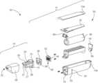
- FIG. 5is a skewed isometric exploded view of the vaporization device of FIG. 1 from a top perspective.
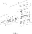
- FIG. 6is a skewed isometric exploded view of the vaporization device of FIG. 1 , from a bottom perspective.
- FIG. 7is an isometric view of a vaporization device, according to another example embodiment, from a top perspective.
- FIG. 8is an isometric view of the vaporization device of FIG. 7 with external components shown transparent to reveal underlying features and components thereof.
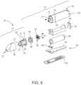
- FIG. 9is a skewed isometric view of the vaporization device of FIG. 7 with external components shown partially cut away to reveal underlying features and components thereof.
- FIG. 10is a skewed isometric view of the vaporization device of FIG. 7 with a vaporization head detached from a base assembly thereof, and with a removable material screen removed from a vaporization chamber provided by the vaporization head.
- FIG. 11is a partial cross-sectional view of a front end of the vaporization device of FIG. 7 showing internal features and components of the device.
- FIG. 12is a top plan view of the internal components of the vaporization device of FIG. 7 showing a path and relative temperature profile of the air and air-vapor mixture moving through the device during an inhalation event.
- FIG. 13provides diagrams of a mesh heater, according to one embodiment, from front and side perspectives.
- FIG. 14shows additional details of an example embodiment of a nozzle block for supporting a mesh heater within the vaporization device.
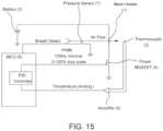
- FIG. 15provides a schematic diagram of a closed loop air temperature control system, according to one example embodiment.
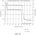
- FIG. 16provides an example plot of air temperature and corresponding heater output percentage over an approximately 30 second inhalation event in accordance with a closed loop air temperature control scheme.
- FIG. 17provides a system block diagram of a vaporization device, according to one example embodiment.
- FIG. 18provides an electronics block diagram of a vaporization device, according to one example embodiment.
- FIG. 19illustrates a vapor concentration measurement device, according to one example embodiment.
- FIG. 20provides a representative plot of obscuration measurements over three vapor production cycles.
- FIG. 21provides schematic diagrams of two example light scattering/detection arrangements.
- FIG. 22provides schematic diagrams of two example light scattering arrangements comprising a multi-angle system (upper right image) and a multi-wavelength system (lower right image).
- Embodiments described hereinprovide vaporization devices suitable for selectively delivering vaporized plant material (or other material) in an efficient and reliable manner for inhalation by a user.
- Embodimentsinclude vaporization devices that utilize a closed loop temperature control technique to drive current from a power source to a forced convection air heater to provide rapid, on-demand vapor delivery.
- Embodimentsmay further include breath detection functionality to assist in delivering the vaporized plant material on-demand.
- Embodimentsmay be provided in multi-part form factors including, for example, a vaporization head detachable from a base assembly, which includes the system electronics.
- the vaporization headincludes a vaporization chamber for receiving the material to be vaporized.
- the vaporization headmay be configured to dissipate heat and sufficiently cool the vapor stream for safe and comfortable inhalation by the user.
- the vaporization devicesmay be configured to enable a user to safely inhale vaporized plant material on-demand without significant delay despite fluctuations in inhalation strength, inhalation duration, ambient environmental conditions, and/or plant material characteristics (e.g., size, moisture content), thereby enhancing user experience.
- vaporization devices and methods described hereinare shown and described often in the context of handheld, electronically controlled, breath actuated vaporizer devices for delivering vaporized plant material to a user, it will be appreciated by those of ordinary skill in the relevant art that features and aspects of such devices may be applied to other devices and for other purposes, including, for example, benchtop vaporization devices or systems for delivering vaporized material for recreational, medical or other purposes.
- FIGS. 1 through 6show one example embodiment of a handheld, electronically controlled, battery driven, breath actuated vapor delivery unit in the form of a vaporizer device 10 .
- the vaporizer device 10includes a base assembly 12 , which includes the system electronics contained in a housing 13 a , 13 b , and a vaporizer head 14 that is removably coupleable to the base assembly 12 for vaporizing material (e.g., plant material, including plant material extracts, concentrates and derivatives) loaded in the vaporizer head 14 for inhalation by a user.
- the vaporization head 14may be removably coupled to the base assembly 12 via a magnetic coupling arrangement 15 or other coupling arrangement, such as, detents, snaps, clips, latches, or other fasteners.
- the vaporizer device 10includes an air intake 20 (e.g., plurality of intake apertures), through which air enters the vaporization device 10 during an inhalation event, and an outlet 22 , through which vapor is withdrawn from the vaporization device 10 by the user.
- the vaporization device 10further includes a vaporization chamber 24 for accommodating the material to be vaporized.
- the vaporization head 14may include a heat exchanger 26 and a removable mouthpiece 28 detachably coupled to the heat exchanger 26 .
- the vaporization chamber 24is defined at least in part by the heat exchanger 26 and is accessible to a user by removing the mouthpiece 28 from the heat exchanger 26 .
- a usermay conveniently remove or disengage the mouthpiece 28 from the heat exchanger 26 to load the vaporization device 10 with material to be vaporized as desired.
- the mouthpiece 28may be removably coupled to the heat exchanger 26 via one or more detent mechanisms 29 or other coupling arrangements, such as, snaps, clips, latches, magnets or other fasteners.
- the vaporization chamber 24may be selectively accessible to a user without removing the mouthpiece 28 .
- the mouthpiece 28may slide relative to the heat exchanger 26 to reveal the vaporization chamber 24 while remaining coupled to the heat exchanger 26 .
- an access panel or covermay provide access to the vaporization chamber 24 .
- the heat exchanger 26includes one or more vapor flow passages 27 extending from the vaporization chamber 24 toward the outlet 22 .
- the example embodiment of FIGS. 1 through 6includes a heat exchanger 26 having opposing passages 27 offset from a central plane of the vaporization device 10 .
- the heat exchanger 26further includes a central portion that provides an obstruction around which the vapor must flow to reach the outlet 22 .
- heat exchanger 26is configured such that a portion of the heat transferred to the heat exchanger 26 from the vapor is conducted upstream to a location adjacent the vaporization chamber 24 to assist in heating the material to be vaporized via conduction.
- the vaporization device 10further includes a mesh heater 30 supported upstream of the vaporization chamber 24 , which is operable to heat air which passes through the mesh heater 30 during each inhalation event as it moves from the air intake 20 toward the outlet 22 .
- the mesh heater 30may comprise a wire mesh 32 of a first material (e.g., stainless steel) and a frame 34 of a second material (e.g., ceramic material).
- the wire mesh 32is fixed to the frame 34 and supported by the frame 34 within the vaporization device 10 .
- the frame 34may be a portion of a frame assembly that further comprises opposing bus bars (e.g., low resistance, copper bus bars) integrally formed therewith. Opposing ends of the mesh 32 may be bonded (e.g., silver soldered) to the opposing bus bars, along with heater leads (not shown) for supplying electric current through the mesh 32 in accordance with the control system functionality disclosed herein.
- the vaporization device 10may further comprise a nozzle block 36 for supporting the mesh heater 30 upstream of the vaporization chamber 24 .
- the nozzle block 36may include a nozzle passage 38 that is shaped to funnel air passing through the mesh heater 30 toward a central location (as illustrated best in the example embodiment shown in FIG. 14 ).
- the vaporization device 10may further include one or more temperature sensor(s) (e.g., one or more thermocouple(s)) positioned downstream of the mesh heater 30 which are operable to sense a temperature of the air downstream of the mesh heater 30 at the central location and/or other locations. Temperature readings may be used to control various operational aspects of the vaporization device 10 as described herein.
- Temperature sensing locationsmay include immediately downstream of the mesh heater 30 to sense a temperature of the heated air stream generated by the mesh heater 30 , within the vaporization chamber 24 , immediately downstream of the vaporization chamber 24 , at or near the outlet 22 , and at or near the air intake 20 .
- the vaporization devicemay further include a control system 50 , comprising one or more printed circuit board assemblies 52 , 54 , which is/are operatively coupled to the temperature sensor and the mesh heater 30 to provide a closed loop control scheme for controlling heat generated by the mesh heater 30 so as to maintain a temperature of the air delivered to the vaporization chamber 24 at or within a predetermined tolerance of a desired vaporization temperature for at least a majority of a duration of an inhalation event.
- the control system 50may further include a power source 56 (e.g., a low voltage, high current battery) and a charging circuit, including a power connector 58 , for enabling the power source 56 of the vaporization device 10 to be recharged as needed.
- the vaporization device 10may further include a pressure sensor 60 operatively coupled to the control system 50 to sense the initiation of an inhalation event.
- the pressure sensor 60may be positioned upstream of the mesh heater 30 and configured to sense a drop in pressure as a user begins to inhale on the device 10 .
- the pressure sensor 60may be used to initiate a soft start of the mesh heater 30 in accordance with aspects of the control methodology described herein prior to employing the closed loop control scheme.
- the vaporization device 10may further include a trigger (e.g., depressible button) to initiate the soft start of the mesh heater 30 .
- the pressure sensor 60may be used to measure pressure periodically or constantly throughout the inhalation event, and the mesh heater 30 may be controlled based at least in part on such pressure measurements.
- FIGS. 7 through 11show a vaporization device having the same or similar features to the example embodiment of the vaporization device 10 of FIGS. 1 through 6 . Select features of the vaporization device are labeled in the figures for additional clarity.
- FIG. 12illustrates the air and air-vapor mixture moving through a front end of the vaporization device during an inhalation event.
- relatively cool ambient airis drawn into the device during inhalation through an air intake, as represented by the blue arrow.
- the airis rapidly heated to a desired vaporization temperature (e.g., approximately 225° C. for vaporizing certain types of plant matter), as represented by the red arrow.
- a desired vaporization temperaturee.g., approximately 225° C. for vaporizing certain types of plant matter
- the heated airinteracts with the material to be vaporized in the vaporization chamber to generate an air-vapor mixture that is discharged from the vaporization chamber at a lower exit temperature, as represented by the arrow transitioning from red to yellow.
- air-vapor mixturemoves through vapor flow passages of a heat exchanger whereby heat is transferred from the air-vapor mixture to the heat exchanger to cool the air-vapor mixture to a comfortable temperature before being discharged through the outlet of the vaporization head for inhalation, as represented by the arrows transitioning from yellow to blue.
- some of the heat from the air-vapor mixturemay be reclaimed by the heat exchanger for conductive heating of the material to be vaporized, as represented by the yellow arrows outlined in broken lines.
- FIG. 13provides a schematic representation of a mesh heater according to aspects of the vaporizer devices described herein.
- the mesh heateris a compact, high power density, high efficiency forced-convection air heater for flowing air which is configured to provide a rapid rate of heating.
- the mesh heateris depicted in FIG. 13 with a wire mesh resistive element 1 held in housing 2 , which is electrically insulating or has an insulating layer.
- Bus bars 3provide connections at opposing ends of the wire mesh resistive element 1 , and are connected to wire leads (not shown) which provide electrical power to the heating element (i.e., wire mesh resistive element 1 ).
- An air opening 4is provided adjacent the mesh, and converges to a nozzle/mixer 5 , wherein a temperature measurement element 6 is provided.
- the mesh heaterrapidly heats air through forced convection. Electrical current is passed through the mesh resistive element 1 , which then heats to a high surface temperature. Air flowing through the mesh heater is heated by the wire mesh resistive element 1 .
- the mesh heateris of low electrical resistance, and the convection is very efficient, two factors which combine to give the heater a fast thermal time constant and effect a rapid heating rate of the air. Heated air flows into the nozzle/mixer 5 and heats the temperature measurement element 6 , which can be used to effect closed-loop temperature control.
- the bus bars 3are connected to the mesh 1 with a low resistance connection.
- the housing 2is mechanically robust, which protects the delicate wire mesh resistive element 1 from external physical loads. The housing 2 also provides thermal management of the wire leads (not shown).
- the material of the mesh 1may have a positive temperature coefficient of resistance, which helps to self-limit the temperature of the heater during operation.
- the mesh heaterprovides a particularly compact and efficient form factor for transferring a large amount of heat into a flow of air, especially when considering power consumption in relation to heat transferred into the moving air stream.
- the mesh heatermay provide a particularly rapid heating rate of the air flow (e.g., up to and exceeding 100° C., 150° C. or 200° C. per second) with the use of a low-mass, low impedance mesh heating element 1 .
- the heating elementmay be a single piece of fine wire mesh 1 .
- the heating elementmay be designed to be powered with a low voltage, high current battery.
- the heating elementmay provide particularly efficient heating as nearly all power consumed may be transferred to the moving air stream via convection with minimal losses.
- the heating elementmay provide a high surface area-to-volume ratio thereby providing a high thermal power density.
- the mesh heatermay comprise a mechanically robust form factor having an integrated housing 2 .
- the temperature measurement element 6may be integrated with the housing 2 and supported at a central location.
- the housing 2may provide a nozzle or funnel which forces the air flowing through the mesh resistive element 1 to mix so that a single point temperature measurement more accurately represents the average temperature of the flowing air stream.
- the mesh resistive element 1may comprise stainless steel, which has the property of self-limiting the electrical current through the mesh resistive element 1 since the electrical resistance of the stainless steel mesh increases with temperature as it heats up. This helps prevent the mesh resistive element 1 from self-fusing or from other damage.
- the stainless steel mesh resistive element 1may provide a safer material with regard to biocompatibility and inhalation when compared to Nichrome (NiCr) and other common resistive heating element materials.
- a heater element in the form of a coil, pancake coil, wire screen, wire array or other heater element device or arrangementmay be provided in lieu of the wire mesh 32 .
- FIG. 14shows different views of an example nozzle block (similar to nozzle block 36 of FIGS. 5 and 6 ) to further illustrate an example of a location of the temperature sensor and funneling characteristics of the nozzle passage thereof, which may assist in mixing the heated air stream to obtain a more accurate reading of the average air temperature of the air stream passing through the mesh heater (or other heater).
- FIG. 14highlights features of the example nozzle block which help manage heat management within the device.
- the mesh heatermay be held offset from the nozzle block via one or more bosses such that, apart from the one or more bosses, a space is maintained between the mesh heater and the nozzle block. This helps to reduce conductive heat transfer from the mesh heater to the nozzle block during operation.
- bossesare shown as being integrally formed with the nozzle block, it is appreciated that the bosses may be provided by the frame of the mesh heater rather than the nozzle block. Alternatively, one or more spacers or mounting members may be provided in lieu of bosses.
- the nozzle blockmay also be held offset from the device housing via one or more bosses such that, apart from the one or more other bosses, a space is maintained between the nozzle block and the housing. This helps to reduce conductive heat transfer between the nozzle block and the housing during operation.
- bossesare shown as being integrally formed with the nozzle block, it is appreciated that the bosses may be provided by the housing rather than the nozzle block. Alternatively, one or more spacers or mounting members may be provided in lieu of bosses.
- FIG. 15provides a schematic of a closed loop air temperature control scheme that may be employed with embodiments of the vaporizer devices described herein.
- the closed loop air temperature control schememay be used to quickly and accurately heat air to a given temperature set point over a wide range of flow rates, ambient conditions, and battery states in order to vaporize target constituents of the material to be vaporized and inhaled.
- the mesh heater ( 1 )expressed schematically in FIG. 15 as a resistor, may comprise a fine stainless steel mesh through which air passes when a user inhales via a mouthpiece. Air temperature is measured with a thermocouple ( 2 ) (or other temperature sensor) placed in the air path, downstream of the heater ( 1 ).
- thermocouple signalis conditioned and amplified by an amplifier ( 5 ) for measurement by an analog-to-digital converter (ADC) located within a microcontroller (MCU) ( 6 ).
- ADCanalog-to-digital converter
- MCUmicrocontroller
- a software PID loopor other control loop feedback mechanism in the MCU ( 6 ) adjusts the output of the heater ( 1 ) based on feedback from the signal of the thermocouple ( 2 ).
- the thermocouple measurementis less than the desired air temperature, the heater output is increased. If the thermocouple measurement is greater than the desired air temperature, the heater output is decreased.
- the heater outputwill be adjusted throughout a use cycle in order to maintain an output temperature that is equal to or within an acceptable tolerance (e.g., ⁇ 5° C., ⁇ 2° C.) of a desired set point or vaporization temperature.
- One side of the heater ( 1 )is connected to a power source ( 3 ) of the device, and the other side is connected to a power MOSFET ( 4 ).
- MOSFETMOSFET
- the on/off duty cyclemay be modulated between 0-100% based on the feedback from the thermocouple ( 2 ).
- Pulse width modulationmay be employed in the control scheme at a frequency of 100 Hz, or at other frequencies.
- FIG. 16provides a representative graph of the temperature control scheme employed over about a 30 second inhalation event.
- the closed loop air temperature control schemeprovides enhanced temperature control to provide an improved user experience as compared to other vaporizer devices which may set a heater element at a fixed output without feedback from a temperature sensor, which would result in inaccurate temperature control outside of narrow default operating conditions, such as flow rate, ambient temperature, and battery voltage.
- Measuring the temperature of the heated airstream directly, rather than the heater elementprovides enhanced control of the user experience over a wider range of dynamic operating conditions (e.g., flow rate, ambient temperature, and battery voltage).
- monitoring the air temperature with a fine-wire thermocoupleminimizes the thermal mass of the sensor, and thus response time. This allows increased accuracy of heater adjustment that may self-correct for different inhalation rates, ambient temperatures, and/or battery voltages, even if these parameters are changing significantly within a single-use.
- the closed-loop air temperature control schemeis designed for the purpose of vaporizing target constituents on-demand in a target material (e.g., plant material, including plant material extracts, concentrates, and derivatives) for inhalation, and may be configured in conjunction with the mesh heater to provide up to and exceeding 100 W to provide a fast response while heating air 200° C. or more above ambient over a wide range of flow rates (e.g., up to 10 liters per minute or more).
- a target materiale.g., plant material, including plant material extracts, concentrates, and derivatives
- An efficient heater designwill have near zero conducted heat loss to its surrounding environment, such that all power provided to the heater will be convectively transferred to the flowing air. As the design approaches this ideal, it is imperative that the heater only be activated when air is flowing in order to avoid heating the system without an accompanying heat loss path.
- the mesh heateris controlled via closed-loop control, with feedback coming from a thermocouple in the air path downstream from the heater. Without air moving through the heater, the air around the temperature sensor may heat slightly, but not nearly enough to approach the desired set point at the temperature sensor downstream from the heater. Accordingly, the closed loop control would quickly increase the heater output to 100% without any forced convection air heat transfer, resulting in extremely high temperatures at the heater element. This has the effect of shortening heater and battery life, and, eventually, causing uncomfortable or, possibly, dangerous touch temperatures at the surface of the device. Accordingly, in order to mitigate this risk, a method for turning on the heater at a low level momentarily in order to verify expected thermal response from the air, and thus air velocity beyond a minimum threshold, has been developed. This method assures that the temperature control of the heater is only activated during a valid breath.
- the mesh heater ( 1 )may comprise a fine mesh through which air passes when a user inhales via a mouthpiece. Air temperature is measured with a thermocouple ( 2 ) placed in the air path, downstream of the mesh heater ( 1 ). The thermocouple signal is conditioned and amplified by an amplifier ( 5 ) for measurement by an analog-to-digital converter (ADC) located within the MCU ( 6 ). A pressure sensor ( 7 ) may be included upstream of the heater for the purpose of detecting air flow. When air flow above a minimal threshold is detected, a heater soft start may be initiated.
- ADCanalog-to-digital converter
- the heater soft startis accomplished by enabling the heater at a low duty cycle (e.g., 5% or less, 2% or less) and monitoring the temperature sensor output for a rapid thermal response. In the absence of adequate airflow, the reported temperature will increase, but only slowly. With airflow, the temperature increases much more rapidly.
- dT/dtthe heater feedback control loop is initiated only when dT/dt exceeds a software configurable threshold. If a heater soft start exceeds a software configurable timeout period, the heater is completely disabled and will not start again until a new breath is detected with the pressure sensor ( 7 ) or other detection means.
- the feedback control loop in the MCU ( 6 )adjusts the heater output based on feedback from the temperature sensor signal. Generally, if the temperature sensor measurement is less than the desired air temperature, the heater output is increased. If the temperature sensor measurement is greater than the desired air temperature, the heater output is decreased. The heater output will be adjusted throughout a use cycle in order to maintain an output temperature that is equal to or within an acceptable tolerance of the desired set point or vaporization temperature.
- the soft start and associated control schemeenables on-demand use of the vaporizer device without preheating, which would otherwise require a more powerful heater and additional safeguards to prevent false triggering, and which may scorch the material or otherwise degrade the quality of the vapor and subsequent user experience.
- the soft start functionalso allows detection of adequate air flow prior to enabling closed-loop control of the heater to its set point temperature. This function is implemented without requiring any additional components beyond what is needed for typical closed-loop control.
- the soft startis described as being triggered by breath detection via a pressure sensor ( 7 ), it is appreciated that in other embodiments a user accessible trigger or other control may be provided in addition to or in lieu of the pressure sensor ( 7 ) for triggering the soft start.
- the control systemmay also be configured to disable the mesh heater and stop the closed loop feedback control scheme upon detection of a divergence of a measured air temperature associated with a delivered heater power from an expected air temperature, the divergence arising from a lack of air flow through the vaporization device (i.e., cessation of the inhalation event).
- the mesh heatermay be operated at a given level (e.g., 40% ⁇ 2%) to maintain a desired vaporization temperature (e.g., 200° C. ⁇ 5° C.). Then, upon cessation of the inhalation event, the sensed temperature may drop significantly despite maintaining the mesh heater at the same power level given the lack of moving air that would otherwise transfer heat generated by the mesh heater to the location of the temperature sensor. This divergence thus signals that air flow has ceased and that the closed loop control scheme should be disabled until another inhalation event occurs.
- FIG. 17provides a system block diagram of a vaporization device, according to one embodiment
- FIG. 18provides an electronics block diagram of a vaporization device, according to one example embodiment.
- FIG. 17provides a system block diagram of a vaporization device, according to one embodiment
- FIG. 18provides an electronics block diagram of a vaporization device, according to one example embodiment.
- FIG. 17schematically depicts a control system comprising one or more microprocessors that are communicatively coupled to a power supply (e.g., battery); a charging port, such as may provide power charging functionality for the power supply; one or more user controls (e.g., a trigger), such as may be operated by a user to initiate the vaporization process; one or more user feedback devices (e.g., LEDs, electronic display), such as may be used to communicate information (e.g., power on/off state) to the user; a heater (e.g., wire mesh heater), such as may be used to heat a flow of air moving through the vaporization device during an inhalation event; a breath detection sensor (e.g., pressure sensor), such as may be used to detect an inhalation event and initiate a soft start of the heater; and a temperature sensing device (e.g., thermocouple), such as may be used to detect air temperature and provide a closed loop air temperature control scheme in conjunction with the microprocessor and the heater.
- a vaporization device(including a benchtop device) may be provided with one or more vapor concentration measurement devices for modifying operational parameters of the vaporization device based at least in part on concentration measurement data obtained therefrom.
- the vaporization devicemay be configured to measure vapor concentration by obscuration.
- FIG. 19One example vapor concentration measurement device is depicted in FIG. 19 . As shown in FIG.
- the vapor concentration measurement devicemay include an elongated measurement chamber through which a flow of vapor may be passed through inlet and exhaust ports with a light source at one end and an optical power meter or photodiode at the other end to measure a change in power readings associated with a decrease in the amount of light reaching the optical power meter or photodiode as a result of light being obscured by vapor in the measurement chamber.
- FIG. 20provides a representative plot of obscuration measurements over three vapor production cycles.
- the first cycleis characterized by a power reading of about 3.95 mW prior to vapor introduction and a power reading of about 3.51 mW upon vapor introduction, thus resulting in a percentage of light obscuration per foot of about 11.1% ((power before vapor-power during vapor)/(power before vapor)*100).
- concentration measurementsmay be used to determine when the material to be vaporized has been consumed, such as, for example, comparing measured concentration against expected concentration for given operating parameters and/or by monitoring the rate of decline in measured concentration.
- vapor concentration measured in real-timecould allow for user feedback from the device to indicate to the user that vapor is being produced.
- haptic feedbackmay be provided from a vibration device mounted inside the vaporizer, or visual feedback through an indicator (e.g., LED, electronic display), based on such measurements.
- an indicatore.g., LED, electronic display
- the vaporization devicemay be configured to measure vapor concentration and/or detect combustion particles via light scattering detection techniques as opposed to measuring obscuration. Measuring light scatter has the aforementioned advantages of detecting vapor concentration by obscuration, but also has the added advantage that it can be used to discriminate effluent from vapor. Detecting, and having the ability to avoid, other gasses or particles in the vapor stream is especially important in applications where end-users cannot tolerate contaminants (e.g., asthmatic users), or more broadly, when vapor purity is desired by the end-user. Furthermore, the scatter detection approach may enable a very compact light source/measurement area/detector to be constructed within a vapor delivery device, such as, for example, a handheld vaporization device.
- light guidesmay be added to create a form factor in which the light source (e.g., LED(s)) and photodiode are co-planar for ease of packaging.
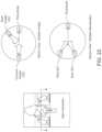
- FIG. 21provides schematic diagrams of two example light scattering arrangements wherein photodiodes are arranged to detect light emanating from a light source (e.g., LED) that is scattered by vapor moving through a vaporization device to be inhaled by a user.
- a light sourcee.g., LED
- a multi-angle system or a multi-wavelength systemmay be used to differentiate target vapor from other gasses or particulate streams.
- absolute magnitude of photodiode signalcould be used to differentiate particle size. Any of these methods may in turn be used to differentiate desirable vapor particles from undesirable particles for modifying or otherwise controlling user experience.
- a vaporizing devicemay use this differentiation, for example, to maximize vaporization without producing undesirable particles. Differentiating based on wavelength or angle may not be as sensitive to contamination or other outside influences as differentiating based on the absolute magnitude of photodiode signal. Furthermore, wavelength and angle discrimination give particle differentiation independently of vapor concentration, while differentiating based on the absolute magnitude of photodiode signal would not.
- FIG. 22provides schematic diagrams of two example light scattering arrangements comprising a multi-angle system (upper right image) and a multi-wavelength system (lower right image).
Landscapes
- Physical Vapour Deposition (AREA)
- Sampling And Sample Adjustment (AREA)
Abstract
Description
Claims (20)
Priority Applications (1)
| Application Number | Priority Date | Filing Date | Title |
|---|---|---|---|
| US18/440,049US12207689B2 (en) | 2016-01-28 | 2024-02-13 | Vapor delivery systems and methods |
Applications Claiming Priority (9)
| Application Number | Priority Date | Filing Date | Title |
|---|---|---|---|
| US201662288314P | 2016-01-28 | 2016-01-28 | |
| US15/418,435US20170215478A1 (en) | 2016-01-28 | 2017-01-27 | Vapor delivery systems and methods |
| US16/137,348US20190090542A1 (en) | 2016-01-28 | 2018-09-20 | Vapor delivery systems and methods |
| US16/365,057US10588356B2 (en) | 2016-01-28 | 2019-03-26 | Vapor delivery systems and methods |
| US16/777,570US10959464B2 (en) | 2016-01-28 | 2020-01-30 | Vapor delivery systems and methods |
| US17/181,871US11425931B2 (en) | 2016-01-28 | 2021-02-22 | Vapor delivery systems and methods |
| US17/889,266US11666088B2 (en) | 2016-01-28 | 2022-08-16 | Vapor delivery systems and methods |
| US18/309,635US11950638B2 (en) | 2016-01-28 | 2023-04-28 | Vapor delivery systems and methods |
| US18/440,049US12207689B2 (en) | 2016-01-28 | 2024-02-13 | Vapor delivery systems and methods |
Related Parent Applications (1)
| Application Number | Title | Priority Date | Filing Date |
|---|---|---|---|
| US18/309,635ContinuationUS11950638B2 (en) | 2016-01-28 | 2023-04-28 | Vapor delivery systems and methods |
Publications (2)
| Publication Number | Publication Date |
|---|---|
| US20240245109A1 US20240245109A1 (en) | 2024-07-25 |
| US12207689B2true US12207689B2 (en) | 2025-01-28 |
Family
ID=59386079
Family Applications (8)
| Application Number | Title | Priority Date | Filing Date |
|---|---|---|---|
| US15/418,435AbandonedUS20170215478A1 (en) | 2016-01-28 | 2017-01-27 | Vapor delivery systems and methods |
| US16/137,348AbandonedUS20190090542A1 (en) | 2016-01-28 | 2018-09-20 | Vapor delivery systems and methods |
| US16/365,057ActiveUS10588356B2 (en) | 2016-01-28 | 2019-03-26 | Vapor delivery systems and methods |
| US16/777,570ActiveUS10959464B2 (en) | 2016-01-28 | 2020-01-30 | Vapor delivery systems and methods |
| US17/181,871ActiveUS11425931B2 (en) | 2016-01-28 | 2021-02-22 | Vapor delivery systems and methods |
| US17/889,266ActiveUS11666088B2 (en) | 2016-01-28 | 2022-08-16 | Vapor delivery systems and methods |
| US18/309,635ActiveUS11950638B2 (en) | 2016-01-28 | 2023-04-28 | Vapor delivery systems and methods |
| US18/440,049ActiveUS12207689B2 (en) | 2016-01-28 | 2024-02-13 | Vapor delivery systems and methods |
Family Applications Before (7)
| Application Number | Title | Priority Date | Filing Date |
|---|---|---|---|
| US15/418,435AbandonedUS20170215478A1 (en) | 2016-01-28 | 2017-01-27 | Vapor delivery systems and methods |
| US16/137,348AbandonedUS20190090542A1 (en) | 2016-01-28 | 2018-09-20 | Vapor delivery systems and methods |
| US16/365,057ActiveUS10588356B2 (en) | 2016-01-28 | 2019-03-26 | Vapor delivery systems and methods |
| US16/777,570ActiveUS10959464B2 (en) | 2016-01-28 | 2020-01-30 | Vapor delivery systems and methods |
| US17/181,871ActiveUS11425931B2 (en) | 2016-01-28 | 2021-02-22 | Vapor delivery systems and methods |
| US17/889,266ActiveUS11666088B2 (en) | 2016-01-28 | 2022-08-16 | Vapor delivery systems and methods |
| US18/309,635ActiveUS11950638B2 (en) | 2016-01-28 | 2023-04-28 | Vapor delivery systems and methods |
Country Status (1)
| Country | Link |
|---|---|
| US (8) | US20170215478A1 (en) |
Families Citing this family (95)
| Publication number | Priority date | Publication date | Assignee | Title |
|---|---|---|---|---|
| US20160345631A1 (en) | 2005-07-19 | 2016-12-01 | James Monsees | Portable devices for generating an inhalable vapor |
| US10279934B2 (en) | 2013-03-15 | 2019-05-07 | Juul Labs, Inc. | Fillable vaporizer cartridge and method of filling |
| USD842536S1 (en) | 2016-07-28 | 2019-03-05 | Juul Labs, Inc. | Vaporizer cartridge |
| DE202014011260U1 (en) | 2013-12-23 | 2018-11-13 | Juul Labs Uk Holdco Limited | Systems for an evaporation device |
| US10159282B2 (en) | 2013-12-23 | 2018-12-25 | Juul Labs, Inc. | Cartridge for use with a vaporizer device |
| US10058129B2 (en) | 2013-12-23 | 2018-08-28 | Juul Labs, Inc. | Vaporization device systems and methods |
| US10076139B2 (en) | 2013-12-23 | 2018-09-18 | Juul Labs, Inc. | Vaporizer apparatus |
| USD825102S1 (en) | 2016-07-28 | 2018-08-07 | Juul Labs, Inc. | Vaporizer device with cartridge |
| US20160366947A1 (en) | 2013-12-23 | 2016-12-22 | James Monsees | Vaporizer apparatus |
| US10117463B2 (en)* | 2014-01-03 | 2018-11-06 | Robert P Thomas, Jr. | Vapor delivery device |
| MX394125B (en) | 2014-12-05 | 2025-03-24 | Juul Labs Inc | CALIBRATED DOSE CONTROL |
| US12245337B2 (en) | 2015-02-17 | 2025-03-04 | Mark Krietzman | Vaporizing consumables heated with convection and conduction in a portable device |
| US10893707B2 (en) | 2015-02-17 | 2021-01-19 | Mark H. Krietzman | Portable temperature controlled aromatherapy vaporizers |
| USD874720S1 (en) | 2015-04-22 | 2020-02-04 | Altria Client Services, Llc | Pod for an electronic vaping device |
| USD1052163S1 (en) | 2015-04-22 | 2024-11-19 | Altria Client Services Llc | Electronic vaping device |
| US10064432B2 (en) | 2015-04-22 | 2018-09-04 | Altria Client Services Llc | Pod assembly, dispensing body, and E-vapor apparatus including the same |
| US10104913B2 (en) | 2015-04-22 | 2018-10-23 | Altria Client Services Llc | Pod assembly, dispensing body, and E-vapor apparatus including the same |
| USD874059S1 (en) | 2015-04-22 | 2020-01-28 | Altria Client Servies Llc | Electronic vaping device |
| USD980507S1 (en) | 2015-04-22 | 2023-03-07 | Altria Client Services Llc | Electronic vaping device |
| WO2016172420A1 (en) | 2015-04-22 | 2016-10-27 | Altria Client Services Llc | Pod assembly, dispensing body, and e-vapor apparatus including the same |
| US20170215478A1 (en) | 2016-01-28 | 2017-08-03 | Stratos Product Development Llc | Vapor delivery systems and methods |
| USD861975S1 (en) | 2016-02-08 | 2019-10-01 | Juul Labs, Inc. | Vaporizer device with cartridges |
| EP3413960B1 (en) | 2016-02-11 | 2021-03-31 | Juul Labs, Inc. | Fillable vaporizer cartridge and method of filling |
| CO2018009342A2 (en) | 2016-02-11 | 2018-09-20 | Juul Labs Inc | Secure fixing cartridges for vaporizing devices |
| US10405582B2 (en) | 2016-03-10 | 2019-09-10 | Pax Labs, Inc. | Vaporization device with lip sensing |
| US20170355495A1 (en) | 2016-06-08 | 2017-12-14 | N2 Packaging Systems, Llc | Child resistant and senior friendly can lid |
| USD849996S1 (en) | 2016-06-16 | 2019-05-28 | Pax Labs, Inc. | Vaporizer cartridge |
| JP7090561B2 (en)* | 2016-06-16 | 2022-06-24 | ジュール・ラブズ・インコーポレイテッド | Instant portable heat convection vaporizer |
| USD851830S1 (en) | 2016-06-23 | 2019-06-18 | Pax Labs, Inc. | Combined vaporizer tamp and pick tool |
| USD836541S1 (en) | 2016-06-23 | 2018-12-25 | Pax Labs, Inc. | Charging device |
| UA124462C2 (en)* | 2016-07-25 | 2021-09-22 | Філіп Морріс Продактс С.А. | CARTRIDGE FOR SYSTEM GENERATING AN AEROSOL WITH HEATER PROTECTION |
| US10327477B2 (en)* | 2016-07-25 | 2019-06-25 | Altria Client Services Llc | Cartridge for an aerosol-generating system with heater protection |
| USD829978S1 (en)* | 2016-07-31 | 2018-10-02 | Altria Client Services Llc | Electronic cigarette |
| USD829974S1 (en) | 2016-07-31 | 2018-10-02 | Altria Client Services Llc | Electronic cigarette |
| USD829370S1 (en) | 2017-01-27 | 2018-09-25 | Altria Client Services Llc | Electronic cigarette |
| USD808071S1 (en)* | 2016-11-01 | 2018-01-16 | GS Holistic, LLC | Vaporizer |
| USD846798S1 (en)* | 2017-04-25 | 2019-04-23 | Shenzhen Smoore Technology Limited | Electronic cigarette |
| JP1599399S (en)* | 2017-05-08 | 2018-03-12 | ||
| USD846796S1 (en)* | 2017-05-24 | 2019-04-23 | Shenzhen Smoore Technology Limited | Electronic cigarette |
| US11958666B2 (en) | 2017-06-07 | 2024-04-16 | N2 Packaging Systems, Llc | Child resistant double seam container lid |
| US11834237B2 (en) | 2017-06-07 | 2023-12-05 | N2 Packaging Systems, Llc | Child resistant double seam container lid adapter ring |
| AU201810219S (en) | 2017-07-21 | 2018-02-07 | Nicoventures Holdings Ltd | Vaping device |
| USD843650S1 (en)* | 2017-08-29 | 2019-03-19 | VMR Products, LLC | Vaporizer |
| USD887632S1 (en) | 2017-09-14 | 2020-06-16 | Pax Labs, Inc. | Vaporizer cartridge |
| CN107510096A (en)* | 2017-09-27 | 2017-12-26 | 深圳市舜宝科技有限公司 | A kind of temperature control system of electronic cigarette fever tablet |
| USD861979S1 (en)* | 2017-10-10 | 2019-10-01 | N2 Packaging Systems, Llc | Snap-open preservation tube for tobacco and tobacco-like products |
| USD870375S1 (en)* | 2017-10-11 | 2019-12-17 | Altria Client Services Llc | Battery for an electronic vaping device |
| USD843649S1 (en)* | 2017-10-17 | 2019-03-19 | Fontem Holdings 1 B.V. | Mouthpiece for an electronic vaping device |
| EP3713627A4 (en) | 2017-11-22 | 2021-10-20 | Juul Labs, Inc. | USER INTERFACE AND USER EXPERIENCE FOR AN EVAPORATOR DEVICE |
| USD863675S1 (en)* | 2017-12-08 | 2019-10-15 | Shenzhen Goldreams Technology Co., Ltd. | Electronic cigarette |
| USD829372S1 (en)* | 2017-12-08 | 2018-09-25 | Shenzhen Goldreams Technology Co., Ltd. | Electronic cigarette |
| USD834746S1 (en)* | 2017-12-15 | 2018-11-27 | Huizhou Kimree Technology Co., Ltd. Shenzhen Branch | Electronic cigarette |
| USD829373S1 (en)* | 2017-12-19 | 2018-09-25 | Shenzhen Goldreams Technology Co., Ltd. | Electronic cigarette |
| CN207853506U (en)* | 2017-12-26 | 2018-09-11 | 深圳市优维尔科技有限公司 | To the pole host of atomizer power supply |
| USD855878S1 (en)* | 2018-02-10 | 2019-08-06 | Joyetech Europe Holding Gmbh | Electronic cigarette |
| CA3128462A1 (en)* | 2018-02-14 | 2019-08-22 | Zenigata Llc | Vaporization system with integrated heaters |
| US10986875B2 (en)* | 2018-06-25 | 2021-04-27 | Juul Labs, Inc. | Vaporizer device heater control |
| DE102018127926A1 (en)* | 2018-07-09 | 2020-01-09 | Hauni Maschinenbau Gmbh | Vaporizer head for an inhaler, especially for an electronic cigarette product |
| EP3845081A4 (en)* | 2018-08-27 | 2022-04-06 | Japan Tobacco Inc. | DEVICE FOR RELEASING AROMA INGREDIENTS |
| USD910904S1 (en)* | 2018-10-23 | 2021-02-16 | Tuanfang Liu | Electronic cigarette |
| EP4537877A3 (en) | 2018-11-05 | 2025-06-04 | Juul Labs, Inc. | Cartridges for vaporizer devices |
| CN209420955U (en)* | 2018-11-14 | 2019-09-24 | 常州市派腾电子技术服务有限公司 | an electronic cigarette |
| KR102203853B1 (en)* | 2018-11-16 | 2021-01-15 | 주식회사 케이티앤지 | Aerosol generating device and method of controlling same |
| US11614720B2 (en)* | 2018-11-19 | 2023-03-28 | Rai Strategic Holdings, Inc. | Temperature control in an aerosol delivery device |
| USD902473S1 (en)* | 2019-01-21 | 2020-11-17 | Shenzhen Smoore Technology Limited | Electronic cigarette |
| JP1650479S (en)* | 2019-01-29 | 2023-01-11 | Electronic Cigarette | |
| US11140918B2 (en)* | 2019-03-15 | 2021-10-12 | Flair Products Llc | Personal vaporizer |
| US12329201B2 (en) | 2019-03-22 | 2025-06-17 | Imperial Tobacco Limited | Smoking substitute system |
| USD901756S1 (en)* | 2019-04-20 | 2020-11-10 | Smiss Technology Co., Ltd. | Electronic cigarette |
| USD908952S1 (en)* | 2019-04-24 | 2021-01-26 | Shenzhen Itsuwa Electron Co., Ltd | Electronic cigarette |
| USD902474S1 (en)* | 2019-05-06 | 2020-11-17 | Smiss Technology Co., Ltd. | Electronic cigarette |
| EP3738631B1 (en)* | 2019-05-13 | 2023-10-25 | Mark Krietzman | Portable convection aromatherapy system |
| USD903191S1 (en)* | 2019-06-14 | 2020-11-24 | Ming Li | Electronic cigarette |
| CN110226779A (en) | 2019-06-27 | 2019-09-13 | 深圳雾芯科技有限公司 | Electronic atomizer and electronic atomizer device |
| CA208741S (en) | 2019-08-01 | 2022-04-07 | Nicoventures Trading Ltd | Aerosol generating device |
| EP4009821A1 (en)* | 2019-08-08 | 2022-06-15 | JT International SA | Aerosol generation device, method for manufacturing |
| US20220408840A1 (en)* | 2019-10-25 | 2022-12-29 | Jt International Sa | Electronic Cigarette Device with Heater Control |
| USD943158S1 (en) | 2019-11-14 | 2022-02-08 | Juul Labs, Inc. | Vaporizer cartridge |
| USD943159S1 (en) | 2019-11-14 | 2022-02-08 | Juul Labs, Inc. | Component for a vaporizer cartridge |
| USD943160S1 (en) | 2019-11-14 | 2022-02-08 | Juul Labs, Inc. | Vaporizer device |
| USD943161S1 (en) | 2019-11-14 | 2022-02-08 | Juul Labs, Inc. | Vaporizer device |
| US11684083B2 (en) | 2019-12-09 | 2023-06-27 | Scott Reimann | Hexagonal cartridge having a hexagon shaped mouthpiece with six air flow inlets |
| WO2021119050A1 (en)* | 2019-12-10 | 2021-06-17 | Juul Labs, Inc. | Vaporizer device including metallic bifunctional wick-heater assembly |
| EP4099856B1 (en) | 2020-02-04 | 2025-02-26 | Juul Labs, Inc. | Aerosol dispensing device with disposable container |
| WO2021223200A1 (en)* | 2020-05-08 | 2021-11-11 | 昂纳自动化技术(深圳)有限公司 | Method and apparatus for preventing dry burning of electronic cigarette, and electronic cigarette |
| CN111685378B (en)* | 2020-06-15 | 2023-07-28 | 上海复旦微电子集团股份有限公司 | Electronic cigarette pods and electronic cigarettes |
| KR20220148234A (en)* | 2020-06-23 | 2022-11-04 | 썬전 화청다 프리시젼 인더스트리 컴퍼니 리미티드 | Frame body type heating assembly, heating unit and atomization system |
| WO2021258314A1 (en)* | 2020-06-24 | 2021-12-30 | 深圳麦克韦尔科技有限公司 | Aerosol generation apparatus control method, aerosol generation apparatus, and control circuit |
| EP4195959A4 (en)* | 2020-07-31 | 2024-12-18 | Flat Planet Limited | DOUBLE CONVECTION AND CONDUCTION OVEN FOR FLOWER STICK |
| KR102605496B1 (en)* | 2020-08-21 | 2023-11-22 | 주식회사 케이티앤지 | Covection heater and aerosol-generating apparatus including the same |
| US11064738B2 (en)* | 2020-10-20 | 2021-07-20 | Dr. Dabber Inc. | Ceramic heating element with embedded temperature sensor and electronic vaporizer having a ceramic heating element with embedded temperature sensor |
| US11730205B2 (en) | 2020-10-20 | 2023-08-22 | Dr. Dabber Inc. | Quick connect adapter and electronic vaporizer having a ceramic heating element having a quick connect adapter |
| USD985187S1 (en) | 2021-01-08 | 2023-05-02 | Nicoventures Trading Limited | Aerosol generator |
| US20240245133A1 (en)* | 2021-05-14 | 2024-07-25 | Jt International S.A. | Aerosol Generating Device Comprising a Temperature Sensor |
| USD984730S1 (en) | 2021-07-08 | 2023-04-25 | Nicoventures Trading Limited | Aerosol generator |
Citations (67)
| Publication number | Priority date | Publication date | Assignee | Title |
|---|---|---|---|---|
| US5060671A (en) | 1989-12-01 | 1991-10-29 | Philip Morris Incorporated | Flavor generating article |
| US5095921A (en) | 1990-11-19 | 1992-03-17 | Philip Morris Incorporated | Flavor generating article |
| US5144962A (en) | 1989-12-01 | 1992-09-08 | Philip Morris Incorporated | Flavor-delivery article |
| US5179966A (en) | 1990-11-19 | 1993-01-19 | Philip Morris Incorporated | Flavor generating article |
| US5261424A (en) | 1991-05-31 | 1993-11-16 | Philip Morris Incorporated | Control device for flavor-generating article |
| US5322075A (en) | 1992-09-10 | 1994-06-21 | Philip Morris Incorporated | Heater for an electric flavor-generating article |
| US5372148A (en) | 1993-02-24 | 1994-12-13 | Philip Morris Incorporated | Method and apparatus for controlling the supply of energy to a heating load in a smoking article |
| US5819756A (en) | 1993-08-19 | 1998-10-13 | Mielordt; Sven | Smoking or inhalation device |
| US6095153A (en) | 1998-06-19 | 2000-08-01 | Kessler; Stephen B. | Vaporization of volatile materials |
| US20040020500A1 (en) | 2000-03-23 | 2004-02-05 | Wrenn Susan E. | Electrical smoking system and method |
| US20040200488A1 (en) | 2002-11-08 | 2004-10-14 | Philip Morris Usa, Inc. | Electrically heated cigarette smoking system with internal manifolding for puff detection |
| US7997280B2 (en) | 2004-01-30 | 2011-08-16 | Joshua Rosenthal | Portable vaporizer |
| US8091558B2 (en) | 2006-01-03 | 2012-01-10 | Gaiatrend Sarl | Cigarette substitute |
| US20120234315A1 (en) | 2009-06-19 | 2012-09-20 | Wenbo Li | High frequency induction atomizing device |
| US20120269497A1 (en) | 2011-04-22 | 2012-10-25 | Mark Hatten | Herbal Vaporizer with Electric Heating Element |
| US20130133675A1 (en) | 2010-07-30 | 2013-05-30 | Japan Tobacco Inc. | Smokeless flavor inhalator |
| US20130152922A1 (en) | 2011-12-14 | 2013-06-20 | Atmos Technology, Llc. | Portable Pen Sized Electric Herb Vaporizer with Ceramic Heating Chamber |
| US8550069B2 (en) | 2010-08-24 | 2013-10-08 | Eli Alelov | Inhalation device including substance usage controls |
| US20130298905A1 (en) | 2012-03-12 | 2013-11-14 | UpToke, LLC | Electronic vaporizing device and methods for use |
| US20140064715A1 (en) | 2009-12-30 | 2014-03-06 | Philip Morris Usa Inc. | Shaped heater for an aerosol generating system |
| US8739786B2 (en) | 2012-03-26 | 2014-06-03 | Vaporfection International, Inc. | Portable hand-held vaporizer heating assembly |
| US20140150810A1 (en) | 2011-08-04 | 2014-06-05 | Fontem Holdings 1 B.V. | Electronic cigarette with capacitor sensor |
| US20140202454A1 (en) | 2011-07-27 | 2014-07-24 | Batmark Limited | Inhaler component |
| US8820330B2 (en) | 2011-10-28 | 2014-09-02 | Evolv, Llc | Electronic vaporizer that simulates smoking with power control |
| US20140251324A1 (en) | 2013-03-05 | 2014-09-11 | Zhiyong Xiang | Method and device for heating control of an electronic cigarette |
| US20140278258A1 (en) | 2013-03-15 | 2014-09-18 | Altria Client Services Inc. | Accessory for electronic cigarette |
| US20140261492A1 (en) | 2013-03-15 | 2014-09-18 | Altria Client Services Inc. | Electronic smoking article |
| US20140299141A1 (en) | 2011-10-27 | 2014-10-09 | Philip Morris Products S.A. | Aerosol generating system with improved aerosol production |
| US8881737B2 (en) | 2012-09-04 | 2014-11-11 | R.J. Reynolds Tobacco Company | Electronic smoking article comprising one or more microheaters |
| US20140345635A1 (en) | 2013-05-22 | 2014-11-27 | Njoy, Inc. | Compositions, devices, and methods for nicotine aerosol delivery |
| US20150034103A1 (en) | 2012-04-18 | 2015-02-05 | Fontem Holdings 1 B.V. | Electronic cigarette |
| US20150059780A1 (en) | 2013-08-28 | 2015-03-05 | R.J. Reynolds Tobacco Company | Carbon conductive substrate for electronic smoking article |
| US20150090256A1 (en) | 2013-10-02 | 2015-04-02 | Esquire Properties Trading Inc. | Vapor Inhaler |
| US20150125136A1 (en) | 2013-11-05 | 2015-05-07 | Timothy H. Sanchez | Vaporization & Inhalation System with Convective and Conductive Heaters for Herbal Material and/or Fluid Extracts |
| US20150136158A1 (en) | 2013-11-15 | 2015-05-21 | Jj 206, Llc | Systems and methods for a vaporization device and product usage control and documentation |
| US20150150305A1 (en) | 2013-11-01 | 2015-06-04 | Yuval Shenkal | Hybrid e-cigarette/vaporizer with exhale filter capability |
| US20150173124A1 (en) | 2012-11-13 | 2015-06-18 | Joyetech (Changzhou) Electronics Co., Ltd. | Intelligent controller and method for electronic cigarette |
| US20150173419A1 (en) | 2013-12-20 | 2015-06-25 | Xiang Zheng Tu | Electronic Cigarette with Thermal Flow Sensor Based Controller |
| US20150216235A1 (en) | 2013-04-08 | 2015-08-06 | Quiming Liu | Electronic cigarette and circuit used in the same |
| US20150230521A1 (en) | 2011-12-30 | 2015-08-20 | Philip Morris Products S.A. | Aerosol generating device with air flow detection |
| US20150237917A1 (en) | 2012-10-19 | 2015-08-27 | Nicoventures Holdings Limited | Electronic vapour provision device |
| US20150245658A1 (en) | 2014-02-28 | 2015-09-03 | R.J. Reynolds Tobacco Company | Control body for an electronic smoking article |
| US20150257448A1 (en) | 2012-10-19 | 2015-09-17 | Nicoventures Holdings Limited | Electronic inhalation device |
| US20150272222A1 (en) | 2014-03-25 | 2015-10-01 | Nicotech, LLC | Inhalation sensor for alternative nicotine/thc delivery device |
| US20150272220A1 (en) | 2014-03-25 | 2015-10-01 | Nicotech, LLC | Nicotine dosage sensor |
| US20150282527A1 (en) | 2014-04-04 | 2015-10-08 | R.J. Reynolds Tobacco Company | Sensor for an aerosol delivery device |
| US9155848B2 (en) | 2007-10-15 | 2015-10-13 | Vapir, Inc. | Method and system for vaporization of a substance |
| US20150296885A1 (en) | 2013-04-07 | 2015-10-22 | Qiuming Liu | Atomization temperature controllable electronic cigarette |
| US20150313284A1 (en) | 2012-10-05 | 2015-11-05 | Smart Chip Microelectronic Co. Limited | Electronic smoke apparatus |
| US20150351456A1 (en) | 2013-01-08 | 2015-12-10 | L. Perrigo Company | Electronic cigarette |
| US20150359263A1 (en) | 2014-06-14 | 2015-12-17 | Evolv, Llc | Electronic vaporizer having temperature sensing and limit |
| US9226525B2 (en) | 2012-11-22 | 2016-01-05 | Huizhou Kimree Technology Co., Ltd., Shenzhen Branch | Electronic cigarette and electronic cigarette device |
| US20160000149A1 (en) | 2014-07-02 | 2016-01-07 | Njoy, Inc. | Devices and methods for vaporization |
| US20160000145A1 (en) | 2014-07-03 | 2016-01-07 | Tuanfang Liu | Electronic cigarette |
| US20160235124A1 (en) | 2015-02-17 | 2016-08-18 | Mark Krietzman | Convection vaporizers |
| US20160262454A1 (en) | 2015-03-10 | 2016-09-15 | R.J. Reynolds Tobacco Company | Aerosol delivery device with microfluidic delivery component |
| US20160295919A1 (en) | 2014-01-03 | 2016-10-13 | Robert P. Thomas, JR. | Vapor Delivery Device |
| US20170035115A1 (en) | 2013-12-23 | 2017-02-09 | James Monsees | Cartridge for use with a vaporizer device |
| US20170119048A1 (en) | 2015-10-30 | 2017-05-04 | British American Tobacco (Investments) Limited | Article for Use with Apparatus for Heating Smokable Material |
| US20170156399A1 (en) | 2015-12-07 | 2017-06-08 | Giant Concepts LLC | Inhalation device with metering |
| US20170215478A1 (en) | 2016-01-28 | 2017-08-03 | Stratos Product Development Llc | Vapor delivery systems and methods |
| US20170231283A1 (en) | 2016-02-12 | 2017-08-17 | Alexander Gadas | Modular Vaporizer |
| US20170303588A1 (en) | 2016-04-22 | 2017-10-26 | Rui Nuno BATISTA | Aerosol-generating device comprising semiconductor heaters |
| US20170325442A1 (en) | 2014-12-15 | 2017-11-16 | Dainihon Jochugiku Co., Ltd. | Device and method for vaporizing/discharging chemical agent |
| US9861127B2 (en) | 2012-09-11 | 2018-01-09 | Shenzhen Kimsen Technology Co., Ltd. | Electronic cigarette and electronic cigarette device |
| US20180028993A1 (en) | 2011-12-08 | 2018-02-01 | Phillip Morris Products S.A. | Aerosol generating device with adjustable airflow |
| US20200128875A1 (en) | 2017-03-16 | 2020-04-30 | Ventus Medical Limited | A mouthpiece and heater assembly for an inhalation device |
- 2017
- 2017-01-27USUS15/418,435patent/US20170215478A1/ennot_activeAbandoned
- 2018
- 2018-09-20USUS16/137,348patent/US20190090542A1/ennot_activeAbandoned
- 2019
- 2019-03-26USUS16/365,057patent/US10588356B2/enactiveActive
- 2020
- 2020-01-30USUS16/777,570patent/US10959464B2/enactiveActive
- 2021
- 2021-02-22USUS17/181,871patent/US11425931B2/enactiveActive
- 2022
- 2022-08-16USUS17/889,266patent/US11666088B2/enactiveActive
- 2023
- 2023-04-28USUS18/309,635patent/US11950638B2/enactiveActive
- 2024
- 2024-02-13USUS18/440,049patent/US12207689B2/enactiveActive
Patent Citations (80)
| Publication number | Priority date | Publication date | Assignee | Title |
|---|---|---|---|---|
| US5060671A (en) | 1989-12-01 | 1991-10-29 | Philip Morris Incorporated | Flavor generating article |
| US5144962A (en) | 1989-12-01 | 1992-09-08 | Philip Morris Incorporated | Flavor-delivery article |
| US5095921A (en) | 1990-11-19 | 1992-03-17 | Philip Morris Incorporated | Flavor generating article |
| US5179966A (en) | 1990-11-19 | 1993-01-19 | Philip Morris Incorporated | Flavor generating article |
| US5261424A (en) | 1991-05-31 | 1993-11-16 | Philip Morris Incorporated | Control device for flavor-generating article |
| US5322075A (en) | 1992-09-10 | 1994-06-21 | Philip Morris Incorporated | Heater for an electric flavor-generating article |
| US5372148A (en) | 1993-02-24 | 1994-12-13 | Philip Morris Incorporated | Method and apparatus for controlling the supply of energy to a heating load in a smoking article |
| US5819756A (en) | 1993-08-19 | 1998-10-13 | Mielordt; Sven | Smoking or inhalation device |
| US6095153A (en) | 1998-06-19 | 2000-08-01 | Kessler; Stephen B. | Vaporization of volatile materials |
| US20040020500A1 (en) | 2000-03-23 | 2004-02-05 | Wrenn Susan E. | Electrical smoking system and method |
| US6688313B2 (en) | 2000-03-23 | 2004-02-10 | Philip Morris Incorporated | Electrical smoking system and method |
| US20040200488A1 (en) | 2002-11-08 | 2004-10-14 | Philip Morris Usa, Inc. | Electrically heated cigarette smoking system with internal manifolding for puff detection |
| US6810883B2 (en) | 2002-11-08 | 2004-11-02 | Philip Morris Usa Inc. | Electrically heated cigarette smoking system with internal manifolding for puff detection |
| US7997280B2 (en) | 2004-01-30 | 2011-08-16 | Joshua Rosenthal | Portable vaporizer |
| US8091558B2 (en) | 2006-01-03 | 2012-01-10 | Gaiatrend Sarl | Cigarette substitute |
| US9155848B2 (en) | 2007-10-15 | 2015-10-13 | Vapir, Inc. | Method and system for vaporization of a substance |
| US20120234315A1 (en) | 2009-06-19 | 2012-09-20 | Wenbo Li | High frequency induction atomizing device |
| US20140064715A1 (en) | 2009-12-30 | 2014-03-06 | Philip Morris Usa Inc. | Shaped heater for an aerosol generating system |
| US20130133675A1 (en) | 2010-07-30 | 2013-05-30 | Japan Tobacco Inc. | Smokeless flavor inhalator |
| US8550069B2 (en) | 2010-08-24 | 2013-10-08 | Eli Alelov | Inhalation device including substance usage controls |
| US20140224245A1 (en) | 2010-08-24 | 2014-08-14 | Eli Alelov | Inhalation device including substance usage controls |
| US8714150B2 (en) | 2010-08-24 | 2014-05-06 | Eli Alelov | Inhalation device including substance usage controls |
| US20120269497A1 (en) | 2011-04-22 | 2012-10-25 | Mark Hatten | Herbal Vaporizer with Electric Heating Element |
| US20140202454A1 (en) | 2011-07-27 | 2014-07-24 | Batmark Limited | Inhaler component |
| US20140150810A1 (en) | 2011-08-04 | 2014-06-05 | Fontem Holdings 1 B.V. | Electronic cigarette with capacitor sensor |
| US20140299141A1 (en) | 2011-10-27 | 2014-10-09 | Philip Morris Products S.A. | Aerosol generating system with improved aerosol production |
| US20140332016A1 (en) | 2011-10-28 | 2014-11-13 | Evolv, Llc | Electronic vaporizer that simulates smoking with power control |
| US8820330B2 (en) | 2011-10-28 | 2014-09-02 | Evolv, Llc | Electronic vaporizer that simulates smoking with power control |
| US20180028993A1 (en) | 2011-12-08 | 2018-02-01 | Phillip Morris Products S.A. | Aerosol generating device with adjustable airflow |
| US20130152922A1 (en) | 2011-12-14 | 2013-06-20 | Atmos Technology, Llc. | Portable Pen Sized Electric Herb Vaporizer with Ceramic Heating Chamber |
| US20150230521A1 (en) | 2011-12-30 | 2015-08-20 | Philip Morris Products S.A. | Aerosol generating device with air flow detection |
| US20130298905A1 (en) | 2012-03-12 | 2013-11-14 | UpToke, LLC | Electronic vaporizing device and methods for use |
| US8739786B2 (en) | 2012-03-26 | 2014-06-03 | Vaporfection International, Inc. | Portable hand-held vaporizer heating assembly |
| US20150034103A1 (en) | 2012-04-18 | 2015-02-05 | Fontem Holdings 1 B.V. | Electronic cigarette |
| US8881737B2 (en) | 2012-09-04 | 2014-11-11 | R.J. Reynolds Tobacco Company | Electronic smoking article comprising one or more microheaters |
| US9861127B2 (en) | 2012-09-11 | 2018-01-09 | Shenzhen Kimsen Technology Co., Ltd. | Electronic cigarette and electronic cigarette device |
| US20150313284A1 (en) | 2012-10-05 | 2015-11-05 | Smart Chip Microelectronic Co. Limited | Electronic smoke apparatus |
| US20150257448A1 (en) | 2012-10-19 | 2015-09-17 | Nicoventures Holdings Limited | Electronic inhalation device |
| US20150237917A1 (en) | 2012-10-19 | 2015-08-27 | Nicoventures Holdings Limited | Electronic vapour provision device |
| US20150173124A1 (en) | 2012-11-13 | 2015-06-18 | Joyetech (Changzhou) Electronics Co., Ltd. | Intelligent controller and method for electronic cigarette |
| US9226525B2 (en) | 2012-11-22 | 2016-01-05 | Huizhou Kimree Technology Co., Ltd., Shenzhen Branch | Electronic cigarette and electronic cigarette device |
| US20150351456A1 (en) | 2013-01-08 | 2015-12-10 | L. Perrigo Company | Electronic cigarette |
| US20140251324A1 (en) | 2013-03-05 | 2014-09-11 | Zhiyong Xiang | Method and device for heating control of an electronic cigarette |
| US20140261492A1 (en) | 2013-03-15 | 2014-09-18 | Altria Client Services Inc. | Electronic smoking article |
| US20140278258A1 (en) | 2013-03-15 | 2014-09-18 | Altria Client Services Inc. | Accessory for electronic cigarette |
| US20150296885A1 (en) | 2013-04-07 | 2015-10-22 | Qiuming Liu | Atomization temperature controllable electronic cigarette |
| US20150216235A1 (en) | 2013-04-08 | 2015-08-06 | Quiming Liu | Electronic cigarette and circuit used in the same |
| US20140345635A1 (en) | 2013-05-22 | 2014-11-27 | Njoy, Inc. | Compositions, devices, and methods for nicotine aerosol delivery |
| US20150059780A1 (en) | 2013-08-28 | 2015-03-05 | R.J. Reynolds Tobacco Company | Carbon conductive substrate for electronic smoking article |
| US20150090256A1 (en) | 2013-10-02 | 2015-04-02 | Esquire Properties Trading Inc. | Vapor Inhaler |
| US20150150305A1 (en) | 2013-11-01 | 2015-06-04 | Yuval Shenkal | Hybrid e-cigarette/vaporizer with exhale filter capability |
| US20150125136A1 (en) | 2013-11-05 | 2015-05-07 | Timothy H. Sanchez | Vaporization & Inhalation System with Convective and Conductive Heaters for Herbal Material and/or Fluid Extracts |
| US20150136158A1 (en) | 2013-11-15 | 2015-05-21 | Jj 206, Llc | Systems and methods for a vaporization device and product usage control and documentation |
| US20150173419A1 (en) | 2013-12-20 | 2015-06-25 | Xiang Zheng Tu | Electronic Cigarette with Thermal Flow Sensor Based Controller |
| US20170035115A1 (en) | 2013-12-23 | 2017-02-09 | James Monsees | Cartridge for use with a vaporizer device |
| US20160295919A1 (en) | 2014-01-03 | 2016-10-13 | Robert P. Thomas, JR. | Vapor Delivery Device |
| US20150245658A1 (en) | 2014-02-28 | 2015-09-03 | R.J. Reynolds Tobacco Company | Control body for an electronic smoking article |
| US20150272222A1 (en) | 2014-03-25 | 2015-10-01 | Nicotech, LLC | Inhalation sensor for alternative nicotine/thc delivery device |
| US20150272220A1 (en) | 2014-03-25 | 2015-10-01 | Nicotech, LLC | Nicotine dosage sensor |
| US20150282527A1 (en) | 2014-04-04 | 2015-10-08 | R.J. Reynolds Tobacco Company | Sensor for an aerosol delivery device |
| US20150359263A1 (en) | 2014-06-14 | 2015-12-17 | Evolv, Llc | Electronic vaporizer having temperature sensing and limit |
| US20160000149A1 (en) | 2014-07-02 | 2016-01-07 | Njoy, Inc. | Devices and methods for vaporization |
| US20160000145A1 (en) | 2014-07-03 | 2016-01-07 | Tuanfang Liu | Electronic cigarette |
| US20170325442A1 (en) | 2014-12-15 | 2017-11-16 | Dainihon Jochugiku Co., Ltd. | Device and method for vaporizing/discharging chemical agent |
| US20160235124A1 (en) | 2015-02-17 | 2016-08-18 | Mark Krietzman | Convection vaporizers |
| US20160262454A1 (en) | 2015-03-10 | 2016-09-15 | R.J. Reynolds Tobacco Company | Aerosol delivery device with microfluidic delivery component |
| US20170119048A1 (en) | 2015-10-30 | 2017-05-04 | British American Tobacco (Investments) Limited | Article for Use with Apparatus for Heating Smokable Material |
| US20170156399A1 (en) | 2015-12-07 | 2017-06-08 | Giant Concepts LLC | Inhalation device with metering |
| US20170215478A1 (en) | 2016-01-28 | 2017-08-03 | Stratos Product Development Llc | Vapor delivery systems and methods |
| US10588356B2 (en) | 2016-01-28 | 2020-03-17 | Zenigata Llc | Vapor delivery systems and methods |
| US10959464B2 (en) | 2016-01-28 | 2021-03-30 | Zenigata Llc | Vapor delivery systems and methods |
| US20220007712A1 (en) | 2016-01-28 | 2022-01-13 | Zenigata Llc | Vapor delivery systems and methods |
| US11425931B2 (en) | 2016-01-28 | 2022-08-30 | Zenigata Llc | Vapor delivery systems and methods |
| US20230047657A1 (en) | 2016-01-28 | 2023-02-16 | Zenigata Llc | Vapor delivery systems and methods |
| US11666088B2 (en) | 2016-01-28 | 2023-06-06 | Zenigata Llc | Vapor delivery systems and methods |
| US20230263215A1 (en) | 2016-01-28 | 2023-08-24 | Zenigata Llc | Vapor delivery systems and methods |
| US11950638B2 (en)* | 2016-01-28 | 2024-04-09 | Zenigata Llc | Vapor delivery systems and methods |
| US20170231283A1 (en) | 2016-02-12 | 2017-08-17 | Alexander Gadas | Modular Vaporizer |
| US20170303588A1 (en) | 2016-04-22 | 2017-10-26 | Rui Nuno BATISTA | Aerosol-generating device comprising semiconductor heaters |
| US20200128875A1 (en) | 2017-03-16 | 2020-04-30 | Ventus Medical Limited | A mouthpiece and heater assembly for an inhalation device |
Non-Patent Citations (11)
| Title |
|---|
| Canadian Office Action mailed Mar. 25, 2024 for Canadian Application No. 3,013,398, 16pp. |
| International Search Report Dated Apr. 12, 2019, for International Application No. PCT/US2019/018054, 9 pages. |
| Office Action Dated Jan. 27, 2022 for U.S. Appl. No. 17/181,871, 10 pages. |
| Office Action Dated Jul. 31, 2020 for U.S. Appl. No. 16/777,750, 4 pages. |
| Office Action Dated Oct. 19, 2017 for U.S. Appl. No. 15/418,435, 12 pages. |
| Office Action for U.S. Appl. No. 15/418,435 mailed on Oct. 19, 2017, Christopher Harrison, "Vapor Delivery Systems and Methods", 12 pages. |
| Office Action for U.S. Appl. No. 16/777,750 mailed on Jul. 31, 2020, Christopher Harrison, "Vapor Delivery Systems and Methods", 4 pages. |
| Office Action for U.S. Appl. No. 16/969,925, Dated Aug. 5, 2024, 11 pages. |
| Office Action for U.S. Appl. No. 16/969,925, mailed on Aug. 16, 2023, Harrision, "Vaporization System With Integrated Heaters", 11 pages. |
| Office Action for U.S. Appl. No. 16/969,925, mailed on Jan. 25, 2024, Harrision, "Vaporization System With Integrated Heaters", 13 pages. |
| Office Action for U.S. Appl. No. 17/181,871, mailed on Jan. 27, 2022, Harrison, "Vapor Delivery Systems and Methods", 10 pages. |
Also Published As
| Publication number | Publication date |
|---|---|
| US20220007712A1 (en) | 2022-01-13 |
| US11425931B2 (en) | 2022-08-30 |
| US11666088B2 (en) | 2023-06-06 |
| US20200022410A1 (en) | 2020-01-23 |
| US20200337371A1 (en) | 2020-10-29 |
| US20170215478A1 (en) | 2017-08-03 |
| US20240245109A1 (en) | 2024-07-25 |
| US20230263215A1 (en) | 2023-08-24 |
| US10959464B2 (en) | 2021-03-30 |
| US11950638B2 (en) | 2024-04-09 |
| US20230047657A1 (en) | 2023-02-16 |
| US20190090542A1 (en) | 2019-03-28 |
| US10588356B2 (en) | 2020-03-17 |
Similar Documents
| Publication | Publication Date | Title |
|---|---|---|
| US12207689B2 (en) | Vapor delivery systems and methods | |
| US12251509B2 (en) | Vaporizer power system | |
| US11857718B2 (en) | On-demand, portable convection vaporizer | |
| US11882879B2 (en) | Aerosol-generating device comprising multiple sensors | |
| CN111466620B (en) | electronic smoking device | |
| US20120199572A1 (en) | Herbal vaporization apparatus and method | |
| US20230042402A1 (en) | Mouthpiece for Vaporizer Including Positive Temperature Coefficient of Resistivity Heater | |
| CA3013398A1 (en) | Vapor delivery systems and methods | |
| HK40007590B (en) | On-demand, portable convection vaporizer | |
| HK40007590A (en) | On-demand, portable convection vaporizer |
Legal Events
| Date | Code | Title | Description |
|---|---|---|---|
| FEPP | Fee payment procedure | Free format text:ENTITY STATUS SET TO UNDISCOUNTED (ORIGINAL EVENT CODE: BIG.); ENTITY STATUS OF PATENT OWNER: SMALL ENTITY | |
| AS | Assignment | Owner name:ZENIGATA VENTURES, LLC, WASHINGTON Free format text:ASSIGNMENT OF ASSIGNORS INTEREST;ASSIGNOR:STRATOS PRODUCT DEVELOPMENT, LLC;REEL/FRAME:066464/0584 Effective date:20170518 Owner name:STRATOS PRODUCT DEVELOPMENT, LLC, WASHINGTON Free format text:ASSIGNMENT OF ASSIGNORS INTEREST;ASSIGNORS:HARRISON, CHRISTOPHER B.;RODRIGUEZ, STEVEN A.;KIRKOS, GREGORY A.;AND OTHERS;REEL/FRAME:066464/0444 Effective date:20160129 Owner name:ZENIGATA LLC, WASHINGTON Free format text:CHANGE OF NAME;ASSIGNOR:ZENIGATA VENTURES, LLC;REEL/FRAME:066599/0912 Effective date:20180328 | |
| FEPP | Fee payment procedure | Free format text:ENTITY STATUS SET TO SMALL (ORIGINAL EVENT CODE: SMAL); ENTITY STATUS OF PATENT OWNER: SMALL ENTITY | |
| STPP | Information on status: patent application and granting procedure in general | Free format text:DOCKETED NEW CASE - READY FOR EXAMINATION | |
| STPP | Information on status: patent application and granting procedure in general | Free format text:NOTICE OF ALLOWANCE MAILED -- APPLICATION RECEIVED IN OFFICE OF PUBLICATIONS | |
| STPP | Information on status: patent application and granting procedure in general | Free format text:PUBLICATIONS -- ISSUE FEE PAYMENT VERIFIED | |
| STCF | Information on status: patent grant | Free format text:PATENTED CASE |