US12204109B2 - Wide angle and high resolution tiled head-mounted display device - Google Patents
Wide angle and high resolution tiled head-mounted display deviceDownload PDFInfo
- Publication number
- US12204109B2 US12204109B2US18/123,503US202318123503AUS12204109B2US 12204109 B2US12204109 B2US 12204109B2US 202318123503 AUS202318123503 AUS 202318123503AUS 12204109 B2US12204109 B2US 12204109B2
- Authority
- US
- United States
- Prior art keywords
- tiled
- display channel
- display
- mounted display
- head
- Prior art date
- Legal status (The legal status is an assumption and is not a legal conclusion. Google has not performed a legal analysis and makes no representation as to the accuracy of the status listed.)
- Active
Links
Images


Classifications
- G—PHYSICS
- G02—OPTICS
- G02B—OPTICAL ELEMENTS, SYSTEMS OR APPARATUS
- G02B27/00—Optical systems or apparatus not provided for by any of the groups G02B1/00 - G02B26/00, G02B30/00
- G02B27/01—Head-up displays
- G02B27/017—Head mounted
- G02B27/0172—Head mounted characterised by optical features
- G—PHYSICS
- G02—OPTICS
- G02B—OPTICAL ELEMENTS, SYSTEMS OR APPARATUS
- G02B5/00—Optical elements other than lenses
- G02B5/04—Prisms
- G—PHYSICS
- G02—OPTICS
- G02B—OPTICAL ELEMENTS, SYSTEMS OR APPARATUS
- G02B27/00—Optical systems or apparatus not provided for by any of the groups G02B1/00 - G02B26/00, G02B30/00
- G02B27/01—Head-up displays
- G02B27/0101—Head-up displays characterised by optical features
- G02B2027/011—Head-up displays characterised by optical features comprising device for correcting geometrical aberrations, distortion
- G—PHYSICS
- G02—OPTICS
- G02B—OPTICAL ELEMENTS, SYSTEMS OR APPARATUS
- G02B27/00—Optical systems or apparatus not provided for by any of the groups G02B1/00 - G02B26/00, G02B30/00
- G02B27/01—Head-up displays
- G02B27/0101—Head-up displays characterised by optical features
- G02B2027/0123—Head-up displays characterised by optical features comprising devices increasing the field of view
- G—PHYSICS
- G02—OPTICS
- G02B—OPTICAL ELEMENTS, SYSTEMS OR APPARATUS
- G02B27/00—Optical systems or apparatus not provided for by any of the groups G02B1/00 - G02B26/00, G02B30/00
- G02B27/01—Head-up displays
- G02B27/0101—Head-up displays characterised by optical features
- G02B2027/0147—Head-up displays characterised by optical features comprising a device modifying the resolution of the displayed image
Definitions
- the present inventionrelates to a head-mounted display device, and in particular, to a tiled head-mounted display device comprising wedge-shaped prisms with free-form surfaces.
- Head-mounted display devices for virtual environment and augmented environmentare popular products in display industry and have been extensively developed in recent years.
- Head-mounted display devicecan be used in consumer applications such as 3D movie, video game and sports as well as high end applications such as scientific research, medical/industry training, flight simulation, immersed entertainments.
- the head-mounted displaymust be capable of generating high fidelity and wide field of view scene.
- the compactness and lightweightare also preferred to reduce user's neck fatigue.
- a head-mounted display devicetypically consists of three parts: display component, optical system and helmet.
- display componentIn order to reduce the weight of the head-mounted display device, it is crucial to use an optical system with a short focal length and a micro-display.
- the optical systemIn order to reduce the weight of the head-mounted display device, it is crucial to use an optical system with a short focal length and a micro-display.
- the optical systemit is necessary for the optical system to have a large field of view and large exit pupil diameter.
- the large field of viewincreases the sense of immersion and allows the users to observe mobile object better.
- the large exit pupil diameterallows the users to arbitrarily move their eyes during observation without image lost. It would also allow various users with different interpupillary distance to use the system without adjusting the interpupillary distance of the helmet.
- R and FOVare mutually restricted by each other with a given N value, that is, a large field of view will result in a low resolution. Therefore it is difficult to satisfy the requirements of large field of view and high resolution simultaneously in a conventional head-mounted display device employing a single display channel.
- FIG. 1 ashows a schematic view of a tiled optical system and a schematic view showing distortion correction of each display channel of the system.
- FIG. 1 bshows a schematic view of image shown on a screen observed through the system formed by tiling two oculars with rotational symmetry when the micro-displays in the system display an image of regular rectangles.
- the tiled head-mounted optical display system based on the conventional rotational symmetry ocularsrequires a great number of oculars tiled together in order to obtain a satisfied field of view.
- the rotational deviation of the respective display channels and the corresponding micro-displays from the user's viewing axisleads to tilting in the image planes of display channels.
- image magnificationvaries throughout the tiled system, resulting in image distortion on the pupil plane for the displays located at the edges.
- FIG. 1 ba regular rectangle image displayed by micro-displays is observed as a trapezoid through the rotational tiled oculars.
- the images to be displayed on each display of the tiled optical systemneeds to be pre-warped, otherwise the user will observe distorted images.
- the warping for the regular rectangle imageis shown in the right portion of FIG. 1 a .
- the image displayed on central displaysis unchanged and is still a regular rectangle, while the image displayed on marginal displays needs to be pre-warped to be as a trapezoid.
- the eye clearance (ec′) of the optical tiled systemis less than the eye clearance (ec) of an ocular with a single display channel. Therefore, in order to satisfy the overall requirements of the eye clearance, so that such system can also be used by the users who wear for example glasses or mask, the exit pupil distance or eye clearance of a single ocular must be increased. Moreover, the exit pupil planes of the respective oculars do not coincide with each other but are tilted relative to each other.
- the ocular with rotational symmetryis located between the user's eyes and the micro-displays. If the head-mounted display device is used for augmented environment, a transmissive-reflective optical component needs to be added in order to satisfy the requirements of optical transmission and reflection. In that case, the ocular size will be further increased in order to ensure minimum eye clearance (from half mirror to user's eyes). For a system tiled by a plurality of oculars, the structure of optical system is greatly complicated, and the weight and size of optical systems are increased significantly.
- the tiling process of the oculars with rotational symmetryis complex, requiring additional processes for the tiling surfaces.
- positions and angles of the tiled surfaces of each ocularare different depending on the positions of the oculars in the tiled system.
- For the ocular at the centerit is necessary to process three or four tilted tiling surface.
- the processing requirements for oculars at different positionare also different. Therefore, it is very difficult to process and assemble this tiled system with relatively high precision.
- a tiled head-mounted display devicecomprising: an optical component including a plurality of prisms with free-form surfaces, each prism being a wedge prism comprising a first optical surface, a second optical surface and a third optical surface; and a display component including a plurality of micro-displays.
- the number of the micro-displays and the number of the prisms with free-form surfacesis identical.
- Each prism with free-form surfaces and the corresponding micro-displayconstitutes a display channel.
- a coordinate system for the tiled head-mounted display deviceis defined as: global coordinate origin O is the exit pupil center (eye pupil); Z-axis is in a direction along the viewing axis of the user's eye; Y-axis is perpendicular to Z-axis and extends right above the eye; X-axis is perpendicular to both Y-axis and Z-axis, constituting a Cartesian coordinate.
- the display channelsare tiled in a mosaic pattern, similar to a video wall so that the overall display field of view of the tiled device is equivalent to tiles from individual display channels abutted together.
- the center of exit pupil of each display channel in the tiled deviceis located at a common point, i.e. center of the eye pupil.
- the prismcan comprise a first optical surface, a second optical surface and a third optical surface in a counter-clockwise order relative to X-axis.
- the first optical surface and the second optical surfaceare free-form surfaces
- the third optical surfacecan be selected from free-form, spherical or aspherical surface.
- the first optical surfaceis a transmissive surface
- the second optical surfaceis a concave reflective surface or semi-transmissive and semi-reflective surface
- the third optical surfaceis a transmissive surface.
- the free-form surface equation of the first optical surface, the second optical surface and the third optical surfacemay follow (but are not limited to) any one of conditions (1) to (4),
- zis the sag of the free-form surface measured along the z-axis of a local x, y, z coordinate system
- c xis radius of curvature in the x direction in the xz-plane
- c yis radius of curvature in the y direction in the yz-plane
- k xis conic coefficient in x direction
- k yis conic coefficient in y direction
- a iare
- zis the sag of the free-form surface measured along the z-axis of a local x, y, z coordinate system
- cis radius of curvature of surface
- C jis polynomial coefficients
- kconic coefficient
- man even number
- zis the sag of the free-form surface measured along the z-axis of a local x, y, z coordinate system
- cis radius of curvature of surface
- kconic coefficient
- Z jis Zernike polynomial
- C j+1is coefficients for Z j ;
- zcx 2 1 + [ 1 - ( 1 + k ) ⁇ c 2 ⁇ x 2 ] 1 / 2 + A ⁇ x 4 + B ⁇ x 6 + C ⁇ x 8 + D ⁇ x 1 ⁇ 0 ( 5 )
- zis the sag of the free-form surface measured along the z-axis of a local x, y, z coordinate system
- cis radius of curvature
- kconic coefficient
- A, B, C, Dare aspheric coefficients of 4, 6, 8 and 10 orders, respectively.
- the display channelscan be tiled by mechanical tiling methods, the first optical surface, the second optical surface and the third optical surface of each prism satisfy following conditions (6)-(8):
- the prisms with free-form surfacealso satisfy following conditions regarding incident angles of R u on the first optical surface:
- ⁇ mi1is an incident angle of R u emitted from the displays first striking the first optical surface ( 2 )
- ⁇ mi2is an incident angle of R u striking the first optical surface ( 2 ) at the second time
- nis a refractive index of prism material
- the mechanical tiling methodsinclude a first mechanical tiling method and a second mechanical tiling method.
- first mechanical tiling methodbottom surfaces of two prisms to be tiled are subject to mechanical processing and then cemented together, the bottom surface is positioned between the first optical surface and the second optical surface.
- second mechanical tiling methodside surfaces of two prisms to be tiled are subject to mechanical processing and then cemented together, the side surface intersects with all of the first optical surface, the second optical surface and the third optical surface of the prism.
- the display channelscan be tiled by optical tiling methods, the first optical surface, the second optical surface and the third optical surface of each prism satisfy following conditions (10)-(12): 18 ⁇ Z Pd ⁇ 28 (10) 1.5 Z Pd′ ⁇ Z Pd ⁇ 4 (11) Z Pc ⁇ the eye clearance distance, i.e., 15 (12) where, P c is the intersection point of R u with the first optical surface upon total reflection, P d is the intersection point of chief ray R c in horizontal field of view with the first optical surface, P d is the intersection point of R c with the second optical surface.
- the optical tiling methodscomprise a first optical tiling method and a second optical tiling method.
- first optical tiling methodthe bottom surfaces of both prisms to be tiled are directly cemented together.
- the bottom surface of the prismis positioned between the first optical surface and the second optical surface.
- second optical tiling methodthe side surfaces of the respective prisms are directly cemented. The side surface of each prism intersects with the first optical surface, the second optical surface and the third optical surface of the prism.
- the prism with free-form surfacescan be made of a material having a refractive index N d1 of 1.4 ⁇ N d1 ⁇ 1.8 and an Abbe number V d1 above 20.
- the prism with free-form surfaceshas a first order focal length of 14 ⁇ f ⁇ 27 mm.
- the head-mounted display devicecomprises a first display channel and a second display channel tiled by the first mechanical tiling method, the first display channel is rotated by a first angle in YOZ plane about X-axis of a global coordinate system, the second display channel is rotated by ⁇ 180° about Z axis which is in a direction along viewing axis of a human eye, and then rotated by the first angle in the opposite direction about X-axis of the global coordinate system.
- the tiled head-mounted display according to the first embodimenthas a horizontal field of view of at least 50° and a vertical field of view of at least 40°.
- the head-mounted display devicecomprises a first display channel and a second display channel tiled by the second mechanical tiling method, the first display channel is rotated by a second angle in XOZ plane about Y-axis of a global coordinate system, the second display channel is rotated by the second angle in the opposite direction about Y-axis of the global coordinate system.
- the tiled head-mounted display according to the second embodimenthas a horizontal field of view of at least 70° and a vertical field of view of at least 30°.
- the head-mounted display devicecomprises a first display channel, a second display channel and a third display channel rotated about Y-axis of a global coordinate system by a predetermined angle, the second display channel is tiled with the first display channel and the third display channel using second mechanical tiling method, respectively.
- the tiled head-mounted display according to the third embodimenthas a horizontal field of view of at least 100° and a vertical field of view of at least 30°.
- the head-mounted display devicecomprises a first display channel, a second display channel, a third display channel and a fourth display channel rotated about Y-axis of the global coordinate system by a predetermined angle, the second display channel is tiled with the first display channel and the third display channel with the second mechanical tiling method, respectively, the third display channel is tiled with the second display channel and the fourth display channel using the second mechanical tiling method, respectively.
- the tiled head-mounted display according to the fifth embodimenthas a horizontal field of view of at least 120° and a vertical field of view of at least 30°.
- the head-mounted display devicecomprises a first display channel, a second display channel, a third display channel and a fourth display channel
- the first display channel and the third display channelare rotated by a second angle in XOZ plane about Y-axis of a global coordinate system
- the second display channel and the fourth display channelare rotated by the second angle in the opposite direction about Y-axis of the global coordinate system
- the first display channel and the second display channelare tiled with the second mechanical tiling method
- the third display channel and the fourth display channelare tiled with the second mechanical tiling method
- the first display channel and the third display channelare tiled with the first mechanical tiling method
- the second display channel and the fourth display channelare tiled with the first mechanical tiling method.
- the tiled head-mounted display according to the fifth embodimenthas a horizontal field of view of at least 70° and a vertical field of view of at least 50°.
- the head-mounted display devicecomprises a first display channel, a second display channel, a third display channel, a fourth display channel, a fifth display channel and a sixth display channel
- the first display channel, the second display channel and the third display channelare rotated about Y-axis of a global coordinate system by a predetermined angle
- the fourth display channel, the fifth display channel and the sixth display channelare rotated about Y-axis of a global coordinate system by the predetermined angle
- the second display channelis tiled with the first display channel and the third display channel using the second mechanical tiling method respectively
- the fifth display channelis tiled with the fourth display channel and the sixth display channel using the second mechanical tiling method respectively
- the first display channel and the fourth display channelare tiled with the first mechanical tiling method
- the second display channel and the fifth display channelare tiled with the first mechanical tiling method
- the third display channel and the sixth display channelare tiled with the first mechanical tiling method.
- the head-mounted display devicecomprises a first display channel, a second display channel, a third display channel, a fourth display channel, a fifth display channel, a sixth display channel, a seventh display channel and an eighth display channel
- the first display channel, the second display channel, the third display channel and the fourth display channelare rotated about Y-axis of a global coordinate system by a predetermined angle
- the fifth display channel, the sixth display channel, the seventh display channel and the eighth display channelare rotated about Y-axis of a global coordinate system by the predetermined angle
- the second display channelis tiled with the first display channel and the third display channel using the second mechanical tiling method respectively
- the third display channelis tiled with the second display channel and the fourth display channel using the second mechanical tiling method respectively
- the sixth display channelis tiled with the fifth display channel and the seventh display channel using the second mechanical tiling method respectively
- the seventh display channelis tiled with the six display channel and the eighth display channel using the second mechanical tiling method respectively
- the tiled head-mounted display systemcomprises a first display channel and a second display channel tiled by the first optical tiling method, the first display channel is rotated by a first angle in YOZ plane about X-axis of a global coordinate system, the second display channel is rotated by ⁇ 180° about Z axis and then rotated by the first angle in the opposite direction about X-axis of the global coordinate system.
- the tiled head-mounted display according to the eighth embodimenthas a horizontal field of view of at least 50° and a vertical field of view of at least 40°.
- the tiled head-mounted display systemcomprises a first display channel and a second display channel tiled by the second optical tiling method, the first display channel is rotated by a second angle in XOZ plane about Y-axis of a global coordinate system, the second display channel is rotated by the second angle in the opposite direction about Y-axis of the global coordinate system.
- the tiled head-mounted display according to the ninth embodimenthas a horizontal field of view of at least 70° and a vertical field of view of at least 30°.
- the tiled head-mounted display systemcomprises a first display channel, a second display channel, a third display channel and a fourth display channel
- the first display channel and the third display channelare rotated by a second angle in XOZ plane about Y-axis of a global coordinate system
- the second display channel and the fourth display channelare rotated by the second angle in the opposite direction about Y-axis of the global coordinate system
- the first display channel and the second display channelare tiled with the second optical tiling method
- the third display channel and the fourth display channelare tiled with the second optical tiling method
- the first display channel and the third display channelare tiled with the first optical tiling method
- the second display channel and the fourth display channelare tiled with the first optical tiling method.
- the tiled head-mounted display according to the tenth embodimenthas a horizontal field of view of at least 70° and a vertical field of view of at least 50°.
- the tiled head-mounted display systemcan further comprise an auxiliary lens with free-form surfaces.
- Each lenscooperates with the corresponding prism with free-form surfaces, so that the user is able to see external scenery for augmented reality application.
- the second optical surface of the prismis a semi-transmissive and semi-reflective mirror surface.
- the optical tiled head-mounted display deviceis compact and lightweight, and the exit pupil planes of all display channels are coincident, thus avoiding pupil aberration and keeping pupil diameter and eye clearance constant. Furthermore, there is no resolution variance in the overall field of view, thus preventing additional distortion.
- the tiled head-mounted display device according to the present inventioncan be readily applicable to augmented reality. In comparison, for a conventional head-mounted display device to be used in augmented reality, it is necessary to introduce a half mirror into the device to fold optical path in order to achieve optical transmission, thus requiring a complex and bulky structure.
- the surfaces of the prisms according to the present invention for optical tilingcan be formed continuous together as larger optical surfaces, each larger surface can be fabricated in one time and thus it does not require additional processing for the tiling surface.
- all optical surfaces of the prism of the display channels in the head-mounted display devicecan be formed integrally, thus reducing difficulty and complexity of the tiling process.
- FIG. 1 a and FIG. 1 bare schematic views showing a tiled head-mounted display system based on conventional oculars with rotational symmetry;
- FIG. 2 a and FIG. 2 bare two-dimensional schematic view and three-dimensional schematic view of one display channel in a tiled head-mounted display system according to the present invention
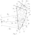
- FIG. 3is a two dimensional schematic view of a single display channel in a tiled head-mounted display system according to the present invention with a mechanical tiling method
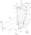
- FIG. 4is a two dimensional schematic view of a single display channel in a tiled head-mounted display system according to the present invention with an optical tiling method
- FIG. 5 ais a schematic view of a tiled head-mounted display system according to a first embodiment of the present invention
- FIG. 5 bis a schematic view illustrating field of view of the tiled head-mounted display system according to a first embodiment of the present invention
- FIG. 6 ais a schematic view of a tiled head-mounted display system according to a second embodiment of the present invention
- FIG. 6 bis a schematic view illustrating field of view of the tiled head-mounted display system according to a second embodiment of the present invention
- FIG. 7 ais a schematic view of a tiled head-mounted display system according to a third embodiment of the present invention
- FIG. 7 bis a schematic view illustrating field of view of the tiled head-mounted display system according to a third embodiment of the present invention
- FIG. 8 ais a schematic view of a tiled head-mounted display system according to a fourth embodiment of the present invention
- FIG. 8 bis a schematic view illustrating field of view of the tiled head-mounted display system according to a fourth embodiment of the present invention
- FIG. 9 ais a schematic view of a tiled head-mounted display system according to a fifth embodiment of the present invention
- FIG. 9 bis a schematic view illustrating field of view of the tiled head-mounted display system according to a fifth embodiment of the present invention
- FIG. 10 ais a schematic view of a tiled head-mounted display system according to a sixth embodiment of the present invention
- FIG. 10 bis a schematic view illustrating field of view of the tiled head-mounted display system according to a sixth embodiment of the present invention
- FIG. 11 ais a schematic view of a tiled head-mounted display system according to a seventh embodiment of the present invention
- FIG. 11 bis a schematic view illustrating field of view of the tiled head-mounted display system according to a seventh embodiment of the present invention
- FIG. 12is a two dimensional schematic view of one display channel in a tiled head-mounted display system for augmented environment according to the present invention.
- FIG. 13 a and FIG. 13 bare two-dimensional schematic view and three-dimensional schematic view of a tiled head-mounted display system for augmented environment according to the present invention.
- FIG. 14is a schematic view showing the tiled head-mounted display system for augmented environment according to the present invention worn by a user.
- FIG. 2 a and FIG. 2 bare two-dimensional schematic view and three-dimensional schematic view of one display channel in a tiled head-mounted display system according to the present invention.
- the coordinate systemis defined as: global coordinate origin O is exit pupil center; Z-axis is in a direction along the viewing axis of user's eye; Y-axis is perpendicular to Z-axis and extends right above the eye; X-axis is perpendicular to both Y-axis and Z-axis, constituting a Cartesian coordinate.
- One display channel of a tiled head-mounted display device according to the present inventioncan comprise a prism with three free-form optical surfaces and a micro-display.
- the prismcomprises a first optical surface 2 , a second optical surface 3 and a third optical surface 4 in a counter-clockwise order relative to X-axis.
- the first optical surface 2 and the second optical surface 3are free-form surfaces, the third optical surface 4 may be selected from free-form, spherical or non-spherical surface.
- the first optical surface 2can be a concave transmissive surface on the user side, for example.
- the second optical surface 3can be a concave reflective surface or semi-transmissive and semi-reflective surface on the user side for magnifying image, for example.
- the third optical surface 4can be a concave transmissive surface on the user's side.
- the light path in the head-mounted display device according to the inventionstarts from the micro-display 6 .
- the lights emitted by the micro-display 6such as a LCD enter into the prism through the third optical surface 4 , and then are subject to total reflection on the inner side of the first optical surface 2 , then reflected by the second optical surface 3 and finally enter into user's eye through the first optical surface 2 .
- the free-form surface equation of the first optical surface 2 , the second optical surface 3 and the third optical surface 4may follow (but are not limited to) any one of conditions (1) to (5).
- zis the sag of the free-form surface measured along the z-axis of a local x, y, z coordinate system
- cis radius of curvature of surface
- C jis polynomial coefficients
- mis an even number in the present invention
- zcx 2 1 + [ 1 - ( 1 + k ) ⁇ c 2 ⁇ x 2 ] 1 / 2 + A ⁇ x 4 + B ⁇ x 6 + C ⁇ x 8 + D ⁇ x 1 ⁇ 0 ( 5 )
- zis the sag of the free-form surface measured along the z-axis of a local x, y, z coordinate system
- cis the radius of curvature
- kis conic coefficient
- A, B, C, Dare aspheric coefficients of 4, 6, 8 and 10 orders, respectively.
- the tiled head-mounted display deviceincludes a number of display channels each comprising the prism with free-form surface described above and a corresponding micro-display.
- the display channelsare tiled so that the overall field of view of the tiled device can be substantially a summation of individual field of view of each display channel and the center of exit pupil of each display channel in the tiled device is coincident with each other.
- Tiling methods of the tiled head-mounted displays according to the present inventioncan be categorized as mechanical tiling methods and optical tiling methods.
- FIG. 3is a two dimensional schematic view of a single display channel in a tiled head-mounted display system according to the present invention with a mechanical tiling method.
- FIG. 4is a two dimensional schematic view of a single display channel in a tiled head-mounted display system according to the present invention with an optical tiling method.
- the tiling methodscomprise cementing the prisms with free-form surfaces of display channels by methods such as adhering, gluing, bonding and welding or integrating the prisms by injection molding.
- the first optical surface 2 , the second optical surface 3 and the third optical surface 4 of each prism 101may satisfy following conditions (6)-(8):
- the prism 101must also satisfy following conditions regarding incident angles of R u on the first optical surface 2 :
- ⁇ mi1is an incident angle of R u emitted from the displays first striking the first optical surface 2
- ⁇ mi2is an incident angle of R u striking the first optical surface 2 at the second time
- nis a refractive index of prism material.
- Mechanical tiling methodscan include a first mechanical tiling method and a second mechanical tiling method.
- first mechanical tiling methodbottom surfaces 12 of two prisms are subject to mechanical processing such as cutting and polishing and then cemented together.
- the bottom surface 12 indicated by dotted linesis positioned between the first optical surface 2 and the second optical surface 3 .
- second mechanical tiling methodside surfaces of two prisms, for example, side surfaces 22 and 23 in FIG. 2 a are subject to mechanical processing such as cutting and polishing and then cemented together. The side surface may intersect with all of the first optical surface 2 , the second optical surface 3 and the third optical surface 4 of prism.
- the first optical surface 2 , the second optical surface 3 and the third optical surface 4 of each prism 102may satisfy following conditions (10)-(12): 18 ⁇ Z Pd ⁇ 28 (10) 1.5 ⁇ Z Pd′ ⁇ Z Pd ⁇ 3 (11) Z Pc ⁇ the eye clearance distance, i.e., 15 (12) where, P c is an intersection point of R u with the first optical surface 2 upon total reflection, P d is an intersection point of chief ray R c in horizontal field of view and the first optical surface 2 , P d is an intersection point of R c with the second optical surface 3 .
- optical tiling methodscan also comprise a first optical tiling method and a second optical tiling method.
- first optical tiling methodthe bottom surfaces 11 of both prisms in two display channels to be tiled can be directly cemented together or the two prisms can be formed integrally by injection molding, the bottom surface 11 of the prism is positioned between the first optical surface 2 and the second optical surface 3 ;
- second optical tiling methodthe side surface of the respective prisms 11 such as side surfaces 23 can be directly cemented or the two prisms can be formed integrally by injection molding. The side surface intersects with the first optical surface, the second optical surface and the third optical surface of the prism.
- the tiled head-mounted display formed by the mechanical tiling methodshas a smaller exit pupil diameter and eye clearance compared with the tiled head-mounted displays formed by the optical tiling methods.
- the tiled head-mounted displays formed by the optical tiling methodsit is not necessary to correct trapezoidal distortions due to positional change and the user will not see discontinuous images even if his/her eyeballs are moving. In some cases, user might see stitches between different display channels in the field of view in the tiled head-mounted display formed by the mechanical tiling methods while the tiled head-mounted display formed by the optical tiling methods does not suffer from this problem.
- FIG. 5 ais a schematic view of a tiled head-mounted display system according to a first embodiment of the present invention
- FIG. 5 bis a schematic view illustrating field of view of the tiled head-mounted display system according to a first embodiment of the present invention.
- a head-mounted display devicecan comprise a first display channel 501 and a second display channel 502 tiled by the first mechanical tiling method as described above.
- the first display channel 501is rotated by a first angle in YOZ plane about X-axis of a global coordinate system.
- the second display channel 502is rotated by ⁇ 180° about Z axis which is in a direction along viewing axis of a human eye, and then rotated by the first angle in the opposite direction about X-axis of the global coordinate system.
- the tiled head-mounted display according to the first embodiment of the present inventionhas a horizontal field of view of at least 50° and a vertical field of view of at least 40°.
- FIG. 6 ais a schematic view of a tiled head-mounted display system according to a second embodiment of the present invention
- FIG. 6 bis a schematic view illustrating field of view of the tiled head-mounted display system according to a second embodiment of the present invention.
- a head-mounted display devicecan comprise a first display channel 601 and a second display channel 602 tiled by the second mechanical tiling method as described above.
- the first display channel 601is rotated by a second angle in XOZ plane about Y-axis of a global coordinate system.
- the second display channel 602is rotated by the second angle in the opposite direction about Y-axis of the global coordinate system.
- the tiled head-mounted display according to the second embodiment of the present inventionhas a horizontal field of view of at least 70° and a vertical field of view of at least 30°.
- FIG. 7 ais a schematic view of a tiled head-mounted display system according to a third embodiment of the present invention
- FIG. 7 bis a schematic view illustrating field of view of the tiled head-mounted display system according to a third embodiment of the present invention.
- a head-mounted display devicecan comprise a first display channel 701 , a second display channel 702 and a third display channel 703 rotated by a predetermined angle about Y-axis of a global coordinate system.
- the second display channel 702is tiled with the first display channel 701 and the third display channel 703 using the second mechanical tiling method, respectively.
- the tiled head-mounted display according to the third embodiment of the present inventionhas a horizontal field of view of at least 100° and a vertical field of view of at least 30°.
- FIG. 8 ais a schematic view of a tiled head-mounted display system according to a fourth embodiment of the present invention
- FIG. 8 bis a schematic view illustrating field of view of the tiled head-mounted display system according to a fourth embodiment of the present invention.
- a head-mounted display devicecan comprise a first display channel 801 , a second display channel 802 , a third display channel 803 and a fourth display channel 804 rotated by a predetermined angle about Y-axis of a global coordinate system.
- the second display channel 802is tiled with the first display channel 801 and the third display channel 803 using the second mechanical tiling method, respectively.
- the third display channel 803is tiled with the second display channel 802 and the fourth display channel 804 using the second mechanical tiling method, respectively.
- the tiled head-mounted display according to the fourth embodiment of the present inventionhas a horizontal field of view of at least 120° and a vertical field of view of at least 30°.
- FIG. 9 ais a schematic view of a tiled head-mounted display system according to a fifth embodiment of the present invention
- FIG. 9 bis a schematic view illustrating field of view of the tiled head-mounted display system according to a fifth embodiment of the present invention.
- a head-mounted display devicecan comprise a first display channel 901 , a second display channel 902 , a third display channel 903 and a fourth display channel 904 .
- the first display channel 901 and the third display channel 903are rotated by a second angle in XOZ plane about Y-axis of a global coordinate system.
- the second display channel 902 and the fourth display channel 904are rotated by the second angle in the opposite direction about Y-axis of the global coordinate system.
- the first display channel 901 and the second display channel 902are tiled with the second mechanical tiling method.
- the third display channel 903 and the fourth display channel 904are tiled with the second mechanical tiling method.
- the first display channel 901 and the third display channel 903are tiled with the first mechanical tiling method.
- the second display channel 902 and the fourth display channel 904are tiled with the first mechanical tiling method.
- the tiled head-mounted display according to the fifth embodiment of the present inventionhas a horizontal field of view of at least 70° and a vertical field of view of at least 50°.
- FIG. 10 ais a schematic view of a tiled head-mounted display system according to a sixth embodiment of the present invention
- FIG. 10 bis a schematic view illustrating field of view of the tiled head-mounted display system according to a sixth embodiment of the present invention.
- a head-mounted display devicecan comprise a first display channel 1001 , a second display channel 1002 , a third display channel 1003 , a fourth display channel 1004 , a fifth display channel 1005 and a sixth display channel 1006 .
- the first display channel 1001 , the second display channel 1002 and the third display channel 1003are rotated by a predetermined angle about Y-axis of a global coordinate system.
- the fourth display channel 1004 , the fifth display channel 1005 and the sixth display channel 1006are rotated by a predetermined angle about Y-axis of a global coordinate system.
- the second display channel 1002is tiled with the first display channel 1001 and the third display channel 1003 using the second mechanical tiling method respectively.
- the fifth display channel 1005is tiled with the fourth display channel 1004 and the sixth display channel 1006 using the second mechanical tiling method respectively.
- the first display channel 1001 and the fourth display channel 1004are tiled with the first mechanical tiling method.
- the second display channel 1002 and the fifth display channel 1005are tiled with the first mechanical tiling method.
- the third display channel 1003 and the sixth display channel 1006are tiled with the first mechanical tiling method.
- the tiled head-mounted display according to the sixth embodiment of the present inventionhas a horizontal field of view of at least 100° and a vertical field of view of at least 50°.
- FIG. 11 ais a schematic view of a tiled head-mounted display system according to a seventh embodiment of the present invention
- FIG. 11 bis a schematic view illustrating field of view of the tiled head-mounted display system according to a seventh embodiment of the present invention.
- a head-mounted display devicecan comprise a first display channel 1101 , a second display channel 1102 , a third display channel 1103 , a fourth display channel 1104 , a fifth display channel 1105 , a sixth display channel 1106 , a seventh display channel 1107 and an eighth display channel 1108 .
- the first display channel 1101 , the second display channel 1102 , the third display channel 1103 and the fourth display channel 1104are rotated by a predetermined angle about Y-axis of a global coordinate system.
- the fifth display channel 1105 , the sixth display channel 1106 , the seventh display channel 1107 and the eighth display channel 1108are rotated by a predetermined angle about Y-axis of a global coordinate system.
- the second display channel 1102is tiled with the first display channel 1101 and the third display channel 1103 using the second mechanical tiling method respectively.
- the third display channel 1103is tiled with the second display channel 1102 and the fourth display channel 1104 using the second mechanical tiling method respectively.
- the sixth display channel 1106is tiled with the fifth display channel 1105 and the seventh display channel 1107 using the second mechanical tiling method respectively.
- the seventh display channel 1107is tiled with the six display channel 1106 and the eighth display channel 1108 using the second mechanical tiling method respectively.
- the first display channel 1101 and the fifth display channel 1005are tiled with the first mechanical tiling method.
- the second display channel 1102 and the sixth display channel 1106are tiled with the first mechanical tiling method.
- the third display channel 1103 and the seventh display channel 1107are tiled with the first mechanical tiling method.
- the fourth display channel 1104 and the eighth display channel 1108are tiled with the first mechanical tiling method.
- the tiled head-mounted display according to the seventh embodiment of the present inventionhas a horizontal field of view of at least 120° and a vertical field of view of at least 50°.
- a tiled head-mounted display systemcan comprise a first display channel and a second display channel tiled by the first optical tiling method as described above, which is similar to the illustration of FIG. 5 a in structure.
- the first display channelis rotated by a first angle in YOZ plane about X-axis of a global coordinate system.
- the second display channelis rotated by ⁇ 180° about Z axis and then rotated by the first angle in the opposite direction about X-axis of the global coordinate system.
- the tiled head-mounted display according to the eighth embodiment of the present inventionhas a horizontal field of view of at least 50° and a vertical field of view of at least 40°.
- a tiled head-mounted display systemcan comprise a first display channel and a second display channel tiled by the second optical tiling method as described above, which is similar to the illustration of FIG. 6 a in structure.
- the first display channelis rotated by a second angle in XOZ plane about Y-axis of a global coordinate system.
- the second display channelis rotated by the second angle in the opposite direction about Y-axis of the global coordinate system.
- the tiled head-mounted display according to the ninth embodiment of the present inventionhas a horizontal field of view of at least 70° and a vertical field of view of at least 30°.
- a tiled head-mounted display systemcan comprise a first display channel, a second display channel, a third display channel and a fourth display channel, which is similar to the illustration of FIG. 9 a in structure.
- the first display channel and the third display channelare rotated by a second angle in XOZ plane about Y-axis of a global coordinate system.
- the second display channel and the fourth display channelare rotated by the second angle in the opposite direction about Y-axis of the global coordinate system.
- the first display channel and the second display channel 902are tiled with the second optical tiling method.
- the third display channel 903 and the fourth display channel 904are tiled with the second optical tiling method.
- the first display channel 901 and the third display channel 903are tiled with the first optical tiling method.
- the second display channel 902 and the fourth display channel 904are tiled with the first optical tiling method.
- the tiled head-mounted display according to the tenth embodiment of the present inventionhas a horizontal field of view of at least 70° and a vertical field of view of at least 50°.
- tiled head-mounted display devicesif the second optical surface 3 of the prism in each display channel is coated with a reflective film to be formed as a reflective surface, the tiled head-mounted display devices can be mainly used for virtual environment application. If the second optical surface 3 of the prism in each display channel can be coated with a transflective film to be formed as a semi-transmissive and semi-reflective surface, an head-mounted display device for augmented environment application can be formed by adding an auxiliary lens with free-form surfaces in the display device, so that the lens and the prisms can constitute a focus-free system and allow user to see through the display device to observe outside real world.
- FIG. 12is a two dimensional schematic view of one display channel in a tiled head-mounted display system for augmented environment according to the present invention. Therefore the embodiments as discussed above can be used for augmented environment by adding an auxiliary lens with free-form surfaces.
- FIG. 13 a and FIG. 13 bare two-dimensional schematic view and three-dimensional schematic view of a tiled head-mounted display system for augmented environment according to the present invention.
- the tiled head-mounted display devicecan comprise display channels each comprising a prism 1301 with free-form surfaces, a micro-display device 1302 and a lens 1303 with free-form surfaces 1304 .
- the display channelscan be tiled by the first mechanical tiling method, thus a part of prism 1301 and a part of lens 1303 are removed during tiling.
- FIG. 14is a schematic view showing the tiled head-mounted display system for augmented environment according to the present invention worn by a user.
- the tiled head-mounted display system for augmented environment according to the present inventioncan be used as a single ocular system for just one eye. Alternatively, it could also be used as a binocular head-mounted display system for both eyes.
- the optical tiled head-mounted display deviceis compact and lightweight, and the exit pupil planes of all display channels are coincident, thus avoiding pupil aberration and keeping pupil diameter and eye clearance constant. Furthermore, there is no resolution variation in the field of view, thus preventing additional distortion.
- the tiled head-mounted display device according to the present inventioncan be readily applicable to augmented reality. In comparison, for a conventional head-mounted display device to be used in augmented reality, it is necessary to introduce a semi-reflective semi-transmissive mirror into the device to fold optical path in order to achieve optical transmission, thus requiring a complex and bulky structure.
- the surfaces of the prisms according to the present invention for optical tilingcan be formed continuous together as larger optical surfaces, they can be fabricated in one time and thus it does not require additional processing for the tiling surface.
- all optical surfaces of the prisms of the display channels in the head-mounted display devicecan be formed integrally, thus reducing difficulty and complexity of the tiling process.
Landscapes
- Physics & Mathematics (AREA)
- General Physics & Mathematics (AREA)
- Optics & Photonics (AREA)
- Lenses (AREA)
Abstract
Description
where z is the sag of the free-form surface measured along the z-axis of a local x, y, z coordinate system, cxis radius of curvature in the x direction in the xz-plane, cyis radius of curvature in the y direction in the yz-plane, kxis conic coefficient in x direction, kyis conic coefficient in y direction, Aiare aspherical coefficients of 4, 6, 8, 10, . . . 2n orders, Piare non-rotational symmetry coefficient of 4, 6, 8, 10, . . . 2n orders, and the surface has rotational symmetry about z-axis.
where z is the sag of the free-form surface measured along the z-axis of a local x, y, z coordinate system, c is radius of curvature of surface, Cjis polynomial coefficients, k is conic coefficient, m is an even number;
where z is the sag of the free-form surface measured along the z-axis of a local x, y, z coordinate system, c is radius of curvature of surface, k is conic coefficient, Zjis Zernike polynomial, Cj+1is coefficients for Zj;
where z is the sag of the free-form surface measured along the z-axis of a local x, y, z coordinate system, c is the vertex curvature, k is the conic constant, cxis radius of curvature of surface in sagittal direction, cyis radius of curvature of surface in tangential direction, and Cjis the coefficient for x2myn.
where z is the sag of the free-form surface measured along the z-axis of a local x, y, z coordinate system, c is radius of curvature, k is conic coefficient, A, B, C, D are aspheric coefficients of 4, 6, 8 and 10 orders, respectively.
where Ruis the top marginal ray of the maximum field of view in positive Y direction, Rbis the light ray at lower boundary of the maximum field of view in negative Y direction; Pais an intersection point at which Rbis transmitted through the first optical surface, Pa′ is an intersection point of Rbwith the second optical surface and Pa″ is an intersection point of Rbwith the first optical surface upon total reflection; Pbis an intersection point of Ruwith the second optical surface (3), Pb′ is an intersection point of Rbwith the third optical surface; Pcis an intersection point at which Ruis reflected on the first optical surface, Pc′ is an intersection point of Ruwith the third optical surface, Y, Z are coordinates of each point in global coordinate system, respectively,
where θmi1is an incident angle of Ruemitted from the displays first striking the first optical surface (2), and θmi2is an incident angle of Rustriking the first optical surface (2) at the second time, n is a refractive index of prism material,
18≤ZPd≤28 (10)
1.5ZPd′−ZPd≤4 (11)
ZPc≥the eye clearance distance, i.e., 15 (12)
where, Pcis the intersection point of Ruwith the first optical surface upon total reflection, Pdis the intersection point of chief ray Rcin horizontal field of view with the first optical surface, Pdis the intersection point of Rcwith the second optical surface.
where z is the sag of the free-form surface measured along the z-axis of a local x, y, z coordinate system, cxis radius of curvature in the x direction in the xz-plane, cyis radius of curvature in the y direction in the yz-plane, kxis conic coefficient in x direction, kyis conic coefficient in y direction, Aiare aspherical coefficients of 4, 6, 8, 10, . . . 2n orders, Piare non-rotational symmetry coefficient of 4, 6, 8, 10, . . . 2n orders, and the surface has rotational symmetry about z-axis;
where z is the sag of the free-form surface measured along the z-axis of a local x, y, z coordinate system, c is radius of curvature of surface, Cjis polynomial coefficients, m is an even number in the present invention;
where z is the sag of the free-form surface measured along the z-axis of a local x, y, z coordinate system, c is radius of curvature of surface, k is conic coefficient, Zjis Zernike polynomial, Cj+1is coefficients for Zj;
where z is the sag of the free-form surface measured along the z-axis of a local x, y, z coordinate system, c is the vertex curvature, k is the conic constant, cxis radius of curvature of surface in sagittal direction, cyis radius of curvature of surface in tangential direction, and Cjis the coefficient for x2myn.
where z is the sag of the free-form surface measured along the z-axis of a local x, y, z coordinate system, c is the radius of curvature, k is conic coefficient, A, B, C, D are aspheric coefficients of 4, 6, 8 and 10 orders, respectively.
where Ruis the top marginal ray of the maximum field of view in positive Y direction, Rbis the light ray at lower boundary of the maximum field of view in negative Y direction; Pais an intersection point at which Rbis transmitted through the first
where θmi1is an incident angle of Ruemitted from the displays first striking the first
18≤ZPd≤28 (10)
1.5≤ZPd′−ZPd≤3 (11)
ZPc≥the eye clearance distance, i.e., 15 (12)
where, Pcis an intersection point of Ruwith the first
Claims (8)
Priority Applications (1)
| Application Number | Priority Date | Filing Date | Title |
|---|---|---|---|
| US18/123,503US12204109B2 (en) | 2010-04-30 | 2023-03-20 | Wide angle and high resolution tiled head-mounted display device |
Applications Claiming Priority (6)
| Application Number | Priority Date | Filing Date | Title |
|---|---|---|---|
| PCT/CN2010/072376WO2011134169A1 (en) | 2010-04-30 | 2010-04-30 | Wide angle and high resolution tiled head-mounted display device |
| US201313695069A | 2013-04-02 | 2013-04-02 | |
| US14/953,563US10281723B2 (en) | 2010-04-30 | 2015-11-30 | Wide angle and high resolution tiled head-mounted display device |
| US16/366,204US10809533B2 (en) | 2010-04-30 | 2019-03-27 | Wide angle and high resolution tiled head-mounted display device |
| US17/065,788US11609430B2 (en) | 2010-04-30 | 2020-10-08 | Wide angle and high resolution tiled head-mounted display device |
| US18/123,503US12204109B2 (en) | 2010-04-30 | 2023-03-20 | Wide angle and high resolution tiled head-mounted display device |
Related Parent Applications (1)
| Application Number | Title | Priority Date | Filing Date |
|---|---|---|---|
| US17/065,788ContinuationUS11609430B2 (en) | 2010-04-30 | 2020-10-08 | Wide angle and high resolution tiled head-mounted display device |
Publications (2)
| Publication Number | Publication Date |
|---|---|
| US20230333387A1 US20230333387A1 (en) | 2023-10-19 |
| US12204109B2true US12204109B2 (en) | 2025-01-21 |
Family
ID=44860782
Family Applications (5)
| Application Number | Title | Priority Date | Filing Date |
|---|---|---|---|
| US13/695,069Active2031-03-18US9244277B2 (en) | 2010-04-30 | 2010-04-30 | Wide angle and high resolution tiled head-mounted display device |
| US14/953,563Active2031-02-08US10281723B2 (en) | 2010-04-30 | 2015-11-30 | Wide angle and high resolution tiled head-mounted display device |
| US16/366,204ActiveUS10809533B2 (en) | 2010-04-30 | 2019-03-27 | Wide angle and high resolution tiled head-mounted display device |
| US17/065,788ActiveUS11609430B2 (en) | 2010-04-30 | 2020-10-08 | Wide angle and high resolution tiled head-mounted display device |
| US18/123,503ActiveUS12204109B2 (en) | 2010-04-30 | 2023-03-20 | Wide angle and high resolution tiled head-mounted display device |
Family Applications Before (4)
| Application Number | Title | Priority Date | Filing Date |
|---|---|---|---|
| US13/695,069Active2031-03-18US9244277B2 (en) | 2010-04-30 | 2010-04-30 | Wide angle and high resolution tiled head-mounted display device |
| US14/953,563Active2031-02-08US10281723B2 (en) | 2010-04-30 | 2015-11-30 | Wide angle and high resolution tiled head-mounted display device |
| US16/366,204ActiveUS10809533B2 (en) | 2010-04-30 | 2019-03-27 | Wide angle and high resolution tiled head-mounted display device |
| US17/065,788ActiveUS11609430B2 (en) | 2010-04-30 | 2020-10-08 | Wide angle and high resolution tiled head-mounted display device |
Country Status (4)
| Country | Link |
|---|---|
| US (5) | US9244277B2 (en) |
| EP (1) | EP2564259B1 (en) |
| CN (1) | CN102782562B (en) |
| WO (1) | WO2011134169A1 (en) |
Families Citing this family (106)
| Publication number | Priority date | Publication date | Assignee | Title |
|---|---|---|---|---|
| GB2468997A (en) | 2008-01-22 | 2010-09-29 | Univ Arizona State | Head-mounted projection display using reflective microdisplays |
| WO2010123934A1 (en) | 2009-04-20 | 2010-10-28 | The Arizona Board Of Regents On Behalf Of The University Of Arizona | Optical see-through free-form head-mounted display |
| US20110075257A1 (en) | 2009-09-14 | 2011-03-31 | The Arizona Board Of Regents On Behalf Of The University Of Arizona | 3-Dimensional electro-optical see-through displays |
| EP2564259B1 (en) | 2010-04-30 | 2015-01-21 | Beijing Institute Of Technology | Wide angle and high resolution tiled head-mounted display device |
| US10156722B2 (en)* | 2010-12-24 | 2018-12-18 | Magic Leap, Inc. | Methods and systems for displaying stereoscopy with a freeform optical system with addressable focus for virtual and augmented reality |
| FR2982376B1 (en)* | 2011-11-07 | 2014-01-03 | Laster | PORTABLE DEVICE OF INCREASED VISION. |
| NZ627582A (en) | 2012-01-24 | 2016-11-25 | Univ Arizona State | Compact eye-tracked head-mounted display |
| CN103207454B (en)* | 2012-09-17 | 2016-09-07 | 北京理工大学 | There is the double-view field free curved surface prism helmet display optical system at extension edge |
| DE102012216581A1 (en)* | 2012-09-17 | 2014-02-27 | Carl Zeiss Ag | Display device e.g. look-around display device, for displaying formed image with eye, has imaging element including positively refracting power and optical dispersion that are larger than another optical dispersion of imaging optics |
| CN110022472B (en) | 2012-10-18 | 2022-07-26 | 亚利桑那大学评议会 | Stereoscopic display with addressable focus cues |
| US8937771B2 (en)* | 2012-12-12 | 2015-01-20 | Microsoft Corporation | Three piece prism eye-piece |
| JP6165174B2 (en)* | 2012-12-28 | 2017-07-19 | オリンパス株式会社 | Head-mounted display device |
| US9915826B2 (en) | 2013-11-27 | 2018-03-13 | Magic Leap, Inc. | Virtual and augmented reality systems and methods having improved diffractive grating structures |
| US9857591B2 (en) | 2014-05-30 | 2018-01-02 | Magic Leap, Inc. | Methods and system for creating focal planes in virtual and augmented reality |
| JP6269046B2 (en)* | 2013-12-26 | 2018-01-31 | セイコーエプソン株式会社 | Virtual image display device |
| EP4099274B1 (en) | 2014-01-31 | 2024-03-06 | Magic Leap, Inc. | Multi-focal display system and method |
| CN110376743B (en) | 2014-01-31 | 2022-03-04 | 奇跃公司 | Multi-focus display system and method |
| US9086569B1 (en) | 2014-02-05 | 2015-07-21 | Google Inc. | Head mounted display with color correcting doublet eyepiece |
| KR20150094891A (en)* | 2014-02-11 | 2015-08-20 | (주)그린광학 | Optical system for Head Mount Display |
| CA2941655C (en) | 2014-03-05 | 2021-03-09 | Arizona Board Of Regents On Behalf Of The University Of Arizona | Wearable 3d augmented reality display with variable focus and/or object recognition |
| CN203811978U (en)* | 2014-05-15 | 2014-09-03 | 广景科技有限公司 | DLP miniature projector |
| AU2015266670B2 (en)* | 2014-05-30 | 2019-05-09 | Magic Leap, Inc. | Methods and systems for displaying stereoscopy with a freeform optical system with addressable focus for virtual and augmented reality |
| EP3149528B1 (en) | 2014-05-30 | 2023-06-07 | Magic Leap, Inc. | Methods and system for creating focal planes in virtual and augmented reality |
| CN104253989B (en)* | 2014-06-09 | 2018-05-18 | 黄石 | Full multi-view image display device |
| KR102627249B1 (en)* | 2015-01-21 | 2024-01-18 | 테세랜드 엘엘씨 | Display with total internal reflection |
| IL310369A (en) | 2015-01-26 | 2024-03-01 | Magic Leap Inc | Virtual and augmented reality systems and methods with improved diffractive lattice structures |
| US10176961B2 (en) | 2015-02-09 | 2019-01-08 | The Arizona Board Of Regents On Behalf Of The University Of Arizona | Small portable night vision system |
| CN104932105A (en)* | 2015-06-24 | 2015-09-23 | 北京理工大学 | Splicing type head-mounted display device |
| JP6373232B2 (en)* | 2015-07-23 | 2018-08-15 | キヤノン株式会社 | Image display device |
| US9989765B2 (en) | 2015-08-03 | 2018-06-05 | Oculus Vr, Llc | Tile array for near-ocular display |
| US10552676B2 (en) | 2015-08-03 | 2020-02-04 | Facebook Technologies, Llc | Methods and devices for eye tracking based on depth sensing |
| US10459305B2 (en) | 2015-08-03 | 2019-10-29 | Facebook Technologies, Llc | Time-domain adjustment of phase retardation in a liquid crystal grating for a color display |
| US10297180B2 (en) | 2015-08-03 | 2019-05-21 | Facebook Technologies, Llc | Compensation of chromatic dispersion in a tunable beam steering device for improved display |
| US10338451B2 (en) | 2015-08-03 | 2019-07-02 | Facebook Technologies, Llc | Devices and methods for removing zeroth order leakage in beam steering devices |
| CN105137600A (en)* | 2015-09-02 | 2015-12-09 | 胡东海 | Virtual reality helmet and visual sense compensation method |
| US11609427B2 (en) | 2015-10-16 | 2023-03-21 | Ostendo Technologies, Inc. | Dual-mode augmented/virtual reality (AR/VR) near-eye wearable displays |
| US10247858B2 (en) | 2015-10-25 | 2019-04-02 | Facebook Technologies, Llc | Liquid crystal half-wave plate lens |
| US10416454B2 (en) | 2015-10-25 | 2019-09-17 | Facebook Technologies, Llc | Combination prism array for focusing light |
| US11106273B2 (en) | 2015-10-30 | 2021-08-31 | Ostendo Technologies, Inc. | System and methods for on-body gestural interfaces and projection displays |
| CN105334628B (en)* | 2015-11-21 | 2017-06-23 | 胡东海 | Virtual implementing helmet |
| CN105334608B (en)* | 2015-12-05 | 2018-06-26 | 中国航空工业集团公司洛阳电光设备研究所 | A kind of prism optical system |
| CN106855655B (en)* | 2015-12-08 | 2020-01-03 | 铭异科技股份有限公司 | Asymmetric curved prism image display optical system |
| US10345594B2 (en) | 2015-12-18 | 2019-07-09 | Ostendo Technologies, Inc. | Systems and methods for augmented near-eye wearable displays |
| US10203566B2 (en) | 2015-12-21 | 2019-02-12 | Facebook Technologies, Llc | Enhanced spatial resolution using a segmented electrode array |
| US10578882B2 (en) | 2015-12-28 | 2020-03-03 | Ostendo Technologies, Inc. | Non-telecentric emissive micro-pixel array light modulators and methods of fabrication thereof |
| WO2017127494A1 (en) | 2016-01-22 | 2017-07-27 | Corning Incorporated | Wide field personal display |
| US10353203B2 (en) | 2016-04-05 | 2019-07-16 | Ostendo Technologies, Inc. | Augmented/virtual reality near-eye displays with edge imaging lens comprising a plurality of display devices |
| US11067797B2 (en) | 2016-04-07 | 2021-07-20 | Magic Leap, Inc. | Systems and methods for augmented reality |
| US10453431B2 (en) | 2016-04-28 | 2019-10-22 | Ostendo Technologies, Inc. | Integrated near-far light field display systems |
| US10522106B2 (en) | 2016-05-05 | 2019-12-31 | Ostendo Technologies, Inc. | Methods and apparatus for active transparency modulation |
| CN106019586A (en)* | 2016-06-02 | 2016-10-12 | 上海理鑫光学科技有限公司 | Double optical waveguide sheet-type augment reality eyeglass |
| US10353202B2 (en)* | 2016-06-09 | 2019-07-16 | Microsoft Technology Licensing, Llc | Wrapped waveguide with large field of view |
| CN106019595B (en)* | 2016-07-27 | 2019-10-11 | 上海渺视光学科技有限公司 | A kind of big visual field augmented reality optical system of big emergent pupil |
| WO2018052590A2 (en) | 2016-08-12 | 2018-03-22 | Arizona Board Of Regents On Behalf Of The University Of Arizona | High-resolution freeform eyepiece design with a large exit pupil |
| US10261328B2 (en) | 2016-09-02 | 2019-04-16 | Microsoft Technology Licensing, Llc | Enhanced illumination system |
| CN106483660B (en)* | 2016-11-25 | 2019-10-25 | 北京理工大学 | A large field of view holographic waveguide near-eye display system |
| CN114325903B (en)* | 2016-12-08 | 2024-11-05 | 北京耐德佳显示技术有限公司 | A free-form surface prism assembly and a near-eye display device using the same |
| CN108738358B (en) | 2017-02-22 | 2021-03-26 | 鲁姆斯有限公司 | Light guide optics |
| JP7182796B2 (en) | 2017-03-09 | 2022-12-05 | アリゾナ ボード オブ リージェンツ オン ビハーフ オブ ザ ユニバーシティ オブ アリゾナ | Head-mounted Lightfield Display Using Integral Imaging and Waveguide Prisms |
| US12078802B2 (en) | 2017-03-09 | 2024-09-03 | Arizona Board Of Regents On Behalf Of The University Of Arizona | Head-mounted light field display with integral imaging and relay optics |
| CN107302694B (en)* | 2017-05-22 | 2019-01-18 | 歌尔科技有限公司 | Method, equipment and the virtual reality device of scene are presented by virtual reality device |
| DE102017111607B4 (en) | 2017-05-29 | 2020-09-24 | tooz technologies GmbH | Imaging device, data glasses and method for generating an image from an initial image in data glasses |
| US11388389B2 (en)* | 2017-06-22 | 2022-07-12 | Tesseland, Llc | Visual display with time multiplexing for stereoscopic view |
| US10859834B2 (en) | 2017-07-03 | 2020-12-08 | Holovisions | Space-efficient optical structures for wide field-of-view augmented reality (AR) eyewear |
| US10338400B2 (en) | 2017-07-03 | 2019-07-02 | Holovisions LLC | Augmented reality eyewear with VAPE or wear technology |
| US12436394B2 (en) | 2017-07-03 | 2025-10-07 | Holovisions | Augmented reality (or mixed reality) eyewear with see-through optical elements having individually-adjustable opacity/reflectivity levels |
| US12013538B2 (en) | 2017-07-03 | 2024-06-18 | Holovisions LLC | Augmented reality (AR) eyewear with a section of a fresnel reflector comprising individually-adjustable transmissive-reflective optical elements |
| US12205231B2 (en) | 2017-07-03 | 2025-01-21 | Holovisions | Holovisions™—adjustable and/or modular augmented reality (AR) eyewear with a movable transflective mirror and different viewing modes |
| US10976551B2 (en) | 2017-08-30 | 2021-04-13 | Corning Incorporated | Wide field personal display device |
| CN107918208B (en)* | 2017-09-06 | 2023-10-03 | 塔普翊海(上海)智能科技有限公司 | Visual field spliced head-mounted display device |
| CN109782441A (en)* | 2017-11-14 | 2019-05-21 | 塔普翊海(上海)智能科技有限公司 | A kind of aobvious optical system of the see-through head of nearly eye |
| JP6922702B2 (en)* | 2017-12-06 | 2021-08-18 | 株式会社ニコン | Head mounted display |
| KR102704523B1 (en) | 2017-12-10 | 2024-09-06 | 루머스 리미티드 | Image projector |
| CN208367337U (en)* | 2018-01-16 | 2019-01-11 | 塔普翊海(上海)智能科技有限公司 | A kind of AR display equipment |
| JP7185331B2 (en) | 2018-03-22 | 2022-12-07 | アリゾナ ボード オブ リージェンツ オン ビハーフ オブ ザ ユニバーシティ オブ アリゾナ | How to render light field images for integral imaging light field displays |
| KR102752134B1 (en) | 2018-05-14 | 2025-01-08 | 루머스 리미티드 | Projector configuration with sub-optical aperture for near-eye display and corresponding optical system |
| IL278511B2 (en)* | 2018-05-17 | 2025-01-01 | Lumus Ltd | Near-eye display having overlapping projector assemblies |
| US11415812B2 (en) | 2018-06-26 | 2022-08-16 | Lumus Ltd. | Compact collimating optical device and system |
| CN112601993A (en) | 2018-08-26 | 2021-04-02 | 鲁姆斯有限公司 | Reflection suppression in near-eye displays |
| CN109270694A (en)* | 2018-12-03 | 2019-01-25 | 深圳市世尊科技有限公司 | A kind of intelligent glasses of achievable AR or VR or MR |
| US10725303B2 (en) | 2018-12-18 | 2020-07-28 | Sharp Kabushiki Kaisha | Wide angle display |
| US11175483B2 (en) | 2019-01-17 | 2021-11-16 | Sharp Kabushiki Kaisha | Wide field of view head mounted display |
| TWI800657B (en) | 2019-03-12 | 2023-05-01 | 以色列商魯姆斯有限公司 | Image projector |
| US12339450B2 (en) | 2019-03-29 | 2025-06-24 | Beijing Antvr Technology Co., Ltd. | Total reflection based compact near-eye display device with large field of view |
| CN110045503B (en) | 2019-03-29 | 2024-12-27 | 北京蚁视科技有限公司 | A compact, large-field-of-view near-eye display device based on total reflection |
| US10775626B1 (en)* | 2019-05-16 | 2020-09-15 | Rockwell Collins, Inc. | Wide field of view head worn display device |
| CA3137994A1 (en) | 2019-06-27 | 2020-12-30 | Lumus Ltd | Apparatus and methods for eye tracking based on eye imaging via a light-guide optical element |
| US11009766B2 (en)* | 2019-06-28 | 2021-05-18 | Intel Corporation | Foveated virtual reality near eye displays |
| CN110824710B (en)* | 2019-11-12 | 2022-04-19 | 塔普翊海(上海)智能科技有限公司 | Near-to-eye perspective head display optical system |
| US20230023263A1 (en)* | 2019-12-17 | 2023-01-26 | Reality Plus Ltd. | Multilens direct view near eye display |
| CN111308710B (en)* | 2020-02-28 | 2022-07-05 | 京东方科技集团股份有限公司 | Optical display device and head-mounted imaging device |
| WO2021220267A1 (en) | 2020-04-30 | 2021-11-04 | Lumus Ltd. | Optical sample characterization |
| CN111751915B (en)* | 2020-06-27 | 2021-05-11 | 同济大学 | A compact infrared viewfinder optical system based on free-form surface prism |
| CN112285935B (en)* | 2020-11-17 | 2022-06-14 | 京东方科技集团股份有限公司 | Display assembly and assembly method thereof, and wearable display device |
| WO2022133968A1 (en)* | 2020-12-25 | 2022-06-30 | 京东方科技集团股份有限公司 | Optical system and display device |
| KR102835526B1 (en)* | 2021-02-05 | 2025-07-18 | 삼성디스플레이 주식회사 | Display apparatus, head mounted display system having the same and method of driving the display apparatus |
| CN113189777B (en)* | 2021-04-25 | 2021-12-14 | 深圳市光舟半导体技术有限公司 | Binocular AR eyepiece vision correction system |
| KR102676604B1 (en) | 2021-07-04 | 2024-06-18 | 루머스 리미티드 | Display with stacked light guiding elements providing different parts of the field of view |
| CN116547584A (en) | 2021-11-23 | 2023-08-04 | 京东方科技集团股份有限公司 | Near-eye display device |
| US12124060B2 (en)* | 2021-12-28 | 2024-10-22 | Mloptic Corp. | Prism to enable large FOV high resolution sampling with smaller FOV imaging system |
| US20250155773A1 (en)* | 2022-01-24 | 2025-05-15 | Arizona Board Of Regents On Behalf Of The University Of Arizona | Real-time computer generated hologram (cgh) generation by compute unified device architecture (cuda)-open-gl for adaptive beam steering |
| US12366923B2 (en) | 2022-09-26 | 2025-07-22 | Pison Technology, Inc. | Systems and methods for gesture inference using ML model selection |
| US12366920B2 (en) | 2022-09-26 | 2025-07-22 | Pison Technology, Inc. | Systems and methods for gesture inference using transformations |
| US12340627B2 (en) | 2022-09-26 | 2025-06-24 | Pison Technology, Inc. | System and methods for gesture inference using computer vision |
| US20250046026A1 (en)* | 2023-08-04 | 2025-02-06 | Applied Materials, Inc. | Optical prism for augmented reality waveguide wrapping angle |
| CN120143453A (en)* | 2023-12-11 | 2025-06-13 | 北京极溯光学科技有限公司 | Display device and head mounted display device |
Citations (183)
| Publication number | Priority date | Publication date | Assignee | Title |
|---|---|---|---|---|
| US3493290A (en) | 1966-01-14 | 1970-02-03 | Mitre Corp | Three-dimensional display |
| US3632184A (en) | 1970-03-02 | 1972-01-04 | Bell Telephone Labor Inc | Three-dimensional display |
| US3992084A (en) | 1973-05-11 | 1976-11-16 | Nippon Kogaku K.K. | Zoom lens system also capable of ultra-closeup photography |
| US4468101A (en) | 1981-05-29 | 1984-08-28 | Marconi Avionics Limited | Night vision goggles |
| US4669810A (en) | 1984-02-03 | 1987-06-02 | Flight Dynamics, Inc. | Head up display system |
| US4753522A (en) | 1985-06-03 | 1988-06-28 | Ricoh Company, Ltd. | Plastic lens assembly for use in copying machines |
| US4863251A (en) | 1987-03-13 | 1989-09-05 | Xerox Corporation | Double gauss lens for a raster input scanner |
| JPH02200074A (en) | 1989-01-30 | 1990-08-08 | Nippon Hoso Kyokai <Nhk> | Solid-state image pickup device with image intensifier |
| EP0408344A2 (en) | 1989-07-14 | 1991-01-16 | Gec-Marconi Limited | Helmet systems |
| US5109469A (en) | 1990-11-01 | 1992-04-28 | Itt Corporation | Phosphor screen for correcting luminous non-uniformity and method for making same |
| US5172275A (en) | 1990-12-14 | 1992-12-15 | Eastman Kodak Company | Apochromatic relay lens systems suitable for use in a high definition telecine apparatus |
| US5172272A (en) | 1989-12-25 | 1992-12-15 | Olympus Optical Co., Ltd. | Imaging lens system |
| US5416315A (en) | 1994-01-24 | 1995-05-16 | Night Vision General Partnership | Visor-mounted night vision visor |
| US5436763A (en) | 1992-04-07 | 1995-07-25 | Hughes Aircraft Company | Wide spectral bandwidth virtual image display optical system |
| US5526183A (en) | 1993-11-29 | 1996-06-11 | Hughes Electronics | Helmet visor display employing reflective, refractive and diffractive optical elements |
| JPH08160345A (en) | 1994-12-05 | 1996-06-21 | Olympus Optical Co Ltd | Head mounted display device |
| US5572229A (en) | 1991-04-22 | 1996-11-05 | Evans & Sutherland Computer Corp. | Head-mounted projection display system featuring beam splitter and method of making same |
| US5621572A (en) | 1994-08-24 | 1997-04-15 | Fergason; James L. | Optical system for a head mounted display using a retro-reflector and method of displaying an image |
| US5625495A (en) | 1994-12-07 | 1997-04-29 | U.S. Precision Lens Inc. | Telecentric lens systems for forming an image of an object composed of pixels |
| JPH09218375A (en) | 1996-02-08 | 1997-08-19 | Canon Inc | Fatigue determination method and observation device using the same |
| JPH09297282A (en) | 1996-05-01 | 1997-11-18 | Nippon Telegr & Teleph Corp <Ntt> | Head mounted display device |
| US5699194A (en) | 1996-02-13 | 1997-12-16 | Olympus Optical Co., Ltd. | Image display apparatus comprising an internally reflecting ocular optical system |
| US5701202A (en) | 1995-05-18 | 1997-12-23 | Olympus Optical Co., Ltd. | Head or face mounted image display apparatus |
| US5706136A (en) | 1995-02-28 | 1998-01-06 | Canon Kabushiki Kaisha | Optical system, and image observing apparatus and image pickup apparatus using it |
| JPH1013861A (en) | 1996-04-24 | 1998-01-16 | Sony Corp | Three-dimension image display method and its display device |
| WO1998010402A1 (en) | 1996-09-07 | 1998-03-12 | Philips Electronics N.V. | Electrical device comprising an array of pixels |
| US5818632A (en) | 1995-04-13 | 1998-10-06 | Melles Griot, Inc | Multi-element lens system |
| JPH10307263A (en) | 1997-05-07 | 1998-11-17 | Olympus Optical Co Ltd | Prism optical element and image observation device |
| US5880711A (en) | 1996-04-24 | 1999-03-09 | Sony Corporation | Three-dimensional image display method and its display apparatus |
| US5880888A (en) | 1989-01-23 | 1999-03-09 | Hughes Aircraft Company | Helmet mounted display system |
| US5886822A (en) | 1996-10-08 | 1999-03-23 | The Microoptical Corporation | Image combining system for eyeglasses and face masks |
| WO1999023647A1 (en) | 1997-11-05 | 1999-05-14 | Omd Devices, L.L.C. | Focus error correction apparatus |
| US5917656A (en) | 1996-11-05 | 1999-06-29 | Olympus Optical Co., Ltd. | Decentered optical system |
| US5959780A (en) | 1996-04-15 | 1999-09-28 | Olympus Optical Co., Ltd. | Head-mounted display apparatus comprising a rotationally asymmetric surface |
| JPH11326820A (en) | 1998-05-18 | 1999-11-26 | Olympus Optical Co Ltd | Observing optical system and observing device using it |
| US6008781A (en) | 1992-10-22 | 1999-12-28 | Board Of Regents Of The University Of Washington | Virtual retinal display |
| US6023373A (en) | 1998-03-26 | 2000-02-08 | Mixed Reality Systems Laboratory Inc. | Reflective image display apparatus |
| US6028606A (en) | 1996-08-02 | 2000-02-22 | The Board Of Trustees Of The Leland Stanford Junior University | Camera simulation system |
| US6034823A (en) | 1997-02-07 | 2000-03-07 | Olympus Optical Co., Ltd. | Decentered prism optical system |
| CN1252133A (en) | 1997-12-11 | 2000-05-03 | 皇家菲利浦电子有限公司 | Image display device and head-mounted display comprising same |
| JP2000249974A (en) | 1999-03-02 | 2000-09-14 | Canon Inc | Display device and stereoscopic display device |
| JP2001013446A (en) | 1999-07-02 | 2001-01-19 | Olympus Optical Co Ltd | Observation optical system |
| US6198577B1 (en) | 1998-03-10 | 2001-03-06 | Glaxo Wellcome, Inc. | Doubly telecentric lens and imaging system for multiwell plates |
| US6201646B1 (en) | 1998-10-26 | 2001-03-13 | Olympus Optical Co., Ltd | Image-forming optical system and viewing optical system |
| JP2001066543A (en) | 1999-08-25 | 2001-03-16 | Canon Inc | Composite optical device |
| US6236521B1 (en) | 1998-02-09 | 2001-05-22 | Canon Kabushiki Kaisha | Objective lens and image pickup device using the same |
| EP1102105A1 (en) | 1999-11-19 | 2001-05-23 | Mixed Reality Systems Laboratory Inc. | Image display apparatus |
| JP2001145127A (en) | 1999-11-12 | 2001-05-25 | Shunichi Suda | Three-dimensional image display device |
| US6239915B1 (en) | 1998-08-26 | 2001-05-29 | Mixed Reality Systems Laboratory Inc. | Composite display apparatus |
| US6243199B1 (en) | 1999-09-07 | 2001-06-05 | Moxtek | Broad band wire grid polarizing beam splitter for use in the visible wavelength region |
| US20010009478A1 (en)* | 1994-06-13 | 2001-07-26 | Shoichi Yamazaki | Head-up display device with rotationally asymmetric curved surface |
| JP2001238229A (en) | 2000-02-21 | 2001-08-31 | Nippon Hoso Kyokai <Nhk> | Stereoscopic image photographing device, stereoscopic image display device, and stereoscopic image photographing display system |
| US20010048561A1 (en) | 2000-08-24 | 2001-12-06 | Heacock Gregory L. | Virtual imaging system for small font text |
| US20020015116A1 (en) | 2000-07-31 | 2002-02-07 | Daeyang E&C Co., Ltd. | Optical system for head mounted display |
| US20020041446A1 (en) | 2000-08-01 | 2002-04-11 | Toshiyuki Nagaoka | Image display apparatus |
| US20020051299A1 (en)* | 2000-08-08 | 2002-05-02 | Takayoshi Togino | Image display apparatus having three-dimensionally decentered opitical path |
| JP2002148559A (en) | 2000-11-15 | 2002-05-22 | Mixed Reality Systems Laboratory Inc | Image observing device and image observing system using the device |
| US20020060850A1 (en) | 2000-09-22 | 2002-05-23 | Tetsuhide Takeyama | Observing optical system and imaging optical system |
| US6396639B1 (en) | 1999-02-04 | 2002-05-28 | Olympus Optical Co., Ltd. | Viewing optical system and image display apparatus using the same |
| US20020063913A1 (en) | 2000-09-29 | 2002-05-30 | Tohru Nakamura | Observation optical system using volume hologram |
| US20020067467A1 (en) | 2000-09-07 | 2002-06-06 | Dorval Rick K. | Volumetric three-dimensional display system |
| US6404562B1 (en) | 1999-05-20 | 2002-06-11 | Konica Corporation | Zoom lens |
| US6404561B1 (en) | 1999-10-29 | 2002-06-11 | Minolta Co., Ltd. | Taking lens apparatus |
| US6433376B2 (en) | 1999-12-08 | 2002-08-13 | Dongbu Electronics Co., Ltd. | Ferroelectric memory integrated circuit |
| US6433760B1 (en) | 1999-01-14 | 2002-08-13 | University Of Central Florida | Head mounted display with eyetracking capability |
| US20020114077A1 (en) | 2001-01-23 | 2002-08-22 | Bahram Javidi | Integral three-dimensional imaging with digital reconstruction |
| US20020181115A1 (en)* | 2001-04-20 | 2002-12-05 | John Hopkins University | Head mounted display with full field of view and high resolution |
| US6493146B2 (en) | 2000-08-09 | 2002-12-10 | Canon Kabushiki Kaisha | Image display apparatus |
| US6510006B1 (en) | 1998-12-07 | 2003-01-21 | Olympus Optical Co., Ltd. | Image-forming optical system |
| US20030076591A1 (en) | 1998-04-21 | 2003-04-24 | Shigeto Ohmori | Lens optical system |
| US6563648B2 (en) | 2000-10-20 | 2003-05-13 | Three-Five Systems, Inc. | Compact wide field of view imaging system |
| US20030090753A1 (en) | 2001-07-24 | 2003-05-15 | Olympus Optical Co., Ltd. | Optical system and device using the same |
| JP2003241100A (en) | 2002-02-18 | 2003-08-27 | Olympus Optical Co Ltd | Eccentric optical system |
| US6646811B2 (en) | 2001-03-01 | 2003-11-11 | Canon Kabushiki Kaisha | Optical element and compound display apparatus using the same |
| US6653989B2 (en) | 2001-02-21 | 2003-11-25 | Canon Kabushiki Kaisha | Composite display apparatus and head mounted display system using the same |
| US6671099B2 (en) | 2000-12-25 | 2003-12-30 | Olympus Optical Co., Ltd. | Image-forming optical system |
| US6731434B1 (en) | 2001-05-23 | 2004-05-04 | University Of Central Florida | Compact lens assembly for the teleportal augmented reality system |
| US20040136097A1 (en) | 2002-12-30 | 2004-07-15 | Samsung Techwin Co., Ltd. | Photographing lens |
| US20040164927A1 (en) | 1996-01-17 | 2004-08-26 | Nippon Telegraph And Telephone Corporation | Optical device and three-dimensional display device |
| WO2004079431A1 (en) | 2003-03-05 | 2004-09-16 | 3M Innovative Properties Company | Diffractive lens |
| US20040196213A1 (en) | 1998-11-09 | 2004-10-07 | University Of Washington | Scanned beam display with focal length adjustment |
| US20040218243A1 (en) | 2003-04-23 | 2004-11-04 | Shoichi Yamazaki | Scanning optical system |
| US20040233551A1 (en) | 1997-05-07 | 2004-11-25 | Olympus Corporation | Prism optical element, image observation apparatus and image display apparatus |
| US6829113B2 (en) | 1999-02-12 | 2004-12-07 | Olympus Corporation | Image-forming optical system |
| US20050036119A1 (en) | 2003-04-24 | 2005-02-17 | Ruda Mitchell C. | Solid state light engine optical system |
| US20050179868A1 (en) | 2004-02-13 | 2005-08-18 | Angstrom Inc. | Three-dimensional display using variable focusing lens |
| US6963454B1 (en) | 2002-03-01 | 2005-11-08 | Research Foundation Of The University Of Central Florida | Head-mounted display by integration of phase-conjugate material |
| US20050248849A1 (en) | 2004-04-23 | 2005-11-10 | Microvision, Inc. | Optical element that includes a microlens array and related method |
| US20060028400A1 (en) | 2004-08-03 | 2006-02-09 | Silverbrook Research Pty Ltd | Head mounted display with wave front modulator |
| US6999239B1 (en) | 2001-05-23 | 2006-02-14 | Research Foundation Of The University Of Central Florida, Inc | Head-mounted display by integration of phase-conjugate material |
| JP2006091333A (en) | 2004-09-22 | 2006-04-06 | Nikon Corp | 3D image display device |
| US20060077558A1 (en) | 2004-10-08 | 2006-04-13 | Takashi Urakawa | Eye detection apparatus and image display apparatus |
| US20060119951A1 (en) | 2004-09-01 | 2006-06-08 | Mcguire James P Jr | Compact head mounted display devices with tilted/decentered lens element |
| JP2006276884A (en) | 2006-06-16 | 2006-10-12 | Olympus Corp | Eccentric prism optical system |
| WO2007002694A2 (en) | 2005-06-24 | 2007-01-04 | Texas Instruments Incorporated | Optical engine for projectors using led illumination |
| US7177083B2 (en) | 2003-02-17 | 2007-02-13 | Carl-Zeiss-Stiftung Trading As | Display device with electrooptical focussing |
| JP2007101930A (en) | 2005-10-05 | 2007-04-19 | Matsushita Electric Ind Co Ltd | 3D image element image creation and display method and 3D image display device |
| US20070109505A1 (en) | 2005-10-05 | 2007-05-17 | Matsushita Electric Industrial Co., Ltd. | Projection three-dimensional display apparatus |
| US7249853B2 (en) | 2005-04-13 | 2007-07-31 | Eastman Kodak Company | Unpolished optical element with periodic surface roughness |
| WO2007085682A1 (en) | 2006-01-26 | 2007-08-02 | Nokia Corporation | Eye tracker device |
| US20070246641A1 (en) | 2004-02-27 | 2007-10-25 | Baun Kenneth W | Night vision system with video screen |
| WO2007140273A2 (en) | 2006-05-26 | 2007-12-06 | Hebert Raymond T | Devices, methods and systems for image viewing |
| US20080036853A1 (en) | 2006-05-04 | 2008-02-14 | Samsung Electronics Co., Ltd. | High resolution autostereoscopic display apparatus with interlaced image |
| WO2008089417A2 (en) | 2007-01-18 | 2008-07-24 | The Arizona Board Of Regents On Behalf Of The University Of Arizona | A polarized head-mounted projection display |
| US7405881B2 (en) | 2005-05-30 | 2008-07-29 | Konica Minolta Holdings, Inc. | Image display apparatus and head mount display |
| US20080291531A1 (en) | 2006-10-09 | 2008-11-27 | Heimer Richard J | Compact Objective Lens Assembly |
| CN101359089A (en) | 2008-10-08 | 2009-02-04 | 北京理工大学 | Optical system of light, small and large field of view free-form prism head-mounted display |
| US7522344B1 (en) | 2005-12-14 | 2009-04-21 | University Of Central Florida Research Foundation, Inc. | Projection-based head-mounted display with eye-tracking capabilities |
| CN101424788A (en) | 2008-12-09 | 2009-05-06 | 中国科学院长春光学精密机械与物理研究所 | Glasses type climbing helmet display optical system |
| US20090115842A1 (en)* | 2007-11-02 | 2009-05-07 | Canon Kabushiki Kaisha | Image display apparatus |
| US20090153960A1 (en)* | 2007-12-14 | 2009-06-18 | Canon Kabushiki Kaisha | Image display apparatus |
| US20090168010A1 (en) | 2007-12-27 | 2009-07-02 | Igor Vinogradov | Adaptive focusing using liquid crystal lens in electro-optical readers |
| FR2928034A1 (en) | 2008-02-26 | 2009-08-28 | New Imaging Technologies Soc P | Matrix sensor for intensified camera in monitoring application, has screen defining windows formed above detection elements to allow incident electrons to bombard elements, and conductive layer providing electrical potential to form lenses |
| US20090256943A1 (en) | 2006-06-08 | 2009-10-15 | Yasushi Kondo | Image pickup apparatus |
| JP2010072188A (en) | 2008-09-17 | 2010-04-02 | Pioneer Electronic Corp | Display device |
| US20100091027A1 (en) | 2008-10-14 | 2010-04-15 | Canon Kabushiki Kaisha | Image processing apparatus and image processing method |
| US20100109977A1 (en)* | 2008-10-31 | 2010-05-06 | Canon Kabushiki Kaisha | Image display apparatus |
| US20100208372A1 (en) | 2009-02-19 | 2010-08-19 | Drs Sensors & Targeting Systems, Inc. | Compact Objective Lens Assembly for Simultaneously Imaging Multiple Spectral Bands |
| US20100271698A1 (en) | 2009-04-24 | 2010-10-28 | David Kessler | Pupil-expanded volumetric display |
| US20100289970A1 (en) | 2008-01-29 | 2010-11-18 | Brother Kogyo Kabushiki Kaisha | Image display device using variable-focus lens at conjugate image plane |
| US20110037951A1 (en) | 2008-01-22 | 2011-02-17 | Hong Hua | Head-mounted projection display using reflective microdisplays |
| US20110043644A1 (en) | 2008-04-02 | 2011-02-24 | Esight Corp. | Apparatus and Method for a Dynamic "Region of Interest" in a Display System |
| US20110075257A1 (en) | 2009-09-14 | 2011-03-31 | The Arizona Board Of Regents On Behalf Of The University Of Arizona | 3-Dimensional electro-optical see-through displays |
| US20110090389A1 (en) | 2009-10-15 | 2011-04-21 | Canon Kabushiki Kaisha | Image-pickup display device having optical element provided with diffraction element portion |
| US20110221656A1 (en) | 2010-02-28 | 2011-09-15 | Osterhout Group, Inc. | Displayed content vision correction with electrically adjustable lens |
| WO2011134169A1 (en) | 2010-04-30 | 2011-11-03 | Beijing Institute Of Technology | Wide angle and high resolution tiled head-mounted display device |
| US20120013988A1 (en) | 2010-07-16 | 2012-01-19 | Hutchin Richard A | Head mounted display having a panoramic field of view |
| US20120019557A1 (en) | 2010-07-22 | 2012-01-26 | Sony Ericsson Mobile Communications Ab | Displaying augmented reality information |
| US20120050891A1 (en) | 2010-08-31 | 2012-03-01 | Fraunhofer-Gesellschaft Zur Foerderung Der Angewandten Forschung E.V. | Objective |
| US20120057129A1 (en) | 2009-05-27 | 2012-03-08 | Qinetiq Limited | Eye tracking apparatus |
| US20120081800A1 (en) | 2009-04-20 | 2012-04-05 | Dewen Cheng | Optical see-through free-form head-mounted display |
| US20120113092A1 (en) | 2010-11-08 | 2012-05-10 | Avi Bar-Zeev | Automatic variable virtual focus for augmented reality displays |
| US20120160302A1 (en) | 2010-12-27 | 2012-06-28 | Jeffrey Michael Citron | Trough shaped fresnel reflector solar concentrator |
| US20120162549A1 (en) | 2010-12-24 | 2012-06-28 | Chunyu Gao | Ergonomic Head Mounted Display Device And Optical System |
| WO2012118573A1 (en) | 2011-02-28 | 2012-09-07 | Osterhout Group, Inc. | Light control in head mounted displays |
| US20120242697A1 (en) | 2010-02-28 | 2012-09-27 | Osterhout Group, Inc. | See-through near-eye display glasses with the optical assembly including absorptive polarizers or anti-reflective coatings to reduce stray light |
| US20120262802A1 (en) | 2011-04-12 | 2012-10-18 | Ability Enterprise Co., Ltd. | Zoom lens |
| US20120320161A1 (en) | 2005-08-08 | 2012-12-20 | University Of Connecticut | Depth and lateral size control of three-dimensional images in projection integral imaging |
| US20130100524A1 (en) | 2011-10-19 | 2013-04-25 | Simon Magarill | Microdisplay-based head-up display system |
| US20130112705A1 (en) | 2010-07-16 | 2013-05-09 | Mcgill Technology Limited | Dispensing apparatus |
| US8467133B2 (en) | 2010-02-28 | 2013-06-18 | Osterhout Group, Inc. | See-through display with an optical assembly including a wedge-shaped illumination system |
| US20130182317A1 (en) | 2010-09-06 | 2013-07-18 | Olympus Corporation | Prism optical system, and image display apparatus and imaging apparatus incorporating the same |
| WO2013112705A1 (en) | 2012-01-24 | 2013-08-01 | The Arizona Board Of Regents On Behalf Of The University Of Arizona | Compact eye-tracked head-mounted display |
| US8503087B1 (en) | 2010-11-02 | 2013-08-06 | Google Inc. | Structured optical surface |
| US20130222896A1 (en) | 2012-02-24 | 2013-08-29 | Seiko Epson Corporation | Virtual image display apparatus |
| US20130258461A1 (en) | 2012-03-29 | 2013-10-03 | Fujitsu Limited | 3d display device and method |
| US20130286053A1 (en) | 2012-04-25 | 2013-10-31 | Rod G. Fleck | Direct view augmented reality eyeglass-type display |
| US20130285885A1 (en) | 2012-04-25 | 2013-10-31 | Andreas G. Nowatzyk | Head-mounted light-field display |
| US20130300634A1 (en) | 2012-05-09 | 2013-11-14 | Nokia Corporation | Method and apparatus for determining representations of displayed information based on focus distance |
| US20140035959A1 (en) | 2012-08-04 | 2014-02-06 | Paul Lapstun | Light Field Display Device and Method |
| US20140049833A1 (en) | 2012-08-17 | 2014-02-20 | Seiko Epson Corporation | Virtual image display apparatus |
| US20140071539A1 (en) | 2012-09-11 | 2014-03-13 | Magic Leap, Inc. | Ergonomic head mounted display device and optical system |
| US20140085282A1 (en) | 2012-09-21 | 2014-03-27 | Nvidia Corporation | See-through optical image processing |
| WO2014062912A1 (en) | 2012-10-18 | 2014-04-24 | The Arizona Board Of Regents On Behalf Of The University Of Arizona | Stereoscopic displays with addressable focus cues |
| US20140139403A1 (en) | 2012-11-16 | 2014-05-22 | Seiko Epson Corporation | Optical member and virtual image display apparatus |
| US20140300869A1 (en) | 2013-04-09 | 2014-10-09 | Massachusetts Institute Of Technology | Methods and Apparatus for Light Field Projection |
| US20140347361A1 (en) | 2013-03-15 | 2014-11-27 | Ostendo Technologies, Inc. | 3D Light Field Displays and Methods with Improved Viewing Angle, Depth and Resolution |
| US20150168802A1 (en) | 2012-03-21 | 2015-06-18 | Microsoft Technology Licensing, Llc | Freeform-prism eyepiece with illumination waveguide |
| US20150177445A1 (en) | 2013-12-24 | 2015-06-25 | Seiko Epson Corporation | Light guide device, virtual image display appratus, and method for manufacturing light guide device |
| US20150201176A1 (en) | 2014-01-10 | 2015-07-16 | Ostendo Technologies, Inc. | Methods for Full Parallax Compressed Light Field 3D Imaging Systems |
| US20150208061A1 (en) | 2013-11-21 | 2015-07-23 | Chih-Ming Yang | Three-dimensional display device |
| US20150212321A1 (en) | 2012-08-10 | 2015-07-30 | Johnson Controls Gmbh | Laser scanning head-up display system for vehicles |
| WO2015134738A1 (en) | 2014-03-05 | 2015-09-11 | Arizona Board Of Regents On Behalf Of The University Of Arizona | Wearable 3d augmented reality display |
| US9201193B1 (en) | 2013-02-18 | 2015-12-01 | Exelis, Inc. | Textured fiber optic coupled image intensified camera |
| US20150346495A1 (en) | 2014-05-30 | 2015-12-03 | Magic Leap, Inc. | Methods and system for creating focal planes in virtual and augmented reality |
| US20150363978A1 (en) | 2013-01-15 | 2015-12-17 | The University Of North Carolina At Chapel Hill | Methods, systems, and computer readable media for generating an augmented scene display |
| US20160011419A1 (en) | 2010-12-24 | 2016-01-14 | Magic Leap, Inc. | Methods and systems for displaying stereoscopy with a freeform optical system with addressable focus for virtual and augmented reality |
| WO2016033317A1 (en) | 2014-08-29 | 2016-03-03 | Arizona Board Of Regent On Behalf Of The University Of Arizona | Ultra-compact head-up displays based on freeform waveguide |
| JP2016045644A (en) | 2014-08-21 | 2016-04-04 | 日本放送協会 | Image generation device, image generation method, and program |
| US20160239985A1 (en) | 2015-02-17 | 2016-08-18 | Osterhout Group, Inc. | See-through computer display systems |
| US20160320620A1 (en) | 2013-12-19 | 2016-11-03 | The University Of North Carolina At Chapel Hill | Optical see-through near-eye display using point light source backlight |
| JP2017518532A (en) | 2014-05-30 | 2017-07-06 | マジック リープ, インコーポレイテッド | Method and system for displaying stereoscopic vision using a freeform optical system with addressable focus for virtual and augmented reality |
| US20170202633A1 (en) | 2014-02-21 | 2017-07-20 | The University Of Akron | Imaging and display system for guiding medical interventions |
| US9791700B2 (en) | 2013-11-27 | 2017-10-17 | Magic Leap, Inc. | Virtual and augmented reality systems and methods |
| JP2018007110A (en) | 2016-07-05 | 2018-01-11 | 株式会社ニコン | Display device and screen |
| US20180045949A1 (en) | 2016-08-12 | 2018-02-15 | Arizona Board Of Regents On Behalf Of The University Of Arizona | High-resolution freeform eyepiece design with a large exit pupil |
| US20180343434A1 (en) | 2017-05-26 | 2018-11-29 | Google Llc | Near-eye display with sparse sampling super-resolution |
| CN110770633A (en) | 2017-03-09 | 2020-02-07 | 亚利桑那大学评议会 | Head-mounted light field display with integrated imaging and waveguide prism |
| US10593507B2 (en) | 2015-02-09 | 2020-03-17 | Arizona Board Of Regents On Behalf Of The University Of Arizona | Small portable night vision system |
| CN110914741A (en) | 2017-03-09 | 2020-03-24 | 亚利桑那大学评议会 | Free form prism and head mounted display with increased field of view |
| US20200393676A1 (en) | 2017-03-09 | 2020-12-17 | Arizona Board Of Regents On Behalf Of The University Of Arizona | Head-mounted light field display with integral imaging and relay optics |
| US20210014473A1 (en) | 2018-03-22 | 2021-01-14 | Arizona Board Of Regents On Behalf Of The University Of Arizona | Methods of rendering light field images for integral-imaging-based light field display |
| WO2021242667A1 (en) | 2020-05-28 | 2021-12-02 | Arizona Board Of Regents On Behalf Of The University Of Arizona | Optical see-through head-mounted lightfield displays based on substrate-guided combiners |
Family Cites Families (3)
| Publication number | Priority date | Publication date | Assignee | Title |
|---|---|---|---|---|
| JPH0686438B2 (en) | 1989-03-27 | 1994-11-02 | 三菱化成株式会社 | Aminobenzenesulfonic acid derivative |
| JP4819532B2 (en)* | 2006-03-01 | 2011-11-24 | キヤノン株式会社 | Image display device |
| JP5652079B2 (en) | 2010-09-17 | 2015-01-14 | 凸版印刷株式会社 | Transparent conductive laminate and method for producing the same |
- 2010
- 2010-04-30EPEP10850502.5Apatent/EP2564259B1/enactiveActive
- 2010-04-30WOPCT/CN2010/072376patent/WO2011134169A1/enactiveApplication Filing
- 2010-04-30CNCN201080015063.4Apatent/CN102782562B/enactiveActive
- 2010-04-30USUS13/695,069patent/US9244277B2/enactiveActive
- 2015
- 2015-11-30USUS14/953,563patent/US10281723B2/enactiveActive
- 2019
- 2019-03-27USUS16/366,204patent/US10809533B2/enactiveActive
- 2020
- 2020-10-08USUS17/065,788patent/US11609430B2/enactiveActive
- 2023
- 2023-03-20USUS18/123,503patent/US12204109B2/enactiveActive
Patent Citations (242)
| Publication number | Priority date | Publication date | Assignee | Title |
|---|---|---|---|---|
| US3493290A (en) | 1966-01-14 | 1970-02-03 | Mitre Corp | Three-dimensional display |
| US3632184A (en) | 1970-03-02 | 1972-01-04 | Bell Telephone Labor Inc | Three-dimensional display |
| US3992084A (en) | 1973-05-11 | 1976-11-16 | Nippon Kogaku K.K. | Zoom lens system also capable of ultra-closeup photography |
| US4468101A (en) | 1981-05-29 | 1984-08-28 | Marconi Avionics Limited | Night vision goggles |
| US4669810A (en) | 1984-02-03 | 1987-06-02 | Flight Dynamics, Inc. | Head up display system |
| US4753522A (en) | 1985-06-03 | 1988-06-28 | Ricoh Company, Ltd. | Plastic lens assembly for use in copying machines |
| US4863251A (en) | 1987-03-13 | 1989-09-05 | Xerox Corporation | Double gauss lens for a raster input scanner |
| US5880888A (en) | 1989-01-23 | 1999-03-09 | Hughes Aircraft Company | Helmet mounted display system |
| JPH02200074A (en) | 1989-01-30 | 1990-08-08 | Nippon Hoso Kyokai <Nhk> | Solid-state image pickup device with image intensifier |
| EP0408344A2 (en) | 1989-07-14 | 1991-01-16 | Gec-Marconi Limited | Helmet systems |
| JPH03101709A (en) | 1989-07-14 | 1991-04-26 | Gec Marconi Ltd | Helmet system |
| US5172272A (en) | 1989-12-25 | 1992-12-15 | Olympus Optical Co., Ltd. | Imaging lens system |
| US5109469A (en) | 1990-11-01 | 1992-04-28 | Itt Corporation | Phosphor screen for correcting luminous non-uniformity and method for making same |
| US5172275A (en) | 1990-12-14 | 1992-12-15 | Eastman Kodak Company | Apochromatic relay lens systems suitable for use in a high definition telecine apparatus |
| US5572229A (en) | 1991-04-22 | 1996-11-05 | Evans & Sutherland Computer Corp. | Head-mounted projection display system featuring beam splitter and method of making same |
| US5436763A (en) | 1992-04-07 | 1995-07-25 | Hughes Aircraft Company | Wide spectral bandwidth virtual image display optical system |
| US6008781A (en) | 1992-10-22 | 1999-12-28 | Board Of Regents Of The University Of Washington | Virtual retinal display |
| US5526183A (en) | 1993-11-29 | 1996-06-11 | Hughes Electronics | Helmet visor display employing reflective, refractive and diffractive optical elements |
| US5416315A (en) | 1994-01-24 | 1995-05-16 | Night Vision General Partnership | Visor-mounted night vision visor |
| US20080094720A1 (en) | 1994-06-13 | 2008-04-24 | Canon Kabushiki Kaisha | Display device |
| US20010009478A1 (en)* | 1994-06-13 | 2001-07-26 | Shoichi Yamazaki | Head-up display device with rotationally asymmetric curved surface |
| US5621572A (en) | 1994-08-24 | 1997-04-15 | Fergason; James L. | Optical system for a head mounted display using a retro-reflector and method of displaying an image |
| JPH08160345A (en) | 1994-12-05 | 1996-06-21 | Olympus Optical Co Ltd | Head mounted display device |
| US5625495A (en) | 1994-12-07 | 1997-04-29 | U.S. Precision Lens Inc. | Telecentric lens systems for forming an image of an object composed of pixels |
| US5706136A (en) | 1995-02-28 | 1998-01-06 | Canon Kabushiki Kaisha | Optical system, and image observing apparatus and image pickup apparatus using it |
| US5818632A (en) | 1995-04-13 | 1998-10-06 | Melles Griot, Inc | Multi-element lens system |
| US5701202A (en) | 1995-05-18 | 1997-12-23 | Olympus Optical Co., Ltd. | Head or face mounted image display apparatus |
| US20040164927A1 (en) | 1996-01-17 | 2004-08-26 | Nippon Telegraph And Telephone Corporation | Optical device and three-dimensional display device |
| JPH09218375A (en) | 1996-02-08 | 1997-08-19 | Canon Inc | Fatigue determination method and observation device using the same |
| US5699194A (en) | 1996-02-13 | 1997-12-16 | Olympus Optical Co., Ltd. | Image display apparatus comprising an internally reflecting ocular optical system |
| US5959780A (en) | 1996-04-15 | 1999-09-28 | Olympus Optical Co., Ltd. | Head-mounted display apparatus comprising a rotationally asymmetric surface |
| JPH1013861A (en) | 1996-04-24 | 1998-01-16 | Sony Corp | Three-dimension image display method and its display device |
| US5880711A (en) | 1996-04-24 | 1999-03-09 | Sony Corporation | Three-dimensional image display method and its display apparatus |
| JPH09297282A (en) | 1996-05-01 | 1997-11-18 | Nippon Telegr & Teleph Corp <Ntt> | Head mounted display device |
| US6028606A (en) | 1996-08-02 | 2000-02-22 | The Board Of Trustees Of The Leland Stanford Junior University | Camera simulation system |
| JP2000501857A (en) | 1996-09-07 | 2000-02-15 | フィリップス エレクトロニクス ネムローゼ フェンノートシャップ | Electrical device with pixel array |
| WO1998010402A1 (en) | 1996-09-07 | 1998-03-12 | Philips Electronics N.V. | Electrical device comprising an array of pixels |
| US5886822A (en) | 1996-10-08 | 1999-03-23 | The Microoptical Corporation | Image combining system for eyeglasses and face masks |
| US5917656A (en) | 1996-11-05 | 1999-06-29 | Olympus Optical Co., Ltd. | Decentered optical system |
| US6034823A (en) | 1997-02-07 | 2000-03-07 | Olympus Optical Co., Ltd. | Decentered prism optical system |
| US20040233551A1 (en) | 1997-05-07 | 2004-11-25 | Olympus Corporation | Prism optical element, image observation apparatus and image display apparatus |
| JPH10307263A (en) | 1997-05-07 | 1998-11-17 | Olympus Optical Co Ltd | Prism optical element and image observation device |
| WO1999023647A1 (en) | 1997-11-05 | 1999-05-14 | Omd Devices, L.L.C. | Focus error correction apparatus |
| CN1252133A (en) | 1997-12-11 | 2000-05-03 | 皇家菲利浦电子有限公司 | Image display device and head-mounted display comprising same |
| US6236521B1 (en) | 1998-02-09 | 2001-05-22 | Canon Kabushiki Kaisha | Objective lens and image pickup device using the same |
| US6198577B1 (en) | 1998-03-10 | 2001-03-06 | Glaxo Wellcome, Inc. | Doubly telecentric lens and imaging system for multiwell plates |
| US6271972B1 (en) | 1998-03-10 | 2001-08-07 | Glaxo Wellcome, Inc. | Doubly telecentric lens and imaging system for multiwell plates |
| US6023373A (en) | 1998-03-26 | 2000-02-08 | Mixed Reality Systems Laboratory Inc. | Reflective image display apparatus |
| US20030076591A1 (en) | 1998-04-21 | 2003-04-24 | Shigeto Ohmori | Lens optical system |
| JPH11326820A (en) | 1998-05-18 | 1999-11-26 | Olympus Optical Co Ltd | Observing optical system and observing device using it |
| US6239915B1 (en) | 1998-08-26 | 2001-05-29 | Mixed Reality Systems Laboratory Inc. | Composite display apparatus |
| US6201646B1 (en) | 1998-10-26 | 2001-03-13 | Olympus Optical Co., Ltd | Image-forming optical system and viewing optical system |
| US7230583B2 (en) | 1998-11-09 | 2007-06-12 | University Of Washington | Scanned beam display with focal length adjustment |
| US20040196213A1 (en) | 1998-11-09 | 2004-10-07 | University Of Washington | Scanned beam display with focal length adjustment |
| US6510006B1 (en) | 1998-12-07 | 2003-01-21 | Olympus Optical Co., Ltd. | Image-forming optical system |
| US6433760B1 (en) | 1999-01-14 | 2002-08-13 | University Of Central Florida | Head mounted display with eyetracking capability |
| US6396639B1 (en) | 1999-02-04 | 2002-05-28 | Olympus Optical Co., Ltd. | Viewing optical system and image display apparatus using the same |
| US6829113B2 (en) | 1999-02-12 | 2004-12-07 | Olympus Corporation | Image-forming optical system |
| JP2000249974A (en) | 1999-03-02 | 2000-09-14 | Canon Inc | Display device and stereoscopic display device |
| US6404562B1 (en) | 1999-05-20 | 2002-06-11 | Konica Corporation | Zoom lens |
| JP2001013446A (en) | 1999-07-02 | 2001-01-19 | Olympus Optical Co Ltd | Observation optical system |
| JP2001066543A (en) | 1999-08-25 | 2001-03-16 | Canon Inc | Composite optical device |
| US6243199B1 (en) | 1999-09-07 | 2001-06-05 | Moxtek | Broad band wire grid polarizing beam splitter for use in the visible wavelength region |
| US6404561B1 (en) | 1999-10-29 | 2002-06-11 | Minolta Co., Ltd. | Taking lens apparatus |
| JP2001145127A (en) | 1999-11-12 | 2001-05-25 | Shunichi Suda | Three-dimensional image display device |
| US6384983B1 (en) | 1999-11-19 | 2002-05-07 | Mixed Realty Systems Laboratory Inc. | Image display apparatus |
| EP1102105A1 (en) | 1999-11-19 | 2001-05-23 | Mixed Reality Systems Laboratory Inc. | Image display apparatus |
| US6433376B2 (en) | 1999-12-08 | 2002-08-13 | Dongbu Electronics Co., Ltd. | Ferroelectric memory integrated circuit |
| JP2001238229A (en) | 2000-02-21 | 2001-08-31 | Nippon Hoso Kyokai <Nhk> | Stereoscopic image photographing device, stereoscopic image display device, and stereoscopic image photographing display system |
| US20020015116A1 (en) | 2000-07-31 | 2002-02-07 | Daeyang E&C Co., Ltd. | Optical system for head mounted display |
| US20020041446A1 (en) | 2000-08-01 | 2002-04-11 | Toshiyuki Nagaoka | Image display apparatus |
| US20020051299A1 (en)* | 2000-08-08 | 2002-05-02 | Takayoshi Togino | Image display apparatus having three-dimensionally decentered opitical path |
| US6493146B2 (en) | 2000-08-09 | 2002-12-10 | Canon Kabushiki Kaisha | Image display apparatus |
| US20010048561A1 (en) | 2000-08-24 | 2001-12-06 | Heacock Gregory L. | Virtual imaging system for small font text |
| US20020067467A1 (en) | 2000-09-07 | 2002-06-06 | Dorval Rick K. | Volumetric three-dimensional display system |
| US20020060850A1 (en) | 2000-09-22 | 2002-05-23 | Tetsuhide Takeyama | Observing optical system and imaging optical system |
| US20020063913A1 (en) | 2000-09-29 | 2002-05-30 | Tohru Nakamura | Observation optical system using volume hologram |
| US6563648B2 (en) | 2000-10-20 | 2003-05-13 | Three-Five Systems, Inc. | Compact wide field of view imaging system |
| JP2002148559A (en) | 2000-11-15 | 2002-05-22 | Mixed Reality Systems Laboratory Inc | Image observing device and image observing system using the device |
| US6671099B2 (en) | 2000-12-25 | 2003-12-30 | Olympus Optical Co., Ltd. | Image-forming optical system |
| US20020114077A1 (en) | 2001-01-23 | 2002-08-22 | Bahram Javidi | Integral three-dimensional imaging with digital reconstruction |
| US6653989B2 (en) | 2001-02-21 | 2003-11-25 | Canon Kabushiki Kaisha | Composite display apparatus and head mounted display system using the same |
| US6646811B2 (en) | 2001-03-01 | 2003-11-11 | Canon Kabushiki Kaisha | Optical element and compound display apparatus using the same |
| US20020181115A1 (en)* | 2001-04-20 | 2002-12-05 | John Hopkins University | Head mounted display with full field of view and high resolution |
| US6731434B1 (en) | 2001-05-23 | 2004-05-04 | University Of Central Florida | Compact lens assembly for the teleportal augmented reality system |
| US6999239B1 (en) | 2001-05-23 | 2006-02-14 | Research Foundation Of The University Of Central Florida, Inc | Head-mounted display by integration of phase-conjugate material |
| US20030090753A1 (en) | 2001-07-24 | 2003-05-15 | Olympus Optical Co., Ltd. | Optical system and device using the same |
| JP2003241100A (en) | 2002-02-18 | 2003-08-27 | Olympus Optical Co Ltd | Eccentric optical system |
| US6963454B1 (en) | 2002-03-01 | 2005-11-08 | Research Foundation Of The University Of Central Florida | Head-mounted display by integration of phase-conjugate material |
| US20040136097A1 (en) | 2002-12-30 | 2004-07-15 | Samsung Techwin Co., Ltd. | Photographing lens |
| US7177083B2 (en) | 2003-02-17 | 2007-02-13 | Carl-Zeiss-Stiftung Trading As | Display device with electrooptical focussing |
| WO2004079431A1 (en) | 2003-03-05 | 2004-09-16 | 3M Innovative Properties Company | Diffractive lens |
| US20040218243A1 (en) | 2003-04-23 | 2004-11-04 | Shoichi Yamazaki | Scanning optical system |
| US7152977B2 (en) | 2003-04-24 | 2006-12-26 | Qubic Light Corporation | Solid state light engine optical system |
| US20050036119A1 (en) | 2003-04-24 | 2005-02-17 | Ruda Mitchell C. | Solid state light engine optical system |
| US20050179868A1 (en) | 2004-02-13 | 2005-08-18 | Angstrom Inc. | Three-dimensional display using variable focusing lens |
| US20070246641A1 (en) | 2004-02-27 | 2007-10-25 | Baun Kenneth W | Night vision system with video screen |
| US20050248849A1 (en) | 2004-04-23 | 2005-11-10 | Microvision, Inc. | Optical element that includes a microlens array and related method |
| US20060028400A1 (en) | 2004-08-03 | 2006-02-09 | Silverbrook Research Pty Ltd | Head mounted display with wave front modulator |
| US20060119951A1 (en) | 2004-09-01 | 2006-06-08 | Mcguire James P Jr | Compact head mounted display devices with tilted/decentered lens element |
| JP2006091333A (en) | 2004-09-22 | 2006-04-06 | Nikon Corp | 3D image display device |
| US20060077558A1 (en) | 2004-10-08 | 2006-04-13 | Takashi Urakawa | Eye detection apparatus and image display apparatus |
| US7414791B2 (en) | 2004-10-08 | 2008-08-19 | Canon Kabushiki Kaisha | Eye detection apparatus and image display apparatus |
| US7249853B2 (en) | 2005-04-13 | 2007-07-31 | Eastman Kodak Company | Unpolished optical element with periodic surface roughness |
| US7405881B2 (en) | 2005-05-30 | 2008-07-29 | Konica Minolta Holdings, Inc. | Image display apparatus and head mount display |
| WO2007002694A3 (en) | 2005-06-24 | 2007-04-19 | Texas Instruments Inc | Optical engine for projectors using led illumination |
| WO2007002694A2 (en) | 2005-06-24 | 2007-01-04 | Texas Instruments Incorporated | Optical engine for projectors using led illumination |
| US20120320161A1 (en) | 2005-08-08 | 2012-12-20 | University Of Connecticut | Depth and lateral size control of three-dimensional images in projection integral imaging |
| JP2007101930A (en) | 2005-10-05 | 2007-04-19 | Matsushita Electric Ind Co Ltd | 3D image element image creation and display method and 3D image display device |
| US20070109505A1 (en) | 2005-10-05 | 2007-05-17 | Matsushita Electric Industrial Co., Ltd. | Projection three-dimensional display apparatus |
| US7522344B1 (en) | 2005-12-14 | 2009-04-21 | University Of Central Florida Research Foundation, Inc. | Projection-based head-mounted display with eye-tracking capabilities |
| US20110109880A1 (en) | 2006-01-26 | 2011-05-12 | Ville Nummela | Eye Tracker Device |
| WO2007085682A1 (en) | 2006-01-26 | 2007-08-02 | Nokia Corporation | Eye tracker device |
| US20080036853A1 (en) | 2006-05-04 | 2008-02-14 | Samsung Electronics Co., Ltd. | High resolution autostereoscopic display apparatus with interlaced image |
| WO2007140273A2 (en) | 2006-05-26 | 2007-12-06 | Hebert Raymond T | Devices, methods and systems for image viewing |
| US20090256943A1 (en) | 2006-06-08 | 2009-10-15 | Yasushi Kondo | Image pickup apparatus |
| JP2006276884A (en) | 2006-06-16 | 2006-10-12 | Olympus Corp | Eccentric prism optical system |
| US20080291531A1 (en) | 2006-10-09 | 2008-11-27 | Heimer Richard J | Compact Objective Lens Assembly |
| WO2008089417A2 (en) | 2007-01-18 | 2008-07-24 | The Arizona Board Of Regents On Behalf Of The University Of Arizona | A polarized head-mounted projection display |
| US20090115842A1 (en)* | 2007-11-02 | 2009-05-07 | Canon Kabushiki Kaisha | Image display apparatus |
| US20090153960A1 (en)* | 2007-12-14 | 2009-06-18 | Canon Kabushiki Kaisha | Image display apparatus |
| US20090168010A1 (en) | 2007-12-27 | 2009-07-02 | Igor Vinogradov | Adaptive focusing using liquid crystal lens in electro-optical readers |
| US11150449B2 (en) | 2008-01-22 | 2021-10-19 | Arizona Board Of Regents On Behalf Of The University Of Arizona | Head-mounted projection display using reflective microdisplays |
| US20200110250A1 (en) | 2008-01-22 | 2020-04-09 | Arizona Board Of Regents On Behalf Of The University Of Arizona | Head-mounted projection display using reflective microdisplays |
| US8511827B2 (en) | 2008-01-22 | 2013-08-20 | The Arizona Board Of Regents On Behalf Of The University Of Arizona | Head-mounted projection display using reflective microdisplays |
| US9310591B2 (en) | 2008-01-22 | 2016-04-12 | The Arizona Board Of Regents On Behalf Of The University Of Arizona | Head-mounted projection display using reflective microdisplays |
| US10495859B2 (en) | 2008-01-22 | 2019-12-03 | The Arizona Board Of Regents On Behalf Of The University Of Arizona | Head-mounted projection display using reflective microdisplays |
| US20110037951A1 (en) | 2008-01-22 | 2011-02-17 | Hong Hua | Head-mounted projection display using reflective microdisplays |
| US20130329304A1 (en) | 2008-01-22 | 2013-12-12 | The Arizona Board Of Regents On Behalf Of The University Of Arizona | Head-mounted projection display using reflective microdisplays |
| US20100289970A1 (en) | 2008-01-29 | 2010-11-18 | Brother Kogyo Kabushiki Kaisha | Image display device using variable-focus lens at conjugate image plane |
| FR2928034A1 (en) | 2008-02-26 | 2009-08-28 | New Imaging Technologies Soc P | Matrix sensor for intensified camera in monitoring application, has screen defining windows formed above detection elements to allow incident electrons to bombard elements, and conductive layer providing electrical potential to form lenses |
| US20110043644A1 (en) | 2008-04-02 | 2011-02-24 | Esight Corp. | Apparatus and Method for a Dynamic "Region of Interest" in a Display System |
| JP2010072188A (en) | 2008-09-17 | 2010-04-02 | Pioneer Electronic Corp | Display device |
| CN101359089A (en) | 2008-10-08 | 2009-02-04 | 北京理工大学 | Optical system of light, small and large field of view free-form prism head-mounted display |
| US20100091027A1 (en) | 2008-10-14 | 2010-04-15 | Canon Kabushiki Kaisha | Image processing apparatus and image processing method |
| US20100109977A1 (en)* | 2008-10-31 | 2010-05-06 | Canon Kabushiki Kaisha | Image display apparatus |
| CN101424788A (en) | 2008-12-09 | 2009-05-06 | 中国科学院长春光学精密机械与物理研究所 | Glasses type climbing helmet display optical system |
| US20100208372A1 (en) | 2009-02-19 | 2010-08-19 | Drs Sensors & Targeting Systems, Inc. | Compact Objective Lens Assembly for Simultaneously Imaging Multiple Spectral Bands |
| US20120081800A1 (en) | 2009-04-20 | 2012-04-05 | Dewen Cheng | Optical see-through free-form head-mounted display |
| US20140009845A1 (en) | 2009-04-20 | 2014-01-09 | Dewen Cheng | Optical see-through free-form head-mounted display |
| US20200103654A1 (en) | 2009-04-20 | 2020-04-02 | Arizona Board Of Regents On Behalf Of The University Of Arizona | Optical see-through free-form head-mounted display |
| US20160085075A1 (en) | 2009-04-20 | 2016-03-24 | The Arizona Board Of Regents On Behalf Of The University Of Arizona | Optical see-through free-form head-mounted display |
| US9239453B2 (en) | 2009-04-20 | 2016-01-19 | Beijing Institute Of Technology | Optical see-through free-form head-mounted display |
| US20100271698A1 (en) | 2009-04-24 | 2010-10-28 | David Kessler | Pupil-expanded volumetric display |
| US20120057129A1 (en) | 2009-05-27 | 2012-03-08 | Qinetiq Limited | Eye tracking apparatus |
| US20110075257A1 (en) | 2009-09-14 | 2011-03-31 | The Arizona Board Of Regents On Behalf Of The University Of Arizona | 3-Dimensional electro-optical see-through displays |
| US20210103148A1 (en) | 2009-09-14 | 2021-04-08 | Arizona Board Of Regents On Behalf Of The University Of Arizona | 3-dimensional electro-optical see-through displays |
| US20110090389A1 (en) | 2009-10-15 | 2011-04-21 | Canon Kabushiki Kaisha | Image-pickup display device having optical element provided with diffraction element portion |
| US20120242697A1 (en) | 2010-02-28 | 2012-09-27 | Osterhout Group, Inc. | See-through near-eye display glasses with the optical assembly including absorptive polarizers or anti-reflective coatings to reduce stray light |
| US8467133B2 (en) | 2010-02-28 | 2013-06-18 | Osterhout Group, Inc. | See-through display with an optical assembly including a wedge-shaped illumination system |
| US20110221656A1 (en) | 2010-02-28 | 2011-09-15 | Osterhout Group, Inc. | Displayed content vision correction with electrically adjustable lens |
| WO2011134169A1 (en) | 2010-04-30 | 2011-11-03 | Beijing Institute Of Technology | Wide angle and high resolution tiled head-mounted display device |
| US10809533B2 (en)* | 2010-04-30 | 2020-10-20 | Arizona Board Of Regents On Behalf Of The University Of Arizona | Wide angle and high resolution tiled head-mounted display device |
| US20130187836A1 (en) | 2010-04-30 | 2013-07-25 | Dewen Cheng | Wide angle and high resolution tiled head-mounted display device |
| US20210088795A1 (en) | 2010-04-30 | 2021-03-25 | Arizona Board Of Regents On Behalf Of The University Of Arizona | Wide angle and high resolution tiled head-mounted display device |
| US9244277B2 (en) | 2010-04-30 | 2016-01-26 | The Arizona Board Of Regents On Behalf Of The University Of Arizona | Wide angle and high resolution tiled head-mounted display device |
| US11609430B2 (en)* | 2010-04-30 | 2023-03-21 | The Arizona Board Of Regents On Behalf Of The University Of Arizona | Wide angle and high resolution tiled head-mounted display device |
| US10281723B2 (en)* | 2010-04-30 | 2019-05-07 | The Arizona Board Of Regents On Behalf Of The University Of Arizona | Wide angle and high resolution tiled head-mounted display device |
| US20120013988A1 (en) | 2010-07-16 | 2012-01-19 | Hutchin Richard A | Head mounted display having a panoramic field of view |
| US20130112705A1 (en) | 2010-07-16 | 2013-05-09 | Mcgill Technology Limited | Dispensing apparatus |
| US20120019557A1 (en) | 2010-07-22 | 2012-01-26 | Sony Ericsson Mobile Communications Ab | Displaying augmented reality information |
| US20120050891A1 (en) | 2010-08-31 | 2012-03-01 | Fraunhofer-Gesellschaft Zur Foerderung Der Angewandten Forschung E.V. | Objective |
| US20130182317A1 (en) | 2010-09-06 | 2013-07-18 | Olympus Corporation | Prism optical system, and image display apparatus and imaging apparatus incorporating the same |
| US8503087B1 (en) | 2010-11-02 | 2013-08-06 | Google Inc. | Structured optical surface |
| WO2012064546A1 (en) | 2010-11-08 | 2012-05-18 | Microsoft Corporation | Automatic variable virtual focus for augmented reality displays |
| US20120113092A1 (en) | 2010-11-08 | 2012-05-10 | Avi Bar-Zeev | Automatic variable virtual focus for augmented reality displays |
| JP2014505381A (en) | 2010-11-08 | 2014-02-27 | マイクロソフト コーポレーション | Automatic variable virtual focus for augmented reality display |
| US20160011419A1 (en) | 2010-12-24 | 2016-01-14 | Magic Leap, Inc. | Methods and systems for displaying stereoscopy with a freeform optical system with addressable focus for virtual and augmented reality |
| CN103688208A (en) | 2010-12-24 | 2014-03-26 | 奇跃公司 | Ergonomic Head Mounted Displays and Optical Systems |
| US20120162549A1 (en) | 2010-12-24 | 2012-06-28 | Chunyu Gao | Ergonomic Head Mounted Display Device And Optical System |
| US9753286B2 (en) | 2010-12-24 | 2017-09-05 | Magic Leap, Inc. | Ergonomic head mounted display device and optical system |
| US20120160302A1 (en) | 2010-12-27 | 2012-06-28 | Jeffrey Michael Citron | Trough shaped fresnel reflector solar concentrator |
| WO2012118573A1 (en) | 2011-02-28 | 2012-09-07 | Osterhout Group, Inc. | Light control in head mounted displays |
| US20120262802A1 (en) | 2011-04-12 | 2012-10-18 | Ability Enterprise Co., Ltd. | Zoom lens |
| US20130100524A1 (en) | 2011-10-19 | 2013-04-25 | Simon Magarill | Microdisplay-based head-up display system |
| US20210255464A1 (en) | 2012-01-24 | 2021-08-19 | Arizona Board Of Regents On Behalf Of The University Of Arizona | Compact eye-tracked head-mounted display |
| US20200278550A1 (en) | 2012-01-24 | 2020-09-03 | Arizona Board Of Regents On Behalf Of The University Of Arizona | Compact eye-tracked head-mounted display |
| US9720232B2 (en) | 2012-01-24 | 2017-08-01 | The Arizona Board Of Regents On Behalf Of The University Of Arizona | Compact eye-tracked head-mounted display |
| US10969592B2 (en) | 2012-01-24 | 2021-04-06 | Arizona Board Of Regents On Behalf Of The University Of Arizona | Compact eye-tracked head-mounted display |
| WO2013112705A1 (en) | 2012-01-24 | 2013-08-01 | The Arizona Board Of Regents On Behalf Of The University Of Arizona | Compact eye-tracked head-mounted display |
| US20140361957A1 (en) | 2012-01-24 | 2014-12-11 | The Arizonia Board Of Regents On Behalf Of The University Of Arizonz | Compact eye-tracked head-mounted display |
| US11181746B2 (en) | 2012-01-24 | 2021-11-23 | Arizona Board Of Regents On Behalf Of The University Of Arizona | Compact eye-tracked head-mounted display |
| US10598939B2 (en) | 2012-01-24 | 2020-03-24 | Arizona Board Of Regents On Behalf Of The University Of Arizona | Compact eye-tracked head-mounted display |
| US20220050299A1 (en) | 2012-01-24 | 2022-02-17 | Arizona Board Of Regents On Behalf Of The University Of Arizona | Compact eye-tracked head-mounted display |
| US20130222896A1 (en) | 2012-02-24 | 2013-08-29 | Seiko Epson Corporation | Virtual image display apparatus |
| US20150168802A1 (en) | 2012-03-21 | 2015-06-18 | Microsoft Technology Licensing, Llc | Freeform-prism eyepiece with illumination waveguide |
| US20130258461A1 (en) | 2012-03-29 | 2013-10-03 | Fujitsu Limited | 3d display device and method |
| US20130285885A1 (en) | 2012-04-25 | 2013-10-31 | Andreas G. Nowatzyk | Head-mounted light-field display |
| US20130286053A1 (en) | 2012-04-25 | 2013-10-31 | Rod G. Fleck | Direct view augmented reality eyeglass-type display |
| US20130300634A1 (en) | 2012-05-09 | 2013-11-14 | Nokia Corporation | Method and apparatus for determining representations of displayed information based on focus distance |
| US20140035959A1 (en) | 2012-08-04 | 2014-02-06 | Paul Lapstun | Light Field Display Device and Method |
| US20150212321A1 (en) | 2012-08-10 | 2015-07-30 | Johnson Controls Gmbh | Laser scanning head-up display system for vehicles |
| US20140049833A1 (en) | 2012-08-17 | 2014-02-20 | Seiko Epson Corporation | Virtual image display apparatus |
| US20140071539A1 (en) | 2012-09-11 | 2014-03-13 | Magic Leap, Inc. | Ergonomic head mounted display device and optical system |
| US20140085282A1 (en) | 2012-09-21 | 2014-03-27 | Nvidia Corporation | See-through optical image processing |
| US20190346686A1 (en) | 2012-10-18 | 2019-11-14 | Arizona Board Of Regents On Behalf Of The University Of Arizona | Stereoscopic displays with addressable focus cues |
| US20150277129A1 (en) | 2012-10-18 | 2015-10-01 | The Arizona Board Of Regents On Behalf Of The University Of Arizona | Stereoscopic displays with addressable focus cues |
| WO2014062912A1 (en) | 2012-10-18 | 2014-04-24 | The Arizona Board Of Regents On Behalf Of The University Of Arizona | Stereoscopic displays with addressable focus cues |
| US9874760B2 (en) | 2012-10-18 | 2018-01-23 | Arizona Board Of Regents On Behalf Of The University Of Arizona | Stereoscopic displays with addressable focus cues |
| AU2019204862A1 (en) | 2012-10-18 | 2019-07-25 | The Arizona Board Of Regents On Behalf Of The University Of Arizona | Stereoscopic displays with addressable focus cues |
| US20200192118A1 (en) | 2012-10-18 | 2020-06-18 | Arizona Board Of Regents On Behalf Of The University Of Arizona | Stereoscopic displays with addressable focus cues |
| US20140139403A1 (en) | 2012-11-16 | 2014-05-22 | Seiko Epson Corporation | Optical member and virtual image display apparatus |
| US20150363978A1 (en) | 2013-01-15 | 2015-12-17 | The University Of North Carolina At Chapel Hill | Methods, systems, and computer readable media for generating an augmented scene display |
| US9201193B1 (en) | 2013-02-18 | 2015-12-01 | Exelis, Inc. | Textured fiber optic coupled image intensified camera |
| US20140347361A1 (en) | 2013-03-15 | 2014-11-27 | Ostendo Technologies, Inc. | 3D Light Field Displays and Methods with Improved Viewing Angle, Depth and Resolution |
| US20140300869A1 (en) | 2013-04-09 | 2014-10-09 | Massachusetts Institute Of Technology | Methods and Apparatus for Light Field Projection |
| US20150208061A1 (en) | 2013-11-21 | 2015-07-23 | Chih-Ming Yang | Three-dimensional display device |
| US9791700B2 (en) | 2013-11-27 | 2017-10-17 | Magic Leap, Inc. | Virtual and augmented reality systems and methods |
| US20160320620A1 (en) | 2013-12-19 | 2016-11-03 | The University Of North Carolina At Chapel Hill | Optical see-through near-eye display using point light source backlight |
| US20150177445A1 (en) | 2013-12-24 | 2015-06-25 | Seiko Epson Corporation | Light guide device, virtual image display appratus, and method for manufacturing light guide device |
| US20150201176A1 (en) | 2014-01-10 | 2015-07-16 | Ostendo Technologies, Inc. | Methods for Full Parallax Compressed Light Field 3D Imaging Systems |
| US20170202633A1 (en) | 2014-02-21 | 2017-07-20 | The University Of Akron | Imaging and display system for guiding medical interventions |
| US11350079B2 (en) | 2014-03-05 | 2022-05-31 | Arizona Board Of Regents On Behalf Of The University Of Arizona | Wearable 3D augmented reality display |
| US20170078652A1 (en) | 2014-03-05 | 2017-03-16 | The Arizona Board Of Regents On Behalf Of The University Of Arizona | A wearable 3d augmented reality display |
| WO2015134738A1 (en) | 2014-03-05 | 2015-09-11 | Arizona Board Of Regents On Behalf Of The University Of Arizona | Wearable 3d augmented reality display |
| CN110879468A (en) | 2014-03-05 | 2020-03-13 | 亚利桑那大学评议会 | Wearable 3D Augmented Reality Display |
| WO2015134740A1 (en) | 2014-03-05 | 2015-09-11 | Arizona Board Of Regents On Behalf Of The University Of Arizona | Wearable 3d augmented reality display with variable focus and/or object recognition |
| US10469833B2 (en) | 2014-03-05 | 2019-11-05 | The Arizona Board Of Regents On Behalf Of The University Of Arizona | Wearable 3D augmented reality display with variable focus and/or object recognition |
| US20190260982A1 (en) | 2014-03-05 | 2019-08-22 | Arizona Board Of Regents On Behalf Of The University Of Arizona | A wearable 3d augmented reality display |
| US10805598B2 (en) | 2014-03-05 | 2020-10-13 | The Arizona Board Of Regents On Behalf Of The University Of Arizona | Wearable 3D lightfield augmented reality display |
| US10326983B2 (en) | 2014-03-05 | 2019-06-18 | The University Of Connecticut | Wearable 3D augmented reality display |
| US20170102545A1 (en) | 2014-03-05 | 2017-04-13 | The Arizona Board Of Regents On Behalf Of The University Of Arizona | Wearable 3d augmented reality display with variable focus and/or object recognition |
| US20210006773A1 (en) | 2014-03-05 | 2021-01-07 | Arizona Board Of Regents On Behalf Of The University Of Arizona | Wearable 3d augmented reality display |
| US20150346495A1 (en) | 2014-05-30 | 2015-12-03 | Magic Leap, Inc. | Methods and system for creating focal planes in virtual and augmented reality |
| JP2017518532A (en) | 2014-05-30 | 2017-07-06 | マジック リープ, インコーポレイテッド | Method and system for displaying stereoscopic vision using a freeform optical system with addressable focus for virtual and augmented reality |
| JP2016045644A (en) | 2014-08-21 | 2016-04-04 | 日本放送協会 | Image generation device, image generation method, and program |
| WO2016033317A1 (en) | 2014-08-29 | 2016-03-03 | Arizona Board Of Regent On Behalf Of The University Of Arizona | Ultra-compact head-up displays based on freeform waveguide |
| US10593507B2 (en) | 2015-02-09 | 2020-03-17 | Arizona Board Of Regents On Behalf Of The University Of Arizona | Small portable night vision system |
| US20160239985A1 (en) | 2015-02-17 | 2016-08-18 | Osterhout Group, Inc. | See-through computer display systems |
| JP2018007110A (en) | 2016-07-05 | 2018-01-11 | 株式会社ニコン | Display device and screen |
| US10739578B2 (en) | 2016-08-12 | 2020-08-11 | The Arizona Board Of Regents On Behalf Of The University Of Arizona | High-resolution freeform eyepiece design with a large exit pupil |
| US20180045949A1 (en) | 2016-08-12 | 2018-02-15 | Arizona Board Of Regents On Behalf Of The University Of Arizona | High-resolution freeform eyepiece design with a large exit pupil |
| WO2018052590A2 (en) | 2016-08-12 | 2018-03-22 | Arizona Board Of Regents On Behalf Of The University Of Arizona | High-resolution freeform eyepiece design with a large exit pupil |
| US20200386993A1 (en) | 2017-03-09 | 2020-12-10 | Arizona Board Of Regents On Behalf Of The University Of Arizona | Freeform Prism and Head-Mounted Display with Increased Field of View |
| CN110914741A (en) | 2017-03-09 | 2020-03-24 | 亚利桑那大学评议会 | Free form prism and head mounted display with increased field of view |
| CN110770633A (en) | 2017-03-09 | 2020-02-07 | 亚利桑那大学评议会 | Head-mounted light field display with integrated imaging and waveguide prism |
| US20200393676A1 (en) | 2017-03-09 | 2020-12-17 | Arizona Board Of Regents On Behalf Of The University Of Arizona | Head-mounted light field display with integral imaging and relay optics |
| US20200393677A1 (en) | 2017-03-09 | 2020-12-17 | Arizona Board Of Regents On Behalf Of The University Of Arizona | Head-Mounted Light Field Display with Integral Imaging and Waveguide Prism |
| US20180343434A1 (en) | 2017-05-26 | 2018-11-29 | Google Llc | Near-eye display with sparse sampling super-resolution |
| US11546575B2 (en) | 2018-03-22 | 2023-01-03 | Arizona Board Of Regents On Behalf Of The University Of Arizona | Methods of rendering light field images for integral-imaging-based light field display |
| US20210014473A1 (en) | 2018-03-22 | 2021-01-14 | Arizona Board Of Regents On Behalf Of The University Of Arizona | Methods of rendering light field images for integral-imaging-based light field display |
| WO2021242667A1 (en) | 2020-05-28 | 2021-12-02 | Arizona Board Of Regents On Behalf Of The University Of Arizona | Optical see-through head-mounted lightfield displays based on substrate-guided combiners |
Non-Patent Citations (197)
| Title |
|---|
| ‘Fresnel Lenses’ downloaded from http://www.fresneltech.com on Jun. 8, 2011. Copyright Fresnel Technologies, Inc., 2003. |
| "OLED-XL Microdisplays," eMagin 5 pages (2010). |
| A. Castro, Y. Frauel, and B. Javidi, "Integral imaging with large depth of field using an asymmetric phase mask," Journal of Optics Express, vol. 15, Issue 16, pp. 10266-10273 (Aug. 2007). |
| A. Jones, I. McDowall, Yamada H., M. Bolas, P. Debevec, Rendering for an Interactive 360° Light Field Display ACM Transactions on Graphics (TOG)—Proceedings of ACM SIGGRAPH 2007, 26(3), 2007. |
| A. Malmone, and H. Fuchs, "Computational augmented reality eyeglasses," Proc. of ISMAR 2012. |
| A. T. Duchowski, "Incorporating the viewer's Point-Of-Regard (POR) in gaze-contingent virtual environments", SPIE-Int. Soc. Opt. Eng. Proceedings of Spie—the International Society for Optical Engineering, vol. 3295, 1998, pp. 332-343. |
| A. Yabe, "Representation of freeform surface suitable for optimization," Applied Optics, 2012. |
| Akeley et al., "A Stereo Display Prototype with Multiple Focal Distances," ACM Trans. Graphics 23:804-813 (2004). |
| Armitage, David, Ian Underwood, and Shin-Tson Wu. Introduction to Microdisplays. Chichester, England: Wiley, 2006. |
| Azuma, R., et al., ‘Recent advances in augmented reality’, IEEE Computer Graphics App;. 21, 34-47 (2001). |
| B. Liu, X. Sang, X. Yu, X. Gao, L. Liu, C. Gao, P. Wang, Y. Le, and J. Du, "Time-multiplexed light field display with 120-degree wide viewing angle". Opt. Express 27(24), pp. 35728-35739 (2019). |
| B. T. Schowengerdt, M. Murari, E. J. Seibel, "Volumetric display using scanned fiber array," SID Symposium Digest of Technical Papers, 2010. |
| Bajura, M., et al., "Merging virtual objects with the real world: seeing ultrasound imagery within the patient" in Proceedings of ACM SIGGRAPH (ACM, Chicago, 1992), pp. 203-210. |
| Biocca, et al., "Virtual eyes can rearrange your body: adapting to visual displacement in see-through, head-mounted displays", Presence: Teleoperators and Virtual Environments 7, 262-277 (1998). |
| Blundell, B. G., and Schwarz, A. J., "The classification of volumetric display systems: characteristics and predictability of the image space," IEEE Transaction on Visualization and Computer Graphics, 8(1), pp. 66-75, 2002. |
| Bunkenburg, J. ‘Innovative Diffractive Eyepiece for Helmet-Mounted Display.’ SPIE vol. 3430. pp. 41-49 Jul. 1998. |
| C. B. Burckhardt, "Optimum parameters and resolution limitation of integral photography," J. Opt. Soc. Am. 58, 71-76 (1968). |
| C. Curatu, H. Hua, and J. P. Rolland, "Projection-based headmounted display with eye-tracking capabilities," Proc. SPIE 5875, 587050J (2005). |
| C. Manh Do, R. Martinez-Cuenca, and B. Javidi, "Three-dimensional object-distortion-tolerant recognition for integral imaging using independent component analysis," Journal of Optical Society of America A 26, issue 2, pp. 245-251 (Feb. 1, 2009). |
| Cakmakci, O., et al., ‘Head-Worn Displays: A Review’. Journal of Display Technology, vol. 2, No. 3, Sep. 2006, pp. 199-216. |
| Caudell, T., et al., "Augmented reality: an application of heads-up display technology to manual manufacturing processes" in Proceedings of Hawaii International Conferences on Systems Sciences (Hawaii, 1992), pp. 659-669. |
| Cheol-Joong Kim et al, "Depth plane adaptive integral imaging using a varifocal liquid lens array" , Applied Optics, OSA, vol. 54, No. 10, Apr. 1, 2015 (Apr. 1, 2015) , pp. 2565-2571. |
| Chih-Wei Chen, Myungjin Cho, Yi-Pai Huang, and Bahram Javidi, "Improved viewing zones for projection type integral imaging 3D display using adaptive liquid crystal prism array," IEEE Journal of Display Technology, 2014. |
| Christopher M. Bishop, Neural Networks for Pattern Recognition, Oxford University Press, Inc. New York, NY 1995. |
| Cruz-Neira et al., ‘Surround-Screen Projection-Based Virtual Reality: the Design and Implementation of the CAVE,’ Proceedings of the 20th Annual Conference on Computer Graphics and Interactive Techniques pp. 135-142, ACM SIGGRAPH, ACM Press (1993). |
| Curatu, C., J.P. Rolland, and Hong Hua, "Dual purpose lens for an eye-tracked projection head-mounted display," Proceedings of International Optical Design Conference, Vancouver, Canada, Jun. 2006. |
| D. Cheng, Y. Wang, H. Hua, and M. M. Talha, "Design of an optical see-through head-mounted display with a low f-number and large field of view using a freeform prism," Appl. Opt., 48(14):2655-2668, 2009. |
| D. Cheng, Y. Wang, H. Hua, J. Sasian, "Design of a wide-angle, lightweight head-mounted display using free-form optics tiling," Opt. Lett., 36(11):2098-100, 2011. |
| D. Cheng, Y.Wang, H. Hua, and M. M. Talha, Design of an optical see-through headmounted display with a low f-number and large field of view using a free-form prism, App. Opt. 48 (14), pp. 2655-2668, 2009. |
| D. Lanman and D. Luebke, "Near-eye light field displays," ACM Trans. Graph. 32(6), 1-10 (2013). |
| D.M. Hoffman, A.R. Girshick, K. Akeley, and M.S. Banks, "Vergence-Accommodation Conflicts Hinder Visual Performance and Cause Visual Fatigue," J. Vision, 8(3), 1-30, (2008). |
| Davis et al., "Accommodation to Large Disparity Stereograms," Journal of AAPOS 6:377-384 (2002). |
| Dewen Cheng et al.; "Large field-of-view and high resolution free-form head-mounted display"; SPIE-OSA/ vol. 7652 Jun. 2018. |
| Downing et al., "A Three-Color, Solid-State, Three-Dimensional Display," Science 273:1185-1189 (1996). |
| Duchowski, A., "Eyetracking Methodology: theory and practice," Publisher: Springer, 2003. |
| Duchowski, A.T., and A. Coltekin, "Foveated gaze-contingent displays for peripheral LOD management, 3D visualization, and stereo imaging," ACM Trans. on Mult. Comp., Comm., and App. 3, 1-21, (2007). |
| Edgar et al., "Visual Accommodation Problems with Head-Up and Helmet-Mounted Displays," Displays 15:68-75 (1994). |
| European Search Report dated Apr. 28, 2016 from EP application 13847218.8. |
| European Search Report dated Aug. 14, 2015 in corresponding EP application 13740989.2. |
| Examination Report dated Apr. 29, 2011 from corresponding GB Application No. GB1012165.5. |
| F. Okano, H. Hoshino, J. Arai y I. Yuyama, "Real-time pickup method for a three-dimensional image based on integral photography," Appl. Opt. 36, 1598-1603 (1997). |
| F.Z. Fang, X. D. Zhang, A. Weckenmann, G.X. Zhang, C. Evans, Manufacturing and measurement of free form optics, CI RP Annals, vol. 62, Issue 2, 2013, pp. 823-846, ISSN 0007-8506, https://doi .org/10.1016/j .cirp.2013.05.003. (https://www.sciencedirect.com/science/article/pii/S0007850613001935) (Year: 2013). |
| Favalora et al., "100 Million-Voxel Volumetric Display," Proc. SPIE 4712:300-312 (2002). |
| Full Certified Translation of Reference JP 02200074. |
| Full Certified Translation of Reference JP008160345. |
| G. E. Favalora, "Volumetric 3D displays and application infrastructure," Computer, 38(8), 37-44 (2005). |
| G. Li, D. Lee, Y. Jeong, J. Cho, and B. Lee, "Holographic display for see-through augmented reality using mirror-lens holographic optical element," Opt. Letters 41(11), 2486-2489 (2016). |
| G. Lippmann, "Epreuves reversibles donnant la sensation du relief," Journal of Physics (Paris) 7, 821-825 (1908). |
| G. Wetzstein et al., "Tensor Displays: Compressive light field synthesis using multilayer displays with directional backlighting," ACM Transactions on Graphics, 31(4), 2012. |
| GB Examination Report corresponding to GB 1012165.5 dated Jun. 28, 2011. |
| Geisler, W.S., U.S. Perry and J. Najemnik, "Visual search: The role of peripheral information measured using gaze-contingent displays," J. Vision 6, 858-873 (2006). |
| Graham-Rowe, "Liquid Lenses Make a Splash," Nature-Photonics pp. 2-4 (2006). |
| H. Hoshi, N. Taniguchi, H. Morishima, T. Akiyama, S. Yamazaki and A. Okuyama, "Off-axial HMD optical system consisting of aspherical surfaces without rotational symmetry," SPIE vol. 2653, 234 (1996). |
| H. Hua and B. Javidi, "A 3D integral imaging optical see-through head-mounted display", Optics Express, 22(11): 13484-13491, 2014. |
| H. Hua and C. Gao, "A polarized head-mounted projective display," in Proceedings of IEEE and ACM International Symposium on Mixed and Augmented Reality 2005 (IEEE, 2005), pp. 32-35. |
| H. Hua, "Enabling focus cues in head-mounted displays," Proceedings of the IEEE 105(5), 805-824 (2017). |
| H. Hua, "Sunglass-like displays become a reality with freeform optical technology," SPIE Newsroom, 2012. |
| H. Hua, C. Gao, and J. P. Rolland, ‘Study of the Imaging properties of retroreflective materials used in head-mounted projective displays (HMPDs),’ Proc. SPIE4711, 194-201 (2002). |
| H. Hua, C. Gao, F. Biocca, and J. P. Rolland, "An ultra-light and compact design and implementation of head-mounted projective displays," in Proceedings of IEEE VR 2001, pp. 175-182. |
| H. Hua, C. Pansing, and J.P. Rolland, "Modeling of an eye-imaging system for optimizing illumination schemes in an eye-tracked head-mounted display," Appl. Opt., 46(31):7757-75, Oct. 2007. |
| H. Hua, L. Brown, and C. Gao, "A new collaborative infrastructure: SCAPE," in Proceedings of IEEE VR 2003 (IEEE, 2003), pp. 171-179. |
| H. Hua, L. Brown, and C. Gao, "SCAPE: supporting stereoscopic collaboration in augmented and projective environments," IEEE Comput. Graphics Appl. 24, 66-75 (2004). |
| H. Hua, L. Brown, and C. Gao, "System and interface framework for SCAPE as a collaborative infrastructure," Presence: Teleoperators and Virtual Environments 13, 234-250 (2004). |
| H. Hua, P. Krishnaswamy, and J.P. Rolland, ‘Video-based eyetracking methods and algorithms in head-mounted displays,’ Opt. Express, 14(10):4328-50, May 2006. |
| H. Hua, X. Hu, and C. Gao, "A high-resolution optical see-through head-mounted display with eyetracking capability," Optics Express, Nov. 2013. |
| H. Hua, Y. Ha, and J. P. Rolland, ‘Design of an ultra-light and compact projection lens,’ Appl. Opt. 42, 1-12 (2003), pp. 97-107. |
| H. Hua., A. Girardot, C. Gao. J. P. Rolland. ‘Engineering of head-mounted projective displays’. Applied Optics. 39 (22), pp. 3814-3824. (2000). |
| H. Huang and H. Hua, "Generalized methods and strategies for modeling and optimizing the optics of 3D head-mounted light field displays," Opt. Express 27(18), 25154-25171 (2019). |
| H. Huang and H. Hua, "High-performance integral-imaging-based light field augmented reality display using freeform optics," Opt. Express 26(13), 17578-17590 (2018). |
| H. Huang and H. Hua, "Systematic characterization and optimization of 3D light field displays," Opt. Express 25(16), 18508-18525 (2017). |
| H. Mukawa, K. Akutsu, I. Matsumura, S. Nakano, T. Yoshida, M. Kuwahara, and K. Aiki, A full-color eyewear display using planar waveguides with reflection volume holograms, J. Soc. Inf. Display 19 (3), pp. 185-193, 2009. |
| H. Yu, K. Lee, J. Park, and Y. Park, "Ultrahigh-definition dynamic 3D holographic display by active control of volume speckle fields," Nature Photonics 11(3), 186 (2017). |
| Heanue et al., "Volume Holographic Storage and Retrieval of Digital Data," Science 265:749-752 (1994). |
| Hidenori Kuriyabashi, Munekazu Date, Shiro Suyama, Toyohiko HatadaJ. of the SID 14/5, 2006 pp. 493-498. |
| Hoshi, et al, "Off-axial HMD optical system consisting of aspherical surfaces without rotational symmetry," Proc. SPIE 2653, Stereoscopic Displays and Virtual Reality Systems III, 234 (Apr. 10, 1996). |
| Hu and Hua, "Design and tolerance of a freeform optical system for an optical see-through multi-focal plane display," Applied Optics, 2015. |
| Hu, X., Development of the Depth-Fused Multi-Focal Plane Display Technology, Ph.D. Dissertation, College of Optical Sciences, University of Arizona, 2014. |
| Hua et al., ‘Design of a Bright Polarized Head-Mounted Projection Display’ Applied Optics 46:2600-2610 (2007). |
| Hua et al., "Compact eyetracked optical see-through head-mounted display", Proc. SPIE 8288, Stereoscopic Displays and Applications XXIII, 82881F (Feb. 9, 2012). |
| Hua, "Merging the Worlds of Atoms and Bits: Augmented Virtual Environments," Optics and Photonics News 17:26-33 (2006). |
| Hua, H. "Integration of eye tracking capability into optical see-through head-mounted displays," Proceedings of SPIE (Electronic Imaging 2001), pp. 496-503, Jan. 2001. |
| Hua, H., C. Pansing, and J. P. Rolland, "Modeling of an eye-imaging system for optimizing illumination schemes in an eye-tracked head-mounted display," Applied Optics, 46(32): 1-14, Nov. 2007. |
| Huan Deng et al: "The Realization of Computer Generated Integral Imaging Based on Two Step Pickup Method", Photonics and Optoelectronic (Sopo), 2010 Symposium on, IEEE, Piscataway, NJ, USA, Jun. 19, 2010 (Jun. 19, 2010), pp. 1-3. |
| Huang et al., "An integral-imaging-based head-mounted light field display using a tunable lens ,;1nd aperture array." Journal of the Society for Information Display Mar. 1, 2017; p. 199-201. |
| Inoue et al., "Accommodative Responses to Stereoscopic Three-Dimensional Display," Applied Optics, 36:4509-4515 (1997). |
| International Search Report and Written Opinion dated Nov. 24, 2015 in corresponding PCT application PCT/US2015/047163. |
| International Search Report dated Feb. 10, 2011 from PCT/CN2010/072376. |
| International Search Report dated Jan. 29, 2014 in corresponding international application PCT/US2013/065422. |
| International Search Report dated Jun. 18, 2010 in corresponding international application PCT/US2010/031799. |
| International Search Report dated Mar. 9, 2009 with regard to International Patent Application No. PCT/ US2009/031606. |
| J. Arai, et al., "Depth-control method for integral imaging," Feb. 1, 2008 / vol. 33, No. 3 / Optics Letters. |
| J. E. Melzer's: ‘Overcoming the field-of-view/resolution invariant in head-mounted displays’ Proc. SPIE vol. 3362, 1998, p. 284. |
| J. G. Droessler, D. J. Rotier, "Tilted cat helmet-mounted display," Opt. Eng., vol. 29, 849 (1990). |
| J. H. Park, S. W. Min, S. Jung, and B. Lee. "Analysis of viewing parameters for two display methods based on integral photography." Applied Optics 40, No. 29 5217-5232 (2001). |
| J. Hong, S. Min, and B. Lee, "Integral floating display systems for augmented reality," Applixed Optics, 51(18):4201-9, 2012. |
| J. L. Pezzaniti and R. A. Chipman, "Angular dependence of polarizing beam-splitter cubes," Appl. Opt. 33, 1916-1929 (1994). |
| J. P. Rolland and Hong Hua. "Head-mounted display systems," in Encyclopedia of Optical Engineering. R. Barry Johnson and Ronald O. Driggers, Eds, (2005). |
| J. P. Rolland, "Wide-angle, off-axis, see-through head-mounted display," Opt. Eng., vol. 39, 1760 (2000). |
| J. P. Rolland, F. Biocca, F. Hamza-Lup, Y. Ha, and R. Martins, "Development of head-mounted projection displays for distributed, collaborative, augmented reality applications," Presence: Teleoperators and Virtual Environments 14, 528-549 (2005). |
| J. S. Jang and B. Javidi, "Large depth-of-focus time-multiplexed three-dimensional integral imaging by use of lenslets with non-uniform focal lengths and aperture sizes," Opt. Lett. vol. 28, pp. 1924-1926 (2003). |
| J. S. Jang, F. Jin, and B. Javidi, "Three-dimensional integral imaging with large depth of focus by use of real and virtual image fields," Opt. Lett. 28:1421-23, 2003. |
| J. Y. Son, W.H. Son, S.K. Kim, K.H. Lee, B. Javidi, "Three-Dimensional Imaging for Creating Real-World-Like Environments," Proceedings of IEEE Journal, vol. 101, issue 1, pp. 190-205, Jan. 2013. |
| Jason Geng: "Three-dimensional display technologies", Advances in Optics and Photonics, vol. 5, No. 4, Nov. 22, 2013 (Nov. 22, 2013), pp. 456-535. |
| Jisoo Hong, et al., "Three-dimensional display technologies of recent interest: Principles, Status, and Issues," Applied Optics (Dec. 1, 2011) 50(34):106. |
| K. Iwamoto, K. Tanie, T. T. Maeda, "A head-mounted eye movement tracking display and its image display method", Systems & Computers in Japan, vol. 28, No. 7, Jun. 30, 1997, pp. 89-99. Publisher: Scripta Technica, USA. |
| K. Iwamoto, S. Katsumata, K. Tanie, "An eye movement tracking type head mounted display for virtual reality system:—evaluation experiments of a prototype system", Proceedings of 1994 IEEE International Conference on Systems, Man, and Cybernetics. Humans, Information and Technology (Cat. No.94CH3571-5). IEEE. Part vol. 1, 1994, pp. 13-18 vol. 1. New York, NY, USA. |
| K. Ukai and P.A. Howardth, "Visual fatigue caused by viewing stereoscopic motion images: background, theories, and observations," Displays, 29(2), pp. 106-116, 2008. |
| Kim Cheoljoong et al: "Depth-enhanced integral imaging display system with time-multiplexed depth planes using a varifocal liquid lens array", Proceedings of SPIE, IEEE, US, vol. 9385, Mar. 11, 2015 (Mar. 11, 2015), pp. 93850D-93850D. |
| Krueerke, Daniel, "Speed May Give Ferroelectric LCOS Edge in Projection Race," Display Devices Fall '05. Copyright 2005 Dempa Publications, Inc. pp. 29-31. |
| Kuiper et al., "Variable-Focus Liquid Lens for Miniature Cameras," Applied Physics Letters 85:1128-1130 (2004). |
| Kuribayashi, et al., "A Method for Reproducing Apparent Continuous Depth in a Stereoscopic Display Using "Depth-Fused 3D" Technology" Journal of the Society for Information Display 14:493-498 (2006). |
| L. Brown and H. Hua, "Magic lenses for augmented virtual environments," IEEE Comput. Graphics Appl. 26, 64-73 (2006). |
| L. Davis, J. P. Rolland, F. Hamza-Lup, Y. Ha, J. Norfleet, and C. Imielinska, ‘Enabling a continuum of virtual environment experiences,’ IEEE Comput. Graphics Appl. 23, pp. 10-12 Mar./Apr. 2003. |
| L. G. Brown's: ‘Applications of the Sensics panoramic Hmd’ SID Symposium Digest vol. 39, 2008, p. 77. |
| Laurence R. Young, David Sheena, "Survey of eye movement recording methods", Behavior Research Methods & Instrumentation, 7(5), 397-429, 1975. |
| Liu et al., ‘A Novel Prototype for an Optical See-Through Head-Mounted Display with Addressable Focus Cues,’ IEEE Transactions on Visualization and Computer Graphics 16:381-393 (2010). |
| Liu et al., "A Systematic Method for Designing Depth-Fused Multi-Focal Plane Three-Dimensional Displays," Optics Express 18:11562-11573 (2010). |
| Liu et al., "An Optical See-Through head Mounted Display with Addressable Focal Planes," IEEE Computer Society, pp. 33-42 (2008). |
| Liu et al., "Time-Multiplexed Dual-Focal Plane Head-Mounted Display with a Liquid Lens," Optics Letters 34:1642-1644 (2009). |
| Loschky, L.C. and Wolverton, G.S., "How late can you update gaze-contingent multiresolutional displays without detection" ACM Trans. Mult. Comp. Comm. and App. 3, Nov. 2007. |
| Love et al. (High Speed switchable lens enables the development of a volumetric stereoscopic display. Aug. 2009, Optics Express. vol. 17, No. 18, pp. 15716-15725.). |
| M. D. Missig and G. M. Morris, "Diffractive optics applied to eyepiece design," Appl. Opt. 34, 2452-2461 (1995). |
| M. Daneshpanah, B. Javidi, and E. Watson, "Three dimensional integral imaging with randomly distributed sensors," Journal of Optics Express, vol. 16, Issue 9, pp. 6368-6377, Apr. 21, 2008. |
| M. Gutin: ‘Automated design and fabrication of ocular optics’ Proc. SPIE 2008, p. 7060. |
| M. Inami, N. Kawakami, and S. Tachi, ‘Optical camouflage using retro-reflective projection technology,’ in Proceedings of ISMAR 2003 {ISMAR, 2003). |
| M. Inami, N. Kawakami, D. Sekiguchi, Y. Yanagida, T. Maeda, and S. Tachi, "Visuo-haptic display using head-mounted projector," in Proceedings of IEEE Virtual Reality 2000, pp. 233-240. |
| M. L. Thomas, W. P. Siegmund, S. E. Antos, and R. M. Robinson, "Fiber optic development for use on the fiber optic helmet-mounted display", Helmet-Mounted Displays, J. T. Carollo, ed., Proc. SPIE 116, 90-101, 1989. |
| M. Lucente, "Interactive three-dimensional holographic displays: seeing the future in depth," Computer Graphics, 31(2), pp. 63-67, 1997. |
| M. Marti-nez-Corral, H. Navarro, R. Marti-nez-Cuenca, G. Saavedra, and B. Javidi, "Full parallax 3-D Tv with programmable display parameters," Opt. Phot. News 22, 50-50 (2011). |
| M. Robinson. J. Chen, and G. Sharp, Polarization Engineering for LCD Projection. John Wiley & Sons, Ltd. England, 2005. |
| M. Xu and H. Hua, "Finite-depth and varifocal head-mounted display based on geometrical lightguide," Opt. Express 28(8), 12121-12137 (2020). |
| Martinez-Cuenca R et al: "Progress in 3-D Multiperspective Display by Integral Imaging", Proceedings of the IEEE, IEEE. New York, US, vol. 97, No. 6, Jun. 1, 2009 (Jun. 1, 2009), pp. 1067-1077. |
| Mcquaide et al., "A Retinal Scanning Display System That Produces Multiple Focal Planes with a Deformable Membrane Mirror," Displays 24:65-72 (2003). |
| Mon-Williams et al., "Binocular Vision in a Virtual World: Visual Deficits Following the Wearing of a Head-Mounted Display," Ophthalmic Physiol. Opt. 13:387-391 (1993). |
| N. Kawakami, M. Inami, D. Sekiguchi, Y. Yangagida, T. Maeda, and S. Tachi, ‘Object-oriented displays: a new type of display systemsfrom immersive display to object-oriented displays,’ in Proceedings of IEEE SMC 1999, IEEE International Conference on Systems, Man, and Cybernetics, vol. 5, pp. 1066-1069. |
| O. Cakmakci, B. Moore, H. Foroosh, and J. P. Rolland, "Optimal local shape description for rotationally non-symmetric optical surface design and analysis," Opt. Express 16, 1583-1589 (2008). |
| Optical Research Associates, http://www.opticalres.com, 2 pages (obtained Jan. 26, 2011). |
| P. A. Blanche, et al, "Holographic three-dimensional telepresence using large-area photorefractive polymer", Nature, 468, 80-83, Nov. 2010. |
| P. Gabbur, H. Hua, and K. Barnard, ‘A fast connected components labeling algorithm for real-time pupil detection,’ Mach. Vision Appl., 21(5):779-787, 2010. |
| R. Azuma, A Survey of Augmented Reality in Presence; Teleoperators and Virtual Environments 6. 4, 355-385, (1997). |
| R. Kijima and T. Ojika, "Transition between virtual environment and workstation environment with projective headmounted display," in Proceedings of IEEE VR 1997 (IEEE, 1997), pp. 130-137. |
| R. Kijima, K. Haza, Y. Tada, and T. Ojika, "Distributed display approach using PHMD with infrared camera," in Proceedings of IEEE 2002 Virtual Reality Annual International Symposium (IEEE, 2002), pp. 1-8. |
| R. Martins, V. Shaoulov, Y. Ha, and J. P. Rolland, "Projection based head-mounted displays for wearable computers," Proc. SPIE 5442, 104-110 (2004). |
| R. N. Berry, L. A. Riggs, and C. P. Duncan, "The relation of vernier and depth discriminations to field brightness," J. Exp. Psychol. 40, 349-354 (1950). |
| R. R.Martinez-Cuenca et al, H. Navarro, G. Saavedra, B. Javidi, and M. Martinez-Corral, "Enhanced viewing-angle integral imaging by multiple-axis telecentric relay system," Optics Express, vol. 15, Issue 24, pp. 16255-16260, Nov. 21, 2007. |
| R. Schulein, C. Do, and B. Javidi, "Distortion-tolerant 3D recognition of underwater objects using neural networks," Journal of Optical Society of America A, vol. 27, No. 3, pp. 461-468, Mar. 2010. |
| R. Schulein, M. DaneshPanah, and B. Javidi, "3D imaging with axially distributed sensing," Journal of Optics Letters, vol. 34, Issue 13, pp. 2012-2014, Jul. 1, 2009. |
| R.J. Jacob, "The use of eye movements in human-computer interaction techniques: what you look at is what you get", ACM Transactions on Information Systems, 9(2), 152-69, 1991. |
| Reingold, E.M., L.C. Loschky, G.W. McConkie and D.M. Stampe, "Gaze-contingent multiresolutional displays: An integrative review," Hum. Factors 45, 307-328 (2003). |
| Rolland et al., "Multifocal Planes Head-Mounted Displays," Applied Optics 39:3209-3215 (2000). |
| Rolland, J. P., A. Yoshida, L. D. Davis and J. H. Reif, "High-resolution inset head-mounted display," Appl. Opt. 37, 4183-93 (1998). |
| Rolland, J.P., et al., ‘Optical versus video see-through head mounted displays in medical visualization’, Presence' Teleoperators and Virtual Environments 9, 287-309 (2000). |
| S. B. Kim and J. H. Park, "Optical see-through Maxwellian near-to-eye display with an enlarged eyebox," Opt. Letters 43(4), 767-770 (2018). |
| S. Bagheri and B. Javidi, "Extension of Depth of Field Using Amplitude and Phase Modulation of the Pupil Function," Journal of Optics Letters, vol. 33, No. 7, pp. 757-759, Apr. 1, 2008. |
| S. Feiner, 2002, "Augmented reality: A new way of seeing," Scientific American, No. 54, 2002. |
| S. Hong and B. Javidi, "Distortion-tolerant 3D recognition of occluded objects using computational integral imaging," Journal of Optics Express, vol. 14, Issue 25, pp. 12085-12095, Dec. 11, 2006. |
| S. Hong, J. Jang, and B. Javidi,"Three-dimensional volumetric object reconstruction using computational integral imaging," Journal of Optics Express, on-line Journal of the Optical Society of America, vol. 12, No. 3, pp. 483-491, Feb. 9, 2004. |
| S. Kishk and B. Javidi, "Improved Resolution 3D Object Sensing and Recognition using time multiplexed Computational Integral Imaging," Optics Express, on-line Journal of the Optical Society of America, vol. 11, No. 26, pp. 3528-3541, Dec. 29, 2003. |
| S. Nikzad, Q. Yu, A. L. Smith, T. J. Jones, T. A. Tombrello, S. T. Elliott, "Direct detection and imaging of low-energy electrons with delta-doped charge-coupled devices," Applied Physics Letters, vol. 73, p. 3417, 1998. |
| S. Ravikumar, K. Akeley, and M. S. Banks, "Creating effective focus cues in multi-plane 3D displays," Opt. Express 19, 20940-20952, 2011. |
| Schowengerdt et al., "True 3-D Scanned Voxel Displays Using Single or Multiple Light Sources," J. Soc. Info. Display 14:135-143 (2006). |
| Schowengerdt, B. T., and Seibel, E. J., "True 3-D scanned voxel displays using single or multiple light sources," Journal of SID, 14(2), pp. 135-143, 2006. |
| Sheedy et al., "Performance and Comfort on Near-Eye Computer Displays," Optometry and Vision Science 79:306-312 (2002). |
| Shibata et al., "Stereoscopic 3-D Display with Optical Correction for the Reduction of the Discrepancy Between Accommodation and Convergence," Journal of the Society for Information Display 13:665-671 (2005). |
| Shiwa et al., "Proposal for a 3-D Display with Accommodative Compensation: 3DDAC," Journal of the Society for Information Display 4:255-261 (1996). |
| Sullivan, "A Solid-State Multi-Planar Volumetric Display," SID Symposium Digest of Technical Papers 34:354-356 (2003). |
| Suyama, S., Ohtsuka, S., Takada, H., Uehira, K., and Sakai, S., "Apparent 3D image perceived from luminance-modulated two 2D images displayed at different depths," Vision Research, 44: 785-793, 2004. |
| T. Ando, K. Yamasaki, M. Okamoto, and E. Shimizu, "Head Mounted Display using holographic optical element," Proc. SPIE, vol. 3293, 183 (1998). |
| T. Okoshi, "Optimum design and depth resolution of lens-sheet and projection-type three-dimensional displays," Appl. Opt. 10, 2284-2291 (1971). |
| T. Peterka, R. Kooima, D. Sandin, A. Johnson, J. Leigh, T. DeFanti, "Advances in the Dynallax solid-state dynamic parallax barrier autostereoscopi visualization display system," IEEE Trans. Visua. Comp. Graphics, 14(3): 487-499, 2008. |
| Tibor Balogh, "The HoloVizio System," Proceedings of SPIE, Voi 6055, 2006. |
| Varioptic, "Video Auto Focus and Optical Image Stabilization," http://vwww.varioptic.com/en/home.html, 2 pages (2008). |
| W. Song, Y. Wang. D. Cheng, Y. Liu, "Light field head-mounted display with correct focus cue using micro structure array," Chinese Optics Letters, 12(6): 060010, 2014. |
| Wann et al., Natural Problems for Stereoscopic Depth Perception in Virtual Environments, Vision Res. 35:2731-2736 (1995). |
| Wartenberg, Philipp, "EyeCatcher, the Bi-directional OLED Microdisplay," Proc. of SID 2011. |
| Watt et al., "Focus Cues Affect Perceived Depth," J Vision 5:834-862 (2005). |
| Winterbottom, M., et al., ‘Helmet-Mounted Displays for use in Air Force Training and Simulation’, Human Effectiveness Directorate, Nov. 2005, pp. 1-54. |
| Written Opinion dated Feb. 10, 2011 from PCT/CN2010/072376. |
| Written Opinion dated Jun. 18, 2010 in corresponding international application PCT/US2010/031799. |
| Written Opinion of the International Searching Authority dated Mar. 9, 2009 with regard to International Patent Application No. PCT/US2009/031606. |
| X. Hu and H. Hua, "Design and assessment of a depth-fused multi-focal-plane display prototype," Journal of Display Technology, Dec. 2013. |
| X. Hu and H. Hua, "Design and tolerance of a free-form optical system for an optical see-hrough multi-focal-plane display," Applied Optics, 54(33): 9990-9, 2015. |
| X. Wang, and H. Hua. "Digitally Switchable Micro Lens Array for Integral Imaging." SID Symposium Digest of Technical Papers. vol. 51. No. 1. (2020). |
| X. Wang, Y. Qin, H. Hua, Y. H. Lee, and S. T. Wu. "Digitally switchable multi-focal lens using freeform optics." Opt. Express 16;26(8):11007-17(2018). |
| Xiao Xiao, Bahram Javidi, Manuel Martinez-Corral, and Adrian Stern , "Advances in Three-Dimensional Integral Imaging: Sensing, Display, and Applications," Applied Optics, 52(4):. 546-560,2013. |
| Xin et al., "Design of Secondary Optics for IRED in active night vision systems," Jan. 10, 2013, vol. 21, No. 1, Optics Express, pp. 1113-1120. |
| Xin Shen et al: "Large depth of focus dynamic micro integral imaging for optical see-through augmented reality display using a focus-tunable lens", Applied Optics, vol. 57, No. 7, Mar. 1, 2018 (Mar. 1, 2018), p. B184. |
| Xin Shen, Yu-Jen Wang, Hung-Shan Chen, Xiao Xiao, Yi-Hsin Lin, and Bahram Javidi, "Extended depth-of-focus 3D micro integral imaging display using a bifocal liquid crystal lens," Optics Letters, vol. 40, issue 4, pp. 538-541 (Feb. 9, 2015). |
| Xinda Hu and Hong Hua, "High-resolution optical see-through multi-focal-plane head-mounted display using freeform optics," Optics Express,22(11): 13896-13903, Jun. 2014. |
| Xinda Hu et al: "48.1: Distinguished Student Paper: A Depth-Fused Multi-Focal-Plane Display Prototype Enabling Focus Cues in StereoscopicDisplays", SID International Symposium. Digest of Technical Papers, vol. 42, No. I, Jun. 1, 2011 (Jun. 1, 2011), pp. 691-694, XP055266326. |
| Y. Ha, H. Hua, R. Martins, and J. P. Rolland, "Design of a wearable wide-angle projection color display," in Proceedings of International Optical Design Conference 2002 (IODC, 2002), pp. 67-73. |
| Y. Takaki, Y. Urano, S. Kashiwada, H. Ando, and K. Nakamura, "Super multi-view winshield display for long-distance image information presentation," Opt. Express, 19, 704-16, 2011. |
| Yamazaki et al, "Thin wide-field-of-view HMD with free-form-surface prism and applications", Proc. SPIE 3639, Stereoscopic Displays and Virtual Reality Systems VI, 453 (May 24, 1999). |
| Yano, S., Emoto, M., Mitsuhashi, T., and Thwaites, H., "A study of visual fatigue and visual comfort for 3D HDTV/HDTV images," Displays, 23(4), pp. 191-201, 2002. |
| Zhang, R., "8.3: Design of a Compact Light Engine for FLCOS Microdisplays in a p-HMPD system", Society for Information Display 2008 International Symposium, Seminar and Exhibition (SID2008), Los Angeles, CA, May 2008. |
| Zhang, R., et al., "Design of a Polarized Head-Mounted Projection Display Using Ferroelectric Liquid-Crystal-on-Silicon Microdisplays", Applied Optics, vol. 47, No. 15, May 20, 2008, pp. 2888-2896. |
| Zhang, R., et al., "Design of a Polarized Head-Mounted Projection Display using FLCOS Microdisplays", Proc. of SPIE vol. 6489, 64890B-1. (2007). |
Also Published As
| Publication number | Publication date |
|---|---|
| US9244277B2 (en) | 2016-01-26 |
| US20230333387A1 (en) | 2023-10-19 |
| US10281723B2 (en) | 2019-05-07 |
| US10809533B2 (en) | 2020-10-20 |
| EP2564259B1 (en) | 2015-01-21 |
| CN102782562B (en) | 2015-07-22 |
| US20210088795A1 (en) | 2021-03-25 |
| US20190271847A1 (en) | 2019-09-05 |
| EP2564259A4 (en) | 2014-01-01 |
| US11609430B2 (en) | 2023-03-21 |
| US20130187836A1 (en) | 2013-07-25 |
| US20160085074A1 (en) | 2016-03-24 |
| EP2564259A1 (en) | 2013-03-06 |
| CN102782562A (en) | 2012-11-14 |
| WO2011134169A1 (en) | 2011-11-03 |
Similar Documents
| Publication | Publication Date | Title |
|---|---|---|
| US12204109B2 (en) | Wide angle and high resolution tiled head-mounted display device | |
| KR101890328B1 (en) | An ergonomic head mounted display device and optical system | |
| CN104423044B (en) | virtual image display device | |
| US8094377B2 (en) | Head-mounted optical apparatus using an OLED display | |
| US6349004B1 (en) | Head mounted display viewing optics with improved optical performance | |
| JP6221732B2 (en) | Virtual image display device | |
| JP6221731B2 (en) | Virtual image display device | |
| US20170045742A1 (en) | Placement of a computer generated display with focal plane at finite distance using optical devices and a see-through head-mounted display incorporating the same | |
| EP3761072A1 (en) | Compact eye-tracked head-mounted display | |
| US20040085647A1 (en) | Optical element and compound display apparatus using the same | |
| JP2015534108A (en) | Ergonomic head mounted display device and optical system | |
| TWI553344B (en) | Head-mounted display apparatus employing one or more fresnel lenses | |
| CN108508523A (en) | A kind of Waveguide mode optical element and its use its nearly eye display device | |
| JP2003241100A (en) | Eccentric optical system | |
| JP7696717B2 (en) | Optical system and display device | |
| JP2006313365A (en) | Image display apparatus | |
| JPH09166760A (en) | Picture display device | |
| JP2002090690A (en) | Image display device | |
| JP4592884B2 (en) | Image display device having three-dimensional eccentric optical path | |
| HK40040136A (en) | Compact eye-tracked head-mounted display | |
| HK1237884A1 (en) | An ergonomic head mounted display device and optical system | |
| JP2018169501A (en) | Observation optical system and image observation device |
Legal Events
| Date | Code | Title | Description |
|---|---|---|---|
| FEPP | Fee payment procedure | Free format text:ENTITY STATUS SET TO UNDISCOUNTED (ORIGINAL EVENT CODE: BIG.); ENTITY STATUS OF PATENT OWNER: LARGE ENTITY | |
| STPP | Information on status: patent application and granting procedure in general | Free format text:DOCKETED NEW CASE - READY FOR EXAMINATION | |
| AS | Assignment | Owner name:THE ARIZONA BOARD OF REGENTS ON BEHALF OF THE UNIVERSITY OF ARIZONA ("UA"), ARIZONA Free format text:ASSIGNMENT OF ASSIGNORS INTEREST;ASSIGNOR:CHENG, DEWEN;REEL/FRAME:065615/0035 Effective date:20140520 Owner name:BEIJING INSTITUTE OF TECHNOLOGY ("BIT"), CHINA Free format text:ASSIGNMENT OF ASSIGNORS INTEREST;ASSIGNOR:CHENG, DEWEN;REEL/FRAME:065615/0035 Effective date:20140520 Owner name:BEIJING INSTITUTE OF TECHNOLOGY, CHINA Free format text:ASSIGNMENT OF ASSIGNORS INTEREST;ASSIGNOR:WANG, YONGTIAN;REEL/FRAME:065615/0020 Effective date:20140509 Owner name:THE ARIZONA BOARD OF REGENTS ON BEHALF OF THE UNIVERSITY OF ARIZONA, ARIZONA Free format text:ASSIGNMENT OF ASSIGNORS INTEREST;ASSIGNOR:HUA, HONG;REEL/FRAME:065615/0045 Effective date:20140514 | |
| STPP | Information on status: patent application and granting procedure in general | Free format text:NON FINAL ACTION MAILED | |
| STPP | Information on status: patent application and granting procedure in general | Free format text:RESPONSE TO NON-FINAL OFFICE ACTION ENTERED AND FORWARDED TO EXAMINER | |
| STPP | Information on status: patent application and granting procedure in general | Free format text:NOTICE OF ALLOWANCE MAILED -- APPLICATION RECEIVED IN OFFICE OF PUBLICATIONS | |
| ZAAB | Notice of allowance mailed | Free format text:ORIGINAL CODE: MN/=. | |
| STPP | Information on status: patent application and granting procedure in general | Free format text:AWAITING TC RESP., ISSUE FEE NOT PAID | |
| STPP | Information on status: patent application and granting procedure in general | Free format text:NOTICE OF ALLOWANCE MAILED -- APPLICATION RECEIVED IN OFFICE OF PUBLICATIONS | |
| STPP | Information on status: patent application and granting procedure in general | Free format text:PUBLICATIONS -- ISSUE FEE PAYMENT VERIFIED | |
| STCF | Information on status: patent grant | Free format text:PATENTED CASE |