US12203953B2 - Helix wash station that augments the fluid dynamics associated with clinical chemistry and immunoassay probe cleaning - Google Patents
Helix wash station that augments the fluid dynamics associated with clinical chemistry and immunoassay probe cleaningDownload PDFInfo
- Publication number
- US12203953B2 US12203953B2US18/007,132US202118007132AUS12203953B2US 12203953 B2US12203953 B2US 12203953B2US 202118007132 AUS202118007132 AUS 202118007132AUS 12203953 B2US12203953 B2US 12203953B2
- Authority
- US
- United States
- Prior art keywords
- probe
- elongated conduit
- helix
- wash station
- basin
- Prior art date
- Legal status (The legal status is an assumption and is not a legal conclusion. Google has not performed a legal analysis and makes no representation as to the accuracy of the status listed.)
- Active
Links
- 239000000523sampleSubstances0.000titleclaimsabstractdescription79
- 238000004140cleaningMethods0.000titleclaimsabstractdescription36
- 239000012530fluidSubstances0.000titleabstractdescription42
- 238000003018immunoassayMethods0.000titledescription4
- 238000000338in vitroMethods0.000claimsabstractdescription5
- 238000003780insertionMethods0.000claimsabstractdescription5
- 230000037431insertionEffects0.000claimsabstractdescription5
- XLYOFNOQVPJJNP-UHFFFAOYSA-NwaterSubstancesOXLYOFNOQVPJJNP-UHFFFAOYSA-N0.000claimsdescription17
- 238000000034methodMethods0.000claimsdescription8
- 230000006835compressionEffects0.000claimsdescription2
- 238000007906compressionMethods0.000claimsdescription2
- 238000012546transferMethods0.000description15
- 239000003153chemical reaction reagentSubstances0.000description11
- 238000006243chemical reactionMethods0.000description10
- 238000007865dilutingMethods0.000description6
- 230000007246mechanismEffects0.000description4
- 239000013610patient sampleSubstances0.000description4
- 230000008569processEffects0.000description4
- 238000010790dilutionMethods0.000description3
- 239000012895dilutionSubstances0.000description3
- 230000035882stressEffects0.000description3
- 230000008901benefitEffects0.000description2
- 230000005574cross-species transmissionEffects0.000description2
- 238000013461designMethods0.000description2
- 239000000463materialSubstances0.000description2
- 239000007787solidSubstances0.000description2
- 239000002699waste materialSubstances0.000description2
- 208000011616HELIX syndromeDiseases0.000description1
- 230000003190augmentative effectEffects0.000description1
- 230000009286beneficial effectEffects0.000description1
- 238000012512characterization methodMethods0.000description1
- 239000003795chemical substances by applicationSubstances0.000description1
- 238000011109contaminationMethods0.000description1
- 238000006073displacement reactionMethods0.000description1
- 230000005484gravityEffects0.000description1
- 230000006872improvementEffects0.000description1
- 230000003993interactionEffects0.000description1
- 238000012986modificationMethods0.000description1
- 230000004048modificationEffects0.000description1
- 239000000047productSubstances0.000description1
- 238000005086pumpingMethods0.000description1
- 230000008698shear stressEffects0.000description1
- 229910001220stainless steelInorganic materials0.000description1
- 239000010935stainless steelSubstances0.000description1
- 239000000126substanceSubstances0.000description1
- 239000013589supplementSubstances0.000description1
- 238000012360testing methodMethods0.000description1
- 238000012384transportation and deliveryMethods0.000description1
Images


Classifications
- G—PHYSICS
- G01—MEASURING; TESTING
- G01N—INVESTIGATING OR ANALYSING MATERIALS BY DETERMINING THEIR CHEMICAL OR PHYSICAL PROPERTIES
- G01N35/00—Automatic analysis not limited to methods or materials provided for in any single one of groups G01N1/00 - G01N33/00; Handling materials therefor
- G01N35/10—Devices for transferring samples or any liquids to, in, or from, the analysis apparatus, e.g. suction devices, injection devices
- G01N35/1004—Cleaning sample transfer devices
- B—PERFORMING OPERATIONS; TRANSPORTING
- B08—CLEANING
- B08B—CLEANING IN GENERAL; PREVENTION OF FOULING IN GENERAL
- B08B3/00—Cleaning by methods involving the use or presence of liquid or steam
- B08B3/04—Cleaning involving contact with liquid
Definitions
- the present disclosureis directed, in general, to clinical chemistry and immunoassay probe cleaning, and more particularly to a wash station that includes one or more helix-based mechanisms for augmenting the fluid dynamics of the cleaning process.
- Clinical analyzerstypically utilize hypodermic needle-like probes to aspirate and dispense fluids, such as patient samples and reagents, transferring the fluids between vessels and containers.
- probesare used in a clinical analyzer to transfer fluid between a reagent container and a reaction vessel and between a primary patient sample container and a dilution vessel.
- the probesneed to be cleaned between transfers to avoid “carrying over” fluids from one reaction to another. Carryover can lead to incorrect results of a patient test through either unintended introduction of trace amounts of a previously used reagent, or by introduction of analytes that were present in a previously-handled patient sample. Thus, it is important to thoroughly clean the transfer probes between deliveries.
- Probe exteriorsmay also often be rinsed mid-transfer (i.e., between the aspiration and dispense) to remove any extra (or unmetered) fluid that adhered to the exterior of the probe while the fluid was aspirated. This prevents the unmetered fluid from being introduced to the destination vessel, which could cause an incorrect or imprecise result of the reaction.
- Probe rinsingis performed by a component of the system, referred to herein as a “probe wash station.”
- Conventional probe wash stationseither use low-speed water flow or high-speed, vacuumed air to clean the probe.
- some systemsutilize an expensive air vacuum driven system because it was needed to develop enough shear-stress to clean the probe and eliminate carryover.
- Water-based systemsare less expensive: however, characterization work has found that such wash stations do not completely mitigate reagent carryover. In all conventional wash stations, the flow structures and flow paths are unguided along the length of the probe.
- Embodiments of the present inventionaddress and overcome one or more of the above shortcomings and drawbacks by providing a helix wash station that augments the fluid dynamics associated with clinical chemistry and immunoassay probe cleaning.
- a helix wash stationthat augments the fluid dynamics associated with clinical chemistry and immunoassay probe cleaning.
- conventional designsdo not develop and optimize the flow around the probe to favor probe cleaning.
- the helixaugments the shear stress and residence time of the cleaning fluid to strip the probe of containments.
- a wash station for use in a clinical analyzer of an in vitro diagnostics (IVD) environment for cleaning a probecomprises a basin, a vertically-elongated conduit, an inlet port, and a helix insert.
- the vertically-elongated conduitis attached to the interior wall of the basin.
- the inlet portis connected to a bottom portion of the basin.
- the inlet portis sized to receive and secure a wash feed line that propels a wash fluid upward through the vertically-elongated conduit.
- the helix insertis positioned within the vertically-elongated conduit and sized to allow insertion of the probe through a center portion of the helix insert for cleaning.
- the helix insertcauses the wash fluid to flow in a helical shape around the probe as it is transported through the vertically-elongated conduit, thereby cleaning the probe.
- a wash station for use in a clinical analyzer of an IVD environment for cleaning a probecomprises a basin, a vertically-elongated conduit, and an inlet port.
- the vertically-elongated conduitis attached to the basin and sized to receive the probe for cleaning.
- the inlet portsecures a wash feed line that propels a wash fluid through the vertically-elongated conduit.
- the vertically-elongated conduitcomprises one or more mechanisms that cause the wash fluid to flow in a helical shape around the probe as it is transported through the vertically-elongated conduit, thereby cleaning the probe.
- a method for cleaning a probe in an IVD environmentincludes inserting the probe in a vertically-elongated conduit attached to the interior of a basin.
- a helix insertis positioned within the vertically-elongated conduit and the probe is inserted through a center portion of the helix insert.
- a wash fluidis propelled upward through the vertically-elongated conduit.
- the helix insertcauses the wash fluid to flow in a helical shape around the probe as it is transported through the vertically-elongated conduit thereby cleaning the probe.
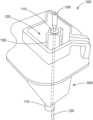
- FIG. 1provides a perspective view of a wash station, according to some embodiments
- FIG. 2provides an internal view of the vertically-elongated conduit of the wash station with the fluid removed:
- FIG. 3 Ashows a cutaway view of the wash station having a helix insert in the shape of a circular helix, according to some embodiments:
- FIG. 3 Bshows a cutaway view of the wash station having a helix insert in the shape of a conic helix, according to some embodiments:
- FIG. 4shows a plot of Reynolds number vs. time for comparing a wash station with a helix insert with a conventional wash station
- FIG. 5provides a layout of an example system architecture within which embodiments of the invention may be implemented, according to an embodiment.
- embodiments of the present inventionare directed to a wash station comprising a wash nozzle for providing a fluid (e.g., water) source to clean an exterior portion of a probe, a helix insert that directs fluid in a helical shape around the probe, and a basin allowing for waste fluid and fluid ejected from within the probe to be collected and drained.
- a wash stationcomprising a wash nozzle for providing a fluid (e.g., water) source to clean an exterior portion of a probe, a helix insert that directs fluid in a helical shape around the probe, and a basin allowing for waste fluid and fluid ejected from within the probe to be collected and drained.
- the helixprovides a variety of features that are desirable for a fluid dynamics cleaning of a surface including, without limitation, increasing the wall shear stress on the probe, increasing the residence time of the flow, and allowing the flow to develop a velocity profile.
- Computational fluid dynamicsmay be used to understand the improvement in cleaning.
- FIG. 1provides a perspective view of a wash station 100 , according to some embodiments.
- the wash station 100includes a fluid inlet port 110 and a basin 300 .
- the internal cavity 125 of the basin 300comprises a vertically-elongated conduit 130 that is sized to hold a probe 105 for cleaning.
- the vertically-elongated conduit 130can have a variety of different shapes, including a cylinder as shown in the embodiment in FIG. 1 .
- a fluid inlet port 110 located at the bottom portion of the basin 300secures a wash feed line 120 .
- the wash feed line 120fills the vertically-elongated conduit 130 with fluid 115 to facilitate the cleaning.
- the pressure of the wash feed line 120is approximately 11 psi. After the vertically-elongated conduit 130 is completely filled with fluid 115 , the wash feed line 120 continues to deliver the fluid 115 such that it overflows into the internal cavity 125 of the basin 300 for draining.
- FIG. 2provides an internal view of the vertically-elongated conduit 130 of the wash station 100 with the fluid 115 removed.
- This viewshows the helix insert 135 in the vertically-elongated conduit 130 of the basin 300 (shown in FIG. 1 ).
- the helix insert 135causes the fluid to flow in a helical shape as it is transported through the vertically-elongated conduit 130 to provide for more efficient cleaning compared to conventional probe cleaning systems.
- the helix insert 135displaces volume and tightly hugs the probe 105 , the flow velocity increases and results in higher shear stress.
- the helix insert 135causes more interaction between the probe 105 and fluid which, in turn, helps to reduce cleaning time.
- the helixalso creates a unique velocity profile, unlike that of flow between concentric cylinders, that is beneficial to cleaning.
- the helix insert 135can be shaped as a circular helix, such as in the embodiment shown in FIG. 3 A , or a conic helix, such as in the embodiment shown in FIG. 3 B .
- the helix insert 135is defined by the following parameters.
- the free length of helix insert 135is the length of the spring in the free or unloaded condition. This may be contrasted with the solid length which is the length of the helix insert 135 while in a compressed state.
- the solid lengthis a product of the number of coils and the dimensions of the wire or other material that is wound into the helix.
- the pitchis the distance from center to center of adjacent coils.
- the angle between the coils and the base of the helix insert 135is the helix angle.
- the mean helix diameteris the average of the outer diameter and inner diameter of the helix insert 135 .
- the helix inner diametercan be selected to provide a clearance, designated “c” in FIG. 2 , between the probe 105 and the helix insert 135 . In one embodiment, the clearance can be equal to 0.5 mm.
- the pitch of the helix insert 135can be defined with respect to the length of the vertically-elongated conduit 130 .
- the pitch of the helix insert 135can be a particular ratio with respect to the length of the vertically-elongated conduit 130 .
- the pitch of the helix insert 135can be equal to one tenth the length of the vertically-elongated conduit 130 .
- this helix insert 135is integrated with the vertically-elongated conduit 130 .
- the basin 300shown in FIG. 1
- the helix insert 135is printed with the vertically-elongated conduit 130 as a single component.
- the helix insert 135is an insert placed in the vertically-elongated conduit 130 and secured, for example, via compression or with internal tabs or other securing mechanisms (not shown in FIG. 1 ) in the vertically-elongated conduit 130 .
- the helix insert 135can be attached to an interior wall of the vertically-elongated conduit 130 .
- the helix insert 135may be composed of, for example, rubber or a similar material.
- the helical flowis created by one or more jet nozzles that inject pressurized fluid into the vertically-elongated conduit 130 .
- one or more jet feed linescan be installed at openings on the side wall of the vertically-elongated conduit 130 .
- the angle of inclination of the jet feed lines with respect to the floor of the basincan be varied as desired to create the desired helix angle.
- the wash feed line 120itself may serve as the jet feed line.
- FIGS. 3 A and 3 Bshow cutaway views of the wash station 100 , according to some embodiments.
- the helix insert 135is in the shape of a circular helix
- the helix insert 135is in the shape of a conic helix.
- the helix insert 135extends the length of the vertically-elongated conduit 130 into the top of the fluid inlet port 110 . Without the helix insert 135 , fluid would extend in a generally straight upward direction along the length of the vertically-elongated conduit 130 .
- the helix insert 135imparts a rotational force that causes the fluid to proceed up the vertically-elongated conduit 130 in the shape of a helix. As the fluid overflows the vertically-elongated conduit 130 , it is collected in the internal cavity 125 before draining out a drain port 140 on the underside of the wash station 100 . Furthermore, for the assumed contact angles, rotational flow caused by the helix lowers the height of the free surface at the probe (because the probe sits in the eye of the rotational flow where the water height is lowest, it might not lower the height at the spill over walls) at the spill over walls in comparison to conventional systems. Therefore, the chance of sleeve contamination is reduced during wash.
- the helix insert 135could be extended even further up the vertically-elongated conduit 130 to cover more of the probe's height.
- the only limitation to the length of the helix insert 135is how it disturbs the free surface of the wash station 100 . For example, a wave of fluid generated by the helix insert 135 should not hit the stainless steel sleeve of the probe.
- FIG. 4shows a plot of Reynolds number vs. time for comparing a wash station with a helix insert with a conventional wash station.
- Reynolds numberis the ratio of inertial forces to viscous forces. As shown in this example, the helix insert significantly increases the inertial forces around the probe. The Reynolds number settles out after approximately 0.5 seconds.
- FIG. 5provides a layout of an example system architecture 400 within which embodiments of the invention may be implemented, according to an embodiment. Shown in FIG. 5 are various transfer arms 410 ( 410 a , 410 b , 410 c , and 410 d ) with respective probes (such as the probe 105 described above with respect to the wash station 100 ); a diluting turntable 420 including a plurality of diluting containers arranged in one or more diluting rings: a reaction turntable 430 including a plurality of reaction containers arranged in one or more reaction rings; and reagent storage areas 440 a and 440 b dedicated to storage and supply of a respective reagent, each reagent storage area 440 a and 440 b may also include a plurality of reagent containers.
- transfer arm 410 a and its respective probemay operate to transfer sample from an access position to one or more diluting containers on the diluting turntable 420 to create a dilution therein.
- Transfer arm 410 b and its respective probemay operate to transfer dilution from a diluting container to a reaction container on the reaction turntable 430 .
- Transfer arms 410 c and 410 d and their respective probesmay operate to transfer a reagent from reagent storage area 440 a and 440 b , respectively, to a reaction container on the reaction turntable 430 .
- the various transfersoccur by use of a pumping mechanism, such as a displacement pump, for example, attached to the transfer arms 410 .
- the system architecture 400includes one or more controllers (not shown) for controlling operation of the various components, including the transfer arms 410 , the probes, and the turntables.
- one or more wash stations 100are mounted to the baseplate of the architecture 400 , in locations where the probes can be reached via their respective transfer arm 410 .
- the architecture 400can be embodied as a clinical analyzer.
- the system architecture 400 of FIG. 5 and the accompanying descriptionsare purely exemplary and non-limiting to the wash station 100 disclosed herein.
- the system architecture 400is just one example system in which the wash station 100 according to embodiments herein may be implemented.
Landscapes
- Physics & Mathematics (AREA)
- Health & Medical Sciences (AREA)
- Life Sciences & Earth Sciences (AREA)
- Chemical & Material Sciences (AREA)
- Analytical Chemistry (AREA)
- Biochemistry (AREA)
- General Health & Medical Sciences (AREA)
- General Physics & Mathematics (AREA)
- Immunology (AREA)
- Pathology (AREA)
- Automatic Analysis And Handling Materials Therefor (AREA)
- Sampling And Sample Adjustment (AREA)
Abstract
Description
Claims (19)
Priority Applications (1)
| Application Number | Priority Date | Filing Date | Title |
|---|---|---|---|
| US18/007,132US12203953B2 (en) | 2020-07-29 | 2021-07-15 | Helix wash station that augments the fluid dynamics associated with clinical chemistry and immunoassay probe cleaning |
Applications Claiming Priority (3)
| Application Number | Priority Date | Filing Date | Title |
|---|---|---|---|
| US202063058358P | 2020-07-29 | 2020-07-29 | |
| PCT/US2021/041899WO2022026205A1 (en) | 2020-07-29 | 2021-07-15 | A helix wash station that augments the fluid dynamics associated with clinical chemistry and immunoassay probe cleaning |
| US18/007,132US12203953B2 (en) | 2020-07-29 | 2021-07-15 | Helix wash station that augments the fluid dynamics associated with clinical chemistry and immunoassay probe cleaning |
Publications (2)
| Publication Number | Publication Date |
|---|---|
| US20230213542A1 US20230213542A1 (en) | 2023-07-06 |
| US12203953B2true US12203953B2 (en) | 2025-01-21 |
Family
ID=80036047
Family Applications (1)
| Application Number | Title | Priority Date | Filing Date |
|---|---|---|---|
| US18/007,132ActiveUS12203953B2 (en) | 2020-07-29 | 2021-07-15 | Helix wash station that augments the fluid dynamics associated with clinical chemistry and immunoassay probe cleaning |
Country Status (5)
| Country | Link |
|---|---|
| US (1) | US12203953B2 (en) |
| EP (1) | EP4189391A4 (en) |
| JP (1) | JP2023536457A (en) |
| CN (1) | CN115777067A (en) |
| WO (1) | WO2022026205A1 (en) |
Citations (19)
| Publication number | Priority date | Publication date | Assignee | Title |
|---|---|---|---|---|
| US5201232A (en) | 1988-12-29 | 1993-04-13 | Technicon Instruments Corporation | Integrated sampler for closed and open sample containers |
| JP2001133466A (en) | 1999-11-05 | 2001-05-18 | Toshiba Corp | Automatic analyzer |
| US20030164049A1 (en)* | 2001-12-14 | 2003-09-04 | Schlumberger Technology Corporation | Flow characteristic measuring apparatus and method |
| US20050051642A1 (en) | 2002-07-05 | 2005-03-10 | Katsuji Negoro | Fluid delivery tube structural body |
| JP2008500516A (en) | 2004-05-12 | 2008-01-10 | ワイス | Perfusion system and apparatus for automated multi-channel patch clamp recording using inside-out whole-cell configuration |
| US20080099057A1 (en)* | 2006-10-27 | 2008-05-01 | Dade Behring Inc. | Method and Device for Cleaning a Liquid Aspiration and Dispense Probe |
| US20080302393A1 (en)* | 2007-05-11 | 2008-12-11 | Bio-Rad Laboratories, Inc. | Wash ring assembly and method of use |
| US20090101175A1 (en) | 2007-10-17 | 2009-04-23 | Peter Honkanen | Continual flow pin washer |
| US20090114250A1 (en)* | 2005-04-21 | 2009-05-07 | Wako Pure Chemical Industries, Ltd. | Pipetter cleaning device and cleaning method |
| JP2009222593A (en) | 2008-03-17 | 2009-10-01 | Olympus Corp | Nozzle-cleaning method and nozzle-cleaning apparatus |
| US20110262919A1 (en)* | 2008-12-25 | 2011-10-27 | Hideji Tajima | Method for pretreating specimen and method for assaying biological substance |
| US20120227771A1 (en)* | 2009-11-20 | 2012-09-13 | Siemens Healthcare Diagnostics Inc. | Apparatus, Systems, And Methods Adapted To Rinse And Dry Clinical Analyzer Sample Probes |
| JP2014167401A (en) | 2013-02-28 | 2014-09-11 | Sysmex Corp | Sample analyzing device |
| US20150192601A1 (en)* | 2012-07-25 | 2015-07-09 | Siemens Healthcare Diagnostic Inc. | Apparatus, systems, and methods to clean probes in clinical analyzers |
| US20150276772A1 (en)* | 2012-11-01 | 2015-10-01 | Leica Biosystems Melbourne Pty Ltd | Fluid transport system |
| US20160069922A1 (en)* | 2013-04-22 | 2016-03-10 | Hitachi High-Technologies Corporation | Automatic analyzer |
| WO2017197025A1 (en) | 2016-05-11 | 2017-11-16 | Siemens Healthcare Diagnostics Inc. | Probe wash station for analytical instrumentation |
| US20190369132A1 (en) | 2016-12-23 | 2019-12-05 | Roche Diagnostics Operations, Inc. | Method of washing an aspiration probe of an in-vitro diagnostic system, in-vitro diagnostic method, and in-vitro diagnostic system |
| US20190391171A1 (en) | 2015-03-27 | 2019-12-26 | Sysmex Corporation | Blood measuring device control method |
- 2021
- 2021-07-15USUS18/007,132patent/US12203953B2/enactiveActive
- 2021-07-15CNCN202180047976.2Apatent/CN115777067A/enactivePending
- 2021-07-15WOPCT/US2021/041899patent/WO2022026205A1/ennot_activeCeased
- 2021-07-15EPEP21848824.5Apatent/EP4189391A4/enactivePending
- 2021-07-15JPJP2023505840Apatent/JP2023536457A/enactivePending
Patent Citations (20)
| Publication number | Priority date | Publication date | Assignee | Title |
|---|---|---|---|---|
| US5201232A (en) | 1988-12-29 | 1993-04-13 | Technicon Instruments Corporation | Integrated sampler for closed and open sample containers |
| JP2001133466A (en) | 1999-11-05 | 2001-05-18 | Toshiba Corp | Automatic analyzer |
| US20030164049A1 (en)* | 2001-12-14 | 2003-09-04 | Schlumberger Technology Corporation | Flow characteristic measuring apparatus and method |
| US20050051642A1 (en) | 2002-07-05 | 2005-03-10 | Katsuji Negoro | Fluid delivery tube structural body |
| JP2008500516A (en) | 2004-05-12 | 2008-01-10 | ワイス | Perfusion system and apparatus for automated multi-channel patch clamp recording using inside-out whole-cell configuration |
| US20090114250A1 (en)* | 2005-04-21 | 2009-05-07 | Wako Pure Chemical Industries, Ltd. | Pipetter cleaning device and cleaning method |
| US20080099057A1 (en)* | 2006-10-27 | 2008-05-01 | Dade Behring Inc. | Method and Device for Cleaning a Liquid Aspiration and Dispense Probe |
| US20080302393A1 (en)* | 2007-05-11 | 2008-12-11 | Bio-Rad Laboratories, Inc. | Wash ring assembly and method of use |
| US20090101175A1 (en) | 2007-10-17 | 2009-04-23 | Peter Honkanen | Continual flow pin washer |
| US20110017238A1 (en)* | 2008-03-17 | 2011-01-27 | Beckman Coulter, Inc. | Method of cleaning nozzle and device for cleaning nozzle |
| JP2009222593A (en) | 2008-03-17 | 2009-10-01 | Olympus Corp | Nozzle-cleaning method and nozzle-cleaning apparatus |
| US20110262919A1 (en)* | 2008-12-25 | 2011-10-27 | Hideji Tajima | Method for pretreating specimen and method for assaying biological substance |
| US20120227771A1 (en)* | 2009-11-20 | 2012-09-13 | Siemens Healthcare Diagnostics Inc. | Apparatus, Systems, And Methods Adapted To Rinse And Dry Clinical Analyzer Sample Probes |
| US20150192601A1 (en)* | 2012-07-25 | 2015-07-09 | Siemens Healthcare Diagnostic Inc. | Apparatus, systems, and methods to clean probes in clinical analyzers |
| US20150276772A1 (en)* | 2012-11-01 | 2015-10-01 | Leica Biosystems Melbourne Pty Ltd | Fluid transport system |
| JP2014167401A (en) | 2013-02-28 | 2014-09-11 | Sysmex Corp | Sample analyzing device |
| US20160069922A1 (en)* | 2013-04-22 | 2016-03-10 | Hitachi High-Technologies Corporation | Automatic analyzer |
| US20190391171A1 (en) | 2015-03-27 | 2019-12-26 | Sysmex Corporation | Blood measuring device control method |
| WO2017197025A1 (en) | 2016-05-11 | 2017-11-16 | Siemens Healthcare Diagnostics Inc. | Probe wash station for analytical instrumentation |
| US20190369132A1 (en) | 2016-12-23 | 2019-12-05 | Roche Diagnostics Operations, Inc. | Method of washing an aspiration probe of an in-vitro diagnostic system, in-vitro diagnostic method, and in-vitro diagnostic system |
Non-Patent Citations (2)
| Title |
|---|
| Extended EP Search Report dated Dec. 15, 2023 of corresponding European Application No. 21848824.5, 4 Pages. |
| PCT International Search Report and Written Opinion dated Oct. 26, 2021 (7 Pages). |
Also Published As
| Publication number | Publication date |
|---|---|
| US20230213542A1 (en) | 2023-07-06 |
| WO2022026205A1 (en) | 2022-02-03 |
| CN115777067A (en) | 2023-03-10 |
| JP2023536457A (en) | 2023-08-25 |
| EP4189391A1 (en) | 2023-06-07 |
| EP4189391A4 (en) | 2024-01-17 |
Similar Documents
| Publication | Publication Date | Title |
|---|---|---|
| US7300525B2 (en) | Device for cleaning pipette probes or stirrers | |
| JP4406643B2 (en) | Liquid sampling probe and cleaning fluidics system | |
| US4730631A (en) | Probe wash station | |
| JP6466846B2 (en) | Nozzle cleaning method and automatic analyzer | |
| US9255937B2 (en) | Automatic analyzer | |
| JP5744923B2 (en) | Automatic analyzer | |
| JP2013511721A (en) | Apparatus, system and method adapted to rinse / dry clinical analyzer sample probe | |
| US8969098B2 (en) | Methods and systems providing reagent mixing | |
| CN110121650B (en) | Nozzle cleaner and automatic analyzer using the same | |
| CN102326085A (en) | Chemical Analysis Device | |
| JPH05502726A (en) | Apparatus and method for cleaning reagent dispensing probes | |
| US10695803B2 (en) | Pipette cleaning methods and apparatus, neutralizing liquid vessels, and methods of reducing carryover | |
| EP0839075A1 (en) | Apparatus and method for washing a pipette probe | |
| CN111788488A (en) | Probe wash arrangement with multiple configurations for sample analyzer and method of use thereof | |
| EP3455003B1 (en) | Probe wash station for analytical instrumentation | |
| US12203953B2 (en) | Helix wash station that augments the fluid dynamics associated with clinical chemistry and immunoassay probe cleaning | |
| EP2410343B1 (en) | Wash station and process for washing reusable fluid manipulators | |
| CN113711055A (en) | Automatic analyzer | |
| HK40083329A (en) | A helix wash station that augments the fluid dynamics associated with clinical chemistry and immunoassay probe cleaning | |
| JP2005249535A (en) | Dispensation probe and autoanalyzer equipped therewith | |
| JP2009031174A (en) | Automatic analyzer | |
| JPWO2020066198A1 (en) | Automatic analyzer and cleaning method | |
| CN120604127A (en) | Automatic analyzer and method for cleaning dispensing probe | |
| HK40025356A (en) | Probe tip eject devices and methods thereof for automated diagnostic analysis apparatus | |
| HK1260704A1 (en) | Probe wash station for analytical instrumentation |
Legal Events
| Date | Code | Title | Description |
|---|---|---|---|
| FEPP | Fee payment procedure | Free format text:ENTITY STATUS SET TO UNDISCOUNTED (ORIGINAL EVENT CODE: BIG.); ENTITY STATUS OF PATENT OWNER: LARGE ENTITY | |
| AS | Assignment | Owner name:SIEMENS HEALTHCARE DIAGNOSTICS INC., NEW YORK Free format text:ASSIGNMENT OF ASSIGNORS INTEREST;ASSIGNOR:EBELING, CHRISTOPHER;REEL/FRAME:062554/0426 Effective date:20200831 | |
| STPP | Information on status: patent application and granting procedure in general | Free format text:FINAL REJECTION MAILED | |
| STPP | Information on status: patent application and granting procedure in general | Free format text:RESPONSE AFTER FINAL ACTION FORWARDED TO EXAMINER | |
| STPP | Information on status: patent application and granting procedure in general | Free format text:ADVISORY ACTION MAILED | |
| STPP | Information on status: patent application and granting procedure in general | Free format text:DOCKETED NEW CASE - READY FOR EXAMINATION | |
| STPP | Information on status: patent application and granting procedure in general | Free format text:NON FINAL ACTION MAILED | |
| STPP | Information on status: patent application and granting procedure in general | Free format text:RESPONSE TO NON-FINAL OFFICE ACTION ENTERED AND FORWARDED TO EXAMINER | |
| STPP | Information on status: patent application and granting procedure in general | Free format text:FINAL REJECTION MAILED | |
| STPP | Information on status: patent application and granting procedure in general | Free format text:RESPONSE AFTER FINAL ACTION FORWARDED TO EXAMINER | |
| STPP | Information on status: patent application and granting procedure in general | Free format text:DOCKETED NEW CASE - READY FOR EXAMINATION | |
| STPP | Information on status: patent application and granting procedure in general | Free format text:NOTICE OF ALLOWANCE MAILED -- APPLICATION RECEIVED IN OFFICE OF PUBLICATIONS | |
| ZAAB | Notice of allowance mailed | Free format text:ORIGINAL CODE: MN/=. | |
| STPP | Information on status: patent application and granting procedure in general | Free format text:PUBLICATIONS -- ISSUE FEE PAYMENT VERIFIED | |
| STCF | Information on status: patent grant | Free format text:PATENTED CASE |