US12201531B2 - Implants having bone growth promoting agents contained within biodegradable materials - Google Patents
Implants having bone growth promoting agents contained within biodegradable materialsDownload PDFInfo
- Publication number
- US12201531B2 US12201531B2US17/370,873US202117370873AUS12201531B2US 12201531 B2US12201531 B2US 12201531B2US 202117370873 AUS202117370873 AUS 202117370873AUS 12201531 B2US12201531 B2US 12201531B2
- Authority
- US
- United States
- Prior art keywords
- implant
- struts
- bone
- truss
- bone growth
- Prior art date
- Legal status (The legal status is an assumption and is not a legal conclusion. Google has not performed a legal analysis and makes no representation as to the accuracy of the status listed.)
- Active
Links
Images


Classifications
- A—HUMAN NECESSITIES
- A61—MEDICAL OR VETERINARY SCIENCE; HYGIENE
- A61F—FILTERS IMPLANTABLE INTO BLOOD VESSELS; PROSTHESES; DEVICES PROVIDING PATENCY TO, OR PREVENTING COLLAPSING OF, TUBULAR STRUCTURES OF THE BODY, e.g. STENTS; ORTHOPAEDIC, NURSING OR CONTRACEPTIVE DEVICES; FOMENTATION; TREATMENT OR PROTECTION OF EYES OR EARS; BANDAGES, DRESSINGS OR ABSORBENT PADS; FIRST-AID KITS
- A61F2/00—Filters implantable into blood vessels; Prostheses, i.e. artificial substitutes or replacements for parts of the body; Appliances for connecting them with the body; Devices providing patency to, or preventing collapsing of, tubular structures of the body, e.g. stents
- A61F2/02—Prostheses implantable into the body
- A61F2/30—Joints
- A61F2/44—Joints for the spine, e.g. vertebrae, spinal discs
- A61F2/4455—Joints for the spine, e.g. vertebrae, spinal discs for the fusion of spinal bodies, e.g. intervertebral fusion of adjacent spinal bodies, e.g. fusion cages
- A61F2/4465—Joints for the spine, e.g. vertebrae, spinal discs for the fusion of spinal bodies, e.g. intervertebral fusion of adjacent spinal bodies, e.g. fusion cages having a circular or kidney shaped cross-section substantially perpendicular to the axis of the spine
- A—HUMAN NECESSITIES
- A61—MEDICAL OR VETERINARY SCIENCE; HYGIENE
- A61F—FILTERS IMPLANTABLE INTO BLOOD VESSELS; PROSTHESES; DEVICES PROVIDING PATENCY TO, OR PREVENTING COLLAPSING OF, TUBULAR STRUCTURES OF THE BODY, e.g. STENTS; ORTHOPAEDIC, NURSING OR CONTRACEPTIVE DEVICES; FOMENTATION; TREATMENT OR PROTECTION OF EYES OR EARS; BANDAGES, DRESSINGS OR ABSORBENT PADS; FIRST-AID KITS
- A61F2/00—Filters implantable into blood vessels; Prostheses, i.e. artificial substitutes or replacements for parts of the body; Appliances for connecting them with the body; Devices providing patency to, or preventing collapsing of, tubular structures of the body, e.g. stents
- A61F2/02—Prostheses implantable into the body
- A61F2/30—Joints
- A61F2/30767—Special external or bone-contacting surface, e.g. coating for improving bone ingrowth
- A—HUMAN NECESSITIES
- A61—MEDICAL OR VETERINARY SCIENCE; HYGIENE
- A61F—FILTERS IMPLANTABLE INTO BLOOD VESSELS; PROSTHESES; DEVICES PROVIDING PATENCY TO, OR PREVENTING COLLAPSING OF, TUBULAR STRUCTURES OF THE BODY, e.g. STENTS; ORTHOPAEDIC, NURSING OR CONTRACEPTIVE DEVICES; FOMENTATION; TREATMENT OR PROTECTION OF EYES OR EARS; BANDAGES, DRESSINGS OR ABSORBENT PADS; FIRST-AID KITS
- A61F2/00—Filters implantable into blood vessels; Prostheses, i.e. artificial substitutes or replacements for parts of the body; Appliances for connecting them with the body; Devices providing patency to, or preventing collapsing of, tubular structures of the body, e.g. stents
- A61F2/02—Prostheses implantable into the body
- A61F2/30—Joints
- A61F2/3094—Designing or manufacturing processes
- A—HUMAN NECESSITIES
- A61—MEDICAL OR VETERINARY SCIENCE; HYGIENE
- A61F—FILTERS IMPLANTABLE INTO BLOOD VESSELS; PROSTHESES; DEVICES PROVIDING PATENCY TO, OR PREVENTING COLLAPSING OF, TUBULAR STRUCTURES OF THE BODY, e.g. STENTS; ORTHOPAEDIC, NURSING OR CONTRACEPTIVE DEVICES; FOMENTATION; TREATMENT OR PROTECTION OF EYES OR EARS; BANDAGES, DRESSINGS OR ABSORBENT PADS; FIRST-AID KITS
- A61F2/00—Filters implantable into blood vessels; Prostheses, i.e. artificial substitutes or replacements for parts of the body; Appliances for connecting them with the body; Devices providing patency to, or preventing collapsing of, tubular structures of the body, e.g. stents
- A61F2/02—Prostheses implantable into the body
- A61F2/30—Joints
- A61F2/44—Joints for the spine, e.g. vertebrae, spinal discs
- A61F2/4455—Joints for the spine, e.g. vertebrae, spinal discs for the fusion of spinal bodies, e.g. intervertebral fusion of adjacent spinal bodies, e.g. fusion cages
- A61F2/447—Joints for the spine, e.g. vertebrae, spinal discs for the fusion of spinal bodies, e.g. intervertebral fusion of adjacent spinal bodies, e.g. fusion cages substantially parallelepipedal, e.g. having a rectangular or trapezoidal cross-section
- A—HUMAN NECESSITIES
- A61—MEDICAL OR VETERINARY SCIENCE; HYGIENE
- A61L—METHODS OR APPARATUS FOR STERILISING MATERIALS OR OBJECTS IN GENERAL; DISINFECTION, STERILISATION OR DEODORISATION OF AIR; CHEMICAL ASPECTS OF BANDAGES, DRESSINGS, ABSORBENT PADS OR SURGICAL ARTICLES; MATERIALS FOR BANDAGES, DRESSINGS, ABSORBENT PADS OR SURGICAL ARTICLES
- A61L27/00—Materials for grafts or prostheses or for coating grafts or prostheses
- A61L27/50—Materials characterised by their function or physical properties, e.g. injectable or lubricating compositions, shape-memory materials, surface modified materials
- A61L27/54—Biologically active materials, e.g. therapeutic substances
- A—HUMAN NECESSITIES
- A61—MEDICAL OR VETERINARY SCIENCE; HYGIENE
- A61L—METHODS OR APPARATUS FOR STERILISING MATERIALS OR OBJECTS IN GENERAL; DISINFECTION, STERILISATION OR DEODORISATION OF AIR; CHEMICAL ASPECTS OF BANDAGES, DRESSINGS, ABSORBENT PADS OR SURGICAL ARTICLES; MATERIALS FOR BANDAGES, DRESSINGS, ABSORBENT PADS OR SURGICAL ARTICLES
- A61L27/00—Materials for grafts or prostheses or for coating grafts or prostheses
- A61L27/50—Materials characterised by their function or physical properties, e.g. injectable or lubricating compositions, shape-memory materials, surface modified materials
- A61L27/56—Porous materials, e.g. foams or sponges
- B—PERFORMING OPERATIONS; TRANSPORTING
- B33—ADDITIVE MANUFACTURING TECHNOLOGY
- B33Y—ADDITIVE MANUFACTURING, i.e. MANUFACTURING OF THREE-DIMENSIONAL [3-D] OBJECTS BY ADDITIVE DEPOSITION, ADDITIVE AGGLOMERATION OR ADDITIVE LAYERING, e.g. BY 3-D PRINTING, STEREOLITHOGRAPHY OR SELECTIVE LASER SINTERING
- B33Y80/00—Products made by additive manufacturing
- A—HUMAN NECESSITIES
- A61—MEDICAL OR VETERINARY SCIENCE; HYGIENE
- A61F—FILTERS IMPLANTABLE INTO BLOOD VESSELS; PROSTHESES; DEVICES PROVIDING PATENCY TO, OR PREVENTING COLLAPSING OF, TUBULAR STRUCTURES OF THE BODY, e.g. STENTS; ORTHOPAEDIC, NURSING OR CONTRACEPTIVE DEVICES; FOMENTATION; TREATMENT OR PROTECTION OF EYES OR EARS; BANDAGES, DRESSINGS OR ABSORBENT PADS; FIRST-AID KITS
- A61F2/00—Filters implantable into blood vessels; Prostheses, i.e. artificial substitutes or replacements for parts of the body; Appliances for connecting them with the body; Devices providing patency to, or preventing collapsing of, tubular structures of the body, e.g. stents
- A61F2/02—Prostheses implantable into the body
- A61F2/28—Bones
- A61F2002/2817—Bone stimulation by chemical reactions or by osteogenic or biological products for enhancing ossification, e.g. by bone morphogenetic or morphogenic proteins [BMP] or by transforming growth factors [TGF]
- A—HUMAN NECESSITIES
- A61—MEDICAL OR VETERINARY SCIENCE; HYGIENE
- A61F—FILTERS IMPLANTABLE INTO BLOOD VESSELS; PROSTHESES; DEVICES PROVIDING PATENCY TO, OR PREVENTING COLLAPSING OF, TUBULAR STRUCTURES OF THE BODY, e.g. STENTS; ORTHOPAEDIC, NURSING OR CONTRACEPTIVE DEVICES; FOMENTATION; TREATMENT OR PROTECTION OF EYES OR EARS; BANDAGES, DRESSINGS OR ABSORBENT PADS; FIRST-AID KITS
- A61F2/00—Filters implantable into blood vessels; Prostheses, i.e. artificial substitutes or replacements for parts of the body; Appliances for connecting them with the body; Devices providing patency to, or preventing collapsing of, tubular structures of the body, e.g. stents
- A61F2/02—Prostheses implantable into the body
- A61F2/30—Joints
- A61F2002/30001—Additional features of subject-matter classified in A61F2/28, A61F2/30 and subgroups thereof
- A61F2002/30003—Material related properties of the prosthesis or of a coating on the prosthesis
- A61F2002/3006—Properties of materials and coating materials
- A61F2002/30062—(bio)absorbable, biodegradable, bioerodable, (bio)resorbable, resorptive
- A—HUMAN NECESSITIES
- A61—MEDICAL OR VETERINARY SCIENCE; HYGIENE
- A61F—FILTERS IMPLANTABLE INTO BLOOD VESSELS; PROSTHESES; DEVICES PROVIDING PATENCY TO, OR PREVENTING COLLAPSING OF, TUBULAR STRUCTURES OF THE BODY, e.g. STENTS; ORTHOPAEDIC, NURSING OR CONTRACEPTIVE DEVICES; FOMENTATION; TREATMENT OR PROTECTION OF EYES OR EARS; BANDAGES, DRESSINGS OR ABSORBENT PADS; FIRST-AID KITS
- A61F2/00—Filters implantable into blood vessels; Prostheses, i.e. artificial substitutes or replacements for parts of the body; Appliances for connecting them with the body; Devices providing patency to, or preventing collapsing of, tubular structures of the body, e.g. stents
- A61F2/02—Prostheses implantable into the body
- A61F2/30—Joints
- A61F2002/30001—Additional features of subject-matter classified in A61F2/28, A61F2/30 and subgroups thereof
- A61F2002/30108—Shapes
- A61F2002/3011—Cross-sections or two-dimensional shapes
- A61F2002/30138—Convex polygonal shapes
- A—HUMAN NECESSITIES
- A61—MEDICAL OR VETERINARY SCIENCE; HYGIENE
- A61F—FILTERS IMPLANTABLE INTO BLOOD VESSELS; PROSTHESES; DEVICES PROVIDING PATENCY TO, OR PREVENTING COLLAPSING OF, TUBULAR STRUCTURES OF THE BODY, e.g. STENTS; ORTHOPAEDIC, NURSING OR CONTRACEPTIVE DEVICES; FOMENTATION; TREATMENT OR PROTECTION OF EYES OR EARS; BANDAGES, DRESSINGS OR ABSORBENT PADS; FIRST-AID KITS
- A61F2/00—Filters implantable into blood vessels; Prostheses, i.e. artificial substitutes or replacements for parts of the body; Appliances for connecting them with the body; Devices providing patency to, or preventing collapsing of, tubular structures of the body, e.g. stents
- A61F2/02—Prostheses implantable into the body
- A61F2/30—Joints
- A61F2002/30001—Additional features of subject-matter classified in A61F2/28, A61F2/30 and subgroups thereof
- A61F2002/30316—The prosthesis having different structural features at different locations within the same prosthesis; Connections between prosthetic parts; Special structural features of bone or joint prostheses not otherwise provided for
- A61F2002/30535—Special structural features of bone or joint prostheses not otherwise provided for
- A61F2002/30593—Special structural features of bone or joint prostheses not otherwise provided for hollow
- A—HUMAN NECESSITIES
- A61—MEDICAL OR VETERINARY SCIENCE; HYGIENE
- A61F—FILTERS IMPLANTABLE INTO BLOOD VESSELS; PROSTHESES; DEVICES PROVIDING PATENCY TO, OR PREVENTING COLLAPSING OF, TUBULAR STRUCTURES OF THE BODY, e.g. STENTS; ORTHOPAEDIC, NURSING OR CONTRACEPTIVE DEVICES; FOMENTATION; TREATMENT OR PROTECTION OF EYES OR EARS; BANDAGES, DRESSINGS OR ABSORBENT PADS; FIRST-AID KITS
- A61F2/00—Filters implantable into blood vessels; Prostheses, i.e. artificial substitutes or replacements for parts of the body; Appliances for connecting them with the body; Devices providing patency to, or preventing collapsing of, tubular structures of the body, e.g. stents
- A61F2/02—Prostheses implantable into the body
- A61F2/30—Joints
- A61F2002/30001—Additional features of subject-matter classified in A61F2/28, A61F2/30 and subgroups thereof
- A61F2002/30621—Features concerning the anatomical functioning or articulation of the prosthetic joint
- A61F2002/30622—Implant for fusing a joint or bone material
- A—HUMAN NECESSITIES
- A61—MEDICAL OR VETERINARY SCIENCE; HYGIENE
- A61F—FILTERS IMPLANTABLE INTO BLOOD VESSELS; PROSTHESES; DEVICES PROVIDING PATENCY TO, OR PREVENTING COLLAPSING OF, TUBULAR STRUCTURES OF THE BODY, e.g. STENTS; ORTHOPAEDIC, NURSING OR CONTRACEPTIVE DEVICES; FOMENTATION; TREATMENT OR PROTECTION OF EYES OR EARS; BANDAGES, DRESSINGS OR ABSORBENT PADS; FIRST-AID KITS
- A61F2/00—Filters implantable into blood vessels; Prostheses, i.e. artificial substitutes or replacements for parts of the body; Appliances for connecting them with the body; Devices providing patency to, or preventing collapsing of, tubular structures of the body, e.g. stents
- A61F2/02—Prostheses implantable into the body
- A61F2/30—Joints
- A61F2002/30001—Additional features of subject-matter classified in A61F2/28, A61F2/30 and subgroups thereof
- A61F2002/30667—Features concerning an interaction with the environment or a particular use of the prosthesis
- A61F2002/30677—Means for introducing or releasing pharmaceutical products, e.g. antibiotics, into the body
- A—HUMAN NECESSITIES
- A61—MEDICAL OR VETERINARY SCIENCE; HYGIENE
- A61F—FILTERS IMPLANTABLE INTO BLOOD VESSELS; PROSTHESES; DEVICES PROVIDING PATENCY TO, OR PREVENTING COLLAPSING OF, TUBULAR STRUCTURES OF THE BODY, e.g. STENTS; ORTHOPAEDIC, NURSING OR CONTRACEPTIVE DEVICES; FOMENTATION; TREATMENT OR PROTECTION OF EYES OR EARS; BANDAGES, DRESSINGS OR ABSORBENT PADS; FIRST-AID KITS
- A61F2/00—Filters implantable into blood vessels; Prostheses, i.e. artificial substitutes or replacements for parts of the body; Appliances for connecting them with the body; Devices providing patency to, or preventing collapsing of, tubular structures of the body, e.g. stents
- A61F2/02—Prostheses implantable into the body
- A61F2/30—Joints
- A61F2/30767—Special external or bone-contacting surface, e.g. coating for improving bone ingrowth
- A61F2/30771—Special external or bone-contacting surface, e.g. coating for improving bone ingrowth applied in original prostheses, e.g. holes or grooves
- A61F2002/30838—Microstructures
- A—HUMAN NECESSITIES
- A61—MEDICAL OR VETERINARY SCIENCE; HYGIENE
- A61F—FILTERS IMPLANTABLE INTO BLOOD VESSELS; PROSTHESES; DEVICES PROVIDING PATENCY TO, OR PREVENTING COLLAPSING OF, TUBULAR STRUCTURES OF THE BODY, e.g. STENTS; ORTHOPAEDIC, NURSING OR CONTRACEPTIVE DEVICES; FOMENTATION; TREATMENT OR PROTECTION OF EYES OR EARS; BANDAGES, DRESSINGS OR ABSORBENT PADS; FIRST-AID KITS
- A61F2/00—Filters implantable into blood vessels; Prostheses, i.e. artificial substitutes or replacements for parts of the body; Appliances for connecting them with the body; Devices providing patency to, or preventing collapsing of, tubular structures of the body, e.g. stents
- A61F2/02—Prostheses implantable into the body
- A61F2/30—Joints
- A61F2/30767—Special external or bone-contacting surface, e.g. coating for improving bone ingrowth
- A61F2/30771—Special external or bone-contacting surface, e.g. coating for improving bone ingrowth applied in original prostheses, e.g. holes or grooves
- A61F2002/3084—Nanostructures
- A—HUMAN NECESSITIES
- A61—MEDICAL OR VETERINARY SCIENCE; HYGIENE
- A61F—FILTERS IMPLANTABLE INTO BLOOD VESSELS; PROSTHESES; DEVICES PROVIDING PATENCY TO, OR PREVENTING COLLAPSING OF, TUBULAR STRUCTURES OF THE BODY, e.g. STENTS; ORTHOPAEDIC, NURSING OR CONTRACEPTIVE DEVICES; FOMENTATION; TREATMENT OR PROTECTION OF EYES OR EARS; BANDAGES, DRESSINGS OR ABSORBENT PADS; FIRST-AID KITS
- A61F2/00—Filters implantable into blood vessels; Prostheses, i.e. artificial substitutes or replacements for parts of the body; Appliances for connecting them with the body; Devices providing patency to, or preventing collapsing of, tubular structures of the body, e.g. stents
- A61F2/02—Prostheses implantable into the body
- A61F2/30—Joints
- A61F2/30767—Special external or bone-contacting surface, e.g. coating for improving bone ingrowth
- A61F2002/3092—Special external or bone-contacting surface, e.g. coating for improving bone ingrowth having an open-celled or open-pored structure
- A—HUMAN NECESSITIES
- A61—MEDICAL OR VETERINARY SCIENCE; HYGIENE
- A61F—FILTERS IMPLANTABLE INTO BLOOD VESSELS; PROSTHESES; DEVICES PROVIDING PATENCY TO, OR PREVENTING COLLAPSING OF, TUBULAR STRUCTURES OF THE BODY, e.g. STENTS; ORTHOPAEDIC, NURSING OR CONTRACEPTIVE DEVICES; FOMENTATION; TREATMENT OR PROTECTION OF EYES OR EARS; BANDAGES, DRESSINGS OR ABSORBENT PADS; FIRST-AID KITS
- A61F2/00—Filters implantable into blood vessels; Prostheses, i.e. artificial substitutes or replacements for parts of the body; Appliances for connecting them with the body; Devices providing patency to, or preventing collapsing of, tubular structures of the body, e.g. stents
- A61F2/02—Prostheses implantable into the body
- A61F2/30—Joints
- A61F2/30767—Special external or bone-contacting surface, e.g. coating for improving bone ingrowth
- A61F2002/3093—Special external or bone-contacting surface, e.g. coating for improving bone ingrowth for promoting ingrowth of bone tissue
- A—HUMAN NECESSITIES
- A61—MEDICAL OR VETERINARY SCIENCE; HYGIENE
- A61F—FILTERS IMPLANTABLE INTO BLOOD VESSELS; PROSTHESES; DEVICES PROVIDING PATENCY TO, OR PREVENTING COLLAPSING OF, TUBULAR STRUCTURES OF THE BODY, e.g. STENTS; ORTHOPAEDIC, NURSING OR CONTRACEPTIVE DEVICES; FOMENTATION; TREATMENT OR PROTECTION OF EYES OR EARS; BANDAGES, DRESSINGS OR ABSORBENT PADS; FIRST-AID KITS
- A61F2/00—Filters implantable into blood vessels; Prostheses, i.e. artificial substitutes or replacements for parts of the body; Appliances for connecting them with the body; Devices providing patency to, or preventing collapsing of, tubular structures of the body, e.g. stents
- A61F2/02—Prostheses implantable into the body
- A61F2/30—Joints
- A61F2/3094—Designing or manufacturing processes
- A61F2/30942—Designing or manufacturing processes for designing or making customized prostheses, e.g. using templates, CT or NMR scans, finite-element analysis or CAD-CAM techniques
- A61F2002/30962—Designing or manufacturing processes for designing or making customized prostheses, e.g. using templates, CT or NMR scans, finite-element analysis or CAD-CAM techniques using stereolithography
- A—HUMAN NECESSITIES
- A61—MEDICAL OR VETERINARY SCIENCE; HYGIENE
- A61F—FILTERS IMPLANTABLE INTO BLOOD VESSELS; PROSTHESES; DEVICES PROVIDING PATENCY TO, OR PREVENTING COLLAPSING OF, TUBULAR STRUCTURES OF THE BODY, e.g. STENTS; ORTHOPAEDIC, NURSING OR CONTRACEPTIVE DEVICES; FOMENTATION; TREATMENT OR PROTECTION OF EYES OR EARS; BANDAGES, DRESSINGS OR ABSORBENT PADS; FIRST-AID KITS
- A61F2/00—Filters implantable into blood vessels; Prostheses, i.e. artificial substitutes or replacements for parts of the body; Appliances for connecting them with the body; Devices providing patency to, or preventing collapsing of, tubular structures of the body, e.g. stents
- A61F2/02—Prostheses implantable into the body
- A61F2/30—Joints
- A61F2/3094—Designing or manufacturing processes
- A61F2002/3097—Designing or manufacturing processes using laser
- A—HUMAN NECESSITIES
- A61—MEDICAL OR VETERINARY SCIENCE; HYGIENE
- A61F—FILTERS IMPLANTABLE INTO BLOOD VESSELS; PROSTHESES; DEVICES PROVIDING PATENCY TO, OR PREVENTING COLLAPSING OF, TUBULAR STRUCTURES OF THE BODY, e.g. STENTS; ORTHOPAEDIC, NURSING OR CONTRACEPTIVE DEVICES; FOMENTATION; TREATMENT OR PROTECTION OF EYES OR EARS; BANDAGES, DRESSINGS OR ABSORBENT PADS; FIRST-AID KITS
- A61F2/00—Filters implantable into blood vessels; Prostheses, i.e. artificial substitutes or replacements for parts of the body; Appliances for connecting them with the body; Devices providing patency to, or preventing collapsing of, tubular structures of the body, e.g. stents
- A61F2/02—Prostheses implantable into the body
- A61F2/30—Joints
- A61F2/3094—Designing or manufacturing processes
- A61F2002/30985—Designing or manufacturing processes using three dimensional printing [3DP]
- A—HUMAN NECESSITIES
- A61—MEDICAL OR VETERINARY SCIENCE; HYGIENE
- A61F—FILTERS IMPLANTABLE INTO BLOOD VESSELS; PROSTHESES; DEVICES PROVIDING PATENCY TO, OR PREVENTING COLLAPSING OF, TUBULAR STRUCTURES OF THE BODY, e.g. STENTS; ORTHOPAEDIC, NURSING OR CONTRACEPTIVE DEVICES; FOMENTATION; TREATMENT OR PROTECTION OF EYES OR EARS; BANDAGES, DRESSINGS OR ABSORBENT PADS; FIRST-AID KITS
- A61F2/00—Filters implantable into blood vessels; Prostheses, i.e. artificial substitutes or replacements for parts of the body; Appliances for connecting them with the body; Devices providing patency to, or preventing collapsing of, tubular structures of the body, e.g. stents
- A61F2/02—Prostheses implantable into the body
- A61F2/30—Joints
- A61F2/44—Joints for the spine, e.g. vertebrae, spinal discs
- A61F2002/4495—Joints for the spine, e.g. vertebrae, spinal discs having a fabric structure, e.g. made from wires or fibres
- A—HUMAN NECESSITIES
- A61—MEDICAL OR VETERINARY SCIENCE; HYGIENE
- A61F—FILTERS IMPLANTABLE INTO BLOOD VESSELS; PROSTHESES; DEVICES PROVIDING PATENCY TO, OR PREVENTING COLLAPSING OF, TUBULAR STRUCTURES OF THE BODY, e.g. STENTS; ORTHOPAEDIC, NURSING OR CONTRACEPTIVE DEVICES; FOMENTATION; TREATMENT OR PROTECTION OF EYES OR EARS; BANDAGES, DRESSINGS OR ABSORBENT PADS; FIRST-AID KITS
- A61F2310/00—Prostheses classified in A61F2/28 or A61F2/30 - A61F2/44 being constructed from or coated with a particular material
- A61F2310/00005—The prosthesis being constructed from a particular material
- A61F2310/00365—Proteins; Polypeptides; Degradation products thereof
- A61F2310/00371—Collagen
- A—HUMAN NECESSITIES
- A61—MEDICAL OR VETERINARY SCIENCE; HYGIENE
- A61L—METHODS OR APPARATUS FOR STERILISING MATERIALS OR OBJECTS IN GENERAL; DISINFECTION, STERILISATION OR DEODORISATION OF AIR; CHEMICAL ASPECTS OF BANDAGES, DRESSINGS, ABSORBENT PADS OR SURGICAL ARTICLES; MATERIALS FOR BANDAGES, DRESSINGS, ABSORBENT PADS OR SURGICAL ARTICLES
- A61L2430/00—Materials or treatment for tissue regeneration
- A61L2430/02—Materials or treatment for tissue regeneration for reconstruction of bones; weight-bearing implants
- B—PERFORMING OPERATIONS; TRANSPORTING
- B22—CASTING; POWDER METALLURGY
- B22F—WORKING METALLIC POWDER; MANUFACTURE OF ARTICLES FROM METALLIC POWDER; MAKING METALLIC POWDER; APPARATUS OR DEVICES SPECIALLY ADAPTED FOR METALLIC POWDER
- B22F10/00—Additive manufacturing of workpieces or articles from metallic powder
- B22F10/20—Direct sintering or melting
- B22F10/28—Powder bed fusion, e.g. selective laser melting [SLM] or electron beam melting [EBM]
- B—PERFORMING OPERATIONS; TRANSPORTING
- B22—CASTING; POWDER METALLURGY
- B22F—WORKING METALLIC POWDER; MANUFACTURE OF ARTICLES FROM METALLIC POWDER; MAKING METALLIC POWDER; APPARATUS OR DEVICES SPECIALLY ADAPTED FOR METALLIC POWDER
- B22F3/00—Manufacture of workpieces or articles from metallic powder characterised by the manner of compacting or sintering; Apparatus specially adapted therefor ; Presses and furnaces
- B22F3/10—Sintering only
- B22F3/11—Making porous workpieces or articles
- B22F3/1103—Making porous workpieces or articles with particular physical characteristics
- C—CHEMISTRY; METALLURGY
- C22—METALLURGY; FERROUS OR NON-FERROUS ALLOYS; TREATMENT OF ALLOYS OR NON-FERROUS METALS
- C22C—ALLOYS
- C22C1/00—Making non-ferrous alloys
- C22C1/08—Alloys with open or closed pores
- Y—GENERAL TAGGING OF NEW TECHNOLOGICAL DEVELOPMENTS; GENERAL TAGGING OF CROSS-SECTIONAL TECHNOLOGIES SPANNING OVER SEVERAL SECTIONS OF THE IPC; TECHNICAL SUBJECTS COVERED BY FORMER USPC CROSS-REFERENCE ART COLLECTIONS [XRACs] AND DIGESTS
- Y02—TECHNOLOGIES OR APPLICATIONS FOR MITIGATION OR ADAPTATION AGAINST CLIMATE CHANGE
- Y02P—CLIMATE CHANGE MITIGATION TECHNOLOGIES IN THE PRODUCTION OR PROCESSING OF GOODS
- Y02P10/00—Technologies related to metal processing
- Y02P10/25—Process efficiency
Definitions
- the present inventionrelates generally to medical devices and, more specifically, to implants.
- Implantsmay be used in human and/or animals to support and/or secure one or more bones.
- implantsmay be used in the spine to support and/or replace damaged tissue between the vertebrae in the spine. Once implanted between two vertebrae, the implant may provide support between the two vertebrae and bone growth may take place around and through the implant to at least partially fuse the two vertebrae for long-term support.
- Implantsmay include relatively large rims with solid material that may cover, for example, 50% of the area that interacts with the endplate. The rim may provide a contact area between the implant and the vertebral endplates. Large rims may have several drawbacks. For example, large rims may impede bone growth and reduce the size of the bone column fusing the superior and inferior vertebral bodies. Additionally, large rims preferentially support and regionalize loads, preventing distribution of force and accommodating response. The process of localizing loading also serves to under load other areas of the vertebral bodies, thereby activating regional resorption according to negative microstrain.
- Spinal implantsmay include open channels through the center of the supporting rims in a superior/inferior direction.
- the open channel designmay require members of the implant that separate the rims that interact with the vertebral endplates to absorb the compressive forces between the vertebral endplates. This may increase the pressure on smaller areas of the vertebral endplates and may potentially lead to stress risers in the vertebral endplates.
- bone graft materialis often used in conjunction with implants to encourage bone growth
- the open column design of implantsmay reduce the likelihood of bone graft material from securing itself to the implant which could result in a bio-mechanical cooperation that is not conducive to promoting good fusion.
- Bone graft materialmay be packed into the implant in a high-pressure state to prevent bone graft material from exiting the implant while being placed between the vertebral endplates.
- the high-pressure statemay also reduce the potential for the bone graft material loosening due to motion between the implant and the vertebral endplates or compressive forces experienced during settling of the implant.
- a high-pressure environmentmay allow the bone graft material to re-model and fuse at greater strength.
- High-pressure statesmay be difficult to create and maintain for the bone graft material in an implant. In particular, the lack of attachment of the bulk graft cannot fully accept or integrate the differential loading anticipated in normal kinetic scope.
- an implant for interfacing with a bone structureincludes a web structure, including a space truss, configured to interface with human bone tissue, including cells, matrix, and ionic milieu.
- the space trussincludes two or more planar truss units having a plurality of struts joined at nodes. Bone growth promoting agents may be incorporated into the implant.
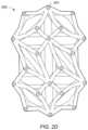
- FIGS. 1 A- 1 Billustrate views of an implant with lordosis, according to an embodiment.
- FIGS. 2 A- 2 Dillustrate views of an implant without lordosis, according to an embodiment.
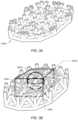
- FIGS. 3 A- 3 Cillustrate progressive sectioned views of the implant showing the internal structure of the implant, according to an embodiment.
- FIG. 3 Dillustrates an isometric view of the implant, according to an embodiment.
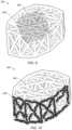
- FIGS. 4 A- 4 Dillustrate another configuration of the web structure, according to an embodiment.
- FIG. 5illustrates a flowchart of a method for making an implant, according to an embodiment.
- FIG. 6illustrates a flowchart of a method for implanting a spinal implant, according to an embodiment.
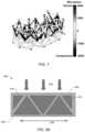
- FIG. 7depicts a diagram of stresses distributed through an implant.
- FIGS. 5 A-Cdepict schematic diagrams of the effect of compression on osteoblast cells.
- FIG. 9illustrates an isometric view of an implant filled with particles, according to some embodiments.
- FIG. 10illustrates an isometric view of an implant with particles (fibers) coating struts of the implant, according to some embodiments.
- a “truss structure”is a structure having one or more elongate struts connected at joints referred to as nodes. Trusses may include variants of a pratt truss, king post truss, queen post truss, town's lattice truss, planar truss, space truss, and/or a tardendeel truss (other trusses may also be used).
- a “truss unit”is a structure having a perimeter defined by three or more elongate struts.”
- planar trussis a truss structure where all of the struts and nodes lie substantially within a single two-dimensional plane.
- a planar trussmay include one or more “truss units” where each of the struts is a substantially straight member such that the entirety of the struts and the nodes of the one or more truss units lie in substantially the same plane.
- a truss unit where each of the struts is a substantially straight strut and the entirety of the struts and the nodes of the truss unit lie in substantially the same planeis referred to as a “planar truss unit.”
- space trussis a truss having struts and nodes that are not substantially confined in a single two-dimensional plane.
- a space trussmay include two or more planar trusses (e.g., planar truss units) wherein at least one of the two or more planar trusses lies in a plane that is not substantially parallel to a plane of at least one or more of the other two or more planar trusses.
- a space trussmay include two planar truss units adjacent to one another (e.g., sharing a common strut) wherein each of the planar truss units lie in separate planes that are angled with respect to one another (e.g., not parallel to one another).
- a “triangular truss”is a structure having one or more triangular units that are formed by three straight struts connected at joints referred to as nodes.
- a triangular trussmay include three straight elongate strut members that are coupled to one another at three nodes to from a triangular shaped truss.
- a “planar triangular truss”is a triangular truss structure where all of the struts and nodes lie substantially within a single two-dimensional plane.
- Each triangular unitmay be referred to as a “triangular truss unit.”
- a triangular truss unit where each of the struts is a substantially straight member such that the entirety of the struts and the nodes of the triangular truss units lie in substantially the same planeis referred to as a “planar triangular truss unit.”
- a “triangular space truss”is a space truss including one or more triangular truss units.
- an implantmay include a web structure.
- the web structure for the implantmay include a micro truss design.
- the micro truss designmay include a web structure with multiple struts.
- Other web structuresare also contemplated.
- the web structuremay extend throughout the implant (including a central portion of the implant). The web structure may thus reinforce the implant along multiple planes (including internal implant load bearing) and provide increased area for bone graft fusion.
- the web structuremay be used in implants such as spinal implants, corpectomy devices, hip replacements, knee replacements, long bone reconstruction scaffolding, and cranio-maxillofacial implants foot and ankle, hand and wrist, shoulder and elbow (large joint, small joint, extremities).
- the web structure for the implantmay include one or more geometric objects (e.g., polyhedrons). In some embodiments, the web structure may not include a pattern of geometrical building blocks (e.g., an irregular pattern of struts may be used in the implant). In some embodiments, the web structure may include a triangulated web structure including two or more tetrahedrons. A tetrahedron may include four triangular faces in which three of the four triangles meet at each vertex. The web structure may further include two tetrahedrons placed together at two adjacent faces to form a web structure with a hexahedron-shaped frame (including six faces).
- geometric objectse.g., polyhedrons
- the web structuremay not include a pattern of geometrical building blocks (e.g., an irregular pattern of struts may be used in the implant).
- the web structuremay include a triangulated web structure including two or more tetrahedrons. A tetrahedron may include four tri
- multiple hexahedron-shaped web structuresmay be arranged in a side-by-side manner.
- the web structuresmay connect directly through side vertices (e.g., two or more hexahedron-shaped web structures may share a vertex).
- the web structuremay be angled to provide lordosis to the implant.
- FIGS. 1 A- 1 Billustrate views of implant 100 , according to an embodiment.
- the specifically depicted implant 100may be used, for example, in anterior lumbar inter-body fusion (ALIF) or posterior lumbar inter-body fusion (PLIF), however, it should be understood that implant 100 may have a variety of shapes suitable for bone fusion applications.
- implant 100may include a web structure with one or more trusses 102 (e.g., planar and space trusses).
- Implant 100may be used in various types of implants for humans or animals such as spinal implants, corpectomy devices, knee replacements, hip replacements, long bone reconstruction scaffolding, and cranio-maxifacial implants foot and ankle, hand and wrist, shoulder and elbow (large joint, small joint, extremity as well as custom trauma implants). Other implant uses are also contemplated.
- the trusses 102 of the web structuremay include one or more planar truss units (e.g., planar triangular truss units) constructed with straight or curved/arched members (e.g., struts) connected at various nodes.
- the trusses 102may be micro-trusses.
- a “micro-truss”is a truss having dimensions sufficiently small enough such that a plurality of micro-trusses can be assembled or otherwise coupled to one another to form a web structure having a small enough overall dimension (e.g., height, length and width) such that substantially all of the web structure can be inserted into an implant location (e.g., between two vertebra).
- the diameters of the struts forming the micro-trussmay be between about 0.25 millimeters (mm) and 5 mm in diameter (e.g., a diameter of about 0.25 mm, 0.5 mm, 0.6 mm, 0.7 mm, 0.8 mm, 0.9 mm, 1 mm, 2 mm, 3 mm, 4 mm, or 5 mm).
- a micro-trussmay have an overall length or width of less than about 1 inch (e.g., a length less than about 0.9 in, 0.8 in, 0.7 in, 0.6 in, 0.5 in, 0.4 in, 0.3 in, 0.2 in, 0.1 in).
- the web structuremay extend throughout implant 100 (including the central portion of implant 100 ) to provide support throughout implant 100 .
- Trusses 102 of implant 100may thus support implant 100 against tensile, compressive, and shear forces.
- Web structuremay also reinforce implant 100 along multiple planes.
- the external truss structuremay, for example, provide support against tensile and compressive forces acting vertically through the implant, and the internal web structure may provide support against tensile, compressive, and shear forces along the various planes containing the respective trusses.
- the web structureincludes trusses 102 that form a triangulated web structure with multiple struts (e.g., struts 103 a - f ) (struts are generally referred to herein as “struts 103 ”).
- web structure of the implant 100may include an internal web structure that is at least partially enclosed by an external truss structure.
- web structure 101may include an internal web structure that includes a space truss having at least a portion of the space truss surrounded by an external truss structure that includes one or more planar trusses formed with a plurality of planar truss units that lie substantially in a single plane.
- FIG. 1 Adepicts an embodiment of implant 100 having an internal web structure 104 and an external truss structure 105 .
- internal web structure 104includes a space truss defined by a plurality of planar truss units 106 coupled at an angle with respect to one another such that each adjacent truss unit is not co-planar with each adjacent truss units.
- Adjacent truss unitsmay include two truss units that share a strut and the respective two nodes at the ends of the shared strut.
- external truss structure 105includes a plurality of planar trusses that are coupled about an exterior, interior or other portion of the implant.
- the external truss structure 105includes a series of planar trusses 107 a,b that are coupled to one another.
- Planar truss 107 ais denoted by a dashed line [- - - - -]
- planar truss 107 bis denoted by dotted-dashed line [- ⁇ - ⁇ -].
- Each planar trussis formed from a plurality of planar truss units (e.g., triangular planar truss units.
- planar truss 107 aincludes four triangular planar truss units 108 a,b,c,d having a common vertex 110 and arranged to form a generally rectangular structure that lies in a single common plane.
- the four triangular planar truss unitsare arranged to form a substantially rectangular structure having “X” shaped struts extend from one corner of the rectangular structure to the opposite corner of the rectangular structure.
- the substantially rectangular structuremay include a trapezoidal shape.
- the trapezoidal shapemay be conducive to providing an implant including lordosis.
- Lordosismay include an angled orientation of surfaces (e.g., top and bottom) of an implant that provides for differences in thickness in anterior and posterior regions of the implant such that the implant is conducive for supporting the curvature of a vertebral column.
- planar trusses that form the external trussare coupled to one another, and are aligned along at least one axis.
- planar truss section 107 ais coupled to an adjacent planar truss 107 b .
- Planer truss sections 107 a,bare not parallel in all directions.
- Planar truss sections 107 a,bare, however, arranged parallel to one another in at least one direction (e.g., the vertical direction between the top and the bottom faces of implant 100 ).
- planar trusses 107 a,b and the additional planar trussesare arranged in series with an angle relative to one another to form a generally circular or polygon shaped enclosure having substantially vertical walls defined by the planar trusses and the planar truss units arranged in the vertical direction.
- the external truss portionmay encompass the sides, top, and/or bottom of the implant.
- the external truss portionmay include a top region, side regions, and/or a bottom region.
- FIG. 1 Adepicts an embodiment of implant 100 wherein external truss portion 105 includes a top 111 , bottom 112 and a side region 113 .
- side region 113includes a series of planar trusses arranged vertically to form a circular/polygon ring-like structure that completely or at least partially surrounds the perimeter of the space truss disposed in the central portion of implant 100 .
- top portion 111 of external truss structure 105includes a plurality of truss units coupled to one another to form a planar truss that cover substantially all of the top region of internal web structure 104 .
- the top portion 111spans entirely the region between top edges of the side portion 113 of external truss structure 105 .
- top portion 111is formed from a single planar truss that includes a plurality of truss units that lie in substantially the same plane. In other words, the planar truss of top portion 111 defines a generally flat surface.
- the underside of implant 100may include the bottom portion 112 having a configuration similar to that of the top portion 111 .
- external truss structure 105may include a partial side, top and/or bottom external truss portions. Or may not include one or more of the side, top and bottom external truss portions.
- FIG. 2 Cdepicts an embodiment of implant 180 that includes an internal web structure formed from space trusses, that does not have an external truss structure.
- implant 100may be formed from a biocompatible material such as a titanium alloy (e.g., ⁇ Titanium Aluminides), cobalt, chromium, stainless steel, Polyetheretherketone (PEEK), ceramics, etc. Other materials are also contemplated.
- implant 100may be made through a rapid prototyping process (e.g., electron beam melting (EBM) process) as further described below.
- EBMelectron beam melting
- Other processesare also possible (e.g., injection molding, casting, sintering, selective laser sintering (SLS), Direct Metal Laser Sintering (DMLS), etc).
- SLSmay include laser-sintering of high-performance polymers such as that provided by EOS of North America, Inc., headquartered in Novi, Michigan, U.S.A.
- High-performance polymersmay include various forms of PEEK (e.g., HP3 having a tensile strength of up to about 95 mega Pascal (MPa) and a Young's modulus of up to about 4400 MPa and continuous operating temperature between about 180° C. (356° F.) and 260° C. (500° F.)).
- Other materialsmay include PA 12 and PA 11 provided by EOS of North America, Inc.
- the web structuremay be formed from a plurality of triangular planar truss units.
- the planar truss unitsmay be coupled to each other to define polyhedrons that define the internal web structure.
- Examples of polyhedron structures that may be created by joining planar truss unitsinclude, but are not limited to, tetrahedrons, pentahedrons, hexahedrons, heptahedrons, pyramids, octahedrons, dodecahedrons, icosahedrons, and spherical fullerenes.
- the space truss of the web structuremay connect multiple midpoints of tetrahedron building blocks and include a regular pattern of tetrahedron blocks arranged adjacent one another.
- the web structuremay not include a pattern of geometrical building blocks. Examples of implants composed of a web structure are described in U.S. Published Patent Applications Nos.: 2010/0161061; 2011/0196495; 20110313532; and 2013/0030529, each of which is incorporated herein by reference.
- top surface 115 a and bottom surface 115 b of implant 100may include triangles, squares, circles or other shapes (e.g., a random or custom design).
- Top and bottom surfaces 115 a,bmay be used to connect the top and bottom vertices of various geometrical building blocks used in the web structure of implant 100 .
- each vertexmay be connected through struts to the neighboring vertices of other geometrical building blocks.
- Top surface 115 amay include other strut networks and/or connections.
- bottom surface 115 bmay mirror the top surface (and/or have other designs).
- top surface 115 a and bottom surface 115 bmay engage respective surfaces of two adjacent vertebrae when implant 100 is implanted.
- implant 100may include lordosis (e.g., an angle in top and/or bottom surfaces 115 a,b approximately in a range of 4 to 15 degrees (such as 4, 5, 6, 7, 8, 9, 10, 11, 12, 13, 14, or 15 degrees)) to further support the adjacent vertebrae when implanted.
- lordosismay include an angled orientation of surfaces (e.g., top and bottom) that provide for differences in thickness in the anterior and posterior portions of the implant such that the implant is conducive for supporting the curvature of a vertebral column.
- the thickness of implant 100is greater at or near the anterior portion 118 and lesser at or near the posterior portion 120 of the implant.
- the side portions of external truss structureare arranged substantially vertically, and the lordosis is formed by the angles of the top portion 111 and bottom portion 112 of external truss structure.
- top portion 111 and bottom portion 112 of external truss structureare not perpendicular to the vertical plane defined by the side portion 113 . Rather, the top portion 11 I and bottom portion 112 are arranged with an acute angle relative to the vertical plane of side portion 113 at or near the anterior region 118 of implant 100 and with an obtuse angle relative to the vertical plane of side portion 113 at or near posterior region 120 of implant 100 .
- the vertical struts that form the planar truss of side portion 113 of external truss structure proximate posterior region 120 of implant 100are shorter than struts that form side portion of external truss structure proximate anterior region 118 of implant 100 .
- the struts forming the “X” cross members of the side planar trusses proximate the posterior region 120 of implant 100are shorter than struts forming the “X” cross members of the side planar trusses proximate the anterior region 118 of implant 100 .
- Other embodimentsmay include variations in the arrangement of the trusses to provide various configurations of the implant.
- top and bottom external truss portionsmay be non-perpendicular to the side portions of the external truss proximate the anterior and posterior portions of the implant.
- the side, top, and/or bottom portionsmay include multiple planar trusses angled relative to one another in any orientation.
- the top or bottom portionsmay include four planar trusses, each formed of multiple truss units, such that the portion(s) includes a pyramidal like shape.
- the implantmay not include lordosis.
- FIGS. 2 A- 2 Billustrate two views of an embodiment of an implant 200 without lordosis.
- the top surface and bottom surfacemay not include connecting struts.
- FIGS. 2 C- 2 Dillustrate two views of implant 250 without outer struts (e.g., without external truss portions formed of planar trusses).
- implant 250includes an internal web structure and does not include an external truss structure.
- the exterior faces of implant 250are defined by a plurality of truss units that are angled relative to each of its adjacent truss units.
- the relative alignment of the truss unitsresults in a non-planar exterior that includes a plurality of pointed junctions.
- the pointed junctionse.g., pointed junction 201
- the pointed junctionsmay operate to dig into the surrounding bone to hold the implant in place (for example, if the implant is being used in a corpectomy device).
- FIGS. 3 A- 3 Cillustrate progressive sectioned views of implant 100 showing the internal structure of implant 100 , according to an embodiment.
- FIG. 3 Aillustrates a sectioned view of a lower portion of implant 100 .
- Bottom surface 115 bis shown with various struts (e.g., struts 103 ) extending upward from bottom surface 115 b .
- FIG. 3 Billustrates a sectioned view approximately mid-way through implant 100 .
- Strutssuch as struts 103 e,f , shared by various stacked tetrahedrons in the web structure are shown. Some struts extend through central portion 501 a and/or 501 b of implant 100 .
- FIG. 3 Aillustrates a sectioned view of a lower portion of implant 100 .
- Bottom surface 115 bis shown with various struts (e.g., struts 103 ) extending upward from bottom surface 115 b .
- central portion 501 amay include a rectangular region that has a width of approximately 50% of the implant width, a height of approximately 50% of the implant height, and a length of approximately 50% of the implant length and located in the center of implant 100 .
- central portion 501 bmay encompass a region (e.g., a spherical region, square region, etc.) of approximately a radius of approximately 1 ⁇ 8 to 1 ⁇ 4 of the width of implant too around a position located approximately at one half the width, approximately one half the length, and approximately one-half the height of implant 100 (i.e., the center of implant 100 ).
- Other central portionsare also contemplated.
- the central portionmay include a square region with a length of one of the sides of the square region approximately 1 ⁇ 4 to 1 ⁇ 2 the width of implant 100 around a position approximately at one half the width, approximately one half the length, and approximately one half the height of the implant.
- An example height 502 a , width 502 b , and length 502 cis shown in FIG. 3 D .
- the heightmay be up to about 75 mm or more.
- the width and/or lengthcould be approximately 7 inches or longer.
- the width, length, and/or heightmay vary along implant 100 (e.g., the height may vary if the implant includes lordosis).
- the heightmay be taken at one of the opposing sides, the middle, and/or may be an average of one or more heights along the length of implant 100 .
- the web structuremay extend through central portion 501 a,b of the implant (e.g., at least one strut of the web structure may pass at least partially through central portion 501 a,b ).
- FIG. 3 Cillustrates another sectioned view showing sectioned views of top tetrahedrons in the web structure.
- FIG. 3 Dshows a complete view of implant 100 including top surface 115 a with vertices 301 a - d.
- FIGS. 4 A- 4 Dillustrate alternate embodiments of an implant.
- different sections of the hexahedron-shaped geometric designmay be used.
- the bottom half of the hexahedron-shaped geometric designmay be used (primarily including the lower tetrahedron structures).
- implant 600may be expanded proportionately to have similar overall dimensions as the hexahedron-shaped geometric design (e.g., the tetrahedrons may be expanded to approximately twice the height of the tetrahedrons in the hexahedron-shaped geometric design to give implant 600 a height approximately the same as the hexahedron-shaped geometric design).
- implant 600may also be angled (e.g., on top surface 601 a and/or bottom surface 601 b ) to provide implant 600 with lordosis to, in some embodiments, have a better fit between the vertebral endplates.
- Top surface 601 a and/or bottom surface 601 bmay also include struts to connect nodes of implant 600 (e.g., see the strut network on the top surface in FIG. 4 A ). Other patterns of struts for top surface 601 a and/or bottom surface 601 b may also be used.
- implant 600may not include negative angles between struts and may thus be easier to create through a casting or molding process.
- FIGS. 4 C- 4 Dillustrate another alternate embodiment of an implant.
- approximately the middle 40 to 60 percent of the hexahedron-shaped geometric designmay be used in implant 650 .
- an overall height of the hexahedron-shaped geometric designis approximately 37 mm
- approximately the bottom 10 mm and approximately the top 10 mm of the designmay be removed and approximately the middle 17 mm of the design may be used for the implant.
- Middle portion of implant 650may then be expanded proportionately such that the approximate height of the expanded design may be approximately 37 mm (or a different height as needed).
- Top surface 651 a and bottom surface 651 bmay include a network of struts (e.g., see the struts on top surface 651 a of FIG. 4 C ) (other networks of struts are also contemplated).
- Other portions of the design for the implantare also contemplated (e.g., the top half of the design shown in FIG. 1 A , the bottom half of the design shown in FIG. 1 A , etc).
- Design portionsmay be proportionately expanded to meet specified dimensions (e.g., specified height, width, and length).
- the amount of strutsmay be reduced or material in the implant may be redistributed so that some struts may have a larger diameter and some may have a smaller diameter (e.g., the different diameters may reinforce against different directional forces).
- a partial-design cagemay be used (e.g., with half of the web structure so that the structure includes a tetrahedron.
- the implantmay include angled surfaces (e.g., an angled top surface 651 a and/or angled bottom surface 651 b ) to provide lordosis for implants to be implanted between the vertebral endplates.
- the web structure of an implantmay distribute forces throughout the implant when implanted.
- the connecting struts of the web structuremay extend throughout the core of an implant, and the interconnectivity of struts may disperse the stress of compressive forces throughout implant to reduce the potential of stress risers (the distribution of forces throughout the implant may prevent concentration of stress on one or more portions of the vertebrae that may otherwise result in damage to the vertebrae).
- the web structure of an implantmay also provide surface area for bone graft fusion.
- the web structure extending throughout an implantmay add additional surface areas (e.g., on the surface of the struts making up the implant) to fuse to the bone graft material and prevent bone graft material from loosening or migrating from the implant.
- the web structuremay also support bone in-growth.
- adjacent bonee.g., adjacent vertebrae if the implant is used as a spinal implant
- the bone growth and engagement between the bone growth and the implantmay further stabilize the implant.
- the surfaces of the implantmay be formed with a rough surface to assist in bone in-growth adhesion.
- strutsmay have a diameter approximately in a range of about 0.025 to 5 millimeters (mm) (e.g., 1.0 mm, 1.5 mm, 3 mm, etc). Other diameters are also contemplated (e.g., greater than 5 mm), in some embodiments, the struts may have a length approximately in a range of 0.5 to 20 mm (e.g., depending on the implant size needed to, for example, fit a gap between vertebral endplates). As another example, struts may have a length approximately in a range of 30-40 mm for a hip implant.
- mmmillimeters
- the reduced strut size of the web structuremay allow the open cells in implant 100 to facilitate bone growth (e.g., bone may grow through the open cells once implant 100 is implanted in the body).
- Average subsidence for implantsmay be approximately 1.5 mm within the first 3 weeks post op (other subsidence is also possible (e.g., approximately between 0.5 to 2.5 mm)).
- a strut size that approximately matches the subsidencee.g., a strut size of approximately 1.5 mm in diameter and a subsidence of approximately 1.5 mm
- the net 0 impedance throughout the entire surface area of the implant/vertebrae endplate interfacemay result in a larger fusion column of bone that may result in more stable fusion.
- Other fusion column sizesare also contemplated.
- the configuration of the implantmay redistribute the metal throughout the implant.
- a rimmay not be included on the implant (in some embodiments, a rim may be included).
- the resulting bone growth(e.g., spinal column) may grow through the implant.
- greater than 50% of the interior volume of implant 100may be open. In some embodiments, greater than 60%, greater than 70%, and/or greater than 80% of implant 100 may be open (e.g., 95%). In some embodiments, the open volume may be filled with bone graft material. For example, cancellous bone may be packed into an open/internal region of implant.
- subsidencemay place additional pressure on the bone graft material (which may already be under compressive forces in the implant) and act to push the bone graft material toward the sides of the implant (according to Boussinesq's theory of adjacent material, when a force is applied to a member that is adjacent to other materials (such as sand, dirt, or bone graft material) the force against the member creates a zone of increased pressure (e.g., 60 degrees) in the adjacent material).
- Struts of the implantmay resist bone graft material protrusion from the sides of the web structure and may increase the pressure of the bone graft material.
- Bone graft materialmay need to be implanted in a higher-pressure environment to create an environment conducive to strong bone growth (e.g., according to Wolf's law that bone in a healthy person or animal will adapt to the loads it is placed under).
- the web structuremay thus increase the chance of stronger fusion.
- the trussesmay include a series of packing triangles, a two-web truss, a three-web truss, etc.
- the web structure for an implantmay include one or more trusses as described in U.S. Pat. No. 6,931,812 titled “Web Structure and Method For Making the Same”, which issued Aug. 23, 2005, which is hereby incorporated by reference in its entirety as though fully and completely set forth herein.
- FIG. 5illustrates a flowchart of a method for making an implant.
- an implantmay be made through rapid prototyping (e.g., electron beam melting, laser sintering, etc). It should be noted that in various embodiments of the methods described below, one or more of the elements described may be performed concurrently, in a different order than shown, or may be omitted entirely. Other additional elements may also be performed as desired. In some embodiments, a portion or the entire method may be performed automatically by a computer system.
- a three-dimensional model of an implantis generated and stored in a storage medium accessible to a controller operable to control the implant production process.
- a layer of materiale.g., a powder, liquid, etc.
- the powdermay include ⁇ TiAl ( ⁇ Titanium Aluminides) which may be a high strength/low weight material. Other materials may also be used.
- the powdermay be formed using a gas atomization process and may include granules with diameters approximately in a range of 20 to 200 micrometers ( ⁇ m)(e.g., approximately 80 ⁇ m).
- the powdermay be delivered to the support through a distributer (e.g., delivered from a storage container).
- the distributer and/or the supportmay move during distribution to apply a layer (e.g., of powder) to the support.
- the layermay be approximately a uniform thickness (e.g., with an average thickness of 20 to 200 micrometers ( ⁇ m)).
- the distributer and supportmay not move (e.g., the material may be sprayed onto the support).
- the controllermoves an electron beam relative to the material layer.
- the electron beam generatormay be moved, and in some embodiments the support may be moved. If the material is ⁇ TiAl, a melting temperature approximately in a range of 1200 to 1800 degrees Celsius (e.g., 1500 degrees Celsius) may be obtained between the electron beam and the material.
- additional materialmay be applied by the distributer.
- the unmelted materialis removed and the implantcooled (e.g., using a cool inert gas).
- the edges of the implantmay be smoothed to remove rough edges (e.g., using a diamond sander).
- the implantmay include rough edges to increase friction between the implant and the surrounding bone to increase adhesion of the implant to the bone.
- an implantmay be cast or injection molded.
- multiple partsmay be cast or injection molded and joined together (e.g., through welding, melting, etc).
- individual struts forming the implantmay be generated separately (e.g., by casting, injection molding, etc.) and welded together to form the implant.
- multiple implants of different sizesmay be constructed and delivered in a kit. A medical health professional may choose an implant (e.g., according to a needed size) during the surgery. In some embodiments, multiple implants may be used at the implant site.
- Specialized toolsmay be used to insert the implants described herein. Examples of tools that may be used are described in U.S. Published Patent Applications Nos.: 2010/0161061; 2011/0196495; 20110313532; and 2013/0030529, each of which is incorporated herein by reference.
- FIG. 6illustrates a flowchart of a method for implanting a spinal implant, according to an embodiment. It should be noted that in various embodiments of the methods described below, one or more of the elements described may be performed concurrently, in a different order than shown, or may be omitted entirely. Other additional elements may also be performed as desired. In some embodiments, a portion or the entire method may be performed automatically by a computer system.
- an intersomatic spaceis accessed.
- an anterior openingmay be made in a patient's body for an anterior lumbar inter-body fusion (ALIF) approach or a posterior opening may be made for a posterior lumbar inter-body fusion (PLIF) approach.
- at least a portion of the intersomatic spaceis excised to form a cavity in the intersomatic space.
- the implantis inserted into the cavity in the intersomatic space.
- a handler, or some other deviceis used to grip the implant.
- a forcemay be applied to the implant (e.g., through a hammer) to insert the implant into the cavity.
- the implant and/or space in the cavitymay be packed with bone graft material.
- the access point to the intersomatic spacemay be closed (e.g., using sutures).
- the implantmay be customized.
- three dimensional measurements and/or shape of the implantmay be used to construct an implant that distributes the web structure throughout a three-dimensional shape design.
- a truss/web structuremay be disposed on at least a portion of an implant to facilitate coupling of the implant to an adjacent structure.
- one or more truss structuresmay be disposed on and/or extend from a surface (e.g., an interface plate) of the implant that is intended to contact, and at least partially adhere to, the bony structure during use.
- a surfacee.g., an interface plate
- one or more truss structuresmay be disposed on a contact surface of the intervertebral implant to facilitate bone growth that enhances coupling of the intervertebral implant to the bony structure.
- a truss structuremay include one or more struts that extend from the contact surface to define an open space for bone growth therethrough, thereby enabling bone through growth to interlock the bone structure and the truss structure with one another to couple the implant to the bony structure at or near the contact face.
- Such interlocking bone through growthmay inhibit movement between the implant and the bony structure which could otherwise lead to loosening, migration, subsidence, or dislodging of the implant from the intended position.
- Similar techniquesmay be employed with various types of implants, including those intended to interface with tissue and/or bone structures.
- a truss structuremay be employed on a contact surface of knee implants, in a corpectomy device, in a hip replacement, in a knee replacement, in a long bone reconstruction scaffold, or in a cranio-maxifacial implant hip implants, jaw implant, an implant for long bone reconstruction, foot and ankle implants, shoulder implants or other joint replacement implants or the like to enhance adherence of the implant to the adjacent bony structure or tissue.
- truss structures, and other structures, that may extend from the surface of an implant to facilitate coupling of the implant to an adjacent structureare described in U.S. Published Patent Application No. 2011/0313532, which is incorporated herein by reference.
- implants described hereinare depicted as being composed of substantially straight struts, it should be understood that the struts can be non-linear, including, but not limited to curved, arcuate and arch shaped. Examples of implants having non-linear struts are described in U.S. patent application Ser. No. 13/668,968, which is incorporated herein by reference.
- BMPbone morphogenetic protein
- a web structure that includes a plurality of joined truss unitsexhibits a number of deformations in response to loading.
- FIG. 7 belowdepicts some of the forces that are dispersed along the struts of the truss units that make up the web structure.
- web structures as described hereinmay promote the growth of bone in and around the web structure, in part, because of the enhanced BMP production.
- osteoblastsbecome attached to the struts of a web structure. Under loading, the micro strain in the struts causes localized deformation which in turn transfers the strain to the adhered osteoblasts which cause the osteoblasts to elute BMP.
- FIG. 8 Adepicts a schematic diagram of an implant 400 that includes a space truss 410 .
- Bone structuresare typically disposed against a top face 420 and a bottom face 425 of implant 400 .
- the stress from the contacting bone structurescan cause implant 400 to lengthen (denoted by arrow 435 ) as the implant is compressed.
- This lengtheningcan have a beneficial effect on the formation of BMP by osteoblasts that adhere to the implant.
- Adjacent boneadds compression forces to the slanted struts. This compression may lead to bone remodeling.
- the combination of the two forcescreates bone growth/remodeling which leads to accelerated healing and achieving a mature fusion in a shorter amount of time as compared to predicate devices.
- FIG. 8 Bdepicts a close-up view of strut 415 of implant 400 .
- Strut 415in FIG. 8 B is shown in a non-elongated state. This may represent the state of strut 415 when the implant is not under load from the contacting bone structures.
- Osteoblastsare depicted as adhered to strut 415 . The osteoblasts are shown in their normal, non-elongated form.
- FIG. 8 Cdepicts strut 415 in an elongated state, which exists when the bone structures are applying a compressive force to implant 400 . As shown, the osteoblasts are believed to be stretched due to the elongation of strut 415 .
- Elongation of the osteoblastslead to an influx of calcium which is then converted into BMP and eluted back out.
- the production of BMPmay be attained when the length of the attached osteoblasts is changed between about 0.05% and about 0.2% or between about 0.1% and about 0.15%.
- Configuring a truss system to intentionally create lengthening/microstrain in osteoblastsmay reduce the time needed for the bone structure to be repaired.
- an implant for interfacing with a bone structureincludes a web structure comprising a plurality of struts joined at nodes.
- the web structureis configured to interface with human bone tissue.
- a diameter and/or length of the strutsare predetermined such that when the web structure is in contact with the bone structure, BMP production from osteoblasts adhering to the implant surface is achieved.
- the diameter and/or length of the strutsis predetermined so that at least a portion of the struts create a microstrain in the adhered osteoblasts of between about 1 and 5000 microstrain, 500 ⁇ and about 2000 ⁇ or between about 1000 ⁇ and about 1500 ⁇ .
- the diameter and/or length of the strutsis predetermined so that at least a portion of the struts create a change in length of the adhered osteoblasts of between about 0.05% and about 0.2% or between about 0.1% and about 0.15%.
- An implantmay be prepared having struts of a length of between about 1 to 100 mm.
- the diameter of the strutsmay be set such that the strut undergoes a change of length of between about 0.05% and 0.2% when the web structure is in contact with the bone structure.
- the diameter of the strutsis predetermined such that the strut undergoes a change of length of between about 0.000125% and 0.0005% or between about 0.00025% and 0.000375%.
- any implant described hereinmay be modified so that at least a portion of the struts the form the web structure produce the appropriate microstrain/lengthening of adhered osteoblasts.
- most if not all of the struts that form the web structure of an implantmay be ‘programmed’ (or designed) to stimulate BMP production.
- some strutsmay be programmed/designed for BMP production, while other struts have different physical properties than the programmed struts.
- An implantmay be optimized to distribute stresses encountered by the implant. Most implants used for bone repair are placed in locations that apply non-uniform stress to the implant. The non-uniform stress creates different forces across the implant. If an implant is designed to withstand a certain homogenous force, the implant may fail when subjected to non-uniform stress. In a non-uniform stress situation, some of the stress on the implant may be sufficient to deform the implant. It is desirable to have an implant that is customized to the expected non-uniform stress that will be encountered in the bone structure being repaired.
- an implant for interfacing with a bone structureincludes a web structure having a plurality of struts joined at nodes.
- the web structureis configured to interface with human bone tissue, and has a first bone contact surface and a second bone contact surface.
- a first portion of struts that are part of the space trusshave a physical property that is different from a second portion of the struts that are a part of the space truss.
- the first portion of struts that are part of the space trusshave a deformation strength that is different from a second portion of the struts that are a part of the space truss.
- the space trussmay include one or more central struts extending from the first bone contact surface to the second bone contact surface.
- the central strutsmay have a deformation strength that is greater than or less than the surrounding struts, depending on the location of the implant.
- the space trussmay include one or more longitudinal struts extending parallel to the first bone contact surface and/or the second bone contact surface, wherein the longitudinal struts have a deformation strength that is greater than or less than the surrounding struts.
- the physical properties of the struts of the implantmay be varied such that the diameter of the first portion of the struts is greater than a diameter of the second portion of the struts.
- the first portion of strutsare formed from a material that is different from the material used to form the second portion of struts.
- the first portion of strutshave a diameter that is different from the diameter of the second portion of struts.
- the first portion of strutshave a density that is different from the density of the second portion of struts.
- he first portion of strutshave a porosity that is different from the porosity of the second portion of struts. Any combination of these different physical properties may be present in an implant to help optimize the distribution of stress throughout the implant.
- one or more biologicsmay be included in an implant.
- various biologicsmay be included to promote bone growth or bone adhesion, or to add an antimicrobial agent to prevent infections.
- biologicsare added to an implant by coating structures (e.g., struts) of the implant with fibers and/or particles.
- biologicsare added to an implant by placing or positioning fibers and/or particles inside the interior volume (e.g., open space) of the implant.
- the fibers or particlesmay fill at least a portion of an interior volume of the implant.
- Embodimentsmay also be contemplated with combinations of coating fibers and/or particles or filling the interior volume with fibers or particles. Such combinations may include the same types of fibers or particles as both coatings and fillings or different types of fibers or particles for the coatings and fillings.
- a biologicmay include a coating, such as hydroxyapatite, bone morphogenetic protein (BMP), insulin-like growth factors I and II, transforming growth factor-beta, acidic and basic fibroblast growth factor, platelet-derived growth factor, and/or similar bone growth stimulant that facilitates good biological fixation between the bone growth and a surface of the implant.
- BMPbone morphogenetic protein
- insulin-like growth factors I and IIinsulin-like growth factors I and II
- transforming growth factor-betatransforming growth factor-beta
- acidic and basic fibroblast growth factortransforming growth factor-beta
- platelet-derived growth factorplatelet-derived growth factor
- similar bone growth stimulantthat facilitates good biological fixation between the bone growth and a surface of the implant.
- a bone growth factormay include a naturally occurring substance capable of stimulating cellular growth, proliferation and cellular differentiation (e.g., a protein or steroid hormone).
- the surface of the implante.g., the struts
- a biologic and/or growth factormay be secured to a central region of an implant.
- a biologic or growth factormay be provided on at least a portion of a strut that extends through central portion 501 a and/or 501 b of implant 100 , shown in FIG. 3 B .
- Such an embodimentmay enable the delivery of a biologic and or a growth factor to a central portion of an implant.
- the biologic or growth factormay be physically secured to a strut in a central portion of the implant as opposed to being packed into an open volume that does not include a strut provided therein for the physical attachment of the biologic and/or growth factor.
- implantsmay be at least partially filled or coated with nanofibers and/or microfibers that include a bone promoting agent.
- microfiberrefers to fibers whose diameter ranges from about 1 micrometer to about 1000 micrometers.
- nanofiberrefers to fibers whose diameter ranges from about 1 nanometer to about 1000 nanometers.
- macrofibersrefers to fibers whose diameters are above about 1000 micrometers.
- fiberswithout a qualifier, refers to macrofibers, millimeter fibers, microfibers, and nanofibers.
- bone growth promoting agentsinclude, but are not limited to, calcium phosphate materials, biological bone growth promoting agents, and polysaccharides.
- calcium phosphate materialsinclude, but are not limited to, hydroxyapatite (Hap, Ca 10 (PO 4 ) 6 (OH) 2 ), ⁇ - and ⁇ -tricalcium phosphate (TCP: Ca 3 (PO 4 ) 2 ), and whitlockite (WH, Ca 9 Mg(HPO 4 )(PO 4 ) 6 ).
- Biological bone promoting agentsinclude, but are not limited to, proteins, peptides, and small organic molecules that promote or enhance bone growth. Promotion or enhancement of bone growth may, in some embodiments, be accomplished by increasing the concentration of bone promoting proteins either directly or indirectly. Direct promotion of bone growth may be accomplished by treating a site in need of bone repair with a protein or peptide that creates a bone growth promoting response. Examples of agents that directly promote bone growth include, but are not limited to, insulin-like growth factor (IGF-1, IGF-11), transforming growth factor ⁇ (TGF ⁇ ), heparin binding growth.
- IGF-1, IGF-11insulin-like growth factor
- TGF ⁇transforming growth factor ⁇
- HBGFstromal cell-derived factor
- SDF-1vascular endothelial growth factor
- FGFfibroblast growth factor
- PDGFplatelet-derived growth factor
- PTHparathyroid hormone
- PTHrPparathyroid hormone Related peptide
- BFGFbasic fibroblast growth factor
- TGF ⁇ superfamily factorbone morphogenetic protein (BMP), preferably BMP2, BMP3, BMP4, BMP5, BMP7, somatropin, growth differentiation factor (GDF), bone-specific alkaline phosphatase (BAP), collagen, osteocalcin (bone gamma-carboxyglutamic acid-containing protein (BGLAP)), granulocyte colony-stimulating factor (GCSF), phosphate-regulating neutral endopeptidase, X-linked (PHEX), and transcription factor Sp7 (SP7).
- Agents that indirectly promote bone growthtrigger the body to produce direct bone promoting agents in response to the indirect bone growth promoting agent.
- Polysaccharidesinclude, but are not limited to dextran, agar, alginic acid, hyaluronic acid, inulin, pullulan, heparin, fucoidan, chitosan, scleroglucan, curdlan, starch, cellulose, and the like. Additionally, chemically modified polysaccharides with acidic groups (carboxylates, sulfates, phosphates), amino groups (ethyleneamine, diethylaminoethylamine, propylamine), and hydrophobic groups (alkyl, benzyl) may be used.
- acidic groupscarboxylates, sulfates, phosphates
- amino groupsethyleneamine, diethylaminoethylamine, propylamine
- hydrophobic groupsalkyl, benzyl
- fibers that include a bone growth promoting agentmay be produced by an electrospinning process.
- the electrospinning processapplies a high voltage to a polymer solution or melt as the material is ejected through a needle.
- the electric voltageis sufficient enough to overcome the surface tension of the polymer solution or melt and causes the polymer droplets to elongate so that the polymer is pulled into fibers.
- the fibersare collected on a grounded or charged metal plate in the form of non-woven mats.
- fibers that include a bone growth promoting agentmay be produced by a centrifugal spinning process.
- a centrifugal spinning processa polymer solution or melt is loaded into a “spinneret.” The spinneret is then rotated at speeds (typically at least 500 rpms) sufficient to eject material at a sufficient velocity to create micro- and/or nano- diameter fibers.
- Apparatuses and methods that may be used to create the polymer fibers and/or polymer structures using centrifugal spinningare described in the following U.S. Published Patent Applications: 2009/0280325; 2009/0269429; 2009/0232920; 2009/0280207 and 201510184317, all of which are incorporated herein by reference.
- fibers or particlesmay be formed from a composition of a polymer and a bone growth promoting agent.
- the polymerfunctions as a substrate for the bone growth promoting agent.
- the polymer usedmay be selected based on the type of bone growth promoting agent and the desired delivery of the bone growth promoting agent.
- the nanofibers/microfibersmay be produced from a bone growth promoting agent mixed with a non-degradable biocompatible polymer.
- biocompatible polymerrefers to a polymer that the body generally accepts without a substantial immune response, which is capable of implantation in biological systems, without causing excessive fibrosis or rejection reactions.
- non-degradable biocompatible polymersinclude, but are not limited to: polysiloxanes (e.g., poly(dimethyl siloxane); copolymers of dimethylsiloxanes and methylvinylsiloxanes; ethylene/vinyl acetate copolymers (EVA); polyethylene; polypropylene; ethylenelpropylene copolymers; acrylic acid polymers; ethylene/ethyl acrylate copolymers; polytetrafluoroethylene (PTFE); polyurethanes; polyesters; polybutadiene; polyisoprene; poly(methacrylate); polymethyl methacrylate; styrene-butadiene-styrene block copolymers; poly(hydroxyethylmethacrylate) (pHEMA); polyvinyl chloride; polyvinyl acetate; polyethers; polyacrylonitriles; polyethylene glycols; polymethylpentene; polybutadiene; polyhydroxy
- fibers or particlesmay be produced from a bone growth promoting agent mixed with (or contained within) a biodegradable polymer.
- biodegradablerefers to the ability of a substance or material to break down into harmless substances over time by the action of living organisms.
- biodegradable polymersinclude, but are not limited to: polycaprolactone (PCL); poly(glycolic acid (PGA); polylactide (PLA); poly (lactic acid-glycolic acid) (PLGA), poly(dioxanone), poly(3-hydroxybutyrate), poly(3-hydroxyvalerate), poly(valerolactone), poly(tartronic acid), poly( ⁇ -malonic acid), and poly[1,6-bis(carboxyphenoxy)hexane].
- PCLpolycaprolactone
- PGApoly(glycolic acid
- PLApolylactide
- PLApoly (lactic acid-glycolic acid)
- PLGApoly(dioxanone), poly(3-hydroxybutyrate), poly(3-hydroxyvalerate), poly(valerolactone), poly(tartronic acid), poly( ⁇ -malonic acid), and poly[1,6-bis(carboxyphenoxy)hexane].
- the lactide used to form the polymerhas 3 optical isomers (L-lactide, D-lactide, and DL-lactide), the polymers obtained from L-lactide, D-lactide, and DL-lactide are abbreviated to PLLA, PDLA, and PDLLA, respectively.
- Biodegradable polymersmay break down over time when placed in the body and release the bone growth promoting agent.
- the release rate of the bone growth promoting agentmay be controlled by selection of the biodegradable polymer.
- a biodegradable polymerwill degrade in between 1 to 24 months, depending on the type of polymer used. Accordingly, the release rate of the bone growth promoting agent may be determined by the rate of degradation of the biodegradable polymer.
- particle size of the biodegradable polymermay determine the release rate of the bone growth promoting agent. For instance, larger particle sizes may take longer to degrade and release the bone growth promoting agent.
- particles of biodegradable polymer that fill the implant or are coated on struts of the implanthave varying rates of degradation in order to release the bone growth promoting agent at various times.
- the varying rates of degradationmay be implemented, for example, by providing biodegradable polymers of varying sizes (e.g., a distribution of sizes) to the implant.
- the varying rates of degradationmay be implemented by providing a bone growth promoting agent (or a plurality of bone growth promoting agent) in different biodegradable polymers that have different degradation rates.
- various biodegradable polymer particles included in an implanthave various bone growth promoting agents associated with them (e.g., contained within the particles).
- a first biodegradable polymermay contain a first bone growth promoting agent while a second biodegradable polymer may contain a second bone growth promoting agent.
- the first bone growth promoting agentmay be released at a rate determined by the first biodegradable polymer while the second bone growth promoting agent is released at a rate determine by the second biodegradable polymer.
- Various embodimentsmay be contemplated with varying types and sizes of biodegradable polymers are combined with varying types of bone growth promoting agents.
- Table Ishows some typical biodegradable polymers and the approximate degradation time.
- FIG. 9illustrates an isometric view of an implant filled with particles, according to some embodiments.
- implant 900includes struts 902 with particles 904 filling portions of the space/volume between the struts.
- Particles 904may be positioned in an interior volume of implant 900 .
- particles 904fill or substantially fill the entire interior volume of implant 900 .
- particles 904may fill a portion or portions of the interior volume of implant 900 .
- particles 904include microgranules.
- particles 904may be fibers such as polymeric fibers or collagen fibers.
- particles 904include polymeric substrates (such as biodegradable polymeric substrates) that contain a bone growth promoting agent, as described herein.
- Polymeric substratesmay include, for example, biodegradable polymers that release the bone growth agent over time as the polymers degrade.
- Particles 904may have a variety of sizes.
- particles 904may include microfibers, nanofibers, macrofibers, or a combination thereof. The sizes of particles 904 may, in some embodiments, be determined by the size of the polymeric substrates.
- particles 904may be placed into implant 900 after formation of the implant.
- a fibrous matmay be collected from the electrospinning or centrifugal spinning process. The mat may be pushed into the web structure of implant 900 such that the fibers are positioned in (e.g., filled or embedded into) an interior volume of the implant.
- particles 904may be electrospun into implant 900 .
- FIG. 10illustrates an isometric view of an implant with fibers coating struts of the implant, according to some embodiments.
- implant 900includes struts 902 coated with fibers 906 .
- Fibers 906may have a variety of sizes. Examples of fiber sizes include, but are not limited to, microfibers, nanofibers, macrofibers, or combinations thereof. Fibers 906 may include, but not be limited to, collagen fibers, cortical fibers, allograft fibers, synthetic fibers, or combinations thereof.
- fibers 906are coated on struts 902 on the exterior of implant 900 (e.g., the exterior of the web structure). Fibers 906 may, however, also be coated on struts 902 in the interior of implant 900 . Fibers 906 may be coated on any number of struts or all the struts depending on desired properties of implant 900 . In various embodiments, as described above, fibers 906 may coat the outside of implant 900 either with or without particles (e.g., particles 904 ) being positioned in the web structure. For example, in an electrospinning process, the implant may be connected to an electrical source to create an electrical charge on the implant opposite to the electrical charge of the fibers being produced.
- particlese.g., particles 904
- the charged fibersare therefore attracted to the implant and form a coating on the implant.
- the elongated fibers produced during the electrospinning processmay become wrapped around the struts of a planar truss structure implant during production, coating at least a portion of the exterior surface of the web structure.
- This processmay be used in combination with filling (e.g., embedding) the implant with particles (or other bone growth promoting materials) to form an implant that is filled with particles containing a bone growth promoting agent and coated with fibers.
- fibers 906are attached to one or more struts 902 of the implant 900 .
- fibers 906may be attached to one or more struts 902 by placing the fibers within the web structure of the implant, or coating the implant with the fibers, and heating the fibers to a temperature above the glass transition temperature of the polymer. Heating above the glass transition temperature of the polymer creates melting of the outer surface of the fibers. The at least partially melted fibers will stick to the struts as the melted fibrous material begins to surround the strut. After a sufficient amount of time, the fibers are cooled, returning the fibrous material to a solid state. The cooled fibers are connected to the struts. This method may be used to attach fibers to the interior or exterior of the implant.
- particles or fibers composed of a polymer and a bone growth promoting agentmay be used to improve bone growth through and around an implant.
- Particlesmay be macroparticles, microparticles, and/or nanoparticles.
- macroparticlesrefers to particles having an average diameter ranging from about 1 mm to 10 mm.
- microparticlerefers to particles having an average diameter ranging from about 1 micrometer to about 1000 micrometers.
- nanoparticlerefers to particles whose average diameter ranges from about 1 nanometer to about 1000 nanometers.
- the term “particles” without a qualifierrefers to macroparticles, microparticles, and nanoparticles.
- Particlesmay be formed from non-degradable biocompatible polymer or biodegradable polymers.
- Bone growth promoting agentsas described earlier, may be incorporated into the polymers during the formation of the particles, or may be coated onto the outer surface of the particles.
- a polymer and a bone growth promoting agentmay be combined in a solvent forming a homogeneous mixture.
- the homogenous mixturemay be formed into a bulk polymer material.
- the bulk polymer materialmay be passed through a milling process to produce particles. The conditions of the milling process may be set to produce macroparticles, microparticles, or nanoparticles, as needed for the particular implant.
- the particlesmay be placed inside the web structure of the implant, as shown in FIG. 9 .
- the particlesmay be attached to one or more struts of the implant (e.g., such as fibers 906 shown in FIG. 10 ).
- the particlesmay be attached to one or more struts by placing the particles within the web structure of the implant and heating the particles to a temperature above the glass transition temperature of the polymer. Heating above the glass transition temperature of the polymer creates melting of the outer surface of the polymeric particles. The at least partially melted particles will stick to the struts as the melted polymer begins to surround the strut. After a sufficient amount of time, the particles are cooled, returning the polymer to a solid state. The cooled polymer is connected to the struts. This method may be used to coat the interior or exterior of the implant with the particles.
- the particlesmay include a bone growth promoting agent encapsulated in a biocompatible case.
- the biocompatible casemay include, for example, fibrous material or fibers such as collagen, cortical, allograft, or synthetic fibers.
- the particlesmay be placed inside the implant. During use, the biological fluids present at the location of the implant will dissolve the biodegradable portions of the particles, allowing the bone growth promoting agents in the particles to interact with the surrounding tissues to promote bone growth throughout the implant.
- the properties of particles or fibersmay be modified by incorporating other additives into the fibers.
- adding carbon materialse.g., graphene or carbon fibers
- Antibiotic compoundsmay also be incorporated into the fibers or particles to provide a release of antibiotic agents into the tissues surrounding the implant.
- a mixture of PLGA and hyaluronic acidwere combined in a ratio of 9:1.
- the resulting mixturewas milled to the desired particle size.
- the mixturewas milled to produce millimeter particles having an average diameter from 1 mm to 10 mm.
- the millimeter particleswere pushed into the web structure of an implant.
- the PLGAis dissolved by the body fluids in the vicinity of the implant and the hyaluronic acid released within the implant to promote bone growth through and around the implant.
- PLGAwas dissolved in methylene chloride in a 1:15 weight to volume ratio.
- Solution of PLGAwas added dropwise to a 1% solution of polyvinyl alcohol (PVA) in water.
- PVApolyvinyl alcohol
- the resulting mixturewas evaporated while stirring to produce PLGA/PVA microparticles.
- the particleswere treated with a solution of BMP-7 in 50% ethanol/0.01% trifluoracetic acid at a concentration of 0.2 mg BMP-7/mL.
- the particlesare saturated with the BMP-7 solution and stored as ⁇ 20 C for 24 hours. After this time, the particles were lyophilized for 24 hours to form particles coated with BMP-7.
- the BMP-7 coating the surface of the particlesis released within the implant to promote bone growth through and around the implant.
- aqueous solutionwas formed by mixing hydroxyapatite nanoparticles with a PVA polymer and forming a 7 wt % aqueous solution from the mixture. Electrospinning was carried out at room temperature at applied voltages from 3 kV to 20 kV. The resulting nanofibers were placed into an implant. During use, the PVA is dissolved by the body fluids in the vicinity of the implant and the hydroxyapatite nanoparticles released within the implant to promote bone growth through and around the implant.
- a solution of PLGAwas formed by dissolving PLGA in hexafluoro-2-propanol at a weight/volume ration of 15%. Electrospinning was carried out at 10 kV. The PLGA fibers were coated with hydroxyapatite using a dipping method. The PLGA fibers were immersed in a 0.5 M CaCl 2 solution for 10 min, rinsed, then immersed in a 0.3 M NaHPO 4 solution for 10 min. This cycle was repeated three times. The nanofibers were freeze dried overnight. The resulting hydroxyapatite nanofibers were placed into an implant. During use, the PLGA is dissolved by the body fluids in the vicinity of the implant and the hydroxyapatite nanoparticles released within the implant to promote bone growth through and around the implant. poly (lactic acid-glycolic acid)
- a solution for electrospinningwas formed by mixing hydroxyapatite nanoparticles with polycaprolactone (PCL) in 2,2,2-trifluoroethanol at a concentration of 12% w/v. Electrospinning was carried out at an applied voltage of 20 kV. The resulting nanofibers were placed into an implant. During use, the PCL is dissolved by the body fluids in the vicinity of the implant and the hydroxyapatite nanoparticles released within the implant to promote bone growth through and around the implant.
- PCLpolycaprolactone
- a solution for electrospinningwas formed by mixing hydroxyapatite nanoparticles with polycaprolactone (PCL) and gelatin in 2,2,2-trifluoroethanol at a concentration of 12% w/v. The weight ratio of PCL to gelatin was 1:1. Electrospinning was carried out at an applied voltage of 20 kV. The resulting nanofibers were placed into an implant. During use, the PCL is dissolved by the body fluids in the vicinity of the implant and the hydroxyapatite nanoparticles released within the implant to promote bone growth through and around the implant.
- PCLpolycaprolactone
- PCLPolycaprolactone
- PLAPoly Lactic Acid
- a solution for electrospinningwas formed by mixing PCL, PLA, and hydroxyapatite (HA) nanoparticles in dichloromethane and dimethylformamide.
- the weight ratio of PCL/PLA/HAwas 2:1:0.1 or 2:1:0.5.
- the ratio of DCM:DMFwas 3:1 (v/v).
- Electrospinningwas carried out and the resulting nanofibers were placed into an implant.
- the PCL and PLAis dissolved by the body fluids in the vicinity of the implant and the hydroxyapatite nanoparticles released within the implant to promote bone growth through and around the implant.
Landscapes
- Health & Medical Sciences (AREA)
- Engineering & Computer Science (AREA)
- Biomedical Technology (AREA)
- Orthopedic Medicine & Surgery (AREA)
- Life Sciences & Earth Sciences (AREA)
- Public Health (AREA)
- Neurology (AREA)
- Oral & Maxillofacial Surgery (AREA)
- Animal Behavior & Ethology (AREA)
- General Health & Medical Sciences (AREA)
- Veterinary Medicine (AREA)
- Transplantation (AREA)
- Heart & Thoracic Surgery (AREA)
- Vascular Medicine (AREA)
- Cardiology (AREA)
- Chemical & Material Sciences (AREA)
- Medicinal Chemistry (AREA)
- Dermatology (AREA)
- Epidemiology (AREA)
- Manufacturing & Machinery (AREA)
- Molecular Biology (AREA)
- Materials Engineering (AREA)
- Dispersion Chemistry (AREA)
- Prostheses (AREA)
Abstract
Description
| TABLE 1 | |
| Polymer | Approximate Degradation Time |
| Poly(glycolic acid) | 6-12 | months |
| Poly(l-lactic acid) | 24 to 36 | months |
| Poly(d,l-lactic acid) | 12 to 16 | monthsd |
| Poly (d,l-lactic-co-glycolic acid (85/15) | 1 to 6 | months |
| Poly(caprolactone) | 24-36 | months |
Claims (6)
Priority Applications (1)
| Application Number | Priority Date | Filing Date | Title |
|---|---|---|---|
| US17/370,873US12201531B2 (en) | 2020-07-08 | 2021-07-08 | Implants having bone growth promoting agents contained within biodegradable materials |
Applications Claiming Priority (2)
| Application Number | Priority Date | Filing Date | Title |
|---|---|---|---|
| US202063049122P | 2020-07-08 | 2020-07-08 | |
| US17/370,873US12201531B2 (en) | 2020-07-08 | 2021-07-08 | Implants having bone growth promoting agents contained within biodegradable materials |
Publications (2)
| Publication Number | Publication Date |
|---|---|
| US20220008217A1 US20220008217A1 (en) | 2022-01-13 |
| US12201531B2true US12201531B2 (en) | 2025-01-21 |
Family
ID=79171913
Family Applications (1)
| Application Number | Title | Priority Date | Filing Date |
|---|---|---|---|
| US17/370,873ActiveUS12201531B2 (en) | 2020-07-08 | 2021-07-08 | Implants having bone growth promoting agents contained within biodegradable materials |
Country Status (4)
| Country | Link |
|---|---|
| US (1) | US12201531B2 (en) |
| EP (1) | EP4178496A4 (en) |
| CA (1) | CA3183956A1 (en) |
| WO (1) | WO2022011173A1 (en) |
Families Citing this family (1)
| Publication number | Priority date | Publication date | Assignee | Title |
|---|---|---|---|---|
| CO2022002677A1 (en)* | 2022-03-07 | 2022-04-08 | Inst Distrital De Ciencia Biotecnologia E Innovacion En Salud Idcbis | Manufacturing method of a medical device by 3d printing and electrospinning |
Citations (170)
| Publication number | Priority date | Publication date | Assignee | Title |
|---|---|---|---|---|
| US3840904A (en) | 1973-04-30 | 1974-10-15 | R Tronzo | Acetabular cup prosthesis |
| US3867728A (en) | 1971-12-30 | 1975-02-25 | Cutter Lab | Prosthesis for spinal repair |
| JPS52148995A (en) | 1976-06-03 | 1977-12-10 | Huggler Arnold H | Spherical head link artificial limb |
| US4686970A (en) | 1983-12-15 | 1987-08-18 | A. W. Showell (Surgicraft) Limited | Devices for spinal fixation |
| EP0268115A1 (en) | 1986-11-03 | 1988-05-25 | Lutz Biedermann | Space keeping device, especially for a vertebra |
| US4863474A (en) | 1983-07-08 | 1989-09-05 | Zimmer Limited | Skeletal implants |
| US4904261A (en) | 1987-08-06 | 1990-02-27 | A. W. Showell (Surgicraft) Limited | Spinal implants |
| US4938771A (en) | 1987-09-17 | 1990-07-03 | Vilmos Vecsei | Femoral portion of a hip joint prosthesis |
| EP0396883A2 (en) | 1989-05-11 | 1990-11-14 | Vilmos Prof. Dr. Vécsei | Joint prosthesis |
| US5030233A (en) | 1984-10-17 | 1991-07-09 | Paul Ducheyne | Porous flexible metal fiber material for surgical implantation |
| US5108435A (en) | 1989-09-28 | 1992-04-28 | Pfizer Hospital Products Group, Inc. | Cast bone ingrowth surface |
| EP0489684A1 (en) | 1990-12-05 | 1992-06-10 | SULZER Medizinaltechnik AG | Implant for the construction of bone tissue |
| US5201768A (en) | 1990-01-08 | 1993-04-13 | Caspari Richard B | Prosthesis for implant on the tibial plateau of the knee |
| EP0561263A1 (en) | 1992-03-14 | 1993-09-22 | ESKA Implants GmbH & Co. | Bone replacement implant |
| US5282861A (en) | 1992-03-11 | 1994-02-01 | Ultramet | Open cell tantalum structures for cancellous bone implants and cell and tissue receptors |
| US5306149A (en) | 1991-07-15 | 1994-04-26 | Institut Straumann Ag | Implant for attaching a substitute tooth or the like to a jaw |
| JPH06503990A (en) | 1991-10-12 | 1994-05-12 | エスカ インプランツ ゲゼルシャフト ミット ベシュレンクテル ハフツング ウント コンパニー | Method for producing bone grafts and bone grafts produced thereby |
| US5336266A (en) | 1990-01-08 | 1994-08-09 | Caspari Richard B | Knee joint prosthesis |
| US5609635A (en) | 1988-06-28 | 1997-03-11 | Michelson; Gary K. | Lordotic interbody spinal fusion implants |
| US5609637A (en) | 1993-07-09 | 1997-03-11 | Biedermann; Lutz | Space keeper, in particular for an intervertebral disk |
| DE19543530C1 (en) | 1995-11-22 | 1997-05-07 | Eska Implants Gmbh & Co | Bone replacement implant |
| US5676700A (en) | 1994-10-25 | 1997-10-14 | Osteonics Corp. | Interlocking structural elements and method for bone repair, augmentation and replacement |
| US5702451A (en) | 1995-02-14 | 1997-12-30 | Biedermann; Lutz | Space holder, in particular for a vertebra or an intervertebral disk |
| US5702449A (en) | 1995-06-07 | 1997-12-30 | Danek Medical, Inc. | Reinforced porous spinal implants |
| DE19721661A1 (en) | 1997-05-23 | 1998-11-26 | Zimmer Markus | Bone and cartilage replacement structures |
| US5879385A (en) | 1993-06-11 | 1999-03-09 | Hillway Surgical Limited | Surgical implant |
| US5897556A (en) | 1997-06-02 | 1999-04-27 | Sdgi Holdings, Inc. | Device for supporting weak bony structures |
| US5954504A (en) | 1997-03-31 | 1999-09-21 | Biohorizons Implants Systems | Design process for skeletal implants to optimize cellular response |
| US5989290A (en) | 1995-05-24 | 1999-11-23 | Biedermann; Lutz | Height-adjustable artificial vertebral body |
| US6010502A (en) | 1995-12-19 | 2000-01-04 | Spine-Tech, Inc. | Method and apparatus for conjoining bone bodies |
| US6090732A (en) | 1997-11-27 | 2000-07-18 | Japan As Represented By Director General Of Agency Of Industrial Science And Technology | Zinc-doped tricalcium phosphate ceramic material |
| US6143032A (en) | 1997-11-12 | 2000-11-07 | Schafer Micomed Gmbh | Intervertebral implant |
| US6149689A (en) | 1995-11-22 | 2000-11-21 | Eska Implants Gmbh & Co. | Implant as bone replacement |
| US6206924B1 (en) | 1999-10-20 | 2001-03-27 | Interpore Cross Internat | Three-dimensional geometric bio-compatible porous engineered structure for use as a bone mass replacement or fusion augmentation device |
| US6245110B1 (en) | 1997-07-04 | 2001-06-12 | Eska Implants Gmbh & Co. | Shankless knee joint endoprosthesis |
| US6245108B1 (en) | 1999-02-25 | 2001-06-12 | Spineco | Spinal fusion implant |
| US6264695B1 (en) | 1999-09-30 | 2001-07-24 | Replication Medical, Inc. | Spinal nucleus implant |
| US6280478B1 (en) | 1997-03-04 | 2001-08-28 | Implico B.V. | Artefact suitable for use as a bone implant |
| US6290726B1 (en) | 2000-01-30 | 2001-09-18 | Diamicron, Inc. | Prosthetic hip joint having sintered polycrystalline diamond compact articulation surfaces |
| US6379385B1 (en) | 2000-01-06 | 2002-04-30 | Tutogen Medical Gmbh | Implant of bone matter |
| WO2002071986A2 (en) | 2001-03-13 | 2002-09-19 | Depuy International Ltd. | Vertebral body replacement device |
| US6464727B1 (en) | 1999-09-01 | 2002-10-15 | Hugh R. Sharkey | Intervertebral spacer implant |
| JP2002536046A (en) | 1999-02-01 | 2002-10-29 | エスカ・インプランツ・ゲーエムベーハー・ウント・コンパニー | Hollow rasp to prepare tubular bone |
| US20020169066A1 (en) | 2001-04-16 | 2002-11-14 | Cerabio, L.L.C. | Dense porous structures for use as bone substitutes |
| DE10120330A1 (en) | 2001-04-26 | 2002-11-21 | Ulrich Muender | Casting model, for a joint prosthesis implant, uses a lost mold method to give the casting a macro-pore surface structure with interconnecting zones for the bone to fuse to it without bonding cement |
| US20020183858A1 (en) | 2001-06-05 | 2002-12-05 | Contiliano Joseph H. | Attachment of absorbable tissue scaffolds to scaffold fixation devices |
| US6520997B1 (en) | 1999-12-08 | 2003-02-18 | Baxter International Inc. | Porous three dimensional structure |
| JP2003511198A (en) | 1999-10-20 | 2003-03-25 | エスディージーアイ・ホールディングス・インコーポレーテッド | Orthopedic implants |
| US20030078660A1 (en) | 2001-02-15 | 2003-04-24 | Dale Clifford | Orthopedic implant and method for orthopedic treatment |
| US6585770B1 (en) | 1997-06-02 | 2003-07-01 | Sdgi Holdings, Inc. | Devices for supporting bony structures |
| US6712852B1 (en) | 2002-09-30 | 2004-03-30 | Depuy Spine, Inc. | Laminoplasty cage |
| US20040082999A1 (en) | 2001-01-30 | 2004-04-29 | Robert Mathys | Bone implant, in particular, an inter-vertebral implant |
| US6730252B1 (en) | 2000-09-20 | 2004-05-04 | Swee Hin Teoh | Methods for fabricating a filament for use in tissue engineering |
| US20040121451A1 (en) | 2001-03-16 | 2004-06-24 | Niko Moritz | Treatment of sols, gels and mixtures thereof |
| US6761738B1 (en) | 2000-09-19 | 2004-07-13 | Sdgi Holdings, Inc. | Reinforced molded implant formed of cortical bone |
| USD493533S1 (en) | 2003-02-14 | 2004-07-27 | Nuvasive, Inc. | Intervertebral implant |
| US20040236336A1 (en) | 2001-06-07 | 2004-11-25 | Opus Medical, Inc. | Method and apparatus for attaching connective tissues to bone using a suture anchoring device |
| US20040252382A1 (en) | 2002-02-07 | 2004-12-16 | Olympus Optical Co., Ltd. | Zoom optical system and imaging apparatus using the same |
| US20050004572A1 (en) | 2002-09-12 | 2005-01-06 | Lutz Biedermann | Space keeper for vertebrae or intervertebral disks |
| US20050015154A1 (en) | 2003-06-25 | 2005-01-20 | Baylor College Of Medicine Office Of Technology Administration | Tissue integration design for seamless implant fixation |
| WO2005009729A2 (en) | 2003-07-24 | 2005-02-03 | Tecomet, Inc. | Assembled non-random foams |
| US20050033425A1 (en) | 2003-08-04 | 2005-02-10 | Schwab Frank J. | Bone supporting devices with bio-absorbable end members |
| US6866682B1 (en) | 1999-09-02 | 2005-03-15 | Stryker Spine | Distractable corpectomy device |
| US6881228B2 (en) | 1999-06-04 | 2005-04-19 | Sdgi Holdings, Inc. | Artificial disc implant |
| US20050090900A1 (en) | 2003-10-22 | 2005-04-28 | Nordquist William D. | Implantable brace for a fracture and methods |
| US20050129726A1 (en) | 2002-02-28 | 2005-06-16 | William Marsh Rice University | Pre-fabricated tissue-engineered plug |
| US20050143827A1 (en) | 1999-01-27 | 2005-06-30 | Disco-O-Tech Medical Technologies Ltd. | Expandable intervertebral spacer |
| US20050171613A1 (en) | 2001-12-13 | 2005-08-04 | Christian Sartorius | Wrist articulation prosthesis and set of elements allowing building of this prosthesis |
| US6931812B1 (en) | 2000-12-22 | 2005-08-23 | Stephen Leon Lipscomb | Web structure and method for making the same |
| US20050222683A1 (en) | 2004-03-31 | 2005-10-06 | Sdgi Holdings | Shape memory alloy disc replacement device |
| US6972019B2 (en) | 2001-01-23 | 2005-12-06 | Michelson Gary K | Interbody spinal implant with trailing end adapted to receive bone screws |
| US20060074488A1 (en) | 2004-08-23 | 2006-04-06 | Abdou M S | Bone fixation and fusion device |
| US20060106461A1 (en) | 2004-11-12 | 2006-05-18 | Embry Jill M | Implantable vertebral lift |
| US20060141012A1 (en)* | 2004-11-09 | 2006-06-29 | Peter Gingras | Tissue scaffold |
| US20060147332A1 (en) | 2004-12-30 | 2006-07-06 | Howmedica Osteonics Corp. | Laser-produced porous structure |
| US20060173542A1 (en)* | 2004-12-28 | 2006-08-03 | Takiron Co., Ltd. | Biomaterial for artificial cartilage |
| US20060182780A1 (en)* | 2005-02-16 | 2006-08-17 | Riley Susan L | Resorbable hollow devices for implantation and delivery of therapeutic agents |
| US20060200062A1 (en) | 2000-12-20 | 2006-09-07 | Usgi Medical Inc. | Multi-barbed device for retaining tissue in apposition and methods of use |
| US20060241776A1 (en) | 2005-04-21 | 2006-10-26 | Biomet Manufacturing Corp. | Method and apparatus for use of porous implants |
| DE202006015414U1 (en) | 2006-09-29 | 2006-11-30 | Aesculap Ag & Co. Kg | Device for fixing segments of fractured tubular bone, designed as hollow shape made of perforated metal and fitted with lid segment |
| DE202006015415U1 (en) | 2006-09-29 | 2006-11-30 | Aesculap Ag & Co. Kg | Element to be used as replacement for damaged bone tissue, made of several layers of grids and provided with large openings |
| US7156874B2 (en) | 2000-12-05 | 2007-01-02 | Stryker Spine | Spinal intervertebral implant adjustable in situ comprising hard pass point |
| US7163560B2 (en) | 2000-10-11 | 2007-01-16 | Mason Michael D | Method for graftless spinal fusion |
| US7163561B2 (en) | 2000-07-10 | 2007-01-16 | Warsaw Orthopedic, Inc. | Flanged interbody spinal fusion implants |
| US20070027544A1 (en) | 2005-07-28 | 2007-02-01 | Altiva Corporation | Spinal cage implant |
| US20070032876A1 (en) | 2005-08-05 | 2007-02-08 | Ron Clark | Knee joint prosthesis |
| US20070040478A1 (en) | 2005-07-19 | 2007-02-22 | Tofail Syed A | Implants |
| US20070055376A1 (en) | 2002-02-02 | 2007-03-08 | Michelson Gary K | Spinal fusion implant having deployable bone engaging projections |
| US20070083268A1 (en) | 2003-11-21 | 2007-04-12 | Osteopore International Pte Ltd | Bioabsorbable plug implants and method for bone tissue regeneration |
| WO2007048817A1 (en) | 2005-10-26 | 2007-05-03 | Etervind Ab | An osseointegration implant |
| US20070106383A1 (en) | 2005-10-03 | 2007-05-10 | Abdou M S | Devices and methods for inter-vertebral orthopedic device placement |
| US20070129806A1 (en) | 2003-08-12 | 2007-06-07 | Biedermann Motech Gmbh | Space holder for vertebrae or intervertebral discs |
| JP2007167665A (en) | 2005-12-23 | 2007-07-05 | Biedermann Motech Gmbh | Multi-layer placeholder |
| US20070191834A1 (en) | 2006-01-27 | 2007-08-16 | Sdgi Holdings, Inc. | Artificial spinous process for the sacrum and methods of use |
| US20070233248A1 (en) | 2005-09-26 | 2007-10-04 | Schwab Frank J | Anterior hybrid implant |
| US20070255422A1 (en) | 2006-04-25 | 2007-11-01 | Mei Wei | Calcium phosphate polymer composite and method |
| US20070255420A1 (en) | 2005-08-26 | 2007-11-01 | Johnson James F | Thrust plate hip prosthesis |
| US7291149B1 (en) | 1995-06-07 | 2007-11-06 | Warsaw Orthopedic, Inc. | Method for inserting interbody spinal fusion implants |
| US20070270956A1 (en) | 2006-04-13 | 2007-11-22 | Sdgi Holdings, Inc. | Vertebral fusion implants and methods of use |
| US20080014457A1 (en) | 2006-07-14 | 2008-01-17 | Paolo Gennaro | Mass production of tridimensional articles made of intermetallic compounds |
| US20080021461A1 (en) | 2006-07-24 | 2008-01-24 | Warsaw Orthopedic Inc. | Spinal stabilization and reconstruction with fusion rods |
| US20080039948A1 (en) | 2006-07-14 | 2008-02-14 | Lutz Biedermann | Spacer for insertion between two vertebrae |
| WO2008022206A2 (en) | 2006-08-15 | 2008-02-21 | Motionback Llc | Spinal implant |
| US20080071356A1 (en) | 2005-04-27 | 2008-03-20 | Stout Medical Group, L.P. | Expandable support device and methods of use |
| US20080075752A1 (en) | 2003-10-01 | 2008-03-27 | University Of Washington | Novel Porous Biomaterials |
| DE102006047663A1 (en) | 2006-09-29 | 2008-04-03 | Aesculap Ag & Co. Kg | Augmentation component for bone implant is constructed on bone implant from connected bridges that form cavities between them of dimensions between 0.5 and 6 mm |
| EP1925271A1 (en) | 2006-11-22 | 2008-05-28 | Flexismed SA | Intervertebral implant |
| US20080154314A1 (en) | 2006-08-16 | 2008-06-26 | Mcdevitt Dennis M | Composite interference screw for attaching a graft ligament to a bone, and other apparatus for making attachments to bone |
| US20080221594A1 (en) | 2006-01-31 | 2008-09-11 | Hamman Ned M | Resorbable truss |
| WO2008146141A2 (en) | 2007-05-29 | 2008-12-04 | Lima - Lto Spa | Prosthetic element and relative method to make it |
| CN201164511Y (en) | 2008-03-03 | 2008-12-17 | 曼德卡姆有限公司 | Artificial hip joint acetabulum outer lining |
| JP2009006186A (en) | 1999-01-27 | 2009-01-15 | Disc-O-Tech Medical Technologies Ltd | Spacer |
| US20090041838A1 (en)* | 2005-02-08 | 2009-02-12 | Flamel Technologies, S.A. | Anti-Misuse Microparticulate Oral Drug Form |
| US20090054987A1 (en) | 2005-07-05 | 2009-02-26 | Spinefrontier Lls | Spinal fusion assembly |
| CN201200499Y (en) | 2008-05-19 | 2009-03-04 | 曼德卡姆有限公司 | Latticed metal orthopedic implant |
| US20090076508A1 (en) | 2005-11-07 | 2009-03-19 | Ft Innovations (Fti) B.V. | Implantable prosthesis |
| JP2009112719A (en) | 2007-11-09 | 2009-05-28 | Japan Medical Materials Corp | Component for artificial hip joints |
| US20090138015A1 (en) | 2007-11-19 | 2009-05-28 | Magellan Spine Technologies, Inc. | Spinal implants and methods |
| US20090149956A1 (en) | 2006-05-01 | 2009-06-11 | Stout Medical Group, L.P. | Expandable support device and method of use |
| US20090149947A1 (en) | 2004-06-09 | 2009-06-11 | J.A.C.C. Gmbh | Implantable device for drug delivery and improved visibility |
| US20090182336A1 (en) | 2008-01-14 | 2009-07-16 | Brenzel Michael P | Apparatus and methods for fracture repair |
| US7572293B2 (en) | 2005-06-30 | 2009-08-11 | Depuy Products, Inc. | Tibial insert and associated surgical method |
| US7578850B2 (en) | 2005-04-18 | 2009-08-25 | Uni-Knee, Llc | Unicondylar knee implant |
| US20090222098A1 (en) | 2008-02-28 | 2009-09-03 | Warsaw Orthopedics, Inc. | Spinal nucleus replacement with varying modulus |
| US20090228112A1 (en) | 2008-02-29 | 2009-09-10 | Ron Clark | Tibial Prosthesis |
| US20090276048A1 (en) | 2007-05-08 | 2009-11-05 | Chirico Paul E | Devices and method for bilateral support of a compression-fractured vertebral body |
| WO2009144434A1 (en) | 2008-05-28 | 2009-12-03 | University Of Bath | Improvements in or relating to joints and/or implants |
| US20090317447A1 (en) | 2008-06-24 | 2009-12-24 | Sunmax Biotechnology Co., Ltd. | Biodegradable bone graft for orthopedic use |
| US20090326657A1 (en) | 2008-06-25 | 2009-12-31 | Alexander Grinberg | Pliable Artificial Disc Endplate |
| US20100094292A1 (en) | 2008-10-14 | 2010-04-15 | Zimmer, Inc. | Modular intramedullary nail |
| US20100106194A1 (en) | 2004-10-26 | 2010-04-29 | P Tech, Llc | Stabilizing a spinal anatomical structure |
| US20100161061A1 (en) | 2008-12-18 | 2010-06-24 | Jessee Hunt | Truss implant |
| US20100174377A1 (en) | 2007-06-07 | 2010-07-08 | Smith & Nephew, Inc. | Reticulated particle porous coating for medical implant use |
| US20100174380A1 (en) | 2006-11-13 | 2010-07-08 | Lewis Ralph H | Extended range of motion, constrained prosthetic hip-joint |
| US20100179667A1 (en) | 2009-01-15 | 2010-07-15 | The Curators Of The University Of Missouri | Scaffold for bone and tissue repair in mammals |
| US20100228355A1 (en) | 2007-09-17 | 2010-09-09 | Linares Medical Devices, Llc | Hip socket with assembleable male ball shape having integrally formed ligament and female receiver and installation kit |
| US20100298950A1 (en) | 2009-05-19 | 2010-11-25 | National University Of Ireland, Galway, Established By Charter Dated 1908 | Bone Implant with a Surface Anchoring Structure |
| US7846296B2 (en) | 2002-11-07 | 2010-12-07 | Georgia-Pacific Consumer Products Lp | Absorbent sheet exhibiting resistance to moisture penetration |
| US20110022180A1 (en) | 2009-07-24 | 2011-01-27 | Warsaw Orthopedic, Inc. | Implantable medical devices |
| US20110035020A1 (en) | 2009-08-10 | 2011-02-10 | Laughner Lisa M | Prosthetic implant and method for forming a prosthetic implant |
| US20110076316A1 (en) | 2007-10-08 | 2011-03-31 | Sureshan Sivananthan | Scalable matrix for the in vivo cultivation of bone and cartilage |
| US20110118852A1 (en) | 2009-11-18 | 2011-05-19 | Synthes Usa, Llc | Piezoelectric implant |
| US20110218585A1 (en) | 2010-03-08 | 2011-09-08 | Krinke Todd A | Apparatus and methods for bone repair |
| US20110251690A1 (en) | 2010-04-09 | 2011-10-13 | Roger Berger | Intervertebral implant |
| US20110264229A1 (en) | 2010-01-13 | 2011-10-27 | Jcbd, Llc | Sacroiliac joint fixation system |
| US20110307073A1 (en) | 2008-10-17 | 2011-12-15 | Swee Hin Teoh | Resorbable Scaffolds For Bone Repair And Long Bone Tissue Engineering |
| US20110313532A1 (en) | 2010-06-18 | 2011-12-22 | Jessee Hunt | Bone implant interface system and method |
| WO2012010327A1 (en) | 2010-07-23 | 2012-01-26 | Privelop-Spine Ag | Surgical implant |
| JP2012520120A (en) | 2009-03-13 | 2012-09-06 | スパイナル シンプリシティ エルエルシー | Interspinous implant and fusion cage spacer |
| US20120290089A1 (en) | 2011-05-10 | 2012-11-15 | Melamed Hooman M | Vertebral spacer |
| WO2013006778A2 (en) | 2011-07-07 | 2013-01-10 | 4-Web, Inc. | Foot and ankle implant system and method |
| US20130030529A1 (en) | 2011-07-29 | 2013-01-31 | Jessee Hunt | Implant interface system and method |
| US20130030540A1 (en) | 2011-07-26 | 2013-01-31 | Rita Leibinger GmbH & Co., KG | Tibia implant for tightening the patella tendons |
| US20130123935A1 (en) | 2011-11-03 | 2013-05-16 | Jessee Hunt | Method of length preservation during bone repair |
| US20130184835A1 (en) | 2010-07-09 | 2013-07-18 | Board Of Regents Of The Unversity Of Texas System | Biodegradable scaffolds |
| US20130218282A1 (en) | 2012-02-08 | 2013-08-22 | Jessee Hunt | Prosthetic implant for ball and socket joints and method of use |
| US20140121776A1 (en) | 2012-09-25 | 2014-05-01 | 4Web, Inc. | Programmable implants and methods of using programmable implants to repair bone structures |
| US20140277569A1 (en) | 2013-03-13 | 2014-09-18 | Warsaw Orthopedic, Inc. | Hybrid osteoinductive bone graft |
| US20140288650A1 (en)* | 2013-03-15 | 2014-09-25 | 4Web, Inc. | Motion preservation implant and methods |
| US20140288649A1 (en) | 2013-03-15 | 2014-09-25 | 4Web, Inc. | Traumatic bone fracture repair systems and methods |
| US8906074B2 (en) | 2011-01-25 | 2014-12-09 | DePuy Synthes Products, LLC | Expandable bone fixation implant |
| US8998990B2 (en) | 2006-07-24 | 2015-04-07 | DePuy Synthes Products, LLC | Intervertebral implant with keel |
| US20160081803A1 (en)* | 2014-09-23 | 2016-03-24 | Warsaw Orthopedic, Inc. | Bone graft materials and methods of use |
| US20160081807A1 (en) | 2014-09-23 | 2016-03-24 | Cytex Therapeutics, Inc. | Articular cartilage repair |
| US20160338842A1 (en) | 2015-05-22 | 2016-11-24 | Surgical Alternatives | Joint or segmental bone implant for deformity correction |
| US20170042697A1 (en)* | 2015-04-29 | 2017-02-16 | Institute of Musculoskeletal Science & Education | Implant With Arched Bone Contacting Elements |
| US20170157299A1 (en) | 2009-01-08 | 2017-06-08 | Bio Dg, Inc | Implantable medical devices comprising bio-degradable alloys |
| US9968463B2 (en) | 2009-07-10 | 2018-05-15 | Bio2 Technologies, Inc. | Devices and methods for tissue engineering |
| US20190099515A1 (en) | 2017-10-04 | 2019-04-04 | Prosidyan, Inc. | Implantable fusion devices comprising bioactive glass |
| US20190151114A1 (en) | 2017-11-21 | 2019-05-23 | Institute for Musculoskeletal Science and Education, Ltd. | Implant with Improved Bone Contact |
Family Cites Families (2)
| Publication number | Priority date | Publication date | Assignee | Title |
|---|---|---|---|---|
| EP2257660A4 (en) | 2008-03-17 | 2012-01-04 | Univ Texas | METHODS AND APPARATUSES FOR REALIZING SUPERFIN FIBERS |
| US9988271B2 (en) | 2013-11-29 | 2018-06-05 | Board Of Regents Of The University Of Texas System | Method of preparing carbon fibers |
- 2021
- 2021-07-08EPEP21837378.5Apatent/EP4178496A4/enactivePending
- 2021-07-08WOPCT/US2021/040939patent/WO2022011173A1/ennot_activeCeased
- 2021-07-08CACA3183956Apatent/CA3183956A1/enactivePending
- 2021-07-08USUS17/370,873patent/US12201531B2/enactiveActive
Patent Citations (211)
| Publication number | Priority date | Publication date | Assignee | Title |
|---|---|---|---|---|
| US3867728A (en) | 1971-12-30 | 1975-02-25 | Cutter Lab | Prosthesis for spinal repair |
| US3840904A (en) | 1973-04-30 | 1974-10-15 | R Tronzo | Acetabular cup prosthesis |
| JPS52148995A (en) | 1976-06-03 | 1977-12-10 | Huggler Arnold H | Spherical head link artificial limb |
| US4129903A (en) | 1976-06-03 | 1978-12-19 | Huggler Arnold H | Hinge prosthetic joint with ball head |
| US4863474A (en) | 1983-07-08 | 1989-09-05 | Zimmer Limited | Skeletal implants |
| US4686970A (en) | 1983-12-15 | 1987-08-18 | A. W. Showell (Surgicraft) Limited | Devices for spinal fixation |
| US5030233A (en) | 1984-10-17 | 1991-07-09 | Paul Ducheyne | Porous flexible metal fiber material for surgical implantation |
| EP0268115A1 (en) | 1986-11-03 | 1988-05-25 | Lutz Biedermann | Space keeping device, especially for a vertebra |
| US4820305A (en) | 1986-11-03 | 1989-04-11 | Harms Juergen | Place holder, in particular for a vertebra body |
| US4904261A (en) | 1987-08-06 | 1990-02-27 | A. W. Showell (Surgicraft) Limited | Spinal implants |
| US4938771A (en) | 1987-09-17 | 1990-07-03 | Vilmos Vecsei | Femoral portion of a hip joint prosthesis |
| US5609635A (en) | 1988-06-28 | 1997-03-11 | Michelson; Gary K. | Lordotic interbody spinal fusion implants |
| EP0396883A2 (en) | 1989-05-11 | 1990-11-14 | Vilmos Prof. Dr. Vécsei | Joint prosthesis |
| US5108435A (en) | 1989-09-28 | 1992-04-28 | Pfizer Hospital Products Group, Inc. | Cast bone ingrowth surface |
| US5201768A (en) | 1990-01-08 | 1993-04-13 | Caspari Richard B | Prosthesis for implant on the tibial plateau of the knee |
| US5336266A (en) | 1990-01-08 | 1994-08-09 | Caspari Richard B | Knee joint prosthesis |
| EP0489684A1 (en) | 1990-12-05 | 1992-06-10 | SULZER Medizinaltechnik AG | Implant for the construction of bone tissue |
| US5147402A (en) | 1990-12-05 | 1992-09-15 | Sulzer Brothers Limited | Implant for ingrowth of osseous tissue |
| US5306149A (en) | 1991-07-15 | 1994-04-26 | Institut Straumann Ag | Implant for attaching a substitute tooth or the like to a jaw |
| US5571185A (en) | 1991-10-12 | 1996-11-05 | Eska Implants Gmbh | Process for the production of a bone implant and a bone implant produced thereby |
| JPH06503990A (en) | 1991-10-12 | 1994-05-12 | エスカ インプランツ ゲゼルシャフト ミット ベシュレンクテル ハフツング ウント コンパニー | Method for producing bone grafts and bone grafts produced thereby |
| US5282861A (en) | 1992-03-11 | 1994-02-01 | Ultramet | Open cell tantalum structures for cancellous bone implants and cell and tissue receptors |
| EP0561263A1 (en) | 1992-03-14 | 1993-09-22 | ESKA Implants GmbH & Co. | Bone replacement implant |
| US5433750A (en) | 1992-03-14 | 1995-07-18 | Eska Medical Gmbh & Co. | Bone replacement with different regions of porosities |
| US5879385A (en) | 1993-06-11 | 1999-03-09 | Hillway Surgical Limited | Surgical implant |
| US5609637A (en) | 1993-07-09 | 1997-03-11 | Biedermann; Lutz | Space keeper, in particular for an intervertebral disk |
| US5676700A (en) | 1994-10-25 | 1997-10-14 | Osteonics Corp. | Interlocking structural elements and method for bone repair, augmentation and replacement |
| US5702451A (en) | 1995-02-14 | 1997-12-30 | Biedermann; Lutz | Space holder, in particular for a vertebra or an intervertebral disk |
| US5989290A (en) | 1995-05-24 | 1999-11-23 | Biedermann; Lutz | Height-adjustable artificial vertebral body |
| US5702449A (en) | 1995-06-07 | 1997-12-30 | Danek Medical, Inc. | Reinforced porous spinal implants |
| US7291149B1 (en) | 1995-06-07 | 2007-11-06 | Warsaw Orthopedic, Inc. | Method for inserting interbody spinal fusion implants |
| DE19543530C1 (en) | 1995-11-22 | 1997-05-07 | Eska Implants Gmbh & Co | Bone replacement implant |
| US6149689A (en) | 1995-11-22 | 2000-11-21 | Eska Implants Gmbh & Co. | Implant as bone replacement |
| US6010502A (en) | 1995-12-19 | 2000-01-04 | Spine-Tech, Inc. | Method and apparatus for conjoining bone bodies |
| US6280478B1 (en) | 1997-03-04 | 2001-08-28 | Implico B.V. | Artefact suitable for use as a bone implant |
| US5954504A (en) | 1997-03-31 | 1999-09-21 | Biohorizons Implants Systems | Design process for skeletal implants to optimize cellular response |
| DE19721661A1 (en) | 1997-05-23 | 1998-11-26 | Zimmer Markus | Bone and cartilage replacement structures |
| US5897556A (en) | 1997-06-02 | 1999-04-27 | Sdgi Holdings, Inc. | Device for supporting weak bony structures |
| US6585770B1 (en) | 1997-06-02 | 2003-07-01 | Sdgi Holdings, Inc. | Devices for supporting bony structures |
| US6245110B1 (en) | 1997-07-04 | 2001-06-12 | Eska Implants Gmbh & Co. | Shankless knee joint endoprosthesis |
| US6143032A (en) | 1997-11-12 | 2000-11-07 | Schafer Micomed Gmbh | Intervertebral implant |
| US6090732A (en) | 1997-11-27 | 2000-07-18 | Japan As Represented By Director General Of Agency Of Industrial Science And Technology | Zinc-doped tricalcium phosphate ceramic material |
| JP2009006186A (en) | 1999-01-27 | 2009-01-15 | Disc-O-Tech Medical Technologies Ltd | Spacer |
| US7621950B1 (en) | 1999-01-27 | 2009-11-24 | Kyphon Sarl | Expandable intervertebral spacer |
| US20050143827A1 (en) | 1999-01-27 | 2005-06-30 | Disco-O-Tech Medical Technologies Ltd. | Expandable intervertebral spacer |
| US6660041B1 (en) | 1999-02-01 | 2003-12-09 | Eska Implants Gmbh & Co. | Hollow rasp for preparing a tubular bone |
| JP2002536046A (en) | 1999-02-01 | 2002-10-29 | エスカ・インプランツ・ゲーエムベーハー・ウント・コンパニー | Hollow rasp to prepare tubular bone |
| US6245108B1 (en) | 1999-02-25 | 2001-06-12 | Spineco | Spinal fusion implant |
| US6881228B2 (en) | 1999-06-04 | 2005-04-19 | Sdgi Holdings, Inc. | Artificial disc implant |
| US6464727B1 (en) | 1999-09-01 | 2002-10-15 | Hugh R. Sharkey | Intervertebral spacer implant |
| US6866682B1 (en) | 1999-09-02 | 2005-03-15 | Stryker Spine | Distractable corpectomy device |
| US6264695B1 (en) | 1999-09-30 | 2001-07-24 | Replication Medical, Inc. | Spinal nucleus implant |
| US7537616B1 (en) | 1999-10-20 | 2009-05-26 | Warsaw Orthopedic, Inc. | Impacted orthopedic bone support implant |
| JP2003511198A (en) | 1999-10-20 | 2003-03-25 | エスディージーアイ・ホールディングス・インコーポレーテッド | Orthopedic implants |
| US6206924B1 (en) | 1999-10-20 | 2001-03-27 | Interpore Cross Internat | Three-dimensional geometric bio-compatible porous engineered structure for use as a bone mass replacement or fusion augmentation device |
| WO2001028460A1 (en) | 1999-10-20 | 2001-04-26 | Interpore Cross International | Three-dimensional geometric porous engineered structure for use as a bone mass replacement or fusion augmentation device |
| US6520997B1 (en) | 1999-12-08 | 2003-02-18 | Baxter International Inc. | Porous three dimensional structure |
| US6379385B1 (en) | 2000-01-06 | 2002-04-30 | Tutogen Medical Gmbh | Implant of bone matter |
| US6290726B1 (en) | 2000-01-30 | 2001-09-18 | Diamicron, Inc. | Prosthetic hip joint having sintered polycrystalline diamond compact articulation surfaces |
| US7163561B2 (en) | 2000-07-10 | 2007-01-16 | Warsaw Orthopedic, Inc. | Flanged interbody spinal fusion implants |
| US6761738B1 (en) | 2000-09-19 | 2004-07-13 | Sdgi Holdings, Inc. | Reinforced molded implant formed of cortical bone |
| US6730252B1 (en) | 2000-09-20 | 2004-05-04 | Swee Hin Teoh | Methods for fabricating a filament for use in tissue engineering |
| US7163560B2 (en) | 2000-10-11 | 2007-01-16 | Mason Michael D | Method for graftless spinal fusion |
| US7156874B2 (en) | 2000-12-05 | 2007-01-02 | Stryker Spine | Spinal intervertebral implant adjustable in situ comprising hard pass point |
| US20060200062A1 (en) | 2000-12-20 | 2006-09-07 | Usgi Medical Inc. | Multi-barbed device for retaining tissue in apposition and methods of use |
| US6931812B1 (en) | 2000-12-22 | 2005-08-23 | Stephen Leon Lipscomb | Web structure and method for making the same |
| US6972019B2 (en) | 2001-01-23 | 2005-12-06 | Michelson Gary K | Interbody spinal implant with trailing end adapted to receive bone screws |
| US20040082999A1 (en) | 2001-01-30 | 2004-04-29 | Robert Mathys | Bone implant, in particular, an inter-vertebral implant |
| US20030078660A1 (en) | 2001-02-15 | 2003-04-24 | Dale Clifford | Orthopedic implant and method for orthopedic treatment |
| WO2002071986A2 (en) | 2001-03-13 | 2002-09-19 | Depuy International Ltd. | Vertebral body replacement device |
| US20040121451A1 (en) | 2001-03-16 | 2004-06-24 | Niko Moritz | Treatment of sols, gels and mixtures thereof |
| US20020169066A1 (en) | 2001-04-16 | 2002-11-14 | Cerabio, L.L.C. | Dense porous structures for use as bone substitutes |
| DE10120330A1 (en) | 2001-04-26 | 2002-11-21 | Ulrich Muender | Casting model, for a joint prosthesis implant, uses a lost mold method to give the casting a macro-pore surface structure with interconnecting zones for the bone to fuse to it without bonding cement |
| US20020183858A1 (en) | 2001-06-05 | 2002-12-05 | Contiliano Joseph H. | Attachment of absorbable tissue scaffolds to scaffold fixation devices |
| US20040236336A1 (en) | 2001-06-07 | 2004-11-25 | Opus Medical, Inc. | Method and apparatus for attaching connective tissues to bone using a suture anchoring device |
| US20050171613A1 (en) | 2001-12-13 | 2005-08-04 | Christian Sartorius | Wrist articulation prosthesis and set of elements allowing building of this prosthesis |
| US20070055376A1 (en) | 2002-02-02 | 2007-03-08 | Michelson Gary K | Spinal fusion implant having deployable bone engaging projections |
| US20040252382A1 (en) | 2002-02-07 | 2004-12-16 | Olympus Optical Co., Ltd. | Zoom optical system and imaging apparatus using the same |
| US20050129726A1 (en) | 2002-02-28 | 2005-06-16 | William Marsh Rice University | Pre-fabricated tissue-engineered plug |
| US20050004572A1 (en) | 2002-09-12 | 2005-01-06 | Lutz Biedermann | Space keeper for vertebrae or intervertebral disks |
| US6712852B1 (en) | 2002-09-30 | 2004-03-30 | Depuy Spine, Inc. | Laminoplasty cage |
| US7846296B2 (en) | 2002-11-07 | 2010-12-07 | Georgia-Pacific Consumer Products Lp | Absorbent sheet exhibiting resistance to moisture penetration |
| USD493533S1 (en) | 2003-02-14 | 2004-07-27 | Nuvasive, Inc. | Intervertebral implant |
| US20050015154A1 (en) | 2003-06-25 | 2005-01-20 | Baylor College Of Medicine Office Of Technology Administration | Tissue integration design for seamless implant fixation |
| US7208222B2 (en) | 2003-07-24 | 2007-04-24 | Viasys Healthcare Inc. | Assembled non-random foams |
| WO2005009729A2 (en) | 2003-07-24 | 2005-02-03 | Tecomet, Inc. | Assembled non-random foams |
| US20050033425A1 (en) | 2003-08-04 | 2005-02-10 | Schwab Frank J. | Bone supporting devices with bio-absorbable end members |
| US8062365B2 (en) | 2003-08-04 | 2011-11-22 | Warsaw Orthopedic, Inc. | Bone supporting devices with bio-absorbable end members |
| US20070129806A1 (en) | 2003-08-12 | 2007-06-07 | Biedermann Motech Gmbh | Space holder for vertebrae or intervertebral discs |
| US20080075752A1 (en) | 2003-10-01 | 2008-03-27 | University Of Washington | Novel Porous Biomaterials |
| US20050090900A1 (en) | 2003-10-22 | 2005-04-28 | Nordquist William D. | Implantable brace for a fracture and methods |
| US20070083268A1 (en) | 2003-11-21 | 2007-04-12 | Osteopore International Pte Ltd | Bioabsorbable plug implants and method for bone tissue regeneration |
| US20050222683A1 (en) | 2004-03-31 | 2005-10-06 | Sdgi Holdings | Shape memory alloy disc replacement device |
| US20090149947A1 (en) | 2004-06-09 | 2009-06-11 | J.A.C.C. Gmbh | Implantable device for drug delivery and improved visibility |
| US20060074488A1 (en) | 2004-08-23 | 2006-04-06 | Abdou M S | Bone fixation and fusion device |
| US20100106194A1 (en) | 2004-10-26 | 2010-04-29 | P Tech, Llc | Stabilizing a spinal anatomical structure |
| US20060141012A1 (en)* | 2004-11-09 | 2006-06-29 | Peter Gingras | Tissue scaffold |
| US20060106461A1 (en) | 2004-11-12 | 2006-05-18 | Embry Jill M | Implantable vertebral lift |
| US20060173542A1 (en)* | 2004-12-28 | 2006-08-03 | Takiron Co., Ltd. | Biomaterial for artificial cartilage |
| US20060147332A1 (en) | 2004-12-30 | 2006-07-06 | Howmedica Osteonics Corp. | Laser-produced porous structure |
| US20090041838A1 (en)* | 2005-02-08 | 2009-02-12 | Flamel Technologies, S.A. | Anti-Misuse Microparticulate Oral Drug Form |
| US20060182780A1 (en)* | 2005-02-16 | 2006-08-17 | Riley Susan L | Resorbable hollow devices for implantation and delivery of therapeutic agents |
| US7578850B2 (en) | 2005-04-18 | 2009-08-25 | Uni-Knee, Llc | Unicondylar knee implant |
| US20060241776A1 (en) | 2005-04-21 | 2006-10-26 | Biomet Manufacturing Corp. | Method and apparatus for use of porous implants |
| US8292967B2 (en) | 2005-04-21 | 2012-10-23 | Biomet Manufacturing Corp. | Method and apparatus for use of porous implants |
| JP2008539817A (en) | 2005-04-27 | 2008-11-20 | スタウト メディカル グループ,エル.ピー. | Expandable support and method of use |
| US20080071356A1 (en) | 2005-04-27 | 2008-03-20 | Stout Medical Group, L.P. | Expandable support device and methods of use |
| US7572293B2 (en) | 2005-06-30 | 2009-08-11 | Depuy Products, Inc. | Tibial insert and associated surgical method |
| US20090054987A1 (en) | 2005-07-05 | 2009-02-26 | Spinefrontier Lls | Spinal fusion assembly |
| US20070040478A1 (en) | 2005-07-19 | 2007-02-22 | Tofail Syed A | Implants |
| US20070027544A1 (en) | 2005-07-28 | 2007-02-01 | Altiva Corporation | Spinal cage implant |
| US20070032876A1 (en) | 2005-08-05 | 2007-02-08 | Ron Clark | Knee joint prosthesis |
| US20070255420A1 (en) | 2005-08-26 | 2007-11-01 | Johnson James F | Thrust plate hip prosthesis |
| US20070233248A1 (en) | 2005-09-26 | 2007-10-04 | Schwab Frank J | Anterior hybrid implant |
| US20070106383A1 (en) | 2005-10-03 | 2007-05-10 | Abdou M S | Devices and methods for inter-vertebral orthopedic device placement |
| WO2007048817A1 (en) | 2005-10-26 | 2007-05-03 | Etervind Ab | An osseointegration implant |
| US20090076508A1 (en) | 2005-11-07 | 2009-03-19 | Ft Innovations (Fti) B.V. | Implantable prosthesis |
| US20070179610A1 (en) | 2005-12-23 | 2007-08-02 | Lutz Biedermann | Multi-walled placeholder |
| JP2007167665A (en) | 2005-12-23 | 2007-07-05 | Biedermann Motech Gmbh | Multi-layer placeholder |
| US20070191834A1 (en) | 2006-01-27 | 2007-08-16 | Sdgi Holdings, Inc. | Artificial spinous process for the sacrum and methods of use |
| US20080221594A1 (en) | 2006-01-31 | 2008-09-11 | Hamman Ned M | Resorbable truss |
| US20070270956A1 (en) | 2006-04-13 | 2007-11-22 | Sdgi Holdings, Inc. | Vertebral fusion implants and methods of use |
| US20070255422A1 (en) | 2006-04-25 | 2007-11-01 | Mei Wei | Calcium phosphate polymer composite and method |
| US20090149956A1 (en) | 2006-05-01 | 2009-06-11 | Stout Medical Group, L.P. | Expandable support device and method of use |
| US20080039948A1 (en) | 2006-07-14 | 2008-02-14 | Lutz Biedermann | Spacer for insertion between two vertebrae |
| US20080014457A1 (en) | 2006-07-14 | 2008-01-17 | Paolo Gennaro | Mass production of tridimensional articles made of intermetallic compounds |
| US20080021461A1 (en) | 2006-07-24 | 2008-01-24 | Warsaw Orthopedic Inc. | Spinal stabilization and reconstruction with fusion rods |
| US8998990B2 (en) | 2006-07-24 | 2015-04-07 | DePuy Synthes Products, LLC | Intervertebral implant with keel |
| WO2008022206A2 (en) | 2006-08-15 | 2008-02-21 | Motionback Llc | Spinal implant |
| US20080154314A1 (en) | 2006-08-16 | 2008-06-26 | Mcdevitt Dennis M | Composite interference screw for attaching a graft ligament to a bone, and other apparatus for making attachments to bone |
| DE102006047663A1 (en) | 2006-09-29 | 2008-04-03 | Aesculap Ag & Co. Kg | Augmentation component for bone implant is constructed on bone implant from connected bridges that form cavities between them of dimensions between 0.5 and 6 mm |
| DE202006015415U1 (en) | 2006-09-29 | 2006-11-30 | Aesculap Ag & Co. Kg | Element to be used as replacement for damaged bone tissue, made of several layers of grids and provided with large openings |
| DE202006015414U1 (en) | 2006-09-29 | 2006-11-30 | Aesculap Ag & Co. Kg | Device for fixing segments of fractured tubular bone, designed as hollow shape made of perforated metal and fitted with lid segment |
| US20100174380A1 (en) | 2006-11-13 | 2010-07-08 | Lewis Ralph H | Extended range of motion, constrained prosthetic hip-joint |
| EP1925271A1 (en) | 2006-11-22 | 2008-05-28 | Flexismed SA | Intervertebral implant |
| US20090276048A1 (en) | 2007-05-08 | 2009-11-05 | Chirico Paul E | Devices and method for bilateral support of a compression-fractured vertebral body |
| WO2008146141A2 (en) | 2007-05-29 | 2008-12-04 | Lima - Lto Spa | Prosthetic element and relative method to make it |
| US20100174377A1 (en) | 2007-06-07 | 2010-07-08 | Smith & Nephew, Inc. | Reticulated particle porous coating for medical implant use |
| US20100228355A1 (en) | 2007-09-17 | 2010-09-09 | Linares Medical Devices, Llc | Hip socket with assembleable male ball shape having integrally formed ligament and female receiver and installation kit |
| US20110076316A1 (en) | 2007-10-08 | 2011-03-31 | Sureshan Sivananthan | Scalable matrix for the in vivo cultivation of bone and cartilage |
| JP2009112719A (en) | 2007-11-09 | 2009-05-28 | Japan Medical Materials Corp | Component for artificial hip joints |
| US20090138015A1 (en) | 2007-11-19 | 2009-05-28 | Magellan Spine Technologies, Inc. | Spinal implants and methods |
| US20090182336A1 (en) | 2008-01-14 | 2009-07-16 | Brenzel Michael P | Apparatus and methods for fracture repair |
| US20090222098A1 (en) | 2008-02-28 | 2009-09-03 | Warsaw Orthopedics, Inc. | Spinal nucleus replacement with varying modulus |
| US20090228112A1 (en) | 2008-02-29 | 2009-09-10 | Ron Clark | Tibial Prosthesis |
| CN201164511Y (en) | 2008-03-03 | 2008-12-17 | 曼德卡姆有限公司 | Artificial hip joint acetabulum outer lining |
| CN201200499Y (en) | 2008-05-19 | 2009-03-04 | 曼德卡姆有限公司 | Latticed metal orthopedic implant |
| WO2009144434A1 (en) | 2008-05-28 | 2009-12-03 | University Of Bath | Improvements in or relating to joints and/or implants |
| US20110125284A1 (en) | 2008-05-28 | 2011-05-26 | University Of Bath | Improvements in or Relating to Joints and/or Implants |
| US20090317447A1 (en) | 2008-06-24 | 2009-12-24 | Sunmax Biotechnology Co., Ltd. | Biodegradable bone graft for orthopedic use |
| US20090326657A1 (en) | 2008-06-25 | 2009-12-31 | Alexander Grinberg | Pliable Artificial Disc Endplate |
| US20100094292A1 (en) | 2008-10-14 | 2010-04-15 | Zimmer, Inc. | Modular intramedullary nail |
| US20110307073A1 (en) | 2008-10-17 | 2011-12-15 | Swee Hin Teoh | Resorbable Scaffolds For Bone Repair And Long Bone Tissue Engineering |
| US20110196495A1 (en) | 2008-12-18 | 2011-08-11 | 4-Web Spine, Inc. | Implant system and method |
| US20200155326A1 (en) | 2008-12-18 | 2020-05-21 | 4Web, Inc. | Implant having a shaft coated with a web structure |
| US20150282933A1 (en) | 2008-12-18 | 2015-10-08 | 4Web, Inc. | Implant interface system and device |
| US20150282946A1 (en) | 2008-12-18 | 2015-10-08 | 4Web, Inc. | Implant device having curved or arced struts |
| US20150282945A1 (en) | 2008-12-18 | 2015-10-08 | 4Web, Inc. | Implant device having a non-planar surface |
| US9421108B2 (en) | 2008-12-18 | 2016-08-23 | 4Web, Inc. | Implant system and method |
| US9545317B2 (en) | 2008-12-18 | 2017-01-17 | 4Web, Inc. | Implant interface system and device |
| US20170216035A1 (en) | 2008-12-18 | 2017-08-03 | 4Web, Inc. | System and method of length preservation during bone repair |
| US9999516B2 (en) | 2008-12-18 | 2018-06-19 | 4Web, Inc. | Implant device having a non-planar surface |
| WO2010080511A1 (en) | 2008-12-18 | 2010-07-15 | 4-Web Spine, Inc. | Truss implant |
| US20180085230A1 (en) | 2008-12-18 | 2018-03-29 | 4Web, Inc. | Implant device allowing motion preservation |
| US8430930B2 (en) | 2008-12-18 | 2013-04-30 | 4-Web, Inc. | Truss implant |
| US20100161061A1 (en) | 2008-12-18 | 2010-06-24 | Jessee Hunt | Truss implant |
| US20170157299A1 (en) | 2009-01-08 | 2017-06-08 | Bio Dg, Inc | Implantable medical devices comprising bio-degradable alloys |
| US20100179667A1 (en) | 2009-01-15 | 2010-07-15 | The Curators Of The University Of Missouri | Scaffold for bone and tissue repair in mammals |
| JP2012520120A (en) | 2009-03-13 | 2012-09-06 | スパイナル シンプリシティ エルエルシー | Interspinous implant and fusion cage spacer |
| US20100298950A1 (en) | 2009-05-19 | 2010-11-25 | National University Of Ireland, Galway, Established By Charter Dated 1908 | Bone Implant with a Surface Anchoring Structure |
| US9968463B2 (en) | 2009-07-10 | 2018-05-15 | Bio2 Technologies, Inc. | Devices and methods for tissue engineering |
| US20110022180A1 (en) | 2009-07-24 | 2011-01-27 | Warsaw Orthopedic, Inc. | Implantable medical devices |
| US20110035020A1 (en) | 2009-08-10 | 2011-02-10 | Laughner Lisa M | Prosthetic implant and method for forming a prosthetic implant |
| US20110118852A1 (en) | 2009-11-18 | 2011-05-19 | Synthes Usa, Llc | Piezoelectric implant |
| US20110264229A1 (en) | 2010-01-13 | 2011-10-27 | Jcbd, Llc | Sacroiliac joint fixation system |
| US20110218585A1 (en) | 2010-03-08 | 2011-09-08 | Krinke Todd A | Apparatus and methods for bone repair |
| US20110251690A1 (en) | 2010-04-09 | 2011-10-13 | Roger Berger | Intervertebral implant |
| US20110313532A1 (en) | 2010-06-18 | 2011-12-22 | Jessee Hunt | Bone implant interface system and method |
| US20130158672A1 (en) | 2010-06-18 | 2013-06-20 | 4-Web, Inc. | Bone implant interface system and method |
| US20130184835A1 (en) | 2010-07-09 | 2013-07-18 | Board Of Regents Of The Unversity Of Texas System | Biodegradable scaffolds |
| WO2012010327A1 (en) | 2010-07-23 | 2012-01-26 | Privelop-Spine Ag | Surgical implant |
| US8906074B2 (en) | 2011-01-25 | 2014-12-09 | DePuy Synthes Products, LLC | Expandable bone fixation implant |
| US20120290089A1 (en) | 2011-05-10 | 2012-11-15 | Melamed Hooman M | Vertebral spacer |
| WO2013006778A2 (en) | 2011-07-07 | 2013-01-10 | 4-Web, Inc. | Foot and ankle implant system and method |
| US20130030540A1 (en) | 2011-07-26 | 2013-01-31 | Rita Leibinger GmbH & Co., KG | Tibia implant for tightening the patella tendons |
| US20130030529A1 (en) | 2011-07-29 | 2013-01-31 | Jessee Hunt | Implant interface system and method |
| US20130123935A1 (en) | 2011-11-03 | 2013-05-16 | Jessee Hunt | Method of length preservation during bone repair |
| US20170319344A1 (en) | 2012-02-08 | 2017-11-09 | 4Web, Inc. | Prosthetic implant for ball and socket joints and method of use |
| US20130218282A1 (en) | 2012-02-08 | 2013-08-22 | Jessee Hunt | Prosthetic implant for ball and socket joints and method of use |
| US20160287389A1 (en) | 2012-09-25 | 2016-10-06 | 4Web | Programmable implant having an angled exterior surface |
| US9757235B2 (en) | 2012-09-25 | 2017-09-12 | 4Web, Inc. | Spinal programmable implant |
| US20190060077A1 (en) | 2012-09-25 | 2019-02-28 | 4Web | Programmable implant |
| US20160287405A1 (en) | 2012-09-25 | 2016-10-06 | 4Web, Inc | Programmable implant having a non-planar outer surface |
| US9549823B2 (en) | 2012-09-25 | 2017-01-24 | 4-Web, Inc. | Programmable implant having curved or arced struts |
| US20160287404A1 (en) | 2012-09-25 | 2016-10-06 | 4Web | Programmable implant having curved or arced struts |
| US9572669B2 (en) | 2012-09-25 | 2017-02-21 | 4-Web, Inc. | Programmable implant having an angled exterior surface |
| US20170360563A1 (en) | 2012-09-25 | 2017-12-21 | 4Web | Programmable implant having curved or arced struts |
| US20140121776A1 (en) | 2012-09-25 | 2014-05-01 | 4Web, Inc. | Programmable implants and methods of using programmable implants to repair bone structures |
| US9271845B2 (en) | 2012-09-25 | 2016-03-01 | 4Web | Programmable implants and methods of using programmable implants to repair bone structures |
| US9987137B2 (en) | 2012-09-25 | 2018-06-05 | 4Web, Inc. | Programmable implant having curved or arced struts |
| US20140277569A1 (en) | 2013-03-13 | 2014-09-18 | Warsaw Orthopedic, Inc. | Hybrid osteoinductive bone graft |
| US20140288649A1 (en) | 2013-03-15 | 2014-09-25 | 4Web, Inc. | Traumatic bone fracture repair systems and methods |
| US9636226B2 (en) | 2013-03-15 | 2017-05-02 | 4Web, Inc. | Traumatic bone fracture repair systems and methods |
| US20180064540A1 (en) | 2013-03-15 | 2018-03-08 | 4Web, Inc. | Motion preservation implant and methods |
| US20140288650A1 (en)* | 2013-03-15 | 2014-09-25 | 4Web, Inc. | Motion preservation implant and methods |
| US20160081807A1 (en) | 2014-09-23 | 2016-03-24 | Cytex Therapeutics, Inc. | Articular cartilage repair |
| US20160081803A1 (en)* | 2014-09-23 | 2016-03-24 | Warsaw Orthopedic, Inc. | Bone graft materials and methods of use |
| US20170042697A1 (en)* | 2015-04-29 | 2017-02-16 | Institute of Musculoskeletal Science & Education | Implant With Arched Bone Contacting Elements |
| US20160338842A1 (en) | 2015-05-22 | 2016-11-24 | Surgical Alternatives | Joint or segmental bone implant for deformity correction |
| US20190099515A1 (en) | 2017-10-04 | 2019-04-04 | Prosidyan, Inc. | Implantable fusion devices comprising bioactive glass |
| US20190151114A1 (en) | 2017-11-21 | 2019-05-23 | Institute for Musculoskeletal Science and Education, Ltd. | Implant with Improved Bone Contact |
Non-Patent Citations (157)
| Title |
|---|
| "Biofoam Wedge System Surgical Technique" Wright, Copyright 2010. (pp. 1-12). |
| "Biofoam Wedge System" Wright, Copyright 2010. (pp. 1-4). |
| "CINN", accessed on Oct. 6, 2009 at <http://www.cinn.org/cr-articles/CR-artificial-disc.html>, Copyright 2008. (pp. 1-9). |
| "e-Manufacturing is making its inroad to series production", Nov. 20, 2008. (pp. 1-2). |
| "Image: C60a.phg", Wikipedia, accessed on Oct. 1, 2008 at <http://en.wikipedia.org/wiki/Image:C60a.png> (pp. 1-3). |
| "Image:Icosahedron.svg", Wikipedia, accessed on Oct. 1, 2008 at <http://en.wikipedia.org/wiki/Image: lcosahedron.svg>. (pp. 1-2). |
| "Image:Octahedron.svg", Wikipedia, accessed on Oct. 1, 2008 at <http://en.wikipedia.org/wiki/Image:Octahedron.svg>. (pp. 1-3). |
| "Image:POV-Ray-Dodecahedron.svg", Wikipedia, accessed at on Oct. 1, 2008 at <http://en.wikipedia.org/wiki/Image:POV-Ray-Dodecahedron.svg>. (pp. 1-4). |
| "InFix Anterior Lumbar Device" Dec. 17, 2009. (p. 1). |
| "LPT2 Great Toe Implant" Wright, Copyright 2008. (p. 1-16). |
| "Midlantic Medical Systems—Geo Structure Rectangles (Posterior Approach)" accessed Jun. 11, 2008 at <http://www.midlanticmedical.com/products/anteriorColumnSpacers.php?p=2>. (p. 1). |
| "Midlantic Medical Systems—Nexus (Transverse Approach)" accessed Jun. 11, 2008 at <http://www.midlanticmedical.com/products/anteriorColumnSpacers.php?p=4>. (p. 1). |
| "Multifunctional Electrochemical Energy Storage Materials", accessed on Oct. 1, 2008 at <http://www.uvapf.org/technologies/index.cfm/fuseaction/invention/invention_id/85/?CFID=1785971&CFTOKEN=59649784&>. (pp. 1-2). |
| "NexGen Trabecular Metal Tibial Cone Augments" accessed at <http://catalog.zimmer.com/content/zpc/products/200/250/C60/CE008/2653.html>, Nov. 17, 2009. (p. 1). |
| "Rapid prototyping enables company to manufacture revolutionary new medical product", accessed at <http://www.newslettersonline.com/user/user.fas/s=63/fp=3/tp=47?T=open_article,565208&P=article>, Oct. 9, 2003. (pp. 1-2). |
| "Spinal Kinetics", accessed on Oct. 6, 2009 at <http://www.spinalkinetics.com/m6systems.html>. (p. 1). |
| "Truss" Wikipedia, accessed at <http://en.wikipedia.org/wiki/Truss>, Dec. 16, 2009. (pp. 1-9). |
| "Wolff's Law", Wikipedia, accessed at <http://en.wikipedia.org/wiki/Wolff's_law>, Jun. 9, 2010. (pp. 1-2). |
| "Zimmer Anatomical Shoulder Fracture System", copyright 2007. (pp. 1-6). |
| "Zimmer® Trabecular Metal™ Technology", accessed at <http://www.zimmerindia.com/z/ctl/op/global/action/1/id/9512/template/PC/navid/8173>, Jul. 9, 2006. (pp. 1-5). |
| Advisory Action for U.S. Appl. No. 15/721,940 issued Mar. 13, 2020. |
| Australian Examination Report for AU Application No. 2011267941 dated Jan. 16, 2014. |
| Australian Examination Report for AU Application No. 2012332092 dated Dec. 19, 2017. |
| Australian Examination Report for AU Application No. 2012332092 dated Feb. 14, 2017. |
| Australian Examination Report for AU Application No. 2012332092 dated Feb. 9, 2018. |
| Australian Examination Report for AU Application No. 2013216947 dated Feb. 16, 2018. |
| Australian Examination Report for AU Application No. 2013216947 dated Mar. 27, 2017. |
| Australian Examination Report for AU Application No. 2013323602 dated Jul. 4, 2017. |
| Australian Examination Report for AU Application No. 2018201065 dated Jul. 20, 2018. |
| Australian Examination Report for AU Application No. 2018201065 dated Jul. 3, 2019. |
| Australian Examination Report for AU Application No. 2018202175 dated Aug. 23, 2019. |
| Australian Examination Report for AU Application No. 2018202175 dated Nov. 22, 2018. |
| Australian Examination Report for Australian Patent Application No. 2009335771 dated Jan. 14, 2014. |
| Australian Examination Report for Australian Patent Application No. 2013323602 dated Jul. 4, 2017. |
| Baranovskaya et al. ITECH M. Sc. Programme-Uni Stuttgart, Institut Fur Computerbasiertes Entwerfen (ICD, Stuttgart, Germany located at htpp:/architecture-is-yes.tumblr.com/post/8525760 accessed Aug. 21, 2015. |
| Canadian Examination Report for CA Application No. 2,863,865 dated Jun. 5, 2020. |
| Canadian Examination Report for CA Application No. 2,863,865 dated Oct. 5, 2018. |
| Canadian Examination Report for CA Application No. 2,889,063 dated Jul. 31, 2020. |
| Canadian Examination Report for CA Application No. 2,889,063 dated Sep. 20, 2019. |
| Canadian Examination Report for CA Application No. 2,911,880 dated Mar. 26, 2021. |
| Canadian Examination Report for Canadian Patent Application No. 2,746,505 dated Dec. 1, 2015. |
| Canadian Examination Report for Canadian Patent Application No. 2,803,015 dated Dec. 30, 2020. |
| Canadian Examination Report for Canadian Patent Application No. 2,803,015 dated Dec. 5, 2019. |
| Canadian Examination Report for Canadian Patent Application No. 2,803,015 dated Feb. 9, 2018. |
| Canadian Examination Report for Canadian Patent Application No. 2,803,015 dated Jun. 15, 2017. |
| Canadian Examination Report for Canadian Patent Application No. 2,854,021 dated Jul. 26, 2018. |
| Chinese Examination Report for CN Application No. 20130055597.3 dated Apr. 5, 2016. |
| Chinese Examination Report for CN Application No. 20130055597.3 dated Jun. 8, 2017. |
| Chinese Examination Report for CN Application No. 20130055597.3 dated Nov. 16, 2016. |
| Chinese Examination Report for CN Application No. 201480026652.0 dated Dec. 2, 2016. |
| Chinese Examination Report for CN Application No. 201480026652.0 dated Jul. 31, 2017. |
| Cobos et al. "The Cylindrical Titanium Mesh Cage for Treatment of a Long Bone Segmental Defect: Description of a New Technique and Report of Two Cases" Journal of Orthopaedic Trauma (2000) vol. 14, No. 1, pp. 54-59. |
| Distension Blog located at htpp://kineticdistensio.blogspot.com/2011_10_0_archive.html including entry of Oct. 14, 2011. |
| EPO International Search Report and Written Opinion for PCT/US2009/068512 mailed May 12, 2010. (pp. 1-61). |
| EPO International Search Report and Written Opinion for PCT/US2011/040117 mailed Aug. 12, 2011. |
| European Examination Report for EP Application No. 09796208.8 dated Aug. 21, 2014. |
| European Examination Report for EP Application No. 09796208.8 dated Feb. 7, 2014. |
| European Examination Report for EP Application No. 11726306.1 dated Jan. 7, 2016. |
| European Examination Report for EP Application No. 11726306.1 dated Nov. 13, 2017. |
| European Examination Report for EP Application No. 13746753.6 dated Oct. 28, 2016. |
| European Examination Report for EP Application No. 13746753.6 dated Sep. 23, 2015. |
| European Examination Report for EP Application No. 14762747 dated Jan. 26, 2017. |
| European Office Action for EP Application No. 12846553.1 issued Aug. 19, 2016. |
| European Office Action for EP Application No. 12846553.1 issued Mar. 17, 2016. |
| Extended European Search Report for European Application No. 13843010.3 dated Apr. 16, 2019. |
| Extended Search Report in European Application No. 21837378.5, dated Jul. 11, 2024, 7 pgs. |
| Final Office Action for U.S. Appl. No. 12/818,508 issued Aug. 15, 2013. |
| Final Office Action for U.S. Appl. No. 12/818,508 issued Nov. 20, 2015. |
| Final Office Action for U.S. Appl. No. 13/194,561 issued Sep. 26, 2013. |
| Final Office Action for U.S. Appl. No. 13/668,968 issued Nov. 16, 2016. |
| Final Office Action for U.S. Appl. No. 13/805,231 issued Apr. 25, 2017. |
| Final Office Action for U.S. Appl. No. 13/805,231 issued Dec. 11, 2015. |
| Final Office Action for U.S. Appl. No. 14/743,555 issued Jul. 3, 2017. |
| Final Office Action for U.S. Appl. No. 14/743,607 issued Apr. 6, 2018. |
| Final Office Action for U.S. Appl. No. 14/743,607 issued Aug. 4, 2020. |
| Final Office Action for U.S. Appl. No. 14/743,607 issued Jun. 10, 2019. |
| Final Office Action for U.S. Appl. No. 14/743,607 issued Sep. 12, 2016. |
| Final Office Action for U.S. Appl. No. 15/463,458 issued Oct. 24, 2018. |
| Final Office Action for U.S. Appl. No. 15/721,940 issued Oct. 16, 2019. |
| HRL Announces Extraordinary New Lightweight Materials, HRL Laboratories | News, Oct. 29, 2007, 2 pgs. |
| International Preliminary Report on Patentability for PCT/US2009/068512 dated Mar. 31, 2011. (pp. 1-8). |
| International Preliminary Report on Patentability for PCT/US2011/040117 dated Dec. 19, 2012. |
| International Preliminary Report on Patentability for PCT/US2012/045717 dated Jan. 7, 2014. |
| International Preliminary Report on Patentability for PCT/US2012/048300 Feb. 4, 2014. |
| International Preliminary Report on Patentability for PCT/US2012/063600 issued May 6, 2014. |
| International Preliminary Report on Patentability for PCT/US2013/025281 issued Aug. 12, 2014. |
| International Preliminary Report on Patentability for PCT/US2013/061725 issued Mar. 13, 2015. |
| International Preliminary Report on Patentability for PCT/US2014/030319 issued Sep. 15, 2015. |
| International Preliminary Report on Patentability for PCTUS201430358 issued Sep. 15, 2015. |
| International Search Report and Written Opinion for PCT/US2012/045717 issued Jan. 30, 2013. |
| International Search Report and Written Opinion for PCT/US2012/048300 May 7, 2013. |
| International Search Report and Written Opinion for PCT/US2012/063600 issued Jan. 31, 2013. |
| International Search Report and Written Opinion for PCT/US2013/025281 issued May 15, 2013. |
| International Search Report and Written Opinion for PCT/US2013/061725 issued Jan. 13, 2014. |
| International Search Report and Written Opinion for PCT/US2014/030319 issued Apr. 6, 2015. |
| International Search Report and Written Opinion for PCT/US2020/58330 issued Jan. 29, 2021. |
| International Search Report and Written Opinion for PCT/US2020/60759 issued Feb. 17, 2021. |
| International Search Report and Written Opinion for PCT/US2021/023782 issued Jul. 1, 2021. |
| International Search Report and Written Opinion for PCT/US2021/040939 issued Nov. 4, 2021. |
| International Search Report and Written Opinion for PCTUS201430358 issued Aug. 27, 2014. |
| Japanese Examination Report for JP Application No. 2013-515407 dated Feb. 24, 2015. |
| Japanese Examination Report for JP Application No. 2013-515407 dated Nov. 24, 2015. |
| Japanese Examination Report for JP Application No. 2013-533302 dated Aug. 15, 2017. |
| Japanese Examination Report for JP Application No. 2014-523976 dated May 24, 2016. |
| Japanese Examination Report for JP Application No. 2014-540188 dated Jul. 14, 2016. |
| Japanese Examination Report for JP Application No. 2014-556705 dated Nov. 29, 2016. |
| Japanese Examination Report for JP Application No. 2014-556705 dated Sep. 19, 2017. |
| Japanese Examination Report for JP Application No. 2016-503373 dated Dec. 17, 2018. |
| Japanese Examination Report for JP Application No. 2016-503373 dated Jan. 29, 2018. |
| Japanese Examination Report for JP Application No. 2018-006991 dated Nov. 12, 2019. |
| Japanese Examination Report for JP Application No. 2018-006991 dated Nov. 20, 2018. |
| Japanese Examination Report for JP Application No. 2019-147711 dated Jul. 22, 2020. |
| Korean Office Action for Korean Application No. 10-2015-7010324 dated May 18, 2020. |
| Korean Office Action for KR Application No. 10-2015-7029384 dated Oct. 22, 2020. |
| Lefebvre, Louis-Philippe, et al., Porous Metals and Metallic Foams: Current Status and Recent Developments, Sep. 17, 2008, Advanced Engineering Materials 2008, 10, No. 9, pp. 775-787. |
| Lindsey et al. "The Efficacy of Cylindrical Titanium Mesh Cage for the Reconstruction of a Critical-Size Canine Segmental Remoral Diaphyseal Defect" Journal of Orthopaedic Research (Jul. 2006), pp. 1438-1453. |
| Murr et al. "Next-generation biomedical implants using additive manufacturing of complex, cellular and functional mesh arrays", Philosophical Transactions of the Royal Society, Mar. 22, 2010, vol. 368, No. 1917, pp. 1999-2032. |
| Office Action for U.S. Appl. No. 12/640,825 issued Aug. 30, 2012. |
| Office Action for U.S. Appl. No. 12/818,508 issued Dec. 2, 2016. |
| Office Action for U.S. Appl. No. 12/818,508 issued Feb. 4, 2013. |
| Office Action for U.S. Appl. No. 12/818,508 issued May 22, 2015. |
| Office Action for U.S. Appl. No. 12/960,092 issued Apr. 24, 2015. |
| Office Action for U.S. Appl. No. 12/960,092 issued Aug. 20, 2014. |
| Office Action for U.S. Appl. No. 13/194,561 issued Jan. 20, 2015. |
| Office Action for U.S. Appl. No. 13/194,561 issued Mar. 19, 2013. |
| Office Action for U.S. Appl. No. 13/668,968 issued Apr. 14, 2016. |
| Office Action for U.S. Appl. No. 13/668,968 issued Aug. 18, 2014. |
| Office Action for U.S. Appl. No. 13/668,968 issued Jan. 7, 2015. |
| Office Action for U.S. Appl. No. 13/668,968 issued Jun. 29, 2015. |
| Office Action for U.S. Appl. No. 13/762,825 issued Dec. 12, 2014. |
| Office Action for U.S. Appl. No. 13/762,825 issued Jul. 2, 2014. |
| Office Action for U.S. Appl. No. 13/762,825 issued Mar. 7, 2016. |
| Office Action for U.S. Appl. No. 13/762,825 issued Sep. 20, 2016. |
| Office Action for U.S. Appl. No. 13/805,231 issued Aug. 20, 2015. |
| Office Action for U.S. Appl. No. 13/805,231 issued Dec. 18, 2017. |
| Office Action for U.S. Appl. No. 13/805,231 issued Oct. 12, 2016. |
| Office Action for U.S. Appl. No. 14/036,974 issued Jul. 22, 2015. |
| Office Action for U.S. Appl. No. 14/215,961 issued Mar. 11, 2016. |
| Office Action for U.S. Appl. No. 14/216,087 issued Aug. 27, 2015. |
| Office Action for U.S. Appl. No. 14/216,087 issued Feb. 2, 2017. |
| Office Action for U.S. Appl. No. 14/216,087 issued Jul. 14, 2016. |
| Office Action for U.S. Appl. No. 14/743,555 issued Sep. 27, 2016. |
| Office Action for U.S. Appl. No. 14/743,579 issued Apr. 5, 2016. |
| Office Action for U.S. Appl. No. 14/743,607 issued Apr. 6, 2016. |
| Office Action for U.S. Appl. No. 14/743,607 issued Dec. 14, 2018. |
| Office Action for U.S. Appl. No. 14/743,607 issued Jan. 13, 2020. |
| Office Action for U.S. Appl. No. 14/743,607 issued Jun. 7, 2017. |
| Office Action for U.S. Appl. No. 15/463,458 issued Dec. 26, 2017. |
| Office Action for U.S. Appl. No. 15/721,940 issued Jun. 2, 2020. |
| Office Action for U.S. Appl. No. 15/721,940 issued Jun. 29, 2018. |
| Office Action for U.S. Appl. No. 15/721,940 issued Mar. 26, 2019. |
| Office Action in Australian Patent Application No. 2023200653, dated Jun. 24, 2024, 3 pgs. |
| Office Action issued in Canadian Application No. 2,911,880 dated Mar. 26, 2021. |
| Rosen, Dr. David, et al., Design of General Lattice Structures for Lightweight and Compliance Applications, Jul. 5, 2006, Rapid Manufacturing Conference, Loughborough University, Jul. 5-6, 2006, 14 pgs. |
| Supplemental European Search Report for EP Application No. 12846553.1 issued May 20, 2015. |
| Third Party Observations for European Application No. 13843010.3 dated Jan. 30, 2020. |
| Yan, et al. "Mechanical strain regulates osteoblast proliferation through integrin-mediated ERK activation", PloS One, Apr. 23, 2012, vol. 7, No. 4, Article No. e35709. |
Also Published As
| Publication number | Publication date |
|---|---|
| EP4178496A4 (en) | 2024-08-14 |
| CA3183956A1 (en) | 2022-01-13 |
| EP4178496A1 (en) | 2023-05-17 |
| US20220008217A1 (en) | 2022-01-13 |
| WO2022011173A1 (en) | 2022-01-13 |
Similar Documents
| Publication | Publication Date | Title |
|---|---|---|
| US12279964B2 (en) | Implants having bone growth promoting agents and methods of using such implants to repair bone structures | |
| US10849756B2 (en) | Programmable implant | |
| US20240008990A1 (en) | Motion preservation implant and methods | |
| AU2018202175B2 (en) | Prosthetic implant for ball and socket joints and method of use | |
| US12201531B2 (en) | Implants having bone growth promoting agents contained within biodegradable materials | |
| US20250107895A1 (en) | Piezoelectric coated implants and methods of using piezoelectric coated implants to repair bone structures | |
| AU2024204047B2 (en) | Implants having bone growth promoting agents contained within biodegradable materials | |
| AU2023200653B2 (en) | Implants having bone growth promoting agents contained within biodegradable materials | |
| US12115071B2 (en) | Programmable intramedullary implants and methods of using programmable intramedullary implants to repair bone structures | |
| US20250114203A1 (en) | Programmable intramedullary implants and methods of using programmable intramedullary implants to repair bone structures |
Legal Events
| Date | Code | Title | Description |
|---|---|---|---|
| FEPP | Fee payment procedure | Free format text:ENTITY STATUS SET TO UNDISCOUNTED (ORIGINAL EVENT CODE: BIG.); ENTITY STATUS OF PATENT OWNER: SMALL ENTITY | |
| FEPP | Fee payment procedure | Free format text:ENTITY STATUS SET TO SMALL (ORIGINAL EVENT CODE: SMAL); ENTITY STATUS OF PATENT OWNER: SMALL ENTITY | |
| STPP | Information on status: patent application and granting procedure in general | Free format text:DOCKETED NEW CASE - READY FOR EXAMINATION | |
| AS | Assignment | Owner name:4WEB, INC., TEXAS Free format text:ASSIGNMENT OF ASSIGNORS INTEREST;ASSIGNOR:HUNT, JESSEE;REEL/FRAME:057806/0214 Effective date:20211015 | |
| STPP | Information on status: patent application and granting procedure in general | Free format text:NON FINAL ACTION MAILED | |
| STPP | Information on status: patent application and granting procedure in general | Free format text:FINAL REJECTION MAILED | |
| STPP | Information on status: patent application and granting procedure in general | Free format text:DOCKETED NEW CASE - READY FOR EXAMINATION | |
| STPP | Information on status: patent application and granting procedure in general | Free format text:NON FINAL ACTION MAILED | |
| AS | Assignment | Owner name:4WEB, INC., TEXAS Free format text:PARTIAL RELEASE OF INTELLECTUAL PROPERTY SECURITY INTEREST;ASSIGNOR:SWK FUNDING LLC;REEL/FRAME:066873/0807 Effective date:20240318 | |
| AS | Assignment | Owner name:4WEB, LLC, TEXAS Free format text:ASSIGNMENT OF ASSIGNORS INTEREST;ASSIGNOR:4WEB, INC.;REEL/FRAME:067024/0252 Effective date:20240318 | |
| STPP | Information on status: patent application and granting procedure in general | Free format text:RESPONSE TO NON-FINAL OFFICE ACTION ENTERED AND FORWARDED TO EXAMINER | |
| STPP | Information on status: patent application and granting procedure in general | Free format text:FINAL REJECTION MAILED | |
| STPP | Information on status: patent application and granting procedure in general | Free format text:NOTICE OF ALLOWANCE MAILED -- APPLICATION RECEIVED IN OFFICE OF PUBLICATIONS | |
| ZAAB | Notice of allowance mailed | Free format text:ORIGINAL CODE: MN/=. | |
| STPP | Information on status: patent application and granting procedure in general | Free format text:PUBLICATIONS -- ISSUE FEE PAYMENT VERIFIED | |
| STCF | Information on status: patent grant | Free format text:PATENTED CASE |