US12201526B2 - Percutaneous transvalvular intraannular band for mitral valve repair - Google Patents
Percutaneous transvalvular intraannular band for mitral valve repairDownload PDFInfo
- Publication number
- US12201526B2 US12201526B2US17/237,682US202117237682AUS12201526B2US 12201526 B2US12201526 B2US 12201526B2US 202117237682 AUS202117237682 AUS 202117237682AUS 12201526 B2US12201526 B2US 12201526B2
- Authority
- US
- United States
- Prior art keywords
- implant
- transvalvular
- leaflet
- anchor
- transvalvular intraannular
- Prior art date
- Legal status (The legal status is an assumption and is not a legal conclusion. Google has not performed a legal analysis and makes no representation as to the accuracy of the status listed.)
- Active, expires
Links
- 210000004115mitral valveAnatomy0.000titleclaimsabstractdescription135
- 230000008439repair processEffects0.000titledescription2
- 239000007943implantSubstances0.000claimsdescription142
- 210000002216heartAnatomy0.000claimsdescription27
- 239000000463materialSubstances0.000claimsdescription23
- 230000002829reductive effectEffects0.000claimsdescription19
- 208000012287ProlapseDiseases0.000claimsdescription16
- 230000017531blood circulationEffects0.000claimsdescription15
- 210000003709heart valveAnatomy0.000claimsdescription10
- 210000002837heart atriumAnatomy0.000claimsdescription9
- 230000001746atrial effectEffects0.000claimsdescription5
- 230000006835compressionEffects0.000claimsdescription3
- 238000007906compressionMethods0.000claimsdescription3
- 238000004873anchoringMethods0.000abstractdescription43
- 206010027727Mitral valve incompetenceDiseases0.000abstractdescription18
- 208000003430Mitral Valve ProlapseDiseases0.000abstractdescription4
- 210000001519tissueAnatomy0.000description74
- 238000000034methodMethods0.000description42
- 210000005240left ventricleAnatomy0.000description39
- 210000005246left atriumAnatomy0.000description31
- 239000008280bloodSubstances0.000description21
- 210000004369bloodAnatomy0.000description21
- 238000013459approachMethods0.000description19
- 230000002861ventricularEffects0.000description14
- 230000006870functionEffects0.000description12
- 210000003698chordae tendineaeAnatomy0.000description10
- 229910001000nickel titaniumInorganic materials0.000description10
- 230000014759maintenance of locationEffects0.000description9
- 239000005020polyethylene terephthalateSubstances0.000description9
- 229920000642polymerPolymers0.000description9
- 230000000747cardiac effectEffects0.000description8
- 239000004744fabricSubstances0.000description8
- 238000002513implantationMethods0.000description8
- 230000033001locomotionEffects0.000description8
- HLXZNVUGXRDIFK-UHFFFAOYSA-Nnickel titaniumChemical compound[Ti].[Ti].[Ti].[Ti].[Ti].[Ti].[Ti].[Ti].[Ti].[Ti].[Ti].[Ni].[Ni].[Ni].[Ni].[Ni].[Ni].[Ni].[Ni].[Ni].[Ni].[Ni].[Ni].[Ni].[Ni]HLXZNVUGXRDIFK-UHFFFAOYSA-N0.000description8
- 229920004934Dacron®Polymers0.000description7
- 239000000306componentSubstances0.000description7
- 238000010276constructionMethods0.000description7
- 229910045601alloyInorganic materials0.000description6
- 239000000956alloySubstances0.000description6
- 210000000709aortaAnatomy0.000description6
- 210000001765aortic valveAnatomy0.000description6
- 230000008901benefitEffects0.000description6
- 229920000669heparinPolymers0.000description5
- 210000004971interatrial septumAnatomy0.000description5
- 230000007246mechanismEffects0.000description5
- 229910052751metalInorganic materials0.000description5
- 239000002184metalSubstances0.000description5
- 230000004048modificationEffects0.000description5
- 238000012986modificationMethods0.000description5
- 229920001296polysiloxanePolymers0.000description5
- 229910001220stainless steelInorganic materials0.000description5
- 238000011282treatmentMethods0.000description5
- HTTJABKRGRZYRN-UHFFFAOYSA-NHeparinChemical compoundOC1C(NC(=O)C)C(O)OC(COS(O)(=O)=O)C1OC1C(OS(O)(=O)=O)C(O)C(OC2C(C(OS(O)(=O)=O)C(OC3C(C(O)C(O)C(O3)C(O)=O)OS(O)(=O)=O)C(CO)O2)NS(O)(=O)=O)C(C(O)=O)O1HTTJABKRGRZYRN-UHFFFAOYSA-N0.000description4
- 230000004323axial lengthEffects0.000description4
- 238000011049fillingMethods0.000description4
- 229960002897heparinDrugs0.000description4
- 230000000302ischemic effectEffects0.000description4
- -1polypropylenePolymers0.000description4
- 239000010935stainless steelSubstances0.000description4
- 206010019280Heart failuresDiseases0.000description3
- 206010067171RegurgitationDiseases0.000description3
- 239000000853adhesiveSubstances0.000description3
- 230000001070adhesive effectEffects0.000description3
- 210000003484anatomyAnatomy0.000description3
- 230000008602contractionEffects0.000description3
- 238000012937correctionMethods0.000description3
- 201000010099diseaseDiseases0.000description3
- 208000037265diseases, disorders, signs and symptomsDiseases0.000description3
- 230000004064dysfunctionEffects0.000description3
- 230000000694effectsEffects0.000description3
- 229920001971elastomerPolymers0.000description3
- 239000000806elastomerSubstances0.000description3
- 229910000701elgiloys (Co-Cr-Ni Alloy)Inorganic materials0.000description3
- 238000011068loading methodMethods0.000description3
- 150000002739metalsChemical class0.000description3
- 208000005907mitral valve insufficiencyDiseases0.000description3
- 230000003387muscularEffects0.000description3
- 210000003540papillary muscleAnatomy0.000description3
- 230000035515penetrationEffects0.000description3
- 230000008569processEffects0.000description3
- 210000003492pulmonary veinAnatomy0.000description3
- 230000000717retained effectEffects0.000description3
- 210000005245right atriumAnatomy0.000description3
- 210000005241right ventricleAnatomy0.000description3
- 238000009958sewingMethods0.000description3
- 238000001356surgical procedureMethods0.000description3
- 210000001631vena cava inferiorAnatomy0.000description3
- 208000011682Mitral valve diseaseDiseases0.000description2
- 239000004698PolyethyleneSubstances0.000description2
- 239000004743PolypropyleneSubstances0.000description2
- 229910001069Ti alloyInorganic materials0.000description2
- RTAQQCXQSZGOHL-UHFFFAOYSA-NTitaniumChemical compound[Ti]RTAQQCXQSZGOHL-UHFFFAOYSA-N0.000description2
- HZEWFHLRYVTOIW-UHFFFAOYSA-N[Ti].[Ni]Chemical compound[Ti].[Ni]HZEWFHLRYVTOIW-UHFFFAOYSA-N0.000description2
- 230000009471actionEffects0.000description2
- 210000002376aorta thoracicAnatomy0.000description2
- 238000010009beatingMethods0.000description2
- 238000000576coating methodMethods0.000description2
- 238000004891communicationMethods0.000description2
- 230000007423decreaseEffects0.000description2
- 230000002939deleterious effectEffects0.000description2
- 238000013461designMethods0.000description2
- 238000006073displacement reactionMethods0.000description2
- 238000009826distributionMethods0.000description2
- 238000005538encapsulationMethods0.000description2
- 229920000295expanded polytetrafluoroethylenePolymers0.000description2
- 210000001105femoral arteryAnatomy0.000description2
- 239000003527fibrinolytic agentSubstances0.000description2
- 238000011065in-situ storageMethods0.000description2
- 238000007914intraventricular administrationMethods0.000description2
- 230000000670limiting effectEffects0.000description2
- 230000007774longtermEffects0.000description2
- 210000004072lungAnatomy0.000description2
- 238000002324minimally invasive surgeryMethods0.000description2
- 230000002107myocardial effectEffects0.000description2
- 208000010125myocardial infarctionDiseases0.000description2
- 238000002355open surgical procedureMethods0.000description2
- 229920000515polycarbonatePolymers0.000description2
- 239000004417polycarbonateSubstances0.000description2
- 229920000573polyethylenePolymers0.000description2
- 229920000139polyethylene terephthalatePolymers0.000description2
- 229920001155polypropylenePolymers0.000description2
- 229920001343polytetrafluoroethylenePolymers0.000description2
- 239000004810polytetrafluoroethyleneSubstances0.000description2
- 210000001147pulmonary arteryAnatomy0.000description2
- 210000003102pulmonary valveAnatomy0.000description2
- 230000009467reductionEffects0.000description2
- 238000007634remodelingMethods0.000description2
- 230000004044responseEffects0.000description2
- 239000004447silicone coatingSubstances0.000description2
- 229910052719titaniumInorganic materials0.000description2
- 239000010936titaniumSubstances0.000description2
- 230000009466transformationEffects0.000description2
- 230000001131transforming effectEffects0.000description2
- 210000000591tricuspid valveAnatomy0.000description2
- 230000002792vascularEffects0.000description2
- 210000005166vasculatureAnatomy0.000description2
- 210000002620vena cava superiorAnatomy0.000description2
- 208000031229CardiomyopathiesDiseases0.000description1
- JOYRKODLDBILNP-UHFFFAOYSA-NEthyl urethaneChemical compoundCCOC(N)=OJOYRKODLDBILNP-UHFFFAOYSA-N0.000description1
- 208000035874ExcoriationDiseases0.000description1
- 206010016654FibrosisDiseases0.000description1
- 206010048858Ischaemic cardiomyopathyDiseases0.000description1
- MWCLLHOVUTZFKS-UHFFFAOYSA-NMethyl cyanoacrylateChemical compoundCOC(=O)C(=C)C#NMWCLLHOVUTZFKS-UHFFFAOYSA-N0.000description1
- 239000004696Poly ether ether ketoneSubstances0.000description1
- 229920002614Polyether block amidePolymers0.000description1
- 208000004550Postoperative PainDiseases0.000description1
- 241000282887SuidaeSpecies0.000description1
- 208000007536ThrombosisDiseases0.000description1
- 239000004699Ultra-high molecular weight polyethyleneSubstances0.000description1
- 238000005299abrasionMethods0.000description1
- 230000001154acute effectEffects0.000description1
- 230000002411adverseEffects0.000description1
- 230000004075alterationEffects0.000description1
- 238000000137annealingMethods0.000description1
- 230000010100anticoagulationEffects0.000description1
- 210000001367arteryAnatomy0.000description1
- 238000000418atomic force spectrumMethods0.000description1
- 210000004191axillary arteryAnatomy0.000description1
- JUPQTSLXMOCDHR-UHFFFAOYSA-Nbenzene-1,4-diol;bis(4-fluorophenyl)methanoneChemical compoundOC1=CC=C(O)C=C1.C1=CC(F)=CC=C1C(=O)C1=CC=C(F)C=C1JUPQTSLXMOCDHR-UHFFFAOYSA-N0.000description1
- 230000002146bilateral effectEffects0.000description1
- 239000012503blood componentSubstances0.000description1
- 210000002302brachial arteryAnatomy0.000description1
- 230000002612cardiopulmonary effectEffects0.000description1
- 210000001715carotid arteryAnatomy0.000description1
- 239000000919ceramicSubstances0.000description1
- 210000000038chestAnatomy0.000description1
- 230000004087circulationEffects0.000description1
- 239000011248coating agentSubstances0.000description1
- 229920001577copolymerPolymers0.000description1
- 208000029078coronary artery diseaseDiseases0.000description1
- 230000007797corrosionEffects0.000description1
- 238000005260corrosionMethods0.000description1
- 230000006378damageEffects0.000description1
- 230000003247decreasing effectEffects0.000description1
- 230000007812deficiencyEffects0.000description1
- 230000002950deficientEffects0.000description1
- 230000003412degenerative effectEffects0.000description1
- 230000023753dehiscenceEffects0.000description1
- 230000003205diastolic effectEffects0.000description1
- 230000010339dilationEffects0.000description1
- 230000003292diminished effectEffects0.000description1
- 238000007599dischargingMethods0.000description1
- 230000009977dual effectEffects0.000description1
- 239000006263elastomeric foamSubstances0.000description1
- 230000003073embolic effectEffects0.000description1
- 206010014665endocarditisDiseases0.000description1
- 238000005516engineering processMethods0.000description1
- 230000003628erosive effectEffects0.000description1
- 238000002474experimental methodMethods0.000description1
- 238000001125extrusionMethods0.000description1
- 230000004761fibrosisEffects0.000description1
- 239000012530fluidSubstances0.000description1
- 239000006261foam materialSubstances0.000description1
- 210000004491foramen ovaleAnatomy0.000description1
- 208000019622heart diseaseDiseases0.000description1
- 210000003361heart septumAnatomy0.000description1
- 238000010438heat treatmentMethods0.000description1
- 230000000004hemodynamic effectEffects0.000description1
- 229920001903high density polyethylenePolymers0.000description1
- 239000004700high-density polyethyleneSubstances0.000description1
- 208000015181infectious diseaseDiseases0.000description1
- 230000002458infectious effectEffects0.000description1
- 230000004054inflammatory processEffects0.000description1
- 230000010354integrationEffects0.000description1
- 238000003698laser cuttingMethods0.000description1
- 238000004519manufacturing processMethods0.000description1
- 238000005259measurementMethods0.000description1
- 230000008018meltingEffects0.000description1
- 238000002844meltingMethods0.000description1
- 239000012528membraneSubstances0.000description1
- 230000003278mimic effectEffects0.000description1
- 210000003205muscleAnatomy0.000description1
- 239000004745nonwoven fabricSubstances0.000description1
- 238000006213oxygenation reactionMethods0.000description1
- 238000002638palliative careMethods0.000description1
- 230000008807pathological lesionEffects0.000description1
- 230000037361pathwayEffects0.000description1
- 230000000149penetrating effectEffects0.000description1
- 238000005240physical vapour depositionMethods0.000description1
- 230000035479physiological effects, processes and functionsEffects0.000description1
- 238000005554picklingMethods0.000description1
- 238000007747platingMethods0.000description1
- 229920001692polycarbonate urethanePolymers0.000description1
- 229920002530polyetherether ketonePolymers0.000description1
- 230000002980postoperative effectEffects0.000description1
- 238000012545processingMethods0.000description1
- 230000001737promoting effectEffects0.000description1
- 208000002815pulmonary hypertensionDiseases0.000description1
- 238000005086pumpingMethods0.000description1
- 210000002321radial arteryAnatomy0.000description1
- 230000003014reinforcing effectEffects0.000description1
- 230000003252repetitive effectEffects0.000description1
- 238000002271resectionMethods0.000description1
- 208000004124rheumatic heart diseaseDiseases0.000description1
- 238000005096rolling processMethods0.000description1
- 210000004872soft tissueAnatomy0.000description1
- 229910001256stainless steel alloyInorganic materials0.000description1
- 210000001050stapeAnatomy0.000description1
- 239000000126substanceSubstances0.000description1
- 239000003356suture materialSubstances0.000description1
- 230000001360synchronised effectEffects0.000description1
- 210000000779thoracic wallAnatomy0.000description1
- 230000009424thromboembolic effectEffects0.000description1
- 201000011112tricuspid valve prolapseDiseases0.000description1
- SBHRWOBHKASWGU-UHFFFAOYSA-Mtridodecyl(methyl)azanium;chlorideChemical compound[Cl-].CCCCCCCCCCCC[N+](C)(CCCCCCCCCCCC)CCCCCCCCCCCCSBHRWOBHKASWGU-UHFFFAOYSA-M0.000description1
- 229920000785ultra high molecular weight polyethylenePolymers0.000description1
- 238000012800visualizationMethods0.000description1
- 239000002759woven fabricSubstances0.000description1
Images


Classifications
- A—HUMAN NECESSITIES
- A61—MEDICAL OR VETERINARY SCIENCE; HYGIENE
- A61F—FILTERS IMPLANTABLE INTO BLOOD VESSELS; PROSTHESES; DEVICES PROVIDING PATENCY TO, OR PREVENTING COLLAPSING OF, TUBULAR STRUCTURES OF THE BODY, e.g. STENTS; ORTHOPAEDIC, NURSING OR CONTRACEPTIVE DEVICES; FOMENTATION; TREATMENT OR PROTECTION OF EYES OR EARS; BANDAGES, DRESSINGS OR ABSORBENT PADS; FIRST-AID KITS
- A61F2/00—Filters implantable into blood vessels; Prostheses, i.e. artificial substitutes or replacements for parts of the body; Appliances for connecting them with the body; Devices providing patency to, or preventing collapsing of, tubular structures of the body, e.g. stents
- A61F2/02—Prostheses implantable into the body
- A61F2/24—Heart valves ; Vascular valves, e.g. venous valves; Heart implants, e.g. passive devices for improving the function of the native valve or the heart muscle; Transmyocardial revascularisation [TMR] devices; Valves implantable in the body
- A61F2/2442—Annuloplasty rings or inserts for correcting the valve shape; Implants for improving the function of a native heart valve
- A61F2/246—Devices for obstructing a leak through a native valve in a closed condition
- A—HUMAN NECESSITIES
- A61—MEDICAL OR VETERINARY SCIENCE; HYGIENE
- A61F—FILTERS IMPLANTABLE INTO BLOOD VESSELS; PROSTHESES; DEVICES PROVIDING PATENCY TO, OR PREVENTING COLLAPSING OF, TUBULAR STRUCTURES OF THE BODY, e.g. STENTS; ORTHOPAEDIC, NURSING OR CONTRACEPTIVE DEVICES; FOMENTATION; TREATMENT OR PROTECTION OF EYES OR EARS; BANDAGES, DRESSINGS OR ABSORBENT PADS; FIRST-AID KITS
- A61F2/00—Filters implantable into blood vessels; Prostheses, i.e. artificial substitutes or replacements for parts of the body; Appliances for connecting them with the body; Devices providing patency to, or preventing collapsing of, tubular structures of the body, e.g. stents
- A61F2/02—Prostheses implantable into the body
- A61F2/24—Heart valves ; Vascular valves, e.g. venous valves; Heart implants, e.g. passive devices for improving the function of the native valve or the heart muscle; Transmyocardial revascularisation [TMR] devices; Valves implantable in the body
- A61F2/2412—Heart valves ; Vascular valves, e.g. venous valves; Heart implants, e.g. passive devices for improving the function of the native valve or the heart muscle; Transmyocardial revascularisation [TMR] devices; Valves implantable in the body with soft flexible valve members, e.g. tissue valves shaped like natural valves
- A61F2/2418—Scaffolds therefor, e.g. support stents
- A—HUMAN NECESSITIES
- A61—MEDICAL OR VETERINARY SCIENCE; HYGIENE
- A61F—FILTERS IMPLANTABLE INTO BLOOD VESSELS; PROSTHESES; DEVICES PROVIDING PATENCY TO, OR PREVENTING COLLAPSING OF, TUBULAR STRUCTURES OF THE BODY, e.g. STENTS; ORTHOPAEDIC, NURSING OR CONTRACEPTIVE DEVICES; FOMENTATION; TREATMENT OR PROTECTION OF EYES OR EARS; BANDAGES, DRESSINGS OR ABSORBENT PADS; FIRST-AID KITS
- A61F2/00—Filters implantable into blood vessels; Prostheses, i.e. artificial substitutes or replacements for parts of the body; Appliances for connecting them with the body; Devices providing patency to, or preventing collapsing of, tubular structures of the body, e.g. stents
- A61F2/02—Prostheses implantable into the body
- A61F2/24—Heart valves ; Vascular valves, e.g. venous valves; Heart implants, e.g. passive devices for improving the function of the native valve or the heart muscle; Transmyocardial revascularisation [TMR] devices; Valves implantable in the body
- A61F2/2427—Devices for manipulating or deploying heart valves during implantation
- A—HUMAN NECESSITIES
- A61—MEDICAL OR VETERINARY SCIENCE; HYGIENE
- A61F—FILTERS IMPLANTABLE INTO BLOOD VESSELS; PROSTHESES; DEVICES PROVIDING PATENCY TO, OR PREVENTING COLLAPSING OF, TUBULAR STRUCTURES OF THE BODY, e.g. STENTS; ORTHOPAEDIC, NURSING OR CONTRACEPTIVE DEVICES; FOMENTATION; TREATMENT OR PROTECTION OF EYES OR EARS; BANDAGES, DRESSINGS OR ABSORBENT PADS; FIRST-AID KITS
- A61F2/00—Filters implantable into blood vessels; Prostheses, i.e. artificial substitutes or replacements for parts of the body; Appliances for connecting them with the body; Devices providing patency to, or preventing collapsing of, tubular structures of the body, e.g. stents
- A61F2/02—Prostheses implantable into the body
- A61F2/24—Heart valves ; Vascular valves, e.g. venous valves; Heart implants, e.g. passive devices for improving the function of the native valve or the heart muscle; Transmyocardial revascularisation [TMR] devices; Valves implantable in the body
- A61F2/2442—Annuloplasty rings or inserts for correcting the valve shape; Implants for improving the function of a native heart valve
- A61F2/2454—Means for preventing inversion of the valve leaflets, e.g. chordae tendineae prostheses
- A—HUMAN NECESSITIES
- A61—MEDICAL OR VETERINARY SCIENCE; HYGIENE
- A61F—FILTERS IMPLANTABLE INTO BLOOD VESSELS; PROSTHESES; DEVICES PROVIDING PATENCY TO, OR PREVENTING COLLAPSING OF, TUBULAR STRUCTURES OF THE BODY, e.g. STENTS; ORTHOPAEDIC, NURSING OR CONTRACEPTIVE DEVICES; FOMENTATION; TREATMENT OR PROTECTION OF EYES OR EARS; BANDAGES, DRESSINGS OR ABSORBENT PADS; FIRST-AID KITS
- A61F2/00—Filters implantable into blood vessels; Prostheses, i.e. artificial substitutes or replacements for parts of the body; Appliances for connecting them with the body; Devices providing patency to, or preventing collapsing of, tubular structures of the body, e.g. stents
- A61F2/02—Prostheses implantable into the body
- A61F2/24—Heart valves ; Vascular valves, e.g. venous valves; Heart implants, e.g. passive devices for improving the function of the native valve or the heart muscle; Transmyocardial revascularisation [TMR] devices; Valves implantable in the body
- A61F2/2442—Annuloplasty rings or inserts for correcting the valve shape; Implants for improving the function of a native heart valve
- A61F2/2463—Implants forming part of the valve leaflets
- A—HUMAN NECESSITIES
- A61—MEDICAL OR VETERINARY SCIENCE; HYGIENE
- A61F—FILTERS IMPLANTABLE INTO BLOOD VESSELS; PROSTHESES; DEVICES PROVIDING PATENCY TO, OR PREVENTING COLLAPSING OF, TUBULAR STRUCTURES OF THE BODY, e.g. STENTS; ORTHOPAEDIC, NURSING OR CONTRACEPTIVE DEVICES; FOMENTATION; TREATMENT OR PROTECTION OF EYES OR EARS; BANDAGES, DRESSINGS OR ABSORBENT PADS; FIRST-AID KITS
- A61F2/00—Filters implantable into blood vessels; Prostheses, i.e. artificial substitutes or replacements for parts of the body; Appliances for connecting them with the body; Devices providing patency to, or preventing collapsing of, tubular structures of the body, e.g. stents
- A61F2/02—Prostheses implantable into the body
- A61F2/24—Heart valves ; Vascular valves, e.g. venous valves; Heart implants, e.g. passive devices for improving the function of the native valve or the heart muscle; Transmyocardial revascularisation [TMR] devices; Valves implantable in the body
- A61F2/2442—Annuloplasty rings or inserts for correcting the valve shape; Implants for improving the function of a native heart valve
- A61F2/2466—Delivery devices therefor
- A—HUMAN NECESSITIES
- A61—MEDICAL OR VETERINARY SCIENCE; HYGIENE
- A61F—FILTERS IMPLANTABLE INTO BLOOD VESSELS; PROSTHESES; DEVICES PROVIDING PATENCY TO, OR PREVENTING COLLAPSING OF, TUBULAR STRUCTURES OF THE BODY, e.g. STENTS; ORTHOPAEDIC, NURSING OR CONTRACEPTIVE DEVICES; FOMENTATION; TREATMENT OR PROTECTION OF EYES OR EARS; BANDAGES, DRESSINGS OR ABSORBENT PADS; FIRST-AID KITS
- A61F2/00—Filters implantable into blood vessels; Prostheses, i.e. artificial substitutes or replacements for parts of the body; Appliances for connecting them with the body; Devices providing patency to, or preventing collapsing of, tubular structures of the body, e.g. stents
- A61F2/02—Prostheses implantable into the body
- A61F2/24—Heart valves ; Vascular valves, e.g. venous valves; Heart implants, e.g. passive devices for improving the function of the native valve or the heart muscle; Transmyocardial revascularisation [TMR] devices; Valves implantable in the body
- A61F2/2478—Passive devices for improving the function of the heart muscle, i.e. devices for reshaping the external surface of the heart, e.g. bags, strips or bands
- A61F2/2487—Devices within the heart chamber, e.g. splints
- A—HUMAN NECESSITIES
- A61—MEDICAL OR VETERINARY SCIENCE; HYGIENE
- A61B—DIAGNOSIS; SURGERY; IDENTIFICATION
- A61B17/00—Surgical instruments, devices or methods
- A61B17/00234—Surgical instruments, devices or methods for minimally invasive surgery
- A61B2017/00238—Type of minimally invasive operation
- A61B2017/00243—Type of minimally invasive operation cardiac
- A—HUMAN NECESSITIES
- A61—MEDICAL OR VETERINARY SCIENCE; HYGIENE
- A61F—FILTERS IMPLANTABLE INTO BLOOD VESSELS; PROSTHESES; DEVICES PROVIDING PATENCY TO, OR PREVENTING COLLAPSING OF, TUBULAR STRUCTURES OF THE BODY, e.g. STENTS; ORTHOPAEDIC, NURSING OR CONTRACEPTIVE DEVICES; FOMENTATION; TREATMENT OR PROTECTION OF EYES OR EARS; BANDAGES, DRESSINGS OR ABSORBENT PADS; FIRST-AID KITS
- A61F2/00—Filters implantable into blood vessels; Prostheses, i.e. artificial substitutes or replacements for parts of the body; Appliances for connecting them with the body; Devices providing patency to, or preventing collapsing of, tubular structures of the body, e.g. stents
- A61F2/02—Prostheses implantable into the body
- A61F2/24—Heart valves ; Vascular valves, e.g. venous valves; Heart implants, e.g. passive devices for improving the function of the native valve or the heart muscle; Transmyocardial revascularisation [TMR] devices; Valves implantable in the body
- A61F2/2427—Devices for manipulating or deploying heart valves during implantation
- A61F2/2436—Deployment by retracting a sheath
- A—HUMAN NECESSITIES
- A61—MEDICAL OR VETERINARY SCIENCE; HYGIENE
- A61F—FILTERS IMPLANTABLE INTO BLOOD VESSELS; PROSTHESES; DEVICES PROVIDING PATENCY TO, OR PREVENTING COLLAPSING OF, TUBULAR STRUCTURES OF THE BODY, e.g. STENTS; ORTHOPAEDIC, NURSING OR CONTRACEPTIVE DEVICES; FOMENTATION; TREATMENT OR PROTECTION OF EYES OR EARS; BANDAGES, DRESSINGS OR ABSORBENT PADS; FIRST-AID KITS
- A61F2/00—Filters implantable into blood vessels; Prostheses, i.e. artificial substitutes or replacements for parts of the body; Appliances for connecting them with the body; Devices providing patency to, or preventing collapsing of, tubular structures of the body, e.g. stents
- A61F2/02—Prostheses implantable into the body
- A61F2/24—Heart valves ; Vascular valves, e.g. venous valves; Heart implants, e.g. passive devices for improving the function of the native valve or the heart muscle; Transmyocardial revascularisation [TMR] devices; Valves implantable in the body
- A61F2/2442—Annuloplasty rings or inserts for correcting the valve shape; Implants for improving the function of a native heart valve
- A61F2/2445—Annuloplasty rings in direct contact with the valve annulus
- A—HUMAN NECESSITIES
- A61—MEDICAL OR VETERINARY SCIENCE; HYGIENE
- A61F—FILTERS IMPLANTABLE INTO BLOOD VESSELS; PROSTHESES; DEVICES PROVIDING PATENCY TO, OR PREVENTING COLLAPSING OF, TUBULAR STRUCTURES OF THE BODY, e.g. STENTS; ORTHOPAEDIC, NURSING OR CONTRACEPTIVE DEVICES; FOMENTATION; TREATMENT OR PROTECTION OF EYES OR EARS; BANDAGES, DRESSINGS OR ABSORBENT PADS; FIRST-AID KITS
- A61F2/00—Filters implantable into blood vessels; Prostheses, i.e. artificial substitutes or replacements for parts of the body; Appliances for connecting them with the body; Devices providing patency to, or preventing collapsing of, tubular structures of the body, e.g. stents
- A61F2/02—Prostheses implantable into the body
- A61F2/24—Heart valves ; Vascular valves, e.g. venous valves; Heart implants, e.g. passive devices for improving the function of the native valve or the heart muscle; Transmyocardial revascularisation [TMR] devices; Valves implantable in the body
- A61F2/2442—Annuloplasty rings or inserts for correcting the valve shape; Implants for improving the function of a native heart valve
- A61F2/2454—Means for preventing inversion of the valve leaflets, e.g. chordae tendineae prostheses
- A61F2/2457—Chordae tendineae prostheses
- A—HUMAN NECESSITIES
- A61—MEDICAL OR VETERINARY SCIENCE; HYGIENE
- A61F—FILTERS IMPLANTABLE INTO BLOOD VESSELS; PROSTHESES; DEVICES PROVIDING PATENCY TO, OR PREVENTING COLLAPSING OF, TUBULAR STRUCTURES OF THE BODY, e.g. STENTS; ORTHOPAEDIC, NURSING OR CONTRACEPTIVE DEVICES; FOMENTATION; TREATMENT OR PROTECTION OF EYES OR EARS; BANDAGES, DRESSINGS OR ABSORBENT PADS; FIRST-AID KITS
- A61F2220/00—Fixations or connections for prostheses classified in groups A61F2/00 - A61F2/26 or A61F2/82 or A61F9/00 or A61F11/00 or subgroups thereof
- A61F2220/0008—Fixation appliances for connecting prostheses to the body
- A61F2220/0016—Fixation appliances for connecting prostheses to the body with sharp anchoring protrusions, e.g. barbs, pins, spikes
Definitions
- Embodiments of the present inventionrelate generally to treatment of mitral or tricuspid valve prolapse and mitral regurgitation, and more specifically, relate to the use of a transvalvular intraannular band to treat mitral valve prolapse and mitral regurgitation.
- the heartis a double (left and right side), self-adjusting muscular pump, the parts of which work in unison to propel blood to all parts of the body.
- the right side of the heartreceives poorly oxygenated (“venous”) blood from the body from the superior vena cava and inferior vena cava and pumps it through the pulmonary artery to the lungs for oxygenation.
- the left sidereceives well-oxygenated (“arterial”) blood from the lungs through the pulmonary veins and pumps it into the aorta for distribution to the body.
- the hearthas four chambers, two on each side—the right and left atria, and the right and left ventricles.
- the atriaare the blood-receiving chambers, which pump blood into the ventricles.
- the ventriclesare the blood-discharging chambers.
- the synchronous pumping actions of the left and right sides of the heartconstitute the cardiac cycle.
- the cyclebegins with a period of ventricular relaxation, called ventricular diastole.
- the cycleends with a period of ventricular contraction, called ventricular systole.
- the hearthas four valves that ensure that blood does not flow in the wrong direction during the cardiac cycle; that is, to ensure that the blood does not back flow from the ventricles into the corresponding atria, or back flow from the arteries into the corresponding ventricles.
- the valve between the left atrium and the left ventricleis the mitral valve.
- the valve between the right atrium and the right ventricleis the tricuspid valve.
- the pulmonary valveis at the opening of the pulmonary artery.
- the aortic valveis at the opening of the aorta.
- the mitral valveis comprised of an anterior leaflet and a posterior leaflet.
- the bases of the leafletsare fixed to a circumferential partly fibrous structure, the annulus, preventing dehiscence of the valve.
- a subvalvular apparatus of chordae and papillary musclesprevents the valve from prolapsing into the left atrium.
- Mitral valve diseasecan be expressed as a complex variety of pathological lesions of either valve or subvalvular structures, but can also be related to the functional status of the valve. Functionally the mitral valve disease can be categorized into two anomalies, increased leaflet motion i.e. leaflet prolapse leading to regurgitation, or diminished leaflet motion i.e. restricted leaflet motion leading to obstruction and/or regurgitation of blood flow.
- Leaflet prolapseis defined as when a portion of the leaflet overrides the plane of the orifice during ventricular contraction.
- the mitral regurgitationcan also develop secondary to alteration in the annular ventricular apparatus and altered ventricular geometry, followed by incomplete leaflet coaptation.
- ischemic heart failurethis can be attributed to papillary or lateral wall muscle dysfunction, and in non-ischemic heart failure it can be ascribed to annular dilation and chordal tethering, all as a result of dysfunctional remodeling.
- the predominant cause of dysfunction of the mitral valveis regurgitation which produces an ineffective cardiac pump function resulting in several deleterious conditions such as ventricular and atrial enlargement, pulmonary hypertension and heart-failure and ultimately death.
- the main objective for the surgical correctionis to restore normal function and not necessarily anatomical correction. This is accomplished by replacing the valve or by reconstructing the valve. Both of the procedures require the use of cardiopulmonary bypass and is a major surgical operation carrying a non-negligible early morbidity and mortality risk, and a postoperative rehabilitation for months with substantial postoperative pain.
- mitral valve replacementwas mitral valve replacement, however with certain adverse consequences such as thromboembolic complications, the need for anticoagulation, insufficient durability of the valve, loss of ventricular function and geometry.
- Reconstruction of the mitral valveis therefore the preferred treatment for the correction of mitral valve regurgitation and typically consists of a quadrangular resection of the posterior valve (valvuloplasty) in combination with a reduction of the mitral valve annulus (annuloplasty) by the means of suturing a ring onto the annulus.
- valvuloplastyquadrangular resection of the posterior valve
- annuloplastyreduction of the mitral valve annulus
- prolapse of the valvehas been repaired by anchoring the free edge of the prolapsing leaflet to the corresponding free edge of the opposing leaflet and thereby restoring apposition but not necessarily coaptation.
- a ring annuloplastyis also required to attain complete coaptation.
- edge-to-edgeThis method commonly referred to as an edge-to-edge or “Alfieri” repair also has certain drawbacks such as the creation of a double orifice valve and thereby reducing the effective orifice area.
- edge-to-edgeSeveral less invasive approaches related to the edge-to-edge technique has been suggested, for repairing mitral valve regurgitation by placing a clip through a catheter to suture the valve edges.
- annuloplasty procedurewhich has not yet been resolved by a catheter technique and therefore is to be performed by conventional surgery, which makes the method impractical.
- transvalvularas used herein encompasses “across”, “over”, or “through” the valve surfaces by any means, and “intraannular” provides an axial spatial reference to within the native valve annulus or an annular band that serves to function within the valve annulus.
- Axial with respect to the valve axismeans along the axis of the valve and can describe position relative to the atrium, “supra”, or relative to the ventricle, “infra”.
- a method of delivering a transvalvular intraannular implantincludes the steps of providing a delivery catheter, the delivery catheter comprising an elongate body; a movable outer sheath; and a transvalvular intraannular implant having a longitudinal axis and comprising a valve leaflet support portion and an anchoring portion, the valve leaflet support portion at least partially longitudinally offset from the anchoring portion; percutaneously delivering the delivery catheter to the vicinity of a heart valve annulus; transforming the implant from a first radially reduced configuration to a second radially enlarged configuration; and positioning the implant in its second radially enlarged configuration within the heart valve annulus such that the implant is oriented in the valve annulus such that the longitudinal axis of the implant is oriented substantially transversely to a coaptive edge of a heart valve positioned within the valve annulus.
- the heart valve annuluscan be, for example, a mitral, aortic, tricuspid, or pulmonary valve annulus.
- transforming the implant from the first radially reduced configuration to the second radially enlarged configurationcomprises retracting or pushing forward the movable outer sheath of the delivery catheter, exposing the implant.
- the delivery cathetercan further include a self-expandable support structure, such as a ring or stent for example, operably connected to the transvalvular implant.
- Percutaneously delivering the delivery catheter to the vicinity of the valve annuluscan include one or more of approaching the valve annulus from a supraannular location, infraannular location, cardiac septum, such as the intra-atrial or intra-ventricular septum, a vascular cut-down, or a thoracoscopic procedure.
- the anchoring portion of the implantcan be secured to tissue of the valve annulus, such as passing a tissue anchor through the anchoring portion of the implant and tissue of the valve annulus.
- providing a delivery catheterincludes providing a control wire operably attached to the implant, and positioning the implant includes applying tension to the control wire to move the implant.
- the control wirecan be detached from the implant after being properly positioned, in some embodiments.
- a transvalvular intraannular delivery systemincludes a percutaneous delivery catheter comprising an elongate body; a movable outer sheath; and a transvalvular intraannular implant having a longitudinal axis and comprising a valve leaflet support portion and an anchoring portion, the valve leaflet support portion at least partially longitudinally offset from the anchoring portion, wherein the transvalvular implant is configured to be transformable from a first radially reduced configuration to a second radially enlarged configuration; wherein the transvalvular implant is configured to be housed within the percutaneous delivery catheter in its first radially reduced configuration, wherein the transvalvular implant is configured to be positioned in its second radially enlarged configuration within a heart valve annulus such that the implant is oriented in the valve annulus such that the longitudinal axis of the implant is oriented substantially transversely to a coaptive edge of a heart valve positioned within the valve annulus.
- the systemcan also include a control wire operably attached to the implant for positioning the implant within the heart valve annulus.
- the systemalso includes at least one tissue anchor for attaching the implant to tissue of the valve annulus.
- the systemalso includes a self-expandable support structure operably connected to the transvalvular implant, for securing the implant to tissue of the valve annulus.
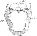
- FIG. 1is a simplified cross-sectional view of the heart with a normal mitral valve during systole.
- the intraaannular planeis illustrated relative to supraannular and infrannular.
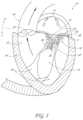
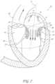
- FIG. 2is a cross-sectional view of the heart with a normal mitral valve during diastole. The axis of the mitral valve is illustrated, and shown piercing the intraannular plane.
- FIG. 3is a bottom view of the normal mitral valve of FIG. 1 during systole looking from the left atrium to the left ventricle.
- FIG. 4is a bottom view of the normal mitral valve of FIG. 2 during diastole looking from the left atrium to the left ventricle.
- FIG. 5is a cross-sectional schematic view of the normal mitral valve of FIG. 1 during systole, illustrating the depth of the coaption zone.
- FIG. 6is a cross-sectional schematic view of the normal mitral valve of FIG. 2 during diastole.
- FIG. 7is a cross-sectional view of the heart during systole showing a mitral valve with a prolapsed anterior leaflet caused by the rupture of the chordae tendineae attached to the anterior leaflet.
- FIG. 8is a bottom view of the mitral valve of FIG. 7 having a prolapsed anterior leaflet looking from the left atrium to the left ventricle.
- FIG. 9is a cross-sectional view of the heart during systole showing a mitral valve with a prolapsed posterior leaflet caused by the rupture of the chordae tendineae attached to the posterior leaflet.
- FIG. 10is a bottom view of the mitral valve of FIG. 9 having a prolapsed posterior leaflet looking from the left atrium to the left ventricle.
- FIG. 11is a cross-sectional view of the heart during systole showing a mitral valve with anterior leaflet prolapse.
- FIG. 11 Ais a cross sectional view as in FIG. 11 , showing posterior leaflet prolapse.
- FIG. 11 Bis a cross sectional view as in FIG. 11 , showing bileaflet prolapse with mitral regurgitation.
- FIG. 11 Cillustrates a dilated mitral annulus with little or no coaption of both leaflets causing central mitral regurgitation in ischemic cardiomyopathy.
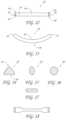
- FIG. 12is a top view of an embodiment of a transvalvular band.
- FIG. 13is a side view of the transvalvular band of FIG. 12 .
- FIG. 14is a cross-sectional view of a transvalvular band with a triangular cross-section.
- FIG. 15is a cross-sectional view of a transvalvular band with an oblong cross-section.
- FIG. 16is a cross-sectional view of a transvalvular band with a circular cross-section.
- FIG. 17is a cross-sectional view of a transvalvular band with a rectangular cross-section.
- FIG. 18is a top view of another embodiment of a transvalvular band.
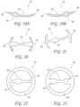
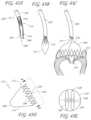
- FIGS. 19 A and Bshow a perspective view of yet another embodiment of a transvalvular band, with a widened coaptive edge support portion.
- FIGS. 20 - 23are top views of other embodiments of a transvalvular band.
- FIG. 23 Ashows a central mitral transvalvular band with posterior annuloplasty ring.
- FIG. 23 Bshows an intraannular band formed from a length of wire.
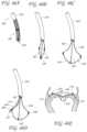
- FIGS. 24 - 27are side views of other embodiments of a transvalvular band.
- FIG. 28is a cross-sectional view of a heart during systole with a transvalvular band implanted in the mitral annulus.
- FIG. 29is a bottom view of the mitral valve of FIG. 28 during systole with a transvalvular band implanted in the mitral annulus looking from the left atrium to the left ventricle.
- FIG. 30is a cross-sectional view of a heart during diastole with mitral valve and a transvalvular band implanted in the mitral annulus.
- FIG. 31is a bottom view of the mitral valve of FIG. 30 during diastole with a transvalvular band implanted in the mitral annulus looking from the left atrium to the left ventricle.
- FIG. 32is a cross-sectional schematic view of the mitral valve of FIG. 28 during systole with a transvalvular band implanted in the mitral annulus.
- FIG. 33is a cross-sectional schematic view of the mitral valve of FIG. 32 during systole without the transvalvular band implanted in the mitral annulus.
- FIG. 34is a cross-sectional schematic view of the mitral valve of FIG. 30 during diastole with the transvalvular band implanted in the mitral annulus.
- FIG. 35is a cross-sectional schematic view of the mitral valve of FIG. 34 during diastole without the transvalvular band implanted in the mitral annulus.
- FIG. 36is a bottom view of the mitral valve during systole with another embodiment of the transvalvular band implanted in the mitral annulus looking from the left atrium to the left ventricle.
- FIG. 37is a cross-sectional view of a transvalvular band with a transverse leaflet support.
- FIG. 38is a cross-sectional schematic view of the mitral valve treated with the transvalvular band of FIG. 37 and an Alfieri type procedure.
- FIG. 39is a schematic cross-sectional view of the heart, showing a typical antegrade approach to the mitral valve by way of a transseptal crossing.
- FIG. 40is a cross sectional view as in FIG. 39 , showing placement of a guidewire through the mitral valve.
- FIG. 41is a cross sectional view of the heart showing a typical retrograde approach to the mitral valve by way of a femoral artery access.
- FIG. 42shows a retrograde approach as in FIG. 41 , with a guidewire placed across the mitral valve.
- FIG. 43 Ais a schematic view of the distal end of a percutaneous deployment catheter having a self-expandable implant positioned therein.
- FIG. 43 Bis a schematic view as in FIG. 43 A , with the implant partially deployed from the catheter.
- FIG. 43 Cis a schematic view of the deployment catheter showing the implant fully expanded at the deployment site, but still tethered to the deployment catheter.
- FIG. 43 Dis a side elevational view of the implant of FIG. 43 C .
- FIG. 43 Eis an end view taken along the line 43 E- 43 E of FIG. 43 D .
- FIG. 44 Ais a side elevational perspective view of an anchor deployment catheter in accordance with the present invention.
- FIG. 44 Bis a cross sectional view taken along the line 44 B- 44 B of FIG. 44 A .
- FIG. 44 Cis a cross sectional side view of the anchor deployment catheter of FIG. 44 A .
- FIG. 45 Ais a schematic plan view of a self-expandable transvalvular band in accordance with the present invention.
- FIG. 45 Bis a side elevational view of the transvalvular band of FIG. 45 A shown in a reduced crossing profile (folded) configuration, and attached to three control wires.
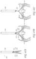
- FIG. 46 Ais a cut-away perspective view of the distal end of a deployment catheter having a self-expandable implant contained therein.
- FIG. 46 Bis a deployment catheter as in FIG. 46 A , with the implant partially deployed.
- FIG. 46 Cis a view as in FIG. 46 B , showing the implant released from the deployment catheter, but connected to three control wires.
- FIG. 46 Dis a view as in FIG. 46 C with a tissue anchor deployment catheter.
- FIG. 46 Eis a cross sectional view of a mitral valve, having an implant anchored in place and the deployment catheter removed.
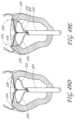
- FIG. 47 Ais a side elevational view of the distal end of a deployment catheter, having an implant partially deployed therefrom.
- FIG. 47 Bis a schematic view of the catheter and implant of FIG. 47 A , during implantation at the mitral valve.
- FIG. 47 Cis a schematic view as in FIG. 47 B , with the tissue anchor deployment guides removed.
- FIG. 47 Dis a schematic view as in FIG. 47 C , with the implant configured to move coaption earlier in the cardiac cycle.
- FIG. 47 Eis a schematic view of the implant of FIG. 47 D , with the deployment catheter removed.
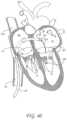
- FIG. 48 Ais schematic cross sectional view of a transapical deployment device positioned across the mitral valve.
- FIG. 48 Bis a schematic view of the device of FIG. 48 A , with tissue anchors engaged at the mitral valve annulus.
- FIG. 48 Cis a schematic view as in FIG. 48 B , with the deployment catheter withdrawn through the mitral valve.
- FIG. 48 Dis a schematic view as in FIG. 48 C , in an embodiment having a transventricular support.
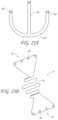
- FIGS. 49 A through 49 Gillustrate an implantation sequence for a transvalvular band at the mitral valve, via a transapical access.
- FIG. 49 Hshows an alternate end point, in which the transvalvular band is additionally provided with a transventricular truss and an epicardial anchor.
- FIG. 50 Ais a side elevational schematic view of the distal end of a deployment catheter, having a rolled up transvalvular band therein.
- FIG. 50 Bis an illustration as in FIG. 50 A , following distal deployment of the transvalvular band.
- FIGS. 51 A and 51 Billustrate top plan views and side views of a transvalvular band in accordance with the present invention.
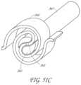
- FIG. 51 Cillustrates a perspective view of one embodiment of a transvalvular band in a rolled-up configuration and mounted on a delivery mandrel.
- FIG. 51 Dillustrates a view of at least a non-linear portion of a strut of FIG. 51 B .
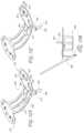
- FIGS. 52 A through 52 Cillustrate a transvalvular band, with a “t-tag” deployment system and suture tensioning feature.
- FIG. 52 Dillustrates an embodiment of a plurality of tissue anchors looped together on a suture.
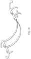
- FIG. 53is a side elevational perspective view of a transvalvular band in accordance with the present invention.
- FIG. 54is a schematic illustration of various suture lock configurations for use on transvalvular bands of the present invention.
- FIG. 55is a side elevational perspective view of a transvalvular band, having barbed tissue anchors thereon.
- FIG. 56is a side elevational perspective view of a transvalvular band in accordance with the present invention, having arcuate tissue anchors thereon.
- FIGS. 56 A-Bare graphs illustrating data regarding chordal physiologic force experiments.
- FIG. 1illustrates a cross-sectional view of the heart 10 with a normal mitral valve 18 in systole.
- the heart 10comprises the left atrium 12 which receives oxygenated blood from the pulmonary veins 14 and the left ventricle 16 which receives blood from the left atrium 12 .
- the mitral valve 18is located between the left atrium 12 and left ventricle 16 and functions to regulate the flow of blood from the left atrium 12 to the left ventricle 16 .
- the mitral valve 18is open which allows blood to fill the left ventricle 16 .
- the left ventricle 16contracts, which results in an increase in pressure inside the left ventricle 16 .
- the mitral valve 18closes when the pressure inside the left ventricle 16 increases above the pressure within the left atrium 12 .
- the pressure within the left ventricle 16continues increasing until the pressure within the left ventricle 16 exceeds the pressure within the aorta 20 , which causes the aortic valve 22 to open and blood to be ejected from the left ventricle and into the aorta 20 .
- the mitral valve 18comprises an anterior leaflet 24 and a posterior leaflet 26 that have base portions that are attached to a fibrous ring called the mitral valve annulus 28 .
- Each of the leaflets 24 and 26has respective free edges 36 and 38 .
- Attached to the ventricular side of the leaflets 24 and 26are relatively inelastic chordae tendineae 30 .
- the chordae tendineae 30are anchored to papillary muscles 32 that extend from the intraventricular septum 34 .
- the chordae tendineae 30 and papillary muscle 32function to prevent the leaflets 24 and 26 from prolapsing and enable proper coaptation of the leaflets 24 and 26 during mitral valve 18 closure.
- line 9 through the valve annulus 28representing the intraannular plane. Arrow 8 points supraannularly, toward the left atrium 12 , while arrow 7 points infraannularly, toward the left ventricle 16 .
- FIG. 2illustrates a cross-sectional view of the heart 10 with a normal mitral valve 18 in diastole.
- the left ventricle 16relaxes, which results in a drop in pressure within the left ventricle 16 .
- the aortic valve 22closes. The pressure within the left ventricle 16 continues dropping until the pressure in the left ventricle 16 is less than the pressure in the left atrium 12 , at which point the mitral valve 18 opens, as shown in FIG. 2 .
- bloodpassively fills the left ventricle 16 and this accounts for most of the filling of the left ventricle 16 in an individual at rest.
- the left atrium 12contracts and provides a final kick that ejects additional blood into the left ventricle.
- intraannular plane 9as described above, and line 6 representing the longitudinal axis 6 of the valve 18 .
- FIG. 3illustrates a bottom view of normal mitral valve 18 in systole, looking from the left atrium and to the left ventricle.
- the anterior leaflet 24 and posterior leaflet 26are properly coapted, thereby forming a coaptive edge 40 that forms a seal that prevents retrograde flow of blood through the mitral valve 18 , which is known as mitral regurgitation.
- FIG. 4illustrates a bottom view of normal mitral valve 18 in diastole.
- FIG. 5provides a side cross-sectional view of a normal mitral valve 18 in systole. As shown in FIG. 5 , the valve leaflets 24 and 26 do not normally cross the plane P defined by the annulus and the free edges 36 and 38 coapt together to form a coaptive edge 40 .
- FIG. 5also illustrates a coaption zone 41 .
- the depth of coaptionis at least about 2 mm or 5 mm, and is preferably within the range of from about 7 mm to about 10 mm for the mitral valve.
- implantation of the devices in accordance with the present inventionpreferably achieves an increase in the depth of coaption. At increase of at least about 1 mm, preferably at least about 2 mm, and in some instances an increase of at least about 3 mm to 5 mm or more may be accomplished.
- implantation of devices in accordance with the present inventionpreferably also increase the width of coaptation along the coaption plane. This may be accomplished, for example, by utilizing an implant having a widened portion for contacting the leaflets in the area of coaption such as is illustrated in connection with FIGS. 19 A and 19 B below.
- a further modification of the coaptive action of the leaflets which is accomplished in accordance with the present inventionis to achieve early coaption. This is accomplished by the curvature or other elevation of the implant in the ventricle direction. This allows the present invention to achieve early coaption relative to the cardiac cycle, relative to the coaption point prior to implantation of devices in accordance with the present invention.
- FIGS. 4 and 6illustrate normal mitral valve 18 in diastole. As shown, the anterior leaflet 24 and posterior leaflet 26 are in a fully opened configuration which allows blood to flow from the left atrium to the left ventricle.
- FIGS. 7 and 8illustrate a heart 10 in systole where the anterior leaflet 24 of the mitral valve 18 is in prolapse.
- Anterior leaflet 24 prolapsecan be caused by a variety of mechanisms. For example, as illustrated in FIG. 7 , rupture 42 of a portion of the chordae tendineae 30 attached to the anterior leaflet 24 can cause the free edge 36 of the anterior leaflet 24 to invert during mitral valve 18 closure. As shown in FIG. 8 , inversion 44 of the anterior leaflet 24 can prevent the mitral valve leaflets 24 and 26 from properly coapting and forming a seal. This situation where the free edge 36 of the anterior leaflet 24 crosses into the left atrium 12 during mitral valve 18 closure can lead to mitral regurgitation.
- FIGS. 9 and 10illustrate posterior leaflet 26 prolapse caused by a rupture of the chordae tendineae 30 attached to the posterior leaflet 26 .
- the posterior leaflet 26can invert and cross into the left atrium 12 during mitral valve 18 closure. The inversion of the posterior leaflet 26 prevents the mitral valve leaflets 24 and 26 from properly coapting and forming a seal, which can lead to mitral regurgitation.
- Mitral regurgitationcan also be caused by an elongated valve leaflet 24 and 26 .
- an elongated anterior leaflet 24as shown in FIG. 11 , can prevent the valve leaflets 24 and 26 from properly coapting during mitral valve 18 closure. This can lead to excessive bulging of the anterior leaflet 24 into the left atrium 12 and misalignment of the free edges 36 and 38 during coaptation, which can lead to mitral regurgitation.
- FIGS. 12 and 13One embodiment of a transvalvular band 50 that would improve mitral valve leaflet 24 and 26 coaptation and prevent or reduce mitral regurgitation is illustrated in FIGS. 12 and 13 .
- FIG. 12provides a top view of the transvalvular band 50 while FIG. 13 provides a side view of the transvalvular band 50 .
- the transvalvular band 50comprises an elongate and curved structure with a first end 52 , a second end 54 , a central portion 64 located between the two ends 52 and 54 , and a length that is capable of extending across the annulus.
- the leaflet contact surface 56is convex along the longitudinal axis, as best illustrated in FIG. 13 . In other embodiments, the leaflet contact surface 56 can have a different shape and profile.
- the contact surface 56can be concave, straight, a combination of convex, concave and/or straight, or two concave or straight portions joined together at an apex.
- the transvalvular band 50can have a substantially constant width between the first end 52 and the second end 54 .
- the first end 52has a first anchoring portion 58 and the second end 54 has a second anchoring portion 60 .
- the anchoring portions 58 and 60can have holes 62 for sutures that allow the transvalvular band 50 to be secured to the annulus.
- the anchoring portions 58 and 60can have other means for securing the transvalvular band 50 to the annulus.
- the anchoring portions 58 and 60can be made of a membrane or other fabric-like material such as Dacron or ePTFE. Sutures can be threaded directly through the fabric without the need for distinct holes 62 .
- the fabriccan be attached to the other portions of the transvalvular band 50 by a variety of techniques.
- the fabriccan be attached to the other portions of the transvalvular band 50 with the use of an adhesive, by suturing, by tying, by clamping or by fusing the parts together.
- an adhesiveby suturing, by tying, by clamping or by fusing the parts together.
- Another non-limiting technique of securing the transvalvular band to the annulusis to coat a malleable metal basis material, which creates structure for securing a skeleton of the transvalvular band, with a polymer such as silicone and bonding a material, such as PET (i.e., Dacron) velour for comprehensive tissue ingrowth when desired.
- PETi.e., Dacron
- the central portion of the transvalvular band 50can have a variety of cross-sectional shapes, as illustrated in FIGS. 14 - 17 .
- the cross sectional shapecan be substantially rectangular, circular, oblong or triangular.
- the edges of the transvalvular band 50can be rounded or otherwise configured so that the transvalvular band 50 presents an atraumatic surface 51 to the valve leaflets.
- the cross-sectioncan be oriented in a particular fashion to enhance performance of the transvalvular band 50 . For example as shown in FIG.
- a transvalvular band 50 with a triangular cross sectioncan be designed so that a relatively larger surface 56 of the triangle contacts the valve leaflets while a lower profile leading edge 53 of the triangle opposite the surface 51 faces the left atrium.
- This configurationallows a larger surface area to make contact with and support the mitral valve leaflets, while also presenting a more streamlined shape that provides less resistance to blood flowing from the left atrium to the left ventricle. Decreasing the resistance to blood flow is desirable because it can reduce turbulence and reduce the impedance of the transvalvular band 50 on the filling of the left ventricle.
- the transvalvular bands 50 with an oblong or rectangular cross-sectioncan be oriented to either increase the surface area for contact with the valve leaflets, or be oriented to reduce the resistance to blood flow.
- transvalvular band 50will vary, depending upon the specific configuration of the band 50 as well as the intended patient.
- transvalvular band 50will have an axial length from first end 52 to second end 54 within the range of from about 20 mm to about 32 mm. In one embodiment, intended for a typical male adult, the axial length of the transvalvular band 50 is about 24 mm to 26 mm.
- the width of the transvalvular band 50 in the central zone 64may be varied depending upon the desired performance, as will be discussed herein.
- the trailing surface 51 against which leaflets will seatis preferably large enough to minimize the risk of erosion resulting from repeated contact between the closed leaflets and the implant.
- width of the leading edge 53is preferably minimized, as discussed above, to minimize flow turbulence and flow obstruction.
- widths of the surface 51 measured perpendicular to the flow of bloodare presently contemplated to be less than about 5 mm, and often within the range of from about 5 mm to about 10 mm in the zone of coaptation.
- the central portion 64 of the transvalvular band 50can be narrower in width, measured perpendicular to blood flow than the first and second anchoring portions 58 and 60 .
- narrowing the central portion 64the resistance to blood flow can be reduced.
- narrowing the central portion 64reduces the surface area of the leaflet contact surface 56 that supports the valve leaflets.
- the narrowed central portion 64is separated from the first anchoring portion 58 and second anchoring portion 60 by a first shoulder 57 and second shoulder 59 .
- the length of the central portion 64 , between first shoulder 57 and second shoulder 59can be less than about 50% of the overall length of the device, or less than about 30% of the overall length of the device if it is desired to minimize the obstruction in the center of the flow path, while presenting a wider transverse surface for supporting the leaflets when the valve is closed.
- the length of the central zone 64may be greater than 50%, and in some embodiments greater than 75% of the overall length of the implant.
- a coaptive edge support portion 66 of the central portion 64 of the transvalvular band 50can be wider than the adjacent portions of the transvalvular band 50 , leading up to and potentially including the first and second anchoring portions 58 and 60 .
- the support portion 66can be located at a fixed position or adjustable along the transvalvular band so that its position can be optimized by the surgeon and then secured at a fixed point such as by suturing, or removed if deemed unnecessary.
- the transvalvular bandcomprises a first component for primary reduction and a second component for fine adjustment.
- the device illustrated in FIG. 19 Amay be provided with an adjustable (e.g. slidable) support portion 66 .
- the transvalvular bandmay be positioned across the annulus as has been described herein, and hemodynamic function of the valve may be evaluated.
- the support portion 66may thereafter be adjusted along the length of the transvalvular band to treat residual leakage or otherwise optimize the functionality of the implant such as by increasing the zone of coaptation.
- the second componente.g. support portion 66
- the second portionmay be separate from and connectable to the transvalvular band such as stitching, clips, suturing or other technique known in the art.
- the coaptive edge support portion 66can be offset from the center of the transvalvular band 50 , to reflect the asymmetry between the anterior leaflet and the posterior leaflet.
- the coaptive edge support portion 66can be positioned closer to the first anchoring portion 58 than to the second anchoring portion 60 .
- the edge support portion 66will be centered about a point which is within the range of from about 20% to about 45% of the overall length of the implant from the closest end.
- FIG. 20illustrates another embodiment of a transvalvular band 50 that is a modification of the transvalvular band 50 shown in FIG. 18 .
- the transvalvular band 50has a narrow central portion 64 that provides relatively low resistance to blood flow.
- the first and second anchoring portions 58 and 60extend further in a lateral direction, and can be arcuate to conform to the mitral valve annulus.
- These laterally extended anchoring portions 58 and 60provide additional anchoring of the transvalvular band 50 and can help improve the stability of the device after implantation.
- the laterally extending anchoring portion 58 and 60may be provided with any of a variety of structures for facilitating anchoring to the valve annulus.
- the anchoring portionsmay be provided with a plurality of apertures 61 , for conventional stitching or to receive any of a variety of clips or tissue anchors.
- the anchoring portionsmay alternatively be provided with any of a variety of barbs or hooks, or may be provided with a fabric covering such as a Dacron sleeve to facilitate sewing. Further, in some embodiments, this sewing ring may have an elastomeric core upon which the Dacron is secured to provide a more compliant structure to hold the implant.
- the laterally extending anchoring portionswill have an arc length of greater than about 5 mm, and, in some embodiments, greater than about 1 cm. Arc lengths of at least about 2 cm, and, in some embodiments, at least about 3 cm may be utilized, depending upon the desired clinical performance.
- FIG. 21illustrates another embodiment of a transvalvular band 50 with the extended anchoring portions 58 and 60 and a wider, offset coaptive edge support portion 66 .
- This embodimenthas the benefit of additional stability provided by the extended anchoring portions 58 and 60 and enhanced support of the coaptive edge.
- FIGS. 22 and 23illustrate another embodiment of a transvalvular band 50 which is combined with an annular ring 68 .
- the annular ring 68can be used as both a support for the transvalvular band 50 and, if desired, also to help stabilize the size and shape of the mitral valve annulus itself.
- the annular ring 68can be used to reduce the size of the mitral valve annulus and to bring the mitral valve leaflets closer together. This can be accomplished by, for example, suturing the mitral valve annulus to an annular ring 68 of smaller diameter.
- the annular ring 68provides additional support and stability to the transvalvular band 50 .
- the anchoring portions 58 and 60 of the transvalvular band 50can be formed integrally with the annular ring 68 , or the anchoring portions 58 and 60 can be attached to the annular ring by a variety of means, such as suturing, bonding, adhesives, stapling and fusing.
- FIG. 22discloses an embodiment with a narrow central portion 64 while FIG. 23 discloses an embodiment with a wider, offset coaptive edge support portion 66 .
- FIG. 23 Aillustrates a further implementation of the invention, adapted to treat ischemic mitral regurgitation with posterior annuloplasty.
- a transvalvular band 61is provided for spanning the leaflet coaption plane as has been described herein. Any of the features described in connection with other transvalvular bands disclosed herein may be incorporated into the transvalvular band 61 .
- An arcuate posterior annuloplasty support 63is connected to the transvalvular band 61 , and adapted to extend for an arc length along the native annulus.
- the support 63extends through an arc of approximately 180°, extending from a first trigone attachment zone 65 to a second trigone attachment zone 67 .
- the attachment zonesmay be provided with sewing apertures, a fabric covering, or other structure for facilitating attachment to tissue.
- the transvalvular band 61will have dimensions similar to those described elsewhere herein.
- the transverse dimension from first trigone zone 65 to second trigone zone 67may be varied depending upon the size of the native annulus, but will generally be within the range of from about 35 mm to about 45 mm.
- transvalvular bandin accordance with the present invention, formed from a single length or several lengths of flexible wire.
- the bend angles and orientation of the struts in the illustrated embodimentmay be readily altered, to accommodate the desired axes of compression which may be desirable for a particular deployment procedure.
- the transvalvular band 71comprises an elongate flexible wire 73 formed into a serpentine pattern, for providing a support for the valve leaflets as has been discussed herein.
- the wire 73may be formed such that it bows or inclines in the direction of the ventricle to achieve early closure as is discussed elsewhere herein.
- the wire 73may extend into a first connection section 75 and a second connection section 77 .
- Each of the connection sections 75 and 77may be provided with a plurality of eyelets 79 , to receive sutures for attaching the implant to the valve annulus.
- the implantmay be formed from any of a variety of flexible materials, including various polymers described elsewhere herein as well as titanium, titanium alloy, Nitinol, stainless steel, elgiloy, MP35N, or other metals known in the art.
- This designhas an advantage of providing a relatively large support footprint against the valve leaflets, while at the same time optimizing the area of open space to permit maximum blood flow therethrough.
- the designmay be treated or coated with silicone or other suitable material to eliminate untoward effects such as thrombosis or corrosion. Treatments may be sequential and include more than one listed but not limited to electropolishing, harperization, tumbling, pickling, plating, encapsulation or physical vapor deposition of appropriate materials.
- FIGS. 24 - 27illustrate side views of transvalvular bands 50 with different inclinations.
- One of the objectives of the present inventionis to not merely provide support to the leaflets during systole, but to elevate the plane of coaption in the direction of the ventricle, to cause early coaption (closure) relative to the cardiac cycle, as is discussed elsewhere herein.
- the variation in conditions, and other patient to patient variationsmay warrant production of the transvalvular band of the present invention in an array of sizes and/or configurations, so that clinical judgment may be exercised to select the appropriate implant for a given case.
- the transvalvular bandmay be provided in an adjustable form or a modular form so that an implant of the desired configuration can be constructed or modified intraoperatively at the clinical site.
- a central segmentmay be provided for positioning within the center of the flow path, or centered on the coaptive edges of the leaflets.
- First and second end portionsmay be connected to the central portion, for supporting the central portion relative to the tissue anchors.
- First and second end portionsmay be provided in a variety of lengths and curvatures, enabling construction of a relatively customized modular implant as may be desired for a particular patient.
- FIG. 24illustrates a transvalvular band 50 with a central portion 64 and two gently angled arm portions 70 and 72 .
- the first and second ends 52 and 54are displaced from the central portion 64 by a height, h 1 and h 2 , respectively.
- h 1 and h 2are about equal and can range from about 0 mm to about 10 mm.
- h 1 and h 2will be at least about 2 mm and will often be at least about 4 mm or 6 mm or more, but generally no more than about 10 mm or 12 mm.
- FIG. 25illustrates a transvalvular band 50 with a central portion 64 and two sharply angled arm portions 70 and 72 .
- the first and second ends 52 and 54are displaced from the central portion 64 by a height, h 1 and h 2 , respectively.
- h 1 and h 2are about equal and can range from about 8 mm to about 12 mm.
- FIG. 26illustrates a transvalvular band 50 with a central portion 64 , a highly angled first arm 70 and a gently angled second arm 72 .
- the first and second ends 52 and 54are displaced from the central portion 64 by a height, h 1 and h 2 , respectively.
- h 1is greater than h 2 .
- FIG. 27illustrates a transvalvular band 50 with a central portion 64 , a gently angled first arm 70 and a highly angled second arm 72 .
- the first and second ends 52 and 54are displaced from the central portion 64 by a height, h 1 and h 2 , respectively.
- FIG. 27may be a mirror image of FIG. 26 .
- the transvalvular band 50can be made of any of a variety of materials that are compatible with implantation within a patient's body and which has the requisite structural integrity to support the mitral valve leaflets.
- suitable materialsinclude titanium, titanium alloys, stainless steel, stainless steel alloys, nitinol, elgiloy, MP35N, other metals and alloys, ceramics, and polymers such as PTFE, polycarbonate, polypropylene, UHMWPE, HDPE, PEEK, PEBAX and the like.
- the transvalvular band 50can be provided with a smooth surface or appropriately micro-texture the surface in some embodiments, such as via a porous or microporous structure. Other factors such as surface chemistry, energy, morphology, macrofeatures, and general material properties matching the in situ needs can also be considered in tailoring the surface of the band.
- the transvalvular band 50can be coated with a variety of substances to reduce thrombogenicity.
- the transvalvular band 50can be coated with a antithrombogenic agent such as heparin, a polymer such as PTFE, or a polymer conjugated with heparin or another antithrombogenic agent. Heparin coatings can be achieved in a variety of methods, one of which may be to coat or drip the prosthesis in TDMAC-heparin (Tridodecylmethylammonium heparinate).
- the transvalvular band 50is implanted in the plane of the mitral valve annulus 28 in a patient suffering from anterior leaflet 26 prolapse caused by the rupture 42 of the chordae tendineae 30 attached to the anterior leaflet 26 .
- anterior leaflet 26prolapsed anterior leaflet 26
- the transvalvular band 50can be attached to the annulus 28 by a variety of techniques, such as sutures, anchors, barbs, stapes, self-expanding stents, or other techniques that are known or are apparent to those of skill in the art.
- the transvalvular band 50is oriented in the annulus 28 so that the transvalvular band 50 is positioned approximately transversely to the coaptive edge 42 formed by the closure of the mitral valve leaflets 24 and 26 .
- the transvalvular band 50can also be positioned over the prolapsed portion of the anterior leaflet 26 so that the transvalvular band 50 can directly support the prolapsed portion of the anterior leaflet 24 and keep the anterior leaflet 24 inferior to the plane of the mitral valve annulus 28 , i.e., elevated in the direction of the ventricle or of antegrade flow, thereby preventing or reducing prolapse and mitral regurgitation.
- FIGS. 28 and 29illustrate the effect of the transvalvular band 50 on the mitral valve 18 during systole.
- both the anterior leaflet 24 and the posterior leaflet 26are supported by the transvalvular band during closure of the mitral valve 18 .
- the arcuate transvalvular band 50functions to keep both leaflets 24 and 26 inferior to the plane of the annulus 28 and enables the leaflets 24 and 26 to form a coaptive edge 40 .
- multiple transvalvular bands 50such as two or three or more can be implanted across the annulus 28 to provide additional support to the mitral valve leaflets 24 and 26 .
- FIGS. 30 and 31illustrate the effect of the transvalvular band 50 on the mitral valve 18 during diastole.
- the mitral valve 18opens so that blood can fill the left ventricle 16 from the left atrium 12 .
- the transvalvular band 50obstructs only a small portion of the mitral valve 18 opening, and therefore, does not cause excessive resistance to blood flow.
- FIGS. 32 - 35are cross-sectional side views of the mitral valve 18 with and without the support of the transvalvular band 50 .
- the mitral valve 18closes. Without the transvalvular band 50 , the anterior leaflet 24 crosses the plane P defined by the mitral valve annulus 28 and prolapse, which leads to mitral regurgitation, as shown in FIG. 33 .
- the transvalvular band 50in the annulus 28 such that the arcuate transvalvular band 50 arches towards the left ventricle and the central portion 64 is displaced from the plane P, the anterior leaflet 24 is prevented from prolapsing above the plane P thus eliminating or reducing retrograde flow (shown in FIG. 33 ).
- the leaflets 24 and 26rest upon the transvalvular band 50 and the pressure exerted by the blood upon the distal portion of the leaflets 24 and 26 form the coaptive edge 40 . As illustrated in FIGS. 34 and 35 , the performance of the mitral valve 18 during diastole is not substantially affected by the transvalvular band 50 .
- FIG. 36illustrates a transvalvular band 50 with a wider, offset coaptive edge support portion 66 that has been implanted in the mitral valve annulus. As shown, the coaptive edge support 66 is offset so that it positioned to support the coaptive edge of the mitral valve 18 .
- the transvalvular band 50can be used in conjunction with other devices and procedures, such as a separate or integrally attached annular or annuloplasty ring described above.
- the transvalvular band 50can be used in conjunction with the Alfieri procedure, where the tips of the mitral valve leaflets 24 and 26 are sutured 74 together, as shown in FIG. 38 .
- FIG. 37there is illustrated a perspective view of a transvalvular band 50 having a transverse projection or support 51 extending in the direction of the ventricle or in the direction of diastolic blood flow, which could be considered antegrade.
- the support 51has a width W, which may be at least about 3 mm, and in some embodiments, at least about 5 mm, and in other embodiments at least about 1.0 cm.
- the projection 51may be utilized without an Alfieri stitch, so that the leaflets of the mitral valve close against opposing side walls 53 and 55 of the projection 51 .
- the projection 51thus helps center the closure of the leaflets, as well as controlling the width of coaption.
- the band 50is illustrated as convex in the direction of the ventricle, to accomplish early closure as has been discussed herein.
- the transvalvular band in accordance with the present inventioncan be implanted via an open surgical procedure, via thoracotomy (e.g. transapically) or alternatively, via a percutaneous procedure using a translumenally implantable embodiment.
- one or more transvalvular bandscan be attached to a self-expandable support structure, such as a self-expandable ring or self-expandable stent having a relatively short axial length relative to its expanded diameter.
- the transvalvular band and the compressed self-expandable support structureare loaded into a catheter with a retractable outer sheath which is inserted percutaneously and advanced translumenally into or across the mitral valve.
- the retractable outer sheathcan be retracted to allow the self-expandable support structure to expand adjacent or against the annulus, thereby positioning the one or more transvalvular bands in about the plane of the mitral annulus.
- Each transvalvular bandcan be characterized by a longitudinal axis, and the transvalvular band is oriented in the mitral valve such that the longitudinal axis of the transvalvular band in oriented substantially transversely to the coaptive edge of the mitral valve.
- percutaneousit is meant that a location of the vasculature remote from the heart is accessed through the skin, such as using needle access through, for example, the Seldinger technique. However, it may also include using a surgical cut down procedure or a minimally invasive procedure. The ability to percutaneously access the remote vasculature is well-known and described in the patent and medical literature.
- the approach to the mitral valvemay be antegrade and require entry into the left atrium via the pulmonary vein or by crossing the interatrial septum.
- approach to the mitral valvecan be retrograde where the left ventricle is entered through the aortic valve.
- the interventional tools and supporting catheter(s)will be advanced to the heart intravascularly where they may be positioned adjacent the target cardiac valve in a variety of manners, as described elsewhere herein. While the methods will preferably be percutaneous and intravascular, many of the implants and catheters described herein will, of course, also be useful for performing open surgical techniques where the heart is beating or stopped and the heart valve accessed through the myocardial tissue. Many of the devices will also find use in minimally invasive procedures where access is achieved thorascopically and where the heart will usually be stopped but in some instances could remain beating.
- the mitral valve MVmay be accessed by a standard approach from the inferior vena cava IVC or superior vena cava SVC, through the right atrium RA, across the interatrial septum IAS and into the left atrium LA above the mitral valve MV.
- a catheter 120 having a needle 122may be advanced from the inferior vena cava IVC into the right atrium RA. Once the catheter 120 reaches the interatrial septum IAS, the needle 122 may be advanced so that it penetrates through the septum at the fossa ovalis FO or the foramen ovale into the left atrium LA.
- a guidewiremay be advanced out of the needle 122 and the catheter 120 withdrawn.
- access through the interatrial septum IASwill usually be maintained by the placement of a guide catheter 125 , typically over a guidewire 124 which has been placed as described above.
- the guide catheter 125affords subsequent access to permit introduction of the tool(s) which will be used for performing the valve or tissue modification, as described in more detail below.
- FIG. 41A typical retrograde approach to the mitral valve is depicted in FIG. 41 .
- the mitral valve MVmay be accessed by an approach from the aortic arch AA, across the aortic valve AV, and into the left ventricle below the mitral valve MV.
- the aortic arch AAmay be accessed through a conventional femoral artery access route, as well as through more direct approaches via the brachial artery, axillary artery, or a radial or carotid artery.
- FIG. 42such access may be achieved with the use of a guidewire 128 .
- a guide catheter 126may be tracked over the guidewire 128 .
- the guide catheter 126affords subsequent access to permit introduction of the tool(s) which will be used for performing the valve modification, as described in more detail below.
- access routes to the mitral valvemay be established in both antegrade and retrograde approach directions. This may be useful when, for instance, grasping is performed with the use of specific devices introduced through one route and fixation is achieved with the use of separate devices introduced through another route.
- the transvalvular bandmay be introduced via a retrograde approach. While the transvalvular band is held in place, a fixation tool may be introduced via an antegrade approach to fix the transvalvular band in place.
- the access pathways for the transvalvular band and fixation toolmay alternatively be reversed.
- a variety of access routesmay be used individually or in combination with the methods and devices of the present invention.
- the deployment systemincludes a deployment catheter 200 , only a distal end of which is illustrated herein.
- Deployment catheter 200is configured in accordance with known technology for accessing the mitral valve, utilizing conventional dimensions and the materials known to those of skill in the art.
- the deployment catheter 200comprises an elongate flexible tubular body 202 extending between a proximal end (not illustrated) and a distal end 204 .
- the proximal endis provided with a proximal manifold, including access portals such as luer connectors in communication with each functional lumen in the catheter 200 .
- the distal end 204is provided with a distally facing opening 208 , which is in communication with the proximal end via a central lumen 206 .
- Implant 210is transformable between a first, radially reduced configuration such as for positioning within the deployment catheter 200 and a second, radially enlarged configuration (see FIG. 43 C ) for positioning at the treatment site. Transformation of the implant from the first configuration to the second configuration may be accomplished under positive force, such as via balloon dilatation. Alternatively, as illustrated herein, transformation is accomplished by self-expansion of the implant 210 in response to removal of the constraint provided by the tubular body 202 .
- the implant 210comprises a frame or anchor component 212 and a leaflet support component 214 .
- Leaflet support component 214may comprise any of a variety of structures similar to those described previously herein as the annular band, configured or reconfigured such that the annular band may be radially reduced for positioning within a deployment catheter and subsequently radially enlarged for spanning the mitral valve.
- the implant 210additionally comprises an anchor component, for anchoring the leaflet support 214 at the treatment site.
- anchor 212is schematically illustrated as a zigzag wire or filament structure, which is radially expansible following removal of the constraint. However, any of a variety of configurations may be utilized for the anchor 212 .
- FIG. 43 Bthe outer tubular flexible body 202 is shown partially retracted from the implant, permitting the implant to begin to radially expand.
- FIG. 43 Cillustrates further retraction of the tubular body 202 , to fully release the anchor 212 at the deployment site. As illustrated, anchor 212 radially expands within the left atrium.
- the leaflet support 214extends approximately transversely to the coaptive edge of the mitral valve leaflets, and is convex or inclined in the direction of the mitral valve to advance the coaptation of the mitral valve leaflets in the direction of the ventricle as has been described elsewhere herein.
- control line 216extends throughout the length of the deployment catheter 200 , and to at least one control on or near the proximal manifold. This enables proximal retraction of the flexible body 202 with respect to the implant 210 , and control of implant 210 prior to final detachment from the deployment system.
- Control wires 216 , 218 and 220enable manipulation of the implant into its final desired position, and, if necessary, proximal retraction of the implant back within the deployment catheter should the decision be made to remove the implant prior to final detachment.
- anchor 212may be provided with any of a variety of tissue anchors or barbs, for engaging the mitral valve annulus or the base of the leaflets or other adjacent anatomical structures.
- tissue anchorsmay be advanced through the deployment catheter 200 , and utilized to secure the anchor 212 to the adjacent tissue. Suitable anchors are preferably enlargeable from a first, reduced cross sectional configuration for traveling through the deployment catheter 200 and piercing tissue, to a second, enlarged configuration for resisting removal from the tissue. In the embodiment illustrated in FIG. 43 C , no secondary anchoring structures are illustrated for simplicity.
- control wires 216 , 218 and 220are detached from the anchor 212 , and the deployment catheter 200 is removed from the patient.
- Detachment of the control wires from the implant 210may be accomplished in any of a variety of ways, such as by electrolytic detachment, detachment by thermal elevation of a softenable or meltable link, mechanical detachment such as by rotating the control wire such that a threaded end of the control wire is threadably disengaged from the anchor 212 , or other detachment techniques depending upon the desired functionality and profile of the system.
- FIG. 43 Dthere is illustrated a side elevational view of the implant 210 in an unconstrained (e.g., bench top) expanded configuration.
- the anchor 210comprises a plurality of struts 222 , which are joined at a first end by a plurality of apices 224 and a second end by a plurality of apices 226 to produce a zigzag structure sometimes referred to as a “Z stent” configuration.
- This configurationis convenient and well understood in the intravascular implant arts, although any wide variety of structures may be utilized. For example, zigzag wire patterns, woven wire patterns, or sinusoidal wire patterns may be utilized.
- Laser cut wall patternssuch as from tubing stock may also be utilized, and may be provided with any of a wide variety of complex wall patterns.
- nickel titanium alloyssuch as any of a variety of nitinol alloys are preferred.
- stainless steel, elgiloy, certain polymers or other materialsmay also be utilized.
- Heat treatmentmay be required to anneal and shape set an alloy such as Nitinol.
- Other alloysmay require only annealing to relieve stresses incurred during prior processing.
- the transvalvular bandcomprises a plurality of struts 230 which are connected to the anchor 212 at junctions 232 .
- Struts 230may in turn be divided into a bifurcated section 234 or other configuration to increase the effective footprint of the transvalvular band measured along the coaptive edge of the valve, while minimizing obstruction to blood flow therethrough.
- the coaptive edge of the valve, as implantedwill preferably be approximately aligned with the transverse axis 236 illustrated in FIG. 43 E of the band, as implanted.
- the axis of coaption of the mitral valveis preferably parallel to axis 236 in the implanted configuration, but may be within about 45°, preferably within about 20°, and most preferably within about 10° of the axis 236 .
- Anchor deployment catheter 250comprises an elongate flexible tubular body 252 , configured to access the vicinity of the mitral valve.
- Tubular body 252extends between a proximal end 254 and a distal end 256 .
- Distal end 256is provided with a distal opening 258 , enabling access to a central lumen 260 .
- An elongate flexible core wire 262extends from the proximal end 254 throughout most of the length of the lumen 260 to a distal surface 264 . See FIG. 44 C .
- the proximal end of the core wire 262is provided with a control 266 that enables axial reciprocal movement of the core wire 262 within the central lumen 260 .
- a tissue anchor 268may be positioned within the distal end of the delivery catheter 250 .
- manipulation of the control 266such as by distal axial advance relative to the tubular body 252 , distally, axially advances the core wire 262 to expel the anchor 268 through the distal opening 258 .
- Distal opening 258is preferably provided with a bevel or angled cut to provide a sharpened distal tip 270 . This enables distal axial advance of the distal tip 270 into tissue at a desired site, so that the control 266 may be manipulated to deploy all or a portion of the anchor 268 into the target tissue.
- tissue anchors 268may be utilized, depending upon the desired configuration of the implant and the implant anchor interface.
- the anchor 268is configured as a double “t-tag” anchor.
- a first tissue engaging element 272is connected to a second implant engaging element 274 by a filament 276 .
- the distal tip 270is positioned within the tissue of the mitral valve annulus.
- Control 266is manipulated to deploy the first element 272 beneath the surface of the tissue.
- the tubular body 252is thereafter proximally retracted, enabling the second element 274 to engage the implant and retain it against the adjacent tissue.
- the anchor delivery catheter 250may be advanced through the deployment catheter 200 , and/or along a guide such as a guidewire or support wire.
- the anchor deployment catheter 250is provided with a guide lumen 278 allowing the anchor delivery catheter to track along a guidewire.
- Guide lumen 278is defined by a tubular wall 280 .
- Tubular wall 280may extend the entire length of the anchor delivery catheter 250 , such as by forming the catheter body as a dual lumen extrusion.
- tubular wall 280may be provided with an axial length that is short relative to the overall length of the catheter, such as no more than about 3 cm and preferably no more than about 2 cm in length. This allows the anchor delivery catheter to ride along a guidewire in a monorail or rapid exchange manner as will be illustrated below.
- the implantconfigured for use with the anchor delivery catheter described above.
- the implantcomprises a first leaflet support 292 and a second leaflet support 294 , separated by a flexible connection 296 .
- Flexible connection 296permits the implant 290 to be folded within a deployment catheter, and later expanded in a manner that permits the implant 290 to function as a transvalvular band as described.
- the implant 290may be manufactured in any of a variety of ways, such as using a wire frame or by laser cutting from sheet stock as will be appreciated by those of skill in the art.
- a first and second flexible connection 296reside in a plane configured to be substantially parallel to the axis of coaption the as implanted orientation.
- the lateral edges of the each of the first leaflet support 292 and second leaflet support 294are provided with at least one and preferably two or three eyes 298 , fabric patches, or other anchor attachment structure, for receiving a tissue anchor.
- control wires 300 , 302 and 304are illustrated releasably connected to the implant 290 .
- Control wires 300 , 302 and 304may be utilized to advance the implant 290 from the deployment catheter such as catheter 200 described above, and manipulate the implant until the anchors have been fully deployed. Thereafter, control wires 300 , 302 and 304 may be removed such as by electrolytic detachment, melting a polymeric link, unscrewing a threaded connection, or other detachment mechanism depending upon the desired functionality of the device.
- FIGS. 46 A through 46 Ethere is illustrated a sequence of deploying an implant at the mitral valve from an antegrade direction.
- the implant 290may be similar to that illustrated in FIGS. 45 A and 45 B , or have wall patterns or characteristics of other implants disclosed elsewhere herein.
- the implant 290is deployed from the catheter 200 in the sequence illustrated in FIGS. 46 A through 46 C .
- the surrounding anatomyhas been eliminated for simplicity.
- the anchor delivery catheter 250is advanced onto the proximal end of one of the control wires 300 , such that the control wire 300 is axially moveably positioned within guide lumen 278 .
- Thisenables the anchor delivery catheter 250 to be advanced along the control wire 300 in a monorail or rapid exchange configuration as is understood in the catheter arts.
- Anchor delivery catheter 250is advanced along the control wire 300 until the distal tip 270 advances through the eye 298 or fabric tab or other attachment structure, and into the adjacent tissue of the base of the mitral valve leaflet or mitral valve annulus.
- the control 266is manipulated such as by distal advance to advance the first anchor element 272 out of the distal opening 258 and into the tissue as illustrated in FIG. 46 D .
- the anchor delivery catheter 250is thereafter proximally withdrawn to position the distal opening 258 on the device proximal side of the eye 298 , and the core wire 262 is further distally advanced to deploy the second anchor element 274 from the distal opening 258 of the anchor delivery catheter 250 .
- Anchor delivery catheter 250may thereafter be proximally withdrawn from the patient. Either the same or a different anchor delivery catheter 250 may thereafter be advanced along the third control wire 304 , enabling deployment of another tissue anchor as is illustrated in FIG. 46 E .
- the implant 290is illustrated in FIG. 46 E as having a central portion inclined in the direction of the ventricle to support the leaflets as has been discussed elsewhere herein. This configuration may be retained by the inherent bias built into the structure and materials of the implant 290 . Alternatively, the configuration of inclining in the direction of the ventricle may be retained by active intervention such as by providing a mechanical interlock, in situ heat weld with capacitive discharge/electrolytic weld, application of a clip or other locking structure by way of control wire 302 or simply by the mechanical forces attributable to the mitral valve annulus, which prohibit lateral expansion of the device sufficient for the flexible connection 296 to invert in the direction of the atrium.
- an implantable control wire(not illustrated) may be introduced, to connect the implant 290 such as in the vicinity of the flexible connection 296 to the opposing wall of the ventricle, as will be described in connection with a transapical implementation of the invention described below.
- FIGS. 47 A through 47 EA further implementation of the invention is illustrated in connection with FIGS. 47 A through 47 E .
- the first control line 300 and third control line 304have been replaced by a first guide tube 310 and a second guide tube 312 .
- First guide tube 310 and second guide tube 312each has the double function of controlling deployment of the implant, as well as enabling introduction of a tissue anchor therethrough. This avoids the use of a separate tissue anchor deployment catheter such as that described above.
- tissue anchor 314is deployed through the first guide tube 310 .
- a second tissue anchor 316is deployed through the second guide tube 312 .
- the tissue anchorsmay comprise “T” tag type constructions, pigtail or corkscrew constructions, or any of a variety of other soft tissue anchors known in the art.
- tissue anchors utilized for the present purposeare preferably transformable from a first, reduced cross-sectional configuration to a second, radially enlarged cross-sectional configuration to enable deployment through a small needle or tube and then provide a relatively higher resistance to pull out. Radial enlargement may be accomplished by angular movement of a portion of the anchor, or by physical expansion in a radial direction.
- the first guide tube 310 and second guide tube 312have been removed following deployment of the tissue anchors.
- the guide tubesmay be removed using any of a variety of detachment techniques disclosed elsewhere herein. Either before or after removal of the guide tubes, distal pressure on either the tubular body 202 or the control wire 302 inverts the implant from the configuration shown in FIG. 47 C to the final configuration shown in FIGS. 47 D and E. The inverted configuration of FIGS. 47 D and E may be retained by the mechanical bias imparted through the anchoring to the mitral valve annulus, or using techniques described elsewhere herein. The control wire 300 is thereafter detached from the implant, as illustrated in FIG. 47 E .
- any of a variety of the implants of the present inventionmay alternatively be introduced across the ventricle, such as in a transapical approach.
- the retrograde approach to the mitral valvewill necessitate certain modifications to both the implant and the deployment system, as will be appreciated by those of skill in the art in view of the disclosure herein.
- FIGS. 48 A through 48 Da transventricle approach is illustrated in FIGS. 48 A through 48 D .
- a deployment catheter 320is introduced into the ventricle, and retrograde through the mitral valve to position the distal opening 208 within the atrium.
- An implantis carried within the deployment catheter 320 , as has been described elsewhere herein.
- the implantcomprises a first leaflet support 292 and a second leaflet support 294 separated by a flexible zone or pivot point.
- the first and second leaflet supportsare flexible or pivotable with respect to the longitudinal axis of the control wire 300 , such that they may be moved between a first configuration in which there are substantially parallel with the axis of the control wire 300 , and a second position, as illustrated in FIGS. 48 A through 48 D , in which they are inclined radially outwardly from the longitudinal axis of the control wire 300 in the device proximal direction.
- the implantmay thus reside within the deployment catheter 320 when the first leaflet support 292 and second leaflet support 294 are in the first, reduced crossing profile configuration, with each of the tissue anchors 314 and 316 pointing in a device proximal direction.
- the tissue anchor 314may be permanently affixed to or integral with the first leaflet support 292 and the second anchor 316 may be similarly carried by the second leaflet support 294 .
- the control wire 300may be distally advanced to advance the anchors 314 and 316 beyond the distal opening 208 . This releases the implant and allows the angle between the first and second leaflet supports to be increased, so that the tissue anchors 314 and 316 may be aimed at the desired tissue anchor target sites. Proximal retraction on the control wire 300 may be utilized to seat the tissue anchors within the target tissue, as illustrated in FIG. 48 B .
- proximal traction on the control wire 300may be utilized to invert the implant into the configuration illustrated in FIG. 48 C .
- the control wire 300may be severed from the implant as has been discussed elsewhere herein.
- the deployment catheter 320may be proximally retracted leaving the control wire 300 secured to the implant, and a second portion of the control wire may be secured to a tissue anchor 322 within or on the epicardial surface of the ventricle.
- Anchor 322may comprise any of a variety of structures, such as a pledget, button, or other structure that provides a footprint against the epicardial surface to resist retraction of the control wire 300 into the ventricle.
- the control wire 300may thereafter be severed proximally of its securement to the anchor 322 , leaving the control wire 300 and anchor 322 in position to span the ventricle and retain the configuration of the implant as illustrated in FIG. 48 D .
- the final configuration of the implant within the mitral valveis illustrated in a highly schematic form, and the angle and degree of inclination into the direction of the ventricle may be significantly greater than that illustrated herein depending upon the desired clinical performance.
- the transvalvular band inclinationcan be highly advantageous in some embodiments in providing clinical benefit as it facilitates “physiologic coaptation” in a preferred manner as its surface mimics the three dimensional feature created by the leaflets as they would have coapted in a healthy native valve.
- FIGS. 49 A through 49 Hthere is illustrated a transapical approach to the mitral valve, and deployment of a transvalvular band in accordance with the present invention.
- a deployment catheter 320has been introduced such as via thoracotomy, and advanced retrograde through the mitral valve.
- a transvalvular band 324has been deployed distally from the catheter 320 , and is illustrated in FIG. 49 A in an expanded configuration within the left atrium. Expansion of the transvalvular band 324 from a reduced cross-sectional profile for positioning within the catheter 320 to the enlarged cross-sectional profile illustrated in FIG. 49 A may be accomplished either under mechanical force, such as by dilatation of an inflatable balloon or other mechanical mechanism.
- transvalvular band 324is self-expandable so that it converts from the reduced profile to the enlarged profile automatically upon deployment from the distal end of the catheter 320 .
- the transvalvular band 324comprises an arcuate central portion 325 , which is convex in the direction of the ventricle. See FIGS. 49 A and 49 B .
- the transvalvular band 324is provided with a first attachment structure 326 and a second attachment structure 328 .
- Attachment structures 326 and 328may comprise any of a variety of structures disclosed herein, such as tissue anchors, including hooks or barbs.
- the first attachment structure 326 , and second attachment structure 328each comprise a target for receiving an anchor as will be disclosed below. Suitable targets for the present purpose include woven or non-woven fabrics, polymers, or other materials or constructions which permit a needle or sharpened anchor to penetrate therethrough, as will be discussed.
- each of the attachment structurescomprises a Dacron mesh, having a frame for supporting the mesh and securing the mesh to the transvalvular band 324 .
- FIG. 49 Bthere is illustrated a perspective view of the transvalvular band 324 illustrated in FIG. 49 A .
- the transvalvular band 324comprises a central section 325 , convex in the direction of the ventricle for affecting leaflet closure as has been described herein.
- Central section 325is formed by a frame 327 , which comprises at least one strut 329 extending between the first attachment structure 326 and second attachment structure 328 .
- three strutsextend generally parallel to each other, defining at least two elongate openings therebetween.
- One or two or four or more transverse elements 331may be provided, such as to enhance structural integrity of the construct.
- At least a first control wire 300 and, optionally a second or third or fourth control wire 300is releasably attached to the transvalvular band 324 , to enable manipulation of the band into position as shown in FIG. 49 C .
- Control wire 300is releasably connected to the transvalvular band 324 at a connection point 301 .
- the connection at point 301may be established by threadable engagement, an electrolytically detachable link or weld, or other detachment mechanism.
- Electrolytically detachable deployment systemsare know, among other places, in the neurovascular embolic coil and stent arts, and suitable systems are disclosed in U.S. Pat. No. 5,976,131 to Guglielmi, et al.; U.S. Pat. No. 6,168,618 to Frantzen; and U.S. Pat. No. 6,468,266 to Bashiri, et al., the disclosures of which are hereby incorporated in their entireties herein by reference
- the first attachment structure 326comprises a support 333 carried by the frame 327 .
- support 333comprises an enclosed loop, having a central opening filled or covered by a mesh 337 .
- the support 333may alternatively comprise any of a variety of structures, such as a single linear element, sinusoidal or zigzag pattern, depending upon the desired performance.
- the support 333is conveniently provided in the form of a loop, to facilitate holding mesh 337 in a generally planar configuration, and support the mesh so that it may be punctured by an anchor, suture or other retention structure.
- a second support 335is similarly provided with a mesh 337 , to facilitate attachment.
- the mesh 337may conveniently be a layer or pad of Dacron or other material, such as an integration of a silicone core with a Dacron jacket, which facilitates both piercing by an attachment structure, as well as tissue in-growth for long term retention.
- the first support 333 and second support 335may comprise a radio opaque material, or be provided with radio opaque markers to enable aiming the anchor deployment system into the mesh 337 under fluoroscopic visualization.
- the first attachment structure 326 and second attachment structure 328may be secured to the adjacent tissue using any of a variety of clips, staples, barbs, sutures, or other structure which may be conveniently pierced through the mesh 337 and/or looped around the first and second supports 333 , 335 .
- the retention elementmay be approached from either the side of the left atrium, the ventricle, or epicardially, such as by way of a minimally invasive puncture on the chest wall. In the implementation of the method described below, the example of advancing the retention elements from the left ventricle will be described.
- proximal traction on the catheter 320 and on the control wire 300pulls the transvalvular band 324 snuggly against the left atrial side of the mitral valve, such that the first attachment structure 326 and second attachment structure 328 are seated against the valve annulus.
- Anchor guides 330 and 332may be alternatively associated with or carried by the catheter 320 in a variety of ways.
- the first and second anchor guides 330 and 332may be pivotably carried by the catheter 320 , such that they may be inclined radially outwardly from the longitudinal axis of the catheter in the distal direction.
- the first and second anchor guidescomprise a wire or tube for directing an anchor as will be discussed.
- the wire or tube of the anchor guidemay comprise any of a variety of materials, such as nickel titanium alloys (e.g. nitinol) which may be preset to assume a position similar to that illustrated in FIG. 49 D upon distal advance from the catheter 320 .
- the first and second anchor guidesmay be provided with radio-opaque markers, or may be constructed from a radio-opaque material, to permit fluoroscopic guidance.
- the first and second anchor guidesare in the form of tubes, for axially slidably receiving a tissue anchor and tissue anchor deployment structures therein.
- a retention element in the form of a first anchor 334is illustrated as having been distally advanced from the first anchor guide 330 , through the tissue in the vicinity of the mitral valve annulus, and through the first attachment structure 326 . Penetration of the first anchor 334 through the first attachment structure 326 may be accomplished while providing proximal traction on the control wire 300 .
- the first anchor 334is provided with at least one and preferably two or four or more transverse elements 336 to resist proximal retraction of the first anchor 334 back through the opening formed in the first attachment structure 326 .
- the transverse element or surface 336may be provided on any of a variety of structures, such as an umbrella-type structure, t-tag, barbs, or other anchoring configuration which can pass in a first direction through an opening formed in the first attachment structure 326 , but resist retraction in a second, opposite direction, back through the first attachment structure 326 .
- the transverse element 336is carried by a filament 338 , which extends through the adjacent myocardial tissue.
- Filament 338may comprise any of a variety of materials, such as a monofilament or multi-filament structure made from polypropylene, any of a variety of other known suture materials such as polyethylene, or metals such as stainless steel, nitinol, and others known in the art.
- the filament 338may be a mono-filament structure or a multi-filament structure which may be braided or woven, depending upon the desired clinical performance.
- At least a second, similar anchor 340is introduced on the opposing side of the mitral valve.
- a second transverse element 342is shown secured to or carried by the ventricular end of the filament 338 , to provide a secure anchoring through the tissue wall for the transvalvular band.
- a similar structureis provided on the opposing side of the mitral valve.
- additional anchoring systemssuch as a total of four or six or eight or more, typically in even numbers to produce bilateral symmetry, may be used.
- the number and configuration of tissue anchorswill depend upon the configuration of the transvalvular band, as will be apparent to those of skill in the art in view of the disclosure herein.
- the anchorshave been fully deployed and the first anchor guide 330 and second anchor guide 332 have been proximally retracted into the catheter 320 .
- control wire 300may thereafter be detached from the transvalvular band and removed. Detachment of control wire 300 may be accomplished in any of a variety of ways, as has been described elsewhere herein.
- control wire 300may be left in place as is illustrated in FIG. 49 H .
- Control wire 300is secured to an epicardial anchor 322 , to provide a transventricular truss, as has been described.
- the deployment catheter 360includes an elongate tubular body having a central lumen 362 , opening at a distal end 364 . Carried within the central lumen 362 is a transvalvular band 366 , in a rolled-up configuration. Transvalvular band 366 is maintained in a rolled-up configuration by the constraint imposed by the deployment catheter 360 .
- the transvalvular band 366unrolls under its natural bias into a predetermined configuration for implantation across the mitral valve.
- transvalvular bandOne configuration for the transvalvular band is shown rolled out in plan view in FIG. 51 A .
- any of a variety of alternative transvalvular band configurations disclosed hereincan be utilized with the catheter of FIGS. 50 A and 50 B .
- transvalvular band 366having a central portion 368 for spanning the coaptive edges of the mitral valve.
- a first attachment zone 370 and a second attachment zone 372are provided on opposing ends of the central portion 368 .
- the central portioncomprises at least a first strut 374 for spanning the mitral valve as has been discussed.
- a second strut 376 and a third strut 378are provided, spaced apart to increase the width of the contact footprint with the valve leaflet but permit blood flow therethrough.
- a first end of each of the struts 374 , 376 , and 378are connected at the first attachment zone 370 , and the second ends of the three struts are connected at the second attachment zone 372 .
- the first and second attachment zonesmay be provided with a reinforcing element 382 , to facilitate long term attachment.
- Apertures 380are illustrated, which may be provided to allow manual suturing when the transvalvular band 366 is intended for use in an open surgical procedure. Alternatively, apertures 380 may be configured for attachment using an anchor deployment catheter when intended for use in a translumenal or transapical deployment.
- Each of the first, second and third ribsmay be provided with a central core, such as a nitinol or stainless steel wire or ribbon, and an outer coating such as a polycarbonate urethane with or without copolymers like silicone, silicone coating, or a fabric such as PET, ePTFE, polyethylene, or a hybrid of, for example, the aforementioned materials impregnated silicone coating, to reduce the risk of abrasion of the mitral valve leaflets
- a central coresuch as a nitinol or stainless steel wire or ribbon
- an outer coatingsuch as a polycarbonate urethane with or without copolymers like silicone, silicone coating, or a fabric such as PET, ePTFE, polyethylene, or a hybrid of, for example, the aforementioned materials impregnated silicone coating
- FIG. 51 Dillustrates one embodiment of a fatigue-resistant terminal portion of a proximal and/or distal end of one, two, or more of the struts 374 , 376 , 378 illustrated in FIG. 51 D .
- the terminal portion 51 Dmay have a non-linear portion 378 ′ and a head portion 379 .
- the non-linear portioncould be a coil with a helical, zig-zag, or any other generally non-linear shape to advantageously provide increased fatigue resistance for the struts.
- at least a portion of the terminal portion 51 Dis embedded in an elastomer such as silicone, polycarbonate, urethane, or the like to further improve fatigue tolerance.
- the terminal portion 51 Dmay have a straight-line length that is less than 20%, 15%, 10%, 5%, or less of the strut. In some embodiments, the terminal portion 51 D may have a straight-line length that is at least about 5%, 10%, 15%, 20%, 25%, or more of the length of the strut, or could even cover the entire length of one, two, or more struts 374 , 376 , 378 from first attachment zone 370 to second attachment zone 372 (e.g., a strut without a linear portion). Head portion 379 is operably connected to non-linear portion 378 ′ and the portions may be integrally formed.
- the head portion 379could be spherical, ovoid, square, rectangular, triangular, or a variety of other shapes. Head portion 379 is in turn operably connected to first attachment zone 370 and/or second attachment zone 372 . In some embodiments, the head portion 379 is not attached to an attachment zone but rather terminates as a free end of one or more of the struts 374 , 376 , 378 .
- FIG. 51 Bis a side elevational view of the transvalvular band 366 of FIG. 51 A , shown in a flat configuration.
- the transvalvular bandwill typically be provided with a curvature such that it advances the mitral valve leaflets in the direction of the ventricle and provides for physiologic coaptation.
- FIG. 51 Cillustrates a perspective view of a transannular band 366 in a rolled-up configuration for delivery, similar to that illustrated in FIG. 50 B .
- the bandcan be rolled in a variety of ways, such as capturing the band 366 at or near the center (near 363) and rolling it such that both ends are drawn inward as shown.
- the bandcould be rolled up like a scroll, or folded into a “V”, “W”, or a variety of other shapes.
- at least a portion of the band 366resides within one or more slots 363 or movable jaw-like elements on the distal end 363 of a mandrel 367 or other elongate body within a delivery catheter.
- Actuation of the jaw-like elements to release the band 366can be employed to deploy the band 366 .
- distal movement of a pusher tube, retraction of the mandrel 367 relative to another catheter, or other mechanismcan be employed to deploy the band 366 .
- turning the mandrel a desired distance, such as about 90 degrees,can help facilitate unfurling of the band 366 for deployment.
- transvalvular bandin accordance with the present invention having a tissue attachment system which may be adapted for either percutaneous or open surgical use.
- the transvalvular bandcomprises a central zone 368 carrying a first attachment zone 370 and a second attachment zone 372 as has been described.
- a tissue anchor 390such as a “t-tag” anchor includes a transverse element 392 and an elongate flexible suture 394 .
- sutureis not limited to its normal definition, but also includes any of a wide variety of elongate flexible filaments, including polymeric, metal, combinations of both as well as monofilament and multifilament structures. Multifilament structures may be braided, woven, or otherwise configured, depending upon the desired performance.
- the suture 394is illustrated to extend through a first guide 396 in the second attachment zone 372 .
- first guide 396in the second attachment zone 372 .
- anchoring systemmay be utilized on both ends of the central zone 368 , and more than one, such as two or three or more, anchors 390 may be utilized on each attachment zone.
- the suture 394is illustrated as extending through first guide 396 , and then through a lock 398 which will be described below.
- the free end 402 of the suture 394is further advanced through a second guide 400 .
- the free end 402may extend proximally throughout the length of the deployment catheter, where it may be manipulated such as by proximal traction in order to tighten the second attachment zone 372 with respect to the transverse element 392 . Thereafter, the free end 402 may be severed in the vicinity of the second attachment zone 372 or elsewhere.
- the lock 398includes an aperture 404 through which the suture 394 may extend.
- An engaging element 406is exposed to the interior of the aperture, for permitting the suture to advance in a first direction through the aperture 404 but resist movement of the suture 394 in an opposite direction through the aperture 404 .
- the engaging element 406is a sharpened point or spike configured to mechanically pierce or engage the suture 394 .
- the foregoing structurepermits the free end 402 to be proximally withdrawn away from the second attachment zone 372 in a manner that draws the transverse element 392 closer to the second attachment zone 372 .
- traction on the transverse element 392causes the suture 394 to engage the engaging element 406 , and prevents the transverse element 392 from pulling away from the second attachment zone 372 .
- a suture 394which can be looped through one, two, or more transverse elements 392 of anchors.
- the suture 394 looped through the anchorcan function as a pulley, where appropriate traction on the suture 394 can tighten the anchors into place.
- Having a plurality of anchors as shown connected on one loop, such as, for example, 2, 3, 4, 5, or more anchors,can advantageously allow one cinching maneuver to tighten all of the anchors at once.
- Deployment tool 408may comprise an elongate flexible wire having a proximal end 410 and a distal end 412 .
- the deployment tool 408may extend throughout the length of a percutaneous translumenal catheter, with the proximal end 410 exposed or attached to a control to allow axial reciprocal movement of the deployment tool 408 .
- the distal end 412is releasably positioned within an aperture 414 on a first end of the transverse element 392 .
- a second end of the transverse element 392is provided with a sharpened point 416 .
- distal axial advance of the deployment tool 408is utilized to drive the transverse element 392 into a target tissue, to a desired depth.
- proximal retraction on the deployment tool 408proximally retracts the distal end 412 out of the aperture 414 , allowing removal of the deployment tool 408 but leaving the transverse element 392 behind within the target tissue.
- Proximal traction on the free end 402 of the suture 394enables tightening of the transvalvular band with respect to the transverse element 392 .
- releasing the free end 402allows engaging element 406 to lock the suture 394 against further release, thereby holding the transvalvular band into position.
- lock 398is illustrated as an enclosed aperture
- alternative lock embodimentsmay involve access from a lateral edge of the implant. This permits side-loading of the suture into the lock, which may in some instances be desired over an enclosed aperture which requires end loading of the suture through the aperture.
- a variety of alternative side-loading lock configurationsis illustrated in FIG. 53 .
- FIG. 54there is illustrated a perspective view of an alternate transvalvular band in accordance with the present invention.
- the central section 368is provided with an asymmetrical curvature, to provide asymmetrical support to the mitral valve leaflets.
- thisprovides a contour mimicking the three-dimensional shape of the coapted mitral valve in a healthy native valve, and provides a physiologic analog thereby promoting correct anatomy during coaptation.
- FIGS. 55 and 56illustrate alternative transvalvular bands in accordance with the present invention.
- the attachment zonesare provided with tissue anchors configured to pierce the tissue of the valve annulus.
- the tissue anchorseach comprise a pointed end, for penetrating tissue and a retention structure for resisting removal of the tissue anchor from the tissue.
- the retention element in FIG. 55is in the form of a first or second barb or shoulder, as will be understood by those skilled in the art.
- the retention feature of the transvalvular band illustrated in FIG. 56comprises an arcuate configuration for the tissue-piercing structure.
- the barbscan be used as a primary anchor that can be crimped or otherwise secured in place.
- the barbscould act as positioning features, to temporarily hold the band in place while verifying the position.
- the bandcould then be anchored in a secondary step, such as using a crimp, staple, suture, or other anchor as described herein.
- the barbscan be self-locking upon penetration through tissue.
- a transvalvular bandthat provides resistance to coaptation in the same manner as the chordae provides resistance to coaptation in a continuously nonlinear fashion, like a viscoelastic response.
- This bandcould have a configuration such as described and illustrated above, and could have material properties or additional features to provide non-linear resistance to coaptation.
- Such embodimentscould retain a curvature mimicking the natural three dimensional surface of the coapted mitral valve yet could displace in the retrograde direction up to the anatomically correct plane of coaption when appropriate.
- the direction of displacement, for example, with respect to the mitral valveis better described in the atrial direction during systole to provide a cushioned impact for the valve leaflets as opposed to the leaflets striking a ridged implant structure and remodeling in a potentially deleterious fashion such as fibrosis or thinning around impact edges.
- FIG. 1The direction of displacement, for example, with respect to the mitral valve is better described in the atrial direction during systole to provide a cushioned impact for the valve leaflets as opposed to the leaflets striking a ridged implant structure and remodeling in a potentially deleterious fashion such as fibrosis or thinning around impact edges.
- chordae forcewith respect to time increases and then decays in a non-linear manner during systole.
- a band mimicking this performancecould benefit the valvular surface as it returns its coaptive forces to a near normal state.
- a bandcould cushion or physiologically reduce or prevent physical stress caused by repetitive contact with the coaptive leaflet surfaces.
- the bandcould accomplish this by virtue of construction such as chambered struts that may or may not be filled with a media such as a fluid. These chambers would be enclosed and impermeable or substantially impermeable to blood or blood component penetration within a lifetime.
- Another method of cushioned coaptionwould be a device that allows some flexing during coaption. This flexibility could be designed based upon strut material, thickness, width, inferior and superior cross-section such as a ripple, or encapsulation material such as an elastomer or elastomeric foam. The foam material could be sealed by an exterior polymer of equal overall flexibility. Additional embodiments would be coils (such as illustrated in FIG.
- the bandcan proceed down to the chordae and devices can be adapted to shorten or augment the chordae to achieve natural physiology.
- Devices of this mannercan be, for example, crimped bands with elastomer bodies between the crimped bands. The elastomeric bodies would replicate the deficient portion of the chordae to mimic the correct force curve during coaptation. This may provide enough benefit in some grades of the disease so as to provide palliative care or resolve it.
- tissue anchor constructionsmay be utilized in combination with the transvalvular band of the present invention.
- a variety of featureshave been described as illustrative in connection with a variety of implementations of the invention. Any of the features described above, may be recombined with any other of the embodiments disclosed herein, without departing from the present invention, as should be apparent to those of skill in the art.
Landscapes
- Health & Medical Sciences (AREA)
- Cardiology (AREA)
- Engineering & Computer Science (AREA)
- Biomedical Technology (AREA)
- Heart & Thoracic Surgery (AREA)
- Transplantation (AREA)
- Oral & Maxillofacial Surgery (AREA)
- Vascular Medicine (AREA)
- Life Sciences & Earth Sciences (AREA)
- Animal Behavior & Ethology (AREA)
- General Health & Medical Sciences (AREA)
- Public Health (AREA)
- Veterinary Medicine (AREA)
- Prostheses (AREA)
Abstract
Description
Claims (20)
Priority Applications (1)
| Application Number | Priority Date | Filing Date | Title |
|---|---|---|---|
| US17/237,682US12201526B2 (en) | 2008-04-16 | 2021-04-22 | Percutaneous transvalvular intraannular band for mitral valve repair |
Applications Claiming Priority (7)
| Application Number | Priority Date | Filing Date | Title |
|---|---|---|---|
| US12/104,011US8262725B2 (en) | 2008-04-16 | 2008-04-16 | Transvalvular intraannular band for valve repair |
| US12/579,330US20100121435A1 (en) | 2008-04-16 | 2009-10-14 | Percutaneous transvalvular intrannular band for mitral valve repair |
| US13/650,998US8961597B2 (en) | 2008-04-16 | 2012-10-12 | Percutaneous transvalvular intraannular band for mitral valve repair |
| US14/628,114US9468526B2 (en) | 2008-04-16 | 2015-02-20 | Percutaneous transvalvular intraannular band for mitral valve repair |
| US15/295,204US10238488B2 (en) | 2008-04-16 | 2016-10-17 | Percutaneous transvalvular intraannular band for mitral valve repair |
| US16/361,694US11013599B2 (en) | 2008-04-16 | 2019-03-22 | Percutaneous transvalvular intraannular band for mitral valve repair |
| US17/237,682US12201526B2 (en) | 2008-04-16 | 2021-04-22 | Percutaneous transvalvular intraannular band for mitral valve repair |
Related Parent Applications (1)
| Application Number | Title | Priority Date | Filing Date |
|---|---|---|---|
| US16/361,694ContinuationUS11013599B2 (en) | 2008-04-16 | 2019-03-22 | Percutaneous transvalvular intraannular band for mitral valve repair |
Publications (2)
| Publication Number | Publication Date |
|---|---|
| US20210290388A1 US20210290388A1 (en) | 2021-09-23 |
| US12201526B2true US12201526B2 (en) | 2025-01-21 |
Family
ID=67904795
Family Applications (2)
| Application Number | Title | Priority Date | Filing Date |
|---|---|---|---|
| US16/361,694Active2028-05-23US11013599B2 (en) | 2008-04-16 | 2019-03-22 | Percutaneous transvalvular intraannular band for mitral valve repair |
| US17/237,682Active2030-09-22US12201526B2 (en) | 2008-04-16 | 2021-04-22 | Percutaneous transvalvular intraannular band for mitral valve repair |
Family Applications Before (1)
| Application Number | Title | Priority Date | Filing Date |
|---|---|---|---|
| US16/361,694Active2028-05-23US11013599B2 (en) | 2008-04-16 | 2019-03-22 | Percutaneous transvalvular intraannular band for mitral valve repair |
Country Status (1)
| Country | Link |
|---|---|
| US (2) | US11013599B2 (en) |
Families Citing this family (13)
| Publication number | Priority date | Publication date | Assignee | Title |
|---|---|---|---|---|
| US11013599B2 (en) | 2008-04-16 | 2021-05-25 | Heart Repair Technologies, Inc. | Percutaneous transvalvular intraannular band for mitral valve repair |
| AU2017382273A1 (en) | 2016-12-22 | 2019-08-08 | Heart Repair Technologies, Inc. | Percutaneous delivery systems for anchoring an implant in a cardiac valve annulus |
| US10653523B2 (en) | 2017-01-19 | 2020-05-19 | 4C Medical Technologies, Inc. | Systems, methods and devices for delivery systems, methods and devices for implanting prosthetic heart valves |
| US10561495B2 (en) | 2017-01-24 | 2020-02-18 | 4C Medical Technologies, Inc. | Systems, methods and devices for two-step delivery and implantation of prosthetic heart valve |
| US12029647B2 (en) | 2017-03-07 | 2024-07-09 | 4C Medical Technologies, Inc. | Systems, methods and devices for prosthetic heart valve with single valve leaflet |
| US12036113B2 (en) | 2017-06-14 | 2024-07-16 | 4C Medical Technologies, Inc. | Delivery of heart chamber prosthetic valve implant |
| US11857441B2 (en) | 2018-09-04 | 2024-01-02 | 4C Medical Technologies, Inc. | Stent loading device |
| WO2020167672A1 (en) | 2019-02-11 | 2020-08-20 | Subramanian Valavanur A | Percutaneous delivery systems for anchoring an implant in a cardiac valve annulus |
| US11452628B2 (en) | 2019-04-15 | 2022-09-27 | 4C Medical Technologies, Inc. | Loading systems for collapsible prosthetic heart valve devices and methods thereof |
| US11931253B2 (en) | 2020-01-31 | 2024-03-19 | 4C Medical Technologies, Inc. | Prosthetic heart valve delivery system: ball-slide attachment |
| US12133797B2 (en) | 2020-01-31 | 2024-11-05 | 4C Medical Technologies, Inc. | Prosthetic heart valve delivery system: paddle attachment feature |
| US12053375B2 (en) | 2020-03-05 | 2024-08-06 | 4C Medical Technologies, Inc. | Prosthetic mitral valve with improved atrial and/or annular apposition and paravalvular leakage mitigation |
| US11992403B2 (en) | 2020-03-06 | 2024-05-28 | 4C Medical Technologies, Inc. | Devices, systems and methods for improving recapture of prosthetic heart valve device with stent frame having valve support with inwardly stent cells |
Citations (132)
| Publication number | Priority date | Publication date | Assignee | Title |
|---|---|---|---|---|
| US3789851A (en) | 1971-07-01 | 1974-02-05 | H Leveen | Wound splints |
| US4056854A (en) | 1976-09-28 | 1977-11-08 | The United States Of America As Represented By The Department Of Health, Education And Welfare | Aortic heart valve catheter |
| US4270143A (en) | 1978-12-20 | 1981-05-26 | General Electric Company | Cross-correlation video tracker and method |
| GB2254254A (en) | 1991-03-19 | 1992-10-07 | Kenji Kusuhara | Heart valve occluder supporter and a method of attachment thereof |
| US5181513A (en) | 1990-05-29 | 1993-01-26 | Pierre-Jean Touboul | Method of acquiring ultrasound images |
| US5291889A (en) | 1991-05-23 | 1994-03-08 | Vanguard Imaging Ltd. | Apparatus and method for spatially positioning images |
| US5381791A (en) | 1992-03-10 | 1995-01-17 | Siemens Medical Systems, Inc. | Automatic indentification of anatomical features of interest from data acquired in nuclear medicine studies and automatic positioning of scintillation cameras to carry out such studies at optimal positions |
| US5398691A (en) | 1993-09-03 | 1995-03-21 | University Of Washington | Method and apparatus for three-dimensional translumenal ultrasonic imaging |
| US5400771A (en) | 1993-01-21 | 1995-03-28 | Pirak; Leon | Endotracheal intubation assembly and related method |
| US5434617A (en) | 1993-01-29 | 1995-07-18 | Bell Communications Research, Inc. | Automatic tracking camera control system |
| US5572999A (en) | 1992-05-27 | 1996-11-12 | International Business Machines Corporation | Robotic system for positioning a surgical instrument relative to a patient's body |
| US5593424A (en) | 1994-08-10 | 1997-01-14 | Segmed, Inc. | Apparatus and method for reducing and stabilizing the circumference of a vascular structure |
| DE29618925U1 (en) | 1996-10-31 | 1997-01-23 | Mahmoodi, Mehrdad, 24148 Kiel | Mitral valve reconstruction ring |
| US5631970A (en) | 1993-05-21 | 1997-05-20 | Hsu; Shin-Yi | Process for identifying simple and complex objects from fused images and map data |
| US5631981A (en) | 1994-01-13 | 1997-05-20 | Eastman Kodak Company | Bitmap registration by gradient descent |
| US5638819A (en) | 1995-08-29 | 1997-06-17 | Manwaring; Kim H. | Method and apparatus for guiding an instrument to a target |
| US5690108A (en) | 1994-11-28 | 1997-11-25 | Chakeres; Donald W. | Interventional medicine apparatus |
| US5765561A (en) | 1994-10-07 | 1998-06-16 | Medical Media Systems | Video-based surgical targeting system |
| US5792155A (en) | 1991-07-16 | 1998-08-11 | Van Cleef; Jean-Francois | Process for partially or totally flattening a vein |
| US5906578A (en) | 1997-06-18 | 1999-05-25 | Rajan; Govinda N. | Method and system for probe positioning in transesophageal echocardiography |
| US5961440A (en) | 1997-01-02 | 1999-10-05 | Myocor, Inc. | Heart wall tension reduction apparatus and method |
| US6001127A (en) | 1998-03-31 | 1999-12-14 | St. Jude Medical, Inc. | Annuloplasty ring holder |
| US6019791A (en) | 1995-07-17 | 2000-02-01 | Wood; Alfred E. | Buttress for cardiac valve reconstruction |
| US6045497A (en) | 1997-01-02 | 2000-04-04 | Myocor, Inc. | Heart wall tension reduction apparatus and method |
| US6050936A (en) | 1997-01-02 | 2000-04-18 | Myocor, Inc. | Heart wall tension reduction apparatus |
| US6117162A (en) | 1996-08-05 | 2000-09-12 | Arthrex, Inc. | Corkscrew suture anchor |
| WO2000060995A2 (en) | 1999-04-09 | 2000-10-19 | Evalve, Inc. | Methods and apparatus for cardiac valve repair |
| EP1059893A1 (en) | 1998-03-04 | 2000-12-20 | Endologix, Inc. | Endoluminal vascular prosthesis |
| US6332893B1 (en) | 1997-12-17 | 2001-12-25 | Myocor, Inc. | Valve to myocardium tension members device and method |
| US20020013571A1 (en)* | 1999-04-09 | 2002-01-31 | Evalve, Inc. | Methods and devices for capturing and fixing leaflets in valve repair |
| US20020065554A1 (en) | 2000-10-25 | 2002-05-30 | Streeter Richard B. | Mitral shield |
| US6416522B1 (en) | 1997-07-24 | 2002-07-09 | Ernst Peter Strecker | Intraluminal implantation device |
| US6419695B1 (en) | 2000-05-22 | 2002-07-16 | Shlomo Gabbay | Cardiac prosthesis for helping improve operation of a heart valve |
| US20030083742A1 (en) | 2000-02-02 | 2003-05-01 | Paul A. Spence | Heart valve repair apparatus and methods |
| US20030093148A1 (en) | 2001-11-13 | 2003-05-15 | Bolling Steven F. | Mitral valve annuloplasty ring for molding left ventricle geometry |
| US20030120340A1 (en) | 2001-12-26 | 2003-06-26 | Jan Liska | Mitral and tricuspid valve repair |
| US6626899B2 (en) | 1999-06-25 | 2003-09-30 | Nidus Medical, Llc | Apparatus and methods for treating tissue |
| US20030199974A1 (en) | 2002-04-18 | 2003-10-23 | Coalescent Surgical, Inc. | Annuloplasty apparatus and methods |
| US20030233022A1 (en) | 2002-06-12 | 2003-12-18 | Vidlund Robert M. | Devices and methods for heart valve treatment |
| US20040049211A1 (en) | 2002-06-12 | 2004-03-11 | Mitral Interventions, Inc. | Method and apparatus for tissue connection |
| US6723038B1 (en) | 2000-10-06 | 2004-04-20 | Myocor, Inc. | Methods and devices for improving mitral valve function |
| US6726717B2 (en) | 2001-05-17 | 2004-04-27 | Edwards Lifesciences Corporation | Annular prosthesis for mitral valve |
| US20040106989A1 (en) | 2002-07-03 | 2004-06-03 | Wilson Robert F. | Leaflet reinforcement for regurgitant valves |
| US20040127982A1 (en) | 2002-10-01 | 2004-07-01 | Ample Medical, Inc. | Devices, systems, and methods for reshaping a heart valve annulus |
| US20040127981A1 (en) | 2000-09-20 | 2004-07-01 | Ample Medical, Inc. | Devices, systems, and methods for retaining a native heart valve leaflet |
| US20040138745A1 (en) | 2001-10-01 | 2004-07-15 | Ample Medical, Inc. | Methods and devices for heart valve treatments |
| US6764510B2 (en) | 2002-01-09 | 2004-07-20 | Myocor, Inc. | Devices and methods for heart valve treatment |
| US20040148021A1 (en) | 2002-08-29 | 2004-07-29 | Cartledge Richard G. | Implantable devices for controlling the internal circumference of an anatomic orifice or lumen |
| US20040260393A1 (en) | 2000-09-20 | 2004-12-23 | Ample Medical, Inc. | Devices, systems, and methods for reshaping a heart valve annulus |
| US20050004665A1 (en) | 2003-07-02 | 2005-01-06 | Lishan Aklog | Annuloplasty rings and methods for repairing cardiac valves |
| US20050004668A1 (en) | 2003-07-02 | 2005-01-06 | Flexcor, Inc. | Annuloplasty rings and methods for repairing cardiac valves |
| US20050010287A1 (en) | 2000-09-20 | 2005-01-13 | Ample Medical, Inc. | Devices, systems, and methods for supplementing, repairing, or replacing a native heart valve leaflet |
| US20050038505A1 (en) | 2001-11-05 | 2005-02-17 | Sun Biomedical Ltd. | Drug-delivery endovascular stent and method of forming the same |
| US20050038508A1 (en) | 2003-08-13 | 2005-02-17 | Shlomo Gabbay | Implantable cardiac prosthesis for mitigating prolapse of a heart valve |
| US6869444B2 (en) | 2000-05-22 | 2005-03-22 | Shlomo Gabbay | Low invasive implantable cardiac prosthesis and method for helping improve operation of a heart valve |
| US20050070999A1 (en) | 2000-02-02 | 2005-03-31 | Spence Paul A. | Heart valve repair apparatus and methods |
| US20050107871A1 (en) | 2003-03-30 | 2005-05-19 | Fidel Realyvasquez | Apparatus and methods for valve repair |
| US20050143811A1 (en) | 2003-12-02 | 2005-06-30 | Fidel Realyvasquez | Methods and apparatus for mitral valve repair |
| US6913608B2 (en) | 2000-10-23 | 2005-07-05 | Viacor, Inc. | Automated annular plication for mitral valve repair |
| US20050216039A1 (en) | 2002-11-15 | 2005-09-29 | Lederman Robert J | Method and device for catheter based repair of cardiac valves |
| US20050256568A1 (en) | 2004-05-14 | 2005-11-17 | St. Jude Medical, Inc. | C-shaped heart valve prostheses |
| US20050267572A1 (en) | 2004-05-14 | 2005-12-01 | St. Jude Medical, Inc. | Systems and methods for holding annuloplasty rings |
| US20050288776A1 (en) | 2004-06-29 | 2005-12-29 | Emanuel Shaoulian | Adjustable cardiac valve implant with coupling mechanism |
| US20060020336A1 (en) | 2001-10-23 | 2006-01-26 | Liddicoat John R | Automated annular plication for mitral valve repair |
| US20060030885A1 (en)* | 2002-10-15 | 2006-02-09 | Hyde Gregory M | Apparatuses and methods for heart valve repair |
| US20060058871A1 (en) | 2004-09-14 | 2006-03-16 | Edwards Lifesciences, Ag | Device and method for treatment of heart valve regurgitation |
| WO2006052687A1 (en) | 2004-11-03 | 2006-05-18 | North Carolina State University | Fixation device and associated apparatus |
| WO2006065212A1 (en) | 2004-12-15 | 2006-06-22 | Medtentia Ab | A device and method for improving the function of a heart valve |
| US20060135967A1 (en) | 2004-11-22 | 2006-06-22 | Fidel Realyvasquez | Method and apparatus for attaching a valve prosthesis |
| US20060161040A1 (en) | 1997-01-02 | 2006-07-20 | Myocor, Inc. | Methods and devices for improving cardiac function in hearts |
| US20060229708A1 (en) | 2005-02-07 | 2006-10-12 | Powell Ferolyn T | Methods, systems and devices for cardiac valve repair |
| US7125421B2 (en) | 2001-08-31 | 2006-10-24 | Mitral Interventions, Inc. | Method and apparatus for valve repair |
| US20060259135A1 (en)* | 2005-04-20 | 2006-11-16 | The Cleveland Clinic Foundation | Apparatus and method for replacing a cardiac valve |
| US20060287661A1 (en) | 2001-11-28 | 2006-12-21 | Aptus Endosystems, Inc. | Devices, systems, and methods for supporting tissue and/or structures within a hollow body organ |
| US20070015957A1 (en) | 2005-07-15 | 2007-01-18 | Boston Scientific Scimed, Inc. | Tension-adjustable surgical sling assembly |
| WO2007029252A2 (en) | 2005-09-06 | 2007-03-15 | Vital Valve (Israel) Ltd. | Method and device for treatment of congestive heart failure and valve dysfunction |
| US20070118151A1 (en) | 2005-11-21 | 2007-05-24 | The Brigham And Women's Hospital, Inc. | Percutaneous cardiac valve repair with adjustable artificial chordae |
| US20070173930A1 (en)* | 2006-01-20 | 2007-07-26 | Boston Scientific Scimed, Inc. | Translumenal apparatus, system, and method |
| US20070213810A1 (en) | 2005-03-14 | 2007-09-13 | Richard Newhauser | Segmented endoprosthesis |
| US20070250161A1 (en) | 2006-04-25 | 2007-10-25 | Medtronic Vascular, Inc. | Cardiac valve annulus restraining device |
| US20070270943A1 (en)* | 2006-05-18 | 2007-11-22 | Jan Otto Solem | Device and method for improving heart valve function |
| US20080243245A1 (en) | 2004-03-11 | 2008-10-02 | Percutaneous Cardiovascular Solutions Pty Limited | Percutaneous Heart Valve Prosthesis |
| US20080306586A1 (en) | 2007-02-05 | 2008-12-11 | Cartledge Richard G | Minimally Invasive System for Delivering and Securing an Annular Implant |
| US20090163934A1 (en) | 1999-04-09 | 2009-06-25 | Evalve, Inc. | Detachment mechanism for implantable fixation devices |
| US20090177277A1 (en) | 2001-12-21 | 2009-07-09 | Simcha Milo | Implantation system for annuloplasty rings |
| US20090264995A1 (en) | 2008-04-16 | 2009-10-22 | Subramanian Valavanur A | Transvalvular intraannular band for valve repair |
| US20090276055A1 (en) | 2008-05-01 | 2009-11-05 | Ethicon Endo-Surgery, Inc. | Method for gastric volume reduction surgery |
| US20090292353A1 (en) | 2005-12-15 | 2009-11-26 | Georgia Tech Research Corporation | Systems and methods to control the dimension of a heart valve |
| US7691144B2 (en) | 2003-10-01 | 2010-04-06 | Mvrx, Inc. | Devices, systems, and methods for reshaping a heart valve annulus |
| US20100121435A1 (en) | 2008-04-16 | 2010-05-13 | Cardiovascular Technologies, Llc | Percutaneous transvalvular intrannular band for mitral valve repair |
| US20100121437A1 (en) | 2008-04-16 | 2010-05-13 | Cardiovascular Technologies, Llc | Transvalvular intraannular band and chordae cutting for ischemic and dilated cardiomyopathy |
| US20100131057A1 (en) | 2008-04-16 | 2010-05-27 | Cardiovascular Technologies, Llc | Transvalvular intraannular band for aortic valve repair |
| US20100262233A1 (en) | 2009-04-12 | 2010-10-14 | Texas Tech University System | Mitral Valve Coaptation Plate For Mitral Valve Regurgitation |
| US20110082538A1 (en) | 2009-10-01 | 2011-04-07 | Jonathan Dahlgren | Medical device, kit and method for constricting tissue or a bodily orifice, for example, a mitral valve |
| WO2011047168A1 (en) | 2009-10-14 | 2011-04-21 | Cardiovascular Technologies, Llc | Percutaneous transvalvular intraannular band for mitral valve repair |
| WO2011086401A1 (en) | 2010-01-12 | 2011-07-21 | Valve Medical Ltd | Self-assembling modular percutaneous valve and methods of folding, assembly and delivery |
| US20120101489A1 (en) | 2010-10-26 | 2012-04-26 | Bloom Eliot F | Electrosurgical Cutting Devices |
| US20120209375A1 (en) | 2011-02-11 | 2012-08-16 | Gilbert Madrid | Stability device for use with percutaneous delivery systems |
| US8333777B2 (en) | 2005-04-22 | 2012-12-18 | Benvenue Medical, Inc. | Catheter-based tissue remodeling devices and methods |
| US8382829B1 (en) | 2008-03-10 | 2013-02-26 | Mitralign, Inc. | Method to reduce mitral regurgitation by cinching the commissure of the mitral valve |
| US20130226289A1 (en) | 2012-02-29 | 2013-08-29 | Valcare, Inc. | Percutaneous annuloplasty system with anterior-posterior adjustment |
| US20130331930A1 (en) | 2012-06-07 | 2013-12-12 | Edwards Lifesciences Corporation | Systems for implanting annuloplasty rings with microanchors |
| US20140039607A1 (en) | 2012-08-02 | 2014-02-06 | St. Jude Medical, Cardiology Division, Inc. | Mitral valve leaflet clip |
| US20140039615A1 (en) | 2011-01-25 | 2014-02-06 | Emory University | Devices and methods for surgical and percutaneous repair of heart valve lesions |
| US20140275757A1 (en) | 2013-03-15 | 2014-09-18 | Mitralign, Inc. | Translation Catheters, Systems, and Methods of Use Thereof |
| US8845717B2 (en) | 2011-01-28 | 2014-09-30 | Middle Park Medical, Inc. | Coaptation enhancement implant, system, and method |
| US20140343601A1 (en) | 2005-12-05 | 2014-11-20 | ProMed, Inc. | Clip-based systems and methods for treating septal defects |
| US9180005B1 (en) | 2014-07-17 | 2015-11-10 | Millipede, Inc. | Adjustable endolumenal mitral valve ring |
| US20150366556A1 (en) | 2014-06-24 | 2015-12-24 | Middle Peak Medical, Inc. | Systems and methods for anchoring an implant |
| US20160045314A1 (en) | 2013-03-04 | 2016-02-18 | Medical Research Infrastructure And Health Service Fund Of The Tel-Aviv Medical Center | Cardiac valve commissure brace |
| US20160324636A1 (en) | 2012-02-13 | 2016-11-10 | Mitraspan, Inc. | Method and apparatus for repairing a mitral valve |
| US9554903B2 (en) | 2005-05-24 | 2017-01-31 | Edwards Lifesciences Corporation | Rapid deployment prosthetic heart valve |
| WO2017066480A1 (en) | 2015-10-14 | 2017-04-20 | Heart Repair Technologies, Inc. | Transvalvular intraannular band for mitral valve repair |
| US20170105839A1 (en) | 2008-04-16 | 2017-04-20 | Heart Repair Technologies, Inc. | Transvalvular intraannular band for mitral valve repair |
| US20170224477A1 (en) | 2014-10-16 | 2017-08-10 | Jacques Seguin | Intervalvular implant for a mitral valve |
| US20170354500A1 (en) | 2016-06-08 | 2017-12-14 | Cook Medical Technologies Llc | Mitral prolapse valve restrictor |
| US20180126119A1 (en) | 2016-07-29 | 2018-05-10 | Sean A. McNiven | Intravascular device delivery sheath |
| US9968451B2 (en) | 2013-06-12 | 2018-05-15 | Edwards Lifesciences Corporation | Cardiac implant with integrated suture fasteners |
| WO2018119304A1 (en) | 2016-12-22 | 2018-06-28 | Heart Repair Technologies, Inc. | Percutaneous delivery systems for anchoring an implant in a cardiac valve annulus |
| US20180256153A1 (en) | 2006-02-03 | 2018-09-13 | Biomet Sports Medicine, Llc | Method and apparatus for coupling soft tissue to a bone |
| US20180318083A1 (en) | 2015-12-30 | 2018-11-08 | Pipeline Medical Technologies, Inc. | Mitral leaflet tethering |
| US10143553B2 (en) | 2011-12-12 | 2018-12-04 | Cardiac Implants, Llc | Heart valve repair device |
| US20190282361A1 (en) | 2008-04-16 | 2019-09-19 | Heart Repair Technologies, Inc. | Percutaneous transvalvular intraannular band for mitral valve repair |
| US20190298521A1 (en) | 2016-05-06 | 2019-10-03 | Transmural Systems Llc | Annuloplasty procedures, related devices and methods |
| US20190298522A1 (en) | 2008-04-16 | 2019-10-03 | Heart Repair Technologies, Inc. | Transvalvular intraanular band and chordae cutting for ischemic and dilated cardiomyopathy |
| US20190336284A1 (en) | 2018-05-03 | 2019-11-07 | Medtronic Vascular, Inc. | Tip assemblies, systems, and methods for fracturing a frame of a deployed prosthesis |
| WO2019241777A1 (en) | 2018-06-15 | 2019-12-19 | Dura Llc | Heart valve leaflet replacement device and multi-stage, multi-lumen heart valve delivery system and method for the same |
| US20200030096A1 (en) | 2013-01-10 | 2020-01-30 | Innercore Medical Ltd. | Devices and implantation methods for treating mitral valve condition |
| US20200188109A1 (en) | 2018-12-13 | 2020-06-18 | Medtronic Vascular, Inc. | Coaptation zone curtain |
| US20200276017A1 (en) | 2019-02-11 | 2020-09-03 | Valavanur A. Subramanian | Percutaneous delivery systems for anchoring an implant in a cardiac valve annulus |
| US20220273432A1 (en) | 2021-02-26 | 2022-09-01 | Heart Repair Technologies, Inc. | Transvalvular intraannular implant for valve repair |
| US20240058127A1 (en) | 2022-08-22 | 2024-02-22 | Heart Repair Technologies, Inc. | Transvalvular intraannular implant for valve repair |
- 2019
- 2019-03-22USUS16/361,694patent/US11013599B2/enactiveActive
- 2021
- 2021-04-22USUS17/237,682patent/US12201526B2/enactiveActive
Patent Citations (199)
| Publication number | Priority date | Publication date | Assignee | Title |
|---|---|---|---|---|
| US3789851A (en) | 1971-07-01 | 1974-02-05 | H Leveen | Wound splints |
| US4056854A (en) | 1976-09-28 | 1977-11-08 | The United States Of America As Represented By The Department Of Health, Education And Welfare | Aortic heart valve catheter |
| US4270143A (en) | 1978-12-20 | 1981-05-26 | General Electric Company | Cross-correlation video tracker and method |
| US5181513A (en) | 1990-05-29 | 1993-01-26 | Pierre-Jean Touboul | Method of acquiring ultrasound images |
| US5360444A (en) | 1991-03-19 | 1994-11-01 | Kenji Kusuhara | Occluder supporter and a method of attachment thereof |
| GB2254254A (en) | 1991-03-19 | 1992-10-07 | Kenji Kusuhara | Heart valve occluder supporter and a method of attachment thereof |
| JPH05184611A (en) | 1991-03-19 | 1993-07-27 | Kenji Kusuhara | Valvular annulation retaining member and its attaching method |
| US5291889A (en) | 1991-05-23 | 1994-03-08 | Vanguard Imaging Ltd. | Apparatus and method for spatially positioning images |
| US5792155A (en) | 1991-07-16 | 1998-08-11 | Van Cleef; Jean-Francois | Process for partially or totally flattening a vein |
| US5381791A (en) | 1992-03-10 | 1995-01-17 | Siemens Medical Systems, Inc. | Automatic indentification of anatomical features of interest from data acquired in nuclear medicine studies and automatic positioning of scintillation cameras to carry out such studies at optimal positions |
| US5572999A (en) | 1992-05-27 | 1996-11-12 | International Business Machines Corporation | Robotic system for positioning a surgical instrument relative to a patient's body |
| US5400771A (en) | 1993-01-21 | 1995-03-28 | Pirak; Leon | Endotracheal intubation assembly and related method |
| US5434617A (en) | 1993-01-29 | 1995-07-18 | Bell Communications Research, Inc. | Automatic tracking camera control system |
| US5631970A (en) | 1993-05-21 | 1997-05-20 | Hsu; Shin-Yi | Process for identifying simple and complex objects from fused images and map data |
| US5398691A (en) | 1993-09-03 | 1995-03-21 | University Of Washington | Method and apparatus for three-dimensional translumenal ultrasonic imaging |
| US5631981A (en) | 1994-01-13 | 1997-05-20 | Eastman Kodak Company | Bitmap registration by gradient descent |
| US5593424A (en) | 1994-08-10 | 1997-01-14 | Segmed, Inc. | Apparatus and method for reducing and stabilizing the circumference of a vascular structure |
| US5765561A (en) | 1994-10-07 | 1998-06-16 | Medical Media Systems | Video-based surgical targeting system |
| US5690108A (en) | 1994-11-28 | 1997-11-25 | Chakeres; Donald W. | Interventional medicine apparatus |
| US6019791A (en) | 1995-07-17 | 2000-02-01 | Wood; Alfred E. | Buttress for cardiac valve reconstruction |
| US5638819A (en) | 1995-08-29 | 1997-06-17 | Manwaring; Kim H. | Method and apparatus for guiding an instrument to a target |
| US6117162A (en) | 1996-08-05 | 2000-09-12 | Arthrex, Inc. | Corkscrew suture anchor |
| WO1998018411A1 (en) | 1996-10-31 | 1998-05-07 | Mehrdad Mahmoodi | Mitral valve reconstruction ring |
| DE29618925U1 (en) | 1996-10-31 | 1997-01-23 | Mahmoodi, Mehrdad, 24148 Kiel | Mitral valve reconstruction ring |
| US5961440A (en) | 1997-01-02 | 1999-10-05 | Myocor, Inc. | Heart wall tension reduction apparatus and method |
| US20060161040A1 (en) | 1997-01-02 | 2006-07-20 | Myocor, Inc. | Methods and devices for improving cardiac function in hearts |
| US6045497A (en) | 1997-01-02 | 2000-04-04 | Myocor, Inc. | Heart wall tension reduction apparatus and method |
| US6050936A (en) | 1997-01-02 | 2000-04-18 | Myocor, Inc. | Heart wall tension reduction apparatus |
| US5906578A (en) | 1997-06-18 | 1999-05-25 | Rajan; Govinda N. | Method and system for probe positioning in transesophageal echocardiography |
| US6416522B1 (en) | 1997-07-24 | 2002-07-09 | Ernst Peter Strecker | Intraluminal implantation device |
| US20060195012A1 (en) | 1997-12-17 | 2006-08-31 | Myocor, Inc. | Valve to myocardium tension members device and method |
| US6332893B1 (en) | 1997-12-17 | 2001-12-25 | Myocor, Inc. | Valve to myocardium tension members device and method |
| EP1059893A1 (en) | 1998-03-04 | 2000-12-20 | Endologix, Inc. | Endoluminal vascular prosthesis |
| US6001127A (en) | 1998-03-31 | 1999-12-14 | St. Jude Medical, Inc. | Annuloplasty ring holder |
| US20150223793A1 (en) | 1999-04-09 | 2015-08-13 | Abbott Vascular, Inc. | Methods and devices for capturing and fixing leaflets in valve repair |
| US20040225300A1 (en) | 1999-04-09 | 2004-11-11 | Evalve, Inc. | Methods and devices for capturing and fixing leaflets in valve repair |
| US6752813B2 (en) | 1999-04-09 | 2004-06-22 | Evalve, Inc. | Methods and devices for capturing and fixing leaflets in valve repair |
| US20090163934A1 (en) | 1999-04-09 | 2009-06-25 | Evalve, Inc. | Detachment mechanism for implantable fixation devices |
| US20020013571A1 (en)* | 1999-04-09 | 2002-01-31 | Evalve, Inc. | Methods and devices for capturing and fixing leaflets in valve repair |
| WO2000060995A2 (en) | 1999-04-09 | 2000-10-19 | Evalve, Inc. | Methods and apparatus for cardiac valve repair |
| US6626899B2 (en) | 1999-06-25 | 2003-09-30 | Nidus Medical, Llc | Apparatus and methods for treating tissue |
| US20030083742A1 (en) | 2000-02-02 | 2003-05-01 | Paul A. Spence | Heart valve repair apparatus and methods |
| US20060149368A1 (en) | 2000-02-02 | 2006-07-06 | Spence Paul A | Heart valve repair apparatus and methods |
| US6797002B2 (en) | 2000-02-02 | 2004-09-28 | Paul A. Spence | Heart valve repair apparatus and methods |
| US20050070999A1 (en) | 2000-02-02 | 2005-03-31 | Spence Paul A. | Heart valve repair apparatus and methods |
| US20040088047A1 (en) | 2000-02-02 | 2004-05-06 | Paul A. Spence | Heart valve repair apparatus and methods |
| US6869444B2 (en) | 2000-05-22 | 2005-03-22 | Shlomo Gabbay | Low invasive implantable cardiac prosthesis and method for helping improve operation of a heart valve |
| US20030033009A1 (en) | 2000-05-22 | 2003-02-13 | Shlomo Gabbay | Cardiac prosthesis for helping improve operation of a heat valve |
| US6419695B1 (en) | 2000-05-22 | 2002-07-16 | Shlomo Gabbay | Cardiac prosthesis for helping improve operation of a heart valve |
| US7527646B2 (en) | 2000-09-20 | 2009-05-05 | Ample Medical, Inc. | Devices, systems, and methods for retaining a native heart valve leaflet |
| US20040127981A1 (en) | 2000-09-20 | 2004-07-01 | Ample Medical, Inc. | Devices, systems, and methods for retaining a native heart valve leaflet |
| US20090228099A1 (en) | 2000-09-20 | 2009-09-10 | Ample Medical, Inc. | Devices, systems, and methods for retaining a native heart valve leaflet |
| US20050267573A9 (en) | 2000-09-20 | 2005-12-01 | Ample Medical, Inc. | Devices, systems, and methods for supplementing, repairing, or replacing a native heart valve leaflet |
| US20060069430A9 (en) | 2000-09-20 | 2006-03-30 | Ample Medical, Inc. | Devices, systems, and methods for retaining a native heart valve leaflet |
| US7381220B2 (en) | 2000-09-20 | 2008-06-03 | Ample Medical, Inc. | Devices, systems, and methods for supplementing, repairing, or replacing a native heart valve leaflet |
| US20050010287A1 (en) | 2000-09-20 | 2005-01-13 | Ample Medical, Inc. | Devices, systems, and methods for supplementing, repairing, or replacing a native heart valve leaflet |
| US20040260393A1 (en) | 2000-09-20 | 2004-12-23 | Ample Medical, Inc. | Devices, systems, and methods for reshaping a heart valve annulus |
| US20050075723A1 (en) | 2000-10-06 | 2005-04-07 | Myocor, Inc. | Methods and devices for improving mitral valve function |
| US20040152947A1 (en) | 2000-10-06 | 2004-08-05 | Schroeder Richard F. | Methods and devices for improving mitral valve function |
| US6723038B1 (en) | 2000-10-06 | 2004-04-20 | Myocor, Inc. | Methods and devices for improving mitral valve function |
| US6913608B2 (en) | 2000-10-23 | 2005-07-05 | Viacor, Inc. | Automated annular plication for mitral valve repair |
| US20060004443A1 (en) | 2000-10-23 | 2006-01-05 | Liddicoat John R | Automated annular plication for mitral valve repair |
| US20060247492A1 (en) | 2000-10-25 | 2006-11-02 | Streeter Richard B | Mitral shield |
| US20020065554A1 (en) | 2000-10-25 | 2002-05-30 | Streeter Richard B. | Mitral shield |
| US7070618B2 (en) | 2000-10-25 | 2006-07-04 | Viacor, Inc. | Mitral shield |
| US20050004666A1 (en) | 2001-05-17 | 2005-01-06 | Ottavio Alfieri | Annular prosthesis for mitral valve |
| US6726717B2 (en) | 2001-05-17 | 2004-04-27 | Edwards Lifesciences Corporation | Annular prosthesis for mitral valve |
| US7125421B2 (en) | 2001-08-31 | 2006-10-24 | Mitral Interventions, Inc. | Method and apparatus for valve repair |
| US7291168B2 (en) | 2001-10-01 | 2007-11-06 | Ample Medical, Inc. | Methods and devices for heart valve treatments |
| US20040138745A1 (en) | 2001-10-01 | 2004-07-15 | Ample Medical, Inc. | Methods and devices for heart valve treatments |
| US20060020336A1 (en) | 2001-10-23 | 2006-01-26 | Liddicoat John R | Automated annular plication for mitral valve repair |
| US20050038505A1 (en) | 2001-11-05 | 2005-02-17 | Sun Biomedical Ltd. | Drug-delivery endovascular stent and method of forming the same |
| US6805710B2 (en) | 2001-11-13 | 2004-10-19 | Edwards Lifesciences Corporation | Mitral valve annuloplasty ring for molding left ventricle geometry |
| US20030093148A1 (en) | 2001-11-13 | 2003-05-15 | Bolling Steven F. | Mitral valve annuloplasty ring for molding left ventricle geometry |
| US20060287661A1 (en) | 2001-11-28 | 2006-12-21 | Aptus Endosystems, Inc. | Devices, systems, and methods for supporting tissue and/or structures within a hollow body organ |
| US20090177277A1 (en) | 2001-12-21 | 2009-07-09 | Simcha Milo | Implantation system for annuloplasty rings |
| US20040162610A1 (en) | 2001-12-26 | 2004-08-19 | Tradinco Ab | Mitral and tricuspid vlave repair |
| US20030120340A1 (en) | 2001-12-26 | 2003-06-26 | Jan Liska | Mitral and tricuspid valve repair |
| US6764510B2 (en) | 2002-01-09 | 2004-07-20 | Myocor, Inc. | Devices and methods for heart valve treatment |
| US7077862B2 (en) | 2002-01-09 | 2006-07-18 | Myocor, Inc. | Devices and methods for heart valve treatment |
| US20030199974A1 (en) | 2002-04-18 | 2003-10-23 | Coalescent Surgical, Inc. | Annuloplasty apparatus and methods |
| US20040049211A1 (en) | 2002-06-12 | 2004-03-11 | Mitral Interventions, Inc. | Method and apparatus for tissue connection |
| US20030233022A1 (en) | 2002-06-12 | 2003-12-18 | Vidlund Robert M. | Devices and methods for heart valve treatment |
| US7101395B2 (en) | 2002-06-12 | 2006-09-05 | Mitral Interventions, Inc. | Method and apparatus for tissue connection |
| US8348963B2 (en) | 2002-07-03 | 2013-01-08 | Hlt, Inc. | Leaflet reinforcement for regurgitant valves |
| US20040106989A1 (en) | 2002-07-03 | 2004-06-03 | Wilson Robert F. | Leaflet reinforcement for regurgitant valves |
| US7455690B2 (en) | 2002-08-29 | 2008-11-25 | Mitralsolutions, Inc. | Methods for controlling the internal circumference of an anatomic orifice or lumen |
| US20040148021A1 (en) | 2002-08-29 | 2004-07-29 | Cartledge Richard G. | Implantable devices for controlling the internal circumference of an anatomic orifice or lumen |
| US20040127982A1 (en) | 2002-10-01 | 2004-07-01 | Ample Medical, Inc. | Devices, systems, and methods for reshaping a heart valve annulus |
| US20060106456A9 (en) | 2002-10-01 | 2006-05-18 | Ample Medical, Inc. | Devices, systems, and methods for reshaping a heart valve annulus |
| US20060030885A1 (en)* | 2002-10-15 | 2006-02-09 | Hyde Gregory M | Apparatuses and methods for heart valve repair |
| US7087064B1 (en) | 2002-10-15 | 2006-08-08 | Advanced Cardiovascular Systems, Inc. | Apparatuses and methods for heart valve repair |
| US20050216039A1 (en) | 2002-11-15 | 2005-09-29 | Lederman Robert J | Method and device for catheter based repair of cardiac valves |
| US20050107871A1 (en) | 2003-03-30 | 2005-05-19 | Fidel Realyvasquez | Apparatus and methods for valve repair |
| US20050004665A1 (en) | 2003-07-02 | 2005-01-06 | Lishan Aklog | Annuloplasty rings and methods for repairing cardiac valves |
| US20050004668A1 (en) | 2003-07-02 | 2005-01-06 | Flexcor, Inc. | Annuloplasty rings and methods for repairing cardiac valves |
| US7160322B2 (en) | 2003-08-13 | 2007-01-09 | Shlomo Gabbay | Implantable cardiac prosthesis for mitigating prolapse of a heart valve |
| US20050038508A1 (en) | 2003-08-13 | 2005-02-17 | Shlomo Gabbay | Implantable cardiac prosthesis for mitigating prolapse of a heart valve |
| US7691144B2 (en) | 2003-10-01 | 2010-04-06 | Mvrx, Inc. | Devices, systems, and methods for reshaping a heart valve annulus |
| US20050143811A1 (en) | 2003-12-02 | 2005-06-30 | Fidel Realyvasquez | Methods and apparatus for mitral valve repair |
| US20080243245A1 (en) | 2004-03-11 | 2008-10-02 | Percutaneous Cardiovascular Solutions Pty Limited | Percutaneous Heart Valve Prosthesis |
| US20050256568A1 (en) | 2004-05-14 | 2005-11-17 | St. Jude Medical, Inc. | C-shaped heart valve prostheses |
| US20050267572A1 (en) | 2004-05-14 | 2005-12-01 | St. Jude Medical, Inc. | Systems and methods for holding annuloplasty rings |
| US20050288776A1 (en) | 2004-06-29 | 2005-12-29 | Emanuel Shaoulian | Adjustable cardiac valve implant with coupling mechanism |
| US7704277B2 (en) | 2004-09-14 | 2010-04-27 | Edwards Lifesciences Ag | Device and method for treatment of heart valve regurgitation |
| US20060058871A1 (en) | 2004-09-14 | 2006-03-16 | Edwards Lifesciences, Ag | Device and method for treatment of heart valve regurgitation |
| WO2006052687A1 (en) | 2004-11-03 | 2006-05-18 | North Carolina State University | Fixation device and associated apparatus |
| US20060135967A1 (en) | 2004-11-22 | 2006-06-22 | Fidel Realyvasquez | Method and apparatus for attaching a valve prosthesis |
| WO2006065212A1 (en) | 2004-12-15 | 2006-06-22 | Medtentia Ab | A device and method for improving the function of a heart valve |
| JP2008523886A (en) | 2004-12-15 | 2008-07-10 | メッドテンティア エービー | Devices and methods for improving heart valve function |
| US20060229708A1 (en) | 2005-02-07 | 2006-10-12 | Powell Ferolyn T | Methods, systems and devices for cardiac valve repair |
| US20070213810A1 (en) | 2005-03-14 | 2007-09-13 | Richard Newhauser | Segmented endoprosthesis |
| US20060259135A1 (en)* | 2005-04-20 | 2006-11-16 | The Cleveland Clinic Foundation | Apparatus and method for replacing a cardiac valve |
| US8333777B2 (en) | 2005-04-22 | 2012-12-18 | Benvenue Medical, Inc. | Catheter-based tissue remodeling devices and methods |
| US9554903B2 (en) | 2005-05-24 | 2017-01-31 | Edwards Lifesciences Corporation | Rapid deployment prosthetic heart valve |
| US20070015957A1 (en) | 2005-07-15 | 2007-01-18 | Boston Scientific Scimed, Inc. | Tension-adjustable surgical sling assembly |
| WO2007029252A2 (en) | 2005-09-06 | 2007-03-15 | Vital Valve (Israel) Ltd. | Method and device for treatment of congestive heart failure and valve dysfunction |
| US20070118151A1 (en) | 2005-11-21 | 2007-05-24 | The Brigham And Women's Hospital, Inc. | Percutaneous cardiac valve repair with adjustable artificial chordae |
| US20140343601A1 (en) | 2005-12-05 | 2014-11-20 | ProMed, Inc. | Clip-based systems and methods for treating septal defects |
| US20090292353A1 (en) | 2005-12-15 | 2009-11-26 | Georgia Tech Research Corporation | Systems and methods to control the dimension of a heart valve |
| US20070173930A1 (en)* | 2006-01-20 | 2007-07-26 | Boston Scientific Scimed, Inc. | Translumenal apparatus, system, and method |
| US20180256153A1 (en) | 2006-02-03 | 2018-09-13 | Biomet Sports Medicine, Llc | Method and apparatus for coupling soft tissue to a bone |
| US20070250161A1 (en) | 2006-04-25 | 2007-10-25 | Medtronic Vascular, Inc. | Cardiac valve annulus restraining device |
| US20070270943A1 (en)* | 2006-05-18 | 2007-11-22 | Jan Otto Solem | Device and method for improving heart valve function |
| US20080306586A1 (en) | 2007-02-05 | 2008-12-11 | Cartledge Richard G | Minimally Invasive System for Delivering and Securing an Annular Implant |
| US8382829B1 (en) | 2008-03-10 | 2013-02-26 | Mitralign, Inc. | Method to reduce mitral regurgitation by cinching the commissure of the mitral valve |
| US8956406B2 (en) | 2008-04-16 | 2015-02-17 | Heart Repair Technologies, Inc. | Transvalvular intraanular band and chordae cutting for ischemic and dilated cardiomyopathy |
| US10456259B2 (en) | 2008-04-16 | 2019-10-29 | Heart Repair Technologies, Inc. | Transvalvular intraannular band for mitral valve repair |
| US20210386546A1 (en) | 2008-04-16 | 2021-12-16 | Heart Repair Technologies, Inc. | Transvalvular intraanular band and chordae cutting for ischemic and dilated cardiomyopathy |
| US20210290388A1 (en) | 2008-04-16 | 2021-09-23 | Heart Repair Technologies, Inc. | Percutaneous transvalvular intraannular band for mitral valve repair |
| US11083579B2 (en) | 2008-04-16 | 2021-08-10 | Heart Repair Technologies, Inc. | Transvalvular intraanular band and chordae cutting for ischemic and dilated cardiomyopathy |
| US11013599B2 (en) | 2008-04-16 | 2021-05-25 | Heart Repair Technologies, Inc. | Percutaneous transvalvular intraannular band for mitral valve repair |
| US8262725B2 (en) | 2008-04-16 | 2012-09-11 | Cardiovascular Technologies, Llc | Transvalvular intraannular band for valve repair |
| US20190298522A1 (en) | 2008-04-16 | 2019-10-03 | Heart Repair Technologies, Inc. | Transvalvular intraanular band and chordae cutting for ischemic and dilated cardiomyopathy |
| US20100131057A1 (en) | 2008-04-16 | 2010-05-27 | Cardiovascular Technologies, Llc | Transvalvular intraannular band for aortic valve repair |
| US20100121437A1 (en) | 2008-04-16 | 2010-05-13 | Cardiovascular Technologies, Llc | Transvalvular intraannular band and chordae cutting for ischemic and dilated cardiomyopathy |
| US20130090724A1 (en) | 2008-04-16 | 2013-04-11 | Cardiovascular Technologies, Llc | Transvalvular intraanular band and chordae cutting for ischemic and dilated cardiomyopathy |
| US20130103140A1 (en) | 2008-04-16 | 2013-04-25 | CardioVascular Technolgies, LLC | Percutaneous transvalvular intraannular band for mitral valve repair |
| US20130103142A1 (en) | 2008-04-16 | 2013-04-25 | Cardiovascular Technologies, Llc | Transvalvular intraannular band for aortic valve repair |
| US8480732B2 (en) | 2008-04-16 | 2013-07-09 | Heart Repair Technologies, Inc. | Transvalvular intraannular band for valve repair |
| US20190282361A1 (en) | 2008-04-16 | 2019-09-19 | Heart Repair Technologies, Inc. | Percutaneous transvalvular intraannular band for mitral valve repair |
| US10238488B2 (en) | 2008-04-16 | 2019-03-26 | Heart Repair Technologies, Inc. | Percutaneous transvalvular intraannular band for mitral valve repair |
| US10219903B2 (en) | 2008-04-16 | 2019-03-05 | Heart Repair Technologies, Inc. | Transvalvular intraanular band and chordae cutting for ischemic and dilated cardiomyopathy |
| US20090264995A1 (en) | 2008-04-16 | 2009-10-22 | Subramanian Valavanur A | Transvalvular intraannular band for valve repair |
| US20180055638A1 (en) | 2008-04-16 | 2018-03-01 | Heart Repair Technologies, Inc. | Transvalvular intraanular band and chordae cutting for ischemic and dilated cardiomyopathy |
| US20170172741A1 (en) | 2008-04-16 | 2017-06-22 | Heart Repair Technologies, Inc. | Transvalvular intraannular band for valve repair |
| US20100121435A1 (en) | 2008-04-16 | 2010-05-13 | Cardiovascular Technologies, Llc | Percutaneous transvalvular intrannular band for mitral valve repair |
| US20100076550A1 (en) | 2008-04-16 | 2010-03-25 | Cardiovascular Technologies, Llc | Transvalvular intraannular band for valve repair |
| US8961597B2 (en) | 2008-04-16 | 2015-02-24 | Heart Repair Technologies, Inc. | Percutaneous transvalvular intraannular band for mitral valve repair |
| US20170105839A1 (en) | 2008-04-16 | 2017-04-20 | Heart Repair Technologies, Inc. | Transvalvular intraannular band for mitral valve repair |
| US20150223935A1 (en) | 2008-04-16 | 2015-08-13 | Heart Repair Technologies, Inc. | Percutaneous transvalvular intraannular band for mitral valve repair |
| US20150257884A1 (en) | 2008-04-16 | 2015-09-17 | Heart Repair Technologies, Inc. | Transvalvular intraanular band and chordae cutting for ischemic and dilated cardiomyopathy |
| US9168137B2 (en) | 2008-04-16 | 2015-10-27 | Heart Repair Technologies, Inc. | Transvalvular intraannular band for aortic valve repair |
| US20170100245A1 (en) | 2008-04-16 | 2017-04-13 | Heart Repair Technologies, Inc. | Percutaneous transvalvular intraannular band for mitral valve repair |
| US9615925B2 (en) | 2008-04-16 | 2017-04-11 | Heart Repair Technologies, Inc. | Transvalvular intraanular band for ischemic and dilated cardiomyopathy |
| US9585753B2 (en) | 2008-04-16 | 2017-03-07 | Heart Repair Technologies, Inc. | Transvalvular intraannular band for valve repair |
| US20160143735A1 (en) | 2008-04-16 | 2016-05-26 | Heart Repair Technologies, Inc. | Transvalvular intraannular band for valve repair |
| US9468526B2 (en) | 2008-04-16 | 2016-10-18 | Heart Repair Technologies, Inc. | Percutaneous transvalvular intraannular band for mitral valve repair |
| WO2009129189A1 (en) | 2008-04-16 | 2009-10-22 | Cardiovascular Technologies, Llc | Transvalvular intraannular band for valve repair |
| US20090276055A1 (en) | 2008-05-01 | 2009-11-05 | Ethicon Endo-Surgery, Inc. | Method for gastric volume reduction surgery |
| US20100262233A1 (en) | 2009-04-12 | 2010-10-14 | Texas Tech University System | Mitral Valve Coaptation Plate For Mitral Valve Regurgitation |
| US20110082538A1 (en) | 2009-10-01 | 2011-04-07 | Jonathan Dahlgren | Medical device, kit and method for constricting tissue or a bodily orifice, for example, a mitral valve |
| WO2011047168A1 (en) | 2009-10-14 | 2011-04-21 | Cardiovascular Technologies, Llc | Percutaneous transvalvular intraannular band for mitral valve repair |
| WO2011086401A1 (en) | 2010-01-12 | 2011-07-21 | Valve Medical Ltd | Self-assembling modular percutaneous valve and methods of folding, assembly and delivery |
| US20120101489A1 (en) | 2010-10-26 | 2012-04-26 | Bloom Eliot F | Electrosurgical Cutting Devices |
| US20140039615A1 (en) | 2011-01-25 | 2014-02-06 | Emory University | Devices and methods for surgical and percutaneous repair of heart valve lesions |
| US8845717B2 (en) | 2011-01-28 | 2014-09-30 | Middle Park Medical, Inc. | Coaptation enhancement implant, system, and method |
| US20120209375A1 (en) | 2011-02-11 | 2012-08-16 | Gilbert Madrid | Stability device for use with percutaneous delivery systems |
| US10143553B2 (en) | 2011-12-12 | 2018-12-04 | Cardiac Implants, Llc | Heart valve repair device |
| US20160324636A1 (en) | 2012-02-13 | 2016-11-10 | Mitraspan, Inc. | Method and apparatus for repairing a mitral valve |
| US20130226289A1 (en) | 2012-02-29 | 2013-08-29 | Valcare, Inc. | Percutaneous annuloplasty system with anterior-posterior adjustment |
| US20130331930A1 (en) | 2012-06-07 | 2013-12-12 | Edwards Lifesciences Corporation | Systems for implanting annuloplasty rings with microanchors |
| US20140039607A1 (en) | 2012-08-02 | 2014-02-06 | St. Jude Medical, Cardiology Division, Inc. | Mitral valve leaflet clip |
| US20200030096A1 (en) | 2013-01-10 | 2020-01-30 | Innercore Medical Ltd. | Devices and implantation methods for treating mitral valve condition |
| US20160045314A1 (en) | 2013-03-04 | 2016-02-18 | Medical Research Infrastructure And Health Service Fund Of The Tel-Aviv Medical Center | Cardiac valve commissure brace |
| US20140275757A1 (en) | 2013-03-15 | 2014-09-18 | Mitralign, Inc. | Translation Catheters, Systems, and Methods of Use Thereof |
| US9968451B2 (en) | 2013-06-12 | 2018-05-15 | Edwards Lifesciences Corporation | Cardiac implant with integrated suture fasteners |
| US20150366556A1 (en) | 2014-06-24 | 2015-12-24 | Middle Peak Medical, Inc. | Systems and methods for anchoring an implant |
| US9180005B1 (en) | 2014-07-17 | 2015-11-10 | Millipede, Inc. | Adjustable endolumenal mitral valve ring |
| US20170224477A1 (en) | 2014-10-16 | 2017-08-10 | Jacques Seguin | Intervalvular implant for a mitral valve |
| US20220151783A1 (en) | 2015-10-14 | 2022-05-19 | Heart Repair Technologies, Inc. | Transvalvular intraannular band for mitral valve repair |
| WO2017066480A1 (en) | 2015-10-14 | 2017-04-20 | Heart Repair Technologies, Inc. | Transvalvular intraannular band for mitral valve repair |
| AU2016339984A1 (en) | 2015-10-14 | 2018-04-26 | Heart Repair Technologies, Inc. | Transvalvular intraannular band for mitral valve repair |
| US20200253733A1 (en) | 2015-10-14 | 2020-08-13 | Heart Repair Technologies, Inc. | Transvalvular intraannular band for mitral valve repair |
| US20180318083A1 (en) | 2015-12-30 | 2018-11-08 | Pipeline Medical Technologies, Inc. | Mitral leaflet tethering |
| US20190298521A1 (en) | 2016-05-06 | 2019-10-03 | Transmural Systems Llc | Annuloplasty procedures, related devices and methods |
| US20170354500A1 (en) | 2016-06-08 | 2017-12-14 | Cook Medical Technologies Llc | Mitral prolapse valve restrictor |
| US20180126119A1 (en) | 2016-07-29 | 2018-05-10 | Sean A. McNiven | Intravascular device delivery sheath |
| US20180214270A1 (en) | 2016-12-22 | 2018-08-02 | Heart Repair Technologies, Inc. | Percutaneous delivery systems for anchoring an implant in a cardiac valve annulus |
| US11033391B2 (en) | 2016-12-22 | 2021-06-15 | Heart Repair Technologies, Inc. | Percutaneous delivery systems for anchoring an implant in a cardiac valve annulus |
| WO2018119304A1 (en) | 2016-12-22 | 2018-06-28 | Heart Repair Technologies, Inc. | Percutaneous delivery systems for anchoring an implant in a cardiac valve annulus |
| US20210290391A1 (en) | 2016-12-22 | 2021-09-23 | Heart Repair Technologies, Inc. | Percutaneous delivery systems for anchoring an implant in a cardiac valve annulus |
| US11986391B2 (en) | 2016-12-22 | 2024-05-21 | Heart Repair Technologies, Inc. | Percutaneous delivery systems for anchoring an implant in a cardiac valve annulus |
| US20190336284A1 (en) | 2018-05-03 | 2019-11-07 | Medtronic Vascular, Inc. | Tip assemblies, systems, and methods for fracturing a frame of a deployed prosthesis |
| WO2019241777A1 (en) | 2018-06-15 | 2019-12-19 | Dura Llc | Heart valve leaflet replacement device and multi-stage, multi-lumen heart valve delivery system and method for the same |
| US20200188109A1 (en) | 2018-12-13 | 2020-06-18 | Medtronic Vascular, Inc. | Coaptation zone curtain |
| US20200276017A1 (en) | 2019-02-11 | 2020-09-03 | Valavanur A. Subramanian | Percutaneous delivery systems for anchoring an implant in a cardiac valve annulus |
| US20220273432A1 (en) | 2021-02-26 | 2022-09-01 | Heart Repair Technologies, Inc. | Transvalvular intraannular implant for valve repair |
| US20240058127A1 (en) | 2022-08-22 | 2024-02-22 | Heart Repair Technologies, Inc. | Transvalvular intraannular implant for valve repair |
Non-Patent Citations (92)
| Title |
|---|
| Australian 1st Office Action for App. No. 2009/236358, issued Nov. 26, 2013, in 4 pages. |
| Australian 1st Office Action for App. No. 2015/261696, issued Feb. 10, 2017, in 5 pages. |
| Australian 1st Office Action for App. No. 2018200859, issued Sep. 21, 2018, in 3 pages. |
| Australian 1st Office Action for Application No. 2010/306762 issued Jan. 9, 2014, in 6 pages. |
| Australian Notice of Acceptance for App. No. 2018200859, issued Sep. 9, 2019, in 4 pages. |
| Australian Notice of Acceptance for Application No. 2009/236358, issued Aug. 17, 2015 in 5 pages. |
| Australian Notice of Acceptance for Application No. 2010/306762 issued Sep. 29, 2015, in 3 pages. |
| Canadian 1st Office Action for Application No. 2,721,450, issued Feb. 1, 2016, in 4 pages. |
| Canadian 1st Office Action for Application No. 2,777,067 issued Sep. 1, 2016, in 4 pages. |
| Canadian 2nd Office Action for Application No. 2,777,067 issued May 17, 2017, in 4 pages. |
| Canadian 3nd Office Action for Application No. 2,777,067 issued Feb. 11, 2019, in 4 pages. |
| Canadian Notice of Abandonment for Application No. 2,777,067, issued Nov. 17, 2017, in 1 page. |
| Canadian Notice of Abandonment for Application No. 2,965,632, issued Oct. 30, 2017, in 1 page. |
| Canadian Notice of Allowance for Application No. 2,721,450, issued Oct. 27, 2016, in 4 pages. |
| EPO Communcaiton for Application No. EP 09732605 dated Aug. 13, 2015, in 4 pages. |
| EPO Communcaiton for Application No. EP 09732605 dated Aug. 22, 2016, in 4 pages. |
| EPO Communcaiton for Application No. EP 09732605 dated May 9, 2014, in 4 pages. |
| EPO Communcaiton for Application No. EP 09732605 dated Sep. 3, 2019, in 44 pages. |
| EPO Communication for Application No. EP 09732605 dated Jan. 15, 2019, in 4 pages. |
| EPO Communication for Application No. EP 10824103 dated Jan. 12, 2017, in 4 pages. |
| Extended European Search Report for Application No. 10824103.5 dated Sep. 16, 2013, in 9 pages. |
| Extended European Search Report for Application No. EP 09732605 dated Jul. 31, 2013, in 6 pages. |
| Extended European Search Report for Application No. EP 16856213.0 dated Apr. 9, 2019 in 8 pages. |
| Extended European Search Report for Application No. EP 17883051.9 dated Mar. 1, 2021, in 11 pages. |
| Extended European Search Report for Application No. EP 20756481.6 dated Oct. 11, 2022 in 6 pages. |
| Final Office Action for U.S. Appl. No. 12/104,011 mailed Mar. 30, 2012, in 8 pages. |
| Final Office Action for U.S. Appl. No. 12/104,011, mailed Nov. 15, 2010, in 9 pages. |
| Final Office Action for U.S. Appl. No. 12/626,272 mailed Jan. 24, 2011, in 9 pages. |
| Final Office Action for U.S. Appl. No. 14/622,611 mailed Jun. 3, 2016, in 6 pages. |
| Final Office Action for U.S. Appl. No. 15/450,971 mailed Apr. 9, 2020 in 11 pages. |
| Final Office Action for U.S. Appl. No. 15/450,971 mailed Oct. 5, 2018, in 18 pages. |
| Final Office Action for U.S. Appl. No. 16/665,786 mailed Aug. 31, 2021, in 21 pages. |
| Final Office Action for U.S. Appl. No. 16/786,580 mailed Sep. 19, 2022, in 10 pages. |
| International Search Report and Written Opinion for PCT/US2010/052695 mailed Dec. 6, 2010, in 18 pages. |
| International Search Report and Written Opinion for PCT/US2016/056900 mailed Jan. 12, 2017, in 7 pages. |
| International Search Report and Written Opinion for PCT/US2017/068011 mailed Mar. 29, 2018, in 11 pages. |
| International Search Report and Written Opinion for PCT/US2020/017526 mailed May 21, 2020, in 7 pages. |
| International Search Report for PCT/US2009/040386 mailed Jun. 4, 2009, in 7 pages. |
| International Search Report for PCT/US2022/070534 mailed May 19, 2022, in 9 pages. |
| International Search Report for PCT/US2023/030608 mailed Jan. 11, 2024, in 17 pages. |
| Invitation to Pay Additional Fees for PCT/US2023/030608 mailed Oct. 31, 2023. |
| Japanese First Office Action for Application No. 2011/505117 issued May 28, 2013, in 4 pages. |
| Japanese First Office Action for Application No. 2012-534360 issued Aug. 25, 2014, in 3 pages. |
| Japanese Notice of Allowance for Application No. 2011/505117 issued May 26, 2014, in 3 pages. |
| Japanese Notice of Allowance for Application No. 2012-534360 issued Jun. 1, 2015, in 3 pages. |
| Japanese Office Action for Application No. 2011-505117 dated Nov. 26, 2013, in 3 pages. |
| Medical Carbon Research Institute, LLC, "Summary of Safety and Effectiveness Data On-X Prosthetic Heart Valve, Models ONXM and ONXMC," Mar. 6, 2002; 16 pages. |
| Non-Final Office Action for Appl. No. 14/628,114 mailed Oct. 7, 2015, in 13 pages. |
| Non-Final Office Action for U.S. Appl. No. 12/104,011 mailed Feb. 23, 2010, in 12 pages. |
| Non-Final Office Action for U.S. Appl. No. 12/104,011 mailed Feb. 3, 2011, in 9 pages. |
| Non-Final Office Action for U.S. Appl. No. 12/104,011 mailed Jul. 12, 2011, in 9 pages. |
| Non-Final Office Action for U.S. Appl. No. 12/579,330 mailed Jul. 13, 2012, in 13 pages. |
| Non-Final Office Action for U.S. Appl. No. 12/579,331 mailed Jun. 26, 2012, in 14 pages. |
| Non-Final Office Action for U.S. Appl. No. 12/579,364 mailed Jul. 18, 2012, in 18 pages. |
| Non-Final Office Action for U.S. Appl. No. 12/626,272 mailed Apr. 29, 2010, in 10 pages. |
| Non-Final Office Action for U.S. Appl. No. 12/626,272 mailed Jan. 6, 2012, in 8 pages. |
| Non-Final Office Action for U.S. Appl. No. 13/630,197 mailed Sep. 12, 2013, in 12 pages. |
| Non-Final Office Action for U.S. Appl. No. 13/653,783 mailed Oct. 24, 2014, in 11 pages. |
| Non-Final Office Action for U.S. Appl. No. 14/622,611 mailed Nov. 6, 2015, in 9 pages. |
| Non-Final Office Action for U.S. Appl. No. 14/919,525 mailed Apr. 4, 2016, in 5 pages. |
| Non-Final Office Action for U.S. Appl. No. 15/293,111 mailed Apr. 25, 2018, in 26 pages. |
| Non-Final Office Action for U.S. Appl. No. 15/295,204 mailed Apr. 20, 2018, in 13 pages. |
| Non-Final Office Action for U.S. Appl. No. 15/450,971 mailed Jul. 18, 2019, in 11 pages. |
| Non-Final Office Action for U.S. Appl. No. 15/450,971 mailed Oct. 20, 2017, in 4 pages. |
| Non-Final Office Action for U.S. Appl. No. 15/482,650 mailed Mar. 27, 2018, in 15 pages. |
| Non-Final Office Action for U.S. Appl. No. 15/851,577 mailed Dec. 9, 2019, in 26 pages. |
| Non-Final Office Action for U.S. Appl. No. 16/290,195 mailed Aug. 18, 2020, in 6 pages. |
| Non-Final Office Action for U.S. Appl. No. 16/290,195 mailed Nov. 18, 2019, in 15 pages. |
| Non-Final Office Action for U.S. Appl. No. 16/361,694 mailed Jun. 25, 2020, in 16 pages. |
| Non-Final Office Action for U.S. Appl. No. 16/665,786 mailed May 14, 2021, in 25 pages. |
| Non-Final Office Action for U.S. Appl. No. 16/786,580 mailed Mar. 28, 2022, in 31 pages. |
| Notice of Acceptance for Application No. 2,965,632, issued Sep. 25, 2019, in 1 page. |
| Notice of Allowance for U.S. Appl. No. 12/104,011 mailed Jun. 25, 2012, in 7 pages. |
| Notice of Allowance for U.S. Appl. No. 12/626,272 mailed May 13, 2013, in 6 pages. |
| Notice of Allowance for U.S. Appl. No. 13/630,197 mailed Oct. 10, 2014, in 5 pages. |
| Notice of Allowance for U.S. Appl. No. 13/650,998 mailed Jun. 15, 2016, in 5 pages. |
| Notice of Allowance for U.S. Appl. No. 13/650,998 mailed Oct. 10, 2014, in 7 pages. |
| Notice of Allowance for U.S. Appl. No. 13/653,783 mailed Aug. 14, 2015, in 5 pages. |
| Notice of Allowance for U.S. Appl. No. 14/622,611 mailed Nov. 9, 2016, in 5 pages. |
| Notice of Allowance for U.S. Appl. No. 14/919,525 mailed Oct. 17, 2016, in 5 pages. |
| Notice of Allowance for U.S. Appl. No. 15/293,111 mailed Oct. 11, 2018, in 7 pages. |
| Notice of Allowance for U.S. Appl. No. 15/295,204 mailed Nov. 6, 2018, in 6 pages. |
| Notice of Allowance for U.S. Appl. No. 15/482,650 mailed Oct. 24, 2018, in 8 pages. |
| Notice of Allowance for U.S. Appl. No. 15/851,577 mailed Jan. 11, 2021, in 10 pages. |
| Notice of Allowance for U.S. Appl. No. 15/851,577 mailed May 18, 2020, in 8 pages. |
| Notice of Allowance for U.S. Appl. No. 15/851,577 mailed Sep. 8, 2020, in 10 pages. |
| Notice of Allowance for U.S. Appl. No. 16/290,195 mailed Mar. 30, 2021, in 10 pages. |
| Notice of Allowance for U.S. Appl. No. 16/361,694 mailed Jan. 27, 2021, in 10 pages |
| Office Action for Application No. 10824103.5 dated Mar. 15, 2021, in 4 pages. |
| Office Action for Application No. 10824103.5 dated Nov. 12, 2018, in 4 pages. |
| U.S. Appl. No. 16/655,780, filed Feb. 20, 2020, Subramanian et al. |
| U.S. Appl. No. 16/655,786, filed Oct. 17, 2019, Subramanian et al. |
Also Published As
| Publication number | Publication date |
|---|---|
| US11013599B2 (en) | 2021-05-25 |
| US20210290388A1 (en) | 2021-09-23 |
| US20190282361A1 (en) | 2019-09-19 |
Similar Documents
| Publication | Publication Date | Title |
|---|---|---|
| US20220151783A1 (en) | Transvalvular intraannular band for mitral valve repair | |
| US10238488B2 (en) | Percutaneous transvalvular intraannular band for mitral valve repair | |
| US12201526B2 (en) | Percutaneous transvalvular intraannular band for mitral valve repair | |
| US11986391B2 (en) | Percutaneous delivery systems for anchoring an implant in a cardiac valve annulus | |
| US10456259B2 (en) | Transvalvular intraannular band for mitral valve repair | |
| US10219903B2 (en) | Transvalvular intraanular band and chordae cutting for ischemic and dilated cardiomyopathy | |
| US9585753B2 (en) | Transvalvular intraannular band for valve repair | |
| US12364604B2 (en) | Percutaneous delivery systems for anchoring an implant in a cardiac valve annulus | |
| US20210386546A1 (en) | Transvalvular intraanular band and chordae cutting for ischemic and dilated cardiomyopathy | |
| EP2488126B1 (en) | Percutaneous transvalvular intraannular band for mitral valve repair |
Legal Events
| Date | Code | Title | Description |
|---|---|---|---|
| FEPP | Fee payment procedure | Free format text:ENTITY STATUS SET TO UNDISCOUNTED (ORIGINAL EVENT CODE: BIG.); ENTITY STATUS OF PATENT OWNER: SMALL ENTITY | |
| FEPP | Fee payment procedure | Free format text:ENTITY STATUS SET TO SMALL (ORIGINAL EVENT CODE: SMAL); ENTITY STATUS OF PATENT OWNER: SMALL ENTITY | |
| AS | Assignment | Owner name:HEART REPAIR TECHNOLOGIES, INC., CALIFORNIA Free format text:CHANGE OF NAME;ASSIGNOR:CARDIOVASCULAR TECHNOLOGIES, LLC;REEL/FRAME:056524/0656 Effective date:20130403 Owner name:CARDIOVASCULAR TECHNOLOGIES, LLC, CALIFORNIA Free format text:ASSIGNMENT OF ASSIGNORS INTEREST;ASSIGNORS:SUBRAMANIAN, VALAVANUR A.;AFZAL, THOMAS;HULME, GARY;AND OTHERS;SIGNING DATES FROM 20091203 TO 20100104;REEL/FRAME:056474/0592 | |
| STPP | Information on status: patent application and granting procedure in general | Free format text:DOCKETED NEW CASE - READY FOR EXAMINATION | |
| STPP | Information on status: patent application and granting procedure in general | Free format text:NON FINAL ACTION MAILED | |
| STPP | Information on status: patent application and granting procedure in general | Free format text:RESPONSE TO NON-FINAL OFFICE ACTION ENTERED AND FORWARDED TO EXAMINER | |
| STPP | Information on status: patent application and granting procedure in general | Free format text:NOTICE OF ALLOWANCE MAILED -- APPLICATION RECEIVED IN OFFICE OF PUBLICATIONS | |
| ZAAB | Notice of allowance mailed | Free format text:ORIGINAL CODE: MN/=. | |
| STPP | Information on status: patent application and granting procedure in general | Free format text:PUBLICATIONS -- ISSUE FEE PAYMENT VERIFIED | |
| STCF | Information on status: patent grant | Free format text:PATENTED CASE | |
| CC | Certificate of correction |