US12201506B2 - Rotatable thrombus engagement tool - Google Patents
Rotatable thrombus engagement toolDownload PDFInfo
- Publication number
- US12201506B2 US12201506B2US18/136,036US202318136036AUS12201506B2US 12201506 B2US12201506 B2US 12201506B2US 202318136036 AUS202318136036 AUS 202318136036AUS 12201506 B2US12201506 B2US 12201506B2
- Authority
- US
- United States
- Prior art keywords
- catheter
- thrombus
- segment
- distal
- thrombus engagement
- Prior art date
- Legal status (The legal status is an assumption and is not a legal conclusion. Google has not performed a legal analysis and makes no representation as to the accuracy of the status listed.)
- Active
Links
Images


Classifications
- A—HUMAN NECESSITIES
- A61—MEDICAL OR VETERINARY SCIENCE; HYGIENE
- A61F—FILTERS IMPLANTABLE INTO BLOOD VESSELS; PROSTHESES; DEVICES PROVIDING PATENCY TO, OR PREVENTING COLLAPSING OF, TUBULAR STRUCTURES OF THE BODY, e.g. STENTS; ORTHOPAEDIC, NURSING OR CONTRACEPTIVE DEVICES; FOMENTATION; TREATMENT OR PROTECTION OF EYES OR EARS; BANDAGES, DRESSINGS OR ABSORBENT PADS; FIRST-AID KITS
- A61F2/00—Filters implantable into blood vessels; Prostheses, i.e. artificial substitutes or replacements for parts of the body; Appliances for connecting them with the body; Devices providing patency to, or preventing collapsing of, tubular structures of the body, e.g. stents
- A61F2/01—Filters implantable into blood vessels
- A61F2/011—Instruments for their placement or removal
- A—HUMAN NECESSITIES
- A61—MEDICAL OR VETERINARY SCIENCE; HYGIENE
- A61M—DEVICES FOR INTRODUCING MEDIA INTO, OR ONTO, THE BODY; DEVICES FOR TRANSDUCING BODY MEDIA OR FOR TAKING MEDIA FROM THE BODY; DEVICES FOR PRODUCING OR ENDING SLEEP OR STUPOR
- A61M1/00—Suction or pumping devices for medical purposes; Devices for carrying-off, for treatment of, or for carrying-over, body-liquids; Drainage systems
- A61M1/71—Suction drainage systems
- A61M1/74—Suction control
- A61M1/741—Suction control with means for varying suction manually
- A61M1/7413—Suction control with means for varying suction manually by changing the cross-section of the line
- A61M1/7415—Suction control with means for varying suction manually by changing the cross-section of the line by deformation of the fluid passage
- A—HUMAN NECESSITIES
- A61—MEDICAL OR VETERINARY SCIENCE; HYGIENE
- A61B—DIAGNOSIS; SURGERY; IDENTIFICATION
- A61B17/00—Surgical instruments, devices or methods
- A61B17/22—Implements for squeezing-off ulcers or the like on inner organs of the body; Implements for scraping-out cavities of body organs, e.g. bones; for invasive removal or destruction of calculus using mechanical vibrations; for removing obstructions in blood vessels, not otherwise provided for
- A—HUMAN NECESSITIES
- A61—MEDICAL OR VETERINARY SCIENCE; HYGIENE
- A61B—DIAGNOSIS; SURGERY; IDENTIFICATION
- A61B17/00—Surgical instruments, devices or methods
- A61B17/32—Surgical cutting instruments
- A61B17/3205—Excision instruments
- A61B17/3207—Atherectomy devices working by cutting or abrading; Similar devices specially adapted for non-vascular obstructions
- A61B17/320758—Atherectomy devices working by cutting or abrading; Similar devices specially adapted for non-vascular obstructions with a rotating cutting instrument, e.g. motor driven
- A—HUMAN NECESSITIES
- A61—MEDICAL OR VETERINARY SCIENCE; HYGIENE
- A61M—DEVICES FOR INTRODUCING MEDIA INTO, OR ONTO, THE BODY; DEVICES FOR TRANSDUCING BODY MEDIA OR FOR TAKING MEDIA FROM THE BODY; DEVICES FOR PRODUCING OR ENDING SLEEP OR STUPOR
- A61M1/00—Suction or pumping devices for medical purposes; Devices for carrying-off, for treatment of, or for carrying-over, body-liquids; Drainage systems
- A61M1/71—Suction drainage systems
- A61M1/76—Handpieces
- A—HUMAN NECESSITIES
- A61—MEDICAL OR VETERINARY SCIENCE; HYGIENE
- A61M—DEVICES FOR INTRODUCING MEDIA INTO, OR ONTO, THE BODY; DEVICES FOR TRANSDUCING BODY MEDIA OR FOR TAKING MEDIA FROM THE BODY; DEVICES FOR PRODUCING OR ENDING SLEEP OR STUPOR
- A61M1/00—Suction or pumping devices for medical purposes; Devices for carrying-off, for treatment of, or for carrying-over, body-liquids; Drainage systems
- A61M1/71—Suction drainage systems
- A61M1/79—Filters for solid matter
- A—HUMAN NECESSITIES
- A61—MEDICAL OR VETERINARY SCIENCE; HYGIENE
- A61M—DEVICES FOR INTRODUCING MEDIA INTO, OR ONTO, THE BODY; DEVICES FOR TRANSDUCING BODY MEDIA OR FOR TAKING MEDIA FROM THE BODY; DEVICES FOR PRODUCING OR ENDING SLEEP OR STUPOR
- A61M25/00—Catheters; Hollow probes
- A61M25/0043—Catheters; Hollow probes characterised by structural features
- A61M25/005—Catheters; Hollow probes characterised by structural features with embedded materials for reinforcement, e.g. wires, coils, braids
- A—HUMAN NECESSITIES
- A61—MEDICAL OR VETERINARY SCIENCE; HYGIENE
- A61B—DIAGNOSIS; SURGERY; IDENTIFICATION
- A61B17/00—Surgical instruments, devices or methods
- A61B17/34—Trocars; Puncturing needles
- A61B17/3417—Details of tips or shafts, e.g. grooves, expandable, bendable; Multiple coaxial sliding cannulas, e.g. for dilating
- A61B17/3421—Cannulas
- A61B17/3423—Access ports, e.g. toroid shape introducers for instruments or hands
- A—HUMAN NECESSITIES
- A61—MEDICAL OR VETERINARY SCIENCE; HYGIENE
- A61B—DIAGNOSIS; SURGERY; IDENTIFICATION
- A61B17/00—Surgical instruments, devices or methods
- A61B17/34—Trocars; Puncturing needles
- A61B17/3462—Trocars; Puncturing needles with means for changing the diameter or the orientation of the entrance port of the cannula, e.g. for use with different-sized instruments, reduction ports, adapter seals
- A—HUMAN NECESSITIES
- A61—MEDICAL OR VETERINARY SCIENCE; HYGIENE
- A61B—DIAGNOSIS; SURGERY; IDENTIFICATION
- A61B17/00—Surgical instruments, devices or methods
- A61B2017/00681—Aspects not otherwise provided for
- A61B2017/00685—Archimedes screw
- A—HUMAN NECESSITIES
- A61—MEDICAL OR VETERINARY SCIENCE; HYGIENE
- A61B—DIAGNOSIS; SURGERY; IDENTIFICATION
- A61B17/00—Surgical instruments, devices or methods
- A61B2017/00831—Material properties
- A61B2017/00902—Material properties transparent or translucent
- A61B2017/00907—Material properties transparent or translucent for light
- A—HUMAN NECESSITIES
- A61—MEDICAL OR VETERINARY SCIENCE; HYGIENE
- A61B—DIAGNOSIS; SURGERY; IDENTIFICATION
- A61B17/00—Surgical instruments, devices or methods
- A61B17/22—Implements for squeezing-off ulcers or the like on inner organs of the body; Implements for scraping-out cavities of body organs, e.g. bones; for invasive removal or destruction of calculus using mechanical vibrations; for removing obstructions in blood vessels, not otherwise provided for
- A61B2017/22079—Implements for squeezing-off ulcers or the like on inner organs of the body; Implements for scraping-out cavities of body organs, e.g. bones; for invasive removal or destruction of calculus using mechanical vibrations; for removing obstructions in blood vessels, not otherwise provided for with suction of debris
- A—HUMAN NECESSITIES
- A61—MEDICAL OR VETERINARY SCIENCE; HYGIENE
- A61B—DIAGNOSIS; SURGERY; IDENTIFICATION
- A61B17/00—Surgical instruments, devices or methods
- A61B17/32—Surgical cutting instruments
- A61B17/320016—Endoscopic cutting instruments, e.g. arthroscopes, resectoscopes
- A61B17/32002—Endoscopic cutting instruments, e.g. arthroscopes, resectoscopes with continuously rotating, oscillating or reciprocating cutting instruments
- A61B2017/320032—Details of the rotating or oscillating shaft, e.g. using a flexible shaft
- A—HUMAN NECESSITIES
- A61—MEDICAL OR VETERINARY SCIENCE; HYGIENE
- A61B—DIAGNOSIS; SURGERY; IDENTIFICATION
- A61B90/00—Instruments, implements or accessories specially adapted for surgery or diagnosis and not covered by any of the groups A61B1/00 - A61B50/00, e.g. for luxation treatment or for protecting wound edges
- A61B90/39—Markers, e.g. radio-opaque or breast lesions markers
- A61B2090/3966—Radiopaque markers visible in an X-ray image
- A—HUMAN NECESSITIES
- A61—MEDICAL OR VETERINARY SCIENCE; HYGIENE
- A61B—DIAGNOSIS; SURGERY; IDENTIFICATION
- A61B2217/00—General characteristics of surgical instruments
- A61B2217/002—Auxiliary appliance
- A61B2217/005—Auxiliary appliance with suction drainage system
- A—HUMAN NECESSITIES
- A61—MEDICAL OR VETERINARY SCIENCE; HYGIENE
- A61F—FILTERS IMPLANTABLE INTO BLOOD VESSELS; PROSTHESES; DEVICES PROVIDING PATENCY TO, OR PREVENTING COLLAPSING OF, TUBULAR STRUCTURES OF THE BODY, e.g. STENTS; ORTHOPAEDIC, NURSING OR CONTRACEPTIVE DEVICES; FOMENTATION; TREATMENT OR PROTECTION OF EYES OR EARS; BANDAGES, DRESSINGS OR ABSORBENT PADS; FIRST-AID KITS
- A61F2230/00—Geometry of prostheses classified in groups A61F2/00 - A61F2/26 or A61F2/82 or A61F9/00 or A61F11/00 or subgroups thereof
- A61F2230/0002—Two-dimensional shapes, e.g. cross-sections
- A61F2230/0004—Rounded shapes, e.g. with rounded corners
- A61F2230/0006—Rounded shapes, e.g. with rounded corners circular
- A—HUMAN NECESSITIES
- A61—MEDICAL OR VETERINARY SCIENCE; HYGIENE
- A61F—FILTERS IMPLANTABLE INTO BLOOD VESSELS; PROSTHESES; DEVICES PROVIDING PATENCY TO, OR PREVENTING COLLAPSING OF, TUBULAR STRUCTURES OF THE BODY, e.g. STENTS; ORTHOPAEDIC, NURSING OR CONTRACEPTIVE DEVICES; FOMENTATION; TREATMENT OR PROTECTION OF EYES OR EARS; BANDAGES, DRESSINGS OR ABSORBENT PADS; FIRST-AID KITS
- A61F2250/00—Special features of prostheses classified in groups A61F2/00 - A61F2/26 or A61F2/82 or A61F9/00 or A61F11/00 or subgroups thereof
- A61F2250/0058—Additional features; Implant or prostheses properties not otherwise provided for
- A61F2250/0096—Markers and sensors for detecting a position or changes of a position of an implant, e.g. RF sensors, ultrasound markers
- A61F2250/0098—Markers and sensors for detecting a position or changes of a position of an implant, e.g. RF sensors, ultrasound markers radio-opaque, e.g. radio-opaque markers
- A—HUMAN NECESSITIES
- A61—MEDICAL OR VETERINARY SCIENCE; HYGIENE
- A61M—DEVICES FOR INTRODUCING MEDIA INTO, OR ONTO, THE BODY; DEVICES FOR TRANSDUCING BODY MEDIA OR FOR TAKING MEDIA FROM THE BODY; DEVICES FOR PRODUCING OR ENDING SLEEP OR STUPOR
- A61M25/00—Catheters; Hollow probes
- A61M2025/0004—Catheters; Hollow probes having two or more concentrically arranged tubes for forming a concentric catheter system
- A—HUMAN NECESSITIES
- A61—MEDICAL OR VETERINARY SCIENCE; HYGIENE
- A61M—DEVICES FOR INTRODUCING MEDIA INTO, OR ONTO, THE BODY; DEVICES FOR TRANSDUCING BODY MEDIA OR FOR TAKING MEDIA FROM THE BODY; DEVICES FOR PRODUCING OR ENDING SLEEP OR STUPOR
- A61M2210/00—Anatomical parts of the body
- A61M2210/12—Blood circulatory system
- A—HUMAN NECESSITIES
- A61—MEDICAL OR VETERINARY SCIENCE; HYGIENE
- A61M—DEVICES FOR INTRODUCING MEDIA INTO, OR ONTO, THE BODY; DEVICES FOR TRANSDUCING BODY MEDIA OR FOR TAKING MEDIA FROM THE BODY; DEVICES FOR PRODUCING OR ENDING SLEEP OR STUPOR
- A61M25/00—Catheters; Hollow probes
- A61M25/0043—Catheters; Hollow probes characterised by structural features
- A61M25/0045—Catheters; Hollow probes characterised by structural features multi-layered, e.g. coated
- A—HUMAN NECESSITIES
- A61—MEDICAL OR VETERINARY SCIENCE; HYGIENE
- A61M—DEVICES FOR INTRODUCING MEDIA INTO, OR ONTO, THE BODY; DEVICES FOR TRANSDUCING BODY MEDIA OR FOR TAKING MEDIA FROM THE BODY; DEVICES FOR PRODUCING OR ENDING SLEEP OR STUPOR
- A61M25/00—Catheters; Hollow probes
- A61M25/0043—Catheters; Hollow probes characterised by structural features
- A61M25/005—Catheters; Hollow probes characterised by structural features with embedded materials for reinforcement, e.g. wires, coils, braids
- A61M25/0052—Localized reinforcement, e.g. where only a specific part of the catheter is reinforced, for rapid exchange guidewire port
- A—HUMAN NECESSITIES
- A61—MEDICAL OR VETERINARY SCIENCE; HYGIENE
- A61M—DEVICES FOR INTRODUCING MEDIA INTO, OR ONTO, THE BODY; DEVICES FOR TRANSDUCING BODY MEDIA OR FOR TAKING MEDIA FROM THE BODY; DEVICES FOR PRODUCING OR ENDING SLEEP OR STUPOR
- A61M25/00—Catheters; Hollow probes
- A61M25/0043—Catheters; Hollow probes characterised by structural features
- A61M25/0054—Catheters; Hollow probes characterised by structural features with regions for increasing flexibility
- A—HUMAN NECESSITIES
- A61—MEDICAL OR VETERINARY SCIENCE; HYGIENE
- A61M—DEVICES FOR INTRODUCING MEDIA INTO, OR ONTO, THE BODY; DEVICES FOR TRANSDUCING BODY MEDIA OR FOR TAKING MEDIA FROM THE BODY; DEVICES FOR PRODUCING OR ENDING SLEEP OR STUPOR
- A61M25/00—Catheters; Hollow probes
- A61M25/0067—Catheters; Hollow probes characterised by the distal end, e.g. tips
- A61M25/0068—Static characteristics of the catheter tip, e.g. shape, atraumatic tip, curved tip or tip structure
- A—HUMAN NECESSITIES
- A61—MEDICAL OR VETERINARY SCIENCE; HYGIENE
- A61M—DEVICES FOR INTRODUCING MEDIA INTO, OR ONTO, THE BODY; DEVICES FOR TRANSDUCING BODY MEDIA OR FOR TAKING MEDIA FROM THE BODY; DEVICES FOR PRODUCING OR ENDING SLEEP OR STUPOR
- A61M39/00—Tubes, tube connectors, tube couplings, valves, access sites or the like, specially adapted for medical use
- A61M39/02—Access sites
- A61M39/06—Haemostasis valves, i.e. gaskets sealing around a needle, catheter or the like, closing on removal thereof
- A61M39/0693—Haemostasis valves, i.e. gaskets sealing around a needle, catheter or the like, closing on removal thereof including means for seal penetration
Definitions
- Removal of blood clots from the vascular system (thrombectomy) using a trans vascular approachmay be accomplished at any of a variety of treatment sites, such as arteries in the extremities, veins for deep vein thrombosis (DVT), large veins and arteries (central vessels) such as iliac veins and arteries, the aorta, the inferior vena cava and pulmonary arteries to treat pulmonary emboli (PE).
- VVTdeep vein thrombosis
- PEpulmonary emboli
- VTEvenous thromboembolic disease
- DVT and PEare part of the same continuum of disease, with over 95% of emboli originating in the lower extremities.
- PEpulmonary artery
- RVright ventricular
- PEthrombolytic therapy delivered systemically or more locally through Catheter Directed Thrombolytics. These approaches result in multiple catheterization lab visits, lengthy hospital stays and often lead to bleeding complications.
- Newer approaches to PE treatmentinclude single session thrombectomy treatments without the use of thrombolytics. These thrombectomy treatments include delivering a catheter into the PA to remove the thrombus through aspiration, and secondary tools may also macerate or disrupt the thrombus prior to aspiration.
- thrombectomyresults in fewer bleeding complications and reduced hospital stays compared to thrombolytics, there is much to be improved upon given the challenges of the procedure itself, including the ability to capture a broad spectrum of thrombus types and reduce the total volume of blood loss during the procedure.
- the thrombectomy catheteris introduced through an introducer puncture in a large diameter vein.
- a flexible guide wireis passed through the introducer into the vein and the introducer is removed.
- the flexible guidewireprovides a rail for a flexible guide catheter to be advanced through the right atrium into the right ventricle and into the pulmonary artery.
- the flexible guidewireis removed and replaced with a stiff guidewire.
- the large diameter thrombectomy catheter with support dilatoris then advanced over the stiff guidewire to the pulmonary artery and the dilator is removed. If the large diameter thrombectomy catheter is not successful in accessing or aspirating thrombus in a more distal portion of the vessel, a smaller diameter catheter may be inserted through the large diameter catheter.
- peripheral arterial occlusive (PAO) diseaseoccurs in more than 4% of individuals over age 40 and markedly increases in incidence after the age of 70.
- Acute PAOis usually due to thrombosis of the peripheral vasculature and is associated with a significant risk of limb loss.
- therapy for acute PAOcenters on the rapid restoration of arterial patency and blood flow such as through mechanical thrombectomy in procedures similar to those described above.
- Clot aspiration using certain commercial vacuum-assisted thrombectomy systemsmay sometimes need to be terminated due to the risk of excessive blood loss by the patient, especially when using large aspiration catheters.
- aspiration thrombectomywhen the catheter tip falls out of contact with the thrombus or other occlusive material, the tip is exposed to healthy blood and full flow of blood through the catheter ensues. Under such conditions, the total volume of blood loss may be excessive, and in some cases, may result in premature termination of the procedure.
- the blood loss ratecan be on the order of 30-40 cc per second with an 24 French size catheter. With a maximum tolerable blood loss on the order of about 500 mL, the catheter cannot run in unrestricted mode for more than approximately 10 to 15 seconds. The aggregate blood loss may reach an unacceptable level before sufficient clot is removed.
- a clot capture modulefor use in a thrombectomy system, such as within the sterile field.
- the clot capture modulecomprises a housing; a clot capture chamber in the housing; a window in the housing to permit visual inspection of the clot chamber; and a filter in the clot chamber, visible through the window, the filter having an upstream surface and a downstream surface.
- An incoming flow pathis configured to direct incoming blood from an aspiration catheter against the upstream surface of the filter.
- An aspiration control valveis provided in the incoming flow path, configured to block or permit the flow of incoming blood.
- An outgoing flow pathis configured to direct blood from the second side of the filter to a remote vacuum canister.
- the clot capture modulemay further comprise a vent valve, openable to permit an optically transparent media such as air or saline to be drawn into the clot chamber, enabling blood to be evacuated from the clot chamber to a remote canister.
- the upstream surface of the filtermay be visible through the window, so that clot accumulated on the upstream surface can be visually observed through the window, once the vent has been opened to evacuate blood from the clot capture chamber.
- the windowmay comprise a transparent cylindrical portion of the housing.
- the upstream surface of the filtermay be substantially planar. Alternatively, the upstream surface of the filter may be convex.
- the filtermay comprise a tubular porous membrane such as a cylinder, and the upstream surface of the filter may be on a radially outwardly facing surface of the membrane.
- the tubular filter membranemay enclose a filtered blood chamber which is in communication with the outgoing flow path.
- the modulemay further comprise an aspiration control, for controlling the aspiration control valve.
- the aspiration controlmay comprise a rocker switch, configured to selectively collapse or allow reopening of a collapsible tubing.
- the aspiration control valvemay be normally closed, and may be spring biased into the closed configuration.
- the clot capture modulemay be provided in combination with a vacuum line leading to an aspiration pump and canister, wherein the clot capture module is configured to reside within a sterile field and the aspiration pump and canister are outside of the sterile field.
- the vacuum linemay be at least about 30 inches or 50 inches or more in length.
- a manually actuated aspiration devicee.g., a syringe
- an aspiration pumpto permit a user to manually apply aspiration through the vacuum line.
- a thrombus engagement toolconfigured to advance through an aspiration catheter and engage thrombus.
- the thrombus engagement toolcomprises a rotatable core wire having a proximal end and a distal end; and a thrombus engagement tip on the distal end of the core wire.
- the tipmay comprise a helical thread; an advance segment on a distal side of the thread and a trailing segment on a proximal side of the thread.
- the advance segment, helical thread and trailing segmentmay all be molded onto the core wire.
- the thrombus engagement toolmay further comprise a projection on the core wire, underneath at least one of the advance segment and the trailing segment, to form an interference fit with the thrombus engagement tip.
- the projectionmay comprise an annular ring, which may be a radiopaque marker.
- the thrombus engagement toolmay comprise a first radiopaque marker under the advance segment and a second radiopaque marker under the trailing segment.
- An outer periphery of the helical threadmay substantially conform to an inside surface of a cylinder.
- the threadmay comprise a proximal surface which inclines radially outwardly in a proximal direction to define a proximally opening undercut.
- the thrombus engagement toolmay further comprise a handle on the proximal end of the core wire configured for hand turning the core wire.
- a limit bearing surfacemay be provided on the handle, for limiting distal projection of the thrombus engagement tip relative to a distal end of the aspiration catheter.
- the methodcomprises the steps of providing an aspiration catheter having a central lumen and a distal end; advancing the distal end to obstructive material in a vessel; applying vacuum to the lumen to draw clot at least partially into the lumen; and introducing a thrombus engagement tool into the lumen.
- the thrombus engagement toolmay have a tip with an axial length of no more than about 1 cm or about 5 mm and a helical thread having a major diameter that is at least about 0.015 inches smaller than an inside diameter of the lumen, to provide an aspiration flow path through the lumen around the outside of the tip.
- the methodfurther comprises manually rotating the tip to engage clot between the tip and an inside wall of the lumen.
- a method of aspirating a vascular occlusion from a remote sitecomprises the steps of advancing an elongate tubular body through a vascular access site and up to a vascular occlusion, the tubular body comprising a proximal end, a distal end, a central lumen, and a stop surface.
- a rotatable coreis advanced distally through the lumen until a limit surface carried by the core rotatably slidably engages the stop surface to provide a rotatable bearing which limits further distal advance of the core within the lumen. Vacuum is applied to the lumen and the core is manually rotated to engage thrombus.
- the advancing the rotatable coremay be accomplished after the step of advancing the elongate tubular body through the vascular access site and up to the vascular occlusion.
- the coremay be a solid core wire or a cannulated structure such as a hypotube or microcatheter having a central lumen extending axially between a proximal opening and a distal opening.
- the coremay carry a proximal handle, and the limit surface may be carried by the handle.
- the tubular bodymay include a proximal hub, and the stop surface may be carried by the hub.
- the coremay carry an engagement tip having a helical thread, and the engaging thrombus step may comprise pinning thrombus between a first side of the tip and an inside surface of the tubular body.
- an inserter for guiding a device through a hemostasis valvecomprising an elongate tubular body, having a proximal end, a distal end and a central lumen; a laterally facing concave landing zone on the proximal end, having a radius of curvature that increases in the proximal direction; and an axially extending slit in the sidewall, extending from the distal end to the landing zone.
- the tubular bodymay further comprise a tapered distal tip, and a proximal pull tab to facilitate removal of the inserter from the device.
- a surface of the landing zonemay comprises a different color than an outside surface of the tubular body, to facilitate visualization of the landing zone and advancing the distal end of the device into the tubular body.
- a method of passing a device through a hemostasis valvemay comprise the steps of providing an inserter, having a tubular body with a split sidewall; advancing the tubular body through a hemostasis valve; advancing a device through the tubular body and beyond the hemostasis valve; and proximally retracting the tubular body so that the device escapes laterally from the tubular body through the split sidewall, leaving the device in place across the hemostasis valve.
- the advancing the tubular body stepmay comprise advancing a tapered distal tip on the tubular body through the hemostasis valve.
- the advancing the tubular body through the hemostasis valve stepmay be accomplished with the device pre loaded inside the tubular body.
- a distal nose segment of the tubular bodymay expand in diameter in response to advancing the device therethrough.
- the devicemay be a thrombus engagement tool or a secondary catheter.
- the secondary cathetermay be an aspiration catheter.
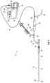
- FIG. 1is a schematic view of a thrombus removal system in accordance with the present invention.
- FIG. 2is a perspective view of a flow control module.
- FIG. 3is an elevational of cross-sectional view through the flow control module of FIG. 2 .
- FIG. 4is a schematic view of the dual vacuum chamber configuration that produces an accelerated aspiration response.
- FIG. 5is a qualitative fluid flow rate diagram at the catheter tip following opening of the vacuum control valve.
- FIG. 6 Ais a side elevational view of a thrombus engagement tool.
- FIG. 6 Bis an enlarged detail view of the distal end of the thrombus engagement tool of FIG. 6 A .
- FIG. 6 Cis a longitudinal elevational cross-section through the thrombus engagement tool of FIG. 6 B .
- FIGS. 7 A- 7 Eare side elevational views of various embodiments of thrombectomy catheters.
- FIG. 8is a cross-sectional view through a distal portion of the embolectomy catheter showing a side wall construction.
- FIG. 9is a cross-sectional view through a distal portion of the embolectomy catheter showing the radiopaque marker and inclined distal face.
- FIGS. 10 A- 10 Bare perspective views of an inserter tool to facilitate passing a catheter through a hemostasis valve.
- FIG. 10 Cis an end view of the inserter of FIGS. 10 A and 10 B .
- the system 10includes a thrombectomy catheter 12 , having an elongate tubular body 14 extending between the proximal end 16 and a distal end 18 .
- a central lumen 20(not illustrated in FIG. 1 ) extends between a proximal catheter connector 22 and a distal port 24 on the distal end 18 .
- catheters of the present inventioncan readily be modified to incorporate additional structures, such as permanent or removable column strength enhancing mandrels, two or more lumen such as to permit drug, contrast or irrigant infusion or to supply inflation media to an inflatable balloon carried by the catheter, or any combinations of these features, as will be readily apparent to one of skill in the art in view of the disclosure herein.
- additional structuressuch as permanent or removable column strength enhancing mandrels, two or more lumen such as to permit drug, contrast or irrigant infusion or to supply inflation media to an inflatable balloon carried by the catheter, or any combinations of these features, as will be readily apparent to one of skill in the art in view of the disclosure herein.
- the disclosurewill be described primarily in the context of removing obstructive material from the vasculature, but it will be understood to have applicability as an access catheter for delivery and removal of any of a variety of diagnostics or therapeutic devices with or without aspiration.
- catheters disclosed hereinmay readily be adapted for use throughout the body wherever it may be desirable to distally advance a low profile high flexibility catheter into a variety of type of vasculature, such as small or large vasculature and/or tortuous or relatively straight vasculature.
- catheter shafts in accordance with any embodiment described hereinmay be dimensioned for use throughout the neurovascular, coronary and peripheral vasculature, the gastrointestinal tract, the urethra, ureters, Fallopian tubes and other lumens and potential lumens, as well.
- the catheter shaft construction of any embodiment hereinmay also be used to provide minimally invasive percutaneous tissue access, such as for diagnostic or therapeutic access to a solid tissue target (e.g., breast or liver or brain biopsy or tissue excision), delivery of laparoscopic tools or access to bones such as the spine for delivery of screws, bone cement or other tools or implants.
- a solid tissue targete.g., breast or liver or brain biopsy or tissue excision
- laparoscopic tools or access to bonessuch as the spine for delivery of screws, bone cement or other tools or implants.
- Catheter 12will have a length and diameter suitable for the intended access point and target location.
- the catheter 12may have an effective length from the distal end of manifold or hub 22 to distal tip 18 generally no more than about 230 cm, no more than about 210 cm, no more than about 180 cm, or no more than about 160 cm, and typically from about 50 cm to about 150 cm, from about 90 cm to about 130 cm, or from about 105 cm to about 115 cm.
- the outer diameter of the catheter 10may be from about 0.035 inches to about 0.15 inches, from about 0.09 inches to about 0.13 inches, and may be lower in a distal segment than in a proximal segment.
- the inner diameter of the catheter 12 in a single central lumen embodimentmay be greater than or equal to about 0.1 inches, greater than or equal to about 0.088 inches, or greater than or equal to about 0.08 inches, or greater than or equal to about 0.06.
- the inner diameter of the catheter 12 in a single central lumen embodimentmay be less than about 0.20 inches or 0.15 inches, or less than or equal to about 0.11 inches, less than or equal to about 0.1 inches, less than or equal to about 0.088 inches, or less than or equal to about 0.07 inches, and often no more than about 0.095 inches.
- the catheter 12is releasably connectable to a flow control module 28 by way of a complementary connector module 30 .
- Connector module 30provides a releasable connection to complementary catheter connector 22 and may include a side port 32 for releasable connection to tubing 34 which may lead to a valve 36 .
- Connector module 30may additionally comprise a hemostasis valve configured to receive another device such as a guidewire or thrombus engagement tool, discussed below.
- Valve 36may selectively place tubing 34 into communication with side port 37 or the flow control module 28 discussed in greater detail below.
- Side port 37may be placed into communication with a source of media such as saline, contrast solution or medication, or a manifold 38 which can provide selective communication with each.
- the use of valve 36allows infusion of a desired media without detaching the tubing 34 from the connector module 30 .
- the flow control module 28is in communication with the valve 36 by way of a distal tube 44 .
- Flow control module 28is in communication with the selector valve 49 by way of a proximal tube 46 . This establishes a flow path between the distal port 24 through the catheter 12 through the various tubing and flow control module 28 to the pump assembly 42 .
- the flow control module 28may be integrally formed within the hub of thrombectomy catheter 12 to which the catheter 12 may be removably or non-removably attached or within the connector module 30 .
- a manually actuated aspiration devicee.g., a syringe
- an aspiration pump assembly 42may be used in addition to, or as an alternative to, an aspiration pump assembly 42 to permit a user to manually apply aspiration through the vacuum line.
- a manually actuated aspiration devicemay be in addition to, or as an alternative to, the pump assembly described in any embodiment herein.
- Flow control module 28may include a flow regulator such as an on-off control for regulating flow through the flow path between the catheter 12 and pump 42 .
- the flow regulatoris configured to provide a reversible restriction in the flow path, such as by an expandable or contractible iris, a ball valve or other rotary core valve, leaf valve, a pinch tubing, or others known in the art.
- the flow regulatorcomprises a collapsible portion 29 of the tubular wall defining the flow path, such as a section of polymeric tubing.
- An actuator 31 positioned adjacent the tubingis movable in response to a control such as a push button or toggle switch 48 between a first position where it compresses the tubing, thereby completely restricting flow, and a second position where it has moved away from the tubing, allowing the tubing to resume its full inside diameter and allow fluid flow.
- the actuator 31may be spring biased or have another default driver in the direction of the first (restricted) position, and only movable into the second (open) position in the presence of an affirmative mechanical force or release of a constraint allowing the flow path to open. Upon removal of the momentary “on” command, the actuator 31 automatically resumes the first position, obstructing flow.
- the actuator 31may be driven by a mechanical control such as a lever or rotatable knob, or an electrically driven system such as a solenoid, operated by any of a variety of buttons, levers, triggers, foot pedals or other switches known in the art, depending upon the desired functionality.
- a mechanical controlsuch as a lever or rotatable knob
- an electrically driven systemsuch as a solenoid, operated by any of a variety of buttons, levers, triggers, foot pedals or other switches known in the art, depending upon the desired functionality.
- the flow control module 28may contain a filter chamber 33 for example, which is in communication with the vacuum canister 58 on the pump assembly 42 by way of elongate aspiration tubing 40 .
- the toggle switch 48is in between the filter chamber 33 and the catheter 12 . In a default off position of some embodiments, this allows the entire length of the aspiration tubing 40 and the filter chamber 33 to reach the same low pressure as the aspiration canister 58 on the pump 42 .
- a filter assembly 35includes an outer tubular sidewall 37 having a transparent window 39 . In some implementations the entire tubular sidewall 37 can be a transparent window.
- the side wall 37encloses a filter 41 .
- the filter 41includes a filter sidewall 43 defining an interior (downstream) chamber (not illustrated) for filtered blood.
- blood and thrombusare drawn in the direction from catheter 12 via vacuum line 44 through a first filter aperture 45 and into the clot collection chamber 33 . Any thrombus will be captured on the outside (upstream side) of filter 43 . Blood is drawn through the filter 43 and proximal tubing 46 en route to the canister 58 .
- the filter 43is tubular however it may alternatively be planar or other shape depending upon the desired configuration.
- the switch 48may thereafter be closed to compress tubing 29 and isolate the catheter 12 from the vacuum source.
- a normally closed vent 47may be momentarily opened, to permit intake of an optically transparent media such as saline or ambient air. This allows residual blood in the chamber 33 to be drawn through the filter 43 and aspirated out via proximal tubing 46 , enabling visualization of any clot on the surface of the filter 43 through the window 39 .
- the vent 47may be manually actuated by a user and/or automatically actuated by the system. In some instances, a user may manually actuate the vent 47 through actuation of a button 62 located on the flow control module 28 .
- the vent 67may be normally closed, and then transitioned to an open configuration when the button 62 is being actuated (or vice versa). When in the open configuration, the vent 67 may expose the clot collection chamber 33 to an ambient environment. In some instances, exposure of the chamber 33 to the ambient environment allowing intake of air and acceleration of blood flow through the clot collection chamber 33 and towards the proximal tubing. Increased acceleration of blood flow due to vent 47 actuation may facilitate visualization of the clot by displacing the amount of blood or other fluids from the optical path between the window and the filter and/or decrease the amount of time required for the physician to accurately identify the clot in the chamber 33 .
- the valved ventalso allows the physician to deliver pulsatile negative pressure waves at the distal opening 24 .
- the flow control module 28comprises a proximal housing 31 and a distal housing 29 separated by the transparent tubular sidewall 35 .
- the tubular sidewall 35 and the filter 43are carried by the proximal housing 31 .
- Housing 29 and tubular sidewall 35may be joined at a releasable connection 33 that, in some instances, includes a gasket 59 to form a sealed connection.
- Complementary surface structurese.g., inclined corresponding grooves and pins or flanges
- the proximal housing 31 and the distal housing 29may be rotated relative to each other (e.g., by relative rotation across the gasket) to disconnect the housings from each other.
- the filter 43may be attached to any one of the distal housing 29 or the proximal housing 31 upon disconnection of the housings.
- the tubular sidewall 35may be attached to either one of the distal housing 29 and/or the proximal housing 31 such that, upon disconnection, the tubular sidewall 35 may remain attached to one of the housings 29 , 31 .
- the tubular sidewall 35may be configured to remain around the filter 43 or may be configured to be removed from over the filter 43 . In either instance, disconnection of the housings 29 , 31 from each other can expose the filter 43 and allow a clot to be easily accessed and removed.
- the interior surface of the clot collection container 33may comprise a coating to provide one or more of a variety of properties to the clot collection containers 33 .
- the coatingmay be configured to enhance visualization through at least a portion of the clot collection container 33 (such as the transparent window 39 ).
- the coatingmay be configured to inhibit blood accumulation or increase blood repellant properties.
- the clot collection container 33may comprise a coating to inhibit foam formation during an aspiration procedure.
- the coatingsmay be located at least partially along an interior surface of the tubular sidewall 35 and/or the clot collection container 33 or along an entire interior surface of the tubular sidewall 35 and/or the clot collection container 33 .
- the coatingis located along an interior surface of the transparent window 39 .
- the coatingcan be both hydrophobic and oleophobic.
- the coatingmay have some hydrophilic features on a portion of the polymer to increase oleophobic properties.
- Aspiration pump assembly 42may be releasably placed into communication with flow control module 28 such as by a luer connection between selector valve 45 and tubing 40 .
- Aspiration pump assembly 42may include a vacuum pump 50 , and may also include a vacuum gauge 51 , and an optional pressure adjustment control 54 .
- the vacuum gauge 51is in fluid communication with the vacuum pump and indicates the vacuum pressure generated by the pump.
- the pressure adjustment control 54allows the user to set to a specific vacuum pressure.
- Power button 56activates the pump 50 .
- the vacuum canister 58may be provided with a vent 53 to atmosphere, opened or closed by a valve.
- the valveis normally closed to permit vacuum in the canister to reach a desired low pressure.
- the valvemay be momentarily opened as desired to permit introduction of air and reduction of the vacuum, such as to reduce foaming within the vacuum canister 58 .
- the ventmay function to reduce foaming and increase visibility within the canister.
- the vent 53comprises a permanently opened vent such as in a lid or side wall of the vacuum canister.
- the ventmay comprise an aperture formed through the lid or side wall having a diameter of no more than about 0.5 mm or 0.25 mm and may be a laser cut hole through a metal sheet which may be in the form of a disc carried by the lid.
- the inside surface of the canister 58may be provided with a coating of one or more materials to inhibit foaming of blood under vacuum.
- the coatingsmay be located at least partially along or entirely along an interior surface of the vacuum canister 58 .
- the coatingcan be both hydrophobic and oleophobic. In some instances, the coating may have some hydrophilic features on a portion of the polymer to increase oleophobic properties.
- Aspiration pump 50may alternatively be a manually activated pump such as a syringe.
- a flow restrictormay be coupled such as by luer connectors in series with the vacuum line 40 .
- the flow restrictorsenables toggling between a low flow and a high flow configuration.
- the flow restrictorsmay comprise a variable restrictor that may be adjusted by a user. This may be accomplished by selectively diverting flow between a relatively smaller diameter and larger diameter aperture, a variable diameter aperture, or other flow regulators such as any of those disclosed in the United States patent publication No. 2021/0315597 to Buck, et al, entitled Aspiration System with Accelerated Response, the disclosure of which is hereby incorporated in its entirety herein.
- a rotatable drumis provided with a first transverse flow path having a first diameter.
- the drumis rotatable within a housing having an inlet port and an outlet port.
- the drummay be rotated to place the inlet port into fluid communication with the outlet port through the first flow path.
- a second flow path having a second, different diameteralso extends transversely through the drum, rotationally offset from the first flow path.
- the drummay be rotated to place the inlet port into communication with the outlet port through the second flow path, thereby providing a flow rate through the drum different from the flow rate provided by the first flow path.
- the filter chamber 33 on the flow control module 28 or on the connector module 30is spaced apart from the remote vacuum pump 42 and vacuum canister 58 to provide enhanced aspiration performance.
- Conventional aspiration pumps and filtersare intended to be placed outside of the sterile field and may be far enough away from the patient to require a length of aspiration tubing 40 between the pump assembly 42 and the catheter 12 to be at least about 50 inches or about 100 inches or more.
- the tubing 40may be about 102 inches.
- the pumptypically includes an aspiration canister 58 for blood collection.
- an aspiration canister 58for blood collection.
- a valveis opened to place the low pressure canister 58 in communication with the catheter 12 by way of the aspiration tubing 40 , to aspirate material from the patient.
- the length of the aspiration tubing extending from inside to outside of the sterile fieldoperates as a flow restrictor, causing a delay between the time of activating the vacuum button on the pump assembly 42 and actual application of suction to the clot at the distal end of the catheter.
- the only flow restriction between a source of vacuum (filter chamber 33 ) and the patientis the relatively short aspiration pathway between the on/off valve in the handpiece actuated by toggle switch 48 and the distal end 18 of the catheter.
- the aspiration control 48is activated to open the flow path, the flow restriction and enclosed volume on the patient side of the filter chamber 33 is low relative to the flow restriction and enclosed volume through aspiration tubing 40 on the pump side of the filter chamber 33 .
- This dual chamber configurationproduces a rapid spike in negative pressure experienced at the distal end 18 of the catheter 12 upon activation of the aspiration control 48 , and rapid filling of the chamber 33 .
- the response time between activating the aspiration control 48 and realizing suction actually experienced at the clotis significantly faster and allows significantly higher initial flow than the response time realized in a conventional system having only a vacuum chamber 58 located at the pump assembly 42 outside of the sterile field.
- the spike of negative pressure experienced at the distal end of the catheterwill fade as pressure equilibrium is reached between the filter chamber 33 and canister 58 .
- the vacuum pump 50will gradually bring the pressure in the filter chamber 33 back down to the level in the vacuum canister 58 at the pump.
- FIG. 4A simplified fluid flow diagram is illustrated in FIG. 4 , and a qualitative flow rate diagram is illustrated in FIG. 5 .
- the flow restriction between chamber 33 and the distal end 18 of catheter 12is small relative to the flow restriction between the vacuum canister 58 and the vacuum chamber 33 . This allows a negative pressure peak experienced at distal end 18 almost instantaneously upon activation of vacuum switch 48 .
- the flow rate of material into the catheter 12rapidly reaches a peak and subsides as vacuum chamber 33 fills with aspirated material.
- the vacuum in chamber 33declines to a minimum, and slowly recharges by the large vacuum chamber 58 and associated pump through tubing 40 when the toggle switch 48 is moved into the closed position.
- a clinicianmay choose to close the vacuum switch 48 at or shortly following the maximum flow rate, just giving a short burst or series of bursts of pulsatile vacuum to facilitate spiration of thrombus into the catheter 12 .
- a similar effectmay be established by utilizing the vent 47 .
- the vacuum in chamber 33may decline to a minimum as the button 62 is actuated such that the vent is opened. Thereafter, the vacuum chamber 33 may slowly recharge by the large vacuum chamber 58 and associated pump through tubing 40 when the button 62 and vent 47 are moved into the closed position.
- a clinicianmay choose to open the vent 47 at or shortly following the maximum flow rate, just giving a short burst or series of bursts of pulsatile vacuum to facilitate spiration of thrombus into the catheter 12 .
- an elongate flexible thrombus engagement toolmay be advanced through the aspiration catheter, to facilitate retrieval of the clot.
- the thrombus engagement toolmay comprise an elongate flexible shaft having a proximal hand piece such as a knob configured to be rotated by hand.
- the distal endcarries a clot engagement tip which may include one or more radially outwardly extending engagement structures such as a helical thread.
- a thrombus engagement tool 80may comprise an elongate flexible shaft 82 having a proximal end 84 and a distal end 86 .
- a proximal hand piecesuch as a torquing handle 88 may be configured to be rotated by hand.
- Distal end 86carries a clot engagement tip 90 which may include one or more radially outwardly extending structures such as a helical thread 92 .
- the handle 88may have an indicium of rotational direction such as a printed or molded arrow 94 which indicates the direction to rotate the handle 88 in order for the helical thread 92 to engage clot.
- the distal tip 90includes a helical thread 92 extending between a distal thread end 96 and a proximal thread end 94 and supported by flexible shaft 98 .
- the axial length of the distal tip 90is at least about 5 mm or 10 mm or 15 mm or 20 mm and in some embodiments no more than about 30 mm or 20 mm measured along the flexible shaft 98 .
- the axial lengthwill be within the range of from about 20 mm to about 25 mm.
- the helical thread 92wraps around the axis at least about 1 or 2 or 4 or more full revolutions, but in some embodiments no more than about 10 or no more than about 6 revolutions. Preferably, the thread 92 wraps around the axis within the range of from about 2.5 to about 4.5 revolutions. In some embodiments the axial length along the threaded portion of the tip is within the range of from about 5 to about 15 mm, and preferably within the range of from about 8 mm to about 12 mm.
- the helical thread 92 on this implementationmay have a constant pitch throughout its length.
- the pitchmay be within the range of from about 5 to about 10 threads per inch depending upon desired performance.
- the thread to thread spacing in the axial directionmay be within the range of from about 2 mm to about 6 mm, preferably from about 3 mm to about 4 mm.
- the threadmay have multiple pitches (e.g. stepped or graduated) designed to engage, transport or grasp thrombus within the catheter lumen.
- a distal pitchmay be less than a proximal pitch.
- the pitchmay vary continuously along the length of the thread, or may step from a first, constant pitch in a proximal zone to a second, different pitch in a distal zone of the thread.
- the thread 92may comprise a continuous single helical flange or may have a plurality of discontinuities to produce a plurality of teeth or serrations, arranged helically around the core wire.
- the maximum OD of the thread 92is preferably smaller than the diameter of a sliding fit within the intended catheter lumen, and may generally be at least about 0.015 inches or at least about 0.010 inches smaller than the catheter lumen ID. In some implementations, the max OD of the tip may be significantly less than the inside diameter of the catheter lumen to allow more space for the thrombus along the side of the tip but still create significant grasping force via lateral engagement of the helical threads with the thrombus.
- the maximum helical thread diameteris about 0.110 inches
- the catheter lumen IDis about 0.275 inches (24F) (a 0.165 inch gap between the helical threads and catheter wall).
- the maximum OD of the tipis within the range of from about 0.03 to about 0.06 inches within a catheter having a distal end ID within the range from about 0.068 inches to about 0.073 inches. This leaves a substantial tip bypass flow path.
- the max OD of the tipis no more than about 35% or no more than about 40% or no more than about 60% of the ID of the corresponding catheter and may be within the range of from about 35% to about 55% of the catheter ID. In some instances, the max OD of the tip may slightly less than the ID of the corresponding catheter to provide a sliding fit within the intended catheter lumen. For example, the max OD of the tip may be no less than about 90% or no less than about 95% or no less than about 97% of the ID of the corresponding catheter.
- the tip 90will normally be pushed to one side of the aspiration lumen.
- manual manipulationsuch as rotation of the tip 90 can engage the clot like a worm gear and either grasp the clot (e.g., by pinning it against the opposing catheter sidewall) for retraction or facilitate freeing the blockage and aid in ingestion of the clot into the catheter.
- Manual manipulationmay also include axial proximal and distal reciprocation along with rotation, during aspiration, which can facilitate ingestion of the clot into the catheter.
- annular flow pathis created in the annular (if the tip were centered) space between the maximum OD of the tip, and the ID of the catheter lumen.
- This annular flow pathcooperates with the vacuum and helical tip to grab and pull obstructive material into the catheter under rotation and vacuum.
- the annular flow pathis significantly greater than any flow path created by manufacturing tolerances in a tip configured to shear embolic material between the tip and the catheter wall.
- a cross sectional area of the helical flow path of a tip having a maximum OD in the range of from about 0.0400 to about 0.0406 incheswill generally be at least about 0.0003 square inches, and in some embodiments at least about 0.00035 or at least about 0.000375 inches.
- the total aspiration flow path across the helical tipis therefore the sum of the helical flow path through the tip and the annular flow path defined between the OD of the tip and the ID of the catheter lumen.
- Aspirationoccurs both through the helical channel formed between adjacent helical threads as well as around the outside of the tip such that the assembly is configured for engaging and capturing embolic material but not shearing it between a sharp edge of the thread and the inside wall of the catheter.
- the distal advance segment 100advantageously permits the thrombus engagement device 80 to at least partially move past the thrombus without “pushing” the thrombus in a distal direction as the tip 90 is advanced. This may inhibit the thrombus (or any particulate thereof) from passing downstream within the vessel during engagement of the device 80 with the thrombus.
- the distal advance segment 100can comprise a continuation of the helical thread 92 .
- the distal advance segment 100may comprise a threaded segment continuing from the helical thread 92 .
- the threaded distal advance segment 100may maintain an outer diameter consistent with the remainder of the helical thread 92 .
- the threaded distal advance segment 100may comprise a thread that tapers in a distal direction towards a smaller outer diameter relative to the remainder of the helical thread 92 .
- the helical thread 92may comprise a proximal cylindrical segment and a distal tapered segment that extends along the distal advance segment 100 .
- the profile of the tip 90 in an end view along the axis of rotationmay be circular and/or, in some instances, may vary to create a non circular pattern around the axis of rotation.
- profilemay comprise a helical pattern, such as an oval cross-section that rotates along the axis of rotation to create the helical profile.
- the tip as seen in an end elevational viewthus may exhibit a major diameter and a minor diameter.
- the minor diametermay be no more than about 95% or 90% or 80% or 70% of the major diameter, depending upon desired performance.
- the outer edge 93 of the thread 92lies along the surface of a cylinder.
- an outer edge 93 of the thread 92thus has a linear surface in the axial direction, substantially conforming to the surface of a cylinder.
- a distal side 95 of the thread 92is inclined radially outwardly in a proximal direction.
- a proximal side 97 of the thread 92also inclines radially outwardly in a proximal direction thereby defining a proximally facing undercut along the length of the thread.
- the illustrated tip 90includes an atraumatic, tapered distal advance segment 100 extending between an atraumatic distal tip at 102 and a transition to the distal end 96 of the thread 92 .
- Helical thread 92extends proximally from the transition to a proximal end 94 of the helical thread 92 .
- a trailing segment 104may extend between the proximal end 94 of the thread and the proximal end 106 of the tip.
- the axial length of the distal advance segment 100may be at least about 5 mm or at least about 8 mm or 9 mm and generally less than about 15 mm, and in some implementations is within the range of from about 8 mm to about 12 mm.
- the outside diameter of the flexible shaft 82is generally less than about 0.02 inches, or less than about 0.015 inches and, in one implementation, is about 0.008 inches.
- the flexible shaft 82may comprise a distal tapered section.
- the distal tapered sectionmay advantageously increase tip flexibility and/or maximize aspiration.
- the outside diameter at the distal end of the distal tapered section of the flexible shaft 82is generally less than about 0.01 inches, or less than about 0.008 inches and, in one implementation, is no more than about 0.006 inches.
- the outside diameter of the advance segment 100 at distal tip 102is generally less than about 0.024 inches, or less than about 0.020 inches and, in one implementation, is about 0.018 inches.
- the maximum outside diameter of the advance segment 100 and helical thread 92may be within the range from about 0.020 to about 0.045 inches, and, in one implementation, is less than about 0.040 inches, such as about 0.035 inches.
- the advance segment, helical thread and trailing segment of the tip 90may be molded as a single piece over the flexible shaft 82 using any of a variety of polymers known in the catheter arts.
- a first radiopaque marker 110may be carried on the flexible shaft 82 beneath the advance segment 100 .
- a second radiopaque marker 112may be carried on the flexible shaft 82 within the trailing segment 104 .
- Each radiopaque markermay comprise a radiopaque tube or a coil of radiopaque wire such as a platinum iridium alloy wire having a diameter about 0.002 inches and positioned or wrapped around the flexible shaft 82 and soldered to the flexible shaft 82 to produce an RO sleeve or coil having an outside diameter of less than about 0.020 inches, such as about 0.012 inches.
- the radiopaque markersmay also provide an axial interference fit between the flexible shaft 82 and the advance segment 100 and trailing segment 104 to resist core wire axial pull out from the tip 90 (tip detachment).
- the maximum OD of the thread 92exceeds the maximum OD of the advance segment 100 by at least about 15% or 25% or 30% or more of the OD of the advance segment 100 , to facilitate crossing the clot with the advance segment 100 and engaging the clot with the thread 92 .
- the distal tip 102may be permitted to extend at least about 2 cm or 3 cm and preferably as much as 4 to 8 cm beyond the catheter (such as to permit manual removal of engaged thrombus), but generally will be limited to extend no more than a preset distance such as 12 cm or 8 cm or 5 cm beyond the catheter (e.g., within the range of from about 5 cm to about 10 cm) depending upon desired performance.
- Distal advance of the tip 102may be limited by providing mechanical interference at the desired distal limit of travel.
- a distal stop surface 114which may be on the handle 88 (see FIG. 6 A ) provides an interference engagement with a complementary proximal surface (e.g. proximal surface 33 on connector module 30 or on the catheter hub) carried by the aspiration catheter through which the thrombus engagement tool 80 is advanced.
- a distal engagement surfacecan be carried anywhere along the length of the thrombus engagement tool 80 , for sliding rotational engagement with a complementary proximally facing stop surface carried by the catheter. Additional details of distal limit configurations may be found in U.S.
- the limit on distal advance of the helical tipmay enable a first configuration in which the distal tip may be advanced through the catheter and placed at a first position approximately aligned with the distal end of the catheter 12 . The physician may then advance the tip to a second position extending beyond the distal end of the catheter such as for inspection and cleaning purposes.
- a position indicator 85may be carried by the flexible shaft 82 spaced apart from the distal surface 114 by a distance corresponding to the maximum length of the thrombus engagement tool intended to extend beyond the distal end of the catheter.
- the distal tip 102may be positioned approximately at the distal end of the catheter. This way the physician will know that any further distal advance of the thrombus engagement tool will be extending beyond the distal end of the catheter. The maximum extension will be reached when the distal surface 114 contacts the catheter hub.
- the position indicator 85may comprise any of a variety of visual or tactile features, such as a color change or a colored band surrounding the flexible shaft 82 .
- a visual indicium implementationcolor change or circumferential line
- the distal tip 102may be positioned approximately at the distal end of the catheter when the indicator is visible just outside of the hub.
- the position indicator 85comprises the transition between the distal end of the hypo tube 87 and the underlying flexible shaft 82 . This provides haptic feedback as the indicator (step in outside diameter) encounters and passes through the valve of the RHV.
- the hypo tube 87additionally functions as a strain relief or anti buckling feature and may have an axial length within the range of from about 3 cm to about 15 cm and in some implementations within the range of from about 5 cm to about 9 cm.
- a distal segment 120may have a length within the range of about 1-3 cm and a durometer of less than about 35D or 30D.
- An adjacent proximal segment 122may have a length within the range of about 4-6 cm, and a durometer of less than about 35D or 30D.
- An adjacent proximal segment 124may have a length within the range of about 4-6 cm, and a durometer of about 35D or less.
- An adjacent proximal segment 126may have a length within the range of about 1-3 cm, and a durometer within the range of from about 35D to about 45D (e.g., 40D).
- An adjacent proximal segment 128may have a length within the range of about 1-3 cm, and a durometer within the range of from about 50D to about 60D (e.g., about 55D).
- An adjacent proximal segment 130may have a length within the range of about 1-3 cm, and a durometer within the range of from about 35D to about 50D to about 60D (e.g., about 55D).
- An adjacent proximal segment 132may have a length within the range of about 1-3 cm, and a durometer of at least about 60D and typically less than about 75D. More proximal segments may have a durometer of at least about 65D or 70D.
- the distal most two or three segmentsmay comprise a material such as Tecothane and/or PEBAX, and more proximal segments may comprise PEBAX or other catheter jacket materials known in the art.
- At least three or five or seven or nine or more discrete segmentsmay be utilized, having a change in durometer between highest and lowest along the length of the catheter shaft of at least about 10D, preferably at least about 20D and in some implementations at least about 30D or 40D or more.
- FIGS. 7 A- 7 Eillustrate various embodiments of catheters, at least some of which incorporate a plurality of catheter outer jacket segments with varying lengths and/or hardness for varying flexibility along the length of the catheter body. It will be understood that any of the features shown or described in connection with any of the catheters of FIGS. 7 A- 7 E can be used with any of the embodiments described and/or contemplated herein. It will also be understood that any of the features described and/or contemplated in connection with any of the embodiments disclosed herein can be utilized with any of the catheters described in connection with FIGS. 7 A- 7 E . As with all embodiments in this specification, any feature, structure, material, method, or step that is described and/or illustrated in the embodiments of FIGS. 7 A- 7 E can be used with or instead of any feature, structure, material, method, or step that is described and/or illustrated in any other embodiment of this specification.
- FIGS. 7 B- 7 Eillustrates embodiments of various catheters 400 , 500 , 600 .
- the catheters 400 , 500 , 600may include differing properties (e.g., such as length, diameter, etc.) such that one or more of the catheters 400 , 500 , 600 may interact with any of the other catheters 400 , 500 , 600 in any various manner.
- each of catheters 400 , 500 , 600may comprise a different size to permit the catheters 400 , 500 , 600 to at least partially extend through one or more of the other catheters 400 , 500 , 600 .
- the lengths of each of the catheters 400 , 500 , 600may vary so as to permit a smaller catheter to pass through and extend distally beyond a larger catheter in a telescoping manner.
- catheter 500may be configured to pass through and extend beyond catheter 400 .
- catheter 600may be configured to pass through and extend beyond at least one of catheter 500 or catheter 400 in a telescoping manner.
- FIG. 7 Eillustrates an example telescoping catheter stack including each of catheters 400 , 500 , 600 , it will be understood by one having skill in the art that any combination of catheters 400 , 500 , 600 may be utilized.
- a systemmay incorporate the use of catheter 400 and catheter 500 , the use of catheter 400 and catheter 600 , or the use of catheter 500 and catheter 600 .
- Catheter 400may comprise an 8F catheter. In some instances, catheter 400 comprises a diameter larger than the diameter of any of the remaining catheters in a system. Additionally, or alternatively, catheter 400 may comprise an overall length shorter than the length of any of the remaining catheters in a system. In this manner, catheter 400 may comprise the outermost catheter in a telescoping system and may permit any of the remaining catheters 500 , 600 to extend distally beyond a distal end of catheter 400 .
- the catheter 400may comprise a length between about 35 cm and about 105 cm or, a length between about 45 cm and about 95 cm.
- the catheter 400may comprise a length of from about 50 cm to about 90 cm.
- the catheter 400may comprise a length at least shorter than any catheter with a diameter smaller than catheter 400 (e.g., such as catheter 500 , 600 ).
- Catheter 500may comprise a 6F catheter.
- catheter 500comprises a diameter in between the diameters of the remaining catheters in a system.
- catheter 500may comprise a length in between the lengths of the remaining catheters in the system.
- catheter 500may comprise a middle catheter in a telescoping system and may be configured to pass through and extend beyond one or more catheters while also permitting another catheter to extend distally beyond a distal end of catheter 500 .
- the catheter 500may comprise a length between about 120 cm and about 155 cm or between about 130 cm and about 145 cm.
- the catheter 500may comprise a length of about from 135 cm to about 137 cm.
- the catheter 500may comprise a length at least longer than any catheter with a diameter larger than catheter 500 (e.g., such as catheter 400 ).
- the catheter 500may comprise a length at least shorter than any catheter with a diameter smaller than catheter 500 (e.g., such as catheter 600 ).
- Catheter 600may comprise a 5F catheter. In some instances, catheter 600 comprises a diameter smaller than the diameters of the remaining catheters in a system. Additionally, or alternatively, catheter 600 may comprise a length longer than the lengths of any of the remaining catheters in the system. In this manner, catheter 600 may comprise an innermost catheter in a telescoping system and may be configured to pass through and extend beyond one or more of the other catheters.
- the catheter 600may comprise a length between about 145 cm and about 175 cm or between about 155 cm and about 165 cm.
- the catheter 600may comprise a length of about 160 cm.
- the catheter 600may comprise a length at least longer than any catheter with a diameter larger than catheter 600 (e.g., such as catheter 400 , 500 ).
- One or more of the catheters 400 , 500 , 600may include a coil and/or a braid in the sidewall extending through at least a portion of the sidewall of the catheter 400 , 500 , 600 , as discussed herein.
- the braidmay have properties that vary along the length of each catheter 400 , 500 , 600 to generate a variety of desired characteristics of the catheter 400 , 500 , 600 .
- a wire density of the braidmay vary gradually or in steps along the length of the catheter 400 , 500 , 600 and/or vary between discrete sections of the catheter 400 , 500 , 600 .
- Catheter 600may comprise one or more discrete sections with braid properties varying between one or more of the sections.
- catheter 600may comprise a first section, a second (e.g., intermediate) section, and a third distal section.
- a sidewall propertysuch as a length and/or a wire density the braid along a respective section, may vary between the sections.
- a pics per inch (ppi) count of the braid in connection with the wire density of the braidmay gradually transition between one or more of the catheter sections.
- the ppi count of the braidin some instances, may remain generally consistent through a length of the first section and a length of the third section but gradually transition along the length of the second, intermediate section.
- the first section of catheter 600may have a length of at least about 20 cm.
- the length of the first sectionmay be from about 25 cm to about 35 cm or, in one example, about 30 cm.
- the braid through the first sectionmay have a wire density of at least about 100 ppi.
- the braid through the first sectionmay have wire density of at least about 120 ppi or, more specifically, about 130 ppi.
- the third section of catheter 600may have a length of at least about 100 cm.
- the length of the third sectionmay be from about 120 cm to about 140 cm or, more specifically, about 130 cm.
- the braid through the third sectionmay have a wire density of no greater than about 85 ppi.
- the braid through the third sectionmay have wire density from about 70 ppi to about 80 ppi.
- the second section of catheter 600may be an intermediate section between the first section and the third section.
- the second sectionmay have a length of at least about 3 cm. In some instances, the second section may have a length no greater than about 20 cm or, more specifically, no greater than about 10 cm. For example, the length of the second section may be about 5 cm.
- the braid through the second sectionmay have a wire density of no greater than the wire density of the first section and no less than the wire density of the third section.
- Catheter 500may comprise one or more discrete sections with braid properties varying between one or more of the sections.
- catheter 500may comprise a first section, a second (e.g., intermediate) section, and a third section.
- a sidewall propertysuch as a length and/or a wire density the braid along a respective section, may vary between the sections.
- a ppi count of the braid in connection with the wire density of the braidmay gradually transition between one or more of the catheter sections.
- the ppi count of the braidin some instances, may remain generally consistent through a length of the first section and a length of the third section but gradually transition along the length of the second, intermediate section.
- the first section of catheter 500may have a length of at least about 20 cm.
- the length of the first sectionmay be from about 25 cm to about 35 cm or, in one example, about 30 cm.
- the braid through the first sectionmay have a wire density of at least about 100 ppi.
- the braid through the first sectionmay have wire density of at least about 120 ppi or, in one example, about 130 ppi.
- the third section of catheter 500may have a length of at least about 80 cm.
- the length of the third sectionmay be from about 100 cm to about 120 cm or, in one example, about 105 cm.
- the braid through the third sectionmay have a wire density of no greater than about 100 ppi.
- the braid through the third sectionmay have wire density from about 80 ppi to about 90 ppi.
- the second section of catheter 600may be an intermediate section between the first section and the third section.
- the second sectionmay have a length of at least about 3 cm. In some instances, the second section may have a length no greater than about 20 cm or, more specifically, no greater than about 10 cm. For example, the length of the second section may be about 5 cm.
- the braid through the second sectionmay have a wire density of no greater than the wire density of the first section and no less than the wire density of the third section.
- Catheter 400may comprise one or more discrete sections with braid properties varying between one or more of the sections.
- catheter 400may comprise one section.
- the catheter 400may comprise a greater number of sections (e.g., two sections, three sections, four sections, or greater).
- catheter 400may comprise three sections as described in connection with either one or catheter 500 or catheter 600 .
- a sidewall property, such as a length and/or a wire density the braid,may vary along catheter 400 .
- a ppi count of the braid in connection with the wire density of the braidmay gradually transition to increasing flexibility in a distal direction along catheter 400 .
- the section of catheter 400may have a length of at least about 40 cm.
- the length of the sectionmay be from about 50 cm to about 60 cm or, in one example, about 55 cm.
- the braid through the sectionmay have a wire density of at least about 80 ppi.
- the braid through the sectionmay have wire density of at least about 90 ppi.
- the braidin some instances, may extend along an entire length of the catheter sidewall. In some instance, a junction between the braid and a coil is not present in the catheter and/or the catheter sidewall does not incorporate a coil. It will be understood that this braid configuration may be applied to any catheter disclosed herein, including, but not limited to, catheters 400 , 500 , 600 .
- One or more of the catheters 400 , 500 , 600may an outer jacket segment stacking pattern for a progressive flexibility catheter.
- the outer jacket segmentmay each have properties that vary along the length of each catheter 400 , 500 , 600 to generate a variety of desired characteristics of the catheter 400 , 500 , 600 .
- each segment of the outer jacketmay have a corresponding Shore D hardness to vary the flexibility along the length of the catheter 400 , 500 , 600 .
- the outer jacket segmentsmay be made of a thermoplastic elastomer made of flexible polyether and rigid polyamide (e.g., Pebax®).
- each segment of the outer jacketmay comprise a different variation of the thermoplastic elastomer to alter flexiblity.
- Catheter 600may comprise a plurality of discrete segments of the outer jacket with varying flexibility between one or more of the segments.
- catheter 600may comprise a plurality of segments.
- a sidewall property, such as Shore D hardness and/or flexibility,may vary between the segments.
- a Shore D hardness of the outer jacket segmentsmay gradually transition from higher at proximal end segment of the outer jacket to lower at a distal end segment of the outer jacket.
- the proximal end segment of the outer jacket of the catheter 600may have a Shore D hardness of at least about 60.
- the Shore D hardness of the proximal end segmentmay be from about 70 to about 80 or, more specifically, at least about 75.
- the distal end segment of the outer jacket of the catheter 600may have a Shore D hardness of at most about 40.
- Shore D hardness of the distal end segmentmay be from about 30 to about 20 or, more specifically, no more than about 27.
- a plurality of the intermediate segments between the distal end segment and the proximal end segmentmay each comprise a variety of Shore D hardness.
- each segmentdecreases in a Shore D hardness in a distal direction and may have a smaller Shore D hardness than a proximally adjacent segment.
- the Shore D hardness of a first segmentmay be from about 30 to about 50 or, more specifically, about 40.
- the first segmentin some instances, may be between positioned about 120 cm to about 160 cm or, more specifically, about 140 cm away from a distal end face of the catheter 600 .
- the Shore D hardness of the second segmentmay be from about 50 to about 70 or, more specifically, about 65.
- the second segmentin some instances, may be between positioned about 220 cm to about 260 cm or, more specifically, about 240 cm away from a distal end face of the catheter 600 .
- Catheter 500may comprise a plurality of discrete segments of the outer jacket with varying flexibility between one or more of the segments.
- cathetermay comprise a plurality of segments.
- a sidewall property, such as Shore D hardness and/or flexibility,may vary between the segments.
- a Shore D hardness of the outer jacket segmentsmay gradually transition from higher at a proximal end segment of the outer jacket to lower at a distal end segment of the outer jacket.
- the proximal end segment of the outer jacket of the catheter 500may have a Shore D hardness of at least about 60.
- the Shore D hardness of the proximal end segmentmay be from about 70 to about 80 or, more specifically, at least about 75.
- the distal end segment of the outer jacket of the catheter 500may have a Shore D hardness of at most about 40.
- Shore D hardness of the distal end segmentmay be from about 30 to about 20 or, more specifically, no more than about 27.
- a plurality of the intermediate segments between the distal end segment and the proximal end segmentmay each comprise a variety of Shore D hardness.
- each segmentdecreases in a Shore D hardness in a distal direction and may have a smaller Shore D hardness than a proximally adjacent segment.
- the Shore D hardness of a first segmentmay be from about 30 to about 50 or, more specifically, about 40.
- the first segmentin some instances, may be between positioned about 70 cm to about 110 cm or, more specifically, about 90 cm away from a distal end face of the catheter 500 .
- the Shore D hardness of a second segmentmay be from about 50 to about 70 or, more specifically, about 65.
- the second segmentin some instances, may be between positioned about 160 cm to about 200 cm or, more specifically, about 180 cm away from a distal end face of the catheter 500 .
- Catheter 400may comprise a plurality of discrete segments of the outer jacket with varying flexibility between one or more of the segments.
- catheter 400may comprise a plurality of segments.
- a sidewall property, such as Shore D hardness and/or flexibility,may vary between the segments.
- a Shore D hardness of the outer jacket segmentsmay gradually transition from a proximal end segment of the outer jacket to a distal end segment of the outer jacket.
- the proximal end segment of the outer jacket of the catheter 400may have a Shore D hardness of at least about 60.
- the Shore D hardness of the proximal end segmentmay be from about 70 to about 80 or, more specifically, about 75.
- the distal end segment of the outer jacket of the catheter 400may have a Shore D hardness of at most about 40.
- Shore D hardness of the distal end segmentmay be from about 30 to about 20 or, more specifically, no more than about 27.
- a plurality of the intermediate segments between the distal end segment and the proximal end segmentmay each comprise a variety of Shore D hardness.
- each segmentdecreases in a Shore D hardness in a distal direction and may have a smaller Shore D hardness than a proximally adjacent segment.
- the Shore D hardness of a first segmentmay be from about 30 to about 50 or, more specifically, about 40.
- a first segmentin some instances, may be between positioned about 65 cm to about 105 cm or, more specifically, about 85 cm away from a distal end face of the catheter 400 .
- the Shore D hardness of a second segmentmay be from about 40 to about 65 or, more specifically, about 55.
- the second segmentin some instances, may be between positioned about 105 cm to about 145 cm or, more specifically, about 125 cm away from a distal end face of the catheter 400 .
- the Shore D hardness of a third segmentmay be from about 60 to about 80 or, more specifically, about 70.
- the third segmentin some instances, may be between positioned about 140 cm to about 180 cm or, more specifically, about 160 cm away from a distal end face of the catheter 400 .
- Catheter 400may comprise a tubular body length of about 90+/ ⁇ 5 cm. In some instances, catheter 400 may comprise a tubular body length of about 50+/ ⁇ 5 cm. A number of the plurality of discrete segments of the outer jacket of catheter 400 may vary with respect to the tubular body length of catheter 400 . A length of the respective segments of the plurality of discrete segments of the outer jacket of catheter 400 may vary with respect to the tubular body length of catheter 400 .
- a coatingin some instances, may be located along an outer diameter of a distal portion of the catheter sidewall.
- the coatingcan be configured to decrease frictional resistance of the distal portion of the catheter sidewall with any adjacent structure (e.g., a vessel wall). In some instances, the coating increases the lubriciousness of the catheter distal portion outer sidewall.
- the coatingmay advantageously reduce friction on the distal end of the catheter going through tortuous vasculature. This may facilitate advancement and rotation of the catheter distal end, particularly in situations where the catheter contains an increased flexibility along a distal end portion of the catheter.
- the coatingmay extend in a proximal direction from, or proximate to, a catheter distal end face. The coating may extend at least about 20 cm in a proximal direction.
- the coatingextends no farther than about 50 cm from the catheter distal end face.
- the coatingmay extend for a length of about 25 cm to about 35 cm or, more specifically, about 30 cm from a catheter distal end face. It will be understood that the coating may be applied to any catheter disclosed herein, including, but not limited to, catheters 400 , 500 , 600 .
- FIG. 8illustrates a cross section through the sidewall of a distal portion of a single lumen catheter.
- An internal support layermay comprise either a coil or braid.
- adjacent loops or filars of the coil 140may have a constant pitch throughout the length of the coil or may be closely tightly wound in a proximal zone with a distal section having looser spacing between adjacent loops.
- At least the distal about 1 cm or about 2 cm or about 3 cm or about 4 cm of the coilwill have a spacing that is at least about 130%, and in some implementations at least about 150% or more than the spacing in the proximal coil section.
- the spacing in the proximal coilmay be about 0.004 inches and in the distal section may be at least about 0.006 inches or about 0.007 inches or more.
- the distal end of the coil or braid 140can be spaced proximally from the distal end of the inner liner 142 , for example, to provide room for an annular radiopaque marker 144 .
- the coil or braid 140may be set back proximally from the distal end, in some embodiments, by approximately no more than about 1 cm, about 2 cm, or about 3 cm.
- the distal end of the catheter 12is provided with a beveled (inclined) distal surface 146 residing on a plane having an angle of at least about 10 degrees or about 20 degrees and in one embodiment about 30 degrees with respect to a longitudinal axis of the catheter 10 .
- At least a distally facing edge of the annular radiopaque marker 144may be an ellipse, residing on a plane which is inclined with respect to the longitudinal axis to complement the bevel angle of the distal surface 146 . Additional details are described in connection with FIG. 9 below.
- the distal braid or coil and the RO marker 144are provided with an outer jacket 156 such as a polymer tube formed from a plurality of axially adjacent cylindrical segments to enclose the catheter body 16 .
- the outer sleeve 156may comprise any of a variety of materials, such as polyethylene, polyurethane, polyether block amide (e.g., PEBAXTM), nylon or others known in the art. Sufficient heat is applied to cause the polymer to flow into and embed the proximal braid and distal coil.
- the outer jacket 156is formed by sequentially advancing a plurality of short tubular segments 133 , 132 , 130 , 128 , 126 , 124 , 122 , 120 concentrically over the catheter shaft subassembly, and applying heat to shrink the sections on to the catheter 12 and provide a smooth continuous outer tubular body.
- the foregoing segmented constructionmay extend along at least the most distal about 10 cm, and preferably at least about the most distal about 20 cm, about 25 cm, about 30 cm, about 35 cm, about 40 cm, or more than about 40 cm of the catheter body 10 .
- the entire length of the outer jacket 156may be formed from tubular segments and the length of the distal tubular segments may be shorter than the one or more tubular segments forming the proximal portion of the outer jacket 156 proximal to the junction between the braid 150 and coil 140 in order to provide proximal backup support and steeper transitions in flexibility toward the distal end of the catheter 12 .
- the durometer of the outer wall segmentsmay decrease in a distal direction.
- proximal segmentssuch as 133 and 132
- proximal segmentssuch as 133 and 132
- a 25 cm sectionmay have at least about 3 or about 5 or about 7 or more segments and the catheter 12 overall may have at least about 6 or about 8 or about 10 or more distinct flexibility zones.
- the distal 1 or 2 or 4 or more segments 122 , 120may have a smaller OD following shrinking than the more proximal segments 133 - 124 to produce a step down in OD for the finished catheter body 16 .
- the length of a lower OD section 160may be within the range of from about 3 cm to about 15 cm and, in some embodiments, is within the range of from about 5 cm to about 10 cm such as about 7 cm or about 8 cm and may be accomplished by providing the distal segments 122 , 120 with a lower wall thickness.
- the most distal portion of the catheter 12may comprise a durometer of less than approximately 35D (e.g., 25D) to form a highly flexible distal portion of the catheter and have a length between approximately 25 cm and approximately 35 cm.
- the distal portionmay comprise one or more tubular segments of the same durometer (e.g., segment 120 ).
- a series of proximally adjacent tubular segmentsmay form a transition region between a proximal stiffer portion of the catheter 12 and the distal highly flexible portion of the catheter.
- the series of tubular segments forming the transition regionmay have the same or substantially similar lengths, such as approximately 1 cm.
- each of the series of tubular segmentsmay provide a steep drop in durometer over the transition region.
- the transition regionmay have a proximal tubular segment 122 (proximally adjacent the distal portion) having a durometer of approximately 35D.
- An adjacent proximal segment 124may have a durometer of approximately 55D.
- An adjacent proximal segment 126may have a durometer of approximately 63D.
- An adjacent proximal segment 128may have a durometer of approximately 72D.
- More proximal segmentsmay comprise a durometer or durometers greater than approximately 72D and may extend to the proximal end of the catheter.
- a catheter segmentmay comprise a proximal portion greater than approximately 72D between about 1 cm and about 3 cm. In some embodiments, the proximal portion may be about 2 cm long.
- the most distal segmentse.g., 120 , 122
- more proximal segmentsmay comprise a generally stiffer material, such as Vestamid®.
- the inner diameter of the catheter 10may be between approximately 0.06 and 0.08 inches, between approximately 0.065 and 0.075 inches, or between approximately 0.068 and 0.073 inches. In some embodiments, the inner diameter is approximately 0.071 inches.
- the distal most portionmay step or taper to a decreased inner diameter such as under segments 122 and 120 .
- the tapermay occur approximately between the distal highly flexible portion and the transition region (e.g., over the most proximal portion of the distal highly flexible portion).
- the tapermay be relatively gradual (e.g., occurring over approximately 10 or more cm) or may be relatively steep (e.g., occurring over less than approximately 5 cm).
- the inner diametermay taper to an inner diameter between about 0.03 and about 0.06 inches.
- the inner diametermay be about 0.035 inches, about 0.045 inches, or about 0.055 inches at the distal end of the catheter 12 .
- the inner diametermay remain constant, at least over the catheter extension segment.
- the coil 140may extend proximally from a distal end of the catheter 12 along the highly flexible distal portion ending at or overlapping with the distal end of the braid 150 . In other embodiments, the coil 140 may extend the entire length of the catheter 12 .
- the braid 150when present, may extend from about the transition 163 the proximal end of the coil 140 to the proximal end of the catheter 12 .
- distal catheter tip 18comprises a tubular body 14 which includes an advance segment 200 , and a marker band 144 .
- An inner tubular liner 142may extend throughout the length of the distal catheter tip and may comprise dip coated PTFE.
- a reinforcing element 140such as a braid and/or spring coil is embedded in an outer jacket which may extend the entire length of the catheter proximally of the radiopaque marker.
- the advance segment 200terminates distally in an angled face 146 , to provide a leading side wall portion 202 having a length measured between the distal end 204 of the marker band 144 and a distal tip 206 .
- a trailing side wall portion 208 of the advance segment 200has an axial length in the illustrated embodiment of approximately equal to the axial length of the leading side wall portion 202 as measured at approximately 180 degrees around the catheter from the leading side wall portion 202 .
- the leading side wall portion 202may have an axial length within the range of from about 0.1 mm to about 5 mm and generally within the range of from about 1 to 3 mm.
- the trailing side wall portion 208may be at least about 0.1 or 0.5 or 1 mm or 2 mm or more shorter than the axial length of the leading side wall portion 202 , depending upon the desired performance.
- the angled face 146inclines at an angle A within the range of from about 45 degrees to about 80 degrees from the longitudinal axis of the catheter.
- the angleis within the range of from about 50 degrees to about 70 degrees or within the range of from about 55 degrees to about 65 degrees from the longitudinal axis of the catheter.
- the angle Ais about 60 degrees.
- One consequence of an angle A of less than 90 degreesis an elongation of a major axis of the area of the distal port which increases the surface area of the port and may enhance clot aspiration or clot retention.
- the area of the angled portis generally at least about 105%, and no more than about 130%, in some implementations within the range of from about 110% and about 125% and in one example is about 115%.
- the axial length of the advance segmentis substantially constant around the circumference of the catheter, so that the angled face 146 is approximately parallel to the distal surface 210 of the marker band 144 .
- the marker band 144has a proximal surface approximately transverse to the longitudinal axis of the catheter, producing a marker band 144 having a right trapezoid configuration in a side elevational view.
- a short sidewall 212is rotationally aligned with the trailing side wall portion 208 , and has an axial length within the range of from about 0.2 mm to about 4 mm, and typically from about 0.5 mm to about 2 mm.
- An opposing long sidewall 214is rotationally aligned with the leading side wall portion 202 .
- Long sidewall 214 of the marker band 144is generally at least about 10% or 20% longer than short sidewall 212 and may be at least about 50% or 70% or 90% or more longer than short sidewall 212 , depending upon desired performance. Generally, the long sidewall 214 will have a length of at least about 0.5 mm or 1 mm and less than about 5 mm or about 4 mm.
- any of the marker bands described hereinmay be a continuous annular structure, or may optionally have at least one and optionally two or three or more axially extending slits throughout its length.
- the slitmay be located on the short sidewall 212 or the long sidewall 214 or in between, depending upon desired bending characteristics.
- Any of the marker bands described hereinmay comprise any of a variety of radiopaque materials, such as a platinum/iridium alloy, with a wall thickness preferably no more than about 0.003 inches and in one implementation is about 0.001 inches.
- the advance segment 200may comprise a distal extension of the outer polymer jacket and optionally the inner liner, without other internal supporting structures distally of the marker band 144 .
- the outer jacketmay comprise extruded Tecothane and/or PEBAX.
- the advance segment 200may have a bending stiffness and radial crush stiffness that is no more than about 50%, and in some implementations no more than about 25% or 15% or 5% or less than the corresponding value for the adjacent proximal catheter body.
- the proximal end of the catheter 12is preferably provided with a hemostasis valve, to facilitate introduction of a thrombus engagement tool or a secondary catheter there through.
- the hemostasis valvemay be carried by the connector module 30 , or directly by the proximal catheter connector 22 . Any of a variety of hemostasis valve configurations may be used.
- valve inserterin accordance with another embodiment.
- the inserterenables opening a valve (e.g., the hemostasis valve and/or an introducer sheath valve having an elastomeric membrane valve with a passive slit) and supporting it in an open configuration while providing an access lumen therethrough to enable a delicate secondary device such as a thrombus engagement tool or a catheter to advance therethrough without encountering any resistance or damage from the valve.
- a valvee.g., the hemostasis valve and/or an introducer sheath valve having an elastomeric membrane valve with a passive slit
- the inserter 300comprises an elongate tubular body 302 having a proximal end 304 , a distal end 306 , and a central lumen 308 extending therethrough.
- the tubular body 302has an inside diameter sufficient to accommodate the secondary device, and an OD capable of passing through a compatible hemostasis valve.
- tubular bodywill have an outside diameter within the range of from about 0.04′′ to about 0.1, and a length within the range of from about 1′′ to about 4′′.
- Tubular body 302can be formed as an extrusion from any of a variety of common catheter polymers such as Nylon, PEEK, polyethylene, polyimide or others known in the art having sufficient crush resistance and column strength to enter and to maintain patency under the closing pressure of a hemostasis valve.
- common catheter polymerssuch as Nylon, PEEK, polyethylene, polyimide or others known in the art having sufficient crush resistance and column strength to enter and to maintain patency under the closing pressure of a hemostasis valve.
- the proximal end 304 of the tubular body 302may be provided with a funnel shaped landing zone 322 leading to the central lumen, to facilitate introducing the distal tip of the secondary device into the inserter.
- the proximal end of the tubular bodyis provided with an inclined face 314 .
- a distal, leading edge 316 of the inclined face 314is axially distally spaced apart from the trailing proximal edge 318 of the face 314 by a distance D.
- the distance D[between 316 and 318] may be at least about 0.1′′ and typically no more than about 0.5′′.
- the inclined facecooperates with the curved sidewall of the tube to create a side opening for funneling the distal tip of the secondary device into the proximal end of the lumen.
- the side wall at the trailing edge 318may be provided with a curvature having a greater radius than the radius of curvature at the leading edge 316 with a progressively changing radius in between, creating a funnel shape for the landing zone 322 .
- the tubular body 302is provided with an axially extending slit 310 extending between the distal end 306 and the leading edge 316 of the inclined face 314 , to enable the inserter to be peeled away laterally from the secondary device extending therethrough once the inserter has enabled passage of the secondary device through the hemostasis valve.
- a pull tab 312may be provided on the proximal end of the tubular body 302 to enable the inserter 300 to be grasped and pulled away from the secondary device extending therethrough.
- the pull tab 312may be integrally formed with the tubular body 302 (e.g., as a portion of the sidewall of the tube stock as illustrated) or attached thereto such as by adhesive bonding or mechanical compression or interference engagement.
- the pull tab 312inclines laterally away from the longitudinal axis of the tubular body, to allow coaxial approach and introduction of the catheter into the inserter 300 .
- the tubular bodyhas a substantially constant diameter throughout most (e.g., at least about 80% or 90%) of its length overall. However, at least the outside diameter in a distal nose segment 324 may be necked down to a smaller outside diameter at the distal end. This enables the inserter to better enter the hemostasis valve under distal compression.
- the tubular bodyhas an 8 French ID along most of its length but necks down to 6 French in the distal nose segment 324 . This inserter will facilitate the introduction of either a 6 French or an 8 French catheter through the hemostasis valve, since the 8 French catheter can simply forcibly dilate the necked distal end due to the axial slit 310 .
- the concave entrance funnel surface of the landing zone 322may be provided with a visual indicium such as a different color than the outside surface of the tubular body 302 , to facilitate visualization of the funnel opening and assist in loading the secondary catheter into the funnel. This may be accomplished by providing a colored coating on either the inside or outside surface of the tube stock, or by forming at least a portion of the tube stock as a coextrusion of dissimilar colored materials.
- a clot capture modulefor use in a thrombectomy system, the clot capture module comprising one or more of the following:
- a clot capture moduleas described in any embodiment herein, wherein the upstream surface of the filter is visible through the window.
- a clot capture moduleas described in any embodiment herein, wherein the filter comprises a blood permeable membrane, and wherein the upstream surface of the filter is on a radially outwardly facing surface of the blood permeable membrane.
- a clot capture moduleas described in any embodiment herein, wherein the blood permeable membrane at least partially encloses a filtered blood chamber which is in fluid communication with the outgoing flow path.
- a clot capture module as described in any embodiment herein,comprising a proximal housing, and a distal housing separated by a transparent tubular side wall.
- a clot capture moduleas described in any embodiment herein, wherein at least one of the proximal housing and distal housing is releasably connected to the transparent tubular side wall.
- a thrombus engagement toolconfigured to be advanced through a catheter and to engage thrombus, the thrombus engagement tool comprising one or more of the following:
- a thrombus engagement tool as described in any embodiment herein,comprising a first radiopaque marker under the advance segment and a second radiopaque marker under the trailing segment.
- a thrombus engagement tool as described in any embodiment herein,comprising a limit bearing surface on the handle, the limit bearing surface being configured to limit projection of the thrombus engagement tip in a distal direction relative to a distal end of the aspiration catheter.
- a thrombus engagement toolas described in any embodiment herein, wherein the advance segment, the helical thread, and the trailing segment are all molded onto the rotatable core.
- a method of removing embolic material from a vessel with mechanical and aspiration assistancecomprising one or more of the following:
- a method of removing embolic material as described in any embodiment herein,comprising the step of advancing the catheter to a pulmonary embolism.
- a method of removing embolic material as described in any embodiment herein,comprising the step of advancing the catheter to a deep venous thrombosis.
- a method of removing embolic material as described in any embodiment herein,comprising the step of introducing a thrombus engagement tool having a tip with a major diameter that is no more than about 60% of the inside diameter of the central lumen.
- a method of removing embolic material as described in any embodiment herein,comprising introducing a thrombus engagement tool having a tip with a major diameter that is no more than about 40% of the inside diameter of the central lumen.
- a method of removing embolic material as described in any embodiment hereinfurther comprising axially reciprocating the thrombus engagement tool within the catheter.
- a method of removing embolic material as described in any embodiment herein,comprising extending the distal tip at least about 2 cm beyond the distal end of the catheter.
- a method of removing embolic material as described in any embodiment herein,comprising axially aligning the distal tip with the distal end of the catheter using a position indicator on the rotatable core.
- An inserter for guiding a device through a valvecomprising one or more of the following:
- a surface of the concave landing zonecomprises a different color than an outside surface of the elongate tubular body.
- a method of passing a device through a valvecomprising one or more of the following:
- a method of passing a device through a valve as described in any embodiment herein, wherein advancing the tubular body through the valvecomprises advancing a tapered distal tip on the tubular body through the valve.
Landscapes
- Health & Medical Sciences (AREA)
- Heart & Thoracic Surgery (AREA)
- Life Sciences & Earth Sciences (AREA)
- Animal Behavior & Ethology (AREA)
- Engineering & Computer Science (AREA)
- Biomedical Technology (AREA)
- Veterinary Medicine (AREA)
- Public Health (AREA)
- General Health & Medical Sciences (AREA)
- Vascular Medicine (AREA)
- Anesthesiology (AREA)
- Surgery (AREA)
- Hematology (AREA)
- Molecular Biology (AREA)
- Medical Informatics (AREA)
- Nuclear Medicine, Radiotherapy & Molecular Imaging (AREA)
- Cardiology (AREA)
- Oral & Maxillofacial Surgery (AREA)
- Transplantation (AREA)
- Orthopedic Medicine & Surgery (AREA)
- Biophysics (AREA)
- Pulmonology (AREA)
- Surgical Instruments (AREA)
Abstract
Description
- a housing;
- a clot capture chamber in the housing;
- a window in the housing to permit visual inspection of the clot capture chamber;
- a filter in the clot capture chamber, the filter being visible through the window, the filter having an upstream surface and a downstream surface;
- an incoming flow path configured to direct incoming blood from an aspiration catheter against the upstream surface of the filter;
- a normally closed aspiration control valve in the incoming flow path, the aspiration control valve configured to block flow of incoming aspirated blood until actuated to permit inflow of aspirated blood; and
- an outgoing flow path configured to direct blood from a downstream side of the filter to a remote vacuum canister.
- a rotatable core having a proximal end and a distal end; and
- a thrombus engagement tip on the distal end of the rotatable core, the thrombus engagement tip comprising:
- a helical thread;
- an advance segment on a distal side of the helical thread; and
- a trailing segment on a proximal side of the helical thread.
- providing an aspiration catheter having a central lumen and a distal end;
- advancing the distal end to obstructive material in a vessel;
- applying vacuum to the central lumen to draw clot into the central lumen;
- introducing a thrombus engagement tool into the central lumen, the thrombus engagement tool having a tip comprising a helical thread having a major diameter that is at least about 0.015 inches smaller than an inside diameter of the central lumen, the helical thread being configured to provide an aspiration flow path around the tip; and
- manually manipulating the tip to engage clot between the tip and an inside wall of the central lumen.
- an elongate tubular body having a proximal end, a distal end, and a sidewall at least partially defining a central lumen;
- a laterally facing concave landing zone on the proximal end, the concave landing zone having a radius of curvature that increases in a proximal direction; and
- an axially extending slit in the sidewall, the axially extending slit extending from the distal end to the concave landing zone.
- providing an inserter having a tubular body with a split sidewall;
- advancing the tubular body through a valve;
- advancing a device through the tubular body and beyond the valve; and
- proximally retracting the tubular body so that the device escapes laterally from the tubular body through the split sidewall, leaving the device in place across the valve.
Claims (22)
Priority Applications (1)
| Application Number | Priority Date | Filing Date | Title |
|---|---|---|---|
| US18/136,036US12201506B2 (en) | 2019-12-18 | 2023-04-18 | Rotatable thrombus engagement tool |
Applications Claiming Priority (8)
| Application Number | Priority Date | Filing Date | Title |
|---|---|---|---|
| US201962950058P | 2019-12-18 | 2019-12-18 | |
| US202063044511P | 2020-06-26 | 2020-06-26 | |
| US202063064273P | 2020-08-11 | 2020-08-11 | |
| US17/125,723US11065018B2 (en) | 2019-12-18 | 2020-12-17 | Methods and systems for advancing a catheter to a target site |
| US17/357,490US11457936B2 (en) | 2019-12-18 | 2021-06-24 | Catheter system for treating thromboembolic disease |
| US202263341926P | 2022-05-13 | 2022-05-13 | |
| US17/857,649US11633272B2 (en) | 2019-12-18 | 2022-07-05 | Manually rotatable thrombus engagement tool |
| US18/136,036US12201506B2 (en) | 2019-12-18 | 2023-04-18 | Rotatable thrombus engagement tool |
Related Parent Applications (1)
| Application Number | Title | Priority Date | Filing Date |
|---|---|---|---|
| US17/857,649ContinuationUS11633272B2 (en) | 2019-12-18 | 2022-07-05 | Manually rotatable thrombus engagement tool |
Publications (2)
| Publication Number | Publication Date |
|---|---|
| US20230248501A1 US20230248501A1 (en) | 2023-08-10 |
| US12201506B2true US12201506B2 (en) | 2025-01-21 |
Family
ID=87522040
Family Applications (8)
| Application Number | Title | Priority Date | Filing Date |
|---|---|---|---|
| US18/136,046PendingUS20230248502A1 (en) | 2019-12-18 | 2023-04-18 | Sterile field clot capture module for use in thrombectomy system |
| US18/136,001PendingUS20230248499A1 (en) | 2019-12-18 | 2023-04-18 | Manually rotatable thrombus engagement tool |
| US18/136,082PendingUS20230248504A1 (en) | 2019-12-18 | 2023-04-18 | Sterile field clot capture module for use in thrombectomy system |
| US18/136,036ActiveUS12201506B2 (en) | 2019-12-18 | 2023-04-18 | Rotatable thrombus engagement tool |
| US18/136,047PendingUS20230248503A1 (en) | 2019-12-18 | 2023-04-18 | Sterile field clot capture module for use in thrombectomy system |
| US18/135,961PendingUS20230248498A1 (en) | 2019-12-18 | 2023-04-18 | Manually rotatable thrombus engagement tool |
| US18/136,019PendingUS20230248500A1 (en) | 2019-12-18 | 2023-04-18 | Sterile field clot capture module for use in thrombectomy system |
| US18/223,907PendingUS20230355371A1 (en) | 2019-12-18 | 2023-07-19 | Clot capture module for use in thrombectomy system |
Family Applications Before (3)
| Application Number | Title | Priority Date | Filing Date |
|---|---|---|---|
| US18/136,046PendingUS20230248502A1 (en) | 2019-12-18 | 2023-04-18 | Sterile field clot capture module for use in thrombectomy system |
| US18/136,001PendingUS20230248499A1 (en) | 2019-12-18 | 2023-04-18 | Manually rotatable thrombus engagement tool |
| US18/136,082PendingUS20230248504A1 (en) | 2019-12-18 | 2023-04-18 | Sterile field clot capture module for use in thrombectomy system |
Family Applications After (4)
| Application Number | Title | Priority Date | Filing Date |
|---|---|---|---|
| US18/136,047PendingUS20230248503A1 (en) | 2019-12-18 | 2023-04-18 | Sterile field clot capture module for use in thrombectomy system |
| US18/135,961PendingUS20230248498A1 (en) | 2019-12-18 | 2023-04-18 | Manually rotatable thrombus engagement tool |
| US18/136,019PendingUS20230248500A1 (en) | 2019-12-18 | 2023-04-18 | Sterile field clot capture module for use in thrombectomy system |
| US18/223,907PendingUS20230355371A1 (en) | 2019-12-18 | 2023-07-19 | Clot capture module for use in thrombectomy system |
Country Status (1)
| Country | Link |
|---|---|
| US (8) | US20230248502A1 (en) |
Families Citing this family (13)
| Publication number | Priority date | Publication date | Assignee | Title |
|---|---|---|---|---|
| US10238406B2 (en) | 2013-10-21 | 2019-03-26 | Inari Medical, Inc. | Methods and apparatus for treating embolism |
| CN113796927B (en) | 2015-10-23 | 2025-03-04 | 伊纳里医疗公司 | Intravascular treatment of vascular occlusion and related devices, systems and methods |
| WO2017147493A1 (en) | 2016-02-24 | 2017-08-31 | Incept, Llc | Enhanced flexibility neurovascular catheter |
| FI3528717T3 (en) | 2016-10-24 | 2024-08-09 | Inari Medical Inc | Devices for treating vascular occlusion |
| WO2019050765A1 (en) | 2017-09-06 | 2019-03-14 | Inari Medical, Inc. | Hemostasis valves and methods of use |
| US11154314B2 (en) | 2018-01-26 | 2021-10-26 | Inari Medical, Inc. | Single insertion delivery system for treating embolism and associated systems and methods |
| AU2019262972B2 (en) | 2018-05-01 | 2025-02-27 | Incept, Llc | Devices and methods for removing obstructive material from an intravascular site |
| JP7638273B2 (en) | 2019-10-16 | 2025-03-03 | イナリ メディカル, インコーポレイテッド | Systems, devices and methods for treating vascular obstructions |
| US20230248502A1 (en) | 2019-12-18 | 2023-08-10 | Imperative Care, Inc. | Sterile field clot capture module for use in thrombectomy system |
| WO2022109034A1 (en)* | 2020-11-18 | 2022-05-27 | Inari Medical, Inc. | Catheters having steerable distal portions, and associated systems and methods |
| EP4463083A1 (en) | 2022-01-11 | 2024-11-20 | Inari Medical, Inc. | Devices for removing clot material from intravascularly implanted devices, and associated systems and methods |
| US12171917B1 (en) | 2024-01-08 | 2024-12-24 | Imperative Care, Inc. | Devices for blood capture and reintroduction during aspiration procedure |
| CN119606485A (en)* | 2025-02-12 | 2025-03-14 | 迪泰医学科技(苏州)有限公司 | Thrombus separator and thrombus removal system |
Citations (506)
| Publication number | Priority date | Publication date | Assignee | Title |
|---|---|---|---|---|
| US2434835A (en) | 1946-05-04 | 1948-01-20 | Goodrich Co B F | Variable fluid passage |
| US2846179A (en) | 1956-11-16 | 1958-08-05 | Monckton Mary Catherine | Sleeve valve |
| US4030503A (en)* | 1975-11-05 | 1977-06-21 | Clark Iii William T | Embolectomy catheter |
| GB2042128A (en) | 1979-02-02 | 1980-09-17 | Reed International Ltd | Fluid flow control valve |
| US4412669A (en) | 1980-12-11 | 1983-11-01 | Yoshiyuki Hanyu | Feed-control valve with contractable tube |
| US4523737A (en) | 1983-03-21 | 1985-06-18 | Honeywell Inc. | Sleeve valve actuator means |
| EP0150666A1 (en) | 1983-12-27 | 1985-08-07 | Alfred Pfister-Lehmann | Closure at a ureteral catheter |
| US4611594A (en) | 1984-04-11 | 1986-09-16 | Northwestern University | Medical instrument for containment and removal of calculi |
| US4735606A (en) | 1982-10-12 | 1988-04-05 | Sherwood Medical Company | Chest drainage apparatus |
| US4767399A (en) | 1986-12-05 | 1988-08-30 | Fisher Scientific Group Inc. Dba Imed Corporation | Volumetric fluid withdrawal system |
| US4810582A (en) | 1985-11-12 | 1989-03-07 | Tyndale Plains-Hunter Ltd. | Hydrophilic polyurethane composition |
| EP0309471A1 (en) | 1986-06-02 | 1989-04-05 | Target Therapeutics Inc | CATHETER PROBE AND METHOD FOR INSERTION IN TISSUE. |
| US4830023A (en) | 1987-11-27 | 1989-05-16 | Medi-Tech, Incorporated | Medical guidewire |
| DE8900059U1 (en) | 1989-01-04 | 1989-05-24 | Schneider (Europe) AG, Zürich | Catheter for the treatment of arterial thrombosis |
| US4844064A (en) | 1987-09-30 | 1989-07-04 | Baxter Travenol Laboratories, Inc. | Surgical cutting instrument with end and side openings |
| EP0330843A1 (en) | 1988-03-04 | 1989-09-06 | ANGIOMED Aktiengesellschaft | Method and apparatus for removing deposits from blood vessels and organs of living beings |
| US4898575A (en) | 1987-08-31 | 1990-02-06 | Medinnovations, Inc. | Guide wire following tunneling catheter system and method for transluminal arterial atherectomy |
| US4923462A (en) | 1987-03-17 | 1990-05-08 | Cordis Corporation | Catheter system having a small diameter rotatable drive member |
| US5011488A (en) | 1988-12-07 | 1991-04-30 | Robert Ginsburg | Thrombus extraction system |
| US5035688A (en) | 1988-04-23 | 1991-07-30 | Masahiko Inui | Polyp or cell block collecting instrument |
| US5131391A (en) | 1989-06-22 | 1992-07-21 | Colin Electronics Co., Ltd. | Pulse oxymeter having probe with warming means |
| US5197955A (en) | 1991-10-18 | 1993-03-30 | Ethicon, Inc. | Universal seal for trocar assembly |
| US5226909A (en) | 1989-09-12 | 1993-07-13 | Devices For Vascular Intervention, Inc. | Atherectomy device having helical blade and blade guide |
| US5243997A (en) | 1992-09-14 | 1993-09-14 | Interventional Technologies, Inc. | Vibrating device for a guide wire |
| US5279596A (en) | 1990-07-27 | 1994-01-18 | Cordis Corporation | Intravascular catheter with kink resistant tip |
| EP0582533A1 (en) | 1992-08-06 | 1994-02-09 | Laboratoires Domilens Societe Anonyme | Surgical instrument for the in situ fragmentation of living tisue |
| US5304143A (en) | 1991-06-07 | 1994-04-19 | United States Surgical Corporation | Valve system for introducing objects into anatomical body portions |
| US5308327A (en) | 1991-11-25 | 1994-05-03 | Advanced Surgical Inc. | Self-deployed inflatable retractor |
| WO1995009659A1 (en) | 1993-10-06 | 1995-04-13 | Marvin Slepian | Local polymeric gel cellular therapy |
| US5417697A (en) | 1993-07-07 | 1995-05-23 | Wilk; Peter J. | Polyp retrieval assembly with cauterization loop and suction web |
| US5423846A (en) | 1991-10-21 | 1995-06-13 | Cathco, Inc. | Dottering auger catheter system |
| US5429136A (en) | 1993-04-21 | 1995-07-04 | Devices For Vascular Intervention, Inc. | Imaging atherectomy apparatus |
| US5441484A (en) | 1992-03-17 | 1995-08-15 | Scimed Life Systems, Inc. | Balloon dilatation catheter having a free core wire |
| US5474563A (en) | 1993-03-25 | 1995-12-12 | Myler; Richard | Cardiovascular stent and retrieval apparatus |
| US5536242A (en) | 1994-07-01 | 1996-07-16 | Scimed Life Systems, Inc. | Intravascular device utilizing fluid to extract occlusive material |
| US5549119A (en) | 1994-09-13 | 1996-08-27 | Cordis Corporation | Vibrating tip catheter |
| US5569178A (en) | 1995-10-20 | 1996-10-29 | Henley; Julian L. | Power assisted suction lipectomy device |
| US5591187A (en) | 1995-07-14 | 1997-01-07 | Dekel; Moshe | Laparoscopic tissue retrieval device and method |
| US5638818A (en) | 1991-03-21 | 1997-06-17 | Masimo Corporation | Low noise optical probe |
| US5662622A (en) | 1995-04-04 | 1997-09-02 | Cordis Corporation | Intravascular catheter |
| US5702373A (en) | 1995-08-31 | 1997-12-30 | Target Therapeutics, Inc. | Composite super-elastic alloy braid reinforced catheter |
| US5713848A (en) | 1993-05-19 | 1998-02-03 | Dubrul; Will R. | Vibrating catheter |
| US5766191A (en) | 1992-04-07 | 1998-06-16 | Johns Hopkins University | Percutaneous mechanical fragmentation catheter system |
| US5792124A (en) | 1995-01-04 | 1998-08-11 | Medtronic, Inc. | Reinforced catheter which gets softer towards the distal tip |
| US5827242A (en) | 1996-06-21 | 1998-10-27 | Medtronic, Inc. | Reinforced catheter body and method for its fabrication |
| US5873882A (en) | 1995-03-28 | 1999-02-23 | Straub Medical Ag | Catheter for detaching abnormal deposits from blood vessels in humans |
| US5876414A (en) | 1995-03-28 | 1999-03-02 | Straub Medical Ag | Catheter for detaching abnormal deposits from blood vessels in humans |
| US5885209A (en) | 1996-02-02 | 1999-03-23 | Green; Anthony D. | Endoscopic working channel and method of making same |
| US5885259A (en) | 1996-01-19 | 1999-03-23 | Scimed Life Systems, Inc. | Increasing radius curve catheter |
| US5891114A (en) | 1997-09-30 | 1999-04-06 | Target Therapeutics, Inc. | Soft-tip high performance braided catheter |
| US5893869A (en) | 1997-02-19 | 1999-04-13 | University Of Iowa Research Foundation | Retrievable inferior vena cava filter system and method for use thereof |
| US5895398A (en) | 1996-02-02 | 1999-04-20 | The Regents Of The University Of California | Method of using a clot capture coil |
| US5899892A (en) | 1996-05-31 | 1999-05-04 | Scimed Life Systems, Inc. | Catheter having distal fiber braid |
| US5916192A (en) | 1991-01-11 | 1999-06-29 | Advanced Cardiovascular Systems, Inc. | Ultrasonic angioplasty-atherectomy catheter and method of use |
| US5935112A (en) | 1997-10-15 | 1999-08-10 | Stevens; Brian W. | Hemostasis valve with catheter/guidewire seals |
| US5938645A (en) | 1995-05-24 | 1999-08-17 | Boston Scientific Corporation Northwest Technology Center Inc. | Percutaneous aspiration catheter system |
| US5951539A (en) | 1997-06-10 | 1999-09-14 | Target Therpeutics, Inc. | Optimized high performance multiple coil spiral-wound vascular catheter |
| US6007530A (en) | 1995-02-09 | 1999-12-28 | C.R. Bard, Inc. | Angioplasty catheter for expanding and/or opening up blood vessels |
| WO2000000100A1 (en) | 1998-06-30 | 2000-01-06 | Ethicon, Inc. | Endometrial balloon ablation catheter having heater |
| US6056837A (en) | 1996-07-23 | 2000-05-02 | Medtronic, Inc. | Spiral sheath retainer for autoperfusion dilatation catheter balloon |
| US6090118A (en) | 1998-07-23 | 2000-07-18 | Mcguckin, Jr.; James F. | Rotational thrombectomy apparatus and method with standing wave |
| US6143009A (en) | 1999-02-02 | 2000-11-07 | Shiber; Samuel | Flexible-agitator system and method |
| US6152909A (en) | 1996-05-20 | 2000-11-28 | Percusurge, Inc. | Aspiration system and method |
| US6171295B1 (en) | 1999-01-20 | 2001-01-09 | Scimed Life Systems, Inc. | Intravascular catheter with composite reinforcement |
| US6197016B1 (en) | 1991-12-13 | 2001-03-06 | Endovascular Technologies, Inc. | Dual valve, flexible expandable sheath and method |
| US6197014B1 (en) | 1996-05-30 | 2001-03-06 | Target Therapeutics, Inc. | Kink-resistant braided catheter with distal side holes |
| US6217557B1 (en) | 1996-05-23 | 2001-04-17 | Elekta Ab | Device for injecting a substance into a body, especially human or animal |
| US6221038B1 (en) | 1996-11-27 | 2001-04-24 | Pharmasonics, Inc. | Apparatus and methods for vibratory intraluminal therapy employing magnetostrictive transducers |
| US6228046B1 (en) | 1997-06-02 | 2001-05-08 | Pharmasonics, Inc. | Catheters comprising a plurality of oscillators and methods for their use |
| US6258052B1 (en) | 1997-11-13 | 2001-07-10 | Lumend, Inc. | Guidewire and catheter with rotating and reciprocating symmetrical or asymmetrical distal tip |
| US6285903B1 (en) | 1998-06-30 | 2001-09-04 | Eclipse Surgical Technologies, Inc. | Intracorporeal device with radiopaque marker |
| US6322534B1 (en) | 1998-11-07 | 2001-11-27 | Cordis Corporation | Variable stiffness balloon catheter |
| US20010049486A1 (en) | 1999-12-31 | 2001-12-06 | Evans Michael A. | Method and system for re-infusing filtered bodily aspirates |
| US20020016565A1 (en) | 1997-03-06 | 2002-02-07 | Gholam-Reza Zadno-Azizi | Catheter system for emboli containment |
| US20020026145A1 (en) | 1997-03-06 | 2002-02-28 | Bagaoisan Celso J. | Method and apparatus for emboli containment |
| US6355027B1 (en) | 1999-06-09 | 2002-03-12 | Possis Medical, Inc. | Flexible microcatheter |
| US6394976B1 (en) | 2000-01-31 | 2002-05-28 | Intraluminal Therapeutics, Inc. | Catheter for controlling the advancement of a guide wire |
| US6400971B1 (en) | 1999-10-12 | 2002-06-04 | Orsense Ltd. | Optical device for non-invasive measurement of blood-related signals and a finger holder therefor |
| US20020091372A1 (en) | 2001-01-09 | 2002-07-11 | Andrew Cragg | Micro catheter and guidewire system having improved pushability and control |
| US6451036B1 (en) | 1998-04-10 | 2002-09-17 | Endicor Medical, Inc. | Rotational atherectomy system with stationary cutting elements |
| US6451005B1 (en) | 2000-02-09 | 2002-09-17 | Terumo Kabushiki Kaisha | Catheter |
| JP2002535049A (en) | 1999-01-20 | 2002-10-22 | ボストン サイエンティフィック リミテッド | Vascular catheter with composite reinforcement |
| US20020156459A1 (en) | 2001-04-20 | 2002-10-24 | Scimed Life Systems, Inc | Microcatheter with improved distal tip and transitions |
| US6482217B1 (en) | 1998-04-10 | 2002-11-19 | Endicor Medical, Inc. | Neuro thrombectomy catheter |
| US20020173812A1 (en) | 1997-07-24 | 2002-11-21 | Mcguckin James F. | Rotational thrombectomy device |
| US20020177899A1 (en) | 1999-11-03 | 2002-11-28 | Eum Jay J. | Method of loading a stent on a delivery catheter |
| US20020177800A1 (en) | 2001-04-16 | 2002-11-28 | Bagaoisan Celso J. | Aspiration catheters and method of use |
| US6497010B1 (en) | 2000-05-15 | 2002-12-24 | Muhr Und Bender Kg | Spring band clamp block |
| US6511492B1 (en) | 1998-05-01 | 2003-01-28 | Microvention, Inc. | Embolectomy catheters and methods for treating stroke and other small vessel thromboembolic disorders |
| US6520934B1 (en) | 1999-12-29 | 2003-02-18 | Advanced Cardiovascular Systems, Inc. | Catheter assemblies with flexible radiopaque marker |
| US6524303B1 (en) | 2000-09-08 | 2003-02-25 | Stereotaxis, Inc. | Variable stiffness magnetic catheter |
| US20030071285A1 (en) | 1999-09-02 | 2003-04-17 | Scimed Life Systems, Inc. | Intravascular filter retrieval device and method |
| US6554820B1 (en) | 2000-03-08 | 2003-04-29 | Scimed Life Systems, Inc. | Composite flexible tube for medical applications |
| US6582440B1 (en) | 1996-12-26 | 2003-06-24 | Misonix Incorporated | Non-clogging catheter for lithotrity |
| US20030135193A1 (en) | 1999-12-08 | 2003-07-17 | Peter Hilgers | Disposable element for a device for carrying out a medical treatment using a liquid |
| US20030135198A1 (en) | 1999-07-23 | 2003-07-17 | Tfx Medical Extrusion Products | Catheter device having multi-lumen reinforced shaft and method of manufacture for same |
| US20030153874A1 (en) | 2001-12-26 | 2003-08-14 | Michael Tal | Vascular access device |
| US20030153847A1 (en) | 1996-04-03 | 2003-08-14 | Rush-Presbyterian - St. Luke's Medical Center | Method and apparatus for characterizing gastrointestinal sounds |
| US20030195467A1 (en) | 2000-08-08 | 2003-10-16 | Mickley Timothy J. | Controlled depth injection device |
| US20030212384A1 (en) | 2002-05-10 | 2003-11-13 | Hayden Scott William | Expandable interventional system |
| US20030225336A1 (en) | 2002-03-21 | 2003-12-04 | Radiant Medical, Inc. | Devices and methods for measuring blood flow rate or cardiac output and for heating or cooling the body |
| US20030225379A1 (en) | 2002-02-19 | 2003-12-04 | Medamicus, Inc. | Composite stasis valve |
| US6663613B1 (en) | 2000-01-25 | 2003-12-16 | Bacchus Vascular, Inc. | System and methods for clot dissolution |
| US6669670B1 (en) | 1997-03-06 | 2003-12-30 | Medtronic Ave, Inc. | Catheter core wire |
| US20040006306A1 (en) | 2002-05-14 | 2004-01-08 | Bacchus Vascular Inc. | Apparatus and method for removing occlusive material within blood vessels |
| WO2004008974A1 (en) | 2002-07-23 | 2004-01-29 | Micrus Corporation | Stretch resistant therapeutic device |
| US20040019322A1 (en) | 2002-07-23 | 2004-01-29 | Hoffmann Gerard Von | Intracranial aspiration catheter |
| WO2004009171A1 (en) | 2002-07-16 | 2004-01-29 | Georg-August-Universität Göttingen | Venous catheter provided with a t-shaped connecting fitting |
| US20040059290A1 (en) | 2002-09-24 | 2004-03-25 | Maria Palasis | Multi-balloon catheter with hydrogel coating |
| US6719717B1 (en) | 2000-03-17 | 2004-04-13 | Advanced Research & Technology Institute, Inc. | Thrombectomy treatment system and method |
| US20040138693A1 (en) | 2003-01-14 | 2004-07-15 | Scimed Life Systems, Inc. | Snare retrievable embolic protection filter with guidewire stopper |
| US6767353B1 (en) | 2002-03-01 | 2004-07-27 | Samuel Shiber | Thrombectomy catheter |
| US20040153049A1 (en) | 2002-10-10 | 2004-08-05 | Hewitt Todd J. | Wire braid-reinforced microcatheter |
| US6776770B1 (en) | 2000-09-07 | 2004-08-17 | Advanced Research & Technology Institute | Thromboaspiration valve-filter device and methods |
| US20040172008A1 (en) | 2002-11-19 | 2004-09-02 | Gmp/Cardiac Care, Inc. | Hemostasis valve and method of using a hemostasis valve |
| US6796976B1 (en) | 1998-03-06 | 2004-09-28 | Scimed Life Systems, Inc. | Establishing access to the body |
| US6805692B2 (en) | 1997-03-06 | 2004-10-19 | Medtronic Ave, Inc. | Aspiration method |
| US6824553B1 (en) | 1995-04-28 | 2004-11-30 | Target Therapeutics, Inc. | High performance braided catheter |
| US6824550B1 (en) | 2000-04-06 | 2004-11-30 | Norbon Medical, Inc. | Guidewire for crossing occlusions or stenosis |
| US20040243102A1 (en) | 1994-02-14 | 2004-12-02 | Scimed Life Systems, Inc. | Guide catheter having selected flexural modulus segments |
| US20050021002A1 (en) | 2003-06-10 | 2005-01-27 | Deckman Robert K. | Catheter systems and methods for crossing vascular occlusions |
| US6860463B2 (en) | 2001-12-04 | 2005-03-01 | William A. Cook Australia Pty. Ltd. | Access valve |
| US20050049574A1 (en) | 2003-09-02 | 2005-03-03 | Velocimed Dmc, Inc. | Devices and methods for crossing a chronic total occlusion |
| US6871660B2 (en) | 2002-06-19 | 2005-03-29 | Bioanalytical Systems, Inc. | Pinch valve and method of operating same |
| US20050080400A1 (en) | 2003-05-27 | 2005-04-14 | Cardia, Inc. | Flexible medical device |
| US20050103332A1 (en) | 2003-11-17 | 2005-05-19 | Bruce Gingles | Airway exchange catheter |
| US20050124985A1 (en) | 2003-11-21 | 2005-06-09 | Terumo Kabushiki Kaisha | Laser induced liquid jet generatng apparatus |
| US6929633B2 (en) | 2000-01-25 | 2005-08-16 | Bacchus Vascular, Inc. | Apparatus and methods for clot dissolution |
| US20050182386A1 (en) | 2004-02-17 | 2005-08-18 | Steen Aggerholm | Catheter with stiffening element |
| US20050187570A1 (en) | 2004-02-19 | 2005-08-25 | Applied Medical Resources Corporation | Embolectomy capture sheath |
| US6936025B1 (en) | 1992-05-19 | 2005-08-30 | Bacchus Vascular, Inc. | Thrombolysis device |
| US6966896B2 (en) | 2002-09-04 | 2005-11-22 | Paul A. Kurth | Introducer and hemostatic valve combination and method of using the same |
| US20050283165A1 (en) | 2004-06-17 | 2005-12-22 | Gadberry Donald L | Hemostasis valve and method for assembling same |
| US20060030835A1 (en) | 2004-06-29 | 2006-02-09 | Sherman Darren R | Catheter shaft tubes and methods of making |
| US7004954B1 (en) | 2000-03-22 | 2006-02-28 | Endovascular Technologies, Inc. | Device for removal of thrombus through physiological adhesion |
| US20060064036A1 (en) | 2004-09-21 | 2006-03-23 | Cook Incorporated | Variable flexibility wire guide |
| US7018372B2 (en) | 2001-04-17 | 2006-03-28 | Salviac Limited | Catheter |
| JP2006087643A (en) | 2004-09-24 | 2006-04-06 | Terumo Corp | Apparatus for sucking foreign substance from blood vessel |
| US20060074401A1 (en) | 2004-09-30 | 2006-04-06 | Ross Christopher D | Guide catheter |
| US7029482B1 (en) | 2002-01-22 | 2006-04-18 | Cardica, Inc. | Integrated anastomosis system |
| JP2006102222A (en) | 2004-10-06 | 2006-04-20 | Sekisui Chem Co Ltd | Detachable balloon catheter |
| US20060089618A1 (en) | 2004-10-21 | 2006-04-27 | Mcferran Sean | Catheter with a pre-shaped distal tip |
| US20060095062A1 (en) | 2004-11-01 | 2006-05-04 | Medical Components, Inc. | Universal catheter tunneler |
| US20060111649A1 (en) | 2004-11-19 | 2006-05-25 | Scimed Life Systems, Inc. | Catheter having improved torque response and curve retention |
| US20060124212A1 (en) | 2002-09-10 | 2006-06-15 | Pu Zhou | Shaped reinforcing member for medical device and method for making the same |
| US20060184108A1 (en) | 2002-06-25 | 2006-08-17 | Enpath Medical, Inc. | Catheter assembly with side wall exit lumen and method therefor |
| US7112298B2 (en) | 2001-10-03 | 2006-09-26 | Scimed Life Systems, Inc. | Method for forming a medical device with polymer coated inner lumen |
| US20060217664A1 (en) | 2004-11-15 | 2006-09-28 | Hattler Brack G | Telescoping vascular dilator |
| WO2006101170A1 (en) | 2005-03-24 | 2006-09-28 | Yamaguchi University | Stirring device and catheter |
| US20060224106A1 (en) | 2005-03-15 | 2006-10-05 | Honchel Tammy J | Dual syringe with sieve |
| US20060247755A1 (en) | 2005-04-20 | 2006-11-02 | Dharmendra Pal | Internal joint for medical devices, and methods of making the internal joint |
| US20070016132A1 (en) | 2004-05-27 | 2007-01-18 | Oepen Randolf V | Catheter having plurality of stiffening members |
| US7172572B2 (en) | 2001-10-04 | 2007-02-06 | Boston Scientific Scimed, Inc. | Manifold system for a medical device |
| US20070038225A1 (en) | 2005-08-12 | 2007-02-15 | Cook Incorporated | Thrombus removal device |
| US20070043333A1 (en) | 2002-10-03 | 2007-02-22 | Scimed Life Systems, Inc. | Method for forming a medical device with a polymer coated inner lumen |
| US7204810B2 (en) | 2002-01-02 | 2007-04-17 | Sdgi Holdings, Inc. | Autogenous bone collection and delivery system |
| US7223274B2 (en) | 2002-01-23 | 2007-05-29 | Cardica, Inc. | Method of performing anastomosis |
| US7250042B2 (en) | 2003-01-22 | 2007-07-31 | Nipro Corporation | Thrombus suction catheter with improved suction and crossing |
| US20070185521A1 (en) | 2005-12-05 | 2007-08-09 | Cook Incorporated | Rapid exchange assembly |
| US20070197956A1 (en) | 2006-02-23 | 2007-08-23 | Possis Medical, Inc. | Dual lumen aspiration catheter system |
| CN101123918A (en) | 2004-03-04 | 2008-02-13 | 施特劳勃医疗器械股份公司 | Catheter for sucking, fragmenting removing material extractable from blood vessels |
| US7335216B2 (en) | 2002-01-22 | 2008-02-26 | Cardica, Inc. | Tool for creating an opening in tissue |
| CA2599104A1 (en) | 2006-08-29 | 2008-02-29 | Cordis Development Corporation | Catheter tip configuration for improved crossability and trackability |
| US20080064984A1 (en) | 2001-03-23 | 2008-03-13 | Stryker Puerto Rico Limited | Micro-invasive device |
| US20080086051A1 (en) | 2006-09-20 | 2008-04-10 | Ethicon Endo-Surgery, Inc. | System, storage medium for a computer program, and method for displaying medical images |
| US20080097251A1 (en) | 2006-06-15 | 2008-04-24 | Eilaz Babaev | Method and apparatus for treating vascular obstructions |
| US20080167621A1 (en) | 2005-05-16 | 2008-07-10 | Wagner Gary S | Multi-Barrel Syringe Having Integral Manifold |
| US20080188928A1 (en) | 2005-09-16 | 2008-08-07 | Amr Salahieh | Medical device delivery sheath |
| CN101252958A (en) | 2005-09-02 | 2008-08-27 | 埃丝特尔企业有限公司 | fluid exchange conduit system |
| US20080234715A1 (en) | 2003-09-11 | 2008-09-25 | Depuy Mitek, Inc. | Tissue Extraction and Collection Device |
| US7431717B2 (en) | 2003-09-30 | 2008-10-07 | Serene Medical, Inc. | Central nervous system administration of medications by means of pelvic venous catheterization and reversal of Batson's Plexus |
| US20080262471A1 (en) | 2007-04-17 | 2008-10-23 | Medtronic Vascular, Inc. | Catheter with braided and coiled reinforcing layer |
| US20080300493A1 (en) | 2005-12-07 | 2008-12-04 | Rodolfo Gatto | Optical microprobe for blood clot detection |
| CN101321552A (en) | 2005-11-08 | 2008-12-10 | 定制医疗应用有限公司 | Reinforced catheter with articulated distal tip |
| US20080312639A1 (en) | 2007-06-13 | 2008-12-18 | Jan Weber | Hardened polymeric lumen surfaces |
| US7469727B2 (en) | 2002-08-21 | 2008-12-30 | Biodrain Medical, Inc. | Method and apparatus for disposing of liquid surgical waste for protection of healthcare workers |
| CN101340849A (en) | 2005-12-12 | 2009-01-07 | 菲诺克斯有限公司 | Device for the removal of thrombi from blood vessels |
| US20090030400A1 (en) | 2007-07-25 | 2009-01-29 | Arani Bose | System and method for intracranial access |
| WO2009054968A1 (en) | 2007-10-22 | 2009-04-30 | Atheromed, Inc. | Atherectomy devices and methods |
| US20090182370A1 (en) | 2005-12-30 | 2009-07-16 | C.R. Bard, Inc. | Embolus blood clot filter removal system and method |
| US20090187143A1 (en) | 2008-01-18 | 2009-07-23 | Ev3 Inc. | Angled tip catheter |
| US20090216205A1 (en) | 2003-08-08 | 2009-08-27 | Biodrain Medical, Inc. | Fluid waste collection and disposal system and method |
| US20090234321A1 (en) | 2008-03-12 | 2009-09-17 | James Edward Shapland | Visualization of coronary vein procedure |
| US7601138B2 (en) | 2001-06-19 | 2009-10-13 | B. Braun Melsungen Ag | Catheter |
| WO2009125575A1 (en) | 2008-04-11 | 2009-10-15 | 日本ライフライン株式会社 | Catheter |
| US20090270888A1 (en) | 2008-04-23 | 2009-10-29 | Patel Himanshu N | Catheter System and Method for Boring through Blocked Vascular Passages |
| US20090270800A1 (en) | 2008-04-24 | 2009-10-29 | Medtronic Vascular, Inc. | Aspiration Catheter Having Selectively Deformable Tip |
| US20090287190A1 (en) | 2005-03-23 | 2009-11-19 | Shippert Ronald D | Tissue transfer method and apparatus |
| US7648120B1 (en) | 2006-09-05 | 2010-01-19 | Sridhar Kota | Compliant iris flow control system |
| US20100023033A1 (en) | 2008-07-25 | 2010-01-28 | Medtronic Vescular, Inc. | Hydrodynamic Thrombectomy Catheter |
| US20100030256A1 (en) | 1997-11-12 | 2010-02-04 | Genesis Technologies Llc | Medical Devices and Methods |
| US20100049168A1 (en) | 2008-08-20 | 2010-02-25 | Cook Incorporated | Introducer sheath having dual reinforcing elements |
| US20100057051A1 (en) | 2008-08-26 | 2010-03-04 | Cook Incorporated | Introducer sheath with encapsulated reinforcing member |
| US20100063413A1 (en) | 2008-08-25 | 2010-03-11 | Ekos Corporation | Lysis Indication |
| US20100114017A1 (en) | 2002-07-23 | 2010-05-06 | Reverse Medical Corporation | Systems and methods for removing obstructive matter from body lumens and treating vascular defects |
| WO2010048649A1 (en) | 2008-10-28 | 2010-05-06 | Allomed Medizintechnik Gmbh | Guide sleeve for a medical instrument having a self-closing valve |
| US20100125253A1 (en) | 2008-11-17 | 2010-05-20 | Avinger | Dual-tip Catheter System for Boring through Blocked Vascular Passages |
| CN101795631A (en) | 2007-08-31 | 2010-08-04 | 金伯利-克拉克环球有限公司 | Stoma dilator |
| US20100204712A1 (en) | 2009-02-11 | 2010-08-12 | Mark Mallaby | Neurovascular microcatheter device, system and methods for use thereof |
| US7780649B2 (en) | 2005-03-23 | 2010-08-24 | Shippert Ronald D | Tissue transplantation method and apparatus |
| US20100217235A1 (en) | 2007-02-15 | 2010-08-26 | Thorstenson Chad A | Catheter and method of manufacture |
| CN201596219U (en) | 2010-02-09 | 2010-10-06 | 北京泰杰伟业科技有限公司 | Micro-catheter for vascular interventional therapy |
| US20100312141A1 (en) | 2009-05-08 | 2010-12-09 | Broncus Technologies, Inc. | Tissue sampling devices, systems and methods |
| US7850623B2 (en) | 2005-10-27 | 2010-12-14 | Boston Scientific Scimed, Inc. | Elongate medical device with continuous reinforcement member |
| WO2011011493A1 (en) | 2009-07-23 | 2011-01-27 | Neurointerventional Therapeutics, Inc. | System and method for removing a blood clot |
| US20110034986A1 (en) | 2007-07-18 | 2011-02-10 | Chou Tony M | Systems and methods for treating a carotid artery |
| US20110077620A1 (en) | 2009-09-30 | 2011-03-31 | Debeer Nicholas C | Guide Catheters |
| US20110112567A1 (en) | 2009-09-11 | 2011-05-12 | Onset Medical Corporation | Expandable cerebrovascular sheath and method of use |
| US7942852B2 (en) | 2008-04-23 | 2011-05-17 | Medtronic Vascular, Inc. | Aspiration catheter having an internal vacuum accumulator |
| US20110137399A1 (en) | 2009-12-02 | 2011-06-09 | Chomas James E | Microvalve Protection Device and Method of Use for Protection Against Embolization Agent Reflux |
| CN102159146A (en) | 2008-06-08 | 2011-08-17 | 浩特斯博尔技术公司 | Apparatus and methods for removing obstructive material from body lumens |
| US20110238041A1 (en) | 2010-03-24 | 2011-09-29 | Chestnut Medical Technologies, Inc. | Variable flexibility catheter |
| CN102205161A (en) | 2005-06-08 | 2011-10-05 | 庄臣及庄臣株式会社 | Aspiration catheter |
| US8075510B2 (en) | 2007-12-20 | 2011-12-13 | Vortex Medical, Inc. | Systems and methods for removing undesirable material within a circulatory system |
| CN102319097A (en) | 2011-08-04 | 2012-01-18 | 东莞永胜医疗制品有限公司 | Thrombus aspiration catheter and method of use thereof |
| US8114106B2 (en) | 2004-03-04 | 2012-02-14 | Straub Medical Ag | Catheter for aspirating, fragmenting and removing material |
| US20120041474A1 (en) | 2008-08-29 | 2012-02-16 | Rapid Medical Ltd. | Device and method for clot engagement |
| US8157103B2 (en) | 2009-09-22 | 2012-04-17 | Haemonetics Corporation | Reservoir for use with a blood collection system |
| WO2012052159A1 (en) | 2010-10-18 | 2012-04-26 | Marvis Technologies Gmbh | Rod shaped body and medical device |
| US20120123327A1 (en) | 2010-11-03 | 2012-05-17 | Biocardia, Inc. | Steerable endoluminal devices and methods |
| CN102573701A (en) | 2004-05-25 | 2012-07-11 | 泰科保健集团有限合伙公司 | Vascular Stents for Aneurysms |
| US20120179032A1 (en) | 2009-03-18 | 2012-07-12 | Corindus Inc. | Remote catheter system with steerable catheter |
| US8241264B2 (en) | 2004-10-14 | 2012-08-14 | Astra Tech Ab | Method and apparatus for autotransfusion |
| US20120232326A1 (en) | 2009-11-04 | 2012-09-13 | Nagy Habib | Lumenal remodelling device and methods |
| US8282069B2 (en) | 2008-11-25 | 2012-10-09 | Acrison, Inc. | Cinch valve |
| US8298591B2 (en) | 2008-09-10 | 2012-10-30 | Micro-Dose Life Sciences Llc | Anti-fever botanical composition and uses thereof |
| US20120277845A1 (en) | 2009-12-17 | 2012-11-01 | Bowe Jason S | Delivery system with retractable proximal end |
| US8308655B2 (en) | 2003-05-30 | 2012-11-13 | Boston Scientific Scimed, Inc. | Transbronchial needle aspiration device |
| CN102844071A (en) | 2010-04-19 | 2012-12-26 | 麦克鲁斯内血管有限责任公司 | Low profile guiding catheter for neurovascular applications |
| CN102847220A (en) | 2011-06-30 | 2013-01-02 | 南通伊诺精密塑胶导管有限公司 | Thin-wall fracture-resistant high pressure catheter |
| US20130012924A1 (en) | 2011-07-06 | 2013-01-10 | Boston Scientific Scimed, Inc. | Dual Durometer Soft/Flexible Enhanced Bond Strength Guiding Tip |
| US20130018359A1 (en) | 2011-07-14 | 2013-01-17 | Med Works Limited | Guide Wire Incorporating a Handle |
| US20130018318A1 (en) | 2011-07-15 | 2013-01-17 | Cook Medical Technologies Llc | Introducer sheath with braided filament securement mechanism |
| US8361095B2 (en) | 2009-02-17 | 2013-01-29 | Cook Medical Technologies Llc | Loop thrombectomy device |
| US20130030461A1 (en) | 2011-07-26 | 2013-01-31 | Marks Michael P | Intravascular thromboembolectomy device and method using the same |
| US8366408B2 (en) | 2007-05-11 | 2013-02-05 | Schlumberger Technology Corporation | Externally assisted valve for a positive displacement pump |
| US20130035628A1 (en) | 2011-08-05 | 2013-02-07 | Garrison Michi E | Methods and systems for treatment of acute ischemic stroke |
| US8382739B2 (en) | 2003-12-02 | 2013-02-26 | Boston Scientific Scimed, Inc. | Composite medical device and method of forming |
| US8382660B2 (en) | 2008-03-13 | 2013-02-26 | Olympus Medical Systems Corp. | Endoscope system having an endoscope and a tissue-collecting apparatus |
| US8394078B2 (en) | 2006-10-04 | 2013-03-12 | Medrad, Inc. | Interventional catheters incorporating an active aspiration system |
| US20130096551A1 (en) | 2007-10-08 | 2013-04-18 | Biosense Webster (Israel), Ltd. | Catheter with pressure sensing |
| US8425455B2 (en) | 2010-03-30 | 2013-04-23 | Angiodynamics, Inc. | Bronchial catheter and method of use |
| US8430845B2 (en) | 2001-05-01 | 2013-04-30 | St. Jude Medical, Cardiology Division, Inc. | Emboli protection devices and related methods of use |
| US20130116701A1 (en) | 2011-11-09 | 2013-05-09 | Boston Scientific Scimed, Inc. | Guide extension catheter |
| US20130131499A1 (en) | 2010-02-09 | 2013-05-23 | Koninklijke Philips Electronics N.V. | Apparatus, system and method for imaging and treatment using optical position sensing |
| US20130131641A1 (en) | 2006-05-12 | 2013-05-23 | Micrus Design Technology, Inc. | Double helix reinforced catheter |
| US20130144328A1 (en) | 2011-12-06 | 2013-06-06 | Boston Scientific Scimed, Inc. | Expanding distal sheath with combined embolic protection |
| US8460312B2 (en) | 2004-09-10 | 2013-06-11 | Penumbra, Inc. | System and method for treating ischemic stroke |
| US20130158511A1 (en) | 2011-12-19 | 2013-06-20 | Cook Medical Technologies Llc | Thrombus removal apparatus and method |
| US8475487B2 (en) | 2005-04-07 | 2013-07-02 | Medrad, Inc. | Cross stream thrombectomy catheter with flexible and expandable cage |
| US20130172851A1 (en) | 2011-06-30 | 2013-07-04 | Tyco Healthcare Group Lp | Distal access aspiration guide catheter |
| US8485969B2 (en) | 2008-09-18 | 2013-07-16 | Jeffrey Grayzel | Medical guide element with diameter transition |
| US8506512B2 (en) | 2007-12-20 | 2013-08-13 | Angio Dynamics | Systems and methods for removing undesirable material within a circulatory system utilizing a balloon catheter |
| US20130218073A1 (en) | 2010-06-24 | 2013-08-22 | Olof Ekdahl | Blood access device |
| US20130245430A1 (en) | 1998-01-13 | 2013-09-19 | Lumend, Inc. | Catheter systems for crossing total occlusions in vasculature |
| US8545432B2 (en) | 2009-06-03 | 2013-10-01 | Silk Road Medical, Inc. | System and methods for controlling retrograde carotid arterial blood flow |
| US8568432B2 (en) | 2008-11-27 | 2013-10-29 | Straub Medical Ag. | Catheter for aspirating, fragmenting and removing extractable material from blood vessels |
| CN203263993U (en) | 2013-04-02 | 2013-11-06 | 业聚医疗器械(深圳)有限公司 | Fast switching guide catheter |
| US20140039461A1 (en) | 2012-08-01 | 2014-02-06 | Boston Scientific Scimed, Inc. | Guide extension catheters and methods for manufacturing the same |
| US20140046243A1 (en) | 2012-08-13 | 2014-02-13 | Covidien Lp | Apparatus and methods for clot disruption and evacuation |
| US20140046244A1 (en) | 2012-08-13 | 2014-02-13 | Covidien Lp | Apparatus and methods for clot disruption and evacuation |
| US8663259B2 (en) | 2010-05-13 | 2014-03-04 | Rex Medical L.P. | Rotational thrombectomy wire |
| US20140074144A1 (en) | 2012-09-11 | 2014-03-13 | Tyco Healthcare Group Lp | Retrieval catheter with expandable tip |
| CN103648574A (en) | 2010-10-04 | 2014-03-19 | 科维蒂恩有限合伙公司 | Distal Access Suction Guide Catheter |
| US8684963B2 (en) | 2012-07-05 | 2014-04-01 | Abbott Cardiovascular Systems Inc. | Catheter with a dual lumen monolithic shaft |
| US8690907B1 (en) | 2013-03-15 | 2014-04-08 | Insera Therapeutics, Inc. | Vascular treatment methods |
| US20140100531A1 (en) | 2011-02-07 | 2014-04-10 | James Allen Ankrum | Medical aspiration apparatus |
| US20140114287A1 (en) | 2012-10-22 | 2014-04-24 | Medtronic Ardian Luxembourg S.A.R.L. | Catheters with enhanced flexibility and associated devices, systems, and methods |
| CN103764214A (en) | 2011-08-31 | 2014-04-30 | 夸利梅德创新医药产品有限公司 | Aspiration catheter |
| US20140163367A1 (en) | 2012-12-07 | 2014-06-12 | Covidien Lp | Microcatheter |
| US8764779B2 (en) | 2010-05-13 | 2014-07-01 | Rex Medical, L.P. | Rotational thrombectomy wire |
| US20140200608A1 (en) | 2011-03-09 | 2014-07-17 | Neuravi Limited | Clot retrieval device for removing occlusive clot from a blood vessel |
| US20140249508A1 (en) | 2013-03-01 | 2014-09-04 | Boston Scientific Scimed, Inc. | Guide extension catheter with a retractable wire |
| US20140276618A1 (en) | 2013-03-15 | 2014-09-18 | Qxmedical, Llc | Boosting Catheter and Related Systems and Methods |
| WO2014151209A1 (en) | 2013-03-18 | 2014-09-25 | Virginia Commonwealth Univerisity | Dynamic aspiration methods and systems |
| US20140296889A1 (en) | 2011-10-04 | 2014-10-02 | Angioworks Medical B.V. | Devices and methods for percutaneous endarterectomy |
| US8858518B2 (en) | 2011-02-22 | 2014-10-14 | Mark E. Schafer | Canister for autologous fat transfer |
| US20140309533A1 (en) | 2012-01-23 | 2014-10-16 | Terumo Kabushiki Kaisha | Medical tube, catheter and method of manufacturing medical tube |
| US20140330286A1 (en) | 2013-04-25 | 2014-11-06 | Michael P. Wallace | Methods and Devices for Removing Obstructing Material From the Human Body |
| US20140343537A1 (en) | 2013-05-20 | 2014-11-20 | Christian S. Eversull | Catheters with intermediate layers and methods for making them |
| US20140350645A1 (en) | 2009-09-16 | 2014-11-27 | Board Of Regents, The University Of Texas System | Altering Temperature in a Mammalian Body |
| US8900179B2 (en) | 2007-02-05 | 2014-12-02 | Boston Scientific Scimed, Inc. | Thrombectomy apparatus and method |
| US8900257B2 (en) | 2009-08-27 | 2014-12-02 | Straub Medical Ag | Catheter comprising a protection system for aspirating, fragmenting and extracting removable material from hollow bodies or vessels of a human or animal body |
| US20140358123A1 (en) | 2013-05-30 | 2014-12-04 | Terumo Kabushiki Kaisha | Treatment method using catheter assembly and catheter assembly |
| US20140371718A1 (en) | 2011-06-30 | 2014-12-18 | The Spectranetics Corporation | Reentry cathether and method thereof |
| US20150025562A1 (en) | 2013-07-16 | 2015-01-22 | Reverse Medical Corporation | Microcatheter with Modified PTFE Liner |
| US20150046148A1 (en) | 2013-08-06 | 2015-02-12 | Samsung Electronics Co., Ltd. | Mobile terminal and method for controlling the same |
| CN204158457U (en) | 2014-07-14 | 2015-02-18 | 业聚医疗器械(深圳)有限公司 | The conduit of band cutting atherosclerotic plaque and pumping function |
| US8996095B2 (en) | 2012-01-31 | 2015-03-31 | Boston Scientific Scimed, Inc. | Guide extension catheter |
| US8992506B2 (en) | 2008-12-10 | 2015-03-31 | MircoVention, Inc. | Microcatheter |
| US8998946B2 (en)* | 2008-12-30 | 2015-04-07 | Invatec S.P.A. | Blood clot removal device |
| US9005166B2 (en) | 2003-04-08 | 2015-04-14 | Bayer Medical Care Inc. | Fluid delivery systems, devices and methods for delivery of hazardous fluids |
| US9014786B2 (en) | 2005-05-11 | 2015-04-21 | Eyoca Medical Ltd. | Device and method for opening vascular obstructions |
| CN104548316A (en) | 2009-06-24 | 2015-04-29 | 施菲姆德控股有限责任公司 | Steerable medical delivery device and method of use |
| US20150119859A1 (en) | 2013-10-24 | 2015-04-30 | St. Jude Medical, Cardiology Division, Inc. | Flexible catheter shaft and method of manufacture |
| US9023070B2 (en) | 2010-05-13 | 2015-05-05 | Rex Medical, L.P. | Rotational thrombectomy wire coupler |
| US20150133978A1 (en) | 2013-11-11 | 2015-05-14 | Cook Medical Technologies Llc | Devices and methods for modifying veins and other bodily vessels |
| CN104622538A (en) | 2015-03-12 | 2015-05-20 | 湖南瑞康通科技发展有限公司 | Thrombus excision system |
| US20150157772A1 (en) | 2012-06-08 | 2015-06-11 | Guangcheng Li | Dual Container-Type Balanced Lavage Apparatus of Thrombus Remover |
| US20150174368A1 (en) | 2013-12-23 | 2015-06-25 | Silk Road Medical, Inc. | Transcarotid Neurovascular Catheter |
| US20150174363A1 (en) | 2013-12-20 | 2015-06-25 | Boston Scientific Scimed, Inc. | Integrated catheter system |
| US9089672B2 (en) | 2011-09-23 | 2015-07-28 | Cook Medical Technologies Llc | Introducer placement system |
| US9107691B2 (en) | 2010-10-19 | 2015-08-18 | Distal Access, Llc | Apparatus for rotating medical devices, systems including the apparatus, and associated methods |
| CN104884117A (en) | 2012-12-14 | 2015-09-02 | 株式会社戈德曼 | Suction catheter |
| US9126018B1 (en) | 2014-09-04 | 2015-09-08 | Silk Road Medical, Inc. | Methods and devices for transcarotid access |
| CN104918578A (en) | 2013-01-09 | 2015-09-16 | 柯惠有限合伙公司 | Connector for connecting an intravascular interventional device to a manipulation member |
| US9138307B2 (en) | 2007-09-14 | 2015-09-22 | Cook Medical Technologies Llc | Expandable device for treatment of a stricture in a body vessel |
| US20150269825A1 (en) | 2014-03-20 | 2015-09-24 | Bao Tran | Patient monitoring appliance |
| US20150290390A1 (en) | 2012-11-21 | 2015-10-15 | Amgen Inc. | Drug delivery device |
| US9168353B2 (en) | 2002-07-22 | 2015-10-27 | Jeffrey W. Chambers | Catheter with flexible tip and shape retention |
| EP2937108A1 (en) | 2014-04-25 | 2015-10-28 | Asahi Intecc Co., Ltd. | Catheter |
| US20150335857A1 (en) | 2014-05-21 | 2015-11-26 | Asahi Intecc Co., Ltd. | Catheter |
| US9199009B2 (en) | 2010-12-23 | 2015-12-01 | Procell Surgical Inc. | Intra-operative blood recovery system |
| US9199064B2 (en) | 2008-12-18 | 2015-12-01 | Invatec S.P.A. | Catheter guide |
| CN105120776A (en) | 2014-03-20 | 2015-12-02 | 波士顿科学有限公司 | Thrombectomy catheter |
| US9211396B2 (en) | 2010-02-23 | 2015-12-15 | Covidien Lp | Devices and methods for vascular recanalization |
| US20150359547A1 (en) | 2014-06-13 | 2015-12-17 | Neuravi Limited | Devices and methods for removal of acute blockages from blood vessels |
| US9220878B2 (en) | 2010-10-29 | 2015-12-29 | Asahi Intecc Co., Ltd. | Auxiliary dilator and catheter assembly having the same |
| CN105208945A (en) | 2013-03-14 | 2015-12-30 | 波士顿科学有限公司 | Hydrodynamic Eccentric Pivot Conduit |
| CN105208951A (en) | 2013-03-12 | 2015-12-30 | 波士顿科学国际有限公司 | Vibration and inertia enhanced atherectomy device and method |
| CN204909516U (en) | 2015-02-28 | 2015-12-30 | 卡迪欧凯尼迪克斯公司 | System of vascular system through patient of marcing and carry out external member of surgery operation to patient's chambers of heart |
| US20160000443A1 (en) | 2014-07-01 | 2016-01-07 | Boston Scientific Scimed, Inc. | Overlapped braid termination |
| WO2016001712A2 (en) | 2014-02-03 | 2016-01-07 | Medinol Ltd. | Improved device for traversing vessel occlusions and method of use |
| US20160030079A1 (en) | 2014-08-01 | 2016-02-04 | Patrick Cohen | Cannula assembly |
| WO2016018781A1 (en) | 2014-07-28 | 2016-02-04 | Silk Road Medical, Inc. | Transcarotid neurovascular catheter |
| US20160051386A1 (en) | 2013-03-12 | 2016-02-25 | Abbott Cardiovascular Systems Inc. | Balloon Catheter Having Hydraulic Actuator |
| US20160058513A1 (en) | 2013-04-05 | 2016-03-03 | Sofar S.P.A. | Surgical system with sterile wrappings |
| US9289546B2 (en) | 2012-08-16 | 2016-03-22 | Dirk Jerome Erickson | Exsanguination preventing device |
| US9322748B1 (en) | 2014-09-16 | 2016-04-26 | II Melbourne Kimsey | Tissue collection and refining device and method |
| US9339282B2 (en) | 2012-10-02 | 2016-05-17 | Cook Medical Technologies Llc | Auger guidewire |
| US20160135829A1 (en) | 2014-11-13 | 2016-05-19 | Angiodynamics, Inc. | Systems and methods for en bloc removal of undesirable material from passageways |
| US9345856B2 (en) | 2011-05-16 | 2016-05-24 | Brainlab Ag | Medical catheter with reduced backflow |
| US9345858B2 (en) | 1998-03-31 | 2016-05-24 | Medtronic Vascular, Inc. | Catheters, systems and methods for percutaneous in situ arterio-venous bypass |
| US9345508B2 (en) | 2013-03-13 | 2016-05-24 | The Spectranetics Corporation | Material capturing guidewire |
| US20160166265A1 (en) | 2014-12-16 | 2016-06-16 | Penumbra Inc. | Methods and Devices for Removal of Thromboembolic Material |
| US9375223B2 (en) | 2009-10-06 | 2016-06-28 | Cardioprolific Inc. | Methods and devices for endovascular therapy |
| US20160213396A1 (en) | 2015-01-22 | 2016-07-28 | Cook Medical Technologies Llc | Catheter with an auger and method of use thereof |
| US20160220741A1 (en) | 2014-03-21 | 2016-08-04 | Route 92 Medical, Inc. | Rapid aspiration thrombectomy system and method |
| US9433427B2 (en) | 2014-04-08 | 2016-09-06 | Incuvate, Llc | Systems and methods for management of thrombosis |
| US9440018B2 (en) | 2000-05-23 | 2016-09-13 | Gambro Lundia Ab | Method for ultrafiltration of blood |
| US9446216B2 (en) | 2010-10-14 | 2016-09-20 | Medtronic, Inc. | Cannular device and method of manufacture |
| US9480813B2 (en) | 2012-07-20 | 2016-11-01 | Terumo Kabushiki Kaisha | Coronary artery catheter and engaging method therefor |
| US20160346515A1 (en) | 2015-05-26 | 2016-12-01 | Vascular Solutions, Inc. | Guidewire fixation |
| US20160346508A1 (en) | 2015-05-29 | 2016-12-01 | Covidien Lp | Catheter distal tip configuration |
| US9510854B2 (en) | 2008-10-13 | 2016-12-06 | Boston Scientific Scimed, Inc. | Thrombectomy catheter with control box having pressure/vacuum valve for synchronous aspiration and fluid irrigation |
| US20170000576A1 (en) | 2013-03-15 | 2017-01-05 | Corindus, Inc. | Catheter system with magnetic coupling |
| US9539022B2 (en) | 2012-11-28 | 2017-01-10 | Microvention, Inc. | Matter conveyance system |
| US20170007277A1 (en) | 2015-07-10 | 2017-01-12 | Warsaw Orthopedic, Inc. | Nerve and soft tissue removal device |
| US20170020540A1 (en) | 2015-07-24 | 2017-01-26 | Route 92 Medical, Inc. | Anchoring delivery system and methods |
| US9561129B2 (en) | 2009-01-07 | 2017-02-07 | Rodney L. Ross | Tissue removal devices, systems and methods |
| US20170035444A1 (en) | 2004-03-03 | 2017-02-09 | Boston Scientific Scimed, Inc. | Apparatus and methods for removing vertebral bone and disc tissue |
| US9592372B2 (en) | 2013-10-21 | 2017-03-14 | Cook Medical Technologies Llc | Linkage actuated hemostasis mechanism and method |
| US20170072165A1 (en) | 2015-09-11 | 2017-03-16 | Cathera, Inc. | Catheter shaft and associated devices, systems, and methods |
| US20170072163A1 (en) | 2015-09-11 | 2017-03-16 | Cathera, Inc. | Catheter shaft and associated devices, systems, and methods |
| US9616172B2 (en) | 2013-02-05 | 2017-04-11 | Ivenix, Inc. | Fluid flow measurement and control |
| US9616213B2 (en) | 2014-07-09 | 2017-04-11 | Freudenberg Medical, Llc | Medical valve with a variable diameter seal |
| US20170100142A1 (en) | 2015-10-09 | 2017-04-13 | Incuvate, Llc | Systems and methods for management of thrombosis |
| US20170105743A1 (en) | 2014-06-13 | 2017-04-20 | Neuravi Limited | Devices and methods for removal of acute blockages from blood vessels |
| US20170143416A1 (en) | 2015-11-21 | 2017-05-25 | Boston Scientific Scimed Inc. | Force sensing catheter with a slotted tube element |
| US20170181835A1 (en) | 2015-12-29 | 2017-06-29 | Emboline, Inc. | Multi-access intraprocedural embolic protection device |
| US9724491B2 (en) | 2011-04-05 | 2017-08-08 | Thermopeutix, Inc. | Microcatheter with distal tip portion and proximal solution lumen |
| US20170252057A1 (en) | 2016-03-03 | 2017-09-07 | Boston Scientific Scimed, Inc. | Accessory devices for use with catheters |
| US20170259037A1 (en) | 2016-03-14 | 2017-09-14 | Covidien Lp | Compound curve navigation catheter |
| US9801643B2 (en) | 2014-09-02 | 2017-10-31 | Cook Medical Technologies Llc | Clot retrieval catheter |
| US9808277B2 (en) | 2004-04-27 | 2017-11-07 | The Spectranetics Corporation | Thrombectomy and soft debris removal device |
| US9808610B2 (en) | 2005-05-09 | 2017-11-07 | Boston Scientific Scimed, Inc. | Method and device for tissue removal and for delivery of a therapeutic agent or bulking agent |
| US9820764B2 (en) | 2014-01-03 | 2017-11-21 | Legacy Ventures LLC | Clot retrieval system |
| US20170333000A1 (en) | 2016-05-19 | 2017-11-23 | Acist Medical Systems, Inc. | Position sensing in intravascular processes |
| CN107405159A (en) | 2015-02-04 | 2017-11-28 | 92号医疗公司 | Rapid suction thrombectomy system and method |
| US9826998B2 (en) | 2014-01-03 | 2017-11-28 | Legacy Ventures LLC | Clot retrieval system |
| US9827047B2 (en) | 2012-07-10 | 2017-11-28 | Panasonic Intellectual Property Management Co., Ltd. | Control apparatus and control method of insertion apparatus, insertion apparatus having control apparatus, control program for insertion apparatus, and controlling integrated electronic circuit of insertion apparatus |
| US20170340867A1 (en) | 2016-05-26 | 2017-11-30 | Merit Medical Systems, Inc. | Expandable introducer assembly |
| CN107441615A (en) | 2016-04-25 | 2017-12-08 | 索立纳斯医学有限公司 | Self-sealing tubular grafts, patches, and methods of making and using same |
| US9839506B2 (en) | 2014-01-03 | 2017-12-12 | Legacy Ventures LLC | Catheter-delivered endovascualar devices |
| US9855072B2 (en) | 2010-06-14 | 2018-01-02 | Covidien Lp | Material removal device and method of use |
| US20180015254A1 (en) | 2016-07-13 | 2018-01-18 | NeuVT Limited | High flexibility, kink resistant catheter shaft |
| US9877742B2 (en) | 2013-11-14 | 2018-01-30 | Cook Medical Technologies Llc | Thrombectomy catheter with flow directing mechanism |
| WO2018019829A1 (en) | 2016-07-26 | 2018-02-01 | Neuravi Limited | A clot retrieval system for removing occlusive clot from a blood vessel |
| US9913960B2 (en) | 2010-08-12 | 2018-03-13 | C. R. Bard, Inc. | Trimmable catheter including distal portion stability features |
| US9931129B2 (en) | 2015-03-19 | 2018-04-03 | Gyrus Acmi, Inc. | Small fragment retrieval device |
| US9943321B2 (en) | 2014-12-16 | 2018-04-17 | Penumbra, Inc. | Methods and devices for removal of thromboembolic material |
| US9980813B2 (en) | 2014-04-28 | 2018-05-29 | Cook Medical Technologies Llc | Selective fluid barrier valve device and method of treatment |
| US9987028B2 (en) | 2015-02-12 | 2018-06-05 | Cook Medical Technologies Llc | Partially covered braided funnel aspiration catheter |
| US9987027B2 (en) | 2012-01-15 | 2018-06-05 | Triticum Ltd. | Device and method for removing occlusions in a biological vessel |
| US10010698B2 (en) | 2012-11-13 | 2018-07-03 | Terumo Kabushiki Kaisha | Catheter |
| DE102017004383B3 (en) | 2017-05-06 | 2018-07-12 | Michael Verlage | Fitting and fitting with fitting |
| US20180207397A1 (en) | 2017-01-23 | 2018-07-26 | Walk Vascular, Llc | Systems and methods for removal of blood and thrombotic material |
| US20180207412A1 (en) | 2015-10-30 | 2018-07-26 | Cerevasc, Llc | Systems and methods for treating hydrocephalus |
| US20180228502A1 (en) | 2017-02-13 | 2018-08-16 | Penumbra, Inc. | Dual lumen hypotube catheter |
| US20180242999A1 (en) | 2017-02-28 | 2018-08-30 | Angiosafe, Inc. | Device and method for centering and crossing a vascular occlusion |
| US20180242962A1 (en) | 2015-02-26 | 2018-08-30 | Stryker Corporation | Surgical Instrument With Articulation Region |
| WO2018169032A1 (en) | 2017-03-16 | 2018-09-20 | テルモ株式会社 | Catheter assembly |
| US20180296236A1 (en) | 2010-09-22 | 2018-10-18 | Acclarent, Inc. | Methods and Apparatus for Treating Disorders of the Sinuses |
| US20180296233A1 (en) | 2015-10-28 | 2018-10-18 | Stg Medical Ag | Aspiration catheter |
| US20180304040A1 (en) | 2017-04-20 | 2018-10-25 | Covidien Lp | Catheter including an inner liner with a flexible distal section |
| US10117976B2 (en) | 2015-03-13 | 2018-11-06 | Terumo Kabushiki Kaisha | Medical device |
| US20180338770A1 (en) | 2017-05-23 | 2018-11-29 | Asahi Intecc Co., Ltd. | Assistive jet aspiration thrombectomy catheter and method of using same |
| US10143782B2 (en) | 2015-06-30 | 2018-12-04 | Ecomed Solutions, Llc | Blood collection canister assembly |
| US20180353194A1 (en) | 2017-06-07 | 2018-12-13 | Penumbra, Inc. | Apparatus and methods for clot aspiration |
| US10154853B2 (en) | 2006-06-30 | 2018-12-18 | Atheromed, Inc. | Devices, systems, and methods for cutting and removing occlusive material from a body lumen |
| US10179224B2 (en) | 2016-02-24 | 2019-01-15 | Incept, Llc | Enhanced flexibility neurovascular catheter with tensile support |
| US10207077B2 (en) | 2003-03-27 | 2019-02-19 | Boston Scientific Scimed, Inc. | Medical device |
| US10219814B2 (en) | 2013-12-13 | 2019-03-05 | Rex Medical, L.P. | Aspiration system for thrombectomy procedures |
| US20190070387A1 (en) | 2017-09-02 | 2019-03-07 | Mayank Goyal | System and methods for accessing and treating cerebral venous sinus thrombosis |
| US10226277B2 (en) | 2011-10-13 | 2019-03-12 | Atheromed, Inc. | Atherectomy apparatus, systems, and methods |
| US10238833B2 (en) | 2010-08-12 | 2019-03-26 | C. R. Bard, Inc. | Access port and catheter assembly including catheter distal portion stability features |
| US20190105477A1 (en) | 2014-10-31 | 2019-04-11 | Cerevasc, Llc | Systems and methods for deploying an implant in the vasculature |
| US10258452B2 (en) | 2008-08-29 | 2019-04-16 | Rapid Medical Ltd | Device and method for clot engagement and capture |
| US10278678B2 (en) | 2010-11-21 | 2019-05-07 | Merit Medical Systems, Inc. | Tissue removal device and method of use |
| USRE47376E1 (en) | 2005-04-01 | 2019-05-07 | Nexgen Medical Systems, Incorporated | Thrombus removal system and process |
| US20190183517A1 (en) | 2017-12-20 | 2019-06-20 | Mivi Neuroscience, Inc. | Suction catheter systems for applying effective aspiration in remote vessels, especially cerebral arteries |
| US10369346B2 (en) | 2010-08-12 | 2019-08-06 | Silk Road Medical, Inc. | Systems and methods for treating a carotid artery |
| US20190239910A1 (en) | 2016-07-26 | 2019-08-08 | Neuravi Limited | A clot retrieval system for removing occlusive clot from a blood vessel |
| US10383751B2 (en) | 2012-01-17 | 2019-08-20 | Perflow Medical Ltd. | Method and apparatus for occlusion removal |
| US10383691B2 (en) | 2013-03-13 | 2019-08-20 | The Spectranetics Corporation | Last catheter with helical internal lumen |
| US20190269368A1 (en) | 2004-05-28 | 2019-09-05 | St. Jude Medical, Atrial Fibrillation Division, Inc. | Robotic Surgical System and Method for Automated Creation of Ablation Lesions |
| US10405924B2 (en) | 2014-05-30 | 2019-09-10 | The Spectranetics Corporation | System and method of ablative cutting and vacuum aspiration through primary orifice and auxiliary side port |
| EP3534838A1 (en) | 2017-02-24 | 2019-09-11 | Bolton Medical, Inc. | Radially adjustable stent graft delivery system |
| WO2019178165A1 (en) | 2018-03-12 | 2019-09-19 | Xtract Medical | Devices and methods for removing material from a patient |
| US20190290884A1 (en) | 2016-11-25 | 2019-09-26 | Sumitomo Bakelite Co., Ltd. | Catheter and method for manufacturing catheter |
| US10456552B2 (en) | 2014-07-28 | 2019-10-29 | Mayank Goyal | System and methods for intracranial vessel access |
| US20190329003A1 (en) | 2017-03-29 | 2019-10-31 | Terumo Kabushiki Kaisha | Catheter assembly |
| US20190336142A1 (en) | 2018-01-26 | 2019-11-07 | Smith & Nephew, Inc. | Tissue collection and delivery device and methods of use thereof |
| WO2019213179A1 (en) | 2018-05-01 | 2019-11-07 | Imperative Care, Inc. | Systems and devices for removing obstructive material from an intravascular site |
| US10478535B2 (en) | 2017-05-24 | 2019-11-19 | Mivi Neuroscience, Inc. | Suction catheter systems for applying effective aspiration in remote vessels, especially cerebral arteries |
| US20190351182A1 (en) | 2018-05-17 | 2019-11-21 | Route 92 Medical, Inc. | Aspiration catheter systems and methods of use |
| CN110548209A (en) | 2018-06-01 | 2019-12-10 | 柯惠有限合伙公司 | Flexible tip catheter |
| US20190381223A1 (en) | 2018-06-15 | 2019-12-19 | Incuvate, Llc | Systems and methods for aspiration and monitoring |
| WO2019246583A1 (en) | 2018-06-21 | 2019-12-26 | Nasser Rafiee | Guidewires and related methods and systems |
| CN110652645A (en) | 2019-08-13 | 2020-01-07 | 上海沃比医疗科技有限公司 | Multilayer catheter body and catheter assembly therefor |
| US10531883B1 (en) | 2018-07-20 | 2020-01-14 | Syntheon 2.0, LLC | Aspiration thrombectomy system and methods for thrombus removal with aspiration catheter |
| CN110916768A (en) | 2019-11-29 | 2020-03-27 | 昆山金泰医疗科技有限公司 | High-efficient spiral shell rotary-cut bolt device |
| US10653434B1 (en) | 2018-05-01 | 2020-05-19 | Imperative Care, Inc. | Devices and methods for removing obstructive material from an intravascular site |
| US10668192B2 (en) | 2008-11-07 | 2020-06-02 | Johnson & Johnson Surgical Vision, Inc. | Automatically switching different aspiration levels and/or pumps to an ocular probe |
| US20200171276A1 (en) | 2017-05-26 | 2020-06-04 | Sumitomo Bakelite Co., Ltd. | Catheter |
| US20200188630A1 (en) | 2017-08-25 | 2020-06-18 | Sumitomo Bakelite Co., Ltd. | Catheter and catheter kit |
| US20200205845A1 (en) | 2018-05-01 | 2020-07-02 | Imperative Care, Inc. | Devices and methods for removing obstructive material from an intravascular site |
| WO2020145928A1 (en) | 2019-01-08 | 2020-07-16 | Canakkale Onsekiz Mart Universitesi Rektorlugu | Telescopically moveable aspiration catheter |
| US10716583B2 (en) | 2014-05-19 | 2020-07-21 | Walk Vascular, Llc | Systems and methods for removal of blood and thrombotic material |
| US10716915B2 (en) | 2015-11-23 | 2020-07-21 | Mivi Neuroscience, Inc. | Catheter systems for applying effective suction in remote vessels and thrombectomy procedures facilitated by catheter systems |
| US10722683B2 (en) | 2011-04-05 | 2020-07-28 | Thermopeutix, Inc. | Microcatheter with distal tip portion and proximal solution lumen |
| US10751073B2 (en) | 2008-08-29 | 2020-08-25 | Rapid Medical Ltd | Clot removal device with steerable element |
| EP3698740A1 (en) | 2017-12-26 | 2020-08-26 | Shanghai Bluevascular Medtech Co., Ltd. | Thrombus retrieval catheter |
| US10772647B2 (en) | 2015-01-28 | 2020-09-15 | Triticum Ltd. | Device and method for removing occlusions in a biological vessel |
| US20200289136A1 (en) | 2018-05-17 | 2020-09-17 | Route 92 Medical, Inc. | Aspiration catheter systems and methods of use |
| US10792402B2 (en) | 2007-02-09 | 2020-10-06 | Kci Licensing, Inc. | System and method for applying reduced pressure at a tissue site |
| US20200345904A1 (en) | 2019-05-01 | 2020-11-05 | Neuravi Limited | Aspiration control valve |
| US20200345979A1 (en) | 2019-03-22 | 2020-11-05 | Yince Loh | Transradial Access Systems Particularly Useful for Cerebral Access |
| US20200352494A1 (en) | 2005-02-14 | 2020-11-12 | Optiscan Biomedical Corporation | Fluid handling cassette |
| US10835278B2 (en) | 2017-02-21 | 2020-11-17 | Boston Scientific Scimed, Inc. | Medical device systems and accessories |
| US20200368494A1 (en) | 2014-08-22 | 2020-11-26 | Jaywant P. Parmar | Advanced Electromagnetic Motion and Tracking Peripherally Inserted Central Venous Catheter System with Extended Endovascular Applications |
| US10856898B2 (en) | 2015-03-11 | 2020-12-08 | Terumo Kabushiki Kaisha | Foreign object removal device |
| US20200397957A1 (en) | 2018-07-24 | 2020-12-24 | Penumbra, Inc. | Apparatus and Methods for Controlled Clot Aspiration |
| US10874423B2 (en) | 2016-02-15 | 2020-12-29 | Terumo Kabushiki Kaisha | Medical device |
| WO2021016213A1 (en) | 2019-07-19 | 2021-01-28 | Elixir Medical Corporation | Devices and methods for aspiration of thrombus |
| US10918834B2 (en) | 2016-09-29 | 2021-02-16 | Rapid Medical Ltd. | Rotationally torquable endovascular device with actuatable working end |
| US20210045622A1 (en) | 2015-08-31 | 2021-02-18 | Gentuity, Llc | Imaging system includes imaging probe and delivery devices |
| US20210052296A1 (en) | 2011-08-05 | 2021-02-25 | Route 92 Medical, Inc. | Methods and systems for treatment of acute ischemic stroke |
| WO2021064955A1 (en) | 2019-10-03 | 2021-04-08 | 朝日インテック株式会社 | Medical tubular body |
| US10973534B2 (en) | 2015-11-25 | 2021-04-13 | Smith & Nephew, Inc. | Tissue trap for chondral autograft transfer system |
| US10980555B2 (en) | 2016-07-12 | 2021-04-20 | Cardioprolific Inc. | Methods and devices for clots and tissue removal |
| US11000682B2 (en) | 2017-09-06 | 2021-05-11 | Inari Medical, Inc. | Hemostasis valves and methods of use |
| WO2021090821A1 (en) | 2019-11-08 | 2021-05-14 | 朝日インテック株式会社 | Catheter |
| WO2021105658A2 (en) | 2019-11-26 | 2021-06-03 | The University Of Sheffield | Guiding device for a vascular catheter |
| US11039845B2 (en) | 2009-10-06 | 2021-06-22 | Cardioprolific Inc. | Methods and devices for endovascular therapy |
| US20210187176A1 (en) | 2018-06-20 | 2021-06-24 | Fresenius Hemocare Italia S.R.L. | Filter assembly and container for collecting blood containing the same |
| US20210187244A1 (en) | 2019-12-18 | 2021-06-24 | Imperative Care, Inc. | Methods and systems for treating a pulmonary embolism |
| US20210228844A1 (en) | 2020-01-24 | 2021-07-29 | Mivi Neuroscience, Inc. | Suction catheter systems with designs allowing rapid clearing of clots |
| US11076876B2 (en) | 2014-06-30 | 2021-08-03 | Neuravi Limited | System for removing a clot from a blood vessel |
| US20210283371A1 (en) | 2020-03-12 | 2021-09-16 | Terumo Kabushiki Kaisha | Catheter and method of engaging catheter |
| US11135049B2 (en) | 2006-07-19 | 2021-10-05 | Novate Medical Limited | Vascular filter |
| US20210315598A1 (en) | 2019-12-18 | 2021-10-14 | Imperative Care, Inc. | Methods of placing large bore aspiration catheters |
| US11154314B2 (en) | 2018-01-26 | 2021-10-26 | Inari Medical, Inc. | Single insertion delivery system for treating embolism and associated systems and methods |
| US20210353314A1 (en) | 2020-01-23 | 2021-11-18 | Stryker Corporation | Mechanically resonant pulse relief valve for assisted clearing of plugged aspiration |
| US20210361366A1 (en) | 2010-10-14 | 2021-11-25 | Corindus, Inc. | Occlusion traversal robotic catheter system |
| US11207497B1 (en) | 2020-08-11 | 2021-12-28 | Imperative Care, Inc. | Catheter with enhanced tensile strength |
| US11207096B2 (en) | 2006-06-30 | 2021-12-28 | Atheromed, Inc. | Devices systems and methods for cutting and removing occlusive material from a body lumen |
| US11224457B2 (en) | 2017-12-21 | 2022-01-18 | W. L. Gore & Associates, Inc. | Catheter-based occlusion removal systems and method |
| US11243277B2 (en) | 2019-03-13 | 2022-02-08 | Siemens Healthcare Gmbh | Passive field camera and method for operating the passive field camera |
| US11253292B2 (en) | 2015-09-13 | 2022-02-22 | Rex Medical, L.P. | Atherectomy device |
| US11266434B2 (en) | 2010-03-01 | 2022-03-08 | Covidien Lp | Introducer sheaths, thrombus collection devices, and associated methods |
| US11305048B2 (en) | 2016-10-19 | 2022-04-19 | Medtec Medical, Inc. | Electronic vacuum regulator device |
| US20220151646A1 (en) | 2020-11-13 | 2022-05-19 | Microvention, Inc. | Distal Aspiration Catheter And Method |
| US20220226550A1 (en) | 2019-06-19 | 2022-07-21 | Fresenius Hemocare Italia S.R.L. | Filter Assembly and Container for Collecting a Body Fluid Containing the Same |
| US20220241485A1 (en) | 2019-06-03 | 2022-08-04 | Nipro Corporation | Suction bottle for thrombus aspirator and thrombus aspirator |
| US11413054B2 (en) | 2016-12-09 | 2022-08-16 | Legacy Ventures LLC | Catheter-delivered endovascular devices |
| US20220305189A1 (en) | 2021-03-23 | 2022-09-29 | C. R. Bard, Inc. | Vacuum Chamber with Snap Fit Plunger Mechanism |
| US11471582B2 (en) | 2018-07-06 | 2022-10-18 | Incept, Llc | Vacuum transfer tool for extendable catheter |
| US20220331509A1 (en) | 2019-12-18 | 2022-10-20 | Imperative Care, Inc. | Method of removing embolic material with thrombus engagement tool |
| US11478248B2 (en) | 2017-05-12 | 2022-10-25 | National University Of Ireland, Galway | Percutaneous vascular surgical system and method |
| US20220361901A1 (en) | 2021-05-17 | 2022-11-17 | Trifortis Llc | Pulmonary embolism extraction device |
| US11517335B2 (en) | 2018-07-06 | 2022-12-06 | Incept, Llc | Sealed neurovascular extendable catheter |
| US11559382B2 (en) | 2018-08-13 | 2023-01-24 | Inari Medical, Inc. | System for treating embolism and associated devices and methods |
| US11565082B2 (en) | 2020-03-10 | 2023-01-31 | Imperative Care, Inc. | Enhanced flexibility neurovascular catheter |
| US20230064188A1 (en) | 2021-08-31 | 2023-03-02 | Imperative Care, Inc. | Neurovascular access catheter with microcatheter segment |
| US20230061728A1 (en) | 2021-08-31 | 2023-03-02 | Imperative Care, Inc. | Neurovascular access catheter with microcatheter segment |
| US20230074586A1 (en) | 2021-09-06 | 2023-03-09 | Fresenius Hemocare Italia S.R.L. | Filter Assembly and Container for Collecting a Body Fluid Containing the Same |
| US20230069826A1 (en) | 2021-09-08 | 2023-03-09 | Neuravi Limited | Neuro access guide wire |
| US20230093602A1 (en) | 2020-09-03 | 2023-03-23 | Cardiovascular Systems, Inc. | Systems, methods and devices for removal of thrombus and/or soft plaque with asymmetric mass distribution within working region of impeller |
| US11672561B2 (en) | 2015-09-03 | 2023-06-13 | Walk Vascular, Llc | Systems and methods for manipulating medical devices |
| US11678905B2 (en) | 2018-07-19 | 2023-06-20 | Walk Vascular, Llc | Systems and methods for removal of blood and thrombotic material |
| US20230211122A1 (en) | 2020-09-14 | 2023-07-06 | Imperative Care, Inc. | Self centering low friction extendable neurovascular catheter |
| US20230248502A1 (en) | 2019-12-18 | 2023-08-10 | Imperative Care, Inc. | Sterile field clot capture module for use in thrombectomy system |
| US11766539B2 (en) | 2019-03-29 | 2023-09-26 | Incept, Llc | Enhanced flexibility neurovascular catheter |
| US20240016505A1 (en) | 2022-07-13 | 2024-01-18 | Retriever Medical, Inc. | Systems, apparatus and methods for removing and filtering vessel occlusions to isolate blood for reinfusion into a patient |
| US11878108B2 (en) | 2017-03-09 | 2024-01-23 | Brightwake Limited | Apparatus negative pressure wound therapy |
Family Cites Families (19)
| Publication number | Priority date | Publication date | Assignee | Title |
|---|---|---|---|---|
| US3858577A (en)* | 1974-04-05 | 1975-01-07 | Univ Southern California | Fiber optic laser light delivery system |
| GB8829182D0 (en)* | 1988-12-14 | 1989-01-25 | Univ Birmingham | Surgical instrument |
| US5827229A (en)* | 1995-05-24 | 1998-10-27 | Boston Scientific Corporation Northwest Technology Center, Inc. | Percutaneous aspiration thrombectomy catheter system |
| US5782917A (en)* | 1996-02-26 | 1998-07-21 | Sunmed, Inc. | Intramedullary bone plug |
| US6295989B1 (en)* | 1997-02-06 | 2001-10-02 | Arteria Medical Science, Inc. | ICA angioplasty with cerebral protection |
| US20020077651A1 (en)* | 2000-12-15 | 2002-06-20 | Holmes David R. | Side branch dilatation catheter |
| US6697677B2 (en)* | 2000-12-28 | 2004-02-24 | Medtronic, Inc. | System and method for placing a medical electrical lead |
| US9510900B2 (en)* | 2003-01-21 | 2016-12-06 | Baylis Medical Company Inc. | Electrosurgical device for creating a channel through a region of tissue and methods of use thereof |
| US20060047301A1 (en)* | 2004-09-02 | 2006-03-02 | Ogle Matthew F | Emboli removal system with oxygenated flow |
| US20060135962A1 (en)* | 2004-09-09 | 2006-06-22 | Kick George F | Expandable trans-septal sheath |
| US8608687B2 (en)* | 2009-07-31 | 2013-12-17 | Medivity, LLC | Multi-lumen endoscopic accessory and system |
| GB2477942B (en)* | 2010-02-18 | 2012-07-04 | Icon Technology Systems Ltd | Water filters |
| US9392929B2 (en)* | 2010-10-14 | 2016-07-19 | Medivators Inc. | Connector comprising backflow valve for a tube set |
| US9204887B2 (en)* | 2012-08-14 | 2015-12-08 | W. L. Gore & Associates, Inc. | Devices and systems for thrombus treatment |
| US9254205B2 (en)* | 2012-09-27 | 2016-02-09 | Covidien Lp | Vascular stent with improved vessel wall apposition |
| US10646625B2 (en)* | 2012-11-29 | 2020-05-12 | Boehringer Laboratories, Inc. | Gastric sizing systems including instruments for use in bariatric surgery |
| EP3046458B1 (en)* | 2013-09-20 | 2020-10-21 | Camplex, Inc. | Surgical visualization systems |
| US9636477B2 (en)* | 2014-10-09 | 2017-05-02 | Vascular Solutions, Inc. | Catheter |
| US10517632B2 (en)* | 2015-06-25 | 2019-12-31 | Covidien Lp | Tissue-removing catheter with reciprocating tissue-removing head |
- 2023
- 2023-04-18USUS18/136,046patent/US20230248502A1/enactivePending
- 2023-04-18USUS18/136,001patent/US20230248499A1/enactivePending
- 2023-04-18USUS18/136,082patent/US20230248504A1/enactivePending
- 2023-04-18USUS18/136,036patent/US12201506B2/enactiveActive
- 2023-04-18USUS18/136,047patent/US20230248503A1/enactivePending
- 2023-04-18USUS18/135,961patent/US20230248498A1/enactivePending
- 2023-04-18USUS18/136,019patent/US20230248500A1/enactivePending
- 2023-07-19USUS18/223,907patent/US20230355371A1/enactivePending
Patent Citations (638)
| Publication number | Priority date | Publication date | Assignee | Title |
|---|---|---|---|---|
| US2434835A (en) | 1946-05-04 | 1948-01-20 | Goodrich Co B F | Variable fluid passage |
| US2846179A (en) | 1956-11-16 | 1958-08-05 | Monckton Mary Catherine | Sleeve valve |
| US4030503A (en)* | 1975-11-05 | 1977-06-21 | Clark Iii William T | Embolectomy catheter |
| GB2042128A (en) | 1979-02-02 | 1980-09-17 | Reed International Ltd | Fluid flow control valve |
| US4412669A (en) | 1980-12-11 | 1983-11-01 | Yoshiyuki Hanyu | Feed-control valve with contractable tube |
| US4735606A (en) | 1982-10-12 | 1988-04-05 | Sherwood Medical Company | Chest drainage apparatus |
| US4523737A (en) | 1983-03-21 | 1985-06-18 | Honeywell Inc. | Sleeve valve actuator means |
| EP0150666A1 (en) | 1983-12-27 | 1985-08-07 | Alfred Pfister-Lehmann | Closure at a ureteral catheter |
| US4611594A (en) | 1984-04-11 | 1986-09-16 | Northwestern University | Medical instrument for containment and removal of calculi |
| US4810582A (en) | 1985-11-12 | 1989-03-07 | Tyndale Plains-Hunter Ltd. | Hydrophilic polyurethane composition |
| EP0309471A1 (en) | 1986-06-02 | 1989-04-05 | Target Therapeutics Inc | CATHETER PROBE AND METHOD FOR INSERTION IN TISSUE. |
| US4767399A (en) | 1986-12-05 | 1988-08-30 | Fisher Scientific Group Inc. Dba Imed Corporation | Volumetric fluid withdrawal system |
| US4923462A (en) | 1987-03-17 | 1990-05-08 | Cordis Corporation | Catheter system having a small diameter rotatable drive member |
| US4898575A (en) | 1987-08-31 | 1990-02-06 | Medinnovations, Inc. | Guide wire following tunneling catheter system and method for transluminal arterial atherectomy |
| US4844064A (en) | 1987-09-30 | 1989-07-04 | Baxter Travenol Laboratories, Inc. | Surgical cutting instrument with end and side openings |
| US4830023A (en) | 1987-11-27 | 1989-05-16 | Medi-Tech, Incorporated | Medical guidewire |
| EP0330843A1 (en) | 1988-03-04 | 1989-09-06 | ANGIOMED Aktiengesellschaft | Method and apparatus for removing deposits from blood vessels and organs of living beings |
| US5035688A (en) | 1988-04-23 | 1991-07-30 | Masahiko Inui | Polyp or cell block collecting instrument |
| US5011488A (en) | 1988-12-07 | 1991-04-30 | Robert Ginsburg | Thrombus extraction system |
| DE8900059U1 (en) | 1989-01-04 | 1989-05-24 | Schneider (Europe) AG, Zürich | Catheter for the treatment of arterial thrombosis |
| US5131391A (en) | 1989-06-22 | 1992-07-21 | Colin Electronics Co., Ltd. | Pulse oxymeter having probe with warming means |
| US5226909A (en) | 1989-09-12 | 1993-07-13 | Devices For Vascular Intervention, Inc. | Atherectomy device having helical blade and blade guide |
| US5569277A (en) | 1989-09-12 | 1996-10-29 | Devices For Vascular Intervention, Inc. | Atherectomy device having helical blade and blade guide |
| US5279596A (en) | 1990-07-27 | 1994-01-18 | Cordis Corporation | Intravascular catheter with kink resistant tip |
| US5916192A (en) | 1991-01-11 | 1999-06-29 | Advanced Cardiovascular Systems, Inc. | Ultrasonic angioplasty-atherectomy catheter and method of use |
| US5638818A (en) | 1991-03-21 | 1997-06-17 | Masimo Corporation | Low noise optical probe |
| US5304143A (en) | 1991-06-07 | 1994-04-19 | United States Surgical Corporation | Valve system for introducing objects into anatomical body portions |
| US5197955A (en) | 1991-10-18 | 1993-03-30 | Ethicon, Inc. | Universal seal for trocar assembly |
| US5423846A (en) | 1991-10-21 | 1995-06-13 | Cathco, Inc. | Dottering auger catheter system |
| US5308327A (en) | 1991-11-25 | 1994-05-03 | Advanced Surgical Inc. | Self-deployed inflatable retractor |
| US6197016B1 (en) | 1991-12-13 | 2001-03-06 | Endovascular Technologies, Inc. | Dual valve, flexible expandable sheath and method |
| US5441484A (en) | 1992-03-17 | 1995-08-15 | Scimed Life Systems, Inc. | Balloon dilatation catheter having a free core wire |
| US5766191A (en) | 1992-04-07 | 1998-06-16 | Johns Hopkins University | Percutaneous mechanical fragmentation catheter system |
| US6936025B1 (en) | 1992-05-19 | 2005-08-30 | Bacchus Vascular, Inc. | Thrombolysis device |
| EP0582533A1 (en) | 1992-08-06 | 1994-02-09 | Laboratoires Domilens Societe Anonyme | Surgical instrument for the in situ fragmentation of living tisue |
| US5243997A (en) | 1992-09-14 | 1993-09-14 | Interventional Technologies, Inc. | Vibrating device for a guide wire |
| US5474563A (en) | 1993-03-25 | 1995-12-12 | Myler; Richard | Cardiovascular stent and retrieval apparatus |
| US5429136A (en) | 1993-04-21 | 1995-07-04 | Devices For Vascular Intervention, Inc. | Imaging atherectomy apparatus |
| US5713848A (en) | 1993-05-19 | 1998-02-03 | Dubrul; Will R. | Vibrating catheter |
| US5417697A (en) | 1993-07-07 | 1995-05-23 | Wilk; Peter J. | Polyp retrieval assembly with cauterization loop and suction web |
| WO1995009659A1 (en) | 1993-10-06 | 1995-04-13 | Marvin Slepian | Local polymeric gel cellular therapy |
| US20040243102A1 (en) | 1994-02-14 | 2004-12-02 | Scimed Life Systems, Inc. | Guide catheter having selected flexural modulus segments |
| US5536242A (en) | 1994-07-01 | 1996-07-16 | Scimed Life Systems, Inc. | Intravascular device utilizing fluid to extract occlusive material |
| US5549119A (en) | 1994-09-13 | 1996-08-27 | Cordis Corporation | Vibrating tip catheter |
| US5792124A (en) | 1995-01-04 | 1998-08-11 | Medtronic, Inc. | Reinforced catheter which gets softer towards the distal tip |
| US6007530A (en) | 1995-02-09 | 1999-12-28 | C.R. Bard, Inc. | Angioplasty catheter for expanding and/or opening up blood vessels |
| US5873882A (en) | 1995-03-28 | 1999-02-23 | Straub Medical Ag | Catheter for detaching abnormal deposits from blood vessels in humans |
| US5876414A (en) | 1995-03-28 | 1999-03-02 | Straub Medical Ag | Catheter for detaching abnormal deposits from blood vessels in humans |
| US5662622A (en) | 1995-04-04 | 1997-09-02 | Cordis Corporation | Intravascular catheter |
| US6824553B1 (en) | 1995-04-28 | 2004-11-30 | Target Therapeutics, Inc. | High performance braided catheter |
| US5938645A (en) | 1995-05-24 | 1999-08-17 | Boston Scientific Corporation Northwest Technology Center Inc. | Percutaneous aspiration catheter system |
| US5591187A (en) | 1995-07-14 | 1997-01-07 | Dekel; Moshe | Laparoscopic tissue retrieval device and method |
| US5702373A (en) | 1995-08-31 | 1997-12-30 | Target Therapeutics, Inc. | Composite super-elastic alloy braid reinforced catheter |
| US5569178A (en) | 1995-10-20 | 1996-10-29 | Henley; Julian L. | Power assisted suction lipectomy device |
| US5885259A (en) | 1996-01-19 | 1999-03-23 | Scimed Life Systems, Inc. | Increasing radius curve catheter |
| US5895398A (en) | 1996-02-02 | 1999-04-20 | The Regents Of The University Of California | Method of using a clot capture coil |
| US5885209A (en) | 1996-02-02 | 1999-03-23 | Green; Anthony D. | Endoscopic working channel and method of making same |
| US8608754B2 (en) | 1996-02-02 | 2013-12-17 | The Regents Of The University Of California | Clot capture coil |
| US20010031980A1 (en) | 1996-02-02 | 2001-10-18 | Kathleen M. Olster | Clot capture coil |
| US20030153847A1 (en) | 1996-04-03 | 2003-08-14 | Rush-Presbyterian - St. Luke's Medical Center | Method and apparatus for characterizing gastrointestinal sounds |
| US6569148B2 (en) | 1996-05-20 | 2003-05-27 | Medtronic Ave, Inc. | Methods for emboli containment |
| US6152909A (en) | 1996-05-20 | 2000-11-28 | Percusurge, Inc. | Aspiration system and method |
| US6217557B1 (en) | 1996-05-23 | 2001-04-17 | Elekta Ab | Device for injecting a substance into a body, especially human or animal |
| US6197014B1 (en) | 1996-05-30 | 2001-03-06 | Target Therapeutics, Inc. | Kink-resistant braided catheter with distal side holes |
| US5899892A (en) | 1996-05-31 | 1999-05-04 | Scimed Life Systems, Inc. | Catheter having distal fiber braid |
| US5827242A (en) | 1996-06-21 | 1998-10-27 | Medtronic, Inc. | Reinforced catheter body and method for its fabrication |
| US6056837A (en) | 1996-07-23 | 2000-05-02 | Medtronic, Inc. | Spiral sheath retainer for autoperfusion dilatation catheter balloon |
| US6221038B1 (en) | 1996-11-27 | 2001-04-24 | Pharmasonics, Inc. | Apparatus and methods for vibratory intraluminal therapy employing magnetostrictive transducers |
| US6582440B1 (en) | 1996-12-26 | 2003-06-24 | Misonix Incorporated | Non-clogging catheter for lithotrity |
| US5893869A (en) | 1997-02-19 | 1999-04-13 | University Of Iowa Research Foundation | Retrievable inferior vena cava filter system and method for use thereof |
| US20020016565A1 (en) | 1997-03-06 | 2002-02-07 | Gholam-Reza Zadno-Azizi | Catheter system for emboli containment |
| US6669670B1 (en) | 1997-03-06 | 2003-12-30 | Medtronic Ave, Inc. | Catheter core wire |
| US6805692B2 (en) | 1997-03-06 | 2004-10-19 | Medtronic Ave, Inc. | Aspiration method |
| US20020026145A1 (en) | 1997-03-06 | 2002-02-28 | Bagaoisan Celso J. | Method and apparatus for emboli containment |
| US6228046B1 (en) | 1997-06-02 | 2001-05-08 | Pharmasonics, Inc. | Catheters comprising a plurality of oscillators and methods for their use |
| US5951539A (en) | 1997-06-10 | 1999-09-14 | Target Therpeutics, Inc. | Optimized high performance multiple coil spiral-wound vascular catheter |
| US20020173812A1 (en) | 1997-07-24 | 2002-11-21 | Mcguckin James F. | Rotational thrombectomy device |
| US5891114A (en) | 1997-09-30 | 1999-04-06 | Target Therapeutics, Inc. | Soft-tip high performance braided catheter |
| US5935112A (en) | 1997-10-15 | 1999-08-10 | Stevens; Brian W. | Hemostasis valve with catheter/guidewire seals |
| US20100030256A1 (en) | 1997-11-12 | 2010-02-04 | Genesis Technologies Llc | Medical Devices and Methods |
| US6258052B1 (en) | 1997-11-13 | 2001-07-10 | Lumend, Inc. | Guidewire and catheter with rotating and reciprocating symmetrical or asymmetrical distal tip |
| US20130245430A1 (en) | 1998-01-13 | 2013-09-19 | Lumend, Inc. | Catheter systems for crossing total occlusions in vasculature |
| US6796976B1 (en) | 1998-03-06 | 2004-09-28 | Scimed Life Systems, Inc. | Establishing access to the body |
| US9345858B2 (en) | 1998-03-31 | 2016-05-24 | Medtronic Vascular, Inc. | Catheters, systems and methods for percutaneous in situ arterio-venous bypass |
| US6482217B1 (en) | 1998-04-10 | 2002-11-19 | Endicor Medical, Inc. | Neuro thrombectomy catheter |
| US20020169467A1 (en) | 1998-04-10 | 2002-11-14 | Harold A. Heitzmann | Rotational atherectomy system with serrated cutting tip |
| US6451036B1 (en) | 1998-04-10 | 2002-09-17 | Endicor Medical, Inc. | Rotational atherectomy system with stationary cutting elements |
| US7235088B2 (en) | 1998-04-10 | 2007-06-26 | Ev3 Endovascular, Inc. | Neuro thrombectomy catheter |
| US6666874B2 (en) | 1998-04-10 | 2003-12-23 | Endicor Medical, Inc. | Rotational atherectomy system with serrated cutting tip |
| US7842055B2 (en) | 1998-04-10 | 2010-11-30 | Ev3 Endovascular, Inc. | Neuro thrombectomy catheter |
| US6511492B1 (en) | 1998-05-01 | 2003-01-28 | Microvention, Inc. | Embolectomy catheters and methods for treating stroke and other small vessel thromboembolic disorders |
| WO2000000100A1 (en) | 1998-06-30 | 2000-01-06 | Ethicon, Inc. | Endometrial balloon ablation catheter having heater |
| US6285903B1 (en) | 1998-06-30 | 2001-09-04 | Eclipse Surgical Technologies, Inc. | Intracorporeal device with radiopaque marker |
| US6090118A (en) | 1998-07-23 | 2000-07-18 | Mcguckin, Jr.; James F. | Rotational thrombectomy apparatus and method with standing wave |
| US6322534B1 (en) | 1998-11-07 | 2001-11-27 | Cordis Corporation | Variable stiffness balloon catheter |
| US6171295B1 (en) | 1999-01-20 | 2001-01-09 | Scimed Life Systems, Inc. | Intravascular catheter with composite reinforcement |
| JP2002535049A (en) | 1999-01-20 | 2002-10-22 | ボストン サイエンティフィック リミテッド | Vascular catheter with composite reinforcement |
| US6143009A (en) | 1999-02-02 | 2000-11-07 | Shiber; Samuel | Flexible-agitator system and method |
| US6355027B1 (en) | 1999-06-09 | 2002-03-12 | Possis Medical, Inc. | Flexible microcatheter |
| US20030135198A1 (en) | 1999-07-23 | 2003-07-17 | Tfx Medical Extrusion Products | Catheter device having multi-lumen reinforced shaft and method of manufacture for same |
| US20030071285A1 (en) | 1999-09-02 | 2003-04-17 | Scimed Life Systems, Inc. | Intravascular filter retrieval device and method |
| US6400971B1 (en) | 1999-10-12 | 2002-06-04 | Orsense Ltd. | Optical device for non-invasive measurement of blood-related signals and a finger holder therefor |
| US20020177899A1 (en) | 1999-11-03 | 2002-11-28 | Eum Jay J. | Method of loading a stent on a delivery catheter |
| US20030135193A1 (en) | 1999-12-08 | 2003-07-17 | Peter Hilgers | Disposable element for a device for carrying out a medical treatment using a liquid |
| US6520934B1 (en) | 1999-12-29 | 2003-02-18 | Advanced Cardiovascular Systems, Inc. | Catheter assemblies with flexible radiopaque marker |
| US20010049486A1 (en) | 1999-12-31 | 2001-12-06 | Evans Michael A. | Method and system for re-infusing filtered bodily aspirates |
| US6929633B2 (en) | 2000-01-25 | 2005-08-16 | Bacchus Vascular, Inc. | Apparatus and methods for clot dissolution |
| US6663613B1 (en) | 2000-01-25 | 2003-12-16 | Bacchus Vascular, Inc. | System and methods for clot dissolution |
| US6394976B1 (en) | 2000-01-31 | 2002-05-28 | Intraluminal Therapeutics, Inc. | Catheter for controlling the advancement of a guide wire |
| US6451005B1 (en) | 2000-02-09 | 2002-09-17 | Terumo Kabushiki Kaisha | Catheter |
| US6554820B1 (en) | 2000-03-08 | 2003-04-29 | Scimed Life Systems, Inc. | Composite flexible tube for medical applications |
| US6719717B1 (en) | 2000-03-17 | 2004-04-13 | Advanced Research & Technology Institute, Inc. | Thrombectomy treatment system and method |
| US7004954B1 (en) | 2000-03-22 | 2006-02-28 | Endovascular Technologies, Inc. | Device for removal of thrombus through physiological adhesion |
| US6824550B1 (en) | 2000-04-06 | 2004-11-30 | Norbon Medical, Inc. | Guidewire for crossing occlusions or stenosis |
| US6497010B1 (en) | 2000-05-15 | 2002-12-24 | Muhr Und Bender Kg | Spring band clamp block |
| US9440018B2 (en) | 2000-05-23 | 2016-09-13 | Gambro Lundia Ab | Method for ultrafiltration of blood |
| US20030195467A1 (en) | 2000-08-08 | 2003-10-16 | Mickley Timothy J. | Controlled depth injection device |
| US6776770B1 (en) | 2000-09-07 | 2004-08-17 | Advanced Research & Technology Institute | Thromboaspiration valve-filter device and methods |
| US6524303B1 (en) | 2000-09-08 | 2003-02-25 | Stereotaxis, Inc. | Variable stiffness magnetic catheter |
| EP1349486A1 (en) | 2001-01-09 | 2003-10-08 | Micro Therapeutics, Inc. | Micro catheter and guidewire system having improved pushability and control |
| WO2002065897A1 (en) | 2001-01-09 | 2002-08-29 | Micro Therapeutics, Inc. | Micro catheter and guidewire system having improved pushability and control |
| US20020091372A1 (en) | 2001-01-09 | 2002-07-11 | Andrew Cragg | Micro catheter and guidewire system having improved pushability and control |
| US6533751B2 (en) | 2001-01-09 | 2003-03-18 | Andrew Cragg | Micro catheter and guidewire system having improved pushability and control |
| US20080064984A1 (en) | 2001-03-23 | 2008-03-13 | Stryker Puerto Rico Limited | Micro-invasive device |
| US20020177800A1 (en) | 2001-04-16 | 2002-11-28 | Bagaoisan Celso J. | Aspiration catheters and method of use |
| US7018372B2 (en) | 2001-04-17 | 2006-03-28 | Salviac Limited | Catheter |
| US20020156459A1 (en) | 2001-04-20 | 2002-10-24 | Scimed Life Systems, Inc | Microcatheter with improved distal tip and transitions |
| US8430845B2 (en) | 2001-05-01 | 2013-04-30 | St. Jude Medical, Cardiology Division, Inc. | Emboli protection devices and related methods of use |
| US7763196B2 (en) | 2001-06-19 | 2010-07-27 | B. Braun Melsungen Ag | Catheter |
| US7601138B2 (en) | 2001-06-19 | 2009-10-13 | B. Braun Melsungen Ag | Catheter |
| US7112298B2 (en) | 2001-10-03 | 2006-09-26 | Scimed Life Systems, Inc. | Method for forming a medical device with polymer coated inner lumen |
| US7172572B2 (en) | 2001-10-04 | 2007-02-06 | Boston Scientific Scimed, Inc. | Manifold system for a medical device |
| US6860463B2 (en) | 2001-12-04 | 2005-03-01 | William A. Cook Australia Pty. Ltd. | Access valve |
| US20030153874A1 (en) | 2001-12-26 | 2003-08-14 | Michael Tal | Vascular access device |
| US7204810B2 (en) | 2002-01-02 | 2007-04-17 | Sdgi Holdings, Inc. | Autogenous bone collection and delivery system |
| US7029482B1 (en) | 2002-01-22 | 2006-04-18 | Cardica, Inc. | Integrated anastomosis system |
| US7335216B2 (en) | 2002-01-22 | 2008-02-26 | Cardica, Inc. | Tool for creating an opening in tissue |
| US7223274B2 (en) | 2002-01-23 | 2007-05-29 | Cardica, Inc. | Method of performing anastomosis |
| US20030225379A1 (en) | 2002-02-19 | 2003-12-04 | Medamicus, Inc. | Composite stasis valve |
| US6767353B1 (en) | 2002-03-01 | 2004-07-27 | Samuel Shiber | Thrombectomy catheter |
| US20030225336A1 (en) | 2002-03-21 | 2003-12-04 | Radiant Medical, Inc. | Devices and methods for measuring blood flow rate or cardiac output and for heating or cooling the body |
| US20030212384A1 (en) | 2002-05-10 | 2003-11-13 | Hayden Scott William | Expandable interventional system |
| US20040006306A1 (en) | 2002-05-14 | 2004-01-08 | Bacchus Vascular Inc. | Apparatus and method for removing occlusive material within blood vessels |
| US6871660B2 (en) | 2002-06-19 | 2005-03-29 | Bioanalytical Systems, Inc. | Pinch valve and method of operating same |
| US20060184108A1 (en) | 2002-06-25 | 2006-08-17 | Enpath Medical, Inc. | Catheter assembly with side wall exit lumen and method therefor |
| WO2004009171A1 (en) | 2002-07-16 | 2004-01-29 | Georg-August-Universität Göttingen | Venous catheter provided with a t-shaped connecting fitting |
| US9168353B2 (en) | 2002-07-22 | 2015-10-27 | Jeffrey W. Chambers | Catheter with flexible tip and shape retention |
| US20100114017A1 (en) | 2002-07-23 | 2010-05-06 | Reverse Medical Corporation | Systems and methods for removing obstructive matter from body lumens and treating vascular defects |
| US20040019322A1 (en) | 2002-07-23 | 2004-01-29 | Hoffmann Gerard Von | Intracranial aspiration catheter |
| WO2004008974A1 (en) | 2002-07-23 | 2004-01-29 | Micrus Corporation | Stretch resistant therapeutic device |
| US8123731B2 (en) | 2002-08-21 | 2012-02-28 | Biodrain Medical, Inc. | Method and apparatus for disposing of liquid surgical waste for protection of healthcare workers |
| US7469727B2 (en) | 2002-08-21 | 2008-12-30 | Biodrain Medical, Inc. | Method and apparatus for disposing of liquid surgical waste for protection of healthcare workers |
| US6966896B2 (en) | 2002-09-04 | 2005-11-22 | Paul A. Kurth | Introducer and hemostatic valve combination and method of using the same |
| US20060124212A1 (en) | 2002-09-10 | 2006-06-15 | Pu Zhou | Shaped reinforcing member for medical device and method for making the same |
| US20040059290A1 (en) | 2002-09-24 | 2004-03-25 | Maria Palasis | Multi-balloon catheter with hydrogel coating |
| US20070043333A1 (en) | 2002-10-03 | 2007-02-22 | Scimed Life Systems, Inc. | Method for forming a medical device with a polymer coated inner lumen |
| US20040153049A1 (en) | 2002-10-10 | 2004-08-05 | Hewitt Todd J. | Wire braid-reinforced microcatheter |
| US7507229B2 (en) | 2002-10-10 | 2009-03-24 | Micro Therapeutics, Inc. | Wire braid-reinforced microcatheter |
| US20040172008A1 (en) | 2002-11-19 | 2004-09-02 | Gmp/Cardiac Care, Inc. | Hemostasis valve and method of using a hemostasis valve |
| US20040138693A1 (en) | 2003-01-14 | 2004-07-15 | Scimed Life Systems, Inc. | Snare retrievable embolic protection filter with guidewire stopper |
| US7250042B2 (en) | 2003-01-22 | 2007-07-31 | Nipro Corporation | Thrombus suction catheter with improved suction and crossing |
| US10207077B2 (en) | 2003-03-27 | 2019-02-19 | Boston Scientific Scimed, Inc. | Medical device |
| US9005166B2 (en) | 2003-04-08 | 2015-04-14 | Bayer Medical Care Inc. | Fluid delivery systems, devices and methods for delivery of hazardous fluids |
| US20050080400A1 (en) | 2003-05-27 | 2005-04-14 | Cardia, Inc. | Flexible medical device |
| US8308655B2 (en) | 2003-05-30 | 2012-11-13 | Boston Scientific Scimed, Inc. | Transbronchial needle aspiration device |
| US20050021002A1 (en) | 2003-06-10 | 2005-01-27 | Deckman Robert K. | Catheter systems and methods for crossing vascular occlusions |
| US20090216205A1 (en) | 2003-08-08 | 2009-08-27 | Biodrain Medical, Inc. | Fluid waste collection and disposal system and method |
| US20050049574A1 (en) | 2003-09-02 | 2005-03-03 | Velocimed Dmc, Inc. | Devices and methods for crossing a chronic total occlusion |
| US20080234715A1 (en) | 2003-09-11 | 2008-09-25 | Depuy Mitek, Inc. | Tissue Extraction and Collection Device |
| US7431717B2 (en) | 2003-09-30 | 2008-10-07 | Serene Medical, Inc. | Central nervous system administration of medications by means of pelvic venous catheterization and reversal of Batson's Plexus |
| US20050103332A1 (en) | 2003-11-17 | 2005-05-19 | Bruce Gingles | Airway exchange catheter |
| US20050124985A1 (en) | 2003-11-21 | 2005-06-09 | Terumo Kabushiki Kaisha | Laser induced liquid jet generatng apparatus |
| US8382739B2 (en) | 2003-12-02 | 2013-02-26 | Boston Scientific Scimed, Inc. | Composite medical device and method of forming |
| US20050182386A1 (en) | 2004-02-17 | 2005-08-18 | Steen Aggerholm | Catheter with stiffening element |
| US20050187570A1 (en) | 2004-02-19 | 2005-08-25 | Applied Medical Resources Corporation | Embolectomy capture sheath |
| US20170035444A1 (en) | 2004-03-03 | 2017-02-09 | Boston Scientific Scimed, Inc. | Apparatus and methods for removing vertebral bone and disc tissue |
| CN101123918A (en) | 2004-03-04 | 2008-02-13 | 施特劳勃医疗器械股份公司 | Catheter for sucking, fragmenting removing material extractable from blood vessels |
| US8114106B2 (en) | 2004-03-04 | 2012-02-14 | Straub Medical Ag | Catheter for aspirating, fragmenting and removing material |
| US9808277B2 (en) | 2004-04-27 | 2017-11-07 | The Spectranetics Corporation | Thrombectomy and soft debris removal device |
| CN102573701A (en) | 2004-05-25 | 2012-07-11 | 泰科保健集团有限合伙公司 | Vascular Stents for Aneurysms |
| US20070016132A1 (en) | 2004-05-27 | 2007-01-18 | Oepen Randolf V | Catheter having plurality of stiffening members |
| US20190269368A1 (en) | 2004-05-28 | 2019-09-05 | St. Jude Medical, Atrial Fibrillation Division, Inc. | Robotic Surgical System and Method for Automated Creation of Ablation Lesions |
| US20050283165A1 (en) | 2004-06-17 | 2005-12-22 | Gadberry Donald L | Hemostasis valve and method for assembling same |
| US20060030835A1 (en) | 2004-06-29 | 2006-02-09 | Sherman Darren R | Catheter shaft tubes and methods of making |
| US8460312B2 (en) | 2004-09-10 | 2013-06-11 | Penumbra, Inc. | System and method for treating ischemic stroke |
| US20060064036A1 (en) | 2004-09-21 | 2006-03-23 | Cook Incorporated | Variable flexibility wire guide |
| JP2006087643A (en) | 2004-09-24 | 2006-04-06 | Terumo Corp | Apparatus for sucking foreign substance from blood vessel |
| US7306585B2 (en) | 2004-09-30 | 2007-12-11 | Engineering Resources Group, Inc. | Guide catheter |
| US20060074401A1 (en) | 2004-09-30 | 2006-04-06 | Ross Christopher D | Guide catheter |
| JP2006102222A (en) | 2004-10-06 | 2006-04-20 | Sekisui Chem Co Ltd | Detachable balloon catheter |
| US8241264B2 (en) | 2004-10-14 | 2012-08-14 | Astra Tech Ab | Method and apparatus for autotransfusion |
| US8403912B2 (en) | 2004-10-21 | 2013-03-26 | Boston Scientific Scimed, Inc. | Catheter with a pre-shaped distal tip |
| US20060089618A1 (en) | 2004-10-21 | 2006-04-27 | Mcferran Sean | Catheter with a pre-shaped distal tip |
| US20060095062A1 (en) | 2004-11-01 | 2006-05-04 | Medical Components, Inc. | Universal catheter tunneler |
| US20060217664A1 (en) | 2004-11-15 | 2006-09-28 | Hattler Brack G | Telescoping vascular dilator |
| US20060111649A1 (en) | 2004-11-19 | 2006-05-25 | Scimed Life Systems, Inc. | Catheter having improved torque response and curve retention |
| US20200352494A1 (en) | 2005-02-14 | 2020-11-12 | Optiscan Biomedical Corporation | Fluid handling cassette |
| US20060224106A1 (en) | 2005-03-15 | 2006-10-05 | Honchel Tammy J | Dual syringe with sieve |
| US7780649B2 (en) | 2005-03-23 | 2010-08-24 | Shippert Ronald D | Tissue transplantation method and apparatus |
| US20090287190A1 (en) | 2005-03-23 | 2009-11-19 | Shippert Ronald D | Tissue transfer method and apparatus |
| WO2006101170A1 (en) | 2005-03-24 | 2006-09-28 | Yamaguchi University | Stirring device and catheter |
| USRE47376E1 (en) | 2005-04-01 | 2019-05-07 | Nexgen Medical Systems, Incorporated | Thrombus removal system and process |
| US8475487B2 (en) | 2005-04-07 | 2013-07-02 | Medrad, Inc. | Cross stream thrombectomy catheter with flexible and expandable cage |
| US20060247755A1 (en) | 2005-04-20 | 2006-11-02 | Dharmendra Pal | Internal joint for medical devices, and methods of making the internal joint |
| US9808610B2 (en) | 2005-05-09 | 2017-11-07 | Boston Scientific Scimed, Inc. | Method and device for tissue removal and for delivery of a therapeutic agent or bulking agent |
| US9014786B2 (en) | 2005-05-11 | 2015-04-21 | Eyoca Medical Ltd. | Device and method for opening vascular obstructions |
| US20080167621A1 (en) | 2005-05-16 | 2008-07-10 | Wagner Gary S | Multi-Barrel Syringe Having Integral Manifold |
| CN102205161A (en) | 2005-06-08 | 2011-10-05 | 庄臣及庄臣株式会社 | Aspiration catheter |
| US20070038225A1 (en) | 2005-08-12 | 2007-02-15 | Cook Incorporated | Thrombus removal device |
| CN101252958A (en) | 2005-09-02 | 2008-08-27 | 埃丝特尔企业有限公司 | fluid exchange conduit system |
| US20080188928A1 (en) | 2005-09-16 | 2008-08-07 | Amr Salahieh | Medical device delivery sheath |
| US20130046285A1 (en) | 2005-10-27 | 2013-02-21 | Boston Scientific Scimed, Inc. | Elongate Medical Device with Continuous Reinforcement Member |
| US7850623B2 (en) | 2005-10-27 | 2010-12-14 | Boston Scientific Scimed, Inc. | Elongate medical device with continuous reinforcement member |
| CN101321552A (en) | 2005-11-08 | 2008-12-10 | 定制医疗应用有限公司 | Reinforced catheter with articulated distal tip |
| US20070185521A1 (en) | 2005-12-05 | 2007-08-09 | Cook Incorporated | Rapid exchange assembly |
| US20080300493A1 (en) | 2005-12-07 | 2008-12-04 | Rodolfo Gatto | Optical microprobe for blood clot detection |
| CN101340849A (en) | 2005-12-12 | 2009-01-07 | 菲诺克斯有限公司 | Device for the removal of thrombi from blood vessels |
| US20090182370A1 (en) | 2005-12-30 | 2009-07-16 | C.R. Bard, Inc. | Embolus blood clot filter removal system and method |
| US20070197956A1 (en) | 2006-02-23 | 2007-08-23 | Possis Medical, Inc. | Dual lumen aspiration catheter system |
| US20130131641A1 (en) | 2006-05-12 | 2013-05-23 | Micrus Design Technology, Inc. | Double helix reinforced catheter |
| US20080097251A1 (en) | 2006-06-15 | 2008-04-24 | Eilaz Babaev | Method and apparatus for treating vascular obstructions |
| US10154853B2 (en) | 2006-06-30 | 2018-12-18 | Atheromed, Inc. | Devices, systems, and methods for cutting and removing occlusive material from a body lumen |
| US11207096B2 (en) | 2006-06-30 | 2021-12-28 | Atheromed, Inc. | Devices systems and methods for cutting and removing occlusive material from a body lumen |
| US11135049B2 (en) | 2006-07-19 | 2021-10-05 | Novate Medical Limited | Vascular filter |
| CA2599104A1 (en) | 2006-08-29 | 2008-02-29 | Cordis Development Corporation | Catheter tip configuration for improved crossability and trackability |
| US7648120B1 (en) | 2006-09-05 | 2010-01-19 | Sridhar Kota | Compliant iris flow control system |
| US20080086051A1 (en) | 2006-09-20 | 2008-04-10 | Ethicon Endo-Surgery, Inc. | System, storage medium for a computer program, and method for displaying medical images |
| US8394078B2 (en) | 2006-10-04 | 2013-03-12 | Medrad, Inc. | Interventional catheters incorporating an active aspiration system |
| US9662137B2 (en) | 2007-02-05 | 2017-05-30 | Boston Scientific Scimed Inc. | Thrombectomy apparatus and method |
| US8900179B2 (en) | 2007-02-05 | 2014-12-02 | Boston Scientific Scimed, Inc. | Thrombectomy apparatus and method |
| US10792402B2 (en) | 2007-02-09 | 2020-10-06 | Kci Licensing, Inc. | System and method for applying reduced pressure at a tissue site |
| US20100217235A1 (en) | 2007-02-15 | 2010-08-26 | Thorstenson Chad A | Catheter and method of manufacture |
| US20080262471A1 (en) | 2007-04-17 | 2008-10-23 | Medtronic Vascular, Inc. | Catheter with braided and coiled reinforcing layer |
| US8366408B2 (en) | 2007-05-11 | 2013-02-05 | Schlumberger Technology Corporation | Externally assisted valve for a positive displacement pump |
| US20080312639A1 (en) | 2007-06-13 | 2008-12-18 | Jan Weber | Hardened polymeric lumen surfaces |
| US20110034986A1 (en) | 2007-07-18 | 2011-02-10 | Chou Tony M | Systems and methods for treating a carotid artery |
| US20090030400A1 (en) | 2007-07-25 | 2009-01-29 | Arani Bose | System and method for intracranial access |
| CN101795631A (en) | 2007-08-31 | 2010-08-04 | 金伯利-克拉克环球有限公司 | Stoma dilator |
| US9138307B2 (en) | 2007-09-14 | 2015-09-22 | Cook Medical Technologies Llc | Expandable device for treatment of a stricture in a body vessel |
| US9398946B2 (en) | 2007-09-14 | 2016-07-26 | Cook Medical Technologies Llc | Expandable device for treatment of a stricture in a body vessel |
| US20130096551A1 (en) | 2007-10-08 | 2013-04-18 | Biosense Webster (Israel), Ltd. | Catheter with pressure sensing |
| EP2211732A1 (en) | 2007-10-22 | 2010-08-04 | Atheromed, Inc. | Atherectomy devices and methods |
| WO2009054968A1 (en) | 2007-10-22 | 2009-04-30 | Atheromed, Inc. | Atherectomy devices and methods |
| US8506512B2 (en) | 2007-12-20 | 2013-08-13 | Angio Dynamics | Systems and methods for removing undesirable material within a circulatory system utilizing a balloon catheter |
| US8075510B2 (en) | 2007-12-20 | 2011-12-13 | Vortex Medical, Inc. | Systems and methods for removing undesirable material within a circulatory system |
| US20090187143A1 (en) | 2008-01-18 | 2009-07-23 | Ev3 Inc. | Angled tip catheter |
| US20090234321A1 (en) | 2008-03-12 | 2009-09-17 | James Edward Shapland | Visualization of coronary vein procedure |
| US8382660B2 (en) | 2008-03-13 | 2013-02-26 | Olympus Medical Systems Corp. | Endoscope system having an endoscope and a tissue-collecting apparatus |
| WO2009125575A1 (en) | 2008-04-11 | 2009-10-15 | 日本ライフライン株式会社 | Catheter |
| US8062316B2 (en) | 2008-04-23 | 2011-11-22 | Avinger, Inc. | Catheter system and method for boring through blocked vascular passages |
| WO2009132218A1 (en) | 2008-04-23 | 2009-10-29 | Avinger, Inc. | Catheter system and method for boring through blocked vascular passages |
| US20090270888A1 (en) | 2008-04-23 | 2009-10-29 | Patel Himanshu N | Catheter System and Method for Boring through Blocked Vascular Passages |
| US7942852B2 (en) | 2008-04-23 | 2011-05-17 | Medtronic Vascular, Inc. | Aspiration catheter having an internal vacuum accumulator |
| US7947012B2 (en) | 2008-04-24 | 2011-05-24 | Medtronic Vascular, Inc. | Aspiration catheter having selectively deformable tip |
| US20090270800A1 (en) | 2008-04-24 | 2009-10-29 | Medtronic Vascular, Inc. | Aspiration Catheter Having Selectively Deformable Tip |
| CN102159146A (en) | 2008-06-08 | 2011-08-17 | 浩特斯博尔技术公司 | Apparatus and methods for removing obstructive material from body lumens |
| US20100023033A1 (en) | 2008-07-25 | 2010-01-28 | Medtronic Vescular, Inc. | Hydrodynamic Thrombectomy Catheter |
| US20100049168A1 (en) | 2008-08-20 | 2010-02-25 | Cook Incorporated | Introducer sheath having dual reinforcing elements |
| US20100063413A1 (en) | 2008-08-25 | 2010-03-11 | Ekos Corporation | Lysis Indication |
| US20100057051A1 (en) | 2008-08-26 | 2010-03-04 | Cook Incorporated | Introducer sheath with encapsulated reinforcing member |
| US10258452B2 (en) | 2008-08-29 | 2019-04-16 | Rapid Medical Ltd | Device and method for clot engagement and capture |
| US10751073B2 (en) | 2008-08-29 | 2020-08-25 | Rapid Medical Ltd | Clot removal device with steerable element |
| US20120041474A1 (en) | 2008-08-29 | 2012-02-16 | Rapid Medical Ltd. | Device and method for clot engagement |
| US8864792B2 (en) | 2008-08-29 | 2014-10-21 | Rapid Medical, Ltd. | Device and method for clot engagement |
| US8298591B2 (en) | 2008-09-10 | 2012-10-30 | Micro-Dose Life Sciences Llc | Anti-fever botanical composition and uses thereof |
| US20190022363A1 (en) | 2008-09-18 | 2019-01-24 | Jeffrey Grayzel | Medical guide element with diameter transition |
| US8485969B2 (en) | 2008-09-18 | 2013-07-16 | Jeffrey Grayzel | Medical guide element with diameter transition |
| US9238124B2 (en) | 2008-09-18 | 2016-01-19 | Jeffrey Grayzel | Medical guide element with diameter transition |
| US10086169B2 (en) | 2008-09-18 | 2018-10-02 | Jeffrey Grayzel | Medical guide element with diameter transition |
| US9510854B2 (en) | 2008-10-13 | 2016-12-06 | Boston Scientific Scimed, Inc. | Thrombectomy catheter with control box having pressure/vacuum valve for synchronous aspiration and fluid irrigation |
| US11497521B2 (en) | 2008-10-13 | 2022-11-15 | Walk Vascular, Llc | Assisted aspiration catheter system |
| US10499944B2 (en) | 2008-10-13 | 2019-12-10 | Boston Scientific Scimed, Inc. | Thrombectomy catheter with control box having pressure/vacuum valve for synchronous aspiration and fluid irrigation |
| US20200015840A1 (en) | 2008-10-13 | 2020-01-16 | Boston Scientific Scimed, Inc. | Assisted aspiration catheter system |
| WO2010048649A1 (en) | 2008-10-28 | 2010-05-06 | Allomed Medizintechnik Gmbh | Guide sleeve for a medical instrument having a self-closing valve |
| US10668192B2 (en) | 2008-11-07 | 2020-06-02 | Johnson & Johnson Surgical Vision, Inc. | Automatically switching different aspiration levels and/or pumps to an ocular probe |
| US20100125253A1 (en) | 2008-11-17 | 2010-05-20 | Avinger | Dual-tip Catheter System for Boring through Blocked Vascular Passages |
| US8282069B2 (en) | 2008-11-25 | 2012-10-09 | Acrison, Inc. | Cinch valve |
| US8568432B2 (en) | 2008-11-27 | 2013-10-29 | Straub Medical Ag. | Catheter for aspirating, fragmenting and removing extractable material from blood vessels |
| US8992506B2 (en) | 2008-12-10 | 2015-03-31 | MircoVention, Inc. | Microcatheter |
| US9199064B2 (en) | 2008-12-18 | 2015-12-01 | Invatec S.P.A. | Catheter guide |
| US8998946B2 (en)* | 2008-12-30 | 2015-04-07 | Invatec S.P.A. | Blood clot removal device |
| US9561129B2 (en) | 2009-01-07 | 2017-02-07 | Rodney L. Ross | Tissue removal devices, systems and methods |
| US20100204712A1 (en) | 2009-02-11 | 2010-08-12 | Mark Mallaby | Neurovascular microcatheter device, system and methods for use thereof |
| US8361095B2 (en) | 2009-02-17 | 2013-01-29 | Cook Medical Technologies Llc | Loop thrombectomy device |
| US20120179032A1 (en) | 2009-03-18 | 2012-07-12 | Corindus Inc. | Remote catheter system with steerable catheter |
| US20100312141A1 (en) | 2009-05-08 | 2010-12-09 | Broncus Technologies, Inc. | Tissue sampling devices, systems and methods |
| US8517955B2 (en) | 2009-05-08 | 2013-08-27 | Broncus Medical Inc. | Tissue sampling devices, systems and methods |
| US8545432B2 (en) | 2009-06-03 | 2013-10-01 | Silk Road Medical, Inc. | System and methods for controlling retrograde carotid arterial blood flow |
| CN104548316A (en) | 2009-06-24 | 2015-04-29 | 施菲姆德控股有限责任公司 | Steerable medical delivery device and method of use |
| WO2011011493A1 (en) | 2009-07-23 | 2011-01-27 | Neurointerventional Therapeutics, Inc. | System and method for removing a blood clot |
| US8900257B2 (en) | 2009-08-27 | 2014-12-02 | Straub Medical Ag | Catheter comprising a protection system for aspirating, fragmenting and extracting removable material from hollow bodies or vessels of a human or animal body |
| JP2013504388A (en) | 2009-09-11 | 2013-02-07 | オンセット メディカル コーポレイション | Expandable cerebrovascular sheath and method of use |
| US20110112567A1 (en) | 2009-09-11 | 2011-05-12 | Onset Medical Corporation | Expandable cerebrovascular sheath and method of use |
| US20140350645A1 (en) | 2009-09-16 | 2014-11-27 | Board Of Regents, The University Of Texas System | Altering Temperature in a Mammalian Body |
| US8157103B2 (en) | 2009-09-22 | 2012-04-17 | Haemonetics Corporation | Reservoir for use with a blood collection system |
| US20110077620A1 (en) | 2009-09-30 | 2011-03-31 | Debeer Nicholas C | Guide Catheters |
| US11039845B2 (en) | 2009-10-06 | 2021-06-22 | Cardioprolific Inc. | Methods and devices for endovascular therapy |
| US11116528B2 (en) | 2009-10-06 | 2021-09-14 | Cardioprolific, Inc. | Methods and devices for endovascular therapy |
| US11364043B2 (en) | 2009-10-06 | 2022-06-21 | Cardioprolific Inc. | Methods and devices for endovascular therapy |
| US9375223B2 (en) | 2009-10-06 | 2016-06-28 | Cardioprolific Inc. | Methods and devices for endovascular therapy |
| US20120232326A1 (en) | 2009-11-04 | 2012-09-13 | Nagy Habib | Lumenal remodelling device and methods |
| US20110137399A1 (en) | 2009-12-02 | 2011-06-09 | Chomas James E | Microvalve Protection Device and Method of Use for Protection Against Embolization Agent Reflux |
| US8696698B2 (en) | 2009-12-02 | 2014-04-15 | Surefire Medical, Inc. | Microvalve protection device and method of use for protection against embolization agent reflux |
| US20120277845A1 (en) | 2009-12-17 | 2012-11-01 | Bowe Jason S | Delivery system with retractable proximal end |
| CN201596219U (en) | 2010-02-09 | 2010-10-06 | 北京泰杰伟业科技有限公司 | Micro-catheter for vascular interventional therapy |
| US20130131499A1 (en) | 2010-02-09 | 2013-05-23 | Koninklijke Philips Electronics N.V. | Apparatus, system and method for imaging and treatment using optical position sensing |
| US9211396B2 (en) | 2010-02-23 | 2015-12-15 | Covidien Lp | Devices and methods for vascular recanalization |
| US10300256B2 (en) | 2010-02-23 | 2019-05-28 | Covidien Lp | Devices and methods for vascular recanalization |
| US11266434B2 (en) | 2010-03-01 | 2022-03-08 | Covidien Lp | Introducer sheaths, thrombus collection devices, and associated methods |
| US20110238041A1 (en) | 2010-03-24 | 2011-09-29 | Chestnut Medical Technologies, Inc. | Variable flexibility catheter |
| US8425455B2 (en) | 2010-03-30 | 2013-04-23 | Angiodynamics, Inc. | Bronchial catheter and method of use |
| CN102844071A (en) | 2010-04-19 | 2012-12-26 | 麦克鲁斯内血管有限责任公司 | Low profile guiding catheter for neurovascular applications |
| US9023070B2 (en) | 2010-05-13 | 2015-05-05 | Rex Medical, L.P. | Rotational thrombectomy wire coupler |
| US9282992B2 (en) | 2010-05-13 | 2016-03-15 | Rex Medical, L.P. | Rotational thrombectomy wire |
| US8663259B2 (en) | 2010-05-13 | 2014-03-04 | Rex Medical L.P. | Rotational thrombectomy wire |
| US8764779B2 (en) | 2010-05-13 | 2014-07-01 | Rex Medical, L.P. | Rotational thrombectomy wire |
| US9855072B2 (en) | 2010-06-14 | 2018-01-02 | Covidien Lp | Material removal device and method of use |
| US20130218073A1 (en) | 2010-06-24 | 2013-08-22 | Olof Ekdahl | Blood access device |
| US20210146094A1 (en) | 2010-08-12 | 2021-05-20 | C. R. Bard, Inc. | Access Port and Catheter Assembly Including Catheter Distal Portion Stability Features |
| US10238833B2 (en) | 2010-08-12 | 2019-03-26 | C. R. Bard, Inc. | Access port and catheter assembly including catheter distal portion stability features |
| US10369346B2 (en) | 2010-08-12 | 2019-08-06 | Silk Road Medical, Inc. | Systems and methods for treating a carotid artery |
| US9913960B2 (en) | 2010-08-12 | 2018-03-13 | C. R. Bard, Inc. | Trimmable catheter including distal portion stability features |
| US10905850B2 (en) | 2010-08-12 | 2021-02-02 | C. R. Bard, Inc. | Access port and catheter assembly including catheter distal portion stability features |
| US20180296236A1 (en) | 2010-09-22 | 2018-10-18 | Acclarent, Inc. | Methods and Apparatus for Treating Disorders of the Sinuses |
| CN103648574A (en) | 2010-10-04 | 2014-03-19 | 科维蒂恩有限合伙公司 | Distal Access Suction Guide Catheter |
| US20210361366A1 (en) | 2010-10-14 | 2021-11-25 | Corindus, Inc. | Occlusion traversal robotic catheter system |
| US20160354532A1 (en) | 2010-10-14 | 2016-12-08 | Medtronic, Inc. | Cannular Device and Method of Manufacture |
| US9446216B2 (en) | 2010-10-14 | 2016-09-20 | Medtronic, Inc. | Cannular device and method of manufacture |
| WO2012052159A1 (en) | 2010-10-18 | 2012-04-26 | Marvis Technologies Gmbh | Rod shaped body and medical device |
| US9107691B2 (en) | 2010-10-19 | 2015-08-18 | Distal Access, Llc | Apparatus for rotating medical devices, systems including the apparatus, and associated methods |
| US9220878B2 (en) | 2010-10-29 | 2015-12-29 | Asahi Intecc Co., Ltd. | Auxiliary dilator and catheter assembly having the same |
| US20120123327A1 (en) | 2010-11-03 | 2012-05-17 | Biocardia, Inc. | Steerable endoluminal devices and methods |
| US10278678B2 (en) | 2010-11-21 | 2019-05-07 | Merit Medical Systems, Inc. | Tissue removal device and method of use |
| US9199009B2 (en) | 2010-12-23 | 2015-12-01 | Procell Surgical Inc. | Intra-operative blood recovery system |
| US20140100531A1 (en) | 2011-02-07 | 2014-04-10 | James Allen Ankrum | Medical aspiration apparatus |
| US8858518B2 (en) | 2011-02-22 | 2014-10-14 | Mark E. Schafer | Canister for autologous fat transfer |
| US20140200608A1 (en) | 2011-03-09 | 2014-07-17 | Neuravi Limited | Clot retrieval device for removing occlusive clot from a blood vessel |
| US10722683B2 (en) | 2011-04-05 | 2020-07-28 | Thermopeutix, Inc. | Microcatheter with distal tip portion and proximal solution lumen |
| US9724491B2 (en) | 2011-04-05 | 2017-08-08 | Thermopeutix, Inc. | Microcatheter with distal tip portion and proximal solution lumen |
| US9345856B2 (en) | 2011-05-16 | 2016-05-24 | Brainlab Ag | Medical catheter with reduced backflow |
| CN102847220A (en) | 2011-06-30 | 2013-01-02 | 南通伊诺精密塑胶导管有限公司 | Thin-wall fracture-resistant high pressure catheter |
| US20140371718A1 (en) | 2011-06-30 | 2014-12-18 | The Spectranetics Corporation | Reentry cathether and method thereof |
| US20130172851A1 (en) | 2011-06-30 | 2013-07-04 | Tyco Healthcare Group Lp | Distal access aspiration guide catheter |
| US20130012924A1 (en) | 2011-07-06 | 2013-01-10 | Boston Scientific Scimed, Inc. | Dual Durometer Soft/Flexible Enhanced Bond Strength Guiding Tip |
| US20130018359A1 (en) | 2011-07-14 | 2013-01-17 | Med Works Limited | Guide Wire Incorporating a Handle |
| US20130018318A1 (en) | 2011-07-15 | 2013-01-17 | Cook Medical Technologies Llc | Introducer sheath with braided filament securement mechanism |
| US20130030461A1 (en) | 2011-07-26 | 2013-01-31 | Marks Michael P | Intravascular thromboembolectomy device and method using the same |
| CN102319097A (en) | 2011-08-04 | 2012-01-18 | 东莞永胜医疗制品有限公司 | Thrombus aspiration catheter and method of use thereof |
| US20130035628A1 (en) | 2011-08-05 | 2013-02-07 | Garrison Michi E | Methods and systems for treatment of acute ischemic stroke |
| US20200337716A1 (en) | 2011-08-05 | 2020-10-29 | Route 92 Medical, Inc. | Methods and systems for treatment of acute ischemic stroke |
| US10646239B2 (en) | 2011-08-05 | 2020-05-12 | Route 92 Medical, Inc. | Methods and systems for treatment of acute ischemic stroke |
| US10722251B2 (en) | 2011-08-05 | 2020-07-28 | Route 92 Medical, Inc. | Methods and systems for treatment of acute ischemic stroke |
| US20210045758A1 (en) | 2011-08-05 | 2021-02-18 | Route 92 Medical, Inc. | Methods and systems for treatment of acute ischemic stroke |
| US20210052296A1 (en) | 2011-08-05 | 2021-02-25 | Route 92 Medical, Inc. | Methods and systems for treatment of acute ischemic stroke |
| US10743893B2 (en) | 2011-08-05 | 2020-08-18 | Route 92 Medical, Inc. | Methods and systems for treatment of acute ischemic stroke |
| US10327790B2 (en) | 2011-08-05 | 2019-06-25 | Route 92 Medical, Inc. | Methods and systems for treatment of acute ischemic stroke |
| CN103764214A (en) | 2011-08-31 | 2014-04-30 | 夸利梅德创新医药产品有限公司 | Aspiration catheter |
| US9878076B2 (en) | 2011-08-31 | 2018-01-30 | Qualimed Innovative Medizinprodukte Gmbh | Aspiration catheter |
| US9089672B2 (en) | 2011-09-23 | 2015-07-28 | Cook Medical Technologies Llc | Introducer placement system |
| US20140296889A1 (en) | 2011-10-04 | 2014-10-02 | Angioworks Medical B.V. | Devices and methods for percutaneous endarterectomy |
| US10226277B2 (en) | 2011-10-13 | 2019-03-12 | Atheromed, Inc. | Atherectomy apparatus, systems, and methods |
| US20130116701A1 (en) | 2011-11-09 | 2013-05-09 | Boston Scientific Scimed, Inc. | Guide extension catheter |
| US20130144328A1 (en) | 2011-12-06 | 2013-06-06 | Boston Scientific Scimed, Inc. | Expanding distal sheath with combined embolic protection |
| US20130158511A1 (en) | 2011-12-19 | 2013-06-20 | Cook Medical Technologies Llc | Thrombus removal apparatus and method |
| US10786268B2 (en) | 2012-01-15 | 2020-09-29 | Triticum Ltd. | Device and method for removing occlusions in a biological vessel |
| US9987027B2 (en) | 2012-01-15 | 2018-06-05 | Triticum Ltd. | Device and method for removing occlusions in a biological vessel |
| US10383751B2 (en) | 2012-01-17 | 2019-08-20 | Perflow Medical Ltd. | Method and apparatus for occlusion removal |
| US11197771B2 (en) | 2012-01-17 | 2021-12-14 | Perflow Medical Ltd. | Method and apparatus for occlusion removal |
| US20190275290A1 (en) | 2012-01-23 | 2019-09-12 | Terumo Kabushiki Kaisha | Medical tube, catheter and method of manufacturing medical tube |
| US20140309533A1 (en) | 2012-01-23 | 2014-10-16 | Terumo Kabushiki Kaisha | Medical tube, catheter and method of manufacturing medical tube |
| US8996095B2 (en) | 2012-01-31 | 2015-03-31 | Boston Scientific Scimed, Inc. | Guide extension catheter |
| US20150157772A1 (en) | 2012-06-08 | 2015-06-11 | Guangcheng Li | Dual Container-Type Balanced Lavage Apparatus of Thrombus Remover |
| US9707380B2 (en) | 2012-07-05 | 2017-07-18 | Abbott Cardiovascular Systems Inc. | Catheter with a dual lumen monolithic shaft |
| US8684963B2 (en) | 2012-07-05 | 2014-04-01 | Abbott Cardiovascular Systems Inc. | Catheter with a dual lumen monolithic shaft |
| US9827047B2 (en) | 2012-07-10 | 2017-11-28 | Panasonic Intellectual Property Management Co., Ltd. | Control apparatus and control method of insertion apparatus, insertion apparatus having control apparatus, control program for insertion apparatus, and controlling integrated electronic circuit of insertion apparatus |
| US9480813B2 (en) | 2012-07-20 | 2016-11-01 | Terumo Kabushiki Kaisha | Coronary artery catheter and engaging method therefor |
| US20140039461A1 (en) | 2012-08-01 | 2014-02-06 | Boston Scientific Scimed, Inc. | Guide extension catheters and methods for manufacturing the same |
| US20140046244A1 (en) | 2012-08-13 | 2014-02-13 | Covidien Lp | Apparatus and methods for clot disruption and evacuation |
| US20140046243A1 (en) | 2012-08-13 | 2014-02-13 | Covidien Lp | Apparatus and methods for clot disruption and evacuation |
| US9289546B2 (en) | 2012-08-16 | 2016-03-22 | Dirk Jerome Erickson | Exsanguination preventing device |
| US20140074144A1 (en) | 2012-09-11 | 2014-03-13 | Tyco Healthcare Group Lp | Retrieval catheter with expandable tip |
| US9339282B2 (en) | 2012-10-02 | 2016-05-17 | Cook Medical Technologies Llc | Auger guidewire |
| US20140114287A1 (en) | 2012-10-22 | 2014-04-24 | Medtronic Ardian Luxembourg S.A.R.L. | Catheters with enhanced flexibility and associated devices, systems, and methods |
| US10010698B2 (en) | 2012-11-13 | 2018-07-03 | Terumo Kabushiki Kaisha | Catheter |
| US20150290390A1 (en) | 2012-11-21 | 2015-10-15 | Amgen Inc. | Drug delivery device |
| US10610256B2 (en) | 2012-11-28 | 2020-04-07 | Microvention, Inc. | Matter conveyance system |
| US9539022B2 (en) | 2012-11-28 | 2017-01-10 | Microvention, Inc. | Matter conveyance system |
| US20140163367A1 (en) | 2012-12-07 | 2014-06-12 | Covidien Lp | Microcatheter |
| CN104884117A (en) | 2012-12-14 | 2015-09-02 | 株式会社戈德曼 | Suction catheter |
| CN104918578A (en) | 2013-01-09 | 2015-09-16 | 柯惠有限合伙公司 | Connector for connecting an intravascular interventional device to a manipulation member |
| US9616172B2 (en) | 2013-02-05 | 2017-04-11 | Ivenix, Inc. | Fluid flow measurement and control |
| US20140249508A1 (en) | 2013-03-01 | 2014-09-04 | Boston Scientific Scimed, Inc. | Guide extension catheter with a retractable wire |
| US20160051386A1 (en) | 2013-03-12 | 2016-02-25 | Abbott Cardiovascular Systems Inc. | Balloon Catheter Having Hydraulic Actuator |
| CN105208951A (en) | 2013-03-12 | 2015-12-30 | 波士顿科学国际有限公司 | Vibration and inertia enhanced atherectomy device and method |
| US10383691B2 (en) | 2013-03-13 | 2019-08-20 | The Spectranetics Corporation | Last catheter with helical internal lumen |
| US9345508B2 (en) | 2013-03-13 | 2016-05-24 | The Spectranetics Corporation | Material capturing guidewire |
| CN105208945A (en) | 2013-03-14 | 2015-12-30 | 波士顿科学有限公司 | Hydrodynamic Eccentric Pivot Conduit |
| US8690907B1 (en) | 2013-03-15 | 2014-04-08 | Insera Therapeutics, Inc. | Vascular treatment methods |
| US20170000576A1 (en) | 2013-03-15 | 2017-01-05 | Corindus, Inc. | Catheter system with magnetic coupling |
| US20140276618A1 (en) | 2013-03-15 | 2014-09-18 | Qxmedical, Llc | Boosting Catheter and Related Systems and Methods |
| WO2014151209A1 (en) | 2013-03-18 | 2014-09-25 | Virginia Commonwealth Univerisity | Dynamic aspiration methods and systems |
| CN203263993U (en) | 2013-04-02 | 2013-11-06 | 业聚医疗器械(深圳)有限公司 | Fast switching guide catheter |
| US20160058513A1 (en) | 2013-04-05 | 2016-03-03 | Sofar S.P.A. | Surgical system with sterile wrappings |
| US10959750B2 (en) | 2013-04-25 | 2021-03-30 | Cardioprolific Inc. | Methods and devices for removing obstructing material from the human body |
| US20140330286A1 (en) | 2013-04-25 | 2014-11-06 | Michael P. Wallace | Methods and Devices for Removing Obstructing Material From the Human Body |
| US20140343537A1 (en) | 2013-05-20 | 2014-11-20 | Christian S. Eversull | Catheters with intermediate layers and methods for making them |
| US20140358123A1 (en) | 2013-05-30 | 2014-12-04 | Terumo Kabushiki Kaisha | Treatment method using catheter assembly and catheter assembly |
| US20150025562A1 (en) | 2013-07-16 | 2015-01-22 | Reverse Medical Corporation | Microcatheter with Modified PTFE Liner |
| US20150046148A1 (en) | 2013-08-06 | 2015-02-12 | Samsung Electronics Co., Ltd. | Mobile terminal and method for controlling the same |
| US9592372B2 (en) | 2013-10-21 | 2017-03-14 | Cook Medical Technologies Llc | Linkage actuated hemostasis mechanism and method |
| US20150119859A1 (en) | 2013-10-24 | 2015-04-30 | St. Jude Medical, Cardiology Division, Inc. | Flexible catheter shaft and method of manufacture |
| US20150133978A1 (en) | 2013-11-11 | 2015-05-14 | Cook Medical Technologies Llc | Devices and methods for modifying veins and other bodily vessels |
| US9877742B2 (en) | 2013-11-14 | 2018-01-30 | Cook Medical Technologies Llc | Thrombectomy catheter with flow directing mechanism |
| US10219814B2 (en) | 2013-12-13 | 2019-03-05 | Rex Medical, L.P. | Aspiration system for thrombectomy procedures |
| US20150174363A1 (en) | 2013-12-20 | 2015-06-25 | Boston Scientific Scimed, Inc. | Integrated catheter system |
| US20150173782A1 (en) | 2013-12-23 | 2015-06-25 | Silk Road Medical, Inc. | Methods and Systems for Treatment of Acute Ischemic Stroke |
| US10471233B2 (en) | 2013-12-23 | 2019-11-12 | Route 92 Medical, Inc. | Methods and systems for treatment of acute ischemic stroke |
| US10384034B2 (en) | 2013-12-23 | 2019-08-20 | Silk Road Medical, Inc. | Transcarotid neurovascular catheter |
| US20200171277A1 (en) | 2013-12-23 | 2020-06-04 | Silk Road Medical, Inc. | Transcarotid neurovascular catheter |
| US9265512B2 (en) | 2013-12-23 | 2016-02-23 | Silk Road Medical, Inc. | Transcarotid neurovascular catheter |
| US20210069467A1 (en) | 2013-12-23 | 2021-03-11 | Route 92 Medical, Inc. | Methods and systems for treatment of acute ischemic stroke |
| US10213582B2 (en) | 2013-12-23 | 2019-02-26 | Route 92 Medical, Inc. | Methods and systems for treatment of acute ischemic stroke |
| US11534575B2 (en) | 2013-12-23 | 2022-12-27 | Route 92 Medical, Inc. | Methods and systems for treatment of acute ischemic stroke |
| US20150174368A1 (en) | 2013-12-23 | 2015-06-25 | Silk Road Medical, Inc. | Transcarotid Neurovascular Catheter |
| US10864351B2 (en) | 2013-12-23 | 2020-12-15 | Route 92 Medical, Inc. | Methods and systems for treatment of acute ischemic stroke |
| US20220280753A1 (en) | 2013-12-23 | 2022-09-08 | Route 92 Medical, Inc. | Methods and systems for treatment of acute ischemic stroke |
| US10569049B2 (en) | 2013-12-23 | 2020-02-25 | Route 92 Medical, Inc. | Methods and systems for treatment of acute ischemic stroke |
| US11318282B2 (en) | 2013-12-23 | 2022-05-03 | Route 92 Medical, Inc. | Methods and systems for treatment of acute ischemic stroke |
| US9839506B2 (en) | 2014-01-03 | 2017-12-12 | Legacy Ventures LLC | Catheter-delivered endovascualar devices |
| US9826998B2 (en) | 2014-01-03 | 2017-11-28 | Legacy Ventures LLC | Clot retrieval system |
| US9820764B2 (en) | 2014-01-03 | 2017-11-21 | Legacy Ventures LLC | Clot retrieval system |
| WO2016001712A2 (en) | 2014-02-03 | 2016-01-07 | Medinol Ltd. | Improved device for traversing vessel occlusions and method of use |
| US20150269825A1 (en) | 2014-03-20 | 2015-09-24 | Bao Tran | Patient monitoring appliance |
| CN105120776A (en) | 2014-03-20 | 2015-12-02 | 波士顿科学有限公司 | Thrombectomy catheter |
| US20160220741A1 (en) | 2014-03-21 | 2016-08-04 | Route 92 Medical, Inc. | Rapid aspiration thrombectomy system and method |
| US9433427B2 (en) | 2014-04-08 | 2016-09-06 | Incuvate, Llc | Systems and methods for management of thrombosis |
| US20190108540A1 (en) | 2014-04-08 | 2019-04-11 | Incuvate, Llc | Systems and methods for management of thrombosis |
| EP2937108A1 (en) | 2014-04-25 | 2015-10-28 | Asahi Intecc Co., Ltd. | Catheter |
| US9980813B2 (en) | 2014-04-28 | 2018-05-29 | Cook Medical Technologies Llc | Selective fluid barrier valve device and method of treatment |
| US11490909B2 (en) | 2014-05-19 | 2022-11-08 | Walk Vascular, Llc | Systems and methods for removal of blood and thrombotic material |
| US10716583B2 (en) | 2014-05-19 | 2020-07-21 | Walk Vascular, Llc | Systems and methods for removal of blood and thrombotic material |
| US20150335857A1 (en) | 2014-05-21 | 2015-11-26 | Asahi Intecc Co., Ltd. | Catheter |
| US10405924B2 (en) | 2014-05-30 | 2019-09-10 | The Spectranetics Corporation | System and method of ablative cutting and vacuum aspiration through primary orifice and auxiliary side port |
| US20150359547A1 (en) | 2014-06-13 | 2015-12-17 | Neuravi Limited | Devices and methods for removal of acute blockages from blood vessels |
| US20170105743A1 (en) | 2014-06-13 | 2017-04-20 | Neuravi Limited | Devices and methods for removal of acute blockages from blood vessels |
| US11076876B2 (en) | 2014-06-30 | 2021-08-03 | Neuravi Limited | System for removing a clot from a blood vessel |
| US20160000443A1 (en) | 2014-07-01 | 2016-01-07 | Boston Scientific Scimed, Inc. | Overlapped braid termination |
| US9616213B2 (en) | 2014-07-09 | 2017-04-11 | Freudenberg Medical, Llc | Medical valve with a variable diameter seal |
| CN204158457U (en) | 2014-07-14 | 2015-02-18 | 业聚医疗器械(深圳)有限公司 | The conduit of band cutting atherosclerotic plaque and pumping function |
| US10456552B2 (en) | 2014-07-28 | 2019-10-29 | Mayank Goyal | System and methods for intracranial vessel access |
| WO2016018781A1 (en) | 2014-07-28 | 2016-02-04 | Silk Road Medical, Inc. | Transcarotid neurovascular catheter |
| US20200009350A1 (en) | 2014-07-28 | 2020-01-09 | Mayank Goyal | System and methods for intracranial vessel access |
| US20160030079A1 (en) | 2014-08-01 | 2016-02-04 | Patrick Cohen | Cannula assembly |
| US20200368494A1 (en) | 2014-08-22 | 2020-11-26 | Jaywant P. Parmar | Advanced Electromagnetic Motion and Tracking Peripherally Inserted Central Venous Catheter System with Extended Endovascular Applications |
| US9801643B2 (en) | 2014-09-02 | 2017-10-31 | Cook Medical Technologies Llc | Clot retrieval catheter |
| US10039906B2 (en) | 2014-09-04 | 2018-08-07 | Silk Road Medical, Inc. | Methods and devices for transcarotid access |
| US9126018B1 (en) | 2014-09-04 | 2015-09-08 | Silk Road Medical, Inc. | Methods and devices for transcarotid access |
| US9322748B1 (en) | 2014-09-16 | 2016-04-26 | II Melbourne Kimsey | Tissue collection and refining device and method |
| US20190105477A1 (en) | 2014-10-31 | 2019-04-11 | Cerevasc, Llc | Systems and methods for deploying an implant in the vasculature |
| US20160135829A1 (en) | 2014-11-13 | 2016-05-19 | Angiodynamics, Inc. | Systems and methods for en bloc removal of undesirable material from passageways |
| US20160166265A1 (en) | 2014-12-16 | 2016-06-16 | Penumbra Inc. | Methods and Devices for Removal of Thromboembolic Material |
| US20180263642A1 (en) | 2014-12-16 | 2018-09-20 | Penumbra Inc. | Methods and Devices for Removal of Thromboembolic Material |
| US9943321B2 (en) | 2014-12-16 | 2018-04-17 | Penumbra, Inc. | Methods and devices for removal of thromboembolic material |
| US20180242989A1 (en) | 2014-12-16 | 2018-08-30 | Penumbra Inc. | Methods and Devices for Removal of Thromboembolic Material |
| US20160213396A1 (en) | 2015-01-22 | 2016-07-28 | Cook Medical Technologies Llc | Catheter with an auger and method of use thereof |
| US10772647B2 (en) | 2015-01-28 | 2020-09-15 | Triticum Ltd. | Device and method for removing occlusions in a biological vessel |
| CN107405159A (en) | 2015-02-04 | 2017-11-28 | 92号医疗公司 | Rapid suction thrombectomy system and method |
| US11633570B2 (en) | 2015-02-04 | 2023-04-25 | Route 92 Medical, Inc. | Rapid aspiration thrombectomy system and method |
| US9987028B2 (en) | 2015-02-12 | 2018-06-05 | Cook Medical Technologies Llc | Partially covered braided funnel aspiration catheter |
| US20180242962A1 (en) | 2015-02-26 | 2018-08-30 | Stryker Corporation | Surgical Instrument With Articulation Region |
| CN204909516U (en) | 2015-02-28 | 2015-12-30 | 卡迪欧凯尼迪克斯公司 | System of vascular system through patient of marcing and carry out external member of surgery operation to patient's chambers of heart |
| US10856898B2 (en) | 2015-03-11 | 2020-12-08 | Terumo Kabushiki Kaisha | Foreign object removal device |
| CN104622538A (en) | 2015-03-12 | 2015-05-20 | 湖南瑞康通科技发展有限公司 | Thrombus excision system |
| US10117976B2 (en) | 2015-03-13 | 2018-11-06 | Terumo Kabushiki Kaisha | Medical device |
| US9931129B2 (en) | 2015-03-19 | 2018-04-03 | Gyrus Acmi, Inc. | Small fragment retrieval device |
| US20160346515A1 (en) | 2015-05-26 | 2016-12-01 | Vascular Solutions, Inc. | Guidewire fixation |
| US20160346508A1 (en) | 2015-05-29 | 2016-12-01 | Covidien Lp | Catheter distal tip configuration |
| US10143782B2 (en) | 2015-06-30 | 2018-12-04 | Ecomed Solutions, Llc | Blood collection canister assembly |
| US20170007277A1 (en) | 2015-07-10 | 2017-01-12 | Warsaw Orthopedic, Inc. | Nerve and soft tissue removal device |
| US20170020540A1 (en) | 2015-07-24 | 2017-01-26 | Route 92 Medical, Inc. | Anchoring delivery system and methods |
| US20210045622A1 (en) | 2015-08-31 | 2021-02-18 | Gentuity, Llc | Imaging system includes imaging probe and delivery devices |
| US11672561B2 (en) | 2015-09-03 | 2023-06-13 | Walk Vascular, Llc | Systems and methods for manipulating medical devices |
| US20170072165A1 (en) | 2015-09-11 | 2017-03-16 | Cathera, Inc. | Catheter shaft and associated devices, systems, and methods |
| US20170072163A1 (en) | 2015-09-11 | 2017-03-16 | Cathera, Inc. | Catheter shaft and associated devices, systems, and methods |
| US11253292B2 (en) | 2015-09-13 | 2022-02-22 | Rex Medical, L.P. | Atherectomy device |
| US20170100142A1 (en) | 2015-10-09 | 2017-04-13 | Incuvate, Llc | Systems and methods for management of thrombosis |
| US20180296233A1 (en) | 2015-10-28 | 2018-10-18 | Stg Medical Ag | Aspiration catheter |
| US20190105478A1 (en) | 2015-10-30 | 2019-04-11 | Cerevasc, Llc | Systems and methods for deploying an implant in the vasculature |
| US20180207412A1 (en) | 2015-10-30 | 2018-07-26 | Cerevasc, Llc | Systems and methods for treating hydrocephalus |
| US20170143416A1 (en) | 2015-11-21 | 2017-05-25 | Boston Scientific Scimed Inc. | Force sensing catheter with a slotted tube element |
| US20200276411A1 (en) | 2015-11-23 | 2020-09-03 | Mivi Neuroscience, Inc. | Catheter systems for applying effective suction in remote vessels and thrombectomy procedures facilitated by catheter systems |
| US10716915B2 (en) | 2015-11-23 | 2020-07-21 | Mivi Neuroscience, Inc. | Catheter systems for applying effective suction in remote vessels and thrombectomy procedures facilitated by catheter systems |
| US10973534B2 (en) | 2015-11-25 | 2021-04-13 | Smith & Nephew, Inc. | Tissue trap for chondral autograft transfer system |
| US20170181835A1 (en) | 2015-12-29 | 2017-06-29 | Emboline, Inc. | Multi-access intraprocedural embolic protection device |
| US10874423B2 (en) | 2016-02-15 | 2020-12-29 | Terumo Kabushiki Kaisha | Medical device |
| US10183147B2 (en) | 2016-02-24 | 2019-01-22 | Incept, Llc | Neurovascular catheter extension segment |
| US11147949B2 (en) | 2016-02-24 | 2021-10-19 | Incept, Llc | Method of making an enhanced flexibility neurovascular catheter |
| US10661053B2 (en) | 2016-02-24 | 2020-05-26 | Incept, Llc | Method of pulsatile neurovascular aspiration with telescoping catheter |
| US10179224B2 (en) | 2016-02-24 | 2019-01-15 | Incept, Llc | Enhanced flexibility neurovascular catheter with tensile support |
| US10183145B2 (en) | 2016-02-24 | 2019-01-22 | Incept, Llc | Enhanced flexibility neurovascular catheter |
| US10441745B2 (en) | 2016-02-24 | 2019-10-15 | Incept, Llc | Neurovascular catheter with enlargeable distal end |
| US10183146B2 (en) | 2016-02-24 | 2019-01-22 | Incept, Llc | Method of making an enhanced flexibility neurovascular catheter |
| US10835711B2 (en) | 2016-02-24 | 2020-11-17 | Incept, Llc | Telescoping neurovascular catheter with enlargeable distal opening |
| US20170252057A1 (en) | 2016-03-03 | 2017-09-07 | Boston Scientific Scimed, Inc. | Accessory devices for use with catheters |
| US20170259037A1 (en) | 2016-03-14 | 2017-09-14 | Covidien Lp | Compound curve navigation catheter |
| CN107441615A (en) | 2016-04-25 | 2017-12-08 | 索立纳斯医学有限公司 | Self-sealing tubular grafts, patches, and methods of making and using same |
| US20170333000A1 (en) | 2016-05-19 | 2017-11-23 | Acist Medical Systems, Inc. | Position sensing in intravascular processes |
| US20170340867A1 (en) | 2016-05-26 | 2017-11-30 | Merit Medical Systems, Inc. | Expandable introducer assembly |
| US10980555B2 (en) | 2016-07-12 | 2021-04-20 | Cardioprolific Inc. | Methods and devices for clots and tissue removal |
| US20180015254A1 (en) | 2016-07-13 | 2018-01-18 | NeuVT Limited | High flexibility, kink resistant catheter shaft |
| US11464528B2 (en) | 2016-07-26 | 2022-10-11 | Neuravi Limited | Clot retrieval system for removing occlusive clot from a blood vessel |
| WO2018019829A1 (en) | 2016-07-26 | 2018-02-01 | Neuravi Limited | A clot retrieval system for removing occlusive clot from a blood vessel |
| US20190239910A1 (en) | 2016-07-26 | 2019-08-08 | Neuravi Limited | A clot retrieval system for removing occlusive clot from a blood vessel |
| US10918834B2 (en) | 2016-09-29 | 2021-02-16 | Rapid Medical Ltd. | Rotationally torquable endovascular device with actuatable working end |
| US11305048B2 (en) | 2016-10-19 | 2022-04-19 | Medtec Medical, Inc. | Electronic vacuum regulator device |
| US20190290884A1 (en) | 2016-11-25 | 2019-09-26 | Sumitomo Bakelite Co., Ltd. | Catheter and method for manufacturing catheter |
| US11413054B2 (en) | 2016-12-09 | 2022-08-16 | Legacy Ventures LLC | Catheter-delivered endovascular devices |
| US20180207397A1 (en) | 2017-01-23 | 2018-07-26 | Walk Vascular, Llc | Systems and methods for removal of blood and thrombotic material |
| US20180228502A1 (en) | 2017-02-13 | 2018-08-16 | Penumbra, Inc. | Dual lumen hypotube catheter |
| US10835278B2 (en) | 2017-02-21 | 2020-11-17 | Boston Scientific Scimed, Inc. | Medical device systems and accessories |
| EP3534838A1 (en) | 2017-02-24 | 2019-09-11 | Bolton Medical, Inc. | Radially adjustable stent graft delivery system |
| US20180242999A1 (en) | 2017-02-28 | 2018-08-30 | Angiosafe, Inc. | Device and method for centering and crossing a vascular occlusion |
| US11878108B2 (en) | 2017-03-09 | 2024-01-23 | Brightwake Limited | Apparatus negative pressure wound therapy |
| WO2018169032A1 (en) | 2017-03-16 | 2018-09-20 | テルモ株式会社 | Catheter assembly |
| US20190329003A1 (en) | 2017-03-29 | 2019-10-31 | Terumo Kabushiki Kaisha | Catheter assembly |
| US20180304040A1 (en) | 2017-04-20 | 2018-10-25 | Covidien Lp | Catheter including an inner liner with a flexible distal section |
| DE102017004383B3 (en) | 2017-05-06 | 2018-07-12 | Michael Verlage | Fitting and fitting with fitting |
| US11478248B2 (en) | 2017-05-12 | 2022-10-25 | National University Of Ireland, Galway | Percutaneous vascular surgical system and method |
| US20180338770A1 (en) | 2017-05-23 | 2018-11-29 | Asahi Intecc Co., Ltd. | Assistive jet aspiration thrombectomy catheter and method of using same |
| US10478535B2 (en) | 2017-05-24 | 2019-11-19 | Mivi Neuroscience, Inc. | Suction catheter systems for applying effective aspiration in remote vessels, especially cerebral arteries |
| US11771867B2 (en) | 2017-05-24 | 2023-10-03 | Mivi Neuroscience, Inc. | Suction catheter systems for applying effective aspiration in remote vessels, especially cerebral arteries |
| US20190381221A1 (en) | 2017-05-24 | 2019-12-19 | Mivi Neuroscience, Inc. | Suction catheter systems for applying effective aspiration in remote vessels, especially cerebral arteries |
| US20200171276A1 (en) | 2017-05-26 | 2020-06-04 | Sumitomo Bakelite Co., Ltd. | Catheter |
| US20180353194A1 (en) | 2017-06-07 | 2018-12-13 | Penumbra, Inc. | Apparatus and methods for clot aspiration |
| US11432835B2 (en) | 2017-06-07 | 2022-09-06 | Penumbra, Inc. | Apparatus and methods for clot aspiration |
| US20200188630A1 (en) | 2017-08-25 | 2020-06-18 | Sumitomo Bakelite Co., Ltd. | Catheter and catheter kit |
| US20190070387A1 (en) | 2017-09-02 | 2019-03-07 | Mayank Goyal | System and methods for accessing and treating cerebral venous sinus thrombosis |
| US11000682B2 (en) | 2017-09-06 | 2021-05-11 | Inari Medical, Inc. | Hemostasis valves and methods of use |
| US11697012B2 (en) | 2017-09-06 | 2023-07-11 | Inari Medical, Inc. | Hemostasis valves and methods of use |
| US20220096104A1 (en) | 2017-12-20 | 2022-03-31 | Mivi Neuroscience, Inc. | Suction catheter systems for applying effective aspiration in remote vessels, especially cerebral arteries |
| US11234723B2 (en) | 2017-12-20 | 2022-02-01 | Mivi Neuroscience, Inc. | Suction catheter systems for applying effective aspiration in remote vessels, especially cerebral arteries |
| US20190183517A1 (en) | 2017-12-20 | 2019-06-20 | Mivi Neuroscience, Inc. | Suction catheter systems for applying effective aspiration in remote vessels, especially cerebral arteries |
| US11224457B2 (en) | 2017-12-21 | 2022-01-18 | W. L. Gore & Associates, Inc. | Catheter-based occlusion removal systems and method |
| EP3698740A1 (en) | 2017-12-26 | 2020-08-26 | Shanghai Bluevascular Medtech Co., Ltd. | Thrombus retrieval catheter |
| US20220346814A1 (en) | 2018-01-26 | 2022-11-03 | Inari Medical, Inc. | Single insertion delivery system for treating embolism and associated systems and methods |
| US11849963B2 (en) | 2018-01-26 | 2023-12-26 | Inari Medical, Inc. | Single insertion delivery system for treating embolism and associated systems and methods |
| US20190336142A1 (en) | 2018-01-26 | 2019-11-07 | Smith & Nephew, Inc. | Tissue collection and delivery device and methods of use thereof |
| US11154314B2 (en) | 2018-01-26 | 2021-10-26 | Inari Medical, Inc. | Single insertion delivery system for treating embolism and associated systems and methods |
| US20220240959A1 (en) | 2018-01-26 | 2022-08-04 | Inari Medical, Inc. | Single insertion delivery system for treating embolism and associated systems and methods |
| WO2019178165A1 (en) | 2018-03-12 | 2019-09-19 | Xtract Medical | Devices and methods for removing material from a patient |
| WO2019213179A1 (en) | 2018-05-01 | 2019-11-07 | Imperative Care, Inc. | Systems and devices for removing obstructive material from an intravascular site |
| US10786270B2 (en) | 2018-05-01 | 2020-09-29 | Imperative Care, Inc. | Neurovascular aspiration catheter with elliptical aspiration port |
| US20200205845A1 (en) | 2018-05-01 | 2020-07-02 | Imperative Care, Inc. | Devices and methods for removing obstructive material from an intravascular site |
| US11123090B2 (en) | 2018-05-01 | 2021-09-21 | Incept, Llc | Neurovascular catheter having atraumatic angled tip |
| US10835272B2 (en) | 2018-05-01 | 2020-11-17 | Incept, Llc | Devices and methods for removing obstructive material from an intravascular site |
| US11311303B2 (en) | 2018-05-01 | 2022-04-26 | Incept, Llc | Enhanced flexibility neurovascular catheter with tensile support |
| US11395665B2 (en) | 2018-05-01 | 2022-07-26 | Incept, Llc | Devices and methods for removing obstructive material, from an intravascular site |
| US10653434B1 (en) | 2018-05-01 | 2020-05-19 | Imperative Care, Inc. | Devices and methods for removing obstructive material from an intravascular site |
| US20200023160A1 (en) | 2018-05-17 | 2020-01-23 | Route 92 Medical, Inc. | Aspiration catheter systems and methods of use |
| US20200289136A1 (en) | 2018-05-17 | 2020-09-17 | Route 92 Medical, Inc. | Aspiration catheter systems and methods of use |
| US20190351182A1 (en) | 2018-05-17 | 2019-11-21 | Route 92 Medical, Inc. | Aspiration catheter systems and methods of use |
| WO2019222518A2 (en) | 2018-05-17 | 2019-11-21 | Route 92 Medical, Inc. | Aspiration catheter systems and methods of use |
| CN110548209A (en) | 2018-06-01 | 2019-12-10 | 柯惠有限合伙公司 | Flexible tip catheter |
| US20190381223A1 (en) | 2018-06-15 | 2019-12-19 | Incuvate, Llc | Systems and methods for aspiration and monitoring |
| US10716880B2 (en) | 2018-06-15 | 2020-07-21 | Incuvate, Llc | Systems and methods for aspiration and monitoring |
| US20210187176A1 (en) | 2018-06-20 | 2021-06-24 | Fresenius Hemocare Italia S.R.L. | Filter assembly and container for collecting blood containing the same |
| WO2019246583A1 (en) | 2018-06-21 | 2019-12-26 | Nasser Rafiee | Guidewires and related methods and systems |
| US20210106792A1 (en) | 2018-06-21 | 2021-04-15 | Transmural Systems Llc | Guidewires and related methods and systems |
| US20230165596A1 (en) | 2018-07-06 | 2023-06-01 | Incept, Llc | Sealed neurovascular extendable catheter |
| US11471582B2 (en) | 2018-07-06 | 2022-10-18 | Incept, Llc | Vacuum transfer tool for extendable catheter |
| US20230114375A1 (en) | 2018-07-06 | 2023-04-13 | Incept, Llc | Vacuum transfer tool for extendable catheter |
| US11517335B2 (en) | 2018-07-06 | 2022-12-06 | Incept, Llc | Sealed neurovascular extendable catheter |
| US11678905B2 (en) | 2018-07-19 | 2023-06-20 | Walk Vascular, Llc | Systems and methods for removal of blood and thrombotic material |
| US11547426B2 (en) | 2018-07-20 | 2023-01-10 | Rapidpulse, Inc. | Aspiration thrombectomy system and methods for thrombus removal with aspiration catheter |
| US20200022712A1 (en) | 2018-07-20 | 2020-01-23 | Syntheon 2.0, LLC | Aspiration thrombectomy system and methods for thrombus removal with aspiration catheter |
| US11406402B2 (en) | 2018-07-20 | 2022-08-09 | Rapidpulse, Inc. | Aspiration thrombectomy system and methods for thrombus removal with aspiration catheter |
| US10722253B2 (en) | 2018-07-20 | 2020-07-28 | Syntheon 2.0, LLC | Aspiration thrombectomy system and methods for thrombus removal with aspiration catheter |
| US20220218366A1 (en) | 2018-07-20 | 2022-07-14 | Rapidpulse, Inc. | Aspiration thrombectomy system and methods for thrombus removal with aspiration catheter |
| US10531883B1 (en) | 2018-07-20 | 2020-01-14 | Syntheon 2.0, LLC | Aspiration thrombectomy system and methods for thrombus removal with aspiration catheter |
| US20200297362A1 (en) | 2018-07-20 | 2020-09-24 | Syntheon 2.0, LLC | Aspiration Thrombectomy System and Methods for Thrombus Removal with Aspiration Catheter |
| US20220218365A1 (en) | 2018-07-20 | 2022-07-14 | Rapidpulse, Inc. | Aspiration thrombectomy system and methods for thrombus removal with aspiration catheter |
| US20210128182A1 (en) | 2018-07-24 | 2021-05-06 | Penumbra, Inc. | Apparatus and Methods for Controlled Clot Aspiration |
| US20200397957A1 (en) | 2018-07-24 | 2020-12-24 | Penumbra, Inc. | Apparatus and Methods for Controlled Clot Aspiration |
| US11337712B2 (en) | 2018-07-24 | 2022-05-24 | Penumbra, Inc. | Aspiration thrombectomy system and methods for thrombus removal with aspiration catheter |
| US11759219B2 (en) | 2018-07-24 | 2023-09-19 | Penumbra, Inc. | Apparatus and methods for controlled clot aspiration |
| US11096712B2 (en) | 2018-07-24 | 2021-08-24 | Penumbra, Inc. | Aspiration thrombectomy system and methods for thrombus removal with aspiration catheter |
| US11197683B1 (en) | 2018-07-24 | 2021-12-14 | Penumbra Inc. | Aspiration thrombectomy system and methods for thrombus removal with aspiration catheter |
| US11559382B2 (en) | 2018-08-13 | 2023-01-24 | Inari Medical, Inc. | System for treating embolism and associated devices and methods |
| US11744691B2 (en) | 2018-08-13 | 2023-09-05 | Inari Medical, Inc. | System for treating embolism and associated devices and methods |
| WO2020145928A1 (en) | 2019-01-08 | 2020-07-16 | Canakkale Onsekiz Mart Universitesi Rektorlugu | Telescopically moveable aspiration catheter |
| US11243277B2 (en) | 2019-03-13 | 2022-02-08 | Siemens Healthcare Gmbh | Passive field camera and method for operating the passive field camera |
| US20200345979A1 (en) | 2019-03-22 | 2020-11-05 | Yince Loh | Transradial Access Systems Particularly Useful for Cerebral Access |
| US11766539B2 (en) | 2019-03-29 | 2023-09-26 | Incept, Llc | Enhanced flexibility neurovascular catheter |
| US20200345904A1 (en) | 2019-05-01 | 2020-11-05 | Neuravi Limited | Aspiration control valve |
| US20220241485A1 (en) | 2019-06-03 | 2022-08-04 | Nipro Corporation | Suction bottle for thrombus aspirator and thrombus aspirator |
| US20220226550A1 (en) | 2019-06-19 | 2022-07-21 | Fresenius Hemocare Italia S.R.L. | Filter Assembly and Container for Collecting a Body Fluid Containing the Same |
| WO2021016213A1 (en) | 2019-07-19 | 2021-01-28 | Elixir Medical Corporation | Devices and methods for aspiration of thrombus |
| CN110652645A (en) | 2019-08-13 | 2020-01-07 | 上海沃比医疗科技有限公司 | Multilayer catheter body and catheter assembly therefor |
| WO2021064955A1 (en) | 2019-10-03 | 2021-04-08 | 朝日インテック株式会社 | Medical tubular body |
| WO2021090821A1 (en) | 2019-11-08 | 2021-05-14 | 朝日インテック株式会社 | Catheter |
| WO2021105658A2 (en) | 2019-11-26 | 2021-06-03 | The University Of Sheffield | Guiding device for a vascular catheter |
| CN110916768A (en) | 2019-11-29 | 2020-03-27 | 昆山金泰医疗科技有限公司 | High-efficient spiral shell rotary-cut bolt device |
| US20210186537A1 (en) | 2019-12-18 | 2021-06-24 | Imperative Care, Inc. | Methods and systems for accessing and retrieving thrombo-emboli |
| US20230248503A1 (en) | 2019-12-18 | 2023-08-10 | Imperative Care, Inc. | Sterile field clot capture module for use in thrombectomy system |
| US20220331509A1 (en) | 2019-12-18 | 2022-10-20 | Imperative Care, Inc. | Method of removing embolic material with thrombus engagement tool |
| US11457936B2 (en) | 2019-12-18 | 2022-10-04 | Imperative Care, Inc. | Catheter system for treating thromboembolic disease |
| US11553935B2 (en) | 2019-12-18 | 2023-01-17 | Imperative Care, Inc. | Sterile field clot capture module for use in thrombectomy system |
| US20230015259A1 (en) | 2019-12-18 | 2023-01-19 | Imperative Care, Inc. | Inserter for guiding a device through a hemostasis valve and method thereof |
| US20210187244A1 (en) | 2019-12-18 | 2021-06-24 | Imperative Care, Inc. | Methods and systems for treating a pulmonary embolism |
| US20230248500A1 (en) | 2019-12-18 | 2023-08-10 | Imperative Care, Inc. | Sterile field clot capture module for use in thrombectomy system |
| US11065018B2 (en) | 2019-12-18 | 2021-07-20 | Imperative Care, Inc. | Methods and systems for advancing a catheter to a target site |
| US20230355371A1 (en) | 2019-12-18 | 2023-11-09 | Imperative Care, Inc. | Clot capture module for use in thrombectomy system |
| US20230248498A1 (en) | 2019-12-18 | 2023-08-10 | Imperative Care, Inc. | Manually rotatable thrombus engagement tool |
| US20230248502A1 (en) | 2019-12-18 | 2023-08-10 | Imperative Care, Inc. | Sterile field clot capture module for use in thrombectomy system |
| US20210315598A1 (en) | 2019-12-18 | 2021-10-14 | Imperative Care, Inc. | Methods of placing large bore aspiration catheters |
| US11439799B2 (en) | 2019-12-18 | 2022-09-13 | Imperative Care, Inc. | Split dilator aspiration system |
| US20210315596A1 (en) | 2019-12-18 | 2021-10-14 | Imperative Care, Inc. | Catheter system for treating thromboembolic disease |
| US11633272B2 (en)* | 2019-12-18 | 2023-04-25 | Imperative Care, Inc. | Manually rotatable thrombus engagement tool |
| US11259821B2 (en) | 2019-12-18 | 2022-03-01 | Imperative Care, Inc. | Aspiration system with accelerated response |
| US20230248499A1 (en) | 2019-12-18 | 2023-08-10 | Imperative Care, Inc. | Manually rotatable thrombus engagement tool |
| US20210316127A1 (en) | 2019-12-18 | 2021-10-14 | Imperative Care, Inc. | Hemostasis valve |
| US20230248504A1 (en) | 2019-12-18 | 2023-08-10 | Imperative Care, Inc. | Sterile field clot capture module for use in thrombectomy system |
| US20210353314A1 (en) | 2020-01-23 | 2021-11-18 | Stryker Corporation | Mechanically resonant pulse relief valve for assisted clearing of plugged aspiration |
| US20210228844A1 (en) | 2020-01-24 | 2021-07-29 | Mivi Neuroscience, Inc. | Suction catheter systems with designs allowing rapid clearing of clots |
| US20230226318A1 (en) | 2020-03-10 | 2023-07-20 | Imperative Care, Inc. | Enhanced flexibility neurovascular catheter |
| US11565082B2 (en) | 2020-03-10 | 2023-01-31 | Imperative Care, Inc. | Enhanced flexibility neurovascular catheter |
| US20210283371A1 (en) | 2020-03-12 | 2021-09-16 | Terumo Kabushiki Kaisha | Catheter and method of engaging catheter |
| US11207497B1 (en) | 2020-08-11 | 2021-12-28 | Imperative Care, Inc. | Catheter with enhanced tensile strength |
| US20230093602A1 (en) | 2020-09-03 | 2023-03-23 | Cardiovascular Systems, Inc. | Systems, methods and devices for removal of thrombus and/or soft plaque with asymmetric mass distribution within working region of impeller |
| US20230211122A1 (en) | 2020-09-14 | 2023-07-06 | Imperative Care, Inc. | Self centering low friction extendable neurovascular catheter |
| US20220151646A1 (en) | 2020-11-13 | 2022-05-19 | Microvention, Inc. | Distal Aspiration Catheter And Method |
| US20220305189A1 (en) | 2021-03-23 | 2022-09-29 | C. R. Bard, Inc. | Vacuum Chamber with Snap Fit Plunger Mechanism |
| US20220361901A1 (en) | 2021-05-17 | 2022-11-17 | Trifortis Llc | Pulmonary embolism extraction device |
| US20230061728A1 (en) | 2021-08-31 | 2023-03-02 | Imperative Care, Inc. | Neurovascular access catheter with microcatheter segment |
| US20230064188A1 (en) | 2021-08-31 | 2023-03-02 | Imperative Care, Inc. | Neurovascular access catheter with microcatheter segment |
| US20230074586A1 (en) | 2021-09-06 | 2023-03-09 | Fresenius Hemocare Italia S.R.L. | Filter Assembly and Container for Collecting a Body Fluid Containing the Same |
| US20230069826A1 (en) | 2021-09-08 | 2023-03-09 | Neuravi Limited | Neuro access guide wire |
| US20240016505A1 (en) | 2022-07-13 | 2024-01-18 | Retriever Medical, Inc. | Systems, apparatus and methods for removing and filtering vessel occlusions to isolate blood for reinfusion into a patient |
Non-Patent Citations (23)
| Title |
|---|
| Angiodynamics, Inc., 2015, AngioVac: Cannula and Circuit, product brochure, 6 pp. |
| Arko et al., Jul. 2019, Mechanical Power Aspiration with the Indigo® System: Rethinking Clot Removal, Insert to Endovascular Today, 18(7):33-40. |
| Bose et al., Aug. 2008, The Penumbra System: A Mechanical Device for the Treatment of Acute Stroke due to Thromboembolism, AJNR Am J Neuroradiol, 29:1409-1413. |
| Boston Scientific, 2015, Angiojet™ Thrombectomy System, Clears Thrombus. Right, from the start., product brochure, 24 pp. |
| Boston Scientific, 2015, Angiojet™ Ultra Thrombectomy System, Power Pulse™ Delivery, product brochure, 2 pp. |
| Crowner et al., Sep. 2019, Percutaneous thrombectomy using a novel single-session device for acute ilio-caval deep vein thrombosis, Journal of Vascular Surgery Cases and Innovative Techniques, 5(3):302-304. |
| Dennis et al., eds., 1895, System of Surgery v. 2, Lea Brothers & Co., Philadelphia, pp. 96-97, 919-926. |
| Dopheide et al., Jan. 2018, Early clinical outcomes of a novel rheolytic directional thrombectomy technique for patients with iliofemoral deep vein thrombosis, VASA, 47(1):56-62. |
| Dragstedt et al., 2013, Utility of thrombectomy in primary percutaneous coronary intervention, Intervent Cardiol Clin, 2:361-374. |
| Engelberger et al., Nov. 8, 2011, Catheter-Based Reperfusion Treatment of Pulmonary Embolism, Circulation, 124(19):2139-2144. |
| International Search Report and Written Opinion dated May 7, 2021 in application No. PCT/US20/65349. |
| Invatec, Diver C.E. Max, product brochure, downloaded Dec. 18, 2023 from htps:www.acar.cz/img/kardio/invatec/diver.pdf, 2 pp. |
| Invitation to Pay Additional Fees for International Application No. PCT/US20/65349 dated Feb. 24, 2021. |
| Medtronic, 2013, Export™ Aspiration Catheter, instructions for use, 8 pp. |
| Nikoubashman et al., 2018, Under Pressure: Comparison of Aspiration Techniques for Endovascular Mechanical Thrombectomy, AJNR Am J Neuroradiol., 39(5):905-909. |
| Nikoubashman et al., 2018, Under pressure: comparison of aspiration techniques for endovascular mechanical thrombectomy, Am J Neuroradiol, 39(5):905-909. |
| Park, Mar. 2015, A Suction Thrombectomy Technique: A Rapid and Effective Method for Intra-Arterial Thrombolysis, Journal of Cerebrovascular and Endovascular Neurosurgery, 17(1):13-19. |
| Schaerf et al., Oct.-Nov. 2016, Percutaneous Vacuum-Assisted Thrombectomy Device Used for Removal of Large Vegetations on Infected Pacemaker and Defibrillator Leads as an Adjunct to Lead Extraction, Journal of Atrial Fibrillation, 9(3):15-17. |
| Shidham et al., Sep. 29, 2009, Preparation and Using Phantom Lesions to Practice Fine Needle Aspiration Biopsies, Journal of Visualized Experiments, 31 (e1404)1-7. |
| Silk Road Medical Inc., Jan. 2017, Instructions for Use: ENROUTE® Transcarotid Neuroprotection System (NPS), 20 pp. |
| Taleb et al., 2014, Review of current technologies for thromboembolism management, Minerva Cardioangiol, 62:343-357. |
| UCLAHealth.org, Spring 2014, Vacuum Device Offers Alternative to Surgery for Patients with Potentially Deadly Clots, 62:1-2. |
| Vascular Access, 2013, Occlusion Management Guideline for Central Venous Access Devices (CVADs), Journal of the Canadian Vascular Access Association, 7(Supplement 1):1-36. |
Also Published As
| Publication number | Publication date |
|---|---|
| US20230248499A1 (en) | 2023-08-10 |
| US20230355371A1 (en) | 2023-11-09 |
| US20230248503A1 (en) | 2023-08-10 |
| US20230248500A1 (en) | 2023-08-10 |
| US20230248498A1 (en) | 2023-08-10 |
| US20230248504A1 (en) | 2023-08-10 |
| US20230248501A1 (en) | 2023-08-10 |
| US20230248502A1 (en) | 2023-08-10 |
Similar Documents
| Publication | Publication Date | Title |
|---|---|---|
| US11553935B2 (en) | Sterile field clot capture module for use in thrombectomy system | |
| US20230015259A1 (en) | Inserter for guiding a device through a hemostasis valve and method thereof | |
| US12201506B2 (en) | Rotatable thrombus engagement tool | |
| US11457936B2 (en) | Catheter system for treating thromboembolic disease | |
| US8241315B2 (en) | Apparatus and method for treating occluded vasculature | |
| US20090163851A1 (en) | Occlusive material removal device having selectively variable stiffness | |
| US20120232570A1 (en) | Apparatus and method for treating occluded vasculature | |
| US12171917B1 (en) | Devices for blood capture and reintroduction during aspiration procedure | |
| EP4171400A1 (en) | Aspiration system with accelerated response | |
| WO2023220707A2 (en) | Transvascular thrombectomy system | |
| US20250221721A1 (en) | Devices for blood capture and reintroduction having a filter | |
| US20250222181A1 (en) | Methods for blood capture and reintroduction during aspiration procedure | |
| WO2025178639A1 (en) | Hemostasis valve | |
| WO2025178637A1 (en) | Catheter system for treating thromboembolic disease | |
| WO2025178638A1 (en) | Catheter system for treating thromboembolic disease having deep pulsatile suction with differential flow and method of using same |
Legal Events
| Date | Code | Title | Description |
|---|---|---|---|
| AS | Assignment | Owner name:IMPERATIVE CARE, INC., CALIFORNIA Free format text:ASSIGNMENT OF ASSIGNORS INTEREST;ASSIGNORS:BUCK, MICHAEL;FOX, JULIA;JACOBS, JAMES;REEL/FRAME:063366/0841 Effective date:20221005 | |
| FEPP | Fee payment procedure | Free format text:ENTITY STATUS SET TO UNDISCOUNTED (ORIGINAL EVENT CODE: BIG.); ENTITY STATUS OF PATENT OWNER: LARGE ENTITY | |
| STPP | Information on status: patent application and granting procedure in general | Free format text:NON FINAL ACTION MAILED | |
| STPP | Information on status: patent application and granting procedure in general | Free format text:RESPONSE TO NON-FINAL OFFICE ACTION ENTERED AND FORWARDED TO EXAMINER | |
| STPP | Information on status: patent application and granting procedure in general | Free format text:NOTICE OF ALLOWANCE MAILED -- APPLICATION RECEIVED IN OFFICE OF PUBLICATIONS | |
| ZAAA | Notice of allowance and fees due | Free format text:ORIGINAL CODE: NOA | |
| ZAAB | Notice of allowance mailed | Free format text:ORIGINAL CODE: MN/=. | |
| STPP | Information on status: patent application and granting procedure in general | Free format text:DOCKETED NEW CASE - READY FOR EXAMINATION | |
| STPP | Information on status: patent application and granting procedure in general | Free format text:NON FINAL ACTION MAILED | |
| STPP | Information on status: patent application and granting procedure in general | Free format text:RESPONSE TO NON-FINAL OFFICE ACTION ENTERED AND FORWARDED TO EXAMINER | |
| STPP | Information on status: patent application and granting procedure in general | Free format text:NOTICE OF ALLOWANCE MAILED -- APPLICATION RECEIVED IN OFFICE OF PUBLICATIONS | |
| ZAAB | Notice of allowance mailed | Free format text:ORIGINAL CODE: MN/=. | |
| STPP | Information on status: patent application and granting procedure in general | Free format text:PUBLICATIONS -- ISSUE FEE PAYMENT VERIFIED | |
| STCF | Information on status: patent grant | Free format text:PATENTED CASE |