US12201456B2 - Systems for diagnosing and/or treating medical conditions - Google Patents
Systems for diagnosing and/or treating medical conditionsDownload PDFInfo
- Publication number
- US12201456B2 US12201456B2US16/864,537US202016864537AUS12201456B2US 12201456 B2US12201456 B2US 12201456B2US 202016864537 AUS202016864537 AUS 202016864537AUS 12201456 B2US12201456 B2US 12201456B2
- Authority
- US
- United States
- Prior art keywords
- sensor
- occlusive clot
- flow
- pressure
- aneurysm
- Prior art date
- Legal status (The legal status is an assumption and is not a legal conclusion. Google has not performed a legal analysis and makes no representation as to the accuracy of the status listed.)
- Active, expires
Links
Images


Classifications
- A—HUMAN NECESSITIES
- A61—MEDICAL OR VETERINARY SCIENCE; HYGIENE
- A61B—DIAGNOSIS; SURGERY; IDENTIFICATION
- A61B5/00—Measuring for diagnostic purposes; Identification of persons
- A61B5/72—Signal processing specially adapted for physiological signals or for diagnostic purposes
- A61B5/7271—Specific aspects of physiological measurement analysis
- A61B5/7278—Artificial waveform generation or derivation, e.g. synthesizing signals from measured signals
- A—HUMAN NECESSITIES
- A61—MEDICAL OR VETERINARY SCIENCE; HYGIENE
- A61B—DIAGNOSIS; SURGERY; IDENTIFICATION
- A61B17/00—Surgical instruments, devices or methods
- A61B17/12—Surgical instruments, devices or methods for ligaturing or otherwise compressing tubular parts of the body, e.g. blood vessels or umbilical cord
- A61B17/12022—Occluding by internal devices, e.g. balloons or releasable wires
- A61B17/12099—Occluding by internal devices, e.g. balloons or releasable wires characterised by the location of the occluder
- A61B17/12109—Occluding by internal devices, e.g. balloons or releasable wires characterised by the location of the occluder in a blood vessel
- A61B17/12113—Occluding by internal devices, e.g. balloons or releasable wires characterised by the location of the occluder in a blood vessel within an aneurysm
- A61B17/12118—Occluding by internal devices, e.g. balloons or releasable wires characterised by the location of the occluder in a blood vessel within an aneurysm for positioning in conjunction with a stent
- A—HUMAN NECESSITIES
- A61—MEDICAL OR VETERINARY SCIENCE; HYGIENE
- A61B—DIAGNOSIS; SURGERY; IDENTIFICATION
- A61B17/00—Surgical instruments, devices or methods
- A61B17/12—Surgical instruments, devices or methods for ligaturing or otherwise compressing tubular parts of the body, e.g. blood vessels or umbilical cord
- A61B17/12022—Occluding by internal devices, e.g. balloons or releasable wires
- A61B17/12131—Occluding by internal devices, e.g. balloons or releasable wires characterised by the type of occluding device
- A61B17/1214—Coils or wires
- A—HUMAN NECESSITIES
- A61—MEDICAL OR VETERINARY SCIENCE; HYGIENE
- A61B—DIAGNOSIS; SURGERY; IDENTIFICATION
- A61B5/00—Measuring for diagnostic purposes; Identification of persons
- A61B5/02—Detecting, measuring or recording for evaluating the cardiovascular system, e.g. pulse, heart rate, blood pressure or blood flow
- A61B5/02007—Evaluating blood vessel condition, e.g. elasticity, compliance
- A61B5/02014—Determining aneurysm
- A—HUMAN NECESSITIES
- A61—MEDICAL OR VETERINARY SCIENCE; HYGIENE
- A61B—DIAGNOSIS; SURGERY; IDENTIFICATION
- A61B5/00—Measuring for diagnostic purposes; Identification of persons
- A61B5/02—Detecting, measuring or recording for evaluating the cardiovascular system, e.g. pulse, heart rate, blood pressure or blood flow
- A61B5/021—Measuring pressure in heart or blood vessels
- A61B5/0215—Measuring pressure in heart or blood vessels by means inserted into the body
- A—HUMAN NECESSITIES
- A61—MEDICAL OR VETERINARY SCIENCE; HYGIENE
- A61B—DIAGNOSIS; SURGERY; IDENTIFICATION
- A61B5/00—Measuring for diagnostic purposes; Identification of persons
- A61B5/02—Detecting, measuring or recording for evaluating the cardiovascular system, e.g. pulse, heart rate, blood pressure or blood flow
- A61B5/026—Measuring blood flow
- A61B5/0265—Measuring blood flow using electromagnetic means, e.g. electromagnetic flowmeter
- A61B5/027—Measuring blood flow using electromagnetic means, e.g. electromagnetic flowmeter using catheters
- A—HUMAN NECESSITIES
- A61—MEDICAL OR VETERINARY SCIENCE; HYGIENE
- A61B—DIAGNOSIS; SURGERY; IDENTIFICATION
- A61B5/00—Measuring for diagnostic purposes; Identification of persons
- A61B5/48—Other medical applications
- A61B5/4848—Monitoring or testing the effects of treatment, e.g. of medication
- A—HUMAN NECESSITIES
- A61—MEDICAL OR VETERINARY SCIENCE; HYGIENE
- A61B—DIAGNOSIS; SURGERY; IDENTIFICATION
- A61B5/00—Measuring for diagnostic purposes; Identification of persons
- A61B5/68—Arrangements of detecting, measuring or recording means, e.g. sensors, in relation to patient
- A61B5/6846—Arrangements of detecting, measuring or recording means, e.g. sensors, in relation to patient specially adapted to be brought in contact with an internal body part, i.e. invasive
- A61B5/6847—Arrangements of detecting, measuring or recording means, e.g. sensors, in relation to patient specially adapted to be brought in contact with an internal body part, i.e. invasive mounted on an invasive device
- A61B5/6851—Guide wires
- A—HUMAN NECESSITIES
- A61—MEDICAL OR VETERINARY SCIENCE; HYGIENE
- A61B—DIAGNOSIS; SURGERY; IDENTIFICATION
- A61B5/00—Measuring for diagnostic purposes; Identification of persons
- A61B5/68—Arrangements of detecting, measuring or recording means, e.g. sensors, in relation to patient
- A61B5/6846—Arrangements of detecting, measuring or recording means, e.g. sensors, in relation to patient specially adapted to be brought in contact with an internal body part, i.e. invasive
- A61B5/6847—Arrangements of detecting, measuring or recording means, e.g. sensors, in relation to patient specially adapted to be brought in contact with an internal body part, i.e. invasive mounted on an invasive device
- A61B5/6852—Catheters
- A—HUMAN NECESSITIES
- A61—MEDICAL OR VETERINARY SCIENCE; HYGIENE
- A61B—DIAGNOSIS; SURGERY; IDENTIFICATION
- A61B5/00—Measuring for diagnostic purposes; Identification of persons
- A61B5/72—Signal processing specially adapted for physiological signals or for diagnostic purposes
- A61B5/7235—Details of waveform analysis
- A61B5/7246—Details of waveform analysis using correlation, e.g. template matching or determination of similarity
- A—HUMAN NECESSITIES
- A61—MEDICAL OR VETERINARY SCIENCE; HYGIENE
- A61B—DIAGNOSIS; SURGERY; IDENTIFICATION
- A61B6/00—Apparatus or devices for radiation diagnosis; Apparatus or devices for radiation diagnosis combined with radiation therapy equipment
- A61B6/02—Arrangements for diagnosis sequentially in different planes; Stereoscopic radiation diagnosis
- A61B6/03—Computed tomography [CT]
- A61B6/032—Transmission computed tomography [CT]
- A—HUMAN NECESSITIES
- A61—MEDICAL OR VETERINARY SCIENCE; HYGIENE
- A61B—DIAGNOSIS; SURGERY; IDENTIFICATION
- A61B6/00—Apparatus or devices for radiation diagnosis; Apparatus or devices for radiation diagnosis combined with radiation therapy equipment
- A61B6/50—Apparatus or devices for radiation diagnosis; Apparatus or devices for radiation diagnosis combined with radiation therapy equipment specially adapted for specific body parts; specially adapted for specific clinical applications
- A61B6/504—Apparatus or devices for radiation diagnosis; Apparatus or devices for radiation diagnosis combined with radiation therapy equipment specially adapted for specific body parts; specially adapted for specific clinical applications for diagnosis of blood vessels, e.g. by angiography
- A—HUMAN NECESSITIES
- A61—MEDICAL OR VETERINARY SCIENCE; HYGIENE
- A61F—FILTERS IMPLANTABLE INTO BLOOD VESSELS; PROSTHESES; DEVICES PROVIDING PATENCY TO, OR PREVENTING COLLAPSING OF, TUBULAR STRUCTURES OF THE BODY, e.g. STENTS; ORTHOPAEDIC, NURSING OR CONTRACEPTIVE DEVICES; FOMENTATION; TREATMENT OR PROTECTION OF EYES OR EARS; BANDAGES, DRESSINGS OR ABSORBENT PADS; FIRST-AID KITS
- A61F2/00—Filters implantable into blood vessels; Prostheses, i.e. artificial substitutes or replacements for parts of the body; Appliances for connecting them with the body; Devices providing patency to, or preventing collapsing of, tubular structures of the body, e.g. stents
- A61F2/82—Devices providing patency to, or preventing collapsing of, tubular structures of the body, e.g. stents
- A61F2/86—Stents in a form characterised by the wire-like elements; Stents in the form characterised by a net-like or mesh-like structure
- A61F2/90—Stents in a form characterised by the wire-like elements; Stents in the form characterised by a net-like or mesh-like structure characterised by a net-like or mesh-like structure
- A—HUMAN NECESSITIES
- A61—MEDICAL OR VETERINARY SCIENCE; HYGIENE
- A61B—DIAGNOSIS; SURGERY; IDENTIFICATION
- A61B17/00—Surgical instruments, devices or methods
- A61B17/32—Surgical cutting instruments
- A61B17/3205—Excision instruments
- A61B17/3207—Atherectomy devices working by cutting or abrading; Similar devices specially adapted for non-vascular obstructions
- A—HUMAN NECESSITIES
- A61—MEDICAL OR VETERINARY SCIENCE; HYGIENE
- A61B—DIAGNOSIS; SURGERY; IDENTIFICATION
- A61B17/00—Surgical instruments, devices or methods
- A61B2017/00017—Electrical control of surgical instruments
- A61B2017/00022—Sensing or detecting at the treatment site
- A—HUMAN NECESSITIES
- A61—MEDICAL OR VETERINARY SCIENCE; HYGIENE
- A61B—DIAGNOSIS; SURGERY; IDENTIFICATION
- A61B17/00—Surgical instruments, devices or methods
- A61B17/22—Implements for squeezing-off ulcers or the like on inner organs of the body; Implements for scraping-out cavities of body organs, e.g. bones; for invasive removal or destruction of calculus using mechanical vibrations; for removing obstructions in blood vessels, not otherwise provided for
- A61B2017/22082—Implements for squeezing-off ulcers or the like on inner organs of the body; Implements for scraping-out cavities of body organs, e.g. bones; for invasive removal or destruction of calculus using mechanical vibrations; for removing obstructions in blood vessels, not otherwise provided for after introduction of a substance
- A—HUMAN NECESSITIES
- A61—MEDICAL OR VETERINARY SCIENCE; HYGIENE
- A61B—DIAGNOSIS; SURGERY; IDENTIFICATION
- A61B90/00—Instruments, implements or accessories specially adapted for surgery or diagnosis and not covered by any of the groups A61B1/00 - A61B50/00, e.g. for luxation treatment or for protecting wound edges
- A61B90/06—Measuring instruments not otherwise provided for
- A61B2090/063—Measuring instruments not otherwise provided for for measuring volume
- A—HUMAN NECESSITIES
- A61—MEDICAL OR VETERINARY SCIENCE; HYGIENE
- A61B—DIAGNOSIS; SURGERY; IDENTIFICATION
- A61B90/00—Instruments, implements or accessories specially adapted for surgery or diagnosis and not covered by any of the groups A61B1/00 - A61B50/00, e.g. for luxation treatment or for protecting wound edges
- A61B90/06—Measuring instruments not otherwise provided for
- A61B2090/064—Measuring instruments not otherwise provided for for measuring force, pressure or mechanical tension
- A—HUMAN NECESSITIES
- A61—MEDICAL OR VETERINARY SCIENCE; HYGIENE
- A61F—FILTERS IMPLANTABLE INTO BLOOD VESSELS; PROSTHESES; DEVICES PROVIDING PATENCY TO, OR PREVENTING COLLAPSING OF, TUBULAR STRUCTURES OF THE BODY, e.g. STENTS; ORTHOPAEDIC, NURSING OR CONTRACEPTIVE DEVICES; FOMENTATION; TREATMENT OR PROTECTION OF EYES OR EARS; BANDAGES, DRESSINGS OR ABSORBENT PADS; FIRST-AID KITS
- A61F2/00—Filters implantable into blood vessels; Prostheses, i.e. artificial substitutes or replacements for parts of the body; Appliances for connecting them with the body; Devices providing patency to, or preventing collapsing of, tubular structures of the body, e.g. stents
- A61F2/82—Devices providing patency to, or preventing collapsing of, tubular structures of the body, e.g. stents
- A61F2002/823—Stents, different from stent-grafts, adapted to cover an aneurysm
Definitions
- the present disclosuregenerally relates to medical systems and methods, and, in particular, relates to systems and associated methods for diagnosing and/or treating neurovascular conditions with the use of an intravascular guidewires or catheters having pressure, volume and/or flow sensing capabilities.
- MRImagnetic resonance imaging
- CT-perfusionsor both are generally used to determine whether the patient is a good candidate for a thrombectomy.
- diagnostic proceduresoften take a substantial amount of time and can be quite expensive.
- the aneurysmmay be filled with coils or may be bypassed via a stent.
- the packing density of the coilmay be measured.
- measurement of the packing densitymay be inaccurate.
- an angiogramTo determine whether an aneurysm is sufficiently bypassed by a stent or filled via coiling, an angiogram is commonly used. However, an angiogram measures neither pressure, pressure drop, flow direction nor flow rate, and thus may not be the best indicator of effectiveness of the procedure.
- the present disclosureis directed to a method for performing a diagnostic or therapeutic procedure on a partial occlusion within a blood vessel, including:
- the methodfurther includes determining a surgical protocol based on analyzing the data. In some embodiments, the method further includes obtaining a CT scan of the blood vessel and/or the occlusion and wherein determining the surgical protocol includes reviewing the CT scan.
- the methodincludes treating the occlusion.
- Treating the occlusionmay include at least one of introducing a thrombectomy device to remove the occlusion, initiating drug therapy to treat the occlusion or implanting a stent or flow diverter adjacent the occlusion.
- measuring at least one of pressure, volume or flow downstream of the occlusion using the sensoris also performed subsequent to treating the occlusion to test effectiveness thereof.
- the methodalso may include measuring at least one of pressure, volume or flow upstream of the occlusion using the sensor.
- analyzing dataincludes comparing measurements obtained by the sensor upstream and downstream of the occlusion.
- a method for performing a diagnostic or therapeutic procedure on an aneurysmincludes:
- the methodincludes obtaining a CT scan to assist in determining the effectiveness of the intravascular device.
- positioning the sensorincludes disposing the sensor within the aneurysm. In other embodiments, positioning the sensor includes disposing the sensor upstream of the aneurysm and measuring at least one of pressure, volume or blood flow velocity with the sensor, and disposing the sensor downstream of the aneurysm and measuring at least one of pressure, volume or blood flow velocity with the sensor, and further including comparing data obtained via these measurements.
- introducing the intravascular deviceincludes delivering a plurality of microcoils within the aneurysm to at least partially occlude the aneurysm, delivering an embolic material into the aneurysm, and/or positioning a stent to traverse the aneurysm and thereby divert blood flow away from the aneurysm.
- the methodfurther includes delivering an auxiliary intra-aneurysm device adjacent the stent and into the aneurysm based on detected changes in pressure, volume or blood flow velocity.
- Delivering an auxiliary intra-aneurysm devicemay include delivering an embolic material and/or microcoils into the aneurysm.
- introducing the intravascular deviceincludes advancing the intravascular device through a lumen of the guide.
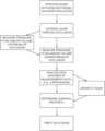
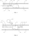
- FIG. 1is a view of a system for performing a diagnostic or therapeutic procedure incorporating an intravascular guide disposed upstream of an occlusion in a vessel;
- FIG. 2is a view of the system of FIG. 1 illustrating the guide advanced through the occlusion with the sensor downstream of the occlusion;
- FIG. 3is a flow chart illustrating a method of determining the viability of tissue downstream of the occlusion with the system of FIGS. 1 - 2 ;
- FIG. 4is a flow chart illustrating a method for performing a diagnostic or therapeutic procedure on an aneurysm with the system of FIGS. 1 - 2 ;
- FIG. 5is a view of the system of FIGS. 1 - 2 performing a diagnostic or therapeutic procedure on an aneurysm in accordance with the method embodied in the flow chart of FIG. 4 ;
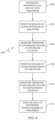
- FIG. 6is a flow chart illustrating another method for performing a diagnostic or therapeutic procedure on an aneurysm
- FIG. 7is a view of the system of FIGS. 1 - 2 for performing a diagnostic or therapeutic procedure on an aneurysm in accordance with the method embodied in the flow chart of FIG. 6 ;
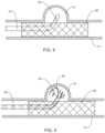
- FIG. 8is a view of the system of FIGS. 1 - 2 for performing a diagnostic or therapeutic procedure on an aneurysm at least partially occluded by a stent or flow diverter,
- FIG. 9is a view similar to the view of FIG. 8 illustrating use of the guide to deliver coils through the stent and into the aneurysm;
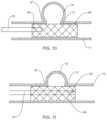
- FIG. 10is a view of a system for performing a diagnostic or therapeutic procedure incorporating the guide with the sensor disposed upstream of an aneurysm at least partially occluded by a stent;
- FIG. 11is view similar to the view of FIG. 10 illustrating the guide with the sensor disposed downstream of the aneurysm.
- proximal and distalrefer to the relative position of the system in a body lumen such as a blood vessel, e.g., in the neurovascular region.
- proximal or distalrefers to the relative position of the system in a body lumen such as a blood vessel, e.g., in the neurovascular region.
- the “proximal” or “trailing” end of the system, which includes a guide (e.g., guidewire or catheter),is the portion that is closest to the clinician.
- the “distal” or “leading” end of the system or guideis the portion that is placed farthest into a body lumen from the entrance site.
- the methods and systems of the present disclosurehave particular application in neurovascular procedures, but may be used in any interventional, diagnostic, and/or therapeutic procedure including coronary vascular, peripheral vascular, and gastro-intestinal applications in addition to a neurovascular application.
- guideis used to mean guidewires, catheters (e.g., catheters that slide over guidewires) and/or microcatheters.
- the full length of the guide of the disclosed systemis not shown.
- the length of a guidewirecan vary depending on the type of interventional procedure or method, though typically it ranges in length from 30 centimeters to 400 centimeters (cm).
- Common lengths of guidewires for coronary, peripheral and neurovascular proceduresmay range from 150 (or less) cm to 300 cm in length. These lengths permit the use of standardized rapid exchange or over-the-wire catheter systems.
- the length of the shaped distal endalso may vary, for example, from about 3 cm to about 80 cm in length.
- FIGS. 1 - 11A body or blood vessel, including a tortuous vasculature such as within the neurovascular space “n” is illustrated in the figures.
- FIGS. 1 - 11methods and systems are illustrated and include a guide 10 positioned at least partially within the neurovascular space “n.”
- the guide 10includes at least one or more sensors 20 .
- the sensors 20may include a pressure sensor, a flow sensor, a volume sensor or any type of sensor adapted to detect a parameter associated with the viability of vascular tissue.
- one sensor 20is provided.
- multiple sensors 20are provided (two are shown in FIGS. 1 - 2 as an example), and may include different sensor types, e.g., any combination of pressure, volume and flow sensors.
- Examples of guidewires or catheters with pressure or flow sensing capabilitiesare disclosed in the literature. So-called “diagnostic wires” or “diagnostic members” are also available from Volcano (San Diego, CA) and St. Jude Medical, Inc. (St. Paul, MN). While in the illustrated embodiments, the sensor(s) 20 is/are shown positioned at a particular location on the guide 10 , it is envisioned that the sensors 20 may be located at the extreme distal end or tip of the guide 10 or disposed on a location proximal of the distal tip.
- a volume sensormay be an infrared or ultrasonic sensor for measuring the interior volume of a segment of the blood vessel and/or the volume of blood within the segment.
- the pressure, flow and/or volume sensor 20may be mounted to the guide 10 to face in a general distal direction orthogonal to the axis “k” of the guide 10 or mounted in parallel relation to the axis to face the vessel wall during application. Other angular orientations are also envisioned.
- the guide 10may be constructed to permit operation in conjunction with other devices, such as thrombectomy devices, stents, or coils while still obtaining pressure and/or flow measurements, and/or be a component of a system incorporating such devices. Alternatively, the measurement may be taken, then the guide 10 removed, the treatment delivered, and the guide 10 repositioned to take another measurement.
- the guide 10may include a lumen 25 therethrough such as a microcatheter providing the ability to utilize the lumen for introduction of therapeutic elements such as embolics, drugs, micro-coils or the like.
- FIGS. 1 - 3a method using the system 1 to test the viability of tissue downstream of an occlusion (e.g., a partial or full occlusion) is illustrated.
- the guide 10is shown proximally or upstream of the partial or total occlusion “O”, and in FIG. 2 , the guide 10 is shown extending through the occlusion “O”.
- FIG. 3in conjunction with FIGS.
- the method 100includes positioning the guide 10 and the sensor 20 within a blood vessel adjacent an occlusion “O” (Step 102 ), advancing the guide 10 through the occlusion “O” such that the sensor 20 is downstream of the occlusion “O” (Step 104 ), measuring at least one of pressure, flow or volume downstream of the occlusion “O” using the sensor 20 of the guide 10 (Step 106 ), analyzing the measurements obtained from the sensor 20 (Step 108 ), and determining the appropriate surgical protocol based on the analyzed data (Step 110 ). Analyzing the measurements (Step 108 ) may include the use of a processor, software or logic to receive the data and provide appropriate calculations and/or output.
- the protocol selectedmay include, e.g., a thrombectomy treatment, aspiration, application of a stent, retrieval of a previously positioned stent or potentially no treatment if the determination is that the neurological tissue beyond the obstruction cannot be revitalized.
- the same guide 10is utilized to gain access to a desired location within the body vessel “n”, penetrate the occlusion “O,” and to obtain the measurements associated with pressure, flow or volume within the artery or blood vessel “n”.
- measuring the pressure, volume and/or flow (e.g., blood flow rate) downstream of at least a partial occlusion “O”provides a reliable indicator of tissue viability adjacent this location.
- the detected pressure, volume and/or flow values obtained by the guide 10may be compared with predetermined values based on historical or known data. Such predetermined measurements may be based on historical or empirical data developed or obtained from the patient or developed statistically from a statistical population of similar subjects. It is envisioned that if the measured values are below or above an acceptable range that viability of the tissue beyond the occlusion “O” may be ascertained to determine whether a surgical procedure is warranted or would be successful.
- the senor 20 of the guide 10may be utilized to measure at least one of pressure, volume and/or flow upstream of the occlusion “O” (Step 112 ), and this measurement(s) or data compared to the measurement(s) taken downstream of the occlusion (Step 108 ).
- the same guide 10is advanced to the occlusion “O,” and pressure, volume and/or flow measurements are obtained while advancing the guide through the occlusion “O”.
- measuring the pressure, volume and/or flow of at least a partial occlusion “O”may provide a reliable indicator of the length of an occluding clot. The information gained by measuring the length of the occluding clot may be used to appropriately size and/or determine the type of device used for thrombectomy.
- the system and method described in connection with FIGS. 1 - 3may further include the use of a conventional unenhanced computed tomography (CT) scan with or without the guide 10 positioned adjacent the occlusion “O” (Step 114 ).
- CTcomputed tomography
- the CT scan shown schematically in FIG. 2 as reference numeral 30may be performed prior to, during and/or after the procedure to assist in assessing the condition of the downstream tissue.
- the disclosed system and method in combination with a conventional CT scanmay be used in lieu of magnetic resonance imaging (MRI) perfusion or CT perfusion techniques, which are quite expensive and time consuming, thereby saving time and money that may otherwise be spent on intervention and/or diagnostic procedures.
- MRImagnetic resonance imaging
- the system and methodmay include treating the occlusion (Step 116 ) through, e.g., the use of a thrombectomy device, such as the SOLITAIRETM Revascularization Device, sold by Covidien (Irvine, CA). Further details of the SOLITAIRETM device are described in U.S. Pat. No. 8,088,140.
- Embodiments of the system and methodalso include the removal of at least a portion of the occlusion “O” using the thrombectomy device, aspiration means or the like, and measuring at least one of pressure and flow downstream of the occlusion using the sensor 20 subsequent to the removal of the occlusion “O” with the thrombectomy device.
- the delta or change in measured flow and/or pressure before and after application of the thrombectomy device, in conjunction with a conventional CT scan taken of the tissuemay be a reliable indicator that the procedure was successful or not.
- the disclosed methodmay be performed prior to, during, or after use of the thrombectomy device, and that measurements may be taken at anytime during the procedure with the sensor 20 .
- the systems and/or methods disclosed hereincan be used during diagnosis and/or treatment of ischemic strokes, and or assessing tissue damage beyond the clot in an ischemic stroke.
- measuring pressure distal to an occlusion or clotcan assist in successfully determining the viability of the tissue located distally of the occlusion following thrombosis, and in conjunction with a conventional CT scan taken of the tissue may be determinative as to whether the clot should be removed.
- measuring pressure, volume and/or flow upstream and/or downstream of the clotmay provide an indicator of clot morphology and assist in determining the preferred thrombectomy technique such as aspiration for a soft clot or the use of a retriever device such as the aforementioned SOLITAIRETM Revascularization Device.
- pressure, volume and/or flowmay be monitored in conjunction with drug therapy (e.g., antiplatelet therapy) to determine the effectiveness of the therapy and/or when to discontinue the drug therapy when a target flow or pressure parameter is obtained.
- drug therapye.g., antiplatelet therapy
- the guide 10may be used with patients having atherosclerotic stenosis to measure fractional flow reserve downstream of the stenotic area within the neurovasculature.
- Fractional flow reserveis defined as the pressure or flow downstream of a stenosis relative to the pressure or flow upstream of the stenosis.
- the fractional flow reservemay be quantified as a value reflective of the percentage drop in blood pressure caused by the stenotic area. Measuring fractional flow reserve in the brain through obtaining flow and/or pressure measurements upstream and downstream of the stenotic area may provide a good indication as to which stenotic areas require stenting.
- an intravascular deviceis introduced through a parent vessel “n” and adjacent an aneurysm “a” to reduce blood flow from the parent vessel “n” into the aneurysm (Step 202 ).
- the intravascular devicemay include a plurality of coils 40 which are introduced within the aneurysm “a” to at least partially pack or fill the aneurysm “a” in connection with a neurovascular coiling procedure, or may include placement of other intravascular devices such as an expandable cage adjacent the aneurysm “a” or use of liquid embolics.
- the guide 10may be utilized to introduce the coils 40 through the lumen 25 if the guide 10 .
- the objective of the coiling procedureis to fill the aneurysm “a” or AVM with the intra-aneurysm device, e.g., coils 40 , to create a clotting or thrombotic reaction to substantially close the aneurysm and prevent flow from the parent vessel “n”.
- the guide 10is positioned relative to the parent vessel “n” and the sensor(s) 20 is disposed within or adjacent the aneurysm “a” (Step 204 ).
- FIG. 5depicts the sensor 20 within the aneurysm “a”.
- the sensor 20is used to obtain quantifiable data including blood pressure, blood volume and/or flow velocity measurements inside or adjacent the aneurysm “a”.
- the collected dataassists in determining whether the aneurysm “a” is sufficiently packed or closed.
- pressure, volume and/or flow velocity measurementsmay be taken with the sensor 20 prior to, and/or subsequent to, coil placement (Step 206 ). The measurements may be compared.
- any changes in flow, volume or pressure detected by the sensor 20may be indicative of leakage into the aneurysm “a” from the parent vessel “n” and potentially require remedy of the aneurysm packing procedure (Step 208 ).
- a CT scanmay be taken of the parent vessel “n” and the aneurysm “a” to confirm success or failure of the procedure (Step 210 ).
- the guide 10e.g., in the form of a microcatheter with a lumen, may be utilized to deliver the coils 40 and/or liquid embolics into the aneurysm and the pressure, volume and/or flow velocity be continually monitored until flow or pressure are stabilized indicating a sufficiently packed or occluded aneurysm sac.
- Suitable embolic compositionsare disclosed in commonly assigned U.S. Pat. Nos. 5,667,767; 5,580,568; 5,851,508; 5,695,480; and 7,507,394.
- the sensor 20 of the guide 10is positioned upstream of the aneurysm “a”, e.g., adjacent the proximal neck “p” of the aneurysm (step 304 ), and pressure, volume and/or flow velocity are detected to obtain at least a first measurement (Step 306 ).
- the guide 10is then advanced downstream of the aneurysm “a” adjacent the downstream or distal neck “z” of the aneurysm “a” (as shown in phantom in FIG.
- Step 308a second measurement of at least one of pressure, volume and/or flow downstream of the aneurysm “a” using the sensor 20 is obtained (Step 310 ).
- the first measurement and the second measurementmay be compared relative to each other and/or historical data with, e.g., the use of a processor or software (Step 312 ).
- the pressure, volume and/or flow velocitiesmay generally correspond at each location in the presence of a sufficiently packed aneurysm “a”.
- a change or difference in either pressure, volume and/or velocity at these two locations below a threshold valuemay be indicative of an insufficiently packed or open aneurysm, thus subjecting the patient to potential complications including rupture.
- a third measurementmay be taken directly adjacent the aneurysm “a” between the proximal and distal necks “p”, “z” and compared to the first and second measurements.
- multiple sensors 20may be used to detect any combination of pressure, volume and velocity measurements upstream and downstream of the aneurysm “a”.
- CT scansmay be taken to confirm success or failure of the procedure.
- the systems and methods described above relating to FIGS. 4 - 7may further include calculating the difference in the measurements and comparing the difference to a predetermined value and potentially comparing these measurements against a statistical population or empirical database.
- the predetermined valuee.g., between about 80% and about 100%
- the aneurysm “a”may be deemed to be sufficiently occluded with an acceptable coil density.
- the methods and systems of FIGS. 4 - 7may be used in conjunction with conventional CT scans and/or angiography to verify that there is no leakage into the aneurysm.
- the guide 10may be used to obtain pressure, volume and/or flow velocity measurements both prior, and subsequent to, the aneurysm “a” being packed with coils 40 at the upstream and downstream locations. The difference in these measured values may be of significance in determining the effectiveness of aneurysm closure.
- the guide 10may be modified to both sense pressure, volume and/or flow velocity and to eject the coils 40 into the aneurysm 10 .
- the sensing functioncould be incorporated in a catheter or guidewire.
- the methods and systemsmay incorporate positioning a stent 50 through the parent vessel “n” and adjacent the aneurysm “a”.
- the guide 10may be manipulated through the interstices of the stent 50 to position the sensor(s) 20 within the aneurysm “a”.
- One suitable flow diverter or stent 50is the PIPELINETM stent sold by Covidien LP (Irvine, CA). Further details of the PIPELINETM stent are described in commonly assigned U.S. Pat. No. 8,267,986.
- the PIPELINETM stentis self-expandable and may be placed in the parent blood vessel “n” to traverse the aneurysm “a”.
- the braided structure of the stent 50slows blood flow into the aneurysm “a” permitting the diseased vessel to heal.
- Other flow diverters or stentsare also envisioned.
- the one or more sensor(s) 20will obtain pressure, volume and/or flow velocity data within the aneurysm “a” to determine the effectiveness of the stent 50 in occluding the aneurysm “a”.
- changes in flow, volume and/or pressuremay be indicative that there is blood leakage into the aneurysm “a” requiring repositioning of the stent or the use of auxiliary intra-aneurysm devices. For example, with reference to FIG.
- the guidewire/microcathetermay be used to eject coils 40 through a lumen 25 of the guide 10 into the aneurysm “a” to supplement the functioning of the stent 50 to fill and/or occlude the aneurysm “a”.
- scanning with conventional CT modalities and/or angiographymay be used to verify proper functioning of the stent.
- pressure, volume and/or flow measurementsmay be taken with the sensor 20 subsequent to deployment of the stent 50 , and prior to any coiling procedure. Such measurements may provide an indication that coiling is not necessary due to effectiveness of the stent 50 in diverting blood flow.
- measurements of flow, volume and pressuremay be taken at predetermined intervals during the coiling procedure to determine its effectiveness, which will potentially eliminate the unnecessary implantation of additional coils once stagnation is determined.
- pressure, volume and/or velocity measurementsare taken with the one or more sensors 20 to determine when to stop adding additional coils, rather than relying on packing (visual) density or retropulsion of the catheter or guide 10 . This will reduce cost and procedure time.
- the guide 10is advanced at least partially along the outside of the stent 50 and within the aneurysm “a” to obtain the appropriate measurements.
- the stent 50will securely retain or trap the guide 10 within the aneurysm.
- the guide 10is positioned such that the sensor(s) 20 is upstream relative to the aneurysm “a” and a first measurement is taken. A second measurement is taken using the sensor 20 of the guide 10 downstream relative to the aneurysm “a”.
- the same guide 10may be used to gain access to a desired location within a vessel and to obtain the measurements.
- the pressure, volume and or flow velocities upstream and downstream of the aneurysm “a”would generally correspond or be within comparable ranges if the stent is functioning as intended in limiting blood flow into, or closing, the aneurysm “a”.
- the guide 10may be used to measure whether placement of the stent 50 affects the elasticity of the vessel in the stent region, causing changes in the hemodynamics and potentially greater amplitude oscillations downstream of the stent 50 , which may potentially lead to undesired changes in the vessel wall including tearing or rupture.
- Such changes of flow or pressure downstream of the stent 50 relative to upstream locations or adjacent the stent 50may be a reliable indicator of the efficiency of stent placement relative to the aneurysm “a” and/or the potential of subsequent or current diseased conditions of the vessel wall adjacent the stent 50 .
- any of the steps disclosed in the diagnostic or treatment procedures of the flow chartsmay occur in any sequence or order.
- Calculating and/or analyzing the datamay include a processor, software or logic.
- the output datamay be coordinated with software of the CT scan to provide visual, graphical or textual information to the clinician to assist in determining the treatment approach or treatment effectiveness.
Landscapes
- Health & Medical Sciences (AREA)
- Life Sciences & Earth Sciences (AREA)
- Engineering & Computer Science (AREA)
- Surgery (AREA)
- Biomedical Technology (AREA)
- Medical Informatics (AREA)
- Animal Behavior & Ethology (AREA)
- Veterinary Medicine (AREA)
- Public Health (AREA)
- Heart & Thoracic Surgery (AREA)
- General Health & Medical Sciences (AREA)
- Molecular Biology (AREA)
- Physics & Mathematics (AREA)
- Pathology (AREA)
- Biophysics (AREA)
- Vascular Medicine (AREA)
- Cardiology (AREA)
- Physiology (AREA)
- Nuclear Medicine, Radiotherapy & Molecular Imaging (AREA)
- Reproductive Health (AREA)
- Neurosurgery (AREA)
- Hematology (AREA)
- High Energy & Nuclear Physics (AREA)
- Psychiatry (AREA)
- Signal Processing (AREA)
- Computer Vision & Pattern Recognition (AREA)
- Oral & Maxillofacial Surgery (AREA)
- Optics & Photonics (AREA)
- Radiology & Medical Imaging (AREA)
- Artificial Intelligence (AREA)
- Electromagnetism (AREA)
- Dentistry (AREA)
- Theoretical Computer Science (AREA)
- Transplantation (AREA)
- Pulmonology (AREA)
- Surgical Instruments (AREA)
- Measuring Pulse, Heart Rate, Blood Pressure Or Blood Flow (AREA)
Abstract
Description
- positioning a guide having a sensor configured and adapted to measure at least one of pressure, volume or flow within a blood vessel;
- advancing the guide through an at least partial occlusion within the blood vessel such that the sensor is downstream of the occlusion;
- measuring at least one of pressure, volume or flow downstream of the occlusion using the sensor, and
- analyzing data obtained from the sensor to assist in determining the viability of tissue of the blood vessel downstream of the occlusion.
- introducing an intravascular device through a parent vessel and adjacent an aneurysm to reduce blood flow from the parent vessel into the aneurysm;
- advancing a guide through the parent vessel;
- positioning a sensor of the guide at least adjacent to the aneurysm; and
- measuring at least one of pressure, volume or blood flow velocity adjacent the aneurysm with the sensor to determine the effectiveness of the intravascular device in minimizing blood flow from the parent vessel into the aneurysm.
Claims (10)
Priority Applications (2)
| Application Number | Priority Date | Filing Date | Title |
|---|---|---|---|
| US16/864,537US12201456B2 (en) | 2012-12-11 | 2020-05-01 | Systems for diagnosing and/or treating medical conditions |
| US18/988,315US20250114046A1 (en) | 2012-12-11 | 2024-12-19 | Systems for diagnosing and/or treating medical conditions |
Applications Claiming Priority (4)
| Application Number | Priority Date | Filing Date | Title |
|---|---|---|---|
| US201261735694P | 2012-12-11 | 2012-12-11 | |
| PCT/US2013/073810WO2014093197A1 (en) | 2012-12-11 | 2013-12-09 | Systems for diagnosing and/or treating medical conditions |
| US201514758754A | 2015-06-30 | 2015-06-30 | |
| US16/864,537US12201456B2 (en) | 2012-12-11 | 2020-05-01 | Systems for diagnosing and/or treating medical conditions |
Related Parent Applications (2)
| Application Number | Title | Priority Date | Filing Date |
|---|---|---|---|
| PCT/US2013/073810DivisionWO2014093197A1 (en) | 2012-12-11 | 2013-12-09 | Systems for diagnosing and/or treating medical conditions |
| US14/758,754DivisionUS10674966B2 (en) | 2012-12-11 | 2013-12-09 | Systems for diagnosing and/or treating medical conditions |
Related Child Applications (1)
| Application Number | Title | Priority Date | Filing Date |
|---|---|---|---|
| US18/988,315ContinuationUS20250114046A1 (en) | 2012-12-11 | 2024-12-19 | Systems for diagnosing and/or treating medical conditions |
Publications (2)
| Publication Number | Publication Date |
|---|---|
| US20200253563A1 US20200253563A1 (en) | 2020-08-13 |
| US12201456B2true US12201456B2 (en) | 2025-01-21 |
Family
ID=50934856
Family Applications (3)
| Application Number | Title | Priority Date | Filing Date |
|---|---|---|---|
| US14/758,754Active2034-10-02US10674966B2 (en) | 2012-12-11 | 2013-12-09 | Systems for diagnosing and/or treating medical conditions |
| US16/864,537Active2036-10-29US12201456B2 (en) | 2012-12-11 | 2020-05-01 | Systems for diagnosing and/or treating medical conditions |
| US18/988,315PendingUS20250114046A1 (en) | 2012-12-11 | 2024-12-19 | Systems for diagnosing and/or treating medical conditions |
Family Applications Before (1)
| Application Number | Title | Priority Date | Filing Date |
|---|---|---|---|
| US14/758,754Active2034-10-02US10674966B2 (en) | 2012-12-11 | 2013-12-09 | Systems for diagnosing and/or treating medical conditions |
Family Applications After (1)
| Application Number | Title | Priority Date | Filing Date |
|---|---|---|---|
| US18/988,315PendingUS20250114046A1 (en) | 2012-12-11 | 2024-12-19 | Systems for diagnosing and/or treating medical conditions |
Country Status (2)
| Country | Link |
|---|---|
| US (3) | US10674966B2 (en) |
| WO (1) | WO2014093197A1 (en) |
Families Citing this family (7)
| Publication number | Priority date | Publication date | Assignee | Title |
|---|---|---|---|---|
| US10674966B2 (en) | 2012-12-11 | 2020-06-09 | Covidien Lp | Systems for diagnosing and/or treating medical conditions |
| US10849774B2 (en)* | 2014-10-23 | 2020-12-01 | Trivascular, Inc. | Stent graft delivery system with access conduit |
| WO2017205718A1 (en)* | 2016-05-27 | 2017-11-30 | University Of Pittsburgh-Of The Commonwealth System Of Higher Education | Novel ultra-low profile wireless flow sensors to monitor hemodynamic alterations in the vascular system |
| US12035919B2 (en)* | 2017-08-10 | 2024-07-16 | Philips Image Guided Therapy Corporation | Real-time monitoring of fluid flow with flow sensing element in an aneurysm and associated devices, systems, and methods |
| US11666307B2 (en)* | 2017-08-10 | 2023-06-06 | Philips Image Guided Therapy Corporation | Devices, systems, and methods for real-time monitoring of fluid flow in an anuerysm |
| US11134984B2 (en)* | 2018-07-31 | 2021-10-05 | Medtronic, Inc. | Pressure-sensing implant tools |
| US20250120654A1 (en)* | 2021-08-24 | 2025-04-17 | Canary Medical Switzerland Ag | Implantable medical device with sensing and communication functionality |
Citations (32)
| Publication number | Priority date | Publication date | Assignee | Title |
|---|---|---|---|---|
| US5580568A (en) | 1995-07-27 | 1996-12-03 | Micro Therapeutics, Inc. | Cellulose diacetate compositions for use in embolizing blood vessels |
| US5667767A (en) | 1995-07-27 | 1997-09-16 | Micro Therapeutics, Inc. | Compositions for use in embolizing blood vessels |
| US5695480A (en) | 1996-07-29 | 1997-12-09 | Micro Therapeutics, Inc. | Embolizing compositions |
| US5715827A (en) | 1994-09-02 | 1998-02-10 | Cardiometrics, Inc. | Ultra miniature pressure sensor and guide wire using the same and method |
| US6167763B1 (en) | 1995-06-22 | 2001-01-02 | Radi Medical Systems Ab | Pressure sensor and guide wire assembly for biological pressure measurements |
| US6295990B1 (en)* | 1998-02-03 | 2001-10-02 | Salient Interventional Systems, Inc. | Methods and systems for treating ischemia |
| US20020183629A1 (en) | 2001-05-31 | 2002-12-05 | Fitz Matthew Joseph | Implantable device for monitoring aneurysm sac parameters |
| US20030199772A1 (en) | 2002-04-23 | 2003-10-23 | Michel Letort | Sensing device and method for determining aneurysmal pressure in a body cavity |
| US20030229388A1 (en) | 2002-06-07 | 2003-12-11 | Hayashi Reid K. | Endovascular graft with pressure, temperature, flow and voltage sensors |
| US20040059407A1 (en) | 2002-09-23 | 2004-03-25 | Angeli Escamilla | Expandable stent and delivery system |
| US20040167385A1 (en) | 2002-12-18 | 2004-08-26 | Rioux Robert F. | Catheter based sensing for intraluminal procedures |
| US6986744B1 (en) | 1999-02-02 | 2006-01-17 | Transonic Systems, Inc. | Method and apparatus for determining blood flow during a vascular corrective procedure |
| US20060106321A1 (en)* | 2003-01-16 | 2006-05-18 | Galil Medical Ltd. | Device, system, and method for detecting, localizing, and characterizing plaque-induced stenosis of a blood vessel |
| US20060122691A1 (en) | 1998-12-03 | 2006-06-08 | Jacob Richter | Hybrid stent |
| WO2008139347A1 (en) | 2007-05-09 | 2008-11-20 | Koninklijke Philips Electronics N.V. | Sensor probe for measuring a physical property inside a bodily lumen |
| US20090003521A1 (en)* | 2007-06-28 | 2009-01-01 | Estelle Camus | Optimized clinical workflow for combined 2D/3D morphological and functional coronary interventions using a robotic angiography system |
| US7507394B2 (en) | 1999-05-21 | 2009-03-24 | Micro Therapeutics, Inc. | High viscosity embolizing compositions |
| US7524303B1 (en) | 2004-06-21 | 2009-04-28 | T. Anthony Don Michael | Arterial obstruction treatment kit |
| US7666220B2 (en) | 2005-07-07 | 2010-02-23 | Nellix, Inc. | System and methods for endovascular aneurysm treatment |
| US7699059B2 (en) | 2002-01-22 | 2010-04-20 | Cardiomems, Inc. | Implantable wireless sensor |
| US20100198329A1 (en) | 2005-07-29 | 2010-08-05 | Cvdevices, Llc | Endograft devices and methods for using the same |
| US20100204634A1 (en) | 2009-02-08 | 2010-08-12 | Blaise Baxter | Devices and methods for perfusion therapy |
| US20100234698A1 (en)* | 2008-09-11 | 2010-09-16 | Acist Medical Systems, Inc. | Physiological sensor delivery device and method |
| US7918800B1 (en) | 2004-10-08 | 2011-04-05 | Endovascular Technologies, Inc. | Aneurysm sensing devices and delivery systems |
| US20110224606A1 (en) | 2010-03-10 | 2011-09-15 | Shibaji Shome | Method and apparatus for remote ischemic conditioning during revascularization |
| US8088140B2 (en) | 2008-05-19 | 2012-01-03 | Mindframe, Inc. | Blood flow restorative and embolus removal methods |
| US20120187604A1 (en) | 2010-12-20 | 2012-07-26 | Wataru Karino | Polymer Stents and Methods of Manufacture |
| US8257421B2 (en) | 2005-05-25 | 2012-09-04 | Tyco Healthcare Group Lp | System and method for delivering and deploying an occluding device within a vessel |
| US8267986B2 (en) | 2004-05-25 | 2012-09-18 | Tyco Healthcare Group Lp | Vascular stenting for aneurysms |
| US20160022222A1 (en) | 2012-12-11 | 2016-01-28 | Covidien Lp | Systems for diagnosing and/or treating medical conditions |
| US9314584B1 (en)* | 2011-06-27 | 2016-04-19 | Bayer Healthcare Llc | Method and apparatus for fractional flow reserve measurements |
| US11064964B2 (en)* | 2007-03-08 | 2021-07-20 | Sync-Rx, Ltd | Determining a characteristic of a lumen by measuring velocity of a contrast agent |
- 2013
- 2013-12-09USUS14/758,754patent/US10674966B2/enactiveActive
- 2013-12-09WOPCT/US2013/073810patent/WO2014093197A1/enactiveApplication Filing
- 2020
- 2020-05-01USUS16/864,537patent/US12201456B2/enactiveActive
- 2024
- 2024-12-19USUS18/988,315patent/US20250114046A1/enactivePending
Patent Citations (36)
| Publication number | Priority date | Publication date | Assignee | Title |
|---|---|---|---|---|
| US7097620B2 (en) | 1994-09-02 | 2006-08-29 | Volcano Corporation | Guidewire with pressure and temperature sensing capabilities |
| US5715827A (en) | 1994-09-02 | 1998-02-10 | Cardiometrics, Inc. | Ultra miniature pressure sensor and guide wire using the same and method |
| US6976965B2 (en) | 1994-09-02 | 2005-12-20 | Volcano Corporation | Ultra miniature pressure sensor |
| US6767327B1 (en) | 1994-09-02 | 2004-07-27 | Volcano Therapeutics, Inc. | Method of measuring blood pressure and velocity proximally and distally of a stenosis |
| US6167763B1 (en) | 1995-06-22 | 2001-01-02 | Radi Medical Systems Ab | Pressure sensor and guide wire assembly for biological pressure measurements |
| US5667767A (en) | 1995-07-27 | 1997-09-16 | Micro Therapeutics, Inc. | Compositions for use in embolizing blood vessels |
| US5851508A (en) | 1995-07-27 | 1998-12-22 | Microtherapeutics, Inc. | Compositions for use in embolizing blood vessels |
| US5580568A (en) | 1995-07-27 | 1996-12-03 | Micro Therapeutics, Inc. | Cellulose diacetate compositions for use in embolizing blood vessels |
| US5695480A (en) | 1996-07-29 | 1997-12-09 | Micro Therapeutics, Inc. | Embolizing compositions |
| US6295990B1 (en)* | 1998-02-03 | 2001-10-02 | Salient Interventional Systems, Inc. | Methods and systems for treating ischemia |
| US20060122691A1 (en) | 1998-12-03 | 2006-06-08 | Jacob Richter | Hybrid stent |
| US6986744B1 (en) | 1999-02-02 | 2006-01-17 | Transonic Systems, Inc. | Method and apparatus for determining blood flow during a vascular corrective procedure |
| US7507394B2 (en) | 1999-05-21 | 2009-03-24 | Micro Therapeutics, Inc. | High viscosity embolizing compositions |
| US20020183629A1 (en) | 2001-05-31 | 2002-12-05 | Fitz Matthew Joseph | Implantable device for monitoring aneurysm sac parameters |
| US7699059B2 (en) | 2002-01-22 | 2010-04-20 | Cardiomems, Inc. | Implantable wireless sensor |
| US20030199772A1 (en) | 2002-04-23 | 2003-10-23 | Michel Letort | Sensing device and method for determining aneurysmal pressure in a body cavity |
| US20030229388A1 (en) | 2002-06-07 | 2003-12-11 | Hayashi Reid K. | Endovascular graft with pressure, temperature, flow and voltage sensors |
| US20040059407A1 (en) | 2002-09-23 | 2004-03-25 | Angeli Escamilla | Expandable stent and delivery system |
| US20040167385A1 (en) | 2002-12-18 | 2004-08-26 | Rioux Robert F. | Catheter based sensing for intraluminal procedures |
| US20060106321A1 (en)* | 2003-01-16 | 2006-05-18 | Galil Medical Ltd. | Device, system, and method for detecting, localizing, and characterizing plaque-induced stenosis of a blood vessel |
| US8267986B2 (en) | 2004-05-25 | 2012-09-18 | Tyco Healthcare Group Lp | Vascular stenting for aneurysms |
| US7524303B1 (en) | 2004-06-21 | 2009-04-28 | T. Anthony Don Michael | Arterial obstruction treatment kit |
| US7918800B1 (en) | 2004-10-08 | 2011-04-05 | Endovascular Technologies, Inc. | Aneurysm sensing devices and delivery systems |
| US8257421B2 (en) | 2005-05-25 | 2012-09-04 | Tyco Healthcare Group Lp | System and method for delivering and deploying an occluding device within a vessel |
| US7666220B2 (en) | 2005-07-07 | 2010-02-23 | Nellix, Inc. | System and methods for endovascular aneurysm treatment |
| US20100198329A1 (en) | 2005-07-29 | 2010-08-05 | Cvdevices, Llc | Endograft devices and methods for using the same |
| US11064964B2 (en)* | 2007-03-08 | 2021-07-20 | Sync-Rx, Ltd | Determining a characteristic of a lumen by measuring velocity of a contrast agent |
| WO2008139347A1 (en) | 2007-05-09 | 2008-11-20 | Koninklijke Philips Electronics N.V. | Sensor probe for measuring a physical property inside a bodily lumen |
| US20090003521A1 (en)* | 2007-06-28 | 2009-01-01 | Estelle Camus | Optimized clinical workflow for combined 2D/3D morphological and functional coronary interventions using a robotic angiography system |
| US8088140B2 (en) | 2008-05-19 | 2012-01-03 | Mindframe, Inc. | Blood flow restorative and embolus removal methods |
| US20100234698A1 (en)* | 2008-09-11 | 2010-09-16 | Acist Medical Systems, Inc. | Physiological sensor delivery device and method |
| US20100204634A1 (en) | 2009-02-08 | 2010-08-12 | Blaise Baxter | Devices and methods for perfusion therapy |
| US20110224606A1 (en) | 2010-03-10 | 2011-09-15 | Shibaji Shome | Method and apparatus for remote ischemic conditioning during revascularization |
| US20120187604A1 (en) | 2010-12-20 | 2012-07-26 | Wataru Karino | Polymer Stents and Methods of Manufacture |
| US9314584B1 (en)* | 2011-06-27 | 2016-04-19 | Bayer Healthcare Llc | Method and apparatus for fractional flow reserve measurements |
| US20160022222A1 (en) | 2012-12-11 | 2016-01-28 | Covidien Lp | Systems for diagnosing and/or treating medical conditions |
Non-Patent Citations (4)
| Title |
|---|
| "Blood pressure in the artery distal to an intraarterial embolus during thrombolytic therapy for occlusion of a major artery: a predictor of cerebral infarction following good recanalization" by Sorimachi et al., in the Journal of Neurosurgery 102:870-878 (May 2005). |
| International Preliminary Report on Patentability from International Application No. PCT/US2013/073810, mailed Jun. 25, 2015, 8 pp. |
| International Search Report and Written Opinion from PCT Application No. PCT/US2013/073810, dated Feb. 27, 2014, 21 pgs. |
| Prosecution History from U.S. Appl. No. 14/758,754, dated Aug. 26, 2016 through May 7, 2020, 247 pp. |
Also Published As
| Publication number | Publication date |
|---|---|
| US10674966B2 (en) | 2020-06-09 |
| US20200253563A1 (en) | 2020-08-13 |
| US20250114046A1 (en) | 2025-04-10 |
| WO2014093197A1 (en) | 2014-06-19 |
| US20160022222A1 (en) | 2016-01-28 |
Similar Documents
| Publication | Publication Date | Title |
|---|---|---|
| US12201456B2 (en) | Systems for diagnosing and/or treating medical conditions | |
| US12364492B2 (en) | Thrombectomy system and method of use | |
| Rajan et al. | Prevalence and treatment of cephalic arch stenosis in dysfunctional autogenous hemodialysis fistulas | |
| EP3880090B1 (en) | A thrombectomy system | |
| US11040140B2 (en) | Deep vein thrombosis therapeutic methods | |
| Jinga et al. | Transarterial embolization of renal vascular lesions after percutaneous nephrolithotomy | |
| Murphy et al. | Imaging in vascular access | |
| JP2010510857A (en) | Catheter with ultrasonic transducer and variable focusing lens used in aneurysm evaluation | |
| AU2018336787A1 (en) | Intracoronary characterization of microvascular obstruction (MVO) and myocardial infarction | |
| US20230372025A1 (en) | Extraluminal imaging based intraluminal therapy guidance systems, devi es, and methods | |
| Amin-Hanjani et al. | Flow-assisted surgical technique in cerebrovascular surgery | |
| Wang et al. | Renal arteriovenous malformation causing hematuria: case report and review of the literature | |
| Dilley et al. | A comparison of B-mode real-time imaging and arteriography in the intraoperative assessment of carotid endarterectomy | |
| US20250032134A1 (en) | Thrombectomy system and method of use | |
| Verzini et al. | Carotid artery stenting: technical issues and role of operators' experience | |
| JP2019017728A (en) | Blood flow control system and treatment method | |
| US20250255504A1 (en) | Flow sensing vascular implant | |
| Rigatelli et al. | Renal Artery Interventions | |
| US20230024693A1 (en) | Systems and methods of reducing in-hospital mortality rate | |
| EP3706629A1 (en) | Actively tracked pulmonary artery catheterization | |
| Moukarbel et al. | Transfemoral Retrograde/Antegrade Access | |
| Lugli | Intravascular ultrasound: technique, provided information and indications | |
| Daskalov et al. | Coiling in Patients with Unruptured and Ruptured Brain Aneurysms | |
| Dean et al. | Conventional angiography | |
| Rigatelli et al. | Iliac Artery Stenosis |
Legal Events
| Date | Code | Title | Description |
|---|---|---|---|
| FEPP | Fee payment procedure | Free format text:ENTITY STATUS SET TO UNDISCOUNTED (ORIGINAL EVENT CODE: BIG.); ENTITY STATUS OF PATENT OWNER: LARGE ENTITY | |
| STPP | Information on status: patent application and granting procedure in general | Free format text:DOCKETED NEW CASE - READY FOR EXAMINATION | |
| AS | Assignment | Owner name:COVIDIEN LP, MASSACHUSETTS Free format text:ASSIGNMENT OF ASSIGNORS INTEREST;ASSIGNORS:FOLK, CHRISTOPHER;KEARNS, JACOB;REEL/FRAME:057211/0026 Effective date:20121212 | |
| STPP | Information on status: patent application and granting procedure in general | Free format text:NON FINAL ACTION MAILED | |
| STPP | Information on status: patent application and granting procedure in general | Free format text:RESPONSE TO NON-FINAL OFFICE ACTION ENTERED AND FORWARDED TO EXAMINER | |
| STPP | Information on status: patent application and granting procedure in general | Free format text:FINAL REJECTION MAILED | |
| STPP | Information on status: patent application and granting procedure in general | Free format text:RESPONSE AFTER FINAL ACTION FORWARDED TO EXAMINER | |
| STPP | Information on status: patent application and granting procedure in general | Free format text:ADVISORY ACTION MAILED | |
| STPP | Information on status: patent application and granting procedure in general | Free format text:DOCKETED NEW CASE - READY FOR EXAMINATION | |
| STPP | Information on status: patent application and granting procedure in general | Free format text:NON FINAL ACTION MAILED | |
| STPP | Information on status: patent application and granting procedure in general | Free format text:RESPONSE TO NON-FINAL OFFICE ACTION ENTERED AND FORWARDED TO EXAMINER | |
| STPP | Information on status: patent application and granting procedure in general | Free format text:NOTICE OF ALLOWANCE MAILED -- APPLICATION RECEIVED IN OFFICE OF PUBLICATIONS | |
| ZAAB | Notice of allowance mailed | Free format text:ORIGINAL CODE: MN/=. | |
| STPP | Information on status: patent application and granting procedure in general | Free format text:PUBLICATIONS -- ISSUE FEE PAYMENT VERIFIED | |
| STCF | Information on status: patent grant | Free format text:PATENTED CASE |