US12201405B2 - Assessing effectiveness of CPR - Google Patents
Assessing effectiveness of CPRDownload PDFInfo
- Publication number
- US12201405B2 US12201405B2US14/885,891US201514885891AUS12201405B2US 12201405 B2US12201405 B2US 12201405B2US 201514885891 AUS201514885891 AUS 201514885891AUS 12201405 B2US12201405 B2US 12201405B2
- Authority
- US
- United States
- Prior art keywords
- patient
- cri
- cpr
- data
- values
- Prior art date
- Legal status (The legal status is an assumption and is not a legal conclusion. Google has not performed a legal analysis and makes no representation as to the accuracy of the status listed.)
- Active
Links
Images


Classifications
- A—HUMAN NECESSITIES
- A61—MEDICAL OR VETERINARY SCIENCE; HYGIENE
- A61B—DIAGNOSIS; SURGERY; IDENTIFICATION
- A61B5/00—Measuring for diagnostic purposes; Identification of persons
- A61B5/02—Detecting, measuring or recording for evaluating the cardiovascular system, e.g. pulse, heart rate, blood pressure or blood flow
- A61B5/02042—Determining blood loss or bleeding, e.g. during a surgical procedure
- A—HUMAN NECESSITIES
- A61—MEDICAL OR VETERINARY SCIENCE; HYGIENE
- A61B—DIAGNOSIS; SURGERY; IDENTIFICATION
- A61B5/00—Measuring for diagnostic purposes; Identification of persons
- A61B5/02—Detecting, measuring or recording for evaluating the cardiovascular system, e.g. pulse, heart rate, blood pressure or blood flow
- A61B5/02028—Determining haemodynamic parameters not otherwise provided for, e.g. cardiac contractility or left ventricular ejection fraction
- A—HUMAN NECESSITIES
- A61—MEDICAL OR VETERINARY SCIENCE; HYGIENE
- A61B—DIAGNOSIS; SURGERY; IDENTIFICATION
- A61B5/00—Measuring for diagnostic purposes; Identification of persons
- A61B5/02—Detecting, measuring or recording for evaluating the cardiovascular system, e.g. pulse, heart rate, blood pressure or blood flow
- A61B5/0205—Simultaneously evaluating both cardiovascular conditions and different types of body conditions, e.g. heart and respiratory condition
- A—HUMAN NECESSITIES
- A61—MEDICAL OR VETERINARY SCIENCE; HYGIENE
- A61B—DIAGNOSIS; SURGERY; IDENTIFICATION
- A61B5/00—Measuring for diagnostic purposes; Identification of persons
- A61B5/02—Detecting, measuring or recording for evaluating the cardiovascular system, e.g. pulse, heart rate, blood pressure or blood flow
- A61B5/021—Measuring pressure in heart or blood vessels
- A61B5/02108—Measuring pressure in heart or blood vessels from analysis of pulse wave characteristics
- A—HUMAN NECESSITIES
- A61—MEDICAL OR VETERINARY SCIENCE; HYGIENE
- A61B—DIAGNOSIS; SURGERY; IDENTIFICATION
- A61B5/00—Measuring for diagnostic purposes; Identification of persons
- A61B5/48—Other medical applications
- A61B5/4848—Monitoring or testing the effects of treatment, e.g. of medication
- A—HUMAN NECESSITIES
- A61—MEDICAL OR VETERINARY SCIENCE; HYGIENE
- A61B—DIAGNOSIS; SURGERY; IDENTIFICATION
- A61B5/00—Measuring for diagnostic purposes; Identification of persons
- A61B5/48—Other medical applications
- A61B5/4869—Determining body composition
- A61B5/4875—Hydration status, fluid retention of the body
- A—HUMAN NECESSITIES
- A61—MEDICAL OR VETERINARY SCIENCE; HYGIENE
- A61B—DIAGNOSIS; SURGERY; IDENTIFICATION
- A61B5/00—Measuring for diagnostic purposes; Identification of persons
- A61B5/72—Signal processing specially adapted for physiological signals or for diagnostic purposes
- A61B5/7271—Specific aspects of physiological measurement analysis
- A61B5/7275—Determining trends in physiological measurement data; Predicting development of a medical condition based on physiological measurements, e.g. determining a risk factor
- A—HUMAN NECESSITIES
- A61—MEDICAL OR VETERINARY SCIENCE; HYGIENE
- A61H—PHYSICAL THERAPY APPARATUS, e.g. DEVICES FOR LOCATING OR STIMULATING REFLEX POINTS IN THE BODY; ARTIFICIAL RESPIRATION; MASSAGE; BATHING DEVICES FOR SPECIAL THERAPEUTIC OR HYGIENIC PURPOSES OR SPECIFIC PARTS OF THE BODY
- A61H31/00—Artificial respiration by a force applied to the chest; Heart stimulation, e.g. heart massage
- G—PHYSICS
- G16—INFORMATION AND COMMUNICATION TECHNOLOGY [ICT] SPECIALLY ADAPTED FOR SPECIFIC APPLICATION FIELDS
- G16H—HEALTHCARE INFORMATICS, i.e. INFORMATION AND COMMUNICATION TECHNOLOGY [ICT] SPECIALLY ADAPTED FOR THE HANDLING OR PROCESSING OF MEDICAL OR HEALTHCARE DATA
- G16H50/00—ICT specially adapted for medical diagnosis, medical simulation or medical data mining; ICT specially adapted for detecting, monitoring or modelling epidemics or pandemics
- G16H50/20—ICT specially adapted for medical diagnosis, medical simulation or medical data mining; ICT specially adapted for detecting, monitoring or modelling epidemics or pandemics for computer-aided diagnosis, e.g. based on medical expert systems
- G—PHYSICS
- G16—INFORMATION AND COMMUNICATION TECHNOLOGY [ICT] SPECIALLY ADAPTED FOR SPECIFIC APPLICATION FIELDS
- G16H—HEALTHCARE INFORMATICS, i.e. INFORMATION AND COMMUNICATION TECHNOLOGY [ICT] SPECIALLY ADAPTED FOR THE HANDLING OR PROCESSING OF MEDICAL OR HEALTHCARE DATA
- G16H50/00—ICT specially adapted for medical diagnosis, medical simulation or medical data mining; ICT specially adapted for detecting, monitoring or modelling epidemics or pandemics
- G16H50/50—ICT specially adapted for medical diagnosis, medical simulation or medical data mining; ICT specially adapted for detecting, monitoring or modelling epidemics or pandemics for simulation or modelling of medical disorders
- A—HUMAN NECESSITIES
- A61—MEDICAL OR VETERINARY SCIENCE; HYGIENE
- A61B—DIAGNOSIS; SURGERY; IDENTIFICATION
- A61B2562/00—Details of sensors; Constructional details of sensor housings or probes; Accessories for sensors
- A61B2562/02—Details of sensors specially adapted for in-vivo measurements
- A61B2562/0219—Inertial sensors, e.g. accelerometers, gyroscopes, tilt switches
- A—HUMAN NECESSITIES
- A61—MEDICAL OR VETERINARY SCIENCE; HYGIENE
- A61B—DIAGNOSIS; SURGERY; IDENTIFICATION
- A61B5/00—Measuring for diagnostic purposes; Identification of persons
- A61B5/0002—Remote monitoring of patients using telemetry, e.g. transmission of vital signals via a communication network
- A61B5/0015—Remote monitoring of patients using telemetry, e.g. transmission of vital signals via a communication network characterised by features of the telemetry system
- A61B5/002—Monitoring the patient using a local or closed circuit, e.g. in a room or building
- A—HUMAN NECESSITIES
- A61—MEDICAL OR VETERINARY SCIENCE; HYGIENE
- A61B—DIAGNOSIS; SURGERY; IDENTIFICATION
- A61B5/00—Measuring for diagnostic purposes; Identification of persons
- A61B5/02—Detecting, measuring or recording for evaluating the cardiovascular system, e.g. pulse, heart rate, blood pressure or blood flow
- A61B5/021—Measuring pressure in heart or blood vessels
- A61B5/022—Measuring pressure in heart or blood vessels by applying pressure to close blood vessels, e.g. against the skin; Ophthalmodynamometers
- A61B5/02233—Occluders specially adapted therefor
- A61B5/02241—Occluders specially adapted therefor of small dimensions, e.g. adapted to fingers
- A—HUMAN NECESSITIES
- A61—MEDICAL OR VETERINARY SCIENCE; HYGIENE
- A61B—DIAGNOSIS; SURGERY; IDENTIFICATION
- A61B5/00—Measuring for diagnostic purposes; Identification of persons
- A61B5/02—Detecting, measuring or recording for evaluating the cardiovascular system, e.g. pulse, heart rate, blood pressure or blood flow
- A61B5/026—Measuring blood flow
- A61B5/029—Measuring blood output from the heart, e.g. minute volume
- A—HUMAN NECESSITIES
- A61—MEDICAL OR VETERINARY SCIENCE; HYGIENE
- A61B—DIAGNOSIS; SURGERY; IDENTIFICATION
- A61B5/00—Measuring for diagnostic purposes; Identification of persons
- A61B5/03—Measuring fluid pressure within the body other than blood pressure, e.g. cerebral pressure ; Measuring pressure in body tissues or organs
- A61B5/031—Intracranial pressure
- A—HUMAN NECESSITIES
- A61—MEDICAL OR VETERINARY SCIENCE; HYGIENE
- A61B—DIAGNOSIS; SURGERY; IDENTIFICATION
- A61B5/00—Measuring for diagnostic purposes; Identification of persons
- A61B5/145—Measuring characteristics of blood in vivo, e.g. gas concentration or pH-value ; Measuring characteristics of body fluids or tissues, e.g. interstitial fluid or cerebral tissue
- A61B5/1455—Measuring characteristics of blood in vivo, e.g. gas concentration or pH-value ; Measuring characteristics of body fluids or tissues, e.g. interstitial fluid or cerebral tissue using optical sensors, e.g. spectral photometrical oximeters
- A61B5/14551—Measuring characteristics of blood in vivo, e.g. gas concentration or pH-value ; Measuring characteristics of body fluids or tissues, e.g. interstitial fluid or cerebral tissue using optical sensors, e.g. spectral photometrical oximeters for measuring blood gases
- A—HUMAN NECESSITIES
- A61—MEDICAL OR VETERINARY SCIENCE; HYGIENE
- A61B—DIAGNOSIS; SURGERY; IDENTIFICATION
- A61B5/00—Measuring for diagnostic purposes; Identification of persons
- A61B5/24—Detecting, measuring or recording bioelectric or biomagnetic signals of the body or parts thereof
- A61B5/316—Modalities, i.e. specific diagnostic methods
- A61B5/318—Heart-related electrical modalities, e.g. electrocardiography [ECG]
- A—HUMAN NECESSITIES
- A61—MEDICAL OR VETERINARY SCIENCE; HYGIENE
- A61B—DIAGNOSIS; SURGERY; IDENTIFICATION
- A61B5/00—Measuring for diagnostic purposes; Identification of persons
- A61B5/24—Detecting, measuring or recording bioelectric or biomagnetic signals of the body or parts thereof
- A61B5/316—Modalities, i.e. specific diagnostic methods
- A61B5/369—Electroencephalography [EEG]
- A—HUMAN NECESSITIES
- A61—MEDICAL OR VETERINARY SCIENCE; HYGIENE
- A61B—DIAGNOSIS; SURGERY; IDENTIFICATION
- A61B5/00—Measuring for diagnostic purposes; Identification of persons
- A61B5/24—Detecting, measuring or recording bioelectric or biomagnetic signals of the body or parts thereof
- A61B5/316—Modalities, i.e. specific diagnostic methods
- A61B5/398—Electrooculography [EOG], e.g. detecting nystagmus; Electroretinography [ERG]
- A—HUMAN NECESSITIES
- A61—MEDICAL OR VETERINARY SCIENCE; HYGIENE
- A61B—DIAGNOSIS; SURGERY; IDENTIFICATION
- A61B5/00—Measuring for diagnostic purposes; Identification of persons
- A61B5/48—Other medical applications
- A61B5/4836—Diagnosis combined with treatment in closed-loop systems or methods
- A—HUMAN NECESSITIES
- A61—MEDICAL OR VETERINARY SCIENCE; HYGIENE
- A61B—DIAGNOSIS; SURGERY; IDENTIFICATION
- A61B5/00—Measuring for diagnostic purposes; Identification of persons
- A61B5/68—Arrangements of detecting, measuring or recording means, e.g. sensors, in relation to patient
- A61B5/6801—Arrangements of detecting, measuring or recording means, e.g. sensors, in relation to patient specially adapted to be attached to or worn on the body surface
- A61B5/6813—Specially adapted to be attached to a specific body part
- A61B5/6825—Hand
- A61B5/6826—Finger
- A—HUMAN NECESSITIES
- A61—MEDICAL OR VETERINARY SCIENCE; HYGIENE
- A61B—DIAGNOSIS; SURGERY; IDENTIFICATION
- A61B5/00—Measuring for diagnostic purposes; Identification of persons
- A61B5/72—Signal processing specially adapted for physiological signals or for diagnostic purposes
- A61B5/7235—Details of waveform analysis
- A61B5/7246—Details of waveform analysis using correlation, e.g. template matching or determination of similarity
- A—HUMAN NECESSITIES
- A61—MEDICAL OR VETERINARY SCIENCE; HYGIENE
- A61B—DIAGNOSIS; SURGERY; IDENTIFICATION
- A61B5/00—Measuring for diagnostic purposes; Identification of persons
- A61B5/72—Signal processing specially adapted for physiological signals or for diagnostic purposes
- A61B5/7235—Details of waveform analysis
- A61B5/7264—Classification of physiological signals or data, e.g. using neural networks, statistical classifiers, expert systems or fuzzy systems
- A61B5/7267—Classification of physiological signals or data, e.g. using neural networks, statistical classifiers, expert systems or fuzzy systems involving training the classification device
- A—HUMAN NECESSITIES
- A61—MEDICAL OR VETERINARY SCIENCE; HYGIENE
- A61B—DIAGNOSIS; SURGERY; IDENTIFICATION
- A61B5/00—Measuring for diagnostic purposes; Identification of persons
- A61B5/74—Details of notification to user or communication with user or patient; User input means
- A61B5/742—Details of notification to user or communication with user or patient; User input means using visual displays
- A—HUMAN NECESSITIES
- A61—MEDICAL OR VETERINARY SCIENCE; HYGIENE
- A61B—DIAGNOSIS; SURGERY; IDENTIFICATION
- A61B7/00—Instruments for auscultation
- A61B7/02—Stethoscopes
- A61B7/04—Electric stethoscopes
- A—HUMAN NECESSITIES
- A61—MEDICAL OR VETERINARY SCIENCE; HYGIENE
- A61M—DEVICES FOR INTRODUCING MEDIA INTO, OR ONTO, THE BODY; DEVICES FOR TRANSDUCING BODY MEDIA OR FOR TAKING MEDIA FROM THE BODY; DEVICES FOR PRODUCING OR ENDING SLEEP OR STUPOR
- A61M1/00—Suction or pumping devices for medical purposes; Devices for carrying-off, for treatment of, or for carrying-over, body-liquids; Drainage systems
- A61M1/14—Dialysis systems; Artificial kidneys; Blood oxygenators ; Reciprocating systems for treatment of body fluids, e.g. single needle systems for hemofiltration or pheresis
- A61M1/16—Dialysis systems; Artificial kidneys; Blood oxygenators ; Reciprocating systems for treatment of body fluids, e.g. single needle systems for hemofiltration or pheresis with membranes
- A61M1/1601—Control or regulation
- A61M1/1613—Profiling or modelling of patient or predicted treatment evolution or outcome
- G—PHYSICS
- G16—INFORMATION AND COMMUNICATION TECHNOLOGY [ICT] SPECIALLY ADAPTED FOR SPECIFIC APPLICATION FIELDS
- G16H—HEALTHCARE INFORMATICS, i.e. INFORMATION AND COMMUNICATION TECHNOLOGY [ICT] SPECIALLY ADAPTED FOR THE HANDLING OR PROCESSING OF MEDICAL OR HEALTHCARE DATA
- G16H40/00—ICT specially adapted for the management or administration of healthcare resources or facilities; ICT specially adapted for the management or operation of medical equipment or devices
- G16H40/20—ICT specially adapted for the management or administration of healthcare resources or facilities; ICT specially adapted for the management or operation of medical equipment or devices for the management or administration of healthcare resources or facilities, e.g. managing hospital staff or surgery rooms
- G—PHYSICS
- G16—INFORMATION AND COMMUNICATION TECHNOLOGY [ICT] SPECIALLY ADAPTED FOR SPECIFIC APPLICATION FIELDS
- G16H—HEALTHCARE INFORMATICS, i.e. INFORMATION AND COMMUNICATION TECHNOLOGY [ICT] SPECIALLY ADAPTED FOR THE HANDLING OR PROCESSING OF MEDICAL OR HEALTHCARE DATA
- G16H40/00—ICT specially adapted for the management or administration of healthcare resources or facilities; ICT specially adapted for the management or operation of medical equipment or devices
- G16H40/60—ICT specially adapted for the management or administration of healthcare resources or facilities; ICT specially adapted for the management or operation of medical equipment or devices for the operation of medical equipment or devices
- G16H40/63—ICT specially adapted for the management or administration of healthcare resources or facilities; ICT specially adapted for the management or operation of medical equipment or devices for the operation of medical equipment or devices for local operation
Definitions
- the '483 applicationis also a continuation-in-part of U.S. patent application Ser. No. 13/041,006, filed Mar. 4, 2011 by Grudic et al. and entitled “Active Physical Perturbations to Enhance Intelligent Medical Monitoring”, referred to hereinafter as the “'006 application”), which claims priority to provisional U.S. Patent Application No. 61/310,583, filed Mar. 4, 2010, by Grudic and entitled “Active Physical Perturbations to Enhance Intelligent Medical Monitoring”, referred to hereinafter as the “'583 application”), both of which are hereby incorporated by reference.
- the '006 applicationis a continuation-in-part of U.S. patent application Ser. No. 13/028,140 (the “'140 application,” now U.S. Pat.
- the present disclosurerelates, in general, tools and techniques for medical monitoring, and more particularly, to tools and techniques that can provide assessment of effectiveness of CPR before, during, and after performance of CPR, in some cases, in real-time.
- Cardiopulmonary Resuscitationcan be an effective technique to continue circulatory function during a cardiac arrest.
- Several variablesincluding without limitation the caregiver's technique and the patient's condition, can affect the effectiveness of the therapy, and it can be difficult to determine whether CPR is effectively serving its purpose.
- FIG. 1 Ais a schematic diagram illustrating a system for estimating compensatory reserve, in accordance with various embodiments.
- FIG. 1 Bis a schematic diagram illustrating a sensor system that can be worn on a patient's body, in accordance with various embodiments.
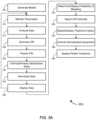
- FIG. 2 Ais a process flow diagram illustrating a method of assessing effectiveness of CPR, in accordance with various embodiments.
- FIG. 2 Billustrates a technique for assessing effectiveness of CPR, in accordance with various embodiments.
- FIG. 3 Ais a process flow diagram illustrating a method estimating a patient's compensatory reserve and/or dehydration state, in accordance with various embodiments.
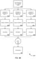
- FIG. 3 Billustrates a technique for estimating and/or predicting a patient's compensatory reserve index, in accordance with various embodiments.
- FIG. 4is a process flow diagram illustrating a method of generating a model of a physiological state, in accordance with various embodiments.
- FIG. 5is a process flow diagram illustrating a method of implementing estimation of CRI values before, during, and after CPR is performed, in accordance with various embodiments.
- FIGS. 6 - 8are exemplary screen captures illustrating display features of a compensatory reserve monitor showing assessments of CPR based on CRI values estimated or obtained before, during, and/or after CPR is performed, in accordance with various techniques.
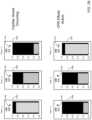
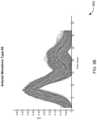
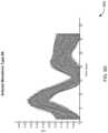
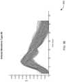
- FIGS. 9 A- 9 Fare graphical diagrams illustrating an example set of clusters of arterial waveforms, each cluster of arterial waveform representing one waveform type, in accordance with various embodiments.
- FIG. 10is a generalized schematic diagram illustrating a computer system, in accordance with various embodiments.
- Various embodimentscan assess and provide feedback on the effectiveness of CPR (e.g., whether the CPR is effectively delivering oxygenated blood to the patient's tissues, in particular the brain).
- CPRpatient's compensatory reserve index
- HDRIcardiodynamic reserve index
- the assessmentsmight be based on raw waveform data (e.g., PPG waveform data) captured by a sensor on the patent (such as the sensors described in the Related Applications, for example).
- a combination of waveform data and calculated/estimated CRIcan be used to assess effectiveness of CPR efforts.
- such functionalitycan be provided by and/or integrated with systems and devices (such as a cardiac reserve monitor), tool, techniques, methods, and software described in the Related Applications, including in particular the '483 application.
- systems and devicessuch as a cardiac reserve monitor
- various operations described in accordance with the methods disclosed by the Related Applicationscan be employed in a method of assessing effectiveness of resuscitation and/or calculating an amount of fluid needed for effective resuscitation.
- such techniquescan be performed by the systems and/or embodied by the software products described in the Related Applications.
- An embodimentcan include a system that comprises one or more sensors placed on the patient and a computer system (such as those described in the Related Applications) that performs a method for using sensor data for estimating and predicting (in real-time, after every heartbeat, or as the information is needed) one or more of the relevant parameters outlined above.
- Other embodimentscan comprise the computer system programmed to perform such a method, an apparatus comprising instructions to program a computer to perform such a method, and/or such a method itself.
- a sensormay include but is not limited to any of the following: a noninvasive blood pressure sensor such as the Nexfin (BMEYE, B.V.) or Finometer (Finapres Medical Systems B.V.); invasive arterial blood pressure, using an arterial catheter; invasive central venous pressure; invasive or noninvasive intracranial pressure monitor; EEG (electroencephalograph); cardiac monitor (EKG); transcranial Doppler sensor; transthoracic impedance plethysmography; pulse oximetry; a sensor generating a photoplethysmograph (PPG) waveform; near infrared spectroscopy; electronic stethoscope; and/or the like.
- a noninvasive blood pressure sensorsuch as the Nexfin (BMEYE, B.V.) or Finometer (Finapres Medical Systems B.V.)
- invasive arterial blood pressureusing an arterial catheter
- invasive central venous pressureinvasive or noninvasive intracranial pressure monitor
- EEGelectroencephalograph
- the '816 applicationdescribes several exemplary embodiments, but various embodiments are not limited to those described in the '816 application.
- FIG. 1 of the '816 applicationillustrates an exemplary sensor that can be used to collect waveform data for analysis, but other sensors could be used as well.
- the '816 applicationdescribes several techniques for assessing the effectiveness of CPR on a patient. Many such techniques depend on an estimate of a patient's CRI, which can be calculated using the techniques described in the '483 application. It should be appreciated, however, that other embodiments of assessing the effectiveness of CPR and/or of estimating CRI can be employed in various embodiments.
- a methodcan include receiving data from such a sensor and analyzing such data using techniques including, but not limited to, analyzing the data using models described in the Related Applications.
- a modelmight be constructed using test subject data from a study, such as the LBNP study, which can be used to predict or estimate a CRI (or HDRI) value, as described in the Related Applications, and in particular in the '483 application. From this calculated value of CRI (or, in some embodiments, from the waveform data itself, alone or in combination with the CRI value), various embodiments can assess and provide feedback on the effectiveness of CPR, for example, using the techniques described in the '816 application.
- a methodmight comprise capturing waveform data from a patient with the sensor before, during, and/or after CPR is performed and/or calculating a CRI value for the patient at these times.
- the variation in CRI values obtained during the procedurecan be used to assess the effectiveness of CPR.
- the standard deviation of the CRI values during the recording and/or the difference in CRI values before, during, and/or after performance of CPRcan be used to estimate or assess the effectiveness of CPR, as detailed in the '816 application.
- Some embodimentsfurther provide feedback on the effectiveness of CPR. For example, one embodiment might provide feedback in the form of a classification (such as “very good,” “good,” or “poor”) of the effectiveness of CPR. Other embodiments might provide feedback indicating a number within a range (e.g., between 0 to 100) indicating the effectiveness of the CPR.
- a classificationsuch as “very good,” “good,” or “poor”
- Other embodimentsmight provide feedback indicating a number within a range (e.g., between 0 to 100) indicating the effectiveness of the CPR.
- a nodecould be “virtual” or supported on a hypervisor or Host system, or could be a physical node or network device within a network.
- the figuresillustrate bridging a virtual path and possibly a node (virtual machine) across the path or between two physical nodes.
- the “swapping” of paths via orchestrationcan occur in any combination of physical and/or virtual nodes, physical and/or virtual links, or the like.
- a methodmight comprise one or more procedures, any or all of which are executed by a computer system.
- an embodimentmight provide a computer system configured with instructions to perform one or more procedures in accordance with methods provided by various other embodiments.
- a computer programmight comprise a set of instructions that are executable by a computer system (and/or a processor therein) to perform such operations.
- software programsare encoded on physical, tangible, and/or non-transitory computer readable media (such as, to name but a few examples, optical media, magnetic media, and/or the like).
- a systemmight be provided that comprises one or more sensors to obtain physiological data from a patient and a computer system in communication with the one or more sensors.
- the computer systemmight comprise one or more processors and a non-transitory computer readable medium in communication with the one or more processors.
- the computer readable mediummight have encoded thereon a set of instructions executable by the one or more processors to cause the computer system to receive the physiological data from the one or more sensors, analyze the physiological data, assess effectiveness of a cardiopulmonary resuscitation (“CPR”) procedure on the patient, and display, on a display device, an indication of the effectiveness of the CPR procedure on the patient.
- CPRcardiopulmonary resuscitation
- a methodmight be provided that comprises monitoring, with one or more sensors, physiological data of a patient, analyzing, with a computer system, the physiological data, and assessing effectiveness of a cardiopulmonary resuscitation (“CPR”) procedure on the patient, based at least in part on the analyzed physiological data.
- the methodmight further comprise displaying, on a display device, an indication of the effectiveness of the CPR procedure on the patient.
- CPRcardiopulmonary resuscitation
- one or more of monitoring the physiological data, analyzing the physiological data, assessing effectiveness of the CPR procedure on the patient, or displaying the indication of the effectiveness of the CPR procedure on the patientare performed in real-time.
- assessing effectiveness of a CPR procedure on the patientmight comprise assessing the effectiveness of the CPR procedure on the patient, based on one or more values of compensatory reserve index (“CRI”) estimated based on the received physiological data.
- CRIcompensatory reserve index
- the one or more values of CRIare estimated based on physiological data that are at least one of received before, received during, or received after the CPR procedure.
- the one or more values of CRImight comprise a plurality of values of CRI.
- assessing effectiveness of a CPR procedure on the patientmight comprise assessing the effectiveness of the CPR procedure on the patient based at least in part on one or more of an average value of CRI over a particular period of time, a standard deviation of at least some of the plurality of values of CRI, a skewness of at least some of the plurality of values of CRI, a rate of change of at least some of the plurality of values of CRI, a rate of rate change of at least some of the plurality of values of CRI, and/or a difference between at least some of the plurality of values of CRI.
- the indicationis selected from a plurality of categories including “very good,” “good,” and “poor.” According to some embodiments, the indication is a number on a scale from 0 to 100. In some embodiments, a value of 0 might indicate that the CPR procedure is ineffectively performed, while a value of 100 might indicate that the CPR procedure is effectively performed.
- estimating a CRI of the patientcomprises estimating a CRI by comparing the physiological data to a model constructed using the following formula:
- the physiological datacomprises waveform data and wherein estimating the CRI comprises comparing the waveform data with one or more sample waveforms generated by exposing one or more test subjects to state of hemodynamic decompensation or near hemodynamic decompensation, or a series of states progressing towards hemodynamic decompensation, and monitoring physiological data of the test subjects.
- the physiological datamight comprise waveform data
- estimating the CRImight comprise comparing the waveform data with a plurality of sample waveforms, each of the sample waveforms corresponding to a different value of the CRI to produce a similarity coefficient expressing a similarity between the waveform data and each of the sample waveforms, normalizing the similarity coefficients for each of the sample waveforms, and summing the normalized similarity coefficients to produce an estimated CRI value for the patient.
- assessing effectiveness of CPRis based on a fixed time history of monitoring the physiological data of the patient.
- assessing effectiveness of CPRis based on a dynamic time history of monitoring the physiological data of the patient.
- at least one of the one or more sensorsis selected from the group consisting of a blood pressure sensor, an intracranial pressure monitor, a central venous pressure monitoring catheter, an arterial catheter, an electroencephalograph, a cardiac monitor, a transcranial Doppler sensor, a transthoracic impedance plethysmograph, a pulse oximeter, a near infrared spectrometer, a ventilator, an accelerometer, an electrooculogram, a transcutaneous glucometer, an electrolyte sensor, and an electronic stethoscope.
- physiological datamight comprise at least one of blood pressure waveform data, plethysmograph waveform data, or photoplethysmograph (PPG) waveform data.
- PPGphotoplethysmograph
- analyzing the physiological datamight comprise analyzing the physiological data against a pre-existing model.
- the methodmight further comprise generating the pre-existing model prior to analyzing the physiological data.
- generating the pre-existing modelmight comprise receiving data pertaining to one or more physiological parameters of a test subject to obtain a plurality of physiological data sets, directly measuring one or more physiological states of the test subject with a reference sensor to obtain a plurality of physiological state measurements, and correlating the received data with the physiological state measurements of the test subject.
- the one or more physiological statescomprises reduced circulatory system volume.
- the methodmight further comprise inducing the physiological state of reduced circulatory system volume in the test subject.
- inducing the physiological statecomprise at least one of subjecting the test subject to lower body negative pressure (“LBNP”), subjecting the test subject to dehydration, and/or the like.
- the one or more physiological statesmight comprise at least one of a state of cardiovascular collapse or near-cardiovascular collapse, a state of euvolemia, a state of hypervolemia, a state of dehydration, and/or the like.
- the most-predictive set of signals S kcorresponds to a first data set representing a first physiological parameter
- each of the one or more outcomes o krepresents a physiological state measurement
- ô kis a prediction of outcome o k derived from a model M k that uses as inputs values obtained from the set of signals S k .
- an apparatusmight be provided that comprises a non-transitory computer readable medium that has encoded thereon a set of instructions executable by one or more computers to cause the apparatus to receive physiological data from one or more sensors, analyze the physiological data, assess effectiveness of a cardiopulmonary resuscitation (“CPR”) procedure on the patient, and display, on a display device, an indication of the effectiveness of the CPR procedure on the patient.
- CPRcardiopulmonary resuscitation
- CRICompensatory Reserve Index
- Various embodimentscan assess the effectiveness of fluid intake hydration, where effectiveness can be defined, but not limited to, as leading to a better hydration state or maintain an optimal hydration state.
- optimal hydrationmight be defined as a fluid state that maximized some performance index/measure, perhaps indicated by the patient's compensatory reserve index (“CRI,” also referred to herein and in the Related Applications as “cardiac reserve index” or “hemodynamic reserve index” (“HDRI”), all of which should be considered synonymous for purposes of this disclosure).
- CRMIcompensatory reserve index
- HDRIhemodynamic reserve index
- the term, “patient,”is used herein for convenience, that descriptor should not be considered limiting, because various embodiments can be employed both in a clinical setting and outside any clinical setting, such as by an athlete before, during, or after an athletic contest or training, a person during daily activities, a soldier on the battlefield, etc.
- the term, “patient,” as used herein,should be interpreted broadly and should be considered to be synonymous with “person.”
- the assessmentsmight be based on raw waveform data (e.g., PPG waveform data) captured by a sensor on the patent (such as the sensors described below and the Related Applications, for example).
- a combination of waveform data and calculated/estimated CRIcan be used to calculate the effectiveness of hydration and/or the amount of fluid needed for effective hydration.
- such functionalitycan be provided by and/or integrated with systems, devices (such as a cardiac reserve monitor and/or wrist-worn sensor device), tools, techniques, methods, and software described below and in the Related Applications.
- An exemplary methodmight comprise monitoring, with one or more sensors, physiological data of a patient.
- the methodmight further comprise analyzing, with a computer system, the physiological data.
- Many different types of physiological datacan be monitored and/or analyzed by various embodiments, including without limitation, blood pressure waveform data, plethysmograph waveform data, photoplethysmograph (“PPG”) waveform data (such as that generated by a pulse oximeter), and/or the like.
- analyzing the physiological datamight comprise analyzing the data against a pre-existing model.
- the methodcan further comprise assessing the effectiveness of hydration efforts, and/or displaying (e.g., on a display device) an assessment of the effectiveness of the hydration efforts.
- an assessmentcan include, without limitation, an estimate of the effectiveness at a current time, a prediction of the effectiveness at some point in the future, an estimate and/or prediction of a volume of fluid necessary for effective hydration, an estimate of the probability a patient requires fluids, etc.
- a systemin accordance with yet another set of embodiments, might comprise one or more processors and a computer readable medium in communication with the one or more processors.
- the computer readable mediummight have encoded thereon a set of instructions executable by the computer system to perform one or more operations, such as the set of instructions described above, to name one example.
- the systemmight further comprise one or more sensors and/or a therapeutic device, either or both of which might be in communication with the processor and/or might be controlled by the processor.
- a devicewhich can be worn on the patient's body, can include one or more sensors that monitor a patient's physiological parameters.
- the device(or a computer in communication with the device) can analyze the data captured by the sensors and compare such data with a model (which can be generated in accordance with other embodiments) to assess the effectiveness of hydration, as described in further detail in the '426 application, and/or to assess CPR effectiveness (e.g., before, during, and/or after resuscitation).
- Different embodimentscan measure a number of different physiological parameters from the patient, and the analysis of those parameters can vary according to which parameters are measured (and which, according to the generated model, are found to be most predictive of the effectiveness of hydration, including the probability of the need for hydration and/or the volume of fluids needed, or most predictive of blood loss).
- the parameters themselvese.g., continuous waveform data captured by a photoplethysmograph
- assessments of hydration effectiveness or assessments of CPR effectivenesse.g., before, during, and/or after resuscitation).
- the '483 applicationdescribes a compensatory reserve monitor (also described as a cardiac reserve monitor or hemodynamic reserve monitor) that is able to estimate the compensatory reserve of a patient.
- this monitorquickly, accurately and/or in real-time can determine the effectiveness of CPR that is being performed or was performed on a patient.
- the devicecan simultaneously monitor the patient's compensatory reserve by tracking the patient's CRI, to appropriately and effectively guide hydration and ongoing patient care.
- the same devicecan also include advanced functionality to assess the effectiveness of hydration, based on the monitored CRI values, as explained in further detail in the '426 application, and/or to rapidly assess CPR effectiveness (e.g., before, during, and/or after resuscitation).
- CRIis a hemodynamic parameter that is indicative of the individual-specific proportion of intravascular fluid reserve remaining before the onset of hemodynamic decompensation.
- CRIhas values that range from 1 to 0, where values near 1 are associated with normovolemia (normal circulatory volume) and values near 0 are associated with the individual specific circulatory volume at which hemodynamic decompensation occurs.
- LBNP (t)is the LBNP level that the individual is experiencing at time “t”
- LBNP HDDis the LNPB level that the individual will enter hemodynamic decompensation.
- CPR effCPR effectiveness
- CPR effis a measure or an estimate of effectiveness of CPR
- ⁇ CPR eff(CRI t , FV t , S t ) is an algorithm embodied by a model generated empirically, e.g., using the techniques described with respect to FIG. 4 below, and/or in the Related Applications
- CRI tis a time history of CRI values (which can range from a single CRI value to many hours of CRI values)
- FV tis a time history of fluid volume being given to the patient (which can range from a single value to many hours of values)
- S tis a time history of raw sensor values, such as physiological data measured by the sensors, as described elsewhere herein (which can range from one value to many hours of values).
- Eq. 4is similar to but not limited to the form of the CRI model in the sense that time histories of (CRI t , FV t , S t ) data gathered from human subjects at various levels of CPR eff are compared to time histories of (CRI t , FV t , S t ) for the current patient being monitored.
- the estimated CPR eff for the current patientis then that which is the closest in (CRI t , FV t , S t ) space to the previously gathered data.
- Eq. 4is the general expression for CPR eff
- various embodimentsmight use subsets of the parameters considered in Eq. 4.
- a modelmight consider only the volume of fluid and CRI data, without accounting for raw sensor input.
- CPR eff⁇ CPR eff (FV t ,S t ) (Eq. 6)
- the effectiveness of hydrationcan be assessed by estimating or predicting the volume, V, of fluid necessary for effective hydration of the patient.
- This volume, Vcan indicate a volume of fluid needed for full hydration if therapy has not yet begun, and/or it can indicate a volume remaining for fully effective hydration if therapy is underway.
- Vcan be estimated/predicted using the modeling techniques described herein and in the Related Applications.
- Vis an estimated volume of fluid needed by a patient need to prevent over or under hydration
- ⁇ V (CRI t , FV t , S t )is an algorithm embodied by a model generated empirically, e.g., using the techniques described with respect to FIG. 4 below, and/or in the Related Applications
- CRI tis a time history of CRI values
- FV tis a time history of fluid volume being given to the patient
- S tis a time history of physiological data received from the one or more sensors.
- Yet another way of assessing effectiveness of hydrationis estimating the probability P ⁇ that the patient requires fluids; this probability can estimate the likelihood that the patient requires hydration if therapy has not been initiated, and/or, if hydration therapy is underway, the probability can estimate the likelihood that further hydration is necessary.
- the function ⁇expresses a relationship that is derived based on empirical study.
- various sensor datacan be collected from test subjects before, during, and/or after hydration efforts, during hemorrhaging, or under other conditions that might simulate such situations. This sensor data can be analyzed to develop models, using techniques similar to those of FIG. 4 below, which can then be used to estimate various assessments of hydration effectiveness, using, e.g., the methods described below with respect to FIGS. 2 and 3 .
- a measure of CRI, CPR eff , V, and/or P ⁇can be useful in a variety of clinical settings, including but not limited to: 1) acute blood loss volume due to injury or surgery; 2) acute circulatory volume loss due to hemodialysis (also called intradialytic hypotension); and 3) acute circulatory volume loss due to various causes of dehydration (e.g. reduced fluid intake, vomiting, dehydration, etc.).
- a change in CRIcan also herald other conditions, including without limitation changes in blood pressure, general fatigue, overheating and certain types of illnesses. Accordingly, the tools and techniques for estimating and/or predicting CRI can have a variety of applications in a clinical setting, including without limitation diagnosing such conditions.
- measures of CRI, CPR eff , V, and/or P ⁇can have applicability outside the clinical setting.
- an athletecan be monitored (e.g., using a wrist-wearable hydration monitor) before, during, or after competition or training to ensure optimal performance (and overall health and recovery).
- a person concerned about overall wellbeingcan employ a similar hydration monitor to ensure that he or she is getting enough (but not too much) fluid, ill infants or adults can be monitored while ill to ensure that symptoms (e.g., vomiting, diarrhea) do not result in dehydration, and the like.
- soldiers in the fieldcan be monitored to ensure optimal operational readiness.
- a hydration monitor, compensatory reserve monitor, a wrist-wearable sensor device, and/or another integrated systemcan include, but is not limited to, some or all of the following functionality, as described in further detail herein and in the Related Applications:
- an excess valuefor example, CRI>1 representing a state in which the patient is hypervolemic
- the patient's normalized compensatory reservecan be displayed on a continuum between the minimum and maximum values (perhaps labeled by different symbols and/
- MEstimate and/or predicting a volume of fluid intake necessary for adequate hydration of a patient or user.
- CRI, CPR eff , V, and/or P ⁇ estimatescan be (i) based on a fixed time history of patient monitoring (for example a 30 second or 30 heart beat window); (ii) based on a dynamic time history of patient monitoring (for example monitoring for 200 minutes, the system may use all sensor information gathered during that time to refine and improve CRI estimates, hydration effectiveness assessments, etc.); (iii) based on either establishing baseline estimates when the patient is normovolemic (no volume loss has occurred); and/or (iv) based on NO baselines estimates when patient is normovolemic.
- Certain embodimentscan also recommend treatment options, based on the analysis of the patient's condition (including the estimated/predicted blood pressure, probability of bleeding, state of dehydration, and/or the patient's estimated and/or predicted CRI).
- Treatment optionscan include, without limitation, such things as optimizing hemodynamics, ventilator adjustments, IV fluid adjustments (e.g., controlling the flow rate of an IV pump or the drip rate of an IV drip), transfusion of blood or blood products, infusion of volume expanders, medication changes, changes in patient position and surgical therapy.
- certain embodimentscan be used to control an IV drip, IV pump, or rapid infuser. For instance, an embodiment might estimate the probability that a patient requires fluids and activate such a device in response to that estimate (or instruct a clinician to attach such a device to the patient and activate the device). The system might then monitor the progress of the hydration effort (through continual or periodic assessment of the effectiveness of hydration) and increase/decrease drip or flow rates accordingly.
- certain embodimentscan be used as an input for a hemodialysis procedure. For example, certain embodiments can predict how much intravascular (blood) volume can be safely removed from a patient during a hemodialysis process. For example, an embodiment might provide instructions to a human operator of a hemodialysis machine, based on estimates or predictions of the patient's CRI. Additionally and/or alternatively, such embodiments can be used to continuously self-adjust the ultra-filtration rate of the hemodialysis equipment, thereby completely avoiding intradialytic hypotension and its associated morbidity.
- certain embodimentscan be used to estimate and/or predict a dehydration state (and/or the amount of dehydration) in an individual (e.g., a trauma patient, an athlete, an elder living at home, etc.) and/or to provide treatment (either by providing recommendations to treating personnel or by directly controlling appropriate therapeutic equipment).
- an analytical modelindicates a relationship between CRI (and/or any other physiological phenomena that can be measured and/or estimated using the techniques described herein and in the Related Applications) and dehydration state
- an embodimentcan apply that model, using the techniques described herein, to estimate a dehydration state of the patient.
- FIGS. 1 - 10illustrate some of the features of the method, system, and apparatus for implementing rapid assessment of CPR before, during, and after resuscitation, as referred to above.
- FIGS. 1 - 9illustrate some of the specific (although non-limiting) exemplary features of the method, system, and apparatus for implementing rapid assessment of CPR before, during, and after resuscitation, while FIG. 10 illustrates exemplary system and hardware implementation.
- the methods, systems, and apparatuses illustrated by FIGS. 1 - 10refer to examples of different embodiments that include various components and steps, which can be considered alternatives or which can be used in conjunction with one another in the various embodiments.
- the description of the illustrated methods, systems, and apparatuses shown in FIGS. 1 - 10is provided for purposes of illustration and should not be considered to limit the scope of the different embodiments.
- FIG. 1 Aprovides a general overview of a system provided by certain embodiments.
- the systemincludes a computer system or computational device 100 in communication with one or more sensors 105 , which are configured to obtain physiological data from the subject (e.g., animal or human test subject or patient) 110 .
- the computer system 100comprises a Lenovo THINKPAD X200, 4 GB of RAM with Microsoft WINDOWS 7 operating system and is programmed with software to execute the computational methods outlined herein.
- the computational methodscan be implemented in MATLAB 2009b and C++ programming languages.
- a more general example of a computer system 100 that can be used in some embodimentsis described in further detail below.
- the computer system 100can be any system of one or more computers that are capable of performing the techniques described herein.
- the computer system 100is capable of reading values from the physiological sensors 105 , generating models of physiological state from those sensors, and/or employing such models to make individual-specific estimations, predictions, or other diagnoses, displaying the results, recommending and/or implementing a therapeutic treatment as a result of the analysis, and/or archiving (learning) these results for use in future, model building and predictions.
- the sensors 105can be any of a variety of sensors (including without limitation those described herein) for obtaining physiological data from the subject.
- An exemplary sensor suitemight include a Finometer sensor for obtaining a noninvasive continuous blood pressure waveform, a pulse oximeter sensor, an Analog to Digital Board (National Instruments USB-9215A 16-Bit, 4 channel) for connecting the sensors (either the pulse oximeter and/or the finometer) to the computer system 100 .
- one or more sensors 105might obtain, e.g., using one or more of the techniques described herein, continuous physiological waveform data, such as continuous blood pressure.
- Input from the sensors 105can constitute continuous data signals and/or outcomes that can be used to generate, and/or can be applied to, a predictive model as described below.
- the structure or systemmight include a therapeutic device 115 (also referred to herein as a “physiological assistive device”), which can be controlled by the computer system 100 to administer therapeutic treatment, in accordance with the recommendations developed by analysis of a patient's physiological data.
- the therapeutic devicemight comprise hemodialysis equipment (also referred to as a hemodialysis machine), which can be controlled by the computer system 100 based on the estimated CRI of the patient, as described in further detail below.
- therapeutic devices in other embodimentscan include a cardiac assist device, a ventilator, an automatic implantable cardioverter defibrillator (“AICD”), pacemakers, an extracorporeal membrane oxygenation circuit, a positive airway pressure (“PAP”) device (including without limitation a continuous positive airway pressure (“cPAP”) device or the like), an anesthesia machine, an integrated critical care system, a medical robot, intravenous and/or intra-arterial pumps that can provide fluids and/or therapeutic compounds (e.g., through intravenous injection), intravenous drips, a rapid infuser, a heating/cooling blanket, and/or the like.
- AICDautomatic implantable cardioverter defibrillator
- PAPpositive airway pressure
- cPAPcontinuous positive airway pressure
- FIG. 1 Billustrates in more detail an exemplary sensor device 105 , which can be used in the system 100 described above.
- the illustrated sensor device 105is designed to be worn on a patient's wrist and therefore can be used both in clinical settings and in the field (e.g., on any person for whom monitoring might be beneficial, for a variety of reasons, including without limitation assessment of blood pressure and/or hydration during athletic competition or training, daily activities, military training or action, etc.).
- the sensor device 105can serve as an integrated hydration monitor, which can assess hydration as described herein, display an indication of the assessment, recommend therapeutic action based on the assessment, or the like, in a form factor that can be worn during athletic events and/or daily activities.
- the exemplary sensor 105 device(hydration monitor) includes a finger cuff 125 and a wrist unit 130 .
- the finger cuff 125includes a fingertip sensor 135 (in this case, a PPG sensor) that captures data based on physiological conditions of the patient, such as PPG waveform data.
- the sensor 135communicates with an input/output unit 140 of the wrist unit 130 to provide output from the sensor 135 to a processing unit 145 of the wrist unit 130 .
- Such communicationcan be wired (e.g., via a standard—such as USB—or proprietary connector on the wrist unit 130 ) and/or wireless (e.g., via Bluetooth, such as Bluetooth Low Energy (“BTLE”), near field connection (“NFC”), WiFi, or any other suitable radio technology).
- BTLEBluetooth Low Energy
- NFCnear field connection
- WiFior any other suitable radio technology
- the processing unit 145can have different types of functionality. For example, in some cases, the processing unit 145 might simply act to store and/or organize data prior to transmitting the data through the I/O unit 140 to a monitoring computer 100 , which might perform data analysis, to control a therapeutic device 115 , etc. In other cases, however, the processing unit 145 might act as a specialized computer (e.g., with some or all of the components described in connection with FIG. 9 , below and/or some or all of the functionality ascribed to the computer 100 of FIGS. 1 A and 1 B ), such that the processing unit 145 can perform data analysis onboard, e.g., to estimate and/or predict a patient's current and/or future blood pressure.
- a specialized computere.g., with some or all of the components described in connection with FIG. 9 , below and/or some or all of the functionality ascribed to the computer 100 of FIGS. 1 A and 1 B
- the wrist unit 105might include a display, which can display any output described herein, including, without limitation, estimated and/or predicted values (e.g., of CRI, blood pressure, hydration status, etc.), data captured by the sensor (e.g., heart rate, pulse ox, etc.), and/or the like.
- estimated and/or predicted valuese.g., of CRI, blood pressure, hydration status, etc.
- data captured by the sensore.g., heart rate, pulse ox, etc.
- the wrist unit 130might include a wrist strap 155 that allows the unit to be worn on the wrist, similar to a wrist watch.
- a wrist strap 155that allows the unit to be worn on the wrist, similar to a wrist watch.
- the sensor device 105might not include all of the components described above, and/or various components might be combined and/or reorganized; once again, the embodiment illustrated by FIG. 1 B should be considered only illustrative, and not limiting, in nature.
- FIGS. 2 A, 2 B, 3 A, 3 B, 4 , and 5illustrate methods and screen displays in accordance with various embodiments. While the methods of FIGS. 2 A, 2 B, 3 A, 3 B, 4 , and 5 are illustrated, for ease of description, as different methods, it should be appreciated that the various techniques and procedures of these methods can be combined in any suitable fashion, and that, in some embodiments, the methods depicted by FIGS. 2 A, 2 B, 3 A, 3 B, 4 , and 5 can be considered interoperable and/or as portions of a single method.
- FIGS. 2 A, 2 B, 3 A, 3 B, 4 , and 5can be implemented by (and, in some cases, are described below with respect to) the computer system 100 of FIG. 1 (or other components of the system, such as the sensor 105 of FIGS. 1 A and 1 B ), these methods may also be implemented using any suitable hardware implementation.
- the computer system 100 of FIG. 1(and/or other components of such a system) can operate according to the methods illustrated by FIGS. 2 A, 2 B, 3 A, 3 B, 4 , and 5 (e.g., by executing instructions embodied on a computer readable medium), the system 100 can also operate according to other modes of operation and/or perform other suitable procedures.
- a methodmight comprise one or more procedures, any or all of which are executed by a computer system.
- an embodimentmight provide a computer system configured with instructions to perform one or more procedures in accordance with methods provided by various other embodiments.
- a computer programmight comprise a set of instructions that are executable by a computer system (and/or a processor therein) to perform such operations.
- software programsare encoded on physical, tangible and/or non-transitory computer readable media (such as, to name but a few examples, optical media, magnetic media, and/or the like).
- FIG. 2illustrates an exemplary method 200 in accordance with various embodiments.
- the method 200might comprise generating a model, e.g., with a computer system, against which patient data can be analyzed to estimate and/or predict various physiological states (block 205 ).
- generating the modelcan comprise receiving data pertaining to a plurality of more physiological parameters of a test subject to obtain a plurality of physiological data sets.
- datacan include PPG waveform data to name one example, and/or any other type of sensor data including, without limitation, data captured by other sensors described herein and in the Related Applications.
- Generating a modelcan further comprise directly measuring one or more physiological states of the test subject with a reference sensor to obtain a plurality of physiological state measurements.
- the one or more physiological statescan include, without limitation, states of various volumes of blood loss and/or fluid resuscitation, various states of hydration and/or dehydration, and/or various cardiopulmonary states, or the like.
- different statescan include a state of hypervolemia, a state of euvolemia, and/or a state of cardiovascular collapse (or near-cardiovascular collapse), and/or can include states that have been simulated, e.g., through use of an LBNP apparatus).
- Other physiological states that can be used to generate a modelare described elsewhere herein and in the Related Applications.
- a number of physiological parameters of a plurality of test subjectsmight be measured.
- a subjectmight undergo varying, measured levels of blood loss (either real or simulated) or intravenous fluid addition.
- the systemcan determine which sensor information most effectively differentiates between subjects at different blood loss/addition volume levels.
- some embodimentsmight construct a model based on data that is derived from sensor data.
- a modelmight use, as input values, CRI values of test subjects in different states of cardiac arrest or different cardiopulmonary states. Accordingly, the process of generating a model might first comprise building a model of CRI, and then, from that model, building a model of CPR effectiveness. (In other cases, a hybrid model might consider both raw sensor data and CRI data.)
- a CRI modelcan be generated in different ways. For example, in some cases, one or more test subjects might be subjected to LBNP.
- LBNP datais collected from human subjects being exposed to progressively lower levels of LBNP, until hemodynamic decompensation, at which time LBNP is released and the subject recovers. Each level of LBNP represents an additional amount of blood loss.
- physiological dataincluding, without limitation, waveform data, such as continuous non-invasive blood pressure data
- waveform datasuch as continuous non-invasive blood pressure data
- a relationship(as expressed by Equation 2) can be identified between LBNP and intravascular volume loss, and this relationship can be used to estimate CRI.
- Equation 2a relationship for the development of the hemodynamic parameter referred to herein as CRI and can be used to generate models of this parameter.
- the method 200might further comprise analyzing, with a computer system (e.g., a monitoring computer 100 and/or a processing unit 135 of a sensor unit, as described above), the physiological data (block 215 ).
- a computer systeme.g., a monitoring computer 100 and/or a processing unit 135 of a sensor unit, as described above
- the physiological datais analyzed against a pre-existing model (which might be generated as described above and which in turn, can be updated based on the analysis, as described in further detail below and in the Related Applications).
- sensor datacan be analyzed directly against a generated model to assess the effectiveness of hydration (which can include estimating current values, and/or predicting future values for any or all of CPR eff , V, and/or P ⁇ , as expressed above.
- the sensor datacan be compared to determine similarities with models that estimate and/or predict any of these values.
- an input waveform captured by a sensor from a patientmight be compared with sample waveforms generated by models for each of these values.
- any number of sample waveformscan be used for the comparison; for example, if there is a nonlinear relationship between the measured sensor data and the CPR eff values, more sample waveforms might provide for a better comparison.
- a similarity coefficientis calculated (e.g., using a least squares or similar analysis) to express the similarity between the sampled waveform and each of the reference waveforms (block 280 ).
- These similarity coefficientscan be normalized (if appropriate) (block 285 ), and the normalized coefficients can be summed (block 290 ) to produce an estimated CPR eff value of the patient (block 295 ).
- FIG. 3 Aillustrates a method 300 of calculating a patient's CRI, which can be used (in some embodiments) as a parameter that can be analyzed to assess the effectiveness of hydration (including the probability that fluids are needed and/or the estimated volume of fluid necessary for effective hydration) and/or to assess effectiveness of CPR (e.g., before, during, and/or after resuscitation).
- the method 300includes generating a model of CRI (block 305 ), monitoring physiological parameters ( 310 ) and analyzing the monitored physical parameters (block 315 ), using techniques such as those described above and in the '483 application, for example.
- the method 300includes estimating, with the computer system, a compensatory reserve of the patient, based on analysis of the physiological data (block 320 ).
- the methodmight further comprise predicting, with the computer system, the compensatory reserve of the patient at one or more time points in the future, based on analysis of the physiological data (block 325 ).
- the operations to predict a future value of a parametercan be similar to those for estimating a current value; in the prediction context, however, the applied model might correlate measured data in a test subject with subsequent values of the diagnostic parameter, rather than contemporaneous values. It is worth noting, of course, that in some embodiments, the same model can be used to both estimate a current value and predict future values of a physiological parameter.
- the estimated and/or predicted compensatory reserve of the patientcan be based on several factors.
- the estimated/predicted compensatory reservecan be based on a fixed time history of monitoring the physiological data of the patient and/or a dynamic time history of monitoring the physiological data of the patient.
- the estimated/predicted compensatory reservecan be based on a baseline estimate of the patient's compensatory reserve established when the patient is euvolemic.
- the estimate and/or predictionmight not be based on a baseline estimate of the patient's compensatory reserve established when the patient is euvolemic.
- FIG. 3 Billustrates one technique 300 ′ for deriving an estimate of CRI in accordance with some embodiments similar to the technique 200 ′ described above with respect to FIG. 2 B for deriving an assessment of hydration effectiveness and/or deriving an assessment of CPR effectiveness (e.g., before, during, and/or after resuscitation) directly from sensor data (and, in fact, CRI can be derived as described herein, and that derived value can be used, alone or with raw sensor data, to assess such effectiveness).
- CPR effectivenesse.g., before, during, and/or after resuscitation
- the illustrated techniquecomprises sampling waveform data (e.g., any of the data described herein and in the Related Applications, including, without limitation, arterial waveform data, such as continuous PPG waveforms and/or continuous noninvasive blood pressure waveforms) for a specified period, such as 32 heartbeats (block 370 ). That sample is compared with a plurality of waveforms of reference data corresponding to different CRI values (block 375 ). (These reference waveforms might be derived using the algorithms described in the Related Applications, might be the result of experimental data, and/or the like).
- waveform datae.g., any of the data described herein and in the Related Applications, including, without limitation, arterial waveform data, such as continuous PPG waveforms and/or continuous noninvasive blood pressure waveforms
- a specified periodsuch as 32 heartbeats
- That sampleis compared with a plurality of waveforms of reference data corresponding to different CRI values (block 375 ).
- These reference waveformsmight be derived using the algorithms described in the Related Applications
- the samplemight be compared with waveforms corresponding to a CRI of 1 (block 375 a ), a CRI of 0.5 (block 375 b ), and a CRI of 0 (block 375 c ), as illustrated.
- a similarity coefficientis calculated (e.g., using a least squares or similar analysis) to express the similarity between the sampled waveform and each of the reference waveforms (block 380 ).
- These similarity coefficientscan be normalized (if appropriate) (block 385 ), and the normalized coefficients can be summed (block 390 ) to produce an estimated value of the patient's CRI (block 395 ).
- the method 300can comprise estimating and/or predicting a patient's dehydration state (block 330 ).
- the patient's state of dehydrationcan be expressed in a number of ways. For instance, the state of dehydration might be expressed as a normalized value (for example, with 1.0 corresponding to a fully hydrated state and 0.0 corresponding to a state of morbid dehydration). In other cases, the state of dehydration might be expressed as a missing volume of fluid or as a volume of fluid present in the patient's system, or using any other appropriate metric.
- estimating a dehydration state of the patientmight comprise estimating the compensatory reserve (e.g., CRI) of the patient, and then, based on that estimate and the known relationship, estimating the dehydration state.
- CRIcompensatory reserve
- a predicted value of compensatory reserve at some point in the futurecan be used to derive a predicted dehydration state at that point in the future.
- Other techniquesmight use a parameter other than CRI to model dehydration state.
- the method 300might further comprise normalizing the results of the analysis (block 335 ), such as the compensatory reserve, dehydration state, probability of bleeding, and/or effectiveness of CPR, to name a few examples.
- the estimated/predicted compensatory reserve of the patientcan be normalized relative to a normative normal blood volume value corresponding to euvolemia, a normative excess blood volume value corresponding to circulatory overload, and a normative minimum blood volume value corresponding to cardiovascular collapse. Any values can be selected as the normative values.
- the normative excess blood volume valueis >1
- the normative normal blood volume valueis 1
- the normative minimum blood volume valueis 0.
- the normative excess blood volume valuemight be defined as 1, the normative normal blood volume value might be defined as 0, and the normative minimum blood volume value at the point of cardiovascular collapse might be defined as ⁇ 1.
- different embodimentsmight use a number of different scales to normalize CRI and other estimated parameters.
- normalizing the datacan provide benefits in a clinical setting, because it can allow the clinician to quickly make a qualitative judgment of the patient's condition, while interpretation of the raw estimates/predictions might require additional analysis.
- that estimatemight be normalized relative to a normative normal blood volume value corresponding to euvolemia and a normative minimum blood volume value corresponding to cardiovascular collapse.
- any valuescan be selected as the normative values.
- the normative normal blood volumeis defined as 1, and the normative minimum blood volume value is defined as 0, the normalized value, falling between 0.0 and 1.0 can quickly apprise a clinician of the patient's location on a continuum between euvolemia and cardiovascular collapse. Similar normalizing procedures can be implemented for other estimated data (such as probability of bleeding, dehydration, effectiveness of CPR, and/or the like).
- the method 300might further comprise displaying data with a display device (block 340 ).
- datamight include an estimate and/or prediction of the compensatory reserve of the patient and/or an estimate and/or prediction of the patient's dehydration state.
- a variety of techniquescan be used to display such data.
- displaying the estimate of the compensatory reserve of the patientmight comprise displaying the normalized estimate of the compensatory reserve of the patient.
- displaying the normalized estimate of the compensatory reserve of the patientmight comprise displaying a graphical plot showing the normalized excess blood volume value, the normalized normal blood volume value, the normalized minimum blood volume value, the normalized estimate of the compensatory reserve (e.g., relative to the normalized excess blood volume value, the normalized normal blood volume value, the normalized minimum blood volume value), and the normalized value indicative of CPR effectiveness.
- the method 300might comprise repeating the operations of monitoring physiological data of the patient, analyzing the physiological data, and estimating (and/or predicting) the compensatory reserve of the patient, to produce a new estimated (and/or predicted) compensatory reserve of the patient.
- displaying the estimate (and/or prediction) of the compensatory reserve of the patientmight comprise updating a display of the estimate of the compensatory reserve to show the new estimate (and/or prediction) of the compensatory reserve, in order to display a plot of the estimated compensatory reserve over time.
- the method 300can comprise determining a probability that the patient is bleeding, and/or displaying, with the display device, an indication of the probability that the patient is bleeding (block 345 ). For example, some embodiments might generate a model based on data that removes fluid from the circulatory system (such as LBNP, dehydration, etc.). Another embodiment might generate a model based on fluid removed from a subject voluntarily, e.g., during a blood donation, based on the known volume (e.g., 500 cc) of the donation. Based on this model, using techniques similar to those described above, a patient's physiological data can be monitored and analyzed to estimate a probability that the patient is bleeding (e.g., internally). In some cases, bleeding or blood loss (e.g., a state of hypovolemia) may be a contributing factor for cardiac arrest.
- bleeding or blood losse.g., a state of hypovolemia
- the probability that the patient is bleedingcan be used to adjust the patient's estimated CRI.
- the estimated CRIcan be adjusted to produce a more accurate diagnosis of the patient's condition at a given point in time.
- the method 300might comprise selecting, with the computer system, a recommended treatment option for the patient, and/or displaying, with the display device, the recommended treatment option (block 355 ).
- the recommended treatment optioncan be any of a number of treatment options, including, without limitation, optimizing hemodynamics of the patient, a ventilator adjustment, an intravenous fluid adjustment, transfusion of blood or blood products to the patient, infusion of volume expanders to the patient, a change in medication administered to the patient, a change in patient position, and surgical therapy, or the like.
- the method 300might comprise controlling operation of hemodialysis equipment (block 360 ), based at least in part on the estimate of the patient's compensatory reserve.
- a computer system that performs the monitoring and estimating functionsmight also be configured to adjust an ultra-filtration rate of the hemodialysis equipment in response to the estimated CRI values of the patient.
- the computer systemmight provide instructions or suggestions to a human operator of the hemodialysis equipment, such as instructions to manually adjust an ultra-filtration rate, etc.
- the method 300might include assessing the tolerance of an individual to blood loss, general volume loss, and/or dehydration (block 365 ). For example, such embodiments might include estimating a patient's CRI based on the change in a patient's position (e.g., from lying prone to standing, from standing to lying prone, from lying prone to sitting, from sitting to lying prone, from standing to sitting, and/or from sitting to standing). Based on changes to the patient's CRI in response to these maneuvers, the patient's sensitivity to blood loss, volume loss, and/or dehydration can be measured.
- a patient's CRIbased on the change in a patient's position (e.g., from lying prone to standing, from standing to lying prone, from lying prone to sitting, from sitting to lying prone, from standing to sitting, and/or from sitting to standing). Based on changes to the patient's CRI in response to these maneuvers, the patient's sensitivity to blood loss, volume loss, and/or dehydration can be
- this measurementcan be performed using a CRI model generated as described above; the patient can be monitored using one or more of the sensors described above, and the changes in the sensor output when the subject changes position can be analyzed according to the model (as described above, for example) to assess the tolerance of the individual to volume loss.
- Such monitoring and/or analysiscan be performed in real time.
- the method 200can include assessing the effectiveness of CPR in resuscitating the patient (block 220 ), based on analysis of the patient's physiological data against the model.
- assessing the effectiveness of CPRcan include estimating or predicting a number of values, such as the estimated effectiveness, CPR eff , of the CPR effort, the volume, V, of fluid necessary for effective hydration or cardiopulmonary resuscitation, the probability, P ⁇ , that the patient needs fluids, and/or the like.
- the assessment of the effectiveness of CPRwill be based on the analysis of a plurality of measured (or derived) values of a particular physiological parameter (or plurality of parameters).
- the analysis of the datamight be performed on a continuous waveform, either during or after measurement of the waveform with a sensor (or both), and the assessment of the effectiveness of CPR can be updated as resuscitation efforts continue and/or as hydration or other efforts continue.
- the amount of fluids added to the patient's blood volumecan be measured directly, and these direct measurements can be fed back into the model to update the model (at block 225 ) and thereby improve performance of the algorithms in the model (e.g., by refining the weights given to different parameters in terms of estimative or predictive value).
- the updated modelcan then be used to continue assessing the treatment (in the instant patient and/or in a future patient), as shown by the broken lines on FIG. 2 A .
- the method 200comprises displaying data (block 230 ) indicating the assessment of the effectiveness of CPR.
- the datamight be displayed on a display of a sensor device (such as the device 105 illustrated by FIG. 1 B ).
- the datamight be displayed on a dedicated machine, such as a compensatory reserve monitor, or on a monitor of a generic computer system.
- the datamight be displayed alphanumerically, graphically, or both.
- FIGS. 6 - 8described below, illustrate several possible exemplary displays of assessments of the effectiveness of CPR and/or CRI. There are many different ways that the data can be displayed, and any assessments, estimates or predictions generated by the method 200 can be displayed in any desired way, in accordance with various embodiments.
- the method 200can include selecting and/or displaying treatment options for the patient (block 235 ) and/or controlling a therapeutic device (block 240 ), based on the assessment of the blood loss of the patient.
- a displaymight indicate to a clinician or the patient him or herself that the patient is losing (or has lost) blood, that fluid resuscitation therapy should be initiated or continued, an estimated volume of fluid to drink, infuse, or otherwise consume, a drip rate for an IV drip, a flow rate for an IV pump or infuser, that CPR efforts are effectively or ineffectively being performed, or the like.
- the systemmight be configured to control operation of a therapeutic device, such as dispensing a fluid to drink from an automated dispenser, activating or adjusting the flow rate of an IV pump or infuser, adjusting the drip rate of an IV drip, and/or the like, based, e.g., on the assessment of the effectiveness of hydration, or the like.
- a therapeutic devicesuch as dispensing a fluid to drink from an automated dispenser, activating or adjusting the flow rate of an IV pump or infuser, adjusting the drip rate of an IV drip, and/or the like, based, e.g., on the assessment of the effectiveness of hydration, or the like.
- certain embodimentsmight include a water bladder (e.g., a backpack-based hydration pack, such as those available from Camelbak Products LLC) or a water bottle, and the hydration monitor could communicate with and/or control operation of such a dispensing device (e.g., to cause the device to dispense a certain amount of fluid, to cause the device to trigger an audible alarm, etc.).
- a water bladdere.g., a backpack-based hydration pack, such as those available from Camelbak Products LLC
- the hydration monitorcould communicate with and/or control operation of such a dispensing device (e.g., to cause the device to dispense a certain amount of fluid, to cause the device to trigger an audible alarm, etc.).
- the method 200can include functionality to help a clinician (or other entity) to monitor hydration, fluid resuscitation, blood volume status, and/or CPR effectiveness.
- a clinicianor other entity
- any measure of effectiveness outside of the normal rangewould set off various alarm conditions, such as an audible alarm, a message to a physician, a message to the patient, an update written automatically to a patient's chart, etc.
- Such messagingcould be accomplished by electronic mail, text message, etc., and a sensor device or monitoring computer could be configured with, e.g., an SMTP client, text messaging client, or the like to perform such messaging.
- a hydration monitormight be configured to send monitoring results (e.g., any of the assessments, estimates and/or predictions described herein) to another device or computer, either for personal monitoring by the patient or for monitoring by another. Examples could include transmitting such alarms or data (e.g., by Bluetooth, NFC, WiFi, etc.) to a wireless phone, wearable device (e.g., smart watch or glasses) or other personal device of the patient, e.g., for inclusion in a health monitoring application.
- monitoring resultse.g., any of the assessments, estimates and/or predictions described herein
- Examplescould include transmitting such alarms or data (e.g., by Bluetooth, NFC, WiFi, etc.) to a wireless phone, wearable device (e.g., smart watch or glasses) or other personal device of the patient, e.g., for inclusion in a health monitoring application.
- such informationcould be sent to a specified device or computer (e.g., via any available IP connection), for example to allow a parent to monitor a child's (or a child to monitor an elderly parent's) hydration remotely, to allow a coach to monitor a player's hydration remotely, and/or to allow a superior officer to monitor a soldier's hydration remotely, or the like.
- a specified device or computere.g., via any available IP connection
- an applicationmight aggregate results from a plurality of hydration monitors, to allow the supervisor to view (e.g., in a dashboard-type configuration), hydration effectiveness and/or blood loss (and/or any other data, such as CRI, blood pressure, etc.) for a group of people.
- a displaymight employ, for example, a plurality of “fuel gauge” displays, one (or more) for each person in the group, allowing the supervisor to quickly ascertain any unusual results (e.g., based on the color of the gauge, etc.).
- an alarm conditionwere met for another physiological parameter (such as blood pressure, which can be estimated as described in the '171 application, for example), that alarm could trigger an assessment of hydration effectiveness via the method 200 , to determine whether the first alarm condition has merit or not. If not, perhaps there could be an automated silencing of the original alarm condition, since all is well at present. More generally, the assessment techniques could be added to an ecosystem of monitoring algorithms (including, without limitation, those described in the Related Applications), which would inform one another or work in combination, to inform one another about how to maintain optimal physiological stability.
- another physiological parametersuch as blood pressure, which can be estimated as described in the '171 application, for example
- FIG. 4illustrates a method 400 of employing such a self-learning predictive model (or machine learning) technique, according to some embodiments.
- the method 400can be used to correlate physiological data received from a subject sensor with a measured physiological state. More specifically, with regard to various embodiments, the method 400 can be used to generate a model for assessing, predicting and/or estimating various physiological parameters, such as blood loss volume, effectiveness of hydration or fluid resuscitation efforts, estimated and/or predicted blood pressure, CRI, the probability that a patient is bleeding, a patient's dehydration state, effectiveness of CPR, and/or the like, from one or more of a number of different physiological parameters, including without limitation those described above and in the Related Applications.
- various physiological parameterssuch as blood loss volume, effectiveness of hydration or fluid resuscitation efforts, estimated and/or predicted blood pressure, CRI, the probability that a patient is bleeding, a patient's dehydration state, effectiveness of CPR, and/or the like, from one or more of a number
- the method 400begins at block 405 by collecting raw data measurements that may be used to derive a set of D data signals s 1 , . . . , s D as indicated at block 410 (each of the data signals s being, in a particular case, input from one or many different physiological sensors).
- Embodimentsare not constrained by the type of measurements that are made at block 405 and may generally operate on any data set.
- data signalscan be retrieved from a computer memory and/or can be provided from a sensor or other input device.
- the data signalsmight correspond to the output of the sensors described above (which measure the types of waveform data described above, such as continuous, non-invasive PPG data and/or blood pressure waveform data).
- the methodautonomously generates a predictive model M that relates the derived data signals ⁇ right arrow over (s) ⁇ with the outcomes ⁇ right arrow over (o) ⁇ .
- “autonomous”means “without human intervention.”
- thisis achieved by identifying the most predictive set of signals S k , where S k contains at least some (and perhaps all) of the derived signals s 1 , . . . , s D for each outcome o k , where k ⁇ 1, . . . , K ⁇ .
- a probabilistic predictive model ô kM k (S k ) is learned at block 425 , where ô k is the prediction of outcome o k derived from the model M k that uses as inputs values obtained from the set of signals S k , for all k ⁇ 1, . . . , K ⁇ .
- a linear model frameworkmay be used to identify predictive variables for each new increment of data.
- ⁇ kis any mapping from one input to one output
- a 0 , a 1 , . . . , a dare the linear model coefficients.
- the framework used to derive the linear model coefficientsmay estimate which signals s, s 1 , . . . , s d are not predictive and accordingly sets the corresponding coefficients a 0 , a 1 , . . . , a d to zero.
- the modelbuilds a predictive density model of the data, ⁇ ( ⁇ right arrow over (s) ⁇ 1 , ⁇ right arrow over (o) ⁇ 1 ), ( ⁇ right arrow over (s) ⁇ 2 , ⁇ right arrow over (o) ⁇ 2 ), . . . ⁇ .
- a new predictive density modelscan be constructed.
- a prediction systemcan be implemented that can predict future results from previously analyzed data using a predictive model and/or modify the predictive model when data does not fit the predictive model.
- the prediction systemcan make predictions and/or to adapt the predictive model in real-time.
- a prediction systemcan use large data sets not only to create the predictive model, but also predict future results as well as adapt the predictive model.
- a self-learning, prediction devicecan include a data input, a processor, and an output.
- Memorycan include application software that when executed can direct the processor to make a prediction from input data based on a predictive model. Any type of predictive model can be used that operates on any type of data.
- the predictive modelcan be implemented for a specific type of data.
- when data is receivedthe predictive model can determine whether it understands the data according to the predictive model. If the data is understood, a prediction is made and the appropriate output provided based on the predictive model. If the data is not understood when received, then the data can be added to the predictive model to modify the model.
- the devicecan wait to determine the result of the specified data and can then modify the predictive model accordingly.
- the data and the outcomecan be used to modify the predictive model.
- modification of the predictive modelcan occur in real-time.
- Particular embodimentscan employ the tools and techniques described in the Related Applications in accordance with the methodology described herein perform the functions of a cardiac reserve monitor, a wrist-wearable sensor device, and/or a monitoring computer, as described herein (the functionality of any or all of which can be combined in a single, integrated device, in some embodiments).
- These functionsinclude, but are not limited to, assessing fluid resuscitation of a patient, assessing hydration of a patient, monitoring, estimating and/or predicting a subject's (including, without limitation, a patient's) current or future blood pressure and/or compensatory reserve, estimating and/or determining the probability that a patient is bleeding (e.g., internally) and/or has been bleeding, determining effectiveness of CPR, recommending treatment options for such conditions, and/or the like.
- Such tools and techniquesinclude, in particular, the systems (e.g., computer systems, sensors, therapeutic devices, etc.) described in the Related Applications, the methods (e.g., the analytical methods for generating and/or employing analytical models, the diagnostic methods, etc.), and the software programs described herein and in the Related Applications, which are incorporated herein by reference.
- method 500might comprise recording the patient's CRI, before, during, and/or after CPR is performed.
- the CRImay be recorded or stored on one or more of a data storage device that is part of processing unit 145 and/or a memory device that is part of the monitoring computer 100 of FIG. 1 , or the like.
- Method 500might further comprise calculating an average CRI over a period of K seconds (where K>1), before, during, and/or after CPR is performed (block 515 ), calculating a standard deviation or variance of CRI over a period of K seconds (where K>1), before, during, and/or after CPR is performed (block 520 ), calculating Pearson's moment coefficient of skewness of CRI over a period of K seconds (where K>1), before, during, and/or after CPR is performed (block 525 ), calculating a rate of change of CRI over a period of K seconds (where K>1), before, during, and/or after CPR is performed (block 530 ), calculating a rate of rate change of CRI (also referred to herein as “acceleration of CRI”) over a period of K seconds (where K>1), before, during, and/or after CPR is performed (block 535 ).
- method 500might further comprise, at block 540 , determining effectiveness of CPR in real-time or after CPR has been performed, based on one or more of the calculations in blocks 515 - 535 (which may be referred to herein as “CRI variation results”).
- CRI variation resultsmight be used to assess effectiveness of the CPR.
- one embodimentmight provide feedback in the form of a classification (such as “very good,” “good,” or “poor”) of the effectiveness of CPR.
- Other embodimentsmight provide feedback indicating a number within a range (e.g., between 0 to 100) indicating the effectiveness of the CPR.
- CRI value sample(i) a set of values of CRI, (iii) average CRI, (iv) median CRI, (v) standard deviation of CRI, (vi) rate of change of CRI, (vii) rate of change of rate change of CRI, and (viii) skewness of CRI:
- CRI K MedMedian ⁇ CRI( t 1 ),CRI( t 2 ), . . . ,CRI( t K ) ⁇ ;
- Rate of change of CRIdenoted by m K , over a set of CRI values ⁇ CRI(t 1 ), CRI(t 2 ), . . . , CRI(t K ) ⁇ , where the rate of change measures some increase or decrease of CRI over a specific period of time, and, for example, may be calculated as a slope of the line:
- Ais a matrix defined by:
- Rate of change of rate change of CRIdenoted by r K , over a set of CRI values ⁇ CRI(t 1 ), CRI(t 2 ), . . . , CRI(t K ) ⁇ , where the rate of change of rate change measures some rate of change of increase or decrease of CRI over a specific period of time, and, for example, may be calculated as a second order increase or decrease of a curve:
- Bis a matrix defined by:
- S Kis some other measure of skewness, possibly Galton skewness (or Bowley's skewness), as defined as:
- a method for assessing whether CPR being performed or that was performed can be classified as “very good” or “good”might include, but is not limited to, one of the following calculations or a combination of two or more such calculations, perhaps within a statistical and/or machine learning framework, or the like: (1) Average of CRI during CPR (“ CRI DR ”)>CPRG1; (2) Average of CRI after CPR (“ CRI AR ”)>CPRG2; (3) standard deviation or variance of CRI during CPR (“[SD(CRI)] DR ”) ⁇ CPRG3; (4) standard deviation or variance of CRI after CPR (“[SD(CRI)] AR ”) ⁇ CPRG4; (5) moment coefficient of skewness of CRI (positive or negative) during CPR (“S DR ”) ⁇ CPRG5; (6) moment coefficient of skewness of CRI (positive or negative) after CPR (“S AR ”) ⁇ CPRG6; (7) rate of change of CRI during CPR (“m DR ”)>CPRG7; (8) rate of change of CRI after
- each of, or one or more of, CPRG1 through CPRG10might either be estimated experimentally or set by the user.
- the number K>0may be different in each instance of the calculations (1) through (10), may be chosen by the user, or may be experimentally determined.
- CRI AR⁇ CRI (t 1 ), CRI(t 2 ), . . . , CRI(t K ) ⁇
- m ARmay be a measure of rate of change of those points (perhaps as defined above).
- G m ARe.g., CPRG8 above
- CRI DR⁇ CRI (t 1 ), CRI(t 2 ), . . . , CRI(t K ) ⁇
- r DRmay be a measure of rate of rate change of those points (perhaps as defined above).
- G r DRe.g., CPRG9 above
- a method for assessing whether CPR being performed or that was performed can be classified as “poor” or “bad”might include, but is not limited to, one of the following calculations or a combination of two or more such calculations, perhaps within a statistical and/or machine learning framework, or the like: (1) Average of CRI during CPR (“ CRI DR ”) ⁇ CPRB1; (2) Average of CRI after CPR (“CRI AR ”) ⁇ CPRB2; (3) standard deviation or variance of CRI during CPR (“[SD(CRI)] DR ”)>CPRB3; (4) standard deviation or variance of CRI after CPR (“[SD(CRI)] AR ”)>CPRB4; (5) moment coefficient of skewness of CRI (positive or negative) during CPR (“S DR ”)>CPRB5; (6) moment coefficient of skewness of CRI (positive or negative) after CPR (“S AR ”)>CPRB6; (7) rate of change of CRI during CPR (“m DR ”) ⁇ CPRB7; (8)
- each of, or one or more of, CPRB1 through CPRB10might either be estimated experimentally or set by the user.
- the number K>0may be different in each instance of the calculations (1) through (10), may be chosen by the user, or may be experimentally determined.
- CRI AR⁇ CRI (t 1 ), CRI(t 2 ), . . . , CRI(t K ) ⁇
- m ARmay be a measure of rate of change of those points (perhaps as defined above).
- B m ARe.g., CPRB8 above
- CRI DR⁇ CRI (t 1 ), CRI(t 2 ), . . . , CRI(t K ) ⁇
- r DRmay be a measure of rate of rate change of those points (perhaps as defined above).
- B r DRe.g., CPRB9 above
- a method for estimating a value within a range(e.g., 0 to 100) that corresponds to a spectrum or continuum between worse and better CPR effectiveness (e.g., with lower values indicating worse CPR effectiveness and higher values indicating better CPR effectiveness) might include, but is not limited to, one of the above calculations or a combination of two or more such calculations, perhaps within a statistical and/or machine learning framework, or the like, to estimate the value corresponding to level of effectiveness of CPR.
- the methodmight include, without limitation, empirical estimations of probability density functions, cumulative distribution functions using graphical and/or nonparametric models, and/or the like.
- estimated CRI valuesmight include, but are not limited to, one or more of CRI values estimated or measured after every heartbeat, CRI values averaged over the preceding or last N seconds (where N>1), and/or the median value of CRI over the preceding or last N seconds (where N>1), or the like. According to some embodiments, the calculations described above with respect to blocks 515 - 535 might utilize these estimated CRI values.
- a methodinstead of using CRI measurements, a method might use all or some of the calculations above that replace CRI values with values corresponding to measurements related to any measure of compensatory reserve, or derivative thereof, using one or more of the sensor types described above.
- FIGS. 6 - 8illustrate exemplary screen captures from a display device of a compensatory reserve monitor, showing various features that can be provided by one or more embodiments. Similar screens could be shown by other monitoring devices, such as a display of a wrist-wearable sensor device, a display of a monitoring computer, and/or the like. While FIGS. 6 - 8 use CPR eff or CRI as an example condition for illustrative purposes, other embodiments might also display values for the volume, V, the volume of fluid necessary for effective hydration, or the probability, P ⁇ , that the patient needs fluid (including additional fluid, if hydration efforts already are underway).
- FIG. 6illustrates an exemplary display 600 of a compensatory reserve monitor implementation where a normalized CRI estimate of “1” implies that normal cardiac state of the patient is reached and that CPR is certainly effective, and “0” implies that cardiac arrest is severe and that CPR up to this point has certainly not been effective. Values in between “0” and “1” imply a continuum of (relative, or higher/lower) effectiveness of CPR.
- FIG. 7 Aillustrates four screen captures 700 of a display of a compensatory reserve monitor implementation that displays CPR eff as a “fuel gauge” type bar graph for a person undergoing central volume blood loss and subsequent hydration efforts, or for a person who is undergoing cardiac arrest and is about to, is undergoing, or has undergone CPR efforts. While FIG. 6 illustrates a trace of CRI over time, the bar graphs of FIG. 7 A provide snapshots of CRI at the time of each screen capture corresponding to the CRI of FIG. 6 . (In the illustrated implementation, the bar graphs are continuously and/or periodically updated, such that each bar graph could correspond to a particular position on the X-axis of FIG. 6 .)
- FIG. 7 Billustrates similar “fuel gauge” type displays, but the displays feature bars of different colors—for example, green (illustrated by diagonal cross-hatching), yellow (illustrated by a checked pattern) and red illustrated by gray shading) corresponding to different levels of CRI, along with arrows 710 indicating trending in the CRI values (e.g., rising, declining, or remaining stable), the CRI values and trends being indicative of cardiac arrest occurring and/or CPR efforts being active.
- greenillustrated by diagonal cross-hatching
- yellowillustrated by a checked pattern
- FIG. 8illustrates an exemplary display 800 of a monitoring system.
- the display 800includes a historical display 805 of recent CPR eff values, along with a historical display 810 of recent CRI estimates; in this example, each bar on each of, or one of, the historical displays 805 and 810 might correspond to an estimate performed every minute, but different estimate frequencies are possible, and in some embodiments, the operator can be given the option to specify a different frequency.
- a “fuel gauge” displayor other indicator of CPR eff or CRI and/or different physiological parameters
- FIG. 8illustrates an exemplary display 800 of a monitoring system.
- the display 800includes a historical display 805 of recent CPR eff values, along with a historical display 810 of recent CRI estimates; in this example, each bar on each of, or one of, the historical displays 805 and 810 might correspond to an estimate performed every minute, but different estimate frequencies are possible, and in some embodiments, the operator can be given the option to specify a different frequency.
- the zero value CPR eff bars of the historical display 810indicate that CPR has not yet been administered, while the subsequent CPR eff values indicate that CPR efforts initially decline, but eventually become more effective, which is also reflected in the eventual upward trend of the CRI values.
- the display 800also includes numerical display 815 of the current CPR eff values as well as a trend indicator 820 (similar to that indicated above).
- the display 800can include additional information (and, in some cases, the types of information displayed and/or the type of display can be configured by the operator).
- the exemplary display 800includes an indicator 825 of the patient's current heart rate and an indicator 830 of the patient's blood oxygen saturation level (SpO2).
- the exemplary display 800also includes an indicator of the estimated volume, V, necessary for effective hydration, as well as an numerical indicator 840 , a trend indicator 845 , and a similar color coded “fuel gauge” display 850 of the current CRI.
- Other monitored parametersmight be displayed as well, such as an ECG tracing, blood pressure, probability of bleeding estimates, and/or the like.
- FIGS. 9 A- 9 Fare graphical diagrams illustrating an example set of clusters of arterial waveforms, each cluster of arterial waveform representing one waveform type 900 , in accordance with various embodiments.
- Healthy arterial waveforms obtained from invasive and/or non-invasive blood pressure sensorsof any sensors—including, but not limited to, PPG sensors—that reflect the flow of blood by the heart, have specific shapes. These can be clustered based on shapes of a single heartbeat, either by hand or via automated and/or semi-automated clustering techniques, into specific groups.
- One example set of clustersis represented by FIGS. 9 A- 9 F , each cluster representing one waveform type.
- C icluster i of representative healthy heartbeats, where the total number of clusters is I, where I is either experimentally determined, user specified, or autonomously/semi-autonomously determined using techniques from machine learning and statistics (one possible example is defined in Grudic 2005), thus I ⁇ 1, 2, . . . , I ⁇ .
- the effectiveness of CPRcan be defined, after each heartbeat, using, but not limited to, one or more of the following measures: (1) D min : Smaller values of this measure represent more effective CPR; (2) D max : Smaller values of this measure represent more effective CPR; (3) D total : Smaller values of this measure represent more effective CPR; (4) Some function, linear or nonlinear, of D min , D max , and/or D total , denoted by ⁇ (D min , D max , D total ), which can either be a measure of a probability of effective CPR, or a number between, for example, 0 and 100, where a higher number indicates more effective CPR; and (5) Some function, linear or nonlinear, of all or some of the elements in ⁇ D (w(t), C i ), .
- D (w(t), C 1 ) ⁇denoted by ⁇ (D (w(t), C i ), . . . , D (w(t), C 1 )), which can either be a measure of a probability of effective CPR, or a number between, for example, 0 and 100, where a higher number indicates more effective CPR.
- FIG. 10is a block diagram illustrating an exemplary computer or system hardware architecture, in accordance with various embodiments.
- FIG. 10provides a schematic illustration of one embodiment of a computer system 1000 that can perform the methods provided by various other embodiments, as described herein, and/or can function as a monitoring computer, a CRI monitor, a processing unit of a sensor device, and/or the like, as described above.
- FIG. 10is meant only to provide a generalized illustration of various components, of which one or more (or none) of each may be utilized as appropriate.
- FIG. 10therefore, broadly illustrates how individual system elements may be implemented in a relatively separated or relatively more integrated manner.
- the computer or hardware system 1000is shown comprising hardware elements that can be electrically coupled via a bus 1005 (or may otherwise be in communication, as appropriate).
- the hardware elementsmay include one or more processors 1010 , including, without limitation, one or more general-purpose processors and/or one or more special-purpose processors (such as digital signal processing chips, graphics acceleration processors, and/or the like); one or more input devices 1015 , which can include, without limitation, a mouse, a keyboard and/or the like; and one or more output devices 1020 , which can include, without limitation, a display device, a printer, and/or the like.
- processors 1010including, without limitation, one or more general-purpose processors and/or one or more special-purpose processors (such as digital signal processing chips, graphics acceleration processors, and/or the like)
- input devices 1015which can include, without limitation, a mouse, a keyboard and/or the like
- output devices 1020which can include, without limitation, a display device, a printer, and/or
- the computer or hardware system 1000may further include (and/or be in communication with) one or more storage devices 1025 , which can comprise, without limitation, local and/or network accessible storage, and/or can include, without limitation, a disk drive, a drive array, an optical storage device, solid-state storage device such as a random access memory (“RAM”) and/or a read-only memory (“ROM”), which can be programmable, flash-updateable, and/or the like.
- RAMrandom access memory
- ROMread-only memory
- Such storage devicesmay be configured to implement any appropriate data stores, including, without limitation, various file systems, database structures, and/or the like.
- the computer or hardware system 1000might also include a communications subsystem 1030 , which can include, without limitation, a modem, a network card (wireless or wired), an infra-red communication device, a wireless communication device and/or chipset (such as a BluetoothTM device, an 802.11 device, a WiFi device, a WiMax device, a WWAN device, cellular communication facilities, etc.), and/or the like.
- the communications subsystem 1030may permit data to be exchanged with a network (such as the network described below, to name one example), with other computer or hardware systems, and/or with any other devices described herein.
- the computer or hardware system 1000will further comprise a working memory 1035 , which can include a RAM or ROM device, as described above.
- the computer or hardware system 1000also may comprise software elements, shown as being currently located within the working memory 1035 , including an operating system 1040 , device drivers, executable libraries, and/or other code, such as one or more application programs 1045 , which may comprise computer programs provided by various embodiments (including, without limitation, hypervisors, VMs, and the like), and/or may be designed to implement methods, and/or configure systems, provided by other embodiments, as described herein.
- one or more procedures described with respect to the method(s) discussed abovemight be implemented as code and/or instructions executable by a computer (and/or a processor within a computer); in an aspect, then, such code and/or instructions can be used to configure and/or adapt a general purpose computer (or other device) to perform one or more operations in accordance with the described methods.
- a set of these instructions and/or codemight be encoded and/or stored on a non-transitory computer readable storage medium, such as the storage device(s) 1025 described above.
- the storage mediummight be incorporated within a computer system, such as the system 1000 .
- the storage mediummight be separate from a computer system (i.e., a removable medium, such as a compact disc, etc.), and/or provided in an installation package, such that the storage medium can be used to program, configure, and/or adapt a general purpose computer with the instructions/code stored thereon.
- These instructionsmight take the form of executable code, which is executable by the computer or hardware system 1000 and/or might take the form of source and/or installable code, which, upon compilation and/or installation on the computer or hardware system 1000 (e.g., using any of a variety of generally available compilers, installation programs, compression/decompression utilities, etc.) then takes the form of executable code.
- some embodimentsmay employ a computer or hardware system (such as the computer or hardware system 1000 ) to perform methods in accordance with various embodiments of the invention.
- some or all of the procedures of such methodsare performed by the computer or hardware system 1000 in response to processor 1010 executing one or more sequences of one or more instructions (which might be incorporated into the operating system 1040 and/or other code, such as an application program 1045 ) contained in the working memory 1035 .
- Such instructionsmay be read into the working memory 1035 from another computer readable medium, such as one or more of the storage device(s) 1025 .
- execution of the sequences of instructions contained in the working memory 1035might cause the processor(s) 1010 to perform one or more procedures of the methods described herein.
- machine readable mediumand “computer readable medium,” as used herein, refer to any medium that participates in providing data that causes a machine to operate in a specific fashion.
- various computer readable mediamight be involved in providing instructions/code to processor(s) 1010 for execution and/or might be used to store and/or carry such instructions/code (e.g., as signals).
- a computer readable mediumis a non-transitory, physical, and/or tangible storage medium.
- a computer readable mediummay take many forms, including, but not limited to, non-volatile media, volatile media, or the like.
- Non-volatile mediaincludes, for example, optical and/or magnetic disks, such as the storage device(s) 1025 .
- Volatile mediaincludes, without limitation, dynamic memory, such as the working memory 1035 .
- a computer readable mediummay take the form of transmission media, which includes, without limitation, coaxial cables, copper wire and fiber optics, including the wires that comprise the bus 1005 , as well as the various components of the communication subsystem 1030 (and/or the media by which the communications subsystem 1030 provides communication with other devices).
- transmission mediacan also take the form of waves (including, without limitation, radio, acoustic and/or light waves, such as those generated during radio-wave and infra-red data communications).
- Common forms of physical and/or tangible computer readable mediainclude, for example, a floppy disk, a flexible disk, a hard disk, magnetic tape, or any other magnetic medium, a CD-ROM, any other optical medium, punch cards, paper tape, any other physical medium with patterns of holes, a RAM, a PROM, and EPROM, a FLASH-EPROM, any other memory chip or cartridge, a carrier wave as described hereinafter, or any other medium from which a computer can read instructions and/or code.
- Various forms of computer readable mediamay be involved in carrying one or more sequences of one or more instructions to the processor(s) 1010 for execution.
- the instructionsmay initially be carried on a magnetic disk and/or optical disc of a remote computer.
- a remote computermight load the instructions into its dynamic memory and send the instructions as signals over a transmission medium to be received and/or executed by the computer or hardware system 1000 .
- These signalswhich might be in the form of electromagnetic signals, acoustic signals, optical signals, and/or the like, are all examples of carrier waves on which instructions can be encoded, in accordance with various embodiments of the invention.
- the communications subsystem 1030(and/or components thereof) generally will receive the signals, and the bus 1005 then might carry the signals (and/or the data, instructions, etc. carried by the signals) to the working memory 1035 , from which the processor(s) 1005 retrieves and executes the instructions.
- the instructions received by the working memory 1035may optionally be stored on a storage device 1025 either before or after execution by the processor(s) 1010 .
Landscapes
- Health & Medical Sciences (AREA)
- Life Sciences & Earth Sciences (AREA)
- Engineering & Computer Science (AREA)
- Public Health (AREA)
- Medical Informatics (AREA)
- Biomedical Technology (AREA)
- General Health & Medical Sciences (AREA)
- Pathology (AREA)
- Surgery (AREA)
- Heart & Thoracic Surgery (AREA)
- Animal Behavior & Ethology (AREA)
- Veterinary Medicine (AREA)
- Physics & Mathematics (AREA)
- Molecular Biology (AREA)
- Biophysics (AREA)
- Cardiology (AREA)
- Physiology (AREA)
- Epidemiology (AREA)
- Pulmonology (AREA)
- Data Mining & Analysis (AREA)
- Databases & Information Systems (AREA)
- Primary Health Care (AREA)
- Psychiatry (AREA)
- Computer Vision & Pattern Recognition (AREA)
- Artificial Intelligence (AREA)
- Signal Processing (AREA)
- Nuclear Medicine, Radiotherapy & Molecular Imaging (AREA)
- Emergency Medicine (AREA)
- Pain & Pain Management (AREA)
- Physical Education & Sports Medicine (AREA)
- Rehabilitation Therapy (AREA)
- Vascular Medicine (AREA)
- Measurement Of The Respiration, Hearing Ability, Form, And Blood Characteristics Of Living Organisms (AREA)
- Spectroscopy & Molecular Physics (AREA)
- Optics & Photonics (AREA)
Abstract
Description
where CRI(t) is the compensatory reserve at time t, BLV(t) is an intravascular volume loss of a test subject at time t, and BLVHDDis an intravascular volume loss at a point of hemodynamic decompensation of the test subject. In some embodiments, the physiological data comprises waveform data and wherein estimating the CRI comprises comparing the waveform data with one or more sample waveforms generated by exposing one or more test subjects to state of hemodynamic decompensation or near hemodynamic decompensation, or a series of states progressing towards hemodynamic decompensation, and monitoring physiological data of the test subjects.
BLV=λ·LBNP (Eq. 2)
CPReff=ƒCPR
CPReff=ƒCPR
CPReff=ƒCPR
V=ƒV(CRIt,FVt,St) (Eq. 7)
where V is an estimated volume of fluid needed by a patient need to prevent over or under hydration, ƒV(CRIt, FVt, St) is an algorithm embodied by a model generated empirically, e.g., using the techniques described with respect to
V=ƒV(CRIt,FVt) (Eq. 8)
or
V=ƒV(FVt,St) (Eq. 9)
Pƒ=ƒP
where Pƒis the estimated probability that the patient requires fluid, ƒP
Pƒ=ƒP
or
Pƒ=ƒP
CRIAdjusted(t)=1−((1−CRI(t))×Pr_Bleed(t)) (Eq. 13)
ôk=ƒk(a0+Σi=1daisi) (Eq. 14)
CRI(t); (Eq. 15)
CRI={CRI(t1),CRI(t2), . . . ,CRI(tK)}; (Eq. 16)
CRIKMed=Median{CRI(t1),CRI(t2), . . . ,CRI(tK)}; (Eq. 18)
[SD(CRI)]DR<G[SD(CRI)]DR. (Eq. 28)
[SD(CRI)]AR<G[SD(CRI)]AR. (Eq. 29)
|SDR|<GSDR. (Eq. 30)
|SAR|<GSAR. (Eq. 31)
mDR>GmDR. (Eq. 32)
mAR>GmAR. (Eq. 33)
rDR>GrDR. (Eq. 34)
rAR>GrAR. (Eq. 35)
[SD(CRI)]DR>B[SD(CRI)]DR. (Eq. 38)
[SD(CRI)]AR>B[SD(CRI)]AR. (Eq. 39)
|SDR|>BSDR. (Eq. 40)
|SAR|>BSAR. (Eq. 41)
mDR<BmDR. (Eq. 42)
mAR<BmAR. (Eq. 43)
rDR<BrDR. (Eq. 44)
rAR<BrAR. (Eq. 45)
Pr(CPReff)=ƒ(
W={w(t1),w(t2), . . . ,w(tK)}. (Eq. 47)
D(w(t),Ci)=distance betweenw(t) andCi. (Eq. 48)
Dmin=min{D(w(t),Ci), . . . ,D(w(t),C1)}. (Eq. 49)
Dmax=max{D(w(t),Ci), . . . ,D(w(t),C1)}. (Eq. 50)
Dtotal=Σi=1ID(w(t),Ci). (Eq. 51)
DminW=Σk=1Kmin{D(tk),Ci), . . . ,D(w(tk),C1)}. (Eq. 52)
DmaxW=Σk=1Kmax{D(w(tk),Ci), . . . ,D(w(tk),C1)}. (Eq. 53)
DtotalW=Σk=1KΣi=1ID(w(tk),Ci). (Eq. 54)
Measuring CPR Effectiveness Using Wave Shape
Claims (35)
Priority Applications (3)
| Application Number | Priority Date | Filing Date | Title |
|---|---|---|---|
| US14/885,891US12201405B2 (en) | 2008-10-29 | 2015-10-16 | Assessing effectiveness of CPR |
| US15/261,661US11395634B2 (en) | 2008-10-29 | 2016-09-09 | Estimating physiological states based on changes in CRI |
| US15/620,701US11406269B2 (en) | 2008-10-29 | 2017-06-12 | Rapid detection of bleeding following injury |
Applications Claiming Priority (22)
| Application Number | Priority Date | Filing Date | Title |
|---|---|---|---|
| US10949008P | 2008-10-29 | 2008-10-29 | |
| US16648609P | 2009-04-03 | 2009-04-03 | |
| US16649909P | 2009-04-03 | 2009-04-03 | |
| US16647209P | 2009-04-03 | 2009-04-03 | |
| US25297809P | 2009-10-19 | 2009-10-19 | |
| PCT/US2009/062119WO2010053743A1 (en) | 2008-10-29 | 2009-10-26 | Long term active learning from large continually changing data sets |
| US30511010P | 2010-02-16 | 2010-02-16 | |
| US31058310P | 2010-03-04 | 2010-03-04 | |
| US13/028,140US8512260B2 (en) | 2008-10-29 | 2011-02-15 | Statistical, noninvasive measurement of intracranial pressure |
| US13/041,006US20110172545A1 (en) | 2008-10-29 | 2011-03-04 | Active Physical Perturbations to Enhance Intelligent Medical Monitoring |
| US201161510792P | 2011-07-22 | 2011-07-22 | |
| US201261614426P | 2012-03-22 | 2012-03-22 | |
| US13/554,483US9757041B2 (en) | 2008-10-29 | 2012-07-20 | Hemodynamic reserve monitor and hemodialysis control |
| US201361900980P | 2013-11-06 | 2013-11-06 | |
| US201361904436P | 2013-11-14 | 2013-11-14 | |
| US201361905727P | 2013-11-18 | 2013-11-18 | |
| US201462064809P | 2014-10-16 | 2014-10-16 | |
| US201462064816P | 2014-10-16 | 2014-10-16 | |
| US14/535,171US11382571B2 (en) | 2008-10-29 | 2014-11-06 | Noninvasive predictive and/or estimative blood pressure monitoring |
| US14/542,423US11395594B2 (en) | 2008-10-29 | 2014-11-14 | Noninvasive monitoring for fluid resuscitation |
| US14/542,426US11478190B2 (en) | 2008-10-29 | 2014-11-14 | Noninvasive hydration monitoring |
| US14/885,891US12201405B2 (en) | 2008-10-29 | 2015-10-16 | Assessing effectiveness of CPR |
Related Parent Applications (5)
| Application Number | Title | Priority Date | Filing Date |
|---|---|---|---|
| US13/554,483Continuation-In-PartUS9757041B2 (en) | 2008-10-29 | 2012-07-20 | Hemodynamic reserve monitor and hemodialysis control |
| US14/535,171Continuation-In-PartUS11382571B2 (en) | 2008-10-29 | 2014-11-06 | Noninvasive predictive and/or estimative blood pressure monitoring |
| US14/542,423Continuation-In-PartUS11395594B2 (en) | 2008-10-29 | 2014-11-14 | Noninvasive monitoring for fluid resuscitation |
| US14/542,426Continuation-In-PartUS11478190B2 (en) | 2008-10-29 | 2014-11-14 | Noninvasive hydration monitoring |
| US14/885,888Continuation-In-PartUS11857293B2 (en) | 2008-10-29 | 2015-10-16 | Rapid detection of bleeding before, during, and after fluid resuscitation |
Related Child Applications (2)
| Application Number | Title | Priority Date | Filing Date |
|---|---|---|---|
| US14/885,888Continuation-In-PartUS11857293B2 (en) | 2008-10-29 | 2015-10-16 | Rapid detection of bleeding before, during, and after fluid resuscitation |
| US15/261,661Continuation-In-PartUS11395634B2 (en) | 2008-10-29 | 2016-09-09 | Estimating physiological states based on changes in CRI |
Publications (2)
| Publication Number | Publication Date |
|---|---|
| US20160038043A1 US20160038043A1 (en) | 2016-02-11 |
| US12201405B2true US12201405B2 (en) | 2025-01-21 |
Family
ID=55266495
Family Applications (1)
| Application Number | Title | Priority Date | Filing Date |
|---|---|---|---|
| US14/885,891ActiveUS12201405B2 (en) | 2008-10-29 | 2015-10-16 | Assessing effectiveness of CPR |
Country Status (1)
| Country | Link |
|---|---|
| US (1) | US12201405B2 (en) |
Families Citing this family (23)
| Publication number | Priority date | Publication date | Assignee | Title |
|---|---|---|---|---|
| US11382571B2 (en) | 2008-10-29 | 2022-07-12 | Flashback Technologies, Inc. | Noninvasive predictive and/or estimative blood pressure monitoring |
| US11395634B2 (en) | 2008-10-29 | 2022-07-26 | Flashback Technologies, Inc. | Estimating physiological states based on changes in CRI |
| US11478190B2 (en) | 2008-10-29 | 2022-10-25 | Flashback Technologies, Inc. | Noninvasive hydration monitoring |
| US8512260B2 (en) | 2008-10-29 | 2013-08-20 | The Regents Of The University Of Colorado, A Body Corporate | Statistical, noninvasive measurement of intracranial pressure |
| US11395594B2 (en) | 2008-10-29 | 2022-07-26 | Flashback Technologies, Inc. | Noninvasive monitoring for fluid resuscitation |
| US11857293B2 (en) | 2008-10-29 | 2024-01-02 | Flashback Technologies, Inc. | Rapid detection of bleeding before, during, and after fluid resuscitation |
| US11406269B2 (en) | 2008-10-29 | 2022-08-09 | Flashback Technologies, Inc. | Rapid detection of bleeding following injury |
| US10852069B2 (en) | 2010-05-04 | 2020-12-01 | Fractal Heatsink Technologies, LLC | System and method for maintaining efficiency of a fractal heat sink |
| CA2871608C (en) | 2011-07-22 | 2020-07-07 | Flashback Technologies, Inc. | Hemodynamic reserve monitor and hemodialysis control |
| US11344254B2 (en) | 2016-01-22 | 2022-05-31 | Welch Allyn, Inc. | Estimating hydration using capillary refill time |
| WO2017211814A1 (en)* | 2016-06-06 | 2017-12-14 | Koninklijke Philips N.V. | System and methods for photoplethysmography-based pulse detection support during interruptions in chest compressions |
| US11723579B2 (en) | 2017-09-19 | 2023-08-15 | Neuroenhancement Lab, LLC | Method and apparatus for neuroenhancement |
| US11717686B2 (en) | 2017-12-04 | 2023-08-08 | Neuroenhancement Lab, LLC | Method and apparatus for neuroenhancement to facilitate learning and performance |
| US12280219B2 (en) | 2017-12-31 | 2025-04-22 | NeuroLight, Inc. | Method and apparatus for neuroenhancement to enhance emotional response |
| US11273283B2 (en) | 2017-12-31 | 2022-03-15 | Neuroenhancement Lab, LLC | Method and apparatus for neuroenhancement to enhance emotional response |
| US11364361B2 (en) | 2018-04-20 | 2022-06-21 | Neuroenhancement Lab, LLC | System and method for inducing sleep by transplanting mental states |
| JP6945493B2 (en)* | 2018-05-09 | 2021-10-06 | 富士フイルム株式会社 | Medical image processing equipment, methods and programs |
| EP3849410A4 (en) | 2018-09-14 | 2022-11-02 | Neuroenhancement Lab, LLC | SLEEP ENHANCEMENT SYSTEM AND METHOD |
| US11918386B2 (en) | 2018-12-26 | 2024-03-05 | Flashback Technologies, Inc. | Device-based maneuver and activity state-based physiologic status monitoring |
| US11786694B2 (en) | 2019-05-24 | 2023-10-17 | NeuroLight, Inc. | Device, method, and app for facilitating sleep |
| EP4013297A4 (en) | 2019-08-16 | 2023-12-13 | Poltorak Technologies, LLC | DEVICE AND METHOD FOR MEDICAL DIAGNOSTICS |
| EP4250308A1 (en)* | 2022-03-25 | 2023-09-27 | Fresenius Medical Care Deutschland GmbH | Hydration managing system |
| WO2025160444A1 (en)* | 2024-01-25 | 2025-07-31 | Medtronic, Inc. | Assessing cardiopulmonary resuscitation by an implantable medical device |
Citations (146)
| Publication number | Priority date | Publication date | Assignee | Title |
|---|---|---|---|---|
| US4930517A (en) | 1989-04-25 | 1990-06-05 | Massachusetts Institute Of Technology | Method and apparatus for physiologic system identification |
| US5074310A (en) | 1990-07-31 | 1991-12-24 | Mick Edwin C | Method and apparatus for the measurement of intracranial pressure |
| US5619990A (en)* | 1993-09-30 | 1997-04-15 | Toa Medical Electronics Co., Ltd. | Apparatus and method for making a medical diagnosis by discriminating attribution degrees |
| US5853364A (en) | 1995-08-07 | 1998-12-29 | Nellcor Puritan Bennett, Inc. | Method and apparatus for estimating physiological parameters using model-based adaptive filtering |
| US5865168A (en) | 1997-03-14 | 1999-02-02 | Nellcor Puritan Bennett Incorporated | System and method for transient response and accuracy enhancement for sensors with known transfer characteristics |
| US5967981A (en) | 1997-09-26 | 1999-10-19 | Siemens Corporate Research, Inc. | Time series prediction for event triggering |
| US5984893A (en) | 1997-03-27 | 1999-11-16 | Ward; Roger T. | Blood infusion control system |
| US6094592A (en) | 1998-05-26 | 2000-07-25 | Nellcor Puritan Bennett, Inc. | Methods and apparatus for estimating a physiological parameter using transforms |
| US6206830B1 (en) | 1991-03-07 | 2001-03-27 | Masimo Corporation | Signal processing apparatus and method |
| US6248080B1 (en) | 1997-09-03 | 2001-06-19 | Medtronic, Inc. | Intracranial monitoring and therapy delivery control device, system and method |
| US20010027335A1 (en) | 2000-01-07 | 2001-10-04 | Meyerson Scott C. | Non-invasive method and apparatus for monitoring intracranial pressure |
| US6338713B1 (en) | 1998-08-18 | 2002-01-15 | Aspect Medical Systems, Inc. | System and method for facilitating clinical decision making |
| US6371921B1 (en) | 1994-04-15 | 2002-04-16 | Masimo Corporation | System and method of determining whether to recalibrate a blood pressure monitor |
| US6398728B1 (en) | 1999-11-16 | 2002-06-04 | Cardiac Intelligence Corporation | Automated collection and analysis patient care system and method for diagnosing and monitoring respiratory insufficiency and outcomes thereof |
| US6409675B1 (en) | 1999-11-10 | 2002-06-25 | Pacesetter, Inc. | Extravascular hemodynamic monitor |
| US20030060690A1 (en) | 2001-06-19 | 2003-03-27 | Roger Jelliffe | Therapeutic decisions systems and method using stochastic techniques |
| US6556852B1 (en) | 2001-03-27 | 2003-04-29 | I-Medik, Inc. | Earpiece with sensors to measure/monitor multiple physiological variables |
| US6558336B2 (en) | 2000-06-10 | 2003-05-06 | Ronald Collins | Continuous intra-cranial pressure control |
| US6557553B1 (en) | 2000-09-05 | 2003-05-06 | Mallinckrodt, Inc. | Adaptive inverse control of pressure based ventilation |
| US20030125612A1 (en) | 2001-12-27 | 2003-07-03 | Fox James Kelly | System for monitoring physiological characteristics |
| US6591122B2 (en) | 2001-03-16 | 2003-07-08 | Nellcor Puritan Bennett Incorporated | Device and method for monitoring body fluid and electrolyte disorders |
| US20030130570A1 (en) | 1997-10-14 | 2003-07-10 | Transonic Systems, Inc. | Sensor calibration and blood volume determination |
| US6606509B2 (en) | 2001-03-16 | 2003-08-12 | Nellcor Puritan Bennett Incorporated | Method and apparatus for improving the accuracy of noninvasive hematocrit measurements |
| US20030176931A1 (en) | 2002-03-11 | 2003-09-18 | International Business Machines Corporation | Method for constructing segmentation-based predictive models |
| WO2003077854A2 (en) | 2002-03-15 | 2003-09-25 | University Of Pittsburgh Of The Commonwealth System Of Higher Education | Hemodynamic management using aortic pulse pressure and flow |
| US20030200189A1 (en) | 2002-04-19 | 2003-10-23 | Computer Associates Think, Inc. | Automatic neural-net model generation and maintenance |
| WO2003091421A2 (en) | 2002-03-25 | 2003-11-06 | University Of North Carolina At Charlotte | Methods and systems for the prediction of the biological function of biopolymers |
| US20030212678A1 (en) | 2002-05-10 | 2003-11-13 | Bloom Burton H. | Automated model building and evaluation for data mining system |
| US6675031B1 (en) | 1999-04-14 | 2004-01-06 | Mallinckrodt Inc. | Method and circuit for indicating quality and accuracy of physiological measurements |
| US20040215244A1 (en)* | 2003-04-23 | 2004-10-28 | Marcovecchio Alan F. | Processing pulse signal in conjunction with ECG signal to detect pulse in external defibrillation |
| US20040242972A1 (en) | 2003-05-28 | 2004-12-02 | General Electric Company | Method, system and computer product for prognosis of a medical disorder |
| US20040267145A1 (en) | 1999-07-21 | 2004-12-30 | Daniel David | Physiological measuring system comprising a garment in the form of a sleeve or glove and sensing apparatus incorporated in the garment |
| US20050015009A1 (en) | 2000-11-28 | 2005-01-20 | Allez Physionix , Inc. | Systems and methods for determining intracranial pressure non-invasively and acoustic transducer assemblies for use in such systems |
| WO2005055825A1 (en) | 2003-12-05 | 2005-06-23 | Edwards Lifesciences Corporation | Arterial pressure-based, automatic determination of a cardiovascular parameter |
| US20050209516A1 (en) | 2004-03-22 | 2005-09-22 | Jacob Fraden | Vital signs probe |
| US20050228298A1 (en) | 2004-04-07 | 2005-10-13 | Triage Data Networks | Device, system and method for monitoring vital signs |
| WO2005112756A1 (en) | 2004-05-21 | 2005-12-01 | Nova Technology Corporation | Monitoring the efficacy of fluid resuscitation |
| US20060058691A1 (en) | 2004-09-07 | 2006-03-16 | Kiani Massi E | Noninvasive hypovolemia monitor |
| US20060106743A1 (en) | 2004-11-16 | 2006-05-18 | Microsoft Corporation | Building and using predictive models of current and future surprises |
| US20060161403A1 (en) | 2002-12-10 | 2006-07-20 | Jiang Eric P | Method and system for analyzing data and creating predictive models |
| US20060166176A1 (en) | 2002-09-10 | 2006-07-27 | University Of Vermont And State Agricultural College | Mathematical circulatory system model |
| US20060178585A1 (en) | 2002-09-13 | 2006-08-10 | Sharrock Nigel E | Non-invasive measurement of suprasystolic signals |
| US20060195041A1 (en) | 2002-05-17 | 2006-08-31 | Lynn Lawrence A | Centralized hospital monitoring system for automatically detecting upper airway instability and for preventing and aborting adverse drug reactions |
| US20060253016A1 (en) | 2001-03-16 | 2006-11-09 | R Baker Clark Jr | Systems and methods to assess one or more body fluid metrics |
| US7160250B2 (en) | 2001-07-23 | 2007-01-09 | Universite D'auvergne | Method and equipment for analyzing biological signals representing intracranial and blood pressure fluctuations |
| US20070015972A1 (en) | 2003-06-19 | 2007-01-18 | Le Yi Wang | System for identifying patient response to anesthesia infusion |
| WO2007011565A1 (en) | 2005-07-19 | 2007-01-25 | Cardiac Pacemakers, Inc. | Monitoring physiological responses to steady state activity |
| US20070032732A1 (en) | 2003-03-12 | 2007-02-08 | Shelley Kirk H | Method of assesing blood volume using photoelectric plethysmography |
| US20070099239A1 (en) | 2005-06-24 | 2007-05-03 | Raymond Tabibiazar | Methods and compositions for diagnosis and monitoring of atherosclerotic cardiovascular disease |
| US20070112275A1 (en) | 2005-08-15 | 2007-05-17 | Cooke William H | Medical Intervention Indicator Methods and Systems |
| US7231245B2 (en) | 2002-01-04 | 2007-06-12 | Aspect Medical Systems, Inc. | System and method of assessment of neurological conditions using EEG |
| WO2007098957A1 (en) | 2006-03-03 | 2007-09-07 | Mentis Cura Ehf. | Method and apparatus of constructing and using a reference tool to generate a discriminatory signal for indicating a medical condition of a subject |
| US20070213619A1 (en) | 2006-01-17 | 2007-09-13 | The Trustees Of Dartmouth College | Systems And Methods For Noninvasively Monitoring Baroreflex Response And Nominal Blood Volume |
| WO2007117570A2 (en) | 2006-04-05 | 2007-10-18 | University Of California | Data mining system for noninvasive intracranial pressure assessment |
| US7285100B2 (en) | 2001-07-23 | 2007-10-23 | Universite D'auvergne-Clermont-Ferrand 1 | Method and equipment for analysing biological signals representing intercranial pressure and blood pressure variations |
| WO2007149533A2 (en) | 2006-06-19 | 2007-12-27 | Dose Safety | System, method and article for controlling the dispensing of insulin |
| US20080039731A1 (en) | 2005-08-22 | 2008-02-14 | Massachusetts Institute Of Technology | Wearable Pulse Wave Velocity Blood Pressure Sensor and Methods of Calibration Thereof |
| US20080045845A1 (en) | 2006-06-21 | 2008-02-21 | Iprm Intellectual Property Rights Management | Apparatus and computer program for determining a patient's volemic status represented by cardiopulmonary blood volume |
| US20080067132A1 (en) | 2006-09-15 | 2008-03-20 | Edward Allan Ross | Method for using photoplethysmography to optimize fluid removal during renal replacement therapy by hemodialysis or hemofiltration |
| US20080077023A1 (en) | 2006-09-27 | 2008-03-27 | Nellcor Puritan Bennett Inc. | Method and system for monitoring intracranial pressure |
| US20080097173A1 (en) | 2006-05-30 | 2008-04-24 | Soyemi Olusola O | Measuring Tissue Oxygenation |
| US20080133434A1 (en) | 2004-11-12 | 2008-06-05 | Adnan Asar | Method and apparatus for predictive modeling & analysis for knowledge discovery |
| US20080146890A1 (en) | 2006-12-19 | 2008-06-19 | Valencell, Inc. | Telemetric apparatus for health and environmental monitoring |
| US20080146892A1 (en) | 2006-12-19 | 2008-06-19 | Valencell, Inc. | Physiological and environmental monitoring systems and methods |
| US20080154814A1 (en) | 2006-12-22 | 2008-06-26 | American Express Travel Related Services Company, Inc. | Automated Predictive Modeling |
| US20080234607A1 (en) | 2007-03-19 | 2008-09-25 | Nicholas Hunter-Jones | Skin elasticity measurement |
| US7455643B1 (en) | 2003-07-07 | 2008-11-25 | Nellcor Puritan Bennett Ireland | Continuous non-invasive blood pressure measurement apparatus and methods providing automatic recalibration |
| US20080294217A1 (en) | 2007-05-21 | 2008-11-27 | Jie Lian | Medical device for monitoring biological signals |
| US20090005703A1 (en) | 2007-06-27 | 2009-01-01 | Codman & Shurtleff, Inc. | Medical Monitor User Interface |
| US20090036754A1 (en) | 2007-07-31 | 2009-02-05 | Captomed Eurl | Self-calibrating pressure sensor |
| US20090043222A1 (en) | 2005-10-11 | 2009-02-12 | Scott Chetham | Hydration status monitoring |
| US7496393B2 (en) | 1991-03-07 | 2009-02-24 | Masimo Corporation | Signal processing apparatus |
| US20090069647A1 (en) | 2007-08-31 | 2009-03-12 | Mcnames James | Method, system, and apparatus for cardiovascular signal analysis, modeling, and monitoring |
| US20090112106A1 (en) | 2007-10-24 | 2009-04-30 | Siemens Medical Solutions Usa, Inc. | Signal Analysis of Cardiac and Other Patient Medical Signals |
| US20090143656A1 (en) | 2005-08-15 | 2009-06-04 | Preston Manwaring | System for determination of brain compliance and associated methods |
| US20090149724A1 (en) | 2007-12-05 | 2009-06-11 | Massachusetts Institute Of Technology | System and method for predicting septic shock |
| US20090204162A1 (en) | 2005-02-10 | 2009-08-13 | Paul Stanley Addison | Signal analysis |
| US20090264776A1 (en) | 2008-04-17 | 2009-10-22 | Terence Vardy | Measurement of physiological characteristics |
| US20090272678A1 (en) | 2006-06-07 | 2009-11-05 | Gambro Lundia Ab | Prediction of Rapid Symptomatic Blood Pressure Decrease |
| US20090281434A1 (en)* | 2008-05-08 | 2009-11-12 | The General Electric Company | Personalized fluid assessment |
| US20090287105A1 (en) | 2001-10-31 | 2009-11-19 | Robert Hirsh | Non-invasive method and device to monitor cardiac parameters |
| US20090292198A1 (en) | 2008-05-23 | 2009-11-26 | Svein Kleiven | Non-invasive brain injury evaluation |
| US7647185B2 (en) | 2000-06-16 | 2010-01-12 | Oxford Biosignals Limited | Combining measurements from different sensors |
| WO2010009735A2 (en) | 2008-07-23 | 2010-01-28 | Dako Denmark A/S | Combinatorial analysis and repair |
| US7654964B1 (en) | 2006-03-16 | 2010-02-02 | Pacesetter, Inc. | System and method for detecting arterial blood pressure based on aortic electrical resistance using an implantable medical device |
| US20100041962A1 (en) | 2008-08-12 | 2010-02-18 | Elvir Causevic | Flexible headset for sensing brain electrical activity |
| US7668579B2 (en) | 2006-02-10 | 2010-02-23 | Lynn Lawrence A | System and method for the detection of physiologic response to stimulation |
| US7678507B2 (en) | 2006-01-18 | 2010-03-16 | Inphase Technologies, Inc. | Latent holographic media and method |
| US20100081942A1 (en)* | 2008-09-30 | 2010-04-01 | The General Electric Company | Method, arrangement and apparatus for monitoring fluid balance status of a subject |
| US20100094158A1 (en) | 2006-09-19 | 2010-04-15 | Kristian Solem | Estimation of propensity to symptomatic hypotension |
| WO2010053743A1 (en) | 2008-10-29 | 2010-05-14 | The Regents Of The University Of Colorado | Long term active learning from large continually changing data sets |
| US7720516B2 (en) | 1996-10-10 | 2010-05-18 | Nellcor Puritan Bennett Llc | Motion compatible sensor for non-invasive optical blood analysis |
| US20100160795A1 (en) | 2007-06-12 | 2010-06-24 | Sotera Wireless, Inc. | BODY-WORN SYSTEM FOR MEASURING CONTINUOUS NON-INVASIVE BLOOD PRESSURE (cNIBP) |
| US20100191128A1 (en) | 2008-10-17 | 2010-07-29 | Yale University | Volume Status Monitor: Peripheral Venous Pressure, Hypervolemia and Coherence Analysis |
| US20100204589A1 (en) | 2007-08-02 | 2010-08-12 | Neurodx Development Llc | Non-invasive intracranial pressure sensor |
| US20100249559A1 (en) | 2009-03-25 | 2010-09-30 | Nelicor Puritan Bennett LLC | Medical Device For Assessing Intravascular Blood Volume And Technique For Using The Same |
| WO2010117572A2 (en) | 2009-04-08 | 2010-10-14 | Virginia Commonwealth University | Combining predictive capabilities of transcranial doppler (tcd) with electrocardiogram (ecg) to predict hemorrhagic shock |
| WO2011002904A2 (en) | 2009-06-30 | 2011-01-06 | Edwards Lifesciences Corporation | Systems and methods for monitoring and displaying a patient's status |
| US7873497B2 (en) | 2000-06-05 | 2011-01-18 | Masimo Corporation | Variable indication estimator |
| US20110077532A1 (en) | 2009-09-28 | 2011-03-31 | Apdm, Inc | Method and Apparatus for Assessment of Fluid Responsiveness |
| US7931559B2 (en) | 2007-08-23 | 2011-04-26 | GM Global Technology Operations LLC | Multi-speed transmission |
| WO2011050066A2 (en) | 2009-10-20 | 2011-04-28 | The Research Foundation Of State University Of New York | Apparatus and method for respiratory rate detection and early detection of blood loss volume |
| US7957780B2 (en) | 2005-03-01 | 2011-06-07 | Masimo Laboratories, Inc. | Physiological parameter confidence measure |
| US20110152651A1 (en) | 2005-03-24 | 2011-06-23 | Intelomed Inc. | Device And System That Identifies Cardiovascular Insufficiency |
| US20110160549A1 (en) | 2007-09-05 | 2011-06-30 | Saroka Amir | Method, system and apparatus for using electromagnetic radiation for monitoring a tissue of a user |
| US20110172545A1 (en) | 2008-10-29 | 2011-07-14 | Gregory Zlatko Grudic | Active Physical Perturbations to Enhance Intelligent Medical Monitoring |
| US20110201962A1 (en) | 2008-10-29 | 2011-08-18 | The Regents Of The University Of Colorado | Statistical, Noninvasive Measurement of Intracranial Pressure |
| WO2011103102A1 (en) | 2010-02-16 | 2011-08-25 | The Regents Of The University Of Colorado | Statistical, noninvasive measurement of intracranial pressure |
| WO2011109734A1 (en) | 2010-03-04 | 2011-09-09 | The Regents Of The University Of Colorado | Active physical perturbations to enhance intelligent medical monitoring |
| US8019400B2 (en) | 1994-10-07 | 2011-09-13 | Masimo Corporation | Signal processing apparatus |
| WO2012054880A2 (en) | 2010-10-22 | 2012-04-26 | Meditasks, Llc | Method for evaluating and modifying the state of hydration of a subject |
| US20120123232A1 (en) | 2008-12-16 | 2012-05-17 | Kayvan Najarian | Method and apparatus for determining heart rate variability using wavelet transformation |
| US20120184840A1 (en) | 2009-04-07 | 2012-07-19 | Kayvan Najarian | Automated Measurement of Brain Injury Indices Using Brain CT Images, Injury Data, and Machine Learning |
| US20120245439A1 (en) | 2008-11-20 | 2012-09-27 | David Andre | Method and apparatus for determining critical care parameters |
| US20120269420A1 (en) | 2009-04-07 | 2012-10-25 | Kayvan Najarian | Image Processing and Machine Learning for Diagnostic Analysis of Microcirculation |
| WO2012166568A2 (en) | 2011-05-27 | 2012-12-06 | Virginia Commonwealth University | Assessment and prediction of cardiovascular status during cardiac arrest and the post-resuscitation period using signal processing and machine learning |
| US20120330117A1 (en) | 2008-10-29 | 2012-12-27 | The Regents Of The University Of Colorado, A Body Corporate | Hemodynamic Reserve Monitor and Hemodialysis Control |
| US20130041268A1 (en) | 2010-03-29 | 2013-02-14 | Csem Sa | Sensor device and method for measuring and determining a pulse arrival time (pat) value |
| US8463346B2 (en) | 2009-06-10 | 2013-06-11 | Medtronic, Inc. | Absolute calibrated tissue oxygen saturation and total hemoglobin volume fraction |
| US20130218056A1 (en) | 2010-11-11 | 2013-08-22 | Koninklijke Philips Electronics N.V. | Chest following algorithm for automated cpr device |
| US20130261468A1 (en) | 2001-10-04 | 2013-10-03 | Semler Scientific, Inc. | Non-invasive portable dehydration diagnostic system, device and method |
| US20130343585A1 (en) | 2012-06-20 | 2013-12-26 | Broadcom Corporation | Multisensor hearing assist device for health |
| US8641635B2 (en) | 2006-08-15 | 2014-02-04 | University Of Florida Research Foundation, Inc. | Methods and devices for central photoplethysmographic monitoring methods |
| US20140073938A1 (en) | 2012-09-11 | 2014-03-13 | Nellcor Puritan Bennett Llc | Methods and systems for determining physiological information based on a correlation sequence |
| US20140107437A1 (en) | 2011-06-30 | 2014-04-17 | University Of Pittsburgh - Of The Commonwealth System Of Higher Education | System and method of determining a susceptibility to cardiorespiratory insufficiency |
| US20140236053A1 (en) | 2013-02-20 | 2014-08-21 | Physio-Control, Inc. | Cpr quality assessment accounting for pause aspect |
| WO2014149981A1 (en) | 2013-03-15 | 2014-09-25 | Zoll Medical Corporation | Processing impedance signals for breath detection |
| US20150065826A1 (en) | 2008-10-29 | 2015-03-05 | Flashback Technologies, Inc. | Noninvasive Predictive and/or Estimative Blood Pressure Monitoring |
| US20150073723A1 (en) | 2008-10-29 | 2015-03-12 | Flashback Technologies, Inc. | Noninvasive Hydration Monitoring |
| WO2015042484A1 (en) | 2013-09-21 | 2015-03-26 | Leo Technologies, Inc. | Hydration monitoring |
| WO2015069940A1 (en) | 2013-11-06 | 2015-05-14 | Flashback Technologies, Inc. | Noninvasive predictive and/or estimative blood pressure monitoring |
| WO2015073910A1 (en) | 2013-11-14 | 2015-05-21 | Flashback Technologies, Inc. | Noninvasive hydration monitoring |
| US20150141769A1 (en) | 2008-10-29 | 2015-05-21 | Flashback Technologies, Inc. | Noninvasive Monitoring for Fluid Resuscitation |
| US20160038042A1 (en) | 2008-10-29 | 2016-02-11 | Flashback Technologies, Inc. | Rapid Detection of Bleeding Before, During, and After Fluid Resuscitation |
| WO2016061542A1 (en) | 2014-10-16 | 2016-04-21 | Flashback Technologies, Inc. | Rapid detection of bleeding before, during, and after fluid resuscitation |
| US20160354039A1 (en) | 2004-03-05 | 2016-12-08 | Health Outcomes Sciences, Inc. | Systems and methods for utilizing wireless physiological sensors |
| US20160374625A1 (en) | 2008-10-29 | 2016-12-29 | Flashback Technologies, Inc. | Estimating Physiological States Based on Changes in CRI |
| WO2017044868A1 (en) | 2015-09-09 | 2017-03-16 | Flashback Technologies, Inc. | Estimating physiological states based on changes in cri |
| US9603534B2 (en) | 2012-02-13 | 2017-03-28 | Cardio Scale Ltd. | Method and system for estimating momentary cardiovascular performance reserve |
| US20170215016A1 (en) | 2016-01-25 | 2017-07-27 | Bragi GmbH | In-Ear Sensor Calibration and Detecting System and Method |
| US20170258329A1 (en) | 2014-11-25 | 2017-09-14 | Inova Design Solutions Ltd | Portable physiology monitor |
| US20170347177A1 (en) | 2016-05-25 | 2017-11-30 | Smartear, Inc. | In-Ear Utility Device Having Sensors |
| WO2017218431A1 (en) | 2016-06-13 | 2017-12-21 | Flashback Technologies, Inc. | Rapid detection of bleeding following injury |
| US20180214028A1 (en) | 2015-07-23 | 2018-08-02 | Yono Health Inc. | System for body temperature measurement |
| US20200205747A1 (en) | 2018-12-26 | 2020-07-02 | Flashback Technologies, Inc. | Device-Based Maneuver and Activity State-Based Physiologic Status Monitoring |
| US20200205734A1 (en) | 2018-12-26 | 2020-07-02 | Flashback Technologies, Inc. | Ear-Based Physiological State Monitoring |
- 2015
- 2015-10-16USUS14/885,891patent/US12201405B2/enactiveActive
Patent Citations (179)
| Publication number | Priority date | Publication date | Assignee | Title |
|---|---|---|---|---|
| US4930517A (en) | 1989-04-25 | 1990-06-05 | Massachusetts Institute Of Technology | Method and apparatus for physiologic system identification |
| US5074310A (en) | 1990-07-31 | 1991-12-24 | Mick Edwin C | Method and apparatus for the measurement of intracranial pressure |
| US6206830B1 (en) | 1991-03-07 | 2001-03-27 | Masimo Corporation | Signal processing apparatus and method |
| US7496393B2 (en) | 1991-03-07 | 2009-02-24 | Masimo Corporation | Signal processing apparatus |
| US5619990A (en)* | 1993-09-30 | 1997-04-15 | Toa Medical Electronics Co., Ltd. | Apparatus and method for making a medical diagnosis by discriminating attribution degrees |
| US6371921B1 (en) | 1994-04-15 | 2002-04-16 | Masimo Corporation | System and method of determining whether to recalibrate a blood pressure monitor |
| US6852083B2 (en) | 1994-04-15 | 2005-02-08 | Masimo Corporation | System and method of determining whether to recalibrate a blood pressure monitor |
| US8019400B2 (en) | 1994-10-07 | 2011-09-13 | Masimo Corporation | Signal processing apparatus |
| US5853364A (en) | 1995-08-07 | 1998-12-29 | Nellcor Puritan Bennett, Inc. | Method and apparatus for estimating physiological parameters using model-based adaptive filtering |
| US6411833B1 (en) | 1995-08-07 | 2002-06-25 | Nellcor Puritan Bennett Incorporated | Method and apparatus for estimating physiological parameters using model-based adaptive filtering |
| US6083172A (en) | 1995-08-07 | 2000-07-04 | Nellcor Puritan Bennett Incorporated | Method and apparatus for estimating physiological parameters using model-based adaptive filtering |
| US6721584B2 (en) | 1995-08-07 | 2004-04-13 | Nellcor Puritan Bennett Incorporated | Method and apparatus for estimating physiological parameters using model-based adaptive filtering |
| US7865224B2 (en) | 1995-08-07 | 2011-01-04 | Nellcor Puritan Bennett Llc | Method and apparatus for estimating a physiological parameter |
| US7720516B2 (en) | 1996-10-10 | 2010-05-18 | Nellcor Puritan Bennett Llc | Motion compatible sensor for non-invasive optical blood analysis |
| US6739337B2 (en) | 1997-03-14 | 2004-05-25 | Nellcor Puritan Bennett Incorporated | System and method for transient response and accuracy enhancement for sensors with known transfer characteristics |
| US6553991B1 (en) | 1997-03-14 | 2003-04-29 | Nellcor Puritan Bennett Incorporated | System and method for transient response and accuracy enhancement for sensors with known transfer characteristics |
| US5865168A (en) | 1997-03-14 | 1999-02-02 | Nellcor Puritan Bennett Incorporated | System and method for transient response and accuracy enhancement for sensors with known transfer characteristics |
| US5984893A (en) | 1997-03-27 | 1999-11-16 | Ward; Roger T. | Blood infusion control system |
| US6248080B1 (en) | 1997-09-03 | 2001-06-19 | Medtronic, Inc. | Intracranial monitoring and therapy delivery control device, system and method |
| US5967981A (en) | 1997-09-26 | 1999-10-19 | Siemens Corporate Research, Inc. | Time series prediction for event triggering |
| US20030130570A1 (en) | 1997-10-14 | 2003-07-10 | Transonic Systems, Inc. | Sensor calibration and blood volume determination |
| US6094592A (en) | 1998-05-26 | 2000-07-25 | Nellcor Puritan Bennett, Inc. | Methods and apparatus for estimating a physiological parameter using transforms |
| US6338713B1 (en) | 1998-08-18 | 2002-01-15 | Aspect Medical Systems, Inc. | System and method for facilitating clinical decision making |
| US6675031B1 (en) | 1999-04-14 | 2004-01-06 | Mallinckrodt Inc. | Method and circuit for indicating quality and accuracy of physiological measurements |
| US20040267145A1 (en) | 1999-07-21 | 2004-12-30 | Daniel David | Physiological measuring system comprising a garment in the form of a sleeve or glove and sensing apparatus incorporated in the garment |
| US6409675B1 (en) | 1999-11-10 | 2002-06-25 | Pacesetter, Inc. | Extravascular hemodynamic monitor |
| US6398728B1 (en) | 1999-11-16 | 2002-06-04 | Cardiac Intelligence Corporation | Automated collection and analysis patient care system and method for diagnosing and monitoring respiratory insufficiency and outcomes thereof |
| US6589189B2 (en) | 2000-01-07 | 2003-07-08 | Rice Creek Medical, Llc | Non-invasive method and apparatus for monitoring intracranial pressure |
| US20010027335A1 (en) | 2000-01-07 | 2001-10-04 | Meyerson Scott C. | Non-invasive method and apparatus for monitoring intracranial pressure |
| US7873497B2 (en) | 2000-06-05 | 2011-01-18 | Masimo Corporation | Variable indication estimator |
| US20110112799A1 (en) | 2000-06-05 | 2011-05-12 | Masimo Corporation | Variable indication estimator |
| US6558336B2 (en) | 2000-06-10 | 2003-05-06 | Ronald Collins | Continuous intra-cranial pressure control |
| US7647185B2 (en) | 2000-06-16 | 2010-01-12 | Oxford Biosignals Limited | Combining measurements from different sensors |
| US6557553B1 (en) | 2000-09-05 | 2003-05-06 | Mallinckrodt, Inc. | Adaptive inverse control of pressure based ventilation |
| US20090149751A1 (en) | 2000-11-28 | 2009-06-11 | Physiosonics, Inc. | Systems and methods for determining intracranial pressure non-invasively and acoustic transducer assemblies for use in such systems |
| US20050015009A1 (en) | 2000-11-28 | 2005-01-20 | Allez Physionix , Inc. | Systems and methods for determining intracranial pressure non-invasively and acoustic transducer assemblies for use in such systems |
| US7547283B2 (en) | 2000-11-28 | 2009-06-16 | Physiosonics, Inc. | Methods for determining intracranial pressure non-invasively |
| US6591122B2 (en) | 2001-03-16 | 2003-07-08 | Nellcor Puritan Bennett Incorporated | Device and method for monitoring body fluid and electrolyte disorders |
| US6606509B2 (en) | 2001-03-16 | 2003-08-12 | Nellcor Puritan Bennett Incorporated | Method and apparatus for improving the accuracy of noninvasive hematocrit measurements |
| US20060253016A1 (en) | 2001-03-16 | 2006-11-09 | R Baker Clark Jr | Systems and methods to assess one or more body fluid metrics |
| US6556852B1 (en) | 2001-03-27 | 2003-04-29 | I-Medik, Inc. | Earpiece with sensors to measure/monitor multiple physiological variables |
| US20030060690A1 (en) | 2001-06-19 | 2003-03-27 | Roger Jelliffe | Therapeutic decisions systems and method using stochastic techniques |
| US7285100B2 (en) | 2001-07-23 | 2007-10-23 | Universite D'auvergne-Clermont-Ferrand 1 | Method and equipment for analysing biological signals representing intercranial pressure and blood pressure variations |
| US7160250B2 (en) | 2001-07-23 | 2007-01-09 | Universite D'auvergne | Method and equipment for analyzing biological signals representing intracranial and blood pressure fluctuations |
| US20130261468A1 (en) | 2001-10-04 | 2013-10-03 | Semler Scientific, Inc. | Non-invasive portable dehydration diagnostic system, device and method |
| US20090287105A1 (en) | 2001-10-31 | 2009-11-19 | Robert Hirsh | Non-invasive method and device to monitor cardiac parameters |
| US20030125612A1 (en) | 2001-12-27 | 2003-07-03 | Fox James Kelly | System for monitoring physiological characteristics |
| US7231245B2 (en) | 2002-01-04 | 2007-06-12 | Aspect Medical Systems, Inc. | System and method of assessment of neurological conditions using EEG |
| US20030176931A1 (en) | 2002-03-11 | 2003-09-18 | International Business Machines Corporation | Method for constructing segmentation-based predictive models |
| WO2003077854A2 (en) | 2002-03-15 | 2003-09-25 | University Of Pittsburgh Of The Commonwealth System Of Higher Education | Hemodynamic management using aortic pulse pressure and flow |
| WO2003091421A3 (en) | 2002-03-25 | 2004-09-02 | Univ North Carolina | Methods and systems for the prediction of the biological function of biopolymers |
| WO2003091421A2 (en) | 2002-03-25 | 2003-11-06 | University Of North Carolina At Charlotte | Methods and systems for the prediction of the biological function of biopolymers |
| US20030200189A1 (en) | 2002-04-19 | 2003-10-23 | Computer Associates Think, Inc. | Automatic neural-net model generation and maintenance |
| US20030212678A1 (en) | 2002-05-10 | 2003-11-13 | Bloom Burton H. | Automated model building and evaluation for data mining system |
| US20060195041A1 (en) | 2002-05-17 | 2006-08-31 | Lynn Lawrence A | Centralized hospital monitoring system for automatically detecting upper airway instability and for preventing and aborting adverse drug reactions |
| US20060166176A1 (en) | 2002-09-10 | 2006-07-27 | University Of Vermont And State Agricultural College | Mathematical circulatory system model |
| US20060178585A1 (en) | 2002-09-13 | 2006-08-10 | Sharrock Nigel E | Non-invasive measurement of suprasystolic signals |
| US20060161403A1 (en) | 2002-12-10 | 2006-07-20 | Jiang Eric P | Method and system for analyzing data and creating predictive models |
| US20100016739A1 (en) | 2003-03-12 | 2010-01-21 | Yale University | Method of Assessing Blood Volume Using Photoelectric Plethysmography |
| US20070032732A1 (en) | 2003-03-12 | 2007-02-08 | Shelley Kirk H | Method of assesing blood volume using photoelectric plethysmography |
| US20040215244A1 (en)* | 2003-04-23 | 2004-10-28 | Marcovecchio Alan F. | Processing pulse signal in conjunction with ECG signal to detect pulse in external defibrillation |
| US20040242972A1 (en) | 2003-05-28 | 2004-12-02 | General Electric Company | Method, system and computer product for prognosis of a medical disorder |
| US20070015972A1 (en) | 2003-06-19 | 2007-01-18 | Le Yi Wang | System for identifying patient response to anesthesia infusion |
| US7455643B1 (en) | 2003-07-07 | 2008-11-25 | Nellcor Puritan Bennett Ireland | Continuous non-invasive blood pressure measurement apparatus and methods providing automatic recalibration |
| WO2005055825A1 (en) | 2003-12-05 | 2005-06-23 | Edwards Lifesciences Corporation | Arterial pressure-based, automatic determination of a cardiovascular parameter |
| US20160354039A1 (en) | 2004-03-05 | 2016-12-08 | Health Outcomes Sciences, Inc. | Systems and methods for utilizing wireless physiological sensors |
| US20050209516A1 (en) | 2004-03-22 | 2005-09-22 | Jacob Fraden | Vital signs probe |
| US20050228298A1 (en) | 2004-04-07 | 2005-10-13 | Triage Data Networks | Device, system and method for monitoring vital signs |
| WO2005112756A1 (en) | 2004-05-21 | 2005-12-01 | Nova Technology Corporation | Monitoring the efficacy of fluid resuscitation |
| US20060058691A1 (en) | 2004-09-07 | 2006-03-16 | Kiani Massi E | Noninvasive hypovolemia monitor |
| US7976472B2 (en) | 2004-09-07 | 2011-07-12 | Masimo Corporation | Noninvasive hypovolemia monitor |
| US20080133434A1 (en) | 2004-11-12 | 2008-06-05 | Adnan Asar | Method and apparatus for predictive modeling & analysis for knowledge discovery |
| US20060106743A1 (en) | 2004-11-16 | 2006-05-18 | Microsoft Corporation | Building and using predictive models of current and future surprises |
| US20090204162A1 (en) | 2005-02-10 | 2009-08-13 | Paul Stanley Addison | Signal analysis |
| US20110237914A1 (en) | 2005-03-01 | 2011-09-29 | Masimo Laboratories, Inc. | Physiological parameter confidence measure |
| US7957780B2 (en) | 2005-03-01 | 2011-06-07 | Masimo Laboratories, Inc. | Physiological parameter confidence measure |
| US20110152651A1 (en) | 2005-03-24 | 2011-06-23 | Intelomed Inc. | Device And System That Identifies Cardiovascular Insufficiency |
| US20070099239A1 (en) | 2005-06-24 | 2007-05-03 | Raymond Tabibiazar | Methods and compositions for diagnosis and monitoring of atherosclerotic cardiovascular disease |
| WO2007011565A1 (en) | 2005-07-19 | 2007-01-25 | Cardiac Pacemakers, Inc. | Monitoring physiological responses to steady state activity |
| US20090143656A1 (en) | 2005-08-15 | 2009-06-04 | Preston Manwaring | System for determination of brain compliance and associated methods |
| US20070112275A1 (en) | 2005-08-15 | 2007-05-17 | Cooke William H | Medical Intervention Indicator Methods and Systems |
| US20080039731A1 (en) | 2005-08-22 | 2008-02-14 | Massachusetts Institute Of Technology | Wearable Pulse Wave Velocity Blood Pressure Sensor and Methods of Calibration Thereof |
| US20090043222A1 (en) | 2005-10-11 | 2009-02-12 | Scott Chetham | Hydration status monitoring |
| US20070213619A1 (en) | 2006-01-17 | 2007-09-13 | The Trustees Of Dartmouth College | Systems And Methods For Noninvasively Monitoring Baroreflex Response And Nominal Blood Volume |
| US7678507B2 (en) | 2006-01-18 | 2010-03-16 | Inphase Technologies, Inc. | Latent holographic media and method |
| US7668579B2 (en) | 2006-02-10 | 2010-02-23 | Lynn Lawrence A | System and method for the detection of physiologic response to stimulation |
| WO2007098957A1 (en) | 2006-03-03 | 2007-09-07 | Mentis Cura Ehf. | Method and apparatus of constructing and using a reference tool to generate a discriminatory signal for indicating a medical condition of a subject |
| US7654964B1 (en) | 2006-03-16 | 2010-02-02 | Pacesetter, Inc. | System and method for detecting arterial blood pressure based on aortic electrical resistance using an implantable medical device |
| WO2007117570A2 (en) | 2006-04-05 | 2007-10-18 | University Of California | Data mining system for noninvasive intracranial pressure assessment |
| US20080097173A1 (en) | 2006-05-30 | 2008-04-24 | Soyemi Olusola O | Measuring Tissue Oxygenation |
| US20090272678A1 (en) | 2006-06-07 | 2009-11-05 | Gambro Lundia Ab | Prediction of Rapid Symptomatic Blood Pressure Decrease |
| WO2007149533A2 (en) | 2006-06-19 | 2007-12-27 | Dose Safety | System, method and article for controlling the dispensing of insulin |
| US20080045845A1 (en) | 2006-06-21 | 2008-02-21 | Iprm Intellectual Property Rights Management | Apparatus and computer program for determining a patient's volemic status represented by cardiopulmonary blood volume |
| US8641635B2 (en) | 2006-08-15 | 2014-02-04 | University Of Florida Research Foundation, Inc. | Methods and devices for central photoplethysmographic monitoring methods |
| US7887502B2 (en) | 2006-09-15 | 2011-02-15 | University Of Florida Research Foundation, Inc. | Method for using photoplethysmography to optimize fluid removal during renal replacement therapy by hemodialysis or hemofiltration |
| US20080067132A1 (en) | 2006-09-15 | 2008-03-20 | Edward Allan Ross | Method for using photoplethysmography to optimize fluid removal during renal replacement therapy by hemodialysis or hemofiltration |
| US20100094158A1 (en) | 2006-09-19 | 2010-04-15 | Kristian Solem | Estimation of propensity to symptomatic hypotension |
| US20080077023A1 (en) | 2006-09-27 | 2008-03-27 | Nellcor Puritan Bennett Inc. | Method and system for monitoring intracranial pressure |
| US20080146892A1 (en) | 2006-12-19 | 2008-06-19 | Valencell, Inc. | Physiological and environmental monitoring systems and methods |
| US20080146890A1 (en) | 2006-12-19 | 2008-06-19 | Valencell, Inc. | Telemetric apparatus for health and environmental monitoring |
| US20080154814A1 (en) | 2006-12-22 | 2008-06-26 | American Express Travel Related Services Company, Inc. | Automated Predictive Modeling |
| US20080234607A1 (en) | 2007-03-19 | 2008-09-25 | Nicholas Hunter-Jones | Skin elasticity measurement |
| US20080294217A1 (en) | 2007-05-21 | 2008-11-27 | Jie Lian | Medical device for monitoring biological signals |
| US20100160795A1 (en) | 2007-06-12 | 2010-06-24 | Sotera Wireless, Inc. | BODY-WORN SYSTEM FOR MEASURING CONTINUOUS NON-INVASIVE BLOOD PRESSURE (cNIBP) |
| US20090005703A1 (en) | 2007-06-27 | 2009-01-01 | Codman & Shurtleff, Inc. | Medical Monitor User Interface |
| US20090036754A1 (en) | 2007-07-31 | 2009-02-05 | Captomed Eurl | Self-calibrating pressure sensor |
| US20100204589A1 (en) | 2007-08-02 | 2010-08-12 | Neurodx Development Llc | Non-invasive intracranial pressure sensor |
| US7931559B2 (en) | 2007-08-23 | 2011-04-26 | GM Global Technology Operations LLC | Multi-speed transmission |
| US20090069647A1 (en) | 2007-08-31 | 2009-03-12 | Mcnames James | Method, system, and apparatus for cardiovascular signal analysis, modeling, and monitoring |
| US20110160549A1 (en) | 2007-09-05 | 2011-06-30 | Saroka Amir | Method, system and apparatus for using electromagnetic radiation for monitoring a tissue of a user |
| US20090112106A1 (en) | 2007-10-24 | 2009-04-30 | Siemens Medical Solutions Usa, Inc. | Signal Analysis of Cardiac and Other Patient Medical Signals |
| US20090149724A1 (en) | 2007-12-05 | 2009-06-11 | Massachusetts Institute Of Technology | System and method for predicting septic shock |
| US20090264776A1 (en) | 2008-04-17 | 2009-10-22 | Terence Vardy | Measurement of physiological characteristics |
| US20090281434A1 (en)* | 2008-05-08 | 2009-11-12 | The General Electric Company | Personalized fluid assessment |
| US20090292198A1 (en) | 2008-05-23 | 2009-11-26 | Svein Kleiven | Non-invasive brain injury evaluation |
| WO2010009735A2 (en) | 2008-07-23 | 2010-01-28 | Dako Denmark A/S | Combinatorial analysis and repair |
| US20100041962A1 (en) | 2008-08-12 | 2010-02-18 | Elvir Causevic | Flexible headset for sensing brain electrical activity |
| US20100081942A1 (en)* | 2008-09-30 | 2010-04-01 | The General Electric Company | Method, arrangement and apparatus for monitoring fluid balance status of a subject |
| US20100191128A1 (en) | 2008-10-17 | 2010-07-29 | Yale University | Volume Status Monitor: Peripheral Venous Pressure, Hypervolemia and Coherence Analysis |
| WO2010053743A1 (en) | 2008-10-29 | 2010-05-14 | The Regents Of The University Of Colorado | Long term active learning from large continually changing data sets |
| US20120330117A1 (en) | 2008-10-29 | 2012-12-27 | The Regents Of The University Of Colorado, A Body Corporate | Hemodynamic Reserve Monitor and Hemodialysis Control |
| US20110201962A1 (en) | 2008-10-29 | 2011-08-18 | The Regents Of The University Of Colorado | Statistical, Noninvasive Measurement of Intracranial Pressure |
| US20170007139A9 (en) | 2008-10-29 | 2017-01-12 | The Regents Of The University Of Colorado, A Body Corporate | Statistical, Noninvasive Measurement of Intracranial Pressure |
| US20160374625A1 (en) | 2008-10-29 | 2016-12-29 | Flashback Technologies, Inc. | Estimating Physiological States Based on Changes in CRI |
| US8512260B2 (en) | 2008-10-29 | 2013-08-20 | The Regents Of The University Of Colorado, A Body Corporate | Statistical, noninvasive measurement of intracranial pressure |
| US20130245397A1 (en) | 2008-10-29 | 2013-09-19 | The Regents Of The University Of Colorado, A Body Corporate | Statistical, Noninvasive Measurement of Intracranial Pressure |
| US20110282169A1 (en) | 2008-10-29 | 2011-11-17 | The Regents Of The University Of Colorado, A Body Corporate | Long Term Active Learning from Large Continually Changing Data Sets |
| US9757041B2 (en) | 2008-10-29 | 2017-09-12 | Flashback Technologies, Inc. | Hemodynamic reserve monitor and hemodialysis control |
| US10226194B2 (en) | 2008-10-29 | 2019-03-12 | Flashback Technologies, Inc. | Statistical, noninvasive measurement of a patient's physiological state |
| US20160162786A1 (en) | 2008-10-29 | 2016-06-09 | The Regents Of The University Of Colorado, A Body Corporate | Long Term Active Learning from Large Continually Changing Data Sets |
| US20160038042A1 (en) | 2008-10-29 | 2016-02-11 | Flashback Technologies, Inc. | Rapid Detection of Bleeding Before, During, and After Fluid Resuscitation |
| US20170303799A1 (en) | 2008-10-29 | 2017-10-26 | Flashback Technologies, Inc. | Hemodynamic Reserve Monitor and Hemodialysis Control |
| US20160015284A1 (en) | 2008-10-29 | 2016-01-21 | The Regents Of The University Of Colorado, A Body Corporate | Statistical, Noninvasive Measurement of a Patient's Physiological State |
| US20150141769A1 (en) | 2008-10-29 | 2015-05-21 | Flashback Technologies, Inc. | Noninvasive Monitoring for Fluid Resuscitation |
| US20150073723A1 (en) | 2008-10-29 | 2015-03-12 | Flashback Technologies, Inc. | Noninvasive Hydration Monitoring |
| US20110172545A1 (en) | 2008-10-29 | 2011-07-14 | Gregory Zlatko Grudic | Active Physical Perturbations to Enhance Intelligent Medical Monitoring |
| US20150065826A1 (en) | 2008-10-29 | 2015-03-05 | Flashback Technologies, Inc. | Noninvasive Predictive and/or Estimative Blood Pressure Monitoring |
| US20120245439A1 (en) | 2008-11-20 | 2012-09-27 | David Andre | Method and apparatus for determining critical care parameters |
| US20120123232A1 (en) | 2008-12-16 | 2012-05-17 | Kayvan Najarian | Method and apparatus for determining heart rate variability using wavelet transformation |
| US20100249559A1 (en) | 2009-03-25 | 2010-09-30 | Nelicor Puritan Bennett LLC | Medical Device For Assessing Intravascular Blood Volume And Technique For Using The Same |
| US20120184840A1 (en) | 2009-04-07 | 2012-07-19 | Kayvan Najarian | Automated Measurement of Brain Injury Indices Using Brain CT Images, Injury Data, and Machine Learning |
| US20120269420A1 (en) | 2009-04-07 | 2012-10-25 | Kayvan Najarian | Image Processing and Machine Learning for Diagnostic Analysis of Microcirculation |
| WO2010117572A2 (en) | 2009-04-08 | 2010-10-14 | Virginia Commonwealth University | Combining predictive capabilities of transcranial doppler (tcd) with electrocardiogram (ecg) to predict hemorrhagic shock |
| US20120136224A1 (en) | 2009-04-08 | 2012-05-31 | Kayvan Najarian | Combining Predictive Capabilities of Transcranial Doppler (TCD) with Electrocardiogram (ECG) to Predict Hemorrhagic Shock |
| US8463346B2 (en) | 2009-06-10 | 2013-06-11 | Medtronic, Inc. | Absolute calibrated tissue oxygen saturation and total hemoglobin volume fraction |
| WO2011002904A2 (en) | 2009-06-30 | 2011-01-06 | Edwards Lifesciences Corporation | Systems and methods for monitoring and displaying a patient's status |
| US20110077532A1 (en) | 2009-09-28 | 2011-03-31 | Apdm, Inc | Method and Apparatus for Assessment of Fluid Responsiveness |
| WO2011050066A2 (en) | 2009-10-20 | 2011-04-28 | The Research Foundation Of State University Of New York | Apparatus and method for respiratory rate detection and early detection of blood loss volume |
| US20120296219A1 (en)* | 2009-10-20 | 2012-11-22 | Worcester Polytechnic Institute | Apparatus and method for respiratory rate detection and early detection of blood loss volume |
| WO2011103102A1 (en) | 2010-02-16 | 2011-08-25 | The Regents Of The University Of Colorado | Statistical, noninvasive measurement of intracranial pressure |
| WO2011109734A1 (en) | 2010-03-04 | 2011-09-09 | The Regents Of The University Of Colorado | Active physical perturbations to enhance intelligent medical monitoring |
| US20130041268A1 (en) | 2010-03-29 | 2013-02-14 | Csem Sa | Sensor device and method for measuring and determining a pulse arrival time (pat) value |
| WO2012054880A2 (en) | 2010-10-22 | 2012-04-26 | Meditasks, Llc | Method for evaluating and modifying the state of hydration of a subject |
| US20130218056A1 (en) | 2010-11-11 | 2013-08-22 | Koninklijke Philips Electronics N.V. | Chest following algorithm for automated cpr device |
| WO2012166568A2 (en) | 2011-05-27 | 2012-12-06 | Virginia Commonwealth University | Assessment and prediction of cardiovascular status during cardiac arrest and the post-resuscitation period using signal processing and machine learning |
| WO2012166568A3 (en) | 2011-05-27 | 2013-03-28 | Virginia Commonwealth University | Assessment and prediction of cardiovascular status during cardiac arrest and the post-resuscitation period using signal processing and machine learning |
| US20140107437A1 (en) | 2011-06-30 | 2014-04-17 | University Of Pittsburgh - Of The Commonwealth System Of Higher Education | System and method of determining a susceptibility to cardiorespiratory insufficiency |
| CA2871608A1 (en) | 2011-07-22 | 2013-01-31 | Flashback Technologies, Inc. | Hemodynamic reserve monitor and hemodialysis control |
| WO2013016212A1 (en) | 2011-07-22 | 2013-01-31 | Flashback Technologies, Inc. | Hemodynamic reserve monitor and hemodialysis control |
| US9603534B2 (en) | 2012-02-13 | 2017-03-28 | Cardio Scale Ltd. | Method and system for estimating momentary cardiovascular performance reserve |
| US20130343585A1 (en) | 2012-06-20 | 2013-12-26 | Broadcom Corporation | Multisensor hearing assist device for health |
| US20140073938A1 (en) | 2012-09-11 | 2014-03-13 | Nellcor Puritan Bennett Llc | Methods and systems for determining physiological information based on a correlation sequence |
| US20140236053A1 (en) | 2013-02-20 | 2014-08-21 | Physio-Control, Inc. | Cpr quality assessment accounting for pause aspect |
| WO2014149981A1 (en) | 2013-03-15 | 2014-09-25 | Zoll Medical Corporation | Processing impedance signals for breath detection |
| WO2015042484A1 (en) | 2013-09-21 | 2015-03-26 | Leo Technologies, Inc. | Hydration monitoring |
| WO2015069940A1 (en) | 2013-11-06 | 2015-05-14 | Flashback Technologies, Inc. | Noninvasive predictive and/or estimative blood pressure monitoring |
| WO2015073909A1 (en) | 2013-11-14 | 2015-05-21 | Flashback Technologies, Inc. | Noninvasive monitoring for fluid resuscitation |
| WO2015073910A1 (en) | 2013-11-14 | 2015-05-21 | Flashback Technologies, Inc. | Noninvasive hydration monitoring |
| WO2016061545A1 (en) | 2014-10-16 | 2016-04-21 | Flashback Technologies, Inc. | Assessing effectiveness of cpr |
| WO2016061542A1 (en) | 2014-10-16 | 2016-04-21 | Flashback Technologies, Inc. | Rapid detection of bleeding before, during, and after fluid resuscitation |
| US20170258329A1 (en) | 2014-11-25 | 2017-09-14 | Inova Design Solutions Ltd | Portable physiology monitor |
| US20180214028A1 (en) | 2015-07-23 | 2018-08-02 | Yono Health Inc. | System for body temperature measurement |
| WO2017044868A1 (en) | 2015-09-09 | 2017-03-16 | Flashback Technologies, Inc. | Estimating physiological states based on changes in cri |
| US20170215016A1 (en) | 2016-01-25 | 2017-07-27 | Bragi GmbH | In-Ear Sensor Calibration and Detecting System and Method |
| US20170347177A1 (en) | 2016-05-25 | 2017-11-30 | Smartear, Inc. | In-Ear Utility Device Having Sensors |
| WO2017218431A1 (en) | 2016-06-13 | 2017-12-21 | Flashback Technologies, Inc. | Rapid detection of bleeding following injury |
| EP3468457A1 (en) | 2016-06-13 | 2019-04-17 | Flashback Technologies, Inc. | Rapid detection of bleeding following injury |
| US20200205747A1 (en) | 2018-12-26 | 2020-07-02 | Flashback Technologies, Inc. | Device-Based Maneuver and Activity State-Based Physiologic Status Monitoring |
| US20200205734A1 (en) | 2018-12-26 | 2020-07-02 | Flashback Technologies, Inc. | Ear-Based Physiological State Monitoring |
Non-Patent Citations (150)
| Title |
|---|
| Berkow (Aug. 2010) Intelomed, Inc., "CVInsight," 14 pages. |
| Berkow (Jan. 2012) 510(K) Summary, "CVInsight," 9 pages. |
| Canadian Patent Application No. 2,775,675, NonFinalOA dated Dec. 9, 2015; 3 pages. |
| Canadian Patent Application No. 2,775,675, NonFinalOA dated Nov. 9, 2016; 4 pages. |
| Canadian Patent Application No. 2,775,675, NonFinalOA dated Sep. 27, 2017; 4 pages. |
| Canadian Patent Application No. 2,871,608, NonFinalOA dated Jan. 25, 2018; 5 pages. |
| Canadian Patent Application No. 2,871,608, NonFinalOA dated Nov. 22, 2018, 3 pages. |
| Convertino, Victor, "Estimation of individual-specific progression to impending cardiovascular instability using arterial waveforms," Journal of Applied Physiology, Oct. 15, 2013, vol. 115, No. 8, pp. 1196-1202. |
| Cooke et al. (2004) Journal of Applied Physiology 96(4):1249-1261, "Lower body negative pressure as a model to study progression to acute hemorrhagic shock in humans". |
| Decision to Grant, Apr. 23, 2015 for EP 09825222.4, 3 pages. |
| EP 11745124.5, Office Action 94(3) dated Jul. 31, 2017, 6 pages. |
| EP Application No. 15850241.9, EP Examination Report, dated Oct. 14, 2019, 6 pages. |
| EP11751440.6, Office Action 94(3) dated Feb. 24, 2016, 5 pages. |
| EPO Communication pursuant to Rule 70(2) and 70(a)(2) EPC, dated Mar. 13, 2019, 1 page. |
| EPO Communication pursuant to Rules 161(2) and 162 EPC dated Feb. 1, 2019, 4 pages. |
| EPO Communication pursuant to Rules 71(3) dated Jun. 23, 2020, 57 pages. |
| European Patent Application No. 12816832.5, NonFinalOA dated Oct. 12, 2018, 4 pages. |
| European Search Report, Jun. 15, 2012 for EP 09825222.4, 10 pages. |
| Extended European Search Report for EP 12816832.5, mailed Oct. 6, 2014, 9 pages. |
| Extended European Search Report for EP14862697.1, dated Jun. 14, 2017; 8 pages. |
| Extended European Search Report for EP15850241.9, dated Apr. 5, 2018; 8 pages. |
| Extended European Search Report for EP16845202.7, dated Feb. 1, 2019; 6 pages. |
| Extended European Search Report Written Opinion for EP16845202.7, dated Mar. 11, 2019, 8 pages. |
| Extended European Search Report, Jun. 20, 2017 for EP14859538.2, 8 pages. |
| Extended European Search Report, Jun. 7, 2017 for EP14862921.5, 8 pages. |
| Extended European Search Report, Oct. 18, 2013 for EP11751440.6, 7 pages. |
| International Preliminary Report on Patentability prepared by the International Bureau for PCT International Patent Application No. PCT/US12/047659, mailed Feb. 6, 2014, 10 pages. |
| International Preliminary Report on Patentability prepared by the International Bureau for PCT International Patent Application No. PCT/US14/064413, mailed May 19, 2016, 10 pages. |
| International Preliminary Report on Patentability prepared by the International Bureau for PCT International Patent Application No. PCT/US14/65818, mailed May 26, 2016, 11 pages. |
| International Preliminary Report on Patentability prepared by the International Bureau for PCT International Patent Application No. PCT/US14/65820, mailed May 26, 2016, 11 pages. |
| International Preliminary Report on Patentability prepared by the International Bureau for PCT International Patent Application No. PCT/US2017/037067, mailed Dec. 27, 2018, 13 pages. |
| International Preliminary Report on Patentability prepared by the International Bureau for PCT/US11/24938, mailed Aug. 30, 2012, 7 pages. |
| International Preliminary Report on Patentability prepared by the International Bureau for PCT/US11/27237, mailed Sep. 13, 2012, 10 pages. |
| International Preliminary Report on Patentability prepared by the International Bureau for PCT/US15/56074, mailed Apr. 27, 2017, 10 pages. |
| International Preliminary Report on Patentability prepared by the International Bureau for PCT/US15/56078, mailed Apr. 27, 2017, 7 pages. |
| International Preliminary Report on Patentability prepared by the International Bureau for PCT/US2009/062119, mailed Mar. 22, 2018, 9 pages. |
| International Preliminary Report on Patentability prepared by the International Bureau for PCT/US2009/062119, mailed May 12, 2011, 6 pages. |
| International Search Report and Written Opinion prepared by the Korean Intellectual Property Office as International Searching Authority for PCT International Patent Application No. PCT/US2014/064413, mailed Feb. 12, 2015, 13 pages. |
| International Search Report and Written Opinion prepared by the Korean Intellectual Property Office as International Searching Authority for PCT International Patent Application No. PCT/US2014/065818, mailed Feb. 26, 2015, 14 pages. |
| International Search Report and Written Opinion prepared by the Korean Intellectual Property Office as International Searching Authority for PCT International Patent Application No. PCT/US2014/065820, mailed Feb. 26, 2015, 14 pages. |
| International Search Report and Written Opinion prepared by the Korean Intellectual Property Office as International Searching Authority for PCT International Patent Application No. PCT/US2015/056078, mailed Jan. 25, 2016, 11 pages. |
| International Search Report and Written Opinion prepared by the Korean Intellectual Property Office as International Searching Authority for PCT International Patent Application No. PCT/US2015/56074, mailed Jan. 29, 2016, 13 pages. |
| International Search Report and Written Opinion prepared by the Korean Intellectual Property Office as International Searching Authority for PCT International Patent Application No. PCT/US2016/051130, mailed Dec. 8, 2016, 14 pages. |
| International Search Report and Written Opinion prepared by the Korean Intellectual Property Office as International Searching Authority for PCT International Patent Application No. PCT/US2017/037067, mailed Aug. 18, 2017, 21 pages. |
| International Search Report and Written Opinion prepared by the U.S. International Searching Authority for PCT International Patent Application No. PCT/US12/047659, mailed Oct. 12, 2012, 16 pages. |
| International Search Report and Written Opinion prepared by the U.S. Patent and Trademark Office as International Searching Authority for PCT International Patent Application No. PCT/US09/62119, mailed Feb. 3, 2010, 5 pages. |
| International Search Report and Written Opinion prepared by the U.S. Patent and Trademark Office as International Searching Authority for PCT International Patent Application No. PCT/US2011/027237, mailed May 27, 2011, 16 pages. |
| International Search Report and Written Opinion prepared by the U.S. Patent and Trademark Office as International Searching Authority for PCT International Patent Application No. PCT/US2011/24938, mailed Jun. 7, 2011, 13 pages. |
| Intravenous Therapy (Wikipedia) Accessed on: Sep. 27, 2016, 12 pages. |
| Japan Patent Application No. 2017-539521 Office Action, dated Sep. 5, 2019, 7 pages. |
| Kotsiantis (2007) Department of Computer Science and Technology, "Supervised Matchine Learning: A Review of Classification Techniques," 20 pages. |
| Lambert et al. (2007) ACTA Anesthesiologica Scandinavica 51(4):415-425, "Does a positive 1-27 end-expiratory pressure-induced reduction in stroke volume indicate preload responsiveness? An experimental study". |
| Moulton et al. (2013) Trauma Acute Care Surg 75(6):1053-1059, "Running on empty? The Compensatory Reserve Index". |
| Nadler et al. 2014, Shock 42(2): 93-98, "The Value of Noninvasive Measurement of the Compensatory Reserve Index in Monitoring and Triage of Patients Experiencing Minimal Blood Loss". |
| Nadler et al. 2017, Annals of Medicine and Surgery, "The approximated cardiovascular reserve index complies with haemorrhage related hemodynamic deterioration pattern: A swine exsanguination model" 7 pages. |
| Najarian (2012) VCU School of Engineering ResearchReport, vol. 5, p. 3. |
| Poh et al. (2014) Experimental Physiology, 1421-1426, "Respiratory Pump Contributes to Increased Physiological Reserve for Compensation During Simulated Haemorrhage". |
| Procopio et al (2008) Intelligent Robots And Systems IEEE/RSJ International Conference, pp. 620-627, "Learning in 1-14 dynamic environments with Ensemble Selection for autonomous outdoor robot navigation". |
| Ryan et al. (2008) Journal f Applied Physiology 104(5):1402-1409, "Breathing through an inspiratory threshold device improves stroke volume during central hypovolemia in humans". |
| Schmidt et al. (1997) Stroke, "Noninvasive Prediction of Intracranial Pressure Curves Using Transcranial Doppler Ultrasonography and Blood Pressure Curves," 22 pages. |
| Shoemaker, et al (2001) CHEST, 120(2):528-538, "Outcome Prediction of Emergency Patients by Noninvasive Hemodynamic Monitoring". |
| Supplemental European Search Report, Jul. 3, 2012 for EP 09825222.4, 1 page. |
| Supplemental European Search Report, Jun. 21, 2013 for EP 11745124.5, 7 pages. |
| Supplemental Extended European Search Report, Nov. 6, 2013 for EP11751440.6, 8 pages. |
| U.S. Appl. No. 13/028,140, NonFinal Office Action dated Nov. 13, 2012; 27 pages. |
| U.S. Appl. No. 13/028,140, Notice of Allowance dated Feb. 22, 2013; 22 pages. |
| U.S. Appl. No. 13/041,006, Final Office Action dated Oct. 3, 2018, 9 pages U.S. Appl. No. 15/261,661, NonFinal Office Action dated Oct. 12, 2018, 38 pages. |
| U.S. Appl. No. 13/041,006, Final Office Action, dated Jan. 27, 2022; 32 pages. |
| U.S. Appl. No. 13/041,006, Final Rejection dated Jan. 27, 2020; 10 pages. |
| U.S. Appl. No. 13/041,006, Final Rejection dated Sep. 15, 2015; 19 pages. |
| U.S. Appl. No. 13/041,006, Final Rejection, dated Jan. 7, 2021; 30 pages. |
| U.S. Appl. No. 13/041,006, Non-Final OA dated Apr. 4, 2019, 15 pages. |
| U.S. Appl. No. 13/041,006, Non-final Office Action dated Apr. 22, 2016, 15 pages. |
| U.S. Appl. No. 13/041,006, NonFinal Office Action dated Dec. 15, 2017, 21 pages. |
| U.S. Appl. No. 13/041,006, NonFinal Office Action dated Dec. 22, 2014; 14 pages. |
| U.S. Appl. No. 13/041,006, Non-Final Office Action dated Jul. 16, 2021; 32 pages. |
| U.S. Appl. No. 13/041,006, NonFinal Office Action dated May 23, 2014; 27 pages. |
| U.S. Appl. No. 13/041,006, Non-Final Rejection dated Jun. 12, 2020; 29 pages. |
| U.S. Appl. No. 13/041,006, NonFinalOA dated Mar. 7, 2017, 21 pages. |
| U.S. Appl. No. 13/126,727, Final Rejection dated Aug. 27, 2015; 33 pages. |
| U.S. Appl. No. 13/126,727, NonFinal Office Action dated Sep. 11, 2014; 58 pages. |
| U.S. Appl. No. 13/554,483, Final Office Action dated Oct. 7, 2016, 28 pages. |
| U.S. Appl. No. 13/554,483, Non-Final Office Action dated Mar. 22, 2016; 41 pages. |
| U.S. Appl. No. 13/554,483, Notice of Allowance dated Mar. 7, 2017, 39 pages. |
| U.S. Appl. No. 13/889,513, Final Office Action dated Sep. 20, 2018, 25 pages. |
| U.S. Appl. No. 13/889,513, Final Rejection dated Apr. 11, 2017; 51 pages. |
| U.S. Appl. No. 13/889,513, Non-Final OA, mailed on Jan. 28, 2020, 27 pages. |
| U.S. Appl. No. 13/889,513, NonFinal Office Action dated Dec. 1, 2017, 51 pages. |
| U.S. Appl. No. 13/889,513, NonFinal Office Action mailed Jun. 15, 2015, 27 pages. |
| U.S. Appl. No. 13/889,513, Notice of Abandonment, dated Sep. 25, 2020, 2 pages. |
| U.S. Appl. No. 13/889,513, Restriction Requirement dated Apr. 12, 2019, 9 pages. |
| U.S. Appl. No. 14/535,171, Final OA dated Jul. 3, 2019, 20 pages. |
| U.S. Appl. No. 14/535,171, Final Office Action dated May 19, 2021, 22 pages. |
| U.S. Appl. No. 14/535,171, Final Office Action dated Nov. 16, 2017, 30 pages. |
| U.S. Appl. No. 14/535,171, Non-Final Office Action dated Oct. 5, 2020, 21 pages. |
| U.S. Appl. No. 14/535,171, Non-Final Rejection dated Jan. 23, 2020, 20 pages. |
| U.S. Appl. No. 14/535,171, NonFinalOA dated Dec. 16, 2016, 37 pages. |
| U.S. Appl. No. 14/535,171, Notice of Allowance, dated Feb. 9, 2022, 30 pages. |
| U.S. Appl. No. 14/542,423, Final Office Action dated May 18, 2020, 21 pages. |
| U.S. Appl. No. 14/542,423, Final Office Action dated May 19, 2021, 21 pages. |
| U.S. Appl. No. 14/542,423, NonFinal Office Action dated Dec. 28, 2018, 18 pages. |
| U.S. Appl. No. 14/542,423, NonFinal Office Action dated Feb. 5, 2018, 24 pages. |
| U.S. Appl. No. 14/542,423, Non-Final Office Action dated Jul. 9, 2019, 17 pages. |
| U.S. Appl. No. 14/542,423, NonFinal Office Action dated May 8, 2017; 35 pages. |
| U.S. Appl. No. 14/542,423, Non-Final Office Action dated Oct. 6, 2020, 21 pages. |
| U.S. Appl. No. 14/542,423, Notice of Allowance, dated Mar. 16, 2022; 29 pages. |
| U.S. Appl. No. 14/542,426, Final OA dated Dec. 20, 2019, 19 pages. |
| U.S. Appl. No. 14/542,426, Final Office Action dated Jun. 1, 2021, 20 pages. |
| U.S. Appl. No. 14/542,426, Final Office Action dated Sep. 26, 2016, 25 pages. |
| U.S. Appl. No. 14/542,426, Final Office Action dated Sep. 27, 2018, 11 pages. |
| U.S. Appl. No. 14/542,426, Non-Final OA dated Apr. 5, 2019, 9 pages. |
| U.S. Appl. No. 14/542,426, Non-Final Office Action dated Aug. 6, 2020, 2019, 19 pages. |
| U.S. Appl. No. 14/542,426, Non-Final Office Action dated Feb. 1, 2018, 19 pages. |
| U.S. Appl. No. 14/542,426, Non-Final Office Action dated Feb. 26, 2016; 25 pages. |
| U.S. Appl. No. 14/542,426, Non-Final Office Action dated May 5, 2017; 17 pages. |
| U.S. Appl. No. 14/867,938, NonFinal Office Action dated Dec. 8, 2017, 27 pages. |
| U.S. Appl. No. 14/867,938, Notice of Allowance dated Sep. 6, 2018; 17 pages. |
| U.S. Appl. No. 14/885,888, Final Office Action dated Jan. 2, 2020, 2019, 21 pages. |
| U.S. Appl. No. 14/885,888, Final Office Action dated Jul. 27, 2017, 29 pages. |
| U.S. Appl. No. 14/885,888, Final Office Action dated Mar. 30, 2021, 25 pages. |
| U.S. Appl. No. 14/885,888, Final Office Action dated Sep. 28, 2018, 7 pages. |
| U.S. Appl. No. 14/885,888, Non-Final Office Action dated Aug. 6, 2020, 2019, 21 pages. |
| U.S. Appl. No. 14/885,888, NonFinal Office Action dated Mar. 15, 2018, 11 pages. |
| U.S. Appl. No. 14/885,888, Non-Final Office Action dated May 15, 2019, 21 pages. |
| U.S. Appl. No. 14/885,888, Non-Final Office Action, dated Dec. 24, 2021, 28 pages. |
| U.S. Appl. No. 14/885,888, NonFinalOA dated Dec. 16, 2016, 35 pages. |
| U.S. Appl. No. 15/007,489, Final Office Action dated Mar. 20, 2019, 36 pages. |
| U.S. Appl. No. 15/007,489, NonFinal Office Action dated Jun. 13, 2018; 48 pages. |
| U.S. Appl. No. 15/261,661, Final OA dated Apr. 5, 2019, 19 pages. |
| U.S. Appl. No. 15/261,661, Final Office Action dated May 19, 2021, 25 pages. |
| U.S. Appl. No. 15/261,661, Non-Final Rejection dated Jan. 16, 2020, 20 pages. |
| U.S. Appl. No. 15/261,661, Non-Final Rejection dated Sep. 3, 2020, 22 pages. |
| U.S. Appl. No. 15/261,661, Notice of Allowance, dated Mar. 10, 2022; 48 pages. |
| U.S. Appl. No. 15/620,701, Final Office Action dated Jun. 22, 2020, 25 pages. |
| U.S. Appl. No. 15/620,701, Final Office Action dated Oct. 26, 2021, 22 pages. |
| U.S. Appl. No. 15/620,701, Non-Final Office Action dated Aug. 12, 2019, 27 pages. |
| U.S. Appl. No. 15/620,701, Non-Final Office Action dated Jun. 6, 2021, 22 pages. |
| U.S. Appl. No. 15/620,701, Non-Final Office Action dated Oct. 21, 2020, 20 pages. |
| U.S. Appl. No. 15/649,411, Final OA dated Dec. 23, 2019, 19 pages. |
| U.S. Appl. No. 15/649,411, Non-Final OA dated Apr. 2, 2019, 24 pages. |
| U.S. Appl. No. 15/649,411, Non-Final Office Action, dated Jul. 29, 11 pages. |
| U.S. Appl. No. 15/649,411, Non-Final Office Action, dated May 19, 2021, 21 pages. |
| U.S. Appl. No. 15/649,411, NonFinalOA dated Apr. 5, 2018, 23 pages. |
| U.S. Appl. No. 15/649,411, Notice of Allowance, dated Feb. 2, 2022, 30 pages. |
| U.S. Appl. No. 16/726,334, filed Dec. 24, 2019 by Mulligan et al. and entitled "Device-Based Maneuver and Activity State-Based Physiologic Status Monitoring," 89 pages. |
| U.S. Appl. No. 16/726,337, filed Dec. 24, 2019 by Mulligan et al. and entitled "Ear-Based Physiological State Monitoring" 78 pages. |
| U.S. Appl. No. 16/726,337, Final Office Action dated Sep. 7, 2021, 68 pages. |
| U.S. Appl. No. 16/726,337, Non-Final Office Action dated May 17, 2021; 79 pages. |
| U.S. Patent Application No. 14/535,1711, NonFinalOA dated Aug. 9, 2018, 23 pages. |
| Wu et al, (2009) World Congress on Computer Science and Information Enginerring, "Time Series Mining Approach for Noninvasive Intracranial Pressure Assessment: an Investigation of Different Regularization Techniques," 5 pages. |
Also Published As
| Publication number | Publication date |
|---|---|
| US20160038043A1 (en) | 2016-02-11 |
Similar Documents
| Publication | Publication Date | Title |
|---|---|---|
| US20230404412A1 (en) | Rapid detection of bleeding before, during, and after fluid resuscitation | |
| US12201405B2 (en) | Assessing effectiveness of CPR | |
| US11478190B2 (en) | Noninvasive hydration monitoring | |
| US11389069B2 (en) | Hemodynamic reserve monitor and hemodialysis control | |
| US11944451B2 (en) | Noninvasive monitoring for fluid resuscitation | |
| US11395634B2 (en) | Estimating physiological states based on changes in CRI | |
| US11382571B2 (en) | Noninvasive predictive and/or estimative blood pressure monitoring | |
| US20200205734A1 (en) | Ear-Based Physiological State Monitoring | |
| US11918386B2 (en) | Device-based maneuver and activity state-based physiologic status monitoring | |
| US11395594B2 (en) | Noninvasive monitoring for fluid resuscitation | |
| WO2016061545A1 (en) | Assessing effectiveness of cpr | |
| US11406269B2 (en) | Rapid detection of bleeding following injury | |
| EP2542148B1 (en) | Active physical perturbations to enhance intelligent medical monitoring | |
| EP3468457A1 (en) | Rapid detection of bleeding following injury | |
| EP3346909A1 (en) | Estimating physiological states based on changes in cri | |
| WO2015069940A1 (en) | Noninvasive predictive and/or estimative blood pressure monitoring | |
| US20230116132A1 (en) | Hemodynamic Reserve Monitor and Hemodialysis Control |
Legal Events
| Date | Code | Title | Description |
|---|---|---|---|
| AS | Assignment | Owner name:FLASHBACK TECHNOLOGIES, INC., COLORADO Free format text:ASSIGNMENT OF ASSIGNORS INTEREST;ASSIGNORS:MULLIGAN, ISOBEL JANE;GRUDIC, GREGORY ZLATKO;REEL/FRAME:038912/0806 Effective date:20160528 Owner name:THE REGENTS OF THE UNIVERSITY OF COLORADO, A BODY Free format text:ASSIGNMENT OF ASSIGNORS INTEREST;ASSIGNOR:MOULTON, STEVEN L.;REEL/FRAME:038912/0818 Effective date:20151109 Owner name:THE REGENTS OF THE UNIVERSITY OF COLORADO, A BODY CORPORATE, COLORADO Free format text:ASSIGNMENT OF ASSIGNORS INTEREST;ASSIGNOR:MOULTON, STEVEN L.;REEL/FRAME:038912/0818 Effective date:20151109 | |
| STPP | Information on status: patent application and granting procedure in general | Free format text:DOCKETED NEW CASE - READY FOR EXAMINATION | |
| STPP | Information on status: patent application and granting procedure in general | Free format text:NON FINAL ACTION MAILED | |
| STPP | Information on status: patent application and granting procedure in general | Free format text:RESPONSE TO NON-FINAL OFFICE ACTION ENTERED AND FORWARDED TO EXAMINER | |
| STPP | Information on status: patent application and granting procedure in general | Free format text:FINAL REJECTION MAILED | |
| STPP | Information on status: patent application and granting procedure in general | Free format text:DOCKETED NEW CASE - READY FOR EXAMINATION | |
| STPP | Information on status: patent application and granting procedure in general | Free format text:RESPONSE TO NON-FINAL OFFICE ACTION ENTERED AND FORWARDED TO EXAMINER | |
| STPP | Information on status: patent application and granting procedure in general | Free format text:NON FINAL ACTION MAILED | |
| STPP | Information on status: patent application and granting procedure in general | Free format text:RESPONSE TO NON-FINAL OFFICE ACTION ENTERED AND FORWARDED TO EXAMINER | |
| STPP | Information on status: patent application and granting procedure in general | Free format text:FINAL REJECTION MAILED | |
| STPP | Information on status: patent application and granting procedure in general | Free format text:DOCKETED NEW CASE - READY FOR EXAMINATION | |
| STPP | Information on status: patent application and granting procedure in general | Free format text:NON FINAL ACTION MAILED | |
| STPP | Information on status: patent application and granting procedure in general | Free format text:RESPONSE TO NON-FINAL OFFICE ACTION ENTERED AND FORWARDED TO EXAMINER | |
| STPP | Information on status: patent application and granting procedure in general | Free format text:NOTICE OF ALLOWANCE MAILED -- APPLICATION RECEIVED IN OFFICE OF PUBLICATIONS | |
| ZAAB | Notice of allowance mailed | Free format text:ORIGINAL CODE: MN/=. | |
| STPP | Information on status: patent application and granting procedure in general | Free format text:PUBLICATIONS -- ISSUE FEE PAYMENT VERIFIED | |
| STCF | Information on status: patent grant | Free format text:PATENTED CASE |