US12201387B2 - Systems and methods for trocar kinematics - Google Patents
Systems and methods for trocar kinematicsDownload PDFInfo
- Publication number
- US12201387B2 US12201387B2US17/503,108US202117503108AUS12201387B2US 12201387 B2US12201387 B2US 12201387B2US 202117503108 AUS202117503108 AUS 202117503108AUS 12201387 B2US12201387 B2US 12201387B2
- Authority
- US
- United States
- Prior art keywords
- end effector
- trocar
- reference point
- path
- starting position
- Prior art date
- Legal status (The legal status is an assumption and is not a legal conclusion. Google has not performed a legal analysis and makes no representation as to the accuracy of the status listed.)
- Active, expires
Links
Images


Classifications
- A—HUMAN NECESSITIES
- A61—MEDICAL OR VETERINARY SCIENCE; HYGIENE
- A61B—DIAGNOSIS; SURGERY; IDENTIFICATION
- A61B34/00—Computer-aided surgery; Manipulators or robots specially adapted for use in surgery
- A61B34/20—Surgical navigation systems; Devices for tracking or guiding surgical instruments, e.g. for frameless stereotaxis
- A—HUMAN NECESSITIES
- A61—MEDICAL OR VETERINARY SCIENCE; HYGIENE
- A61B—DIAGNOSIS; SURGERY; IDENTIFICATION
- A61B17/00—Surgical instruments, devices or methods
- A61B17/34—Trocars; Puncturing needles
- A61B17/3417—Details of tips or shafts, e.g. grooves, expandable, bendable; Multiple coaxial sliding cannulas, e.g. for dilating
- A61B17/3421—Cannulas
- A61B17/3423—Access ports, e.g. toroid shape introducers for instruments or hands
- A—HUMAN NECESSITIES
- A61—MEDICAL OR VETERINARY SCIENCE; HYGIENE
- A61B—DIAGNOSIS; SURGERY; IDENTIFICATION
- A61B34/00—Computer-aided surgery; Manipulators or robots specially adapted for use in surgery
- A61B34/30—Surgical robots
- A—HUMAN NECESSITIES
- A61—MEDICAL OR VETERINARY SCIENCE; HYGIENE
- A61B—DIAGNOSIS; SURGERY; IDENTIFICATION
- A61B90/00—Instruments, implements or accessories specially adapted for surgery or diagnosis and not covered by any of the groups A61B1/00 - A61B50/00, e.g. for luxation treatment or for protecting wound edges
- A61B90/50—Supports for surgical instruments, e.g. articulated arms
- A—HUMAN NECESSITIES
- A61—MEDICAL OR VETERINARY SCIENCE; HYGIENE
- A61B—DIAGNOSIS; SURGERY; IDENTIFICATION
- A61B17/00—Surgical instruments, devices or methods
- A61B17/34—Trocars; Puncturing needles
- A—HUMAN NECESSITIES
- A61—MEDICAL OR VETERINARY SCIENCE; HYGIENE
- A61B—DIAGNOSIS; SURGERY; IDENTIFICATION
- A61B17/00—Surgical instruments, devices or methods
- A61B2017/00017—Electrical control of surgical instruments
- A61B2017/00221—Electrical control of surgical instruments with wireless transmission of data, e.g. by infrared radiation or radiowaves
- A—HUMAN NECESSITIES
- A61—MEDICAL OR VETERINARY SCIENCE; HYGIENE
- A61B—DIAGNOSIS; SURGERY; IDENTIFICATION
- A61B34/00—Computer-aided surgery; Manipulators or robots specially adapted for use in surgery
- A61B34/20—Surgical navigation systems; Devices for tracking or guiding surgical instruments, e.g. for frameless stereotaxis
- A61B2034/2046—Tracking techniques
- A61B2034/2059—Mechanical position encoders
- A—HUMAN NECESSITIES
- A61—MEDICAL OR VETERINARY SCIENCE; HYGIENE
- A61B—DIAGNOSIS; SURGERY; IDENTIFICATION
- A61B34/00—Computer-aided surgery; Manipulators or robots specially adapted for use in surgery
- A61B34/30—Surgical robots
- A61B2034/302—Surgical robots specifically adapted for manipulations within body cavities, e.g. within abdominal or thoracic cavities
Definitions
- Robotic surgerymay allow doctors to perform many types of complex procedures with more precision, flexibility and control than is possible with conventional surgical techniques.
- Robotic surgerymay be used for minimally invasive surgical procedures performed through tiny incisions in a subject's body.
- the precision, flexibility, and control of robotic surgical systems and methodsmay be enhanced through accurate detection and tracking of the positions and orientations of different robotic subsystems (e.g., robotic arms and/or end effectors).
- the positions and orientations of robotic arms and end effectorsmay change continuously during a surgical procedure.
- Surgical operatorsmay benefit from a robotic surgical system that can use various reference points to accurately track the positions and orientations of medical tools or instruments attachable to such robotic arms and end effectors to determine one or more optimal motion paths for the robotic arms and end effectors through a surgical scene.
- the one or more optimal motion pathsmay allow a surgical operator to accurately and reliably position and/or orient one or more medical tools or instruments at or near a region of interest within a surgical scene.
- Embodiments of the present disclosuregenerally relate to trocar kinematics.
- the present disclosuredescribes the discretizing motion of a distal end of an end effector between two points in a robotic surgical system.
- the present disclosureprovides systems and methods for determining a translation and/or a rotation of an end effector during motion through a trocar.
- the systemmay comprise a first robotic arm having a proximal end and a distal end, where the proximal end is fixed to a base.
- An end effectormay be disposed at the distal end of the robotic arm, where the end effector has a proximal end and a distal end.
- the end effectormay be disposed within the trocar.
- the systemmay further comprise a computing node comprising a computer readable storage medium having program instructions embodied therewith, which program instructions may be executable by a processor of the computing node to cause the processor to perform a method for determining a three-dimensional starting position and a three-dimensional destination position of the distal end of the end effector.
- the processormay be configured to determine a path between the starting position and the destination position.
- the processormay be configured to determine a plurality of points along the path.
- the processormay be configured to determine a projected vector from a trocar reference point to a first point of the plurality of points.
- the processormay be configured to determine an in-plane rotation of the end effector such that the trocar reference point is maintained. In some embodiments, the processor may be configured to determine a rotation and/or a translation of the end effector based at least in part on the starting position, the first point of the plurality of points, and the in-plane rotation.
- the present disclosureprovides a method for determining a translation and/or a rotation of an end effector during motion through a trocar.
- the methodmay comprise providing a robotic arm having a proximal and distal end.
- the robotic armmay include an end effector disposed at the distal end, where the end effector has a proximal end and a distal end.
- the end effectormay be disposed within the trocar.
- the methodmay comprise determining a three-dimensional starting position and a three-dimensional destination position of the distal end of the end effector.
- the methodmay comprise determining a path between the starting position and the destination position.
- the methodmay comprise determining a plurality of points along the path.
- the methodmay comprise determining a projected vector from a trocar reference point to a first point of the plurality of points. In some embodiments, the method may comprise determining an in-plane rotation of the end effector such that the trocar reference point is maintained. In some embodiments, the method may comprise determining a rotation and translation of the end effector based at least in part on the starting position, the first point of the plurality of points, and the in-plane rotation.
- the present disclosureprovides a computer program product for determining a translation and/or a rotation of an end effector during motion through a trocar, in the form of a computer readable storage medium having program instructions embodied therewith.
- the program instructionsmay be executable by a processor to cause the processor to perform a method for determining a three-dimensional starting position and a three-dimensional destination position of a distal end of an end effector.
- the end effectormay be disposed at a distal end of a robotic arm.
- the processormay be configured to determine a path between the starting position and the destination position.
- the processormay be configured to determine a plurality of points along the path.
- the processormay be configured to determine a projected vector from a trocar reference point to a first of the plurality of points. In some embodiments, the processor may be configured to determine an in-plane rotation of the end effector such that the trocar reference point is maintained. In some embodiments, the processor may be configured to determine a rotation and translation of the end effector based at least in part on the starting position, the first point of the plurality of points, and the in-plane rotation.
- the present disclosureprovides a system for moving an end effector.
- the systemmay comprise a robotic arm; an end effector coupled to a distal portion of the robotic arm; a trocar through which the end effector is configured to be inserted, wherein the trocar comprises a trocar reference point; and a processor configured to (i) determine a starting position and a destination position of a distal end of the end effector, (ii) determine a path between the starting position and the destination position, (iii) determine a plurality of points along the path, and (iv) determine a set of motions to move the distal end of the end effector from the starting position to the destination position, based at least in part on the trocar reference point.
- the processormay be further configured to determine a projected vector from the trocar reference point to a first point of the plurality of points. In some embodiments, the processor may be further configured to determine an in-plane rotation of the end effector such that the trocar reference point is maintained during the in-plane rotation. In some embodiments, the processor may be further configured to determine one or more rotations and one or more translations of the end effector to move the distal end of the end effector to the destination position, based at least in part on the starting position, the first point of the plurality of points, and the in-plane rotation of the end effector.
- the trocar reference pointmay correspond to a reference point that is located on the trocar. In some embodiments, the reference point may correspond to a portion of the trocar that is located adjacent to an incision in a subject's body.
- the processormay be configured to use the trocar reference point to compute a reference frame of the end effector. In some embodiments, the processor may be configured to use the trocar reference point to compute a relative position and a relative orientation of the end effector.
- the set of motionsmay be configured to adjust the position and the orientation of the distal end of the end effector to enable a medical operator to access one or more portions of a surgical scene while avoiding one or more obstacles in the surgical scene. In some embodiments, the set of motions may be configured to adjust the position and the orientation of the distal end of the end effector to enable a medical operator to perform one or more steps of a surgical procedure while minimizing damage to a subject.
- the in-plane rotationmay be determined based at least in part on a rotation matrix, wherein the rotation matrix is computed as a function of (i) a trocar z-axis vector and (ii) the projected vector.
- the rotation matrixmay comprise a rotation portion corresponding to a rotational motion of the end effector and a translation portion corresponding to a translational motion of the end effector.
- the rotation matrixmay comprise an N ⁇ N matrix, wherein N is an integer greater than or equal to 3.
- the rotation matrixmay comprise a 4 ⁇ 4 matrix.
- the in-plane rotationmay be determined based at least in part on an angle between the end effector and the projected vector.
- the angle between the end effector and the projected vectormay range between 0 degrees and about 45 degrees. In some embodiments, the angle may be greater than or equal to 45 degrees.
- the plurality of points along the pathmay be determined by discretizing the path into a plurality of segments having one or more predetermined lengths.
- the plurality of segmentsmay comprise a first set of segments with a same length and a second set of segments with different lengths.
- the one or more predetermined lengthsmay be different lengths.
- the one or more predetermined lengthsmay be a same length.
- the pathmay comprise a linear portion defined by a vector. In some embodiments, the path may comprise a curved portion defined by a plurality of vectors.
- the processormay be further configured to determine a set of transformations for the one or more rotations and the one or more translations of the end effector from a first reference frame to a second reference frame.
- the first reference framemay be a frame of reference defined relative to the end effector and the second reference frame may be a frame of reference defined relative to the robotic arm.
- the present disclosureprovides a method for moving an end effector.
- the methodmay comprise: (a) providing (i) a robotic arm, wherein the robotic arm comprises the end effector, (ii) a trocar through which the end effector is configured to be inserted, wherein the trocar comprises a trocar reference point, and (iii) a processor; and (b) using the processor to (i) determine a starting position and a destination position of a distal end of the end effector, (ii) compute a path between the starting position and the destination position, (iii) identify a plurality of points along the path, and (iv) generate a set of motions to move the distal end of the end effector from the starting position to the destination position, based at least in part on the trocar reference point.
- the end effectormay be coupled to a distal portion of the robotic arm.
- the trocar reference pointmay correspond to a reference point that is located on the trocar. In some embodiments, the reference point may correspond to a portion of the trocar that is located adjacent to an incision in a subject's body.
- the methodmay further comprise using the trocar reference point to compute a reference frame of the end effector. In some embodiments, the method may further comprise using the trocar reference point to compute a relative position and a relative orientation of the end effector. In some embodiments, the method may further comprise using the set of motions to adjust the position and the orientation of the distal end of the end effector to enable a medical operator to access one or more portions of a surgical scene while avoiding one or more obstacles in the surgical scene. In some embodiments, the method may further comprise using the set of motions to adjust the position and the orientation of the distal end of the end effector to enable a medical operator to perform one or more steps of a surgical procedure while minimizing damage to a subject.
- the methodmay further comprise determining a projected vector from the trocar reference point to a first point of the plurality of points. In some embodiments, the method may further comprise determining an in-plane rotation of the end effector such that the trocar reference point is maintained during the in-plane rotation. In some embodiments, the method may further comprise determining one or more rotations and one or more translations of the end effector to move the distal end of the end effector to the destination position, based at least in part on the starting position, the first point of the plurality of points, and the in-plane rotation of the end effector.
- the in-plane rotationmay be determined based at least in part on a rotation matrix, wherein the rotation matrix is computed as a function of (i) a trocar z-axis vector and (ii) the projected vector.
- the rotation matrixmay comprise a rotation portion corresponding to a rotational motion of the end effector and a translation portion corresponding to a translational motion of the end effector.
- the rotation matrixmay comprise an N ⁇ N matrix, wherein N is an integer greater than or equal to 3.
- the rotation matrixmay comprise a 4 ⁇ 4 matrix.
- the in-plane rotationmay be determined based at least in part on an angle between the end effector and the projected vector.
- the angle between the end effector and the projected vectormay range between 0 degrees and about 45 degrees. In some embodiments, the angle may be greater than or equal to 45 degrees.
- the plurality of points along the pathmay be determined by discretizing the path into a plurality of segments having one or more predetermined lengths.
- the plurality of segmentsmay comprise a first set of segments with a same length and a second set of segments with different lengths.
- the one or more predetermined lengthsmay be different lengths.
- the one or more predetermined lengthsmay be a same length.
- the pathmay comprise a linear portion defined by a vector. In some embodiments, the path may comprise a curved portion defined by a plurality of vectors.
- the methodmay further comprise determining a set of transformations for the one or more rotations and the one or more translations of the end effector from a first reference frame to a second reference frame.
- the first reference framemay be a frame of reference defined relative to the end effector and the second reference frame may be a frame of reference defined relative to the robotic arm.
- the present disclosureprovides a computer program comprising a computer readable storage medium having program instructions embodied therewith, the program instructions executable by a processor to cause the processor to perform a method for moving an end effector.
- the methodmay comprise: (a) determining a starting position and a destination position of a distal end of the end effector; (b) computing a path between the starting position and the destination position; (c) identifying a plurality of points along the path; and (d) generating a set of motions to move the distal end of the end effector from the starting position to the destination position, based at least in part on a trocar reference point.
- the end effectormay be coupled to a distal portion of a robotic arm
- the trocar reference pointmay correspond to a reference point that is located on a trocar through which the end effector is inserted. In some embodiments, the reference point may correspond to a portion of the trocar that is located adjacent to an incision in a subject's body.
- the methodmay further comprise using the trocar reference point to compute a reference frame of the end effector. In some embodiments, the method may further comprise using the trocar reference point to compute a relative position and a relative orientation of the end effector. In some embodiments, the method may further comprise using the set of motions to adjust the position and the orientation of the distal end of the end effector to enable a medical operator to access one or more portions of a surgical scene while avoiding one or more obstacles in the surgical scene. In some embodiments, the method may further comprise using the set of motions to adjust the position and the orientation of the distal end of the end effector to enable a medical operator to perform one or more steps of a surgical procedure while minimizing damage to a subject. In some embodiments, the method may further comprise determining a projected vector from the trocar reference point to a first point of the plurality of points.
- the methodmay further comprise determining an in-plane rotation of the end effector such that the trocar reference point is maintained during the in-plane rotation. In some embodiments, the method may further comprise determining one or more rotations and one or more translations of the end effector to move the distal end of the end effector to the destination position, based at least in part on the starting position, the first point of the plurality of points, and the in-plane rotation of the end effector. In some embodiments, the in-plane rotation may be determined based at least in part on a rotation matrix, wherein the rotation matrix is computed as a function of (i) a trocar z-axis vector and (ii) the projected vector.
- the rotation matrixmay comprise a rotation portion corresponding to a rotational motion of the end effector and a translation portion corresponding to a translational motion of the end effector.
- the rotation matrixmay comprise an N ⁇ N matrix, wherein N is an integer greater than or equal to 3.
- the rotation matrixmay comprise a 4 ⁇ 4 matrix.
- the in-plane rotationmay be determined based at least in part on an angle between the end effector and the projected vector. In some embodiments, the angle between the end effector and the projected vector may range between 0 degrees and about 45 degrees. In some embodiments, the angle may be greater than or equal to 45 degrees.
- the plurality of points along the pathmay be determined by discretizing the path into a plurality of segments having one or more predetermined lengths.
- the plurality of segmentsmay comprise a first set of segments with a same length and a second set of segments with different lengths.
- the one or more predetermined lengthsmay be different lengths.
- the one or more predetermined lengthsmay be a same length.
- the pathmay comprise a linear portion defined by a vector. In some embodiments, the path may comprise a curved portion defined by a plurality of vectors.
- the methodmay further comprise determining a set of transformations for the one or more rotations and the one or more translations of the end effector from a first reference frame to a second reference frame.
- the first reference framemay be a frame of reference defined relative to the end effector and the second reference frame may be a frame of reference defined relative to the robotic arm.
- Another aspect of the present disclosureprovides a non-transitory computer readable medium comprising machine executable code that, upon execution by one or more computer processors, implements any of the methods above or elsewhere herein.
- Another aspect of the present disclosureprovides a system comprising one or more computer processors and computer memory coupled thereto.
- the computer memorycomprises machine executable code that, upon execution by the one or more computer processors, implements any of the methods above or elsewhere herein.
- FIG. 1schematically illustrates a robotic arm system for performing laparoscopic surgery, in accordance with some embodiments.
- FIG. 2schematically illustrates a discretized linear path of a distal end of an end effector, in accordance with some embodiments.
- FIG. 3schematically illustrates a discretized curved path of a distal end of an end effector, in accordance with some embodiments.
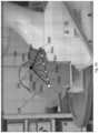
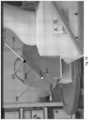
- FIGS. 4 A, 4 B, 4 C, and 4 Dschematically illustrate a robotic arm system configured to follow a linear path while performing a laparoscopic surgery, in accordance with some embodiments.
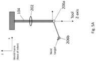
- FIGS. 5 A and 5 Bschematically illustrate a process for iteratively computing steps in a trocar-constrained path of an end effector, in accordance with some embodiments.
- FIG. 6schematically illustrates a flowchart of a method for determining a trocar-constrained path of an end effector, in accordance with some embodiments.
- FIG. 7schematically illustrates an exemplary computing node according to various embodiments of the present disclosure.
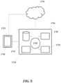
- FIG. 8schematically illustrates a computer system that is programmed or otherwise configured to implement methods provided herein.
- surgical robotsIn fully automated robotic surgical procedures, surgical robots generally include an end effector tool that is inserted through a trocar that was previously inserted into a small, keyhole incision in a body.
- the end effectormay include any suitable medical tool, such as, for example, a camera, a cutting tool, a gripping tool, a crimping tool, an electrocautery tool, or any other medical tool or surgical instrument that is usable to perform or aid in a performance of one or more steps of a surgical procedure.
- the end effectorWhen the end effector is inserted through the trocar in the keyhole incision, the location of the distal end of the end effector and its orientation may be unknown to a surgeon.
- the end effectormay change positions and/or orientations relative to a surgical site (e.g., within an abdominal cavity).
- a surgical operatordesires to adjust a position and/or an orientation of an end effector to visualize different portions of a surgical scene or to perform one or more surgical operations within the surgical scene, the surgical operator may need to determine a motion path between the starting position of the end effector and the destination of the end effector.
- the end effectormay be inserted through a trocar that is within a keyhole incision in a subject's body.
- the end effectorwhen a surgical operator moves the end effector tool within the subject's body, the end effector may pivot about a reference point at the keyhole incision. In some cases, the end effector may pivot relative to the trocar to prevent any injury or damage to a tissue region at or near the keyhole incision in the patient's body (e.g., tearing or other injury at or near the keyhole incision).
- a frame of reference corresponding to a position and/or an orientation of the trocarmay be determined and used to compute one or more optimal motion paths of the end effector.
- the frame of reference corresponding to the position and/or the orientation of the trocarmay be determined and used to verify that the trocar is properly positioned during the surgery to minimize damage to one or more tissue regions at or near the keyhole incision.
- one or more optimal motion paths of the end effectormay be computed such that the trocar does not interfere with various bodily structures during a surgical procedure, which is critically important to the surgical procedure since the end effector may be configured and/or controlled by a surgical operator to perform complex maneuvers in a small space within a surgical site.
- the orientation of the trocarmay be determined or computed by discretizing one or more motion paths (e.g., curved or linear) between a starting position and a destination position.
- a robotic arm of a robotic surgical systemmay be configured to pivot around a predefined fixed point during a surgical procedure.
- these predefined fixed pointsmay be on a trocar of the robotic arm such that the robotic arm pivots around the trocar.
- the robotic armmay comprise a separate motorized track that extends a medical tool or instrument through the trocar.
- the robotic armmay not comprise the separate motorized track. In cases where the robotic arm comprises a separate motorized track, the pivoting of the robotic arm may be decoupled from the extension of the medical tool or instrument.
- a system and method for determining the pivoting and extending motionsis needed to accurately and reliably maneuver the tool as needed while minimizing damage to one or more tissue regions or critical structures in or near the surgical site.
- FIG. 1illustrates a robotic arm system 100 for performing laparoscopic surgery according to an embodiment of the present disclosure.
- the robotic arm system 100may comprise a robotic arm 102 affixed to a base 101 at a proximal end.
- the robotic arm 102may further comprise an end effector 104 at the distal end of the robotic arm 102 .
- the end effector 104may be inserted through a trocar 105 that was previously inserted through a keyhole incision 106 in the abdomen 108 by a healthcare provider 110 overseeing the robotic surgery.
- FIG. 2illustrates a discretized path 200 of a distal end of an end effector according to embodiments of the present disclosure.
- the end effectormay be similar to the end effector described above with respect to FIG. 1 .
- a reference point 202 on the trocarmay be used to compute the reference frame of the end effector including the three-dimensional position (e.g., x, y, z) and/or the Euler angles (e.g., ⁇ , ⁇ , ⁇ ) of the end effector shaft.
- the reference pointmay be stationary.
- the reference pointmay correspond to a point on the trocar that is at the keyhole incision.
- a motion path 200 of a distal end of an end effectormay comprise a starting point 206 a and a destination point 206 f
- the motion path between the starting point 206 a and the destination point 206 fmay be discretized to include additional points 206 b - 206 e .
- FIG. 2further illustrates projections 204 a - 204 f that may correspond to a projection of the end effector shaft from the trocar reference point 202 to the distal end of the end effector at each point 206 a - 206 f along the motion path 200 .
- the end effector shaftmay pass through the reference point 302 at each incremental step.
- the pathmay be discretized into any suitable number of points.
- the number of pointsmay be at least about 1, 2, 3, 4, 5, 6, 7, 8, 9, 10, 20, 30, 40, 50, 60, 70, 80, 90, 100, or more.
- a larger number of pointsmay permit a higher level of precision and/or a higher resolution of motion. Projections of the end effector at each point 206 a - 206 f along the discretized path may pass through the trocar reference point 202 .
- the path 200 of the distal end of the end effectormay be linear.
- a vectormay be computed using the starting position and the destination position of the end effector.
- the vectormay be discretized into two or more points in three-dimensional space that are parameterized increments along the vector (e.g., 2 mm increments).
- the discretized pathmay include a path segment between each adjacent pair of points 206 a - 206 j . The points along the path may be used to iteratively determine a reference frame (x, y, z, ⁇ , ⁇ , ⁇ ) that takes the end effector shaft through the trocar reference point.
- FIG. 3illustrates a discretized path 300 of a distal end of an end effector according to embodiments of the present disclosure.
- the end effectormay be similar to the end effector described above with respect to FIG. 1 .
- a reference point 302 on the trocarmay be used to compute the reference frame of the end effector including the three-dimensional position (x, y, z) and the Euler angles ( ⁇ , ⁇ , ⁇ ) of the end effector shaft.
- the reference pointmay be stationary.
- the reference pointmay correspond to a point on the trocar that is at or near the keyhole incision.
- the end effector shaftmay pass through the reference point 302 at each incremental step of the distal end of the end effector represented by points 306 a - 306 j .
- the discretized motion path 300 of the distal end of the end effectormay comprise a starting point 306 a and a destination point 306 j .
- the path between the starting point 306 a and the destination point 306 jmay be discretized into additional points 306 b - 306 i .
- FIG 3further illustrates projections 304 a - 304 j that represent the projection of the end effector shaft from the trocar reference point 302 to the distal end of the end effector at each point 306 a - 306 j along the path 300 .
- the pathmay be discretized into any suitable number of points. In various embodiments, a larger number of points may permit a higher level of precision and/or a higher resolution of motion. Projections of the end effector at each point 306 a - 306 j along the discretized path may pass through the trocar reference point 302 .
- the path 300 of the distal end of the end effectormay be non-linear (e.g., curved).
- the pathmay be computed using the starting position and the destination position of the end effector.
- the pathmay be discretized into two or more points in three-dimensional space that are parameterized increments along the vector (e.g., 2 mm increments).
- the discretized pathmay comprise a path segment between each adjacent pair of points 306 a - 306 j .
- the points along the pathmay be used to iteratively determine a reference frame (x, y, z, ⁇ , ⁇ , ⁇ ) that takes the end effector shaft through the trocar reference point.
- a desired vectormay be determined from the trocar reference point to a desired incremental point with respect to the distal end of the end effector shaft.
- a current vector representing the current end effector shaft vectori.e., a longitudinal axis of the end effector currently extending through the trocar
- the in-plane rotation of the end effectormay be determined using the desired vector and the current vector.
- a reference framemay be determined from the transformation of the current end effector shaft vector using the in-plane rotation.
- the framemay be converted into a desired coordinate system.
- FIGS. 4 A- 4 Dshows a robotic arm system that is configured to follow a linear path while performing a laparoscopic surgery according to embodiments of the present disclosure.
- the robotic armmay be substantially similar to the robotic arm shown in FIG. 1 and may comprise an end effector 104 that is inserted into a trocar that was previously inserted into a keyhole incision in a body 108 .
- the distal end of the end effector 104may follow a first linear path once inserted into the trocar from trocar reference point 202 to 206 a and may then follow a second linear path (similar to the linear path illustrated in FIG.
- the distal end of the end effector 104may follow the linear path from point 206 a to point 206 f such that the end effector 104 shaft passes through the trocar reference point 202 at each incremental point 206 b - 206 e .
- Projections 204 a - 204 frepresent the projection of the end effector 104 shaft through the trocar reference point to each incremental point 206 a - 206 f
- the methods described hereinmay be similarly applied to each motion of the end effector, including, for example, the linear motion towards 206 a , the linear motion from 206 a to 206 f , and the linear motion from 206 f to another point outside of a subject's body.
- FIG. 4 Bshows the end effector 104 inserted into the trocar (previously inserted into the keyhole incision) such that the end effector 104 passes through the trocar reference point 202 and the distal end of the end effector 104 is located at the starting point 206 a .
- the distal end of the end effector 104may follow a linear path defined by the vector 207 .
- the path defined by vector 207may be broken, divided, or segmented (e.g., discretized) into incremental steps of one or more predetermined lengths as described above.
- the predetermined lengths between each of the plurality of pointsmay be of a same length. Alternatively, the predetermined lengths between each of the plurality of points may be different lengths. In some cases, the one or more predetermined lengths may be at least about 1 nanometer, 1 micrometer, 1 millimeter, 1 centimeter, or more.
- FIG. 4 Cshows a snapshot of the motion of the distal end of the end effector 104 at point 206 d while following the linear path to the destination point 206 f
- the length of projection 204 dmay be shorter than the length of projection 204 a (because the distance from the trocar reference point 202 to point 206 d is shorter than the distance from the trocar reference point 202 to point 206 a ), and the end effector 104 shaft may continue to pass through the trocar reference point 202 while the distal end of the end effector follows the linear path.
- FIG. 4 Dshows a snapshot of the motion of the distal end of the end effector 104 at destination point 206 f.
- FIGS. 5 A- 5 Billustrate a process for iteratively computing steps in a trocar-constrained path of an end effector according to embodiments of the present disclosure.
- a world frame of reference and an end effector frame of referencemay be used.
- the world frame of referencemay correspond to a frame of reference or a coordinate system in which the base of the robot is considered the origin.
- Certain variables used to compute an incremental next position of the trocarmay include:
- the current location of the end effectormay be used as the starting point in the algorithm when the motion path is discretized.
- the current locationmay be used as the origin (or reference frame) from which the other points are transformed to for the Rotation matrix equations described below.
- the current end effector tip locationmay allow the trocar location and the next target location to be expressed with the current location of the end effector as the origin, thereby simplifying the calculations of one or more of the below equations.
- a projected vectormay be computed based on a difference in position between the next incremental target position and the trocar reference point location.
- an in-plane rotationmay be computed between the z-axis of the trocar and the projected vector from the trocar reference point to the next target position of the distal end of the end effector.
- the in-plane rotationmay be represented as a rotation matrix between the z-axis of the trocar and the projected vector.
- the rotation matrix Rmay be computed based at least in part on a cross product of the trocar z-axis vector and the projected vector.
- the cross product of the trocar z-axis vector and the projected vectormay be a vector v, as shown below in Equation 2.
- vz Tool ⁇ projVect (Eqn. 2)
- an angle ⁇ between the z-axis of the trocar and the projected vectormay be computed, as shown below in Equation 3.
- a cross product matrixmay be determined based at least in part on the vector v corresponding to the cross product of the trocar z-axis vector and the projected vector computed from Equation 2, as shown below in Equation 4.
- a rotation matrix Rmay be computed based on the current end effector tip location in the tool frame, as shown below in Equation 5.
- the current end effector tip locationmay be transformed using the rotation matrix R to determine the rotation (in the tool frame) of the next target position.
- the translation of the current end effector tip location to the next target locationmay be determined from the position data (x, y, z) in the end effector frame.
- the rotation matrixmay be represented as a 4 ⁇ 4 matrix of [Rotation] [Translation], where I is the identity matrix.
- RI+v x *sin( ⁇ )+ v x 2 *(1 ⁇ cos( ⁇ )) (Eqn. 5)
- a homogeneous transformation H that combines rotation and displacement in a single matrixmay be computed as shown below in Equations 6a and 6b:
- the rotationmay be represented by a 3 ⁇ 3 matrix which includes Euler angles (n, s, a), and the displacement may be represented by a 1 ⁇ 3 matrix which includes vector d.
- the current end effector tip locationmay be transformed through matrix multiplication to determine the rotation of the next target position for the next incremental point.
- the current end effector tip locationwhich can be represented as a 4 ⁇ 4 matrix of its current rotation and (x, y, z) position, may be multiplied by the rotation matrix R to compute the rotated point.
- the current end effector tip locationmay be represented as a 4 ⁇ 4 matrix of its current rotation and (x, y, z) position.
- the rotation matrixmay also be represented as a 4 ⁇ 4 matrix (with a 1 ⁇ 4 column of 0, 0, 0, 1 representing no translation).
- the 4 ⁇ 4 rotation matrixmay be multiplied by the 4 ⁇ 4 matrix of the current end effector tip position to compute a new 4 ⁇ 4 matrix including the rotated point.
- This new 4 ⁇ 4 matrixmay include the position and/or orientation information required to move the end effector to the next point, and the (x, y, z) coordinates of the new 4 ⁇ 4 matrix may correspond to the (x, y, z) coordinates of the next target point.
- this new 4 ⁇ 4 matrixmay be transformed into the world reference frame (where the base of the robot is considered the origin) for commanding the robot.
- the transformation from end effector reference frame to the world framemay be derived based at least in part on the end effector dimensions, the position and/or orientation of the end effector relative to the robot arm, and the current joint locations of the robot. In various embodiments, this information may be used to determine one or more transformations from the end effector reference frame to the world frame through similar multiplication of the current 4 ⁇ 4 rotation matrix of the end effector by another 4 ⁇ 4 matrix corresponding to a position of the attachment point of the end effector to the robot arm.
- another transformationmay be performed from a first reference frame corresponding to the robot attachment point (or flange) to a second reference frame corresponding to the base of the robot, based at least in part on (i) the robot's dimensions and/or (ii) the relative positions and/or the relative orientations of the robot's joints.
- the position and/or orientation of the trocarmay be determined based at least in part on the current configuration of the robotic arm (e.g., the positions and/or orientations of each of the joints of the robotic arm relative to the robotic arm) and the transformation of the rotation matrix from the tool frame into the world frame.
- the computational process implemented using Equations 1-5may be repeated for each incremental step of a discretized motion path.
- the processmay be applied to a linear path, a curved path, or a path that comprises both linear and curved portions.
- the frames (positions and orientations)may be splined together.
- one or more incremental pointsmay be splined together by instructing the robot to move continuously from one point to the next point such that the robot does not move the end effector to a first point and stop before moving to the next point (i.e., a second point) and stopping in a piecewise fashion.
- the incremental pointsmay be splined together to generate a motion plan where the points are reached in a smooth fashion as if the end effector is tracing the path.
- the velocity and/or the acceleration of the robotmay be managed.
- the robotic arm or the end effector of the robotic armmay move at a constant linear or angular speed.
- the incremental points of the end effector pathmay not or need not be splined together.
- any suitable tool having a straight shaft for insertionmay be used as an end effector.
- the end effectormay comprise a rod with a grasper.
- an Endo360 suturing toolmay be used as an end effector.
- the end effectormay comprise one or more straight and/or curved portions.
- the portion of the end effector that is inserted into the trocarmay be substantially straight.
- FIG. 6illustrates a flowchart of a method 600 for determining a path and rotation of an end effector according to an embodiment of the present disclosure.
- a robotic armmay be provided.
- the robotic armmay comprise an end effector having a proximal end and a distal end.
- the end effectormay be disposed within a trocar that is insertable in a keyhole incision in a subject's body.
- a three-dimensional starting position and a three-dimensional destination position of the distal end of the end effectormay be determined.
- a path between the starting position and the destination positionmay be determined.
- a plurality of points along the pathmay be determined.
- a projected vectormay be determined from a trocar reference point to a first point of the plurality of points.
- an in-plane rotation of the end effectormay be determined such that the trocar reference point may be maintained.
- a rotation and/or a translation of the end effectormay be determined based at least in part on the starting position, the first point of the plurality of points, and/or the in-plane rotation.
- computing node 10is only one example of a suitable computing node and is not intended to suggest any limitation as to the scope of use or functionality of embodiments described herein. Regardless, computing node 10 is capable of being implemented and/or performing any of the functionality set forth hereinabove.
- the computing node 10may comprise a computer system/server 12 , which is operational with numerous other general purpose or special purpose computing system environments or configurations.
- Examples of well-known computing systems, environments, and/or configurations that may be suitable for use with computer system/server 12include, but are not limited to, personal computer systems, server computer systems, thin clients, thick clients, handheld or laptop devices, multiprocessor systems, microprocessor-based systems, set top boxes, programmable consumer electronics, network PCs, minicomputer systems, mainframe computer systems, and distributed cloud computing environments that include any of the above systems or devices, and the like.
- Computer system/server 12may be described in the general context of computer system-executable instructions, such as program modules, being executed by a computer system.
- program modulesmay include routines, programs, objects, components, logic, data structures, and so on that perform particular tasks or implement particular abstract data types.
- Computer system/server 12may be practiced in distributed cloud computing environments where tasks are performed by remote processing devices that are linked through a communications network.
- program modulesmay be located in both local and remote computer system storage media including memory storage devices.
- computer system/server 12 in computing node 10is shown in the form of a general-purpose computing device.
- the components of computer system/server 12may include, but are not limited to, one or more processors or processing units 16 , a system memory 28 , and a bus 18 coupling various system components including system memory 28 to processor 16 .
- Bus 18represents one or more of any of several types of bus structures, including a memory bus or memory controller, a peripheral bus, an accelerated graphics port, and a processor or local bus using any of a variety of bus architectures.
- bus architecturesinclude Industry Standard Architecture (ISA) bus, Micro Channel Architecture (MCA) bus, Enhanced ISA (EISA) bus, Video Electronics Standards Association (VESA) local bus, and Peripheral Component Interconnect (PCI) bus.
- Computer system/server 12typically includes a variety of computer system readable media. Such media may be any available media that is accessible by computer system/server 12 , and it includes both volatile and non-volatile media, removable and non-removable media.
- System memory 28can include computer system readable media in the form of volatile memory, such as random access memory (RAM) 30 and/or cache memory 32 .
- Computer system/server 12may further include other removable/non-removable, volatile/non-volatile computer system storage media.
- storage system 34can be provided for reading from and writing to a non-removable, non-volatile magnetic media (not shown and typically called a “hard drive”).
- a magnetic disk drivefor reading from and writing to a removable, non-volatile magnetic disk (e.g., a “floppy disk”).
- an optical disk drivefor reading from or writing to a removable, non-volatile optical disk such as a CD-ROM, DVD-ROM or other optical media can be provided.
- memory 28may include at least one program product having a set (e.g., at least one) of program modules that are configured to carry out the functions of embodiments of the disclosure.
- Program/utility 40having a set (at least one) of program modules 42 , may be stored in memory 28 by way of example, and not limitation, as well as an operating system, one or more application programs, other program modules, and program data. Each of the operating system, one or more application programs, other program modules, and program data or some combination thereof, may include an implementation of a networking environment.
- Program modules 42generally carry out the functions and/or methodologies of embodiments described herein.
- Computer system/server 12may also communicate with one or more external devices 14 such as a keyboard, a pointing device, a display 24 , etc.; one or more devices that enable a user to interact with computer system/server 12 ; and/or any devices (e.g., network card, modem, etc.) that enable computer system/server 12 to communicate with one or more other computing devices. Such communication can occur via Input/Output (I/O) interfaces 22 . Still yet, computer system/server 12 can communicate with one or more networks such as a local area network (LAN), a general wide area network (WAN), and/or a public network (e.g., the Internet) via network adapter 20 .
- LANlocal area network
- WANwide area network
- public networke.g., the Internet
- network adapter 20communicates with the other components of computer system/server 12 via bus 18 .
- bus 18It should be understood that although not shown, other hardware and/or software components could be used in conjunction with computer system/server 12 . Examples, include, but are not limited to: microcode, device drivers, redundant processing units, external disk drive arrays, RAID systems, tape drives, and data archival storage systems, etc.
- the computer system/servermay be connected to one or more cameras (e.g., digital cameras, light-field cameras) or other imaging/sensing devices (e.g., infrared cameras or sensors).
- camerase.g., digital cameras, light-field cameras
- imaging/sensing devicese.g., infrared cameras or sensors.
- the present disclosureincludes a system, a method, and/or a computer program product.
- the computer program productmay include a computer readable storage medium (or media) having computer readable program instructions thereon for causing a processor to carry out aspects of the present disclosure.
- the computer readable storage mediumcan be a tangible device that can retain and store instructions for use by an instruction execution device.
- the computer readable storage mediummay be, for example, but is not limited to, an electronic storage device, a magnetic storage device, an optical storage device, an electromagnetic storage device, a semiconductor storage device, or any suitable combination of the foregoing.
- a non-exhaustive list of more specific examples of the computer readable storage mediumincludes the following: a portable computer diskette, a hard disk, a random access memory (RAM), a read-only memory (ROM), an erasable programmable read-only memory (EPROM or Flash memory), a static random access memory (SRAM), a portable compact disc read-only memory (CD-ROM), a digital versatile disk (DVD), a memory stick, a floppy disk, a mechanically encoded device such as punch-cards or raised structures in a groove having instructions recorded thereon, and any suitable combination of the foregoing.
- RAMrandom access memory
- ROMread-only memory
- EPROM or Flash memoryerasable programmable read-only memory
- SRAMstatic random access memory
- CD-ROMcompact disc read-only memory
- DVDdigital versatile disk
- memory sticka floppy disk
- a mechanically encoded devicesuch as punch-cards or raised structures in a groove having instructions recorded thereon
- a computer readable storage mediumis not to be construed as being transitory signals per se, such as radio waves or other freely propagating electromagnetic waves, electromagnetic waves propagating through a waveguide or other transmission media (e.g., light pulses passing through a fiber-optic cable), or electrical signals transmitted through a wire.
- Computer readable program instructions described hereincan be downloaded to respective computing/processing devices from a computer readable storage medium or to an external computer or external storage device via a network, for example, the Internet, a local area network, a wide area network and/or a wireless network.
- the networkmay comprise copper transmission cables, optical transmission fibers, wireless transmission, routers, firewalls, switches, gateway computers and/or edge servers.
- a network adapter card or network interface in each computing/processing devicereceives computer readable program instructions from the network and forwards the computer readable program instructions for storage in a computer readable storage medium within the respective computing/processing device.
- Computer readable program instructions for carrying out operations of the present disclosuremay be assembler instructions, instruction-set-architecture (ISA) instructions, machine instructions, machine dependent instructions, microcode, firmware instructions, state-setting data, or either source code or object code written in any combination of one or more programming languages, including an object oriented programming language such as Smalltalk, C++ or the like, and conventional procedural programming languages, such as the “C” programming language or similar programming languages.
- the computer readable program instructionsmay execute entirely on the user's computer, partly on the user's computer, as a stand-alone software package, partly on the user's computer and partly on a remote computer or entirely on the remote computer or server.
- the remote computermay be connected to the user's computer through any type of network, including a local area network (LAN) or a wide area network (WAN), or the connection may be made to an external computer (for example, through the Internet using an Internet Service Provider).
- electronic circuitryincluding, for example, programmable logic circuitry, field-programmable gate arrays (FPGA), or programmable logic arrays (PLA) may execute the computer readable program instructions by utilizing state information of the computer readable program instructions to personalize the electronic circuitry, in order to perform aspects of the present disclosure.
- These computer readable program instructionsmay be provided to a processor of a general purpose computer, special purpose computer, or other programmable data processing apparatus to produce a machine, such that the instructions, which execute via the processor of the computer or other programmable data processing apparatus, create means for implementing the functions/acts specified in the flowchart and/or block diagram block or blocks.
- These computer readable program instructionsmay also be stored in a computer readable storage medium that can direct a computer, a programmable data processing apparatus, and/or other devices to function in a particular manner, such that the computer readable storage medium having instructions stored therein comprises an article of manufacture including instructions which implement aspects of the function/act specified in the flowchart and/or block diagram block or blocks.
- the computer readable program instructionsmay also be loaded onto a computer, other programmable data processing apparatus, or other device to cause a series of operational steps to be performed on the computer, other programmable apparatus or other device to produce a computer implemented process, such that the instructions which execute on the computer, other programmable apparatus, or other device implement the functions/acts specified in the flowchart and/or block diagram block or blocks.
- each block in the flowchart or block diagramsmay represent a module, segment, or portion of instructions, which comprises one or more executable instructions for implementing the specified logical function(s).
- the functions noted in the blockmay occur out of the order noted in the figures.
- two blocks shown in successionmay, in fact, be executed substantially concurrently, or the blocks may sometimes be executed in the reverse order, depending upon the functionality involved.
- Each block of the block diagrams and/or flowchart illustration, and combinations of blocks in the block diagrams and/or flowchart illustrationcan be implemented by special purpose hardware-based systems that perform the specified functions or acts or carry out combinations of special purpose hardware and computer instructions.
- FIG. 8shows a computer system 1701 that is programmed or otherwise configured to implement a method for moving a robotic arm and/or an end effector of the robotic arm.
- the computer system 1701may be configured to, for example, determine a set of motions to move the end effector from a starting position to a destination position, based at least in part on a trocar reference point.
- the computer system 1701may be further configured to determine the starting position and the destination position of the distal end of the end effector, determine a path between the starting position and the destination position; and determine a plurality of points along the path.
- the computer system 1701may be further configured to determine a projected vector from the trocar reference point to a first point of the plurality of points, determine an in-plane rotation of the end effector such that the trocar reference point is maintained, and determine a rotation and translation of the end effector based in part on the starting position, the first point of the plurality of points, and the in-plane rotation.
- the computer system 1701may be further configured to transform the determined rotation and translation of the end effector from a first reference frame to a second reference frame.
- the computer system 1701can be an electronic device of a user or a computer system that is remotely located with respect to the electronic device.
- the electronic devicecan be a mobile electronic device.
- the computer system 1701may include a central processing unit (CPU, also “processor” and “computer processor” herein) 1705 , which can be a single core or multi core processor, or a plurality of processors for parallel processing.
- the computer system 1701also includes memory or memory location 1710 (e.g., random-access memory, read-only memory, flash memory), electronic storage unit 1715 (e.g., hard disk), communication interface 1720 (e.g., network adapter) for communicating with one or more other systems, and peripheral devices 1725 , such as cache, other memory, data storage and/or electronic display adapters.
- the memory 1710 , storage unit 1715 , interface 1720 and peripheral devices 1725are in communication with the CPU 1705 through a communication bus (solid lines), such as a motherboard.
- the storage unit 1715can be a data storage unit (or data repository) for storing data.
- the computer system 1701can be operatively coupled to a computer network (“network”) 1730 with the aid of the communication interface 1720 .
- the network 1730can be the Internet, an internet and/or extranet, or an intranet and/or extranet that is in communication with the Internet.
- the network 1730in some cases is a telecommunication and/or data network.
- the network 1730can include one or more computer servers, which can enable distributed computing, such as cloud computing.
- the network 1730in some cases with the aid of the computer system 1701 , can implement a peer-to-peer network, which may enable devices coupled to the computer system 1701 to behave as a client or a server.
- the CPU 1705can execute a sequence of machine-readable instructions, which can be embodied in a program or software.
- the instructionsmay be stored in a memory location, such as the memory 1710 .
- the instructionscan be directed to the CPU 1705 , which can subsequently program or otherwise configure the CPU 1705 to implement methods of the present disclosure. Examples of operations performed by the CPU 1705 can include fetch, decode, execute, and writeback.
- the CPU 1705can be part of a circuit, such as an integrated circuit.
- a circuitsuch as an integrated circuit.
- One or more other components of the system 1701can be included in the circuit.
- the circuitis an application specific integrated circuit (ASIC).
- the storage unit 1715can store files, such as drivers, libraries and saved programs.
- the storage unit 1715can store user data, e.g., user preferences and user programs.
- the computer system 1701in some cases can include one or more additional data storage units that are located external to the computer system 1701 (e.g., on a remote server that is in communication with the computer system 1701 through an intranet or the Internet).
- the computer system 1701can communicate with one or more remote computer systems through the network 1730 .
- the computer system 1701can communicate with a remote computer system of a user (e.g., a healthcare provider, a surgical operator, a doctor, a nurse, an imaging technician, medical staff, etc.).
- remote computer systemsinclude personal computers (e.g., portable PC), slate or tablet PC's (e.g., Apple® iPad, Samsung® Galaxy Tab), telephones, Smart phones (e.g., Apple® iPhone, Android-enabled device, Blackberry®), or personal digital assistants.
- the usercan access the computer system 1701 via the network 1730 .
- Methods as described hereincan be implemented by way of machine (e.g., computer processor) executable code stored on an electronic storage location of the computer system 1701 , such as, for example, on the memory 1710 or electronic storage unit 1715 .
- the machine executable or machine readable codecan be provided in the form of software.
- the codecan be executed by the processor 1705 .
- the codecan be retrieved from the storage unit 1715 and stored on the memory 1710 for ready access by the processor 1705 .
- the electronic storage unit 1715can be precluded, and machine-executable instructions are stored on memory 1710 .
- the codecan be pre-compiled and configured for use with a machine having a processor adapted to execute the code, or can be compiled during runtime.
- the codecan be supplied in a programming language that can be selected to enable the code to execute in a pre-compiled or as-compiled fashion.
- aspects of the systems and methods provided hereincan be embodied in programming.
- Various aspects of the technologymay be thought of as “products” or “articles of manufacture” typically in the form of machine (or processor) executable code and/or associated data that is carried on or embodied in a type of machine readable medium.
- Machine-executable codecan be stored on an electronic storage unit, such as memory (e.g., read-only memory, random-access memory, flash memory) or a hard disk.
- “Storage” type mediacan include any or all of the tangible memory of the computers, processors or the like, or associated modules thereof, such as various semiconductor memories, tape drives, disk drives and the like, which may provide non-transitory storage at any time for the software programming. All or portions of the software may at times be communicated through the Internet or various other telecommunication networks. Such communications, for example, may enable loading of the software from one computer or processor into another, for example, from a management server or host computer into the computer platform of an application server.
- another type of media that may bear the software elementsincludes optical, electrical and electromagnetic waves, such as used across physical interfaces between local devices, through wired and optical landline networks and over various air-links.
- a machine readable mediumsuch as computer-executable code
- a tangible storage mediumincluding, for example, optical or magnetic disks, or any storage devices in any computer(s) or the like, may be used to implement the databases, etc. shown in the drawings.
- Volatile storage mediainclude dynamic memory, such as main memory of such a computer platform.
- Tangible transmission mediainclude coaxial cables; copper wire and fiber optics, including the wires that comprise a bus within a computer system.
- Carrier-wave transmission mediamay take the form of electric or electromagnetic signals, or acoustic or light waves such as those generated during radio frequency (RF) and infrared (IR) data communications.
- RFradio frequency
- IRinfrared
- Computer-readable mediatherefore include for example: a floppy disk, a flexible disk, hard disk, magnetic tape, any other magnetic medium, a CD-ROM, DVD or DVD-ROM, any other optical medium, punch cards paper tape, any other physical storage medium with patterns of holes, a RAM, a ROM, a PROM and EPROM, a FLASH-EPROM, any other memory chip or cartridge, a carrier wave transporting data or instructions, cables or links transporting such a carrier wave, or any other medium from which a computer may read programming code and/or data. Many of these forms of computer readable media may be involved in carrying one or more sequences of one or more instructions to a processor for execution.
- the computer system 1701can include or be in communication with an electronic display 1735 that comprises a user interface (UI) 1740 for providing, for example, a portal for a surgical operator to monitor or track a motion of a robotic arm and/or an end effector of the robotic arm.
- UIuser interface
- the portalmay be provided through an application programming interface (API).
- APIapplication programming interface
- a user or entitycan also interact with various elements in the portal via the UI.
- Examples of UI'sinclude, without limitation, a graphical user interface (GUI) and web-based user interface.
- An algorithmcan be implemented by way of software upon execution by the central processing unit 1705 .
- the algorithmmay be configured to determine a set of motions to move the end effector from a starting position to a destination position, based at least in part on a trocar reference point.
- the algorithmmay be further configured to determine the starting position and the destination position of the distal end of the end effector, determine a path between the starting position and the destination position; and determine a plurality of points along the path.
- the algorithmmay be further configured to determine a projected vector from the trocar reference point to a first point of the plurality of points, determine an in-plane rotation of the end effector such that the trocar reference point is maintained, and determine a rotation and translation of the end effector based in part on the starting position, the first point of the plurality of points, and the in-plane rotation.
- the algorithmmay be further configured to transform the determined rotation and translation of the end effector from a first reference frame to a second reference frame.
Landscapes
- Health & Medical Sciences (AREA)
- Life Sciences & Earth Sciences (AREA)
- Surgery (AREA)
- Engineering & Computer Science (AREA)
- Medical Informatics (AREA)
- Nuclear Medicine, Radiotherapy & Molecular Imaging (AREA)
- Biomedical Technology (AREA)
- Heart & Thoracic Surgery (AREA)
- Molecular Biology (AREA)
- Animal Behavior & Ethology (AREA)
- General Health & Medical Sciences (AREA)
- Public Health (AREA)
- Veterinary Medicine (AREA)
- Robotics (AREA)
- Pathology (AREA)
- Oral & Maxillofacial Surgery (AREA)
- Manipulator (AREA)
Abstract
Description
- 1. curTool, representing the current end effector tip location in the end effector frame (x,y,z);
- 2. trocTool, representing the trocar reference point location in end effector frame (x,y,z);
- 3. projVect, representing the projected vector from the trocar reference point to the next target position (x,y,z) of the end effector tip;
- 4. nexTarg, representing the location of the next incremental target position (x,y,z) of the end effector tip;
- 5. zTool, representing the vector that is the z-axis of the end effector (x,y,z) in the tool frame.
projVect=nextTarg−trocTool (Eqn. 1)
v=zTool×projVect (Eqn. 2)
R=I+vx*sin(θ)+vx2*(1−cos(θ)) (Eqn. 5)
Claims (18)
Priority Applications (1)
| Application Number | Priority Date | Filing Date | Title |
|---|---|---|---|
| US17/503,108US12201387B2 (en) | 2019-04-19 | 2021-10-15 | Systems and methods for trocar kinematics |
Applications Claiming Priority (3)
| Application Number | Priority Date | Filing Date | Title |
|---|---|---|---|
| US201962836201P | 2019-04-19 | 2019-04-19 | |
| PCT/US2020/028536WO2020214821A1 (en) | 2019-04-19 | 2020-04-16 | Systems and methods for trocar kinematics |
| US17/503,108US12201387B2 (en) | 2019-04-19 | 2021-10-15 | Systems and methods for trocar kinematics |
Related Parent Applications (1)
| Application Number | Title | Priority Date | Filing Date |
|---|---|---|---|
| PCT/US2020/028536ContinuationWO2020214821A1 (en) | 2019-04-19 | 2020-04-16 | Systems and methods for trocar kinematics |
Publications (2)
| Publication Number | Publication Date |
|---|---|
| US20220175471A1 US20220175471A1 (en) | 2022-06-09 |
| US12201387B2true US12201387B2 (en) | 2025-01-21 |
Family
ID=72838367
Family Applications (1)
| Application Number | Title | Priority Date | Filing Date |
|---|---|---|---|
| US17/503,108Active2041-11-21US12201387B2 (en) | 2019-04-19 | 2021-10-15 | Systems and methods for trocar kinematics |
Country Status (2)
| Country | Link |
|---|---|
| US (1) | US12201387B2 (en) |
| WO (1) | WO2020214821A1 (en) |
Families Citing this family (8)
| Publication number | Priority date | Publication date | Assignee | Title |
|---|---|---|---|---|
| WO2020140042A1 (en) | 2018-12-28 | 2020-07-02 | Activ Surgical, Inc. | User interface elements for orientation of remote camera during surgery |
| WO2020140056A1 (en) | 2018-12-28 | 2020-07-02 | Activ Surgical, Inc. | Systems and methods to optimize reachability, workspace, and dexterity in minimally invasive surgery |
| WO2020214821A1 (en) | 2019-04-19 | 2020-10-22 | Activ Surgical, Inc. | Systems and methods for trocar kinematics |
| US20220401178A1 (en)* | 2019-11-01 | 2022-12-22 | True Digital Surgery | Robotic surgical navigation using a proprioceptive digital surgical stereoscopic camera system |
| US12161419B2 (en)* | 2021-03-05 | 2024-12-10 | Verb Surgical Inc. | Robot-assisted setup for a surgical robotic system |
| CN113288358B (en)* | 2021-05-21 | 2022-11-15 | 中国医学科学院生物医学工程研究所 | Pose information determination method and device, electronic equipment and storage medium |
| CN115982893B (en)* | 2023-03-20 | 2023-07-18 | 广东工业大学 | Multi-degree-of-freedom mechanism kinematics modeling method, device, equipment and storage medium |
| EP4434484A1 (en)* | 2023-03-24 | 2024-09-25 | CAScination AG | System for controlled placement of an object in space using a spatial alignment device |
Citations (305)
| Publication number | Priority date | Publication date | Assignee | Title |
|---|---|---|---|---|
| US4772831A (en) | 1986-11-20 | 1988-09-20 | Unimation, Inc. | Multiaxis robot control having improved continuous path operation |
| US5808665A (en) | 1992-01-21 | 1998-09-15 | Sri International | Endoscopic surgical instrument and method for use |
| US5876325A (en) | 1993-11-02 | 1999-03-02 | Olympus Optical Co., Ltd. | Surgical manipulation system |
| US6001108A (en) | 1996-02-20 | 1999-12-14 | Computer Motion, Inc. | Method and apparatus for performing minimally invasive cardiac procedures |
| US6088105A (en) | 1998-04-04 | 2000-07-11 | Joh. & Ernst Link Gmbh & Co. Kg | Measuring unit for determining dimensions of test pieces, preferably of hollow bodies, in particular, of bores of workpieces, and method for measuring such dimensions |
| US6183485B1 (en) | 1993-08-25 | 2001-02-06 | Inlet Medical, Inc. | Insertable suture passing grasping probe and methodology for using same |
| US6206894B1 (en) | 1997-10-09 | 2001-03-27 | Ethicon Endo-Surgery, Inc. | Electrically powered needle holder to assist in suturing |
| US6309397B1 (en) | 1999-12-02 | 2001-10-30 | Sri International | Accessories for minimally invasive robotic surgery and methods |
| US6325808B1 (en) | 1998-12-08 | 2001-12-04 | Advanced Realtime Control Systems, Inc. | Robotic system, docking station, and surgical tool for collaborative control in minimally invasive surgery |
| US6373963B1 (en) | 1998-02-05 | 2002-04-16 | Textile/Clothing Technology Corporation | Systems, methods and computer program for measuring the surface contour of an object |
| US6491702B2 (en) | 1992-04-21 | 2002-12-10 | Sofamor Danek Holdings, Inc. | Apparatus and method for photogrammetric surgical localization |
| US6503195B1 (en) | 1999-05-24 | 2003-01-07 | University Of North Carolina At Chapel Hill | Methods and systems for real-time structured light depth extraction and endoscope using real-time structured light depth extraction |
| US6542249B1 (en) | 1999-07-20 | 2003-04-01 | The University Of Western Ontario | Three-dimensional measurement method and apparatus |
| US6549288B1 (en) | 1998-05-14 | 2003-04-15 | Viewpoint Corp. | Structured-light, triangulation-based three-dimensional digitizer |
| US6564086B2 (en) | 2000-05-03 | 2003-05-13 | Rocky Mountain Biosystems, Inc. | Prosthesis and method of making |
| US6563105B2 (en) | 1999-06-08 | 2003-05-13 | University Of Washington | Image acquisition with depth enhancement |
| US6613041B1 (en) | 1998-08-20 | 2003-09-02 | Bioshape Ag | Device for determining the surface shape of biological tissue |
| US6643563B2 (en) | 2001-07-13 | 2003-11-04 | Brooks Automation, Inc. | Trajectory planning and motion control strategies for a planar three-degree-of-freedom robotic arm |
| US6645196B1 (en)* | 2000-06-16 | 2003-11-11 | Intuitive Surgical, Inc. | Guided tool change |
| US6697164B1 (en) | 1998-08-05 | 2004-02-24 | Cadent Ltd. | Imaging a three-dimensional structure by confocal focussing an array of light beams |
| US20040073257A1 (en) | 2002-10-09 | 2004-04-15 | Spitz Gregory A. | Methods and apparatus for the repair of hernias |
| US20040176751A1 (en) | 2002-08-14 | 2004-09-09 | Endovia Medical, Inc. | Robotic medical instrument system |
| US6800057B2 (en) | 2001-05-29 | 2004-10-05 | Fuji Photo Film Co., Ltd. | Image obtaining apparatus |
| US6850872B1 (en) | 2000-08-30 | 2005-02-01 | Microsoft Corporation | Facial image processing methods and systems |
| US6873867B2 (en) | 2000-04-05 | 2005-03-29 | Brainlab Ag | Referencing or registering a patient or a patient body part in a medical navigation system by means of irradiation of light points |
| US6885464B1 (en) | 1998-06-30 | 2005-04-26 | Sirona Dental Systems Gmbh | 3-D camera for recording surface structures, in particular for dental purposes |
| US20050090840A1 (en) | 2001-12-04 | 2005-04-28 | The Children's Medical Center Corporation | Tissue repair |
| US20050096515A1 (en) | 2003-10-23 | 2005-05-05 | Geng Z. J. | Three-dimensional surface image guided adaptive therapy system |
| USRE38800E1 (en) | 1997-10-16 | 2005-09-20 | The Research Foundation Of State University Of New York | NIR clinical opti-scan system |
| US6965690B2 (en) | 2000-11-22 | 2005-11-15 | Sanyo Electric Co., Ltd. | Three-dimensional modeling apparatus, method, and medium, and three-dimensional shape data recording apparatus, method, and medium |
| US6977732B2 (en) | 2002-12-26 | 2005-12-20 | National Taiwan University | Miniature three-dimensional contour scanner |
| US6987531B2 (en) | 2001-09-04 | 2006-01-17 | Minolta Co., Ltd. | Imaging system, photographing device and three-dimensional measurement auxiliary unit used for the system |
| US20060020272A1 (en) | 2004-06-24 | 2006-01-26 | Gildenberg Philip L | Semi-robotic suturing device |
| US7006236B2 (en) | 2002-05-22 | 2006-02-28 | Canesta, Inc. | Method and apparatus for approximating depth of an object's placement onto a monitored region with applications to virtual interface devices |
| US7068825B2 (en) | 1999-03-08 | 2006-06-27 | Orametrix, Inc. | Scanning system and calibration method for capturing precise three-dimensional information of objects |
| US7099732B2 (en) | 1999-03-29 | 2006-08-29 | Genex Technologies, Inc. | Sanitary sleeve or tip for intra-oral three-dimensional camera |
| US20060258938A1 (en) | 2005-05-16 | 2006-11-16 | Intuitive Surgical Inc. | Methods and system for performing 3-D tool tracking by fusion of sensor and/or camera derived data during minimally invasive robotic surgery |
| US7184150B2 (en) | 2003-03-24 | 2007-02-27 | D4D Technologies, Llc | Laser digitizer system for dental applications |
| US7200262B2 (en) | 2002-01-07 | 2007-04-03 | Canon Kabushiki Kaisha | 3-dimensional image processing method, 3-dimensional image processing device, and 3-dimensional image processing system |
| US20070115484A1 (en) | 2005-10-24 | 2007-05-24 | Peisen Huang | 3d shape measurement system and method including fast three-step phase shifting, error compensation and calibration |
| US7224384B1 (en) | 1999-09-08 | 2007-05-29 | 3Dv Systems Ltd. | 3D imaging system |
| US20070146719A1 (en) | 2005-12-16 | 2007-06-28 | Matthias Wedel | Scanning apparatus for optically scanning surfaces |
| US7242997B2 (en) | 2002-09-03 | 2007-07-10 | Genex Technologies, Inc. | Diffuse optical tomography system and method of use |
| US20070165243A1 (en) | 2004-02-09 | 2007-07-19 | Cheol-Gwon Kang | Device for measuring 3d shape using irregular pattern and method for the same |
| US20070213749A1 (en) | 2006-03-08 | 2007-09-13 | Olympus Medical Systems Corp. | Medical procedure performed inside abdominal cavity |
| US20070249911A1 (en) | 2006-04-21 | 2007-10-25 | Simon David A | Method and apparatus for optimizing a therapy |
| US20070280423A1 (en) | 2006-05-31 | 2007-12-06 | Robert Schmidt | Registration by means of radiation marking elements |
| US20070293734A1 (en) | 2001-06-07 | 2007-12-20 | Intuitive Surgical, Inc. | Methods and apparatus for surgical planning |
| US7313264B2 (en) | 1995-07-26 | 2007-12-25 | 3D Scanners Limited | Scanning apparatus and method |
| US7319529B2 (en) | 2004-06-17 | 2008-01-15 | Cadent Ltd | Method and apparatus for colour imaging a three-dimensional structure |
| US20080013809A1 (en) | 2006-07-14 | 2008-01-17 | Bracco Imaging, Spa | Methods and apparatuses for registration in image guided surgery |
| US20080107305A1 (en) | 2006-11-02 | 2008-05-08 | Northern Digital Inc. | Integrated mapping system |
| US7385708B2 (en) | 2002-06-07 | 2008-06-10 | The University Of North Carolina At Chapel Hill | Methods and systems for laser based real-time structured light depth extraction |
| US7435217B2 (en) | 2006-04-17 | 2008-10-14 | Microvision, Inc. | Scanned beam imagers and endoscopes with positionable light collector |
| US20080266391A1 (en) | 2005-10-19 | 2008-10-30 | Lee Sang-Yoon | Apparatus for and Method of Measuring Image |
| US7450783B2 (en) | 2003-09-12 | 2008-11-11 | Biopticon Corporation | Methods and systems for measuring the size and volume of features on live tissues |
| US7489408B2 (en) | 2005-11-15 | 2009-02-10 | General Electric Company | Optical edge break gage |
| US7491956B2 (en) | 2006-02-01 | 2009-02-17 | Siemens Aktiengesellschaft | Optical scanning device having a distance sensor and a determined focal distance for scanning objects |
| US7522764B2 (en) | 2003-01-31 | 2009-04-21 | Sirona Dental Systems Gmbh | Method and system for imaging an object |
| US7577299B2 (en) | 2003-03-05 | 2009-08-18 | Toyota Jidosha Kabushiki Kaisha | Image pickup apparatus and image pickup method |
| US20090221874A1 (en) | 2005-11-28 | 2009-09-03 | 3Shape A/S | Coded structure light |
| US20090244260A1 (en) | 2008-03-31 | 2009-10-01 | Hoya Corporation | Endoscope measuring 3-d profile |
| US7620209B2 (en) | 2004-10-14 | 2009-11-17 | Stevick Glen R | Method and apparatus for dynamic space-time imaging system |
| US20090326324A1 (en) | 2006-07-28 | 2009-12-31 | Universidad De Malaga | Robotic system for assisting in minimally-invasive surgery, which can position a surgical instrument in response to orders from a surgeon, is not attached to the operating table and does not require pre-calibration of the insertion point |
| US20100081875A1 (en) | 2003-07-15 | 2010-04-01 | EndoRobotics Inc. | Surgical Device For Minimal Access Surgery |
| US7704206B2 (en) | 2002-06-05 | 2010-04-27 | Olympus Corporation | Endoscope that provides selection of each illumination mode of four different illumination modes |
| US20100113921A1 (en) | 2008-06-02 | 2010-05-06 | Uti Limited Partnership | Systems and Methods for Object Surface Estimation |
| US7724932B2 (en) | 2004-01-27 | 2010-05-25 | Densys Ltd | Three-dimensional modeling of the oral cavity |
| US7751871B2 (en) | 1996-09-02 | 2010-07-06 | Orametrix, Inc. | Method and device for carrying out optical pick up |
| US7763841B1 (en) | 2009-05-27 | 2010-07-27 | Microsoft Corporation | Optical component for a depth sensor |
| WO2010096447A2 (en) | 2009-02-17 | 2010-08-26 | Board Of Regents, The University Of Texas System | Quantitative imaging with multi-exposure speckle imaging (mesi) |
| WO2010096453A1 (en) | 2009-02-17 | 2010-08-26 | Board Of Regents, The University Of Texas System | Methods of producing laser speckle contrast images |
| US7794388B2 (en) | 2004-02-11 | 2010-09-14 | Karl Storz Gmbh & Co. Kg | Method and apparatus for generating at least one section of a virtual 3D model of a body interior |
| US7821649B2 (en) | 2008-03-05 | 2010-10-26 | Ge Inspection Technologies, Lp | Fringe projection system and method for a probe suitable for phase-shift analysis |
| US7854700B2 (en) | 2004-08-04 | 2010-12-21 | Olympus Corporation | Capsule-type endoscope |
| US20110015518A1 (en) | 2002-06-13 | 2011-01-20 | Martin Schmidt | Method and instrument for surgical navigation |
| US20110043609A1 (en) | 2009-08-18 | 2011-02-24 | Seung Wook Choi | Apparatus and method for processing a 3d image |
| US7898651B2 (en) | 2005-10-24 | 2011-03-01 | General Electric Company | Methods and apparatus for inspecting an object |
| US20110057930A1 (en) | 2006-07-26 | 2011-03-10 | Inneroptic Technology Inc. | System and method of using high-speed, high-resolution depth extraction to provide three-dimensional imagery for endoscopy |
| US20110080471A1 (en) | 2009-10-06 | 2011-04-07 | Iowa State University Research Foundation, Inc. | Hybrid method for 3D shape measurement |
| US20110123098A1 (en) | 2009-11-24 | 2011-05-26 | Maurice Moshe Ernst | System and a Method for Three-dimensional Modeling of a Three-dimensional Scene Features with a Cooling System |
| US7951073B2 (en) | 2004-01-21 | 2011-05-31 | Boston Scientific Limited | Endoscopic device having spray mechanism and related methods of use |
| US7961912B2 (en) | 2004-10-14 | 2011-06-14 | Stevick Glen R | Method and apparatus for dynamic space-time imaging system |
| US7967743B2 (en) | 2006-02-23 | 2011-06-28 | Olympus Corporation | Endoscope observation device, observation device and observation method using endoscope |
| US7995798B2 (en) | 2007-10-15 | 2011-08-09 | Given Imaging Ltd. | Device, system and method for estimating the size of an object in a body lumen |
| US20110202068A1 (en) | 2010-02-12 | 2011-08-18 | Intuitive Surgical Operations, Inc. | Medical robotic system providing sensory feedback indicating a difference between a commanded state and a preferred pose of an articulated instrument |
| US8027710B1 (en) | 2005-01-28 | 2011-09-27 | Patrick Dannan | Imaging system for endoscopic surgery |
| US8038609B2 (en) | 2006-03-31 | 2011-10-18 | Fujinon Corporation | Electronic endoscope apparatus and program |
| US8052636B2 (en) | 2004-03-05 | 2011-11-08 | Hansen Medical, Inc. | Robotic catheter system and methods |
| US8084753B2 (en) | 2006-03-20 | 2011-12-27 | Baylor College Of Medicine | Method and system for non-contact fluorescence optical tomography with patterned illumination |
| US20120075432A1 (en) | 2010-09-27 | 2012-03-29 | Apple Inc. | Image capture using three-dimensional reconstruction |
| US20120130405A1 (en) | 1999-07-26 | 2012-05-24 | William Cohn | Suture system |
| US20120165681A1 (en) | 2010-12-23 | 2012-06-28 | Tyco Healthcare Group Lp | Delineating Skin or Surface Lesions |
| WO2012096878A2 (en) | 2011-01-10 | 2012-07-19 | East Carolina University | Methods, systems and computer program products for non-invasive determination of blood flow distribution using speckle imaging techniques and hemodynamic modeling |
| US20120206587A1 (en) | 2009-12-04 | 2012-08-16 | Orscan Technologies Ltd | System and method for scanning a human body |
| US8257303B2 (en) | 2005-07-01 | 2012-09-04 | Hansen Medical, Inc. | Robotic catheter system and methods |
| US8264536B2 (en) | 2009-08-25 | 2012-09-11 | Microsoft Corporation | Depth-sensitive imaging via polarization-state mapping |
| US8279418B2 (en) | 2010-03-17 | 2012-10-02 | Microsoft Corporation | Raster scanning for depth detection |
| US8280152B2 (en) | 2007-11-15 | 2012-10-02 | Sirona Dental Systems Gmbh | Method for optical measurement of the three dimensional geometry of objects |
| US8320621B2 (en) | 2009-12-21 | 2012-11-27 | Microsoft Corporation | Depth projector system with integrated VCSEL array |
| US8326020B2 (en) | 2007-02-28 | 2012-12-04 | Sungkyunkwan University Foundation | Structural light based depth imaging method and system using signal separation coding, and error correction thereof |
| US20120310098A1 (en) | 2010-02-12 | 2012-12-06 | Koninklijke Philips Electronics N.V. | Laser enhanced reconstruction of 3d surface |
| US8330804B2 (en) | 2010-05-12 | 2012-12-11 | Microsoft Corporation | Scanned-beam depth mapping to 2D image |
| US20130023732A1 (en) | 2011-07-20 | 2013-01-24 | Samsung Electronics Co., Ltd. | Endoscope and endoscope system |
| US8395342B2 (en) | 2008-03-31 | 2013-03-12 | Intuitive Surgical Operations, Inc. | Medical robotic system adapted to inhibit motions resulting in excessive end effector forces |
| US8400494B2 (en) | 2005-10-11 | 2013-03-19 | Primesense Ltd. | Method and system for object reconstruction |
| US8406859B2 (en) | 2008-08-10 | 2013-03-26 | Board Of Regents, The University Of Texas System | Digital light processing hyperspectral imaging apparatus |
| US20130079928A1 (en) | 2011-09-28 | 2013-03-28 | Universal Robots A/S | Calibration and Programming of Robots |
| US20130085595A1 (en) | 2003-11-10 | 2013-04-04 | Christopher C. Kiley | Wafer center finding with kalman filter |
| US20130096576A1 (en) | 2005-01-24 | 2013-04-18 | Intuitive Surgical Operations, Inc. | Modular manipulator support for robotic surgery |
| US8471897B2 (en) | 2008-01-15 | 2013-06-25 | Universidad De La Laguna | Method and camera for the real-time acquisition of visual information from three-dimensional scenes |
| US20130253313A1 (en) | 2010-08-02 | 2013-09-26 | The Johns Hopkins University | Autofocusing endoscope and system |
| US8553939B2 (en) | 2009-01-30 | 2013-10-08 | Microsoft Corporation | Pose tracking pipeline |
| US8558873B2 (en) | 2010-06-16 | 2013-10-15 | Microsoft Corporation | Use of wavefront coding to create a depth image |
| US20130274596A1 (en) | 2012-04-16 | 2013-10-17 | Children's National Medical Center | Dual-mode stereo imaging system for tracking and control in surgical and interventional procedures |
| US20130296712A1 (en) | 2012-05-03 | 2013-11-07 | Covidien Lp | Integrated non-contact dimensional metrology tool |
| US20130304084A1 (en) | 2010-10-11 | 2013-11-14 | Ecole Polytechnique Federale De Lausanne (Epfl) | Mechanical manipulator for surgical instruments |
| US8593507B2 (en) | 2008-08-03 | 2013-11-26 | Microsoft International Holdings B.V. | Rolling camera system |
| EP2672715A2 (en) | 2012-06-07 | 2013-12-11 | Liberty Reach Inc. | 3-D imaging and processing system including at least one 3-D or depth sensor which is continually calibrated during use |
| US20130331644A1 (en) | 2010-12-10 | 2013-12-12 | Abhilash Pandya | Intelligent autonomous camera control for robotics with medical, military, and space applications |
| US20140031665A1 (en) | 2012-07-25 | 2014-01-30 | Covidien Lp | Telecentric Scale Projection System for Real-Time In-Situ Surgical Metrology |
| US8649024B2 (en) | 2010-12-03 | 2014-02-11 | Zygo Corporation | Non-contact surface characterization using modulated illumination |
| US20140052005A1 (en) | 2011-04-27 | 2014-02-20 | Olympus Corporation | Endoscope apparatus and measuring method |
| US8659765B2 (en) | 2012-03-30 | 2014-02-25 | Canon Kabushiki Kaisha | Three-dimensional shape determining apparatus and three-dimensional shape determining method |
| US20140092281A1 (en) | 2012-09-28 | 2014-04-03 | Pelican Imaging Corporation | Generating Images from Light Fields Utilizing Virtual Viewpoints |
| US8723118B2 (en) | 2009-10-01 | 2014-05-13 | Microsoft Corporation | Imager for constructing color and depth images |
| US8723923B2 (en) | 2010-01-14 | 2014-05-13 | Alces Technology | Structured light system |
| US20140148816A1 (en) | 2012-11-26 | 2014-05-29 | Michael W. McDONALD | Surgery port placement system and related methods |
| US20140148819A1 (en) | 2011-08-04 | 2014-05-29 | Olympus Corporation | Surgical instrument and control method thereof |
| US8755053B2 (en) | 2005-10-14 | 2014-06-17 | Applied Research Associates Nz Limited | Method of monitoring a surface feature and apparatus therefor |
| US20140194747A1 (en) | 2012-05-01 | 2014-07-10 | Empire Technology Development Llc | Infrared scanner and projector to indicate cancerous cells |
| US8792098B2 (en) | 2011-06-01 | 2014-07-29 | Digital Light Innovations | System and method for hyperspectral illumination |
| US8803952B2 (en) | 2010-12-20 | 2014-08-12 | Microsoft Corporation | Plural detector time-of-flight depth mapping |
| US20140243850A1 (en) | 2013-02-28 | 2014-08-28 | Intuitive Surgical Operations, Inc. | Surgical instrument with curved jaws for surgical system |
| US20140257329A1 (en) | 2013-03-08 | 2014-09-11 | Samsung Electronics Co., Ltd. | Control methods of single-port surgical robot |
| US20140277741A1 (en) | 2013-03-15 | 2014-09-18 | Samsung Electronics Co., Ltd. | Robots and methods of controlling the same |
| WO2014152753A1 (en) | 2013-03-15 | 2014-09-25 | East Carolina University | Methods, systems and computer program products for non-invasive determination of blood flow distribution using speckle imaging techniques and hemodynamic modeling |
| US8891087B2 (en) | 2011-06-01 | 2014-11-18 | Digital Light Innovations | System and method for hyperspectral imaging |
| US8896594B2 (en) | 2012-06-30 | 2014-11-25 | Microsoft Corporation | Depth sensing with depth-adaptive illumination |
| US20150012016A1 (en) | 2013-07-03 | 2015-01-08 | Biomet Manufacturing, Llc | Suture passer |
| US8974378B2 (en) | 2012-08-07 | 2015-03-10 | Olympus Medical Systems Corp. | Scanning endoscope apparatus |
| US9001190B2 (en) | 2011-07-05 | 2015-04-07 | Microsoft Technology Licensing, Llc | Computer vision system and method using a depth sensor |
| WO2015070010A1 (en) | 2013-11-08 | 2015-05-14 | Board Of Trustees Of Michigan State University | Calibration system and method for calibrating industrial robot |
| US9057784B2 (en) | 2012-08-14 | 2015-06-16 | Microsoft Technology Licensing, Llc | Illumination light shaping for a depth camera |
| US9068824B2 (en) | 2009-08-27 | 2015-06-30 | Naviswiss Ag | Stereoscopic endoscope for measuring a three dimensional surface |
| US9070194B2 (en) | 2012-10-25 | 2015-06-30 | Microsoft Technology Licensing, Llc | Planar surface detection |
| US9072445B2 (en) | 2008-01-24 | 2015-07-07 | Lifeguard Surgical Systems Inc. | Common bile duct surgical imaging system |
| US9074868B2 (en) | 2013-05-13 | 2015-07-07 | General Electric Company | Automated borescope measurement tip accuracy test |
| US20150238276A1 (en) | 2012-09-30 | 2015-08-27 | M.S.T. Medical Surgery Technologies Ltd. | Device and method for assisting laparoscopic surgery - directing and maneuvering articulating tool |
| US9119552B2 (en) | 2011-11-29 | 2015-09-01 | Karl Storz Gmbh & Co. Kg | Apparatus and method for endoscopic 3D data collection |
| US9135502B2 (en) | 2009-05-11 | 2015-09-15 | Universitat Zu Lubeck | Method for the real-time-capable, computer-assisted analysis of an image sequence containing a variable pose |
| US9142025B2 (en) | 2011-10-05 | 2015-09-22 | Electronics And Telecommunications Research Institute | Method and apparatus for obtaining depth information using optical pattern |
| US20150266183A1 (en) | 2012-10-19 | 2015-09-24 | Inos Automationssoftware Gmbh | Method for In-Line Calibration of an Industrial Robot, Calibration System for Performing Such a Method and Industrial Robot Comprising Such a Calibration System |
| US9149348B2 (en) | 2010-10-29 | 2015-10-06 | Shenzhen University | Intra-oral scanner for digital impression and real-time reconstruction system for inner surface topographic image of oral cavity |
| US9149281B2 (en) | 2002-03-20 | 2015-10-06 | P Tech, Llc | Robotic system for engaging a fastener with body tissue |
| US9157728B2 (en) | 2009-07-24 | 2015-10-13 | Olympus Corporation | Endoscope apparatus and method |
| US9157733B2 (en) | 2010-09-10 | 2015-10-13 | Dimensional Photonics International, Inc. | Method of data acquisition for three-dimensional imaging |
| US9186053B2 (en) | 2012-05-03 | 2015-11-17 | Covidien Lp | Methods of using light to repair hernia defects |
| US9204952B2 (en) | 2012-10-30 | 2015-12-08 | Smart Optics Sensortechnik Gmbh | Method for optical 3D measurement of teeth with reduced point spread function |
| US9220570B2 (en) | 2012-06-29 | 2015-12-29 | Children's National Medical Center | Automated surgical and interventional procedures |
| US20150377613A1 (en) | 2014-06-30 | 2015-12-31 | Samsung Electronics Co., Ltd. | Systems and methods for reconstructing 3d surfaces of tubular lumens |
| US9226811B2 (en) | 2011-02-16 | 2016-01-05 | Covidien Lp | Hernia repair system |
| US9226645B2 (en) | 2004-12-08 | 2016-01-05 | The General Hospital Corporation | System and method for normalized diffuse emission epi-illumination imaging and normalized diffuse emission transillumination imaging |
| US9247865B2 (en) | 2006-05-31 | 2016-02-02 | National University Corporation Chiba University | Three-dimensional-image forming device, three dimensional-image forming method and program |
| US9254078B2 (en) | 2011-08-12 | 2016-02-09 | Intuitive Surgical Operations, Inc. | Image capture unit in a surgical instrument |
| US9254103B2 (en) | 2011-08-15 | 2016-02-09 | The Trustees Of Dartmouth College | Operative microscope having diffuse optical imaging system with tomographic image reconstruction and superposition in field of view |
| US9254076B2 (en) | 2011-08-12 | 2016-02-09 | Intuitive Surgical Operations, Inc. | Feature differentiation image capture unit and method in a surgical instrument |
| US9261356B2 (en) | 2014-07-03 | 2016-02-16 | Align Technology, Inc. | Confocal surface topography measurement with fixed focal positions |
| US9261358B2 (en) | 2014-07-03 | 2016-02-16 | Align Technology, Inc. | Chromatic confocal system |
| US9274047B2 (en) | 2013-05-24 | 2016-03-01 | Massachusetts Institute Of Technology | Methods and apparatus for imaging of occluded objects |
| US9282926B2 (en) | 2008-12-18 | 2016-03-15 | Sirona Dental Systems Gmbh | Camera for recording surface structures, such as for dental purposes |
| US9294758B2 (en) | 2013-04-18 | 2016-03-22 | Microsoft Technology Licensing, Llc | Determining depth data for a captured image |
| US9297889B2 (en) | 2012-08-14 | 2016-03-29 | Microsoft Technology Licensing, Llc | Illumination light projection for a depth camera |
| US9304603B2 (en) | 2012-11-12 | 2016-04-05 | Microsoft Technology Licensing, Llc | Remote control using depth camera |
| WO2016061052A1 (en) | 2014-10-14 | 2016-04-21 | East Carolina University | Methods, systems and computer program products for visualizing anatomical structures and blood flow and perfusion physiology using imaging techniques |
| US9330464B1 (en) | 2014-12-12 | 2016-05-03 | Microsoft Technology Licensing, Llc | Depth camera feedback |
| US20160128553A1 (en) | 2014-11-07 | 2016-05-12 | Zheng Jason Geng | Intra- Abdominal Lightfield 3D Endoscope and Method of Making the Same |
| US20160139039A1 (en) | 2013-05-30 | 2016-05-19 | National Institute Of Advanced Industrial Science And Technology | Imaging system and imaging method |
| US9345389B2 (en) | 2010-11-12 | 2016-05-24 | Emory University | Additional systems and methods for providing real-time anatomical guidance in a diagnostic or therapeutic procedure |
| US9345397B2 (en) | 2010-09-21 | 2016-05-24 | The Johns Hopkins University | Optical sensing system for cochlear implant surgery |
| US9345392B2 (en) | 2012-03-14 | 2016-05-24 | Fujifilm Corporation | Endoscope system and method for imaging exposure control |
| US9351643B2 (en) | 2013-03-12 | 2016-05-31 | Covidien Lp | Systems and methods for optical measurement for in-situ surgical applications |
| US20160157942A1 (en) | 2013-07-26 | 2016-06-09 | gomtec GmbH | Surgical robot system |
| US9364300B2 (en) | 2013-02-04 | 2016-06-14 | D4D Technologies, Llc | Intra-oral scanning device with illumination frames interspersed with image frames |
| US9380224B2 (en) | 2014-02-28 | 2016-06-28 | Microsoft Technology Licensing, Llc | Depth sensing using an infrared camera |
| US9375844B2 (en) | 2013-03-15 | 2016-06-28 | Intuitive Surgical Operations, Inc. | Geometrically appropriate tool selection assistance for determined work site dimensions |
| US9389068B2 (en) | 2012-03-14 | 2016-07-12 | National Institute Of Advanced Industrial Science And Technology | Method and device for analysing phase distribution of fringe image using high-dimensional intensity information, and program for the same |
| US20160206391A1 (en) | 2013-09-24 | 2016-07-21 | Chinmay Deodhar | A system to manipulate organs and instruments for minimally invasive surgery |
| US9402986B2 (en) | 2007-12-13 | 2016-08-02 | Insightra Medical, Inc. | Method for hernia repair |
| US9404741B2 (en) | 2012-07-25 | 2016-08-02 | Siemens Aktiengesellschaft | Color coding for 3D measurement, more particularly for transparent scattering surfaces |
| US20160239978A1 (en) | 2015-02-12 | 2016-08-18 | Nextvr Inc. | Methods and apparatus for making environmental measurements and/or using such measurements |
| US9432593B2 (en) | 2013-03-04 | 2016-08-30 | Beijing Lenovo Software Ltd. | Target object information acquisition method and electronic device |
| US20160260206A1 (en) | 2015-03-06 | 2016-09-08 | Samsung Electronics Co., Ltd. | Method and device for irradiating light for photographing iris |
| US9439568B2 (en) | 2014-07-03 | 2016-09-13 | Align Technology, Inc. | Apparatus and method for measuring surface topography optically |
| US9443310B2 (en) | 2013-10-09 | 2016-09-13 | Microsoft Technology Licensing, Llc | Illumination modules that emit structured light |
| US9444981B2 (en) | 2011-07-26 | 2016-09-13 | Seikowave, Inc. | Portable structured light measurement module/apparatus with pattern shifting device incorporating a fixed-pattern optic for illuminating a subject-under-test |
| US20160262615A1 (en) | 2015-03-12 | 2016-09-15 | Samsung Electronics Co., Ltd. | Method and device for radiating light used to capture iris |
| US9451872B2 (en) | 2011-05-24 | 2016-09-27 | Olympus Corporation | Endoscope and image acquisition method |
| WO2016153741A1 (en) | 2015-03-20 | 2016-09-29 | East Carolina University | Multi-spectral laser imaging (msli) methods and systems for blood flow and perfusion imaging and quantification |
| US20160278678A1 (en) | 2012-01-04 | 2016-09-29 | The Trustees Of Dartmouth College | Method and apparatus for quantitative and depth resolved hyperspectral fluorescence and reflectance imaging for surgical guidance |
| US9462253B2 (en) | 2013-09-23 | 2016-10-04 | Microsoft Technology Licensing, Llc | Optical modules that reduce speckle contrast and diffraction artifacts |
| US20160296225A1 (en) | 2012-12-11 | 2016-10-13 | Howmedica Osteonics Corp. | Systems for soft tissue repair |
| US20160300348A1 (en) | 2014-01-07 | 2016-10-13 | The Regents Of The University Of California | Method for extraction of spatial frequency information for quantitative tissue imaging |
| US9471864B2 (en) | 2012-06-22 | 2016-10-18 | Microsoft Technology Licensing, Llc | Encoding data in depth patterns |
| US20160307326A1 (en) | 2015-04-20 | 2016-10-20 | Yibing Michelle Wang | Cmos image sensor for 2d imaging and depth measurement with ambient light rejection |
| US20160309068A1 (en) | 2014-01-06 | 2016-10-20 | The Regents Of The University Of California | Spatial frequency domain imaging using custom patterns |
| US9491441B2 (en) | 2011-08-30 | 2016-11-08 | Microsoft Technology Licensing, Llc | Method to extend laser depth map range |
| US9494418B2 (en) | 2008-08-01 | 2016-11-15 | SIRONA DENTAL SYSTEMS, GmbH | 3D dental camera for recording surface structures of an object measured by means of triangulation |
| US20160335472A1 (en) | 2014-01-10 | 2016-11-17 | Koh Young Technology Inc | Device and method for measuring three-dimensional shape |
| US9506749B2 (en) | 2010-11-15 | 2016-11-29 | Seikowave, Inc. | Structured light 3-D measurement module and system for illuminating an area-under-test using a fixed-pattern optic |
| US20160346930A1 (en) | 2015-05-29 | 2016-12-01 | Cambridge Medical Robotics Limited | Characterising robot environments |
| US9513113B2 (en) | 2012-10-29 | 2016-12-06 | 7D Surgical, Inc. | Integrated illumination and optical surface topology detection system and methods of use thereof |
| US9513768B2 (en) | 2012-03-05 | 2016-12-06 | Microsoft Technology Licensing, Llc | Generation of depth images based upon light falloff |
| US9545220B2 (en) | 2014-03-02 | 2017-01-17 | V.T.M (Virtual Tape Measure) Technologies Ltd. | Endoscopic measurement system and method |
| US20170014030A1 (en) | 2014-03-07 | 2017-01-19 | Siemens Aktiengesellschaft | Endoscope Featuring Depth Ascertainment |
| US20170026633A1 (en) | 2015-05-28 | 2017-01-26 | University College Cork - National University Of Ireland, Cork | Coded access optical sensor |
| US20170020615A1 (en) | 2015-07-23 | 2017-01-26 | Sri International | Robotic arm and robotic surgical system |
| US20170020393A1 (en) | 2014-03-07 | 2017-01-26 | Siemens Aktiengesellschaft | Endoscope Having Depth Determination |
| US9557574B2 (en) | 2010-06-08 | 2017-01-31 | Microsoft Technology Licensing, Llc | Depth illumination and detection optics |
| US20170032531A1 (en) | 2013-12-27 | 2017-02-02 | Sony Corporation | Image processing device and image processing method |
| US20170030710A1 (en) | 2014-04-11 | 2017-02-02 | Siemens Aktiengesellschaft | Measuring Depth Of A Surface Of A Test Object |
| US9581802B2 (en) | 2011-05-24 | 2017-02-28 | Olympus Corporation | Endoscope device, and measurement method |
| US20170059305A1 (en) | 2015-08-25 | 2017-03-02 | Lytro, Inc. | Active illumination for enhanced depth map generation |
| US9585600B2 (en) | 2012-10-02 | 2017-03-07 | Covidien Lp | Magnetic field viewing film for tracking in-situ surgical applications |
| US20170100024A1 (en) | 2014-07-24 | 2017-04-13 | Z Square Ltd. | Illumination sources for multicore fiber endoscopes |
| US9622644B2 (en) | 2011-05-24 | 2017-04-18 | Olympus Corporation | Endoscope |
| US20170112368A1 (en) | 2005-09-29 | 2017-04-27 | Intuitive Surgical Operations, Inc. | Autofocus and/or Autoscaling in Telesurgery |
| US9638801B2 (en) | 2014-11-24 | 2017-05-02 | Mitsubishi Electric Research Laboratories, Inc | Depth sensing using optical pulses and fixed coded aperature |
| WO2017075602A1 (en) | 2015-10-31 | 2017-05-04 | Children's National Medical Center | Soft surgical tools |
| US9662018B2 (en) | 2012-03-30 | 2017-05-30 | Covidien Lp | Integrated self-fixating visualization devices, systems and methods |
| US9674436B2 (en) | 2012-06-18 | 2017-06-06 | Microsoft Technology Licensing, Llc | Selective imaging zones of an imaging sensor |
| US20170164836A1 (en) | 2014-02-04 | 2017-06-15 | The Trustees Of Dartmouth College | Apparatus and methods for structured light scatteroscopy |
| US20170172382A1 (en) | 2014-04-02 | 2017-06-22 | M.S.T. Medical Surgery Technologies Ltd | An articulated structured light based-laparoscope |
| US9690984B2 (en) | 2015-04-14 | 2017-06-27 | Microsoft Technology Licensing, Llc | Two-dimensional infrared depth sensing |
| US9696427B2 (en) | 2012-08-14 | 2017-07-04 | Microsoft Technology Licensing, Llc | Wide angle depth detection |
| US20170209031A1 (en) | 2014-11-12 | 2017-07-27 | Sony Corporation | Image processing apparatus, image processing method, and program |
| US9720506B2 (en) | 2014-01-14 | 2017-08-01 | Microsoft Technology Licensing, Llc | 3D silhouette sensing system |
| US9729860B2 (en) | 2013-05-24 | 2017-08-08 | Microsoft Technology Licensing, Llc | Indirect reflection suppression in depth imaging |
| US20170227942A1 (en) | 2010-11-16 | 2017-08-10 | Ectoscan Systems, Llc | Surface data acquisition, storage, and assessment system |
| US20170228879A1 (en) | 2015-06-30 | 2017-08-10 | Olympus Corporation | Image processing apparatus, capsule endoscope system, and endoscope system |
| US9739594B2 (en) | 2013-09-03 | 2017-08-22 | Universität Stuttgart | Robust one-shot interferometer |
| US9737239B2 (en) | 2011-10-17 | 2017-08-22 | Atlas5D, Inc. | Systems and methods for tracking body surfaces of individuals |
| US9746318B2 (en) | 2012-05-24 | 2017-08-29 | Mitsubishi Electric Engineering Company, Limited | Imaging apparatus and imaging method |
| US20170251900A1 (en) | 2015-10-09 | 2017-09-07 | 3Dintegrated Aps | Depiction system |
| US20170280970A1 (en) | 2016-03-31 | 2017-10-05 | Covidien Lp | Thoracic endoscope for surface scanning |
| US9782056B2 (en) | 2011-08-12 | 2017-10-10 | Intuitive Surgical Operations, Inc. | Image capture unit and method with an extended depth of field |
| US9788903B2 (en) | 2013-02-04 | 2017-10-17 | Children's National Medical Center | Hybrid control surgical robotic system |
| US9799117B2 (en) | 2013-09-30 | 2017-10-24 | Lenovo (Beijing) Co., Ltd. | Method for processing data and apparatus thereof |
| US9817159B2 (en) | 2015-01-31 | 2017-11-14 | Microsoft Technology Licensing, Llc | Structured light pattern generation |
| US9821456B2 (en) | 2013-10-15 | 2017-11-21 | Kuka Roboter Gmbh | Method for the manipulation of objects by means of at least two industrial robots, and associated industrial robot |
| US20170333030A1 (en) | 2016-03-02 | 2017-11-23 | Stryker Corporation | Suture passing instruments and methods |
| US20170347043A1 (en) | 2016-05-27 | 2017-11-30 | Verily Life Sciences Llc | Systems and Methods for Surface Topography Acquisition Using Laser Speckle |
| US9833145B2 (en) | 2010-08-11 | 2017-12-05 | Snu R&Db Foundation | Method for simultaneously detecting fluorescence and raman signals for multiple fluorescence and raman signal targets, and medical imaging device for simultaneously detecting multiple targets using the method |
| US9841496B2 (en) | 2014-11-21 | 2017-12-12 | Microsoft Technology Licensing, Llc | Multiple pattern illumination optics for time of flight system |
| US20170366773A1 (en) | 2016-06-21 | 2017-12-21 | Siemens Aktiengesellschaft | Projection in endoscopic medical imaging |
| US20180003943A1 (en) | 2016-06-29 | 2018-01-04 | Medical Intubation Technology Corporation | Endoscope with distance measurement function and distance measurement method used in same |
| US20180008371A1 (en) | 2015-01-28 | 2018-01-11 | Brainlab Ag | Light point identification method |
| US20180042466A1 (en) | 2016-08-12 | 2018-02-15 | The Johns Hopkins University | Compact endoscope design for three-dimensional surgical guidance |
| US20180047165A1 (en) | 2015-07-03 | 2018-02-15 | Olympus Corporation | Image processing apparatus and endoscopic system |
| US9901409B2 (en) | 2010-04-28 | 2018-02-27 | Ryerson University | System and methods for intraoperative guidance feedback |
| US9922249B2 (en) | 2013-04-15 | 2018-03-20 | Microsoft Technology Licensing, Llc | Super-resolving depth map by moving pattern projector |
| US9918640B2 (en) | 2010-02-12 | 2018-03-20 | Helmholtz Zentrum München Deutsches Forschungszentrum Für Gesundheit Und Umwelt Gmbh | Method and device for multi-spectral photonic imaging |
| WO2018067515A1 (en) | 2016-10-04 | 2018-04-12 | WortheeMed, Inc. | Enhanced reality medical guidance systems and methods of use |
| US9947099B2 (en) | 2016-07-27 | 2018-04-17 | Microsoft Technology Licensing, Llc | Reflectivity map estimate from dot based structured light systems |
| US9943271B2 (en) | 2014-06-06 | 2018-04-17 | Siemens Aktiengesellschaft | Method and control system for controlling a medical device |
| US20180104009A1 (en) | 2016-02-25 | 2018-04-19 | Kamyar ABHARI | Focused based depth map acquisition |
| US9955140B2 (en) | 2015-03-11 | 2018-04-24 | Microsoft Technology Licensing, Llc | Distinguishing foreground and background with inframed imaging |
| US9953428B2 (en) | 2015-03-03 | 2018-04-24 | Microsoft Technology Licensing, Llc | Digital camera unit with simultaneous structured and unstructured illumination |
| US9958585B2 (en) | 2015-08-17 | 2018-05-01 | Microsoft Technology Licensing, Llc | Computer vision depth sensing at video rate using depth from defocus |
| US9958758B2 (en) | 2015-01-21 | 2018-05-01 | Microsoft Technology Licensing, Llc | Multiple exposure structured light pattern |
| US9955861B2 (en) | 2015-10-16 | 2018-05-01 | Ricoh Company, Ltd. | Construction of an individual eye model using a plenoptic camera |
| US9962244B2 (en) | 2013-02-13 | 2018-05-08 | 3Shape A/S | Focus scanning apparatus recording color |
| US20180125586A1 (en) | 2015-07-13 | 2018-05-10 | Gal Sela | System and method for providing a contour video with a 3d surface in a medical navigation system |
| US9970753B2 (en) | 2014-09-24 | 2018-05-15 | General Electric Company | System and method of measuring geometric characteristics of object |
| US20180165823A1 (en) | 2016-07-11 | 2018-06-14 | Lester F. Ludwig | Advanced Lensless Light-Field Imaging Systems and Methods for Enabling a Wide Range of Entirely New Applications |
| US20180174318A1 (en) | 2015-10-16 | 2018-06-21 | CapsoVision, Inc. | Method and Apparatus for Endoscope with Distance Measuring for Object Scaling |
| US10011014B2 (en) | 2015-04-13 | 2018-07-03 | Siemens Aktiengesellschaft | Determining a unique spatial relationship of a medical device to a further object |
| US10018464B2 (en) | 2008-05-06 | 2018-07-10 | Flashscan3D, Llc | System and method for structured light illumination with frame subwindows |
| US20180214241A1 (en) | 2015-09-28 | 2018-08-02 | Fujifilm Corporation | Projection mapping apparatus |
| US10039439B2 (en) | 2014-09-30 | 2018-08-07 | Fujifilm Corporation | Endoscope system and method for operating the same |
| US10045882B2 (en) | 2009-10-30 | 2018-08-14 | The Johns Hopkins University | Surgical instrument and systems with integrated optical sensor |
| US10055856B2 (en) | 2016-03-14 | 2018-08-21 | Thomson Licensing | Method and device for processing lightfield data |
| US20180235715A1 (en) | 2017-02-22 | 2018-08-23 | Orthosoft Inc. | Bone and tool tracking in robotized computer-assisted surgery |
| US20180243043A1 (en) | 2017-02-24 | 2018-08-30 | Sony Olympus Medical Solutions Inc. | Endoscope device |
| US10066997B2 (en) | 2014-02-21 | 2018-09-04 | Universität Stuttgart | Method and device for generating multispectral or hyperspectral light, for hyperspectral imaging and/or for distance measurement and/or 2D or 3D profile measurement of an object by means of spectrometry |
| US10089737B2 (en) | 2013-11-27 | 2018-10-02 | Children's National Medical Center | 3D corrected imaging |
| US20180338806A1 (en) | 2017-05-24 | 2018-11-29 | KindHeart, Inc. | Surgical simulation system using force sensing and optical tracking and robotic surgery system |
| US20180345492A1 (en) | 2015-11-24 | 2018-12-06 | Kawasaki Jukogyo Kabushiki Kaisha | Direct teaching method of robot |
| WO2019045971A1 (en) | 2017-08-28 | 2019-03-07 | East Carolina University | Multi-spectral physiologic visualization (mspv) using laser imaging methods and systems for blood flow and perfusion imaging and quantification in an endoscopic design |
| US10244991B2 (en) | 2014-02-17 | 2019-04-02 | Children's National Medical Center | Method and system for providing recommendation for optimal execution of surgical procedures |
| US10390718B2 (en) | 2015-03-20 | 2019-08-27 | East Carolina University | Multi-spectral physiologic visualization (MSPV) using laser imaging methods and systems for blood flow and perfusion imaging and quantification in an endoscopic design |
| WO2020006454A1 (en) | 2018-06-28 | 2020-01-02 | Children's National Medical Center | Methods and system for dye-free visualization of blood flow and tissue perfusion in laparoscopy |
| WO2020118244A1 (en) | 2018-12-07 | 2020-06-11 | Activ Surgical, Inc. | Mechanical coupling to join two collaborative robots together for means of calibration |
| WO2020140048A1 (en) | 2018-12-28 | 2020-07-02 | Activ Surgical, Inc. | Kinematics of wristed laparoscopic instruments |
| WO2020140042A1 (en) | 2018-12-28 | 2020-07-02 | Activ Surgical, Inc. | User interface elements for orientation of remote camera during surgery |
| WO2020140056A1 (en) | 2018-12-28 | 2020-07-02 | Activ Surgical, Inc. | Systems and methods to optimize reachability, workspace, and dexterity in minimally invasive surgery |
| US20200305721A1 (en) | 2019-03-26 | 2020-10-01 | East Carolina University | Near-Infrared Fluorescence Imaging for Blood Flow and Perfusion Visualization and Related Systems and Computer Program Products |
| US10792492B2 (en) | 2014-10-14 | 2020-10-06 | East Carolina University | Methods, systems and computer program products for determining physiologic status parameters using signals derived from multispectral blood flow and perfusion imaging |
| WO2020214821A1 (en) | 2019-04-19 | 2020-10-22 | Activ Surgical, Inc. | Systems and methods for trocar kinematics |
| US20210030277A1 (en) | 2014-10-14 | 2021-02-04 | East Carolina University | Methods, Systems and Computer Program Products for Calculating MetaKG Signals for Regions Having Multiple Sets of Optical Characteristics |
| US10948350B2 (en) | 2018-09-05 | 2021-03-16 | East Carolina University | Systems for detecting vascular and arterial disease in asymptomatic patients and related methods |
| US20210137611A1 (en)* | 2018-01-04 | 2021-05-13 | Covidien Lp | Systems and assemblies for mounting a surgical accessory to robotic surgical systems, and providing access therethrough |
| WO2022029308A1 (en) | 2020-08-07 | 2022-02-10 | Limis Development B.V. | Device for coupling coherent light into an endoscopic system |
| US11278220B2 (en) | 2018-06-08 | 2022-03-22 | East Carolina University | Determining peripheral oxygen saturation (SpO2) and hemoglobin concentration using multi-spectral laser imaging (MSLI) methods and systems |
| WO2022058499A1 (en) | 2020-09-18 | 2022-03-24 | Limis Development B.V. | Motion-compensated laser speckle contrast imaging |
- 2020
- 2020-04-16WOPCT/US2020/028536patent/WO2020214821A1/ennot_activeCeased
- 2021
- 2021-10-15USUS17/503,108patent/US12201387B2/enactiveActive
Patent Citations (369)
| Publication number | Priority date | Publication date | Assignee | Title |
|---|---|---|---|---|
| US4772831A (en) | 1986-11-20 | 1988-09-20 | Unimation, Inc. | Multiaxis robot control having improved continuous path operation |
| US5808665A (en) | 1992-01-21 | 1998-09-15 | Sri International | Endoscopic surgical instrument and method for use |
| US6223100B1 (en) | 1992-01-21 | 2001-04-24 | Sri, International | Apparatus and method for performing computer enhanced surgery with articulated instrument |
| US6491702B2 (en) | 1992-04-21 | 2002-12-10 | Sofamor Danek Holdings, Inc. | Apparatus and method for photogrammetric surgical localization |
| US20030083650A1 (en) | 1992-08-10 | 2003-05-01 | Yulun Wang | Method and apparatus for performing minimally invasive cardiac procedures |
| US20030083651A1 (en) | 1992-08-10 | 2003-05-01 | Yulun Wang | Method and apparatus for performing minimally invasive cardiac procedures |
| US6183485B1 (en) | 1993-08-25 | 2001-02-06 | Inlet Medical, Inc. | Insertable suture passing grasping probe and methodology for using same |
| US5876325A (en) | 1993-11-02 | 1999-03-02 | Olympus Optical Co., Ltd. | Surgical manipulation system |
| US7313264B2 (en) | 1995-07-26 | 2007-12-25 | 3D Scanners Limited | Scanning apparatus and method |
| US6001108A (en) | 1996-02-20 | 1999-12-14 | Computer Motion, Inc. | Method and apparatus for performing minimally invasive cardiac procedures |
| US7751871B2 (en) | 1996-09-02 | 2010-07-06 | Orametrix, Inc. | Method and device for carrying out optical pick up |
| US6206894B1 (en) | 1997-10-09 | 2001-03-27 | Ethicon Endo-Surgery, Inc. | Electrically powered needle holder to assist in suturing |
| USRE38800E1 (en) | 1997-10-16 | 2005-09-20 | The Research Foundation Of State University Of New York | NIR clinical opti-scan system |
| US6373963B1 (en) | 1998-02-05 | 2002-04-16 | Textile/Clothing Technology Corporation | Systems, methods and computer program for measuring the surface contour of an object |
| US6088105A (en) | 1998-04-04 | 2000-07-11 | Joh. & Ernst Link Gmbh & Co. Kg | Measuring unit for determining dimensions of test pieces, preferably of hollow bodies, in particular, of bores of workpieces, and method for measuring such dimensions |
| US6549288B1 (en) | 1998-05-14 | 2003-04-15 | Viewpoint Corp. | Structured-light, triangulation-based three-dimensional digitizer |
| US6885464B1 (en) | 1998-06-30 | 2005-04-26 | Sirona Dental Systems Gmbh | 3-D camera for recording surface structures, in particular for dental purposes |
| US9089277B2 (en) | 1998-08-05 | 2015-07-28 | Align Technology, Inc. | Method and apparatus for imaging three-dimensional structure |
| US7092107B2 (en) | 1998-08-05 | 2006-08-15 | Cadent Ltd. | Method and apparatus for imaging three-dimensional structure |
| US7630089B2 (en) | 1998-08-05 | 2009-12-08 | Cadent Ltd. | Method and apparatus for imaging three-dimensional structure |
| US7944569B2 (en) | 1998-08-05 | 2011-05-17 | Cadent Ltd. | Method and apparatus for imaging three-dimensional structure |
| US7477402B2 (en) | 1998-08-05 | 2009-01-13 | Cadent Ltd. | Method and apparatus for imaging three-dimensional structure |
| US6697164B1 (en) | 1998-08-05 | 2004-02-24 | Cadent Ltd. | Imaging a three-dimensional structure by confocal focussing an array of light beams |
| US7990548B2 (en) | 1998-08-05 | 2011-08-02 | Cadent Ltd. | Method and apparatus for imaging three-dimensional structure |
| US9615901B2 (en) | 1998-08-05 | 2017-04-11 | Align Technology, Inc. | Method and apparatus for imaging three-dimensional structure |
| US8310683B2 (en) | 1998-08-05 | 2012-11-13 | Cadent Ltd. | Method and apparatus for imaging three-dimensional structure |
| US7230725B2 (en) | 1998-08-05 | 2007-06-12 | Cadent Ltd | Method and apparatus for imaging three-dimensional structure |
| US6613041B1 (en) | 1998-08-20 | 2003-09-02 | Bioshape Ag | Device for determining the surface shape of biological tissue |
| US6325808B1 (en) | 1998-12-08 | 2001-12-04 | Advanced Realtime Control Systems, Inc. | Robotic system, docking station, and surgical tool for collaborative control in minimally invasive surgery |
| US7305110B2 (en) | 1999-03-08 | 2007-12-04 | Orametrix, Inc. | Scanning system and calibration method for capturing precise three-dimensional information of objects |
| US7068825B2 (en) | 1999-03-08 | 2006-06-27 | Orametrix, Inc. | Scanning system and calibration method for capturing precise three-dimensional information of objects |
| US7099732B2 (en) | 1999-03-29 | 2006-08-29 | Genex Technologies, Inc. | Sanitary sleeve or tip for intra-oral three-dimensional camera |
| US6503195B1 (en) | 1999-05-24 | 2003-01-07 | University Of North Carolina At Chapel Hill | Methods and systems for real-time structured light depth extraction and endoscope using real-time structured light depth extraction |
| US6563105B2 (en) | 1999-06-08 | 2003-05-13 | University Of Washington | Image acquisition with depth enhancement |
| US6542249B1 (en) | 1999-07-20 | 2003-04-01 | The University Of Western Ontario | Three-dimensional measurement method and apparatus |
| US20120130405A1 (en) | 1999-07-26 | 2012-05-24 | William Cohn | Suture system |
| US7224384B1 (en) | 1999-09-08 | 2007-05-29 | 3Dv Systems Ltd. | 3D imaging system |
| US6309397B1 (en) | 1999-12-02 | 2001-10-30 | Sri International | Accessories for minimally invasive robotic surgery and methods |
| US6873867B2 (en) | 2000-04-05 | 2005-03-29 | Brainlab Ag | Referencing or registering a patient or a patient body part in a medical navigation system by means of irradiation of light points |
| US20030195623A1 (en) | 2000-05-03 | 2003-10-16 | Rocky Mountain Biosystems, Inc. | Prosthesis and method of making |
| US6564086B2 (en) | 2000-05-03 | 2003-05-13 | Rocky Mountain Biosystems, Inc. | Prosthesis and method of making |
| US6645196B1 (en)* | 2000-06-16 | 2003-11-11 | Intuitive Surgical, Inc. | Guided tool change |
| US7152024B2 (en) | 2000-08-30 | 2006-12-19 | Microsoft Corporation | Facial image processing methods and systems |
| US7363201B2 (en) | 2000-08-30 | 2008-04-22 | Microsoft Corporation | Facial image processing methods and systems |
| US7433807B2 (en) | 2000-08-30 | 2008-10-07 | Microsoft Corporation | Facial image processing |
| US7124066B2 (en) | 2000-08-30 | 2006-10-17 | Microsoft Corporation | Facial image processing methods and systems |
| US6850872B1 (en) | 2000-08-30 | 2005-02-01 | Microsoft Corporation | Facial image processing methods and systems |
| US7492927B2 (en) | 2000-08-30 | 2009-02-17 | Microsoft Corporation | Facial image processing methods and systems |
| US6965690B2 (en) | 2000-11-22 | 2005-11-15 | Sanyo Electric Co., Ltd. | Three-dimensional modeling apparatus, method, and medium, and three-dimensional shape data recording apparatus, method, and medium |
| US6800057B2 (en) | 2001-05-29 | 2004-10-05 | Fuji Photo Film Co., Ltd. | Image obtaining apparatus |
| US20070293734A1 (en) | 2001-06-07 | 2007-12-20 | Intuitive Surgical, Inc. | Methods and apparatus for surgical planning |
| US6643563B2 (en) | 2001-07-13 | 2003-11-04 | Brooks Automation, Inc. | Trajectory planning and motion control strategies for a planar three-degree-of-freedom robotic arm |
| US6987531B2 (en) | 2001-09-04 | 2006-01-17 | Minolta Co., Ltd. | Imaging system, photographing device and three-dimensional measurement auxiliary unit used for the system |
| US20050090840A1 (en) | 2001-12-04 | 2005-04-28 | The Children's Medical Center Corporation | Tissue repair |
| US7200262B2 (en) | 2002-01-07 | 2007-04-03 | Canon Kabushiki Kaisha | 3-dimensional image processing method, 3-dimensional image processing device, and 3-dimensional image processing system |
| US9192395B2 (en) | 2002-03-20 | 2015-11-24 | P Tech, Llc | Robotic fastening system |
| US9155544B2 (en) | 2002-03-20 | 2015-10-13 | P Tech, Llc | Robotic systems and methods |
| US9149281B2 (en) | 2002-03-20 | 2015-10-06 | P Tech, Llc | Robotic system for engaging a fastener with body tissue |
| US7006236B2 (en) | 2002-05-22 | 2006-02-28 | Canesta, Inc. | Method and apparatus for approximating depth of an object's placement onto a monitored region with applications to virtual interface devices |
| US7704206B2 (en) | 2002-06-05 | 2010-04-27 | Olympus Corporation | Endoscope that provides selection of each illumination mode of four different illumination modes |
| US7385708B2 (en) | 2002-06-07 | 2008-06-10 | The University Of North Carolina At Chapel Hill | Methods and systems for laser based real-time structured light depth extraction |
| US20150164329A1 (en) | 2002-06-13 | 2015-06-18 | Moeller-Wedel Gmbh | Method and instrument for surgical navigation |
| US20110015518A1 (en) | 2002-06-13 | 2011-01-20 | Martin Schmidt | Method and instrument for surgical navigation |
| US20070232855A1 (en) | 2002-08-14 | 2007-10-04 | Hansen Medical, Inc. | Robotic medical instrument system |
| US20070239178A1 (en) | 2002-08-14 | 2007-10-11 | Hansen Medical, Inc. | Robotic medical instrument system |
| US20040176751A1 (en) | 2002-08-14 | 2004-09-09 | Endovia Medical, Inc. | Robotic medical instrument system |
| US20070250097A1 (en) | 2002-08-14 | 2007-10-25 | Hansen Medical, Inc. | Robotic medical instrument system |
| US20080177281A1 (en) | 2002-08-14 | 2008-07-24 | Hansen Medical, Inc. | Robotic medical instrument system |
| US20070250072A1 (en) | 2002-08-14 | 2007-10-25 | Hansen Medical, Inc. | Robotic medical instrument system |
| US7959557B2 (en) | 2002-08-14 | 2011-06-14 | Hansen Medical, Inc. | Robotic medical instrument system |
| US7242997B2 (en) | 2002-09-03 | 2007-07-10 | Genex Technologies, Inc. | Diffuse optical tomography system and method of use |
| US20040073257A1 (en) | 2002-10-09 | 2004-04-15 | Spitz Gregory A. | Methods and apparatus for the repair of hernias |
| US6977732B2 (en) | 2002-12-26 | 2005-12-20 | National Taiwan University | Miniature three-dimensional contour scanner |
| US7522764B2 (en) | 2003-01-31 | 2009-04-21 | Sirona Dental Systems Gmbh | Method and system for imaging an object |
| US7577299B2 (en) | 2003-03-05 | 2009-08-18 | Toyota Jidosha Kabushiki Kaisha | Image pickup apparatus and image pickup method |
| US7184150B2 (en) | 2003-03-24 | 2007-02-27 | D4D Technologies, Llc | Laser digitizer system for dental applications |
| US20100081875A1 (en) | 2003-07-15 | 2010-04-01 | EndoRobotics Inc. | Surgical Device For Minimal Access Surgery |
| US7450783B2 (en) | 2003-09-12 | 2008-11-11 | Biopticon Corporation | Methods and systems for measuring the size and volume of features on live tissues |
| US20050096515A1 (en) | 2003-10-23 | 2005-05-05 | Geng Z. J. | Three-dimensional surface image guided adaptive therapy system |
| US20130085595A1 (en) | 2003-11-10 | 2013-04-04 | Christopher C. Kiley | Wafer center finding with kalman filter |
| US7951073B2 (en) | 2004-01-21 | 2011-05-31 | Boston Scientific Limited | Endoscopic device having spray mechanism and related methods of use |
| US7724932B2 (en) | 2004-01-27 | 2010-05-25 | Densys Ltd | Three-dimensional modeling of the oral cavity |
| US20070165243A1 (en) | 2004-02-09 | 2007-07-19 | Cheol-Gwon Kang | Device for measuring 3d shape using irregular pattern and method for the same |
| US7794388B2 (en) | 2004-02-11 | 2010-09-14 | Karl Storz Gmbh & Co. Kg | Method and apparatus for generating at least one section of a virtual 3D model of a body interior |
| US8052636B2 (en) | 2004-03-05 | 2011-11-08 | Hansen Medical, Inc. | Robotic catheter system and methods |
| US7511829B2 (en) | 2004-06-17 | 2009-03-31 | Cadent Ltd. | Method and apparatus for colour imaging a three-dimensional structure |
| US7319529B2 (en) | 2004-06-17 | 2008-01-15 | Cadent Ltd | Method and apparatus for colour imaging a three-dimensional structure |
| US7724378B2 (en) | 2004-06-17 | 2010-05-25 | Cadent Ltd. | Method and apparatus for colour imaging a three-dimensional structure |
| US20060020272A1 (en) | 2004-06-24 | 2006-01-26 | Gildenberg Philip L | Semi-robotic suturing device |
| US8517928B2 (en) | 2004-08-04 | 2013-08-27 | Olympus Corporation | Capsule-type endoscope |
| US7854700B2 (en) | 2004-08-04 | 2010-12-21 | Olympus Corporation | Capsule-type endoscope |
| US7961912B2 (en) | 2004-10-14 | 2011-06-14 | Stevick Glen R | Method and apparatus for dynamic space-time imaging system |
| US7620209B2 (en) | 2004-10-14 | 2009-11-17 | Stevick Glen R | Method and apparatus for dynamic space-time imaging system |
| US9226645B2 (en) | 2004-12-08 | 2016-01-05 | The General Hospital Corporation | System and method for normalized diffuse emission epi-illumination imaging and normalized diffuse emission transillumination imaging |
| US20130096576A1 (en) | 2005-01-24 | 2013-04-18 | Intuitive Surgical Operations, Inc. | Modular manipulator support for robotic surgery |
| US8027710B1 (en) | 2005-01-28 | 2011-09-27 | Patrick Dannan | Imaging system for endoscopic surgery |
| US20060258938A1 (en) | 2005-05-16 | 2006-11-16 | Intuitive Surgical Inc. | Methods and system for performing 3-D tool tracking by fusion of sensor and/or camera derived data during minimally invasive robotic surgery |
| US8617102B2 (en) | 2005-07-01 | 2013-12-31 | Hansen Medical, Inc. | Robotic catheter system and methods |
| US9457168B2 (en) | 2005-07-01 | 2016-10-04 | Hansen Medical, Inc. | Robotic catheter system and methods |
| US8257303B2 (en) | 2005-07-01 | 2012-09-04 | Hansen Medical, Inc. | Robotic catheter system and methods |
| US20170112368A1 (en) | 2005-09-29 | 2017-04-27 | Intuitive Surgical Operations, Inc. | Autofocus and/or Autoscaling in Telesurgery |
| US8400494B2 (en) | 2005-10-11 | 2013-03-19 | Primesense Ltd. | Method and system for object reconstruction |
| US9377295B2 (en) | 2005-10-14 | 2016-06-28 | Aranz Healthcare Limited | Method of monitoring a surface feature and apparatus therefor |
| US8755053B2 (en) | 2005-10-14 | 2014-06-17 | Applied Research Associates Nz Limited | Method of monitoring a surface feature and apparatus therefor |
| US20080266391A1 (en) | 2005-10-19 | 2008-10-30 | Lee Sang-Yoon | Apparatus for and Method of Measuring Image |
| US20070115484A1 (en) | 2005-10-24 | 2007-05-24 | Peisen Huang | 3d shape measurement system and method including fast three-step phase shifting, error compensation and calibration |
| US7898651B2 (en) | 2005-10-24 | 2011-03-01 | General Electric Company | Methods and apparatus for inspecting an object |
| US7489408B2 (en) | 2005-11-15 | 2009-02-10 | General Electric Company | Optical edge break gage |
| US20090221874A1 (en) | 2005-11-28 | 2009-09-03 | 3Shape A/S | Coded structure light |
| US20070146719A1 (en) | 2005-12-16 | 2007-06-28 | Matthias Wedel | Scanning apparatus for optically scanning surfaces |
| US7491956B2 (en) | 2006-02-01 | 2009-02-17 | Siemens Aktiengesellschaft | Optical scanning device having a distance sensor and a determined focal distance for scanning objects |
| US7967743B2 (en) | 2006-02-23 | 2011-06-28 | Olympus Corporation | Endoscope observation device, observation device and observation method using endoscope |
| US20070213749A1 (en) | 2006-03-08 | 2007-09-13 | Olympus Medical Systems Corp. | Medical procedure performed inside abdominal cavity |
| US8084753B2 (en) | 2006-03-20 | 2011-12-27 | Baylor College Of Medicine | Method and system for non-contact fluorescence optical tomography with patterned illumination |
| US8038609B2 (en) | 2006-03-31 | 2011-10-18 | Fujinon Corporation | Electronic endoscope apparatus and program |
| US7435217B2 (en) | 2006-04-17 | 2008-10-14 | Microvision, Inc. | Scanned beam imagers and endoscopes with positionable light collector |
| US20070249911A1 (en) | 2006-04-21 | 2007-10-25 | Simon David A | Method and apparatus for optimizing a therapy |
| US9247865B2 (en) | 2006-05-31 | 2016-02-02 | National University Corporation Chiba University | Three-dimensional-image forming device, three dimensional-image forming method and program |
| US20070280423A1 (en) | 2006-05-31 | 2007-12-06 | Robert Schmidt | Registration by means of radiation marking elements |
| US20080013809A1 (en) | 2006-07-14 | 2008-01-17 | Bracco Imaging, Spa | Methods and apparatuses for registration in image guided surgery |
| US20110057930A1 (en) | 2006-07-26 | 2011-03-10 | Inneroptic Technology Inc. | System and method of using high-speed, high-resolution depth extraction to provide three-dimensional imagery for endoscopy |
| US20090326324A1 (en) | 2006-07-28 | 2009-12-31 | Universidad De Malaga | Robotic system for assisting in minimally-invasive surgery, which can position a surgical instrument in response to orders from a surgeon, is not attached to the operating table and does not require pre-calibration of the insertion point |
| US20080107305A1 (en) | 2006-11-02 | 2008-05-08 | Northern Digital Inc. | Integrated mapping system |
| US8326020B2 (en) | 2007-02-28 | 2012-12-04 | Sungkyunkwan University Foundation | Structural light based depth imaging method and system using signal separation coding, and error correction thereof |
| US7995798B2 (en) | 2007-10-15 | 2011-08-09 | Given Imaging Ltd. | Device, system and method for estimating the size of an object in a body lumen |
| US8280152B2 (en) | 2007-11-15 | 2012-10-02 | Sirona Dental Systems Gmbh | Method for optical measurement of the three dimensional geometry of objects |
| US9402986B2 (en) | 2007-12-13 | 2016-08-02 | Insightra Medical, Inc. | Method for hernia repair |
| US8471897B2 (en) | 2008-01-15 | 2013-06-25 | Universidad De La Laguna | Method and camera for the real-time acquisition of visual information from three-dimensional scenes |
| US9072445B2 (en) | 2008-01-24 | 2015-07-07 | Lifeguard Surgical Systems Inc. | Common bile duct surgical imaging system |
| US7821649B2 (en) | 2008-03-05 | 2010-10-26 | Ge Inspection Technologies, Lp | Fringe projection system and method for a probe suitable for phase-shift analysis |
| US8395342B2 (en) | 2008-03-31 | 2013-03-12 | Intuitive Surgical Operations, Inc. | Medical robotic system adapted to inhibit motions resulting in excessive end effector forces |
| US20090244260A1 (en) | 2008-03-31 | 2009-10-01 | Hoya Corporation | Endoscope measuring 3-d profile |
| US10018464B2 (en) | 2008-05-06 | 2018-07-10 | Flashscan3D, Llc | System and method for structured light illumination with frame subwindows |
| US20100113921A1 (en) | 2008-06-02 | 2010-05-06 | Uti Limited Partnership | Systems and Methods for Object Surface Estimation |
| US9494418B2 (en) | 2008-08-01 | 2016-11-15 | SIRONA DENTAL SYSTEMS, GmbH | 3D dental camera for recording surface structures of an object measured by means of triangulation |
| US8593507B2 (en) | 2008-08-03 | 2013-11-26 | Microsoft International Holdings B.V. | Rolling camera system |
| US9198578B2 (en) | 2008-08-10 | 2015-12-01 | Board Of Regents, The University Of Texas System | Digital light processing hyperspectral imaging apparatus and method |
| US8406859B2 (en) | 2008-08-10 | 2013-03-26 | Board Of Regents, The University Of Texas System | Digital light processing hyperspectral imaging apparatus |
| US9622662B2 (en) | 2008-08-10 | 2017-04-18 | Board Of Regents, The University Of Texas System | Digital light processing hyperspectral imaging apparatus and method |
| US9282926B2 (en) | 2008-12-18 | 2016-03-15 | Sirona Dental Systems Gmbh | Camera for recording surface structures, such as for dental purposes |
| US8553939B2 (en) | 2009-01-30 | 2013-10-08 | Microsoft Corporation | Pose tracking pipeline |
| US8610665B2 (en) | 2009-01-30 | 2013-12-17 | Microsoft Corporation | Pose tracking pipeline |
| US8823790B2 (en) | 2009-02-17 | 2014-09-02 | Board Of Regents, The University Of Texas System | Methods of producing laser speckle contrast images |
| US20120095354A1 (en) | 2009-02-17 | 2012-04-19 | Andrew Dunn | Quantitative imaging with multi-exposure speckle imaging (mesi) |
| WO2010096453A1 (en) | 2009-02-17 | 2010-08-26 | Board Of Regents, The University Of Texas System | Methods of producing laser speckle contrast images |
| WO2010096447A2 (en) | 2009-02-17 | 2010-08-26 | Board Of Regents, The University Of Texas System | Quantitative imaging with multi-exposure speckle imaging (mesi) |
| US9135502B2 (en) | 2009-05-11 | 2015-09-15 | Universitat Zu Lubeck | Method for the real-time-capable, computer-assisted analysis of an image sequence containing a variable pose |
| US7763841B1 (en) | 2009-05-27 | 2010-07-27 | Microsoft Corporation | Optical component for a depth sensor |
| US9157728B2 (en) | 2009-07-24 | 2015-10-13 | Olympus Corporation | Endoscope apparatus and method |
| US20110043609A1 (en) | 2009-08-18 | 2011-02-24 | Seung Wook Choi | Apparatus and method for processing a 3d image |
| US8264536B2 (en) | 2009-08-25 | 2012-09-11 | Microsoft Corporation | Depth-sensitive imaging via polarization-state mapping |
| US9068824B2 (en) | 2009-08-27 | 2015-06-30 | Naviswiss Ag | Stereoscopic endoscope for measuring a three dimensional surface |
| US8723118B2 (en) | 2009-10-01 | 2014-05-13 | Microsoft Corporation | Imager for constructing color and depth images |
| US20110080471A1 (en) | 2009-10-06 | 2011-04-07 | Iowa State University Research Foundation, Inc. | Hybrid method for 3D shape measurement |
| US10045882B2 (en) | 2009-10-30 | 2018-08-14 | The Johns Hopkins University | Surgical instrument and systems with integrated optical sensor |
| US20110123098A1 (en) | 2009-11-24 | 2011-05-26 | Maurice Moshe Ernst | System and a Method for Three-dimensional Modeling of a Three-dimensional Scene Features with a Cooling System |
| US20120206587A1 (en) | 2009-12-04 | 2012-08-16 | Orscan Technologies Ltd | System and method for scanning a human body |
| US8320621B2 (en) | 2009-12-21 | 2012-11-27 | Microsoft Corporation | Depth projector system with integrated VCSEL array |
| US8723923B2 (en) | 2010-01-14 | 2014-05-13 | Alces Technology | Structured light system |
| US20110202068A1 (en) | 2010-02-12 | 2011-08-18 | Intuitive Surgical Operations, Inc. | Medical robotic system providing sensory feedback indicating a difference between a commanded state and a preferred pose of an articulated instrument |
| US20120310098A1 (en) | 2010-02-12 | 2012-12-06 | Koninklijke Philips Electronics N.V. | Laser enhanced reconstruction of 3d surface |
| US9918640B2 (en) | 2010-02-12 | 2018-03-20 | Helmholtz Zentrum München Deutsches Forschungszentrum Für Gesundheit Und Umwelt Gmbh | Method and device for multi-spectral photonic imaging |
| US8279418B2 (en) | 2010-03-17 | 2012-10-02 | Microsoft Corporation | Raster scanning for depth detection |
| US9147253B2 (en) | 2010-03-17 | 2015-09-29 | Microsoft Technology Licensing, Llc | Raster scanning for depth detection |
| US9901409B2 (en) | 2010-04-28 | 2018-02-27 | Ryerson University | System and methods for intraoperative guidance feedback |
| US8330804B2 (en) | 2010-05-12 | 2012-12-11 | Microsoft Corporation | Scanned-beam depth mapping to 2D image |
| US9557574B2 (en) | 2010-06-08 | 2017-01-31 | Microsoft Technology Licensing, Llc | Depth illumination and detection optics |
| US8558873B2 (en) | 2010-06-16 | 2013-10-15 | Microsoft Corporation | Use of wavefront coding to create a depth image |
| US20130253313A1 (en) | 2010-08-02 | 2013-09-26 | The Johns Hopkins University | Autofocusing endoscope and system |
| US9833145B2 (en) | 2010-08-11 | 2017-12-05 | Snu R&Db Foundation | Method for simultaneously detecting fluorescence and raman signals for multiple fluorescence and raman signal targets, and medical imaging device for simultaneously detecting multiple targets using the method |
| US9157733B2 (en) | 2010-09-10 | 2015-10-13 | Dimensional Photonics International, Inc. | Method of data acquisition for three-dimensional imaging |
| US9345397B2 (en) | 2010-09-21 | 2016-05-24 | The Johns Hopkins University | Optical sensing system for cochlear implant surgery |
| US20120075432A1 (en) | 2010-09-27 | 2012-03-29 | Apple Inc. | Image capture using three-dimensional reconstruction |
| US20130304084A1 (en) | 2010-10-11 | 2013-11-14 | Ecole Polytechnique Federale De Lausanne (Epfl) | Mechanical manipulator for surgical instruments |
| US9149348B2 (en) | 2010-10-29 | 2015-10-06 | Shenzhen University | Intra-oral scanner for digital impression and real-time reconstruction system for inner surface topographic image of oral cavity |
| US9345389B2 (en) | 2010-11-12 | 2016-05-24 | Emory University | Additional systems and methods for providing real-time anatomical guidance in a diagnostic or therapeutic procedure |
| US9506749B2 (en) | 2010-11-15 | 2016-11-29 | Seikowave, Inc. | Structured light 3-D measurement module and system for illuminating an area-under-test using a fixed-pattern optic |
| US20170227942A1 (en) | 2010-11-16 | 2017-08-10 | Ectoscan Systems, Llc | Surface data acquisition, storage, and assessment system |
| US8649024B2 (en) | 2010-12-03 | 2014-02-11 | Zygo Corporation | Non-contact surface characterization using modulated illumination |
| US20130331644A1 (en) | 2010-12-10 | 2013-12-12 | Abhilash Pandya | Intelligent autonomous camera control for robotics with medical, military, and space applications |
| US8803952B2 (en) | 2010-12-20 | 2014-08-12 | Microsoft Corporation | Plural detector time-of-flight depth mapping |
| US20120165681A1 (en) | 2010-12-23 | 2012-06-28 | Tyco Healthcare Group Lp | Delineating Skin or Surface Lesions |
| US9271658B2 (en) | 2011-01-10 | 2016-03-01 | East Carolina University | Methods, systems and computer program products for non-invasive determination of blood flow distribution using speckle imaging techniques and hemodynamic modeling |
| US9226673B2 (en) | 2011-01-10 | 2016-01-05 | East Carolina University | Methods, systems and computer program products for non-invasive determination of blood flow distribution using speckle imaging techniques and hemodynamic modeling |
| WO2012096878A2 (en) | 2011-01-10 | 2012-07-19 | East Carolina University | Methods, systems and computer program products for non-invasive determination of blood flow distribution using speckle imaging techniques and hemodynamic modeling |
| US9226811B2 (en) | 2011-02-16 | 2016-01-05 | Covidien Lp | Hernia repair system |
| US20170143237A1 (en) | 2011-04-27 | 2017-05-25 | Olympus Corporation | Endoscope apparatus and measuring method |
| US20140052005A1 (en) | 2011-04-27 | 2014-02-20 | Olympus Corporation | Endoscope apparatus and measuring method |
| US20170172384A1 (en) | 2011-05-24 | 2017-06-22 | Olympus Corporation | Endoscope |
| US9622644B2 (en) | 2011-05-24 | 2017-04-18 | Olympus Corporation | Endoscope |
| US9581802B2 (en) | 2011-05-24 | 2017-02-28 | Olympus Corporation | Endoscope device, and measurement method |
| US9451872B2 (en) | 2011-05-24 | 2016-09-27 | Olympus Corporation | Endoscope and image acquisition method |
| US8891087B2 (en) | 2011-06-01 | 2014-11-18 | Digital Light Innovations | System and method for hyperspectral imaging |
| US8792098B2 (en) | 2011-06-01 | 2014-07-29 | Digital Light Innovations | System and method for hyperspectral illumination |
| US9001190B2 (en) | 2011-07-05 | 2015-04-07 | Microsoft Technology Licensing, Llc | Computer vision system and method using a depth sensor |
| US20130023732A1 (en) | 2011-07-20 | 2013-01-24 | Samsung Electronics Co., Ltd. | Endoscope and endoscope system |
| US9444981B2 (en) | 2011-07-26 | 2016-09-13 | Seikowave, Inc. | Portable structured light measurement module/apparatus with pattern shifting device incorporating a fixed-pattern optic for illuminating a subject-under-test |
| US20140148819A1 (en) | 2011-08-04 | 2014-05-29 | Olympus Corporation | Surgical instrument and control method thereof |
| US9782056B2 (en) | 2011-08-12 | 2017-10-10 | Intuitive Surgical Operations, Inc. | Image capture unit and method with an extended depth of field |
| US9254078B2 (en) | 2011-08-12 | 2016-02-09 | Intuitive Surgical Operations, Inc. | Image capture unit in a surgical instrument |
| US9254076B2 (en) | 2011-08-12 | 2016-02-09 | Intuitive Surgical Operations, Inc. | Feature differentiation image capture unit and method in a surgical instrument |
| US9254103B2 (en) | 2011-08-15 | 2016-02-09 | The Trustees Of Dartmouth College | Operative microscope having diffuse optical imaging system with tomographic image reconstruction and superposition in field of view |
| US9491441B2 (en) | 2011-08-30 | 2016-11-08 | Microsoft Technology Licensing, Llc | Method to extend laser depth map range |
| US20160136805A1 (en) | 2011-09-28 | 2016-05-19 | Universal Robots A/S | Calibration and Programming of Robots |
| US20130079928A1 (en) | 2011-09-28 | 2013-03-28 | Universal Robots A/S | Calibration and Programming of Robots |
| US9142025B2 (en) | 2011-10-05 | 2015-09-22 | Electronics And Telecommunications Research Institute | Method and apparatus for obtaining depth information using optical pattern |
| US9737239B2 (en) | 2011-10-17 | 2017-08-22 | Atlas5D, Inc. | Systems and methods for tracking body surfaces of individuals |
| US9119552B2 (en) | 2011-11-29 | 2015-09-01 | Karl Storz Gmbh & Co. Kg | Apparatus and method for endoscopic 3D data collection |
| US20160278678A1 (en) | 2012-01-04 | 2016-09-29 | The Trustees Of Dartmouth College | Method and apparatus for quantitative and depth resolved hyperspectral fluorescence and reflectance imaging for surgical guidance |
| US9513768B2 (en) | 2012-03-05 | 2016-12-06 | Microsoft Technology Licensing, Llc | Generation of depth images based upon light falloff |
| US9389068B2 (en) | 2012-03-14 | 2016-07-12 | National Institute Of Advanced Industrial Science And Technology | Method and device for analysing phase distribution of fringe image using high-dimensional intensity information, and program for the same |
| US9345392B2 (en) | 2012-03-14 | 2016-05-24 | Fujifilm Corporation | Endoscope system and method for imaging exposure control |
| US9662018B2 (en) | 2012-03-30 | 2017-05-30 | Covidien Lp | Integrated self-fixating visualization devices, systems and methods |
| US8659765B2 (en) | 2012-03-30 | 2014-02-25 | Canon Kabushiki Kaisha | Three-dimensional shape determining apparatus and three-dimensional shape determining method |
| US20130274596A1 (en) | 2012-04-16 | 2013-10-17 | Children's National Medical Center | Dual-mode stereo imaging system for tracking and control in surgical and interventional procedures |
| US20140194747A1 (en) | 2012-05-01 | 2014-07-10 | Empire Technology Development Llc | Infrared scanner and projector to indicate cancerous cells |
| US20130296712A1 (en) | 2012-05-03 | 2013-11-07 | Covidien Lp | Integrated non-contact dimensional metrology tool |
| US9186053B2 (en) | 2012-05-03 | 2015-11-17 | Covidien Lp | Methods of using light to repair hernia defects |
| US9746318B2 (en) | 2012-05-24 | 2017-08-29 | Mitsubishi Electric Engineering Company, Limited | Imaging apparatus and imaging method |
| EP2672715A2 (en) | 2012-06-07 | 2013-12-11 | Liberty Reach Inc. | 3-D imaging and processing system including at least one 3-D or depth sensor which is continually calibrated during use |
| US9674436B2 (en) | 2012-06-18 | 2017-06-06 | Microsoft Technology Licensing, Llc | Selective imaging zones of an imaging sensor |
| US9471864B2 (en) | 2012-06-22 | 2016-10-18 | Microsoft Technology Licensing, Llc | Encoding data in depth patterns |
| US10675040B2 (en) | 2012-06-29 | 2020-06-09 | Children's National Medical Center | Automated surgical and interventional procedures |
| US9220570B2 (en) | 2012-06-29 | 2015-12-29 | Children's National Medical Center | Automated surgical and interventional procedures |
| US8896594B2 (en) | 2012-06-30 | 2014-11-25 | Microsoft Corporation | Depth sensing with depth-adaptive illumination |
| US20140031665A1 (en) | 2012-07-25 | 2014-01-30 | Covidien Lp | Telecentric Scale Projection System for Real-Time In-Situ Surgical Metrology |
| US9404741B2 (en) | 2012-07-25 | 2016-08-02 | Siemens Aktiengesellschaft | Color coding for 3D measurement, more particularly for transparent scattering surfaces |
| US8974378B2 (en) | 2012-08-07 | 2015-03-10 | Olympus Medical Systems Corp. | Scanning endoscope apparatus |
| US9696427B2 (en) | 2012-08-14 | 2017-07-04 | Microsoft Technology Licensing, Llc | Wide angle depth detection |
| US9297889B2 (en) | 2012-08-14 | 2016-03-29 | Microsoft Technology Licensing, Llc | Illumination light projection for a depth camera |
| US9057784B2 (en) | 2012-08-14 | 2015-06-16 | Microsoft Technology Licensing, Llc | Illumination light shaping for a depth camera |
| US20140092281A1 (en) | 2012-09-28 | 2014-04-03 | Pelican Imaging Corporation | Generating Images from Light Fields Utilizing Virtual Viewpoints |
| US20150238276A1 (en) | 2012-09-30 | 2015-08-27 | M.S.T. Medical Surgery Technologies Ltd. | Device and method for assisting laparoscopic surgery - directing and maneuvering articulating tool |
| US9585600B2 (en) | 2012-10-02 | 2017-03-07 | Covidien Lp | Magnetic field viewing film for tracking in-situ surgical applications |
| US20150266183A1 (en) | 2012-10-19 | 2015-09-24 | Inos Automationssoftware Gmbh | Method for In-Line Calibration of an Industrial Robot, Calibration System for Performing Such a Method and Industrial Robot Comprising Such a Calibration System |
| US9070194B2 (en) | 2012-10-25 | 2015-06-30 | Microsoft Technology Licensing, Llc | Planar surface detection |
| US9513113B2 (en) | 2012-10-29 | 2016-12-06 | 7D Surgical, Inc. | Integrated illumination and optical surface topology detection system and methods of use thereof |
| US20170079724A1 (en) | 2012-10-29 | 2017-03-23 | 7D Surgical Inc. | Integrated illumination and optical surface topology detection system and methods of use thereof |
| US9204952B2 (en) | 2012-10-30 | 2015-12-08 | Smart Optics Sensortechnik Gmbh | Method for optical 3D measurement of teeth with reduced point spread function |
| US9304603B2 (en) | 2012-11-12 | 2016-04-05 | Microsoft Technology Licensing, Llc | Remote control using depth camera |
| US20140148816A1 (en) | 2012-11-26 | 2014-05-29 | Michael W. McDONALD | Surgery port placement system and related methods |
| US20160296225A1 (en) | 2012-12-11 | 2016-10-13 | Howmedica Osteonics Corp. | Systems for soft tissue repair |
| US9788903B2 (en) | 2013-02-04 | 2017-10-17 | Children's National Medical Center | Hybrid control surgical robotic system |
| US10398519B2 (en) | 2013-02-04 | 2019-09-03 | Children's National Medical Center | Hybrid control surgical robotic system |
| US9364300B2 (en) | 2013-02-04 | 2016-06-14 | D4D Technologies, Llc | Intra-oral scanning device with illumination frames interspersed with image frames |
| US9962244B2 (en) | 2013-02-13 | 2018-05-08 | 3Shape A/S | Focus scanning apparatus recording color |
| US20140243850A1 (en) | 2013-02-28 | 2014-08-28 | Intuitive Surgical Operations, Inc. | Surgical instrument with curved jaws for surgical system |
| US9432593B2 (en) | 2013-03-04 | 2016-08-30 | Beijing Lenovo Software Ltd. | Target object information acquisition method and electronic device |
| US20140257329A1 (en) | 2013-03-08 | 2014-09-11 | Samsung Electronics Co., Ltd. | Control methods of single-port surgical robot |
| US9351643B2 (en) | 2013-03-12 | 2016-05-31 | Covidien Lp | Systems and methods for optical measurement for in-situ surgical applications |
| WO2014152753A1 (en) | 2013-03-15 | 2014-09-25 | East Carolina University | Methods, systems and computer program products for non-invasive determination of blood flow distribution using speckle imaging techniques and hemodynamic modeling |
| US20140277741A1 (en) | 2013-03-15 | 2014-09-18 | Samsung Electronics Co., Ltd. | Robots and methods of controlling the same |
| US9375844B2 (en) | 2013-03-15 | 2016-06-28 | Intuitive Surgical Operations, Inc. | Geometrically appropriate tool selection assistance for determined work site dimensions |
| US9922249B2 (en) | 2013-04-15 | 2018-03-20 | Microsoft Technology Licensing, Llc | Super-resolving depth map by moving pattern projector |
| US9294758B2 (en) | 2013-04-18 | 2016-03-22 | Microsoft Technology Licensing, Llc | Determining depth data for a captured image |
| US9074868B2 (en) | 2013-05-13 | 2015-07-07 | General Electric Company | Automated borescope measurement tip accuracy test |
| US9729860B2 (en) | 2013-05-24 | 2017-08-08 | Microsoft Technology Licensing, Llc | Indirect reflection suppression in depth imaging |
| US9274047B2 (en) | 2013-05-24 | 2016-03-01 | Massachusetts Institute Of Technology | Methods and apparatus for imaging of occluded objects |
| US20160139039A1 (en) | 2013-05-30 | 2016-05-19 | National Institute Of Advanced Industrial Science And Technology | Imaging system and imaging method |
| US20150012016A1 (en) | 2013-07-03 | 2015-01-08 | Biomet Manufacturing, Llc | Suture passer |
| US20160157942A1 (en) | 2013-07-26 | 2016-06-09 | gomtec GmbH | Surgical robot system |
| US9739594B2 (en) | 2013-09-03 | 2017-08-22 | Universität Stuttgart | Robust one-shot interferometer |
| US9462253B2 (en) | 2013-09-23 | 2016-10-04 | Microsoft Technology Licensing, Llc | Optical modules that reduce speckle contrast and diffraction artifacts |
| US10024968B2 (en) | 2013-09-23 | 2018-07-17 | Microsoft Technology Licensing, Llc | Optical modules that reduce speckle contrast and diffraction artifacts |
| US20160206391A1 (en) | 2013-09-24 | 2016-07-21 | Chinmay Deodhar | A system to manipulate organs and instruments for minimally invasive surgery |
| US9799117B2 (en) | 2013-09-30 | 2017-10-24 | Lenovo (Beijing) Co., Ltd. | Method for processing data and apparatus thereof |
| US9443310B2 (en) | 2013-10-09 | 2016-09-13 | Microsoft Technology Licensing, Llc | Illumination modules that emit structured light |
| US9821456B2 (en) | 2013-10-15 | 2017-11-21 | Kuka Roboter Gmbh | Method for the manipulation of objects by means of at least two industrial robots, and associated industrial robot |
| WO2015070010A1 (en) | 2013-11-08 | 2015-05-14 | Board Of Trustees Of Michigan State University | Calibration system and method for calibrating industrial robot |
| US10089737B2 (en) | 2013-11-27 | 2018-10-02 | Children's National Medical Center | 3D corrected imaging |
| US20170032531A1 (en) | 2013-12-27 | 2017-02-02 | Sony Corporation | Image processing device and image processing method |
| US20160309068A1 (en) | 2014-01-06 | 2016-10-20 | The Regents Of The University Of California | Spatial frequency domain imaging using custom patterns |
| US20160300348A1 (en) | 2014-01-07 | 2016-10-13 | The Regents Of The University Of California | Method for extraction of spatial frequency information for quantitative tissue imaging |
| US20160335472A1 (en) | 2014-01-10 | 2016-11-17 | Koh Young Technology Inc | Device and method for measuring three-dimensional shape |
| US9720506B2 (en) | 2014-01-14 | 2017-08-01 | Microsoft Technology Licensing, Llc | 3D silhouette sensing system |
| US20170164836A1 (en) | 2014-02-04 | 2017-06-15 | The Trustees Of Dartmouth College | Apparatus and methods for structured light scatteroscopy |
| US10244991B2 (en) | 2014-02-17 | 2019-04-02 | Children's National Medical Center | Method and system for providing recommendation for optimal execution of surgical procedures |
| US10066997B2 (en) | 2014-02-21 | 2018-09-04 | Universität Stuttgart | Method and device for generating multispectral or hyperspectral light, for hyperspectral imaging and/or for distance measurement and/or 2D or 3D profile measurement of an object by means of spectrometry |
| US9380224B2 (en) | 2014-02-28 | 2016-06-28 | Microsoft Technology Licensing, Llc | Depth sensing using an infrared camera |
| US9545220B2 (en) | 2014-03-02 | 2017-01-17 | V.T.M (Virtual Tape Measure) Technologies Ltd. | Endoscopic measurement system and method |
| US20170014030A1 (en) | 2014-03-07 | 2017-01-19 | Siemens Aktiengesellschaft | Endoscope Featuring Depth Ascertainment |
| US20170020393A1 (en) | 2014-03-07 | 2017-01-26 | Siemens Aktiengesellschaft | Endoscope Having Depth Determination |
| US20170172382A1 (en) | 2014-04-02 | 2017-06-22 | M.S.T. Medical Surgery Technologies Ltd | An articulated structured light based-laparoscope |
| US20170030710A1 (en) | 2014-04-11 | 2017-02-02 | Siemens Aktiengesellschaft | Measuring Depth Of A Surface Of A Test Object |
| US9943271B2 (en) | 2014-06-06 | 2018-04-17 | Siemens Aktiengesellschaft | Method and control system for controlling a medical device |
| US20150377613A1 (en) | 2014-06-30 | 2015-12-31 | Samsung Electronics Co., Ltd. | Systems and methods for reconstructing 3d surfaces of tubular lumens |
| US9439568B2 (en) | 2014-07-03 | 2016-09-13 | Align Technology, Inc. | Apparatus and method for measuring surface topography optically |
| US9261356B2 (en) | 2014-07-03 | 2016-02-16 | Align Technology, Inc. | Confocal surface topography measurement with fixed focal positions |
| US9844427B2 (en) | 2014-07-03 | 2017-12-19 | Align Technology, Inc. | Apparatus and method for measuring surface topography optically |
| US9261358B2 (en) | 2014-07-03 | 2016-02-16 | Align Technology, Inc. | Chromatic confocal system |
| US9752867B2 (en) | 2014-07-03 | 2017-09-05 | Align Technology, Inc. | Chromatic confocal system |
| US9675429B2 (en) | 2014-07-03 | 2017-06-13 | Align Technology, Inc. | Confocal surface topography measurement with fixed focal positions |
| US20170328704A1 (en) | 2014-07-03 | 2017-11-16 | Align Technology, Inc. | Chromatic confocal system |
| US9939258B2 (en) | 2014-07-03 | 2018-04-10 | Align Technology, Inc. | Confocal surface topography measurement with fixed focal positions |
| US20170100024A1 (en) | 2014-07-24 | 2017-04-13 | Z Square Ltd. | Illumination sources for multicore fiber endoscopes |
| US9970753B2 (en) | 2014-09-24 | 2018-05-15 | General Electric Company | System and method of measuring geometric characteristics of object |
| US10039439B2 (en) | 2014-09-30 | 2018-08-07 | Fujifilm Corporation | Endoscope system and method for operating the same |
| US10722173B2 (en) | 2014-10-14 | 2020-07-28 | East Carolina University | Methods, systems and computer program products for visualizing anatomical structures and blood flow and perfusion physiology using imaging techniques |
| WO2016061052A1 (en) | 2014-10-14 | 2016-04-21 | East Carolina University | Methods, systems and computer program products for visualizing anatomical structures and blood flow and perfusion physiology using imaging techniques |
| US20210030277A1 (en) | 2014-10-14 | 2021-02-04 | East Carolina University | Methods, Systems and Computer Program Products for Calculating MetaKG Signals for Regions Having Multiple Sets of Optical Characteristics |
| US10792492B2 (en) | 2014-10-14 | 2020-10-06 | East Carolina University | Methods, systems and computer program products for determining physiologic status parameters using signals derived from multispectral blood flow and perfusion imaging |
| US20160128553A1 (en) | 2014-11-07 | 2016-05-12 | Zheng Jason Geng | Intra- Abdominal Lightfield 3D Endoscope and Method of Making the Same |
| US20170209031A1 (en) | 2014-11-12 | 2017-07-27 | Sony Corporation | Image processing apparatus, image processing method, and program |
| US9841496B2 (en) | 2014-11-21 | 2017-12-12 | Microsoft Technology Licensing, Llc | Multiple pattern illumination optics for time of flight system |
| US9638801B2 (en) | 2014-11-24 | 2017-05-02 | Mitsubishi Electric Research Laboratories, Inc | Depth sensing using optical pulses and fixed coded aperature |
| US9330464B1 (en) | 2014-12-12 | 2016-05-03 | Microsoft Technology Licensing, Llc | Depth camera feedback |
| US9958758B2 (en) | 2015-01-21 | 2018-05-01 | Microsoft Technology Licensing, Llc | Multiple exposure structured light pattern |
| US20180008371A1 (en) | 2015-01-28 | 2018-01-11 | Brainlab Ag | Light point identification method |
| US9817159B2 (en) | 2015-01-31 | 2017-11-14 | Microsoft Technology Licensing, Llc | Structured light pattern generation |
| US20160239978A1 (en) | 2015-02-12 | 2016-08-18 | Nextvr Inc. | Methods and apparatus for making environmental measurements and/or using such measurements |
| US9953428B2 (en) | 2015-03-03 | 2018-04-24 | Microsoft Technology Licensing, Llc | Digital camera unit with simultaneous structured and unstructured illumination |
| US20160260206A1 (en) | 2015-03-06 | 2016-09-08 | Samsung Electronics Co., Ltd. | Method and device for irradiating light for photographing iris |
| US9955140B2 (en) | 2015-03-11 | 2018-04-24 | Microsoft Technology Licensing, Llc | Distinguishing foreground and background with inframed imaging |
| US20160262615A1 (en) | 2015-03-12 | 2016-09-15 | Samsung Electronics Co., Ltd. | Method and device for radiating light used to capture iris |
| US10058256B2 (en) | 2015-03-20 | 2018-08-28 | East Carolina University | Multi-spectral laser imaging (MSLI) methods and systems for blood flow and perfusion imaging and quantification |
| US10390718B2 (en) | 2015-03-20 | 2019-08-27 | East Carolina University | Multi-spectral physiologic visualization (MSPV) using laser imaging methods and systems for blood flow and perfusion imaging and quantification in an endoscopic design |
| WO2016153741A1 (en) | 2015-03-20 | 2016-09-29 | East Carolina University | Multi-spectral laser imaging (msli) methods and systems for blood flow and perfusion imaging and quantification |
| US10011014B2 (en) | 2015-04-13 | 2018-07-03 | Siemens Aktiengesellschaft | Determining a unique spatial relationship of a medical device to a further object |
| US9690984B2 (en) | 2015-04-14 | 2017-06-27 | Microsoft Technology Licensing, Llc | Two-dimensional infrared depth sensing |
| US20160307326A1 (en) | 2015-04-20 | 2016-10-20 | Yibing Michelle Wang | Cmos image sensor for 2d imaging and depth measurement with ambient light rejection |
| US20160307325A1 (en) | 2015-04-20 | 2016-10-20 | Yibing Michelle Wang | Cmos image sensor for depth measurement using triangulation with point scan |
| US20170026633A1 (en) | 2015-05-28 | 2017-01-26 | University College Cork - National University Of Ireland, Cork | Coded access optical sensor |
| US9943964B2 (en) | 2015-05-29 | 2018-04-17 | Cmr Surgical Limited | Characterising robot environments |
| US20160346930A1 (en) | 2015-05-29 | 2016-12-01 | Cambridge Medical Robotics Limited | Characterising robot environments |
| US20170228879A1 (en) | 2015-06-30 | 2017-08-10 | Olympus Corporation | Image processing apparatus, capsule endoscope system, and endoscope system |
| US20180047165A1 (en) | 2015-07-03 | 2018-02-15 | Olympus Corporation | Image processing apparatus and endoscopic system |
| US20180125586A1 (en) | 2015-07-13 | 2018-05-10 | Gal Sela | System and method for providing a contour video with a 3d surface in a medical navigation system |
| US20170020615A1 (en) | 2015-07-23 | 2017-01-26 | Sri International | Robotic arm and robotic surgical system |
| US9958585B2 (en) | 2015-08-17 | 2018-05-01 | Microsoft Technology Licensing, Llc | Computer vision depth sensing at video rate using depth from defocus |
| US20170059305A1 (en) | 2015-08-25 | 2017-03-02 | Lytro, Inc. | Active illumination for enhanced depth map generation |
| US20180214241A1 (en) | 2015-09-28 | 2018-08-02 | Fujifilm Corporation | Projection mapping apparatus |
| US20170251900A1 (en) | 2015-10-09 | 2017-09-07 | 3Dintegrated Aps | Depiction system |
| US20180174318A1 (en) | 2015-10-16 | 2018-06-21 | CapsoVision, Inc. | Method and Apparatus for Endoscope with Distance Measuring for Object Scaling |
| US9955861B2 (en) | 2015-10-16 | 2018-05-01 | Ricoh Company, Ltd. | Construction of an individual eye model using a plenoptic camera |
| WO2017075602A1 (en) | 2015-10-31 | 2017-05-04 | Children's National Medical Center | Soft surgical tools |
| US11135028B2 (en) | 2015-10-31 | 2021-10-05 | Children's National Medical Center | Soft surgical tools |
| US20180345492A1 (en) | 2015-11-24 | 2018-12-06 | Kawasaki Jukogyo Kabushiki Kaisha | Direct teaching method of robot |
| US20180104009A1 (en) | 2016-02-25 | 2018-04-19 | Kamyar ABHARI | Focused based depth map acquisition |
| US20170333030A1 (en) | 2016-03-02 | 2017-11-23 | Stryker Corporation | Suture passing instruments and methods |
| US10055856B2 (en) | 2016-03-14 | 2018-08-21 | Thomson Licensing | Method and device for processing lightfield data |
| US20170280970A1 (en) | 2016-03-31 | 2017-10-05 | Covidien Lp | Thoracic endoscope for surface scanning |
| US20170347043A1 (en) | 2016-05-27 | 2017-11-30 | Verily Life Sciences Llc | Systems and Methods for Surface Topography Acquisition Using Laser Speckle |
| US20170366773A1 (en) | 2016-06-21 | 2017-12-21 | Siemens Aktiengesellschaft | Projection in endoscopic medical imaging |
| US20180003943A1 (en) | 2016-06-29 | 2018-01-04 | Medical Intubation Technology Corporation | Endoscope with distance measurement function and distance measurement method used in same |
| US20180165823A1 (en) | 2016-07-11 | 2018-06-14 | Lester F. Ludwig | Advanced Lensless Light-Field Imaging Systems and Methods for Enabling a Wide Range of Entirely New Applications |
| US9947099B2 (en) | 2016-07-27 | 2018-04-17 | Microsoft Technology Licensing, Llc | Reflectivity map estimate from dot based structured light systems |
| US20180042466A1 (en) | 2016-08-12 | 2018-02-15 | The Johns Hopkins University | Compact endoscope design for three-dimensional surgical guidance |
| WO2018067515A1 (en) | 2016-10-04 | 2018-04-12 | WortheeMed, Inc. | Enhanced reality medical guidance systems and methods of use |
| US20180235715A1 (en) | 2017-02-22 | 2018-08-23 | Orthosoft Inc. | Bone and tool tracking in robotized computer-assisted surgery |
| US20180243043A1 (en) | 2017-02-24 | 2018-08-30 | Sony Olympus Medical Solutions Inc. | Endoscope device |
| US20180338806A1 (en) | 2017-05-24 | 2018-11-29 | KindHeart, Inc. | Surgical simulation system using force sensing and optical tracking and robotic surgery system |
| WO2019045971A1 (en) | 2017-08-28 | 2019-03-07 | East Carolina University | Multi-spectral physiologic visualization (mspv) using laser imaging methods and systems for blood flow and perfusion imaging and quantification in an endoscopic design |
| US20210137611A1 (en)* | 2018-01-04 | 2021-05-13 | Covidien Lp | Systems and assemblies for mounting a surgical accessory to robotic surgical systems, and providing access therethrough |
| US11278220B2 (en) | 2018-06-08 | 2022-03-22 | East Carolina University | Determining peripheral oxygen saturation (SpO2) and hemoglobin concentration using multi-spectral laser imaging (MSLI) methods and systems |
| US20210282654A1 (en) | 2018-06-28 | 2021-09-16 | Children's National Medical Center | Methods and system for dye-free visualization of blood flow and tissue perfusion in laparoscopy |
| WO2020006454A1 (en) | 2018-06-28 | 2020-01-02 | Children's National Medical Center | Methods and system for dye-free visualization of blood flow and tissue perfusion in laparoscopy |
| US10948350B2 (en) | 2018-09-05 | 2021-03-16 | East Carolina University | Systems for detecting vascular and arterial disease in asymptomatic patients and related methods |
| US20210354285A1 (en) | 2018-12-07 | 2021-11-18 | Activ Surgical, Inc. | Mechanical coupling to join two collaborative robots together for means of calibration |
| WO2020118244A1 (en) | 2018-12-07 | 2020-06-11 | Activ Surgical, Inc. | Mechanical coupling to join two collaborative robots together for means of calibration |
| WO2020140056A1 (en) | 2018-12-28 | 2020-07-02 | Activ Surgical, Inc. | Systems and methods to optimize reachability, workspace, and dexterity in minimally invasive surgery |
| WO2020140042A1 (en) | 2018-12-28 | 2020-07-02 | Activ Surgical, Inc. | User interface elements for orientation of remote camera during surgery |
| WO2020140048A1 (en) | 2018-12-28 | 2020-07-02 | Activ Surgical, Inc. | Kinematics of wristed laparoscopic instruments |
| US20220000557A1 (en) | 2018-12-28 | 2022-01-06 | Activ Surgical, Inc. | Systems and methods to optimize reachability, workspace, and dexterity in minimally invasive surgery |
| US20220015844A1 (en) | 2018-12-28 | 2022-01-20 | Activ Surgical, Inc. | Kinematics of wristed laparoscopic instruments |
| US20220020160A1 (en) | 2018-12-28 | 2022-01-20 | Activ Surgical, Inc. | User interface elements for orientation of remote camera during surgery |
| US20200305721A1 (en) | 2019-03-26 | 2020-10-01 | East Carolina University | Near-Infrared Fluorescence Imaging for Blood Flow and Perfusion Visualization and Related Systems and Computer Program Products |
| WO2020214821A1 (en) | 2019-04-19 | 2020-10-22 | Activ Surgical, Inc. | Systems and methods for trocar kinematics |
| WO2022029308A1 (en) | 2020-08-07 | 2022-02-10 | Limis Development B.V. | Device for coupling coherent light into an endoscopic system |
| WO2022058499A1 (en) | 2020-09-18 | 2022-03-24 | Limis Development B.V. | Motion-compensated laser speckle contrast imaging |
Non-Patent Citations (12)
| Title |
|---|
| Dunn, et al. Laser speckle contrast imaging in biomedical optics. Journal of Biomedical Optics 15(1), 011109 (Jan./Feb. 2010). |
| EP19901561.1 Extended European Search Report dated Jan. 4, 2023. |
| EP19902562.8 Extended Search Report dated Aug. 22, 2022. |
| Holstein-Rathlou et al. Nephron blood flow dynamics measured by laser speckle contrast imaging. Am J Phsiol Renal Physiol 300: F319-F329, 2011. |
| PCT/US19/068756 Search Report & Written Opinion dated Apr. 1, 2020. |
| PCT/US19/068765 Search Report & Written Opinion dated Apr. 1, 2020. |
| PCT/US19/068778 Search Report & Written Opinion dated Apr. 1, 2020. |
| PCT/US19/65056 International Search Report and Written Opinion dated Nov. 6, 2020. |
| PCT/US20/28536 Search Report & Written Opinion dated Jul. 21, 2020. |
| Richards et al. Intraoperative laser speckle contrast imaging with retrospective motion correction for quantitative assessment of cerebral blood flow. Neurophotonics 1(1), 015006 (Jul.-Sep. 2014). |
| Richards et al. Low-cost laser speckle contrast imaging of blood flow using a webcam. 2013 Optical Society of America. |
| U.S. Appl. No. 17/338,030 Office Action dated Oct. 4, 2023. |
Also Published As
| Publication number | Publication date |
|---|---|
| WO2020214821A1 (en) | 2020-10-22 |
| US20220175471A1 (en) | 2022-06-09 |
Similar Documents
| Publication | Publication Date | Title |
|---|---|---|
| US12201387B2 (en) | Systems and methods for trocar kinematics | |
| US12171520B2 (en) | Image guided motion scaling for robot control | |
| US20230355327A1 (en) | Laparoscopic surgical robotic system with internal degrees of freedom of articulation | |
| US20230000565A1 (en) | Systems and methods for autonomous suturing | |
| US12262952B2 (en) | Systems and methods to optimize reachability, workspace, and dexterity in minimally invasive surgery | |
| US20220015844A1 (en) | Kinematics of wristed laparoscopic instruments | |
| US12396811B2 (en) | Automatic motion control of a dependent surgical robotic arm | |
| US9439556B2 (en) | Intelligent autonomous camera control for robotics with medical, military, and space applications | |
| US12279841B2 (en) | Robotic surgical safety via video processing | |
| CN110587595A (en) | Method for operating a robot, data storage device, robot and robot system | |
| Boctor et al. | Virtual remote center of motion control for needle placement robots | |
| Kong et al. | Kinematic design of a generalized double parallelogram based remote center-of-motion mechanism for minimally invasive surgical robot | |
| Molnár et al. | Visual servoing-based camera control for the da vinci surgical system | |
| Sun et al. | Development of a novel intelligent laparoscope system for semi‐automatic minimally invasive surgery | |
| Qian et al. | Development of a flexible endoscopic robot with autonomous tracking control ability using machine vision and deep learning | |
| Gezgin et al. | Structural design of a positioning spherical parallel manipulator to be utilized in brain biopsy | |
| US20250082420A1 (en) | Method and system for robot guided needle placement | |
| US20240261034A1 (en) | System and method for automated surgical position marking in robot-assisted surgery | |
| Karadimos | Perception control and path planning of robotic laparoscopic surgical system | |
| WO2025194022A1 (en) | Force feedback reduction damper for computer-assisted system | |
| CN115475007A (en) | Surgical robot system, adjustment method and storage medium | |
| Xiaohui et al. | Medical Assistance Robot Design for Liver Tumor |
Legal Events
| Date | Code | Title | Description |
|---|---|---|---|
| FEPP | Fee payment procedure | Free format text:ENTITY STATUS SET TO UNDISCOUNTED (ORIGINAL EVENT CODE: BIG.); ENTITY STATUS OF PATENT OWNER: SMALL ENTITY | |
| FEPP | Fee payment procedure | Free format text:ENTITY STATUS SET TO SMALL (ORIGINAL EVENT CODE: SMAL); ENTITY STATUS OF PATENT OWNER: SMALL ENTITY | |
| AS | Assignment | Owner name:ACTIV SURGICAL, INC., MASSACHUSETTS Free format text:ASSIGNMENT OF ASSIGNORS INTEREST;ASSIGNORS:PICKETT, MICHAEL;BUHARIN, VASILIY;DEHGHANI, HOSSEIN;SIGNING DATES FROM 20200418 TO 20200421;REEL/FRAME:058914/0303 | |
| AS | Assignment | Owner name:ACTIV SURGICAL, INC., MASSACHUSETTS Free format text:ASSIGNMENT OF ASSIGNORS INTEREST;ASSIGNORS:PICKETT, MICHAEL;BUHARIN, VASILIY;DEHGHANI, HOSSEIN;SIGNING DATES FROM 20200418 TO 20200421;REEL/FRAME:058976/0091 | |
| STPP | Information on status: patent application and granting procedure in general | Free format text:DOCKETED NEW CASE - READY FOR EXAMINATION | |
| STPP | Information on status: patent application and granting procedure in general | Free format text:NON FINAL ACTION MAILED | |
| STPP | Information on status: patent application and granting procedure in general | Free format text:RESPONSE TO NON-FINAL OFFICE ACTION ENTERED AND FORWARDED TO EXAMINER | |
| STPP | Information on status: patent application and granting procedure in general | Free format text:NOTICE OF ALLOWANCE MAILED -- APPLICATION RECEIVED IN OFFICE OF PUBLICATIONS | |
| ZAAB | Notice of allowance mailed | Free format text:ORIGINAL CODE: MN/=. | |
| STPP | Information on status: patent application and granting procedure in general | Free format text:PUBLICATIONS -- ISSUE FEE PAYMENT VERIFIED | |
| STCF | Information on status: patent grant | Free format text:PATENTED CASE |