US12201285B2 - Collapsible tube for hemostasis - Google Patents
Collapsible tube for hemostasisDownload PDFInfo
- Publication number
- US12201285B2 US12201285B2US17/507,640US202117507640AUS12201285B2US 12201285 B2US12201285 B2US 12201285B2US 202117507640 AUS202117507640 AUS 202117507640AUS 12201285 B2US12201285 B2US 12201285B2
- Authority
- US
- United States
- Prior art keywords
- anchor
- tissue layer
- housing
- collapsible tube
- filament
- Prior art date
- Legal status (The legal status is an assumption and is not a legal conclusion. Google has not performed a legal analysis and makes no representation as to the accuracy of the status listed.)
- Active, expires
Links
- 230000023597hemostasisEffects0.000titleabstractdescription29
- 230000002792vascularEffects0.000claimsabstractdescription91
- 238000000034methodMethods0.000claimsabstractdescription51
- 230000004323axial lengthEffects0.000claimsdescription27
- 239000000463materialSubstances0.000claimsdescription26
- 239000008280bloodSubstances0.000claimsdescription16
- 210000004369bloodAnatomy0.000claimsdescription16
- 230000002885thrombogenetic effectEffects0.000claimsdescription8
- 208000007536ThrombosisDiseases0.000claimsdescription5
- 230000000149penetrating effectEffects0.000claimsdescription5
- 229920003266Leaf®Polymers0.000claimsdescription3
- 210000003195fasciaAnatomy0.000description49
- 210000001367arteryAnatomy0.000description21
- 210000004204blood vesselAnatomy0.000description12
- 230000006835compressionEffects0.000description12
- 238000007906compressionMethods0.000description12
- -1polyethylene terephthalatePolymers0.000description12
- 239000012528membraneSubstances0.000description11
- 208000032843HemorrhageDiseases0.000description8
- 230000000740bleeding effectEffects0.000description8
- 239000000853adhesiveSubstances0.000description7
- 230000001070adhesive effectEffects0.000description7
- 238000003780insertionMethods0.000description7
- 230000037431insertionEffects0.000description7
- 238000013131cardiovascular procedureMethods0.000description5
- 210000001105femoral arteryAnatomy0.000description5
- 230000035515penetrationEffects0.000description5
- 239000003356suture materialSubstances0.000description5
- 239000012530fluidSubstances0.000description4
- 230000004048modificationEffects0.000description4
- 238000012986modificationMethods0.000description4
- 206010053567CoagulopathiesDiseases0.000description3
- 102000008186CollagenHuman genes0.000description3
- 108010035532CollagenProteins0.000description3
- 230000035602clottingEffects0.000description3
- 239000011248coating agentSubstances0.000description3
- 238000000576coating methodMethods0.000description3
- 229920001436collagenPolymers0.000description3
- 238000006073displacement reactionMethods0.000description3
- 230000002439hemostatic effectEffects0.000description3
- 239000000017hydrogelSubstances0.000description3
- 230000007246mechanismEffects0.000description3
- FHVDTGUDJYJELY-UHFFFAOYSA-N6-{[2-carboxy-4,5-dihydroxy-6-(phosphanyloxy)oxan-3-yl]oxy}-4,5-dihydroxy-3-phosphanyloxane-2-carboxylic acidChemical compoundO1C(C(O)=O)C(P)C(O)C(O)C1OC1C(C(O)=O)OC(OP)C(O)C1OFHVDTGUDJYJELY-UHFFFAOYSA-N0.000description2
- 229920001651CyanoacrylatePolymers0.000description2
- 102000009123FibrinHuman genes0.000description2
- 108010073385FibrinProteins0.000description2
- BWGVNKXGVNDBDI-UHFFFAOYSA-NFibrin monomerChemical compoundCNC(=O)CNC(=O)CNBWGVNKXGVNDBDI-UHFFFAOYSA-N0.000description2
- 108010010803GelatinProteins0.000description2
- MWCLLHOVUTZFKS-UHFFFAOYSA-NMethyl cyanoacrylateChemical compoundCOC(=O)C(=C)C#NMWCLLHOVUTZFKS-UHFFFAOYSA-N0.000description2
- 229920000954PolyglycolidePolymers0.000description2
- 210000000683abdominal cavityAnatomy0.000description2
- 229940072056alginateDrugs0.000description2
- 229920000615alginic acidPolymers0.000description2
- 235000010443alginic acidNutrition0.000description2
- 230000000903blocking effectEffects0.000description2
- 239000003153chemical reaction reagentSubstances0.000description2
- 229960005188collagenDrugs0.000description2
- 210000003191femoral veinAnatomy0.000description2
- 229950003499fibrinDrugs0.000description2
- 229920000159gelatinPolymers0.000description2
- 239000008273gelatinSubstances0.000description2
- 229940014259gelatinDrugs0.000description2
- 235000019322gelatineNutrition0.000description2
- 235000011852gelatine dessertsNutrition0.000description2
- 230000014509gene expressionEffects0.000description2
- 230000001404mediated effectEffects0.000description2
- 229920000139polyethylene terephthalatePolymers0.000description2
- 239000005020polyethylene terephthalateSubstances0.000description2
- 239000004633polyglycolic acidSubstances0.000description2
- 229920001343polytetrafluoroethylenePolymers0.000description2
- 239000004810polytetrafluoroethyleneSubstances0.000description2
- 230000001737promoting effectEffects0.000description2
- 238000001356surgical procedureMethods0.000description2
- 210000003462veinAnatomy0.000description2
- KIUKXJAPPMFGSW-DNGZLQJQSA-N(2S,3S,4S,5R,6R)-6-[(2S,3R,4R,5S,6R)-3-Acetamido-2-[(2S,3S,4R,5R,6R)-6-[(2R,3R,4R,5S,6R)-3-acetamido-2,5-dihydroxy-6-(hydroxymethyl)oxan-4-yl]oxy-2-carboxy-4,5-dihydroxyoxan-3-yl]oxy-5-hydroxy-6-(hydroxymethyl)oxan-4-yl]oxy-3,4,5-trihydroxyoxane-2-carboxylic acidChemical compoundCC(=O)N[C@H]1[C@H](O)O[C@H](CO)[C@@H](O)[C@@H]1O[C@H]1[C@H](O)[C@@H](O)[C@H](O[C@H]2[C@@H]([C@@H](O[C@H]3[C@@H]([C@@H](O)[C@H](O)[C@H](O3)C(O)=O)O)[C@H](O)[C@@H](CO)O2)NC(C)=O)[C@@H](C(O)=O)O1KIUKXJAPPMFGSW-DNGZLQJQSA-N0.000description1
- 229920000936AgarosePolymers0.000description1
- 201000001320AtherosclerosisDiseases0.000description1
- 102000008946FibrinogenHuman genes0.000description1
- 108010049003FibrinogenProteins0.000description1
- 102000016359FibronectinsHuman genes0.000description1
- 108010067306FibronectinsProteins0.000description1
- 206010018852HaematomaDiseases0.000description1
- 239000004696Poly ether ether ketoneSubstances0.000description1
- 239000004743PolypropyleneSubstances0.000description1
- 229920002125Sokalan®Polymers0.000description1
- 239000002250absorbentSubstances0.000description1
- 230000002745absorbentEffects0.000description1
- NIXOWILDQLNWCW-UHFFFAOYSA-Nacrylic acid groupChemical groupC(C=C)(=O)ONIXOWILDQLNWCW-UHFFFAOYSA-N0.000description1
- 230000002411adverseEffects0.000description1
- 230000000845anti-microbial effectEffects0.000description1
- 239000004599antimicrobialSubstances0.000description1
- JUPQTSLXMOCDHR-UHFFFAOYSA-Nbenzene-1,4-diol;bis(4-fluorophenyl)methanoneChemical compoundOC1=CC=C(O)C=C1.C1=CC(F)=CC=C1C(=O)C1=CC=C(F)C=C1JUPQTSLXMOCDHR-UHFFFAOYSA-N0.000description1
- 230000015572biosynthetic processEffects0.000description1
- 230000002308calcificationEffects0.000description1
- 238000004891communicationMethods0.000description1
- 238000002788crimpingMethods0.000description1
- 238000002224dissectionMethods0.000description1
- 238000009826distributionMethods0.000description1
- 230000000694effectsEffects0.000description1
- 210000000109fascia lataAnatomy0.000description1
- 210000003099femoral nerveAnatomy0.000description1
- 229940012952fibrinogenDrugs0.000description1
- 239000006260foamSubstances0.000description1
- 238000007499fusion processingMethods0.000description1
- 239000000499gelSubstances0.000description1
- 229920002674hyaluronanPolymers0.000description1
- 229960003160hyaluronic acidDrugs0.000description1
- 230000003993interactionEffects0.000description1
- 238000002324minimally invasive surgeryMethods0.000description1
- 230000000737periodic effectEffects0.000description1
- 229920000747poly(lactic acid)Polymers0.000description1
- 229920000728polyesterPolymers0.000description1
- 229920002530polyetherether ketonePolymers0.000description1
- 229920001223polyethylene glycolPolymers0.000description1
- 239000004626polylactic acidSubstances0.000description1
- 229920001184polypeptidePolymers0.000description1
- 229920001155polypropylenePolymers0.000description1
- 229920001296polysiloxanePolymers0.000description1
- 229920002635polyurethanePolymers0.000description1
- 239000004814polyurethaneSubstances0.000description1
- 229920002451polyvinyl alcoholPolymers0.000description1
- 102000004196processed proteins & peptidesHuman genes0.000description1
- 108090000765processed proteins & peptidesProteins0.000description1
- 230000009467reductionEffects0.000description1
- 238000007789sealingMethods0.000description1
- 238000004904shorteningMethods0.000description1
- 230000007704transitionEffects0.000description1
- 208000019553vascular diseaseDiseases0.000description1
- 238000003466weldingMethods0.000description1
- 230000037303wrinklesEffects0.000description1
Images


Classifications
- A—HUMAN NECESSITIES
- A61—MEDICAL OR VETERINARY SCIENCE; HYGIENE
- A61B—DIAGNOSIS; SURGERY; IDENTIFICATION
- A61B17/00—Surgical instruments, devices or methods
- A61B17/0057—Implements for plugging an opening in the wall of a hollow or tubular organ, e.g. for sealing a vessel puncture or closing a cardiac septal defect
- A—HUMAN NECESSITIES
- A61—MEDICAL OR VETERINARY SCIENCE; HYGIENE
- A61B—DIAGNOSIS; SURGERY; IDENTIFICATION
- A61B17/00—Surgical instruments, devices or methods
- A61B17/04—Surgical instruments, devices or methods for suturing wounds; Holders or packages for needles or suture materials
- A61B17/0401—Suture anchors, buttons or pledgets, i.e. means for attaching sutures to bone, cartilage or soft tissue; Instruments for applying or removing suture anchors
- A—HUMAN NECESSITIES
- A61—MEDICAL OR VETERINARY SCIENCE; HYGIENE
- A61M—DEVICES FOR INTRODUCING MEDIA INTO, OR ONTO, THE BODY; DEVICES FOR TRANSDUCING BODY MEDIA OR FOR TAKING MEDIA FROM THE BODY; DEVICES FOR PRODUCING OR ENDING SLEEP OR STUPOR
- A61M39/00—Tubes, tube connectors, tube couplings, valves, access sites or the like, specially adapted for medical use
- A61M39/02—Access sites
- A61M39/06—Haemostasis valves, i.e. gaskets sealing around a needle, catheter or the like, closing on removal thereof
- A61M39/0613—Haemostasis valves, i.e. gaskets sealing around a needle, catheter or the like, closing on removal thereof with means for adjusting the seal opening or pressure
- A—HUMAN NECESSITIES
- A61—MEDICAL OR VETERINARY SCIENCE; HYGIENE
- A61B—DIAGNOSIS; SURGERY; IDENTIFICATION
- A61B17/00—Surgical instruments, devices or methods
- A61B17/0057—Implements for plugging an opening in the wall of a hollow or tubular organ, e.g. for sealing a vessel puncture or closing a cardiac septal defect
- A61B2017/00575—Implements for plugging an opening in the wall of a hollow or tubular organ, e.g. for sealing a vessel puncture or closing a cardiac septal defect for closure at remote site, e.g. closing atrial septum defects
- A61B2017/00592—Elastic or resilient implements
- A—HUMAN NECESSITIES
- A61—MEDICAL OR VETERINARY SCIENCE; HYGIENE
- A61B—DIAGNOSIS; SURGERY; IDENTIFICATION
- A61B17/00—Surgical instruments, devices or methods
- A61B17/0057—Implements for plugging an opening in the wall of a hollow or tubular organ, e.g. for sealing a vessel puncture or closing a cardiac septal defect
- A61B2017/00575—Implements for plugging an opening in the wall of a hollow or tubular organ, e.g. for sealing a vessel puncture or closing a cardiac septal defect for closure at remote site, e.g. closing atrial septum defects
- A61B2017/00597—Implements comprising a membrane
- A—HUMAN NECESSITIES
- A61—MEDICAL OR VETERINARY SCIENCE; HYGIENE
- A61B—DIAGNOSIS; SURGERY; IDENTIFICATION
- A61B17/00—Surgical instruments, devices or methods
- A61B17/0057—Implements for plugging an opening in the wall of a hollow or tubular organ, e.g. for sealing a vessel puncture or closing a cardiac septal defect
- A61B2017/00637—Implements for plugging an opening in the wall of a hollow or tubular organ, e.g. for sealing a vessel puncture or closing a cardiac septal defect for sealing trocar wounds through abdominal wall
- A—HUMAN NECESSITIES
- A61—MEDICAL OR VETERINARY SCIENCE; HYGIENE
- A61B—DIAGNOSIS; SURGERY; IDENTIFICATION
- A61B17/00—Surgical instruments, devices or methods
- A61B17/0057—Implements for plugging an opening in the wall of a hollow or tubular organ, e.g. for sealing a vessel puncture or closing a cardiac septal defect
- A61B2017/00646—Type of implements
- A61B2017/00663—Type of implements the implement being a suture
- A—HUMAN NECESSITIES
- A61—MEDICAL OR VETERINARY SCIENCE; HYGIENE
- A61B—DIAGNOSIS; SURGERY; IDENTIFICATION
- A61B17/00—Surgical instruments, devices or methods
- A61B17/0057—Implements for plugging an opening in the wall of a hollow or tubular organ, e.g. for sealing a vessel puncture or closing a cardiac septal defect
- A61B2017/00646—Type of implements
- A61B2017/00668—Type of implements the implement being a tack or a staple
- A—HUMAN NECESSITIES
- A61—MEDICAL OR VETERINARY SCIENCE; HYGIENE
- A61B—DIAGNOSIS; SURGERY; IDENTIFICATION
- A61B17/00—Surgical instruments, devices or methods
- A61B17/0057—Implements for plugging an opening in the wall of a hollow or tubular organ, e.g. for sealing a vessel puncture or closing a cardiac septal defect
- A61B2017/00672—Locating means therefor, e.g. bleed back lumen
- A—HUMAN NECESSITIES
- A61—MEDICAL OR VETERINARY SCIENCE; HYGIENE
- A61B—DIAGNOSIS; SURGERY; IDENTIFICATION
- A61B17/00—Surgical instruments, devices or methods
- A61B17/0057—Implements for plugging an opening in the wall of a hollow or tubular organ, e.g. for sealing a vessel puncture or closing a cardiac septal defect
- A61B2017/00676—Implements for plugging an opening in the wall of a hollow or tubular organ, e.g. for sealing a vessel puncture or closing a cardiac septal defect promotion of self-sealing of the puncture
- A—HUMAN NECESSITIES
- A61—MEDICAL OR VETERINARY SCIENCE; HYGIENE
- A61B—DIAGNOSIS; SURGERY; IDENTIFICATION
- A61B17/00—Surgical instruments, devices or methods
- A61B2017/00743—Type of operation; Specification of treatment sites
- A61B2017/00778—Operations on blood vessels
- A—HUMAN NECESSITIES
- A61—MEDICAL OR VETERINARY SCIENCE; HYGIENE
- A61B—DIAGNOSIS; SURGERY; IDENTIFICATION
- A61B17/00—Surgical instruments, devices or methods
- A61B17/04—Surgical instruments, devices or methods for suturing wounds; Holders or packages for needles or suture materials
- A61B17/0401—Suture anchors, buttons or pledgets, i.e. means for attaching sutures to bone, cartilage or soft tissue; Instruments for applying or removing suture anchors
- A61B2017/0409—Instruments for applying suture anchors
- A—HUMAN NECESSITIES
- A61—MEDICAL OR VETERINARY SCIENCE; HYGIENE
- A61B—DIAGNOSIS; SURGERY; IDENTIFICATION
- A61B17/00—Surgical instruments, devices or methods
- A61B17/04—Surgical instruments, devices or methods for suturing wounds; Holders or packages for needles or suture materials
- A61B17/0401—Suture anchors, buttons or pledgets, i.e. means for attaching sutures to bone, cartilage or soft tissue; Instruments for applying or removing suture anchors
- A61B2017/0417—T-fasteners
- A—HUMAN NECESSITIES
- A61—MEDICAL OR VETERINARY SCIENCE; HYGIENE
- A61B—DIAGNOSIS; SURGERY; IDENTIFICATION
- A61B17/00—Surgical instruments, devices or methods
- A61B17/04—Surgical instruments, devices or methods for suturing wounds; Holders or packages for needles or suture materials
- A61B17/0401—Suture anchors, buttons or pledgets, i.e. means for attaching sutures to bone, cartilage or soft tissue; Instruments for applying or removing suture anchors
- A61B2017/0427—Suture anchors, buttons or pledgets, i.e. means for attaching sutures to bone, cartilage or soft tissue; Instruments for applying or removing suture anchors having anchoring barbs or pins extending outwardly from the anchor body
- A—HUMAN NECESSITIES
- A61—MEDICAL OR VETERINARY SCIENCE; HYGIENE
- A61B—DIAGNOSIS; SURGERY; IDENTIFICATION
- A61B17/00—Surgical instruments, devices or methods
- A61B17/04—Surgical instruments, devices or methods for suturing wounds; Holders or packages for needles or suture materials
- A61B17/0401—Suture anchors, buttons or pledgets, i.e. means for attaching sutures to bone, cartilage or soft tissue; Instruments for applying or removing suture anchors
- A61B2017/0464—Suture anchors, buttons or pledgets, i.e. means for attaching sutures to bone, cartilage or soft tissue; Instruments for applying or removing suture anchors for soft tissue
- A—HUMAN NECESSITIES
- A61—MEDICAL OR VETERINARY SCIENCE; HYGIENE
- A61L—METHODS OR APPARATUS FOR STERILISING MATERIALS OR OBJECTS IN GENERAL; DISINFECTION, STERILISATION OR DEODORISATION OF AIR; CHEMICAL ASPECTS OF BANDAGES, DRESSINGS, ABSORBENT PADS OR SURGICAL ARTICLES; MATERIALS FOR BANDAGES, DRESSINGS, ABSORBENT PADS OR SURGICAL ARTICLES
- A61L2400/00—Materials characterised by their function or physical properties
- A61L2400/04—Materials for stopping bleeding
- A—HUMAN NECESSITIES
- A61—MEDICAL OR VETERINARY SCIENCE; HYGIENE
- A61M—DEVICES FOR INTRODUCING MEDIA INTO, OR ONTO, THE BODY; DEVICES FOR TRANSDUCING BODY MEDIA OR FOR TAKING MEDIA FROM THE BODY; DEVICES FOR PRODUCING OR ENDING SLEEP OR STUPOR
- A61M39/00—Tubes, tube connectors, tube couplings, valves, access sites or the like, specially adapted for medical use
- A61M39/02—Access sites
- A61M39/06—Haemostasis valves, i.e. gaskets sealing around a needle, catheter or the like, closing on removal thereof
- A61M2039/062—Haemostasis valves, i.e. gaskets sealing around a needle, catheter or the like, closing on removal thereof used with a catheter
- A—HUMAN NECESSITIES
- A61—MEDICAL OR VETERINARY SCIENCE; HYGIENE
- A61M—DEVICES FOR INTRODUCING MEDIA INTO, OR ONTO, THE BODY; DEVICES FOR TRANSDUCING BODY MEDIA OR FOR TAKING MEDIA FROM THE BODY; DEVICES FOR PRODUCING OR ENDING SLEEP OR STUPOR
- A61M39/00—Tubes, tube connectors, tube couplings, valves, access sites or the like, specially adapted for medical use
- A61M39/02—Access sites
- A61M39/06—Haemostasis valves, i.e. gaskets sealing around a needle, catheter or the like, closing on removal thereof
- A61M2039/0673—Haemostasis valves, i.e. gaskets sealing around a needle, catheter or the like, closing on removal thereof comprising means actively pressing on the device passing through the seal, e.g. inflatable seals, diaphragms, clamps
Definitions
- a catheterIn many percutaneous cardiovascular procedures, a catheter is inserted into an artery, such as the femoral artery, through a percutaneous vascular access.
- the cathetermay be inserted, typically over a guidewire, directly into an artery (a “bareback” procedure), or the catheter may be inserted through a vascular introducer.
- the physicianremoves the catheter and then removes the introducer from the vessel (if one was used). The physician then must prevent or limit the amount of blood that leaks through the vascular access.
- Physicianscurrently use a number of methods to close the vascular access, such as localized external compression, suture-mediated closure devices, plugs, gels, foams and similar materials.
- a vascular closure devicemay include a housing including an elongate configuration with an axial length greater than a transverse dimension thereof, a proximal end, a distal end and a distal section.
- the vascular closure devicemay further include a plurality of anchor deployers configured to extend from the distal section of the housing.
- Each of the anchor deployersmay include a deployment rod which is slidably disposed relative to the housing and which includes an elongate resilient configuration and a distal end that extends distally and radially outward from the distal section of the housing.
- Some embodiments of a method of preventing blood leakage from a closure site of a passage in a tissue layermay include disposing a distal end of a housing of a vascular closure device to a position adjacent the passage in the tissue layer.
- a plurality of anchor deployersmay be deployed from a distal section of the housing in a distal and radially outward direction from the housing into the tissue layer in positions disposed about the passage in the tissue layer.
- a hemostasis devicemay include a housing having an elongate configuration with an axial length greater than a transverse dimension thereof, a proximal end, a distal end and a distal section.
- the hemostasis devicemay also include an anchor deployer having a deployment rod which is slidably disposed relative to the housing and which includes an elongate resilient configuration and a distal end that extends distally and radially outward from the distal section of the housing.
- An anchormay be removably secured to the distal end of the deployment rod and may be configured to penetrate tissue in a distal direction and optionally prevent tissue penetration in a proximal direction.
- a filamentmay be slidably disposed within the housing and may include a distal end which is secured to the anchor.
- a collapsible tubemay be disposed over a distal section of the filament proximal of the anchor.
- the collapsible tubemay include an elongate configuration having an axial length greater than a transverse dimension thereof and a wall structure that is configured to shorten in an axial orientation and expand radially outward upon axial compression.
- Some embodiments of a method of preventing blood leakage from a tissue layermay include disposing a distal end of a housing of a hemostasis device at a position adjacent the tissue layer and deploying an anchor deployer from a distal section of the housing in a distal direction from the housing into the tissue layer.
- the methodmay also include penetrating the tissue layer with the anchor deployer and extending the anchor deployer distally through the tissue layer until a proximal end of a collapsible tube of the anchor deployer extends distally beyond a lower surface of the tissue layer.
- an anchor of the anchor deployermay be proximally retracted by proximally retracting a filament which is secured thereto thus axially compressing the collapsible tube between the anchor and lower surface of the tissue layer by applying tension to the filament which is secured to the anchor and which is disposed within an inner lumen of the collapsible tube.
- the collapsible tubemay be axially compressed until the collapsible tube shortens in axial length and expands in an outward radial direction.
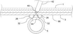
- FIG. 1schematically exemplifies a first embodiment of a vascular closure device.
- FIGS. 2 A and 2 Bshow the creation of a tissue lock using the vascular closure device.
- FIGS. 2 C and 2 Dillustrate a closure sequence for treatment of an unwanted passage through a wall of a blood vessel.
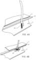
- FIGS. 4 A and 4 Billustrate the operation of an anvil member that functions as a deployable positioning feature.
- FIG. 5is an elevation view of a vascular closure device embodiment.
- FIG. 7shows an embodiment of an anchor deployer of the vascular closure device of FIG. 1 .
- FIG. 8shows an embodiment of an anchor deployer of the vascular closure device of FIG. 1 .
- FIG. 9 Ais a section view of a proximal section of an anchor deployer embodiment.
- FIG. 9 AAis a transverse cross section of the proximal section of the anchor deployer embodiment of FIG. 9 A taken along lines 9 AA- 9 AA of FIG. 9 A .
- FIG. 9 Bis a section view of a proximal section of an anchor deployer embodiment.
- FIG. 9 Cis a section view of a proximal section of an anchor deployer embodiment.
- FIG. 10is an elevation view in section of a distal section of a housing of the vascular closure device of FIG. 1 disposed adjacent an access passage in a fascia tissue layer with anchor deployers being deployed in the fascia tissue layer.
- FIG. 12shows the anchors, associated filaments and collapsible tubes of the vascular closure device disposed below the fascia tissue layer prior to tensioning of the filaments and compression of the collapsible tubes.
- FIG. 13illustrates tensioning of the filaments of the vascular closure device.
- FIG. 14shows the filaments of the vascular closure device in a tensioned state with the collapsible tubes in a compressed and radially expanded state prior to deployment of a lock ring over the filaments.
- FIG. 19shows the hemostasis device of FIG. 18 with a deployment rod thereof being proximally retracted.
- An optional anvil member 9may be arranged inside the blood vessel 5 to create a reference point along an axial orientation to the engagement members 11 and/or for controlling bleeding from an inner lumen of the artery 5 .
- the engagement members 11may then be placed and released through the vascular closure device 10 and may attach to fascia tissue 3 proximate to the blood vessel 5 and may involve the fascia membrane 3 (fascia iliacus), but, in some instances, not a wall 22 of the blood vessel 5 .
- the engagement members 11may for example be pushed out of the vascular closure device 10 and into the fascia membrane 3 using deployment members provided as pusher rods 12 arranged in independent lumens provided with the vascular closure device 10 , for example through a pusher assembly in a common lumen that simultaneously deploys all engagement members 11 , through a spring-loaded mechanism or the like.
- the engagement members 11may be connected with a single filament such as a suture or a plurality of filaments or sutures 13 .
- FIG. 1there is further shown a femoral vein 4 , a femoral nerve 6 and adjacent/interstitial tissues 7 .
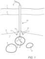
- the suture 13may for example be routed through each of the engagement members 11 in sequence.
- one suture 13may be looped through each of the engagement members 11 in sequence, or a separate suture 13 may be attached to each engagement member 11 .
- the tissuee.g. fascia membrane 3
- the tissuemay then pulled together in a radially inward direction towards an access passage in the fascia layer 3 with the suture 13 connected to the engagement members 11 .
- the tissue/fascia membrane 3is tightened towards the center and the access passage therethrough and may then create a tissue lock, thereby indirectly sealing the access hole in the artery 5 .
- the anvil member 9may be removed from the artery 5 .
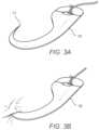
- FIGS. 3 A and 3 Bthere is conceptually illustrated an engagement member, exemplified as an anchor element 15 .
- the anchor element 15is shown as initially deployed, so that it slides easily in the direction away from a deployment point.
- the deployment pointmay optionally be deflected toward the tissue/fascia membrane 3 to promote engagement.
- FIG. 3 Bshows the anchor element 15 after motion has been reversed toward the deployment point, and the anchor element 15 has embedded into the tissue/fascia membrane 3 . That is, a tip 17 of the anchors element 15 is in one embodiment hook-shaped, so that it easily slides outward without engaging the tissue/fascia membrane 3 .
- the tip 17 of the anchor element 15is adapted to mechanically engage with the tissue/fascia membrane 3 .
- FIGS. 4 A and 4 Bconceptually illustrate the operation of an anvil member exemplified as a deployable positioning feature 20 .
- deployable positioning feature 20may be inserted through the wall 22 and into the interior volume of the blood vessel, such as the femoral artery 5 .
- the deployable positioning feature 20may be structured similar to an umbrella (using a mesh material), where the deployable positioning feature 20 in a radially collapsed form may be inserted into the artery 5 .
- the deployable positioning feature 20Once within the artery 5 , with further reference to FIG.
- Some vascular closure device embodiments 24may include a plurality of collapsible tubes 26 which may be utilized to hemostatically close, and prevent additional bleeding from, a vascular access site and target vessel 5 after a percutaneous cardiovascular procedure or the like has been performed.
- the vascular closure device 24 and method embodimentsmay include a plurality of anchor deployers 28 each of which may include a filament 30 which is secured to an anchor 32 , a deployment rod 34 , and a collapsible tube 26 which is disposed over and optionally secured to a distal end of the filament 30 .
- the anchors 32 , filaments 30 , and collapsible tubes 26 of the anchor deployers 28may be manipulated such that fascia tissue layer 3 surrounding the access passage 38 (see FIG. 10 ) at the vascular access site and the collapsible tubes 26 provide hemostatic closure of the access passage 38 and access hole 44 in the target artery 5 of the vascular access site.
- Such devices and proceduresmay also be applicable for use in the treatment of access passages disposed in any other suitable structures beneath a fascia layer 3 (or any other suitable tissue layer) including veins, such as the femoral vein 4 , abdominal cavities, and the like.
- Some such vascular closure device embodimentsmay include about 2 anchor deployers 28 to about 8 anchor deployers 28 , more specifically, about 3 anchor deployers 28 to about 5 anchor deployers 28 .
- a proximal portion 46 of each collapsible tube 26 disposed thereonmay be mechanically captured and stopped by surrounding tissue 3 , while the distal end 48 of each collapsible tube 26 remains secured to the distal end 48 of the filament 30 .
- a compressive axial loadmay be applied to each collapsible tube 26 by the respective filaments 30 disposed therein, resulting in buckling of each collapsible tube 26 about the respective filament 30 .
- the collapsible tubes 26may be fabricated from a thrombogenic material which actively promotes hemostasis such as collagen or any other suitable biologic or synthetic thrombogenic material.
- the collapsible tubes 26may be fabricated from hydrophilic materials (such as hydrogels and the like) which may expand upon interaction with fluids which are present within the tissue adjacent the collapsible tubes 26 . Such expansion of collapsible tube embodiments 26 may provide additional thrombogenicity to the vascular access site and puncture holes 50 .
- collapsible tubes 26may achieve a hemostatic effect via a mechanical tampon or tamponade effect achieved by the buckling of the collapsible tubes 26 or by the biological ⁇ absorbent properties of the material(s) of the collapsible tubes 26 as shown in FIG. 15 .
- Further collapsible tube embodiments 26may be configured to easily slip over a respective filament 30 , and may be configured with a relatively small outer transverse dimension such that the collapsible tube 26 does not interfere with or adversely affect the performance of the filament 30 during such a vascular closure procedure embodiment.
- the vascular closure device embodiment 24includes a plurality of anchor deployers 28 and respective collapsible tubes 26 , filaments 30 disposed therein and anchors 32 .
- the vascular closure device 24may include the housing 36 having an elongate configuration that is to say that an axial length of the housing 36 may be greater than a transverse dimension of the housing 36 .
- the housing 36may also include a proximal end 52 , a distal end 42 , and a distal section 54 .
- the plurality of anchor deployers 28may be suitably disposed within an interior volume of the housing 36 as shown in FIG. 6 A .
- Each anchor deployer 28may be configured to extend from the distal section 54 of the housing 36 and into target tissue during a vascular closure procedure.
- Each anchor 32 of an anchor deployer 28may be removably secured to the distal end 56 of the deployment rod 34 such that after penetration of the tissue layer 3 in a distal direction, the anchors 32 may slide off the distal end of the deployment rod 34 when the deployment rod 34 is proximally retracted.
- Each anchor 32may be configured to penetrate tissue 3 in a distal direction and optionally prevent tissue penetration in a proximal direction. This configuration of the anchors 32 may be used to facilitate the deployment of the anchor deployers 28 distally into the target tissue 3 while allowing for the mechanical capture of the respective anchors 32 by surrounding tissue 3 and the associated collapsible tube 26 after retraction of the deployment rods 34 and proximal tensioning of the filaments 30 .
- Each anchor deployer 28 of the vascular closure device 24may also include the filament 30 that may be slidably disposed within an inner lumen of the housing 36 .
- the distal end 58 of the filament 30may be secured to the anchor 30 .
- each filament 30 of the plurality of anchor deployers 28may be slidably disposed within the housing 36 such that each filament 30 is disposed adjacent to another filament 30 at the distal section 54 of the housing 36 (see FIG. 6 ) and may optionally pass through a common lumen of the housing 36 .
- Each anchor deployer 28may also include a collapsible tube 26 that may be disposed over and secured to a distal section 60 of the respective filament 30 , the distal section 60 of the filament 30 being disposed such that it is proximal of and adjacent to the anchor 30 .
- each collapsible tube 26may have an elongate configuration such that an axial length of the collapsible tube 26 may be greater than a transverse dimension of the collapsible tube 26 .
- each collapsible tube 26may have a wall structure that may be configured to shorten in axial length and radially expand upon axial compression.
- the collapsible tubes 26may be configured to buckle in an axial orientation upon axial compression of the collapsible tube 26 .
- the housing 36may include a guidewire lumen 62 which may extend the axial length of the housing 36 from the proximal end 52 to the distal end 42 and which may include an eccentric lumen in some cases disposed towards an outside portion of the housing 36 .
- the guide wire lumen 62may be configured to allow for the passage of the guidewire 8 through the housing.
- the guidewire 8may remain within the target vessel 5 and within a vascular access channel 38 created during the percutaneous cardiovascular procedure.
- the guidewire lumen 62 disposed within the housing 36 of the vascular closure device 24allows for the vascular closure device 24 to be coupled to the guidewire 62 , thereby allowing for the tracking of the vascular closure device 24 along the guidewire 8 within the vascular access channel 38 as shown in FIGS. 10 - 12 .
- the vascular closure device 24may also include a handle 64 that may be secured to the proximal end 52 of the housing 36 .
- the handle 64may be utilized in order to grasp and manipulate the vascular closure device 24 during a vascular closure procedure, and may include features which control the insertion of the anchor deployers 28 (via distal extension of the deployment rods 34 ), proximal retraction of the deployment rods 34 , proximal tensioning of the filaments 30 , and in some cases deployment of the lock ring 40
- the handle 64may include a Luer lock fitting 66 which is in fluid communication with the guidewire lumen 62 and which allows for access through the handle 64 to the guidewire lumen 62 which may be disposed within the housing 36 .
- the handle 64may also include a rod pusher 68 that may be operatively coupled to each deployment rod 34 .
- the rod pusher 68may be operatively coupled to a proximal end of each deployment rod 34 .
- the rod pusher 68may be configured such that it can slide within the handle 64 both distally and proximally, thereby allowing for the rod pusher 68 to be utilized in order to distally extend or proximally retract each deployment rod 34 during a vascular closure procedure.
- the handle 64may also include a filament tensioner 70 which may be operatively coupled to each filament 30 such that tension applied to the filament tensioner 70 in a proximal direction applies a corresponding proximal tension to the filaments 30 .
- the filament tensioner 70may be configured such that it can slide proximally within the handle 64 , thereby allowing for the filament tensioner 70 to be utilized in order to proximally tension the filaments 30 .
- such axial bucklingmay lead to a shortening of the axial length of the collapsible tube embodiments 26 and an expansion outward in a radial direction of the collapsible tube 26 to create a larger transverse profile of the collapsible tube 26 .
- the collapsible tubes 26may be fabricated from a material which may be thrombogenic such that the collapsible tubes 26 induce clotting, or from a material which absorbs fluids and expands in order to increase the volume of the collapsible tube 26 upon deployment.
- Embodiments of collapsible tubes 26are shown in FIGS. 7 , 7 A, 8 , 9 A, 9 B, and 9 C .
- Each collapsible tube embodiment 26may have an elongated configuration wherein the axial length of the collapsible tube 26 may be greater than the transverse dimension of the axial tube.
- Each collapsible tube embodiment 26 which is discussed hereinmay optionally have an axial length of about 3 mm to about 15 mm, and an outer transverse dimension of about 0.5 mm to about 2 mm.
- the collapsible tube embodiments 26may be configured for ease of insertion during anchor deployer actuation, ease of collapsible tube wall structure bucking during tensioning of the filaments, mechanical stoppage against the fascia tissue layer 3 against which the collapsible tubes 26 are compressed during filament tensioning or any combination of these configurations.
- FIG. 7depicts a collapsible tube embodiment 26 having a distal section 72 which tapers distally to a reduced outer transverse dimension.
- the purpose of the distal section 72 which tapersis to facilitate the insertion of the collapsible tube 26 through a puncture hole 50 during distal deployment of the respective anchor deployer 28 .
- a distal end 48 of the collapsible tube 26may be secured to the filament 30 in a position which is proximal of and adjacent to the anchor 32 .
- the collapsible tube 26may be secured to the filament 30 with an adhesive 74 which may be disposed between an inner surface of the distal section 72 of the collapsible tube 26 and an outer surface of the filament 30 as shown in FIG.
- the adhesive 74may be any suitable adhesive such as cyanoacrylate, UV-cured adhesive, or the like.
- the collapsible tube 26may be welded or fused to the filament 30 wherein material contained within the distal section 60 of the filament 30 may be thermally fused to material contained within the distal section 72 of the collapsible tube 26 such that the distal section 72 of the collapsible tube 26 is adjacent to the anchor 32 after the fusion process.
- an axial length of the bond section between the filament 30 and the distal end of the collapsible tube 26may be up to about 10 percent of an overall axial length of the collapsible tube 26 .
- the distal end 48 of the collapsible tube 26may be secured directly to the anchor 32 as shown in FIG. 8 .
- the distal end 48 of the collapsible tube 26may be secured directly to the anchor 32 by the adhesive 74 such as cyanoacrylate, UV-cured adhesive, thermal bonding, welding, mechanical crimping or the like.
- the wall structure 76 of the collapsible tubes 26may be modified in order to facilitate buckling of the collapsible tubes 26 upon proximal tensioning of the filaments.
- the collapsible tube embodiments 26which are depicted in FIGS. 7 and 8 each incorporate at least one longitudinal slit 78 in a middle section 80 of the wall structure 76 of each collapsible tube 26 .
- Each collapsible tube embodiment 26 which is discussed hereinmay include a plurality of longitudinal slits 78 within the wall 76 of the middle section 80 , in some instances the longitudinal slits 78 may extend entirely through the wall 76 from an outside surface to an inside surface of the wall 76 .
- each collapsible tube 26may have from about 1 to about 5 longitudinal slits disposed within the wall structure 76 thereof. Additionally, an axial length of each longitudinal slit 78 may be from about 25 percent to about 75 percent of an axial length of the respective collapsible tube 26 . As discussed above, such structures may be useful for effecting axial buckling of the collapsible tubes 26 in a predetermined regular sinusoidal fashion, such as in an accordion fashion.
- materials that may be used for some embodiments of the collapsible tubes 26may have thrombogenic or hydrophilic properties in order to reduce bleeding from the access passage 38 or through the puncture holes 50 created during the deployment of the anchor deployers 28 .
- Some materials that may be used for the collapsible tube embodiments 26 that are discussed hereinmay be selected from the group consisting of polyurethane, polyethylene terephthalate (PET), polyetherether keytone PEEK, polytetrafluoroethylene (PTFE), acrylic, silicone, polypropylene, and polyester or the like.
- Some materials that may be used for the collapsible tube embodiments 26 that are discussed hereinmay include thrombogenic materials may include collagen, fibrin, fibrinogen, gelatin, polylactic acid (PLA), polyglycolic acid (PGA), alginate and fibronectin or the like.
- Some materials that may be used for the collapsible tube embodiments 26 that are discussed hereinmay include hydrogel materials which absorb fluids from surrounding tissue and expand.
- Hydrogel collapsible tube materialsmay include fibrin, collagen, gelatin, hyaluronic acid, alginate, agarose, poly(ethylene glycol), poly(acrylic acid), poly(vinyl alcohol), polypeptides, and poly(vinyl pyrrolidone).
- biodegradable or bio-absorbable materialssuch as poly(lactic acid), which may be absorbed by the surrounding tissue over time.
- a proximal section 46 of each collapsible tube 26may be mechanically stopped in a proximal direction by surrounding tissue of a bottom surface of the fascia tissue layer 3 such that the collapsible tube 26 is not retracted proximally through the puncture hole 50 created during the deployment of the respective anchor deployer 28 .
- 9 A, 9 B, and 9 Cshow collapsible tube embodiments 26 having proximal sections 46 which are configured to expand and be mechanically stopped in a proximal direction by a bottom surface of the fascia tissue layer 3 or any other surrounding tissue during proximal tensioning of the filaments 30 .
- the proximal section 46 of a collapsible tube embodiment 26may have at least one proximal slit 82 through the wall 76 of the collapsible tube 26 , the proximal slit 82 extending distally from the proximal end 84 of the collapsible tube 26 as shown in FIGS. 9 A and 9 AA .
- the proximal section 46 of the collapsible tube 26may have about 1 to about 5 slits, and an axial length of each proximal slit 82 may be from about 1 mm to about 4 mm.
- the proximal slits 82may allow for outward radial expansion of the proximal section 46 against the bottom surface of the fascia tissue layer 3 or any other adjacent tissue, with the result being the proximal section 46 being mechanically stopped in a proximal axial direction by the bottom surface of the fascia tissue layer 3 during tensioning of the filaments 30 and the proximal section 46 is prevented from being pulled through the puncture holes 50 back through the fascia tissue layer.
- FIG. 9 Bdepicts the proximal section 46 of a collapsible tube embodiment 26 wherein a wall thickness of the wall structure 76 of the collapsible tube 26 tapers to a reduced wall thickness from a position which is distal of the proximal end 84 of the collapsible tube 26 to a position at the proximal end 84 of the collapsible tube 26 .
- the reduced wall thicknessmay facilitate outward radial expansion of proximal section 46 over a bottom surface of the fascia tissue layer 3 with the result being the proximal section 46 is mechanically stopped from proximal movement or being pulled back through the puncture hole 50 during tensioning of the filaments 30 .
- the proximal section 46 of the collapsible tube embodiment 26flares to a larger outer transverse dimension from a position which is distal of the proximal end 84 of the collapsible tube 26 to a position at the proximal end 84 of the collapsible tube 26 .
- the flared expanded wall 76allows for a wider distribution of compressive force by the proximal end 84 of the collapsible tube 26 against the bottom surface of the fascia tissue layer 3 .
- Outward radial expansion of proximal section 46may also be facilitated by the flared configuration.
- 9 Cmay be useful to mechanically stop the proximal end 84 of the collapsible tube 26 and prevent proximal movement of the proximal end 84 or the proximal end 84 from being pulled back through the puncture hole 50 during tensioning of the filaments 30 .
- Embodiments of the vascular closure device 24may include any suitable configuration of the filaments 30 and or filament material including suture material.
- the suture material of the filaments 30may be configured as a monolithic strand, and in some other cases the suture material may be braided.
- bio-absorbable suturemay be utilized.
- the suture materialmay be coated with any suitable coating such as a hydrophilic coating or an antimicrobial coating.
- the size of the suture of some filament embodiments 30may vary from U.S.P. #1 to U.S.P. #4 and may also include suture materials such as 2/0 suture to 3/0 suture, or other high strength filament 30 of the same or similar diameter.
- the collapsible tubes 26may be configured to slide easily over the respective filament 30 and may also be configured with a minimal outer transverse dimension such that the collapsible tubes 26 do not interfere with the deployment of the anchor deployers 28 .
- the ratio of the outer transverse dimension of the collapsible tube 26 to an outer transverse dimension of the filament 30may be from about 1.5:1 to about 4:1.
- Some vascular closure device embodiments 24may also include a filament grip feature that may be configured as the lock ring 40 and that may function to mechanically secure the filaments 30 in fixed relation to each other and the fascia tissue layer 3 after proximal tensioning and axial collapse of the collapsible tubes 26 .
- the lock ring 40may be disposed on the distal end 42 of the housing 36 as shown in FIG. 6 A .
- the lock ring 40is disposed adjacent and about the filaments 30 at the distal end 42 of the housing 36 , and may be configured to compress and secure the filaments 30 relative to each other once deployed from the distal end 42 of the housing 36 so as to transition from an expanded state on the housing 36 to a self-contracting relaxed state with a compressive inward radial force on the filaments 30 .
- the lock ring 40may be configured as a self-retracting coil having a central lumen 41 which is disposed about the filaments 30 .
- the lock ring 40may be sized in order to allow free movement of the filaments 30 when the self-retracting coil is disposed in an expanded state.
- the lock ring 40may have an interior surface of the central lumen 41 that is sized and configured to compress the filaments 31 when in the lock ring 40 is disposed a retracted state as shown in FIG. 15 .
- the anchors 32may act to mechanically capture surrounding tissue after deployment of the anchor deployers 28 and upon proximal tensioning of the filaments 30 .
- the anchors 32may optionally be sized and configured to present a surface area adjacent to the connection between the filament 30 and the anchor 32 that is wider than an outer transverse dimension of the collapsible tube which may prevent the filament 30 and anchor 32 from being pulled through the inner lumen of the collapsible tube 26 upon tensioning of the filaments 30 against the lower surface of the fascia tissue layer 3 .
- the anchors 32may be configured to rotate, pivot or expand after being deployed from the distal end 56 of the respective deployment rods 34 .
- the anchors 32may be formed from a hypo tube section which has an inclined sharpened end portion with the respective filament 30 secured to a mid-portion of the anchor 32 .
- the distal end of the filament 30may be secured to the anchor 32 with adhesive, a knot, an enlarged distal portion of the filament 30 captured by a hole in the anchor 32 or the like.
- FIGS. 10 - 15depict a method for the deployment of the vascular closure device 24 into a vascular access site for closure of the access passage 38 in order to prevent blood leakage from the access hole 44 in the artery 5 of the vascular access site.
- the distal end 42 of a housing 36 of the vascular closure device 24may be disposed to a position adjacent the access passage 38 in the fascia tissue layer 3 , as well as the deploying of a plurality of anchor deployers 28 from the distal section 54 of the housing 36 in a distal and radially outward direction from the housing 36 and into the tissue layer 3 in positions which are disposed about the access passage 38 in the fascia tissue layer 3 .
- the plurality of anchor deployers 28 of the vascular closure device 24are shown to be penetrating the tissue layer 3 and extending through the tissue layer 3 until a proximal end 84 of the collapsible tube 26 of each of the plurality of anchor deployers 28 extends distally beyond the lower surface 86 of the tissue layer 3 .
- FIG. 11depicts proximally withdrawing the deployment rods 34 of each of the plurality of anchor deployers 28 from respective anchors 32 and into the distal section 54 of the housing 36 of the vascular closure device 24 .
- FIG. 12depicts partially retracting the anchor 32 of each of the anchor deployers 28 by proximally retracting a filament 30 which is secured to the respective anchor 32 .
- FIGS. 13 and 14depict axially compressing the collapsible tube 26 of each of the plurality of anchor deployers 28 between the respective anchor 32 and lower surface 86 of the tissue layer 3 by applying tension to the filament 30 which is secured to the anchor 32 and which is disposed within an inner lumen of the collapsible tube 26 . Tension is applied to the filament 30 until the collapsible tube 26 shortens in axial length and expands in an outward radial direction adjacent the access passage 38 .
- Tensionmay be applied to the filaments 30 from the distal section 54 of the housing 36 by actuation of the filament tensioner 70 in order to reduce a distance between the anchors 32 , thereby drawing the anchors 32 and adjacent tissue of the tissue layer 3 radially inward so as to reduce the size of the access passage 38 in the tissue layer 3 .
- a filament gripwhich may be configured as a self-contracting lock ring 40 as shown in FIG. 15 may be deployed onto the filaments 30 in order to secure the filaments 30 relative to each other at the lock ring 40 after the size of the access passage 38 in the tissue layer 3 has been reduced.
- the self-contracting lock ring 40may be deployed onto the filaments 30 by sliding the self-contracting lock ring 40 in an expanded state from the distal end 42 of the housing 36 , then allowing the self-contracting lock ring 40 to contract to a relaxed state over the filaments 30 .
- collapsible tubes 26 formed from a thrombogenic materialmay be utilized, and upon deployment into a blood field which is below the tissue layer thrombus may form adjacent to the collapsible tubes 26 as shown in FIG. 15 .
- the collapsible tubes 26may be configured with a proximal section 46 which has been configured to be mechanically stopped by a bottom surface 86 of the fascia tissue layer 3 adjacent the proximal section 46 as has been discussed previously. In this case the method which is depicted in FIGS.
- 10 - 15may further include preferentially radially expanding and axially collapsing the proximal end 84 and/or proximal section 46 of the collapsible tubes 26 against the lower surface 86 of the fascia tissue layer 3 in an outward radial direction due to the slotted or otherwise weakened wall structure 76 of the collapsible tubes 26 at the proximal section 46 thereof while axially compressing the collapsible tubes 26 while proximally tensioning the filaments 30 .
- Radially expanding and axially collapsing a proximal end 46 of collapsible tubes 26may include in some cases splaying leafs of respective proximal ends 84 of collapsible tube embodiments 26 that include proximal slits 82 from the proximal ends 84 of the collapsible tubes 26 as shown in the collapsible tube embodiment of FIG. 9 A .
- the method which is depicted in FIGS. 10 - 15may also include alternative methods for mechanically stopping the proximal sections 46 of the collapsible tubes 26 such as disposing a flared proximal end 84 of collapsible tube embodiments 26 against the lower surface 86 of the tissue layer 3 and spaced from the edge of the puncture hole 50 formed by the respective anchor deployers 28 , and crumpling the proximal ends 84 of the collapsible tubes 26 which have a reduced wall thickness (as shown in the collapsible tube embodiment 26 of FIG. 9 B ) against the lower surface 86 of the tissue layer 3 .
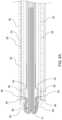
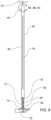
- FIGS. 16 and 17show an embodiment of a hemostasis device 90 that includes a housing 92 having an elongate configuration with an axial length of the housing 92 may be greater than a transverse dimension of the housing 92 .
- the housing 92may also include a proximal end 94 , a distal end 96 , and a distal section 98 .
- the hemostasis device 90may include a single anchor deployer 28 that may be suitably disposed within an interior volume of the housing 92 as shown in FIG. 17 .
- the anchor deployer 28may be configured to extend from the distal section 98 of the housing 92 and into target tissue during a hemostasis procedure.
- the anchor deployer 28may include the deployment rod 34 , the anchor 32 , the filament 30 , and the collapsible tube 26 that may be disposed over the filament 30 .
- the collapsible tube 26may include features, materials, and dimensions which are the same as or similar to those features, materials and dimensions of collapsible tube embodiments 26 discussed above.
- the deployment rod 34may have an elongate resilient configuration, and may be slidably disposed relative to the housing 92 such that the distal end 56 of the deployment rod 34 may extend distally and radially from the distal section 98 of the housing 92 upon deployment of the anchor deployer 28 .
- the anchor 32 of the anchor deployer 28may be removably secured to the distal end 56 of the deployment rod 34 .
- the anchor 32may be configured to penetrate tissue 3 in a distal direction and optionally prevent tissue penetration of the fascia tissue layer 3 in a proximal direction.
- the anchor 32may optionally be configured to facilitate the deployment of the anchor deployer 28 distally into the target tissue 3 while allowing for the mechanical capture of the anchor 32 by surrounding tissue 3 upon retraction of the deployment rod 34 and proximal tensioning of the filament 30 .
- the anchor deployer 28 of the hemostasis device 90may also include the filament 30 that may be slidably disposed within the housing 92 and which may include the distal end 58 that may be secured to the anchor 32 .
- the anchor deployer 28may also include the collapsible tube 26 that may be disposed over and secured to a distal section of the filament 30 , the distal section 60 of the filament 30 being disposed such that it is proximal of and adjacent to the anchor 32 .
- the collapsible tube 26may have an elongate configuration such that an axial length of the collapsible tube 26 may be greater than a transverse dimension of the collapsible tube 26 .
- the collapsible tube 26may have a wall structure 76 that may be configured to buckle in an axial orientation upon axial compression of the collapsible tube 26 .
- the housing 92may include a guidewire lumen (not shown) which may extend the axial length of the housing 92 from the proximal end 94 to the distal end 96 .
- the guide wire lumenmay be configured to allow for the passage of a guidewire 8 through the housing 92 .
- a guidewire 8may remain within a target vessel and within a vascular access channel created during the percutaneous cardiovascular procedure.
- the guidewire lumen disposed within the housing 92 of the hemostasis device 90allows for the vascular closure device to be coupled to the guidewire 8 thereby allowing for the tracking of the hemostasis device 90 along the guidewire 8 within the vascular access passage 38 or access hole 44 the artery 5 if applicable.
- the hemostasis device 90may also include a handle 100 that may be secured to the proximal end 94 of the housing 92 .
- the handle 100may be utilized in order to grasp and manipulate the hemostasis device 90 during a vascular closure procedure, and may include features which control the insertion of the anchor deployer 28 (via distal extension of the rod pusher 102 ), proximal retraction of the deployment rod 34 , proximal tensioning of the filament 30 , and in some cases deployment of a lock ring 40 .
- the handle 100may include a Luer lock (not shown) which allows for access through the handle 100 to the guidewire lumen which may be disposed within the housing 92 .
- the rod pusher 102may be operatively coupled to the deployment rod 34 , in some cases the rod pusher 102 may be operatively coupled to a proximal end of the deployment rod 34 .
- the rod pusher 102may be configured such that it can slide within the handle 100 both distally and proximally, thereby allowing for the rod pusher 102 to be utilized in order to distally extend or proximally retract the deployment rod 34 during a vascular closure procedure.
- the handle 100may also include a filament tensioner 104 which may be operatively coupled to the filament 30 .
- the filament tensioner 104may be configured such that it can slide proximally within the handle 100 , thereby allowing for the filament tensioner 104 to be utilized in order to proximally tension the filament 30 .
- the hemostasis device 90may also include a filament grip feature that may be configured as the lock ring 40 and that may function to mechanically capture the filament 30 after proximal tensioning.
- the lock ring 40may be disposed on the distal end 96 of the housing 92 (see FIG. 17 ) adjacent the filament 30 , and may be configured to compress and secure the filament 30 once deployed from an expanded state on the distal end 96 of the housing 92 .
- the lock ring 40may be configured as a self-retracting coil having a central lumen 41 which may be disposed about the filament 30 .
- the lock ring 40may be sized in order to allow free movement of the filament 30 when the self-retracting lock ring 40 is disposed in an expanded state.
- the lock ring 40may have an interior surface of the central lumen 41 that is configured to compress and be secured to the filament 30 when the lock ring 40 is disposed a retracted state.
- the anchor 32may optionally act to mechanically capture surrounding tissue after deployment of the anchor deployer 28 and upon proximal tensioning of the filament.
- the anchor 32may be sized and configured to present a surface area adjacent to the connection between the filament 30 and the anchor 32 that is wider than an outer transverse dimension of the collapsible tube which may prevent the filament 30 and anchor 32 from being pulled through the inner lumen of the collapsible tube 26 upon tensioning of the filament 30 against the lower surface of the fascia tissue layer 3 .
- the anchor 32may be configured to rotate, pivot or expand after being deployed from the distal end 56 of the deployment rod 34 .
- the anchor 32may be formed from a hypo tube section which has an inclined sharpened end portion.
- FIGS. 18 - 21depict a method for the deployment of the hemostasis device 90 in order to prevent or reduce blood leakage from a vascular closure site in a tissue layer 3 .
- FIG. 18depicts disposing a distal end 96 of a housing 92 of the hemostasis device 90 to a position adjacent the access passage 38 in the tissue layer 3 , as well as the deploying of the anchor deployer 28 from the distal section 98 of the housing 92 in a distal direction from the housing 92 in the tissue layer 3 .
- the anchor deployer 28may be deployed distally by distally advancing the deployment rod 34 from the housing 92 .
- the anchor deployer 28 of the hemostasis device 90is shown to be penetrating the tissue layer 3 and extending through the tissue layer 3 until a proximal end 84 of the collapsible tube 26 of the anchor deployer 28 extends distally beyond a lower surface 86 of the tissue layer 3 .
- FIG. 19depicts proximally withdrawing the deployment rod 34 of the anchor deployer 28 from the anchor 32 and into the distal section 98 of the housing 92 .
- FIG. 19depicts partially retracting the anchor 32 of the anchor deployer 28 by proximally retracting the filament 30 which may be secured to the anchor 32 with the filament tensioner 104 .
- FIG. 20depicts axially compressing the collapsible tube 26 of the anchor deployer 28 between the anchor 32 and lower surface 86 of the tissue layer 3 by applying tension to the filament 30 which may be secured to the anchor 32 and which may be disposed within an inner lumen of the collapsible tube 26 . Tension is applied to the filament 30 until the collapsible tube 26 shortens in axial length and expands in an outward radial direction adjacent the puncture hole 50 .
- the lock ring 40which may be configured as a self-contracting lock ring (see FIG. 17 ) may be deployed onto the filament 30 after tensioning in order to secure the filament 30 relative to the fascia tissue layer 3 to prevent distal movement of the filament 30 through the tissue layer 3 .
- the self-contracting lock ring 40may be deployed onto the filament 30 by sliding the self-contracting lock ring 40 in an expanded state from the distal end 96 of the housing 92 , then allowing the self-contracting lock ring 40 to contract to a relaxed state over the filament 30 .
- the collapsible tube 26may be formed from a thrombogenic material, and upon deployment into a blood field which is below the tissue layer 3 thrombus may form adjacent to the collapsible tube 26 as shown in FIG. 21 . Additionally, in some instances the collapsible tube 26 may be configured with a proximal section which has been configured to be mechanically stopped from passing back through the puncture hole 50 as has been discussed previously. In this case the method which is depicted in FIGS.
- 18 - 21may further include radially expanding and axially collapsing the proximal end 84 of the collapsible tube 26 against the lower surface 86 of the tissue layer 3 in an outward radial direction while axially compressing the collapsible tube 26 while proximally tensioning the filament 30 .
- Radially expanding and axially collapsing a proximal end 84 of collapsible tube 26may include in some cases splaying leafs of a proximal end 84 of the collapsible tube 26 that include proximal slits 82 from the proximal end 84 of the collapsible tube 26 .
- the method which is depicted in FIGS. 18 - 21may also include alternative methods for mechanically stopping the proximal section 46 of the collapsible tube 26 from passing through the puncture hole 50 in a proximal direction such as disposing a flared proximal end 84 of the collapsible tube 26 against the lower surface 86 of the tissue layer 3 and spaced from the puncture hole 50 formed by deployment of the anchor deployer 28 , and crumpling the proximal end 84 of the collapsible tube 26 which has a reduced wall thickness against the lower surface 86 of the tissue layer 3 .
- Embodiments illustratively described hereinsuitably may be practiced in the absence of any element(s) not specifically disclosed herein.
- any of the terms “comprising,” “consisting essentially of,” and “consisting of”may be replaced with either of the other two terms.
- the terms and expressions which have been employedare used as terms of description and not of limitation and use of such terms and expressions do not exclude any equivalents of the features shown and described or portions thereof, and various modifications are possible.
- a or “an”can refer to one of or a plurality of the elements it modifies (e.g., “a reagent” can mean one or more reagents) unless it is contextually clear either one of the elements or more than one of the elements is described.
Landscapes
- Health & Medical Sciences (AREA)
- Life Sciences & Earth Sciences (AREA)
- Heart & Thoracic Surgery (AREA)
- Surgery (AREA)
- Public Health (AREA)
- Animal Behavior & Ethology (AREA)
- Biomedical Technology (AREA)
- Veterinary Medicine (AREA)
- Engineering & Computer Science (AREA)
- General Health & Medical Sciences (AREA)
- Medical Informatics (AREA)
- Molecular Biology (AREA)
- Nuclear Medicine, Radiotherapy & Molecular Imaging (AREA)
- Pulmonology (AREA)
- Anesthesiology (AREA)
- Hematology (AREA)
- Cardiology (AREA)
- Rheumatology (AREA)
- Surgical Instruments (AREA)
Abstract
Description
Claims (9)
Priority Applications (2)
| Application Number | Priority Date | Filing Date | Title |
|---|---|---|---|
| US17/507,640US12201285B2 (en) | 2017-11-16 | 2021-10-21 | Collapsible tube for hemostasis |
| US18/976,041US20250099092A1 (en) | 2017-11-16 | 2024-12-10 | Collapsible tube for hemostasis |
Applications Claiming Priority (3)
| Application Number | Priority Date | Filing Date | Title |
|---|---|---|---|
| US201762587341P | 2017-11-16 | 2017-11-16 | |
| US16/190,654US11179145B2 (en) | 2017-11-16 | 2018-11-14 | Collapsible tube for hemostasis |
| US17/507,640US12201285B2 (en) | 2017-11-16 | 2021-10-21 | Collapsible tube for hemostasis |
Related Parent Applications (1)
| Application Number | Title | Priority Date | Filing Date |
|---|---|---|---|
| US16/190,654DivisionUS11179145B2 (en) | 2017-11-16 | 2018-11-14 | Collapsible tube for hemostasis |
Related Child Applications (1)
| Application Number | Title | Priority Date | Filing Date |
|---|---|---|---|
| US18/976,041DivisionUS20250099092A1 (en) | 2017-11-16 | 2024-12-10 | Collapsible tube for hemostasis |
Publications (2)
| Publication Number | Publication Date |
|---|---|
| US20220039781A1 US20220039781A1 (en) | 2022-02-10 |
| US12201285B2true US12201285B2 (en) | 2025-01-21 |
Family
ID=66432937
Family Applications (3)
| Application Number | Title | Priority Date | Filing Date |
|---|---|---|---|
| US16/190,654Active2039-04-17US11179145B2 (en) | 2017-11-16 | 2018-11-14 | Collapsible tube for hemostasis |
| US17/507,640Active2040-05-28US12201285B2 (en) | 2017-11-16 | 2021-10-21 | Collapsible tube for hemostasis |
| US18/976,041PendingUS20250099092A1 (en) | 2017-11-16 | 2024-12-10 | Collapsible tube for hemostasis |
Family Applications Before (1)
| Application Number | Title | Priority Date | Filing Date |
|---|---|---|---|
| US16/190,654Active2039-04-17US11179145B2 (en) | 2017-11-16 | 2018-11-14 | Collapsible tube for hemostasis |
Family Applications After (1)
| Application Number | Title | Priority Date | Filing Date |
|---|---|---|---|
| US18/976,041PendingUS20250099092A1 (en) | 2017-11-16 | 2024-12-10 | Collapsible tube for hemostasis |
Country Status (2)
| Country | Link |
|---|---|
| US (3) | US11179145B2 (en) |
| WO (1) | WO2019098921A1 (en) |
Families Citing this family (8)
| Publication number | Priority date | Publication date | Assignee | Title |
|---|---|---|---|---|
| US10639020B2 (en) | 2015-09-28 | 2020-05-05 | M-V Arterica AB | Vascular closure device |
| US11179145B2 (en) | 2017-11-16 | 2021-11-23 | M-V Arterica AB | Collapsible tube for hemostasis |
| US20190142403A1 (en) | 2017-11-16 | 2019-05-16 | M-V Arterica AB | Tissue closure device |
| EP3870076A4 (en) | 2018-10-24 | 2022-08-10 | Arterica Inc. | SELF-EXPANDING HEMOSTATIC DEVICES AND METHODS FOR FASCIAL AND VASCULAR PASSAGES |
| EP4061244A4 (en)* | 2019-11-19 | 2024-06-19 | Arterica Inc. | VASCULAR CLOSURE DEVICES AND METHODS |
| EP4069098B1 (en)* | 2019-12-05 | 2025-10-15 | Novelrad Ltd. | Suturing systems and components thereof |
| CN112401966B (en)* | 2020-12-04 | 2024-05-31 | 大连科万维医疗科技有限公司 | Hemostatic ring size adjusting device used on human blood vessel |
| EP4358859A1 (en) | 2022-09-08 | 2024-05-01 | The Global Heart Valve Innovation Center (Israel) Ltd. | Suture closure devices |
Citations (126)
| Publication number | Priority date | Publication date | Assignee | Title |
|---|---|---|---|---|
| US5108421A (en) | 1990-10-01 | 1992-04-28 | Quinton Instrument Company | Insertion assembly and method of inserting a vessel plug into the body of a patient |
| US5364408A (en) | 1992-09-04 | 1994-11-15 | Laurus Medical Corporation | Endoscopic suture system |
| US5391183A (en) | 1990-09-21 | 1995-02-21 | Datascope Investment Corp | Device and method sealing puncture wounds |
| US5413571A (en) | 1992-07-16 | 1995-05-09 | Sherwood Medical Company | Device for sealing hemostatic incisions |
| US5417699A (en) | 1992-12-10 | 1995-05-23 | Perclose Incorporated | Device and method for the percutaneous suturing of a vascular puncture site |
| US5507744A (en) | 1992-04-23 | 1996-04-16 | Scimed Life Systems, Inc. | Apparatus and method for sealing vascular punctures |
| US5507755A (en) | 1993-08-03 | 1996-04-16 | Origin Medsystems, Inc. | Apparatus and method for closing puncture wounds |
| US5540704A (en) | 1992-09-04 | 1996-07-30 | Laurus Medical Corporation | Endoscopic suture system |
| WO1997003613A1 (en) | 1995-07-14 | 1997-02-06 | Abacus Design & Development, Inc. | Wound closure apparatus and method |
| US5626601A (en) | 1995-10-27 | 1997-05-06 | Gary Gershony | Vascular sealing apparatus and method |
| US5725551A (en) | 1993-07-26 | 1998-03-10 | Myers; Gene | Method and apparatus for arteriotomy closure |
| US5728134A (en) | 1996-09-17 | 1998-03-17 | Barak; Shlomo | Method and apparatus for hemostasis |
| US5730725A (en) | 1988-07-22 | 1998-03-24 | Yoon; Inbae | Expandable multifunctional manipulating instruments for various medical procedures and methods therefor |
| US5807326A (en) | 1992-04-27 | 1998-09-15 | Minnesota Mining And Manufacturing Company | Retrograde coronary sinus catheter |
| US5836913A (en) | 1997-05-02 | 1998-11-17 | Innerdyne, Inc. | Device and method for accessing a body cavity |
| US5860990A (en) | 1995-08-24 | 1999-01-19 | Nr Medical, Inc. | Method and apparatus for suturing |
| US5868762A (en) | 1997-09-25 | 1999-02-09 | Sub-Q, Inc. | Percutaneous hemostatic suturing device and method |
| US6048358A (en) | 1998-07-13 | 2000-04-11 | Barak; Shlomo | Method and apparatus for hemostasis following arterial catheterization |
| US6048357A (en) | 1998-07-09 | 2000-04-11 | X-Site, L.L.C. | Anchoring device and method for sealing punctures in vessels |
| US6059800A (en) | 1997-09-10 | 2000-05-09 | Applied Medical Resources Corporation | Suturing apparatus and method |
| US6077279A (en) | 1998-05-08 | 2000-06-20 | X-Site L.L.C. | Device and method employing adhesive for sealing blood vessels and the like |
| US6110184A (en) | 1999-08-04 | 2000-08-29 | Weadock; Kevin S. | Introducer with vascular sealing mechanism |
| US6231561B1 (en) | 1999-09-20 | 2001-05-15 | Appriva Medical, Inc. | Method and apparatus for closing a body lumen |
| US6238412B1 (en) | 1997-11-12 | 2001-05-29 | William Dubrul | Biological passageway occlusion removal |
| US6328758B1 (en)* | 1998-04-21 | 2001-12-11 | Tornier Sa | Suture anchor with reversible expansion |
| GB2365342A (en) | 2000-08-02 | 2002-02-20 | Christopher Leonard Watts | Self-inflating medical apparatus |
| US20020026208A1 (en) | 2000-01-05 | 2002-02-28 | Medical Technology Group, Inc. | Apparatus and methods for delivering a closure device |
| US20020045908A1 (en) | 1995-08-24 | 2002-04-18 | Nobles Anthony A. | Suturing device and method |
| US20020077581A1 (en) | 2000-12-19 | 2002-06-20 | Alan Davidner | Simplified cerebral retroperfusion apparatus and method |
| US6461366B1 (en) | 1997-09-12 | 2002-10-08 | Evalve, Inc. | Surgical device for connecting soft tissue |
| US6626918B1 (en) | 2000-10-06 | 2003-09-30 | Medical Technology Group | Apparatus and methods for positioning a vascular sheath |
| US20030233120A1 (en) | 2002-06-12 | 2003-12-18 | Radi Medical Systems Ab | Closure device |
| US6669719B2 (en) | 1996-12-09 | 2003-12-30 | Microtherapeutics, Inc. | Intracranial stent and method of use |
| US20040087967A1 (en) | 2002-11-06 | 2004-05-06 | Israel Schur | Device and method for withdrawing a tubular body part |
| US20040097978A1 (en) | 1999-03-04 | 2004-05-20 | Modesitt D. Bruce | Articulating suturing device and method |
| JP2005511130A (en) | 2001-11-30 | 2005-04-28 | インテグレイテッド・バスキュラー・システムズ・インコーポレイテッド | Apparatus and method for providing tactile feedback while delivering a closure |
| US20050121042A1 (en) | 2003-12-03 | 2005-06-09 | Belhe Kedar R. | Suture based vascular closure apparatus and method incorporating a pre-tied knot |
| US20050149066A1 (en) | 2003-12-23 | 2005-07-07 | Joshua Stafford | Suturing device with split arm and method of suturing tissue |
| US20050155608A1 (en) | 2001-07-26 | 2005-07-21 | Cook Incorporated | Bodily lumen closure apparatus and method |
| US20050251155A1 (en) | 2002-06-19 | 2005-11-10 | Orban Joseph P Iii | Method and apparatus for anastomosis |
| US20050267528A1 (en) | 2000-12-14 | 2005-12-01 | Ensure Medical, Inc. | Vascular plug having composite construction |
| US20060069397A1 (en) | 2004-09-27 | 2006-03-30 | Nobles Anthony A | Handle for suturing apparatus |
| US20060089627A1 (en) | 2004-10-26 | 2006-04-27 | Polymorfix, Inc. | Medical device delivery catheter |
| US20060135991A1 (en) | 2004-12-17 | 2006-06-22 | Terumo Kabushiki Kaisha | Tissue closure and tissue closing device |
| US20060142784A1 (en) | 2004-12-28 | 2006-06-29 | Stavros Kontos | Device and method for suturing internal structures puncture wounds |
| US20070049967A1 (en) | 2005-08-24 | 2007-03-01 | Sibbitt Wilmer L Jr | Vascular closure methods and apparatuses |
| US20070083231A1 (en) | 2005-10-07 | 2007-04-12 | Benjamin Lee | Vascular closure |
| US20070112425A1 (en) | 2005-04-22 | 2007-05-17 | Laurent Schaller | Catheter-based tissue remodeling devices and methods |
| US20070203507A1 (en) | 2005-08-26 | 2007-08-30 | G-Surge Medical Solutions, Inc. | Suturing apparatus and methods |
| US20070203506A1 (en) | 2005-08-24 | 2007-08-30 | Sibbitt Wilmer L Jr | Vascular closure methods and apparatuses |
| US20070213616A1 (en) | 2005-10-20 | 2007-09-13 | Thomas Anderson | Systems and methods for arteriotomy localization |
| US20080097509A1 (en) | 2003-12-15 | 2008-04-24 | Mordechay Beyar | Biodegradable Closure Device |
| US20080147112A1 (en) | 2006-10-20 | 2008-06-19 | John Wesley Sheets | Stomach invagination method and apparatus |
| US20080154303A1 (en) | 2006-12-21 | 2008-06-26 | Cardiva Medical, Inc. | Hemostasis-enhancing device and method for its use |
| US20080177288A1 (en) | 2007-01-19 | 2008-07-24 | Carlson Mark A | Remote Suturing Device |
| US20080287988A1 (en) | 2007-05-17 | 2008-11-20 | Smith Paul J | Tissue aperture securing and sealing apparatuses and related methods of use |
| US20080294001A1 (en) | 2007-05-25 | 2008-11-27 | Wilson-Cook Medical Inc. | Medical devices, systems and methods for closing perforations |
| US7458978B1 (en) | 2005-03-28 | 2008-12-02 | Cardica, Inc. | Vascular closure system utilizing a staple |
| US20080300629A1 (en) | 2007-05-31 | 2008-12-04 | Wilson-Cook Medical Inc. | Suture lock |
| US20090143808A1 (en) | 2001-04-24 | 2009-06-04 | Houser Russell A | Guided Tissue Cutting Device, Method of Use and Kits Therefor |
| US20090248056A1 (en) | 2008-03-28 | 2009-10-01 | Ethicon, Inc. | Applicator instruments for controlling bleeding at surgical sites and methods therefor |
| US20090254119A1 (en) | 2005-08-24 | 2009-10-08 | Avasca Medical Inc. | Vascular Closure Methods and Apparatuses |
| US20090254110A1 (en) | 2008-04-04 | 2009-10-08 | Accessclosure, Inc. | Apparatus and Methods for Sealing a Vascular Puncture |
| US20090264922A1 (en) | 2008-04-22 | 2009-10-22 | Medtronic Vascular, Inc. | Device and Method for Effecting Hemostasis about a Blood Vessel Puncture |
| US20090306685A1 (en) | 2008-06-10 | 2009-12-10 | Ension, Inc. | Noninvasive trans-catheter method and apparatus for remote suture placement such as for septal defect repair, left atrial appendage closure, pacemaker electrode placement, mitral valve repair, and other inner-cardiac and inner-arterial applications |
| US20090318936A1 (en) | 2007-03-13 | 2009-12-24 | Longevity Surgical, Inc. | Methods, devices and systems for approximation and fastening of soft tissue |
| US20100042118A1 (en) | 2008-08-13 | 2010-02-18 | Garrison Michi E | Suture delivery device |
| US20100179572A1 (en) | 2009-01-09 | 2010-07-15 | Abbott Vascular Inc. | Closure devices, systems, and methods |
| WO2010081103A1 (en) | 2009-01-09 | 2010-07-15 | Abbott Vascular Inc. | Vessel closure devices and methods |
| US20100217308A1 (en) | 2009-02-20 | 2010-08-26 | Boston Scientific Scimed, Inc. | Locking element for vascular closure device |
| US20100217311A1 (en) | 2009-02-20 | 2010-08-26 | Boston Scientific Scimed, Inc. | Tissue puncture closure device |
| US20100217312A1 (en) | 2009-02-20 | 2010-08-26 | Boston Scientific Scimed, Inc. | Composite plug for arteriotomy closure and method of use |
| US7789893B2 (en) | 2006-09-12 | 2010-09-07 | Boston Scientific Scimed, Inc. | Method and apparatus for promoting hemostasis of a blood vessel puncture |
| US20100262166A1 (en) | 2009-04-10 | 2010-10-14 | Gordian Surgical, LLC | Systems and methods for suture anchor deployment |
| US20110077668A1 (en) | 2009-09-25 | 2011-03-31 | Lindsay Gordon | Devices for approximating tissue and related methods of use |
| EP2308521A1 (en) | 2009-10-08 | 2011-04-13 | Tyco Healthcare Group LP | Shape memory surgical fasteners |
| US20110218568A1 (en) | 2009-01-09 | 2011-09-08 | Voss Laveille K | Vessel closure devices, systems, and methods |
| US20110238090A1 (en) | 2008-07-22 | 2011-09-29 | Spirx Closure, Llc | Methods and devices for delivering sutures in tissue |
| US20110301619A1 (en) | 2010-06-08 | 2011-12-08 | Walters Greg A | Deployment instrument for closure device for percutaneously sealing punctures |
| US20120010633A1 (en) | 2007-10-23 | 2012-01-12 | Noda Wayne A | Devices and methods for securing tissue |
| US20120158045A1 (en) | 2009-07-28 | 2012-06-21 | St. Jude Medical Puerto Rico Llc | Vascular closure device with automatic suture cutter |
| US20120290001A1 (en) | 2011-05-11 | 2012-11-15 | Accessclosure, Inc. | Apparatus and methods for sealing a vascular puncture |
| US20120296373A1 (en) | 2011-05-19 | 2012-11-22 | Abbott Cardiovascular Systems, Inc. | Closure devices and methods |
| US20130006297A1 (en) | 2011-06-30 | 2013-01-03 | William Joseph Drasler | Large Vessel Closure Sheath |
| US8414528B2 (en) | 2011-05-27 | 2013-04-09 | Abbott Cardiovascular Systems Inc. | Polymer scaffold sheaths |
| US20130123844A1 (en) | 2011-11-16 | 2013-05-16 | St. Jude Medical Puerto Rico Llc | Large bore closure device with inner and outer seals |
| US20130123812A1 (en) | 2011-11-16 | 2013-05-16 | St. Jude Medical Puerto Rico Llc | Large bore location device and methods |
| US20130190812A1 (en) | 2012-01-24 | 2013-07-25 | St. Jude Medical Puerto Rico Llc | Bioresorbable tip with low force release and methods |
| US20130231701A1 (en) | 2012-03-02 | 2013-09-05 | Abbott Cardiovascular Systems, Inc. | Suture securing systems, devices and methods |
| EP2656816A1 (en) | 2012-04-26 | 2013-10-30 | Rex Medical, L.P. | Vascular device and method for valve leaflet apposition |
| US8617204B2 (en) | 2006-09-13 | 2013-12-31 | Accessclosure, Inc. | Apparatus and methods for sealing a vascular puncture |
| US20140039547A1 (en) | 2011-04-20 | 2014-02-06 | St. Jude Medical Puerto Rico Llc | Tissue puncture closure device with limited force auto compaction |
| US20140076955A1 (en) | 2012-09-17 | 2014-03-20 | The Cleveland Clinic Foundation | Endoscopic stapler |
| US20140214079A1 (en) | 2013-01-31 | 2014-07-31 | Richard C. Ewers | Percutaneous hernia repair |
| US8821532B2 (en) | 2009-01-30 | 2014-09-02 | Cook Medical Technologies Llc | Vascular closure device |
| US20140257359A1 (en) | 2013-03-11 | 2014-09-11 | St. Jude Medical Puerto Rico Llc | Temporary sealing device with blood flashback for vessel location |
| WO2014169215A2 (en) | 2013-04-11 | 2014-10-16 | University Of Utah Research Foundation | Self-closing laparoscopic port |
| US8920442B2 (en) | 2005-08-24 | 2014-12-30 | Abbott Vascular Inc. | Vascular opening edge eversion methods and apparatuses |
| US20150005810A1 (en) | 2013-06-26 | 2015-01-01 | W. L. Gore & Associates, Inc. | Space filling devices |
| US20150105805A1 (en) | 2013-10-11 | 2015-04-16 | Abbott Cardiovascular Systems, Inc. | Suture-based closure with hemostatic tract plug |
| US9017374B2 (en) | 2004-04-09 | 2015-04-28 | Cardiva Medical, Inc. | Device and method for sealing blood vessels |
| US20150142049A1 (en) | 2013-11-21 | 2015-05-21 | Edwards Lifesciences Corporation | Sealing devices, related delivery apparatuses, and uses thereof |
| US20150265350A1 (en) | 2014-03-24 | 2015-09-24 | Terumo Kabushiki Kaisha | Treatment device |
| US20150289861A1 (en) | 2014-03-12 | 2015-10-15 | Stb, Ltd. | Devices for use with hemostatic materials |
| US20160228109A1 (en) | 2015-02-10 | 2016-08-11 | Vascular Solution, Inc. | Closure device for sealing percutaneous opening in a vessel |
| US20160242793A1 (en) | 2015-02-24 | 2016-08-25 | Biomet Sports Medicine, Llc | Anatomic Soft Tissue Repair |
| WO2017019525A1 (en) | 2015-07-24 | 2017-02-02 | The Johns Hopkins University | Method and device for tissue acquisition or closure |
| US20170049426A1 (en) | 2009-01-09 | 2017-02-23 | Abbott Vascular Inc. | Closure devices and methods |
| US20170049570A1 (en) | 2008-04-15 | 2017-02-23 | Medtronic Vascular, Inc. | Devices and Methods for Treating Valvular Regurgitation |
| US20170086804A1 (en) | 2015-09-28 | 2017-03-30 | M-V Arterica AB | Vascular closure device |
| US9687216B2 (en) | 2004-11-05 | 2017-06-27 | Incept, Llc | Methods for sealing a vascular puncture |
| US20170203082A1 (en) | 2015-08-11 | 2017-07-20 | The Spectranetics Corporation | Temporary occlusion balloon devices and methods for preventing blood flow through a vascular perforation |
| US20170325794A1 (en) | 2016-05-16 | 2017-11-16 | Boston Scientific Scimed, Inc. | Endoscopic Suture And Cinch Anastomotic Leak Repair Device |
| US20180049731A1 (en) | 2010-04-29 | 2018-02-22 | Muffin Incorporated | Closing device for tissue openings |
| WO2018195274A1 (en) | 2017-04-19 | 2018-10-25 | The Board Of Trustees Of The Leland Stanford Junior University | Device for suturing tissue to close defects |
| US20190142402A1 (en) | 2017-11-16 | 2019-05-16 | M-V Arterica AB | Collapsible tube for hemostasis |
| US20190142403A1 (en) | 2017-11-16 | 2019-05-16 | M-V Arterica AB | Tissue closure device |
| WO2019157022A1 (en) | 2018-02-09 | 2019-08-15 | LK Innovations, LLC | Anal and perianal therapeutic substance delivery device |
| US20200046343A1 (en) | 2017-04-19 | 2020-02-13 | The Board of Trustees of the Leland Stanfjord Junior University | Interlocking Shelf and Fascia Release Mechanism |
| WO2020081864A1 (en) | 2018-10-18 | 2020-04-23 | The Board Of Trustees Of The Leland Stanford Junior University | Interlocking shelf and fascia release mechanism |
| US20200129164A1 (en) | 2018-10-24 | 2020-04-30 | M-V Arterica AB | Self-expanding hemostatic devices and methods for fascia and vessel passages |
| US20200155817A1 (en) | 2009-02-27 | 2020-05-21 | Cvdevices, Llc | Systems and methods for selective auto-retroperfusion along with regional mild hypothermia |
| WO2021102044A1 (en) | 2019-11-19 | 2021-05-27 | Arterica Inc. | Vascular closure devices and methods |
| EP4169453A1 (en) | 2021-10-25 | 2023-04-26 | SpioRAD Medical Limited | Large bore vascular closure system |
| US20230309979A1 (en) | 2020-12-03 | 2023-10-05 | Xdot Medical Inc. | Access site management system for percutaneous vascular access |
| US20240138824A1 (en) | 2022-10-28 | 2024-05-02 | Arterica Inc. | Vascular closure devices and methods |
- 2018
- 2018-11-14USUS16/190,654patent/US11179145B2/enactiveActive
- 2018-11-14WOPCT/SE2018/051172patent/WO2019098921A1/ennot_activeCeased
- 2021
- 2021-10-21USUS17/507,640patent/US12201285B2/enactiveActive
- 2024
- 2024-12-10USUS18/976,041patent/US20250099092A1/enactivePending
Patent Citations (139)
| Publication number | Priority date | Publication date | Assignee | Title |
|---|---|---|---|---|
| US5730725A (en) | 1988-07-22 | 1998-03-24 | Yoon; Inbae | Expandable multifunctional manipulating instruments for various medical procedures and methods therefor |
| US5391183A (en) | 1990-09-21 | 1995-02-21 | Datascope Investment Corp | Device and method sealing puncture wounds |
| US5716375A (en) | 1990-10-01 | 1998-02-10 | Quinton Instrument Company | Insertion assembly and method of inserting a vessel plug into the body of a patient |
| US5108421A (en) | 1990-10-01 | 1992-04-28 | Quinton Instrument Company | Insertion assembly and method of inserting a vessel plug into the body of a patient |
| US5507744A (en) | 1992-04-23 | 1996-04-16 | Scimed Life Systems, Inc. | Apparatus and method for sealing vascular punctures |
| US5807326A (en) | 1992-04-27 | 1998-09-15 | Minnesota Mining And Manufacturing Company | Retrograde coronary sinus catheter |
| US5413571A (en) | 1992-07-16 | 1995-05-09 | Sherwood Medical Company | Device for sealing hemostatic incisions |
| US5364408A (en) | 1992-09-04 | 1994-11-15 | Laurus Medical Corporation | Endoscopic suture system |
| US5540704A (en) | 1992-09-04 | 1996-07-30 | Laurus Medical Corporation | Endoscopic suture system |
| US5417699A (en) | 1992-12-10 | 1995-05-23 | Perclose Incorporated | Device and method for the percutaneous suturing of a vascular puncture site |
| US5725551A (en) | 1993-07-26 | 1998-03-10 | Myers; Gene | Method and apparatus for arteriotomy closure |
| US5507755A (en) | 1993-08-03 | 1996-04-16 | Origin Medsystems, Inc. | Apparatus and method for closing puncture wounds |
| US5700273A (en) | 1995-07-14 | 1997-12-23 | C.R. Bard, Inc. | Wound closure apparatus and method |
| WO1997003613A1 (en) | 1995-07-14 | 1997-02-06 | Abacus Design & Development, Inc. | Wound closure apparatus and method |
| US5860990A (en) | 1995-08-24 | 1999-01-19 | Nr Medical, Inc. | Method and apparatus for suturing |
| US20020045908A1 (en) | 1995-08-24 | 2002-04-18 | Nobles Anthony A. | Suturing device and method |
| US20070276413A1 (en) | 1995-08-24 | 2007-11-29 | Nobles Anthony A | Suturing device and method |
| US5626601A (en) | 1995-10-27 | 1997-05-06 | Gary Gershony | Vascular sealing apparatus and method |
| US5728134A (en) | 1996-09-17 | 1998-03-17 | Barak; Shlomo | Method and apparatus for hemostasis |
| US6669719B2 (en) | 1996-12-09 | 2003-12-30 | Microtherapeutics, Inc. | Intracranial stent and method of use |
| US5836913A (en) | 1997-05-02 | 1998-11-17 | Innerdyne, Inc. | Device and method for accessing a body cavity |
| US6059800A (en) | 1997-09-10 | 2000-05-09 | Applied Medical Resources Corporation | Suturing apparatus and method |
| US6461366B1 (en) | 1997-09-12 | 2002-10-08 | Evalve, Inc. | Surgical device for connecting soft tissue |
| US5868762A (en) | 1997-09-25 | 1999-02-09 | Sub-Q, Inc. | Percutaneous hemostatic suturing device and method |
| US6238412B1 (en) | 1997-11-12 | 2001-05-29 | William Dubrul | Biological passageway occlusion removal |
| US6328758B1 (en)* | 1998-04-21 | 2001-12-11 | Tornier Sa | Suture anchor with reversible expansion |
| US6077279A (en) | 1998-05-08 | 2000-06-20 | X-Site L.L.C. | Device and method employing adhesive for sealing blood vessels and the like |
| US6048357A (en) | 1998-07-09 | 2000-04-11 | X-Site, L.L.C. | Anchoring device and method for sealing punctures in vessels |
| US6048358A (en) | 1998-07-13 | 2000-04-11 | Barak; Shlomo | Method and apparatus for hemostasis following arterial catheterization |
| US20040097978A1 (en) | 1999-03-04 | 2004-05-20 | Modesitt D. Bruce | Articulating suturing device and method |
| US6110184A (en) | 1999-08-04 | 2000-08-29 | Weadock; Kevin S. | Introducer with vascular sealing mechanism |
| US6231561B1 (en) | 1999-09-20 | 2001-05-15 | Appriva Medical, Inc. | Method and apparatus for closing a body lumen |
| US20020026208A1 (en) | 2000-01-05 | 2002-02-28 | Medical Technology Group, Inc. | Apparatus and methods for delivering a closure device |
| GB2365342A (en) | 2000-08-02 | 2002-02-20 | Christopher Leonard Watts | Self-inflating medical apparatus |
| US6626918B1 (en) | 2000-10-06 | 2003-09-30 | Medical Technology Group | Apparatus and methods for positioning a vascular sheath |
| EP2095774A2 (en) | 2000-12-07 | 2009-09-02 | Integrated Vascular Systems, Inc. | Apparatus and methods for delivering a closure device |
| US20050267528A1 (en) | 2000-12-14 | 2005-12-01 | Ensure Medical, Inc. | Vascular plug having composite construction |
| US20020077581A1 (en) | 2000-12-19 | 2002-06-20 | Alan Davidner | Simplified cerebral retroperfusion apparatus and method |
| US20090143808A1 (en) | 2001-04-24 | 2009-06-04 | Houser Russell A | Guided Tissue Cutting Device, Method of Use and Kits Therefor |
| US20050155608A1 (en) | 2001-07-26 | 2005-07-21 | Cook Incorporated | Bodily lumen closure apparatus and method |
| JP2005511130A (en) | 2001-11-30 | 2005-04-28 | インテグレイテッド・バスキュラー・システムズ・インコーポレイテッド | Apparatus and method for providing tactile feedback while delivering a closure |
| US20030233120A1 (en) | 2002-06-12 | 2003-12-18 | Radi Medical Systems Ab | Closure device |
| US20050251155A1 (en) | 2002-06-19 | 2005-11-10 | Orban Joseph P Iii | Method and apparatus for anastomosis |
| US20040087967A1 (en) | 2002-11-06 | 2004-05-06 | Israel Schur | Device and method for withdrawing a tubular body part |
| US20050121042A1 (en) | 2003-12-03 | 2005-06-09 | Belhe Kedar R. | Suture based vascular closure apparatus and method incorporating a pre-tied knot |
| US20080097509A1 (en) | 2003-12-15 | 2008-04-24 | Mordechay Beyar | Biodegradable Closure Device |
| US20050149066A1 (en) | 2003-12-23 | 2005-07-07 | Joshua Stafford | Suturing device with split arm and method of suturing tissue |
| US9017374B2 (en) | 2004-04-09 | 2015-04-28 | Cardiva Medical, Inc. | Device and method for sealing blood vessels |
| US20060069397A1 (en) | 2004-09-27 | 2006-03-30 | Nobles Anthony A | Handle for suturing apparatus |
| US20060089627A1 (en) | 2004-10-26 | 2006-04-27 | Polymorfix, Inc. | Medical device delivery catheter |
| US9687216B2 (en) | 2004-11-05 | 2017-06-27 | Incept, Llc | Methods for sealing a vascular puncture |
| US20060135991A1 (en) | 2004-12-17 | 2006-06-22 | Terumo Kabushiki Kaisha | Tissue closure and tissue closing device |
| US20060142784A1 (en) | 2004-12-28 | 2006-06-29 | Stavros Kontos | Device and method for suturing internal structures puncture wounds |
| US7458978B1 (en) | 2005-03-28 | 2008-12-02 | Cardica, Inc. | Vascular closure system utilizing a staple |
| US20070112425A1 (en) | 2005-04-22 | 2007-05-17 | Laurent Schaller | Catheter-based tissue remodeling devices and methods |
| US20070203506A1 (en) | 2005-08-24 | 2007-08-30 | Sibbitt Wilmer L Jr | Vascular closure methods and apparatuses |
| US8920442B2 (en) | 2005-08-24 | 2014-12-30 | Abbott Vascular Inc. | Vascular opening edge eversion methods and apparatuses |
| US20070049967A1 (en) | 2005-08-24 | 2007-03-01 | Sibbitt Wilmer L Jr | Vascular closure methods and apparatuses |
| US20150066055A1 (en) | 2005-08-24 | 2015-03-05 | Abbott Vascular Inc. | Redundant tissue closure methods and apparatuses |
| US20090254119A1 (en) | 2005-08-24 | 2009-10-08 | Avasca Medical Inc. | Vascular Closure Methods and Apparatuses |
| US20070203507A1 (en) | 2005-08-26 | 2007-08-30 | G-Surge Medical Solutions, Inc. | Suturing apparatus and methods |
| US20070083231A1 (en) | 2005-10-07 | 2007-04-12 | Benjamin Lee | Vascular closure |
| US20070213616A1 (en) | 2005-10-20 | 2007-09-13 | Thomas Anderson | Systems and methods for arteriotomy localization |
| US7789893B2 (en) | 2006-09-12 | 2010-09-07 | Boston Scientific Scimed, Inc. | Method and apparatus for promoting hemostasis of a blood vessel puncture |
| US8617204B2 (en) | 2006-09-13 | 2013-12-31 | Accessclosure, Inc. | Apparatus and methods for sealing a vascular puncture |
| US20080147112A1 (en) | 2006-10-20 | 2008-06-19 | John Wesley Sheets | Stomach invagination method and apparatus |
| US20080154303A1 (en) | 2006-12-21 | 2008-06-26 | Cardiva Medical, Inc. | Hemostasis-enhancing device and method for its use |
| US20080177288A1 (en) | 2007-01-19 | 2008-07-24 | Carlson Mark A | Remote Suturing Device |
| US20090318936A1 (en) | 2007-03-13 | 2009-12-24 | Longevity Surgical, Inc. | Methods, devices and systems for approximation and fastening of soft tissue |
| US20080287988A1 (en) | 2007-05-17 | 2008-11-20 | Smith Paul J | Tissue aperture securing and sealing apparatuses and related methods of use |
| US20080294001A1 (en) | 2007-05-25 | 2008-11-27 | Wilson-Cook Medical Inc. | Medical devices, systems and methods for closing perforations |
| US20080300629A1 (en) | 2007-05-31 | 2008-12-04 | Wilson-Cook Medical Inc. | Suture lock |
| US20120010633A1 (en) | 2007-10-23 | 2012-01-12 | Noda Wayne A | Devices and methods for securing tissue |
| US20090248056A1 (en) | 2008-03-28 | 2009-10-01 | Ethicon, Inc. | Applicator instruments for controlling bleeding at surgical sites and methods therefor |
| US20090254110A1 (en) | 2008-04-04 | 2009-10-08 | Accessclosure, Inc. | Apparatus and Methods for Sealing a Vascular Puncture |
| US20170049570A1 (en) | 2008-04-15 | 2017-02-23 | Medtronic Vascular, Inc. | Devices and Methods for Treating Valvular Regurgitation |
| US20090264922A1 (en) | 2008-04-22 | 2009-10-22 | Medtronic Vascular, Inc. | Device and Method for Effecting Hemostasis about a Blood Vessel Puncture |
| US20090306685A1 (en) | 2008-06-10 | 2009-12-10 | Ension, Inc. | Noninvasive trans-catheter method and apparatus for remote suture placement such as for septal defect repair, left atrial appendage closure, pacemaker electrode placement, mitral valve repair, and other inner-cardiac and inner-arterial applications |
| US20110238090A1 (en) | 2008-07-22 | 2011-09-29 | Spirx Closure, Llc | Methods and devices for delivering sutures in tissue |
| US20100042118A1 (en) | 2008-08-13 | 2010-02-18 | Garrison Michi E | Suture delivery device |
| US20100179590A1 (en) | 2009-01-09 | 2010-07-15 | Abbott Vascular Inc. | Vessel closure devices and methods |
| US20100179572A1 (en) | 2009-01-09 | 2010-07-15 | Abbott Vascular Inc. | Closure devices, systems, and methods |
| US20110218568A1 (en) | 2009-01-09 | 2011-09-08 | Voss Laveille K | Vessel closure devices, systems, and methods |
| WO2010081103A1 (en) | 2009-01-09 | 2010-07-15 | Abbott Vascular Inc. | Vessel closure devices and methods |
| US20170049426A1 (en) | 2009-01-09 | 2017-02-23 | Abbott Vascular Inc. | Closure devices and methods |
| US8821532B2 (en) | 2009-01-30 | 2014-09-02 | Cook Medical Technologies Llc | Vascular closure device |
| US20100217311A1 (en) | 2009-02-20 | 2010-08-26 | Boston Scientific Scimed, Inc. | Tissue puncture closure device |
| US20100217312A1 (en) | 2009-02-20 | 2010-08-26 | Boston Scientific Scimed, Inc. | Composite plug for arteriotomy closure and method of use |
| US20100217308A1 (en) | 2009-02-20 | 2010-08-26 | Boston Scientific Scimed, Inc. | Locking element for vascular closure device |
| US20200155817A1 (en) | 2009-02-27 | 2020-05-21 | Cvdevices, Llc | Systems and methods for selective auto-retroperfusion along with regional mild hypothermia |
| US20100262166A1 (en) | 2009-04-10 | 2010-10-14 | Gordian Surgical, LLC | Systems and methods for suture anchor deployment |
| US20120158045A1 (en) | 2009-07-28 | 2012-06-21 | St. Jude Medical Puerto Rico Llc | Vascular closure device with automatic suture cutter |
| US20110077668A1 (en) | 2009-09-25 | 2011-03-31 | Lindsay Gordon | Devices for approximating tissue and related methods of use |
| EP2308521A1 (en) | 2009-10-08 | 2011-04-13 | Tyco Healthcare Group LP | Shape memory surgical fasteners |
| US20180049731A1 (en) | 2010-04-29 | 2018-02-22 | Muffin Incorporated | Closing device for tissue openings |
| US20110301619A1 (en) | 2010-06-08 | 2011-12-08 | Walters Greg A | Deployment instrument for closure device for percutaneously sealing punctures |
| US20140039547A1 (en) | 2011-04-20 | 2014-02-06 | St. Jude Medical Puerto Rico Llc | Tissue puncture closure device with limited force auto compaction |
| US20120290001A1 (en) | 2011-05-11 | 2012-11-15 | Accessclosure, Inc. | Apparatus and methods for sealing a vascular puncture |
| US20120296373A1 (en) | 2011-05-19 | 2012-11-22 | Abbott Cardiovascular Systems, Inc. | Closure devices and methods |
| US8414528B2 (en) | 2011-05-27 | 2013-04-09 | Abbott Cardiovascular Systems Inc. | Polymer scaffold sheaths |
| US20130006297A1 (en) | 2011-06-30 | 2013-01-03 | William Joseph Drasler | Large Vessel Closure Sheath |
| US20130123812A1 (en) | 2011-11-16 | 2013-05-16 | St. Jude Medical Puerto Rico Llc | Large bore location device and methods |
| US20130123844A1 (en) | 2011-11-16 | 2013-05-16 | St. Jude Medical Puerto Rico Llc | Large bore closure device with inner and outer seals |
| US20130190812A1 (en) | 2012-01-24 | 2013-07-25 | St. Jude Medical Puerto Rico Llc | Bioresorbable tip with low force release and methods |
| US20130231701A1 (en) | 2012-03-02 | 2013-09-05 | Abbott Cardiovascular Systems, Inc. | Suture securing systems, devices and methods |
| JP2013226414A (en) | 2012-04-26 | 2013-11-07 | Rex Medical Lp | Vascular device and method for valve leaflet apposition |
| EP2656816A1 (en) | 2012-04-26 | 2013-10-30 | Rex Medical, L.P. | Vascular device and method for valve leaflet apposition |
| US20140076955A1 (en) | 2012-09-17 | 2014-03-20 | The Cleveland Clinic Foundation | Endoscopic stapler |
| US20140214079A1 (en) | 2013-01-31 | 2014-07-31 | Richard C. Ewers | Percutaneous hernia repair |
| US20140257359A1 (en) | 2013-03-11 | 2014-09-11 | St. Jude Medical Puerto Rico Llc | Temporary sealing device with blood flashback for vessel location |
| WO2014169215A2 (en) | 2013-04-11 | 2014-10-16 | University Of Utah Research Foundation | Self-closing laparoscopic port |
| US20160228107A1 (en) | 2013-04-11 | 2016-08-11 | Spencer Madsen | Self-contained port closure trocar and method of use |
| US20150005810A1 (en) | 2013-06-26 | 2015-01-01 | W. L. Gore & Associates, Inc. | Space filling devices |
| US20150105805A1 (en) | 2013-10-11 | 2015-04-16 | Abbott Cardiovascular Systems, Inc. | Suture-based closure with hemostatic tract plug |
| US20150142049A1 (en) | 2013-11-21 | 2015-05-21 | Edwards Lifesciences Corporation | Sealing devices, related delivery apparatuses, and uses thereof |
| US20150289861A1 (en) | 2014-03-12 | 2015-10-15 | Stb, Ltd. | Devices for use with hemostatic materials |
| US20150265350A1 (en) | 2014-03-24 | 2015-09-24 | Terumo Kabushiki Kaisha | Treatment device |
| US20160228109A1 (en) | 2015-02-10 | 2016-08-11 | Vascular Solution, Inc. | Closure device for sealing percutaneous opening in a vessel |
| US20160242793A1 (en) | 2015-02-24 | 2016-08-25 | Biomet Sports Medicine, Llc | Anatomic Soft Tissue Repair |
| WO2017019525A1 (en) | 2015-07-24 | 2017-02-02 | The Johns Hopkins University | Method and device for tissue acquisition or closure |
| US20170203082A1 (en) | 2015-08-11 | 2017-07-20 | The Spectranetics Corporation | Temporary occlusion balloon devices and methods for preventing blood flow through a vascular perforation |
| US20170086804A1 (en) | 2015-09-28 | 2017-03-30 | M-V Arterica AB | Vascular closure device |
| US20170086807A1 (en) | 2015-09-28 | 2017-03-30 | M-V Arterica AB | Vascular closure device |
| US9782156B2 (en) | 2015-09-28 | 2017-10-10 | M-V Arterica AB | Vascular closure device |
| US20170325794A1 (en) | 2016-05-16 | 2017-11-16 | Boston Scientific Scimed, Inc. | Endoscopic Suture And Cinch Anastomotic Leak Repair Device |
| WO2018195274A1 (en) | 2017-04-19 | 2018-10-25 | The Board Of Trustees Of The Leland Stanford Junior University | Device for suturing tissue to close defects |
| US20200046343A1 (en) | 2017-04-19 | 2020-02-13 | The Board of Trustees of the Leland Stanfjord Junior University | Interlocking Shelf and Fascia Release Mechanism |
| US20190142402A1 (en) | 2017-11-16 | 2019-05-16 | M-V Arterica AB | Collapsible tube for hemostasis |
| US20190142403A1 (en) | 2017-11-16 | 2019-05-16 | M-V Arterica AB | Tissue closure device |
| WO2019157022A1 (en) | 2018-02-09 | 2019-08-15 | LK Innovations, LLC | Anal and perianal therapeutic substance delivery device |
| WO2020081864A1 (en) | 2018-10-18 | 2020-04-23 | The Board Of Trustees Of The Leland Stanford Junior University | Interlocking shelf and fascia release mechanism |
| WO2020085983A1 (en) | 2018-10-24 | 2020-04-30 | M-V Arterica AB | Self-expanding hemostatic devices and methods for fascia and vessel passages |
| US20200129164A1 (en) | 2018-10-24 | 2020-04-30 | M-V Arterica AB | Self-expanding hemostatic devices and methods for fascia and vessel passages |
| WO2021102044A1 (en) | 2019-11-19 | 2021-05-27 | Arterica Inc. | Vascular closure devices and methods |
| US20230309979A1 (en) | 2020-12-03 | 2023-10-05 | Xdot Medical Inc. | Access site management system for percutaneous vascular access |
| EP4169453A1 (en) | 2021-10-25 | 2023-04-26 | SpioRAD Medical Limited | Large bore vascular closure system |
| WO2023072972A1 (en) | 2021-10-25 | 2023-05-04 | SpioRAD Medical Limited | Large bore vascular closure system |
| US20240138824A1 (en) | 2022-10-28 | 2024-05-02 | Arterica Inc. | Vascular closure devices and methods |
| WO2024092233A2 (en) | 2022-10-28 | 2024-05-02 | Arterica Inc. | Vascular closure devices and methods |
Non-Patent Citations (48)
| Title |
|---|
| Bountouris et al., "Endovascular aneurysm repair with Fascia suture technique: short and mid-term results," Int Angiol, Epub Nov. 10, 2015. |
| Extended European Search Report dated May 22, 2024 in European Patent Application No. 20891101.6 filed: Nov. 18, 2020. |
| Extended European Search Report dated: Jul. 11, 2022 in European Patent Application No. EP19875930.0 filed as: PCT/SE2019/051041 on: Oct. 23, 2019. |
| Extended European Search Report dated: May 13, 2019 in European Patent Application No. EP16850451.2 based on International Patent Application PCT/IB2016/001498 filed: Sep. 27, 2016 and published as: EP3355803 on Aug. 8, 2018. |
| Final Office Action dated: Apr. 24, 2019 in U.S. Appl. No. 15/277,542, filed Sep. 27, 2016 published as 2017-0086804 on Mar. 30, 2017. |
| Final Office Action dated: Aug. 4, 2021 in U.S. Appl. No. 16/190,694, filed Nov. 14, 2018 and published as: 2019/0142403 on: May 16, 2019. |
| Final Office Action dated: Jan. 10, 2018 in U.S. Appl. No. 15/611,665, filed Jun. 1, 2017, published as: 2017-0265848 on Sep. 21, 2017. |
| Final Office Action dated: Oct. 3, 2019 in U.S. Appl. No. 15/277,542, filed Sep. 27, 2016 published as 2017-0086804 on Mar. 30, 2017. |
| Final Office Action dated: Sep. 13, 2023 in U.S. Appl. No. 16/661,261, filed Oct. 23, 2019 and published as: 2020/0129164 on: Apr. 30, 2020. |
| Final Office Action dated: Sep. 2, 2022 in U.S. Appl. No. 16/661,261, filed Oct. 23, 2019 and published as: 2020/0129164 on: Apr. 30, 2020. |
| Fisher, "The Fascia Suture Technique: This Late Bloomer Could Become a Winner," J. Endovasc Ther, 2012, 19:397-399. |
| Freitas et al., "The use of closure devices in peripheral endovascular interventions: The Leipzig real-world report," Journal of The American College of Cardiology, TCT Abstracts/Vascular Access and Intervention—Femoral (includes closure devices) Abstract TCT-842, p. B245, Saturday, Sep. 13, 2014, 5:00 PM-7:00 PM. |
| Harrison et al., "Fascial Closure Following Percutaneous Endovascular Aneurysm Repair," Eur J Vasc Endovasc Surg (2011) 41, 346-349. |
| International Preliminary Report on Patentability dated: Jun. 2, 2022 in International Application No. PCT/US2020/061117 filed: Nov. 18, 2020 and published as: WO/2021/102044 on May 27, 2021. |
| International Search Report and Written Opinion dated: Apr. 10, 2024 in International Application No. PCT/US2023/078087 filed: Oct. 27, 2023 and published as: WO/2024/092233 on May 2, 2024. |
| International Search Report and Written Opinion dated: Feb. 12, 2019 in International Application No. PCT/SE2018/051172 filed: Nov. 14, 2018. |
| International Search Report and Written Opinion dated: Feb. 13, 2019 in International Application No. PCT/SE2018/051173 filed: Nov. 14, 2018. |
| International Search Report and Written Opinion dated: Jan. 28, 2020 in International Application No. PCT/SE2018/051041 filed: Oct. 23, 2019. |
| International Search Report and Written Opinion dated: Jan. 31, 2017 in International Application No. PCT/IB2016/001498 filed: Sep. 27, 2016. |
| International Search Report and Written Opinion dated: Mar. 26, 2021 in International Application No. PCT/US2020/061117 filed: Nov. 18, 2020. |
| Invitation to Pay Additional Fees dated: Feb. 20, 2024 in International Application No. PCT/US2023/078087 filed: Oct. 27, 2023. |
| Invitation to Pay Additional Fees dated: Jan. 25, 2021 in International Application No. PCT/US2020/061117 filed: Nov. 18, 2020. |
| Larzon et al., "Editor's Choice—A Randomized Controlled Trial of the Fascia Suture Technique Compared with a Suture-mediated Closure Device for Femoral Arterial Closure after Endovascular Aortic Repair," Eur J Vasc Endovasc Surg (Feb. 2015) 49, 166-173. |
| Larzon et al., "Fascia Suturing of Large Access Sites After Endovascular Treatment of Aortic Aneurysms and Dissections," J Endovasc Ther, 2006, 13:152-157. |
| Lee et al., "Midterm outcomes of femoral arteries after percutaneous endovascular aortic repair using the Preclose technique," J Vasc Surg, 2008: 47:919-923. |
| Mathisen et al., "Complication Rate of the Fascia Closure Technique in Endovascular Aneurysm Repair," J Endovasc Ther 2012; 19:392-396. |
| Montan et al., "Short- and Midterm Results of the Fascia Suture Technique for Closure of Femoral Artery Access Sites After Endovascular Aneurysm Repair," J Endovasc Ther, 2011; 18:789-796. |
| Nelson, "Closure and Arterial Access Conundrums" Presentat+A25ion, Saturday Jun. 7, 2014, Society for Vascular Surgery, 2014 Vascular Annual Meeting, Boston, June 5-7. |
| Non Final Office Action dated: Dec. 15, 2016 in U.S. Appl. No. 15/291,991, filed Oct. 12, 2016, published as US-2017/0086807 on Mar. 30, 2017. |
| Non-Final Office Action dated: Aug. 30, 2018 in U.S. Appl. No. 15/277,542, filed Sep. 27, 2016 published as 2017-0086804 on Mar. 30, 2017. |
| Non-Final Office Action Dated: Aug. 8, 2024 in U.S. Appl. No. 18/538,926, filed Dec. 13, 2023 and published as: 2024-0108321 on Apr. 4, 2024. |
| Non-Final Office Action dated: Aug. 9, 2017 in U.S. Appl. No. 15/611,665, filed Jun. 1, 2017, published as: 2017-0265848 on Sep. 21, 2017. |
| Non-Final Office Action dated: Aug. 9, 2017 in U.S. Appl. No. 16/836,609, filed Mar. 31, 2020, published as: 2020-0245987 on Aug. 6, 2020. |
| Non-Final Office Action dated: Feb. 8, 2021 in U.S. Appl. No. 16/190,694, filed Nov. 14, 2018 published as: 2019-0142403 on: May 16, 2019. |
| Non-Final Office Action dated: Jan. 31, 2024 in U.S. Appl. No. 16/661,261, filed Oct. 23, 2019 and published as: 2020/0129164 on: Apr. 30, 2020. |
| Non-Final Office Action dated: Jan. 4, 2023 in U.S. Appl. No. 16/661,261, filed Oct. 23, 2019 and published as: 2020/0129164 on: Apr. 30, 2020. |
| Non-Final Office Action dated: Jul. 13, 2022 in U.S. Appl. No. 16/190,694, filed Nov. 14, 2018 and published as: 2019/0142403 on: May 16, 2019. |
| Non-Final Office Action dated: Mar. 15, 2022 in U.S. Appl. No. 16/661,261, filed Oct. 23, 2019 and published as: 2020/0129164 on: Apr. 30, 2020. |
| Non-Final Office Action Dated: Mar. 17, 2021 in U.S. Appl. No. 16/190,654, filed Nov. 14, 2018 and published as: 2019-0142402 on May 16, 2019. |
| Non-Final Office Action dated: Nov. 18, 2021 in U.S. Appl. No. 16/190,694, filed Nov. 14, 2018 and published as: 2019/0142403 on: May 16, 2019. |
| Notice of Allowance and Corrected Notice of Allowability Dated: Aug. 30, 2021 in U.S. Appl. No. 16/190,654, filed Nov. 14, 2018 and published as: 2019-0142402 on May 16, 2019. |
| Notice of Allowance dated: Jan. 2, 2020 in U.S. Appl. No. 15/277,542, filed Sep. 27, 2016 published as 2017-0086804 on Mar. 30, 2017. |
| Notice of Allowance dated: Jun. 12, 2024 in U.S. Appl. No. 16/661,261, filed Oct. 23, 2019 and published as: 2020/0129164 on: Apr. 30, 2020. |
| Notice of Allowance dated: May 12, 2017 in U.S. Appl. No. 15/291,991, filed Oct. 12, 2016, published as US-2017/0086807 on Mar. 30, 2017. |
| Notice of Allowance dated: Nov. 14, 2023 in U.S. Appl. No. 16/951,886, filed Nov. 18, 2020 and published as: 2021/0145421 on May 20, 2021. |
| Notice of Allowance dated: Nov. 20, 2018 in U.S. Appl. No. 15/611,665, filed Jun. 1, 2017, published as: 2017-0265848 on Sep. 21, 2017. |
| Notice of Allowance dated: Sep. 19, 2018 in U.S. Appl. No. 15/611,665, filed Jun. 1, 2017, published as: 2017-0265848 on Sep. 21, 2017. |
| Wanhainen, A., "Invited Commentary, Commentary on ‘A Randomized Controlled Trial of the Fascia Suture Technique Compared with a Suture-mediated Closure Device for Femoral Arterial Closure After Endovascular Aortic Repair’" Eur J Vasc Endovasc Surg (Feb. 2015) 49, 174-174. |
Also Published As
| Publication number | Publication date |
|---|---|
| US20250099092A1 (en) | 2025-03-27 |
| US20190142402A1 (en) | 2019-05-16 |
| US11179145B2 (en) | 2021-11-23 |
| WO2019098921A1 (en) | 2019-05-23 |
| US20220039781A1 (en) | 2022-02-10 |
Similar Documents
| Publication | Publication Date | Title |
|---|---|---|
| US12201285B2 (en) | Collapsible tube for hemostasis | |
| US7875054B2 (en) | Connective tissue closure device and method | |
| US9375214B2 (en) | Apparatus and methods for facilitating hemostasis within a vascular puncture | |
| US9504457B2 (en) | Systems and methods for closing a vessel wound | |
| EP2782506B1 (en) | Devices useful for sealing bodily openings | |
| US20240423597A1 (en) | Self-expanding hemostatic devices and methods for fascia and vessel passages | |
| US10159474B2 (en) | Vascular closure device | |
| US12329369B2 (en) | Tissue closure device | |
| US9265488B2 (en) | Suturing device and method for sealing an opening in a blood vessel or other biological structure | |
| US20230285018A1 (en) | Closing device for tissue openings | |
| WO2018217878A1 (en) | Closing device for tissue openings |
Legal Events
| Date | Code | Title | Description |
|---|---|---|---|
| FEPP | Fee payment procedure | Free format text:ENTITY STATUS SET TO UNDISCOUNTED (ORIGINAL EVENT CODE: BIG.); ENTITY STATUS OF PATENT OWNER: SMALL ENTITY | |
| FEPP | Fee payment procedure | Free format text:ENTITY STATUS SET TO SMALL (ORIGINAL EVENT CODE: SMAL); ENTITY STATUS OF PATENT OWNER: SMALL ENTITY | |
| STPP | Information on status: patent application and granting procedure in general | Free format text:DOCKETED NEW CASE - READY FOR EXAMINATION | |
| AS | Assignment | Owner name:M-V ARTERICA AB, SWEDEN Free format text:ASSIGNMENT OF ASSIGNORS INTEREST;ASSIGNORS:LARZON, THOMAS;LARZON, CECILIA;SIGNING DATES FROM 20190221 TO 20190222;REEL/FRAME:058197/0628 | |
| AS | Assignment | Owner name:ARTERICA INC., CALIFORNIA Free format text:ASSIGNMENT OF ASSIGNORS INTEREST;ASSIGNOR:M-V ARTERICA AB;REEL/FRAME:058750/0546 Effective date:20211228 | |
| STPP | Information on status: patent application and granting procedure in general | Free format text:NON FINAL ACTION MAILED | |
| STPP | Information on status: patent application and granting procedure in general | Free format text:RESPONSE TO NON-FINAL OFFICE ACTION ENTERED AND FORWARDED TO EXAMINER | |
| STPP | Information on status: patent application and granting procedure in general | Free format text:NOTICE OF ALLOWANCE MAILED -- APPLICATION RECEIVED IN OFFICE OF PUBLICATIONS | |
| ZAAB | Notice of allowance mailed | Free format text:ORIGINAL CODE: MN/=. | |
| STPP | Information on status: patent application and granting procedure in general | Free format text:PUBLICATIONS -- ISSUE FEE PAYMENT VERIFIED | |
| STCF | Information on status: patent grant | Free format text:PATENTED CASE |