US12198525B2 - Fall detection and reporting technology - Google Patents
Fall detection and reporting technologyDownload PDFInfo
- Publication number
- US12198525B2 US12198525B2US17/736,147US202217736147AUS12198525B2US 12198525 B2US12198525 B2US 12198525B2US 202217736147 AUS202217736147 AUS 202217736147AUS 12198525 B2US12198525 B2US 12198525B2
- Authority
- US
- United States
- Prior art keywords
- event
- determining
- sensor data
- threshold
- fall
- Prior art date
- Legal status (The legal status is an assumption and is not a legal conclusion. Google has not performed a legal analysis and makes no representation as to the accuracy of the status listed.)
- Active
Links
Images


Classifications
- G—PHYSICS
- G08—SIGNALLING
- G08B—SIGNALLING OR CALLING SYSTEMS; ORDER TELEGRAPHS; ALARM SYSTEMS
- G08B21/00—Alarms responsive to a single specified undesired or abnormal condition and not otherwise provided for
- G08B21/02—Alarms for ensuring the safety of persons
- G08B21/04—Alarms for ensuring the safety of persons responsive to non-activity, e.g. of elderly persons
- G08B21/0407—Alarms for ensuring the safety of persons responsive to non-activity, e.g. of elderly persons based on behaviour analysis
- G08B21/043—Alarms for ensuring the safety of persons responsive to non-activity, e.g. of elderly persons based on behaviour analysis detecting an emergency event, e.g. a fall
- A—HUMAN NECESSITIES
- A61—MEDICAL OR VETERINARY SCIENCE; HYGIENE
- A61B—DIAGNOSIS; SURGERY; IDENTIFICATION
- A61B5/00—Measuring for diagnostic purposes; Identification of persons
- A61B5/0002—Remote monitoring of patients using telemetry, e.g. transmission of vital signals via a communication network
- A61B5/0015—Remote monitoring of patients using telemetry, e.g. transmission of vital signals via a communication network characterised by features of the telemetry system
- A61B5/0022—Monitoring a patient using a global network, e.g. telephone networks, internet
- A—HUMAN NECESSITIES
- A61—MEDICAL OR VETERINARY SCIENCE; HYGIENE
- A61B—DIAGNOSIS; SURGERY; IDENTIFICATION
- A61B5/00—Measuring for diagnostic purposes; Identification of persons
- A61B5/103—Measuring devices for testing the shape, pattern, colour, size or movement of the body or parts thereof, for diagnostic purposes
- A61B5/11—Measuring movement of the entire body or parts thereof, e.g. head or hand tremor or mobility of a limb
- A61B5/1116—Determining posture transitions
- A61B5/1117—Fall detection
- G—PHYSICS
- G06—COMPUTING OR CALCULATING; COUNTING
- G06T—IMAGE DATA PROCESSING OR GENERATION, IN GENERAL
- G06T7/00—Image analysis
- G06T7/10—Segmentation; Edge detection
- G06T7/194—Segmentation; Edge detection involving foreground-background segmentation
- G—PHYSICS
- G06—COMPUTING OR CALCULATING; COUNTING
- G06T—IMAGE DATA PROCESSING OR GENERATION, IN GENERAL
- G06T7/00—Image analysis
- G06T7/70—Determining position or orientation of objects or cameras
- G06T7/73—Determining position or orientation of objects or cameras using feature-based methods
- G—PHYSICS
- G08—SIGNALLING
- G08B—SIGNALLING OR CALLING SYSTEMS; ORDER TELEGRAPHS; ALARM SYSTEMS
- G08B21/00—Alarms responsive to a single specified undesired or abnormal condition and not otherwise provided for
- G08B21/02—Alarms for ensuring the safety of persons
- G—PHYSICS
- G16—INFORMATION AND COMMUNICATION TECHNOLOGY [ICT] SPECIALLY ADAPTED FOR SPECIFIC APPLICATION FIELDS
- G16H—HEALTHCARE INFORMATICS, i.e. INFORMATION AND COMMUNICATION TECHNOLOGY [ICT] SPECIALLY ADAPTED FOR THE HANDLING OR PROCESSING OF MEDICAL OR HEALTHCARE DATA
- G16H40/00—ICT specially adapted for the management or administration of healthcare resources or facilities; ICT specially adapted for the management or operation of medical equipment or devices
- G16H40/60—ICT specially adapted for the management or administration of healthcare resources or facilities; ICT specially adapted for the management or operation of medical equipment or devices for the operation of medical equipment or devices
- G16H40/67—ICT specially adapted for the management or administration of healthcare resources or facilities; ICT specially adapted for the management or operation of medical equipment or devices for the operation of medical equipment or devices for remote operation
- G—PHYSICS
- G16—INFORMATION AND COMMUNICATION TECHNOLOGY [ICT] SPECIALLY ADAPTED FOR SPECIFIC APPLICATION FIELDS
- G16Z—INFORMATION AND COMMUNICATION TECHNOLOGY [ICT] SPECIALLY ADAPTED FOR SPECIFIC APPLICATION FIELDS, NOT OTHERWISE PROVIDED FOR
- G16Z99/00—Subject matter not provided for in other main groups of this subclass
- A—HUMAN NECESSITIES
- A61—MEDICAL OR VETERINARY SCIENCE; HYGIENE
- A61B—DIAGNOSIS; SURGERY; IDENTIFICATION
- A61B5/00—Measuring for diagnostic purposes; Identification of persons
- A61B5/0059—Measuring for diagnostic purposes; Identification of persons using light, e.g. diagnosis by transillumination, diascopy, fluorescence
- A61B5/0077—Devices for viewing the surface of the body, e.g. camera, magnifying lens
- G—PHYSICS
- G06—COMPUTING OR CALCULATING; COUNTING
- G06T—IMAGE DATA PROCESSING OR GENERATION, IN GENERAL
- G06T2207/00—Indexing scheme for image analysis or image enhancement
- G06T2207/10—Image acquisition modality
- G06T2207/10016—Video; Image sequence
- G—PHYSICS
- G06—COMPUTING OR CALCULATING; COUNTING
- G06T—IMAGE DATA PROCESSING OR GENERATION, IN GENERAL
- G06T2207/00—Indexing scheme for image analysis or image enhancement
- G06T2207/30—Subject of image; Context of image processing
- G06T2207/30196—Human being; Person
- Y—GENERAL TAGGING OF NEW TECHNOLOGICAL DEVELOPMENTS; GENERAL TAGGING OF CROSS-SECTIONAL TECHNOLOGIES SPANNING OVER SEVERAL SECTIONS OF THE IPC; TECHNICAL SUBJECTS COVERED BY FORMER USPC CROSS-REFERENCE ART COLLECTIONS [XRACs] AND DIGESTS
- Y02—TECHNOLOGIES OR APPLICATIONS FOR MITIGATION OR ADAPTATION AGAINST CLIMATE CHANGE
- Y02A—TECHNOLOGIES FOR ADAPTATION TO CLIMATE CHANGE
- Y02A90/00—Technologies having an indirect contribution to adaptation to climate change
- Y02A90/10—Information and communication technologies [ICT] supporting adaptation to climate change, e.g. for weather forecasting or climate simulation
Definitions
- This disclosurerelates to fall detection and reporting technology.
- Fallsare a public health concern and cause for institutionalization in the senescent population, for whom they disproportionately affect. Loosely defined as an unintentional and uncontrolled movement towards the ground or lower level, a fall can have debilitating and sometimes fatal consequences. Although falls increase rates of morbidity and mortality, earlier detection and reporting of such events can improve outcomes.
- a methodincludes monitoring output from at least one sensor configured to sense, in a room of a building, activity associated with a patient falling and, based on the monitoring of output from the at least one sensor, determining to capture one or more images of the room.
- the methodalso includes capturing, with a camera positioned to include the patient within a field of view of the camera, an image of the room and analyzing the captured image of the room to detect a state of the patient at a time of capturing the image.
- the methodfurther includes determining, based on the detected state of the patient, a potential fall event for the patient and, based on the determination of the potential fall event for the patient, sending, by a communication device, a message indicating the potential fall event for the patient.
- Implementationsmay include one or more of the following features.
- the at least one sensor configured to sense activity associated with the patient fallingmay be an on-body sensor configured to detect an impact and determine a change in an orientation of the patient.
- the methodmay include receiving data indicating a detected change in an orientation of the patient and an amount of the orientation change, receiving data indicating a detected impact and a severity of the detected impact, and determining, based on the received amount of orientation change and the received data indicating the severity of the impact of the patient, a threshold for inactivity of the patient.
- the methodalso may include determining, based on output from the on-body sensor, that the patient has been inactive for a period of time greater than the determined threshold and determining to capture one or more images of the room based on the determination that the patient has been inactive for a period of time greater than the determined threshold.
- the at least one sensor configured to sense activity associated with the patient fallingmay be a button located in the room at a position that permits the patient to press the button after a fall and the method may include determining that the button has been pressed.
- the at least one sensor configured to sense activity associated with the patient fallingmay be a sensor configured to determine a presence of the patient in the room and the method may include receiving, from the sensor configured to determine the presence of the patient in the room, a signal indicating that the patient is present in the room and, after a threshold period of time, determining that the patient has not left the room and that no further signals have been received from the sensor configured to determine the presence of the patient in the room.
- the methodmay include determining to capture one or more images of the room based on determining that the patient has not left the room and that no further signals have been received from the sensor configured to determine the presence of the patient in the room.
- the methodmay include performing image foreground segmentation on the captured image to create a segmented image, performing template matching on the segmented image to identify a human shape in the segmented image, and calculating a position and an orientation associated with the identified human shape in the segmented image.
- the methodmay include determining a potential fall event for the patient based on the calculated position and the calculated orientation.
- the methodmay include monitoring successive image and sensor data after calculating the position and the orientation, comparing the successive image and sensor data with prior image and sensor data, determining an activity level of the patient based on the comparison of the successive image and sensor data with the prior image and sensor data, classifying the potential fall event based on the determined activity level of the patient, and handling reporting for the potential fall event based on the classification of the potential fall event.
- the methodmay include analyzing the monitored output from the at least one sensor over a period of time to determine activities of the patient over the period of time and accessing information indicative of expected activities of the patient over the period of time. In these implementations, the method may include comparing the determined activities of the patient over the period of time to the expected activities of the patient over the period of time and, based on the comparison revealing that the determined activities of the patient over the period of time do not match the expected activities of the patient over the period of time, determining a level of fall risk associated with the patient.
- the methodmay include determining that the level of fall risk associated with the patient exceeds a threshold and, based on the determination that the level of fall risk associated with the patient exceeds the threshold, sending a message to a monitoring server that is located remotely from the building.
- the methodalso may include determining that the level of fall risk associated with the patient exceeds a threshold and, based on the determination that the level of fall risk associated with the patient exceeds the threshold, automatically performing one or more operations to reduce the level of fall risk associated with the patient.
- the methodmay include sending, to the patient, the message indicating the potential fall event and providing the patient with an opportunity to cancel the potential fall event.
- the methodmay include determining that the patient has not cancelled the potential fall event within a threshold period of time and, based on determining that the patient has not cancelled the potential fall event within the threshold period of time, sending a message to a monitoring server indicating the potential fall event.
- the methodmay include receiving, from the patient, an indication to cancel the potential fall event and, based on receiving the indication to cancel the potential fall event, determining an overall activity of the patient between detecting the potential fall event and receiving the indication to cancel the potential fall event.
- the methodmay include determining that the overall activity of the patient is above a threshold of activity and, based on determining that the overall activity of the patient is above the threshold of activity, signaling that the potential fall event was detection of a false fall.
- the methodalso may include determining that the overall activity of the patient is below a threshold of activity and, based on determining that the overall activity of the patient is below the threshold of activity, determining an orientation of the patient.
- the methodfurther may include determining that the determined orientation of the patient is upright and, based on determining that the determined orientation of the patient is upright, signaling that the potential fall event was detection of a minor fall.
- the methodmay include determining that the determined orientation of the patient is not upright and, based on determining that the determined orientation of the patient is not upright, sending another message to the patient that provides the patient with another opportunity to cancel the potential fall event.
- the methodmay include determining that the patient has not cancelled the potential fall event within a threshold period of time after sending another message to the patient that provides the patient with another opportunity to cancel the potential fall event and, based on determining that the patient has not cancelled the potential fall event within the threshold period of time after sending another message to the patient that provides the patient with another opportunity to cancel the potential fall event, sending a message to a monitoring server indicating the potential fall event.
- the methodmay include after sending another message to the patient that provides the patient with another opportunity to cancel the potential fall event, receiving, from the patient, an indication to cancel the potential fall event and, based on receiving the indication to cancel the potential fall event, signaling that the potential fall event was a cancelled fall event.
- Implementations of the described techniquesmay include hardware, a method or process implemented at least partially in hardware, or a computer-readable storage medium encoded with executable instructions that, when executed by a processor, perform operations.
- FIGS. 1 , 2 , and 4 to 6illustrate example systems.
- FIGS. 3 , 7 , 8 , 10 , and 11are flow charts illustrating example processes.
- FIG. 9is illustrates example fall detection criteria.
- FIG. 12is a diagram illustrating fall detection examples.
- a monitoring system in a premiseperforms fall detection and reporting operations based on output from a sensor (e.g., an image sensor).
- a sensore.g., an image sensor.
- FIG. 1illustrates an image sensing device 110 that may be installed within a monitored home or facility.
- the image sensing device 110combines multi-modal sensing (e.g., passive infrared motion sensor, triaxial inertial sensor, illumination sensor), an infrared illumination source, camera, processor, memory, battery, and input/output capabilities.
- the image sensing device 110detects events indicative of potential falls proximal to its installation location.
- a plurality of image sensing devicescan be installed throughout a home or facility, and used in conjunction with other sensors, to increase the fall detection coverage area and provide specific location information for fall reporting and response.
- the image sensing device 110includes a processor 111 , a memory 112 , a camera 113 , an illumination source 114 , a motion sensor 115 , an illumination sensor 116 , a battery 117 , and an input/output port 118 .
- the processor 111controls operations of the image sensing device 110 and may be any suitable processor.
- the memory 112stores instructions that are executed by the processor 111 and also stores images captured by the camera 113 .
- the memory 112may be any type of memory that is capable storing data and may include a combination of multiple, memory units.
- the memory 112may be a Flash memory component that stores both instructions that are executed by the processor and images captured by the camera 113 .
- the camera 113captures images of an area proximate to where the image sensing device is located.
- the camera 113may be placed at an upper corner of a room in a building and, in this instance, the camera 113 captures images of the room.
- the camera 113may be a video/photographic camera or other type of optical sensing device configured to capture images.
- the camera 113is a CMOS camera sensor (or other CCD sensor) that captures images at various, different resolutions (e.g., low and/or high resolutions).
- the CMOS camera sensormay capture 640 ⁇ 480 pixels (e.g., VGA resolution) or higher resolutions.
- the illumination source 114may be any source of illumination that improves capturing of images in a dark area.
- the illumination source 114may include one or more Infra Red LEDs that emit Infra Red light over an area within a field of view of the camera 113 to illuminate objects within the area.
- the processor 111may control the illumination source 114 to emit light when the illumination sensor 116 detects a level of light that is below a threshold level.
- the motion sensor 115may be Passive Infra Red (PIR) motion sensor, a microwave motion sensor, or any type of sensor that detects motion in an area corresponding to a field of view of the camera 113 .
- the processor 111may monitor output of the motion sensor 115 and trigger the camera 113 to capture images in response to the motion sensor 115 detecting motion in the area corresponding to the field of view of the camera 113 .
- PIRPassive Infra Red
- the battery 117is the power source of the image sensing device 110 and may be any type of battery capable of delivering power to the image sensing device 110 .
- the battery 117may have a relatively small size and may be a standard type of battery available for purchase at retail stores.
- the battery 117may be located in a compartment that is easily accessible to a user of the image sensing device 110 to facilitate changing of the battery 117 , which may occur relatively frequently (e.g., every couple of months) depending on the power consumption and image capture settings of the image sensing device 110 .
- the input/output port 118is a communication interface through which the image sensing device may send and receive wireless communications.
- the input/output port 118may, using a short range wireless protocol (e.g., Bluetooth, Z-Wave, ZigBee, local wireless 900 MHz communication band, etc.), receive and send short range wireless communications with other devices.
- the input/output port 118may include a “normally open” or “normally closed” digital input that can trigger capture of images using the camera 113 .
- the processor 111may control components of the image sensing device 110 to periodically enter sleep mode operation. For example, the processor 111 may awaken every second to determine whether any communications have been received at the input/output port 118 . If no communications have been received, the processor 111 may place itself and other components (e.g., the memory 112 , the camera 113 , etc.) in a sleep mode for another second before awaking again to determine whether any communications have been received at the input/output port 118 . The processor 111 also may awaken from a sleep mode state based on output from the motion sensor 115 indicating that motion has been detected and/or based on output from an “inertial sensor” that detects impacts to the image sensing device 110 .
- the processor 111may awaken every second to determine whether any communications have been received at the input/output port 118 . If no communications have been received, the processor 111 may place itself and other components (e.g., the memory 112 , the camera 113 , etc.) in a sleep mode for
- FIG. 2illustrates an example of an electronic system 200 configured to provide fall detection and reporting.
- the system 200includes the image sensing device 110 , a gateway 120 , one or more remote monitoring servers 130 , one or more user devices 140 , and a central monitoring station 150 .
- the image sensing device 110is a relatively small and affordable unit that captures still images of an area that corresponds to a location of the image sensing device. Because the image sensing device 110 is relatively small, runs off of battery power, and communicates via a wireless communication protocol, the image sensing device 110 may be easily placed at any location within a monitored property (or just outside of a monitored property) to provide image surveillance of an area of the monitored property (or an area just outside of the monitored property).
- the gateway 120is a communication device configured to exchange short range wireless communications with the image sensing device 110 and long range wireless or wired communications with the remote monitoring server 130 over the network 135 . Because the gateway 120 exchanges short range wireless communications with the image sensing device 110 , the gateway 120 is positioned nearby the image sensing device 110 . As shown in FIG. 2 , the gateway 120 and the image sensing device 110 are both located within a monitored property that is remote (and may be very far away from) the remote monitoring server 130 .
- the gateway 120may include a wireless communication device configured to exchange long range communications over a wireless data channel.
- the gateway 120may transmit header data and image data over a wireless data channel.
- the gateway 120may include one or more of a GSM module, a radio modem, cellular transmission module, or any type of module configured to exchange communications in one of the following formats: GSM or GPRS, CDMA, EDGE or EGPRS, EV-DO or EVDO, or UMTS.
- the gateway 120includes a buffer memory 122 that stores image data captured by the image sensing device 110 .
- the buffer memory 122may temporarily store image data captured by the image sensing device 110 to delay a decision of whether the image data (or a subset of the image data) is worthwhile to send to the remote monitoring server 130 .
- the buffer memory 122may be larger than the memory 112 of the image sensing device 110 and, because the gateway 120 operates using an AC power source, using the buffer memory 122 to store images captured by the image sensing device 110 may be more efficient.
- the gateway 120also may include a display with which the stored images may be displayed to a user.
- the long range wireless network 135enables wireless communication between the gateway 120 and the remote monitoring server 130 .
- the long range wireless network 135may be any type of cellular network and may support any one or more of the following protocols: GSM or GPRS, CDMA, EDGE or EGPRS, EV-DO or EVDO, or UMTS. It may be relatively expensive to transmit data over the long range wireless network 135 and, therefore, the image sensing device 110 and the gateway 120 may be selective in the image data transmitted to the remote monitoring server 130 .
- the remote monitoring server 130receives image data from the gateway 120 over the long range wireless or wired network 135 .
- the remote monitoring server 130stores the received image data and makes the image data available to one or more user devices 140 and/or the central monitoring station 150 over the IP-based network 145 .
- the remote monitoring server 130may make the image data available to the one or more user devices 140 and/or the central monitoring station 150 at a website accessible by the one or more user devices 140 and/or the central monitoring station 150 over the Internet.
- the remote monitoring server 130also may make the image data available to the one or more user devices 140 and/or the central monitoring station 150 in an electronic message, such as an electronic mail message.
- the remote monitoring server 130receives the image data from the gateway 120 as a reference image and a series of differential images that indicate the difference between the corresponding image and the reference image.
- header information sent with the image dataindicates which images are reference images, which images are differential images, and which reference image each differential image corresponds to.
- the remote monitoring server 130processes the reference image and the differential images and converts each image into a standard image format, such as JPEG
- the remote monitoring server 130then stores the converted images in a database or a file system and makes the converted images available to the one or more user devices 140 and/or the central monitoring station 150 .
- the central monitoring station 150includes an electronic device (e.g., a server) configured to provide alarm monitoring service by exchanging communications with the remote monitoring server 130 over the network 145 .
- the central monitoring station 150may be configured to monitor alarm events generated by a monitoring or alarm system that monitors the home or facility where the image sensing device 110 is located.
- the central monitoring station 150may exchange communications with the remote monitoring server 130 to receive information regarding alarm events detected by the monitoring or alarm system.
- the central monitoring station 150also may receive information regarding alarm events from the one or more user devices 140 .
- the central monitoring station 150may receive images captured by the image sensing device 110 to enable verification of potential fall events.
- the central monitoring station 150may be connected to multiple terminals.
- the terminalsmay be used by operators to process alarm events.
- the central monitoring station 150may route alarm data to the terminals to enable an operator to process the alarm data.
- the terminalsmay include general-purpose computers (e.g., desktop personal computers, workstations, or laptop computers) that are configured to receive alarm data from a server in the central monitoring station 150 and render a display of information based on the alarm data.
- the central monitoring station 150may receive alarm data and route the alarm data to a terminal for processing by an operator associated with the terminal.
- the terminalmay render a display to the operator that includes information associated with the alarm event (e.g., the name of the user of the alarm system, the address of the building the alarm system is monitoring, the type of alarm event, images of fall events taken of the image sensing device 110 , etc.) and the operator may handle the alarm event based on the displayed information.
- information associated with the alarm evente.g., the name of the user of the alarm system, the address of the building the alarm system is monitoring, the type of alarm event, images of fall events taken of the image sensing device 110 , etc.
- the one or more user devices 140include devices that host user interfaces.
- the user devices 140may include a mobile device that hosts one or more native applications (e.g., a fall detection and reporting application).
- the user devices 140may include a cellular phone or a non-cellular locally networked device with a display.
- the user devices 140may include a smart phone, a tablet PC, a personal digital assistant (“PDA”), or any other portable device configured to communicate over a network and display information.
- PDApersonal digital assistant
- implementationsmay also include Blackberry-type devices (e.g., as provided by Research in Motion), electronic organizers, iPhone-type devices (e.g., as provided by Apple), iPod devices (e.g., as provided by Apple) or other portable music players, other communication devices, and handheld or portable electronic devices for gaming, communications, and/or data organization.
- the user devices 140may perform functions unrelated to the monitoring system, such as placing personal telephone calls, playing music, playing video, displaying pictures, browsing the Internet, maintaining an electronic calendar, etc.
- the user devices 140may include a native fall detection and reporting application.
- the native fall detection and reporting applicationrefers to a software/firmware program running on the corresponding mobile device that enables the user interface and features described throughout.
- the user devices 140may load or install the native fall detection and reporting application based on data received over a network or data received from local media.
- the native fall detection and reporting applicationruns on mobile device platforms, such as iPhone, iPod touch, Blackberry, Google Android, Windows Mobile, etc.
- the native fall detection and reporting applicationenables the user devices 140 to receive and process image and sensor data from the monitoring system.
- the user devices 140also may include a general-purpose computer (e.g., a desktop personal computer, a workstation, or a laptop computer) that is configured to communicate with the remote monitoring server 130 over the network 145 .
- the user devices 140may be configured to display a fall detection and reporting user interface that is generated by the user devices 140 or generated by the remote monitoring server 130 .
- the user devices 140may be configured to display a user interface (e.g., a web page) provided by the remote monitoring server 130 that enables a user to perceive images captured by the image sensing device 110 and/or reports related to the monitoring system.
- the system 200further includes one or more trigger sources 128 .
- the trigger sources 128may include devices that assist in detecting fall events.
- the trigger sources 128may include contact or pressure sensors that are positioned at a lower part of a building (e.g., at or near the floor).
- the system 200may use output of the trigger sources 128 to identify a possible fall location and begin capturing and processing images near that location to determine whether the trigger relates to an actual fall event or a false alarm, such as inadvertent contact with a trigger source.
- the system 200may include inertial sensors (e.g., accelerometers) to detect an impact potentially generated from a fall.
- the inertial sensorsmay detect an impact and the system 200 may use the detected impact to infer a potential fall.
- the system 200may use output of the inertial sensors to identify a possible fall location and begin capturing and processing images near that location to determine whether the detected impact relates to an actual fall event or a false alarm, such as dropping of an object that resulted in the detected impact.
- the image sensing device 110 and the gateway 120may be part of a home or facility monitoring system (e.g., a home security system).
- the home or facility monitoring systemmay sense many types of events or activities associated with the home or facility and the sensed events or activities may be leveraged in performing fall detection and reporting features.
- the home or facility monitoring systemmay include a controller that communicates with the gateway 120 .
- the controllermay be configured to control the home or facility monitoring system (e.g., a home alarm or security system).
- the controllermay include a processor or other control circuitry configured to execute instructions of a program that controls operation of an alarm system.
- the controllermay be configured to receive input from sensors, detectors, or other devices included in the home or facility monitoring system and control operations of devices included in the home or facility monitoring system or other household devices (e.g., a thermostat, an appliance, lights, etc.).
- devices included in the home or facility monitoring system or other household devicese.g., a thermostat, an appliance, lights, etc.
- the home or facility monitoring systemalso includes one or more sensors or detectors.
- the home or facility monitoring systemmay include multiple sensors, including a contact sensor, a motion sensor, a glass break sensor, or any other type of sensor included in an alarm system or security system.
- the sensorsalso may include an environmental sensor, such as a temperature sensor, a water sensor, a rain sensor, a wind sensor, a light sensor, a smoke detector, a carbon monoxide detector, an air quality sensor, etc.
- the sensorsfurther may include a health monitoring sensor, such as a prescription bottle sensor that monitors taking of prescriptions, a blood pressure sensor, a blood sugar sensor, a bed mat configured to sense presence of liquid (e.g., bodily fluids) on the bed mat, bathroom usage sensors, food consumption sensors, etc.
- the sensors 120may include a radio-frequency identification (RFID) sensor that identifies a particular article that includes a pre-assigned RFID tag.
- RFIDradio-frequency identification
- the system 200 shown in FIG. 2may be used for the two example processes 300 and 400 of fall detection and reporting described with respect to FIGS. 3 and 4 .
- the example processes 300 and 400are independent; however, they can be staged so that first level fall detection triggers further (e.g., second level) analysis and classification of potential fall events.
- Both processes 300 and 400have multiple steps, although a subset of steps may be employed to still meet practical requirements of fall detection and reporting.
- FIG. 3illustrates an example process 300 for fall detection and reporting.
- the operations of the example process 300are described generally as being performed by the system 200 .
- the operations of the example process 300may be performed by one of the components of the system 200 (e.g., the image sensing device 110 , the gateway 120 , the remote monitoring server 130 , etc.) or may be performed by any combination of the components of the system 200 .
- operations of the example process 300may be performed by one or more processors included in one or more electronic devices.
- the process 300enables fall detection and reporting based on room occupancy analysis.
- the system 200detects room occupancy ( 310 ).
- movement eventsmay be detected by the image sensing device or other external sensors (e.g., perceived motion by passive infrared motion sensor of the image sensing devices, door openings and closings detected by door/window contact sensors of a home security system).
- the movement eventssignal possible human entrance into a room where the image sensing device is located and are used to detect room occupancy.
- the system 200may capture camera image(s) and analyze the camera image(s) to verify that the room is occupied.
- the system 200After detecting room occupancy, the system 200 detects a lack of room vacation ( 320 ). For example, the system 200 monitors output of the image sensing device or other external sensors for movement events in the occupied room and other rooms in the property. In this example, the system 200 detects successive movement events based on sensors of the image device or other external sensors (even in other rooms). The successive movement events signal human vacation of the room and the system 200 analyzes the successive movement events to determine whether the room has been vacated. For instance, the system 200 may determine that the room has been vacated when no successive movement events are detected in the room and successive movement events are detected in other rooms of the property.
- the system 200may determine that the room has not been vacated when successive movement events are detected in the room and/or no successive movement events are detected in other rooms of the property. Based on a determination that the room has been vacated, the system 200 ceases further analysis and does not perform fall detection processing for the room until the room is detected as being occupied again.
- the system 200Based on a determination that the room remains occupied, the system 200 captures one or more images for analysis and/or reporting ( 330 ). For instance, if sensors indicate that the room remains occupied, but further movement has ceased over a prescribed and configurable interval of time, the system 200 initiates image capture for reporting, further assessment, and/or validation of the possible fall event.
- FIG. 4illustrates another example of an electronic system 400 configured to provide fall detection and reporting.
- the system 400includes one or more passive sensors 410 , one or more assistance devices 420 , one or more imaging sensors 430 , one or more user interface devices 440 , a gateway device 450 , one or more remote servers 460 , and a monitoring center 470 .
- the one or more user interface devices 440 , the gateway device 450 , the one or more remote servers 460 , and the monitoring center 470may exchange communications over a communication network 480 .
- Passive sensors 410may be employed to measure activity or inactivity within a monitored residence.
- the activity or inactivitycan be associated with a fall (e.g., impact, period of inactivity, location, time, etc.) or it can measure aspects of behavior related to fall risk (e.g., general activity level, sleeping, eating, bathroom use, medication use, gait speed, etc.).
- the behavior profilingcan help to promote fall risk reduction via automated assistance devices 420 or through behavior change suggestions via user interface device(s) 440 .
- Assistance devices 420are capable of performing automated tasks based on inputs from sensors 410 , a gateway device 450 , user interface device(s) 440 , or remote servers 460 . Assistance devices 420 can be programmed to respond based on rules specified by users, by caregivers, or by default. For example, a light can be illuminated in response to a bed sensor being vacated during the evening. Assistance devices 420 can also report their state to other devices, systems, or stakeholders.
- Imaging sensors 430are capable of detecting possible falls. Furthermore, imaging sensors 430 can forward images of possible falls to remote servers 460 , caregivers, or monitoring centers 470 for automated or human verification. Imaging sensors 430 may also have other modes of sensing (e.g., motion, acceleration, etc.) to trigger or augment native imaging and sensing capabilities. For example, impact sensed by the image sensor 430 could be used to trigger image capture. Captured images, sensed data, or other information (e.g., location, time, etc.) may be communicated to other devices, systems, or stakeholders.
- modes of sensinge.g., motion, acceleration, etc.
- impact sensed by the image sensor 430could be used to trigger image capture. Captured images, sensed data, or other information (e.g., location, time, etc.) may be communicated to other devices, systems, or stakeholders.
- the image sensing device 110 described above with respect to FIG. 1may be used as the imaging sensors 430 .
- the image sensing device 110may be installed within a monitored home or facility.
- the device 110combines multi-modal sensing (e.g., passive infrared motion sensor, triaxial inertial sensor, illumination sensor), an infrared illumination source, camera, processor, memory, battery, input/output, and radio (e.g., via input/output) capabilities.
- the device 110detects events indicative of potential falls proximal to its installation location.
- a plurality of devices 110may be installed throughout a home or facility, and used in conjunction with other sensors, to increase the fall detection coverage area and provide specific location information for fall reporting and response.
- a user interface device 440may be used to communicate information to or gather information from a user about activity related to fall prevention, fall detection, or daily living. Possible physical incarnations of user interface devices 440 may include light or audio sources, displays, push buttons, or mobile devices (e.g., mobile phones or mobile phone applications). A user interface device 440 may also act as a sensing device and relay data to a gateway device 450 or directly to remote servers 460 through the communication network 480 .
- FIG. 5illustrates an example of a user interface and sensing device. Specifically, FIG. 5 illustrates an on-body sensor 510 .
- the on-body sensor 510may be a fall and movement sensor with an emergency button.
- the on-body sensor 510is intended to be worn and easily attached to many articles of clothing on the trunk (e.g., belt, lapel, brazier, lanyard, etc.).
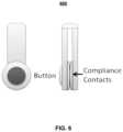
- FIG. 6illustrates a device 600 that represents an example of the on-body sensor 510 .
- the device 600embodies a clip form factor.
- the clipis fastened closed through tension when no force is applied, but can be opened upon demand (e.g., similar to a clothes pin), thereby ensuring that it remains connected to an article of clothing.
- the device 600When no force is applied to the clip, both sides of the device 600 are in contact with one another.
- the device 600includes compliance contacts (e.g., an electrical switch) comprising a conductive contact on each side of the clip.
- compliance contactse.g., an electrical switch
- the switchWhen the clip is forced open or clipped around a piece of fabric, the switch is opened. Otherwise, the switch is closed and the circuit loop completed.
- the system 400can identify whether the sensor is being worn. This information can be used to identify false falls created from dropping or otherwise handling the device 600 when not worn.
- the usercan also be reminded via audible or visual interfaces based on the system 400 detecting that the device 600 is not being worn as a result of the output of the compliance contacts. In determining whether to provide the reminder, the system 400 may consider other sensors within the monitored premise.
- the system 400may detect motion within the monitored premise based on output of one or more motion sensors, determine that the device 600 is not being worn based on output from the compliance contacts, and provide a reminder to wear the device 600 based on the determination that the device 600 is not being worn at a time when motion has been detected in the monitored premise.
- the on-body sensor 510comprises multi-modal sensing (e.g., triaxial inertial sensor, angular rate sensor, magnetometer, barometric pressure sensor, etc.), input/output, radio (e.g., via input/output), a processor, memory, battery, and user interface capabilities for human interaction (e.g., a button, LED/LCD, buzzer, etc.).
- the on-body sensor 510may be used to measure gross human motion and activity, detect specific events or behaviors (e.g., falls, walking, running, sleeping, etc.), communicate to the user (e.g., reminders, notifications, etc.), or capture user input (e.g., panic button press, verification of event, etc.). Detecting falls with on-body sensing is described in further detail below.
- a gateway device 450can be used to relay information between remote servers 460 (e.g., over public or private communication network) and systems at the user location.
- the gateway device 450can also allow systems within a user's location to communicate without involvement from remote servers 460 .
- Certain incarnations of the system 400may not include a gateway device 450 . Therefore, passive sensors 410 , assistance devices 420 , imaging sensors 430 , and/or user interface devices 440 may be connected directly to the communication network 480 .
- Remote servers 460may be employed to store, process, and initiate actions based upon fall, fall-related, or other data collected about each monitored user and location. Monitoring center agents can also annotate user records stored on the remote servers 460 .
- a monitoring center 470may employ automated or human agents to observe users' fall-related events and contact users or caregivers based on defined protocols, quantitative or qualitative assessments. Monitoring center agents can also annotate user records stored on the remote server 460 .
- FIG. 7illustrates an example process 700 for fall management.
- the operations of the example process 700are described generally as being performed by the system 400 .
- the operations of the example process 700may be performed by one of the components of the system 400 or may be performed by any combination of the components of the system 400 .
- the operations of the example process 700also may be performed by one of the components of the system 200 or may be performed by any combination of the components of the system 200 .
- operations of the example process 700may be performed by one or more processors included in one or more electronic devices.
- the fall management process 700includes data capture ( 710 ), fall detection ( 720 ), fall verification ( 730 ), fall risk assessment ( 740 ), fall risk reduction ( 750 ), and reporting ( 760 ). Although several steps are illustrated as part of the fall management process 700 , some fall management implementations may only employ a subset of these steps.
- the system 400performs data capture ( 710 ).
- Datacan be captured from one or more passive sensors, imaging sensors, assistance devices, and user interface devices.
- Datacan be unprocessed sensor readings or sensor-processed readings.
- Data capturecan be triggered by the passive sensors, imaging sensors, user interface devices, remote servers, or monitoring center.
- Data capturecan consist of instantaneous or continuously sampled readings.
- Datacan be forwarded directly from devices to remote servers or to remote servers via a gateway device.
- Remote servers, a gateway device, or sensorsmay coordinate the capture of data or buffer data to facilitate on-sensor, on-gateway, or remote processing.
- meta-data encompassing sensor location, timestamp, etc.can be forwarded to other devices, sensors, gateways, or remote servers.
- the system 400performs fall detection ( 720 ).
- Fallscan be detected independently by passive sensors, imaging sensors, or user interface devices (e.g., on-body sensor). Each device can classify a possible fall and communicate fall events or quantitative metrics related to the possibility of a fall (e.g., fall classification score).
- an on-body sensorcan capture human motion and detect motion characteristics indicative of a fall (described in more detail below).
- an image sensorcan detect the likelihood of a fall through analysis of images and other in-device sensors (described in more detail below).
- Fall detectionmay also be accomplished through the use of multiple sensors in parallel (e.g., hierarchical) or sequentially to improve sensitivity and specificity of fall detection. Numerous examples of combined sequential and parallel fall detection may be used and data from any combination of the sensors described throughout this disclosure may be fused and considered in combination to detect a potential fall event.
- the system 400may detect entry into a room based on output from a motion sensor and/or a door sensor. In this example, the system 400 detects that the room has not been exited after a threshold period of time has passed since the room entry was detected and detects sensor inactivity across all sensors after the room entry was detected.
- the system 400determines that a potential fall event may have occurred in the room and, in response to the determination that a potential fall event may have occurred in the room, initiates further processing to verify whether a potential fall event has occurred in the room.
- the system 400detects a potential fall event based on output from an on-body sensor.
- the system 400controls an imaging sensor to capture one or more images in a room where the potential fall event is expected to have occurred, performs analysis of the captured images, and detects possible presence of a prone individual on the ground in the room.
- the system 400also detects sensor inactivity across all sensors after detecting the potential fall event based on output from the on-body sensor. Based on the detections made and consideration of output of all of the sensors within the system 400 , the system 400 determines that a potential fall event may have occurred in the room and, in response to the determination that a potential fall event may have occurred in the room, initiates further processing to verify whether a potential fall event has occurred in the room.
- Independent fall detection processes on single devices or groups of devicesalso may be weighted (e.g., based on confidence or accuracy of fall detection efficacy). Such weighting may be used to compute an aggregate score indicative of the confidence of a possible fall. Weights may be assigned based on currently observed data and conditions, historic data from the monitored individual, or population data. Fall detection sensitivity may be configured by the user based on manipulation of weights associated with any of the aforementioned steps. For example, fall sensitivity could be set by adjusting the interval of sensed inactivity or the threshold for decreased activity. The system 400 may consider output from any of the sensors in the system 400 in computing the aggregate score. The system 400 may use the aggregate score to detect a potential fall event by comparing the aggregate score to a threshold.
- the system 400detects a potential fall event based on the comparison of the aggregate score to the threshold revealing that the aggregate score meets the threshold and determines that a potential fall event has not occurred based on the comparison of the aggregate score to the threshold revealing that the aggregate score does not meet the threshold.
- the system 400may provide more accurate fall detection with a lower false positive rate because detection of a fall detection only occurs when several sensors sense potential fall criteria or a single sensor detects a very high likelihood of a potential fall.
- the system 400performs fall verification ( 730 ). If a likely fall is detected, the detecting device, gateway, remote server, or monitoring center can initiate fall verification.
- the processcan include an automated or human-prompted user response. For example, a user may be alerted (e.g., by audible tone, vibration, human operator, automated operator, or visual indicator) to verify their need for help (e.g., a button press or vocal response) or may be alerted to respond within a period of time to cancel a potential fall event.
- helpe.g., a button press or vocal response
- a human operatormay also speak and listen to a user over two-way communication link.
- Fall verificationalso may be made by human inspection of captured images. For example, following the detection of a potential fall event, an image or successive images captured proximal to the fall may be sent to the monitoring center for human verification. Image capture also may be triggered post fall (e.g., by a monitoring center or by other caregivers) to verify a fall event. Other contextual sensor or meta-data may be forwarded to human responders to assist in the verification of fall.
- Fall verification proceduresmay be staged sequentially or paired with fall detection mechanisms to create a hierarchical fall escalation process. For example, less accurate fall detection methods may trigger less invasive user verification (e.g., prompted user button press). If no user response is given within a threshold period of time, then more accurate fall detection methods may be employed alongside more invasive fall verification (e.g., two way communications with monitoring center).
- less accurate fall detection methodsmay trigger less invasive user verification (e.g., prompted user button press). If no user response is given within a threshold period of time, then more accurate fall detection methods may be employed alongside more invasive fall verification (e.g., two way communications with monitoring center).
- the system 400performs fall risk assessment ( 740 ).
- Assessment of fall riskmay be made on the basis of data captured by sensors, user interface devices, or historic and stored data. Measures such as gait speed and balance can be directly assessed via passive and user interface devices. For example, two motion sensors placed in a hallway can measure gait speed and balance can be assessed via an on-body user interface device (e.g., via on-board inertial sensor and angular rate sensor). Other behavioral data such as medication adherence, sleep patterns, kitchen or restroom use can be used to augment mobility metrics. Data can be combined with prior knowledge of fall incidents or previously verified fall events.
- Scorescan be computed, compared, or modified against individual or population scores and histories. Scores can also be computed for various timescales and locations. Fall risk assessment may also take into consideration trending of scores for an individual.
- the system 400performs fall risk reduction ( 750 ).
- Various assistive approachesmay be employed with or without prior fall risk assessment scoring to help reduce fall risk.
- Assistance devicessuch as automated lighting or medication dispensers can be used to reduce environmental hazards or behaviors related to increase in fall risk, respectively. Assistance devices may be triggered by fall assessment scores, other sensors, user interface devices, or remote servers. For example, automated lighting can be turned-on when a user gets out of bed.
- notifications or educational materialcan be delivered (e.g., by default, for certain fall risk assessment scores, for certain events, etc.) to the user (e.g., via a user interface device or other output device) to help the user better understand and correct fall risk factors. Tips or behavior change techniques can help the user set up a safer environment or promote behaviors associated with decreased fall risk. Notifications may be combined with sensing or other user interface prompts (e.g., prompts to answer questionnaires) to assess adherence to fall risk reduction techniques in real-time or across a period of time. Users may be scored on their ability to reduce fall risk at various timescales or in various locations. Fall risk reduction scores may be compared to individual or population historic data.
- the system 400performs reporting ( 760 ).
- Fall risk, detection, and prevention data, scores, annotations, or observationscan be stored at the remote server.
- Datacan be compiled and reported to users, caregivers, monitoring centers, or other trusted parties.
- Data(including timestamps, scores, locations, confidence, etc.) can be used for the purposes of response to events, for preventative fall risk reduction strategies, or by professional caregivers for general health assessment.
- Data or scorescan be compared to individual or population data and reported to all aforementioned parties when appropriate.
- Data reportingmay be combined with prompts for data entry. For example, a user could receive a notification that bathroom habits are abnormal and be asked whether they are feeling well. Access to reported data can be restricted based on preferences of the user or caregivers. Notifications, reminders, user prompts, questionnaires, monitored responses, and other user interface modes can be configured by rules with associated parameters. Rules can be stored and executed at the remote server, gateway device, sensors, or user interface devices.
- FIG. 8illustrates an example process 800 for fall detection using an on-body user interface device.
- the operations of the example process 800are described generally as being performed by the system 400 .
- the operations of the example process 800may be performed by one of the components of the system 400 or may be performed by any combination of the components of the system 400 .
- the operations of the example process 800also may be performed by one of the components of the system 200 or may be performed by any combination of the components of the system 200 .
- operations of the example process 800may be performed by one or more processors included in one or more electronic devices.
- the on-body user interface deviceidentifies the various characteristics of a fall comprised of the user starting from a standing or sitting position, falling through to the ground, impacting a surface, and remaining inactive after the fall.
- the user's trunkmay transition from a vertical to horizontal position. This may result in a ninety degree change in trunk orientation, but since the user may not be standing straight before the fall, or may not be prone or supine after the fall, the angle may not reach ninety degrees.
- FIG. 8illustrates a fall detection process 800 for users wearing an on-body sensor with continuous sensing and detection.
- the system 400triggers fall detection processing based on detection of a fall-related signature ( 810 ).
- the fall detection processmay be triggered by an impact metric (e.g., measured from inertial sensing) or a similar fall-related signature (e.g., free fall) crossing a minimum threshold.
- the fall-related signaturemay be quantified and stratified into defined ranges indicative of fall detection confidence.
- FIG. 9illustrates example fall detection criteria.
- the fall detection criteriainclude a range of impact metrics 910 used to quantify a measured impact metric.
- the range of impact metricsmay include less than two, between two to five, between five to ten, between ten to fifteen, and greater than fifteen.
- the system 400may use the impact metric of two as a threshold for triggering fall detection processing. For instance, the system 400 quantifies a measured impact within the ranges of impact metrics and determines not to trigger fall detection processing based on the measured impact falling within the range of less than two. For any of the other ranges, the system 400 triggers fall detection processing and records the range in which the measured impact falls for later processing.
- the system 400calculates orientation change based on triggering fall detection processing ( 820 ). Based on the system 400 detecting that a measured impact or similar metric crosses the previously mentioned minimum threshold, the system 400 calculates an orientation change using inertial or angular rate measures from before and after the detected impact or other event.
- the orientation valuemay be quantified and stratified into defined ranges.
- the fall detection criteria shown in FIG. 9include a range of orientation changes 920 used to quantify an orientation change.
- the range of orientation changesmay include less than fifty, between fifty to sixty, between sixty to seventy-five, between seventy-five to eighty-five, and greater than eighty-five.
- the system 400may use the orientation change of fifty as a threshold for continuing fall detection processing. For instance, the system 400 quantifies a calculated orientation change within the ranges of orientation changes and determines not to continue fall detection processing based on the calculated orientation change falling within the range of less than fifty. For any of the other ranges, the system 400 continues fall detection processing and records the range in which the calculated orientation change falls for later processing.
- the system 400determines a minimum required inactivity period based on the fall-related signature and the orientation change ( 830 ). Based on the defined ranges derived from impact/signature scoring and orientation scoring, a minimum required inactivity period can be determined by a lookup table or functional relationship.
- the fall detection criteria shown in FIG. 9include an inactivity period lookup table 930 .
- the system 400references the lookup table 930 using the range of the measured impact and the range of the calculated orientation change and sets the minimum required inactivity period as the period of time defined by the appropriate entry in the lookup table 930 . For example, with an impact metric greater than ten, but less than fifteen, and an orientation change greater than eighty-five, the inactivity period is set as low as thirty seconds to signal a likely fall.
- the system 400detects a potential fall event based on monitoring activity during the minimum required inactivity period ( 840 ).
- the system 400may monitor output of the on-body sensor and output from any of the other sensors in the system 400 and determine whether any of the sensors signal activity.
- the system 400continues to monitor the sensor output until the set period of inactivity has been reached and the system 400 detects a potential fall event based on determining that the set period of inactivity has passed without detecting sensed activity from any of the sensors in the system 400 .
- FIG. 10illustrates an example process 1000 for tuning sensitivity and specificity of fall detection.
- the operations of the example process 1000are described generally as being performed by the system 400 .
- the operations of the example process 1000may be performed by one of the components of the system 400 or may be performed by any combination of the components of the system 400 .
- the operations of the example process 1000also may be performed by one of the components of the system 200 or may be performed by any combination of the components of the system 200 .
- operations of the example process 1000may be performed by one or more processors included in one or more electronic devices.
- the process 1000uses user feedback.
- the process 1000may produce more granular fall reporting (e.g., true, false, minor, canceled falls) and may help to reduce and report incidence of false positives or false negatives.
- the system 400detects a potential fall event ( 1005 ).
- a possible fallis detected by the on-body device, by other sensors, or user interface devices. Any of the techniques described throughout this disclosure may be used to detect a potential fall event.
- the system 400prompts the user for cancellation of the potential fall event ( 1010 ).
- a user promptmay be initiated (e.g., audible or visual).
- the usercan respond (e.g., by a button press or vocalization) to the user prompt at the device to cancel the detected potential fall event.
- the system 400determines whether the user cancels the potential fall event within a defined period of time ( 1015 ). For instance, the system 400 monitors for input cancelling the potential fall event until the defined period of time has been reached and the system 400 determines whether the user cancelled the potential fall event within the defined period of time based on the monitoring. Based on a determination that the potential fall event was not cancelled within the defined period of time, the system 400 generates a fall signal (e.g., a fall signal from the body-worn device).
- a fall signale.g., a fall signal from the body-worn device.
- the system 400Based on a determination that the potential fall event was cancelled within the defined period of time, the system 400 makes a measurement of overall activity over the minimum inactivity period previously mentioned ( 1020 ). For example, the system 400 measures the activity detected by the on-body sensor after detection of the potential fall event until the input cancelling the potential fall event was received.
- the system 400determines whether the measurement of overall activity meets an expected maximum activity ( 1025 ). For instance, the system 400 compares the measurement of overall activity to the expected maximum activity and determines whether the measurement of overall activity meets the expected maximum activity based on the comparison.
- the system 400Based on a determination that the measurement of overall activity meets the expected maximum activity, the system 400 signals a false fall detection ( 1030 ). For example, the system 400 classifies the sensor data used to detect the potential fall event as being sensor data associated with a false detection of a potential fall event. In this example, the system 400 may tune the potential fall detection process such that sensor data similar to the sensor data associated with the false detection of the potential fall event does not result in detection of a potential fall event in the future.
- the system 400Based on a determination that the measurement of overall activity does not meet the expected maximum activity, the system 400 measures posture or orientation ( 1035 ) and determines whether the subject recovered from the suspected fall based on the measured posture or orientation ( 1040 ). For instance, the system 400 analyzes the measured posture or orientation and determines whether the subject has returned to an upright position.
- the system 400Based on a determination that the subject recovered from the suspected fall, the system 400 triggers a minor fall ( 1045 ). For example, the system 400 classifies the sensor data used to detect the potential fall event as being sensor data associated with a minor fall. In this example, the system 400 may tune the potential fall detection process such that sensor data similar to the sensor data associated with the minor fall results in detection of a minor fall event in the future. The system 400 may handle minor fall events differently than regular fall events. For instance, the system 400 may wait longer to see if a patient recovers from a minor fall prior to alerting a remote caregiver or monitoring station.
- the system 400Based on a determination that the subject did not recover from the suspected fall, the system 400 performs another user prompt for cancellation ( 1050 ) and determines whether the user cancels the potential fall event within a defined period of time from the additional prompt for cancellation ( 1055 ). Based on a determination that the potential fall event was cancelled within the defined period of time, the system 400 signals a cancelled fall ( 1060 ). For instance, the system 400 does not provide an alert for the potential fall event, but does classify the sensor data used to detect the potential fall event as being sensor data associated with a fall that was ultimately cancelled.
- the system 400Based on a determination that the potential fall event was not cancelled within the defined period of time, the system 400 generates a fall signal ( 1065 ). For instance, the system 400 may generate a fall signal from the body-worn device. The fall signal may be sent to a remote caregiver or monitoring station to alert the remote caregiver or monitoring station to provide assistance to the patient who experienced the potential fall event.
- Granular fall detection classessuch as true fall, false fall, minor fall, and cancelled fall can be used to tune system parameters for each individual user, provide caregivers or trusted individuals with fall data, and provide automated mechanisms for fall verification. Furthermore, the data can be stored at the remote servers.
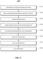
- FIG. 11illustrates an example process 1100 for fall detection and reporting.
- the operations of the example process 1100are described generally as being performed by the system 400 .
- the operations of the example process 1100may be performed by one of the components of the system 400 or may be performed by any combination of the components of the system 400 .
- the operations of the example process 1100also may be performed by one of the components of the system 200 or may be performed by any combination of the components of the system 200 .
- operations of the example process 1100may be performed by one or more processors included in one or more electronic devices.
- the process 1100enables fall detection and reporting based on human movement analysis.
- the system 400performs a triggered or scheduled image capture ( 1110 ).
- the system 400may trigger a camera on an image sensing device to capture an image based on events detected by one or more of the image sensing device's sensors (e.g., perceived motion passive infrared motion sensor, triaxial inertial sensor).
- the system 400may trigger the camera by one or more external sensors interfaced via a gateway device. For instance, the press of a panic button or the opening of a door sensor may trigger one or more image sensing devices to capture an image.
- image capturemay be scheduled (e.g., capture an image every one minute during the hours of six in the morning through ten in the evening).
- the system 400may employ infrared illumination to increase image detail and quality.
- the system 400After image capture, the system 400 performs image foreground segmentation and filtering ( 1120 ).
- the system 400e.g., the image sensing device
- the system 400may filter captured images to help reduce foreground noise and isolate large regions of change.
- the processmay identify changed pixels from previous images, including those morphologically likely to represent human forms or shapes.
- the system 400After image foreground segmentation and filtering, the system 400 performs human segmentation ( 1130 ).
- the system 400segments possible human shapes via template matches, shape fitting, or similar methods. For example, the system 400 may segment a foreground shape falling within an approximate elliptical boundary over a size threshold. Such segmentation may reduce incidence of false detection and reporting (e.g., small pet activity).
- the system 400may remove regions of the camera's field of view from analysis. For instance, if a bed were present in the field of view, the bed may be marked as a non-detection region and the system 400 would not analyze that portion of images captured by the image sensing device.
- the system 400After human segmentation, the system 400 performs human orientation and position estimation ( 1140 ). For example, the system 400 calculates orientation (e.g., human shape upright, angled, prone, etc.) and position (e.g., human shape above floor, near floor, etc.) by template or boundary shape proportion and rotation relative to a horizontal image plane. This estimation enables identification of postures and resting positions indicative of a fall.
- the floor proximal planar boundarycan be specifically defined and moved to fit the unique geometries of different rooms.
- the system 400After human orientation and position estimation, the system 400 performs successive image and/or sensor data comparison ( 1150 ). For example, the system 400 stores, either on or off the image sensing device, the orientation and position information calculated previously and compares the prior orientation and position information with successive image orientations and positions. The system 200 repeats this process and isolates changes in position and orientation indicative of a fall (e.g., movement towards the ground), or relative stasis of position and orientation indicative of a fall (e.g., incapacitation after a fall). Furthermore, the system 400 combines motion sensor information with or used independent of image-based analysis to ascertain movement through horizontal planes of motion (e.g., human falling from an upright position).
- the system 400combines motion sensor information with or used independent of image-based analysis to ascertain movement through horizontal planes of motion (e.g., human falling from an upright position).
- the system 200performs inactivity detection ( 1160 ).
- the system 400detects periods of relative inactivity, such as those following a potential fall, from lack of or decreased motion, inertial measures, image-derived orientation and position information, external sensors, or even a combination thereof.
- the system 400may classify longer periods of relative inactivity as being indicative of a fall, and classify shorter periods of relative inactivity as being indicative of a non-fall event or recovery from a fall.
- the system 400After inactivity detection, the system 400 performs fall classification ( 1170 ).
- the system 400may combine (e.g., logically or algebraically) the data and information compiled in previous operations of the process 1100 and use the combined data in several ways to classify possible falls. For example, if an impact is detected, orientation and position are indicative of a human in a fallen state, and a period of inactivity has exceeded a defined threshold, then the system 400 classifies the event as a fall.
- Classification sensitivitymay be configured by the user based on manipulation of variables associated with any of the aforementioned steps. For example, fall sensitivity could be set by adjusting the interval of sensed inactivity or the threshold for decreased activity. Not all prior conditions must be met, nor all prior steps completed, for fall classification.
- the system 400may report classification confidence based on the quality of inputs or classifier performance.
- the system 400may implement the classifier in a variety of ways such as, but not limited to an expert system, native Bayes, decision tree, neural network, etc.
- the system 400After fall classification, the system 400 performs fall reporting ( 1180 ). For example, potential fall events are forwarded to a gateway device, remote monitoring servers, and ultimately to users or central monitoring station(s) if appropriate rules and preferences are met. Images (e.g., past and present), data, and location information can be sent for purposes of reporting and verification. Moreover, potential non-fall events, images, data, and location can be forwarded to users or central monitoring station(s) for verification. Verification of fall events is not a requisite function of the system, rather an additional feature. Fall detection can be performed with or without image or other human-based verification.
- Fall detectioncan be performed with or without image or other human-based verification.
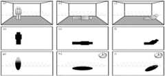
- FIG. 12shows fall detection examples with three possible scenarios that illustrate aspects of the fall detection process 1000 discussed above.
- first scenario (a)a person stands upright in a room.
- second scenario (b)a person has fallen and is prone on the floor.
- third scenario (c)a person has fallen to a slumped position on the floor.
- Illustrations (d), (e), and (f)represent the results of foreground separation and filtering of illustrations (a), (b), and (c), respectively.
- Illustrations (g), (h), and (i)represent the results of human orientation and position estimation and inactivity detection (as denoted by a clock) of the previous illustrations, respectively.
- Analysis of room geometry within captured imagesmay be used to project a virtual plane of where a person should be oriented below in a fall event.
- the system 400may analyze floor geometry and then perform centroid-based processing to determine where the floor is located in the captured images. After determining the location of the floor, the system 400 projects the virtual plane within the captured images at a particular distance above the floor.
- the image sensing device and optional trigger sourcescommunicate to a gateway (e.g., home monitoring panel) within a home or facility.
- the gateway's memoryenables buffering of images and data from the image sensor and other sensors.
- Datais forwarded to remote monitoring servers over a long range wireless network (e.g., cellular link).
- Rules and preferences set at the remote monitoring serverenable potential fall information (e.g., captured images and data) to be forwarded via an IP network to users or a central monitoring station for fall verification.
- a responsecan be initiated (e.g., a two-way voice call may be established with the gateway device, emergency responders may be dispatched, etc.) and location information from the system can be communicated to those providing assistance.
- the systemmay evaluate context in determining how to handle a fall detection event.
- the systemmay check other activity in the property and determine how to handle the fall detection event based on the other activity. For instance, when the system detects other activity in the property, the system may attempt to alert someone in the property to the potential fall event (e.g., by providing an audible alert in the home that indicates the fall detection event).
- the systemmay, based on the fall detection event, send electronic messages to a caregiver associated with the property to alert the caregiver to the fall detection event, establish a two-way voice communication session with a monitoring system at the property, and/or dispatch emergency services.
- the systemmay tune sensitivity of one or more sensors/contexts used in fall detection and may determine a score as part of fall classification.
- the systemmay determine the score based on a number of sensors that indicate a potential fall. For instance, the system may determine a relatively high score when the system detects a thud based on an accelerometer sensor, detects multiple motion sensors indicating motion consistent with a fall, and performs image analysis that suggests that a person has moved from a vertical orientation to a horizontal orientation below a plane near the floor. The system may determine a relatively low score when the system only performs image analysis that suggests that a person is horizontally oriented below a plane near the floor. The system may consider the number of motion sensors detecting motion and leverage all sensor data.
- the systemmay typically operate using a subset of sensors and move to a process that leverages all sensors when a potential fall is detected by the subset of sensors.
- the systemmay consider historic data (e.g., classification by caregivers of whether a fall detection event was actually a fall or a mistake) and tune fall detection based on the historic data.
- the location in the home where the fall occurredmay be determined and communicated to an emergency response team.
- the location in the home where the fall occurredmay be used to pick the other sensors the system reviews in confirming a potential fall event. For instance, when the system determines that the potential fall occurs in the basement, the system determines not to consider sensors in the upstairs bedroom, as the sensors in the upstairs bedroom are unlikely to be relevant to the potential fall event in the basement.
- the described systems, methods, and techniquesmay be implemented in digital electronic circuitry, computer hardware, firmware, software, or in combinations of these elements. Apparatus implementing these techniques may include appropriate input and output devices, a computer processor, and a computer program product tangibly embodied in a machine-readable storage device for execution by a programmable processor. A process implementing these techniques may be performed by a programmable processor executing a program of instructions to perform desired functions by operating on input data and generating appropriate output.
- the techniquesmay be implemented in one or more computer programs that are executable on a programmable system including at least one programmable processor coupled to receive data and instructions from, and to transmit data and instructions to, a data storage system, at least one input device, and at least one output device.
- Each computer programmay be implemented in a high-level procedural or object-oriented programming language, or in assembly or machine language if desired; and in any case, the language may be a compiled or interpreted language.
- Suitable processorsinclude, by way of example, both general and special purpose microprocessors. Generally, a processor will receive instructions and data from a read-only memory and/or a random access memory.
- Storage devices suitable for tangibly embodying computer program instructions and datainclude all forms of non-volatile memory, including by way of example semiconductor memory devices, such as Erasable Programmable Read-Only Memory (EPROM), Electrically Erasable Programmable Read-Only Memory (EEPROM), and flash memory devices; magnetic disks such as internal hard disks and removable disks; magneto-optical disks; and Compact Disc Read-Only Memory (CD-ROM). Any of the foregoing may be supplemented by, or incorporated in, specially-designed ASICs (application-specific integrated circuits).
- EPROMErasable Programmable Read-Only Memory
- EEPROMElectrically Erasable Programmable Read-Only Memory
- CD-ROMCompact Disc Read-Only Memory
Landscapes
- Health & Medical Sciences (AREA)
- Engineering & Computer Science (AREA)
- Life Sciences & Earth Sciences (AREA)
- Physics & Mathematics (AREA)
- Biomedical Technology (AREA)
- General Health & Medical Sciences (AREA)
- General Physics & Mathematics (AREA)
- Medical Informatics (AREA)
- Public Health (AREA)
- Business, Economics & Management (AREA)
- Veterinary Medicine (AREA)
- Biophysics (AREA)
- Pathology (AREA)
- Heart & Thoracic Surgery (AREA)
- Molecular Biology (AREA)
- Surgery (AREA)
- Animal Behavior & Ethology (AREA)
- Computer Vision & Pattern Recognition (AREA)
- Theoretical Computer Science (AREA)
- Emergency Management (AREA)
- Dentistry (AREA)
- Physiology (AREA)
- Oral & Maxillofacial Surgery (AREA)
- Computer Networks & Wireless Communication (AREA)
- General Business, Economics & Management (AREA)
- Epidemiology (AREA)
- Primary Health Care (AREA)
- Social Psychology (AREA)
- Psychiatry (AREA)
- Psychology (AREA)
- Gerontology & Geriatric Medicine (AREA)
- Alarm Systems (AREA)
- Aiming, Guidance, Guns With A Light Source, Armor, Camouflage, And Targets (AREA)
- Transition And Organic Metals Composition Catalysts For Addition Polymerization (AREA)
Abstract
Description
Claims (22)
Priority Applications (2)
| Application Number | Priority Date | Filing Date | Title |
|---|---|---|---|
| US17/736,147US12198525B2 (en) | 2011-04-04 | 2022-05-04 | Fall detection and reporting technology |
| US19/000,913US20250131809A1 (en) | 2011-04-04 | 2024-12-24 | Fall detection and reporting technology |
Applications Claiming Priority (8)
| Application Number | Priority Date | Filing Date | Title |
|---|---|---|---|
| US201161471495P | 2011-04-04 | 2011-04-04 | |
| US13/439,690US8675920B2 (en) | 2011-04-04 | 2012-04-04 | Fall detection and reporting technology |
| US14/200,407US9036019B2 (en) | 2011-04-04 | 2014-03-07 | Fall detection and reporting technology |
| US14/714,485US9495855B2 (en) | 2011-04-04 | 2015-05-18 | Fall detection and reporting technology |
| US15/348,550US10037669B2 (en) | 2011-04-04 | 2016-11-10 | Fall detection and reporting technology |
| US16/049,063US10825315B2 (en) | 2011-04-04 | 2018-07-30 | Fall detection and reporting technology |
| US17/085,683US11328571B2 (en) | 2011-04-04 | 2020-10-30 | Fall detection and reporting technology |
| US17/736,147US12198525B2 (en) | 2011-04-04 | 2022-05-04 | Fall detection and reporting technology |
Related Parent Applications (1)
| Application Number | Title | Priority Date | Filing Date |
|---|---|---|---|
| US17/085,683ContinuationUS11328571B2 (en) | 2011-04-04 | 2020-10-30 | Fall detection and reporting technology |
Related Child Applications (1)
| Application Number | Title | Priority Date | Filing Date |
|---|---|---|---|
| US19/000,913ContinuationUS20250131809A1 (en) | 2011-04-04 | 2024-12-24 | Fall detection and reporting technology |
Publications (2)
| Publication Number | Publication Date |
|---|---|
| US20220262224A1 US20220262224A1 (en) | 2022-08-18 |
| US12198525B2true US12198525B2 (en) | 2025-01-14 |
Family
ID=46964797
Family Applications (8)
| Application Number | Title | Priority Date | Filing Date |
|---|---|---|---|
| US13/439,690Active2032-07-29US8675920B2 (en) | 2011-04-04 | 2012-04-04 | Fall detection and reporting technology |
| US14/200,407ActiveUS9036019B2 (en) | 2011-04-04 | 2014-03-07 | Fall detection and reporting technology |
| US14/714,485ActiveUS9495855B2 (en) | 2011-04-04 | 2015-05-18 | Fall detection and reporting technology |
| US15/348,550Active2032-05-04US10037669B2 (en) | 2011-04-04 | 2016-11-10 | Fall detection and reporting technology |
| US16/049,063Active2032-08-25US10825315B2 (en) | 2011-04-04 | 2018-07-30 | Fall detection and reporting technology |
| US17/085,683Active2032-04-16US11328571B2 (en) | 2011-04-04 | 2020-10-30 | Fall detection and reporting technology |
| US17/736,147ActiveUS12198525B2 (en) | 2011-04-04 | 2022-05-04 | Fall detection and reporting technology |
| US19/000,913PendingUS20250131809A1 (en) | 2011-04-04 | 2024-12-24 | Fall detection and reporting technology |
Family Applications Before (6)
| Application Number | Title | Priority Date | Filing Date |
|---|---|---|---|
| US13/439,690Active2032-07-29US8675920B2 (en) | 2011-04-04 | 2012-04-04 | Fall detection and reporting technology |
| US14/200,407ActiveUS9036019B2 (en) | 2011-04-04 | 2014-03-07 | Fall detection and reporting technology |
| US14/714,485ActiveUS9495855B2 (en) | 2011-04-04 | 2015-05-18 | Fall detection and reporting technology |
| US15/348,550Active2032-05-04US10037669B2 (en) | 2011-04-04 | 2016-11-10 | Fall detection and reporting technology |
| US16/049,063Active2032-08-25US10825315B2 (en) | 2011-04-04 | 2018-07-30 | Fall detection and reporting technology |
| US17/085,683Active2032-04-16US11328571B2 (en) | 2011-04-04 | 2020-10-30 | Fall detection and reporting technology |
Family Applications After (1)
| Application Number | Title | Priority Date | Filing Date |
|---|---|---|---|
| US19/000,913PendingUS20250131809A1 (en) | 2011-04-04 | 2024-12-24 | Fall detection and reporting technology |
Country Status (2)
| Country | Link |
|---|---|
| US (8) | US8675920B2 (en) |
| CA (3) | CA2773507C (en) |
Families Citing this family (285)
| Publication number | Priority date | Publication date | Assignee | Title |
|---|---|---|---|---|
| US9318012B2 (en)* | 2003-12-12 | 2016-04-19 | Steve Gail Johnson | Noise correcting patient fall risk state system and method for predicting patient falls |
| US11368429B2 (en) | 2004-03-16 | 2022-06-21 | Icontrol Networks, Inc. | Premises management configuration and control |
| US20090077623A1 (en) | 2005-03-16 | 2009-03-19 | Marc Baum | Security Network Integrating Security System and Network Devices |
| US8635350B2 (en) | 2006-06-12 | 2014-01-21 | Icontrol Networks, Inc. | IP device discovery systems and methods |
| US11582065B2 (en) | 2007-06-12 | 2023-02-14 | Icontrol Networks, Inc. | Systems and methods for device communication |
| US12063220B2 (en) | 2004-03-16 | 2024-08-13 | Icontrol Networks, Inc. | Communication protocols in integrated systems |
| US11811845B2 (en) | 2004-03-16 | 2023-11-07 | Icontrol Networks, Inc. | Communication protocols over internet protocol (IP) networks |
| US11277465B2 (en) | 2004-03-16 | 2022-03-15 | Icontrol Networks, Inc. | Generating risk profile using data of home monitoring and security system |
| US10200504B2 (en) | 2007-06-12 | 2019-02-05 | Icontrol Networks, Inc. | Communication protocols over internet protocol (IP) networks |
| US9729342B2 (en) | 2010-12-20 | 2017-08-08 | Icontrol Networks, Inc. | Defining and implementing sensor triggered response rules |
| US9531593B2 (en) | 2007-06-12 | 2016-12-27 | Icontrol Networks, Inc. | Takeover processes in security network integrated with premise security system |
| US11113950B2 (en) | 2005-03-16 | 2021-09-07 | Icontrol Networks, Inc. | Gateway integrated with premises security system |
| US10522026B2 (en) | 2008-08-11 | 2019-12-31 | Icontrol Networks, Inc. | Automation system user interface with three-dimensional display |
| US11343380B2 (en) | 2004-03-16 | 2022-05-24 | Icontrol Networks, Inc. | Premises system automation |
| US11316958B2 (en) | 2008-08-11 | 2022-04-26 | Icontrol Networks, Inc. | Virtual device systems and methods |
| US10062273B2 (en) | 2010-09-28 | 2018-08-28 | Icontrol Networks, Inc. | Integrated security system with parallel processing architecture |
| US9141276B2 (en) | 2005-03-16 | 2015-09-22 | Icontrol Networks, Inc. | Integrated interface for mobile device |
| US20170118037A1 (en) | 2008-08-11 | 2017-04-27 | Icontrol Networks, Inc. | Integrated cloud system for premises automation |
| US10142392B2 (en) | 2007-01-24 | 2018-11-27 | Icontrol Networks, Inc. | Methods and systems for improved system performance |
| US11916870B2 (en) | 2004-03-16 | 2024-02-27 | Icontrol Networks, Inc. | Gateway registry methods and systems |
| US10339791B2 (en) | 2007-06-12 | 2019-07-02 | Icontrol Networks, Inc. | Security network integrated with premise security system |
| US10380871B2 (en) | 2005-03-16 | 2019-08-13 | Icontrol Networks, Inc. | Control system user interface |
| US10237237B2 (en) | 2007-06-12 | 2019-03-19 | Icontrol Networks, Inc. | Communication protocols in integrated systems |
| US10348575B2 (en) | 2013-06-27 | 2019-07-09 | Icontrol Networks, Inc. | Control system user interface |
| US10156959B2 (en) | 2005-03-16 | 2018-12-18 | Icontrol Networks, Inc. | Cross-client sensor user interface in an integrated security network |
| US11159484B2 (en) | 2004-03-16 | 2021-10-26 | Icontrol Networks, Inc. | Forming a security network including integrated security system components and network devices |
| US11201755B2 (en) | 2004-03-16 | 2021-12-14 | Icontrol Networks, Inc. | Premises system management using status signal |
| US11244545B2 (en) | 2004-03-16 | 2022-02-08 | Icontrol Networks, Inc. | Cross-client sensor user interface in an integrated security network |
| US11677577B2 (en) | 2004-03-16 | 2023-06-13 | Icontrol Networks, Inc. | Premises system management using status signal |
| US10721087B2 (en) | 2005-03-16 | 2020-07-21 | Icontrol Networks, Inc. | Method for networked touchscreen with integrated interfaces |
| JP2007529826A (en) | 2004-03-16 | 2007-10-25 | アイコントロール ネットワークス, インコーポレイテッド | Object management network |
| US7711796B2 (en) | 2006-06-12 | 2010-05-04 | Icontrol Networks, Inc. | Gateway registry methods and systems |
| US11489812B2 (en) | 2004-03-16 | 2022-11-01 | Icontrol Networks, Inc. | Forming a security network including integrated security system components and network devices |
| US20110128378A1 (en) | 2005-03-16 | 2011-06-02 | Reza Raji | Modular Electronic Display Platform |
| US11615697B2 (en) | 2005-03-16 | 2023-03-28 | Icontrol Networks, Inc. | Premise management systems and methods |
| US11496568B2 (en) | 2005-03-16 | 2022-11-08 | Icontrol Networks, Inc. | Security system with networked touchscreen |
| US9306809B2 (en) | 2007-06-12 | 2016-04-05 | Icontrol Networks, Inc. | Security system with networked touchscreen |
| US10999254B2 (en) | 2005-03-16 | 2021-05-04 | Icontrol Networks, Inc. | System for data routing in networks |
| US11700142B2 (en) | 2005-03-16 | 2023-07-11 | Icontrol Networks, Inc. | Security network integrating security system and network devices |
| US20170180198A1 (en) | 2008-08-11 | 2017-06-22 | Marc Baum | Forming a security network including integrated security system components |
| US9189934B2 (en) | 2005-09-22 | 2015-11-17 | Rsi Video Technologies, Inc. | Security monitoring with programmable mapping |
| US10079839B1 (en) | 2007-06-12 | 2018-09-18 | Icontrol Networks, Inc. | Activation of gateway device |
| US12063221B2 (en) | 2006-06-12 | 2024-08-13 | Icontrol Networks, Inc. | Activation of gateway device |
| US11706279B2 (en) | 2007-01-24 | 2023-07-18 | Icontrol Networks, Inc. | Methods and systems for data communication |
| US7633385B2 (en) | 2007-02-28 | 2009-12-15 | Ucontrol, Inc. | Method and system for communicating with and controlling an alarm system from a remote server |
| US8451986B2 (en) | 2007-04-23 | 2013-05-28 | Icontrol Networks, Inc. | Method and system for automatically providing alternate network access for telecommunications |
| US11601810B2 (en) | 2007-06-12 | 2023-03-07 | Icontrol Networks, Inc. | Communication protocols in integrated systems |
| US12283172B2 (en) | 2007-06-12 | 2025-04-22 | Icontrol Networks, Inc. | Communication protocols in integrated systems |
| US11237714B2 (en) | 2007-06-12 | 2022-02-01 | Control Networks, Inc. | Control system user interface |
| US11316753B2 (en) | 2007-06-12 | 2022-04-26 | Icontrol Networks, Inc. | Communication protocols in integrated systems |
| US11212192B2 (en) | 2007-06-12 | 2021-12-28 | Icontrol Networks, Inc. | Communication protocols in integrated systems |
| US12184443B2 (en) | 2007-06-12 | 2024-12-31 | Icontrol Networks, Inc. | Controlling data routing among networks |
| US11423756B2 (en) | 2007-06-12 | 2022-08-23 | Icontrol Networks, Inc. | Communication protocols in integrated systems |
| US11646907B2 (en) | 2007-06-12 | 2023-05-09 | Icontrol Networks, Inc. | Communication protocols in integrated systems |
| US10523689B2 (en) | 2007-06-12 | 2019-12-31 | Icontrol Networks, Inc. | Communication protocols over internet protocol (IP) networks |
| US11089122B2 (en) | 2007-06-12 | 2021-08-10 | Icontrol Networks, Inc. | Controlling data routing among networks |
| US11218878B2 (en) | 2007-06-12 | 2022-01-04 | Icontrol Networks, Inc. | Communication protocols in integrated systems |
| US12003387B2 (en) | 2012-06-27 | 2024-06-04 | Comcast Cable Communications, Llc | Control system user interface |
| US11831462B2 (en) | 2007-08-24 | 2023-11-28 | Icontrol Networks, Inc. | Controlling data routing in premises management systems |
| US9936143B2 (en) | 2007-10-31 | 2018-04-03 | Google Technology Holdings LLC | Imager module with electronic shutter |
| US11916928B2 (en) | 2008-01-24 | 2024-02-27 | Icontrol Networks, Inc. | Communication protocols over internet protocol (IP) networks |
| US20170185278A1 (en) | 2008-08-11 | 2017-06-29 | Icontrol Networks, Inc. | Automation system user interface |
| US11758026B2 (en) | 2008-08-11 | 2023-09-12 | Icontrol Networks, Inc. | Virtual device systems and methods |
| US11258625B2 (en) | 2008-08-11 | 2022-02-22 | Icontrol Networks, Inc. | Mobile premises automation platform |
| US11792036B2 (en) | 2008-08-11 | 2023-10-17 | Icontrol Networks, Inc. | Mobile premises automation platform |
| US10530839B2 (en) | 2008-08-11 | 2020-01-07 | Icontrol Networks, Inc. | Integrated cloud system with lightweight gateway for premises automation |
| US11729255B2 (en) | 2008-08-11 | 2023-08-15 | Icontrol Networks, Inc. | Integrated cloud system with lightweight gateway for premises automation |
| US8638211B2 (en) | 2009-04-30 | 2014-01-28 | Icontrol Networks, Inc. | Configurable controller and interface for home SMA, phone and multimedia |
| US8836467B1 (en) | 2010-09-28 | 2014-09-16 | Icontrol Networks, Inc. | Method, system and apparatus for automated reporting of account and sensor zone information to a central station |
| US11750414B2 (en) | 2010-12-16 | 2023-09-05 | Icontrol Networks, Inc. | Bidirectional security sensor communication for a premises security system |
| US9147337B2 (en) | 2010-12-17 | 2015-09-29 | Icontrol Networks, Inc. | Method and system for logging security event data |
| CA2773507C (en) | 2011-04-04 | 2020-10-13 | Mark Andrew Hanson | Fall detection and reporting technology |
| US20130127620A1 (en) | 2011-06-20 | 2013-05-23 | Cerner Innovation, Inc. | Management of patient fall risk |
| US10546481B2 (en) | 2011-07-12 | 2020-01-28 | Cerner Innovation, Inc. | Method for determining whether an individual leaves a prescribed virtual perimeter |
| US9367770B2 (en) | 2011-08-30 | 2016-06-14 | Digimarc Corporation | Methods and arrangements for identifying objects |
| US9571723B2 (en) | 2011-11-18 | 2017-02-14 | National Science Foundation | Automatic detection by a wearable camera |
| US10034624B2 (en) | 2012-01-18 | 2018-07-31 | Nike, Inc. | Activity points |
| WO2013164721A1 (en)* | 2012-05-02 | 2013-11-07 | Koninklijke Philips N.V. | Device and method for routing a medical alert to a selected staff member |
| US9392322B2 (en) | 2012-05-10 | 2016-07-12 | Google Technology Holdings LLC | Method of visually synchronizing differing camera feeds with common subject |
| US12176093B1 (en)* | 2012-06-22 | 2024-12-24 | Cerner Innovation Inc. | Decision support for managing mental health conditions |
| US10332059B2 (en)* | 2013-03-14 | 2019-06-25 | Google Llc | Security scoring in a smart-sensored home |
| US9959727B2 (en) | 2012-09-21 | 2018-05-01 | Google Llc | Handling visitor interaction at a smart-home in a do not disturb mode |
| US9960929B2 (en) | 2012-09-21 | 2018-05-01 | Google Llc | Environmental sensing with a doorbell at a smart-home |
| US9881474B2 (en) | 2012-09-21 | 2018-01-30 | Google Llc | Initially detecting a visitor at a smart-home |
| US9978238B2 (en) | 2012-09-21 | 2018-05-22 | Google Llc | Visitor options at an entryway to a smart-home |
| US10735216B2 (en) | 2012-09-21 | 2020-08-04 | Google Llc | Handling security services visitor at a smart-home |
| US9953514B2 (en) | 2012-09-21 | 2018-04-24 | Google Llc | Visitor feedback to visitor interaction with a doorbell at a smart-home |
| GB2506885B (en)* | 2012-10-10 | 2017-04-12 | Read Dale | Occupancy sensor |
| US9538158B1 (en) | 2012-10-16 | 2017-01-03 | Ocuvera LLC | Medical environment monitoring system |
| US10229491B1 (en) | 2012-10-16 | 2019-03-12 | Ocuvera LLC | Medical environment monitoring system |
| US11570421B1 (en) | 2012-10-16 | 2023-01-31 | Ocuvera, LLC | Medical environment monitoring system |
| US10229489B1 (en) | 2012-10-16 | 2019-03-12 | Ocuvera LLC | Medical environment monitoring system |
| US9798302B2 (en) | 2013-02-27 | 2017-10-24 | Rockwell Automation Technologies, Inc. | Recognition-based industrial automation control with redundant system input support |
| US9393695B2 (en) | 2013-02-27 | 2016-07-19 | Rockwell Automation Technologies, Inc. | Recognition-based industrial automation control with person and object discrimination |
| US9498885B2 (en) | 2013-02-27 | 2016-11-22 | Rockwell Automation Technologies, Inc. | Recognition-based industrial automation control with confidence-based decision support |
| US9804576B2 (en)* | 2013-02-27 | 2017-10-31 | Rockwell Automation Technologies, Inc. | Recognition-based industrial automation control with position and derivative decision reference |
| JP6171415B2 (en)* | 2013-03-06 | 2017-08-02 | ノーリツプレシジョン株式会社 | Information processing apparatus, information processing method, and program |
| CA2914240C (en)* | 2013-06-06 | 2023-04-04 | Koninklijke Philips N.V. | Fall detection system and method |
| US10182757B2 (en)* | 2013-07-22 | 2019-01-22 | The Rockefeller University | System and method for optical detection of skin disease |
| US9472067B1 (en) | 2013-07-23 | 2016-10-18 | Rsi Video Technologies, Inc. | Security devices and related features |
| WO2015020975A1 (en) | 2013-08-05 | 2015-02-12 | Ameer Sami | System and method for automating electrical devices at a building structure |
| US10664795B1 (en) | 2013-09-20 | 2020-05-26 | Amazon Technologies, Inc. | Weight based item tracking |
| US10515309B1 (en)* | 2013-09-20 | 2019-12-24 | Amazon Technologies, Inc. | Weight based assistance determination |
| WO2015069124A1 (en)* | 2013-11-08 | 2015-05-14 | Performance Lab Technologies Limited | Automated prescription of activity based on physical activity data |
| US10037821B2 (en)* | 2013-12-27 | 2018-07-31 | General Electric Company | System for integrated protocol and decision support |
| US9729833B1 (en) | 2014-01-17 | 2017-08-08 | Cerner Innovation, Inc. | Method and system for determining whether an individual takes appropriate measures to prevent the spread of healthcare-associated infections along with centralized monitoring |
| US10225522B1 (en) | 2014-01-17 | 2019-03-05 | Cerner Innovation, Inc. | Method and system for determining whether an individual takes appropriate measures to prevent the spread of healthcare-associated infections |
| US10878323B2 (en) | 2014-02-28 | 2020-12-29 | Tyco Fire & Security Gmbh | Rules engine combined with message routing |
| US20150287295A1 (en) | 2014-04-02 | 2015-10-08 | Tyco Fire & Security Gmbh | Smart Emergency Exit Signs |
| US9792129B2 (en) | 2014-02-28 | 2017-10-17 | Tyco Fire & Security Gmbh | Network range extender with multi-RF radio support for plurality of network interfaces |
| US11146637B2 (en)* | 2014-03-03 | 2021-10-12 | Icontrol Networks, Inc. | Media content management |
| US11405463B2 (en)* | 2014-03-03 | 2022-08-02 | Icontrol Networks, Inc. | Media content management |
| US9405770B2 (en)* | 2014-03-10 | 2016-08-02 | Google Inc. | Three dimensional navigation among photos |
| US9357127B2 (en) | 2014-03-18 | 2016-05-31 | Google Technology Holdings LLC | System for auto-HDR capture decision making |
| US10043369B2 (en)* | 2014-03-20 | 2018-08-07 | Better Alerts, LLC | System and method for sending medical emergency alerts |
| US10713614B1 (en) | 2014-03-25 | 2020-07-14 | Amazon Technologies, Inc. | Weight and vision based item tracking |
| US10657411B1 (en) | 2014-03-25 | 2020-05-19 | Amazon Technologies, Inc. | Item identification |
| US9774779B2 (en) | 2014-05-21 | 2017-09-26 | Google Technology Holdings LLC | Enhanced image capture |
| US9813611B2 (en) | 2014-05-21 | 2017-11-07 | Google Technology Holdings LLC | Enhanced image capture |
| US9571727B2 (en) | 2014-05-21 | 2017-02-14 | Google Technology Holdings LLC | Enhanced image capture |
| US9412255B1 (en)* | 2014-05-21 | 2016-08-09 | West Corporation | Remote monitoring of activity triggered sensors and a customized updating application |
| US9729784B2 (en) | 2014-05-21 | 2017-08-08 | Google Technology Holdings LLC | Enhanced image capture |
| US9349268B2 (en)* | 2014-06-08 | 2016-05-24 | Cornelius Tillman | TNT-medical alert system |
| US9413947B2 (en)* | 2014-07-31 | 2016-08-09 | Google Technology Holdings LLC | Capturing images of active subjects according to activity profiles |
| US20160165387A1 (en)* | 2014-08-26 | 2016-06-09 | Hoang Nhu | Smart home platform with data analytics for monitoring and related methods |
| US11580439B1 (en)* | 2014-09-10 | 2023-02-14 | Dp Technologies, Inc. | Fall identification system |
| US9654700B2 (en) | 2014-09-16 | 2017-05-16 | Google Technology Holdings LLC | Computational camera using fusion of image sensors |
| JP2017528241A (en)* | 2014-09-16 | 2017-09-28 | ヒップ ホープ テクノロジーズ リミテッド | Fall detection device and method |
| US10346811B1 (en) | 2014-10-07 | 2019-07-09 | State Farm Mutual Automobile Insurance Company | Systems and methods for responding to a broken circuit |
| JP5866551B1 (en)* | 2014-11-20 | 2016-02-17 | パナソニックIpマネジメント株式会社 | Monitoring system and monitoring method in monitoring system |
| JP5866540B1 (en)* | 2014-11-21 | 2016-02-17 | パナソニックIpマネジメント株式会社 | Monitoring system and monitoring method in monitoring system |
| CN106999108A (en)* | 2014-12-10 | 2017-08-01 | 皇家飞利浦有限公司 | System and method for falling detection |
| US10325484B2 (en) | 2014-12-23 | 2019-06-18 | Q-Links Home Automation Inc. | Method and system for determination of false alarm |
| US10090068B2 (en) | 2014-12-23 | 2018-10-02 | Cerner Innovation, Inc. | Method and system for determining whether a monitored individual's hand(s) have entered a virtual safety zone |
| US10524722B2 (en) | 2014-12-26 | 2020-01-07 | Cerner Innovation, Inc. | Method and system for determining whether a caregiver takes appropriate measures to prevent patient bedsores |
| HUE038097T2 (en)* | 2015-01-05 | 2018-09-28 | Schreder | Method for marking luminaires, controller arrangement and luminaire |
| US10635907B2 (en)* | 2015-01-13 | 2020-04-28 | Vivint, Inc. | Enhanced doorbell camera interactions |
| US10133935B2 (en) | 2015-01-13 | 2018-11-20 | Vivint, Inc. | Doorbell camera early detection |
| US10586114B2 (en) | 2015-01-13 | 2020-03-10 | Vivint, Inc. | Enhanced doorbell camera interactions |
| US10347108B2 (en)* | 2015-01-16 | 2019-07-09 | City University Of Hong Kong | Monitoring user activity using wearable motion sensing device |
| WO2016161119A1 (en)* | 2015-04-01 | 2016-10-06 | Smartcare Consultants, Llc | System for determining behavioral patterns and deviations from determined behavioral patterns |
| TW201636961A (en)* | 2015-04-07 | 2016-10-16 | Amaryllo International Inc | Emergency reporting device and system thereof |
| US10342478B2 (en) | 2015-05-07 | 2019-07-09 | Cerner Innovation, Inc. | Method and system for determining whether a caretaker takes appropriate measures to prevent patient bedsores |
| US9892611B1 (en) | 2015-06-01 | 2018-02-13 | Cerner Innovation, Inc. | Method for determining whether an individual enters a prescribed virtual zone using skeletal tracking and 3D blob detection |
| US20180300538A1 (en)* | 2015-06-10 | 2018-10-18 | Konica Minolta, Inc. | Image processing system, image processing apparatus, image processing method, and image processing program |
| US11864926B2 (en) | 2015-08-28 | 2024-01-09 | Foresite Healthcare, Llc | Systems and methods for detecting attempted bed exit |
| KR102612874B1 (en) | 2015-08-31 | 2023-12-12 | 마시모 코오퍼레이션 | Wireless patient monitoring systems and methods |
| US11170626B2 (en) | 2015-09-17 | 2021-11-09 | Luvozo Pbc | Automated environment hazard detection |
| CN105118236B (en)* | 2015-09-25 | 2018-08-28 | 广东乐源数字技术有限公司 | Paralysis falls to monitor and preventing mean and its processing method |
| GB201518050D0 (en)* | 2015-10-12 | 2015-11-25 | Binatone Electronics Internat Ltd | Home monitoring and control systems |
| US9922524B2 (en) | 2015-10-30 | 2018-03-20 | Blue Willow Systems, Inc. | Methods for detecting and handling fall and perimeter breach events for residents of an assisted living facility |
| US10096383B2 (en) | 2015-11-24 | 2018-10-09 | International Business Machines Corporation | Performing a health analysis using a smart floor mat |
| KR102638748B1 (en)* | 2015-12-04 | 2024-02-20 | 삼성전자 주식회사 | Apparatus and method for managing device using at least one sensor |
| BR112018013439A2 (en)* | 2015-12-30 | 2018-12-04 | 3M Innovative Properties Co | electronic fall event communication system |
| US10614288B2 (en) | 2015-12-31 | 2020-04-07 | Cerner Innovation, Inc. | Methods and systems for detecting stroke symptoms |
| US10147296B2 (en)* | 2016-01-12 | 2018-12-04 | Fallcall Solutions, Llc | System for detecting falls and discriminating the severity of falls |
| US11064912B2 (en)* | 2016-01-26 | 2021-07-20 | Climax Technology Co., Ltd. | Fall sensor |
| FR3047342B1 (en)* | 2016-02-03 | 2020-12-11 | Metaleo | PERSONAL BED EXIT DETECTION DEVICE |
| US10641013B2 (en) | 2016-02-16 | 2020-05-05 | Go Lock Technology, Inc. | Portable lock with integrity sensors |
| WO2017146643A1 (en)* | 2016-02-23 | 2017-08-31 | Apeiron Technology Pte Ltd | A patient monitoring system |
| US10489661B1 (en) | 2016-03-08 | 2019-11-26 | Ocuvera LLC | Medical environment monitoring system |
| US11170616B2 (en) | 2016-03-16 | 2021-11-09 | Triax Technologies, Inc. | System and interfaces for managing workplace events |
| US11810032B2 (en) | 2016-03-16 | 2023-11-07 | Triax Technologies, Inc. | Systems and methods for low-energy wireless applications using networked wearable sensors |
| WO2017160812A1 (en)* | 2016-03-16 | 2017-09-21 | Triax Technologies, Inc. | System and interfaces for managing workplace events |
| US10769562B2 (en) | 2016-03-16 | 2020-09-08 | Triax Technologies, Inc. | Sensor based system and method for authorizing operation of worksite equipment using a locally stored access control list |
| US10692024B2 (en) | 2016-03-16 | 2020-06-23 | Triax Technologies, Inc. | Wireless mesh network system for monitoring worksite events including detecting false events |
| MX2018012484A (en) | 2016-04-15 | 2019-03-01 | Walmart Apollo Llc | Systems and methods for facilitating shopping in a physical retail facility. |
| CA3020974A1 (en) | 2016-04-15 | 2017-10-19 | Walmart Apollo, Llc | Partiality vector refinement systems and methods through sample probing |
| WO2017181052A1 (en) | 2016-04-15 | 2017-10-19 | Wal-Mart Stores, Inc. | Systems and methods for providing content-based product recommendations |
| US10674953B2 (en)* | 2016-04-20 | 2020-06-09 | Welch Allyn, Inc. | Skin feature imaging system |
| WO2017223339A1 (en)* | 2016-06-23 | 2017-12-28 | Mayo Foundation For Medical Education And Research | Proximity based fall and distress detection systems and methods |
| TWI585283B (en)* | 2016-06-24 | 2017-06-01 | 系微股份有限公司 | Blue door lock system with emergency notification function and its operation method |
| US10373464B2 (en) | 2016-07-07 | 2019-08-06 | Walmart Apollo, Llc | Apparatus and method for updating partiality vectors based on monitoring of person and his or her home |
| WO2018009630A1 (en)* | 2016-07-07 | 2018-01-11 | Wal-Mart Stores, Inc. | Method and apparatus for monitoring person and home |
| JP6983866B2 (en)* | 2016-08-08 | 2021-12-17 | コーニンクレッカ フィリップス エヌ ヴェKoninklijke Philips N.V. | Devices, systems, and methods for fall detection |
| CN109963508A (en) | 2016-10-12 | 2019-07-02 | 皇家飞利浦有限公司 | Method and device for determining fall risk |
| JP6725411B2 (en)* | 2016-12-27 | 2020-07-15 | 積水化学工業株式会社 | Behavior evaluation device, behavior evaluation method |
| US10671925B2 (en)* | 2016-12-28 | 2020-06-02 | Intel Corporation | Cloud-assisted perceptual computing analytics |
| US10600204B1 (en) | 2016-12-28 | 2020-03-24 | Ocuvera | Medical environment bedsore detection and prevention system |
| US10147184B2 (en) | 2016-12-30 | 2018-12-04 | Cerner Innovation, Inc. | Seizure detection |
| KR101860062B1 (en)* | 2017-01-06 | 2018-05-23 | 한국과학기술원 | Fall detection system and method |
| US12254755B2 (en) | 2017-02-13 | 2025-03-18 | Starkey Laboratories, Inc. | Fall prediction system including a beacon and method of using same |
| WO2018147943A1 (en) | 2017-02-13 | 2018-08-16 | Starkey Laboratories, Inc. | Fall prediction system including an accessory and method of using same |
| SE541712C2 (en)* | 2017-02-22 | 2019-12-03 | Next Step Dynamics Ab | Method and apparatus for health prediction |
| CN106875629B (en)* | 2017-03-07 | 2023-02-10 | 吉林省家人帮信息服务有限公司 | Home-based endowment system based on somatosensory network and control method thereof |
| US10878342B2 (en)* | 2017-03-30 | 2020-12-29 | Intel Corporation | Cloud assisted machine learning |
| KR102391683B1 (en)* | 2017-04-24 | 2022-04-28 | 엘지전자 주식회사 | An audio device and method for controlling the same |
| US10304302B2 (en) | 2017-04-28 | 2019-05-28 | Arlo Technologies, Inc. | Electronic monitoring system using push notifications |
| US10325471B1 (en) | 2017-04-28 | 2019-06-18 | BlueOwl, LLC | Systems and methods for detecting a medical emergency event |
| US10742940B2 (en) | 2017-05-05 | 2020-08-11 | VergeSense, Inc. | Method for monitoring occupancy in a work area |
| US11044445B2 (en) | 2017-05-05 | 2021-06-22 | VergeSense, Inc. | Method for monitoring occupancy in a work area |
| WO2018208391A1 (en)* | 2017-05-09 | 2018-11-15 | Reliant Medical Group, Inc. | Patient treatment status notification system |
| KR102013935B1 (en)* | 2017-05-25 | 2019-08-23 | 삼성전자주식회사 | Method and system for detecting a dangerous situation |
| EP3422315B1 (en) | 2017-06-28 | 2019-08-14 | Koninklijke Philips N.V. | Method and apparatus for providing feedback to a user about a fall risk |
| US11114200B2 (en)* | 2017-07-07 | 2021-09-07 | Careview Communications, Inc. | Smart monitoring safety system using sensors |
| US10055961B1 (en)* | 2017-07-10 | 2018-08-21 | Careview Communications, Inc. | Surveillance system and method for predicting patient falls using motion feature patterns |
| US20210254644A1 (en) | 2017-08-03 | 2021-08-19 | Tidi Products, Llc | Integrated Belt and Sensor for Alarm for Patient Furniture |
| US20190057190A1 (en)* | 2017-08-16 | 2019-02-21 | Wipro Limited | Method and system for providing context based medical instructions to a patient |
| KR102481883B1 (en)* | 2017-09-27 | 2022-12-27 | 삼성전자주식회사 | Method and apparatus for detecting a dangerous situation |
| US11282361B2 (en) | 2017-09-29 | 2022-03-22 | Apple Inc. | Detecting falls using a mobile device |
| US10629048B2 (en) | 2017-09-29 | 2020-04-21 | Apple Inc. | Detecting falls using a mobile device |
| US11527140B2 (en) | 2017-09-29 | 2022-12-13 | Apple Inc. | Detecting falls using a mobile device |
| US11282362B2 (en) | 2017-09-29 | 2022-03-22 | Apple Inc. | Detecting falls using a mobile device |
| US11282363B2 (en) | 2017-09-29 | 2022-03-22 | Apple Inc. | Detecting falls using a mobile device |
| US11039084B2 (en)* | 2017-11-14 | 2021-06-15 | VergeSense, Inc. | Method for commissioning a network of optical sensors across a floor space |
| JP6878260B2 (en) | 2017-11-30 | 2021-05-26 | パラマウントベッド株式会社 | Abnormality judgment device, program |
| US10643446B2 (en) | 2017-12-28 | 2020-05-05 | Cerner Innovation, Inc. | Utilizing artificial intelligence to detect objects or patient safety events in a patient room |
| US10482321B2 (en) | 2017-12-29 | 2019-11-19 | Cerner Innovation, Inc. | Methods and systems for identifying the crossing of a virtual barrier |
| US20200373019A1 (en)* | 2018-01-31 | 2020-11-26 | ETS Platform, LLC | Preventive care platform for interactive patient monitoring |
| US11232694B2 (en)* | 2018-03-14 | 2022-01-25 | Safely You Inc. | System and method for detecting, recording and communicating events in the care and treatment of cognitively impaired persons |
| GB2572412B (en)* | 2018-03-29 | 2021-03-10 | 270 Vision Ltd | Sensor apparatus |
| US10825318B1 (en) | 2018-04-09 | 2020-11-03 | State Farm Mutual Automobile Insurance Company | Sensing peripheral heuristic evidence, reinforcement, and engagement system |
| US11504071B2 (en) | 2018-04-10 | 2022-11-22 | Hill-Rom Services, Inc. | Patient risk assessment based on data from multiple sources in a healthcare facility |
| US11908581B2 (en) | 2018-04-10 | 2024-02-20 | Hill-Rom Services, Inc. | Patient risk assessment based on data from multiple sources in a healthcare facility |
| US10827951B2 (en)* | 2018-04-19 | 2020-11-10 | Careview Communications, Inc. | Fall detection using sensors in a smart monitoring safety system |
| KR102449905B1 (en)* | 2018-05-11 | 2022-10-04 | 삼성전자주식회사 | Electronic device and method for controlling the electronic device thereof |
| WO2020003705A1 (en)* | 2018-06-26 | 2020-01-02 | コニカミノルタ株式会社 | Control program, report output method, and report output device |
| EP3588458A1 (en) | 2018-06-29 | 2020-01-01 | Koninklijke Philips N.V. | A fall detection apparatus, a method of detecting a fall by a subject and a computer program product for implementing the method |
| TWI679613B (en)* | 2018-07-02 | 2019-12-11 | 瀚誼世界科技股份有限公司 | Method for avoiding false alarm by non-fall detection, an apparatus for human fall detection thereof |
| US10225492B1 (en)* | 2018-07-23 | 2019-03-05 | Mp High Tech Solutions Pty Ltd. | User interfaces to configure a thermal imaging system |
| CN108813834B (en)* | 2018-08-03 | 2020-09-29 | 歌尔科技有限公司 | Intelligent bracelet and method for judging motion state |
| US10932970B2 (en) | 2018-08-27 | 2021-03-02 | Careview Communications, Inc. | Systems and methods for monitoring and controlling bed functions |
| BR102018070596A2 (en)* | 2018-10-05 | 2020-04-22 | Techbalance Solucao Digital Para Reabilitacao Ltda | system and method for preventing and predicting the risk of postural fall |
| US10692346B2 (en) | 2018-10-22 | 2020-06-23 | Tidi Products, Llc | Electronic fall monitoring system |
| US11210922B2 (en) | 2018-10-22 | 2021-12-28 | Tidi Products, Llc | Electronic fall monitoring system |
| US10878683B2 (en)* | 2018-11-01 | 2020-12-29 | Apple Inc. | Fall detection-audio looping |
| US10922936B2 (en) | 2018-11-06 | 2021-02-16 | Cerner Innovation, Inc. | Methods and systems for detecting prohibited objects |
| US11277697B2 (en) | 2018-12-15 | 2022-03-15 | Starkey Laboratories, Inc. | Hearing assistance system with enhanced fall detection features |
| FR3090973B1 (en)* | 2018-12-21 | 2021-09-10 | Kapelse | Device and method for monitoring a situation within a volume |
| US10916119B2 (en) | 2018-12-27 | 2021-02-09 | Hill-Rom Services, Inc. | System and method for caregiver availability determination |
| US11179064B2 (en)* | 2018-12-30 | 2021-11-23 | Altum View Systems Inc. | Method and system for privacy-preserving fall detection |
| US12419543B2 (en) | 2019-03-11 | 2025-09-23 | Celloscope Ltd. | System, method and computer program product for processing a mobile phone user's condition |
| US11751813B2 (en) | 2019-03-11 | 2023-09-12 | Celloscope Ltd. | System, method and computer program product for detecting a mobile phone user's risky medical condition |
| WO2020190894A1 (en) | 2019-03-15 | 2020-09-24 | VergeSense, Inc. | Arrival detection for battery-powered optical sensors |
| WO2020201969A1 (en)* | 2019-03-29 | 2020-10-08 | University Health Network | System and method for remote patient monitoring |
| EP3946050A1 (en)* | 2019-04-03 | 2022-02-09 | Starkey Laboratories, Inc. | Monitoring system and method of using same |
| CN110084932B (en)* | 2019-04-23 | 2022-03-18 | 上海救要救信息科技有限公司 | Rescue method and device |
| US11699528B2 (en)* | 2019-06-28 | 2023-07-11 | Hill-Rom Services, Inc. | Falls risk management |
| US12170143B1 (en) | 2019-07-03 | 2024-12-17 | State Farm Mutual Automobile Insurance Company | Multi-sided match making platforms |
| US20250285741A1 (en) | 2019-07-03 | 2025-09-11 | State Farm Mutual Automobile Insurance Company | Senior living care coordination platforms |
| US11367527B1 (en) | 2019-08-19 | 2022-06-21 | State Farm Mutual Automobile Insurance Company | Senior living engagement and care support platforms |
| CN112447023A (en)* | 2019-08-29 | 2021-03-05 | 奇酷互联网络科技(深圳)有限公司 | Abnormal condition reminding method and device and storage device |
| US11620808B2 (en) | 2019-09-25 | 2023-04-04 | VergeSense, Inc. | Method for detecting human occupancy and activity in a work area |
| JP7235137B2 (en)* | 2019-11-28 | 2023-03-08 | 日本電信電話株式会社 | MONITORING SYSTEM, MONITORING METHOD AND MONITORING PROGRAM |
| EP3828855A1 (en) | 2019-11-29 | 2021-06-02 | Koninklijke Philips N.V. | Personalized fall detector |
| EP3828854A1 (en) | 2019-11-29 | 2021-06-02 | Koninklijke Philips N.V. | Fall detection method and system |
| EP3836105A1 (en)* | 2019-12-11 | 2021-06-16 | Koninklijke Philips N.V. | Fall detection |
| US10916115B1 (en) | 2019-12-19 | 2021-02-09 | Jeff Daniel Grammer | Wearable device adapted for fall detection and transmission of automated notifications for emergency assistance |
| CN111160179A (en)* | 2019-12-20 | 2020-05-15 | 南昌大学 | A fall detection method based on head segmentation and convolutional neural network |
| US12148512B2 (en) | 2019-12-31 | 2024-11-19 | Cerner Innovation, Inc. | Patient safety using virtual observation |
| US11450192B2 (en)* | 2020-01-06 | 2022-09-20 | National Cheng Kung University | Fall detection system |
| US12050133B2 (en) | 2020-03-06 | 2024-07-30 | Butlr Technologies, Inc. | Pose detection using thermal data |
| US11022495B1 (en) | 2020-03-06 | 2021-06-01 | Butlr Technologies, Inc. | Monitoring human location, trajectory and behavior using thermal data |
| US12390114B2 (en) | 2020-03-20 | 2025-08-19 | Masimo Corporation | Wearable device for monitoring health status |
| CN111466903A (en)* | 2020-04-23 | 2020-07-31 | 杭州微萤科技有限公司 | A fall detection method and device |
| US11436906B1 (en)* | 2020-05-18 | 2022-09-06 | Sidhya V Peddinti | Visitor detection, facial recognition, and alert system and processes for assisting memory-challenged patients to recognize entryway visitors |
| CN111601088B (en)* | 2020-05-27 | 2021-12-21 | 大连成者科技有限公司 | A sitting posture monitoring system based on monocular camera sitting posture recognition technology |
| CN111739248B (en)* | 2020-06-11 | 2022-04-01 | 湖北美和易思教育科技有限公司 | Artificial intelligent Internet of things security system and control method |
| US12437865B2 (en) | 2020-07-09 | 2025-10-07 | State Farm Mutual Automobile Insurance Company | Systems and methods for home health evaluation and remediation |
| CN111904429A (en)* | 2020-07-30 | 2020-11-10 | 中国建设银行股份有限公司 | Human body falling detection method and device, electronic equipment and storage medium |
| US11282367B1 (en)* | 2020-08-16 | 2022-03-22 | Vuetech Health Innovations LLC | System and methods for safety, security, and well-being of individuals |
| US11477614B2 (en) | 2020-10-26 | 2022-10-18 | Motorola Solutions, Inc. | Device, system and method for vertical location change notifications based on periodic location reports |
| US11688516B2 (en) | 2021-01-19 | 2023-06-27 | State Farm Mutual Automobile Insurance Company | Alert systems for senior living engagement and care support platforms |
| US20220245593A1 (en) | 2021-01-29 | 2022-08-04 | State Farm Mutual Automobile Insurance Company | Senior living engagement and care support platforms with chatbot and list integration |
| DE202021102454U1 (en) | 2021-04-22 | 2022-07-25 | Ion Cristea | Stationary emergency call unit, monitoring system and electronic data processing system |
| CA3217804A1 (en) | 2021-05-11 | 2022-11-17 | Tidi Products, Llc | Patient monitoring system and method |
| GB202108554D0 (en)* | 2021-06-16 | 2021-07-28 | Essence Smartcare Ltd | Occupancy dependent fall detection |
| JP7697282B2 (en)* | 2021-06-16 | 2025-06-24 | 株式会社アイシン | Surveillance system |
| US12190272B2 (en)* | 2021-07-08 | 2025-01-07 | At&T Intellectual Property I, L.P. | Methods, systems, and devices for collaborative design of an equipment site |
| JP2023015598A (en)* | 2021-07-20 | 2023-02-01 | コニカミノルタ株式会社 | Control device, control method, control program, and information processing system |
| USD1000975S1 (en) | 2021-09-22 | 2023-10-10 | Masimo Corporation | Wearable temperature measurement device |
| AU2022387894A1 (en)* | 2021-11-09 | 2024-05-23 | AvaSure, LLC | Predictive system for elopement detection |
| CN114038162A (en)* | 2021-12-29 | 2022-02-11 | 神思电子技术股份有限公司 | Vulnerable user nursing and alarming method, equipment and medium |
| WO2023129254A1 (en)* | 2021-12-30 | 2023-07-06 | Google Llc | Fall risk assessment for a user |
| CN119301428B (en)* | 2022-03-30 | 2025-06-17 | 佰络科技公司 | Posture detection using thermal data |
| USD1048908S1 (en) | 2022-10-04 | 2024-10-29 | Masimo Corporation | Wearable sensor |
| KR102738830B1 (en)* | 2022-10-05 | 2024-12-05 | 장민석 | Smart home emergency treatment device based on iot camera |
| US12211283B2 (en) | 2023-01-30 | 2025-01-28 | SimpliSafe, Inc. | Methods and apparatus for detecting pets |
| US12169940B2 (en) | 2023-01-30 | 2024-12-17 | SimpliSafe, Inc. | Methods and apparatus for motion detection |
| US11922642B1 (en)* | 2023-01-30 | 2024-03-05 | SimpliSafe, Inc. | Methods and apparatus for detecting unrecognized moving objects |
| DE102024104805A1 (en) | 2023-02-22 | 2024-08-22 | howRyou GmbH | USER SENSOR MONITORING DATA PROCESSING COMMUNICATION SYSTEM AND USER SENSOR MONITORING DATA PROCESSING COMMUNICATION METHOD |
| CN116863648A (en)* | 2023-07-18 | 2023-10-10 | 立讯精密工业股份有限公司 | Fall detection method and device, electronic equipment and storage medium |
| US11922669B1 (en) | 2023-07-31 | 2024-03-05 | SimpliSafe, Inc. | Object detection via regions of interest |
| US12355658B2 (en) | 2023-08-08 | 2025-07-08 | Butlr Technologies, Inc. | Energy efficient wireless network of sensors |
| CN117423210B (en)* | 2023-12-19 | 2024-02-13 | 西南医科大学附属医院 | Nursing is with disease anti-drop intelligent response alarm system |
Citations (52)
| Publication number | Priority date | Publication date | Assignee | Title |
|---|---|---|---|---|
| US4387437A (en) | 1979-07-25 | 1983-06-07 | John W. Lowrey | Runners watch |
| EP0045656B1 (en) | 1980-08-05 | 1985-11-13 | Research Triangle Institute | Vision enhancing system |
| US5212774A (en) | 1988-12-09 | 1993-05-18 | Dallas Semiconductor Corporation | Two processor communications system with processor controlled modem |
| US5331990A (en) | 1992-10-06 | 1994-07-26 | Hall H Eugene | Safety cane |
| US5412801A (en) | 1990-01-17 | 1995-05-02 | E-Net | Gap recovery for off-site data storage and recovery systems |
| US5511045A (en) | 1991-12-19 | 1996-04-23 | Casio Computer Co., Ltd. | Time measurement apparatus and system having reception or transmission function |
| US5553007A (en) | 1994-12-27 | 1996-09-03 | Brisson; Lawrence J. | Travel computer with memory and means for determining various performance variables in real time |
| US5573013A (en) | 1991-06-17 | 1996-11-12 | Precision Control Design, Inc. | Method of monitoring body movements using activity monitoring apparatus |
| US5593431A (en) | 1995-03-30 | 1997-01-14 | Medtronic, Inc. | Medical service employing multiple DC accelerometers for patient activity and posture sensing and method |
| WO1997039677A1 (en) | 1996-04-25 | 1997-10-30 | The Board Of Trustees Of The Leland Stanford Junior University | Portable motor symptoms assessment device |
| US5778882A (en) | 1995-02-24 | 1998-07-14 | Brigham And Women's Hospital | Health monitoring system |
| US5803740A (en) | 1997-04-22 | 1998-09-08 | Board Of Trustees Of Western Michigan University | Learning and assessment aid for a severely visually impaired individual |
| US5808903A (en) | 1995-09-12 | 1998-09-15 | Entek Scientific Corporation | Portable, self-contained data collection systems and methods |
| US5857939A (en) | 1997-06-05 | 1999-01-12 | Talking Counter, Inc. | Exercise device with audible electronic monitor |
| US5899963A (en) | 1995-12-12 | 1999-05-04 | Acceleron Technologies, Llc | System and method for measuring movement of objects |
| US5916181A (en) | 1997-10-24 | 1999-06-29 | Creative Sports Designs, Inc. | Head gear for detecting head motion and providing an indication of head movement |
| US5919149A (en) | 1996-03-19 | 1999-07-06 | Allum; John H. | Method and apparatus for angular position and velocity based determination of body sway for the diagnosis and rehabilitation of balance and gait disorders |
| US5941837A (en) | 1995-12-18 | 1999-08-24 | Seiko Epson Corporation | Health management device and exercise support device |
| US5976083A (en) | 1997-07-30 | 1999-11-02 | Living Systems, Inc. | Portable aerobic fitness monitor for walking and running |
| US6018705A (en) | 1997-10-02 | 2000-01-25 | Personal Electronic Devices, Inc. | Measuring foot contact time and foot loft time of a person in locomotion |
| US6059576A (en) | 1997-11-21 | 2000-05-09 | Brann; Theodore L. | Training and safety device, system and method to aid in proper movement during physical activity |
| US6059692A (en) | 1996-12-13 | 2000-05-09 | Hickman; Paul L. | Apparatus for remote interactive exercise and health equipment |
| US20060195050A1 (en) | 2003-04-03 | 2006-08-31 | University Of Virginia Patent Foundation | Method and system for the derivation of human gait characteristics and detecting falls passively from floor vibrations |
| US20060214805A1 (en)* | 2001-08-08 | 2006-09-28 | Claire-Lise Boujon | Device for security device for swimming pools and amusement parks |
| US20070085690A1 (en)* | 2005-10-16 | 2007-04-19 | Bao Tran | Patient monitoring apparatus |
| US20070152837A1 (en)* | 2005-12-30 | 2007-07-05 | Red Wing Technologies, Inc. | Monitoring activity of an individual |
| JP2008047097A (en) | 2006-06-28 | 2008-02-28 | Sysmex Corp | Patient abnormality notification system |
| US20080129518A1 (en) | 2006-12-05 | 2008-06-05 | John Carlton-Foss | Method and system for fall detection |
| US20080133277A1 (en)* | 2006-12-04 | 2008-06-05 | Electronics And Telecommunications Research Institute | Fall detecting apparatus and method, and emergency aid system and method using the same |
| US20090174565A1 (en) | 2008-01-04 | 2009-07-09 | Aviton Care Limited | Fall detection system |
| US20090278934A1 (en) | 2003-12-12 | 2009-11-12 | Careview Communications, Inc | System and method for predicting patient falls |
| US20090322540A1 (en) | 2008-06-27 | 2009-12-31 | Richardson Neal T | Autonomous fall monitor |
| US20100007502A1 (en)* | 2006-09-29 | 2010-01-14 | Norbert Noury | Processes and system for detection of abnormal situations of a person in a living space |
| US20100182136A1 (en)* | 2004-09-07 | 2010-07-22 | Timothy Pryor | Control of appliances, kitchen and home |
| US20100286567A1 (en) | 2009-05-06 | 2010-11-11 | Andrew Wolfe | Elderly fall detection |
| US20110066064A1 (en)* | 2009-09-15 | 2011-03-17 | Wellcore Corporation | Method and System for Analyzing Breathing of a User |
| US7987069B2 (en) | 2007-11-12 | 2011-07-26 | Bee Cave, Llc | Monitoring patient support exiting and initiating response |
| US8001096B2 (en) | 1995-04-11 | 2011-08-16 | Kinetech, Inc. | Computer file system using content-dependent file identifiers |
| US20110199216A1 (en)* | 2008-10-16 | 2011-08-18 | Koninklijke Philips Electronics N.V. | Fall detection system |
| US20110201972A1 (en)* | 2008-10-17 | 2011-08-18 | Koninklijke Philips Electronics N.V. | fall detection system and a method of operating a fall detection system |
| US20110205053A1 (en)* | 2010-02-25 | 2011-08-25 | Qualcomm Incorporated | Method and apparatus for enhanced indoor position location with assisted user profiles |
| US8106782B2 (en) | 2002-11-21 | 2012-01-31 | Secumanagement B.V. | Method and device for fall prevention and detection |
| US20120059284A1 (en)* | 2009-03-16 | 2012-03-08 | Johannes Eschler | Status detecting device to be attached to a living being |
| US20120101411A1 (en)* | 2009-06-24 | 2012-04-26 | The Medical Research, Infrastructure and Health Services Fund of the Tel Aviv Medical Center | Automated near-fall detector |
| US8351894B2 (en)* | 2009-02-27 | 2013-01-08 | Research In Motion Limited | Mobile wireless communications device with orientation sensing and related methods |
| US20130135097A1 (en) | 2010-07-29 | 2013-05-30 | J&M I.P. Holding Company, Llc | Fall-Responsive Emergency Device |
| US20130192336A1 (en)* | 2009-10-06 | 2013-08-01 | Delloch Limited | Protective device |
| US8675920B2 (en) | 2011-04-04 | 2014-03-18 | Alarm.Com Incorporated | Fall detection and reporting technology |
| US20150077737A1 (en)* | 2013-08-09 | 2015-03-19 | Cnry Inc. | System and methods for monitoring an environment |
| US9318012B2 (en) | 2003-12-12 | 2016-04-19 | Steve Gail Johnson | Noise correcting patient fall risk state system and method for predicting patient falls |
| US11570539B2 (en)* | 2021-03-20 | 2023-01-31 | International Business Machines Corporation | Safeguarding audio device based on detection of freefall or lost scenarios |
| US11678144B2 (en)* | 2020-03-27 | 2023-06-13 | TraKid LLC | Real-time location and alert system |
- 2012
- 2012-04-04CACA2773507Apatent/CA2773507C/enactiveActive
- 2012-04-04USUS13/439,690patent/US8675920B2/enactiveActive
- 2012-04-04CACA3177719Apatent/CA3177719A1/enactivePending
- 2012-04-04CACA3090537Apatent/CA3090537A1/enactivePending
- 2014
- 2014-03-07USUS14/200,407patent/US9036019B2/enactiveActive
- 2015
- 2015-05-18USUS14/714,485patent/US9495855B2/enactiveActive
- 2016
- 2016-11-10USUS15/348,550patent/US10037669B2/enactiveActive
- 2018
- 2018-07-30USUS16/049,063patent/US10825315B2/enactiveActive
- 2020
- 2020-10-30USUS17/085,683patent/US11328571B2/enactiveActive
- 2022
- 2022-05-04USUS17/736,147patent/US12198525B2/enactiveActive
- 2024
- 2024-12-24USUS19/000,913patent/US20250131809A1/enactivePending
Patent Citations (57)
| Publication number | Priority date | Publication date | Assignee | Title |
|---|---|---|---|---|
| US4387437A (en) | 1979-07-25 | 1983-06-07 | John W. Lowrey | Runners watch |
| EP0045656B1 (en) | 1980-08-05 | 1985-11-13 | Research Triangle Institute | Vision enhancing system |
| US5212774A (en) | 1988-12-09 | 1993-05-18 | Dallas Semiconductor Corporation | Two processor communications system with processor controlled modem |
| US5412801A (en) | 1990-01-17 | 1995-05-02 | E-Net | Gap recovery for off-site data storage and recovery systems |
| US5573013A (en) | 1991-06-17 | 1996-11-12 | Precision Control Design, Inc. | Method of monitoring body movements using activity monitoring apparatus |
| US5511045A (en) | 1991-12-19 | 1996-04-23 | Casio Computer Co., Ltd. | Time measurement apparatus and system having reception or transmission function |
| US5331990A (en) | 1992-10-06 | 1994-07-26 | Hall H Eugene | Safety cane |
| US5553007A (en) | 1994-12-27 | 1996-09-03 | Brisson; Lawrence J. | Travel computer with memory and means for determining various performance variables in real time |
| US5778882A (en) | 1995-02-24 | 1998-07-14 | Brigham And Women's Hospital | Health monitoring system |
| US5593431A (en) | 1995-03-30 | 1997-01-14 | Medtronic, Inc. | Medical service employing multiple DC accelerometers for patient activity and posture sensing and method |
| US8001096B2 (en) | 1995-04-11 | 2011-08-16 | Kinetech, Inc. | Computer file system using content-dependent file identifiers |
| US5808903A (en) | 1995-09-12 | 1998-09-15 | Entek Scientific Corporation | Portable, self-contained data collection systems and methods |
| US5899963A (en) | 1995-12-12 | 1999-05-04 | Acceleron Technologies, Llc | System and method for measuring movement of objects |
| US5941837A (en) | 1995-12-18 | 1999-08-24 | Seiko Epson Corporation | Health management device and exercise support device |
| US5919149A (en) | 1996-03-19 | 1999-07-06 | Allum; John H. | Method and apparatus for angular position and velocity based determination of body sway for the diagnosis and rehabilitation of balance and gait disorders |
| WO1997039677A1 (en) | 1996-04-25 | 1997-10-30 | The Board Of Trustees Of The Leland Stanford Junior University | Portable motor symptoms assessment device |
| US6059692A (en) | 1996-12-13 | 2000-05-09 | Hickman; Paul L. | Apparatus for remote interactive exercise and health equipment |
| US5803740A (en) | 1997-04-22 | 1998-09-08 | Board Of Trustees Of Western Michigan University | Learning and assessment aid for a severely visually impaired individual |
| US5857939A (en) | 1997-06-05 | 1999-01-12 | Talking Counter, Inc. | Exercise device with audible electronic monitor |
| US5976083A (en) | 1997-07-30 | 1999-11-02 | Living Systems, Inc. | Portable aerobic fitness monitor for walking and running |
| US6018705A (en) | 1997-10-02 | 2000-01-25 | Personal Electronic Devices, Inc. | Measuring foot contact time and foot loft time of a person in locomotion |
| US5916181A (en) | 1997-10-24 | 1999-06-29 | Creative Sports Designs, Inc. | Head gear for detecting head motion and providing an indication of head movement |
| US6059576A (en) | 1997-11-21 | 2000-05-09 | Brann; Theodore L. | Training and safety device, system and method to aid in proper movement during physical activity |
| US20060214805A1 (en)* | 2001-08-08 | 2006-09-28 | Claire-Lise Boujon | Device for security device for swimming pools and amusement parks |
| US8106782B2 (en) | 2002-11-21 | 2012-01-31 | Secumanagement B.V. | Method and device for fall prevention and detection |
| US20060195050A1 (en) | 2003-04-03 | 2006-08-31 | University Of Virginia Patent Foundation | Method and system for the derivation of human gait characteristics and detecting falls passively from floor vibrations |
| US20090278934A1 (en) | 2003-12-12 | 2009-11-12 | Careview Communications, Inc | System and method for predicting patient falls |
| US9318012B2 (en) | 2003-12-12 | 2016-04-19 | Steve Gail Johnson | Noise correcting patient fall risk state system and method for predicting patient falls |
| US20100182136A1 (en)* | 2004-09-07 | 2010-07-22 | Timothy Pryor | Control of appliances, kitchen and home |
| US20070085690A1 (en)* | 2005-10-16 | 2007-04-19 | Bao Tran | Patient monitoring apparatus |
| US20070152837A1 (en)* | 2005-12-30 | 2007-07-05 | Red Wing Technologies, Inc. | Monitoring activity of an individual |
| JP2008047097A (en) | 2006-06-28 | 2008-02-28 | Sysmex Corp | Patient abnormality notification system |
| US20100007502A1 (en)* | 2006-09-29 | 2010-01-14 | Norbert Noury | Processes and system for detection of abnormal situations of a person in a living space |
| US20080133277A1 (en)* | 2006-12-04 | 2008-06-05 | Electronics And Telecommunications Research Institute | Fall detecting apparatus and method, and emergency aid system and method using the same |
| US20080129518A1 (en) | 2006-12-05 | 2008-06-05 | John Carlton-Foss | Method and system for fall detection |
| US7987069B2 (en) | 2007-11-12 | 2011-07-26 | Bee Cave, Llc | Monitoring patient support exiting and initiating response |
| US20090174565A1 (en) | 2008-01-04 | 2009-07-09 | Aviton Care Limited | Fall detection system |
| US20090322540A1 (en) | 2008-06-27 | 2009-12-31 | Richardson Neal T | Autonomous fall monitor |
| US20110199216A1 (en)* | 2008-10-16 | 2011-08-18 | Koninklijke Philips Electronics N.V. | Fall detection system |
| US20110201972A1 (en)* | 2008-10-17 | 2011-08-18 | Koninklijke Philips Electronics N.V. | fall detection system and a method of operating a fall detection system |
| US8351894B2 (en)* | 2009-02-27 | 2013-01-08 | Research In Motion Limited | Mobile wireless communications device with orientation sensing and related methods |
| US20120059284A1 (en)* | 2009-03-16 | 2012-03-08 | Johannes Eschler | Status detecting device to be attached to a living being |
| US20100286567A1 (en) | 2009-05-06 | 2010-11-11 | Andrew Wolfe | Elderly fall detection |
| US20120101411A1 (en)* | 2009-06-24 | 2012-04-26 | The Medical Research, Infrastructure and Health Services Fund of the Tel Aviv Medical Center | Automated near-fall detector |
| US20110066064A1 (en)* | 2009-09-15 | 2011-03-17 | Wellcore Corporation | Method and System for Analyzing Breathing of a User |
| US20130192336A1 (en)* | 2009-10-06 | 2013-08-01 | Delloch Limited | Protective device |
| US20110205053A1 (en)* | 2010-02-25 | 2011-08-25 | Qualcomm Incorporated | Method and apparatus for enhanced indoor position location with assisted user profiles |
| US20130135097A1 (en) | 2010-07-29 | 2013-05-30 | J&M I.P. Holding Company, Llc | Fall-Responsive Emergency Device |
| US8675920B2 (en) | 2011-04-04 | 2014-03-18 | Alarm.Com Incorporated | Fall detection and reporting technology |
| US9036019B2 (en) | 2011-04-04 | 2015-05-19 | Alarm.Com Incorporated | Fall detection and reporting technology |
| US9495855B2 (en) | 2011-04-04 | 2016-11-15 | Alarm.Com Incorporated | Fall detection and reporting technology |
| US10037669B2 (en) | 2011-04-04 | 2018-07-31 | Alarm.Com Incorporated | Fall detection and reporting technology |
| US10825315B2 (en) | 2011-04-04 | 2020-11-03 | Alarm.Com Incorporated | Fall detection and reporting technology |
| US11328571B2 (en) | 2011-04-04 | 2022-05-10 | Alarm.Com Incorporated | Fall detection and reporting technology |
| US20150077737A1 (en)* | 2013-08-09 | 2015-03-19 | Cnry Inc. | System and methods for monitoring an environment |
| US11678144B2 (en)* | 2020-03-27 | 2023-06-13 | TraKid LLC | Real-time location and alert system |
| US11570539B2 (en)* | 2021-03-20 | 2023-01-31 | International Business Machines Corporation | Safeguarding audio device based on detection of freefall or lost scenarios |
Non-Patent Citations (7)
| Title |
|---|
| CA Office Action issued in Canadian Application No. 2,773,507, dated Oct. 25, 2018, 6 pages. |
| Office Action in Canadian Appln. No. 3177719, mailed Apr. 5, 2024, 4 pages. |
| U.S. Non-Final Office Action for U.S. Appl. No. 13/439,690 dated Oct. 29, 2013, 9 pages. |
| U.S. Non-Final Office Action for U.S. Appl. No. 14/200,407 dated Sep. 3, 2014, 9 pages. |
| U.S. Notice of Allowance for U.S. Appl. No. 13/439,690 dated Jan. 6, 2014, 10 pages. |
| U.S. Notice of Allowance for U.S. Appl. No. 14/200,407 dated Jan. 14, 2015, 10 pages. |
| U.S. Notice of Allowance for U.S. Appl. No. 14/714,485 dated Aug. 17, 2016, 10 pages. |
Also Published As
| Publication number | Publication date |
|---|---|
| US20220262224A1 (en) | 2022-08-18 |
| US20140247335A1 (en) | 2014-09-04 |
| US8675920B2 (en) | 2014-03-18 |
| US9036019B2 (en) | 2015-05-19 |
| US10037669B2 (en) | 2018-07-31 |
| CA2773507C (en) | 2020-10-13 |
| CA3090537A1 (en) | 2012-10-04 |
| US20150248825A1 (en) | 2015-09-03 |
| US20250131809A1 (en) | 2025-04-24 |
| US20180336773A1 (en) | 2018-11-22 |
| US9495855B2 (en) | 2016-11-15 |
| US20170061763A1 (en) | 2017-03-02 |
| US10825315B2 (en) | 2020-11-03 |
| CA3177719A1 (en) | 2012-10-04 |
| CA2773507A1 (en) | 2012-10-04 |
| US20210049887A1 (en) | 2021-02-18 |
| US11328571B2 (en) | 2022-05-10 |
| US20120314901A1 (en) | 2012-12-13 |
Similar Documents
| Publication | Publication Date | Title |
|---|---|---|
| US12198525B2 (en) | Fall detection and reporting technology | |
| US10736582B2 (en) | Monitoring and tracking system, method, article and device | |
| US11881295B2 (en) | Medication management and reporting technology | |
| CN113397520B (en) | Information detection method and device for indoor object, storage medium and processor | |
| US12011259B2 (en) | Systems and methods for fall detection | |
| US20160307428A1 (en) | Remote monitoring system and related methods | |
| US20250160686A1 (en) | Fall detection using sensors in a smart monitoring safety system | |
| CN109561855A (en) | Equipment, system and method for fall detection | |
| WO2013023067A2 (en) | Monitoring and tracking system, method, article and device | |
| CN209091352U (en) | care system | |
| US12217590B2 (en) | Shadow-based fall detection | |
| JP2023105966A (en) | Method and program executed by computer to detect change in state of resident, and resident state change detection device | |
| Sukreep et al. | Recognizing Falls, Daily Activities, and Health Monitoring by Smart Devices. | |
| JP7753699B2 (en) | Method executed by a computer for providing information to support nursing care, program for causing a computer to execute the method, and nursing care support information providing device | |
| CN119969978A (en) | A stable health monitoring system | |
| KR20240154859A (en) | Apparatus and method for checking safety of ward | |
| Kutzik et al. | Technological tools of the future | |
| JP2023012291A (en) | A computer-implemented method for providing information to support nursing care, a program for causing a computer to execute the method, and a care support information providing device | |
| CN116863643A (en) | A child safety system for home environment and its control method |
Legal Events
| Date | Code | Title | Description |
|---|---|---|---|
| FEPP | Fee payment procedure | Free format text:ENTITY STATUS SET TO UNDISCOUNTED (ORIGINAL EVENT CODE: BIG.); ENTITY STATUS OF PATENT OWNER: LARGE ENTITY | |
| AS | Assignment | Owner name:ALARM.COM INCORPORATED, VIRGINIA Free format text:ASSIGNMENT OF ASSIGNORS INTEREST;ASSIGNORS:HANSON, MARK ANDREW;MARTIN, JEAN-PAUL;BARTH, ADAM T.;AND OTHERS;SIGNING DATES FROM 20120720 TO 20120822;REEL/FRAME:059822/0274 | |
| STPP | Information on status: patent application and granting procedure in general | Free format text:DOCKETED NEW CASE - READY FOR EXAMINATION | |
| STPP | Information on status: patent application and granting procedure in general | Free format text:NON FINAL ACTION MAILED | |
| STPP | Information on status: patent application and granting procedure in general | Free format text:FINAL REJECTION MAILED | |
| STPP | Information on status: patent application and granting procedure in general | Free format text:RESPONSE AFTER FINAL ACTION FORWARDED TO EXAMINER | |
| STPP | Information on status: patent application and granting procedure in general | Free format text:ADVISORY ACTION MAILED | |
| STPP | Information on status: patent application and granting procedure in general | Free format text:DOCKETED NEW CASE - READY FOR EXAMINATION | |
| STPP | Information on status: patent application and granting procedure in general | Free format text:NON FINAL ACTION MAILED | |
| STPP | Information on status: patent application and granting procedure in general | Free format text:RESPONSE TO NON-FINAL OFFICE ACTION ENTERED AND FORWARDED TO EXAMINER | |
| STPP | Information on status: patent application and granting procedure in general | Free format text:NOTICE OF ALLOWANCE MAILED -- APPLICATION RECEIVED IN OFFICE OF PUBLICATIONS | |
| STPP | Information on status: patent application and granting procedure in general | Free format text:PUBLICATIONS -- ISSUE FEE PAYMENT VERIFIED | |
| STCF | Information on status: patent grant | Free format text:PATENTED CASE |