US12195205B2 - Propellant injector system for plasma production devices and thrusters - Google Patents
Propellant injector system for plasma production devices and thrustersDownload PDFInfo
- Publication number
- US12195205B2 US12195205B2US17/635,677US202017635677AUS12195205B2US 12195205 B2US12195205 B2US 12195205B2US 202017635677 AUS202017635677 AUS 202017635677AUS 12195205 B2US12195205 B2US 12195205B2
- Authority
- US
- United States
- Prior art keywords
- propellant
- plasma production
- plenum
- plasma
- production chamber
- Prior art date
- Legal status (The legal status is an assumption and is not a legal conclusion. Google has not performed a legal analysis and makes no representation as to the accuracy of the status listed.)
- Active, expires
Links
Images


Classifications
- B64G1/405—
- B—PERFORMING OPERATIONS; TRANSPORTING
- B64—AIRCRAFT; AVIATION; COSMONAUTICS
- B64G—COSMONAUTICS; VEHICLES OR EQUIPMENT THEREFOR
- B64G1/00—Cosmonautic vehicles
- B64G1/22—Parts of, or equipment specially adapted for fitting in or to, cosmonautic vehicles
- B64G1/40—Arrangements or adaptations of propulsion systems
- B64G1/411—Electric propulsion
- B64G1/413—Ion or plasma engines
- F—MECHANICAL ENGINEERING; LIGHTING; HEATING; WEAPONS; BLASTING
- F03—MACHINES OR ENGINES FOR LIQUIDS; WIND, SPRING, OR WEIGHT MOTORS; PRODUCING MECHANICAL POWER OR A REACTIVE PROPULSIVE THRUST, NOT OTHERWISE PROVIDED FOR
- F03H—PRODUCING A REACTIVE PROPULSIVE THRUST, NOT OTHERWISE PROVIDED FOR
- F03H1/00—Using plasma to produce a reactive propulsive thrust
- F03H1/0006—Details applicable to different types of plasma thrusters
- F03H1/0012—Means for supplying the propellant
- F—MECHANICAL ENGINEERING; LIGHTING; HEATING; WEAPONS; BLASTING
- F03—MACHINES OR ENGINES FOR LIQUIDS; WIND, SPRING, OR WEIGHT MOTORS; PRODUCING MECHANICAL POWER OR A REACTIVE PROPULSIVE THRUST, NOT OTHERWISE PROVIDED FOR
- F03H—PRODUCING A REACTIVE PROPULSIVE THRUST, NOT OTHERWISE PROVIDED FOR
- F03H1/00—Using plasma to produce a reactive propulsive thrust
- F03H1/0093—Electro-thermal plasma thrusters, i.e. thrusters heating the particles in a plasma
- H—ELECTRICITY
- H05—ELECTRIC TECHNIQUES NOT OTHERWISE PROVIDED FOR
- H05H—PLASMA TECHNIQUE; PRODUCTION OF ACCELERATED ELECTRICALLY-CHARGED PARTICLES OR OF NEUTRONS; PRODUCTION OR ACCELERATION OF NEUTRAL MOLECULAR OR ATOMIC BEAMS
- H05H1/00—Generating plasma; Handling plasma
- H05H1/54—Plasma accelerators
- F—MECHANICAL ENGINEERING; LIGHTING; HEATING; WEAPONS; BLASTING
- F03—MACHINES OR ENGINES FOR LIQUIDS; WIND, SPRING, OR WEIGHT MOTORS; PRODUCING MECHANICAL POWER OR A REACTIVE PROPULSIVE THRUST, NOT OTHERWISE PROVIDED FOR
- F03H—PRODUCING A REACTIVE PROPULSIVE THRUST, NOT OTHERWISE PROVIDED FOR
- F03H1/00—Using plasma to produce a reactive propulsive thrust
- F03H1/0037—Electrostatic ion thrusters
- F03H1/0062—Electrostatic ion thrusters grid-less with an applied magnetic field
- F03H1/0075—Electrostatic ion thrusters grid-less with an applied magnetic field with an annular channel; Hall-effect thrusters with closed electron drift
Definitions
- This inventiongenerally relates to propellant injection and control systems used in association with plasma production devices including plasma thrusters.
- Radio frequency (RF) thrustersare electric propulsion systems that use radio frequency electromagnetic signals to accelerate a plasma propellant, thereby generating thrust.
- a common propellant for use in such systemsis supercritically-stored xenon.
- Xenonhas several advantages over other propellants including: (i) it is a chemically inert gas, (ii) its first ionization potential is relatively low (12.13 eV/ion) and (iii) it is relatively easy to pump in vacuum facilities by means of condensation on cryopumps.
- xenonhas significant drawbacks in that it is rare, expensive, and difficult to obtain.
- the inventionprovides a plasma production device that includes:
- the plenum volumeis about 1%-50% of the plasma production chamber volume including, for example about 1%, 2.5%, 5%, 7.5%, 10%, 15%, 20%, 25%, 30%, 35%, 40%, 45%, or 50%, or less than about 5%, 7.5%, 10%, 15%, 20%, 25%, 30%, 35%, 40%, 45%, or 50% of the plasma production chamber volume.
- the closed endcomprises a closed-end portion of the RF antenna.
- the antennacomprises a coiled antenna, a flat spiral antenna, and/or a flat spiral coiled hybrid antenna, as described herein.
- the antennais configured to deliver an RF energy to an interior region of the plenum.
- the closed-end portion of the RF antennais so configured.
- the plasma production deviceincluding the RF antenna and plenum, is configured to deliver the RF energy to an interior region of the plenum with sufficient power to ionize at least some of the propellant in the plenum to form a plasma within the plenum.
- the plenumis configured to direct plasma ions and electrons into the (interior of the) plasma production chamber.
- the apertureis configured to maintain P p >P C when propellant is flowing from the propellant tank into the plasma production chamber.
- the propellant pressure (P p )is established to optimize the probability of propellant ionization in the plenum.
- the inventionprovides a plasma production device that includes:
- the injectorcomprises one inner face aperture aligned with the longitudinal axis of the plasma production device.
- the injectorcomprises a plurality of laterally-disposed inner face apertures.
- the plurality of laterally-disposed inner face aperturesmay be arranged in a symmetrical pattern (e.g., in a pattern of one or more concentric rings), an asymmetrical pattern, or even randomly located.
- the antenna used in conjunction with this aspect of the inventionmay have the same structure and configuration as described above and elsewhere herein.
- This plasma production device of this aspect of the inventionalso may comprise a plenum as described above and elsewhere herein (i.e., such that the plasma production device comprises both a plenum and a propellant injector having a plurality of inner face apertures.
- the plasma production deviceis configured as a thrust-producing device including, for example, a satellite thruster or other motor or motor component that may be used for on-orbit applications.
- AC power sourceis meant an upstream component that provides alternating current to a downstream component.
- An AC power sourcemay directly provide alternating current or may be the combination of a direct current (DC) power source and a DC-to-AC converter such as an inverter, and optionally a power amplifier.
- the AC power sourcemay be coupled to the antenna via a passive electrical circuit called a “matching network.”
- ionis meant the positively-charged plasma ions formed from the neutral propellant, as distinguished from the negatively-charged electrons.
- plasmais meant an ionized state of matter generated from a neutral propellant gas that primarily consists of free negatively-charged electrons and positively-charged ions, wherein, the density of charged particles, n c is greater than 0.5% of the density of total particles n T (charged and neutral) in the system, or n c /n T >0.005.
- plasma lineris meant the physical chamber in which the propellant is ionized to form plasma.
- the plasma lineris cylindrical having a cylinder body, a closed end and an open end.
- Propellantmay be introduced into the plasma liner through an aperture, nozzle, or injector in the closed end.
- the propellantmay be introduced to the cylinder body (i.e., the side wall), as described herein.
- propellantwill be introduced through the cylinder body at or near the closed end (i.e., within the upstream 5%, 10%, 15%, 20% or 25% of the cylinder body).
- the open endserves as an exit for the plasma which, in conjunction with the associated magnetic field described herein forms a nozzle for directing the plasma out of the plasma liner.
- the plasma linermay be constructed from, or lined with, any suitable material that is resistant to plasma-induced corrosion and/or erosion.
- Suitable plasma liner materialsinclude, for example, various ceramics; such as alumina, boron nitride, aluminum nitride, and Macor®; glasses such as borosilicate, quartz, and Pyrex®; and refractory metals such as graphite, tungsten, carbon, tantalum, and molybdenum.
- pluriis meant the area immediately outside of the open end of the plasma liner and is formed by the ejection of plasma ions and electrons from within the plasma liner.
- the “plume”may refer to the plume of the thruster generally, in thruster applications, or the plume of the plasma liner component of the thruster, specifically, from which the plasma ions are ejected.
- propellantis meant an electrically neutral atomic, molecular, or mixed species that is capable of being ionized into plasma.
- Suitable propellantsmay be condensable or non-condensable.
- the propellantis condensable into a liquid or solid.
- the propellantforms a gas or vapor under operating conditions (i.e., when present in the plasma production chamber or plenum under conditions suitable for plasma formation) but is condensed or condensable into a liquid or solid under storage conditions such as in the propellant storage tank.
- Condensable propellants suitable for use in certain aspects of the inventive plasma production devices (e.g., satellite thrusters) described hereininclude, for example, ammonia, iodine (I 2 ), water and water vapor, bismuth, magnesium, cesium, zinc, caffeine, methane (CH 4 ), ethane (C 2 H 6 ), propane (C 3 H 8 ), butane (C 4 H 10 ), and other higher order alkanes, and hydrogen peroxide.
- Suitable non-condensable propellantsinclude, for example, xenon, krypton, argon, air and other N 2 —O 2 mixtures, nitrogen (N 2 ), oxygen (O 2 ), carbon dioxide (CO 2 ), and dinitrogen oxide (N 2 O).
- VHF bandor “very high frequency band” is meant the range of radio frequency (RF) or electromagnetic radiation waves having a frequency of 30-300 MHz, including, for example the band at about 100-300 MHz, 150-300 MHz, 200-300 MHz, 100-250 MHz, 150-250 MHz, and 100-200 MHz.
- RFradio frequency
- outer face apertureand “inner face aperture” refer to apertures on the closed end of the plasma production chamber, wherein the “inner face” of that chamber is the facing or otherwise exposed to the plasma production chamber interior (i.e., downstream-facing) and the “outer face” is upstream-facing (i.e., facing towards the plenum or otherwise provides the input location for the propellant to enter the plasma production chamber.
- FIG. 1is a schematic diagram of a plasma production device.
- FIG. 2is a schematic diagram of a plenum and its attachment to a plasma liner.
- FIG. 3is a schematic diagram of a plenum and its attachment to a plasma liner and further illustrating plasma ignition in the plenum.
- FIG. 4is a graph showing the probability of propellant ionization vs. pressure x voltage.
- FIG. 5is a graph showing the relationship between thrust and RF Power input for water vapor propellant.
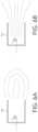
- FIG. 6 Ais a schematic diagram of a plasma plume having a diffuse profile.
- FIG. 6 Bis a schematic diagram of a plasma plume having a W-mode profile.
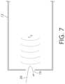
- FIG. 7is a schematic diagram illustrating the propellant flow when P H exceeds P P .
- FIG. 8is a cross-sectional view of a multi-aperture propellant injector.
- FIGS. 9 A- 9 Dare schematic drawings showing exemplary aperture placement patterns for use on a propellant injector.
- the present inventionprovides an electrothermal RF thruster design and associated propellant delivery system that may utilize a variety of propellants, including condensable propellants such as water vapor and iodine.
- propellantsincluding condensable propellants such as water vapor and iodine.
- one embodiment of the inventionprovides unique components and design characteristics that facilitate the use of water vapor as a propellant, but which can be applied to other primary propellant species and particularly condensable propellant species.
- the disclosed electrothermal RF thruster design and associated componentsmay be miniaturized to the mass, volume, and power budget of Cube Satellites (CubeSats) to meet the propulsion needs of the small satellite ( ⁇ 5 to ⁇ 500 kg) constellations and all-electric satellite buses.
- Propulsion systems constructed according to the principles described hereinmay be simple, scalable, robust, and relatively inexpensive compared to existing systems using other propulsion technologies.
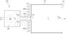
- FIG. 1is a schematic diagram of the core components of a plasma production device 10 and associated components.
- the plasma production device 10includes a plasma liner 12 (also referred to as a plasma chamber) with a closed end 14 and an open end 15 .
- a propellantis injected into the plasma liner 12 from the closed end 14 in the direction of the open end 15 and is energized therein to produce plasma.
- a propellant delivery system 20is located external to the plasma liner 12 and includes at least a propellant tank 22 and a plenum 24 .
- the propellant tank 22serves as a reservoir for pressurized and/or condensed propellant 26 .
- the propellant tank 22is configured to deliver a flow of the propellant 26 to the plenum 24
- the plenum 24is configured to deliver the propellant 26 to the interior of the plasma liner 12 .
- the propellant delivery system 20also comprises a flow regulator 28 configured to meter the flow of the propellant 26 between the propellant tank 22 and the plenum 24 .
- the plasma liner 12is surrounded by an antenna assembly 40 through which an alternating current is driven at a specified frequency.
- the antenna assembly 40is configured to radiate radio frequency (RF) energy into the plasma liner 12 .
- RFradio frequency
- the RF energymay radiate at frequencies in the high frequency (HF) to very high frequency (VHF) bands (from 3 to 30 MHz and 30 to 300 MHz, respectively). Other frequencies also may be used.
- the antenna assembly 40may include a flat spiral portion 40 a that is disposed against the exterior surface of the closed end 14 of the plasma liner 12 (or at least in close proximity to the closed end 14 ), and/or a coiled portion 40 b wrapped around the body of the plasma liner 12 in the direction of the open end 15 .
- the flat spiral portion 40 ahas a spiral configuration that expands in a radial direction from a central point but with no change/extension of the coils in a longitudinal direction. In other words, a “flat” spiral is planar.
- the coil portion 40 bmay be a standard coil (e.g., half-helix, helical, etc.) or another suitable antenna configuration.
- the combination of the flat spiral portion 40 a and the coiled portion 40 bmay be referred to as a “flat spiral coil hybrid” antenna (“FSCH” antenna).
- FSCHflat spiral coil hybrid antenna
- the plane of the flat spiral portion 40 ais perpendicular to the longitudinal axis of the coiled portion 40 b .
- the FSCH antennais configured to cause a constructive interference in magnetic fields produced in the plasma liner 12 and to cause ionization of the propellant 26 into plasma when the propellant 26 is exposed to the antenna's RF field under appropriate pressure and power conditions as described herein.
- the alternating current to the antenna assembly 40is supplied from a power control system 50 such as a terrestrial alternating current power source (e.g., grid power), or from solar panels and/or DC batteries for space (on-orbit) applications.
- a power control system 50such as a terrestrial alternating current power source (e.g., grid power), or from solar panels and/or DC batteries for space (on-orbit) applications.
- DCdirect current
- ACalternating current
- a power amplifieralso may be used to boost the power of the alternating current, and a frequency modulator may be used to set its frequency.
- antenna assembly 40is configured to deliver RF energy into plenum 24 and plasma liner 12 at a desired power and frequency.
- the flat spiral portion of an FSCHmay be configured and positioned such that the generated RF energy is delivered to both while coiled portion delivers RF energy substantially only to plasma liner 12 .
- the flat spiral portionis “sandwiched” between plasma liner 12 and plenum 24 such that the flat spiral portion delivers a substantial amount of RF energy into the plenum.
- a magnet system 60having radially-disposed magnets 62 , surrounds at least a portion of the body of the plasma liner 12 .
- the magnets 62are coaxially aligned relative to the longitudinal axis of the plasma liner 12 , and each magnet 62 produces a magnetic field of the same polarity (either positive or negative) within the plasma liner 12 .
- the magnet system 60also may include a planar magnet 66 in combination with the radially-disposed magnets 62 and disposed at or in close proximity to the closed end 14 .
- the magnet system 60acts to prevent the plasma ions from impacting the interior surface of the liner 12 .
- FIG. 2illustrates the principles of plenum 24 design and integration with plasma liner 12 .
- plenum 24generally serves as an antechamber for propellant 26 as it transitions from tank 22 to plasma liner 12 .
- the propellant pressure in plenum 24(“P P ”) is equal to or greater than (preferably greater than) the propellant pressure in plasma liner 12 (“P L ”).
- Higher plenum pressurescan be maintained by a constricting aperture 16 located in the propellant flow path between plenum 24 and plasma liner 12 .
- plenum 24at least serves as a propellant pressure reservoir.
- plasma ignitionoccurs within plenum 24 such that high-energy electrons are delivered into plasma liner 12 and aid in plasma ignition within that chamber.
- plenum 24may be constructed of the same or similar materials as described herein for plasma liner 12 .
- Plenum 24comprises a housing 41 (also referred to as a plenum chamber) having an upstream end 42 and a downstream end 44 defining an inner volume 46 therebetween.
- Plenum 24receives propellant 26 at its upstream end 42 from the propellant source 22 , collects the propellant 26 within its inner volume 46 and dispenses the propellant 26 into the plasma liner 12 through its downstream end 44 (e.g., through the aperture 16 or other type of propellant injector device).
- Aperture 16defines the gate in the fluid flow path between plenum 24 and plasma liner 12 through which propellant 26 passes.
- a passageway 45(e.g., tubing) is disposed between the downstream end 44 of plenum 24 and the input to aperture 16 to deliver propellant 26 from plenum 24 to aperture 16 .
- passageway 45is incorporated directly into plenum 24 and/or aperture 16 .
- aperture 16may be centrally located in closed end 14 of plasma liner 12 (e.g., in the center of the flat spiral portion of antenna 40 ). In some embodiments, aperture 16 is configured to maintain P P >P L . In other embodiments, the aperture 16 may be located in other areas with respect to the plasma liner 12 (e.g., on the longitudinal sides of the liner 12 ) and plenum 24 , as other design specifics and variables may dictate. In other embodiments, multiple apertures 16 in different locations may be used.
- the volume of plenum 24is less than the volume of plasma liner 12 .
- the shape of plenum 24is chosen to ensure that the structural and functional features are met.
- Plenum 24may be designed to hold a particular propellant pressure P P , to be sufficiently close to the antenna assembly 40 to cause ionization of the propellant 26 within the plenum 24 , and/or to maximize component packing (i.e., thruster assembly) into the smallest three-dimensional volume.
- plenum 24may have a cylindrical shape (i.e., substantially circular in cross-section) and, optionally, may comprise one or more magnets (e.g., annular magnets) to contain the plasma away from housing 41 (i.e., towards the center of plenum 24 ) and/or direct plasma in a downstream direction.
- magnetse.g., annular magnets
- the inner volume 46 of the plenum 24receives RF energy EM 1 from the antenna assembly 40 , for example, from the flat spiral portion 40 a , causing a portion of the propellant 26 within the inner volume 46 to ionize.
- the propellant's pressure P p within the plenum 24is set to optimize the conditions necessary for the propellant 26 to ionize.
- the passageway 45receives RF energy EM 1 causing a portion of the propellant 26 within the passageway 45 to ionize.
- FIG. 4is a graph showing the probability of propellant ionization within the plenum 24 vs. the product of propellant pressure and voltage (P p ⁇ V) within the plenum 24 .
- the plenum 24may be designed to provide a propellant pressure P p equal to P optimal (or within 10% of P optimal as shown by the bounds P O1 -P O2 ) to maximize the ionization efficiency of the propellant within the plenum 24 .
- Ionization within the plenum 24 and/or passageway 45provides electrons (seed electrons) that may flow into the plasma liner 12 , where in combination with the RF energy provided by the antenna assembly 40 , may induce energization of the propellant 26 into plasma within the plasma liner 12 .
- the plenum 24acts as a small source plasma ignition system, and the propellant energization may be more easily achieved within the plasma liner 12 than in a system without a plenum.
- the higher plenum pressure relative to the plasma liner pressurefacilitates initial plasma ignition within the plenum. High energy electrons from that plasma ignition are then fed into plasma liner 12 which facilitate plasma ignition in the latter chamber despite the fact that the ignition probability may be lower compared to the plenum because of the lower plasma liner pressure.
- the propellant's pressure P p within the plenum 24may be about 1 ⁇ -10,000 ⁇ of the propellant's pressure P L within the plasma liner 12 , including, for example, about 1, 2, 5, 10, 25, 50, 100, 500, 1,000, 2,500, 5,000, 7,500, or 10,000 times.
- the propellant pressure within the plenum 24 (“P p ”)may be about 0.001, 0.002, 0.005, 0.01, 0.05, 0.1, 0.5, 1, 2, 3, 4, 5, 6, 7, 8, 9, 10 Torr or more.
- the propellant pressure within the plasma liner(“P L ”) may be about 0.001, 0.002, 0.005, 0.01, 0.05, 0.1, 0.5, 1, 2, 3, 4, 5, 6, 7, 8, 9, 10 Torr or more, but in any event, P P is equal to or at least slightly greater than P L .
- the plenum's inner volume 46may be about 1%-50% of the plasma liner inner volume including, for example about 1%, 2.5%, 5%, 7.5%, 10%, 15%, 20%, 25%, 30%, 35%, 40%, 45%, or 50%, or less than about 5%, 7.5%, 10%, 15%, 20%, 25%, 30%, 35%, 40%, 45%, or 50% of the plasma liner inner volume.
- plasma production within the plasma liner 12may operate at different steady-state modes with different plasma density profiles versus position in the liner depending on the propellant used and the conditions within the liner 12 .
- these modesmay produce diffuse plasma and/or plasma with parabolic density profiles such as a psi-mode (“ ⁇ -mode”) plasma.
- ⁇ -modepsi-mode
- the bulk plasmahas a higher density along the longitudinal midline X ML of the liner 12 than towards the liner's periphery (e.g., a centrally-peaked mode with a high-density core).
- a standard plasma production devicedispenses propellant into the closed end of the liner through an aperture located at the midline X ML .
- This standard configurationinjects propellant directly into the high density region of the plasma.
- propellantse.g., water vapor
- FIG. 5shows the relationship between the applied RF power and the resulting thrust T W when Using water vapor as the propellant 26 .
- the thrust T Wlinearly increases as expected as the RF power is ramped through lower values until an RF power level of P Max is reached.
- the plasma production device 10includes propellant injector 70 having multiple apertures 80 at its closed end 14 .
- Propellant injector 70has an outer face 72 , an inner face 74 and a propellant flow path 76 configured therebetween.
- Outer face 72includes at least one outer face aperture 78
- inner face 74includes two or more inner face apertures 80 .
- Injector 70receives propellant 26 from the upstream propellant delivery system 20 into outer face aperture 78 and dispenses propellant 26 downstream into plasma liner 12 through two or more inner face apertures 80 .
- injector 70is configured to provide multiple propellant flow paths entering plasma liner 12 in contrast to the traditional configuration that provides only a single propellant inlet aligned with the midline axis X ML of plasma liner 12 .
- injector 70Various configurations and features of injector 70 are described in detail below.
- Outer face aperture 78may be aligned with the midline axis X ML of the plasma liner 12 or it may be offset from this axis.
- Inner face 74may have a first inner face aperture 80 - 1 aligned with the midline axis X ML of the plasma liner 12 , and at least a second inner face aperture 80 - 2 offset from the midline axis X ML . (See, for example, FIG. 9 C .)
- inner face 74may not have an aperture aligned with midline axis X ML such that all apertures 80 are offset from midline axis X ML .
- Propellant 26flows through the outer face aperture 78 and into plasma liner 12 via the inner face apertures 80 .
- propellant 26 entering the liner 12 at this laterally offset locationmay not be blocked or otherwise obstructed by the high-pressure P h region concentrated along the midline X ML of the liner 12 . Instead, propellant 26 enters liner 12 at this laterally offset location, is ionized, the ions are relegated towards the midline by the magnetic fields, and eventually ejected from liner 12 creating thrust.
- the lateral offset between the liner's midline axis X ML and the laterally offset inner aperture(s) 80 - 1 and/or 80 - 2is chosen to place the aperture(s) 80 - 1 and/or 80 - 2 sufficiently outside the high-pressure P h region within the liner 12 .
- FIGS. 9 A- 9 Dillustrate a cross-sectional view along axis A-A ( FIG. 8 ) showing exemplary patterns for apertures 80 including apertures arranged in a single ring ( FIG. 9 A ), concentric rings ( FIG. 9 B ), a grid ( FIG. 9 C ), and a random pattern ( FIG. 9 D ).
- the outer face 72includes two or more outer face apertures 78 in communication with the two or more inner face apertures 80 .
- the injector 70receives propellant 26 upstream from the propellant delivery system 20 into its two or more outer face apertures 78 and dispenses the propellant 26 downstream into the plasma liner 12 through its two or more inner face apertures 80 .
- the inner face apertures 80may be placed and arranged as described above with respect to the other embodiments.
- One or more of the two or more outer face apertures 78may be laterally offset from midline X ML of the plasma liner 12 .
- the Systemas a Thrust-Providing Device
- the plasma production device 10is configured as a thrust-producing device.
- the propellant 26is dispensed into the plasma liner 12 (via the plenum 24 , aperture 16 and/or the injector 70 ) and is energized into plasma by the RF energy provided by the antenna assembly 40 .
- the liner 10 and antenna 40are positioned inside a generated magnetic field provided by the magnet system 60 .
- the magnetic fieldshave a specified strength as a function of position within the plasma liner 12 .
- the magnetic fieldsrapidly expand radially in the reference frame of an accelerated plasma particle traveling out of the liner 12 thereby forming a “magnetic nozzle”.
- the magnetic field strength inside liner 12is such that the ions that are generated within the liner 12 are “weakly magnetized,” which implies that ions under a specific temperature perpendicular to the magnetic field will not have orbits that intersect the inner wall of liner 12 .
- the magnetic field geometry within liner 12ensures that electrons maintain enough time in regions of high neutral (i.e., non-ionized propellant 26 ) density to produce significant ionization of the propellant gas 26 via electron collisions with the neutral particles, and that electrons that are lost are largely lost via expansion in the magnetic nozzle, rather than upstream towards the closed end 14 of liner 12 .
- the rapid flux of electrons into the plume of the thrustercreates a momentary charge imbalance in the thruster.
- the slower positively-charged propellant (e.g., water) ionsare then pushed out of the plasma liner 12 via the charge imbalance at a rate sufficient to satisfy overall ambipolar fluxes of particles out of the system.
- the ion acceleration generated thereinis the primary source of thrust when the plasma liner 12 and its associated components are integrated into a thruster.
Landscapes
- Engineering & Computer Science (AREA)
- Chemical & Material Sciences (AREA)
- Combustion & Propulsion (AREA)
- Physics & Mathematics (AREA)
- Plasma & Fusion (AREA)
- Mechanical Engineering (AREA)
- General Engineering & Computer Science (AREA)
- Spectroscopy & Molecular Physics (AREA)
- Remote Sensing (AREA)
- Aviation & Aerospace Engineering (AREA)
- Plasma Technology (AREA)
Abstract
Description
- (a) a plasma production chamber having a first closed end comprising an aperture and a second open end;
- (b) a radio frequency (RF) antenna external to the plasma production chamber, electrically coupled to an AC power source, and configured to deliver an RF energy to an interior region of the plasma production chamber;
- (c) a propellant tank and flow regulator in communication with the plasma production chamber and configured to deliver a propellant into the plasma production chamber; and
- (d) a plenum, wherein the plenum is disposed between the propellant tank and the plasma production chamber;
- wherein the plenum is adapted to accept propellant at an upstream end from the propellant tank and dispense propellant at a downstream end into the plasma production chamber through the aperture; and
- wherein the plasma production device is configured such that, when propellant is flowing from the propellant tank to the plasma production chamber, the propellant has a plenum pressure (Pp) that is greater than a plasma production chamber pressure (Pc).
- (a) a downstream plasma production chamber having a first closed end and a second open end wherein the closed end comprises a propellant injector providing a propellant flow path between an outer face and an inner face;
- (b) a radio frequency (RF) antenna external to the plasma production chamber, electrically coupled to an AC power source, and configured to deliver an RF energy to an interior region of the plasma production chamber;
- (c) an upstream propellant tank and flow regulator in communication with the injector; and
- wherein the injector comprises at least one outer face aperture and two or more inner face apertures, wherein the propellant tank is in communication with the at least one outer face aperture and the at least one outer face aperture is in communication with the inner face apertures; and
- wherein at least one inner face aperture is disposed laterally relative to the longitudinal axis of the plasma production chamber.
P=kη·T
- where:
- P is the pressure;
- k is “Boltzamnn's constant”
- η is the density of the mass; and
- T is the mass's temperature.
Claims (18)
Priority Applications (1)
| Application Number | Priority Date | Filing Date | Title |
|---|---|---|---|
| US17/635,677US12195205B2 (en) | 2019-09-04 | 2020-09-01 | Propellant injector system for plasma production devices and thrusters |
Applications Claiming Priority (3)
| Application Number | Priority Date | Filing Date | Title |
|---|---|---|---|
| US201962895816P | 2019-09-04 | 2019-09-04 | |
| PCT/US2020/048924WO2021046044A1 (en) | 2019-09-04 | 2020-09-01 | Propellant injector system for plasma production devices and thrusters |
| US17/635,677US12195205B2 (en) | 2019-09-04 | 2020-09-01 | Propellant injector system for plasma production devices and thrusters |
Publications (2)
| Publication Number | Publication Date |
|---|---|
| US20220281620A1 US20220281620A1 (en) | 2022-09-08 |
| US12195205B2true US12195205B2 (en) | 2025-01-14 |
Family
ID=74853322
Family Applications (1)
| Application Number | Title | Priority Date | Filing Date |
|---|---|---|---|
| US17/635,677Active2040-11-11US12195205B2 (en) | 2019-09-04 | 2020-09-01 | Propellant injector system for plasma production devices and thrusters |
Country Status (3)
| Country | Link |
|---|---|
| US (1) | US12195205B2 (en) |
| EP (1) | EP4026159A4 (en) |
| WO (1) | WO2021046044A1 (en) |
Families Citing this family (1)
| Publication number | Priority date | Publication date | Assignee | Title |
|---|---|---|---|---|
| CN113306746B (en)* | 2021-05-26 | 2022-10-14 | 成都天巡微小卫星科技有限责任公司 | Iodine working medium electric propulsion storage and supply system based on sonic nozzle flow control |
Citations (51)
| Publication number | Priority date | Publication date | Assignee | Title |
|---|---|---|---|---|
| US2992345A (en) | 1958-03-21 | 1961-07-11 | Litton Systems Inc | Plasma accelerators |
| US3173248A (en) | 1960-11-07 | 1965-03-16 | Litton Systems Inc | Ionization and plasma acceleration apparatus |
| US3388291A (en) | 1964-08-31 | 1968-06-11 | Electro Optical Systems Inc | Annular magnetic hall current accelerator |
| US4301391A (en) | 1979-04-26 | 1981-11-17 | Hughes Aircraft Company | Dual discharge plasma device |
| US4548033A (en) | 1983-06-22 | 1985-10-22 | Cann Gordon L | Spacecraft optimized arc rocket |
| US4862032A (en) | 1986-10-20 | 1989-08-29 | Kaufman Harold R | End-Hall ion source |
| US4909914A (en) | 1985-05-11 | 1990-03-20 | Canon Kabushiki Kaisha | Reaction apparatus which introduces one reacting substance within a convergent-divergent nozzle |
| US4978071A (en) | 1989-04-11 | 1990-12-18 | General Electric Company | Nozzle with thrust vectoring in the yaw direction |
| US5339623A (en) | 1991-12-27 | 1994-08-23 | Matra Marconi Space Uk Limited | Singly fueled multiple thrusters simultaneously energized by a common power supply |
| US5418431A (en) | 1993-08-27 | 1995-05-23 | Hughes Aircraft Company | RF plasma source and antenna therefor |
| US5751113A (en) | 1996-04-01 | 1998-05-12 | Space Power, Inc. | Closed electron drift hall effect plasma accelerator with all magnetic sources located to the rear of the anode |
| US5945781A (en) | 1995-12-29 | 1999-08-31 | Societe Nationale D'etude Et De Construction De Moteurs D'aviation | Ion source with closed electron drift |
| US6293090B1 (en) | 1998-07-22 | 2001-09-25 | New England Space Works, Inc. | More efficient RF plasma electric thruster |
| US6334302B1 (en)* | 1999-06-28 | 2002-01-01 | The United States Of America As Represented By The Administrator Of The National Aeronautics And Space Administration | Variable specific impulse magnetoplasma rocket engine |
| US20020008451A1 (en) | 2000-04-11 | 2002-01-24 | Satis Rtc Photonics System Ltd. | Plasma Source |
| US6449941B1 (en) | 1999-04-28 | 2002-09-17 | Lockheed Martin Corporation | Hall effect electric propulsion system |
| US6609363B1 (en) | 1999-08-19 | 2003-08-26 | The United States Of America As Represented By The Secretary Of The Air Force | Iodine electric propulsion thrusters |
| US6771026B2 (en) | 2002-06-12 | 2004-08-03 | Tokyo Electron Limited | Plasma generation by mode-conversion of RF-electromagnetic wave to electron cyclotron wave |
| US20060064984A1 (en) | 2004-09-27 | 2006-03-30 | Gratton Jason A | Throat retention apparatus for hot gas applications |
| US7176469B2 (en) | 2002-05-22 | 2007-02-13 | The Regents Of The University Of California | Negative ion source with external RF antenna |
| US20080093506A1 (en) | 2004-09-22 | 2008-04-24 | Elwing Llc | Spacecraft Thruster |
| US7400096B1 (en) | 2004-07-19 | 2008-07-15 | The United States Of America As Represented By The Administrator Of The National Aeronautics And Space Administration | Large area plasma source |
| WO2008100642A2 (en) | 2007-02-16 | 2008-08-21 | Ad Astra Rocket Company | Improved plasma source |
| US7461502B2 (en) | 2003-03-20 | 2008-12-09 | Elwing Llc | Spacecraft thruster |
| US7498592B2 (en) | 2006-06-28 | 2009-03-03 | Wisconsin Alumni Research Foundation | Non-ambipolar radio-frequency plasma electron source and systems and methods for generating electron beams |
| US20090166554A1 (en) | 2007-12-28 | 2009-07-02 | Varian Semiconductor Equipment Associates, Inc. | Techniques for providing a multimode ion source |
| US7679025B1 (en) | 2005-02-04 | 2010-03-16 | Mahadevan Krishnan | Dense plasma focus apparatus |
| US20110226422A1 (en) | 2010-02-02 | 2011-09-22 | The Regents Of The University Of California | Rf-driven ion source with a back-streaming electron dump |
| US20120080148A1 (en) | 2010-09-30 | 2012-04-05 | Fei Company | Compact RF Antenna for an Inductively Coupled Plasma Ion Source |
| US20120217876A1 (en) | 2011-02-25 | 2012-08-30 | Trustees Of Princeton University | Systems and Methods for Cylindrical Hall Thrusters with Independently Controllable Ionization and Acceleration Stages |
| US20130067883A1 (en) | 2004-09-22 | 2013-03-21 | Elwing Llc | Spacecraft thruster |
| US20130200219A1 (en) | 2010-08-12 | 2013-08-08 | Snecma | Electric thruster, a method of stopping an electric engine included in such a thruster, and a satellite including such a thruster |
| US8610356B2 (en) | 2011-07-28 | 2013-12-17 | Busek Co., Inc. | Iodine fueled plasma generator system |
| US8635850B1 (en) | 2008-08-29 | 2014-01-28 | U.S. Department Of Energy | Ion electric propulsion unit |
| US20140202131A1 (en) | 2011-05-12 | 2014-07-24 | Roderick William Boswell | Plasma micro-thruster |
| US20140263181A1 (en) | 2013-03-15 | 2014-09-18 | Jaeyoung Park | Method and apparatus for generating highly repetitive pulsed plasmas |
| US8875485B2 (en) | 2010-04-06 | 2014-11-04 | The George Washington University | Micro-cathode thruster and a method of increasing thrust output for a micro-cathode thruster |
| WO2015031447A1 (en) | 2013-08-27 | 2015-03-05 | The Regents Of The University Of Michigan | Converging/diverging magnetic nozzle |
| WO2015031450A1 (en) | 2013-08-27 | 2015-03-05 | The Regents Of The University Of Michigan | Electrodeless plasma thruster |
| CN104411082A (en) | 2014-11-12 | 2015-03-11 | 中国科学院深圳先进技术研究院 | Plasma source system and plasma generating method |
| WO2015155004A1 (en) | 2014-04-10 | 2015-10-15 | Justus-Liebig-Universität Giessen | Ion drive and method for operating an ion drive |
| US9215789B1 (en) | 2014-05-20 | 2015-12-15 | King Abdulaziz City For Science And Technology | Hybrid plasma source |
| US9334855B1 (en) | 2005-12-01 | 2016-05-10 | Busek Company, Inc. | Hall thruster for use with a condensable propellant |
| US9591741B2 (en) | 2011-12-29 | 2017-03-07 | Onera (Office National D'etudes Et De Recherches Aerospatiales) | Plasma thruster and method for generating a plasma propulsion thrust |
| US20170210493A1 (en)* | 2014-07-30 | 2017-07-27 | Safran Aircraft Engines | Spacecraft propulsion system and method |
| JP6263179B2 (en) | 2012-08-02 | 2018-01-17 | スリーエム イノベイティブ プロパティズ カンパニー | Portable electronic device and vapor sensor card |
| US20180043457A1 (en) | 2016-08-15 | 2018-02-15 | Illinois Tool Works Inc. | Device for providing a laminar flow of shielding gas in a welding device |
| WO2018118223A1 (en) | 2016-12-21 | 2018-06-28 | Phase Four, Inc. | Plasma production and control device |
| US20180216605A1 (en) | 2015-08-31 | 2018-08-02 | Ecole Polytechnique | Gridded ion thruster with integrated solid propellant |
| US20180310393A1 (en) | 2015-10-27 | 2018-10-25 | Aernnova | Plasma accelerator with modulated thrust |
| US20190107104A1 (en) | 2017-10-09 | 2019-04-11 | Phase Four, Inc. | Electrothermal radio frequency thruster and components |
- 2020
- 2020-09-01EPEP20861790.2Apatent/EP4026159A4/enactivePending
- 2020-09-01USUS17/635,677patent/US12195205B2/enactiveActive
- 2020-09-01WOPCT/US2020/048924patent/WO2021046044A1/ennot_activeCeased
Patent Citations (68)
| Publication number | Priority date | Publication date | Assignee | Title |
|---|---|---|---|---|
| US2992345A (en) | 1958-03-21 | 1961-07-11 | Litton Systems Inc | Plasma accelerators |
| US3173248A (en) | 1960-11-07 | 1965-03-16 | Litton Systems Inc | Ionization and plasma acceleration apparatus |
| US3388291A (en) | 1964-08-31 | 1968-06-11 | Electro Optical Systems Inc | Annular magnetic hall current accelerator |
| US4301391A (en) | 1979-04-26 | 1981-11-17 | Hughes Aircraft Company | Dual discharge plasma device |
| US4548033A (en) | 1983-06-22 | 1985-10-22 | Cann Gordon L | Spacecraft optimized arc rocket |
| US4909914A (en) | 1985-05-11 | 1990-03-20 | Canon Kabushiki Kaisha | Reaction apparatus which introduces one reacting substance within a convergent-divergent nozzle |
| US4862032A (en) | 1986-10-20 | 1989-08-29 | Kaufman Harold R | End-Hall ion source |
| US4978071A (en) | 1989-04-11 | 1990-12-18 | General Electric Company | Nozzle with thrust vectoring in the yaw direction |
| US5339623A (en) | 1991-12-27 | 1994-08-23 | Matra Marconi Space Uk Limited | Singly fueled multiple thrusters simultaneously energized by a common power supply |
| US5418431A (en) | 1993-08-27 | 1995-05-23 | Hughes Aircraft Company | RF plasma source and antenna therefor |
| US5945781A (en) | 1995-12-29 | 1999-08-31 | Societe Nationale D'etude Et De Construction De Moteurs D'aviation | Ion source with closed electron drift |
| US5751113A (en) | 1996-04-01 | 1998-05-12 | Space Power, Inc. | Closed electron drift hall effect plasma accelerator with all magnetic sources located to the rear of the anode |
| US6293090B1 (en) | 1998-07-22 | 2001-09-25 | New England Space Works, Inc. | More efficient RF plasma electric thruster |
| US6449941B1 (en) | 1999-04-28 | 2002-09-17 | Lockheed Martin Corporation | Hall effect electric propulsion system |
| US6334302B1 (en)* | 1999-06-28 | 2002-01-01 | The United States Of America As Represented By The Administrator Of The National Aeronautics And Space Administration | Variable specific impulse magnetoplasma rocket engine |
| US6609363B1 (en) | 1999-08-19 | 2003-08-26 | The United States Of America As Represented By The Secretary Of The Air Force | Iodine electric propulsion thrusters |
| US20020008451A1 (en) | 2000-04-11 | 2002-01-24 | Satis Rtc Photonics System Ltd. | Plasma Source |
| US7176469B2 (en) | 2002-05-22 | 2007-02-13 | The Regents Of The University Of California | Negative ion source with external RF antenna |
| US6771026B2 (en) | 2002-06-12 | 2004-08-03 | Tokyo Electron Limited | Plasma generation by mode-conversion of RF-electromagnetic wave to electron cyclotron wave |
| US7461502B2 (en) | 2003-03-20 | 2008-12-09 | Elwing Llc | Spacecraft thruster |
| US7400096B1 (en) | 2004-07-19 | 2008-07-15 | The United States Of America As Represented By The Administrator Of The National Aeronautics And Space Administration | Large area plasma source |
| US20080093506A1 (en) | 2004-09-22 | 2008-04-24 | Elwing Llc | Spacecraft Thruster |
| US20130067883A1 (en) | 2004-09-22 | 2013-03-21 | Elwing Llc | Spacecraft thruster |
| US20060064984A1 (en) | 2004-09-27 | 2006-03-30 | Gratton Jason A | Throat retention apparatus for hot gas applications |
| US7679025B1 (en) | 2005-02-04 | 2010-03-16 | Mahadevan Krishnan | Dense plasma focus apparatus |
| US9334855B1 (en) | 2005-12-01 | 2016-05-10 | Busek Company, Inc. | Hall thruster for use with a condensable propellant |
| US7498592B2 (en) | 2006-06-28 | 2009-03-03 | Wisconsin Alumni Research Foundation | Non-ambipolar radio-frequency plasma electron source and systems and methods for generating electron beams |
| US7875867B2 (en) | 2006-06-28 | 2011-01-25 | Wisconsin Alumni Research Foundation | Non-ambipolar radio-frequency plasma electron source and systems and methods for generating electron beams |
| US20100213851A1 (en) | 2007-02-16 | 2010-08-26 | Ad Astra Rocket Company | Plasma source |
| WO2008100642A2 (en) | 2007-02-16 | 2008-08-21 | Ad Astra Rocket Company | Improved plasma source |
| US8593064B2 (en) | 2007-02-16 | 2013-11-26 | Ad Astra Rocket Company | Plasma source improved with an RF coupling system |
| US20090166554A1 (en) | 2007-12-28 | 2009-07-02 | Varian Semiconductor Equipment Associates, Inc. | Techniques for providing a multimode ion source |
| US8635850B1 (en) | 2008-08-29 | 2014-01-28 | U.S. Department Of Energy | Ion electric propulsion unit |
| US20110226422A1 (en) | 2010-02-02 | 2011-09-22 | The Regents Of The University Of California | Rf-driven ion source with a back-streaming electron dump |
| US8729806B2 (en) | 2010-02-02 | 2014-05-20 | The Regents Of The University Of California | RF-driven ion source with a back-streaming electron dump |
| US8875485B2 (en) | 2010-04-06 | 2014-11-04 | The George Washington University | Micro-cathode thruster and a method of increasing thrust output for a micro-cathode thruster |
| US20130200219A1 (en) | 2010-08-12 | 2013-08-08 | Snecma | Electric thruster, a method of stopping an electric engine included in such a thruster, and a satellite including such a thruster |
| US20120080148A1 (en) | 2010-09-30 | 2012-04-05 | Fei Company | Compact RF Antenna for an Inductively Coupled Plasma Ion Source |
| US20120217876A1 (en) | 2011-02-25 | 2012-08-30 | Trustees Of Princeton University | Systems and Methods for Cylindrical Hall Thrusters with Independently Controllable Ionization and Acceleration Stages |
| US20140202131A1 (en) | 2011-05-12 | 2014-07-24 | Roderick William Boswell | Plasma micro-thruster |
| US8610356B2 (en) | 2011-07-28 | 2013-12-17 | Busek Co., Inc. | Iodine fueled plasma generator system |
| US9591741B2 (en) | 2011-12-29 | 2017-03-07 | Onera (Office National D'etudes Et De Recherches Aerospatiales) | Plasma thruster and method for generating a plasma propulsion thrust |
| JP6263179B2 (en) | 2012-08-02 | 2018-01-17 | スリーエム イノベイティブ プロパティズ カンパニー | Portable electronic device and vapor sensor card |
| US20140263181A1 (en) | 2013-03-15 | 2014-09-18 | Jaeyoung Park | Method and apparatus for generating highly repetitive pulsed plasmas |
| WO2015031447A1 (en) | 2013-08-27 | 2015-03-05 | The Regents Of The University Of Michigan | Converging/diverging magnetic nozzle |
| WO2015031450A1 (en) | 2013-08-27 | 2015-03-05 | The Regents Of The University Of Michigan | Electrodeless plasma thruster |
| US11365016B2 (en) | 2013-08-27 | 2022-06-21 | The Regents Of The University Of Michigan | Electrodeless plasma thruster |
| US11325727B2 (en) | 2013-08-27 | 2022-05-10 | The Regents Of The University Of Michigan | Converging/diverging magnetic nozzle |
| US20160200458A1 (en) | 2013-08-27 | 2016-07-14 | The Regents Of The University Of Michigan | Converging/diverging magnetic nozzle |
| US20160207642A1 (en)* | 2013-08-27 | 2016-07-21 | The Regents Of The University Of Michigan | Electrodeless plasma thruster |
| WO2015155004A1 (en) | 2014-04-10 | 2015-10-15 | Justus-Liebig-Universität Giessen | Ion drive and method for operating an ion drive |
| EP3129653B1 (en) | 2014-04-10 | 2020-09-02 | Justus-Liebig- Universitat Giessen | Ion drive and method for operating an ion drive |
| US9215789B1 (en) | 2014-05-20 | 2015-12-15 | King Abdulaziz City For Science And Technology | Hybrid plasma source |
| US20170210493A1 (en)* | 2014-07-30 | 2017-07-27 | Safran Aircraft Engines | Spacecraft propulsion system and method |
| CN104411082A (en) | 2014-11-12 | 2015-03-11 | 中国科学院深圳先进技术研究院 | Plasma source system and plasma generating method |
| US20180216605A1 (en) | 2015-08-31 | 2018-08-02 | Ecole Polytechnique | Gridded ion thruster with integrated solid propellant |
| US20180310393A1 (en) | 2015-10-27 | 2018-10-25 | Aernnova | Plasma accelerator with modulated thrust |
| US20180043457A1 (en) | 2016-08-15 | 2018-02-15 | Illinois Tool Works Inc. | Device for providing a laminar flow of shielding gas in a welding device |
| EP3560298A1 (en) | 2016-12-21 | 2019-10-30 | Phase Four, Inc. | Plasma production and control device |
| US20190390662A1 (en) | 2016-12-21 | 2019-12-26 | Phase Four, Inc. | Plasma production and control device |
| US11067065B2 (en) | 2016-12-21 | 2021-07-20 | Phase Four, Inc. | Plasma production and control device |
| WO2018118223A1 (en) | 2016-12-21 | 2018-06-28 | Phase Four, Inc. | Plasma production and control device |
| WO2019074785A1 (en) | 2017-10-09 | 2019-04-18 | Phase Four, Inc. | Electrothermal radio frequency thruster and components |
| EP3695117A1 (en) | 2017-10-09 | 2020-08-19 | Phase Four, Inc. | Electrothermal radio frequency thruster and components |
| US20190107103A1 (en) | 2017-10-09 | 2019-04-11 | Phase Four, Inc. | Electrothermal radio frequency thruster and components |
| JP2020537323A (en) | 2017-10-09 | 2020-12-17 | フェーズ フォー, インコーポレイテッド | Electric heating radio frequency thrusters and components |
| US11231023B2 (en) | 2017-10-09 | 2022-01-25 | Phase Four, Inc. | Electrothermal radio frequency thruster and components |
| US20190107104A1 (en) | 2017-10-09 | 2019-04-11 | Phase Four, Inc. | Electrothermal radio frequency thruster and components |
Non-Patent Citations (107)
| Title |
|---|
| Bathgate, S. N., et al., "Electrodeless plasma thrusters for spacecraft: a review", Plasmas Sci. Technol., 2017, vol. 19, pp. 1-24. |
| BC wire "Copper MagnetWire" (Year: 2015). |
| Berenguer "Plasma Reactors and Plasma Thrusters Modeling by Ar Complete Global Models" (Year: 2012).* |
| Blackwell D. et al., "Two-dimensional imaging ofa helicon discharge" Plasma Sources Science and Technology, Sep. 1997, 9 pages. |
| Bonoli, P. T., "Review of recent experimental and modeling progress in the lower hybrid range of frequencies at ITER relevant parameters", Physics of Plasmas, 2014, vol. 21, pp. 061508-1-061508-22. |
| Boswell R. "Very efficient plasma generation by whistler waves near the lower hybrid frequency" Plasma Physics and Controlled Fusion, vol. 26, No. 10, pp. 1147-1162, Feb. 1984. |
| Cannat, F., et al., "Optimization ofa coaxial electron cyclotron resonance plasma thruster with an analytical model", Physics of Plasmas, 2015, vol. 22, pp. 053503-1-053503-11. |
| Chabert P. et al., "Physics of Radio-Frequency Plasma" Cambridge University Press, Feb. 2011, 395 pages. |
| Charles C. "Topical Review: Plasmas for spacecraft propulsion" Journal ofPhysics D: Applied Physics, vol. 42, No. 16, Aug. 2009, 18 pages. |
| Chen, F. F., "Helicon discharges and sources: a review", Plasmas Sources Sci. Technol., 2015, vol. 24, pp. 1-25. |
| Chen, F. F., et al., "Upper Limit to Landau Damping in Helicon Discharges", Physical Review Letters, 1999, vol. 82, No. 13, pp. 2677-2680. |
| Chiravalle, V.P., et al., "Non-Equilibrium Numerical Study ofa Two-Stage Microwave Electrothermal Thruster," 27th International Electric Propulsion Conference, Oct. 15-19, 2001. 11 Pages. |
| Choi, G., "13.56 MHz, Class-E, 1 KW RF Generator using a Microsemi DRF1200 Driver/MOSFET Hybrid", retrieved from www.microsemi.com, 2013, pp. 1-10. |
| Choueiri, E. Y., et al., "Coherent Ion Acceleration using Two Electrostatic Waves", 36th AIAA/ASME/SAE/ASSE JointPropulsion Conference, Huntsville, AL, 2000, pp. 1-12. |
| Collard, T. A., et al., "A Numerical Examination ofthe Performance of Small Magnetic Nozzle Thrusters", 53rd AIA/SAE/ASEE Joint Propulsion Conference, 2017, pp. 1-16. |
| Communication pursuant to Rule 164(1) EPC issued for EP Patent Application No. 20861790.2 filed on Mar. 29, 2022, on behalf of Phase Four, Inc. Mail Date: Oct. 23, 2023. 16 Pages. |
| Communication pursuant to Rules 161(2) and 162 EPC issued for EP Patent Application No. 20861790.2 filed on Mar. 29, 2022, on behalf of Phase Four, Inc. Mail Date: Apr. 21, 2022. 3 Pages. |
| Corrected Notice of Allowability for U.S. Appl. No. 16/165,138 filed on Oct. 19, 2018, on behalf of Phase Four Inc. Mail Date: Nov. 5, 2021. 2 Pages. |
| Courtney, D. G., et al., "Diverging Cusped-Field Hall Thruster (DCHT)", 30th International Electric Propulsion Conference, Florence, Italy, 2007, pp. 1-10. |
| Dedrick, J., et al., "Transient propagation dynamics of flowing plasmas accelerated by radio-frequency electric fields", Physics of Plasmas, 2017, vol. 24, pp. 050703-1-050703-4. |
| Duchemin "Cryostorage of Propellants for Electric Propulsion" (Year: 2009).* |
| Ellingboe, A. R., et al., "Electron beam pulses produced by heliconwave excitation", Physics of Plasmas, 1995, vol. 2, No. 6, pp. 1807-1809. |
| EP Communication pursuant to Article 94(3) EPC for EP Application No. 17882721.8 filed on Oct. 30, 2017 on behalf of Phase Four, Inc. Mail Date: Nov. 10, 2021, 8 pages. |
| Extended European Search Report for EP Application No. 17882721.8 filed on Oct. 30, 2017 on behalf of Phase Four, Inc. Mail Date: Jul. 14, 2020 8 pages. |
| Extended European Search Report for EP Application No. 18865461.0 filed on Oct. 15, 2018 on behalf of Phase Four Inc. Mail Date: Jun. 9, 2021 14 pages. |
| Final Office Action for U.S. Appl. No. 14/914,056, filed Feb. 24, 2016 on behalf of Phase Four Inc Mail Date: May 14, 2019 19 pages. |
| Final Office Action for U.S. Appl. No. 14/914,056, filed Feb. 24, 2016 on behalf of Phase Four Inc Mail Date: Nov. 6, 2020 36 pages. |
| Final Office Action for U.S. Appl. No. 14/914,056, filed Feb. 24, 2016 on behalf of Phase Four Inc Mail Date: Oct. 3, 2017 25 pages. |
| Final Office Action for U.S. Appl. No. 14/914,065, filed Feb. 24, 2016 on behalf of Phase Four Inc Mail Date: Apr. 4, 2019 17 pages. |
| Final Office Action for U.S. Appl. No. 14/914,065, filed Feb. 24, 2016 on behalf of Phase Four Inc Mail Date: Oct. 2, 2017 28 pages. |
| Final Office Action for U.S. Appl. No. 14/914,065, filed Feb. 24, 2016 on behalf of Phase Four Inc Mail Date: Oct. 6, 2020 30 pages. |
| Final Office Action for U.S. Appl. No. 14/914,065, filed Feb. 24, 2016 on behalf of Phase Four, Inc. Mail Date: Dec. 27, 2021. 33 pages. |
| Final Office Action for U.S. Appl. No. 15/982,862, filed May 17, 2018 on behalf of Phase Four Inc Mail Date: Nov. 2, 2020 39 pages. |
| Final Office Action for U.S. Appl. No. 16/165,138 filed on Oct. 19, 2018 on behalf of Phase Four Inc Mail Date: Jan. 21, 2020 42 pages. |
| Final Office Action for U.S. Appl. No. 16/165,138 filed on Oct. 19, 2018, on behalf of Phase Four Inc. Mail Date: Mar. 26, 2021. 32 Pages. |
| Final Office Action for U.S. Appl. No. 16/439,205 filed on Jun. 12, 2019 on behalfof Phase Four Inc Mail Date: Nov. 24, 2020 19 pages. |
| Gerst D. et al., "Plasma drift in a low-pressure magnetized radio frequency discharge" Plasma Sources Science and Technology Institute of Physics Publishing, vol. 22 No. 1, Jan. 2013, 6 pages. |
| Gerwin, R. A., Integrity ofthe Plasma Magnetic Nozzle, Los Alamos National Laboratory, Los Alamos, New Mexico, 2009, NASA/TP-2009213439, pp. 1-120. |
| Gilland, J., "Helicon Wave Physics Impacts On Electrodeless Thruster Design", International Electric Propulsion Conference ERPS, Toulouse, France, 2003, pp. 1-10. |
| Gilland, J., et al., "Neutral pumping in a helicon discharge", Plasmas Sources Sci. Technol., 1998, pp. 416-422. |
| Hofer, R. F., et al., "A Comparison of Nude and Collimated Faraday Probes for Use with Hall Thrusters", 27th International Electric Propulsion Conference, Pasadena, CA, 2001, pp. 1-17. |
| Hopwood, J., "Review ofinductively coupled plasmas for plasma processing", Plasma Sources Sci. Technol., 1992, vol. 1, pp. 109-116. |
| Hsu, A.G., et al., "Laboratory Testing of a Modular 8-Thruster Scalable Ion Electrospray Propulsion System", retrieved from https://iepc2017.org/sites/default/files/speaker-papers/aiaa_iepc_paper_electrospray_hsu_final.pdf on May 17, 2018, pp. 1-12. |
| Huba, J.D., "NRL Plasma Formulary", Naval Research Laboratory, Washington DC, 2013. pp. 1-71. |
| International Preliminary Report on Patentability for International Application No. PCT/US2014/052856 filed on Aug. 27, 2014 on behalf of The Regents of the University of Michigan Mail Date: Mar. 1, 2016. 7 pages. |
| International Preliminary Report on Patentability for International Application No. PCT/US2014/052861 filed on Aug. 27, 2014 on behalf of The Regents of the University of Michigan Mail Date: Mar. 1, 2016 8 pages. |
| International Preliminary Report on Patentability for International PCT Application No. PCT/US2020/048924 filed on Sep. 1, 2020, filed on behalf of Phase Four, Inc. Mail Date: Sep. 28, 2021. 29 Pages. |
| International Preliminary Report on Patentability issued for International Application No. PCT/US2017/059096 filed on Oct. 30, 2017 on behalf of Phase Four Inc Mail Date: Jun. 25, 2019. 4 Pages. |
| International Preliminary Report on Patentability issued for International Application No. PCT/US2018/054555 filed on Oct. 5, 2018 on behalf of Phase Four, Inc. Mail Date: Apr. 14, 2020. 8 Pages. |
| International Search Report and Written Opinion for International Application No. PCT/US2014/052856 filed on Aug. 27, 2014 on behalf of The Regents of the University of Michigan Mail Date: Dec. 12, 2014 9 pages. |
| International Search Report and Written Opinion for International Application No. PCT/US2014/052861 filed on Aug. 27, 2014 on behalf of The Regents of the University of Michigan Mail Date: Dec. 12, 2014 8 pages. |
| International Search Report and Written Opinion for International Application No. PCT/US2017/059096 filed on Oct. 30, 2017 on behalfof Phase Four Inc Mail Date: Jan. 29, 2018 7 pages. |
| International Search Report and Written Opinion for International Application No. PCT/US2018/054555 filed on Oct. 5, 2018 on behalf of Phase Four, Inc. Mail Date: Dec. 7, 2018 15 pages. |
| International Search Report for International PCT Application No. PCT/US2020/048924 filed on Sep. 1, 2020, filed on behalfof Phase Four, Inc. Mail Date: Nov. 13, 2020. 3 Pages. |
| Jacobson, V. T., et al., "DevelopmentofVASIMR Helicon Source", 43rd Annual Meeting of the APS Division of Plasma Physics Mini-Conference on Helicon Sources, Long Beach, California, 2001, pp. 1-35. |
| Kikuchi, T., et al., "Plasma Production and Wave Propagation in a Plasma Source Using Lower Hybrid Waves", Jpn. J. Appl. Phys., 1999, vol. 38, pp. 4351-4356. |
| Kinder, R. L., et al., "Noncollisional heating and electron energy distributions in magnetically enhanced inductively coupled and helicon plasma sources", Journal of Applied Physics, 2001, vol. 90, No. 8, pp. 3699-3712. |
| Kolobov V. I. et al., "Review Article: The anomalous kin effect in gas discharge plasmas" Plasma Sources Science and Technology Institute of Physics Publishing, vol. 6 No. 2, May 1997, 17 pages. |
| Kuwahara "High-Density Helicon Plasma Thrusters Using Electrodeless Acceleration Schemes" (Year: 2015).* |
| Liou, J. J., et al., "RF MOSFET: recent advances, current status and future trends", Solid-State Electronics, 2003, vol. 47, pp. 1881-1895. |
| Longmier B. et al., "A Large Delta-V Plasma Thruster for Nanosatellites" Interplanetary Small Satellite Conference, 2014, 24 pages. |
| Longmier B. et al., "Ambipolar Ion Acceleration in the Expanding Magnetic Nozzle ofthe VASIMR VX-200i" 45th AIAA/ASME/SAE/ASEE Joint Propulsion Conference & Exhibit, Aug. 2009, 11 pages. |
| Longmier B. et al., "Ambipolar lon Acceleration in a 20,000 G Magnetic Nozzle" 2013 Abstracts IEEE International Conference on Plasma Science, Jun. 2013, 17 pages. |
| Longmier, B. W., et al., "VX-200 Magnetoplasma Thruster Performance Results Exceeding Fifty-Percent Thruster Efficiency", Journal of Propulsion and Power, 2011, vol. 27, No. 4, pp. 915-920. |
| Longmier, B.W., et al., "Ambipolar ion acceleration in an expanding magneticnozzle," Plasma Sources Sci. Technol 20 015007, 2011. 10 Pages. |
| Magee, R. M., et al., "Direct measurements ofthe ionization profile in krypton helicon plasmas", Physics of Plasmas, 2012. vol. 19, pp. 123506-1-123506-6. |
| Motomura T. et al., "Characteristics oflarge diameter, high-density helicon plasma with short axial length using a flat spiral antenna" Journal of Plasma and Fusion Research Series, vol. 8, Sep. 2009, 5 pages. |
| Nakamura, T., et al., "Direct Measurement of Electromagnetic Thrust if Electrodeless Helicon Plasma Thruster Using Magnetic Nozzle", World Academy of Science, Engineering, and Technology, 2012, vol. 6, No. 11, pp. 581-585. |
| Nishiyama, K., et al., "Development and Testing of the Hayabusa2 Ion Engine System", Joint Conference of 30th International Symposium of Space Technology and Science 34th International Electric Propulsion Conference and 6th Nano-satellite Symposium, Hyogo—Kobe, Japan, 2015, pp. 1-15. |
| Non-Final Office Action for U.S. Appl. No. 14/914,056, filed Feb. 24, 2016 on behalf of Phase Four Inc Mail Date: Jan. 19, 2017 14 pages. |
| Non-Final Office Action for U.S. Appl. No. 14/914,056, filed Feb. 24, 2016 on behalf of Phase Four Inc Mail Date: Jan. 21, 2020 35 pages. |
| Non-Final Office Action for U.S. Appl. No. 14/914,056, filed Feb. 24, 2016 on behalf of Phase Four Inc Mail Date: Jul. 10, 2018 23 pages. |
| Non-Final Office Action for U.S. Appl. No. 14/914,056, filed Feb. 24, 2016 on behalf of Phase Four, Inc. Mail Date: Jun. 24, 2021 27 pages. |
| Non-Final Office Action for U.S. Appl. No. 14/914,065, filed Feb. 24, 2016 on behalf of Phase Four Inc Mail Date: Dec. 12, 2019 19 pages. |
| Non-Final Office Action for U.S. Appl. No. 14/914,065, filed Feb. 24, 2016 on behalf of Phase Four Inc Mail Date: Dec. 14, 2016 14 pages. |
| Non-Final Office Action for U.S. Appl. No. 14/914,065, filed Feb. 24, 2016 on behalf of Phase Four Inc Mail Date: Jun. 13, 2018 18 pages. |
| Non-Final Office Action for U.S. Appl. No. 14/914,065, filed Feb. 24, 2016 on behalf of Phase Four, Inc. Mail Date: Jun. 11, 2021 30 pages. |
| Non-Final Office Action for U.S. Appl. No. 15/982,862, filed May 17, 2018 on behalf of Phase Four Inc Mail Date: Jan. 22, 2020 39 pages. |
| Non-Final Office Action for U.S. Appl. No. 16/165,138 filed on Oct. 19, 2018 on behalf of Phase Four Inc Mail Date: Aug. 14, 2020 33 pages. |
| Non-Final Office Action for U.S. Appl. No. 16/165,138 filed on Oct. 19, 2018 on behalf of Phase Four Inc Mail Date: May 16, 2019 35 pages. |
| Non-Final Office Action for U.S. Appl. No. 16/439,205, filed Jun. 12, 2019 on behalf of Phase Four Inc Mail Date: Feb. 5, 2020 19 pages. |
| Notice of Allowance for U.S. Appl. No. 14/914,056, filed Feb. 24, 2016 on behalf of Phase Four, Inc. Mail Date: Jan. 12, 2022. 12 Pages. |
| Notice of Allowance for U.S. Appl. No. 14/914,065, filed Feb. 24, 2016 on behalf of Phase Four, Inc. Mail Date: Mar. 16, 2022. 16 Pages. |
| Notice of Allowance for U.S. Appl. No. 16/165,138 filed on Oct. 19, 2018 on behalf of Phase Four Inc. Mail Date: Dec. 8, 2021. 10 Pages. |
| Notice of Allowance for U.S. Appl. No. 16/165,138 filed on Oct. 19, 2018, on behalf of Phase Four Inc. Mail Date: Sep. 22, 2021. 17 Pages. |
| Notice of Allowance for U.S. Appl. No. 16/439,205, filed Jun. 12, 2019, on behalf of Phase Four Inc. Mail Date: Jun. 10, 2021. 9 Pages. |
| Otto, A., "Chapter 1—Introduction and Review of Basic Plasma Properties", University of Alaska Fairbanks, pp. 1-22. |
| Paschen's Law. Wikipedia Page. Downloaded on Feb. 15, 2022, from https://en.wikipedia.org/wiki/Paschen%27s law. 5 Pages. |
| Pavarin D. et al., "Design of 50W Helicon Plasma Thruster" 31st International Electric Propulsion Conference, Sep. 2009, 9 pages. |
| Plihon N. et al. "Experimental investigation of double layers in expanding plasmas" Physics of Plasmas, vol. 14, Jan. 2007, 16 pages. |
| Power J. et al., "Developmentofa High Power Microwave Thruster, With a Magnetic Nozzle, for Space Applications" 24th Microwave Power Symposium, Aug. 1989. |
| Scime, E. E., et al., "The hothelicon experiment (HELIX) and the large experimenton instabilities and anisotropy (LEIA)", J. Plasma Physics, 2014, pp. 1-22. |
| Shabshelowitz, A., et al., "Performance and Probe Measurements of a Radio-Frequency Plasma Thruster", Journal of Propulsion and Power, 2013, vol. 29, No. 4, pp. 919-929. |
| Siddiqui, M. U. et al., "Electron heating and density production in microwave-assisted helicon plasmas", Plasma Sources Sci. Technol., 2015, vol. 24, pp. 1-13. |
| Siddiqui, M. U., et al., "First Performance Measurements of the Phase Four RF Thruster", 35th International Electric Propulsion Conference, Atlanta, GA, 2017, pp. 1-21. |
| Siddiqui, M.U., "Updated Performance Measurements ofthe Phase Four RF Thruster", 34th Space Symposium, 2018, pp. 1-7. |
| Stephan, K. et al., "Absolute partial electron impactionization cross sections of Xe from threshold up to 180 eV", Journal of Chemical Physics, 1984, vol. 81, No. 7, pp. 3116-3117. |
| Supplementary European Extended Search Report issued for EP Patent Application No. 20861790.2 filed on Mar. 29, 2022, on behalf of Phase Four, Inc. Mail Date: Feb. 21, 2024. 16 Pages. |
| Takahashi K. et al., "Effect of magnetic and physical nozzles on plasma thruster performance" Plasma Sources Science and Technology Institute of Physics Publishing, vol. 23 No. 4, Jul. 2014, 9 pages. |
| Takahashi K. et al., "Ion acceleration in a solenoid-free plasma expanded by permanent magnets" Physics of Plasmas, Aug. 2008, 4 pages. |
| Takahashi, K., et al., "Direct thrust measurement of a permanent magnet helicon double layer thruster", Applied Physics Letters, 2011, vol. 98, pp. 141503-1-141503-3. |
| Takahiro N. et al., "Thrust Performance of High Magnetic Field Permanent Magnet Type Helicon Plasma Thruster" 50th AIAA/ASME/SAE/ASEE Joint Propulsion Conference, Jul. 2014, pp. 1-8. |
| Wikipedia: "Gyroradius"(Year: 2019). |
| Wikipedia: Electron Cyclotron Resonance (Year: 2019). |
| Williams, L.T., et al., "Thrust Measurements ofa Radio Frequency Plasma Source", Journal of Propulsion and Power, 2013, vol. 29, No. 3, pp. 520-527. |
| Written Opinion for International PCT Application No. PCT/US2020/048924 filed on Sep. 1, 2020, filed on behalf of Phase Four, Inc. Mail Date: Nov. 13, 2020. 6 Pages. |
| Yildiz M. et al., "Global Energy Transfer Model of Microwave Induced Plasma in a Microwave Electrothermal Thruster Resonant Cavity" Joint Conference of 30th International Symposium on Space Technology and Science, Jul. 2015, 10 pages. |
Also Published As
| Publication number | Publication date |
|---|---|
| EP4026159A4 (en) | 2024-03-20 |
| WO2021046044A1 (en) | 2021-03-11 |
| EP4026159A1 (en) | 2022-07-13 |
| US20220281620A1 (en) | 2022-09-08 |
Similar Documents
| Publication | Publication Date | Title |
|---|---|---|
| JP6120878B2 (en) | Plasma thruster and method for generating plasma thrust | |
| Mazouffre | Electric propulsion for satellites and spacecraft: established technologies and novel approaches | |
| Bathgate et al. | Electrodeless plasma thrusters for spacecraft: a review | |
| EP1640608B1 (en) | Spacecraft thruster | |
| US6334302B1 (en) | Variable specific impulse magnetoplasma rocket engine | |
| US11365016B2 (en) | Electrodeless plasma thruster | |
| US11231023B2 (en) | Electrothermal radio frequency thruster and components | |
| JP2022105221A (en) | System and method for improved sustainability of high-performance frc and harmonic high-speed wave electron heating in high-performance frc | |
| Rafalskyi et al. | Brief review on plasma propulsion with neutralizer-free systems | |
| Koizumi et al. | Miniature microwave discharge ion thruster driven by 1 watt microwave power | |
| WO2020117354A2 (en) | Optimized rf-sourced gridded ion thruster and components | |
| US20130067883A1 (en) | Spacecraft thruster | |
| US7395656B2 (en) | Dual mode hybrid electric thruster | |
| WO2013188393A1 (en) | Dual use hydrazine propulsion thruster system | |
| CN206487598U (en) | Plasma engines | |
| CN110545612A (en) | A Multilevel Ionized Rotating Magnetic Field Accelerated Helicon Wave Plasma Source | |
| US12195205B2 (en) | Propellant injector system for plasma production devices and thrusters | |
| WO2021154124A1 (en) | Module with a multi-channel plasma propulsion system for a small spacecraft | |
| Kirtley et al. | Steady operation of an FRC thruster on Martian atmosphere and liquid water propellants | |
| RU2764823C1 (en) | Bidirectional wave plasma engine for a space vehicle | |
| Cassady et al. | VASIMR technological advances and first stage performance results | |
| WO2023037138A1 (en) | Electrodeless plasma thruster with close ring-shaped gas discharge chamber | |
| Krishnamurthy | Development and characterization of an inertial electrostatic confinement thruster | |
| Dubois et al. | Ion acceleration through a magnetic barrier: Toward an optimized double-stage Hall thruster concept | |
| Stallard et al. | Plasma confinement in the whistler wave plasma thruster |
Legal Events
| Date | Code | Title | Description |
|---|---|---|---|
| FEPP | Fee payment procedure | Free format text:ENTITY STATUS SET TO UNDISCOUNTED (ORIGINAL EVENT CODE: BIG.); ENTITY STATUS OF PATENT OWNER: SMALL ENTITY | |
| STPP | Information on status: patent application and granting procedure in general | Free format text:APPLICATION UNDERGOING PREEXAM PROCESSING | |
| FEPP | Fee payment procedure | Free format text:ENTITY STATUS SET TO SMALL (ORIGINAL EVENT CODE: SMAL); ENTITY STATUS OF PATENT OWNER: SMALL ENTITY | |
| AS | Assignment | Owner name:PHASE FOUR, INC., CALIFORNIA Free format text:ASSIGNMENT OF ASSIGNORS INTEREST;ASSIGNORS:TSAI, DAVID;THOMPSON, DEREK;SIDDIQUI, MOHAMMED UMAIR;REEL/FRAME:059418/0143 Effective date:20220317 | |
| STPP | Information on status: patent application and granting procedure in general | Free format text:DOCKETED NEW CASE - READY FOR EXAMINATION | |
| STPP | Information on status: patent application and granting procedure in general | Free format text:NON FINAL ACTION MAILED | |
| STPP | Information on status: patent application and granting procedure in general | Free format text:RESPONSE TO NON-FINAL OFFICE ACTION ENTERED AND FORWARDED TO EXAMINER | |
| STPP | Information on status: patent application and granting procedure in general | Free format text:FINAL REJECTION MAILED | |
| STPP | Information on status: patent application and granting procedure in general | Free format text:RESPONSE AFTER FINAL ACTION FORWARDED TO EXAMINER | |
| STPP | Information on status: patent application and granting procedure in general | Free format text:NOTICE OF ALLOWANCE MAILED -- APPLICATION RECEIVED IN OFFICE OF PUBLICATIONS | |
| STPP | Information on status: patent application and granting procedure in general | Free format text:PUBLICATIONS -- ISSUE FEE PAYMENT VERIFIED | |
| STCF | Information on status: patent grant | Free format text:PATENTED CASE |