US12194620B2 - Selectively flexible extension tool - Google Patents
Selectively flexible extension toolDownload PDFInfo
- Publication number
- US12194620B2 US12194620B2US16/577,268US201916577268AUS12194620B2US 12194620 B2US12194620 B2US 12194620B2US 201916577268 AUS201916577268 AUS 201916577268AUS 12194620 B2US12194620 B2US 12194620B2
- Authority
- US
- United States
- Prior art keywords
- sequentially arranged
- links
- arranged links
- extension tool
- tool
- Prior art date
- Legal status (The legal status is an assumption and is not a legal conclusion. Google has not performed a legal analysis and makes no representation as to the accuracy of the status listed.)
- Active, expires
Links
Images


Classifications
- B—PERFORMING OPERATIONS; TRANSPORTING
- B25—HAND TOOLS; PORTABLE POWER-DRIVEN TOOLS; MANIPULATORS
- B25J—MANIPULATORS; CHAMBERS PROVIDED WITH MANIPULATION DEVICES
- B25J19/00—Accessories fitted to manipulators, e.g. for monitoring, for viewing; Safety devices combined with or specially adapted for use in connection with manipulators
- B—PERFORMING OPERATIONS; TRANSPORTING
- B25—HAND TOOLS; PORTABLE POWER-DRIVEN TOOLS; MANIPULATORS
- B25J—MANIPULATORS; CHAMBERS PROVIDED WITH MANIPULATION DEVICES
- B25J18/00—Arms
- B25J18/06—Arms flexible
- B—PERFORMING OPERATIONS; TRANSPORTING
- B25—HAND TOOLS; PORTABLE POWER-DRIVEN TOOLS; MANIPULATORS
- B25B—TOOLS OR BENCH DEVICES NOT OTHERWISE PROVIDED FOR, FOR FASTENING, CONNECTING, DISENGAGING OR HOLDING
- B25B33/00—Hand tools not covered by any other group in this subclass
- B—PERFORMING OPERATIONS; TRANSPORTING
- B25—HAND TOOLS; PORTABLE POWER-DRIVEN TOOLS; MANIPULATORS
- B25J—MANIPULATORS; CHAMBERS PROVIDED WITH MANIPULATION DEVICES
- B25J18/00—Arms
- B25J18/02—Arms extensible
- B—PERFORMING OPERATIONS; TRANSPORTING
- B25—HAND TOOLS; PORTABLE POWER-DRIVEN TOOLS; MANIPULATORS
- B25J—MANIPULATORS; CHAMBERS PROVIDED WITH MANIPULATION DEVICES
- B25J18/00—Arms
- B25J18/02—Arms extensible
- B25J18/025—Arms extensible telescopic
- B—PERFORMING OPERATIONS; TRANSPORTING
- B25—HAND TOOLS; PORTABLE POWER-DRIVEN TOOLS; MANIPULATORS
- B25J—MANIPULATORS; CHAMBERS PROVIDED WITH MANIPULATION DEVICES
- B25J9/00—Programme-controlled manipulators
- B25J9/06—Programme-controlled manipulators characterised by multi-articulated arms
- B—PERFORMING OPERATIONS; TRANSPORTING
- B25—HAND TOOLS; PORTABLE POWER-DRIVEN TOOLS; MANIPULATORS
- B25J—MANIPULATORS; CHAMBERS PROVIDED WITH MANIPULATION DEVICES
- B25J9/00—Programme-controlled manipulators
- B25J9/10—Programme-controlled manipulators characterised by positioning means for manipulator elements
- B25J9/104—Programme-controlled manipulators characterised by positioning means for manipulator elements with cables, chains or ribbons
- B25J9/1045—Programme-controlled manipulators characterised by positioning means for manipulator elements with cables, chains or ribbons comprising tensioning means
Definitions
- the present subject matterrelates generally to a selectively flexible extension tool and a method for using the same.
- Robotic arm assembliesare useful throughout various industries for performing operations at, e.g., remote locations, hazardous locations, etc.
- At least certain robotic arm assembliesinclude a robotic arm formed of a plurality of links joined together at respective joints.
- a plurality of control wiresmay extend through the robotic arm, with each wire terminating at an individual link for moving such link relative to an aft-adjacent link.
- the control wiresmay be coupled to one or more motors within a base of the robotic arm assembly, such that the robotic arm assembly may control a movement of the robotic arm by increasing and/or decreasing tension on the plurality of control wires.
- robotic armsmay be useful in reaching out-of-sight locations within various environments.
- robotic armsmay generally be cost prohibitive and/or more complicated than desired for certain applications. Accordingly, a tool that may allow for a user to reach remote locations within an environment in a more cost efficient manner would be useful.
- a selectively flexible extension toolincludes a line assembly; and a plurality of sequentially arranged links, the line assembly operable with the plurality of sequentially arranged links to move the plurality of sequentially arranged links between a slacked position and a tensioned position, the plurality of sequentially arranged links spaced from one another when in the slacked position to allow the plurality of sequentially arranged links to pivotably move relative to one another, the plurality of sequentially arranged links pressed against one another when in the tensioned position to rigidly fix the plurality of sequentially arranged links to one another.
- the plurality of sequentially arranged linksincludes a first link extending between a forward end and an aft end and a second link extending between a forward end and an aft end, the forward end of the first link defining a first interface geometry, the aft end of the second link defining a second interface geometry complementary to the first interface geometry.
- the line assemblyincludes a first line slidable relative to at least the first link to move the plurality of sequentially arranged links between the slacked position and the tensioned position.
- the first linkdefines a first geometry
- the second linkdefines a second geometry
- the first geometry and the second geometryare substantially the same.
- the first linkdefines a first geometry
- the second linkdefines a second geometry
- the first geometryis different than the second geometry
- the first interface geometrydefines a circumference and comprises at least two extension members spaced along the circumference
- the second interface geometryalso defines a circumference and comprises at least two indentions corresponding in shape to the at least two extension members.
- the at least two extension members of the first interface geometrycomprises three extension members, and wherein the at least two indentions of the second interface geometry comprises three corresponding indentions.
- the at least two extension members of the first interface geometryare pressed within the at least two indentions of the second interface geometry when the plurality of links is in the tensioned position.
- the flexible extension toolfurther includes a biasing member operable with the first link and the second link for biasing the second link away from the first link, and wherein the line assembly is configured to overcome the biasing member when moving the plurality of links to the tensioned position.
- the biasing memberis an elastic member positioned at least partially between the first link and the second link.
- each of the plurality of linksdefines an outer surface
- the biasing memberis a spring attached to the outer surface of the first link and the outer surface of the second link for biasing the second link away from the first link
- each of the plurality of linksdefines an outer surface
- the biasing memberis a spring positioned inward of the outer surface of the first link and inward of the outer surface of the second link.
- the flexible extension toolfurther includes a plurality of biasing members, wherein each biasing member is operable with a pair of adjacent links of the plurality of links for biasing the adjacent links away from one another.
- the flexible extension toolfurther includes a biasing member operable with each of the plurality of links for biasing adjacent links away from one another, wherein each of the plurality of links defines an outer surface, and wherein the biasing member is operable with the outer surface of each of the plurality of links.
- the biasing memberincludes an elastomeric material attached to the outer surface of each of the plurality of links.
- the biasing membercomprises a continuous spring member attached to the outer surface of each of the plurality of links.
- each of the plurality of linksdefines a substantially similar geometry.
- each of the plurality of linksis formed through an additive manufacturing process.
- the selectively flexible extension toolis a guide tube, and wherein the plurality of links together define a hollow tube extending therethrough.
- the selectively flexible extension toolis a tool member further comprising a tool implement coupled to one of the plurality of links.
- the tool implementincludes a drill
- the selectively flexible extension toolcomprises a flexible driveshaft extending through the plurality of links.
- the tool implementcomprises one or more sensors, a camera, or both.
- each of the plurality of linksincludes a circumferential wall, wherein the line assembly includes a first line, and wherein the first line of the line assembly extends through the circumferential wall of each of the plurality of links.
- each link of the plurality of linksdefines a lengthwise opening in the circumferential wall, and wherein the first line of the line assembly is slidably received through the lengthwise opening of the circumferential wall of each link of the plurality of links.
- the line assemblyincludes a plurality of lines operable with the plurality of links.
- the plurality of sequentially arranged linksis a first plurality of sequentially arranged links defining a first guide tube extending therethrough, and wherein the selectively flexible extension tool further includes a second plurality of sequentially arranged links movably positioned at least partially within the first guide tube of the first plurality of sequentially arranged links.
- the plurality of sequentially arranged linksdefines is a first plurality of sequentially arranged links defining a forward end
- the selectively flexible extension toolfurther includes a second plurality of sequentially arranged links coupled to the forward end of the first plurality of sequentially arranged links.
- the line assemblyincludes a first line operable with the first plurality of sequentially arranged links to move the first plurality of sequentially arranged links between a slacked position and a tensioned position, and a second line operable with the second plurality of sequentially arranged links to move the second plurality of sequentially arranged links between a slacked position and a tensioned position, and wherein the second line is operable with the second plurality of sequentially arranged links independent of the first line being operable with the first plurality of sequentially arranged links.
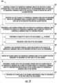
- a method for operating a selectively flexible extension tool within an environment defining a nonlinear pathincludes inserting a plurality of sequentially arranged links of the selectively flexible extension tool at least partially into the nonlinear path of the environment while the plurality of sequentially arranged links of the selectively flexible extension tool are in a slacked position; and tensioning a line of a line assembly operable with the plurality of sequentially arranged links to move the plurality of sequentially arranged links to a tensioned position to rigidly fix the plurality of sequentially arranged links to one another.
- the methodfurther includes inserting a tool implement through a guide tube defined by the plurality of sequentially arranged links in the tensioned position to access the environment.
- the plurality of sequentially arranged links of the extension toolis a first plurality of sequentially arranged links
- the extension toolfurther includes a second plurality of sequentially arranged links
- the second plurality of sequentially arranged linksis movable between a retracted position wherein the second plurality of sequentially arranged links is substantially nested within the first plurality of sequentially arranged links and an extended position wherein the second plurality of sequentially arranged links is substantially extended from within the first plurality of sequentially arranged links
- the second plurality of sequentially arranged linksis further movable between a slacked position and a tensioned position.
- inserting the plurality of sequentially arranged links of the selectively flexible extension toolincludes inserting the first plurality of sequentially arranged links into the nonlinear path of the environment while the second plurality of sequentially arranged links is in the retracted position and the slacked position.
- tensioning the line of the line assemblyincludes tensioning a first line of the line assembly, and wherein the method further includes moving the second plurality of sequentially arranged links to the extended position subsequent to tensioning the first line of the line assembly.
- the methodfurther includes tensioning a second line of the line assembly operable with the second plurality of sequentially arranged links to rigidize the second plurality of sequentially arranged links and rigidly fix the second plurality of sequentially arranged links to one another.
- the plurality of sequentially arranged links of the extension toolis a first plurality of sequentially arranged links
- the extension toolfurther includes a second plurality of sequentially arranged links
- the line of the line assemblyis a first line of the line assembly
- the line assemblyfurther includes a second line operable with the second plurality of sequentially arranged links
- the methodfurther includes tensioning the second line of the line assembly to move the second plurality of sequentially arranged links to a tensioned position to rigidize the second plurality of sequentially arranged links and rigidly fix the second plurality sequentially arranged links to one another independently from the tensioning of the first line of the line assembly.
- the first plurality of sequentially arranged linksdefines a forward end
- the second plurality of sequentially arranged linksdefines an aft end
- the aft end of the second plurality of sequentially arranged linksis coupled to the forward end of the first plurality of sequentially arranged links.
- a tool assemblyin another exemplary embodiment of the present disclosure, includes a first selectively flexible tool including a first plurality of sequentially arranged links moveable between a slacked position and a tensioned position; and a second selectively flexible tool including a second plurality of sequentially arranged links moveable between a slacked position and a tensioned position, the second plurality of sequentially arranged links moveable over or through the first plurality of sequentially arranged links.
- the first selectively flexible tooldefines a first outer diameter
- the second plurality of sequentially arranged links of the second selectively flexible tooldefine a second hollow tube defining a second inner diameter
- the first outer diameter of the first selectively flexible toolis less than the second inner diameter of the second hollow tube of the second plurality of sequentially arranged links such that the second plurality of sequentially arranged links of the second selectively flexible tool are moveable over the first plurality of sequentially arranged links of the first selectively flexible tool.
- the first selectively flexible toolfurther includes a line operable with the first plurality of sequentially arranged links to move the first plurality of sequentially arranged links between a slacked position and a tensioned position.
- each of the plurality of joint membersdefines a first longitudinal opening
- each of the plurality of link membersdefines a second longitudinal opening
- the second selectively flexible toolfurther includes a line assembly extending through the first longitudinal opening of each joint member of the plurality of joint members and further extending through the second longitudinal opening of each link member of the plurality of link members.
- first longitudinal opening of each joint memberextends through a joint member centerline of the respective joint member
- second longitudinal opening of each link memberextends through a link member centerline of the respective link member
- each of the plurality of joint membersextends between a first end and a second end, and wherein the first end and second end of each joint member defines a convex surface.
- each link member of the plurality of link membersextends between a first end and a second end, and wherein the first end and second end of each link member defines a concave opening mateable with a convex surface of an adjacent joint member.
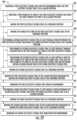
- a method for operating a tool assembly within an environmentincludes inserting a first selectively flexible tool into the environment while the first selectively flexible tool is in a slacked position; moving the first selectively flexible tool to a tensioned position; positioning a second selectively flexible tool at least partially over or through the first selectively flexible tool while the second selectively flexible tool is in a slacked position; and moving the second selectively flexible tool to a tensioned position.
- inserting the first selectively flexible tool into the environmentincludes inserting a first plurality of links of the first selectively flexible tool while the first plurality of links is in a slacked position, and wherein moving the first selectively flexible tool to the tensioned position includes moving the first plurality of links of the first selectively flexible tool to a tensioned position.
- the first plurality of links of the first selectively flexible tooldefine a hollow tube extending therethrough when in the tensioned position, and wherein positioning the second selectively flexible tool at least partially over or through the first selectively flexible tool includes positioning the second selectively flexible tool at least partially through the hollow tube of the first plurality of links of the first selectively flexible tool.
- positioning the second selectively flexible tool at least partially over or through the first selectively flexible tool while the second selectively flexible tool is in the slacked positionincludes positioning a distal end of the second selectively flexible tool proximate a distal end of the first selectively flexible tool.
- positioning the second selectively flexible tool at least partially over or through the first selectively flexible tool while the second selectively flexible tool is in the slacked positionincludes positioning the second selectively flexible tool at least partially over the first selectively flexible tool.
- the methodfurther includes moving the first selectively flexible tool to slacked position subsequent to moving the second selectively flexible tool to the tensioned position; and removing the first selectively flexible tool from the environment.
- the methodfurther includes moving the second selectively flexible tool to the slacked position subsequent to moving the third selectively flexible tool to the tensioned position; and removing the second selectively flexible tool from the environment.
- the first selectively flexible tooldefines a first outer diameter
- the third selectively flexible tooldefines a third outer diameter
- the third outer diameteris substantially equal to the first outer diameter
- the first selectively flexible tooldefines a first hollow tube defining a first inner diameter
- the third selectively flexible tooldefines a third hollow tube defining a third inner diameter
- the third inner diameteris substantially equal to the first inner diameter
- the second selectively flexible tooldefines a second outer diameter, and wherein the second outer diameter is less than the first inner diameter and the third inner diameter.
- the first selectively flexible toolincludes a first plurality of sequentially arranged links movable between a slacked position when the first selectively flexible tool as in the slacked position and a tensioned position when the first selectively flexible tool is in the tensioned position.
- the second selectively flexible toolincludes a second plurality of sequentially arranged links movable between a slacked position when the second selectively flexible tool is in the slacked position and a tensioned position when the second selectively flexible tool is in the tensioned position.
- the second selectively flexible toolincludes a plurality of joint members, a plurality of link members, and a line assembly, wherein each joint member is positioned between adjacent link members and defines a first longitudinal opening, wherein each of the plurality of link members defines a second longitudinal opening, and wherein the line assembly extends through the first longitudinal opening of each joint member of the plurality of joint members and further extends through the second longitudinal opening of each link member of the plurality of link members.
- the environmentis an interior of a gas turbine engine.
- inserting the first selectively flexible tool into the environment while the first selectively flexible tool is in the slacked positionincludes inserting the first selectively flexible tool into the gas turbine engine through an opening in the gas turbine engine.
- the openingis a borescope opening.
- FIG. 1is a schematic view of an extension tool in accordance with an exemplary embodiment of the present disclosure in a slacked position.
- FIG. 2is a schematic view of the exemplary extension tool of FIG. 1 in a tensioned position.
- FIG. 3is a schematic, cross sectional view of an extension tool in accordance with another exemplary embodiment of the present disclosure.
- FIG. 4is a schematic, close-up view of an extension tool in accordance with yet another exemplary embodiment of the present disclosure.
- FIG. 5is an end view of a first link of the exemplary extension tool of FIG. 4 .
- FIG. 6is an end view of a second link of the exemplary extension tool of FIG. 4 .
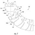
- FIG. 7is a close-up view of a plurality of links of an extension tool in accordance with an exemplary embodiment of the present disclosure.
- FIG. 8is another view of the exemplary plurality of links of FIG. 7 .
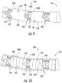
- FIG. 9is a schematic, close-up view of an extension tool in accordance with yet another exemplary embodiment of the present disclosure.
- FIG. 10is a schematic, close-up view of an extension tool in accordance with still another exemplary embodiment of the present disclosure.
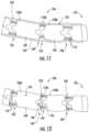
- FIG. 11is a schematic, close-up view of an extension tool in accordance with yet another exemplary embodiment of the present disclosure.
- FIG. 12is a schematic, close-up view of an extension tool in accordance with still another exemplary embodiment of the present disclosure.
- FIG. 13is a schematic, cross-sectional view of an extension tool in accordance with the present disclosure including multiple pluralities of links, arranged in a retracted position.
- FIG. 14is a schematic, cross-sectional view of the extension tool of FIG. 13 with the multiple pluralities of links arranged in an extended position.
- FIG. 15is a schematic, cross-sectional view of an extension tool in accordance with another embodiment of the present disclosure including multiply pluralities of links.
- FIG. 16 Ais a schematic view of a tool assembly in accordance with an exemplary embodiment of the present disclosure in a first position.
- FIG. 16 Bis a schematic view of the exemplary tool assembly of FIG. 16 A in a second position.
- FIG. 16 Cis a schematic view of the exemplary tool assembly of FIG. 16 A in a third position.
- FIG. 16 Dis a schematic view of the exemplary tool assembly of FIG. 16 A in a fourth position.
- FIG. 16 Eis a schematic view of the exemplary tool assembly of FIG. 16 A in a fifth position.
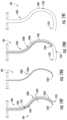
- FIG. 17is a schematic view of a selectively flexible tool in accordance with still another exemplary embodiment of the present disclosure in a slacked position.
- FIG. 18is a schematic view of the exemplary selectively flexible tool of FIG. 17 in a tensioned position.
- FIG. 19 Ais a schematic view of a tool assembly in accordance with an exemplary embodiment of the present disclosure in a first position.
- FIG. 19 Bis a schematic view of the exemplary tool assembly of FIG. 19 A in a second position.
- FIG. 19 Cis a schematic view of the exemplary tool assembly of FIG. 19 A in a third position.
- FIG. 19 Dis a schematic view of the exemplary tool assembly of FIG. 19 A in a fourth position.
- FIG. 19 Eis a schematic view of the exemplary tool assembly of FIG. 19 A in a fifth position.
- FIG. 19 Fis a schematic view of the exemplary tool assembly of FIG. 19 A in a sixth position.
- FIG. 19 Gis a schematic view of the exemplary tool assembly of FIG. 19 A in a seventh position.
- FIG. 19 His a schematic view of the exemplary tool assembly of FIG. 19 A in a eighth position.
- FIG. 19 Iis a schematic view of the exemplary tool assembly of FIG. 19 A in a ninth position.
- FIG. 20is a schematic view of a gas turbine engine and extension tool in accordance with an exemplary embodiment of the present disclosure.
- FIG. 21is a flow diagram of a method for operating an extension tool in accordance with an exemplary aspect of the present disclosure.
- FIG. 22is a flow diagram of a method for operating a tool assembly in accordance with an exemplary aspect of the present disclosure.
- first”, “second”, and “third”may be used interchangeably to distinguish one component from another and are not intended to signify location or importance of the individual components.
- forward and aftrefer to relative positions of a component or system, and refer to the normal operational attitude of the component or system.
- forwardrefers to a position closer to a distal end of the extension tool and aft refers to a position closer to a root end of the extension tool.
- Coupledrefers to both direct coupling, fixing, or attaching, as well as indirect coupling, fixing, or attaching through one or more intermediate components or features, unless otherwise specified herein.
- Approximating languageis applied to modify any quantitative representation that could permissibly vary without resulting in a change in the basic function to which it is related. Accordingly, a value modified by a term or terms, such as “about”, “approximately”, and “substantially”, are not to be limited to the precise value specified. In at least some instances, the approximating language may correspond to the precision of an instrument for measuring the value, or the precision of the methods or machines for constructing or manufacturing the components and/or systems. For example, the approximating language may refer to being within a 10 percent margin.
- FIG. 1is a schematic view of a selectively flexible extension tool 100 (or simply “extension tool”) in accordance with an exemplary embodiment of the present disclosure in a slacked position; and
- FIG. 2is a schematic view of the exemplary extension tool 100 of FIG. 1 in a tensioned position.
- the extension tool 100generally includes a base 102 , a line assembly 104 , and a plurality of sequentially arranged links 106 .
- the base 102generally includes a first plate 108 , a second plate 110 , and one or more extension guides 112 .
- the one or more extension guides 112includes a pair of extension guides 112 fixedly coupled to the first plate 108 and extending in a lengthwise direction LW.
- the second plate 110 of the base 102includes openings 114 corresponding to the pair of extension guides 112 , such that the second plate 110 is slidable along the extension guides 112 in the lengthwise direction LW away from the first plate 108 and towards the first plate 108 .
- the line assembly 104generally includes a root 116 coupled to the second plate 110 of the base 102 and a plurality of lines 188 extending from the root 116 .
- the plurality of lines 118includes a first line 118 A, and the first line 118 A (along with the rest of the lines 118 for the embodiment shown) is operable with the plurality of sequentially arranged links 106 to move the plurality of sequentially arranged links 106 between the slacked position ( FIG. 1 ) and the tensioned position ( FIG. 2 ).
- the plurality of sequentially arranged links 106are spaced from one another when in the slacked position to allow the plurality of sequentially arranged links 106 to pivotably move relative to one another.
- the plurality of sequentially arranged links 106are pressed against one another when in the tensioned position to rigidly fix the plurality of sequentially arranged links 106 to one another.
- each of the plurality of lines 118is operable with the plurality of sequentially arranged links 106 to move the plurality of sequentially arranged links 106 between the slacked position and the tensioned position.
- each of these lines 118may be configured as cables, ropes, threads, etc. Accordingly, it will be appreciated that the lines 118 are generally flexible (i.e., will not prevent the plurality of sequentially arranged links 106 from pivotably moving relative to one another in the slacked position).
- the extension tool 100 depicted in FIGS. 1 and 2is a tool member including a tool implement 120 coupled to one of the plurality of links 106 . More specifically, the extension tool 100 defines a distal end 122 , and the tool implement 120 is coupled to the link 106 at the distal end 122 .
- the tool implement 120includes one or more sensors, cameras, or both, and more specifically includes a sensor 124 .
- the one or more sensors, cameras, or bothmay be operably coupled to a controller or other device (not shown) through one or more electric lines extending through the plurality of sequentially arranged links 106 (e.g., in a manner similar to lines 118 , or alternatively through a tube 126 of the plurality of links 106 ; see, e.g., FIG. 3 ), or alternatively, through a wireless communication network.
- the extension tool 100may be configured in other suitable manner.
- FIG. 3a schematic, partially cross-sectional view of an extension tool 100 in accordance with another exemplary embodiment of the present disclosure is depicted.
- the exemplary extension tool 100 depicted in FIG. 3is configured as a guide tube.
- the plurality of sequentially arranged links 106 of the extension tool 100together define a hollow tube 126 extending therethrough.
- a separate drill 128is depicted extending through the hollow tube 126 of the extension tool 100 .
- the drill 128is, for the embodiment shown, a handheld drill including a handle 130 for rotating the drill 128 , a flexible driveshaft 132 extending through the hollow tube 126 defined by the plurality of links 106 , and a drill bit 134 .
- the drill bit 134may be configured as any other suitable rotatable implement, such as a Phillips head screwdriver bit, a flathead screwdriver bit, a Torx bit, Allen bit, Pozidrive, etc.
- the extension tool 100may facilitate directing the drill bit 134 of the drill 128 at a remote location, or along an obscure vector within an environment (e.g., along a non-linear path within the environment) in a manner that would otherwise not be possible.
- the tool implement 120may be integrated with the extension tool 100 .
- the flexible driveshaft of the drill 128may instead be coupled to a motor 136 attached to the base 102 , or rather, attached to the second plate 110 of the base 102 .
- the extension tool 100may be an integrally formed drill tool having a specific/dedicated function.
- the extension tool 100may not be used for, e.g., drilling at a remote location, and instead may be utilized to provide a fluid (e.g., a gas or liquid) to a remote location.
- a fluide.g., a gas or liquid
- the hollow tube 126may be used to provide a heated gas or liquid to a remote location, may be used to provide lubrication oil to a remote location, etc.
- FIG. 4provides a close-up, schematic view of a distal end 122 of an extension tool 100 in accordance with an exemplary embodiment of the present disclosure.
- the extension tool 100 of FIG. 4may be configured in substantially the same manner as exemplary extension tool 100 of FIG. 1 .
- the extension tool 100 of FIG. 4is depicted in the slacked position.
- the lines 118extend down a length of the extension tool 100 and then loop around to extend back the other way along the length of the extension tool 100 at, for the embodiment depicted, the distal end 151 .
- one or more of the lines 118may include a crimp or other attachment at the distal end 151 (or proximate thereto).
- the crimp or other attachmentmay not be under load during normal operation, and instead may be configured to prevent the entire line 118 from pulling out of the plurality of links 106 in the event that the line fails (e.g., breaks or snaps) during operation. In such a case, the crimp or other attachment would be engaged such that the line could be used to pull the plurality of links 106 out of the environment.
- the plurality of sequentially arranged links 106 of the extension tool 100includes a first link 106 A extending between a forward end 140 and an aft end 142 along a first lengthwise direction L 1 .
- the plurality of sequentially arranged links 106further includes a second link 106 B also extending between a forward end 140 and an aft end 142 along a second lengthwise direction L 2 .
- the forward end 140 of the first link 106 Adefines a first interface geometry
- the aft end 142 of the second link 106 Bdefines a second interface geometry complementary to the first interface geometry.
- the term “complementary” with reference to two geometriesrefers to the two geometries having components configured to fit together to limit movement of the components including the geometries.
- the aft end 142 of the first link 106 Adefines an interface geometry substantially equal to the second interface geometry
- the forward end 140 of the second link 106 Bdefines an interface geometry substantially equal to the first interface geometry.
- different complementary geometriesmay be provided between other adjacent links.
- first interface geometry and second interface geometrytogether form a kinematic mount between the first link 106 A and second link 106 B (when in the tensioned position) that restricts relative movement between the first link 106 A and second link 106 B along at least four degrees of freedom (e.g., opposing circumferential and radial directions; the lines 118 restrict along the longitudinal directions/axial directions, as is explained below).
- the first interface geometrydefines a first circumferential direction C 1 and includes at least two indentions 144 spaced along the first circumferential direction C 1 .
- the second interface geometrydefines a second circumferential direction C 2 includes at least two extension members 146 corresponding in shape to the least two indentions 144 .
- the at least two indentions 144 of the first interface geometryincludes three indentions 144 spaced along the first circumferential direction C 1 of the first interface geometry
- the at least two extension members 146 of the second interface geometryincludes three corresponding extension members 146 spaced along the second circumferential direction C 2 of the second interface geometry.
- each of the three extension members 146 of the second interface geometryare received within/rest within the three indentions 144 of the first interface geometry to restrict movement of the second link 106 B relative to the first link 106 A in all degrees of freedom (with the help of the lines 118 ; see, e.g., FIG. 2 ).
- any other suitable kinematic mounting geometriesmay be provided between adjacent links 106 to restrict movement of the adjacent links 106 when the links 106 are in the tensioned position.
- the first and/or second geometrymay include pins, ridges, etc., and the other of the first and/or second geometry may include corresponding openings, valleys, etc.
- each of the plurality of links 106and accordingly the hollow tube 126 defined thereby, defines an inner diameter 127 .
- the term “inner diameter”may refer to the smallest crosswise measure of the hollow tube 126 .
- the inner diameter 127may dictate the size of tools or other components that may extend through the hollow tube 126 .
- the extension tool 100or rather the plurality of links 106 further define an outer diameter 129 , which may refer to the largest crosswise measure of the plurality of links 106 of the extension tool 100 .
- the first line 118 A, or rather, the plurality of lines 118 , of the line assembly 104is operable with the plurality of links 106 to move the plurality of links 106 between the slacked position (shown) and the tensioned position.
- the plurality of lines 118are slidable relative to at least the first link 106 A to move the plurality of sequentially arranged links 106 between the slacked position and the tensioned position. More specifically, still, referring again briefly to FIGS.
- each of the plurality of links 106includes a circumferential wall 148 , and the first line 118 A of the line assembly 104 extends through the circumferential wall 148 of each of the plurality of links 106 . More particularly, as may be clearly seen in FIGS. 5 and 6 , for the embodiment shown each link 106 of the plurality of links 106 defines a lengthwise opening 150 in the circumferential wall 148 , with the first line 118 A of the line assembly 104 slidably received through the lengthwise opening 150 of the circumferential wall 148 of each link 106 of the plurality of links 106 .
- each of the plurality of lines 118 of the line assembly 104are slidably received through corresponding lengthwise openings 150 in the circumferential walls 148 of the plurality of links 106 .
- one or more of the plurality of lines 118 of the line assembly 104may instead be slidably coupled to the links 106 in any other suitable manner (e.g., through eyelets on the outer surface of the links 106 , inner surfaces of the circumferential walls 148 , etc.).
- the extension tool 100includes a cap 151 positioned at the distal end 122 and coupled to the link 106 at the distal end 122 .
- the lines 118are looped through a suitable channel in the cap 151 (i.e., not slidable relative to the cap 151 ), such that when the lines 118 are tensioned, the links 106 are moved to the tensioned position. (However, in other embodiments, one or more of the lines 118 may be fixed to the cap 151 .)
- FIG. 4depicts the first link 106 A and the second link 106 B in the slacked position.
- the second link 106 Bis spaced from the first link 106 A when the plurality of links 106 are in the slacked position to allow the second link 106 B to pivotably move relative to the first link 106 A (e.g., in a pivot direction P).
- the second link 106 Bwhen in the slacked position, is connected to the first link 106 A only through the plurality of lines 118 of the line assembly 104 .
- the plurality of lines 118may be relatively flexible, the second link 106 B may pivot relative to the first link 106 A.
- the second link 106 Bmay move relative to the first link 106 A such that an angle defined between the second lengthwise direction L 2 and the first lengthwise direction L 1 varies, e.g., at least about thirty degrees, such as at least about sixty degrees, such as at least about ninety degrees, such as up to about three hundred degrees.
- the extension tool 100may be maneuvered through, e.g., a serpentine path, or other non-linear path, within an environment when the plurality of links 106 are in the slacked position.
- the second link 106 Bis pressed against the first link 106 A when the plurality of links 106 are in the tensioned position to press the second interface geometry of the aft end 142 of the second link 106 B against the first interface geometry of the forward end 140 of the second link 106 B and rigidly fix the second link 106 B to the first link 106 A.
- the plurality of links 106form an effectively solid/rigid arm of the extension tool 100 .
- the plurality of links 106 of the extension tool 100may be moved from the slacked position ( FIG. 1 ) to the tensioned position ( FIG. 2 ) by tensioning the plurality of lines 118 of the line assembly 104 , and more specifically, by moving the second plate 110 of the base 102 along the extension guides 112 of the base 102 away from the first plate 108 , pulling the plurality of lines 118 of the line assembly 104 at the root 116 .
- the lines 118may be slidably coupled to each of the plurality of links 106 , with the exception of the link 106 at the distal end 122 (or rather the cap 151 , as noted above).
- the lines 118may be fixed to the link 106 and/or cap 151 at the distal end 122 , such that when the plurality of lines 118 are tensioned, the links 106 are each pressed together to rigidize the links 106 /move the links to the tensioned position.
- the plurality of links 106may form a desired shape when in the tensioned position.
- the plurality of links 106 in the slacked positionmay be threaded through, e.g., a relatively serpentine or other non-linear path within an environment, and then may be moved to the tensioned position using the plurality of lines 118 of line assembly 104 once inserted to effectively result in a rigid tool within the nonlinear path of the environment.
- the extension tool 100may facilitate performing operations or inspections on components within an environment that would otherwise be unreachable, or unreachable without taking apart, dismantling, or damaging the environment.
- each of the plurality of links 106are specifically designed to result in a specific rigidized shape when the plurality of links 106 are moved to the tensioned position.
- the first link 106 Adefines a first geometry (i.e., length, curvature, etc.) and the second link 106 B defines a second geometry (i.e., link, curvature, etc.).
- the first geometryis different than the second geometry.
- each of the plurality of links 106may be formed through an additive manufacturing process (sometimes also referred to as 3D printing). Such may facilitate the formation of specifically shaped links 106 to be fitted within the plurality of links 106 of an extension tool 100 resulting in a desired shape when moved to the tensioned position, yet still remaining flexible enough to fit through the anticipated environment.
- additive manufacturing processsometimes also referred to as 3D printing
- the plurality of links 106 of the extension tool 100may be formed in any other suitable manner and may have any other suitable shape or configuration.
- FIGS. 7 and 8a plurality of links 106 of an extension tool 100 in accordance with another embodiment of the present disclosure is depicted.
- the plurality of links 106 of the extension tool 100 of FIGS. 7 and 8may be configured in a similar manner to the exemplary plurality of links 106 described above with reference to, e.g., FIGS. 4 through 6 .
- the exemplary plurality of links 106 described in FIGS. 7 and 8includes a first link 106 A and a second link 106 B (see FIG. 7 ).
- the first link 106 Adefines a first geometry and the second link 106 B defines a second geometry.
- Each link 106includes a circumferential wall 148 defining an outer rim 149 on an exterior of the circumferential wall 148 at the forward end 140 and an outer rim 151 at the aft end 142 .
- the links 106are each pressed together such that the outer rim 149 at the forward end 140 of each link 106 are aligned and in direct contact with the outer rim 151 at the aft end 142 of an adjacent link 106 .
- the first geometry and the second geometryare substantially the same.
- each link of the plurality of links 106 of FIGS. 7 and 8generally defines a longitudinal direction L 3 and a circumferential direction C 3 (see FIG. 7 ).
- Each link 106generally includes a short side 152 at a first circumferential position along the circumferential direction C 3 and a long side 154 at a second circumferential position along the circumferential direction C 3 (the short side 152 defining a length along the longitudinal direction L 3 less than a length of the long side 154 along the longitudinal direction L 3 ).
- each link 106 of the plurality of links 106includes a uniform first interface geometry at a forward end 140 along the longitudinal direction and a uniform second interface geometry at an aft end 142 along the longitudinal direction.
- the first interface geometryincludes three extension members 146 spaced evenly along the circumferential direction C 3
- the second interface geometryincludes three correspondingly shaped indentions 144 also spaced evenly along the circumferential direction C 3 (i.e., for receiving the three extension members 146 of an adjacent link 106 ).
- the plurality of uniform links 106may be arranged to define just about any desired shape when the plurality of links 106 are moved to the tensioned position.
- the short side 152 of one link 106 with the long side 154 of an adjacent link 106sequentially may allow for forming a substantially linear portion (e.g., straight portion 156 )
- pairing the short side 152 of one link 106 with the short side 152 of an adjacent link 106sequentially may allow for forming a relatively tight bend (e.g., bend 158 ), etc.
- the plurality of links 106may define any desired three-dimensional shape when tensioned.
- a relative orientatione.g., circumferentially
- the uniform geometry links 106may be stored in bulk on-site, and a specialized extension tool 100 defining a unique three-dimensional shape and length may be formed relatively quickly by arranging sequential links 106 in a particular manner/circumferential orientation.
- adjacent links 106may be able to pivot relative to one another to allow the plurality of links 106 to maneuver through nonlinear paths through an environment.
- gravityis assisting with maintaining the plurality of links 106 separate from one another, it may be relatively easy to maneuver the plurality of links 106 through the nonlinear path.
- other featuresmay be provided for maintaining the plurality of links 106 separate from one another to facilitate the maneuverability of the plurality of links 106 through a nonlinear path.
- each of the exemplary extension tools 100 of FIGS. 9 through 12generally includes a plurality of links 106 (including a first link 106 A and a second link 106 B) and a line assembly 104 (including a plurality of lines 118 and particularly a first line 118 A).
- a plurality of links 106including a first link 106 A and a second link 106 B
- a line assembly 104including a plurality of lines 118 and particularly a first line 118 A.
- the extension tool 100further includes a biasing member 160 operable with the first link 106 A and the second link 106 B for biasing the second link 106 B away from the first link 106 A.
- the plurality of lines 118 of the line assembly 104including the first line 118 A of the line assembly 104 , is configured to overcome the biasing member 160 when the plurality of links 106 are moved to the tensioned position.
- biasing member 160is a spring attached to the first link 106 A and attached to the second link 106 B for pressing the second link 106 B away from the first link 106 A.
- each of the plurality of links 106includes a circumferential wall 148 that defines an outer surface 162 and the biasing member 160 /spring is positioned inward of the outer surface 162 of the circumferential wall 148 of the first link 106 A and inward of the outer surface 162 of the circumferential wall 148 of the second link 106 B.
- the biasing member 160 /springis positioned inward of the circumferential wall 148 of the first link 106 A and inward of the circumferential wall 148 of the second link 106 B.
- the biasing member 160 /springmay be coupled to, or otherwise attached to an inner surface (not shown) of the circumferential walls 148 of the first link 106 A and the second link 106 B.
- the extension tool 100further includes a plurality of biasing members 160 , with each biasing member 160 operable with a pair of adjacent links 160 of the plurality of links 106 for biasing the adjacent links 160 away from one another.
- the plurality of links 106define a hollow tube 126 extending therethrough (e.g., when the extension tool 100 is configured as a guide tube; see FIG. 3 )
- the springsmay be configured such that the openings/center of the springs are aligned with the hollow tube 126 extending through the plurality of links 106 (and not blocking the hollow tube 126 ).
- each of the plurality of links 106defines an outer surface 162 (or rather includes a circumferential wall 148 defining an outer surface 162 ) and the biasing member 160 is operable with the outer surface 162 of each of the plurality of links 106 . More specifically, still, for the embodiment depicted in FIG.
- the biasing member 160is a continuous spring attached to the outer surface 162 of the first link 106 A and the outer surface 162 of the second link 106 B, as well as the outer surfaces 162 of the other links 106 of the plurality of links 106 , for biasing the second link 106 B away from the first link 106 A, as well as the other links 106 away from adjacent links 106 .
- the springdefines a substantially constant pitch where it is attached to the outer surfaces 162 of the links 106 , and defines a variable pitch between adjacent links 106 , based on e.g., a position of the plurality of links 106 in the slacked position or tensioned position, an angle defined between adjacent links 106 , etc.
- any other suitable biasing member 160may be provided operable with each of the plurality of links 106 and coupled to the outer surface 162 of each of the plurality of links 106 .
- the biasing member 160comprises an elastomeric material attached the outer surface 162 of each of the plurality of links 106 and extending substantially continuously along each of the plurality of links 106 .
- the elastomeric materialmay be an elastomeric sleeve extending around each of the plurality of links 106 and coupled to the outer surface 162 of each of the plurality of links 106 .
- the elastomeric materialmay be discrete strips extending along the plurality of links 106 coupled to the outer surface 162 of each of the plurality of links 106 , may be a plurality of elastomeric sections extending between adjacent pairs of links 106 , etc.
- the exemplary extension tool 100 depicted againincludes a plurality of individual biasing members 160 .
- Each of the individual biasing members 160is configured as an elastomeric material positioned between adjacent links 106 of the plurality of links 106 .
- one of the plurality biasing members 160is configured as an elastic member positioned at least partially between the first link 106 A and the second link 106 B.
- each of the biasing members 160may be configured as discs configured to urge adjacent links 106 away from one another, and more specifically, configured to urge indentions 144 of one link 106 away from corresponding extension members 146 in an adjacent link 106 .
- any other suitable biasing member 160may be provided for urging a first link 106 A away from a second, adjacent link 106 B, or for urging any of the adjacent links 106 away from one another, when in the slacked position, to assist with the insertion and/or removal of the plurality of links 106 of the extension tool 100 to and/or from, e.g., a nonlinear path within the environment.
- FIG. 13providing a schematic, cross-sectional view of an extension tool 100 in accordance with another exemplary embodiment of the present disclosure.
- the exemplary extension tool 100 of FIG. 13may be configured in a similar manner to the exemplary extension tools 100 described above with reference to FIGS. 1 through 12 .
- the exemplary extension tool 100 of FIG. 13generally includes a base 102 , a line assembly 104 , and a plurality of sequentially arranged links 106 .
- the line assembly 104includes a first line 118 A operable with the plurality of sequentially arranged links 106 to move the plurality of sequentially arranged links 106 between a slacked position and a tensioned position (shown).
- the plurality of sequentially arranged links 106are spaced from one another when in the slacked position to allow the plurality of sequentially arranged links 106 to pivotably move relative to one another.
- the plurality of sequentially arranged links 106are pressed against one another in the tensioned position to rigidly fix the plurality of sequentially arranged links 106 to one another as is depicted.
- the plurality of sequentially arranged links 106is configured as a first plurality of sequentially arranged links 106 - 1 defining a first guide tube 126 - 1 extending therethrough.
- the extension tool 100further includes a second plurality of sequentially arranged links 106 - 2 movably positioned at least partially within the first guide tube 126 - 1 of the first plurality of sequentially arranged links 106 - 1 .
- the second plurality of sequentially arranged links 106 - 2similarly defines a second guide tube 126 - 2 extending therethrough.
- the extension tool 100includes a third plurality of sequentially arranged links 106 - 3 movably positioned at least partially within the second guide tube 126 - 2 of the second plurality of sequentially arranged links 106 - 2 .
- the line assembly 104further includes a second line 118 B and a third line 118 C.
- the second line 118 Bis operable with the second plurality of links 106 - 2 to move the second plurality of links 106 - 2 between a slacked position (e.g., similar to the slacked position of the sequentially arranged links 106 of FIG. 1 ) and a tensioned position (shown).
- the third line 118 Cis operable with the third plurality of links 106 - 3 to move the third plurality of links 106 - 3 between a slacked position (e.g., similar to the slacked position of the sequentially arranged links 106 of FIG. 1 ) and a tensioned position (shown).
- the second plurality of links 106 - 2 and third plurality of links 106 - 3are depicted in FIG. 13 in a retracted, nested configuration.
- first plurality of links 106 - 1 , second plurality of links 106 - 2 , and third plurality of links 106 - 3are nested within one another and each in the slacked position, they may move in unison through a first section of a nonlinear path through an environment.
- the first plurality of links 106 - 1may then be independently moved to a tensioned position using the first line 118 A (or plurality of first lines 118 A).
- the second plurality of links 106 - 2 and third plurality of links 106 - 3may subsequently be extended from the first guide tube 126 - 1 through a second portion of a nonlinear path through an environment.
- the second plurality of links 106 - 2may then be independently be moved to a tensioned position using the second line 118 B (or plurality of second lines 118 B).
- the third plurality of links 106 - 3may be extended from the second guide tube 126 - 2 through a third portion of a non-linear path of an environment.
- the third plurality of links 106 - 3may then independently be moved to a tensioned position using the third line 118 C (or a plurality of third lines 118 C).
- the exemplary extension tool 100 of FIG. 13is depicted with the second plurality of sequentially arranged links 106 - 2 extended from the first guide tube 126 - 1 of the first plurality of sequentially arranged links 106 - 1 , and further with the third plurality of sequentially arranged links 106 - 3 extended from the second guide tube 126 - 2 .
- the first plurality of links 106 - 1has been moved to the tensioned position
- the second plurality of links 106 - 2is also been moved to the tensioned position.
- the third plurality of links 106 - 3is in the slacked position.
- the third plurality of linksmay be maneuvered through a nonlinear path within an environment before also being moved to the tensioned position.
- a configurationmay allow for the extension tool 100 to position the second plurality of links 106 - 2 adjacent to, e.g., a nonlinear path within an environment that would otherwise be difficult to reach, or unreachable using a singular plurality of links 106 .
- the extension toolmay position the third plurality of links 106 - 3 adjacent to, e.g., another nonlinear path within the environment that would otherwise be difficult to reach, or unreachable using two pluralities of links.
- the first plurality of links 106 - 1includes a stopper 164 at a distal end extending into the first guide tube 126 - 1
- the second plurality of links 106 - 2includes a flange 166 at a forward end configured to catch the stopper 164 at the distal end of the first plurality of links 106 - 1 and prevent the second plurality of links 106 - 2 from being removed completely from the first guide tube 126 - 1 .
- the second plurality of links 106 - 2includes a stopper 168 at a distal end extending into the second guide tube 126 - 2
- the third plurality of links 106 - 3includes a flange 170 at a forward end configured to catch the stopper 168 at the distal end of the second plurality of links 106 - 2 to prevent the third plurality of links 106 - 3 from being removed completely from the second guide tube 126 - 2 .
- the first, second, and third pluralities of sequentially arranged links 106may be extended by a work implement extended through a third guide tube 126 - 3 extending through the third plurality of links 106 - 3 that catches a stopper 172 positioned at a distal end of the third plurality of links 106 - 3 extending into the third guide tube 126 - 3 .
- any other suitable apparatusmay be utilized to selectively extend the second plurality of links 106 - 2 from the first plurality of links 106 - 1 , and further to selectively extend the third plurality of links 106 - 3 from the second plurality of links 106 - 2 .
- the exemplary extension tool 100 depicted in FIGS. 13 and 14is provided by way of example only.
- any other suitable extension tool 100 having pluralities of sequentially arranged links 106may be provided.
- the extension toolmay have any other suitable number of pluralities links 106 , such as two, four, six, etc. and each of such pluralities of links 106 may define any desired shape.
- each of the pluralities of sequentially arranged links 106are nested within one another (at least when in the retracted position), in other embodiments, any other suitable arrangement of pluralities sequentially arranged links 106 may be provided.
- the extension tool 100may again include multiple pluralities of sequentially arranged links 106 , but in other suitable configurations.
- FIG. 15an extension tool 100 in accordance with another exemplary embodiment of the present disclosure is provided.
- the exemplary extension tool 100 of FIG. 15may be configured in a similar manner as the exemplary extension tool 100 of FIG. 13 .
- the exemplary extension tool 100 of FIG. 15may generally include a first plurality of links 106 - 1 , a second plurality of links 106 - 2 , and a third plurality of links 106 - 3 .
- the first plurality of links 106 - 1includes a forward end 174
- the second plurality of links 106 - 2includes a forward end 176 and an aft end 178
- the third plurality of links 106 - 3also includes a forward end 180 and an aft end 182 .
- the second plurality of links 106 - 2is coupled to the forward end 174 of the first plurality of links 106 - 1
- the third plurality of links 106 - 3is coupled to the forward end 176 of the second plurality of links 106 - 2 .
- the first plurality of links 106 - 1 , second plurality of links 106 - 2 , and third plurality of links 106 - 3are each arranged in series.
- the line assembly 104further includes a second line 118 B and a third line 118 C.
- the second line 118 Bis operable with the second plurality of links 106 - 2 to move the second plurality of links 106 - 2 between a slacked position and a tensioned position.
- the third line 118 Cis operable with the third plurality of links 106 - 3 to move the third plurality of links 106 - 3 between a slacked position and a tensioned position.
- the second line 118 Bis operable with the second plurality of links 106 - 2 independent of the first line 118 A being operable with the first plurality of links 106 - 1
- the third line 118 Cis operable with the third plurality of links 106 - 3 independent of the first line 118 A and second line 118 B being operable with the first plurality of links 106 - 1 and second plurality of links 106 - 2 , respectively.
- Inclusion of multiple pluralities of sequentially arranged links 106may allow for insertion of the extension tool 100 into more complex nonlinear paths within the environment.
- FIG. 16a tool assembly 184 in accordance with an exemplary embodiment of the present disclosure is provided.
- the tool assembly 184 depicted in FIG. 16may incorporate or otherwise utilize various aspects of one or more the exemplary embodiments described above with reference to FIGS. 1 through 15 .
- the exemplary tool assembly 184includes a first selectively flexible extension tool 100 A (or simply “extension tool”).
- first extension tool 100 Amay include a first plurality of sequentially arranged links 106 A movable between a slacked position and a tensioned position (shown).
- the first extension tool 100 A of FIG. 16 Amay be configured in accordance with, e.g., the embodiment of FIGS. 1 and 2 , the embodiment of FIG. 3 , the embodiment of FIGS. 4 through 6 , the embodiment of FIGS. 7 and 8 , or in accordance with any other suitable embodiment.
- the first extension tool 100 Adefines a first hollow tube 126 A extending therethrough.
- the first hollow tube 126 Adefines a first inner diameter 127 A, which may refer to a minimum crosswise measure of the first hollow tube 126 A.
- the first extension tool 100 Adefines a first outer diameter 129 A, which may refer to a maximum crosswise measure of the first plurality of links 106 A of the first extension tool 100 A.
- the first extension tool 100 Amay be inserted through an opening 186 into an environment in a slacked position, and subsequently moved to a tensioned position.
- the first extension tool 100 Amay define a predefined shape such that a first distal end 122 A of the first extension tool 100 A is positioned at a desired location and orientation.
- the tool assembly 184further includes a second extension tool 100 B.
- the second extension tool 100 Bmay include a second plurality of sequentially arranged links 106 B movable between a slacked position and a tensioned position (shown). As will be appreciated from the FIGS.
- the second plurality of sequentially arranged links 106 Bare movable over or through the first plurality of sequentially arranged links 106 A, and more specifically, for the embodiment shown the second plurality of sequentially arranged links 106 B of the second extension tool 100 B are movable over the first plurality of sequentially arranged links 106 A of the first extension tool 100 A.
- the second plurality of sequentially arranged links 106 Bdefines a second hollow tube 126 B extending therethrough when the second plurality of sequentially arranged links 106 B are in the tensioned position.
- the second hollow tube 126 Bdefines a second inner diameter 127 B.
- the first outer diameter 129 A of the first plurality of sequentially arranged links 106 Ais less than the second inner diameter 127 B of the second plurality of sequentially arranged links 106 B to allow for the second plurality of sequentially arranged links 106 B to be provided over the first plurality of sequentially arranged links 106 A.
- the second plurality of sequentially arranged links 106 Bwhile in the slacked positioned, may be movable over the first plurality of sequentially arranged links 106 A while the first plurality of sequentially arranged links 106 A are in the tensioned position.
- the second plurality of sequentially arranged links 106 Bmay then be moved to the tensioned position.
- the predetermined shape of the first plurality of sequentially arranged links 106 Amay ensure the second plurality of sequentially arranged links 106 B make it through, e.g., a first section 188 A of a nonlinear path through the environment prior to being inserted through a second section 188 B of the nonlinear path through the environment (see FIG. 16 D ).
- the second plurality of sequentially arranged links 106 Bwhen in the tensioned position, define a second overall length (i.e., centerline length) that is greater than a first overall length (i.e., centerline length) of the first plurality of sequentially arranged links 106 A, when in the tensioned position.
- the second overall lengthis at least about 25 percent greater than the first overall length, such as at least about 50 percent greater than the first overall length, such as up to about 1000 percent greater than the first overall length.
- the second plurality of sequentially arranged links 106 Bmay reach further into the environment, or rather, further along a nonlinear path through the environment.
- the first plurality of sequentially arranged links 106 Amay subsequently be moved back to the slacked position and removed from the environment while the second plurality of sequentially arranged links 106 B remain in the tensioned position.
- a second distal end 122 B of the second plurality of sequentially arranged links 106 Bmay be positioned at a desired location and orientation within the environment and may remain there without maintaining the first extension tool 100 A in position.
- the second plurality of sequentially arranged links 106 B of the second extension tool 100 Bmay be utilized to perform desired operations (e.g., inspections, repairs, or maintenance operations).
- further extension tools 100may be utilized to reach more remote positions and/or orientations within the environment.
- the exemplary tool assembly 184further includes a third extension tool 100 C.
- the third extension tool 100 Cmay be configured in substantially the same manner as the first extension tool 100 A.
- the third extension tool 100 Cmay include a third plurality of sequentially arranged links 106 C defining a third outer diameter 129 C.
- the third outer diameter 129 Cmay be substantially equal to the first outer diameter 129 A.
- the third outer diameter 129 Cmay be less than the second inner diameter 127 B (of the second hollow tube 126 B of the second plurality of sequentially arranged links 106 B), such that the third plurality of sequentially arranged links 106 C may be movable through the second hollow tube 126 B of the second plurality of sequentially arranged links 106 B when in the slacked position.
- a third overall length (i.e., centerline length) of the third plurality of sequentially arranged links 106 C of the third extension tool 100 C(when in the tensioned position) is greater than the second overall length, and further is greater than the first overall length.
- the third extension tool 100 Cmay reach further into the environment to position a third distal end 122 C further into the environment, or more specifically, further along a nonlinear path through the environment.
- such a configurationmay ensure the third plurality of sequentially arranged links 106 C are able to navigate through a first section 188 A and a second section 188 B of the environment prior to being inserted in an unguided manner into a third section 188 C of the environment in the slacked position.
- the second extension tool 100 Bmay be removed from the environment.
- the tool assembly 184 of FIG. 16may therefore allow for various operations to be conducted at the third distal end 122 C of the third extension tool 100 C.
- the exemplary tool assembly 184 depicted in FIGS. 16 A through 16 Eis by way of example only.
- the exemplary tool assembly 184 in FIG. 16 A through 16 Einclude a second extension tool 100 B movable over a first extension tool 100 A
- the second extension tool 100 Bmay instead be movable through a first hollow tube 126 A of the first extension tool 100 A (and a second outer diameter of the second plurality of links 106 B of the second extension tool 100 B may be less than the first inner diameter 127 A).
- three extension tools 100 A, 100 B, 100 Care depicted, in other embodiments, the tool assembly 184 may only include two extension tools, or alternatively, may include any other suitable number of extension tools (e.g., 4, 5, 6, etc.).
- FIGS. 16 A through 16 Bdepicts a selectively flexible tool (or “extension tool”) 100 in accordance with another exemplary embodiment of the present disclosure in a slacked position and FIG. 18 depicts the exemplary extension tool 100 of FIG. 17 in a tensioned position.
- the exemplary extension tool 100 of FIGS. 17 and 18generally includes a plurality of sequentially arranged links 106 movable between the slacked position ( FIG. 17 ) and the tensioned position ( FIG. 18 ). More specifically, for the embodiment shown, the plurality of sequentially arranged links 106 includes a plurality of joint members 190 and a plurality of link members 191 . Each joint member 190 is positioned between adjacent link members 191 . The joint members 190 are configured to allow the link members 191 to define any suitable orientation relative to one another while in the slacked position and further to retain a particular shape when moved to the tensioned position.
- the joint members 190each extend between a first end 192 and a second end 193 along a first longitudinal direction L 1 (i.e., a longitudinal direction of the respective joint member 190 ).
- first end and the second end 192 , 193 of each joint member 190defines a convex surface.
- each link member 191 of the plurality of link members 191extends between a first end 194 and a second end 195 along a second longitudinal direction L 2 (i.e., a longitudinal direction of the respective link member 191 ).
- the first end 194 and the second end 195 of each link member 191defines a concave opening 186 mateable with the convex surface of an adjacent joint member 190 .
- the concave opening 186 of the first end 194 of a particular link member 191may be mateable with the convex surface of the second end 193 of an adjacent joint member 190 .
- first and second ends 192 , 193 of the joint members 190each define a complementary shape to the first and second ends 194 , 195 of each of the link members 191 .
- first and second ends 192 , 193 of the joint members 190each define a rounded surface and the first and second ends 194 , 195 of the link members 191 each define a rounded opening 186 .
- each of the plurality of joint members 190 in the embodiment depicteddefine a substantially spherical shape and each of the plurality of link members 191 of the embodiment depicted define a substantially cylindrical shape.
- each of the plurality of joint members 190defines a first longitudinal opening 196 and each of the plurality of link members 191 defines a second longitudinal opening 197 .
- first longitudinal opening 196 of each joint member 190extends through a joint member centerline of the respective joint member 190 (which extends along the first longitudinal direction L 1 for the embodiment shown)
- second longitudinal opening 197 of each link member 191extends through a link member centerline of the respective link member 191 (which extends along the second longitudinal direction L 2 for the embodiment shown).
- the first and/or second longitudinal openings 196 , 197may be positioned at any other suitable manner.
- the extension tool 100 of FIGS. 17 and 18includes a line assembly, and more specifically, includes a line 118 .
- the line 118 of the line assemblyextends through the first longitudinal opening 196 of each joint member 190 of the plurality of joint members 190 and further extends through the second longitudinal opening 197 of each link member 191 the plurality of link members 191 .
- the line 118 of the line assemblymay be configured to move the plurality of sequentially arranged links 106 between the slacked position of FIG. 17 and the tensioned position of FIG. 18 by tensioning (e.g., shortening) and pressing the plurality of sequentially arranged links 106 against one another.
- the plurality of links 106may adapt to just about any three dimensional shape when in the slacked position ( FIG. 17 ), the plurality of joint members 190 and/or the plurality of link members 191 define a relatively high coefficient of friction at the joints/where they contact one another.
- the plurality of sequentially arranged links 106 of the extension tool 100may define a relatively rigid configuration when moved to the tensioned position, such that they remain in the three dimensional shape they adapted to while in the slacked position.
- the exemplary extension tool 100 of FIGS. 17 and 18may be utilized in a tool assembly 184 in accordance with one or more exemplary aspects of the present disclosure, the exemplary extension tool 100 of FIGS. 17 and 18 does not define a predefined shape that it must conform to when moved to the tensioned position.
- FIG. 19a tool assembly 184 is provided in accordance with another exemplary embodiment that may utilize an extension tool that does not define a predefined shape when in the tensioned position (such as the exemplary extension tool 100 of FIGS. 17 and 18 ). More specifically, FIGS. 19 A through 19 I depicted various exemplary aspects of the tool assembly 184 .
- the exemplary tool assembly 184 of FIGS. 19 A through 19 Imay operate in a similar manner to the exemplary tool assembly 184 described above with reference to FIG. 16 A through 16 E .
- the exemplary tool assembly 184includes a first extension tool 100 A movable between a slacked position and a tensioned position (shown).
- the first extension tool 100 Aalthough depicted in a simplified and schematic manner, may include a first plurality of sequentially arranged links 106 A.
- the first plurality of sequentially arranged links 106 A of the first extension tool 100 Adefine a predetermined shape when in the tensioned position (shown in FIG. 19 A ).
- the tool assembly 184further includes a second extension tool 100 B.
- the second extension tool 100 Bmay similarly include a second plurality of sequentially arranged links 106 B movable between a slacked position and a tensioned position (shown).
- the second plurality of sequentially arranged links 106 Bare movable over or through the first plurality of sequentially arranged links 106 A, and more specifically, are movable through the first plurality of sequentially arranged links 106 A.
- the second plurality of sequentially arranged links 106 Bmay define a second outer diameter 129 B that is less than a first inner diameter 127 A of a first hollow tube 126 A of the first plurality of links 106 A.
- the second extension tool 100 Bmay be configured in a similar manner to the extension tool 100 of FIGS. 17 and 18 . Accordingly, while the second extension tool 100 B may not define a predetermined shape when in the tensioned position, it may take the shape of the first hollow tube 126 A of the first extension tool 100 A.
- the second extension tool 100 Bmay be inserted through the first hollow tube 126 A of the first plurality of sequentially arranged links 106 A of the first extension tool 100 A such that a second distal end 122 B of the second extension tool 100 B is positioned adjacent to a first distal end 122 A of the first extension tool 100 A.
- the second extension tool 100 Bmay then be moved to the tensioned position, retaining the shape of the first extension tool 100 A, and the first extension tool 100 A may then be removed. Such is depicted in FIG. 19 C .
- a third extension tool 100 C of the tool assembly 184may be moved over the second extension tool 100 B (i.e., while in the slacked position).
- the third extension tool 100 Cmay be configured in a similar manner as the first extension tool 100 A (i.e., defining a third hollow tube 126 C defining a third inner diameter 127 C substantially equal to the first inner diameter 126 A), but may define a greater overall length.
- the second extension tool 100 Bmay guide the third extension tool 100 C through the environment at least to the second distal end 122 B of the second extension tool 100 B.
- the third plurality of links 106 Cmay then extend further into the environment and the third extension tool 100 C may then be moved to the tensioned position.
- the second extension tool 100 Bmay thereafter be moved back to the slacked position and be removed from within the third extension tool 100 C and from the environment.
- a third distal end 122 C of the third extension tool 100 Cmay be at a desired position and orientation within the environment.
- the exemplary tool assembly 184may facilitate inspection, repair, or maintenance operations at a location within the environment proximate the third distal end 122 C.
- the tool assembly 184may include further extension tools to reach further, more remote locations within the environment.
- the tool assembly 184may further include a fourth extension tool 100 D (configured in a similar manner to the second extension tool 100 B, but defining a greater overall length, or more particular, defining an overall length is substantially equal to an overall length of the third extension tool 100 C) and a fifth extension tool 100 E (configured in a manner similar to the first extension tool 100 A and third extension tool 100 C, but defining a greater overall length than each of the first extension tool 100 A and the third extension tool 100 C).
- the fourth extension tool 100 Dmay be inserted through the third extension tool 100 C while in a slacked position.
- the fourth extension tool 100 Dmay then be moved to the tensioned position, whereby the fourth extension tool 100 retains the shape of the third extension tool 100 C.
- the third extension tool 100 Cmay then be moved to the slacked position and removed from within the environment.
- the fifth extension tool 100 Emay be moved over the fourth extension tool 100 while in a slacked position.
- the fifth extension tool 100 Emay then be moved to the tensioned position. Referring to FIG.
- the fourth extension tool 100 Dmay be moved back to the slacked position and removed from within the fifth extension tool 100 E.
- a fifth distal end 122 E of the fifth extension tool 100 Eis positioned at a desired position and/or orientation within the environment to facilitate, e.g., inspection, repair, and/or maintenance of one or more components within the environment proximate the fifth distal end 122 E.
- FIG. 20depicts a tool assembly 184 in accordance with an exemplary embodiment of the present disclosure being utilized to navigate through a nonlinear path within an environment, which for the embodiment shown is a gas turbine engine 200 .
- the gas turbine engine 200is configured as a turbofan engine.
- the turbofan enginegenerally includes a fan section 204 and a turbomachine 206 .
- the turbomachine 206generally includes a compressor section having a low pressure (“LP”) compressor 208 and a high pressure (“HP”) compressor 210 ; a combustion section 212 ; a turbine section including an HP compressor 214 and an LP compressor 216 ; and an exhaust section (not shown).
- the compressor section, combustion section 212 , turbine section, and exhaust sectionare each arranged in serial flow order.
- the LP compressor 208 and LP turbine 216are coupled through an LP shaft 218
- the HP compressor 210 and HP turbine 214are coupled to an HP shaft 220 .
- the turbomachine 26includes a casing 221 enclosing at least in part the above-noted components of the turbomachine 206 .
- the fan section 204includes a fan having a plurality of fan blades 222 , with the fan and plurality of fan blades 222 being driven by the LP shaft 218 .
- the HP compressor 210includes a plurality of rotating compressor rotor blades 224 (which may be coupled to, and driven by, the HP shaft 220 ) and a plurality of stationary guide vanes 226 positioned at least partially within a flowpath liner 225 .
- a radially inner end of one of the rotating compressor rotor blades 224includes a fastener 228 , which may be a bolt, screw, etc., such as a locking lug.
- the exemplary liner 225defines an opening 230 , which may be a borescope opening. Given the proximity of the fastener 228 , it will be extremely difficult to effectively tighten or loosen the fastener 228 through the opening 230 in the liner 225 using traditional tools. However, utilizing the tool assembly 184 , a nonlinear path may be defined by one or more extension tools 100 to facilitate inspection, repair, or maintenance operations at the remote location of the faster 228 . For example, a plurality of sequentially arranged links 106 of an extension tool 100 may be inserted through the opening 230 in a slacked position, and moved to the tensioned position using a line assembly 104 .
- a guide tube 126 defined by the links 106may allow for insertion of a flexible tool 232 (e.g., screwdriver, Torx wrench, Allen bit, etc.) which may be used to tighten or loosen the fastener 228 (see, e.g., FIGS. 1 through 12 ).
- a multitude of pluralities of links 106may be provided with the extension tool 100 (see, e.g., FIGS. 13 through 15 ), the tool assembly 184 may include multiple extension tools 100 (see, e.g., FIGS. 16 through 19 ), or both. Such may facilitate the inspection, repair, and/or maintenance action on the gas turbine engine 200 without removal of the liner 225 of the turbomachine 206 .
- the exemplary environment depicted in FIG. 20is provided by way of example only.
- the tool assembly 184may be utilized to perform actions within any other suitable environment, such as other suitable locations within a gas turbine engine, other suitable engines, hazardous environments, complex machines, etc.
- a method 300is provided for operating a selectively flexible extension tool within an environment defining a nonlinear path.
- the methodmay utilize one or more of the exemplary selectively flexible extension tools described above with reference to FIGS. 1 through 10 .
- any other suitable selectively flexible extension toolmay be utilized.
- the method 300generally includes at ( 302 ) inserting a plurality of sequentially arranged links of the selectively flexible extension tool at least partially into the nonlinear path of the environment while the plurality of sequentially arranged links of the selectively flexible extension tool are in a slacked position.
- the method 300further includes at ( 304 ) tensioning a line assembly operable with the plurality of sequentially arranged links to rigidize the plurality of sequentially arranged links to move the plurality of sequentially arranged links to a tensioned position.
- tensioning the line assembly at ( 304 )may include at ( 306 ) tensioning a plurality of lines of the line assembly, e.g., in unison.
- the exemplary method 300includes at ( 308 ) inserting a tool implement through a guide tube defined by the plurality of sequentially arranged links in the tensioned position to access the environment. Inserting the tool implement through the guide tube defined by the plurality of sequentially arranged links at ( 308 ) may include performing a maintenance operation or a repair operation on a component within the environment using the tool implement.
- the plurality of sequentially arranged links of the extension toolis a first plurality of sequentially arranged links and the extension tool further includes a second plurality of sequentially arranged links.
- the second plurality of linksis movable between a slacked position and a tensioned position.
- the second plurality of linksis movable between a retracted position wherein the second plurality of links is substantially nested within the first plurality of links, and an extended position wherein the second plurality of links is substantially extended from the first plurality of links.
- the term “substantially”refers to more than half of the links.
- inserting the plurality of links at ( 302 )includes at ( 310 ) inserting the first plurality of sequentially arranged links into the nonlinear path of the environment while the second plurality of sequentially arranged links is in the retracted position and slacked position.
- tensioning the line of the line assembly at ( 304 )includes at ( 312 ) tensioning a first line of the line assembly and the method 300 further includes at ( 314 ) moving the second plurality of sequentially arranged links to the extended position subsequent to tensioning the first line of the line assembly at ( 312 ).
- the first plurality of sequentially arranged linksare inserted into the environment and are in the tensioned position.
- the second plurality of sequentially arranged linkshave been extended from the first plurality of sequentially arranged links and may be in the slacked position to facilitate further insertion of the second plurality of links in or through a nonlinear path within the environment and/or the extension tube of the first plurality of links.
- the method 300further includes at ( 316 ) tensioning a second line of the line assembly operable with the second plurality of sequentially arranged links to move the second plurality of sequentially arranged links to a tensioned position to rigidly fix the second plurality of sequentially arranged links to one another.
- tensioning the second line of the line assembly at ( 316 )may include at ( 318 ) tensioning the second line of the line assembly independently from the tensioning of the first line of the line assembly at ( 312 ).
- the exemplary method 300 depicted in FIG. 21is discussed as being operable with an extension tool including two pluralities of sequentially arranged links, in other exemplary aspects, the method 300 may be utilized with an extension tool including three or more pluralities or a single plurality of sequentially arranged links (see, e.g., FIGS. 1 through 6 ). Further, although the exemplary method 300 depicted in FIG. 21 is discussed as being operable with an extension tool including nested pluralities of sequentially arranged links, in still other exemplary aspects, the method 300 may be utilized with an extension tool including pluralities of sequentially arranged links arranged, e.g. in series. With such an exemplary aspect, an aft end of a second plurality of sequentially arranged links may be coupled to a forward end of a first plurality of sequentially arranged links (see, e.g., FIG. 15 ).
- a method 400is provided for operating a tool assembly within an environment in accordance with an exemplary aspect of the present disclosure.
- the exemplary tool assemblymay be configured in a manner similar to one or more of the embodiments described above with reference to FIGS. 16 through 20 .
- the tool assembly operated through the method 400may be configured in accordance with any other suitable exemplary embodiment.
- the method 400includes at ( 402 ) inserting a first selectively flexible tool into the environment while the first selectively flexible tool is in a slacked position. More specifically, inserting the first selectively flexible tool into the environment at ( 402 ) includes at ( 404 ) inserting a first plurality of links of the first selectively flexible tool while the first plurality of links is in a slacked position.
- the method 400further includes at ( 406 ) moving the first selectively flexible tool to a tensioned position. More specifically, moving the first selectively flexible tool to the tensioned position at ( 406 ) includes at ( 408 ) moving the plurality of links of the first selectively flexible tool to the tensioned position, and although not depicted may further include moving the plurality of links of the first selectively flexible tool to the tensioned position using a line assembly of the first selectively flexible tool.
- the method 400includes at ( 410 ) positioning a second selectively flexible tool at least partially over or through the first selectively flexible tool while the second selectively flexible tool is in a slacked position, and at ( 412 ) moving the second selectively flexible tool to a tensioned position.
- positioning the second selectively flexible tool at least partially over or through the first selectively flexible tool at ( 410 )may include at ( 414 ) positioning the second selectively flexible tool at least partially through a hollow tube of the first plurality of links of the first selectively flexible tool.
- positioning the second selectively flexible tool at least partially over or through the first selectively flexible tool at ( 410 )may include at ( 416 ) positioning the second selectively flexible tool at least partially over the first plurality of links of the first selectively flexible tool, such that the first plurality of links of the first selectively flexible tool are positioned within a second hollow tube of the second selectively flexible tool.
- the exemplary method 400further includes at ( 418 ) moving the first selectively flexible tool to the slacked position subsequent to moving the second selectively flexible tool to the tensioned position at ( 412 ), and further includes at ( 420 ) removing the first selectively flexible tool from the environment.
- at least certain exemplary aspects of the present disclosuremay utilize additional selectively flexible tools to allow the tool assembly to reach more remote locations within the environment. Accordingly, the exemplary aspect of the method 400 depicted in FIG.
- the exemplary method 400includes at ( 426 ) moving the second selectively flexible tool to the slacked position subsequent to moving the third selectively flexible tool to the tensioned position at ( 424 ), and ( 428 ) removing the second selectively flexible tool from within the environment.
- additional selectively flexible toolsmay be utilized in additional exemplary aspects of the present disclosure.
- the method 400may utilize less selectively flexible tools.
- a selectively flexible extension toolincluding: a line assembly; and a plurality of sequentially arranged links, the line assembly operable with the plurality of sequentially arranged links to move the plurality of sequentially arranged links between a slacked position and a tensioned position, the plurality of sequentially arranged links spaced from one another when in the slacked position to allow the plurality of sequentially arranged links to pivotably move relative to one another, the plurality of sequentially arranged links pressed against one another when in the tensioned position to rigidly fix the plurality of sequentially arranged links to one another.
- the plurality of sequentially arranged linksincludes a first link extending between a forward end and an aft end and a second link extending between a forward end and an aft end, the forward end of the first link defining a first interface geometry, the aft end of the second link defining a second interface geometry complementary to the first interface geometry.
- the line assemblyincludes a first line slidable relative to at least the first link to move the plurality of sequentially arranged links between the slacked position and the tensioned position.
- first linkdefines a first geometry
- second linkdefines a second geometry
- first geometry and the second geometryare substantially the same.
- first linkdefines a first geometry
- second linkdefines a second geometry
- first geometryis different than the second geometry
- first interface geometrydefines a circumference and comprises at least two extension members spaced along the circumference
- second interface geometryalso defines a circumference and comprises at least two indentions corresponding in shape to the at least two extension members.
- the selectively flexible extension tool of any preceding clausefurther including: a biasing member operable with the first link and the second link for biasing the second link away from the first link, and wherein the line assembly is configured to overcome the biasing member when moving the plurality of links to the tensioned position.
- the biasing memberis an elastic member positioned at least partially between the first link and the second link.
- each of the plurality of linksdefines an outer surface
- the biasing memberis a spring attached to the outer surface of the first link and the outer surface of the second link for biasing the second link away from the first link
- each of the plurality of linksdefines an outer surface
- the biasing memberis a spring positioned inward of the outer surface of the first link and inward of the outer surface of the second link.
- the selectively flexible extension tool of any preceding clausefurther including: a plurality of biasing members, wherein each biasing member is operable with a pair of adjacent links of the plurality of links for biasing the adjacent links away from one another.
- the selectively flexible extension tool of any preceding clausefurther including: a biasing member operable with each of the plurality of links for biasing adjacent links away from one another, wherein each of the plurality of links defines an outer surface, and wherein the biasing member is operable with the outer surface of each of the plurality of links.
- the biasing membercomprises an elastomeric material attached to the outer surface of each of the plurality of links.
- the biasing membercomprises a continuous spring member attached to the outer surface of each of the plurality of links.
- each of the plurality of linksdefines a substantially similar geometry.
- each of the plurality of linksis formed through an additive manufacturing process.
- the selectively flexible extension toolis a guide tube, and wherein the plurality of links together define a hollow tube extending therethrough.
- selectively flexible extension toolof any preceding clause, wherein the selectively flexible extension tool is a tool member further comprising a tool implement coupled to one of the plurality of links.
- the selectively flexible extension toolof any preceding clause, wherein the tool implement comprises a drill, and wherein the selectively flexible extension tool comprises a flexible driveshaft extending through the plurality of links.
- the tool implementcomprises one or more sensors, a camera, or both.
- each of the plurality of linkscomprises a circumferential wall
- the line assemblycomprises a first line
- the first line of the line assemblyextends through the circumferential wall of each of the plurality of links.
- each link of the plurality of linksdefines a lengthwise opening in the circumferential wall, and wherein the first line of the line assembly is slidably received through the lengthwise opening of the circumferential wall of each link of the plurality of links.
- the line assemblycomprises a plurality of lines operable with the plurality of links.
- the selectively flexible extension toolof any preceding clause, wherein the plurality of sequentially arranged links is a first plurality of sequentially arranged links defining a first guide tube extending therethrough, and wherein the selectively flexible extension tool further includes: a second plurality of sequentially arranged links movably positioned at least partially within the first guide tube of the first plurality of sequentially arranged links.
- the line assemblycomprises a first line operable with the first plurality of sequentially arranged links to move the first plurality of sequentially arranged links between a slacked position and a tensioned position, and a second line operable with the second plurality of sequentially arranged links to move the second plurality of sequentially arranged links between a slacked position and a tensioned position.
- the selectively flexible extension toolof any preceding clause, wherein the second plurality of sequentially arranged links together define a second guide tube extending therethrough, and wherein the selectively flexible extension tool further includes: a third plurality of sequentially arranged links movably positioned at least partially within the second guide tube of the second plurality of sequentially arranged links.
- the selectively flexible extension toolof any preceding clause, wherein the plurality of sequentially arranged links defines is a first plurality of sequentially arranged links defining a forward end, and wherein the selectively flexible extension tool further includes: a second plurality of sequentially arranged links coupled to the forward end of the first plurality of sequentially arranged links.
- the line assemblycomprises a first line operable with the first plurality of sequentially arranged links to move the first plurality of sequentially arranged links between a slacked position and a tensioned position, and a second line operable with the second plurality of sequentially arranged links to move the second plurality of sequentially arranged links between a slacked position and a tensioned position, and wherein the second line is operable with the second plurality of sequentially arranged links independent of the first line being operable with the first plurality of sequentially arranged links.
- a method for operating a selectively flexible extension tool within an environment defining a nonlinear pathincluding: inserting a plurality of sequentially arranged links of the selectively flexible extension tool at least partially into the nonlinear path of the environment while the plurality of sequentially arranged links of the selectively flexible extension tool are in a slacked position; and tensioning a line of a line assembly operable with the plurality of sequentially arranged links to move the plurality of sequentially arranged links to a tensioned position to rigidly fix the plurality of sequentially arranged links to one another.
- the plurality of sequentially arranged links of the extension toolis a first plurality of sequentially arranged links
- the extension toolfurther comprises a second plurality of sequentially arranged links, wherein the second plurality of sequentially arranged links is movable between a retracted position wherein the second plurality of sequentially arranged links is substantially nested within the first plurality of sequentially arranged links and an extended position wherein the second plurality of sequentially arranged links is substantially extended from within the first plurality of sequentially arranged links, and wherein the second plurality of sequentially arranged links is further movable between a slacked position and a tensioned position.
- inserting the plurality of sequentially arranged links of the selectively flexible extension toolcomprises inserting the first plurality of sequentially arranged links into the nonlinear path of the environment while the second plurality of sequentially arranged links is in the retracted position and the slacked position.
- tensioning the line of the line assemblycomprises tensioning a first line of the line assembly
- the methodfurther includes: moving the second plurality of sequentially arranged links to the extended position subsequent to tensioning the first line of the line assembly.
- the methodfurther includes: tensioning a second line of the line assembly operable with the second plurality of sequentially arranged links to rigidize the second plurality of sequentially arranged links and rigidly fix the second plurality of sequentially arranged links to one another.
- the plurality of sequentially arranged links of the extension toolis a first plurality of sequentially arranged links
- the extension toolfurther comprises a second plurality of sequentially arranged links
- the line of the line assemblyis a first line of the line assembly
- the line assemblyfurther comprises a second line operable with the second plurality of sequentially arranged links
- the methodfurther comprises: tensioning the second line of the line assembly to move the second plurality of sequentially arranged links to a tensioned position to rigidize the second plurality of sequentially arranged links and rigidly fix the second plurality sequentially arranged links to one another independently from the tensioning of the first line of the line assembly.
- first plurality of sequentially arranged linksdefines a forward end
- second plurality of sequentially arranged linksdefines an aft end
- the aft end of the second plurality of sequentially arranged linksis coupled to the forward end of the first plurality of sequentially arranged links.
- the environmentis a gas turbine engine
- the nonlinear pathis a nonlinear path from a borescope opening of the gas turbine engine to a radially inner end of a gas turbine engine component.
- gas turbine engine componentis a compressor rotor blade or a turbine rotor blade.
Landscapes
- Engineering & Computer Science (AREA)
- Mechanical Engineering (AREA)
- Robotics (AREA)
- Manipulator (AREA)
Abstract
Description
Claims (40)
Priority Applications (8)
| Application Number | Priority Date | Filing Date | Title |
|---|---|---|---|
| US16/577,268US12194620B2 (en) | 2018-10-15 | 2019-09-20 | Selectively flexible extension tool |
| CA3058066ACA3058066C (en) | 2018-10-15 | 2019-10-09 | Selectively flexible extension tool |
| EP19202826.4AEP3643451A1 (en) | 2018-10-15 | 2019-10-11 | Selectively flexible extension tool |
| SG10201909538XASG10201909538XA (en) | 2018-10-15 | 2019-10-11 | Selectively flexible extension tool |
| CN201910977830.2ACN111037602A (en) | 2018-10-15 | 2019-10-15 | Selective flexible extension tool |
| CN202510416294.4ACN120269611A (en) | 2018-10-15 | 2019-10-15 | Selective flexible extension tool |
| CN202510159574.1ACN119748513A (en) | 2018-10-15 | 2019-10-15 | Selective flexible extension tool |
| US18/733,557US20240326266A1 (en) | 2018-10-15 | 2024-06-04 | Selectively flexible extension tool |
Applications Claiming Priority (2)
| Application Number | Priority Date | Filing Date | Title |
|---|---|---|---|
| US201862745727P | 2018-10-15 | 2018-10-15 | |
| US16/577,268US12194620B2 (en) | 2018-10-15 | 2019-09-20 | Selectively flexible extension tool |
Related Child Applications (1)
| Application Number | Title | Priority Date | Filing Date |
|---|---|---|---|
| US18/733,557ContinuationUS20240326266A1 (en) | 2018-10-15 | 2024-06-04 | Selectively flexible extension tool |
Publications (2)
| Publication Number | Publication Date |
|---|---|
| US20200114528A1 US20200114528A1 (en) | 2020-04-16 |
| US12194620B2true US12194620B2 (en) | 2025-01-14 |
Family
ID=68280893
Family Applications (2)
| Application Number | Title | Priority Date | Filing Date |
|---|---|---|---|
| US16/577,268Active2042-06-02US12194620B2 (en) | 2018-10-15 | 2019-09-20 | Selectively flexible extension tool |
| US18/733,557PendingUS20240326266A1 (en) | 2018-10-15 | 2024-06-04 | Selectively flexible extension tool |
Family Applications After (1)
| Application Number | Title | Priority Date | Filing Date |
|---|---|---|---|
| US18/733,557PendingUS20240326266A1 (en) | 2018-10-15 | 2024-06-04 | Selectively flexible extension tool |
Country Status (5)
| Country | Link |
|---|---|
| US (2) | US12194620B2 (en) |
| EP (1) | EP3643451A1 (en) |
| CN (3) | CN120269611A (en) |
| CA (1) | CA3058066C (en) |
| SG (1) | SG10201909538XA (en) |
Cited By (4)
| Publication number | Priority date | Publication date | Assignee | Title |
|---|---|---|---|---|
| US20240159085A1 (en)* | 2021-03-15 | 2024-05-16 | Zeal Innovation Ltd | Elongate body with Exoskeleton |
| US12264591B2 (en) | 2019-01-14 | 2025-04-01 | General Electric Company | Component repair system and method |
| US12405187B2 (en) | 2019-10-04 | 2025-09-02 | General Electric Company | Insertion apparatus for use with rotary machines |
| US12416800B2 (en) | 2021-01-08 | 2025-09-16 | General Electric Company | Insertion tool |
Families Citing this family (18)
| Publication number | Priority date | Publication date | Assignee | Title |
|---|---|---|---|---|
| US12194620B2 (en) | 2018-10-15 | 2025-01-14 | Oliver Crisipin Robotics Limited | Selectively flexible extension tool |
| US11707819B2 (en) | 2018-10-15 | 2023-07-25 | General Electric Company | Selectively flexible extension tool |
| US10996140B2 (en)* | 2019-03-08 | 2021-05-04 | Rolls-Royce Corporation | Gas turbine engine probes and methods of detecting an engine condition |
| US11692650B2 (en) | 2020-01-23 | 2023-07-04 | General Electric Company | Selectively flexible extension tool |
| US11752622B2 (en)* | 2020-01-23 | 2023-09-12 | General Electric Company | Extension tool having a plurality of links |
| US11613003B2 (en)* | 2020-01-24 | 2023-03-28 | General Electric Company | Line assembly for an extension tool having a plurality of links |
| US11371437B2 (en) | 2020-03-10 | 2022-06-28 | Oliver Crispin Robotics Limited | Insertion tool |
| US12091981B2 (en) | 2020-06-11 | 2024-09-17 | General Electric Company | Insertion tool and method |
| US20220221706A1 (en)* | 2021-01-08 | 2022-07-14 | General Electric Company | Insertion tool |
| US11654547B2 (en) | 2021-03-31 | 2023-05-23 | General Electric Company | Extension tool |
| CN113442148A (en)* | 2021-07-07 | 2021-09-28 | 重庆七腾科技有限公司 | Multi-dimensional adjustable manipulator |
| CN114227696B (en)* | 2022-01-25 | 2023-08-11 | 东南大学 | Bionic rigid-flexible coupling variable-rigidity continuum robot and control method |
| CN114872061B (en)* | 2022-04-27 | 2023-11-14 | 西南科技大学 | Vehicle-mounted flexible detection robot |
| US20240159711A1 (en) | 2022-11-11 | 2024-05-16 | General Electric Company | Inspection Systems and Methods Employing Different Wavelength Directional Light For Enhanced Imaging |
| US20240163537A1 (en) | 2022-11-11 | 2024-05-16 | General Electric Company | Inspection Systems and Methods Employing Directional Light For Enhanced Imaging |
| US20240314447A1 (en) | 2023-03-15 | 2024-09-19 | General Electric Company | Pulse illumination imaging of a target element |
| CN116477299B (en)* | 2023-04-25 | 2024-07-05 | 江苏科技大学 | Flexible transmission unit for flexible manipulator and control method |
| EP4521166A1 (en) | 2023-09-05 | 2025-03-12 | General Electric Company | Velocity matching imaging of a target element |
Citations (380)
| Publication number | Priority date | Publication date | Assignee | Title |
|---|---|---|---|---|
| US338310A (en) | 1886-03-23 | Armor for rubber hose | ||
| US1774986A (en) | 1928-04-11 | 1930-09-02 | Gat Gun Lubricating Corp | Metallic hose |
| US1987972A (en) | 1933-01-07 | 1935-01-15 | Linde Air Prod Co | Decoking lance |
| US2073903A (en)* | 1936-04-14 | 1937-03-16 | Maurice B O'neil | Flexible tool |
| US2510198A (en) | 1947-10-17 | 1950-06-06 | Earl B Tesmer | Flexible positioner |
| GB779248A (en) | 1952-12-23 | 1957-07-17 | British Petroleum Co | Improvements in or relating to gas turbine engines |
| US2974676A (en) | 1959-02-17 | 1961-03-14 | George A Hagelthorn | Hose and conduit system |
| US3096962A (en) | 1960-02-04 | 1963-07-09 | Meijs Pieter Johannes | Locking device for a measuring apparatus or the like |
| US3190286A (en) | 1961-10-31 | 1965-06-22 | Bausch & Lomb | Flexible viewing probe for endoscopic use |
| US3266059A (en)* | 1963-06-19 | 1966-08-16 | North American Aviation Inc | Prestressed flexible joint for mechanical arms and the like |
| US3270641A (en) | 1963-07-01 | 1966-09-06 | Iota Cam Corp | Remote inspection device and threaded member used therein |
| US3583393A (en) | 1967-12-26 | 1971-06-08 | Olympus Optical Co | Bendable tube assembly |
| US3625084A (en) | 1970-09-21 | 1971-12-07 | Nasa | Flexible/rigidifiable cable assembly |
| US3778170A (en) | 1972-11-02 | 1973-12-11 | Gen Electric | Borescope guide tube |
| GB1437405A (en) | 1972-09-25 | 1976-05-26 | Titan Coder | Carriages for supporting pipes |
| US4035137A (en) | 1973-04-26 | 1977-07-12 | Forney Engineering Company | Burner unit |
| US4041695A (en) | 1975-11-21 | 1977-08-16 | The Garrett Corporation | Fuel system pneumatic purge apparatus and method |
| US4095418A (en) | 1975-10-28 | 1978-06-20 | Stal-Laval Turbin Ab | Fuel flushing from injector for combustion chamber |
| US4170489A (en) | 1977-10-11 | 1979-10-09 | Teledyne Sprague Engineering Division of Teledyne, Inc. | Process for cleaning jet engine nozzles |
| US4215979A (en) | 1978-03-01 | 1980-08-05 | Toyota Jidosha Kogyo Kabushiki Kaisha | Ignition torch |
| US4227584A (en)* | 1978-12-19 | 1980-10-14 | Driver W B | Downhole flexible drive system |
| US4242863A (en) | 1978-03-16 | 1981-01-06 | Caterpillar Tractor Co. | Dual phase fuel vaporizing combustor |
| US4483326A (en) | 1981-04-21 | 1984-11-20 | Kabushiki Kaisha Medos Kenkyusho | Curvature control mechanism in endoscopes |
| DE3504824A1 (en) | 1985-02-13 | 1986-08-14 | Schölly Fiberoptic GmbH, 7809 Denzlingen | Endoscope |
| CN86101283A (en) | 1985-02-12 | 1986-08-27 | 英国石油公司 | Operating means |
| US4625936A (en)* | 1983-06-06 | 1986-12-02 | Sine Products Company | Flexible support and carrier assembly |
| US4651718A (en) | 1984-06-29 | 1987-03-24 | Warner-Lambert Technologies Inc. | Vertebra for articulatable shaft |
| US4655673A (en) | 1983-05-10 | 1987-04-07 | Graham S. Hawkes | Apparatus providing tactile feedback to operators of remotely controlled manipulators |
| US4696544A (en) | 1985-11-18 | 1987-09-29 | Olympus Corporation | Fiberscopic device for inspection of internal sections of construction, and method for using same |
| US4703888A (en) | 1985-06-11 | 1987-11-03 | Isuzu Motors Limited | Cleaning apparatus for fuel burner |
| US4713120A (en) | 1986-02-13 | 1987-12-15 | United Technologies Corporation | Method for cleaning a gas turbine engine |
| US4714339A (en) | 1986-02-28 | 1987-12-22 | The United States Of America As Represented By The Secretary Of Commerce | Three and five axis laser tracking systems |
| US4730960A (en) | 1986-12-15 | 1988-03-15 | Wilbur Lewis | Flexible socket extension |
| US4735501A (en) | 1986-04-21 | 1988-04-05 | Identechs Corporation | Method and apparatus for fluid propelled borescopes |
| US4757258A (en) | 1985-11-27 | 1988-07-12 | Westinghouse Electric Corp. | Probe carrier system for inspecting boiler tubes |
| GB2199842A (en) | 1986-12-30 | 1988-07-20 | Us Energy | Power generating system and method utilizing hydropyrolysis |
| US4773395A (en) | 1987-05-12 | 1988-09-27 | Olympus Optical Co., Ltd. | Endoscope |
| US4790294A (en) | 1987-07-28 | 1988-12-13 | Welch Allyn, Inc. | Ball-and-socket bead endoscope steering section |
| US4790624A (en) | 1986-10-31 | 1988-12-13 | Identechs Corporation | Method and apparatus for spatially orienting movable members using shape memory effect alloy actuator |
| US4846573A (en) | 1987-04-10 | 1989-07-11 | Identechs Corporation | Shape memory effect alloy pull wire articulator for borescopes |
| NO162227B (en) | 1985-09-06 | 1989-08-21 | Bjarne Fjoerstad | DEVICE FOR A CRANE CALCULATED FOR USE FOR UNLOADING AND LOADING A VESSEL EXPOSED TO WAVE MOVEMENT. |
| US4890602A (en) | 1987-11-25 | 1990-01-02 | Hake Lawrence W | Endoscope construction with means for controlling rigidity and curvature of flexible endoscope tube |
| US4911206A (en) | 1987-07-21 | 1990-03-27 | Witzenmann Gmbh Metallschlauch-Fabrik Pforzheim | Supported flexible thin-walled tube structure |
| GB2228644A (en) | 1989-01-06 | 1990-08-29 | Pearpoint Ltd | Miniature TV camera system |
| US4972048A (en) | 1988-06-06 | 1990-11-20 | W. L. Gore & Associates, Inc. | Flexible housing for a transmission line in a hydrostatically pressurized environment |
| US4991565A (en) | 1989-06-26 | 1991-02-12 | Asahi Kogaku Kogyo Kabushiki Kaisha | Sheath device for endoscope and fluid conduit connecting structure therefor |
| DE4102211A1 (en) | 1990-01-26 | 1991-08-01 | Asahi Optical Co Ltd | BENDING DEVICE FOR AN ENDOSCOPE |
| WO1991016598A1 (en) | 1990-04-25 | 1991-10-31 | Metronor A/S | Device for determination of the topography of a surface |
| US5090205A (en) | 1989-08-28 | 1992-02-25 | Foster Charles D | Methods and apparatus for periodic chemical cleanings of turbines |
| US5102221A (en) | 1989-10-25 | 1992-04-07 | Societe Nationale D'etude Et De Construction De Moteurs D'aviation "S.N.E.C.M.A." | Apparatus for retouching, in situ, components such as the rotor blades of a turbomachine, and a retouching method using the apparatus |
| US5164826A (en) | 1991-08-19 | 1992-11-17 | Westinghouse Electric Corp. | Method and apparatus for visual inspection of the internal structure of apparatus through internal passages |
| US5203646A (en) | 1992-02-06 | 1993-04-20 | Cornell Research Foundation, Inc. | Cable crawling underwater inspection and cleaning robot |
| US5254809A (en) | 1990-10-26 | 1993-10-19 | W. L. Gore & Associates, Inc. | Segmented flexible housing |
| US5271382A (en) | 1991-07-24 | 1993-12-21 | Kabushiki Kaisha Machida Seisakusho | Bending device |
| US5323962A (en) | 1992-03-31 | 1994-06-28 | Irt Inspection Research And Technologies Ltd. | Flexible guide system |
| US5337733A (en) | 1989-10-23 | 1994-08-16 | Peter Bauerfeind | Tubular inserting device with variable rigidity |
| US5339845A (en) | 1993-07-26 | 1994-08-23 | Fuel Systems Textron, Inc. | Cleaning apparatus and method for fuel and other passages |
| US5372162A (en) | 1992-03-06 | 1994-12-13 | Frey; Andre F. | Repair device for the in situ repair of pipes, and a method of repairing pipes |
| US5385102A (en) | 1991-11-29 | 1995-01-31 | Commissariat A L'energie Atomique | Vehicle for the automatic laying of a track by a vehicle travelling on said track and track designed for installation by such a vehicle |
| US5390402A (en) | 1993-01-26 | 1995-02-21 | General Electric Company | Apparatus for installing guide tubes for instrumentation signal bearing wires in the bearing housing of a turbine |
| US5399164A (en) | 1992-11-02 | 1995-03-21 | Catheter Imaging Systems | Catheter having a multiple durometer |
| US5408970A (en) | 1994-05-02 | 1995-04-25 | General Motors Corporation | Electronically controlled continuous flow fuel system |
| US5482029A (en) | 1992-06-26 | 1996-01-09 | Kabushiki Kaisha Toshiba | Variable flexibility endoscope system |
| US5501156A (en) | 1992-09-05 | 1996-03-26 | Richter; Hans | Curved guide rail |
| US5558665A (en) | 1994-06-24 | 1996-09-24 | Archimedes Surgical, Inc. | Surgical instrument and method for intraluminal retraction of an anatomic structure |
| US5644394A (en) | 1994-10-19 | 1997-07-01 | United Technologies Corporation | System for repairing damaged gas turbine engine airfoils |
| US5667023A (en)* | 1994-11-22 | 1997-09-16 | Baker Hughes Incorporated | Method and apparatus for drilling and completing wells |
| CN1162516A (en) | 1996-01-11 | 1997-10-22 | 布克刀具股份有限公司 | Combination tool with oppositely deploying handles |
| JPH10146316A (en) | 1996-11-20 | 1998-06-02 | Olympus Optical Co Ltd | Endoscope |
| US5807241A (en) | 1995-09-22 | 1998-09-15 | Richard Wolf Gmbh | Bendable tube and method for its manufacture |
| US5816769A (en) | 1995-11-07 | 1998-10-06 | Siemens Aktiengesellschaft | Flexible manipulator |
| US5842381A (en) | 1994-07-28 | 1998-12-01 | Siemens Aktiengesellschaft | Precisely controllable flexible actuator |
| DE29902753U1 (en) | 1999-02-16 | 1999-06-24 | Otto-von-Guericke-Universität Magdeburg, 39106 Magdeburg | Flexible guide gear for handling technology |
| WO2000006336A1 (en) | 1998-07-28 | 2000-02-10 | Keymed (Medical & Industrial Equipment) Limited | Apparatus for performing operations on a workpiece at an inaccessible location |
| CN1050781C (en) | 1992-10-06 | 2000-03-29 | 陈威宇 | Apparatus for internal cleaning of processing systems |
| US6123273A (en) | 1997-09-30 | 2000-09-26 | General Electric Co. | Dual-fuel nozzle for inhibiting carbon deposition onto combustor surfaces in a gas turbine |
| US6156974A (en) | 1996-02-16 | 2000-12-05 | Igus Spritzgussteile Fur Die Industrie Gmbh | Flexible raceway for energy lines |
| US6213974B1 (en) | 1996-12-30 | 2001-04-10 | Visionary Biomedical, Inc. | Steerable catheter having segmented tip and one-piece inlet housing, and method of fabricating same |
| US6216439B1 (en) | 1998-05-08 | 2001-04-17 | Mitsubishi Heavy Industries, Ltd. | Gas turbine fuel system comprising fuel oil distribution control system, fuel oil purge system, purging air supply system and fuel nozzle wash system |
| US6287206B1 (en) | 1998-10-26 | 2001-09-11 | Jack W. Stage | Limited angle universal joint |
| US6311704B1 (en) | 2000-03-03 | 2001-11-06 | Hydrochem Industrial Services | Methods and apparatus for chemically cleaning turbines |
| US6371148B1 (en) | 1999-03-31 | 2002-04-16 | Certainteed Corporation | Hose feed and retrieval system related applications |
| EP1216797A1 (en) | 2000-12-19 | 2002-06-26 | General Electric Company | Methods for robotically inspecting gas turbine combustion components |
| US6432046B1 (en) | 1996-07-15 | 2002-08-13 | Universal Technologies International, Inc. | Hand-held, portable camera for producing video images of an object |
| US6431824B2 (en) | 1999-10-01 | 2002-08-13 | General Electric Company | Turbine nozzle stage having thermocouple guide tube |
| US6478033B1 (en) | 2000-05-26 | 2002-11-12 | Hydrochem Industrial Services, Inc. | Methods for foam cleaning combustion turbines |
| US6481195B1 (en) | 1998-04-20 | 2002-11-19 | Igus Spritzgussteile für die Industrie GmbH | Energy transmission chain system |
| DE10160922A1 (en) | 2001-12-06 | 2003-05-15 | Epflex Feinwerktech Gmbh | Endoscope tube piece e.g. for surgical endoscope, has interlocking elements on facing tube segments surfaces for stabilizing torsional or lateral forces |
| US20030171736A1 (en) | 2002-03-07 | 2003-09-11 | Edwin Bon | Catheter shaft with coextruded stiffener |
| US6643877B1 (en) | 1999-09-21 | 2003-11-11 | Wera Werk Hermann Werner Gmbh & Co. Kg | Tool set |
| US20030229420A1 (en) | 2000-08-18 | 2003-12-11 | Buckingham Robert Oliver | Robotic positioning of a work tool or sensor |
| US6698456B2 (en) | 2001-03-08 | 2004-03-02 | Frankische Rohrwerke Gebr. Kirchner Gmbh + Co Kg | Protective corrugated plastic pipe |
| US20040059191A1 (en) | 2002-06-17 | 2004-03-25 | Robert Krupa | Mechanical steering mechanism for borescopes, endoscopes, catheters, guide tubes, and working tools |
| US20040138525A1 (en) | 2003-01-15 | 2004-07-15 | Usgi Medical Corp. | Endoluminal tool deployment system |
| US6783491B2 (en) | 2002-06-13 | 2004-08-31 | Vahid Saadat | Shape lockable apparatus and method for advancing an instrument through unsupported anatomy |
| US20040186350A1 (en) | 2003-01-13 | 2004-09-23 | Usgi Medical Corp. | Apparatus and methods for guiding an endoscope via a rigidizable wire guide |
| US20040193016A1 (en) | 2002-06-17 | 2004-09-30 | Thomas Root | Endoscopic delivery system for the non-destructive testing and evaluation of remote flaws |
| US20040249367A1 (en)* | 2003-01-15 | 2004-12-09 | Usgi Medical Corp. | Endoluminal tool deployment system |
| EP1489269A2 (en) | 2003-06-18 | 2004-12-22 | General Electric Company | Methods and apparatus for injecting cleaning fluids into combustors |
| US6837846B2 (en) | 2000-04-03 | 2005-01-04 | Neo Guide Systems, Inc. | Endoscope having a guide tube |
| US20050075538A1 (en) | 2003-04-01 | 2005-04-07 | Banik Michael S. | Single use endoscopic imaging system |
| US20050107667A1 (en) | 2003-05-23 | 2005-05-19 | Novare Surgical Systems, Inc. | Hand-actuated device for remote manipulation of a grasping tool |
| US20050124856A1 (en) | 2003-12-05 | 2005-06-09 | Tetsuya Fujikura | Insertion assisting tool for endoscope |
| US20050148287A1 (en) | 2003-11-18 | 2005-07-07 | Dieter Moeller | Rotary grinding apparatus for blending defects on turbine blades and associated method of use |
| CN1656312A (en) | 2002-03-22 | 2005-08-17 | 克里萨里斯技术公司 | Apparatus and methods for preparing and delivering fuel |
| US6943570B2 (en) | 2003-09-26 | 2005-09-13 | Honeywell International, Inc. | Device for detecting a crack on a turbine blade of an aircraft engine |
| US6941974B2 (en) | 2003-09-11 | 2005-09-13 | Tsubakimoto Chain Co. | Cable or the like protection and guide device |
| EP1574675A2 (en) | 2004-03-12 | 2005-09-14 | General Electric Company | Mobile flushing unit and process |
| US20050203340A1 (en) | 2002-03-06 | 2005-09-15 | John Butler | Steerable colonoscope probe with variable stiffness |
| US20050204489A1 (en) | 2004-03-16 | 2005-09-22 | United Technologies Corporation | Rotary probe for cleaning an internal cavity |
| US6955023B2 (en) | 2000-12-13 | 2005-10-18 | Kevin Chaite Rotheroe | Unitary metal structural member with internal reinforcement |
| US6957781B2 (en) | 2003-09-15 | 2005-10-25 | Kraft Food Holdings, Inc. | Cleaning attachment for fluid dispenser nozzles and fluid dispensers using same |
| US20050273085A1 (en) | 2004-06-07 | 2005-12-08 | Novare Surgical Systems, Inc. | Articulating mechanism with flex-hinged links |
| US6974411B2 (en) | 2000-04-03 | 2005-12-13 | Neoguide Systems, Inc. | Endoscope with single step guiding apparatus |
| US20060074283A1 (en) | 2004-10-05 | 2006-04-06 | Theron Technologies, L.L.C. | Apparatuses and methods for non-invasively monitoring blood parameters |
| US20060074383A1 (en) | 2004-09-30 | 2006-04-06 | Boulais Dennis R | Steerable device and system |
| US20060073348A1 (en) | 2004-10-06 | 2006-04-06 | General Electric Company | Electroplated fuel nozzle/swirler wear coat |
| US20060131908A1 (en) | 2004-11-01 | 2006-06-22 | Sharp Kabushiki Kaisha | Joint drive mechanism and robot hand |
| JP2006184832A (en) | 2004-12-28 | 2006-07-13 | Olympus Corp | Endoscopic device |
| US20060156851A1 (en) | 2004-12-02 | 2006-07-20 | Jacobsen Stephen C | Mechanical serpentine device |
| US20060170386A1 (en) | 2003-06-17 | 2006-08-03 | Science Applications International Corporation | Toroidal propulsion and steering system |
| US7150416B2 (en) | 2004-04-09 | 2006-12-19 | Tronox Llc | Liquid fuel injection |
| CN1903517A (en) | 2006-08-02 | 2007-01-31 | 葛汉祥 | Hand gripping device |
| US7182024B2 (en) | 2005-03-16 | 2007-02-27 | Seagate Technology Llc | Flexible rail section |
| US7182025B2 (en) | 2001-10-17 | 2007-02-27 | William Marsh Rice University | Autonomous robotic crawler for in-pipe inspection |
| US7185407B2 (en) | 2004-05-27 | 2007-03-06 | The Boeing Company | Side rack rail system apparatus and method |
| US7258521B2 (en) | 2005-05-31 | 2007-08-21 | Scriptpro Llc | Chain-driven robotic arm |
| CN101048102A (en) | 2004-06-07 | 2007-10-03 | 诺瓦尔外科系统公司 | Link systems and articulation mechanisms for remote manipulation of surgical or diagnostic tools |
| US20080066821A1 (en) | 2006-09-20 | 2008-03-20 | Shoichiro Komiya | Folding type cable protection and guide device |
| EP1914010A2 (en) | 2006-10-16 | 2008-04-23 | Gas Turbine Efficiency Sweden AB | System and method for optimized gas turbine compressor cleaning and performance measurement |
| US20080149141A1 (en) | 2004-06-14 | 2008-06-26 | Sales Hubert E | Turboengine water wash system |
| US20080161971A1 (en) | 2005-06-21 | 2008-07-03 | Robert Oliver Buckingham | Robotic Arms |
| US20080199304A1 (en) | 2005-05-03 | 2008-08-21 | Rolls-Royce Plc | Instruments Including Tools |
| US20080218728A1 (en) | 2004-11-19 | 2008-09-11 | Leica Geosystems Ag | Method for Determining the Orientation of an Orientation Indicator |
| US20080250769A1 (en) | 2006-09-11 | 2008-10-16 | Gas Turbine Efficiency Sweden Ab, | System and method for augmenting turbine power output |
| EP2011619A2 (en) | 2007-07-05 | 2009-01-07 | SKF Aerospace France | Mechanical joint assembly, such as a rotating assembly, and method of manufacturing such a rotating assembly |
| US7509735B2 (en) | 2004-04-22 | 2009-03-31 | Siemens Energy, Inc. | In-frame repairing system of gas turbine components |
| US20090084411A1 (en) | 2004-10-19 | 2009-04-02 | Honeywell International Inc. | On-wing combustor cleaning using direct insertion nozzle, wash agent, and procedure |
| US20090086014A1 (en) | 2007-09-28 | 2009-04-02 | The Boeing Company | Local positioning system and method |
| US20090084408A1 (en) | 2005-09-24 | 2009-04-02 | Karl Georg Thiemann | Method of Cleaning Cavities on Gas Turbine Components |
| US20090084108A1 (en) | 2005-01-14 | 2009-04-02 | Lev Alexander Prociw | Integral heater for fuel conveying member |
| EP2052792A2 (en) | 2007-10-09 | 2009-04-29 | Gas Turbine Efficiency Sweden AB | Drain valve, washing system and sensing of rinse and wash completion |
| US20090132085A1 (en) | 2007-03-09 | 2009-05-21 | Abb Research Ltd. | Detection of condition changes in an industrial robot system |
| US7543518B2 (en) | 2001-06-13 | 2009-06-09 | Oliver Crispin Robotics Limited | Link assembly for a snake like robot arm |
| WO2009081164A1 (en) | 2007-12-21 | 2009-07-02 | Oliver Crispin Robotics Limited | Robotic arm |
| US7559340B2 (en) | 2007-04-17 | 2009-07-14 | Tsubakimoto Chain Co. | Tube type cable protection and guide device |
| US7571735B2 (en) | 2006-09-29 | 2009-08-11 | Gas Turbine Efficiency Sweden Ab | Nozzle for online and offline washing of gas turbine compressors |
| US20090216245A1 (en)* | 2008-02-26 | 2009-08-27 | Tyco Healthcare Group Lp | Flexible Hollow Spine With Locking Feature And Manipulation Structure |
| US20090216374A1 (en) | 2008-02-25 | 2009-08-27 | Sri International | Mitigating effects of biodynamic feedthrough on an electronic control device |
| CN101528111A (en) | 2006-08-14 | 2009-09-09 | 卡迪欧机器人技术股份有限公司 | Steerable multi-linked device having multiple working ports |
| US20090256007A1 (en) | 2008-04-11 | 2009-10-15 | Mcmasters Marie Ann | Repairable fuel nozzle |
| US20090320891A1 (en) | 2006-08-16 | 2009-12-31 | Ralf Liedtke | Burner cleaning device |
| US7654143B2 (en) | 2007-04-03 | 2010-02-02 | General Electric Company | Method and apparatus for in-situ inspection of rotary machine components |
| US20100030377A1 (en)* | 2006-05-24 | 2010-02-04 | John Unsworth | Snaking Robotic Arm with Movable Shapers |
| US7662091B2 (en) | 2004-12-30 | 2010-02-16 | General Electric Company | Flexible borescope assembly for inspecting internal turbine components at elevated temperatures |
| US20100037924A1 (en) | 2008-08-12 | 2010-02-18 | General Electric Company | System for reducing deposits on a compressor |
| US7677181B2 (en) | 2006-11-06 | 2010-03-16 | The Boeing Company | Interlocking precision flexible rail system |
| US7707704B2 (en) | 2001-03-13 | 2010-05-04 | Enterprise Managed Services Limited | Sealing methods |
| US20100108107A1 (en) | 2008-10-31 | 2010-05-06 | General Electric Company | System and apparatus for fluoride ion cleaning |
| US7712301B1 (en) | 2006-09-11 | 2010-05-11 | Gas Turbine Efficiency Sweden Ab | System and method for augmenting turbine power output |
| US7718894B2 (en) | 2003-10-15 | 2010-05-18 | Igus Gmbh | Line guide device |
| US20100147330A1 (en) | 2006-10-16 | 2010-06-17 | Gas Turbine Efficiency Sweden Ab | Gas turbine compressor water wash control of drain water purge and sensing of rinse and wash completion |
| US7741563B2 (en) | 2006-11-27 | 2010-06-22 | Tsubakimoto Chain Co. | Closed type cable or the like protection and guide device |
| US20100160736A1 (en) | 2004-08-31 | 2010-06-24 | Surgical Solutions Llc | Medical Device With Articulating Shaft |
| US20100234988A1 (en) | 2007-06-23 | 2010-09-16 | Robert Oliver Buckingham | Robotic Arm With A Plurality Of Articulated Segments |
| US20100256447A1 (en) | 2007-09-24 | 2010-10-07 | Shay Dubi | Virtual channel enabling device for use in endoscopic instrument insertion and body cavity cleansing |
| US20100275404A1 (en) | 2009-05-04 | 2010-11-04 | General Electric Company | On-line cleaning of turbine hot gas path deposits via pressure pulsations |
| US7854109B2 (en) | 2006-10-24 | 2010-12-21 | Carnegie Mellon University | Steerable multi-linked device having a modular link assembly |
| EP1967295B1 (en) | 2007-03-07 | 2011-01-26 | Gas Turbine Efficiency Sweden AB | Transportable integrated wash unit |
| US7883674B2 (en) | 2006-05-10 | 2011-02-08 | United Technologies Corporation | In-situ continuous coke deposit removal by catalytic steam gasification |
| US20110030381A1 (en) | 2008-04-09 | 2011-02-10 | Sordyl John | Gas turbine engine rotary injection system and method |
| CN201769177U (en) | 2010-09-01 | 2011-03-23 | 嘉兴敏惠汽车零部件有限公司 | Arc decoration strip pressing device |
| CN201800016U (en) | 2009-06-25 | 2011-04-20 | 纽弗雷公司 | Telescopic pre-winding device assembly with infinite adjusting capability for mounting spiral wound wire insert |
| EP2320262A1 (en) | 2009-11-10 | 2011-05-11 | Siemens Aktiengesellschaft | Inspection device and method for positioning an inspection device |
| US20110112527A1 (en) | 2009-11-06 | 2011-05-12 | Angiodynamics, Inc. | Flexible medical ablation device and method of use |
| US20110174108A1 (en) | 2008-06-30 | 2011-07-21 | Andrew Crispin Graham | Robotic arm |
| WO2011092891A1 (en) | 2010-01-28 | 2011-08-04 | オリンパス株式会社 | Flexible tube for endoscope, and endoscope having said flexible tube |
| FR2956608A1 (en) | 2010-02-19 | 2011-08-26 | Tecks Eac M | Mechanical articulated device controlling device for use in military application, has mechanical forward orientation device placed in median plane that equalizes orientation angle authorized by articulations with orientation angle |
| EP2375104A1 (en) | 2008-12-19 | 2011-10-12 | Kawabuchi Mechanical Engineering Laboratory, Inc. | Linearly moving extendable mechanism and robot arm equipped with linearly moving extendable mechanism |
| EP2286933B1 (en) | 2009-08-21 | 2011-11-09 | Gas Turbine Efficiency Sweden AB | Staged compressor water wash system |
| US20110295427A1 (en) | 2010-05-26 | 2011-12-01 | Motzer William P | Methods and systems for inspection sensor placement |
| US8069747B2 (en) | 2006-01-06 | 2011-12-06 | Oliver Crispin Robotics Limited | Robotic arms with coaxially mounted helical spring means |
| US20110303053A1 (en) | 2010-06-10 | 2011-12-15 | Steven Schneider | Flexible socket wrench extension |
| CN102292013A (en) | 2008-09-05 | 2011-12-21 | 卡内基梅隆大学 | Multi-section endoscopic device with spherical distal end assembly |
| US8096030B2 (en) | 2007-10-18 | 2012-01-17 | Siemens Aktiengesellschaft | Mobile repair apparatus for repairing a stationary rotor seal of a turbo machine |
| US8100031B2 (en) | 2007-02-27 | 2012-01-24 | Carnegie Mellon University | Multi-linked device having a reinforcing member |
| US8125755B2 (en) | 2007-07-26 | 2012-02-28 | Sri International | Selectively rigidizable and actively steerable articulatable device |
| US20120067158A1 (en) | 2010-09-17 | 2012-03-22 | Rolls-Royce Plc | Flexible tool |
| WO2012042921A1 (en) | 2010-09-30 | 2012-04-05 | 国立大学法人東京工業大学 | Device for testing piping |
| US8152934B2 (en) | 2006-07-27 | 2012-04-10 | Rolls-Royce Plc | Aeroengine washing system and method |
| WO2012054829A2 (en) | 2010-10-22 | 2012-04-26 | Medrobotics Corporation | Highly articulated robotic probes and methods of production and use of such probes |
| US20120125164A1 (en) | 2008-09-18 | 2012-05-24 | Eazypower Corporation | Extension Shaft For Hold a Tool for Rotary Driven Motion |
| US8206488B2 (en) | 2008-10-31 | 2012-06-26 | General Electric Company | Fluoride ion cleaning method |
| US8205522B2 (en) | 2001-06-13 | 2012-06-26 | Oliver Crispin Robotics Limited | Link assembly with defined boundaries for a snake like robot arm |
| US20120167547A1 (en) | 2011-01-03 | 2012-07-05 | Hua Zhang | Combustion turbine purge system and method of assembling same |
| US20120184817A1 (en) | 2010-09-30 | 2012-07-19 | Olympus Medical Systems Corp. | Insertion aid and endoscope apparatus |
| US20120197241A1 (en)* | 2011-01-31 | 2012-08-02 | Boston Scientific Scimed, Inc. | Articulation joints for torque transmission |
| CN102687057A (en) | 2009-11-10 | 2012-09-19 | 西门子公司 | Inspection device and method for positioning an inspection device |
| CN102711585A (en) | 2009-11-02 | 2012-10-03 | 波士顿科学国际医疗贸易公司 | Flexible endoscope with modifiable stiffness |
| CN102729240A (en) | 2012-06-28 | 2012-10-17 | 中国民航大学 | Plane fuel tank inspecting robot based on connector structure and control method thereof |
| US20120260497A1 (en) | 2009-10-08 | 2012-10-18 | Surgical Innovations Limited | Surgical instrument |
| US8299785B2 (en) | 2009-07-09 | 2012-10-30 | Snecma | Device for the non-destructive testing of parts in a turbomachine |
| US8303243B2 (en) | 2009-01-15 | 2012-11-06 | Pratt & Whitney Canada Corp. | Turbine wash port for a gas turbine engine |
| US8327518B2 (en) | 2009-04-09 | 2012-12-11 | Richard Wolf Gmbh | Method for manufacturing a bendable tube |
| US8395300B2 (en) | 2006-11-28 | 2013-03-12 | University Of Tartu | Uses of electroactive polymer materials |
| US8400501B2 (en) | 2008-05-12 | 2013-03-19 | Rolls-Royce Plc | Inspection arrangement |
| US8409248B2 (en) | 2000-12-14 | 2013-04-02 | Core Medical, Inc. | Plug with detachable guidewire element and methods for use |
| US20130125753A1 (en) | 2010-03-26 | 2013-05-23 | Yanmar Co., Ltd. | Method and Apparatus for Cleaning a Filter for Removing Particulate Matter |
| EP2597273A2 (en) | 2011-11-28 | 2013-05-29 | Rolls-Royce plc | An apparatus and a method of inspecting a turbomachine |
| US8453533B2 (en) | 2010-02-05 | 2013-06-04 | The Regents Of The University Of California | Four degree of freedom (4-DOF) single modular robot unit or joint |
| US20130192353A1 (en) | 2012-01-31 | 2013-08-01 | Clifford Hatcher | System and method for automated optical inspection of industrial gas turbines and other power generation machinery with multi-axis inspection scope |
| US20130199040A1 (en) | 2012-02-06 | 2013-08-08 | Rolls-Royce Deutschland Ltd & Co Kg | Device and method for treatment of high-pressure turbine blades of a gas turbine |
| US20130226033A1 (en) | 2012-02-28 | 2013-08-29 | Tyco Healthcare Group Lp | Intravascular guidewire |
| US20130255410A1 (en) | 2012-04-02 | 2013-10-03 | Samsung Electronics Co., Ltd | Robot arm driving apparatus and robot arm having the same |
| TW201341090A (en) | 2011-07-29 | 2013-10-16 | Bosch Tool Corp | Hinge connections and power miter saw with hinge linkage linear guide including such hinge connections |
| US8571711B2 (en) | 2007-07-10 | 2013-10-29 | Raytheon Company | Modular robotic crawler |
| US20130335530A1 (en) | 2012-01-31 | 2013-12-19 | Clifford Hatcher, JR. | System and method for visual inspection and 3d white light scanning of off-line industrial gas turbines and other power generation machinery |
| CN203370761U (en) | 2013-07-12 | 2014-01-01 | 西安航空动力股份有限公司 | Nozzle cleaning device of aero-engine |
| US20140012288A1 (en) | 2010-11-11 | 2014-01-09 | Medrobotics Corporation | Introduction devices for highly articulated robotic probes and methods of production and use of such probes |
| US8635849B2 (en) | 2005-04-29 | 2014-01-28 | Bruce A. Tassone | Method and system for introducing fluid into an airstream |
| US8640531B2 (en) | 2012-04-17 | 2014-02-04 | General Electric Company | Turbine inspection system and related method of operation |
| US20140055596A1 (en)* | 2012-08-23 | 2014-02-27 | Clifford Hatcher, JR. | Flexible linkage camera system and method for visual inspection of off line industrial gas turbines and other power generation machinery |
| US20140069460A1 (en) | 2012-09-07 | 2014-03-13 | Rolls-Royce Plc | Boroscope and a method of processing a component within an assembled apparatus using a boroscope |
| US8674222B2 (en) | 2011-12-26 | 2014-03-18 | Kang Yang Hardware Enterprises Co., Ltd. | Guiding and protecting device for cable and conduit |
| FR2995996A1 (en) | 2012-09-26 | 2014-03-28 | Snecma | Measurement device for measuring parameters of combustion chamber of gas turbine engine mounted on test bench, has elbow connecting rectilinear portions of tube, where elbow presents oblong section |
| US20140125791A1 (en) | 2012-11-07 | 2014-05-08 | Solar Turbines Incorporated | Combustor imaging inspection system |
| US20140133269A1 (en) | 2011-07-12 | 2014-05-15 | Bo Hansen | Ultrasound Imaging Probe |
| CN103895012A (en) | 2014-04-25 | 2014-07-02 | 清华大学 | Trunk-simulating mechanical arm unit device |
| US8786848B2 (en) | 2011-05-05 | 2014-07-22 | Siemens Energy, Inc. | Inspection system for a combustor of a turbine engine |
| US8833826B2 (en) | 2011-03-21 | 2014-09-16 | Sri International | Mobile robotic manipulator system |
| US20140260755A1 (en) | 2013-03-14 | 2014-09-18 | Rolls-Royce Plc | Multi-jointed arm assembly |
| CN104175325A (en) | 2013-05-23 | 2014-12-03 | 江南大学 | Self-locking boosting type flexible and smooth tail end gripper for serial connection loose hinge |
| US20140371764A1 (en) | 2011-09-13 | 2014-12-18 | Medrobotics Corporation | Highly articulated probes with anti-twist link arrangement, methods of formation thereof, and methods of performing medical procedures |
| US20150032252A1 (en) | 2013-07-25 | 2015-01-29 | IAM Robotics, LLC | System and method for piece-picking or put-away with a mobile manipulation robot |
| US8945096B2 (en) | 2008-06-05 | 2015-02-03 | Carnegie Mellon University | Extendable articulated probe device |
| US20150036150A1 (en) | 2013-07-30 | 2015-02-05 | Olympus Corporation | Blade inspection apparatus and blade inspection method |
| US8959902B2 (en) | 2013-02-27 | 2015-02-24 | Tenneco Automotive Operating Company Inc. | Exhaust treatment burner and mixer system |
| US20150064008A1 (en) | 2013-09-04 | 2015-03-05 | General Electric Company | Turbomachine bucket having angel wing for differently sized discouragers and related methods |
| US8991163B2 (en) | 2013-02-27 | 2015-03-31 | Tenneco Automotive Operating Company Inc. | Burner with air-assisted fuel nozzle and vaporizing ignition system |
| US8998567B2 (en) | 2012-06-08 | 2015-04-07 | General Electric Company | Method, system and apparatus for enhanced off line compressor and turbine cleaning |
| US20150159557A1 (en) | 2013-12-06 | 2015-06-11 | General Electric Company | Gas turbine engine systems and methods for imparting corrosion resistance to gas turbine engines |
| CN103639156B (en) | 2013-10-25 | 2015-07-29 | 沈阳黎明航空发动机(集团)有限责任公司 | A kind of aero-engine nozzle deposit carbon minimizing technology |
| CN104870141A (en) | 2013-12-24 | 2015-08-26 | 费斯托股份有限两合公司 | Linear driver and method for manufacturing same |
| US20150246449A1 (en) | 2014-02-28 | 2015-09-03 | Nachi-Fujikoshi Corp. | Industrial robot |
| US9127234B2 (en) | 2011-06-22 | 2015-09-08 | Envirochem Solutions Llc | Coke compositions for on-line gas turbine cleaning |
| US20150300920A1 (en) | 2012-01-31 | 2015-10-22 | Siemens Energy, Inc. | Method and system for surface profile inspection of off-line industrial gas turbines and other power generation machinery |
| US9187700B2 (en) | 2012-01-13 | 2015-11-17 | United Technologies Corporation | Method for reducing coke deposition |
| US20150338353A1 (en) | 2012-01-31 | 2015-11-26 | Siemens Energy, Inc. | Optical inspection scope with deformable, self-supporting deployment tether |
| US20150341600A1 (en) | 2014-05-22 | 2015-11-26 | Siemens Energy, Inc. | Flexible tether position tracking camera inspection system for visual inspection of off line industrial gas turbines and other power generation machinery |
| CN105144514A (en) | 2013-04-05 | 2015-12-09 | 易格斯有限公司 | Line guide made of multi-axially angle-adjustable links |
| US20150360629A1 (en) | 2013-02-05 | 2015-12-17 | Yazaki Corporation | Reinforcement structure for power-supplying case |
| US9220398B2 (en) | 2007-10-11 | 2015-12-29 | Intuitive Surgical Operations, Inc. | System for managing Bowden cables in articulating instruments |
| US20160000629A1 (en) | 2014-07-07 | 2016-01-07 | Roger P. Jackson | Radiolucent Hinge for a Surgical Table |
| US20160032761A1 (en) | 2014-08-04 | 2016-02-04 | Rolls-Royce Corporation | Aircraft engine cleaning system |
| US20160031078A1 (en) | 2014-07-30 | 2016-02-04 | Kabushiki Kaisha Yaskawa Denki | Robot and device having multi-axis motion sensor, and method of use thereof |
| US9263866B2 (en) | 2012-10-05 | 2016-02-16 | Sumitomo Wiring Systems, Ltd. | Corrugated tube and wire harness with corrugated tube |
| CN105377116A (en) | 2013-05-07 | 2016-03-02 | 杰特普雷普有限公司 | Rigid head for a body passage device |
| CN105436127A (en) | 2015-12-03 | 2016-03-30 | 中国南方航空工业(集团)有限公司 | Deposited carbon removing method for fuel nozzle |
| WO2016063074A2 (en) | 2014-10-22 | 2016-04-28 | Q-Bot Limited | Robotic device |
| US20160114488A1 (en) | 2014-10-24 | 2016-04-28 | Fellow Robots, Inc. | Customer service robot and related systems and methods |
| US20160146036A1 (en) | 2014-11-24 | 2016-05-26 | General Electric Technology Gmbh | Engine casing element |
| US20160182776A1 (en) | 2014-12-19 | 2016-06-23 | Oasis Scientific | 180 Degree Bendable Articulating Borescope Endoscope |
| US20160174816A1 (en) | 2004-06-25 | 2016-06-23 | Carnegie Mellon University | Steerable, follow the leader device |
| US20160175057A1 (en) | 2013-09-05 | 2016-06-23 | MAQUET GmbH | Assistance device for imaging support of a surgeon during a surgical operation |
| US20160186602A1 (en) | 2014-12-31 | 2016-06-30 | Aerocore Technologies Llc | Nozzle for foam washing of jet engine |
| US9389150B2 (en) | 2013-03-15 | 2016-07-12 | Aegion Coating Services, Llc | Pipe outer surface inspection apparatus |
| US9399299B2 (en) | 2011-04-01 | 2016-07-26 | Igus Gmbh | Guide system for supply lines and a robot with a guide system |
| US9403244B2 (en) | 2011-12-28 | 2016-08-02 | Rolls-Royce Deutschland Ltd & Co Kg | Method for repairing an abradable coating of a compressor of a gas turbine |
| US9409292B2 (en) | 2013-09-13 | 2016-08-09 | Sarcos Lc | Serpentine robotic crawler for performing dexterous operations |
| EP3061923A1 (en) | 2015-02-13 | 2016-08-31 | General Electric Company | Detergent delivery methods and systems for turbine engines |
| US9435750B2 (en) | 2012-09-12 | 2016-09-06 | Honda Motor Co., Ltd. | Borescope |
| CN105927820A (en) | 2016-07-07 | 2016-09-07 | 西南石油大学 | Pipeline robot capable of active steering |
| EP3072642A2 (en) | 2015-03-23 | 2016-09-28 | Rolls-Royce plc | Flexible tools and apparatus for machining objects |
| US9458735B1 (en) | 2015-12-09 | 2016-10-04 | General Electric Company | System and method for performing a visual inspection of a gas turbine engine |
| US9492906B2 (en) | 2010-08-03 | 2016-11-15 | Mtu Aero Engines Gmbh | Cleaning of a turbo-machine stage |
| CN106113019A (en) | 2016-07-22 | 2016-11-16 | 长春理工大学 | Multi-joint flexible manipulator arm |
| CN106163431A (en) | 2013-12-04 | 2016-11-23 | 福蒂美迪克斯外科医疗器材有限公司 | Access arrangement and the assembly including this equipment |
| US20160339584A1 (en) | 2015-05-20 | 2016-11-24 | Airbus Defence and Space S.A. | Robot for inspection of confined spaces |
| US9549663B2 (en) | 2006-06-13 | 2017-01-24 | Intuitive Surgical Operations, Inc. | Teleoperated surgical retractor system |
| US20170023154A1 (en) | 2014-04-03 | 2017-01-26 | Igus Gmbh | Guide system for supply lines and robot having a guide system |
| CN106427289A (en) | 2015-08-07 | 2017-02-22 | 张世明 | Universal-wheel pen tip |
| US9581440B2 (en) | 2013-10-02 | 2017-02-28 | Siemens Energy, Inc. | In-situ blade-mounted optical camera inspected systems for turbine engines |
| WO2017037723A1 (en) | 2015-09-04 | 2017-03-09 | Memic Innovative Surgery Ltd. | Actuation of a device comprising mechanical arms |
| US20170095922A1 (en) | 2015-10-05 | 2017-04-06 | James Michael LICHT | Medical devices having smoothly articulating multi-cluster joints |
| EP3153604A1 (en) | 2015-10-05 | 2017-04-12 | General Electric Company | Cleaning solution and methods of cleaning a turbine engine |
| US20170100197A1 (en) | 2014-06-05 | 2017-04-13 | Medrobotics Corporation | Articulating robotic probes, systesm and methods incorporating the same, and methods for performing surgical procedures |
| CN106659438A (en) | 2014-08-26 | 2017-05-10 | 威蓝诺血管股份有限公司 | Systems and methods for blood withdrawal through a peripheral IV catheter |
| US20170129110A1 (en) | 2015-11-05 | 2017-05-11 | Irobot Corporation | Robotic fingers and end effectors including same |
| EP3176365A1 (en) | 2015-12-03 | 2017-06-07 | General Electric Company | System and method for performing an in situ repair of an internal component of a gas turbine engine |
| US20170167289A1 (en) | 2015-12-09 | 2017-06-15 | General Electric Company | System and Method for Locating a Probe within a Gas Turbine Engine |
| US20170175569A1 (en) | 2015-12-17 | 2017-06-22 | General Electric Company | System and Method for In Situ Cleaning of Internal Components of a Gas Turbine Engine and a Related Plug Assembly |
| US20170191376A1 (en) | 2016-01-05 | 2017-07-06 | General Electric Company | Abrasive Gel Detergent for Cleaning Gas Turbine Engine Components |
| US20170219815A1 (en) | 2012-01-31 | 2017-08-03 | Siemens Energy, Inc. | Single-axis inspection scope with bendable knuckle and method for internal inspection of power generation machinery |
| US20170219814A1 (en) | 2012-01-31 | 2017-08-03 | Siemens Energy, Inc. | Single-axis inspection scope with anti-rotation extension and method for internal inspection of power generation machinery |
| US9726628B2 (en) | 2014-09-09 | 2017-08-08 | Siemens Energy, Inc. | Hardware and method for implementation of in situ acoustic thermograph inspections |
| US9733195B2 (en) | 2015-12-18 | 2017-08-15 | General Electric Company | System and method for inspecting turbine blades |
| US20170239762A1 (en) | 2016-02-22 | 2017-08-24 | General Electric Company | System and Method for In Situ Repair of Gas Turbine Engine Casing Clearance |
| CA2960352A1 (en) | 2016-03-22 | 2017-09-22 | General Electric Company | Gas turbine in situ inflatable bladders for on-wing repair |
| CN107205622A (en) | 2015-01-16 | 2017-09-26 | B-K医疗公司 | Joint motion uniaxial stress for ultrasound imaging probe is eliminated |
| US9788141B2 (en) | 2015-09-17 | 2017-10-10 | Sunpower Corporation | Communicating with arrays of module units |
| US20170319048A1 (en) | 2015-01-28 | 2017-11-09 | Olympus Corporation | Flexible tube insertion apparatus |
| US20170328497A1 (en) | 2014-11-21 | 2017-11-16 | Airbus Group Sas | "flexible-rigid" air pipe |
| US20170359530A1 (en) | 2016-06-13 | 2017-12-14 | Siemens Energy, Inc. | Flash thermography device for inspecting turbine components |
| CN107468339A (en) | 2017-08-04 | 2017-12-15 | 吉林大学 | A kind of robot assisted Minimally Invasive Surgery Flexible Multi-joint operating theater instruments |
| US20170361470A1 (en) | 2016-06-21 | 2017-12-21 | Ansaldo Energia Ip Uk Limited | Robotic system for confined space operations |
| WO2017221982A1 (en) | 2016-06-23 | 2017-12-28 | ライフロボティクス株式会社 | Linear-motion expansion/contraction mechanism |
| US9857002B2 (en) | 2014-05-09 | 2018-01-02 | United Technologies Corporation | Fluid couplings and methods for additive manufacturing thereof |
| WO2018001967A1 (en) | 2016-06-30 | 2018-01-04 | Lebrun-Nimy Sa | Device for extending and retracting a conditioned air hose for aircraft on the ground |
| US9902024B2 (en) | 2012-11-28 | 2018-02-27 | Lufthansa Technik Ag | Method and device for repairing an aircraft and/or gas turbine component |
| US20180058233A1 (en) | 2016-08-26 | 2018-03-01 | Rolls-Royce Plc | Apparatus for insertion into a cavity of an object |
| US9909694B2 (en) | 2009-12-18 | 2018-03-06 | Ge Oil & Gas Uk Limited | Flexible pipe having a carcass layer |
| US20180071039A1 (en) | 2013-12-20 | 2018-03-15 | Corbin E. Barnett | Surgical system and related methods |
| US20180094538A1 (en) | 2013-12-09 | 2018-04-05 | General Electric Company | Methods of cleaning a hot gas flowpath comonent of a turbine engine |
| US20180119568A1 (en) | 2015-04-10 | 2018-05-03 | General Electric Company | Systems and methods for attaching a borescope flexible probe or a guide tube to a component of a gas turbine |
| US20180149038A1 (en) | 2016-11-30 | 2018-05-31 | General Electric Company | Gas turbine engine wash system |
| US20180156132A1 (en) | 2016-12-06 | 2018-06-07 | General Electric Company | Gas turbine engine maintenance tool |
| US20180156062A1 (en) | 2016-12-06 | 2018-06-07 | General Electric Company | Gas turbine engine maintenance method |
| CN108356747A (en) | 2013-10-16 | 2018-08-03 | 艾沛克斯品牌公司 | Ratchet tool for driven socket |
| US20180231162A1 (en) | 2017-02-14 | 2018-08-16 | Zhuhai Pusheng Medical Science&Technology Co., Ltd | Snake bone |
| US10060569B2 (en) | 2014-06-25 | 2018-08-28 | Orlande Wayne Sivacoe | Pipe pig |
| US10085624B2 (en)* | 2013-07-26 | 2018-10-02 | Olympus Corporation | Manipulator and manipulator system |
| CN207941781U (en) | 2017-08-08 | 2018-10-09 | 中石化河南油建工程有限公司 | Spherical pig group and ball serving device |
| US20180313225A1 (en) | 2017-04-26 | 2018-11-01 | General Electric Company | Methods of cleaning a component within a turbine engine |
| CN108972527A (en) | 2018-07-09 | 2018-12-11 | 中南大学 | A kind of snakelike arm robot of variable rigidity based on phase-change material |
| US20180361960A1 (en) | 2015-12-22 | 2018-12-20 | Autonetworks Technologies, Ltd. | Slide wiring apparatus |
| CN109068938A (en) | 2016-04-12 | 2018-12-21 | 奥林巴斯株式会社 | insertion system |
| US20190022877A1 (en) | 2017-07-18 | 2019-01-24 | General Electric Company | Actuated sensor module and method for in situ gap inspection robots |
| US20190054638A1 (en) | 2017-08-18 | 2019-02-21 | Rolls-Royce Plc | Hyper-redundant manipulators |
| CN109476019A (en) | 2016-07-26 | 2019-03-15 | Groove X 株式会社 | multi-joint robot |
| US10238457B2 (en) | 2013-09-13 | 2019-03-26 | Vanderbilt University | System and method for endoscopic deployment of robotic concentric tube manipulators for performing surgery |
| CN109561935A (en) | 2016-05-23 | 2019-04-02 | 帝国创新有限公司 | Surgical instruments, robotic arms and control systems for robotic arms |
| CA3077622A1 (en) | 2017-10-16 | 2019-04-25 | Lufthansa Technik Ag | Device and method for borescope inspection of jet engines |
| CN109716194A (en) | 2016-10-13 | 2019-05-03 | 康普技术有限责任公司 | Fiber optic tap transitioning component comprising epoxy plugs and cable strain relief member |
| US20190145498A1 (en) | 2016-07-30 | 2019-05-16 | Life Robotics Inc. | Robot arm mechanism |
| WO2019097688A1 (en) | 2017-11-17 | 2019-05-23 | オリンパス株式会社 | Variable-rigidity device, variable-rigidity system, and endoscope |
| US20190190190A1 (en) | 2017-12-15 | 2019-06-20 | Radiall Sa | Cable joint articulated extension piece for a connector intended to be linked to at least one cable |
| CN110001286A (en) | 2017-12-05 | 2019-07-12 | 坎培诺洛有限公司 | Bicycle use spoke wheel and spoke attachment element for this wheel |
| US20190246878A1 (en) | 2015-11-13 | 2019-08-15 | Daryl BODNER | Endoscope |
| US20190277770A1 (en) | 2018-03-07 | 2019-09-12 | General Electric Company | Probe Insertion System |
| US20190292938A1 (en) | 2016-10-14 | 2019-09-26 | General Electric Company | Gas turbine engine wash system |
| US10428993B2 (en) | 2017-01-25 | 2019-10-01 | Whitefield Plastics Corporation | Non-metallic clip connection system |
| US20190308319A1 (en) | 2018-04-10 | 2019-10-10 | General Electric Company | Systems and methods for inspecting, cleaning, and/or repairing one or more blades attached to a rotor of a gas turbine engine using a robotic system |
| CA3043720A1 (en) | 2018-05-23 | 2019-11-23 | General Electric Company | System and method for controlling a robotic arm |
| US10488349B2 (en) | 2017-11-14 | 2019-11-26 | General Electric Company | Automated borescope insertion system |
| EP3572632A1 (en) | 2018-05-23 | 2019-11-27 | General Electric Company | Inspection tool and method |
| US20190358833A1 (en) | 2018-05-23 | 2019-11-28 | General Electric Company | Robotic Arm Assembly Construction |
| US20190366536A1 (en) | 2018-05-29 | 2019-12-05 | General Electric Company | Robotic Arm Assembly Construction |
| FR3082136A1 (en) | 2018-06-12 | 2019-12-13 | Safran Aircraft Engines | MOBILE INSPECTION ROBOT OF A TURBOMACHINE |
| US20190383158A1 (en) | 2018-06-14 | 2019-12-19 | General Electric Company | Probe Motion Compensation |
| US20190383161A1 (en) | 2018-06-14 | 2019-12-19 | General Electric Company | Inspection Tool and Method |
| CN110757412A (en) | 2019-11-27 | 2020-02-07 | 河南中烟工业有限责任公司 | Valve opening and closing tool |
| US20200113412A1 (en) | 2018-10-12 | 2020-04-16 | Ambu A/S | Articulated tip part for an endoscope |
| US20200114497A1 (en) | 2018-10-15 | 2020-04-16 | General Electric Company | Selectively Flexible Extension Tool |
| CN111037602A (en) | 2018-10-15 | 2020-04-21 | 通用电气公司 | Selective flexible extension tool |
| US20200182345A1 (en) | 2018-12-07 | 2020-06-11 | Abb Schweiz Ag | Transmission gear and deceleration mechanism comprising the same |
| US20200205908A1 (en) | 2018-12-28 | 2020-07-02 | Auris Health, Inc. | Medical instrument with articulable segment |
| US20200224552A1 (en) | 2019-01-14 | 2020-07-16 | General Electric Company | Component repair system and method |
| US20200316789A1 (en) | 2019-04-02 | 2020-10-08 | Ford Global Technologies, Llc | Robotic arm with a detachable and mobile end-effector |
| DE102019002892A1 (en) | 2019-04-23 | 2020-10-29 | Kuka Deutschland Gmbh | Tool and gripper having a tool |
| US20200359879A1 (en) | 2019-05-17 | 2020-11-19 | Boston Scientific Scimed, Inc. | Systems and devices for an endoscope tubeless working channel |
| US20200405142A1 (en) | 2019-06-30 | 2020-12-31 | Innovasis, Inc. | Medical use camera |
| US10884232B1 (en) | 2019-12-30 | 2021-01-05 | General Electric Company | Insertion apparatus including rigidizable body |
| US10926403B1 (en) | 2018-10-24 | 2021-02-23 | Amazon Technologies, Inc. | Gripping tool having adjustable gripping area, and related methods |
| WO2021040376A1 (en) | 2019-08-29 | 2021-03-04 | 한국과학기술원 | Flexible actuator |
| US20210078165A1 (en) | 2017-05-24 | 2021-03-18 | China University Of Mining And Technology | Serpentine inspection robot mechanism for lifting cage guide driven by magnetic wheels |
| US10967504B2 (en) | 2017-09-13 | 2021-04-06 | Vanderbilt University | Continuum robots with multi-scale motion through equilibrium modulation |
| US20210102870A1 (en) | 2019-10-04 | 2021-04-08 | General Electric Company | Insertion apparatus for use with rotary machines |
| US20210137354A1 (en) | 2018-05-03 | 2021-05-13 | Konstantin Bob | Endoscope deflection using a distal folding mechanism |
| US20210223142A1 (en) | 2020-01-21 | 2021-07-22 | Mitsubishi Heavy Industries Compressor Corporation | Probe device |
| CN113146599A (en) | 2020-01-23 | 2021-07-23 | 通用电气公司 | Extension tool with multiple links |
| US20210231239A1 (en) | 2020-01-23 | 2021-07-29 | General Electric Company | Selectively flexible extension tool |
| US20210229270A1 (en) | 2020-01-24 | 2021-07-29 | General Electric Company | Line assembly for an extension tool having a plurality of links |
| EP3879075A1 (en) | 2020-03-10 | 2021-09-15 | Oliver Crispin Robotics Limited | Insertion tool |
| DE102020106508A1 (en) | 2020-03-10 | 2021-09-16 | Lufthansa Technik Aktiengesellschaft | Device for the borescope inspection of technical devices |
| US20210388737A1 (en) | 2020-06-11 | 2021-12-16 | General Electric Company | Insertion tool and method |
| US20220221707A1 (en) | 2021-01-08 | 2022-07-14 | General Electric Company | Insertion tool |
| US20220221706A1 (en) | 2021-01-08 | 2022-07-14 | General Electric Company | Insertion tool |
| US20220314430A1 (en) | 2021-03-31 | 2022-10-06 | Oliver Crispin Robotics Limited | Extension tool |
| US20230194234A1 (en) | 2021-12-16 | 2023-06-22 | Oliver Crispin Robotics Limited | System and method of adjusting a tool |
| US11787069B2 (en) | 2021-11-01 | 2023-10-17 | Oliver Crispin Robotics Limited | Insertion tool with flexible spine |
- 2019
- 2019-09-20USUS16/577,268patent/US12194620B2/enactiveActive
- 2019-10-09CACA3058066Apatent/CA3058066C/enactiveActive
- 2019-10-11SGSG10201909538XApatent/SG10201909538XA/enunknown
- 2019-10-11EPEP19202826.4Apatent/EP3643451A1/enactivePending
- 2019-10-15CNCN202510416294.4Apatent/CN120269611A/enactivePending
- 2019-10-15CNCN202510159574.1Apatent/CN119748513A/enactivePending
- 2019-10-15CNCN201910977830.2Apatent/CN111037602A/enactivePending
- 2024
- 2024-06-04USUS18/733,557patent/US20240326266A1/enactivePending
Patent Citations (468)
| Publication number | Priority date | Publication date | Assignee | Title |
|---|---|---|---|---|
| US338310A (en) | 1886-03-23 | Armor for rubber hose | ||
| US1774986A (en) | 1928-04-11 | 1930-09-02 | Gat Gun Lubricating Corp | Metallic hose |
| US1987972A (en) | 1933-01-07 | 1935-01-15 | Linde Air Prod Co | Decoking lance |
| US2073903A (en)* | 1936-04-14 | 1937-03-16 | Maurice B O'neil | Flexible tool |
| US2510198A (en) | 1947-10-17 | 1950-06-06 | Earl B Tesmer | Flexible positioner |
| GB779248A (en) | 1952-12-23 | 1957-07-17 | British Petroleum Co | Improvements in or relating to gas turbine engines |
| US2974676A (en) | 1959-02-17 | 1961-03-14 | George A Hagelthorn | Hose and conduit system |
| US3096962A (en) | 1960-02-04 | 1963-07-09 | Meijs Pieter Johannes | Locking device for a measuring apparatus or the like |
| US3190286A (en) | 1961-10-31 | 1965-06-22 | Bausch & Lomb | Flexible viewing probe for endoscopic use |
| US3266059A (en)* | 1963-06-19 | 1966-08-16 | North American Aviation Inc | Prestressed flexible joint for mechanical arms and the like |
| US3270641A (en) | 1963-07-01 | 1966-09-06 | Iota Cam Corp | Remote inspection device and threaded member used therein |
| US3583393A (en) | 1967-12-26 | 1971-06-08 | Olympus Optical Co | Bendable tube assembly |
| US3625084A (en) | 1970-09-21 | 1971-12-07 | Nasa | Flexible/rigidifiable cable assembly |
| GB1437405A (en) | 1972-09-25 | 1976-05-26 | Titan Coder | Carriages for supporting pipes |
| US3778170A (en) | 1972-11-02 | 1973-12-11 | Gen Electric | Borescope guide tube |
| US4035137A (en) | 1973-04-26 | 1977-07-12 | Forney Engineering Company | Burner unit |
| US4095418A (en) | 1975-10-28 | 1978-06-20 | Stal-Laval Turbin Ab | Fuel flushing from injector for combustion chamber |
| US4041695A (en) | 1975-11-21 | 1977-08-16 | The Garrett Corporation | Fuel system pneumatic purge apparatus and method |
| US4170489A (en) | 1977-10-11 | 1979-10-09 | Teledyne Sprague Engineering Division of Teledyne, Inc. | Process for cleaning jet engine nozzles |
| US4215979A (en) | 1978-03-01 | 1980-08-05 | Toyota Jidosha Kogyo Kabushiki Kaisha | Ignition torch |
| US4242863A (en) | 1978-03-16 | 1981-01-06 | Caterpillar Tractor Co. | Dual phase fuel vaporizing combustor |
| US4227584A (en)* | 1978-12-19 | 1980-10-14 | Driver W B | Downhole flexible drive system |
| US4483326A (en) | 1981-04-21 | 1984-11-20 | Kabushiki Kaisha Medos Kenkyusho | Curvature control mechanism in endoscopes |
| US4655673A (en) | 1983-05-10 | 1987-04-07 | Graham S. Hawkes | Apparatus providing tactile feedback to operators of remotely controlled manipulators |
| US4625936A (en)* | 1983-06-06 | 1986-12-02 | Sine Products Company | Flexible support and carrier assembly |
| US4651718A (en) | 1984-06-29 | 1987-03-24 | Warner-Lambert Technologies Inc. | Vertebra for articulatable shaft |
| CN86101283A (en) | 1985-02-12 | 1986-08-27 | 英国石油公司 | Operating means |
| US4826087A (en) | 1985-02-12 | 1989-05-02 | David Chinery | Manipulative device |
| DE3504824A1 (en) | 1985-02-13 | 1986-08-14 | Schölly Fiberoptic GmbH, 7809 Denzlingen | Endoscope |
| US4703888A (en) | 1985-06-11 | 1987-11-03 | Isuzu Motors Limited | Cleaning apparatus for fuel burner |
| NO162227B (en) | 1985-09-06 | 1989-08-21 | Bjarne Fjoerstad | DEVICE FOR A CRANE CALCULATED FOR USE FOR UNLOADING AND LOADING A VESSEL EXPOSED TO WAVE MOVEMENT. |
| US4696544A (en) | 1985-11-18 | 1987-09-29 | Olympus Corporation | Fiberscopic device for inspection of internal sections of construction, and method for using same |
| US4757258A (en) | 1985-11-27 | 1988-07-12 | Westinghouse Electric Corp. | Probe carrier system for inspecting boiler tubes |
| US4713120A (en) | 1986-02-13 | 1987-12-15 | United Technologies Corporation | Method for cleaning a gas turbine engine |
| US4714339B1 (en) | 1986-02-28 | 1997-03-18 | Us Army | Three and five axis laser tracking systems |
| US4714339A (en) | 1986-02-28 | 1987-12-22 | The United States Of America As Represented By The Secretary Of Commerce | Three and five axis laser tracking systems |
| US4714339B2 (en) | 1986-02-28 | 2000-05-23 | Us Commerce | Three and five axis laser tracking systems |
| US4735501A (en) | 1986-04-21 | 1988-04-05 | Identechs Corporation | Method and apparatus for fluid propelled borescopes |
| US4735501B1 (en) | 1986-04-21 | 1990-11-06 | Identechs Inc | |
| US4790624A (en) | 1986-10-31 | 1988-12-13 | Identechs Corporation | Method and apparatus for spatially orienting movable members using shape memory effect alloy actuator |
| US4730960A (en) | 1986-12-15 | 1988-03-15 | Wilbur Lewis | Flexible socket extension |
| GB2199842A (en) | 1986-12-30 | 1988-07-20 | Us Energy | Power generating system and method utilizing hydropyrolysis |
| US4846573A (en) | 1987-04-10 | 1989-07-11 | Identechs Corporation | Shape memory effect alloy pull wire articulator for borescopes |
| US4773395A (en) | 1987-05-12 | 1988-09-27 | Olympus Optical Co., Ltd. | Endoscope |
| US4911206A (en) | 1987-07-21 | 1990-03-27 | Witzenmann Gmbh Metallschlauch-Fabrik Pforzheim | Supported flexible thin-walled tube structure |
| US4790294A (en) | 1987-07-28 | 1988-12-13 | Welch Allyn, Inc. | Ball-and-socket bead endoscope steering section |
| US4890602A (en) | 1987-11-25 | 1990-01-02 | Hake Lawrence W | Endoscope construction with means for controlling rigidity and curvature of flexible endoscope tube |
| US4972048A (en) | 1988-06-06 | 1990-11-20 | W. L. Gore & Associates, Inc. | Flexible housing for a transmission line in a hydrostatically pressurized environment |
| GB2228644A (en) | 1989-01-06 | 1990-08-29 | Pearpoint Ltd | Miniature TV camera system |
| US4991565A (en) | 1989-06-26 | 1991-02-12 | Asahi Kogaku Kogyo Kabushiki Kaisha | Sheath device for endoscope and fluid conduit connecting structure therefor |
| US5090205A (en) | 1989-08-28 | 1992-02-25 | Foster Charles D | Methods and apparatus for periodic chemical cleanings of turbines |
| US5337733A (en) | 1989-10-23 | 1994-08-16 | Peter Bauerfeind | Tubular inserting device with variable rigidity |
| US5102221A (en) | 1989-10-25 | 1992-04-07 | Societe Nationale D'etude Et De Construction De Moteurs D'aviation "S.N.E.C.M.A." | Apparatus for retouching, in situ, components such as the rotor blades of a turbomachine, and a retouching method using the apparatus |
| DE4102211A1 (en) | 1990-01-26 | 1991-08-01 | Asahi Optical Co Ltd | BENDING DEVICE FOR AN ENDOSCOPE |
| WO1991016598A1 (en) | 1990-04-25 | 1991-10-31 | Metronor A/S | Device for determination of the topography of a surface |
| US5254809A (en) | 1990-10-26 | 1993-10-19 | W. L. Gore & Associates, Inc. | Segmented flexible housing |
| US5271382A (en) | 1991-07-24 | 1993-12-21 | Kabushiki Kaisha Machida Seisakusho | Bending device |
| US5164826A (en) | 1991-08-19 | 1992-11-17 | Westinghouse Electric Corp. | Method and apparatus for visual inspection of the internal structure of apparatus through internal passages |
| US5385102A (en) | 1991-11-29 | 1995-01-31 | Commissariat A L'energie Atomique | Vehicle for the automatic laying of a track by a vehicle travelling on said track and track designed for installation by such a vehicle |
| US5203646A (en) | 1992-02-06 | 1993-04-20 | Cornell Research Foundation, Inc. | Cable crawling underwater inspection and cleaning robot |
| US5372162A (en) | 1992-03-06 | 1994-12-13 | Frey; Andre F. | Repair device for the in situ repair of pipes, and a method of repairing pipes |
| US5323962A (en) | 1992-03-31 | 1994-06-28 | Irt Inspection Research And Technologies Ltd. | Flexible guide system |
| US5482029A (en) | 1992-06-26 | 1996-01-09 | Kabushiki Kaisha Toshiba | Variable flexibility endoscope system |
| US5501156A (en) | 1992-09-05 | 1996-03-26 | Richter; Hans | Curved guide rail |
| CN1050781C (en) | 1992-10-06 | 2000-03-29 | 陈威宇 | Apparatus for internal cleaning of processing systems |
| US5399164A (en) | 1992-11-02 | 1995-03-21 | Catheter Imaging Systems | Catheter having a multiple durometer |
| US5390402A (en) | 1993-01-26 | 1995-02-21 | General Electric Company | Apparatus for installing guide tubes for instrumentation signal bearing wires in the bearing housing of a turbine |
| US5339845A (en) | 1993-07-26 | 1994-08-23 | Fuel Systems Textron, Inc. | Cleaning apparatus and method for fuel and other passages |
| US5408970A (en) | 1994-05-02 | 1995-04-25 | General Motors Corporation | Electronically controlled continuous flow fuel system |
| US5787897A (en)* | 1994-06-24 | 1998-08-04 | Archimedes Surgical, Inc. | Surgical method for intraluminally plicating a fundus of a patient |
| US5558665A (en) | 1994-06-24 | 1996-09-24 | Archimedes Surgical, Inc. | Surgical instrument and method for intraluminal retraction of an anatomic structure |
| US5842381A (en) | 1994-07-28 | 1998-12-01 | Siemens Aktiengesellschaft | Precisely controllable flexible actuator |
| US5644394A (en) | 1994-10-19 | 1997-07-01 | United Technologies Corporation | System for repairing damaged gas turbine engine airfoils |
| US5667023B1 (en)* | 1994-11-22 | 2000-04-18 | Baker Hughes Inc | Method and apparatus for drilling and completing wells |
| US5667023A (en)* | 1994-11-22 | 1997-09-16 | Baker Hughes Incorporated | Method and apparatus for drilling and completing wells |
| US5807241A (en) | 1995-09-22 | 1998-09-15 | Richard Wolf Gmbh | Bendable tube and method for its manufacture |
| US5816769A (en) | 1995-11-07 | 1998-10-06 | Siemens Aktiengesellschaft | Flexible manipulator |
| CN1162516A (en) | 1996-01-11 | 1997-10-22 | 布克刀具股份有限公司 | Combination tool with oppositely deploying handles |
| US6156974A (en) | 1996-02-16 | 2000-12-05 | Igus Spritzgussteile Fur Die Industrie Gmbh | Flexible raceway for energy lines |
| US6432046B1 (en) | 1996-07-15 | 2002-08-13 | Universal Technologies International, Inc. | Hand-held, portable camera for producing video images of an object |
| JPH10146316A (en) | 1996-11-20 | 1998-06-02 | Olympus Optical Co Ltd | Endoscope |
| US6213974B1 (en) | 1996-12-30 | 2001-04-10 | Visionary Biomedical, Inc. | Steerable catheter having segmented tip and one-piece inlet housing, and method of fabricating same |
| US6123273A (en) | 1997-09-30 | 2000-09-26 | General Electric Co. | Dual-fuel nozzle for inhibiting carbon deposition onto combustor surfaces in a gas turbine |
| US6481195B1 (en) | 1998-04-20 | 2002-11-19 | Igus Spritzgussteile für die Industrie GmbH | Energy transmission chain system |
| US6216439B1 (en) | 1998-05-08 | 2001-04-17 | Mitsubishi Heavy Industries, Ltd. | Gas turbine fuel system comprising fuel oil distribution control system, fuel oil purge system, purging air supply system and fuel nozzle wash system |
| WO2000006336A1 (en) | 1998-07-28 | 2000-02-10 | Keymed (Medical & Industrial Equipment) Limited | Apparatus for performing operations on a workpiece at an inaccessible location |
| US6542230B1 (en) | 1998-07-28 | 2003-04-01 | Keymed (Medical & Industrial) Ltd. | Apparatus for performing operations on a workpiece at an inaccessible location |
| US6287206B1 (en) | 1998-10-26 | 2001-09-11 | Jack W. Stage | Limited angle universal joint |
| DE29902753U1 (en) | 1999-02-16 | 1999-06-24 | Otto-von-Guericke-Universität Magdeburg, 39106 Magdeburg | Flexible guide gear for handling technology |
| US6371148B1 (en) | 1999-03-31 | 2002-04-16 | Certainteed Corporation | Hose feed and retrieval system related applications |
| US6643877B1 (en) | 1999-09-21 | 2003-11-11 | Wera Werk Hermann Werner Gmbh & Co. Kg | Tool set |
| US6431824B2 (en) | 1999-10-01 | 2002-08-13 | General Electric Company | Turbine nozzle stage having thermocouple guide tube |
| US6311704B1 (en) | 2000-03-03 | 2001-11-06 | Hydrochem Industrial Services | Methods and apparatus for chemically cleaning turbines |
| US6837846B2 (en) | 2000-04-03 | 2005-01-04 | Neo Guide Systems, Inc. | Endoscope having a guide tube |
| US6974411B2 (en) | 2000-04-03 | 2005-12-13 | Neoguide Systems, Inc. | Endoscope with single step guiding apparatus |
| US6478033B1 (en) | 2000-05-26 | 2002-11-12 | Hydrochem Industrial Services, Inc. | Methods for foam cleaning combustion turbines |
| EP2267508A2 (en) | 2000-08-18 | 2010-12-29 | Oliver Crispin Robotics Limited | Improvements in and relating to the robotic positioning of a work tool or sensor |
| US20030229420A1 (en) | 2000-08-18 | 2003-12-11 | Buckingham Robert Oliver | Robotic positioning of a work tool or sensor |
| CN1678937A (en) | 2000-08-18 | 2005-10-05 | 奥利弗克里斯品机器人有限公司 | Improvements in and relating to the robotic positioning of a work tool or sensor |
| US7171279B2 (en) | 2000-08-18 | 2007-01-30 | Oliver Crispin Robotics Limited | Articulating arm for positioning a tool at a location |
| US6955023B2 (en) | 2000-12-13 | 2005-10-18 | Kevin Chaite Rotheroe | Unitary metal structural member with internal reinforcement |
| US8409248B2 (en) | 2000-12-14 | 2013-04-02 | Core Medical, Inc. | Plug with detachable guidewire element and methods for use |
| EP1216797A1 (en) | 2000-12-19 | 2002-06-26 | General Electric Company | Methods for robotically inspecting gas turbine combustion components |
| US6698456B2 (en) | 2001-03-08 | 2004-03-02 | Frankische Rohrwerke Gebr. Kirchner Gmbh + Co Kg | Protective corrugated plastic pipe |
| US7707704B2 (en) | 2001-03-13 | 2010-05-04 | Enterprise Managed Services Limited | Sealing methods |
| US8205522B2 (en) | 2001-06-13 | 2012-06-26 | Oliver Crispin Robotics Limited | Link assembly with defined boundaries for a snake like robot arm |
| US7543518B2 (en) | 2001-06-13 | 2009-06-09 | Oliver Crispin Robotics Limited | Link assembly for a snake like robot arm |
| US7182025B2 (en) | 2001-10-17 | 2007-02-27 | William Marsh Rice University | Autonomous robotic crawler for in-pipe inspection |
| DE10160922A1 (en) | 2001-12-06 | 2003-05-15 | Epflex Feinwerktech Gmbh | Endoscope tube piece e.g. for surgical endoscope, has interlocking elements on facing tube segments surfaces for stabilizing torsional or lateral forces |
| US20050203340A1 (en) | 2002-03-06 | 2005-09-15 | John Butler | Steerable colonoscope probe with variable stiffness |
| US20030171736A1 (en) | 2002-03-07 | 2003-09-11 | Edwin Bon | Catheter shaft with coextruded stiffener |
| CN1656312A (en) | 2002-03-22 | 2005-08-17 | 克里萨里斯技术公司 | Apparatus and methods for preparing and delivering fuel |
| US6783491B2 (en) | 2002-06-13 | 2004-08-31 | Vahid Saadat | Shape lockable apparatus and method for advancing an instrument through unsupported anatomy |
| US20040193016A1 (en) | 2002-06-17 | 2004-09-30 | Thomas Root | Endoscopic delivery system for the non-destructive testing and evaluation of remote flaws |
| US20040059191A1 (en) | 2002-06-17 | 2004-03-25 | Robert Krupa | Mechanical steering mechanism for borescopes, endoscopes, catheters, guide tubes, and working tools |
| US20040186350A1 (en) | 2003-01-13 | 2004-09-23 | Usgi Medical Corp. | Apparatus and methods for guiding an endoscope via a rigidizable wire guide |
| US20040249367A1 (en)* | 2003-01-15 | 2004-12-09 | Usgi Medical Corp. | Endoluminal tool deployment system |
| US20040138525A1 (en) | 2003-01-15 | 2004-07-15 | Usgi Medical Corp. | Endoluminal tool deployment system |
| US20050075538A1 (en) | 2003-04-01 | 2005-04-07 | Banik Michael S. | Single use endoscopic imaging system |
| US20050107667A1 (en) | 2003-05-23 | 2005-05-19 | Novare Surgical Systems, Inc. | Hand-actuated device for remote manipulation of a grasping tool |
| US20130340559A1 (en) | 2003-05-23 | 2013-12-26 | Intuitive Surgical Operations, Inc. | Articulating mechanisms with actuatable elements actuatable |
| US20060170386A1 (en) | 2003-06-17 | 2006-08-03 | Science Applications International Corporation | Toroidal propulsion and steering system |
| US20040255422A1 (en) | 2003-06-18 | 2004-12-23 | Reback Scott Mitchell | Methods and apparatus for injecting cleaning fluids into combustors |
| EP1489269A2 (en) | 2003-06-18 | 2004-12-22 | General Electric Company | Methods and apparatus for injecting cleaning fluids into combustors |
| US6941974B2 (en) | 2003-09-11 | 2005-09-13 | Tsubakimoto Chain Co. | Cable or the like protection and guide device |
| US6957781B2 (en) | 2003-09-15 | 2005-10-25 | Kraft Food Holdings, Inc. | Cleaning attachment for fluid dispenser nozzles and fluid dispensers using same |
| US6943570B2 (en) | 2003-09-26 | 2005-09-13 | Honeywell International, Inc. | Device for detecting a crack on a turbine blade of an aircraft engine |
| US7718894B2 (en) | 2003-10-15 | 2010-05-18 | Igus Gmbh | Line guide device |
| US20050148287A1 (en) | 2003-11-18 | 2005-07-07 | Dieter Moeller | Rotary grinding apparatus for blending defects on turbine blades and associated method of use |
| US20060258265A1 (en) | 2003-11-18 | 2006-11-16 | Dieter Moeller | Rotary Grinding Apparatus For Blending Defects on Turbine Blades and Associated Method of Use |
| US20050124856A1 (en) | 2003-12-05 | 2005-06-09 | Tetsuya Fujikura | Insertion assisting tool for endoscope |
| EP1574675A2 (en) | 2004-03-12 | 2005-09-14 | General Electric Company | Mobile flushing unit and process |
| US20050204489A1 (en) | 2004-03-16 | 2005-09-22 | United Technologies Corporation | Rotary probe for cleaning an internal cavity |
| US7150416B2 (en) | 2004-04-09 | 2006-12-19 | Tronox Llc | Liquid fuel injection |
| US7509735B2 (en) | 2004-04-22 | 2009-03-31 | Siemens Energy, Inc. | In-frame repairing system of gas turbine components |
| US7185407B2 (en) | 2004-05-27 | 2007-03-06 | The Boeing Company | Side rack rail system apparatus and method |
| CN102871636A (en) | 2004-06-07 | 2013-01-16 | 诺瓦尔外科系统公司 | Articulating mechanism with flex-hinged links |
| US20050273085A1 (en) | 2004-06-07 | 2005-12-08 | Novare Surgical Systems, Inc. | Articulating mechanism with flex-hinged links |
| CN101048102A (en) | 2004-06-07 | 2007-10-03 | 诺瓦尔外科系统公司 | Link systems and articulation mechanisms for remote manipulation of surgical or diagnostic tools |
| CN101048101A (en) | 2004-06-07 | 2007-10-03 | 诺瓦尔外科系统公司 | Articulation mechanism with flexibly articulated links |
| US20080149141A1 (en) | 2004-06-14 | 2008-06-26 | Sales Hubert E | Turboengine water wash system |
| US20160174816A1 (en) | 2004-06-25 | 2016-06-23 | Carnegie Mellon University | Steerable, follow the leader device |
| US20100160736A1 (en) | 2004-08-31 | 2010-06-24 | Surgical Solutions Llc | Medical Device With Articulating Shaft |
| US20060074383A1 (en) | 2004-09-30 | 2006-04-06 | Boulais Dennis R | Steerable device and system |
| US20060074283A1 (en) | 2004-10-05 | 2006-04-06 | Theron Technologies, L.L.C. | Apparatuses and methods for non-invasively monitoring blood parameters |
| US20060073348A1 (en) | 2004-10-06 | 2006-04-06 | General Electric Company | Electroplated fuel nozzle/swirler wear coat |
| US20090084411A1 (en) | 2004-10-19 | 2009-04-02 | Honeywell International Inc. | On-wing combustor cleaning using direct insertion nozzle, wash agent, and procedure |
| US20060131908A1 (en) | 2004-11-01 | 2006-06-22 | Sharp Kabushiki Kaisha | Joint drive mechanism and robot hand |
| US20080218728A1 (en) | 2004-11-19 | 2008-09-11 | Leica Geosystems Ag | Method for Determining the Orientation of an Orientation Indicator |
| US20060156851A1 (en) | 2004-12-02 | 2006-07-20 | Jacobsen Stephen C | Mechanical serpentine device |
| JP2006184832A (en) | 2004-12-28 | 2006-07-13 | Olympus Corp | Endoscopic device |
| US7662091B2 (en) | 2004-12-30 | 2010-02-16 | General Electric Company | Flexible borescope assembly for inspecting internal turbine components at elevated temperatures |
| US20090084108A1 (en) | 2005-01-14 | 2009-04-02 | Lev Alexander Prociw | Integral heater for fuel conveying member |
| US7182024B2 (en) | 2005-03-16 | 2007-02-27 | Seagate Technology Llc | Flexible rail section |
| US8635849B2 (en) | 2005-04-29 | 2014-01-28 | Bruce A. Tassone | Method and system for introducing fluid into an airstream |
| US8714038B2 (en) | 2005-05-03 | 2014-05-06 | Rolls Royce Plc | Instruments including tools |
| US20080199304A1 (en) | 2005-05-03 | 2008-08-21 | Rolls-Royce Plc | Instruments Including Tools |
| US7258521B2 (en) | 2005-05-31 | 2007-08-21 | Scriptpro Llc | Chain-driven robotic arm |
| US20080161971A1 (en) | 2005-06-21 | 2008-07-03 | Robert Oliver Buckingham | Robotic Arms |
| US20090084408A1 (en) | 2005-09-24 | 2009-04-02 | Karl Georg Thiemann | Method of Cleaning Cavities on Gas Turbine Components |
| US8069747B2 (en) | 2006-01-06 | 2011-12-06 | Oliver Crispin Robotics Limited | Robotic arms with coaxially mounted helical spring means |
| US7883674B2 (en) | 2006-05-10 | 2011-02-08 | United Technologies Corporation | In-situ continuous coke deposit removal by catalytic steam gasification |
| US20100030377A1 (en)* | 2006-05-24 | 2010-02-04 | John Unsworth | Snaking Robotic Arm with Movable Shapers |
| US9549663B2 (en) | 2006-06-13 | 2017-01-24 | Intuitive Surgical Operations, Inc. | Teleoperated surgical retractor system |
| US8152934B2 (en) | 2006-07-27 | 2012-04-10 | Rolls-Royce Plc | Aeroengine washing system and method |
| CN1903517A (en) | 2006-08-02 | 2007-01-31 | 葛汉祥 | Hand gripping device |
| CN101528111A (en) | 2006-08-14 | 2009-09-09 | 卡迪欧机器人技术股份有限公司 | Steerable multi-linked device having multiple working ports |
| US20090320891A1 (en) | 2006-08-16 | 2009-12-31 | Ralf Liedtke | Burner cleaning device |
| US8920579B2 (en) | 2006-08-16 | 2014-12-30 | Siemens Aktiengesellschaft | Burner cleaning device |
| EP1903188B1 (en) | 2006-09-11 | 2013-05-01 | Gas Turbine Efficiency Sweden AB | Gas turbine |
| EP2275648B1 (en) | 2006-09-11 | 2012-03-28 | Gas Turbine Efficiency Sweden AB | System and method for augmenting turbine power output |
| US7703272B2 (en) | 2006-09-11 | 2010-04-27 | Gas Turbine Efficiency Sweden Ab | System and method for augmenting turbine power output |
| US20080250769A1 (en) | 2006-09-11 | 2008-10-16 | Gas Turbine Efficiency Sweden Ab, | System and method for augmenting turbine power output |
| US7712301B1 (en) | 2006-09-11 | 2010-05-11 | Gas Turbine Efficiency Sweden Ab | System and method for augmenting turbine power output |
| US20080066821A1 (en) | 2006-09-20 | 2008-03-20 | Shoichiro Komiya | Folding type cable protection and guide device |
| EP1908928B1 (en) | 2006-09-29 | 2016-12-14 | Gas Turbine Efficiency Sweden AB | Nozzle for online and offline washing of gas turbine compressors |
| US7571735B2 (en) | 2006-09-29 | 2009-08-11 | Gas Turbine Efficiency Sweden Ab | Nozzle for online and offline washing of gas turbine compressors |
| US20100116292A1 (en) | 2006-10-16 | 2010-05-13 | Gas Turbine Efficiency Sweden Ab | System and method for optimized gas turbine compressor cleaning and performance measurement |
| US20100147330A1 (en) | 2006-10-16 | 2010-06-17 | Gas Turbine Efficiency Sweden Ab | Gas turbine compressor water wash control of drain water purge and sensing of rinse and wash completion |
| EP1914010A3 (en) | 2006-10-16 | 2010-09-15 | Gas Turbine Efficiency Sweden AB | System and method for optimized gas turbine compressor cleaning and performance measurement |
| US7849878B2 (en) | 2006-10-16 | 2010-12-14 | Gas Turbine Efficiency Sweden Ab | Gas turbine compressor water wash control of drain water purge and sensing of rinse and wash completion |
| EP1914010A2 (en) | 2006-10-16 | 2008-04-23 | Gas Turbine Efficiency Sweden AB | System and method for optimized gas turbine compressor cleaning and performance measurement |
| US7854109B2 (en) | 2006-10-24 | 2010-12-21 | Carnegie Mellon University | Steerable multi-linked device having a modular link assembly |
| US7677181B2 (en) | 2006-11-06 | 2010-03-16 | The Boeing Company | Interlocking precision flexible rail system |
| US7741563B2 (en) | 2006-11-27 | 2010-06-22 | Tsubakimoto Chain Co. | Closed type cable or the like protection and guide device |
| US8395300B2 (en) | 2006-11-28 | 2013-03-12 | University Of Tartu | Uses of electroactive polymer materials |
| US8100031B2 (en) | 2007-02-27 | 2012-01-24 | Carnegie Mellon University | Multi-linked device having a reinforcing member |
| EP2353739A1 (en) | 2007-03-07 | 2011-08-10 | Gas Turbine Efficiency Sweden AB | Transportable integrated wash unit |
| EP1967295B1 (en) | 2007-03-07 | 2011-01-26 | Gas Turbine Efficiency Sweden AB | Transportable integrated wash unit |
| US8190294B2 (en) | 2007-03-09 | 2012-05-29 | Abb Research Ltd. | Detection of condition changes in an industrial robot system |
| US20090132085A1 (en) | 2007-03-09 | 2009-05-21 | Abb Research Ltd. | Detection of condition changes in an industrial robot system |
| US7654143B2 (en) | 2007-04-03 | 2010-02-02 | General Electric Company | Method and apparatus for in-situ inspection of rotary machine components |
| US7559340B2 (en) | 2007-04-17 | 2009-07-14 | Tsubakimoto Chain Co. | Tube type cable protection and guide device |
| US20100234988A1 (en) | 2007-06-23 | 2010-09-16 | Robert Oliver Buckingham | Robotic Arm With A Plurality Of Articulated Segments |
| US8505204B2 (en) | 2007-07-05 | 2013-08-13 | Skf Aerospace France | Method of manufacturing a ball joint assembly |
| EP2011619A2 (en) | 2007-07-05 | 2009-01-07 | SKF Aerospace France | Mechanical joint assembly, such as a rotating assembly, and method of manufacturing such a rotating assembly |
| US8571711B2 (en) | 2007-07-10 | 2013-10-29 | Raytheon Company | Modular robotic crawler |
| US8125755B2 (en) | 2007-07-26 | 2012-02-28 | Sri International | Selectively rigidizable and actively steerable articulatable device |
| US20100256447A1 (en) | 2007-09-24 | 2010-10-07 | Shay Dubi | Virtual channel enabling device for use in endoscopic instrument insertion and body cavity cleansing |
| US20090086014A1 (en) | 2007-09-28 | 2009-04-02 | The Boeing Company | Local positioning system and method |
| EP2052792A3 (en) | 2007-10-09 | 2011-06-22 | Gas Turbine Efficiency Sweden AB | Drain valve, washing system and sensing of rinse and wash completion |
| EP2052792A2 (en) | 2007-10-09 | 2009-04-29 | Gas Turbine Efficiency Sweden AB | Drain valve, washing system and sensing of rinse and wash completion |
| US9220398B2 (en) | 2007-10-11 | 2015-12-29 | Intuitive Surgical Operations, Inc. | System for managing Bowden cables in articulating instruments |
| US8096030B2 (en) | 2007-10-18 | 2012-01-17 | Siemens Aktiengesellschaft | Mobile repair apparatus for repairing a stationary rotor seal of a turbo machine |
| US8374722B2 (en) | 2007-12-21 | 2013-02-12 | Oliver Crispin Robotics Limited | Robotic arm |
| WO2009081164A1 (en) | 2007-12-21 | 2009-07-02 | Oliver Crispin Robotics Limited | Robotic arm |
| EP2237931A1 (en) | 2007-12-21 | 2010-10-13 | Oliver Crispin Robotics Limited | Robotic arm |
| US20090216374A1 (en) | 2008-02-25 | 2009-08-27 | Sri International | Mitigating effects of biodynamic feedthrough on an electronic control device |
| US20090216245A1 (en)* | 2008-02-26 | 2009-08-27 | Tyco Healthcare Group Lp | Flexible Hollow Spine With Locking Feature And Manipulation Structure |
| US20110030381A1 (en) | 2008-04-09 | 2011-02-10 | Sordyl John | Gas turbine engine rotary injection system and method |
| US20090255116A1 (en) | 2008-04-11 | 2009-10-15 | General Electric Company | Method of repairing a fuel nozzle |
| US20090256007A1 (en) | 2008-04-11 | 2009-10-15 | Mcmasters Marie Ann | Repairable fuel nozzle |
| US20090255102A1 (en) | 2008-04-11 | 2009-10-15 | Mcmasters Marie Ann | Repair of fuel nozzle component |
| US8400501B2 (en) | 2008-05-12 | 2013-03-19 | Rolls-Royce Plc | Inspection arrangement |
| US8945096B2 (en) | 2008-06-05 | 2015-02-03 | Carnegie Mellon University | Extendable articulated probe device |
| US9505125B2 (en) | 2008-06-05 | 2016-11-29 | Carnegie Mellon University | Extendable articulated probe device |
| US8758232B2 (en) | 2008-06-30 | 2014-06-24 | Oliver Crispin Robotics Limited | Robotic arm |
| US20110174108A1 (en) | 2008-06-30 | 2011-07-21 | Andrew Crispin Graham | Robotic arm |
| US20100037924A1 (en) | 2008-08-12 | 2010-02-18 | General Electric Company | System for reducing deposits on a compressor |
| US20110313243A1 (en) | 2008-09-05 | 2011-12-22 | Carnegie Mellon University | Multi-linked endoscopic device with spherical distal assembly |
| CN102292013A (en) | 2008-09-05 | 2011-12-21 | 卡内基梅隆大学 | Multi-section endoscopic device with spherical distal end assembly |
| US20120125164A1 (en) | 2008-09-18 | 2012-05-24 | Eazypower Corporation | Extension Shaft For Hold a Tool for Rotary Driven Motion |
| US20100108107A1 (en) | 2008-10-31 | 2010-05-06 | General Electric Company | System and apparatus for fluoride ion cleaning |
| US8206488B2 (en) | 2008-10-31 | 2012-06-26 | General Electric Company | Fluoride ion cleaning method |
| EP2375104A1 (en) | 2008-12-19 | 2011-10-12 | Kawabuchi Mechanical Engineering Laboratory, Inc. | Linearly moving extendable mechanism and robot arm equipped with linearly moving extendable mechanism |
| US8303243B2 (en) | 2009-01-15 | 2012-11-06 | Pratt & Whitney Canada Corp. | Turbine wash port for a gas turbine engine |
| US8327518B2 (en) | 2009-04-09 | 2012-12-11 | Richard Wolf Gmbh | Method for manufacturing a bendable tube |
| US20100275404A1 (en) | 2009-05-04 | 2010-11-04 | General Electric Company | On-line cleaning of turbine hot gas path deposits via pressure pulsations |
| CN101881218A (en) | 2009-05-04 | 2010-11-10 | 通用电气公司 | Turbine hot gas path deposits is by the online removing of pressure pulsation |
| US8377232B2 (en) | 2009-05-04 | 2013-02-19 | General Electric Company | On-line cleaning of turbine hot gas path deposits via pressure pulsations |
| CN201800016U (en) | 2009-06-25 | 2011-04-20 | 纽弗雷公司 | Telescopic pre-winding device assembly with infinite adjusting capability for mounting spiral wound wire insert |
| US8299785B2 (en) | 2009-07-09 | 2012-10-30 | Snecma | Device for the non-destructive testing of parts in a turbomachine |
| EP2286933B1 (en) | 2009-08-21 | 2011-11-09 | Gas Turbine Efficiency Sweden AB | Staged compressor water wash system |
| US20150233263A1 (en) | 2009-08-21 | 2015-08-20 | Gas Turbine Efficiency Sweden Ab | Stage compressor water wash system |
| US9016293B2 (en) | 2009-08-21 | 2015-04-28 | Gas Turbine Efficiency Sweden Ab | Staged compressor water wash system |
| US20130074879A1 (en) | 2009-08-21 | 2013-03-28 | Gas Turbine Efficiency Sweden Ab | Staged compressor water wash system |
| US9028618B2 (en) | 2009-08-21 | 2015-05-12 | Gas Turbine Efficiency Sweden Ab | Staged compressor water wash system |
| US20120260497A1 (en) | 2009-10-08 | 2012-10-18 | Surgical Innovations Limited | Surgical instrument |
| CN102711585A (en) | 2009-11-02 | 2012-10-03 | 波士顿科学国际医疗贸易公司 | Flexible endoscope with modifiable stiffness |
| US20110112527A1 (en) | 2009-11-06 | 2011-05-12 | Angiodynamics, Inc. | Flexible medical ablation device and method of use |
| US20120279323A1 (en) | 2009-11-10 | 2012-11-08 | Karsten Broda | Inspection device and method for positioning an inspection device |
| JP2013510339A (en) | 2009-11-10 | 2013-03-21 | シーメンス アクティエンゲゼルシャフト | Inspection device and method for positioning inspection device |
| US20120312103A1 (en) | 2009-11-10 | 2012-12-13 | Kerstin Hannott | Inspection device and method for positioning an inspection device |
| CN102687057A (en) | 2009-11-10 | 2012-09-19 | 西门子公司 | Inspection device and method for positioning an inspection device |
| EP2320262A1 (en) | 2009-11-10 | 2011-05-11 | Siemens Aktiengesellschaft | Inspection device and method for positioning an inspection device |
| US9909694B2 (en) | 2009-12-18 | 2018-03-06 | Ge Oil & Gas Uk Limited | Flexible pipe having a carcass layer |
| WO2011092891A1 (en) | 2010-01-28 | 2011-08-04 | オリンパス株式会社 | Flexible tube for endoscope, and endoscope having said flexible tube |
| US8453533B2 (en) | 2010-02-05 | 2013-06-04 | The Regents Of The University Of California | Four degree of freedom (4-DOF) single modular robot unit or joint |
| FR2956608A1 (en) | 2010-02-19 | 2011-08-26 | Tecks Eac M | Mechanical articulated device controlling device for use in military application, has mechanical forward orientation device placed in median plane that equalizes orientation angle authorized by articulations with orientation angle |
| US20130125753A1 (en) | 2010-03-26 | 2013-05-23 | Yanmar Co., Ltd. | Method and Apparatus for Cleaning a Filter for Removing Particulate Matter |
| US9149929B2 (en) | 2010-05-26 | 2015-10-06 | The Boeing Company | Methods and systems for inspection sensor placement |
| US20110295427A1 (en) | 2010-05-26 | 2011-12-01 | Motzer William P | Methods and systems for inspection sensor placement |
| US20110303053A1 (en) | 2010-06-10 | 2011-12-15 | Steven Schneider | Flexible socket wrench extension |
| US9492906B2 (en) | 2010-08-03 | 2016-11-15 | Mtu Aero Engines Gmbh | Cleaning of a turbo-machine stage |
| CN201769177U (en) | 2010-09-01 | 2011-03-23 | 嘉兴敏惠汽车零部件有限公司 | Arc decoration strip pressing device |
| US20120067158A1 (en) | 2010-09-17 | 2012-03-22 | Rolls-Royce Plc | Flexible tool |
| US9016159B2 (en) | 2010-09-17 | 2015-04-28 | Rolls-Royce Plc | Flexible tool |
| WO2012042921A1 (en) | 2010-09-30 | 2012-04-05 | 国立大学法人東京工業大学 | Device for testing piping |
| US20120184817A1 (en) | 2010-09-30 | 2012-07-19 | Olympus Medical Systems Corp. | Insertion aid and endoscope apparatus |
| WO2012054829A2 (en) | 2010-10-22 | 2012-04-26 | Medrobotics Corporation | Highly articulated robotic probes and methods of production and use of such probes |
| US20140005683A1 (en)* | 2010-10-22 | 2014-01-02 | Medrobotics Corporation | Highly articulated robotic probes and methods of production and use of such probes |
| US8992421B2 (en) | 2010-10-22 | 2015-03-31 | Medrobotics Corporation | Highly articulated robotic probes and methods of production and use of such probes |
| EP2629655A2 (en) | 2010-10-22 | 2013-08-28 | Medrobotics Corporation | Highly articulated robotic probes and methods of production and use of such probes |
| US20140012288A1 (en) | 2010-11-11 | 2014-01-09 | Medrobotics Corporation | Introduction devices for highly articulated robotic probes and methods of production and use of such probes |
| US20120167547A1 (en) | 2011-01-03 | 2012-07-05 | Hua Zhang | Combustion turbine purge system and method of assembling same |
| US20120197241A1 (en)* | 2011-01-31 | 2012-08-02 | Boston Scientific Scimed, Inc. | Articulation joints for torque transmission |
| US9272425B2 (en) | 2011-03-21 | 2016-03-01 | Sri International | Twisted string actuator systems |
| US8833826B2 (en) | 2011-03-21 | 2014-09-16 | Sri International | Mobile robotic manipulator system |
| US9399299B2 (en) | 2011-04-01 | 2016-07-26 | Igus Gmbh | Guide system for supply lines and a robot with a guide system |
| US8786848B2 (en) | 2011-05-05 | 2014-07-22 | Siemens Energy, Inc. | Inspection system for a combustor of a turbine engine |
| US9127234B2 (en) | 2011-06-22 | 2015-09-08 | Envirochem Solutions Llc | Coke compositions for on-line gas turbine cleaning |
| US20140133269A1 (en) | 2011-07-12 | 2014-05-15 | Bo Hansen | Ultrasound Imaging Probe |
| TW201341090A (en) | 2011-07-29 | 2013-10-16 | Bosch Tool Corp | Hinge connections and power miter saw with hinge linkage linear guide including such hinge connections |
| US20160262840A1 (en) | 2011-09-13 | 2016-09-15 | Medrobotics Corporation | Highly articulated probes with anti-twist link arrangement, methods of formation thereof, and methods of performing medical procedures |
| US20140371764A1 (en) | 2011-09-13 | 2014-12-18 | Medrobotics Corporation | Highly articulated probes with anti-twist link arrangement, methods of formation thereof, and methods of performing medical procedures |
| EP2597273A2 (en) | 2011-11-28 | 2013-05-29 | Rolls-Royce plc | An apparatus and a method of inspecting a turbomachine |
| US9300926B2 (en) | 2011-11-28 | 2016-03-29 | Rolls-Royce Plc | Apparatus and a method of inspecting a turbomachine |
| US8674222B2 (en) | 2011-12-26 | 2014-03-18 | Kang Yang Hardware Enterprises Co., Ltd. | Guiding and protecting device for cable and conduit |
| US9403244B2 (en) | 2011-12-28 | 2016-08-02 | Rolls-Royce Deutschland Ltd & Co Kg | Method for repairing an abradable coating of a compressor of a gas turbine |
| US9187700B2 (en) | 2012-01-13 | 2015-11-17 | United Technologies Corporation | Method for reducing coke deposition |
| US20130335530A1 (en) | 2012-01-31 | 2013-12-19 | Clifford Hatcher, JR. | System and method for visual inspection and 3d white light scanning of off-line industrial gas turbines and other power generation machinery |
| US20130192353A1 (en) | 2012-01-31 | 2013-08-01 | Clifford Hatcher | System and method for automated optical inspection of industrial gas turbines and other power generation machinery with multi-axis inspection scope |
| US20150338353A1 (en) | 2012-01-31 | 2015-11-26 | Siemens Energy, Inc. | Optical inspection scope with deformable, self-supporting deployment tether |
| US20170219815A1 (en) | 2012-01-31 | 2017-08-03 | Siemens Energy, Inc. | Single-axis inspection scope with bendable knuckle and method for internal inspection of power generation machinery |
| US20170219814A1 (en) | 2012-01-31 | 2017-08-03 | Siemens Energy, Inc. | Single-axis inspection scope with anti-rotation extension and method for internal inspection of power generation machinery |
| US20150300920A1 (en) | 2012-01-31 | 2015-10-22 | Siemens Energy, Inc. | Method and system for surface profile inspection of off-line industrial gas turbines and other power generation machinery |
| US9778141B2 (en) | 2012-01-31 | 2017-10-03 | Siemens Energy, Inc. | Video inspection system with deformable, self-supporting deployment tether |
| US20130199040A1 (en) | 2012-02-06 | 2013-08-08 | Rolls-Royce Deutschland Ltd & Co Kg | Device and method for treatment of high-pressure turbine blades of a gas turbine |
| US20130226033A1 (en) | 2012-02-28 | 2013-08-29 | Tyco Healthcare Group Lp | Intravascular guidewire |
| US20130255410A1 (en) | 2012-04-02 | 2013-10-03 | Samsung Electronics Co., Ltd | Robot arm driving apparatus and robot arm having the same |
| US8640531B2 (en) | 2012-04-17 | 2014-02-04 | General Electric Company | Turbine inspection system and related method of operation |
| US8998567B2 (en) | 2012-06-08 | 2015-04-07 | General Electric Company | Method, system and apparatus for enhanced off line compressor and turbine cleaning |
| CN102729240A (en) | 2012-06-28 | 2012-10-17 | 中国民航大学 | Plane fuel tank inspecting robot based on connector structure and control method thereof |
| CN104582909A (en) | 2012-08-23 | 2015-04-29 | 西门子能量股份有限公司 | Flexible linkage camera system and method for visual inspection of off-line industrial gas turbines and other power generation machinery |
| US20140055596A1 (en)* | 2012-08-23 | 2014-02-27 | Clifford Hatcher, JR. | Flexible linkage camera system and method for visual inspection of off line industrial gas turbines and other power generation machinery |
| US9294737B2 (en) | 2012-08-23 | 2016-03-22 | Siemens Energy, Inc. | Flexible linkage camera system and method for visual inspection of off line industrial gas turbines and other power generation machinery |
| US20140069460A1 (en) | 2012-09-07 | 2014-03-13 | Rolls-Royce Plc | Boroscope and a method of processing a component within an assembled apparatus using a boroscope |
| US9329377B2 (en) | 2012-09-07 | 2016-05-03 | Rolls-Royce Plc | Boroscope and a method of processing a component within an assembled apparatus using a boroscope |
| US9435750B2 (en) | 2012-09-12 | 2016-09-06 | Honda Motor Co., Ltd. | Borescope |
| FR2995996A1 (en) | 2012-09-26 | 2014-03-28 | Snecma | Measurement device for measuring parameters of combustion chamber of gas turbine engine mounted on test bench, has elbow connecting rectilinear portions of tube, where elbow presents oblong section |
| US9263866B2 (en) | 2012-10-05 | 2016-02-16 | Sumitomo Wiring Systems, Ltd. | Corrugated tube and wire harness with corrugated tube |
| US20140125791A1 (en) | 2012-11-07 | 2014-05-08 | Solar Turbines Incorporated | Combustor imaging inspection system |
| US9902024B2 (en) | 2012-11-28 | 2018-02-27 | Lufthansa Technik Ag | Method and device for repairing an aircraft and/or gas turbine component |
| US20150360629A1 (en) | 2013-02-05 | 2015-12-17 | Yazaki Corporation | Reinforcement structure for power-supplying case |
| US8991163B2 (en) | 2013-02-27 | 2015-03-31 | Tenneco Automotive Operating Company Inc. | Burner with air-assisted fuel nozzle and vaporizing ignition system |
| US8959902B2 (en) | 2013-02-27 | 2015-02-24 | Tenneco Automotive Operating Company Inc. | Exhaust treatment burner and mixer system |
| US20140260755A1 (en) | 2013-03-14 | 2014-09-18 | Rolls-Royce Plc | Multi-jointed arm assembly |
| US9389150B2 (en) | 2013-03-15 | 2016-07-12 | Aegion Coating Services, Llc | Pipe outer surface inspection apparatus |
| US20160040803A1 (en) | 2013-04-05 | 2016-02-11 | Igus Gmbh | Line guide made of multi-axially angle-adjustable links |
| CN105144514A (en) | 2013-04-05 | 2015-12-09 | 易格斯有限公司 | Line guide made of multi-axially angle-adjustable links |
| CN105377116A (en) | 2013-05-07 | 2016-03-02 | 杰特普雷普有限公司 | Rigid head for a body passage device |
| CN104175325A (en) | 2013-05-23 | 2014-12-03 | 江南大学 | Self-locking boosting type flexible and smooth tail end gripper for serial connection loose hinge |
| CN203370761U (en) | 2013-07-12 | 2014-01-01 | 西安航空动力股份有限公司 | Nozzle cleaning device of aero-engine |
| US20150032252A1 (en) | 2013-07-25 | 2015-01-29 | IAM Robotics, LLC | System and method for piece-picking or put-away with a mobile manipulation robot |
| US10085624B2 (en)* | 2013-07-26 | 2018-10-02 | Olympus Corporation | Manipulator and manipulator system |
| US20150036150A1 (en) | 2013-07-30 | 2015-02-05 | Olympus Corporation | Blade inspection apparatus and blade inspection method |
| US20150064008A1 (en) | 2013-09-04 | 2015-03-05 | General Electric Company | Turbomachine bucket having angel wing for differently sized discouragers and related methods |
| US20160175057A1 (en) | 2013-09-05 | 2016-06-23 | MAQUET GmbH | Assistance device for imaging support of a surgeon during a surgical operation |
| US9409292B2 (en) | 2013-09-13 | 2016-08-09 | Sarcos Lc | Serpentine robotic crawler for performing dexterous operations |
| US10238457B2 (en) | 2013-09-13 | 2019-03-26 | Vanderbilt University | System and method for endoscopic deployment of robotic concentric tube manipulators for performing surgery |
| US9581440B2 (en) | 2013-10-02 | 2017-02-28 | Siemens Energy, Inc. | In-situ blade-mounted optical camera inspected systems for turbine engines |
| CN108356747A (en) | 2013-10-16 | 2018-08-03 | 艾沛克斯品牌公司 | Ratchet tool for driven socket |
| CN103639156B (en) | 2013-10-25 | 2015-07-29 | 沈阳黎明航空发动机(集团)有限责任公司 | A kind of aero-engine nozzle deposit carbon minimizing technology |
| CN106163431A (en) | 2013-12-04 | 2016-11-23 | 福蒂美迪克斯外科医疗器材有限公司 | Access arrangement and the assembly including this equipment |
| US20150159557A1 (en) | 2013-12-06 | 2015-06-11 | General Electric Company | Gas turbine engine systems and methods for imparting corrosion resistance to gas turbine engines |
| US20180094538A1 (en) | 2013-12-09 | 2018-04-05 | General Electric Company | Methods of cleaning a hot gas flowpath comonent of a turbine engine |
| US20180071039A1 (en) | 2013-12-20 | 2018-03-15 | Corbin E. Barnett | Surgical system and related methods |
| CN104870141A (en) | 2013-12-24 | 2015-08-26 | 费斯托股份有限两合公司 | Linear driver and method for manufacturing same |
| US20150246449A1 (en) | 2014-02-28 | 2015-09-03 | Nachi-Fujikoshi Corp. | Industrial robot |
| US20170023154A1 (en) | 2014-04-03 | 2017-01-26 | Igus Gmbh | Guide system for supply lines and robot having a guide system |
| CN103895012A (en) | 2014-04-25 | 2014-07-02 | 清华大学 | Trunk-simulating mechanical arm unit device |
| US9857002B2 (en) | 2014-05-09 | 2018-01-02 | United Technologies Corporation | Fluid couplings and methods for additive manufacturing thereof |
| US20150341600A1 (en) | 2014-05-22 | 2015-11-26 | Siemens Energy, Inc. | Flexible tether position tracking camera inspection system for visual inspection of off line industrial gas turbines and other power generation machinery |
| US20170100197A1 (en) | 2014-06-05 | 2017-04-13 | Medrobotics Corporation | Articulating robotic probes, systesm and methods incorporating the same, and methods for performing surgical procedures |
| US10060569B2 (en) | 2014-06-25 | 2018-08-28 | Orlande Wayne Sivacoe | Pipe pig |
| US20160000629A1 (en) | 2014-07-07 | 2016-01-07 | Roger P. Jackson | Radiolucent Hinge for a Surgical Table |
| US20160031078A1 (en) | 2014-07-30 | 2016-02-04 | Kabushiki Kaisha Yaskawa Denki | Robot and device having multi-axis motion sensor, and method of use thereof |
| US20160032761A1 (en) | 2014-08-04 | 2016-02-04 | Rolls-Royce Corporation | Aircraft engine cleaning system |
| CN106659438A (en) | 2014-08-26 | 2017-05-10 | 威蓝诺血管股份有限公司 | Systems and methods for blood withdrawal through a peripheral IV catheter |
| US9726628B2 (en) | 2014-09-09 | 2017-08-08 | Siemens Energy, Inc. | Hardware and method for implementation of in situ acoustic thermograph inspections |
| WO2016063074A2 (en) | 2014-10-22 | 2016-04-28 | Q-Bot Limited | Robotic device |
| US20160114488A1 (en) | 2014-10-24 | 2016-04-28 | Fellow Robots, Inc. | Customer service robot and related systems and methods |
| US20170328497A1 (en) | 2014-11-21 | 2017-11-16 | Airbus Group Sas | "flexible-rigid" air pipe |
| US20160146036A1 (en) | 2014-11-24 | 2016-05-26 | General Electric Technology Gmbh | Engine casing element |
| US20160182776A1 (en) | 2014-12-19 | 2016-06-23 | Oasis Scientific | 180 Degree Bendable Articulating Borescope Endoscope |
| US20160186602A1 (en) | 2014-12-31 | 2016-06-30 | Aerocore Technologies Llc | Nozzle for foam washing of jet engine |
| CN107205622A (en) | 2015-01-16 | 2017-09-26 | B-K医疗公司 | Joint motion uniaxial stress for ultrasound imaging probe is eliminated |
| US20170319048A1 (en) | 2015-01-28 | 2017-11-09 | Olympus Corporation | Flexible tube insertion apparatus |
| EP3061923A1 (en) | 2015-02-13 | 2016-08-31 | General Electric Company | Detergent delivery methods and systems for turbine engines |
| US10213919B2 (en) | 2015-03-23 | 2019-02-26 | Rolls-Royce Plc | Flexible tools and apparatus for machining objects |
| EP3072642A2 (en) | 2015-03-23 | 2016-09-28 | Rolls-Royce plc | Flexible tools and apparatus for machining objects |
| US20180119568A1 (en) | 2015-04-10 | 2018-05-03 | General Electric Company | Systems and methods for attaching a borescope flexible probe or a guide tube to a component of a gas turbine |
| US20160339584A1 (en) | 2015-05-20 | 2016-11-24 | Airbus Defence and Space S.A. | Robot for inspection of confined spaces |
| CN106427289A (en) | 2015-08-07 | 2017-02-22 | 张世明 | Universal-wheel pen tip |
| US10470831B2 (en) | 2015-09-04 | 2019-11-12 | Memic Innovative Surgery Ltd. | Actuation of a device comprising mechanical arms |
| WO2017037723A1 (en) | 2015-09-04 | 2017-03-09 | Memic Innovative Surgery Ltd. | Actuation of a device comprising mechanical arms |
| US9788141B2 (en) | 2015-09-17 | 2017-10-10 | Sunpower Corporation | Communicating with arrays of module units |
| EP3153604A1 (en) | 2015-10-05 | 2017-04-12 | General Electric Company | Cleaning solution and methods of cleaning a turbine engine |
| CN108472025A (en) | 2015-10-05 | 2018-08-31 | 弗莱克斯德克斯公司 | Medical device with smoothly articulating multi-tuft joint |
| US20170095922A1 (en) | 2015-10-05 | 2017-04-06 | James Michael LICHT | Medical devices having smoothly articulating multi-cluster joints |
| US20170129110A1 (en) | 2015-11-05 | 2017-05-11 | Irobot Corporation | Robotic fingers and end effectors including same |
| US20190246878A1 (en) | 2015-11-13 | 2019-08-15 | Daryl BODNER | Endoscope |
| CN105436127A (en) | 2015-12-03 | 2016-03-30 | 中国南方航空工业(集团)有限公司 | Deposited carbon removing method for fuel nozzle |
| US20170157719A1 (en) | 2015-12-03 | 2017-06-08 | General Electric Company | System and Method for Performing an In Situ Repair of an Internal Component of a Gas Turbine Engine |
| EP3176365A1 (en) | 2015-12-03 | 2017-06-07 | General Electric Company | System and method for performing an in situ repair of an internal component of a gas turbine engine |
| US10265810B2 (en) | 2015-12-03 | 2019-04-23 | General Electric Company | System and method for performing an in situ repair of an internal component of a gas turbine engine |
| CN106988798A (en) | 2015-12-03 | 2017-07-28 | 通用电气公司 | The system and method for performing the spot reconditioning of the internals of gas-turbine unit |
| US20170167953A1 (en) | 2015-12-09 | 2017-06-15 | General Electric Company | System and Method for Performing a Visual Inspection of a Gas Turbine Engine |
| US20170167289A1 (en) | 2015-12-09 | 2017-06-15 | General Electric Company | System and Method for Locating a Probe within a Gas Turbine Engine |
| US10197473B2 (en) | 2015-12-09 | 2019-02-05 | General Electric Company | System and method for performing a visual inspection of a gas turbine engine |
| US9458735B1 (en) | 2015-12-09 | 2016-10-04 | General Electric Company | System and method for performing a visual inspection of a gas turbine engine |
| US20170175569A1 (en) | 2015-12-17 | 2017-06-22 | General Electric Company | System and Method for In Situ Cleaning of Internal Components of a Gas Turbine Engine and a Related Plug Assembly |
| US9951647B2 (en) | 2015-12-17 | 2018-04-24 | General Electric Company | System and method for in situ cleaning of internal components of a gas turbine engine and a related plug assembly |
| US9733195B2 (en) | 2015-12-18 | 2017-08-15 | General Electric Company | System and method for inspecting turbine blades |
| US20180361960A1 (en) | 2015-12-22 | 2018-12-20 | Autonetworks Technologies, Ltd. | Slide wiring apparatus |
| US20170191376A1 (en) | 2016-01-05 | 2017-07-06 | General Electric Company | Abrasive Gel Detergent for Cleaning Gas Turbine Engine Components |
| US20170239762A1 (en) | 2016-02-22 | 2017-08-24 | General Electric Company | System and Method for In Situ Repair of Gas Turbine Engine Casing Clearance |
| US20170274484A1 (en) | 2016-03-22 | 2017-09-28 | General Electric Company | Gas Turbine In Situ Inflatable Bladders for On-Wing Repair |
| CA2960352A1 (en) | 2016-03-22 | 2017-09-22 | General Electric Company | Gas turbine in situ inflatable bladders for on-wing repair |
| US20190046010A1 (en) | 2016-04-12 | 2019-02-14 | Olympus Corporation | Insertion system |
| CN109068938A (en) | 2016-04-12 | 2018-12-21 | 奥林巴斯株式会社 | insertion system |
| CN109561935A (en) | 2016-05-23 | 2019-04-02 | 帝国创新有限公司 | Surgical instruments, robotic arms and control systems for robotic arms |
| US20170359530A1 (en) | 2016-06-13 | 2017-12-14 | Siemens Energy, Inc. | Flash thermography device for inspecting turbine components |
| US20170361470A1 (en) | 2016-06-21 | 2017-12-21 | Ansaldo Energia Ip Uk Limited | Robotic system for confined space operations |
| WO2017221982A1 (en) | 2016-06-23 | 2017-12-28 | ライフロボティクス株式会社 | Linear-motion expansion/contraction mechanism |
| WO2018001967A1 (en) | 2016-06-30 | 2018-01-04 | Lebrun-Nimy Sa | Device for extending and retracting a conditioned air hose for aircraft on the ground |
| CN105927820A (en) | 2016-07-07 | 2016-09-07 | 西南石油大学 | Pipeline robot capable of active steering |
| CN106113019A (en) | 2016-07-22 | 2016-11-16 | 长春理工大学 | Multi-joint flexible manipulator arm |
| CN109476019A (en) | 2016-07-26 | 2019-03-15 | Groove X 株式会社 | multi-joint robot |
| US20190145498A1 (en) | 2016-07-30 | 2019-05-16 | Life Robotics Inc. | Robot arm mechanism |
| US20180058233A1 (en) | 2016-08-26 | 2018-03-01 | Rolls-Royce Plc | Apparatus for insertion into a cavity of an object |
| CN109716194A (en) | 2016-10-13 | 2019-05-03 | 康普技术有限责任公司 | Fiber optic tap transitioning component comprising epoxy plugs and cable strain relief member |
| US20190292938A1 (en) | 2016-10-14 | 2019-09-26 | General Electric Company | Gas turbine engine wash system |
| US20180149038A1 (en) | 2016-11-30 | 2018-05-31 | General Electric Company | Gas turbine engine wash system |
| US20180156132A1 (en) | 2016-12-06 | 2018-06-07 | General Electric Company | Gas turbine engine maintenance tool |
| CN110462169A (en) | 2016-12-06 | 2019-11-15 | 通用电气公司 | Gas-turbine unit maintenance tool |
| US20180156062A1 (en) | 2016-12-06 | 2018-06-07 | General Electric Company | Gas turbine engine maintenance method |
| US10428993B2 (en) | 2017-01-25 | 2019-10-01 | Whitefield Plastics Corporation | Non-metallic clip connection system |
| US20180231162A1 (en) | 2017-02-14 | 2018-08-16 | Zhuhai Pusheng Medical Science&Technology Co., Ltd | Snake bone |
| US20180313225A1 (en) | 2017-04-26 | 2018-11-01 | General Electric Company | Methods of cleaning a component within a turbine engine |
| US20210078165A1 (en) | 2017-05-24 | 2021-03-18 | China University Of Mining And Technology | Serpentine inspection robot mechanism for lifting cage guide driven by magnetic wheels |
| US20190022877A1 (en) | 2017-07-18 | 2019-01-24 | General Electric Company | Actuated sensor module and method for in situ gap inspection robots |
| CN107468339A (en) | 2017-08-04 | 2017-12-15 | 吉林大学 | A kind of robot assisted Minimally Invasive Surgery Flexible Multi-joint operating theater instruments |
| CN207941781U (en) | 2017-08-08 | 2018-10-09 | 中石化河南油建工程有限公司 | Spherical pig group and ball serving device |
| US20190054638A1 (en) | 2017-08-18 | 2019-02-21 | Rolls-Royce Plc | Hyper-redundant manipulators |
| US10967504B2 (en) | 2017-09-13 | 2021-04-06 | Vanderbilt University | Continuum robots with multi-scale motion through equilibrium modulation |
| CA3077622A1 (en) | 2017-10-16 | 2019-04-25 | Lufthansa Technik Ag | Device and method for borescope inspection of jet engines |
| US20200319119A1 (en) | 2017-10-16 | 2020-10-08 | Lufthansa Technik Ag | Device and method for borescope inspection of jet engines |
| WO2019076876A1 (en) | 2017-10-16 | 2019-04-25 | Lufthansa Technik Ag | DEVICE AND METHOD FOR BOROSCOPIC INSPECTION OF RADIATOR WORKS |
| US10488349B2 (en) | 2017-11-14 | 2019-11-26 | General Electric Company | Automated borescope insertion system |
| WO2019097688A1 (en) | 2017-11-17 | 2019-05-23 | オリンパス株式会社 | Variable-rigidity device, variable-rigidity system, and endoscope |
| CN110001286A (en) | 2017-12-05 | 2019-07-12 | 坎培诺洛有限公司 | Bicycle use spoke wheel and spoke attachment element for this wheel |
| US20190190190A1 (en) | 2017-12-15 | 2019-06-20 | Radiall Sa | Cable joint articulated extension piece for a connector intended to be linked to at least one cable |
| US10775315B2 (en) | 2018-03-07 | 2020-09-15 | General Electric Company | Probe insertion system |
| US20190277770A1 (en) | 2018-03-07 | 2019-09-12 | General Electric Company | Probe Insertion System |
| US20190308319A1 (en) | 2018-04-10 | 2019-10-10 | General Electric Company | Systems and methods for inspecting, cleaning, and/or repairing one or more blades attached to a rotor of a gas turbine engine using a robotic system |
| US20210137354A1 (en) | 2018-05-03 | 2021-05-13 | Konstantin Bob | Endoscope deflection using a distal folding mechanism |
| US20190358833A1 (en) | 2018-05-23 | 2019-11-28 | General Electric Company | Robotic Arm Assembly Construction |
| CN110529254A (en) | 2018-05-23 | 2019-12-03 | 通用电气公司 | Checking tool and method |
| US20190358813A1 (en) | 2018-05-23 | 2019-11-28 | General Electric Company | System and Method for Controlling a Robotic Arm |
| US10962345B2 (en) | 2018-05-23 | 2021-03-30 | General Electric Company | Tool and method for inspecting an annular space of an engine |
| US20190360794A1 (en) | 2018-05-23 | 2019-11-28 | General Electric Company | Inspection Tool and Method |
| EP3572632A1 (en) | 2018-05-23 | 2019-11-27 | General Electric Company | Inspection tool and method |
| CA3043720A1 (en) | 2018-05-23 | 2019-11-23 | General Electric Company | System and method for controlling a robotic arm |
| US20190366536A1 (en) | 2018-05-29 | 2019-12-05 | General Electric Company | Robotic Arm Assembly Construction |
| FR3082136A1 (en) | 2018-06-12 | 2019-12-13 | Safran Aircraft Engines | MOBILE INSPECTION ROBOT OF A TURBOMACHINE |
| US20190383158A1 (en) | 2018-06-14 | 2019-12-19 | General Electric Company | Probe Motion Compensation |
| US20190383161A1 (en) | 2018-06-14 | 2019-12-19 | General Electric Company | Inspection Tool and Method |
| CN108972527A (en) | 2018-07-09 | 2018-12-11 | 中南大学 | A kind of snakelike arm robot of variable rigidity based on phase-change material |
| US20200113412A1 (en) | 2018-10-12 | 2020-04-16 | Ambu A/S | Articulated tip part for an endoscope |
| US20200114497A1 (en) | 2018-10-15 | 2020-04-16 | General Electric Company | Selectively Flexible Extension Tool |
| US11707819B2 (en) | 2018-10-15 | 2023-07-25 | General Electric Company | Selectively flexible extension tool |
| CN111037602A (en) | 2018-10-15 | 2020-04-21 | 通用电气公司 | Selective flexible extension tool |
| US20240326266A1 (en) | 2018-10-15 | 2024-10-03 | Oliver Crispin Robotics Limited | Selectively flexible extension tool |
| US10926403B1 (en) | 2018-10-24 | 2021-02-23 | Amazon Technologies, Inc. | Gripping tool having adjustable gripping area, and related methods |
| US20200182345A1 (en) | 2018-12-07 | 2020-06-11 | Abb Schweiz Ag | Transmission gear and deceleration mechanism comprising the same |
| US20200205908A1 (en) | 2018-12-28 | 2020-07-02 | Auris Health, Inc. | Medical instrument with articulable segment |
| CN111486008A (en) | 2019-01-14 | 2020-08-04 | 通用电气公司 | Component repair system and method |
| US20200224552A1 (en) | 2019-01-14 | 2020-07-16 | General Electric Company | Component repair system and method |
| US20240011413A1 (en) | 2019-01-14 | 2024-01-11 | General Electric Company | Component repair system and method |
| US20200316789A1 (en) | 2019-04-02 | 2020-10-08 | Ford Global Technologies, Llc | Robotic arm with a detachable and mobile end-effector |
| DE102019002892A1 (en) | 2019-04-23 | 2020-10-29 | Kuka Deutschland Gmbh | Tool and gripper having a tool |
| US20200359879A1 (en) | 2019-05-17 | 2020-11-19 | Boston Scientific Scimed, Inc. | Systems and devices for an endoscope tubeless working channel |
| US20200405142A1 (en) | 2019-06-30 | 2020-12-31 | Innovasis, Inc. | Medical use camera |
| WO2021040376A1 (en) | 2019-08-29 | 2021-03-04 | 한국과학기술원 | Flexible actuator |
| US20210102870A1 (en) | 2019-10-04 | 2021-04-08 | General Electric Company | Insertion apparatus for use with rotary machines |
| CN110757412A (en) | 2019-11-27 | 2020-02-07 | 河南中烟工业有限责任公司 | Valve opening and closing tool |
| US10884232B1 (en) | 2019-12-30 | 2021-01-05 | General Electric Company | Insertion apparatus including rigidizable body |
| US20210223142A1 (en) | 2020-01-21 | 2021-07-22 | Mitsubishi Heavy Industries Compressor Corporation | Probe device |
| US11752622B2 (en) | 2020-01-23 | 2023-09-12 | General Electric Company | Extension tool having a plurality of links |
| CN113232042A (en) | 2020-01-23 | 2021-08-10 | 通用电气公司 | Selective flexible extension tool |
| CN113146599A (en) | 2020-01-23 | 2021-07-23 | 通用电气公司 | Extension tool with multiple links |
| US20210231239A1 (en) | 2020-01-23 | 2021-07-29 | General Electric Company | Selectively flexible extension tool |
| US20210229269A1 (en) | 2020-01-23 | 2021-07-29 | General Electric Company | Extension tool having a plurality of links |
| US20210229270A1 (en) | 2020-01-24 | 2021-07-29 | General Electric Company | Line assembly for an extension tool having a plurality of links |
| US20220290608A1 (en) | 2020-03-10 | 2022-09-15 | Oliver Crispin Robotics Limited | Insertion tool |
| US11371437B2 (en) | 2020-03-10 | 2022-06-28 | Oliver Crispin Robotics Limited | Insertion tool |
| US20210285374A1 (en) | 2020-03-10 | 2021-09-16 | Oliver Crispin Robotics Limited | Insertion tool |
| DE102020106508A1 (en) | 2020-03-10 | 2021-09-16 | Lufthansa Technik Aktiengesellschaft | Device for the borescope inspection of technical devices |
| EP3879075A1 (en) | 2020-03-10 | 2021-09-15 | Oliver Crispin Robotics Limited | Insertion tool |
| US20210388737A1 (en) | 2020-06-11 | 2021-12-16 | General Electric Company | Insertion tool and method |
| US20240280033A1 (en) | 2020-06-11 | 2024-08-22 | General Electric Company | Insertion tool and method |
| US12091981B2 (en) | 2020-06-11 | 2024-09-17 | General Electric Company | Insertion tool and method |
| US20220221707A1 (en) | 2021-01-08 | 2022-07-14 | General Electric Company | Insertion tool |
| US20220221706A1 (en) | 2021-01-08 | 2022-07-14 | General Electric Company | Insertion tool |
| US20220314430A1 (en) | 2021-03-31 | 2022-10-06 | Oliver Crispin Robotics Limited | Extension tool |
| US11787069B2 (en) | 2021-11-01 | 2023-10-17 | Oliver Crispin Robotics Limited | Insertion tool with flexible spine |
| US20230194234A1 (en) | 2021-12-16 | 2023-06-22 | Oliver Crispin Robotics Limited | System and method of adjusting a tool |
Non-Patent Citations (77)
| Title |
|---|
| Bakhshi, M et al., Tunnel Segmental Lining Geometry, Tolerance and Measurement, Tunnelling & Trenchless Conference, 2018, 10 pp. |
| European Search Report Corresponding to Application No. 19202826 dated Mar. 27, 2020. |
| European Search Report Corresponding to EP Application No. 181694589 dated Aug. 21, 2018. |
| FET20 (Wireless Borescope, Klein Tools, Jan. 2019) (Year: 2019). |
| Huang et al., In-Situ Continuous Coke Deposit Removal by Catalytic Steam Gasification for Fuel-Cooled Thermal Management, Journal of Engineering for Gas Turbines and Power, vol. 134, Oct. 2012, 8 Pages. |
| International Search Report Corresponding to Application No. PCT/US2019/037022 on Nov. 15, 2019. |
| Mascarenas et al., "A Compliant Mechanism for Inspecting Extremely Confined Spaces" Smart Materials and Structures, vol. No: 26, pp. 1-16, Oct. 26, 2017. |
| Mascarenas, et al., A compliant mechanism for inspecting extremely confined spaces, Smart Materials and Structures, Oct. 26, 2017, vol. 26, pp. 1-16. |
| U.S. Appl. No. 15/812,004, filed Nov. 14, 2017. |
| U.S. Appl. No. 15/914,469, filed Mar. 7, 2018. |
| U.S. Appl. No. 15/986,958 filed 23MAY2018. |
| U.S. Appl. No. 16/577,331; Non-Final Rejection dated Jan. 19, 2022; (pp. 1-8). |
| U.S. Appl. No. 16/577,331; Notice of Allowance and Fees Due (PTOL-85) dated Feb. 15, 2023; (pp. 1-5). |
| U.S. Appl. No. 16/577,331; Notice of Allowance and Fees Due (PTOL-85) dated Jul. 25, 2022; (pp. 1-5). |
| U.S. Appl. No. 16/577,331; Notice of Allowance and Fees Due (PTOL-85) dated May 26, 2023; (pp. 1-5). |
| U.S. Appl. No. 16/577,331; Notice of Allowance and Fees Due (PTOL-85) dated Nov. 7, 2022; (pp. 1-5). |
| U.S. Appl. No. 16/696,025, filed Nov. 26, 2019. |
| U.S. Appl. No. 16/696,025; Final Rejection dated Dec. 28, 2023; (pp. 1-14). |
| U.S. Appl. No. 16/696,025; Final Rejection dated Sep. 16, 2022; (pp. 1-34). |
| U.S. Appl. No. 16/696,025; Non-Final Rejection dated Mar. 28, 2023; (pp. 1-29). |
| U.S. Appl. No. 16/735,191; Non-Final Rejection dated Aug. 3, 2022; (pp. 1-11). |
| U.S. Appl. No. 16/735,191; Notice of Allowance and Fees Due (PTOL-85) dated Dec. 8, 2022; (pp. 1-8). |
| U.S. Appl. No. 16/735,191; Notice of Allowance and Fees Due (PTOL-85) dated Mar. 27, 2023; (pp. 1-5). |
| U.S. Appl. No. 16/750,665, filed Jan. 23, 2020. |
| U.S. Appl. No. 16/750,665; Non-Final Rejection dated Jul. 20, 2022; (pp. 1-9). |
| U.S. Appl. No. 16/750,665; Notice of Allowance and Fees Due (PTOL-85) dated Aug. 7, 2023; (pp. 1-8). |
| U.S. Appl. No. 16/750,665; Notice of Allowance and Fees Due (PTOL-85) dated Mar. 24, 2023; (pp. 1-6). |
| U.S. Appl. No. 16/750,665; Notice of Allowance and Fees Due (PTOL-85) dated Nov. 17, 2022; (pp. 1-5). |
| U.S. Appl. No. 16/750,743, filed Jan. 23, 2020. |
| U.S. Appl. No. 16/750,743; Final Rejection dated Nov. 7, 2022; (pp. 1-13). |
| U.S. Appl. No. 16/750,743; Non-Final Rejection dated Apr. 27, 2022; (pp. 1-12). |
| U.S. Appl. No. 16/750,743; Notice of Allowance and Fees Due (PTOL-85) dated Jan. 23, 2023; (pp. 1-5). |
| U.S. Appl. No. 16/750,743; Notice of Allowance and Fees Due (PTOL-85) dated May 16, 2023; (pp. 1-5). |
| U.S. Appl. No. 16/751,802, filed Jan. 24, 2020. |
| U.S. Appl. No. 16/751,802; Final Rejection dated Jul. 28, 2022; (pp. 1-9). |
| U.S. Appl. No. 16/751,802; Non-Final Rejection dated Feb. 28, 2022; (pp. 1-12). |
| U.S. Appl. No. 16/751,802; Notice of Allowance and Fees Due (PTOL-85) dated Feb. 6, 2023; (pp. 1-5). |
| U.S. Appl. No. 16/751,802; Notice of Allowance and Fees Due (PTOL-85) dated Oct. 19, 2022; (pp. 1-7). |
| U.S. Appl. No. 16/751,802; Supplemental Notice of Allowance dated Feb. 27, 2023; (pp. 1-4). |
| U.S. Appl. No. 16/813,829, filed Mar. 10, 2020. |
| U.S. Appl. No. 16/898,629, filed Jun. 11, 2020. |
| U.S. Appl. No. 16/898,629; Final Office Action dated Oct. 10, 2023; (pp. 1-12). |
| U.S. Appl. No. 16/898,629; Final Rejection dated Feb. 28, 2023; (pp. 1-22). |
| U.S. Appl. No. 16/898,629; Non-Final Rejection dated Jun. 7, 2023; (pp. 1-14). |
| U.S. Appl. No. 16/898,629; Non-Final Rejection dated Sep. 13, 2022; (pp. 1-14). |
| U.S. Appl. No. 16/898,629; Notice of Allowance and Fees Due (PTOL-85) dated Jan. 17, 2024; (pp. 1-7). |
| U.S. Appl. No. 17/144,487, filed Jan. 8, 2021. |
| U.S. Appl. No. 17/144,487; Final Rejection dated Feb. 12, 2024; (pp. 1-5). |
| U.S. Appl. No. 17/144,487; Final Rejection dated Jan. 11, 2023; (pp. 1-5). |
| U.S. Appl. No. 17/144,487; Final Rejection dated Jul. 20, 2023; (pp. 1-7). |
| U.S. Appl. No. 17/144,487; Non-Final Rejection dated Mar. 22, 2023; (pp. 1-6). |
| U.S. Appl. No. 17/144,487; Non-Final Rejection dated Nov. 1, 2023; (pp. 1-15). |
| U.S. Appl. No. 17/219,577; Notice of Allowance and Fees Due (PTOL-85) dated Jan. 4, 2023; (pp. 1-5). |
| U.S. Appl. No. 17/824,691; Notice of Allowance and Fees Due (PTOL-85) dated Jun. 21, 2023; (pp. 1-9). |
| U.S. Appl. No. 17/824,691; Notice of Allowance and Fees Due (PTOL-85) dated Oct. 10, 2023; (pp. 1-8). |
| U.S. Final Office Action from U.S. Appl. No. 15/986,958 dated Sep. 9, 2020, 10 pgs. |
| U.S. Non-Final Office Action from U.S. Appl. No. 15/986,958 dated Apr. 23, 2020,12 pgs. |
| U.S. Notice of Allowance and Notice of Allowability, dated Nov. 18, 2020, from U.S. Appl. No. 15/986,958, 9 pgs. |
| USPTO; U.S. Appl. No. 16/008,475; Final Rejection mailed Aug. 4, 2022; (pp. 1-8). |
| USPTO; U.S. Appl. No. 16/008,475; Final Rejection mailed Dec. 15, 2023; (pp. 1-24). |
| USPTO; U.S. Appl. No. 16/008,475; Final Rejection mailed Mar. 2, 2023; (pp. 1-21). |
| USPTO; U.S. Appl. No. 16/008,475; Final Rejection mailed Nov. 4, 2024; (pp. 1-50). |
| USPTO; U.S. Appl. No. 16/008,475; Non-Final Rejection mailed Apr. 22, 2024; (pp. 1-33). |
| USPTO; U.S. Appl. No. 16/008,475; Non-Final Rejection mailed Jun. 15, 2023; (pp. 1-23). |
| USPTO; U.S. Appl. No. 16/008,475; Non-Final Rejection mailed Oct. 21, 2022; (pp. 1-18). |
| USPTO; U.S. Appl. No. 16/696,025; Final Rejection mailed Aug. 13, 2024; (pp. 1-25). |
| USPTO; U.S. Appl. No. 16/696,025; Non-Final Rejection mailed May 7, 2024; (pp. 1-25). |
| USPTO; U.S. Appl. No. 16/898,629; Notice of Allowance and Fees Due (PTOL-85) mailed Aug. 2, 2024; (pp. 1-5). |
| USPTO; U.S. Appl. No. 17/144,435; Non-Final Rejection mailed Mar. 11, 2024; (pp. 1-12). |
| USPTO; U.S. Appl. No. 17/144,487; Final Rejection mailed Sep. 18, 2024; (pp. 1-14). |
| USPTO; U.S. Appl. No. 17/144,487; Non-Final Rejection mailed Apr. 18, 2024; (pp. 1-12). |
| USPTO; U.S. Appl. No. 17/552,848; Final Rejection mailed Oct. 28, 2024; (pp. 1-23). |
| USPTO; U.S. Appl. No. 17/552,848; Non-Final Rejection mailed Jun. 21, 2024; (pp. 1-38). |
| USPTO; U.S. Appl. No. 17/552,848; Requirement for Restriction/Election mailed Feb. 26, 2024; (pp. 1-8). |
| USPTO; U.S. Appl. No. 18/328,076; Final Rejection mailed Sep. 24, 2024; (pp. 1-12). |
| USPTO; U.S. Appl. No. 18/328,076; Non-Final Rejection mailed Feb. 27, 2024; (pp. 1-14). |
| Wickham et al., High Heat Flux Surface Coke Deposition and Removal Assessment, Technical Paper, Air Force Research Laboratory, Edwards AFB, Jan. 2015, California, 21 Pages. |
Cited By (4)
| Publication number | Priority date | Publication date | Assignee | Title |
|---|---|---|---|---|
| US12264591B2 (en) | 2019-01-14 | 2025-04-01 | General Electric Company | Component repair system and method |
| US12405187B2 (en) | 2019-10-04 | 2025-09-02 | General Electric Company | Insertion apparatus for use with rotary machines |
| US12416800B2 (en) | 2021-01-08 | 2025-09-16 | General Electric Company | Insertion tool |
| US20240159085A1 (en)* | 2021-03-15 | 2024-05-16 | Zeal Innovation Ltd | Elongate body with Exoskeleton |
Also Published As
| Publication number | Publication date |
|---|---|
| CN111037602A (en) | 2020-04-21 |
| CA3058066C (en) | 2023-01-03 |
| CN120269611A (en) | 2025-07-08 |
| US20200114528A1 (en) | 2020-04-16 |
| US20240326266A1 (en) | 2024-10-03 |
| EP3643451A1 (en) | 2020-04-29 |
| CN119748513A (en) | 2025-04-04 |
| CA3058066A1 (en) | 2020-04-15 |
| SG10201909538XA (en) | 2020-05-28 |
Similar Documents
| Publication | Publication Date | Title |
|---|---|---|
| US12194620B2 (en) | Selectively flexible extension tool | |
| US11707819B2 (en) | Selectively flexible extension tool | |
| EP3862151B1 (en) | Extension tool having a plurality of links | |
| EP3862145A1 (en) | Selectively flexible extension tool | |
| US20220221706A1 (en) | Insertion tool | |
| CN114750108B (en) | Insertion tool | |
| JP7034665B2 (en) | Installing or removing turbine blades at the base of the turbine blades | |
| KR20140138877A (en) | Apparatus and method for servicing turbomachinery components in-situ | |
| EP3225779B1 (en) | Removal tool | |
| US11913344B2 (en) | Multi-tube servicing tool and method of servicing gas turbine engine components | |
| EP4592021A1 (en) | Method and apparatus for servicing engines | |
| EP3808944A1 (en) | Maintenance system with tubular assembly for servicing a turbomachine | |
| US20170297156A1 (en) | Apparatus for machining components of gas turbine engines | |
| EP4613440A1 (en) | Telescoping insertion tool | |
| KR102658098B1 (en) | hose connection system |
Legal Events
| Date | Code | Title | Description |
|---|---|---|---|
| AS | Assignment | Owner name:GENERAL ELECTRIC COMPANY, NEW YORK Free format text:ASSIGNMENT OF ASSIGNORS INTEREST;ASSIGNOR:GRAHAM, ANDREW CRISPIN;REEL/FRAME:050443/0923 Effective date:20190919 | |
| FEPP | Fee payment procedure | Free format text:ENTITY STATUS SET TO UNDISCOUNTED (ORIGINAL EVENT CODE: BIG.); ENTITY STATUS OF PATENT OWNER: LARGE ENTITY | |
| STPP | Information on status: patent application and granting procedure in general | Free format text:DOCKETED NEW CASE - READY FOR EXAMINATION | |
| AS | Assignment | Owner name:OLIVER CRISPIN ROBOTICS LIMITED, UNITED KINGDOM Free format text:ASSIGNMENT OF ASSIGNORS INTEREST;ASSIGNOR:GENERAL ELECTRIC COMPANY;REEL/FRAME:056929/0528 Effective date:20200102 | |
| STPP | Information on status: patent application and granting procedure in general | Free format text:NON FINAL ACTION MAILED | |
| STPP | Information on status: patent application and granting procedure in general | Free format text:RESPONSE TO NON-FINAL OFFICE ACTION ENTERED AND FORWARDED TO EXAMINER | |
| STPP | Information on status: patent application and granting procedure in general | Free format text:RESPONSE TO NON-FINAL OFFICE ACTION ENTERED AND FORWARDED TO EXAMINER | |
| STPP | Information on status: patent application and granting procedure in general | Free format text:FINAL REJECTION MAILED | |
| STPP | Information on status: patent application and granting procedure in general | Free format text:RESPONSE AFTER FINAL ACTION FORWARDED TO EXAMINER | |
| STPP | Information on status: patent application and granting procedure in general | Free format text:DOCKETED NEW CASE - READY FOR EXAMINATION | |
| STPP | Information on status: patent application and granting procedure in general | Free format text:NON FINAL ACTION MAILED | |
| STPP | Information on status: patent application and granting procedure in general | Free format text:RESPONSE TO NON-FINAL OFFICE ACTION ENTERED AND FORWARDED TO EXAMINER | |
| ZAAA | Notice of allowance and fees due | Free format text:ORIGINAL CODE: NOA | |
| STPP | Information on status: patent application and granting procedure in general | Free format text:NOTICE OF ALLOWANCE MAILED -- APPLICATION RECEIVED IN OFFICE OF PUBLICATIONS | |
| ZAAB | Notice of allowance mailed | Free format text:ORIGINAL CODE: MN/=. | |
| STPP | Information on status: patent application and granting procedure in general | Free format text:DOCKETED NEW CASE - READY FOR EXAMINATION | |
| STPP | Information on status: patent application and granting procedure in general | Free format text:NON FINAL ACTION MAILED | |
| STPP | Information on status: patent application and granting procedure in general | Free format text:RESPONSE TO NON-FINAL OFFICE ACTION ENTERED AND FORWARDED TO EXAMINER | |
| STPP | Information on status: patent application and granting procedure in general | Free format text:NOTICE OF ALLOWANCE MAILED -- APPLICATION RECEIVED IN OFFICE OF PUBLICATIONS | |
| ZAAB | Notice of allowance mailed | Free format text:ORIGINAL CODE: MN/=. | |
| STPP | Information on status: patent application and granting procedure in general | Free format text:PUBLICATIONS -- ISSUE FEE PAYMENT RECEIVED | |
| STPP | Information on status: patent application and granting procedure in general | Free format text:PUBLICATIONS -- ISSUE FEE PAYMENT VERIFIED | |
| STCF | Information on status: patent grant | Free format text:PATENTED CASE | |
| CC | Certificate of correction |