US12193772B2 - Determining relative robot base positions using externally positioned imagers - Google Patents
Determining relative robot base positions using externally positioned imagersDownload PDFInfo
- Publication number
- US12193772B2 US12193772B2US17/944,170US202217944170AUS12193772B2US 12193772 B2US12193772 B2US 12193772B2US 202217944170 AUS202217944170 AUS 202217944170AUS 12193772 B2US12193772 B2US 12193772B2
- Authority
- US
- United States
- Prior art keywords
- emitters
- light emitted
- subsystem
- robotic
- tracker
- Prior art date
- Legal status (The legal status is an assumption and is not a legal conclusion. Google has not performed a legal analysis and makes no representation as to the accuracy of the status listed.)
- Active, expires
Links
- 238000000034methodMethods0.000claimsdescription17
- 230000003287optical effectEffects0.000abstractdescription6
- 238000003491arrayMethods0.000description8
- 238000004364calculation methodMethods0.000description4
- 230000009466transformationEffects0.000description4
- 230000004069differentiationEffects0.000description3
- 238000001356surgical procedureMethods0.000description3
- 238000000844transformationMethods0.000description3
- 239000003086colorantSubstances0.000description2
- 238000004590computer programMethods0.000description2
- 239000003550markerSubstances0.000description2
- 238000000926separation methodMethods0.000description2
- 206010002091AnaesthesiaDiseases0.000description1
- 230000037005anaesthesiaEffects0.000description1
- 230000009286beneficial effectEffects0.000description1
- 238000004422calculation algorithmMethods0.000description1
- 238000002432robotic surgeryMethods0.000description1
- 238000005096rolling processMethods0.000description1
- 238000001228spectrumMethods0.000description1
- 210000001113umbilicusAnatomy0.000description1
Images


Classifications
- A—HUMAN NECESSITIES
- A61—MEDICAL OR VETERINARY SCIENCE; HYGIENE
- A61B—DIAGNOSIS; SURGERY; IDENTIFICATION
- A61B34/00—Computer-aided surgery; Manipulators or robots specially adapted for use in surgery
- A61B34/20—Surgical navigation systems; Devices for tracking or guiding surgical instruments, e.g. for frameless stereotaxis
- A—HUMAN NECESSITIES
- A61—MEDICAL OR VETERINARY SCIENCE; HYGIENE
- A61B—DIAGNOSIS; SURGERY; IDENTIFICATION
- A61B34/00—Computer-aided surgery; Manipulators or robots specially adapted for use in surgery
- A61B34/30—Surgical robots
- A—HUMAN NECESSITIES
- A61—MEDICAL OR VETERINARY SCIENCE; HYGIENE
- A61B—DIAGNOSIS; SURGERY; IDENTIFICATION
- A61B90/00—Instruments, implements or accessories specially adapted for surgery or diagnosis and not covered by any of the groups A61B1/00 - A61B50/00, e.g. for luxation treatment or for protecting wound edges
- A61B90/36—Image-producing devices or illumination devices not otherwise provided for
- A61B90/361—Image-producing devices, e.g. surgical cameras
- A—HUMAN NECESSITIES
- A61—MEDICAL OR VETERINARY SCIENCE; HYGIENE
- A61B—DIAGNOSIS; SURGERY; IDENTIFICATION
- A61B90/00—Instruments, implements or accessories specially adapted for surgery or diagnosis and not covered by any of the groups A61B1/00 - A61B50/00, e.g. for luxation treatment or for protecting wound edges
- A61B90/36—Image-producing devices or illumination devices not otherwise provided for
- A61B90/37—Surgical systems with images on a monitor during operation
- A—HUMAN NECESSITIES
- A61—MEDICAL OR VETERINARY SCIENCE; HYGIENE
- A61B—DIAGNOSIS; SURGERY; IDENTIFICATION
- A61B17/00—Surgical instruments, devices or methods
- A61B2017/00017—Electrical control of surgical instruments
- A61B2017/00216—Electrical control of surgical instruments with eye tracking or head position tracking control
- A—HUMAN NECESSITIES
- A61—MEDICAL OR VETERINARY SCIENCE; HYGIENE
- A61B—DIAGNOSIS; SURGERY; IDENTIFICATION
- A61B34/00—Computer-aided surgery; Manipulators or robots specially adapted for use in surgery
- A61B34/20—Surgical navigation systems; Devices for tracking or guiding surgical instruments, e.g. for frameless stereotaxis
- A61B2034/2046—Tracking techniques
- A61B2034/2055—Optical tracking systems
- A—HUMAN NECESSITIES
- A61—MEDICAL OR VETERINARY SCIENCE; HYGIENE
- A61B—DIAGNOSIS; SURGERY; IDENTIFICATION
- A61B34/00—Computer-aided surgery; Manipulators or robots specially adapted for use in surgery
- A61B34/20—Surgical navigation systems; Devices for tracking or guiding surgical instruments, e.g. for frameless stereotaxis
- A61B2034/2046—Tracking techniques
- A61B2034/2059—Mechanical position encoders
- A—HUMAN NECESSITIES
- A61—MEDICAL OR VETERINARY SCIENCE; HYGIENE
- A61B—DIAGNOSIS; SURGERY; IDENTIFICATION
- A61B34/00—Computer-aided surgery; Manipulators or robots specially adapted for use in surgery
- A61B34/20—Surgical navigation systems; Devices for tracking or guiding surgical instruments, e.g. for frameless stereotaxis
- A61B2034/2046—Tracking techniques
- A61B2034/2065—Tracking using image or pattern recognition
- A—HUMAN NECESSITIES
- A61—MEDICAL OR VETERINARY SCIENCE; HYGIENE
- A61B—DIAGNOSIS; SURGERY; IDENTIFICATION
- A61B34/00—Computer-aided surgery; Manipulators or robots specially adapted for use in surgery
- A61B34/30—Surgical robots
- A61B2034/305—Details of wrist mechanisms at distal ends of robotic arms
- A—HUMAN NECESSITIES
- A61—MEDICAL OR VETERINARY SCIENCE; HYGIENE
- A61B—DIAGNOSIS; SURGERY; IDENTIFICATION
- A61B90/00—Instruments, implements or accessories specially adapted for surgery or diagnosis and not covered by any of the groups A61B1/00 - A61B50/00, e.g. for luxation treatment or for protecting wound edges
- A61B90/39—Markers, e.g. radio-opaque or breast lesions markers
- A61B2090/3937—Visible markers
- A61B2090/3945—Active visible markers, e.g. light emitting diodes
- A—HUMAN NECESSITIES
- A61—MEDICAL OR VETERINARY SCIENCE; HYGIENE
- A61B—DIAGNOSIS; SURGERY; IDENTIFICATION
- A61B90/00—Instruments, implements or accessories specially adapted for surgery or diagnosis and not covered by any of the groups A61B1/00 - A61B50/00, e.g. for luxation treatment or for protecting wound edges
- A61B90/39—Markers, e.g. radio-opaque or breast lesions markers
- A61B2090/397—Markers, e.g. radio-opaque or breast lesions markers electromagnetic other than visible, e.g. microwave
- A61B2090/3975—Markers, e.g. radio-opaque or breast lesions markers electromagnetic other than visible, e.g. microwave active
- A61B2090/3979—Markers, e.g. radio-opaque or breast lesions markers electromagnetic other than visible, e.g. microwave active infrared
- A—HUMAN NECESSITIES
- A61—MEDICAL OR VETERINARY SCIENCE; HYGIENE
- A61B—DIAGNOSIS; SURGERY; IDENTIFICATION
- A61B2560/00—Constructional details of operational features of apparatus; Accessories for medical measuring apparatus
- A61B2560/04—Constructional details of apparatus
- A61B2560/0437—Trolley or cart-type apparatus
Definitions
- the described inventionis a system and method for determining the relative positioning of subsystem components of a surgical robotic system using computer vision, such as one or more manipulator arms, a surgeon console, and/or patient bed.
- the disclosed systemis one that allows the relative positions of the subsystem components to be determined (i) in cases where all subsystems of the surgical robotic system are visible by a single camera, as well as in cases where not all subsystems may be seen by a single camera, but in which case multiple camera instances may be used to determine the relative positions.
- a surgeon console 12has two input devices such as handles 17 , 18 that the surgeon selectively assigns to two of the robotic manipulators 13 , 14 , 15 , allowing surgeon control of two of the surgical instruments 10 a , 10 b , and 10 c disposed at the working site at any given time.
- one of the two handles 17 , 18is operatively disengaged from one of the initial two instruments and then operatively paired with the third instrument.
- a fourth robotic manipulatormay support and maneuver an additional instrument.
- One of the instruments 10 a , 10 b , 10 cis a laparoscopic camera that captures images for display on a display 23 at the surgeon console 12 .
- the cameramay be moved by its corresponding robotic manipulator using input from an eye tracker 21 , or using input from one of the input devices 17 , 18 .
- the input devices at the consolemay be equipped to provide the surgeon with tactile feedback so that the surgeon can feel on the input devices 17 , 18 the forces exerted by the instruments on the patient's tissues.
- a surgeon positioned at the console 12uses the input devices 17 , 18 and, where applicable, the eye tracker 21 , to give input to the system to move the instruments and/or camera.
- a control unit 30is operationally connected to the robotic arms and to the user interface. The control unit receives user input from the input devices corresponding to the desired movement of the surgical instruments and/or camera, and the robotic arms are caused to manipulate the surgical instruments/camera accordingly.
- each arm 13 , 14 , 15is separately positionable within the operating room during surgical set up.
- the bases of the armsare independently moveable across the floor of the surgical room.
- the patient bed 2is likewise separately positionable. This configuration differs from other systems that have multiple manipulator arms on a common base, so that the relative positions of the arms can be kinematically determined by the system.
- manipulators and other components and personnel within an operating roomcertain components may be occluded from the view of a camera capturing images within the operating room for use in determining relative manipulator base positions.
- This applicationalso describes systems and methods for allowing for determining the relative positions of the arms and, optionally, the surgeon console 12 and/or patient bed, even where one or more of the components whose position is to be determined is blocked from the view of one or more of the cameras.
- FIG. 1illustrates a surgical robotic system that may incorporate methods and modes of operation described herein;
- FIG. 2shows a top plan view of an operating room using optical trackers and emitters to determine relative positions of subsystem components.
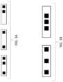
- FIG. 3A schematically illustrates three emitter arrays displaying different emitter patterns.
- FIG. 3 Bschematically illustrates a pair of emitter arrays having different emitter spacings.
- FIG. 3 Cschematically illustrates a pair of emitter arrays displaying different blink sequences.
- FIG. 4shows a top plan view of an operating room using optical trackers and emitters to determine relative positions of subsystem components.
- FIG. 5is a side elevation view of a robotic manipulator showing one example of optical tracker and emitter placements.
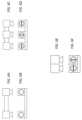
- FIGS. 6 A- 6 Fillustrate exemplary tracking camera unit configurations.
- an exemplary systemincludes one or more manipulator arms 13 , 14 , 15 , and a surgeon console 12 .
- these componentsmay be referred to generically as “subsystems.”
- the subsystemsare shown positioned relative to a patient bed.
- the console 12 and manipulator arms 13 , 14 , 15are independently positionable and thus may be relocated to different areas of the operating room independent of one another, such as by unlocking their wheels and rolling them to a new position.
- Optical trackingis used to determine the relative positions of the subsystems.
- Each sub-systemwill have at least one light emitter or set of light emitters, or at least one camera (which may be alternatively referred to as a tracking sensor, imager or tracker), or both light emitter(s) and a camera in order to allow determination of the relative position of each sub-system related to all the others.
- a camera 200is shown mounted on each subsystem.
- An emitter or set of emitters(not shown in FIG. 2 but see FIG. 5 ) is also mounted in a similar location on each subsystem.
- the emittersmay be configured to emit wavelengths in either or both the infrared (IR) and visible light spectrums.
- the emittersare IR transmitters, but visible light emitters or other wavelengths or combinations of wavelengths are within the scope of this disclosure.
- the distance between two emitters fixably mounted to a single subsystem componentis known a priori, then the distance from a camera viewing those emitters may be calculated using triangulation.
- the camera field-of-view (FoV) of each camerais identified in FIG. 2 using dashed lines.
- the camera on the console 12has a FoV that allows it to “see” arm 14 and arm 13 , but arm 15 is outside of its field of view.
- arm 15is within the FoV of the camera on arm 13 , and thus the relative coordinate system transformations between each subsystem may be known, and their position in a “global” coordinate system may be known as well.
- the relevant global coordinate systemmay reference the console 12 , the OR table, the patient umbilicus (which in some cases may be the planned or likely location for the port/trocar through which the endoscopic camera will be inserted), or some other relevant location within the operating room. Further tracking means and/or calculations may be performed to provide this information.
- This relative positioning datamay be accomplished in a few different ways:
- each subsystemmay include a processor having a memory storing a computer program that includes instructions executable by the processor to receive image data corresponding to images captured by that subsystem's camera, to execute an algorithm to detect light from emitters of neighboring subsystems in the captured images, and to perform the relative position calculation of all subsystems that it can see in a coordinate system relative to itself.
- the processorthen publishes that data onto the network for other subsystems to digest, or then publish that data to some other processing unit that aggregates this information into an overall positioning calculation.
- the data from each cameramay be sent (as raw image data, or as digitally processed data) to a central processing unit having a memory storing a computer program that includes instructions executable by the processor to receive the image data and to aggregate the raw data from each subsystem, and to then calculate the relative positioning of each base in an overall global coordinate system.
- the emittersmay be configured to allow the system to determine which subsystem a given emitter or emitter set or array is positioned on based on the received image data.
- Memory associated with the processor that determines the relative positioningstores information correlating the identifying characteristics of an emitter or emitter array with its corresponding subsystem component.
- the emitters or emitter arrayscan be uniquely identifiable by the system. For example, relative distance between multiple emitters on a single subsystem may be used to differentiate between different subsystems or subsystem types. For instance, each subsystem might have a different pattern of emitter arrays. One such example is shown in FIG. 3 A , which shows three emitter arrays, each having a different pattern.
- a different patternmay be achieved by positioning the emitters of each array in its unique pattern, whereas in another configuration the emitters one each subsystem may be arranged in identical patterns but illuminated so that only select ones of the emitters are illuminated to create the individual patterns.
- the three arrays of FIG. 3 Amight each consist of four emitters with uniform spacing, with the black squares showing which of the emitters are illuminated to create each individual pattern.
- each arm or subsystemmay be differentiated by having different spacing between their respective IR emitters. See FIG. 3 B .
- common subsystemsmight have the same emitter arrangement.
- a consolemay be differentiated from a robotic manipulator arm by their respective differences in emitter arrangement.
- Other means of differentiationmay be emitters strobing or pulsing at different speeds and/or in different sequences, and/or emitting light at different wavelengths.
- blink sequencesmay serve as differentiators.
- a black squaredenotes an emitter that is on
- a white squareis an emitter that is off.
- the distance between emitters in an emitter “set” or arraymay be different for different subsystems and may provide orientation and identification information by virtue of that information. This may be further enhanced by the use of differently-colored (e.g., LED) emitters, or even by color-changing emitters (such as RGB LEDs) which can be driven to provide many different colors, thus increasing the potential differentiation capability.
- differently-colored (e.g., LED) emittersor even by color-changing emitters (such as RGB LEDs) which can be driven to provide many different colors, thus increasing the potential differentiation capability.
- the systemcan determine relative base positioning as long as there is a serial chain of visibility of subsystems. As long as each one subsystem's emitters are seen by at least one other subsystem's camera, the relative positioning of each subsystem may be determined. From there the system can perform a serial chain of coordinate system transformations, and the global position of each subsystem can be determined.
- FIG. 2 embodimentdescribes the system as being used to track the manipulator arms and, optionally, the console, they may be used to track other subsystems including various equipment or objects within the operating room (OR), including, without limitation:
- emitters and/or tracking camerasmay be positioned on any portion of the system or other features within the operating room, including the manipulator arms, surgeon console, boom lights, laparoscopic towers, cars, the ceiling, a floor mounted structure, the operating table, anesthesia equipment, IV stands, etc.
- some or all of the various subsystems of the surgical systemmay be equipped with multiple emitters (and/or trackers) to enhance visibility and enable robust tracking of the respective positions of the robotic system components.
- each emitter on the subsystemmay have differentiating features of the type described above, such as different blink sequences and/or colors or color patterns.
- a tracker/camera/set of camerasis then able to determine the side of the manipulator arm in question simply by the IDs/emitters in view.
- Emittersmay be placed on either or both of a fixed portion of the manipulator arm, or a moveable portion of the manipulator arm.
- each armhas a base 100 that remains in a fixed position while surgery is performed, and a boom 102 that may move to robotically manipulate the surgical instrument during the procedure.
- a first emitter or collection of emitters 104is positioned on the (fixed) base.
- Emitters 104may be spaced around the perimeter of the base 100 . Where the base is multi-sided, emitters 104 may be spaced along two or more sides of the base as shown. Note that these are but examples, and that the emitters 104 may be on any part of the base 100 that remains fixed during surgery.
- a second emitter or collection of emitters 106may be positioned on a moveable part of the manipulator arm.
- the emitters 106are shown on boom 102 , but in other embodiments they might be on another moveable part of the manipulator arm. It should be understood that while FIG. 4 only shows emitters 104 , 106 on two of the arms, it is contemplated that either or both emitter sets/arrays 104 , 106 may be positioned on each of the arms, and emitters might also be placed on the console 12 and/or patient bed.
- the separation between the emitters 104 and the emitters 106may be determined using the kinematic data from the relevant manipulator joints and the associated transformations.
- a tracker/camerato the moveable portion of the manipulator arm, such as on the boom as shown.
- the camerais mounted to a moving portion of the manipulator, it is necessary to consider the movements on the camera (i.e., using kinematic data from the relevant manipulator joints) when performing the triangulation calculations.
- the relative base positions of the subsystemsmay be determined using emitters on fixed portions of the tracked subsystems or on tracked moving portions. Kinematic data from each subsystem may be used to determine movements of that subsystem's joints and their impacts on the cameras or emitters. An internal transformation between the base and the moving camera(s)/emitter(s) on that subsystem is performed. Knowledge of the positions of the emitters/cameras for each subsystem then allows the relative positions of each subsystem base to be determined using triangulation as described above.
- the cameramay comprise a tracking camera unit (TCU), which this may be a single camera/imager or a set of cameras/imagers. Referring to the top and front views of FIGS. 6 A and 6 B , respectively, in some cases, this may be a single stereo pair of imagers separated by a known baseline distance. In other cases, the TCU may be similar to the type manufactured by Sixdof Space, comprising a stereo pair of imagers to provide horizontal plane or depth information along with a centrally-located vertical imager to provide elevation information. See the top and front views shown in FIGS. 6 C and 6 D , respectively.
- TCUtracking camera unit
- the TCUmay comprise a pair of imagers, one with optics to provide horizontal plane information and another to provide vertical plane information ( FIGS. 6 E and 6 F ).
- the emitters and trackersmay be combined into a single housing mounted to the relevant subsystem. In others they are separately positioned as illustrated in FIG. 5 , for example.
Landscapes
- Health & Medical Sciences (AREA)
- Life Sciences & Earth Sciences (AREA)
- Surgery (AREA)
- Engineering & Computer Science (AREA)
- Nuclear Medicine, Radiotherapy & Molecular Imaging (AREA)
- Medical Informatics (AREA)
- Public Health (AREA)
- Heart & Thoracic Surgery (AREA)
- Veterinary Medicine (AREA)
- Molecular Biology (AREA)
- Animal Behavior & Ethology (AREA)
- General Health & Medical Sciences (AREA)
- Biomedical Technology (AREA)
- Robotics (AREA)
- Oral & Maxillofacial Surgery (AREA)
- Pathology (AREA)
- Gynecology & Obstetrics (AREA)
- Radiology & Medical Imaging (AREA)
- Manipulator (AREA)
Abstract
Description
- The OR table base
- The OR table top and its tilting surface
- OR staff—any marker(s) or trackable objects worn by the OR staff (i.e., on a headlamp, mask, head covering, watch, wristband, etc.)
- The patient, or any marker(s) or trocar(s) affixed or inserted into the patient
Claims (13)
Priority Applications (3)
| Application Number | Priority Date | Filing Date | Title |
|---|---|---|---|
| US17/944,170US12193772B2 (en) | 2021-09-13 | 2022-09-13 | Determining relative robot base positions using externally positioned imagers |
| US18/460,458US20240091942A1 (en) | 2021-09-13 | 2023-09-01 | Simultaneous direct relative measurement and calculated positions of equipment bases |
| US19/020,930US20250152269A1 (en) | 2021-09-13 | 2025-01-14 | Determining relative robot base positions using externally positioned imagers |
Applications Claiming Priority (3)
| Application Number | Priority Date | Filing Date | Title |
|---|---|---|---|
| US202163243716P | 2021-09-13 | 2021-09-13 | |
| US202163294765P | 2021-12-29 | 2021-12-29 | |
| US17/944,170US12193772B2 (en) | 2021-09-13 | 2022-09-13 | Determining relative robot base positions using externally positioned imagers |
Related Parent Applications (1)
| Application Number | Title | Priority Date | Filing Date |
|---|---|---|---|
| US18/092,194Continuation-In-PartUS20230404702A1 (en) | 2021-09-13 | 2022-12-30 | Use of external cameras in robotic surgical procedures |
Related Child Applications (2)
| Application Number | Title | Priority Date | Filing Date |
|---|---|---|---|
| US18/460,458Continuation-In-PartUS20240091942A1 (en) | 2021-09-13 | 2023-09-01 | Simultaneous direct relative measurement and calculated positions of equipment bases |
| US19/020,930ContinuationUS20250152269A1 (en) | 2021-09-13 | 2025-01-14 | Determining relative robot base positions using externally positioned imagers |
Publications (2)
| Publication Number | Publication Date |
|---|---|
| US20230080041A1 US20230080041A1 (en) | 2023-03-16 |
| US12193772B2true US12193772B2 (en) | 2025-01-14 |
Family
ID=85477992
Family Applications (2)
| Application Number | Title | Priority Date | Filing Date |
|---|---|---|---|
| US17/944,170Active2043-02-09US12193772B2 (en) | 2021-09-13 | 2022-09-13 | Determining relative robot base positions using externally positioned imagers |
| US19/020,930PendingUS20250152269A1 (en) | 2021-09-13 | 2025-01-14 | Determining relative robot base positions using externally positioned imagers |
Family Applications After (1)
| Application Number | Title | Priority Date | Filing Date |
|---|---|---|---|
| US19/020,930PendingUS20250152269A1 (en) | 2021-09-13 | 2025-01-14 | Determining relative robot base positions using externally positioned imagers |
Country Status (1)
| Country | Link |
|---|---|
| US (2) | US12193772B2 (en) |
Families Citing this family (1)
| Publication number | Priority date | Publication date | Assignee | Title |
|---|---|---|---|---|
| CN119818189B (en)* | 2024-12-26 | 2025-09-12 | 佗道医疗科技有限公司 | Positioning method for mechanical arm trolley |
Citations (12)
| Publication number | Priority date | Publication date | Assignee | Title |
|---|---|---|---|---|
| US20070005045A1 (en) | 2005-06-30 | 2007-01-04 | Intuitive Surgical Inc. | Indicator for tool state and communication in multi-arm robotic telesurgery |
| US20070083098A1 (en) | 2005-09-29 | 2007-04-12 | Intuitive Surgical Inc. | Autofocus and/or autoscaling in telesurgery |
| US20120307027A1 (en) | 2010-01-08 | 2012-12-06 | Koninklijke Philips Electronics N.V. | Uncalibrated visual servoing using real-time velocity optimization |
| US20130066335A1 (en) | 2010-05-25 | 2013-03-14 | Ronny Bärwinkel | Method for moving an instrument arm of a laparoscopy robot into a predeterminable relative position with respect to a trocar |
| US20140083058A1 (en)* | 2011-03-17 | 2014-03-27 | Ssi Schaefer Noell Gmbh Lager-Und Systemtechnik | Controlling and monitoring of a storage and order-picking system by means of motion and speech |
| US20150297313A1 (en) | 2012-12-14 | 2015-10-22 | The Trustees Of Columbia University In The City Of New York | Markerless tracking of robotic surgical tools |
| US20170079722A1 (en) | 2014-03-17 | 2017-03-23 | Intuitive Surgical Operations, Inc. | Methods and devices for table pose tracking using fudicial markers |
| US20170333137A1 (en) | 2016-05-23 | 2017-11-23 | Mako Surgical Corp. | Systems And Methods For Identifying And Tracking Physical Objects During A Robotic Surgical Procedure |
| US20190069962A1 (en)* | 2016-02-26 | 2019-03-07 | Think Surgical, Inc. | Method and system for guiding user positioning of a robot |
| US20210153958A1 (en)* | 2018-04-20 | 2021-05-27 | Covidien Lp | Systems and methods for surgical robotic cart placement |
| US20220117680A1 (en)* | 2019-01-14 | 2022-04-21 | Intuitive Surgical Operations, Inc. | System and method for automated docking |
| US20230270511A1 (en)* | 2020-08-26 | 2023-08-31 | Mazor Robotics Ltd. | Registration of multiple robotic arms using single reference frame |
- 2022
- 2022-09-13USUS17/944,170patent/US12193772B2/enactiveActive
- 2025
- 2025-01-14USUS19/020,930patent/US20250152269A1/enactivePending
Patent Citations (12)
| Publication number | Priority date | Publication date | Assignee | Title |
|---|---|---|---|---|
| US20070005045A1 (en) | 2005-06-30 | 2007-01-04 | Intuitive Surgical Inc. | Indicator for tool state and communication in multi-arm robotic telesurgery |
| US20070083098A1 (en) | 2005-09-29 | 2007-04-12 | Intuitive Surgical Inc. | Autofocus and/or autoscaling in telesurgery |
| US20120307027A1 (en) | 2010-01-08 | 2012-12-06 | Koninklijke Philips Electronics N.V. | Uncalibrated visual servoing using real-time velocity optimization |
| US20130066335A1 (en) | 2010-05-25 | 2013-03-14 | Ronny Bärwinkel | Method for moving an instrument arm of a laparoscopy robot into a predeterminable relative position with respect to a trocar |
| US20140083058A1 (en)* | 2011-03-17 | 2014-03-27 | Ssi Schaefer Noell Gmbh Lager-Und Systemtechnik | Controlling and monitoring of a storage and order-picking system by means of motion and speech |
| US20150297313A1 (en) | 2012-12-14 | 2015-10-22 | The Trustees Of Columbia University In The City Of New York | Markerless tracking of robotic surgical tools |
| US20170079722A1 (en) | 2014-03-17 | 2017-03-23 | Intuitive Surgical Operations, Inc. | Methods and devices for table pose tracking using fudicial markers |
| US20190069962A1 (en)* | 2016-02-26 | 2019-03-07 | Think Surgical, Inc. | Method and system for guiding user positioning of a robot |
| US20170333137A1 (en) | 2016-05-23 | 2017-11-23 | Mako Surgical Corp. | Systems And Methods For Identifying And Tracking Physical Objects During A Robotic Surgical Procedure |
| US20210153958A1 (en)* | 2018-04-20 | 2021-05-27 | Covidien Lp | Systems and methods for surgical robotic cart placement |
| US20220117680A1 (en)* | 2019-01-14 | 2022-04-21 | Intuitive Surgical Operations, Inc. | System and method for automated docking |
| US20230270511A1 (en)* | 2020-08-26 | 2023-08-31 | Mazor Robotics Ltd. | Registration of multiple robotic arms using single reference frame |
Non-Patent Citations (1)
| Title |
|---|
| Non-Final Office Action dated Aug. 17, 2022 for co-pending U.S. Appl. No. 16/733,200. |
Also Published As
| Publication number | Publication date |
|---|---|
| US20250152269A1 (en) | 2025-05-15 |
| US20230080041A1 (en) | 2023-03-16 |
Similar Documents
| Publication | Publication Date | Title |
|---|---|---|
| US20250152269A1 (en) | Determining relative robot base positions using externally positioned imagers | |
| US11793390B2 (en) | Endoscopic imaging with augmented parallax | |
| JP7376533B2 (en) | Camera tracking bar for computer-assisted navigation during surgical procedures | |
| US20210251701A1 (en) | Methods and devices for table pose tracking using fiducial markers | |
| US11950858B2 (en) | Systems for performing computer assisted surgery | |
| US12162143B2 (en) | Systems and methods for master/tool registration and control for intuitive motion | |
| US20200170718A1 (en) | Systems and methods for detection of objects within a field of view of an image capture device | |
| US20150223725A1 (en) | Mobile maneuverable device for working on or observing a body | |
| EP1415609A1 (en) | Optical object tracking system | |
| CN113768621B (en) | Camera tracking system for computer-aided navigation during surgery | |
| US20230126611A1 (en) | Information processing apparatus, information processing system, and information processing method | |
| US20230083605A1 (en) | Extended reality systems for visualizing and controlling operating room equipment | |
| CA2700475A1 (en) | Optical tracking cas system | |
| EP4203832B1 (en) | Robot control system for multiple robots | |
| CN111132631B (en) | System and method for interactive point display in a remotely operated component | |
| CA3198089A1 (en) | Robotic surgery system with user interfacing | |
| US20240225752A1 (en) | Systems, methods, and devices for determining an object pose | |
| US20240091942A1 (en) | Simultaneous direct relative measurement and calculated positions of equipment bases | |
| US20240382280A1 (en) | Surgeon input system using event-based vision sensors for a surgical robotic system | |
| US20240358453A1 (en) | Electrical interface for surgical robot arm | |
| US20240335240A1 (en) | Camera tracking system identifying phantom markers during computer assisted surgery navigation | |
| US20250057517A1 (en) | Calibration body, medical assistance system, method for evaluating a calibration and computer-readable storage medium | |
| HK40058671A (en) | Surgical object tracking in visible light via fiducial seeding and synthetic image registration | |
| US20210259779A1 (en) | Multi-camera user interface device calibration and tracking | |
| Emirdag | Collecting Relevant Environmental Parameters for Surgical Lighting Control |
Legal Events
| Date | Code | Title | Description |
|---|---|---|---|
| FEPP | Fee payment procedure | Free format text:ENTITY STATUS SET TO UNDISCOUNTED (ORIGINAL EVENT CODE: BIG.); ENTITY STATUS OF PATENT OWNER: LARGE ENTITY | |
| FEPP | Fee payment procedure | Free format text:ENTITY STATUS SET TO SMALL (ORIGINAL EVENT CODE: SMAL); ENTITY STATUS OF PATENT OWNER: LARGE ENTITY | |
| STPP | Information on status: patent application and granting procedure in general | Free format text:DOCKETED NEW CASE - READY FOR EXAMINATION | |
| STPP | Information on status: patent application and granting procedure in general | Free format text:NON FINAL ACTION MAILED | |
| AS | Assignment | Owner name:ASENSUS SURGICAL US, INC., NORTH CAROLINA Free format text:ASSIGNMENT OF ASSIGNORS INTEREST;ASSIGNORS:CAMPISANO, FEDERICO;HUFFORD, KEVIN ANDREW;ALPERT, LIOR;SIGNING DATES FROM 20240423 TO 20240515;REEL/FRAME:067418/0635 | |
| STPP | Information on status: patent application and granting procedure in general | Free format text:RESPONSE TO NON-FINAL OFFICE ACTION ENTERED AND FORWARDED TO EXAMINER | |
| STPP | Information on status: patent application and granting procedure in general | Free format text:NOTICE OF ALLOWANCE MAILED -- APPLICATION RECEIVED IN OFFICE OF PUBLICATIONS | |
| FEPP | Fee payment procedure | Free format text:ENTITY STATUS SET TO UNDISCOUNTED (ORIGINAL EVENT CODE: BIG.); ENTITY STATUS OF PATENT OWNER: LARGE ENTITY | |
| STPP | Information on status: patent application and granting procedure in general | Free format text:PUBLICATIONS -- ISSUE FEE PAYMENT RECEIVED | |
| STPP | Information on status: patent application and granting procedure in general | Free format text:PUBLICATIONS -- ISSUE FEE PAYMENT VERIFIED | |
| STCF | Information on status: patent grant | Free format text:PATENTED CASE | |
| AS | Assignment | Owner name:KARL STORZ SE & CO. KG, CALIFORNIA Free format text:SECURITY INTEREST;ASSIGNORS:ASENSUS SURGICAL, INC.;ASENSUS SURGICAL US, INC.;ASENSUS SURGICAL EUROPE S.A R.L.;AND OTHERS;REEL/FRAME:069795/0381 Effective date:20240403 | |
| AS | Assignment | Owner name:ASENSUS SURGICAL EUROPE S.A.R.L., LUXEMBOURG Free format text:CORRECTIVE ASSIGNMENT TO CORRECT THE CONVEYING AND RECEIVING PARTY'S DATA PREVIOUSLY RECORDED AT REEL: 67418 FRAME: 635. ASSIGNOR(S) HEREBY CONFIRMS THE ASSIGNMENT;ASSIGNORS:HUFFORD, KEVIN ANDREW;CAMPISANO, FEDERICO;ALPERT, LIOR;SIGNING DATES FROM 20240423 TO 20240515;REEL/FRAME:070161/0882 Owner name:ASENSUS SURGICAL US, INC., NORTH CAROLINA Free format text:CORRECTIVE ASSIGNMENT TO CORRECT THE CONVEYING AND RECEIVING PARTY'S DATA PREVIOUSLY RECORDED AT REEL: 67418 FRAME: 635. ASSIGNOR(S) HEREBY CONFIRMS THE ASSIGNMENT;ASSIGNORS:HUFFORD, KEVIN ANDREW;CAMPISANO, FEDERICO;ALPERT, LIOR;SIGNING DATES FROM 20240423 TO 20240515;REEL/FRAME:070161/0882 |