US12187446B2 - Personal aircraft - Google Patents
Personal aircraftDownload PDFInfo
- Publication number
- US12187446B2 US12187446B2US18/423,127US202418423127AUS12187446B2US 12187446 B2US12187446 B2US 12187446B2US 202418423127 AUS202418423127 AUS 202418423127AUS 12187446 B2US12187446 B2US 12187446B2
- Authority
- US
- United States
- Prior art keywords
- aircraft
- rotor assemblies
- lift rotor
- flight
- lift
- Prior art date
- Legal status (The legal status is an assumption and is not a legal conclusion. Google has not performed a legal analysis and makes no representation as to the accuracy of the status listed.)
- Active
Links
- 230000000712assemblyEffects0.000claimsabstractdescription40
- 238000000429assemblyMethods0.000claimsabstractdescription40
- 230000007704transitionEffects0.000claimsabstractdescription14
- 238000000034methodMethods0.000claimsdescription25
- 230000003213activating effectEffects0.000claims5
- 230000005484gravityEffects0.000abstractdescription4
- 230000008030eliminationEffects0.000abstract1
- 238000003379elimination reactionMethods0.000abstract1
- 239000002131composite materialSubstances0.000description12
- 229920000049Carbon (fiber)Polymers0.000description8
- 239000004917carbon fiberSubstances0.000description8
- VNWKTOKETHGBQD-UHFFFAOYSA-NmethaneChemical compoundCVNWKTOKETHGBQD-UHFFFAOYSA-N0.000description8
- 230000003247decreasing effectEffects0.000description6
- 230000003993interactionEffects0.000description5
- 125000004122cyclic groupChemical group0.000description4
- 230000007423decreaseEffects0.000description4
- 238000009826distributionMethods0.000description4
- 230000006870functionEffects0.000description4
- 230000033001locomotionEffects0.000description4
- 230000007246mechanismEffects0.000description4
- 230000001681protective effectEffects0.000description4
- 230000004044responseEffects0.000description4
- RZVHIXYEVGDQDX-UHFFFAOYSA-N9,10-anthraquinoneChemical compoundC1=CC=C2C(=O)C3=CC=CC=C3C(=O)C2=C1RZVHIXYEVGDQDX-UHFFFAOYSA-N0.000description3
- 229920000271Kevlar®Polymers0.000description3
- 229910052782aluminiumInorganic materials0.000description3
- XAGFODPZIPBFFR-UHFFFAOYSA-NaluminiumChemical compound[Al]XAGFODPZIPBFFR-UHFFFAOYSA-N0.000description3
- 230000005540biological transmissionEffects0.000description3
- 239000004761kevlarSubstances0.000description3
- 230000015654memoryEffects0.000description3
- 239000004215Carbon black (E152)Substances0.000description2
- 230000001133accelerationEffects0.000description2
- 230000008901benefitEffects0.000description2
- 230000008859changeEffects0.000description2
- 238000004590computer programMethods0.000description2
- 238000010586diagramMethods0.000description2
- 230000007613environmental effectEffects0.000description2
- 230000002349favourable effectEffects0.000description2
- 230000004907fluxEffects0.000description2
- 229930195733hydrocarbonNatural products0.000description2
- 150000002430hydrocarbonsChemical class0.000description2
- 238000012423maintenanceMethods0.000description2
- 229910052751metalInorganic materials0.000description2
- 239000002184metalSubstances0.000description2
- 230000003287optical effectEffects0.000description2
- 230000002829reductive effectEffects0.000description2
- 238000000926separation methodMethods0.000description2
- 239000002023woodSubstances0.000description2
- WHXSMMKQMYFTQS-UHFFFAOYSA-NLithiumChemical compound[Li]WHXSMMKQMYFTQS-UHFFFAOYSA-N0.000description1
- 229910000831SteelInorganic materials0.000description1
- 239000011358absorbing materialSubstances0.000description1
- 230000009471actionEffects0.000description1
- 230000002411adverseEffects0.000description1
- 238000005452bendingMethods0.000description1
- 230000000981bystanderEffects0.000description1
- 238000006243chemical reactionMethods0.000description1
- 230000009194climbingEffects0.000description1
- 230000008878couplingEffects0.000description1
- 238000010168coupling processMethods0.000description1
- 238000005859coupling reactionMethods0.000description1
- 230000009977dual effectEffects0.000description1
- 239000000446fuelSubstances0.000description1
- 229910000078germaneInorganic materials0.000description1
- 238000007689inspectionMethods0.000description1
- 230000000670limiting effectEffects0.000description1
- 229910052744lithiumInorganic materials0.000description1
- 239000000463materialSubstances0.000description1
- 239000004033plasticSubstances0.000description1
- 229920003023plasticPolymers0.000description1
- 239000004417polycarbonateSubstances0.000description1
- 229920000515polycarbonatePolymers0.000description1
- 229920000642polymerPolymers0.000description1
- 230000008569processEffects0.000description1
- 230000004043responsivenessEffects0.000description1
- 230000000717retained effectEffects0.000description1
- 239000010959steelSubstances0.000description1
- 238000010408sweepingMethods0.000description1
Images


Classifications
- B—PERFORMING OPERATIONS; TRANSPORTING
- B64—AIRCRAFT; AVIATION; COSMONAUTICS
- B64C—AEROPLANES; HELICOPTERS
- B64C3/00—Wings
- B64C3/10—Shape of wings
- B64C3/16—Frontal aspect
- B—PERFORMING OPERATIONS; TRANSPORTING
- B64—AIRCRAFT; AVIATION; COSMONAUTICS
- B64C—AEROPLANES; HELICOPTERS
- B64C11/00—Propellers, e.g. of ducted type; Features common to propellers and rotors for rotorcraft
- B64C11/46—Arrangements of, or constructional features peculiar to, multiple propellers
- B—PERFORMING OPERATIONS; TRANSPORTING
- B64—AIRCRAFT; AVIATION; COSMONAUTICS
- B64C—AEROPLANES; HELICOPTERS
- B64C29/00—Aircraft capable of landing or taking-off vertically, e.g. vertical take-off and landing [VTOL] aircraft
- B—PERFORMING OPERATIONS; TRANSPORTING
- B64—AIRCRAFT; AVIATION; COSMONAUTICS
- B64C—AEROPLANES; HELICOPTERS
- B64C29/00—Aircraft capable of landing or taking-off vertically, e.g. vertical take-off and landing [VTOL] aircraft
- B64C29/0008—Aircraft capable of landing or taking-off vertically, e.g. vertical take-off and landing [VTOL] aircraft having its flight directional axis horizontal when grounded
- B64C29/0016—Aircraft capable of landing or taking-off vertically, e.g. vertical take-off and landing [VTOL] aircraft having its flight directional axis horizontal when grounded the lift during taking-off being created by free or ducted propellers or by blowers
- B64C29/0025—Aircraft capable of landing or taking-off vertically, e.g. vertical take-off and landing [VTOL] aircraft having its flight directional axis horizontal when grounded the lift during taking-off being created by free or ducted propellers or by blowers the propellers being fixed relative to the fuselage
- B—PERFORMING OPERATIONS; TRANSPORTING
- B64—AIRCRAFT; AVIATION; COSMONAUTICS
- B64C—AEROPLANES; HELICOPTERS
- B64C39/00—Aircraft not otherwise provided for
- B64C39/12—Canard-type aircraft
- B—PERFORMING OPERATIONS; TRANSPORTING
- B64—AIRCRAFT; AVIATION; COSMONAUTICS
- B64D—EQUIPMENT FOR FITTING IN OR TO AIRCRAFT; FLIGHT SUITS; PARACHUTES; ARRANGEMENT OR MOUNTING OF POWER PLANTS OR PROPULSION TRANSMISSIONS IN AIRCRAFT
- B64D31/00—Power plant control systems; Arrangement of power plant control systems in aircraft
- B64D31/16—Power plant control systems; Arrangement of power plant control systems in aircraft for electric power plants
- Y—GENERAL TAGGING OF NEW TECHNOLOGICAL DEVELOPMENTS; GENERAL TAGGING OF CROSS-SECTIONAL TECHNOLOGIES SPANNING OVER SEVERAL SECTIONS OF THE IPC; TECHNICAL SUBJECTS COVERED BY FORMER USPC CROSS-REFERENCE ART COLLECTIONS [XRACs] AND DIGESTS
- Y02—TECHNOLOGIES OR APPLICATIONS FOR MITIGATION OR ADAPTATION AGAINST CLIMATE CHANGE
- Y02T—CLIMATE CHANGE MITIGATION TECHNOLOGIES RELATED TO TRANSPORTATION
- Y02T50/00—Aeronautics or air transport
- Y02T50/10—Drag reduction
Definitions
- This disclosurerelates generally to a personal aircraft configured to provide safe operations while achieving robust control.
- the described embodimentsinclude an aircraft with vertical takeoff and landing capability, and that provides vertical and horizontal thrust in a controlled fashion for hover, transition and cruise flight.
- VTOLvertical takeoff and landing
- the rotary wing aircraftis one common type of VTOL aircraft.
- Helicoptershave large rotors that provide both vertical and horizontal thrust.
- the rotorsare typically quite complex.
- the rotor bladesmust be at different orientation angles around the 360 degrees of azimuth rotation to provide the needed thrust. Therefore, rotors have both collective and cyclic variation of the blade orientation angle.
- Collectivevaries the angle of each blade equally, independent of the 360-degree rotation azimuth angle.
- Cyclicvaries the blade angle of attack as a function of the 360-degree rotation azimuth angle. Cyclic control allows the rotor to be tilted in various directions and therefore direct the thrust of the rotor forwards, backwards, left or right. This direction provides control forces to move the helicopter in the horizontal plane and respond to disturbances such as wind gusts.
- Helicopter rotorsare large and unprotected from hitting nearby obstacles. Additionally, they utilize mechanically complex systems to control both the collective and cyclic blade angles. Such rotors are mechanically complex and require maintenance. The rotors generally rotate at a low speed; this results in heavy transmissions between the rotor and motor. The transmissions, or gearboxes, decrease the vehicle payload potential, as well as vehicle safety. Because of the mechanical complexity across the entire vehicle system, many parts are single points of failure. Because of this lack of redundancy, frequent inspections and maintenance are required to keep the vehicle safe.
- the described embodimentsprovide a personal aircraft with a configuration that is safe, quiet, and efficient, as well as easy to control, highly compact, and able to accomplish vertical takeoff and landing with transition to and from forward flight.
- the aircraft configurationincludes multiple rotors oriented to provide vertical thrust for lift and control during takeoff, transition to and from forward flight, and landing.
- the rotorsare attached to the airframe in fixed, non-planar orientations.
- the orientations of rotorsprovide lateral and, in some embodiments, fore and aft control of aircraft without requiring a change of attitude, and minimize disturbances to the flow when the aircraft is cruising.
- the rotorshave forward, backwards, left, and right orientations, and are located longitudinally along the port and starboard sides of the fuselage, with two or more rotors located on each side.
- the fuselagecarries a variable-weight payload.
- the aircrafthas tandem wings at the front and rear of the vehicle.
- the wingsprovide lift and control during cruise, and one or more propellers provide forward thrust.
- the combination of vertical lift rotors and front and rear tandem wingsbound the rotors, permitting movement in the aircraft's center of gravity while still enabling the vehicle to maintain vertical and horizontal flight control.
- the forward and rear wingsare also located to provide a boundary to avoid foreign object damage (FOD) to the lift rotors.
- the control surfaceswhich include elevator and ailerons, are usable to compensate for changes in CG of the aircraft during flight by adjusting the center of lift, in addition to changing angle of attack and attitude.
- the vertical lift rotorsare arranged around the CG, and the thrust of each rotor is adjustable, which permits the relocation of the center of lift in vertical flight if the CG shifts.
- the vertical thrustis redundant and thrust and control remain available even with the failure of any single rotor. Since there are multiple vertical rotors that provide large control forces, the rotors are smaller, with faster response rates for operation even in gusty wind conditions.
- a separate electric motor and controllerpowers each vertical lift rotor, in order to provide lift system redundancy from failure of one or more lifting rotors.
- the vertical thrust rotorsare embedded in ducts that conceal them and provide increased lift. Other embodiments are relatively open with protective shrouding to act as guards to prevent contact with other objects and prevent FOD to the rotors.
- the protective shielding in combination with in-line vertical lift rotorsprovide low cruise drag for efficient flight.
- Low tip speed vertical lift rotorsare used in various embodiments to produce low community noise levels during takeoff, transition, and landing.
- Embodiments with a low front wing and high rear wing with wingletsprovide high aerodynamic efficiency while also providing yaw stability for the aircraft.
- the wings foldto provide a compact vehicle footprint when in hover or while on the ground.
- Some embodiments of the winghave control surfaces only on the inner part of the wing fold so that no articulating control linkages are required. Since the lift rotors that are used for vertical lift are separate from the forward thrust propellers, each is optimized for its specific operating conditions. Such a vehicle can be used for either piloted or unpiloted embodiments across a range of occupant sizes or payloads.
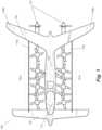
- FIG. 1is a top view of a personal aircraft vehicle in accordance with one embodiment.
- FIG. 2illustrates a second view of a personal aircraft vehicle in accordance with one embodiment.
- FIG. 3illustrates a front view of a personal aircraft vehicle in accordance with one embodiment.
- FIG. 4illustrates a view of the left side of a personal aircraft vehicle in accordance with one embodiment.
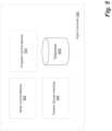
- FIG. 5is a block diagram illustrating a flight computer in accordance with one embodiment.
- FIG. 6is a flowchart illustrating a method for transitioning from vertical takeoff to forward flight in accordance with one embodiment.
- FIG. 1illustrates a personal aircraft 100 in accordance with one embodiment.
- Aircraft 100includes vertical lift rotor assemblies 101 a and 101 b (generally, 101 ) with fixed orientations; forward flight propellers 103 ; a forward wing 104 ; a rear wing 105 having winglets 106 a and 106 b (generally, 106 ); fences 110 a and 110 b (generally 110 ), a cockpit area 112 and a fuselage 107 .
- Fuselage 107also includes landing gear, a flight computer and power source (not shown), each of which is described further below.
- FIG. 2illustrates a second view of personal aircraft 100 , including propulsion booms 114 , port-side main landing gear 202 and forward landing gear 204 .
- FIG. 3illustrates a front view of personal aircraft 100 , in which port landing gear 202 a , starboard landing gear 202 b and nose gear 204 are visible.
- FIG. 4illustrates a view of the left (port) side of aircraft 100 in accordance with one embodiment.
- aircraft 100is sized to accommodate a single pilot and personal cargo.
- the length of the aircraft from nose to its aft-most surfaceis between 15 and 20 feet, and its wingspan is between 15 and 20 feet.
- the aircraftmay be longer or shorter, wider or narrower, as will be appreciated by those of skill in the art, without departing from the principles described here.
- Aircraft 100is constructed in various embodiments primarily of a composite material.
- Fuselage 107 and wings 104 , 105are made from carbon fiber composite material.
- the wingsmay have metal fittings and ribs attached to the inside and outside of a carbon fiber composite wing skin.
- the wing skinsmay comprise composite materials made of carbon fiber combined with other composite materials such as Kevlar.
- the fuselagemay comprise a metal truss made from steel or aluminum with a composite skin that covers the truss.
- the composite fuselage skin in this embodimentmay be made of carbon fiber, Kevlar, or other composite materials as understood by those of skill in the art.
- the cockpit windows in one embodimentare polycarbonate, though other lightweight clear plastics may also be used.
- Fences 110are made from a Kevlar and carbon fiber composite.
- Rotor assemblies 101include rotors that in one embodiment have a 16 inch radius, and are made from carbon fiber composite material, and in an alternative embodiment from carbon fiber composite blades attached to an aluminum hub. In other embodiments, rotors are made from wood blades attached to an aluminum hub, or wood blades attached to a carbon fiber composite hub. The rotors may be a single piece that bolts onto the motor assembly. Rotor assemblies 101 are described further below.
- Aircraft 100includes a forward wing 104 and an aft wing 105 .
- the forward and aft wingsare similar in span.
- the aft wingis swept back and has winglets 106 at its ends.
- the wingletsprovide lateral stability and decrease the drag due to lift on the aft wing. Sweeping the wing back improves the pitch stability of the aircraft and increases the benefits of the winglets on lateral stability.
- the aft wingcan fold, and thus maintain the same overall vehicle length as an aircraft with an unswept aft wing.
- the sweep of the aft wingprovides more space for the rotors to fit into.
- Forward wing 104is also attached to fuselage 107 at a point substantially lower than is aft wing 105 in various embodiments.
- a non-planar wing lifting systemenables the wings to develop efficient lift during cruise flight.
- the vertical separation between the two wingsis chosen to be as large as possible, given the constraint of attaching to the fuselage.
- the negative aerodynamic interaction between the front wing and the rear wingis reduced.
- the drag due to lift of the vehicleis significantly decreased, for example by 15-20% compared to a single in-plane wing lifting system.
- the winglets 106are located at the tip of rear wing 105 to provide decreased drag due to lift on the rear wing, as well as yaw or directional stability and control.
- the particular winglet shapeis established for adequate stability, as will be understood by those skilled in the art.
- the wingletsextend downward and provide improved controllability by reducing the coupling between the sideslip angle of the aircraft and the yawing moment that the airflow produces on the aircraft.
- the tandem wing systemhas joints where the wingtips on each wing fold, allowing aircraft 100 to fit in a constrained space.
- folding the wingsenables the aircraft 100 to be stored an 8′ by 7′ by 16′ space, or the space provided by a typical single car garage.
- the rear wing 105has a dihedral angle of 8.4 degrees. In other embodiments the dihedral ranges between ⁇ 10 and 10 degrees.
- a propulsion boom 114( FIG. 2 ) is secured to each side of the fuselage 107 .
- forward flight propellers 103are attached to the rear end of the booms 114
- the vertical lift rotor assemblies 101are installed on top of the booms 114 .
- Propulsion booms 114are attached to the fuselage 107 with struts 116 .
- the struts 116are positioned so that the downwash from the rotors does not impinge on the struts.
- the strutsmay be swept forward, aft, up, or down to improve the attachment of the booms to the fuselage.
- a vertically oriented support structureprovides increased bending stiffness from the vertical lift rotor loads during hover.
- Each vertical lift rotor assembly 101includes a rotor and a motor.
- the rotormay comprise blades attached to a hub, or may be manufactured as a single piece with an integral hub.
- the hubprovides a central structure to which the blades connect, and in some embodiments is made in a shape that envelops the motor.
- the motorincludes a rotating part and a stationary part.
- the rotating partis concentric to the stationary part, known as a radial flux motor.
- the stationary partmay form the outer ring of the motor, known as an inrunner motor, or the stationary part may form the inner ring of the motor, known as an outrunner motor.
- the rotating and stationary partsare flat and arranged in opposition to each other, known as an axial flux motor.
- the motor partsare low-profile so that the entire motor fits within the hub of the rotor, presenting lower resistance to the air flow when flying forward.
- the rotoris attached to the rotating part of the motor.
- the stationary part of the motoris attached to the propulsion boom 114 .
- the motoris a permanent magnet motor and is controlled by an electronic motor controller. The electronic motor controller sends electrical currents to the motor in a precise sequence to allow the rotor to turn at a desired speed or with a desired torque.
- aircraft 100includes multiple rotor assemblies 101 per side.
- the vertical lift rotorsgenerate thrust that is independent of the thrust generated by the forward flight propellers 103 during horizontal cruise.
- the vertical lift rotorsprovide enough thrust to lift the aircraft off the ground and maintain control.
- each rotorgenerates more, e.g., 40% more, thrust than is needed to hover, to maintain control in all portions of the flight envelope.
- the rotorsare optimized by selecting the diameter, blade chord, and blade incidence distributions to provide the needed thrust with minimum consumed power at hover and low speed flight conditions.
- half of the rotorsrotate in one direction, and the other half rotate in the opposite direction to balance the reaction torque on the aircraft.
- rotors directly across from each other on the port and starboard sides of the aircrafthave opposite directions of rotation. In other embodiments the rotors directly across from each other have the same direction of rotation. In some embodiments, the rotors may be individually tuned to account for different interactions between the rotors, or between the airframe and the rotors. In such embodiments the tuning includes adjusting the incidence or chord distributions on the blades to account for favorable or adverse interactions and achieve the necessary performance from the rotor. In the embodiment illustrated in FIG. 1 , four vertical lift rotor assemblies 101 per side are shown. In alternative embodiments more or fewer vertical lift rotors provide the vertical lift and control.
- two vertical lift rotor assemblies 101 per sideare located in front of the CG and two are located behind the CG. In this manner, the center of lift of the rotors in hover is co-located with the center of gravity of the aircraft 100 .
- Flight computer 500modifies the thrust produced by each vertical lift rotor independently, providing a balanced vertical lift or, alternatively, unbalanced lift to provide control.
- the rotor orientationprovides lateral and longitudinal control of the aircraft without requiring a change of attitude. Because rotor assemblies 101 are each mounted to cant outward, inward, forward, or back, a proper combination of rotor thrusts results in a net force in the horizontal plane, as well as the needed vertical lift force. This is helpful when maneuvering near the ground, for example. In addition, in the case of a rotor failure in which a blade becomes damaged or separated, the different cant angles make it less likely that another rotor will be damaged, thus making the design more failure tolerant. The orientations are also chosen to minimize disturbances to the flow when the aircraft is cruising.
- the orientation of the rotorsis varied forward, backward, left, and right, enabling the aircraft to maneuver in any direction without changing attitude. In other embodiments, the orientation is varied only left and right, minimizing the disturbance to the flow during cruise, but meaning that the aircraft can only maneuver side-to-side, not forward and backward, without changing attitude. In one embodiment with four rotors per side, the rotors are oriented, from front to back, 10 degrees out, 10 degrees in, 10 degrees in, and 10 degrees out.
- Forward flight propellers 103provide the thrust for transition to forward flight, climb, descent, and cruise.
- two or more forward thrust propellers 103are mounted along the span of the rear wing 105 .
- a single forward thrust propelleris mounted on the aft portion of the fuselage 107 at the center of the span.
- one or more propellersare mounted to the front of the wings or propulsion booms as tractor propellers.
- the propellerscan be rotated in opposite directions so that the torque required to turn them does not produce a net torque on the airplane.
- the thrust of the two propellerscan be varied differentially to provide a yaw control moment. Positioning on the wing results in less inflow disturbance to the propellers.
- the forward propellersare fixed-pitch.
- the chord and incidence distributionsare optimized to provide adequate thrust for acceleration and climbing both when the vehicle is moving slowly and supported in the air by the thrust of the rotors and when the aircraft is moving quickly and is fully supported by the lift of the wings. Additionally, the chord and incidence distributions are selected to provide efficient thrust at the cruising speed of the aircraft.
- the forward propellersutilize a variable pitch mechanism which allows the incidence of each blade to be adjusted depending on the flight condition.
- the vertical lift rotors and the forward propellersare driven by electric motors that are powered by a power system.
- the power systemincludes a battery that is attached to one motor controller for each motor.
- the batterycomprises one or more modules located within the fuselage of the aircraft. In other embodiments the battery modules are located in the propulsion booms.
- the batteryprovides a DC voltage and current that the motor controllers turn into the AC signals that make the motors spin.
- the batterycomprises lithium polymer cells connected together in parallel and in series to generate the needed voltage and current. Alternatively, cells of other chemistry may be used. In one embodiment the cells are connected into 93 cell series strings, and 6 of these strings are connected in parallel.
- the cellsare connected with more or fewer cells in series and more or fewer cells in parallel.
- the rotors and propellersare powered by a power system that includes a hybrid-electric system with a small hydrocarbon-based fuel engine and a smaller battery.
- the hydrocarbon engineprovides extended range in forward flight and can recharge the battery system.
- the vertical lift rotor assemblies 101 in various embodimentsare protected by protective fences 110 to avoid accidental blade strikes.
- the protective fenceis designed to maximize the thrust of all the rotors near the fence by providing incremental lift.
- the fence 110is shaped so that the flow over the fence induced by the rotor system 101 creates an upward force on the fence 110 . This is accomplished by selecting a cross sectional shape and angle with respect to vertical of the fence that generates the upward force.
- the fenceis designed to reduce the apparent noise of the rotor system by shielding bystanders from the noise of the rotors.
- the fencesare either filled with a conventional sound absorbing material, or are coated with a conventional sounds adsorbing material.
- aircraft 100does not include fences 110 .
- a system that includes six or more rotorspermits hover and vertical ascent/descent with safe operation without forward airspeed, even if one or several individual components fail.
- FIG. 5is a block diagram of a flight computer 500 in accordance with one embodiment.
- Flight computer 500is located on board aircraft 100 , typically within the fuselage 107 .
- Flight computer 500includes a rotor control module 502 , propeller control module 504 , position sensor interface 506 , and a database 508 .
- Position sensor interface 506is communicatively coupled to the aircraft's instruments and receives sensor data in one embodiment that includes the aircraft's position, altitude, attitude and velocity.
- Rotor control module 502receives data from position sensor interface 506 and from control inputs in the cockpit and determines how much thrust is required from each of the vertical lift rotors 101 to achieve the commanded response.
- Rotor control module 502commands each rotor assembly 101 independently to produce the determined required thrust.
- rotor control module 502adjusts the thrust requirements to compensate for the lost rotor.
- Propeller control module 504receives data from position sensor interface 506 and from control inputs in the cockpit, determines how much forward thrust is required from each of the propellers 103 , and commands the propellers to produce the required thrust.
- Database 508includes programmed trajectories for ascent and descent to be used during transition, and may also include additional features used for navigation and control of aircraft 100 as will be appreciated by those of skill in the art.
- Flight computer 500also includes other components and modules to perform navigation and flight operations and which are known to those of skill in the art, but not germane to this description.
- FIG. 6illustrates a method for transitioning from vertical to forward flight in accordance with one embodiment.
- rotor control module 502 of flight computer 500applies 602 power to the rotors. In one embodiment, equal power is applied to each of the rotors during this initial phase of takeoff. In alternative embodiments different power is applied to each rotor during the initial phase of takeoff to facilitate taking off from a slope, or in a crosswind.
- Position sensor interface 506receives 604 attitude and altitude data from aircraft instruments. Once a minimum altitude, e.g., 200 feet above ground level, has been reached 606 , propeller control module 504 activates 608 the forward propellers and in some embodiments activates their control input inside the cockpit.
- no minimum altitudeis required for powered forward propulsion.
- the minimum altitudeis adjustable and/or overrideable. For example, tall trees may demand a higher initial ascent before beginning acceleration.
- the pilotprograms an initial altitude into flight computer 500 .
- the pilotuses flight control input to indicate that a higher altitude is desired. If 610 additional altitude is required, position sensor interface 502 determines 612 the aircraft's attitude and velocity and rotor control module 502 adjusts 614 power to the rotors individually as needed to maintain vertical thrust and a level orientation.
- position sensor interface 506determines 616 whether the forward velocity of the aircraft is sufficiently large to generate lift, i.e., whether the aircraft's speed is greater than its stall speed. If not, flight computer 500 determines 618 how much lift is required from the rotors, and applies 620 the required power. In one embodiment, the amount of lift required is the amount required to maintain the aircraft's altitude in view of the lift generated by the airfoils. As the speed increases, the wings develop lift and the thrust required of the vertical lift rotors is decreased. In one embodiment, the thrust from the rotors is adjusted to maintain during the transition an optimal trajectory and reject any disturbances due to interactions or environmental effects such as gusts.
- the optimal trajectoryis determined prior to flight and stored by flight computer 500 in database 508 .
- Flight computer 500continues to determine 622 the aircraft's attitude, altitude and velocity and adjust rotor power until a desired speed is reached or a minimum level of lift is being generated by the airfoils. Once 616 the speed is greater than the stall speed, i.e., high enough that the wings can support the entire weight of the aircraft, or in an alternative embodiment a different minimum speed is reached, the vertical lift rotors are completely deactivated 624 .
- propeller control module 504reduces the thrust of the forward propellers 103 to reduce speed.
- rotor control module 502automatically commands the rotors to begin generating vertical lift.
- the thrust required of the vertical lift rotorsincreases as the lift on the wings decreases.
- the thrust from the rotorsis adjusted by rotor control module 502 in response to readings from position sensor interface 506 to maintain during the transition an optimal trajectory determined by the flight computer, e.g., based on a trajectory stored in database 508 , and reject any disturbances due to interactions or environmental effects such as gusts.
- the forward speedis zero or approaching zero and the vertical lift rotors provide all the lift.
- the vehiclethen descends to the ground either via a descent command from the pilot, or by flight computer 500 automatically reducing power to the individual rotors to maintain a desired descent rate and a level orientation.
- wing 104 and 105 foldin some embodiments. Some embodiments have a wing fold that is positioned at a location where the loads are small, outboard of 50% of the span, for example, to permit a lighter weight hinge. In other embodiments, the forward wing does not fold. In other embodiments, the wings fold so the aircraft can fit into an 8′ wide space, such as a typical single car garage. Alternative embodiments also include folding the forward wing in other ways, such as in a scissor motion underneath the fuselage or along the side of the fuselage. This scissor folding is accomplished through pivot and pin at the center of the front wing that permits a rotation backwards about that center pivot point.
- the landing gearincludes a single front wheel 204 with two main rear landing gear wheels 202 .
- aircraft 100is capable of taking off and landing with the front and rear wings folded. Taking off and landing with the wings folded in vertical flight decreases the gust response of the vehicle due to unsteady wind conditions through decreased wing lift performance and shorter wing spans. Since the wing lift is not required in hover flight, but only in forward flight, is it possible to wait to unfold the wings until sufficient altitude is achieved away from ground. Avoiding ground wing unfolding is advantageous for some operations where the ground takeoff and landing space available and wind conditions are not favorable.
- An electromechanical actuatorprovides the actuation force to unfold the wing before commencing forward flight.
- control surfacesare located on the inner portion of the front wing fold 301 and rear wing fold 302 to permit folding without control lines required outboard of the folding hinge mechanism to provide less mechanical complexity through fewer moving parts.
- the control surfacesprovide pitch, roll, and yaw control during forward flight aerodynamically so that the vertical lift rotors are not required for control except at low or zero forward speed.
- Other embodiments that require greater forward flight control responsivenessalso have control surfaces outboard of the wing fold mechanism.
- Other embodimentsonly have control surfaces on the outboard section of the wing.
- Landing gear 202 , 204is provided with wheels to permit the aircraft to move while on the ground.
- One forward 204 and two rear 202 main landing gearprovide lower drag and less lift interference on the front wing.
- the landing gearis a skid and has no wheels, since the aircraft is capable of takeoff and landing without forward movement.
- Alternative embodimentsinclude two forward and one rear main landing gear to permit the front landing gear to be widely separated for ground stability.
- some or all of the wheelsare fitted with electric motors that allow the wheels to be driven. Such motors allow the vehicle to be self-propelled while on the ground.
- aircraft 100is designed to accommodate two or more occupants.
- the wingspanis larger, the rotors have a larger diameter, and the fuselage 107 is wider.
- aircraft 100is an unmanned vehicle that is capable of flight without a pilot or passengers.
- Embodiments without passengershave additional control systems that provide directional control inputs in place of a pilot, either through a ground link or through a predetermined flight path trajectory.
- Electronic components of the described embodimentsmay be specially constructed for the required purposes, or may comprise one or more general-purpose computers selectively activated or reconfigured by a computer program stored in the computer.
- a computer programmay be stored in a computer readable storage medium, such as, but is not limited to, any type of disk including floppy disks, optical disks, DVDs, CD-ROMs, magnetic-optical disks, read-only memories (ROMs), random access memories (RAMs), EPROMs, EEPROMs, magnetic or optical cards, application specific integrated circuits (ASICs), or any type of media suitable for storing electronic instructions, and each coupled to a computer system bus.
Landscapes
- Engineering & Computer Science (AREA)
- Aviation & Aerospace Engineering (AREA)
- Mechanical Engineering (AREA)
- Toys (AREA)
- Other Liquid Machine Or Engine Such As Wave Power Use (AREA)
- Structures Of Non-Positive Displacement Pumps (AREA)
- Electric Propulsion And Braking For Vehicles (AREA)
- Wind Motors (AREA)
Abstract
Description
Claims (20)
Priority Applications (2)
| Application Number | Priority Date | Filing Date | Title |
|---|---|---|---|
| US18/423,127US12187446B2 (en) | 2011-07-19 | 2024-01-25 | Personal aircraft |
| US18/970,781US20250091722A1 (en) | 2011-07-19 | 2024-12-05 | Personal aircraft |
Applications Claiming Priority (6)
| Application Number | Priority Date | Filing Date | Title |
|---|---|---|---|
| US201161509530P | 2011-07-19 | 2011-07-19 | |
| US13/553,438US8485464B2 (en) | 2011-07-19 | 2012-07-19 | Personal aircraft |
| US13/931,954US9242738B2 (en) | 2011-07-19 | 2013-06-30 | Personal aircraft |
| US14/975,130US10974838B2 (en) | 2011-07-19 | 2015-12-18 | Personal aircraft |
| US17/191,549US11939071B2 (en) | 2011-07-19 | 2021-03-03 | Personal aircraft |
| US18/423,127US12187446B2 (en) | 2011-07-19 | 2024-01-25 | Personal aircraft |
Related Parent Applications (1)
| Application Number | Title | Priority Date | Filing Date |
|---|---|---|---|
| US17/191,549ContinuationUS11939071B2 (en) | 2011-07-19 | 2021-03-03 | Personal aircraft |
Related Child Applications (1)
| Application Number | Title | Priority Date | Filing Date |
|---|---|---|---|
| US18/970,781ContinuationUS20250091722A1 (en) | 2011-07-19 | 2024-12-05 | Personal aircraft |
Publications (2)
| Publication Number | Publication Date |
|---|---|
| US20240158092A1 US20240158092A1 (en) | 2024-05-16 |
| US12187446B2true US12187446B2 (en) | 2025-01-07 |
Family
ID=47555117
Family Applications (6)
| Application Number | Title | Priority Date | Filing Date |
|---|---|---|---|
| US13/553,438ActiveUS8485464B2 (en) | 2011-07-19 | 2012-07-19 | Personal aircraft |
| US13/931,954ActiveUS9242738B2 (en) | 2011-07-19 | 2013-06-30 | Personal aircraft |
| US14/975,130Active2035-08-18US10974838B2 (en) | 2011-07-19 | 2015-12-18 | Personal aircraft |
| US17/191,549Active2033-07-06US11939071B2 (en) | 2011-07-19 | 2021-03-03 | Personal aircraft |
| US18/423,127ActiveUS12187446B2 (en) | 2011-07-19 | 2024-01-25 | Personal aircraft |
| US18/970,781PendingUS20250091722A1 (en) | 2011-07-19 | 2024-12-05 | Personal aircraft |
Family Applications Before (4)
| Application Number | Title | Priority Date | Filing Date |
|---|---|---|---|
| US13/553,438ActiveUS8485464B2 (en) | 2011-07-19 | 2012-07-19 | Personal aircraft |
| US13/931,954ActiveUS9242738B2 (en) | 2011-07-19 | 2013-06-30 | Personal aircraft |
| US14/975,130Active2035-08-18US10974838B2 (en) | 2011-07-19 | 2015-12-18 | Personal aircraft |
| US17/191,549Active2033-07-06US11939071B2 (en) | 2011-07-19 | 2021-03-03 | Personal aircraft |
Family Applications After (1)
| Application Number | Title | Priority Date | Filing Date |
|---|---|---|---|
| US18/970,781PendingUS20250091722A1 (en) | 2011-07-19 | 2024-12-05 | Personal aircraft |
Country Status (11)
| Country | Link |
|---|---|
| US (6) | US8485464B2 (en) |
| EP (1) | EP2734444A4 (en) |
| JP (1) | JP5676824B2 (en) |
| KR (2) | KR20150023061A (en) |
| CN (1) | CN103796917B (en) |
| AU (1) | AU2012283923B2 (en) |
| BR (1) | BR112014001325A2 (en) |
| CA (1) | CA2841315C (en) |
| IL (2) | IL230343A (en) |
| TW (1) | TWI538852B (en) |
| WO (1) | WO2013013084A1 (en) |
Families Citing this family (221)
| Publication number | Priority date | Publication date | Assignee | Title |
|---|---|---|---|---|
| JP5421503B2 (en) | 2010-07-19 | 2014-02-19 | ズィー.エアロ インコーポレイテッド | Private aircraft |
| TWI538852B (en) | 2011-07-19 | 2016-06-21 | 季航空股份有限公司 | Personal aircraft |
| US9384668B2 (en) | 2012-05-09 | 2016-07-05 | Singularity University | Transportation using network of unmanned aerial vehicles |
| FR2990685B1 (en)* | 2012-05-21 | 2014-11-21 | Eurocopter France | METHOD FOR CONTROLLING WING SHUTTERS AND HORIZONTAL TRUCK OF A HYBRID HELICOPTER |
| FR2990684B1 (en)* | 2012-05-21 | 2014-11-21 | Eurocopter France | METHOD FOR CONTROLLING WING SHUTTERS AND HORIZONTAL TRUCK OF A HYBRID HELICOPTER |
| AU2013327362B2 (en)* | 2012-10-05 | 2017-04-20 | Marcus LENG | Electrically powered aerial vehicles and flight control methods |
| US9527597B1 (en) | 2013-01-11 | 2016-12-27 | Jaime Sada | Unmanned aerial vehicle with twin-engine fore/AFT configuration and associated systems and methods |
| JP6027939B2 (en)* | 2013-05-02 | 2016-11-16 | 香山 恒夫 | airplane |
| JP6076833B2 (en)* | 2013-05-27 | 2017-02-08 | 富士重工業株式会社 | Control method for vertical takeoff and landing vehicle |
| WO2014198642A1 (en)* | 2013-06-09 | 2014-12-18 | Eth Zurich | Controlled flight of a multicopter experiencing a failure affecting an effector |
| DE102013109392A1 (en)* | 2013-08-29 | 2015-03-05 | Airbus Defence and Space GmbH | Fast-flying, vertically launchable aircraft |
| SG11201602420SA (en) | 2013-12-24 | 2016-04-28 | Singapore Tech Aerospace Ltd | An unmanned aerial vehicle |
| US10124890B2 (en)* | 2014-04-11 | 2018-11-13 | Dronetechuav Corporation | Modular nacelles to provide vertical takeoff and landing (VTOL) capabilities to fixed wing aerial vehicles, and associated systems and methods |
| US9764822B2 (en)* | 2014-05-01 | 2017-09-19 | Alakai Technologies Corporation | Clean fuel electric multirotor aircraft for personal air transportation and manned or unmanned operation |
| CN107074358B (en)* | 2014-05-07 | 2020-01-07 | Xti飞行器公司 | vertical take-off and landing aircraft |
| US9878257B2 (en)* | 2014-06-10 | 2018-01-30 | University Of Kansas | Aerial vehicles and methods of use |
| US9296477B1 (en) | 2014-07-21 | 2016-03-29 | Glenn Coburn | Multi-rotor helicopter |
| US20160031554A1 (en)* | 2014-07-30 | 2016-02-04 | Siniger LLC | Control system for an aircraft |
| IL233942B (en) | 2014-08-04 | 2020-01-30 | Israel Aerospace Ind Ltd | Propulsion system assembly |
| WO2016022040A1 (en)* | 2014-08-05 | 2016-02-11 | Ардн Технолоджи Лимитед | Air-mobile |
| US10046853B2 (en) | 2014-08-19 | 2018-08-14 | Aergility LLC | Hybrid gyrodyne aircraft employing a managed autorotation flight control system |
| US9664175B2 (en) | 2014-08-30 | 2017-05-30 | X Development Llc | Carbon fiber motor rotor integrating propeller mount |
| US9889930B2 (en) | 2014-11-24 | 2018-02-13 | Amazon Technologies, Inc. | Unmanned aerial vehicle protective frame configuration |
| US9868524B2 (en)* | 2014-11-11 | 2018-01-16 | Amazon Technologies, Inc. | Unmanned aerial vehicle configuration for extended flight |
| EP3218261A4 (en) | 2014-11-12 | 2018-07-18 | Sikorsky Aircraft Corporation | High-authority yaw control for a tandem vehicle with rigid rotors |
| US11485488B1 (en)* | 2014-12-07 | 2022-11-01 | L3Harris Latitude Llc | Vertical take-off and landing aircraft with rotor thrust yaw control |
| KR101715136B1 (en)* | 2014-12-09 | 2017-03-13 | 한국항공우주연구원 | Vertical takeoff and landing unmanned aerial vehicle and position control method thereof |
| US10040544B2 (en) | 2015-01-02 | 2018-08-07 | Jesse Antoine Marcel | Multi-rotor personal air vehicle with a central lifting fan |
| DE102015001704B4 (en)* | 2015-02-13 | 2017-04-13 | Airbus Defence and Space GmbH | Vertical launching aircraft |
| FR3032687B1 (en)* | 2015-02-16 | 2018-10-12 | Hutchinson | AERODYNE VTOL WITH SOUFFLANTE (S) AXIALE (S) CARRIER (S) |
| US20160236775A1 (en)* | 2015-02-18 | 2016-08-18 | Siniger LLC | Vertical takeoff and landing aircraft |
| US10640204B2 (en)* | 2015-03-03 | 2020-05-05 | Amazon Technologies, Inc. | Unmanned aerial vehicle with a tri-wing configuration |
| US9946267B2 (en) | 2015-04-06 | 2018-04-17 | Thomas A. Youmans | Control and stabilization of a flight vehicle from a detected perturbation by tilt and rotation |
| DE102015006511A1 (en)* | 2015-05-26 | 2016-12-01 | Airbus Defence and Space GmbH | Vertical launching aircraft |
| JP6435991B2 (en)* | 2015-05-28 | 2018-12-12 | 株式会社村田製作所 | Electric aircraft |
| EP3124379B1 (en) | 2015-07-29 | 2019-05-01 | Airbus Defence and Space GmbH | Hybrid-electric drive train for vtol drones |
| RU2603302C1 (en)* | 2015-08-20 | 2016-11-27 | Общество с ограниченной ответственностью "АвиаНовации" | Vertical take-off and landing aircraft |
| EP3141478B1 (en)* | 2015-09-11 | 2018-11-07 | AIRBUS HELICOPTERS DEUTSCHLAND GmbH | Compound helicopter |
| EP3374263A4 (en)* | 2015-11-10 | 2019-05-08 | Matternet, Inc. | METHODS AND TRANSPORT SYSTEMS USING PILOT-FREE AIR VEHICLES |
| US20180162525A1 (en) | 2016-12-08 | 2018-06-14 | Aurora Flight Sciences Corporation | Double-Blown Wing Vertical Takeoff and Landing Aircraft |
| ES2925005T3 (en)* | 2015-12-09 | 2022-10-13 | Ideaforge Tech Pvt Ltd | Multirotor aerial vehicle with redundancy for single arm failure |
| WO2017106013A1 (en)* | 2015-12-18 | 2017-06-22 | Amazon Technologies, Inc. | Selecting propellers for performance and noise shaping |
| EP3184425B1 (en) | 2015-12-21 | 2018-09-12 | AIRBUS HELICOPTERS DEUTSCHLAND GmbH | Multirotor aircraft |
| EP3416887B1 (en) | 2016-02-17 | 2021-01-27 | ARDN Technology Limited | Multicopter with different purpose propellers |
| WO2017184742A1 (en)* | 2016-04-19 | 2017-10-26 | Advanced Aircraft Company | Unmanned aerial vehicle |
| US9840327B1 (en)* | 2016-04-29 | 2017-12-12 | Rfrank Llc | Vertical takeoff and landing (VTOL) aircraft and system |
| US9975629B2 (en) | 2016-05-24 | 2018-05-22 | Kitty Hawk Corporation | Control system for a stopped rotor aircraft |
| US9944387B2 (en) | 2016-05-24 | 2018-04-17 | Kitty Hawk Corporation | Stopped rotor aircraft |
| US11027837B2 (en) | 2016-07-01 | 2021-06-08 | Textron Innovations Inc. | Aircraft having thrust to weight dependent transitions |
| US10011351B2 (en) | 2016-07-01 | 2018-07-03 | Bell Helicopter Textron Inc. | Passenger pod assembly transportation system |
| US10501193B2 (en) | 2016-07-01 | 2019-12-10 | Textron Innovations Inc. | Aircraft having a versatile propulsion system |
| US10870487B2 (en) | 2016-07-01 | 2020-12-22 | Bell Textron Inc. | Logistics support aircraft having a minimal drag configuration |
| US10633087B2 (en) | 2016-07-01 | 2020-04-28 | Textron Innovations Inc. | Aircraft having hover stability in inclined flight attitudes |
| US10597164B2 (en) | 2016-07-01 | 2020-03-24 | Textron Innovations Inc. | Aircraft having redundant directional control |
| US10220944B2 (en) | 2016-07-01 | 2019-03-05 | Bell Helicopter Textron Inc. | Aircraft having manned and unmanned flight modes |
| US10981661B2 (en) | 2016-07-01 | 2021-04-20 | Textron Innovations Inc. | Aircraft having multiple independent yaw authority mechanisms |
| US10232950B2 (en)* | 2016-07-01 | 2019-03-19 | Bell Helicopter Textron Inc. | Aircraft having a fault tolerant distributed propulsion system |
| US10633088B2 (en) | 2016-07-01 | 2020-04-28 | Textron Innovations Inc. | Aerial imaging aircraft having attitude stability during translation |
| US10227133B2 (en) | 2016-07-01 | 2019-03-12 | Bell Helicopter Textron Inc. | Transportation method for selectively attachable pod assemblies |
| US10618647B2 (en)* | 2016-07-01 | 2020-04-14 | Textron Innovations Inc. | Mission configurable aircraft having VTOL and biplane orientations |
| US11084579B2 (en) | 2016-07-01 | 2021-08-10 | Textron Innovations Inc. | Convertible biplane aircraft for capturing drones |
| US10214285B2 (en) | 2016-07-01 | 2019-02-26 | Bell Helicopter Textron Inc. | Aircraft having autonomous and remote flight control capabilities |
| US10737778B2 (en) | 2016-07-01 | 2020-08-11 | Textron Innovations Inc. | Two-axis gimbal mounted propulsion systems for aircraft |
| US10315761B2 (en) | 2016-07-01 | 2019-06-11 | Bell Helicopter Textron Inc. | Aircraft propulsion assembly |
| US10737765B2 (en) | 2016-07-01 | 2020-08-11 | Textron Innovations Inc. | Aircraft having single-axis gimbal mounted propulsion systems |
| US11124289B2 (en) | 2016-07-01 | 2021-09-21 | Textron Innovations Inc. | Prioritizing use of flight attitude controls of aircraft |
| US10625853B2 (en) | 2016-07-01 | 2020-04-21 | Textron Innovations Inc. | Automated configuration of mission specific aircraft |
| US11104446B2 (en) | 2016-07-01 | 2021-08-31 | Textron Innovations Inc. | Line replaceable propulsion assemblies for aircraft |
| US11608173B2 (en) | 2016-07-01 | 2023-03-21 | Textron Innovations Inc. | Aerial delivery systems using unmanned aircraft |
| US10604249B2 (en) | 2016-07-01 | 2020-03-31 | Textron Innovations Inc. | Man portable aircraft system for rapid in-situ assembly |
| US11142311B2 (en) | 2016-07-01 | 2021-10-12 | Textron Innovations Inc. | VTOL aircraft for external load operations |
| US10183746B2 (en)* | 2016-07-01 | 2019-01-22 | Bell Helicopter Textron Inc. | Aircraft with independently controllable propulsion assemblies |
| RU2627220C1 (en)* | 2016-07-26 | 2017-08-04 | Общество с ограниченной ответственностью "АвиаНовации" | Vertical takeoff and landing aircraft |
| US10301016B1 (en)* | 2016-08-09 | 2019-05-28 | Vimana, Inc. | Stabilized VTOL flying apparatus and aircraft |
| US10252796B2 (en)* | 2016-08-09 | 2019-04-09 | Kitty Hawk Corporation | Rotor-blown wing with passively tilting fuselage |
| TWI605978B (en)* | 2016-08-10 | 2017-11-21 | 元智大學 | Fixed-wing aircraft |
| NL2017611B1 (en)* | 2016-10-12 | 2018-04-20 | Univ Delft Tech | Aerial vehicle with angularly displaced propulsion units |
| US10364024B2 (en) | 2016-10-18 | 2019-07-30 | Kitty Corporation | Multicopter with angled rotors |
| US10364036B2 (en)* | 2016-10-18 | 2019-07-30 | Kitty Hawk Corporation | Multicopter with boom-mounted rotors |
| US10399673B1 (en) | 2016-10-24 | 2019-09-03 | Kitty Hawk Corporation | Integrated float-wing |
| CN110546068B (en)* | 2016-11-02 | 2023-05-26 | 杰欧比航空有限公司 | VTOL aircraft using rotors to simulate rigid wing aerodynamics |
| US10689105B2 (en)* | 2016-11-21 | 2020-06-23 | John Daniel Romo | Passenger-carrying rotorcraft with fixed-wings for generating lift |
| CN106741932B (en)* | 2016-11-22 | 2020-11-03 | 四川尚航智能科技有限公司 | Nine unmanned aerial vehicle of mixed type based on VTOL |
| JP2018134908A (en)* | 2017-02-20 | 2018-08-30 | 株式会社菊池製作所 | Unmanned aircraft |
| IL250996B2 (en)* | 2017-03-07 | 2025-06-01 | Colugo Systems Ltd | Multi-bladed folding wing |
| US20180290735A1 (en)* | 2017-04-06 | 2018-10-11 | John Uptigrove | Vtol high speed aircraft |
| US10577091B2 (en) | 2017-04-24 | 2020-03-03 | Bcg Digital Ventures Gmbh | Vertical take-off and landing aircraft |
| USD822579S1 (en) | 2017-04-24 | 2018-07-10 | AFS-DV VTOL Technologies Corporation | Aircraft |
| EP3621877B1 (en)* | 2017-05-08 | 2022-09-21 | Insitu, Inc. | Modular aircraft with vertical takeoff and landing capability |
| KR102627083B1 (en)* | 2017-05-22 | 2024-01-18 | 오버에어, 인코퍼레이티드 | Evtol aircraft using large, variable speed tilt rotors |
| US10351232B2 (en) | 2017-05-26 | 2019-07-16 | Bell Helicopter Textron Inc. | Rotor assembly having collective pitch control |
| US10661892B2 (en) | 2017-05-26 | 2020-05-26 | Textron Innovations Inc. | Aircraft having omnidirectional ground maneuver capabilities |
| US10442522B2 (en) | 2017-05-26 | 2019-10-15 | Bell Textron Inc. | Aircraft with active aerosurfaces |
| US10618646B2 (en) | 2017-05-26 | 2020-04-14 | Textron Innovations Inc. | Rotor assembly having a ball joint for thrust vectoring capabilities |
| US10329014B2 (en) | 2017-05-26 | 2019-06-25 | Bell Helicopter Textron Inc. | Aircraft having M-wings |
| US20180354609A1 (en)* | 2017-06-07 | 2018-12-13 | Joseph R. Renteria | Aircraft with linear thruster arrangement |
| US11634211B2 (en)* | 2017-06-07 | 2023-04-25 | Joseph R. Renteria | Aircraft with linear thruster arrangement |
| US10730622B2 (en) | 2017-06-14 | 2020-08-04 | Bell Helicopter Textron Inc. | Personal air vehicle with ducted fans |
| US10822101B2 (en)* | 2017-07-21 | 2020-11-03 | General Electric Company | Vertical takeoff and landing aircraft having a forward thrust propulsor |
| US10745099B2 (en)* | 2017-08-31 | 2020-08-18 | Wisk Aero Llc | Conductor in composite |
| JP2020536016A (en)* | 2017-10-02 | 2020-12-10 | カリフォルニア インスティチュート オブ テクノロジー | Autonomous flight ambulance |
| USD843889S1 (en)* | 2017-10-04 | 2019-03-26 | Elroy Air, Inc. | Unmanned cargo delivery aircraft |
| USD852092S1 (en)* | 2017-10-12 | 2019-06-25 | Wing Aviation Llc | Unmanned aerial vehicle |
| US11628933B2 (en) | 2017-10-27 | 2023-04-18 | Elroy Air, Inc. | Compound multi-copter aircraft |
| USD858352S1 (en)* | 2017-10-30 | 2019-09-03 | Shenzhen Valuelink E-Commerce Co., Ltd. | Drone |
| KR102669208B1 (en) | 2017-11-03 | 2024-05-28 | 조비 에어로, 인크. | VTOL M-wing configuration |
| US11034445B2 (en)* | 2017-11-27 | 2021-06-15 | Wing Aviation Llc | Wing structure and attachment to frame for unmanned aerial vehicles |
| US10723433B2 (en) | 2017-11-27 | 2020-07-28 | Wing Aviation Llc | Assembly systems and methods for unmanned aerial vehicles |
| CN109311536A (en)* | 2017-12-04 | 2019-02-05 | 深圳市大疆创新科技有限公司 | Power device, unmanned vehicle and flight control method |
| US11447248B2 (en) | 2017-12-21 | 2022-09-20 | Elroy Air, Inc. | Unmanned vehicle cargo handling and carrying system |
| US11008093B2 (en)* | 2018-03-22 | 2021-05-18 | Aurora Flight Sciences Corporation | Systems and methods for reducing the propeller noise |
| JP6731604B2 (en)* | 2018-03-31 | 2020-07-29 | 中松 義郎 | High-speed drones and other aircraft |
| US12044699B2 (en) | 2018-04-24 | 2024-07-23 | Fuelle Landing Systems, Inc. | Ground-based vectored thrust system |
| AU2019257746B2 (en)* | 2018-04-27 | 2023-11-02 | Textron Systems Corporation | Variable pitch rotor assembly for electrically driven vectored thrust aircraft applications |
| US11091260B2 (en)* | 2018-04-27 | 2021-08-17 | Wing Aviation Llc | Counter-rotating propellers for aerial vehicle |
| WO2019211875A1 (en)* | 2018-05-04 | 2019-11-07 | Anthony Alvin | Hybrid vertical takeoff and landing (vtol) aircraft with vehicle assist |
| US12006048B2 (en) | 2018-05-31 | 2024-06-11 | Joby Aero, Inc. | Electric power system architecture and fault tolerant VTOL aircraft using same |
| CN112368208A (en) | 2018-05-31 | 2021-02-12 | 杰欧比飞行有限公司 | Electric power system architecture and fault-tolerant VTOL (virtual volume on-board) aircraft using same |
| KR102480033B1 (en) | 2018-06-01 | 2022-12-21 | 조비 에어로, 인크. | Systems and methods for aircraft noise abatement |
| EP3581491B1 (en)* | 2018-06-13 | 2020-06-24 | AIRBUS HELICOPTERS DEUTSCHLAND GmbH | A multirotor aircraft with a thrust producing unit that comprises an aerodynamically optimized shrouding |
| US10775784B2 (en)* | 2018-06-14 | 2020-09-15 | Wing Aviation Llc | Unmanned aerial vehicle with decentralized control system |
| US11136115B2 (en)* | 2018-06-20 | 2021-10-05 | Textron Innovations Inc. | Tilted propellers for enhanced distributed propulsion control authority |
| US10710741B2 (en) | 2018-07-02 | 2020-07-14 | Joby Aero, Inc. | System and method for airspeed determination |
| KR20210034071A (en) | 2018-07-27 | 2021-03-29 | 에어본 모터 워크스 인코포레이티드 | Thrust generation split flywheel gyroscope method and apparatus |
| EP3841354B1 (en) | 2018-08-26 | 2024-03-13 | Airborne Motor Works Inc. | Electromagnetic gyroscopic stabilizing propulsion system method and apparatus |
| US11708157B2 (en) | 2018-09-11 | 2023-07-25 | Eve Uam, Llc | Vertical take-off and landing (VTOL) aircraft with cruise rotor positioning control for minimum drag |
| EP3853736A4 (en) | 2018-09-17 | 2022-11-16 | Joby Aero, Inc. | AIRCRAFT CONTROL SYSTEM |
| US10556704B1 (en) | 2018-09-17 | 2020-02-11 | Kitty Hawk Corporation | Health based actuator allocation |
| FR3086641B1 (en)* | 2018-09-28 | 2020-09-04 | Airbus Helicopters | ELECTRIC OR HYBRID MOTORIZED MULTIROTOR AIRCRAFT WITH OPTIMIZED ENERGY CONSUMPTION |
| US11912405B2 (en)* | 2018-10-02 | 2024-02-27 | Embraer S.A. | Vertical and short takeoff and landing (VSTOL) aircraft |
| JP6648802B2 (en)* | 2018-10-26 | 2020-02-14 | 株式会社村田製作所 | Electric aircraft |
| US10640212B1 (en)* | 2018-11-18 | 2020-05-05 | Faruk Dizdarevic | Double wing aircraft |
| US12286207B2 (en)* | 2018-11-27 | 2025-04-29 | Yanmar Power Technology Co., Ltd. | Control target generation device and ship-steering control device |
| US10787255B2 (en) | 2018-11-30 | 2020-09-29 | Sky Canoe Inc. | Aerial vehicle with enhanced pitch control and interchangeable components |
| WO2020180373A2 (en) | 2018-12-07 | 2020-09-10 | Joby Aero, Inc. | Aircraft control system and method |
| US20200331602A1 (en) | 2018-12-07 | 2020-10-22 | Joby Aero, Inc. | Rotary airfoil and design method therefor |
| WO2020132332A1 (en) | 2018-12-19 | 2020-06-25 | Joby Aero, Inc. | Vehicle navigation system |
| EP3911290A4 (en) | 2019-01-20 | 2022-10-26 | Airborne Motors, LLC | METHOD AND APPARATUS FOR THE MANUFACTURE OF A MEDICAL STABILIZER |
| CN111688920B (en)* | 2019-02-20 | 2024-02-02 | 上海峰飞航空科技有限公司 | VTOL fixed wing flight platform system |
| US12103670B2 (en) | 2019-02-28 | 2024-10-01 | Beta Air, Llc | Vertical take-off and landing (VTOL) aircraft |
| US20200277080A1 (en)* | 2019-02-28 | 2020-09-03 | Beta Air Llc | Systems and methods for in-flight operational assessment |
| CA3132276A1 (en) | 2019-03-01 | 2020-09-10 | Pratt & Whitney Canada Corp. | Cooling system configurations for an aircraft having hybrid-electric propulsion system |
| US11628942B2 (en) | 2019-03-01 | 2023-04-18 | Pratt & Whitney Canada Corp. | Torque ripple control for an aircraft power train |
| US11148852B2 (en) | 2019-04-11 | 2021-10-19 | Elroy Air, Inc. | Modular aerial cargo aerodynamic encasement |
| US11230384B2 (en) | 2019-04-23 | 2022-01-25 | Joby Aero, Inc. | Vehicle cabin thermal management system and method |
| EP3730404B1 (en)* | 2019-04-23 | 2021-08-18 | LEONARDO S.p.A. | Vertical take-off and landing aircraft and related control method |
| CN116646641B (en) | 2019-04-23 | 2024-09-13 | 杰欧比飞行有限公司 | Battery thermal management system and method |
| US11574548B2 (en) | 2019-04-25 | 2023-02-07 | Pratt & Whitney Canada Corp. | Aircraft degraded operation ceiling increase using electric power boost |
| US10988248B2 (en) | 2019-04-25 | 2021-04-27 | Joby Aero, Inc. | VTOL aircraft |
| EP3959125A4 (en) | 2019-04-26 | 2023-03-22 | Aergility Corporation | Hybrid gyrodyne aircraft |
| US11643199B2 (en)* | 2019-05-10 | 2023-05-09 | Eve Uam, Llc | Vertical take-off and landing (VTOL) aircraft |
| WO2020237082A1 (en)* | 2019-05-21 | 2020-11-26 | Joby Aero, Inc. | Vtol aircraft using fixed forward canted rotors to simulate rigid wing dynamics |
| US12006033B1 (en) | 2019-06-10 | 2024-06-11 | Joby Aero, Inc. | Boom assembly for aerial vehicle |
| JP2020158100A (en)* | 2019-06-25 | 2020-10-01 | 株式会社A.L.I.Technologies | Flying vehicle |
| US11148791B2 (en)* | 2019-06-27 | 2021-10-19 | Harry Messimore | Hybrid power tri-propeller helicopter apparatus |
| GB201909464D0 (en)* | 2019-07-01 | 2019-08-14 | Rolls Royce Plc | Aircraft control method |
| US11661193B2 (en)* | 2019-07-18 | 2023-05-30 | Elroy Air, Inc. | Unmanned aerial vehicle optimization |
| US11305872B2 (en)* | 2019-07-29 | 2022-04-19 | Aurora Flight Sciences Corporation | Retractable propulsor assemblies for vertical take-off and landing (VTOL) aircraft |
| US11347242B2 (en)* | 2019-08-05 | 2022-05-31 | The Boeing Company | Methods and apparatus for flight control prioritization |
| US11667391B2 (en) | 2019-08-26 | 2023-06-06 | Pratt & Whitney Canada Corp. | Dual engine hybrid-electric aircraft |
| US11912422B2 (en) | 2019-08-26 | 2024-02-27 | Hamilton Sundstrand Corporation | Hybrid electric aircraft and powerplant arrangements |
| EP3800723A1 (en)* | 2019-10-02 | 2021-04-07 | Rolls-Royce Deutschland Ltd & Co KG | Battery module and aircraft with a battery module |
| EP4592189A3 (en)* | 2019-10-09 | 2025-09-03 | Kitty Hawk Corporation | Hybrid power systems for different modes of flight |
| US11738881B2 (en) | 2019-10-21 | 2023-08-29 | Hamilton Sundstrand Corporation | Auxiliary power unit systems |
| US11312491B2 (en) | 2019-10-23 | 2022-04-26 | Textron Innovations Inc. | Convertible biplane aircraft for autonomous cargo delivery |
| RU2726391C1 (en)* | 2019-11-22 | 2020-07-13 | Федор Александрович Рябков | Aircraft |
| US20210253248A1 (en)* | 2020-02-08 | 2021-08-19 | Samir Hanna Safar | Aircraft wings with reduced wingspan |
| JP7630526B2 (en)* | 2020-02-10 | 2025-02-17 | ウィスク アエロ エルエルシー | Aircraft with pusher propellers |
| DE102020104783A1 (en)* | 2020-02-24 | 2021-08-26 | Volocopter Gmbh | Battery holding device, battery system, aircraft and method for changing a battery for an aircraft |
| JP7104427B2 (en)* | 2020-02-27 | 2022-07-21 | 義郎 中松 | Winged drone |
| EP4111053A4 (en) | 2020-02-28 | 2024-03-06 | Airborne Motor Works Inc. | METHOD AND DEVICE FOR LIMITING THE FRICTION OF A TURBINE GENERATOR CYCLE |
| KR20210122476A (en)* | 2020-04-01 | 2021-10-12 | 이광무 | Propeller structure in the form of twin Mobius blades for aircraft |
| WO2021206970A1 (en)* | 2020-04-07 | 2021-10-14 | MightyFly Inc. | System and method for package transportation |
| EP4146538B1 (en)* | 2020-05-07 | 2024-11-06 | BAE SYSTEMS plc | Rotorcraft |
| EP3907131A1 (en)* | 2020-05-07 | 2021-11-10 | BAE SYSTEMS plc | Piloted rotorcraft |
| WO2021224593A1 (en) | 2020-05-07 | 2021-11-11 | Bae Systems Plc | Rotorcraft |
| US20210362849A1 (en)* | 2020-05-19 | 2021-11-25 | Archer Aviation, Inc. | Vertical take-off and landing aircraft |
| US11053017B1 (en) | 2020-08-20 | 2021-07-06 | Kitty Hawk Corporation | Rotor noise reduction using signal processing |
| US11530035B2 (en) | 2020-08-27 | 2022-12-20 | Textron Innovations Inc. | VTOL aircraft having multiple wing planforms |
| WO2022049764A1 (en)* | 2020-09-07 | 2022-03-10 | 株式会社エアロネクスト | Flying vehicle |
| US11319064B1 (en) | 2020-11-04 | 2022-05-03 | Textron Innovations Inc. | Autonomous payload deployment aircraft |
| US11630467B2 (en) | 2020-12-23 | 2023-04-18 | Textron Innovations Inc. | VTOL aircraft having multifocal landing sensors |
| US20220212788A1 (en)* | 2021-01-05 | 2022-07-07 | Chiu-Shia Fen | Solar unmanned aircraft |
| FR3118622B1 (en)* | 2021-01-06 | 2022-12-09 | Ascendance Flight Tech | Hybrid Power Source Aircraft |
| US11919631B2 (en) | 2021-02-08 | 2024-03-05 | Archer Aviation, Inc. | Vertical take-off and landing aircraft with aft rotor tilting |
| EP4291489A1 (en)* | 2021-02-09 | 2023-12-20 | Joby Aero, Inc. | Aircraft propulsion unit |
| US12168508B2 (en)* | 2021-03-29 | 2024-12-17 | Textron Innovations Inc. | Tilting hexrotor aircraft |
| US20220324558A1 (en)* | 2021-03-29 | 2022-10-13 | Bell Textron Inc. | Tilting hexrotor aircraft |
| US20240199203A1 (en)* | 2021-04-14 | 2024-06-20 | Aeronext Inc | Flight body, landing method, and program |
| US11208206B1 (en)* | 2021-05-17 | 2021-12-28 | Beta Air, Llc | Aircraft for fixed pitch lift |
| US11541999B2 (en)* | 2021-06-01 | 2023-01-03 | Hoversurf, Inc. | Methods of vertical take-off/landing and horizontal straight flight of aircraft and aircraft for implementation |
| US11383831B1 (en)* | 2021-06-01 | 2022-07-12 | Hoversurf, Inc. | Methods of vertical take-off/landing and horizontal straight flight of aircraft and aircraft for implementation |
| US11299287B1 (en)* | 2021-06-29 | 2022-04-12 | Beta Air, Llc | Methods and systems for orienting a thrust propulsor in response to a failure event of a vertical take-off and landing aircraft |
| US20230002034A1 (en)* | 2021-07-01 | 2023-01-05 | Beta Air, Llc | System for fixed-pitch lift configured for use in an electric aircraft |
| US12187422B2 (en) | 2021-07-23 | 2025-01-07 | Beta Air, Llc | System and method of rotor management |
| US11623743B2 (en) | 2021-07-23 | 2023-04-11 | Beta Air, Llc | System and method of rotor management |
| US12134466B2 (en)* | 2021-08-09 | 2024-11-05 | Insitu, Inc. | Unmanned aerial vehicles including wing capture devices and related methods |
| EP4345001B1 (en)* | 2021-08-27 | 2025-10-15 | SZ DJI Technology Co., Ltd. | Aerial vehicle and control method and apparatus therefor, and storage medium |
| US11377220B1 (en) | 2021-09-27 | 2022-07-05 | Hoversurf, Inc. | Methods of increasing flight safety, controllability and maneuverability of aircraft and aircraft for implementation thereof |
| KR102606816B1 (en)* | 2021-11-02 | 2023-11-29 | 주식회사 새안알엔디 | Manned drone with jet engine cluster unit as propellant |
| KR102606817B1 (en)* | 2021-11-02 | 2023-11-29 | 주식회사 새안알엔디 | Manned drone with jet engine cluster unit as propellant |
| US12084200B2 (en) | 2021-11-03 | 2024-09-10 | Textron Innovations Inc. | Ground state determination systems for aircraft |
| US20240270399A1 (en)* | 2021-11-17 | 2024-08-15 | Verdego Aero, Inc. | Hybrid control system spanning multiple operation modes |
| US11932387B2 (en) | 2021-12-02 | 2024-03-19 | Textron Innovations Inc. | Adaptive transition systems for VTOL aircraft |
| US11643207B1 (en) | 2021-12-07 | 2023-05-09 | Textron Innovations Inc. | Aircraft for transporting and deploying UAVs |
| JP7571002B2 (en) | 2021-12-22 | 2024-10-22 | 本田技研工業株式会社 | aircraft |
| US12296972B2 (en) | 2021-12-22 | 2025-05-13 | Honda Motor Co., Ltd. | Airflow guide structure and aircraft |
| JP7692347B2 (en) | 2021-12-28 | 2025-06-13 | 本田技研工業株式会社 | Aircraft and method |
| US20230207901A1 (en)* | 2021-12-29 | 2023-06-29 | Beta Air, Llc | System for transmitting battery pack data of an electric aircraft and method for its use |
| US11673662B1 (en) | 2022-01-05 | 2023-06-13 | Textron Innovations Inc. | Telescoping tail assemblies for use on aircraft |
| US12103673B2 (en) | 2022-01-10 | 2024-10-01 | Textron Innovations Inc. | Payload saddle assemblies for use on aircraft |
| FR3134562B1 (en)* | 2022-04-15 | 2024-09-27 | Ascendance Flight Tech | Hybrid energy aircraft |
| US11912430B2 (en)* | 2022-04-28 | 2024-02-27 | BETA Technologies, Inc. | Systems and methods for displaying a pilot display for an aircraft |
| US11827346B1 (en) | 2022-05-04 | 2023-11-28 | Beta Air, Llc | Electric aircraft |
| TR2022010974A2 (en)* | 2022-07-03 | 2022-07-21 | Buelent Oran | INTERIOR PROPELLER CO-AXIS ELECTRIC MOTOR ASSEMBLY (Worm MOTOR) MOUNTING DRIVE SYSTEM FOR MARINE VESSELS |
| US12145753B2 (en)* | 2022-08-09 | 2024-11-19 | Pete Bitar | Compact and lightweight drone delivery device called an ArcSpear electric jet drone system having an electric ducted air propulsion system and being relatively difficult to track in flight |
| US11613350B1 (en) | 2022-10-07 | 2023-03-28 | Archer Aviation, Inc. | Systems and methods for lifter motor cooling in eVTOL aircraft |
| EP4536552A1 (en) | 2022-10-07 | 2025-04-16 | Archer Aviation, Inc. | Systems and methods for motor cooling in vtol aircraft |
| US11679872B1 (en) | 2022-12-12 | 2023-06-20 | Archer Aviation Inc. | Tilter motor cooling apparatus for vertical takeoff and landing aircraft and operating method of the same |
| CN115806072B (en)* | 2022-12-21 | 2024-01-26 | 南方科技大学 | Vector control-based rotorcraft and control method thereof |
| CN119099859B (en)* | 2024-10-10 | 2025-08-26 | 上海翱坤信息科技有限公司 | An aircraft electric propulsion system |
Citations (46)
| Publication number | Priority date | Publication date | Assignee | Title |
|---|---|---|---|---|
| US1425555A (en) | 1922-08-15 | Airship | ||
| US3081964A (en) | 1958-12-08 | 1963-03-19 | Boeing Co | Airplanes for vertical and/or short take-off and landing |
| JPS4919599A (en) | 1972-04-14 | 1974-02-21 | ||
| JPH0382699A (en) | 1989-08-28 | 1991-04-08 | Aretsukusu Denshi Kogyo Kk | Small-sized vertical take-off and landing aircraft |
| JPH0577789A (en) | 1991-09-20 | 1993-03-30 | Kawasaki Heavy Ind Ltd | Vertical takeoff and landing aircraft |
| US5244167A (en) | 1991-08-20 | 1993-09-14 | John Turk | Lift augmentation system for aircraft |
| JPH05262295A (en) | 1992-01-29 | 1993-10-12 | Sky Disc Holding Sa | Aircraft |
| JPH06502364A (en) | 1990-07-25 | 1994-03-17 | サドレアー・ヴィートール・エアクラフト・カンパニー・プロプライエタリー・リミテッド | Propulsion unit for VTOL aircraft |
| US5419514A (en) | 1993-11-15 | 1995-05-30 | Duncan; Terry A. | VTOL aircraft control method |
| JP2001071998A (en) | 1999-06-29 | 2001-03-21 | Rokuro Hosoda | Aircraft and rotating force transmitting device |
| US6293491B1 (en) | 1997-10-15 | 2001-09-25 | Aloys Wobben | Vertical take-off and landing aircraft |
| US6460810B2 (en) | 1996-09-06 | 2002-10-08 | Terry Jack James | Semiautonomous flight director |
| US20030034420A1 (en) | 2000-08-18 | 2003-02-20 | Helmut Konig | Aircraft and drive device for aircraft |
| US20030038213A1 (en) | 2001-08-21 | 2003-02-27 | Romeo Yankee Ltd. | Ducted vehicles particularly useful as VTOL aircraft |
| US20030062443A1 (en) | 2001-10-02 | 2003-04-03 | Joseph Wagner | VTOL personal aircraft |
| US6561456B1 (en) | 2001-12-06 | 2003-05-13 | Michael Thomas Devine | Vertical/short take-off and landing aircraft |
| US6655631B2 (en) | 2000-07-28 | 2003-12-02 | John Frederick Austen-Brown | Personal hoverplane with four tiltmotors |
| JP2004026034A (en) | 2002-06-26 | 2004-01-29 | Toyota Motor Corp | Vertical takeoff and landing aircraft |
| US20040065772A1 (en) | 2002-09-13 | 2004-04-08 | Malvestuto Frank S. | High-lift, low-drag, stall-resistant airfoil |
| JP2004210266A (en) | 2002-12-20 | 2004-07-29 | Tsuneo Kayama | Airplane |
| US20040195433A1 (en) | 2002-12-20 | 2004-10-07 | Tsuneo Kayama | Aircraft |
| US20040245374A1 (en) | 2003-01-06 | 2004-12-09 | Morgan Brian H. | Vertical take-off and landing aircraft |
| US6886776B2 (en) | 2001-10-02 | 2005-05-03 | Karl F. Milde, Jr. | VTOL personal aircraft |
| US20060142904A1 (en) | 2003-03-28 | 2006-06-29 | Thales | On-board flight management system for aircraft |
| US20060151666A1 (en) | 2005-01-13 | 2006-07-13 | Vandermey Timothy | Vertical take-off and landing (VTOL) aircraft with distributed thrust and control |
| WO2006113877A2 (en) | 2005-04-20 | 2006-10-26 | Lugg Richard H | Hybrid jet/electric vtol aircraft |
| JP2006290255A (en) | 2005-04-13 | 2006-10-26 | Toyota Motor Corp | Vertical take-off and landing aircraft |
| CN1978277A (en) | 2005-12-09 | 2007-06-13 | 赵润生 | Combined rotor aircraft |
| US7267300B2 (en) | 2005-02-25 | 2007-09-11 | The Boeing Company | Aircraft capable of vertical and short take-off and landing |
| US20070252029A1 (en) | 2005-09-06 | 2007-11-01 | Abe Karem | Electronics for manned or unmanned vehicles |
| US20080054121A1 (en) | 2006-05-11 | 2008-03-06 | Urban Aeronautics Ltd. | Ducted fan VTOL vehicles |
| US7472863B2 (en) | 2004-07-09 | 2009-01-06 | Steve Pak | Sky hopper |
| US20090084890A1 (en) | 2006-04-26 | 2009-04-02 | Gert Joachim Reinhardt | Aircraft |
| JP2009083798A (en) | 2007-10-03 | 2009-04-23 | Japan Aerospace Exploration Agency | Control method of electric vertical take-off and landing aircraft |
| US20090216392A1 (en) | 2007-07-11 | 2009-08-27 | Piasecki Aircraft Corporation | Vectored thruster augmented aircraft |
| US20110031355A1 (en) | 2009-06-04 | 2011-02-10 | Alvarez Calderon F Alberto | Aircraft with dual flight regimes |
| WO2012012474A2 (en) | 2010-07-19 | 2012-01-26 | Zee.Aero Inc. | Personal aircraft |
| US8453962B2 (en) | 2007-02-16 | 2013-06-04 | Donald Orval Shaw | Modular flying vehicle |
| US8485464B2 (en) | 2011-07-19 | 2013-07-16 | Zee.Aero Inc. | Personal aircraft |
| US20130206915A1 (en) | 2010-04-22 | 2013-08-15 | Jean-Marc (Joseph) Desaulniers | Vertical take-off and landing multimodal, multienvironment, gyropendular craft with compensatory propulsion and fluidic gradient collimation |
| US8579227B2 (en) | 2011-01-24 | 2013-11-12 | J. Kellogg Burnham | Vertical and horizontal flight aircraft “sky rover” |
| US9132915B2 (en) | 2010-05-07 | 2015-09-15 | Ohio Univeristy | Multi-modal vehicle |
| AU2014202607B2 (en) | 2011-07-19 | 2016-05-12 | Wisk Aero Llc | Personal aircraft |
| US9550577B1 (en) | 2014-06-26 | 2017-01-24 | Amazon Technologies, Inc. | Electricity generation in automated aerial vehicles |
| US10364024B2 (en) | 2016-10-18 | 2019-07-30 | Kitty Corporation | Multicopter with angled rotors |
| JP2025003073A (en) | 2023-06-23 | 2025-01-09 | 京セラ株式会社 | Filter device and communication device |
Family Cites Families (2)
| Publication number | Priority date | Publication date | Assignee | Title |
|---|---|---|---|---|
| SE340200B (en) | 1970-06-12 | 1971-11-08 | Skf Ind Handel En Onwikkeling | |
| JPS5676824U (en) | 1979-11-20 | 1981-06-23 |
- 2012
- 2012-07-18TWTW101125915Apatent/TWI538852B/ennot_activeIP Right Cessation
- 2012-07-19BRBR112014001325Apatent/BR112014001325A2/ennot_activeIP Right Cessation
- 2012-07-19JPJP2014521800Apatent/JP5676824B2/ennot_activeExpired - Fee Related
- 2012-07-19CACA2841315Apatent/CA2841315C/ennot_activeExpired - Fee Related
- 2012-07-19USUS13/553,438patent/US8485464B2/enactiveActive
- 2012-07-19AUAU2012283923Apatent/AU2012283923B2/ennot_activeCeased
- 2012-07-19KRKR1020157001999Apatent/KR20150023061A/ennot_activeWithdrawn
- 2012-07-19CNCN201280045400.3Apatent/CN103796917B/ennot_activeExpired - Fee Related
- 2012-07-19WOPCT/US2012/047467patent/WO2013013084A1/enactiveApplication Filing
- 2012-07-19EPEP12815339.2Apatent/EP2734444A4/ennot_activeWithdrawn
- 2012-07-19KRKR1020147003769Apatent/KR101502290B1/ennot_activeExpired - Fee Related
- 2013
- 2013-06-30USUS13/931,954patent/US9242738B2/enactiveActive
- 2014
- 2014-01-06ILIL230343Apatent/IL230343A/enactiveIP Right Grant
- 2014-04-24ILIL232257Apatent/IL232257A0/enunknown
- 2015
- 2015-12-18USUS14/975,130patent/US10974838B2/enactiveActive
- 2021
- 2021-03-03USUS17/191,549patent/US11939071B2/enactiveActive
- 2024
- 2024-01-25USUS18/423,127patent/US12187446B2/enactiveActive
- 2024-12-05USUS18/970,781patent/US20250091722A1/enactivePending
Patent Citations (72)
| Publication number | Priority date | Publication date | Assignee | Title |
|---|---|---|---|---|
| US1425555A (en) | 1922-08-15 | Airship | ||
| US3081964A (en) | 1958-12-08 | 1963-03-19 | Boeing Co | Airplanes for vertical and/or short take-off and landing |
| JPS4919599A (en) | 1972-04-14 | 1974-02-21 | ||
| US3856238A (en) | 1972-04-14 | 1974-12-24 | F Malvestuto | Aircraft transporter |
| GB1421013A (en) | 1972-04-14 | 1976-01-14 | Malvestuto F | Aircraft |
| JPH0382699A (en) | 1989-08-28 | 1991-04-08 | Aretsukusu Denshi Kogyo Kk | Small-sized vertical take-off and landing aircraft |
| JPH06502364A (en) | 1990-07-25 | 1994-03-17 | サドレアー・ヴィートール・エアクラフト・カンパニー・プロプライエタリー・リミテッド | Propulsion unit for VTOL aircraft |
| US5244167A (en) | 1991-08-20 | 1993-09-14 | John Turk | Lift augmentation system for aircraft |
| JPH0577789A (en) | 1991-09-20 | 1993-03-30 | Kawasaki Heavy Ind Ltd | Vertical takeoff and landing aircraft |
| JPH05262295A (en) | 1992-01-29 | 1993-10-12 | Sky Disc Holding Sa | Aircraft |
| US5419514A (en) | 1993-11-15 | 1995-05-30 | Duncan; Terry A. | VTOL aircraft control method |
| US6460810B2 (en) | 1996-09-06 | 2002-10-08 | Terry Jack James | Semiautonomous flight director |
| US6293491B1 (en) | 1997-10-15 | 2001-09-25 | Aloys Wobben | Vertical take-off and landing aircraft |
| JP2001071998A (en) | 1999-06-29 | 2001-03-21 | Rokuro Hosoda | Aircraft and rotating force transmitting device |
| US6655631B2 (en) | 2000-07-28 | 2003-12-02 | John Frederick Austen-Brown | Personal hoverplane with four tiltmotors |
| US20030034420A1 (en) | 2000-08-18 | 2003-02-20 | Helmut Konig | Aircraft and drive device for aircraft |
| US20030038213A1 (en) | 2001-08-21 | 2003-02-27 | Romeo Yankee Ltd. | Ducted vehicles particularly useful as VTOL aircraft |
| US6886776B2 (en) | 2001-10-02 | 2005-05-03 | Karl F. Milde, Jr. | VTOL personal aircraft |
| US20030062443A1 (en) | 2001-10-02 | 2003-04-03 | Joseph Wagner | VTOL personal aircraft |
| US6561456B1 (en) | 2001-12-06 | 2003-05-13 | Michael Thomas Devine | Vertical/short take-off and landing aircraft |
| JP2004026034A (en) | 2002-06-26 | 2004-01-29 | Toyota Motor Corp | Vertical takeoff and landing aircraft |
| US20040065772A1 (en) | 2002-09-13 | 2004-04-08 | Malvestuto Frank S. | High-lift, low-drag, stall-resistant airfoil |
| JP2004210266A (en) | 2002-12-20 | 2004-07-29 | Tsuneo Kayama | Airplane |
| US6969026B2 (en) | 2002-12-20 | 2005-11-29 | Tsuneo Kayama | Aircraft |
| US20040195433A1 (en) | 2002-12-20 | 2004-10-07 | Tsuneo Kayama | Aircraft |
| US20040245374A1 (en) | 2003-01-06 | 2004-12-09 | Morgan Brian H. | Vertical take-off and landing aircraft |
| US6843447B2 (en) | 2003-01-06 | 2005-01-18 | Brian H. Morgan | Vertical take-off and landing aircraft |
| US20060142904A1 (en) | 2003-03-28 | 2006-06-29 | Thales | On-board flight management system for aircraft |
| US7472863B2 (en) | 2004-07-09 | 2009-01-06 | Steve Pak | Sky hopper |
| US20060151666A1 (en) | 2005-01-13 | 2006-07-13 | Vandermey Timothy | Vertical take-off and landing (VTOL) aircraft with distributed thrust and control |
| US7159817B2 (en) | 2005-01-13 | 2007-01-09 | Vandermey Timothy | Vertical take-off and landing (VTOL) aircraft with distributed thrust and control |
| US7267300B2 (en) | 2005-02-25 | 2007-09-11 | The Boeing Company | Aircraft capable of vertical and short take-off and landing |
| JP2006290255A (en) | 2005-04-13 | 2006-10-26 | Toyota Motor Corp | Vertical take-off and landing aircraft |
| WO2006113877A2 (en) | 2005-04-20 | 2006-10-26 | Lugg Richard H | Hybrid jet/electric vtol aircraft |
| US20070252029A1 (en) | 2005-09-06 | 2007-11-01 | Abe Karem | Electronics for manned or unmanned vehicles |
| CN1978277A (en) | 2005-12-09 | 2007-06-13 | 赵润生 | Combined rotor aircraft |
| US20090084890A1 (en) | 2006-04-26 | 2009-04-02 | Gert Joachim Reinhardt | Aircraft |
| US20080054121A1 (en) | 2006-05-11 | 2008-03-06 | Urban Aeronautics Ltd. | Ducted fan VTOL vehicles |
| US8453962B2 (en) | 2007-02-16 | 2013-06-04 | Donald Orval Shaw | Modular flying vehicle |
| US20090216392A1 (en) | 2007-07-11 | 2009-08-27 | Piasecki Aircraft Corporation | Vectored thruster augmented aircraft |
| JP2009083798A (en) | 2007-10-03 | 2009-04-23 | Japan Aerospace Exploration Agency | Control method of electric vertical take-off and landing aircraft |
| US20110031355A1 (en) | 2009-06-04 | 2011-02-10 | Alvarez Calderon F Alberto | Aircraft with dual flight regimes |
| US8690096B2 (en) | 2009-06-04 | 2014-04-08 | Alberto Alvarez-Calderon F. | Aircraft with dual flight regimes |
| US20130206915A1 (en) | 2010-04-22 | 2013-08-15 | Jean-Marc (Joseph) Desaulniers | Vertical take-off and landing multimodal, multienvironment, gyropendular craft with compensatory propulsion and fluidic gradient collimation |
| US9132915B2 (en) | 2010-05-07 | 2015-09-15 | Ohio Univeristy | Multi-modal vehicle |
| JP2013532601A (en) | 2010-07-19 | 2013-08-19 | ズィー.エアロ インコーポレイテッド | Private aircraft |
| US8393564B2 (en) | 2010-07-19 | 2013-03-12 | Zee.Aero Inc. | Personal aircraft |
| CA2801651C (en) | 2010-07-19 | 2015-11-10 | Zee.Aero Inc. | Personal aircraft |
| JP5421503B2 (en) | 2010-07-19 | 2014-02-19 | ズィー.エアロ インコーポレイテッド | Private aircraft |
| US9845150B2 (en) | 2010-07-19 | 2017-12-19 | Kitty Hawk Corporation | Personal aircraft |
| AU2011282250A1 (en) | 2010-07-19 | 2013-01-31 | Wisk Aero Llc | Personal aircraft |
| IL224219A (en) | 2010-07-19 | 2016-06-30 | Zee Aero Inc | Personal aircraft |
| EP2595882B1 (en) | 2010-07-19 | 2016-06-08 | Zee.Aero Inc. | Personal aircraft |
| NZ607121A (en) | 2010-07-19 | 2015-02-27 | Zee Aero Inc | Personal aircraft |
| CN103079955B (en) | 2010-07-19 | 2016-03-30 | 吉·埃罗公司 | Private airplane |
| WO2012012474A2 (en) | 2010-07-19 | 2012-01-26 | Zee.Aero Inc. | Personal aircraft |
| US8579227B2 (en) | 2011-01-24 | 2013-11-12 | J. Kellogg Burnham | Vertical and horizontal flight aircraft “sky rover” |
| US8485464B2 (en) | 2011-07-19 | 2013-07-16 | Zee.Aero Inc. | Personal aircraft |
| TWI538852B (en) | 2011-07-19 | 2016-06-21 | 季航空股份有限公司 | Personal aircraft |
| CA2841315C (en) | 2011-07-19 | 2015-09-22 | Zee.Aero Inc. | Personal aircraft |
| US9242738B2 (en) | 2011-07-19 | 2016-01-26 | Zee.Aero Inc. | Personal aircraft |
| KR101502290B1 (en) | 2011-07-19 | 2015-03-12 | 지.에어로 아이엔씨. | Personal aircraft |
| AU2014202607B2 (en) | 2011-07-19 | 2016-05-12 | Wisk Aero Llc | Personal aircraft |
| JP5676824B2 (en) | 2011-07-19 | 2015-02-25 | ズィー.エアロ インコーポレイテッド | Private aircraft |
| NZ621370A (en) | 2011-07-19 | 2015-10-30 | Zee Aero Inc | Personal aircraft |
| IL230343A (en) | 2011-07-19 | 2014-05-28 | Zee Aero Inc | Personal aircraft |
| CN103796917B (en) | 2011-07-19 | 2016-07-06 | 吉.埃罗公司 | personal aircraft |
| US10974838B2 (en) | 2011-07-19 | 2021-04-13 | Wisk Aero Llc | Personal aircraft |
| AU2012283923B2 (en) | 2011-07-19 | 2014-03-27 | Wisk Aero Llc | Personal aircraft |
| US9550577B1 (en) | 2014-06-26 | 2017-01-24 | Amazon Technologies, Inc. | Electricity generation in automated aerial vehicles |
| US10364024B2 (en) | 2016-10-18 | 2019-07-30 | Kitty Corporation | Multicopter with angled rotors |
| JP2025003073A (en) | 2023-06-23 | 2025-01-09 | 京セラ株式会社 | Filter device and communication device |
Non-Patent Citations (52)
| Title |
|---|
| "Israel Aerospace Industries to Unveil the "Panther"—A New UAV for Tactical Missions—at 2010 Latrun Conference", Israel Aerospace Industries, Ltd., Oct. 4, 2010, 1 page. |
| AU2011282250 , "First Examination Report", Apr. 19, 2013, 4 pages. |
| AU2011282250 , "Notice of Acceptance", Jul. 30, 2013, 2 pages. |
| AU2012283923 , "Notice of Acceptance", Mar. 14, 2014, 2 pages. |
| AU2014202607 , "First Examination Report", Jun. 29, 2015, 2 pages. |
| AU2014202607 , "Notice of Acceptance", May 2, 2016, 2 pages. |
| CA2,801,651 , "Office Action", Apr. 10, 2013, 3 pages. |
| CA2,801,651 , "Office Action", Jul. 2, 2014, 2 pages. |
| CA2,801,651 , "Office Action", Nov. 26, 2013, 3 pages. |
| CN201180042776.4 , "Notice of Decision to Grant", Dec. 28, 2015, 3 pages. |
| CN201180042776.4 , "Office Action", Aug. 14, 2014, 14 pages. |
| CN201180042776.4 , "Office Action", Jul. 3, 2015, 8 pages. |
| CN201280045400.3 , "Notice of Decision to Grant", Mar. 23, 2016, 3 pages. |
| CN201280045400.3 , "Office Action", Mar. 27, 2015, 13 pages. |
| CN201280045400.3 , "Office Action", Sep. 28, 2014, 12 pages. |
| CN201280045400.3 , "Office Action", Sep. 30, 2015, 8 pages. |
| CN201280045400.3 , "Supplementary Search", Feb. 17, 2016, 1 page. |
| EP11810313.4 , "Extended European Search Report", Oct. 10, 2013, 6 pages. |
| EP11810313.4 , "Notice of Decision to Grant", May 12, 2016, 1 page. |
| EP11810313.4 , "Office Action", Feb. 17, 2015, 6 pages. |
| JP2013-520824 , "Notice of Decision to Grant", Oct. 22, 2013, 5 pages. |
| JP2013-520824 , "Office Action", Jul. 2, 2013, 4 pages. |
| JP2014-521800 , "Decision to Grant", Nov. 25, 2014, 5 pages. |
| JP2014-521800 , "Office Action", Jul. 1, 2014, 9 pages. |
| JP2014-521800 , "Office Action", Oct. 14, 2014, 6 pages. |
| KR10-2013-7004144 , "Office Action", Apr. 8, 2013, 9 pages. |
| KR10-2013-7004144 , "Office Action", Aug. 5, 2013, 4 pages. |
| KR10-2013-7004144 , "Office Action", Dec. 10, 2013, 6 pages. |
| KR10-2014-7003769 , "Office Action", May 26, 2014, 14 pages. |
| KR10-2014-7003769 , "Office Action", Oct. 23, 2014, 5 pages. |
| NZ607121 , "Office Action", Aug. 13, 2013, 2 pages. |
| PCT/US2011/044591 , "International Preliminary Report on Patentability", Jan. 31, 2013, 5 pages. |
| PCT/US2011/044591 , "International Search Report and Written Opinion", Mar. 2, 2012, 6 pages. |
| PCT/US2012/047467 , "International Preliminary Report on Patentability", Jan. 21, 2014, 7 pages. |
| PCT/US2012/047467 , "International Search Report and Written Opinion", Dec. 3, 2012, 8 pages. |
| TW101125915 , "Office Action", Oct. 6, 2015, 6 pages. |
| U.S. Appl. No. 13/229,717 , "Corrected Notice of Allowability", Jan. 15, 2013, 6 pages. |
| U.S. Appl. No. 13/229,717 , "Notice of Allowance", Nov. 8, 2012, 11 pages. |
| U.S. Appl. No. 13/553,438 , "Notice of Allowance", Mar. 14, 2013, 14 pages. |
| U.S. Appl. No. 13/764,697 , "Non-Final Office Action", May 29, 2014, 6 pages. |
| U.S. Appl. No. 13/764,697 , "Notice of Allowance", Jan. 20, 2015, 7 pages. |
| U.S. Appl. No. 13/764,697 , "Notice of Allowance", Oct. 6, 2017, 7 pages. |
| U.S. Appl. No. 13/931,954 , "Non-Final Office Action", May 29, 2014, 7 pages. |
| U.S. Appl. No. 13/931,954 , "Notice of Allowance", Jan. 27, 2015, 7 pages. |
| U.S. Appl. No. 13/931,954 , "Notice of Allowance", Oct. 7, 2015, 5 pages. |
| U.S. Appl. No. 14/975,130 , "Non-Final Office Action", Aug. 4, 2020, 10 pages. |
| U.S. Appl. No. 14/975,130 , "Notice of Allowance", Dec. 3, 2020, 14 pages. |
| U.S. Appl. No. 15/811,510 , "Advisory Action", Jun. 9, 2020, 6 pages. |
| U.S. Appl. No. 15/811,510 , "Final Office Action", Mar. 23, 2020, 12 pages. |
| U.S. Appl. No. 15/811,510 , "Non-Final Office Action", Nov. 21, 2019, 11 pages. |
| U.S. Appl. No. 17/191,549 , "Non-Final Office Action", Jun. 26, 2023, 8 pages. |
| U.S. Appl. No. 17/191,549 , "Notice of Allowance", Oct. 27, 2023, 7 pages. |
Also Published As
| Publication number | Publication date |
|---|---|
| IL232257A0 (en) | 2014-06-30 |
| AU2012283923B2 (en) | 2014-03-27 |
| TW201313557A (en) | 2013-04-01 |
| US8485464B2 (en) | 2013-07-16 |
| WO2013013084A1 (en) | 2013-01-24 |
| CN103796917B (en) | 2016-07-06 |
| CA2841315C (en) | 2015-09-22 |
| IL230343A (en) | 2014-05-28 |
| KR101502290B1 (en) | 2015-03-12 |
| US20240158092A1 (en) | 2024-05-16 |
| JP2014520726A (en) | 2014-08-25 |
| KR20150023061A (en) | 2015-03-04 |
| KR20140028148A (en) | 2014-03-07 |
| JP5676824B2 (en) | 2015-02-25 |
| EP2734444A4 (en) | 2014-11-26 |
| BR112014001325A2 (en) | 2017-04-18 |
| US20130311008A1 (en) | 2013-11-21 |
| US9242738B2 (en) | 2016-01-26 |
| US20200172256A1 (en) | 2020-06-04 |
| CA2841315A1 (en) | 2013-01-24 |
| US11939071B2 (en) | 2024-03-26 |
| CN103796917A (en) | 2014-05-14 |
| AU2012283923A1 (en) | 2014-02-27 |
| US10974838B2 (en) | 2021-04-13 |
| US20130020429A1 (en) | 2013-01-24 |
| EP2734444A1 (en) | 2014-05-28 |
| US20250091722A1 (en) | 2025-03-20 |
| US20210276726A1 (en) | 2021-09-09 |
| TWI538852B (en) | 2016-06-21 |
| NZ621370A (en) | 2015-10-30 |
Similar Documents
| Publication | Publication Date | Title |
|---|---|---|
| US12187446B2 (en) | Personal aircraft | |
| US8393564B2 (en) | Personal aircraft | |
| US9764833B1 (en) | Ventilated rotor mounting boom for personal aircraft | |
| US20180065435A1 (en) | Flying car | |
| AU2014202607B2 (en) | Personal aircraft | |
| AU2011282250B2 (en) | Personal aircraft | |
| NZ621370B2 (en) | Personal aircraft |
Legal Events
| Date | Code | Title | Description |
|---|---|---|---|
| FEPP | Fee payment procedure | Free format text:ENTITY STATUS SET TO UNDISCOUNTED (ORIGINAL EVENT CODE: BIG.); ENTITY STATUS OF PATENT OWNER: LARGE ENTITY | |
| STPP | Information on status: patent application and granting procedure in general | Free format text:DOCKETED NEW CASE - READY FOR EXAMINATION | |
| AS | Assignment | Owner name:WISK AERO LLC, CALIFORNIA Free format text:CHANGE OF NAME;ASSIGNOR:CORA AERO LLC;REEL/FRAME:068765/0838 Effective date:20191202 Owner name:KITTY HAWK CORPORATION, CALIFORNIA Free format text:MERGER AND CHANGE OF NAME;ASSIGNORS:ZEE.AERO INC.;KITTY HAWK CORPORATION;REEL/FRAME:068763/0082 Effective date:20160830 Owner name:CORA AERO LLC, CALIFORNIA Free format text:ASSIGNMENT OF ASSIGNORS INTEREST;ASSIGNOR:KITTY HAWK CORPORATION;REEL/FRAME:068387/0171 Effective date:20190912 Owner name:ZEE.AERO INC., CALIFORNIA Free format text:ASSIGNMENT OF ASSIGNORS INTEREST;ASSIGNOR:KROO, ILAN;REEL/FRAME:068386/0898 Effective date:20120723 | |
| STPP | Information on status: patent application and granting procedure in general | Free format text:NOTICE OF ALLOWANCE MAILED -- APPLICATION RECEIVED IN OFFICE OF PUBLICATIONS | |
| STPP | Information on status: patent application and granting procedure in general | Free format text:PUBLICATIONS -- ISSUE FEE PAYMENT VERIFIED | |
| STCF | Information on status: patent grant | Free format text:PATENTED CASE |