US12186263B2 - Portable, reusable, and disposable intermittent pneumatic compression system - Google Patents
Portable, reusable, and disposable intermittent pneumatic compression systemDownload PDFInfo
- Publication number
- US12186263B2 US12186263B2US17/354,277US202117354277AUS12186263B2US 12186263 B2US12186263 B2US 12186263B2US 202117354277 AUS202117354277 AUS 202117354277AUS 12186263 B2US12186263 B2US 12186263B2
- Authority
- US
- United States
- Prior art keywords
- bladder
- wrap
- container
- air pump
- pump controller
- Prior art date
- Legal status (The legal status is an assumption and is not a legal conclusion. Google has not performed a legal analysis and makes no representation as to the accuracy of the status listed.)
- Active, expires
Links
Images


Classifications
- A—HUMAN NECESSITIES
- A61—MEDICAL OR VETERINARY SCIENCE; HYGIENE
- A61H—PHYSICAL THERAPY APPARATUS, e.g. DEVICES FOR LOCATING OR STIMULATING REFLEX POINTS IN THE BODY; ARTIFICIAL RESPIRATION; MASSAGE; BATHING DEVICES FOR SPECIAL THERAPEUTIC OR HYGIENIC PURPOSES OR SPECIFIC PARTS OF THE BODY
- A61H1/00—Apparatus for passive exercising; Vibrating apparatus; Chiropractic devices, e.g. body impacting devices, external devices for briefly extending or aligning unbroken bones
- A—HUMAN NECESSITIES
- A61—MEDICAL OR VETERINARY SCIENCE; HYGIENE
- A61H—PHYSICAL THERAPY APPARATUS, e.g. DEVICES FOR LOCATING OR STIMULATING REFLEX POINTS IN THE BODY; ARTIFICIAL RESPIRATION; MASSAGE; BATHING DEVICES FOR SPECIAL THERAPEUTIC OR HYGIENIC PURPOSES OR SPECIFIC PARTS OF THE BODY
- A61H9/00—Pneumatic or hydraulic massage
- A61H9/005—Pneumatic massage
- A61H9/0078—Pneumatic massage with intermittent or alternately inflated bladders or cuffs
- A61H9/0092—Cuffs therefor
- A—HUMAN NECESSITIES
- A61—MEDICAL OR VETERINARY SCIENCE; HYGIENE
- A61H—PHYSICAL THERAPY APPARATUS, e.g. DEVICES FOR LOCATING OR STIMULATING REFLEX POINTS IN THE BODY; ARTIFICIAL RESPIRATION; MASSAGE; BATHING DEVICES FOR SPECIAL THERAPEUTIC OR HYGIENIC PURPOSES OR SPECIFIC PARTS OF THE BODY
- A61H2201/00—Characteristics of apparatus not provided for in the preceding codes
- A61H2201/01—Constructive details
- A61H2201/0103—Constructive details inflatable
- A—HUMAN NECESSITIES
- A61—MEDICAL OR VETERINARY SCIENCE; HYGIENE
- A61H—PHYSICAL THERAPY APPARATUS, e.g. DEVICES FOR LOCATING OR STIMULATING REFLEX POINTS IN THE BODY; ARTIFICIAL RESPIRATION; MASSAGE; BATHING DEVICES FOR SPECIAL THERAPEUTIC OR HYGIENIC PURPOSES OR SPECIFIC PARTS OF THE BODY
- A61H2201/00—Characteristics of apparatus not provided for in the preceding codes
- A61H2201/01—Constructive details
- A61H2201/0157—Constructive details portable
- A—HUMAN NECESSITIES
- A61—MEDICAL OR VETERINARY SCIENCE; HYGIENE
- A61H—PHYSICAL THERAPY APPARATUS, e.g. DEVICES FOR LOCATING OR STIMULATING REFLEX POINTS IN THE BODY; ARTIFICIAL RESPIRATION; MASSAGE; BATHING DEVICES FOR SPECIAL THERAPEUTIC OR HYGIENIC PURPOSES OR SPECIFIC PARTS OF THE BODY
- A61H2201/00—Characteristics of apparatus not provided for in the preceding codes
- A61H2201/12—Driving means
- A61H2201/1238—Driving means with hydraulic or pneumatic drive
- A—HUMAN NECESSITIES
- A61—MEDICAL OR VETERINARY SCIENCE; HYGIENE
- A61H—PHYSICAL THERAPY APPARATUS, e.g. DEVICES FOR LOCATING OR STIMULATING REFLEX POINTS IN THE BODY; ARTIFICIAL RESPIRATION; MASSAGE; BATHING DEVICES FOR SPECIAL THERAPEUTIC OR HYGIENIC PURPOSES OR SPECIFIC PARTS OF THE BODY
- A61H2201/00—Characteristics of apparatus not provided for in the preceding codes
- A61H2201/16—Physical interface with patient
- A61H2201/1602—Physical interface with patient kind of interface, e.g. head rest, knee support or lumbar support
- A61H2201/164—Feet or leg, e.g. pedal
- A61H2201/1642—Holding means therefor
- A—HUMAN NECESSITIES
- A61—MEDICAL OR VETERINARY SCIENCE; HYGIENE
- A61H—PHYSICAL THERAPY APPARATUS, e.g. DEVICES FOR LOCATING OR STIMULATING REFLEX POINTS IN THE BODY; ARTIFICIAL RESPIRATION; MASSAGE; BATHING DEVICES FOR SPECIAL THERAPEUTIC OR HYGIENIC PURPOSES OR SPECIFIC PARTS OF THE BODY
- A61H2201/00—Characteristics of apparatus not provided for in the preceding codes
- A61H2201/16—Physical interface with patient
- A61H2201/1602—Physical interface with patient kind of interface, e.g. head rest, knee support or lumbar support
- A61H2201/1645—Physical interface with patient kind of interface, e.g. head rest, knee support or lumbar support contoured to fit the user
- A—HUMAN NECESSITIES
- A61—MEDICAL OR VETERINARY SCIENCE; HYGIENE
- A61H—PHYSICAL THERAPY APPARATUS, e.g. DEVICES FOR LOCATING OR STIMULATING REFLEX POINTS IN THE BODY; ARTIFICIAL RESPIRATION; MASSAGE; BATHING DEVICES FOR SPECIAL THERAPEUTIC OR HYGIENIC PURPOSES OR SPECIFIC PARTS OF THE BODY
- A61H2201/00—Characteristics of apparatus not provided for in the preceding codes
- A61H2201/16—Physical interface with patient
- A61H2201/1683—Surface of interface
- A61H2201/1688—Surface of interface disposable
- A—HUMAN NECESSITIES
- A61—MEDICAL OR VETERINARY SCIENCE; HYGIENE
- A61H—PHYSICAL THERAPY APPARATUS, e.g. DEVICES FOR LOCATING OR STIMULATING REFLEX POINTS IN THE BODY; ARTIFICIAL RESPIRATION; MASSAGE; BATHING DEVICES FOR SPECIAL THERAPEUTIC OR HYGIENIC PURPOSES OR SPECIFIC PARTS OF THE BODY
- A61H2201/00—Characteristics of apparatus not provided for in the preceding codes
- A61H2201/16—Physical interface with patient
- A61H2201/1683—Surface of interface
- A61H2201/169—Physical characteristics of the surface, e.g. material, relief, texture or indicia
- A—HUMAN NECESSITIES
- A61—MEDICAL OR VETERINARY SCIENCE; HYGIENE
- A61H—PHYSICAL THERAPY APPARATUS, e.g. DEVICES FOR LOCATING OR STIMULATING REFLEX POINTS IN THE BODY; ARTIFICIAL RESPIRATION; MASSAGE; BATHING DEVICES FOR SPECIAL THERAPEUTIC OR HYGIENIC PURPOSES OR SPECIFIC PARTS OF THE BODY
- A61H2201/00—Characteristics of apparatus not provided for in the preceding codes
- A61H2201/50—Control means thereof
- A61H2201/5023—Interfaces to the user
- A61H2201/5025—Activation means
- A—HUMAN NECESSITIES
- A61—MEDICAL OR VETERINARY SCIENCE; HYGIENE
- A61H—PHYSICAL THERAPY APPARATUS, e.g. DEVICES FOR LOCATING OR STIMULATING REFLEX POINTS IN THE BODY; ARTIFICIAL RESPIRATION; MASSAGE; BATHING DEVICES FOR SPECIAL THERAPEUTIC OR HYGIENIC PURPOSES OR SPECIFIC PARTS OF THE BODY
- A61H2201/00—Characteristics of apparatus not provided for in the preceding codes
- A61H2201/50—Control means thereof
- A61H2201/5023—Interfaces to the user
- A61H2201/5043—Displays
- A—HUMAN NECESSITIES
- A61—MEDICAL OR VETERINARY SCIENCE; HYGIENE
- A61H—PHYSICAL THERAPY APPARATUS, e.g. DEVICES FOR LOCATING OR STIMULATING REFLEX POINTS IN THE BODY; ARTIFICIAL RESPIRATION; MASSAGE; BATHING DEVICES FOR SPECIAL THERAPEUTIC OR HYGIENIC PURPOSES OR SPECIFIC PARTS OF THE BODY
- A61H2201/00—Characteristics of apparatus not provided for in the preceding codes
- A61H2201/50—Control means thereof
- A61H2201/5056—Control means thereof pneumatically controlled
- A—HUMAN NECESSITIES
- A61—MEDICAL OR VETERINARY SCIENCE; HYGIENE
- A61H—PHYSICAL THERAPY APPARATUS, e.g. DEVICES FOR LOCATING OR STIMULATING REFLEX POINTS IN THE BODY; ARTIFICIAL RESPIRATION; MASSAGE; BATHING DEVICES FOR SPECIAL THERAPEUTIC OR HYGIENIC PURPOSES OR SPECIFIC PARTS OF THE BODY
- A61H2201/00—Characteristics of apparatus not provided for in the preceding codes
- A61H2201/50—Control means thereof
- A61H2201/5058—Sensors or detectors
- A61H2201/5071—Pressure sensors
- A—HUMAN NECESSITIES
- A61—MEDICAL OR VETERINARY SCIENCE; HYGIENE
- A61H—PHYSICAL THERAPY APPARATUS, e.g. DEVICES FOR LOCATING OR STIMULATING REFLEX POINTS IN THE BODY; ARTIFICIAL RESPIRATION; MASSAGE; BATHING DEVICES FOR SPECIAL THERAPEUTIC OR HYGIENIC PURPOSES OR SPECIFIC PARTS OF THE BODY
- A61H2205/00—Devices for specific parts of the body
- A61H2205/10—Leg
- A61H2205/106—Leg for the lower legs
- A—HUMAN NECESSITIES
- A61—MEDICAL OR VETERINARY SCIENCE; HYGIENE
- A61H—PHYSICAL THERAPY APPARATUS, e.g. DEVICES FOR LOCATING OR STIMULATING REFLEX POINTS IN THE BODY; ARTIFICIAL RESPIRATION; MASSAGE; BATHING DEVICES FOR SPECIAL THERAPEUTIC OR HYGIENIC PURPOSES OR SPECIFIC PARTS OF THE BODY
- A61H2209/00—Devices for avoiding blood stagnation, e.g. Deep Vein Thrombosis [DVT] devices
Definitions
- This inventionrelates to an intermittent pneumatic compression system, and more particularly, to a portable intermittent pneumatic compression system with a reusable air pump and bladder and a disposable wrap for holding the air pump and bladder.
- DVTdeep vein thrombosis
- peripheral edemaA major concern for immobile patients and like persons are medical conditions that form clots in the blood, such as, deep vein thrombosis (DVT) and peripheral edema. These conditions associated with patient immobility may be controlled or alleviated by applying intermittent pressure to a patient's limb, such as, a leg to assist in blood circulation.
- Such compression devicesare typically constructed of two sheets of material secured together at the seams to define one or more fluid impervious bladders, which are connected by tubes to a source of pressure for applying sequential pressure around a patient's body parts for improving blood return to the heart.
- Conventional DVT devicesfocus on two methods for providing compression therapy—(1) a separate pump connected by tubes to a combination wrap/bladder and (2) an integrated pump/bladder/wrap.
- a DVT wrap manufacturer's business modelis to provide the compression pump to the medical institution at no charge and the manufacturer receives compensation by requiring the medical institution to purchase a given number of wraps per pump.
- Conventional wrapsinclude an air bladder combined with features to provide for donning and attachment, which allow the patient to wear the compression wrap for therapy.
- This pump consignment business modelis used because it allows a healthcare provider to have compression pumps without entering into a capital purchase process.
- This current business modelbenefits the wrap/bladder manufacturer because it guarantees sales, but has risk because they are responsible for pump maintenance. Healthcare providers are supposed to purchase new wraps, but they have found ways to use cleaning services to reuse wraps at a significantly lower cost, which upsets the business model.
- the present inventionwas designed to overcome one or more of these portability, reusability, and disposability problems with the current DVT devices.
- the present inventionis a new approach to compression therapy and is intended to be a cost saving model, where the total cost for single use wraps combined with multi-use pumps and bladders is below the operating costs for the current pump consignment method.
- the present inventionis designed to be used by a patient in the home or a healthcare facility to prevent DVT by stimulating blood flow in the extremities (stimulating muscle contractions).
- this DVT device(1) aids in the prevention of DVT, (2) enhances blood circulation, (3) diminishes pain and swelling, (4) reduces wound healing time, (5) aids in the treatment of stasis, venous stasis ulcers, arterial and diabetic leg ulcers, chronic venous insufficiency, and reduction of edema in the lower limbs, and (6) acts as a prophylaxis for DVT by persons expecting to be stationary for long periods of time.
- the present inventionprovides a DVT device that is portable, tubeless, and battery-operated, which ensures that the patient will have maximum mobility during recovery.
- the systemprovides pneumatically controlled bladder portion that is attached to and actuated by an electronically controlled air pump, wherein the pump/bladder combination is enclosed in a “pocket” of a wrap or cuff. All pump, battery, and control components are protectively housed in a plastic case that is permanently attached to the bladder portion. There is also a port for connecting the battery charger/AC adapter plug and a USB port for use in data reporting.
- the micro-controllermay include or be coupled to nonvolatile RAM for data storage. Such data may include time stamped usage logs and corresponding sensed pressure data.
- single patient use wraps or cuffs containing no bladderare supplied to the user and will act as a “pocket” for the bladder portion and air pump. Once the bladder portion and air pump are placed in the “pocket” the wrap or cuff will be permanently sealed.
- the wraps or cuffsare single use, disposable garments designed to provide an absorbent barrier during use and incorporate a pressure sensitive adhesion, which is skin friendly and repositionable once upon removal. The bladder portion and air pump remain clean during use and can be reused by the patient or hospital staff.
- Tabs or extensionsmay be used to secure the bladder portion and/or air pump after insertion into the “pocket” of the wrap or cuff. Additional tabs or extensions may be used on opposite sides of the wrap to secure the wrap to an appendage (arm, leg, etc.).
- the bladder portionmay consist of two chambers that may be filled with air and are connected to the air pump.
- a first channelenables the air pump to deliver air to the bottom of said chambers, while a second channel at the top of said chambers, enables the air pump to measure the pressure in said chambers.
- the two chambersare designed to fit around the user's calf to horizontally compress the calf muscle during inflation of the bladder portion.
- the chambers of the bladder portionalso fill from the bottom through the first channel to create distal to proximal compression of the leg, which further benefits the user.
- the bladder portionmay be combined with the wrap or cuff, wherein this bladder/wrap combination is the single use, disposable garment. More specifically, the bladder portion includes the additional features of the wrap, so that it can be attached to a user's appendage. The reusable air pump may then be removably attached to the bladder/wrap combination. A connection mechanism would connect the air pump to the bladder/wrap combination, such that the air pump can provide air to the bladder/wrap combination through a first channel and measure the pressure of the chambers of the bladder/wrap combination through a second channel.
- FIGS. 1 A, 1 B, and 1 Cshow a portable intermittent compression system according to embodiments of the invention
- FIGS. 2 A, 2 B, and 2 Cshow a portable intermittent compression system being attached to a user according to embodiments of the invention
- FIG. 3shows the portable intermittent compression system attached to a user
- FIG. 4shows a wrap of the portable intermittent compression system according to embodiments of the invention
- FIG. 5shows an air pump and a bladder assembly of the portable intermittent compression system according to embodiments of the invention
- FIGS. 6 A, 6 B, and 6 Cshow alternative views of the air pump controller of the portable intermittent compression system according to embodiments of the invention
- FIG. 7shows an exploded view of the air pump controller of the portable intermittent compression system according to embodiments of the invention.
- FIG. 8shows a connection of the air pump controller and a bladder assembly of the portable intermittent compression system according to embodiments of the invention
- FIG. 9shows a front view of the connection between the air pump controller and the bladder assembly of the portable intermittent compression system according to embodiments of the invention.
- FIG. 10shows a back view of the connection between the air pump controller and the bladder assembly of the portable intermittent compression system according to embodiments of the invention
- FIG. 11shows a bladder assembly of the portable intermittent compression system according to embodiments of the invention.
- FIG. 12shows an exploded view of the bladder assembly of the portable intermittent compression system according to embodiments of the invention.
- FIGS. 13 A and 13 Bshow alternative views of a wrap of the portable intermittent compression system
- FIG. 14shows a perspective view of the wrap of the portable intermittent compression system
- FIG. 15shows an exploded view of the wrap of the portable intermittent compression system
- FIG. 16shows a bladder assembly of the portable intermittent compression system according to embodiments of the invention.
- FIG. 17shows an alternative portable intermittent compression system according to embodiments of the invention.
- FIG. 18shows an alternative portable intermittent compression system according to embodiments of the invention.
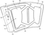
- FIGS. 1 A- 1 Cshow a portable, reusable, and disposable intermittent compression system 100 according to the present invention.
- the air pump and bladder 110are configured to be placed in the pocket of the wrap 120 , as shown in FIGS. 1 A- 1 C .
- FIG. 1 Athe air pump and bladder 110 are shown separated from the wrap 120 .
- FIG. 1 Bshows the air pump and bladder 110 being put inside a pocket 126 of the wrap 120
- FIG. 1 Cshows the air pump and bladder 110 fully inside the pocket 126 of the wrap 120 .
- the air pump with bladder 110comprises an air pump controller 112 that is connected to a bladder portion 114 .
- the bladder portion 114contains one or more bladders that are filled with air or liquid by the air pump controller 112 . These components will be further described below.
- the wrap 120comprises a pump pocket 122 for holding the air pump controller 112 , and a bladder pocket 126 for holding the bladder portion 114 . As shown in FIG. 1 B , the air pump with bladder 110 fits into the corresponding portions of the pump pocket 122 and bladder pocket 126 .
- a first tab or extension 140is used to secure the air pump controller 112 and a second tab(s) or extension(s) 128 is used to secure the bladder portion 114 .
- the first and second tabs or extensions 140 , 128may use a hook and fastener system, or other adhesive to secure the air pump with bladder 110 after it has been inserted.
- FIG. 1 Cshows the air pump with bladder 110 fully inserted in the wrap 120 .
- Complementary adhesive strips 130connect to the second tabs or extensions 128 to secure the bladder portion 114 .
- Wrap tabs or extensions 124are used by the user to secure the wrap 120 to an appendage (arm, leg, etc.).
- the wrap extensions 124connect to the adhesive strips 136 to secure the air pump with bladder 110 and wrap 120 to an appendage of the user.
- the wrap extensions 124 and adhesive strips 136may also be a hook and fastener system.
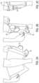
- FIGS. 2 A, 2 B, and 2 Cshow a portable intermittent compression system 100 being attached to a user according to embodiments of the invention.
- the air pump with bladder 110is inserted in the wrap 120 and secured, then the user may attach the system 100 to an appendage.
- the wrap extensions 124are connected to the adhesive strips 136 on the wrap 120 by the user to secure the system 110 .
- the profile of the wrap 120matches the user's appendage and no portions of the wrap are protruding.
- the air pump controller 112is visible through a small window 150 on the wrap 120 . The user may be able to view power status or readings from the air pump controller 112 through this window 150 .
- the air pump controller 112is the only component that protrudes from the user's appendage and its protrusion is minimal. Tab 140 holds the air pump controller 112 in place. Importantly, no wires, tubes, or bulky straps protrude from the wrap 120 , which improves the mobility of the patient.
- the compression system of the present inventionwill inflate the bladder portion 114 from a distal location to a proximal location to a preset pressure of 50 mmHg, although other preset pressures are within the scope of this disclosure. Once the inflation reaches the preset pressure, the bladder portion 114 will deflate. Cycles of inflation and deflation will repeat approximately once a minute until the unit is turned off. For use on the leg of a user, the bladder portion 114 provides compression therapy to the sides of the calf distal and flowing proximal (traditional therapy is applied to the calf posterior starting in the distal and flowing proximal). This manner of horizontal compression will be further described herein.
- the bladder portion 114may contain reticulated foam or webbing to maintain proper air flow passageways.
- the airflow passagewaysare designed to provide simultaneous pressure to both sides of the user's appendage.
- the shape of the bladder portions 114may be designed to mimic the calf muscle and optimally minimize the therapy area, which minimizes the amount of air required to fill the bladder portion 114 and provides for a shorter fill time to reach 50 mmHg. These features may improve efficacy and reduce wear and tear on the system.
- FIG. 3shows an alternative embodiment of a portable intermittent compression system 100 attached to a user.
- the air pump with bladder 110is already secured inside the wrap 120 .
- the wrap extensions 124are connected to the adhesive strips (not shown in this figure) to fit comfortably around the user's leg.
- the first tab or extension 140holds the air pump controller 112 (not shown) inside the wrap 120 .
- the pump pocket 122has a hole or gap 308 for displaying a window or screen 302 of the air pump controller 112 .
- This window or screen 302may display an on/off button, a battery life indicator, a pressure reading, or any other status indications that may be helpful to the user.
- FIG. 1shows an alternative embodiment of a portable intermittent compression system 100 attached to a user.
- the air pump with bladder 110is already secured inside the wrap 120 .
- the wrap extensions 124are connected to the adhesive strips (not shown in this figure) to fit comfortably around the user's leg.
- the first tab or extension 140holds the air pump controller 112 (
- FIG. 3also shows an elastic strip 306 at the bottom of the wrap 120 for securing the wrap 120 to the user's leg or other appendage. Similar to the elastic strip 306 at the bottom of the wrap 120 , there is an elastic strip 310 designed to flexibly hold the air pump controller 112 in the pump pocket 122 . There is also a hole 304 at the bottom side of the pump pocket 122 for a charger plug. Here a user may use a charger cord to connect to a plug or other power source to charge the battery of the air pump controller 112 . In some embodiments, the air pump controller 112 may be powered by internal rechargeable batteries, or for longer use, the user may plug a supplied power adapter into an outlet, and connecting the adapter to the air pump controller 112 . The hole 304 may also provide access for a USB connector for use in data reporting. The air pump controller 112 may include or be coupled to nonvolatile RAM for data storage, such as time stamped usage logs and corresponding sensed pressure data.
- the air pump with bladder 110may be self-contained and run off a rechargeable lithium ion battery.
- there is an accessory batterywhich is removeably attached to the air pump controller 112 , which allows the user to experience compression therapy without being anchored to a power supply for long periods of time.
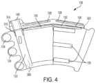
- FIG. 4shows an alternative view of the wrap 120 for the portable intermittent compression system 100 .
- the wrap tabs or extensions 124are designed to adhere to the complementary adhesive strips 136 on the wrap 120 .
- the tabs or extensions 128are designed to adhere to the complementary adhesive strips 130 on the wrap 120 to secure the air pump with bladder 110 in the bladder pocket 126 .
- Hook and fastener strips, peel and stick adhesive, or other adhesivemay be used to secure the air pump with bladder 110 .
- peel and stick adhesiveis used for the complementary tabs 128 and strips 130 .
- a dotted linerepresents a tear away seam 320 for removing the air pump and bladder 110 from the wrap 120 . Specifically, the user will tear away the tabs or extensions 128 , 140 by pulling on the dotted line 320 after finished with the system 100 or to replace the wrap 120 .
- the single-use wrap of the present inventionprevents the spread of disease by not transferring germs or viruses from the wrap from patient to patient via a multi-use wrap.
- the wrap materialmay be hydrophobic to prevent disease, germs, or viruses from passing through the wrap and on to the bladder which is transferrable from patient to patient.
- the shape and size of the wrapshould be designed to totally encompass the bladder.
- FIG. 5shows an alternative view of the air pump and bladder 110 for the portable intermittent compression system 100 .
- the bladder portioncontains two air cells 502 , 504 , one for each side of the user's leg.
- the air pump controller 112includes an air pump for inflating the air cells 502 , 504 for the desired amount of time and to the desired air pressure.
- the air or fluidenters the air cells 502 , 504 through a first passageway 540 , which is connected to a first valve within the air pump controller 112 .
- the air or fluidmay also exit air cells 502 , 504 through the first passageway 540 .
- the air cells 502 , 504may be manufactured out of nylon impregnated urethane.
- a central slot 550 in the bladder portion 114may be a central slot 550 in the bladder portion 114 , which facilitates the bladder to bend around the convex calf shape of a user.
- a second passageway 530is connected to a second valve within the air pump controller 112 , which is used to measure the air pressure within the air cells 502 , 504 . This process will be further described below.
- a hole or aperture 550 in one of the air cells 504may be included as a safety feature. For example, if the air pump controller 112 stops functioning correctly and continues to fill the air cells 502 , 504 beyond a safe pressure, air can be released through this hole or aperture 550 to relieve the pressure. In some embodiments, multiple holes or apertures may be used.
- the air pump with bladder 110may be set or programmed to provide compression for a specific duration.
- the air pump controller 112may progressively fill the bladder portion 114 . Due to the configuration of the bladder portion 114 , the filling and compression starts from the bottom to the top.
- the desired pressuree.g., 50 mmHg
- inflationmay cease for a certain period of time, so that the pressure is temporarily held (e.g., 2-10 seconds).
- the air pump controller 112deflates the bladder portion 114 for a period of time or until the pressure reaches a desired pressure (e.g., 10 mmHg).
- a flexible USB port 512is shown in FIG. 5 .
- This port 512can be accessed by the user to download past readings or use information from the air pump controller 112 .
- a display window 520could display various readings or information to the user, while an LED indicator 522 could inform the user of the air pump controller's 112 status. For example, the LED indicator 522 could blink red during compression and blink green during deflation, while the display window 520 informs the user of the current air pressure.
- a power button 524is also shown. The connection for the power adaptor can be accessed through a bottom portion 510 of the air pump controller 112 .
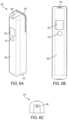
- FIG. 6 Ashows a perspective view of an air pump controller 600
- FIG. 6 Bshows a front view of the air pump controller 600
- FIG. 6 Cshows a bottom view of the air pump controller 600
- the controller 600includes a display window 602 and an indicator window 612 for battery light indicator.
- the display window 602can be used to provide information to the user, such as an on/off button, a battery life indicator, a pressure reading, or any other status indications that may be helpful to the user.
- the indicator window 612is used to indicate whether the system is on or off. For example, a green light may indicate that the system is in use and a red light may indicate that the system is off.
- a casingwhich includes a front portion 606 , a bottom portion 610 , and a back portion 608 .
- a cover 604is located at the top of the casing to provide access to and protect a USB port, which can be used to transmit and collect data.
- a charging port 620is located at the bottom of the casing for plugging a charging cable into the air pump controller 600 .
- the front portion 606 , bottom portion 610 , and back portion 608may be connected with an adhesive (i.e., glue, tape) or by mechanical means (i.e., screws, bolts, pegs, form fitting).
- FIG. 7illustrates an exploded view of an air pump controller 600 .
- This viewincludes the casing, which includes a front portion 606 , bottom portion 610 , and back portion 608 . These portions of the casing are designed to enclose the components of the air pump controller 600 .
- the front portion 606 and the back portion 608are mechanically connected through pegs 660 located on the back portion 608 and corresponding apertures or holes on the front portion 606 .
- the cover 604provides access to and covers a USB port on the controller 600 .
- the back portion 608is further connected to a lock plate for the bladder 670 . This plate 670 , which is described in further detail below, enables attachment between the air pump controller 600 and the bladder portion of present invention.
- the air pump controller 600includes (1) a two-digit alpha-numeric display to show air pressure, (2) a DC power adapter, and (3) a deformable rubber cover over a USB connection.
- a DC jack 652connects the charging port 620 to the battery 650 and converts AC current to DC current for power and charging the battery 650 .
- the air pump controller 600can run off the battery 650 or an external power supply that feeds the battery 650 .
- the air pump 644is connected to an air pump manifold 638 , which is designed to connect the pump 644 to a pressure relief valve 640 and a solenoid valve 642 .
- the solenoid valve 642transitions the air pump 644 between three states. In a first state, the air pump delivers air to the bladder (not shown in FIG. 7 ), in a second state the solenoid valve 642 prevents air from entering the bladder, and in a third state, the solenoid valve 642 controls the release of air from the bladder.
- the pressure relief valve 640is used as a safety valve. If the pressure in the bladder gets too high, then the pressure relief valve 640 kicks in to release that pressure.
- a small barbed connectorwhich is not shown in this figure, is used to connect the air pump 644 to the bladder through the solenoid valve 642 by means of a first bladder aperture 674 .
- the solenoid valve 642controls the air into and out of the bladder.
- a connector 636 and manifold IPS 634are utilized to connect a pressure switch (not shown) on the circuit board 632 to a second bladder aperture 672 .
- a small barbed connectorwhich is not shown in this figure, may be used for this connection between the manifold IPS 634 and the bladder. This pressure switch measures the pressure in the top portion of the bladder. If the IPS 634 and/or the pressure switch stop working, the pressure relief valve 640 will ensure that the pressure does not exceed an amount that would be uncomfortable to the user.
- the air pump controller 600may be connected to the bladder by a goose neck feature, which enables the air pump controller 600 and bladder to be inserted into the wrap and maintain the wrap's tensile integrity.
- a lock plate 670is used to connect the back portion 608 to the bladder (not shown).
- the lock plate 670includes open sections for the first and second bladder apertures 672 , 674 to connect with the bladder.
- the lock plate 670 and back portion 608may include complementary mating pins for connection. In FIG. 7 , the back portion 608 has protrusions and the lock plate 670 has complementary apertures.
- an ultrasonic push fit methodcould be used to attach the air pump controller 600 to the bladder.
- one tube fitting (top) 804is connected to the manifold IPS 634 in the air pump controller 600 and the other tube fitting (bottom) 804 is connected to the solenoid valve 642 .
- the air pump controller 600is mounted to the bladder assembly 802 through the lock plate 670 .
- various other connection mechanismsi.e., adhesives, fasteners, other mechanical connections
- FIG. 9shows a front view of the air pump controller 600 and bladder assembly 802 combination 800
- FIG. 10shows a back view of the air pump controller 600 and bladder assembly 802 combination 800
- FIG. 9shows the side of the combination 800 that faces away from the user
- FIG. 10shows the side of the combination 800 that faces toward the user.
- the display window 602can be seen by the user through a wrap because it is facing away, while the inner bladder portions and the lock plate 670 face towards the user.
- the tube fittings 804are not shown, but they provide an air connection between a top channel 810 of the bladder assembly 802 and the manifold IPS 634 and a bottom channel 820 of the bladder assembly 802 and the solenoid valve 642 . These connections allow the air pump controller 600 to control the air in the bladder assembly 802 and read corresponding pressures within the bladder assembly 802 .
- FIG. 11shows a bladder assembly 1100 of the present invention.
- An upper channel 1102 and a lower channel 1104lead to a first bladder portion 1106 and a second bladder portion 1108 .
- the bladder assembly 1100inflates distal to proximal, air is provided to the first and second bladder portions 1106 , 1108 through the lower channel 1104 .
- an aperture or port 1114 within the lower channel 1104indicates a connection to the air pump (not shown).
- the upper channel 1102provides a connection to a pressure sensor (not shown) through an aperture or port 1112 . This pressure sensor connects to the most distant or remote portion from the lower channel 1104 .
- the bladder assembly 1100includes a gap or strip 1120 that is designed to line up with the center of the user's calf muscle.
- This strip 1120 and surrounding area between the first and second bladder portions 1106 , 1108provides flexibility around the user's calf muscle.
- the first and second bladder portions 1106 , 1108therefore inflate to provide compression or pressure around the user's calf, such that the inflation is not directly on top of the calf muscle.
- the first and second bladder portions 1106 , 1108 , and the upper and lower channels 1102 , 1104contain nano webbing, mesh, or reticulated foam These features ensure that the outer layers of the bladder assembly 1100 do not collapse or touch, which could make it difficult for the air pump controller (not shown) to expand the channels and cavities. By inserting a material such as nano webbing in these channels and cavities, the air is free to flow into the bladder assembly and inflate the first and second bladder portions 1106 , 1108 . This feature also prevents kinking within the bladder assembly 1100 . Stitching, adhesives, or other fastening methods may be used to create the cavities or pockets within the upper and lower channels 1102 , 1104 and the first and second bladder portions 1106 , 1108 .
- first and second bladder portions 1106 , 1108surround the user's calf when in operation and fill simultaneously from the bottom channel 1104 . This allows the present invention to begin the compression at the bottom and on the outside of the user's calf and push towards the top of the user's calf, which pushes the blood from the foot area up towards the heart. This motion also pulls the calf together laterally through sequential and gradient compression.
- This manner of compressionmimics ambulation and assists with circulation in the lymphatic system, veins, and arteries.
- This type of compressionis not posterior focused like prior methods, but has a horizontal compression feature.
- FIG. 12shows an exploded view of the bladder assembly 1100 of the present invention.
- An inner membrane, sleeve, or sheet 1240connects to an outer membrane, sleeve, or sheet 1220 to create the bladder assembly 1100 .
- Stitching, adhesives, or other fastening methodsmay be used to connect these membranes 1240 , 1220 .
- similar stitching, adhesives, or other fastening methodsmay be used to create the channels, cavities, and/or pockets between the membranes 1240 , 1220 .
- An upper channel mesh 1208fits within the upper channel 1102 (not shown in FIG. 12 ) to prevent collapse of the channel and improve air circulation within the bladder assembly 1100 .
- a lower channel mesh 1210fits within the lower channel 1104 (not shown in FIG.
- Tube fittings 1204 , 1206are inserted between the inner 1240 and outer membranes 1220 to enable air to flow into or from the upper and lower channels 1102 , 1104 (not shown). Apertures 1112 , 1114 are provided in the outer membrane 1220 , but not the inner membrane 1240 , such that the tube fittings 1204 , 1206 terminate between the two membranes.
- tube fitting 1204is connected to the manifold IPS 634 in the air pump controller 600 and tube fitting 1206 is connected to the solenoid valve 642 (shown in FIG. 7 ).
- bias tape 1202may be used on the outside edges of the bladder assembly 1100 to assist with holding the inner 1220 and outer membranes 1240 together and to provide a smooth edge connection between the membranes. For example, when the membranes 1220 , 1240 are stitched or adhered together, there may be snags or rough edges that could get caught up during insertion of the bladder assembly 1100 into the wrap. The bias tape 1202 helps to smooth out these snags or rough edges.
- the outer membrane 1220may be made of a flexible material (i.e., thermoplastic polyurethane (TPU)) calendared or attached to a strong woven nylon sheet.
- This nylon sheetmay provide strength and resistance to deformation during the inflation cycle.
- This strength and resistance to deformationencourages the inner membrane 1240 , which is also made of a flexible material (i.e., TPU), to deform first and act upon the calf muscle more readily. Due to this difference in material, the membrane adjacent to the user's leg is faster to deform and supply compression to the user.
- FIGS. 13 A and 13 Bshow alternative views of a wrap 1300 according to embodiments of the present invention.
- FIG. 13 Ashows a front view of the wrap 1300
- FIG. 13 Bshows a back view of the wrap 1300 .
- FIG. 13 Ashows the side of the wrap 1300 that faces away from the user
- FIG. 13 Bshows the side of the 1300 that faces toward the user.
- three tabs or extensions 1302extend from the left edge of the wrap 1300 .
- three hook fastener discs 1340are located on the opposite side of those three tabs or extensions 1302 . These hook fastener discs 1340 are designed to connect with three loop fasteners 1310 when wrapped around the user's leg.
- the three loop fasteners 1310are attached to the outside panel of the wrap in such locations and sizes to accommodate a variety of calf sizes.
- An extended pocket cover 1308holds the air pump controller (not shown) and includes a display window 1306 and aperture or hole 1304 for access to the charging port of the air pump controller.
- a perforation line 1314is shown in FIGS. 13 A and 13 B , which indicates the top edge of the pocket for the air pump controller and bladder assembly (not shown).
- a strip 1316 that can be folded over by the userenables the user to close the pocket over the air pump controller and bladder assembly.
- the strip 1316may include an adhesive (with or without a paper cover) or a hook and fastener system for closing the pocket.
- An additional tab or extension 1318extends from the strip 1316 for enclosing the air pump controller within the extended pocket cover 1308 . This tab 1318 may include the same adhesive or hook and fastener system for sealing in the air pump controller.
- the back side of the tab 1318 and the strip 1316are shown in FIG. 13 B .
- the userwould fold over the tab 1318 and the strip 1316 to enclose the air pump controller and bladder assembly.
- a pull tab 1312 that connects to the perforation line 1314is used to tear off the tab 1318 and strip 1316 after use. Specifically, the user may grab or pull the pull tab 1312 and pull across the wrap 1300 to open the pocket after use. This way the air pump controller and bladder assembly can be easily accessed and removed for future use with another wrap.
- the adhesive used with the tab 1318 and strip 1316may be protected by a peel off liner tape.
- FIG. 14shows a perspective view of the wrap 1300 according to embodiments of the present invention. This figure is similar to FIG. 13 A , but illustrates how the wrap 1300 opens up to reveal a bladder pocket 1410 and an air pump controller pocket 1420 .
- the air pump controller and bladder combination(not shown) fit into these pockets 1410 , 1420 during operation.
- the extended pocket cover 1308provides additional space for the air pump controller.
- the usercan fold over the strip 1316 and tab 1318 using the adhesive or hook and fastener system to enclose it.
- the perforation line 1314signifies where the strip 1316 and tab 1318 would be folded over.
- the wrap 1300may comprise two sheets or membranes that are connected or attached on three sides (left, bottom, and right). The fourth side (top) is not connected or attached, so that the two sheets or membranes can be separated to create a pocket for the air pump controller and bladder combination (not shown).
- FIG. 15shows an exploded view of the wrap 1300 according to embodiments of the present invention. Most of the reference numerals in FIG. 15 were described with respect to FIGS. 13 A, 13 B, and 14 , but the exploded view highlights a few additional features of the wrap 1300 .
- This viewillustrates that the pockets of the wrap are created by four separate panels. Wrap panel 1 1514 and wrap panel 2 1516 are connected by adhesive, stitching, or other means to create a front layer of wrap 1300 , while wrap panel 3 1510 and wrap panel 4 1512 are connected to create a back layer of the wrap 1300 .
- a first wrap tape 1502fits over the tab 1318 and first portion of the strip 1316 of wrap panel 3 1510 and a second wrap tape 1504 fits over a second portion of the strip 1316 of wrap panel 4 1512 .
- Other connection means for wrap tapes 1502 , 1504i.e., hook and fastener, mechanical fitting
- a wrap panel window 1506is also shown. This provides protection for the air pump controller (not shown), while allowing a user to see the display panel. In combination, the extended pocket cover 1308 and the wrap panel window 1506 keep the air pump controller clean and sanitary for future use.
- wrap panel 3 1510 and/or wrap panel 4 1512may include one or more elastic or flexible sections to assist with placement on the user's leg and to prevent the wrap 1300 from falling off or slipping down the user's leg.
- an elastic or flexible sectionmay be included behind the air pump controller pocket 1420 .
- wrap panel 3 1510may have an elastic region mated to wrap panel 1 1514 , which holds the air pump controller. With this placement, the elastic or flexible section would also assist with keeping the air pump controller in place and allowing the user to easily slide the air pump controller into the external pocket 1420 .
- This elastic regionhas a fixed amount of expansion, which allows the wrap 1300 to be tightly donned on the leg.
- the extended pocket cover 1308further assists with holding the pump in place.
- This extended pocket cover 1308may be formed from a single sheet by folding and attaching the material to wrap panel 1 1514 .
- An elastic band or stripmay also be included at the bottom of the wrap 1300 to prevent the wrap from falling off or slipping down the leg.
- the wrap panels 1510 , 1512 , 1514 , 1516comprise two flat fabric sheets with “S” shaped curves, such that when they are joined together they create a 3-dimensional shape which mimics the shape of the calf.
- This featurehelps keep the wrap 1300 in the correct location on the calf and helps it to tightly wrap around the calf, which removes excess material that would have to be tightened in the inflation cycle. Without this excess material, the wrap 1300 of the present invention enjoys a shorter inflation cycle and a higher therapeutic benefit.
- the wrap 1300may have an inner boundary, which provides for accurate placement of the wrap 1300 and this boundary is tapered so the bladder assembly (not shown) can be easily inserted.
- the wrap 1300may include an elastic strip 1530 on wrap panel 3 1510 , which may be located behind the extended pocket cover 1308 .
- This elastic strip 1530is designed to improve the flexibility of the inner wrap panels 1510 , 1512 , so that it can attach to and stay on the user's appendage during use.
- the elastic strip 1530should have a limited width and height, so that it does not encompass a significant surface area of the wrap. If the elastic strip 1530 extended throughout the entire inner wrap panels 1510 , 1512 , then it may reduce the therapeutic effect of compression because it would stretch along with the expansion of the bladder. Placement of the elastic strip 1530 on the inner wrap panels 1510 , 1512 assists with holding the wrap in place during movement by the user.
- the remainder of the wrap 1300may be made of a substantially non-elastic material, which allows for quicker inflation because it does not stretch or compress.
- the wrap panels 1510 , 1512 , 1514 , 1516 and extended pocket cover 1308are made of a material that is commonly used in hospital gowns, surgery aprons, and other equipment (i.e., polyvinyl chloride (PVC), polyethylene, and polypropylene). These materials are strong and hydrophobic to protect the air pump controller, bladder, and patient, and are widely accepted within the healthcare community.
- the wrap and the bladder assemblycould be integrated, and an air pump controller could be mounted to the bladder wrap/bladder assembly combination.
- the air pump controllermay be reusable, while the wrap/bladder assembly combination could be disposed of after one or more uses.
- the wrap/bladder assembly combinationcould be made of PVC, polyethylene, or polypropylene, so that it is comfortable to the user.
- FIG. 16shows a bladder assembly 1600 of the present invention, which is similar to FIG. 11 .
- An upper channel 1602 and a lower channel 1604lead to a first bladder portion 1606 and a second bladder portion 1608 .
- the bladder assembly 1600inflates distal to proximal, air is provided to the first and second bladder portions 1606 , 1608 through the lower channel 1604 .
- an aperture or port 1614 within the lower channel 1604indicates a connection to the air pump (not shown).
- the upper channel 1602provides a connection to a pressure sensor (not shown) through an aperture or port 1612 . This pressure sensor connects to the most distant or remote portion from the lower channel 1604 .
- This location of the upper channel 1602ensures that the pressure sensor is sensing the pressure at the most remote or distant location from where the first and second bladder portions 1606 , 1608 are being filled with air.
- the bladder portions 1606 , 1608may be separated to create numerous sections. For example, a first peninsula section 1624 may separate first bladder portion 1606 into an upper and lower portion, wherein the lower portion fills with air before the upper portion. Similarly, a second peninsula section 1622 may separate second bladder portion 1608 into an upper and lower portion. By segregating these sections and measuring the air pressure at remote sections of the bladder portions 1606 , 1608 , the system ensures that a determined pressure is being achieved in the bladder assembly 1600 .
- the bladder assembly 1600includes a gap or strip 1620 that is designed to line up with the center of the user's calf muscle.
- the first and second peninsula sections 1624 , 1622provide a narrow passageway between the lower and upper portions of the bladder portions 1606 , 1608 . This enables progressive inflation and deflation, with the lower portions inflating and deflating before the upper portions.
- FIG. 17shows a portable intermittent compression system with an integrated bladder assembly 1700 , wherein the wrap and bladder assembly are integrated.
- the material 1750 of the integrated bladder assembly 1700may be made of PVC, polyethylene, or polypropylene, so that it is comfortable to the user.
- the integrated bladder assembly 1700could be disposable or for limited use, such that it would have to attach and detach from an air pump controller 1702 .
- a connector 1704may connect the air pump controller 1702 to the integrated bladder assembly 1700 .
- aperture 1708connects a lower channel 1720 to the air pump controller 1702
- aperture 1706connects the upper channel 1710 to the air pump controller 1702 .
- FIG. 18shows a similar intermittent compression system, where an air pump controller 1802 connects to the integrated bladder assembly 1800 through tubing 1804 .
- the material 1850 of the integrated bladder assembly 1800may be made of PVC, polyethylene, or polypropylene, so that it is comfortable to the user.
- the integrated bladder assembly 1800could be disposable or for limited use, such that it would have to attach and detach from the tubing 1804 .
- a first connector 1806may connect the tubing 1804 to a second connector 1808 , which is attached to the integrated bladder assembly 1800 .
- the first connector 1806 and the second connector 1808link the air pump controller 1802 to a lower channel 1820 and an upper channel 1810 .
- the integrated bladder assembly 1800also has a first bladder portion 1830 and second bladder portion 1840 .
- the advantage of this embodimentis that the air pump controller 1802 is reusable and can be reattached to numerous integrated bladder assemblies 1800 . In a hospital environment, a single air pump controller 1802 could be assigned to a hospital room or a patient for repeated use with different integrated bladder assemblies 1800 .
Landscapes
- Health & Medical Sciences (AREA)
- Epidemiology (AREA)
- Pain & Pain Management (AREA)
- Physical Education & Sports Medicine (AREA)
- Rehabilitation Therapy (AREA)
- Life Sciences & Earth Sciences (AREA)
- Animal Behavior & Ethology (AREA)
- General Health & Medical Sciences (AREA)
- Public Health (AREA)
- Veterinary Medicine (AREA)
- Massaging Devices (AREA)
Abstract
Description
Claims (7)
Priority Applications (2)
| Application Number | Priority Date | Filing Date | Title |
|---|---|---|---|
| US17/354,277US12186263B2 (en) | 2017-11-01 | 2021-06-22 | Portable, reusable, and disposable intermittent pneumatic compression system |
| US18/965,756US20250177234A1 (en) | 2017-11-01 | 2024-12-02 | Portable, reusable, and disposable intermittent pneumatic compression system |
Applications Claiming Priority (3)
| Application Number | Priority Date | Filing Date | Title |
|---|---|---|---|
| US15/800,541US10434033B2 (en) | 2017-11-01 | 2017-11-01 | Portable, reusable, and disposable intermittent pneumatic compression system |
| US16/550,819US11052015B2 (en) | 2017-11-01 | 2019-08-26 | Portable, reusable, and disposable intermittent pneumatic compression system |
| US17/354,277US12186263B2 (en) | 2017-11-01 | 2021-06-22 | Portable, reusable, and disposable intermittent pneumatic compression system |
Related Parent Applications (1)
| Application Number | Title | Priority Date | Filing Date |
|---|---|---|---|
| US16/550,819ContinuationUS11052015B2 (en) | 2017-11-01 | 2019-08-26 | Portable, reusable, and disposable intermittent pneumatic compression system |
Related Child Applications (1)
| Application Number | Title | Priority Date | Filing Date |
|---|---|---|---|
| US18/965,756ContinuationUS20250177234A1 (en) | 2017-11-01 | 2024-12-02 | Portable, reusable, and disposable intermittent pneumatic compression system |
Publications (2)
| Publication Number | Publication Date |
|---|---|
| US20220142851A1 US20220142851A1 (en) | 2022-05-12 |
| US12186263B2true US12186263B2 (en) | 2025-01-07 |
Family
ID=66245848
Family Applications (4)
| Application Number | Title | Priority Date | Filing Date |
|---|---|---|---|
| US15/800,541ActiveUS10434033B2 (en) | 2017-11-01 | 2017-11-01 | Portable, reusable, and disposable intermittent pneumatic compression system |
| US16/550,819Active2038-03-16US11052015B2 (en) | 2017-11-01 | 2019-08-26 | Portable, reusable, and disposable intermittent pneumatic compression system |
| US17/354,277Active2039-08-25US12186263B2 (en) | 2017-11-01 | 2021-06-22 | Portable, reusable, and disposable intermittent pneumatic compression system |
| US18/965,756PendingUS20250177234A1 (en) | 2017-11-01 | 2024-12-02 | Portable, reusable, and disposable intermittent pneumatic compression system |
Family Applications Before (2)
| Application Number | Title | Priority Date | Filing Date |
|---|---|---|---|
| US15/800,541ActiveUS10434033B2 (en) | 2017-11-01 | 2017-11-01 | Portable, reusable, and disposable intermittent pneumatic compression system |
| US16/550,819Active2038-03-16US11052015B2 (en) | 2017-11-01 | 2019-08-26 | Portable, reusable, and disposable intermittent pneumatic compression system |
Family Applications After (1)
| Application Number | Title | Priority Date | Filing Date |
|---|---|---|---|
| US18/965,756PendingUS20250177234A1 (en) | 2017-11-01 | 2024-12-02 | Portable, reusable, and disposable intermittent pneumatic compression system |
Country Status (1)
| Country | Link |
|---|---|
| US (4) | US10434033B2 (en) |
Cited By (1)
| Publication number | Priority date | Publication date | Assignee | Title |
|---|---|---|---|---|
| USD1089861S1 (en)* | 2024-02-01 | 2025-08-19 | JKH Health Co., Ltd. | Protective gear |
Families Citing this family (19)
| Publication number | Priority date | Publication date | Assignee | Title |
|---|---|---|---|---|
| US10434033B2 (en)* | 2017-11-01 | 2019-10-08 | Vena Group, LLC | Portable, reusable, and disposable intermittent pneumatic compression system |
| US10500125B2 (en)* | 2018-02-26 | 2019-12-10 | John A. Bennett | Inflation garment having a portable controller for treatment of DVT |
| US10893998B2 (en)* | 2018-10-10 | 2021-01-19 | Inova Labs Inc. | Compression apparatus and systems for circulatory disorders |
| US20210386594A1 (en)* | 2018-10-10 | 2021-12-16 | Inova Labs, Inc. | Compression apparatus and systems for circulatory-related disorders |
| WO2020159851A1 (en)* | 2019-01-28 | 2020-08-06 | Smart Tools Plus, LLC | Blood flow restriction system |
| KR102179175B1 (en)* | 2019-03-11 | 2020-11-16 | (주)선메딕스 | Movable air massage apparatus |
| US11974964B2 (en)* | 2019-03-29 | 2024-05-07 | Hill-Rom Services, Inc. | Patient support apparatus with integrated patient therapy device |
| CN110013376A (en)* | 2019-05-20 | 2019-07-16 | 王洪坤 | A kind of fixator for avoiding patients with deep venous thrombosis mobile |
| US11478606B1 (en) | 2020-01-08 | 2022-10-25 | New Heights Energy, LLC | Wearable devices and methods for providing therapy to a user and/or for measuring physiological parameters of the user |
| US11918539B2 (en) | 2020-06-10 | 2024-03-05 | Welch Allyn, Inc. | Wearable health management system |
| US12343305B2 (en) | 2020-08-12 | 2025-07-01 | Welch Allyn, Inc. | Health management system |
| US20220125661A1 (en)* | 2020-10-22 | 2022-04-28 | Jacob Waterman | Patient-Worn Therapeutic Apparatus |
| GB2635258A (en)* | 2021-01-29 | 2025-05-07 | Therabody Inc | Pneumatic compression device with integrated pump |
| US11446202B1 (en)* | 2021-12-28 | 2022-09-20 | JKH Health Co., Ltd. | Pneumatic physiotherapy apparatus with a unique structure |
| US11865069B2 (en)* | 2021-12-28 | 2024-01-09 | JKH Health Co., Ltd. | Pneumatic therapy apparatus and method with overlapped compression |
| US12226369B2 (en)* | 2021-12-28 | 2025-02-18 | JKH Health Co., Ltd. | Pneumatic therapy apparatus and method |
| USD987832S1 (en) | 2022-01-03 | 2023-05-30 | Therabody, Inc. | Pneumatic compression device |
| US20230270622A1 (en)* | 2022-02-28 | 2023-08-31 | Reathlete Llc | Rechargeable and portable compression device and method of use |
| WO2023172676A2 (en) | 2022-03-10 | 2023-09-14 | New Heights Energy, LLC | Wearable devices, systems, and methods for providing therapy to a user and/or for measuring physiological parameters of the user |
Citations (81)
| Publication number | Priority date | Publication date | Assignee | Title |
|---|---|---|---|---|
| US3859989A (en) | 1973-01-05 | 1975-01-14 | Theodore E Spielberg | Therapeutic cuff |
| US4320746A (en) | 1979-12-07 | 1982-03-23 | The Kendall Company | Compression device with improved pressure control |
| US4374518A (en) | 1980-10-09 | 1983-02-22 | Raul Villanueva | Electronic device for pneumomassage to reduce lymphedema |
| US4402312A (en) | 1981-08-21 | 1983-09-06 | The Kendall Company | Compression device |
| US4453538A (en) | 1977-04-07 | 1984-06-12 | Whitney John K | Medical apparatus |
| US4597384A (en) | 1984-06-29 | 1986-07-01 | Gaymar Industries, Inc. | Sequential compression sleeve |
| US5031604A (en) | 1989-04-12 | 1991-07-16 | The Kendall Company | Device for applying compressive pressures to a patient's limb |
| US5307791A (en) | 1991-05-30 | 1994-05-03 | Matsushita Electric Works, Ltd. | Air massaging device with a precise pressure control |
| US5437610A (en) | 1994-01-10 | 1995-08-01 | Spinal Cord Society | Extremity pump apparatus |
| US5478119A (en) | 1993-09-16 | 1995-12-26 | The Kendall Company | Polarized manifold connection device |
| US5496262A (en) | 1994-01-06 | 1996-03-05 | Aircast, Inc. | Therapeutic intermittent compression system with inflatable compartments of differing pressure from a single source |
| US5588955A (en) | 1993-07-08 | 1996-12-31 | Aircast, Inc. | Method and apparatus for providing therapeutic compression for reducing risk of DVT |
| US5626556A (en) | 1994-07-26 | 1997-05-06 | The Kendall Company | Hook and loop attachment for a compression sleeve and method of attaching a hook and loop fastener to a compression sleeve |
| US5672148A (en) | 1991-12-06 | 1997-09-30 | Maunier; Daniel | Hydraulic device for lymphatic drainage and massage of the human body |
| US5795312A (en) | 1993-09-27 | 1998-08-18 | The Kendall Company | Compression sleeve |
| US5876359A (en) | 1994-11-14 | 1999-03-02 | Bock; Malcolm G. | Sequential compression device controller |
| US6030353A (en) | 1998-04-28 | 2000-02-29 | American Biosystems, Inc. | Pneumatic chest compression apparatus |
| US20010000262A1 (en) | 1998-08-12 | 2001-04-12 | Mcewen James A. | Apparatus and method for applying an adaptable pressure waveform to a limb |
| US6231532B1 (en) | 1998-10-05 | 2001-05-15 | Tyco International (Us) Inc. | Method to augment blood circulation in a limb |
| US6315745B1 (en) | 1999-04-30 | 2001-11-13 | Richard J. Kloecker | Compression garment for selective application for treatment of lymphedema and related illnesses manifested at various locations of the body |
| US6336907B1 (en) | 1998-11-25 | 2002-01-08 | Matsushita Electric Works, Ltd. | Massaging system |
| US20020042583A1 (en) | 1998-03-11 | 2002-04-11 | Jakob Barak | Automatic portable pneumatic compression system |
| US6537235B1 (en)* | 2001-09-25 | 2003-03-25 | Clara Connor | Scarf with electrically operated massager |
| US20030078674A1 (en) | 2001-07-26 | 2003-04-24 | Phillips Van L. | Socket insert having a bladder system |
| US20030181990A1 (en) | 2001-07-26 | 2003-09-25 | Phillips Van L. | Socket insert having a bladder system |
| US20040039317A1 (en)* | 2002-08-23 | 2004-02-26 | Souney Sean J. | Separable compression sleeve with barrier protection device and reusable coupler |
| US20040237203A1 (en) | 1998-05-06 | 2004-12-02 | Romano James J. | Patient support |
| US20050070828A1 (en) | 2001-07-20 | 2005-03-31 | Huntleigh Technology Plc | Inflatable apparatus |
| US20050143797A1 (en) | 2003-07-18 | 2005-06-30 | Thermotek, Inc. | Compression sequenced thermal therapy system |
| US20050154336A1 (en) | 1999-04-30 | 2005-07-14 | Kloecker Richard J. | Segmented pneumatic pad for regulating pressure upon parts of the body during usage |
| US20050187500A1 (en) | 2004-02-23 | 2005-08-25 | Perry Matthew J. | Compression treatment system |
| US20050256556A1 (en)* | 2004-05-17 | 2005-11-17 | Coolsystems, Inc. | Modular apparatus for therapy of an animate body |
| US7044924B1 (en) | 2000-06-02 | 2006-05-16 | Midtown Technology | Massage device |
| US20060236464A1 (en) | 2005-04-22 | 2006-10-26 | R&D Products, Llc | Multicompartmented air mattress |
| US20060258964A1 (en)* | 2003-04-11 | 2006-11-16 | Biondo John P | System for compression therapy |
| US20070049853A1 (en) | 2005-07-21 | 2007-03-01 | Bristol-Myers Squibb Company | Compression device for the limb |
| US20070213650A1 (en)* | 2005-10-07 | 2007-09-13 | Thomas Raley | Apparatus for facilitating circulation |
| US20070249977A1 (en)* | 2006-01-24 | 2007-10-25 | Bristol-Myers Squibb Company | Pressurized medical device |
| US7329232B2 (en) | 2004-02-27 | 2008-02-12 | Circaid Medical Products, Inc. | Limb encircling therapeutic compression device |
| US20080058911A1 (en) | 1998-06-08 | 2008-03-06 | Parish Overton L | Method and system for thermal and compression therapy relative to the prevention of deep vein thrombosis |
| US20080132976A1 (en) | 2006-12-04 | 2008-06-05 | Kane John Roy | Methods and apparatus for adjusting blood circulation |
| US20080195012A1 (en)* | 2007-02-13 | 2008-08-14 | Coolsystems, Inc. | Flexible joint wrap |
| US20080262399A1 (en) | 2007-04-20 | 2008-10-23 | Clotbuster Llc | Medical device |
| US20090177184A1 (en) | 2008-01-09 | 2009-07-09 | Christensen Scott A | Method and apparatus for improving venous access |
| US20090299239A1 (en) | 2005-09-23 | 2009-12-03 | Walter Meyer | Apparatus for Preventing Deep Vein Thrombosis |
| US20100042026A1 (en) | 1999-04-30 | 2010-02-18 | Kloecker Richard J | Segmented pneumatic pad regulating pressure upon parts of the body during usage |
| US20100081974A1 (en) | 2008-09-30 | 2010-04-01 | Tyco Healthcare Group Lp | Portable Controller Unit for a Compression Device |
| US20100081977A1 (en) | 2008-09-30 | 2010-04-01 | Tyco Healthcare Group Lp | Tubeless Compression Device |
| US20100100017A1 (en) | 2006-10-12 | 2010-04-22 | Pirko Maguina | Motion therapy system |
| US20100137764A1 (en) | 2008-12-02 | 2010-06-03 | Patrick Eddy | Compression device and control system for applying pressure to a limb of a living being |
| US20110082401A1 (en) | 2009-09-17 | 2011-04-07 | Emily Iker | Method and apparatus for treating lymphedema |
| US20110131839A1 (en) | 2009-12-03 | 2011-06-09 | C-Boot Ltd. | Pneumatic Alternating Pressure Relief of a Foot |
| US20110172579A1 (en) | 2010-01-08 | 2011-07-14 | China Medical University | Inflation type cervical vertebrae rehabilitation device and method for using the same |
| US20110201981A1 (en) | 2010-02-12 | 2011-08-18 | Tyco Healthcare Group Lp | Compression garment assembly |
| US20110224589A1 (en) | 2010-03-09 | 2011-09-15 | Tyco Healthcare Group Lp | Venous Augmentation System |
| US20110288458A1 (en) | 2010-04-16 | 2011-11-24 | Medefficiency, Inc. | Ambulatory negative pressure therapeutical compression device |
| US8079970B2 (en) | 2005-12-12 | 2011-12-20 | Tyco Healthcare Group Lp | Compression sleeve having air conduits formed by a textured surface |
| US20120065561A1 (en) | 2010-09-03 | 2012-03-15 | Epoch Medical Innovations, Inc. | Device, system, and method for the treatment, prevention and diagnosis of chronic venous insufficiency, deep vein thrombosis, lymphedema and other circulatory conditions |
| US20120078146A1 (en) | 2010-09-29 | 2012-03-29 | Tyco Healthcare Group Lp | Compression garment apparatus having baseline pressure |
| US20120078145A1 (en) | 2010-09-29 | 2012-03-29 | Tyco Healthcare Group Lp | Compression garment apparatus having support bladder |
| US20120089063A1 (en)* | 2010-10-12 | 2012-04-12 | Venous Health System, Inc. | Apparatus, systems, and methods for augmenting the flow of fluid within body vessels |
| US20120209153A1 (en) | 2011-02-14 | 2012-08-16 | Farrow Mark A | Deep vein thrombosis therapy device |
| US8257289B2 (en) | 2010-02-03 | 2012-09-04 | Tyco Healthcare Group Lp | Fitting of compression garment |
| US20130012847A1 (en) | 2011-06-17 | 2013-01-10 | Coolsystems, Inc. | Adjustable patient therapy device |
| US8403870B2 (en) | 2009-09-15 | 2013-03-26 | Covidien Lp | Portable, self-contained compression device |
| US20130245508A1 (en) | 2008-07-10 | 2013-09-19 | Maldonado Medical Llc | Thermal compression therapy apparatus and system |
| US20130253383A1 (en)* | 2008-07-10 | 2013-09-26 | Maldonado Medical Llc | Gradient sequential thermal compression therapy apparatus and system |
| US20130310719A1 (en) | 2012-05-17 | 2013-11-21 | Nike, Inc. | Compressive therapeutic device |
| US20130338552A1 (en) | 2012-06-18 | 2013-12-19 | Tyco Healthcare Group Lp | Compression System With Vent Cooling Feature |
| US20130345519A1 (en) | 2012-06-22 | 2013-12-26 | Gregory Piskun | Floating, multi-lumen-catheter retractor system for a minimally-invasive, operative gastrointestinal treatment |
| US20140094726A1 (en) | 2012-09-28 | 2014-04-03 | Covidien Lp | Vascular compression system |
| US20140222121A1 (en) | 2011-07-20 | 2014-08-07 | Scr Inc. | Athletic cooling and heating systems, devices and methods |
| US20140276254A1 (en)* | 2013-03-13 | 2014-09-18 | Carefusion 2200, Inc. | Patient warming and dvt prevention system |
| US20140303533A1 (en) | 2013-03-15 | 2014-10-09 | Innovamed Health, LLC | Portable intermittent pneumatic compression system |
| US9192539B2 (en) | 2003-07-18 | 2015-11-24 | Thermotek, Inc. | Method and system for thermal and compression therapy relative to the prevention of deep vein thrombosis |
| US20160074656A1 (en) | 2008-02-05 | 2016-03-17 | Djo, Llc | Stimulation brace |
| US20160361224A1 (en) | 2014-02-07 | 2016-12-15 | Raj Ramakrishna | A portable compression device |
| US10149796B1 (en) | 2014-07-02 | 2018-12-11 | Currie Medical Specialties, Inc. | Pneumatic compression devices and garments for the prevention of deep vein thrombosis |
| US10166166B1 (en) | 2015-08-11 | 2019-01-01 | Trevor James Theriot | Apparatus for applying periodic pressure to the limb of a patient and method of use |
| US20190008717A1 (en) | 2017-07-07 | 2019-01-10 | Djo, Llc | Portable deep vein thrombosis compression device having an integrated pressure cuff and utilizing a disposable cuff barrier |
| US10434033B2 (en) | 2017-11-01 | 2019-10-08 | Vena Group, LLC | Portable, reusable, and disposable intermittent pneumatic compression system |
Family Cites Families (1)
| Publication number | Priority date | Publication date | Assignee | Title |
|---|---|---|---|---|
| US9114055B2 (en) | 2012-03-13 | 2015-08-25 | Cothera Llc | Deep vein thrombosis (“DVT”) and thermal/compression therapy systems, apparatuses and methods |
- 2017
- 2017-11-01USUS15/800,541patent/US10434033B2/enactiveActive
- 2019
- 2019-08-26USUS16/550,819patent/US11052015B2/enactiveActive
- 2021
- 2021-06-22USUS17/354,277patent/US12186263B2/enactiveActive
- 2024
- 2024-12-02USUS18/965,756patent/US20250177234A1/enactivePending
Patent Citations (87)
| Publication number | Priority date | Publication date | Assignee | Title |
|---|---|---|---|---|
| US3859989A (en) | 1973-01-05 | 1975-01-14 | Theodore E Spielberg | Therapeutic cuff |
| US4453538A (en) | 1977-04-07 | 1984-06-12 | Whitney John K | Medical apparatus |
| US4320746A (en) | 1979-12-07 | 1982-03-23 | The Kendall Company | Compression device with improved pressure control |
| US4374518A (en) | 1980-10-09 | 1983-02-22 | Raul Villanueva | Electronic device for pneumomassage to reduce lymphedema |
| US4402312A (en) | 1981-08-21 | 1983-09-06 | The Kendall Company | Compression device |
| US4597384A (en) | 1984-06-29 | 1986-07-01 | Gaymar Industries, Inc. | Sequential compression sleeve |
| US5031604A (en) | 1989-04-12 | 1991-07-16 | The Kendall Company | Device for applying compressive pressures to a patient's limb |
| US5307791A (en) | 1991-05-30 | 1994-05-03 | Matsushita Electric Works, Ltd. | Air massaging device with a precise pressure control |
| US5672148A (en) | 1991-12-06 | 1997-09-30 | Maunier; Daniel | Hydraulic device for lymphatic drainage and massage of the human body |
| US5588955A (en) | 1993-07-08 | 1996-12-31 | Aircast, Inc. | Method and apparatus for providing therapeutic compression for reducing risk of DVT |
| US5478119A (en) | 1993-09-16 | 1995-12-26 | The Kendall Company | Polarized manifold connection device |
| US5795312A (en) | 1993-09-27 | 1998-08-18 | The Kendall Company | Compression sleeve |
| US5496262A (en) | 1994-01-06 | 1996-03-05 | Aircast, Inc. | Therapeutic intermittent compression system with inflatable compartments of differing pressure from a single source |
| US5437610A (en) | 1994-01-10 | 1995-08-01 | Spinal Cord Society | Extremity pump apparatus |
| US5626556A (en) | 1994-07-26 | 1997-05-06 | The Kendall Company | Hook and loop attachment for a compression sleeve and method of attaching a hook and loop fastener to a compression sleeve |
| US5876359A (en) | 1994-11-14 | 1999-03-02 | Bock; Malcolm G. | Sequential compression device controller |
| US20020042583A1 (en) | 1998-03-11 | 2002-04-11 | Jakob Barak | Automatic portable pneumatic compression system |
| US6030353A (en) | 1998-04-28 | 2000-02-29 | American Biosystems, Inc. | Pneumatic chest compression apparatus |
| US20040237203A1 (en) | 1998-05-06 | 2004-12-02 | Romano James J. | Patient support |
| US20080058911A1 (en) | 1998-06-08 | 2008-03-06 | Parish Overton L | Method and system for thermal and compression therapy relative to the prevention of deep vein thrombosis |
| US20010000262A1 (en) | 1998-08-12 | 2001-04-12 | Mcewen James A. | Apparatus and method for applying an adaptable pressure waveform to a limb |
| US6231532B1 (en) | 1998-10-05 | 2001-05-15 | Tyco International (Us) Inc. | Method to augment blood circulation in a limb |
| US6336907B1 (en) | 1998-11-25 | 2002-01-08 | Matsushita Electric Works, Ltd. | Massaging system |
| US20100042026A1 (en) | 1999-04-30 | 2010-02-18 | Kloecker Richard J | Segmented pneumatic pad regulating pressure upon parts of the body during usage |
| US6315745B1 (en) | 1999-04-30 | 2001-11-13 | Richard J. Kloecker | Compression garment for selective application for treatment of lymphedema and related illnesses manifested at various locations of the body |
| US20050154336A1 (en) | 1999-04-30 | 2005-07-14 | Kloecker Richard J. | Segmented pneumatic pad for regulating pressure upon parts of the body during usage |
| US7044924B1 (en) | 2000-06-02 | 2006-05-16 | Midtown Technology | Massage device |
| US20050070828A1 (en) | 2001-07-20 | 2005-03-31 | Huntleigh Technology Plc | Inflatable apparatus |
| US20030078674A1 (en) | 2001-07-26 | 2003-04-24 | Phillips Van L. | Socket insert having a bladder system |
| US20030181990A1 (en) | 2001-07-26 | 2003-09-25 | Phillips Van L. | Socket insert having a bladder system |
| US6537235B1 (en)* | 2001-09-25 | 2003-03-25 | Clara Connor | Scarf with electrically operated massager |
| US20040039317A1 (en)* | 2002-08-23 | 2004-02-26 | Souney Sean J. | Separable compression sleeve with barrier protection device and reusable coupler |
| US20060258964A1 (en)* | 2003-04-11 | 2006-11-16 | Biondo John P | System for compression therapy |
| US9192539B2 (en) | 2003-07-18 | 2015-11-24 | Thermotek, Inc. | Method and system for thermal and compression therapy relative to the prevention of deep vein thrombosis |
| US20050143797A1 (en) | 2003-07-18 | 2005-06-30 | Thermotek, Inc. | Compression sequenced thermal therapy system |
| US20050187500A1 (en) | 2004-02-23 | 2005-08-25 | Perry Matthew J. | Compression treatment system |
| US7354410B2 (en) | 2004-02-23 | 2008-04-08 | Tyco Healthcare Group Lp | Compression treatment system |
| US7329232B2 (en) | 2004-02-27 | 2008-02-12 | Circaid Medical Products, Inc. | Limb encircling therapeutic compression device |
| US20050256556A1 (en)* | 2004-05-17 | 2005-11-17 | Coolsystems, Inc. | Modular apparatus for therapy of an animate body |
| US20060236464A1 (en) | 2005-04-22 | 2006-10-26 | R&D Products, Llc | Multicompartmented air mattress |
| US20070049853A1 (en) | 2005-07-21 | 2007-03-01 | Bristol-Myers Squibb Company | Compression device for the limb |
| US20090299239A1 (en) | 2005-09-23 | 2009-12-03 | Walter Meyer | Apparatus for Preventing Deep Vein Thrombosis |
| US20070213650A1 (en)* | 2005-10-07 | 2007-09-13 | Thomas Raley | Apparatus for facilitating circulation |
| US8079970B2 (en) | 2005-12-12 | 2011-12-20 | Tyco Healthcare Group Lp | Compression sleeve having air conduits formed by a textured surface |
| US20070249977A1 (en)* | 2006-01-24 | 2007-10-25 | Bristol-Myers Squibb Company | Pressurized medical device |
| US20100100017A1 (en) | 2006-10-12 | 2010-04-22 | Pirko Maguina | Motion therapy system |
| US20080132976A1 (en) | 2006-12-04 | 2008-06-05 | Kane John Roy | Methods and apparatus for adjusting blood circulation |
| US20080195012A1 (en)* | 2007-02-13 | 2008-08-14 | Coolsystems, Inc. | Flexible joint wrap |
| US20080262399A1 (en) | 2007-04-20 | 2008-10-23 | Clotbuster Llc | Medical device |
| US20090177184A1 (en) | 2008-01-09 | 2009-07-09 | Christensen Scott A | Method and apparatus for improving venous access |
| US20160074656A1 (en) | 2008-02-05 | 2016-03-17 | Djo, Llc | Stimulation brace |
| US20130253383A1 (en)* | 2008-07-10 | 2013-09-26 | Maldonado Medical Llc | Gradient sequential thermal compression therapy apparatus and system |
| US20130245508A1 (en) | 2008-07-10 | 2013-09-19 | Maldonado Medical Llc | Thermal compression therapy apparatus and system |
| US8177734B2 (en) | 2008-09-30 | 2012-05-15 | Tyco Healthcare Group Lp | Portable controller unit for a compression device |
| US20100081974A1 (en) | 2008-09-30 | 2010-04-01 | Tyco Healthcare Group Lp | Portable Controller Unit for a Compression Device |
| US9433532B2 (en) | 2008-09-30 | 2016-09-06 | Covidien Lp | Tubeless compression device |
| US8535253B2 (en) | 2008-09-30 | 2013-09-17 | Covidien Lp | Tubeless compression device |
| US20100081977A1 (en) | 2008-09-30 | 2010-04-01 | Tyco Healthcare Group Lp | Tubeless Compression Device |
| US20100137764A1 (en) | 2008-12-02 | 2010-06-03 | Patrick Eddy | Compression device and control system for applying pressure to a limb of a living being |
| US8449483B2 (en) | 2008-12-02 | 2013-05-28 | Patrick Eddy | Compression device and control system for applying pressure to a limb of a living being |
| US8403870B2 (en) | 2009-09-15 | 2013-03-26 | Covidien Lp | Portable, self-contained compression device |
| US20110082401A1 (en) | 2009-09-17 | 2011-04-07 | Emily Iker | Method and apparatus for treating lymphedema |
| US20110131839A1 (en) | 2009-12-03 | 2011-06-09 | C-Boot Ltd. | Pneumatic Alternating Pressure Relief of a Foot |
| US20110172579A1 (en) | 2010-01-08 | 2011-07-14 | China Medical University | Inflation type cervical vertebrae rehabilitation device and method for using the same |
| US8257289B2 (en) | 2010-02-03 | 2012-09-04 | Tyco Healthcare Group Lp | Fitting of compression garment |
| US20110201981A1 (en) | 2010-02-12 | 2011-08-18 | Tyco Healthcare Group Lp | Compression garment assembly |
| US20110224589A1 (en) | 2010-03-09 | 2011-09-15 | Tyco Healthcare Group Lp | Venous Augmentation System |
| US20110288458A1 (en) | 2010-04-16 | 2011-11-24 | Medefficiency, Inc. | Ambulatory negative pressure therapeutical compression device |
| US20120065561A1 (en) | 2010-09-03 | 2012-03-15 | Epoch Medical Innovations, Inc. | Device, system, and method for the treatment, prevention and diagnosis of chronic venous insufficiency, deep vein thrombosis, lymphedema and other circulatory conditions |
| US20120078145A1 (en) | 2010-09-29 | 2012-03-29 | Tyco Healthcare Group Lp | Compression garment apparatus having support bladder |
| US20120078146A1 (en) | 2010-09-29 | 2012-03-29 | Tyco Healthcare Group Lp | Compression garment apparatus having baseline pressure |
| US20120089063A1 (en)* | 2010-10-12 | 2012-04-12 | Venous Health System, Inc. | Apparatus, systems, and methods for augmenting the flow of fluid within body vessels |
| US20120209153A1 (en) | 2011-02-14 | 2012-08-16 | Farrow Mark A | Deep vein thrombosis therapy device |
| US20130012847A1 (en) | 2011-06-17 | 2013-01-10 | Coolsystems, Inc. | Adjustable patient therapy device |
| US20140222121A1 (en) | 2011-07-20 | 2014-08-07 | Scr Inc. | Athletic cooling and heating systems, devices and methods |
| US20130310719A1 (en) | 2012-05-17 | 2013-11-21 | Nike, Inc. | Compressive therapeutic device |
| US20130338552A1 (en) | 2012-06-18 | 2013-12-19 | Tyco Healthcare Group Lp | Compression System With Vent Cooling Feature |
| US20130345519A1 (en) | 2012-06-22 | 2013-12-26 | Gregory Piskun | Floating, multi-lumen-catheter retractor system for a minimally-invasive, operative gastrointestinal treatment |
| US20140094726A1 (en) | 2012-09-28 | 2014-04-03 | Covidien Lp | Vascular compression system |
| US20140276254A1 (en)* | 2013-03-13 | 2014-09-18 | Carefusion 2200, Inc. | Patient warming and dvt prevention system |
| US20140303533A1 (en) | 2013-03-15 | 2014-10-09 | Innovamed Health, LLC | Portable intermittent pneumatic compression system |
| US10058475B2 (en) | 2013-03-15 | 2018-08-28 | Innovamed Health, LLC | Portable intermittent pneumatic compression system |
| US20160361224A1 (en) | 2014-02-07 | 2016-12-15 | Raj Ramakrishna | A portable compression device |
| US10149796B1 (en) | 2014-07-02 | 2018-12-11 | Currie Medical Specialties, Inc. | Pneumatic compression devices and garments for the prevention of deep vein thrombosis |
| US10166166B1 (en) | 2015-08-11 | 2019-01-01 | Trevor James Theriot | Apparatus for applying periodic pressure to the limb of a patient and method of use |
| US20190008717A1 (en) | 2017-07-07 | 2019-01-10 | Djo, Llc | Portable deep vein thrombosis compression device having an integrated pressure cuff and utilizing a disposable cuff barrier |
| US10434033B2 (en) | 2017-11-01 | 2019-10-08 | Vena Group, LLC | Portable, reusable, and disposable intermittent pneumatic compression system |
Non-Patent Citations (5)
| Title |
|---|
| Notice of Allowance dated Apr. 30, 2021 for U.S. Appl. No. 16/550,819. |
| Notice of Allowance dated Aug. 7, 2019 for U.S. Appl. No. 15/800,541. |
| Office Action dated Feb. 8, 2018 for U.S. Appl. No. 15/800,541. |
| Office Action dated Jun. 13, 2019 for U.S. Appl. No. 15/800,541. |
| Office Action dated Sep. 6, 2018 for U.S. Appl. No. 15/800,541. |
Cited By (1)
| Publication number | Priority date | Publication date | Assignee | Title |
|---|---|---|---|---|
| USD1089861S1 (en)* | 2024-02-01 | 2025-08-19 | JKH Health Co., Ltd. | Protective gear |
Also Published As
| Publication number | Publication date |
|---|---|
| US11052015B2 (en) | 2021-07-06 |
| US20250177234A1 (en) | 2025-06-05 |
| US10434033B2 (en) | 2019-10-08 |
| US20190374424A1 (en) | 2019-12-12 |
| US20190125619A1 (en) | 2019-05-02 |
| US20220142851A1 (en) | 2022-05-12 |
Similar Documents
| Publication | Publication Date | Title |
|---|---|---|
| US12186263B2 (en) | Portable, reusable, and disposable intermittent pneumatic compression system | |
| CN109789050B (en) | Therapeutic compression devices and methods of use | |
| TWI612956B (en) | System for performing remote ischemic conditioning | |
| US20200155409A1 (en) | Intermittent Pneumatic Compression System | |
| EP1833450B1 (en) | An automated massage therapy device for biomechanical rehabilitation massage and method for use | |
| US20210275386A1 (en) | Therapeutic compression apparatus and methods of use | |
| US20130018291A1 (en) | Apparatus for facilitating circulation | |
| US20240366464A1 (en) | Arm therapeutic compression system, apparatus & methods of use | |
| AU2017206222B2 (en) | System for performing remote ischemic conditioning |
Legal Events
| Date | Code | Title | Description |
|---|---|---|---|
| AS | Assignment | Owner name:PRECISION HOLDINGS USA, INC., CALIFORNIA Free format text:ASSIGNMENT OF ASSIGNORS INTEREST;ASSIGNOR:VENA GROUP, LLC;REEL/FRAME:056620/0648 Effective date:20210408 Owner name:VENA GROUP, LLC, TEXAS Free format text:ASSIGNMENT OF ASSIGNORS INTEREST;ASSIGNORS:ZEUTZIUS, TURNER LUCAS;SLATTERY, ADRIAN;HALLEY, DOUGLAS;SIGNING DATES FROM 20171026 TO 20171031;REEL/FRAME:056620/0530 Owner name:IMPACT IP, LLC, CALIFORNIA Free format text:ASSIGNMENT OF ASSIGNORS INTEREST;ASSIGNOR:PRECISION HOLDINGS USA, INC.;REEL/FRAME:056620/0713 Effective date:20210511 | |
| FEPP | Fee payment procedure | Free format text:ENTITY STATUS SET TO UNDISCOUNTED (ORIGINAL EVENT CODE: BIG.); ENTITY STATUS OF PATENT OWNER: SMALL ENTITY | |
| FEPP | Fee payment procedure | Free format text:ENTITY STATUS SET TO SMALL (ORIGINAL EVENT CODE: SMAL); ENTITY STATUS OF PATENT OWNER: SMALL ENTITY | |
| STPP | Information on status: patent application and granting procedure in general | Free format text:DOCKETED NEW CASE - READY FOR EXAMINATION | |
| AS | Assignment | Owner name:BANK OF THE WEST, CALIFORNIA Free format text:SECURITY INTEREST;ASSIGNORS:PRECISION HOLDINGS USA INC.;PRECISION DISPOSABLE PRODUCTS, INC.;PRECISION MEDICAL PRODUCTS, INC.;AND OTHERS;REEL/FRAME:062798/0785 Effective date:20230220 | |
| STPP | Information on status: patent application and granting procedure in general | Free format text:NON FINAL ACTION MAILED | |
| STPP | Information on status: patent application and granting procedure in general | Free format text:RESPONSE TO NON-FINAL OFFICE ACTION ENTERED AND FORWARDED TO EXAMINER | |
| ZAAB | Notice of allowance mailed | Free format text:ORIGINAL CODE: MN/=. | |
| STPP | Information on status: patent application and granting procedure in general | Free format text:AWAITING TC RESP., ISSUE FEE NOT PAID | |
| STPP | Information on status: patent application and granting procedure in general | Free format text:NOTICE OF ALLOWANCE MAILED -- APPLICATION RECEIVED IN OFFICE OF PUBLICATIONS | |
| STPP | Information on status: patent application and granting procedure in general | Free format text:PUBLICATIONS -- ISSUE FEE PAYMENT VERIFIED | |
| STCF | Information on status: patent grant | Free format text:PATENTED CASE |